scaffolding code of practice 2009 - worksafe connect - scaffolding-cop-2009.pdf · pn11186...
TRANSCRIPT

PN11186 Scaffolding Code of Practice 2009 Page 1 of 54
Scaffolding Code of Practice 2009

PN11186 Scaffolding Code of Practice 2009 Page 2 of 54
This Queensland code of practice was preserved as a code of practice under section 284 of the Work Health and Safety Act 2011. This code was varied by the Minister for Education and Industrial Relations on 27 November 2011 and published in the Queensland Government Gazette on 2 December 2011. This preserved code commences on 1 January 2012.
PN11186 © The State of Queensland (Department of Justice and Attorney-General) 2013 Copyright protects this document. The State of Queensland has no objection to this material being reproduced, but asserts its right to be recognised as author of the original material and the right to have the material unaltered. The material presented in this publication is distributed by the Queensland Government as an information source only. The State of Queensland makes no statements, representations, or warranties about the accuracy or completeness of the information contained in this publication, and the reader should not rely on it. The Queensland Government disclaims all responsibility and all liability (including, without limitation, liability in negligence) for all expenses, losses, damages and costs you might incur as a result of the information being inaccurate or incomplete in any way, and for any reason.
PN11186 Scaffolding Code of Practice 2009 Page 3 of 54
Contents 1. Introduction...........................................................................................................5 2. Training and competency ....................................................................................6
2.1 WHS occupational licences...............................................................................6 2.2 Competent persons...........................................................................................6 2.3 Trainees ............................................................................................................6
3. Planning for scaffold work...................................................................................7 3.1 Planning construction activities .........................................................................7
3.1.1 Scaffold plan...............................................................................................7 4. Hazards..................................................................................................................7
4.1 Work near powerlines .......................................................................................8 4.2 Mobile plant and traffic ......................................................................................8 4.3 Mixing and matching scaffold components .......................................................8 4.4 Falls from height ...............................................................................................9 4.5 Falling objects ...................................................................................................9 4.6 Scaffold collapse.............................................................................................10 4.7 Manual tasks...................................................................................................10
4.7.1 Examples of design controls.....................................................................10 4.7.2 Examples of administrative controls .........................................................10
5. General design....................................................................................................11 5.1 Design principles.............................................................................................11 5.2 Basis of design................................................................................................11 5.3 Foundations ....................................................................................................11
5.3.1 Ground conditions ....................................................................................11 5.3.2 Loadings...................................................................................................11
5.4 Supporting structure........................................................................................13 5.4.1 Soleboards and baseplates ......................................................................13
5.5 Stability ...........................................................................................................13 5.6 Tying ...............................................................................................................14 5.7 Working platforms ...........................................................................................14 5.8 Fall arresting platforms....................................................................................16 5.9 Edge protection...............................................................................................16 5.10 Access and egress........................................................................................16
5.10.1 Ladders ..................................................................................................17 5.11 Perimeter containment screening .................................................................17
6. Erecting or dismantling scaffold.......................................................................18 6.1 Risk of a fall at any height ...............................................................................18 6.2 Additional safe work practices.........................................................................19
6.2.1 Safe dismantling of scaffolding.................................................................19 6.2.2 Scaffold alteration.....................................................................................19 6.2.3 Fall-arrest systems ...................................................................................19
7. Types of scaffold ................................................................................................20 7.1 Independent scaffold.......................................................................................21
7.1.1 Birdcage scaffold ......................................................................................21 7.1.2 Tower scaffold ..........................................................................................21 7.1.3 Mobile scaffold..........................................................................................22 7.1.4 Hung scaffold ...........................................................................................23
7.2 Single pole scaffold .........................................................................................23 7.3 Suspended (swing-stage) scaffold ..................................................................23
7.3.1 Design issues ...........................................................................................24
PN11186 Scaffolding Code of Practice 2009 Page 4 of 54
7.4 Special scaffolds .............................................................................................26 7.4.1 Cantilever scaffold ....................................................................................26 7.4.2 Hanging bracket scaffold ..........................................................................26 7.4.3 Spur scaffold ............................................................................................27
7.5 Scaffolding for demolition work .......................................................................27 8. Inspection and maintenance procedures .........................................................28
8.1 Frequency of inspection ..................................................................................28 8.2 Structural inspection........................................................................................28 8.3 Hand over inspections.....................................................................................28
Appendix 1 – Dictionary.........................................................................................29 Appendix 2 – Inspection checklist ........................................................................32 Appendix 3 – Published technical standards.......................................................34 Appendix 4 – Scaffold handover certificate: Scaffold over 4 metres.................35 Appendix 5 – Compliance pack for swing-stage scaffold...................................36
Swing stage advice ...............................................................................................38 A5.1 Equipment supply advice ..........................................................................38 A5.2 Scaffold environment advice .....................................................................39 A5.3 Installation design advice ..........................................................................39 A5.4 Scaffold erection advice ............................................................................40 A5.5 Electrical installation advice ......................................................................41 A5.6 Scaffold operation advice..........................................................................42 A5.7 Boatswain’s chair operation advice ...........................................................43
PCBU checklists ...................................................................................................44 A5.8 Swing stage scaffold supplier checklist .....................................................44 A5.9 Swing stage scaffold principal contractor / body corporate checklist.........44 A5.10 Swing stage scaffold erection and installation checklist ..........................44 A5.11 Swing stage scaffold electrical installation checklist................................45 A5.12 Swing stage scaffold handover checklist.................................................46 A6.13 Swing stage scaffold and boatswain’s chair operation checklist .............46 A5.14 Unattended swing stage scaffold checklist..............................................47 A5.15 Inspection, servicing and maintenance checklist ....................................47
Verification forms ..................................................................................................48 Principal contractor or building owner swing-stage statement...........................49 Verification benchmarks for swing-stage set up ................................................50 Swing-stage suspension system verification statement.....................................52 Swing-stage load test procedure .......................................................................54
PN11186 Scaffolding Code of Practice 2009 Page 5 of 54
1. Introduction This Scaffolding Code of Practice is an approved code of practice under section 274 of the Work Health and Safety Act 2011 (the Act). An approved code of practice is a practical guide to achieving the standards of health, safety and welfare required under the Act and the Work Health and Safety Regulation 2011 (the Regulation). A code of practice applies to anyone who has a duty of care in the circumstances described in the code. In most cases, following an approved code of practice would achieve compliance with the health and safety duties in the Act, in relation to the subject matter of the code. Like regulations, codes of practice deal with particular issues and do not cover all hazards or risks which may arise. The health and safety duties require duty holders to consider all risks associated with work, not only those for which regulations and codes of practice exist. Codes of practice are admissible in court proceedings under the Act and Regulation. Courts may regard a code of practice as evidence of what is known about a hazard, risk or control and may rely on the code in determining what is reasonably practicable in the circumstances to which the code relates. Compliance with the Act and Regulation may be achieved by following another method, such as a technical or an industry standard, if it provides an equivalent or higher standard of work health and safety than the code. An inspector may refer to an approved code of practice when issuing an improvement or prohibition notice. How is the code organised In providing guidance, the word ‘should’ is used in this Code to indicate a recommended course of action, while ‘may’ is used to indicate an optional course of action. This Code also includes various references to provisions of the Act and Regulation which set out the legal requirements. These references are not exhaustive. The words ‘must’, ‘requires’ or ‘mandatory’ indicate that a legal requirement exists and must be complied with. Who has duties? A person conducting a business or undertaking (PCBU) has the primary duty under the Act to ensure, as far as reasonably practicable, that workers and other persons are not exposed to health and safety risks arising from the business or undertaking. Officers, such as company directors, have a duty to exercise due diligence to ensure that the business or undertaking complies with the Act and Regulation. This includes taking reasonable steps to ensure that the business or undertaking has and uses appropriate resources and processes to provide and maintain a safe work environment. Workers have a duty to take reasonable care for their own health and safety and that they do not adversely affect the health and safety of other persons. Workers must comply with any reasonable instruction and cooperate with any reasonable policy or procedure relating to health and safety at the workplace.
PN11186 Scaffolding Code of Practice 2009 Page 6 of 54
Consulting workers Consultation involves sharing of information, giving workers a reasonable opportunity to express views and taking those views into account before making decisions on health and safety matters. The Act requires that you consult, so far as is reasonably practicable, with workers who carry out work for you who are (or are likely to be) directly affected by a work health and safety matter. If the workers are represented by a health and safety representative, the consultation must involve that representative. You must consult your workers when proposing any changes to the work that may affect their health and safety. Consulting, cooperating and coordinating activities with other duty holders The Act requires that you consult, cooperate and coordinate activities with all other persons who have a work health or safety duty in relation to the same matter, so far as is reasonably practicable. Sometimes you may share responsibility for a health and safety matter with other business operators who are involved in the same activities or who share the same workplace. In these situations, you should exchange information to find out who is doing what and work together in a cooperative and coordinated way so that all risks are eliminated or minimised as far as reasonably practicable. Further guidance on consultation is available in the Work Health and Safety Consultation, Coordination and Cooperation Code of Practice.
2. Training and competency 2.1 WHS occupational licences A person must hold a basic, intermediate or advanced scaffolder certificate if a person or thing may fall more than 4 metres from the scaffold.
2.2 Competent persons A person is not required to hold a scaffolding certificate if a person or thing may fall 4 metres or less from the scaffold. However, PCBU and principal contractors still have a general duty to ensure the workplace health and safety of themselves, workers and other persons. This includes ensuring any person performing scaffolding work is competent. The person should receive information, instruction, training and supervision in the safe erection, dismantling, maintenance and alteration of the scaffolding.
2.3 Trainees A person can not perform high risk work without having appropriate authority to do so. As such the person must either hold a licence to work, or be a trainee. A person is a trainee if they are on a training plan and log book. Formal training must take place prior to any tasks being logged in the log book; this means the trainee must receive training involving theory and practical demonstration. Both the theory and practical demonstration can be provided by either a WHSQ approved trainer/assessor or a nominated supervisor in the workplace, this must be a person who holds a licence for the relevant plant.
PN11186 Scaffolding Code of Practice 2009 Page 7 of 54
3. Planning for scaffold work 3.1 Planning construction activities Planning before scaffolding work starts can help eliminate many of the associated health and safety risks. An effective plan will help identify ways to protect persons who are: • erecting, dismantling, maintaining and altering the scaffolding • using the scaffolding • near the scaffolding (for example, other workers and members of the public) A scaffold plan is one tool that can assist you to safely plan and manage scaffold work and help you meet some of your health and safety duties under the Act. 3.1.1 Scaffold plan A scaffold plan should be prepared and provided by the PCBU doing scaffold work. To develop an effective and useful scaffold plan consult with: • the scaffold designer, for example, to discuss the design loads and the capability of the
structure to support any additional loadings • the builder or principal contractor, for example, to assess the location of underground
drains or pits. The work should be planned so as to avoid excavating service trenches under, through or adjacent to scaffolds; and
• workers, workplace health and safety committees, and workplace health and safety representatives (WHSR), regarding erecting, dismantling, maintaining and altering the scaffolding.
The scaffold plan should include a site layout plan and detail the elevations and sections of the scaffold. It is to be made available for inspection at the worksite. The scaffold plan should address the following issues: • basis of design • foundations (including ground conditions and loadings) • supporting structure • access and egress • tying • bracing • type of scaffold • edge protection Refer to section 5 General design and section 7 Types of scaffold for further information on each of these issues. There are two other tools which can help to plan work, such as scaffolding work. These tools are WHS Management Plans and safe work method statements for high risk construction activities. These tools can be used as part of a scaffold plan.
4. Hazards A number of hazards exist that have the potential to cause death or injury when working with scaffolding. These include: 4.1 work near powerlines 4.2 mobile plant and traffic 4.3 mixing and matching scaffold components
PN11186 Scaffolding Code of Practice 2009 Page 8 of 54
4.4 falls from heights 4.5 falling objects 4.6 scaffold collapse 4.7 manual tasks
4.1 Work near powerlines In Queensland, information and guidance for working near exposed live electrical parts are provided in the following publications. • Electrical Safety Act 2002 (ES Act) • Electrical Safety Regulation 2002 (ES Regulation) • Electrical Safety Code of Practice 2010 - Working near exposed live parts • Electrical Safety Code of Practice 2010 - Electrical Work The ES Act outlines general electrical safety duties. The ES Regulation states the allowable distance for working near an electrical part. The Codes of Practice give practical advice on safe systems of work and exclusion zones. Care must be taken when doing scaffolding work in close proximity to bare and insulated electrical lines and hidden electrical cables (for example, cables concealed behind a surface where an anchor is to be fitted). When work is to be performed around electrical parts the following steps should be taken. • Contact the electricity entity in control of the electrical part to confirm voltage, insulation
and appropriate systems of work. • Determine the exclusion zone1 by referring to Schedule 2 in the ES Regulation.
4.2 Mobile plant and traffic Mobile plant and vehicular traffic are hazards which can potentially affect worker safety and the safe use and structural integrity of scaffolding. Outlined below are control measures that can be used to prevent or minimise exposure to the risk of death or injury from moving plant and traffic. • Re-route motor vehicles and mobile plant away from the location of the scaffold, for
example, by using traffic controllers to redirect traffic. • Use barricades, signs, posts, buffer rails, guards, or concrete or timber kerbs to prevent
mobile plant and traffic from coming into contact with scaffolding. • Ensure scaffolding does not have any unnecessary protrusions, such as over-length
transoms, putlogs, tie tubes or over-height standards. 4.3 Mixing and matching scaffold components Components from different manufacturers or suppliers, while looking compatible, are often of different dimensions and tolerances. Mixing and matching incompatible scaffold components can lead to difficulties in disassembly which in turn may increase the risk of musculoskeletal injury, increase wear on the components, and affect the load capacity of the scaffold. The following controls can be used to prevent or minimise the risk of injury and scaffold collapse due to the incorrect mixing and matching of components:
1 An exclusion zone is a safety envelope around an electrical part (exposed part or an overhead insulated electric line). No part of a worker, operating plant or vehicle may cross into the exclusion zone while an electrical part is live.
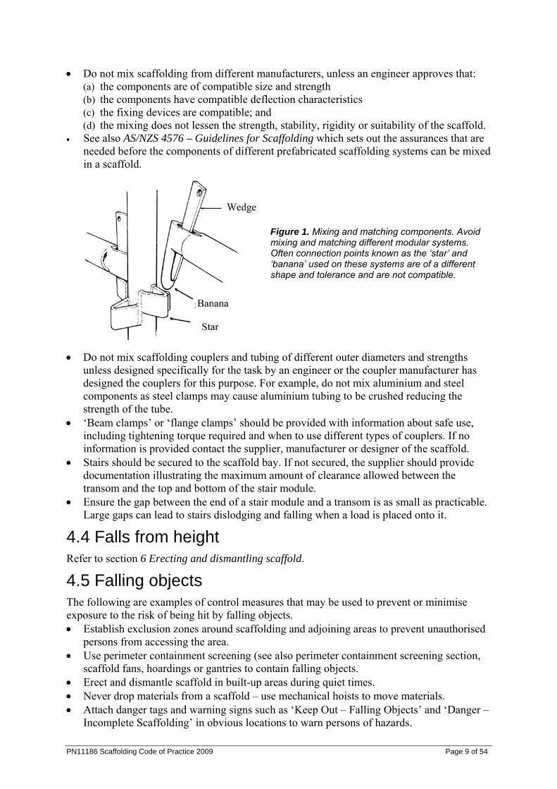
• Do not mix scaffolding from different manufacturers, unless an engineer approves that: (a) the components are of compatible size and strength (b) the components have compatible deflection characteristics (c) the fixing devices are compatible; and (d) the mixing does not lessen the strength, stability, rigidity or suitability of the scaffold.
• See also AS/NZS 4576 – Guidelines for Scaffolding which sets out the assurances that are needed before the components of different prefabricated scaffolding systems can be mixed in a scaffold.
Figure 1. Mixing and matching components. Avoid mixing and matching different modular systems. Often connection points known as the ‘star’ and ‘banana’ used on these systems are of a different shape and tolerance and are not compatible.
• Do not mix scaffolding couplers and tubing of different outer diameters and strengths unless designed specifically for the task by an engineer or the coupler manufacturer has designed the couplers for this purpose. For example, do not mix aluminium and steel components as steel clamps may cause aluminium tubing to be crushed reducing the strength of the tube.
• ‘Beam clamps’ or ‘flange clamps’ should be provided with information about safe use, including tightening torque required and when to use different types of couplers. If no information is provided contact the supplier, manufacturer or designer of the scaffold.
• Stairs should be secured to the scaffold bay. If not secured, the supplier should provide documentation illustrating the maximum amount of clearance allowed between the transom and the top and bottom of the stair module.
• Ensure the gap between the end of a stair module and a transom is as small as practicable. Large gaps can lead to stairs dislodging and falling when a load is placed onto it.
4.4 Falls from height Refer to section 6 Erecting and dismantling scaffold.
4.5 Falling objects The following are examples of control measures that may be used to prevent or minimise exposure to the risk of being hit by falling objects. • Establish exclusion zones around scaffolding and adjoining areas to prevent unauthorised
persons from accessing the area. • Use perimeter containment screening (see also perimeter containment screening section,
scaffold fans, hoardings or gantries to contain falling objects. • Erect and dismantle scaffold in built-up areas during quiet times. • Never drop materials from a scaffold – use mechanical hoists to move materials. • Attach danger tags and warning signs such as ‘Keep Out – Falling Objects’ and ‘Danger –
Incomplete Scaffolding’ in obvious locations to warn persons of hazards.
PN11186 Scaffolding Code of Practice 2009 Page 9 of 54
PN11186 Scaffolding Code of Practice 2009 Page 10 of 54
4.6 Scaffold collapse See section 7 Types of scaffolding for control measures which may be used to prevent or minimise exposure to the risk of death or injury from scaffold collapse.
4.7 Hazardous manual tasks Guidance on hazardous manual tasks is available in the Hazardous Manual Tasks Code of Practice. 4.7.1 Examples of design controls Job design and redesign • Use scaffold systems which are made of lighter weight materials and use modern
technologies (for example, modular systems which have shorter standard lengths or systems that are made of aluminium rather than steel or timber).
• Use components that are shorter in length thereby reducing the weight of the standards and making them easier to handle.
• Store scaffolding components as close as practical to the work area in order to minimise the distance over which loads are manually moved. Clear access ways should also be ensured so that materials and equipment can be easily accessed.
• Avoid using different types of scaffolding together as increased force may be required to assemble and dismantle components that are not made to fit together.
• Use the appropriate tools for the work performed and avoid over tightening scaffold couplers which results in the need for greater force when loosening them during the dismantling stage.
Mechanical aids • Use mechanical aids such as cranes, hoists, pallet jacks or trolleys to move equipment and
materials wherever possible (for example, when lifting bundles of components, moving components/materials around the site, or unloading vehicles). Team lifting is not a preferred method for load handling and should only be used as a last resort when mechanical aids cannot be used or the work cannot be redesigned. Workers must be trained in team lifting techniques and adequate numbers of workers must be provided.
• Use electric winches (preferred) or gin wheels to lift components up the scaffold. • 4.7.2 Examples of administrative controls Work organisation • Incorporate rest breaks or task variety into the job where the risk can not be prevented or
minimised. • Ensure there are adequate numbers of workers to meet deadlines. Task specific training • Workers should be provided with education and training in relation to the performance of
manual tasks. This includes training in the correct use of mechanical devices, tools and equipment, as well as safe performance of the specific manual tasks and handling methods (for example, team lifting).
Preventative maintenance program • Clean and maintain tools, equipment and scaffolding components regularly. Tools and
equipment which are not properly maintained, as well as components that have been damaged and therefore no longer fit easily together, may require increased force when using them.
PN11186 Scaffolding Code of Practice 2009 Page 11 of 54
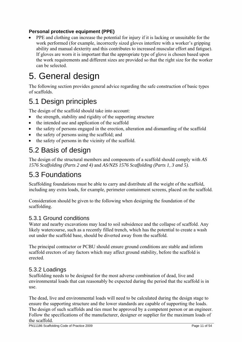
Personal protective equipment (PPE) • PPE and clothing can increase the potential for injury if it is lacking or unsuitable for the
work performed (for example, incorrectly sized gloves interfere with a worker’s gripping ability and manual dexterity and this contributes to increased muscular effort and fatigue). If gloves are worn it is important that the appropriate type of glove is chosen based upon the work requirements and different sizes are provided so that the right size for the worker can be selected.
5. General design The following section provides general advice regarding the safe construction of basic types of scaffolds.
5.1 Design principles The design of the scaffold should take into account: • the strength, stability and rigidity of the supporting structure • the intended use and application of the scaffold • the safety of persons engaged in the erection, alteration and dismantling of the scaffold • the safety of persons using the scaffold; and • the safety of persons in the vicinity of the scaffold.
5.2 Basis of design The design of the structural members and components of a scaffold should comply with AS 1576 Scaffolding (Parts 2 and 4) and AS/NZS 1576 Scaffolding (Parts 1, 3 and 5).
5.3 Foundations Scaffolding foundations must be able to carry and distribute all the weight of the scaffold, including any extra loads, for example, perimeter containment screens, placed on the scaffold. Consideration should be given to the following when designing the foundation of the scaffolding. 5.3.1 Ground conditions Water and nearby excavations may lead to soil subsidence and the collapse of scaffold. Any likely watercourse, such as a recently filled trench, which has the potential to create a wash out under the scaffold base, should be diverted away from the scaffold. The principal contractor or PCBU should ensure ground conditions are stable and inform scaffold erectors of any factors which may affect ground stability, before the scaffold is erected. 5.3.2 Loadings Scaffolding needs to be designed for the most adverse combination of dead, live and environmental loads that can reasonably be expected during the period that the scaffold is in use. The dead, live and environmental loads will need to be calculated during the design stage to ensure the supporting structure and the lower standards are capable of supporting the loads. The design of such scaffolds and ties must be approved by a competent person or an engineer. Follow the specifications of the manufacturer, designer or supplier for the maximum loads of the scaffold.
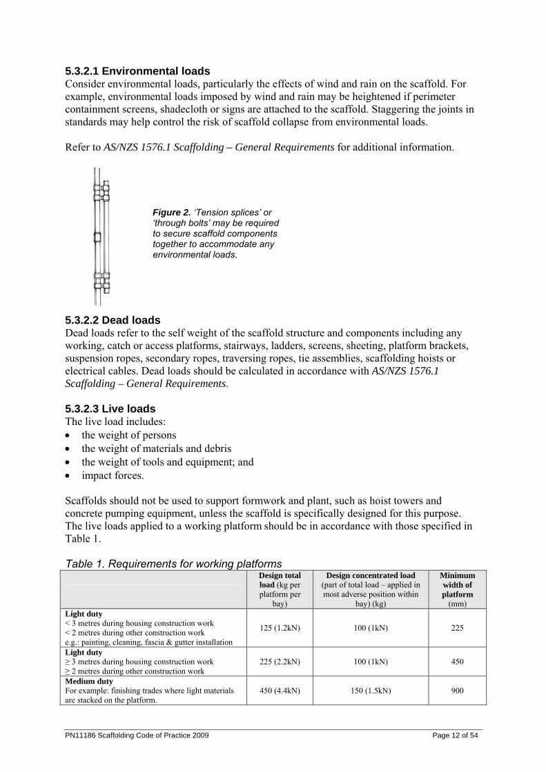
5.3.2.1 Environmental loads Consider environmental loads, particularly the effects of wind and rain on the scaffold. For example, environmental loads imposed by wind and rain may be heightened if perimeter containment screens, shadecloth or signs are attached to the scaffold. Staggering the joints in standards may help control the risk of scaffold collapse from environmental loads. Refer to AS/NZS 1576.1 Scaffolding – General Requirements for additional information.
Figure 2. ‘Tension splices’ or ‘through bolts’ may be required to secure scaffold components together to accommodate any environmental loads.
5.3.2.2 Dead loads Dead loads refer to the self weight of the scaffold structure and components including any working, catch or access platforms, stairways, ladders, screens, sheeting, platform brackets, suspension ropes, secondary ropes, traversing ropes, tie assemblies, scaffolding hoists or electrical cables. Dead loads should be calculated in accordance with AS/NZS 1576.1 Scaffolding – General Requirements. 5.3.2.3 Live loads The live load includes: • the weight of persons • the weight of materials and debris • the weight of tools and equipment; and • impact forces. Scaffolds should not be used to support formwork and plant, such as hoist towers and concrete pumping equipment, unless the scaffold is specifically designed for this purpose. The live loads applied to a working platform should be in accordance with those specified in Table 1. Table 1. Requirements for working platforms
Design total load (kg per platform per
bay)
Design concentrated load (part of total load – applied in most adverse position within
bay) (kg)
Minimum width of platform
(mm) Light duty < 3 metres during housing construction work < 2 metres during other construction work e.g.: painting, cleaning, fascia & gutter installation
125 (1.2kN) 100 (1kN) 225
Light duty ≥ 3 metres during housing construction work ≥ 2 metres during other construction work
225 (2.2kN) 100 (1kN) 450
Medium duty For example: finishing trades where light materials are stacked on the platform.
450 (4.4kN) 150 (1.5kN) 900
PN11186 Scaffolding Code of Practice 2009 Page 12 of 54
Heavy duty For example: bricklaying and demolition work (special duty may be required for some demolition).
675 (6.6kN) 200 (2kN) 1000
Special duty Seek guidance from designer, manufacturer, supplier or engineer Note: No materials are permitted on platforms 450 mm wide or less. All other scaffolds must have a clear platform width of at least 450 mm.
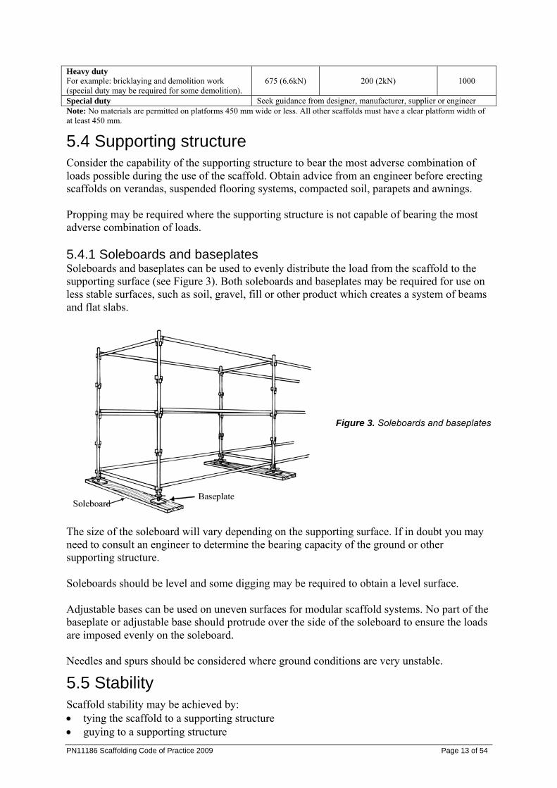
5.4 Supporting structure Consider the capability of the supporting structure to bear the most adverse combination of loads possible during the use of the scaffold. Obtain advice from an engineer before erecting scaffolds on verandas, suspended flooring systems, compacted soil, parapets and awnings. Propping may be required where the supporting structure is not capable of bearing the most adverse combination of loads. 5.4.1 Soleboards and baseplates Soleboards and baseplates can be used to evenly distribute the load from the scaffold to the supporting surface (see Figure 3). Both soleboards and baseplates may be required for use on less stable surfaces, such as soil, gravel, fill or other product which creates a system of beams and flat slabs.
Figure 3. Soleboards and baseplates
The size of the soleboard will vary depending on the supporting surface. If in doubt you may need to consult an engineer to determine the bearing capacity of the ground or other supporting structure. Soleboards should be level and some digging may be required to obtain a level surface. Adjustable bases can be used on uneven surfaces for modular scaffold systems. No part of the baseplate or adjustable base should protrude over the side of the soleboard to ensure the loads are imposed evenly on the soleboard. Needles and spurs should be considered where ground conditions are very unstable.
5.5 Stability Scaffold stability may be achieved by: • tying the scaffold to a supporting structure • guying to a supporting structure PN11186 Scaffolding Code of Practice 2009 Page 13 of 54
PN11186 Scaffolding Code of Practice 2009 Page 14 of 54
• increasing the dead load by securely attaching counterweights near the base; and • adding bays to increase the base dimension.
5.6 Tying Tie methods and spacing need to be in accordance with the instructions of the manufacturer, designer or supplier. Outlined below are safe work practices and control measures for tying scaffold. • Consult with the scaffold designer, manufacturer, supplier or an engineer if it is not
practical to position the ties in accordance with the instructions. • More ties may be required if:
(a) the scaffold is sheeted or netted due to increased wind loadings (b) it is used as a loading platform for materials or equipment; and (c) attaching lifting appliances or rubbish chutes.
• The principal contractor or a PCBU should have a competent person regularly inspect the existence and effectiveness of scaffold ties to ensure they are not modified or altered by unauthorised persons (for example, finishing trades who may loosen, relocate or remove ties to obtain access to walls and openings).
• Consult with the scaffold designer or supplier before attaching additional loads on the scaffold, for example, signs and perimeter containment screens.
• Cast-in anchors or ‘through bolts’ (i.e. pass through a wall) are preferred to drill-in expansion or chemical anchors for securing scaffold ties because of possible failure due to faulty tensioning or epoxies.
• Drill-in expansion anchors should be limited to the load (torque) controlled type. The working load limit should be limited to 65% of the ‘first slip load’ stated in the information provided by the supplier.
• Deformation-controlled anchors, including self-drilling anchors and drop-in (setting) impact anchors, should not be used.
• Where chemical anchors are used, all anchors should be tested and proof loaded to the working load multiplied by a factor of 1.25.
• All drill-in expansion anchors must be installed using a torque wrench set to the appropriate torque, unless the anchor has an in-built torque indicator. Documented verification is to be kept on site, stating the anchor setting torque, date of installation, location of installation and name of competent person installing the anchors.
• Drill-in expansion or chemical anchors should have a safety factor of 3 to 1 on their failure load. If any anchors fail, the remaining anchors on the same level should be tested.
• Ties should not obstruct access along the working and access platforms. • Ties should interconnect with both the inner and outer scaffold standards (unless
otherwise specified by an engineer) to increase the rigidity of the scaffold.
5.7 Working platforms Working platforms, except suspended scaffolds should have duty classifications and dimensions complying with section 5.3.2 Loadings. Each scaffold should be designed to carry the required number of working platforms and to support its live loads. The following are safe work practices or control measures for working platforms. • Scaffold planks should:
(a) have a slip-resistant surface
(b) not be cracked or split (c) be of uniform thickness (d) be captive (i.e. can not be kicked off ) and fixed to prevent uplift or displacement
during normal use; and (e) be positioned so that no single gap between planks exceeds 25 mm and the total gap
between all planks does not exceed 50 mm. • Planks should not be lapped on straight runs of modular and tube and coupler scaffolding
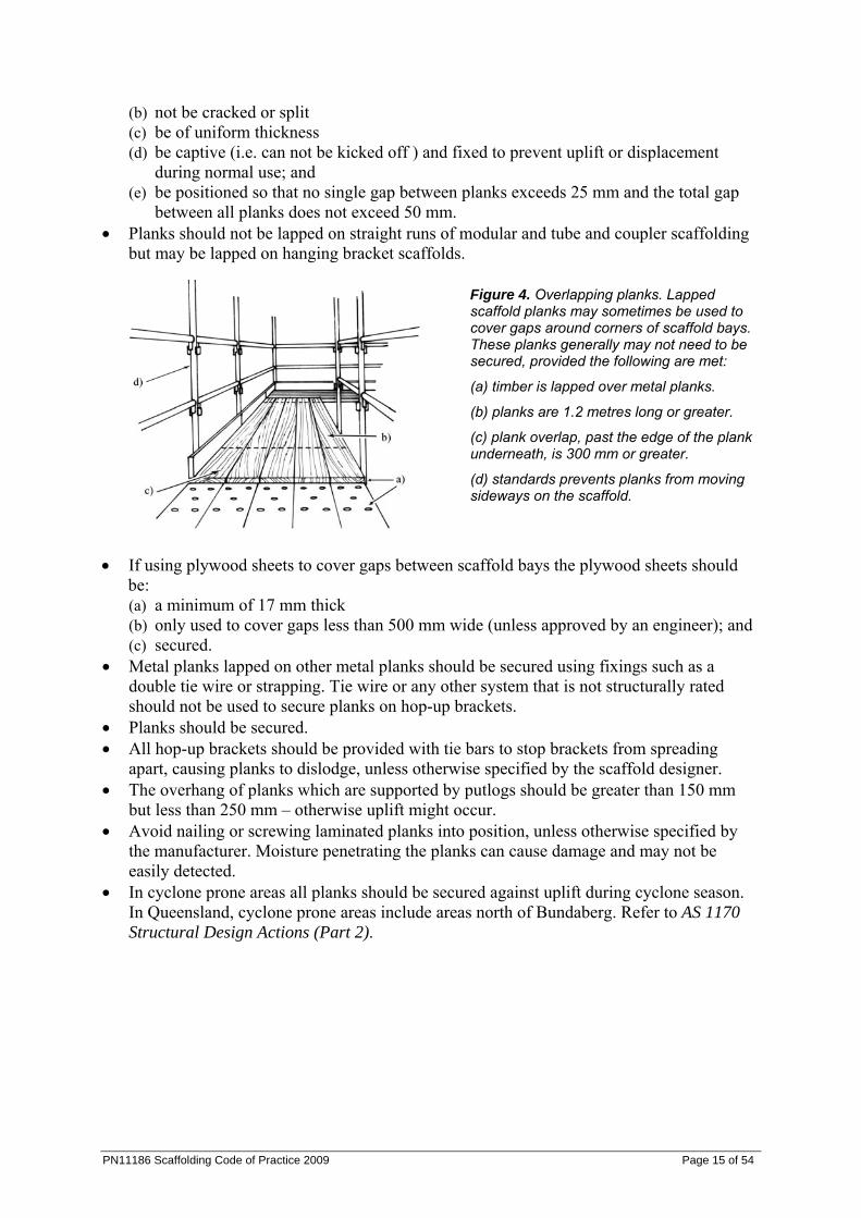
but may be lapped on hanging bracket scaffolds.
Figure 4. Overlapping planks. Lapped scaffold planks may sometimes be used to cover gaps around corners of scaffold bays. These planks generally may not need to be secured, provided the following are met:
(a) timber is lapped over metal planks.
(b) planks are 1.2 metres long or greater.
(c) plank overlap, past the edge of the plank underneath, is 300 mm or greater.
(d) standards prevents planks from moving sideways on the scaffold.
• If using plywood sheets to cover gaps between scaffold bays the plywood sheets should be: (a) a minimum of 17 mm thick (b) only used to cover gaps less than 500 mm wide (unless approved by an engineer); and (c) secured.
• Metal planks lapped on other metal planks should be secured using fixings such as a double tie wire or strapping. Tie wire or any other system that is not structurally rated should not be used to secure planks on hop-up brackets.
• Planks should be secured. • All hop-up brackets should be provided with tie bars to stop brackets from spreading
apart, causing planks to dislodge, unless otherwise specified by the scaffold designer. • The overhang of planks which are supported by putlogs should be greater than 150 mm
but less than 250 mm – otherwise uplift might occur. • Avoid nailing or screwing laminated planks into position, unless otherwise specified by
the manufacturer. Moisture penetrating the planks can cause damage and may not be easily detected.
• In cyclone prone areas all planks should be secured against uplift during cyclone season. In Queensland, cyclone prone areas include areas north of Bundaberg. Refer to AS 1170 Structural Design Actions (Part 2).
PN11186 Scaffolding Code of Practice 2009 Page 15 of 54
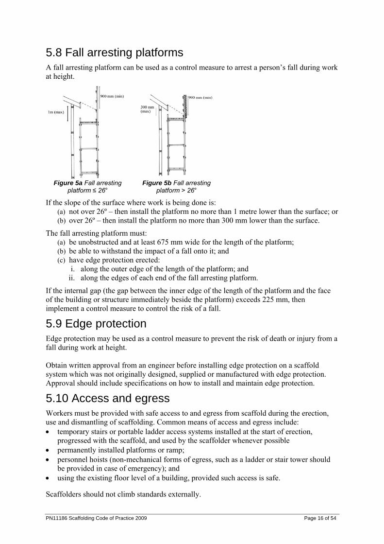
5.8 Fall arresting platforms A fall arresting platform can be used as a control measure to arrest a person’s fall during work at height.
Figure 5a Fall arresting
platform ≤ 26° Figure 5b Fall arresting
platform > 26°
If the slope of the surface where work is being done is: (a) not over 26º – then install the platform no more than 1 metre lower than the surface; or (b) over 26º – then install the platform no more than 300 mm lower than the surface.
The fall arresting platform must: (a) be unobstructed and at least 675 mm wide for the length of the platform; (b) be able to withstand the impact of a fall onto it; and (c) have edge protection erected:
i. along the outer edge of the length of the platform; and ii. along the edges of each end of the fall arresting platform.
If the internal gap (the gap between the inner edge of the length of the platform and the face of the building or structure immediately beside the platform) exceeds 225 mm, then implement a control measure to control the risk of a fall.
5.9 Edge protection Edge protection may be used as a control measure to prevent the risk of death or injury from a fall during work at height. Obtain written approval from an engineer before installing edge protection on a scaffold system which was not originally designed, supplied or manufactured with edge protection. Approval should include specifications on how to install and maintain edge protection.
5.10 Access and egress Workers must be provided with safe access to and egress from scaffold during the erection, use and dismantling of scaffolding. Common means of access and egress include: • temporary stairs or portable ladder access systems installed at the start of erection,
progressed with the scaffold, and used by the scaffolder whenever possible • permanently installed platforms or ramp; • personnel hoists (non-mechanical forms of egress, such as a ladder or stair tower should
be provided in case of emergency); and • using the existing floor level of a building, provided such access is safe. Scaffolders should not climb standards externally.
PN11186 Scaffolding Code of Practice 2009 Page 16 of 54
PN11186 Scaffolding Code of Practice 2009 Page 17 of 54
5.10.1 Ladders The following are additional safe work practices which should be followed when working on ladders: • Ladders may be used where access to the working platform is needed by only a few
persons, and where tools and equipment can be delivered separately to the working platform (for example, by materials hoist, crane or a rope and gin wheel).
• Ladders should be within a separate ladder access bay of the scaffold, wherever space permits.
• If the access bay is part of the working platform, a trap door is to be provided. Strict controls are to be implemented to ensure the trap door remains closed while working from the platform.
• Ladders should be set up on a firm, level surface and not used on scaffold bays to gain extra height.
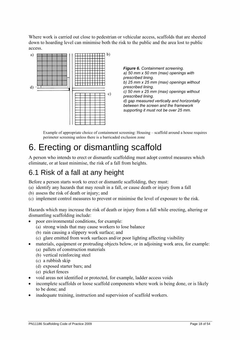
5.11 Perimeter containment screening Perimeter containment screening is used to protect persons from falling objects. Perimeter containment screens must be made of mesh, timber, plywood, metal sheeting or other material suitable for the purpose. The requirements for mesh are summarised in Table 2 (also see Figure 6). Table 2. Summary of requirements for mesh perimeter containment screens Mesh pattern Size of mesh openings (max) Mesh gauge Square or other rectangle - with prescribed lining* 50 mm x 50 mm 2.5 mm - without prescribed lining* 25 mm x 25 mm 2.5 mm - without prescribed lining* 25 mm x 50 mm 2.5 mm Not square or other rectangle - with prescribed lining* 50 mm in any direction 2.5 mm - without prescribed lining* 25 mm in any direction 2.5 mm * prescribed lining means intact shade cloth, or another intact lining, that when tested, wet or dry, in accordance with method A in AS 2001.2.4 has a mean bursting pressure of at least 1000 kPa. Perimeter containment screens must be located inside the standards on working platforms. The prescribed lining2 must be attached to the inside of the mesh. The prescribed lining can be attached using non-structural locating product which keeps the lining in place while minimising damage to the lining. The framework supporting a screen must be able to bear the load of the screen. Each of the following gaps must be not over 25 mm:
(a) the gap, measured horizontally, between screens immediately beside each other (b) the gap, measured vertically, between a screen and another screen immediately above
it; and (c) the gap, measured vertically and horizontally, between a screen and the framework
supporting it. Containment sheeting should be installed no higher than the upper most tie, unless certified otherwise by an engineer.
2 prescribed lining means intact shade cloth, or another intact lining, that when tested, wet or dry, in accordance with method A in AS 2001.2.4 has a mean bursting pressure of at least 1000 kPa.
Where work is carried out close to pedestrian or vehicular access, scaffolds that are sheeted down to hoarding level can minimise both the risk to the public and the area lost to public access.
Figure 6. Containment screening. a) 50 mm x 50 mm (max) openings with prescribed lining. b) 25 mm x 25 mm (max) openings without prescribed lining. c) 50 mm x 25 mm (max) openings without prescribed lining. d) gap measured vertically and horizontally between the screen and the framework supporting it must not be over 25 mm.
Example of appropriate choice of containment screening: Housing – scaffold around a house requires perimeter screening unless there is a barricaded exclusion zone
6. Erecting or dismantling scaffold A person who intends to erect or dismantle scaffolding must adopt control measures which eliminate, or at least minimise, the risk of a fall from heights.
6.1 Risk of a fall at any height Before a person starts work to erect or dismantle scaffolding, they must: (a) identify any hazards that may result in a fall, or cause death or injury from a fall (b) assess the risk of death or injury; and (c) implement control measures to prevent or minimise the level of exposure to the risk. Hazards which may increase the risk of death or injury from a fall while erecting, altering or dismantling scaffolding include: • poor environmental conditions, for example:
(a) strong winds that may cause workers to lose balance (b) rain causing a slippery work surface; and (c) glare emitted from work surfaces and/or poor lighting affecting visibility
• materials, equipment or protruding objects below, or in adjoining work area, for example: (a) pallets of construction materials (b) vertical reinforcing steel (c) a rubbish skip (d) exposed starter bars; and (e) picket fences
• void areas not identified or protected, for example, ladder access voids • incomplete scaffolds or loose scaffold components where work is being done, or is likely
to be done; and • inadequate training, instruction and supervision of scaffold workers.
PN11186 Scaffolding Code of Practice 2009 Page 18 of 54
PN11186 Scaffolding Code of Practice 2009 Page 19 of 54
6.2 Additional safe work practices The following additional safe work practices should be followed when erecting scaffold. • Scaffold ‘fittings’ and other connections should be securely tightened. Where ‘safety
fittings’ are used, they should be fitted in accordance with the scaffold plan. • All scaffold components should be installed as the scaffold is erected. For example, the
installation of: (a) all bracing and ties; and (b) guy ropes or buttresses.
• Consider using specifically designed loading platforms and/or back propping to prevent overloading the building floor or the scaffold.
• Obtain certification from an engineer before erecting scaffold on awnings. • Limit the number of workers on a scaffold at any one time. • Develop a methodical work sequence if more than one worker will be on the scaffold at
the one time, for example, allocate specific tasks to each scaffolder. • Work from a full deck of planks whenever possible. • Do not climb on guardrails to gain extra height. • Where the internal gap3 on scaffolding (includes hanging bracket scaffolding) is greater
than 225 mm, put in place measures to control the risk of a fall. For example, install: (a) edge protection on the inside edge of the platform; and (b) additional scaffold planks to minimise the size of the internal gap.
6.2.1 Safe dismantling of scaffolding The following summarises a safe method for dismantling scaffold. • Edge protection and any means of access can be removed as the scaffolding is dismantled,
provided it is removed at the last possible stage. • A platform of at least 450 mm wide, at the level the dismantling has reached, is in place,
where practicable. • Ensure that when dismantling scaffold, the platform immediately below the level the
worker is standing on, has a full set of planks across its width. • A section of the scaffold may be left open (for example no platform in place) to allow the
lowering of planks or other scaffolding components between levels. Note: To prevent death or injury to persons and damage to components, do not drop scaffolding components from heights when dismantling scaffold.
6.2.2 Scaffold alteration Control measures to minimise the risk of death or injury during scaffold alteration include ensuring: • the scaffold designer is consulted before making any alterations • only a competent person makes scaffold alterations • scaffold alterations are in accordance with the scaffold plan • alterations do not compromise the structural integrity of the scaffold; and • systems are in place (for example, regular inspections) to identify unauthorised
interference with the scaffold. 6.2.3 Fall-arrest systems Fall-arrest systems can be used as a control measure to arrest a person’s fall when working on scaffolding. However, fall-arrest systems are not usually appropriate for erecting scaffolding because:
3 The gap between the inner edge of the length of the platform and the face of the building or structure immediately beside the platform.
PN11186 Scaffolding Code of Practice 2009 Page 20 of 54
• workers are likely to hit a component of the scaffold before the fall is arrested • obtaining suitable anchorage points that can support a load of 15kN may be difficult • continuously hooking on and off the scaffold may be inconvenient; and • fall arrest lines may become trip hazards. Fall-arrest systems should only be used during the following scaffold activities. • erecting or dismantling ‘drop’ or ‘hung’ scaffold where the scaffold is constructed from
top to bottom, this allows for a clear fall zone, in the event of a fall • the fixing and removal of trolley tracks on suspension rigs • erecting or dismantling cantilevered needles and decking between the needles. Fall arrest
systems could also be used during the erection of the first lift of scaffolding where workers are standing on the deck between the needles
• the erection and dismantling of cantilevered scaffolds prior to or when removing the initial platform; and
• the attachment and removal of spurs projecting from the supporting structure. 6.2.3.1 Rescue procedures Ensure that there are written procedures about: (a) safely retrieving a person who has fallen and (b) ensuring the safety of the person involved in the retrieval. In the event of an accident, the suspended person must be retrieved immediately – otherwise there is the risk of permanent injury to the person. Rescue procedures must also ensure the safety of the persons involved in the retrieval. Emergency plans may need to identify the location and means of access for the rescuer. A fall-arrest system should not be used unless there is at least one other person (or two persons if the fallen person is heavy or unconscious) on site who will be able to rescue the user. If an elevating work platform (EWP) is to be used for a rescue, it should be readily available and at all times be able to reach the position of the person using the fall-arrest system. Workers must be provided with training in the safe and correct use of the fall-arrest system.
7. Types of scaffold Consider the design, shape and location of the building or other structure when selecting the type of scaffold to be used. Choose a scaffold system that is most adaptable to the contour of the building or other structure, particularly if a modular scaffold is being considered. Also consider the purpose for which the scaffold is to be used, for example, bricklaying, plastering or demolition. The following section identifies different types of scaffolds and control measures to prevent or minimise exposure to the risk of death or injury. Scaffolds should be erected in accordance with the designer’s instructions and the scaffold plan. A person doing scaffolding work more than 4 metres in height must hold a certificate for basic, intermediate or advanced scaffolding.
PN11186 Scaffolding Code of Practice 2009 Page 21 of 54
7.1 Independent scaffold An independent scaffold consists of two or more rows of standards connected longitudinally and transversely. 7.1.1 Birdcage scaffold A birdcage scaffold is an independent scaffold that consists of more than two rows of standards in both directions and is connected by ledgers and transoms. It is mainly used for work that is to be carried out on a single level, such as ceilings. Refer to the designer’s specifications when erecting and dismantling birdcage scaffolds made from modular scaffolding. The following control measures should be implemented for birdcage scaffolds made from tube and coupler scaffolding: • Provide untied birdcage scaffolds with lengthwise bracing at each outer longitudinal row
of standards. • Only use birdcage scaffold to support formwork that has been specifically designed for
this purpose. • Provide longitudinal bracing or a tied face at every third longitudinal row of standards. • Brace the outside row of standards on each face and each third row internally with
longitudinal bracing. • Provide transverse bracing at every fourth bay on the ends of the scaffold. • Use scissor lifts to erect or dismantle birdcage scaffolds. A fall arrest system is generally not an appropriate control measure for the erection or dismantling of perimeter and birdcage scaffolds (see section 7.2.3 Fall arrest systems for further information). Use another control measure to prevent or minimise exposure to the risk of death or injury from a fall. 7.1.2 Tower scaffold A tower scaffold is an independent scaffold consisting of four vertical members connected longitudinally and transversely. The following control measures should be implemented for tower scaffolds. • Construct the tower with modular, frame, or tube and coupler scaffolding. • Ensure the tower is resting on firm level ground with the wheels or feet properly
supported. Do not use bricks or building blocks to take the weight of any part of the tower.
• Ensure the height of a tower scaffold, from the bottom of the scaffold to the working surface, is no greater than three times the minimum base dimension, unless otherwise specified by the manufacturer, supplier or designer.
• Use alternative height to base ratios or extra support if the scaffold is: (a) sheeted or likely to be exposed to strong winds (b) loaded with heavy equipment or materials (c) used to hoist heavy materials or support rubbish chutes (d) used for operations involving heavy or awkward equipment (for example, grit blasting
or water-jetting); and (e) supporting a ladder.
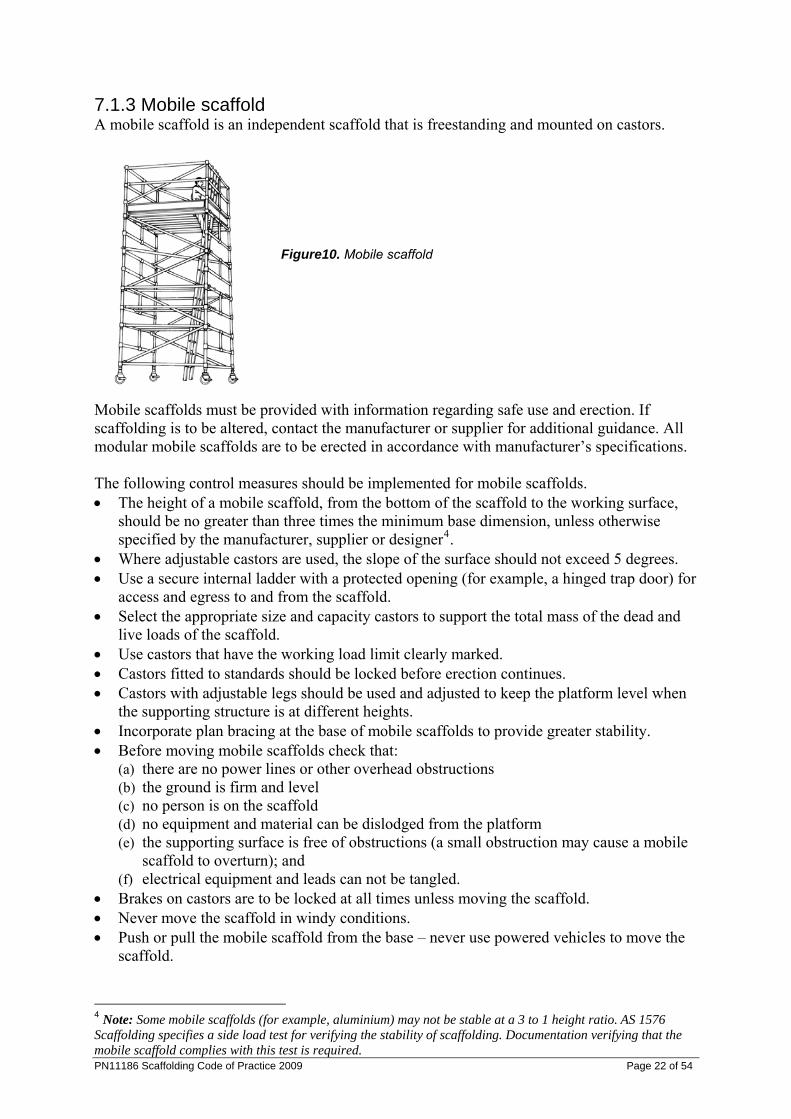
7.1.3 Mobile scaffold A mobile scaffold is an independent scaffold that is freestanding and mounted on castors.
Figure10. Mobile scaffold
Mobile scaffolds must be provided with information regarding safe use and erection. If scaffolding is to be altered, contact the manufacturer or supplier for additional guidance. All modular mobile scaffolds are to be erected in accordance with manufacturer’s specifications. The following control measures should be implemented for mobile scaffolds. • The height of a mobile scaffold, from the bottom of the scaffold to the working surface,
should be no greater than three times the minimum base dimension, unless otherwise specified by the manufacturer, supplier or designer4.
• Where adjustable castors are used, the slope of the surface should not exceed 5 degrees. • Use a secure internal ladder with a protected opening (for example, a hinged trap door) for
access and egress to and from the scaffold. • Select the appropriate size and capacity castors to support the total mass of the dead and
live loads of the scaffold. • Use castors that have the working load limit clearly marked. • Castors fitted to standards should be locked before erection continues. • Castors with adjustable legs should be used and adjusted to keep the platform level when
the supporting structure is at different heights. • Incorporate plan bracing at the base of mobile scaffolds to provide greater stability. • Before moving mobile scaffolds check that:
(a) there are no power lines or other overhead obstructions (b) the ground is firm and level (c) no person is on the scaffold (d) no equipment and material can be dislodged from the platform (e) the supporting surface is free of obstructions (a small obstruction may cause a mobile
scaffold to overturn); and (f) electrical equipment and leads can not be tangled.
• Brakes on castors are to be locked at all times unless moving the scaffold. • Never move the scaffold in windy conditions. • Push or pull the mobile scaffold from the base – never use powered vehicles to move the
scaffold.
PN11186 Scaffolding Code of Practice 2009 Page 22 of 54
4 Note: Some mobile scaffolds (for example, aluminium) may not be stable at a 3 to 1 height ratio. AS 1576 Scaffolding specifies a side load test for verifying the stability of scaffolding. Documentation verifying that the mobile scaffold complies with this test is required.
• If lifting a mobile scaffold by crane, sling the scaffold at its lowest point to prevent dislodgment of scaffold components. However, a crane should not be used to lift aluminium mobile scaffolds because the scaffold components may fail.
7.1.4 Hung scaffold A hung scaffold is an independent scaffold that hangs from another structure, but is not capable of being raised or lowered when in use. The following control measures should be implemented for a hung scaffold: • The hung scaffold should be designed by a competent person and verification obtained
that the structure that is to support the hung scaffold is capable of bearing the load. • The scaffold plan should include information about the position of the safety couplers. • If a cantilevered suspension rig is to be used, information should be included on how the
rig is to be constructed and secured. • Standards on a hung scaffold should be tension spliced (refer to Figure 2). • All vertical hanging tubes are to be provided with safety couplers at the suspension points
and underneath the platform.
7.2 Single pole scaffold A single pole scaffold consists of a single row of standards connected by ledgers. Putlogs are fixed to the ledgers and built into the wall of the building or structure. A single pole scaffold is dependent upon the structure against which it is placed for support. It is important that no components of this type of scaffold are removed until the scaffold is being dismantled.
7.3 Suspended (swing-stage) scaffold A suspended scaffold incorporates a suspended platform that is capable of being raised or lowered when in use. An example of a suspended scaffold is a swing-stage scaffold. A summary of the requirements for suspended (swing-stage) scaffold are listed in this part. Appendix 5 – Compliance pack for swing-stage scaffold of this code provides a package of information and safety requirements to be followed. In addition, any relevant component manufacturers’ requirements and specific engineer requirements for each installation must also be followed. Any person who is erecting or installing suspended scaffold must have undertaken the Course in the Safe Erection/Installation of Swing Stage Scaffolds (30825QLD). A user of the swing stage must have undertaken the Course in the Safe Use of Swing Stage Scaffolds 30826QLD).
Figure 11a. Suspended (swing-stage) scaffold –Suspension mounting.
PN11186 Scaffolding Code of Practice 2009 Page 23 of 54
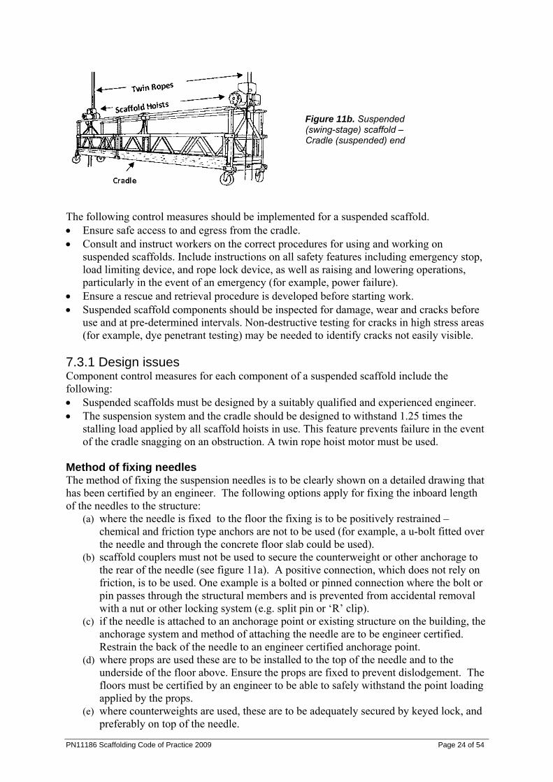
Figure 11b. Suspended (swing-stage) scaffold – Cradle (suspended) end
The following control measures should be implemented for a suspended scaffold. • Ensure safe access to and egress from the cradle. • Consult and instruct workers on the correct procedures for using and working on
suspended scaffolds. Include instructions on all safety features including emergency stop, load limiting device, and rope lock device, as well as raising and lowering operations, particularly in the event of an emergency (for example, power failure).
• Ensure a rescue and retrieval procedure is developed before starting work. • Suspended scaffold components should be inspected for damage, wear and cracks before
use and at pre-determined intervals. Non-destructive testing for cracks in high stress areas (for example, dye penetrant testing) may be needed to identify cracks not easily visible.
7.3.1 Design issues Component control measures for each component of a suspended scaffold include the following: • Suspended scaffolds must be designed by a suitably qualified and experienced engineer. • The suspension system and the cradle should be designed to withstand 1.25 times the
stalling load applied by all scaffold hoists in use. This feature prevents failure in the event of the cradle snagging on an obstruction. A twin rope hoist motor must be used.
Method of fixing needles The method of fixing the suspension needles is to be clearly shown on a detailed drawing that has been certified by an engineer. The following options apply for fixing the inboard length of the needles to the structure:
(a) where the needle is fixed to the floor the fixing is to be positively restrained – chemical and friction type anchors are not to be used (for example, a u-bolt fitted over the needle and through the concrete floor slab could be used).
(b) scaffold couplers must not be used to secure the counterweight or other anchorage to the rear of the needle (see figure 11a). A positive connection, which does not rely on friction, is to be used. One example is a bolted or pinned connection where the bolt or pin passes through the structural members and is prevented from accidental removal with a nut or other locking system (e.g. split pin or ‘R’ clip).
(c) if the needle is attached to an anchorage point or existing structure on the building, the anchorage system and method of attaching the needle are to be engineer certified. Restrain the back of the needle to an engineer certified anchorage point.
(d) where props are used these are to be installed to the top of the needle and to the underside of the floor above. Ensure the props are fixed to prevent dislodgement. The floors must be certified by an engineer to be able to safely withstand the point loading applied by the props.
(e) where counterweights are used, these are to be adequately secured by keyed lock, and preferably on top of the needle.
PN11186 Scaffolding Code of Practice 2009 Page 24 of 54
PN11186 Scaffolding Code of Practice 2009 Page 25 of 54
Suspension systems • Ensure the suspension system is designed and constructed in accordance with the
designer’s specifications. • Inspect the suspension system before use and after relocation to ensure all components are
secure and in working order. • Ensure persons who use suspended scaffolds are competent and receive training and
instruction on the safe use of the system, including information on hoist operation and emergency procedures.
• Obtain engineer certification that the suspension needles, parapets, roof structure or other parts of the structure can support the ‘parapet clamps’ or outriggers. An example of an unsuitable support system would be timber or single skin brick parapets.
• Access to the suspension system should be restricted to persons involved in the work. Access can be restricted by: (a) erecting signs and barricading (e.g. warning tape, barrier mesh/parawebbing, or
temporary fencing) around the suspension rig, (b) the use of permit-to-work systems in the restricted area, or (c) locking off access doors and hatches to the roof, balcony or other area where the
suspension system is located. The person in control of the suspension system area (principal contractor and/or body corporate) should ensure the restriction is in place.
• Ensure counterweights are secured to prevent unauthorised removal. • Suspension ropes should be inspected for damage such as kinks, wear, corroded or broken
wires, and replaced if necessary. See AS 2759 – Steel wire rope–Use, operation and maintenance for guidance.
Scaffold hoists • Ensure scaffold hoists comply with the manufacturer’s specifications. Only suspension
ropes noted in the specifications (compliance plate attached to the hoist) should be used. • Ensure scaffold hoists comply with AS 1418.2 Cranes (including hoists and winches) -
Serial hoists and winches . • After each use, ensure a trained person inspects and checks scaffold hoists, in accordance
with the manufacturer’s instructions. • Electric scaffold hoists must have a device to limit the lifting capacity of the hoist to a
maximum of 1.25 times the rating of the hoist, as specified in AS 1576.4 Scaffolding - Suspended scaffolding . The scaffold hoist limiting devices must be tested to the manufacturer’s instructions prior to use.
Cradles • Cradles are to be constructed in accordance with the manufacturer’s specifications. • Inspect all connection fixings before use to check they are secure. • Evenly distribute materials in the cradle. • Cradles should be clearly marked with the working load limit (WLL). The length and type
of material used to construct the cradle will influence the WLL of the cradle. Verify the WLL with the manufacturer or supplier where there are no clear markings on the cradle.
• If the cradle varies from the original manufacturer’s specifications, a suitably qualified and experienced engineer must verify the modification before use.
• To restrict the lateral movement of the cradle, use suction caps, tie off the cradle with rope.
• Work should cease and the cradle lowered to the ground during windy conditions.
PN11186 Scaffolding Code of Practice 2009 Page 26 of 54
Trolleys To prevent a trolley from falling off the beam, use lower keeper plates or a strap that wraps around the top of the beam. Trolleys that are not fitted with such a system should be removed from service. Obtain guidance from manufacturers and designers on effective systems to use. Fall arrest and travel restraint harness systems • Persons located in swing-stage cradles are to wear fall arrest harnesses attached to a
properly designed anchorage system. However, the harnesses may be used in a travel restraint application, attached to a static line in the cradle, where a fall out of the cradle is not possible. A thorough assessment needs to be undertaken to ensure appropriate control measures are in place to address any secondary risks that might arise.
• Where the guardrail or other edge protection is not provided for scaffolders erecting the suspension system, fall arrest systems are to be used. This includes, erecting or dismantling swing-stage scaffold components, or when doing preparatory or quoting activities where other positive fall prevention (such as staying on the safe side of a 900mm parapet) is not used.
• If independently anchored safety lines are used, then a high level of training and rescue procedures must be in place.
• Wherever fall arrest systems are used, a rescue procedure must be developed and documented. The rescue procedure should not place others at risk of injury.
• Fall arrest systems must comply with the Regulation. Appendix 5 – Compliance pack for swing-stage scaffold at the end of this code provides a package of information and safety requirements to be followed.
7.4 Special scaffolds 7.4.1 Cantilever scaffold A cantilever scaffold is a scaffold that is supported by cantilevered load-bearing members. The following control measures should be implemented for a cantilevered scaffold. • Design and position cantilever beams in accordance with the engineer’s requirements and
the scaffold plan. • Ensure a competent person certifies that the supporting structure can support the
cantilevered scaffold. • The following are preferred methods for fixing the inboard length of the cantilevered
beam to the structure: (a) fix the beam to the floor below using a positive fixing (for example, a u-bolt fitted
over the beam and through the concrete floor slab) (b) use counterweights on the beam; or (c) install props to the top of the beam and to the underside of the floor above. Ensure the
props are fixed to prevent dislodgement.
7.4.2 Hanging bracket scaffold Hanging bracket scaffolds are systems supported by frames on buildings or other structures. Hanging brackets are sometimes in the shape of an upside down ‘L’, one arm of which is fixed to a vertical surface, the other projecting horizontally to support scaffold planks. Other hanging bracket scaffold systems may include horizontal members that are supported by floors of buildings or other structures.
PN11186 Scaffolding Code of Practice 2009 Page 27 of 54
The following control measures should be implemented for hanging bracket scaffolds. • A safe means of access for persons installing hanging brackets should be provided. Where
fall arrest systems are used, these must comply with the WHS Regulation. • Connectors are used where differential deflection5 becomes a tripping hazard. • Hanging bracket scaffolds and their means of support should be designed by an engineer.
Engineering verification may be provided by calculation and/or load testing. • Supporting structure should be able to support dead and live loads applied by the hanging
brackets. • Spacing of brackets should not exceed the maximum plank spans specified by the
manufacturer. • Planks may overlap planks on straight runs on hanging bracket scaffolds, provided the
overlap is at least 300 mm. Note: This does not refer to overlap of planks on putlogs. Minimum and maximum overlapping for planks on putlogs is provided in AS 1576 Scaffolding.
7.4.3 Spur scaffold A spur scaffold is a scaffold that is supported by inclined load-bearing members. The following control measures should be implemented for a spur scaffold. • Fix propping systems between the floor and ceiling at intervals to suit the spacing of the
standards within the scaffold. • Suitable headstocks should be provided at the top of each propping system to distribute
the loads imposed. • All propping systems should be securely tied together and braced. • Spurs exceeding 1.8 metres in length should be braced in both directions at the centre,
unless designed otherwise.
7.5 Scaffolding for demolition work At a minimum, heavy or special duty scaffolding should be used during demolition work to contain dislodged materials or to provide a safe working platform and edge protection for workers. Factors which affect the stability of scaffolding for demolition work include: • load imposed by demolished material dislodged onto the scaffold • wind forces acting on containment sheeting on the scaffold face • water retention in containment sheeting by capillary attraction • progressive removal of building elements affecting the lateral stability of the upper
portion of the scaffold; and • progressive removal of ties and dismantling of scaffold. These factors should be considered when using scaffolding for demolition work. The following control measures should be implemented for scaffolding for demolition work. • The vertical spacing of scaffold ties may have to be reduced to facilitate the demolition
cycle. • Containment sheeting on the internal face of the scaffold should be installed to deflect any
material into the building. This reduces the potential for overloading the scaffold. • Ensure the scaffold is dismantled progressively and in line with the demolition work. • Scaffold planks should be secured to prevent dislodgement from falling debris. 5 Differential deflection occurs when two scaffold planks sag unevenly.
PN11186 Scaffolding Code of Practice 2009 Page 28 of 54
8. Inspection and maintenance procedures Procedures must be developed for the inspection and maintenance of the scaffold to ensure it remains in a safe condition. The inspection of scaffolding on site is particularly important when the scaffold is in place for a prolonged period of time.
8.1 Frequency of inspection The frequency of inspections may vary depending on weather and site conditions, the type and size of the scaffold and the risks associated with scaffold collapse. The person with management or control of a scaffold at a workplace must ensure that the scaffold and its supporting structure are inspected by a competent person: (a) before the scaffold is used; and (b) before use of the scaffold is resumed after an incident occurs that may reasonably be
expected to affect the stability of the scaffold; and (c) before use of the scaffold is resumed after repairs; and (d) at least every 30 days. Discuss appropriate intervals for inspection with the supplier when the scaffold is first installed. The person inspecting the scaffold must be capable of determining areas that have been incorrectly altered and have experience in identifying faults in the scaffolding. Inspection records should be kept on site and include the location, comments, date and time of inspections, relevant design or specification reference and the person who conducted the inspection. Further information can be found in the AS/NZS 4576 Guidelines for scaffolding.
8.2 Structural inspection Suppliers and owners of plant must ensure their plant is without risk to health when used properly. Procedures for the regular inspection of new and re-used equipment should be developed and implemented to ensure defects and structural damage is detected.
8.3 Hand over inspections The person responsible for the erection of the scaffold should provide the PCBU or principal contractor with a handover certificate which is kept on site until the scaffold has been dismantled. See also Appendix 4 Scaffold handover certificate: scaffold over 4 metres.
PN11186 Scaffolding Code of Practice 2009 Page 29 of 54
Appendix 1: Dictionary Access platform – a platform that is only used or intended to be used to provide access for persons, or for persons and materials to or from places of work. Advanced scaffolder means a person who performs: (a) the work of an intermediate scaffolder; and (b) scaffolding work, using scaffolding from which a person or object may fall more than 4m,
associated with: i. hung scaffolds, including scaffolds hanging from tubes, wire ropes and chains; or
ii. suspended scaffolds. Baseplate – a plate to distribute the load from a load-bearing member to the supporting structure. Basic scaffolder means a person who performs scaffolding work, using scaffolding from which a person or object may fall more than 4m, associated with: (a) prefabricated scaffolds; or (b) cantilevered materials hoists with a maximum working load of 500kg; or (c) ropes; or (d) gin wheels; or (e) safety nets and static lines; or (f) bracket scaffolds. Bay – the space enclosed by four adjacent standards, or the equivalent space in a single pole scaffold. Brace – a member fixed diagonally to two or more members of the scaffold to provide rigidity to the scaffold. Butt – a tube fixed to a scaffold and butting to an adjacent structure, to prevent horizontal movement of the scaffold in the direction of the structure. Buttress – a support to the side of a scaffold which provides for an effective increase in the on-ground base width, allowing a greater freestanding height. Castor – a swivelling wheel attached to the lower end of a standard for the purpose of supporting and moving a scaffold. Counterweight – a weight or series of weights that counterbalance a scaffold from overturning. Cradle – that portion of the assembly incorporating a suspended platform. Guardrail – a structural member to prevent persons from falling off any platform, walkway, stairway or landing. Guy rope – a rope used to help stabilise a vertical member. Intermediate scaffolder means a person who performs: (a) the work of a basic scaffolder; and
PN11186 Scaffolding Code of Practice 2009 Page 30 of 54
(b) scaffolding work, using scaffolding from which a person or object may fall more than 4m, associated with: i. cantilevered crane loading platforms; or
ii. cantilevered and spurred scaffolds; or iii. barrow ramps and sloping platforms; or iv. perimeter safety screens and shutters; or v. mast climbers; or
vi. tube and coupler scaffolds, including tube and coupler covered ways and gantries. Landing – a level area used to provide access to a stairway or ladder, or located at an intermediate level in a system of stairways or ladders. Ledger – a horizontal structural member longitudinally spanning a scaffold. Lift – the vertical distance from the supporting surface to the lowest ledger or level at which a platform can be constructed, or the vertical distance between adjacent ledgers or levels at which platforms can be constructed. Loading bay – a platform on a scaffold for the storage of materials and equipment. Member – anything that forms part of the scaffold assembly. Needle – a cantilevered structural member that forms part of the scaffold assembly. Outrigger – a framed component that increases the effectiveness of base dimensions of a tower and is attached to the vertical load-bearing members. Parapets – a vertical element usually located at the edge of a balcony, roof, bridge or similar structure. Perimeter containment screening means a screen: (a) designed to stop objects falling on persons from a level of a building; or (b) to redirect a falling object onto a catch platform. Platform – an elevated surface. Platform bracket – a bracket attached to the scaffold to enable a platform to be placed between the scaffold and the building or structure. Putlog – a horizontal structural member spanning between ledgers or a ledger and an adjacent wall, and intended to support a platform. Scaffold – means a temporary structure specifically erected to support access or working platforms. Scaffolding work – means erecting, altering or dismantling a temporary structure that is or has been erected to support a platform and from which a person or object could fall more than 4m from the platform or the structure. Scaffold plank – a decking component, other than a prefabricated platform, that is used or intended to be used in construction of any platform supported by a scaffold.
PN11186 Scaffolding Code of Practice 2009 Page 31 of 54
Soleboard – a board that is able to distribute the load from a load-bearing member to a supporting surface and is intended for use underneath baseplates. Spur – an inclined load-bearing member that transmits a load to the supporting structure. Standard – a vertical structural member that transmits a load to the supporting structure. Static line means a flexible line, to which a lanyard is attached, supported by at least 2 anchorage points located so that the angle between the horizontal and an imaginary straight line between any anchorage point and the other or nearest anchorage point is: (a) if the manufacturer of the flexible line has specified the size of the angle—not more than
the size specified; or (b) if the manufacturer has not specified the size of the angle—not more than 5º. Strut – a scaffold member subject to a compressive force. Supporting structure – any structure, structural member or foundation that supports a scaffold. Suspension rig – a supporting structure (including the trolley rack) from which a cradle is suspended. Suspension rope – a rope carrying the weight of a cradle and supporting an imposed load. Tie – a member or assembly of members used to tie a scaffold to a supporting structure. Transom – a horizontal structural member transversely spanning an independent scaffold at the standards. Working load limit – the maximum working load that may be applied to any component or system. Working platform – a platform from which persons perform work and may also be used to support materials and equipment.
PN11186 Scaffolding Code of Practice 2009 Page 32 of 54
Appendix 2: Inspection checklist 1. Scaffold vicinity
Has public protection been provided? Have sufficient safeguards against electric powerlines been provided? Is there sufficient control over vehicle movement? Is there sufficient control over crane operation? Are there sufficient controls for the storage, handling and use of hazardous
chemicals? Are scaffolds erected a safe distance away from trenches or excavations?
2. Supporting structure
Is the supporting structure in good condition? Does the supporting structure have adequate strength? Are there sufficient controls to prevent deterioration of the supporting structure? Are all measures to strengthen the supporting structure adequate? Is the risk of the supporting structure being overloaded from other sources
adequately controlled? Is the scaffold built on solid ground? If built on soft ground, are soleboards used to
properly distribute the load?
3. Soleboards and baseplates Are there sufficient soleboards? Are the soleboards of suitable material and in a serviceable condition? Are the soleboards secure? Are there sufficient baseplates? Are the baseplates of the appropriate type? Are the baseplates serviceable and of suitable dimensions? Are the baseplates secure?
4. Scaffold structure
Are the standards bearing firmly? Are the standards plumb (or as designed)? Are the longitudinal standard spacings correct? Are the transverse standard spacings correct? Are the joints in standards correctly positioned? Are the joints in standards correctly secured (special duty or hung scaffold)? Are the ledgers level (or as designed)? Are the ledgers continuous (or as designed)? Are the lift heights correct? Are the horizontal ledger spacings correct? Are the ledgers correctly secured? Are ledger joints correctly positioned (tube and coupler scaffold)? Are the joints in ledgers correctly secured (tube and coupler scaffold)? Are there sufficient transoms/putlogs? Are the transoms/putlogs correctly positioned and secured? Is the bracing adequate? Is the scaffold sufficiently stable? Are the ties correctly positioned and correctly fixed?
PN11186 Scaffolding Code of Practice 2009 Page 33 of 54
5. Platforms
Does the scaffold have the required number of working platforms? Are the working platforms at the required locations? Are catch platforms correctly positioned? Are the platforms and supporting scaffold constructed for the appropriate duty live
loads? Are the platform dimensions suitable for the intended work? Is there adequate edge protection? Are the platforms correctly constructed? Are planks secured against wind?
6. Access and egress
Is there safe access and egress to every scaffold platform? Are temporary stairways correctly installed? Are portable ladders of an industrial grade, serviceable and correctly installed? Are access ways and access platforms correctly installed?
7. Containment sheeting
Has the scaffold been designed for wind loading on any containment sheeting? Are the fixing ties secure? Are there any rips or tears? Are the overlap joints satisfactory?
8. General fitness for purpose
Is there adequate provision for material handling? Are the clearances between the scaffold and adjacent structures correct? Is there adequate protection from falling debris? Has the scaffold been adequately designed to support all attachments? Are all approaches and platforms effectively lit?
9. Mobile scaffolds
Is the supporting surface hard and flat? Is the area of operation free of floor penetrations, powerlines and other hazards? Are the castor wheel locks in working order? They should be locked at all times,
except during movement of the scaffold.
PN11186 Scaffolding Code of Practice 2009 Page 34 of 54
Appendix 3: Published technical standards AS 1418.2: Cranes (including hoists and winches) - Serial hoists and winches This Standard specifies requirements for serial hoists and winches. Section 5 relates to scaffolding hoists. AS/NZS 1576.1: Scaffolding – General requirements This Standard sets out design and operational requirements for scaffolding, except trestle scaffolding, portable ladders intended to be used as working platforms and elevating working platforms. AS 1576.2: Scaffolding – Couplers and accessories This Standard specifies requirements for couplers and accessories for light, medium and heavy duty scaffolding, in accordance with AS 1576.1. AS/NZS 1576.3: Scaffolding – Prefabricated and tube-and-coupler scaffolding This Standard specifies performance requirements for prefabricated and tube-and-coupler scaffolding. It is to be read in conjunction with AS/NZS 1576.1. AS 1576.4: Scaffolding – Suspended scaffolding This Standard sets out requirements for the materials, and design, of suspended scaffolding including the supporting structure (excluding building maintenance units). It is to be read in conjunction with AS 1576.1. AS/NZS 1576.5: Scaffolding – Prefabricated splitheads and trestles This Standard specifies requirements for splitheads and trestles that are used as supports for temporary platforms (excluding trestle ladders). AS/NZS 4576: Guidelines for scaffolding This Standard gives practical guidance for the training and certification of scaffolders, the preparation of sites for scaffolding, and the safe selection, supply, erection, alteration, dismantling, maintenance, inspection and use of scaffolding and scaffolding equipment. AS/NZS 1170.2: Structural design actions – Wind actions This Standard sets out procedures for determining wind speeds and resulting wind actions to be used in the structural design of structures subjected to wind actions other than those caused by tornadoes. The Standard covers structures within the following criteria: (a) Buildings less than 200 m high. (b) Structures with roof spans less than 100 m. (c) Structures other than offshore structures, bridges and transmission towers.

Appendix 4: Scaffold handover certificate: Scaffold over 4 metres Scaffold supplier/erector Client Certificate no: Company name:
Client name:
Address: Address:
Site address:
Contact Phone: Contact phone: Fax: Fax:
Project details Project/Reference number: Description of area handed over:
Drawings attached: Intended use of scaffold: Duty classification:
Number of working decks:
Top working platform height:
3 m Bays: 2.4 m Bays: 1.8 m Bays: 1.3 m Bays: 0.8 m Bays: Access bays: Plant Design Registration Number:
Additional details:
Handover of scaffold The scaffold detailed above has been erected in accordance with the attached drawings, Scaffolding Code of Practice, AS 1576 (1-5) and AS 4576 and is suitable for its intended purpose. Name: Certificate no:
Signature:
Time: Date: Acceptance – on behalf of the client
Signature: Name: Date: Arrange for scaffold to be inspected at intervals not exceeding 30 days or immediately following any incident which may affect the adequacy of the scaffold. Design registration number must be displayed at access points.
PN11186 Scaffolding Code of Practice 2009 Page 35 of 54
PN11186 Scaffolding Code of Practice 2009 Page 36 of 54
Appendix 5: Compliance pack for swing-stage scaffold Ensuring safe use of swing-stage scaffold Principal contractors, building owners and managers, PCBUs and self-employed persons have a duty to assess and manage the risks of using suspended scaffolds. Risk assessment and risk management for suspended scaffolds includes: 1. Design and engineering All components of the suspension rig should be designed and documented by a qualified and suitably experienced engineer. All areas of design for a suspended scaffolding system need to receive a formal sign-off from a qualified and suitably experienced engineer. The formal sign-off for the swing-stage system is to include the needle suspension system, cradle, and hoist. Certification of the different components can be provided by different parties. Prior to being set up, engineering verification of the structural adequacy of the suspension system and the cradle is to be obtained. The manufacturers of the cradle and hoist are to provide the structural verification and information on the maximum working load limit (WLL). The suspension and supporting structures are to be designed and verified by a suitably qualified engineer. 2. Loading The working load limit (WLL) is to be clearly marked on the cradle of the suspended scaffold. The WLL of a cradle will depend on factors such as its length, type of construction and material type. Materials loaded into the cradle should be evenly distributed and not be concentrated in one area. To prevent overloading, swing-stage operators must verify the mass of the load to be included in the cradle. 3. Load-limiting devices AS 1576.4 Scaffolding – Suspended scaffolding specifies electric scaffold hoists shall have a device to limit the lifting capacity of the hoist to a maximum of 1.25 times the rating of the hoist. Whatever the hoist stall capacity is, the suspension system and the cradle are to be designed to withstand the stalling load applied by all scaffold hoists in use. This feature prevents failure in the event of the cradle snagging on an obstruction. 4. Installation At the first installation of a swing-stage scaffold system, a qualified, experienced engineer must provide verification that the swing-stage scaffold system has been installed safely. Persons holding an advanced rigger or advanced scaffolder certificate under the National certification system must be engaged to install suspended scaffolds. On subsequent moves and reinstallation of the swing-stage scaffold system on that project, the reinstallation must be reinspected and verified. If the reinstallation is different to that which was originally verified by the engineer, other than a smaller outboard, smaller cradle or larger inboard, an engineer must approve the new installation. If the reinstallation is set-up as per the
PN11186 Scaffolding Code of Practice 2009 Page 37 of 54
approved system originally verified by the engineer, then a competent person can check and verify the system’s set-up. A competent person, for this activity, means a person who meets the criteria outlined in the Competent person benchmarks for swing-stage set-up verification. The competent person and their PCBU must sign this form to verify the competent person’s statement of competency. The competent person must complete a Swing-stage suspension system verification statement. 5. Inspection Inspections to provide verification are to be carried out as outlined in previous sections. In addition, swing-stage components are to be inspected for damage, wear and cracks before use and at pre-determined intervals. Some cracks may not normally be visible to the eye. Non-destructive testing is to be performed to check for cracks in high stress areas. 6. Fall arrest systems Persons located in swing-stage cradles are to wear fall arrest harnesses attached to a properly designed anchorage system. A travel restraint system, where a fall is not possible, attached to a static line in the cradle may be used. A thorough assessment needs to be undertaken to ensure appropriate control measures are in place to address any secondary risks that might arise. Fall arrest systems must comply with the WHS Regulation and are to be designed by a competent person. Guidance on the design of fall arrest systems is also provided in Australian Standard AS 1891 - Industrial fall arrest systems and devices. 7. Public protection Where work is carried out above or in the vicinity of pedestrian or vehicular access, adequate protection (such as hoarding and other falling object restriction devices) must be used to minimise the risk to the public, and area lost to public access. Further requirements are listed in the Workplace Health and Safety legislation. 8. Training and competence A principal contractor must ensure a person is competent, trained and has had a site-specific swing stage induction before that person begins using the swing-stage. The swing stage induction needs to address safe operation of the swing-stage scaffold. The principal contractor must make a record of the people inducted and the date it was given. The record must be kept for the duration of the construction work. Installers of the swing stage scaffolding must be: • holder of an advanced rigger or advanced scaffolder certificate; and • holder of a suspended scaffold installer’s certificate under the National certification
system, if available (such as the Course in the Safe Erection/Installation of Swing Stage Scaffolds (30825QLD).
Users of the swing stage scaffolding must have: • a suspended scaffold user’s certificate under the National certification system, if available
(such as the Course in the Safe Use of Swing Stage Scaffolds 30826QLD); and • completed the site specific swing stage induction
PN11186 Scaffolding Code of Practice 2009 Page 38 of 54
Swing stage advice A5.1 Equipment supply advice Suppliers should obtain and keep written confirmation that: • The suspended scaffolding system has been designed in accordance with AS/NZS 1576.1 and AS 1576.4. • Couplers supplied for use with suspended scaffolding have been designed, tested and marked in accordance
with AS 1576.2. • Scaffolding hoists have been designed, manufactured and tested in accordance with AS 1418.2. In particular, suppliers should ensure that:
A5.1.1 The design of the powered scaffolding hoists being supplied must be a twin rope type.
A5.1.2 All scaffolding hoists and secondary protective devices should have legible data plates bearing the following information: • Type model identification • Serial number • Details of steel wire rope used with the hoist – nominal size, grade (quality), construction, and
maximum length (where applicable) • Rated capacity hoisting • Name or identification mark of the manufacturer of the hoist • Reeving requirements, where applicable • Power supply requirements, where applicable.
A5.1.3 The Residual Current Device (RCD) for the cradle, should have a legible data label bearing the
following information: • Rating load in Amps • Residual tripping current (not exceeding 30 mA) • Power supply in Volts.
A5.1.4 All hoisting controls must be labelled and, unless the function is obvious, the operational functions
displayed. All switches should be of the spring loaded/deadman type, that returns to safe operation. See AS 4576 for further advice. Labels should include: • Operation instructions • Emergency stop switch • Up and down control.
A5.1.5 The control box should be compatible with the operation of the specific type and model of hoist
and, if multiple hoists are used, each hoist should have the same operating specifications.
A5.1.6 The control box should be removable, unless an alternative method is used to isolate power to the cradle, for safety and security when the suspended scaffold is not in service.
A5.1.7 Before each site delivery, each scaffolding hoist, each secondary protective device and each load-
limiting device should have been inspected and subjected to an operational test in accordance with the recommendations given in AS/NZS 4576.
• Undergo inspection and testing • If an electrically powered scaffolding hoist, be fitted with a load-limiting device that will prevent the
hoist from lifting more than 125% of its rated load • If a secondary protective device, be capable of preventing the cradle from falling due to a failure within
the hoist.
A5.1.8 Between hiring’s of scaffolding equipment the supplier must ensure that all scaffolding components are inspected and maintained.
A5.1.9 The supplier of the suspended scaffold must provide, for the users of the equipment, written
operating and safe use instructions and the daily safety checklists.
PN11186 Scaffolding Code of Practice 2009 Page 39 of 54
A5.2 Scaffold environment advice Scaffold erectors and operators need to take into consideration the areas around the suspended scaffold during design, erection and operation. The following particular areas of concern should be considered and addressed prior to work commencing on the erection or operation of the scaffold.
A5.2.1 Where the scaffold is erected adjacent or over public space or adjoining property, there may be the need to provide specific controls (e.g. hoardings, catch platforms, barricades, etc.)
A5.2.2 Where the possibility exists for other workers to enter the area below the suspended scaffold,
specific controls may need to be provided (e.g. catch platforms, barricades, signs, etc).
A5.2.3 Power-lines are a major hazard and no part of the suspended scaffold including suspension and secondary ropes, which should be anchored, shall be closer than 4.6m to any power-line. Refer to the Electrical Safety Office information for conditions for erecting scaffolding near overhead powerlines.
A5.2.4 All power-lines should be considered live unless there is written confirmation from the local
distribution company that the power-lines are not live at the specific time that work is being undertaken.
A5.2.5 Uncontrolled vehicle movement in close proximity to a suspended scaffold (collision), the trailing power cable or hoisting cables (entanglement) may lead to structural collapse, uncontrolled movement of the platform or mechanical damage. Protective measures may need to be provided to control the movement of vehicles.
A5.2.6 Where cranes operate in close proximity of a suspended scaffold, there is a risk of the load
snagging the scaffold or endangering persons on the platform. Specific site procedures may need to be developed to minimise the risk.
A5.2.7 Where corrosive substances are to be used on the scaffold or in its vicinity, it may be necessary to
develop specific procedures to minimise the risk of damage to critical scaffolding components.
A5.2.8 The use of certain types of equipment in some areas may place persons at high risk. The dangers presented by hazardous areas should be assessed before selecting equipment (e.g. electric hoists should not be used where dust can form an explosive atmosphere).
A5.3 Installation design advice The principal contractor or body corporate needs to ensure that any scaffolding configuration which they design, modify or allow to be modified is suitable for the location and the intended use of the equipment. The designer of the scaffold should consider the following to ensuring that during erection and when properly used it is not unsafe and a risk to health.
A5.3.1 The building or structure to which the suspended scaffold is to be mounted must be capable of supporting the scaffold and all intended loads (dead, live and environmental loads). The supporting structure needs to be assessed by an engineer and a statement of assessment provided.
A5.3.2 A detailed design plan must be prepared for the erection of each suspended scaffold, that takes into
account the design specifications of the scaffold, the limitations of the support structure, maximum operational wind speed or lateral forces it may be exposed to during erection or operation.
A5.3.3 Where structural alterations to the suspended scaffold are made, the changes should be recorded on
an amended design plan. The designer or another competent person should review and approve the changes before the scaffold is used for the first time.
A5.3.4 Damage can be caused to the cradle or hoisting systems if certain activities are undertaken without
adequate protective measures being in place (e.g. welding, water or pressure blasting, demolition activities, etc).
A5.3.5 To operate correctly an adequate power supply must be available for electrically powered hoists,
ensure that the voltage drop does not exceed 5% of the nominal supply voltage. • The flexible cord for the suspended scaffold is only part of this 5%. • Additional information on the electrical requirements is provided in A5.5.
PN11186 Scaffolding Code of Practice 2009 Page 40 of 54
A5.3.6 Lateral restraints should be used to prevent instability of the platform which may result from the work procedures or wind, and may include: • Lanyards • Tensioned wire ropes • Removable ties • Fan units • Suction Units Ensure all restraints are removed when no longer required.
A5.4 Scaffold erection advice The scaffold erector needs to ensure that nothing in the way which the suspended scaffold is erected is unsafe or a risk to the health of the scaffolder(s) or others and when installed and properly used is not unsafe or a risk to health of the operators or others.
A5.4.1 The person carrying out or directly supervising the erection, dismantling or modification work on any suspended scaffold must have either Advanced Certificate in Scaffolding or Rigging.
A5.4.2 The person supervising the work must have a copy of the design plan, which specifies the rigging
requirements including the number, size and positioning of the counterweights, prior to the erection or modification of the suspended scaffold.
A5.4.3 Ensure that fall protection is in position at the building edge or the scaffolders are using safety
harnesses with adequate anchorage points if working near an exposed edge.
A5.4.4 To prevent injury to workers the area around the support rig should be restricted to only those workers engaged in assembling the scaffold.
A5.4.5 To prevent injury to persons, from dropped cables, rigging components or tools, a sufficiently
large area below the scaffold should be barricaded off to prevent access.
A5.4.6 During erection, where there is no physical barrier at edge to prevent objects falling off the supporting structure or when work is occurring over the edge, a safety observer should be positioned, if necessary, to prevent people accessing the barricaded area below the scaffold.
A5.4.7 Any counterweight should be manufactured for that purpose, labelled with its mass in Kg, be
placed directly on the needle or innermost support in the designed location, and secured by a keyed lock.
A5.4.8 When used, traversing tracks should be fitted with through-bolted stops at the ends, to prevent any trolley from running off and each trolley must have a rated working load of a least 1000 Kg.
A5.4.9 The outboard end of a needle should never be lower than the inboard end.
A5.4.10 The suspension rig must form a structure that is rigid and stable under working conditions.
A5.4.11 Only the wire rope recommended by the manufacturer for the hoist shall be used, details of the
wire rope construction can be located on the hoist data plate. The use of the wrong construction of wire rope in a scaffold hoist has result in sudden failure, with the rope severing in the hoist.
A5.4.12 A secondary protective device shall be provided for each scaffolding hoist, to operate on a
secondary wire rope. This device provides an emergency brake to hold the cradle if the hoist or wire rope within the hoist fails, some types may also prevent an over-speed decent.
A5.4.13 It is essential that the secondary protective device’s internal mechanism is adjusted for the size of
wire rope fitted, as some devices are capable of using different sizes of wire rope.
A5.4.14 The secondary wire rope for any scaffolding hoist should be attached to the suspension rigging, at a point that is independent of the main suspension rope attachment.
A5.4.15 All cradle components should be inspected, on site, prior to assembly and checked to ensure all
locating pins and clips are fitted and in position.
PN11186 Scaffolding Code of Practice 2009 Page 41 of 54
A5.4.16 A sign, clearly displaying the safe working load limit, in kilograms, should be fixed to the inside of each cradle.
A5.4.17 The cradle should have guardrails, midrails and toe boards fitted, the working deck needs to be
fixed, of a non-slip type and with adequate drainage holes. None of these components should have visible signs of mechanical damage (cracked or split welds, missing or broken decking, cut or bent guardrails, etc).
A5.4.18 The finished suspended scaffold must conform to the design plan. Alterations due to installation
conditions must be included on an amended plan. The designer or another competent person must review these variations and approve the modified plan before the scaffold is first used.
A5.4.19 A competent person or the certificate holder responsible for erecting or altering the scaffold should
supply a written statement that the scaffold is complete and safe for use before the scaffold is used for the first time and after every alteration.
A5.5 Electrical installation advice It is essential for safe operation of the suspended scaffold hoists and electrical protection devices to have an adequate power supply. The principal, electrical and scaffolding contractors should co-ordinate on the planning of the electrical installation to ensure appropriate voltage levels are provided.
A5.5.1 This may include the positioning the power-board close to the scaffold, dedicated power circuits, larger sub-mains, alternative methods of positioning the power-board, etc.
A5.5.2 To limit voltage drop the suspended flexible cord should:
• Not be of excessive length, or • If extra length is required, have larger size conductors to compensate.
A5.5.3 The power supply for the suspended scaffold may need to be close to the scaffold, to limit the
length of the flexible cord needed to descend to the platform; this will assist in limiting voltage drop.
A5.5.4 The construction power-board should be designed so the removal of the suspension flexible cord from the socket-outlet requires a person to complete a deliberate act.
A5.5.5 The suspended flexible cord should be supported in a manner that protects the cable from
mechanical damage and prevents the cable from bending at a radius less than the manufacturer’s minimum. If manufacturer’s information is not available, AS/NZS3000 gives the minimum internal radius as 6 times the cable diameter.
A5.5.6 Any suspended flexible cord shall be the heavy-duty double insulated type and be able to support
its own weight over the length of the drop. Electrical cable should be fitted with thimble and eye for suspension to stop damage to cable.
A5.5.7 The flexible cord must be supported in such a manner as to prevent the cradle from fouling or
causing mechanical damage to the cable. The cable should be installed so that it is not pulled across the structure of the cradle.
A5.5.8 The flexible cord must be long enough to allow the cradle to descend to the ground or a lower
structure, for egress, in an emergency.
A5.5.9 When in use the control box should preferably be attached to the guardrail of the cradle on the side away from the working face.
A5.5.10 The electrical cables installed in the cradle should not be excessive in length, to prevent
mechanical damage occurring to the cables and to limit voltage drop.
A5.5.11 Electrical cables from the control box to the hoists should be enclosed for protection from mechanical damage and securely attached to cradle. Additional mechanical protection may be required and is dependent on the work undertaken (e.g. demolition, grinding, abrasive blasting, etc).
PN11186 Scaffolding Code of Practice 2009 Page 42 of 54
A5.5.12 There should be a system that allows the suspended scaffold to be effectively isolated from the power supply when not in use, to prevent unauthorised operation; this may be located within a locked power-board or by the use of a readily removable control panel on the cradle.
A5.6 Scaffold operation advice The PCBU of persons working in the suspended scaffold, prior to operating the equipment, should have procedures and safe systems of work in place to ensure that the equipment is not unsafe when properly used and persons are not exposed to risks to health.
A5.6.1 A written statement that the scaffold is complete and safe for use must be supplied by a competent person or the certificate holder responsible for erecting or altering the scaffold, prior to operating the scaffold.
A5.6.2 The supplier of the suspended scaffold must provide, for the users of the equipment, written
operating and safe use instructions and the daily safety checklists.
A5.6.3 The people suspended on the platform must have a method of safe egress; procedures must be in place for the rapid retrieval of the suspended people in the event of an emergency. This could be an onsite crane work box or other method. It is not sufficient to rely on the local fire and rescue service.
A5.6.4 The danger of debris, from higher work, falling onto workers in the cradle may exist and measures
may need to be in place to control this risk.
A5.6.5 The PCBU must nominate the designated operator(s) and provide written authorisation.
A5.6.6 The PCBU must provide operator(s) with information, training and instruction on the specific type of equipment to enable them carry out the daily inspections and to use the equipment safely.
A5.6.7 The PCBU must ensure workers are trained in the safe work practices for suspended scaffolds,
including any emergency procedures. Workers should be able to demonstrate these safe work practices before working in the suspended scaffold.
A5.6.8 The PCBU must maintain and have available up-to-date records of this training.
A5.6.9 Effective communications must be in place between the cradle or chair and other workers to alert
others on site in case of an emergency. It may include people onsite being in sight of the cradle/chair at all times to observe hand signals, hear whistles, bells or in radio or telephone communication.
A5.6.10 Where access and egress is not from the ground or a protected landing, safety harnesses and
lanyards shall be provided and used when entering or leaving the cradle. During this procedure, safety harnesses shall be attached to suitable anchorage points on the main structure. The cradle should also be effectively secured to prevent movement.
A5.6.11 If the scaffold is subjected to movement due to wind forces or the work procedures being
undertaken, lateral restraints are required.
A5.6.12 The cradle platform should be in a tidy condition with unobstructed access along the entire length.
A5.6.13 The total load of all persons, materials, and equipment must not exceed the safe working load limit of the suspended scaffold.
A5.6.14 During meal breaks etc, the platform may be secured to the structure, to prevent damage due to
wind. The power should be disconnected from the scaffold hoists, supply point or control board.
A5.6.15 Overnight or longer periods require the platform to be parked in its storage position and secured to the structure to prevent movement or damage due to wind: • Where not on a secured site, it should be parked in an inaccessible position. • All trailing ropes and cables to be securely stored, protective devices locked onto ropes, power
cables disconnected from supply and if air operated air-lines disconnected and pressure released.
A5.6.16 Each day, prior to commencing work from the scaffold, the operator must carry out a safety inspection and complete the daily log-in sheet, in line with the requirements of the supplier.
PN11186 Scaffolding Code of Practice 2009 Page 43 of 54
A5.6.17 A competent person should inspect the cradle and suspension system at not greater than monthly
intervals, if the scaffold has been onsite and not altered during that time.
A5.6.18 All portable electrical equipment including scaffolding hoists and cabling is required to be inspected and tested every 3 months, while the RCD protection devices are to be time/current tested monthly.
A5.7 Boatswain’s chair operation advice When boatswain’s chairs are used, the following issues also need to be addressed.
A5.7.1 Unless a large enough exclusion zone is setup under the chair to protect other persons, measures
should be in place to prevent tools or equipment falling from the chair (e.g. lanyards for hand tools, heavy equipment suspended from another rope, etc).
A5.7.2 The operator must be able to activate all controls including the emergency descent system from the
seated position.
A5.7.3 If the chair is subjected to movement due to wind forces or the work procedures being undertaken, lateral restraints are required.
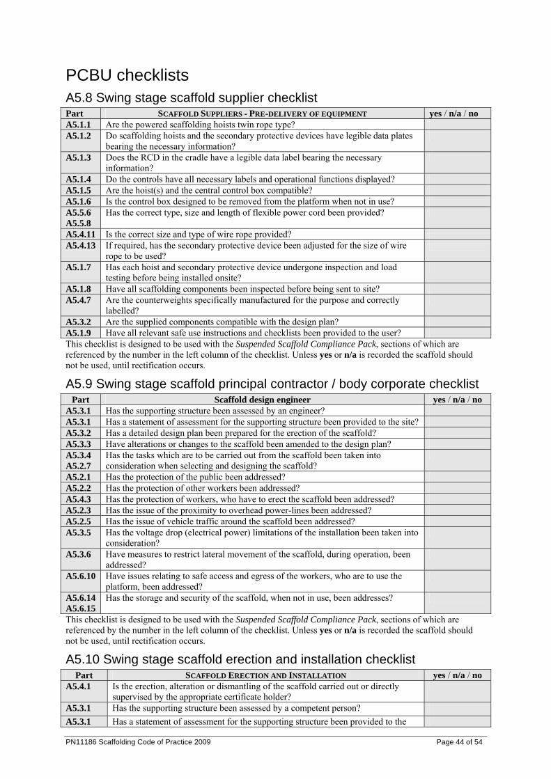
PN11186 Scaffolding Code of Practice 2009 Page 44 of 54
PCBU checklists A5.8 Swing stage scaffold supplier checklist Part SCAFFOLD SUPPLIERS - PRE-DELIVERY OF EQUIPMENT yes / n/a / no A5.1.1 Are the powered scaffolding hoists twin rope type? A5.1.2 Do scaffolding hoists and the secondary protective devices have legible data plates
bearing the necessary information?
A5.1.3 Does the RCD in the cradle have a legible data label bearing the necessary information?
A5.1.4 Do the controls have all necessary labels and operational functions displayed? A5.1.5 Are the hoist(s) and the central control box compatible? A5.1.6 Is the control box designed to be removed from the platform when not in use? A5.5.6 A5.5.8
Has the correct type, size and length of flexible power cord been provided?
A5.4.11 Is the correct size and type of wire rope provided? A5.4.13 If required, has the secondary protective device been adjusted for the size of wire
rope to be used?
A5.1.7 Has each hoist and secondary protective device undergone inspection and load testing before being installed onsite?
A5.1.8 Have all scaffolding components been inspected before being sent to site? A5.4.7 Are the counterweights specifically manufactured for the purpose and correctly
labelled?
A5.3.2 Are the supplied components compatible with the design plan? A5.1.9 Have all relevant safe use instructions and checklists been provided to the user? This checklist is designed to be used with the Suspended Scaffold Compliance Pack, sections of which are referenced by the number in the left column of the checklist. Unless yes or n/a is recorded the scaffold should not be used, until rectification occurs.
A5.9 Swing stage scaffold principal contractor / body corporate checklist Part Scaffold design engineer yes / n/a / no
A5.3.1 Has the supporting structure been assessed by an engineer? A5.3.1 Has a statement of assessment for the supporting structure been provided to the site? A5.3.2 Has a detailed design plan been prepared for the erection of the scaffold? A5.3.3 Have alterations or changes to the scaffold been amended to the design plan? A5.3.4 A5.2.7
Has the tasks which are to be carried out from the scaffold been taken into consideration when selecting and designing the scaffold?
A5.2.1 Has the protection of the public been addressed? A5.2.2 Has the protection of other workers been addressed? A5.4.3 Has the protection of workers, who have to erect the scaffold been addressed? A5.2.3 Has the issue of the proximity to overhead power-lines been addressed? A5.2.5 Has the issue of vehicle traffic around the scaffold been addressed? A5.3.5 Has the voltage drop (electrical power) limitations of the installation been taken into
consideration?
A5.3.6 Have measures to restrict lateral movement of the scaffold, during operation, been addressed?
A5.6.10 Have issues relating to safe access and egress of the workers, who are to use the platform, been addressed?
A5.6.14 A5.6.15
Has the storage and security of the scaffold, when not in use, been addresses?
This checklist is designed to be used with the Suspended Scaffold Compliance Pack, sections of which are referenced by the number in the left column of the checklist. Unless yes or n/a is recorded the scaffold should not be used, until rectification occurs.
A5.10 Swing stage scaffold erection and installation checklist Part SCAFFOLD ERECTION AND INSTALLATION yes / n/a / no
A5.4.1 Is the erection, alteration or dismantling of the scaffold carried out or directly supervised by the appropriate certificate holder?
A5.3.1 Has the supporting structure been assessed by a competent person? A5.3.1 Has a statement of assessment for the supporting structure been provided to the
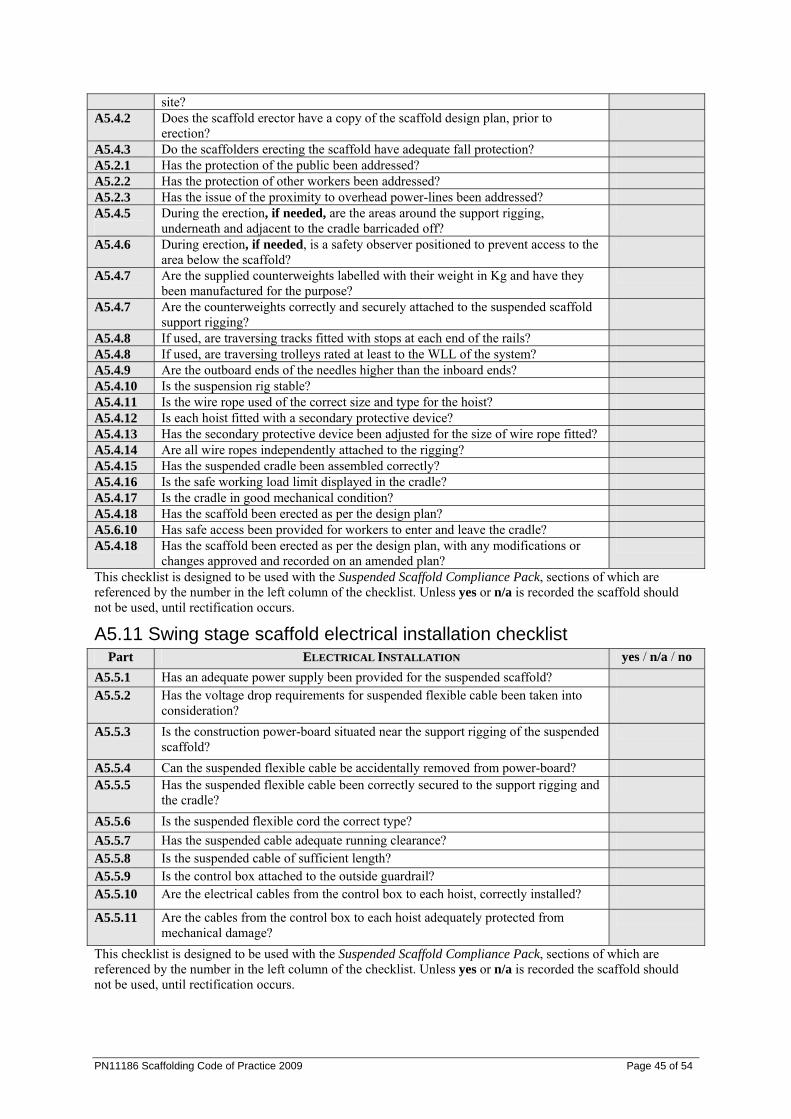
PN11186 Scaffolding Code of Practice 2009 Page 45 of 54
site? A5.4.2 Does the scaffold erector have a copy of the scaffold design plan, prior to
erection?
A5.4.3 Do the scaffolders erecting the scaffold have adequate fall protection? A5.2.1 Has the protection of the public been addressed? A5.2.2 Has the protection of other workers been addressed? A5.2.3 Has the issue of the proximity to overhead power-lines been addressed? A5.4.5
During the erection, if needed, are the areas around the support rigging, underneath and adjacent to the cradle barricaded off?
A5.4.6 During erection, if needed, is a safety observer positioned to prevent access to the area below the scaffold?
A5.4.7 Are the supplied counterweights labelled with their weight in Kg and have they been manufactured for the purpose?
A5.4.7 Are the counterweights correctly and securely attached to the suspended scaffold support rigging?
A5.4.8 If used, are traversing tracks fitted with stops at each end of the rails? A5.4.8 If used, are traversing trolleys rated at least to the WLL of the system? A5.4.9 Are the outboard ends of the needles higher than the inboard ends? A5.4.10 Is the suspension rig stable? A5.4.11 Is the wire rope used of the correct size and type for the hoist? A5.4.12 Is each hoist fitted with a secondary protective device? A5.4.13 Has the secondary protective device been adjusted for the size of wire rope fitted? A5.4.14 Are all wire ropes independently attached to the rigging? A5.4.15 Has the suspended cradle been assembled correctly? A5.4.16 Is the safe working load limit displayed in the cradle? A5.4.17 Is the cradle in good mechanical condition? A5.4.18 Has the scaffold been erected as per the design plan? A5.6.10 Has safe access been provided for workers to enter and leave the cradle? A5.4.18 Has the scaffold been erected as per the design plan, with any modifications or
changes approved and recorded on an amended plan?
This checklist is designed to be used with the Suspended Scaffold Compliance Pack, sections of which are referenced by the number in the left column of the checklist. Unless yes or n/a is recorded the scaffold should not be used, until rectification occurs.
A5.11 Swing stage scaffold electrical installation checklist Part ELECTRICAL INSTALLATION yes / n/a / no
A5.5.1 Has an adequate power supply been provided for the suspended scaffold? A5.5.2 Has the voltage drop requirements for suspended flexible cable been taken into
consideration?
A5.5.3 Is the construction power-board situated near the support rigging of the suspended scaffold?
A5.5.4 Can the suspended flexible cable be accidentally removed from power-board? A5.5.5 Has the suspended flexible cable been correctly secured to the support rigging and
the cradle?
A5.5.6 Is the suspended flexible cord the correct type? A5.5.7 Has the suspended cable adequate running clearance? A5.5.8 Is the suspended cable of sufficient length? A5.5.9 Is the control box attached to the outside guardrail? A5.5.10 Are the electrical cables from the control box to each hoist, correctly installed?
A5.5.11 Are the cables from the control box to each hoist adequately protected from mechanical damage?
This checklist is designed to be used with the Suspended Scaffold Compliance Pack, sections of which are referenced by the number in the left column of the checklist. Unless yes or n/a is recorded the scaffold should not be used, until rectification occurs.
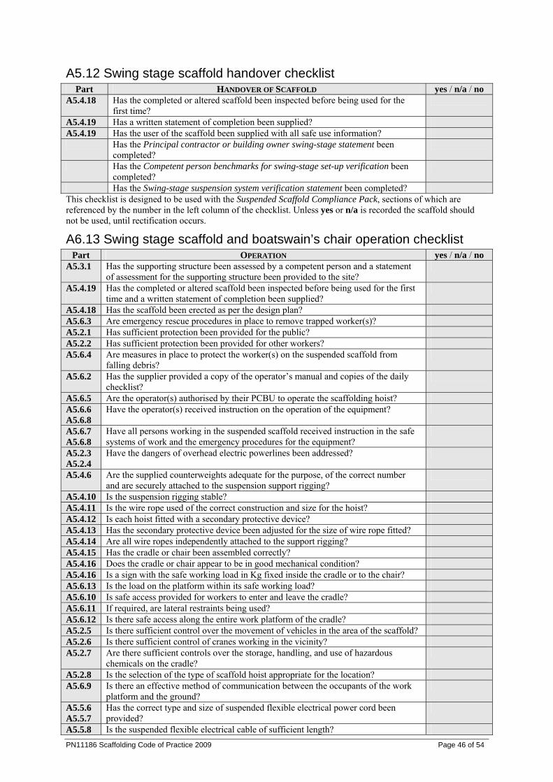
PN11186 Scaffolding Code of Practice 2009 Page 46 of 54
A5.12 Swing stage scaffold handover checklist Part HANDOVER OF SCAFFOLD yes / n/a / no
A5.4.18 Has the completed or altered scaffold been inspected before being used for the first time?
A5.4.19 Has a written statement of completion been supplied? A5.4.19 Has the user of the scaffold been supplied with all safe use information? Has the Principal contractor or building owner swing-stage statement been
completed?
Has the Competent person benchmarks for swing-stage set-up verification been completed?
Has the Swing-stage suspension system verification statement been completed? This checklist is designed to be used with the Suspended Scaffold Compliance Pack, sections of which are referenced by the number in the left column of the checklist. Unless yes or n/a is recorded the scaffold should not be used, until rectification occurs.
A6.13 Swing stage scaffold and boatswain’s chair operation checklist Part OPERATION yes / n/a / no
A5.3.1 Has the supporting structure been assessed by a competent person and a statement of assessment for the supporting structure been provided to the site?
A5.4.19
Has the completed or altered scaffold been inspected before being used for the first time and a written statement of completion been supplied?
A5.4.18 Has the scaffold been erected as per the design plan? A5.6.3 Are emergency rescue procedures in place to remove trapped worker(s)? A5.2.1 Has sufficient protection been provided for the public? A5.2.2 Has sufficient protection been provided for other workers? A5.6.4 Are measures in place to protect the worker(s) on the suspended scaffold from
falling debris?
A5.6.2 Has the supplier provided a copy of the operator’s manual and copies of the daily checklist?
A5.6.5 Are the operator(s) authorised by their PCBU to operate the scaffolding hoist? A5.6.6 A5.6.8
Have the operator(s) received instruction on the operation of the equipment?
A5.6.7 A5.6.8
Have all persons working in the suspended scaffold received instruction in the safe systems of work and the emergency procedures for the equipment?
A5.2.3 A5.2.4
Have the dangers of overhead electric powerlines been addressed?
A5.4.6 Are the supplied counterweights adequate for the purpose, of the correct number and are securely attached to the suspension support rigging?
A5.4.10 Is the suspension rigging stable? A5.4.11 Is the wire rope used of the correct construction and size for the hoist? A5.4.12 Is each hoist fitted with a secondary protective device? A5.4.13 Has the secondary protective device been adjusted for the size of wire rope fitted? A5.4.14 Are all wire ropes independently attached to the support rigging? A5.4.15 Has the cradle or chair been assembled correctly? A5.4.16 Does the cradle or chair appear to be in good mechanical condition? A5.4.16 Is a sign with the safe working load in Kg fixed inside the cradle or to the chair? A5.6.13 Is the load on the platform within its safe working load? A5.6.10 Is safe access provided for workers to enter and leave the cradle? A5.6.11 If required, are lateral restraints being used? A5.6.12 Is there safe access along the entire work platform of the cradle? A5.2.5 Is there sufficient control over the movement of vehicles in the area of the scaffold? A5.2.6 Is there sufficient control of cranes working in the vicinity? A5.2.7 Are there sufficient controls over the storage, handling, and use of hazardous
chemicals on the cradle?
A5.2.8 Is the selection of the type of scaffold hoist appropriate for the location? A5.6.9 Is there an effective method of communication between the occupants of the work
platform and the ground?
A5.5.6 A5.5.7
Has the correct type and size of suspended flexible electrical power cord been provided?
A5.5.8 Is the suspended flexible electrical cable of sufficient length?
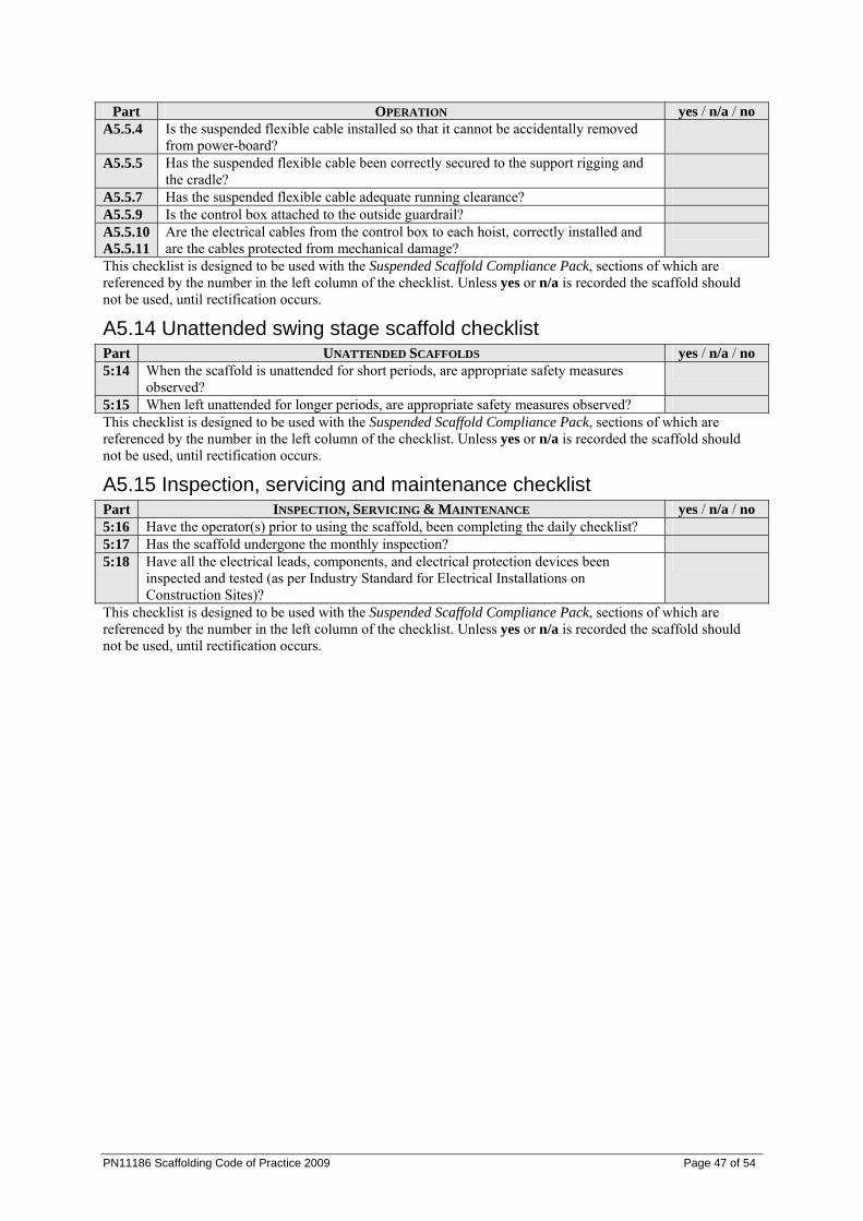
PN11186 Scaffolding Code of Practice 2009 Page 47 of 54
Part OPERATION yes / n/a / no A5.5.4 Is the suspended flexible cable installed so that it cannot be accidentally removed
from power-board?
A5.5.5 Has the suspended flexible cable been correctly secured to the support rigging and the cradle?
A5.5.7 Has the suspended flexible cable adequate running clearance? A5.5.9 Is the control box attached to the outside guardrail? A5.5.10 A5.5.11
Are the electrical cables from the control box to each hoist, correctly installed and are the cables protected from mechanical damage?
This checklist is designed to be used with the Suspended Scaffold Compliance Pack, sections of which are referenced by the number in the left column of the checklist. Unless yes or n/a is recorded the scaffold should not be used, until rectification occurs.
A5.14 Unattended swing stage scaffold checklist Part UNATTENDED SCAFFOLDS yes / n/a / no 5:14 When the scaffold is unattended for short periods, are appropriate safety measures
observed?
5:15 When left unattended for longer periods, are appropriate safety measures observed? This checklist is designed to be used with the Suspended Scaffold Compliance Pack, sections of which are referenced by the number in the left column of the checklist. Unless yes or n/a is recorded the scaffold should not be used, until rectification occurs.
A5.15 Inspection, servicing and maintenance checklist Part INSPECTION, SERVICING & MAINTENANCE yes / n/a / no 5:16 Have the operator(s) prior to using the scaffold, been completing the daily checklist? 5:17 Has the scaffold undergone the monthly inspection? 5:18 Have all the electrical leads, components, and electrical protection devices been
inspected and tested (as per Industry Standard for Electrical Installations on Construction Sites)?
This checklist is designed to be used with the Suspended Scaffold Compliance Pack, sections of which are referenced by the number in the left column of the checklist. Unless yes or n/a is recorded the scaffold should not be used, until rectification occurs.
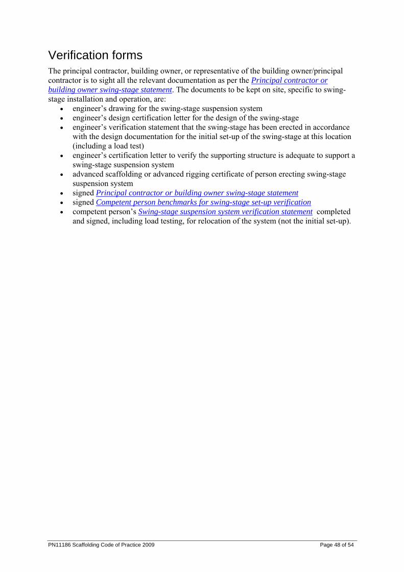
PN11186 Scaffolding Code of Practice 2009 Page 48 of 54
Verification forms The principal contractor, building owner, or representative of the building owner/principal contractor is to sight all the relevant documentation as per the Principal contractor or building owner swing-stage statement. The documents to be kept on site, specific to swing-stage installation and operation, are:
• engineer’s drawing for the swing-stage suspension system • engineer’s design certification letter for the design of the swing-stage • engineer’s verification statement that the swing-stage has been erected in accordance
with the design documentation for the initial set-up of the swing-stage at this location (including a load test)
• engineer’s certification letter to verify the supporting structure is adequate to support a swing-stage suspension system
• advanced scaffolding or advanced rigging certificate of person erecting swing-stage suspension system
• signed Principal contractor or building owner swing-stage statement • signed Competent person benchmarks for swing-stage set-up verification • competent person’s Swing-stage suspension system verification statement completed
and signed, including load testing, for relocation of the system (not the initial set-up).
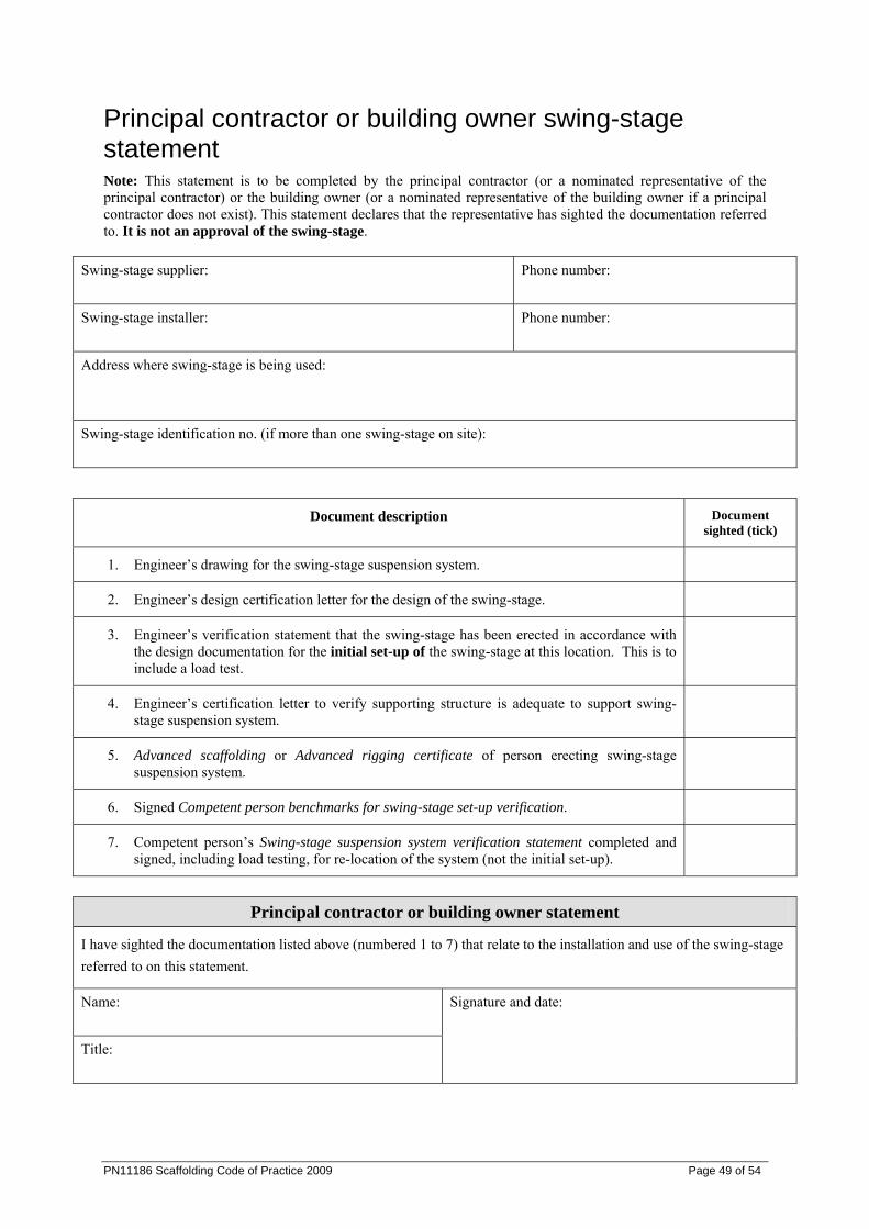
PN11186 Scaffolding Code of Practice 2009 Page 49 of 54
Principal contractor or building owner swing-stage statement Note: This statement is to be completed by the principal contractor (or a nominated representative of the principal contractor) or the building owner (or a nominated representative of the building owner if a principal contractor does not exist). This statement declares that the representative has sighted the documentation referred to. It is not an approval of the swing-stage.
Swing-stage supplier:
Phone number:
Swing-stage installer:
Phone number:
Address where swing-stage is being used:
Swing-stage identification no. (if more than one swing-stage on site):
Document description Document sighted (tick)
1. Engineer’s drawing for the swing-stage suspension system.
2. Engineer’s design certification letter for the design of the swing-stage.
3. Engineer’s verification statement that the swing-stage has been erected in accordance with the design documentation for the initial set-up of the swing-stage at this location. This is to include a load test.
4. Engineer’s certification letter to verify supporting structure is adequate to support swing-stage suspension system.
5. Advanced scaffolding or Advanced rigging certificate of person erecting swing-stage suspension system.
6. Signed Competent person benchmarks for swing-stage set-up verification.
7. Competent person’s Swing-stage suspension system verification statement completed and signed, including load testing, for re-location of the system (not the initial set-up).
Principal contractor or building owner statement
I have sighted the documentation listed above (numbered 1 to 7) that relate to the installation and use of the swing-stage referred to on this statement.
Name:
Title:
Signature and date:
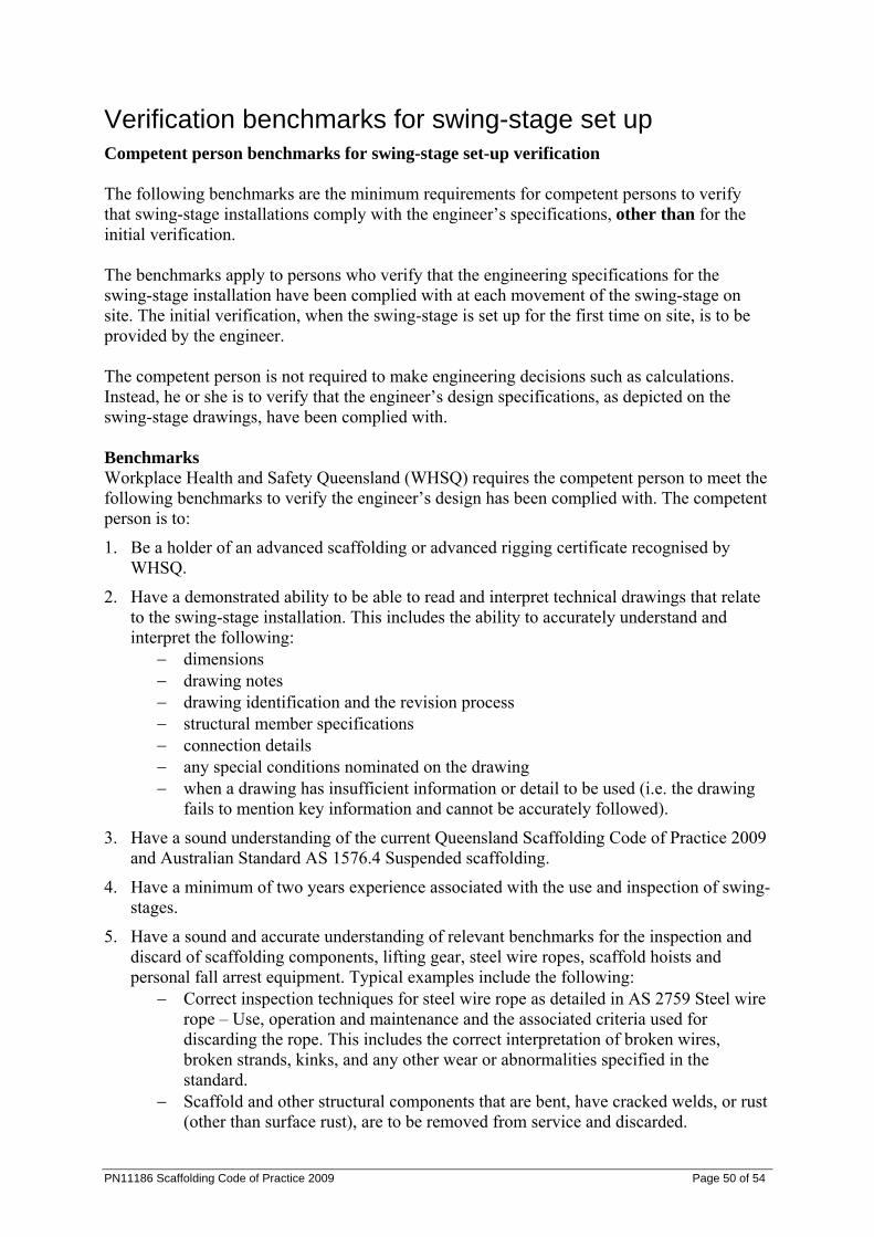
PN11186 Scaffolding Code of Practice 2009 Page 50 of 54
Verification benchmarks for swing-stage set up Competent person benchmarks for swing-stage set-up verification The following benchmarks are the minimum requirements for competent persons to verify that swing-stage installations comply with the engineer’s specifications, other than for the initial verification. The benchmarks apply to persons who verify that the engineering specifications for the swing-stage installation have been complied with at each movement of the swing-stage on site. The initial verification, when the swing-stage is set up for the first time on site, is to be provided by the engineer. The competent person is not required to make engineering decisions such as calculations. Instead, he or she is to verify that the engineer’s design specifications, as depicted on the swing-stage drawings, have been complied with. Benchmarks Workplace Health and Safety Queensland (WHSQ) requires the competent person to meet the following benchmarks to verify the engineer’s design has been complied with. The competent person is to:
1. Be a holder of an advanced scaffolding or advanced rigging certificate recognised by WHSQ.
2. Have a demonstrated ability to be able to read and interpret technical drawings that relate to the swing-stage installation. This includes the ability to accurately understand and interpret the following:
− dimensions − drawing notes − drawing identification and the revision process − structural member specifications − connection details − any special conditions nominated on the drawing − when a drawing has insufficient information or detail to be used (i.e. the drawing
fails to mention key information and cannot be accurately followed).
3. Have a sound understanding of the current Queensland Scaffolding Code of Practice 2009 and Australian Standard AS 1576.4 Suspended scaffolding.
4. Have a minimum of two years experience associated with the use and inspection of swing-stages.
5. Have a sound and accurate understanding of relevant benchmarks for the inspection and discard of scaffolding components, lifting gear, steel wire ropes, scaffold hoists and personal fall arrest equipment. Typical examples include the following:
− Correct inspection techniques for steel wire rope as detailed in AS 2759 Steel wire rope – Use, operation and maintenance and the associated criteria used for discarding the rope. This includes the correct interpretation of broken wires, broken strands, kinks, and any other wear or abnormalities specified in the standard.
− Scaffold and other structural components that are bent, have cracked welds, or rust (other than surface rust), are to be removed from service and discarded.
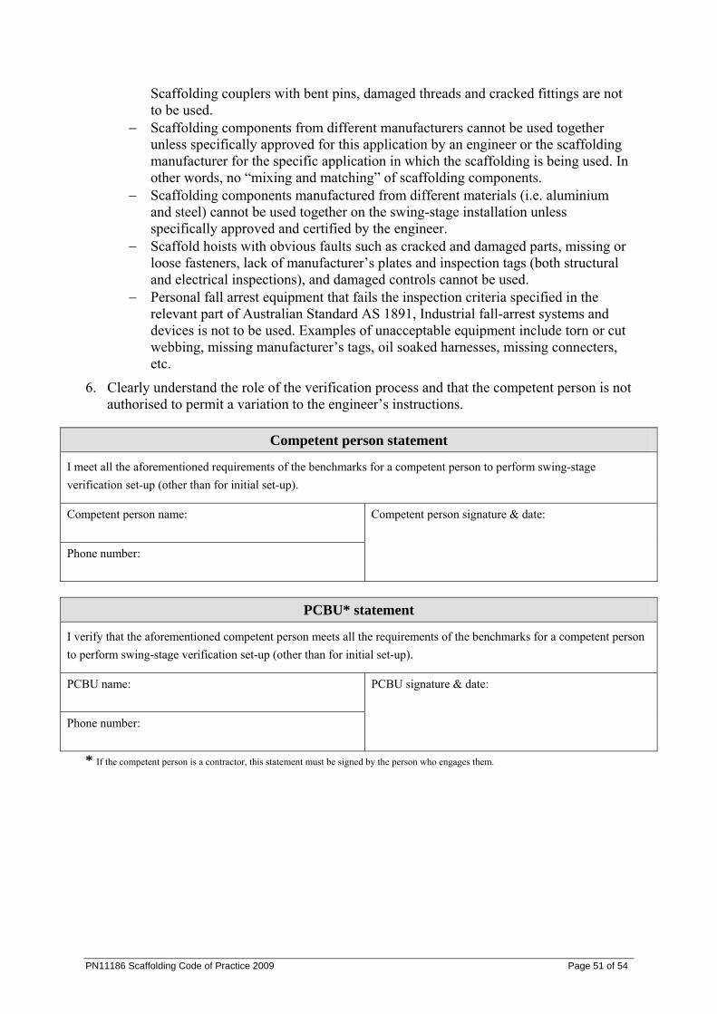
PN11186 Scaffolding Code of Practice 2009 Page 51 of 54
Scaffolding couplers with bent pins, damaged threads and cracked fittings are not to be used.
− Scaffolding components from different manufacturers cannot be used together unless specifically approved for this application by an engineer or the scaffolding manufacturer for the specific application in which the scaffolding is being used. In other words, no “mixing and matching” of scaffolding components.
− Scaffolding components manufactured from different materials (i.e. aluminium and steel) cannot be used together on the swing-stage installation unless specifically approved and certified by the engineer.
− Scaffold hoists with obvious faults such as cracked and damaged parts, missing or loose fasteners, lack of manufacturer’s plates and inspection tags (both structural and electrical inspections), and damaged controls cannot be used.
− Personal fall arrest equipment that fails the inspection criteria specified in the relevant part of Australian Standard AS 1891, Industrial fall-arrest systems and devices is not to be used. Examples of unacceptable equipment include torn or cut webbing, missing manufacturer’s tags, oil soaked harnesses, missing connecters, etc.
6. Clearly understand the role of the verification process and that the competent person is not authorised to permit a variation to the engineer’s instructions.
Competent person statement
I meet all the aforementioned requirements of the benchmarks for a competent person to perform swing-stage verification set-up (other than for initial set-up).
Competent person name:
Phone number:
Competent person signature & date:
PCBU* statement
I verify that the aforementioned competent person meets all the requirements of the benchmarks for a competent person to perform swing-stage verification set-up (other than for initial set-up).
PCBU name:
Phone number:
PCBU signature & date:
* If the competent person is a contractor, this statement must be signed by the person who engages them.
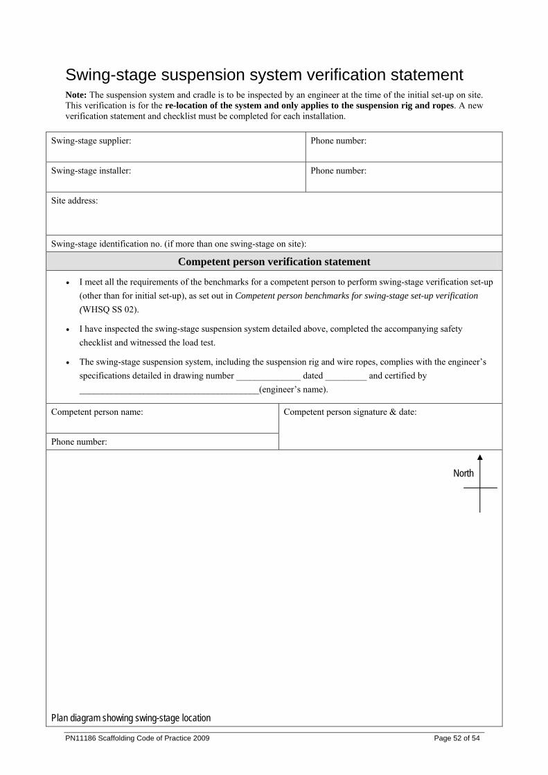
Swing-stage suspension system verification statement Note: The suspension system and cradle is to be inspected by an engineer at the time of the initial set-up on site. This verification is for the re-location of the system and only applies to the suspension rig and ropes. A new verification statement and checklist must be completed for each installation.
Swing-stage supplier:
Phone number:
Swing-stage installer:
Phone number:
Site address:
Swing-stage identification no. (if more than one swing-stage on site):
Competent person verification statement
• I meet all the requirements of the benchmarks for a competent person to perform swing-stage verification set-up (other than for initial set-up), as set out in Competent person benchmarks for swing-stage set-up verification (WHSQ SS 02).
• I have inspected the swing-stage suspension system detailed above, completed the accompanying safety checklist and witnessed the load test.
• The swing-stage suspension system, including the suspension rig and wire ropes, complies with the engineer’s specifications detailed in drawing number ______________ dated _________ and certified by _______________________________________(engineer’s name).
Competent person name:
Phone number:
Competent person signature & date:
North
Plan diagram showing swing-stage location
PN11186 Scaffolding Code of Practice 2009 Page 52 of 54
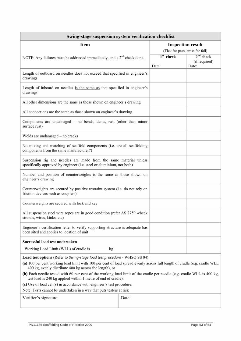
PN11186 Scaffolding Code of Practice 2009 Page 53 of 54
Swing-stage suspension system verification checklist
Inspection result (Tick for pass, cross for fail)
Item NOTE: Any failures must be addressed immediately, and a 2nd check done. 1st check
Date:
2nd check (if required)
Date:
Length of outboard on needles does not exceed that specified in engineer’s drawings
Length of inboard on needles is the same as that specified in engineer’s drawings
All other dimensions are the same as those shown on engineer’s drawing
All connections are the same as those shown on engineer’s drawing
Components are undamaged – no bends, dents, rust (other than minor surface rust)
Welds are undamaged – no cracks
No mixing and matching of scaffold components (i.e. are all scaffolding components from the same manufacturer?)
Suspension rig and needles are made from the same material unless specifically approved by engineer (i.e. steel or aluminium, not both)
Number and position of counterweights is the same as those shown on engineer’s drawing
Counterweights are secured by positive restraint system (i.e. do not rely on friction devices such as couplers)
Counterweights are secured with lock and key
All suspension steel wire ropes are in good condition (refer AS 2759 -check strands, wires, kinks, etc)
Engineer’s certification letter to verify supporting structure is adequate has been sited and applies to location of unit
Successful load test undertaken
Working Load Limit (WLL) of cradle is ________ kg
Load test options (Refer to Swing-stage load test procedure - WHSQ SS 04): (a) 100 per cent working load limit with 100 per cent of load spread evenly across full length of cradle (e.g. cradle WLL
400 kg, evenly distribute 400 kg across the length), or (b) Each needle tested with 60 per cent of the working load limit of the cradle per needle (e.g. cradle WLL is 400 kg,
test load is 240 kg applied within 1 metre of end of cradle). (c) Use of load cell(s) in accordance with engineer’s test procedure. Note: Tests cannot be undertaken in a way that puts testers at risk
Verifier’s signature:
Date:
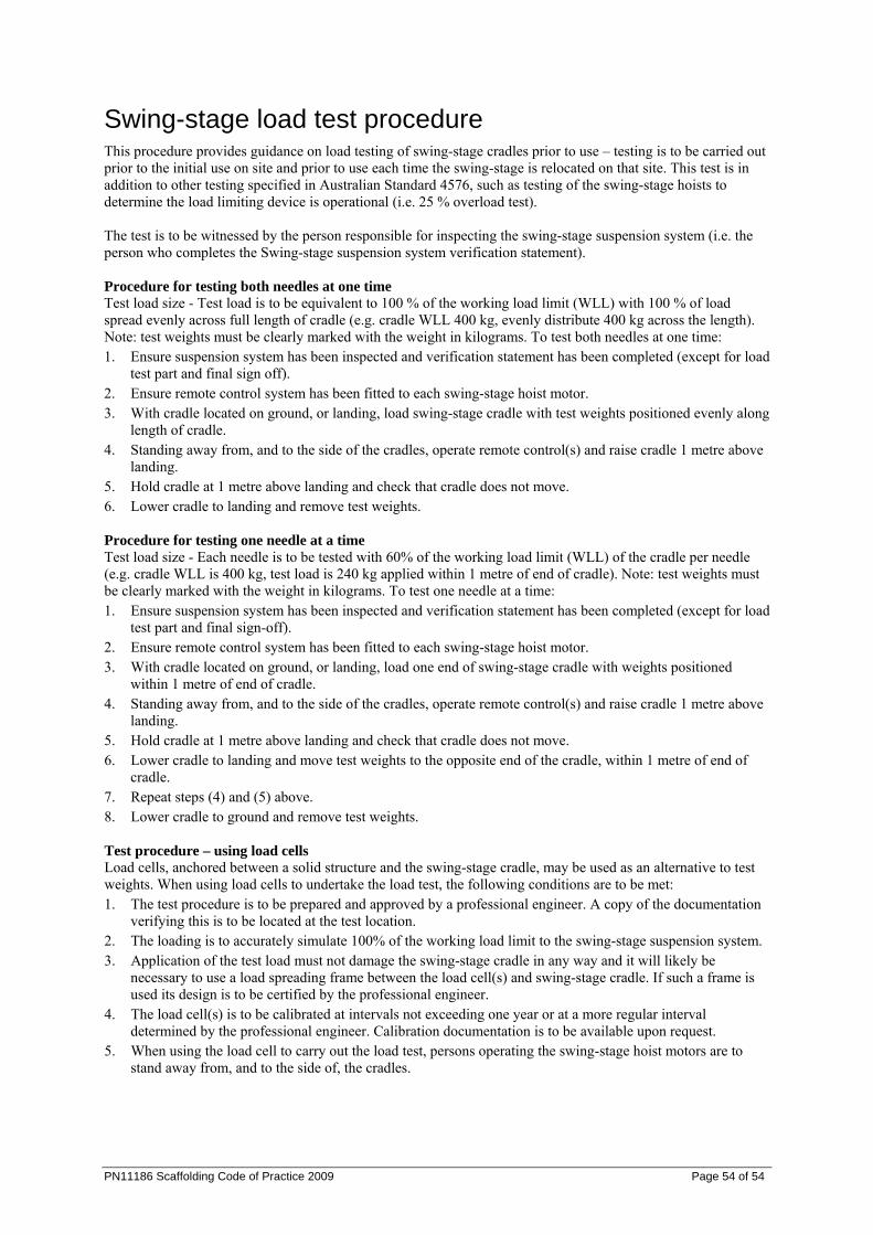
PN11186 Scaffolding Code of Practice 2009 Page 54 of 54
Swing-stage load test procedure This procedure provides guidance on load testing of swing-stage cradles prior to use – testing is to be carried out prior to the initial use on site and prior to use each time the swing-stage is relocated on that site. This test is in addition to other testing specified in Australian Standard 4576, such as testing of the swing-stage hoists to determine the load limiting device is operational (i.e. 25 % overload test). The test is to be witnessed by the person responsible for inspecting the swing-stage suspension system (i.e. the person who completes the Swing-stage suspension system verification statement). Procedure for testing both needles at one time Test load size - Test load is to be equivalent to 100 % of the working load limit (WLL) with 100 % of load spread evenly across full length of cradle (e.g. cradle WLL 400 kg, evenly distribute 400 kg across the length). Note: test weights must be clearly marked with the weight in kilograms. To test both needles at one time: 1. Ensure suspension system has been inspected and verification statement has been completed (except for load
test part and final sign off). 2. Ensure remote control system has been fitted to each swing-stage hoist motor. 3. With cradle located on ground, or landing, load swing-stage cradle with test weights positioned evenly along
length of cradle. 4. Standing away from, and to the side of the cradles, operate remote control(s) and raise cradle 1 metre above
landing. 5. Hold cradle at 1 metre above landing and check that cradle does not move. 6. Lower cradle to landing and remove test weights. Procedure for testing one needle at a time Test load size - Each needle is to be tested with 60% of the working load limit (WLL) of the cradle per needle (e.g. cradle WLL is 400 kg, test load is 240 kg applied within 1 metre of end of cradle). Note: test weights must be clearly marked with the weight in kilograms. To test one needle at a time: 1. Ensure suspension system has been inspected and verification statement has been completed (except for load
test part and final sign-off). 2. Ensure remote control system has been fitted to each swing-stage hoist motor. 3. With cradle located on ground, or landing, load one end of swing-stage cradle with weights positioned
within 1 metre of end of cradle. 4. Standing away from, and to the side of the cradles, operate remote control(s) and raise cradle 1 metre above
landing. 5. Hold cradle at 1 metre above landing and check that cradle does not move. 6. Lower cradle to landing and move test weights to the opposite end of the cradle, within 1 metre of end of
cradle. 7. Repeat steps (4) and (5) above. 8. Lower cradle to ground and remove test weights. Test procedure – using load cells Load cells, anchored between a solid structure and the swing-stage cradle, may be used as an alternative to test weights. When using load cells to undertake the load test, the following conditions are to be met: 1. The test procedure is to be prepared and approved by a professional engineer. A copy of the documentation
verifying this is to be located at the test location. 2. The loading is to accurately simulate 100% of the working load limit to the swing-stage suspension system. 3. Application of the test load must not damage the swing-stage cradle in any way and it will likely be
necessary to use a load spreading frame between the load cell(s) and swing-stage cradle. If such a frame is used its design is to be certified by the professional engineer.
4. The load cell(s) is to be calibrated at intervals not exceeding one year or at a more regular interval determined by the professional engineer. Calibration documentation is to be available upon request.
5. When using the load cell to carry out the load test, persons operating the swing-stage hoist motors are to stand away from, and to the side of, the cradles.