scalance s and softnet security client
DESCRIPTION
Siemens Scalance STRANSCRIPT
SIMATIC NET
SCALANCE S and SOFTNET Security Client
Operating Instructions
02/2011 C79000-G8976-C196-07
Preface
Introduction and basics 1
Product properties and commissioning
2
GETTING STARTED 3
Configuring with the Security Configuration Tool
4
Firewall, router and other module properties
5
Secure communication in the VPN over an IPSec tunnel (S612/S613)
6
SOFTNET Security Client (S612/S613)
7
Online functions - test, diagnostics, and logging
8
Tips and help on problems A
Notes on the CE Mark B
References C
Dimension drawing D
Document history E
Legal information Warning notice system
This manual contains notices you have to observe in order to ensure your personal safety, as well as to prevent damage to property. The notices referring to your personal safety are highlighted in the manual by a safety alert symbol, notices referring only to property damage have no safety alert symbol. These notices shown below are graded according to the degree of danger.
DANGER indicates that death or severe personal injury will result if proper precautions are not taken.
WARNING indicates that death or severe personal injury may result if proper precautions are not taken.
CAUTION with a safety alert symbol, indicates that minor personal injury can result if proper precautions are not taken.
CAUTION without a safety alert symbol, indicates that property damage can result if proper precautions are not taken.
NOTICE indicates that an unintended result or situation can occur if the corresponding information is not taken into account.
If more than one degree of danger is present, the warning notice representing the highest degree of danger will be used. A notice warning of injury to persons with a safety alert symbol may also include a warning relating to property damage.
Qualified Personnel The product/system described in this documentation may be operated only by personnel qualified for the specific task in accordance with the relevant documentation for the specific task, in particular its warning notices and safety instructions. Qualified personnel are those who, based on their training and experience, are capable of identifying risks and avoiding potential hazards when working with these products/systems.
Proper use of Siemens products Note the following:
WARNING Siemens products may only be used for the applications described in the catalog and in the relevant technical documentation. If products and components from other manufacturers are used, these must be recommended or approved by Siemens. Proper transport, storage, installation, assembly, commissioning, operation and maintenance are required to ensure that the products operate safely and without any problems. The permissible ambient conditions must be adhered to. The information in the relevant documentation must be observed.
Trademarks All names identified by ® are registered trademarks of the Siemens AG. The remaining trademarks in this publication may be trademarks whose use by third parties for their own purposes could violate the rights of the owner.
Disclaimer of Liability We have reviewed the contents of this publication to ensure consistency with the hardware and software described. Since variance cannot be precluded entirely, we cannot guarantee full consistency. However, the information in this publication is reviewed regularly and any necessary corrections are included in subsequent editions.
Siemens AG Industry Sector Postfach 48 48 90026 NÜRNBERG GERMANY
order number: C79000-G8976-C196-07 Ⓟ 02/2011
Copyright © Siemens AG 2006, 2007, 2008, 2010, 2011. Technical data subject to change

SCALANCE S and SOFTNET Security Client Operating Instructions, 02/2011, C79000-G8976-C196-07 3
Preface
This manual… ...supports you when commissioning the SCALANCE S602 / S612 / S613 security modules and the SOFTNET Security Client. The variants SCALANCE S602 / S612 / S613 are simply called SCALANCE S in the rest of the manual.
Preface
SCALANCE S and SOFTNET Security Client 4 Operating Instructions, 02/2011, C79000-G8976-C196-07
New in this issue This issue includes descriptions of the following new functions:
● Security Configuration Tool V2.3
To improve handling and achieve a better overview of the various module types, the procedures for module integration and module replacement have been improved.
You can configure a SOFTNET Security Client V3.0 together with an MD741-1 and create the corresponding configuration files (see GETTING STARTED Example 5: Remote access - VPN tunnel example with MD741-1 and SOFTNET Security Client (Page 86)).
For the IKE mode (phase 1), you can set the encryption algorithms AES-128, AES-192 and AES-256.
Apart from the operating systems Windows XP SP2 and Windows XP SP3, the Windows 7 operating system is also supported (not the Home version).
● SOFTNET Security Client V3.0
To improve visualization and diagnostics of the statuses of the connections, new icons were implemented and an additional diagnostics overview ("Advanced diagnostics") was added.
For the logging console in the tunnel overview, you can now make settings relating to the messages to be displayed and the size of the log files.
To save costs on volume-oriented connections, you have the option of deactivating the reachability test at the cost of the diagnostics capability of the SOFTNET Security Client V3.0.
During diagnostics of the reachability of tunnel partners, it is possible that the reachability is shown as being negative although communication does work in principle. This occurs with tunnels via slower transmission paths (UMTS, GPRS etc.). In this case, the wait time for the ping reply (reachability test) can be globally increased.
Connection establishment to an MD741-1 is supported. In this context, a DynDNS address can be configured (see GETTING STARTED Example 5: Remote access - VPN tunnel example with MD741-1 and SOFTNET Security Client (Page 86)).
Apart from the operating systems Windows XP SP2 and Windows XP SP3, the Windows 7 operating system is also supported (not the Home version).
● Configuration data for module MD 741-1
To configure an external MD741-1 for access with the SOFTNET Security Client V3.0, you can export the configuration data to a text file with the Security Configuration Tool V2.3. (GETTING STARTED Example 5: Remote access - VPN tunnel example with MD741-1 and SOFTNET Security Client (Page 86)).

Preface
SCALANCE S and SOFTNET Security Client Operating Instructions, 02/2011, C79000-G8976-C196-07 5
F1
Validity of this manual This manual is valid for the following devices and components:
● SIMATIC NET SCALANCE S602 6GK5 602-0BA00-2AA3 - with firmware version as of V2.3
● SIMATIC NET SCALANCE S612 V2 6GK5 612-0BA00-2AA3 - with firmware version as of V2.3
● SIMATIC NET SCALANCE S613 V2 6GK5 613-0BA00-2AA3 - with firmware version as of V2.3
● SIMATIC NET SOFTNET Security Client 6GK1 704-1VW02-0AA0 - as of version 2008
● Security Configuration Tool - version V2.3
Audience This manual is intended for personnel involved in the commissioning of SCALANCE S Security Modules and the SOFTNET Security Client in a network.
Further documentation The "SIMATIC NET Industrial Ethernet Twisted Pair and Fiber Optic Networks“ manual contains additional information on other SIMATIC NET products that you can operate along with the SCALANCE S security module in an Industrial Ethernet network.
You can download this network manual in electronic format from Customer Support at the following address:
http://support.automation.siemens.com/WW/view/de/1172207 (http://support.automation.siemens.com/WW/view/de/1172207)
Standards and approvals The SCALANCE S device meets the requirements for the CE mark. For more detailed information, refer to the appendix of this manual.
Symbols used in this manual
This symbol highlights special tips in the manual.
This symbol indicates specific further reading material.
This symbol indicates that detailed help texts are available in the context help. You can call this with the F1 key or using the "Help" button in the relevant dialog.

Preface
SCALANCE S and SOFTNET Security Client 6 Operating Instructions, 02/2011, C79000-G8976-C196-07
References /.../ References to other documentation are shown in slashes /.../. Based on these numbers, you can find the title of the documentation in the references at the end of the manual.
SCALANCE S and SOFTNET Security Client Operating Instructions, 02/2011, C79000-G8976-C196-07 7
Contents
Preface ...................................................................................................................................................... 3
1 Introduction and basics............................................................................................................................ 11
1.1 Uses of the SCALANCE S612, S613 and SOFTNET Security Client .........................................11
1.2 Using the SCALANCE S602........................................................................................................14
1.3 Configuration and administration .................................................................................................16
2 Product properties and commissioning .................................................................................................... 17
2.1 Product Characteristics................................................................................................................17 2.1.1 Hardware characteristics and overview of the functions .............................................................17 2.1.2 Components of the product..........................................................................................................18 2.1.3 Unpacking and checking..............................................................................................................19 2.1.4 Attachment to Ethernet ................................................................................................................19 2.1.5 Power supply................................................................................................................................20 2.1.6 Signaling contact..........................................................................................................................21 2.1.7 Reset button - resetting the configuration to factory defaults ......................................................22 2.1.8 Displays........................................................................................................................................23 2.1.9 Technical specifications ...............................................................................................................24
2.2 Installation....................................................................................................................................26 2.2.1 Installation on a DIN rail...............................................................................................................28 2.2.2 Installation on a standard rail .......................................................................................................30 2.2.3 Wall mounting ..............................................................................................................................30 2.2.4 Grounding ....................................................................................................................................31
2.3 Commissioning.............................................................................................................................31 2.3.1 Step 1: Connecting the SCALANCE S module............................................................................33 2.3.2 Step 2: Configuring and downloading..........................................................................................33
2.4 C-PLUG (configuration plug)........................................................................................................35
2.5 Transferring firmware...................................................................................................................38
3 GETTING STARTED ............................................................................................................................... 39
3.1 Example 1: VPN tunnel - IPsec tunnel example with SCALANCE S612 / S613 .........................40 3.1.1 Overview ......................................................................................................................................40 3.1.2 Set up SCALANCE S and the network ........................................................................................41 3.1.3 Make the IP settings for the PCs .................................................................................................42 3.1.4 Create the project and modules...................................................................................................44 3.1.5 Configuring a tunnel connection ..................................................................................................45 3.1.6 Download the configuration to the SCALANCE S module ..........................................................46 3.1.7 Test the tunnel function (ping test) ..............................................................................................47
3.2 Example 2: Firewall - Operating a SCALANCE S as a firewall ...................................................48 3.2.1 Overview ......................................................................................................................................48 3.2.2 Set up SCALANCE S and the network ........................................................................................50 3.2.3 Make the IP settings for the PCs .................................................................................................51 3.2.4 Create the project and module.....................................................................................................52
Contents
SCALANCE S and SOFTNET Security Client 8 Operating Instructions, 02/2011, C79000-G8976-C196-07
3.2.5 Configure the firewall .................................................................................................................. 54 3.2.6 Download the configuration to the SCALANCE S module.......................................................... 56 3.2.7 Test the firewall function (ping test) ............................................................................................ 56 3.2.8 Log firewall data traffic ................................................................................................................ 58
3.3 Example 3: Firewall and router - Operating a SCALANCE S as a firewall and router................ 59 3.3.1 Overview ..................................................................................................................................... 59 3.3.2 Set up SCALANCE S and the network ....................................................................................... 61 3.3.3 Make the IP settings for the PCs ................................................................................................ 62 3.3.4 Create the project and module.................................................................................................... 63 3.3.5 Configuring the NAT router mode ............................................................................................... 65 3.3.6 Configure the firewall .................................................................................................................. 67 3.3.7 Download the configuration to the SCALANCE S module.......................................................... 70 3.3.8 Test the NAT router function (ping test)...................................................................................... 70
3.4 Example 4: Remote access - VPN tunnel example with SCALANCE S612 / S613 and SOFTNET Security Client ........................................................................................................... 73
3.4.1 Overview ..................................................................................................................................... 73 3.4.2 Set up SCALANCE S and the network ....................................................................................... 75 3.4.3 Make the IP settings for the PCs ................................................................................................ 76 3.4.4 Create the project and modules.................................................................................................. 78 3.4.5 Configuring a tunnel connection ................................................................................................. 81 3.4.6 Loading the configuration on the SCALANCE S and saving the SOFTNET Security Client
configuration................................................................................................................................ 82 3.4.7 Set up a tunnel with the SOFTNET Security Client .................................................................... 83 3.4.8 Test the tunnel function (ping test).............................................................................................. 84
3.5 Example 5: Remote access - VPN tunnel example with MD741-1 and SOFTNET Security Client ........................................................................................................................................... 86
3.5.1 Overview ..................................................................................................................................... 86 3.5.2 Setting up the MD741-1 and the network ................................................................................... 88 3.5.3 Make the IP settings for the PCs ................................................................................................ 89 3.5.4 Create the project and modules.................................................................................................. 90 3.5.5 Configuring a tunnel connection ................................................................................................. 91 3.5.6 Saving the configuration of the MD741-1 and the SOFTNET Security Client ............................ 94 3.5.7 Configuring the MD741-1............................................................................................................ 94 3.5.8 Setting up a tunnel with the SOFTNET Security Client ............................................................ 101 3.5.9 Test the tunnel function (ping test)............................................................................................ 103
4 Configuring with the Security Configuration Tool ................................................................................... 107
4.1 Range functions and how they work ......................................................................................... 107
4.2 Installation ................................................................................................................................. 109
4.3 User interface and menu commands ........................................................................................ 110
4.4 Managing projects..................................................................................................................... 113 4.4.1 Overview ................................................................................................................................... 113 4.4.2 Creating and editing projects .................................................................................................... 115 4.4.3 Setting up users ........................................................................................................................ 118 4.4.4 Consistency checks .................................................................................................................. 120 4.4.5 You can assign symbolic names for IP / MAC addresses. ....................................................... 121
4.5 Download the configuration to the SCALANCE S module........................................................ 124
4.6 Configuration data for MD 740 / MD 741 .................................................................................. 126

Contents
SCALANCE S and SOFTNET Security Client Operating Instructions, 02/2011, C79000-G8976-C196-07 9
5 Firewall, router and other module properties ......................................................................................... 129
5.1 Overview / basics.......................................................................................................................129 5.1.1 SCALANCE S as firewall ...........................................................................................................129 5.1.2 SCALANCE S as router .............................................................................................................130 5.1.3 SCALANCE S as DHCP server .................................................................................................131
5.2 Creating modules and setting network parameters ...................................................................131
5.3 Firewall - module properties in standard mode..........................................................................135 5.3.1 Configure the firewall .................................................................................................................135 5.3.2 Firewall defaults .........................................................................................................................138
5.4 Firewall - module properties in advanced mode........................................................................140 5.4.1 Configure the firewall .................................................................................................................141 5.4.2 Global firewall rules....................................................................................................................142 5.4.3 Setting local IP packet filter rules...............................................................................................144 5.4.4 IP packet filter rules ...................................................................................................................146 5.4.5 Defining IP services ...................................................................................................................149 5.4.6 defining ICMP services ..............................................................................................................151 5.4.7 Setting MAC packet filter rules...................................................................................................153 5.4.8 MAC packet filter rules...............................................................................................................154 5.4.9 defining MAC services ...............................................................................................................156 5.4.10 Setting up service groups ..........................................................................................................158
5.5 Time synchronization .................................................................................................................159
5.6 Creating SSL certificates ...........................................................................................................161
5.7 Routing mode.............................................................................................................................162 5.7.1 Routing.......................................................................................................................................162 5.7.2 NAT/NAPT routing .....................................................................................................................164 5.7.3 NAT/NAPT routing - Examples of configuration part 1 ..............................................................168 5.7.4 NAT/NAPT routing - Examples of configuration part 2 ..............................................................170
5.8 DHCP server ..............................................................................................................................172
6 Secure communication in the VPN over an IPSec tunnel (S612/S613) ................................................. 177
6.1 VPN with SCALANCE S ............................................................................................................177
6.2 Groups .......................................................................................................................................180 6.2.1 Creating groups and assigning modules ...................................................................................180 6.2.2 Module types within a group ......................................................................................................182
6.3 Tunnel configuration in standard mode .....................................................................................183
6.4 Tunnel configuration in advanced mode....................................................................................183 6.4.1 Configuring group properties .....................................................................................................184 6.4.2 Including a SCALANCE S in a configured group.......................................................................187 6.4.3 SOFTNET Security Client ..........................................................................................................188 6.4.4 Configuring module-specific VPN properties .............................................................................189
6.5 Configuring internal network nodes ...........................................................................................192 6.5.1 How the learning mode works....................................................................................................192 6.5.2 Displaying the detected internal nodes......................................................................................194 6.5.3 Configuring nodes manually ......................................................................................................195
Contents
SCALANCE S and SOFTNET Security Client 10 Operating Instructions, 02/2011, C79000-G8976-C196-07
7 SOFTNET Security Client (S612/S613) ................................................................................................. 199
7.1 Using the SOFTNET Security Client......................................................................................... 199
7.2 Installation and commissioning of the SOFTNET Security Client............................................. 202 7.2.1 Installing and starting SOFTNET Security Client ...................................................................... 202 7.2.2 Uninstalling SOFTNET Security Client ..................................................................................... 203
7.3 Creating a configuration file with the Security Configuration Tool ............................................ 203
7.4 Working with SOFTNET Security Client ................................................................................... 206
7.5 Setting up and editing tunnels................................................................................................... 209
8 Online functions - test, diagnostics, and logging .................................................................................... 219
8.1 Overview of the functions in the online dialog........................................................................... 220
8.2 Logging events.......................................................................................................................... 222 8.2.1 Local log - settings in the configuration..................................................................................... 223 8.2.2 Network Syslog - settings in the configuration.......................................................................... 225 8.2.3 Configuring packet logging........................................................................................................ 228
A Tips and help on problems..................................................................................................................... 231
A.1 SCALANCE S module does not boot correctly ......................................................................... 231
A.2 SCALANCE S module cannot be reached................................................................................ 231
A.3 Replacing a SCALANCE S module .......................................................................................... 231
A.4 SCALANCE S module is compromised .................................................................................... 231
A.5 Key from the configuration data compromised or lost .............................................................. 232
A.6 General operational response................................................................................................... 233
B Notes on the CE Mark ........................................................................................................................... 235
C References ............................................................................................................................................ 237
D Dimension drawing ................................................................................................................................ 239
E Document history................................................................................................................................... 241
E.1 Document history ...................................................................................................................... 241
Glossary / abbreviations and acronyms ................................................................................................. 243
Index...................................................................................................................................................... 255

SCALANCE S and SOFTNET Security Client Operating Instructions, 02/2011, C79000-G8976-C196-07 11
Introduction and basics 1
With SIMATIC NET SCALANCE S and SIMATIC NET SOFTNET Security Client, you have chosen the SIEMENS security concept that meets the exacting requirements of secure communication in industrial automation engineering.
This chapter provides you with an overview of the security functions of the devices and components.
● SCALANCE S Security Module
● SOFTNET Security Client
Tip: To get started quickly with the SCALANCE S, work through Chapter 3 "GETTING STARTED".
1.1 Uses of the SCALANCE S612, S613 and SOFTNET Security Client
All-round protection - the job of SCALANCE S612 / S613 With a combination of different security measures such as firewall, NAT/NAPT routers and VPN (Virtual Private Network) over IPsec tunnels, the SCALANCE S612 / S613 devices protect individual devices or even entire automation cells from:
● Data espionage
● Data manipulation
● Unauthorized access
SCALANCE S612 / S613 allows this protection flexibly, without repercussions, protocol-independent (as of Layer 2 according to IEEE 802.3) and without complicated handling.
SCALANCE S612 / S613 and SOFTNET Security Client are configured with the Security Configuration Tool.
Introduction and basics 1.1 Uses of the SCALANCE S612, S613 and SOFTNET Security Client
SCALANCE S and SOFTNET Security Client 12 Operating Instructions, 02/2011, C79000-G8976-C196-07
External
Internal
External
Internal
External
Internal
External
Internal
0 1
•
Service computerwith
Security client
external network
HMI
OP 270
IE/PBLink
ET 200X
S7-400 S7-300
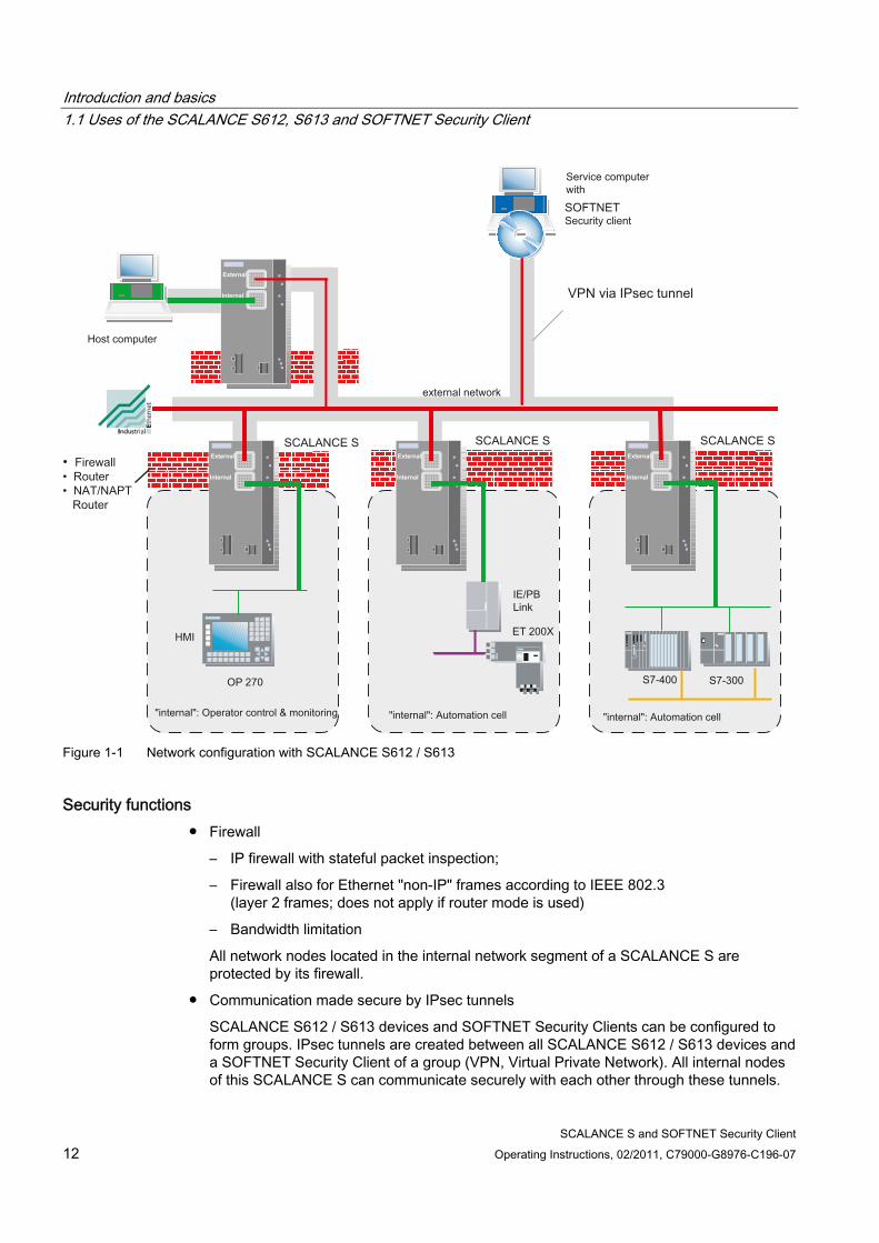
Figure 1-1 Network configuration with SCALANCE S612 / S613
Security functions ● Firewall
– IP firewall with stateful packet inspection;
– Firewall also for Ethernet "non-IP" frames according to IEEE 802.3 (layer 2 frames; does not apply if router mode is used)
– Bandwidth limitation
All network nodes located in the internal network segment of a SCALANCE S are protected by its firewall.
● Communication made secure by IPsec tunnels
SCALANCE S612 / S613 devices and SOFTNET Security Clients can be configured to form groups. IPsec tunnels are created between all SCALANCE S612 / S613 devices and a SOFTNET Security Client of a group (VPN, Virtual Private Network). All internal nodes of this SCALANCE S can communicate securely with each other through these tunnels.
Introduction and basics 1.1 Uses of the SCALANCE S612, S613 and SOFTNET Security Client
SCALANCE S and SOFTNET Security Client Operating Instructions, 02/2011, C79000-G8976-C196-07 13
● Protocol-independent
Tunneling also includes Ethernet frames according to IEEE 802.3 (layer 2 frames; does not apply if router mode is used).
Both IP and non-IP frames are transmitted through the IPsec tunnel.
● Router mode
By operating the SCALANCE S as a router, you connect the internal network with the external network. The internal network connected by SCALANCE S therefore becomes a separate subnet.
● Protection for devices and network segments
The firewall and VPN protective function can be applied to the operation of single devices, several devices, or entire network segments.
● No repercussions when included in flat networks (bridge mode)
Internal network nodes can be found without configuration. This means that when a SCALANCE S612 / S613 is installed in an existing network infrastructure, the end devices do not need to be reconfigured.
The module attempts to find internal nodes; internal nodes that cannot be found in this way must nevertheless be configured.
PC/PG communication in the VPN - job of the SOFTNET Security Client With the SOFTNET Security Client PC software, secure remote access is possible from PCs/PGs to automation systems protected by SCALANCE S via public networks.
With the SOFTNET Security Client, a PC/PG is configured automatically so that it can establish secure IPsec tunnel communication in the VPN (Virtual Private Network) with one or more SCALANCE S devices.
PG/PC applications such as NCM Diagnostics or STEP 7 can then access devices or networks in an internal network protected by SCALANCE S over a secure tunnel connection.
The SOFTNET Security Client PC software is also configured with the Security Configuration Tool ensuring fully integrated configuration without any special security know-how.
Introduction and basics 1.2 Using the SCALANCE S602
SCALANCE S and SOFTNET Security Client 14 Operating Instructions, 02/2011, C79000-G8976-C196-07
Internal and external network nodes SCALANCE S612 / S613 divides networks into two areas:
● Internal network: Protected areas with the "internal nodes"
Internal nodes are all the nodes secured by a SCALANCE S.
● External network: Unprotected areas with the "external nodes"
External nodes are all the nodes located outside the protected areas.
NOTICE
The internal network is considered to be secure (trustworthy).
Connect an internal network segment to the external network segments only over SCALANCE S.
There must be no other paths connecting the internal and external network!
1.2 Using the SCALANCE S602
Firewall and router - the job of the SCALANCE S602 With a combination of different security measures such as firewall and NAT/NAPT routers, the SCALANCE S602 protects individual devices or even entire automation cells from:
● Data espionage
● Unauthorized access
SCALANCE S602 allows this protection flexibly and without complicated handling.
SCALANCE S602 is configured with the Security Configuration Tool.

Introduction and basics 1.2 Using the SCALANCE S602
SCALANCE S and SOFTNET Security Client Operating Instructions, 02/2011, C79000-G8976-C196-07 15
External
Internal
External
Internal
External
Internal
0 1
•
"internal": Operator control & monitoring "internal": Automation cell "internal": Automation cell
HMI
SCALANCE S
OP 270
IE/PBLink
ET 200X
S7-400 S7-300
SCALANCE SSCALANCE S
Figure 1-2 Network configuration with SCALANCE S602
Security functions ● Firewall
– IP firewall with stateful packet inspection;
– Firewall also for Ethernet "non-IP" frames according to IEEE 802.3 (layer 2 frames; does not apply to S602 if router mode is used);
– Bandwidth limitation
All network nodes located in the internal network segment of a SCALANCE S are protected by its firewall.
● Router mode
By operating the SCALANCE S as a router, you separate the internal network from the external network. The internal network connected over SCALANCE S therefore becomes a separate subnet; SCALANCE S must be addressed explicitly as a router using its IP address.
● Protection for devices and network segments
The firewall protective function can be applied to the operation of single devices, several devices, or entire network segments.
● No repercussions when included in flat networks (bridge mode)
This means that when a SCALANCE S602 is installed in an existing network infrastructure, the settings of end devices do not need to be made again.

Introduction and basics 1.3 Configuration and administration
SCALANCE S and SOFTNET Security Client 16 Operating Instructions, 02/2011, C79000-G8976-C196-07
Internal and external network nodes SCALANCE S602 divides networks into two areas:
● Internal network: Protected areas with the "internal nodes"
Internal nodes are all the nodes secured by a SCALANCE S.
● External network: Unprotected areas with the "external nodes"
External nodes are all the nodes located outside the protected areas.
NOTICE
The internal network is considered to be secure (trustworthy).
Connect an internal network segment to the external network segments only over SCALANCE S.
There must be no other paths connecting the internal and external network!
1.3 Configuration and administration
The most important features at a glance In conjunction with the Security Configuration Tool, you are guided to a simple and secure application of the SCALANCE S modules:
● Configuration without expert IT knowledge with the Security Configuration Tool
With the Security Configuration Tool, a SCALANCE S module can be set by non IT experts. When necessary, more complex settings can be made in an extended mode.
● Secure administrative communication
The settings are transferred to SCALANCE S over an SSL-encrypted connection.
● Access protection in the Security Configuration Tool
The user administration of the Security Configuration Tool ensures access protection for the SCALANCE S devices and the configuration data.
● C-PLUG exchangeable memory medium can be used
The C-PLUG is a plug-in memory medium on which the encrypted configuration data can be stored. It allows configuration without a PC/PG when replacing a SCALANCE S.
SCALANCE S and SOFTNET Security Client Operating Instructions, 02/2011, C79000-G8976-C196-07 17
Product properties and commissioning 2
This chapter will familiarize you with the handling and all important properties of the SCALANCE S device.
You will learn how the device can be installed and commissioned in a few simple steps.
Further information How to configure the device for standard applications is shown in a condensed form in the Chapter "GETTING STARTED".
For details on configuration and the online functions, refer to the reference section of the manual.
2.1 Product Characteristics
Note
The specified approvals apply only when the corresponding mark is printed on the product.
2.1.1 Hardware characteristics and overview of the functions All SCALANCE S modules have the following essential characteristics:
Hardware ● Robust housing with degree of protection IP30
● Optional mounting on an S7-300 or DIN 35 mm rail
● Redundant power supply

Product properties and commissioning 2.1 Product Characteristics
SCALANCE S and SOFTNET Security Client 18 Operating Instructions, 02/2011, C79000-G8976-C196-07
● Signaling contact
● Extended temperature range (-20 °C to +70 °C SCALANCE S613)
Overview of the functions of the device types The following table shows you the functions supported by your device.
Note
This manual describes all functions. Based on the following table, you can recognize which descriptions apply to the device you are using.
You should also note the additional information in the titles of the sections.
Table 2- 1 Overview of the functions
Function S602 S612 V1 S612 V2 S613 V1 S613 V2 Firewall x x x x x NAT/NAPT router x - x - x DHCP server x - x - x Network Syslog x - x - x IPsec tunnel (VPN, Virtual Private Network) - x x x x SOFTNET Security Client - x x x x
x Function supported - Function not supported
2.1.2 Components of the product
What ships with the SCALANCE S? ● SCALANCE S device
● 2-pin plug-in terminal block
Product properties and commissioning 2.1 Product Characteristics
SCALANCE S and SOFTNET Security Client Operating Instructions, 02/2011, C79000-G8976-C196-07 19
● 4-pin plug-in terminal block
● Information on the product
● CD with the following content:
– Manual
– Security Configuration Tool
2.1.3 Unpacking and checking
Unpacking, checking 1. Make sure that the package is complete.
2. Check all the parts for transport damage.
WARNING
Do not use any parts that show evidence of damage!
2.1.4 Attachment to Ethernet
Possible attachments SCALANCE S has 2 RJ-45 jacks for attachment to Ethernet.
Note
TP cords or TP-XP cords with a maximum length of 10 m can be connected at the RJ-45 TP port.
In conjunction with the Industrial Ethernet FastConnect IE FC Standard Cable and IE FC RJ-45 Plug 180, a total cable length of maximum 100 m is possible between two devices.
NOTICE The Ethernet attachments at port 1 and port 2 are handled differently by the SCALANCE S and must not be swapped over when connecting to the communication network: Port 1 - external network
upper RJ-45 jack, marked red = unprotected network area; Port 2 - Internal Network
Lower RJ-45 jack, marked green = network protected by SCALANCE S;
If the ports are swapped over, the device loses its protective function.

Product properties and commissioning 2.1 Product Characteristics
SCALANCE S and SOFTNET Security Client 20 Operating Instructions, 02/2011, C79000-G8976-C196-07
Autonegotiation SCALANCE S supports autonegotiation.
Autonegotiation means that the connection and transmission parameters are negotiated automatically with the addressed network node.
MDI /MDIX autocrossover function SCALANCE S supports the MDI / MDIX autocrossover function.
The advantage of the MDI /MDIX autocrossover function is that straight-through cables can be used throughout and crossover Ethernet cables are unnecessary. This prevents malfunctions resulting from mismatching send and receive wires. This greatly simplifies installation.
2.1.5 Power supply
WARNING The SCALANCE S is designed for operation with safety extra-low voltage. This means that only safety extra-low voltages (SELV) complying with IEC950/EN60950/ VDE0805 can be connected to the power supply terminals.
The power supply unit to supply the SCALANCE S must comply with NEC Class 2 (voltage range 18 - 32 V, current requirement 250 mA).
The device may only be supplied by a power unit that meets the requirements of class 2 for power supply units of the "National Electrical Code, Table 11 (b)". If the device is connected to a redundant power supply (two separate power supplies), both must meet these requirements.
NOTICE Never connect the SCALANCE S to AC voltage or to DC voltage higher than 32 VDC.
The power supply is connected using a 4-pin plug-in terminal block. The power supply can be connected redundantly. Both inputs are isolated. There is no distribution of load. When a redundant power supply is used, the power supply unit with the higher output voltage supplies the SCALANCE S alone. The power supply is connected over a high resistance with the enclosure to allow an ungrounded set up.
Product properties and commissioning 2.1 Product Characteristics
SCALANCE S and SOFTNET Security Client Operating Instructions, 02/2011, C79000-G8976-C196-07 21
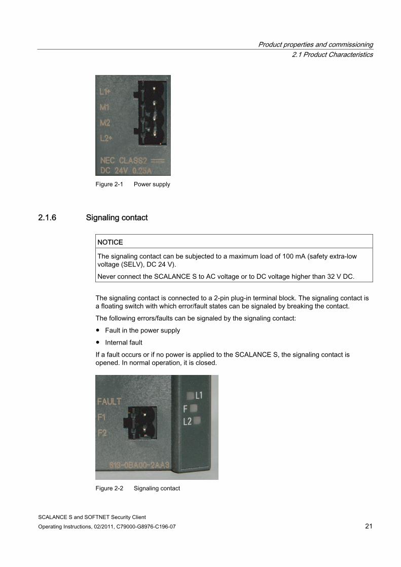
Figure 2-1 Power supply
2.1.6 Signaling contact
NOTICE The signaling contact can be subjected to a maximum load of 100 mA (safety extra-low voltage (SELV), DC 24 V).
Never connect the SCALANCE S to AC voltage or to DC voltage higher than 32 V DC.
The signaling contact is connected to a 2-pin plug-in terminal block. The signaling contact is a floating switch with which error/fault states can be signaled by breaking the contact.
The following errors/faults can be signaled by the signaling contact:
● Fault in the power supply
● Internal fault
If a fault occurs or if no power is applied to the SCALANCE S, the signaling contact is opened. In normal operation, it is closed.
Figure 2-2 Signaling contact
Product properties and commissioning 2.1 Product Characteristics
SCALANCE S and SOFTNET Security Client 22 Operating Instructions, 02/2011, C79000-G8976-C196-07
2.1.7 Reset button - resetting the configuration to factory defaults SCALANCE S has a reset button. The reset button is located on the rear of the housing below a cover secured with screws immediately beside the C-PLUG.
The reset button is mechanically protected against being activated accidentally.
NOTICE Make sure that only authorized personnel has access to the SCALANCE S.
What does the button do? Two functions can be triggered with the reset button:
● Restart
The module is restarted. The loaded configuration is retained.
● Reset to factory settings
The module is restarted and reset to the status set in the factory. A loaded configuration is deleted.
Restart - follow the steps below 1. If necessary, remove the SCALANCE S module from its mounting to allow access to the
recess.
2. Remove the M32 plug on the rear of the device.
The reset button is in a recess on the rear of the SCALANCE S directory beside the slot for the C-PLUG. This recess is protected by a screw plug. The button is located in a narrow hole and is therefore protected from being activated accidentally.
3. Press the reset button for less than five seconds.
The restart takes up to 2 minutes. During the restart, the fault LED is lit yellow. Make sure that the power supply is not interrupted during the reset.
On completion of the restart, the device automatically changes to productive mode. The fault LED is then lit permanently green.
4. Close the recess with the M32 plug and mount the device again.
Reset to factory settings - follow the steps below
NOTICE If a C-PLUG is plugged in when you reset to factory settings, the C-PLUG is erased!

Product properties and commissioning 2.1 Product Characteristics
SCALANCE S and SOFTNET Security Client Operating Instructions, 02/2011, C79000-G8976-C196-07 23
1. If necessary, remove the SCALANCE S module from its mounting to allow access to the recess.
2. Remove the M32 plug on the rear of the device.
The reset button is in a recess on the rear of the SCALANCE S directory beside the slot for the C-PLUG. This recess is protected by a screw plug. The button is located in a narrow hole and is therefore protected from being activated accidentally.
3. Press the reset button and keep it pressed for longer than 5 seconds until the fault LED flashes yellow-red.
Resetting takes up to 2 minutes. During the reset, the fault LED flashes yellow-red. Make sure that the power supply is not interrupted during the reset.
On completion of the reset, the device starts up again automatically. The fault LED is then lit yellow.
4. Close the recess with the M32 plug and mount the device again.
2.1.8 Displays
Fault LED Display of the operating state:
Status Meaning Lit red Module detects an error.
(Signaling contact is open). The following faults are detected: Internal error/fault (for example: startup failed) Invalid C-PLUG (invalid formatting)
Lit green Module in productive operation (Signaling contact closed).
NOT lit Module failure; no power supply (Signaling contact open).
Product properties and commissioning 2.1 Product Characteristics
SCALANCE S and SOFTNET Security Client 24 Operating Instructions, 02/2011, C79000-G8976-C196-07
Status Meaning Lit yellow (constant) Module in startup.
(Signaling contact open). If no IP address exists, the module remains in this status.
Flashes yellow and red alternately
Module resets itself to factory settings. (Signaling contact open).
Power LEDs (L1, L2) The status of the power supply is indicated by two LEDs:
Status Meaning Lit green Power supply L1 or L2 is connected. Not lit Power supply L1 or L2 not connected or < 14 V (L+) Lit red Power supply L1 or L2 failed during operation or < 14 V (L+)
Port status LEDs (P1 and TX, P2 and TX) The status of the interfaces is indicated by 2 LEDs for each of the two ports:
Status Meaning LED P1 / P2 Lit green TP link exists Flashes / lit yellow Receiving data at RX off No TP link or no data being received LED TX Flashes / lit yellow Data being sent off No data being sent
2.1.9 Technical specifications Connectors Attachment of end devices or network components over twisted pair
2xRJ–45 jacks with MDI-X pinning 10/100 Mbps (half/full duplex)
Connector for power supply 1x4-pin plug-in terminal block Connector for signaling contact 1x2-pin plug-in terminal block Electrical data Power supply 24 V DC power supply (18 through 32 V DC)
Implemented redundantly Safety extra-low voltage (SELV)
Power loss at 24 V DC 3.84 W
Product properties and commissioning 2.1 Product Characteristics
SCALANCE S and SOFTNET Security Client Operating Instructions, 02/2011, C79000-G8976-C196-07 25
Current consumption at rated voltage 250 mA maximum Permitted cable lengths Connection over Industrial Ethernet FC TP cables:
0 - 100 m Industrial Ethernet FC TP standard cable with IE FC RJ-45 plug 180 or Over Industrial Ethernet FC outlet RJ-45 with 0 - 90 m Industrial Ethernet FC TP standard cable + 10 m TP cord
0 - 85 m Industrial Ethernet FC TP marine/trailing cable with IE FC RJ-45 plug 180 or 0 - 75 m Industrial Ethernet FC TP marine/trailing cable + 10 m TP cord
Software configuration limits for VPN Number of IPsec tunnels SCALANCE S612 SCALANCE S613
64 maximum 128 maximum
Software "firewall" configuration limits Number of firewall rules SCALANCE S602 SCALANCE S612 SCALANCE S613
256 maximum 256 maximum 256 maximum
Permitted environmental conditions / EMC Operating temperature SCALANCE S602 0 °C through +60 °C Operating temperature SCALANCE S612 0 °C through +60 °C Operating temperature SCALANCE S613 -20 °C through +70 °C Storage/transport temperature -40 °C through +80 °C Relative humidity in operation 95% (no condensation) Operating altitude Up to 2000 m above sea level at max. 56 °C
ambient temperature Up to 3000 m above sea level at max. 50 °C ambient temperature
RF interference level EN 50081-2 Class A Immunity EN 50082-2 Degree of protection IP 30 Certification c-UL-us UL 60950 CSA C22.2 No. 60950 c-Ul-us for hazardous locations UL 1604, UL 2279Pt.15 FM FM 3611 C-TICK AS/NZS 2064 (Class A). CE EN 50081-2, EN 50082-2 ATEX Zone 2 EN50021
Product properties and commissioning 2.2 Installation
SCALANCE S and SOFTNET Security Client 26 Operating Instructions, 02/2011, C79000-G8976-C196-07
MTBF 81.09 years Construction Dimensions (W x H x D) in mm 60 x 125 x 124 Weight in g 780 Installation options DIN rail
S7-300 standard rail Wall mounting
Order numbers SCALANCE S602 6GK5602-0BA00-2AA3 SCALANCE S612 6GK5612-0BA00-2AA3 SCALANCE S613 6GK5613-0BA00-2AA3 "Industrial Ethernet TP and Fiber Optic Networks" manual
6GK1970-1BA10-0AA0
Order numbers for accessories IE FC Stripping Tool 6GK1901-1GA00 IE FC blade cassettes 6GK1901-1GB00 IE FC TP standard cable 6XV1840 2AH10 IE FC TP trailing cable 6XV1840-3AH10 IE FC TP marine cable 6XV1840-4AH10 IE FC RJ–45 Plug 180 pack of 1
6GK1 901-1BB10-2AA0
IE FC RJ–45 Plug 180 pack of 10
6GK1 901-1BB10-2AB0
IE FC RJ–45 Plug 180 pack of 50
6GK1 901-1BB10-2AE0
2.2 Installation
Note
The requirements of EN61000-4-5, surge test on power supply lines are met only when a Blitzductor VT AD 24V type no. 918 402 is used.
Manufacturer: DEHN+SÖHNE GmbH+Co.KG Hans Dehn Str.1 Postfach 1640 D-92306 Neumarkt, Germany

Product properties and commissioning 2.2 Installation
SCALANCE S and SOFTNET Security Client Operating Instructions, 02/2011, C79000-G8976-C196-07 27
WARNING When used under hazardous conditions (zone 2), the SCALANCE S product must be installed in an enclosure.
To comply with ATEX 95 (EN 50021), this enclosure must meet the requirements of at least IP54 in compliance with EN 60529.
WARNING EXPLOSION HAZARD: DO NOT DISCONNECT EQUIPMENT WHEN A FLAMMABLE OR COMBUSTIBLE ATMOSPHERE IS PRESENT.
Types of installation The SCALANCE S can be installed in various ways:
● Installation on a 35 mm DIN rail
● Installation on a SIMATIC S7-300 standard rail
● Wall mounting
Note
When installing and operating the device, keep to the installation instructions and safety-related notices as described here and in the manual SIMATIC NET Industrial Ethernet Twisted Pair and Fiber Optic Networks /1/.
NOTICE
We recommend that you provide suitable shade to protect the device from direct sunlight.
This avoids unwanted warming of the device and prevents premature aging of the device and cabling.
Product properties and commissioning 2.2 Installation
SCALANCE S and SOFTNET Security Client 28 Operating Instructions, 02/2011, C79000-G8976-C196-07
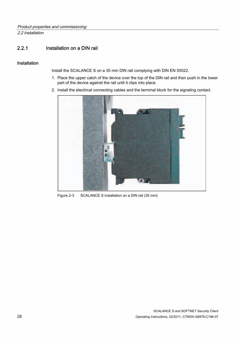
2.2.1 Installation on a DIN rail
Installation Install the SCALANCE S on a 35 mm DIN rail complying with DIN EN 50022.
1. Place the upper catch of the device over the top of the DIN rail and then push in the lower part of the device against the rail until it clips into place.
2. Install the electrical connecting cables and the terminal block for the signaling contact.
Figure 2-3 SCALANCE S installation on a DIN rail (35 mm)

Product properties and commissioning 2.2 Installation
SCALANCE S and SOFTNET Security Client Operating Instructions, 02/2011, C79000-G8976-C196-07 29
Uninstalling To remove the SCALANCE S from the DIN rail:
1. First disconnect the TP cables and pull out the terminal blocks for the power supply and the signaling contact.
2. Use a screwdriver to release the lower rail catch of the device and pull the lower part of the device away from the rail.
Figure 2-4 SCALANCE S removing from a DIN rail (35 mm)

Product properties and commissioning 2.2 Installation
SCALANCE S and SOFTNET Security Client 30 Operating Instructions, 02/2011, C79000-G8976-C196-07
2.2.2 Installation on a standard rail
Installation on a SIMATIC S7-300 standard rail 1. Place the upper guide at the top of the SCALANCE S housing in the S7 standard rail.
2. Screw the SCALANCE S device to the lower part of the standard rail.
Figure 2-5 SCALANCE S installation on a SIMATIC S7-300 standard rail
2.2.3 Wall mounting
Installation fittings Use the following fittings, for example when mounting on a concrete wall:
● 4 wall plugs, 6 mm in diameter and 30 mm long
● Screws 3.5 mm in diameter and 40 mm long
Note
The wall mounting must be capable of supporting at least four times the weight of the device.

Product properties and commissioning 2.3 Commissioning
SCALANCE S and SOFTNET Security Client Operating Instructions, 02/2011, C79000-G8976-C196-07 31
2.2.4 Grounding
Installation on a DIN rail The device is grounded over the DIN rail.
S7 standard rail The device is grounded over its rear panel and the neck of the screw.
Wall mounting The device is grounded by the securing screw in the unpainted hole.
NOTICE Please note that the SCALANCE S must be grounded over one securing screw with minimum resistance.
2.3 Commissioning
NOTICE Before putting the device into operation, make sure that you read the information in the sections "Product properties" and "Installation" carefully and follow the instructions there, particularly those in the safety notices.
Principle To operate the SCALANCE S, you need to download a configuration created with the Security Configuration Tool. This procedure is described below.
A SCALANCE S configuration includes the IP parameters and the setting for firewall rules and, if applicable, the setting for IPsec tunnels (S612 / S613) or router mode.
Before putting the device into operation, you can first create the entire configuration offline and then download it. For the first configuration (device with factory settings), use the MAC address printed on the device.
Depending on the application, you will download the configuration to one or more modules during the commissioning phase.

Product properties and commissioning 2.3 Commissioning
SCALANCE S and SOFTNET Security Client 32 Operating Instructions, 02/2011, C79000-G8976-C196-07
External
Internal
External
Internal
Figure 2-6 Overview of commissioning
Factory defaults With the factory defaults (settings as supplied or after resetting to factory defaults), the SCALANCE S behaves as follows after turning on the power supply:
● IP communication is not possible since the IP settings are missing; the SCALANCE S itself does not yet have an IP address.
As soon as the SCALANCE S module is assigned a valid IP address by the configuration, the module is accessible even over routers (IP communication is then possible).
● The device has a fixed, default MAC address; the MAC address is printed on the device and must be used during configuration.
● The firewall is preconfigured with the following basic firewall rules:
– Unsecured data traffic from internal port to external port and vice versa (external ↔ internal) is not possible;
The unconfigured status can be recognized when the F LED is lit yellow.
See also Product Characteristics (Page 17)
Installation (Page 26)
Product properties and commissioning 2.3 Commissioning
SCALANCE S and SOFTNET Security Client Operating Instructions, 02/2011, C79000-G8976-C196-07 33
2.3.1 Step 1: Connecting the SCALANCE S module
Follow the steps below: 1. First unpack the SCALANCE S and check that it is undamaged.
2. Connect the power supply to the SCALANCE S.
Result: After connecting the power, the Fault LED (F) is lit yellow.
3. Now establish the physical network connections by plugging the network cable connectors into the ports being used (RJ-45 jacks).
Connect port 1 (external port) with the external network to which the configuration PC/PG is connected.
Connect port 2 (internal port) with the internal network.
Note: During commissioning, you can, in principle, initially connect the configuration PC/PG to port 1 or port 2 and do without a connection to other network nodes until the device has been supplied with a configuration. If you connect to port 2, however, you must configure each individual SCALANCE S module separately!
4. Now continue with the next step "Configuring and downloading".
2.3.2 Step 2: Configuring and downloading The section below describes how to configure the SCALANCE S module starting from the factory settings.
Follow the steps below: 1. Start the supplied Security Configuration Tool.
2. Select the menu command Project ▶ New.
You will be prompted to enter a user name and a password. The user entry you specify here will be assigned the role of an administrator.
3. Enter a user name and a password and confirm your entries to create a new project.
4. The "Selection of the module or software configuration" dialog is automatically displayed. Now configure your product type, the module and the firmware release.
Product properties and commissioning 2.3 Commissioning
SCALANCE S and SOFTNET Security Client 34 Operating Instructions, 02/2011, C79000-G8976-C196-07
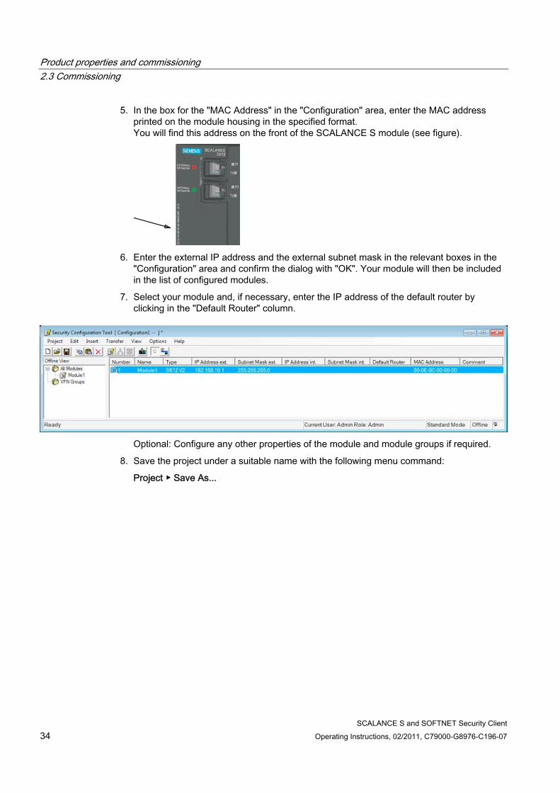
5. In the box for the "MAC Address" in the "Configuration" area, enter the MAC address printed on the module housing in the specified format. You will find this address on the front of the SCALANCE S module (see figure).
6. Enter the external IP address and the external subnet mask in the relevant boxes in the
"Configuration" area and confirm the dialog with "OK". Your module will then be included in the list of configured modules.
7. Select your module and, if necessary, enter the IP address of the default router by clicking in the "Default Router" column.
Optional: Configure any other properties of the module and module groups if required.
8. Save the project under a suitable name with the following menu command:
Project ▶ Save As...
Product properties and commissioning 2.4 C-PLUG (configuration plug)
SCALANCE S and SOFTNET Security Client Operating Instructions, 02/2011, C79000-G8976-C196-07 35
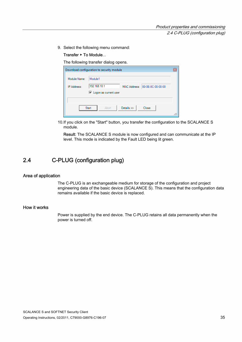
9. Select the following menu command:
Transfer ▶ To Module...
The following transfer dialog opens.
10. If you click on the "Start" button, you transfer the configuration to the SCALANCE S
module.
Result: The SCALANCE S module is now configured and can communicate at the IP level. This mode is indicated by the Fault LED being lit green.
2.4 C-PLUG (configuration plug)
Area of application The C-PLUG is an exchangeable medium for storage of the configuration and project engineering data of the basic device (SCALANCE S). This means that the configuration data remains available if the basic device is replaced.
How it works Power is supplied by the end device. The C-PLUG retains all data permanently when the power is turned off.
Product properties and commissioning 2.4 C-PLUG (configuration plug)
SCALANCE S and SOFTNET Security Client 36 Operating Instructions, 02/2011, C79000-G8976-C196-07
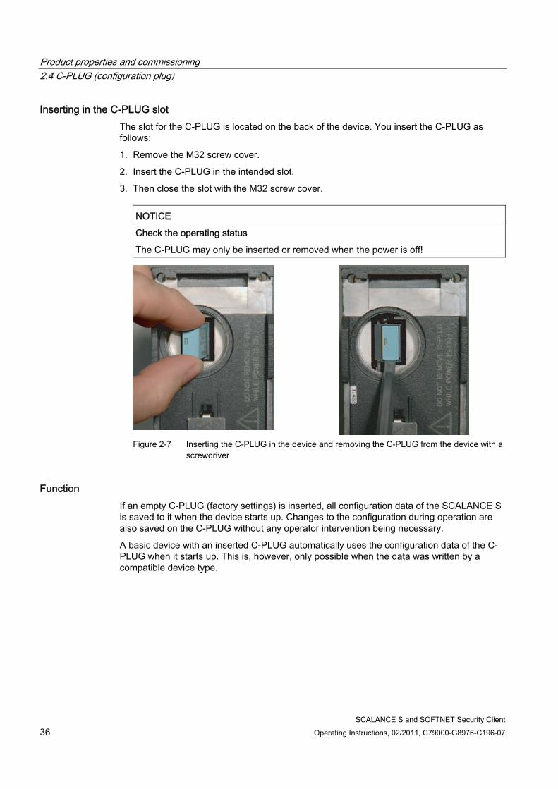
Inserting in the C-PLUG slot The slot for the C-PLUG is located on the back of the device. You insert the C-PLUG as follows:
1. Remove the M32 screw cover.
2. Insert the C-PLUG in the intended slot.
3. Then close the slot with the M32 screw cover.
NOTICE
Check the operating status
The C-PLUG may only be inserted or removed when the power is off!
Figure 2-7 Inserting the C-PLUG in the device and removing the C-PLUG from the device with a
screwdriver
Function If an empty C-PLUG (factory settings) is inserted, all configuration data of the SCALANCE S is saved to it when the device starts up. Changes to the configuration during operation are also saved on the C-PLUG without any operator intervention being necessary.
A basic device with an inserted C-PLUG automatically uses the configuration data of the C-PLUG when it starts up. This is, however, only possible when the data was written by a compatible device type.

Product properties and commissioning 2.4 C-PLUG (configuration plug)
SCALANCE S and SOFTNET Security Client Operating Instructions, 02/2011, C79000-G8976-C196-07 37
This allows fast and simple replacement of the basic device. If a device is replaced, the C-PLUG is taken from the failed component and inserted in the replacement. After it has started up, the replacement device has the same device configuration as the failed device.
Note Consistent project data - adapting the MAC address
After replacing the device with a spare, the project engineering data should be consistent. To achieve this, you should adapt the MAC address from the project engineering to the MAC address printed on the replacement device.
If you use the previously configured C_PLUG of the device you are replacing, this is not absolutely necessary to start up and run the device.
NOTICE Reset to factory settings
If a C-PLUG is plugged in when you reset to factory settings, the C-PLUG is erased!
Using a previously written C-PLUG Use only C-PLUGs that are formatted for the relevant SCALANCE S module type. C-PLUGs that have already been used in other device types and formatted for these device types must not be used.
The following table shows which C-PLUG you can use for which SCALANCE S module type:
C-PLUG formatted by SCALANCE S module
type S602 S612 S613 S602 x - - S612 - x x *) S613 - x x
x C-PLUG can be used with the module type - C-PLUG cannot be used with the module type *) Compatibility depends on configuration limits.
Removing the C-PLUG It is only necessary to remove the C-PLUG if the basic device fails (hardware fault).
NOTICE Check the operating status
The C-PLUG may only be removed when the power is off!

Product properties and commissioning 2.5 Transferring firmware
SCALANCE S and SOFTNET Security Client 38 Operating Instructions, 02/2011, C79000-G8976-C196-07
Diagnostics Inserting a C-PLUG that does not contain the configuration of a compatible device type, inadvertently removing the C-PLUG, or general malfunctions of the C-PLUG are indicated by the diagnostic mechanisms of the end device (fault LED red).
2.5 Transferring firmware You can download new firmware versions to the SCALANCE S modules using the Security Configuration Tool.
Requirements To transfer new firmware to a SCALANCE S module, the following conditions must be met:
● You must have administrator permissions for the project;
● SCALANCE S must already have been configured with an IP address.
The transfer is secure The firmware is transferred over a secure connection and can therefore also be transferred from the unprotected network.
The firmware itself is signed and encrypted. This ensures that only authentic firmware can be downloaded to the SCALANCE S module.
The transfer can take place during operation The firmware can be transferred while a SCALANCE S module is in operation. Communication is, however, interrupted after the download until the automatic restart of the SCALANCE S is completed. Newly downloaded firmware only becomes active after the SCALANCE S module has been restarted.
If the transfer is disturbed and aborted, the module starts up again with the old firmware version.
How to make the transfer Select the following menu command:
Transfer ▶ Firmware Update...

SCALANCE S and SOFTNET Security Client Operating Instructions, 02/2011, C79000-G8976-C196-07 39
GETTING STARTED 3
Getting results fast with GETTING STARTED Based on a simple test network, this chapter shows you how to work with SCALANCE S and the Security Configuration Tool. You will soon see that you can implement the security functions of SCALANCE S in the network without any great project engineering effort.
Working through the chapter, you will be able to implement the basic functions SCALANCE S/ SOFTNET Security Client based on various security examples:
● With SCALANCE S612 / S613:
– Configuring a VPN with SCALANCE S modules as IPsec tunnel endpoints
– Configuring a VPN with SCALANCE S modules and SOFTNET Security Client as IPsec tunnel endpoints
● With all SCALANCE S modules:
– Configuring SCALANCE S as a firewall;
– Configuring SCALANCE S as NAT/NAPT router and firewall
● With SOFTNET Security Client
– Configuring a VPN with SCALANCE S modules and SOFTNET Security Client as IPsec tunnel endpoints
– Configuring a VPN with MD741-1 and SOFTNET Security Client as IPsec tunnel endpoints
If you want to know more You will find more detailed information in the next chapters of this manual. They describe the entire functionality in detail.
Note
The IP settings in the examples are freely selected and do not cause any conflicts in the isolated test network.
In a real network, you would need to adapt these IP settings to avoid possible address conflicts.

GETTING STARTED 3.1 Example 1: VPN tunnel - IPsec tunnel example with SCALANCE S612 / S613
SCALANCE S and SOFTNET Security Client 40 Operating Instructions, 02/2011, C79000-G8976-C196-07
3.1 Example 1: VPN tunnel - IPsec tunnel example with SCALANCE S612 / S613
3.1.1 Overview In this example, the tunnel function is configured in the "standard mode" project engineering view. SCALANCE S module 1 and SCALANCE S module 2 are the two tunnel endpoints for the secure tunnel connection in this example.
With this configuration, IP traffic and layer 2 traffic (bridge mode only) is possible only over the established tunnel connections with authorized partners.
Setting up the test network
PC1PC2
PC3
internes Netz 1 internes Netz 2externes Netz
● Internal network - attachment to SCALANCE S port 2 ("internal network" port)
In the test setup, in the internal network, the network node is implemented in each case by one PC connected to the "internal network" port (port 2, green) of a SCALANCE S module.
– PC1: Represents a node in internal network 1
– PC2: Represents a node in internal network 2
– SCALANCE S module 1: SCALANCE S module for internal network 1
– SCALANCE S module 2: SCALANCE S module for internal network 2
● External network - attachment to SCALANCE S port 1 ("external network" port)
The public external network is attached to the "external network" port (port 1, red) of a SCALANCE S module.
PC3: PC with the Security Configuration Tool

GETTING STARTED 3.1 Example 1: VPN tunnel - IPsec tunnel example with SCALANCE S612 / S613
SCALANCE S and SOFTNET Security Client Operating Instructions, 02/2011, C79000-G8976-C196-07 41
Required devices/components: Use the following components to set up to the network:
● 2 x SCALANCE S modules, (optional: one or two suitably installed standard rails with fittings);
● 1 x or 2 x 24 V power supplies with cable connections and terminal block plugs (both modules can also be operated from a common power supply);
● 1 x PC on which the "Security Configuration Tool" is installed;
● 2 x PCs in the internal networks to test the configuration;
● 1 x network hub or switch to set up the network connections with the two SCALANCE S modules and the PCs/PGs;
● The required network cable, TP cable (twisted pair) complying with the IE FC RJ-45 standard for Industrial Ethernet.
Overview of the next steps:
3.1.2 Set up SCALANCE S and the network
Follow the steps outlined below: 1. First unpack the SCALANCE S devices and check that they are undamaged.
2. Connect the power supply to the SCALANCE S.
GETTING STARTED 3.1 Example 1: VPN tunnel - IPsec tunnel example with SCALANCE S612 / S613
SCALANCE S and SOFTNET Security Client 42 Operating Instructions, 02/2011, C79000-G8976-C196-07
Result: After connecting the power, the Fault LED (F) is lit yellow.
WARNING The SCALANCE S is designed for operation with safety extra-low voltage. This means that only safety extra-low voltages (SELV) complying with IEC950/EN60950/ VDE0805 can be connected to the power supply terminals.
The power supply unit to supply the SCALANCE S must comply with NEC Class 2 (voltage range 18 - 32 V, current requirement approx. 250 mA).
When installing and connecting the SCALANCE S modules, refer to Chapter 2 "Product characteristics and commissioning".
1. Now establish the physical network connections by plugging the network cable connectors into the ports being used (RJ-45 jacks):
– Connect PC1 with port 2 of module 1 and PC2 with port 2 of module 2.
– Connect port 1 of module 1 and port 1 of module 2 with the hub/switch.
– Connect PC3 to the hub/switch as well.
2. Now turn on the PCs.
NOTICE
The Ethernet attachments at port 1 and port 2 are handled differently by the SCALANCE S and must not be swapped over when connecting to the communication network: Port 1 - external network
Upper RJ-45 jack, marked red = unprotected network area; Port 2 - internal network
Lower RJ-45 jack, marked green = network protected by SCALANCE S;
If the ports are swapped over, the device loses its protective function.
3.1.3 Make the IP settings for the PCs For the test, the PCs should be given the following IP address settings:
PC IP address Subnet mask PC1 191.0.0.1 255.255.0.0 PC2 191.0.0.2 255.255.0.0 PC3 191.0.0.3 255.255.0.0
GETTING STARTED 3.1 Example 1: VPN tunnel - IPsec tunnel example with SCALANCE S612 / S613
SCALANCE S and SOFTNET Security Client Operating Instructions, 02/2011, C79000-G8976-C196-07 43
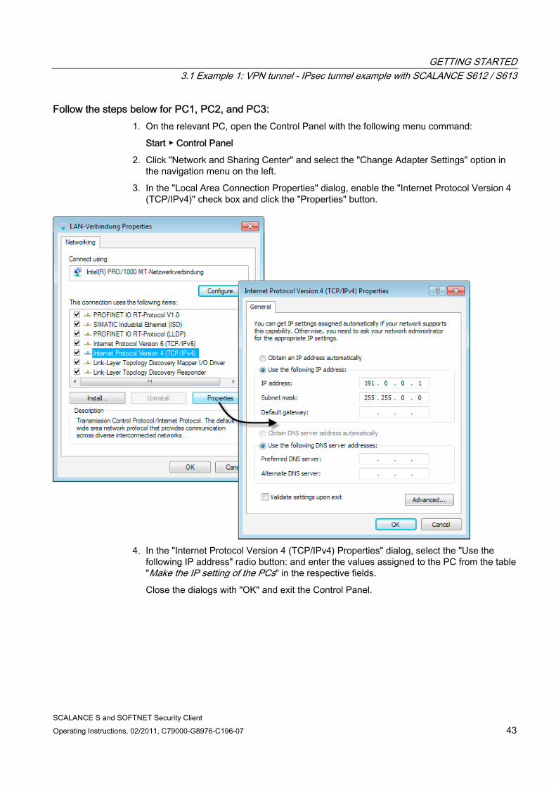
Follow the steps below for PC1, PC2, and PC3: 1. On the relevant PC, open the Control Panel with the following menu command:
Start ▶ Control Panel
2. Click "Network and Sharing Center" and select the "Change Adapter Settings" option in the navigation menu on the left.
3. In the "Local Area Connection Properties" dialog, enable the "Internet Protocol Version 4 (TCP/IPv4)" check box and click the "Properties" button.
4. In the "Internet Protocol Version 4 (TCP/IPv4) Properties" dialog, select the "Use the
following IP address" radio button: and enter the values assigned to the PC from the table "Make the IP setting of the PCs" in the respective fields.
Close the dialogs with "OK" and exit the Control Panel.
GETTING STARTED 3.1 Example 1: VPN tunnel - IPsec tunnel example with SCALANCE S612 / S613
SCALANCE S and SOFTNET Security Client 44 Operating Instructions, 02/2011, C79000-G8976-C196-07
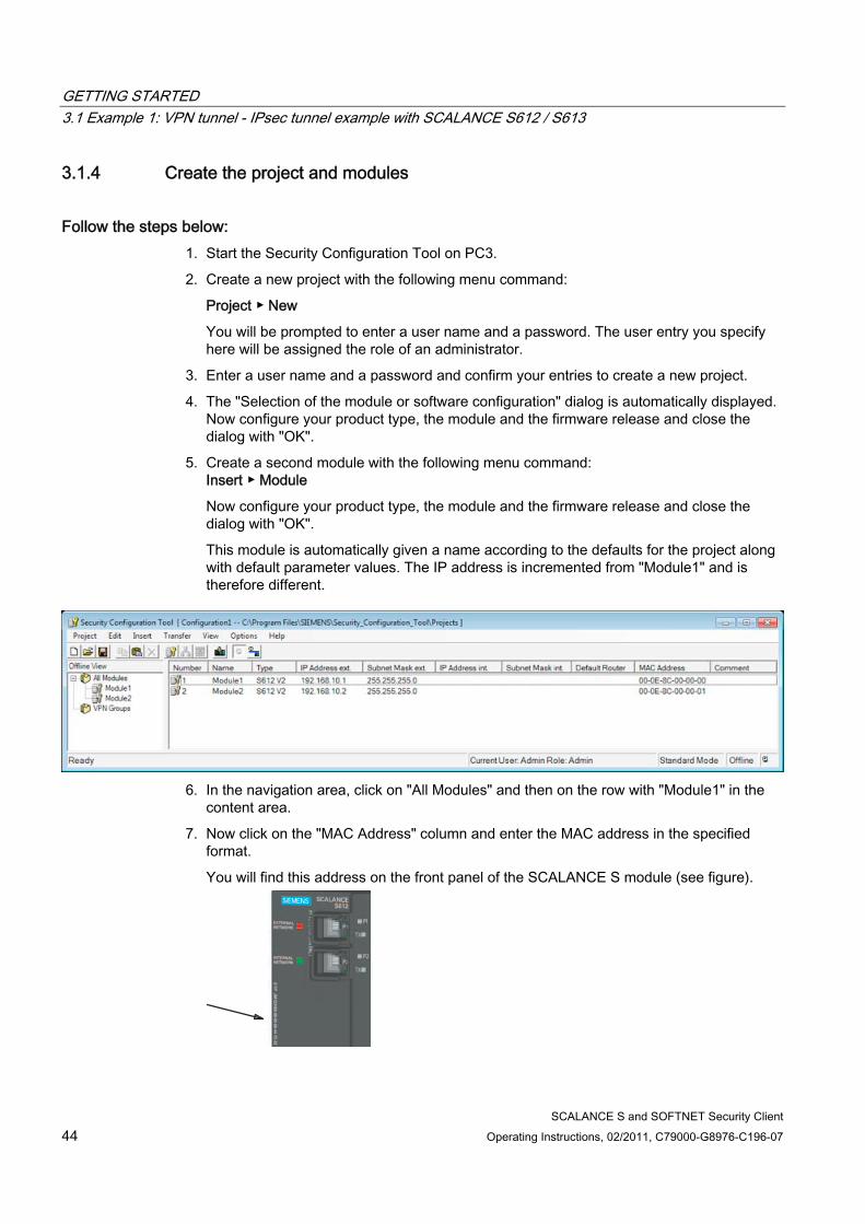
3.1.4 Create the project and modules
Follow the steps below: 1. Start the Security Configuration Tool on PC3.
2. Create a new project with the following menu command:
Project ▶ New
You will be prompted to enter a user name and a password. The user entry you specify here will be assigned the role of an administrator.
3. Enter a user name and a password and confirm your entries to create a new project.
4. The "Selection of the module or software configuration" dialog is automatically displayed. Now configure your product type, the module and the firmware release and close the dialog with "OK".
5. Create a second module with the following menu command: Insert ▶ Module
Now configure your product type, the module and the firmware release and close the dialog with "OK".
This module is automatically given a name according to the defaults for the project along with default parameter values. The IP address is incremented from "Module1" and is therefore different.
6. In the navigation area, click on "All Modules" and then on the row with "Module1" in the
content area.
7. Now click on the "MAC Address" column and enter the MAC address in the specified format.
You will find this address on the front panel of the SCALANCE S module (see figure).
GETTING STARTED 3.1 Example 1: VPN tunnel - IPsec tunnel example with SCALANCE S612 / S613
SCALANCE S and SOFTNET Security Client Operating Instructions, 02/2011, C79000-G8976-C196-07 45
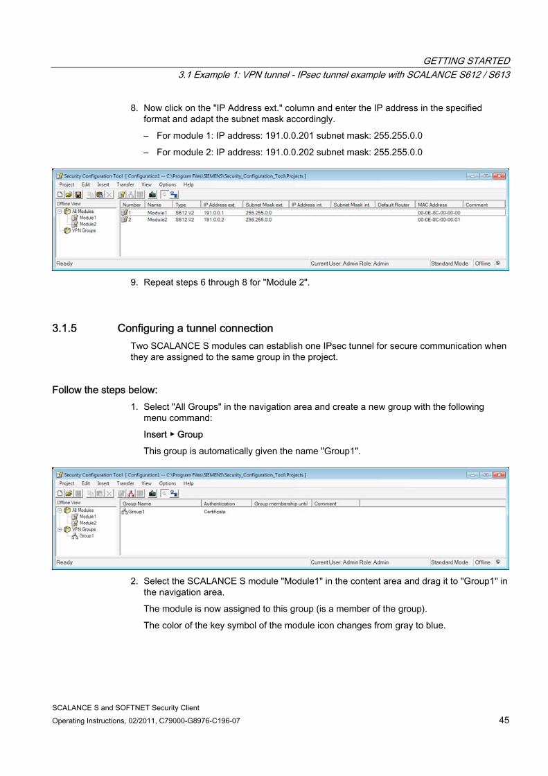
8. Now click on the "IP Address ext." column and enter the IP address in the specified format and adapt the subnet mask accordingly.
– For module 1: IP address: 191.0.0.201 subnet mask: 255.255.0.0
– For module 2: IP address: 191.0.0.202 subnet mask: 255.255.0.0
9. Repeat steps 6 through 8 for "Module 2".
3.1.5 Configuring a tunnel connection Two SCALANCE S modules can establish one IPsec tunnel for secure communication when they are assigned to the same group in the project.
Follow the steps below: 1. Select "All Groups" in the navigation area and create a new group with the following
menu command:
Insert ▶ Group
This group is automatically given the name "Group1".
2. Select the SCALANCE S module "Module1" in the content area and drag it to "Group1" in
the navigation area.
The module is now assigned to this group (is a member of the group).
The color of the key symbol of the module icon changes from gray to blue.
GETTING STARTED 3.1 Example 1: VPN tunnel - IPsec tunnel example with SCALANCE S612 / S613
SCALANCE S and SOFTNET Security Client 46 Operating Instructions, 02/2011, C79000-G8976-C196-07
3. Select the SCALANCE S module "Module2" in the content area and drag it to the "Group1" in the navigation area.
The module is now also assigned to this group.
4. Save this project under a suitable name with the following menu command:
Project ▶Save As...
The configuration of the tunnel connection is now complete.
3.1.6 Download the configuration to the SCALANCE S module
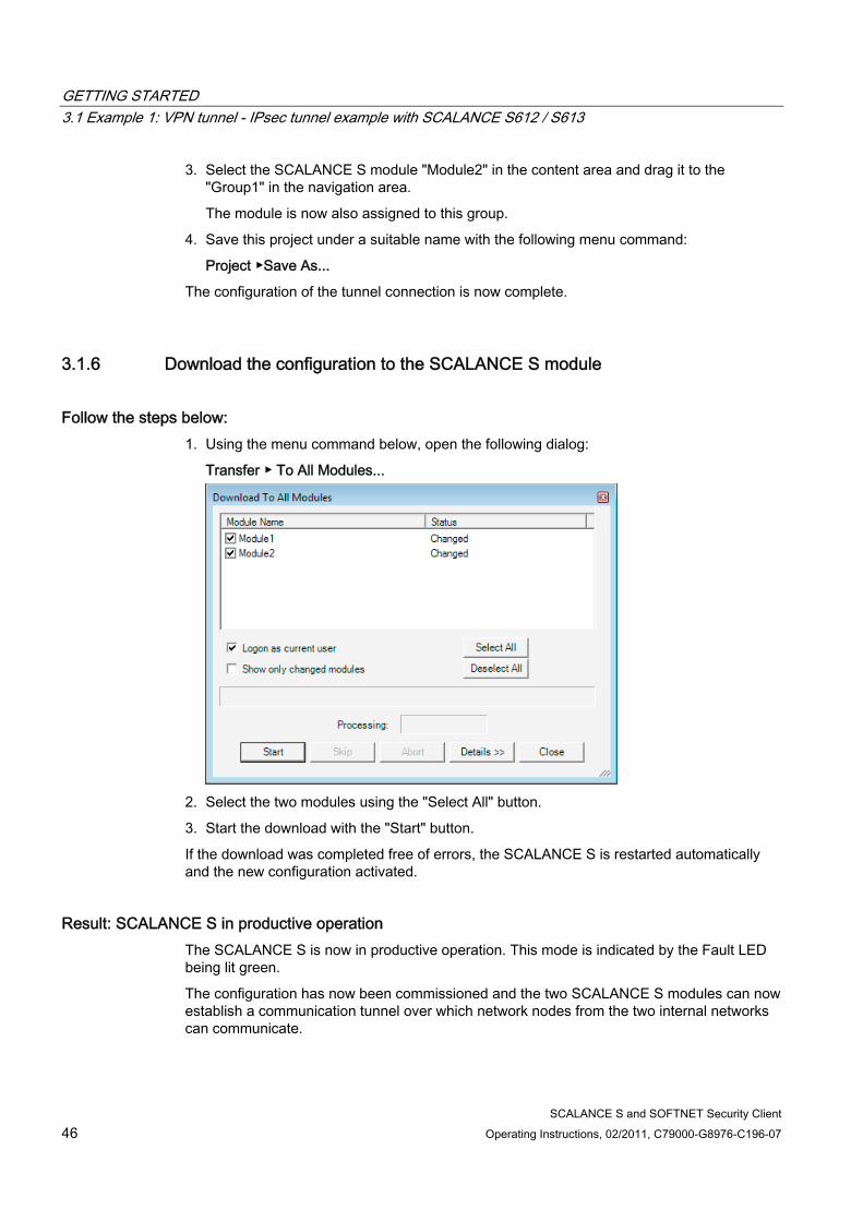
Follow the steps below: 1. Using the menu command below, open the following dialog:
Transfer ▶ To All Modules...
2. Select the two modules using the "Select All" button.
3. Start the download with the "Start" button.
If the download was completed free of errors, the SCALANCE S is restarted automatically and the new configuration activated.
Result: SCALANCE S in productive operation The SCALANCE S is now in productive operation. This mode is indicated by the Fault LED being lit green.
The configuration has now been commissioned and the two SCALANCE S modules can now establish a communication tunnel over which network nodes from the two internal networks can communicate.
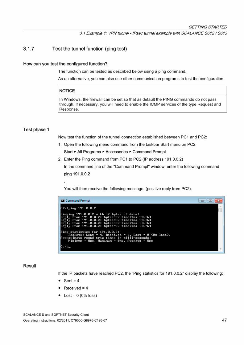
GETTING STARTED 3.1 Example 1: VPN tunnel - IPsec tunnel example with SCALANCE S612 / S613
SCALANCE S and SOFTNET Security Client Operating Instructions, 02/2011, C79000-G8976-C196-07 47
3.1.7 Test the tunnel function (ping test)
How can you test the configured function? The function can be tested as described below using a ping command.
As an alternative, you can also use other communication programs to test the configuration.
NOTICE In Windows, the firewall can be set so that as default the PING commands do not pass through. If necessary, you will need to enable the ICMP services of the type Request and Response.
Test phase 1 Now test the function of the tunnel connection established between PC1 and PC2:
1. Open the following menu command from the taskbar Start menu on PC2:
Start ▶ All Programs ▶ Accessories ▶ Command Prompt
2. Enter the Ping command from PC1 to PC2 (IP address 191.0.0.2)
In the command line of the "Command Prompt" window, enter the following command
ping 191.0.0.2
.
You will then receive the following message: (positive reply from PC2).
Result If the IP packets have reached PC2, the "Ping statistics for 191.0.0.2" display the following:
● Sent = 4
● Received = 4
● Lost = 0 (0% loss)

GETTING STARTED 3.2 Example 2: Firewall - Operating a SCALANCE S as a firewall
SCALANCE S and SOFTNET Security Client 48 Operating Instructions, 02/2011, C79000-G8976-C196-07
Since no other communication is permitted, these packets must have been transported through the VPN tunnel.
Test phase 2 Now repeat the test by sending a ping command from PC3.
1. Open the following menu command from the taskbar Start menu on PC3:
Start ► All Programs ► Accessories ► Command Prompt
2. Send the same ping command (ping 191.0.0.2) in the Command Prompt window of PC3.
You will then receive the following message: (no reply from PC2).
Result The IP frames from PC3 cannot reach PC2 since neither tunnel communication between these two devices is configured nor is normal IP data traffic permitted.
This is shown in the "Ping statistics" for 191.0.0.2 as follows:
● Sent = 4
● Received = 0
● Lost = 4 (100% loss)
3.2 Example 2: Firewall - Operating a SCALANCE S as a firewall
3.2.1 Overview In this example, the firewall is configured in the "standard mode" project engineering view. The standard mode includes predefined sets of rules for data traffic.
With this configuration, IP traffic can only be initiated from the internal network; only the response is permitted from the external network.

GETTING STARTED 3.2 Example 2: Firewall - Operating a SCALANCE S as a firewall
SCALANCE S and SOFTNET Security Client Operating Instructions, 02/2011, C79000-G8976-C196-07 49
Setting up the test network
External
Internal
● Internal network - attachment to SCALANCE S port 2
In the test setup, in the internal network, the network node is implemented by one PC connected to the "internal network" port (port 2, green) of a SCALANCE S module.
– PC2: Represents a node in the internal network
– SCALANCE S module 1: SCALANCE S module for the internal network
● External network - attachment to SCALANCE S port 1
The public external network is attached to the "external network" port (port 1, red) of a SCALANCE S module.
– PC1: PC with the Security Configuration Tool
Required devices/components: Use the following components to set up to the network:
● 1 x SCALANCE S module, (additional option: a suitably installed DIN rail with fittings)
● 1 x 24 V power supply with cable connector and terminal block plug
GETTING STARTED 3.2 Example 2: Firewall - Operating a SCALANCE S as a firewall
SCALANCE S and SOFTNET Security Client 50 Operating Instructions, 02/2011, C79000-G8976-C196-07
● 1 x PC on which the Security Configuration Tool is installed
● 1 x PC in the internal network to test the configuration
● The required network cable, TP cable (twisted pair) complying with the IE FC RJ-45 standard for Industrial Ethernet
Overview of the next steps:
3.2.2 Set up SCALANCE S and the network
Follow the steps below: 1. First unpack the SCALANCE S and check that it is undamaged.
2. Connect the power supply to the SCALANCE S.
Result: After connecting the power, the Fault LED (F) is lit yellow.
WARNING The SCALANCE S is designed for operation with safety extra-low voltage. This means that only safety extra-low voltages (SELV) complying with IEC950/EN60950/ VDE0805 can be connected to the power supply terminals.
The power supply unit to supply the SCALANCE S must comply with NEC Class 2 (voltage range 18 - 32 V, current requirement approx. 250 mA).
When installing and connecting the SCALANCE S modules, refer to Chapter 2 "Product characteristics and commissioning"
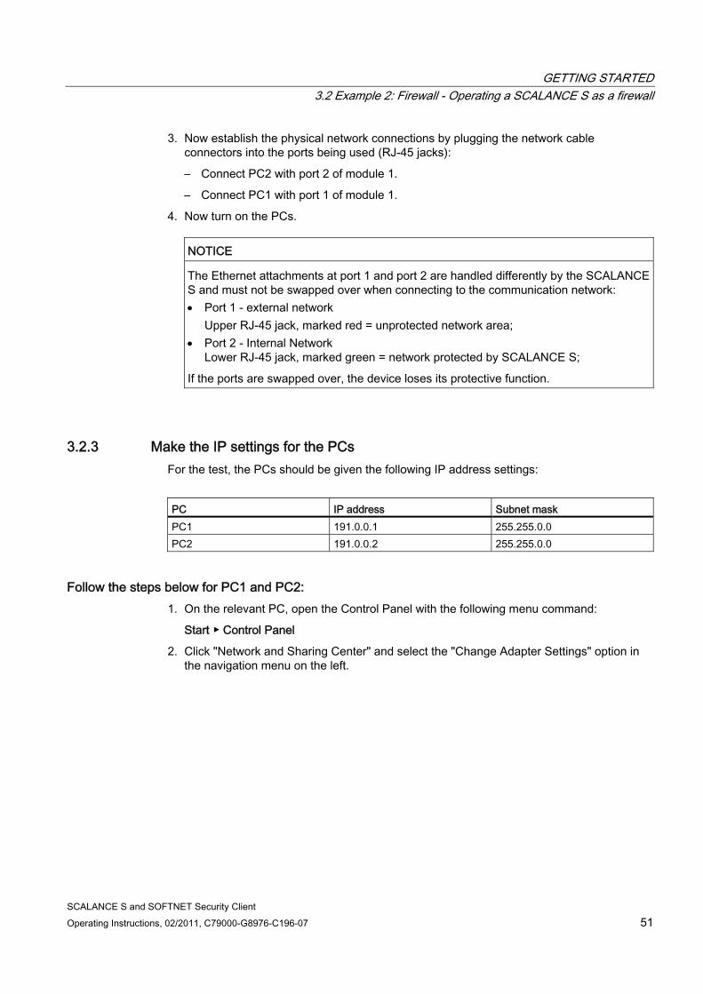
GETTING STARTED 3.2 Example 2: Firewall - Operating a SCALANCE S as a firewall
SCALANCE S and SOFTNET Security Client Operating Instructions, 02/2011, C79000-G8976-C196-07 51
3. Now establish the physical network connections by plugging the network cable connectors into the ports being used (RJ-45 jacks):
– Connect PC2 with port 2 of module 1.
– Connect PC1 with port 1 of module 1.
4. Now turn on the PCs.
NOTICE
The Ethernet attachments at port 1 and port 2 are handled differently by the SCALANCE S and must not be swapped over when connecting to the communication network: Port 1 - external network
Upper RJ-45 jack, marked red = unprotected network area; Port 2 - Internal Network
Lower RJ-45 jack, marked green = network protected by SCALANCE S;
If the ports are swapped over, the device loses its protective function.
3.2.3 Make the IP settings for the PCs For the test, the PCs should be given the following IP address settings:
PC IP address Subnet mask PC1 191.0.0.1 255.255.0.0 PC2 191.0.0.2 255.255.0.0
Follow the steps below for PC1 and PC2: 1. On the relevant PC, open the Control Panel with the following menu command:
Start ▶ Control Panel
2. Click "Network and Sharing Center" and select the "Change Adapter Settings" option in the navigation menu on the left.
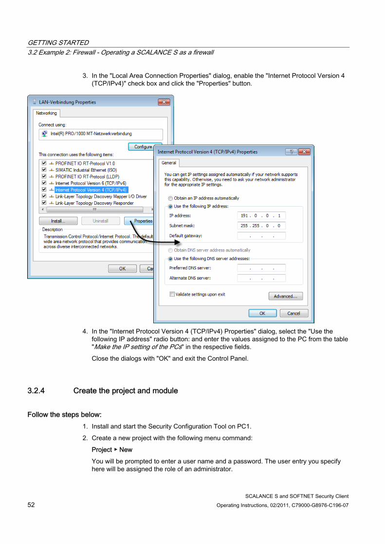
GETTING STARTED 3.2 Example 2: Firewall - Operating a SCALANCE S as a firewall
SCALANCE S and SOFTNET Security Client 52 Operating Instructions, 02/2011, C79000-G8976-C196-07
3. In the "Local Area Connection Properties" dialog, enable the "Internet Protocol Version 4 (TCP/IPv4)" check box and click the "Properties" button.
4. In the "Internet Protocol Version 4 (TCP/IPv4) Properties" dialog, select the "Use the
following IP address" radio button: and enter the values assigned to the PC from the table "Make the IP setting of the PCs" in the respective fields.
Close the dialogs with "OK" and exit the Control Panel.
3.2.4 Create the project and module
Follow the steps below: 1. Install and start the Security Configuration Tool on PC1.
2. Create a new project with the following menu command:
Project ▶ New
You will be prompted to enter a user name and a password. The user entry you specify here will be assigned the role of an administrator.

GETTING STARTED 3.2 Example 2: Firewall - Operating a SCALANCE S as a firewall
SCALANCE S and SOFTNET Security Client Operating Instructions, 02/2011, C79000-G8976-C196-07 53
3. Enter a user name and a password and confirm your entries to create a new project.
4. The "Selection of the module or software configuration" dialog is automatically displayed.
Now configure your product type, the module and the firmware release.

GETTING STARTED 3.2 Example 2: Firewall - Operating a SCALANCE S as a firewall
SCALANCE S and SOFTNET Security Client 54 Operating Instructions, 02/2011, C79000-G8976-C196-07
5. In the box for the "MAC Address" in the "Configuration" area, enter the MAC address printed on the module housing in the specified format. You will find this address on the front of the SCALANCE S module (see figure).
6. Enter the external IP address also in the required format (191.0.0.200) and the external
subnet mask (255.255.0.0) and confirm the dialog with "OK". Your module will then be included in the list of configured modules.
3.2.5 Configure the firewall In standard mode, the firewall can be set simply with predefined sets of rules. You can activate these sets of rules by clicking on them.
Follow the steps below: 1. Select the "Module1" row in the content area.
2. Select the following menu command:
Edit ▶ Properties…
3. Select the "Firewall" tab in the displayed dialog.
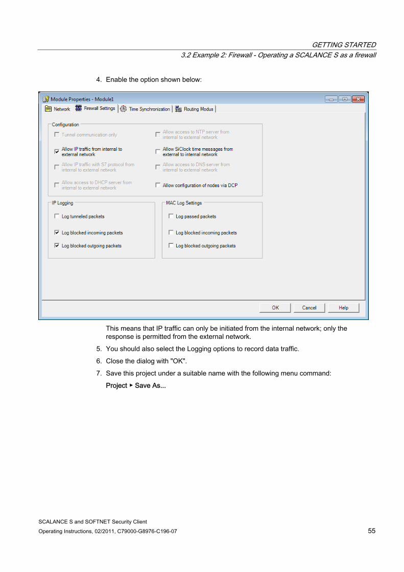
GETTING STARTED 3.2 Example 2: Firewall - Operating a SCALANCE S as a firewall
SCALANCE S and SOFTNET Security Client Operating Instructions, 02/2011, C79000-G8976-C196-07 55
4. Enable the option shown below:
This means that IP traffic can only be initiated from the internal network; only the response is permitted from the external network.
5. You should also select the Logging options to record data traffic.
6. Close the dialog with "OK".
7. Save this project under a suitable name with the following menu command:
Project ▶ Save As...

GETTING STARTED 3.2 Example 2: Firewall - Operating a SCALANCE S as a firewall
SCALANCE S and SOFTNET Security Client 56 Operating Instructions, 02/2011, C79000-G8976-C196-07
3.2.6 Download the configuration to the SCALANCE S module
Follow the steps below: 1. Select the module in the content area.
2. Select the following menu command:
Transfer ▶ To Module…
3. Start the download with the "Start" button.
If the download was completed free of errors, the SCALANCE S module is restarted automatically and the new configuration activated.
Result: SCALANCE S in productive operation The SCALANCE S is now in productive operation. This mode is indicated by the Fault LED being lit green.
Commissioning the configuration is now complete and the SCALANCE S is now protecting the internal network (PC2) with the firewall according to the configured rule: "Allow IP traffic from internal to external network".
3.2.7 Test the firewall function (ping test)
How can you test the configured function? The function can be tested as described below using a ping command.
As an alternative, you can also use other communication programs to test the configuration.
NOTICE In Windows, the firewall can be set so that as default the PING commands do not pass through. If necessary, you will need to enable the ICMP services of the type Request and Response.

GETTING STARTED 3.2 Example 2: Firewall - Operating a SCALANCE S as a firewall
SCALANCE S and SOFTNET Security Client Operating Instructions, 02/2011, C79000-G8976-C196-07 57
Test phase 1 Now test the function of the firewall configuration, first with allowed outgoing IP data traffic as follows:
1. Open the following menu command from the taskbar Start menu on PC2:
Start ▶ All Programs ▶ Accessories ▶ Command Prompt
2. Enter the Ping command from PC2 to PC1 (IP address 191.0.0.1)
In the command line of the "Command Prompt" window, enter the following command:
ping 191.0.0.1
You will then receive the following message: (positive reply from PC1).
Result If the IP packets have reached PC1, the "Ping statistics for 191.0.01" display the following:
● Sent = 4
● Received = 4
● Lost = 0 (0% loss)
Due to the configuration, the ping packets can pass from the internal network to the external network. The PC in the external network has replied to the ping packets. Due to the "stateful inspection" function of the firewall, the reply packets arriving from the external network are automatically passed into the internal network.
Test phase 2 Now test the function of the firewall configuration with blocked outgoing IP data traffic as follows:
1. Now reopen the firewall dialog as described above.
2. Deselect the "Allow IP traffic from internal to external network" box in the "Firewall Settings" tab.
Close the dialog with "OK".

GETTING STARTED 3.2 Example 2: Firewall - Operating a SCALANCE S as a firewall
SCALANCE S and SOFTNET Security Client 58 Operating Instructions, 02/2011, C79000-G8976-C196-07
3. Now download the modified configuration to the SCALANCE S module again.
4. If the downloading is completed free of errors, enter the same ping command again (ping 191.0.0.1) in the Command Prompt window of PC2 as described above.
You will then receive the following message: (no reply from PC1).
Result The IP packets from PC2 now cannot reach PC1 since the data traffic from the "internal network" (PC2) to the "external network" (PC1) is not permitted.
This is shown in the "Ping statistics for 191.0.0.1" as follows:
● Sent = 4
● Received = 0
● Lost = 4 (100% loss)
3.2.8 Log firewall data traffic On the SCALANCE S, the local logging of system, audit and packet filter events is enabled as default.
While working through this example, you also activated the logging options when configuring the firewall.
You can therefore display the recorded events in online mode.
Follow the steps below: 1. Now change to online mode on PC1 in the Security Configuration Tool with the following
menu command:
View ▶ Online
2. Select the following menu command:
Edit ▶ Online Diagnostics...
3. Select the "Packet Filter Log" tab.

GETTING STARTED 3.3 Example 3: Firewall and router - Operating a SCALANCE S as a firewall and router
SCALANCE S and SOFTNET Security Client Operating Instructions, 02/2011, C79000-G8976-C196-07 59
4. Click the "Start Reading" button.
5. Acknowledge the displayed dialog with OK.
Result: The log entries are read from the SCALANCE S and displayed here.
3.3 Example 3: Firewall and router - Operating a SCALANCE S as a firewall and router
3.3.1 Overview In this example, you configure the NAT router mode. You configure in the "advanced mode" configuration view.
With the configuration introduced here, you have the situation that all the packets sent from the internal subnet to the PC1 node in the external network are allowed to pass the firewall. The packets are forwarded to the outside with an IP address transformed to the IP address of the SCALANCE S and with a dynamically assigned port number.
Only the replies to these packets is allowed to pass from the external network.
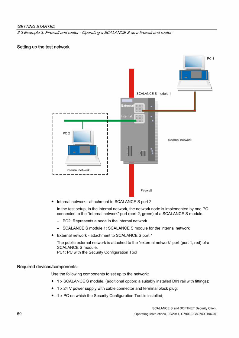
GETTING STARTED 3.3 Example 3: Firewall and router - Operating a SCALANCE S as a firewall and router
SCALANCE S and SOFTNET Security Client 60 Operating Instructions, 02/2011, C79000-G8976-C196-07
Setting up the test network
External
Internal
● Internal network - attachment to SCALANCE S port 2
In the test setup, in the internal network, the network node is implemented by one PC connected to the "internal network" port (port 2, green) of a SCALANCE S module.
– PC2: Represents a node in the internal network
– SCALANCE S module 1: SCALANCE S module for the internal network
● External network - attachment to SCALANCE S port 1
The public external network is attached to the "external network" port (port 1, red) of a SCALANCE S module. PC1: PC with the Security Configuration Tool
Required devices/components: Use the following components to set up to the network:
● 1 x SCALANCE S module, (additional option: a suitably installed DIN rail with fittings);
● 1 x 24 V power supply with cable connector and terminal block plug;
● 1 x PC on which the Security Configuration Tool is installed;
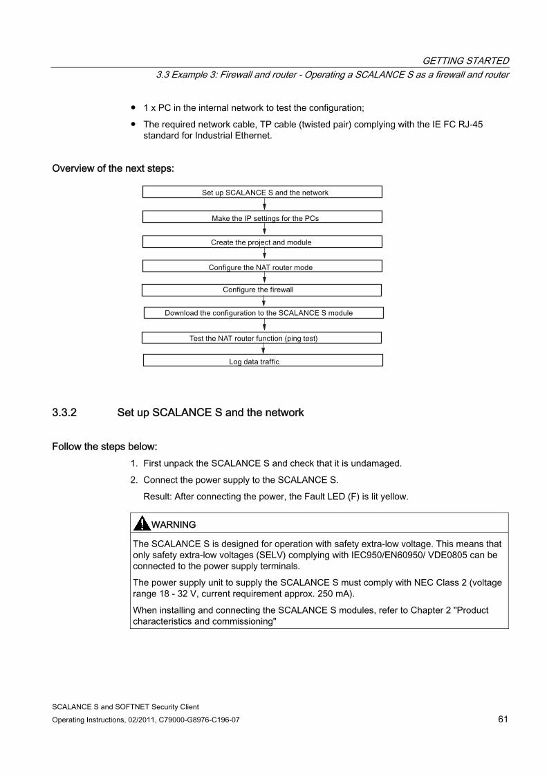
GETTING STARTED 3.3 Example 3: Firewall and router - Operating a SCALANCE S as a firewall and router
SCALANCE S and SOFTNET Security Client Operating Instructions, 02/2011, C79000-G8976-C196-07 61
● 1 x PC in the internal network to test the configuration;
● The required network cable, TP cable (twisted pair) complying with the IE FC RJ-45 standard for Industrial Ethernet.
Overview of the next steps:
3.3.2 Set up SCALANCE S and the network
Follow the steps below: 1. First unpack the SCALANCE S and check that it is undamaged.
2. Connect the power supply to the SCALANCE S.
Result: After connecting the power, the Fault LED (F) is lit yellow.
WARNING The SCALANCE S is designed for operation with safety extra-low voltage. This means that only safety extra-low voltages (SELV) complying with IEC950/EN60950/ VDE0805 can be connected to the power supply terminals.
The power supply unit to supply the SCALANCE S must comply with NEC Class 2 (voltage range 18 - 32 V, current requirement approx. 250 mA).
When installing and connecting the SCALANCE S modules, refer to Chapter 2 "Product characteristics and commissioning"
GETTING STARTED 3.3 Example 3: Firewall and router - Operating a SCALANCE S as a firewall and router
SCALANCE S and SOFTNET Security Client 62 Operating Instructions, 02/2011, C79000-G8976-C196-07
3. Now establish the physical network connections by plugging the network cable connectors into the ports being used (RJ-45 jacks):
– Connect PC2 with port 2 of module 1.
– Connect PC1 with port 1 of module 1.
4. Now turn on the PCs.
NOTICE
The Ethernet attachments at port 1 and port 2 are handled differently by the SCALANCE S and must not be swapped over when connecting to the communication network: Port 1 - External Network
Upper RJ-45 jack, marked red = unprotected network area; Port 2 - Internal Network
Lower RJ-45 jack, marked green = network protected by SCALANCE S;
If the ports are swapped over, the device loses its protective function.
3.3.3 Make the IP settings for the PCs For the test, the PCs should be given the following IP address settings:
PC IP address Subnet mask Default gateway PC1 192.168.10.100 255.255.255.0 192.168.10.1 PC2 172.10.10.100 255.255.255.0 172.10.10.1
For standard gateway, you specify the IP addresses that will be assigned to the SCALANCE S module for the internal and external interface in the subsequent project engineering:
● PC1 uses the external interface.
● PC2 uses the internal interface.
Follow the steps below for PC1 and PC2: 1. On the relevant PC, open the Control Panel with the following menu command:
Start ▶ Control Panel
2. Click "Network and Sharing Center" and select the "Change Adapter Settings" option in the navigation menu on the left.
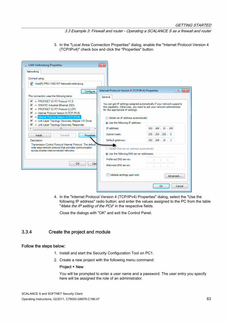
GETTING STARTED 3.3 Example 3: Firewall and router - Operating a SCALANCE S as a firewall and router
SCALANCE S and SOFTNET Security Client Operating Instructions, 02/2011, C79000-G8976-C196-07 63
3. In the "Local Area Connection Properties" dialog, enable the "Internet Protocol Version 4 (TCP/IPv4)" check box and click the "Properties" button.
4. In the "Internet Protocol Version 4 (TCP/IPv4) Properties" dialog, select the "Use the
following IP address" radio button: and enter the values assigned to the PC from the table "Make the IP setting of the PCs" in the respective fields.
Close the dialogs with "OK" and exit the Control Panel.
3.3.4 Create the project and module
Follow the steps below: 1. Install and start the Security Configuration Tool on PC1.
2. Create a new project with the following menu command:
Project ▶ New
You will be prompted to enter a user name and a password. The user entry you specify here will be assigned the role of an administrator.

GETTING STARTED 3.3 Example 3: Firewall and router - Operating a SCALANCE S as a firewall and router
SCALANCE S and SOFTNET Security Client 64 Operating Instructions, 02/2011, C79000-G8976-C196-07
3. Enter a user name and a password and confirm your entries to create a new project.
4. The "Selection of the module or software configuration" dialog is automatically displayed. Now configure your product type, the module and the firmware release.
5. In the box for the "MAC address" in the "Configuration" area, enter the MAC address printed on the module housing in the specified format.
You will find this address on the front panel of the SCALANCE S module (see figure).
6. Enter the external IP address also in the required format (192.168.10.1) and the external
subnet mask (255.255.255.0) and confirm the dialog with "OK". Your module will then be included in the list of configured modules.

GETTING STARTED 3.3 Example 3: Firewall and router - Operating a SCALANCE S as a firewall and router
SCALANCE S and SOFTNET Security Client Operating Instructions, 02/2011, C79000-G8976-C196-07 65
3.3.5 Configuring the NAT router mode The common use case in which all internal nodes send packets to the external network and keep their IP addresses hidden by the NAT functionality is preconditioned on the SCALANCE S. As shown below, you can enable this behavior simply by clicking in routing mode.
Enabling router mode - follow the steps below: 1. First change the configuration view to advanced mode.
2. Select the following menu command:
View ▶ Advanced Mode
3. Now double-click on the SCALANCE S module. This opens the dialog for setting the module properties.
4. Select the "Routing Mode" tab in the displayed dialog.
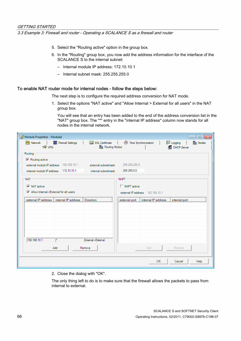
GETTING STARTED 3.3 Example 3: Firewall and router - Operating a SCALANCE S as a firewall and router
SCALANCE S and SOFTNET Security Client 66 Operating Instructions, 02/2011, C79000-G8976-C196-07
5. Select the "Routing active" option in the group box.
6. In the "Routing" group box, you now add the address information for the interface of the SCALANCE S to the internal subnet:
– Internal module IP address: 172.10.10.1
– Internal subnet mask: 255.255.255.0
To enable NAT router mode for internal nodes - follow the steps below: The next step is to configure the required address conversion for NAT mode.
1. Select the options "NAT active" and "Allow Internal > External for all users" in the NAT group box.
You will see that an entry has been added to the end of the address conversion list in the "NAT" group box. The "*" entry in the "internal IP address" column now stands for all nodes in the internal network.
2. Close the dialog with "OK".
The only thing left to do is to make sure that the firewall allows the packets to pass from internal to external.

GETTING STARTED 3.3 Example 3: Firewall and router - Operating a SCALANCE S as a firewall and router
SCALANCE S and SOFTNET Security Client Operating Instructions, 02/2011, C79000-G8976-C196-07 67
3.3.6 Configure the firewall You now need to define a set of rules that allows the traffic from the internal node (PC2) to the node in the external network (PC1).
The example also shows you how to define a global set of rules and assign it to a module. If you then configure additional modules in the same project, you then simply need to assign the defined set of rules to the other modules using drag and drop. This, of course, assumes that the same rules apply.
To define a global rule set, follow the steps below: 1. Expand the "Global FW Rulesets" object and select "FW IP Rulesets".
2. Select the following menu command with the right mouse button:
Insert > Firewall rule set
3. Enter a rule set in the dialog as shown below:

GETTING STARTED 3.3 Example 3: Firewall and router - Operating a SCALANCE S as a firewall and router
SCALANCE S and SOFTNET Security Client 68 Operating Instructions, 02/2011, C79000-G8976-C196-07
4. Click in the "Log" column in the row for the new rule set. This enables the packet filter logging option. Packets to which the defined rule is applied are then logged.
You will use this log in the example shown here in the final test of the configuration.
5. Close the dialog with "OK".
To assign a global rule set, follow the steps below: 1. Select the "Module1" object in the navigation area and holding down the left mouse
button, drag it to the newly created global firewall rule set.

GETTING STARTED 3.3 Example 3: Firewall and router - Operating a SCALANCE S as a firewall and router
SCALANCE S and SOFTNET Security Client Operating Instructions, 02/2011, C79000-G8976-C196-07 69
2. You can check the assignment by reopening the dialog for setting the module properties and selecting the "Firewall" tab.
You will see that the global firewall rule was saved there.
3. If you click the "Expand Rulesets" button, you can view the rule set in detail.
This completes offline configuration.

GETTING STARTED 3.3 Example 3: Firewall and router - Operating a SCALANCE S as a firewall and router
SCALANCE S and SOFTNET Security Client 70 Operating Instructions, 02/2011, C79000-G8976-C196-07
3.3.7 Download the configuration to the SCALANCE S module
Follow the steps below: 1. Select the module in the content area.
2. Select the following menu command:
Transfer ▶ To Module…
3. Start the download with the "Start" button.
If the download was completed free of errors, the SCALANCE S module is restarted automatically and the new configuration activated.
Result: SCALANCE S in productive operation The SCALANCE S is now in productive operation. This mode is indicated by the Fault LED being lit green.
Commissioning the configuration is now complete and the SCALANCE S is now protecting the internal network (PC2) with the firewall according to the configured rule: "Allow outgoing IP traffic" from the internal to the external network.
3.3.8 Test the NAT router function (ping test)
How can you test the configured function? The function can be tested as described below using a ping command. To be able to recognize the effects of the NAT router mode, use the packet filter logging on the firewall interface.
A reminder: In the definition of the global firewall rule, you have already enabled the packet filter logging option.

GETTING STARTED 3.3 Example 3: Firewall and router - Operating a SCALANCE S as a firewall and router
SCALANCE S and SOFTNET Security Client Operating Instructions, 02/2011, C79000-G8976-C196-07 71
Note on the ping command: As an alternative, you can also use other communication programs to test the configuration.
NOTICE In Windows, the firewall can be set so that as default the PING commands do not pass through. If necessary, you will need to enable the ICMP services of the type Request and Response.
Test part 1 - sending the ping command Now test the function of the NAT router mode in IP data traffic from internal to external as follows:
1. Open the following menu command from the taskbar Start menu on PC2:
Start ▶ All Programs ▶ Accessories ▶ Command Prompt
2. Enter the ping command from PC2 to PC1 (IP address 192.168.10.100)
In the command line of the "Command Prompt" window, enter the following command:
ping 192.168.10.100
You will then receive the following message: (positive reply from PC1).
Test part 2 - evaluating the result 1. Now change to the online mode of the Security Configuration Tool. Select the following
menu command:
View ▶ Online
2. Select the module you want to edit and then select the following menu command to open the online dialog
Edit ▶ Online Diagnostics...
Select the "Packet Filter Log" tab.
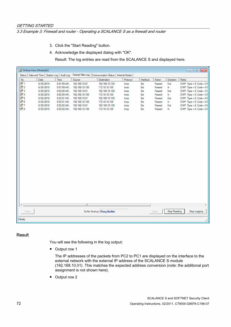
GETTING STARTED 3.3 Example 3: Firewall and router - Operating a SCALANCE S as a firewall and router
SCALANCE S and SOFTNET Security Client 72 Operating Instructions, 02/2011, C79000-G8976-C196-07
3. Click the "Start Reading" button.
4. Acknowledge the displayed dialog with "OK".
Result: The log entries are read from the SCALANCE S and displayed here.
Result You will see the following in the log output:
● Output row 1
The IP addresses of the packets from PC2 to PC1 are displayed on the interface to the external network with the external IP address of the SCALANCE S module (192.168.10.01). This matches the expected address conversion (note: the additional port assignment is not shown here).
● Output row 2
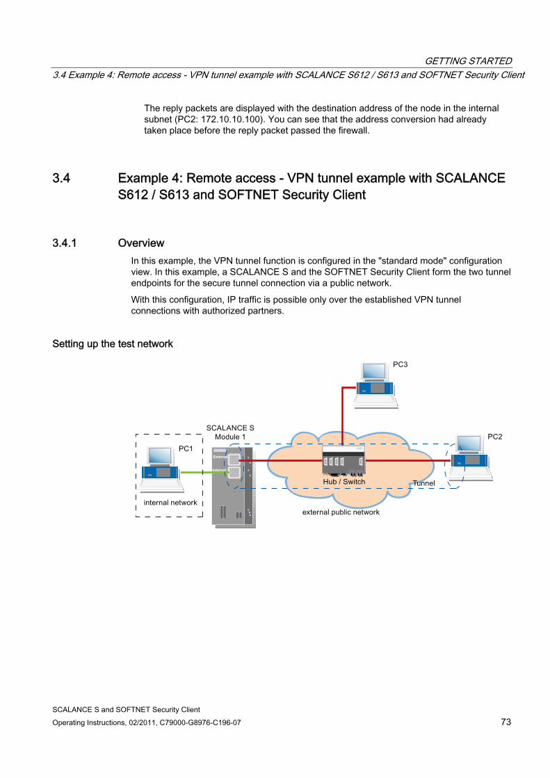
GETTING STARTED 3.4 Example 4: Remote access - VPN tunnel example with SCALANCE S612 / S613 and SOFTNET Security Client
SCALANCE S and SOFTNET Security Client Operating Instructions, 02/2011, C79000-G8976-C196-07 73
The reply packets are displayed with the destination address of the node in the internal subnet (PC2: 172.10.10.100). You can see that the address conversion had already taken place before the reply packet passed the firewall.
3.4 Example 4: Remote access - VPN tunnel example with SCALANCE S612 / S613 and SOFTNET Security Client
3.4.1 Overview In this example, the VPN tunnel function is configured in the "standard mode" configuration view. In this example, a SCALANCE S and the SOFTNET Security Client form the two tunnel endpoints for the secure tunnel connection via a public network.
With this configuration, IP traffic is possible only over the established VPN tunnel connections with authorized partners.
Setting up the test network
External
Internal
Hub / Switch
PC3
PC2PC1
GETTING STARTED 3.4 Example 4: Remote access - VPN tunnel example with SCALANCE S612 / S613 and SOFTNET Security Client
SCALANCE S and SOFTNET Security Client 74 Operating Instructions, 02/2011, C79000-G8976-C196-07
● Internal network - attachment to SCALANCE S port 2 ("internal network" port)
In the test setup, in the internal network, a network node is implemented by one PC connected to the "internal network" port (port 2, green) of a SCALANCE S module.
– PC1: Represents a node in the internal network
– SCALANCE S module 1: SCALANCE S module for protection of the internal network
● External, public network - attachment to SCALANCE S port 1 ("external network" port)
The external public network is attached to the "external network" port (port 1, red) of a SCALANCE S module.
– PC2: PC with Security Configuration Tool configuration software and the SOFTNET Security Client software for secure VPN access to the internal network
– PC3: Test PC for test phase 2
Note
In the example, a local area network is used as a substitute for an external public WAN to illustrate the principles of the functionality.
Explanations relating to the use of a WAN are provided where necessary.
Required devices/components: Use the following components to set up to the network:
● 1 x SCALANCE S module, (optional: a suitably installed DIN rail with fittings);
● 1 x 24 V power supply with cable connector and terminal block plug;
● 1 x PC on which the "Security Configuration Tool" and VPN client "SOFTNET Security Client" are installed;
● 1 x PC in the internal network to test the configuration;
● 1 x PC in the external network to test the configuration;
● 1 x network hub or switch to set up the network connections with the SCALANCE S module and the PCs;
● The required network cable, TP cable (twisted pair) complying with the IE FC RJ-45 standard for Industrial Ethernet.
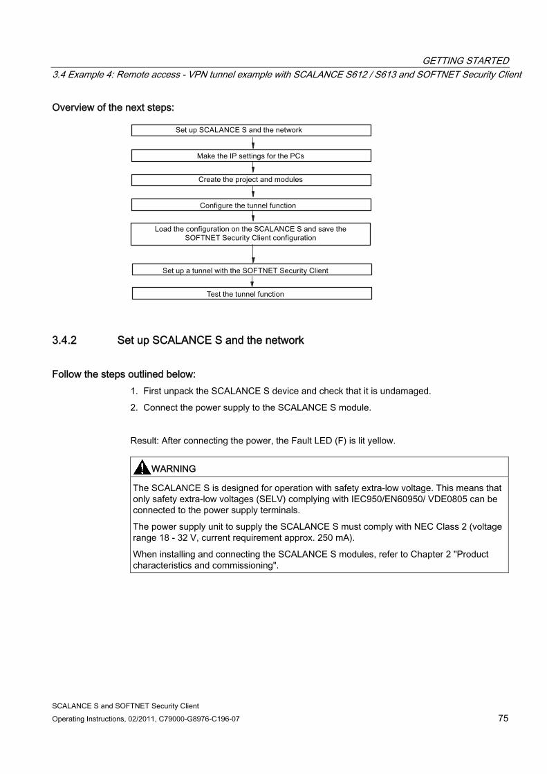
GETTING STARTED 3.4 Example 4: Remote access - VPN tunnel example with SCALANCE S612 / S613 and SOFTNET Security Client
SCALANCE S and SOFTNET Security Client Operating Instructions, 02/2011, C79000-G8976-C196-07 75
Overview of the next steps:
3.4.2 Set up SCALANCE S and the network
Follow the steps outlined below: 1. First unpack the SCALANCE S device and check that it is undamaged.
2. Connect the power supply to the SCALANCE S module.
Result: After connecting the power, the Fault LED (F) is lit yellow.
WARNING The SCALANCE S is designed for operation with safety extra-low voltage. This means that only safety extra-low voltages (SELV) complying with IEC950/EN60950/ VDE0805 can be connected to the power supply terminals.
The power supply unit to supply the SCALANCE S must comply with NEC Class 2 (voltage range 18 - 32 V, current requirement approx. 250 mA).
When installing and connecting the SCALANCE S modules, refer to Chapter 2 "Product characteristics and commissioning".

GETTING STARTED 3.4 Example 4: Remote access - VPN tunnel example with SCALANCE S612 / S613 and SOFTNET Security Client
SCALANCE S and SOFTNET Security Client 76 Operating Instructions, 02/2011, C79000-G8976-C196-07
1. Now establish the physical network connections by plugging the network cable connectors into the ports being used (RJ-45 jacks):
– Connect PC1 with port 2 of module 1.
– Connect port 1 of module 1 with the hub/switch.
– Connect PC2 and PC3 to the hub/switch as well.
2. Now turn on the PCs.
Note
To use a WAN as an external public network, the connections to the hub/switch must be replaced by the connections to the WAN (Internet access).
NOTICE
The Ethernet attachments at port 1 and port 2 are handled differently by the SCALANCE S and must not be swapped over when connecting to the communication network: Port 1 - "external network"
Upper RJ-45 jack, marked red = unprotected network area; Port 2 - "internal network"
Lower RJ-45 jack, marked green = network protected by SCALANCE S;
If the ports are swapped over, the device loses its protective function.
3.4.3 Make the IP settings for the PCs For the test, the PCs should be given the following IP address settings.
PC IP address Subnet mask Default gateway PC1 192.168.0.1 255.255.255.0 192.168.0.201 PC2 191.0.0.2 255.255.0.0 191.0.0.201 PC3 191.0.0.3 255.255.0.0 191.0.0.201
For standard gateway, you specify the IP addresses that will be assigned to the SCALANCE S module for the internal and external interface in the subsequent project engineering:
● PC1 uses the internal interface.
● PC2 and PC3 use the external interface.
Note
To use a WAN as an external public network, the relevant IP settings for the connection to the WAN (Internet) must be made on PC2 and PC3.
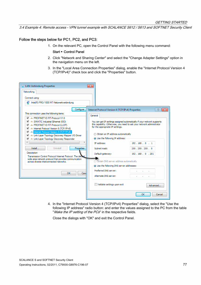
GETTING STARTED 3.4 Example 4: Remote access - VPN tunnel example with SCALANCE S612 / S613 and SOFTNET Security Client
SCALANCE S and SOFTNET Security Client Operating Instructions, 02/2011, C79000-G8976-C196-07 77
Follow the steps below for PC1, PC2, and PC3: 1. On the relevant PC, open the Control Panel with the following menu command:
Start ► Control Panel
2. Click "Network and Sharing Center" and select the "Change Adapter Settings" option in the navigation menu on the left.
3. In the "Local Area Connection Properties" dialog, enable the "Internet Protocol Version 4 (TCP/IPv4)" check box and click the "Properties" button.
4. In the "Internet Protocol Version 4 (TCP/IPv4) Properties" dialog, select the "Use the
following IP address" radio button: and enter the values assigned to the PC from the table "Make the IP setting of the PCs" in the respective fields.
Close the dialogs with "OK" and exit the Control Panel.

GETTING STARTED 3.4 Example 4: Remote access - VPN tunnel example with SCALANCE S612 / S613 and SOFTNET Security Client
SCALANCE S and SOFTNET Security Client 78 Operating Instructions, 02/2011, C79000-G8976-C196-07
3.4.4 Create the project and modules
Follow the steps outlined below: 1. Start the Security Configuration Tool on PC2.
2. Create a new project with the following menu command:
Project ▶ New
You will be prompted to enter a user name and a password. The user entry you specify here will automatically be assigned the role of an administrator.
3. Enter a user name and a password and confirm your entries to create a new project.
4. The "Selection of the module or software configuration" dialog is automatically displayed. Now configure your product type, the module and the firmware release and close the dialog with "OK".
5. Create a second module with the following menu command:
Insert ► Module
Now configure the product type "SOFTNET Configuration", the "SOFTNET Security Client" module and the firmware release of your SOFTNET Security Client version and then close the dialog with "OK".
This module is automatically given a name according to the defaults for the project.
6. In the navigation area, click on "All Modules" and then on the row with "Module1" in the content area.
7. Now click on the "MAC Address" column and enter the MAC address in the specified format.
You will find this address on the front panel of the SCALANCE S module (see figure).

GETTING STARTED 3.4 Example 4: Remote access - VPN tunnel example with SCALANCE S612 / S613 and SOFTNET Security Client
SCALANCE S and SOFTNET Security Client Operating Instructions, 02/2011, C79000-G8976-C196-07 79
8. Now click on the "IP Address ext." column and enter the IP address in the specified format and adapt the subnet mask accordingly. For module 1: IP address: 191.0.0.201, subnet mask: 255.255.0.0
Note
To use a WAN as an external public network, enter the static IP address you received from your provider as the "IP Address ext." via which the SCALANCE S module will then be accessible in the WAN (Internet).
Before the SCALANCE S module can send packets in the WAN (Internet), you will need to enter your DSL router as the "Default Router".
If you use a DSL router as Internet gateway, the following ports (at least) must be forwarded on it:
• Port 500 (ISAKMP)
• Port 4500 (NAT-T)
For configuration downloads (not through an active tunneL), port 443 (HTTPS) must also be forwarded.
9. Now open the properties menu of "Module1" by right-clicking on the entry and selecting the "Properties..." menu command.
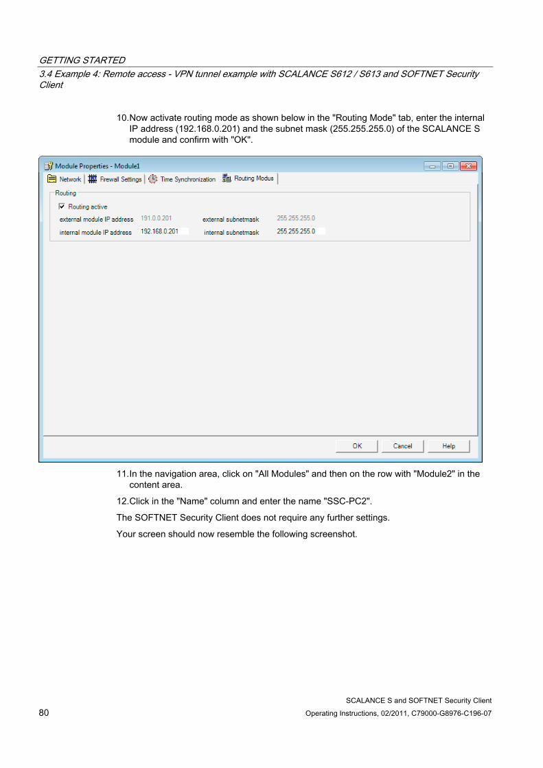
GETTING STARTED 3.4 Example 4: Remote access - VPN tunnel example with SCALANCE S612 / S613 and SOFTNET Security Client
SCALANCE S and SOFTNET Security Client 80 Operating Instructions, 02/2011, C79000-G8976-C196-07
10. Now activate routing mode as shown below in the "Routing Mode" tab, enter the internal IP address (192.168.0.201) and the subnet mask (255.255.255.0) of the SCALANCE S module and confirm with "OK".
11. In the navigation area, click on "All Modules" and then on the row with "Module2" in the
content area.
12. Click in the "Name" column and enter the name "SSC-PC2".
The SOFTNET Security Client does not require any further settings.
Your screen should now resemble the following screenshot.

GETTING STARTED 3.4 Example 4: Remote access - VPN tunnel example with SCALANCE S612 / S613 and SOFTNET Security Client
SCALANCE S and SOFTNET Security Client Operating Instructions, 02/2011, C79000-G8976-C196-07 81
3.4.5 Configuring a tunnel connection A SCALANCE S and the SOFTNET Security Client can establish one IPsec tunnel for secure communication when they are assigned to the same group in the project.
Follow the steps outlined below: 1. Select "All Groups" in the navigation area and create a new group with the following
menu command:
Insert ► Group
This group is automatically given the name "Group1".
2. Select the SCALANCE S module "Module1" in the content area and drag it to "Group1" in
the navigation area.
The module is now assigned to this group (is a member of the group).
The color of the key symbol of the module icon changes from gray to blue.
3. Select the SOFTNET Security Client in the content area and drag it to "Group1" in the navigation area.
The module is now also assigned to this group.
4. Save this project under a suitable name with the following menu command:
Project ► Save As...
The configuration of the tunnel connection is now complete.

GETTING STARTED 3.4 Example 4: Remote access - VPN tunnel example with SCALANCE S612 / S613 and SOFTNET Security Client
SCALANCE S and SOFTNET Security Client 82 Operating Instructions, 02/2011, C79000-G8976-C196-07
3.4.6 Loading the configuration on the SCALANCE S and saving the SOFTNET Security Client configuration
Follow the steps outlined below: 1. Using the menu command below, open the following dialog:
Transfer ► To All Modules...
2. Start the download with the "Start" button.
3. Save the configuration file "projectname.SSC-PC2.dat" in your project folder and assign a password for the private key of the certificate.
If the download was completed free of errors, the SCALANCE S is restarted automatically and the new configuration activated.
Result: SCALANCE S in productive operation The SCALANCE S is now in productive operation. This mode is indicated by the Fault LED being lit green.
The configuration has now been commissioned and the SCALANCE S module and the SOFTNET Security Client can now establish a communication tunnel over which network nodes from the two internal networks can communicate securely with PC2 from within the internal network.
Note
To use a WAN as an external public network, you cannot configure a SCALANCE S module with the factory settings via the WAN. In this case, configure the SCALANCE S module from within the internal network.
GETTING STARTED 3.4 Example 4: Remote access - VPN tunnel example with SCALANCE S612 / S613 and SOFTNET Security Client
SCALANCE S and SOFTNET Security Client Operating Instructions, 02/2011, C79000-G8976-C196-07 83
3.4.7 Set up a tunnel with the SOFTNET Security Client
Follow the steps outlined below: 1. Start the SOFTNET Security Client on PC2.
2. Click the "Load Configuration" button, change to your project folder and load the "Projectname.SSC-PC2.dat" configuration file.
3. Enter the password for the private key of the certificate and confirm with "Next".
4. Confirm the "Enable all statically configured nodes?" dialog with "Yes".
5. Click the "Tunnel Overview" button.
Result: Active tunnel connection The tunnel between SCALANCE S and SOFTNET Security Client was established. This status is indicated by the green circle beside the "Module1" entry.
In the log console of the tunnel overview of the SOFTNET Security Client, you can see several messages from your system indicating what happened during the connection attempt and whether or not a policy for the communication connection was created.

GETTING STARTED 3.4 Example 4: Remote access - VPN tunnel example with SCALANCE S612 / S613 and SOFTNET Security Client
SCALANCE S and SOFTNET Security Client 84 Operating Instructions, 02/2011, C79000-G8976-C196-07
The configuration has now been commissioned and the SCALANCE S module and the SOFTNET Security Client have established a communication tunnel over which network nodes can communicate securely with PC2 from within the internal network.
3.4.8 Test the tunnel function (ping test)
How can you test the configured function? The function can be tested as described below using a ping command.
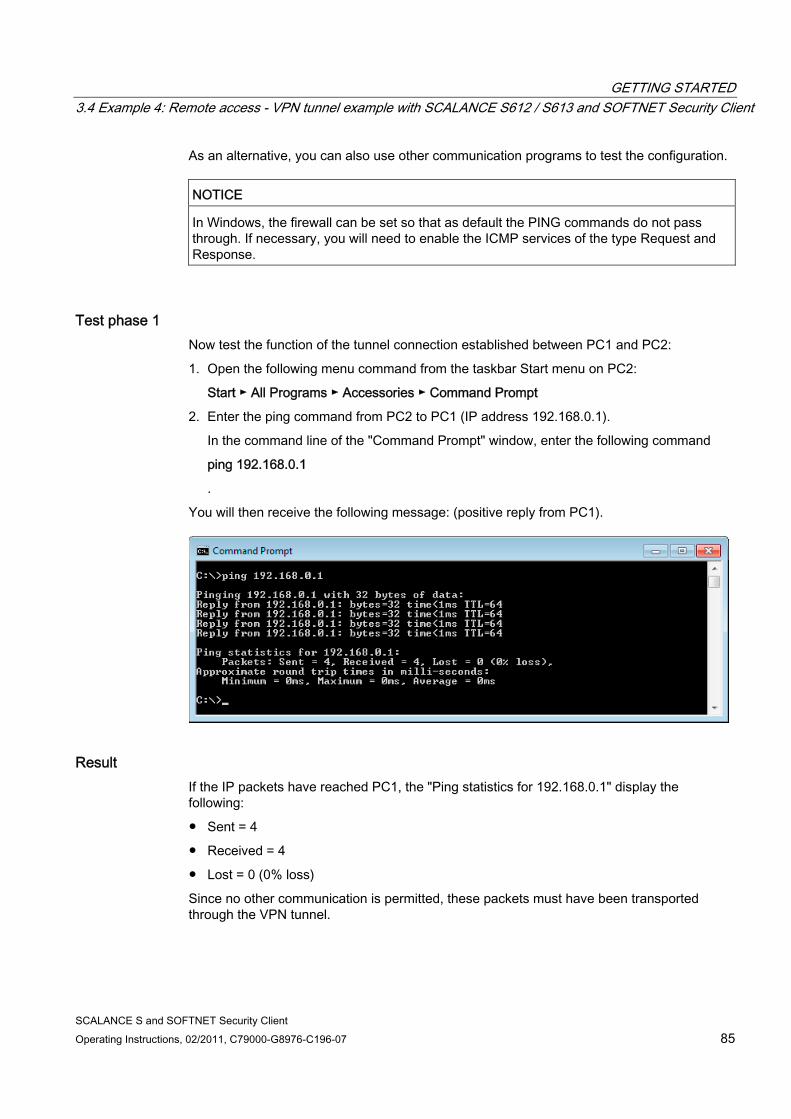
GETTING STARTED 3.4 Example 4: Remote access - VPN tunnel example with SCALANCE S612 / S613 and SOFTNET Security Client
SCALANCE S and SOFTNET Security Client Operating Instructions, 02/2011, C79000-G8976-C196-07 85
As an alternative, you can also use other communication programs to test the configuration.
NOTICE In Windows, the firewall can be set so that as default the PING commands do not pass through. If necessary, you will need to enable the ICMP services of the type Request and Response.
Test phase 1 Now test the function of the tunnel connection established between PC1 and PC2:
1. Open the following menu command from the taskbar Start menu on PC2:
Start ► All Programs ► Accessories ► Command Prompt
2. Enter the ping command from PC2 to PC1 (IP address 192.168.0.1).
In the command line of the "Command Prompt" window, enter the following command
ping 192.168.0.1
.
You will then receive the following message: (positive reply from PC1).
Result If the IP packets have reached PC1, the "Ping statistics for 192.168.0.1" display the following:
● Sent = 4
● Received = 4
● Lost = 0 (0% loss)
Since no other communication is permitted, these packets must have been transported through the VPN tunnel.

GETTING STARTED 3.5 Example 5: Remote access - VPN tunnel example with MD741-1 and SOFTNET Security Client
SCALANCE S and SOFTNET Security Client 86 Operating Instructions, 02/2011, C79000-G8976-C196-07
Test phase 2 Now repeat the test by sending a ping command from PC3.
1. Open the following menu command from the taskbar Start menu on PC3:
Start ► All Programs ► Accessories ► Command Prompt
2. Send the same ping command (ping 192.168.0.1) in the Command Prompt window of PC3.
You will then receive the following message: (no reply from PC1).
Result The IP frames from PC3 cannot reach PC1 since neither tunnel communication between these two devices is configured nor is normal IP data traffic permitted.
This is shown in the "Ping statistics" for 192.168.0.1 as follows:
● Sent = 4
● Received = 0
● Lost = 4 (100% loss)
3.5 Example 5: Remote access - VPN tunnel example with MD741-1 and SOFTNET Security Client
3.5.1 Overview In this example, the VPN tunnel function is configured in the "advanced mode" project engineering view. An MD741-1 and the SOFTNET Security Client form the two tunnel endpoints for the secure tunnel connection via a public network.
GETTING STARTED 3.5 Example 5: Remote access - VPN tunnel example with MD741-1 and SOFTNET Security Client
SCALANCE S and SOFTNET Security Client Operating Instructions, 02/2011, C79000-G8976-C196-07 87
With this configuration, IP traffic is possible only over the established VPN tunnel connection with authorized partners.
Note
To configure this example, you need a public, fixed IP address from your provider (mobile wireless provider) for the SIM card of the MD741-1 that can also be reached from the Internet.
(As an alternative, it is also possible to work with a DynDNS address for the MD741-1.)
Setting up the test network:
● Internal network - attachment to MD741-1 port X2 ("internal network")
In the test setup, in the internal network, a network node is implemented by a PC connected to the "internal network" port (port X2) of an MD741-1 module.
– PC1: Represents a node in the internal network
– MD741-1: MD741-1 module for protection of the internal network
External, public network - connection via MD741-1 antenna ("external network")
The external, public network must be a GSM or mobile wireless network that can be selected by the user at the provider (mobile wireless provider) and is reached via the antenna of the MD741-1.
– PC2: PC with Security Configuration Tool configuration software and the SOFTNET Security Client software for secure VPN access to the internal network
Required devices/components: Use the following components to set up to the network:
● 1 x MD741-1 module with SIM card, (optional: a suitably installed DIN rail with fittings);
● 1 x 24 V power supply with cable connector and terminal block plug;
● 1 x PC on which the "Security Configuration Tool" and VPN client "SOFTNET Security Client" are installed;
GETTING STARTED 3.5 Example 5: Remote access - VPN tunnel example with MD741-1 and SOFTNET Security Client
SCALANCE S and SOFTNET Security Client 88 Operating Instructions, 02/2011, C79000-G8976-C196-07
● 1 x PC in the internal network of the MD741-1 with a browser for configuring the MD741-1 and testing the configuration;
● 1 x DSL router (connection to the Internet for the PC with the VPN client (ISDN, DSL, UMTS etc.))
● The required network cable, TP cable (twisted pair) complying with the IE FC RJ-45 standard for Industrial Ethernet.
Overview of the next steps
3.5.2 Setting up the MD741-1 and the network
Follow the steps outlined below: 1. First unpack the MD741-1 device and check that it is undamaged.
2. Follow the step-by-step commissioning as described in the MD741-1 system manual up to the point at which you need to set it up to suit your own requirements. To do this, use PC1; for setting up the MD741, refer to the section Configuring the MD741-1 (Page 94).
3. Now establish the physical network connections by plugging the network cable connectors into the ports being used (RJ-45 jacks):
– Connect PC1 with Port X2 ("internal network") of the MD741-1
– Connect PC2 with the DSL router
4. Now turn on the PCs.

GETTING STARTED 3.5 Example 5: Remote access - VPN tunnel example with MD741-1 and SOFTNET Security Client
SCALANCE S and SOFTNET Security Client Operating Instructions, 02/2011, C79000-G8976-C196-07 89
3.5.3 Make the IP settings for the PCs For the test, the PCs should be given the following IP address settings.
PC IP address Subnet mask Default gateway PC1 192.168.1.101 255.255.255.0 192.168.1.1 PC2 192.168.2.202 255.255.255.0 192.168.2.1
Under Default gateway for PC1, specify the IP address that you will assign to the MD741-1 module (for the internal network interface) in the subsequent configuration. For PC2, specify the IP address of the DSL router (for the internal network interface).
Follow the steps below with PC1 and PC2 to open the network connections on the relevant PC: 1. On the relevant PC, open the Control Panel with the following menu command:
Start ► Control Panel
2. Open the "Network and Sharing Center" icon.
3. In the "Local Area Connection Properties" dialog, enable the "Internet Protocol Version 4 (TCP/IPv4)" check box and click the "Properties" button.

GETTING STARTED 3.5 Example 5: Remote access - VPN tunnel example with MD741-1 and SOFTNET Security Client
SCALANCE S and SOFTNET Security Client 90 Operating Instructions, 02/2011, C79000-G8976-C196-07
4. In the "Internet Protocol Version 4 (TCP/IPv4) Properties" dialog, select the "Use the following IP address" radio button: off. Now enter the values assigned to the PC from the table "Make the IP settings for the PCs" in the relevant boxes.
Close the dialogs with "OK" and exit the Control Panel.
3.5.4 Create the project and modules
Follow the steps outlined below: 1. Start the Security Configuration Tool on PC2.
2. Create a new project with the following menu command:
Project ▶ New
You will be prompted to enter a user name and a password. The user entry you specify here will automatically be assigned the role of an administrator.
3. Enter a user name and a password and confirm your entries to create a new project.
The "Selection of a module or software configuration" dialog opens automatically.
4. Now configure the product type "SOFTNET Configuration (SOFTNET Security Client, MD74x)", the module "SOFTNET Security Client", the firmware version "V3.0" and assign the module name "SSC-PC2".
5. Close the dialog with "OK".
6. Create a second module with the following menu command:
Insert ► Module
Now configure the product type "SOFTNET Configuration (SOFTNET Security Client, MD74x)", the module "MD74x" and assign the module name "MD741-1".
7. Now click on the "IP Address (ext.)" box in the "Configuration" area and enter the IP address in the specified format. Configure the corresponding external subnet mask as well.
Note
To configure this example, you need a public, fixed IP address from your provider (mobile wireless provider) for the SIM card of the MD741-1 that can also be reached from the Internet. Enter this IP address as the external IP address for your module.
If you work with dynamic addresses for the MD741-1, you require a DynDNS address for the module. In this case, you do not need to adapt the external IP address at this point. The IP address entered therefore serves simply as a placeholder.
When configuring the SOFTNET Security Client later, specify a DNS name instead of an external IP address.

GETTING STARTED 3.5 Example 5: Remote access - VPN tunnel example with MD741-1 and SOFTNET Security Client
SCALANCE S and SOFTNET Security Client Operating Instructions, 02/2011, C79000-G8976-C196-07 91
8. Now click on the "IP Address (int.)" box in the "Configuration" area and enter the IP address in the specified format. (IP address: 192.168.1.1) Configure the corresponding internal subnet mask as well. (Subnet mask: 255.255.255.0)
9. Now close the dialog with "OK".
You obtain a view similar to that in the following figure.
3.5.5 Configuring a tunnel connection An MD741-1 and the SOFTNET Security Client can establish one IPsec tunnel for secure communication when they are assigned to the same group in the project.
Follow the steps outlined below: 1. Select "All Groups" in the navigation area and create a new group with the following
menu command:
Insert ► Group
This group is automatically given the name "Group1".
2. Select the MD741-1 module "MD741-1" in the content area and drag it to "Group1" in the
navigation area.
The module is now assigned to this group (is a member of the group).
The color of the key symbol of the module icon changes from gray to blue. Which indicates that an IPsec connection was configured for the module.
GETTING STARTED 3.5 Example 5: Remote access - VPN tunnel example with MD741-1 and SOFTNET Security Client
SCALANCE S and SOFTNET Security Client 92 Operating Instructions, 02/2011, C79000-G8976-C196-07
3. Select the SOFTNET Security Client module "SSC-PC2" in the content area and drag it to "Group1" in the navigation area.
The module is now also assigned to this group.
4. Now change your project to advanced mode with the following menu command:
View ► Advanced Mode
5. Open the group properties of Group1 by selecting the "Properties..." shortcut menu.
6. Change the SA Life for Phase 1 and Phase 2 to 1440 minutes and leave all other settings at their default values.
GETTING STARTED 3.5 Example 5: Remote access - VPN tunnel example with MD741-1 and SOFTNET Security Client
SCALANCE S and SOFTNET Security Client Operating Instructions, 02/2011, C79000-G8976-C196-07 93
NOTICE
A successful tunnel connection between MD741-1 and the SOFTNET Security Client can only be established if you keep exactly to the parameters listed below.
If you use different parameter settings, it is possible that the two tunnel partners will not be able to set up a VPN connection between them.
Authentication method: Certificate
Advanced Settings Phase 1: IKE Mode: Main Phase 1 DH Group: Group2 Phase 1 Encryption: 3DES-168 SA Life (minutes): 1440 Phase 1 Authentication: SHA1
Advanced Settings Phase 2: SA Lifetype: Time Phase 2 Encryption: 3DES-168 SA Life (minutes): 1440 Phase 2 Authentication: SHA1
7. Save this project under a suitable name with the following menu command:
Project ► Save As...
The configuration of the tunnel connection is now complete.

GETTING STARTED 3.5 Example 5: Remote access - VPN tunnel example with MD741-1 and SOFTNET Security Client
SCALANCE S and SOFTNET Security Client 94 Operating Instructions, 02/2011, C79000-G8976-C196-07
3.5.6 Saving the configuration of the MD741-1 and the SOFTNET Security Client
Follow the steps outlined below: 1. Using the menu command below, open the following dialog:
Transfer ► To All Modules...
2. Start the download with the "Start" button.
3. Save the configuration file "projectname.SSC-PC2.dat" in your project folder and assign a password for the private key of the certificate. The following files will be saved in your project directory:
– "Projectname.SSC-PC2.dat"
– "Projectname.string.SSC-PC2.p12"
– "Projectname.group1.cer"
4. Save the configuration file "projectname.MD741-1.txt" in your project folder and assign a password for the private key of the certificate. The following files will be saved in your project directory:
– "projectname.MD741-1.txt"
– "projectname.string.MD741-1.p12"
– "projectname.group1.MD741-1.cer"
You have now saved all the necessary files and certificates and can put the MD741-1 and the SOFTNET Security Client into operation.
3.5.7 Configuring the MD741-1 The using the saved text file "projectname.MD741-1.txt" you can create the configuration of the MD741-1 very simply based on its Web-based management. Below, this example shows you the configuration of the MD741-1 step-by-step.
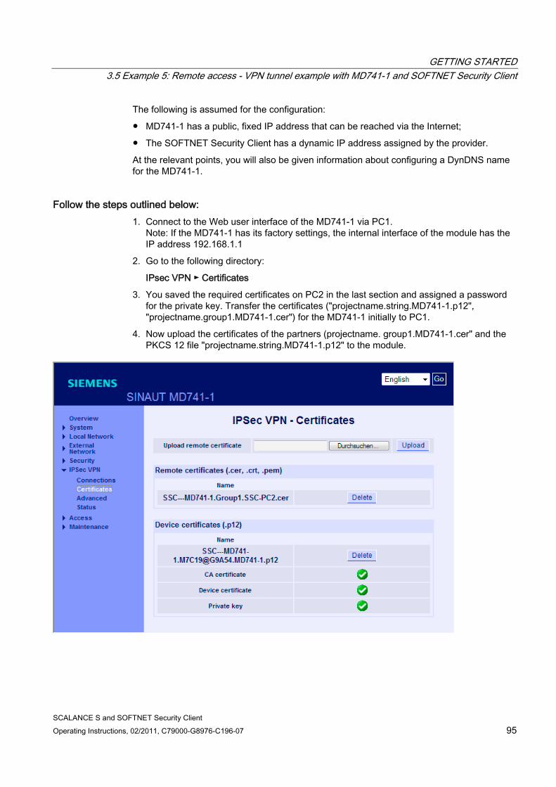
GETTING STARTED 3.5 Example 5: Remote access - VPN tunnel example with MD741-1 and SOFTNET Security Client
SCALANCE S and SOFTNET Security Client Operating Instructions, 02/2011, C79000-G8976-C196-07 95
The following is assumed for the configuration:
● MD741-1 has a public, fixed IP address that can be reached via the Internet;
● The SOFTNET Security Client has a dynamic IP address assigned by the provider.
At the relevant points, you will also be given information about configuring a DynDNS name for the MD741-1.
Follow the steps outlined below: 1. Connect to the Web user interface of the MD741-1 via PC1.
Note: If the MD741-1 has its factory settings, the internal interface of the module has the IP address 192.168.1.1
2. Go to the following directory:
IPsec VPN ► Certificates
3. You saved the required certificates on PC2 in the last section and assigned a password for the private key. Transfer the certificates ("projectname.string.MD741-1.p12", "projectname.group1.MD741-1.cer") for the MD741-1 initially to PC1.
4. Now upload the certificates of the partners (projectname. group1.MD741-1.cer" and the PKCS 12 file "projectname.string.MD741-1.p12" to the module.
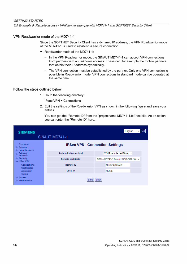
GETTING STARTED 3.5 Example 5: Remote access - VPN tunnel example with MD741-1 and SOFTNET Security Client
SCALANCE S and SOFTNET Security Client 96 Operating Instructions, 02/2011, C79000-G8976-C196-07
VPN Roadwarrior mode of the MD741-1 Since the SOFTNET Security Client has a dynamic IP address, the VPN Roadwarrior mode of the MD741-1 is used to establish a secure connection.
● Roadwarrior mode of the MD741-1:
– In the VPN Roadwarrior mode, the SINAUT MD741-1 can accept VPN connections from partners with an unknown address. These can, for example, be mobile partners that obtain their IP address dynamically.
– The VPN connection must be established by the partner. Only one VPN connection is possible in Roadwarrior mode. VPN connections in standard mode can be operated at the same time.
Follow the steps outlined below: 1. Go to the following directory:
IPsec VPN ► Connections
2. Edit the settings of the Roadwarrior VPN as shown in the following figure and save your entries.
You can get the "Remote ID" from the "projectname.MD741-1.txt" text file. As an option, you can enter the "Remote ID" here.
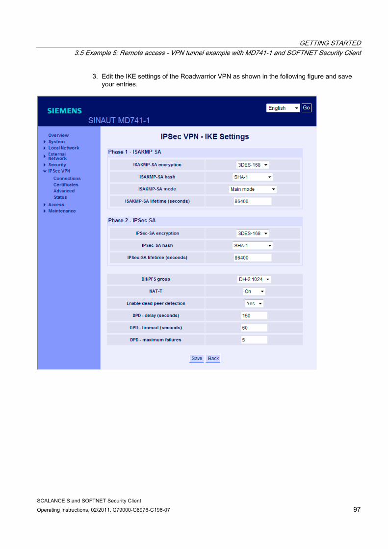
GETTING STARTED 3.5 Example 5: Remote access - VPN tunnel example with MD741-1 and SOFTNET Security Client
SCALANCE S and SOFTNET Security Client Operating Instructions, 02/2011, C79000-G8976-C196-07 97
3. Edit the IKE settings of the Roadwarrior VPN as shown in the following figure and save your entries.

GETTING STARTED 3.5 Example 5: Remote access - VPN tunnel example with MD741-1 and SOFTNET Security Client
SCALANCE S and SOFTNET Security Client 98 Operating Instructions, 02/2011, C79000-G8976-C196-07
NOTICE
A successful tunnel connection between MD741-1 and the SOFTNET Security Client can only be established if you keep exactly to the parameters listed below.
If you use different parameter settings, the two tunnel partners will not be able to set up a VPN connection between them. You should therefore always keep to the settings in the exported text file (as shown extra below).
Authentication method: X.509 partner certificate
Phase 1 - ISKAMP SA: ISAKMP-SA encryption:3DES-168 ISAKMP-SA hash: SHA-1 ISAKMP-SA mode: Main mode ISAKMP-SA Lifetime (seconds): 86400
Phase 2 - IPSec SA: IPSec SA encryption: 3DES-168 IPSec SA hash: SHA-1 IPSec SA lifetime (seconds): 86400
DH/PFS group: DH-2 1024

GETTING STARTED 3.5 Example 5: Remote access - VPN tunnel example with MD741-1 and SOFTNET Security Client
SCALANCE S and SOFTNET Security Client Operating Instructions, 02/2011, C79000-G8976-C196-07 99
4. To be able to use the diagnostics function of the SOFTNET Security Client for successfully established VPN tunnels in conjunction with the MD741-1, you need to allow a ping from the external network of the MD741-1.
To do this, go to the directory:
Security ► Advanced Settings
Set the "External ICMP to the MD741-1" function to the value "Allow Ping" and save your entry. Note also the following figure.
Note
If you do not enable this function, you will not be able to use the diagnostics function of the SOFTNET Security Client for successfully established VPN tunnels in conjunction with the MD741-1. You then do not receive any feedback as to whether the tunnel was successfully established but can nevertheless communicate securely via the tunnel.
5. To allow you to access the Web interface of the MD741-1 module via the external
interface as well, enable the HTTPS remote access.
This gives you the opportunity of configuring and diagnosing the MD741-1 remotely via an established tunnel.
To do this, go to the directory:
Access ► HTTPS
Set in the "Enable HTTPS remote access" function to the value "Yes" as shown in the following figure and save your entry.

GETTING STARTED 3.5 Example 5: Remote access - VPN tunnel example with MD741-1 and SOFTNET Security Client
SCALANCE S and SOFTNET Security Client 100 Operating Instructions, 02/2011, C79000-G8976-C196-07
Note
If you want to access the MD741-1 using a DNS name, make the settings for the DynDNS server connection in the following directory:
External Network ► Advanced Settings ► DynDNS 1. Change the setting "Log on to to DynDNS server" to the value "Yes". 2. Specify your username and the password of your DynDNS account. 3. Enter the full DynDNS address in the "DynDNS hostname" box. Remember to specify
the domain for this address as well. (Example: "mydns.dyndns.org")
The commissioning of the MD741-1 module is now complete. The module and the SOFTNET Security Client can establish a communication tunnel over which network nodes can communicate securely with PC2 from within the internal network.

GETTING STARTED 3.5 Example 5: Remote access - VPN tunnel example with MD741-1 and SOFTNET Security Client
SCALANCE S and SOFTNET Security Client Operating Instructions, 02/2011, C79000-G8976-C196-07 101
3.5.8 Setting up a tunnel with the SOFTNET Security Client
Follow the steps outlined below: 1. Start the SOFTNET Security Client on PC2.
2. Click the "Load Configuration" button, change to your project folder and load the "Projectname.SSC-PC2.dat" configuration file.
3. For an MD741-1 configuration, the SOFTNET Security Client opens the dialog "IP-/DNS settings MD741-1". In this dialog, enter the public IP address of the MD741-1 module that you received from your provider. Confirm the dialog with "OK".
Note: If you work with a DNS name, you can configure this instead of an IP address in this dialog.
4. Enter the password for the certificate and confirm with "Next".
5. Confirm the "Enable all statically configured nodes?" dialog with "Yes".
6. Click the "Tunnel Overview" button.
Note
If you want to reach the MD741-1 module using a DNS name, set the full DynDNS address in the "DNS Name" input box in step 3. (Example: "mydns.dyndns.org")
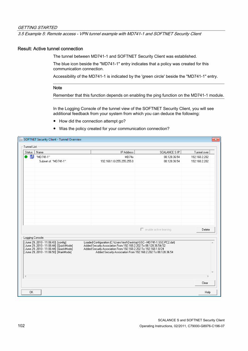
GETTING STARTED 3.5 Example 5: Remote access - VPN tunnel example with MD741-1 and SOFTNET Security Client
SCALANCE S and SOFTNET Security Client 102 Operating Instructions, 02/2011, C79000-G8976-C196-07
Result: Active tunnel connection The tunnel between MD741-1 and SOFTNET Security Client was established.
The blue icon beside the "MD741-1" entry indicates that a policy was created for this communication connection.
Accessibility of the MD741-1 is indicated by the 'green circle' beside the "MD741-1" entry.
Note
Remember that this function depends on enabling the ping function on the MD741-1 module.
In the Logging Console of the tunnel view of the SOFTNET Security Client, you will see additional feedback from your system from which you can deduce the following:
● How did the connection attempt go?
● Was the policy created for your communication connection?
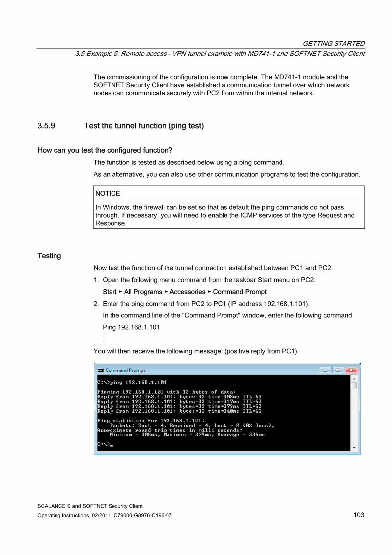
GETTING STARTED 3.5 Example 5: Remote access - VPN tunnel example with MD741-1 and SOFTNET Security Client
SCALANCE S and SOFTNET Security Client Operating Instructions, 02/2011, C79000-G8976-C196-07 103
The commissioning of the configuration is now complete. The MD741-1 module and the SOFTNET Security Client have established a communication tunnel over which network nodes can communicate securely with PC2 from within the internal network.
3.5.9 Test the tunnel function (ping test)
How can you test the configured function? The function is tested as described below using a ping command.
As an alternative, you can also use other communication programs to test the configuration.
NOTICE In Windows, the firewall can be set so that as default the ping commands do not pass through. If necessary, you will need to enable the ICMP services of the type Request and Response.
Testing Now test the function of the tunnel connection established between PC1 and PC2:
1. Open the following menu command from the taskbar Start menu on PC2:
Start ► All Programs ► Accessories ► Command Prompt
2. Enter the ping command from PC2 to PC1 (IP address 192.168.1.101).
In the command line of the "Command Prompt" window, enter the following command
Ping 192.168.1.101
.
You will then receive the following message: (positive reply from PC1).

GETTING STARTED 3.5 Example 5: Remote access - VPN tunnel example with MD741-1 and SOFTNET Security Client
SCALANCE S and SOFTNET Security Client 104 Operating Instructions, 02/2011, C79000-G8976-C196-07
Result If the IP packets have reached PC1, the "Ping statistics for 192.168.1.101" display the following:
● Sent = 4
● Received = 4
● Lost = 0 (0 % loss)
Since no other communication is permitted, these packets must have been transported through the VPN tunnel.

GETTING STARTED 3.5 Example 5: Remote access - VPN tunnel example with MD741-1 and SOFTNET Security Client
SCALANCE S and SOFTNET Security Client Operating Instructions, 02/2011, C79000-G8976-C196-07 105


SCALANCE S and SOFTNET Security Client Operating Instructions, 02/2011, C79000-G8976-C196-07 107
F1
Configuring with the Security Configuration Tool 4
The Security Configuration Tool is the configuration tool is supplied with SCALANCE S.
This chapter will familiarize you with the user interface and the functionality of the configuration tool.
You will learn how to set up, work with, and manage SCALANCE S projects.
Further information How to configure modules and IPsec tunnels is described in detail in the next chapters of this manual.
You will find detailed information on the dialogs and parameter settings in the online help. You can call this with the F1 key or using the "Help" button in the relevant dialog.
4.1 Range functions and how they work
Scope of performance You use the Security Configuration Tool for the following tasks:
● Configuration of SCALANCE S
● Configuration of SOFTNET Security Client (S612 / S613 / MD 741-1)
● Creating the configuration data for MD 740-1 / MD 741-1
● Test and diagnostic functions, status displays

Configuring with the Security Configuration Tool 4.1 Range functions and how they work
SCALANCE S and SOFTNET Security Client 108 Operating Instructions, 02/2011, C79000-G8976-C196-07
Modes The Security Configuration Tool has two modes:
● Offline - configuration view
In offline mode, you create the configuration data for the SCALANCE S modules and SOFTNET Security Clients. Prior to downloading, there must already be a connection to a SCALANCE S.
● Online
The online mode is used for testing and diagnostics of a SCALANCE S.
Two operating views The Security Configuration Tool provides two operating views in offline mode:
● Standard mode
Standard mode is the default mode in the Security Configuration Tool. It allows fast, uncomplicated configuration of SCALANCE S operation.
● Advanced mode
Advanced mode provides extended options allowing individual settings for the firewall rules and security functionality.
How it works - security and consistency ● Access only for authorized users
You can protect each project from unauthorized access by assigning passwords.
● Consistent project data
Consistency checks are running even while you make the entries in the dialogs. You can also start a project-wide consistency check for all dialogs at any time.
Only consistent project data can be downloaded.
● Protecting project data by encryption
The saved project and configuration data are protected by encryption both in the project file and on the C-PLUG.
Configuring with the Security Configuration Tool 4.2 Installation
SCALANCE S and SOFTNET Security Client Operating Instructions, 02/2011, C79000-G8976-C196-07 109
4.2 Installation You install the Security Configuration Tool from the supplied SCALANCE S CD.
Requirements The prerequisites for installation and operation of the Security Configuration Tool on a PC/PG are as follows:
● Operating system Windows XP SP2 or SP3 (not Home), Windows 7 (not Home);
● PC/PG with at least 128 Mbytes of RAM and a 1 GHz CPU or faster.
Follow the steps below
NOTICE Before you install the Security Configuration Tool, make sure that you read the "README" file on the CD. This file contains important notes and any late modifications.
● Insert the SCALANCE S CD in your CD-ROM drive; if the Autorun function is active, the user interface with which you make the installation starts automatically.
or ● Start the "start.exe" application on the supplied SCALANCE S CD.
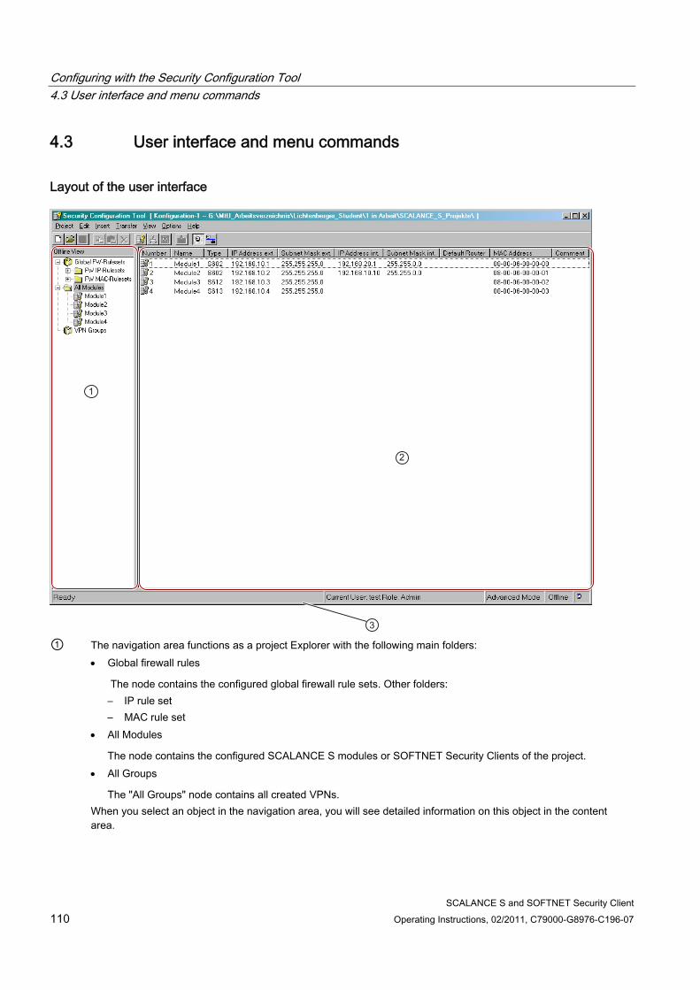
Configuring with the Security Configuration Tool 4.3 User interface and menu commands
SCALANCE S and SOFTNET Security Client 110 Operating Instructions, 02/2011, C79000-G8976-C196-07
4.3 User interface and menu commands
Layout of the user interface
① The navigation area functions as a project Explorer with the following main folders:
Global firewall rules
The node contains the configured global firewall rule sets. Other folders: – IP rule set – MAC rule set
All Modules
The node contains the configured SCALANCE S modules or SOFTNET Security Clients of the project. All Groups
The "All Groups" node contains all created VPNs. When you select an object in the navigation area, you will see detailed information on this object in the content area.

Configuring with the Security Configuration Tool 4.3 User interface and menu commands
SCALANCE S and SOFTNET Security Client Operating Instructions, 02/2011, C79000-G8976-C196-07 111
② Content area: When you select an object in the navigation area, you will see detailed information on this object in the content area. Several parameters can be entered here. By double clicking on the objects, you open properties dialogs in which you can enter further parameters.
③ Status bar The status bar displays operating states and current status messages; these include: The current user and user type The operator view - standard mode/advanced mode The mode - online/offline
Menu bar Below, you will see an overview of the available menu commands and their meaning.
Menu command Meaning / remarks Shortcut Project ▶… Functions for project-specific settings and for downloading and
saving the project file.
New Create a new project Open… Open the existing project. Save Save the open project in the current path and under the current
project name.
Save As… Save the open project in a selectable path and under a selectable project name.
Properties… Open dialog for project properties. Recent Projects Allows you to select previously opened projects directly. Quit Edit ▶… Note:
If you have selected an object, some of the functions listed here are also available in the popup menu available with the right mouse button.
Copy Copy the selected object. Ctrl+C Paste Fetch object from the clipboard and paste. Ctrl+V Delete Delete the selected object. Del Rename Rename the selected object. F2 Properties Open the properties dialog for the selected object. F4 Online Diagnostics… Access test and diagnostic functions.
This menu command is only available in the online view.
Insert ▶… (Menu commands only in offline mode) Module Create new module.
The menu command is enabled only when a module object or a group is selected in the navigation area.
Ctrl+M
Configuring with the Security Configuration Tool 4.3 User interface and menu commands
SCALANCE S and SOFTNET Security Client 112 Operating Instructions, 02/2011, C79000-G8976-C196-07
Menu command Meaning / remarks Shortcut Group Create new group.
The menu command is enabled only when a group object is selected in the navigation area.
Ctrl+G
Firewall rule set Create a new globally valid set of firewall IP rules or MAC rules. The menu command is enabled only when a firewall object is selected in the navigation area.
Ctrl+F
Transfer ▶… To Module… Download data to the selected modules.
Note: Only consistent project data can be downloaded.
To All Modules… Download data to all configured modules. Note: Only consistent project data can be downloaded.
Configuration Status… Display configuration status of the configured modules in a list. Firmware Update... Download new firmware to the selected SCALANCE S. View ▶… Advanced mode Switch from the standard to the advanced mode.
Notice: If you switch to the advanced mode for the current project, you can only switch back as long as you have made no modifications. The standard mode is the default.
Ctrl+E
Offline Is the default. Ctrl+Shift+D Online Ctrl+D Options ▶… IP Service Definitions … Open a dialog for service definitions for IP firewall rules.
This menu command is only available in the "advanced mode" view.
MAC Service Definitions…
Open a dialog for service definitions for MAC firewall rules. This menu command is only available in the "advanced mode" view.
Change Project Password...
Function for changing the user password.
Network adapter... Function for selecting the local network adapter over which a connection will be established to a SCALANCE S.
Log Files… Displays log files. Log files can be read and logs can be started.
Symbolic Names... You can assign symbolic names for IP addresses or MAC addresses.
Consistency checks Check the consistency of the entire project. A result list is displayed.
Help ▶… Contents ... Help on the functions and parameters required in the Security
Configuration Tool. Ctrl+Shift+F1

Configuring with the Security Configuration Tool 4.4 Managing projects
SCALANCE S and SOFTNET Security Client Operating Instructions, 02/2011, C79000-G8976-C196-07 113
Menu command Meaning / remarks Shortcut Index... Help on the functions and parameters required in the Security
Configuration Tool. Ctrl+Shift+F2
Info... Information on the version and revision of the Security Configuration Tool.
4.4 Managing projects
4.4.1 Overview
SCALANCE S project A project in the Security Configuration Tool includes all the configuration and management information for one or more SCALANCE S devices, SOFTNET Security Clients and MD74x devices.
You create a module for each SCALANCE S device, each SOFTNET Security Client and each MD74x device in the project.
Generally, the configurations of a project contain the following:
● Valid settings throughout the project
● Settings for specific modules
● Group assignments for IPsec tunnel (S612 / S613 / SOFTNET Security Client)
User management also handles access permissions to the project data and therefore to the SCALANCE S devices.

Configuring with the Security Configuration Tool 4.4 Managing projects
SCALANCE S and SOFTNET Security Client 114 Operating Instructions, 02/2011, C79000-G8976-C196-07
Valid settings throughout the project ● Project properties
These include not only address and name information but also initialization values and authentication settings.
● Global firewall rules
Global firewall rules can be assigned to several modules at the same time. In many situations, this simplifies the configuration compared with configuring local sets of firewall rules in the settings for specific modules.
● Service definitions
Using the IP service definitions, you can define succinct and clear firewall rules.
Settings for specific modules Most functions are configured in the properties dialog of a module. Here, you will find an overview of the tabs available and their functions:
Specified in mode ... Function / tab in the properties dialog
Standard Advanced Network Here, you can specify addresses of any routers in your network.
X
X
Firewall In standard mode, you enable the firewall with simple standard rules. You can also enable logging settings here. In advanced mode, you can define detailed packet filter rules. You can also define explicit logging settings for each packet filter rule.
X
X
SSL certificates When necessary, for example with a compressed certificate, you can import a certificate or use the Security Configuration Tool to create a new certificate.
X
Time synchronization Here, you specify the type of synchronization for the date and time.
X
X
Logging Here, you can make more precise settings for recording and storing logged events.
X
Nodes For a module in bridge mode, you can configure the static internal subnets and internal IP/MAC nodes here and enable or disable the learning of internal nodes. For a module in routing mode, you can enter the internal nodes / complete subnets to be tunneled.
X

Configuring with the Security Configuration Tool 4.4 Managing projects
SCALANCE S and SOFTNET Security Client Operating Instructions, 02/2011, C79000-G8976-C196-07 115
Specified in mode ... Function / tab in the properties dialog
Standard Advanced VPN If the module is in a group, you can configure dead peer detection, the type of connection establishment and the WAN IP address here.
X
Routing mode In standard mode, you can enable the "Router" function here. In advanced mode, you can also enable the NAT/NAPT router function and specify the address conversion in a list.
X
X
DHCP server You can enable the module as a DHCP server for the internal network.
X
You will find a detailed description of this function in the section "Firewall, routers and other module properties".
Group assignments for IPsec tunnel (S612 / S613 / SOFTNET Security Client) These specify which SCALANCE S modules, SOFTNET Security Clients and MD74x modules can communicate with each other over an IPsec tunnel.
By assigning SCALANCE S modules, SOFTNET Security Clients and MD74x modules to a group, these modules can establish a communication tunnel over a VPN (virtual private network).
Only modules in the same group can communicate securely with each other over tunnels and SCALANCE S modules, SOFTNET Security Clients and MD74x modules can belong to several groups at the same time.
4.4.2 Creating and editing projects
How to create a project Select the following menu command
Project ▶ New…
You will be prompted to assign a user name and a password. The user you create here is of the type Administrator.

Configuring with the Security Configuration Tool 4.4 Managing projects
SCALANCE S and SOFTNET Security Client 116 Operating Instructions, 02/2011, C79000-G8976-C196-07
As default, the Security Configuration Tool then creates a project and automatically opens the "Selection of a module or software configuration" dialog in which you can configure your first module.
Specifying initialization values for a project With the initialization values, you specify the properties to be adopted when you create new modules.
To enter the initialization values, select the following menu command:
Project ▶ Properties…, "Default Initialization Values" tab

Configuring with the Security Configuration Tool 4.4 Managing projects
SCALANCE S and SOFTNET Security Client Operating Instructions, 02/2011, C79000-G8976-C196-07 117
Protecting project data by encryption The saved project and configuration data are protected by encryption both in the project file and on the C-PLUG.
See also Firewall, router and other module properties (Page 129)
Configuring with the Security Configuration Tool 4.4 Managing projects
SCALANCE S and SOFTNET Security Client 118 Operating Instructions, 02/2011, C79000-G8976-C196-07
4.4.3 Setting up users
User types and permissions Access to projects and SCALANCE S modules is managed by configurable user settings. SCALANCE S recognizes two user types with different permissions:
● Administrators
With the "Administrator" user role, you have unrestricted access to all configuration data and the SCALANCE S modules.
● User
With the "User" user role, you have the following access permissions:
– Read access to configurations; exception: You are not permitted to change your own password.
– Read access to a SCALANCE S in the "Online" mode for testing and diagnostics.
User authentication The users of the project must authenticate themselves during access. For each user, you can specify a password authentication.
NOTICE Make sure that you keep your passwords safely.
If you forget your user passwords, you can no longer access the relevant project and its configurations nor the SCALANCE S modules.
You can then only access the SCALANCE S modules by resetting them to factory settings; however, you will lose the configurations.
Dialog for setting up users Select the following menu command to set up users:
Project ▶ Properties…, "Authentication Settings" tab.

Configuring with the Security Configuration Tool 4.4 Managing projects
SCALANCE S and SOFTNET Security Client Operating Instructions, 02/2011, C79000-G8976-C196-07 119
Protection against accidental prevention of access The system makes sure that always one user of the type "Administrator" is retained in a project. This prevents access to a project being lost entirely by accidentally deleting yourself.
NOTICE if the authentication settings are changed, the configuration must be downloaded to the SCALANCE S modules again before the settings (for example, new users, password changes) become active on the modules.

Configuring with the Security Configuration Tool 4.4 Managing projects
SCALANCE S and SOFTNET Security Client 120 Operating Instructions, 02/2011, C79000-G8976-C196-07
4.4.4 Consistency checks
Overview The Security Configuration Tool distinguishes between:
● Local consistency checks
● Project-wide consistency checks
Refer to the "Consistency check" sections of the dialog descriptions in the manual for information on the rules that are checked during input in the dialogs.
Local consistency checks A consistency check is local when it can be performed directly within a dialog. Checks can be made during the following actions:
● After exiting a box
● After exiting a row in a table
● When you close the dialog with "OK"
Project-wide consistency checks Project-wide consistency checks provide you with information on correctly configured modules. Since continuous consistency checks throughout the project take too much time, and because inconsistent project data is normally created in the project engineering stage of a project, there is an automatic check only when the following actions are performed:
● When you save the project
● When you open the project
● Before you download a configuration
NOTICE
You can only download configuration data when the entire project is consistent.
How to start a project-wide consistency check You can start a consistency check for an open project with the following menu command:
Options ▶ Check Consistency
The test result is output in the form of a list. The status bar also draws your attention to the results of the consistency check if the project contains inconsistent data. By positioning the mouse pointer in the status bar, you can then display the list.
Configuring with the Security Configuration Tool 4.4 Managing projects
SCALANCE S and SOFTNET Security Client Operating Instructions, 02/2011, C79000-G8976-C196-07 121
4.4.5 You can assign symbolic names for IP / MAC addresses.
Meaning and advantages In a SCALANCE S project, you can assign symbolic names in a symbol table that stand for IP addresses and MAC addresses.
This makes it simpler and more reliable when configuring the individual services.
Symbolic names within the project are taken into account by the following functions and can be used during their configuration:
● Firewall
● NAT/NAPT router
● Syslog
● DHCP
Validity and uniqueness The validity of the symbolic names specified in the symbol table is restricted to configuration within a SCALANCE S project.
Each symbolic name must be assigned uniquely to a single IP address or MAC address within the project.
Automatic entry of symbolic names in the symbol table You can use symbolic names instead of IP addresses for the listed functions - for example, when creating firewall rules - without these already being assigned in the symbol table described here.
Symbolic names assigned in this way are automatically entered in the symbol table and can be assigned at a later point in time. Within the framework of the consistency check, you will be informed of missing assignments.
Dialog for assigning symbolic names To avoid inconsistencies between an "IP address - symbolic name" assignment, and "MAC address - symbolic name", the symbolic names are managed in a single symbol table.
You can open the symbol table with the following menu command:
Options ▶ Symbolic Names...
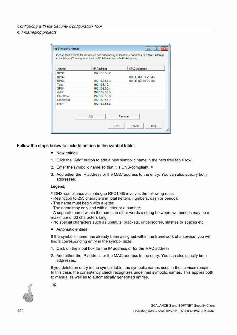
Configuring with the Security Configuration Tool 4.4 Managing projects
SCALANCE S and SOFTNET Security Client 122 Operating Instructions, 02/2011, C79000-G8976-C196-07
Follow the steps below to include entries in the symbol table: ● New entries
1. Click the "Add" button to add a new symbolic name in the next free table row.
2. Enter the symbolic name so that it is DNS-compliant. 1)
3. Add either the IP address or the MAC address to the entry. You can also specify both addresses.
Legend: 1) DNS-compliance according to RFC1035 involves the following rules: - Restriction to 255 characters in total (letters, numbers, dash or period); - The name must begin with a letter; - The name may only end with a letter or a number; - A separate name within the name, in other words a string between two periods may be a maximum of 63 characters long; - No special characters such as umlauts, brackets, underscores, slashes or spaces etc.
● Automatic entries
If the symbolic name has already been assigned within the framework of a service, you will find a corresponding entry in the symbol table.
1. Click on the input box for the IP address or for the MAC address.
2. Add either the IP address or the MAC address to the entry. You can also specify both addresses.
If you delete an entry in the symbol table, the symbolic names used in the services remain. In this case, the consistency check recognizes undefined symbolic names. This applies both to manual as well as to automatically generated entries.
Tip:

Configuring with the Security Configuration Tool 4.4 Managing projects
SCALANCE S and SOFTNET Security Client Operating Instructions, 02/2011, C79000-G8976-C196-07 123
The use of the project-wide consistency check is especially practical for the symbol table described here. Based on the list, you can recognize every inconsistency and correct it.
You can start a consistency check for an open project with the following menu command:
Options ▶ Check Consistency
Consistency check - these rules must be adhered to Remember the following rules when making the entries.
Check made1) Check / rule
locally project-wide The assignment of a symbolic name to an IP or MAC address must be unique in both directions.
x
The symbolic names must be DNS-compliant. 2) x Each row of the symbol table must contain a symbolic name. Either an IP address or a MAC address or both must be specified.
x
No symbolic names may be assigned to the IP addresses of the SCALANCE S modules.
x
Symbolic names used in the project for IP or MAC addresses must be included in the symbol table. Inconsistencies can occur when entries in the symbol table are deleted and not removed or corrected in the configuration dialogs.
x
Legend: 1) Note the explanations in the section "Consistency checks". 2) DNS-compliance according to RFC1035 involves the following rules: - Restriction to 255 characters in total (letters, numbers, dash or period); - The name must begin with a letter; - The name may only end with a letter or a number; - A separate name within the name, in other words a string between two periods may be a maximum of 63 characters long; - No special characters such as umlauts, brackets, underscores, slashes or spaces etc.

Configuring with the Security Configuration Tool 4.5 Download the configuration to the SCALANCE S module
SCALANCE S and SOFTNET Security Client 124 Operating Instructions, 02/2011, C79000-G8976-C196-07
4.5 Download the configuration to the SCALANCE S module The configuration data created offline is downloaded to the SCALANCE S modules available on the network using suitable menu commands.

Configuring with the Security Configuration Tool 4.5 Download the configuration to the SCALANCE S module
SCALANCE S and SOFTNET Security Client Operating Instructions, 02/2011, C79000-G8976-C196-07 125
Requirements ● Ports
In principle, you can download the configuration data both over device port 1 or device port 2.
Ideally, you should configure the modules of a group over the common external network of these modules (device port 1).
If the configuration computer is located in an internal network, you must enable the IP addresses of the other modules of the group explicitly in the firewall of this SCALANCE S and configure this module first. (This procedure is only supported when all SCALANCE S modules have already been assigned an IP address: see "Point note during initial configuration")
NOTICE
Using multiple network adapters during initial configuration
If you operate more than one network adapter in your PC/PG, first select the network adapter over which you can reach the SCALANCE S module prior to initial configuration.
Use the menu command "Options ▶ Network Adapter…"
● Operating state
Configurations can be downloaded while the SCALANCE S devices are operating. After downloading, the devices are automatically restarted. Following the download, there may be a short interruption in communication between the internal and external network.
NOTICE
Point note during initial configuration
As long as a module has not yet set IP parameters; in other words, prior to the first configuration, there must be no router or SCALANCE S between the module and the configuration computer.
NOTICE
Changing the PC port
If you swap a PC from the internal to the external interface of the SCALANCE S, access from this PC to the SCALANCE S is blocked for approximately 10 minutes (security function to defend against "ARP cache spoofing").
NOTICE
The project must be consistent
You can only download configuration data when the entire project is consistent. If there is an inconsistency, a detailed check list is displayed.
Secure transfer The data is transferred with a secure protocol.

Configuring with the Security Configuration Tool 4.6 Configuration data for MD 740 / MD 741
SCALANCE S and SOFTNET Security Client 126 Operating Instructions, 02/2011, C79000-G8976-C196-07
Follow the steps below To download, use the following alternative menu commands:
● Transfer ▶ To Module…
This transfers the configuration to all selected modules.
● Transfer ▶ To All Modules...
This transfers the configuration to all modules configured in the project.
Synchronizing configuration discrepancies It is not possible to read back configuration data from the SCALANCE S module to the project.
4.6 Configuration data for MD 740 / MD 741
Transferring to a module You can generate your VPN information for the assignment of parameters to an MD 740-1 / MD 741-1 using the Security Configuration Tool. Once you have generated files, you can use them to configure the MD 740-1 / MD 741-1.
The following file types are generated:
● Export file with the configuration data
– File type: ".txt" file in ASCII format
– Contains the exported configuration information for the MD 740 / MD 741 including information on the additionally generated certificates.
● Module certificate
– File type: ".p12" file
– The file contains the module certificate and the key material.
– Access is password protected.
● Group certificate
– File type: ".cer" file
The configuration files for the MD 740-1 / MD 741-1 can also be used to configure other VPN client types that are not included in the module selection. Minimum requirement for the use of these VPN clients is support of IPsec VPNs in tunnel mode.
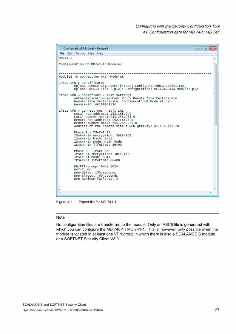
Configuring with the Security Configuration Tool 4.6 Configuration data for MD 740 / MD 741
SCALANCE S and SOFTNET Security Client Operating Instructions, 02/2011, C79000-G8976-C196-07 127
Figure 4-1 Export file for MD 741-1
Note
No configuration files are transferred to the module. Only an ASCII file is generated with which you can configure the MD 740-1 / MD 741-1. This is, however, only possible when the module is located in at least one VPN group in which there is also a SCALANCE S module or a SOFTNET Security Client V3.0.
Configuring with the Security Configuration Tool 4.6 Configuration data for MD 740 / MD 741
SCALANCE S and SOFTNET Security Client 128 Operating Instructions, 02/2011, C79000-G8976-C196-07
Follow the steps below 1. Select the "MD 740-1" / "MD 741-1" module in the content area and then select Transfer
▶ To Module...
2. In the save dialog that then opens, enter the path and file name of the configuration file and click "Save".
3. You will then be asked whether you want to create your own password for the two created certificate files.
If you select "No", the name of the configuration is assigned as the password (for example DHCP_without_Routing_02), not the project password.
If you select "Yes" (recommended), you enter your password in the next dialog.
Result: The files (and certificates) are stored in the folder you specify.
Note
After the files have been stored, a message reminds of the upwards compatibility of the project. Projects stored, for example, with the Security Configuration Tool V2.1 cannot be loaded with the Security Configuration Tool V2.
Note
For more information on the configuration of the MD 740-1 / MD 741-1, refer to the system manual MD 741-1 / MD 740-1.
SCALANCE S and SOFTNET Security Client Operating Instructions, 02/2011, C79000-G8976-C196-07 129
F1
Firewall, router and other module properties 5
This chapter familiarizes you with the procedures for creating modules and the possible settings for the individual modules in a project. The main emphasis is on the settings for the firewall function and NAT/NAPT function of SCALANCE S.
Note S612/S613
The firewall settings you can make for the individual modules can also influence communication handled over the IPSec tunnel connections in the internal network (VPN).
Further information How to configure IPSec tunnels is described in detail in the next chapter of this manual.
You will find detailed information on the dialogs and parameter settings in the online help.
You can call this with the F1 key or using the "Help" button in the relevant dialog.
NOTICE Performance features and device types
Note which functions the device type you are using supports.
See also Online functions - test, diagnostics, and logging (Page 219)
Hardware characteristics and overview of the functions (Page 17)
5.1 Overview / basics
5.1.1 SCALANCE S as firewall
Meaning The firewall functionality of SCALANCE S has the task of protecting the internal network from influences or disturbances from the external network. This means that; depending on the configuration, only certain previously specified communication relations between network nodes from the internal network and network nodes from the external network are allowed.
Firewall, router and other module properties 5.1 Overview / basics
SCALANCE S and SOFTNET Security Client 130 Operating Instructions, 02/2011, C79000-G8976-C196-07
All network nodes located in the internal network segment of a SCALANCE S are protected by its firewall.
The firewall functionality can be configured for the following protocol levels:
● IP firewall with stateful packet inspection;
● Firewall also for Ethernet "non-IP" frames according to IEEE 802.3; (Layer 2 frames)
● Bandwidth limitation
Firewall rules Firewall rules rules for data traffic in the following directions:
● from the internal to the external network and vice versa;
● from the internal network into an IPsec tunnel and vice versa (S612/S613).
Project engineering A distinction must be made between the two operating views:
● In standard mode, simple, predefined rules are used.
● In advanced mode, you can define specific rules.
In advanced mode, a further distinction must be made between local firewall rules and global firewall rules for modules:
– Local firewall rules are always assigned to a module. They are configured in the properties dialog of the modules.
– Global firewall rules can be assigned to several modules at the same time. This option simplifies configuration in many situations.
With the aid of service definitions, you can also define firewall rules clearly in a compact form. You can reference these service definitions both directly in the local firewall rules and in the global firewall rule sets.
5.1.2 SCALANCE S as router
Meaning By operating the SCALANCE S as a router, you connect the internal network with the external network. The internal network connected by SCALANCE S therefore becomes a separate subnet.
You have the following options:
● Routing - can be set in both standard and advanced mode
● NAT/NAPT routing - can be set in advanced mode

Firewall, router and other module properties 5.2 Creating modules and setting network parameters
SCALANCE S and SOFTNET Security Client Operating Instructions, 02/2011, C79000-G8976-C196-07 131
Routing - can be set in both standard and advanced mode Packets intended for an existing IP address in the subnets (internal or external) are forwarded. The firewall rules for the direction of transmission also apply.
For this mode, you must also configure an IP address for the internal subnet.
Note: In contrast to the bridge mode of the SCALANCE S , VLAN tags are lost in routing mode.
NAT/NAPT routing - can be set in advanced mode In this mode, the IP addresses are also converted. The IP addresses of the devices in the internal subnet are mapped to external IP addresses and are therefore not "visible" in the external network.
For this mode, you configure the address conversion in a list. You assign an external IP address to an internal IP address.
Depending on the method you want to use, the following applies to the assignment:
● NAT (Network Address Translation)
The following applies here: Address = IP address
● NAPT (Network Address Port Translation)
The following applies here: Address = IP address + port number
5.1.3 SCALANCE S as DHCP server
Meaning You can operate SCALANCE S on the internal network as a DHCP server. This allows IP addresses to be assigned automatically to the devices connected to the internal network.
The IP addresses are assigned either dynamically from an address band you have specified or you can select a specific IP address for a particular device.
Project engineering Configuration as a DHCP server is possible in the "advanced mode" view
5.2 Creating modules and setting network parameters
Creating modules When you create a new project, the Security Configuration Tool opens the "Selection of a module or software configuration" dialog in which you can configure your first module.
You can create further modules with the following menu commands:

Firewall, router and other module properties 5.2 Creating modules and setting network parameters
SCALANCE S and SOFTNET Security Client 132 Operating Instructions, 02/2011, C79000-G8976-C196-07
Insert ▶ Module
As an alternative: Using the context menu with the "All Modules" object selected.
In the next step in this dialog, select your product type, the module and the firmware release.
Network settings of a module The network settings of a module include the following:
● Address parameters of the module
● Addresses of external routers
Address parameters You can configure some address parameters in the "Selection of a module or software configuration" dialog when you create a module.
You can also enter the address parameters in the content area by selecting the "All Modules" object in the navigation area:
The following properties of the modules are displayed in columns:

Firewall, router and other module properties 5.2 Creating modules and setting network parameters
SCALANCE S and SOFTNET Security Client Operating Instructions, 02/2011, C79000-G8976-C196-07 133
Table 5- 1 IP parameters - "All Modules" selected
Property/column Meaning Comment/selection Number Consecutive module number Assigned automatically Name Technologically relevant module name. Freely selectable IP address ext. IP address over which the device can be
reached in the external network, for example for downloading the configuration.
Assigned as suitable in the network
Subnet mask ext. Subnet mask Assigned as suitable in the network IP address int. IP address over which the device can be
reached in the internal network when it is configured as a router.
Assigned as suitable in the network The input box can be edited only when router mode was enabled in the module properties.
Subnet mask int. Subnet mask Assigned as suitable in the network The input box can be edited only when router mode was enabled in the module properties.
Default Router IP address of the router in the external network
Assigned as suitable in the network
MAC address Hardware address of the module The MAC address is printed on the module housing. Remember the additional MAC address
in routing mode (you will find more information below this table).
SCALANCE S602 SCALANCE S612 V1 SCALANCE S612 V2 SCALANCE S613 V1 SCALANCE S613 V2
Type Device type
SOFTNET Security Client 2005 SOFTNET Security Client 2008 SOFTNET Security Client V3.0 MD 74x There is no "Properties dialog" for these module types. For MD 74x, you can set the IP addresses and the subnet masks in the contents area.
Comment Useful technological information on the module and the subnet protected by the module.
Freely selectable
Additional MAC address in routing mode In routing mode, SCALANCE S uses an additional MAC address on the interface to the internal subnet. This second MAC address is derived from the MAC address printed on the device:
● MAC address (internal) = printed MAC address + 1

Firewall, router and other module properties 5.2 Creating modules and setting network parameters
SCALANCE S and SOFTNET Security Client 134 Operating Instructions, 02/2011, C79000-G8976-C196-07
When operating in flat networks (bridge mode), the printed MAC address is valid both on the internal and on the external interface.
The currently valid MAC addresses are displayed in the "Status" tab in the online dialog of the Security Configuration Tool.
"Network / External Routers" dialog Depending on the existing network structure, it is possible that you must specify further routers in addition to the standard router.
Select the module you want to edit and then select the following menu command to set up external routers:
Edit ▶ Properties..., "Network" tab.
Figure 5-1 "Network" dialog
See also Overview of the functions in the online dialog (Page 220)
Firewall, router and other module properties 5.3 Firewall - module properties in standard mode
SCALANCE S and SOFTNET Security Client Operating Instructions, 02/2011, C79000-G8976-C196-07 135
5.3 Firewall - module properties in standard mode
5.3.1 Configure the firewall
Protection from disturbances from the external network The firewall functionality of SCALANCE S has the task of protecting the internal network from influences or disturbances from the external network. This means that only certain previously specified communication relations between network nodes from the internal network and network nodes from the external network are allowed.
With packet filter rules, you define whether the data traffic passing through is permitted or restricted based on properties of the data packets.
With SCALANCE S612 / S613, the firewall can be used for encrypted (IPsec tunnel) and unencrypted data traffic.
In standard mode, it is only possible to make settings for unencrypted data traffic.
Note Routing mode
If you have enabled the routing mode for the SCALANCE S module, MAC rules are irrelevant.
Dialog Select the module you want to edit and then select the following menu command to set up the firewall:
Edit ▶ Properties..., "Firewall" tab
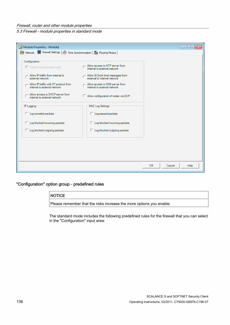
Firewall, router and other module properties 5.3 Firewall - module properties in standard mode
SCALANCE S and SOFTNET Security Client 136 Operating Instructions, 02/2011, C79000-G8976-C196-07
"Configuration" option group - predefined rules
NOTICE Please remember that the risks increase the more options you enable.
The standard mode includes the following predefined rules for the firewall that you can select in the "Configuration" input area:

Firewall, router and other module properties 5.3 Firewall - module properties in standard mode
SCALANCE S and SOFTNET Security Client Operating Instructions, 02/2011, C79000-G8976-C196-07 137
Table 5- 2 Predefined rules of the simple firewall
Rule/option Function Default setting
Tunneled communication only (S612/S613) Tunnel communication only
This is the default setting. With this setting, only encrypted IPsec data transfer is permitted; only nodes in the internal networks of SCALANCE S can communicate with each other. This option can only be selected when the module is in a group. If this option is deselected, tunnel communication and the type of communication selected in the other check boxes are permitted.
On
Allow outgoing IP traffic Allow outgoing IP traffic
Internal nodes can initiate a communication connection to nodes in the external network. Only response packets from the external network are passed on to the internal network. No communication connection can be initiated from the external network to nodes in the internal network.
Off
Allow outgoing S7 protocol Allow outgoing S7 protocol
Internal nodes can initiate an S7 communication connection (S7 protocol - TCP/port 102) to nodes in the external network. Only response packets from the external network are passed on to the internal network. No communication connection can be initiated from the external network to nodes in the internal network.
Off
Allow access to external DHCP server Allow access to external DHCP server
Internal nodes can initiate a communication connection to a DHCP server in the external network. Only the response packets of the DHCP server are passed into the internal network. No communication connection can be initiated from the external network to nodes in the internal network.
Off
Allow access to external NTP server Allow access to external NTP server
Internal nodes can initiate a communication connection to an NTP (Network Time Protocol) server in the external network. Only the response packets of the NTP server are passed into the internal network. No communication connection can be initiated from the external network to nodes in the internal network.
Off
Allow access to external SiClock server Allow access to external SiClock server
This option allows SiClock time-of-day frames from the external network to the internal network.
Off (The option cannot be used in routing mode.)
Allow access to external DNS server Allow access to external DNS server
Internal nodes can initiate a communication connection to a DNS server in the external network. Only the response packets of the DNS server are passed into the internal network. No communication connection can be initiated from the external network to nodes in the internal network.
Off
Allow access from external or internal nodes via DCP server Allow access from external or internal nodes via DCP server
The DCP protocol is used by the PST tool to set the IP parameters (node initialization) of SIMATIC NET network components. This rule allows nodes in the external network to access nodes in the internal network using the DCP protocol.
Off (The option cannot be used in routing mode.)

Firewall, router and other module properties 5.3 Firewall - module properties in standard mode
SCALANCE S and SOFTNET Security Client 138 Operating Instructions, 02/2011, C79000-G8976-C196-07
"Log" group - setting recording options You can log the incoming and outgoing data traffic.
5.3.2 Firewall defaults
Response with defaults The firewall defaults have been selected so that no IP data traffic is possible. Communication between the nodes in the internal networks of SCALANCE S modules is allowed only if you have configured an IPSec tunnel.
The following diagrams show the default settings in detail for the IP packet filter and the MAC packet filter.
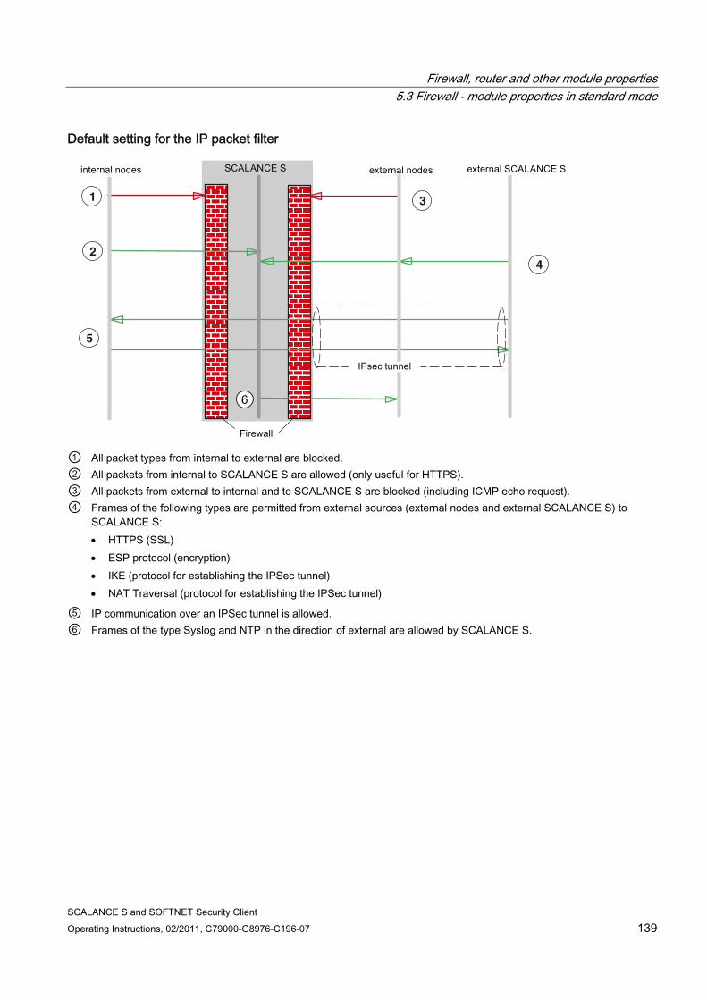
Firewall, router and other module properties 5.3 Firewall - module properties in standard mode
SCALANCE S and SOFTNET Security Client Operating Instructions, 02/2011, C79000-G8976-C196-07 139
Default setting for the IP packet filter
1
2
3
4
5
① All packet types from internal to external are blocked. ② All packets from internal to SCALANCE S are allowed (only useful for HTTPS). ③ All packets from external to internal and to SCALANCE S are blocked (including ICMP echo request). ④ Frames of the following types are permitted from external sources (external nodes and external SCALANCE S) to
SCALANCE S: HTTPS (SSL) ESP protocol (encryption) IKE (protocol for establishing the IPSec tunnel) NAT Traversal (protocol for establishing the IPSec tunnel)
⑤ IP communication over an IPSec tunnel is allowed. ⑥ Frames of the type Syslog and NTP in the direction of external are allowed by SCALANCE S.

Firewall, router and other module properties 5.4 Firewall - module properties in advanced mode
SCALANCE S and SOFTNET Security Client 140 Operating Instructions, 02/2011, C79000-G8976-C196-07
Default setting for the MAC packet filter
l
1
2
35
6
7
① All packet types from internal to external are blocked. ② All packets from internal to SCALANCE S are allowed. ③ ARP packets from internal to external are allowed. ④ All packets from external to internal and to SCALANCE S are blocked. ⑤ Packets from external to internal of the following types are allowed:
ARP with bandwidth limitation
⑥ Packets from external to SCALANCE S of the following types are allowed: ARP with bandwidth limitation DCP
⑦ MAC protocols sent through an IPSec tunnel are permitted.
5.4 Firewall - module properties in advanced mode Advanced mode provides extended options allowing individual settings for the firewall rules and security functionality.
Switch over to advanced mode To use all the functions and menu commands described in section, switch over the mode:

Firewall, router and other module properties 5.4 Firewall - module properties in advanced mode
SCALANCE S and SOFTNET Security Client Operating Instructions, 02/2011, C79000-G8976-C196-07 141
View ▶ Advanced Mode...
Note
If you switch to the advanced mode for the current project, you can no longer switch back if you make any modifications.
Symbolic names are supported You can also enter the IP addresses or MAC addresses as symbolic names in the functions described below.
5.4.1 Configure the firewall In contrast to the configuration of fixed packet filter rules in standard mode, you can configure individual packet filter rules in the Security Configuration Tool in advanced mode.
You can set the packet filter rules in selectable tabs for the following protocols:
● IP protocol (layer 3)
● MAC protocol (layer 2)
If you do not enter any rules in the dialogs described below, the default settings apply as described in the section "Firewall defaults".
Note Routing mode
If you have enabled the routing mode for the SCALANCE S module, MAC rules are irrelevant (dialogs are disabled).
Global and local definition possible ● Global firewall rules
A global firewall rule can be assigned to several modules at the same time. This option simplifies configuration in many situations.
● Local firewall rules
A local firewall rule is assigned to a module. This is configured in the properties dialog of a module.
Several local firewall rules and several global firewall rules can be assigned to a module.
In principle, the definition of global and local rules is identical. The following description therefore applies to both methods.
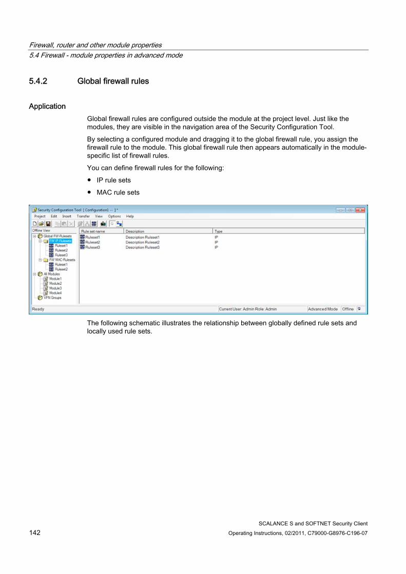
Firewall, router and other module properties 5.4 Firewall - module properties in advanced mode
SCALANCE S and SOFTNET Security Client 142 Operating Instructions, 02/2011, C79000-G8976-C196-07
5.4.2 Global firewall rules
Application Global firewall rules are configured outside the module at the project level. Just like the modules, they are visible in the navigation area of the Security Configuration Tool.
By selecting a configured module and dragging it to the global firewall rule, you assign the firewall rule to the module. This global firewall rule then appears automatically in the module-specific list of firewall rules.
You can define firewall rules for the following:
● IP rule sets
● MAC rule sets
The following schematic illustrates the relationship between globally defined rule sets and locally used rule sets.
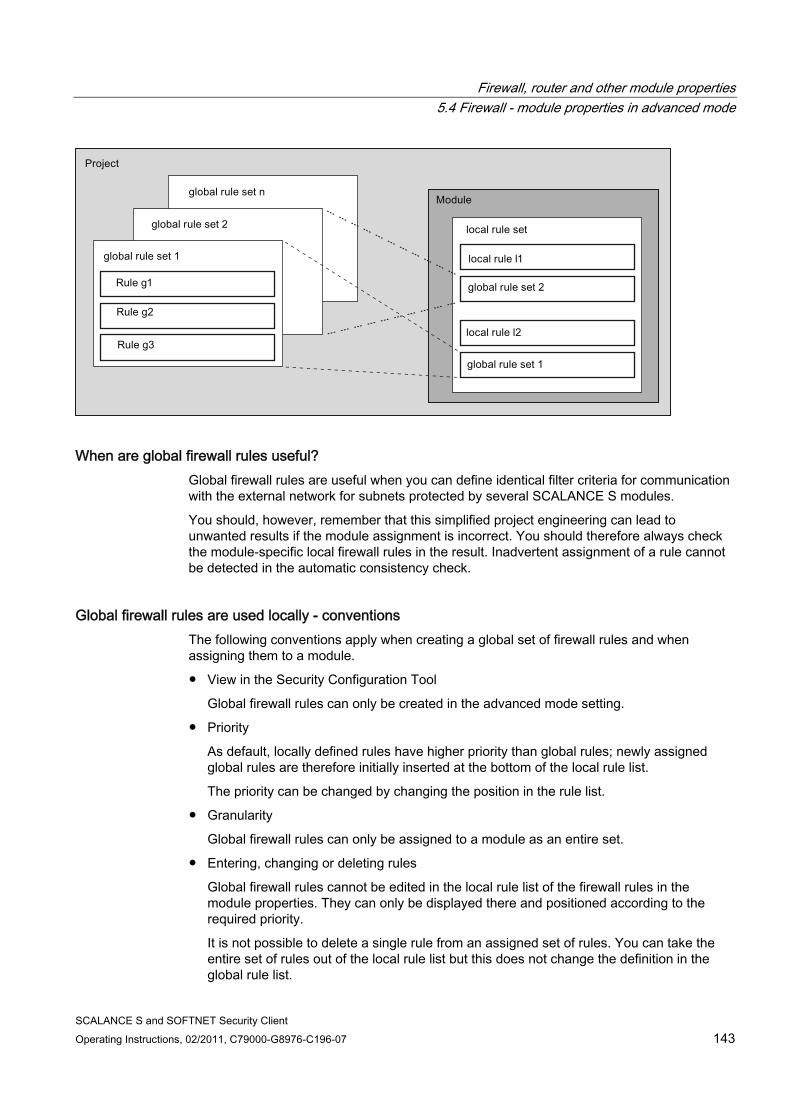
Firewall, router and other module properties 5.4 Firewall - module properties in advanced mode
SCALANCE S and SOFTNET Security Client Operating Instructions, 02/2011, C79000-G8976-C196-07 143
When are global firewall rules useful? Global firewall rules are useful when you can define identical filter criteria for communication with the external network for subnets protected by several SCALANCE S modules.
You should, however, remember that this simplified project engineering can lead to unwanted results if the module assignment is incorrect. You should therefore always check the module-specific local firewall rules in the result. Inadvertent assignment of a rule cannot be detected in the automatic consistency check.
Global firewall rules are used locally - conventions The following conventions apply when creating a global set of firewall rules and when assigning them to a module.
● View in the Security Configuration Tool
Global firewall rules can only be created in the advanced mode setting.
● Priority
As default, locally defined rules have higher priority than global rules; newly assigned global rules are therefore initially inserted at the bottom of the local rule list.
The priority can be changed by changing the position in the rule list.
● Granularity
Global firewall rules can only be assigned to a module as an entire set.
● Entering, changing or deleting rules
Global firewall rules cannot be edited in the local rule list of the firewall rules in the module properties. They can only be displayed there and positioned according to the required priority.
It is not possible to delete a single rule from an assigned set of rules. You can take the entire set of rules out of the local rule list but this does not change the definition in the global rule list.

Firewall, router and other module properties 5.4 Firewall - module properties in advanced mode
SCALANCE S and SOFTNET Security Client 144 Operating Instructions, 02/2011, C79000-G8976-C196-07
Creating and assigning global packet filter rules If you want to define and assign a global firewall rule set, follow the steps below:
1. Select one of the following folders from the navigation area:
– Global FW Rulesets / FW IP Rulesets.
– Global FW Rulesets / FW MAC Rulesets.
2. Select the following menu command to set up a global rule set:
Insert ▶ Firewall rule set
3. Enter the firewall rules in the list one after the other; note the parameter description and the evaluation in the following section or in the online help.
4. Assign the global firewall rule to the modules in which you want it to be used. You do this by selecting a module in the navigation area and dragging it to the relevant global rule set in the navigation area.
Result: The global rule set is used by the selected module as a local rule set.
5.4.3 Setting local IP packet filter rules Using the IP packet filter rules, you can filter IP packets such as UDP, TCP, ICMP packets.
Within an IP packet filter rule, you can also include service definitions and further restrict the filter criteria. If you do not specify services, the IP packet filter rule applies to all services.
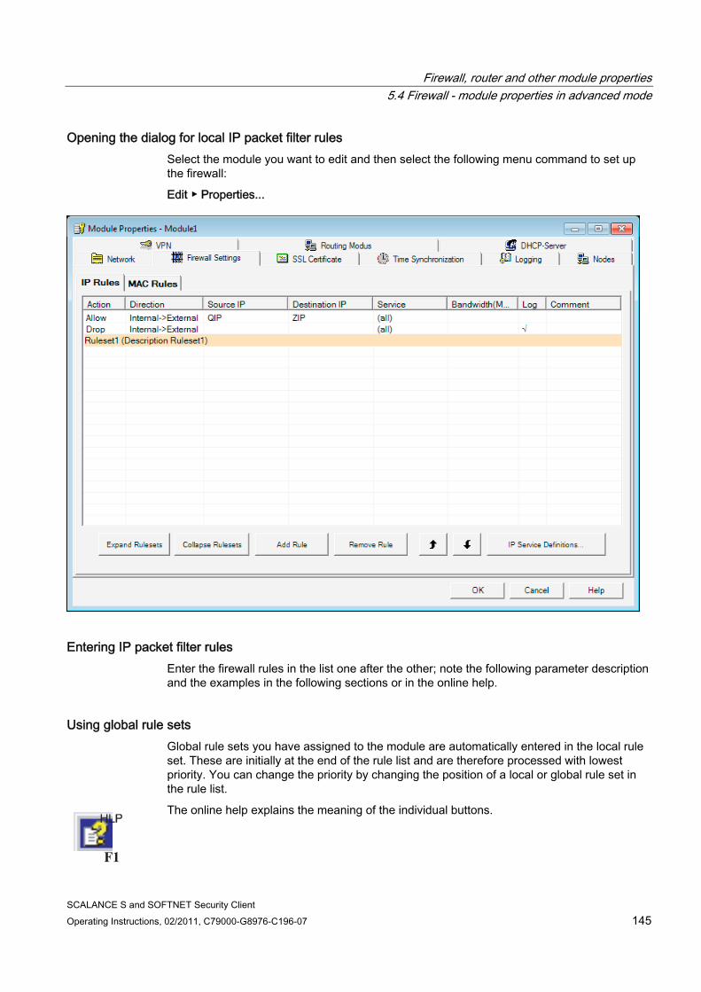
Firewall, router and other module properties 5.4 Firewall - module properties in advanced mode
SCALANCE S and SOFTNET Security Client Operating Instructions, 02/2011, C79000-G8976-C196-07 145
F1
Opening the dialog for local IP packet filter rules Select the module you want to edit and then select the following menu command to set up the firewall:
Edit ▶ Properties...
Entering IP packet filter rules Enter the firewall rules in the list one after the other; note the following parameter description and the examples in the following sections or in the online help.
Using global rule sets Global rule sets you have assigned to the module are automatically entered in the local rule set. These are initially at the end of the rule list and are therefore processed with lowest priority. You can change the priority by changing the position of a local or global rule set in the rule list.
The online help explains the meaning of the individual buttons.
Firewall, router and other module properties 5.4 Firewall - module properties in advanced mode
SCALANCE S and SOFTNET Security Client 146 Operating Instructions, 02/2011, C79000-G8976-C196-07
5.4.4 IP packet filter rules IP packet rules are processed based on the following evaluations:
● Parameters entered in the rule;
● Order and associated priority of the rule within the rule set.
Parameter The configuration of an IP rule includes the following parameters:
Name Meaning/comment Available options / ranges of
values Action Allow/disallow (enable/block) Allow
Allow packets according to definition.
Drop
Block packets according to definition.
Direction Specifies the direction of data traffic ("Tunnel / Any" only for S612/S613)
Internal → external Internal ← external Tunnel → internal Tunnel ← internal Internal → any Internal ← any
Source IP Source IP address Destination IP Destination IP address
Refer to the section "IP addresses in IP packet filter rules" in this chapter. As an alternative, you can enter symbolic names.
Service Name of the IP/ICMP service or service group used. Using the service definitions, you can define succinct and clear packet filter rules. Here, you select one of the services you defined in the IP services dialog: IP services or ICMP services If you have not yet defined any services or want to define a further service, click the "IP/MAC Service Definition..." button.
The drop-down list box displays the configured services and service groups you can select. No entry means: No service is checked, the rule applies to all services.
Bandwidth (Mbps) Option for setting a bandwidth limitation. A packet passes through the firewall if the pass rule matches and the permitted bandwidth for this rule has not yet been exceeded.
Range of values: 0.001 to 100 Mbps
Logging Enable or disable logging for this rule Comment Space for your own explanation of the rule

Firewall, router and other module properties 5.4 Firewall - module properties in advanced mode
SCALANCE S and SOFTNET Security Client Operating Instructions, 02/2011, C79000-G8976-C196-07 147
IP addresses in IP packet filter rules The IP address consists of four decimal numbers with the range from 0 to 255, each number separated by a period; example: 141.80.0.16
In the packet filter rule, you have the following options for specifying IP addresses:
● Nothing specified
There is no check, the rule applies to all IP addresses.
● An IP address
The rule applies specifically to the specified address.
● Address range
The rule applies to all the IP addresses covered by the address range.
An address range is defined by specifying the number of valid bit places in the IP address in the format:
[IP address]/[number of bits to be included]
– [IP address]/24 therefore means that only the most significant 24 bits of the IP address are included in the filter rule: These are the first three octets or numbers numbers in the IP address.
– [IP address ]/25 means that only the first three octets and the highest bit of the fourth octet of the IP address are included in the filter rule.
Table 5- 3 Examples of address ranges in IP addresses
Source IP or destination IP
Address range Number of addresses*)
from to 192.168.0.0/16 192.168.0.0 192.168.255.255 65.536 192.168.10.0/24 192.168.10.0 192.168.10.255 256 192.168.10.0/25 192.168.10.0 192.168.10.127 128 192.168.10.0/26 192.168.10.0 192.168.10.63 64 192.168.10.0/27 192.168.10.0 192.168.10.31 32 192.168.10.0/28 192.168.10.0 192.168.10.15 16 192.168.10.0/29 192.168.10.0 192.168.10.7 8 192.168.10.0/30 192.168.10.0 192.168.10.3 4 *) Note: Note that the address values 0 and 255 in the IP address have special functions (0 stands for a network address, 255 for a broadcast address). The number of actually available addresses is therefore reduced.

Firewall, router and other module properties 5.4 Firewall - module properties in advanced mode
SCALANCE S and SOFTNET Security Client 148 Operating Instructions, 02/2011, C79000-G8976-C196-07
Order for rule evaluation by SCALANCE S The packet filter rules are evaluated by a SCALANCE S as follows:
● The list is evaluated from top to bottom; if rules are contradictory, the rule higher in the list is therefore applied.
● In rules for communication between the internal and external network, the final rule is: All packets except for the packets explicitly allowed in the list are blocked.
● In rules for communication between the internal network and IPsec tunnel, the final rule is: All packets except for the packets explicitly blocked in the list are allowed.
Example
The packet filter rules shown as examples in the dialog above have the following effects:

Firewall, router and other module properties 5.4 Firewall - module properties in advanced mode
SCALANCE S and SOFTNET Security Client Operating Instructions, 02/2011, C79000-G8976-C196-07 149
1 2
3
4
5
6
① All packet types from internal to external are blocked as default, except for those explicitly allowed. ② All packet types from external to internal are blocked as default, except for those explicitly allowed. ③ IP packet filter rule 1 allows packets with the service definition "Service X1" from internal to external. ④ IP packet filter rule 2 allows packets from external to internal when the following conditions are met:
IP address of the sender: 196.65.254.2 IP address of the recipient: 197.54.199.4 Service definition: "Service X2"
⑤ IP packet filter rule 3 blocks packets with the service definition "Service X2" in the VPN (IPsec tunnel). ⑥ IPsec tunnel communication is allowed as default except for the explicitly blocked packet types.
5.4.5 Defining IP services Using the IP service definitions, you can define succinct and clear firewall rules for specific services. You select a name and assign the service parameters to it.
These services defined in this way can also be grouped together under a group name.
When you configure the global or local packet filter rule, you simply use this name.

Firewall, router and other module properties 5.4 Firewall - module properties in advanced mode
SCALANCE S and SOFTNET Security Client 150 Operating Instructions, 02/2011, C79000-G8976-C196-07
Dialog / tab Open the dialog as follows:
● Using the menu command Options ▶ IP/MAC Service Definition...
or
● From the "Firewall/IP Rules" tab with the "IP Service Definitions..." button.
Parameters for IP services You define the IP services using the following parameters:
Table 5- 4 IP services: Parameter
Name Meaning/comment Available options / ranges of values Name User-definable name for the service that is used as
identification in the rule definition or in the group. Can be selected by user
Firewall, router and other module properties 5.4 Firewall - module properties in advanced mode
SCALANCE S and SOFTNET Security Client Operating Instructions, 02/2011, C79000-G8976-C196-07 151
Name Meaning/comment Available options / ranges of values Protocol Name of the protocol type TCP
UDP Any (TCP and UDP)
Source port The filtering is based on the specified port number; this defines the service access at the packet sender.
Examples: *: Port is not checked 20 or 21: FTP service
Destination port The filtering is based on the specified port number; this defines the service access at the packet recipient.
Examples: *: Port is not checked 80: Web HTTP service 102: S7 protocol - TCP/port
5.4.6 defining ICMP services Using the ICMP service definitions, you can define succinct and clear firewall rules for specific services. You select a name and assign the service parameters to it.
These services defined in this way can also be grouped together under a group name.
When you configure the packet filter rules, you simply use this name.
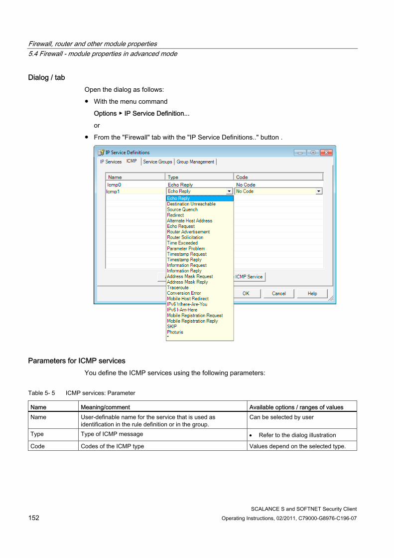
Firewall, router and other module properties 5.4 Firewall - module properties in advanced mode
SCALANCE S and SOFTNET Security Client 152 Operating Instructions, 02/2011, C79000-G8976-C196-07
Dialog / tab Open the dialog as follows:
● With the menu command
Options ▶ IP Service Definition...
or
● From the "Firewall" tab with the "IP Service Definitions.." button .
Parameters for ICMP services You define the ICMP services using the following parameters:
Table 5- 5 ICMP services: Parameter
Name Meaning/comment Available options / ranges of values Name User-definable name for the service that is used as
identification in the rule definition or in the group. Can be selected by user
Type Type of ICMP message Refer to the dialog illustration
Code Codes of the ICMP type Values depend on the selected type.
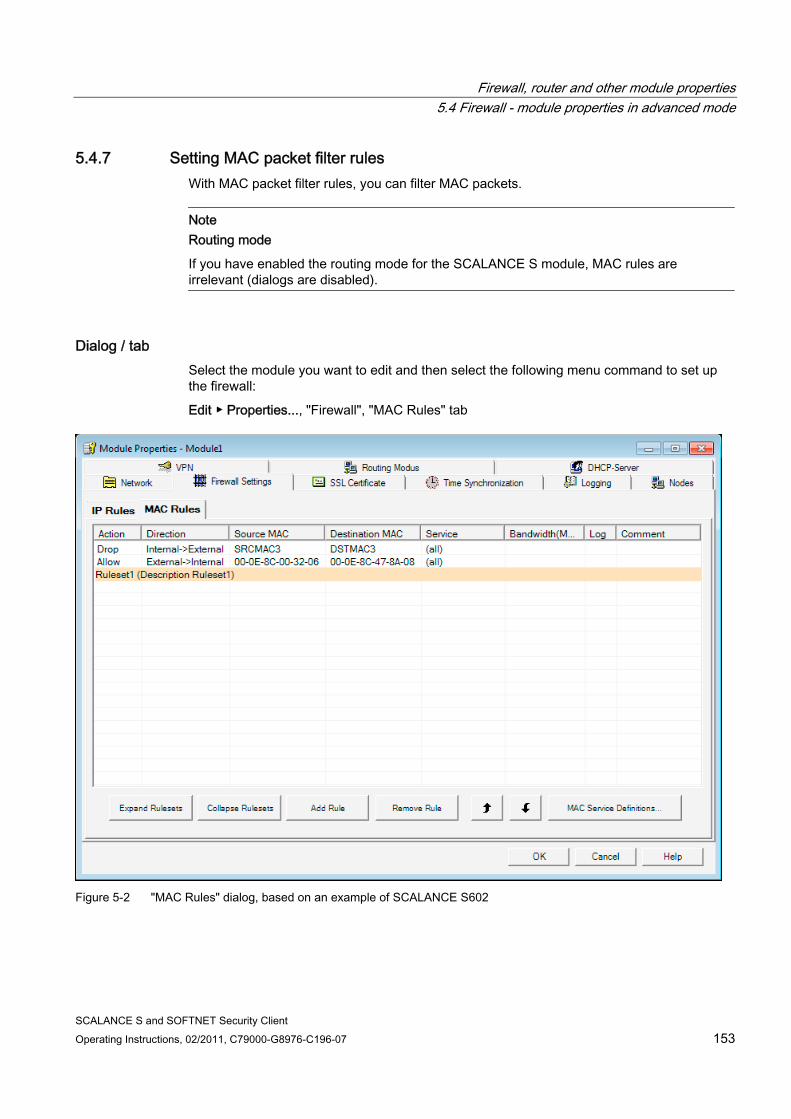
Firewall, router and other module properties 5.4 Firewall - module properties in advanced mode
SCALANCE S and SOFTNET Security Client Operating Instructions, 02/2011, C79000-G8976-C196-07 153
5.4.7 Setting MAC packet filter rules With MAC packet filter rules, you can filter MAC packets.
Note Routing mode
If you have enabled the routing mode for the SCALANCE S module, MAC rules are irrelevant (dialogs are disabled).
Dialog / tab Select the module you want to edit and then select the following menu command to set up the firewall:
Edit ▶ Properties..., "Firewall", "MAC Rules" tab
Figure 5-2 "MAC Rules" dialog, based on an example of SCALANCE S602
Firewall, router and other module properties 5.4 Firewall - module properties in advanced mode
SCALANCE S and SOFTNET Security Client 154 Operating Instructions, 02/2011, C79000-G8976-C196-07
F1
Entering packet filter rules Enter the firewall rules in the list one after the other; note the following parameter description and the examples in the following sections or in the online help.
Using global rule sets Global rule sets you have assigned to the module are automatically entered in the local rule set. These are initially at the end of the rule list and are therefore processed with lowest priority. You can change the priority by changing the position of a local or global rule set in the rule list.
The online help explains the meaning of the individual buttons.
5.4.8 MAC packet filter rules MAC packet filter rules are processed based on the following evaluations:
● Parameters entered in the rule;
● Priority of the rule within the rule set.
MAC packet filter rules The configuration of a MAC rule includes the following parameters:
Table 5- 6 MAC rules: Parameter
Name Meaning/comment Available options / ranges of values
Action Allow/disallow (enable/block) Allow
Allow packets according to definition.
Drop
Block packets according to definition.
Direction Specifies the direction and type of data traffic ("Tunnel / Any" only for S612/S613)
Internal → external Internal ← external Tunnel → internal Tunnel ← internal Internal → any Internal ← any
Source MAC Source MAC address Destination MAC Destination MAC address
As an alternative to specifying a MAC address, you can enter a symbolic name.
Firewall, router and other module properties 5.4 Firewall - module properties in advanced mode
SCALANCE S and SOFTNET Security Client Operating Instructions, 02/2011, C79000-G8976-C196-07 155
Name Meaning/comment Available options / ranges of values
Service Name of the MAC service or service group used. The drop-down list box displays the configured services and service groups you can select. No entry means: No service is checked, the rule applies to all services.
Bandwidth (Mbps) Option for setting a bandwidth limitation. A packet passes through the firewall if the pass rule matches and the permitted bandwidth for this rule has not yet been exceeded.
Range of values: 0.001 to 100 Mbps
Logging Enable or disable logging for this rule Comment Space for your own explanation of the rule
How SCALANCE S evaluates the rules The packet filter rules are evaluated by a SCALANCE S as follows:
● The list is evaluated from top to bottom; if rules are contradictory, the rule higher in the list is therefore applied.
● The following applies to all packets not explicitly listed for the rules for communication in the direction internal -> external and internal <- external: All packets except for the packets explicitly allowed in the list are blocked.
● The following applies to all packets not explicitly listed for the rules for communication in the direction internal -> IPsec tunnel and internal <- IPsec tunnel: All packets except for the packets explicitly blocked in the list are allowed.
NOTICE
In bridge mode: IP rules apply to IP packets, MAC rules apply to layer 2 packets
If a module is in bridge mode, both IP and MAC rules can be defined for the firewall. Rules for editing in the firewall are based on the Ethertype.
IP packets are forwarded or blocked depending on the IP rules and layer 2 packets are forwarded or blocked depending on the MAC rules.
It is not possible to filter an IP packet using a MAC firewall rule, for example based on a MAC address.
Examples You can apply the example of an IP packet filter in Section 5.4.3 analogously to the MAC packet filter rules.
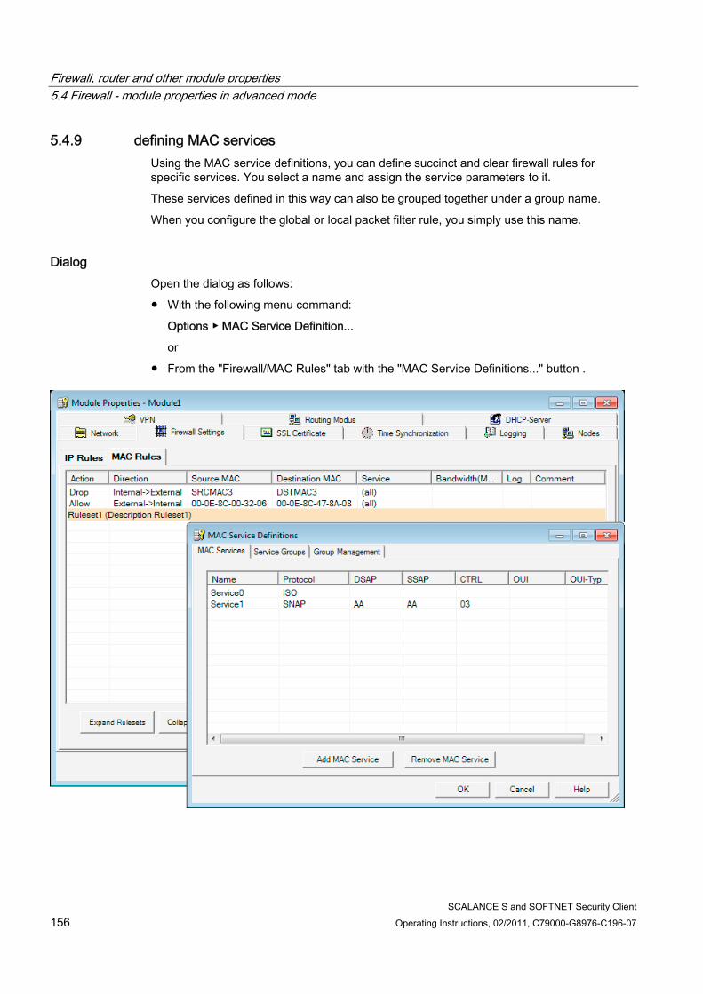
Firewall, router and other module properties 5.4 Firewall - module properties in advanced mode
SCALANCE S and SOFTNET Security Client 156 Operating Instructions, 02/2011, C79000-G8976-C196-07
5.4.9 defining MAC services Using the MAC service definitions, you can define succinct and clear firewall rules for specific services. You select a name and assign the service parameters to it.
These services defined in this way can also be grouped together under a group name.
When you configure the global or local packet filter rule, you simply use this name.
Dialog Open the dialog as follows:
● With the following menu command:
Options ▶ MAC Service Definition...
or
● From the "Firewall/MAC Rules" tab with the "MAC Service Definitions..." button .
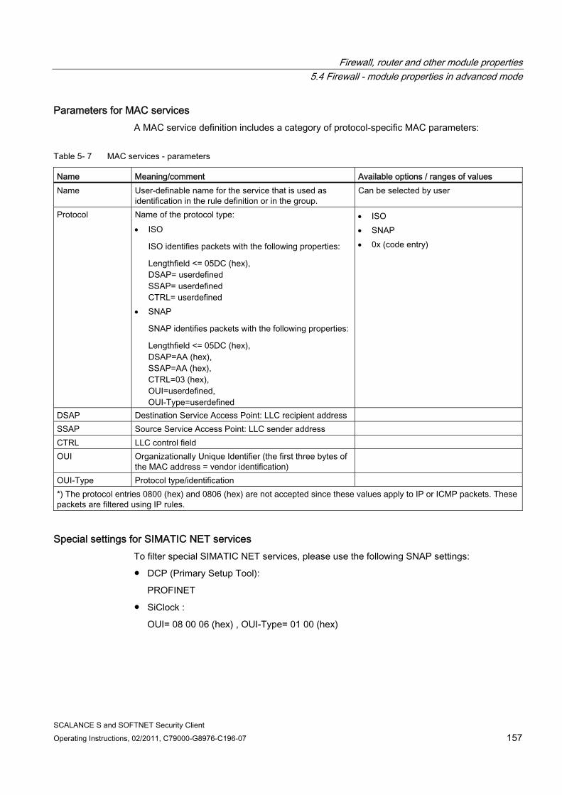
Firewall, router and other module properties 5.4 Firewall - module properties in advanced mode
SCALANCE S and SOFTNET Security Client Operating Instructions, 02/2011, C79000-G8976-C196-07 157
Parameters for MAC services A MAC service definition includes a category of protocol-specific MAC parameters:
Table 5- 7 MAC services - parameters
Name Meaning/comment Available options / ranges of values Name User-definable name for the service that is used as
identification in the rule definition or in the group. Can be selected by user
Protocol Name of the protocol type: ISO
ISO identifies packets with the following properties:
Lengthfield <= 05DC (hex), DSAP= userdefined SSAP= userdefined CTRL= userdefined
SNAP
SNAP identifies packets with the following properties:
Lengthfield <= 05DC (hex), DSAP=AA (hex), SSAP=AA (hex), CTRL=03 (hex), OUI=userdefined, OUI-Type=userdefined
ISO SNAP 0x (code entry)
DSAP Destination Service Access Point: LLC recipient address SSAP Source Service Access Point: LLC sender address CTRL LLC control field OUI Organizationally Unique Identifier (the first three bytes of
the MAC address = vendor identification)
OUI-Type Protocol type/identification *) The protocol entries 0800 (hex) and 0806 (hex) are not accepted since these values apply to IP or ICMP packets. These packets are filtered using IP rules.
Special settings for SIMATIC NET services To filter special SIMATIC NET services, please use the following SNAP settings:
● DCP (Primary Setup Tool):
PROFINET
● SiClock :
OUI= 08 00 06 (hex) , OUI-Type= 01 00 (hex)
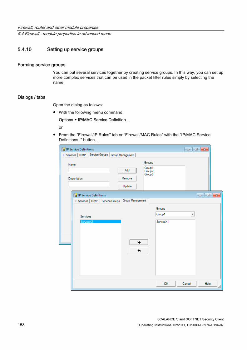
Firewall, router and other module properties 5.4 Firewall - module properties in advanced mode
SCALANCE S and SOFTNET Security Client 158 Operating Instructions, 02/2011, C79000-G8976-C196-07
5.4.10 Setting up service groups
Forming service groups You can put several services together by creating service groups. In this way, you can set up more complex services that can be used in the packet filter rules simply by selecting the name.
Dialogs / tabs Open the dialog as follows:
● With the following menu command:
Options ▶ IP/MAC Service Definition...
or
● From the "Firewall/IP Rules" tab or "Firewall/MAC Rules" with the "IP/MAC Service Definitions.." button. .

Firewall, router and other module properties 5.5 Time synchronization
SCALANCE S and SOFTNET Security Client Operating Instructions, 02/2011, C79000-G8976-C196-07 159
5.5 Time synchronization
Meaning The date and time are kept on the SCALANCE S module to check the validity (time) of a certificate and for the time stamps of log entries.
Note
Time-of-day synchronization relates solely to the SCALANCE S module and cannot be used to synchronize devices in the internal network of the SCALANCE S.
Alternative methods of timekeeping The following alternatives can be configured:
● Local PC clock
The module time is set automatically to the PC time when a configuration is downloaded.
● NTP server
Automatic setting and periodic synchronization of the time using an NTP server (Network Time Protocol).
Opening the dialog for configuring time synchronization Select the module you want to edit and then the following menu command:
Edit ▶ Properties..., "Time Synchronization" tab

Firewall, router and other module properties 5.5 Time synchronization
SCALANCE S and SOFTNET Security Client 160 Operating Instructions, 02/2011, C79000-G8976-C196-07
Synchronization by an NTP time server If you want the time to be synchronized by an NTP time server, specify the two following parameters in the configuration:
● IP address of the NTP server
● The update interval in seconds
NOTICE
If the NTP server cannot be reached by the SCALANCE S over an IPsec tunnel connection, you must allow the packets from the NTP server explicitly in the firewall (UDP, Port 123).
External time frames External time frames are not secure and can be corrupted/counterfeited in the external network. This can, for example, lead to falsification of the local time in the internal network and on SCALANCE S modules.
For this reason, NTP servers should be located in internal networks.

Firewall, router and other module properties 5.6 Creating SSL certificates
SCALANCE S and SOFTNET Security Client Operating Instructions, 02/2011, C79000-G8976-C196-07 161
5.6 Creating SSL certificates
Meaning SSL certificates are sued for authentication of the communication between a device and SCALANCE S in online communication.
Opening the dialog for managing SSL certificates Select the module you want to edit and then the following menu command:
Edit ▶ Properties ..., "SSL Certificate" tab

Firewall, router and other module properties 5.7 Routing mode
SCALANCE S and SOFTNET Security Client 162 Operating Instructions, 02/2011, C79000-G8976-C196-07
5.7 Routing mode
5.7.1 Routing
Meaning If you have enabled routing mode, packets intended for an existing IP address in the subnets (internal or external) are forwarded. The firewall rules for the direction of transmission also apply.
For this mode, you configure an internal IP address and an internal subnet mask for addressing the router in the internal subnet in the dialog shown below.
Operating view Configuration of this function is identical in standard and advanced mode.
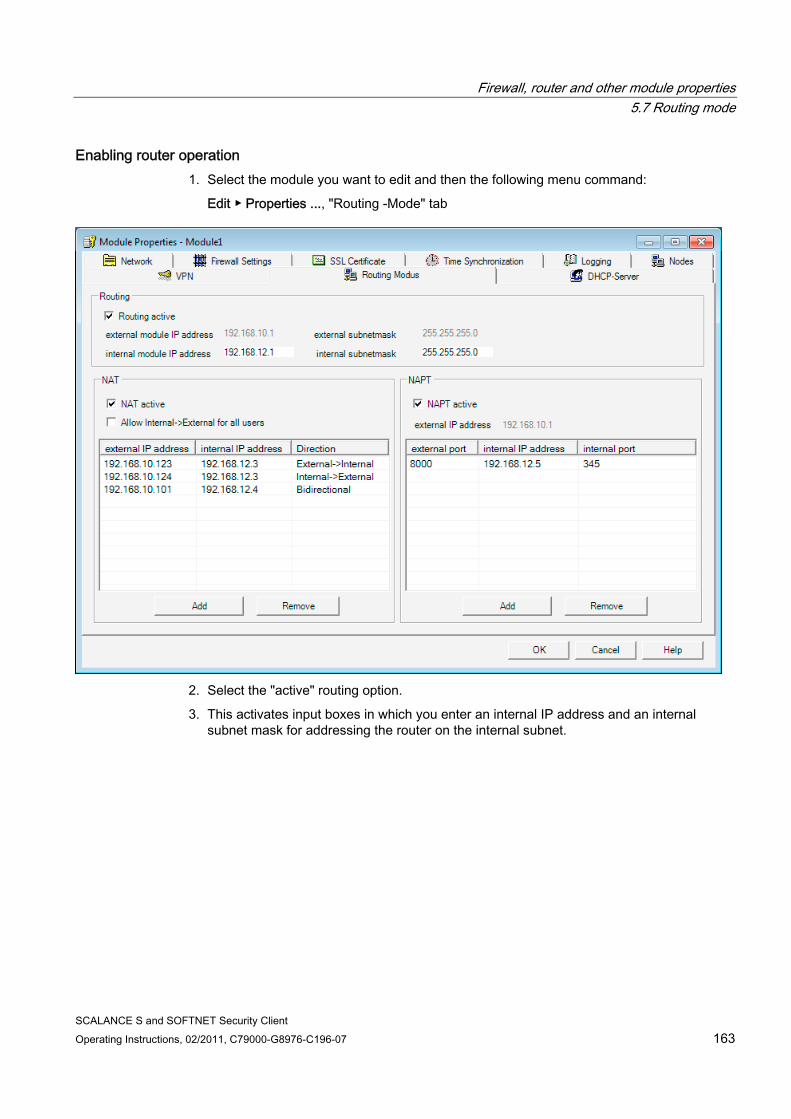
Firewall, router and other module properties 5.7 Routing mode
SCALANCE S and SOFTNET Security Client Operating Instructions, 02/2011, C79000-G8976-C196-07 163
Enabling router operation 1. Select the module you want to edit and then the following menu command:
Edit ▶ Properties ..., "Routing -Mode" tab
2. Select the "active" routing option.
3. This activates input boxes in which you enter an internal IP address and an internal subnet mask for addressing the router on the internal subnet.
Firewall, router and other module properties 5.7 Routing mode
SCALANCE S and SOFTNET Security Client 164 Operating Instructions, 02/2011, C79000-G8976-C196-07
5.7.2 NAT/NAPT routing
Meaning By configuring address conversion in the "Routing Mode" dialog, you operate the SCALANCE S as NAT/NAPT router. With this technique, the addresses of the nodes in the internal subnet are not known in the external network; the internal nodes are visible in the external network only under the external IP addresses defined in the address conversion list (NAT table and NAPT table) and are therefore protected from direct access.
● NAT: Network Address Translation
● NAPT: Network Address Port Translation
Operating view This function is available in advanced mode.
To use all the functions and menu commands described in section, switch over the mode:
View ▶ Advanced Mode
The mode described here includes operation as default router. You should therefore refer to the information in the section "Routing".
Relationship between NAT/NAPT router and firewall Whatever the direction, packets first run through the address conversion in the NAT/NAPT router and then pass through the firewall. The settings for the NAT/NAPT router and the firewall rules must be matched so that packets with a converted address can pass through the firewall.
The firewall and NAT/NAPT router supports the "Stateful Packet Inspection" mechanism. As a result, reply packets can pass through the NAT/NAPT router and firewall without it being necessary for their addresses to be included in the firewall rule and the NAT/NAPT address conversion.
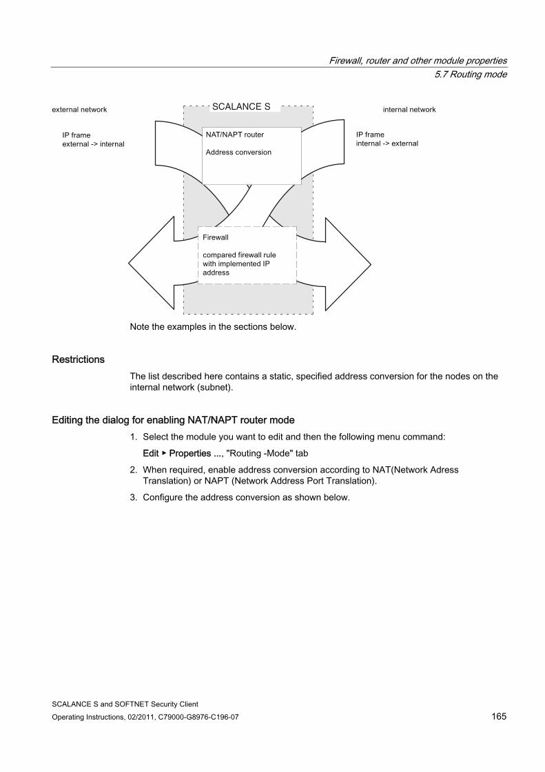
Firewall, router and other module properties 5.7 Routing mode
SCALANCE S and SOFTNET Security Client Operating Instructions, 02/2011, C79000-G8976-C196-07 165
SCALANCE S
Note the examples in the sections below.
Restrictions The list described here contains a static, specified address conversion for the nodes on the internal network (subnet).
Editing the dialog for enabling NAT/NAPT router mode 1. Select the module you want to edit and then the following menu command:
Edit ▶ Properties ..., "Routing -Mode" tab
2. When required, enable address conversion according to NAT(Network Adress Translation) or NAPT (Network Address Port Translation).
3. Configure the address conversion as shown below.
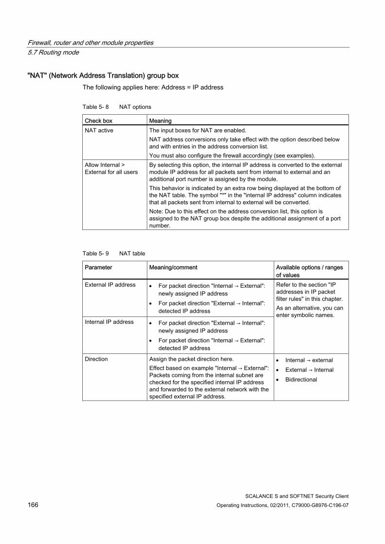
Firewall, router and other module properties 5.7 Routing mode
SCALANCE S and SOFTNET Security Client 166 Operating Instructions, 02/2011, C79000-G8976-C196-07
"NAT" (Network Address Translation) group box The following applies here: Address = IP address
Table 5- 8 NAT options
Check box Meaning NAT active The input boxes for NAT are enabled.
NAT address conversions only take effect with the option described below and with entries in the address conversion list. You must also configure the firewall accordingly (see examples).
Allow Internal > External for all users
By selecting this option, the internal IP address is converted to the external module IP address for all packets sent from internal to external and an additional port number is assigned by the module. This behavior is indicated by an extra row being displayed at the bottom of the NAT table. The symbol "*" in the "internal IP address" column indicates that all packets sent from internal to external will be converted. Note: Due to this effect on the address conversion list, this option is assigned to the NAT group box despite the additional assignment of a port number.
Table 5- 9 NAT table
Parameter Meaning/comment Available options / ranges of values
External IP address For packet direction "Internal → External": newly assigned IP address
For packet direction "External → Internal": detected IP address
Internal IP address For packet direction "External → Internal": newly assigned IP address
For packet direction "Internal → External": detected IP address
Refer to the section "IP addresses in IP packet filter rules" in this chapter. As an alternative, you can enter symbolic names.
Direction Assign the packet direction here. Effect based on example "Internal → External": Packets coming from the internal subnet are checked for the specified internal IP address and forwarded to the external network with the specified external IP address.
Internal → external External → Internal Bidirectional
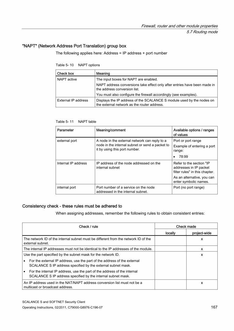
Firewall, router and other module properties 5.7 Routing mode
SCALANCE S and SOFTNET Security Client Operating Instructions, 02/2011, C79000-G8976-C196-07 167
"NAPT" (Network Address Port Translation) group box The following applies here: Address = IP address + port number
Table 5- 10 NAPT options
Check box Meaning NAPT active The input boxes for NAPT are enabled.
NAPT address conversions take effect only after entries have been made in the address conversion list. You must also configure the firewall accordingly (see examples).
External IP address Displays the IP address of the SCALANCE S module used by the nodes on the external network as the router address.
Table 5- 11 NAPT table
Parameter Meaning/comment Available options / ranges of values
external port A node in the external network can reply to a node in the internal subnet or send a packet to it by using this port number.
Port or port range Example of entering a port range: 78:99
Internal IP address IP address of the node addressed on the internal subnet
Refer to the section "IP addresses in IP packet filter rules" in this chapter. As an alternative, you can enter symbolic names.
internal port Port number of a service on the node addressed in the internal subnet.
Port (no port range)
Consistency check - these rules must be adhered to When assigning addresses, remember the following rules to obtain consistent entries:
Check made Check / rule
locally project-wide The network ID of the internal subnet must be different from the network ID of the external subnet.
x
The internal IP addresses must not be identical to the IP addresses of the module. x Use the part specified by the subnet mask for the network ID. For the external IP address, use the part of the address of the external
SCALANCE S IP address specified by the external subnet mask. For the internal IP address, use the part of the address of the internal
SCALANCE S IP address specified by the internal subnet mask.
x
An IP address used in the NAT/NAPT address conversion list must not be a multicast or broadcast address.
x

Firewall, router and other module properties 5.7 Routing mode
SCALANCE S and SOFTNET Security Client 168 Operating Instructions, 02/2011, C79000-G8976-C196-07
Check made Check / rule
locally project-wide The default router must be in one of the two subnets of the SCALANCE S; in other words, it must match either the external or internal IP address.
x
The external ports assigned for the NAPT conversion are in the range > 0 and <= 65535. Port123 (NTP), 443 (HTTPS), 514 (Syslog) and 500+4500 (IPsec; only for S612 and S613) are also excluded.
x
The external IP address of the SCALANCE S may only be used in the NAT table for the direction "Internal → External".
x
The internal IP address of the SCALANCE S may only be used in the NAT table and not in the NAPT table.
x
Checking for duplicates in the NAT table An external IP address used in the direction "External → Internal" or "Bidirectional" may only occur once in the NAT table.
x
Checking for duplicates in the NAPT table An external port number may only be entered once. Since the IP address of
the SCALANCE S is always used as the external IP address, multiple use would lead to ambiguities.
The port numbers or port ranges of the external ports must not overlap.
x
As soon as the routing mode is enabled, the second addresses (IP/subnet) must be assigned to the SCALANCE S.
x
Internal NAPT ports can be between > 0 and <= 65535. x
Once you have completed your entries, run a consistency check.
Select the following menu command:
Options ▶ Check Consistency
5.7.3 NAT/NAPT routing - Examples of configuration part 1
Overview The section contains the following examples of configuring the NAT/NAPT router:
● Example 1: NAT address conversion "External → Internal"
● Example 2: NAT address conversion "Internal → External"
● Example 3: NAT address conversion "Bidirectional"
● Example 4: NAPT address conversion

Firewall, router and other module properties 5.7 Routing mode
SCALANCE S and SOFTNET Security Client Operating Instructions, 02/2011, C79000-G8976-C196-07 169
Project engineering In the following routing configurations, you will find address assignments according to the NAT and NAP address conversion:

Firewall, router and other module properties 5.7 Routing mode
SCALANCE S and SOFTNET Security Client 170 Operating Instructions, 02/2011, C79000-G8976-C196-07
Description ● Example 1: NAT address conversion "External → Internal"
A node in the external network can send a packet to the node with the internal IP address 192.168.12.3 in the internal subnet by using the external IP address 192.168.10.123 as destination address.
● Example 2: NAT address conversion "Internal → External"
Packets of an internal node with the internal IP address 192.168.12.3 are forwarded to the external network with the external IP address 192.168.10.124 as the source address. In the example, the firewall is set so that packets with the source IP address 192.168.10.124 are allowed from internal to external and that nodes with the IP address 192.168.10.11 can be reached.
● Example 3: NAT address conversion "Bidirectional"
In this example, the address conversion is made both for internal and external incoming packets as follows:
– A node in the external network can send a packet to the node with the internal IP address 192.168.12.4 in the internal subnet by using the external IP address 192.168.10.101 as destination address.
– Packets of an internal node with the internal IP address 192.168.12.4 are forwarded on the external network with the external IP address 192.168.10.101 as the source address. The firewall is set so that frames with the source IP address 192.168.10.101 are allowed from internal to external.
● Example 4: NAPT address conversion
Addresses are converted according to NAPT so that additional port numbers are also assigned. The destination IP address and destination port number of all TCP and UDP packets entering the external network are checked.
– A node in the external network can send a packet to the node with IP address 192.168.12.4 and port number 345 in the internal subnet by using the external module IP address 192.160.10.1 and the external or number 8000 as the destination address.
5.7.4 NAT/NAPT routing - Examples of configuration part 2
Overview The section contains the following examples of configuring the NAT/NAPT router:
● Example 1: Allow external communication for all internal nodes
● Example 2: Also allow frames from external to internal.
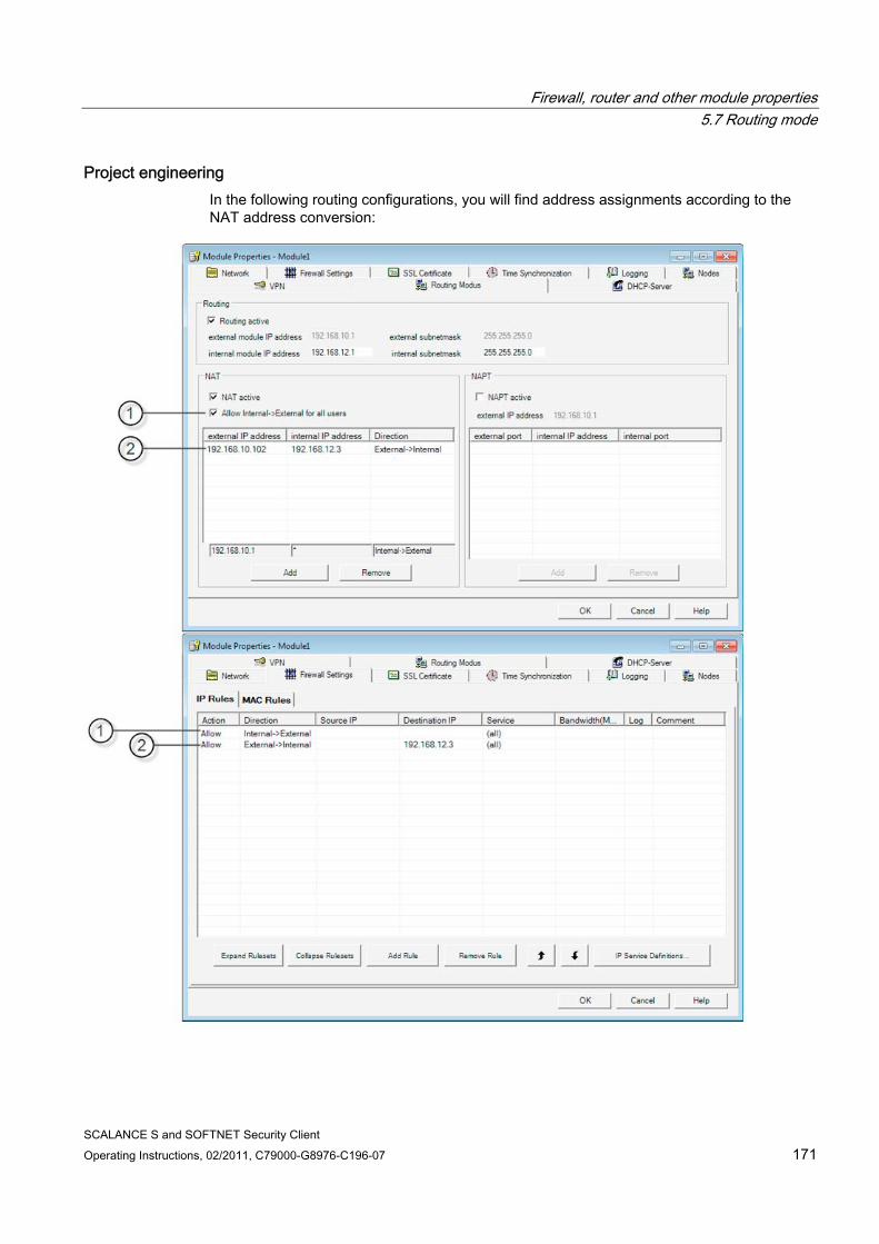
Firewall, router and other module properties 5.7 Routing mode
SCALANCE S and SOFTNET Security Client Operating Instructions, 02/2011, C79000-G8976-C196-07 171
Project engineering In the following routing configurations, you will find address assignments according to the NAT address conversion:
Firewall, router and other module properties 5.8 DHCP server
SCALANCE S and SOFTNET Security Client 172 Operating Instructions, 02/2011, C79000-G8976-C196-07
Description
Example 1 - Allow external communication for all internal nodes The "Allow Internal -> External for all users" check box is selected in the "NAT" group box.
This makes communication from internal to external possible. The address conversion works so that all internal addresses are converted to the external IP address of SCALANCE S and a dynamically assigned port number.
Specifying a direction in the NAT address conversion list is now no longer relevant. All the other information relates to the communication direction external to internal.
The firewall is set so that the frames can pass from internal to external.
Example 2 - Also allow frames from external to internal. To also allow communication from external to internal over and above the communication in example 1, entries must be made in the NAT or NAPT address conversion list. The entry in the example, means that frames to the node with IP address 192.168.10.102 will be converted to the internal IP address 192.168.12.3.
The firewall must be set accordingly. Since the NAT/NAPT conversion is always made first and the converted address is then tested in a second step in the firewall, the internal IP address is entered as the destination IP address in the firewall in our example.
5.8 DHCP server
Overview You can operate SCALANCE S on the internal network as a DHCP server. This allows IP addresses to be assigned automatically to the devices connected to the internal network.
The IP addresses are assigned either dynamically from an address band you have specified or you can select a specific IP address for a particular device.
Switch over to advanced mode Configuration as a DHCP server is possible only in "Advanced mode" in the Security Configuration Tool. Change the mode using the following menu command:
View ▶ Advanced Mode
Prerequisite You configure the devices in the internal network so that they obtain the IP address from a DHCP server.
Depending on the mode, SCALANCE S informs the nodes in the subnet of a router IP address otherwise you must make the router IP address known to the nodes in the subnet.
Firewall, router and other module properties 5.8 DHCP server
SCALANCE S and SOFTNET Security Client Operating Instructions, 02/2011, C79000-G8976-C196-07 173
● Router IP address will be transferred
In the following situations, the DHCP protocol of SCALANCE S will inform the nodes of the router IP address:
– SCALANCE S is configured for router mode;
In this case, SCALANCE S sends its own IP address as the router IP address
– SCALANCE S is not configured for router mode but a default router is specified in the configuration of the SCALANCE S;
In this case, SCALANCE S sends the default router IP address as the router IP address.
● Router IP address will not be transferred
In the following situations, enter the router IP address manually on the nodes:
– SCALANCE S is not configured for router mode;
– No default router is specified in the configuration of SCALANCE S.
Variants You have the following configuration options:
● Static address assignment
Devices with a specific MAC address or client ID are assigned the specified IP addresses. You specify these addresses by entering the devices in the address list in the "Static IP addresses" group box.
● Dynamic address assignment
Devices whose MAC address or whose client ID was not specified specifically, are assigned a random IP address from a specified address range. You set this address range in the "Dynamic IP addresses" group box.
NOTICE
Dynamic address assignment - reaction after interrupting the power supply
Please note that dynamically assigned IP addresses are not saved if the power supply is interrupted. On return of the power, you must therefore make sure that the nodes request an IP address again.
You should therefore only use dynamic address assignment for the following nodes: Nodes that are used temporarily in the subnet (such as service devices); Nodes that have been assigned an IP address and send this as the "preferred
address" the next time they request an address from the DHCP server (for example PC stations).
For nodes in permanent operation, use of a static address assignment by specifying a client ID (recommended for S7-CPs because it is simpler to replace modules) or the MAC address

Firewall, router and other module properties 5.8 DHCP server
SCALANCE S and SOFTNET Security Client 174 Operating Instructions, 02/2011, C79000-G8976-C196-07
Symbolic names are supported You can also enter the IP addresses or MAC addresses as symbolic names in the function described here.
Consistency check - these rules must be adhered to Remember the following rules when making the entries.
Check made1) Check / rule
locally Project-/module-wide
The IP addresses assigned in the address list in the "Static IP addresses" group box must not be in the range of the dynamic IP addresses.
x
Symbolic names must have a numeric address assignment. If you assign symbolic names for the first time here, you must still make the address assignment in the "Symbolic names" dialog.
x
IP addresses, MAC addresses and client IDs may only occur once in the "Static IP addresses" table (related to the SCALANCE S module).
x
For the statically assigned IP addresses, you must specify either the MAC address or the client ID (computer name).
x
The client ID is a string with a maximum of 63 characters. Only the following characters may be used: a-z, A-Z, 0-9 and - (dash). Note: In SIMATIC S7, a client ID can be assigned to the devices on the Ethernet interface to obtain an IP address over DHCP. With PCs, the method depends on the operating system being used; we recommend that you use the MAC address for the assignment here.
x
For the statically assigned IP addresses, you must specify the IP address. x The following IP addresses must not be in the range of the free IP address band (dynamic IP addresses): All router addresses in the "Network" tab NTP server Syslog server Default router SCALANCE S address(es)
x
DHCP is supported by SCALANCE S on the interface to the internal subnet. The following additional requirements for IP addresses in the range of the free IP address band (dynamic IP addresses) result from operational behavior of the SCALANCE S: Operation in flat networks
The range of the free IP address band must be in the network defined by SCALANCE S.
Router mode
The range of the free IP address band must be in the internal subnet defined by SCALANCE S.
x

Firewall, router and other module properties 5.8 DHCP server
SCALANCE S and SOFTNET Security Client Operating Instructions, 02/2011, C79000-G8976-C196-07 175
Check made1) Check / rule
locally Project-/module-wide
The free IP address band must be fully specified by entering the start IP address and the end IP address. The end IP address must be higher than the start IP address.
x
The IP addresses you enter in the address list in the "Static IP addresses" group box must be in the address range of the internal subnet of the SCALANCE S module.
x
Legend: 1) Note the explanations in the section "Consistency checks".

Firewall, router and other module properties 5.8 DHCP server
SCALANCE S and SOFTNET Security Client 176 Operating Instructions, 02/2011, C79000-G8976-C196-07
SCALANCE S and SOFTNET Security Client Operating Instructions, 02/2011, C79000-G8976-C196-07 177
F1
Secure communication in the VPN over an IPSec tunnel (S612/S613) 6
This chapter describes how to connect the IP subnets protected by a SCALANCE S to a virtual private network using drag-and-drop.
As already described in Chapter 5 in the module properties, you can once again use the default settings to achieve secure communication within your internal networks.
Further information You will find detailed information on the dialogs and parameter settings in the online help.
You can call this with the F1 key or using the "Help" button in the relevant dialog.
See also Online functions - test, diagnostics, and logging (Page 219)
6.1 VPN with SCALANCE S
Secure connection through an unprotected network For the internal networks protected by a SCALANCE S, IPsec tunnels allow a secure data connection through the non-secure external network.
Data exchange between devices through the IPsec tunnel in the VPN has the following properties:
● Confidentiality
The data exchanged is safe from eavesdropping;
● Integrity
The data exchanged is safe from corruption/counterfeiting;
● Authenticity
Only those with the appropriate rights can set up a tunnel.
SCALANCE S uses the IPsec protocol for tunneling (tunnel mode of IPsec).

Secure communication in the VPN over an IPSec tunnel (S612/S613) 6.1 VPN with SCALANCE S
SCALANCE S and SOFTNET Security Client 178 Operating Instructions, 02/2011, C79000-G8976-C196-07
External
Internal
External
Internal
External
Internal
External
Internal
0 1
HMI
SCALANCE S
OP 270
SCALANCE S SCALANCE S
IE/PBLink
ET 200X
S7-400 S7-300
Tunnel connections exist between modules in the same group (VPN) The properties of a VPN are put together in a module group on the SCALANCE S for all IPsec tunnels.
IPsec tunnels are established automatically between all SCALANCE S modules and SOFTNET Security Client modules that belong to the same group.
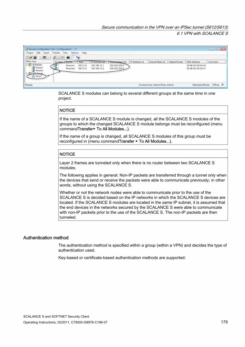
Secure communication in the VPN over an IPSec tunnel (S612/S613) 6.1 VPN with SCALANCE S
SCALANCE S and SOFTNET Security Client Operating Instructions, 02/2011, C79000-G8976-C196-07 179
SCALANCE S modules can belong to several different groups at the same time in one project.
NOTICE If the name of a SCALANCE S module is changed, all the SCALANCE S modules of the groups to which the changed SCALANCE S module belongs must be reconfigured (menu commandTransfer▶ To All Modules...).
If the name of a group is changed, all SCALANCE S modules of this group must be reconfigured in (menu commandTransfer ▶ To All Modules...).
NOTICE Layer 2 frames are tunneled only when there is no router between two SCALANCE S modules.
The following applies in general: Non-IP packets are transferred through a tunnel only when the devices that send or receive the packets were able to communicate previously; in other words, without using the SCALANCE S.
Whether or not the network nodes were able to communicate prior to the use of the SCALANCE S is decided based on the IP networks in which the SCALANCE S devices are located. If the SCALANCE S modules are located in the same IP subnet, it is assumed that the end devices in the networks secured by the SCALANCE S were able to communicate with non-IP packets prior to the use of the SCALANCE S. The non-IP packets are then tunneled.
Authentication method The authentication method is specified within a group (within a VPN) and decides the type of authentication used.
Key-based or certificate-based authentication methods are supported:
Secure communication in the VPN over an IPSec tunnel (S612/S613) 6.2 Groups
SCALANCE S and SOFTNET Security Client 180 Operating Instructions, 02/2011, C79000-G8976-C196-07
● Preshared keys
The preshared key is distributed to all modules in the group.
First enter a password in the "Preshared Key" box in the "Group Properties" dialog.
● Certificate
Certificate-based authentication is the default that is also active in standard mode. The procedure is as follows:
– When a group is generated, a group certificate is generated (group certificate = CA certificate).
– Each SCALANCE S in the group receives a certificate signed with the key of the group CA.
All certificates are based on the ITU standard X.509v3 (ITU, International Telecommunications Union).
The certificates are generated by a certification function in the Security Configuration Tool.
NOTICE
Restriction in VLAN operation
NO VLAN tagging is transferred within a VPN tunnel set up with SCALANCE S.
Reason: The VLAN tags are lost in unicast packets when they pass through the SCALANCE S because IPsec is used to transfer the IP packets. Only IP packets (not Ethernet packets) are transferred through an IPsec tunnel and the VLAN tags are therefore lost.
As default, broadcast or multicast packets cannot be transferred with IPsec. With SCALANCE S, IP broadcast packets are "packaged" and transferred just like MAC packets in UDP including the Ethernet header. With these packets, the VLAN tagging is therefore retained.
6.2 Groups
6.2.1 Creating groups and assigning modules
Follow the steps below to configure a VPN With the menu command
Insert ▶ Group
create a new group.
Assign the SCALANCE S modules and SOFTNET Security Client modules intended for an internal network to the group. by dragging the module to the required group with the mouse.

Secure communication in the VPN over an IPSec tunnel (S612/S613) 6.2 Groups
SCALANCE S and SOFTNET Security Client Operating Instructions, 02/2011, C79000-G8976-C196-07 181
Configuring properties Just as when configuring modules, the two selectable operating views in the Security Configuration Tool have an effect on configuring groups:
(View ▶ Advanced Mode menu command)
● Standard mode
In standard mode, you retain the defaults set by the system. Even if you are not an IT expert, you can nevertheless configure IPsec tunnels and operate secure data communication in your internal networks.
● Advanced mode
The advanced mode provides you with options for setting specific configurations for tunnel communication.
Note Setting parameters for MD 740 / MD 741 or other VPN clients
To set the parameter for MD 740 / MD 741 or other VPN clients, you configure VPN properties for the specific modules in advanced mode.
Displaying all configured groups and their properties Select "All Groups" in the Navigation Area
The following properties of the groups are displayed in columns:

Secure communication in the VPN over an IPSec tunnel (S612/S613) 6.2 Groups
SCALANCE S and SOFTNET Security Client 182 Operating Instructions, 02/2011, C79000-G8976-C196-07
Table 6- 1 Group properties
Property/column Meaning Comment/selection Group Name Group Name Freely selectable Authentication Type of authentication • Preshared Key
• Certificate Group membership until... Life of certificates See below Comment Comment Freely selectable
Setting the life of certificates Open the dialog in which you can set the expiry date of the certificate as follows:
● By double-clicking on a module in the properties window or right-clicking and selecting the Properties menu command.
NOTICE
When the certificate expires, communication through the tunnel is completed.
6.2.2 Module types within a group
Module types You can configure the following module types in groups with the Security Configuration Tool:
● SCALANCE S612
● SCALANCE S613
● SOFTNET Security Client
● MD 74x (stands for MD740-1 or MD741-1)
Rules for forming groups Remember the following rules if you want to create VPN groups:
● The first assigned module in a VPN group decides which other modules can be added to it.
If the first device added is in routing mode, you can only add other modules that have routing enabled on them. If the first device is in bridge mode, you can only add other modules that are in bridge mode. If you want to change the "mode" of a VPN group, you will have to remove all the modules contained in the group and add them again.
● It is not possible to add an MD 740-1/MD 741-1 module to a VPN group that contains a module in bridge mode.
Refer to the following table to see which modules can grouped together in a VPN group.

Secure communication in the VPN over an IPSec tunnel (S612/S613) 6.3 Tunnel configuration in standard mode
SCALANCE S and SOFTNET Security Client Operating Instructions, 02/2011, C79000-G8976-C196-07 183
Module mode… Module
.... in bridge mode … in routing mode S612 V1 x - S612 V2 *) x x S613 V1 x - S613 V2 *) x x SOFTNET Security Client 2005 x - SOFTNET Security Client 2008 x x SOFTNET Security Client V3.0 x x MD 74x - x
6.3 Tunnel configuration in standard mode
Group properties The following properties apply in standard mode:
● All parameters of the IPsec tunnel and the authentication are preset.
You can display the set default values in the properties dialog for the group.
● The learning mode is active for all modules.
Opening the dialog for displaying default values With a group selected, select the following menu command:
Edit ▶ Properties...
The display is identical to the dialog in advanced mode; the values cannot, however, be modified.
6.4 Tunnel configuration in advanced mode The advanced mode provides you with options for setting specific configurations for tunnel communication.
Switch over to advanced mode To use all the functions and menu commands described in section, switch over the mode:

Secure communication in the VPN over an IPSec tunnel (S612/S613) 6.4 Tunnel configuration in advanced mode
SCALANCE S and SOFTNET Security Client 184 Operating Instructions, 02/2011, C79000-G8976-C196-07
View ▶ Advanced Mode
Note
If you switch to the advanced mode for the current project, you can no longer switch back.
Unless you exit the project without saving and the open it again.
6.4.1 Configuring group properties
Group properties The following group properties can be set in the "advanced mode" operating view:
● Authentication method
● IKE settings (dialog area: Advanced Settings Phase 1)
● IPsec settings (dialog area: Advanced Settings Phase 2)
NOTICE
To be able to set these parameters, you require IPsec experience.
If you do not make or modify any settings, the defaults of standard mode apply.

Secure communication in the VPN over an IPSec tunnel (S612/S613) 6.4 Tunnel configuration in advanced mode
SCALANCE S and SOFTNET Security Client Operating Instructions, 02/2011, C79000-G8976-C196-07 185
Opening the dialog for entering group properties ● With a group selected, select the following menu command:
Edit ▶ Properties...
Parameters for advanced settings phase 1 - IKE settings Phase 1: IKE (Internet Key Exchange):
Here, you can set parameters for the protocol of the IPsec key management. The key exchange uses the standardized IKE method.
You can set the following IKE protocol parameters:

Secure communication in the VPN over an IPSec tunnel (S612/S613) 6.4 Tunnel configuration in advanced mode
SCALANCE S and SOFTNET Security Client 186 Operating Instructions, 02/2011, C79000-G8976-C196-07
Table 6- 2 IKE protocol parameters (parameter group "Advanced Settings Phase 1" in the dialog)
Parameter Values/selection Comment IKE Mode Main mode
Aggressive mode
Key exchange method The difference between the main and aggressive mode is the "identity protection" used in the main mode. The identity is transferred encrypted in main mode but not in aggressive mode.
Phase 1 DH Group Phase 1 DH Group
Group 1 Group 2 Group 5
Diffie-Hellman key agreement: Diffie-Hellman groups (selectable cryptographic algorithms in the Oakley key exchange protocol)
SA Lifetype SA Lifetype
Time Phase 1 Security Association (SA) Time limitation (min., default: 2500000)
The lifetime of the current key material is limited in time. When the time expires, the key material is renegotiated.
SA Life SA Life
Numeric value ("Time"→Min., ) Range of values: 1440...2 500 000
Phase 1 Encryption Phase 1 Encryption
DES 3DES-168 AES-128 AES-192 AES-256
Encryption algorithm Data Encryption Standard (56 bit key length, mode CBC) Triple DES (168 bit key length, mode CBC) Advanced Encryption Standard (128 bit, 192 bit or 256
bit key length, mode CBC)
Phase 1 Authentication Phase 1 Authentication
MD5 SHA1
Authentication algorithm Message Digest Version 5 Secure Hash Algorithm 1
Parameters for advanced settings phase 2 - IPsec settings Phase 2: Data exchange (ESP, Encapsulating Security Payload)
Here, you can set parameters for the protocol of the IPsec data exchange. The data exchange uses the standardized security protocol ESP.
You can set the following ESP protocol parameters:
Table 6- 3 IPsec protocol parameters (parameter group "Advanced Settings Phase 2" in the dialog)
Parameter Values/selection Comment SA Lifetype SA Lifetype
Time Phase 2 Security Association (SA) Time limitation (min., default: 2880)
The lifetime of the current key material is limited in time. When the time expires, the key material is renegotiated.
Limit Data amounts limited (Mbytes, default 4000)

Secure communication in the VPN over an IPSec tunnel (S612/S613) 6.4 Tunnel configuration in advanced mode
SCALANCE S and SOFTNET Security Client Operating Instructions, 02/2011, C79000-G8976-C196-07 187
Parameter Values/selection Comment SA Life SA Life
Numeric value ("Time"→Min., "Limit" → Mbyte) Range of values (time): 1440...16 666 666 Range of values (limit): 2000...500 000
Phase 2 Encryption Phase 2 Encryption
3DES-168 DES AES-128
Encryption algorithm Special triple DES (168 bit key length, mode CBC) Data Encryption Standard (56 bit key length, mode CBC) Advanced Encrypting Standard (128 bit key length,
mode CBC)
Phase 2 Authentication Phase 2 Authentication
MD5 SHA1
Authentication algorithm Message Digest Version 5 Secure Hash Algorithm 1
Perfect Forward Secrecy On Off
Each time an IPsec-SA is renegotiated, the key is negotiated again using the Diffie-Hellman method.
6.4.2 Including a SCALANCE S in a configured group The configured group properties are adopted for a SCALANCE S to be included in an existing group.
Follow the steps below: Depending on whether you have changed any group properties or not, you must make a distinction between the following:
● Case a: When you have not changed group properties
1. Add the new SCALANCE S to the group.
2. Download the configuration to the new modules.
● Case b: When you have changed group properties
1. Add the new SCALANCE S to the group.
2. Download the configuration to all modules that belong to the group.
Advantage Existing SCALANCE S modules that have already been commissioned do not need to be reconfigured and downloaded. There is no effect on or interruption of active communication.

Secure communication in the VPN over an IPSec tunnel (S612/S613) 6.4 Tunnel configuration in advanced mode
SCALANCE S and SOFTNET Security Client 188 Operating Instructions, 02/2011, C79000-G8976-C196-07
6.4.3 SOFTNET Security Client
Compatible settings for SOFTNET Security Client Please note the following special features if you include modules of the type SOFTNET Security Client in the configured group:
Parameter Setting / special feature Phase 1 DH Group Phase 1 DH Group
DH group1 and 5 can only be used for communication between the SCALANCE S modules.
Phase 1 Encryption Phase 1 Encryption
No DES, AES-128 and AES-192 possible.
Phase 1 Authentication Phase 1 Authentication
No MD5 possible.
Phase 1 SA Life Phase 1 SA Lifetime
Range of values: 1440 to 2879 (only SOFTNET Security Client V3.0)
SA Lifetype SA Lifetype
Must be selected identical for both phases.
Phase 2 Encryption Phase 2 Encryption
No AES 128 possible.
Phase 2 SA Life Phase 2 SA Lifetime
Range of values: 1440 to 2879 (only SOFTNET Security Client V3.0)
Phase 2 Authentication Phase 2 Authentication
No MD5 possible.
NOTICE The settings of the parameters for a SOFTNET Security Client configuration must match the default proposals of the SCALANCE S modules since a SOFTNET Security Client is usually mobile and obtains its IP address dynamically, the SCALANCE S can only allow a connection using these default proposals.
Please make sure that your Phase 1 settings match one of the three following proposals to be able to establish a tunnel with a SCALANCE S.
If you use other settings in the Security Configuration Tool, when you try to export the configuration, the consistency check cuts in and you cannot export your configuration for the SOFTNET Security Client until you have adapted the settings accordingly.
Authentication IKE Mode DH group Encryption Hash Lifetime (min) Certificate Mainmode DH group 2 3DES-168 SHA1 1440…2879 Preshared key Mainmode DH group 2 3DES-168 SHA1 1440…2879 Certificate Mainmode DH group 2 AES256 SHA1 1440…2879

Secure communication in the VPN over an IPSec tunnel (S612/S613) 6.4 Tunnel configuration in advanced mode
SCALANCE S and SOFTNET Security Client Operating Instructions, 02/2011, C79000-G8976-C196-07 189
6.4.4 Configuring module-specific VPN properties You can configure the following module-specific properties for data exchange over the IPsec tunnel in the VPN:
● Dead peer detection
● Permission to initiate connection establishment
● Public IP address for communication over Internet gateways
Opening the dialog for configuring VPN module properties Select the module you want to edit and then the following menu command in advanced mode:
Edit ▶ Properties..., "VPN" tab
Note
You can only select the "VPN" tab when the module you are configuring is in a VPN group.
Secure communication in the VPN over an IPSec tunnel (S612/S613) 6.4 Tunnel configuration in advanced mode
SCALANCE S and SOFTNET Security Client 190 Operating Instructions, 02/2011, C79000-G8976-C196-07
Dead peer detection (DPD) If DPD is enabled, the modules exchange additional messages at selectable intervals. This makes it possible to detect whether there is still a connection in the VPN. If the connection no longer exists, the "security associations" (SA) are terminated prematurely. If DPD is disabled, the "security association" (SA) is terminated only after the SA life (for setting of SA life: see configuration of the group properties) has elapsed.
As default, DPD is enabled.
Permission to initiate connection establishment You can restrict the permission for initiating the VPN connection establishment to certain modules in the VPN.
The decisive factor the setting of the parameter described here is the assignment of the IP address for the gateway of the module you are configuring. If a static IP address is assigned, the module can be found by the partner. If the IP address is assigned dynamically, and therefore changes constantly, the partner cannot establish a connection as things stand.
Mode Meaning Start connection to remote VPN gateway (standard)
If this option is selected, the module is "active", in other words, it attempts to establish the connection to the partner. This option is recommended when you obtain a dynamic IP address from your provider for the gateway of the SCALANCE S module you are configuring. The partner is addressed over its configured WAN IP address or its external module IP address.
Wait for connection from remote VPN gateway If this option is selected, the module is "passive", in other words, it waits for the partner to establish the connection. This option is recommended when you obtain a static IP address from your provider for the gateway of the module you are configuring. With this setting, only the partner attempts to establish the connection.
NOTICE Make sure that you do not set all the modules in a VPN group to "Wait for connection from remote VPN gateway" otherwise a connection will never be established.
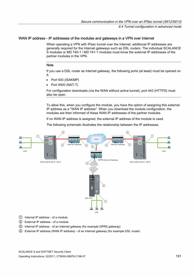
Secure communication in the VPN over an IPSec tunnel (S612/S613) 6.4 Tunnel configuration in advanced mode
SCALANCE S and SOFTNET Security Client Operating Instructions, 02/2011, C79000-G8976-C196-07 191
WAN IP address - IP addresses of the modules and gateways in a VPN over Internet When operating a VPN with IPsec tunnel over the Internet, additional IP addresses are generally required for the Internet gateways such as DSL routers. The individual SCALANCE S modules or MD 740-1 / MD 741-1 modules must know the external IP addresses of the partner modules in the VPN.
Note
If you use a DSL router as Internet gateway, the following ports (at least) must be opened on it: Port 500 (ISAKMP) Port 4500 (NAT-T)
For configuration downloads (via the WAN without active tunnel), port 443 (HTTPS) must also be open.
To allow this, when you configure the module, you have the option of assigning this external IP address as a "WAN IP address". When you download the module configuration, the modules are then informed of these WAN IP addresses of the partner modules.
If no WAN IP address is assigned, the external IP address of the module is used.
The following schematic illustrates the relationship between the IP addresses.
External
Internal
External
Internal
① Internal IP address - of a module ② External IP address - of a module ③ Internal IP address - of an Internet gateway (for example GPRS gateway) ④ External IP address (WAN IP address) - of an Internet gateway (for example DSL router)
Secure communication in the VPN over an IPSec tunnel (S612/S613) 6.5 Configuring internal network nodes
SCALANCE S and SOFTNET Security Client 192 Operating Instructions, 02/2011, C79000-G8976-C196-07
6.5 Configuring internal network nodes To make its own internal nodes known to the tunnel partners, a SCALANCE S must itself know its own internal nodes. It must also know the internal nodes of the SCALANCE S modules that are in the same group as itself. This information is used on a SCALANCE S to decide which data packet will be transferred in which tunnel.
In flat networks, SCALANCE S allows network nodes to be learnt automatically or configured statically.
In routing mode, complete subnets are tunneled; here learning and the static configuration of network nodes is not necessary.
6.5.1 How the learning mode works
Finding nodes for tunnel communication automatically (bridge mode only) One great advantage of configuration and operation of tunnel communication is that SCALANCE S can find nodes in the internal network automatically.
New nodes are detected by SCALANCE S during operation. The detected nodes are signaled to the SCALANCE S modules belonging to the same group. This allows data exchange within the tunnels of a group in both directions at any time.
Requirements The following nodes are detected:
● Network nodes with IP capability
Network nodes with IP capability are found when they send an ICMP response to the ICMP subnet broadcast.
IP nodes downstream from routers can be found if the routers pass on ICMP broadcasts.
● ISO network nodes
Network nodes without IP capability but that can be addressed over ISO protocols can also be learnt.
This is only possible if they reply to XID or TEST packets. TEST and XID (Exchange Identification) are auxiliary protocols for exchanging information on layer 2. By sending these packets with a broadcast address, these network nodes can be located.
● PROFINET nodes
Using DCP (Discovery and basic Configuration Protocol), it is possible to find PROFINET nodes.
Network nodes that do not meet these conditions must be configured.
Subnets Subnets located downstream from internal routers must also be configured.

Secure communication in the VPN over an IPSec tunnel (S612/S613) 6.5 Configuring internal network nodes
SCALANCE S and SOFTNET Security Client Operating Instructions, 02/2011, C79000-G8976-C196-07 193
Enabling/disabling the learning mode The learning function is enabled in the configuration as default for every SCALANCE S module by the Security Configuration Tool configuration software.
Learning can also be disabled completely. In this case, you must configure all internal nodes participating in the tunnel communication manually.
You can open the dialog in which you select the option as follows:
● With a module selected, with the menu command
Edit ▶ Properties..., "Nodes" tab.
When is it useful to disable the automatic learning mode? The default settings for SCALANCE S assume that internal networks are always "secure"; in other words, in a normal situation no network node is connected to the internal network if it is not trustworthy.
Disabling the learning mode can be useful if the internal network is static; in other words, when the number of internal notes and their addresses do not change.
If the learning mode is disabled, this reduces the load on the medium and the nodes in the internal network resulting from the learning packets. The performance of the SCALANCE S is also slightly improved since it does not need to process the learning packets.
Secure communication in the VPN over an IPSec tunnel (S612/S613) 6.5 Configuring internal network nodes
SCALANCE S and SOFTNET Security Client 194 Operating Instructions, 02/2011, C79000-G8976-C196-07
Note: In the learning mode, all nodes in the internal network are detected. The information relating to numbers of stations etc. in the VPN relates only to nodes that communicate over VPN in the internal network.
NOTICE If more than 64 (with SCALANCE S613) or 32 (with SCALANCE S612) internal nodes are being operated, the permitted configuration limits are exceeded and an illegal operating state is generated. Due to the dynamics in the network traffic, this causes internal nodes that have already been learned to be replaced by new previously unknown internal nodes.
6.5.2 Displaying the detected internal nodes All detected nodes can be displayed in the Security Configuration Tool in the "Online" mode in the "Internal Nodes" Tab.
Select the following menu command:
Edit ▶ Online Diagnostics...

Secure communication in the VPN over an IPSec tunnel (S612/S613) 6.5 Configuring internal network nodes
SCALANCE S and SOFTNET Security Client Operating Instructions, 02/2011, C79000-G8976-C196-07 195
6.5.3 Configuring nodes manually
Nodes that cannot be learnt There are nodes in the internal network that cannot be learnt. You must then configure these nodes. To do this, switch to advanced mode in the Security Configuration Tool.
You must also configure subnets located in the internal network of the SCALANCE S.

Secure communication in the VPN over an IPSec tunnel (S612/S613) 6.5 Configuring internal network nodes
SCALANCE S and SOFTNET Security Client 196 Operating Instructions, 02/2011, C79000-G8976-C196-07
Dialog / tab You can open the dialog in which you configure the nodes as follows:
● With a module selected, with the menu command
Edit ▶ Properties..., "Nodes" tab.
Here, in the various tabs, enter the required address parameters for all network nodes to be protected by the selected SCALANCE S module.
"Internal IP Nodes" tab (bridge mode only) Configurable parameters: IP address and optionally the MAC address
"Internal MAC Nodes" tab (bridge mode only) Configurable parameter: MAC address

Secure communication in the VPN over an IPSec tunnel (S612/S613) 6.5 Configuring internal network nodes
SCALANCE S and SOFTNET Security Client Operating Instructions, 02/2011, C79000-G8976-C196-07 197
"Internal Subnets" tab In the case of an internal subnet (a router in the internal network), specify the following address parameters:
Parameter Function Example of a value Network ID Network ID of the subnet: Based on the network ID, the router
recognizes whether a target address is inside or outside the subnet.
196.80.96.0
Subnet mask Subnet mask: The subnet mask structures the network and is used to form the subnet ID.
255.255.255.0
Router IP IP address of the router 196.80.96.1
Effects when using the SOFTNET Security Client If you configure nodes statically as described above when using the SCALANCE S612 / S613, you will also need to download the configuration for a SOFTNET Security Client used in the VPN.

SCALANCE S and SOFTNET Security Client Operating Instructions, 02/2011, C79000-G8976-C196-07 199
F1
SOFTNET Security Client (S612/S613) 7
With the SOFTNET Security Client PC software, secure remote access is possible from PCs/PGs to automation systems protected by SCALANCE S via public networks.
This chapter describes how to configure the SOFTNET Security Client in the Security Configuration Tool and then commission it on the PC/PG.
Further information You will also find detailed information on the dialogs and parameter settings in the online help of the SOFTNET Security Client.
You can call this with the F1 key or using the "Help" button in the relevant dialog.
See also Secure communication in the VPN over an IPSec tunnel (S612/S613) (Page 177)
7.1 Using the SOFTNET Security Client
Area of application - access over VPN With the SOFTNET Security Client, a PC/PG is configured automatically so that it can establish secure IPsec tunnel communication in the VPN (Virtual Private Network) with one or more SCALANCE S devices.
PG/PC applications such as NCM Diagnostics or STEP 7 can then access devices or networks in an internal network protected by SCALANCE S over a secure tunnel connection.
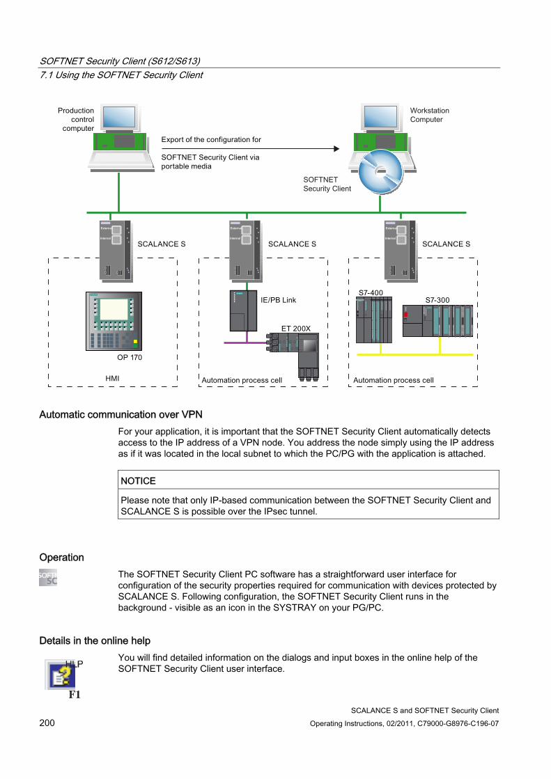
SOFTNET Security Client (S612/S613) 7.1 Using the SOFTNET Security Client
SCALANCE S and SOFTNET Security Client 200 Operating Instructions, 02/2011, C79000-G8976-C196-07
F1
External
Internal
External
Internal
External
Internal
Automatic communication over VPN For your application, it is important that the SOFTNET Security Client automatically detects access to the IP address of a VPN node. You address the node simply using the IP address as if it was located in the local subnet to which the PC/PG with the application is attached.
NOTICE Please note that only IP-based communication between the SOFTNET Security Client and SCALANCE S is possible over the IPsec tunnel.
Operation The SOFTNET Security Client PC software has a straightforward user interface for configuration of the security properties required for communication with devices protected by SCALANCE S. Following configuration, the SOFTNET Security Client runs in the background - visible as an icon in the SYSTRAY on your PG/PC.
Details in the online help You will find detailed information on the dialogs and input boxes in the online help of the SOFTNET Security Client user interface.
SOFTNET Security Client (S612/S613) 7.1 Using the SOFTNET Security Client
SCALANCE S and SOFTNET Security Client Operating Instructions, 02/2011, C79000-G8976-C196-07 201
You can open the online help with the "Help" button or the F1 key.
How does the SOFTNET Security Client work? The SOFTNET Security Client reads in the configuration created with the Security Configuration Tool and obtains the required information on the certificates to be imported from the file.
The root certificate and the private keys are imported and stored on the local PG/PC.
Following this, security settings are made based on the data from the configuration so that applications can access IP addresses downstream from the SCALANCE S modules.
If a learning mode for the internal nodes or programmable controllers is enabled, the configuration module first sets a security policy for the secure access to SCALANCE S modules. The SOFTNET Security Client then addresses the SCALANCE S modules to obtain the IP addresses of the relevant internal nodes.
SOFTNET Security Client enters these IP addresses in special filter lists belonging to this security policy. Following this, applications such as STEP 7 can communicate with the programmable controllers over VPN.
NOTICE On a Windows system, the IP security policies are stored separately for specific users. Only one IP security policy can ever be valid at one time for a user.
If you do not want an existing IP security policy to be overwritten by installing the SOFTNET Security Client, you should install and use the SOFTNET Security Client under a user specifically set up for it.
Environment The SOFTNET Security Client is designed for use with the Windows XP SP2 and SP3 (not "Home Edition") operating systems and Windows 7 (not "Home Edition").
Response to problems If problems occur on your PG/PC, SOFTNET Security Client reacts as follows:
● Established security policies are retained when you turn your PG/PC off and on again;
● Messages are displayed if a configuration is not found.

SOFTNET Security Client (S612/S613) 7.2 Installation and commissioning of the SOFTNET Security Client
SCALANCE S and SOFTNET Security Client 202 Operating Instructions, 02/2011, C79000-G8976-C196-07
7.2 Installation and commissioning of the SOFTNET Security Client
7.2.1 Installing and starting SOFTNET Security Client You install the SOFTNET Security Client PC software from the SCALANCE S CD.
1. First read the information in the README file of your SCALANCE S CD and follow any additional installation instructions it contains.
2. Run the Setup program;
The simplest way is to open the overview of the contents of your SCALANCE S CD → this is started automatically when you insert the CD or can be opened from the start.exe file. You can then select the entry "Installation SOFTNET Security Client" directly
Following installation and startup of the SOFTNET Security Client, the icon of the SOFTNET Security Client appears in the Windows taskbar:
Setting up the SOFTNET Security Client Once activated, the most important functions run in the background on your PG/PC.
The SOFTNET Security Client is configured in two steps:
● Export of a security configuration from the SCALANCE S Security Configuration Tool.
● Import of the security configuration in its own user interface as described in the next section.
Startup behavior With a maximum configuration and depending on the system, the SOFTNET Security Client can require up to 15 minutes to load the security rules. The CPU of the on PG/PC is at 100% usage during this time.
Exiting SOFTNET Security Client - effects If SOFTNET Security Client is exited, the security policy is also deactivated.
You can exit SOFTNET Security Client as follows:

SOFTNET Security Client (S612/S613) 7.3 Creating a configuration file with the Security Configuration Tool
SCALANCE S and SOFTNET Security Client Operating Instructions, 02/2011, C79000-G8976-C196-07 203
● Using the menu command in the SYSTRAY of Windows; select the icon of the SOFTNET Security Client with the right mouse button and then select the "Shut down SOFTNET Security Client" option.
● Using the "Quit" button of the user interface.
7.2.2 Uninstalling SOFTNET Security Client When you uninstall, the security properties set by the SOFTNET Security Client are reset.
7.3 Creating a configuration file with the Security Configuration Tool
Configuring a SOFTNET Security Client module in the project The SOFTNET security client is created as a module in the project. In contrast to the SCALANCE S modules, no further properties can be configured.
You simply assign the SOFTNET Security Client module to one or more module groups in which you want to set up IPsec tunnels to the PC/PG.
The group properties you configured for these groups are then decisive.
NOTICE Please refer to the information on the parameters in Section 6.4, subsection "Compatible settings for SOFTNET Security Client".
Note
If you create several SOFTNET Security Clients within a group, no tunnels are set up between these clients but only from the relevant client to the SCALANCE S modules!

SOFTNET Security Client (S612/S613) 7.3 Creating a configuration file with the Security Configuration Tool
SCALANCE S and SOFTNET Security Client 204 Operating Instructions, 02/2011, C79000-G8976-C196-07
Configuration files for the SOFTNET Security Client The interface between the Security Configuration Tool and the SOFTNET Security Client is controlled by configuration files.
The configuration is stored in three file types:
● *.dat
● *.p12
● *.cer
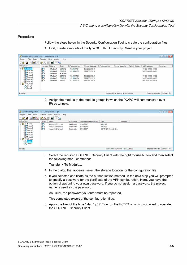
SOFTNET Security Client (S612/S613) 7.3 Creating a configuration file with the Security Configuration Tool
SCALANCE S and SOFTNET Security Client Operating Instructions, 02/2011, C79000-G8976-C196-07 205
Procedure Follow the steps below in the Security Configuration Tool to create the configuration files:
1. First, create a module of the type SOFTNET Security Client in your project.
2. Assign the module to the module groups in which the PC/PG will communicate over
IPsec tunnels.
3. Select the required SOFTNET Security Client with the right mouse button and then select
the following menu command:
Transfer ▶ To Module...
4. In the dialog that appears, select the storage location for the configuration file.
5. If you selected certificate as the authentication method, in the next step you will prompted to specify a password for the certificate of the VPN configuration. Here, you have the option of assigning your own password. If you do not assign a password, the project name is used as the password.
As usual, the password you enter must be repeated.
This completes export of the configuration files.
6. Apply the files of the type *.dat, *.p12, *.cer on the PC/PG on which you want to operate the SOFTNET Security Client.

SOFTNET Security Client (S612/S613) 7.4 Working with SOFTNET Security Client
SCALANCE S and SOFTNET Security Client 206 Operating Instructions, 02/2011, C79000-G8976-C196-07
7.4 Working with SOFTNET Security Client
Configurable properties You can use the following individual services:
● Setting up secure IPsec tunnel communication (VPN) between the PC/PG and all SCALANCE S modules of a project or individual SCALANCE S modules. The PC/PG can access the internal nodes over this IPsec tunnel.
● Enable and disable existing secure connections;
● Set up connections when end devices are added later; (only possible when the learning mode is activated)
● Check a configuration; in other words, which connections are set up or possible.
How to open SOFTNET Security Client for configuration You open the SOFTNET Security Client user interface by double-clicking on the icon in the SYSTRAY or with the "Open SOFTNET Security Client" context menu command (right mouse button):
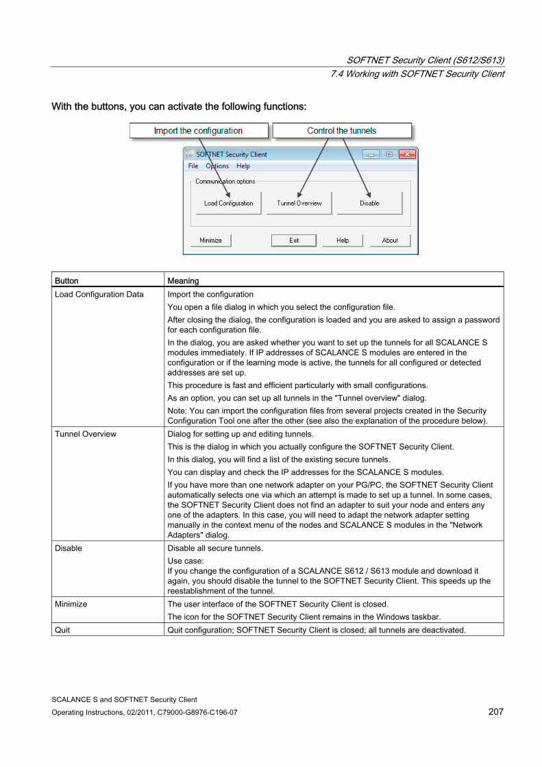
SOFTNET Security Client (S612/S613) 7.4 Working with SOFTNET Security Client
SCALANCE S and SOFTNET Security Client Operating Instructions, 02/2011, C79000-G8976-C196-07 207
With the buttons, you can activate the following functions:
Button Meaning Load Configuration Data Import the configuration
You open a file dialog in which you select the configuration file. After closing the dialog, the configuration is loaded and you are asked to assign a password for each configuration file. In the dialog, you are asked whether you want to set up the tunnels for all SCALANCE S modules immediately. If IP addresses of SCALANCE S modules are entered in the configuration or if the learning mode is active, the tunnels for all configured or detected addresses are set up. This procedure is fast and efficient particularly with small configurations. As an option, you can set up all tunnels in the "Tunnel overview" dialog. Note: You can import the configuration files from several projects created in the Security Configuration Tool one after the other (see also the explanation of the procedure below).
Tunnel Overview Dialog for setting up and editing tunnels. This is the dialog in which you actually configure the SOFTNET Security Client. In this dialog, you will find a list of the existing secure tunnels. You can display and check the IP addresses for the SCALANCE S modules. If you have more than one network adapter on your PG/PC, the SOFTNET Security Client automatically selects one via which an attempt is made to set up a tunnel. In some cases, the SOFTNET Security Client does not find an adapter to suit your node and enters any one of the adapters. In this case, you will need to adapt the network adapter setting manually in the context menu of the nodes and SCALANCE S modules in the "Network Adapters" dialog.
Disable Disable all secure tunnels. Use case: If you change the configuration of a SCALANCE S612 / S613 module and download it again, you should disable the tunnel to the SOFTNET Security Client. This speeds up the reestablishment of the tunnel.
Minimize The user interface of the SOFTNET Security Client is closed. The icon for the SOFTNET Security Client remains in the Windows taskbar.
Quit Quit configuration; SOFTNET Security Client is closed; all tunnels are deactivated.

SOFTNET Security Client (S612/S613) 7.4 Working with SOFTNET Security Client
SCALANCE S and SOFTNET Security Client 208 Operating Instructions, 02/2011, C79000-G8976-C196-07
Button Meaning Help Open online help. Info Information on the version of the SOFTNET Security Client
Details: List of all the files required for the SOFTNET Security Client to function with feedback as to whether these could be found on the system.

SOFTNET Security Client (S612/S613) 7.5 Setting up and editing tunnels
SCALANCE S and SOFTNET Security Client Operating Instructions, 02/2011, C79000-G8976-C196-07 209
7.5 Setting up and editing tunnels
Setting up secure connections to all SCALANCE S modules In the dialog for the configuration import, you can select whether or not the tunnels are set up for all SCALANCE S modules immediately. This results in the following possibilities:
● Enable tunnels automatically
If IP addresses of SCALANCE S modules are entered in the configuration or if the learning mode is active, the tunnels for all configured or detected addresses are set up.
● Read in tunnel configuration only
As an option, you can simply read in the configured tunnels and then enable them individually in the dialog.
How to set up tunnel connections 1. With the "Load Configuration Data", open the dialog for importing the configuration file.
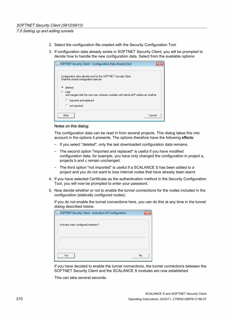
SOFTNET Security Client (S612/S613) 7.5 Setting up and editing tunnels
SCALANCE S and SOFTNET Security Client 210 Operating Instructions, 02/2011, C79000-G8976-C196-07
2. Select the configuration file created with the Security Configuration Tool.
3. If configuration data already exists in SOFTNET Security Client, you will be prompted to decide how to handle the new configuration data. Select from the available options:
Notes on this dialog:
The configuration data can be read in from several projects. This dialog takes this into account in the options it presents. The options therefore have the following effects:
– If you select "deleted", only the last downloaded configuration data remains.
– The second option "imported and replaced" is useful if you have modified configuration data, for example, you have only changed the configuration in project a, projects b and c remain unchanged.
– The third option "not imported" is useful if a SCALANCE S has been added to a project and you do not want to lose internal nodes that have already been learnt.
4. If you have selected Certificate as the authentication method in the Security Configuration Tool, you will now be prompted to enter your password.
5. Now decide whether or not to enable the tunnel connections for the nodes included in the configuration (statically configured nodes).
If you do not enable the tunnel connections here, you can do this at any time in the tunnel dialog described below.
If you have decided to enable the tunnel connections, the tunnel connections between the SOFTNET Security Client and the SCALANCE S modules are now established.
This can take several seconds.
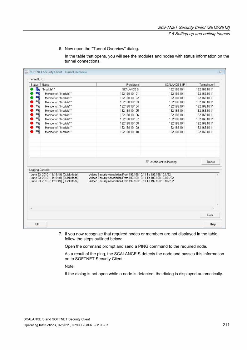
SOFTNET Security Client (S612/S613) 7.5 Setting up and editing tunnels
SCALANCE S and SOFTNET Security Client Operating Instructions, 02/2011, C79000-G8976-C196-07 211
6. Now open the "Tunnel Overview" dialog.
In the table that opens, you will see the modules and nodes with status information on the tunnel connections.
7. If you now recognize that required nodes or members are not displayed in the table,
follow the steps outlined below:
Open the command prompt and send a PING command to the required node.
As a result of the ping, the SCALANCE S detects the node and passes this information on to SOFTNET Security Client.
Note:
If the dialog is not open while a node is detected, the dialog is displayed automatically.
SOFTNET Security Client (S612/S613) 7.5 Setting up and editing tunnels
SCALANCE S and SOFTNET Security Client 212 Operating Instructions, 02/2011, C79000-G8976-C196-07
Note Statically configured nodes and subnets
If you configure nodes or subnets statically when using the SCALANCE S612 / S613, you will also need to download the configuration for a SOFTNET Security Client used in the VPN.
8. Activate the nodes for which the status display indicates that no tunnel connection has yet established.
Once the connection has been established, you can start your application - for example STEP 7 - and establish a communication connection to one of the nodes.
NOTICE
If you have more than one network adapter on your PG/PC, the SOFTNET Security Client automatically selects one via which an attempt is made to set up a tunnel. In some cases, the SOFTNET Security Client does not find an adapter to suit your project and enters any one of the adapters. In this case, you will need to adapt the network adapter setting manually using the context menu of the nodes and SCALANCE S modules.
Meaning of the parameters
Table 7- 1 Meaning of the parameters in the "Tunnel Overview" dialog box
Parameter Meaning / range of values Status You will find possible status displays in Table 7–2 Name Name of the module or the node taken from the configuration
created with the Security Configuration Tool. IP address int. / subnet IP address of the internal node or network ID of the internal subnet
if internal nodes/subnets exist Tunnel endpoint IP IP address of the assigned SCALANCE S module or MD741-1
module Tunnel over.. If you are using more than one network adapter in your PC, the
assigned IP address is displayed here.
Table 7- 2 Status displays
Symbol Meaning There is no connection to the module or node.
There are more nodes to be displayed. Double-click on the symbol to display further nodes.
The node cannot be activated.
The node is activated.
Disabled SCALANCE S module.

SOFTNET Security Client (S612/S613) 7.5 Setting up and editing tunnels
SCALANCE S and SOFTNET Security Client Operating Instructions, 02/2011, C79000-G8976-C196-07 213
Symbol Meaning
Enabled SCALANCE S module.
Deactivated MD741-1 module.
Activated MD741-1 module.
Module / node cannot be reached.
Module / node can be reached.
"enable active learning" check box If the learning mode has been enabled in the configuration of the SCALANCE S modules, you can also use the learning mode for the SOFTNET Security Client; You then obtain the information from the SCALANCE S modules automatically.
Otherwise the "Activate learning mode" is inactive and grayed out.
SOFTNET Security Client (S612/S613) 7.5 Setting up and editing tunnels
SCALANCE S and SOFTNET Security Client 214 Operating Instructions, 02/2011, C79000-G8976-C196-07
Selecting and working with a tunnel entry In the "Tunnel" dialog, you can select an entry and open several menu commands with the right mouse button.
NOTICE If several IP addresses are used for a network adapter, you may need to assign the IP address you want to use in the "Tunnel" dialog for each individual entry.
"Delete All" button This deletes the IP security policy completely including additional entries not set up by SOFTNET Security Client.

SOFTNET Security Client (S612/S613) 7.5 Setting up and editing tunnels
SCALANCE S and SOFTNET Security Client Operating Instructions, 02/2011, C79000-G8976-C196-07 215
Enabling and disabling existing secure connections You can disable existing secure connections with the "Disable" button. If you click the button, the text in the button changes to "Activate" and the icon in the status bar is replaced.
The security policy is now deactivated on the PC.
If you click on the button again, you can undo the change you made above and the tunnels are enabled again.
Logging Console The Logging Console is in the lower part of the "Tunnel Overview" dialog and supplies diagnostics information on the connection establishment with the configured SCALANCE S / MD741-1 modules and internal nodes / subnets.
The times of relevant events can be recorded with a date and time stamp.
The establishment and termination of a security association is shown. The result of a test ping (reachability test) to the configured nodes is displayed it the result is negative.
You can configure what is displayed in the "Settings" dialog.
"Clear" button If you click this, you delete the entries from the logging console of the tunnel overview.
Global settings for the SOFTNET Security Client Open the following menu item in the main dialog of the SOFTNET Security Client:
Options ▶ Settings
Here, you can make global settings that are retained after exiting and re-opening the SOFTNET Security Client.
You will find the functions in the following table:
Function Description / options Log file size (logging console) Log file size of the source file containing the
messages that are output filtered in the logging console and are restricted to a specific number.
Number of messages to be displayed in the logging console of the tunnel overview.
Number of messages that will be extracted from the log file of the source file and displayed in the logging console.

SOFTNET Security Client (S612/S613) 7.5 Setting up and editing tunnels
SCALANCE S and SOFTNET Security Client 216 Operating Instructions, 02/2011, C79000-G8976-C196-07
Output the following log messages in the logging console of the tunnel overview: Display of the negative reachability test (ping) Creation/deletion of security associations
(quick modes) Creation / deletion of main modes Download configuration files Learn internal nodes
Messages that are displayed optionally in the logging console can be enabled and disabled here
Log file size (debug log files) Log file size of the source files for debug messages of the SOFTNET Security Client (can be requested from Customer Support to make analyses easier)
Reachability test, wait time for reply Selectable wait time for a ping that will establish whether a tunnel partner can be reached. It is important to make this setting especially for tunnels over slow transmission paths (UMTS, GPRS, etc.) on which the delay of the data packets is significantly higher. This therefore directly influences the display of the reachability in the tunnel overview. Note For wireless networks, select a wait time of at least 1500 ms.
Disable reachability test globally If you enable this function, the reachability test is disabled globally for all the configurations contained in the SOFTNET Security Client. This has the advantage that no additional packets to create extra data volume and the disadvantage that in the tunnel overview you no longer receive feedback to tell you whether or not a tunnel partner can be reached.
Expanded module diagnostics Open the following menu item in the main dialog of the SOFTNET Security Client:
Options ▶ Advanced Module Diagnostics
Here, you can obtain the status of your system in terms of a configured module. This view is intended solely for diagnostics of your system status and can be helpful if have a query for Customer Support.
● SCALANCE S / MD741-1 module Here, select the module for which you want to diagnose the current system status.
● Routing settings (module-specific parameters) Here, you can see settings of the module relating to its interfaces and internal nodes/subnets obtained from the configuration.
● Active main modes / active quick modes Here, you can see the active main modes or quick modes in detail as soon as they have been set up for the selected module on the PG/PC. You can also see how many main modes or quick modes suitable for the selected module were found on the system.

SOFTNET Security Client (S612/S613) 7.5 Setting up and editing tunnels
SCALANCE S and SOFTNET Security Client Operating Instructions, 02/2011, C79000-G8976-C196-07 217
● Routing settings (network settings of the computer) Here, you can see the current routing settings of your computer. With the "Show all routing settings" option, you can also show the routing settings that were hidden to make the display clearer to read.
● Assigned IP addresses Here, you have a list of the network interfaces known to your computer in conjunction with the configured or assigned IP addresses.

SOFTNET Security Client (S612/S613) 7.5 Setting up and editing tunnels
SCALANCE S and SOFTNET Security Client 218 Operating Instructions, 02/2011, C79000-G8976-C196-07

SCALANCE S and SOFTNET Security Client Operating Instructions, 02/2011, C79000-G8976-C196-07 219
F1
Online functions - test, diagnostics, and logging 8
For test and monitoring purposes, SCALANCE S has diagnostic and logging functions.
● Diagnostic functions
These include various system and status functions that you can use in online mode.
● Logging functions
This involves the recording of system and security events.
The events are logged in the buffer area of the SCALANCE S or a server These functions can only be assigned parameters and evaluated when there is a network connection to the selected SCALANCE S module.
Recording events with logging functions You select the events to be logged in the log settings for the relevant SCALANCE S module.
You can configure the following variants for logging:
● Local log
In this variant, you log events in the local buffer of the SCALANCE S module. You can then access these logs, display them and archive them on the service station in the online dialog of the Security Configuration Tool.
● Network Syslog
With Network Syslog, you use a Syslog server that exists in the network. This logs the events according to the configuration in the log setting for the relevant SCALANCE S module.
Further information For detailed information on the dialogs and the parameters recorded in diagnostics and logging, please refer to the online help of the Security Configuration Tool.
You can call this with the F1 key or using the "Help" button in the relevant dialog.
See also Overview of the functions in the online dialog (Page 220)

Online functions - test, diagnostics, and logging 8.1 Overview of the functions in the online dialog
SCALANCE S and SOFTNET Security Client 220 Operating Instructions, 02/2011, C79000-G8976-C196-07
8.1 Overview of the functions in the online dialog In the Security Configuration Tool, SCALANCE S provides the following functions in the online dialog:
Table 8- 1 Functions and logging in online diagnostics
Function / tab in the online dialog
Meaning
System and status functions Status Display of the device status of the SCALANCE S module selected in the
project. Communications status (S612/S613)
Display of the communication status and the internal nodes for other SCALANCE S modules belonging to the VPN group.
Date and time Date and time setting. Internal nodes (S612/S613)
Display of the internal nodes of the SCALANCE S module.
Logging functions System Log Display of logged system events. Audit Log Display of logged security events. Packet Filter Log Displays logged data packets as well as starting and stopping packet
logging.
Note: Please read the notes on the device types.
Requirements for access Before you can run the online functions on a SCALANCE S module, the following requirements must be met:
● The online mode is activated in the Security Configuration Tool
● There is a network connection to the selected module
● The corresponding project with which the module was configured is open
Opening the online dialog Switch over the mode of the Security Configuration Tool with the following menu command:
View ▶ Online
Select the module you want to edit and then select the following menu command to open the online dialog
Edit ▶ Online Diagnostics...

Online functions - test, diagnostics, and logging 8.1 Overview of the functions in the online dialog
SCALANCE S and SOFTNET Security Client Operating Instructions, 02/2011, C79000-G8976-C196-07 221
Warning if the configuration is not up-to-date or the wrong project has been selected When you open the online dialog, the program checks whether the current configuration on the SCALANCE S module matches the configuration of the loaded project. If there are differences between the two configurations, a warning is displayed. This signals that you have either not yet updated the configuration or have selected the wrong project.
Online settings are not saved in the configuration Settings you make in online mode are not saved in the configuration on the SCALANCE S module. Following a module restart, the settings in the configuration are therefore always effective.

Online functions - test, diagnostics, and logging 8.2 Logging events
SCALANCE S and SOFTNET Security Client 222 Operating Instructions, 02/2011, C79000-G8976-C196-07
8.2 Logging events
Overview You can record events on the SCALANCE S. Depending on the event type, they are stored in volatile or non-volatile buffers. As an alternative, you can also record on a network server.
Configuration in standard and in advanced mode When logging, the options available in the Security Configuration Tool also depend on the selected view:
● Standard mode
The local log is enabled as default in standard mode; packet filter events can be enabled globally in the "Firewall" tab. Network Syslog is not possible in this view.
● Advanced mode
All logging functions can be enabled or disabled individually; packet filter events must be enabled selectively in the "Firewall" tab (local or global rules).
Logging procedures and event classes During configuration, you can specify which data should be logged. As a result, you enable logging as soon as you download the configuration to the SCALANCE S module.
During configuration, you also select one or both of the possible logging procedures:
● Local log
● Network Syslog
In both logging procedures, the SCALANCE S recognizes the three following types of events:
Table 8- 2 Logging - overview of the selectable events
Function / tab in the online dialog How it works Packet filter events (firewall) / packet filter log
The packet filter log records certain packets from the data traffic. Data packets are only logged if they match a configured packet filter rule (firewall) or to which the basic protection reacts (corrupt or invalid packets). This is only possible when logging is enabled for the packet filter rule.
Audit events / audit log The audit log automatically logs successive security-relevant events. This would include, for example, enabling or disabling packet logging or actions when users did not authenticate themselves correctly with a password.
System events / system log The system log automatically logs successive system events, for example the start of a process. The logging can be scaled based on event classes. Line diagnostics can also be configured. Line diagnostics returns messages as soon as the number of bad packets exceeds a selectable limit.
Online functions - test, diagnostics, and logging 8.2 Logging events
SCALANCE S and SOFTNET Security Client Operating Instructions, 02/2011, C79000-G8976-C196-07 223
Storage of logged data in local logging There are two options for storage of recorded data:
● Ring buffer
At the end of the buffer, the recording continues at the start of the buffer and overwrites the oldest entries.
● One-shot buffer
Recording stops when the buffer is full.
Enabling or disabling logging In offline mode, you can enable local logging for the event classes in the log settings and can select the storage mode. These log settings are loaded on the module with the configuration and take effect when the SCALANCE S starts up.
When required, you can also enable or disable local logging of packet filter events and system events in the online functions. This does not change the settings in the project configuration.
8.2.1 Local log - settings in the configuration In offline mode, you can enable the event classes in the log settings and can select the storage mode. These log settings are loaded on the module with the configuration and take effect when the SCALANCE S starts up.
If necessary, you can modify these configured log settings in the online functions. This does not change the settings in the project configuration.
Log settings in standard mode The log settings in standard mode correspond to the defaults in advanced mode. In standard mode, however, you cannot change the settings.
Log settings in advanced mode Select the module you want to edit and then the following menu command:
Edit ▶ Properties ..., "Log Settings" tab
The following dialog shows the standard settings for SCALANCE S; the dialog is also opened to configure the logging of system events:

Online functions - test, diagnostics, and logging 8.2 Logging events
SCALANCE S and SOFTNET Security Client 224 Operating Instructions, 02/2011, C79000-G8976-C196-07
Configuring event classes
Table 8- 3 Local log - overview of the functions
Function / tab in the online dialog
Project engineering Remarks
Packet filter events (firewall) / packet filter log (configurable)
You enable options using the check boxes. You select the storage mode using the check boxes.
Packet filter log data is not retentive
The data is stored in volatile memory on the SCALANCE S and is therefore no longer available after the power supply has been turned off.
Audit events / Audit log (always enabled)
Logging is always enabled. The logged information is always stored in the ring buffer.
Audit log data is retentive
The audit log data is saved in retentive memory on the SCALANCE S. The data of the audit log is therefore available after turning off the power supply.
Online functions - test, diagnostics, and logging 8.2 Logging events
SCALANCE S and SOFTNET Security Client Operating Instructions, 02/2011, C79000-G8976-C196-07 225
Function / tab in the online dialog
Project engineering Remarks
System events / System log (configurable)
You enable options using the check boxes. You select the storage mode using the check boxes. To configure the event filter and line diagnostics, open a further dialog with the "Configure..." button. In this dialog, you set a filter level for the system events. As default, the highest level is set so that only critical events are logged. Line diagnostics generates a special system event. A system event is generated when a user-defined percentage of bad packets is reached. This system event is assigned the priority and significance (facility) that can be set in this dialog.
System log data is not retentive
The system log data is saved in volatile memory on the SCALANCE S. This data is therefore no longer available after the power supply has been turned off.
Filtering system events
Select "Error" as the filter level or a higher value to exclude logging of general, uncritical events.
Priority of the system events of line diagnostics
Make sure that you do not assign a lower priority to the the system events of line diagnostics than for the filter. At a lower priority, these events will not pass through the filter and will not be logged.
8.2.2 Network Syslog - settings in the configuration You can configure SCALANCE S so that it sends Syslog information as a client to a Syslog server. The Syslog server can be in the internal or external subnet. The implementation corresponds to RFC 3164.
Note Firewall - Syslog server not active in the external network
If the Syslog server is not enabled on the addressed computer, this computer generally returns ICMP responses "port not reachable". If these reply packets are logged due to the firewall configuration and sent to the Syslog server, the procedure can become never ending (storm of events).
Remedies: Start the Syslog server; Change the firewall rules; Take the computer with the disabled Syslog server out of the network;
Switch over to advanced mode Configuration of the Syslog server is possible only in "Advanced mode" in the Security Configuration Tool. Change the mode using the following menu command:
View ▶ Advanced Mode

Online functions - test, diagnostics, and logging 8.2 Logging events
SCALANCE S and SOFTNET Security Client 226 Operating Instructions, 02/2011, C79000-G8976-C196-07
Making the logging settings Select the module you want to edit and then the following menu command:
Edit ▶ Properties... , "Log Settings" tab.
The following dialog shows the standard settings for SCALANCE S when logging is enabled for the network Syslog:
Establishing a connection to the Syslog server SCALANCE S uses the configured module name as the host name to identify itself with the Syslog server. You will need to specify the IP address of the Syslog server. You can enter the IP address either as a symbolic name or as a numeric name.
The Syslog server must be reachable from the SCALANCE S using the specified IP address, if necessary using the router configuration in the "Network" tab. If the Syslog server cannot be reached, the sending of Syslog information is disabled. You can recognize this operating situation based on the system messages. To enable the sending of Syslog information again, you may need to update the routing information and restart SCALANCE S.

Online functions - test, diagnostics, and logging 8.2 Logging events
SCALANCE S and SOFTNET Security Client Operating Instructions, 02/2011, C79000-G8976-C196-07 227
Use symbolic names in log You can replace the address information in the log packets transferred to the Syslog server by symbolic names. If the option is enabled, SCALANCE S checks whether corresponding symbolic names are configured and enters them in the log packet. Note that this increases the processing time on the SCALANCE S module.
The module names are automatically used as symbolic names for the IP addresses of the SCALANCE S modules. In routing mode, these names have a port name added to them as follows: "Modulename-P1", "Modulename-P2" etc.
Configuring event classes
Table 8- 4 Network Syslog - overview of the functions
Function / tab in the online dialog
Project engineering Remarks
Packet filter events (firewall) / packet filter log (configurable)
You enable options using the check boxes. You assign the priority and significance (facility) from drop-down list boxes. Each event is assigned the priority and significance (facility) that you set here.
The value you select here for the priority and significance (facility), depends on the evaluation in the Syslog server. This allows you to adapt to the requirements in the Syslog server. Defaults: Facility: 10 (security/auth) Prio: 5 (Notice)
Audit events / Audit log (always enabled)
You enable options using the check boxes. You assign the priority and significance (facility) from drop-down list boxes. Each event is assigned the priority and significance (facility) that you set here.
The value you select here for the priority and significance (facility), depends on the evaluation in the Syslog server. This allows you to adapt to the requirements in the Syslog server. Defaults: Facility: 13 (log audit) Prio: 6 (Informational)
System events / System log (configurable)
You enable options using the check boxes. To configure the event filter and line diagnostics, open a further dialog with the "Configure..." button. In this dialog, you set a filter level for the system events. As default, the highest level is set so that only critical events are logged. Line diagnostics generates a special system event. A system event is generated when a user-defined percentage of bad packets is reached. This system event is assigned the priority and significance (facility) that can be set in this dialog.
Filtering system events
Select "Error" as the filter level or a higher value to exclude logging of general, uncritical events.
Priority of the system events of line diagnostics
With the priority, you can weight the system events of line diagnostics relative to the priority of the other system events.
Make sure that you do not assign a lower priority to the the system events of line diagnostics than for the filter. At a lower priority, these events will not pass through the filter and will not reach the Syslog server.
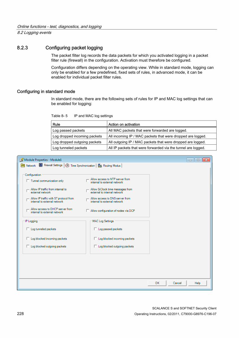
Online functions - test, diagnostics, and logging 8.2 Logging events
SCALANCE S and SOFTNET Security Client 228 Operating Instructions, 02/2011, C79000-G8976-C196-07
8.2.3 Configuring packet logging The packet filter log records the data packets for which you activated logging in a packet filter rule (firewall) in the configuration. Activation must therefore be configured.
Configuration differs depending on the operating view. While in standard mode, logging can only be enabled for a few predefined, fixed sets of rules, in advanced mode, it can be enabled for individual packet filter rules.
Configuring in standard mode In standard mode, there are the following sets of rules for IP and MAC log settings that can be enabled for logging:
Table 8- 5 IP and MAC log settings
Rule Action on activation Log passed packets All MAC packets that were forwarded are logged. Log dropped incoming packets All incoming IP / MAC packets that were dropped are logged. Log dropped outgoing packets All outgoing IP / MAC packets that were dropped are logged. Log tunneled packets All IP packets that were forwarded via the tunnel are logged.
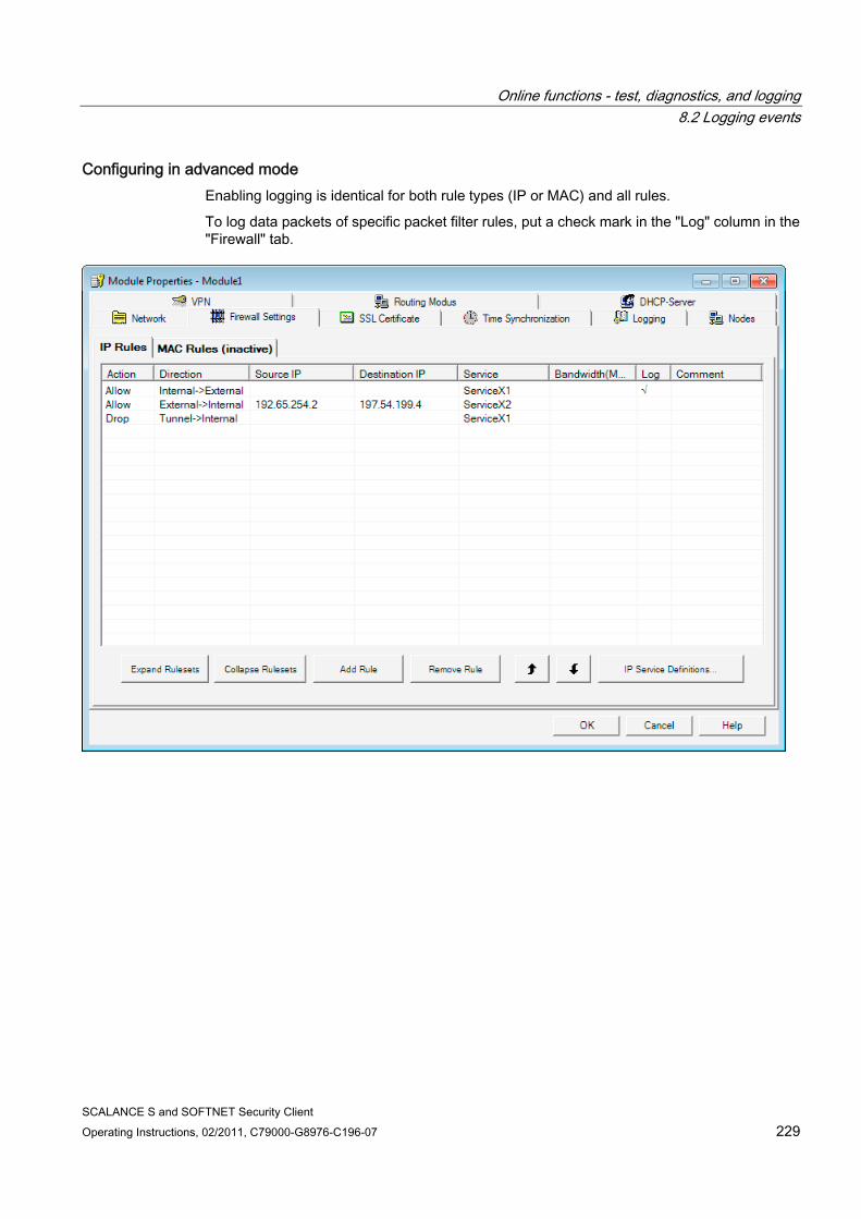
Online functions - test, diagnostics, and logging 8.2 Logging events
SCALANCE S and SOFTNET Security Client Operating Instructions, 02/2011, C79000-G8976-C196-07 229
Configuring in advanced mode Enabling logging is identical for both rule types (IP or MAC) and all rules.
To log data packets of specific packet filter rules, put a check mark in the "Log" column in the "Firewall" tab.


SCALANCE S and SOFTNET Security Client Operating Instructions, 02/2011, C79000-G8976-C196-07 231
Tips and help on problems AA.1 SCALANCE S module does not boot correctly
If the fault LED of the SCALANCE S module is lit red after booting, you should first completely reset the module. Press the reset button until the fault LED starts to flash yellow-red. The module is then reset to the factory settings. For productive operation, you must then download the configuration to the module again.
If the fault display of the SCALANCE S module continues to be lit red, however, the module can only be repaired in the factory.
A.2 SCALANCE S module cannot be reached
If the SCALANCE S module cannot be reached, check or note the following:
● Is your computer in the same network as the module?
● Resetting a module can take several minutes.
A.3 Replacing a SCALANCE S module A SCALANCE S module can be replaced without a PC (without needing to download the configuration to the new module). The C-PLUG of the module you are replacing is simply inserted in the new module you want to commission.
NOTICE The C-PLUG may only be inserted or removed when the power is off!
A.4 SCALANCE S module is compromised A SCALANCE S module is compromised when
● the private key belonging to the server certificate,
● the private key of the CA or
● the password of a user has become known.
Tips and help on problems A.5 Key from the configuration data compromised or lost
SCALANCE S and SOFTNET Security Client 232 Operating Instructions, 02/2011, C79000-G8976-C196-07
Private key of the server certificate known If the private key belonging to the server certificate has become known, the server certificate on the SCALANCE S module must be replaced. The user names stored on the SCALANCE S module do not need to be changed.
Follow the steps below: 1. Select the module you want to edit and then the menu command
Edit ▶ Properties..., "Certificate" tab.
2. Generate a new certificate.
3. Download the configuration to the SCALANCE S module.
The private key of the CA is known If the private key of the CA has become known, the certificate of the CA must be replaced on the SCALANCE S module. The user names can remain unchanged. The users do, however, require new certificates provided by the new CA.
Follow the steps below: 1. Select the group you want to edit and then the menu command
Edit ▶ Properties....
2. Generate a new certificate.
3. Download the configuration to all SCALANCE S modules that belong to the group.
Password of a user from the user group is known If the password of a user from the user group has become known, the password of this user must be changed.
Password of a user from the administrator group is known If the user belongs to the administrators group, the server certificate of the SCALANCE S module should also be changed.
A.5 Key from the configuration data compromised or lost
Key compromised If a private key from the configuration data of the SCALANCE S module is compromised, the key must be changed using the configuration tool of the SCALANCE S module.

Tips and help on problems A.6 General operational response
SCALANCE S and SOFTNET Security Client Operating Instructions, 02/2011, C79000-G8976-C196-07 233
Loss of the key If the private key that authorizes access to the configuration data is lost, it is no longer possible to access the SCALANCE S module with the configuration tool. The only possibility to regain access is to delete the configuration data and therefore also the key. You can delete this information by pressing the reset button. Following this, the SCALANCE S module must be taken into operation again.
A.6 General operational response
Adaptation of the MTU (Maximum Transmission Unit) The MTU specifies the permitted size of a packet for transfer in the network. When these data packets are now transferred by SCALANCE S over the IPsec tunnel, the original packet becomes larger due to the addition of header information and it may be necessary to fragment it for further transmission. This depends on the specified MTU in the connected network. If fragmentation becomes necessary, this can lead to a noticeable loss of performance or even break down of the data transmission.
You can avoid this by adapting to the MTU format; in other words, reducing packet size so that the packets arriving at the SCALANCE S can have the required additional information added without fragmentation being necessary. A practical size is between 1000 and 1400 bytes.

Tips and help on problems A.6 General operational response
SCALANCE S and SOFTNET Security Client 234 Operating Instructions, 02/2011, C79000-G8976-C196-07

SCALANCE S and SOFTNET Security Client Operating Instructions, 02/2011, C79000-G8976-C196-07 235
Notes on the CE Mark B
Product name SIMATIC NET SCALANCE S602 6GK5602-0BA00-2AA3 SIMATIC NET SCALANCE S612 6GK5612-0BA00-2AA3 SIMATIC NET SCALANCE S613 6GK5613-0BA00-2AA3
EMC directive 89/336/EEC "Electromagnetic Compatibility"
Area of application The product is designed for use in an industrial environment:
Area of application Requirements Emission Immunity Industrial area EN 61000-6-4 : 2001 EN 61000-6-2 : 2001
Installation guidelines The product meets the requirements if you keep to the installation instructions and safety-related notices as described here and in the manual "SIMATIC NET Industrial Ethernet Twisted Pair and Fiber Optic Networks" /1/ when installing and operating the device.
Conformity certificates The EC Declaration of Conformity is available for the responsible authorities according to the above-mentioned EC Directive at the following address:
Siemens Aktiengesellschaft Bereich Automatisierungs- und Antriebstechnik Industrielle Kommunikation (A&D SC IC) Postfach 4848 D-90327 Nürnberg

Notes on the CE Mark
SCALANCE S and SOFTNET Security Client 236 Operating Instructions, 02/2011, C79000-G8976-C196-07
Notes for the manufacturers of machines This product is not a machine in the sense of the EC Machinery Directive. There is therefore no declaration of conformity relating to the EC Machinery Directive 89/392/EEC for this product.
If the product is part of the equipment of a machine, it must be included in the procedure for obtaining the declaration of conformity by the manufacturer of the machine.
SCALANCE S and SOFTNET Security Client Operating Instructions, 02/2011, C79000-G8976-C196-07 237
References C
/1/ SIMATIC NET Industrial Twisted Pair and Fiber Optic Networks, Release 05/2001
Order numbers: 6GK1970-1BA10-0AA0 German 6GK1970-1BA10-0AA1 English 6GK1970-1BA10-0AA2 French 6GK1970-1BA10-0AA4 Italian
/2/ The GPRS/GSM Modem SINAUT MD740-1 system manual is available at:
http://support.automation.siemens.com/WW/view/de/23940893

References
SCALANCE S and SOFTNET Security Client 238 Operating Instructions, 02/2011, C79000-G8976-C196-07

SCALANCE S and SOFTNET Security Client Operating Instructions, 02/2011, C79000-G8976-C196-07 239
Dimension drawing D
Figure D-1 Drilling template

Dimension drawing
SCALANCE S and SOFTNET Security Client 240 Operating Instructions, 02/2011, C79000-G8976-C196-07
SCALANCE S and SOFTNET Security Client Operating Instructions, 02/2011, C79000-G8976-C196-07 241
Document history EE.1 Document history
This was new in issue 02 of this manual ● New SCALANCE S602 module
SCALANCE S602 makes a further module available providing scalable security functionality. SCALANCE S602 protects with the Stateful Inspection Firewall, NAT/NAPT routing, DHCP server and Syslog.
This was new in issue 03 of this manual ● Routing mode with the SCALANCE S612 / S613
The SCALANCE S modules S612 and S613 are available with enhanced functionality; they now also support NAT/NAPT routing, DHCP server and syslog.
● Security Configuration Tool V2.1
You can use the new version of the configuration tool to configure the S612 / S613 modules with their new functions.
● Configuration data for MD 740-1
To configure an external MD 740-1 you can create configuration data with the new version of the Security Configuration Tool.
This was new in issue 04 of this manual - Issue was not published -
Document history E.1 Document history
SCALANCE S and SOFTNET Security Client 242 Operating Instructions, 02/2011, C79000-G8976-C196-07
This was new in issue 05 of this manual This issue included descriptions of the following new functions:
● Security Configuration Tool V2.2
A SOFTNET Security Client can be configured in routing mode along with a SCALANCE S. (GETTING STARTED example – remote access)
Apart from the direct internal subnet connected to the SCALANCE S, other subnets can also be configured in routing mode making them accessible.
● SOFTNET Security Client V2.0
In the Tunnel Overview, a text box with diagnostic information on the connection establishment has been added.
The network adapter setting has been simplified with the addition of a new automatic function. When it starts up, the SOFTNET Security Client automatically attempts to find a suitable network adapter setting.
● Configuration data for module MD 741-1
To configure an external MD 741-1 you can create configuration data with the new version of the Security Configuration Tool.
This was new in issue 06 of this manual ● SOFTNET Security Client V3.0
Apart from the operating systems Windows XP SP2 and Windows XP SP3, the Windows 7 operating system is also supported (not the Home version).

SCALANCE S and SOFTNET Security Client Operating Instructions, 02/2011, C79000-G8976-C196-07 243
Glossary / abbreviations and acronyms
AAA AAA is an acronym for a security concept and stands for Authentication, Authorization and Accounting.
AES Advanced Encryption Standard
A symmetrical block cipher. It can be selected with SCALANCE S to encrypt data.
ARP Address Resolution Protocol
A protocol used for address resolution. Its task is to find the corresponding network hardware address (MAC address) for a given protocol address. An ARP protocol implementation is often found on hosts on which the Internet protocol family is used. IP forms a virtual network on the basis of IP addresses. These must be mapped to the given hardware addresses when the data is transported. To achieve this mapping, the ARP protocol is often used.
Bandwidth Maximum throughput of a connecting cable (normally specified in bps).
BDC Backup Domain Controller
The backup domain controllers have a backup copy of the user and logon data that is updated at regular intervals.
BRI Basic Rate Interface
Standard network connection to ISDN.
CA Certification Authority
Certification authority for authentication and encryption and decryption of confidential data transmitted via the Internet and other networks, for example by issuing and signing digital certificates.

Glossary / abbreviations and acronyms
SCALANCE S and SOFTNET Security Client 244 Operating Instructions, 02/2011, C79000-G8976-C196-07
CA certificate A certificate authority (CA) is an organization that issues digital certificates. For communication in computer networks, a digital certificate is the equivalent of an identity card. A certificate authority issues certificates to network users and attests them.
With SCALANCE S, a CA certificate is generated for each group. The group issues certificates to the group members and attests them with the group certificate (group certificate = CA certificate).
CHAP Challenge Handshake Authentication Protocol
Authentication protocol used within the framework of the Point-to-Point Protocol (PPP). PPP is located at the data link layer in the Internet protocol family.
Client A client is a device, or more generally an object, that requests a -> server to provide a service.
CTRL The control field (CTRL) contains control information for the LLC protocol. Logical Link Control (LLC) is the name of a network protocol standardized by the IEEE. It is a protocol mainly intended for data reliability in the data link layer and therefore belongs to layer 2 of the OSI model.
Data Encryption Standard Method for encrypting data (56-bit encryption)
DCP Discovery and basic Configuration Protocol
A protocol that is suitable for obtaining address parameters from PROFINET components.
DES Data Encryption Standard
A symmetrical encryption algorithm
DES3 Data Encryption Standard
A symmetrical encryption scheme; in other words the same key is used to encode and decode the data. DES3 means that the algorithm is used three times to increase security.
Glossary / abbreviations and acronyms
SCALANCE S and SOFTNET Security Client Operating Instructions, 02/2011, C79000-G8976-C196-07 245
DHCP Dynamic Host Configuration Protocol
You can operate SCALANCE S on the internal network as a DHCP server. This allows IP addresses to be assigned automatically to the devices connected to the internal network. The IP addresses are assigned either dynamically from an address band you have specified or you can select a specific IP address for a particular device.
Diffie-Hellmann groups Selectable cryptographic algorithms in the Oakley key determination protocol
Diffie-Hellmann key agreement Protocol for secure exchange of secret keys over an unsecure line.
DMZ Demilitarized Zone
Computer network with security controlled access options to the connected servers.
Encapsulating Security Payload Protocol for secure data transmission
ESP Encapsulating Security Payload
The ESP protocol provides authenticity, integrity and confidentiality of the transferred data. With ESP, it is also possible to have only the authenticity of data checked or to have only the data encrypted. With SCALANCE S, ESP is always used with authentication check and encryption.
HTTPS Secure Hypertext Transfer Protocol or HyperText Transfer Protocol Secured Socket Layer (SSL)
Protocol for transmission of encrypted data. Expansion of HTTP for secure transmission of confidential data with the aid of SSL.
ICMP Internet Control Message Protocol
is an auxiliary protocol of the IP protocol family and is based on the IP protocol. It is used to exchange information and error messages.
Glossary / abbreviations and acronyms
SCALANCE S and SOFTNET Security Client 246 Operating Instructions, 02/2011, C79000-G8976-C196-07
ICMP Echo Request Outgoing ping packet to check whether a network node can be reached.
ICMP subnet broadcast To find the IP nodes in an internal network, SCALANCE S sends an ICMP echo request with the IP subnet broadcast address, in other words, an address that contacts all IP nodes in the internal subnet of the SCALANCE S.
Identity protection The difference between main and aggressive mode is the "identity protection" used in main mode. The identity is transferred encrypted in main mode but not in aggressive mode.
IKE Internet Key Exchange
Protocol for automatic key management for IPsec. IKE works in two phases. In the first phase, the two nodes requiring secure communication identify themselves. Authentication is achieved either using certificates or using pre shared keys. In the second phase, the keys for data communication are exchanged and the encryption algorithms selected.
Internet Key Exchange (IKE) Protocol for establishing an IPsec tunnel. Here, you can set parameters for the protocol of the IPsec key management. The key exchange uses the standardized IKE method. (IKE settings)
IP subnet ID Network ID of the subnet: Based on the network ID, the router recognizes whether a target address is inside or outside the subnet.
IP traffic Term for communication in computer networks using the IP protocol as the network protocol.
IP/MAC service definition Using the IP service definitions, you can define succinct and clear firewall rules. You select a name and assign the service parameters to it.
These services defined in this way can also be grouped together under a group name. When you configure the packet filter rule, you simply use this name.
ISAKMP Internet Security Association and Key Management Protocol
Glossary / abbreviations and acronyms
SCALANCE S and SOFTNET Security Client Operating Instructions, 02/2011, C79000-G8976-C196-07 247
Protocol for establishing Security Associations (SA) and exchange of cryptographic keys on the Internet.
ISO network nodes Network nodes without IP capability but that can be addressed over ISO protocols.
ISP Internet Service Provider
Provider of Internet services
L2F Layer 2 Forwarding
Network protocol (similar to PPTP) that supports various protocols and multiple independent tunnels.
L2TP Layer 2 Tunneling Protocol
Network protocol that tunnels frames of protocols of the data link layer (layer 2) of the OSI model between two networks via the Internet to establish a virtual private network (VPN).
Logging Events can be recorded. They are recorded in logs (log files). Even during configuration, you can specify which data will be recorded and whether the recording is activated when the configuration is loaded.
MAC packet filter rule Using MAC packet filter rules, you can filter for MAC frames.
MAC protocol Controls access to a transmission medium
Maximum Transmission Unit MTU
Specifies the permitted size of a data packet for transmission on the network.
MD Message Digest

Glossary / abbreviations and acronyms
SCALANCE S and SOFTNET Security Client 248 Operating Instructions, 02/2011, C79000-G8976-C196-07
Name of a group of cryptographic protocols.
MD5 Message Digest Version 5
A widely used cryptographic hash function. MD5 is used by numerous security applications to verify the integrity of data. With SCALANCE S, MD5 can be selected to check the integrity of the data transmitted in a tunnel.
MDI / MDI-X autocrossover function The advantage of the MDI /MDI-X autocrossover function is that straight-through cables can be used throughout and crossover Ethernet cables are unnecessary. This prevents malfunctions resulting from mismatching send and receive wires. This makes installation much easier for the user.
NAPT Network Address Port Translation
A procedure with which an IP address is replaced on the router by another address and the port number by another port number.
NAT Network Address Translation
A routine with which an IP address in a message is replaced on the router by another.
NAT traversal Is a method with which IPsec data can traverse NAT devices.
NAT/NAPT router With this technique, you can avoid addresses of node in the internal subnet becoming known in the external network. They are visible in the external network only over the external IP addresses defined in the translation list.
OAKLEY Key Determination protocol The OAKLEY Key Determination protocol describes the generation of secret key material. It is part of the Internet Key Exchange protocol (IKE).
One-shot buffer Recording stops when the buffer is full.
Glossary / abbreviations and acronyms
SCALANCE S and SOFTNET Security Client Operating Instructions, 02/2011, C79000-G8976-C196-07 249
Organizationally Unique Identifier Name for the first 3 bytes of the MAC address = vendor ID.
OUI Organizationally Unique Identifier
24-bit number issued by the IEEE Registration Authority to companies. Companies use the OUI for various hardware products among other things as the first 24 bits of the MAC address.
Packet filter rule Using packet filter rules, you decide whether or not a data packet is allowed to pass through the packet filter. The decision as to whether a packet may pass or not is made based on the protocol fields. Examples of protocol fields are the IP source or the IP destination address. On the SCALANCE S, filter rules can be set for MAC or IP protocols.
PAP Password Authentication Protocol
Password authentication protocol
PEM Privacy Enhanced Mail; Privacy Enhanced Mail
is a standard for the encryption of e-mails on the Internet
Perfect Forward Secrecy Perfect Forward Secrecy
makes sure that new key negotiations are not based on previous keys. Disabling the option means faster but less secure encryption.
PGP Pretty Good Privacy
is a program for encryption and for adding a signature to data.
Ping A test protocol belonging to the IP protocol family. This protocol exists on every MS Windows computer under the same name as a console application (command prompt level). With "Ping", you can prompt a reply (sign of life) from an IP network node within a network as long as you know its IP address. You can find out whether this network node can be reached at the IP level and therefore check the effectiveness of the configured SCALANCE S functionality.
Glossary / abbreviations and acronyms
SCALANCE S and SOFTNET Security Client 250 Operating Instructions, 02/2011, C79000-G8976-C196-07
PKCS Public Key Cryptography Standards
are specifications for cryptographic keys developed by RSA Security and others. A certificate links data of a cryptographic key (or key pair consisting of a public and private key) with data of the owner and a certification issuer.
PKCS#12 format The standard specifies a PKCS format suitable for exchange of the public key and an additional password-protected private key.
PKI Public Key Infrastructure
In cryptology, this describes a system that allows digital certificates to be issued, distributed and checked. The certificates issued within a PKI are used for the security of computer-supported communication.
PoP Point of Presence
Dial-in node of an Internet provider
PPP Point-to-Point Protocol
PPTP Point-to-Point Tunneling Protocol
is a protocol for establishing a Virtual Private Network (VPN). It allows tunneling of PPP through an IP network.
Preshared keys Designates a symmetric key method. The key must be known at both ends prior to communication. This key is also generated automatically when a group is created. However, you must first enter a password in the "Key" box in the Security Configuration Tool "Group Properties" dialog from which the key is generated.
PST (tool) Primary Setup Tool
With the Primary Setup Tool (PST), you can assign an address (for example an IP address) to SIMATIC NET network components, SIMATIC NET Ethernet CPs and gateways.

Glossary / abbreviations and acronyms
SCALANCE S and SOFTNET Security Client Operating Instructions, 02/2011, C79000-G8976-C196-07 251
PSTN Public Switched Telephone Network
Public communications system for voice traffic between remote subscribers.
Public key method The purpose of encryption methods with public keys is to avoid all security risks when mutually exchanging keys. Each has a pair of keys with a public and a secret key. To encrypt a message, you use the public key of the recipient and only the recipient can decrypt the message using its secret key.
RAS Remote Access Service
With the Remote Access Service, you have the option of connecting clients via a modem, ISDN, or X.25 connection to the local area network. Not only different clients are supported but there is also great flexibility in the selection and possible combinations of the network protocols used.
RSA Rivest, Shamir & Adleman Algorithm
is an asymmetrical cryptography system that can be used both for encryption and for digital signatures. It uses a pair of keys consisting of a private key that is used to decode or sign data and a public key for encryption and checking signatures. The private key is kept secret and cannot be calculated from the public key or at least not without considerable effort.
Secure Hash Algorithm 1 Algorithm for verifying data
Security Configuration Tool SCT
Configuration tool for SCALANCE S products.
Server A server is a device, or more generally an object, that can provide certain services; the service is provided when requested by a -> client.
Services Services provided by a communication protocol.
Glossary / abbreviations and acronyms
SCALANCE S and SOFTNET Security Client 252 Operating Instructions, 02/2011, C79000-G8976-C196-07
SHA1 Secure Hash Algorithm 1
A widely used cryptographic hash function. With SCALANCE S, SHA1 can be selected to check the integrity of the data transmitted in a tunnel.
SIMATIC NET Siemens SIMATIC Network and Communication. Product name for networks and network components from Siemens. (previously SINEC)
SNAP Subnetwork Access Protocol
Mechanism for multiplexing protocols in networks that use IEEE 802.2 LLC.
SOHO Small Office, Home Office
SSL certificate SSL certificates are used for authentication of communication between
PG/PC and SCALANCE S when downloading the configuration and when logging.
SSL connection The SSL protocol is located between the TCP (OSI layer 4) and the transmission services (such as HTTP, FTP, IMAP etc.) and is used for a secure transaction. With SSL, the user is sure that it is connected to the required server (authentication) and that the sensitive data is transferred over a secure (encrypted) connection.
SSN = DMZ Secure Server Net = Demilitarized Zone
Stateful packet inspection Stateful Inspection (also known as Stateful Packet Filter or Dynamic Packet Filter) is a firewall technology that operates both on the network and at the application layer. The IP packets are accepted on the network layer, inspected according to their state by an analysis module and compared with a status table. For the communication partner, a firewall with stateful inspection appears as a direct cable that only allows communication according to the rules.
Glossary / abbreviations and acronyms
SCALANCE S and SOFTNET Security Client Operating Instructions, 02/2011, C79000-G8976-C196-07 253
Syslog A service on a server (Syslog-Server) that receives system messages and, for example, records them in log files.
TACACS Terminal Access Controller Access Control System; the Terminal Access Controller Access Control System (TACACS) is an AAA protocol. It is used for client-server communication between AAA servers and a Network Access Server (NAS). TACACS servers provide a central authentication instance for remote users that want to establish an IP connection to an NAS.
Tunnel A tunnel or tunneling means the use of the communications protocol of a network service as a vehicle for data that does not belong to this service.
VLAN identifier An Ethernet packet has a VLAN identifier if a field in the Ethernet packet header (EtherType) has a certain value. In this case, the Ethernet packet header contains information on the virtual LAN and possibly also a packet priority.

Glossary / abbreviations and acronyms
SCALANCE S and SOFTNET Security Client 254 Operating Instructions, 02/2011, C79000-G8976-C196-07
SCALANCE S and SOFTNET Security Client Operating Instructions, 02/2011, C79000-G8976-C196-07 255
Index
A AC voltage, 20 Access protection, 16 Address conversion, 164 Address parameters, 132 Administrator privileges, 38 Advanced mode, 108, 229 Approvals, 17 Approvals, see Standards, Approvals, 25 Authentication
User, 118 Authentication method, 179, 184 Autocrossover, 20 Autonegotiation, 20
B Basic rules for firewall, 32 Broadcast, 180
C Cable lengths, 25 CD, 19, 109 Certificate, 180 Check Consistency, 174
Local, 120 Project wide, 120
Commissioning, 31 Components of the product, 18 Configuration
Initial, 31 Loading, 31
Configuring offline, 31 Connectors, 24 C-PLUG, 16, 35
Empty, 36 Removing, 37 Reset, 37
C-PLUG slot, 36
D Data espionage, 11, 14 Data manipulation, 11 DCP (Primary Setup Tool), 157 Dead peer detection (DPD), 190 Default Router, 133 Default setting, 22 Degree of protection, 17 DHCP
Symbolic names, 121 DHCP server, 131
Configuration, 172 DIN rail, 17, 27, 28 Displays, 23
Fault display, 23 Downloading, 124
E Electrical data, 24 Encryption, 108, 117 Environmental conditions / EMC, 25 ESP protocol, 139 Ethernet cable
Crossover, 20 Exchangeable memory medium
C-PLUG, 16 External nodes, 14, 16
F Factory defaults, 32 Fault LED (F), 23 Firewall, 12, 15, 135
Default, 138 Firewall rules, 130 Predefined rules, 136 Symbolic names, 121
Firewall for Ethernet non IP frames according to IEEE 802.3, 130
Firewall rule sets Global, 114
Firmware update, 38
Index
SCALANCE S and SOFTNET Security Client 256 Operating Instructions, 02/2011, C79000-G8976-C196-07
G Global firewall rules, 130, 142 Grounding, 31 Group, 180 Group assignments, 113 Group name, 149, 156
H Hardware, 17 HTTPS (SSL), 139
I ICMP services, 152 IEEE 802.3, 12 IKE, 139 IKE settings, 184, 185 Installation, 26, 27
Installation on a DIN rail, 28 Installation on a standard rail, 30 Types of installation, 27 Uninstalling, 29 Wall mounting, 30, 31
Internal nodes, 14, 16 IP firewall with stateful packet inspection, 130 IP packet filter rules, 146 IP rule sets, 142 IP services, 149 IPSec encryption, 12, 15 IPsec settings, 184, 186 IPsec tunnel, 12, 177
L Layer 2 frames, 12, 15 Learning capability, 15 Learning functionality, 12, 192 Learning mode, 192 Life of certificates, 182 Load distribution, 20 Local firewall rules, 130 Local PC clock, 159 Logging
Event classes, 227
M M32 screw cover, 36 MAC address, 31, 37, 133
in routing mode, 133 Printed, 134
MAC packet filter rules, 153 MAC rule sets, 142 MAC Rules, 154 MAC services, 156 MD 740
Creating a configuration file, 126 Group certificate, 126 Module certificate, 126
MDI / MDIX autocrossover function, 20 Menu bar, 111 Menu commands, 111 Module
Creating, 131 Multicast, 180
N NAT/NAPT, 164 NAT/NAPT router
Symbolic names, 121 NAT/NAPT router, 164 National Electrical Code,table 11 (b), 20 Network Address Port Translation, 167 Network Address Translation, 166 Network settings
of a module, 132 No repercussions, 12, 13, 15 Nodes
non-learnable, 195 Non IP frames, 179 NTP server, 159
O Offline, 108 Online, 108 Order numbers, 26 Overview of the functions
Device types, 18
P Port status LEDs, 24 Ports, 125 Possible attachments, 19 Power LEDs (L1, L2), 24 Power supply, 17, 20 Preshared keys, 180 Project, 113

Index
SCALANCE S and SOFTNET Security Client Operating Instructions, 02/2011, C79000-G8976-C196-07 257
Creating, 115 Initialization values, 115
Project data Consistent, 108
Protocol-independent, 13 Purpose of the SOFTNET Security Client, 13
R Replacement device, 37 Replacing a device, 37 Reset button, 22 Reset to factory settings, 22 RJ-45 jacks, 19 Router, 131
External, 134 NAT/NAPT router, 131 Standard, 134
Router mode, 15 Routing mode, 130
S S7 standard rail, 31 SCALANCE S CD, 109 SCALANCE S Security Module, 11 Security Configuration Tool, 16, 107
Menu bar, 111 Modes, 108 Operating views, 108
Security settings, 201 Service group, 158 Service groups, 158 SiClock, 157 Signaling contact, 18, 21 SOFTNET Security Client, 11
Database, 204 Enable active learning, 213 Environment, 201 Load Configuration Data, 207 Startup behavior, 202 Uninstalling, 203
Software configuration limits, 25 SSL certificates, 161 Standard applications, 17 Standard mode, 108, 228 Standard rail, 27, 30 Standards, approvals, 25
ATEX 95, 27 EN 50021, 27 EN61000-4-5, 26
IEC950/EN60950/ VDE0805, 20 Stateful packet inspection, 12, 15 Status as supplied, 32 Subnet mask, 133 Symbol table, 121 Symbolic names, 121, 227 Syslog
Symbolic names, 121
T Temperature range
Extended, 18 Terminal block, 18 Time stamp
of log entries, 159 TP Ports, 19 Tunnel, 177 Tunnel functionality, 177
U User
Authorized, 108 Setting up, 118
User management, 113, 118
V VLAN operation, 180 VLAN tagging, 180 VPN, 13, 177
Module-specific properties, 189 SOFTNET Security Client, 199
VPN tunnel, 12, 15
W Wall mounting, 27, 30 Windows 2000, 109 Windows XP / SP1 or SP2, 109

Index
SCALANCE S and SOFTNET Security Client 258 Operating Instructions, 02/2011, C79000-G8976-C196-07