scaling hard vertical surfaces with compliant … hard vertical surfaces with compliant microspine...
TRANSCRIPT

Scaling hard vertical surfaces with compliantmicrospine arrays
Alan T. Asbeck, Sangbae Kim,and M.R. CutkoskySchool of Engineering
Stanford UniversityStanford, California 94305-2232
Email: aasbeck, sangbae, [email protected]
William R. ProvancherUniversity of Utah
Salt Lake City, Utah 84112-9208Email: [email protected]
Michele LanzettaUniversity of Pisa
Pisa, ItalyEmail: [email protected]
Abstract— A new approach for climbing hard vertical surfaceshas been developed that allows a robot to scale concrete, stucco,brick and masonry walls without using suction or adhesives.The approach is inspired by the mechanisms observed in someclimbing insects and spiders and involves arrays of microspinesthat catch on surface asperities. The arrays are located on thetoes of the robot and consist of a tuned, multi-link compliantsuspension. In this paper we discuss the fundamental issuesof spine allometric scaling versus surface roughness and thesuspension needed to maximize the probability that each spinewill find a useable surface irregularity and to distribute climbingtensile and shear loads among many spines. The principles aredemonstrated with a new climbing robot that can scale a widerange of exterior walls.
I. I NTRODUCTION
Previously developed climbing robots have generally em-ployed suction cups [19], [20], [29], magnets [5], [27] orsticky adhesives [2] to cling to smooth vertical surfaces suchas windows and interior walls. None of these approachesis suitable for porous and typically dusty exterior surfacessuch as brick, concrete, stucco or stone. Other robots employhand and foot holds in the manner of a human climber [6],[8]. A recent innovation employing a controlled vortex [1]to create negative aerodynamic lift has been demonstrated onbrick and concrete walls with considerable success. However,this approach consumes significant power (including whenthe robot is stationary), unavoidably generates noise and isdifficult to adapt to non-flat surfaces such as window ledgesand corners.
When we look at animals that exhibit scansorial (verticalsurface) agility, we find a variety of methods employed [9].Larger animals such as cats and raccoons employ strong clawsthat penetrate wood and bark surfaces. Tree frogs and manyinsects employ sticky pads [12], [13]. Geckos and some spidersemploy large numbers of very fine hairs that achieve adhesionvia van der Waalsforces on almost any kind of surface[4], [18], [3]. Other insects, arthropods and reptiles employsmall spines that catch on fine asperities [11]. All of theseapproaches are worthy of examination for climbing robots.However, dry adhesives and spines are particularly attractivefor hard, dusty, exterior surfaces.
Several researchers are currently working on creating syn-thetic versions of the setae found on geckos or the scopulaeseen on spiders [21], [26], [14]. The early results are intriguingbut current synthetic adhesives are not able to sustain the kindsof tensile loads needed at the forelimbs of a climbing robot.Moreover, they are fragile and, as yet, lack the self-cleaningproperty that allows geckos to climb dusty walls.
II. SPINE AND SURFACE SCALING
Insects and arthropods that climb well on vertical surfacesoften have legs equipped with large numbers of small, sharpspines. At a larger scale, geckos that frequent rock surfacessuch as cliffs and caves have small claws on each toe inaddition to their dry adhesive structures [28]. Unlike the largerclaws of a cat, the tiny spines or claws do not need topenetrate the surface. Instead, they engage small asperities(bumps or pits). Several studies in the biology literature haveconsidered the problem of spine/surface interaction. Dai etal. [11] present a planar model of spine/asperity contact andcompute the maximum load per spine as a function of spinestrength, relative size of the spine tip versus that of an asperity,and coefficient of friction. As expected, for rough surfacesthe mechanical strengths of the spine and asperity becomethe limiting factors; for smoother surfaces friction is moreimportant and the ability to pull in toward the surface is muchreduced.
Given the general correlation in nature between spine orclaw size and animal size, we are led to ask: For a climbingrobot of a certain size, how large should the spines be? Fora 0.4 Kg robot we might expect spines or claws similar tothose seen in squirrels or large climbing lizards. However,this argument ignores the point that spines of hardened steelare much stronger and stiffer than their natural counterparts.Indeed, if the strength of the spine/asperity contact were nota constraint, we should make the spines as small as possible.The reason behind this argument is that many natural surfaces,and some man-made surfaces such as concrete and stucco,have an approximately fractal surface topography [10], [15],[16] so that characteristic surface features (asperities) can befound over a wide range of length scales.
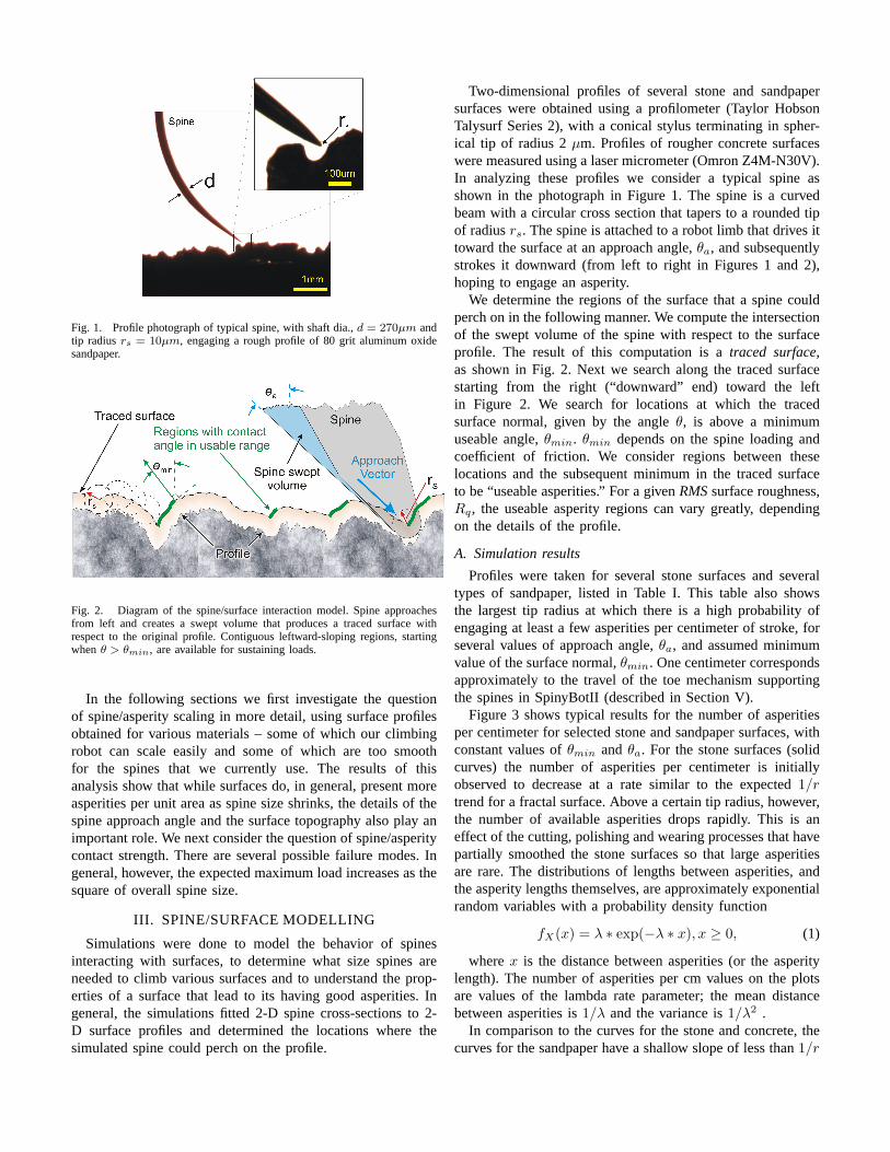
Fig. 1. Profile photograph of typical spine, with shaft dia.,d = 270µm andtip radiusrs = 10µm, engaging a rough profile of 80 grit aluminum oxidesandpaper.
Fig. 2. Diagram of the spine/surface interaction model. Spine approachesfrom left and creates a swept volume that produces a traced surface withrespect to the original profile. Contiguous leftward-sloping regions, startingwhenθ > θmin, are available for sustaining loads.
In the following sections we first investigate the questionof spine/asperity scaling in more detail, using surface profilesobtained for various materials – some of which our climbingrobot can scale easily and some of which are too smoothfor the spines that we currently use. The results of thisanalysis show that while surfaces do, in general, present moreasperities per unit area as spine size shrinks, the details of thespine approach angle and the surface topography also play animportant role. We next consider the question of spine/asperitycontact strength. There are several possible failure modes. Ingeneral, however, the expected maximum load increases as thesquare of overall spine size.
III. SPINE/SURFACE MODELLING
Simulations were done to model the behavior of spinesinteracting with surfaces, to determine what size spines areneeded to climb various surfaces and to understand the prop-erties of a surface that lead to its having good asperities. Ingeneral, the simulations fitted 2-D spine cross-sections to 2-D surface profiles and determined the locations where thesimulated spine could perch on the profile.
Two-dimensional profiles of several stone and sandpapersurfaces were obtained using a profilometer (Taylor HobsonTalysurf Series 2), with a conical stylus terminating in spher-ical tip of radius 2µm. Profiles of rougher concrete surfaceswere measured using a laser micrometer (Omron Z4M-N30V).In analyzing these profiles we consider a typical spine asshown in the photograph in Figure 1. The spine is a curvedbeam with a circular cross section that tapers to a rounded tipof radiusrs. The spine is attached to a robot limb that drives ittoward the surface at an approach angle,θa, and subsequentlystrokes it downward (from left to right in Figures 1 and 2),hoping to engage an asperity.
We determine the regions of the surface that a spine couldperch on in the following manner. We compute the intersectionof the swept volume of the spine with respect to the surfaceprofile. The result of this computation is atraced surface,as shown in Fig. 2. Next we search along the traced surfacestarting from the right (“downward” end) toward the leftin Figure 2. We search for locations at which the tracedsurface normal, given by the angleθ, is above a minimumuseable angle,θmin. θmin depends on the spine loading andcoefficient of friction. We consider regions between theselocations and the subsequent minimum in the traced surfaceto be “useable asperities.” For a givenRMSsurface roughness,Rq, the useable asperity regions can vary greatly, dependingon the details of the profile.
A. Simulation results
Profiles were taken for several stone surfaces and severaltypes of sandpaper, listed in Table I. This table also showsthe largest tip radius at which there is a high probability ofengaging at least a few asperities per centimeter of stroke, forseveral values of approach angle,θa, and assumed minimumvalue of the surface normal,θmin. One centimeter correspondsapproximately to the travel of the toe mechanism supportingthe spines in SpinyBotII (described in Section V).
Figure 3 shows typical results for the number of asperitiesper centimeter for selected stone and sandpaper surfaces, withconstant values ofθmin andθa. For the stone surfaces (solidcurves) the number of asperities per centimeter is initiallyobserved to decrease at a rate similar to the expected1/rtrend for a fractal surface. Above a certain tip radius, however,the number of available asperities drops rapidly. This is aneffect of the cutting, polishing and wearing processes that havepartially smoothed the stone surfaces so that large asperitiesare rare. The distributions of lengths between asperities, andthe asperity lengths themselves, are approximately exponentialrandom variables with a probability density function
fX(x) = λ ∗ exp(−λ ∗ x), x ≥ 0, (1)
wherex is the distance between asperities (or the asperitylength). The number of asperities per cm values on the plotsare values of the lambda rate parameter; the mean distancebetween asperities is1/λ and the variance is1/λ2 .
In comparison to the curves for the stone and concrete, thecurves for the sandpaper have a shallow slope of less than1/r

Surf. Surface Average RMS Approach Angleθa
No. RoughnessRa RoughnessRq 0◦ 45◦ 80◦
(µm) (µm) θmin θmin θmin
45◦ 65◦ 80◦ 45◦ 65◦ 80◦ 45◦ 65◦ 80◦
1 cobblestone 56.85 78.09 52.0 33.3 20.0 52.2 33.5 20.2 41.9 26.4 12.12 machined granite 6.55 10.26 28.3 17.5 NaN 28.4 17.6 NaN 19.1 9.5 NaN3 rough cut granite 53.54 67.49 56.0 40.0 27.5 56.1 40.2 27.6 45.1 35.5 20.54 polished granite 13.23 21.01 39.8 29.9 NaN 38.3 29.9 NaN 28.0 21.0 NaN5 paving stone 73.03 92.16 70.0 40.0 14.4 70.2 40.1 14.4 61.8 37.6 13.86 concrete cinderblock 92.96 131.93 282.9 162.6 101.2 283.7 163.4 101.6 126.9 73.9 NaN7 concrete 2 70.14 88.42 159.5 139.1 NaN 159.6 139.3 NaN 140.3 93.5 NaN8 Al-oxide 80 42.37 57.89 120.1 90.0 40.0 120.5 88.2 40.3 107.6 72.9 32.89 Al-oxide 100 35.83 49.89 110.1 86.7 70.0 107.1 80.6 57.9 88.6 62.9 41.910 Al-oxide 120 20.30 26.05 68.0 48.6 15.0 68.2 48.7 25.1 55.5 32.8 NaN11 Al-oxide 150 21.68 27.82 60.0 55.0 43.3 60.2 53.4 40.2 55.5 33.2 24.112 Painter’s 100 30.54 38.88 105.0 40.0 NaN 100.4 37.6 NaN 95.3 38.2 NaN
TABLE I
TABLE SHOWING THE ROUGHNESS PARAMETERS AND MAXIMUM SPINE TIP RADIUS FOR ENGAGING ASPERITIES ON VARIOUS STONE AND SANDPAPER
SURFACES. THE COLUMNS OF DATA UNDER EACH APPROACH ANGLE INDICATE THE MAXIMUM SPINE TIP RADIUS, IN µM , THAT HAS A HIGH
PROBABILITY OF ENGAGING AT LEAST A FEW ASPERITIES PER CENTIMETER OF VERTICAL STROKE ALONG THE SURFACE. EACH ENTRY IS FOR A GIVEN
APPROACH ANGLE, θa AND ASSUMED VALUE OF θmin , WHICH DEPENDS ON THE COEFFICIENT OF FRICTION. LARGER NUMBERS INDICATE A
GENERALLY ROUGHER SURFACE THAT IS EASIER TO CLIMB WITH LARGER SPINES. A VALUE OF NAN INDICATES THAT THE SURFACE WAS SO SMOOTH
THAT THE SIMULATION DID NOT FIND ANY ASPERITIES FOR ANY RADIUS ABOVE8µM .
Fig. 3. Number of asperities per cm for various surfaces, withθa = 45◦ andθmin = 75◦. Solid lines indicate stone and concrete surfaces, and dashedlines indicate sandpaper surfaces. A band corresponding to the1/r trend thatwould be expected for a perfect fractal surface has been added for reference.
for small tip radii. This occurs because the sandpapers have arelatively uniform particle size. For small radii, the 150 and120 grit aluminum oxide sandpapers have more asperities thanthe larger-grained 80 and 100 grit aluminum oxide sandpapers,but for large radii the reverse is true. Also, for large assumedvalues of θmin > 65+◦, corresponding to a low assumedcoefficient of friction, the 100 grit painter’s sandpaper hassubstantially fewer asperities than 100 grit aluminum oxide
Fig. 4. Number of asperities per cm asθmin is varied, andθa is held constantat 65◦, for a stone surface. A band corresponding to the1/r expected for aperfect fractal surface is shown for comparison.
because it has more rounded particles.
Figure 4 shows the number of asperities per centimeter asθmin is varied, with constantθa. As θmin increases, we areless likely to find useable asperities. The distribution of tracedsurface normal angles is approximately Gaussian, droppingto close to 0 atθ = ±90◦. The shape of this distributionis reflected in the various vertical offsets in the figure. Asθa is varied, with constantθmin, the number of asperities/cm

changes relatively little, decreasing significantly only for largeapproach angles where the spine is nearly parallel to the wall.For small approach angles, the spine’s ability to reach theregions of the surface it hooks on to is only slightly affected.
B. Correlation with climbing robot performance
In this section we compare the results of the foregoinganalysis to the empirical results obtained with our climbingrobot. The parametersθmin and θa used by our climbingrobot, SpinyBotII, were measured and used in the simulation.Based on the geometry of SpinyBotII, the feet are loaded atangles3.5◦ < θload < 8◦ degrees from the wall. For a givencoefficient of friction,µ, we have:
θmin = θload + arccot(µ). (2)
The coefficient of friction between stainless steel spinetips and rock is generally between 0.15 and 0.25, whichcorresponds toθmin between 86.5◦ and 81◦ for an averageθload of 5◦. The approach angle,θa, is from 45◦-65◦, basedon the angle of the spines themselves and the motion of the tipover the surface. The tip radii,rs, of the spines are 10-15µmfor new spines and 25-35µm for spines dulled due to heavyuse. The behavior we see using these values qualitativelycorresponds to the actual performance of SpinyBotII on thecorresponding surfaces. SpinyBotII works extremely well onthe Al-oxide 100 and 80 grit sandpapers, moderately-to-poorlyon the Al-oxide 150 and 120 grit, and poorly on the painter’s100 grit sandpaper. On the natural surfaces, SpinyBotII worksvery well on the rough concretes, moderately well on the roughcut granite, and not at all on the ground and polished surfaces.In the simulation, ifθmin is 82◦-85◦ and θa is 45◦ or 65◦,at radii of 10-40µm the relative ordering of the surfaces innumber of asperities/cm is generally correct, with the 100 gritAl-oxide sandpaper having the most asperities, followed bythe 150, 80 grit sandpapers and the cut granite block surface.
The concrete profiles show somewhat fewer asperities thanwould be expected for small tip radii. this is because they wererecorded using a laser micrometer with a 65µm spot size thatproduced some low-pass filtering. Consequently the concreteprofiles do not appear in the correct order for simulatedasperity densities. In general, though, the ordering of thesurfaces appears to be correct. All of the surfaces show fewerasperities than would be expected ifθmin is increased abovearound 82◦. This discrepancy is likely due to the reducedability of the measurement instruments to accurately recordabrupt changes in surface height.
C. Discussion
Dai et al. [11] present a planar model of spine/asperity con-tact that includes the relative size of the spine tip versus that ofan asperity and coefficient of friction. Our analysis is similar,except that we use actual surface contours and compute thecorresponding traced surface for the swept volume producedby a spine. Dai et al. state that the angle of spine/surfacecontact is key to obtaining traction between beetle clawsand surfaces. However, they frame their conclusions in terms
of general surfaceRMS roughnessRq, a different parameterentirely. Our results indicate that the normal angle,θ, is thecritical parameter, and that surface roughness measuresRa andRq are not always correlated with actual spine performance.As an example, theRa and Rq of the painter’s 100 gritsandpaper are larger than the corresponding values for 120 and150 grit Al-oxide, but it has many fewer useable asperities.
Our present analysis is limited in that it cannot detect thepresence of angles more than 90 degrees (upward-leaningoverhangs). Even at angles close to 90 degrees it is lessaccurate due to the non-zero cone angle of the profilometerstylus. It may be that mechanical interlocking with anglesgreater than 90 degrees is the cause of many of the asperitiesthat SpinyBotII actually uses.
Also, the observed behavior of spines interacting withsurfaces differs slightly from that assumed by the model. Asa foot is brought into contact with surface and begins itsdownward stroke, we observe that many spines briefly catchon “pseudo-asperities” and then break away as the load isramped up, possibly due to slight spine deflections, whichlead to spine slipping. If the load were kept small these“pseudo-asperities” would probably be useable. The spinesalso tend to skip over the surface (i.e., to become brieflyairborne) after slipping off the “pseudo-asperities” and theyundergo alternating regimes of static and dynamic friction. Theeffective coefficient of friction while this occurs is probablyquite low. Finally, there is a chance that as a compliant spinedrags down the wall it may tend to follow a local groove orvalley and thereby be steered away from protruding asperities.Conversely, negative asperities (pits) will tend to steer thespine into a favorable location for obtaining a grip. Hence,actual spine/surface dynamics vary depending on the surfacetype as well as how much the spine is able to move in thedirection perpendicular to its travel.
IV. SPINE/ASPERITY CONTACT STRENGTH
While smaller spines are more effective at engaging asperi-ties on smooth surfaces, they also carry smaller loads. We havefound that when steel spines catch on asperities on concreteor stucco, the contact typically fails in one of three ways:
• plastic failure of the base of the spine in bending,• excessive elastic rotation of the spine tip causing it to slip
off the asperity,• brittle failure of the asperity itself.In each of these cases, if we take a dimension such as the
spine tip radius,rs, as a characteristic length and scale every-thing uniformly, then the maximum load of the spine/asperitycontact increases asr2
s (see Appendix for details).Figure 5 shows graphically how the maximum load of the
spine/asperity contact increases asr2, while the expected num-ber of asperities per unit area decreases as1/r2. Measurementsof contact strength were done using spines of various sizes onconcrete and sandpaper samples attached to a load cell. Wenote that the sandpaper consisted primarily of male features(which had a small bonding cross-section). Therefore, asperityfailure tended to occur before spine failure on that surface. In

Fig. 5. Log/log plot showing the expectedr2 trend of spine/asperity contactstrength versus the expected1/r2 trend for asperities per unit area of thewall. The data for surfaces of rough cut granite and concrete are plottedfor comparison with the expected asperity density trend. Individual tests ofspine/asperity failures are plotted for concrete and sandpaper surfaces.
contrast, the cast concrete primarily consisted of female fea-tures that were consequently much stronger; so spine failure,either by excessive end rotation or plastic bending, tended todominate. For other surfaces, all three failure modes tendedto occur simultaneously. The figure also shows the asperitydensity data for a concrete and machined granite surface ascompared to the expected1/r2 for fractal surfaces. At thebottom of the figure, the representative asperity length scalesfor a few different surfaces are indicated. These indicate, forexample, that rough concrete surfaces will present useableasperities of up to 300µm whereas smooth concrete or stonepanels will present asperities of up to 20µm. These valuesessentially impose an upper limit to the spine size that can beused with these surfaces.
For our first climbing robot, SpinybotI, we employed 4spines per foot, each with a tip radius of approximately 30µm.This machine was able to climb stucco and rough concrete reli-ably. The spine/asperity contacts could sustain loads of severalN, usually limited by brittle failure of the asperity rather thanof the spine. However, for surfaces such as smooth concreteand dressed stone, the probability of a spine encountering auseful asperity during a vertical stroke length of approximately2 cm was too low for reliable climbing. SpinybotII employstwo rows of spines on each foot, each spine having a tipradius of approximately 15µm. The maximum force perspine/asperity contact is 1-2 N, and the probability of findinguseable asperities per centimeter of stroke length is high.
To summarize the preceding discussion, as spines becomesmaller we can ascend smoother surfaces because the densityof useable spine/asperity contacts increases rapidly. However,we need larger numbers of spines because each contact can
Fig. 6. Photograph of SpinyBotII on wall and diagram of climbingmechanism. Each set of three legs is attached to a mechanism such that therobot employs a fixed alternating-tripod gait. A long tail helps to reduce thepitching moment. The center of mass (COM) is always within a polygon ofcontacts, to minimize yawing rotations in the plane of the wall.
sustain less force. In order to make use of large numbers ofspines, the two key design principles are:
• ensure that as many spines as possible will independentlyfind asperities to attach to and
• ensure that the total load is distributed among the spinesas uniformly as possible.
In the next section we briefly describe the design of Spiny-botII that embodies these design principles.
V. SPINYBOTII: CLIMBING WITH COMPLIANTMICROSPINES
A. Body Design: Promoting Load Sharing and Stability
Figure 6 shows a plan view schematic and photograph ofSpinybotII. The robot uses an alternating tripod gait, as foundin climbing insects. At any time, the robot is clinging bythree feet. Like many climbing animals, the robot also hasa tail which reduces the “pull-in” forces needed at the frontlimbs to overcome the pitching moment produced by gravityacting at the center of mass, which is located approximately2 cm outward from the wall. The total weight of the robot,including lithium polymer batteries, wireless camera, and PICmicroprocessor is 0.4 Kg. It can carry an additional payload of0.4 Kg while climbing. The climbing speed is currently quiteslow (2.3cm/s) but can easily be increased by using a morepowerful motor for the alternating tripod mechanism. Whilethe main concern for vertical climbing is to avoid pitching backfrom the plane of the wall, it is also important to maintainrotational stability in the plane of the wall. As seen in Fig.6, the center of mass of SpinybotII lies within a polygon of

contacts at all times. Also, as observed in climbing insectsand reptiles, the legs have a slight inward pull, toward thecenterline of the robot. This arrangement reduces the upsettingmoments (in the plane of the wall) about the center of mass,should one of the legs momentarily lose its grip.
B. Toe and Foot Design: Promoting Spine Attachment andLoad Sharing
The feet on SpinybotII represent the sixth generation ofa compliant, spined design. A failing of earlier designs wasthat on close observation, only a few spines were carryingmost of the load. Each foot of SpinybotII contains a set of 10identical planar mechanisms, or “toes.” The mechanisms arecreated using a rapid prototyping process, Shape DepositionManufacturing (SDM) [22], [7] that permits hard and softmaterials to be combined into a single structure. Figure 7shows a side vide of the robot on a concrete wall and a detailof a single foot, showing several of the planar toe mechanisms,each of of which bears two spines (several of which are visiblyengaged).
Each of the toes is a compliant multi-bar linkage, indepen-dent of its neighbors and able to stretch parallel to the wallunder a load. Thus, if a toe catches an asperity, neighboringtoes are not prevented from catching their own asperitiesbecause they will continue to slide down the wall as the caughttoe stretches. The grey material in the photograph is a softurethane (Innovative Polymers Inc.) of 20 Shore-A hardnessand the white material is a hard urethane of 75 Shore-Dhardness. The spines are approximately 1.5 mm long witha 200 µm shaft diameter and 15µm tip radius. They areembedded directly into the hard white links during the SDMprocess. The soft urethane flexures provide both elasticity andviscoelastic damping. They permit greater extensions withoutfailure than miniature steel springs (as were used on some ofthe earlier foot designs). The distal flexures are designed tobuckle slightly so that the toe is very compliant with respectto positive normal forces (i.e. forces pushing outward fromthe wall) but stiffer when loaded in tension. In addition, thelinkage is designed so that an initial contact at the inner(proximal) spine forces the distal spine outward to facilitateengagement. Finally, it is designed so that tensile loading doesnot cause the spines to rotate upward, which would make themtend to slip off asperities that they have engaged.
VI. CONCLUSIONS AND FUTURE WORK
A. Conclusions
SpinybotII climbs reliably on a wide variety of hard, outdoorsurfaces including concrete, stucco, brick, and dressed sand-stone with average asperity radii of greater than about 25µm.Scaling SpinyBotII to larger payloads is straightforward; onesimply needs more spines. A more challenging problem is totackle rough or corrugated surfaces or, in general, surfaces thathave roughness comparable to spine length. Either the feet andtoes must have enough “suspension travel” to accommodatethe contours of the surface or they must have an additional
Fig. 7. Picture of upper section of SpinybotII on concrete wall and detailedview of several spines independently engaging asperities on the concretesurface.
active degree of freedom, like the toes of geckos or the tendon-actuated tarsus of insect legs. On contoured surfaces it shouldbe possible to exploit internal “grasp” forces, in a mannersimilar to that used by robots that climb with hand-holdsand foot-holds [8], [6], for additional security. The compliantsuspension of the spines will become an increasingly difficultdesign challenge as spines are made smaller: smaller spinesnecessarily have a smaller clearance, possibly preventing themfrom reaching deep holes in the surface while maintaining afavorable loading angle.
Another challenging problem is to climb surfaces with muchlower roughness than concrete or sandstone, such as polishedstone or interior wall panels. The scaling arguments in SectionsIII and IV should still apply. However, for smooth panelsthe average asperity radius may be on the order of a fewmicrometers, requiring spine tip radii of perhaps 1µm. Theseextremely small spines will be over 100 times weaker thanthe spines on SpinybotII and a large number of them willbe required, unless the overall mass of the robot can bereduced correspondingly. Going still smaller, we approach thedimensions of the hairs that are being investigated for syntheticdry adhesives [3], [21], [26], [14]. At the smallest scales, hairsutilizing adhesion have two advantages over microspines ornanospines: they are less sensitive to the local surface normal

distribution and they are loaded primarily in tension, ratherthan in bending.
For a given surface, at a small enough length scale, thesurface will appear fractal. Beyond that point the number ofasperities per unit area will grow as1/r2. Since the spinestrength grows asr2, we hypothesize that the total weightthat can be sustained per unit of surface area using spines isapproximately constant. This weight per unit area number willdepend on the distribution of surface normal angles, which isrelated to the surface’s fractal dimension.
An interesting question is whether some combination ofspines and adhesive hairs will ultimately prove most effec-tive for scaling a variety of hard vertical surfaces. Differentsurfaces have different distributions of surface normal angles.Spines perform best on surfaces with normal angles close to90◦, while dry adhesives do best on smoother surfaces withnormal angles closer to 0◦. To be able to climb the widestvariety of surfaces, both spines and dry adhesives could beused.
B. Future work
Future work in modeling spine/surface contacts could ben-efit from 3-D surface measurement, which would enablemore accurate asperity location predictions. For very smoothsurfaces, an atomic force microscope or similar instrumentmay be required to accurately measure the surface heights. Forrough surfaces, using a laser interferometer with the surfacetilted at an angle could permit measurement of surface normalangles in excess of 90◦. For the robot feet, making smallerspines and better suspension systems is the correspondingnext step. It is still unknown what the minimum scale is forfabricating and using spines effectively.
A video of SpinybotII climbing various buildings and someclose shots of its feet and toes engaging asperities, can befound at http://bdml.stanford.edu/RiSE/Downloads/ . Watchingthe video closely will reveal several instances in which onefoot briefly loses its grip. However, there is enough redundancyand compliance that the robot does not fall. Of course, if therobot encounters a very smooth patch, it either fails to proceedor falls. For greater reliability, we are investigating miniatureaccelerometers at the toes that will indicate when contact hasoccurred and whether the foot is stationary or slipping. Otherobvious improvements are to increase the climbing speedand to provide additional articulation so that the robot cannegiotate vertical/horizontal transitions such as window sills.
VII. APPENDIX: SPINE FAILURE MODES
APPENDIX
We have observed that the spine/asperity contacts have threeprimary failure modes.
1) The spine fails plastically at its base due to tensilestress from bending.
2) The spine deflects elastically such that it slips off theasperity.
3) The asperity fails, typically as a particle becomesunbonded from the surrounding matrix.
Fig. 8. Curved beam with variables used in spine failure mode analysis.
The first mode of failure is due to the tensile stress at thebase of the spine. For a long curved spine, the maximum stressis essentially the same as it would be for a straight cantileverbeam [25]:
σmax =Mc
I=
32fld
πd4∝ 1
d2(if
l
d= const)
where
f = force exerted on tip of the spined = diameter of cross section of spinel = equivalent beam length.
The second mode of failure is excessive tip rotation. Herewe can apply Castigliano’s Theorem to solve for the tipdeflections and rotations for a curved spine [25]. Applyinga dummy end moment,M , and solving for the end rotation,α, we obtain:
α = ∂U/∂M
=R2
2EI[−2Fy + (2Fx + Fy(π + 2β))cos(β)
+(−2Fy + Fxπ + 2Fxβ)sin(β)] ∝ 1d2
(ifR
d= const. at given β, Fx and Fy) (3)
(see figure 8).The third mode of failure is that the asperity itself may break
off. The literature on surface failure or erosion (e.g. [23], [24])for cementitious materials such as concrete, or rock with hardcrystals in a weaker matrix, generally starts with the Hertzstress distribution at the contact [17]. The maximum pressureis at the center of the contact patch:
pmax = 3f/2πa2 = (6fE2/π3R2)1/3
where
a = (3fR/4E)1/3
E = (1− µ2s)/Es + (1− µ2
a)/Ea
(1/R = 1/rs + 1/ra)

and the subscriptss anda refer to the spine tip and asperity,respectively.
The worst case tensile stress is at the periphery of thecontact patch:
σT = ((1− 2µ2)pmax)/3
The actual failure will depend on the local stress state, numberof cracks and fracture toughness of the material. However, itwill be a function of the maximum tensile stress. Thereforewe can write that
fmax = [(πσmax/(1− 2µ2))3(1/2E2)]R2
The quantity in square brackets is a constant depending on thematerials so that, in the end, the maximum sustainable load isexpected to vary as the square of the radii of curvature of thespine tip and asperity.
ACKNOWLEDGMENT
This work was supported in part by the DARPA BiodynoticsProgram under Contract NC66001-03-C-8045. Additional sup-port was provided by a DCI fellowship for W. Provancherand a NSF fellowship for A. Asbeck. The authors thank V.Mattoli for his development of the PIC processor program forcontrolling the RC servos. Thanks are also due to J. Lee forher help in designing and fabricating SpinybotI.
REFERENCES
[1] http://www.vortexhc.com/vmrp.html.[2] Discover. 21(9), 2000.[3] Eduard Arzt, Stanislav Gorb, and Ralph Spolenak. From micro to
nano contacts in biological attachment devices” preceedings of nationalacademy of sciences. InPreceedings of National Academy of Sciences,volume 100, pages 10603–10606, 2003.
[4] K. Autumn and A. Peattie. Mechanisms of adhesion in geckos.Integrative and Comparative Biology, 42(6):1081–1090, 2002.
[5] C. Balaguer, A. Gimenez, J.M. Pastor, V.M. Padron, and C. Abderrahim.A climbing autonomous robot for inspection applications in 3d complexenvironments.Robotica, 18:287–297, 2000.
[6] D. Bevly, S. Dubowsky, and C. Mavroidis. A simplified cartesian-computed torque controller for highly geared systems and its applicationto an experimental climbing robot.Transactions of the ASME. Journalof Dynamic Systems, Measurement and Control, 122(1):27–32, 2000.
[7] M. Binnard and M.R. Cutkosky. A design by composition approachfor layered manufacturing.ASME Transactions, Journal of MechanicalDesign, 122(1):91–101, 2000.
[8] T. Bretl, S. Rock, and J.C. Latombe. Motion planning for a three-limbedclimbing robot in vertical natural terrain. InProceedings of the IEEEInternational Conference on Robotics and Automation. Piscataway, NJ,USA : IEEE, 2003.
[9] M. Catmill. Climbing. In M. Hildebrand, D.M. Bramble, K.F. Liem,and D.B. Wake, editors,Functional Vertebrate Morphology, pages 73–88. The Belknap Press, Cambridge, 1985.
[10] M. A. Costa and M. R. Cutkosky. Roughness perception of hapticallydisplayed fractal surfaces. InProceedings of the ASME Dynamic Systemsand Control Division, volume 69-2, pages 1073–1079, 2000.
[11] Z.D. Dai, S.N. Gorb, and U. Schwarz. Roughness-dependentfriction force of the tarsal claw system in the beetle pachnodamarginata (coleoptera, scarabaeidae).Journal Of Experimental Biology,205(16):2479–2488, 2002.
[12] S.B. Emerson and D. Diehl. Toe pad morphology and mechanisms ofsticking in frogs.Biological Journal of the Linnean Society, 13(3):199–216, 1980.
[13] W. Federle, M. Riehle, A.S.G. Curtis, and R.J. Full. An integrativestudy of insect adhesion: mechanics and wet adhesion of pretarsal padsin ants. Integrative and Comparative Biology, 42(6):1100–1106, 2002.
[14] A. K. Geim, S. V. Dubonos, Grigorieva, K. S. Novoselov, A. A. Zhukov,and S. Yu. Shapoval. Microfabricated adhesive mimicking gecko foot-hair. Nature Materials, 2:461–463, 2003.
[15] J. A. Greenwood. Contact of rough surfaces. In I. L. Singer and H. M.Pollock, editors,Fundamental of Friction: Macroscopic and MicroscopicProcesses, pages 37–56. Kluwer Academic Publishers, Dordrecht, TheNetherlands, 1992.
[16] J. A. Greenwood. Problem with surface roughness. In I. L. Singerand H. M. Pollock, editors,Fundamental of Friction: Macroscopicand Microscopic Processes, page 5776. Kluwer Academic Publishers,Dordrecht, The Netherlands, 1992.
[17] K.L. Johnson. InContact Mechanics, pages 72–94. Cambridge Univer-sity Press, 1985.
[18] A. B. Kesel, A. Martin, and T. Seidl. Adhesion measurements on theattachment devices of the jumping spider evarcha arcuata.The Journalof Experimental Biology, 206:2733–2738, 2003.
[19] G. La Rosa, M. Messina, G. Muscato, and R. Sinatra. A low-cost lightweight climbing robot for the inspection of vertical surfaces.Mechatronics, 12(1):71–96, 2002.
[20] R. Lal Tummala, R. Mukherjee, N. Xi, D. Aslam, H. Dulimarta, JizhongXiao, M. Minor, and G. Dang. Climbing the walls [robots].IEEERobotics and Automation Magazine, 9(4):10–19, 2002.
[21] C. Menon, M. Murphy, and M. Sitti. Gecko inspired surface climbingrobots. Proceedings of the IEEE International Conference on Roboticsand Biomimetics (ROBIO), 2004.
[22] R. Merz, F.B. Prinz, K. Ramaswami, M. Terk, and L. Weiss. Shapedeposition manufacturing. InProceedings of the Solid Freeform Fabri-cation Symposium, volume 1-8, August 1994.
[23] A. W. Momber. Damage to rocks and cementitious materials from solidimpact. Rock Mechanics and Rock Engineering, 37(1):57–82, 2004.
[24] G.L. Sheldon and I. Finnie. The mechanism of material removal in theerosive cutting of brittle materials.ASME Journal of Engineering forIndustry, 88B:393–400, 1966.
[25] C.R. Shigley, J.E.; Mischke. InStandard Handbook of Machine Design(2nd Edition). McGraw-Hill, 1996.
[26] M. Sitti and R.S. Fearing. Synthetic gecko foot-hair micro/nano-structures for future wall-climbing robots. InProceedings of the IEEEInternational Conference on Robotics and Automation, volume 1, pages1164 – 1170. Piscataway, NJ, USA : IEEE, 2003.
[27] Z.L. Xu and P.S. Ma. A wall-climbing robot for labelling scale of oiltank’s volume.Robotica, 20:209–212, 2002.
[28] P.A. Zani. The comparative evolution of lizard claw and toe morphologyand clinging performance.Journal of Evolutionary Biology, 13:316–325,2000.
[29] J. Zhu, D. Sun, and S.K. Tso. Development of a tracked climbing robot.Journal Of Intelligent And Robotic Systems, 35(4):427–444, 2002.