scania cv specification - festo.com€¦scania cv specification . body shop . oskarshamn (se) ......
TRANSCRIPT

Scania CV Specification
Body Shop Oskarshamn (SE)
São Paulo (BR)
Festo components for pneumatics, electro-pneumatics and local control
Date of creation
01.07.2015
Creator
Thorsten Weiß
Version
3.1
Festo AG & Co. KG
Phone: +49 711 347 2030
Fax: +49 711 347 542030
E-Mail: [email protected]
Ruiter Straße 82
73734 Esslingen

Table of Content
1 Document Management Information .............................................................................................................................................. 3
2 Contact Persons at Scania and Festo ..............................................................................................................................................4
2.1 Scania ....................................................................................................................................................................................4 2.2 Festo ...................................................................................................................................................................................... 5
3 General engineering and design guidelines .................................................................................................................................... 6
3.1 Safety requirements ............................................................................................................................................................... 6 3.2 Technical installation of valve terminals ................................................................................................................................. 7
3.2.1 Mechanical installation of CPX/VTSA terminals .............................................................................................................. 7 3.2.2 Mechanical installation of CPX/ MPA terminals .............................................................................................................. 7 3.2.3 Potential equalization .................................................................................................................................................... 8
3.2.3.1 Electrical supply technology - Important things know ............................................................................................ 8 3.2.3.2 Potential equalization of CPX/ VTSA and CPX/ MPA valve terminals ...................................................................... 8
3.2.4 Correct earth connections of CPX valve terminals ........................................................................................................... 9 3.2.5 Earthing concept of fieldbus cable ............................................................................................................................... 10 3.2.6 Profinet – Installation ................................................................................................................................................... 10 3.2.7 Profinet – Fast-Start-Up function .................................................................................................................................. 11 3.2.8 Safety functions with CPX-VTSA ................................................................................................................................... 12 3.2.9 Safety functions with CPX-VTSA – pilot air switching valve ........................................................................................... 13 3.2.10 Safety functions with CPX-VTSA – soft start and exhaust valve .................................................................................... 13
4 Release list overview ....................................................................................................................................................................14
4.1 Pneumatic drives ..................................................................................................................................................................14 4.1.1 Standard cylinders .......................................................................................................................................................14 4.1.2 Guided drives ...............................................................................................................................................................14 4.1.3 Clamping units .............................................................................................................................................................14 4.1.4 Stopper cylinders ......................................................................................................................................................... 15
4.2 Electromechanical drives ...................................................................................................................................................... 16 4.3 Motors and controllers ......................................................................................................................................................... 17 4.4 Valves ................................................................................................................................................................................... 18 4.5 Valve terminals ..................................................................................................................................................................... 19 4.6 Valves for manual lifting devices .......................................................................................................................................... 20 4.7 Valve terminals for manual lifting devices ............................................................................................................................ 20 4.8 Sensors ................................................................................................................................................................................ 20
4.8.1 Proximity sensors ......................................................................................................................................................... 20 4.9 Compressed air preparation ................................................................................................................................................. 21
4.9.1 Complete assembled air preparation units ................................................................................................................... 22 4.9.1.1 Maintenance Unit 1 – Standard – G1/2” .............................................................................................................. 22 4.9.1.2 Maintenance Unit 2 – Standard – G1” .................................................................................................................. 23 4.9.1.3 Maintenance Unit 3 – HIP Main Media Frame – G1” (without coupling and pressure switch) ...............................24 4.9.1.4 Maintenance Unit 4 – Infeed Equipment – G1/2” ................................................................................................. 25 4.9.1.5 Maintenance Unit 5 – Fixtures – G1/2” ................................................................................................................ 26
4.10 Pneumatic fittings system .................................................................................................................................................... 27 4.11 Other pneumatic equipment ................................................................................................................................................. 28
5 Drawings ...................................................................................................................................................................................... 29
Festo AG & Co. KG Page 2 from 30
01.07.2015 Scania_CV_Spezification_BiW_3.1_EN.docx

1 Document Management Information
VERSION DATE WHO TYPE OF CHANGING CHAPTER
3.1 01.07.2015 Thorsten Weiß / Festo - delete Södertälje and Luleå - add valves VUVG - add valves VUWG - add valve terminal VTUG - add visual indicator
page 1 4.6 4.6 4.7 4.11
3.0 27.03.2015 Thorsten Weiß / Festo - specification also valid for Södertälje and Luleå - updated contact persons
page 1 2
2.2 17.02.2015 Thorsten Weiß / Festo - updated contact persons - change to coupling from Atlas Copco - change to coupling from Atlas Copco - add maintenance unit - delete branching module FRM on service unit
2 4.7.1.1 4.7.1.2. 4.7.1.3 4.7.1.5
2.1 13.01.2015 Leif Lindahl / Festo - change code X to T (external pilot air) at MPA 4.5 2.0 17.11.2014 Leif Lindahl / Festo - update Scania Profisafe layout
- add description - update Profinet – Fast-Start-Up function - add clamping units - add e-drives - add motors and controllers - update pre-assembled units with IFM sensor
3.1 3.2.3.1 3.2.7 4.1.3 4.2 4.3 4.7.1.1 and 4.7.1.2
1.0 09.04.2014 Leif Lindahl / Festo - first edition all
Festo AG & Co. KG Page 3 from 30
01.07.2015 Scania_CV_Spezification_BiW_3.1_EN.docx

2 Contact Persons at Scania and Festo
2.1 Scania
Sweden: Lars Kreutner Project Leader Production Development Engineering Scania CV AB P.O. Box 903 SE 572 29 Oskarshamn, Sweden Phone: +46 (491) 765-513 Mobil: +46 (700) 856061 E-Mail: [email protected] Brazil: Wellington J. Magaton Mechatronics Technician, Maintenance Brazil, LDQPCB Scania Latin America LTDA Avenida José Odorizzi, 151 (P40-03) 09810-902, São Bernardo do Campo, SP, BR Phone: +55 (11) 4344 9440 Fax: +55 (11) 4344 9526 E-Mail: [email protected]
Festo AG & Co. KG Page 4 from 30
01.07.2015 Scania_CV_Spezification_BiW_3.1_EN.docx

2.2 Festo
Sweden: General: Joakim Gustafsson ISM Manager Automotive Festo AB Alingsåsvägen 23 51842 Sjömarken, Sweden Phone: +46 (40) 6990-643 Mobil: +46 (70) 5562326 E-Mail: [email protected] Brazil: Antonio Polzatto Head of Industry Segment Automotive Festo Brasil LTDA. Rua Giuseppe Crespi, 76 04183-080 São Paulo, Brazil Tel.: +55 (11) 5013-1880 Mobil: +55 (11) 99622-5048 E-Mail: [email protected] Headquarter: Philipp Hoppe Thorsten Weiß Global Key Account Manager Volkswagen Group International Project Manager Automotive Festo AG & Co. KG Festo AG & Co. KG Ruiter Straße 82 Ruiter Straße 82 73734 Esslingen, Germany 73734 Esslingen, Germany Tel.: +49 (0) 711-347-4257 Tel.: +49 (0) 711-347-2030 Mobil: +49 173-3193759 Fax: +49 (0) 711-347-542030 E-Mail: [email protected] E-Mail: [email protected]
Festo AG & Co. KG Page 5 from 30
01.07.2015 Scania_CV_Spezification_BiW_3.1_EN.docx

3 General engineering and design guidelines
3.1 Safety requirements
(Conceptual configuration)
(Conceptual configuration)
Festo AG & Co. KG Page 6 from 30
01.07.2015 Scania_CV_Spezification_BiW_3.1_EN.docx

3.2 Technical installation of valve terminals
3.2.1 Mechanical installation of CPX/VTSA terminals
3.2.2 Mechanical installation of CPX/ MPA terminals
Festo AG & Co. KG Page 7 from 30
01.07.2015 Scania_CV_Spezification_BiW_3.1_EN.docx

3.2.3 Potential equalization
3.2.3.1 Electrical supply technology - Important things know
3.2.3.2 Potential equalization of CPX/ VTSA and CPX/ MPA valve terminals
Festo AG & Co. KG Page 8 from 30
01.07.2015 Scania_CV_Spezification_BiW_3.1_EN.docx

3.2.4 Correct earth connections of CPX valve terminals
Use terminal strip 576319 NECU-L3G7-C1 (code VS when ordering valve terminal)
Festo AG & Co. KG Page 9 from 30
01.07.2015 Scania_CV_Spezification_BiW_3.1_EN.docx

3.2.5 Earthing concept of fieldbus cable
3.2.6 Profinet – Installation
Festo AG & Co. KG Page 10 from 30
01.07.2015 Scania_CV_Spezification_BiW_3.1_EN.docx
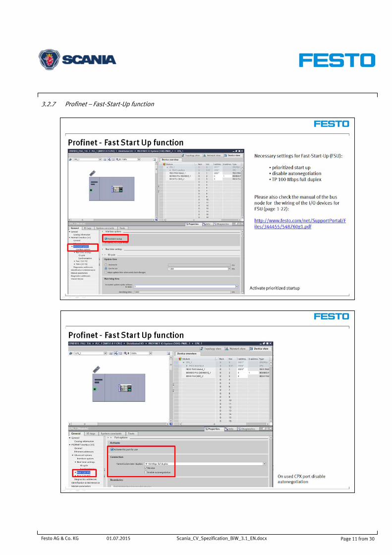
3.2.7 Profinet – Fast-Start-Up function
Festo AG & Co. KG Page 11 from 30
01.07.2015 Scania_CV_Spezification_BiW_3.1_EN.docx

3.2.8 Safety functions with CPX-VTSA
(Conceptual configuration)
Festo AG & Co. KG Page 12 from 30
01.07.2015 Scania_CV_Spezification_BiW_3.1_EN.docx

3.2.9 Safety functions with CPX-VTSA – pilot air switching valve
3.2.10 Safety functions with CPX-VTSA – soft start and exhaust valve
Festo AG & Co. KG Page 13 from 30
01.07.2015 Scania_CV_Spezification_BiW_3.1_EN.docx

4 Release list overview
4.1 Pneumatic drives
4.1.1 Standard cylinders Name Type Remarks Picture Documentation
Compact cylinder ADN *For Foundry use include R8 version ADN-40-50-A-P-A-R8
ADN-... Diameter 12, 16, 20, 25, 32, 40, 50, 63, 80, 100, 125 mm Stroke length 1 ... 500 mm Force 51 ... 7363 N Double-acting Position sensing Cushioning fixed/self-adjusting Female thread Male thread
Catalogue: ADN (engb) Online product: ADN (engb)
Standard cylinder DSBC DSBC-...-PPSA-N3 DSBC-...-PPVA-N3
Diameter 32, 40, 50, 63, 80, 100, 125 mm Stroke length 1 ... 2800 mm Force 483 ... 4712 N Double-acting Position sensing Adjustable/self-adjusting cushioning Female thread Male thread
Catalogue: DSBC (engb) Online product: DSBC (engb)
4.1.2 Guided drives Name Type Remarks Picture Documentation
Guided drives DFM, metric DFM-...-GF Use only plain-bearing guide!
Diameter 12, 16, 20, 25, 32, 40, 50, 63, 80, 100 mm Stroke length 10 ... 400 mm Force 51 ... 4712 N Position sensing Fixed/adjustable cushioning Plain-bearing guide Variants available.
Catalogue: DFM (engb) Online product: DFM (engb)
4.1.3 Clamping units
Name Order code Remarks Picture Documentation
Clamping unit cylinders DNCKE
DNCKE-… Diameters 40, 63, 100 mm Stroke length 10 ... 2000 mm Force 754 ... 4712 N Double-acting Position sensing Adjustable cushioning Male thread For non-horizontal slide units. Safety component MD2006/42/EC.
Catalogue: DNCKE (engb) Online product: DNCKE (engb)
Festo AG & Co. KG Page 14 from 30
01.07.2015 Scania_CV_Spezification_BiW_3.1_EN.docx

4.1.4 Stopper cylinders
Name Type Remarks Picture Documentation
Stopper cylinders STA STA-...-P-A-SA 184831 STA-50-25-P-A-SA-23458 185913 STA-50-50-P-A-SA-23551 2946663 STA-50-75-P-A-SA-1383932A 186414 STA-80-50-P-A-SA-240204A
Diameter 50 and 80 mm Stroke length 25, 50, 75 mm Permissible impact force on the extended piston rod 170 ... 14600 N Position sensing Fixed cushioning.
Drawings on page 29
Stopper cylinders STAF STAF-… Diameter 20, 32, 50, 80 mm Stroke length 10 ... 40 mm Permissible impact force on the extended piston rod 170 ... 14600 N Position sensing Fixed cushioning.
Catalogue: STAF (engb) Online product: STAF (engb)
Stopper cylinder DFST DFST-… Diameters 50, 63, 80 mm Stroke length 30 ... 40 mm Permissible impact force on the advanced piston rod 3000 ... 6000 N Position sensing Fixed cushioning.
Catalogue: DFST (engb) Online product: DFST (engb)
Festo AG & Co. KG Page 15 from 30
01.07.2015 Scania_CV_Spezification_BiW_3.1_EN.docx

4.2 Electromechanical drives
Name Type Remarks Picture Documentation
DNCE electrical cylinders DNCE-… Sizes 32, 40, 63 Stroke length 100 ... 800 mm Force 300 ... 2500 N Motor connection, axial or parallel
Catalogue: DNCE (engb) Online product: DNCE (engb)
Spindle axes EGC-BS EGC-…-BS-… Size 70, 80, 120, 185 mm Stroke length 50 ... 3000 mm Force 300 ... 3000 N also available with mechanical clamping unit (codes 1HL, 1HR, 2H)
Catalogue: EGC-BS (engb) Online product: EGC-BS (engb)
Spindle axes EGC-HD-BS EGC-HD-...-BS Size 125, 160, 220 mm Stroke length 50 ... 2400 mm Force 300 ... 1300 N
Catalogue: EGC-HD-BS (engb) Online product: EGC-HD-BS (engb)
Toothed belt axes EGC-TB EGC-...-TB-... Size 50, 70, 80, 120, 185 mm Stroke length 50 ... 8500 mm Force 50 ... 2500 N also available with mechanical clamping unit (codes 1HL, 1HR, 2H)
Catalogue: EGC-TB (engb) Online product: EGC-TB (engb)
Toothed belt axis EGC-HD-TB EGC-HD-...-TB Size 125, 160, 220 mm Stroke length 50 ... 5000 mm Force 450 ... 1800 N
Catalogue: EGC-HD-TB (engb) Online product: EGC-HD-TB (engb)
Electric cylinder ESBF ESBF-… Size: 63, 80, 100 Stroke length: 1 ... 1500 mm Force: 6000 ... 17,000 N Motor attachable via axial or parallel kit Linear drive with ball screw in clean design
Catalogue: ESBF (engb) Online product: ESBF (engb)
Festo AG & Co. KG Page 16 from 30
01.07.2015 Scania_CV_Spezification_BiW_3.1_EN.docx

4.3 Motors and controllers
Name Order code Remarks Picture Documentation
EMME-AS servo motors EMME-AS-… Size 40, 60, 80, 100 Torque 1.4 ... 30 Nm Voltage 360 ... 565 V DC Nominal current 0.7 ... 4.1 A Suitable motor cable Suitable motor flange.
Catalogue: EMME-AS (engb) Online product: EMME-AS (engb)
EMMS-AS servo motors EMMS-AS-… Size 40, 55, 70, 100, 140, 190 Torque 1 ... 120 Nm Voltage 360 ... 565 V DC Nominal current 0.6 ... 14.4 A Suitable motor cable Suitable motor flange.
Catalogue: EMMS-AS (engb) Online product: EMMS-AS (engb)
EMMS-ST stepper motor EMMS-ST-… Size 28, 42, 57, 87 Holding torque 0.09 ... 8.6 Nm Voltage 24 ... 72 V DC Nominal current 1.4 ... 9.5 A Suitable motor cable Suitable motor flange
Catalogue: EMMS-ST (engb) Online product: EMMS-ST (engb)
Motor controllers CMMS-AS CMMS-AS-… Nominal voltage 230 V AC Nominal current 4 A Rated output 600 VA.
Catalogue: CMMS-AS (engb) Online product: CMMS-AS (engb)
Motor controllers CMMP-AS CMMP-AS-… Nominal voltage: 230 V AC, 400 V AC Nominal current: 2 ... 20 A Rated power: 500 ... 12000 VA
Catalogue: CMMP-AS-M3 (engb) Online product: CMMP-AS-M3 (engb)
Motor controller CMMO-ST CMMO-ST-… Voltage 24 V DC Nominal current 5 A Micro-step, 12 800 steps/rev closed-loop servo controller for stepper motors
Catalogue: CMMO-ST (engb) Online product: CMMO-ST (engb)
Motor controllers CMMS-ST CMMS-ST-… Voltage 24, 48 V DC Nominal current 8 A Max. step frequency 4 kHz
Catalogue: CMMS-ST (engb) Online product: CMMS-ST (engb)
Festo AG & Co. KG Page 17 from 30
01.07.2015 Scania_CV_Spezification_BiW_3.1_EN.docx

4.4 Valves
Name Type Remarks Picture Documentation
Valves on individual sub-base for VTSA-F
VSVA-B-...-1T1L
Connection G1/8, ISO size 18mm (02); G1/4, ISO size 26mm (01), ISO size 42mm (1), ISO size 52mm (2) Flow rate 500 ... 2900 l/min Voltage 24 V DC Sub-base valve - Solenoid actuated, pilot actuated Individual sub-bases.
Catalogue: TYP4445-G (engb) Online product: TYP4445-G (engb)
Pin allocation M12 on individual valve to ISO 20401 with positive logic: Pin1: Unused Pin2: UB for coil 12 Pin3: 0 V for coil 12 and 14 Pin4: UB for coil 14 Sub-bases VABS VABS-…-B-R3 Connection G1/8, G1/4, G3/8,
G1/2 - Individual sub-base - Electrical connection with plug connector M12 - Threaded connection - Internal pilot air supply
Catalogue: TYP4445-G (engb) Online product: VABS (engb)
One-Way flow control valves (exhaust) GRxA, GRxZ
GRLA-... Connection M3, M5, G 1/8, G 1/4, G 3/8, G 1/2 Plug connector 3, 4, 6, 8, 10, 12 mm Flow rate 0 ... 1,400 l/min Non-return and flow control valve.
Catalogue: GRX-VFO (engb) Online product: GRLA (engb)
Festo AG & Co. KG Page 18 from 30
01.07.2015 Scania_CV_Spezification_BiW_3.1_EN.docx

4.5 Valve terminals
Name Type Remarks Picture Documentation
VTSA with CPX terminal type 45 with ProfiNet and ProfiSafe
VTSA-F-... Use only with pilot-air switching valve and soft-start-valve! If use vacuum on valve terminal no use of soft-start-valve possible! Use “Push-Pull Connector AIDA” FB34 and 2 power supplies (MRP)!
Controlled via fieldbus or control block Max. 32 valve positions/max. 32 solenoid coils Max. 10 electrical modules - Digital inputs/outputs - Analogue inputs/outputs - Parameterisation of inputs and outputs - Integrated convenient diagnostics system - Preventive maintenance concepts Connecting thread G.
Catalogue: TYP4445-G (engb) Online product: TYP4445-G (engb)
MPA-S with CPX terminal type 32 with ProfiNet and ProfiSafe Use FB 33 and QP power supply on robot grippers. Fast start up see picture 3.2.7.
MPA-... Only for application at small grippers with limited space! Use separate single valve for switching pilot-air off! Configure valve terminal with external pilot-air (code T)!
Controlled via fieldbus or control block Max. 64 valve positions/max. 128 solenoid coils - Digital inputs/outputs - Analogue inputs/outputs - Parameterisation of inputs and outputs - Integrated convenient diagnostics system - Preventive maintenance concepts.
Catalogue: TYP32-G (engb) Online product: TYP32-G (engb)
CPX electrical terminal type 50 and 51 with ProfiNet and ProfiSafe
CPX-... Polymer to save weight (only to be use on grippers).
Operating mode - Stand-alone - With valve terminal VTSA - With valve terminal MPA Input/output modules Digital Analogue.
Catalogue: CPX (engb) Online product: CPX (engb)
Festo AG & Co. KG Page 19 from 30
01.07.2015 Scania_CV_Spezification_BiW_3.1_EN.docx

4.6 Valves for manual lifting devices
Name Order code Remarks Picture Documentation
Individual valves or mounted on sub base VUVG
VUVG-...-1P3 Only with M8-connection!
Connection M3, M5, M7, G1/8, G1/4 Push-in connector 3, 4, 6, 8, 10 mm Flow rate 90 ... 1380 l/min Voltage 24 V DC In-line valves, semi in-line valves, sub-base valves Solenoid actuated, piloted Pneumatic and mechanical spring return
Catalogue: VTUG-G (engb) Online product: VTUG-G (engb)
Individual pneumatic valves or mounted on sub base VUWG
VUWG- Connection M3, M5, M7, G1/8, G1/4 Flow 90 ... 1380 l/min In-line valves, semi in-line valves, sub-base valves - Pneumatically activated, piloted - Pneumatic and mechanical spring return
Catalogue: VUWG-G (engb) Online product: VUWG-G (engb)
4.7 Valve terminals for manual lifting devices
Name Order code Remarks Picture Documentation
Valve terminal VTUG with multi-pin plug or I/O-Link
VTUG-... Flow rate: 120 ... 630 l/min Width 10, 14 mm Connection M5, M7, G 1/8 Plug connector 3, 4, 6, 8 mm Multi-pin, fieldbus, IO-Link, I-Port Voltage 24 V DC Pressure -0.9 ... 10 bar Protection IP40/IP67 Semi in-line and sub-base valves Metal manifold rail
Catalogue: VTUG-G (engb) Online product: VTUG-G (engb)
4.8 Sensors
4.8.1 Proximity sensors Name Type Remarks Picture Documentation
Proximity sensor SMT-8M-A SMT-8M-A-… Voltage 5...30 V DC Cable length 0.1 ... 30 m Plug connection M8, M12 Electrical Contactless PNP Short design
Catalogue: SMX8 (engb) Online product: SMX8 (engb)
Festo AG & Co. KG Page 20 from 30
01.07.2015 Scania_CV_Spezification_BiW_3.1_EN.docx

4.9 Compressed air preparation
Name Type Remarks Picture Catalogue Online product
Service units MS4 MS4-... Port G1/8, G¼, G3/8 Flow rate 550 ... 1500 l/min
MSB-FRC (engb) MS-COMBINATION (engb) MS-CONFIG-COMBINATION (engb) MS-LFR (engb) MS-FILTERS (engb) MS-REGULATORS (engb) MS-START-UP-EXHAUST-VALVES (engb) MS-FRM (engb)
MSB-FRC (engb) MS-CONFIG-COMBINATION (engb) MS-LFR (engb) MS-FILTERS (engb) MS-REGULATORS (engb) MS4-EM (engb) MS4-EE (engb) MS4-DL (engb) MS4-DE (engb) MS-FRM (engb)
Service units MS6 MS6-... Port G¼, G3/8, G½, G¾ Flow rate 1900 ... 5100 l/min
MSB-FRC (engb) MS-COMBINATION (engb) MS-CONFIG-COMBINATION (engb) MS-LFR (engb) MS-FILTERS (engb) MS-REGULATORS (engb) MS-START-UP-EXHAUST-VALVES (engb) MS-FRM (engb) MS-SV (engb)
MSB-FRC (engb) MS-CONFIG-COMBINATION (engb) MS-LFR (engb) MS-FILTERS (engb) MS-REGULATORS (engb) MS6-EM (engb) MS6-EE (engb) MS6-DL (engb) MS6-DE (engb) MS-FRM (engb) MS-SV (engb)
Service units MS9 MS9-... Port G½, G¾, G1, G1 ¼, G1 ½ Flow rate 5100 ... 14000 l/min.
MS-CONFIG-COMBINATION (engb) MS-LFR (engb) MS-FILTERS (engb) MS-REGULATORS (engb) MS-START-UP-EXHAUST-VALVES (engb) MS-FRM (engb) MS-SV (engb)
MS-CONFIG-COMBINATION (engb) MS-LFR (engb) MS-FILTERS (engb) MS-REGULATORS (engb) MS9-EM (engb) MS9-EE (engb) MS-FRM (engb) MS-SV (engb)
Service units MS12 MS12-... Port G1, G1 ¼, G1 ½, G2 Flow rate 5000 ... 42000 l/min.
MS-LFR (engb) MS-FILTERS (engb) MS-REGULATORS (engb) MS-START-UP-EXHAUST-VALVES (engb) MS-FRM (engb)
MS-LFR (engb) MS-FILTERS (engb) MS-REGULATORS (engb) MS12-EM (engb) MS12-EE (engb) MS12-DL (engb) MS12-DE (engb) MS-FRM (engb)
To match agreed concept see chapter 4.9.1 with complete assembled air preparation units!
Festo AG & Co. KG Page 21 from 30
01.07.2015 Scania_CV_Spezification_BiW_3.1_EN.docx

4.9.1 Complete assembled air preparation units
4.9.1.1 Maintenance Unit 1 – Standard – G1/2” Size: G1/2“ Order number: SE_CS.1446553A Picture: Parts List:
Part number Pieces Description Type code 531030 1 Service unit combination MSB6-AGD:F1:C4:J12:A1:F1-WP
1 Quick coupling socket Atlas Copco 363952 #8202 1304 73
197633 1 Reducing nipple D-1/4I-1/2A 534149 1 Double nipple E-1/4-1/2-MS
12277363 1 Pressure sensor IFM PN7093 Service unit combination consists of :
526082 1 Sub-base set G1/2” MS6-AGD 529853 2 Branching module MS6-FRM-1/2 541268 1 On-off valve, manual, with silencer MS6-EM1-1/2-S
529194 1 Filter regulator, 0.5 - 12 bar, 40 µm, metal bowl, condensate drain fully automatic, lockable rotary knob MS6-LFR-1/2-D7-EUV-AS
529817 1 Soft-start valve, pneumatic MS6-DL-1/2 532195 3 Mounting bracket MS6-WP 532799 3 Module connector MS6-MV
Festo AG & Co. KG Page 22 from 30
01.07.2015 Scania_CV_Spezification_BiW_3.1_EN.docx

4.9.1.2 Maintenance Unit 2 – Standard – G1”
Size: G1“ Order number: SE_CS.1446552A Picture: Parts List:
Part number Pieces Description Type code 552956 1 Sub-base set G1” MS9-AGF 564145 2 Branching module MS9-FRM-G-VS 562952 1 On-off valve, manual, with silencer MS9-EM-G-S-VS
564119 1 Filter regulator, 0.5 - 12 bar, 40 µm, metal bowl, condensate drain fully automatic, lockable rotary knob
MS9-LFR-G-D7-EUV-AG-BAR-AS
541497 1 Soft-start valve, pneumatic MS12-DL-G 537133 2 Mounting bracket MS12-WP 552953 2 Module connector MS9-12-ARMV 552949 1 Mounting bracket MS9-WPB 552950 3 Module connector MS9-MV
5763 2 Blanking plug B-1
1 Quick coupling socket Atlas Copco 363952 #8202 1304 73
197634 2 Reducing nipple D-1/2I-1A 534149 1 Double nipple E-1/4-1/2-MS
12277363 1 Pressure sensor IFM PN7093
Festo AG & Co. KG Page 23 from 30
01.07.2015 Scania_CV_Spezification_BiW_3.1_EN.docx

4.9.1.3 Maintenance Unit 3 – HIP Main Media Frame – G1” (without coupling and pressure switch)
Size: G1“ Order number: DE_CS.1430714B Picture: Parts List:
Part number Pieces Description Type code 552956 1 Sub-base set G1” MS9-AGF 552950 3 Module connector MS9-MV 564145 2 Branching module MS9-FRM-G-VS
5763 2 Blanking plug B-1 552949 2 Mounting bracket MS9-WPB 562952 1 On-off valve, manual, with silencer MS9-EM-G-S-VS
564119 1 Filter regulator, 0.5 - 12 bar, 40 µm, metal bowl, condensate drain fully automatic, lockable rotary knob
MS9-LFR-G-D7-EUV-AG-BAR-AS
552953 2 Module connector MS9-12-ARMV 541497 1 Soft-start valve, pneumatic MS12-DL-G
Festo AG & Co. KG Page 24 from 30
01.07.2015 Scania_CV_Spezification_BiW_3.1_EN.docx

4.9.1.4 Maintenance Unit 4 – Infeed Equipment – G1/2”
Size: G1/2“ Order number: 531030 MSB6-AGD:C4:A1:F1-WP Picture: Parts List:
Part number Pieces Description Type code 526082 1 Sub-base set G1/2 MS6-AGD 541268 1 On-off valve, manual, with silencer MS6-EM1-1/2-S 529817 1 Soft-start valve, pneumatic MS6-DL-1/2 529853 1 Branching module MS6-FRM-1/2 532195 2 Mounting bracket MS6-WP 532799 2 Module connector MS6-MV
Festo AG & Co. KG Page 25 from 30
01.07.2015 Scania_CV_Spezification_BiW_3.1_EN.docx

4.9.1.5 Maintenance Unit 5 – Fixtures – G1/2”
Size: G1/2“ Order number: 531030 MSB6-AGD:C4-WP Picture: Parts List:
Part number Pieces Description Type code 526082 1 Sub-base set G1/2 MS6-AGD 541268 1 On-off valve, manual, with silencer MS6-EM1-1/2-S 532195 1 Mounting bracket MS6-WP
Festo AG & Co. KG Page 26 from 30
01.07.2015 Scania_CV_Spezification_BiW_3.1_EN.docx

4.10 Pneumatic fittings system
Name Type Remarks Picture Documentation
PEN Up to 60 degrees
PEN-… Only colour blue allowed!
Outside diameter 4 ... 16 mm Internal diameter 2.7 ... 10.8 mm Temperature-dependent operating pressure -0.95 ... 10 bar Ambient temperature -30 ... 60 °C Operating medium - Compressed air - Vacuum More extensive resistance to conventional cleaning agents and lubricants
Catalogue: OD-TUBING (engb) Online product: PEN (engb)
PAN-V0 Flame retardant
PAN-VO-… Only colour blue and yellow allowed! Blue = cylinders Yellow = safety
Outside diameter 6 ... 14 mm Temperature-dependent operating pressure -0.95 ... 12 bar Ambient temperature -30 ... 90 °C Operating medium - Compressed air - Vacuum - Water Flame retardant in accordance with UL 94 V0
Catalogue: OD-TUBING (engb) Online product: PAN-VO (engb)
Quick Star NPQM, metal, standard
NPQM-… Connection M5, M7, G1/8, G1/4, G3/8, G1/2 Push-in connector 4, 6, 8, 10, 12, 14 mm Threaded connection - G thread with sealing ring Push-in fittings Push-in connectors Fully metal design
Catalogue: NPQM (engb) Online product: NPQM (engb)
Festo AG & Co. KG Page 27 from 30
01.07.2015 Scania_CV_Spezification_BiW_3.1_EN.docx

4.11 Other pneumatic equipment
Name Type Remarks Picture Documentation
Silencers U U-...-B Port thread M3, M5, G1/2, G1/4, G1/8, G3/8, G3/4, G1 Noise level 65 ... 84 dB(A)
Catalogue: SILENCERS (engb) Online product: U (engb)
Silencers UC UC-... Port thread M5, M7, G1/8, G1/4 Noise level 58 ... 68 dB(A)
Catalogue: SILENCERS (engb) Online product: UC (engb)
Tube holder NPAW NPAW-... Mounting attachment for guiding cables and hoses
Catalogue: CLIP-STRAPS (engb) Online product: NPAW (engb)
Visual indicators OH 4237 OH-22-GN Pressure range 1.5 … 8 bar Colour green Diameter 22 mm.
Online product: OH (engb)
Noise level requirements to be considered!
Festo AG & Co. KG Page 28 from 30
01.07.2015 Scania_CV_Spezification_BiW_3.1_EN.docx

5 Drawings
Festo AG & Co. KG Page 29 from 30
01.07.2015 Scania_CV_Spezification_BiW_3.1_EN.docx

Festo AG & Co. KG Page 30 from 30
01.07.2015 Scania_CV_Spezification_BiW_3.1_EN.docx