scanning ldv using wedge prisms
TRANSCRIPT
ARTICLE IN PRESS
Optics and Lasers in Engineering 47 (2009) 454– 460
Contents lists available at ScienceDirect
Optics and Lasers in Engineering
0143-81
doi:10.1
� Corr
E-m
S.J.Roth
journal homepage: www.elsevier.com/locate/optlaseng
Scanning LDV using wedge prisms
Mario Tirabassi �, Steve J. Rothberg
Mechanical and Manufacturing Engineering, Loughborough University, Loughborough, Leics LE11 3TU, UK
a r t i c l e i n f o
Available online 26 July 2008
Keywords:
Laser Doppler vibrometry (LDV)
Scanning
Tracking
Velocity sensitivity
Rotating machinery
Vibration measurement
66/$ - see front matter & 2008 Published by
016/j.optlaseng.2008.06.003
esponding author.
ail addresses: [email protected] (M. Tir
[email protected] (S. Rothberg).
a b s t r a c t
Recent work on laser vibrometry proposed a mathematical model for the velocity sensed by a laser
beam incident in an arbitrary direction on a rotating target undergoing arbitrary vibration. A single
arbitrary point along the line of incidence of the laser beam must be known, together with an arbitrary
known point along the line of the beam and the main purpose of this paper is to introduce a general
procedure to determine both. This new procedure is applied to a novel, scanning LDV arrangement in
which rotating wedge prisms are used in order to track a rotating component. Special attention is given
to the time-dependent laser beam orientation using a vector description of refraction to enable concise
expression. Experimental data are presented for the first time suggesting advantages over the
convention dual-mirror system currently used for tracking LDV.
& 2008 Published by Elsevier Ltd.
1. Introduction
The principle of Laser Doppler Vibrometry (LDV) is in thedetection of a Doppler shift in the frequency of coherent lightscattered by a moving target, from which a time-resolvedmeasurement of the target velocity is obtained. The non-contactlaser vibrometer is now well established as an effective alter-native to the traditional contacting vibration transducer. Inrotating machinery design and development applications, whereassessment of vibration is essential, important measurementsusing LDV [1] and scanning LDV [2] have been performed.Commercial scanning vibrometers incorporate two orthogonallyaligned mirrors to deflect the laser beam and can operate point bypoint or in a continuous scanning mode [3] such as the trackingmode [4]. In the circular tracking mode, the mirrors must oscillatecontinuously and operation becomes difficult at high rotationalspeeds because of the inertia of the scanning mirrors. Alternativesolutions requiring whole-body rotation of optical devices ratherthan oscillation include the use of a derotator [5], or replacementof the electro–mechanical connection between the structure andtracking system with a complete mechanical connection [6,7].These devices deflect the laser beam through reflection and/orrefraction, emphasising the value of a versatile method ofpredicting incident beam orientation such as that proposed inthis paper. The method is applied to a novel arrangement in whichtwo rotating wedges enable the tracking of a rotating component.(The circular scan is possible with a single wedge but use of twowedges provides flexibility in scan diameter.) A further limitation
Elsevier Ltd.
abassi),
of the conventional dual mirror scanning configuration is thepresence of a measured velocity component at twice the scanfrequency in tracking measurements on rotating components,even for zero misalignment and without target vibration [8]. Forthe new arrangement, this paper will explore any similar effects.
2. Velocity sensitivity model for the wedge scheme
2.1. The general velocity sensitivity model: review
The general velocity sensitivity model [9] asserts that thevelocity measured by a single incident laser beam is
Um ¼ b � ~VP (1)
where b is the unit vector for the incident beam direction and ~VP
is the total velocity of the incident point P. This paper presents ageneral procedure to determine the vector b.
For scanning, laser beam deflection is possible using mirrors orprisms positioned along the optical path. When a laser beam isincident at an interface between homogeneous media withdifferent refractive indices, et and ei, as shown in Fig. 1, reflectionand refraction can occur. The vector expression for the reflectedbeam is given by [8]
br ¼ bi � 2ðbi � nÞn (2)
and that for the refracted beam is [10]
bt ¼ ðbi � ðbi � nÞnÞ�i
�tþ
ffiffiffiffiffiffiffiffiffiffiffiffiffiffiffiffiffiffiffiffiffiffiffiffiffiffiffiffiffiffiffiffiffiffiffiffiffiffiffiffiffiffiffiffiffiffiffiffiffiffi1�
�i
�t
� �2
ð1� ðbi � nÞ2Þ
s0@
1An (3)
ARTICLE IN PRESS
M. Tirabassi, S. Rothberg / Optics and Lasers in Engineering 47 (2009) 454–460 455
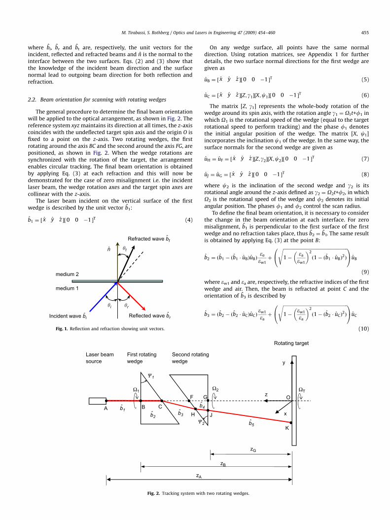
where bi, br and bt are, respectively, the unit vectors for theincident, reflected and refracted beams and n is the normal to theinterface between the two surfaces. Eqs. (2) and (3) show thatthe knowledge of the incident beam direction and the surfacenormal lead to outgoing beam direction for both reflection andrefraction.
2.2. Beam orientation for scanning with rotating wedges
The general procedure to determine the final beam orientationwill be applied to the optical arrangement, as shown in Fig. 2. Thereference system xyz maintains its direction at all times, the z-axiscoincides with the undeflected target spin axis and the origin O isfixed to a point on the z-axis. Two rotating wedges, the firstrotating around the axis BC and the second around the axis FG, arepositioned, as shown in Fig. 2. When the wedge rotations aresynchronized with the rotation of the target, the arrangementenables circular tracking. The final beam orientation is obtainedby applying Eq. (3) at each refraction and this will now bedemonstrated for the case of zero misalignment i.e. the incidentlaser beam, the wedge rotation axes and the target spin axes arecollinear with the z-axis.
The laser beam incident on the vertical surface of the firstwedge is described by the unit vector b1:
b1 ¼ ½ x y z �½0 0 �1 �T (4)
n
Incident wave bi ˆ Reflected wave brˆ
Refracted wave bt
medium 2
medium 1
�i
�t
�r
ˆ
Fig. 1. Reflection and refraction showing unit vectors.
B
b2ˆ b3ˆb1ˆ
�1
�2
C
F
HA
Laser beam
source
First rotating
wedge
Second rotati
wedge
Ω1
b4ˆ
zA
Fig. 2. Tracking system wit
On any wedge surface, all points have the same normaldirection. Using rotation matrices, see Appendix 1 for furtherdetails, the two surface normal directions for the first wedge aregiven as
uB ¼ ½ x y z �½0 0 �1 �T (5)
uC ¼ ½ x y z �½Z; g1�½X;c1�½0 0 �1 �T (6)
The matrix [Z, g1] represents the whole-body rotation of thewedge around its spin axis, with the rotation angle g1 ¼ O1t+f1 inwhich O1 is the rotational speed of the wedge (equal to the targetrotational speed to perform tracking) and the phase f1 denotesthe initial angular position of the wedge. The matrix [X, c1]incorporates the inclination c1 of the wedge. In the same way, thesurface normals for the second wedge are given as
uH ¼ uF ¼ ½ x y z �½Z; g2�½X;c2�½0 0 �1 �T (7)
uJ ¼ uG ¼ ½ x y z �½0 0 �1 �T (8)
where c2 is the inclination of the second wedge and g2 is itsrotational angle around the z-axis defined as g2 ¼ O2t+f2, in whichO2 is the rotational speed of the wedge and f2 denotes its initialangular position. The phases f1 and f2 control the scan radius.
To define the final beam orientation, it is necessary to considerthe change in the beam orientation at each interface. For zeromisalignment, b1 is perpendicular to the first surface of the firstwedge and no refraction takes place, thus b2 ¼ b1. The same resultis obtained by applying Eq. (3) at the point B:
b2 ¼ ðb1 � ðb1 � uBÞuBÞ�a
�w1þ
ffiffiffiffiffiffiffiffiffiffiffiffiffiffiffiffiffiffiffiffiffiffiffiffiffiffiffiffiffiffiffiffiffiffiffiffiffiffiffiffiffiffiffiffiffiffiffiffiffiffiffiffiffiffiffiffiffi1�
�a
�w1
� �2
ð1� ðb1 � uBÞ2Þ
s0@
1AuB
(9)
where ew1 and ea are, respectively, the refractive indices of the firstwedge and air. Then, the beam is refracted at point C and theorientation of b3 is described by
b3 ¼ ðb2 � ðb2 � uCÞuCÞ�w1
�aþ
ffiffiffiffiffiffiffiffiffiffiffiffiffiffiffiffiffiffiffiffiffiffiffiffiffiffiffiffiffiffiffiffiffiffiffiffiffiffiffiffiffiffiffiffiffiffiffiffiffiffiffiffiffiffiffiffiffi1�
�w1
�a
� �2
ð1� ðb2 � uCÞ2Þ
s0@
1AuC
(10)
b5ˆ
G
J
Oz
x
y
K
zB
zG
ng
Rotating target
Ω2 ΩT
h two rotating wedges.
ARTICLE IN PRESS
M. Tirabassi, S. Rothberg / Optics and Lasers in Engineering 47 (2009) 454–460456
On the second wedge, the refractions take place at the points H
and J and the beam orientations are defined by the followingequations:
b4 ¼ ðb3 � ðb3 � uFÞuFÞ�a
�w2þ
ffiffiffiffiffiffiffiffiffiffiffiffiffiffiffiffiffiffiffiffiffiffiffiffiffiffiffiffiffiffiffiffiffiffiffiffiffiffiffiffiffiffiffiffiffiffiffiffiffiffiffiffiffiffiffiffi1�
�a
�w2
� �2
ð1� ðb3 � uF Þ2Þ
s0@
1AuF
(11)
b5 ¼ ðb4 � ðb4 � uGÞuGÞ�w2
�aþ
ffiffiffiffiffiffiffiffiffiffiffiffiffiffiffiffiffiffiffiffiffiffiffiffiffiffiffiffiffiffiffiffiffiffiffiffiffiffiffiffiffiffiffiffiffiffiffiffiffiffiffiffiffiffiffiffiffi1�
�w2
�a
� �2
ð1� ðb4 � uGÞ2Þ
s0@
1AuG
(12)
In this way, the procedure allows straightforward description ofthe final beam orientation, readily incorporating the geometricalcomplexity in the configuration under consideration.
2.3. Determination of the ‘known’ point
To apply the velocity sensitivity model, the incident beamorientation and knowledge of an arbitrary point along theultimate line of the incident beam are required. For a singlewedge, the final beam orientation is b3 given by the (10) and thepoint C, found from the vector OC
�!, is convenient to use:
OC�!¼ OB�!� j BC�!jz (13)
The incident point in the plane of the target is then given by
OK�!¼ OC�!þ j CK�!jb3 ¼ OC
�!þ
OC�!� z
b3 � z
" #b3 (14)
For the system with two wedges, the point J from which thefinal beam b5 originates is the obvious choice of ‘known’ point andis obtained using the vector polygons, as follows:
OJ!¼ OC�!þ CH�!þ HJ!
(15)
The point H from which the beam b4 originates is determinedfrom the following vector system:
OF�!¼ OC�!þ CH�!þ HF�!
HF�!� uH ¼ 0
8<: (16)
which reveals that
CH�!¼ðOF�!� OC�!Þ � uH
b3 � uH
" #b3 (17)
In the same manner, the position for the point J is obtained fromthe following system:
GJ!¼ OC�!þ CH�!þ HJ!� OG�!
OG�!¼ OF�!� FG�!��� ���z
GJ!� uJ ¼ 0
8>>>><>>>>:
(18)
from which it can be shown that
HJ!¼ðOG�!� OC�!� CH�!Þ � uJ
b4 � uJ
" #b4 (19)
The position of J then follows from the substitution of Eqs. (17)and (19) into (15). The incident point in the plane of the target isthen given by
OK�!¼ OJ!þ jJK!jb5 ¼ OJ
!þ
OJ!� z
b5 � z
" #b5 (20)
2.4. Measured velocity and beam path in a tracking system
with a single wedge
For a scanning system with a single wedge, the final laser beamdirection is given by the expansion of Eq. (10) as
b3 ¼ x½Q sin c1 sin ðO1t þ f1Þ� � y½Q sin c1 cos ðO1t þf1Þ�
þ z Q cos c1 ��w1
�a
� �(21a)
where
Q ¼ cos c1
�w1
�a�
ffiffiffiffiffiffiffiffiffiffiffiffiffiffiffiffiffiffiffiffiffiffiffiffiffiffiffiffiffiffiffiffiffiffiffiffiffiffiffiffiffiffiffiffiffi1�
�w1
�a
� �2
ðsin 2c1Þ
s(21b)
Eq. (21a) shows that the x- and y-components of beamorientation are periodic functions of the wedge rotation speed,while the z-component is constant. Substituting Eq. (21a) intoEq. (1), the velocity measured by a laser beam incident on arotating target of flexible cross-section is given by
Um ¼ Q sin c1 sin ðO1t þf1Þ½_xrðP0Þ þ _xf ðPÞ�
� Q sin c1 cos ðO1t þ f1Þ½_yrðP0Þ þ _yf ðPÞ�
þ Q cos c1 ��w1
�a
� �½_zrðP0Þ þ _zf ðPÞ� (22a)
where _xf ðPÞ, _yf ðPÞ and _zf ðPÞ are the vibration velocity componentsdue to the target cross-section flexibility and _xrðP0Þ, _yrðP0Þ and_zrðP0Þ are the resultant vibration velocity components due torigid-body vibration [8]:
_xrðP0Þ ¼ _x� ð _yz þOÞðy0 � yÞ þ ð _yy �OyxÞðz0 � zÞ (22b)
_yrðP0Þ ¼ _yþ ð _yz þOÞðx0 � xÞ � ð _yx þOyyÞðz0 � zÞ (22c)
_zrðP0Þ ¼ _zþ ð _yx þOyyÞðy0 � yÞ � ð _yy �OyxÞðx0 � xÞ (22d)
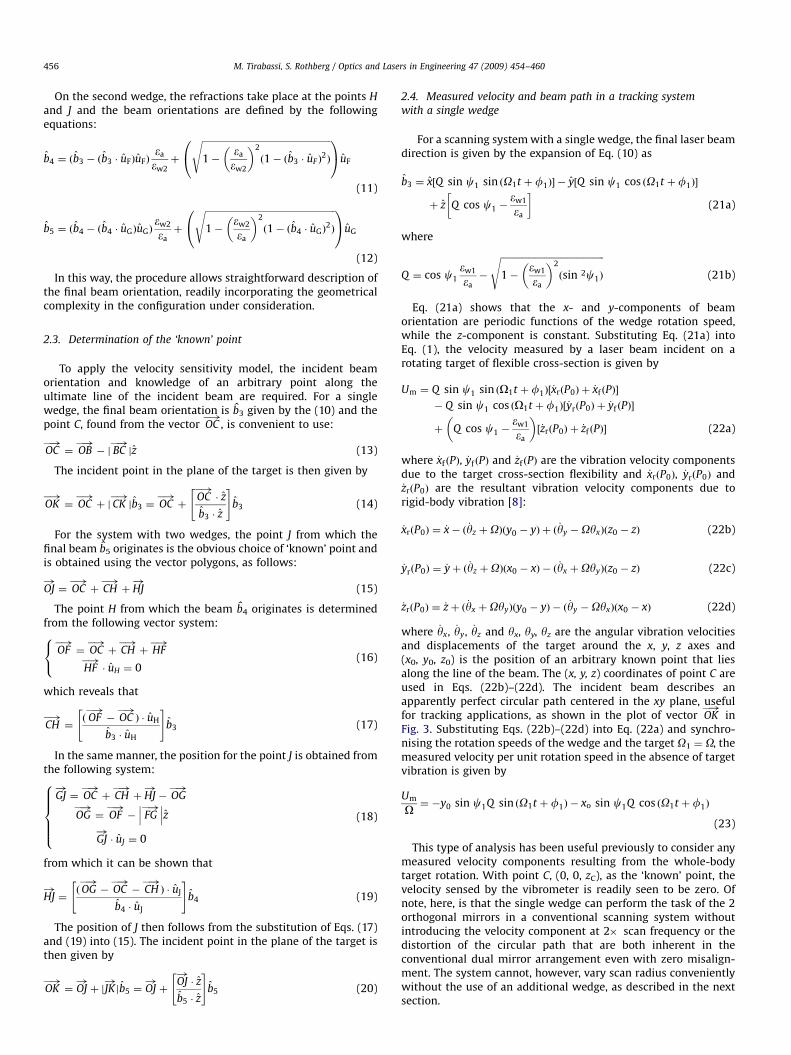
where _yx, _yy, _yz and yx, yy, yz are the angular vibration velocitiesand displacements of the target around the x, y, z axes and(x0, y0, z0) is the position of an arbitrary known point that liesalong the line of the beam. The (x, y, z) coordinates of point C areused in Eqs. (22b)–(22d). The incident beam describes anapparently perfect circular path centered in the xy plane, usefulfor tracking applications, as shown in the plot of vector OK
�!in
Fig. 3. Substituting Eqs. (22b)–(22d) into Eq. (22a) and synchro-nising the rotation speeds of the wedge and the target O1 ¼ O, themeasured velocity per unit rotation speed in the absence of targetvibration is given by
Um
O¼ �y0 sin c1Q sin ðO1t þ f1Þ � xo sin c1Q cos ðO1t þ f1Þ
(23)
This type of analysis has been useful previously to consider anymeasured velocity components resulting from the whole-bodytarget rotation. With point C, (0, 0, zC), as the ‘known’ point, thevelocity sensed by the vibrometer is readily seen to be zero. Ofnote, here, is that the single wedge can perform the task of the 2orthogonal mirrors in a conventional scanning system withoutintroducing the velocity component at 2� scan frequency or thedistortion of the circular path that are both inherent in theconventional dual mirror arrangement even with zero misalign-ment. The system cannot, however, vary scan radius convenientlywithout the use of an additional wedge, as described in the nextsection.
ARTICLE IN PRESS
-0.05 0 0.05
-0.06
-0.04
-0.02
0
0.02
0.04
0.06 Vector OK
0 1 2 3 4 5
10-20
10-15
10-10
10-5
100
Scan Rotation Order
Lo
gM
ag
(m
m/s
)/(r
ad
/s)
FFT
Fig. 3. Simulation of scanning system with a single rotating wedge: (a) beam path (b) velocity spectrum zB ¼ 0.5 m and c1 ¼101.
x
y
Laser source
First rotating wedge
Second rotating
wedge
Rotating target
z
x
A
O
�B1 = Oscillation frequency on the top of the first body wedge�B2 = Oscillation frequency on the top of the second body wedge
�1 = Rotational speed of the first wedge
�2 = Rotational speed of the second wedge
� = Rotational speed of the target
�B1
�B2�
�2
�1
Fig. 4. Schematic representation of all the rotations and oscillations considered for the double wedge scanning arrangement.
M. Tirabassi, S. Rothberg / Optics and Lasers in Engineering 47 (2009) 454–460 457
2.5. Measured velocity and beam path in a tracking system
with two wedges
For this case, expansion of Eq. (12) gives the final beamorientation b5 as
b5 ¼ x Q sin c1 sinðO1t þ f1Þ þ sin c2 R� S�w2
�a
� �sin ðO2t þ f2Þ
� �
� y Q sin c1 cos ðO1t þ f1Þ þ sin c2 R� S�w2
�a
� �cos ðO2t þf2Þ
� �
þ z ��w1
�aþ Q cos c1 þ cos c2 R� S
�w2
�a
� �þ T
�w2
�a�W
� �(24a)
where
R ¼ ðb3 � uHÞ (24b)
S ¼
ffiffiffiffiffiffiffiffiffiffiffiffiffiffiffiffiffiffiffiffiffiffiffiffiffiffiffiffiffiffiffiffiffiffiffiffiffiffiffiffiffiffiffiffiffiffiffiffiffiffiffiffiffiffiffiffiffi1�
�a
�w2
� �2
ð1� ðb3 � uHÞ2Þ
s(24c)
T ¼ ðb4 � uJÞ (24d)
W ¼
ffiffiffiffiffiffiffiffiffiffiffiffiffiffiffiffiffiffiffiffiffiffiffiffiffiffiffiffiffiffiffiffiffiffiffiffiffiffiffiffiffiffiffiffiffiffiffiffiffiffiffiffiffiffiffiffi1�
�w2
�a
� �2
ð1� ðb4 � uJÞ2Þ
s(24e)
Eq. (24a) shows the complexity of the final beam orientation,even for this relatively simple optical arrangement, but it is easilyobtained using the proposed procedure. By combination withEqs. (1) and(24a) is used to derive the velocity sensed, followingthe same pattern as Eqs. (22a)–(22d). In the absence oftarget vibration, the measured velocity per unit rotation speed isgiven by
Um
O1¼ � y0Q sin c1 sinðO1t þ f1Þ
� y0 sin c2 �Q cos c1 cos c2 þ1
�aðcos c2�w1 � S�w2Þ
� �sin ðO2t þf2Þ
þ y0 sin c2 Q sinc1 sin c2 cos ððO1t þf1Þ � ðO2t þf2ÞÞ
sin ðO2t þf2Þ
� x0Q sin c1 cos ðO1t þf1Þ
� x0 sin c2 �Q cos c1 cos c2 þ1
�aðcos c2�w1 � S�w2Þ
� �cos ðO2t þf2Þ
þ x0 sin c2 Q sin c1 sin c2 cos ððO1t þ f1Þ � ðO2t þ f2ÞÞ
cos ðO2t þf2Þ
(25)
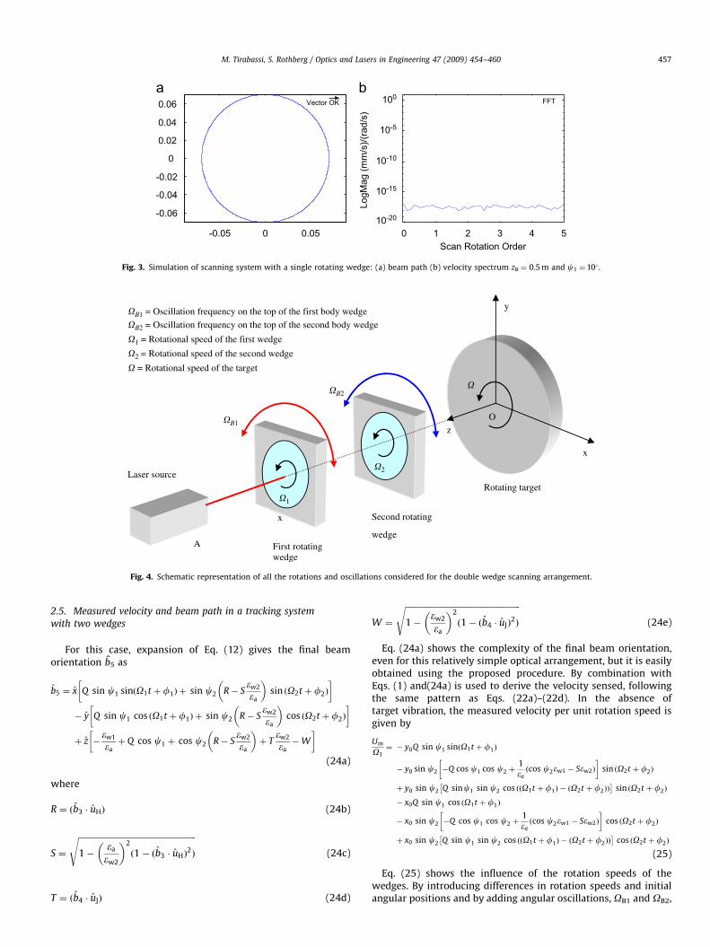
Eq. (25) shows the influence of the rotation speeds of thewedges. By introducing differences in rotation speeds and initialangular positions and by adding angular oscillations, OB1 and OB2,
ARTICLE IN PRESS
M. Tirabassi, S. Rothberg / Optics and Lasers in Engineering 47 (2009) 454–460458
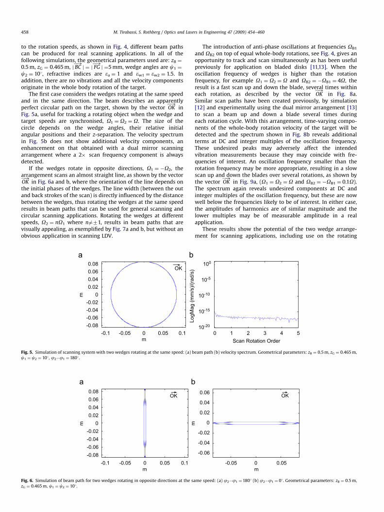
to the rotation speeds, as shown in Fig. 4, different beam pathscan be produced for real scanning applications. In all of thefollowing simulations, the geometrical parameters used are: zB ¼
0.5 m, zG ¼ 0.465 m, j BC�!j ¼ j FG
�!j ¼5 mm, wedge angles are c1 ¼
c2 ¼ 101, refractive indices are ea ¼ 1 and ew1 ¼ ew2 ¼ 1.5. Inaddition, there are no vibrations and all the velocity componentsoriginate in the whole body rotation of the target.
The first case considers the wedges rotating at the same speedand in the same direction. The beam describes an apparentlyperfect circular path on the target, shown by the vector OK
�!in
Fig. 5a, useful for tracking a rotating object when the wedge andtarget speeds are synchronised, O1 ¼ O2 ¼ O. The size of thecircle depends on the wedge angles, their relative initialangular positions and their z-separation. The velocity spectrumin Fig. 5b does not show additional velocity components, anenhancement on that obtained with a dual mirror scanningarrangement where a 2� scan frequency component is alwaysdetected.
If the wedges rotate in opposite directions, O1 ¼ �O2, thearrangement scans an almost straight line, as shown by the vectorOK�!
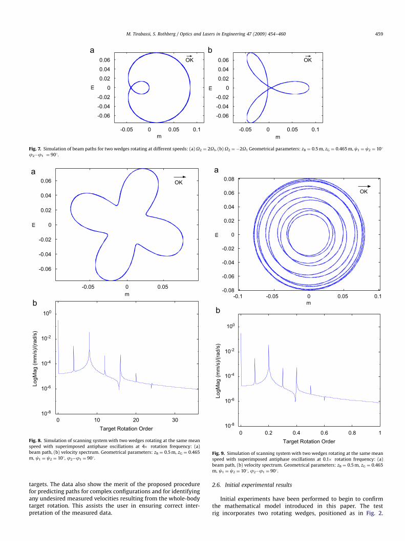
in Fig. 6a and b, where the orientation of the line depends onthe initial phases of the wedges. The line width (between the outand back strokes of the scan) is directly influenced by the distancebetween the wedges, thus rotating the wedges at the same speedresults in beam paths that can be used for general scanning andcircular scanning applications. Rotating the wedges at differentspeeds, O2 ¼ nO1 where n6¼71, results in beam paths that arevisually appealing, as exemplified by Fig. 7a and b, but without anobvious application in scanning LDV.
-0.1 -0.05 0 0.05 0.1
-0.08
-0.06
-0.04
-0.02
0
0.02
0.04
0.06
0.08OK
m
m
Fig. 5. Simulation of scanning system with two wedges rotating at the same speed: (a) b
c1 ¼ c2 ¼ 101, j2�j1 ¼ 1801.
-0.1 -0.05 0 0.05 0.1
-0.08
-0.06
-0.04
-0.02
0
0.02
0.04
0.06
0.08OK
m
m
Fig. 6. Simulation of beam path for two wedges rotating in opposite directions at the s
zG ¼ 0.465 m, c1 ¼ c2 ¼ 101.
The introduction of anti-phase oscillations at frequencies OB1
and OB2 on top of equal whole-body rotations, see Fig. 4, gives anopportunity to track and scan simultaneously as has been usefulpreviously for application on bladed disks [11,13]. When theoscillation frequency of wedges is higher than the rotationfrequency, for example O1 ¼ O2 ¼ O and OB2 ¼ �OB1 ¼ 4O, theresult is a fast scan up and down the blade, several times withineach rotation, as described by the vector OK
�!in Fig. 8a.
Similar scan paths have been created previously, by simulation[12] and experimentally using the dual mirror arrangement [13]to scan a beam up and down a blade several times duringeach rotation cycle. With this arrangement, time-varying compo-nents of the whole-body rotation velocity of the target will bedetected and the spectrum shown in Fig. 8b reveals additionalterms at DC and integer multiples of the oscillation frequency.These undesired peaks may adversely affect the intendedvibration measurements because they may coincide with fre-quencies of interest. An oscillation frequency smaller than therotation frequency may be more appropriate, resulting in a slowscan up and down the blades over several rotations, as shown bythe vector OK
�!in Fig. 9a, (O1 ¼ O2 ¼ O and OB2 ¼ �OB1 ¼ 0.1O).
The spectrum again reveals undesired components at DC andinteger multiples of the oscillation frequency, but these are nowwell below the frequencies likely to be of interest. In either case,the amplitudes of harmonics are of similar magnitude and thelower multiples may be of measurable amplitude in a realapplication.
These results show the potential of the two wedge arrange-ment for scanning applications, including use on the rotating
0 1 2 3 4 510-20
10-15
10-10
10-5
100
Scan Rotation Order
LogM
ag (
mm
/s)/
(rad/s
)
eam path (b) velocity spectrum. Geometrical parameters: zB ¼ 0.5 m, zG ¼ 0.465 m,
-0.05 0 0.05
-0.06
-0.04
-0.02
0
0.02
0.04
0.06OK
m
m
ame speed: (a) j2�j1 ¼1801 (b) j2�j1 ¼ 01. Geometrical parameters: zB ¼ 0.5 m,
ARTICLE IN PRESS
-0.05 0 0.05
-0.06
-0.04
-0.02
0
0.02
0.04
0.06 OK
m
m
0 10 20 3010-8
10-6
10-4
10-2
100
Target Rotation Order
LogM
ag (
mm
/s)/
(rad/s
)
Fig. 8. Simulation of scanning system with two wedges rotating at the same mean
speed with superimposed antiphase oscillations at 4� rotation frequency: (a)
beam path, (b) velocity spectrum. Geometrical parameters: zB ¼ 0.5 m, zG ¼ 0.465
m, c1 ¼ c2 ¼ 101, j2�j1 ¼ 901.
-0.05 0 0.05 0.1
-0.06
-0.04
-0.02
0
0.02
0.04
0.06 OK
m
m
-0.05 0 0.05 0.1
-0.06
-0.04
-0.02
0
0.02
0.04
0.06 OK
m
m
Fig. 7. Simulation of beam paths for two wedges rotating at different speeds: (a) O2 ¼ 2O1, (b) O2 ¼ �2O1 Geometrical parameters: zB ¼ 0.5 m, zG ¼ 0.465 m, c1 ¼ c2 ¼ 101
j2�j1 ¼ 901.
-0.1 -0.05 0 0.05 0.1-0.08
-0.06
-0.04
-0.02
0
0.02
0.04
0.06
0.08
OK
m
m
0 0.2 0.4 0.6 0.8 1
10-8
10-6
10-4
10-2
100
Target Rotation Order
Lo
gM
ag
(m
m/s
)/(r
ad
/s)
Fig. 9. Simulation of scanning system with two wedges rotating at the same mean
speed with superimposed antiphase oscillations at 0.1� rotation frequency: (a)
beam path, (b) velocity spectrum. Geometrical parameters: zB ¼ 0.5 m, zG ¼ 0.465
m, c1 ¼ c2 ¼ 101, j2�j1 ¼ 901.
M. Tirabassi, S. Rothberg / Optics and Lasers in Engineering 47 (2009) 454–460 459
targets. The data also show the merit of the proposed procedurefor predicting paths for complex configurations and for identifyingany undesired measured velocities resulting from the whole-bodytarget rotation. This assists the user in ensuring correct inter-pretation of the measured data.
2.6. Initial experimental results
Initial experiments have been performed to begin to confirmthe mathematical model introduced in this paper. The testrig incorporates two rotating wedges, positioned as in Fig. 2.

ARTICLE IN PRESS
0.001
0.01
0.1
1
10
0 20 40 60 80 100 120 140 160 180 200
Frequency (Hz)
Velo
city (
LogM
ag m
m/s
)
Fig. 10. Experimental data for tracking system (two wedges rotating at the same
mean speed).
M. Tirabassi, S. Rothberg / Optics and Lasers in Engineering 47 (2009) 454–460460
An encoder positioned behind the rotating target drives a signalgenerator which controls the rotation of the wedges using steppermotors and belt drives. Rotating the wedges in the same directionand at the same speed, a circular scan profile with radius of 5 cmwas created at 10 Hz. In the real experiment, it is obviously notpossible to set up the system with zero misalignment. This isparticularly the case as, at this stage of the research, no systematicalignment procedure yet exists for this novel configuration. Bymounting the wedges on simple translation stages, a basicalignment was performed and Fig. 10 reveals velocity componentsof 1.46 and of 0.086 mm/s, respectively, at 1� and 2� targetrotation speed. These components are due to misalignment andthe incorporation of misalignments into the model presented inthis paper is the subject of the next phase of this project. For now,it is noteworthy that the sensitivity to misalignment comparesvery favorably with the conventional dual-mirror system inwhich the residual misalignments, even after completion of thededicated alignment procedure, might result in a measuredvelocity at 1� scan frequency approximately 10 times higher,while the mirror configuration itself would result in a 2� scanfrequency component approximately 50 times higher.
3. Conclusions
Scanning laser Doppler vibrometers require laser beammanipulation by optical devices along the beam path. This paperhas proposed a general procedure able to determine the finalbeam orientation and a known point along the beam forarrangements in which a beam is refracted and/or reflected.Combining the use of rotation matrices with vector expressionsfor refraction and reflection, the final incident beam direction canbe determined for any kind of scanning arrangement. Theprocedure has been applied for the first time to novel scanningLDV arrangements in which one or two rotating wedges enablethe tracking of a rotating component, avoiding the problems ofinertia encountered in galvanometer mirror-based systems. Theprocedure has shown that the wedge angles, their separation andtheir relative initial angular position determine the radius of thecircular tracking paths. Knowledge of the final beam orientationand known point has been used to predict measured velocity inthese tracking applications. In the absence of misalignment, thewedge-based-circular tracking systems do not show any unde-sired velocity components from the target rotation, offering asignificant advantage over the conventional dual mirror scanningsystem which suffers from the presence of an unavoidablevelocity component at twice the scan frequency. Furthermore,
the addition of anti-phase angular oscillations to the wedgerotation speeds can provide a scan up and down the target whiletracking. Even for this more complex arrangement, measuredvelocities have been readily predicted.
Initial experimental measurements performed with tworotating wedges have been encouraging. Undesired velocitycomponents related to inevitable misalignments were detectedat 1� and 2� scan frequency rotation speed, but these were muchlower than those obtained with the dual mirror scanning system,especially at 2� . Further work will incorporate misalignmentsinto the predictions, together with Doppler shifts occurring ontransmission through the wedges themselves.
Appendix 1
The surface normal directions for wedges are obtained usingthe rotation matrices. For example, for a single wedge arrange-ment, the normal uc for the inclined surface of the wedge isdefined as
uC ¼ ½ x y z �½Z; g1�½X;c1�½0 0 �1 �T (A1)
where the matrices [Z, g1] and [X, c1] represent the anticlockwiserotations around the x and the z axes and are defined as [14]
½Z; g1� ¼
cos g1 � sin g1 0
sin g1 cos g1 0
0 0 1
264
375 ½X;c1� ¼
1 0 0
0 cos c1 � sin c1
0 sin c1 cos c1
264
375
(A2)
Other uses of rotation matrices in this paper follow thesame format.
References
[1] Davis QV, Kulczyk WK. Vibrations of turbine blades by means of a laser.Nature 1969;222:475–6.
[2] Hancox J, Staples BC, Parker RJ. The application of scanning laser Dopplervibrometry in aero-engine development. Proc Inst Mech Eng 1995;209:35–42.
[3] Stanbridge AB, Ewins DJ. Modal testing using a scanning laser Dopplervibrometer. Mech Syst Signal Process 1999;13:255–70.
[4] Castellini P, Paone N. Development of the tracking laser vibrometer:performance and uncertainty analysis. Rev Sci Instrum 2000;71:4639–47.
[5] Boedecker S, Drabenstedt A, Heller L, Kraft A, Leonhardt A, Rembe C. Opticalderotator for scanning vibrometer measurements on rotating objects. In:Seventh international conference on vibration measurements by lasertechniques: advances and applications. Proceedings of SPIE, Ancona, Italy,vol. 6345; 2006.
[6] Lomenzo RA, Barker AJ, Wicks AL, King PS. A laser vibrometry system formeasuring vibrations on rotating disks. In: Fourth national turbine enginehigh cycle fatigue (HCF) conference, Monterey, CA; 1999. p. 277–82.
[7] Sever IA. Turbomachinery blade vibration measurements with tracking LDVunder rotation. In: Seventh international conference on vibration measure-ments by laser techniques: advances and applications. Proceedings of SPIE,Ancona, Italy, vol. 6345; 2006.
[8] Halkon BJ, Rothberg SJ. Vibration measurements using continuous scanninglaser vibrometry: theoretical velocity sensitivity analysis with applications.Meas Sci Technol 2003;14:382–9.
[9] Bell JR, Rothberg SJ. Laser vibrometers and contacting transducers, targetrotation and 6 degree-of-freedom vibration: what do we really measure?J Sound Vib 2000;237(2):245–61.
[10] Amirault CT, DiMarzio CA. Precision pointing using a dual-wedge scanner.Appl Opt 1985;24(9):1302–8.
[11] Di Maio D, Ewins DJ. CAISER MYMESIS, a new software platform for virtualand actual vibration testing on rotating structures using a continuouslyscanning LDV technique. In: Proceedings of seventh international conferenceon vibration measurements by laser techniques, 5503. Proceedings of SPIE,63450Q, vol. 6345, Ancona, Italy; 2006.
[12] Gerald F. Marshall. Risley prism scan patterns. Part of the spie conference onoptical scanning: design and application, Denver, Colorado. SPIE 1999;3787:74–86.
[13] Halkon BJ, Rothberg SJ. Synchronised-scanning laser vibrometry. In: Proceed-ing of sixth international Conference on vibration measurements laser tech,5503, Ancona, Italy; 2004. p. 260–71.
[14] Harrison HR, Nettleton T. Advanced engineering dynamics, Arnold Ed., 1997.