sch 6.2.1 planning scheme policy 1 - infrastructure design
TRANSCRIPT

Scenic Rim Planning Scheme - PSP 1 Infrastructure Design 20 March 2020
Page 1 of 114
Sch 6.2.1 Planning Scheme Policy 1 - Infrastructure Design
Contents
Part Table of Contents PSP
Page Number
Part 1 Introduction 2
Part 2 Preliminary 4
Part 3 General Matters 5
Part 4 Roads 7
Part 5 Bridges, Major Culvert Works and Pedestrian Bridges 31
Part 6 Stormwater 34
Part 7 Lighting and Services 53
Part 8 Standards for Park Lands 59
Part 9 Landscaping and Embellishment for Public Areas 65
Part 10 As Constructed Plans 100
Part 11 Manuals for Mechanical and Electrical Equipment 102
Part 12 Bonding and Insurance 105
Part 13 Standard Drawings 109

Scenic Rim Planning Scheme - PSP 1 Infrastructure Design 20 March 2020
Page 2 of 114
1.0 Introduction
1.1 Title
This planning scheme policy may be cited as Planning Scheme Policy 1 - Infrastructure Design.
1.2 Purpose of this planning scheme policy
(1) The purpose of this planning scheme policy is to ensure that development complies with the local government's standards for the planning, design, location and construction of infrastructure that reflects acceptable standards in engineering, asset management, environmental management and natural resource planning by:
(a) specifying information requirements;
(b) specifying standards and guidelines;
(c) specifying administrative arrangements;
(d) specifying the circumstances in which Council may accept a security for the completion of work.
1.3 Structure of this planning scheme policy
This planning scheme policy is divided into twelve parts, being:
(a) Part 1 Introduction
(b) Part 2 Preliminary
(c) Part 3 Information Requirements
(d) Part 4 Roads
(e) Part 5 Bridges, Major Culvert Works and Pedestrian Bridges
(f) Part 6 Stormwater
(g) Part 7 Lighting and Services
(h) Part 8 Standards for Park Lands
(i) Part 9 Landscaping for Public Areas
(j) Part 10 As-Constructed Plans
(k) Part 11 Mechanical and Electrical Equipment
(l) Part 12 Bonding and Insurance
(m) Part 13 Standard Drawings.
1.4 Commencement
This planning scheme policy commences on the date of the Scenic Rim Planning Scheme.
1.5 Relationship to the Planning Act 2016
This planning scheme policy is made pursuant to the Planning Act 2016 (Act).
1.6 Applicability of this planning scheme policy
This planning scheme policy applies to assessable development.
1.7 Relationship to Other Legislation and Standards
This Policy must be read in conjunction with Council's Planning Scheme, statutory requirements including Council Local Laws, the Act and other references/standards as detailed herein.
1.8 Referenced documents
Any non-local government publication referenced must be sourced directly.
1.9 Terminology

Scenic Rim Planning Scheme - PSP 1 Infrastructure Design 20 March 2020
Page 3 of 114
(1) For the purposes of Planning Scheme Policy 1 - Infrastructure Design:
(a) Policy refers to Planning Scheme Policy 1 - Infrastructure Design;
(2) Terms used in the Policy are defined in Schedule 1 - Definitions.
(3) Referenced Standards are non-Council standards which meet the outcomes of the Policy.
(4) Council Standards specified in the Policy may include:
(a) Matters not otherwise referred to in Referenced Standards;
(b) A variation to the Referenced Standard;
(c) Limitation to one or more Referenced Standards (where multiple standards may apply).
(5) Where there is any conflict between Referenced Standards and Council Standards, then the Council Standards shall apply.

Scenic Rim Planning Scheme - PSP 1 Infrastructure Design 20 March 2020
Page 4 of 114
2.0 Preliminary 2.1 Pre-lodgement Meetings
It is strongly recommended that discussions are held with Scenic Rim Regional Council prior to and during the design, concerning design concepts and clarification of specific requirements related to a particular project.
A pre-design site inspection is expected to be undertaken prior to any detailed design work commencing. For Designers, it is recommended that a pre-design site inspection should be held with a representative from Council to discuss specific issues and requirements for the site and surrounds.
2.2 Forms
Relevant development application forms are available from the Department of State Development, Manufacturing, Infrastructure and Planning web site: https://planning.dsdmip.qld.gov.au/
It is recommended that Council's Application Checklist - Engineering Documentation also be completed and submitted.
If you have specific queries about a particular question or matter, it is recommended that you discuss the query initially with Councils Customer Service Section.
2.3 Fees
Fees associated with applications for Operational Works are listed in Council’s Fees and Charges Schedule located on Council’s website: http://www.scenicrim.qld.gov.au/
2.4 Development Construction Guidelines and Public Domain Guidelines
Council's Development Construction Guidelines (DCG) has been prepared to assist and guide developers through the application and construction process. Where development is proposed in the public domain in the town centres of:
• Beaudesert;
• Boonah;
• Canungra; and
• Tamborine Mountain; reference should also be made to Council's Design and Construction Guidelines and Scenic Rim Public Domain Guidelines for site specific guides to public space design principles. Copies of the DCG and the Public Domain Guidelines are available from Council's website: http://www.scenicrim.qld.gov.au/

Scenic Rim Planning Scheme - PSP 1 Infrastructure Design 20 March 2020
Page 5 of 114
3.0 General Matters
3.1 Contents Section Title
3.1 Contents
3.2 Purpose
3.3 General Matters
3.4 Referenced Standards
3.2 Purpose
The purpose of this Part is to:
(1) ensure that development provides appropriate and sufficient information to allow a development application to be properly and professionally assessed.
3.3 General Matters
(1) Any conflicts or departure from the Standard Drawings and the Policy shall be detailed in the application.
(2) Where a staged development has been approved by Council, Council may require engineering design and construction to include the whole of the site, or such additional parts of the site as will enable the Council to maintain the works in a satisfactory condition if the balance of the development does not proceed to completion (e.g. temporary end of road turn around and drainage outlets).
(3) The development application shall include sufficient information outside the development footprint to verify that any future extension of the proposed works can proceed in accordance with this Policy and without any undue cost to future development.
(4) All design drawings and calculations shall be supervised and certified by a Registered Professional Civil Engineer of Queensland (RPEQ (Civil)) before being submitted to Council for examination. The name and RPEQ number of the Engineer must be printed below the signature.
3.3.1 Competency to prepare a report
(1) A person preparing a report, a plan or a drawing relating to development must be a suitably qualified person and includes;
(a) in the case of geotechnical, hydraulic, stormwater infrastructure, civil, structural or electrical engineering issues be a Registered Professional Engineer of Queensland (RPEQ); or
(b) in the case of non-minor landscaping issues be a Registered Landscape Architect with the Australian Institute of Landscape Architects; or
(c) in the case of erosion and sediment control plans be a Certified Professional in Erosion and Sediment Control (CPESC) or a RPEQ who has undertaken the Erosion and Sediment Control training provided by the International Erosion Control Association with demonstrated specialist expertise in the relevant subject matter.
(2) The report, plan or drawing must include a certification signed by the relevant suitably qualified person that the report, plan or drawing is fit for its intended purpose and can be relied upon by Council for that purpose.
3.3.2 Bill of Quantities and Asset Report
A Bill of Quantities shall be provided at the time of submission of the engineering documentation. The Bill of Quantities need not include the contract prices. At the completion of the construction, a completed Asset Report which reflects the actual construction costs, constructed volumes, areas and length of items constructed shall be provided to Council.
Editor's Note - This information is required to update Council's Asset Register.

Scenic Rim Planning Scheme - PSP 1 Infrastructure Design 20 March 2020
Page 6 of 114
3.4 Referenced Standards
3.4.1 The Standards listed in Table 3.4.1 Reference Standards are the applicable standards for datum to be used for survey and design except where:
(1) The Standard is in conflict with a Standard specified in the Policy; or
(2) The standard is specifically varied, amended or removed by the standards specified in Policy.
Table 3.4.1 Referenced Standards
Standard Applicable Sections Applicable to
Australian Height Datum (AHD)
Vertical datum to be used for survey and design
Map Grid of Australia, 1994 (MGA94)
Horizontal datum to be used for survey and design
Scenic Rim Planning Scheme - PSP 1 - Infrastructure Design 20 March 2020
Page 7 of 114
4.0 Roads
4.1 Contents Section Title
4.1 Contents
4.2 Purpose
4.3 General Matters
4.4 Referenced Standards
4.5 Council Standards (including variations to Referenced Standards)
4.5.1 Street and Road Classifications
4.5.2 Street and Road Geometry
4.5.3 Sight Distances
4.5.4 Vehicle Turning Movements
4.5.5 Turning Area At The End Of A Road (Cul-De-Sac)
4.5.6 Manoeuvring Areas
4.5.7 Cross Section Profiles
4.5.8 Intersection Design
4.5.9 Traffic Islands And Medians
4.5.10 Pavement Design
4.5.11 Sub-Grade Evaluation
4.5.12 Flexible Street Pavements
4.5.13 Concrete Street Pavements
4.5.14 Interlocking Pavers
4.5.15 Minimum Pavement Thickness
4.5.16 Compaction Requirements
4.5.17 Soft Areas In Subgrade
4.5.18 Pavement Wearing Course
4.5.19 Traffic Control Devices
4.5.20 Urban Property Accesses
4.5.21 Rural, Industrial And Commercial Property Accesses
4.5.22 Kerb And Channel
4.5.23 Batters And Retaining Walls
4.5.24 Driveway Access
4.5.25 Roads Construction - General
4.5.26 Filling/Excavation and Road Construction
4.5.27 Traffic Control
4.5.28 Setting Out
4.5.29 Clearing and Grubbing
4.5.30 Clearing of Trees
4.5.31 Earthworks
4.5.32 Dams and Embankments
4.5.33 Pavement Materials
4.5.34 Kerb and Channel Construction
4.5.35 Sub-Soil Drainage
4.5.36 Erosion Control Measures
4.5.37 Road Furniture and Line Marking
4.5.38 Compaction Requirements
4.5.39 Tolerances
4.5.40 Testing
4.6 Standard Drawings

Scenic Rim Planning Scheme - PSP 1 - Infrastructure Design 20 March 2020
Page 8 of 114
4.2 Purpose The purpose of this Part is to:
(1) develop a road network and road alignments that balances the existing and future requirements; (2) provide a serviceable pavement for the specified lifetime with minimal maintenance; (3) ensure that staged construction methods are planned to meet the immediate, medium term and ultimate
pavement and drainage design requirements; (4) provide smooth, safe, trafficable horizontal and vertical alignments, adequate sight distance with
consideration being given to road classification requirements, road users and utilities.
4.3 General Matters The following requirements generally apply to new streets and upgrading of existing streets affected by urban residential, commercial and industrial developments. It also applies to new roads and upgrading of existing roads affected by rural and rural residential developments, as well as rural roads impacted by commercial and industrial developments in rural areas.
4.4 Referenced Standards 4.4.1 The Standards listed in Table 4.4.1 Reference Standards are the applicable standards for works on land being existing or future Council land except where:
(1) The standard is in conflict with a standards specified in Section 4.5; or
(2) The standard is varied, amended or removed by the standards specified in Section 4.5. Table 4.4.1 Referenced Standards
Standard Comments
Austroads Guides Guides produced and published by Austroads
Next Generation Planning Handbook
Next Generation Planning. A handbook for planners, designers and developers in South East Queensland. First published 2011 by the Council of Mayors (SEQ)
Complete Streets: Guidelines for Urban Street Design
Produced by: Institute of Public Works Engineering Australia Queensland Division Inc (IPWEAQ)
Queensland Streets The Local Government & Municipal (LGAM) Knowledge Base
Road Planning and Design Manual - 2nd edition Department of Transport and Main Roads
Guide to Traffic Impact Assessment Department of Transport and Main Roads
AS 1289.1.2.1-1998 (R2013) Methods of testing soils for engineering purposes - Sampling and preparation of soils - Disturbed samples - Standard method
Australian Standard
AS 1289.2.1.1-2005 (R2016) Methods of testing soils for engineering purposes - Soil moisture content tests - Determination of the moisture content of a soil - Oven drying method (standard method)
Australian Standard
AS 1289.3.1.1-2009/Amdt 1-2015 Methods of testing soils for engineering purposes - Soil classification tests - Determination of the liquid limit of a soil - Four point Casagrande method
Australian Standard
AS 1289.3.1.2-2009 Methods of testing soils for engineering purposes - Soil classification tests - Determination of the liquid limit of a soil - One point Casagrande method (subsidiary method)
Australian Standard
AS 1289.3.2.1-2009 Methods of testing soils for engineering purposes -
Australian Standard

Scenic Rim Planning Scheme - PSP 1 - Infrastructure Design 20 March 2020
Page 9 of 114
Standard Comments
Soil classification tests - Determination of the plastic limit of a soil - Standard method
AS 1289.3.3.1-2009 Methods of testing soils for engineering purposes - Soil classification tests - Calculation of the plasticity index of a soil
Australian Standard
AS 1289.3.4.1-2008 Methods of testing soils for engineering purposes - Soil classification tests - Determination of the linear shrinkage of a soil - Standard method
Australian Standard
AS 1289.3.6.1-2009 Methods of testing soils for engineering purposes - Soil classification tests - Determination of the particle size distribution of a soil - Standard method of analysis by sieving
Australian Standard
AS 1289.5.1.1-2003 Methods of testing soils for engineering purposes - Soil compaction and density tests - Determination of the dry density/moisture content relation of a soil using standard compactive effort
Australian Standard
AS 1289.5.3.1-2004 (R2016) Methods of testing soils for engineering purposes - Soil compaction and density tests - Determination of the field density of a soil - Sand replacement method using a sand-cone pouring apparatus
Australian Standard
AS 1289.5.4.1-2007 (R2016) Methods of testing soils for engineering purposes - Soil compaction and density tests - Compaction control test - Dry density ratio, moisture variation and moisture ratio
Australian Standard
AS 1289.5.4.2-2007 (R2016) Methods of testing soils for engineering purposes - Soil compaction and density tests - Compaction control test - Assignment of maximum dry density and optimum moisture content values
Australian Standard
AS 1289.5.5.1-1998 (R2016) Methods of testing soils for engineering purposes - Soil compaction and density tests - Determination of the minimum and maximum dry density of a cohesionless material - Standard method
Australian Standard
AS 1289.5.6.1-1998 (R2016) Methods of testing soils for engineering purposes - Soil compaction and density tests - Compaction control test - Density index method for a cohesionless material
Australian Standard
AS 1289.5.8.1-2007 Methods of testing soils for engineering purposes - Soil compaction and density tests - Determination of field density and field moisture content of a soil using a nuclear surface moisture Density gauge - Direct transmission mode
Australian Standard
Q145A - Laboratory compaction to nominated levels of dry density and moisture content
DTMR Materials Testing Manual Edition 4, Amendment 1 March 2016
Q113A - California Bearing Ratio of soil - standard DTMR Materials Testing Manual Edition 4, Amendment 1 March 2016
Q113C - California Bearing Ratio of soil at nominated levels of dry density and moisture content
DTMR Materials Testing Manual Edition 4, Amendment 1

Scenic Rim Planning Scheme - PSP 1 - Infrastructure Design 20 March 2020
Page 10 of 114
Standard Comments
March 2016
Q114B - Insitu California Bearing Ratio - dynamic cone penetrometer
DTMR Materials Testing Manual Edition 4, Amendment 1 March 2016
4.5 Council Standards (including variations to Referenced Standards)
Editor's Note - includes standards not referred to in Referenced Standards and any variations to those standards
4.5.1 Street And Road Classifications
The street classifications and road classifications referred to within this Policy relate specifically to the design and construction of new or upgraded streets.
• The classification of urban streets shall be in accordance with Table 4.5.1.1 Urban Street Characteristics.
• The classification of rural and rural residential roads shall be in accordance with Table 4.5.1.2 Rural & Rural Residential Road Characteristics.
Ultimate traffic volumes for street and road classifications and street and road design shall be based upon approved multipliers of existing traffic movements (measured), through traffic, and an estimate of traffic generated by proposed and future development.
Estimated traffic volumes for undeveloped areas shall be based upon the following:
(1) Residential allotments - 10 vehicle movements per day per lot;
(2) Commercial/Industrial - 45 vehicle movements per day per lot;
(3) Rural and Rural Residential allotments - 8 vehicle movements per day per lot.
Where alternative traffic generations assumptions are used in the preparation of a Traffic Impact Study, details of alternatives shall be provided.
Note - Where Council holds traffic count data on relevant roads and streets, this information may be made available to the applicant.
Note - In some instances, additional traffic count data collection will be required on affected roads and streets to ascertain predevelopment traffic volumes and types. This will generally only be required where traffic count data is greater than three years old, or significant development has taken place since traffic count data was last collected. Where traffic volumes and type vary seasonally, data shall be used conservatively and clearly present assumptions.
4.5.1.1 Urban Street Characteristics
The classification, function, width and general composition of streets within any development are detailed in Table 4.5.1.1 Urban Street Characteristics. Road reserve widths must be sufficient to accommodate the carriageway, required services with approved clearances, pedestrian and bicycle access, parking, landscaping, drainage and bus routes. Where a development design incorporates Water Sensitive Urban Design (WSUD) principles, the road reserve may need to be increased. Minimum road reserve widths will not be allowed where they compromise the provision and standard of pedestrians, bicycles and buses.
Note - Lesser width industrial road reserve for short industrial cul-de-sacs will be considered by Council upon application, however turning at the cul-de-sac shall not be compromised. Curved road reserve boundaries around cul-de-sacs will be considered by Council upon application, but where they are to be fenced as chords, these should not be less than 10 metres. Where a number of such chords occur adjacent to each other, they should, as far as possible, be practically equal.
Table 4.5.1.1 - Urban Street Characteristics
Street Type Traffic Volume (AADT)
Carriageway Width
Min. Reserve Width
Min. Verge Width
Parking Provision
Pedestrian/Cycle Provision within Road Reserve
Kerbing
Trunk Collector/ Connector Street (Bus Route, No Lot Access)
>3000 10.00m 20.30m 5.15m No 1.5m bicycle lane on each side of carriageway & 2.5m shared pathway one side and 1.5m footpath on opposite side
Type B1

Scenic Rim Planning Scheme - PSP 1 - Infrastructure Design 20 March 2020
Page 11 of 114
Street Type Traffic Volume (AADT)
Carriageway Width
Min. Reserve Width
Min. Verge Width
Parking Provision
Pedestrian/Cycle Provision within Road Reserve
Kerbing
Trunk Collector/ Connector Street (Bus Route)
3000 max 11.60m 21.90m 5.15m 2.5m parking lanes both sides
2.5m shared pathway one side and 1.5m footpath on opposite side
Type B1
Access/ Collector Street
1000 max 8.50m 16.80m 4.15m No 1.5m footpath on lower side of street
Type B1
Access Place
300 max (min length 100m)
6.00m 14.30m 4.15m No No Type B1
Note - Refer to Scenic Rim Regional Council standard drawing R-09 for further details.
4.5.1.2 Rural & Rural Residential Road Characteristics
The classification, function and general composition of roads within any development are detailed in Table 4.5.1.2 Rural & Rural Residential Road Characteristics. Road reserve widths must be sufficient to accommodate the carriageway, required services with approved clearances, pedestrian and bicycle access, parking, landscaping, drainage and bus routes. Should the development design incorporate Water Sensitive Urban Design (WSUD) principles the road reserve may need to be increased. Minimum road reserve widths in rural and rural residential developments shall be as detailed in Table 4.5.1.2 Rural & Rural Residential Road Characteristics, with the minimum being 20 metres, however additional reserve width is encouraged to facilitate landscaping and pedestrian/bicycle facilities. Minimum road reserve widths will not be allowed where they compromise the provision and standard of pedestrians, bicycles and buses.
Note - Curved road reserve boundaries around cul-de-sacs will be considered by Council, but where they are to be fenced as chords, these should not be less than 10 metres. Where a number of such chords occur adjacent to each other, they should, as far as possible, be practically equal.
Table 4.5.1.2 - Rural & Rural Residential Road Characteristics
Street Type Traffic Volume (AADT)
Min. Pavement Width
Min. Seal Width Min. Sealed Shoulder Width
Class 4A - Rural Connector
1000 - 3000 9m 7m 1m
Class 4B - Rural Collector
500 - 1000 8m 7m 0.5m
Class 5A - Rural Access
150 - 500 7m 7m Unsealed
Class 5B - Rural Access
80 - 150 7m 6m Unsealed
Class 5C - Rural Access
40 - 80 7m Unsealed Unsealed
Class 5D - Rural Access
2 - 80 5.5m Unsealed Unsealed
Notes- 1. Refer to Scenic Rim Regional Council standard drawing R-10 & R-11 for further information. 2. For traffic volumes >3000 vehicles/day cross section requirements shall be in accordance with Department of Transport and
Main Roads.
4.5.2 Street And Road Geometry

Scenic Rim Planning Scheme - PSP 1 - Infrastructure Design 20 March 2020
Page 12 of 114
(1) The subdivision shall be designed in accordance with the principles in the Next Generation Planning Handbook and the geometric design shall be in accordance with Austroads requirements. The street geometry shall provide sufficient space such that emergency service vehicles, waste collection vehicles and street-cleaning vehicles can carry out their functions while travelling in a forward-only direction throughout the development.
(2) Cul-de-sacs shall be avoided due to the requirement to have permeable networks to distribute traffic more evenly and potentially provide more efficient walking, cycling and public transport. However where they are completely unavoidable, they are to be of bowl geometry. ‘T’ or ‘Y’ cul-de-sac heads are not permitted.
(3) Staging of works shall not negate this requirement and temporary turning areas need to be established between development stages.
(4) Parking, bicycle and bus requirements could potentially impact upon the minimum widths and adequacy for these functions shall be demonstrated.
(5) Street design grading shall be extended a minimum of 100 metres beyond the end of the street where such street is to be extended in the future. Where new street meets an existing road or street the designer shall check the grading for a distance of 50 metres to check that the new street match well and that no abrupt change in grade occurs.
(6) The geometric design of rural roads, including horizontal and vertical alignments, is to be based on Austroads ‘Guide to Road Design, Part 3 - Geometric Road Design’, unless otherwise noted within this Policy.
(7) Road geometry in rural residential developments shall provide sufficient space such that emergency service vehicles and waste collection vehicles can carry out their functions while travelling in a forward-only direction throughout the development. Significant rural and rural residential developments may require provision for school buses. Roads shall be designed such that these vehicles shall not need to reverse.
(8) Staging of works shall not negate the requirement for forward only turning and temporary turning areas shall be established between development stages. This could require the need for temporary table drains around these turning areas.
(9) Road design grading shall be extended a minimum of 100 metres beyond the end of the street where such street is to be extended in the future. Where new roads meet existing roads the designer shall check the grading for a distance of 100 metres to check that roads match well and that no abrupt change in grade occurs.
(10) Vertical curve design shall comply with Austroads ‘Guide to Road Design, Part 3 - Geometric Road Design'. Vertical curves on rural roads shall be designed to provide Stopping Sight Distances for the design speed for the particular road. If the road is on a grade, ensure the stopping sight distance is adjusted before calculating the required "K" value for each vertical curve, as the stopping sight distances used in the tables are calculated on a level grade.
(11) Horizontal and vertical geometry shall be co-ordinated for appearance and safety. In principle, co-ordination means that the horizontal and vertical curves should either be completely superimposed or completely separated. The related horizontal and vertical elements should be of similar lengths with the vertical curve contained within the horizontal curve.
4.5.3 Sight Distances
Reference shall be made to the Austroads Guidelines when considering sight distances, particularly at street intersections and on crest vertical curves.
Adequate horizontal and vertical sight distance should be provided for the design speed in accordance with Austroads publication ‘Guide to Road Design, Part 3 - Geometric Road Design'. The design speed shall be determined using the Austroads "Operating Speed Model".
Note - Software is available to download from the Queensland Department of Transport and Main Roads to assist with this process and should be provided with the design plans and other calculations.
Landscaping plans shall be prepared with consideration to sight distance requirements, as shall any Estate Signage.
Plans submitted for approval shall show all existing and proposed features in sufficient detail to demonstrate that appropriate sight distances are achieved.
Scenic Rim Planning Scheme - PSP 1 - Infrastructure Design 20 March 2020
Page 13 of 114
4.5.4 Vehicle Turning Movements
Vehicle turning movements are to be examined for design vehicles and check vehicles in accordance with Austroads 'Guide to Road Design Part 4: Intersections and crossing - General'.
Street space should be provided such that the design vehicle is able to negotiate a left turn from the left lane without crossing adjacent lanes and without the need to reverse to complete the turning movement. Check vehicles may impinge upon adjacent lanes as they represent infrequent vehicles accessing local streets, such as articulated vehicles delivering building materials in new estates or furniture carrying vehicles.
The intersection design shall be such that 600mm clearance for above ground structures is applied to the total swept path of the design vehicle, and not just to the wheel path. Vehicle accesses and driveways are NOT to be used for turning movements. All roadway and vehicle crossings are desirable to be designed to accommodate the Australian Standard 99th percentile car, but as an absolute minimum the 85th percentile Australian Standard car.
Turning movement plans shall be provided to show turning movements.
4.5.5 Turning Area At The End Of A Road (Cul-De-Sac)
Turning heads at the end of a road are to be circular and:
(i) provide access to a residential use;
(ii) incorporate provision for parking.
Access to adjoining premises does not conflict with a parking area provided at the end or on the verge of a cul-de-sac. The maximum longitudinal grade at the head of a cul-de-sac is 5 percent.
4.5.6 Manoeuvring Areas
Manoeuvring for waste collection vehicles is designed so that:
• no more than one reversing movement is required for access to bin and skip collection areas;
• where waste collection vehicles are required to enter a site, the waste collection vehicle is able to leave the site in a forward gear;
• waste collection vehicle turning radius - kerb to kerb 10.8m;
• waste collection vehicle turning radius - wall to wall 11.5m.
Where development is incomplete (such as a road that ends at a stage boundary) but is to be extended in the future, temporary manoeuvring areas are constructed:
in the form of a gravel turning area.
Where a turning area is to be outside the road reserve, an easement in favour of Council is provided which:
• extends over the full extent of the turning area that is outside the road reserve;
• is for vehicular access purposes and is otherwise on terms satisfactory to Council.
The manoeuvring area has a maximum gradient suitable for waste collection vehicles.
The manoeuvring area has a minimum vertical distance of:
• 3.5 metres for a SRV;
• 4.5 metres for a HRV.
4.5.7 Cross Section Profiles
Cross-sections shall accord with street carriageway and road reserve widths as per sections 4.5.1.1 and 4.5.1.2. Typical cross-sections should be included in the documentation and should nominate:
• Type of kerb and channel
• Pavement construction including material type and depth
• Surface details
Scenic Rim Planning Scheme - PSP 1 - Infrastructure Design 20 March 2020
Page 14 of 114
• Subsoil drainage, if required
• Typical footpath offsets
• Typical service corridors
• Typical landscaping corridors
• Crossfall.
Should design speeds require super-elevation of horizontal curves, design of crossfall shall be based on the current Austroads design manual for urban roads.
Verge crossfalls between footpath and back of kerb shall be 2%, and shall extend into properties at the same grade for a nominal distance of 500 mm. Should steeper verges be proposed, the Designer must demonstrate that car access can be provided to effected allotments.
Wherever new kerb and channel or footpath is to be constructed adjacent to existing roadways and/or wherever excessive crossfalls occur on either the road pavement or nature strip, all vehicle crossings to allotments shall be designed using standard car templates to ensure that car access can be provided.
Grading of residential allotments to a distance of 6m back from the property boundary will be required in steeper locations as this will then set the RL of the Garage or carport of any future house to be built on the 6m front boundary offset.
Whenever it is impractical to provide batters flatter than the maximum slopes specified, development shall provide special treatment such as retaining walls within the property and in areas prone to erosion, erosion control measures shall be used such as concrete, asphalt, diversion drains etc.
Street designs shall be such so as to avoid filling on the low side of the street, unless demonstrated to be impractical.
There shall be two lanes of traffic on rural and rural residential developments.
Cross section design should not be terminated at the property boundaries but should be extended sufficiently to determine cut and fill requirements and to show such on plans.
Should crossfalls of greater than 6% at intersections or horizontal curves be proposed, approval should be sought from Council’s engineering department.
Batter slopes shall be as is appropriate for the predominant use of the locality and shall be designed with consideration of clear zones as defined in Austroads Guidelines.
Whenever it is impractical to provide batters flatter than the maximum slopes specified, barriers may be required.
4.5.8 Intersection Design
4.5.8.1 General
Intersections are to be designed and constructed such that they function in a safe, convenient and appropriate manner for the type of street and development, and shall be designed in accordance with Austroads ‘Guide to Traffic Management Part 6: Intersections, Interchanges and Crossings', ‘Guide to Road Design Part 4: Intersections and Crossings - General’, ‘Guide to Road Design Part 4A: Intersections - Unsignalised and Signalised' and ‘Guide to Road Design Part 4B: Roundabouts’.
4.5.8.2 Special Considerations
For intersections where the proportion of over-dimension or large combination vehicles is higher than the normal percentage in the traffic stream the intersection requirements should be more significant. The Traffic Impact Assessment should address this issue and make recommendations regarding these intersections.
4.5.8.3 Splays
Splays of suitable dimensions shall be provided at all corners of all intersections.
At intersections involving at least one collector road (or higher classification) the minimum splay at the intersecting roads shall be 5 x 5 metre. Otherwise, at intersecting roads of lesser classification the minimum splay to be provided shall be 3 x 3 metre.
Notwithstanding the above minimum, larger splays will be required where engineering assessment indicates a need commensurate with traffic safety and the provision of service corridors and trunk drainage.
Scenic Rim Planning Scheme - PSP 1 - Infrastructure Design 20 March 2020
Page 15 of 114
4.5.8.4 Kerb Returns
At intersections, the minimum kerb return or edge of seal radius shall be as follows:
• Residential areas 7.5 m
• Industrial / Commercial 12.0 m
• Rural Residential areas 7.5 m
• Rural areas 12.0 m.
Further to this, kerb radii shall be designed based upon turning movement requirements.
4.5.9 Traffic Islands And Medians
Medians and traffic islands are designed in accordance with Austroads and the Department of Transport and Main Roads - Road Planning and Design Manual.
Medians are cast in situ. Precast islands are not permitted unless otherwise approved by Council.
Medians and traffic islands are indicated by conspicuous raised kerbs, pavement markings or flush treatment as detailed in the Queensland Government's Manual of Uniform Traffic Control Devices (Queensland) (MUTCD) and are classified as follows:
• reflectorise (or directional) islands;
• roundabouts;
• median islands;
• medians;
• separators;
• Pedestrian refuge islands.
A median is not less than 1.2 metres wide unless otherwise approved by the local government.
Raised kerbed traffic islands less than 12.0m2 or less than 2 metres wide between kerb faces are:
• constructed of concrete;
• designed for occasional heavy vehicle wheel loadings;
• where constructed of concrete, are a minim;um of 100mm thick reinforced concrete with SL72 mesh on a firm sand bedding
• Constructed directly on top of the existing pavement and connected by dowels.
Raised kerbed medians and raised kerbed traffic islands greater than 12.0m2 or wider than 2 metres:
• are excavated in the road pavement to subgrade level;
• are landscaped:
(i) with grass; or
(ii) where landscaping other than grass has been approved by the local government, incorporate a 500mm wide reinforced concrete strip as a working area for garden maintenance in accordance with standard drawing IPWEAQ SEQ R-140 and IPWEAQ SEQ R-142;
• include water supply conduits and services every 80 metres with a minimum of one service per median or traffic island;
• include an approved conduit for an electricity service to a median or traffic island that is landscaped in a location that allows ease of connection of a future electricity service.
Where the slope across a median or traffic island is greater than 1 in 4, the median or traffic island is surfaced with concrete or another treatment approved by the local government.
Where a surface treatment other than concrete has been provided for a median or traffic island, sub-soil drainage is installed in the median or traffic island directly behind kerbs in accordance with standard

Scenic Rim Planning Scheme - PSP 1 - Infrastructure Design 20 March 2020
Page 16 of 114
drawing IPWEAQ SEQ R-140 and IPWEAQ SEQ R-142.
Water and electricity services are provided to a median or traffic island which has been landscaped.
4.5.10 Pavement Design
The minimum depth of flexible or rigid pavement for the proposed pavement and proposed pavement materials shall be determined by design in accordance with Austroads 'Guide to Pavement Technology Parts 1-10', with the pavement design submitted to Council’s Infrastructure Services Department for consideration. Samples and/or results of geotechnical testing and the source of the pavement material shall also be provided.
4.5.10.1 Sub-Grade Evaluation
Pavement design shall be based on the results of sub-grade analysis, including testing for soaked Californian Bearing Ratio (CBR), carried out by a NATA registered testing laboratory.
Sub-grade soil samples shall be taken at maximum intervals of 200 metres, in the bowls of Cul-de-sacs, at all intersections and at all obvious locations where existing sub-grade material changes suddenly. Core samples shall be bored to a minimum depth of 600 mm below final road sub-grade level. The soil sample used for laboratory testing shall be taken from the core at sub-grade level. Full details of sub-grade test results and core samples shall be submitted to Council with the detailed design plans.
The sub-grade inspection must include:
• the checking of the service conduit locations against the markers, if the kerb and channel is in place;
• the determination of the location of the mitre drains and the side drains;
• the proof rolling of the bottom of the box after compaction;
• the checking of the box depths;
• the checking of the sub-grade levels and the crossfalls;
• the checking of all related works.
4.5.10.2 Flexible Street Pavements
Flexible street pavement designs shall be in accordance with the Austroads ‘Guide to Pavement Technology Part 2: Pavement Structural Design'.
Pavement design shall be carried out using equivalent standard axle loadings based on an average traffic generation rate of 6 vehicles per day per residential lot and a 20 year design life for residential and commercial streets. Pavement design for industrial streets shall be based on an average traffic generation rate of 45 vehicles per day per industrial lot and a 40 year design life.
For rural and rural residential roads, pavement design shall be carried out using equivalent standard axle loadings based on an average traffic generation rate of 8 vehicles per day.
4.5.10.3 Concrete Street Pavements
Concrete street pavement designs shall be based on Austroads ‘Guide to Pavement Technology Part 2: Pavement Structural Design', with a minimum 40 year design life.
4.5.10.4 Interlocking Pavers
Due to safety, operational and maintenance issues interlocking block street pavements shall not be used. Alternatives such as stamped and coloured asphalt will be considered.
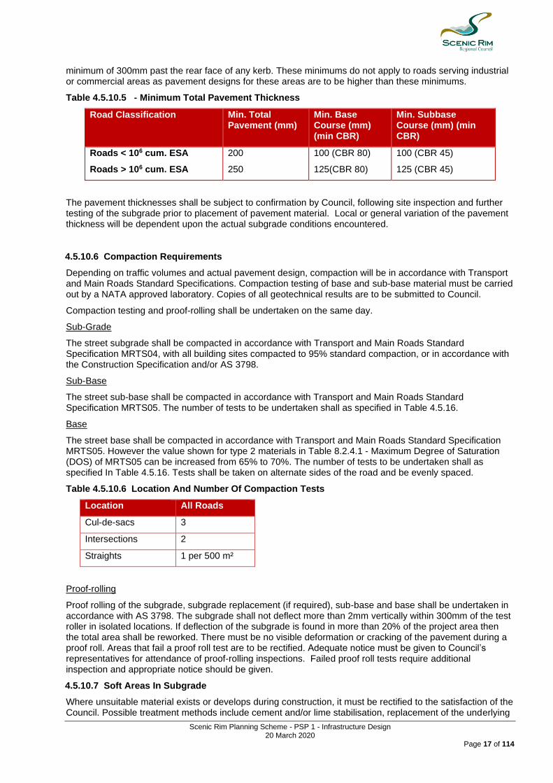
4.5.10.5 Minimum Pavement Thickness
Notwithstanding any of the above requirements, the pavement thickness, including the thickness of surfacing shall not be less than the amount specified in the Table 4.1.18 for streets in which kerb and channel is to be constructed, 200mm for unkerbed roads, and 150mm for carparks. The sub-base layer shall extend a
Scenic Rim Planning Scheme - PSP 1 - Infrastructure Design 20 March 2020
Page 17 of 114
minimum of 300mm past the rear face of any kerb. These minimums do not apply to roads serving industrial or commercial areas as pavement designs for these areas are to be higher than these minimums.
Table 4.5.10.5 - Minimum Total Pavement Thickness
Road Classification Min. Total Pavement (mm)
Min. Base Course (mm) (min CBR)
Min. Subbase Course (mm) (min CBR)
Roads < 106 cum. ESA
Roads > 106 cum. ESA
200
250
100 (CBR 80)
125(CBR 80)
100 (CBR 45)
125 (CBR 45)
The pavement thicknesses shall be subject to confirmation by Council, following site inspection and further testing of the subgrade prior to placement of pavement material. Local or general variation of the pavement thickness will be dependent upon the actual subgrade conditions encountered.
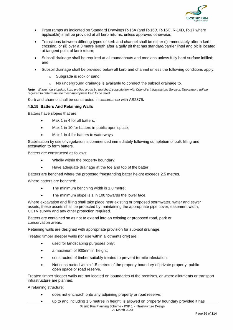
4.5.10.6 Compaction Requirements
Depending on traffic volumes and actual pavement design, compaction will be in accordance with Transport and Main Roads Standard Specifications. Compaction testing of base and sub-base material must be carried out by a NATA approved laboratory. Copies of all geotechnical results are to be submitted to Council.
Compaction testing and proof-rolling shall be undertaken on the same day.
Sub-Grade
The street subgrade shall be compacted in accordance with Transport and Main Roads Standard Specification MRTS04, with all building sites compacted to 95% standard compaction, or in accordance with the Construction Specification and/or AS 3798.
Sub-Base
The street sub-base shall be compacted in accordance with Transport and Main Roads Standard Specification MRTS05. The number of tests to be undertaken shall as specified in Table 4.5.16.
Base
The street base shall be compacted in accordance with Transport and Main Roads Standard Specification MRTS05. However the value shown for type 2 materials in Table 8.2.4.1 - Maximum Degree of Saturation (DOS) of MRTS05 can be increased from 65% to 70%. The number of tests to be undertaken shall as specified In Table 4.5.16. Tests shall be taken on alternate sides of the road and be evenly spaced.
Table 4.5.10.6 Location And Number Of Compaction Tests
Location All Roads
Cul-de-sacs 3
Intersections 2
Straights 1 per 500 m²
Proof-rolling
Proof rolling of the subgrade, subgrade replacement (if required), sub-base and base shall be undertaken in accordance with AS 3798. The subgrade shall not deflect more than 2mm vertically within 300mm of the test roller in isolated locations. If deflection of the subgrade is found in more than 20% of the project area then the total area shall be reworked. There must be no visible deformation or cracking of the pavement during a proof roll. Areas that fail a proof roll test are to be rectified. Adequate notice must be given to Council’s representatives for attendance of proof-rolling inspections. Failed proof roll tests require additional inspection and appropriate notice should be given.
4.5.10.7 Soft Areas In Subgrade
Where unsuitable material exists or develops during construction, it must be rectified to the satisfaction of the Council. Possible treatment methods include cement and/or lime stabilisation, replacement of the underlying

Scenic Rim Planning Scheme - PSP 1 - Infrastructure Design 20 March 2020
Page 18 of 114
material with pavement, the use of geotextiles and/or the lowering of sub-surface drainage to below the level of the area to be rectified. Rectified subgrades must achieve the required levels of compaction as specified above.
As Constructed drawings or quality documentation must show the extent of all reworked soft areas and any form of treatment taken.
4.5.10.8 Pavement Wearing Course
Pavements must be proof rolled and density tested, immediately prior to priming. The frequency of density tests shall be in accordance with AS 3798 and AS 1289 Geotechnical Testing or as otherwise specified by Council.
Pavements must be trimmed to shape, swept and have a surface consistency suitable for priming. Adequate protection shall be provided for signs, concrete edgings, and traffic control devices to prevent over-spray during priming or tack coating.
The wearing surface for all urban streets shall be a minimum of 35mm ACM10 Asphalt (40mm for cul-de-sac heads), with a binder suitable for the traffic environment, and be in accordance with Transport and Main Roads Technical Specification MRTS30. The surface of the final wearing course shall be between 5-10 mm above the concrete edging and detailed on the construction plans for each edging type. The wearing course shall be flush with the lip of the kerb and channel at all footpath kerb crossings (to eliminate any trip hazard).
All new and upgraded roads, including widened roads, that are located in or adjacent to commercial or industrial developments shall be sealed with AC10M Asphalt in accordance with Transport and Main Roads Technical Specification MRTS30. The asphalt is to have a binder suitable for the traffic environment and be of suitable thickness for the expected traffic loading, with the minimum thickness to be 40mm.
All new and upgraded roads, including widened roads, which are located in rural areas, are to be spray sealed. The seal is to be designed in accordance with the 'Austroads Technical Report AP-T68/06: Update of the Austroads Sprayed Seal Design Method'. The seal is to be designed by a person who has undertaken the required official training on the method, and is to be certified by an RPEQ.
Where a dispute arises concerning the finished surface texture or construction methods, wearing course core samples and compaction testing will be required. The person who benefits from the development shall, prior to construction, specify the hotmix design including aggregate size and any additives.
Where road and streets under this section are subject to turning movements that will cause deformation to the wearing surface, deeper asphalt wearing course or structural asphalt Base layer shall be provided.
Where road under this section are subject to turning movements that will cause stone loss from a sprayed seal, or large numbers of heavy vehicles, an asphalt wearing course or asphalt base layer shall be provided.
4.5.11 Traffic Control Devices
Traffic control devices shall be considered in accordance with MUTCD.
4.5.11.1 Signposting And Pavement Marking
Signposting and pavement marking should generally be provided to roads, intersections, traffic control devices, cycleways and carparks in accordance with MUTCD.
4.5.11.2 Road Side Barriers
Where there is a warrant (e.g. an identified hazard in the clear zone) a barrier is to be provided in accordance with Transport and Main Roads specifications, where shown on the approved engineering plan.
4.5.12 Urban Property Accesses
This section applies to urban areas regardless of whether there is kerb and channel.
Driveways and direct vehicle access to trunk collector streets should be designed to allow forward entry and exit from properties.
The maximum number of vehicle crossings to residential properties is one (1) crossing. Crossing shall be constructed in accordance with the requirements of Standard Drawing Numbers R-05 to R-08.
Where any crossing exceeds 3.5 metres width, the maximum width of that crossing is to be 6.0 metres. Crossings to adjacent properties shall be either fully combined, and of maximum width of 6.0 metres, or else have a minimum separation of 9 metres.

Scenic Rim Planning Scheme - PSP 1 - Infrastructure Design 20 March 2020
Page 19 of 114
Vehicle crossings to residential corner allotments are to be located a minimum of 6 metres from the intersection of road reserves and 2 metres clear of pedestrian kerb crossings.
Editor's Note - An Application for Property Access Approval is required to be submitted for each new property access. Property Access Approval is required to ensure that the access meets the following conditions:
1. The access is to be located in a position which can achieve the appropriate safe sight distance for the surrounding speed environment.
2. The construction standard of the access is to comply with Council’s relevant standard drawings. 3. If a piped access is required, the pipe size is to be determined by Council after the initial site inspection. The minimum size
required is 375Ø. 4. Guide posts must be installed on all rural piped accesses. 5. If the access is off of a sealed road, the access requires a 2 coat spray seal.
4.5.13 Rural, Industrial And Commercial Property Accesses
Roads should be located and designed such that vehicular access can be readily obtained at every allotment of a subdivision. Where the natural surface slopes steeply to or from the road, the access to each lot should be given special consideration. The locating of an access is to be avoided if effect to the vertical alignment of the road will occur.
All rural vehicle access crossings shall be designed to be in accordance with Council's Standard Drawing R-08 & R-09.
Culverts shall be designed with the following hydraulic capacity:
• 63.21% AEP capacity before property culvert overtops;
• 1.98% AEP capacity results in overtopping of maximum depth of 300mm; and
• No water shall encroach on edge of shoulder on sealed roads, or edge of gravel on gravel roads.
Industrial and commercial developments located in areas without kerb and channel shall comply with or exceed the guidelines presented in Austroads publication ‘Guide to Road Design Part 4A: Unsignalised and Signalised Intersections' with the minimum requirement being a BAL and BAR.
Rural vehicle crossings shall be upgraded to meet current standards whenever rural land is subdivided or where a planning permit relates to boundary realignment.
Editor's Note - An Application for Property Access Approval is required to be submitted for each new or existing property access. Property Access Approval is required to ensure that the access meets the following conditions:
1. The access is to be located in a position which can achieve the appropriate safe sight distance for the surrounding speed environment.
2. The construction standard of the access is to comply with Council’s relevant standard drawings. 3. If a piped access is required, the pipe must be a minimum of 375Ø to allow for stormwater flow. 4. Guide posts must be installed on all rural piped accesses. 5. If the access is off of a sealed road, the access requires a 2 coat bitumen seal.
4.5.14 Kerb And Channel
All urban streets shall be constructed with an asphalt sealed pavement and provided with cast in-situ concrete kerb and channel on both sides of all streets (unless alternative treatment is integral to a Water Sensitive Urban Design application).
Kerb and channel profiles shall be constructed in accordance with Council’s Standard R-04, and with the following:
• A Barrier kerb (Type B2) can be used on the high side of roads with one way crossfall;
• Barrier kerb and channel with a 450mm channel (Type B1) shall be used in the following locations:
o Adjacent to parks;
o Industrial Streets (Heavy duty barrier to be used i.e.: standard barrier type with an additional 50mm base thickness);
o Sub-Arterial and Arterial urban streets;
o Commercial areas such as Shopping Centres;
o In locations where higher pedestrian volumes are likely, for greater pedestrian safety;
• Semi-mountable kerb shall be used adjacent to medians and traffic islands;
Scenic Rim Planning Scheme - PSP 1 - Infrastructure Design 20 March 2020
Page 20 of 114
• Pram ramps as indicated on Standard Drawings R-16A (and R-16B, R-16C, R-16D, R-17 where applicable) shall be provided at all kerb returns, unless approved otherwise;
• Transitions between differing types of kerb and channel shall be either (i) immediately after a kerb crossing, or (ii) over a 3 metre length after a gully pit that has standard/barrier lintel and pit is located at tangent point of kerb return;
• Subsoil drainage shall be required at all roundabouts and medians unless fully hard surface infilled; and
• Subsoil drainage shall be provided below all kerb and channel unless the following conditions apply:
o Subgrade is rock or sand
o No underground drainage is available to connect the subsoil drainage to.
Note - Where non-standard kerb profiles are to be matched, consultation with Council’s Infrastructure Services Department will be required to determine the most appropriate kerb to be used.
Kerb and channel shall be constructed in accordance with AS2876.
4.5.15 Batters And Retaining Walls
Batters have slopes that are:
• Max 1 in 4 for all batters;
• Max 1 in 10 for batters in public open space;
• Max 1 in 4 for batters to waterways.
Stabilisation by use of vegetation is commenced immediately following completion of bulk filling and excavation to form batters.
Batters are constructed as follows:
• Wholly within the property boundary;
• Have adequate drainage at the toe and top of the batter.
Batters are benched where the proposed freestanding batter height exceeds 2.5 metres.
Where batters are benched:
• The minimum benching width is 1.0 metre;
• The minimum slope is 1 in 100 towards the lower face.
Where excavation and filling shall take place near existing or proposed stormwater, water and sewer assets, these assets shall be protected by maintaining the appropriate pipe cover, easement width, CCTV survey and any other protection required.
Batters are contained so as not to extend into an existing or proposed road, park or conservation areas.
Retaining walls are designed with appropriate provision for sub-soil drainage.
Treated timber sleeper walls (for use within allotments only) are:
• used for landscaping purposes only;
• a maximum of 900mm in height;
• constructed of timber suitably treated to prevent termite infestation;
• Not constructed within 1.5 metres of the property boundary of private property, public open space or road reserve.
Treated timber sleeper walls are not located on boundaries of the premises, or where allotments or transport infrastructure are planned.
A retaining structure:
• does not encroach onto any adjoining property or road reserve;
• up to and including 1.5 metres in height, is allowed on property boundary provided it has

Scenic Rim Planning Scheme - PSP 1 - Infrastructure Design 20 March 2020
Page 21 of 114
adequate drainage;
• exceeding 1.5 metres in height, has a minimum boundary clearance equal to the full height of the retaining structure;
• is designed in accordance with AS 4678: Earth-retaining structures;
• is designed to provide a neat architectural and aesthetic appearance;
• drains storm water discharge to the street or other lawful point of discharge;
• wall adjacent to road reserve boundary is fenced for pedestrian safety;
• wall adjacent to road reserve boundary includes safety measures to protect pedestrians in the road reserve during construction;
• Roadside design is in accordance with Austroads Guide to Road Design.
Retaining walls do not impose any loading on adjoining structures including underground services. Where the area of influence of the load of a proposed retaining structure influences services, the services or the retaining structure, shall be re-located or re-designed so that the wall is supported and does not have an adverse impact on the service.
Retaining walls are not located in a road reserve, however a retaining structure located in a road reserve will be considered upon receipt of a formal submission prior to approval.
Retaining walls:
• in urban and non-urban areas over 1.5 metres in height are stepped a minimum of 1 metre horizontally for every 1.5 metres in height to a maximum height of 3 metres;
Retaining structures are not permitted within detention basins. Retaining structures located within a bioretention basin must not be within a detention basin or other stormwater quantity control measure.
A retaining structure within a bioretention basin shall:
• have a minimum clearance from the boundary of the premises equal to the height of the retaining structure;
• is terraced and landscaped;
• does not exceed an angle of repose of 45 degrees to adjoining buildings;
• has a geotechnical and structural design;
• in industrial and commercial areas, has a maximum height of 5 metres;
• in public open space areas, has a maximum height of 0.6 metres;
• has a design life of not less than 60 years.
The person who has the benefit of the development approval is responsible for the stability of filling and excavation until final acceptance by Council of the works Off-maintenance.
Prior to the acceptance of the works off-maintenance the person who has the benefit of the development approval will replace any section of the filling and excavation that has for any reason become displaced.
Temporary drainage shall be provided to ensure that ponding, flooding, erosion or siltation does not occur on the site or external to the site, as a result of the filling and excavation.
Certification of the retaining structure by a RPEQ (structural) must be submitted to Council at the time of On Maintenance application.
4.5.16 Driveway Access
Driveway access shall be suitable for:
(1) the type of vehicles associated with the use;
(2) frequency of vehicular use associated with development; and
(3) the nature of the development.
Design standard shall be in accordance with Table 4.5.24.

Scenic Rim Planning Scheme - PSP 1 - Infrastructure Design 20 March 2020
Page 22 of 114
Table 4.5.16 Driveway Access Minimum Standards
Use Standard Drawing Other Applicable Standards
Residential R-05 Residential Driveway
Non-Residential R-06 Non-Residential Driveway AS2890 Off-Street Commercial Parking
Rural (Pipe Required)
R-07 Rural Access (Single & Dual) Pipe Required
Rural (No Pipe Required)
R-08 Rural Access (Single & Dual) No Pipe Required - Invert
Editor's Note - Approval pursuant to Councils Local Laws is required for a driveway crossover not associated with other roadworks and an Operational Works Permit authorises the driveway crossover.
4.5.17 Roads Construction - General
Sufficient testing shall be undertaken to ensure works are completed to the standards tolerances and finishes outlined in this Policy, including:
• Traffic Control;
• Excavation;
• Road Pavements;
• Subsoil Drainage;
• Stormwater Drainage;
• Sewerage Reticulation;
• Water Reticulation;
• Bitumen Sealing.
4.5.17.1 Subgrade and Pavement Inspections
Mandatory inspections apply at subgrade and each pavement layer. All levels of pavement, subgrade, subgrade replacement, sub-base and base course will be subjected to testing by proof rolling for compaction and by stringing for depth and crossfall. All levels of pavement must be of a compacted state with no movement under load, and clean of debris and organic material. Compaction test results and material quality tests are to be verified by an RPEQ prior to proceeding with any further works.
4.5.17.2 Preseal Inspection
A mandatory inspection applies at the pre-seal stage. This inspection includes audits by Council of:
• subsoil drainage;
• earthworks profiles of table drains, batters, and the services allocation;
• conduit crossings for depth, shape, location and alignment (check also marker locations against service conduits);
• of stormwater drainage affecting roadworks;
• kerb and channel for line and level;
• evidence provided for testing of the base course layer.
For spray sealed surfaces, proposed application rates of prime, and binder and spread rates of pre-coated aggregate shall have been approved prior to the inspection. Where the seal surface is asphalt, proposed application rates of prime and results of mix acceptance tests shall have been approved prior to the inspection. A pavement design and seal design shall be submitted to Council for approval prior to pavement and seal works commencing.
The base course shall not be sealed if any of the above items require rectification work.
4.5.18 Filling/Excavation and Road Construction
4.5.18.1 Operations
The person who benefits from the development shall be responsible for all damage to grass, cultivation, fences, existing services, buildings or stock, by fire, falling timber or other causes arising from its operations. If the person who benefits from the development damages any existing services it shall immediately arrange for the relevant service authority to make good such damage and all costs for this work shall be borne by the person who benefits from the development.

Scenic Rim Planning Scheme - PSP 1 - Infrastructure Design 20 March 2020
Page 23 of 114
4.5.18.2 Site Disturbance
Soil disturbance associated with filling and excavation is limited to the minimum necessary to perform the required filling and excavation.
A previously undisturbed area of soil is not exposed to erosion where:
• a slope is greater than 1 in 10; or
• A highly erosive or clay-based soil is present.
4.5.18.3 Site Waste Management
Waste water from the washing of tools and painting equipment and the cutting of concrete, masonry, tiles or other products is discharged on the site and over a porous grassed surface or well-drained, loosened soil.
All waste water generated on the site is:
• prevented from flowing off the site and is allowed to infiltrate the soil; or
• filtered through a porous, fine-grained embankment lined with filter cloth before it is allowed to exit the site.
Sand, soil or other material from the site that is deposited on a paved road or within a gutter or a drain is removed:
• immediately, if rain is occurring or is imminent; or
• upon the completion of the day’s work, if rain is not occurring or is not imminent.
Where sand, soil or other material from the site is deposited on a paved road or within a gutter or a drain as a result of the filling and excavation on the site, the sand, soil or material is:
• first shoveled, then swept from the gutter, drain or paved surface;
• not washed from the surface unless directed by the local government.
Solid or liquid waste from a concrete truck and equipment is contained on the site.
Cement residue from works associated with filling and excavation, including concreting and the preparation of exposed aggregate concrete surfaces are:
• washed onto a pervious surface such as a grassed or open soil area; or
• contained in a temporary collection trench formed near the concrete surface; or
• Filtered through a fine-grained, porous embankment lined with an appropriate filter cloth.
An erosion and sediment control measure is kept in working order until:
• the disturbed parts of the site have been effectively stabilised;
• a damaged erosion and sediment control measure is repaired as soon as practicable.
All solid waste collected in erosion and sediment control measure is disposed at an approved landfill site.
4.5.18.4 Treatment of Adjoining Properties
Cross-section plans for filling and excavation that show the adjoining property boundaries where filling and excavation are adjacent to existing developments. The effect on the drainage of adjoining properties from any cut and fill operation is considered and designed to ensure that no ponding of water or nuisance stormwater runoff occurs.
4.5.18.5 Protection of Structures
The filling and excavation for the construction of an embankment or for an excavation do not cause movement of, or undue strain to, any structure.
Scenic Rim Planning Scheme - PSP 1 - Infrastructure Design 20 March 2020
Page 24 of 114
4.5.18.6 Property Pegs
Survey pegs or survey marks that identify areas:
(1) are not to be cleared, excavated or covered by embankments; or
(2) where disturbed, displaced, damaged, or covered, are replaced by a licensed surveyor.
4.5.18.7 Dust Control
Adequate precautions shall be taken to effectively minimise any dust related conditions which occur during the construction of the subdivision or development works and which affect the safety or cause environmental nuisance, to the employees and/or occupants of nearby buildings.
4.5.19 Traffic Control
Construction on any existing road reserve, which has a trafficable road, shall satisfy the requirements of MRS02 and MRTS02.
4.5.20 Setting Out
A Qualified Surveyor shall be used for all level and set out control.
4.5.21 Clearing and Grubbing
Clearing and grubbing operations shall comply with the requirements of MRS 11.04 except as noted herein.
The area of road reserve for roadworks and areas of earthworks to allotments shall be cleared of all boulders, deposited rubbish and vegetation within the clear zone. Clearing shall include the removal of all man made obstructions, including fences, buildings, etc.
In environmentally sensitive areas clearing shall be kept to the full width of the earthworks or roadworks, whichever is the greater plus a further 1.0m on each side.
4.5.22 Clearing of Trees
Prior to clearing land associated with filling and excavation, the land is inspected by appropriately qualified persons accredited and licensed under the Nature Conservation Act 1992 to conduct and/or supervise the preparation and implementation of Wildlife Protection and Management plans and the detection, capture removal and relocation of wildlife from sites proposed to be developed.
4.5.22.1 Trees to be Preserved
• Filling and excavation is undertaken to preserve, without damage, trees and vegetation identified by Wildlife Protection and Management plans;
• Trees and vegetation identified by Council to be of significance are identified, marked and left standing and undamaged;
• Trees and vegetation that form part of a riparian or other buffer zone along rivers, creeks or waterways are clearly identified and preserved;
• The management of trees to be preserved is undertaken in accordance with AS 4970-2009 Protection of Trees on Development Sites.
A 3.0m wide strip clear of all vegetation and accessible by vehicle is to be provided around all boundaries on all proposed Public Open Spaces. All Declared Pests/Plants are to be identified and removed.
Grubbing, or the removal of tree stumps, roots, rocks etc. shall be to a depth of 300mm below the surface of the ground. Grubbing shall be carried out for the full width of the cleared area. All grub holes shall be filled in with good selected material and compacted thoroughly.
4.5.22.2 Damage
Timber shall be prevented from falling onto adjacent properties and any timber falling onto adjacent properties shall be removed. Any fence damaged during the execution of the work shall immediately be repaired .
Work shall be carried out so that underground services are not displaced or disturbed. In the case of any such displacement or damage occurring to such services, the relevant authority shall be contacted and the damage made good.

Scenic Rim Planning Scheme - PSP 1 - Infrastructure Design 20 March 2020
Page 25 of 114
4.5.23 Earthworks
Earthworks shall be carried out in accordance with Queensland Department of Transport and Main Roads - Standard Specification Roads Manual MRS 11.04 except as varied otherwise herein.
Earthworks shall be taken to include all operations necessary to excavate earth and rock, irrespective of type and subsurface conditions, to construct embankments and allotment filling, including the placing of selected material in connection therewith as specified; to place backfill for structures, and culverts, unless separately specified and designated; to remove and replace unsuitable material; to construct road formation; all shown in the drawings and specified in the specifications and any special provisions.
Any specific reference in MRS 11.04 to an earthworks item or operation for a road shall be deemed to include same works within allotments (e.g. The words “road embankment fill” shall be read as “road or allotment fill”).
Note - AS 3798 is a useful reference for earthworks operations and testing. With respect to earthworks operations generally (including allotment filling) Council specification and testing requirements as outlined herein are equivalent to Level 2 as nominated in AS3798. ARRB Sealed Local Roads Manual contains useful technical information and construction tips for general earthworks and road construction.
4.5.24 Dams and Embankments
Embankments, spillways and associated water flow channels are designed and constructed in accordance with the requirements of the Queensland Department of Environment and Heritage and the Queensland Urban Drainage Manual.
Constructed waterways, embankments and associated outlet structures are not constructed within:
• 10 metres of property boundaries; or
• 40 metres of a building.
Maintenance dredging of dams:
• has regard for water quality requirements; • is conducted in a manner that prevents siltation of any downstream watercourse or
property.
Filling of dams:
• Dewatering of dams should be done in the presence of a spotter catcher.
• To ensure the integrity of drainage lines to and from any dam that is to be filled, an alternative drainage path is designed applying the principle of no worsening and utilising best practice natural channel design and erosion and sediment control measures to replace the original drainage path prior to the dam being filled.
Organic material
• No tree, log or other organic material is placed in any embankment, scour, hole, dam to be filled or other hollow place where transport infrastructure or allotments are planned.
4.5.25 Pavement Materials
4.5.25.1 Unbound Pavements
As specified in Queensland Department of Transport and Main Roads - Standard Specification Roads Manual MRS 11.05 Unbound Pavements. The Unbound Material type as specified is Type 2 and is per Table 4.5.25.1.
Table 4.5.25.1
Property Subtype
2.1 2.2 2.3 2.4 2.5
CBR (soaked) min 80 60 45 35 15
CBR tests to verify the quality of base and sub base pavement materials shall be in accordance with Main Roads Test Method Q113C. The single point CBR test shall be carried out at OMC and at the relative

Scenic Rim Planning Scheme - PSP 1 - Infrastructure Design 20 March 2020
Page 26 of 114
compaction indicated in the specification (e.g. for base and sub base layers test at 100% RDD (standard compactive effort)).
CBR tests to verify the quality of subgrade replacement material (Type 2.5) shall be in accordance with Main Roads Test Method Q113A (4-5 point test).
A qualified representative of the soil testing company shall be required to attend the subgrade inspection to verify boundaries of material types if materials with similar visual descriptions have substantially different CBR results or properties.
4.5.25.2 Bound Pavements
As specified in Queensland Department of Transport - Standard Specification Roads Manual MRS 11.08 Plant-Mixed Stabilised Pavements.
4.5.25.3 Bituminous Surfacing
All surfacing shall comply with the relevant Main Roads Standard Specifications as listed below:
MRS 11.11 - Sprayed Bituminous Surfacing MRS 11.17 - Bitumen MRS 11.18 – Polymer Modified Binder MRS 11.19 - Cutter and Flux Oils MRS 11.20 - Cutback Bitumen MRS 11.21 - Bituminous Emulsion MRS 11.22 - Supply of Cover Aggregate MRS 11.30 - Dense Graded Asphalt Pavements.
A Seal Design shall be submitted to Council prior to coordinating the preseal inspection. The preseal inspection shall proceed subject to approval of the wearing course design. Within two weeks of sealing a road, all loose screenings are to be swept from the surface and removed from the site.
Unless approved otherwise by Council, core sampling shall be used for compaction testing and thickness verification of asphalt.
4.5.26 Kerb and Channel Construction
Construction requirements include:
• control joints 5.0 m centres 40 mm deep and 6 mm wide;
• expansion joints not to exceed 20 m spacing and adjoining structures;
• expansion joint material to be 6 mm thick bitumen impregnated fibre board or equivalent;
• kerb to be bedded on 75 mm min compacted Type 2.5 material;
• concrete to be cured for 7 days prior to undertaking adjoining works;
• channels on grades less than 1 % to be water tested for ponding;
• concrete with any faults or chipping will be rejected.
• concrete strength to be 32 mpa
4.5.27 Sub-Soil Drainage
Details and locations of sub-soil drainage shall be in accordance with Council’s Standard Drawing.
Construction requirements include:
• sub-soil drainage shall be provided behind the kerb of all roads which incorporate kerb or kerb and channel; Note - Some discretion on this requirement may be applied where the kerb level is more than 300 mm above natural surface or where the natural materials are free draining.
• Mitre drains shall be incorporated as required. Typically mitre drains shall be used where the road centreline is perpendicular (or nearly) to the natural contours;
• Sub-soil drainage lines shall be located below any service or conduit crossing.
4.5.28 Erosion Control Measures
Where stipulated in the development assessment conditions, an Erosion and Sediment Control Management Plan shall be submitted for approval at time of lodgement of the engineering documentation.
Relevant guidelines for this management plan are contained in The Institute of Engineers Australia (Qld) Soil Erosion and Sediment Control Guidelines and shall be in accordance with Best Practice and Sediment Control, International Erosion Control Association, (IECA) Australasian Chapter.
Scenic Rim Planning Scheme - PSP 1 - Infrastructure Design 20 March 2020
Page 27 of 114
4.5.29 Road Furniture and Line Marking
Road furniture and line marking shall be in accordance with the Queensland Department of Main Roads “Manual of Uniform Traffic Control Devices” volumes 1 and 2 and the Main Roads Standard Specifications MRS 11.14 and 11.15.
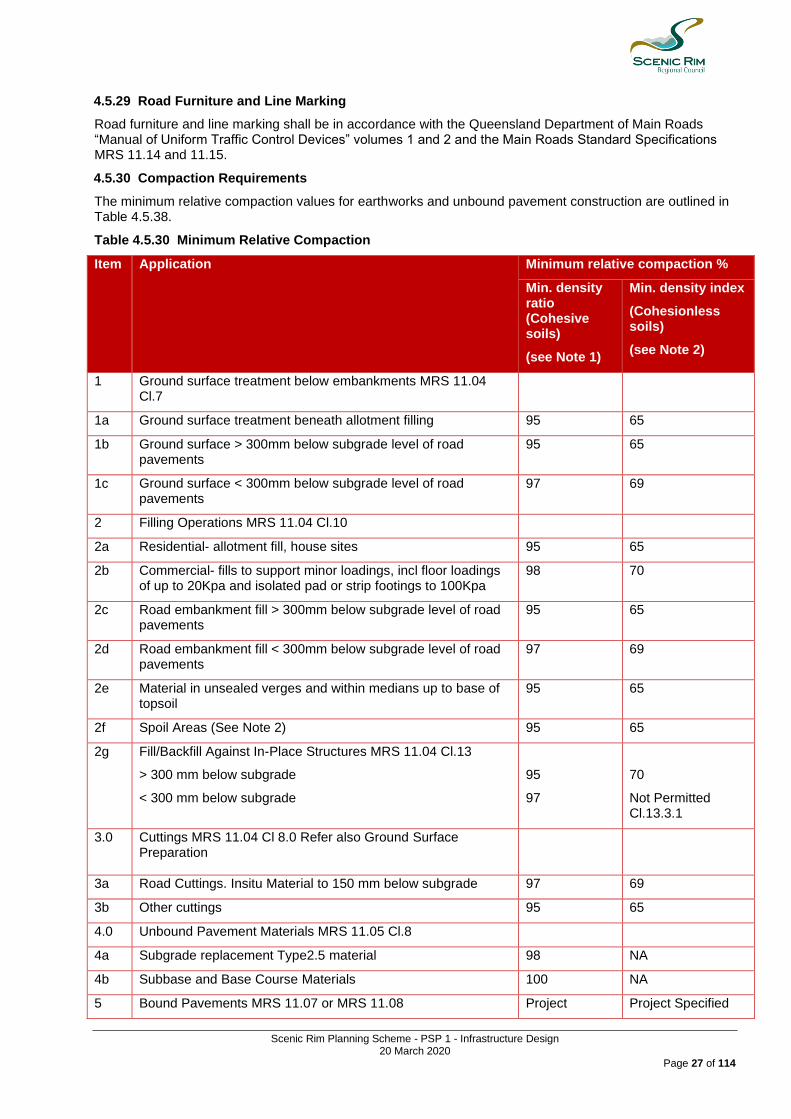
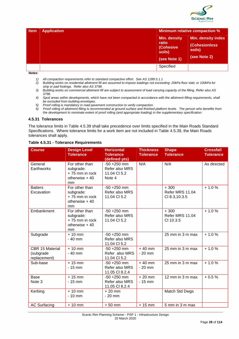
4.5.30 Compaction Requirements
The minimum relative compaction values for earthworks and unbound pavement construction are outlined in Table 4.5.38.
Table 4.5.30 Minimum Relative Compaction
Item Application Minimum relative compaction %
Min. density ratio (Cohesive soils)
(see Note 1)
Min. density index
(Cohesionless soils)
(see Note 2)
1 Ground surface treatment below embankments MRS 11.04 Cl.7
1a Ground surface treatment beneath allotment filling 95 65
1b Ground surface > 300mm below subgrade level of road pavements
95 65
1c Ground surface < 300mm below subgrade level of road pavements
97 69
2 Filling Operations MRS 11.04 Cl.10
2a Residential- allotment fill, house sites 95 65
2b Commercial- fills to support minor loadings, incl floor loadings of up to 20Kpa and isolated pad or strip footings to 100Kpa
98 70
2c Road embankment fill > 300mm below subgrade level of road pavements
95 65
2d Road embankment fill < 300mm below subgrade level of road pavements
97 69
2e Material in unsealed verges and within medians up to base of topsoil
95 65
2f Spoil Areas (See Note 2) 95 65
2g Fill/Backfill Against In-Place Structures MRS 11.04 Cl.13
> 300 mm below subgrade
< 300 mm below subgrade
95
97
70
Not Permitted Cl.13.3.1
3.0 Cuttings MRS 11.04 Cl 8.0 Refer also Ground Surface Preparation
3a Road Cuttings. Insitu Material to 150 mm below subgrade 97 69
3b Other cuttings 95 65
4.0 Unbound Pavement Materials MRS 11.05 Cl.8
4a Subgrade replacement Type2.5 material 98 NA
4b Subbase and Base Course Materials 100 NA
5 Bound Pavements MRS 11.07 or MRS 11.08 Project Project Specified
Scenic Rim Planning Scheme - PSP 1 - Infrastructure Design 20 March 2020
Page 28 of 114
Item Application Minimum relative compaction %
Min. density ratio (Cohesive soils)
(see Note 1)
Min. density index
(Cohesionless soils)
(see Note 2)
Specified
Notes:
1) All compaction requirements refer to standard compactive effort. See AS 1289.5.1.1 2) Building works on residential allotment fill are assumed to impose loadings not exceeding: 20kPa floor slab; or 100kPa for
strip or pad footings. Refer also AS 3798. 3) Building works on commercial allotment fill are subject to assessment of load carrying capacity of the filling. Refer also AS
3798. 4) Spoil areas within developments, which have not been compacted in accordance with the allotment filling requirements, shall
be excluded from building envelopes. 5) Proof rolling is mandatory in road pavement construction to verify compaction. 6) Proof rolling of allotment filling is recommended at ground surface and finished platform levels. The person who benefits from
the development to nominate extent of proof rolling (and appropriate loading) in the supplementary specification.
4.5.31 Tolerances
The tolerance limits in Table 4.5.39 shall take precedence over limits specified in the Main Roads Standard Specifications. Where tolerance limits for a work item are not included in Table 4.5.39, the Main Roads tolerances shall apply.
Table 4.5.31 - Tolerance Requirements
Course
Design Level Tolerance
Horizontal Tolerance (defined pts)
Thickness Tolerance
Shape Tolerance
Crossfall Tolerance
General Earthworks
For other than subgrade: + 75 mm in rock otherwise + 40 mm
-50 +250 mm Refer also MRS 11.04 Cl 5.2 Note 4
N/A
N/A As directed
Batters Excavation
For other than subgrade: + 75 mm in rock otherwise + 40 mm
-50 +250 mm Refer also MRS 11.04 Cl 5.2
+ 300 Refer MRS 11.04 Cl 8.3,10.3.5
+ 1.0 %
Embankment For other than subgrade: + 75 mm in rock otherwise + 40 mm
-50 +250 mm Refer also MRS 11.04 Cl 5.2
+ 300 Refer MRS 11.04 Cl 10.3.5
+ 1.0 %
Subgrade + 10 mm - 40 mm
-50 +250 mm Refer also MRS 11.04 Cl 5.2
25 mm in 3 m max + 1.0 %
CBR 15 Material (subgrade replacement)
+ 10 mm - 40 mm
-50 +250 mm Refer also MRS 11.04 Cl 5.2
+ 40 mm - 20 mm
25 mm in 3 m max + 1.0 %
Sub-base + 15 mm - 15 mm
-50 +250 mm Refer also MRS 11.05 Cl 8.2.4
+ 40 mm - 20 mm
25 mm in 3 m max + 1.0 %
Base Note 3
+ 15 mm - 15 mm
-50 +250 mm Refer also MRS 11.05 Cl 8.2.4
+ 20 mm - 15 mm
12 mm in 3 m max + 0.5 %
Kerbing + 10 mm - 10 mm
+ 20 mm - 20 mm
Match Std Dwgs
AC Surfacing + 10 mm + 50 mm + 15 mm 5 mm in 3 m max
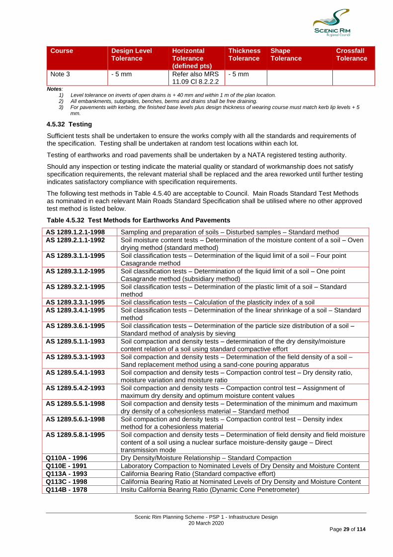
Scenic Rim Planning Scheme - PSP 1 - Infrastructure Design 20 March 2020
Page 29 of 114
Course
Design Level Tolerance
Horizontal Tolerance (defined pts)
Thickness Tolerance
Shape Tolerance
Crossfall Tolerance
Note 3 - 5 mm Refer also MRS 11.09 Cl 8.2.2.2
- 5 mm
Notes: 1) Level tolerance on inverts of open drains is + 40 mm and within 1 m of the plan location. 2) All embankments, subgrades, benches, berms and drains shall be free draining. 3) For pavements with kerbing, the finished base levels plus design thickness of wearing course must match kerb lip levels + 5
mm.
4.5.32 Testing
Sufficient tests shall be undertaken to ensure the works comply with all the standards and requirements of the specification. Testing shall be undertaken at random test locations within each lot.
Testing of earthworks and road pavements shall be undertaken by a NATA registered testing authority.
Should any inspection or testing indicate the material quality or standard of workmanship does not satisfy specification requirements, the relevant material shall be replaced and the area reworked until further testing indicates satisfactory compliance with specification requirements.
The following test methods in Table 4.5.40 are acceptable to Council. Main Roads Standard Test Methods as nominated in each relevant Main Roads Standard Specification shall be utilised where no other approved test method is listed below.
Table 4.5.32 Test Methods for Earthworks And Pavements
AS 1289.1.2.1-1998 Sampling and preparation of soils – Disturbed samples – Standard method
AS 1289.2.1.1-1992 Soil moisture content tests – Determination of the moisture content of a soil – Oven drying method (standard method)
AS 1289.3.1.1-1995 Soil classification tests – Determination of the liquid limit of a soil – Four point Casagrande method
AS 1289.3.1.2-1995 Soil classification tests – Determination of the liquid limit of a soil – One point Casagrande method (subsidiary method)
AS 1289.3.2.1-1995 Soil classification tests – Determination of the plastic limit of a soil – Standard method
AS 1289.3.3.1-1995 Soil classification tests – Calculation of the plasticity index of a soil
AS 1289.3.4.1-1995 Soil classification tests – Determination of the linear shrinkage of a soil – Standard method
AS 1289.3.6.1-1995 Soil classification tests – Determination of the particle size distribution of a soil – Standard method of analysis by sieving
AS 1289.5.1.1-1993 Soil compaction and density tests – determination of the dry density/moisture content relation of a soil using standard compactive effort
AS 1289.5.3.1-1993 Soil compaction and density tests – Determination of the field density of a soil – Sand replacement method using a sand-cone pouring apparatus
AS 1289.5.4.1-1993 Soil compaction and density tests – Compaction control test – Dry density ratio, moisture variation and moisture ratio
AS 1289.5.4.2-1993 Soil compaction and density tests – Compaction control test – Assignment of maximum dry density and optimum moisture content values
AS 1289.5.5.1-1998 Soil compaction and density tests – Determination of the minimum and maximum dry density of a cohesionless material – Standard method
AS 1289.5.6.1-1998 Soil compaction and density tests – Compaction control test – Density index method for a cohesionless material
AS 1289.5.8.1-1995 Soil compaction and density tests – Determination of field density and field moisture content of a soil using a nuclear surface moisture-density gauge – Direct transmission mode
Q110A - 1996 Dry Density/Moisture Relationship – Standard Compaction
Q110E - 1991 Laboratory Compaction to Nominated Levels of Dry Density and Moisture Content
Q113A - 1993 California Bearing Ratio (Standard compactive effort)
Q113C - 1998 California Bearing Ratio at Nominated Levels of Dry Density and Moisture Content
Q114B - 1978 Insitu California Bearing Ratio (Dynamic Cone Penetrometer)

Scenic Rim Planning Scheme - PSP 1 - Infrastructure Design 20 March 2020
Page 30 of 114
4.6 Standard Drawings
4.6.1 The Standard Drawings listed in Part 13 Standard Drawings are the minimum standard of design and construction for this Part.

Scenic Rim Planning Scheme - PSP 1 - Infrastructure Design 20 March 2020
Page 31 of 114
5.0 Bridges, Major Culvert Works and Pedestrian Bridges
5.1 Contents Section Title
5.1 Contents
5.2 Purpose
5.3 General Matters
5.4 Referenced Standards
5.5 Council Standards (including variations to Referenced Standards)
5.5.1 Standards
5.6 Standard Drawings
5.2 Purpose The purpose of this Part is to:
(1) provide a serviceable infrastructure for the specified lifetime with minimal maintenance; (2) provide safe and trafficable bridges for vehicles and pedestrians; (3) ensure design is appropriate for the traffic use and water flows.
5.3 General Matters Prior to the commencement of the bridge design process, requirements with respect to the design criteria need to be obtained from Council. AS 5100.1-2004 /Amdt 1-2010 Bridge design – scope and general - principles Appendix A lists design criteria which need to be resolved prior to commencing the design process.
5.4 Referenced Standards 5.4.1 The Standards listed in Table 5.4.1 Reference Standards are the applicable standards for bridges, major culvert works and pedestrian bridges installed on land being existing or future Council land except where:
(1) the standard is in conflict with a standards specified in Section 5.5; or
(2) the standard is varied, amended or removed by the standards specified in Section 5.5. Table 5.4.1 Referenced Standards
Standard
AS 1597.1: Pre-cast reinforced concrete box culverts - Small culverts
AS 1597.2: Pre-cast reinforced concrete box culverts - Large culverts
AS 1720.1: Timber structures-design methods
AS 3660 (Set): Termite management
AS 5100 Set: Bridge design
AS/NZS 3725: Design for installation of buried concrete pipes
AS/NZS 3845: Road safety barrier systems
Department of Transport and Main Roads' standard drawings
AS 1428 (Set): Design for access and mobility
Austroads (with respect to bicycles)
5.5 Council Standards (including variations to Referenced Standards) Editor's Note - includes standards not referred to in Referenced Standards and any variations to those standards
5.5.1 Standards
(1) All road bridges:
(a) are concrete structures;
(b) incorporate minimum 2.5 metre wide paths between handrails and bridge kerbs;

Scenic Rim Planning Scheme - PSP 1 - Infrastructure Design 20 March 2020
Page 32 of 114
(c) Service ducts with a minimum depth of 400mm deep and a minimum width of 1200mm.
(2) Approach embankments are of sufficient width to accommodate a minimum 2.5 metre wide path fitted with handrails abutting the bridge path.
(3) Afflux calculations prove that bridges constructed over waterways result in no worsening of flood levels on properties upstream of the bridge.
(4) Copies of all approvals are required from other relevant agencies in relation to bridge construction to be submitted with the engineering design documentation.
(5) The following concrete work is coated in an approved non-sacrificial, anti-graffiti protection system:
(a) abutment and wing walls;
(b) piers, piles and site caps;
(c) facings of reinforced soil structures;
(d) service duct covers;
(e) barrier walls;
(f) easily accessible areas.
(6) A brass plugs PSM and brass Date-plaque is installed on one of the bridge abutments in a location approved by Council.
(7) Terrestrial and aquatic fauna movement solutions are included in all waterway crossings.
(8) Pedestrian bridges are designed in accordance with this section and:
(a) AS 1428 (Set): Design for access and mobility;
(b) the provisions of Austroads with respect to bicycles.
(9) The minimum clear width for a pedestrian bridge is:
(a) 2.5 metres; or
(b) where it is deemed necessary for Council to access the pedestrian bridge with maintenance vehicles, 3.5 metres.
(10) A pedestrian bridge that incorporates timber elements:
(a) incorporates termite management systems;
(b) is designed:
(i) to achieve a 50 year design life;
(ii) in accordance with:
(A) AS 1720.1: Timber structures-design methods;
(B) AS 3660 (Set): Termite management.
(11) A design report must include:
(a) horizontal and vertical geometry;
(b) hydrologic and hydraulic data;
(c) statements on environmental impact, aesthetics and future maintenance;
(d) Specification codes and design loads used for loading calculations.

Scenic Rim Planning Scheme - PSP 1 - Infrastructure Design 20 March 2020
Page 33 of 114
5.6 Standard Drawings 5.6.1 The Standard Drawings listed in Table 5.6 Standard Drawings are the minimum standard of design and construction for this Part. Table 5.6 Standard Drawings
Standard Drawing Number Name
DTMR 1508 Bridge Barriers – Steel Bridge Connections for Concrete End Posts
DTMR 1509 Bridge Barriers – Steel Bridge Traffic Rail End Post w Beam Connection
DTMR 1510 Bridge Barriers – Steel Bridge Traffic Rail End Post Thrie Beam Connection
DTMR 1511 Bridge Barriers – Bridge Safety Rail
DTMR 1512 Bridge Barriers – Bridge Balustrade
Scenic Rim Planning Scheme - PSP 1 - Infrastructure Design 20 March 2020
Page 34 of 114
6.0 Stormwater
6.1 Contents Section Title
6.1 Contents
6.2 Purpose
6.3 General Matters
6.4 Referenced Standards
6.5 Council Standards (including variations to Referenced Standards)
6.5.1 Stormwater Drainage Design
6.5.2 Stormwater Drainage Construction
6.5.3 Easements – Drainage
6.6 Standard Drawings
6.2 Purpose The purpose of this Part is to:
(1) provide minimum stormwater drainage design parameters, which allow the safe and efficient removal of stormwater from urban and rural living environments.
6.3 General Matters (1) The development provides an appropriate drainage system, with sufficient capacity to pass through the
design runoff from all upstream catchments. (2) Easements/reserves dedicated in favour of Scenic Rim Regional Council shall be provided for all
drainage paths through the development and for all drainage paths downstream of the development to the legal point of discharge.
(3) The proposed drainage system, and earthworks for the development shall be such that the upstream
drainage is not adversely affected. (4) Pre-development rates of discharge shall be maintained from the site unless approved otherwise. (5) A conceptual site based stormwater management plan is required for development being a material
change of use or a reconfiguring a lot where stormwater quality, frequent flow management or waterway stability infrastructure is being provided.
(6) A detailed site based stormwater management plan is required for development being an operational
work application where stormwater quality, frequent flow management or waterway stability infrastructure is being provided.
6.4 Referenced Standards 6.4.1 The Standards listed in Table 6.4.1 Reference Standards are the applicable standards for stormwater installed on land being existing or future Council controlled land except where:
(1) The standard is in conflict with a standards specified in Section 6.5; or
(2) The standard is varied, amended or removed by the standards specified in Section 6.5. Table 6.4.1 Referenced Standards
Standard Comments
Queensland Urban Drainage Manual (QUDM)
Available from Queensland Department of Energy and Water Supply
Australian Rainfall and Runoff (ARR) Guideline
See www.arr.org.au
Scenic Rim Planning Scheme - PSP 1 - Infrastructure Design 20 March 2020
Page 35 of 114
Standard Comments
Water Sensitive Urban Design Guidelines
Water Sensitive Road Design Cooperative Research Centre For Catchment Hydrology
Australian Runoff Quality: Guide to Water Sensitive Urban Design
See www.engineersaustralia.org.au
Healthy Land and Water Guidelines Bioretention Technical Design Guidelines - Water by Design Healthy Waterways initiative www.hlw.org.au
AS1141 Methods of sampling and testing aggregates
AS1254 Unplasticized PVC (uPVC) Pipes and Fittings for Storm and Surface Water Applications
AS1289 Method of Testing Soils for Engineering Purposes
AS1303 Steel Reinforcing Bars for Concrete
AS1379 The specification and Manufacture of Concrete
AS1597 Small Precast Reinforced - (Part 1) Concrete Box Culverts
AS1597 Large Precast Reinforced - (Part 2) Concrete Box Culverts
AS1646 Elastomeric Seals for Waterworks purposes
AS1650 Hot-dipped Galvanised Coatings on Ferrous Articles
AS1830 Iron Castings - Grey Cast Iron
AS2187 Explosives - storage, transport and use
AS2758 Aggregates and rock for engineering purposes
AS3600 Concrete Structures
AS3678 Structural Steel - Hot-rolled Plates, Floor-plates and Slabs
AS3996 Metal Access Covers, Road Grates and Frames
AS4058 Precast Concrete Pipes
AS4139 Fibre Reinforced Concrete Pipes and Fittings
AS1141 Methods of sampling and testing aggregates
AS1254 Unplasticized PVC (uPVC) Pipes and Fittings for Storm and Surface Water Applications
AS1289 Method of Testing Soils for Engineering Purposes
AS1303 Steel Reinforcing Bars for Concrete
AS1379 The specification and Manufacture of Concrete
6.5 Council Standards (including variations to Referenced Standards)
Editor's Note - includes standards not referred to in Referenced Standards and any variations to those standards
6.5.1 Stormwater Drainage Design
6.5.1.1 Standards
The stormwater network shall be planned and designed in accordance with the Queensland Urban Drainage Manual and the Australian Rainfall and Runoff (ARR).

Scenic Rim Planning Scheme - PSP 1 - Infrastructure Design 20 March 2020
Page 36 of 114
Stormwater quantity infrastructure shall be provided to convey stormwater runoff from the development site to a lawful point of discharge in accordance with the Queensland Urban Drainage Manual.
The QUDM partners recognise that the Manual is not a stand-alone planning and design guideline for stormwater management. It must be used in coordination with other recognised manuals covering topics such as:
(1) Water Sensitive Urban Design (2) Water Sensitive Road Design (3) Natural Channel Design (4) Waterway management including fauna passage (5) Erosion & Sediment Control (6) Bridge and culvert design manuals (7) Australian Rainfall and Runoff (ARR) (8) Australian Runoff Quality (ARQ) (9) Various Australian Standards on product manufacture and installation. 6.5.1.2 Stormwater Network The stormwater network comprises a minor and major drainage system. Both drainage systems need to be planned, designed and constructed as one integrated system.
(1) The minor drainage system fully contains and conveys relatively minor and frequent stormwater flow to prevent nuisance from stormwater runoff on-site as well as offsite. Infrastructure items including, but not limited to:
(a) inlets;
(b) underground drainage;
(c) junction pits;
(d) access chambers;
(e) outlets;
(f) field or kerb inlets installed to collect surface runoff from within allotments as well as the roof water provision for buildings;
(g) cross drainage under minor roads such as low flow pipes or box culverts installed under floodways;
(h) Low flow pipes installed under drainage reserves or park areas.
(2) The major drainage system conveys a major storm event beyond the capacity of the minor drainage system. Both stormwater quantity and quality infrastructure items including, but not limited to:
(a) open space channels, road reserves, grassed or vegetated channels, pavement expanses and other flow paths that can act as overland flow paths in excess of the capacity of the major drainage system;
(b) culverts and bridges;
(c) natural or constructed waterways;
(d) detention or bioretention basins;
(e) underground drainage;
(f) other major water bodies. 6.5.1.3 General Design Criteria (1) The drainage design shall involve the improvement of the effectiveness of natural systems rather than
replacing, upgrading or ignoring them.
Scenic Rim Planning Scheme - PSP 1 - Infrastructure Design 20 March 2020
Page 37 of 114
(2) The impact of development, and particularly urban development, on flow regimes, erosion, silting and flooding is to be controlled by adopting stormwater management techniques that maintain the function of natural drainage systems as far as possible.
(3) All development shall discharge to a legal point of discharge in accordance with the Queensland Urban
Drainage Manual. (4) Where the lawful point of discharge is to a park, the receiving waterway shall be an appropriately
designed, naturalised and constructed within an existing channel or waterway. Any works undertaken within the park shall ensure that the park function is not degraded and the written permission of the asset owner is obtained prior to application being submitted to Council.
(5) A lawful point of discharge is established for infill (brown field) development where the site slopes
downward away from the road reserve and no inter-allotment drainage system exists. If the drainage system passes through a private property, a letter of consent from the owner(s) of downstream property(ies) must be submitted as a part of an approval process for the development application. Easements will be required over any infrastructure and flow paths through downstream private properties.
(6) Development must achieve the principle of "no worsening", as per the Queensland Urban Drainage Manual and the provisions of this planning scheme policy. In achieving the principle of
no worsening, development:
(a) does not result in a detrimental impact on the flooding, or flood risk of any area;
(b) does not result in adverse impacts of any other property in terms of changes in peak discharge, flood levels, the frequency of flooding, the shape of the hydrograph, flow velocities, water quality, sedimentation or scour effects for the full range of ARI storm events up to and including the defined flood event;
(c) does not result in an increase in peak discharge from the development site;
(d) ensures that the time of concentration to the peak of the event does not decrease and where it does increase, consideration is given to the impacts upstream, adjacent, and downstream of the property boundary so as to ensure runoff from the site does not bring the hydrograph peak closer to coincidence with the peak flow in adjoining catchments;
(e) Undertakes a method of modeling agreed with the local government, upstream and, where appropriate, downstream of the site.
(7) Stormwater infrastructure is designed to preserve and enhance public safety. This shall be
achieved by methods including, but not limited to the following:
(a) meeting velocity, depth and velocity*depth limitations for pedestrians and motor vehicles;
(b) providing safe egress from detention systems;
(c) ensuring that in the event of carpark flooding, flooding is limited to a depth of 600mm and a depth*velocity product of less than 0.4m2/s;
(d) applying the principles of crime prevention through environmental design;
(e) adequate signage. 6.5.1.4 Urban Stormwater Systems All urban stormwater systems are to be designed and documented in accordance with the current version of the Queensland Urban Drainage Manual (QUDM), and subsequently certified that they are in accordance with this Policy and QUDM. The hydrologic procedures provided in the Policy are considered appropriate for small catchments of up to 500 hectares. These procedures are generally not considered appropriate for the determination of design flood levels along vegetated (i.e. non-grassed) waterways. Reference shall be made to the latest version of Australian Rainfall and Runoff (ARR) for guidelines on:
(1) The assessment of urban catchments larger than 500 hectares and, (2) Determination of design flood levels along vegetated waterways.

Scenic Rim Planning Scheme - PSP 1 - Infrastructure Design 20 March 2020
Page 38 of 114
6.5.1.5 Rural And Rural Residential Stormwater Systems All rural and rural residential stormwater systems are to be designed in accordance with the current version of the Transport and Main Roads "Road Drainage Manual ". 6.5.1.6 Additional Design Criteria The purpose of this section is to:
(1) Supplement QUDM by providing further detail and guidance where QUDM only provides general guidance,
(2) Specify the criteria to be adopted for certain parameters that QUDM leaves up to the determination of Council and
(3) Document where Council's requirements vary to QUDM, due to Regional Factors as listed in Section 1.02 of QUDM.
6.5.1.6.1 Roof, Allotment And Inter-Allotment Drainage (1) The level of roof and allotment drainage required is specified as an addition to the extract from the
"Recommended design average recurrence intervals" Table 7.02.1 from QUDM below.
(ii) Minor System Design AEP (%) Level of Allotment Drainage Development Category
Central Business and Commercial 9.52 V
Industrial 39.35 V
Urban Residential High Density - greater than 20 dwelling units/ha 9.52
III
Urban Residential High Density - greater than 5 & up to 20 dwelling units/ha 39.35
III
Rural Residential - 2 to 5 dwelling units/ha 39.35 II
(2) Unless approved otherwise by Council inter-allotment drainage (Refer Figure 7.13.2 QUDM) shall be
located on the low side of any sewer reticulation and generally 1.5 metres clear of the sewer alignment (or 1.5 metres from the property boundary alignment where no adjoining sewer).
(3) Easements are required for inter-allotment drainage. (4) Kerb adaptors must be installed within the kerb and channel for each allotment not serviced via an inter-
allotment drainage system. The kerb adaptors shall be of a fabricated metal construction.
6.5.1.6.2 Intensity-Frequency-Duration Data (Refer QUDM 4.07) IFD data is to be generated using the procedures given in ARR (1998) Book 2. Book 2 provides both algebraic and graphical procedures that allow the user to determine either complete or selected IFD design rainfall information for any location in Australia. The procedures enable the determination of rainfall intensities for durations of 5 minutes to 72 hours and ARIs from 1 year to 100 years. Book 2 also describes procedures for extrapolation of ARIs up to 500 years. Alternatively the Bureau of Meteorology has a free program available on their website (listed below) to generate IFD charts that is also acceptable to Council. Editor's Note - refer to http://www.bom.gov.au/water/designRainfalls/ifd/index.shtml
6.5.1.6.3 Stormwater Infrastructure Location
Note - Particular attention should be paid to the Design Procedure in Section 7.15.3 of QUDM as this will guide the layout of the site to achieve the drainage philosophy of "improvement of the effectiveness of natural systems rather than replacing, upgrading or ignoring them". At the start of this procedure consideration should be given to maximising the use of "Natural" drainage solutions (i.e.: naturally vegetated channels beside the road as a feature etc.) before opting for "Built" (pits and pipes) infrastructure. By following this procedure the designer can readily determine the approximate maximum size of the sub-catchment area that is likely to be acceptable to minimise the infrastructure required to convey the minor storm flows, whilst still maintaining the safety requirements of the major storm overland flows.
Scenic Rim Planning Scheme - PSP 1 - Infrastructure Design 20 March 2020
Page 39 of 114
Specific requirements include:
(1) Roads are to be located in gullies to enable appropriate overland flow paths that don't impact private properties.
(2) Stormwater lines are to be located under the kerb and channel with gully pit to gully pit connections. (3) For pipelines greater than 600mm the location of the pipeline is to be behind the kerb and channel.
This will require a wider verges on one side of the road and hence a wider road reserve, for stormwater space allocation in accordance with Section 7.01.1 QUDM. (Therefore layouts should be designed to keep catchments small to keep pipe sizes 600mm and avoid this requirement)
(4) Stormwater manholes and pits are not to be located within the road or street pavement and the length of stormwater pipe under roads or streets is to be minimised.
Note - this is to reduce the risk of pavement failures due to differential settlement and allow economical pavement rehabilitation when required in the future.
A stormwater infrastructure item is only to be provided in or adjacent to a park or open space - where it results in an:
(1) increase in the continuity of greenspace area;
(2) improvement in overall amenity of the area.
If development cannot achieve this requirements, the stormwater infrastructure item must be located within a drainage reserve dedicated for the purpose of stormwater drainage.
Stormwater infrastructure item located within a park, open space, or drainage reserve shall be designed to:
(1) reflect the natural character of the land and its surrounds;
(2) preserve community safety;
(3) allow for maintenance activities to be undertaken.
A stormwater infrastructure item should only be provided in a waterway and wetland buffer area where the buffer area is degraded to such an extent that the construction of the stormwater infrastructure item would result in an enhancement to the condition and ecological function of the buffer area.
A stormwater infrastructure item should not be located within the waterway and wetland buffer area where the buffer area:
(1) contains intact riparian vegetation; or
(2) is located below the 4.88% AEP flood level; or
(3) where the mapped waterway or wetland buffer is less than 30m in width, measured from the top bank.
6.5.1.6.4 Stormwater Inlets And Manholes (Refer QUDM 7.05.1) The following criteria apply to stormwater inlets and manholes: (1) Gully inlets shall be a combination grate and side inlet pre-cast lintel. (2) They shall generally be Lip-in-Line, however Kerb-in-Line is more suitable where parking is allowed near
barrier kerb. (3) Maximum outlet pipe of gully connections in series is 525mm Ø (4) The desirable maximum inlet pit depth should be limited to 1.5m to enable safe maintenance, (5) The desirable minimum and maximum stormwater manhole depth is to be limited to 1.2m and 3.0m
respectively (6) Gully grates shall be "bike proof" (7) Kerb inlet pits at intersections are generally to be located at the tangent point taking into account the
position of pedestrian paths and kerb ramps. Inlets shall not be placed on kerb return unless specifically approved by Council.
(8) Pits are to be free draining. (9) Pipe work openings are to be located within a single wall. I.e. pipes shall not be permitted to enter
through the corner of the pit structure. (10) Inlet pits should be located at the mid-point of allotment frontages to reduce the likelihood of conflict with
service conduits and future driveways. 6.5.1.6.5 Outlets And Outlet Protection
Scenic Rim Planning Scheme - PSP 1 - Infrastructure Design 20 March 2020
Page 40 of 114
(1) All outlets shall be located to facilitate inspection and maintenance access (2) Protection works to outlet shall be designed to meet the following criteria:
(a) Dissipate the outflow velocity to minimise scouring; (b) Provide protection from flows in receiving waters; (c) Provide protection from overland (Major Storm) flows; (d) Provide protection from local scouring or undermining of the outlet structure.
6.5.1.6.6 Open Channels (1) All open channels shall have adequate access provisions for maintenance and cleaning, (2) Subsurface drainage shall be provided in grass-lined channels to prevent water logging of the channel
bed. 6.5.1.6.7 Pipes And Box Culverts (1) Stormwater drainage pipes and boxes shall be generally of reinforced concrete (including FRC)
construction (unless approved by Council) and in accordance with the following: (2) Minimum pipe size 375mmØ in Urban environments and 450mmØ for rural cross road pipes, (3) Minimum box culvert size 450mm x 300mm. 6.5.1.6.8 Cross Road Culverts (1) Cross road culverts shall be designed to pass the flow of an 1.98% AEP storm with the top water level
(TWL) not exceeding edge of carriageway except as indicated below:
(a) For roads servicing less than 20 lots and where the average lot area fronting the road is greater than 7999m2, 18.13% AEP with TWL not exceeding the edge of carriageway. A design check should also be undertaken for Q50 assuming the road acts as a floodway. The floodway should be trafficable at Q50 with a maximum submergence of 200mm and maximum velocity shall be 1.85m/s. Floodways to be designed to Austroads Standards
(b) The culvert should be designed for an 1.92% AEP with TWL not exceeding the edge of carriageway if the subject road has less than 2000 AADT at the 20 year horizon and where there exists an alternate route above the 1.92% AEP flood, which is within an acceptable proximity. This relaxation is subject to the discretion of Council. Other factors pertinent to any approval, are road geometry (sight distance to flood affected area); the speed environment; the period of time the road would be impassable; the location of alternate routes and the standard of other nearby cross road drainage.
(2) The backwater for the 1% AEP storm must not exceed permissible limits. Embankments require facing
where overtopping is likely to occur. (3) In residential and residential low density areas where the pipe extends through private property
downstream of the road the culverts and downstream drainage shall be designed for 1% AEP 6.5.1.6.9 Culvert Backwater In rural, rural residential and low density residential areas, backwater from culverts can extend into private property provided the area of inundation is shown on flood plans lodged at sealing stage and the affected area is excluded from any building envelope and the minimum building envelope criteria is satisfied. 6.5.1.6.10 Culvert Length Criteria Where kerb and channel or flush kerb with shallow table drains:
(1) Culverts are to be full width of the road reserve except where the cumulative span of culvert internal diameters/box widths exceeds 3m. If the latter case applies, culvert length shall be in accordance with Australian Standard 5100, with provision for a footpath on one side of the road. The minimum clear width available for use by pedestrians shall be 1.8m. (Where pedestrian movements are considered significant, footpaths should be included on both sides of the culvert.)
(2) In Rural Residential Zones:
Scenic Rim Planning Scheme - PSP 1 - Infrastructure Design 20 March 2020
Page 41 of 114
(a) Where road frontage is less than or equal to 50m, Culvert to extend from road formation on
upstream side to 5 m beyond the building envelope of the affected and adjoining lot on the downstream side. Where these criteria cannot be achieved, the watercourse downstream of the culverts should be dedicated to Council as Park or Reserve.
(b) Where road frontage is greater than 50m, road formation width shall be in accordance with
AS5100, with provision for a footpath on one side of the road. The minimum clear width for use by pedestrians shall be 1.8m.
6.5.1.6.11 Major Storm Overland Flowpath And Natural Watercourses In Rural and Rural Residential Zones: (1) Major storm flows passing overland through these properties are subject to assessment of the 1% AEP
flood level and compliance with minimum building envelope criteria being satisfied. Where cross road culverts discharge into private property, an easement shall be provided for the extent of any pipeline in the property (if applicable) and for a minimum distance of 30m beyond the culvert apron or channel outfall.
Note - This latter requirement may be waived if the cross-road culvert discharges into a recognisable creek system.
(2) Natural watercourses contained within private property will require easements over the defined width including and allowance for access and maintenance berms.
6.5.1.6.12 Medium/Low Density Residential Zone Alternative Drainage System (1) Table drains to be maximum 400mm deep and fully turfed except where cement grouted stone pitching or
concrete lining or approved equivalent is required for scour protection. Side batters to be 1V:4H maximum.
(2) Pipe/table drain minor system to be designed for 1.98% AEP with top water level not exceeding edge of shoulder level.
(3) Access culvert crossings shall be provided for entry to all allotments in accordance with Council’s Standard Drawings
(4) At or adjacent to road crests, concrete invert style crossings will be considered in lieu of pipe crossings.
6.5.1.6.13 Table Drains - Rural & Rural Residential Areas The invert of table drains to be 150mm lower than the subgrade level, with localised deepening at pipe crossovers, if required. The side batters of table drains shall be 1V:4H maximum. Some road reserve widths on existing roads preclude such flat batters. Where this is the case a proposal is to be submitted to Council and alternatives such as a concrete v-drain with subsoil drain will be determined. Table drains shall be fully turfed except where velocities exceed limits in Table 9.05.3 QUDM, in which case alternative permanent erosion control measures shall be incorporated. 6.5.1.6.14 Detention Basins (5) All detention basins shall be designed and constructed with a minimum two staged outlet.
The low level outlet is located low in the basin and is designed to allow normal flow discharge, with due consideration to any potential blockage of the outlet.
(6) Flows greater than the normal flow discharge shall be conveyed via a weir and pipe or spillway system with no increase in flow from all flood events up to the design event. Weir and pipe, or spillway systems shall be designed:
(a) with a depth velocity value across the weir or spillways of less than or equal to 0.6m²/s;
(b) To ensure structural integrity of the basin is retained during any event, including spilling of the basin.
(7) All outlets are to be designed such that:

Scenic Rim Planning Scheme - PSP 1 - Infrastructure Design 20 March 2020
Page 42 of 114
(a) blockages are prevented;
(b) safety of the public and maintenance personnel is preserved;
(c) intake provisions comply with Queensland Urban Drainage Manual;
(d) scour protection and energy dissipation are provided within the development site boundary for the detention basin inflow and discharge.
(8) Detention basins shall be designed to provide for maintenance. All detention basins shall be designed and constructed with a reinforced concrete heavy vehicle access into the base of the detention basin, or equivalent. Maintenance access must be provided for:
(a) removal of sediment deposits from within the basin;
(b) removal of debris and rubbish after flood events;
(c) repair of cracking, erosion and leakage;
(d) removal of undesirable tree and vegetation growth;
(e) mowing; and
(f) reinstatement of basin materials and planting.
(5) All detention systems, designed and constructed to become a Council asset, shall be provided on land dedicated in favour of Council at no cost to Council. All private on-site systems shall be maintained and managed by the private property owner. Such systems shall not be established on Council owned land, nor will they be accepted by Council as a Council managed asset.
(6) Detention systems sites are to be designed and constructed primarily for flood mitigation purposes. However detention systems sites can also be designed for a secondary purpose, that include:
(a) usable recreational space during dry periods; or
(b) carparking and hardstand areas.
(7) Detention systems sites designed as usable recreational space during dry periods will not be included as park land.
(8) Detention systems sites designed to provide usable open space during dry periods shall be designed and constructed such that:
(a) it dries rapidly after rainfall;
(b) it is inundated to a maximum depth of 1.2m during the 4.88% AEP event, except where the system is a carpark, in which case depths shall be limited to 600mm during a 1% AEP event;
(c) it is safe;
(d) includes a low flow channel, flow path or pipe to maximise community benefit from the area;
(e) Provides pedestrian access to disabled grades and access.
(9) Carparking space should be configured to provide stormwater detention in private development. Where this occurs, development shall ensure that:
(a) it satisfies the requirements for carpark design and stormwater detention system design;
(b) safety is maintained or enhanced;
(c) Flood free or low flood hazard access for the entry and exit points of the carpark is provided. 6.5.1.6.14 Bioretention Basins All bioretention basins shall be designed and constructed using the Bioretention Technical Design Guidelines - Water by Design, Healthy Waterways initiative undertaken by Healthy Land and Water (a not for profit organisation).
Scenic Rim Planning Scheme - PSP 1 - Infrastructure Design 20 March 2020
Page 43 of 114
6.5.2 Stormwater Drainage Construction 6.5.2.1 Purpose This specification details the construction of concrete kerb, kerb and channelling, stormwater drains, inter allotment drainage, manholes, gullies, gully connections, headwalls and other miscellaneous drainage works. The specification applies to the supply, delivery, laying and jointing of drainage pipes, reinforced concrete box culverts and drainage works components including excavation, bedding and backfilling. 6.5.2.2 Standards and Codes
Standard Comments
AS 1141 Methods of sampling and testing aggregates
AS/NZS 1254:2010 PVC-U pipes and fittings for stormwater and surface water applications
AS 1289 Method of Testing Soils for Engineering Purposes
AS 1379-2007 Specification and supply of concrete
AS 1597.1-2010 Precast reinforced concrete box culverts - Small culverts (not exceeding 1200 mm span and 1200 mm height)
AS 1597.2-2013 Precast reinforced concrete box culverts - Large culverts (exceeding 1200 mm span or 1200 mm height and up to and including 4200 mm span and 4200 mm height)
AS 1646-2007 Elastomeric Seals for Waterworks purposes
AS/NZS 4680:2006 Hot-dip galvanized (zinc) coatings on fabricated ferrous articles
AS 1830-2007 Grey cast iron
AS2187 Explosives - storage, transport and use Includes subsidiary Standards
AS2758 Aggregates and rock for engineering purposes
Includes subsidiary Standards
AS3600-2009 Concrete Structures
AS/NZS 3678:2016 Structural Steel - Hot-rolled Plates, Floorplates and Slabs
AS 3996-2006 Access covers and grates
AS/NZS 4058:2007 Precast concrete pipes (pressure and non-pressure)
AS 4139-2003 Fibre reinforced concrete pipes and fittings
6.5.2.3 Existing Services All public utility authorities shall be contacted to ascertain the location of services prior to commencing work.
Before undertaking any work which may interfere with any drain, public utility, railway, road, watercourse or tidal waters or with any structure, the required notice in writing shall be given to the relevant department or authority concerned. No work shall commence until all necessary permits are obtained and such work shall be carried out in accordance with the conditions set out in such permits.
Any damage to any existing services shall be made good.
6.5.2.4 Excavation
Scenic Rim Planning Scheme - PSP 1 - Infrastructure Design 20 March 2020
Page 44 of 114
Excavation for stormwater drainage construction covered by this specification shall be completed to the lines and levels shown on the drawings.
Where over-excavation occurs, it will be made good with bedding material as specified.
All things necessary shall be done to;
(1) divert any water interfering with the progress of the works;
(2) keep the excavations and trenches free from water while the works are in progress; and
(3) prevent any damage to the works by water due to floods or other causes.
Approved pumping gear for keeping the excavation or trenches constantly dewatered shall be on-site during the times the works are in progress. Any work or material damaged by water shall be made good.
Where necessary, the bottom of trenches or excavations shall be compacted prior to the placing of any bedding or concrete materials. Should the foundation material be incapable of effective compaction, the material shall be removed and replaced with a suitable material.
6.5.2.5 Use of Explosives
Where approved, rock should be carefully excavated by blasting procedures.
Handling, storage and use of explosives shall comply with all state laws, and with AS 2187.0-1998 Explosives - Storage, transport and use .
Where explosives are used in rock excavation, the charges shall be so proportioned and placed that they will not loosen the rock outside of the excavation lines shown on the drawings or as provided for. If the rock below the line or slopes designated should be loosened by blasting to such an extent as to render it liable to slide, fall or have a detrimental effect to the works such loosened rock shall be removed. The removed material shall be made good with acceptable material and in a manner approved. 6.5.2.6 Pipe Bedding Bedding and haunch material shall comply with the grading limits on SRRC Standard Drawing D-15.
In wet or unstable ground conditions where the trench bottom requires further stabilising, additional bedding of 20mm and/or 30mm nominal size shall be placed below the standard bedding to a depth determined a suitably qualified person. An approved filter fabric shall be used in conjunction with the additional bedding. Grading limits for the additional bed thickening material (detailed as Type 6 on SRRC Standard Drawing D-15) are shown in Table 6.5.2.6.
The bed and haunch material shall be compacted for the full width of the trench by two passes of a vibrating plate or hand tamping method. Table 6.5.2.6
A.S. SIEVE (mm)
Percentage Passing By Weight
Crushed Rock Nom Size 20mm (additional bedding)
Crushed Rock Nom Size 30mm (additional bedding)
37.5 26.5 19.0 13.2 9.5 6.7 4.75 2.36
- 100
90-100 50-80 30-40
0-5
100 80-100 70-90 60-80 50-70
6.5.2.7 Reinforced Concrete Pipes and Box Culverts - Supply and Delivery
Reinforced concrete pipes and box culverts shall conform in all respects to the following Standards:-
(1) For Precast Concrete Drainage Pipe - AS4058
(2) For Small Precast Reinforced Concrete Box Culverts - AS1597 Part 1

Scenic Rim Planning Scheme - PSP 1 - Infrastructure Design 20 March 2020
Page 45 of 114
(3) For Large Precast Reinforced Box Culverts - AS1597 Part 2
Pipe classes shall be as shown on the drawings. The class of pipe shall be suitable for the intended construction and final traffic loadings. Spigot and socket rubber ring joints shall be used on pipes up to and including 600mm diameter. Interlocking flush joints may be used for pipes greater than 600mm diameter.
Where rubber ring jointing of pipes other than specified above is required, this will be indicated on the drawings or in the Bill of Quantities.
The outside and inside surface of the pipe shall be smooth, dense and hard and shall not be coated with cement wash or other preparation.
6.5.2.8 Reinforced Concrete Pipes and Box Culverts - Laying and Jointing
Pipes, and precast or cast-in-situ box culvert bases shall be bedded on approved material as specified in section 6.5.2.6 herein. The depth and extent of bedding and haunch support shall be as shown on the drawings or as specified. Cast-in-situ box culvert bases shall be constructed to the details shown on the drawings.
Pipe laying shall begin at the downstream end of the line with the socket or grooved ends of the pipe facing upstream. When the pipes are laid, the barrel of each pipe shall be in contact with the bedding material throughout its full length exclusive of the socket. Pipe sockets shall not bear on the bottom of the trench.
When elliptical pipes with circular reinforcement or circular pipes with elliptical reinforcement are used, the pipes shall be laid in such a position that the manufacturer' marks, designating the "Top" or "Bottom" of the pipe shall not be more than 5 degrees from a vertical plane through the longitudinal axis of the pipe.
For rubber ring joints the pipe ends shall be thoroughly cleaned before the joint is made. The two pipe sections shall then be tightly joined with their inner surfaces at the manufacturer's nominated laying gap.
Jointing mortar for pipes (other than rubber ring jointed pipes) shall be of a smooth consistency, consisting of 1 part Portland Cement to 2 parts of fine sand, with water content not greater than 20 litres/bag of cement.
After the joint is made, the inside of the pipes and annular recess at the ends of the pipes shall be cleaned. The recess shall then be filled with mortar and finished smooth and even with the inside surface of the pipes. Joints on pipes greater than 600mm in diameter shall not be finished on the inside until all fill over the pipe has been completed. No backfill shall be carried out until joints have been inspected and passed.
Where shown on the drawings or specified elsewhere that flush jointed pipes are externally jointed these shall have the external joint mortared and covered with an external band.
External bands shall be installed in accordance with the manufacturer's recommendations.
Joints in box culvert segments shall be made using cement mortar to provide as thin a joint as possible. The external faces of the units shall be bandaged with "Denso Tape 600" or approved equivalent 200 mm wide lapped by at least 100 mm.
Lifting holes in pipes and culverts shall be plugged with mortar, precast tapered plugs mortar or tape surrounded, or other approved means prior to backfill material being placed.
Cutting operations for concrete pipe and box culverts shall provide neat end surfaces. The cut surfaces shall be given two coats of tar epoxy paint.
Joints shall not be made under water. The trench shall be de-watered to facilitate joint making and inspection. Precautions shall be taken to prevent erosion of joint material by moving currents of water.
Completed cement mortar joints shall be kept damp and protected from the direct rays of the sun until backfilling takes place.
6.5.2.9 uPVC Pipes - Supply and Delivery uPVC pipes shall:
(1) conform in all respects with the requirements of AS1254. The class of pipes shall be uPVC “Stormwater HD” designed for solvent weld spigot and socket connection. Prior approval for their use is required.
(2) be supplied with sufficient quantities of solvent for making of the pipe joints; and (3) be transported, handled and stacked in accordance with manufacturer’s recommendations.
6.5.2.10 uPVC Pipes - Laying and Jointing
Scenic Rim Planning Scheme - PSP 1 - Infrastructure Design 20 March 2020
Page 46 of 114
Pipe laying shall begin at the downstream end of the line with the socket end of the pipe facing upstream. When the pipes are laid, the barrel of each pipe shall be in contact with the bedding material throughout its full length. The pipe ends shall be thoroughly cleaned before the joint is made. Jointing shall be in accordance with manufacturer's directions using jointing solvent. Joints shall not be made under water. The trench shall be de-watered to facilitate joint making and inspection. Precautions shall be taken to prevent erosion of joint material by moving currents of water. 6.5.2.11 FRC - Pipes Supply and Delivery (1) FRC pipes and fittings shall comply with the requirements of AS4139. (2) The class of pipes shall be as shown on the drawings or in the Bill of Quantities. The class of pipe shall
be suitable for the intended construction and final traffic loadings. (3) The pipes shall carry the manufacturers distinguishing mark, date of manufacture, nominal size and
class of pipe. (4) The pipes shall be transported handled, stacked and protected in accordance with the manufacturer's
recommendations. (5) Evidence shall be provided that compliance testing of process and proof load testing verify that the pipes
supplied meet the manufacturer's product specification. (6) Bends, junctions and associated couplings shall comply with the same requirements as for pipes. (7) Unless otherwise specified all pipe joints shall be made using an approved internal rubber ring joint. 6.5.2.12 FRC - Pipes Laying and Jointing (1) Laying and jointing shall be in accordance with the manufacturer's recommendations. (2) Construction of pipelines on curves shall not be carried out at greater deflections than that recommended
by the manufacturer. (3) Joints shall not be made under water. The trench shall be de-watered to facilitate joint making and
inspection. 6.5.2.13 Drainage Line Pipe Laying Tolerances All drainage lines shall be constructed within 100mm of design line, not less than the design grade and not more than 25mm above the design grade. 6.5.2.14 Rubber Rings and Gaskets Rubber rings and gaskets shall be manufactured and tested in accordance with AS1646. 6.5.15 Sub-Surface, Mitre Drains and Seepage Drains Sub-surface, mitre drains, seepage and diversion drains shall be constructed in accordance with the SRRC Standard Drawings R-18, R-19, R-20, the project drawings. Flushing points and sub-surface inlets are to be provided as shown on the drawings, and/or as directed. All sub-surface and mitre drains shall be tested by flushing.

Scenic Rim Planning Scheme - PSP 1 - Infrastructure Design 20 March 2020
Page 47 of 114
6.5.2.16 Backfilling Under roadways and footpaths the backfill material above the haunch zone shall be compacted in layers not greater than 200mm thick. If the "on site" material is not suitable for backfilling over pipes, material shall be imported with a soaked CBR not less than 15%. In locations other than under roadways and footpaths (e.g. allotments and parks, etc.) the backfill material shall consist of either of the following:
(a) the best of the material from trench excavation; or (b) material from "on site" earthworks selected.
If material from item (a) above is not suitable for backfilling then material from item (b) above shall be used. The backfill material (in locations other than under roadways and footpaths) shall be compacted. Any settlement shall be made good, prior to the end of the On Maintenance Period. Where work is being constructed on private property, and it shall be done only with the written consent of the property owner. All items located on such property including lawns, gardens, etc., shall be reinstated and left in the same condition as before the commencement of the work unless the owner or occupier of the property agrees otherwise in writing. 6.5.2.17 Gullies, Manholes, Inlets, Outlets and Other Structures The grade and slump of concrete to be used in the works shall be as shown on the drawings. The manufacturer, supply, handling and placing of concrete shall comply with the requirements of AS1379 and AS3600. Reinforced concrete drainage elements such as manholes, wingwalls, and aprons shall be inspected prior to the placement of any concrete. (For significant concrete pours (individual element volume > 15 m³) project testing of concrete strengths and slumps is warranted and supplementary specification shall be provided outlining project testing requirements.) Delivery dockets (Manufacturer’s Certificate) for ready mixed concrete shall be retained. The destination element of the relevant delivery shall be shown on the docket. Steel reinforcing bars shall comply with the requirements of AS1302. Welded wire reinforcing fabric shall comply with AS1304. Galvanising shall comply with the requirements of AS1397. Formwork shall comply with the requirements of AS3610. Reinforcing shall conform to the requirements of AS3678. Gullies, manholes, headwalls, and other miscellaneous structures shall be constructed to the forms and dimensions shown on the drawings. Where the ground is solid, back forms need not be used in the construction of manholes and gullies, the concrete being poured against the earth. Where this is done, the thickness of the wall of such gullies or manholes shall be increased by a minimum of 50mm greater than the dimension shown on the drawings. The thickness of the walls of gullies and manholes shown on the drawings shall be the minimum adopted when back forms are used. Benching and rendering shall be as shown on the drawings. Gully gratings, manhole covers and frames shall be provided as shown on the drawings. Gully gratings and frames and manhole lids and frames shall comply with the following criteria:-
(a) Loading requirements to AS3996 Class D (b) Bicycle safety to AS3996 (c) Finished cast iron products shall be dipped in hot bitumen before leaving the manufacturers works (d) Finished steel products shall be hot dip galvanised in accordance with AS1650

Scenic Rim Planning Scheme - PSP 1 - Infrastructure Design 20 March 2020
Page 48 of 114
Manhole covers and frames shall be best quality grey cast iron grade T200 complying with the requirements of AS1830. They shall be free from cracks, flaws and porous spots, before being placed in the works. Casting inspection certificates shall be provided for all cast iron covers and frames incorporated in the works. 6.5.2.18 Concrete Kerb, Kerb and Channel, Kerb Crossings Kerb, kerb and channel or channel shall be bedded on a foundation of a minimum of 75 mm thick of compacted Type 2.5 gravel. The whole of the water channel cross section shall be cast simultaneously i.e. casting of invert and kerb at different times will not be permitted. Where kerb or kerb and channel are constructed by an extrusion process, the extrusion machine shall be fitted with a tamper and an automatic control which allows adjustment of the position of the forming mould while the machine is in operation. The horizontal and vertical alignments of kerb, kerb and channel and channel shall be controlled by means of a sensor working to a control line. The finished kerb, kerb and channel or channel shall be well compacted and shall have exposed surfaces free from voids. Prior to the placing of concrete all loose material shall be removed and the surface of the foundation shall be watered to produce a damp surface. Rendering, if used, shall be mixed in the proportion of one (1) part Portland Cement to two (2) parts fine sand. Rendering to kerb and invert (when approved) shall be broken at the joints and shall show a neat joint line at right angles to the length of the kerb on top of the kerb and the invert of the channel. Joint lines shall not exceed 6mm in width and depth. Connection of extruded kerb and channel to gully pits or existing kerb and channel shall be made by hand to give a smooth transition. Concrete kerb and channel with a longitudinal design grade less than 1% shall be subject to a water test within 24 hours of placing. The test shall consist of placing sufficient water at the high point to make the channel flow over its full length. The criteria for acceptance shall be that not more than 6mm of water ponds in the channel twenty minutes after the flow ceases. All testing shall be supervised.
Note: A similar test may be required prior to the commencement and the expiration of the Defects Liability Period.
The vertical alignments of kerb and kerb and channel shall not vary from that specified by more than 10mm. The horizontal alignment of the kerb and kerb and channel shall not vary from that specified by more than
20mm. Notwithstanding the above tolerances, the alignments of the kerb and kerb and channel shall have smooth lines. Expansion joints shall be made at regular intervals not exceeding 20 m. The joints shall be made by installing 6 mm maximum thickness bitumen impregnated fibre board compressible packing in the full cross section of the kerb, kerb and channel and channel. Expansion joints shall also be provided at the interface with drainage structures. Contraction joints between expansion joints shall be made at regular intervals not exceeding 5 m. The joints shall be made by forming grooves 40 mm deep and not more than 6 mm wide in all exposed surfaces of the kerb, kerb and channel and channel. All grooves shall be normal to the top surfaces and square to the alignment of the kerb, kerb and channel and channel. Concrete shall be cured for a period not less than 7 days before any other roadworks operations are carried out adjacent to the kerb, kerb and channel and channel. 6.5.2.19 Stone Pitching Stone pitching shall be laid as shown on the drawings or elsewhere specified, and shall consist of sound igneous, metamorphic or approved sedimentary rock which will not disintegrate in water. Unless larger stones are specified in the design, the stones shall be not less than 0.015m3, and generally no dimension

Scenic Rim Planning Scheme - PSP 1 - Infrastructure Design 20 March 2020
Page 49 of 114
shall be less than 250mm. The stones shall be properly bedded to even planes on approved loam or sand, and geofrabric. Where stone pitching is provided at a bridge or a culvert abutment, invert, or inlet and an outlet to a culvert, such pitching is grouted with flowable concrete fill.
After trimming of the embankment is complete and the bedding material compacted, selected rock is placed:
(1) with the face of the greatest area against the bedding and the longest side of the rocks horizontal;
(2) so that joints are staggered as much as possible.
All rocks are firmly wedged with stone chips driven into the joint so that the finished surface presents an even face with joints of a nominal width of 25mm.
The grouted stone is shaded and kept damp for at least 48 hours.
If any stones are not firmly held in position after the mortar has set, the mortar is removed around such loose stones and the area re-grouted.
Weep holes are left in the grout at two metre intervals, both horizontal and vertical.
Stone pitching shall not be used as headwalls by itself. 6.5.2.20 Rubble Masonry Rubble masonry shall be laid as shown on the drawings or elsewhere specified, and shall consist of sound igneous, metamorphic or approved sedimentary rock which will not disintegrate in water. Unless larger spalls are specified in the design, the spalls shall be not less than 0.015m³, except spalls for wedging. Spalls shall be placed in cement mortar beds in horizontal layers. All spalls shall be thoroughly wetted before placing. All voids shall be filled with cement mortar and/or smaller size spalls. Mortar for grouted rubble masonry shall be as for Stone Pitching. Hydrated lime may be incorporated into the cement mortar to the extent of 1 part hydrated lime to 10 parts cement (loose volume). 6.5.2.21 Measurement and Payment Quantities in the Bill of Quantities are to be computed on the following basis:
• Kerb, kerb and channel - per plan linear metre including vehicle crossings and access ramps (unless itemised separately).
• Stormwater line - per plan linear metre along the axis of the pipe or culvert between centre line of the manholes and gullies and up to the sealed or open end of the line.
• Other items of drainage works have been measured in the units indicated in the text of the item in the Bill, and based on the dimensions as shown on the drawings or specified elsewhere.
The cost of all work required by this specification including testing, supply of all materials, plant, tools, labour and all expenses necessary for the satisfactory completion of the works, and shall be included in the relevant Bill of Quantities and Asset Report.
Scenic Rim Planning Scheme - PSP 1 - Infrastructure Design 20 March 2020
Page 50 of 114
6.5.3 Easements – Drainage The purpose of this Section is to detail the type/s and extent/s of easement/s in favour of Council required in future allotments created under development proposals within the Region. 6.5.3.1 Easement Details Indicative location/s and extent/s of easement/s required by engineering design shall be identified on the relevant design drawings. Final location/s and extent/s of easement/s, following completion of man-made works, shall be determined by field survey and detailed on the final Survey Plan/s, and accompanied by Easement Documents, prior to submission of the plan/s to Council for signing and sealing. Final Survey Plan/s submitted for Pre-sealing by Council shall only be considered by Council when all required man-made works for inlet/outlet channel/s within proposed lots have been completed, and final extent/s of the easement/s shown on the appropriate Linen Survey Plan/s. 6.5.3.2 Construction Over/or Adjacent To Easements Construction of buildings and works, excluding boundary fences across easements, shall be the subject of project specific approvals, except where works are prohibited in Table 6.5.3.2. Table 6.5.3.2 - Drainage Easements
Purpose Type Of Construction Required Easement/s
1. Stormwater Drainage – Street Discharge System
1.01 Piped system within proposed allotments.
4.0 metres wide, adjacent to side boundary for the full length of the pipe and any extended area as required in Section 2.5. OR 1.0 metres wider than the distance between the outer edges of the pipe or box-culvert or as determined by Council. Whichever is greater.
1.02 Open outlet channel in proposed Rural/Rural Residential lots.
Extent of man-made works, plus 3 metres on one side for maintenance access purposes, with a minimum width of 6 metres – thence for the width of flow, symmetrical about the low point to the legal point of discharge.
1.03 Inlet and/or Outlet works for cross road culverts.
Refer 1.02.
1.04 Downstream discharge works – external Stage or development.
Refer 1.01 and 1.02, as applicable.
2. Stormwater Drainage – Inter-allotment System
2.01 Piped system within proposed allotments.
4 metres wide for the full length of the pipe, with 4 metres by 4 metres in lot at the head of the line.
Note - This type of construction shall only be considered by Council when all other alternatives including widening of road reserves and provision of pathways have been exhausted.

Scenic Rim Planning Scheme - PSP 1 - Infrastructure Design 20 March 2020
Page 51 of 114
6.6 Standard Drawings 6.6.1 The Standard Drawings listed in Table 6.6 Standard Drawings are the minimum standard of design and construction for this Part. Table 6.6 Standard Drawings
SRRC No./ DTMR No.
Drawing Title Version Version
Date
Reinforcing
DTMR 1043 Reinforcing Steel – Standard Bar Shapes
DTMR 1044 Reinforcing Steel – Standard Hook, Lap and Bend Details and General Steel Reinforcement Information
Pipes and Culverts
DTMR 1174 RC Slab Desk Culverts – Construction of End Structure (H 150 – 600)
DTMR 1303 RC Box Culverts & Slab Link Box Culverts – Construction of Reinforced Concrete Wingwalls and Headwalls
DTMR 1304 Pipe Culverts – Construction of Reinforced Concrete Wingwalls and Aprons for Pipe Ø. Up to 2400
DTMR 1305 End to Pipe Culverts – General Arrangement and Installation of Wingwalls, Headwalls & Aprons
DTMR 1306 Ends to Pipe Culverts – Construction of Unreinforced Wingwalls, Headwalls and Aprons
DTMR 1309 Concrete Gully – Field Inlet Type 1
DTMR 1310 Concrete Gully – Field Inlet Type 2
DTMR 1316 RC Box Culverts & Slab Link Box Culverts – General Arrangement and Installation of Precast Units
DTMR 1317 RC Box Culverts & Slab Link Box Culverts – Construction of Bases with Nibs and Aprons
DTMR 1318 RC Box Culverts & Slab Link Box Culverts – Construction of Bases with Recesses and Aprons
DTMR 1319 RC Box Culverts & Slab Link Box Culverts – Construction of Unreinforced Wingwalls and RC Headwalls (H 750 – 2400)
DTMR 1320 RC Box Culverts & Slab Link Box Culverts - Crown Unit Holding Down Anchors
Stormwater Manholes
D-02 Stormwater Access Chamber Detail (Ø 1050 – 2100) A 10/10
D-03 Stormwater Gully – Roadway – Grate and Frame A 10/10
D-04 Stormwater Manhole Roof Slab – Ø 1050 – 2100 A 10/10
D-05 Stormwater Manhole Roof Slab – Ø 1500 – Extended 600 and 900 A 10/10
D-06 Stormwater Manhole Roof Slab – Rectangular Fabric Reinforcement
A 10/10
D-07 Stormwater Manhole Roof Slab – Rectangular Standard Reinforcement
A 10/10
D-08 Stormwater Manhole Cast Iron Cover & Frame C.I. Concrete Filled Cover
A 10/10
D-9 Stormwater Manhole Cast Iron Cover & Frame Bolt Down A 10/10
D-10 Stormwater Manhole Step Irons A 10/10
Roofwater
D-11 Roofwater Inspection Chamber – Interallotment Drainage A 10/10
Drainage Pits
D-12 Drainage Pits – Kerb Inlet – Kerb and Lip In Line A 10/10
D-13 Drainage Pits – Kerb Inlet – Kerb in Line (Anti-Ponding) A 10/10
D-14 Drainage Details – Culvert Inlet Screen A 10/10
Excavation, Bedding and Backfilling
D-15 Excavation, Bedding and Backfilling of Concrete Reinforced Drainage Pits
A 10/10

Scenic Rim Planning Scheme - PSP 1 - Infrastructure Design 20 March 2020
Page 52 of 114
SRRC No./ DTMR No.
Drawing Title Version Version
Date
D-16 Excavation, Bedding and Backfilling of Precast Box Culverts A 10/10
7.0 Lighting and Services
7.1 Contents Section Title
7.1 Contents
7.2 Purpose
7.3 General Matters
7.4 Referenced Standards
7.5 Council Standards (including variations to Referenced Standards)
7.5.1 Street Lighting
7.5.2 Overhead Power
7.5.3 Underground Power
7.5.4 Gas Supply
7.5.5 Telecommunications/NBN
7.5.6 Conduits and Construction
7.6 Standard Drawings
7.2 Purpose The purpose of this Part is to:
(1) achieve the desired requirements for developments in relation to street lighting and services;
(2) to increase the safety and amenity of pedestrians and to improve traffic operations at intersections and hazardous locations.
(3) be made as per Scenic Rim Regional Council, Opens Space Infrastructure Guidelines, "Electrical, Lighting and Telecommunications".
7.3 General Matters The design and installation of utility services shall be approved by the relevant authority including:
(1) Lighting on Main Roads Infrastructure shall be approved by and designed and built to the requirements of Department of Transport and Main Roads.
(2) Telecommunication conduits shall be located and installed as required by telecommunication authorities.
(3) Electrical conduits shall be located and installed in accordance with Energex requirements. (4) Electrical, Lighting and Telecommunications infrastructure shall be located and installed in accordance
with Scenic Rim Regional Council, Open Space Infrastructure Guidelines
7.4 Referenced Standards The Standards listed in Table 7.4.1 Reference Standards are the applicable standards for lighting and services installed on land being existing or future Council land except where:
(1) The standard is in conflict with a standards specified in Section 7.5; or
(2) The standard is varied, amended or removed by the standards specified in Section 7.5. Table 7.4.1 Referenced Standards
Standard Applicable Sections Applicable to
AS1158 SAA Public Lighting Codes All All lighting work
Category V lighting Major Roads

Scenic Rim Planning Scheme - PSP 1 - Infrastructure Design 20 March 2020
Page 53 of 114
Standard Applicable Sections Applicable to
Category P lighting Minor Streets and Roads
Main Roads Departmental Policy & Guidelines for the Provision of Public Lighting
Graph 2.9A Intersection Lighting For Major Roads
AS1159 Polyethylene Pipes for pressure applications
All
AS1289 Method of Testing Soils for Engineering Purposes
All
AS1477 Unplasticised PVC (uPVC) pipes and fittings for pressure applications
All
AS2053 Non-metallic conduits and fittings All
AS2439 Perforated plastics drainage and effluent pipe and fittings
All
Energex standards and policies All Electricity installations
AS1939 Supp1 and 2 - 1990 Degrees of Protection provided by enclosures for electrical equipment(IP Code) - Wallchart 1 and 2
All Electrical Design, Installations and Maintenance
AS/NZS 3000:2007 Electrical Installations. Wiring Rules, requirements for the design construction and verification of electrical installations
All Electrical Design, Installations and Maintenance
AS/NZS 3002:2008 Electrical Installations. Shows and Carnivals. Requirements for the supply of electricity at low voltage by wiring systems to power consuming devices
All Electrical Design, Installations and Maintenance
AS/NZS 3008.1.1:2017 Electrical Installations - Selection of Cables - Cables for alternating voltages up to and including 0.6/1kV
All Electrical Design, Installations and Maintenance
AS/NZS 3017:2007 - Electrical Installations - Verification Guidelines
All Electrical Design, Installations and Maintenance
AS/NZS 3439.1 2002 - Low Voltage Switchgear and Control gear Assemblies - Part 1 Type-tested and partially type tested assemblies
All Electrical Design, Installations and Maintenance
AS 60529:2004 - Degree of Protection Provided by Enclosures ( IP CODE)
All Electrical Design, Installations and Maintenance
AS/CA S009:2013 - Installation Requirements for Customer Cabling (wiring rules)
All Communications - Design, Installations and Maintenance
AS/NZS 1158 Set:2010 - Lighting for Roads and Public Spaces
All Lighting design , installations and maintenance
AS4282:1997 - Control of the Obtrusive Effects of Outdoor Lighting
All Lighting Design , installations and maintenance
AS1110.1:2015 ISO - Metric Hexagon Bolts and Screws - Product grades A and B - Bolts
All Lighting poles design , installations and maintenance
AS1110.1:2000 ISO - Metric Hexagon Bolts and Screws - Product grades A and B - screws
All Lighting poles design , installations and maintenance
AS/NZS 1170.0:2002 - Structural Design Actions - General Principles
All Lighting poles design , installations and maintenance
AS/NZS 1798.0:2014 - Lighting Poles and All Lighting poles design ,
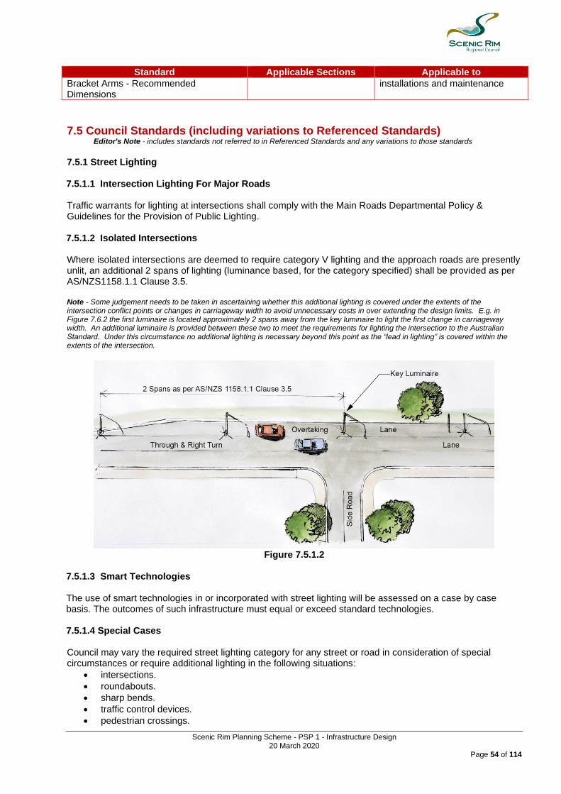
Scenic Rim Planning Scheme - PSP 1 - Infrastructure Design 20 March 2020
Page 54 of 114
Standard Applicable Sections Applicable to
Bracket Arms - Recommended Dimensions
installations and maintenance
7.5 Council Standards (including variations to Referenced Standards) Editor's Note - includes standards not referred to in Referenced Standards and any variations to those standards
7.5.1 Street Lighting 7.5.1.1 Intersection Lighting For Major Roads Traffic warrants for lighting at intersections shall comply with the Main Roads Departmental Policy & Guidelines for the Provision of Public Lighting. 7.5.1.2 Isolated Intersections Where isolated intersections are deemed to require category V lighting and the approach roads are presently unlit, an additional 2 spans of lighting (luminance based, for the category specified) shall be provided as per AS/NZS1158.1.1 Clause 3.5. Note - Some judgement needs to be taken in ascertaining whether this additional lighting is covered under the extents of the intersection conflict points or changes in carriageway width to avoid unnecessary costs in over extending the design limits. E.g. in Figure 7.6.2 the first luminaire is located approximately 2 spans away from the key luminaire to light the first change in carriageway width. An additional luminaire is provided between these two to meet the requirements for lighting the intersection to the Australian Standard. Under this circumstance no additional lighting is necessary beyond this point as the “lead in lighting” is covered within the extents of the intersection.
Figure 7.5.1.2
7.5.1.3 Smart Technologies The use of smart technologies in or incorporated with street lighting will be assessed on a case by case basis. The outcomes of such infrastructure must equal or exceed standard technologies. 7.5.1.4 Special Cases Council may vary the required street lighting category for any street or road in consideration of special circumstances or require additional lighting in the following situations:
• intersections.
• roundabouts.
• sharp bends.
• traffic control devices.
• pedestrian crossings.
Scenic Rim Planning Scheme - PSP 1 - Infrastructure Design 20 March 2020
Page 55 of 114
• cul-de-sac.
• bridges (minimum Category V5 at abutments and minimum Category P3 on deck).
• night time accident locations.
• frequently used night time bus stops.
• areas that may generate pedestrian traffic or vehicle night traffic.
• ends of roads. 7.5.1.5 Street Light Pole Alignment Street light poles shall be located in accordance with Table 7.4.1 Referenced Standards. Alternative proposed alignments addressing engineering and safety aspects will be considered on their merits. Supporting documentation should address:
• potential runoff impact from vehicles,
• road geometry and speed environment,
• kerb type, and
• streetscaping to protect or easily identify such poles, particularly at night. All poles painted in a dark colour shall have a reflectorized band placed or painted around the pole with a minimum width of 50 millimetres and located at a height of one metre above the base of the pole. Streetlight poles are not be located in the central median of roundabouts if the diameter of the island is less than 6m. Streetlight poles are not be located in the central median of a road if the median width is less than 3 metres. Where poles are in vulnerable locations, consideration shall be given to the use of slip base or frangible type poles. Note - Further recommendations on setbacks and clearances are outlined in Appendix B of AS 1158.1.3:1997. 7.5.1.6 Luminaries (1) Subject to (2), Mercury Vapour lights are to be used on all minor roads where B2 standard is specified.
(2) Luminaries shall be the most economical luminary type available and acceptable to Energex. Use of smart LED streetlights should be considered (colour temperatures to be consistent with standard lighting).
(3) For infill developments, new lamps and brackets shall be the same or of similar appearance to those in adjacent existing developments.
(4) Aeroscreen luminaires shall be provided where:
(a) Residences abut roads with Category V or B1 lighting
(b) Background lighting is dark and the aeroscreen will help reduce glare including isolated intersections, isolated ends of road, isolated speed control devices, steep crests, or bridges.
(5) Post-top and opal sphere lanterns shall not be used
7.5.2 Overhead Power
(1) Street lighting poles are to be located opposite common allotment boundaries.
(2) Pole location should avoid likely vehicle conflict points to minimise the risk of damage to both poles and vehicles and injury to vehicle occupants. Consideration should be given to potential paths of vehicles accidentally leaving the carriageway, and also to the swept path of oversize vehicles which need to leave the carriageway to manoeuvre, (e.g. at cul-de-sac turning areas, speed control devices, bends, and intersections).
(3) Pole alignments shall be 3.4 metres from property boundary and no closer than 1.6 metres to the edge of bitumen in non-kerbed areas. Pole alignments may be reduced to 0.3 metres in the following circumstances:
(a) at property boundaries of hatchet blocks with narrow frontages
(b) in cul-de-sacs with narrow frontages
(4) Poles shall not be placed to coincide with water services. Poles may be placed 1.0 metre offset from physically located conduits, if no alternative layout is feasible. Conflicts with drainage structures and table drains, cut batters etc. are to be avoided.

Scenic Rim Planning Scheme - PSP 1 - Infrastructure Design 20 March 2020
Page 56 of 114
7.5.3 Underground Power 7.5.3.1 Conduit Location And Alignment (1) Shared trenching with telecommunications cables is permitted. No sharing of trenches shall occur with
water or gas.
(2) Road crossings shall be at right angles where practicable and in no case shall the skew exceed 45º.
(3) Electrical crossings should be to the opposite boundary to water service crossings. Refer Standard Drawing R-02 & R-03.
(4) Electrical crossings are not permitted within the area defined as an intersection under the Traffic Regulations, unless on the standard alignment off the projected intersecting property boundary.
(5) Laying of conduits is only permissible within the designated service corridor in the road reserve or between service pillars, lamp posts and transformers. Conduits shall not be laid outside the service corridor or as service connections between overhead reticulation and properties, without prior approval of Council.
7.5.3.2 Pillars And Pad Mount Transformers Pillars shall be provided at all entry points, adjacent to the side boundary of each private property, except that for 11kV entry points to an internal transformer. "Cabmarked" Cable Marker post or equivalent are subject to prior approval. Pillars shall not be located at the same side boundaries as fire hydrants, nor on truncated boundaries. Placement on the tangent point will be subject to approval by Council. All pad mounted transformers should be located in areas of level, flood free ground. The area required for a pad mounted site shall comply with Energex specifications and shall be located on road reserve or future road reserve. 7.5.4 Gas Supply Where reticulated gas is proposed an approved design plan must be prepared by the responsible gas supply company. A copy of the plan must be provided to Council. Reticulation gas pipelines should only be installed by the responsible gas supply company or their approved installers. 7.5.5 Telecommunications/NBN Evidence of the telecommunications agent's agreement to provide services must be provided to Council prior to the pre-start meeting. Conduit crossing layouts and alignment shall be provided with engineering documentation. 7.5.6 Conduits and Construction 7.5.6.1 General Works covered by this specification includes: (1) the installation of conduits across roadways and footpaths for water, gas, electricity and
telecommunication services; (2) installation of conduits longitudinally along footpaths for electricity and telecommunication services; and (3) the fixing of brass indicator discs embossed 'W', 'G', ‘T’ and 'E' respectively at water, gas,
telecommunication and electricity conduit locations. 7.5.6.2 Trenches (1) The bottoms of trenches shall be firm and smooth and where they change in level from footpath to
roadway or up an embankment, the change shall be gradual. (2) Trenches shall be excavated so that the conduits are laid with 75mm clearance all around from other
obstructions.

Scenic Rim Planning Scheme - PSP 1 - Infrastructure Design 20 March 2020
Page 57 of 114
(3) Conduits shall be bedded for 120 degrees of their circumference on at least 75mm of compacted sand or trench backfill material.
(4) For new developments: (a) trenches across roadways and pavement areas shall be excavated before pavement material has
been placed; (b) trenches along footpaths shall be excavated before topsoiling and grassing has been carried out.
7.5.6.3 Material for Utility Service Conduits All uPVC pipe conduits, joints and couplings shall comply with AS1477, AS2053 and AS2439 and shall be of the class specified on the drawings or Bill of Quantities. Conduits for electricity services shall comply with Energex requirements. 7.5.6.4 Liaison with Public Utility Authorities The relevant Utility Authorities shall be consulted prior to completion of earthworks and commencement of pavement material to ensure correct sequence of construction activities. 7.5.6.5 End Caps After laying, all conduits shall be cleaned internally and subjected to Council inspection before end caps are installed. 7.5.6.6 Brass Marker Discs Brass marker discs shall be supplied and installed in accordance with the drawings. In locations where there is no kerb and channel, concrete marker blocks shall be constructed. The marker blocks shall consist of Grade N25 concrete blocks 225 mm x 75 mm x 450 mm long with indentation for the indicator disc centrally placed on the top face of each block. 7.5.6.7 Backfill and Compaction Backfill material type shall be in accordance with the Standard Drawing and shall be compacted by mechanical means to 100% Standard Density or 70% density index as applicable.

Scenic Rim Planning Scheme - PSP 1 - Infrastructure Design 20 March 2020
Page 58 of 114
7.6 Standard Drawings 7.6.1 The Standard Drawings listed in Table 7.6 Standard Drawings are the minimum standard of
design and construction for this Part. Table 7.6 Standard Drawings
Standard Drawing Number Name
R-02 Public Utilities - Typical Service Corridors and Alignments
R-03 Public Utilities - Typical Service Conduit Sections
Scenic Rim Planning Scheme - PSP 1 - Infrastructure Design 20 March 2020
Page 59 of 114
Part 8 - Standards for Park Lands
8.1 Contents
Section Title
8.1 Contents
8.2 Purpose
8.3 General Matters
8.4 Referenced Standards
8.5 Council Standards (including variations to Referenced Standards)
8.5.1 Standards for Parks
8.5.2 Minimum Size for Parks
8.5.3 Minimum Post Development Flood Immunity for Parks
8.5.4 Maximum Post Development Grade for Parks
8.6 Standard Drawings
8.2 Purpose
The purpose of this Part is to:
(1) detail the provision of suitable park lands where required by the Scheme for development;
(2) insure park lands meet size, constraint, topographical and service standards appropriate for the desired future use of the park lands.
8.3 General Matters (1) Trunk Parks include the park network planned in accordance with Part 4 - Local Government
Infrastructure Plan section 4.4.3.1 (Park network)) of the planning scheme. (2) Non-trunk Parks includes parks dedicated to the local government pursuant to the Reconfiguration of Lot
Code
8.4 Referenced Standards Not applicable to this Part.
8.5 Council Standards (including variations to Referenced Standards) Editor's Note - reference can be made to Council's - Parks & Amenities Strategy 2015 which has been developed with consideration to linkages with a range of strategic documents, legislation, guidelines and standards relating to Council’s provision of the parks network.
8.5.1 Standards for Parks
Design standards for the park classification specified in Column 1, is provided in accordance with Column 2 of Table 8.5.1.1 – Design Standards for Parks.
Following standards apply to all parks irrespective of their classification:
1. has vehicular access for maintenance and management purposes;
2. has clear and visible lines of sight from formalised entries and pedestrian crossings;
3. provides for casual surveillance to and from the civic space. Queensland Police CPTED
guidelines provides additional guidance.
4. provides embellishments in accordance with Part 9 of this Policy.
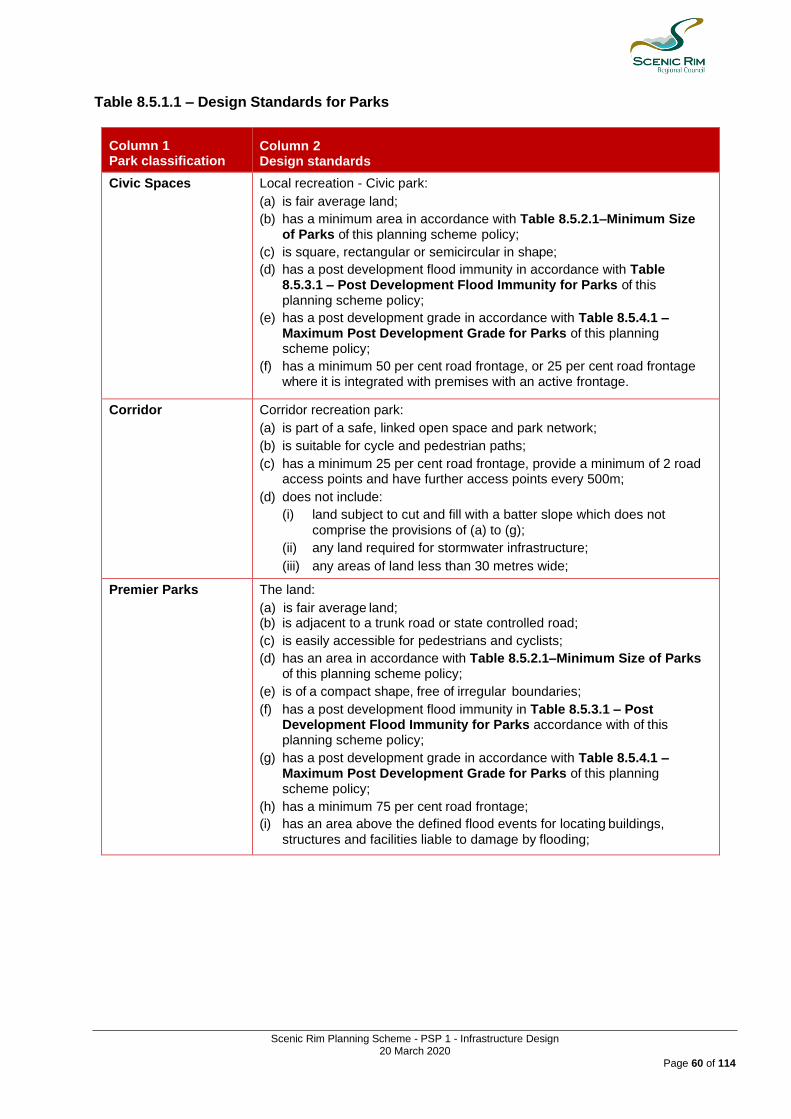
Scenic Rim Planning Scheme - PSP 1 - Infrastructure Design 20 March 2020
Page 60 of 114
Table 8.5.1.1 – Design Standards for Parks
Column 1 Park classification
Column 2 Design standards
Civic Spaces Local recreation - Civic park:
(a) is fair average land;
(b) has a minimum area in accordance with Table 8.5.2.1–Minimum Size of Parks of this planning scheme policy;
(c) is square, rectangular or semicircular in shape;
(d) has a post development flood immunity in accordance with Table 8.5.3.1 – Post Development Flood Immunity for Parks of this planning scheme policy;
(e) has a post development grade in accordance with Table 8.5.4.1 – Maximum Post Development Grade for Parks of this planning scheme policy;
(f) has a minimum 50 per cent road frontage, or 25 per cent road frontage where it is integrated with premises with an active frontage.
Corridor Corridor recreation park:
(a) is part of a safe, linked open space and park network;
(b) is suitable for cycle and pedestrian paths;
(c) has a minimum 25 per cent road frontage, provide a minimum of 2 road access points and have further access points every 500m;
(d) does not include:
(i) land subject to cut and fill with a batter slope which does not
comprise the provisions of (a) to (g);
(ii) any land required for stormwater infrastructure;
(iii) any areas of land less than 30 metres wide;
Premier Parks The land:
(a) is fair average land; (b) is adjacent to a trunk road or state controlled road;
(c) is easily accessible for pedestrians and cyclists;
(d) has an area in accordance with Table 8.5.2.1–Minimum Size of Parks of this planning scheme policy;
(e) is of a compact shape, free of irregular boundaries;
(f) has a post development flood immunity in Table 8.5.3.1 – Post Development Flood Immunity for Parks accordance with of this planning scheme policy;
(g) has a post development grade in accordance with Table 8.5.4.1 – Maximum Post Development Grade for Parks of this planning scheme policy;
(h) has a minimum 75 per cent road frontage;
(i) has an area above the defined flood events for locating buildings,
structures and facilities liable to damage by flooding;

Scenic Rim Planning Scheme - PSP 1 - Infrastructure Design 20 March 2020
Page 61 of 114
Column 1 Park classification
Column 2 Design standards
Local recreation parks Local recreation park:
(a) is fair average land;
(b) is on an urban access road in a residential area;
(c) is easily accessible for pedestrians and cyclists;
(d) is configured such that the land can be expanded by the addition of
adjoining land;
(e) has an area in accordance with Table 8.5.2.1–Minimum Size of Parks
of this planning scheme policy;
(f) is of a compact shape free of irregular boundaries;
(g) has a post development flood immunity in accordance with Table 8.5.3.1 – Post Development Flood Immunity for Parks of this planning scheme policy;
(h) has a post development grade in accordance with Table 8.5.4.1 – Maximum Post Development Grade for Parks of this planning scheme policy;
(i) has road frontage of not less than 75 percent;
District recreation District recreation park:
(a) is fair average land;
(b) is adjacent to a trunk road;
(c) is easily accessible for pedestrians and cyclists;
(d) has an area in accordance with Table 8.5.2.1–Minimum Size of Parks of this planning scheme policy;
(e) is of a compact shape free of irregular boundaries;
(f) has a post development flood immunity in accordance with Table 8.5.3.1 – Post Development Flood Immunity for Parks of this planning scheme policy;
(g) has a post development grade in accordance with Table 8.5.4.1 – Maximum Post Development Grade for Parks of this planning scheme policy;
(h) has a minimum 75 per cent road frontage;
(i) has an area above the defined flood event for locating buildings, structures and facilities liable to damage by flooding.
District and Regional sport
Metropolitan and district sport park:
(a) is fair average land;
(b) is adjacent to a trunk road or state controlled road;
(c) is easily accessible for pedestrians and cyclists;
(d) has an area in accordance with Table 8.5.2.1–Minimum Size of Parks of this planning scheme policy;
(e) is of a compact shape, free of irregular boundaries; (f) has a post development flood immunity in accordance with Table
8.5.3.1 – Post Development Flood Immunity for Parks of this planning scheme policy ;
(g) has a post development grade in accordance with Table 8.5.4.1 – Maximum Post Development Grade for Parks of this planning scheme policy;
(h) has a minimum 75 per cent road frontage;
(i) has a minimum 60 per cent of the area suitable for sports fields
or courts;
(j) is connected to infrastructure including power, water and sewerage;
(k) has an area above the defined flood event for locating buildings, structures and facilities susceptible to damage by flooding

Scenic Rim Planning Scheme - PSP 1 - Infrastructure Design 20 March 2020
Page 62 of 114
Column 1 Park classification
Column 2 Design standards
Non-trunk recreation parks
Non-trunk recreation park:
(a) is fair average land;
(b) is on an urban access road in a residential area;
(c) is easily accessible for pedestrians and cyclists
(d) is configured such that the land can be expanded by the addition of
adjoining land;
(e) is of a compact shape free of irregular boundaries;
(f) has road frontage of not less than 50 percent
Non-trunk landscape parks
Non-trunk landscape park:
(a) is predominately providing landscape values;
(b) is a site that, because of their location, size, or topography, are limited in their use;
(c) is usually undeveloped, and feature lawns, specimen trees, or shrubs
Non-trunk nature parks
Non-trunk nature park:
(a) is bush and wetland areas that have ecological values worth preserving;
(b) is relatively undeveloped park whose principle purpose is to provide for natural ecosystems, predominately bushland, for the preservation of native flora and fauna, and to provide access to these sites where appropriate.
(c) is located where natural features such as wetland areas, bushland, and escarpments occur;
(d) must have a demonstrated conservation value, and ideally be over 10ha in size;
(e) must have 50% of the park perimeter with direct road frontage for regional and district nature park;
(f) must have at least 25% of the park perimeter with direct road frontage for local nature park
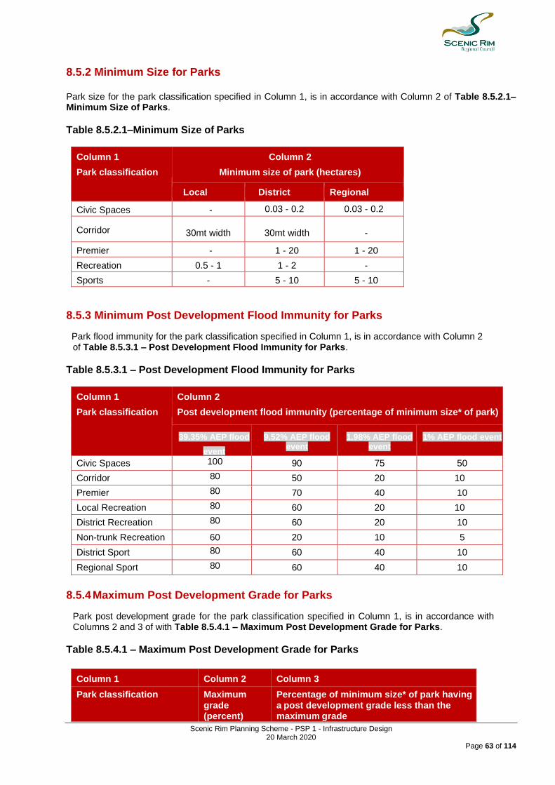
Scenic Rim Planning Scheme - PSP 1 - Infrastructure Design 20 March 2020
Page 63 of 114
8.5.2 Minimum Size for Parks
Park size for the park classification specified in Column 1, is in accordance with Column 2 of Table 8.5.2.1–Minimum Size of Parks.
Table 8.5.2.1–Minimum Size of Parks
Column 1
Park classification
Column 2
Minimum size of park (hectares)
Local District Regional
Civic Spaces - 0.03 - 0.2 0.03 - 0.2
Corridor 30mt width 30mt width -
Premier - 1 - 20 1 - 20
Recreation 0.5 - 1 1 - 2 -
Sports - 5 - 10 5 - 10
8.5.3 Minimum Post Development Flood Immunity for Parks
Park flood immunity for the park classification specified in Column 1, is in accordance with Column 2 of Table 8.5.3.1 – Post Development Flood Immunity for Parks.
Table 8.5.3.1 – Post Development Flood Immunity for Parks
Column 1
Park classification
Column 2
Post development flood immunity (percentage of minimum size* of park)
39.35% AEP flood
event
9.52% AEP flood event
1.98% AEP flood event
1% AEP flood event
Civic Spaces 100 90 75 50
0 Corridor 80 50 20 10
Premier 80 70 40 10
Local Recreation 80 60 20 10
District Recreation 80 60 20 10
Non-trunk Recreation 60 20 10 5
District Sport 80 60 40 10
Regional Sport 80 60 40 10
8.5.4 Maximum Post Development Grade for Parks
Park post development grade for the park classification specified in Column 1, is in accordance with Columns 2 and 3 of with Table 8.5.4.1 – Maximum Post Development Grade for Parks.
Table 8.5.4.1 – Maximum Post Development Grade for Parks
Column 1 Column 2 Column 3
Park classification Maximum grade (percent)
Percentage of minimum size* of park having a post development grade less than the maximum grade

Scenic Rim Planning Scheme - PSP 1 - Infrastructure Design 20 March 2020
Page 64 of 114
Column 1 Column 2 Column 3
Park classification Maximum grade (percent)
Percentage of minimum size* of park having a post development grade less than the maximum grade
Civic Spaces 2 85
Premier Parks 5 75
Local recreation 5 50
District recreation 5 70
Non-trunk Recreation 7 40
District sport 2 70
Regional sport 2 85
8.6 Standard Drawings Not applicable to this Part.
Scenic Rim Planning Scheme - PSP 1 - Infrastructure Design 20 March 2020
Page 65 of 114
9.0 Landscaping & Embellishment for Public Areas
9.1 Information Requirements
9.1.1 Purpose
9.1.2 General Matters
9.1.3 Referenced Standards
9.2 Landscaping for Public Areas
9.2.1 Purpose
9.2.2 General Matters
9.2.3 Referenced Standards
9.2.4 Council Standards (including variations to Referenced Standards)
9.2.5 Standard Drawings
9.1 General Information Requirements
9.1.1 Purpose
The purpose of this Part is to ensure that development provides appropriate and sufficient information to allow a development application to be properly and professionally assessed.
9.1.2 General Matters
(1) Any conflicts or departure from the Standard Drawings or the Policy must be detailed in the application.
(2) Where a staged development has been approved by Council, Council may require landscape design and construction to include the whole of the site, or such additional parts of the site as will enable the Council to maintain the works in a satisfactory condition if the balance of the development does not proceed to completion.
(3) The development application must include sufficient information outside the development footprint to verify that any future extension of the proposed works can proceed in accordance with this Policy and without any undue cost to future development.
(4) All design drawings and calculations must be supervised and certified by a suitably qualified person before being submitted to Council for examination. The name and professional details of the person must be supplied.
9.1.2.1 Competency to prepare a report
(1) A person preparing a report, a plan or a drawing relating to development must be a suitably qualified person and includes, in the case of non-minor landscaping issues, a Registered Landscape Architect with the Australian Institute of Landscape Architects.
(2) The report, plan or drawing must include a certification signed by the suitably qualified person that the report, plan or drawing is fit for its intended purpose and can be relied upon by Council for that purpose.
9.1.2.2 Bill of Quantities and Asset Report
A Bill of Quantities must be provided at the time of submission of the engineering documentation. The Bill of Quantities need not include the contract prices. At the completion of the construction, a completed Asset Report which reflects the actual construction costs, constructed volumes, areas and length of items constructed must be provided to Council.
Editor's Note - This information is required to update Council's Asset Register.
9.1.3 Referenced Standards
9.1.3.1 The Standards listed in Table 9.1.3.1 Reference Standards are the applicable standards for datum to be used for survey and design except where:
(1) The standard is in conflict with a standards specified in the Policy; or
(2) The standard is specifically varied, amended or removed by the standards specified in Policy.

Scenic Rim Planning Scheme - PSP 1 - Infrastructure Design 20 March 2020
Page 66 of 114
Table 9.1.3.1 Referenced Standards
Standard Applicable Sections Applicable to
Australian Height Datum (AHD)
Vertical datum to be used for survey and design
Map Grid of Australia, 1994 (MGA94)
Horizontal datum to be used for survey and design
9.2 Landscaping & Embellishment for Public Areas
9.2.1 Purpose
The purpose of this Part is to:
(1) Recognise the value of landscaping in characterising public open space;
(2) Set minimum design, performance and maintenance standards for landscape works;
(3) Recognise adjacent land uses to ensure that uniform and coherent landscaped corridors are created within developments; and
(4) Set minimum standards for park furnishings and embellishments.
9.2.2 General Matters
(1) Council supports innovative design provided the landscaping outcomes of this Policy can be achieved.
(2) Design principals must take cognisance of adjacent land uses to ensure that uniform and coherent landscaped corridors are created within particular development zones.
(3) All elements of the landscaping design that are structural/building form must be certified by an RPEQ (Civil).
(4) The general landscape elements addressed in this Policy include:
(a) Streetscaping (b) Parks and Public Open Space
9.2.3 Referenced Standards
9.2.3.1 The Standards listed in Table 9.2.3.1 Reference Standards are the applicable standards for and being existing or future Council land except where:
(1) The standard is in conflict with a standards specified in Section 9.2.4; or
(2) The standard is varied, amended or removed by the standards specified in Section 9.2.4. Table 9.2.3.1 Referenced Standards
Standard Comment
AS 4970-2009 Protection of Trees on Development Sites
AS 4373-2007 Pruning of amenity trees
AS4685 - 2014 - Playground Equipment and Surfacing set
Playground equipment manufacturers specifications with a focus on design quality and durability.
AS4685 -2017 - Playground Equipment and Surfacing - development , installation inspection, maintenance and operation.
Playground equipment manufacturers specifications with a focus on design quality and durability.
AS 4422:2016 - Playground surfacing specifications, requirements and test methods
Playground Surfacing
AS 1547:2012 - Onsite domestic wastewater management
Water play equipment
AS/NZS 3000:2007 - Electrical Installation Audio Equipment
AS4174:1994 - Synthetic Shade cloth and Amendment 1:1996.
Shade sails/structures
AS/NZ3661.2:1993 - Slip Resistance of Footpaths

Scenic Rim Planning Scheme - PSP 1 - Infrastructure Design 20 March 2020
Page 67 of 114
Standard Comment
Pedestrian Surfaces
National Construction Code (NCC) Volume 1 and 2 Building code of Australia
Plumbing Code of Australia (PCA)
AS 2890-2009 Parking Facilities Includes
• AS/NZS 2890.1:2004 Parking facilities—Off-street car parking
• AS 2890.2—2002 Parking facilities—Off-street commercial vehicle facilities
• AS 2890.3—2015 Parking facilities - Bicycle parking
• AS 2890.5—1993 Parking facilities—On-street parking
• AS/NZS 2890.6:2009 Parking facilities—Off-street parking for people with disabilities
AS 4419-2003 Soils for landscaping and garden use
AS/NZS 3500 Set (Parts 0-4):2015 Plumbing and drainage Set
Irrigation systems
Austroads Guides Including Cycling Aspects of Austroads Guides
Road Landscape Manual - Department of Main Roads
Streetscaping
Best Practice Erosion and Sediment Control, International Erosion Control Association, Australasia Chapter, 2008
Erosion prevention and control
9.2.4 Council Standards (including variations to Referenced Standards)
Editor's Note - includes standards not referred to in Referenced Standards and any variations to those standards
9.2.4.1 Design
(1) A suitably qualified person supervising the construction of landscaping works must be either: (a) a Landscape Architect holding A.I.L.A. (Australian Institute of Landscaping Architects) Corporate
Membership, or a person eligible for membership; or (b) where minor landscape works, an experienced, qualified Landscape Designer with demonstrated
competence in landscaping works, and contract administration.
(2) Where projects involve only minor landscape works, a full specification is not necessary. Construction and performance notes and supporting detail drawings, presented on the landscaping drawings will suffice.
(3) Variations to these criteria will be considered by Council where they meet design outcomes and standards.
9.2.4.2 Landscaped Design & Environmental Considerations
9.2.4.2.1 General
Consideration must be given to the following parameters when preparing a landscape design:
• Surrounding native flora and fauna
• Existing site vegetation
• Soil types and characteristics
• Topography and slope stability
• Natural drainage patterns and catchments including overland flow paths
• Local climatic elements: o rainfall (annual precipitation and seasonal dominance) o temperature o frost occurrence o solar radiation (intensity and seasonal direction patterns)

Scenic Rim Planning Scheme - PSP 1 - Infrastructure Design 20 March 2020
Page 68 of 114
o wind (prevailing direction and expected velocity)
• Surrounding human influence and cultures
• Dominant local treatments and styles that have been developed or introduced
• Current Local Council and State Government Requirements, Local Laws, Council’s Recreation Strategy, etc.
• Special or additional requirements of applicants and intended users of the habitat In addition, the design must ensure the function of the intended use and purpose of the landscape. Functional elements include:
• traffic flows (pedestrian, cyclist and vehicular)
• focus on features and visual outlooks
• provision of shade and shelter
• retardation of undesirable visual or acoustic elements
• provision of reasonable access to services for maintenance purposes
• the creation of space and comfort
• the provision of recreation facilities
• the encouragement of and nurture of environmental attributes
• the promotion of aesthetic enhancement
• short and long term maintenance requirements
• provision of water storage
• ability to retard bushfires When assessing plant species the following plant characteristics should be researched, in particular:
• dimensions at maturity
• rate of growth
• form or pattern of growth
• cultural and maintenance requirements
• compatibility with aforementioned site, environmental and climatic elements
• root aggression and effect on adjacent roads’ water and sewer mains
• potential to drop litter: leaves, flowers, seed and fruit
• shading effect of canopy on surrounding plants or grasses
• ability to regenerate or spread
• characteristics (size, shape and colour) of plants aesthetic features: trunk, leaves, flowers, etc.
• any restrictive characteristics, poisonous, noxious, spikes or prickles, etc.
• ability to be trained
• fragrance
• availability in local nurseries
• fire resistance
• fire retardance
• native species are typically required, preferably those that are endemic to the Scenic Rim Region
Note - Use of the species listed within the Schedule 1 is encouraged. Schedule 1 is a comprehensive listing of shrub and tree species which are suitable for use within the Scenic Rim. The schedule is divided into various landscaping environments: (1) Major road corridors; (2) Parklands; (3) Streets and avenues; (4) Creek corridors; and (5) Medians, Roundabouts and Screenings.
9.2.4.3 Landscape Design Requirements 9.2.4.3.1 Minimum Planting Requirements All trees and shrubs required to be planted must be at least 750mm and 200mm high respectively when planted. Each required shrub must attain a height of not less than 600mm when fully matured, except where such height would interfere with traffic visibility, e.g. traffic islands or roundabouts.
All existing trees and shrubs between three metres and twenty metres of any building work or approved car parking area or access thereto to be retained and included in a landscape plan. Appropriate action is to be undertaken to minimise disturbance to this vegetation during on-site building work including the need to

Scenic Rim Planning Scheme - PSP 1 - Infrastructure Design 20 March 2020
Page 69 of 114
adhere to Australian Standard 4970-2009 Protection of Trees on Development Sites. All retained trees are to be assessed by a qualified Consulting Arborist and remedial actions taken as per their recommendations. Individual trees are to be identified by species and/or genera and mass vegetation to be identified by vegetation type (notate information on drawing and include the condition, average diameter of the trunk of individual trees and 'significance' value (high, medium, low) per identification). Photos of the vegetation are to be submitted with the plan and to include a 'known' object in the photo to demonstrate the scale of the picture.
Where trees are planted, they must be staked using a minimum of two approved wooden stakes per tree, or an approved metal tree guard well secured into the ground so as to assist in the establishment of the plant’s rooting system and as partial protection against vandalism. Refer to Scenic Rim Standard Drawing P-30 (Specimen Park/Street Tree Planting).
Garden areas to have a maximum slope of 1 in 3. Should site requirements be unable to accommodate this requirement then the slopes are to be stabilised in an Engineer designed manner.
9.2.4.3.2 Streetscaping
Streetscaping guidelines must be incorporated into landscaping within the verges or medians of new roads in a subdivision. Detailed working plans of the landscaping must be lodged with the engineering documentation as part of an Operational Works application.
Conceptual sketches illustrating typical streetscaping treatments and considerations are shown in Figures 9.1- 9.4.
Streetscape must only include feature landscaping within the perimeter of roundabouts and large traffic islands in the higher profile parts of the estate. Full area decorative concrete finishes should be used for smaller and/or lower profile traffic islands, roundabout and traffic calming. Large roundabouts to include a maintenance vehicle set down pad as one of the design features. The dominant feature of the streetscape will be street trees with no or limited gardens within the street footpath/verge area. Roundabout landscaping should typically include a single feature tree, small shrubs (not exceeding 300mm in height) and ground covers. All roundabouts to have a 1.5m wide decorative concrete surround (to provide improved buffer zone between maintenance workers and traffic).
Entry statements/signage and the planting associated with these are to be:
(1) contained within the private land of the estate that is not existing or future Council controlled land; or
(2) on existing or future Council controlled land where there is an established private maintenance agreement and at the finalisation of the estate, such planting is removed and turf established (at no cost to Council) prior to final handover to Council.
Design must satisfy the following criteria:
• Planting is in scale with streetscape.
• Street trees are not planted within 6m of light poles.
• Plants are not placed at access points.
• Plants must not obstruct access to services.
• Planting has limited species variation.
• The street tree alignment must be within the corridor shown on Standard Drawing R-02.
• Earthworks are not carried out within close proximity of existing vegetation.
• All street gardens including roundabouts and medians must be provided with an automatic irrigation system.
• Subsoil drainage must be provided between all street gardens and the road pavement.
• Pedestrian access must be maintained around, and where applicable through, all street planting.
• Visibility lines ensure that the minimum stopping distance for vehicular traffic is maintained, assuming the plantings have grown to full maturity.
Works must also incorporate:
(a) Stabilisation of unstable slopes with retainer wall treatments and revegetated appropriately. (b) Stable slopes will be rehabilitated using low maintenance grasses and/or revegetation techniques. (c) Road verges including table drains in rural zones are grassed with a minimum aerial coverage of 80
percent before acceptance off maintenance. The grass coverage must also have been significantly established and maintained for a minimum period of twelve months before acceptance off maintenance. Bank slopes of drains to be no steeper than 1 in 6 where this can be accommodated

Scenic Rim Planning Scheme - PSP 1 - Infrastructure Design 20 March 2020
Page 70 of 114
and where there is insufficient space, no steeper the 1 in 4 (also refer the Queensland Urban Drainage Manual). Turfed areas are to be accessible by industry standard mowers and shaped in such a way as to accommodate these machines.
(d) Acoustic barriers to be provided for all new roads with design traffic >5000AADT where the abutting properties are residential and have an average lot area <2000m2.
9.2.4.3.3 Parks And Public Open Space
Major estates must provide a management plan for the parkland. A management plan will identify the intended uses of the parkland. In particular the management plan will identify those areas suitable to be used for active sport and recreation and those areas to be preserved for environmental reasons. Refer to Parks standard drawings for further details.
Minimum works required in all parkland areas include:
(1) General (a) Removal and safe disposal of declared plants and environmental weeds; (b) Bollards with appropriate access lock rails/gates are to be installed to all road frontages or access
points; (c) All substantial and significant trees are to be retained where ever practical and protected in
accordance with Australian Standard 4970-2009; (d) All retained trees over 200mm diameter at breast height (ABH) are to be assessed by an
independent qualified Arborist (as per AQF and Australian Standards) and the recommendations from the Arborist report are to be implemented prior to the on maintenance period in accordance with Australian Standard 4373-2007. The Arborist report is to be provided/detailed before any construction commences on the site;
(e) Selective tree planting to areas where weeds have been removed to stabilised soils and suppress regrowth of weeds.
(f) The bank slopes of drains are to be no steeper than 1 in 6 (also refer the Queensland Urban Drainage Manual). Turfed areas are to be accessible by industry standard mowers.
(2) Site Specific Works
(a) Pathway/bikeway/horse trail construction
(b) Playground equipment, seating, shelters and picnic facilities in accordance with section 9.2.4.4 Embellishment for Parks.
(3) Minimum Design Requirements
(a) Landscaping to parkland:
(i) Specify and detail a multi-purpose landscape, through the design and placement of plantings, earthworks, hardscape and park furniture.
(ii) Site preparation: (iii) Specify and detail ground preparation and grassing of the parkland so as to provide an area
free from sudden undulations, ponding and extraneous materials that could potentially injure children performing play activities in the parkland or that would make the site unmowable.
(b) Plantings:
(i) Specify and locate vegetation to the frontages and boundaries of parkland, so as to delineate and promote the location of the parkland.
(ii) Specify and locate plant species, earthen mounding, boulders and other features adjacent to play equipment for the protection from sun, wind and air pollutants, control of surface drainage and provision of innovative play options.
(iii) Locate play areas in proximity to shelters, picnic areas, pathways and amenities and where visible from access roads and pathways.
(iv) Locate play areas no closer than 10m from private properties, road reserves, dense bushland, water courses and any other areas that could potentially jeopardise the safety of children or where their play could disturb neighbours.
(v) Provide seating and shelter for supervisors orientated to clearly view children at play. (c) Playgrounds :
(i) The Relevant sections of AS4685 - 2014, AS4422:2016 - Playground Equipment and Surfacing set and AS4685 -2017 - Playground Equipment and Surfacing - development ,

Scenic Rim Planning Scheme - PSP 1 - Infrastructure Design 20 March 2020
Page 71 of 114
installation inspection, maintenance and operation.
(d) Bikeways:
(i) Bikeways are typically 2.5m wide and are to be of concrete, and suitable for use by cyclists and pedestrians.
(ii) Where bikeways exit parkland onto busy streets, include a physical barrier to restrict accidental movements onto the road pavement.
(iii) Where bikeways restrict access to particular areas of the parkland, provide maintenance vehicle crossovers at practical points to avoid damage to concrete.
Note - Unless otherwise specifically stated in the conditions of a development approval, liaise with Council’s relevant officer to confirm:
• The siting of the parkland and bikeway routes.
• The specific function, targeted user groups and intended frequency of use.
• The items to be provided per park, including play equipment and park furniture in accordance with section 9.2.4.4 Embellishment for Parks.
• The method of drainage required where springs, seepage and overland flow paths exist.
• Provision for access by disabled persons. Note: Any clearing in parkland is to be constructed in accordance with the approved management plan and confirmed on site by Council or one of their delegates.
• Any clearing in parkland is to be constructed in accordance with the approved management plan and confirmed on site by Council or one of their delegates.
• No fill batters, generated by the Development, shall encroach onto the parkland.
• All structures, infrastructure and equipment are to be designed by an appropriately qualified engineer. The improvements must comply with the relevant Australian Standards, Council Standards and where no recognised standard exists the design shall be subject to Council approval.
Detention system sites designed for secondary use as usable recreational space during dry periods will not be included as parkland provision. However they can be contiguous with parkland where incorporated within the overall park design. Naturally occurring waterways are to be contiguous with, but are not to be included within the parkland provision.
Where practicable, natural water flows through the site are to be maintained and water is not be permanently ponded or dammed within parks (with the exception of naturally occurring water bodies). Existing constructed permanent water bodies are to be dewatered and filled/levelled.
9.2.4.3.4 Carparks
Carparking facilities and vehicle access must conform to the requirements of relevant Development Conditions firstly, and AS2890 and Austroads Guidelines as appropriate, to address the following design issues: (1) Location/Layout:
(a) Concentrate carparks to the rear of buildings and/or divide large carparks with buildings, covered walkways or open space.
(b) Provide pedestrian set-down bays and public transport stops. Set-down bays will be considered for use in small-scale commercial deliveries only.
(c) Provide walkways/aisles for circulation of pedestrians. Protect walkways with wheel stops or kerbs. (d) Provide landscaped medians incorporating shade trees within the car parking layout. (e) Orientate parking bays and shade tree planting patterns to optimise the seasonal shade patterns
and minimise the glare from the afternoon sun. (2) Construction - dual use:
(a) Design carparks as detention basins, without inconveniencing the motorist, to detain increases in runoff that may overload the existing stormwater system, or in combination with a series of “small” detention basins to ease the overall load on the development.
(b) Replace concrete kerbs, excluding those at the base of batters, with wheel stops to allow runoff to irrigate surrounding landscaped areas; include a stone and sand filter trench drain, reduce runoff flow and increase percolation.
(3) Landscaping:
(a) Each landscaped island must be of sufficient size to accommodate a mature shade tree. (b) All landscaped areas to be provided with an irrigation system. (c) Subsoil drainage and root barrier protection to be provided around landscaped areas.
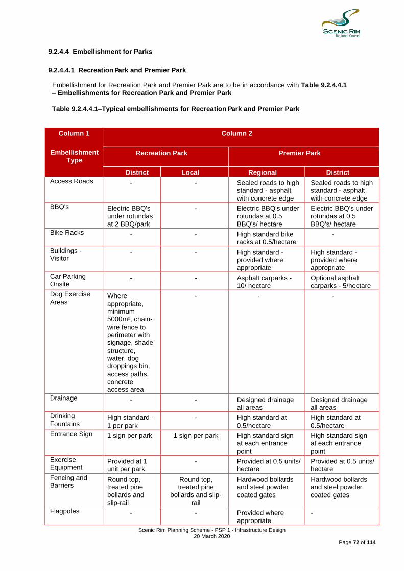
Scenic Rim Planning Scheme - PSP 1 - Infrastructure Design 20 March 2020
Page 72 of 114
9.2.4.4 Embellishment for Parks
9.2.4.4.1 Recreation Park and Premier Park
Embellishment for Recreation Park and Premier Park are to be in accordance with Table 9.2.4.4.1 – Embellishments for Recreation Park and Premier Park
Table 9.2.4.4.1–Typical embellishments for Recreation Park and Premier Park
Column 1
Embellishment Type
Column 2
Recreation Park
Premier Park
District Local Regional District
Access Roads - - Sealed roads to high standard - asphalt with concrete edge
Sealed roads to high standard - asphalt with concrete edge
BBQ's Electric BBQ's under rotundas at 2 BBQ/park
- Electric BBQ's under rotundas at 0.5 BBQ's/ hectare
Electric BBQ's under rotundas at 0.5 BBQ's/ hectare
Bike Racks - - High standard bike racks at 0.5/hectare
-
Buildings - Visitor
- - High standard - provided where appropriate
High standard - provided where appropriate
Car Parking Onsite
- - Asphalt carparks - 10/ hectare
Optional asphalt carparks - 5/hectare
Dog Exercise Areas
Where appropriate, minimum 5000m², chain-wire fence to perimeter with signage, shade structure, water, dog droppings bin, access paths, concrete access area
- - -
Drainage - - Designed drainage all areas
Designed drainage all areas
Drinking Fountains
High standard - 1 per park
- High standard at 0.5/hectare
High standard at 0.5/hectare
Entrance Sign 1 sign per park 1 sign per park High standard sign at each entrance point
High standard sign at each entrance point
Exercise Equipment
Provided at 1 unit per park
- Provided at 0.5 units/ hectare
Provided at 0.5 units/ hectare
Fencing and Barriers
Round top, treated pine bollards and slip-rail
Round top, treated pine
bollards and slip-rail
Hardwood bollards and steel powder coated gates
Hardwood bollards and steel powder coated gates
Flagpoles - - Provided where appropriate
-

Scenic Rim Planning Scheme - PSP 1 - Infrastructure Design 20 March 2020
Page 73 of 114
Column 1
Embellishment Type
Column 2
Recreation Park
Premier Park
District Local Regional District
Footbridges High standard provided where appropriate
High standard provided where appropriate
High standard designed to appropriate code - provided where appropriate
High standard designed to appropriate code - provided where appropriate
Fountains - - High standard architecturally designed - provided where appropriate
-
Gardens Irrigated high standard gardens at 10m² per hectare
- Irrigated high standard gardens at 100m2/ hectare
Irrigated high standard gardens at 50m²/ hectare
Interpretive Signs
- - High standard sign - located where appropriate
-
Irrigation - Turf - - High use grass areas irrigated
-
Lighting - - High standard safety and feature lighting of ornamental features such as artwork and specimen trees
Safety lighting
Public Use Mains Power
Available with event booking only
- Available with event booking only
Available with event booking only
Paths Concrete - Concrete footpaths Concrete footpaths
Playgrounds Up to 5 units, min 50% shaded area
- Between 10-15 play items, min 50% shaded are
Between 5-10 play items, min 50% shaded area
Public Art - - 1 item / hectare 1 item / hectare
Public Toilets Uni-sex toilets at 1 cubicle per hectare (min 2 cubicles per park)
- Uni-sex toilets at 2 cubicles per hectare (min. 2 cubicles per park)
Uni-sex toilets at 1.5 cubicles per hectare (min. 2 cubicles per park)
Rubbish Bins Wheelie bin stand, 2 per park
- 240 litre wheelie bin enclosures at 2 bins / hectare
240 litre wheelie bin enclosures at 1 bin / hectare
Seats High standard at 1 seat/hectare
- High standard at 2 seats / hectare
High standard at 2 seats / hectare
Shelters - - High standard at 0.5 shelters / hectare
High standard at 0.5 shelter / hectare
Tables - - High standard - provided at 0.5
High standard - provided at 0.5

Scenic Rim Planning Scheme - PSP 1 - Infrastructure Design 20 March 2020
Page 74 of 114
Column 1
Embellishment Type
Column 2
Recreation Park
Premier Park
District Local Regional District
hectare if not incorporated into shelter
hectare if not incorporated into shelter
Trees Specimen tree planting to provide shade to infrastructure & for beautification & screen (min. Size 200mm stock, min 25 trees/ hectare)
Specimen tree planting to provide shade to infrastructure & for beautification & screen (min. Size 200mm stock, min 25 trees/ hectare)
Specimen trees planted to landscape design (min. Size 200mm stock, min. 30 trees / hectare
Specimen tree planting to provide shade to infrastructure & for beautification & screening (min. Size 200mm stock, min. 30 trees / hectare)
Viewing Platforms
- - High standard - located where appropriate
High standard - located where appropriate
Water Body - - Up to 25% of site area - where appropriate
Up to 25% of site area - where appropriate
Water Points 1 per BBQ &/or drinking fountain
- 1 per BBQ & / or drinking fountain
1 per BBQ & / or drinking fountain

Scenic Rim Planning Scheme - PSP 1 - Infrastructure Design 20 March 2020
Page 75 of 114
9.2.4.4.2 Corridor and Civic Spaces
Embellishments for Corridor and Civic Spaces are to be in accordance with Table 9.2.4.2.2 Embellishments for Corridor and Civic Spaces.
Table 9.2.4.4.2–Embellishments for Corridor and Civic Spaces
Column 1
Embellishment Type
Column 2
Corridor Civic Spaces
District Local Regional District
Bike Racks - - High standard bike racks at 0.5/hectare
-
Drainage - - Designed drainage all areas
Designed drainage all areas
Drinking Fountains
- - High standard at 1 per park
High standard at 1 per park
Entrance Sign 1 sign per park 1 sign per park High standard sign at 1 per park
High standard sign at 1 per park
Fencing and Barriers
Round top, treated pine bollards and slip-rails at potential points of access by vehicles
Round top, treated pine bollards and slip-rails at potential points of access by vehicles
Aesthetically designed fencing as appropriate
Aesthetically designed fencing as appropriate
Footbridges High standard provided where appropriate
High standard provided where appropriate
- -
Fountains - - High standard architecturally designed - provided where appropriate
High standard - provided where appropriate
Gardens - - Designed, Irrigated high standard gardens
Designed, Irrigated high standard gardens
Interpretive Signs High standard sign - located where appropriate
- High standard sign - located where appropriate
-
Irrigation - Turf - - High use grass areas irrigated
-
Lighting - - High standard safety and feature lighting of ornamental features such as artwork and specimen trees
High standard safety and feature lighting of ornamental features such as artwork and specimen trees
Public Use Mains Power
- - Available with event booking only
Available with event booking only
Paths Concrete Concrete Designed hard surface
Designed hard surface
Public Art - - Specifically designed
Specifically designed
Rubbish Bins - - High standard bin Designed bins at 2
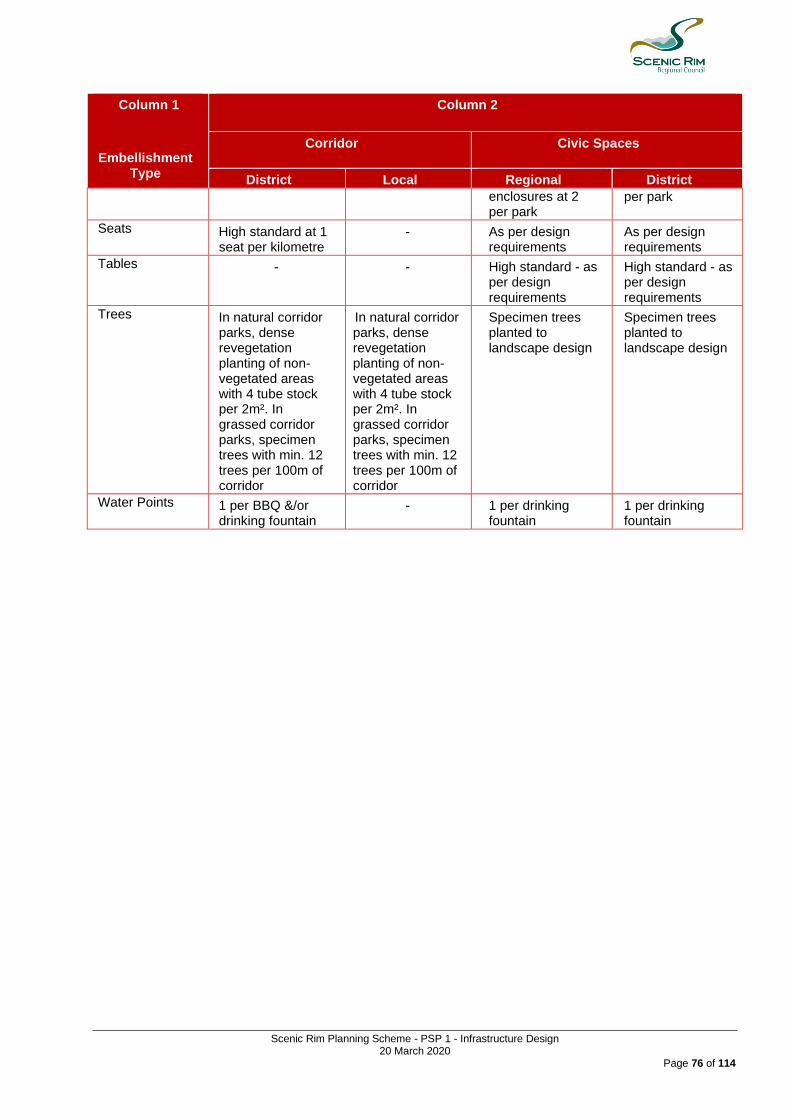
Scenic Rim Planning Scheme - PSP 1 - Infrastructure Design 20 March 2020
Page 76 of 114
Column 1
Embellishment Type
Column 2
Corridor Civic Spaces
District Local Regional District
enclosures at 2 per park
per park
Seats High standard at 1 seat per kilometre
- As per design requirements
As per design requirements
Tables - - High standard - as per design requirements
High standard - as per design requirements
Trees In natural corridor parks, dense revegetation planting of non-vegetated areas with 4 tube stock per 2m². In grassed corridor parks, specimen trees with min. 12 trees per 100m of corridor
In natural corridor parks, dense revegetation planting of non-vegetated areas with 4 tube stock per 2m². In grassed corridor parks, specimen trees with min. 12 trees per 100m of corridor
Specimen trees planted to landscape design
Specimen trees planted to landscape design
Water Points 1 per BBQ &/or drinking fountain
- 1 per drinking fountain
1 per drinking fountain
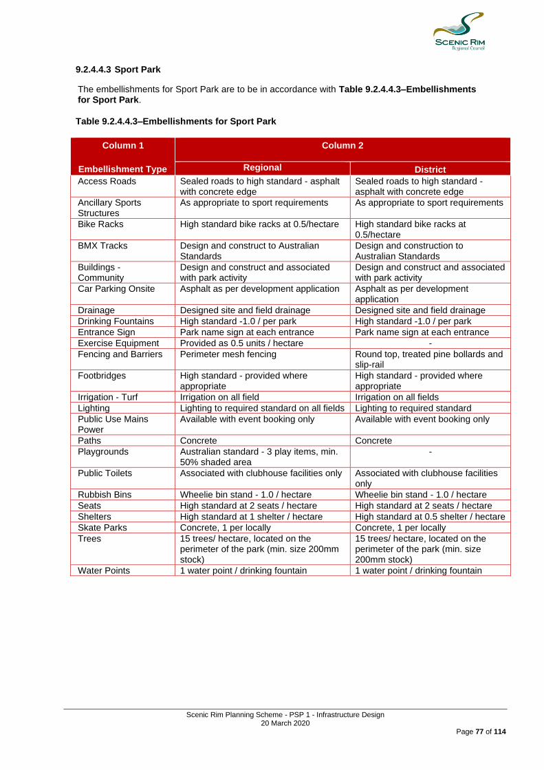
Scenic Rim Planning Scheme - PSP 1 - Infrastructure Design 20 March 2020
Page 77 of 114
9.2.4.4.3 Sport Park
The embellishments for Sport Park are to be in accordance with Table 9.2.4.4.3–Embellishments for Sport Park.
Table 9.2.4.4.3–Embellishments for Sport Park
Column 1
Embellishment Type
Column 2
Regional District
Access Roads Sealed roads to high standard - asphalt with concrete edge
Sealed roads to high standard - asphalt with concrete edge
Ancillary Sports Structures
As appropriate to sport requirements As appropriate to sport requirements
Bike Racks High standard bike racks at 0.5/hectare High standard bike racks at 0.5/hectare
BMX Tracks Design and construct to Australian Standards
Design and construction to Australian Standards
Buildings - Community
Design and construct and associated with park activity
Design and construct and associated with park activity
Car Parking Onsite Asphalt as per development application Asphalt as per development application
Drainage Designed site and field drainage Designed site and field drainage
Drinking Fountains High standard -1.0 / per park High standard -1.0 / per park
Entrance Sign Park name sign at each entrance Park name sign at each entrance
Exercise Equipment Provided as 0.5 units / hectare -
Fencing and Barriers Perimeter mesh fencing Round top, treated pine bollards and slip-rail
Footbridges High standard - provided where appropriate
High standard - provided where appropriate
Irrigation - Turf Irrigation on all field Irrigation on all fields
Lighting Lighting to required standard on all fields Lighting to required standard
Public Use Mains Power
Available with event booking only Available with event booking only
Paths Concrete Concrete
Playgrounds Australian standard - 3 play items, min. 50% shaded area
-
Public Toilets Associated with clubhouse facilities only Associated with clubhouse facilities only
Rubbish Bins Wheelie bin stand - 1.0 / hectare Wheelie bin stand - 1.0 / hectare
Seats High standard at 2 seats / hectare High standard at 2 seats / hectare
Shelters High standard at 1 shelter / hectare High standard at 0.5 shelter / hectare
Skate Parks Concrete, 1 per locally Concrete, 1 per locally
Trees 15 trees/ hectare, located on the perimeter of the park (min. size 200mm stock)
15 trees/ hectare, located on the perimeter of the park (min. size 200mm stock)
Water Points 1 water point / drinking fountain 1 water point / drinking fountain
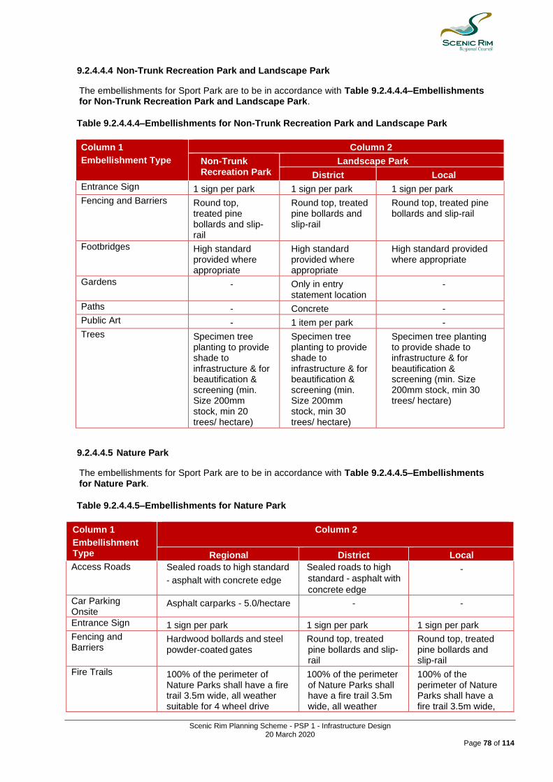
Scenic Rim Planning Scheme - PSP 1 - Infrastructure Design 20 March 2020
Page 78 of 114
9.2.4.4.4 Non-Trunk Recreation Park and Landscape Park
The embellishments for Sport Park are to be in accordance with Table 9.2.4.4.4–Embellishments for Non-Trunk Recreation Park and Landscape Park.
Table 9.2.4.4.4–Embellishments for Non-Trunk Recreation Park and Landscape Park
Column 1
Embellishment Type
Column 2
Non-Trunk Recreation Park
Landscape Park
District Local
Entrance Sign 1 sign per park 1 sign per park 1 sign per park
Fencing and Barriers Round top, treated pine bollards and slip-rail
Round top, treated pine bollards and slip-rail
Round top, treated pine bollards and slip-rail
Footbridges High standard provided where appropriate
High standard provided where appropriate
High standard provided where appropriate
Gardens - Only in entry statement location
-
Paths - Concrete -
Public Art - 1 item per park -
Trees Specimen tree planting to provide shade to infrastructure & for beautification & screening (min. Size 200mm stock, min 20 trees/ hectare)
Specimen tree planting to provide shade to infrastructure & for beautification & screening (min. Size 200mm stock, min 30 trees/ hectare)
Specimen tree planting to provide shade to infrastructure & for beautification & screening (min. Size 200mm stock, min 30 trees/ hectare)
9.2.4.4.5 Nature Park
The embellishments for Sport Park are to be in accordance with Table 9.2.4.4.5–Embellishments for Nature Park.
Table 9.2.4.4.5–Embellishments for Nature Park
Column 1
Embellishment Type
Column 2
Regional District Local
Access Roads Sealed roads to high standard
- asphalt with concrete edge
Sealed roads to high
standard - asphalt with
concrete edge
-
Car Parking Onsite
Asphalt carparks - 5.0/hectare - -
Entrance Sign 1 sign per park 1 sign per park 1 sign per park
Fencing and Barriers
Hardwood bollards and steel powder-coated gates
Round top, treated pine bollards and slip-rail
Round top, treated pine bollards and slip-rail
Fire Trails 100% of the perimeter of Nature Parks shall have a fire trail 3.5m wide, all weather suitable for 4 wheel drive
100% of the perimeter of Nature Parks shall have a fire trail 3.5m wide, all weather
100% of the perimeter of Nature Parks shall have a fire trail 3.5m wide,

Scenic Rim Planning Scheme - PSP 1 - Infrastructure Design 20 March 2020
Page 79 of 114
Column 1
Embellishment Type
Column 2
Regional District Local
access, with a passing bay every 200m.
suitable for 4 wheel drive access, with a passing bay every 200m.
all weather suitable for 4 wheel drive access, with a passing bay every 200m.
Footbridges High standard provided where appropriate
High standard provided where appropriate
Functional standard provided where appropriate
Interpretive Signs High standard - located where appropriate
High standard - located where appropriate
-
Paths Bitumen/stabilised gravel Bitumen/stabilised gravel
Bitumen/stabilised gravel
Public Toilets Yes - -
Seats High standard at 2 seats/ hectare
High standard at 1 seat/ hectare
-
Shelters High standard at 1 shelter/ hectare
- -
Trees Dense revegetation planting of non-vegetated areas with 4 tube-stock/2m². Specimen tree planting to maintained grassed areas (min. 60 trees/hectare) maintained as a revegetation site in the interim
Dense revegetation planting of non-vegetated areas with 4 tube-stock/2m². Specimen tree planting to maintained grassed areas (min. 60 trees/hectare) maintained as a revegetation site in the interim
Dense revegetation planting of non-vegetated areas with 4 tube-stock/2m². Maintained as a revegetation site in the interim
Viewing Platforms High standard - located where appropriate
- -
Water Body Natural occurring only Natural occurring only Natural occurring only
Water Points On new Nature Parks, a water point will be installed where there is a mains water connection available.
On new Nature Parks, a water point will be installed where there is a mains water connection available.
On new Nature Parks, a water point will be installed where there is a mains water connection available.
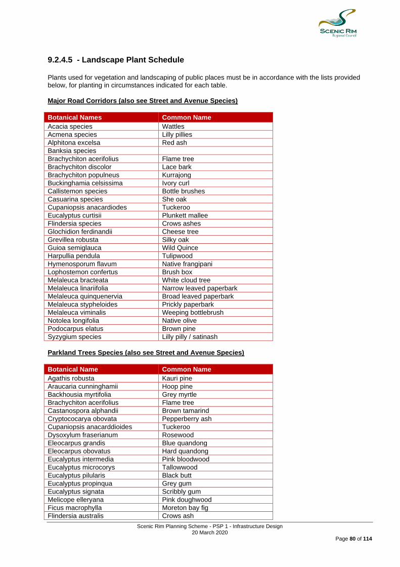
Scenic Rim Planning Scheme - PSP 1 - Infrastructure Design 20 March 2020
Page 80 of 114
9.2.4.5 - Landscape Plant Schedule Plants used for vegetation and landscaping of public places must be in accordance with the lists provided below, for planting in circumstances indicated for each table. Major Road Corridors (also see Street and Avenue Species)
Botanical Names Common Name
Acacia species Wattles
Acmena species Lilly pillies
Alphitona excelsa Red ash
Banksia species
Brachychiton acerifolius Flame tree
Brachychiton discolor Lace bark
Brachychiton populneus Kurrajong
Buckinghamia celsissima Ivory curl
Callistemon species Bottle brushes
Casuarina species She oak
Cupaniopsis anacardiodes Tuckeroo
Eucalyptus curtisii Plunkett mallee
Flindersia species Crows ashes
Glochidion ferdinandii Cheese tree
Grevillea robusta Silky oak
Guioa semiglauca Wild Quince
Harpullia pendula Tulipwood
Hymenosporum flavum Native frangipani
Lophostemon confertus Brush box
Melaleuca bracteata White cloud tree
Melaleuca linariifolia Narrow leaved paperbark
Melaleuca quinquenervia Broad leaved paperbark
Melaleuca stypheloides Prickly paperbark
Melaleuca viminalis Weeping bottlebrush
Notolea longifolia Native olive
Podocarpus elatus Brown pine
Syzygium species Lilly pilly / satinash
Parkland Trees Species (also see Street and Avenue Species)
Botanical Name Common Name
Agathis robusta Kauri pine
Araucaria cunninghamii Hoop pine
Backhousia myrtifolia Grey myrtle
Brachychiton acerifolius Flame tree
Castanospora alphandii Brown tamarind
Cryptococarya obovata Pepperberry ash
Cupaniopsis anacarddioides Tuckeroo
Dysoxylum fraserianum Rosewood
Eleocarpus grandis Blue quandong
Eleocarpus obovatus Hard quandong
Eucalyptus intermedia Pink bloodwood
Eucalyptus microcorys Tallowwood
Eucalyptus pilularis Black butt
Eucalyptus propinqua Grey gum
Eucalyptus signata Scribbly gum
Melicope elleryana Pink doughwood
Ficus macrophylla Moreton bay fig
Flindersia australis Crows ash
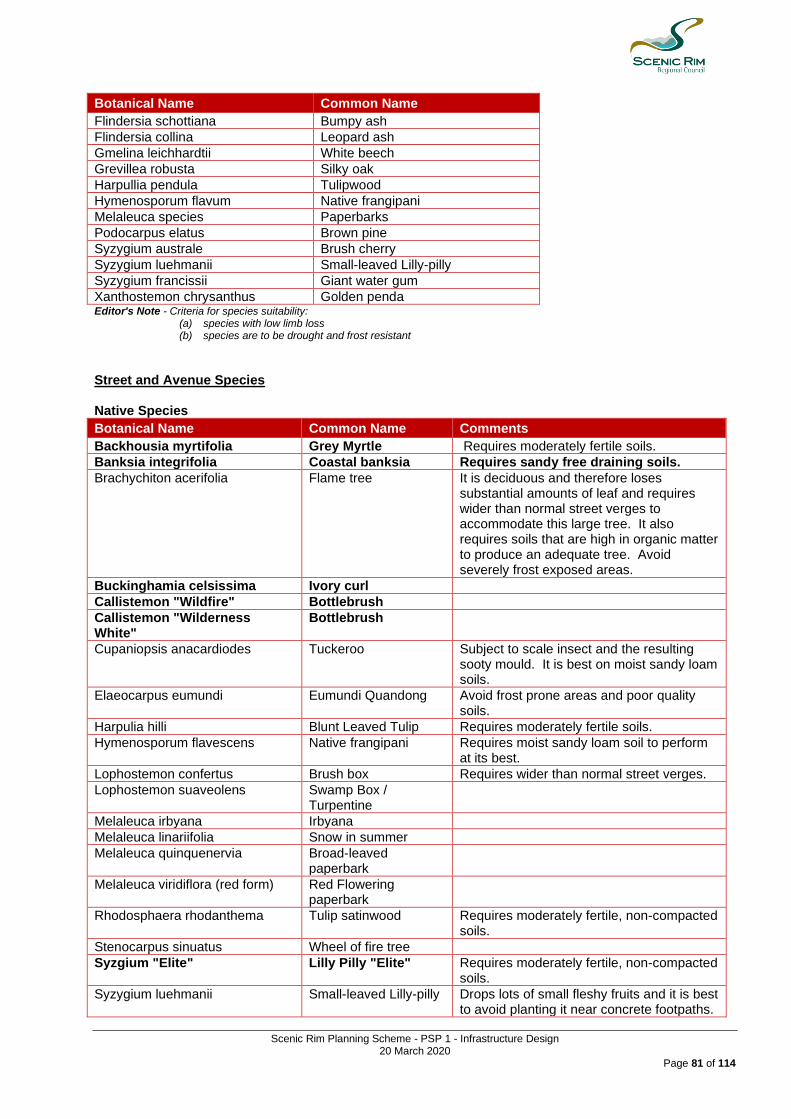
Scenic Rim Planning Scheme - PSP 1 - Infrastructure Design 20 March 2020
Page 81 of 114
Botanical Name Common Name
Flindersia schottiana Bumpy ash
Flindersia collina Leopard ash
Gmelina leichhardtii White beech
Grevillea robusta Silky oak
Harpullia pendula Tulipwood
Hymenosporum flavum Native frangipani
Melaleuca species Paperbarks
Podocarpus elatus Brown pine
Syzygium australe Brush cherry
Syzygium luehmanii Small-leaved Lilly-pilly
Syzygium francissii Giant water gum
Xanthostemon chrysanthus Golden penda Editor's Note - Criteria for species suitability:
(a) species with low limb loss (b) species are to be drought and frost resistant
Street and Avenue Species Native Species
Botanical Name Common Name Comments
Backhousia myrtifolia Grey Myrtle Requires moderately fertile soils.
Banksia integrifolia Coastal banksia Requires sandy free draining soils.
Brachychiton acerifolia Flame tree It is deciduous and therefore loses substantial amounts of leaf and requires wider than normal street verges to accommodate this large tree. It also requires soils that are high in organic matter to produce an adequate tree. Avoid severely frost exposed areas.
Buckinghamia celsissima Ivory curl
Callistemon "Wildfire" Bottlebrush
Callistemon "Wilderness White"
Bottlebrush
Cupaniopsis anacardiodes Tuckeroo Subject to scale insect and the resulting sooty mould. It is best on moist sandy loam soils.
Elaeocarpus eumundi Eumundi Quandong Avoid frost prone areas and poor quality soils.
Harpulia hilli Blunt Leaved Tulip Requires moderately fertile soils.
Hymenosporum flavescens Native frangipani Requires moist sandy loam soil to perform at its best.
Lophostemon confertus Brush box Requires wider than normal street verges.
Lophostemon suaveolens Swamp Box / Turpentine
Melaleuca irbyana Irbyana
Melaleuca linariifolia Snow in summer
Melaleuca quinquenervia
Broad-leaved paperbark
Melaleuca viridiflora (red form) Red Flowering paperbark
Rhodosphaera rhodanthema Tulip satinwood Requires moderately fertile, non-compacted soils.
Stenocarpus sinuatus Wheel of fire tree
Syzgium "Elite" Lilly Pilly "Elite" Requires moderately fertile, non-compacted soils.
Syzygium luehmanii Small-leaved Lilly-pilly Drops lots of small fleshy fruits and it is best to avoid planting it near concrete footpaths.
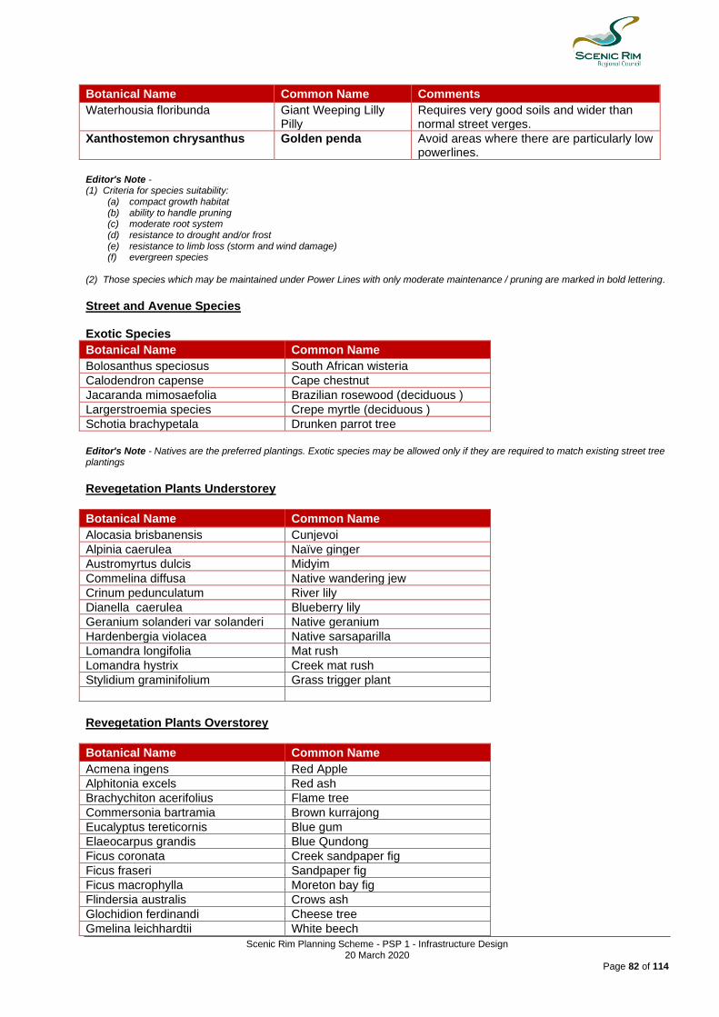
Scenic Rim Planning Scheme - PSP 1 - Infrastructure Design 20 March 2020
Page 82 of 114
Botanical Name Common Name Comments
Waterhousia floribunda Giant Weeping Lilly Pilly
Requires very good soils and wider than normal street verges.
Xanthostemon chrysanthus Golden penda Avoid areas where there are particularly low powerlines.
Editor's Note - (1) Criteria for species suitability:
(a) compact growth habitat (b) ability to handle pruning (c) moderate root system (d) resistance to drought and/or frost (e) resistance to limb loss (storm and wind damage) (f) evergreen species
(2) Those species which may be maintained under Power Lines with only moderate maintenance / pruning are marked in bold lettering.
Street and Avenue Species Exotic Species
Botanical Name Common Name
Bolosanthus speciosus South African wisteria
Calodendron capense Cape chestnut
Jacaranda mimosaefolia Brazilian rosewood (deciduous )
Largerstroemia species Crepe myrtle (deciduous )
Schotia brachypetala Drunken parrot tree
Editor's Note - Natives are the preferred plantings. Exotic species may be allowed only if they are required to match existing street tree plantings
Revegetation Plants Understorey
Botanical Name Common Name
Alocasia brisbanensis Cunjevoi
Alpinia caerulea Naïve ginger
Austromyrtus dulcis Midyim
Commelina diffusa Native wandering jew
Crinum pedunculatum River lily
Dianella caerulea Blueberry lily
Geranium solanderi var solanderi Native geranium
Hardenbergia violacea Native sarsaparilla
Lomandra longifolia Mat rush
Lomandra hystrix Creek mat rush
Stylidium graminifolium Grass trigger plant
Revegetation Plants Overstorey
Botanical Name Common Name
Acmena ingens Red Apple
Alphitonia excels Red ash
Brachychiton acerifolius Flame tree
Commersonia bartramia Brown kurrajong
Eucalyptus tereticornis Blue gum
Elaeocarpus grandis Blue Qundong
Ficus coronata Creek sandpaper fig
Ficus fraseri Sandpaper fig
Ficus macrophylla Moreton bay fig
Flindersia australis Crows ash
Glochidion ferdinandi Cheese tree
Gmelina leichhardtii White beech

Scenic Rim Planning Scheme - PSP 1 - Infrastructure Design 20 March 2020
Page 83 of 114
Botanical Name Common Name
Grevillea robusta Silky oak
Hibiscus heterophyllus Native rosella
Hymenosporum flavum Native frangipani
Lophostemon confertus Brushbox
Melaleuca viminalis Weeping bottlebrush
Myrsine variabilis Muttonwood
Syzygium francisii Giant water Gum
Syzygium oleosum Blue lillipilli
Toona ciliata Red cedar
Creek Corridors and Creek Crossings Tree Species
Botanical Name Common Name
Acacia species Wattles
Acmena smithii Lilly pilly
Alphitona excelsa Red ash
Angophora costata Smooth barked apple
Austromyrtus species Myrtles
Backhousia citriodora Lemon scented myrtle
Backhousia myrtifolia Grey myrtle
Brachychiton acerifolia Flame tree
Callistemon salignus White bottlebrush
Callistemon viminalis Weeping bottlebrush
Castanospermum australe Black bean
Casuarina cunninghamiana River oak
Casuarina glauca Swamp oak
Casuarina littoralis Forest she oak
Casuarina torulosa Forest oak
Commersonia bartramia Brown kurrajong
Cryptocarya glaucescens Brown beech
Cryptocarya microneura Murrogun
Cryptocarya triplivensis Brown laurel
Elaeocarpus grandis Blue quandong
Elaeocarpus obovatus Hard quandong
Elaeocarpus reticulatis Blueberry ash
Eucalyptus intermedia Pink bloodwood
Eucalyptus propinqua Grey gum
Eucalyptus ptychocarpa Swamp bloodwood
Eucalyptus robusta Swamp mahogony
Eucalyptus tereticornis Blue gum
Ficus coronata Sandpaper fig
Ficus obliqua Small leaved fig
Flindersia bennettiana Bennett’s ash
Glochidion ferdinadii Cheese tree
Gmelina leichhardtii White beech
Grevillea robusta Silky oak
Harpullia pendula Tulipwood
Homolanthus nutans Bleeding heart
Hymenosporum flavescens Native frangipani
Jagera pseudorhus Foambark tree
Lepiderema pulchella Fine leaved Tuckeroo
Leptospermum species Tea tree
Lophostemon confertus Brush box
Lophostemon suaveolens Swamp mahogany
Macaranga tanarius Macaranga
Mallotus phillipensis Red kamala
Melaleuca bracteata River tea tree

Scenic Rim Planning Scheme - PSP 1 - Infrastructure Design 20 March 2020
Page 84 of 114
Botanical Name Common Name
Melaleuca linariifolia Snow in summer
Melaleuca nodosa Prickly paperbark
Melaleuca quinquinervia Broad leaved paperbark
Melaleuca stypheloides Prickly paperbark
Notolea longifolia Native olive
Pittosporum revolutum Rough fruit pittosporum
Pittosporum venulosum Rusty pittosporum
Podocarpus elatus Brown pine
Euodia elleryana Pink evodia
Rhodomyrtus psidiodes Native guava
Sterculia quadrifida Peanut tree
Syzygium australe Brush cherry
Syzygium francisii Rose satinash
Syzygium leuhmanii Small leaved lilly pilly
Polyscias elegans Celerywood
Syzygium tierneyanum River cherry
Tristaniopsis laurina Water gum
Waterhousea floribunda Weeping lilly pilly
Xanthostemon crysanthus Golden penda
Medians, Roundabouts and Screening Species Trees
Botanical Name Common Name
Acacia species Wattles
Acmena smithii Lilly pilly
Allocasuarina littoralis Black she oak
Allocasuarina torulosa Forest oak
Alphitonia excelsa Red ash
Backhousia citriodora Lemon scented myrtle
Backhousia myrtifolia Grey myrtle
Banksia integrifolia Coastal banksia
Buckinghamia celcissima Ivory curl tree
Callicoma serratifolia White alder
Casuarina cunninghamiana River oak
Casuarina glauca Swamp oak
Commersonia bartramia Brown kurrajong
Eleocarpus reticulatis Blueberry ash
Eucalyptus curtisii Plunkett mallee
Euodia elleryana Butterfly tree
Grevillea bailyana White Oak
Grevillea banksia "Banks'grevillea"
Grevillea banksia Forest form
Grevillea hilliana White silky oak
Hakea salicifolia Willow leaved hakea
Hibiscus tiliaceus Cottonwood
Lepiderema pulchella Fine leaved Tuckeroo
Leptospermum polygalifolia Tantoon / Jellybush
Leptospermum petersonii Lemon scented tea tree
Melaleuca leucadendron Narrow leaved paperbark
Melaleuca linariifolia Snow in summer
Melaleuca quinquinervia Broad leaved paperbark
Melaleuca salignus White
Callistemon viminalis Weeping bottlebrush
Homolanthus populifolius Bleeding heart
Pittosporum rhombifolium White Holly / Hollywood
Pittosporum undulatum Sweet Pittosporum
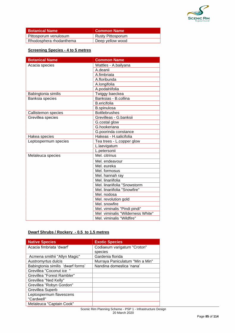
Scenic Rim Planning Scheme - PSP 1 - Infrastructure Design 20 March 2020
Page 85 of 114
Botanical Name Common Name
Pittosporum venulosum Rusty Pittosporum
Rhodosphera rhodanthema Deep yellow wood
Screening Species - 4 to 5 metres
Botanical Name Common Name
Acacia species Wattles - A.bailyana
A.deanii
A.fimbriata
A.floribunda
A.longifolia
A.podalriifolia
Babingtonia similis Twiggy baeckea
Banksia species Banksias - B.collina
B.ericifolia
B.spinulosa
Callistemon species Bottlebrushes
Grevillea species Grevilleas - G.banksii
G.costal glow
G.hookeriana
G.poorinda constance
Hakea species Hakeas - H.salicifolia
Leptospermum species Tea trees - L.copper glow
L.laevigatum
L.petersonii
Melaleuca species
Mel. citrinus
Mel. endeavour Mel. eureka Mel. formosus Mel. hannah ray Mel. linariifolia
Mel. linariifolia "Snowstorm
Mel. linariifolia "Snowfire" Mel. nodosa
Mel. revolution gold
Mel. snowfire
Mel. viminalis "Pindi pindi" Mel viminalis "Wilderness White"
Mel. viminalis "Wildfire" Dwarf Shrubs / Rockery - 0.5 to 1.5 metres
Native Species Exotic Species
Acacia fimbriata ‘dwarf’ Codiaeum varigatum "Croton" species
Acmena smithii "Allyn Magic" Gardenia florida
Austromyrtus dulcis Murraya Paniculatum "Min a Min"
Babingtonia similis ‘dwarf forms’ Nandina domestica ‘nana’
Grevillea "Coconut ice "
Grevillea "Forest Rambler"
Grevillea "Ned Kelly"
Grevillea "Robyn Gordon"
Grevillea Superb
Leptospermum flavescens "Cardwell"
Melaleuca "Captain Cook"
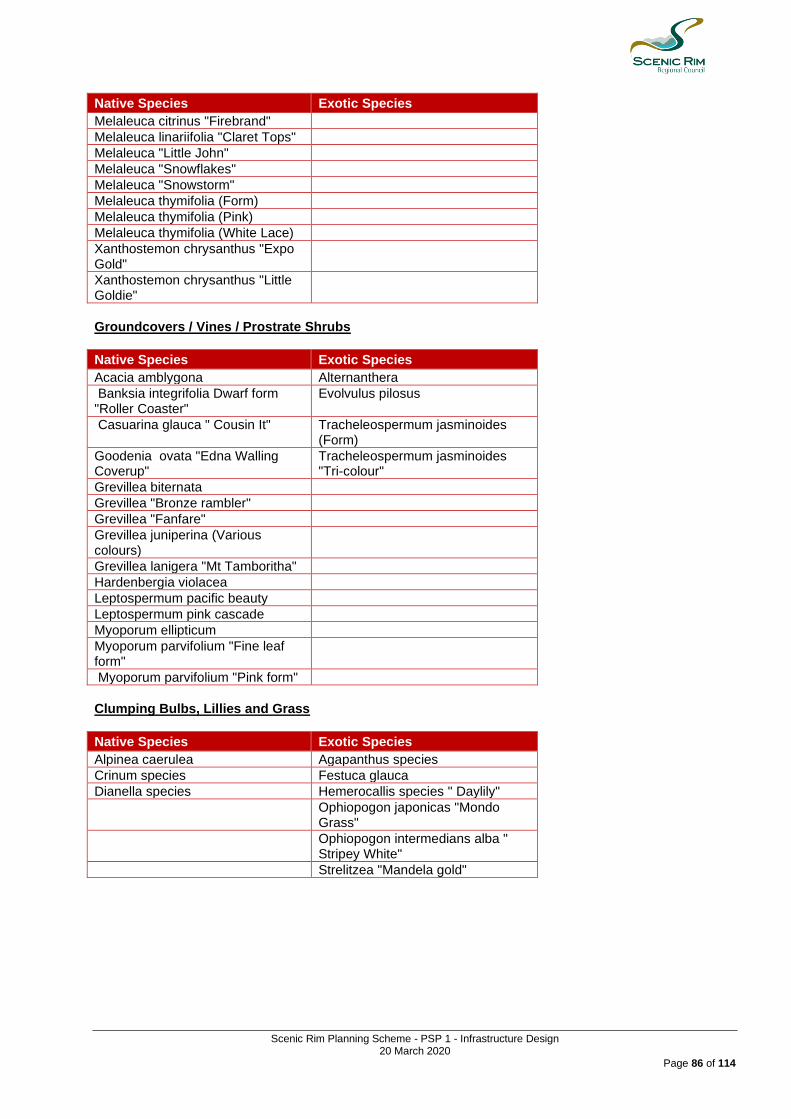
Scenic Rim Planning Scheme - PSP 1 - Infrastructure Design 20 March 2020
Page 86 of 114
Native Species Exotic Species
Melaleuca citrinus "Firebrand"
Melaleuca linariifolia "Claret Tops"
Melaleuca "Little John"
Melaleuca "Snowflakes"
Melaleuca "Snowstorm"
Melaleuca thymifolia (Form)
Melaleuca thymifolia (Pink)
Melaleuca thymifolia (White Lace)
Xanthostemon chrysanthus "Expo Gold"
Xanthostemon chrysanthus "Little Goldie"
Groundcovers / Vines / Prostrate Shrubs
Native Species Exotic Species
Acacia amblygona Alternanthera
Banksia integrifolia Dwarf form "Roller Coaster"
Evolvulus pilosus
Casuarina glauca " Cousin It" Tracheleospermum jasminoides (Form)
Goodenia ovata "Edna Walling Coverup"
Tracheleospermum jasminoides "Tri-colour"
Grevillea biternata
Grevillea "Bronze rambler"
Grevillea "Fanfare"
Grevillea juniperina (Various colours)
Grevillea lanigera "Mt Tamboritha"
Hardenbergia violacea
Leptospermum pacific beauty
Leptospermum pink cascade
Myoporum ellipticum
Myoporum parvifolium "Fine leaf form"
Myoporum parvifolium "Pink form"
Clumping Bulbs, Lillies and Grass
Native Species Exotic Species
Alpinea caerulea Agapanthus species
Crinum species Festuca glauca
Dianella species Hemerocallis species " Daylily"
Ophiopogon japonicas "Mondo Grass"
Ophiopogon intermedians alba " Stripey White"
Strelitzea "Mandela gold"
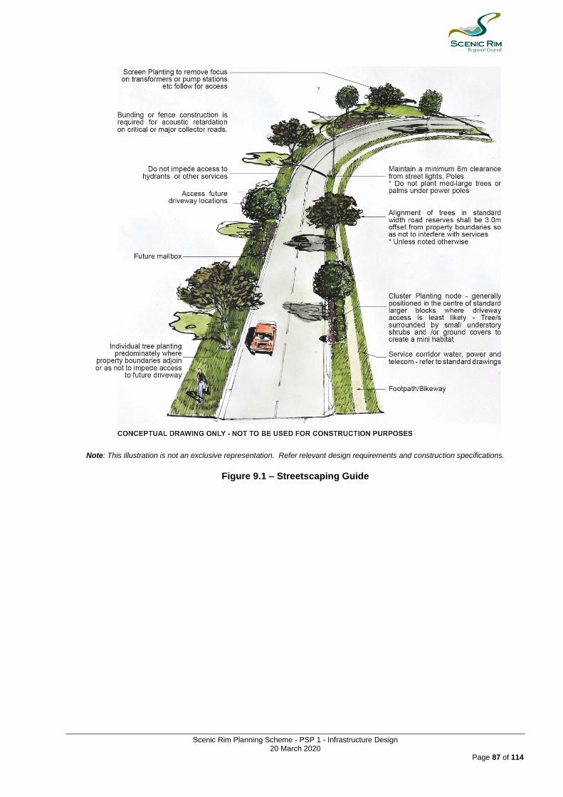
Scenic Rim Planning Scheme - PSP 1 - Infrastructure Design 20 March 2020
Page 87 of 114
Note: This illustration is not an exclusive representation. Refer relevant design requirements and construction specifications.
Figure 9.1 – Streetscaping Guide
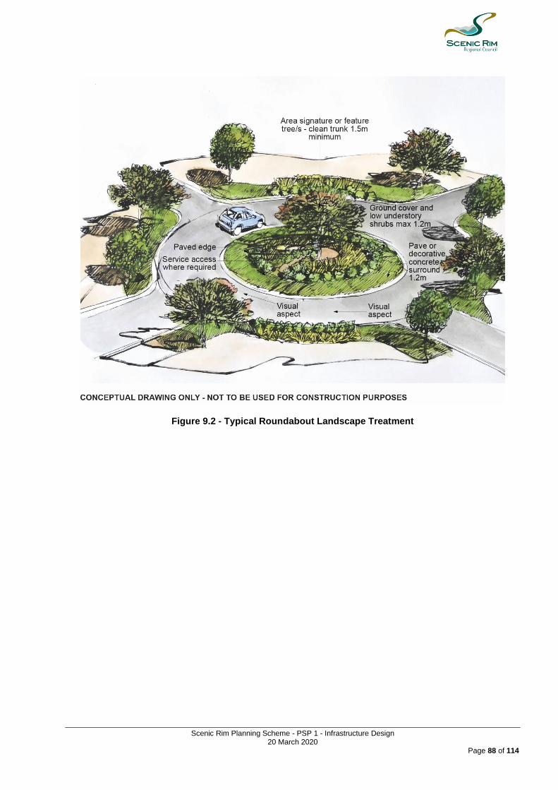
Scenic Rim Planning Scheme - PSP 1 - Infrastructure Design 20 March 2020
Page 88 of 114
Figure 9.2 - Typical Roundabout Landscape Treatment

Scenic Rim Planning Scheme - PSP 1 - Infrastructure Design 20 March 2020
Page 89 of 114
Note: Fence construction shown with capping, plinth and shiplap palings, to minimise air gaps. Where lay of land falls away from the road, acoustic fences required are generally lower in height than where land is higher than the road.
Figure 9.3 - Landscaping Solutions to Acoustic Structure along Arterial or Major Collector Roads
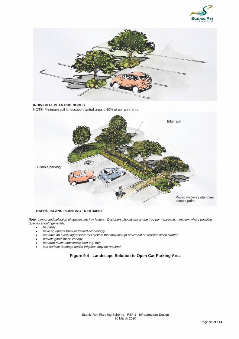
Scenic Rim Planning Scheme - PSP 1 - Infrastructure Design 20 March 2020
Page 90 of 114
Note: Layout and selection of species are key factors. Designers should aim at one tree per 4 carparks minimum where possible. Species should generally:
• be hardy
• have an upright trunk or trained accordingly
• not have an overly aggressive root system that may disrupt pavement or services when planted
• provide good shade canopy
• not drop much undesirable litter e.g. fruit
• sub-surface drainage and/or irrigation may be required
Figure 9.4 - Landscape Solution to Open Car Parking Area
Scenic Rim Planning Scheme - PSP 1 Infrastructure Design 20 March 2020
Page 91 of 114
9.2.4.6 Construction - Landscaping 9.2.4.6.1 General (1) All workmanship must be:
(a) of a workman like standard; (b) undertaken by suitably experienced contractors and staff; (c) by persons holding current licenses and insurances for the scope of works.
(2) All manufactured items must be used in accordance with the manufacturer's specification. (3) Upon request samples must be provided to Council prior to construction. (4) The relevant standards of Standards Australia must be complied with for garden soils, timber
preservation, paving, irrigation and plumbing works, chemical application and general landscape works. 9.2.4.6.2 Environmental Protection Measures Best Practice Erosion and Sediment Control, International Erosion Control Association, (IECA) Australasia Chapter, 2008, measures are to be adhered to for all situations relating to Environmental issues. Where existing vegetation is damaged or requires remedial action due to site works the plants or trees involved must be pruned or maintained by an experienced Arborist promptly to encourage regrowth and facilitate survival. 9.2.4.6.3 Landscaping, Parks and Environmentally Significant Areas Where land, is an existing or proposed bushland reserve, park or conservation park, the following standards apply: (1) Compliance with the approved parkland management plan;
(2) The area(s) must be clearly pegged, flagged or fenced, and inspected and approved by Council prior to any works commencing on the site;
(3) The approved design for tree clearing must have identified any unavoidable intrusion into areas and nominated work practises such as maximum widths of disturbance, nominated access routes, methods and timing of rehabilitation, must be complied with;
(4) Damaged or disturbance must be rehabilitated to pre-development standard; (5) Copies of the approved plans are to be kept on site at all times during construction. 9.2.4.6.4 Minor Landscaping Earthworks The following requirements are for minor earthworks including trench works. (1) Fill, other than topsoil and garden soils must be generally free of:
(a) excessive organic material (b) waste and toxic materials (c) site rubble and large rocks
(2) Site rubble and large rocks must be generally removed from site, however may be buried where:
(a) minimum 600mm cover provided (b) compacted to remove voids (c) no structures are to be built over burial sites
(3) All fill areas including trench works must be compacted so as not to create subsidence problems. (4) Final grades must be surveyed to ensure crossfall is achieved - see Table 9.2.4.6.4. Subsoil drains will
be required where surface drainage is impracticable or inadequate. Subsoil drainage must be in accordance with SRRC Standard Drawings R-18,R-19 & R-20.

Scenic Rim Planning Scheme - PSP 1 Infrastructure Design 20 March 2020
Page 92 of 114
Table 9.2.4.6.4 Minimum Required Crossfalls
Landscape Item Min Required Crossfall
Stone mulched area 1:100
Grassed areas 1:50
Garden areas 1:25
Paved areas 1:100
Drainage pipe/trench base 1:100
(5) All excavated or filled areas must be trimmed with minimum topsoil or garden soil as required. Trimming
must be: (a) free of clods and rocks > 25mm and comply with soil specifications (b) even grades free of low points (c) feather edges to adjoining grades
(6) Cultivation will be required to break up any hard pans and prepare ground suitable to promote a growing
environment. 9.2.4.6.5 Topsoil and Garden Soil (1) It is a preferred outcome that on site topsoil be used. Such topsoil requires blending or conditioning to
attain required specifications. (2) Soil stockpiles must be maintained to control weeds routinely and guard against dispersion by wind or
water. Stockpiles must be limited to a height of two (2) metres and require covering or retaining. Stockpiles are not permitted in close proximity to residential properties.
(3) Soil to be used must comply with the following specification:
(a) friable and free draining (b) good texture and structure for selected use (c) acceptable conductivity and pH levels intended plant species groups to be planted (d) minimum depths
(i) topsoil (turf and grass areas) 100mm (ii) garden soils (all other planted areas) 200mm
(e) Composition to AS 4419-2003 Soils for landscaping and garden use: (i) sand 25-85% (ii) silt 0-50% (iii) clay 5-25% (iv) organic matter >2% (v) salinity (EC) <500 microsiemens / cm (vi) pH 5.5 to 7.0
(4) Topsoil must be tested by an agronomist or laboratory to recommend fertiliser, treatment or cultural
requirements for selected land use. (5) Heavier soils require application of gypsum, typically at a rate of between 2,000 and 2500 kg per hectare. (6) Topdressing where required must be predominantly a graded sandy loam, screeded over turf areas. 9.2.4.6.6 Fertilisers (1) An established and routine fertiliser regime must form an integrated component of the;
• construction programme

Scenic Rim Planning Scheme - PSP 1 Infrastructure Design 20 March 2020
Page 93 of 114
• maintenance programme (2) A fertiliser programme for all planted areas must be provided, based on agronomic and vegetative
analysis which; (a) promotes vigorous growth throughout establishment (b) is applied and repeated at intervals based on fertiliser longevity and plant requirements, in
accordance with agronomists or manufacturers recommendations. 9.2.4.6.7 Mulches (1) It is desirable that mulches be made and stored on site where suitable material is available. (2) Generally loose particle mulches must comply with the following requirements:
(a) particle size range 5mm to 50mm (b) minimum depth:
(i) garden beds, 75mm (ii) revegetation areas, 50mm
(c) final mulch grade 25mm below edge treatments (d) free of weeds, soil, sticks and rocks (e) binding qualities to minimise dispersion by the elements or slope (f) durable - minimum 12 months effective longevity (g) remains pervious
(3) The following mulch composition or origins are not acceptable;
(a) sawdust (b) non-organic material (c) treated or painted timbers (d) noxious or undesirable weeds (e) not composted or stored sufficiently (f) not bind excessively so as to shed water
(4) All garden beds and revegetation are required to be mulched. (5) Organic mulch matting is required for loose particle mulches on steep or unstable slopes.
(6) Organic mulch matting must comply with the following requirements: (a) Natramat TM, 3mm coir fibre mat with latex bonding, or approved equivalent. (b) biodegradable (c) durable - effective longevity minimum requirement, 12 months (Maintenance period). (d) stake to secure effectively (e) overlap edges, layer with the direction of flow to prevent lifting (f) cut holes to locate containerised plant stock (g) repair accidental cuts by staked patches
(7) The following mulch matting products are not acceptable:
(a) non-organic material (b) nylon meshes or wire net binding
Editor's Note - Refer LCD-3 for typical revegetation mulches, LCD-4 for typical garden bed mulches.
9.2.4.6.8 Seeding Seeding must be carried out by:
• reliable broadcast method
• scarifier or direct drill
• purpose built hydroseed/mulch mixer & pump All seeding methods must ensure that the following requirements are met:
• selected seed is viable and not environmentally harmful
• application rates are adequate to provide full cover.

Scenic Rim Planning Scheme - PSP 1 Infrastructure Design 20 March 2020
Page 94 of 114
Minimum germination and cover requirements are:
• 75% germination after 2 months.
• 80% aerial coverage is to be achieved and maintained for a minimum period of 6 months before acceptance Off Maintenance.
• method of coverage is even and reliable.
• ground preparation is consistent with seeding method.
• soil moisture levels are maintained prior and after seeding to promote strong germination and establishment.
• weed competition is eliminated or sufficiently maintained. All traffic to be kept off seeded areas during establishment. Failed seeded areas must be re-sowed promptly to ensure that adequate germination levels are likely to be attained. 9.2.4.6.9 Turfing Turfed areas must be specifically required:
• in high traffic areas.
• on slopes or overland flows (to high water levels).
• in cleared areas prone to erosion and siltation problems.
• to frame or border the edge of treatments. Turf must be supplied and installed in compliance with the following requirements:
• minimum quality ‘B’ grade, 85% dominance of specified grass.
• minimum 25mm turf sod, delivered moist and laid within 24 hours of cutting on farm.
• ensure appropriate ground preparation is carried out.
• final turf grade 25mm below top-grade edge treatment.
• free of undesirable or noxious weeds.
• irrigated and rolled promptly after laying.
• top dress and screed where required to level and fill gaps after first mow.
• maintained to avoid setback. 9.2.4.6.10 Planting Containerised plant stock must be installed in compliance with the following requirements:
• minor root or canopy prune where required.
• excavate sufficient size planting holes, and backfill with suitable soil, whilst allowing for normal long term root development.
• position plant to ensure upon settlement top of root ball is level with final grade.
• stake plants as specified or where required - allow for removal prior to completion of maintenance period.
• fertilise and maintain so as to promote vigorous growth. Street trees must conform to the following specifications:
• minimum container size - 200mm pot
• minimum single trunk clearance - 1m (streets), 1.7m (roundabouts)
• minimum trunk calliper - 20mm
• minimum overall height - 1.2m
• minimum canopy - 0.6m (balance and well formed) Transplanting ex-ground stock must be carried out in accordance with the following provisions:
• plant material is authorised for removal under statutory requirements
• staged root and canopy pruning is carried out to minimise setback
• specimen may require repeat treatments of rooting hormones and/or anti-evapotranspirant to stabilise plant and stimulate regrowth
• root ball is wrapped and adequately protected to prevent disturbance throughout procedure
• standard maintenance program is upgraded to accommodate for careful monitoring throughout establishment.
Scenic Rim Planning Scheme - PSP 1 Infrastructure Design 20 March 2020
Page 95 of 114
9.2.4.6.10 Landscaping Structures 9.2.4.6.10.1 Edge Treatments Edge treatments must comply with the following requirements:
• edge treatments are wide and mountable for ease of mowing and maintenance.
• turf or mulch should be 25mm below top grade of adjoining edge.
• minimum curvature radius at 3m.
• minimum access between edges and other treatments must be 3m.
• avoid restricting access into narrow corners. Materials acceptable to Council for edge treatments are:
• pavers (clay/concrete) o minimum 60mm depth o minimum 110mm width (230 preferred) o mortar base and exposed edges 20mPa o ensure no cracking
• timber o minimum 150mm radius log (winged) or 200mm x 80mm sleeper. o suitably treated for direct burial. o finish ends and joints neatly. o securely pin and fix.
• continuous concrete o minimum width 150mm. o minimum depth 100mm. o minimum 20mPa concrete. o coloured or patterned. o finish end neatly and flush. o bolster cut control joints where required. o R12 re-bar centrally located o ensure no cracking.
9.2.4.6.10.2 Paving and Concrete Construction details must clearly specify, and reference, particulars of paving and concrete works. Notations must indicate:
• colours.
• patterns.
• paver material, where applicable.
• exposed aggregate (size, colour, and surface texture).
• widths, thickness, strength, and reinforcement.
• base preparation.
9.2.4.6.10.3 Retaining Walls Retaining walls included in landscape works less than 1.0m must be constructed of:
• Split face blocks
• Rendered concrete blocks
• Concrete sleepers (Plain or Timber look and colour) Retaining structures exceeding this height require Engineering design and certification. 9.2.4.6.10.4 Fences and Barriers Acoustic fences are required by Council along frontages to major roads. Such fences shall be constructed in accordance with an acoustic engineer’s specification.

Scenic Rim Planning Scheme - PSP 1 Infrastructure Design 20 March 2020
Page 96 of 114
Acoustic fences shall require testing and certification at practical completion before being accepted On Maintenance. Barrier fences shall be required to prevent vehicular trespass into parklands and other public open spaces. 9.2.4.6.10.5 Playground Equipment The playgrounds are to comply with the requirements defined below and AS4685 - 2014 - Playground Equipment and Surfacing set and AS4685 -2017 - Playground Equipment and Surfacing - development , installation inspection, maintenance and operation. Playground equipment for public areas must:
• have Standards Association of Australia certification.
• be constructed of powder coated steel/ aluminium and Engineering grade UV resistant plastic.
• be set out on an approved softfall pad.
• be durable, weather and vandal resistant.
• give due consideration to public health and safety.
9.2.4.6.10.6 Landscape Furniture and Structures Landscape furniture and structures must:
• comply with relevant SAA requirement.
• be durable, vandal resistant and low maintenance.
• have coatings and surfaces that are weather and graffiti resistant.
• comply with statutory building and services requirements.
• be located to maximise public benefit without vehicular or pedestrian traffic problems.
• give due consideration to public health and safety. 9.2.4.6.11 Irrigation 9.2.4.6.11.1 General Where there is reticulated water supply, automatic irrigation systems are to be provided to all garden beds constructed within road reserves, parks and open space as part of the development works. Where specifically required within the development conditions issued by Council, irrigation systems will also be required to be provided to grassed areas within parks and sporting fields. The irrigation systems are to comply with the requirements defined below and AS 3500. Drainage for gardens contained within the road pavement is to link to the established drainage systems and be of sufficient design to cater to the leached water. An impermeable membrane to 900mm depth is to surround the perimeter of gardens to prevent leaching of water into the road subgrade. Note - Reticulated water is to be provided to irrigation systems via a water meter and backflow device - See Queensland Urban Utilities for further information. Payment of costs associated with irrigation water used to establish plants and to maintain the planting during the maintenance period is required to be made before Council will accept the development Off Maintenance.
9.2.4.6.11.2 Layout All irrigation systems are to be fully automatic pop-up spray, drip emitter or subsurface micro-porous flexible pipe. Spray sprinklers are to be located for head to head coverage and minimal over spray onto abutting hard finished surfaces. Main piping lines are to be specified as domestic grade piping. All trenches containing piping are to be sand backfilled. Irrigation layout of parkland grassed areas is to include road verges along the parkland frontage with spray emitters located at the back of kerb. Appropriate filter screens are to be placed within the system adjacent to the connection to the water main. All irrigation emitters are to deliver sufficient precipitation for maximum soil absorption and water uptake by plants with minimum runoff. The design must prioritise deep, less frequent watering. 9.2.4.6.11.3 Water Meters

Scenic Rim Planning Scheme - PSP 1 Infrastructure Design 20 March 2020
Page 97 of 114
Water meters are to be installed at all connections to the watermains. Water meters are to be located as near as practical to the irrigation system being served. Where multiple irrigation systems are to be served, distribution manifolds are to be provided to limit the minimum water meter spacings to 100m. Note - See Queensland Urban Utilities for further information.

Scenic Rim Planning Scheme - PSP 1 Infrastructure Design 20 March 2020
Page 98 of 114
9.2.4.6.11.4 Controllers The controller must be installed in a metal cabinet that is lockable, dust proof and rust proof. It must be constructed so as to minimise the effects of vandalism. It must be easily accessible for maintenance and inspection. The controller must be connected to a 240V power supply. All necessary approvals from, and all fees to, Energex associated with the electrical connection are to be paid before Council will accept the development Off Maintenance. The electrical system must be installed in accordance with the requirements of the relevant Australian Standard. As a minimum specification controllers are to provide the following features:
• an operating voltage of either 12 or 24 volts.
• to be capable of full automatic unattended operation.
• dual programming with multiply start times per day and a 7 day programming ability.
• allow at least 1 free station per system to allow for future system adjustments.
• provide a pump/master valve circuit.
• manual and semi-manual override provision.
• capable of operating any combination of valves.
• all manuals and documentations associated with the above. 9.2.4.6.11.5 Wiring All control wiring must not be less than 1.5 square millimetres and must be contained in continuous light grey, solvent welded PVC conduits. Underground wiring is to have a minimum cover of 350mm. Wiring joints are to be Spears DS-400 prefilled dri-spliced connections or similar. 500mm of excess length of wire is to be provided looped in all valve boxes. 9.2.4.6.11.6 Documentation The following irrigation specific documentation is to be provided to Council before the development will be accepted on maintenance.
• dedicated irrigation ‘As Constructed’ drawings showing the location of all irrigation components and the sizes of connecting pipework.
• a schedule of all equipment installed including brand names and model numbers.
• operation manuals for system controllers.
• warranty documentation applicable to the system component.
• proposed watering program for the irrigation system.

Scenic Rim Planning Scheme - PSP 1 Infrastructure Design 20 March 2020
Page 99 of 114
9.2.5 Standard Drawings Design and construction of infrastructure must comply with the Standard Drawings identified in Table 9.2.5 Standard Drawings. Table 9.2.5 Standard Drawings
SRRC No. Drawing Title Version Date
P-02 Park Name Sign A 06/10
P-03 Garden Bed Edges B 03/13
P-04 Lock Rail with Steel Post A 06/10
P-05 Round Top and Angle Top Bollard A 06/10
P-06 Log Barrier Fence A 06/10
P-07 Timber and Mesh Fence A 06/10
P-08 Timber One Rail and Two Rail Fence A 06/10
P-09 Steel Gate A 06/10
P-10 Horse Step Over A 06/10
P-11 Personnel Gate A 06/10
P-12 Turn style A 06/10
P-13 Removable Bollard A 06/10
P-14 Wheelie Bin Stand A 06/10
P-15 Wheelie Bin Enclosure A 06/10
P-16 General Tap and Maintenance Tap A 06/10
P-17 Water Tap and Bubbler with Dog Bowl A 06/10
P-18 Electric Barbecue Shelter B 03/13
P-20 Toilet Block Siting A 06/10
P-21 Picnic Node A 06/10
P-22 Park Bench – Bolt Down A 06/10
P-23 Park Bench – Embedded A 06/10
P-24 Picnic Table/Double Pedestal – Bolt Down A 06/10
P-25 Picnic Table/Double Pedestal – Embedded A 06/10
P-26 Picnic Table/Single Pedestal – Embedded A 06/10
P-27 Shelter Shed – Small B 03/13
P-28 Shelter Shed – Medium A 06/10
P-29 Shelter Shed – Large A 06/10
P-30 Specimen Park/Street Tree Planting A 06/10
P-31 Landscape Shrub/Ground Cover Planting A 06/10
P-32 Playground Siting Plant B 11/18
P-33 Playground Soft Fall Installation & Playground Shade Notes B 11/18
P-34 Park Footpath Design A 06/10
P-35 Landscape Details (playground) A 11/18
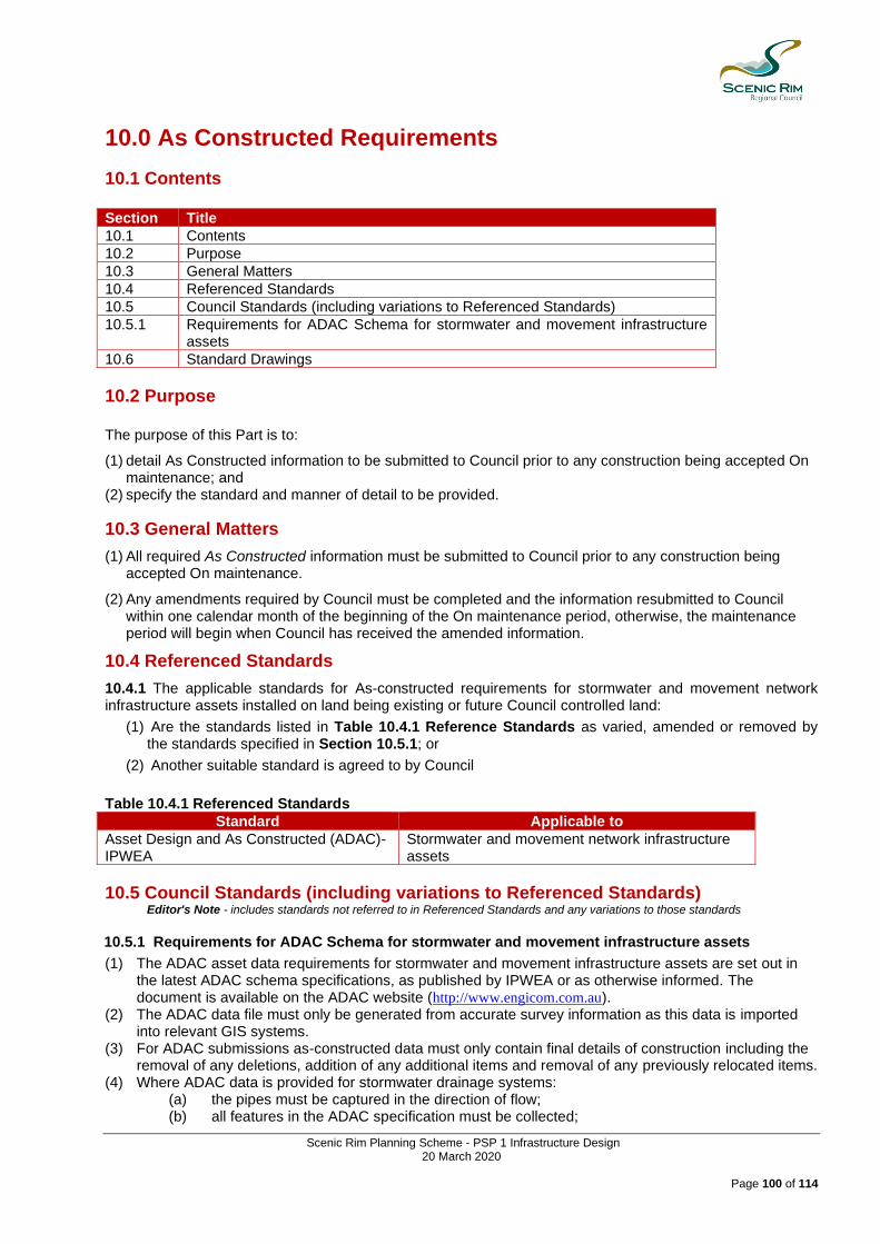
Scenic Rim Planning Scheme - PSP 1 Infrastructure Design 20 March 2020
Page 100 of 114
10.0 As Constructed Requirements
10.1 Contents Section Title
10.1 Contents
10.2 Purpose
10.3 General Matters
10.4 Referenced Standards
10.5 Council Standards (including variations to Referenced Standards)
10.5.1 Requirements for ADAC Schema for stormwater and movement infrastructure assets
10.6 Standard Drawings
10.2 Purpose The purpose of this Part is to:
(1) detail As Constructed information to be submitted to Council prior to any construction being accepted On maintenance; and
(2) specify the standard and manner of detail to be provided.
10.3 General Matters
(1) All required As Constructed information must be submitted to Council prior to any construction being accepted On maintenance.
(2) Any amendments required by Council must be completed and the information resubmitted to Council within one calendar month of the beginning of the On maintenance period, otherwise, the maintenance period will begin when Council has received the amended information.
10.4 Referenced Standards
10.4.1 The applicable standards for As-constructed requirements for stormwater and movement network infrastructure assets installed on land being existing or future Council controlled land:
(1) Are the standards listed in Table 10.4.1 Reference Standards as varied, amended or removed by the standards specified in Section 10.5.1; or
(2) Another suitable standard is agreed to by Council
Table 10.4.1 Referenced Standards
Standard Applicable to
Asset Design and As Constructed (ADAC)- IPWEA
Stormwater and movement network infrastructure assets
10.5 Council Standards (including variations to Referenced Standards) Editor's Note - includes standards not referred to in Referenced Standards and any variations to those standards
10.5.1 Requirements for ADAC Schema for stormwater and movement infrastructure assets
(1) The ADAC asset data requirements for stormwater and movement infrastructure assets are set out in the latest ADAC schema specifications, as published by IPWEA or as otherwise informed. The document is available on the ADAC website (http://www.engicom.com.au).
(2) The ADAC data file must only be generated from accurate survey information as this data is imported into relevant GIS systems.
(3) For ADAC submissions as-constructed data must only contain final details of construction including the removal of any deletions, addition of any additional items and removal of any previously relocated items.
(4) Where ADAC data is provided for stormwater drainage systems: (a) the pipes must be captured in the direction of flow; (b) all features in the ADAC specification must be collected;

Scenic Rim Planning Scheme - PSP 1 Infrastructure Design 20 March 2020
Page 101 of 114
(c) the ends of line features must be snapped to point features; (d) the stormwater pipe elements must be broken at fittings and changes in pipe attributes; (e) the stormwater pipe elements must be broken by access pits or maintenance shaft points or
by changes in pipe attributes. (5) ADAC files:
(a) must be provided electronically in .dwg and .xml formats according to the latest version of the ADAC schema;
(b) must conform to the ADAC .xml data specification as published by the Institute of Public Works Engineering Australia;
(c) must include project cross reference metadata for ADAC xml fillies; (d) have mandatory fields and must be filled in with correct information and never left blank.
10.6 Standard Drawings 10.6.1 The Standard Drawings listed in Table 10.6 Standard Drawings are the minimum standard of design and construction for this Part. Table 10.6 Standard Drawings
Standard Drawing Number Name
None applicable

Scenic Rim Planning Scheme - PSP 1 Infrastructure Design 20 March 2020
Page 102 of 114
11.0 Manuals for Mechanical and Electrical Equipment
11.1 Contents Section Title
11.1 Contents
11.2 Purpose
11.3 General Matters
11.4 Referenced Standards
11.5 Council Standards (including variations to Referenced Standards)
11.5.1 Manual Construction
11.5.2 Documentation
11.6 Standard Drawings
11.2 Purpose The purpose of this Part is to:
(1) Ensure appropriate Operation and maintenance manuals must be provided covering the installation, commissioning, operation and maintenance of any mechanical or electrical equipment supplied.
11.3 General Matters Manual Detail Manuals must: (1) be sufficiently comprehensive to enable Council's staff to operate and maintain the equipment in an
efficient and workmanlike manner; (2) include descriptive information relating to individual items of equipment to assist personnel in becoming
familiar with the equipment and its operation; (3) include clear and concise instructions so as to allow proper and safe installation, commissioning,
operation, correct maintenance, and compliance with the Manufacturer’s Warranty. Such information must relate specifically to the equipment as supplied. Any information which does not pertain to the equipment supplied must be removed or deleted. Maintenance instructions must be in sufficient detail to enable overhaul and replacement of all parts. Submission One (1) draft copy of the Manual to Council must be submitted to Council for review and approval. Council will return a copy of this draft with appropriate comments. Three (3) copies of the final Manual, including amendments based on Councils review, must be provided to Council before the works will be accepted On maintenance. Addenda Should it become necessary to modify, or add to, the final Manual at some later stage, e.g. to include As Constructed information, copies of the addenda must be provided to Council for inclusion within the existing Manuals. Should the addenda modify the existing Manuals extensively, the Manuals must be renewed completely.
11.4 Referenced Standards 11.4.1 The Standards listed in Table 11.4.1 Reference Standards are the applicable standards for mechanical and electrical equipment installed on land being existing or future Council land except where:
(1) The standard is in conflict with a standards specified in Section 11.5; or
(2) The standard is varied, amended or removed by the standards specified in Section 11.5.

Scenic Rim Planning Scheme - PSP 1 Infrastructure Design 20 March 2020
Page 103 of 114

Scenic Rim Planning Scheme - PSP 1 Infrastructure Design 20 March 2020
Page 104 of 114
Table 11.4.1 Referenced Standards
Standard Applicable to
AS1000 The International System of Units (SI) and its Application.
AS1100 Drawing Practice
AS1101 Graphical Symbols for General Engineering
AS1102 Graphical Symbols for Electrotechnical Documentation
11.5 Council Standards (including variations to Referenced Standards) Editor's Note - includes standards not referred to in Referenced Standards and any variations to those standards
11.5.1 Manual Construction
(a) The document(s) must be A4 size, bound in hard cover binders. (b) An electronic copy must be provided in .pdf format. (c) Plans must be in .dwg format. (d) All units must be SI units. (e) All information must be in English. (f) All data sheets for proprietary equipment plant must be clearly reproduced and must indicate the
appropriate information pertinent to the installation. (g) The title and drawing number (issued by Council) must be displayed on the front cover and spine of
the document to enable the Manual to be included in the Drawing Register. 11.5.2 Documentation The document(s) must contain the following - as a minimum:
(a) Equipment specification including a complete system description, and a full specification for each individual item of equipment.
(b) A complete listing of the plant, equipment, valves, pipes, etc., supplied and installed including model and serial numbers.
(c) Functional description of its operation. (d) Erection, assembly, installation, pre-commissioning and commissioning instructions and diagrams. (e) Detailed operating instructions. (f) Service and maintenance schedule and instructions including dismantling/assembly procedures, and
a table of maintenance tasks showing recommended time intervals between carrying out these tasks.
(g) Lubrication schedule, including details of lubricant types, grades and trade names, initial fill quantities, and relubrication quantities and intervals.
(h) Tabulation of all consumables excluding lubricants (e.g. fuel type and quantity, electrical components, chemicals, etc.)
(i) Performance specification (including commissioning data). (j) Certified test sheets for all tests required by Council (k) Drawings (reduced to A3 or A4 size):
• General arrangements
• Component parts/detailed dimensioned drawings including exploded view and/or sectional drawings.
• Flow diagrams
• P and ID's
• Electrical schematics with line diagrams
• Circuit diagrams
• Cabling, wiring and termination diagrams
• All components capable of being dismantled must be shown and identified in the drawings. (l) Addresses, telephone and facsimile numbers of suppliers and local agents for all items of
equipment. (m) List of all parts, with every component cross-referenced to drawings, together with the necessary
details for ordering these, including proprietary catalogue numbers and names.

Scenic Rim Planning Scheme - PSP 1 Infrastructure Design 20 March 2020
Page 105 of 114
(n) Software listing, if appropriate, and details of all software. (o) Programming guide, if appropriate. (p) Assembly and installation instructions. (q) Trouble shooting guide. (r) Recommended settings and calibration details of any protection or control device. (s) A comprehensive index for each set of the specified Manuals.
11.6 Standard Drawings 11.6.1 The Standard Drawings listed in Table 11.6 Standard Drawings are the minimum standard of design and construction for this Part. Table 11.6 Standard Drawings
Standard Drawing Number Name
None applicable

Scenic Rim Planning Scheme - PSP 1 Infrastructure Design 20 March 2020
Page 106 of 114
12.0 Bonding and Insurance
12.1 Contents Section Title
12.1 Contents
12.2 Purpose
12.3 General Matters
12.4 Referenced Standards
12.5 Council Standards (including variations to Referenced Standards)
12.5.1 Indemnity
12.5.2 Insurances
12.5.3 Bonding
12.6 Standard Drawings
12.2 Purpose The purpose of this Part is to:
(1) ensure the timely and proper performance of the works; and
(2) ensure public liability is adequately insured against and Council is indemnified.
12.3 General Matters An estimate of the cost of works (in the form of a schedule of rates) is required to enable the determination of a security value.
12.4 Referenced Standards 12.4.1 The Standards listed in Table 12.4.1 Reference Standards are the applicable standards for existing or future Council land except where:
(1) The standard is in conflict with a standards specified in Section 12.5; or
(2) The standard is varied, amended or removed by the standards specified in Section 12.5. Table 12.4.1 Referenced Standards
Standard Applicable Sections Applicable to
None applicable
12.5 Council Standards (including variations to Referenced Standards) Editor's Note - includes standards not referred to in Referenced Standards and any variations to those standards
12.5.1 Indemnity
An Indemnity, where required, must indemnify and keep indemnified, the Scenic Rim Regional Council and its Councillors, employees and agents against;
(a) all loss of or damage to the property of Council (including The Council-controlled road) and from and against any claim, demand, action, suit or proceeding that may be made or brought by any person against The Council.
(b) personal injury to or the death of any person whomsoever or loss of or damage to any property whatsoever arising out of or as a consequence of the construction or maintenance of the works including associated employees, agents or sub-Contractors and also from any costs and expense that may be incurred in connection with any such claim, demand, action, suit or proceeding.

Scenic Rim Planning Scheme - PSP 1 Infrastructure Design 20 March 2020
Page 107 of 114
12.5.2 Insurances (1) Public Liability Insurance must:
(a) include the Scenic Rim Regional Council, the person who benefits from the development, staff and all sub-Contractors employed from time to time in relation to the works to be carried out for their respective rights and interests to cover their liabilities to third parties including the liabilities;
(b) include a cross-liability Clause in which the insurer agrees to waive all rights of subrogation or action
that he may have or acquire against all or any of the person comprising the insured and for the purpose of which the insurer accepts the term "insured" as applying to each of the person comprising the insured as if a separate policy of insurance had been issued to each of them (subject always to the overall sum insured not being increased thereby).
(c) be for an amount not less than ten million dollars ($10,000,000.00) and must be affected with an
insurer or insurers approved in writing by the Scenic Rim Regional Council and in terms approved in writing by the Scenic Rim Regional Council, which approval must not be unreasonably withheld. The policy must be maintained until the Scenic Rim Regional Council has formally accepted the works Off-maintenance.
(2) An insurance policy must be taken out giving cover to the person who benefits from the development,
staff and all sub-Contractors against any liability, loss, damage, claim, demand, action, suit or proceeding, costs and expenses whatsoever arising at Common Law or under any statute or other legislative provision, including any statute or such provision relating to worker's compensation, as a result of personal injury to or the death of any person employed by the insured in or about the execution of the work.
(3) Each policy of insurance effected as required by Part 12 must contain provisions that will:
(a) Require the insurer, whenever the insurer gives to or serves upon the insured a notice of cancellation or any other notice under or in relation to the policy, at the same time to inform the Scenic Rim Regional Council in writing that the notice has been given to or served upon the insured; and
(b) Provide that a notice of claim given to the insurer by the Scenic Rim Regional Council or the insured must be accepted by the insurer as a notice of claim given to the insurer by the Scenic Rim Regional Council and the sub-Contractor, as the case may require.
(4) Prior to the commencement of work and whenever requested in writing from time to time thereafter to do
so by the Scenic Rim Regional Council evidence must be provided of the currency of insurances affected and maintained for the purpose of Part 12. If, within 7 days of being requested in writing by the Scenic Rim Regional Council to do so, evidence of compliance with its insurance obligations under Part 12 is not provided, the Scenic Rim Regional Council may effect and keep in force any such insurance and pay premiums as may be necessary for that purpose and the amount so paid shall be a debt due to the Scenic Rim Regional Council.
(5) The insured must: (a) as soon as practicable, inform the Scenic Rim Regional Council in writing of the occurrence of an
event that may give rise to a claim under a policy of insurance effected as required by Part 12; and (b) must ensure that the Scenic Rim Regional Council is kept fully informed of subsequent action and
developments concerning the claim; (c) take such steps as are necessary or appropriate to ensure that a sub-Contractor will, in respect of
an event or claim of a like nature arising out of or relating to the operations or responsibilities of the sub-Contractor, take in relation to the Scenic Rim Regional Council the like action to the which the Company is required to take under this paragraph.
12.5.3 Bonding A Bond may be required, as a condition of development approval, for the purpose of ensuring the due and proper performance of the works including;

Scenic Rim Planning Scheme - PSP 1 Infrastructure Design 20 March 2020
Page 108 of 114
(1) On-maintenance Security ‐ to provide security for repairs or emergency actions arising during the maintenance period of a completed development;
(2) As‐constructed Drawings ‐ to provide security to ensure submission of as-constructed drawings while allowing process towards endorsement of Survey Plans;
(3) Vegetation Clearing - to provide security to ensure only approved vegetation is cleared, and/or makes good any damage to other vegetation;
(4) Siltation and Erosion Performance - to provide security to ensure the installation and/or maintenance of siltation and erosion control during the construction and/or maintenance period;
(5) Operational Works Security (within a Road Reserve) - to provide security for repairs or emergency actions arising where works are conducted on a road reserve.
12.5.3.1 Bonding Amounts The amount of a Bond must be: (1) Where the estimated work value of is up to $20,000.00, a $3,000.00 security deposit; or (2) Where the estimated work value is between $20,000.00 to $50,000.00, a $5,000.00 security deposit; or (3) Where the estimated work value exceeds $50,000.00 - a security deposit of $5,000.00 plus 2.5% of the
estimated amount exceeding $50,000.00; or (4) Such other amount, upon assessment of the development application, which is appropriate to provide
security against the degree of risk or costs associated with the development.
Note - The amount of the bond must be determined considering all matters relating to the development including any high value vegetation, risk of sediment and erosion, non-standard designs or likely maintenance costs.
Editor's Note - An estimate of the work value (in the form of a schedule of rates) must be provided to Council prior to the lodgement of security.
12.5.3.2 Provision Of Security The security deposit must be in accordance with Councils administrative policy regarding the form of security that will be accepted. Editor's Note - refer to www.scenicrim.qld.gov.au
12.5.3.3 Conversion Of Security (1) The Council may convert into money at any time, such part of the Security Deposit, which does not
consist of money, and the Council may do so whether or not it is entitled to exercise a right under these Conditions of Approval in respect of the security.
(2) The Council shall not be liable in any way for any loss occasioned by the conversion of any security into
money.
12.5.3.4 Recourse To Security Moneys
The Council shall have recourse to the Security Deposit in the following circumstances: (1) failure to complete the works associated with conditions of a development approval within the nominated
time or such other extensions as granted by Council; or (2) Failure to satisfactorily rectify defects to the as indicated at the On Maintenance or Off Maintenance
inspections within the time period nominated in the notice of defects. Where no time period is nominated, 30 days from the date of notice must be permitted to rectify defects.
If the value of works undertaken by the Council pursuant to this clause exceeds the value of the security deposit, such costs shall be payable to Council.

Scenic Rim Planning Scheme - PSP 1 Infrastructure Design 20 March 2020
Page 109 of 114
12.5.3.5 Release Of Security The Council will release the balance of the security deposit once Council has formally accepted the works Off-maintenance.
12.6 Standard Drawings 12.6.1 The Standard Drawings listed in Table 12.6 Standard Drawings are the minimum standard of design and construction for this Part. Table 12.6 Standard Drawings
Standard Drawing Number Name
None applicable
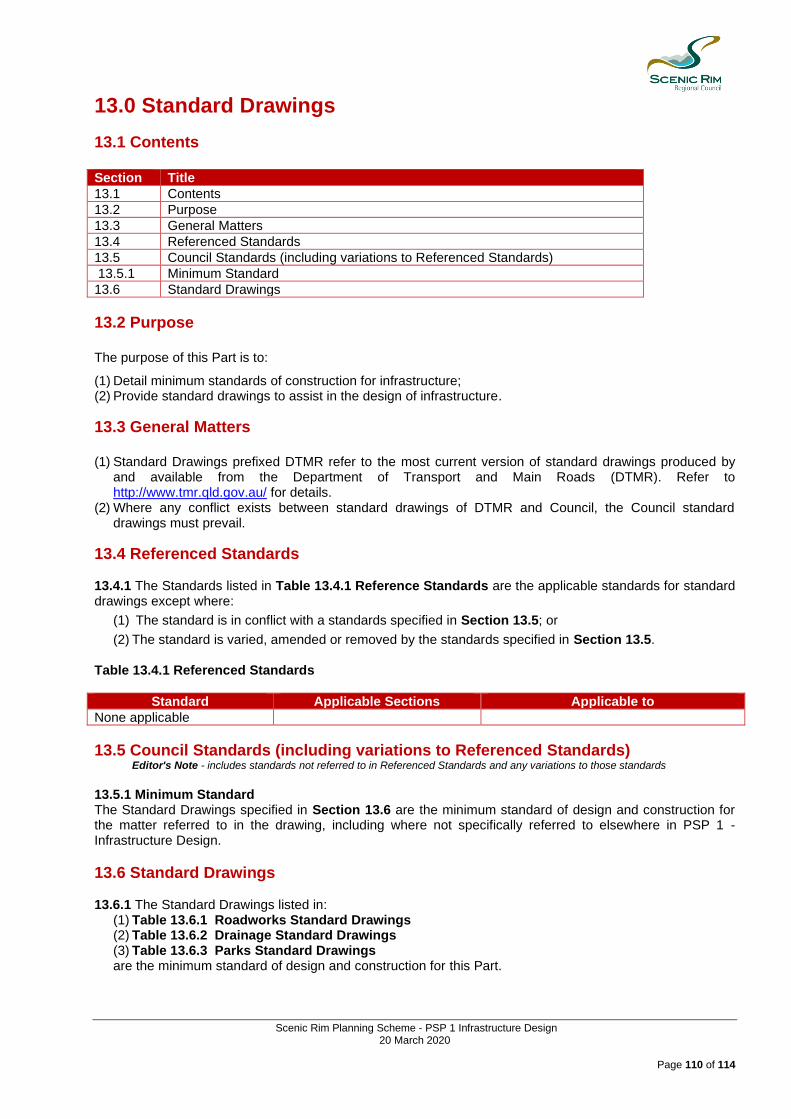
Scenic Rim Planning Scheme - PSP 1 Infrastructure Design 20 March 2020
Page 110 of 114
13.0 Standard Drawings
13.1 Contents Section Title
13.1 Contents
13.2 Purpose
13.3 General Matters
13.4 Referenced Standards
13.5 Council Standards (including variations to Referenced Standards)
13.5.1 Minimum Standard
13.6 Standard Drawings
13.2 Purpose The purpose of this Part is to:
(1) Detail minimum standards of construction for infrastructure; (2) Provide standard drawings to assist in the design of infrastructure.
13.3 General Matters (1) Standard Drawings prefixed DTMR refer to the most current version of standard drawings produced by
and available from the Department of Transport and Main Roads (DTMR). Refer to http://www.tmr.qld.gov.au/ for details.
(2) Where any conflict exists between standard drawings of DTMR and Council, the Council standard drawings must prevail.
13.4 Referenced Standards 13.4.1 The Standards listed in Table 13.4.1 Reference Standards are the applicable standards for standard drawings except where:
(1) The standard is in conflict with a standards specified in Section 13.5; or
(2) The standard is varied, amended or removed by the standards specified in Section 13.5. Table 13.4.1 Referenced Standards
Standard Applicable Sections Applicable to
None applicable
13.5 Council Standards (including variations to Referenced Standards) Editor's Note - includes standards not referred to in Referenced Standards and any variations to those standards
13.5.1 Minimum Standard The Standard Drawings specified in Section 13.6 are the minimum standard of design and construction for the matter referred to in the drawing, including where not specifically referred to elsewhere in PSP 1 - Infrastructure Design.
13.6 Standard Drawings 13.6.1 The Standard Drawings listed in:
(1) Table 13.6.1 Roadworks Standard Drawings (2) Table 13.6.2 Drainage Standard Drawings (3) Table 13.6.3 Parks Standard Drawings are the minimum standard of design and construction for this Part.
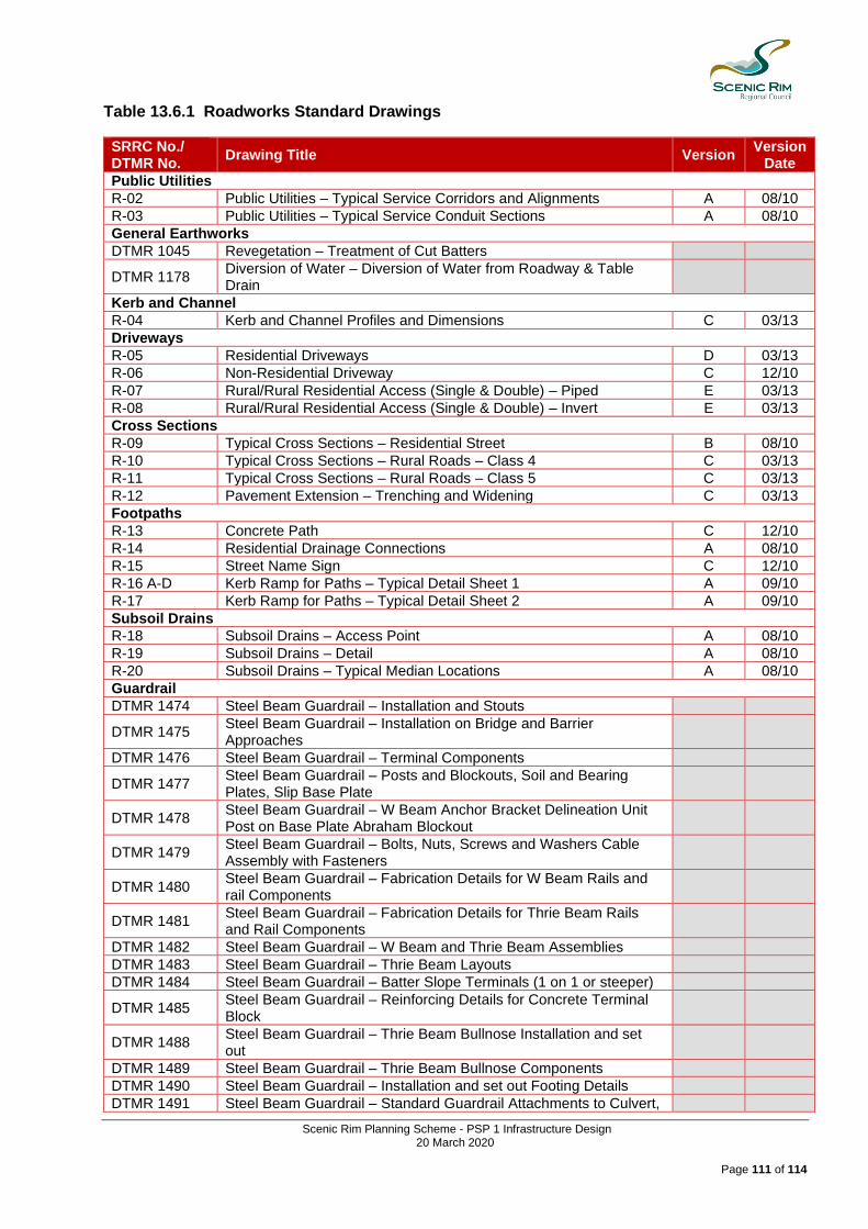
Scenic Rim Planning Scheme - PSP 1 Infrastructure Design 20 March 2020
Page 111 of 114
Table 13.6.1 Roadworks Standard Drawings
SRRC No./ DTMR No.
Drawing Title Version Version
Date
Public Utilities
R-02 Public Utilities – Typical Service Corridors and Alignments A 08/10 R-03 Public Utilities – Typical Service Conduit Sections A 08/10 General Earthworks
DTMR 1045 Revegetation – Treatment of Cut Batters
DTMR 1178 Diversion of Water – Diversion of Water from Roadway & Table Drain
Kerb and Channel
R-04 Kerb and Channel Profiles and Dimensions C 03/13 Driveways
R-05 Residential Driveways D 03/13 R-06 Non-Residential Driveway C 12/10 R-07 Rural/Rural Residential Access (Single & Double) – Piped E 03/13 R-08 Rural/Rural Residential Access (Single & Double) – Invert E 03/13 Cross Sections
R-09 Typical Cross Sections – Residential Street B 08/10 R-10 Typical Cross Sections – Rural Roads – Class 4 C 03/13 R-11 Typical Cross Sections – Rural Roads – Class 5 C 03/13 R-12 Pavement Extension – Trenching and Widening C 03/13 Footpaths
R-13 Concrete Path C 12/10 R-14 Residential Drainage Connections A 08/10 R-15 Street Name Sign C 12/10 R-16 A-D Kerb Ramp for Paths – Typical Detail Sheet 1 A 09/10 R-17 Kerb Ramp for Paths – Typical Detail Sheet 2 A 09/10 Subsoil Drains
R-18 Subsoil Drains – Access Point A 08/10 R-19 Subsoil Drains – Detail A 08/10 R-20 Subsoil Drains – Typical Median Locations A 08/10 Guardrail
DTMR 1474 Steel Beam Guardrail – Installation and Stouts
DTMR 1475 Steel Beam Guardrail – Installation on Bridge and Barrier Approaches
DTMR 1476 Steel Beam Guardrail – Terminal Components
DTMR 1477 Steel Beam Guardrail – Posts and Blockouts, Soil and Bearing Plates, Slip Base Plate
DTMR 1478 Steel Beam Guardrail – W Beam Anchor Bracket Delineation Unit Post on Base Plate Abraham Blockout
DTMR 1479 Steel Beam Guardrail – Bolts, Nuts, Screws and Washers Cable Assembly with Fasteners
DTMR 1480 Steel Beam Guardrail – Fabrication Details for W Beam Rails and rail Components
DTMR 1481 Steel Beam Guardrail – Fabrication Details for Thrie Beam Rails and Rail Components
DTMR 1482 Steel Beam Guardrail – W Beam and Thrie Beam Assemblies
DTMR 1483 Steel Beam Guardrail – Thrie Beam Layouts
DTMR 1484 Steel Beam Guardrail – Batter Slope Terminals (1 on 1 or steeper)
DTMR 1485 Steel Beam Guardrail – Reinforcing Details for Concrete Terminal Block
DTMR 1488 Steel Beam Guardrail – Thrie Beam Bullnose Installation and set out
DTMR 1489 Steel Beam Guardrail – Thrie Beam Bullnose Components
DTMR 1490 Steel Beam Guardrail – Installation and set out Footing Details
DTMR 1491 Steel Beam Guardrail – Standard Guardrail Attachments to Culvert,
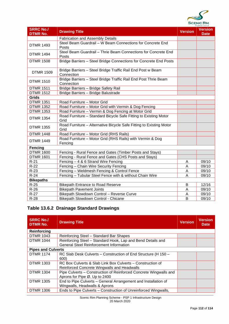
Scenic Rim Planning Scheme - PSP 1 Infrastructure Design 20 March 2020
Page 112 of 114
SRRC No./ DTMR No.
Drawing Title Version Version
Date
Fabrication and Assembly Details
DTMR 1493 Steel Beam Guardrail – W Beam Connections for Concrete End Posts
DTMR 1494 Steel Beam Guardrail – Thrie Beam Connections for Concrete End Posts
DTMR 1508 Bridge Barriers – Steel Bridge Connections for Concrete End Posts
DTMR 1509 Bridge Barriers – Steel Bridge Traffic Rail End Post w Beam Connection
DTMR 1510 Bridge Barriers – Steel Bridge Traffic Rail End Post Thrie Beam Connection
DTMR 1511 Bridge Barriers – Bridge Safety Rail
DTMR 1512 Bridge Barriers – Bridge Balustrade
Grids
DTMR 1351 Road Furniture – Motor Grid
DTMR 1352 Road Furniture – Motor Grid with Vermin & Dog Fencing
DTMR 1353 Road Furniture – Vermin & Dog Fencing at Motor Grid
DTMR 1354 Road Furniture – Standard Bicycle Safe Fitting to Existing Motor Grid
DTMR 1355 Road Furniture – Alternative Bicycle Safe Fitting to Existing Motor Grid
DTMR 1448 Road Furniture – Motor Grid (RHS Rails)
DTMR 1449 Road Furniture – Motor Grid (RHS Rails) with Vermin & Dog Fencing
Fencing
DTMR 1600 Fencing - Rural Fence and Gates (Timber Posts and Stays)
DTMR 1601 Fencing - Rural Fence and Gates (CHS Posts and Stays)
R-21 Fencing – 4 & 6 Strand Wire Fencing A 09/10 R-22 Fencing – Chain Wire Security Fencing A 09/10 R-23 Fencing – Weldmesh Fencing & Control Fence A 09/10 R-24 Fencing – Tubular Steel Fence with & without Chain Wire A 09/10 Bikepaths
R-25 Bikepath Entrance to Road Reserve B 12/16 R-26 Bikepath Pavement Joints A 09/10 R-27 Bikepath Slowdown Control – Reverse Curve A 09/10 R-28 Bikepath Slowdown Control - Chicane B 09/10
Table 13.6.2 Drainage Standard Drawings
SRRC No./ DTMR No.
Drawing Title Version Version
Date
Reinforcing
DTMR 1043 Reinforcing Steel – Standard Bar Shapes
DTMR 1044 Reinforcing Steel – Standard Hook, Lap and Bend Details and General Steel Reinforcement Information
Pipes and Culverts
DTMR 1174 RC Slab Desk Culverts – Construction of End Structure (H 150 – 600)
DTMR 1303 RC Box Culverts & Slab Link Box Culverts – Construction of Reinforced Concrete Wingwalls and Headwalls
DTMR 1304 Pipe Culverts – Construction of Reinforced Concrete Wingwalls and Aprons for Pipe Ø. Up to 2400
DTMR 1305 End to Pipe Culverts – General Arrangement and Installation of Wingwalls, Headwalls & Aprons
DTMR 1306 Ends to Pipe Culverts – Construction of Unreinforced Wingwalls,
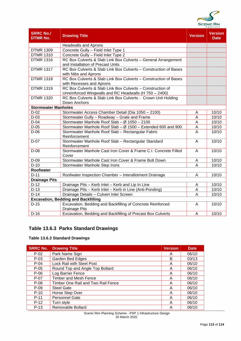
Scenic Rim Planning Scheme - PSP 1 Infrastructure Design 20 March 2020
Page 113 of 114
SRRC No./ DTMR No.
Drawing Title Version Version
Date
Headwalls and Aprons
DTMR 1309 Concrete Gully – Field Inlet Type 1
DTMR 1310 Concrete Gully – Field Inlet Type 2
DTMR 1316 RC Box Culverts & Slab Link Box Culverts – General Arrangement and Installation of Precast Units
DTMR 1317 RC Box Culverts & Slab Link Box Culverts – Construction of Bases with Nibs and Aprons
DTMR 1318 RC Box Culverts & Slab Link Box Culverts – Construction of Bases with Recesses and Aprons
DTMR 1319 RC Box Culverts & Slab Link Box Culverts – Construction of Unreinforced Wingwalls and RC Headwalls (H 750 – 2400)
DTMR 1320 RC Box Culverts & Slab Link Box Culverts - Crown Unit Holding Down Anchors
Stormwater Manholes
D-02 Stormwater Access Chamber Detail (Dia 1050 – 2100) A 10/10 D-03 Stormwater Gully – Roadway – Grate and Frame A 10/10 D-04 Stormwater Manhole Roof Slab – Ø 1050 – 2100 A 10/10 D-05 Stormwater Manhole Roof Slab – Ø 1500 – Extended 600 and 900 A 10/10 D-06 Stormwater Manhole Roof Slab – Rectangular Fabric
Reinforcement A 10/10
D-07 Stormwater Manhole Roof Slab – Rectangular Standard Reinforcement
A 10/10
D-08 Stormwater Manhole Cast Iron Cover & Frame C.I. Concrete Filled Cover
A 10/10
D-09 Stormwater Manhole Cast Iron Cover & Frame Bolt Down A 10/10 D-10 Stormwater Manhole Step Irons A 10/10 Roofwater
D-11 Roofwater Inspection Chamber – Interallotment Drainage A 10/10 Drainage Pits
D-12 Drainage Pits – Kerb Inlet – Kerb and Lip In Line A 10/10 D-13 Drainage Pits – Kerb Inlet – Kerb in Line (Anti-Ponding) A 10/10 D-14 Drainage Details – Culvert Inlet Screen A 10/10 Excavation, Bedding and Backfilling
D-15 Excavation, Bedding and Backfilling of Concrete Reinforced Drainage Pits
A 10/10
D-16 Excavation, Bedding and Backfilling of Precast Box Culverts A 10/10
Table 13.6.3 Parks Standard Drawings Table 13.6.3 Standard Drawings
SRRC No. Drawing Title Version Date
P-02 Park Name Sign A 06/10
P-03 Garden Bed Edges B 03/13
P-04 Lock Rail with Steel Post A 06/10
P-05 Round Top and Angle Top Bollard A 06/10
P-06 Log Barrier Fence A 06/10
P-07 Timber and Mesh Fence A 06/10
P-08 Timber One Rail and Two Rail Fence A 06/10
P-09 Steel Gate A 06/10
P-10 Horse Step Over A 06/10
P-11 Personnel Gate A 06/10
P-12 Turn style A 06/10
P-13 Removable Bollard A 06/10

Scenic Rim Planning Scheme - PSP 1 Infrastructure Design 20 March 2020
Page 114 of 114
SRRC No. Drawing Title Version Date
P-14 Wheelie Bin Stand A 06/10
P-15 Wheelie Bin Enclosure A 06/10
P-16 General Tap and Maintenance Tap A 06/10
P-17 Water Tap and Bubbler with Dog Bowl A 06/10
P-18 Electric Barbecue B 03/13
P-20 Toilet Block Siting A 06/10
P-21 Picnic Node A 06/10
P-22 Park Bench – Bolt Down A 06/10
P-23 Park Bench – Embedded A 06/10
P-24 Picnic Table/Double Pedestal – Bolt Down A 06/10
P-25 Picnic Table/Double Pedestal – Embedded A 06/10
P-26 Picnic Table/Single Pedestal – Embedded A 06/10
P-27 Shelter Shed – Small B 03/13
P-28 Shelter Shed – Medium A 06/10
P-29 Shelter Shed – Large A 06/10
P-30 Specimen Park/Street Tree Planting A 06/10
P-31 Landscape Shrub/Ground Cover Planting A 06/10
P-32 Playground Siting Plant A 06/10
P-33 Playground Soft Fall Installation & Playground Shade Notes A 06/10
P-34 Park Footpath Design A 06/10