schlumberger coiled tubing
DESCRIPTION
goodTRANSCRIPT

Report on the Industrial Internship at Schlumberger
Presented byWaqas Hassan Tanvir 03F-ME-20
Hafiz MUMTAZ ALAM 03F-ME-59
HUMAYUN NAWAZ 03F-ME-64
PRESENTED TODr. Shahid Khalil
Department of Mechanical Engineering University of Engineering & Technology
Taxila.

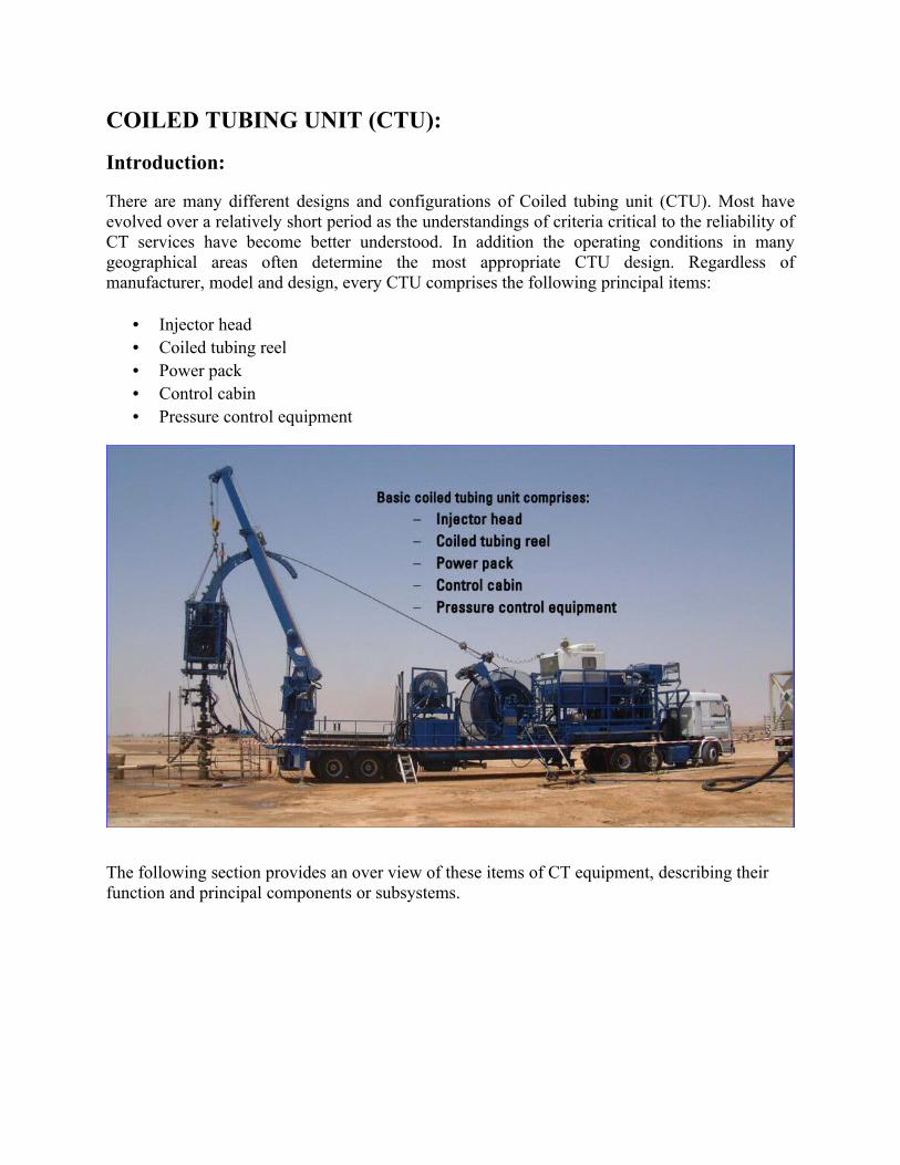
COILED TUBING UNIT (CTU):
Introduction:
There are many different designs and configurations of Coiled tubing unit (CTU). Most have evolved over a relatively short period as the understandings of criteria critical to the reliability of CT services have become better understood. In addition the operating conditions in many geographical areas often determine the most appropriate CTU design. Regardless of manufacturer, model and design, every CTU comprises the following principal items:
• Injector head• Coiled tubing reel• Power pack • Control cabin• Pressure control equipment
The following section provides an over view of these items of CT equipment, describing their function and principal components or subsystems.
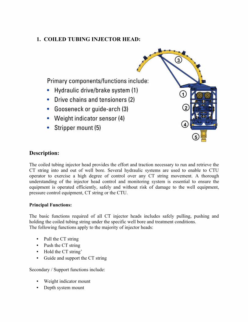
1. COILED TUBING INJECTOR HEAD:
Description:
The coiled tubing injector head provides the effort and traction necessary to run and retrieve the CT string into and out of well bore. Several hydraulic systems are used to enable to CTU operator to exercise a high degree of control over any CT string movement. A thorough understanding of the injector head control and monitoring system is essential to ensure the equipment is operated efficiently, safely and without risk of damage to the well equipment, pressure control equipment, CT string or the CTU.
Principal Functions:
The basic functions required of all CT injector heads includes safely pulling, pushing and holding the coiled tubing string under the specific well bore and treatment conditions.The following functions apply to the majority of injector heads:
• Pull the CT string• Push the CT string• Hold the CT string’• Guide and support the CT string
Secondary / Support functions include:
• Weight indicator mount• Depth system mount
• Stripper Mount.
Pull (Tensile Force):
The injector head pull capacity should be compatible with the weight of the CT string in use, plus :
• Effect of fluid density inside/outside the CT string• Over pull (tension) to be applied at the BHA• Effect of drag (friction) caused by the string or BHA• Friction or drag created by the strippers
Push (snubbing force):
The injector head snubbing capacity should be compatible with:
• The force required to over come the well head pressure• Acting on the cross sectional area of the CT string• Friction or drag created by stripper
Hold:
The injector head should be capable of safely holding the CT string stationary. This holding function should be available with the hydraulic systems or power pack in both normal operating conditions and disabled modes. In addition the transition from stationary to in-hole and out-of-hole modes should be smooth and easily controlled.
Guide the Tubing:
Components of the injector head serve to support and guide the CT string from the delivery angle of the reel into the well bore.
Weigh Indicator mount:
Injector heads are typically configured with the traction and drive components mounted of FLOATING inner chassis. This is contained with in a fixed outer frame with the weight indicator sensors connected b/w the two frames.
Depth system sensor:
The injector head provides a convenient mounting position for friction wheel depth measurement systems. At least two independent sensors are typically required on every CT operation.

Stripper Mount:
The primary stripper is generally permanently mounted to the injector head. Unless the injector head is otherwise supported, the mounting bears all of the forces necessary to run and retrieve the CT string. The stripper mount also provides a reference point with which the drive chains and guide arch are ultimately aligned.
Features:
The design and configuration of injector heads have developed over several years to meet specifications which reflect the evolving nature of CT applications. The trend towards larger tubing sizes which enable greater circulation rates, requires the injector head be capable of handling a wider range of tubing, The principal component of Injector head can be categorized in the following systems or major assemblies:
• Drive and break system• Chain assembly• Guide-arch assembly• Weight indicator
In addition, secondary or support systems include:
• Stripper mount• Depth sensor mounts
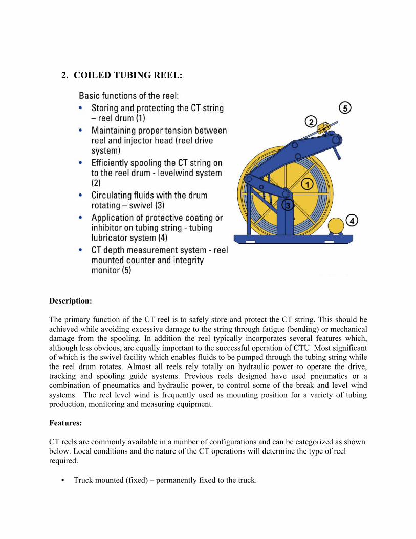
2. COILED TUBING REEL:
Description:
The primary function of the CT reel is to safely store and protect the CT string. This should be achieved while avoiding excessive damage to the string through fatigue (bending) or mechanical damage from the spooling. In addition the reel typically incorporates several features which, although less obvious, are equally important to the successful operation of CTU. Most significant of which is the swivel facility which enables fluids to be pumped through the tubing string while the reel drum rotates. Almost all reels rely totally on hydraulic power to operate the drive, tracking and spooling guide systems. Previous reels designed have used pneumatics or a combination of pneumatics and hydraulic power, to control some of the break and level wind systems. The reel level wind is frequently used as mounting position for a variety of tubing production, monitoring and measuring equipment.
Features:
CT reels are commonly available in a number of configurations and can be categorized as shown below. Local conditions and the nature of the CT operations will determine the type of reel required.
• Truck mounted (fixed) – permanently fixed to the truck.
• Truck mounted (skid) – may be changed out• Skid mounted - for off shore operations• Trailer mounted – for large capacity (length) or heavy weight strings• CT logging reel – fitted with electrical swivel / collector• Special application reel – typically for completion applications.
With the advent of larger CT sizes that are installed as completion tubulars there is increased of use of special reels and spooling stands designed to handle large tubulars. These structures typically enable the shipping spool to be fitted in place of the drum assembly, thereby avoiding unnecessary spooling, which in large tubing sizes can be difficult and hazardous. The evolution of CT string sizes and the general trend towards longer CT work strings has resulted in many different reel designs, many of which are still in common use. However, the facilities and components identified below are found on almost all reels:
• Reel drum(1)• Reel drive and break systems• Reel swivel and manifold(3)• Level wind assembly(2)• Depth measurement accessories(5)• Tubing lubrication equipment(4)• Crash protection frame
_
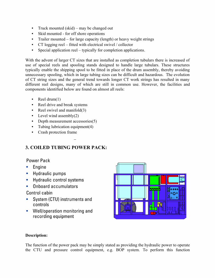
3. COILED TUBING POWER PACK:
Description:
The function of the power pack may be simply stated as providing the hydraulic power to operate the CTU and pressure control equipment, e.g. BOP system. To perform this function
satisfactorily under varied conditions and for the duration of any CT operation, current generation power packs are designed to operate independently of exterior power of air supplies once started. In addition to the hydraulic power supplied when running, the power pack incorporates an accumulator facility to allow limited operation of pressure control equipment following engine shutdown. A compressor mounted on the engine, provides an air supply for operation of the engine controls and pneumatic systems on the CTU, e.g. the stripper air operated pump, injector head chain lubrication, lights and transfer pumps. The power pack air-receiver will provide a sufficient storage to allow an engine restart shortly after shutdown, provided the unit pneumatic systems are isolated. The environment in which CTU is to operate will determine the engine protection facilities required by the relevant local and national authorities.The CTU configuration will determine the location of the power pack and corresponding control equipment:
• Truck or trailer mounted using the truck engine as power source• Truck or trailer mounted with an independent power source• Skid mounted with the control cab and power pack incorporated on one skid• Skid mounted with control cab mounted separately from the power pack
Regardless of the type of the unit to which the power pack is fitted, the function and facility contained with in the power pack will be similar.
Features:
The majority of CTUs in use are assembled by HYDRA-RIG. The evolution of CTU designed to the current standards has resulted in several different designs of the power pack being supplied. In general all power packs will include the following major components:
• Engine• Hydraulic pumps• Pressure control valves• Hydraulic reservoir• Filters and strainers• Hydraulic fluid• Heat exchanger and thermostatic valve• Accumulator
Operation or even startup of the CTU power pack must not be attempted until a series of maintenance and operational checks has been completed. Failure to follow the pre-startup procedure may expose equipment and personnel to unacceptable risks.The pre-startup operational checks will vary with the location and application of the CTU but should include the following points as a minimum requirement: Ensure any location requirements, such as permit to work systems, are complied with fully and that actions need for such requirements have been completed, e.g. positioning of gas detecting and fire-fighting
equipment. Ensure operating and associated personnel are aware of the above requirements, and that only qualified personnel are authorized to operate the equipment.
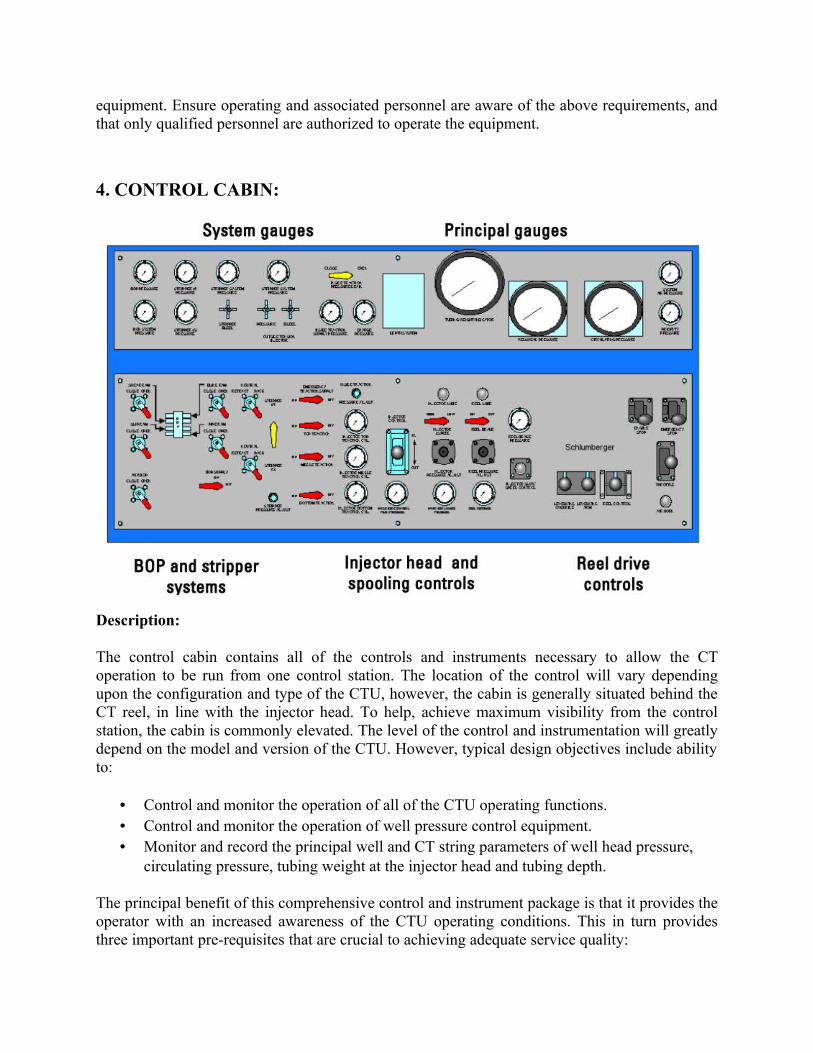
4. CONTROL CABIN:
Description:
The control cabin contains all of the controls and instruments necessary to allow the CT operation to be run from one control station. The location of the control will vary depending upon the configuration and type of the CTU, however, the cabin is generally situated behind the CT reel, in line with the injector head. To help, achieve maximum visibility from the control station, the cabin is commonly elevated. The level of the control and instrumentation will greatly depend on the model and version of the CTU. However, typical design objectives include ability to:
• Control and monitor the operation of all of the CTU operating functions.• Control and monitor the operation of well pressure control equipment.• Monitor and record the principal well and CT string parameters of well head pressure,
circulating pressure, tubing weight at the injector head and tubing depth.
The principal benefit of this comprehensive control and instrument package is that it provides the operator with an increased awareness of the CTU operating conditions. This in turn provides three important pre-requisites that are crucial to achieving adequate service quality:
The CTU can be operated safely and efficiently. Potential problems can be identified and rectified before the interfere with the operation of CTU. An accurate CT string work record is developed, based on primary factors which influence the useful life of the tubing.
Features:
Controls and instruments by function as follows:
• Injector chain inside tension• Injector chain outside tension• Injector-head drive• Reel • Lubrication controls• Power unit• Blow out preventer (BOP).• Stripper• Principal gauges• Emergency hydraulic supply equipments• Electronic equipment
Operating technique:
The control and systems of any CTU must be operated in a manner which ensures that the following general requirements are met: The safety of the personnel associated with the operation and maintenance of the CTUOperation and maintenance of any controls or system of the CTU must not compromise the efficiency of the well control barriers. The operation of primary, secondary and tertiary (where required) well control barriers must be understood. In addition the consequences of their operation must be understood. The operating limits of key components and systems associated with the CTU should not be exceeded. The operating limits defined by CT software models should not be exceeded. Applicable safety and environmental policies must be understood and complied with. During operation, consideration must be given to the speed and levels of the force applied to the CT string. These must be consistent with the well conditions and equipment limitations.
Starting / Stopping:
The process of starting and stopping the movement of the CT must be conducted by applying or reducing the driving force slowly and smoothly. Sudden changes may exert unacceptable high forces to the tubing, reel, injector head, power pack and pressure control equipment components.
Running the CT:
The location of the CT BHA in relation to the well bore tubulars and restrictions should be constant consideration. Appropriate precautions must be taken as the CT BHA passes restrictions or variations in the well bore diameter. These may include, but not be limited to, the following:Close observation of the weight indicator display:
• A reduction in the running speed. • Checking the actual vs. predicted weight.
5. Pressure Control Equipment:
The pressure control equipment and practices associated with the CT operations are designed and prepared to provide a high degree of safety reliability. This key feature enables CT to be widely accepted as live well intervention method, proven on oil and gas wells under a variety of conditions. The pressure control equipment required and selected for any application depends on a number of factors. Such factors may relate to well bore conditions, the applications or treatment to be conducted or the or regulatory requirements applicable in the region a specific well site. However, there are always several items of pressure control equipment required for any operation. The assembled equipment is commonly referred to as the pressure control stack. In assembling this equipment stack, it is not only important that each individual item be correctly specified and operated, but that each item is compatible with the specifications and functions of the assembled stack.The definitions listed below are based on general understanding of some commonly used terms:
Primary Pressure Control:
Equipment and practices which provide or ensure the primary barrier against well bore pressure and fluids. Such equipment is typically operated during normal operating conditions, e.g. stripper.
Secondary Pressure Control:
Equipment and practices which provide or ensure the secondary barrier against well bore pressure and fluids. Such equipment is typically operated in support of normal operating conditions or as a contingency, e.g. BOP.
Tertiary Pressure Control:
Equipment and practices which provide or ensure the tertiary barrier against well bore pressure and fluids. Such equipment is typically operated in contingency or emergency situations e.g. Shear/Seal BOP. Pressure control equipment can be categorized below:
• Stripper systems• Blowout preventers (BOPs)• Well head connections and crossovers• Lubricators and risers
• Live well deployment systems
Applications of Coiled Tubing:
The following main applications are of coiled tubing:
• Well bore fill removal• Matrix stimulation through CT – A chemical treatment injected radially from the well
bore into the reservoir at a pressure below the frac pressure to remove or bypass formation damage.
• CT cementing – The process of forcing cement slurry through perforations, holes, or leaks in the casing / liner to obtain an hydraulic seal
• CT logging and wired applications – to provide electrical power to down hole tool system.
• Fracturing through CT• CT drilling
Well Completion & Productivity (WCP)
An Overview of WCP
How Do They Work:
Step 01: The generation of Acoustic waves that travel into the earth and reflect back to the sensors to be recorded by sensors and interpreted by computers, This provides a subterranean picture of possible resource.
Step 02: The use of a rig and crew for drilling, suspension, completion, production, testing, capping, deepening, plugging back, sidetracking, redrilling or reconditioning of well, and of course sampling.
Step 03: The measurement of one or more physical quantities in or around a well. The term comes from the word “Log” used in the sense of a record or a note wireline logs are taken downhole , transmitted through a wireline to surface and recorded there.
Step 04: Well testing involves providing access to and measurement of dynamic reservoir data, including pressure, temperature, flow rate and fluid whether the well is flowing or shut in.
Step 05: The work done on a well bore to establish safe production of resource or injection fluids after the production casing string has been set, cemented and pressure tested. This work includes running the pipe and jewelry, perforating, setting packers, tuning hangers and Christmas trees in place.
Step 06: Systems that are packed in the wellbore to “Lift” fluids because the reservoir lacks the energy to cause the natural flow of fluid to surface, such as gas lifts or electric submersible pumps
Step 07: Production is the stage in the reservoir life during which hydrocarbons are brought from the reservoir through the completion facilities to be sold. Productivity is the measure of a well completion’s ability to produce, expressed in volumes of gross liquid produced per day per unit of differential pressure between the static reservoir pressure and well’s flowing bottom hole pressure (draw done)
WCP MeteirsCompletion Tools &Services:
• Packer
• Safety Valves
• Retrievable
• Formation isolation valve
• Tubing Conveyed Perforating
• Drill Stem Testing
• Multilaterals
• Sandface Completions
Monitor/Control:
• Downhole Control
• Downhole Monitoring
• Phase watcher /phase tester
• Oilphase DBR
• Arrays and data analysis
Surface Testing:
• Acquisition
• Separators
• Burners
• Manifolds
• Zero Emissions
Interventions:
• Sen Tree Services
• Slickline
REDA Pumps:
• Electric Submersible Pumps
• Power Systems
Gas lift:
• Gas lift systems
• Flow Regulators
Downhole Sensors:
• Pump Watcher
• Surveyor
WCP Services
Tubing Conveyed Perforation (TCP)
Shaped charge perforating is a critical part of well completion process and development of technique has been driven by the need for better well productivity operating efficiency, safety and lower costs. Two basic perforating techniques are available to completion design engineer
Through Tubing Perforating: The guns are lowered into the well through Production string (drill pipe or test string) The guns may be conveyed by
wireline or coiled tubing.
Through tubing perforations guns offer the following features:
• The wellhead and completion string are in place and tested before the
casing is perforated.
• The under balanced differential from the reservoir into the wellbore
provides perforation cleanup.
• Perforation may be made as required over the life of the well, with or
without a rig onsite
Cased Gun and High Shot Density perforating(HSD): Large diameter guns are lowered into the cased well before the production string is run (or in some cases as
part of bottom hole assembly especially during drill stem testing and certain
completion techniques). Casing or HSD Guns offer the following features:
• Gun size is limited only by the internal diameter, allowing the
highest performance deep penetrating or big hole charges to be used
at optimal shot density and perforating pattern.
• When guns are conveyed on wireline the overbalanced differential from
the wellbore into the formation allowsthe4 use of longer guns
Compared to expandables through tubing guns, carrier type guns significantly
reduce the amount of perforating debris introduced into the wellbore during
the perforating process. The choice between wireline and tubing coil
perforating should be made on the completion objectives and operational
considerations. From the perforation view point wireline perforating wireline
perforation operations are usually faster when there are a few short
intervals to perforate. TCP operations are more efficient for long multi zone
perforation intervals.
Benefits of TCP:
• Long intervals may be efficiently perforated in one run with a kill string in place if required.
• The programmed under balance is applied to all perforated intervals evenly in a controlled fashion.
• A variety of firing systems and accessories accommodates a wide range of well conditions and completion techniques
• After firing, expended guns may be dropped to the bottom of the well• allowing future through tubing operation
Firing Heads
Another type of a firing system is by the use of firing heads .The main system that separates on firing head from the other is the method of its actuation.
Differential Pressure Firing Head
The Differential Pressure firing head is actuated by the differential pressure between the annulus above the packer and the rat hole pressure below. The main features are safety spring disables the firing pin when the hydrostatic pressure is below 600 psi making the gun string safe on and near the surface
Hydraulic delay firing head
The hydraulic delay firing head, an absolute pressure firing head, is actuated by tubing pressure shearing calibrated pins when a pre-set pressure level is reached, initiating a time delay period during which under balance pressure is established before the guns are fired. Once the delay has expired pressure at the firing head drives the firing pin into the detonator.
Trigger Charge Firing System
The Trigger charge firing system adapts either the absolute pressure, drop bar or jar down firing system to transfer assembly that is run through the well on slick line (or electric line). After the string and guns have been run, tested and positioned. The main features are
• Heads containing primary explosives are run into the well latched and then retrieved independently of the gun string
• The firing heads are connected after the guns are on depth, which improves the level of safety for the entire operation.
Different Firing Heads Systems
E fire Electronic firing head system
EFire electronic firing head systems for coiled tubing, TCP and wireline provide a more efficient and economical method for a wide range of downhole explosive operations.
Drop-bar actuated trigger firing system
The drop bar-actuated trigger charge firing system TCF-DB is designed to offer maximum flexibility and control over the firing operation because the firing head is run separately from the gun string.
• Jar Down-Actuated Trigger Charge Firing System TCF-JDThe jar down-actuated trigger charge firing head TCF-JD is designed to offer maximum flexibility and control over the firing operation because the firing head is run separately from the gun string.
• Absolute Pressure-Actuated Trigger Charge Firing System TCF-PThe absolute pressure-actuated trigger charge firing system TCF-P is designed to offer maximum flexibility and control over the firing operation because the firing head is run separately from the gun string.
• WCF Wet Connect Firing SystemsThe wet connect firing system WCF is composed of two connector assemblies
Drill Stem Testing
Introduction
A set of drill stem tools is an array of downhole hardware used for the temporary completion of a well. They are run as a means of providing a safe and efficient method of controlling a formation during the gathering of essential reservoir data in the exploration, appraisal and even development phase of a well, or to perform additional pre-conditional or treatment services prior to the completion of the well. Many components are similar to those of permanent completions although the temporary nature of the string requires some additional functionality normally not associated with permanent completions. This can be better understood by considering that DST tools are designed for a wide range of operating environments and multiuse i.e. they can be redressed between runs, while permanent completion components are designed for specific installations and long life
Basic requirements
Drill stem tests are affected by three different pressures:
• Hydrostatic Pressure Ph
• Formation Pressure Pf
• Cushion Pressure Pc
Equipment and tools
Packer
This provides a seal and isolates Ph from Pf much the same as for permanent completions. A packer basically isolates the zones of annulus and the fluid up pumping. The packer is one of the most important tools in the tubing string. The types of packers vary greatly. Often, they're designed or configured to meet specific wellbore or reservoir conditions, such as single- or
tandem-packer configurations, single- or dual-tubing strings, and the full range of pressure and temperature applications.The most basic requirement of the packer and associated tools relates to enabling efficient flow from or injection into the formation to the tubing string or production conduit. The packer must not restrict normal production or injection flow.
SamplingIn order to give our customer a good information of what’s inside our well we have to give them samples. This is a good look for the customer to carry out the instructions of what to do and when to do act. The oil and gas samples either directly or after recombination are taken in special cylinders and then sent to the PVT (pressure volume temperature analysis) laboratory for testing.
Objective of Sampling
Fluid property data is needed to
• Help describe the reservoir• Predict reservoir fluid behaviour• Assist in development
What does OilPhase -DBR do:
• Reservoir fluid sampling• Well site fluid analysis• Advanced fluid research • PVT software• Sampling and PVT equipment manufacturer• Sample management
Types of sampling
1.Surface sampling
2.Bottom hole sampling
Sub category:
(a) Cased hole sampling(b) Bottom hole sampling
Types of samples
• Bottom hole • Well head• Separator recombination• Dead oil• Water
Well conditioning
• Although 1.5 x string volume must have been produced• Stable downhole and WHP• BS&W < 1%• Clean stable burning of fuel• Ph neutral
General sampling preparation
• The client /test engineer verbally confirmed about sampling• Stopped to testing guy to do any changes in pressure and level• Well should be stable 4 hours before sampling• In oil bottles 10% gas cap should be created for safe transportation
Gas sampling
• Check the bottle is vacuumed or not.• Connect the connection with gas line or vertical side• First flush the lines then open the bottle valve slowly• After taking the sample check the bottle pressure should match with separator
pressure• Note down the final pressure and label the bottle• First check any trapped pressure in the bottle• Then pump water/glycol at seperator pressure to avoid flushing • Then purge oil sight glass• After this flush the lines across the bottle• Then open the bottom valve and displace the water/glycol(glycol is added to
prevent rust formation) with seperator pressure slowly• Remove the 600 cc water/glycol over the period of 30 minutes and then close the
sample valve• At last note down the final pressure and temperature
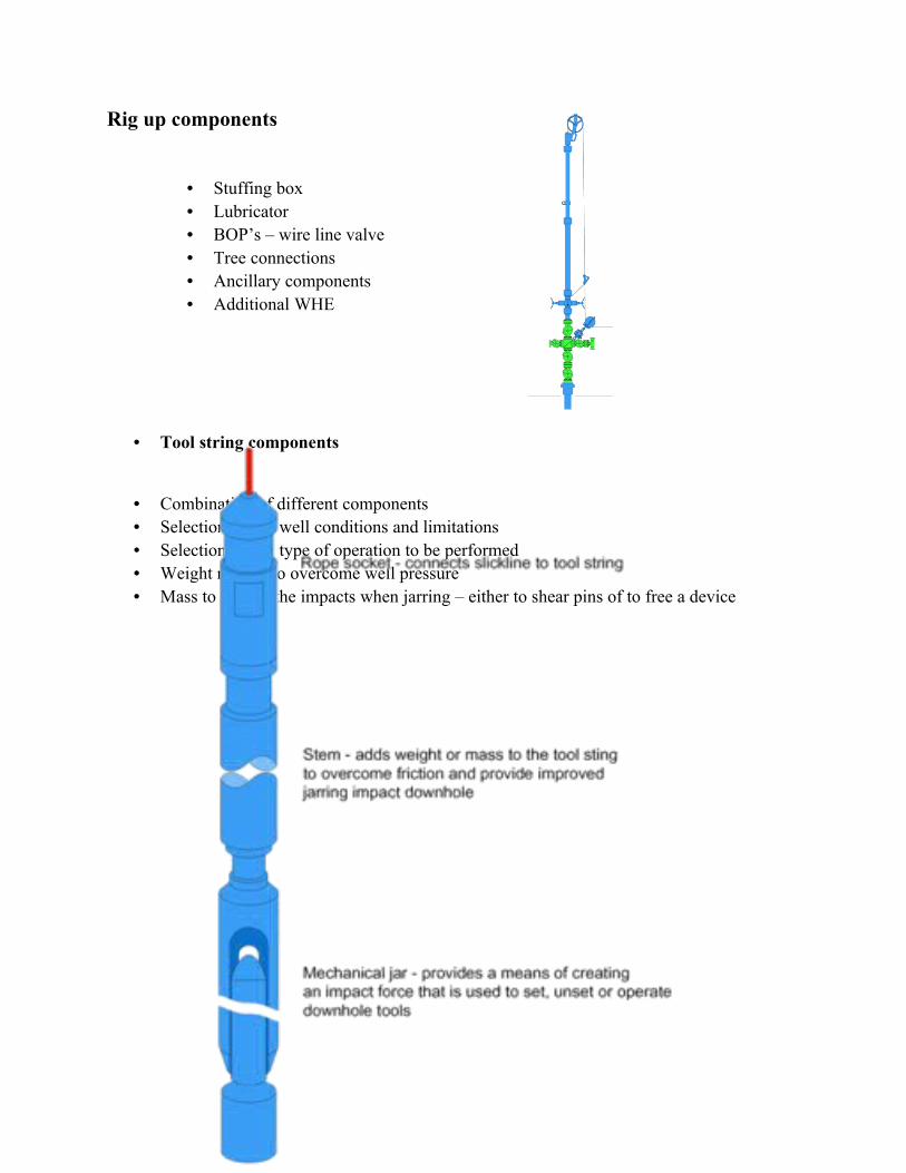
Rig up components
• Stuffing box• Lubricator• BOP’s – wire line valve• Tree connections• Ancillary components• Additional WHE
• Tool string components
• Combination of different components• Selection due to well conditions and limitations• Selection due to type of operation to be performed• Weight needed to overcome well pressure• Mass to deliver the impacts when jarring – either to shear pins of to free a device
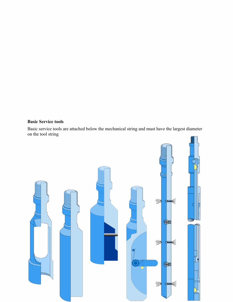
Basic Service tools
Basic service tools are attached below the mechanical string and must have the largest diameter on the tool string
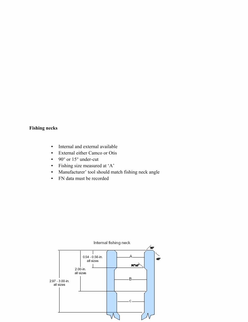
Fishing necks
• Internal and external available• External either Camco or Otis• 90° or 15° under-cut• Fishing size measured at ‘A’• Manufacturer’ tool should match fishing neck angle• FN data must be recorded
Pulling up tools
• Used to recover devices from the well bore• Can be used to set devices e.g. equalizing prongs, standing valves• Can be released from device if retrieval is difficult• Pulling tool O.D. must be considered when selecting tool string size• Shear pin condition can give downhole indication • Can be run minus dogs to ensure clear fishing neck
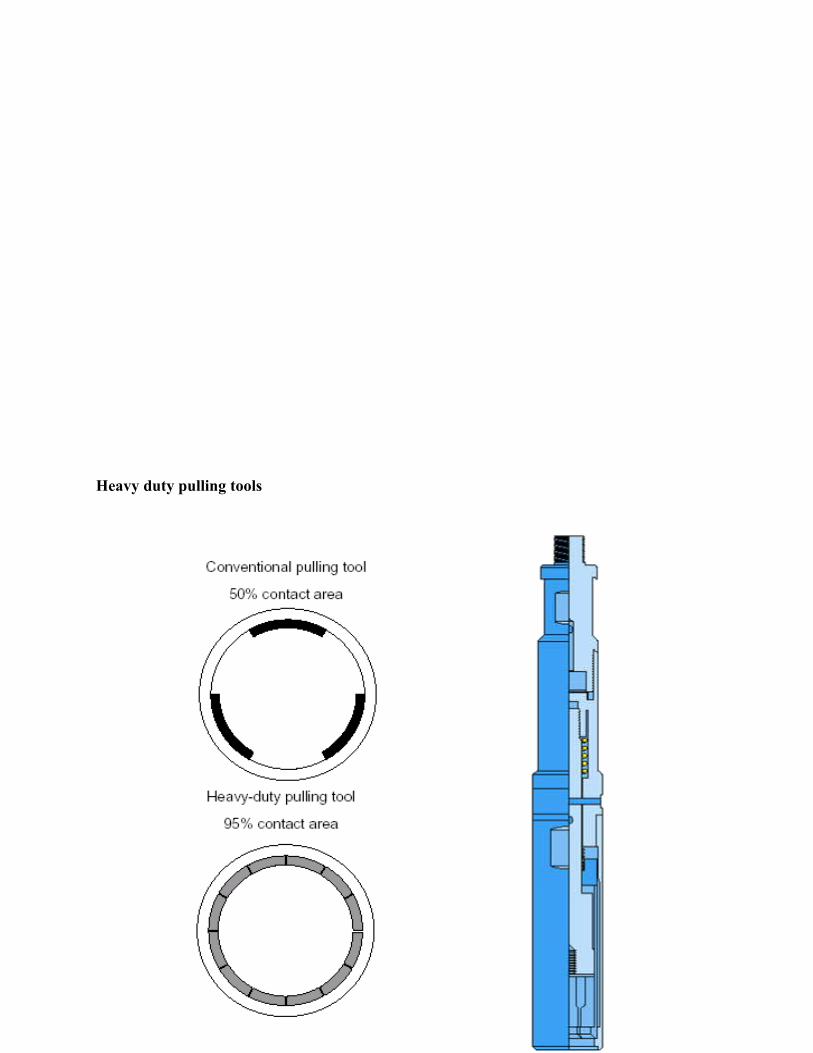
Heavy duty pulling tools
Fishing
• Falls under several descriptions• When a device is stuck and cannot be removed using normal procedures• When ‘jar action’ has been lost when trying to remove a device• When wire is broken, either on surface or down hole• Most can be resolved with patience and good planning
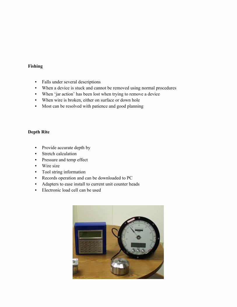
Depth Rite
• Provide accurate depth by• Stretch calculation• Pressure and temp effect• Wire size• Tool string information • Records operation and can be downloaded to PC• Adapters to ease install to current unit counter heads• Electronic load cell can be used
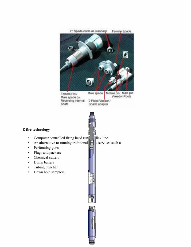
E fire technology
• Computer controlled firing head run on Slick line• An alternative to running traditional e-line services such as• Perforating guns• Plugs and packers• Chemical cutters• Dump bailers• Tubing puncher• Down hole samplers
