schneider altistart ats48 manual
DESCRIPTION
Schneider Altistart ATS48 ManualTRANSCRIPT

www.schneider-electric.com1494
409
Altistart 48Guide d'exploitationUser manualBenutzerhandbuchGuía de explotaciónGuida all’impiego用户手册12/2012
Démarreurs-ralentisseurs progressifs, Soft start- soft stop units,
Sanftanlasser,Arrancadores, ralentizadores
progresivos,Avviatori-rallentatoriprogressvi,
软起动器

86 1494409 12/2012
ENG
LISH
As a rule, the Altistart 48 control (CL1 - CL2) and power (1/L1 - 3/L2 - 5/L3) supplies must bedisconnected before any operation on either the electrical or mechanical parts of theinstallation or machine.During operation the motor can be stopped by cancelling the run command. The starterremains powered up. If personnel safety requires prevention of sudden restarts, this electroniclocking system is not sufficient: fit a breaker on the power circuit.
The starter is fitted with safety devices which, in the event of a fault, can stop the starter andconsequently the motor. The motor itself may be stopped by a mechanical blockage. Finally,voltage variations or line supply failures can also cause shutdowns.If the cause of the shutdown disappears, there is a risk of restarting which may endangercertain machines or installations, especially those which must conform to safety regulations.In this case the user must take precautions against the possibility of restarts, in particular byusing a low speed detector to cut off power to the starter if the motor performs anunprogrammed shutdown.
The products and equipment described in this document may be changed or modified at anytime, either from a technical point of view or in the way they are operated. Their description canin no way be considered contractual.
This starter must be installed and set up in accordance with both international and nationalstandards. Bringing the device into conformity is the responsibility of the systems integratorwho must observe the EMC directive among others within the European Union.The specifications contained in this document must be applied in order to comply with theessential requirements of the EMC directive.
The Altistart 48 must be considered as a component: it is neither a machine nor a device readyfor use in accordance with European directives (machinery directive and electromagneticcompatibility directive). It is the responsibility of the final integrator to guarantee conformity tothe relevant standards.

1494409 12/2012 87
ENG
LISHContents
Steps for setting up the starter ______________________________________________________ 88
Factory configuration _____________________________________________________________ 90
Preliminary recommendations ______________________________________________________ 91
Technical specifications ___________________________________________________________ 92
Operating recommendations _______________________________________________________ 93
Starter-motor combi nations ________________________________________________________ 96
Dimensions ___________________________________________________________________ 102
Mounting recommendations _______________________________________________________ 104
Mounting in a wall-fixing or floor-standing enclosure ____________________________________ 105
Power terminals ________________________________________________________________ 106
Control terminals _______________________________________________________________ 111
Wiring/RUN - STOP commands ____________________________________________________ 112
Application diagram _____________________________________________________________ 113
Thermal protection ______________________________________________________________ 123
Display unit and programming _____________________________________________________ 127
Remote terminal option __________________________________________________________ 130
Settings menu (Set) _____________________________________________________________ 131
Protection menu (PrO) ___________________________________________________________ 136
Advanced settings menu (drC) _____________________________________________________ 140
I/O menu (IO) __________________________________________________________________ 144
2nd motor parameters menu (St2) __________________________________________________ 148
Communication menu (COP) ______________________________________________________ 152
Parameter displayed menu (SUP) __________________________________________________ 154
Compability table _______________________________________________________________ 157
Maintenance __________________________________________________________________ 158
Faults - causes - remedies ________________________________________________________ 159
Configuration/Settings tables ______________________________________________________ 165

ENG
LISH
Steps for setting up the starter
1 - Check the delivery of the Altistart 48• Check that the starter reference printed on the label is the same as that on the delivery note corresponding
to the purchase order.• Remove the Altistart 48 from its packaging and check that it has not been damaged in transit.
2 - Mount the soft starter vertically• Fit the Altistart 48 in accordance with the recommendations on page 104 and page 105.
3 - Connect the Altistart 48: • Wire the soft starter to the ground.• The control line supply (CL1 – CL2), ensuring that it is off• The power line supply (1/L1 - 3/L2 - 5/L3), ensuring that it is off• The motor (2/T1 - 4/T2 - 6/T3), ensuring that its coupling corresponds to the supply voltage
Note: For other wiring diagrams, see page 113 to page 117.If the ATS48pppQ / ATS48pppYS316 is used in the motor delta windings, follow the recommendations onpage 94, page 95 and the diagrams on page 115.
WARNINGDAMAGED SOFT STARTER EQUIPMENTDo not operate or install any soft starter or soft starter accessory that appears damaged.Failure to follow these instructions can result in death, serious injury or equipment damage.
2/T1
4/T2
A2
B2
C2
6/T3
STO
P
RU
N
LI3
LI4
+24
V
LO1
LO2
CO
M
AO
1
R1A
R1C
R2A
R2C
R3A
R3C
3/L2
1/L1
5/L3
CL1
CL2
2 4 6
– KM1
12
34
56
M1 3 c
U1
W1
V1
– T1
PTC
1
PTC
2
R2A
R2C
R1A
R1C
1314
– Q1
– KM3
12
34
56
– KM3
A1
A2
– KM1
A1
A2
A1
A1
LO+
(1) Q2
S1
1 2
1 2
1 2
– Q1
1 3 5
(2)(3)
– Q3 – Q5
– Q4
Emergency Stop
2-wire control
(1) Installation of fast-acting fuses for type 2 coordination(conforming to IEC 60 947-4-2)(2) Assignment of relay R1: isolating relay (r1I). Beware of theoperating limits of the contact, for example when connectingto high rating contactors. See “Electrical characteristics”,page 111.(3) Beware of the operating limits of the contact, for examplewhen connecting to high rating contactors. See See “Electricalcharacteristics”, page 111.
88 1494409 12/2012

ENG
LISH
Steps for setting up the starter4 - Powering up the control part (CL1-CL2) • Powering up without the power part and without giving the run command.• Check that S1 is open.• Switch on: Q1, then Q3, then Q4.• The starter displays: nLP (to indicate that the power is switched off).
5 - Adjust In nominal motor current• See Nominal Motor Current on Motor Nameplate
6 - Powering up the power part (1/L1 - 3/L2 - 5/L3) • Switch on: Q5.• The soft starter displays: rdY (to indicate that the starter is powered up and ready).
7 - Start the motor• Push S1, the motor starts
8 - Troubleshooting information• See Faults - causes - remedies page 159
CAUTIONRISK OF DAMAGE TO THE SOFT STARTER• Check the power supply on CL1 - CL2:
ATS48pppQ must be 220 - 415 V ACATS48pppY must be 110 - 230 V AC
Failure to follow these instructions can result in equipment damage
CAUTIONMOTOR OVERHEATING HAZARDThe ATS 48 starter is factory-configured for a standard application which does not require specificfunctions. It has motor protection class 10.The settings can be changed by accessing the parameters as described on page 128.In all cases the In parameter must be set to the current value indicated on the motor rating plate.Failure to follow these instructions can result in equipment damage
nLP
SEt
ESC
ENT
ESC
ESC
In
Display of starter status
1494409 12/2012 89

ENG
LISH
Factory configuration
Factory settingsThe Altistart 48 is factory-set for the most common operating conditions:
• The ATS 48 is used on the motor line supply (it is not inserted as a delta connection in the motor windings)
• Nominal motor current In: - ATS 48 •••Q: preset for a standard 400 V 4-pole motor- ATS 48 •••Y: preset for NEC current, 460 V motor
• Limiting current (ILt): 400% of the motor current In
• Acceleration ramp (ACC): 15 seconds
• Initial torque on starting (tq0): 20% of the nominal torque
• Stop (StY): Freewheel stop (-F-)
• Motor thermal protection (tHP): class 10 protection curve
• Display: rdY (starter ready) with power and control voltage present, motor current operating
• Logic inputs: - LI1: STOP- LI2: RUN- LI3: Forced freewheel stop (LIA)- LI4: Forced local mode (LIL)
• Logic outputs:- LO1: Motor thermal alarm (tA1)- LO2: Motor powered (mI)
• Relay outputs:- R1: Fault relay (r1I)- R2: Bypass relay at the end of starting- R3: Motor powered (mI)
• Analog output:- AO: Motor current (OCr, 0 - 20 mA)
• Communication parameters:
- Connected via the serial link, the starter has the logic address (Add) = "0" - Transmission speed (tbr): 19200 bits per second- Communication format (FOr): 8 bits, no parity, 1 stop bit (8nl)
If the above values are compatible with the application, the starter can be used without changing the settings.
90 1494409 12/2012

ENG
LISH
Preliminary recommendationsHandling and storageTo ensure the starter is protected before installation, handle and store the device in its packaging.
Handling on installationThe Altistart 48 range comprises 6 sizes of device, with various weights and dimensions.
Small starters can be removed from their packaging and installed without a handling device.
A handling device must be used with large starters; for this reason they are supplied with handling "lugs". The precautions described below must be observed:
Do not handle the starter by the power rails
45°maxi
1494409 12/2012 91

ENG
LISH
Technical specifications
Environment
(1) ATS 48 starters with degree of protection IP00 must be fitted with a protective bar toprotect personnel against electrical contact
Degree of protection • IP 20 for ATS 48D17• to C11•• IP00 for ATS 48C14• to M12• (1)
Vibration resistance Conforming to IEC 68-2-6:• 1.5 mm peak from 2 to 13 Hz• 1 gn from 13 to 200 Hz
Shock resistance Conforming to IEC 68-2-27: • 15 g, 11 ms
Maximum ambient pollution Degree 3 conforming to IEC 947-4-2
Maximum relative humidity 93% without condensation or dripping water conforming to IEC 68-2-3
Ambient temperature around the unit Storage: - 25 °C to + 70 °C
Operation:• - 10 °C to + 40 °C without derating• up to +60 °C, derating the current by 2% for each °C above 40 °C
Maximum operating altitude 1000 m without derating (above this, derate the current by 2 % for each additional 100 m)
Operating position Vertical at ± 10°
92 1494409 12/2012

ENG
LISH
Operating recommendationsAvailable torque
Curves Ts and Is represent the direct line starting of anasynchronous motor.
Curve Ta1 indicates the total torque range available with anATS 48, which is dependent on the limiting current ILt. Theprogression of the starter is controlled by the motor torque withinthis range.
Tr: Resistive torque, which must always be less than the Ts1torque.
Selecting the soft start - soft stop unitS1 motor duty corresponds to starting followed by operation at constant load enabling the thermal equilibriumto be reached.S4 motor duty corresponds to a cycle comprising starting, operation at constant load and an idle period. Thiscycle is characterised by a load factor.
The Altistart 48 must be selected depending on the type of application ("standard" or "severe") and the nominalpower of the motor. "Standard" or "severe" applications define the limiting values of the current and the cyclefor motor duties S1 and S4.
Caution: Do not use the Altistart 48 upstream of loads other than motors (for exampletransformers and resistors are forbidden). Do not connect power factor correctioncapacitors to the terminals of a motor controlled by an Altistart 48
Standard applicationExample: centrifugal pumpIn standard applications, the Altistart 48 is designed to provide:• in S1 duty: starting at 4 In for 23 seconds or starting at 3 In for 46 seconds from a cold state.• in S4 duty: a load factor of 50% and 10 starts per hour, with 3 In for 23 seconds or 4 In for 12 seconds or an
equivalent thermal cycle.In this case, the motor thermal protection must conform to protection class 10.
Severe applicationExample: grinderIn severe applications, the Altistart 48 is designed for S4 duty with a load factor of 50% and 5 starts per hourat 4 In for 23 seconds or an equivalent thermal cycle.In this case, the motor thermal protection must conform to protection class 20. Current In must not remain atits factory setting but must be set to the value indicated on the motor rating plate.
Note: The starter can be oversized by one rating, for example by selecting an ATS 48D17Q for an 11 kW -400 V motor in motor duty S4.To do this, short-circuit the Altistart at the end of starting. This permits 10 starts per hour at 3 times In for23 seconds maximum or equivalent and the thermal motor protection must conform to class 10.
00 0.25 0.5 0.75 1
N/Ns
Cr
Ts1
TsILt
Is
1494409 12/2012 93

ENG
LISH
Operating recommendations
The Altistart 48 Q range (230-415 V) connected in line with the motor or in the motor delta winding
The Altistart 48 connected in the motor supply line
See application diagram page 114
L1
ATS48
U2 V2
1/L1
3/L2
5/L3
2/T1
4/T2
6/T3
W2
U1 V1 W1
L2 L3
The motor connection depends on the supply voltage,which in this example is a star connection.
ATS48
U2
V2
1/L1
3/L2
5/L3
2/T1
4/T2
6/T3
W2
U1
V1
W1
L1 L2 L3
The motor connection depends on the supply voltage,which in this example is a delta connection.
94 1494409 12/2012

ENG
LISH
Operating recommendationsThe Altistart 48 connected in the motor delta winding in series with each windingATS48pppQ or ATS48pppYS316 starters connected to motors with delta connections can be inserted in seriesin the motor windings. They are powered by a current which is less than the line current by a factor of √3, whichenables a starter with a lower rating to be used.
Note: This option can be configured in the Advanced settings menu (dLt = On).The nominal current and limiting current settings as well as the current displayed during operation are on-linevalues and so do not have to be calculated by the user.
The Altistart 48 can only be connected in the motor delta winding for ATS48pppQ orATS48pppYS316 starters. This means that:- dynamic braking stop is not possible- cascading is not possible- preheating is not possible
See the tables on page 96 for more information about starter-motor combinations.
See application diagram page 115
Example:A 400 V - 110 kW motor with a line current of 195 A (nominal current for the delta connection).The current in each winding is equal to 195/1.7 or 114 A.The rating is determined by selecting the starter with a maximum permanent nominal current just above thiscurrent, i.e. 140 A (ATS48C14Q for a standard application).To avoid having to calculate the rating in this way, use the tables on page 98 and 99 which indicate the ratingof the starter corresponding to the motor power for each application type.
ATS4
8ppp
Q /
ATS4
8ppp
YS31
6
ATS48
U2
V2
1/L1
3/L2
5/L3
2/T1
4/T2
6/T3
W2
U1
V1
W1
Connection in the motor delta winding
1494409 12/2012 95

ENG
LISH
Starter-motor combinations
Standard application, 230/415 V supply, starter withline connection
The nominal motor current In must not exceed the max. permanent current in class 10.(1) Value not indicated when there is no corresponding standardised motor.
Temperature deratingThe information in the table above is based on operation at a maximum ambient temperature of 40°C.The ATS 48 can be used up to an ambient temperature of 60°C as long as the max. permanent current in class10 is derated by 2% for each degree above 40°C.Example: ATS 48D32Q at 50°C derated by 10 x 2% = 20%, 32 A becomes 32 x 0.8 = 25.6 A (max. nominalmotor current).
Motor Starter 230/415 V (+ 10% - 15%) - 50/60 Hz
Nominal motor power Max. permanent current in class 10
ICLrating
Starter reference
230 V 400 V
kW kW A A4 7.5 17 17 ATS 48D17Q
5.5 11 22 22 ATS 48D22Q
7.5 15 32 32 ATS 48D32Q
9 18.5 38 38 ATS 48D38Q
11 22 47 47 ATS 48D47Q
15 30 62 62 ATS 48D62Q
18.5 37 75 75 ATS 48D75Q
22 45 88 88 ATS 48D88Q
30 55 110 110 ATS 48C11Q
37 75 140 140 ATS 48C14Q
45 90 170 170 ATS 48C17Q
55 110 210 210 ATS 48C21Q
75 132 250 250 ATS 48C25Q
90 160 320 320 ATS 48C32Q
110 220 410 410 ATS 48C41Q
132 250 480 480 ATS 48C48Q
160 315 590 590 ATS 48C59Q
(1) 355 660 660 ATS 48C66Q
220 400 790 790 ATS 48C79Q
250 500 1000 1000 ATS 48M10Q
355 630 1200 1200 ATS 48M12Q
M
96 1494409 12/2012

ENG
LISH
Starter-motor combinationsSevere application, 230/415 V supply, starter withline connection
The nominal motor current In must not exceed the max. permanent current in class 20.(1) Value not indicated when there is no corresponding standardised motor.
Temperature deratingThe information in the table above is based on operation at a maximum ambient temperature of 40°C.The ATS 48 can be used up to an ambient temperature of 60°C as long as the max. permanent current in class20 is derated by 2% for each degree above 40°C.Example: ATS 48D32Q at 50°C derated by 10 x 2% = 20%, 22 A becomes 22 x 0.8 = 17.6 A (max. nominalmotor current).
Motor Starter 230/415 V (+ 10% - 15%) - 50/60 Hz
Nominal motor power Max. permanent current in class 20
ICLrating
Starter reference
230 V 400 V
kW kW A A3 5.5 12 17 ATS 48D17Q
4 7.5 17 22 ATS 48D22Q
5.5 11 22 32 ATS 48D32Q
7.5 15 32 38 ATS 48D38Q
9 18.5 38 47 ATS 48D47Q
11 22 47 62 ATS 48D62Q
15 30 62 75 ATS 48D75Q
18.5 37 75 88 ATS 48D88Q
22 45 88 110 ATS 48C11Q
30 55 110 140 ATS 48C14Q
37 75 140 170 ATS 48C17Q
45 90 170 210 ATS 48C21Q
55 110 210 250 ATS 48C25Q
75 132 250 320 ATS 48C32Q
90 160 320 410 ATS 48C41Q
110 220 410 480 ATS 48C48Q
132 250 480 590 ATS 48C59Q
160 315 590 660 ATS 48C66Q
(1) 355 660 790 ATS 48C79Q
220 400 790 1000 ATS 48M10Q
250 500 1000 1200 ATS 48M12Q
M
1494409 12/2012 97

ENG
LISH
Starter-motor combinations
Standard application, 230/415 V supply, starter with delta connection
The nominal motor current In must not exceed the max. permanent current in class 10.(1) Value not indicated when there is no corresponding standardised motor.
Temperature deratingThe information in the table above is based on operation at a maximum ambient temperature of 40°C.The ATS 48 can be used up to an ambient temperature of 60°C as long as the max. permanent current in class10 is derated by 2% for each degree above 40°C.Example: ATS 48D32Q at 50°C derated by 10 x 2% = 20%, 55 A becomes 55 x 0.8 = 44 A (max. nominal motorcurrent).
Motor Starter 230/415 V (+ 10% - 15%) - 50/60 Hz
Nominal motor power Max. permanent current in class 10
ICLrating
Starter reference
230 V 400 V
kW kW A A7.5 15 29 29 ATS 48D17Q
9 18.5 38 38 ATS 48D22Q
15 22 55 55 ATS 48D32Q
18.5 30 66 66 ATS 48D38Q
22 45 81 81 ATS 48D47Q
30 55 107 107 ATS 48D62Q
37 55 130 130 ATS 48D75Q
45 75 152 152 ATS 48D88Q
55 90 191 191 ATS 48C11Q
75 110 242 242 ATS 48C14Q
90 132 294 294 ATS 48C17Q
110 160 364 364 ATS 48C21Q
132 220 433 433 ATS 48C25Q
160 250 554 554 ATS 48C32Q
220 315 710 710 ATS 48C41Q
250 355 831 831 ATS 48C48Q
(1) 400 1022 1022 ATS 48C59Q
315 500 1143 1143 ATS 48C66Q
355 630 1368 1368 ATS 48C79Q
(1) 710 1732 1732 ATS 48M10Q
500 (1) 2078 2078 ATS 48M12Q
M
98 1494409 12/2012

ENG
LISH
Starter-motor combinationsSevere application, 230/415 V supply, starter with delta connection
The nominal motor current In must not exceed the max. permanent current in class 20.(1) Value not indicated when there is no corresponding standardised motor.
Temperature deratingThe information in the table above is based on operation at a maximum ambient temperature of 40°C.The ATS 48 can be used up to an ambient temperature of 60°C as long as the max. permanent current in class20 is derated by 2% for each degree above 40°C.Example: ATS 48D32Q at 50°C derated by 10 x 2% = 20%, 38 A becomes 38 x 0.8 = 30.4 A (max. nominalmotor current).
Motor Starter 230/415 V (+ 10% - 15%) - 50/60 Hz
Nominal motor power Max. permanent current in class 20
ICLrating
Starter reference
230 V 400 V
kW kW A A5.5 11 22 29 ATS 48D17Q
7.5 15 29 38 ATS 48D22Q
9 18.5 38 55 ATS 48D32Q
15 22 55 66 ATS 48D38Q
18.5 30 66 81 ATS 48D47Q
22 45 81 107 ATS 48D62Q
30 55 107 130 ATS 48D75Q
37 55 130 152 ATS 48D88Q
45 75 152 191 ATS 48C11Q
55 90 191 242 ATS 48C14Q
75 110 242 294 ATS 48C17Q
90 132 294 364 ATS 48C21Q
110 160 364 433 ATS 48C25Q
132 220 433 554 ATS 48C32Q
160 250 554 710 ATS 48C41Q
220 315 710 831 ATS 48C48Q
250 355 831 1022 ATS 48C59Q
(1) 400 1022 1143 ATS 48C66Q
315 500 1143 1368 ATS 48C79Q
355 630 1368 1732 ATS 48M10Q
(1) 710 1732 2078 ATS 48M12Q
M
1494409 12/2012 99

ENG
LISH
Starter-motor combinations
Standard application, 208/690 V supply, starter withline connection
The nominal motor current In must not exceed the max. permanent current in class 10.(1) Value not indicated when there is no corresponding standardised motor.
Temperature deratingThe information in the table above is based on operation at a maximum ambient temperature of 40°C.The ATS 48 can be used up to an ambient temperature of 60°C as long as the max. permanent current in class10 is derated by 2% for each degree above 40°C.Example: ATS 48D32Y at 50°C derated by 10 x 2% = 20%, 32 A becomes 32 x 0.8 = 25.6 A (max. nominalmotor current).
Motor Starter 208/690 V (+ 10% - 15%) - 50/60 Hz
Nominal motor power Max. permanent current in class 10
ICLrating
Starterreference 208 V 230 V 440 V 460 V 500 V 575 V 690 V
HP HP kW HP kW HP kW A A
3 5 7.5 10 9 15 15 17 17 ATS 48D17Y
5 7.5 11 15 11 20 18.5 22 22 ATS 48D22Y
7,5 10 15 20 18.5 25 22 32 32 ATS 48D32Y
10 (1) 18.5 25 22 30 30 38 38 ATS 48D38Y
(1) 15 22 30 30 40 37 47 47 ATS 48D47Y
15 20 30 40 37 50 45 62 62 ATS 48D62Y
20 25 37 50 45 60 55 75 75 ATS 48D75Y
25 30 45 60 55 75 75 88 88 ATS 48D88Y
30 40 55 75 75 100 90 110 110 ATS 48C11Y
40 50 75 100 90 125 110 140 140 ATS 48C14Y
50 60 90 125 110 150 160 170 170 ATS 48C17Y
60 75 110 150 132 200 200 210 210 ATS 48C21Y
75 100 132 200 160 250 250 250 250 ATS 48C25Y
100 125 160 250 220 300 315 320 320 ATS 48C32Y
125 150 220 300 250 350 400 410 410 ATS 48C41Y
150 (1) 250 350 315 400 500 480 480 ATS 48C48Y
(1) 200 355 400 400 500 560 590 590 ATS 48C59Y
200 250 400 500 (1) 600 630 660 660 ATS 48C66Y
250 300 500 600 500 800 710 790 790 ATS 48C79Y
350 350 630 800 630 1000 900 1000 1000 ATS 48M10Y
400 450 710 1000 800 1200 (1) 1200 1200 ATS 48M12Y
M
100 1494409 12/2012

ENG
LISH
Starter-motor combinationsSevere application, 208/690 V supply, starter with lineconnection
The nominal motor current In must not exceed the max. permanent current in class 20.(1) Value not indicated when there is no corresponding standardised motor.
Temperature deratingThe information in the table above is based on operation at a maximum ambient temperature of 40°C.The ATS 48 can be used up to an ambient temperature of 60°C as long as the max. permanent current in class20 is derated by 2% for each degree above 40°C.Example: ATS 48D32Y at 50°C derated by 10 x 2% = 20%, 22 A becomes 22 x 0.8 = 17.6 A (max. nominalmotor current).
Motor Starter 208/690 V (+ 10% - 15%) - 50/60 Hz
Nominal motor power Max. permanent current in class 20
ICLrating
Starterreference 208 V 230 V 440 V 460 V 500 V 575 V 690 V
HP HP kW HP kW HP kW A A
2 3 5.5 7.5 7.5 10 11 12 17 ATS 48D17Y
3 5 7.5 10 9 15 15 17 22 ATS 48D22Y
5 7.5 11 15 11 20 18.5 22 32 ATS 48D32Y
7,5 10 15 20 18.5 25 22 32 38 ATS 48D38Y
10 (1) 18.5 25 22 30 30 38 47 ATS 48D47Y
(1) 15 22 30 30 40 37 47 62 ATS 48D62Y
15 20 30 40 37 50 45 62 75 ATS 48D75Y
20 25 37 50 45 60 55 75 88 ATS 48D88Y
25 30 45 60 55 75 75 88 110 ATS 48C11Y
30 40 55 75 75 100 90 110 140 ATS 48C14Y
40 50 75 100 90 125 110 140 170 ATS 48C17Y
50 60 90 125 110 150 160 170 210 ATS 48C21Y
60 75 110 150 132 200 200 210 250 ATS 48C25Y
75 100 132 200 160 250 250 250 320 ATS 48C32Y
100 125 160 250 220 300 315 320 410 ATS 48C41Y
125 150 220 300 250 350 400 410 480 ATS 48C48Y
150 (1) 250 350 315 400 500 480 590 ATS 48C59Y
(1) 200 355 400 400 500 560 590 660 ATS 48C66Y
200 250 400 500 (1) 600 630 660 790 ATS 48C79Y
250 300 500 600 500 800 710 790 1000 ATS 48M10Y
350 350 630 800 630 1000 900 1000 1200 ATS 48M12Y
M
1494409 12/2012 101

ENG
LISH
Dimensions
ATS 48D17 • …C66 •
ATS 48 amm
b mm
c mm
emm
G mm
H mm
Ømm
Weightkg
D17Q, D17YD22Q, D22YD32Q, D32YD38Q, D38YD47Q, D47Y
160 275 190 6.6 100 260 7 4.9
D62Q, D62YD75Q, D75YD88Q, D88YC11Q, C11Y
190 290 235 10 150 270 7 8.3
C14Q, C14YC17Q, C17Y
200 340 265 10 160 320 7 12.4
C21Q, C21YC25Q, C25YC32Q, C32Y
320 380 265 15 250 350 9 18.2
C41Q, C41YC48Q, C48YC59Q, C59YC66Q, C66Y
400 670 300 20 300 610 9 51.4
e
G ==
a
H
c
4 x Ø
b
102 1494409 12/2012

ENG
LISH
DimensionsATS 48C79 • …M12 •
ATS 48 amm
b mm
c mm
emm
G mm
H mm
Ømm
Weightkg
C79Q, C79YM10Q, M10YM12Q, M12Y
770 890 315 20 350 850 11 115
GG ==c
a
6 x Ø
bHe
1494409 12/2012 103

ENG
LISH
Mounting recommendations
Install the unit vertically, at ± 10°.
Do not install the unit close to, especially above, heating elements.
Leave sufficient free space to ensure that the air required for cooling purposes can circulate from the bottomto the top of the unit.
Check that no liquids, dust or conductiveobjects can fall into the starter (degree ofprotection IP00 from above)
Starter ventilationOn starters fitted with a cooling fan, the fan is switched on automatically as soon as the heatsink temperaturereaches 50°C. It is switched off when the temperature falls back to 40°C.
Fan flow rate:ATS 48 D32 • and D38 • : 14 m3/hourATS 48 D47 • : 28 m3/hourATS 48 D62 • to C11 • : 86 m3/hourATS 48 C14 • and C17 • : 138 m3/hourATS 48 C21 • to C32 • : 280 m3/hourATS 48 C41 • to C66 • : 600 m3/hourATS 48 C79 • to M12 • : 1,200 m3/hour
≥ 10
0 m
m
≥50
mm
≥ 50
mm
≥ 10
0 m
m
104 1494409 12/2012

ENG
LISH
Mounting in a wall-fixing or floor-standing enclosureMetal wall-fixing or floor-standing enclosure with IP 23 degree of protectionObserve the mounting recommendations on the previous page.
To ensure proper air circulation in the drive:
- Fit ventilation grilles.
- Ensure that ventilation is adequate: if not install a forced ventilation unit, with a filter if necessary.
Power dissipated by the starters, not bypassed, at their nomi-nal current
Note: When the starters are bypassed the amount of power dissipated is extremely small (between 15and 30 W)
- Control consumption (all ratings): 25 W non-ventilated
- Control consumption with fan ventilated :
Starter referenceATS 48 Power in W Starter reference
ATS 48 Power in W
D17Q, D17Y 59 C21Q, C21Y 580
D22Q, D22Y 74 C25Q, C25Y 695
D32Q, D32Y 104 C32Q, C32Y 902
D38Q, D38Y 116 C41Q, C41Y 1339
D47Q, D47Y 142 C48Q, C48Y 1386
D62Q, D62Y 201 C59Q, C59Y 1731
D75Q, D75Y 245 C66Q, C66Y 1958
D88Q, D88Y 290 C79Q, C79Y 2537
C11Q, C11Y 322 M10Q, M10Y 2865
C14Q, C14Y 391 M12Q, M12Y 3497
C17Q, C17Y 479
Soft start Power consumption (W) Apparent power (VA)
ATS 48D17p to C17p 30 80
ATS 48C21p to C32p 50 130
ATS 48C41p to M12p 80 240
θ¡ 40¡Cθ 40 C
1494409 12/2012 105

ENG
LISH
Power terminals
Layout of the power terminals, ATS 48D17 • to C11 •
Motor to be connected to 2/T1, 4/T2, 6/T3
Terminals Functions Maximum connection capacityTerminal tightening torque
ATS 48D17 • D22 •D32 • D38 •D47 •
ATS 48D62 • D75 •D88 • C11 •
ATS 48C14 • C17 •
ATS 48C21 • C25 •C32 •
ATS 48C41 • C48 •C59 • C66 •
ATS 48C79 • M10 • M12 •
tEarth connections connected to earth
10 mm2
1.7 N.m16 mm2
3 N.m120 mm2
27 N.m120 mm2
27 N.m240 mm2
27 N.m2x240 mm2
27 N.m
8 AWG15 lb.in
4 AWG26 lb.in
Busbar238 lb.in
Busbar238 lb.in
Busbar238 lb.in
Busbar238 lb.in
1/L13/L25/L3
Power supply
16 mm2
3 N.m50 mm2
10 N.m95 mm2
34 N.m240 mm2
34 N.m2x240 mm2
57 N.m4x240 mm2
57 N.m
8 AWG26 lb.in
2/0 AWG88 lb.in
2/0 AWG300 lb.in
Busbar300 lb.in
Busbar500 lb.in
Busbar500 lb.in
2/T14/T26/T3
Outputs to motor
16 mm2
3 N.m50 mm2
10 N.m95 mm2
34 N.m240 mm2
34 N.m2x240 mm2
57 N.m4x240 mm2
57 N.m
8 AWG26 lb.in
2/0 AWG88 lb.in
2/0 AWG300 lb.in
Busbar300 lb.in
Busbar500 lb.in
Busbar500 lb.in
A2B2C2
Starter bypass
16 mm2
3 N.m50 mm2
10 N.m95 mm2
34 N.m240 mm2
34 N.m2x240 mm2
57 N.m4x240 mm2
57 N.m
8 AWG26 lb.in
2/0 AWG88 lb.in
2/0 AWG300 lb.in
Busbar300 lb.in
Busbar500 lb.in
Busbar500 lb.in
1/L1
A2 2/T1 B2 4/T2 C2 6/T3
3/L2
s
s
5/L3
M
A2
2/T1
B2
4/T2
C2
6/T3
106 1494409 12/2012

ENG
LISH
Power terminalsLayout of the power terminals, ATS 48C14 • and C17 •
18 M6 20
2
40
38 62 62
159
motor
5
116.55
1625
40
1/L1 3/L2 5/L3
A2 B2 C2
2/T1 4/T2 6/T3
160= =
1
14
1
10
320
M6
9xØ9
1494409 12/2012 107

ENG
LISH
Power terminals
Layout of the power terminals, ATS 48C21 • to C32 •
2
66
70 90 9018
2 1
5 3
50
35M10 20136.55
136.55
196.55
66
1/L1 3/L2 5/L3
A2 B2 C2
4/T22/T1 6/T3
250= =
9xØ12
motor
M10
108 1494409 12/2012

ENG
LISH
Power terminalsLayout of the power terminals, ATS 48C41 • to C66 •
0,25 40
165
2165
5
58
11511550
M10
300= =
120
20
115 115
69
5
127
40
15
610
1655
1/L1 3/L2 5/L3
B2 C2
4/T2 6/T3
9xØ14
2/T1
A2
M10
motor
1494409 12/2012 109

ENG
LISH
Power terminals
Layout of the power terminals, ATS 48C79 • to M12 •
188
60
60
116.55
5 196.5
22995
204
26
26
26
26
26
850
20
2
24
5
1705
350= = 350
257
164 223.5 209.5
129 26 26 26
26
155 180
1/L1 3/L2 5/L3
A2 B2 C2
2/T1 4/T2 6/T3
18xØ14
motor
M10
M10
110 1494409 12/2012
ENG
LISH
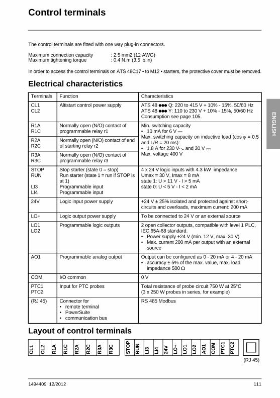
Control terminalsThe control terminals are fitted with one way plug-in connectors.
In order to access the control terminals on ATS 48C17 • to M12 • starters, the protective cover must be removed.
Electrical characteristics
Layout of control terminals
Maximum connection capacity : 2.5 mm2 (12 AWG)Maximum tightening torque : 0.4 N.m (3.5 lb.in)
Terminals Function Characteristics
CL1CL2
Altistart control power supply ATS 48 ppp Q: 220 to 415 V + 10% - 15%, 50/60 HzATS 48 ppp Y: 110 to 230 V + 10% - 15%, 50/60 HzConsumption see page 105.
R1AR1C
Normally open (N/O) contact of programmable relay r1
Min. switching capacity• 10 mA for 6 V cMax. switching capacity on inductive load (cos ϕ = 0.5and L/R = 20 ms):• 1.8 A for 230 Va and 30 V cMax. voltage 400 V
R2AR2C
Normally open (N/O) contact of end of starting relay r2
R3AR3C
Normally open (N/O) contact of programmable relay r3
STOPRUN
LI3LI4
Stop starter (state 0 = stop)Run starter (state 1 = run if STOP is at 1)Programmable inputProgrammable input
4 x 24 V logic inputs with 4.3 kW impedanceUmax = 30 V, Imax = 8 mAstate 1: U > 11 V - I > 5 mAstate 0: U < 5 V - I < 2 mA
24V Logic input power supply +24 V ± 25% isolated and protected against short-circuits and overloads, maximum current: 200 mA
LO+ Logic output power supply To be connected to 24 V or an external source
LO1LO2
Programmable logic outputs 2 open collector outputs, compatible with level 1 PLC, IEC 65A-68 standard.• Power supply +24 V (min. 12 V, max. 30 V)• Max. current 200 mA per output with an external
source
AO1 Programmable analog output Output can be configured as 0 - 20 mA or 4 - 20 mA• accuracy ± 5% of the max. value, max. load
impedance 500 Ω
COM I/O common 0 V
PTC1PTC2
Input for PTC probes Total resistance of probe circuit 750 W at 25°C (3 x 250 W probes in series, for example)
(RJ 45) Connector for• remote terminal• PowerSuite• communication bus
RS 485 Modbus
CL1
CL2
R1A
R1C
R2A
R2C
R3A
R3C
STO
P
RU
N
LI3
LI4
24V
LO+
LO1
LO2
AO
1
CO
M
PTC
1
PTC
2
(RJ 45)
1494409 12/2012 111
ENG
LISH
Wiring/RUN - STOP commands
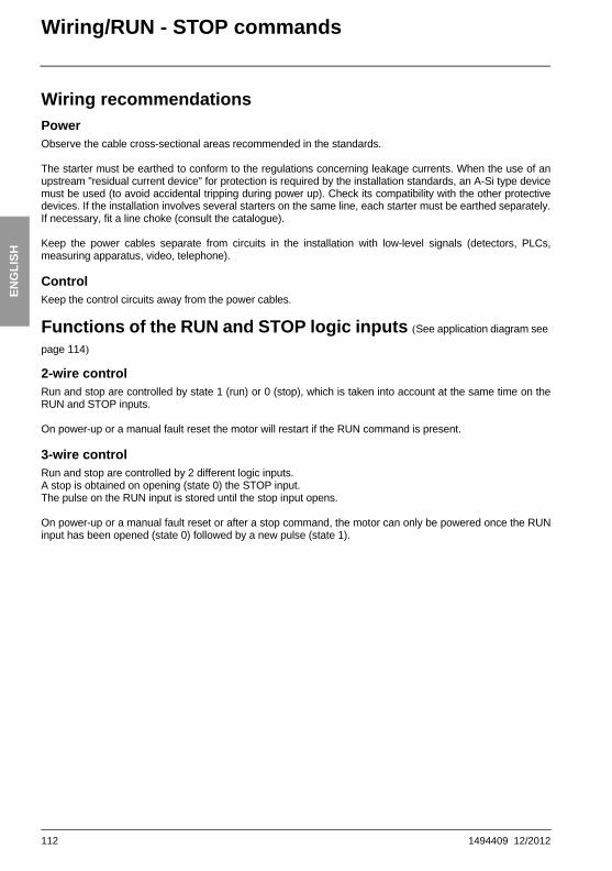
Wiring recommendationsPowerObserve the cable cross-sectional areas recommended in the standards.
The starter must be earthed to conform to the regulations concerning leakage currents. When the use of anupstream "residual current device" for protection is required by the installation standards, an A-Si type devicemust be used (to avoid accidental tripping during power up). Check its compatibility with the other protectivedevices. If the installation involves several starters on the same line, each starter must be earthed separately.If necessary, fit a line choke (consult the catalogue).
Keep the power cables separate from circuits in the installation with low-level signals (detectors, PLCs,measuring apparatus, video, telephone).
ControlKeep the control circuits away from the power cables.
Functions of the RUN and STOP logic inputs (See application diagram see
page 114)
2-wire controlRun and stop are controlled by state 1 (run) or 0 (stop), which is taken into account at the same time on theRUN and STOP inputs.
On power-up or a manual fault reset the motor will restart if the RUN command is present.
3-wire controlRun and stop are controlled by 2 different logic inputs.A stop is obtained on opening (state 0) the STOP input.The pulse on the RUN input is stored until the stop input opens.
On power-up or a manual fault reset or after a stop command, the motor can only be powered once the RUNinput has been opened (state 0) followed by a new pulse (state 1).
112 1494409 12/2012

ENG
LISH
Application diagramATS 48: Non-reversing, with line contactor, freewheel stop, type 1 coordi-nation
(1)Installation of fast-acting fuses for type 2 coordination (conforming to IEC 60 947-4-2)(2)Assignment of relay R1: isolating relay (r1I). See “Electrical characteristics”, page 111. Beware
of the operating limits of the contact, for example when connecting to high rating contactors.(3)Insert a transformer if the supply voltage is different to that permitted by the ATS 48 control. See
“Electrical characteristics”, page 111.
M
2/T1
4/T2
6/T3
STO
P
RUN
LI3
+24V
LO+
LO1
LO2
COM
AO1
R1A
R1C
R2A
R2C
R3A
R3C
3/L2
1/L1
5/L3 CL
2
2 4 6
– KM1
12
34
56
M1 3 c
U1
W1
V1
– T1R1A
(2)
R1C
1314
– Q1
1314
– KM1
– S1
– S2
– KM1
A1
A2
A1
A1
– KM1
Q3(1)
5453
1 2
1 2
1 2
– Q1
1 3 5
CL1
LI4
PTC1
PTC2
(3)
– Q3 – Q5
– Q4
U2 V2
2/T1
4/T2
6/T3
W2
U1 V1 W1U2
V2
2/T1
4/T2
6/T3
W2
U1
V1
W1
M1
stopEmergency
Star connection Delta connection
1494409 12/2012 113

ENG
LISH
Application diagram
ATS 48: Non-reversing with line contactor, bypass, freewheel or controlled stop, type 1 coordination
(1) Installation of fast-acting fuses for type 2 coordination (conforming to IEC 60 947-4-2)(2) Assignment of relay R1: isolating relay (r1I). Beware of the operating limits of the contact, for
example when connecting to high rating contactors. See “Electrical characteristics”, page 111.(3) Beware of the operating limits of the contact, for example when connecting to high rating
contactors. See “Electrical characteristics”, page 111.(4) Insert a transformer if the supply voltage is different to that permitted by the ATS 48 control. See
“Electrical characteristics”, page 111.(5)See “2-wire control”, page 112.(6)See “3-wire control”, page 112.
M
2/T1
4/T2
A2 B2 C26/T3
STO
P
RUN
LI3
LI4
+24V
LO1
LO2
COM
AO1
R1A
R1C
R2A
R2C
R3A
R3C
3/L2
1/L1
5/L3 CL1
CL2
2 4 6
– KM1
12
34
56
M1 3 c
U1
W1
V1
– T1
PTC1
PTC2
R2A
R2C
R1A
R1C
1314
– Q1
– KM3
12
34
56
– KM3
A1A2
– KM1
A1A2
A1
A1
S1
+24V
STO
P
RUN
LO+
(1)
S2
Q2
S1
STO
P
1 2
1 2
1 2
+24V
– Q1
1 3 5
(4)
(2)(3)
– Q1
– Q3 – Q5
– Q4
U2 V2
2/T1
4/T2
6/T3
W2
U1 V1 W1U2
V2
2/T1
4/T2
6/T3
W2
U1
V1
W1
M1
Emergencystop
3-wire control (6)
PC or PLC control
2-wire control (5)Star
connectionDelta
connection
114 1494409 12/2012

ENG
LISH
Application diagramATS 48: Non-reversing, freewheel stop, type 1 coordination, with line contactor, bypass, connection to delta in the motor, ATS 48•••Q or ATS 48•••YS316
Note: Set�dlt to on (see “Advanced settings menu (drC)”, page 141)(1)Installation of fast-acting fuses for type 2 coordination (conforming to IEC 60 947-4-2).(2)It is mandatory to use KM1. External differential thermal protection will need to be added type
Vigirex pour Compact NS80, bloc Vigi pour Compact NS400 à 630,consulter le catalogue Merlin Gérin pour les calibres supérieurs.
(3)Assignment of relay R1: isolating relay (r1I). Beware of the operating limits of the contact, for example when connecting to high rating contactors. See “Electrical characteristics”, page 111.
(4)Beware of the operating limits of the contact, for example when connecting to high rating contactors. See “Electrical characteristics”, page 111.
(5)Insert a transformer if the supply voltage is different to that permissible by the ATS 48 control. See “Electrical characteristics”, page 111.
(6)See “2-wire control”, page 112.(7)See “3-wire control”, page 112.(8)Inductances de lignes éventuelles
If the bypass contactor is used, "PHF" fault detection can be extended.
M
2/T1
4/T2
A2 B2 C26/T3
STOP
RUN
LI3 LI4 +24V
LO1
LO2
COM
AO1
R1A
R1C
R2A
R2C
R3A
R3C
3/L2
1/L1
5/L3 CL1
CL2
2 4 6
– KM1
12
34
56
PTC1
PTC2
– KM3
12
34
56
A1
S1
LO+
(1)
(3)
S2
Q2
1 2
1 2
– Q11 3 5
– T1R2A
R2C
R1A
R1C
1314
– Q1
– KM3
A1A2
– KM1
A1A2
A11 2(4)
(5)
(2)
U1
W1
V1
V2
W2
U2
– Q3 – Q5
– Q4
ATS48
U2
V2
1/L1 3/L2
5/L3
2/T1
4/T2
6/T3
W2
U1
V1
W1
+24V
STOP
RUN
S1ST
OP
+24V
2-wire control (6)
PC or PLC control
3-wire control (7)
Emergencystop
connection to delta in the motor
1494409 12/2012 115

ENG
LISH
Application diagram
ATS 48: Non-reversing, freewheel or controlled stop, line contactor, motor bypass, LSP/HSP with two sets of parameters
(4) Beware of the operating limits of the contact, for example when connecting to high rating contactors. See “Electrical characteristics”, page 111.
(5) Assignment of relay R1: isolating relay (r1I). Beware of the operating limits of the contact, for example when connecting to high rating contactors. See “Electrical characteristics”, page 111.LI3 = LIS (second set of motor parameters)S3: 1 = LSP, 2 = HSP
M
RUN
STO
P
LI3
LI4
+24
V
LO1
LO2
CO
M
AO
1
R1A
R1C
R2A
R2C
R3A
R3C
PTC
1
PTC
2
LO+
2/T1
4/T2
A2
B2 C2
6/T3
3/L2
1/L1
5/L3
CL1
2 4 6
– KM1
12
34
56
CL2
– KM3
12
34
56
– KM2
– KM5
A1
Q2
1 2
1 2
– Q1
1 3 5
– T1
0
2201 2
KA1 KM2
(1)
(2)
M1 3 c
U1
W1
V1
W2
U2
V2
(3)
– Q4
– Q3 – Q5
(1) Installation of fast-acting fuses in the case of type 2 coordination (conforming to IEC 60 947-4-2).
(2) Insert a transformer if the supply voltage is different to that permitted by the ATS 48 control. See “Electrical characteristics”, page 111.
(3) Ensure that the directions of motor rotation correspond for both speeds.
KA1 KM1 KM5KM2
KM5KA1S2
S1
KM2
KM2
KM1
KM5
Q1
220
0
A1
R1C
R1A
KM3
A1
R2C
R2A
KA1
S321
(5)
(4)
Emergencystop
116 1494409 12/2012

ENG
LISH
Application diagramATS 48: Non-reversing with line contactor, starting and deceleration of se-veral cascaded motors with a single Altistart
(1) Installation of fuses for type 2 coordination (conforming to IEC 60 947-4-2)(2) Insert a transformer if the supply voltage is different to that permitted by the ATS 48 control. See “Electrical
characteristics”, page 111.(3) KM1: Must be sized in accordance with the total power of the motors.
Important:• A "cascading" logic input must be configured on the ATS48 (LI3 = LIC). See “Activation of the cascade
function”, page 142.• In the event of a fault it will not be possible to decelerate or brake any motors that may be running at that
time.• Adjust the thermal protection of each circuit breaker Qn1 to the nominal motor current.
M
– KM11
12
34
56
– KM12
12
34
56
– KM1
12
34
56
1/L1
3/L2
5/L3
2/T1
4/T2
6/T3
A1
–T1
2 4 6
1
– Q11
3 5
U1 W1
V1
M1 3
– KM21
12
34
56
– KM22
12
34
56
2 4 6
1
– Q21
3 5
U2 W2
V2
M2 3
– KMn11
2
34
56
– KMn2
12
34
56
2 4 6
1
– Qn1
3 5
Un WnVn
Mn3
Mi3
2 4 6
1 2
1 2 1 2
CL1
CL2
A1
RUN
+24V
KAT
LI3
STOP
KALIT
KALIT
A
KA KALI
B
(1)– Q2
– Q1
1 3 5
(2)(3)– Q3 – Q5
– Q4
Motor 2 Motor nMotor iMotor 1
1494409 12/2012 117

ENG
LISH
Application diagram
ATS 48: Non-reversing with line contactor, starting and deceleration of se-veral cascaded motors with a single Altistart
Motor 1 control
Motor 2 control
BPM1: "Run" button motor 1 BPA1: "Stop" button motor 1BPM2: "Run" button motor 2 BPA2: "Stop" button motor 2
KAM1 AR1 KM11 KM12
KM12
KTSHUNT
SHUNT
KAT ACDECBPM1
BPA1BPA1
KAM1 KM11 KAM1 KM11
KM11
KM12
KM12 AR1 AR1
AR1
ART
B
A
D
C
KM21
KMi1
KMn1
(n-1
) con
tact
s
KAM2 AR2 KM21 KM22
KM22
KTSHUNT
SHUNT
KAT ACDECBPM2
BPA2BPA2
KAM2 KM21 KAM2 KM21
KM21
KM22
KM22 AR2 AR2
AR2
ART
D
C
F
E
KM11
KMi1
KMn1
(n-1
) con
tact
s
118 1494409 12/2012

ENG
LISH
Application diagramATS 48: Non-reversing with line contactor, starting and deceleration of se-veral cascaded motors with a single Altistart
Motor n control
Cascade control
Wait for the end of the timer KALIT between 2 consecutive stop requests
BPMn: "Run" button motor n R1 must be configured as an isolating relay (r1 = r1I)BPAn: "Stop" button motor n
KAMn ARn KMn1 KMn2
KMn2
KTSHUNT
SHUNT
KAT ACDECBPMn
BPAnBPAn
KAMn KMn1 KAMn KMn1
KMn1
KMn2
KMn2 ARn ARn
ARn
ART
F
E
H
G
KM11
KM21
KMi1
(n-1
) con
tact
s
KAT KT
KA K KALI KALIT
KALIT ART ACDEC SHUNT
H
G
J
I
A1 R2C
ATS 48
R2A
R1C
R1A
Time delaysettings
1 s > KA > 0.1 s
K > 0.2 s
KALI > K
KALIT > 0.1 s
1494409 12/2012 119

ENG
LISH
Application diagram
ATS 48: Non-reversing with line contactor, starting and deceleration of se-veral cascaded motors with a single Altistart
Cascade control
MST: General "Run" buttonMHT: General "Stop" button
KM1 KA K KALI
KM1MST
MHT
Qn1
Qi1
Q21 KAM1 KAM2 KAMi KAMn
AR2AR1 ARi ARn
Q11
J
I
n co
ntac
ts
n contacts
n contacts
120 1494409 12/2012

ENG
LISH
Application diagramATS 48: Non-reversing with line contactor, starting and deceleration of se-veral cascaded motors with a single AltistartDescription of the complete sequenceStart with MST so that KM1 rises (line contactor)1 - 2 - 3Press BPM1 to start motor 1. Press BPM2 to start motor 2, press BPMn to start motor n.When BPM1 is pressed, KAM1 rises, as does KM11 because ACDEC is activated (the ATS48 is powered byMST and KM1).KA rises because KAM1 is closed. KAT also rises after an adjustable time delay.4 - 5The ATS48 starts the motor following a run command on RUN with KA and KAT.KAM1 drops out due to KAT.KM11 remains closed.6 - 7At the end of starting, R2 on the ATS48 rises, SHUNT is closed, KM12 is closed by SHUNT and KM11 remainsclosed.8 - 9After a short time R2 drops out followed by R1 (starter bypass function).KM11 opens because ACDEC is open.The motor continues to be powered by KM12.ATS48 display a status code.
Follow the same procedure to start the next motor. To start motor n use BPMn and to stop motor n useBPAn. The motors can be started and stopped in any order.
To stop motor 1 press BPA1. AR1 closesa - b - c - dK and KALI are closed.LI on the ATS48 receives a command from KALI and KALIT (LI must be adjusted to value LIC).R1 and R2 on the ATS48 rise (a pulse on R2 and R1 remains closed until the motor has come to a completestop).eKM11 closes.After an adjustable time delay, KT and KALIT rise.fThe ATS48 receives a stop command from KALIT.gKM12 drops out.The ATS48 decelerates the motor.h R1 on the ATS48 opens when the motor has come to a complete stop.iKM11 opens.The ATS48 is ready to start or stop another motor.
1494409 12/2012 121

ENG
LISH
Application diagram
ATS 48: Non-reversing with line contactor, starting and deceleration of se-veral cascaded motors with a single AltistartTrend diagram
4 8 c
a
f
b
e
d
g
h
h
i
h
3
1
2
5
6 9
7
Motor powered by the ATS48
LI3
STOP
RUN
RI(Isolating relay)
KM11
Speed
R2(Control of the
starter bypass contactor)
KM12
Motor start Motor stop
ATS48 idle
122 1494409 12/2012

ENG
LISH
Thermal protectionStarter thermal protectionThermal protection is provided by the PTC probe fitted on the heatsink and by calculating the temperature riseof the thyristors.
Motor thermal protectionThe starter continuously calculates the temperature rise of the motor based on the controlled nominal currentIn and the actual current absorbed.
Temperature rises can be caused by a low or high overload with a long or short duration. The tripping curveson the following pages are based on the relationship between the starting current Is and the (adjustable) motorcurrent In.
Standard IEC60947-4-2 defines the protection classes giving the starting capacities of the motor (warm or coldstart) without thermal faults. Different protection classes are given for a COLD state (corresponding to astabilised motor thermal state, switched off) and for a WARM state (corresponding to a stabilised motor thermalstate, at nominal power).
The starter is factory-set to protection class 10.This protection class can be modified using the PrO menu.
The thermal protection displayed by the starter corresponds to the iron time constant.- An overload alarm is activated if the motor exceeds its nominal temperature rise threshold (motor thermal
state = 110%).- A thermal fault stops the motor if it exceeds the critical temperature rise threshold (motor thermal state =
125%).
In the event of a prolonged start, the starter can trip on a fault or thermal alarm even if the value displayed isless than the trip value.
The thermal fault can be indicated by relay R1 if thermal protection has not been disabled.
After the motor has stopped or the starter has been switched off, the thermal state is calculated even if thecontrol circuit is not powered. The Altistart thermal control prevents the motor from restarting if the temperaturerise is too high.
If a special motor is used (flameproof, submersible, etc.) thermal protection should be provided by PTC probes.
1494409 12/2012 123

ENG
LISH
Thermal protection
Motor thermal protection
Cold curves
Trip time for a standard application (class 10) Trip time for a severe application (class 20)
3 In 5 In 3.5 In 5 In
46 s 15 s 63 s 29 s
0.5
1
10
100
1000
10000
t(s)
8.00I/Ie
7.507.006.506.005.505.004.504.003.503.002.502.001.51.12
Class 30
Class 10A
Class 2
Class 20Class 15
Class 10
Class 25
124 1494409 12/2012

ENG
LISH
Thermal protectionMotor thermal protectionWarm curves
Trip time for a standard application (class 10) Trip time for a severe application (class 20)
3 In 5 In 3.5 In 5 In
23 s 7.5 s 32 s 15 s
0.5
1
10
100
1000
10000t(s)
8.00I/Ie
7.507.006.506.005.505.004.504.003.503.002.502.001.51.12
Class 30Class 25Class 20Class 15
Class 10
Class 10A
Class 2
1494409 12/2012 125

ENG
LISH
Thermal protection
Motor thermal protection with PTC probesPTC probes integrated in the motor to measure its temperature can be connected to the control card terminals.This analog value is managed by the starter.
The "PTC probe thermal overshoot" value can be processed and used in two ways: - stop in the event of a fault if the signal is active- activate an alarm if the signal is active. This alarm can be displayed in a starter status word (serial link)
or on a configurable logic output.
Note:PTC probe protection does not deactivate the motor thermal protection provided by the calculation. Both typesof protection can operate in parallel.
126 1494409 12/2012

ENG
LISH
Display unit and programmingFunctions of the keys and the display
Pressing or does not store the choices.
Store, save the displayed choice: The display flashes when a value is stored.
Display principleThe display principle for numbers differs depending on the maximum scale of the parameter and its value.• Max. scale 9990:
- values 0.1 to 99.9 (examples: 05.5 = 5.5; 55.0 = 55; 55.5 = 55.5)- values 100 to 999 (example: 555 = 555) - values 1000 to 9990 (example: 5.55 = 5550)
• Max. scale 99900:- values 1 to 999 (examples: 005 = 5; 055 = 55; 550 = 550)- values 1000 to 9990 (example: 5.55 = 5550)- values 10000 to 99900 (example: 55.5 = 55500)
���
ESC ENT
• 3 seven-segment displays
• Enters a menu or a parameter, or saves the displayed parameter or value
• Returns to the previous menu or parameter, or increases the displayed value
• Exits a menu or parameter, or aborts the displayed value to return to the previous value in the memory
• Goes to the next menu or parameter, or decreases the displayed value
ENT
1494409 12/2012 127

ENG
LISH
Display unit and programming
Accessing menus
(1) Management of the displayed value "XXX" is given in the table on the next page.(2) Menu St2. is only visible if the "second set of motor parameters" function is configured.
Accessing parametersStore, save the displayed choice: The display flashes when a value is stored.
Example:
XXX (1)
���
���
���
�
��
���
���
ESC
ENT
ESC
ESC
ENT
ESC
ESC
ENT
ESC
ESC
ENT
ESC
ESC
ENT
ESC
ESC
ENT
ESC
ESC
ENT
ESC
Settings
Protection
Advanced settings
Assignment of the inputs/outputs
2nd motor parameters (2)
Communication
Display of starter status
Selection of the parameter displayed and the locking code
ENT
���
ESC
ENT
���
ESC
ENT
���
�� �� ��
ESC
ENT
Menu
Parameter Value or assignment
Next parameter
1 flash(save)
Browsing withinthe menus
128 1494409 12/2012

ENG
LISH
Display unit and programmingDisplay of starter statusThe displayed value "XXX" follows the following rules:
When current limiting is applied to the starter, the displayed value "XXX" flashes.
It is still possible to modify the parameters even if a fault occurs on the starter.
Value displayed Condition
Fault code Faulty starter
nLPrdY
Starter without run command and:• Power not supplied• Power supplied
tbS Starting time delay not elapsed
HEA Motor heating in progress
Monitoring parameter selected by the user(SUP menu). Factory setting: motor current
Starter with run command
brL Starter braking
Stb Waiting for a command (RUN or STOP) in cascade mode
1494409 12/2012 129

ENG
LISH
Remote terminal option
The VW3 G48101 remote terminal can be mounted on the door of the wall-mounted or floor-standing enclosurewith a seal which offers IP 65 protection. It has a 3 m cable with connectors and communication is via the RJ45/Modbus connection on the starter (see the manual supplied with the terminal). It has the same display andthe same programming buttons as the Altistart 48 with the addition of a menu access locking switch.
View of the front panel: View of the rear panel:
Control of the remote terminal switchThe 3-position switch on the terminal is used as follows:
• locked position : only the monitoring parameters can be accessed. When the starter is running, it is not possible to select a different parameter to be displayed.
• partly locked position : limited access to the SEt, PrO and SUP menu parameters.
• unlocked position : all parameters can be accessed.
Any display restrictions applied to the starter by theremote terminal switch will still be in force once thestarter has been disconnected and even after it hasbeen switched off.
ESC
ENT
4-character 3-character
Connector
3-position switch
ATS48
RJ45
9-pin Sub D
130 1494409 12/2012

ENG
LISH
Settings menu (Set)To access the parameters, see page 128.
���
��
���
���
� � �
� �
���
��
��
�
Nominal motor current
Limiting current as a % of In
Initial starting torque
Acceleration ramp time
Selection of the type of stop
Deceleration(pump)
Braking Freewheel
Deceleration ramp time
Parameters in menu
Can be selected
Parameter appears according to selection
Threshold for changing to freewheel stop mode at theend of deceleration
Internal braking torque level
Pseudo-continuous braking time
1494409 12/2012 131

ENG
LISH
Settings menu (Set)
The settings parameters can only be modified when the motor is stopped.
(1) Factory setting of In corresponding to the usual value of a 4-pole 400 V standardised motor with class 10 protection (for ATS 48•••Q).Factory setting of In corresponding to the usual value of a 460 V standardised motor in accordance with NEC and with class 10 protection (for ATS 48•••Y).
Code Description Settingrange
Factory setting
In Nominal motor current 0.4 to 1.3 ICL (1)
Adjust the value of the nominal motor current indicated on the rating plate, even if the starter is connected in the motor delta winding (dLt in the PrO menu).Check that the current is between 0.4 and 1.3 ICL (ICL: starter rating).
ILt Limiting current 150 to 700% of In, limited to 500% of ICL
400% of In
The limiting current ILt is expressed as a % of In. With the maximum load, the ILt should be set at a high enough value to allow the motor to start.If the application requires more than 500% Icl, the sarter must be oversized.It is limited to 500% of ICL (starter rating, see “Starter-motor combinations”, page 96.)Limiting current = ILt x In.
Example 1: In = 22 A, ILt = 300%, limiting current = 300% x 22 A = 66 AExample 2: ATS 48C21Q, with ICL = 210 A
In = 195 A, ILt = 700%, limiting current = 700% x 195 = 1365, limited to 500% x 210 = 1050 A
ACC Acceleration ramp time 1 to 60 s 15 s
This is the rise time of the starter torque between 0 and the nominal torque Tn, i.e. the gradient of the torque ramp on acceleration.
100
80
60
40
20
0
0 ACC
Time (s)
Reference torqueas a % of Tn
132 1494409 12/2012

ENG
LISH
Settings menu (Set)Code Description Settingrange
Factory setting
tq0 Initial starting torque 0 to 100% of Tn
20%
Initial torque setting during the starting phases, varies from 0 to 100% of the nominal torque.Initial starting torque should be set in order to produce motor rotation as soon as the order is applied to the motor.If set too low, the motor will rotate later after the “Run” signal.
StY Selection of the type of stop d-b-F -F-
Three types of stop are possible:
- d -: Soft stopping by control of torque. The starter applies a motor torque in order to decelerate prgressively on the ramp, avoiding a rapid stop. This type of stop reduces the risk of water hammer on a pump.
- b -: Dynamic braking stop: The starter generates a braking torque in the motor which will slow the motor down if there is considerable inertia.
- F -: Freewheel stop: No torque is applied to the motor by the starter.
Note : If the starter is connected to "delta in the motor", stop type b is not permitted.
100
tq0 = 40
80
60
40
20
0
0
Cn
ACC
Time (s)
1494409 12/2012 133

ENG
LISH
Settings menu (Set)
Code Description Settingrange
Factory setting
dEC Deceleration ramp time 1 to 60 s 15 s
This parameter can only be accessed if StY = -d-.Can be used to set a time between 1 to 60 s to switch from the estimated torque to zero torque (= gradient of the torque ramp on deceleration when a -d- stop is applied).This modifies the progression of the deceleration and avoids hydraulic shocks in pump applicationsby modifying the gradient of the torque reference.
EdC Threshold for changing to freewheel stop mode at the end of deceleration
0 to 100% 20%
This parameter can only be accessed if StY = -d- and if the CLP parameter in the drive menu (drC) is still set to the factory setting (On).Can be used to set the final torque level between 0 and 100% of the estimated torque at the start ofdeceleration.In pump applications, deceleration control is not necessarily effective below a load level set by Edc.If the estimated torque at the start of deceleration is below 20, i.e. 20% of the nominal torque,controlled deceleration is not activated, and the motor changes to freewheel mode.
100
80
60
40
20
0dEC
Time (s)
Estimated torque as a % of the nominal torque
100
80
60
40
20
0dEC
EdC
Time (s)
Estimated torque as a % of the nominal torque
End of controlled deceleration
134 1494409 12/2012

ENG
LISH
Settings menu (Set)Code Description Settingrange
Factory setting
brC Internal braking torque level 0 to 100% 50%
This parameter can only be accessed if StY = -b-.For stop type -b-, used to adjust the braking intensity.
Braking is active up to 20% of the nominal speed. The total stop of the motor is configured by adjusting the injection time of the pseudo-continuous current in the motor (on two phases). See the next parameter EbA.
Pseudo-continuous injection time: T2 = T1 x EbA
Note: Time T1 is not determined by brC. T1 is the time required in seconds for the motor to fall from 100% of the nominal speed to 20% (depends on the motor and application characteristics).
EbA Pseudo-continuous braking time 20 to 100% 20%
This parameter can only be accessed if StY = -b-.For stop type -b-, adjustment of the current injection time at the end of braking.Can be used to adjust the current injection time.Can be set at 20 to 100% of the dynamic braking time (T1).
Example:Dynamic braking = 10 s (T1)The stopping time can vary from 2 to 10 s (T2)
EbA = 20 Corresponds to an injection time of 2 s
EbA = 100 Corresponds to an injection time of 10 s
Factory setting: 20
100 %
20 %
0T1 T2
brc = 0
brc = 100
Motor speed
Dynamic braking time
Adjustment of motorstop by EbA
1494409 12/2012 135

ENG
LISH
Protection menu (PrO)
To access the parameters, see page 128.
���
���
���
���
��� � �� ��
���
���
� �
� �
���
�� � �� ��
���
��
���
Activation of motor underload
Motor thermal protection Protection classes 10, 20, etc.
Alarm Fault Deactivation
Parameters in menu
Can be selected
Parameter appears according to selection
Motor underload time
Excessive starting time (fault)in seconds
Activation of current overload
Alarm Fault Deactivation
Current overload time
Acceptance of phase rotation, 123, 321
Time before restarting
Phase loss threshold
Activation of motor monitoring by PTC probes
Automatic restart
Reset thermal state
Motor underload threshold as a %of the nominal torque
Current overload level as a %of the nominal current
136 1494409 12/2012

ENG
LISH
Protection menu (PrO)The protection parameters can only be modified when the motor is stopped.
The configuration of a monitoring alarm (ALA) indicates the presence of a fault but will notdirectly protect the installation
Code Description Settingrange
Factory setting
tHP Motor thermal protection 10
See “Thermal protection”, page 123.30: class 3025: class 2520: class 20 (severe application)15: class 1510: class 10 (standard application)10A: class 10A2: sub-class 2OFF: no protection
ULL Activation of motor underload OFF
If the motor torque is less than an adjustable threshold LUL for a period of time longer than an adjustable value tUL:- ALA: an alarm is activated (internal bit and configurable logic output)- dEF: the starter is locked and the ULF fault is displayed- OFF: no protection
LUL Motor underload threshold 20% to 100% of Tn
60%
This parameter is not available if ULL = OFF.LUL can be set at between 20% and 100% of the nominal motor torque.
tUL Motor underload time 1 to 60 s 60 s
This parameter is not available if ULL = OFF.Time delay tUL is activated as soon as the motor torque falls below threshold LUL. It is reset to zero if the torque rises above this threshold LUL by + 10% (hysteresis).
tLS Excessive starting time 10 to 999 s or OFF
OFF
If the starting time exceeds the value of tLS, the starter is locked and displays the fault StF. The conditions for the end of starting are: line voltage applied to the motor (min. firing angle) and motor current less than 1.3 In.- OFF: no protection
20 %
(Cn) 100 %
t
T
LUL
+10 %
ULL
< tUL tUL
(hysteresis)
detection
1494409 12/2012 137

ENG
LISH
Protection menu (PrO)
The factory configuration of a monitoring alarm (ALA) indicates the presence of a fault butwill not directly protect the installation
Code Description Settingrange
Factory setting
OIL Activation of current overload OFF
Function active only in steady stateIf the motor current exceeds an adjustable threshold LOC for a period of time longer than anadjustable value tOL:- ALA: an alarm is activated (internal bit and configurable logic output)- dEF: the starter is locked and the OLC fault is displayed- OFF: no protection
LOC Current overload threshold 50% to 300% of In
80%
This parameter is not available if OIL = OFF.LOC can be set at between 50% and 300% of the nominal motor current.
tOL Current overload time 0.1 to 60 s 10 s
This parameter is not available if OIL = OFF.Time delay tOL is activated as soon as the motor current rises above threshold LOC. It is reset to zero if the current falls below this threshold LOC again by at least 10% (hysteresis).
50 %
300 %
I
t
OIL
LOC
tOL< tOL
-10 %
(hysteresis)
detection
138 1494409 12/2012

ENG
LISH
Protection menu (PrO)The factory configuration of a monitoring alarm (ALA) indicates the presence of a fault butwill not directly protect the installation
Code Description Settingrange
Factory setting
PHr Protection against line phase inversion 321 or 123 or no
no
If the line phases are not in the order configured, the starter locks and displays the fault PIF.- 321: reverse (L3 - L2 - L1)- 123: forward (L1 - L2 - L3)- no: no monitoring
tbS Time before starting 0 to 999 s 2 s
Avoids starts in quick succession which may overheat the motor. The time delay starts when the motor changes to freewheel mode.In 2-wire control, the motor is restarted after the time delay if the RUN command input is still activated.In 3-wire control, the motor is restarted after the time delay if a new RUN command is sent (rising edge).The starter displays "tbS" during the time delay.
PHL Phase loss threshold 5 to 10% 10%
If the motor current falls below this threshold in one phase for 0.5 s or in all three phases for 0.2 s, the starter locks and displays the fault PHF.Can be set at between 5 and 10% of the ICL starter rating.
PtC Activation of motor monitoring by PTC probes OFF
The PTC probes on the motor must be connected to the correct analog input. This protection is independent of the calculated thermal protection (tHP parameter). Both types of protection can be used simultaneously.- ALA: an alarm is activated (internal bit and assignable logic output)- dEF: the starter is locked and the OtF fault is displayed- OFF: no protection
ArS Automatic restart On - OFF OFF
After locking on a fault, if the fault has disappeared and the other operating conditions permit the restart.A series of automatic attempts are made to restart the starter at intervals of 60 s. If a restart has not been possible after 6 attempts, the procedure is abandoned and the starter remains locked until it is switched off then switched on again or reset manually (see "Faults - causes - remedies" page 159). The following faults permit this function: PHF, FrF, CLF, USF. The starter fault relay remains activated if this function is active. The run command must be maintained.This function can only be used in 2-wire control.- OFF: Function inactive- On: Function active
Check that an accidental start will not endanger personnel or equipment in any way
rtH Reset motor thermal state calculated by the starter no - YES no
- no: Function inactive- YES: Function active
1494409 12/2012 139

ENG
LISH
Advanced settings menu (drC)
���
���
���
���
���
���
��
���
��
� �
�
���
Parameters in menu
Torque limit as a % of the nominal torque
Voltage boost level
Starter with delta winding connection
Tests on small motor
Torque control
Stator loss compensation
Deceleration gain
Activation of the cascade function
Line voltage (to calculate P in kW)
Line frequency
Reset kWh or the operating time
Return to factory settings
140 1494409 12/2012
ENG
LISH
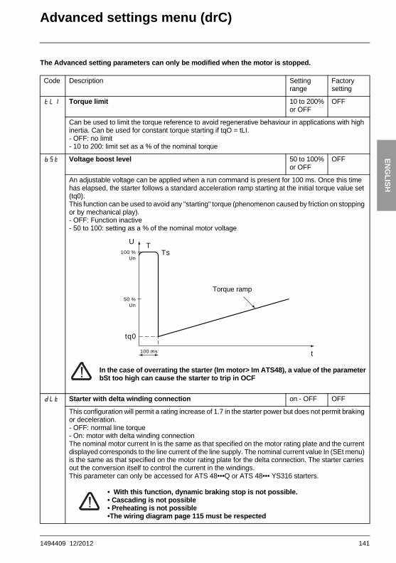
Advanced settings menu (drC)The Advanced setting parameters can only be modified when the motor is stopped.
Code Description Settingrange
Factory setting
tLI Torque limit 10 to 200%or OFF
OFF
Can be used to limit the torque reference to avoid regenerative behaviour in applications with high inertia. Can be used for constant torque starting if tqO = tLI.- OFF: no limit- 10 to 200: limit set as a % of the nominal torque
bSt Voltage boost level 50 to 100%or OFF
OFF
An adjustable voltage can be applied when a run command is present for 100 ms. Once this time has elapsed, the starter follows a standard acceleration ramp starting at the initial torque value set (tq0).This function can be used to avoid any "starting" torque (phenomenon caused by friction on stopping or by mechanical play).- OFF: Function inactive- 50 to 100: setting as a % of the nominal motor voltage
In the case of overrating the starter (Im motor> Im ATS48), a value of the parameterbSt too high can cause the starter to trip in OCF
dLt Starter with delta winding connection on - OFF OFF
This configuration will permit a rating increase of 1.7 in the starter power but does not permit braking or deceleration.- OFF: normal line torque- On: motor with delta winding connectionThe nominal motor current In is the same as that specified on the motor rating plate and the current displayed corresponds to the line current of the line supply. The nominal current value In (SEt menu) is the same as that specified on the motor rating plate for the delta connection. The starter carries out the conversion itself to control the current in the windings.This parameter can only be accessed for ATS 48•••Q or ATS 48••• YS316 starters.
• With this function, dynamic braking stop is not possible. • Cascading is not possible• Preheating is not possible•The wiring diagram page 115 must be respected
50 %Un
100 ms
100 %Un
t
U T
tq0
Ts
Torque ramp
1494409 12/2012 141

ENG
LISH
Advanced settings menu (drC)
Code Description Settingrange
Factory setting
SSt Tests on small motor On - OFF OFF
To check the starter in a testing or maintenance environment, on a motor whose power is very much lower than the starter rating (in particular for high power starters). The torque control parameter CLP is automatically deactivated.- OFF: function inactive- On: function active
Note: • SSt returns to the OFF state as soon as the control voltage is disconnected. On the next
power up, the PHF fault and the CLP parameter return to their initial configuration.• SST is only dedicated for maintenance and testing of the starter.
CLP Torque control (type of control) On-OFF On
- OFF: function inactive- On: function activeIn the On position, starting and deceleration follow the torque ramp.In the OFF position, starting and deceleration are controlled by voltage variation.Voltage control is recommended for applications which use motors in parallel on one starter or amotor whose power is very low in relation to the starter rating (use of an undersized motor to testthe starter) (CLP = OFF).
LSC Stator loss compensation 0 to 90% 50%
Parameter active in acceleration phases (and deceleration phases if StY = -d-).In the event of torque oscillations, reduce this parameter gradually until the device is functioning correctly.Oscillations are most common if the starter is connected in the motor delta winding or in motorswith excessive slip.
tIG Deceleration gain (for torque control) 10 to 50% 40%
This parameter can only be accessed if CLP = On and if the StY parameter (SEt Settings menu) = -d-.Can be used to eliminate instability during deceleration.Adjust the parameter in accordance with the oscillations.
CSC Activation of the cascade function On-OFF OFF
See page 122- On: function active- OFF: function inactiveThis parameter can only be accessed if relay R1 has previously been assigned to the "isolating relay" function and if the "forced freewheel stop", "starter in the motor delta winding" and "preheating" functions are not configured.Assign an input LI = LIC.255 motors max.
ULn Line voltage 170 to 460 V (ATS48••Q)180 to 790 V (ATS48••Y)
400 V(ATS48••Q)460 V (ATS48••Y)
This parameter is used to calculate the power displayed (LPr and LAP parameters from the SUP menu). The display will only be accurate if this parameter has been set correctly.
142 1494409 12/2012

ENG
LISH
Advanced settings menu (drC)(1) This information « kWh consumed » is only visible with the PowerSuite software workshop or online with Modbus (address W4074).
Code Description Adjustment range
Factory setting
FrC Line frequency 50-60-AUt AUt
- 50: 50 Hz (monitoring tolerance of frequency fault FrF = ± 20%).- 60: 60 Hz (monitoring tolerance of frequency fault FrF = ± 20%).- AUt: automatic recognition of the line frequency by the starter with frequency fault monitoring tolerance FrF = ± 5%. Selections 50 and 60 are recommended if the power supply is provided by a generating set, given their high tolerance.
rPr Reset kWh or the operating time no-APH-trE no
- no: function inactive- APH: kWh reset to zero (1)- trE: operating time reset to zeroThe reset command must be confirmed with ENT. APH and trE take effect immediately. The parameter then automatically returns to no.
FCS Return to factory settings no-YES no
Used to reset all parameters to their factory settings.- no: function inactive- YES: function active, must be pressed and held down (for approx. 2 s) in order to be taken into account. The display flashes to confirm. The FCS parameter is then automatically reset to no by pressing ESC.This parameter cannot be modified via the remote terminal.
1494409 12/2012 143

ENG
LISH
I/O menu (IO)
���
���
��
���
��
��
��
��
��
��
���
�
���
���
���
���
���
��
���
���
���
��
��
�
�
�
��
��� ���
��
��
���
���
���
���
���
Parameters in menuCan be selectedParameter appears according to selection
Assignment of logic input LI3
Assignment of logic input LI4Not assigned
Forced freewheel stop
External fault
Motor preheating
Force to local control mode
Inhibits all protection
Reset motor thermal fault
Activation of the cascade function
Reset faults
Activation of second set of motor parameters
Preheating level (if preheating is selected)Time delay before preheating 0 to 999 s
Parameters visible if LIH assigned
Fault relay Isolating relay
Assignment of logic output LO1
Assignment of logic output LO2
Assignment of relay R1
Assignment of relay R3
Not assigned
Thermal alarm motor 1
Motor powered
Motor underload alarm
PTC probe alarm
Second set of motor parameters activated
Assignment of analog output AONot assigned
Motor current
Motor torque
Motor thermal state
Cosine ϕ
Active power
Configuration of the analog output
Scale setting of max. signal of analog output
Motor current alarm
Can be selected
Can be selected
Can be selected
To access the parameters see page 128
NoteLogic input RUN: cannot be assignedLogic input STOP: cannot be assignedStarter bypass contactor control: cannot be assigned (R2)
144 1494409 12/2012

ENG
LISH
I/O menu (IO)The I/O parameters can only be modified when the motor is stopped.
(1) In order for this assignment o take effect, ENT must be pressed for 10 s (confirmed by flashing display).This parameter cannot be modified via the remote terminal.
Code Description Settingrange
Factory setting
LI3
LI4
Logic inputs LIALIL
The selected function is active if the input is powered up.- no: not assigned.- LIA: forced freewheel stop as soon as a STOP command is received. This selection does not appear if the CSC parameter in the drC menu is set to "On". Forces the configuration of a freewheel type stop, but does not control the stop. - LIE: external fault. Enables the starter to detect an external user fault (level, pressure, etc.). The motor comes to a freewheel stop and the starter displays EtF.- LIH: (1) motor preheating. This selection does not appear if the CSC parameter in the drC menu is set to "On". Used to prevent the motor from freezing or to prevent temperature deviations which may cause condensation. Once the motor has stopped an adjustable current IPr flows through it after an adjustable time delay tPr, if the input is active. This current heats the motor without causing it to rotate. IPr and tbr must be adjusted (see below).
Preheating starts when the input is activated and the motor has stopped, after time delays tPr and tbS (PrO menu) have elapsed. Preheating stops if the input is deactivated, if a run command is sent or if the STOP input is activated.- LIL: force to local control mode. If a serial link is used, changes from line mode (control via serial link) to local mode (control via terminals).- LII: (1) inhibits all protection. Warning: This type of use invalidates the starter warranty. Used to override the starter in the event of an emergency (smoke extraction system for example).- LIt: reset motor thermal fault- LIC: activation of the cascade function. In this case motor thermal protection is disabled and relay R1 must be configured as an isolating relay. Can be used to start and decelerate several identical motors one after the other with a single starter (see application diagram).- LIr: reset faults which can be reset- LIS: activation of second set of motor parameters. Used to start and decelerate two different motors one after the other or one motor with two different configurations using a single starter.
RUN
LI
tbS
tPr
Speed
IPr current
1494409 12/2012 145
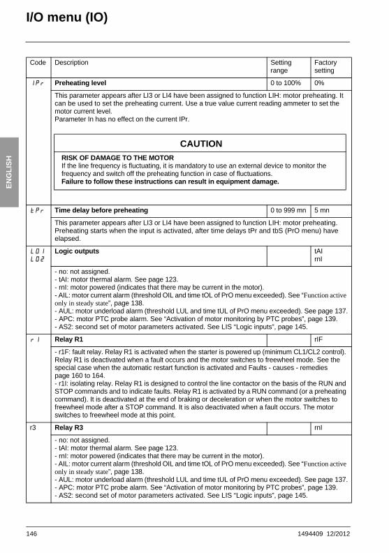
ENG
LISH
I/O menu (IO)
Code Description Settingrange
Factory setting
IPr Preheating level 0 to 100% 0%
This parameter appears after LI3 or LI4 have been assigned to function LIH: motor preheating. It can be used to set the preheating current. Use a true value current reading ammeter to set the motor current level.Parameter In has no effect on the current IPr.
tPr Time delay before preheating 0 to 999 mn 5 mn
This parameter appears after LI3 or LI4 have been assigned to function LIH: motor preheating. Preheating starts when the input is activated, after time delays tPr and tbS (PrO menu) have elapsed.
LO1
LO2
Logic outputs tAIrnI
- no: not assigned.- tAI: motor thermal alarm. See page 123.- rnI: motor powered (indicates that there may be current in the motor). - AIL: motor current alarm (threshold OIL and time tOL of PrO menu exceeded). See “Function active only in steady state”, page 138.- AUL: motor underload alarm (threshold LUL and time tUL of PrO menu exceeded). See page 137.- APC: motor PTC probe alarm. See “Activation of motor monitoring by PTC probes”, page 139.- AS2: second set of motor parameters activated. See LIS “Logic inputs”, page 145.
r1 Relay R1 rIF
- r1F: fault relay. Relay R1 is activated when the starter is powered up (minimum CL1/CL2 control). Relay R1 is deactivated when a fault occurs and the motor switches to freewheel mode. See the special case when the automatic restart function is activated and Faults - causes - remedies page 160 to 164.- r1I: isolating relay. Relay R1 is designed to control the line contactor on the basis of the RUN and STOP commands and to indicate faults. Relay R1 is activated by a RUN command (or a preheating command). It is deactivated at the end of braking or deceleration or when the motor switches to freewheel mode after a STOP command. It is also deactivated when a fault occurs. The motor switches to freewheel mode at this point.
r3 Relay R3 rnI
- no: not assigned.- tAI: motor thermal alarm. See page 123.- rnI: motor powered (indicates that there may be current in the motor). - AIL: motor current alarm (threshold OIL and time tOL of PrO menu exceeded). See “Function active only in steady state”, page 138.- AUL: motor underload alarm (threshold LUL and time tUL of PrO menu exceeded). See page 137.- APC: motor PTC probe alarm. See “Activation of motor monitoring by PTC probes”, page 139.- AS2: second set of motor parameters activated. See LIS “Logic inputs”, page 145.
CAUTIONRISK OF DAMAGE TO THE MOTORIf the line frequency is fluctuating, it is mandatory to use an external device to monitor the frequency and switch off the preheating function in case of fluctuations.Failure to follow these instructions can result in equipment damage.
146 1494409 12/2012

ENG
LISH
I/O menu (IO)End of starting relay R2 (cannot be assigned)
The end of starting relay R2 is activated when the starter is powered up, no faults are present and the motorhas completed the start-up phase. It is deactivated in the event of a stop request or a fault. It has one normallyopen contact (N/O).
It can be used to bypass the ATS 48 at the end of the starting phase.
Code Description Settingrange
Factory setting
AO Analog output OCr
- no: not assigned- OCr: motor current- Otr: motor torque- OtH: motor thermal state- OCO: cosine ϕ- OPr: active power
O�4 Configuration of the type of signal supplied by output AO 020 - 420 020
- 020: 0 - 20 mA signal - 420: 4 - 20 mA signal
ASC Scale setting of max. signal of the analog output 50 to 500% 200
As a percentage of the nominal value of the parameter configured or of 1 for the cosine ϕ.
1494409 12/2012 147

ENG
LISH
2nd motor parameters menu (St2)
The parameters for 1st or 2nd motor are selected by the logic input (LIS). Taking into account the motorparameters selected :
���
���
���
���
�
�
���
���
Parameters in menu
Paramèter appears according to the selection and to the assignement of StY in the SEt menu
Nominal motor current
Limiting current
Acceleration ramp time
Initial starting torque
Deceleration ramp time
Threshold for changing tofreewheel stop mode at the endof deceleration
Maximum torque limiting
Deceleration gain
On the next deceleration
On the next deceleration
On the next acceleration
Immediately
On the next acceleration
On the next acceleration
Immediately
On the next deceleration
148 1494409 12/2012

ENG
LISH
2nd motor parameters menu (St2)This menu is only visible if a logic input is assigned to the function for activating a second set of motorparameters (LIS) in the I/O menu.
(1) Factory setting of In2 corresponding to the usual value of a 4-pole 400 V standardised motor with class 10 protection (for ATS 48•••Q).Factory setting of In2 corresponding to the usual value of a 460 V standardised motor in accordance with NEC and with class 10 protection (for ATS 48•••Y).
Code Description Settingrange
Factory setting
In2 Nominal motor current 0.4 to 1.3 ICL
(1)
Adjust the value of the nominal motor current indicated on the rating plate, even if the starter is connected in the motor delta winding (PrO).Check that the current is between 0.4 and 1.3 ICL (ICL: starter rating). See “Starter-motorcombinations”, page 96.
IL2 Limiting current 150 to 700% of In, limited to 500% of ICL
400% of In
The limiting current IL2 is expressed as a % of In2. It is limited to 500% of ICL (starter rating, see “Starter-motor combinations”, page 96).Limiting current = IL2 x In2
Example 1: In2 = 21 A, IL2 = 300%, limiting current = 300% x 22 A = 66 AExample 2: ATS 48C21Q, with ICL = 210 A
In2 = 195 A, IL2 = 700%, limiting current = 700% x 195 = 1365, limited to 500% x 210 = 1050 A
AC2 Acceleration ramp time 1 to 60 s 15 s
This is the rise time of the starter torque between 0 and the nominal torque Tn, i.e. the gradient of the torque ramp on acceleration.
100
80
60
40
20
0
0 AC2
Time (s)
Reference torqueas a % of Tn
1494409 12/2012 149

ENG
LISH
2nd motor parameters menu (St2)
Code Description Settingrange
Factory setting
tq2 Initial starting torque 0 to 100% of Tn
20%
Initial torque setting during the starting phases, varies from 0 to 100% of the nominal torque.
dE2 Deceleration ramp time 1 to 60 s 15 s
This parameter can only be accessed if StY = -d-.Used to set a time between 1 to 60 s to switch from the estimated torque to zero torque (= gradient of the torque ramp on deceleration when a -d- stop is applied).This modifies the progression of the deceleration and avoids hydraulic shocks in pump applications by modifying the gradient of the torque reference.
100
tq2 = 40
80
60
40
20
0
0
Cn
AC2
Time (s)
100
80
60
40
20
0dE2
Time (s)
Estimated torque as a % of the nominal torque
150 1494409 12/2012

ENG
LISH
2nd motor parameters menu (St2)Code Description Settingrange
Factory setting
Ed2 Threshold for changing to freewheel stop mode at the end of deceleration
0 to 100% 20%
This parameter can only be accessed if StY = -d- and if the CLP parameter in the drive menu (drC) is still set to the factory setting (On).Used to set the final torque level between 0 and 100% of the torque estimated at the beginning ofdeceleration.In pump applications, deceleration control is not necessarily below a load level set by Ed2.If the estimated torque at the start of deceleration is below 20, i.e. 20% of the nominal torque,controlled deceleration is not activated, and the motor changes to freewheel mode.
tL2 Maximum torque limit 10 to 200%or OFF
OFF
Used to limit the torque reference to avoid regenerative behaviour in applications with high inertia. Can be used for constant torque starting if tq2 = tL2.- OFF: no limit- 10 to 200: limit set as a % of the nominal torque
tI2 Deceleration gain (for torque control) 10 to 50% 40%
This parameter can only be accessed if CLP = On and if the StY parameter (SEt Settings menu) = -d-.Used to eliminate instability during deceleration.Adjust the parameter in accordance with the oscillations.
100
80
60
40
20
0dE2
Ed2
Time (s)
Estimated torque as a % of the nominal torque
End of controlled deceleration
1494409 12/2012 151

ENG
LISH
Communication menu (COP)
���
���
���
��
�
Parameters in menu
Starter address
Communication speed
Communication format
Serial link timeout setting
Configuration of the link forcommunication with the remote terminal.
152 1494409 12/2012

ENG
LISH
Communication menu COPThe communication menu parameters can only be modified when the motor is stopped.The internal protocol used is Modbus.
(1) Check that the time set will not interfere with the safe operation of the machine
Code Description Settingrange
Factory setting
Add Starter address by the RS485 serial link 0 to 31 0
tbr Communication speed in kbps. 4.8 - 9.6 - 19.2
19.2
FOr Communication format8o1: 8 data bits, odd parity, 1 stop bit8E1: 8 data bits, even parity, 1 stop bit8n1: 8 data bits, no parity, 1 stop bit8n2: 8 data bits, no parity, 2 stop bits
8n1
tLP Serial link timeout setting (1) 0.1 to 60 s 5 s
PCt Configuration of the serial link for communication with the remote terminalOn: function active. Temporarily configures the starter (tbr and FOr)for communication with the remote terminal, to be used in case oftbr and For a not a factory value.OFF : Temporary configuration function inactive.PCT returns to the OFF state as soon as the control voltage isdisconnected. On the next power up, the tbr and FOrparameters return to their initial configuration.
OFF
1494409 12/2012 153

ENG
LISH
Parameter displayed menu (SUP)
���
���
���
���
��
���
�
��
���
��
��
Parameters in menu
Cosine ϕ
Motor thermal state as a %
Motor current
Operating time since the last reset
Active power as a %
Motor torque as a %
Active power in kW
Display of the current state(ACC, rUn, dEC, etc.)
Phase rotation direction, 1-2-3or 3-2-1
Terminal locking code
Set ULn in the drC menu
Last fault detected
154 1494409 12/2012

ENG
LISH
Parameter displayed menu (SUP)The parameter to be displayed can be modified with the motor stopped or running. The factory setting displays the motor current (parameter LCr).The display chosen is saved by:
- Pressing the ENT key once: the choice is temporary, it will be cleared at the next power up.- Pressing the ENT key again for 2 seconds: the display flashes, the choice is permanent and cannot be
modified.
Code Parameter Unit
COS Cosine ϕ 0.01
tHr Motor thermal stateVaries from 0 to 125%100% corresponds to the nominal thermal state for the current In set.
%
LCr Motor currentIn amperes up to 999 A (examples: 01.5 = 1.5 A; 15.0 = 15 A; 150 = 150 A)In kiloamperes starting at 1000 A (examples: 1.50 = 1500 A; 1.15 = 1150 A)
A or kA
rnt Operating time in hours since the last reset.In hours up to 999 hrs (examples: 001 = 1 hr; 111 = 111 hrs)In kilo-hours from 1000 to 65535 (examples: 1.11 = 1110 hrs; 11.1 = 11100 hrs)Above 65535 hrs (65.5) the display is reset to zero.Operating time is counted when the motor is not stopped, i.e. when the thyristors arefired (heating, acceleration, steady state, deceleration, braking) and in continuousbypass operation. The hour counter can be reset in line mode using the control word or via the terminalwith the motor stopped. When the control part is switched off the hour counter is savedin the EEPROM.
h or kh
LPr Active powerVaries from 0 to 255%100% corresponds to the power at nominal current and at full voltage.
%
Ltr Motor torqueVaries from 0 to 255%100% corresponds to the nominal torque.
%
LAP Active power in kWThis parameter requires configuration of the exact value of the line voltage ULn in thedrC menu.
kW
EtA Display of the current state- nLP: starter without run command and power not supplied- rdY: starter without run command and power supplied- tbS: starting time delay not elapsed- ACC: acceleration in progress- dEC: deceleration in progress- rUn: steady state operation- brL: braking in progress- CLI: starter in current limiting mode- nSt : force to freewheel stop by serial link
LFt Last fault detected (see page 159).If no faults have been saved, the display shows nOF.If faults have been inhibited, the display shows Inh.
PHE Phase rotation direction viewed from the starter- 123: forward (L1 - L2 - L3)- 321: reverse (L3 - L2 - L1)
1494409 12/2012 155

ENG
LISH
Parameter displayed menu (SUP)
When access is locked using a code, only the monitoring parameters can be accessed, with only a temporarychoice of parameter displayed.
Code Parameter
COd Terminal locking codeEnables the starter configuration to be protected using an access code.
Caution: Before entering a code, do not forget to make a careful note of it
• OFF: no access locking codes- To lock access, enter a code (2 to 999). The display can be incremented using the key.
Now press ENT. "On" appears on the screen to indicate that the parameters have been locked.• On: a code is locking access (2 to 999)
- To unlock access, enter the code (incrementing the display using the key) and press ENT. The code remains on the display and access is unlocked until the next power down. Parameter access will be locked again on the next power-up.
- If an incorrect code is entered, the display changes to "On" and the parameters remain locked.
• XXX: parameter access is unlocked (the code remains on the screen).- To reactivate locking with the same code when the parameters have been unlocked, return
to "On" using the button then press ENT. "On" appears on the screen to indicate that the parameters have been locked.
- To lock access with a new code when the parameters have been unlocked, enter a new code (increment the display using the or keys) and press ENT. "On" appears on the screen to indicate that the parameters have been locked.
- To clear locking when the parameters have been unlocked, return to "OFF" using the button and press ENT. "OFF" remains on the screen. The parameters are unlocked and will remain unlocked until the next restart.
156 1494409 12/2012

ENG
LISH
Compability tableThe choice of application functions can be limited by the incompability between certain functions. The functionsthat are not listed in the table are not incompatible with any other functions.
Functions
Soft
stop
Dyn
amic
bra
king
sto
p
Forc
e fre
ewhe
el s
top
Ther
mal
pro
tect
ion
Loss
of a
mot
or p
hase
Con
nect
ing
to "
delta
in th
e m
otor
"
Test
on
smal
l mot
or
Cas
cade
Preh
eatin
g
Soft stop
Dynamic braking stop
Force freewheel stop
Thermal protection (2)
Loss of a motor phase
Connecting to "delta in the motor"
Test on small motor
Cascade
Preheating (2)
Compatible functionsIncompatible functionsNot significant
(1) Motor phase loss not detected(2) While motor’s preheating, the thermal protection is not assured. Set the preheating current IPr.
1494409 12/2012 157

ENG
LISH
Maintenance
ServicingThe Altistart 48 does not require any preventative maintenance. It is nevertheless advisable to perform thefollowing regularly:
- Check the condition and tightness of connections- Ensure that the temperature around the unit remains at an acceptable level and that ventilation is effective
(average service life of fans: 3 to 5 years depending on the operating conditions)- Remove any dust from the heatsink if necessary
Assistance with maintenanceIf a problem arises during setup or operation, ensure that the recommendations relating to the environment,mounting and connections have been observed.
The first fault detected is memorized and displayed on the screen: the starter locks and relays R1 and R2change state according to their assignment.
Clearing the faultSwitch off the starter power supply in the event of a fault which cannot be reset.Wait for the display to go off completely.Find the cause of the fault in order to correct it.Restore the power supply: this clears the fault if it has disappeared.
In some cases there may be an automatic restart once the fault has disappeared if this function has beenprogrammed.
Monitoring menuThis is used to prevent and find the causes of faults by displaying the starter status and its current values.
Spares and repairs Consult Schneider Electric product support.
158 1494409 12/2012

ENG
LISH
Faults - causes - remediesAs a general rule, if a problem arises when the starter is started, it is advisable to return to the factorysettings and repeat your settings step by step.
Starter does not start, no fault displayed• No display: check that the line supply is present on the control supply CL1/CL2 (see page 111).• Check that the code displayed does not correspond to the normal state of the starter (see page 129).• Check for the presence of the RUN/STOP commands (see page 112).
Faults which cannot be resetWhen this type of fault appears the starter locks and the motor switches to freewheel mode.
Signalling:• Opening of end of starting relay R2• Opening of relay R1 (following starter locking)• Fault code flashes on the display• Storing of the last 5 faults, visible with the PowerSuite software workshop
Restart conditions:• Disappearance of the causes of the fault• Disconnection and reconnection of the control supply
Fault displayed Probable cause Procedure, remedy
InF Internal fault Disconnect and reconnect the control supply. If the fault persists, contact Schneider Electric product support.
OCF Overcurrent:• impeding short-circuit on starter output• internal short-circuit • bypass contactor stuck• overrate starter
Switch the starter off.• Check the connecting cables and the
motor isolation• Check the thyristors• Check the bypass contactor (contact
stuck)• Check the parameter value bSt in the
menu drC page 141
PIF Phase inversionLine phase inversion does not conform to the selection made by PHr in the Protection menu.
Invert two line phases or set PHr = no
EEF Internal memory fault Disconnect and reconnect the control supply. If the fault persists, contact Schneider Electric product support.
1494409 12/2012 159

ENG
LISH
Faults - causes - remedies
Faults which can be reset as soon as their causes disappearWhen this type of fault appears the starter locks and the motor switches to freewheel mode.
Signalling:• Opening of end of starting relay R2.• Opening of relay R1 only if it is configured as an isolating relay.• The fault code flashes on the display as long as the fault is present.• Storing of the last 5 faults, visible with the PowerSuite software workshop.
Restart conditions:• Disappearance of the causes of the fault.• In 2-wire control the run command must be maintained on the RUN input.• In 3-wire control a new run command (rising edge) is required on the RUN input.
Fault displayed Probable cause Procedure, remedy
CFF Invalid configuration on power-up • Revert to the factory setting in the drive menu drC.
• Reconfigure the starter.
CFI Invalid configurationThe configuration loaded in the starter via the serial link is incompatible.
• Check the configuration loaded previously.
• Load a compatible configuration.
160 1494409 12/2012

ENG
LISH
Faults - causes - remediesFaults which can be reset manually and can generate an automatic restart (1)
When this type of fault appears the starter locks and the motor switches to freewheel mode.
Signalling with automatic restart:• Opening of end of starting relay R2• Opening of relay R1 only if it is configured as an isolating relay. R1 remains closed if it is configured as a
fault relay, see page 146• The fault code flashes on the display as long as the fault is present• Storing of the last 5 faults, visible with the PowerSuite software workshop
Restart conditions for the following faults with automatic restarting (in 2-wire control only):• Disappearance of the causes of the fault• Run command maintained on the RUN input• 6 restart attemps are carried out at intervals of 60 seconds. At the 6th attempt if the fault is still present it
trips requiring a manual reset (see following page) and R1 opens if it is configured as a fault relay
(1) If the automatic restart function is not selected, see page 163 for the signalling and restart conditions of these faults.
(2) After each Power ON of the control supply, the FrF detection is done only at the first power ON of the main supply.
(3) For next Power ON of the main supply, bad frequency will also generate a desynchronization fault PHF.
Fault displayed
Probable cause Procedure, remedy
FrF (2) Line frequency, out of toleranceThis fault can be configured in theAdvanced settings menu drC, parameterFrC.
• Check the line. • Check that the configuration of the FrC
parameter is compatible with the line used (generating set for example).
PHF�(3) Loss of a line phase
Loss of a motor phaseIf the motor current falls below an adjustable threshold PHL in one phase for 0.5 s or in the three phases for 0.2 s.This fault can be configured in the Protection menu PrO, parameter PHL.
• Check the line, the frequency stability, the connection to the starter and any devices located between the line and the starter (contactor, fuses, circuit-breaker, etc.).
• If bypass contator. is used, check the mechanism ( wear, mechanical play, lubrication, blockages...)
• Check the motor connection (T1, T2, T3 terminal) and any isolating devices located between the starter and the motor (contactors, circuit-breakers, etc.).
• Check the motor state.• Check that the configuration of the PHL
parameter is compatible with the motor used.
1494409 12/2012 161

ENG
LISH
Faults - causes - remedies
Faults which can be reset manually and can generate an automatic restart (1)
When this type of fault appears the starter locks and the motor switches to freewheel mode.
Restart conditions for the following faults:• Disappearance of the causes of the fault• Run command maintained (2-wire control only)
(1) If the automatic restart function is not selected, see page 163 for the signalling and restart conditions of these faults.
Fault displayed
Probable cause Procedure, remedy
USF Power supply fault on a run command • Check the power supply circuit and voltage.
CLF Control line failure • Loss of CL1/CL2 for more than 200 ms
162 1494409 12/2012

ENG
LISH
Faults - causes - remediesFaults which can be manually reset onlyWhen this type of fault appears the starter locks and the motor switches to freewheel mode.
Signalling:• Opening of end of starting relay R2• Opening of relay R1• The fault code flashes on the display as long as the fault is present• Storing of the last 5 faults, visible with the PowerSuite software workshop
Restart conditions:• Disappearance of the causes of the fault• A run command (2 or 3-wire control, requires a rising edge on the RUN input) to reset the fault (1)• Another run command (2 or 3-wire control, requires a rising edge on the RUN input) to restart the motor
(1) A reset will not take place on a run command if LI is assigned to the "fault reset (LIr)" function.
Fault displayed
Probable cause Procedure, remedy
SLF Serial link fault • Check the RS485 connection.
EtF External fault • Check the fault taken into account.
StF Excessive starting time • Check the mechanism (wear, mechanical play, lubrication, blockages, etc.).
• Check the value of the tLs setting in the PrO menu page 137.
• Check the sizing of the starter-motor in relation to the mechanical requirement.
OLC Current overload • Check the mechanism (wear, mechanical play, lubrication, blockages, etc.).
• Check the value of the LOC and tOL parameters in the PrO menu page 138.
OLF Motor thermal fault • Check the mechanism (wear, mechanical play, lubrication, blockages, etc.).
• Check the sizing of the starter-motor in relation to the mechanical requirement.
• Check the value of the tHP parameter in the PrO menu page 137 and that of the In parameter in the SEt menu page 132.
• Check the electrical isolation of the motor.• Wait for the motor to cool before restarting.
OHF Starter thermal fault • Check the mechanism (wear, mechanical play, lubrication, blockages, etc.).
• Check the sizing of the starter in relation to the motor and the mechanical requirement.
• Check the operation of the fan (if the ATS48 used has one), ensuring that the air passage is not obstructed in any way and the heatsink is clean. Ensure that the mounting recommendations are observed.
• Wait for the ATS48 to cool before restarting.
1494409 12/2012 163

ENG
LISH
Faults - causes - remedies
Faults which can be manually reset only
Reset faults using a logic inputIf a logic input LI is configured as "reset motor thermal fault" or "reset faults which can be reset", the followingconditions must be met: • A pulse on logic input LI• In 2-wire control the motor will restart if the run command is maintained on the RUN input• In 3-wire control the motor will restart on a new run command (rising edge) on the RUN input
Fault displayed Probable cause Procedure, remedy
OtF Motor thermal fault detected by the PTC probes
• Check the mechanism (wear, mechanical play, lubrication, blockages, etc.).
• Check the sizing of the starter-motor in relation to the mechanical requirement.
• Check the value of the PtC setting in the PrO menu page 139.
• Wait for the motor to cool before restarting.
ULF Motor underload • Check the hydraulic circuit.• Check the value of the LUL and tUL
parameters in the Pro protection menu page 137.
LrF Locked rotor in steady stateThis fault is only active in steady state with starter bypass contactor. It is detected if the current in a phase is greater than or equal to 5 In for more than 0.2 s.
• Check the mechanism (wear, mechanical play, lubrication, blockages, etc.).
Err7 Only possible on the remote terminal: incorrect values for tbr and FOr
• Configured tbr = 19,2 and FOr = 8n1or PCt = On see page 153
164 1494409 12/2012

ENG
LISH
Configuration/Settings tablesATS 48 starter....................................................................................................................................................Customer identification no.(if applicable)...........................................................................................................Access code (if applicable).................................................................................................................................
Settings menu�SEt
Protection menu�PrO
(1) Depends on the starter rating.
Code Factory setting Customer setting Code Factory setting Customer setting
In (1) dEC 15 s
ILt 400% EdC 20%
ACC 15 s brC 50%
tq0 20% EbA 20%
StY -F-
The parameters in shaded boxes appear if the corresponding functions have been configured.
Code Factory setting Customer setting Code Factory setting Customer setting
tHP 10 tOL 10.0
ULL OFF PHr no
LUL 60% tbS 2 s
tUL 60% PHL 10%
tLS OFF PtC OFF
OIL OFF ArS OFF
LOC 80% rtH no
The parameters in shaded boxes appear if the corresponding functions have been configured.
1494409 12/2012 165

ENG
LISH
Configuration/Settings tables
Advanced settings menu drC
I/O menu IO
(1) -ATS 48 •••Q: 400 V-ATS 48•••Y: 460 V
Code Factory setting Customer setting Code Factory setting Customer setting
tLI OFF LSC 50%
bSt OFF tIG 40%
dLt OFF CSC OFF
SSt OFF ULn (1)
CLP On FrC AUt
The parameters in shaded boxes appear if the corresponding functions have been configured.
Code Factory setting Customer setting Code Factory setting Customer setting
LI3 LIA r1 r1I
LI4 LIL r3 rn1
IPr 0% AO OCr
tPr 5 mn O�4 020
LO1 tA1 ASC 200
LO2 rn1
The parameters in shaded boxes appear if the corresponding functions have been configured.
166 1494409 12/2012

ENG
LISH
Configuration/Settings tables2nd motor parameters menu St2This menu is only visible if a logic input is assigned to the function for activating a second set of motorparameters (LIS) in the I/O menu.
Communication menu COP
(1) Depends on the starter rating.
Code Factory setting Customer setting Code Factory setting Customer setting
In2 (1) dE2 15 s
IL2 400% Ed2 20%
AC2 15 s tL2 OFF
tq2 20% tI2 40%
Code Factory setting Customer setting Code Factory setting Customer setting
Add 0 tLP 5 s
tbr 19.2 kbps PCt OFF
FOr 8n1
1494409 12/2012 167

168 1494409 12/2012
DEU
TSC
H
Grundsätzlich muss die Spannungsversorgung des Steuerteils (CL1 - CL2) und desLeistungsteils (1/L1 - 3/L2 - 5/L3) des Altistart 48 ausgeschaltet werden, bevor elektrische odermechanische Eingriffe an der Anlage oder im Gerät erfolgen.Während des Betriebs kann es durch das Rücksetzen des Fahrbefehls zu einem Anhalten desMotors kommen, wobei der Sanftanlasser jedoch unter Spannung bleibt. Falls es zur Sicherheitdes Personals erforderlich ist, ein plötzliches Wiederanlaufen zu verhindern, ist eineelektronische Sperre nicht ausreichend: Sehen Sie zu diesem Zweck eine Trennung desLeistungsschaltkreises vor.
Der Sanftanlasser verfügt über Sicherheitsvorrichtungen, die bei Störungen das Gerät selbstund damit auch den Motor abschalten können. Der Motor kann auch durch mechanische Fehlerblockiert werden. Ebenso können Schwankungen der Versorgungsspannung oderStromausfälle die Ursache für das Anhalten der Motoren sein.Nach Beseitigung der Ursache, die das Anhalten ausgelöst hat, kann es bei einigen Maschinenund Anlagen durch den automatischen Wiederanlauf zu einem erhöhten Risiko kommen;insbesondere ist dies bei Maschinen zu berücksichtigen, die bestimmtenSicherheitsanforderungen entsprechen müssen.Sofern dies der Fall ist, hat der Betreiber durch die Verwendung von Drehzahlwächtern, die dieVersorgungsspannung des Sanftanlassers abschalten, dafür Sorge zu tragen, dass einWiederanfahren des Motors nach einem nicht vorgesehenen Anhaltevorgang nicht möglich ist.
Technische und betriebsrelevante Änderungen zu den in diesen Unterlagen aufgeführtenProdukten und Geräten sind jederzeit auch ohne Vorankündigung vorbehalten. Die hierinenthaltenen Beschreibungen sind unverbindlich.
Einbau und Inbetriebnahme dieses Sanftanlassers müssen den internationalen IEC-Normenund den am Einbauort geltenden nationalen Normen entsprechen. Der Anwender ist für dieEinhaltung dieser Normen verantwortlich. Innerhalb der Europäischen Union sind außerdemdie entsprechenden Vorschriften zur Elektromagnetischen Verträglichkeit (EMV) zu befolgen.Die in diesem Dokument enthaltenen Angaben müssen angewendet werden, um diegrundlegenden Anforderungen der EMV-Richtlinie zu erfüllen.
Der Altistartþ48 muss als Komponente angesehen werden. Er ist weder eine Maschine noch eineinsatzbereites Gerät nach europäischen Vorschriften (Maschinenrichtlinie und Richtlinie zurelektromagnetischen Verträglichkeit). Es liegt in der Verantwortung des Anlagenherstellers,dafür zu sorgen, daß seine Anlage diesen Vorschriften entspricht.