school without walls - pennsylvania state …...school without walls final report 2 | page...
TRANSCRIPT

SHAUN KREIDEL
STRUCTURAL OPTION
DR. LINDA HANAGAN
4/12/2010
AE SENIOR THESIS FINAL REPORT
SCHOOL WITHOUT WALLS


Shaun Kreidel April 7, 2010 Structural Option Advisor: Dr. Hanagan School Without Walls Final Report
ii | P a g e
EXECUTIVE SUMMARY The Grant School has stood in the heart of the George Washington University campus since 1882 and has housed the School Without Walls since 1977. In 2008, a 68,000 square foot addition was added along the south and east faces of the building. In addition to the building’s expansion, the mechanical and electrical systems were replaced and updated. Currently, the School Without Walls expansion project calls for a floor system that requires beams which range from W10 to W33 sections. With the addition of a 5 ¼” metal deck floor system, the total floor depth amounts to 38 ¼”. A larger clearance between the ceiling and the floor system above would create an easier coordination of the electrical and mechanical systems in the building. The structural design utilizes expansion joints to separate the 68,000 square foot addition from the historic building. These joints require the slab to cantilever from the column line to the edge of the existing historic building. To achieve this using the current steel system, moment connections are required.
This report explores an alternate gravity and lateral system design to the current steel system system. The proposed design consists of a one way post tensioned slab which spans across wide, but shallow post tensioned beams. Using this system easily allows the construction of the required cantilevered sections of the structure. Concrete moment frames, which eliminate the need for the current braced frames and shear walls, will be responsible for resisting the lateral loads that are exerted on the structure.
In addition to the structural depth study, two breadth topics were researched. The construction management breadth focuses on the effect the change in structural system has on schedule and overall cost. The architectural breadth studies how dropping the ceilings of the existing building architecturally affects the spaces. Lowering the ceiling heights will allow for easier MEP coordination.

Shaun Kreidel April 7, 2010 Structural Option Advisor: Dr. Hanagan School Without Walls Final Report
iii | P a g e
ACKNOWLEDGEMENTS I would like to extend a special thanks to the following individuals and firms who were essential to the success of this thesis project:
Turner Construction: Tiffany Moore
The Pennsylvannia State University: Dr. Linda Hanagan Dr. Andres Lepage
Dr. Ali Memari Robert Holland Kevin Parfitt
Holbert Apple Associates: Richard Apple
ReStl Designers Inc.: Adlai Luzuriaga
Ehrenkrantz Eckstut & Kuhn Architects
I would like to also thank all of my friends and family for their continuing support throughout the senior thesis process.

Shaun Kreidel April 12, 2010 Structural Option Advisor: Dr. Hanagan School Without Walls Final Report
1 | P a g e
TABLE OF CONTENTS Abstract…...…………………………………………...………….…………….. i Executive Summary.……….…………………………………………………… ii Acknowledgements………………………….………………………………..... iii Introduction.................................................................................................. 2 Existing Structural Systems…......................................................................... 3 Problem Statement……................................................................................. 9 Solution Method............................................................................................ 9 Altered Floor Plans....................................................................................... 11 Post Tension Design.................................................................................... 16
Area 1 Beam Design............................................................................ 16 Area 1 Slab Design.............................................................................. 18 Area 2 Beam Design............................................................................ 19 Area 2 Slab Design.............................................................................. 21
Lateral System Design.................................................................................. 22 Area 1 Lateral Loads............................................................................ 23 Area 1 Lateral System Analysis............................................................. 24 Area 2 Lateral Loads............................................................................ 25 Area 2 Lateral System Analysis............................................................. 28
Concrete Column Design............................................................................. 30 Depth Study Conclusion.............................................................................. 31 Construction Management Breadth.............................................................. 32 Architectural Breadth................................................................................... 33 Conclusion………………..………………………………………………....... 36 Appendix A: Post Tension Beam Details........................................................ 39 Appendix B: Post Tension Slab Details...........................................................60 Appendix C: Building Weight....................................................................... 77 Appendix D: Seismic Load Calculations........................................................ 82 Appendix E: Concrete Column Spot Check................................................... 85 Appendix F: CM Area 1 Steel Breakdown….................................................. 88 Appendix G: CM Area 1 Concrete Breakdown…........................................... 92 Appendix H: CM Area 2 Steel Breakdown…................................................. 99 Appendix I: CM Area 2 Concrete Breakdown….......................................... 104

Shaun Kreidel April 12, 2010 Structural Option Advisor: Dr. Hanagan School Without Walls Final Report
2 | P a g e
INTRODUCTION The Grant School, located as the red object in Figure 1, has stood in the heart of the George Washington University campus in Washington, D.C. at 2130 G Street NW since 1882 and has housed the School Without Walls since 1977. The "School Without Walls" name comes from the faculties’ encouragement for students to use Washington D.C. as an active classroom, thus not restraining learning to the walls of the senior high school.
The original 32,300 square foot, three story school was in dire need of modernization and expansion due to the increasing number of students and outdated mechanical and electrical equipment. The 68,000 square foot addition and renovation, as seen in blue in Figure 2, blends the 19th century school with a modern design. This is achieved by combining existing brick patterns with glass, steel and curtain walls. The School Without Walls project is expected to receive LEED Gold Certification. The existing three story school is made up of four large classrooms per floor, one at each corner of the square building. The new addition to the school provides an additional two large classrooms on each floor, an open atrium space, a large student commons, roof terrace area and a library. The basement was also reengineered and redesigned to serve as scientific laboratories for the school.
Figure 1: Area Map

Shaun Kreidel April 12, 2010 Structural Option Advisor: Dr. Hanagan School Without Walls Final Report
3 | P a g e
EXISTING STRUCTURAL SYSTEM The 68,000 square foot addition to the School Without Walls project is located in blue in Figure 2. Due to expansion joints located at the interface of the addition and the existing building, the structural systems of the existing and new building work independently. A detail of this expansion joint can be viewed in Figure 3. As stated in the drawing, the expansion joint along the east side of the existing building is 4”, and is 2” along the south side. The new addition to the School Without Walls itself is divided by an expansion joint. This expansion joint therefore creates a total of three independently acting structural systems. The division of the new addition can be viewed in Figure 4. These separate structural systems, which can be distinguished in Figures 4 and 5, will be referred to as “Area 1” and “Area 2” throughout this report.
School Without Walls Addition Area
G StreetFigure 2: Floor Plan Showing Expansion
Figure 3: Expansion Joint Detail

Shaun Kreidel April 12, 2010 Structural Option Advisor: Dr. Hanagan School Without Walls Final Report
4 | P a g e
Area 2
Area 1
Figure 4: Floor Plan Showing Building Separation
Figure 5: West Elevation
G Street
Area 1
G Street
Area 2

Shaun Kreidel April 12, 2010 Structural Option Advisor: Dr. Hanagan School Without Walls Final Report
5 | P a g e
Foundation The geotechnical engineering study was performed by Thomas L. Brown Associates, P.C. on January 28, 2007. After performing a series of in-situ tests, considering the lab test results, anticipated loads, and settlement analyses, a shallow foundation consisting of reinforced cast-in-place spread footings and grade beams was deemed appropriate. Based on the testing and analysis, the footings should be designed for an allowable bearing capacity of 3.0 ksf. The addition utilizes typical footings which are 2’ 6” wide by 2’0” deep and rest on compacted earth 3’0” below the top of the slab-on-grade. Grade beams are also used in the foundation of the new addition. The beams measure 30”x30” along the east side and 30”x24” along the south side of the building. Due to the increased load and the disruption of earth, underpinning the existing footings of the school became necessary. An underpinning detail is located in Figure 6. The underpinning sequence was performed in sections of no larger than 4 feet wide, approximately spaced 12-15 feet apart. Floor System The floor system of School Without Walls is a composite steel system. The floor slab of the new addition is 3 ¼” LWC topping over a 2” 20 GA LOK composite steel floor decking, bringing the total floor slab to 5 ¼” thick. Along the top flange of the beam, ¾”x4” long headed shear studs are used for composite action. A section of this floor system is shown above in Figure 7.
Figure 6: Underpinning Detail
Figure 7: Typical Composite Steel Construction (www.epitech.com)
Area 1Area 2

Shaun Kreidel April 12, 2010 Structural Option Advisor: Dr. Hanagan School Without Walls Final Report
6 | P a g e
Lateral System Summary The lateral system of School Without Walls works as three different systems due to expansion joints as stated before and show above in Figures 4 and 5. Both braced frames and shear walls, located in blue and green respectively in Figure 8, are used to resist lateral loads that are applied to the building.
5
4
32
1
Figure 8: Summary of Lateral Systems
6 7
8
10 9
11 12

Shaun Kreidel April 12, 2010 Structural Option Advisor: Dr. Hanagan School Without Walls Final Report
7 | P a g e
Area 1 Lateral System The two story structure supporting the outside roof terrace (Area 1) utilizes only braced frames for lateral support. All of the braced frames located in this section of building are comprised of only HSS6x6x3/8 sections. Diagonal, cross, and chevron bracing are utilized in braced frames 1, 2 and 3 respectively as labeled in Figures 9, 10 and 11. All of the braced frames extend the entirety of the two story section of building.
Figure 10: Braced Frame 2 Figure 9: Braced Frame 1
Figure 10: Braced Frame 3

Shaun Kreidel April 12, 2010 Structural Option Advisor: Dr. Hanagan School Without Walls Final Report
8 | P a g e
Area 2 Lateral System The four story structure supporting the library, referred to as Area 2 in this technical report, uses a combination of a braced frame system and a shear wall system to resist lateral loads. The braced frame, comprised of HSS square sections reaches from the ground to the roof level as seen in Figure 11. The shear walls are located around both the elevator core and the stair core. The shear walls surrounding the stair well are all 12” thick and are reinforced with #5 vertical bars spaced at 10” on center and #4 horizontal bars spaced at 12” on center at each face. The shear walls surrounding the elevator core are all 8” thick and are reinforced with #5 vertical bars spaced at 10” on center and #4 horizontal bars spaced at 12” on center at each face.
Figure 11: Braced Frame 4

Shaun Kreidel April 12, 2010 Structural Option Advisor: Dr. Hanagan School Without Walls Final Report
9 | P a g e
PROBLEM STATEMENT Currently, the School Without Walls project current floor system calls for steel wide flange beams which range from W10 to W33 sections. With the addition of a 5 ¼” decking system, the total floor depth amounts to 38 ¼”. Due to the updated mechanical system of the existing building and the addition of the science labs a larger clearance between the ceiling and the floor system above would create an easier coordination of the electrical and mechanical systems in the building. In addition to the benefits of a larger ceiling to floor clearance area, the cantilevered sections are typically more easily constructed in concrete than in steel. This is due in part to the welded moment connections required in steel cantilever construction. SOLUTION METHOD To limit the total depth of the floor system, the gravity resisting systems were altered from the current steel composite system to a concrete system. An important goal was to keep the column lines relatively in the same position, therefore effectively meeting the layout which was required by the architect. A post-tensioned concrete system is very applicable to this project because of the relatively large spans the building layout requires and the desire for minimal floor deflection. Post-tensioning of the beams and the slab allowed for the desired cantilever along the face of the existing building and reduced deflections. Concrete columns were also designed as part of this concrete system and replaced the current steel columns. The expansion joints which separate the School Without Walls into three different zones remained, therefore, creating three different lateral systems. The lateral systems of both Area 1 and Area 2 were redesigned, introducing concrete moment frames and thus removing the both the braced frames and shear walls which currently resist lateral loads.

Shaun Kreidel April 12, 2010 Structural Option Advisor: Dr. Hanagan School Without Walls Final Report
10 | P a g e
ACI 318-05 was referenced throughout in the design of the concrete system. PCA column was utilized as an aid in the structural design of the columns and ADAPT PT was used to assist in the design of the post tensioning in the building. An ETABS model was also built in order to effectively analyze the lateral system of the building. Hand calculations were performed to confirm and verify the accuracy of the computer programs.

Shaun Kreidel April 12, 2010 Structural Option Advisor: Dr. Hanagan School Without Walls Final Report
11 | P a g e
Figure 12: Basement Floor Plan
ALTERED FLOOR PLANS Area 1 Throughout the structural redesign of the two story addition of the School Without Walls, the architectural drawings were continually referenced to ensure that the structural components did not interfere with the designed layouts of each floor. In the attempt not to change the architectural layouts, column line positions were altered as little as possible. A revit model was built as an aid to study how the alterations of the structural components affect the architectural layout. Column lines G, 7, and 5, as displayed in Figure 12 were the only column lines which were altered in this portion of the School Without Wall’s structural redesign. Column lines G and 7 were both moved 6.25” towards the interior of the building. Column line 5 was moved 14.25” south of the original line provided by the architectural drawings.
Existing Building
Area 2

Shaun Kreidel April 12, 2010 Structural Option Advisor: Dr. Hanagan School Without Walls Final Report
12 | P a g e
Figure 13: Exterior Wall Section
Figure 14: Cracking Due to Wall Restraint
In post tension design, it is important to allow for the shortening of the slab without restraint. Removing this restraint reduces the amount of cracking due to shrinkage which can be viewed in Figure 14. To avoid restraining the slab, the column lines were displaced from the foundation wall. A typical exterior wall section of Area 1 can be viewed in Figure 13.
Because of the expansion joint located at the interface of the existing school it was necessary to cantilever the slab on the first floor in the area supporting the Student Commons. The slab cantilevered 9’-2.25” from column line 5 in this area as seen in Figure 15. The service area located on the first floor, as stated in Figure 15 works independently from the reinforced loading dock. A section cut is taken at this point in the North-South direction as seen in Figure 16 to display the interaction of the loading dock and the post tensioned floor slab. Because the slab is not restrained to the wall, shortening is possible which limits the amount of cracking due to shrinkage.

Shaun Kreidel April 12, 2010 Structural Option Advisor: Dr. Hanagan School Without Walls Final Report
13 | P a g e
Figure 15: First Floor Plan
Figure 16: Service Area- Loading Dock Section
Service Area
Student Commons
Loading
Area 2
Existing Building
Existing Building

Shaun Kreidel April 12, 2010 Structural Option Advisor: Dr. Hanagan School Without Walls Final Report
14 | P a g e
Figure 17: Basement Floor Plan
Area 2 Likewise as in the structural redesign of Area 1, the architectural drawings were continually referenced in the attempt not to change the architectural layouts. Column lines positions were altered as little as possible. A revit model for Area 2 was built as an aid to study how the alterations of the structural components affects the architectural layout. Column line A was shifted 14” to the west and B was shifted 16” to the east in order to accommodate the beam geometry. Column lines 1 and 7 were both shifted 6” to the south and north respectively. Because of the cantilever capablity of concrete, columns along A.5 and C, located in red, were deleted. The column located in green in Figure 17 was the only column which was added to the School Without Walls. This column necessary to divide the span between 4 and 7 (a span of 46’-6.5”).
Area 1
Existing Building

Shaun Kreidel April 12, 2010 Structural Option Advisor: Dr. Hanagan School Without Walls Final Report
15 | P a g e
Figure 18: Second Floor Plan
Because of the expansion joint located at the interface of the existing school it was necessary to cantilever the slab in the East West direction. The slab cantilevers 9’ from column line B in this area as seen in Figure 18. Because of the presence of an atrium space, as located as the “X” areas in Figure 18, the slab is simply supported on the second, third and fourth floor. Because of the increased of span and removal of the cantilever in sections, the slab thickness was increased. Area 2 required an exterior wall construction much like the type shown in Figure 13 in order to allow for the shortening of the slab without restraint. It must be noted that only the structure supporting floors 1 through 4 were redesigned in concrete. The remaining penthouse level housing the library remained constructed as steel utilizing both wide flange shapes and hollow steel sections. Even though the mixing of trades is not an ideal situation, the complex design of the roof required steel members to be used.
Existing Building
Area 1

Shaun Kreidel April 12, 2010 Structural Option Advisor: Dr. Hanagan School Without Walls Final Report
16 | P a g e
Table 1: Tendon Properties
POST TENSIONED DESIGN The method of post-tensioning involves the tensioning of steel tendons after the concrete has hardened. Unbonded tendons were utilized in all post-tensioning applications in this structural redesign. These tendons are fabricated with a plastic sheathing and grease to prevent a bond with the concrete. All of the tendons used in design were ½” diameter, 7-wire strands. The tendon properties can be viewed in Table 1.
Area= .153 in2 fpu= 270 ksi
Estimated Prestress Loss= 15ksi fse= .7*( fpu )- 15ksi= 174
Peff=A* fse= 26.6 kip/tendon P/A: Max=300, Min=150
The beams were modeled as either as T or L sections based on their geometry. The effective flange was calculated in accordance with Chapter 8 of ACI 318-05. ADAPT PT was used as an aid in designing the post-tensioned beams. The beams were designed in accordance with Chapter 18 of ACI 318-05. After analyzing each beam in the ADAPT PT program, the tendon drape was adjusted to best balance the dead loads. The balanced dead loads, even though not a code requirement, were targeted as 70-80% of the dead load for beams and 60-70% of the dead load for slabs. Superimposed dead loads were not included into this percentage because they are not present at the time of stressing. Area 1 Beams The four beams located in Area 1 span in the east-west direction as seen in Figure 19. This orientation was chosen because the number of beams can be limited which allowed for more ceiling to floor area. Trial sizes of the beams were determined using an L/d ratio of 30. These trial sizes were adjusted based on the architectural components present.

Shaun Kreidel April 12, 2010 Structural Option Advisor: Dr. Hanagan School Without Walls Final Report
17 | P a g e
Figure 19: Isometric View of Column
Figure 20: East-West Section Cut of Area 1
The finalized design of the beams resulted in 18” deep beams supporting the first floor, located in red and green, and 20” deep beams supporting the roof terrace, located in blue and magenta. The beams spanning in the direction of column line 5 are 56” wide, and the beams in the direction of column line 7 measure 40” wide. A detailed output including tendon profiles and required post-tension forces and required reinforcement for Beams B1-B4 as labeled in Figures 19 and 20 can be viewed in Appendix A.
Existing Building

Shaun Kreidel April 12, 2010 Structural Option Advisor: Dr. Hanagan School Without Walls Final Report
18 | P a g e
Area 1 Slabs The post-tensioned slab in Area 1 spans in the north-south direction perpendicular to the post tensioned beams located in Figures 19and 20. Design was carried out using ADAPT PT as an aid while complying with Chapter 18 of ACI 318-05. A spot hand calculation was performed to verify the accuracy of the ADAPT PT program. It was determined that the hand calculation results and computer output were comparable. Preliminary design for the slab thickness was determined by using an L/d ratio equal to 35. The live loads of these slabs were not be reduced because of section 4.8.4 of ASCE 7-05, which states that live loads of 100 lb/ft2 or less shall not be reduced in public assembly areas. During design, the unit strip method was utilized and the one way post tensioned slab was modelled as a 12” wide beam. The transverse beams were modelled into the analysis as well which shortened the clear span of the slab. After completing the analysis, it was found that the required slab on the first floor measures 10” thick throughout and the slab on the second floor, or roof terrace measures 11”. In design, it was assumed that because the roof is acting as an assembly space, therefore there will not be an instance where both the live load and snow load will exist concurently. The assembly load will control over the snow load, therefore the current design for 100 psf of live load is adequate. The super imposed dead load of the roof terrace was also increased for design to account for the roof pavers that were specified by the architect. A detailed output of these slabs containing post tension force, profile and rebar specification can be found in Appendix B.

Shaun Kreidel April 12, 2010 Structural Option Advisor: Dr. Hanagan School Without Walls Final Report
19 | P a g e
Figure 21: Isometric View of Area 2
Area 2 Beams The ten beams located in Area 2 span in the north south direction as seen in Figure 21. This orientation was chosen because the number of beams can be limited which will allow for more ceiling to floor area. Trial sizes of the beams were determined using an L/d ratio of 30 and a b/d ratio of 3. These trial sizes were adjusted based on the architectural components present.
The beams supporting the second through fourth floors referred to as Beams 9 and 10 located in green and red respectively in Figure 21, run the extent of the building. Due to the split entrance/first floor level, four beams were designed to carry the loads of the areas. These beams located in Magenta, Yellow, Orange and Purple in Figure 21 are referred to as Beam 5, Beam 6, Beam 7 and Beam 8 respectively throughout the remainder of this report and the Appendices. The dark blue and cyan colored beams running in the east west direction are necessary to carry the loads of the partition walls from the stairwell and elevator shaft, as well as the one way mildly reinforced slab which spans between each section. These beams were assumed to impose a point load on the main beams. The loads can be viewed in Appendix A.

Shaun Kreidel April 12, 2010 Structural Option Advisor: Dr. Hanagan School Without Walls Final Report
20 | P a g e
Figure 22: North-South Section
The finalized design of the beams resulted in 18” depth for beams located on the entrance and first level in Area 2. The beams on the remaining floors in Area 2 all measure 20” deep. In the direction of column line B, columns measure 60” wide and those spanning in the direction of column line A are 40” wide for all floors. A detailed output including tendon profiles and required post-tension forces for Beams B5-B10 as labeled in Figures 21 and 22 can be viewed in Appendix A.
Top Floor Library
Existing Building

Shaun Kreidel April 12, 2010 Structural Option Advisor: Dr. Hanagan School Without Walls Final Report
21 | P a g e
Figure 23: Second Floor Plan Showing Slab Thicknesses
Area 2 Slabs The post-tensioned slab in Area 2 spans in the east-west direction perpendicular to the post tensioned beams located in Figure 22. Design was carried out using ADAPT PT as an aid and complied with Chapter 18 of ACI 318-05. Preliminary design for the slab thickness was determined by using an L/d ratio equal to 35. Live loads were reduced according to Section 4.8 of ASCE 7-05 using the equation:
Similar to the design method used to calculate the slabs in Area 1, the unit strip method was utilized and the one way post tensioned slab was modelled as a 12” wide beam. The transverse beams were modelled into the analysis as well which shortened the clear span of the slab. It was found that the required slab on the first floor, entrance level and the slab that supports the southern most classroom all measure 10” thick. The simple span areas require a 12” slab. These slab areas can be distiguished in the red and blue areas respectively in Figure 23. To account for the slab area around the stair wells, a one way 8” reinforced slab is utilized located in orange in Figure 23. This slab spans between the transverse beams indicated in dark blue and cyan in Figure 21. A detailed output of these slabs containing post tension force, profile and rebar specification can be found in Appendix B.
Existing Building
Area 1

Shaun Kreidel April 12, 2010 Structural Option Advisor: Dr. Hanagan School Without Walls Final Report
22 | P a g e
Figure 24: Effective Beam Width Model
LATERAL DESIGN The lateral system was changed from one that utilized shear walls and braced frames to one that relies on concrete moment frames. In the direction in which load is applied parallel to the beams, the post tensioned beams and columns work together to create the moment frame. In the case where the lateral load is being applied perpendicular to the beams, the slab interacts with the columns to create a moment frame. The stiffness properties of the lateral force resisting members were modified assuming cracked sections. The section properties that were used are:
Beams: Ieff= .35Ig Columns: Ieff=.70Ig
To aid in creating an ETABS model, the ACI Journal entry “Dynamic Responses of Flat Plate Systems with Shear Reinforcement” by Thomas Kang and John Wallace was referenced. From this document, guidelines on modeling and calculating the effective width of the slab were determined and are summarized in Figure 24. The slab was modeled with rigid end zones at the joints.
l1
l2 αl2 αβl2
α: Effective Beam Width Factor= .65 β: Coefficient accounting for Cracking= .5
Lateral Loads

Shaun Kreidel April 12, 2010 Structural Option Advisor: Dr. Hanagan School Without Walls Final Report
23 | P a g e
Area 1 Lateral Loads Area 1 has a total height of approximately 22 feet above grade, therefore, it is considered a low rise building and was designed in accordance to Method 1 as listed in Chapter 6 of ASCE 7-05. The applied lateral pressures due to wind are located in Table 2. To simplify calculations, pressures resulting from Zone A, or the End Zone, located in Figure 25 were applied for the entire building. This resulted in a conservative design.
Horizontal Pressures (psf) Vertical Pressures (psf)
A B C D E F G H
12.8 -6.7 8.5 -4.0 -15.4 -8.8 -10.7 -6.8
Adjusted Pressures (psf) Adjusted Pressures (psf)
14.7 -7.7 9.8 -4.6 17.71 -10.1 -12.3 -7.8
Figure 25: Wind Designation for Area 1
Table 2: Wind Pressures for Area 1

Shaun Kreidel April 12, 2010 Structural Option Advisor: Dr. Hanagan School Without Walls Final Report
24 | P a g e
The seismic loads were calculated using Chapters 11 and 12 of ASCE 7-05. This seismic analysis includes dead loads from beams, slabs, columns and M/E/P equipment. A takedown of the building weight can be viewed in Appendix C. A summary of these forces can be viewed in Table 3, and a detailed breakdown of these calculations can be viewed in Appendix D of this report.
Floor wx (kip) hx k wxhxk ∑wihik Fx (kip) Story Shear Vx (kip) Moment (k-ft)
2 923 27 1.014 26105.63 37216.05 36.41 -- 983.15
1 976 11 1.014 11110.42 37216.05 15.50 36.41 170.47
Total 1899 27 1.014 37216.05 37216.05 51.91 51.91 1153.61
Area 1 Lateral Analysis To aid in the analysis of the lateral system, an ETABS model of Area 1 was created as shown in Figure 26. The seismic and wind loads were applied to the model and drift was compared for the four wind cases stated by ASCE 7-05, and seismic loads. It was determined that the seismic loads will control the design of the building in both directions. A summary of the drifts can be found in Table 4. The total building drift has been limited to H/400. It is assumed that spread footings will be adequate for this section of the building. The base supports were modelled as pinned supports to effectively account for the behavior of the spread footings.
Table 3: Seismic Loads for Area 1
Figure 26: Area 1 ETABS Model

Shaun Kreidel April 12, 2010 Structural Option Advisor: Dr. Hanagan School Without Walls Final Report
25 | P a g e
Story Diaphragm Load UX (in) UY (in)
STORY2 D2 XWIND 0.3308 0 STORY2 D2 YWIND 0.0002 0.091 STORY2 D2 XQUAKE 0.6515 -0.0001 STORY2 D2 YQUAKE 0 0.5129 STORY2 D2 CASE2X 0.2461 -0.0002 STORY2 D2 CASE2Y 0.0004 0.0683 STORY2 D2 CASE3 0.2482 0.0682 STORY2 D2 CASE4 0.2464 0.0681 STORY1 D1 XWIND 0.2121 0.0002 STORY1 D1 YWIND 0.0003 0.0617 STORY1 D1 XQUAKE 0.3827 0.0006 STORY1 D1 YQUAKE 0.0003 0.3133 STORY1 D1 CASE2X 0.1556 -0.0033 STORY1 D1 CASE2Y 0.0007 0.0467 STORY1 D1 CASE3 0.1593 0.0464 STORY1 D1 CASE4 0.1562 0.0434
Area 2 Lateral Loads Method 2 located in Chapter 6 of ASCE 7-05 was used to determine the wind loads acting on Area 2. This method was chosen because the mean height of the building is greater than 60’. The resulting pressure diagrams can be viewed in Figures 27 and 28, and tabulated in Tables 6 and 7.
Classification Category
V, Basic Wind Speed (Fig. 6-1) 90 mph
Kd (Table 6-4) 0.85
I (Table 6-1) 1.15
Occupancy Category (Table 1-1) III
Exposure Category B
Kzt (Topographic Factor) 1
Table 4: Drifts Due to Lateral Loads
Table 5: Wind Classifications

Shaun Kreidel April 12, 2010 Structural Option Advisor: Dr. Hanagan School Without Walls Final Report
26 | P a g e
East-West Wind Pressure Diagram (Figure 27)
North-South Wind Pressure Diagram (Figure 28)
11.67 psf
10.86 psf
9.92 psf
8.45 psf
7.29 psf
8.68 psf
10.20 psf
11.16 psf
11.99 psf
3.9 psf

Shaun Kreidel April 12, 2010 Structural Option Advisor: Dr. Hanagan School Without Walls Final Report
27 | P a g e
Wind Forces (North-South Direction)
Load (kip) Shear (kip) Moment (ft-kip)Level Trib Height (ft) Total Load N-S (psf) Tributary Width (ft) N-S N-S N-SRoof 6 15.90 46 4.39 0.00 279.15
4 13.6 15.90 46 9.95 4.39 506.803 15.2 15.06 46 10.53 14.34 375.922 17.6 14.10 46 11.42 24.87 233.44
Ground 10 12.58 46 5.79 36.28 0.00 42.07 1395.31
Wind Forces (East-West Direction)
Load (kip) Shear (kip) Moment (ft-kip)
Level Trib Height (ft) Total Load E-W (psf) Tributary Width (ft) E-W E-W E-W
Roof 6 18.96 129 14.68 0.00 933.48
4 13.6 18.96 129 33.26 14.68 1694.77
3 15.2 18.15 129 35.59 47.94 1270.51
2 17.6 17.21 129 39.07 83.53 799.05
Ground 10 15.74 129 20.30 122.60 0.00
142.91 4697.82
The seismic loads were calculated in a similar manner to those of Area 1 using Chapters 11 and 12 of ASCE 7-05. A takedown of the building weight can be viewed in Appendix C. A summary of these forces can be viewed in Table 8, and a detailed breakdown of these calculations can be viewed in Appendix D of this report. Floor wx (kip) hx k wxhxk ∑wihik Fx (kip) Story Shear Vx (kip) Moment (k-ft)
ROOF 164 69.5 1.014 12067 177100 8.81 612.14
4 1139 57.5 1.014 69329 177100 50.60 8.81 2909.78
3 1204 42.25 1.014 53635 177100 39.15 59.41 1654.06
2 1204 27 1.014 34060 177100 24.86 98.56 671.25
1 1113 7 1.014 8010 177100 5.85 123.42 40.93
Total 4824 69.5 1.014 177100 177100 129.27 129.27 5888.15
Table 7: East-West Wind Forces
Table 6: North-South Wind Forces
Table 8: Seismic Loads for Area 2

Shaun Kreidel April 12, 2010 Structural Option Advisor: Dr. Hanagan School Without Walls Final Report
28 | P a g e
Area 1 Lateral Analysis An ETABS model of Area 2, as seen in Figure 29, was created to aid in the lateral system analysis. The seismic and wind loads were applied to the model and drift was compared for the four wind cases stated by ASCE 7-05, and seismic loads. It was determined that the seismic loads will control the design in the North-South direction, however, wind will control in the East-West direction. This was expected because of the large surface area of the East-West side of the building and the relatively small surface areas of the transverse elevations. A summary of the drifts can be found in Table 9. Because drift is a serviceability check, load factors were not applied to the loads. The total building drift has been limited to H/400. It is assumed that because of the increase in weight of the building, the foundation system will need to change to a mat slab or pile system. Because of this, the base restriants were modelled as fixed connections.
Figure 29: Area 2 ETABS Model

Shaun Kreidel April 12, 2010 Structural Option Advisor: Dr. Hanagan School Without Walls Final Report
29 | P a g e
Story Diaphragm Load UX (in) UY (in)
STORY4 D4 XWIND 1.1218 0.0007 STORY4 D4 YWIND -0.0012 0.1851 STORY4 D4 XQUAKE 1.331 0.0016 STORY4 D4 YQUAKE 0.0013 0.7267 STORY4 D4 CASE3 0.8405 0.1394 STORY4 D4 CASE2X 0.8772 0.0033 STORY4 D4 CASE2Y -0.0047 0.1386 STORY4 D4 CASE4 0.8725 0.1418 STORY3 D3 XWIND 0.9105 0.0003 STORY3 D3 YWIND -0.0008 0.1591 STORY3 D3 XQUAKE 1.0466 0.0003 STORY3 D3 YQUAKE 0.0007 0.6051 STORY3 D3 CASE3 0.6823 0.1196 STORY3 D3 CASE2X 0.705 -0.0002 STORY3 D3 CASE2Y -0.0029 0.1194 STORY3 D3 CASE4 0.7021 0.1192 STORY2 D2 XWIND 0.5796 0.0004 STORY2 D2 YWIND -0.0003 0.1097 STORY2 D2 XQUAKE 0.6395 0.0002 STORY2 D2 YQUAKE 0.0003 0.4 STORY2 D2 CASE3 0.4345 0.0826 STORY2 D2 CASE2X 0.4444 -0.0008 STORY2 D2 CASE2Y -0.0013 0.0824 STORY2 D2 CASE4 0.4431 0.0816
ENTRANCE D1 XWIND 0.0622 0.0001 ENTRANCE D1 YWIND 0 0.0116 ENTRANCE D1 XQUAKE 0.0652 0 ENTRANCE D1 YQUAKE 0 0.0401 ENTRANCE D1 CASE3 0.0466 0.0088 ENTRANCE D1 CASE2X 0.0467 -0.0006 ENTRANCE D1 CASE2Y 0 0.0088 ENTRANCE D1 CASE4 0.0467 0.0082
Table 9: Drifts Due to Lateral Loads

Shaun Kreidel April 12, 2010 Structural Option Advisor: Dr. Hanagan School Without Walls Final Report
30 | P a g e
COLUMN DESIGN As seen from the lateral system analysis, the columns were designed to handle the demands of both the gravity system, and to transfer lateral loads. PCA Column was used as an aid to verify column sizes and rebar requirements. A excel spread sheet was created to determine the axial loads imposed on the each column. The moments exerted on the columns were determined from the ETABS model created. The following load combinations were applied to determine the controlling load factors:
1.4D 1.2D + 1.6L
1.2D + 1.6W + 0.5L 1.2D ± 1.0E + 0.5L
0.9D ± (1.6W or 1.0E)
D = dead load L = live load
W = wind load E = earthquake load
For this report, Column B-2 as designated in Figure 18 was spot checked. A detailed breakdown of the load combinations can be found in Appendix E. It was found that (8) #10 bars will be adequate to carry the loads imposed on the column. An interaction diagram can be viewed in Figure 30. From the interaction diagram, it is clear to see that this column does not utilize all of its strength capacity. A more efficient column based on strength requirements was investigated, however using a smaller column results in an unacceptable drift.
Figure 30: Interaction Diagram

Shaun Kreidel April 12, 2010 Structural Option Advisor: Dr. Hanagan School Without Walls Final Report
31 | P a g e
DEPTH STUDY CONCLUSION The goal of reducing the total depth of the floor system was successfully reached by changing the gravity system from a composite steel deck and steel beam system to a concrete system that utilizes the trade of post tensioning. ADAPT PT was used as an aid in design of both the beams and one ways slabs. The deepest beam required in the redesign measured 20”. Spanning the beams in the suggested positions allowed for maximum clearance space. The maximum slab depth measured 12” which was necessary to support the loads over the simple spanned areas. Redesign of the lateral system was required to complement the gravity system. The original braced frames and shear walls were removed from the lateral system. All lateral loads are resisted by concrete moment frames. An ETABS model of the building was created in order to determine the drift and moments the applied lateral loads create. Total drift of the building was limited to H/400. From the column analysis, it is clear to see that the columns chosen were not the most efficient section from a strength standpoint, however were necessary to meet the serviceability requirement of drift. Because the weight of the building increased upon changing structural systems, the foundation system must be altered. Strip footings should be adequate in the case of Area 1; however, the foundation type supporting Area 2 will most likely change. Because of the existing historic building using piles may not be the best alternative due to the vibration they create on impact. A mat foundation therefore could be a viable option for this foundation system.

Shaun Kreidel April 12, 2010 Structural Option Advisor: Dr. Hanagan School Without Walls Final Report
32 | P a g e
CONSTRUCTION MANAGEMENT BREADTH The goal of the construction management breath was to study the cost and schedule impact when changing the current system to a post tensioned concrete system. To accurately compare the cost and schedule of the two different systems, an analysis for both the concrete and steel buildings was conducted using MC2 as an aid. A post tensioned concrete system is a very viable alternative when it comes to geography. Because of the height restrictions of buildings in Washington D.C., post tensioned construction is a common practice in the area. Four separate cost analysis were conducted in order to effectively make comparisons for both Area 1 and Area 2. A detailed takedown and assumptions for each estimate can be found in Appendices F-I. Because the structural system was the only system under investigation and comparison, the beams, columns floor slabs, and lateral resisting components were the only items inserted into the program. It must be noted that the foundation was not incorporated into the estimate. This will most likely add cost to the concrete estimate, because typically, concrete buildings require large foundations. From the analysis of the proposed post-tensioned concrete system, it was found that Area 1 would cost approximately $150,000 and Area 2 approximately $350,000. This was compared to the existing steel system which cost approximately $100,000 for Area 1 and $400,000 for Area 2. From the comparison of the total costs, it was found that both systems cost roughly $500,000. From the detailed cost breakdown of the different elements, it is clear to see that even though the proposed concrete system requires formwork of the columns beams and slab, the eight shear walls, additional fireproofing and steel moment connections are eliminated, which effectively offsets the costs. When comparing the durations of the tasks, a linear progression using one crew was assumed. It was determined that the concrete system took 40% longer to construct than the existing steel system. Even though the time of erection is significantly longer, the lead time is typically much shorter for concrete construction.

Shaun Kreidel April 12, 2010 Structural Option Advisor: Dr. Hanagan School Without Walls Final Report
33 | P a g e
ARCHITECTURAL BREADTH The existing historic building utilizes 2x6 wood joists to transfer gravity loads to load bearing walls. From Figure 31 it is apparent that the direction in which the joists run varies throughout the building. For the historic restoration of School Without Walls, it was detailed by the architect that the gypsum wall board ceiling was to
be directly attached to the wood joists as seen in Figure 32.
Due to the upgraded mechanical systems as part of the modernization process, ceiling clearance is very important. The construction team was challenged with the task of containing the electrical and mechanical systems in the space between the 2x6 joists. In addition to the limited space between joists, careful coordination had to occur when joists running in the transverse direction were encountered. The objective of this breadth is to show that the architecture of each classroom is not compromised by dropping the ceiling to allow for more clearance.
Figure 31: Existing Wood Joist Layout
Figure 32: Existing Ceiling Detail

Shaun Kreidel April 12, 2010 Structural Option Advisor: Dr. Hanagan School Without Walls Final Report
34 | P a g e
The dropped ceiling requires crossties and hangers to be used in order to attach the ceiling to the joists. A detailed section of the proposed ceiling system can be viewed in Figures 33 and 34. The architectural impact was studied if the ceiling is dropped 8”.
In order to effectively the aesthetic changes, a typical classroom was modeled in REVIT. Renderings were created in different areas of the room showing both the existing ceiling, and proposed dropped ceiling. These renderings can be viewed in Figures 35 through 40.
Figure 35: Existing Classroom Render Figure 36: Dropped Ceiling Render
Figure 33: Dropped Ceiling Section Figure 34: Isometric Ceiling Section

Shaun Kreidel April 12, 2010 Structural Option Advisor: Dr. Hanagan School Without Walls Final Report
35 | P a g e
From the architectural investigation, it appears that the drop ceiling does not interfere with any major architectural elements. Using a dropped ceiling, therefore is a very viable option in this instance. Using this type of construction can eliminate extra costs involving MEP coordination without majorly effecting the architectural appeal of the room.
Figure 37: Existing Classroom Render Figure 38: Dropped Ceiling Render
Figure 40: Dropped Ceiling RenderFigure 39: Existing Classroom Render

Shaun Kreidel April 12, 2010 Structural Option Advisor: Dr. Hanagan School Without Walls Final Report
36 | P a g e
CONCLUSION The goal of reducing the total depth of the floor system was successfully reached by changing the gravity system from a composite steel deck and steel beam system to a concrete system that utilizes the trade of post tensioning. ADAPT PT was used as an aid in design of both the beams and one ways slabs. The deepest beam required in the redesign measured 20”. Spanning the beams in the suggested positions allowed for maximum clearance space. The maximum slab depth measured 12” which was necessary to support the loads over the simple spanned areas. The lateral system required redesign to complement the gravity system. The original braced frames and shear walls were removed from the lateral system. All lateral loads are resisted by concrete moment frames. An ETABS model of the building was created in order to determine the drift and moments the applied lateral loads create. Total drift of the building was limited to H/400. From the column analysis, it is clear to see that the columns chosen were not the most efficient section from a strength standpoint, however were necessary to meet the serviceability requirements. The change in systems required an analysis of the cost of the project. A cost breakdown was performed for both the steel and concrete systems using MC2 as an aid. It was found that when comparing the structure cost it was found that the change in systems did not dramatically change the price. The increased labor costs of the concrete building due to formwork were offset by the elimination of shear walls, steel moment connections and required additional fireproofing. Because of the increased weight of the building when changing structural systems, the foundation system must be altered. Strip footings should be adequate in the case of Area 1; however, the foundation supporting Area 2 will most likely change. Because of the existing historic building using piles may not be the best alternative due to the vibration they create on impact. A mat foundation therefore could be a viable option for this foundation system.

Shaun Kreidel April 12, 2010 Structural Option Advisor: Dr. Hanagan School Without Walls Final Report
37 | P a g e
A benefit of reducing the floor system depth of Area 1 and Area 2 is that it allows an easier coordination of the trades between the ceiling, and floor above. Likewise in the existing historic building, more clearance space allows for easier trade coordination. The architectural breadth for the school without walls studies the aesthetic impact dropping the ceiling 8”. After creating a REVIT model and exporting renderings of the space, it was determined that dropping the ceiling was in fact a viable option from an architectural standpoint.

Shaun Kreidel April 12, 2010 Structural Option Advisor: Dr. Hanagan School Without Walls Final Report
38 | P a g e
REFERENCES
1. American Concrete Institute (2008) Building Code Requirements for Structural Concrete (ACI 318-08), ACI, Farmington Hills, MI
2. American Institute of Steel Construction (2005) Steel Construction Manual,
Thirteenth Edition, AISC, Chicago, IL
3. American Society of Civil Engineers (2005) ASCE 7-05:Minimum Design Loads for Building and Other Structures, ASCE, Reston, VA
4. Allred, Brian. Common Post-Tensioning and Construction Issues. Structure
Magazine, July 2005
5. Kang, T. H.-K., and J. W. Wallace, 2005. Dynamic Responses of Flat Plate Systems with Shear Reinforcement, ACI Structural Journal, 102 (5), 763-773.

Shaun Kreidel April 12, 2010 Structural Option Advisor: Dr. Hanagan School Without Walls Final Report
39 | P a g e
APPENDIX A

Shaun Kreidel April 12, 2010 Structural Option Advisor: Dr. Hanagan School Without Walls Final Report
40 | P a g e
AREA 1 BEAM B1
Span Form Lengt
h Width Depth TF
Width TF
Thick. Rh Right
Mult. Left
Mult. ft in in in in in
1 2 35.63 56.00 18.00 281.00 10.00 18.00 0.61 0.39
2 2 18.67 56.00 18.00 281.00 10.00 18.00 0.61 0.39
3 2 34.00 56.00 18.00 281.00 10.00 18.00 0.61 0.39
4 2 25.98 56.00 18.00 199.76 10.00 18.00 0.86 0.14
GEOMETRY
POST-TENSIONING DEFLECTION PROFILE
Span Class Type Wk/ft2
1 LL U 0.1001 SDL U 0.0152 LL U 0.1002 SDL U 0.0153 LL U 0.1003 SDL U 0.0154 LL U 0.0504 SDL U 0.015
INPUT APPLIED LOADING
0.0
2.5
5.0
7.5
10.0
12.5
15.0
17.5
Span 1 Span 2 Span 3 Span 4
Tendon Height DiagramFile: Beam B1
Tend
on H
eigh
t [in
]
0.175
0.150
0.125
0.100
0.075
0.050
0.025
0.000
Span 1 Span 2 Span 3 Span 4
Deflection DiagramsFile: Beam B1
Def
lect
ion
[in]
Service Envelope Max Service Envelope Min

Shaun Kreidel April 12, 2010 Structural Option Advisor: Dr. Hanagan School Without Walls Final Report
41 | P a g e
- MEMBER ELEVATION[ft] 35.63 18.67 34.00 25.98
- TOP REBAR
1 ADAPT selected
2 ADAPT selected 1 11#5X7'6" 2 6#5X11'0" 3 4#5X7'6" 4 4#5X4'0"5 11#5X7'0" 6 11#5X14'0" 7 11#5X12'0" 8 9#5X9'6" 9 9#5X5'6"
10 5#5X7'6"
- TENDON PROFILE
1 Datum Line
2 CGS Distance A[in]
6 CGS Distance B[in]
10 CGS Distance C[in]
3 Force A
7 Force B
11 Force C
11.00 1.75 1.75 14.00[600 kips]
10.00 10.00 14.00[600 kips]
3.00 3.00 14.00[600 kips]
7.50 7.50 11.00[600 kips]
- BOTTOM REBAR
1 ADAPT selected
2 ADAPT selected 11 4#8X14'6" 12 2#8X7'6" 13 4#8X14'0" 14 3#8X10'6"
- REQUIRED & PROVIDED BARS1 Top Bars [ in2] required provided
2 Bottom Bars
max
max
0.0
1.8
3.6
1.6
3.2
3.27
2.79
1.05
1.49
3.16
2.71
2.58
2.33
- SHEAR STIRRUPS1 ADAPT selected. Bar Size # 4 Legs: 2 Spacing [in] 13.5 13.5 13.5 13.5 13.5 13.5
2 User-selected Bar Size # Legs:
3 Required area [in2/ft]
0.0000.0210.0420.0630.084
0.081 0. 0.081 0.

Shaun Kreidel April 12, 2010 Structural Option Advisor: Dr. Hanagan School Without Walls Final Report
42 | P a g e
AREA 1 BEAM B2
Span Form Lengt
h Width Depth TF
Width TF
Thick. Rh Right
Mult. Left
Mult. ft in in in in in 1 2 35.63 40.00 18.00 168.75 10.00 18.00 0.10 0.902 2 18.67 40.00 18.00 168.75 10.00 18.00 0.10 0.903 2 34.00 40.00 18.00 168.75 10.00 18.00 0.10 0.904 2 25.98 40.00 18.00 168.75 10.00 18.00 0.10 0.90
GEOMETRY
POST-TENSIONING DEFLECTION PROFILE
Span Class Type W
k/ft21 LL U 0.1001 SDL U 0.0152 LL U 0.1002 SDL U 0.0153 LL U 0.1003 SDL U 0.0154 LL U 0.0504 SDL U 0.015
INPUT APPLIED LOADING
0.0
2.5
5.0
7.5
10.0
12.5
15.0
17.5
Span 1 Span 2 Span 3 Span 4
Tendon Height DiagramFile: BEAM B2
Tend
on H
eigh
t [in
]
0.125
0.100
0.075
0.050
0.025
-0.000
Span 1 Span 2 Span 3 Span 4
Deflection DiagramsFile: BEAM B2
Def
lect
ion
[in]
Service Envelope Max Service Envelope Min

Shaun Kreidel April 12, 2010 Structural Option Advisor: Dr. Hanagan School Without Walls Final Report
43 | P a g e
2 - MEMBER ELEVATION [ft] 35.63 18.67 34.00 25.98
3 - TOP REBAR
3.1 ADAPT selected
3.2 ADAPT selected 1 10#5X7'6" 2 10#5X11'0" 3 6#5X7'6" 4 6#5X4'0"5 10#5X7'0" 6 10#5X14'0" 7 10#5X12'0" 8 8#5X10'6" 9 8#5X5'6"
4 - TENDON PROFILE
4.1 Datum Line
4.2 CGS Distance A[in]
4.6 CGS Distance B[in]
4.10 CGS Distance C[in]
4.3 Force A
4.7 Force B
4.11 Force C
12.00 1.75 1.75 16.00[300 kips]
11.50 11.50 15.00[300 kips]
1.00 1.00 15.00[300 kips]
5.00 5.00 12.00[300 kips]
5 - BOTTOM REBAR
5.1 ADAPT selected
5.2 ADAPT selected 10 4#8X14'6" 11 3#8X7'6" 12 4#8X14'0" 13 3#8X10'6"
6 - REQUIRED & PROVIDED BARS6.1 Top Bars [ in2] required provided
6.2 Bottom Bars
max
max
0.0
1.6
3.2
1.6
3.2
3.02
2.53
1.85
1.67
2.92
2.44
2.38
2.02
7 - SHEAR STIRRUPS7.1 ADAPT selected. Bar Size # 5 Legs: 2 Spacing [in] 13.5 13.5 13.5 13.513.5 13.5 13.5 13.5 13.513.513.5
7.2 User-selected Bar Size # Legs:
7.3 Required area [in2/ft]
0.0000.0130.0260.0390.052
0.048 0. 0.048 0.048

Shaun Kreidel April 12, 2010 Structural Option Advisor: Dr. Hanagan School Without Walls Final Report
44 | P a g e
AREA 1 BEAM B3
Span Form Length Width Depth TF Width TF Thick. Rh Right
Mult. Left Mult.
ft in in in in in 1 2 35.63 56.00 20.00 196.75 11.00 20.00 0.86 0.142 2 18.67 56.00 20.00 196.75 11.00 20.00 0.86 0.143 2 34.00 56.00 20.00 196.75 11.00 20.00 0.86 0.144 2 25.98 56.00 20.00 196.75 11.00 20.00 0.86 0.14
GEOMETRY
POST-TENSIONING DEFLECTION PROFILE
Span Class Type Wk/ft2
1 LL U 0.1001 SDL U 0.0252 LL U 0.1002 SDL U 0.0253 LL U 0.1003 SDL U 0.0254 LL U 0.1504 SDL U 0.025
INPUT APPLIED LOADING
0.0
2.5
5.0
7.5
10.0
12.5
15.0
17.5
20.0
Span 1 Span 2 Span 3 Span 4
Tendon Height DiagramFile: Beam B3
Tend
on H
eigh
t [in
]
0.150
0.125
0.100
0.075
0.050
0.025
0.000
-0.025
-0.050
Span 1 Span 2 Span 3 Span 4
Deflection DiagramsFile: Beam B3
Def
lect
ion
[in]
Service Envelope Max Service Envelope Min

Shaun Kreidel April 12, 2010 Structural Option Advisor: Dr. Hanagan School Without Walls Final Report
45 | P a g e
2 - MEMBER ELEVATION [ft] 35.63 18.67 34.00 25.98
3 - TOP REBAR
3.1 ADAPT selected
3.2 ADAPT selected 1 12#5X7'6" 2 6#5X11'0" 3 4#5X7'6" 4 4#5X4'0"5 12#5X7'0" 6 12#5X14'0" 7 12#5X12'0" 8 10#5X10'6"9 10#5X5'6"
10 6#5X7'6"
4 - TENDON PROFILE
4.1 Datum Line
4.2 CGS Distance A[in]
4.6 CGS Distance B[in]
4.10 CGS Distance C[in]
4.3 Force A
4.7 Force B
4.11 Force C
12.00 1.75 1.75 19.00[351.5 kips]
13.00 13.00 17.00[351.5 kips]
1.00 1.00 17.00[351.5 kips]
3.00 3.00 11.00[351.5 kips]
5 - BOTTOM REBAR
5.1 ADAPT selected
5.2 ADAPT selected 11 3#8X32'6" 12 3#8X7'6" 13 2#8X31'0" 14 2#8X18'6" 15 1#8X3'0"
16 2#8X14'6" 17 2#8X14'0" 18 2#8X10'6"
6 - REQUIRED & PROVIDED BARS6.1 Top Bars [ in2] required provided
6.2 Bottom Bars
max
max
0.0
1.9
3.8
2.0
4.0
3.67
3.25
1.05
1.64
3.54
3.15
2.88
2.65
7 - SHEAR STIRRUPS7.1 ADAPT selected. Bar Size # 4 Legs: 2 Spacing [in]
7.2 User-selected Bar Size # Legs:
7.3 Required area [in2/ft]
0.0000.0120.0240.0360.048
0.045 0. 0. 0.

Shaun Kreidel April 12, 2010 Structural Option Advisor: Dr. Hanagan School Without Walls Final Report
46 | P a g e
AREA 1 BEAM B4
Span Form Length Width Depth TF Width TF Thick. Rh Right
Mult. Left Mult.
ft in in in in in 1 2 35.63 40.00 20.00 168.75 11.00 20.00 0.10 0.902 2 18.67 40.00 20.00 168.75 11.00 20.00 0.10 0.903 2 34.00 40.00 20.00 168.75 11.00 20.00 0.10 0.904 2 25.98 40.00 20.00 168.75 11.00 20.00 0.10 0.90
GEOMETRY
POST-TENSIONING DEFLECTION PROFILE
Span Class Type Wk/ft2
1 LL U 0.1001 SDL U 0.0252 LL U 0.1002 SDL U 0.0253 LL U 0.1003 SDL U 0.0254 LL U 0.1504 SDL U 0.025
INPUT APPLIED LOADING
0.0
2.5
5.0
7.5
10.0
12.5
15.0
17.5
Span 1 Span 2 Span 3 Span 4
Tendon Height DiagramFile: BEAM B4
Tend
on H
eigh
t [in
]
0.175
0.150
0.125
0.100
0.075
0.050
0.025
0.000
Span 1 Span 2 Span 3 Span 4
Deflection DiagramsFile: BEAM B4
Def
lect
ion
[in]
Service Envelope Max Service Envelope Min

Shaun Kreidel April 12, 2010 Structural Option Advisor: Dr. Hanagan School Without Walls Final Report
47 | P a g e
2 - MEMBER ELEVATION [ft] 35.63 18.67 34.00 25.98
3 - TOP REBAR
3.1 ADAPT selected
3.2 ADAPT selected 1 11#5X7'6" 2 11#5X11'0" 3 7#5X7'6" 4 7#5X4'0"5 10#5X7'0" 6 10#5X14'0" 7 10#5X12'0" 8 8#5X9'6" 9 8#5X5'6"
4 - TENDON PROFILE
4.1 Datum Line
4.2 CGS Distance A[in]
4.6 CGS Distance B[in]
4.10 CGS Distance C[in]
4.3 Force A
4.7 Force B
4.11 Force C
11.00 1.75 1.75 16.00[350 kips]
12.00 12.00 16.00[350 kips]
2.00 2.00 16.00[350 kips]
5.00 5.00 11.00[350 kips]
5 - BOTTOM REBAR
5.1 ADAPT selected
5.2 ADAPT selected 10 4#8X14'6" 11 3#8X7'6" 12 4#8X14'0" 13 3#8X10'6"
6 - REQUIRED & PROVIDED BARS6.1 Top Bars [ in2] required provided
6.2 Bottom Bars
max
max
0.0
1.8
3.6
1.6
3.2
3.17
2.92
1.88
1.77
3.05
2.81
2.44
2.26
7 - SHEAR STIRRUPS7.1 ADAPT selected. Bar Size # 5 Legs: 2 Spacing [in] 13.5 13.5 13.5 13.513.5 13.5 13.5 13.5 13.513.513.5 13.5 13.5
7.2 User-selected Bar Size # Legs:
7.3 Required area [in2/ft]
0.0000.0150.0300.0450.060
0.056 0. 0.056 0.056

Shaun Kreidel April 12, 2010 Structural Option Advisor: Dr. Hanagan School Without Walls Final Report
48 | P a g e
AREA 2 BEAM B5
Span Form Length Width Depth TF Width TF Thick. Rh Right Mult.
Left Mult.
ft in in in in in 1 2 18.63 60.00 18.00 312.00 10.00 18.00 0.35 0.652 2 23.83 60.00 18.00 312.00 10.00 18.00 0.35 0.653 2 18.42 60.00 18.00 312.00 10.00 18.00 0.35 0.65
GEOMETRY
POST-TENSIONING DEFLECTION PROFILE
Span Class Type W A F k/ft2 ft k1 LL U 0.0501 SDL U 0.0152 LL U 0.0822 SDL U 0.0152 SDL C 6.670 13.0002 SDL C 18.000 13.0003 LL U 0.0823 SDL U 0.015
INPUT APPLIED LOADING
0.0
2.5
5.0
7.5
10.0
12.5
15.0
17.5
Span 1 Span 2 Span 3
Tendon Height DiagramFile: BEAM B1
Tend
on H
eigh
t [in
]
0.06
0.05
0.04
0.03
0.02
0.01
-0.00
-0.01
Span 1 Span 2 Span 3
Deflection DiagramsFile: BEAM B1
Def
lect
ion
[in]
Service Envelope Max Service Envelope Min

Shaun Kreidel April 12, 2010 Structural Option Advisor: Dr. Hanagan School Without Walls Final Report
49 | P a g e
2 - MEMBER ELEVATION [ft] 18.63 23.83 18.42
3 - TOP REBAR
3.1 ADAPT selected
3.2 ADAPT selected 1 6#5X4'0" 2 6#5X6'6" 3 8#5X8'6" 4 8#5X8'6" 5 6#5X7'6" 6 6#5X4'0"
4 - TENDON PROFILE
4.1 Datum Line
4.2 CGS Distance A[in]
4.6 CGS Distance B[in]
4.10 CGS Distance C[in]
4.3 Force A
4.7 Force B
4.11 Force C
10.00 7.00 7.00 13.00[431.1 kips]
5.00 5.00 13.00[431.1 kips]
7.00 7.00 10.00[431.1 kips]
5 - BOTTOM REBAR
5.1 ADAPT selected
5.2 ADAPT selected 7 3#8X7'6" 8 3#8X9'6" 9 3#8X7'6"
6 - REQUIRED & PROVIDED BARS6.1 Top Bars [ in2] required provided
6.2 Bottom Bars
max
max
0.0
1.3
2.6
1.2
2.4
1.85
1.66
2.23
1.91
1.84
1.66
7 - SHEAR STIRRUPS7.1 ADAPT selected. Bar Size # 4 Legs: 2 Spacing [in] 13.5 13.5 13.513.5 13.5 13.5
7.2 User-selected Bar Size # Legs:
7.3 Required area [in2/ft]
0.0000.0180.0360.0540.072
0. 0.069 0.069

Shaun Kreidel April 12, 2010 Structural Option Advisor: Dr. Hanagan School Without Walls Final Report
50 | P a g e
AREA 2 BEAM B6
Span Form Length Width Depth TF Width TF Thick. Rh Right
Mult. Left Mult.
ft in in in in in 1 2 18.63 40.00 18.00 224.56 10.00 18.00 0.09 0.912 2 23.83 40.00 18.00 224.56 10.00 18.00 0.09 0.913 2 18.42 40.00 18.00 224.56 10.00 18.00 0.09 0.91
GEOMETRY
POST-TENSIONING DEFLECTION PROFILE
Span Class Type W A F k/ft2 ft k
1 LL U 0.0501 SDL U 0.0152 LL U 0.0502 SDL U 0.0152 SDL C 6.670 16.0002 SDL C 18.000 16.0003 LL U 0.0503 SDL U 0.015
INPUT APPLIED LOADING
0.0
2.5
5.0
7.5
10.0
12.5
15.0
17.5
Span 1 Span 2 Span 3
Tendon Height DiagramFile: BEAM B1
Tend
on H
eigh
t [in
]
0.025
0.020
0.015
0.010
0.005
-0.000
-0.005
-0.010
Span 1 Span 2 Span 3
Deflection DiagramsFile: BEAM B1
Def
lect
ion
[in]
Service Envelope Max Service Envelope Min

Shaun Kreidel April 12, 2010 Structural Option Advisor: Dr. Hanagan School Without Walls Final Report
51 | P a g e
2 - MEMBER ELEVATION [ft] 18.63 23.83 18.42
3 - TOP REBAR
3.1 ADAPT selected
3.2 ADAPT selected 1 6#5X4'0" 2 6#5X6'6" 3 8#5X8'6" 4 8#5X8'6" 5 6#5X7'6" 6 6#5X4'0"
4 - TENDON PROFILE
4.1 Datum Line
4.2 CGS Distance A[in]
4.6 CGS Distance B[in]
4.10 CGS Distance C[in]
4.3 Force A
4.7 Force B
4.11 Force C
10.00 8.00 8.00 13.00[425 kips]
5.00 5.00 13.00[425 kips]
8.00 8.00 10.00[425 kips]
5 - BOTTOM REBAR
5.1 ADAPT selected
5.2 ADAPT selected 7 3#8X7'6" 8 3#8X9'6" 9 3#8X6'6"
6 - REQUIRED & PROVIDED BARS6.1 Top Bars [ in2] required provided
6.2 Bottom Bars
max
max
0.0
1.3
2.6
1.2
2.4
1.85
1.66
2.23
1.91
1.84
1.66
7 - SHEAR STIRRUPS7.1 ADAPT selected. Bar Size # 4 Legs: 2 Spacing [in]
7.2 User-selected Bar Size # Legs:
7.3 Required area [in2/ft]
0.0000.0180.0360.0540.072
0. 0.068 0.

Shaun Kreidel April 12, 2010 Structural Option Advisor: Dr. Hanagan School Without Walls Final Report
52 | P a g e
AREA 2 BEAM B7
Span Form Length Width Depth TF Width
TF Thick.
Rh Right Mult.
Left Mult.
ft in in in in in
C 2 4.00 60.00 18.00 312.00 10.00 18.00 0.35 0.651 2 18.50 60.00 18.00 312.00 10.00 18.00 0.35 0.652 2 29.00 60.00 18.00 312.00 10.00 18.00 0.35 0.65
GEOMETRY
POST-TENSIONING DEFLECTION PROFILE
Span Class Type W
k/ft2CANT LL U 0.082CANT SDL U 0.015
1 LL U 0.0821 SDL U 0.0152 LL U 0.0822 SDL U 0.015
INPUT APPLIED LOADING
0.0
2.5
5.0
7.5
10.0
12.5
15.0
17.5
Left Cantilever Span 1 Span 2
Tendon Height DiagramFile: BEAM B10
Tend
on H
eigh
t [in
]
0.07
0.06
0.05
0.04
0.03
0.02
0.01
-0.00
-0.01
Left Cantilever Span 1 Span 2
Deflection DiagramsFile: BEAM B10
Def
lect
ion
[in]
Service Envelope Max Service Envelope Min

Shaun Kreidel April 12, 2010 Structural Option Advisor: Dr. Hanagan School Without Walls Final Report
53 | P a g e
2 - MEMBER ELEVATION [ft] 4.00 18.50 29.00
3 - TOP REBAR
3.1 ADAPT selected
3.2 ADAPT selected 1 3#5X4'6" 2 6#5X7'6" 3 6#5X4'0"4 9#5X6'0" 5 9#5X7'6" 6 9#5X6'0"
7 3#5X4'0"
4 - TENDON PROFILE
4.1 Datum Line
4.2 CGS Distance A[in]
4.6 CGS Distance B[in]
4.10 CGS Distance C[in]
4.3 Force A
4.7 Force B
4.11 Force C
12.00 12.00 12.00 13.50[500 kips]
10.00 14.00[500 kips]
3.00 3.00 12.00[500 kips]
5 - BOTTOM REBAR
5.1 ADAPT selected
5.2 ADAPT selected 8 3#8X7'6" 9 3#8X12'0"
6 - REQUIRED & PROVIDED BARS6.1 Top Bars [ in2] required provided
6.2 Bottom Bars
max
max
0.0
1.4
2.8
1.2
2.4
0.64
0.00
1.84
1.66
2.58
2.18
7 - SHEAR STIRRUPS7.1 ADAPT selected. Bar Size # 4 Legs: 2 Spacing [in] 13.5 13.5 13.5
7.2 User-selected Bar Size # Legs:
7.3 Required area [in2/ft]
0.0000.0210.0420.0630.084
0. 0.08 0.08

Shaun Kreidel April 12, 2010 Structural Option Advisor: Dr. Hanagan School Without Walls Final Report
54 | P a g e
AREA 2 BEAM B8
Span Form Length
Width Depth TF Width
TF Thick.
Rh Right Mult.
Left Mult.
ft in in in in in C 2 4.00 40.00 18.00 224.56 10.00 18.00 0.09 0.91
1 2 18.50 40.00 18.00 224.56 10.00 18.00 0.09 0.912 2 29.00 40.00 18.00 224.56 10.00 18.00 0.09 0.91
GEOMETRY
POST-TENSIONING DEFLECTION PROFILE
Span Class Type W
k/ft2CANT LL U 0.057CANT SDL U 0.015
1 LL U 0.0571 SDL U 0.0152 LL U 0.0572 SDL U 0.015
INPUT APPLIED LOADING
0.0
2.5
5.0
7.5
10.0
12.5
15.0
17.5
Left Cantilever Span 1 Span 2
Tendon Height DiagramFile: BEAM B10
Tend
on H
eigh
t [in
]
0.03
0.02
0.01
-0.00
-0.01
-0.02
-0.03
Left Cantilever Span 1 Span 2
Deflection DiagramsFile: BEAM B10
Def
lect
ion
[in]
Service Envelope Max Service Envelope Min

Shaun Kreidel April 12, 2010 Structural Option Advisor: Dr. Hanagan School Without Walls Final Report
55 | P a g e
2 - MEMBER ELEVATION [ft] 4.00 18.50 29.00
3 - TOP REBAR
3.1 ADAPT selected
3.2 ADAPT selected 1 3#5X4'6" 2 6#5X6'0" 3 6#5X4'0"4 9#5X6'0" 5 9#5X12'0" 6 9#5X6'0"
7 3#5X4'0"
4 - TENDON PROFILE
4.1 Datum Line
4.2 CGS Distance A[in]
4.6 CGS Distance B[in]
4.10 CGS Distance C[in]
4.3 Force A
4.7 Force B
4.11 Force C
12.00 12.00 12.00 13.50[350 kips]
10.00 15.00[350 kips]
2.00 2.00 12.00[350 kips]
5 - BOTTOM REBAR
5.1 ADAPT selected
5.2 ADAPT selected 8 3#8X7'6" 9 3#8X12'0"
6 - REQUIRED & PROVIDED BARS6.1 Top Bars [ in2] required provided
6.2 Bottom Bars
max
max
0.0
1.4
2.8
1.2
2.4
0.64
0.00
1.84
1.66
2.58
2.18
7 - SHEAR STIRRUPS7.1 ADAPT selected. Bar Size # 4 Legs: 2 Spacing [in]
7.2 User-selected Bar Size # Legs:
7.3 Required area [in2/ft]
0.0000.0150.0300.0450.060
0 0 0 056

Shaun Kreidel April 12, 2010 Structural Option Advisor: Dr. Hanagan School Without Walls Final Report
56 | P a g e
AREA 2 BEAM B9
Span Form Length Width Depth TF Width TF Thick. Rh Right Mult. Left Mult.
ft in in in in in
1 2 18.63 60.00 20.00 312.56 12.00 20.00 0.35 0.65 2 2 23.83 60.00 20.00 312.56 12.00 20.00 0.35 0.65 3 2 30.33 60.00 20.00 234.56 12.00 20.00 0.13 0.87 4 2 18.50 60.00 20.00 312.56 10.00 20.00 0.35 0.65 5 2 28.98 60.00 20.00 234.56 10.00 20.00 0.13 0.87
GEOMETRY
POST-TENSIONING DEFLECTION PROFILE
Span Class Type W A F k/ft2 ft k 1 LL U 0.082 1 SDL U 0.015 2 LL U 0.082 2 SDL U 0.015 3 LL U 0.082 3 SDL U 0.015 3 SDL C 4.000 8.000 3 SDL C 12.000 8.000 4 LL U 0.082 4 SDL U 0.015 4 SDL C 6.000 13.000 4 SDL C 17.000 13.000 5 LL U 0.050 5 SDL U 0.015
INPUT APPLIED LOADING
0.0
2.5
5.0
7.5
10.0
12.5
15.0
17.5
20.0
Span 1 Span 2 Span 3 Span 4 Span 5
Tendon Height DiagramFile: BEAM B6
Tend
on H
eigh
t [in
]
0.05
0.04
0.03
0.02
0.01
-0.00
-0.01
-0.02
-0.03
-0.04
Span 1 Span 2 Span 3 Span 4 Span 5
Deflection DiagramsFile: BEAM B6
Def
lect
ion
[in]
Service Envelope Max Service Envelope Min

Shaun Kreidel April 12, 2010 Structural Option Advisor: Dr. Hanagan School Without Walls Final Report
57 | P a g e
2 - MEMBER ELEVATION [ft] 18.63 23.83 30.33 18.50 28.98
3 - TOP REBAR
3.1 ADAPT selected
3.2 ADAPT selected 1 7#5X4'0"2 7#5X7'6"3 9#5X8'6" 4 9#5X9'6" 5 10#5X11'0" 6 10#5X8'0" 7 10#5X6'6"8 10#5X4'0"9 7#5X7'6"10 7#5X4'0"11 10#5X6'0"12 10#5X12'0" 13 10#5X6'0"
4 - TENDON PROFILE
4.1 Datum Line
4.2 CGS Distance A[in]
4.6 CGS Distance B[in]
4.10 CGS Distance C[in]
4.3 Force A
4.7 Force B
4.11 Force C
10.00 8.00 8.00 14.00[600 kips]
7.70 7.70 14.00[600 kips]
5.00 5.00 14.00[600 kips]
9.50 9.50 14.00[600 kips]
5.50 5.50 10.00[600 kips]
5 - BOTTOM REBAR
5.1 ADAPT selected
5.2 ADAPT selected 14 3#8X7'6" 15 3#8X9'6" 16 4#8X12'6" 17 3#8X7'6" 18 3#8X12'0"
6 - REQUIRED & PROVIDED BARS6.1 Top Bars [ in2] required provided
6.2 Bottom Bars
max
max
0.0
1.6
3.2
1.6
3.2
2.06
1.90
2.49
2.22
3.01
2.64
2.04
1.78
2.83
2.24
7 - SHEAR STIRRUPS7.1 ADAPT selected. Bar Size # 4 Legs: 2 Spacing [in] 15.0 15.0 15.0 15.0 15.0 15.015.0 15.0 15.0 15.015.0 15.0 15.0
7.2 User-selected Bar Size # Legs:
7.3 Required area [in2/ft]
0.0000.0230.0460.0690.092
0.091 0.091 0.091 0.091 0.091

Shaun Kreidel April 12, 2010 Structural Option Advisor: Dr. Hanagan School Without Walls Final Report
58 | P a g e
AREA 2 BEAM B10
Span Form Length Width Depth TF Width TF Thick. Rh Right
Mult. Left Mult.
ft in in in in in
1 2 18.63 40.00 20.00 224.56 12.00 20.00 0.09 0.91 2 2 23.83 40.00 20.00 224.56 12.00 20.00 0.09 0.91 3 2 30.33 40.00 20.00 224.56 12.00 20.00 0.09 0.91 4 2 18.50 40.00 20.00 224.56 10.00 20.00 0.09 0.91 5 2 28.98 40.00 20.00 224.56 10.00 20.00 0.09 0.91
GEOMETRY
POST-TENSIONING DEFLECTION PROFILE
Span Class Type W A F k/ft2 ft k 1 LL U 0.050 1 SDL U 0.015 2 LL U 0.050 2 SDL U 0.015 3 LL U 0.050 3 SDL U 0.015 3 SDL C 4.000 5.000 3 SDL C 12.000 5.000 4 LL U 0.050 4 SDL U 0.015 4 SDL C 6.000 16.000 4 SDL C 17.000 16.000 5 LL U 0.050 5 SDL U 0.015
INPUT APPLIED LOADING
0.0
2.5
5.0
7.5
10.0
12.5
15.0
17.5
20.0
Span 1 Span 2 Span 3 Span 4 Span 5
Tendon Height DiagramFile: BEAM B6
Tend
on H
eigh
t [in
]
0.025
0.020
0.015
0.010
0.005
-0.000
-0.005
Span 1 Span 2 Span 3 Span 4 Span 5
Deflection DiagramsFile: BEAM B6
Def
lect
ion
[in]
Service Envelope Max Service Envelope Min

Shaun Kreidel April 12, 2010 Structural Option Advisor: Dr. Hanagan School Without Walls Final Report
59 | P a g e
2 - MEMBER ELEVATION [ft] 18.63 23.83 30.33 18.50 28.98
3 - TOP REBAR
3.1 ADAPT selected
3.2 ADAPT selected 1 7#5X4'0"2 7#5X6'6"3 9#5X8'6" 4 9#5X9'6" 5 10#5X11'0" 6 10#5X12'6" 7 10#5X6'6"8 10#5X4'0"9 7#5X7'6"10 7#5X4'0"11 10#5X6'0"12 10#5X10'6" 13 10#5X6'0"
4 - TENDON PROFILE
4.1 Datum Line
4.2 CGS Distance A[in]
4.6 CGS Distance B[in]
4.10 CGS Distance C[in]
4.3 Force A
4.7 Force B
4.11 Force C
12.00 9.00 9.00 15.00[400 kips]
8.00 8.00 15.00[400 kips]
2.00 2.00 15.00[400 kips]
9.00 9.00 15.00[400 kips]
4.00 4.00 12.00[400 kips]
5 - BOTTOM REBAR
5.1 ADAPT selected
5.2 ADAPT selected 14 3#8X7'6" 15 3#8X9'6" 16 4#8X12'6" 17 3#8X7'6" 18 3#8X12'0"
6 - REQUIRED & PROVIDED BARS6.1 Top Bars [ in2] required provided
6.2 Bottom Bars
max
max
0.0
1.6
3.2
1.6
3.2
2.06
1.90
2.49
2.22
3.01
2.64
2.04
1.78
2.83
2.24
7 - SHEAR STIRRUPS7.1 ADAPT selected. Bar Size # 4 Legs: 2 Spacing [in] 15.0 15.0 15.0 15.0 15.0
7.2 User-selected Bar Size # Legs:
7.3 Required area [in2/ft]
0.0000.0160.0320.0480.064
0. 0. 0.061 0. 0.061

Shaun Kreidel April 12, 2010 Structural Option Advisor: Dr. Hanagan School Without Walls Final Report
60 | P a g e
APPENDIX B

Shaun Kreidel April 12, 2010 Structural Option Advisor: Dr. Hanagan School Without Walls Final Report
61 | P a g e
HAND CALCULATION SPOT CHECK
AREA 1 CANTILEVER SLAB
Preliminary Slab Thickness
Longest span 28.5 ftL/d= 45
h= 7.59 inAssume 10 in
Materials
Normal Weight Concrete 150 pcf8" Concrete Block 55 psf
f'c= 5000 psi
fy= 60 ksi
1/2"φ, 7 Wire Tendon 0.153 in2
fpu = 270 ksiLoss Assumed 15 ksi
fse= 174 ksiPeff= 26.622 kip/tendon
Set Design Parameters
At time of jacking f'ci= 3000 psi
Compression= 1800 psiTension= 164 psi
At service loads f'c= 5000 psi
Compression= 2250 psiTension= 424 psi
Precompression Limits
P/A= 125 psi min 300 psi max
Section Properties
A= 120 in2
S= 200 in3

Shaun Kreidel April 12, 2010 Structural Option Advisor: Dr. Hanagan School Without Walls Final Report
62 | P a g e
Prestress force required for balancing
Trib Width= 12.00 in UNIT STRIP
L= 37.458 ftx= 9 ft
L-x= 28.458 ft
x/L= 0.240USE
e1= 3.75 in max 3.25 in e2= 1.88 in 4 in
h= 5.25 in
wb= 0.09 k/ft
P= 21.69 kip
Precompression Allowance
# tendons= 0.815 USE 1 TENDON
Pact= 26.622 kip
wb= 0.11505 k/ft
Pact/A= 221.85 psi >125 psi
<300 psi
Loading
Dead Loads Slab 125 plfFinishes 5 plfMEP 10 psf
140 plf
Live Load 100 psf

Shaun Kreidel April 12, 2010 Structural Option Advisor: Dr. Hanagan School Without Walls Final Report
63 | P a g e
Dead Load Live Load Balanced Load
wDL= 0.14 klf wLL= 0.10 klf wDL= 0.12 klf
RA= 1.79 k RA= 1.28 k RA= 1.47 k
RB= 3.45 k RB= 2.47 k RB= 2.84 k
MA= 11.48 ft-k MA= 8.20 ft-k MA= 9.43 ft-k
MB= 5.67 ft-k MB= 4.05 ft-k MB= 4.66 ft-k

Shaun Kreidel April 12, 2010 Structural Option Advisor: Dr. Hanagan School Without Walls Final Report
64 | P a g e
Stage 1: Stresses immediately after jacking (DL+PT)
Midspan Stresses
ftop= -344.579 psi COMP
fbot= -99.121 psi COMP
Support Stresses
ftop= -161.23 psi COMP
fbot= -282.47 psi COMP
Stage 2: Stresses at service loads (DL + LL + PT)
Midspan Stresses
ftop= -836.548 psi COMP
fbot= 392.8484 psi TENS
Support Stresses
ftop= 81.76991 psi TENS
fbot= -525.47 psi COMP
Ultimate Strength
M1= 8.87 ft-k
Msec= -4.21 ft-k
Midspan Moment
Mu= 22.67999 ft-k
Support Moment
Mu= -17.4983 ft-k
Shaun Kreidel April 12, 2010 Structural Option Advisor: Dr. Hanagan School Without Walls Final Report
65 | P a g e
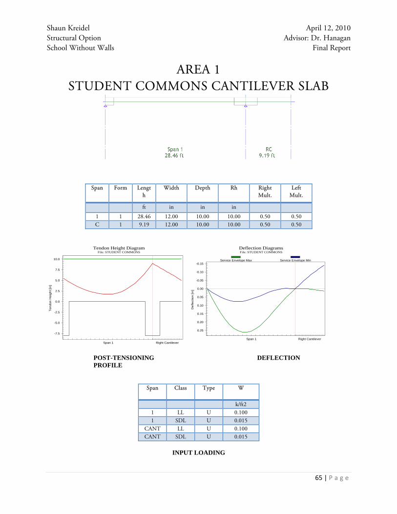
AREA 1 STUDENT COMMONS CANTILEVER SLAB
Span Form Length
Width Depth Rh Right Mult.
Left Mult.
ft in in in
1 1 28.46 12.00 10.00 10.00 0.50 0.50 C 1 9.19 12.00 10.00 10.00 0.50 0.50
POST-TENSIONING DEFLECTION PROFILE
Span Class Type W
k/ft21 LL U 0.1001 SDL U 0.015
CANT LL U 0.100CANT SDL U 0.015
INPUT LOADING
-7.5
-5.0
-2.5
0.0
2.5
5.0
7.5
10.0
Span 1 Right Cantilever
Tendon Height DiagramFile: STUDENT COMMONS
Tend
on H
eigh
t [in
]
0.25
0.20
0.15
0.10
0.05
0.00
-0.05
-0.10
-0.15
Span 1 Right Cantilever
Deflection DiagramsFile: STUDENT COMMONS
Def
lect
ion
[in]
Service Envelope Max Service Envelope Min

Shaun Kreidel April 12, 2010 Structural Option Advisor: Dr. Hanagan School Without Walls Final Report
66 | P a g e
2 - MEMBER ELEVATION [ft] 28.46 9.19
3 - TOP REBAR
3.1 ADAPT selected
3.2 ADAPT selected 1 1#5X6'0" 2 1#5X11'6" 3 1#5X6'0" 4 1#5X9'6"
5 1#5X2'0"6 1#5X0'6"
4 - TENDON PROFILE
4.1 Datum Line
4.2 CGS Distance A[in]
4.6 CGS Distance B[in]
4.10 CGS Distance C[in]
4.3 Force A
4.7 Force B
4.11 Force C
5.50 1.75 9.00[26.3 kips]
7.00 5.00 7.00[26.3 kips]
5 - BOTTOM REBAR
5.1 ADAPT selected
5.2 ADAPT selected 7 1#8X26'0" 8 1#8X1'6"9 1#8X0'0"
6 - REQUIRED & PROVIDED BARS6.1 Top Bars [ in2] required provided
6.2 Bottom Bars
max
max
0.000.310.62
0.40
0.80
0.24
0.31
0.43
0.00
7 - SHEAR STIRRUPS7.1 ADAPT selected. Bar Size # 5 Legs: 2 Spacing [in]
7.2 User-selected Bar Size # Legs:
7.3 Required area [in2/ft]
0.00.30.60.91.2
0. 0.

Shaun Kreidel April 12, 2010 Structural Option Advisor: Dr. Hanagan School Without Walls Final Report
67 | P a g e
AREA 1 SERVICE AREA SIMPLE SLAB
Span Form Length Width Depth Rh Right Mult. Left Mult. ft in in in 1 1 28.79 12.00 10.00 10.00 0.50 0.50
POST-TENSIONING DEFLECTION PROFILE
Span Class Type W A B k/ft2 ft ft1 LL P 0.150 0.000 8.6001 LL P 0.050 8.600 28.7901 SDL U 0.015
INPUT LOADING
-7.5
-5.0
-2.5
0.0
2.5
5.0
7.5
10.0
Span 1
Tendon Height DiagramFile: SERVICE AREA
Tend
on H
eigh
t [in
]
0.50
0.45
0.40
0.35
0.30
0.25
0.20
0.15
0.10
0.05
0.00
Span 1
Deflection DiagramsFile: SERVICE AREA
Def
lect
ion
[in]
Service Envelope Max Service Envelope Min

Shaun Kreidel April 12, 2010 Structural Option Advisor: Dr. Hanagan School Without Walls Final Report
68 | P a g e
2 - MEMBER ELEVATION [ft] 28.79
3 - TOP REBAR
3.1 ADAPT selected
3.2 ADAPT selected 1 1#5X6'0" 2 1#5X6'0"
4 - TENDON PROFILE
4.1 Datum Line
4.2 CGS Distance A[in]
4.6 CGS Distance B[in]
4.10 CGS Distance C[in]
4.3 Force A
4.7 Force B
4.11 Force C
6.00 1.75 1.75 6.00[36 kips]
5 - BOTTOM REBAR
5.1 ADAPT selected
5.2 ADAPT selected 3 1#8X26'0"
6 - REQUIRED & PROVIDED BARS6.1 Top Bars [ in2] required provided
6.2 Bottom Bars
max
max
0.000.160.32
0.200.400.600.80
0.24
0.24
7 - SHEAR STIRRUPS7.1 ADAPT selected. Bar Size # 5 Legs: 2 Spacing [in]
7.2 User-selected Bar Size # Legs:
7.3 Required area [in2/ft]
0.00.30.60.91.2
0

Shaun Kreidel April 12, 2010 Structural Option Advisor: Dr. Hanagan School Without Walls Final Report
69 | P a g e
AREA 1 ROOF TERRACE SIMPLE SLAB
Span Form Length Width Depth Rh Right Mult. Left Mult.
ft in in in 1 1 28.13 12.00 11.00 11.00 0.50 0.50
POST-TENSIONING DEFLECTION PROFILE
Span Class Type Wk/ft2
1 LL U 0.1001 SDL U 0.025
INPUT LOADING
-10.0
-7.5
-5.0
-2.5
0.0
2.5
5.0
7.5
10.0
Span 1
Tendon Height DiagramFile: ROOF TERRACE
Tend
on H
eigh
t [in
]
0.40
0.35
0.30
0.25
0.20
0.15
0.10
0.05
0.00
Span 1
Deflection DiagramsFile: ROOF TERRACE
Def
lect
ion
[in]
Service Envelope Max Service Envelope Min

Shaun Kreidel April 12, 2010 Structural Option Advisor: Dr. Hanagan School Without Walls Final Report
70 | P a g e
2 - MEMBER ELEVATION [ft] 28.13
3 - TOP REBAR
3.1 ADAPT selected
3.2 ADAPT selected 1 1#5X6'0" 2 1#5X6'0"
4 - TENDON PROFILE
4.1 Datum Line
4.2 CGS Distance A[in]
4.6 CGS Distance B[in]
4.10 CGS Distance C[in]
4.3 Force A
4.7 Force B
4.11 Force C
5.50 1.75 1.75 5.50[37.9192 kips]
5 - BOTTOM REBAR
5.1 ADAPT selected
5.2 ADAPT selected 3 1#8X28'6"
6 - REQUIRED & PROVIDED BARS6.1 Top Bars [ in2] required provided
6.2 Bottom Bars
max
max
0.000.160.32
0.200.400.600.80
0.26
0.26
7 - SHEAR STIRRUPS7.1 ADAPT selected. Bar Size # 5 Legs: 2 Spacing [in]
7.2 User-selected Bar Size # Legs:
7.3 Required area [in2/ft]
0.00.30.60.91.2
0.
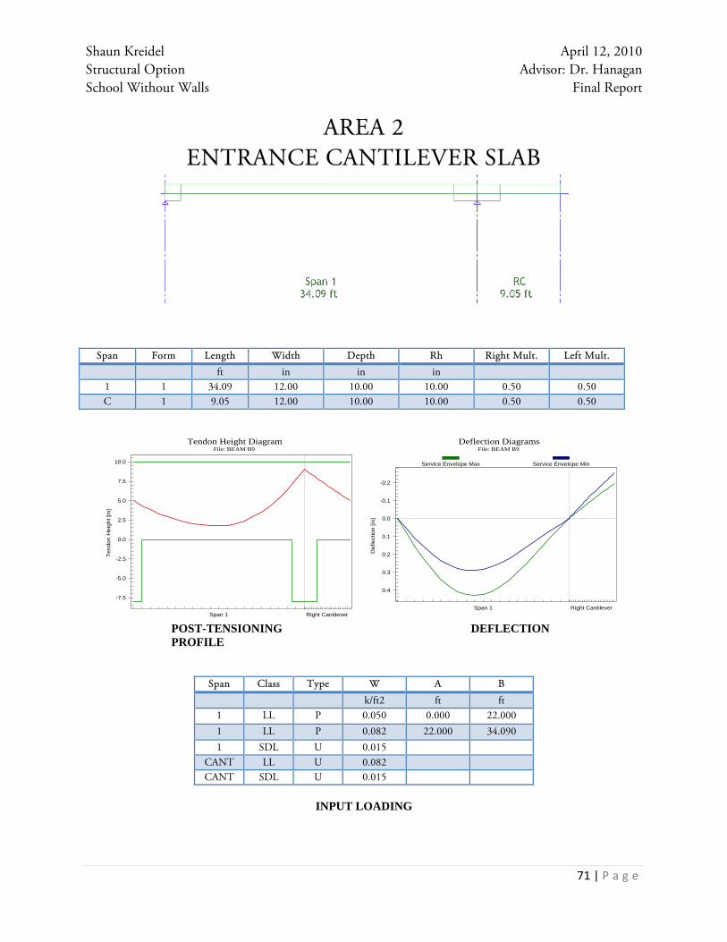
Shaun Kreidel April 12, 2010 Structural Option Advisor: Dr. Hanagan School Without Walls Final Report
71 | P a g e
AREA 2 ENTRANCE CANTILEVER SLAB
Span Form Length Width Depth Rh Right Mult. Left Mult. ft in in in
1 1 34.09 12.00 10.00 10.00 0.50 0.50C 1 9.05 12.00 10.00 10.00 0.50 0.50
POST-TENSIONING DEFLECTION PROFILE
Span Class Type W A B k/ft2 ft ft1 LL P 0.050 0.000 22.000 1 LL P 0.082 22.000 34.090 1 SDL U 0.015
CANT LL U 0.082CANT SDL U 0.015
INPUT LOADING
-7.5
-5.0
-2.5
0.0
2.5
5.0
7.5
10.0
Span 1 Right Cantilever
Tendon Height DiagramFile: BEAM B9
Tend
on H
eigh
t [in
]
0.4
0.3
0.2
0.1
0.0
-0.1
-0.2
Span 1 Right Cantilever
Deflection DiagramsFile: BEAM B9
Def
lect
ion
[in]
Service Envelope Max Service Envelope Min

Shaun Kreidel April 12, 2010 Structural Option Advisor: Dr. Hanagan School Without Walls Final Report
72 | P a g e
2 - MEMBER ELEVATION [ft] 34.09 9.05
3 - TOP REBAR
3.1 ADAPT selected
3.2 ADAPT selected 1 1#5X7'0" 2 1#5X3'6" 3 1#5X16'0"
4 1#5X2'0"5 1#5X0'6"
4 - TENDON PROFILE
4.1 Datum Line
4.2 CGS Distance A[in]
4.6 CGS Distance B[in]
4.10 CGS Distance C[in]
4.3 Force A
4.7 Force B
4.11 Force C
5.00 1.75 9.00[29.4136 kips]
7.00 5.00 7.00[29.4136 kips]
5 - BOTTOM REBAR
5.1 ADAPT selected
5.2 ADAPT selected 6 1#8X31'0" 7 1#8X2'0"
6 - REQUIRED & PROVIDED BARS6.1 Top Bars [ in2] required provided
6.2 Bottom Bars
max
max
0.000.310.62
0.40
0.80
0.24
0.32
0.43
0.00
7 - SHEAR STIRRUPS7.1 ADAPT selected. Bar Size # 4 Legs: 2 Spacing [in]
7.2 User-selected Bar Size # Legs:
7.3 Required area [in2/ft]
0.00.30.60.91.2
0. 0.

Shaun Kreidel April 12, 2010 Structural Option Advisor: Dr. Hanagan School Without Walls Final Report
73 | P a g e
AREA 2 FIRST FLOOR CLASSROOM CANTILEVER SLAB
Span Form Length Width Depth Rh Right Mult. Left Mult. ft in in in
1 1 34.09 12.00 10.00 10.00 0.50 0.50C 1 9.05 12.00 10.00 10.00 0.50 0.50
POST-TENSIONING DEFLECTION PROFILE
Span Class Type W
k/ft21 LL U 0.051 SDL U 0.015
CANT LL U 0.050CANT SDL U 0.015
INPUT LOADING
-7.5
-5.0
-2.5
0.0
2.5
5.0
7.5
10.0
Span 1 Right Cantilever
Tendon Height DiagramFile: ENTRANCE SLAB
Tend
on H
eigh
t [in
]
0.5
0.4
0.3
0.2
0.1
0.0
-0.1
-0.2
-0.3
Span 1 Right Cantilever
Deflection DiagramsFile: ENTRANCE SLAB
Def
lect
ion
[in]
Service Envelope Max Service Envelope Min

Shaun Kreidel April 12, 2010 Structural Option Advisor: Dr. Hanagan School Without Walls Final Report
74 | P a g e
2 - MEMBER ELEVATION [ft] 34.09 9.05
3 - TOP REBAR
3.1 ADAPT selected
3.2 ADAPT selected 1 1#5X7'0" 2 1#5X16'0"
3 1#5X2'0"4 1#5X0'6"
4 - TENDON PROFILE
4.1 Datum Line
4.2 CGS Distance A[in]
4.6 CGS Distance B[in]
4.10 CGS Distance C[in]
4.3 Force A
4.7 Force B
4.11 Force C
5.00 1.75 9.00[29.7267 kips]
7.00 5.00 7.00[29.7267 kips]
5 - BOTTOM REBAR
5.1 ADAPT selected
5.2 ADAPT selected 5 1#8X31'0" 6 1#8X2'0"
6 - REQUIRED & PROVIDED BARS6.1 Top Bars [ in2] required provided
6.2 Bottom Bars
max
max
0.000.310.62
0.40
0.80
0.24
0.33
0.43
0.00
7 - SHEAR STIRRUPS7.1 ADAPT selected. Bar Size # 4 Legs: 2 Spacing [in]
7.2 User-selected Bar Size # Legs:
7.3 Required area [in2/ft]
0.00.30.60.91.2
0. 0.
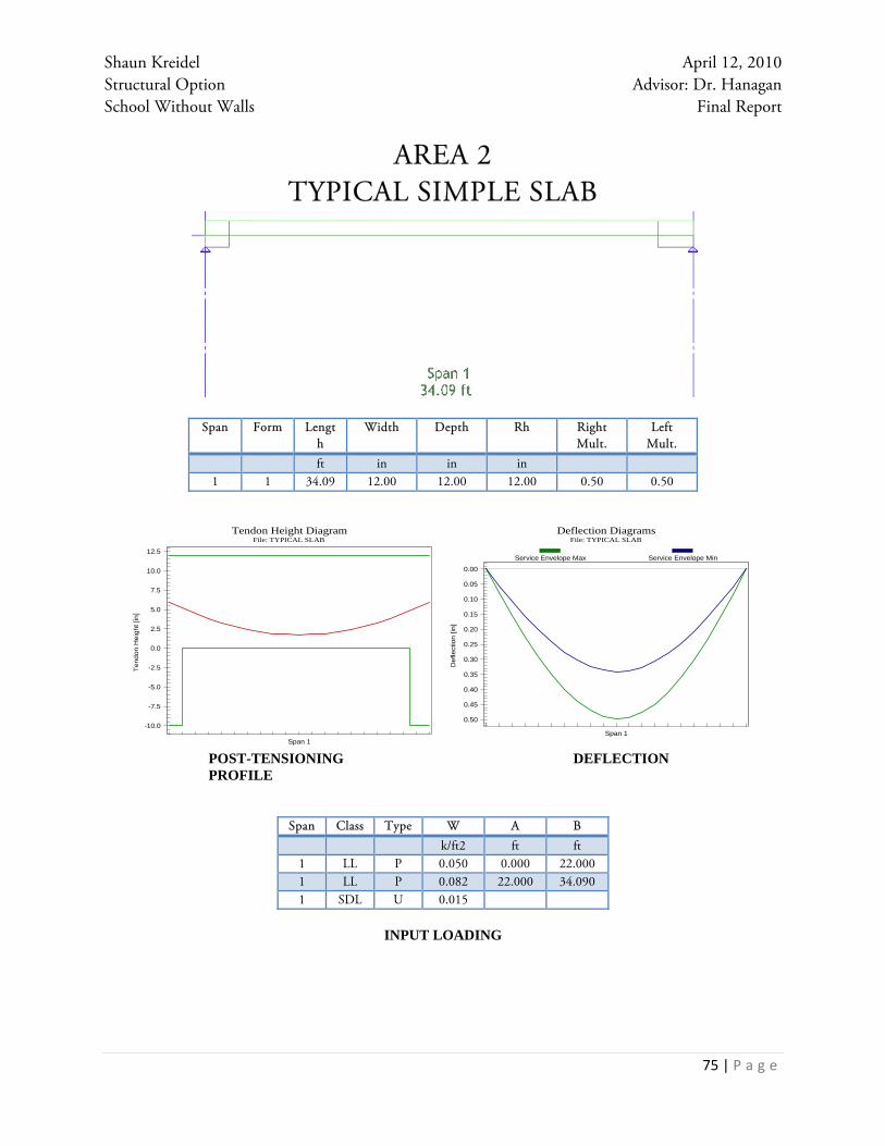
Shaun Kreidel April 12, 2010 Structural Option Advisor: Dr. Hanagan School Without Walls Final Report
75 | P a g e
AREA 2 TYPICAL SIMPLE SLAB
Span Form Length
Width Depth Rh Right Mult.
Left Mult.
ft in in in 1 1 34.09 12.00 12.00 12.00 0.50 0.50
POST-TENSIONING DEFLECTION PROFILE
Span Class Type W A B k/ft2 ft ft1 LL P 0.050 0.000 22.0001 LL P 0.082 22.000 34.0901 SDL U 0.015
INPUT LOADING
-10.0
-7.5
-5.0
-2.5
0.0
2.5
5.0
7.5
10.0
12.5
Span 1
Tendon Height DiagramFile: TYPICAL SLAB
Tend
on H
eigh
t [in
]
0.50
0.45
0.40
0.35
0.30
0.25
0.20
0.15
0.10
0.05
0.00
Span 1
Deflection DiagramsFile: TYPICAL SLAB
Def
lect
ion
[in]
Service Envelope Max Service Envelope Min

Shaun Kreidel April 12, 2010 Structural Option Advisor: Dr. Hanagan School Without Walls Final Report
76 | P a g e
2 - MEMBER ELEVATION [ft] 34.09
3 - TOP REBAR
3.1 ADAPT selected
3.2 ADAPT selected 1 1#5X7'0" 2 1#5X7'0"
4 - TENDON PROFILE
4.1 Datum Line
4.2 CGS Distance A[in]
4.6 CGS Distance B[in]
4.10 CGS Distance C[in]
4.3 Force A
4.7 Force B
4.11 Force C
6.00 1.75 1.75 6.00[43 kips]
5 - BOTTOM REBAR
5.1 ADAPT selected
5.2 ADAPT selected 3 1#8X32'6"
6 - REQUIRED & PROVIDED BARS6.1 Top Bars [ in2] required provided
6.2 Bottom Bars
max
max
0.000.160.32
0.200.400.600.80
0.29
0.29
7 - SHEAR STIRRUPS7.1 ADAPT selected. Bar Size # 4 Legs: 2 Spacing [in]
7.2 User-selected Bar Size # Legs:
7.3 Required area [in2/ft]
0.00.30.60.91.2
0.

Shaun Kreidel April 12, 2010 Structural Option Advisor: Dr. Hanagan School Without Walls Final Report
77 | P a g e
APPENDIX C

Shaun Kreidel April 12, 2010 Structural Option Advisor: Dr. Hanagan School Without Walls Final Report
78 | P a g e
Area 1
First Floor Beams (CONCRETE BUILDING)
Number of beams Shape Weight (lb/ft) Span (ft) Total Weight (lb)
1 18X56 1050 115 120750
1 18x40 750 115 86250
207000
Second Floor Beams (CONCRETE BUILDING)
Number of beams Shape Weight (lb/ft) Span (ft) Total Weight (lb)
1 20x56 1166.667 115 134166.705
1 20x40 833.333 115 95833.295
230000
Floor Weight (CONCRETE BUILDING)
Floor Area (ft^2) Weight Concrete (lb/ft3) Thickness Of Slab (ft) Total Weight (lb)
2 3700 150 0.92 510600
1 4285 150 0.83 533483
1044083
Column Weight (CONCRETE BUILDING)
Number Size Weight (lb/ft) First Floor Second Floor
10 24x24 600 72000 90000
Other Loads
Floor Area Partitions (lb/ft2) Finishes (lb/ft2) M/E/P (lb/ft2) Total Weight (lb)
1 4428 20 5 10 154980
2 3925 20 5 10 137375
292355

Shaun Kreidel April 12, 2010 Structural Option Advisor: Dr. Hanagan School Without Walls Final Report
79 | P a g e
Area 2
First Floor Beams (CONCRETE BUILDING)
Number of beams Shape Weight (lb/ft) Span (ft) Total Weight (lb)
1 18X60 1125 121 136125
1 18x40 750 121 90750
226875
Second Floor Beams (CONCRETE BUILDING)
Number of beams Shape Weight (lb/ft) Span (ft) Total Weight (lb)
1 20x60 1250 121 151250
1 20x40 833.333 121 100833.293
252083.293
Third Floor Beams (CONCRETE BUILDING)
Number of beams Shape Weight (lb/ft) Span (ft) Total Weight (lb)
1 20x60 1250 121 151250
1 20x40 833.333 121 100833.293
252083.293
Fourth Floor Beams (CONCRETE BUILDING)
Number of beams Shape Weight (lb/ft) Span (ft) Total Weight (lb)
1 20x60 1250 121 151250
1 20x40 833.333 121 100833
252083
Floor Weight (CONCRETE BUILDING)
Floor Area (ft2) Weight Concrete (lb/ft3) Thickness Of Slab (ft) Total Weight (lb)
1 5055.4 150 0.83 629397
2 4868.87 150 0.92 671904
3 4868.87 150 0.92 671904
4 4785.88 150 0.92 660451
Roof 3256 130240
2763897

Shaun Kreidel April 12, 2010 Structural Option Advisor: Dr. Hanagan School Without Walls Final Report
80 | P a g e
Roof Beams (STEEL)
Number of beams Shape Weight (lb/ft) Span (ft) Total Weight (lb)
7 W10x12 12 5 420
8 W10x12 12 6 576
2 W10x12 12 7.5 180
1 W10x12 12 9 108
2 W10x12 12 12 288
6 W10x12 12 13 936
10 W12x14 14 5 700
6 W12x14 14 13 1092
4 W12x14 14 14 784
4 W12x14 14 24 1344
1 W12x19 19 8.5 161.5
1 W12x19 19 13 247
1 W12x19 19 15 285
1 W12x26 26 12 312
2 W12x26 26 24 1248
1 W12x58 58 24 1392
2 W12x65 65 38 4940
1 W14x22 22 10 220
1 W16x31 31 24 744
1 W16x36 36 25 900
1 W18x35 35 37 1295
1 W18x40 40 24.5 980
1 W18x40 40 30.5 1220
3 W18x40 40 37 4440
1 W18x46 46 18.5 851
1 W21x44 44 30.5 1342
1 HSS6x6x3/8 27.41 24 657.84
2 HSS8x8x3/8 37.61 24 1805.28
29468.62
Column Weight (STEEL BUILDING)
Number Size Weight (lb/ft) First Level Second Level Third Level Fourth Level Roof Level
12 24x24 600 50400 109800 109800 109800 7668.0775

Shaun Kreidel April 12, 2010 Structural Option Advisor: Dr. Hanagan School Without Walls Final Report
81 | P a g e
Other Loads
Floor Area Partitions (lb/ft2) Finishes (lb/ft2) M/E/P (lb/ft2) Total Weight (lb)
1 5055.4 20 5 10 176939
2 4868.87 20 5 10 170410.45
3 4868.87 20 5 10 170410.45
4 4785.88 20 5 10 167505.8
685265.7

Shaun Kreidel April 12, 2010 Structural Option Advisor: Dr. Hanagan School Without Walls Final Report
82 | P a g e
APPENDIX D

Shaun Kreidel April 12, 2010 Structural Option Advisor: Dr. Hanagan School Without Walls Final Report
83 | P a g e
Area 1
Seismic Loads (ASCE 7-05)
Occupancy Category III (Table 1-1)
Importance Factor(I) 1.25 (Table 11.5-1)
Ss 0.154 g
S1 0.05 g
Site Class C Dense Soil/Soft Rock
Fa 1.2 (Table 11.4-1)
Fv 1.7 (Table 11.4-1)
SMS=Fa*Ss 0.185
SM1=Fv*S1 0.085
SDS=2SMS/3 0.123 Category A
SD1=2SM1/3 0.057 Category A
Ts 0.460
Ta=Cthx 0.311
x 0.9 (Table 12.8-2)
h 27 ft
Ct 0.016 (Table 12.8-2)
T=Cu*Ta 0.528
Cu 1.7 (Table 12.8-1)
TL 8 (Table 22-15)
Cs=SD1/(T(R/I)) 0.0268
SDS/(R/I) 0.0308
R 5 (Table 12.2-1)
k 1.014
V 51.91 kip

Shaun Kreidel April 12, 2010 Structural Option Advisor: Dr. Hanagan School Without Walls Final Report
84 | P a g e
Area 2
Seismic Loads (ASCE 7-05)
Occupancy Category III (Table 1-1)
Importance Factor(I) 1.25 (Table 11.5-1)
Ss 0.154 g
S1 0.05 g
Site Class C Dense Soil/Soft Rock
Fa 1.2 (Table 11.4-1)
Fv 1.7 (Table 11.4-1)
SMS=Fa*Ss 0.185
SM1=Fv*S1 0.085
SDS=2SMS/3 0.123 Category A
SD1=2SM1/3 0.057 Category A
Ts 0.460
Ta=Cthx 0.311
x 0.9 (Table 12.8-2)
h 27 ft
Ct 0.016 (Table 12.8-2)
T=Cu*Ta 0.528
Cu 1.7 (Table 12.8-1)
TL 8 (Table 22-15)
Cs=SD1/(T(R/I)) 0.0268
SDS/(R/I) 0.0308
R 5 (Table 12.2-1)
k 1.014
V 129.3 kip

Shaun Kreidel April 12, 2010 Structural Option Advisor: Dr. Hanagan School Without Walls Final Report
85 | P a g e
APPENDIX E

Shaun Kreidel April 12, 2010 Structural Option Advisor: Dr. Hanagan School Without Walls Final Report
86 | P a g e
Column B-2 First Floor
D = dead load
L = live load
W = wind load
E = earthquake load
Geometry Total Live Load Axial Load 81600 lb
Tributary Area 24 x 20 Roof Axial Load 38400 lb
Fourth Floor Axial Load 118350 lb
Materials Third Floor Axial Load 118350 lb
Second Floor Axial Load 109200 lb
Concrete 150 pcf Total Axial Load 384300 lb
Steel Grade 50
Roof Loads
Dead Loads:
MEP 10 psf
Roof Material 20 psf
Slab/Deck 40 psf
Beams 10 psf
Live Loads: 20 psf
Fourth Floor
Height 15.25 ft
Dead Loads:
Beams 20 x 60
Superimposed 15 psf
Slab 12 in
Column 24 x 24
Live Loads: 50 psf

Shaun Kreidel April 12, 2010 Structural Option Advisor: Dr. Hanagan School Without Walls Final Report
87 | P a g e
Third Floor
Height 15.25 ft
Dead Loads:
Beams 20 x 60
Superimposed 15 psf
Slab 12 in
Column 24 x 24
Live Loads: 50 psf
Second Floor
Height 20 ft
Dead Loads:
Beams 20 x 60
Superimposed 15 psf
Slab 12 in
Column 24 x 24
Live Loads: 50 psf

Shaun Kreidel April 12, 2010 Structural Option Advisor: Dr. Hanagan School Without Walls Final Report
88 | P a g e
APPENDIX F

Shaun Kreidel April 12, 2010 Structural Option Advisor: Dr. Hanagan School Without Walls Final Report
89 | P a g e
AREA 1 First Floor Metal Deck Slab Assumptions:
Length= 116'
Width= 40'
Thickness= 5.25"
4000psi Concrete
4 Edges Formed
Float Finish
6X6 W2.0/W2.0 Mesh
Item Code Description Quantity UM Labor $ Crew Production Prod. UM Total Hours Duration Labor Total Material Total Total Cost
3150.65 SCREEDS FOR SLAB 556.8 LNFT 0.9219 C311 1,250.00 DAY 19.59936 0.44544 513.314 178.176 691.49
3220.011 6x6 W2.1/W2.1 MESH 51.04 SQS 22.008 C320 60 DAY 47.63733 0.85067 1,123.29 543.576 1,666.86
3311.7 **CONC IN SLAB OVER MTL DECK** ****
3311.725 4000 PSI DIRECT 60.86 CUYD 14.6787 C216 60 DAY 36.51852 1.0144 893.407 3,408.40 4,301.80
3315.991 * SLAB OVER METAL DECK AREA * 4,640.00 SQFT
3350.132 FLOAT FINISH 4,640.00 SQFT 0.2754 C276 3,000.00 DAY 49.49333 1.54667 1,277.86 1,277.86
3390.01 PROTECT & CURE 4,640.00 SQFT 0.1102 C276 7,500.00 DAY 19.79733 0.61867 511.328 89.088 600.416
5310.018 2" METAL DECK 4,640.00 SQFT 0.4445 C510 5,170.00 DAY 64.61896 0.89749 2,062.48 4,038.66 6,101.14
5.37334 6381.673 8257.891 14639.56
Second Floor Concrete Slab Assumptions:
Length= 116'
Width= 33'
Thickness= 5.25"
4000psi Concrete
4 Edges Formed
Float Finish
6X6 W2.0/W2.0 Mesh
Item Code Description Quantity UM Labor $ Crew Production Prod. UM Total Hours Duration Labor Total Material Total Total Cost
3150.65 SCREEDS FOR SLAB 459.36 LNFT 0.9219 C311 1,250.00 DAY 16.16947 0.36749 423.484 146.995 570.479
3220.011 6x6 W2.1/W2.1 MESH 42.11 SQS 22.008 C320 60 DAY 39.3008 0.7018 926.713 448.45 1,375.16
3311.7 **CONC IN SLAB OVER MTL DECK** ****
3311.73 4000 PSI W/PUMP 50.21 CUYD 12.5997 C235 120 DAY 26.78025 0.41844 632.668 2,811.93 3,709.72
3315.991 * SLAB OVER METAL DECK AREA * 3,828.00 SQFT
3350.132 FLOAT FINISH 3,828.00 SQFT 0.2754 C276 3,000.00 DAY 40.832 1.276 1,054.23 1,054.23
3390.01 PROTECT & CURE 3,828.00 SQFT 0.1102 C276 7,500.00 DAY 16.3328 0.5104 421.846 73.498 495.343
5310.018 2" METAL DECK 3,828.00 SQFT 0.4445 C510 5,170.00 DAY 53.31064 0.74043 1,701.55 3,331.89 5,033.44
4.01456 5160.488 6812.76 12238.37

Shaun Kreidel April 12, 2010 Structural Option Advisor: Dr. Hanagan School Without Walls Final Report
90 | P a g e
AREA 1 Steel Beams
AREA 1 Steel Columns
AREA 1 Fireproofing
Item Code Description Quantity UM Crew Production Prod. UM Total Hours Duration Labor Total Material Total Total Cost
5129.102 I BEAMS 684.45 CWT C510 80 DAY 616.005 8.55564 19664.25 23955.75 47042.25
5129.404 SHEAR STUD, 3/4" 82 EACH C509 400 DAY 1.40569 0.05849 44.552 58.786 127.928
8.61413 19708.801 24014.536 47170.177
Item Code Description Quantity UM Crew Production Prod. UM Total Hours Duration Labor Total Material Total Total Cost
5129.122 I SHAPES 93.41 CWT C510 80 DAY 84.069 1.16763 2683.669 3269.35 6420.069
Item Code Description Quantity UM Crew Production Prod. UM Total Hours Duration Labor Total Material Total Equip. Cost Total Cost
7810.033 INTUMESCENT FIREPROOFING 1,528.92 BDFT C917 3,000.00 DAY 6.11568 0.50964 167.875 4,442.43 122.314 4,732.62
7812.031 1/8" TOPCOAT 273.96 SQFT C917 4,200.00 DAY 0.78274 0.06523 21.506 105.201 21.917 148.623
7810.035 TYPE A FIREPROOFING 7727.53 BDFT C917 3,000.00 DAY 30.91012 2.57587 848.482 3,956.50 618.204 5,423.18
3.15074 1037.863 8504.129 762.435 10304.422

Shaun Kreidel April 12, 2010 Structural Option Advisor: Dr. Hanagan School Without Walls Final Report
91 | P a g e
AREA 1 Concrete PilastersAssumptions:
Depth= 24"
Width= 18"
4000psi Concrete
3 Edges Formed
Rectangular Plywood Forms
Height=12'
Reinforcing Steel= 375lb/cuyd
Item Code Description Quantity UM Crew Production Prod. UM Total Hours Duration Labor Total Material Total Total Cost
3111.348 WOOD PIER FORMS 504 SQFT C311 1,100.00 DAY 20.16 0.45818 527.99 584.892 1,112.88
3112.1 CHAMFER STRIP 288 LNFT C311 1,700.00 DAY 7.45412 0.16941 195.235 55.296 250.531
3150.9 FORM RELEASING AGENT 504 SQFT C311 5,500.00 DAY 4.032 0.09164 105.588 11.592 117.18
3210.155 PIER REBAR 30 CWT C321 75 DAY 22.4 0.4 711.999 802.5 1,514.50
3310.75 **CONCRETE IN PIERS** ****
3310.781 5000 PSI DIRECT 8 CUYD C216 55 DAY 5.23636 0.14545 128.105 480 608.105
3350.131 POINT & PATCH 504 SQFT C276 7,500.00 DAY 2.1504 0.0672 55.541 6.451 61.992
1.33188 1724.458 1940.731 3665.189

Shaun Kreidel April 12, 2010 Structural Option Advisor: Dr. Hanagan School Without Walls Final Report
92 | P a g e
APPENDIX G

Shaun Kreidel April 12, 2010 Structural Option Advisor: Dr. Hanagan School Without Walls Final Report
93 | P a g e
AREA 1First Floor Concrete Slab Assumtions: Length= 116' Width= 40' Thickness= 10" Story Height= 12' 5000psi Concrete Standard Wood Forms 4 Edges Formed Float Finish Reinforcing Steel= 2.9 lbs/sqft Item Code Description Quantity UM Labor $ Crew Production Prod. UM Total Hours Duration Labor Total Material Total Total Cost
3111.612 SLAB FORM W/2.6 BM/SF 3,712.00 SQFT 2.538 C311 454.058 DAY 359.70735 8.17517 9,421.06 4,688.63 14,109.68
3111.624 SLAB EDGE FORM 260 SQFT 2.1511 C311 535.719 DAY 21.35448 0.48533 559.286 221.702 780.988
3150.65 SCREEDS FOR SLAB 556.8 LNFT 0.9219 C311 1,250.00 DAY 19.59936 0.44544 513.314 178.176 691.49
3150.9 FORM RELEASING AGENT 3,972.00 SQFT 0.2095 C311 5,500.00 DAY 31.776 0.72218 832.134 91.356 923.49
3210.13 SUPPORTED SLAB REBAR 134.56 CWT 32.3636 C321 55 DAY 137.00655 2.44655 4,354.85 3,599.48 7,954.33
3311.5 **CONC IN SUPPORTED SLAB**
****
3311.533 5000 PSI W/CART 143.21 CUYD 14.3996 C220 105 DAY 87.28983 1.3639 2,062.17 8,592.59 10,654.76
3315.986 * SUPPORTED SLAB AREA * 4,640.00 SQFT
3350.131 POINT & PATCH 3,972.00 SQFT 0.1102 C276 7,500.00 DAY 16.9472 0.5296 437.714 50.842 488.556
3350.132 FLOAT FINISH 4,640.00 SQFT 0.2754 C276 3,000.00 DAY 49.49333 1.54667 1,277.86 1,277.86
3390.01 PROTECT & CURE 4,640.00 SQFT 0.1102 C276 7,500.00 DAY 19.79733 0.61867 511.328 89.088 600.416
3250.01 POST TENSIONING ****
3250.055 SUPPORTED SLABS ****
3250.056 GREASED STRANDS 2,436.00 LBS 0.6827 C322 1,500.00 DAY 51.968 1.624 1,663.06 2,484.72 4,216.47
17.95751 21,632.76 19,996.58 41,698.04

Shaun Kreidel April 12, 2010 Structural Option Advisor: Dr. Hanagan School Without Walls Final Report
94 | P a g e
AREA 1 Second Floor Concrete Slab Assumptions: Length= 116' Width= 33' Thickness= 12" Story Height= 15' 5000psi Concrete Standard Wood Forms 4 Edges Formed Float Finish Reinforcing Steel= 2.9 lbs/sqft Item Code Description Quantity UM Labor $ Crew Production Prod. UM Total Hours Duration Labor Total Material Total Total Cost
3111.618 SLAB FORM W/2.9 BM/SF 2,900.00 SQFT 2.8245 C311 408 DAY 312.7451 7.10784 8,191.05 3,989.82 12,180.87
3111.624 SLAB EDGE FORM 298 SQFT 2.1511 C311 535.719 DAY 24.47552 0.55626 641.028 254.105 895.132
3150.65 SCREEDS FOR SLAB 459.36 LNFT 0.9219 C311 1,250.00 DAY 16.16947 0.36749 423.484 146.995 570.479
3150.9 FORM RELEASING AGENT 3,198.00 SQFT 0.2095 C311 5,500.00 DAY 25.584 0.58145 669.981 73.554 743.535
3210.13 SUPPORTED SLAB REBAR 111.01 CWT 32.3636 C321 55 DAY 113.0304 2.0184 3,592.75 2,969.57 6,562.32
3311.5 **C0NC IN SUPPORTED SLAB** ****
3311.533 5000 PSI W/CART 141.78 CUYD 14.3996 C220 105 DAY 86.41693 1.35026 2,041.54 8,506.67 10,548.21
3315.986 * SUPPORTED SLAB AREA * 3,828.00 SQFT
3350.131 POINT & PATCH 3,198.00 SQFT 0.1102 C276 7,500.00 DAY 13.6448 0.4264 352.42 40.934 393.354
3350.132 FLOAT FINISH 3,828.00 SQFT 0.2754 C276 3,000.00 DAY 40.832 1.276 1,054.23 1,054.23
3390.01 PROTECT & CURE 3,828.00 SQFT 0.1102 C276 7,500.00 DAY 16.3328 0.5104 421.846 73.498 495.343
3250.01 POST TENSIONING ****
3250.055 SUPPORTED SLABS ****
3250.056 GREASED STRANDS 2,009.70 LBS 0.6827 C322 1,500.00 DAY 42.8736 1.3398 1,372.02 2,049.89 3,478.59
15.5343 18,760.35 18,105.04 36,922.06

Shaun Kreidel April 12, 2010 Structural Option Advisor: Dr. Hanagan School Without Walls Final Report
95 | P a g e
Beam B1 Assumptions: Width= 4.67' Depth below slab= .67' Length= 116' Story Height= 12' 5000psi Concrete Wood Soffit Forms and Shoring Wood Side Forms
Item Code Description Quantity UM Labor $ Crew Production Prod. UM Total Hours Duration Labor Total Material Total Total Cost
3111.407 BEAM SOFFIT FORMS 10'-12' HIGH 541.37 SQFT 5.6457 C311 204.112 DAY 116.70244 2.65233 3,056.42 2,021.59 5,078.02
3111.42 BEAM SIDE FORMS 154.74 SQFT 2.8709 C311 401.398 DAY 16.96256 0.38551 444.255 159.03 603.285
3111.524 Beam w/slab shoring 10'-12' 541.37 SQFT 5.6457 C311 204.112 DAY 116.70244 2.65233 3,056.42 2,021.59 5,078.02
3150.9 FORM RELEASING AGENT 696.12 SQFT 0.2095 C311 5,500.00 DAY 5.56893 0.12657 145.836 16.011 161.847
3210.901 RE-STEEL @ BEAMS W/SLAB 26.75 CWT 32.3636 C321 55 DAY 27.23411 0.48632 865.655 715.503 1,581.16
3311.1 **CONC IN BEAMS W/SLAB** ****
3311.133 5000 PSI W/CART 13.37 CUYD 15.1196 C220 100 DAY 8.55929 0.13374 202.208 802.434 1,004.64
3315.985 * LENGTH OF BEAMS * 116 LNFT
3350.131 POINT & PATCH 696.12 SQFT 0.1102 C276 7,500.00 DAY 2.97009 0.09282 76.712 8.91 85.622
6.52962 7,847.51 5,745.07 13,592.58
Beam B2 Assumptions: Width= 3.33' Depth below slab= .67' Length= 116' Story Height= 12' 5000psi Concrete Wood Soffit Forms and Shoring Wood Side Forms Item Code Description Quantity UM Labor $ Crew Production Prod. UM Total Hours Duration Labor Total Material Total Total Cost
3111.407 BEAM SOFFIT FORMS 10'-12' HIGH 386.28 SQFT 5.6457 C311 204.112 DAY 83.26958 1.89249 2,180.82 1,442.45 3,623.27
3111.42 BEAM SIDE FORMS 154.74 SQFT 2.8709 C311 401.398 DAY 16.96256 0.38551 444.255 159.03 603.285
3111.524 Beam w/slab shoring 10'-12' 386.28 SQFT 5.6457 C311 204.112 DAY 83.26958 1.89249 2,180.82 1,442.45 3,623.27
3150.9 FORM RELEASING AGENT 541.02 SQFT 0.2095 C311 5,500.00 DAY 4.32819 0.09837 113.345 12.444 125.788
3210.901 RE-STEEL @ BEAMS W/SLAB 19.09 CWT 32.3636 C321 55 DAY 19.4321 0.347 617.662 510.526 1,128.19
3311.1 **CONC IN BEAMS W/SLAB** ****
3311.133 5000 PSI W/CART 9.54 CUYD 15.1196 C220 100 DAY 6.10723 0.09543 144.279 572.553 716.832
3315.985 * LENGTH OF BEAMS * 116 LNFT
3350.131 POINT & PATCH 541.02 SQFT 0.1102 C276 7,500.00 DAY 2.30837 0.07214 59.621 6.925 66.546
4.78343 5,740.80 4,146.37 9,887.18

Shaun Kreidel April 12, 2010 Structural Option Advisor: Dr. Hanagan School Without Walls Final Report
96 | P a g e
Beam B3 Assumptions:
Width= 4.67' Depth below slab= .67' Length= 116' Story Height= 15' 5000psi Concrete Wood Soffit Forms and Shoring Wood Side Forms Item Code Description Quantity UM Labor $ Crew Production Prod. UM Total Hours Duration Labor Total Material Total Total Cost
3111.411 BEAM SOFFIT FORMS 14'-16' HIGH 541.37 SQFT 6.2569 C311 184.175 DAY 129.33551 2.93944 3,387.31 2,319.89 5,707.20
3111.42 BEAM SIDE FORMS 154.74 SQFT 2.8709 C311 401.398 DAY 16.96256 0.38551 444.255 159.03 603.285
3111.526 Beam w/slab shoring 14'-16' 541.37 SQFT 6.2569 C311 184.175 DAY 129.33551 2.93944 3,387.31 2,319.89 5,707.20
3150.9 FORM RELEASING AGENT 696.12 SQFT 0.2095 C311 5,500.00 DAY 5.56893 0.12657 145.836 16.011 161.847
3210.901 RE-STEEL @ BEAMS W/SLAB 26.75 CWT 32.3636 C321 55 DAY 27.23411 0.48632 865.655 715.503 1,581.16
3311.1 **CONC IN BEAMS W/SLAB** ****
3311.133 5000 PSI W/CART 13.37 CUYD 15.1196 C220 100 DAY 8.55929 0.13374 202.208 802.434 1,004.64
3315.985 * LENGTH OF BEAMS * 116 LNFT
3350.131 POINT & PATCH 696.12 SQFT 0.1102 C276 7,500.00 DAY 2.97009 0.09282 76.712 8.91 85.622
7.10384 8,432.57 6,332.75 14,765.33
Beam B4 Assumptions:
Width= 3.33' Depth below slab= .67' Length= 116' Story Height= 15' 5000psi Concrete Wood Soffit Forms and Shoring Wood Side Forms Item Code Description Quantity UM Labor $ Crew Production Total Hours Duration Labor Total Material Total Total Cost
3111.411 BEAM SOFFIT FORMS 14'-16' HIGH 386.28 SQFT 6.2569 C311 184.175 92.28353 2.09735 2,416.92 1,655.29 4,072.20
3111.42 BEAM SIDE FORMS 154.74 SQFT 2.8709 C311 401.398 16.96256 0.38551 444.255 159.03 603.285
3111.526 Beam w/slab shoring 14'-16' 386.28 SQFT 6.2569 C311 184.175 92.28353 2.09735 2,416.92 1,655.29 4,072.20
3150.9 FORM RELEASING AGENT 541.02 SQFT 0.2095 C311 5,500.00 4.32819 0.09837 113.345 12.444 125.788
3210.901 RE-STEEL @ BEAMS W/SLAB 19.09 CWT 32.3636 C321 55 19.4321 0.347 617.662 510.526 1,128.19
3311.1 **CONC IN BEAMS W/SLAB** ****
3311.133 5000 PSI W/CART 9.54 CUYD 15.1196 C220 100 6.10723 0.09543 144.279 572.553 716.832
3315.985 * LENGTH OF BEAMS * 116 LNFT
3350.131 POINT & PATCH 541.02 SQFT 0.1102 C276 7,500.00 2.30837 0.07214 59.621 6.925 66.546
5.19315 6,212.99 4,572.05 10,785.04

Shaun Kreidel April 12, 2010 Structural Option Advisor: Dr. Hanagan School Without Walls Final Report
97 | P a g e
AREA 1 First Floor ColumnsAssumptions: Width= 20" Depth=20" Length= 11' Chamfered Corners=4 5000psi Concrete Plywood Forms Reinforcing Steel= 375 lb/cuyd Item Code Description Quantity UM Labor $ Crew Production Prod. UM Total Hours Duration Labor Total Material Total Total Cost
3111.202 WOOD COLUMN FORMS, 8'-12' 733.33 SQFT 1.213 C311 950 DAY 33.96491 0.77193 889.533 844.433 1,733.97
3112.1 CHAMFER STRIP 440 LNFT 0.6779 C311 1,700.00 DAY 11.38824 0.25882 298.276 84.48 382.756
3150.9 FORM RELEASING AGENT 733.33 SQFT 0.2095 C311 5,500.00 DAY 5.86667 0.13333 153.633 16.867 170.5
3210.15 COLUMN REBAR 42.44 CWT 24.7222 C321 72 DAY 33.00754 0.58942 1,049.17 1,135.22 2,184.39
3310.65 **CONCRETE IN COLUMNS** ****
3310.686 5000 PSI W/PUMP 11.32 CUYD 16.7996 C235 90 DAY 8.04755 0.12574 190.119 679.012 928.884
3315.984 * NO. OF COLUMNS * 10 EACH
3350.131 POINT & PATCH 733.33 SQFT 0.1102 C276 7,500.00 DAY 3.12889 0.09778 80.813 9.387 90.2
1.97702 2661.541 2769.403 5490.698
AREA 1 Second Floor ColumnsAssumptions: Width= 20" Depth=20" Length= 14' Chamfered Corners=4 5000psi Concrete Plywood Forms Reinforcing Steel= 375 lb/cuyd Item Code Description Quantity UM Labor $ Crew Production Prod. UM Total Hours Duration Labor Total Material Total Total Cost
3111.203 WOOD COLUMN FORMS, 12'-16'
933.33 SQFT 1.1524 C311 1,000.00 DAY 41.06667 0.93333 1,075.57 1,145.01 2,220.59
3112.1 CHAMFER STRIP 560 LNFT 0.6779 C311 1,700.00 DAY 14.49412 0.32941 379.624 107.52 487.144
3150.9 FORM RELEASING AGENT 933.33 SQFT 0.2095 C311 5,500.00 DAY 7.46667 0.1697 195.533 21.467 217
3210.15 COLUMN REBAR 54.01 CWT 24.7222 C321 72 DAY 42.0096 0.75017 1,335.30 1,444.83 2,780.13
3310.65 **CONCRETE IN COLUMNS** ****
3310.686 5000 PSI W/PUMP 14.4 CUYD 16.7996 C235 90 DAY 10.24234 0.16004 241.97 864.198 1,182.22
3315.984 * NO. OF COLUMNS * 10 EACH
3350.131 POINT & PATCH 933.33 SQFT 0.1102 C276 7,500.00 DAY 3.98222 0.12444 102.853 11.947 114.8
2.46709 3,330.86 3,594.98 7,001.88

Shaun Kreidel April 12, 2010 Structural Option Advisor: Dr. Hanagan School Without Walls Final Report
98 | P a g e
AREA 1 Beam Post-Tensioning
Item Code Description Quantity UM Labor $ Crew Production Prod. UM Total Hours Duration Labor Total Material Total Total Cost
3250.01 POST TENSIONING ****
3250.051 BEAMS ****
3250.052 GREASED STRANDS 3,654.00 LBS 0.6827 C322 1,500.00 DAY 77.952 2.436 2,494.59 3,727.08 6,324.71

Shaun Kreidel April 12, 2010 Structural Option Advisor: Dr. Hanagan School Without Walls Final Report
99 | P a g e
APPENDIX H

Shaun Kreidel April 12, 2010 Structural Option Advisor: Dr. Hanagan School Without Walls Final Report
100 | P a g e
AREA 2 First Floor Concrete Slab Assumptions:
Length= 122'
Width= 45'
Thickness= 5.25"
4000psi Concrete
4 Edges Formed
Float Finish
6X6 W2.0/W2.0 Mesh
2" Metal Deck
Item Code Description Quantity UM Labor $ Crew Production Prod. UM Total Hours Duration Labor Total Material Total Total Cost
3150.65 SCREEDS FOR SLAB 658.8 LNFT 0.9219 C311 1,250.00 DAY 23.18976 0.52704 607.348 210.816 818.164
3220.011 6x6 W2.1/W2.1 MESH 60.39 SQS 22.008 C320 60 DAY 56.364 1.0065 1,329.06 643.154 1,972.22
3311.7 **CONC IN SLAB OVER MTL DECK** ****
3311.725 4000 PSI DIRECT 72.01 CUYD 14.6787 C216 60 DAY 43.20833 1.20023 1,057.07 4,032.78 5,089.85
3315.991 * SLAB OVER METAL DECK AREA * 5,490.00 SQFT
3350.132 FLOAT FINISH 5,490.00 SQFT 0.2754 C276 3,000.00 DAY 58.56 1.83 1,511.95 1,511.95
3390.01 PROTECT & CURE 5,490.00 SQFT 0.1102 C276 7,500.00 DAY 23.424 0.732 604.998 105.408 710.406
5310.018 2" METAL DECK 5,490.00 SQFT 0.4445 C510 5,170.00 DAY 76.45648 1.0619 2,440.31 4,778.50 7,218.80
6.35767 7550.73 9770.652 17321.38

Shaun Kreidel April 12, 2010 Structural Option Advisor: Dr. Hanagan School Without Walls Final Report
101 | P a g e
AREA 2 Steel Beams
AREA 2 Second-Fourth Floor Concrete Slab Assumptions:
Length= 122'
Width= 38'
Thickness= 5.25"
4000psi Concrete
4 Edges Formed
Float Finish
6X6 W2.0/W2.0 Mesh
2" Metal Deck
Item Code Description Quantity UM Labor $ Crew Production Prod. UM Total Hours Duration Labor Total Material Total Total Cost
3150.65 SCREEDS FOR SLAB 1,668.96 LNFT 0.9219 C311 1,250.00 DAY 58.74739 1.33517 1,538.61 534.067 2,072.68
3220.011 6x6 W2.1/W2.1 MESH 152.99 SQS 22.008 C320 60 DAY 142.7888 2.5498 3,366.96 1,629.32 4,996.28
3311.7 **CONC IN SLAB OVER MTL DECK** ****
3311.726 4000 PSI W/CRANE 182.44 CUYD 13.942 C230 125 DAY 105.0827 1.45948 2,543.51 10,216.37 12,759.88
3315.991 * SLAB OVER METAL DECK AREA * 13,908.00 SQFT
3350.132 FLOAT FINISH 13,908.00 SQFT 0.2754 C276 3,000.00 DAY 148.352 4.636 3,830.26 3,830.26
3390.01 PROTECT & CURE 13,908.00 SQFT 0.1102 C276 7,500.00 DAY 59.3408 1.8544 1,532.66 267.034 1,799.70
5310.018 2" METAL DECK 13,908.00 SQFT 0.4445 C510 5,170.00 DAY 193.6898 2.69014 6,182.11 12,105.52 18,287.63
14.52499 18994.12 24752.32 43746.43
Item Code Description Quantity UM Crew Production Prod. UM Total Hours Duration Labor Total Material Total Total Cost
5129.102 I BEAMS 1965.12 CWT C510 80 DAY 1768.609 24.56405 56457.92 68779.23 135062.8
5129.103 CHANNELS 17.29 CWT C510 80 DAY 15.5601 0.21612 496.713 605.115 1240.14
5129.404 SHEAR STUD, 3/4" 254 EACH C509 1400 DAY 4.35422 0.18126 138.012 182.076 396.282
24.96143 57092.65 69566.42 136699.2

Shaun Kreidel April 12, 2010 Structural Option Advisor: Dr. Hanagan School Without Walls Final Report
102 | P a g e
AREA 2 Steel Columns
AREA 2 Fire Proofing
Item Code Description Quantity UM Crew Production Prod. UM Total Hours Duration Labor Total Material Total Total Cost
5129.122 I SHAPES 355.05 CWT C510 80 DAY 319.545 4.43813 10200.59 12426.75 24402.59
Item Code Description Quantity UM Crew Production Prod. UM Total Hours Duration Labor Total Material Total Equip. Cost Total Cost
7810.035 TYPE A FIREPROOFING 25269.67 BDFT C917 3000 DAY 101.0787 8.42321 2774.606 12938.08 2021.575 17734.25
AREA 2 CONCRETE PILASTERSAssumptions:
Depth= 24"
Width= 18"
4000psi Concrete
3 Edges Formed
Rectangular Plywood Forms
Height=12'
Reinforcing Steel= 375lb/cuyd
Item Code Description Quantity UM Crew Production Prod. UM Total Hours Duration Labor Total Material Total Total Cost
3111.348 WOOD PIER FORMS 588 SQFT C311 1,100.00 DAY 23.52 0.53455 615.989 682.374 1,298.36
3112.1 CHAMFER STRIP 336 LNFT C311 1,700.00 DAY 8.69647 0.19765 227.774 64.512 292.286
3150.9 FORM RELEASING AGENT 588 SQFT C311 5,500.00 DAY 4.704 0.10691 123.186 13.524 136.71
3210.155 PIER REBAR 35 CWT C321 75 DAY 26.13333 0.46667 830.666 936.25 1,766.92
3310.75 **CONCRETE IN PIERS** ****
3310.775 4000 PSI DIRECT 9.33 CUYD C216 55 DAY 6.10909 0.1697 149.456 522.667 672.122
3350.131 POINT & PATCH 588 SQFT C276 7,500.00 DAY 2.5088 0.0784 64.798 7.526 72.324
1.55388 2011.869 2226.853 4238.721

Shaun Kreidel April 12, 2010 Structural Option Advisor: Dr. Hanagan School Without Walls Final Report
103 | P a g e
AREA 2 CONCRETE SHEAR WALLS
Item Code Description Quantity UM Crew Production Prod. UM Total Hours Duration Labor Total Material Total Total Cost
3111.112 WALL FORM 14'-16' HIGH 15,600.00 SQFT C311 346.326 DAY 1,981.95 45.04 51,905.88 22,039.68 73,945.56
3111.189 WALL FORM HARDWARE 7,800.00 SQFT 798.72 798.72
3150.9 FORM RELEASING AGENT 15,600.00 SQFT C311 5,500.00 DAY 124.80 2.84 3,268.20 358.80 3,627.00
3210.16 WALL REBAR 909.73 CWT C321 54 DAY 943.42 16.85 29,987.29 24,335.24 54,322.53
3310.55 **CONCRETE IN WALLS** ****
3310.58 4000 PSI W/PUMP 255.89 CUYD C235 105 DAY 155.97 2.44 3,684.70 14,329.78 19,365.57
3315.982 * CONCRETE WALL AREA * 7,800.00 SQFT
3350.131 POINT & PATCH 15,600.00 SQFT C276 7,500.00 DAY 66.56 2.08 1,719.12 199.68 1,918.80
69.24 90,565.19 62,061.90 153,978.18

Shaun Kreidel April 12, 2010 Structural Option Advisor: Dr. Hanagan School Without Walls Final Report
104 | P a g e
APPENDIX I

Shaun Kreidel April 12, 2010 Structural Option Advisor: Dr. Hanagan School Without Walls Final Report
105 | P a g e
AREA 2 First Floor Concrete Slab Assumptions: Length= 122' Width= 45' Thickness= 12" Story Height= 12' 5000psi Concrete Standard Wood Forms 4 Edges Formed Float Finish Reinforcing Steel= 2.9 lbs/sqft Item Code Description Quantity UM Labor $ Crew Production Prod. UM Total Hours Duration Labor Total Material Total Total Cost
3111.616 SLAB FORM W/2.8 BM/SF 4,477.40 SQFT 2.7392 C311 420.696 DAY 468.2849 10.64284 12,264.49 5,991.66 18,256.15
3111.624 SLAB EDGE FORM 334 SQFT 2.1511 C311 535.719 DAY 27.43229 0.62346 718.467 284.802 1,003.27
3150.65 SCREEDS FOR SLAB 658.8 LNFT 0.9219 C311 1,250.00 DAY 23.18976 0.52704 607.348 210.816 818.164
3150.9 FORM RELEASING AGENT 4,811.40 SQFT 0.2095 C311 5,500.00 DAY 38.4912 0.8748 1,007.99 110.662 1,118.65
3210.13 SUPPORTED SLAB REBAR 159.21 CWT 32.3636 C321 55 DAY 162.1047 2.89473 5,152.61 4,258.87 9,411.48
3311.5 **C0NC IN SUPPORTED SLAB** ****
3311.531 5000 PSI DIRECT 203.33 CUYD 11.7429 C216 75 DAY 97.6 2.71111 2,387.72 12,200.00 14,587.72
3315.986 * SUPPORTED SLAB AREA * 5,490.00 SQFT
3350.131 POINT & PATCH 4,811.40 SQFT 0.1102 C276 7,500.00 DAY 20.52864 0.64152 530.216 61.586 591.802
3350.132 FLOAT FINISH 5,490.00 SQFT 0.2754 C276 3,000.00 DAY 58.56 1.83 1,511.95 1,511.95
3390.01 PROTECT & CURE 5,490.00 SQFT 0.1102 C276 7,500.00 DAY 23.424 0.732 604.998 105.408 710.406
3250.01 POST TENSIONING ****
3250.056 GREASED STRANDS 2,882.25 LBS 0.6827 C322 1,500.00 DAY 61.488 1.9215 1,967.71 2,939.90 4,988.89
23.399 26753.5 26163.69 52998.48

Shaun Kreidel April 12, 2010 Structural Option Advisor: Dr. Hanagan School Without Walls Final Report
106 | P a g e
AREA 2 Second - Fourth Floor Concrete Slab Assumptions: Length= 122' Width= 38' Thickness= 12" Story Height= 15' 5000psi Concrete Standard Wood Forms 4 Edges Formed Float Finish Reinforcing Steel= 2.9 lbs/sqft Item Code Description Quantity UM Labor $ Crew Production Prod. UM Total Hours Duration Labor Total Material Total Total Cost
3111.618 SLAB FORM W/2.9 BM/SF 10,870.20 SQFT 2.8245 C311 408 DAY 1,172.28 26.64265 30,702.88 14,955.22 45,658.10
3111.624 SLAB EDGE FORM 960 SQFT 2.1511 C311 535.719 DAY 78.84731 1.79198 2,065.06 818.592 2,883.65
3150.65 SCREEDS FOR SLAB 1,668.96 LNFT 0.9219 C311 1,250.00 DAY 58.74739 1.33517 1,538.61 534.067 2,072.68
3150.9 FORM RELEASING AGENT 11,830.20 SQFT 0.2095 C311 5,500.00 DAY 94.6416 2.15095 2,478.43 272.095 2,750.52
3210.13 SUPPORTED SLAB REBAR 403.33 CWT 32.3636 C321 55 DAY 410.6653 7.33331 13,053.28 10,789.13 23,842.41
3311.5 **C0NC IN SUPPORTED SLAB** ****
3311.532 5000 PSI W/CRANE 515.11 CUYD 13.942 C230 125 DAY 296.704 4.12089 7,181.68 30,906.67 38,088.35
3315.986 * SUPPORTED SLAB AREA * 13,908.00 SQFT
3350.131 POINT & PATCH 11,830.20 SQFT 0.1102 C276 7,500.00 DAY 50.47552 1.57736 1,303.69 151.427 1,455.12
3350.132 FLOAT FINISH 13,908.00 SQFT 0.2754 C276 3,000.00 DAY 148.352 4.636 3,830.26 3,830.26
3390.01 PROTECT & CURE 13,908.00 SQFT 0.1102 C276 7,500.00 DAY 59.3408 1.8544 1,532.66 267.034 1,799.70
3250.01 POST TENSIONING ****
3250.056 GREASED STRANDS 7,301.70 LBS 0.6827 C322 1,500.00 DAY 155.7696 4.8678 4,984.87 7,447.73 12,638.51
56.31051 68671.42 66141.97 135,019.29
AREA 2 Concrete ColumnsAssumptions: Width= 24" Depth=24" Chamfered Corners=4 5000psi Concrete Plywood Forms Reinforcing Steel= 375 lb/cuyd Item Code Description Quantity UM Crew Production Prod. UM Total Hours Duration Labor Total Material Total Total Cost
3111.203 WOOD COLUMN FORMS, 12'-16' 5,376.00 SQFT C311 1,000.00 DAY 229.0779 5.20632 5,999.69 7,107.98 13,107.67
3112.1 CHAMFER STRIP 2,688.00 LNFT C311 1,700.00 DAY 69.57177 1.58117 1,822.20 516.10 2,338.29
3150.9 FORM RELEASING AGENT 5,376.00 SQFT C311 5,500.00 DAY 43.008 0.97746 1,126.27 123.65 1,249.92
3210.15 COLUMN REBAR 373.33 CWT C321 72 DAY 290.3704 5.18519 9,229.62 9,986.67 19,216.29
3310.65 **CONCRETE IN COLUMNS** ****
3310.686 5000 PSI W/PUMP 99.56 CUYD C235 90 DAY 70.79507 1.10617 1,672.49 5,973.33 8,171.48
3315.984 * NO. OF COLUMNS * 42.00 EACH
3350.131 POINT & PATCH 5,376.00 SQFT C276 7,500.00 DAY 22.9376 0.7168 592.44 68.81 661.25
14.77311 20442.7 23776.54 44744.90

Shaun Kreidel April 12, 2010 Structural Option Advisor: Dr. Hanagan School Without Walls Final Report
107 | P a g e
Beam B5Assumptions:
Width= 5'
Depth below slab= .67'
Length= 62'
Story Height= 12'
5000psi Concrete
Wood Soffit Forms and Shoring
Wood Side Forms
Item Code Description Quantity UM Labor $ Crew Production Prod. UM Total Hours Duration Labor Total Material Total Total Cost
3111.407 BEAM SOFFIT FORMS 10'-12' HIGH 310 SQFT 5.6457 C311 204.112 DAY 66.82606 1.51877 1,750.17 1,157.60 2,907.77
3111.42 BEAM SIDE FORMS 83.08 SQFT 2.8709 C311 401.398 DAY 9.10697 0.20698 238.514 85.381 323.896
3111.524 Beam w/slab shoring 10'-12' 310 SQFT 5.6457 C311 204.112 DAY 66.82606 1.51877 1,750.17 1,157.60 2,907.77
3150.9 FORM RELEASING AGENT 393.08 SQFT 0.2095 C311 5,500.00 DAY 3.14464 0.07147 82.35 9.041 91.391
3210.901 RE-STEEL @ BEAMS W/SLAB 15.39 CWT 32.3636 C321 55 DAY 15.66492 0.27973 497.92 411.554 909.474
3311.1 **CONC IN BEAMS W/SLAB** ****
3311.136 5000 PSI W/PUMP 7.69 CUYD 15.1196 C235 100 DAY 4.92326 0.07693 116.309 461.556 618.481
3315.985 * LENGTH OF BEAMS * 62 LNFT
3350.131 POINT & PATCH 393.08 SQFT 0.1102 C276 7,500.00 DAY 1.67714 0.05241 43.317 5.031 48.349
3.72506 4478.744 3287.767 7807.129
Beam B6Assumptions: Width= 3.33' Depth below slab= .67' Length= 62' Story Height= 12' 5000psi Concrete Wood Soffit Forms and Shoring Wood Side Forms Item Code Description Quantity UM Labor $ Crew Production Prod. UM Total Hours Duration Labor Total Material Total Total Cost
3111.407 BEAM SOFFIT FORMS 10'-12' HIGH 206.46 SQFT 5.6457 C311 204.112 DAY 44.50615 1.0115 1,165.61 770.963 1,936.57
3111.42 BEAM SIDE FORMS 83.08 SQFT 2.8709 C311 401.398 DAY 9.10697 0.20698 238.514 85.381 323.896
3111.524 Beam w/slab shoring 10'-12' 206.46 SQFT 5.6457 C311 204.112 DAY 44.50615 1.0115 1,165.61 770.963 1,936.57
3150.9 FORM RELEASING AGENT 289.54 SQFT 0.2095 C311 5,500.00 DAY 2.31632 0.05264 60.659 6.659 67.318
3210.901 RE-STEEL @ BEAMS W/SLAB 10.25 CWT 32.3636 C321 55 DAY 10.43283 0.1863 331.615 274.095 605.709
3311.1 **CONC IN BEAMS W/SLAB** ****
3311.136 5000 PSI W/PUMP 5.12 CUYD 15.1196 C235 100 DAY 3.27889 0.05123 77.462 307.396 411.909
3315.985 * LENGTH OF BEAMS * 62 LNFT
3350.131 POINT & PATCH 289.54 SQFT 0.1102 C276 7,500.00 DAY 1.23537 0.03861 31.907 3.706 35.613
2.55876 3071.379 2219.163 5317.593

Shaun Kreidel April 12, 2010 Structural Option Advisor: Dr. Hanagan School Without Walls Final Report
108 | P a g e
Beam B7Assumptions: Width= 5' Depth below slab= .67' Length= 52' Story Height= 7' 5000psi Concrete Wood Soffit Forms and Shoring Wood Side Forms Item Code Description Quantity UM Labor $ Crew Production Prod. UM Total Hours Duration Labor Total Material Total Total Cost
3111.403 BEAM SOFFIT FORMS 4'-8' HIGH 260 SQFT 5.0733 C311 227.143 DAY 50.36475 1.14465 1,319.06 779.74 2,098.80
3111.42 BEAM SIDE FORMS 69.68 SQFT 2.8709 C311 401.398 DAY 7.6381 0.17359 200.044 71.61 271.654
3111.522 Beam w/slab shoring 4'-8' 260 SQFT 5.0733 C311 227.143 DAY 50.36475 1.14465 1,319.06 779.74 2,098.80
3150.9 FORM RELEASING AGENT 329.68 SQFT 0.2095 C311 5,500.00 DAY 2.63744 0.05994 69.068 7.583 76.651
3210.901 RE-STEEL @ BEAMS W/SLAB 12.9 CWT 32.3636 C321 55 DAY 13.13832 0.23461 417.61 345.174 762.784
3311.1 **CONC IN BEAMS W/SLAB** ****
3311.136 5000 PSI W/PUMP 6.45 CUYD 15.1196 C235 100 DAY 4.12919 0.06452 97.549 387.111 518.726
3315.985 * LENGTH OF BEAMS * 52 LNFT
3350.131 POINT & PATCH 329.68 SQFT 0.1102 C276 7,500.00 DAY 1.40663 0.04396 36.331 4.22 40.551
2.86592 3458.718 2375.178 5867.962
Beam B8 Assumptions: Width= 3.33' Depth below slab= .67' Length= 52' Story Height= 7' 5000psi Concrete Wood Soffit Forms and Shoring Wood Side Forms
Item Code Description Quantity UM Labor $ Crew Production Prod. UM Total Hours Duration Labor Total Material Total Total Cost
3111.403 BEAM SOFFIT FORMS 4'-8' HIGH 173.16 SQFT 5.0733 C311 227.143 DAY 33.54292 0.76234 878.493 519.307 1,397.80
3111.42 BEAM SIDE FORMS 69.68 SQFT 2.8709 C311 401.398 DAY 7.6381 0.17359 200.044 71.61 271.654
3111.522 Beam w/slab shoring 4'-8' 173.16 SQFT 5.0733 C311 227.143 DAY 33.54292 0.76234 878.493 519.307 1,397.80
3150.9 FORM RELEASING AGENT 242.84 SQFT 0.2095 C311 5,500.00 DAY 1.94272 0.04415 50.875 5.585 56.46
3210.901 RE-STEEL @ BEAMS W/SLAB 8.59 CWT 32.3636 C321 55 DAY 8.75012 0.15625 278.128 229.886 508.014
3311.1 **CONC IN BEAMS W/SLAB** ****
3311.131 5000 PSI DIRECT 4.3 CUYD 14.6787 C216 60 DAY 2.57816 0.07162 63.073 257.816 320.889
3315.985 * LENGTH OF BEAMS * 52 LNFT
3350.131 POINT & PATCH 242.84 SQFT 0.1102 C276 7,500.00 DAY 1.03612 0.03238 26.761 3.108 29.869
2.00267 2375.867 1606.619 3982.484

Shaun Kreidel April 12, 2010 Structural Option Advisor: Dr. Hanagan School Without Walls Final Report
109 | P a g e
Beam B9Assumptions: Width= 5' Depth below slab= .67' Length= 122' Story Height= 15' 5000psi Concrete Wood Soffit Forms and Shoring Wood Side Forms Item Code Description Quantity UM Labor $ Crew Production Prod. UM Total Hours Duration Labor Total Material Total Total Cost
3111.411 BEAM SOFFIT FORMS 14'-16' HIGH 1,830.00 SQFT 6.2569 C311 184.175 DAY 437.1929 9.9362 11,450.13 7,841.92 19,292.04
3111.42 BEAM SIDE FORMS 490.44 SQFT 2.8709 C311 401.398 DAY 53.76051 1.22183 1,408.00 504.025 1,912.03
3111.526 Beam w/slab shoring 14'-16' 1,830.00 SQFT 6.2569 C311 184.175 DAY 437.1929 9.9362 11,450.13 7,841.92 19,292.04
3150.9 FORM RELEASING AGENT 2,320.44 SQFT 0.2095 C311 5,500.00 DAY 18.56352 0.4219 486.132 53.37 539.502
3210.901 RE-STEEL @ BEAMS W/SLAB 90.82 CWT 32.3636 C321 55 DAY 92.47354 1.65131 2,939.33 2,429.49 5,368.83
3311.1 **CONC IN BEAMS W/SLAB** ****
3311.136 5000 PSI W/PUMP 45.41 CUYD 15.1196 C235 100 DAY 29.06311 0.45411 686.598 2,724.67 3,651.04
3315.985 * LENGTH OF BEAMS * 366 LNFT
3350.131 POINT & PATCH 2,320.44 SQFT 0.1102 C276 7,500.00 DAY 9.90054 0.30939 255.712 29.702 285.414
23.93094 28676.03 21425.09 50340.895
Beam B10 Assumptions: Width= 3.33' Depth below slab= .67' Length= 122' Story Height= 15' 5000psi Concrete Wood Soffit Forms and Shoring Wood Side Forms
Item Code Description Quantity UM Labor $ Crew Production Prod. UM Total Hours Duration Labor Total Material Total Total Cost
3111.411 BEAM SOFFIT FORMS 14'-16' HIGH 1,218.78 SQFT 6.2569 C311 184.175 DAY 291.1705 6.61751 7,625.79 5,222.72 12,848.50
3111.42 BEAM SIDE FORMS 490.44 SQFT 2.8709 C311 401.398 DAY 53.76051 1.22183 1,408.00 504.025 1,912.03
3111.526 Beam w/slab shoring 14'-16' 1,218.78 SQFT 6.2569 C311 184.175 DAY 291.1705 6.61751 7,625.79 5,222.72 12,848.50
3150.9 FORM RELEASING AGENT 1,709.22 SQFT 0.2095 C311 5,500.00 DAY 13.67376 0.31077 358.082 39.312 397.394
3210.901 RE-STEEL @ BEAMS W/SLAB 60.49 CWT 32.3636 C321 55 DAY 61.58737 1.09977 1,957.60 1,618.04 3,575.64
3311.1 **CONC IN BEAMS W/SLAB** ****
3311.136 5000 PSI W/PUMP 30.24 CUYD 15.1196 C235 100 DAY 19.35603 0.30244 457.274 1,814.63 2,431.59
3315.985 * LENGTH OF BEAMS * 366 LNFT
3350.131 POINT & PATCH 1,709.22 SQFT 0.1102 C276 7,500.00 DAY 7.29267 0.2279 188.356 21.878 210.234
16.39773 19620.88 14443.32 34223.888
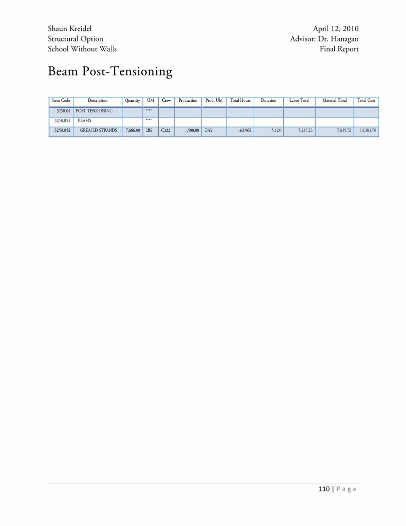
Shaun Kreidel April 12, 2010 Structural Option Advisor: Dr. Hanagan School Without Walls Final Report
110 | P a g e
Beam Post-Tensioning
Item Code Description Quantity UM Crew Production Prod. UM Total Hours Duration Labor Total Material Total Total Cost
3250.01 POST TENSIONING ****
3250.051 BEAMS ****
3250.052 GREASED STRANDS 7,686.00 LBS C322 1,500.00 DAY 163.968 5.124 5,247.23 7,839.72 13,303.70