sci assessed report - armatherm™ structural thermal
TRANSCRIPT

SCI Assessed Report – Armadillo Armatherm FR Thermal Break Material
Report To Armadillo Document: RT1635 Version: 02 Date: January 2015
Armadillo Thermal Break Materials
P:\BCS\BCS305\Projects\14 - Armadillo\RT1635 v02- Armadillo SCI Assessed Report.docx ii
Version Issue Purpose Author Reviewer Approved
01 Dec 2014 Report to client draft EY AW
02 Jan 2015 Report to client EY AW
Although all care has been taken to ensure that all the information contained herein is accurate, The Steel Construction Institute assumes no responsibility for any errors or misinterpretations or any loss or damage arising therefrom.
For information on publications, telephone direct: +44 (0) 1344 636505 or Email: [email protected]
For information on courses, telephone direct: +44 (0) 1344 636500 or Email: [email protected]
Email: [email protected]
World Wide Web site: http://www.steel-sci.org

Armadillo Thermal Break Materials
P:\BCS\BCS305\Projects\14 - Armadillo\RT1635 v02- Armadillo SCI Assessed Report.docx iii
EXECUTIVE SUMMARY This report describes the structural properties of Armadillo thermal break material ArmathermTM FR. The properties are supported by test data and have been confirmed by an independent review carried out by SCI.
Armadillo thermal break materials FR can be used in structural applications. Thermal break plates are used between flanged connections of internal and external steelwork or internal concrete and external steelwork to reduce thermal transmittance through the connection to reduce cold bridging.
SCI has examined the test data for ArmathermTM FR and has derived resistance values suitable for use in structural design. Recommended design methods are presented which should be used when thermal break materials are used in structural connections.
As a result of SCI’s independent review, Armadillo thermal break materials ArmathermTM FR and the associated technical data presented in this report has been granted “SCI Assessed” status.
SCI Assessed A list of SCI Assessed products and their associated certificates are given on the SCI Assessed website – www.sci-assessed.com.

Armadillo Thermal Break Materials
P:\BCS\BCS305\Projects\14 - Armadillo\RT1635 v02- Armadillo SCI Assessed Report.docx iv
Armadillo Thermal Break Materials
P:\BCS\BCS305\Projects\14 - Armadillo\RT1635 v02- Armadillo SCI Assessed Report.docx v
Contents Page No
EXECUTIVE SUMMARY iii�
1� Introduction 1�1.1� Thermal performance 1�1.2� Thermal bridging 1�1.3� Reducing thermal transmittance 2�
2� Products and Applications 3�2.1� Applications 3�2.2� Armadillo products 4�
3� Material Properties 6�3.1� Test data 6�3.2� Compressive strength characteristic values 7�3.3� Long term creep of bolt clamping forces 8�
4� Structural Design Guidance 10�4.1� General 10�4.2� Compression resistance of thermal break 10�4.3� Additional rotation due to compression of thermal break 13�4.4� Bolt shear resistance 14�4.5� Frictional resistance 15�4.6� Structural design summary 15�
5� Other Design Issues 17�5.1� Moisture & UV 17�5.2� Frost 17�5.3� Fire 17�
6� UK Procurement Route and Responsibilities 18�
7� Certification for Manufacturing Procedures 22�
� Test Data 23�A.1� Compressive strength and Modulus of Elasticity 23�A.2� Thermal Conductivity 24�A.3� Density 24�A.4� Water Absorption 24�A.5� Long term creep 25�
� Application Drawings 26�
� Material Safety Data 28�

Armadillo Thermal Break Materials
P:\BCS\BCS305\Projects\14 - Armadillo\RT1635 v02- Armadillo SCI Assessed Report.docx vi

Armadillo Thermal Break Materials
P:\BCS\BCS305\Projects\14 - Armadillo\RT1635 v02- Armadillo SCI Assessed Report.docx 1
1 INTRODUCTION
This report describes the findings of the SCI assessment of the Armadillo thermal break materials ArmathermTM FR.
1.1 Thermal performance Energy efficiency is an increasingly important parameter in the design of buildings. The thermal insulation provided by the building envelope is key to energy efficiency but thermal bridges - weak spots in the insulation - lead to local heat losses that reduce the efficiency.
The thermal efficiency of a building envelope is a function of the thermal performance of the planar elements (e.g. wall, roofs, windows) and the local heat losses that can occur around the planar elements and where the planar elements are penetrated by building components. These local heat losses are the result of areas of the envelope where the thermal insulation is impaired. These areas of impaired thermal insulation are known as ‘thermal bridges’ or ‘cold bridges’.
The ongoing process of revisions to Building Regulations requirements have emphasised the importance of the thermal efficiency of building envelopes, including limiting heat losses through thermal bridges. As part of a thermal assessment of the building envelope, it is recognised that local heat losses due to penetrations or similar local effects have to be calculated and where necessary minimised, so that the thermal efficiency of the building envelope is within acceptable limits.
1.2 Thermal bridging Thermal bridges occur where the insulation layer is penetrated by a material with a relatively high thermal conductivity and at interfaces between building elements where there is a discontinuity in the insulation. Thermal bridges result in local heat losses, which mean more energy is required to maintain the internal temperature of the building and lower internal surface temperatures around the thermal bridge.
Local heat losses caused by thermal bridges become relatively more important, as the thermal performance (i.e. U-values) of the planar elements of the building envelope are improved.
Steel has a high thermal conductivity compared with many other construction materials. The high thermal conductivity means that steel construction systems, both the structural frame and cladding, must be carefully designed to minimise unwanted heat flows.
There are three ways of reducing thermal bridging in steel construction:
x Eliminate the thermal bridge by keeping the steelwork within the insulated envelope
x Locally insulate any steelwork that penetrates the envelope
x Reduce the thermal transmittance of the thermal bridge by using thermal breaks, changing the detailing or by including alternative materials.
Armadillo Thermal Break Materials
P:\BCS\BCS305\Projects\14 - Armadillo\RT1635 v02- Armadillo SCI Assessed Report.docx 2
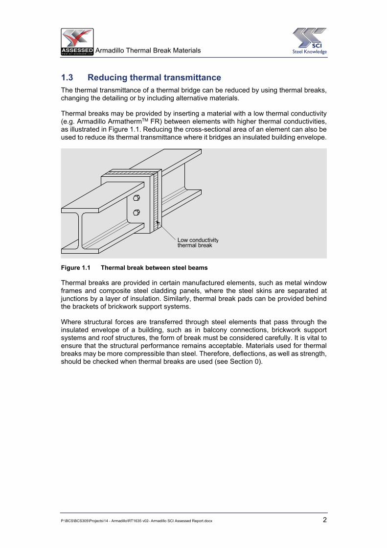
1.3 Reducing thermal transmittance The thermal transmittance of a thermal bridge can be reduced by using thermal breaks, changing the detailing or by including alternative materials.
Thermal breaks may be provided by inserting a material with a low thermal conductivity (e.g. Armadillo ArmathermTM FR) between elements with higher thermal conductivities, as illustrated in Figure 1.1. Reducing the cross-sectional area of an element can also be used to reduce its thermal transmittance where it bridges an insulated building envelope.
Figure 1.1 Thermal break between steel beams
Thermal breaks are provided in certain manufactured elements, such as metal window frames and composite steel cladding panels, where the steel skins are separated at junctions by a layer of insulation. Similarly, thermal break pads can be provided behind the brackets of brickwork support systems.
Where structural forces are transferred through steel elements that pass through the insulated envelope of a building, such as in balcony connections, brickwork support systems and roof structures, the form of break must be considered carefully. It is vital to ensure that the structural performance remains acceptable. Materials used for thermal breaks may be more compressible than steel. Therefore, deflections, as well as strength, should be checked when thermal breaks are used (see Section 0).
Low conductivitythermal break

Armadillo Thermal Break Materials
P:\BCS\BCS305\Projects\14 - Armadillo\RT1635 v02- Armadillo SCI Assessed Report.docx 3
2 PRODUCTS AND APPLICATIONS
2.1 Applications Thermal break plates are used between flanged connections of internal and external steelwork or concrete and external steelwork to reduce thermal transmittance through the connection to reduce cold bridging. They provide a simple, economical and effective solution to meeting Part L of the Building Requirements by way of reducing heat loss and the risk of internal condensation.
The thermal conductivity value of steel is approximately 57 W/mK. Armadillo thermal breaks have a thermal conductivity value between 0.196 and 0.30 W/mK (see Table 3.1). Further improvements in thermal performance of the connection itself can be achieved by using stainless steel bolts and thermal break washers.
Thermal breaks are typically used in new-build and refurbishment projects in the following building elements:
x Balconies
x Brise-soleil
x Entrance structures / canopies
x Roof plant enclosures
x Façade systems
x Internal / external primary structure junctions
x External staircases
x Balustrading
x Man-safe systems.
Figure 2.1 and Figure 2.2 show a typical application of Armadillo thermal break plates and a corresponding bolted connection detail. The thermal break plate should be the same size (height and width) as the steelwork end plates. Additional applications drawings are provided in Appendix B.

Armadillo Thermal Break Materials
P:\BCS\BCS305\Projects\14 - Armadillo\RT1635 v02- Armadillo SCI Assessed Report.docx 4
Figure 2.1 Armadillo thermal break plate between internal and external steelwork
Figure 2.2 Armadillo thermal break plate connection detail steelwork
2.2 Armadillo products There is one type of Armadillo thermal break plates included in this report:
x ArmathermTM FR (fabric reinforced resin).

Armadillo Thermal Break Materials
P:\BCS\BCS305\Projects\14 - Armadillo\RT1635 v02- Armadillo SCI Assessed Report.docx 5
The available product thicknesses are given in Table 2.1.
Table 2.1 Armadillo Thermal Break Plates Product Range
Product Available thicknesses (mm)
ArmathermTM FR 13, 19, 25, 50
Armadillo Thermal Break Materials
P:\BCS\BCS305\Projects\14 - Armadillo\RT1635 v02- Armadillo SCI Assessed Report.docx 6
3 MATERIAL PROPERTIES
3.1 Test data Laboratory testing of Armadillo products has been carried out by various establishments. These include Rowan University, Rubber Consultants, Thermal Measurement Laboratory at University of Salford, Altwater & Sons Ltd and Keighley Laboratories.
Armadillo has provided test reports for the following tests carried out on their thermal break material ArmathermTM FR:
x Compressive strength x Elastic modulus x Thermal conductivity x Density x Water absorption x Long term creep.
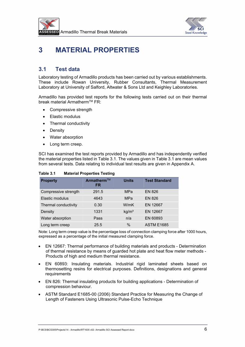
SCI has examined the test reports provided by Armadillo and has independently verified the material properties listed in Table 3.1. The values given in Table 3.1 are mean values from several tests. Data relating to individual test results are given in Appendix A.
Table 3.1 Material Properties Testing
Property
ArmathermTM
FR Units Test Standard
Compressive strength 291.5 MPa EN 826
Elastic modulus 4643 MPa EN 826
Thermal conductivity 0.30 W/mK EN 12667
Density 1331 kg/m³ EN 12667
Water absorption Pass n/a EN 60893
Long term creep 25.5 % ASTM E1685
Note: Long term creep value is the percentage loss of connection clamping force after 1000 hours, expressed as a percentage of the initial measured clamping force.
x EN 12667: Thermal performance of building materials and products - Determination of thermal resistance by means of guarded hot plate and heat flow meter methods - Products of high and medium thermal resistance.
x EN 60893: Insulating materials. Industrial rigid laminated sheets based on thermosetting resins for electrical purposes. Definitions, designations and general requirements
x EN 826: Thermal insulating products for building applications - Determination of compression behaviour.
x ASTM Standard E1685-00 (2006) Standard Practice for Measuring the Change of Length of Fasteners Using Ultrasonic Pulse-Echo Technique

Armadillo Thermal Break Materials
P:\BCS\BCS305\Projects\14 - Armadillo\RT1635 v02- Armadillo SCI Assessed Report.docx 7
3.2 Compressive strength characteristic values For use in structural design calculations, the compressive strength of the thermal break materials which have been obtained from testing must be converted in to characteristic compressive strength values. The characteristic values are used in conjunction with a partial safety factor to obtain a design value of compressive strength. Details of the design process are presented in Section 0.
The characteristic compressive strength values of ArmathermTM FR has been calculated in accordance with BS EN 1990, Annex D. The design resistance is calculated using Equation 1, which is based on BS EN 1990, Equation (D.1).
� �m
bnb1b
m
kd JJ
skmXXX � (1)
where:
Xd is the design resistance of property X
Xk(n) is the characteristic resistance of property X, derived from n tests
Jm is the relevant partial safety factor, in this case JM2
Xb=1 is the resistance of property X corresponding to a correction factor of b = 1
mb is the mean correction factor
kn is an adjustment coefficient that depends on the number of tests that have been undertaken, taken from BS EN 1990, Table D1
sb is the standard deviation of the correction factor
Six compressive strength tests were carried out on ArmathermTM FR (see Table 3.2).
Table 3.2 Compressive strength test results
Test ArmathermTM FR Compressive strength
[N/mm2] 1 298
2 287
3 284
4 297
Mean 291.50
Standard deviation 7.05
For a set of four tests, kn = 2.63, from Table D1 of BS EN 1990 (Vx unknown has been used, as there is no prior knowledge of the variation of the tests). Applying this to the values given in Table 3.2 gives the following characteristic values.

Armadillo Thermal Break Materials
P:\BCS\BCS305\Projects\14 - Armadillo\RT1635 v02- Armadillo SCI Assessed Report.docx 8
For Armatherm FR,
Characteristic compressive strength, fck = 291.50 � 2.63 u 7.05
= 273 N/mm2
The characteristic values for design to BS EN 1993-1-8 should be converted to design values by using the partial safety factor JM2, which is defined as 1.25 in the UK National Annex. This value is considered appropriate for ArmathermTM FR due to the mode of failure and the consistency of the test results. The design values for compressive strength are given in Table 3.3.
Table 3.3 Compressive strength values
Property ArmathermTM [N/mm2]
Characteristic compressive strength, fck 273
Design value for compressive strength, fcd 218.4
3.3 Long term creep of bolt clamping forces The purpose of this testing program was to determine whether connections with ArmathermTM FR thermal barriers are subject to any time-dependent losses of clamping force. This study evaluates the potential losses induced by compression loading of the thermal barrier.
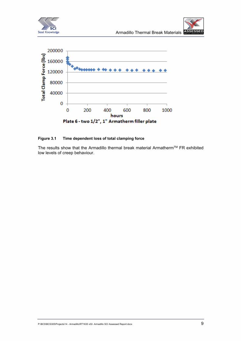
3.3.1 ArmathermTM FR The long term loss of clamping force of the bolted connection was conducted over a maximum period of 1000 hours (41.7 days).
Two tests were carried out and graphs showing clamping load against time are provided in Appendix A.5. The vast majority of the loss of connection clamping force was experienced within the first 168 hours (7 days), with limited additional connection clamping force loss occurring in the period from 168 to 1000 hours. See Figure 3.1.
From the two tests, an average loss of 25.5 % of the bolt clamping force occurred over 1000 hours.
Armadillo Thermal Break Materials
P:\BCS\BCS305\Projects\14 - Armadillo\RT1635 v02- Armadillo SCI Assessed Report.docx 9
Figure 3.1 Time dependent loss of total clamping force
The results show that the Armadillo thermal break material ArmathermTM FR exhibited low levels of creep behaviour.

Armadillo Thermal Break Materials
P:\BCS\BCS305\Projects\14 - Armadillo\RT1635 v02- Armadillo SCI Assessed Report.docx 10
4 STRUCTURAL DESIGN GUIDANCE
4.1 General In general, steelwork connections should be designed in accordance with the latest SCI guidance publications as listed below:
Simple Connections –
x SCI-P212: Joints in steel construction. Simple connections (BS 5950-1).
x SCI-P358: Joints in steel construction. Simple joints to Eurocode 3.
Moment Connections –
x SCI-P207: Joints in steel construction. Moment connections (BS 5950-1).
x SCI-P398: Joints in steel construction. Moment joints to Eurocode 3.
However, additional design checks should be carried out for connections that include Armadillo thermal break plates between the steel elements. These additional checks are explained in the following Sections 4.2, 4.3, 4.4 and 4.5 (of this report).
4.2 Compression resistance of thermal break
4.2.1 Nominally pinned connections Nominally pinned connections (also referred to as simple connections) are generally designed to only transmit shear forces and tying forces, as shown in Figure 4.1. Therefore, the thermal break plate is not required to resist compression forces. Hence, for nominally pinned connections there is generally no requirement for the designer to check the compression resistance of the thermal break plate within the connection.
Figure 4.1 Nominally pinned connection with Armadillo thermal break plate
However, there may be situations where beams are also subject to axial load, in these situations the thermal break plate is required to resist compression forces and should be designed accordingly. The design procedure presented in Section 4.2.2 can be adapted to suit thermal break plates subject to compression. Alternatively, the thermal break plate

Armadillo Thermal Break Materials
P:\BCS\BCS305\Projects\14 - Armadillo\RT1635 v02- Armadillo SCI Assessed Report.docx 11
can be treated in a similar way to the concrete under a column base plate (see Section 7 of SCI publication P358).
4.2.2 Moment connections Applications where Armadillo thermal break plates are required in connections will generally be moment resisting connections e.g. steel beams supporting balconies or canopies.
In moment resisting connections one part of the connection is in tension and the other part of the connection is in compression, as shown in Figure 4.2. Therefore, a thermal break plate within the connection is required to resist compression forces. Hence, for moment connections there is a requirement for the designer to check the compression resistance of the thermal break plate within the connection.
M = Applied moment V = Applied shear Fr1,2,3 = Bolt row tension forces Fc = Compression force
Figure 4.2 Forces in a typical moment connection
The designer must check that the compressive stress applied to the thermal break plate is less than the design compression strength of the thermal break material. This is achieved by satisfying the Expression (2), given below.
M2
ckc J
fLBF uud (2)
where:
Fc is applied design compression force
B is the depth of the compression zone on the thermal break plate
L is the width of the compression zone on the thermal break plate
fck is the characteristic compression strength of the thermal break plate
JM2 is a partial safety factor, which is defined as 1.25 in the UK National Annex. This value is considered appropriate to Armadillo TBL and Armadillo Armatherm due to the mode of failure and the consistency of the test results.
The compression force Fc can be obtained from published data for standard moment connections (see SCI-P207 and SCI-P398). Alternatively, Fc is calculated as part of the normal connection design process if standard moment connections are not used.
Fr1
Fr2
Fr3
Fc
M V

Armadillo Thermal Break Materials
P:\BCS\BCS305\Projects\14 - Armadillo\RT1635 v02- Armadillo SCI Assessed Report.docx 12
The dimensions B and L are calculated based on a dispersal of the compression force from the beam flange as shown in Figure 4.3 and Figure 4.4. Dimensions B and L are defined in expressions (3) and (4). However, it should be noted that B and L must be reduced if the beam end plate projection is insufficient for full dispersal of the force or if the column flange width is insufficient for full dispersal of the force.
� �pbf, 2 tstB �� (3)
where:
tf,b is the beam flange thickness
s is the weld leg length
tp is the end plate thickness.
pb 2 tbL u� (4)
where:
bb is the beam flange width
tp is the end plate thickness.
Figure 4.3 Dispersion of force through connection compression zone

Armadillo Thermal Break Materials
P:\BCS\BCS305\Projects\14 - Armadillo\RT1635 v02- Armadillo SCI Assessed Report.docx 13
Figure 4.4 Thermal break plate compression zone
4.3 Additional rotation due to compression of thermal break
4.3.1 Nominally pinned connections Nominally pinned connections are designed to rotate and therefore any additional rotation due to the presence of a thermal break plate within the connection can generally be neglected in the design process.
4.3.2 Moment connections For moment connections, such as those supporting balconies, the rotation of the connection under load is an important design consideration, typically for aesthetic and serviceability requirements.
The amount of compression of the thermal break plate 'T is calculated as given in expression (5).
tb
btb
EtT tVu ' (5)
where:
ttb is the thickness of the thermal break plate
Vtb is the stress in the compression zone of the thermal break plate
Etb is the elastic modulus of the thermal break plate.
The additional rotation of the connection (T) due to the presence of a thermal break plate within the connection can be calculated using the expression (6).
¸̧¹
·¨̈©
§ '
b
ArcsinhTT (6)
where:
hb is the depth of the beam.
Armadillo Thermal Break Materials
P:\BCS\BCS305\Projects\14 - Armadillo\RT1635 v02- Armadillo SCI Assessed Report.docx 14
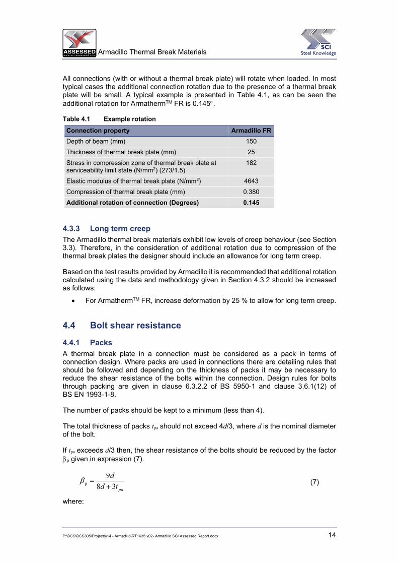
All connections (with or without a thermal break plate) will rotate when loaded. In most typical cases the additional connection rotation due to the presence of a thermal break plate will be small. A typical example is presented in Table 4.1, as can be seen the additional rotation for ArmathermTM FR is 0.145q.
Table 4.1 Example rotation
Connection property Armadillo FRDepth of beam (mm) 150
Thickness of thermal break plate (mm) 25
Stress in compression zone of thermal break plate at serviceability limit state (N/mm2) (273/1.5)
182
Elastic modulus of thermal break plate (N/mm2) 4643
Compression of thermal break plate (mm) 0.380
Additional rotation of connection (Degrees) 0.145
4.3.3 Long term creep The Armadillo thermal break materials exhibit low levels of creep behaviour (see Section 3.3). Therefore, in the consideration of additional rotation due to compression of the thermal break plates the designer should include an allowance for long term creep.
Based on the test results provided by Armadillo it is recommended that additional rotation calculated using the data and methodology given in Section 4.3.2 should be increased as follows:
x For ArmathermTM FR, increase deformation by 25 % to allow for long term creep.
4.4 Bolt shear resistance
4.4.1 Packs A thermal break plate in a connection must be considered as a pack in terms of connection design. Where packs are used in connections there are detailing rules that should be followed and depending on the thickness of packs it may be necessary to reduce the shear resistance of the bolts within the connection. Design rules for bolts through packing are given in clause 6.3.2.2 of BS 5950-1 and clause 3.6.1(12) of BS EN 1993-1-8.
The number of packs should be kept to a minimum (less than 4).
The total thickness of packs tpa should not exceed 4d/3, where d is the nominal diameter of the bolt.
If tpa exceeds d/3 then, the shear resistance of the bolts should be reduced by the factor Ep given in expression (7).
patdd38
9p � E (7)
where:

Armadillo Thermal Break Materials
P:\BCS\BCS305\Projects\14 - Armadillo\RT1635 v02- Armadillo SCI Assessed Report.docx 15
d is nominal bolt diameter
tpa is the total thickness of packs.
4.4.2 Large grip lengths A thermal break plate in a connection will increase the total grip length (Tg) of the bolts. The total grip length is the combined thickness of all the elements that the bolt is connecting together (e.g. end plate, thermal break plate, column flange, additional packs etc.) Depending on the size of the grip length it may be necessary to reduce the shear resistance of the bolts within the connection. Design rules for bolts with large grip lengths are given in clause 6.3.2.3 of BS 5950-1. BS EN 1993-1-8 does not include design rules for bolts with large grip lengths, however, it is recommended that the following design guidance is followed.
If Tg exceeds 5d then, the shear resistance of bolts with large grip lengths should be reduced by the factor Eg give the expression given in expression (7).
gTdd�
3
8gE (8)
where:
d is nominal bolt diameter
Tg is the total grip length of the bolt.
4.5 Frictional resistance
4.5.1 Non-preloaded bolts The coefficient of friction of the thermal break plate is not a relevant property for the structural design of connections with non-preloaded bolts.
4.5.2 Preloaded bolts For the structural design of connections with preloaded bolts the coefficient of friction of the thermal break plate will be required. The slip resistance of the bolted connection is calculated in accordance with Section 3.9 of BS EN 1993-1-8. The number of friction surfaces is required for this calculation.
The SCI has not been provided with data for the coefficient of friction of Armadillo ArmathermTM FR. The manufacturer should be consulted for the necessary data.
In addition, the local compression force around the bolt holes on the thermal break plate must be checked to ensure the compressive strength of the thermal break plate is not exceed.
Preloaded bolts are also known as HSFG bolts.
4.6 Structural design summary Connections that include thermal break plates should be designed in accordance with the relevant design standards (e.g. BS EN 1993-1-8) or industry guidance (e.g. SCI publications). The following additional checks should also be undertaken:

Armadillo Thermal Break Materials
P:\BCS\BCS305\Projects\14 - Armadillo\RT1635 v02- Armadillo SCI Assessed Report.docx 16
1. Check that the thermal break plate can resist the applied compression forces (see Section 4.2).
2. Check that any additional rotation due to the compression of the thermal break plate (including allowance for long term creep) is acceptable (see Section 4.3).
3. Check that the shear resistance of the bolts is acceptable given that there may be a reduction in resistance due to:
a. Packs (see Section 4.4.1).
b. Large grip lengths (see Section 4.4.2).
4. For connections using preloaded bolts:
a. Check the slip resistance of the connection taking into account the coefficient of friction and number of friction surfaces (see Section 4.5.2).
b. Check that the thermal break plate can resist the local compression forces around bolts (see Section 4.5.2).

Armadillo Thermal Break Materials
P:\BCS\BCS305\Projects\14 - Armadillo\RT1635 v02- Armadillo SCI Assessed Report.docx 17
5 OTHER DESIGN ISSUES
Other design issues that are not directly addressed with test data are discussed below. In the majority of situations Armadillo thermal break plates will be used in a protected environment within the façade of a building. Therefore, the thermal break materials are not exposed to the full extent of the environment.
5.1 Moisture & UV Thermal breaks are typically used in protected cavities or within protected roof envelopes and both Armadillo materials have very low water absorption rates which limits their vulnerability to moisture and humidity.
Within the protected environment the materials are protected from UV degradation. However, where an application poses a greater risk (e.g. a fully exposed external location) then additional protection can be provided. If necessary, it is possible to use cladding flashing details to protect thermal breaks.
5.2 Frost Thermal breaks are not normally exposed to extremes of temperatures because they are located in the protected environments in the insulation layer of a façade.
In the event that the Armadillo thermal break materials are exposed to frost, Armatherm FR has very low water absorption rates which limits their vulnerability to any damage caused by frost action.
5.3 Fire Generally, the thermal breaks supplied by Armadillo are used in locations that do not require fire protection. Where the connection requires a fire rating then the following options are available;
x A board fire protection system can be applied.
x Sprayed fire protection can be applied. The compatibility of the applied fire protection material should be checked with the thermal break material. Advice from the manufacturer should be obtained.
x The connection may be designed on the assumption of complete loss of thermal break material in the accidental condition. For accidental conditions excessive deformations are acceptable provided that the stability of the structure is maintained.
However, due to the high concentration of fabric reinforcement, Armatherm FR will not melt and liquefy nor support a flame.
Armadillo Thermal Break Materials
P:\BCS\BCS305\Projects\14 - Armadillo\RT1635 v02- Armadillo SCI Assessed Report.docx 18
6 UK PROCUREMENT ROUTE AND RESPONSIBILITIES
The flowchart in Figure 6.1 shows the typical UK procurement route for Armatherm thermal break materials and the associated responsibilities.
The flowchart in Figure 6.2 shows the typical Works order procedure for Armatherm.
A typical fabrication drawing for Armatherm thermal break plate is shown in Figure 6.3.

Armadillo Thermal Break Materials
P:\BCS\BCS305\Projects\14 - Armadillo\RT1635 v02- Armadillo SCI Assessed Report.docx 19
Figure 6.1 Typical procurement route

Armadillo Thermal Break Materials
P:\BCS\BCS305\Projects\14 - Armadillo\RT1635 v02- Armadillo SCI Assessed Report.docx 20
Figure 6.2 Typical works order procedure

Armadillo Thermal Break Materials
P:\BCS\BCS305\Projects\14 - Armadillo\RT1635 v02- Armadillo SCI Assessed Report.docx 21
Figure 6.3 Typical fabrication drawing
Thermal breaks are normally procured by the steel fabricator as part of the steel frame package on a project. The delivery from Armadillo is normally co-ordinated with the steelwork contractor erection schedule.
Safety data sheets (COSHH) are made available and all operatives handling the thermal breaks on UK construction sites should use appropriate PPE in line with the requirements of the safety data sheets (primarily gloves & safety glasses). Armadillo thermal breaks are bespoke products and no alterations are expected to be undertaken on site.
The general handling requirements for thermal breaks should be in line with other component accessories expected to be handled with the primary steelwork. This is covered in the NSSS: Section 8 Workmanship – Erection. The NSSS also sets out the requirements of the Quality Management System expected to be adopted by all competent steelwork contractors working on UK construction projects.
Material handling data is provided by Armadillo as shown in Appendix C.

Armadillo Thermal Break Materials
P:\BCS\BCS305\Projects\14 - Armadillo\RT1635 v02- Armadillo SCI Assessed Report.docx 22
7 CERTIFICATION FOR MANUFACTURING PROCEDURES
SCI do not carry out factory inspections or assessments of manufacturing quality control procedures. However, the Armadillo chemical process plant, (Attwater & Sons) are certified ISO 9001.
The ISO 9001 certificate is issued by HQA and the scope of said certificate includes the manufacture and supply of thermal break materials. The certificate viewed by SCI is valid until 03/06/2015.
(company name)

Armadillo Thermal Break Materials
P:\BCS\BCS305\Projects\14 - Armadillo\RT1635 v02- Armadillo SCI Assessed Report.docx 23
TEST DATA
A.1 Compressive strength and Modulus of Elasticity
Amatherm FR
Sample Length mm
Widthmm
Thickness (@ 4 points)mm
Average thickness mm
1 80.71 80.51 25.46 25.50 25.53 25.48 25.49
2 80.82 80.67 25.42 25.35 25.49 25.43 25.42
3 80.84 80.60 25.52 25.43 25.38 25.47 25.45
4 80.81 80.69 25.41 25.35 25.43 25.48 25.42
Amatherm FR
Sample Loading rate d/min
Modulus of Elasticity MPa
Stress at 10% Strain MPa
Failure strain %
Failure stress (Compressive strength) MPa
1 0.104 4270 254 12.8 298
2 0.090 4720 284 10.3 287
3 0.092 4800 267 11.1 284
4 0.089 4780 289 10.5 297
Mean 4643 Mean 291.5
Property Armatherm FR MPa
Characteristic compressive strength 273
Design value for compressive strength 218.4
Modulus of Elasticity 4643

Armadillo Thermal Break Materials
P:\BCS\BCS305\Projects\14 - Armadillo\RT1635 v02- Armadillo SCI Assessed Report.docx 24
A.2 Thermal Conductivity Armatherm FR
Sample Thickness mm
Mean temp. [°C]
Thermal Conductivity [W/mK]
Date of test
1 39.6 10 0.328 ± 5% 30-31/10/14
2 39.6 10 0.291 ± 5% 12-13/11/14
3 40.1 10 0.295 ± 5% 13/11/14
4 40.1 10 0.287 ± 5% 13-14/11/14
Mean 0.300 ± 5%
A.3 Density Armatherm FR
Sample Length mm Width mm Height mm Densitykg/m3
1 300 300 40 1349
2 300 300 40 1321
3 300 300 40 1331
4 300 300 40 1324
Mean 1331
A.4 Water Absorption Armatherm FR
Sample Thickness [mm]
Water absorptionmg
Pass/Fail (EN 60893)
1 3 Mean 125 Pass
2 3 Minimum 102 Pass
3 3 Maximum 149 Pass
The requirement for a Pass result is 249 mg maximum.

Armadillo Thermal Break Materials
P:\BCS\BCS305\Projects\14 - Armadillo\RT1635 v02- Armadillo SCI Assessed Report.docx 25
A.5 Long term creep
A.5.1 Armatherm FR Test Initial Total clamping load
(lbs) Stable Total clamping load(lbs)
Percentage loss from initial clamping load
1 177920 130200 25.1
2 176150 174400 26.0
Loss of individual bolt tension over first seven days (168 hours)
Time dependent loss of total clamping force over 1000 hours
Armadillo Thermal Break Materials
P:\BCS\BCS305\Projects\14 - Armadillo\RT1635 v02- Armadillo SCI Assessed Report.docx 26
APPLICATION DRAWINGS
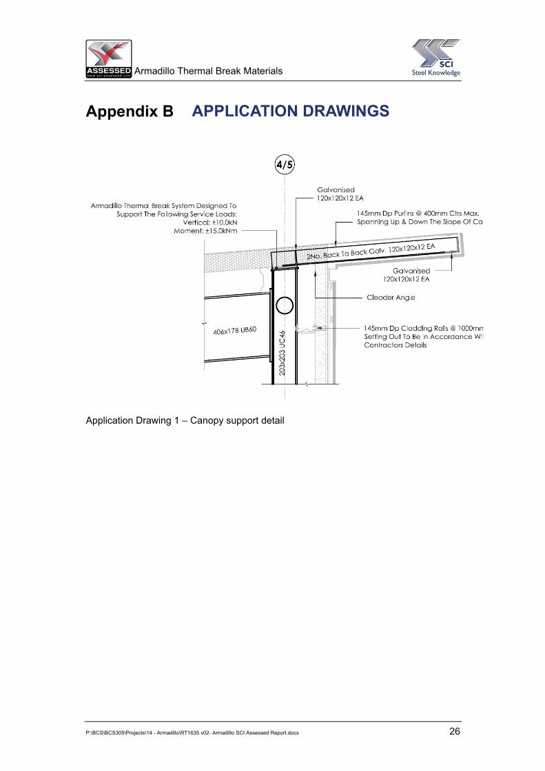
Application Drawing 1 – Canopy support detail

Armadillo Thermal Break Materials
P:\BCS\BCS305\Projects\14 - Armadillo\RT1635 v02- Armadillo SCI Assessed Report.docx 27
Application Drawing 2 – Balcony support bracket

Armadillo Thermal Break Materials
P:\BCS\BCS305\Projects\14 - Armadillo\RT1635 v02- Armadillo SCI Assessed Report.docx 28
MATERIAL SAFETY DATA

Armadillo Thermal Break Materials
P:\BCS\BCS305\Projects\14 - Armadillo\RT1635 v02- Armadillo SCI Assessed Report.docx 29

Armadillo Thermal Break Materials
P:\BCS\BCS305\Projects\14 - Armadillo\RT1635 v02- Armadillo SCI Assessed Report.docx 30