thephysicsteacher.iethephysicsteacher.ie/jc science/jc physics/13... · web viewdraw the symbol...
TRANSCRIPT

Physics: 13. Current ElectricityPlease remember to photocopy 4 pages onto one sheet by going A3→A4 and using back to back on the photocopier
Questions to think about1. Given a battery, lightbulb and wires could you put the circuit together to make the lightbulb light up?
SyllabusOP49 Test electrical conduction in a variety of materials, and classify each material as a conductor or insulator
OP50 Set up a simple electric circuit, use appropriate instruments to measure current, potential difference (voltage) and resistance, and establish the relationship between them
OP51 Demonstrate simple series and parallel circuits containing a switch and two bulbs
OP52 Perform simple calculations based on the relationship between current, potential difference (voltage), and resistance
Student NotesConductors and InsulatorsRemember our definitions of conductors and insulators from the chapter on Static Electricity:A conductor is a substance that allows charge to flow through it easily (metals are conductors).An insulator is a substance that does not allow charge to flow through it (plastics are insulators).
Experiment: Identify materials as conductors or insulators
1. Set up the circuit as shown.
2. Place various different materials between points X and Y in the circuit and turn on the switch.
3. If the bulb lights then the material is a conductor and if it doesn’t then the material is an insulator.
1
Label Circuit componentA SwitchB Power supplyC ResistorD Bulb

ResistorsA resistor is used to reduce the flow of current in a circuit.
A series circuit This is where the two bulbs are connected one after the other. All the current coming from the battery goes through both bulbs. Advantage: Uses less electricity than if the bulbs are connected in parallel. Disadvantage: If one bulb blows the circuit is broken and so no current flows,
e.g. lights in a Christmas tree.
A parallel circuitThe current coming from the battery splits up and some goes through each bulb.Advantage: If one bulb blows there will still be a complete circuit through the other bulb so it will remain lit.Light bulbs in a house are generally connected in parallel for this reason.Disadvantage: It uses more electricity than if connected in series.
2

Current, voltage and resistance
1. Current
The unit of current is the amp (the symbol for the amp is A). The symbol for current is I. Current is measured with an ammeter or multimeter.
For current to flow we need two things:1. There has to be a complete circuit.2. There has to be a source of potential difference (power supplies and batteries both act as a source of potential difference).
2. Potential difference (commonly called ‘voltage’)Current will flow between two points if there is a potential difference between the two points.This is a bit like saying that water will flow between two points if there is a height difference between the two points.
Another way of thinking about potential difference is that it provides the ‘push’ to move the electrons around a circuit. The unit of potential difference is the volt (the symbol for the volt is V) The symbol for potential difference is V. Potential difference is measured with a voltmeter or multimeter.
3. Resistance
The unit of resistance is the ohm (the symbol for the ohm is Ω). The symbol for resistance is R. Resistance is measured with an ohmmeter or mulitmeter.
Summary
Quantity Symbol Unit Symbol Measured with
Symbol
Current I Amps A Ammeter
Potentialdifference
V Volts V Voltmeter
Resistance R Ohms Ω Ohmmeter
Relationship between current, potential difference and resistance
Maths problemsCalculate the resistance of a resistor when 20 V produces a current of 4 A.AnswerV = 20 VoltsI = 4 Amps
R = V÷I = 20 ÷ 4 = 5 Ohms
3
Current is a flow of charge (the charge is usually electrons)
V = I R
Resistance opposes the movement of electrons around a circuit
In an electric circuit, current flows from the positive end of the battery to the negative end.The positive end is represented with a long solid line, and the negative end is represented with a short solid line

Fill in the following table using the formula V = IR:
Experiment: To establish the relationship between potential difference and current
1. Set up the circuit as shown and note the current (I) and potential difference (V)
2. Adjust the variable resistor (rheostat) to get a new set of values.
3. Repeat about 6 times and then plot a graph of potential difference against current.
4. The fact that we get a straight line shows that the potential difference is proportional to the current (this means that if we double the potential difference, the current will double also).
5. Note that the slope of the graph corresponds to the resistance of the component.
This is what the graph should look like
4
Potential Difference (V) Current (I) Resistance(R)
10 52 200
120 30100 2
0.5 20120 10

Exam questions1. [2008 OL]
The diagram shows a simple electrical circuit.Complete the table below correctly matching each of the names of the components in the circuit with one of the labels A, B, C or D.
2. [2008 OL][2012 OL]You are given a piece of copper metal and a piece of timber. Which piece, metal or wood, should you connect between X and Y in order that the bulb would light when the switch is closed? Give a reason for your choice.
3. [2007 OL]A student set up the circuit shown to investigate the relationship between the potential difference (voltage), the current and the resistance of a wire conductor.Gaps are left in the diagram in the places where the ammeter and voltmeter should be placed. The symbols for these devices are given on the right.Complete the circuit inserting the symbols for the ammeter and the voltmeter in their correct positions.
4. [2007]The symbols for two electrical meters are given in the diagram. The symbol is for a meter that measures potential difference, often called ‘voltage’.What electrical quantity can be measured using the meter with the symbol ?
5. [2006][2011 OL]Components, e.g. bulbs, in electrical circuits can be connected in series or in parallel.It is noticed that, when one headlight fails (blows) in a car, the second remains lighting.
(i) State the way the headlights are connected and give a reason why this mode of connection is used.
(ii) All of the bulbs go out in an old set of Christmas tree lights, when one of bulbs fails (blows). In what way are the bulbs connected in this set of lights?
(iii) Explain why, when one bulb blows, they all go out.
6. [2006]Calculate the resistance of the filament of a car headlamp when 12 V produces a current of 5 A in it.In what unit is resistance measured?
5
Label Circuit componentBulbPower supplyResistorSwitch

7. [2012 OL]A student carried out an investigation of the relationship between current flowing through a wire resistor and the voltage across it.The data collected is presented in the table below.
The student then used this data to draw a graph of voltage (y-axis) against current (x-axis)
(i) Use the graph to estimate the current at 2.5 V.(ii) Name the instrument used by the student to measure voltage.(iii) What is the relationship between the current and the voltage in this investigation?
6
Current (A) 0 0.2 0.4 0.6 0.8 1.0Voltage (V) 0 1 2 3 4 5

8. [2007 OL]The student used the variable voltage supply to apply different voltages across the resistor. She measured the voltage across the resistor and the current passing through it several times. She collected the following data.
(i) Draw a graph of the voltage (y-axis) against the current (x-axis). (ii) What conclusion can you draw from the graph about the relationship between the potential difference (voltage)
and the current passing through the wire conductor?
7
Voltage (V) 0 2 4 6 8Current (A) 0 0.
51.0 1.5 2.0

9. [2010 OL]A student carried out an investigation of the relationship between current flowing through a wire resistor and the voltage across it.The data collected is presented in the table below.
(i) Use this data to draw a graph of voltage (y-axis) against current (x-axis) using the grid provided below.
(ii) Use the graph to estimate the current at 3.5 V. (iii) Name the instrument used by students to measure voltage. (iv) Name the instrument used by students to vary the current. (v) What is the relationship between voltage and current in this investigation?
10. [2007]Meters and are used in the circuit shown.Enter ‘A’ into the appropriate circle of one of the meter symbols in the circuit diagram so as to clearly identify its correct position.
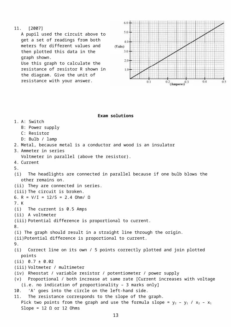
11. [2007]A pupil used the circuit above to get a set of readings from both meters for different values and then plotted this data in the graph shown.Use this graph to calculate the resistance of resistor R shown in the diagram. Give the unit of resistance with your answer.
8
Current (A) 0.2 0.4 0.6 0.8 1.0Voltage (V) 1 2 3 4 5

Exam solutions1. A: Switch
B: Power supply C: Resistor D: Bulb / lamp
2. Metal, because metal is a conductor and wood is an insulator 3. Ammeter in series
Voltmeter in parallel (above the resistor).4. Current 5.(i) The headlights are connected in parallel because if one bulb blows the other remains on.(ii) They are connected in series.(iii) The circuit is broken.6. R = V/I = 12/5 = 2.4 Ohm/ Ω7. K(i) The current is 0.5 Amps(ii) A voltmeter(iii) Potential difference is proportional to current.8.(i) The graph should result in a straight line through the origin.(ii)Potential difference is proportional to current.9.(i) Correct line on its own / 5 points correctly plotted and join plotted points(ii) 0.7 ± 0.02 (iii) Voltmeter / multimeter (iv) Rheostat / variable resistor / potentiometer / power supply(v) Proportional / both increase at same rate [Current increases with voltage (i.e. no indication of proportionality – 3
marks only]10. ‘A’ goes into the circle on the left-hand side.11. The resistance corresponds to the slope of the graph.
Pick two points from the graph and use the formula slope = y2 – y1 / x2 – x1
Slope = 12 Ω or 12 Ohms (accept 11.5 to 12.5)
9

Other Test Questions1. Why is electricity a convenient form of energy?
2. What is an electric current?
3. What is the unit of current?
4. What is the unit of voltage (also called the potential difference)?
5. What is the unit of resistance?
6. Name an instrument used to measure electric current.
7. Name an instrument used to measure voltage.
8. Name an instrument used to measure resistance.
9. What two conditions are required in order for current to flow in a circuit?
10. Draw the symbol for each of the following underneath the wordResistor Switch Voltmeter Light Bulb Battery Rheostat
11. What is meant by the term ‘Potential Difference’ (or ‘Voltage’) as it applies to a circuit?
12.(i) You are given a battery and two light-bulbs. (ii) Draw a circuit diagram showing the batteries arranged (i) in parallel, (ii) in series.(iii) Which circuit will be brighter?(iv) In which circuit will the battery last longer?(v) Which circuit is more likely to represent the arrangement of Christmas lights? Why?
13. A battery provides a potential difference of 9 volts across a metallic conductor of resistance 0.5 ohms. Calculate the current flowing through the circuit.
14. Draw a fully labelled diagram of the apparatus used in the experiment to establish the relationship between potential difference and current.
15. Sketch the graph which you would expect to obtain from this experiment. What does the slope of the graph represent?
16. The measurements made by a student in an experiment to establish the relationship between potential difference and current are shown in the table.
Voltage (V) 1.0 2.0 3.0 4.0 5.0 6.0Current (A) 0.1 0.2 0.3 0.4 0.5 0.6
(i) Use the table to draw a graph – on graph paper - of voltage against current.Put voltage on the Y-axis.
(ii) What is the relationship between potential difference and current? Give a reason for your answer.
(iii) Calculate the resistance of the resistor used in this experiment.
17. Draw the symbol for each of the following underneath the wordResistor Switch Voltmeter Light Bulb Battery Rheostat
18. What is meant by the term ‘Potential Difference’ (or ‘Voltage’) as it applies to a circuit?
10

Teaching Current ElectricitySyllabusOP49 Test electrical conduction in a variety of materials, and classify each material as a conductor or
insulator.
OP50 Set up a simple electric circuit, use appropriate instruments to measure current, potential difference (voltage) and resistance, and establish the relationship between them
OP51 Demonstrate simple series and parallel circuits containing a switch and two bulbs.
OP52 Perform simple calculations based on the relationship between current, potential difference (voltage), and resistance.
OP49: Test electrical conduction in a variety of materials, and classify each material as a conductor or insulator Always turn off the power-supply when changing any aspect of the circuit. Always have the power-supply voltage set to the minimum when turning on the power-supply. Demonstrate the concept that current will flow if you’ve got a power supply and a full circuit by
including a light-bulb in the circuit. Place various materials in the circuit and test whether they’re conductors or insulators. Note that some materials are in between. These are called resistors. Try the ‘lead’ (graphite) from a
pencil. Try different lengths and note what happens. Now use a variable-resistor (called a rheostat) and repeat.
OP50: Set up a simple electric circuit, use appropriate instruments to measure current, potential difference (voltage) and resistance, and establish the relationship between them
Next include an ammeter in series in the circuit. If using a multimeter connect one lead to COM and the other to the connection marked 10 Amp (or 12 Amp). Now set the dial to the corresponding reading on the current section of the multimeter.
Whenever you use a multi-meter remember that if the readings are negative (minus), simply swap the two wires in the multimeter.
Note as you increase the resistance, the light bulb gets dimmer and the current decreases. The current is therefore an indication of the amount of charge (electrons) flowing by.
Try putting the ammeter anywhere else in the circuit (in series). Note that the reading is always the same.
Now slowly increase the voltage. Note that the current increases and the bulb gets brighter. The voltage is therefore somehow responsible for ‘pushing’ the electrons the circuit; the higher the voltage indicator on the power-supply, the more current that flows around the circuit.
Next attach a voltmeter across (in parallel with) the resistor. One lead goes into COM, the other into VOLTS. Now set the dial to DC Volts, on the 20 Volt range.
Note the reading.You are now ready to proceed to the OHM’S LAW experiment.
11

Instructions for Ohm’s Law Experiment1. Clear a large working area. Try to avoid leads crossing each other if at all possible.2. To begin with we will use a light-bulb instead of a coil of wire because we can see the effect of the
current on the light-bulb directly. When we are confident with this set-up we can switch the light-bulb for a coil.
3. Things can get very confusing with all the wires, so it’s a good idea to ensure you are familiar with the theory. The best way to do this by looking at the interactive links here: http://www.thephysicsteacher.ie/resistanceapplets.html
4. Don’t even think about measuring volts/attaching a voltmeter until much later.5. Attach an ammeter in series in the circuit. The ammeter we will use will be a digital multimeter set to
read amps.6. Do this by attaching one lead to the COM socket, and the second lead to the socket that reads 10 Amp,
or 12 Amp. Then turn the dial to the 10 A/12 A setting (in the Direct Current section).7. If you are getting a ‘minus’ reading on your multimeter you can either ignore it or switch the two leads
in the multimeter.8. Make sure the power-supply is set to DC (Direct Current) not AC (alternating current).9. Start off with a power supply in series with a light bulb. Notice that as you turn the knob on the power-
supply the bulb gets brighter. This is because what you are increasing is the potential difference (commonly known as “the volts”). You can think of this as being responsible for “pushing” the electrons (the current) around the circuit).
10. Notice now that as you increase the volts (on the power supply), not only does the bulb get brighter, but the reading on the ammeter increases also; this is because the current is getting bigger.
11. It doesn’t matter if the ammeter goes ‘before’ or ‘after’ the bulb. The current is the same all through the circuit.
12. Now attach a voltmeter in parallel with the light-bulb. The voltmeter we will use will be a digital multimeter set to read volts.
13. Do this by attaching one lead to the COM socket, and the second lead to the socket that reads Volts. Then turn the dial to the 20 Volt setting (in the DC Volts section). This is because we are expecting most of our readings to be between 2 Volts (the next setting down) and 20 Volts.
14. Look at the diagram in the text-book to help you here, or any of the websites mentioned above.15. Now turn on the power supply again, and this time keep an eye on both the current in the ammeter and
the voltmeter.16. If you are getting a ‘minus’ reading on your multimeter you can either ignore it or switch the two leads
in the multimeter.17. We will use the readings on the voltmeter for our Volts rather than the power-supply readings because
this is more accurate, but more importantly because the power-supply indicates the volts for the entire circuit, whereas the voltmeter indicates the volts just for the light-bulb.
18. We are now in a position to switch the light-bulb for a coil of wire. The handiest coil of wire to use is the coil in an electrical calorimeter.
19. This coil can get quite hot (and this in turn can affect its resistance) so to reduce this effect keep the coil covered in water.
20. We don’t need to insulate the water, so I think it helps to keep the coil visible; use a gas jar or beaker for the container of water, and sit the coil of wire into it.
21. By putting the calorimeter wire in the water there is possibility that because water is slightly conducting it will throw out your readings. In practice the resistance of the wire is much less than the resistance of the water and it doesn’t affect the readings at all.
22. Another source of error is that the wire tends to heat up as more current is passed through it; this in turn increases the resistance and can throw out the results. Immersing the coil in water helps to keep the coil at constant temperature and therefore at constant resistance.
23. The final advantage of keeping the coil in water is that it shouldn’t overheat and break.24. Now you are ready to take your readings.25. Start with the dial on the power-supply as low as possible and note the voltage (from the voltmeter) and
the current (from the ammeter).26. Increase the voltage in small steps and note the readings each time.
12
27. Record your results in a table with three columns; the first for voltage, the second for current and the third for resistance, which we’ll come to soon.
28. Next plot a graph of voltage against current (put voltage on the y-axis).29. Next calculate the slope of the graph using the formula y2 – y1 / x2 – x1.30. The slope of the graph represents the resistance of the wire.31. You can double-check this in two ways.(i) Calculate V/I for each set of readings in the table above and put the answer in the third column. The
average of all these readings should be the same as the slope of the graph.(ii) Disconnect the circuit and measure the resistance directly using one of the multimeters set to
measure resistance; put one electrical lead into COM, and put the second lead in to the socket marked (this is the symbol for resistance). Now turn the dial to the lowest resistance setting (because the resistance will be very low). You will probably find that this reading is about 0.2 ohms above the other readings. This is because the multimeter is also taking into account the resistance of the electrical leads. Can you figure out how to correct for this?
Notes1. It may be helpful to throw out the very first reading; the voltage here is just too low (I know that’s not a
proper answer, but cut me some slack).2. This should initially be done as a demonstration. Only if you are very confident that you know what’s
going on should you allow the students to tackle it. One controlled demonstration is much more effective than twelve sets of pandemonium, even if the students think otherwise.
3. Drawing the graph and calculating the slope is itself a considerable skill which needs to be developed in advance of the experiment itself.
4. Bear in mind that all points may not line up perfectly. This may well be the first time students have come across this problem and it also needs to be teased out. DO NOT UNDER ANY CIRCUMSTANCE join the dots. A best fit line should have approximately as many points above it as below it.
5. There is always the option of introducing a rheostat (a variable resistor) - see the links page for a detailed look at how it works. Personally I think the experiment is complicated enough. Tell students that there is a rheostat in the power supply, but that they MUST include it in their diagram separately.
6. The electrical leads come in different colours; usually red and black. These are for clarity purposes only. Remember that each lead is merely a copper wire. It is merely wrapped by different coloured plastics.
7. Instead of digital multimeters you could use the old-fashioned analog ammeters and voltmeters. However where the multimeters merely give a minus sign if the leads are connected in the ‘wrong’ way around, with the analog meters there will be no deflection of the needle if leads are in wrong way around.
8. You will also need crocodile clips or spade tags to connect to the analog meters.9. The analog meters come in different ranges; you need to know in advance what your readings will be.10. Multimeters are quite cheap; you can pick them up for about €10 in many large electrical shops like
Maplin or Peats.11. You can’t get a shock from the power supplies at these low voltages.
Coil in Air Coil in WaterV
(Volts)I
(Amps)R
(Ohms)V
(Volts)I
(Amps)R
(Ohms).05 0.01 5 .05 .01 5.72 0.2 3.6 .72 .2 3.61.55 0.42 3.7 1.55 .43 3.62.42 0.66 3.7 2.42 .67 3.63.3 0.9 3.7 3.31 .92 3.64.22 1.14 3.7 4.22 1.17 3.65.12 1.36 3.8 5.11 1.42 3.66.09 1.6 3.8 6.06 1.69 3.6
13

OP51: Demonstrate simple series and parallel circuits containing a switch and two bulbs This can get quite complicated so is best done as a demonstration, at least initially. It’s also important to note that the filament in the light-bulbs are not all likely to be identical so while
light-bulbs in parallel should have the same brightness, you may well find that they are not.
OP52: Perform simple calculations based on the relationship between current, potential difference (voltage), and resistance
The following ideas are crucial for the understanding of V = I R:1. The more current you want through the resistor, the bigger the voltage you have to apply across it.2. The bigger the resistance, the larger the voltage required to force the current through.
Ohm’s Law states that at constant temperature, the potential difference across a metallic conductor is proportional to the current flowing through it (note that the syllabus doesn’t state explicitly that this must be known).
What power - to condense all the meaning in that long sentence (and more) into a simple 3-symbol equation! That is the art of our science.
Alternatively try the following mnemonic: Very Irritating Rachel (or Very Intelligent Rachel).
Voltage pushes, but Current kills
You must learn the phrase: 'voltage across but current through'
14