scion: a secure internet architecturescion-architecture.net/pdf/scion-book.pdf · despite having...
TRANSCRIPT

SCION:A Secure Internet Architecture
AdrianPerrig
PawelSzalachowski
Raphael M.Reischuk
LaurentChuat
ETH Zurich30th August, 2017

ii

iii


To Miyoung,Thank you for your unwavering support.Love, forever!
Adrian
To Henio,For all these sleepless nights.
Paweł
To my family and thosewho supported me along my way.
Raphael
To Manon,For your patience and encouragement.
Laurent


Contents
Foreword xi
Preface xv
I Overview 1
1 Introduction 31.1 Today’s Internet . . . . . . . . . . . . . . . . . . . . . . . . 31.2 Goals of a Secure Internet Architecture . . . . . . . . . . . . 81.3 Future Internet Architectures . . . . . . . . . . . . . . . . . 13
2 The SCION Architecture 172.1 Control Plane . . . . . . . . . . . . . . . . . . . . . . . . . 212.2 Data Plane . . . . . . . . . . . . . . . . . . . . . . . . . . . 252.3 Security Aspects . . . . . . . . . . . . . . . . . . . . . . . . 272.4 Use Cases . . . . . . . . . . . . . . . . . . . . . . . . . . . 312.5 Incentives for Stakeholders . . . . . . . . . . . . . . . . . . 342.6 Deployment . . . . . . . . . . . . . . . . . . . . . . . . . . 362.7 Extensions . . . . . . . . . . . . . . . . . . . . . . . . . . . 392.8 Main Contributions . . . . . . . . . . . . . . . . . . . . . . 39
3 Isolation Domains (ISDs) 433.1 Why Isolation? . . . . . . . . . . . . . . . . . . . . . . . . . 433.2 The ISD Core . . . . . . . . . . . . . . . . . . . . . . . . . 473.3 Coordination Among ISDs . . . . . . . . . . . . . . . . . . 483.4 Name Resolution . . . . . . . . . . . . . . . . . . . . . . . 483.5 ISD Governance Models . . . . . . . . . . . . . . . . . . . . 513.6 Nested Isolation Domains . . . . . . . . . . . . . . . . . . . 56
II SCION in Detail 59
4 Authentication Infrastructure 614.1 Overview . . . . . . . . . . . . . . . . . . . . . . . . . . . . 614.2 Control-Plane Authentication . . . . . . . . . . . . . . . . . 684.3 Name Authentication . . . . . . . . . . . . . . . . . . . . . 834.4 End-Entity Authentication . . . . . . . . . . . . . . . . . . . 86
vii

Contents
5 ISD Coordination 935.1 Motivation and Objectives . . . . . . . . . . . . . . . . . . . 945.2 Announcing and Discovering New ISDs . . . . . . . . . . . 975.3 Local Resolution of Conflicts . . . . . . . . . . . . . . . . . 100
6 Name Resolution 1016.1 Background . . . . . . . . . . . . . . . . . . . . . . . . . . 1026.2 Name Resolution Architecture . . . . . . . . . . . . . . . . 1046.3 Naming Information Model . . . . . . . . . . . . . . . . . . 1066.4 The RAINS Protocol . . . . . . . . . . . . . . . . . . . . . . 1146.5 The Naming Consistency Observer (NCO) . . . . . . . . . . 116
7 Control Plane 1197.1 Path Exploration and Registration . . . . . . . . . . . . . . . 1197.2 Path Lookup . . . . . . . . . . . . . . . . . . . . . . . . . . 1327.3 Secure Path Revocation . . . . . . . . . . . . . . . . . . . . 1387.4 Failure Resilience and Service Discovery . . . . . . . . . . . 1467.5 AS-Level Anycast Service . . . . . . . . . . . . . . . . . . . 1537.6 SCION Control Message Protocol (SCMP) . . . . . . . . . . 1557.7 Time Synchronization . . . . . . . . . . . . . . . . . . . . . 159
8 Data Plane 1618.1 Path Format . . . . . . . . . . . . . . . . . . . . . . . . . . 1628.2 Creation of Forwarding Paths . . . . . . . . . . . . . . . . . 1648.3 Efficient Path Construction . . . . . . . . . . . . . . . . . . 174
9 Host Structure 1799.1 SCION Dispatcher . . . . . . . . . . . . . . . . . . . . . . . 1799.2 SCION Daemon . . . . . . . . . . . . . . . . . . . . . . . . 1839.3 Transmission Control Protocol (TCP/SCION) . . . . . . . . 1859.4 SCION Stream Protocol (SSP) . . . . . . . . . . . . . . . . 188
10 Deployment and Operation 19110.1 ISP Deployment . . . . . . . . . . . . . . . . . . . . . . . . 19110.2 End-Domain Deployment . . . . . . . . . . . . . . . . . . . 19910.3 The SCION-IP Gateway (SIG) . . . . . . . . . . . . . . . . 20110.4 How to Try Out SCION . . . . . . . . . . . . . . . . . . . . 21110.5 SCION AS Management Framework . . . . . . . . . . . . . 21510.6 Deploying a New AS . . . . . . . . . . . . . . . . . . . . . 21810.7 The SCIONLab Experimentation Environment . . . . . . . . 22010.8 Example: Life of a SCION Data Packet . . . . . . . . . . . . 22310.9 SCION Path Policy . . . . . . . . . . . . . . . . . . . . . . 230
viii
Contents
III Extensions 241
11 SIBRA 24311.1 Motivation and Introduction . . . . . . . . . . . . . . . . . . 24411.2 Goals and Adversary Model . . . . . . . . . . . . . . . . . . 24511.3 Design Overview . . . . . . . . . . . . . . . . . . . . . . . 24711.4 SIBRA Core Paths . . . . . . . . . . . . . . . . . . . . . . . 25011.5 SIBRA Steady Paths . . . . . . . . . . . . . . . . . . . . . . 25911.6 SIBRA Ephemeral Paths . . . . . . . . . . . . . . . . . . . . 26111.7 Priority Traffic Monitoring and Policing . . . . . . . . . . . 26811.8 Use Cases . . . . . . . . . . . . . . . . . . . . . . . . . . . 27211.9 Discussion . . . . . . . . . . . . . . . . . . . . . . . . . . . 27311.10 Further Reading . . . . . . . . . . . . . . . . . . . . . . . . 276
12 OPT and DRKey 27912.1 Introduction . . . . . . . . . . . . . . . . . . . . . . . . . . 28012.2 OPT Problem Definition . . . . . . . . . . . . . . . . . . . . 28112.3 OPT Design Overview . . . . . . . . . . . . . . . . . . . . . 28312.4 OPT Protocol Description . . . . . . . . . . . . . . . . . . . 28612.5 Dynamically Recreatable Keys (DRKey) . . . . . . . . . . . 291
IV Analysis and Evaluation 299
13 Security Analysis 30113.1 Security Goals . . . . . . . . . . . . . . . . . . . . . . . . . 30213.2 Threat Model . . . . . . . . . . . . . . . . . . . . . . . . . 30413.3 Software Security . . . . . . . . . . . . . . . . . . . . . . . 30513.4 Control-Plane Path Manipulation . . . . . . . . . . . . . . . 30713.5 Data-Plane Path Manipulation . . . . . . . . . . . . . . . . . 31213.6 Censorship and Surveillance . . . . . . . . . . . . . . . . . . 31813.7 Attacks Against Availability . . . . . . . . . . . . . . . . . . 32013.8 Absence of Kill Switches . . . . . . . . . . . . . . . . . . . 32513.9 Resilience to Path Hijacking . . . . . . . . . . . . . . . . . . 32713.10 Summary . . . . . . . . . . . . . . . . . . . . . . . . . . . . 330
14 Power Consumption 33114.1 Modeling Power Consumption of an FIA Router . . . . . . . 33214.2 Simulation . . . . . . . . . . . . . . . . . . . . . . . . . . . 334
V Specification 339
15 Packet and Message Formats 34115.1 SCION Packet . . . . . . . . . . . . . . . . . . . . . . . . . 341
ix

Contents
15.2 Control Plane . . . . . . . . . . . . . . . . . . . . . . . . . 35515.3 PCB and Path Segment . . . . . . . . . . . . . . . . . . . . 35615.4 Path Management Messages . . . . . . . . . . . . . . . . . . 36115.5 PKI Interactions . . . . . . . . . . . . . . . . . . . . . . . . 36215.6 SCMP Packet . . . . . . . . . . . . . . . . . . . . . . . . . 363
16 Configuration File Formats 36916.1 Trust Root Configuration . . . . . . . . . . . . . . . . . . . 36916.2 AS Certificates . . . . . . . . . . . . . . . . . . . . . . . . . 37016.3 Discovery Service Configuration . . . . . . . . . . . . . . . 37416.4 Router, Server, and End-Host Configuration . . . . . . . . . 376
17 Cryptographic Algorithms 38117.1 Algorithm Agility . . . . . . . . . . . . . . . . . . . . . . . 38117.2 Symmetric Primitives . . . . . . . . . . . . . . . . . . . . . 38417.3 Asymmetric Primitives . . . . . . . . . . . . . . . . . . . . 38517.4 Post-Quantum Cryptography . . . . . . . . . . . . . . . . . 386
Bibliography 387
Frequently Asked Questions 409
Glossary 417
Abbreviations 421
Index 423
x

Foreword
VIRGIL GLIGOR (CARNEGIE MELLON UNIVERSITY)
Despite having worked with Adrian Perrig for a few years at Carnegie MellonUniversity’s CyLab, where he embarked on the task of developing a securearchitecture for the Internet, I had had no in-depth exposure to SCION until Iattended a presentation he gave at Singapore Management University in late2010. Entitled “SCI-FI: Secure Communication Infrastructure for a FutureInternet,” his talk described the early project that was to become SCION. Theaudience reaction was predictable and all too familiar: you can’t change theInternet; its foundation is immutable!
But in fact it had been clear for a long time that the Internet design hadto change, as security cracks had gradually been appearing in its foundationsince its early days. By the mid-1980s, it was obvious that the denial-of-service problem was not effectively addressed by Internet protocols. By themid-90s, it was clear that BGP was prone to cascading instability, and bythe mid-2000s distributed denial of service had become a predictable Internet“feature.” Other security issues arose, such as prefix hijacking, IP source addressspoofing, and packet-content alteration. Even when cryptographic protocols,such as SSL/TLS, were finally applied in response to e-commerce pressure,their worldwide deployment was more an exception than the rule. Besides, thepublic-key infrastructure (PKI) supporting SSL/TLS continues to be extremelyfragile. As the Internet has expanded in size and use, security problems havebecome increasingly severe: both organized crime and nation states have startedto launch massive attacks for economic or political gain.
Despite repeated wake-up calls for Internet redesign, the response has gener-ally been something of a “boiling frogs” reaction: the severity of the problemshas continued to increase relentlessly, but perception of the enormous effort re-quired to solve them has blocked, frustrated and foiled any impulse for redesignfrom ground up. Over the past decade, it has become clear that security is afundamental problem of Internet design, but it remains a secondary concern. Soagainst that background, the audience reaction to Adrian Perrig’s 2010 SCI-FIpresentation in Singapore was only to be expected.
Since my first exposure to SCION, I have been impressed with several ofits innovative ideas and new properties. For instance, the concept of isolation
xi

Foreword
domains provides control-plane protection and simplifies construction of PKIinfrastructures due to the natural scoping of trust roots. (Although a conceptsimilar to that of isolation domains was considered for the initial Internet design,the focus in that early phase was on getting the network to function at scalebefore introducing hierarchical decomposition mechanisms.) SCION’s con-cepts of transparency and control, which weave through the entire architecture,result in many desirable properties, e.g., both high-performance and multipathcommunication for hosts. Also, cryptographically protected packet-carriedforwarding state brings forwarding-path authorization without incurring anyrouter-state cost. SCION’s architecture integrates these concepts seamlesslyinto a coherent secure system.
This book offers a fascinating view of both the high-level concepts that driveSCION’s design and its implementation, and it leads the reader to draw somesurprising new conclusions.
Contrary to the common belief that security causes a loss of performance,several SCION operations are efficient despite performing cryptographic opera-tions; e.g., SCION packet forwarding can be faster and require less energy thanIP forwarding. This suggests that redesigning the Internet can be rewarding inmore areas than security. I am not aware of any other project that has gone sodeeply and broadly in redesigning an entire secure Internet architecture.
The SCION project contradicts another widely held opinion in demonstratingthat deployment of a new Internet architecture at scale is in fact possible.This book illustrates the basic ingredients of deployment success: SCION hasprovided a multitude of incentives for ISPs and end domains, so that localdeployment can already provide benefits to early adopters. The book alsodescribes some of SCION’s secret deployment sauce: keep the updates of thecurrent routing infrastructure of both ISPs and end domains to a minimum,and reuse the existing intra-domain communication to the maximum extent. Itshould not be surprising that (e.g., Swiss) ISPs have already found it possibleto deploy SCION routers in their core infrastructure and develop new serviceson it.
Contrary to another common belief, a single Internet architecture can en-able integrated defenses against multiple types of attacks, as opposed to onewhich requires piecemeal solutions. In my opinion, the SCION architectureis unique in this sense, and this book illustrates the fact through the solutionsit describes to long-standing problems. For example, SCION provides theseunique properties:
• Global security without any global root of trust. This implies that a global“kill switch,” an unavoidable feature of other secure network architectures,is not possible in SCION.
• Control-plane functions for secure path withdrawals and control messages.Although any network can always cryptographically sign messages in an
xii

attempt to achieve secure operation, SCION secures the control plane ina very efficient way while enabling high-speed router operation.
• Global resource allocation without requiring per-flow or per-computationfairness mechanisms. This stands in contrast to the current Internetdesign, in which these mechanisms enable massive DDoS attacks bycommercially available botnets. The book shows how SCION lever-ages its global resource allocation architecture to offer a range of DDoScountermeasures.
• Practical multipath architecture without having to rely on multiple com-munication media and heterogeneous routing interfaces; e.g., cellularor WiFi connection on cell phones. SCION is currently the only ar-chitecture I am aware of that provides general homogeneous multipathcommunication.
• A robust TLS PKI design with a very limited attack surface; i.e., severalindependent entities need to be compromised for an attack to be launched.In contrast, the current TLS PKI has a huge attack surface; e.g., if a singlekey is compromised of the thousand or more that are trusted to signdomain certificates, an adversary can compromise any TLS-protectedchannel.
So can the Internet be changed and secured from the ground up? This bookprovides a beacon of hope, proposing that the seemingly unsolvable problemof changing the Internet can in fact be solved. With the open-source SCIONimplementation and a readily available testbed, researchers can experiment ona firmer network foundation and develop solutions to today’s pressing securityproblems. It is only through hands-on experiments on common platformslike SCION that we can build a new Internet, one that we can rely on withconfidence. Let’s embrace it!
xiii


Preface
ADRIAN PERRIG
The SCION project started in Summer 2009 at Carnegie Mellon University(CMU), when we began meeting weekly with Haowen Chan, Hsu-Chun Hsiao,and Xin Zhang to consider what a secure inter-domain Internet architecturewould look like if we could start from a clean slate. The goal was to create anarchitecture that offered high availability and security for basic point-to-pointcommunication — which other architectures that provide content-centric ormobility-centric properties could build upon.
The project was arduous, because for every approach we came up with, wesaw at least two new problems. After several months of meetings, all we hadwas many pages filled with requirements that the architecture should meet,but no approach to satisfy even a major subset of the requirements. As timewent on, the project seemed to be increasingly hopeless. But our perseverancepaid off. In Summer of 2010 the basic ideas of beaconing and the creation ofend-to-end paths through path-segment combination emerged. Although wewould have been happy with any approach that satisfied half of the requirements,our basic approach appeared to meet most of our requirements. Delighted withour discovery, we accelerated the pace of the project. We were encouragedby the fact that our architecture could elegantly address every issue we cameup with. We called it the Secure Communication Infrastructure for a FutureInternet (SCI-FI).
In Fall 2010, Dave Andersen and Geoff Hasker joined the project and westarted writing a paper. Many people took issue with the designation SCI-FI,so we went with Geoff Hasker’s suggestion of SCION — despite its ratherpresumptuous meaning of “heir to the throne” — as an acronym for scalability,control, and isolation on next-generation networks. Our paper quickly tookshape, and was accepted for publication at the IEEE Symposium on Security andPrivacy in 2011. Oddly, the paper was placed in the “Secure Information Flowand Information Policies” session, which usually hosts papers of a differenttype. Unfazed, Xin Zhang gave a strong presentation and the work was wellreceived.
Buoyed by the early promise of the project, we continued working on SCIONand convinced the eXpressive Internet Architecture (XIA) team at CMU that
xv

Preface
SCION was a worthwhile choice for host-to-host communication. So initially,SCION developed in the context of XIA, which helped support the early re-search.
The project developed along two major axes: research and implementa-tion. The early research results leveraged SCION for DDoS defense [114]and anonymous communication [113]. To achieve source authentication andpath validation, we designed OPT [132], and performed a formal verificationof the protocol [263]. With the goal of producing a stronger public-key in-frastructure (PKI) for SCION, the Accountable Key Infrastructure (AKI) wasdeveloped [133].
The initial implementation effort started with the help of several studentprojects. However, much of the progress was made when Soo-Bum Lee joinedthe project and completed a first SCION prototype in 2011, which we continu-ously improved throughout 2012.
In view of the opportunities offered by ETH Zurich, we built up a new re-search group around the SCION project in Switzerland. Pawel Szalachowski, apromising postdoctoral researcher from Poland, joined the group in March 2013and became the core designer and developer of SCION. Under his guidance,the SCION prototype and testbed went through several generations of softwareand matured into the system that we currently deploy. Much progress was madewhen Stephen Shirley joined the group, as he improved numerous aspects ofthe system including design and implementation. Jason Lee deserves credit forhis work on the multipath socket and the high-speed router (the latter projectwas in collaboration with Takayuki Sasaki who was visiting from NEC). Morerecently, Tobias Klausmann and Ercan Ucan joined the developer team, greatlyimproving SCION’s infrastructure and deployment. All the hard work haspaid off: in Summer 2016 we started a deployment of SCION routers in theproduction networks of Swisscom and SWITCH, two large ISPs in Switzerland,with several of their customers now engaging in test deployments.
On the research side, many newcomers joined the team at ETH, assisted bythe postdoctoral researchers David Barrera, Raphael Reischuk, and Pawel Sza-lachowski. With SCION as the core focus of the research group, much progresswas accomplished in many directions, such as PKIs [23, 52, 168, 169, 233–235],DDoS defense [22, 143], anonymous communication and privacy [49, 51, 153,156], efficient forwarding [154], fault localization [21], energy analysis [50],high-speed duplicate detection [155], as well as public-policy and legal as-pects [26, 194]. Besides the research contributions, Raphael Reischuk suc-cessfully contributed to outreach and promotion by designing the SCION logoand creating the SCION website, initiating a newsletter, and giving outreachpresentations to help attract early adopters. Many PhD students contributedto SCION — for instance Sam Hitz has made several major contributions bysuggesting Python as a base language (to speed up implementation and increasecode clarity), implementing major parts of the (early) SCION core code, and
xvi

designing and implementing the secure link revocation mechanism. Also manyresearchers contributed to the project, for instance Virgil Gligor, Yih-Chun Hu,and members of the XIA project team, who were involved in several researchprojects and contributed much feedback and many insights to the project.
Over the past eight years, numerous people helped on the project throughresearch discussions, feedback on publications, setup and operation of SCIONinfrastructure, research projects, and more. We estimate that around 80 peoplehave so far played a significant role in the project (about 30 people from ourgroup, about 30 bachelor or master students have completed a semester projector thesis, and about 20 external collaborators and industry visitors who workedclosely with us). We are very grateful for everyone’s help, without which theproject would not have reached its current status. When adding up the amountof time researchers and engineers worked on the SCION architecture, we arriveat approximately 75 person-years of endeavor that has been spent by the end of2016. Consequently, much thought and deliberation have gone into the designdecisions presented in this book.
When we started the project in 2009, it was mostly security researchers whoagreed on the importance of re-designing the Internet from a security perspec-tive [27]. However, many events that have occurred since have brought Internetsecurity to the forefront of awareness: several cases of Internet censorship, theSnowden revelations, NSA backdoors (e.g., in Juniper routers, standardizedcryptographic algorithms), Internet kill switches, IANA’s stewardship transitionto a multi-stakeholder governance, increasingly large DDoS attacks, attackedcertification authorities, the emergence of quantum computers, etc. Today, In-ternet security and privacy is a common topic of conversation. In the IETF, themain body for standardizing Internet protocols, awareness of security concernshas greatly increased — with an IETF draft stating that pervasive monitoringby governments constitutes an attack [85]. These events have given impetus tothe SCION project, as it matured during this period and provides solutions tothe exact problems that have moved into public awareness. Consequently, theSCION architecture goals appear aligned with the public interests and we donot seem to be swimming against the mainstream goals.
Bob Kahn mentioned that simplicity and elegance were the main reasonswhy TCP/IP has lasted as long as it has. When a system is simple and elegant, itis easy to understand, implement, and maintain. Thus, simplicity and eleganceare important goals in SCION, besides availability, security, scalability, andefficiency. In the entire architecture, we attempt to minimize complexity toachieve the desired properties, leveraging well-understood technologies. Unlessthey were in line with the approach we deemed best, we avoided the urge to use“trendy” technologies of the day, such as blockchain or doubly homomorphicencryption. We hope that the readers will also appreciate the results of ourendeavors to produce a clean-slate re-design of a highly available point-to-pointcommunication architecture, and that they will join us on our journey towards asecure Internet.
xvii

Preface
How to Read This Book
This book describes the essential components of the SCION future Internetarchitecture prototype (V1.0) including functional specifications of the SCIONnetwork elements (e.g., servers, routers, gateways), communication protocolsamong these elements, data structures, and configuration files. In particular, thebook focuses on the specification of a working prototype and additional featuresthat are not described in academic papers. We highlight contributions that webelieve are particularly important and interesting with a diamond symbol.
The aim of this book is to provide an easy-to-follow introduction to SCION.To help the reader, it contains a glossary (Page 417) defining important termsand supplying background information. We indicate terms with a glossary entryas follows:
glossary term‹
A gray bar in the margin indicates the presence of an example:
This is an example.
We also provide an index (Page 423), a list of abbreviations (Page 421), andanswers to frequently asked questions (Page 409). A comprehensive exampleof SCION’s operations is on Page 223 and illustrates the end-to-end communi-cation between two hosts, including name resolution, path resolution, packetorigination, and packet forwarding. The example provides references to detailedexplanations of the underlying concepts and techniques, and thus serves as agood starting point for the more technically adept readers.
The book also aims to provide a comprehensive description of the maindesign features for achieving a secure Internet architecture. While many ofthe detailed design aspects are described in research papers, we have addedrelevant details where necessary to understand the important concepts. We havestructured the book in such a way that the technical details gradually increaseas it proceeds: starting with an overview and moving along to the format ofconfiguration files at the end.
Additional SCION resources (research papers, talks, presentations, sourcecode, and links to contributing efforts) are available on our web page:
https://www.scion-architecture.net
We also encourage interested readers to sign up to the SCION mailing list(through the above website). Furthermore, a discussion board for the SCIONcommunity takes questions and offers support regarding the development anddeployment of SCION. As we encounter errors in the book, we will documentthem in an errata list on our web page.
xviii
Acknowledgments
Many people contributed toward this book. Special thanks go to Jeffrey Barnesfor his excellent copy editing, and Ronan Nugent our editor at Springer whoguided us through the publication process. We also thank the following individ-uals for providing valuable feedback that improved the content of this book (inalphabetical order):
David Basin ETH ZurichJan Boogman Swisscom AGSrdjan Capkun ETH ZurichAlexander Gall SWITCHVirgil Gligor Carnegie Mellon University (CMU)David Hausheer Technische Universitat DarmstadtYih-Chun Hu University of Illinois at Urbana-ChampaignJill Jermyn Columbia UniversityBurt Kaliski Verisign, Inc.Ayumu Kubota KDDI CorporationJovan Kurbalija Geneva Internet PlatformHeejo Lee Korea UniversitySimon Leinen SWITCHRene Merz Magnetron LabsPeter Muller ETH ZurichRadha Poovendran University of WashingtonTimothy Roscoe ETH ZurichMark Ryan University of BirminghamAnkit Singla ETH ZurichChristoph Sprenger ETH ZurichPeter Steenkiste Carnegie Mellon University (CMU)Laurent Vanbever ETH ZurichDavid Watrin Swisscom AG
The project was made possible by the generous support of the followingorganizations (in alphabetical order):
• CyLab at Carnegie Mellon University;• ETH Zurich, which provided the majority of funding for the project;• European Research Council, under the European Union’s Seventh Frame-
work Programme (FP7/2007-2013) / ERC grant agreement 617605;• Infosec Global, through a contract;• Institute for Information and Communications Technology Promotion
(IITP), grant funded by the Korean government (MSIP) (No. R0190-16-2011, Development of Vulnerability Discovery Technologies for IoTSoftware Security);
xix

Preface
• Intel Corp., which provided equipment;• KDDI Corporation, through a gift;• National Science Foundation (NSF), under awards CCF-0424422 and
CNS-1040801;• Swisscom AG, through a contract;• Zurich Information Security and Privacy Center (ZISC), through gifts
from Google, NEC, Open Systems, SIX, and ZKB.
Without these sources of support, the project would not have been possible.We would like to express our sincere gratitude to all who contributed.
xx

Part I
Overview
1


1 Introduction
DAVID BARRERA, LAURENT CHUAT, ADRIAN PERRIG,RAPHAEL M. REISCHUK, PAWEL SZALACHOWSKI
The Internet has been successful beyond even the most optimistic expectations.It permeates and intertwines with almost all aspects of our modern society andeconomy. The success of the Internet has created a dependency on communica-tion as many of the processes underpinning the foundations of modern societywould grind to a halt should communication become unavailable. However,much to our dismay, the current state of safety and availability of the Internet isfar from commensurate with its importance.
Although we cannot conclusively determine what the impact of a 1-minute,1-hour, 1-day, or 1-week outage of Internet connectivity on our society would be,anecdotal evidence indicates that even short outages have a profound negativeimpact on governmental, economic, and societal operations. To make mattersworse, the Internet has not primarily been designed for high availability in theface of malicious actions by adversaries. Recent patches to improve Internetsecurity and availability have been constrained by the design of the currentInternet architecture. A new Internet architecture should offer availability andsecurity by design, provide incentives for deployment, and consider economic,political, and legal issues at the design stage.
In this book, we describe SCION, an inter-domain network architecturedesigned to address these issues by providing a fundamental building block:highly available point-to-point communication. We present SCION’s goals,design, limitations, specifications, extensions, and the results of several yearsof research conducted since the initial publication [266]. But we start, as amotivation for our work, by reflecting on the current state of the Internet.
1.1 Today’s Internet
Witnessing the fast advancement of Internet-based services, applications, andtechnologies, it might seem that the Internet is evolving at a rapid pace. Inreality though, only parts of the protocol stack have changed significantly sincethe Internet’s inception. The application and physical layers have adapted to
3

1 Introduction
new needs and trends, but the core protocols have remained mostly the samefor decades. This situation has been referred to as the “Internet Hourglass”,meaning that a handful of protocols form a thin — and seemingly irreplaceable— waist in the protocol stack, while both ends of the stack continue to increasein diversity. In this section, we start by discussing the two core technologies ofthe current Internet: the Internet Protocol (IP) [201] and the Border GatewayProtocol (BGP) [209].
Nobody could have predicted how impressively these protocols would standthe test of time, as they remained relatively static over the past 25 years. How-ever, as the Internet continued to expand and needed to accommodate newuses, numerous issues of the architecture came to light. Since a comprehensivetreatment of the Internet’s problems would require an entire book, in this sectionwe only present an overview of the salient issues that demonstrate the need fora new architecture.
1.1.1 The Internet Protocol (IP)
IP is one of the fundamental protocols of the Internet, as it enables the forward-ing of packets between end hosts. Its first major version (IPv4) was specified in1981 and extended by IPv6 in 1998 [64] (as of April 2017, IPv6 is estimated tobe used by around 15% of hosts [102]). IP routes packets between a source anda destination along a single path that is opaque from the end host’s perspective.To forward packets, end hosts (as well as routers) do not need a completepath, but only a table to determine the next hop solely based on the destinationaddress. Neither senders nor receivers can influence the path that their packetstake. This approach is simple, but it also comes with many drawbacks:
• Lack of separation between routing and forwarding: IP packet for-warding depends on forwarding tables in routers, which change dynami-cally over time. Hence, a working path can suddenly change in directionor even break after an update to forwarding tables.
• Lack of transparency and control: Being able to select and verifythe path that packets take is desirable in many situations. End hostsmight want to avoid packets being routed through adversarial or untrustednetworks, or they might want to choose the most suitable path with regardto a specific metric (e.g., latency or bandwidth). Unfortunately, IP doesnot offer such an option. Although loose and strict source routing exist,these extensions are not commonly supported in today’s networks. It isalso not possible to simultaneously use multiple distinct paths towardsthe same destination — even though multipath communication can offernumerous beneficial properties; as we will demonstrate throughout thebook.
• Stateful routers: IP routers maintain forwarding tables to determine thenext hop of a received packet. This basic requirement has undesirable
4

1.1 Today’s Internet
consequences. Performing a route table lookup for every packet is a time-consuming operation. Therefore, high-performance networking equip-ment typically relies on ternary content-addressable memory (TCAM)hardware, which is expensive and energy-intensive. Moreover, the con-stantly growing size of forwarding tables poses a problem for routers, asthe storage capacity of TCAM hardware is limited. Routers that keepstate for network information can also suffer from denial-of-service (DoS)attacks that rely on the exhaustion of the router’s state [219].
1.1.2 The Border Gateway Protocol (BGP)
BGP is the routing protocol that provides connectivity between independentlyoperated networks or autonomous systems (ASes)‹ such as Internet serviceproviders (ISPs).1 Each AS advertises its reachability information as a list ofIP prefixes‹ through a BGP update message. Such BGP updates accumulatethe sequence of ASes through which they have passed, and they contain a listof attributes characterizing the advertised routes. There are two main types ofbusiness relationships between ASes: a customer-provider relationship (oneAS pays another to forward traffic), and a peering relationship (two ASes agreethat directly connecting to each other without payment is mutually beneficial).BGP lets ISPs perform traffic engineering and select routes based on policiesthat reflect these business relationships through an intricate decision processthat is used to select the best route to a destination [45]. Unfortunately, BGPcomes with a number of shortcomings:
• Outages: Since the control plane‹ and the data plane‹ are not clearlyseparated in today’s Internet, forwarding may suddenly stop during routechanges. By attacking routing, an adversary can thus prevent forwardingfrom functioning correctly. Furthermore, when BGP update messagesare sent, the network may require up to tens of minutes to converge to astable state [145], which can lead to outages. Studies have shown thata sudden degradation in user-perceived quality of VoIP calls is highlycorrelated with BGP updates [144].
• Lack of fault isolation: BGP is a globally distributed protocol, runningamongst all BGP speakers in the entire Internet. BGP update messagesare thus disseminated globally. Due to the lack of any routing hierarchyor isolation between different areas, a single faulty BGP speaker canaffect routing in the entire world, as occurred in the AS 7007 incident,which disrupted global connectivity due to a single faulty router [176].
• Lack of scalability: The amount of work required to be performedby BGP is proportional to the number of destinations. Moreover, pathchanges are disseminated profusely and sometimes throughout the entireInternet. This reduces scalability and prevents BGPsec (a proposal for a
1The definition of words marked with a star can be found in the glossary starting on Page 417.
5
1 Introduction
secured version of BGP) from frequently disseminating freshly signedrouting updates.
• Single path: At the end of the BGP decision process used to determinehow to reach a given destination, a single path is selected. Althoughsome multipath protocols allow simultaneous use of multiple networkinterfaces, BGP does not provide path control to end hosts and does notallow use of multiple AS-level paths.
1.1.3 Lack of Authentication and Trust
Authentication is another important feature that the original Internet protocolslacked. The necessity of authenticating digital data is becoming increasinglyprevalent, as adversaries exploit the absence of authentication to inject maliciousinformation to attack the network.
Infrastructures to provide authentication have been added in an ad hoc man-ner: RPKI provides the roots of trust for the authentication of BGPsec messages;TLS allows browsers to authenticate web servers; and DNSSEC provides au-thentication for DNS. Nevertheless, the current situation is still unsatisfactory inmany regards. For example, all these protocols are sensitive to the compromiseof a single entity. BGPsec and DNSSEC both rely on a single or very smallnumber of roots of trust, while TLS is based on an oligopolistic trust model inwhich any one of hundreds of authorities can issue a certificate for any domainname. The Internet Control Message Protocol (ICMP) does not even have an au-thenticated counterpart, thus allowing the injection of fake ICMP packets. TheInternet also lacks a general infrastructure to enable two end hosts to establisha shared secret key for end-to-end encrypted and authenticated communica-tion; the simplest mechanism today is to rely on trust-on-first-use (TOFU)approaches [250], which opportunistically send the public key unprotected tothe other communicating party.
1.1.4 Attacks
In this section, we present a series of attacks against which the current Internetarchitecture offers little to no protection.
Prefix Hijacking
Due to a lack of fault isolation in BGP, numerous Internet outages are caused bya malicious or erroneous announcement of IP address space, a problem calledprefix hijacking. Perhaps the most famous case of prefix hijacking happened inFebruary 2008 when Pakistan’s internal censorship attempt resulted in a globaloutage of YouTube that took close to two hours to resolve [211]. This was notthe first nor the last such event.
6

1.1 Today’s Internet
A related attack is prefix redirection, where an adversary wants to eavesdropon traffic towards a destination and hijacks its prefix to receive its packets, butalso engineers BGP updates such that the packets finally do reach the intendeddestination. Renesys (now Dyn) documented such cases of prefix redirection,where the adversary managed to re-direct traffic to take a detour across anothercontinent [63].
This problem is exacerbated by the fact that defining BGP routing policies isoften a complicated, manual, and thus error-prone process. It can occur that abackup path is rejected by a routing policy, hence limiting possible recoverypaths.
Spoofing and DDoS Attacks
ICMP can be employed to send error or diagnostic messages (used by tools suchas ping or traceroute). Because ICMP packets are not authenticated, the sourceaddress can easily be spoofed, which can lead to distributed denial-of-service(DDoS) attacks [142], or be used to disconnect two BGP routers from eachother [99]. Since regular IP packets are not authenticated either, they sufferfrom the same problem, i.e., the source IP address can be spoofed.
Distributed denial-of-service (DDoS) attacks have been widely used to pre-vent access to servers or network resources. For example, a large-scale attackagainst Estonia made much of the country’s critical infrastructure inaccessibleduring one week in April 2007 [109], and recently a very large attack with anunprecedented amount of attack traffic — exceeding 1 Tbps — on Dyn’s DNSinfrastructure rendered numerous web sites unavailable [137, 198].
Forged TLS Certificates
Compromised trust roots have been used to create rogue TLS certificates [166,167]. In a famous case, the government of Iran used forged certificates forGoogle and Yahoo services to perform man-in-the-middle attacks on its citizens;Iran is suspected to have mounted the attack on the DigiNotar certificationauthority (CA)‹, which signed these certificates [90,228]. CAs hold significantpower in the TLS public-key infrastructure, as any trusted CA can produce avalid certificate for any domain name. However, browser and OS vendors holdeven more power, as they control which CAs are trusted by default.
1.1.5 Transition to a New Architecture
Changing network protocols as fundamental as IP and BGP is not an easytask. But in the long run, as for any technology, evolution is inevitable. Itis clear, however, that the current architecture cannot be replaced overnight.Consequently, we need to propose a set of models and tools to achieve a
7

1 Introduction
progressive transition towards the desired properties. By redesigning the entirearchitecture from a clean-slate perspective, we follow a holistic approach andaim at fixing a broad range of problems, exploiting the benefit of hindsight andleveraging the inventions made over the past decades.
1.2 Goals of a Secure Internet Architecture
In this section, we present high-level goals that an inter-domain point-to-pointcommunication architecture should accomplish; we illustrate why these goalsare important and how they can be achieved. We also briefly discuss non-goals,i.e., specific properties that we intentionally exclude from the design of oursecure Internet architecture.
1.2.1 Availability in the Presence of Adversaries
Our overarching goal is the design of a point-to-point communication infrastruc-ture that remains highly available even in the presence of distributed adversaries:as long as an attacker-free path between endpoints exists, that path should bediscovered and used with guaranteed bandwidth between these endpoints.
Availability in the presence of adversaries is an exceedingly challengingproperty to achieve. An on-path adversary may drop, delay, or alter packets thatit should forward, or inject additional packets into the network. The architecturehence needs to provide mechanisms to circumvent such malicious elements.An off-path adversary could launch hijack attacks to attract traffic to flowthrough network elements under its control, and then perform on-path attacks.Such traffic attraction can take various forms; for instance, an adversary couldannounce a desirable path to a destination by using forged paths or attractivenetwork metrics. Conversely, an adversary could render paths not traversing itsnetwork less desirable (e.g., by inducing congestion). An adversary controllinga large botnet could also perform distributed denial-of-service (DDoS) attacks,congesting selected network links. Finally, an adversary could interfere withthe discovery of legitimate paths (e.g., by flooding the control plane with boguspaths).
1.2.2 Transparency and Control
We aim to provide greater transparency and control for the forwarding paths ofnetwork packets, and the trust roots used for authentication.
8

1.2 Goals of a Secure Internet Architecture
Transparency and Control over Forwarding Paths
When the network offers path transparency, endpoints know (and can verify) theforwarding path taken by network packets. Applications that transmit sensitivedata can benefit from this property, as it can be ensured that packets traversecertain Internet service providers (ISPs) and avoid others.
Taking transparency of network paths as a first property, we aim to addi-tionally achieve path control, a stronger property that enables ASes to controlthe incoming path segments‹ through which they are reachable. Given pathsegments, senders can then create end-to-end paths. This seemingly benignrequirement has several repercussions — beneficial but also fragile if imple-mented incorrectly. The beneficial aspects of path control for senders andreceivers include the following:
• Separation of control plane and data plane: To enable path control,the control plane (which determines networking paths) needs to be sepa-rated from the data plane (which forwards packets according to the deter-mined paths). The separation ensures that forwarding cannot retroactivelybe influenced by control-plane operations, e.g., routing changes. Theseparation contributes to enhanced availability.
• Enabling of multipath communication: Path control lets any senderselect multiple paths to carry packets towards the destination. Multipathcommunication is a powerful mechanism to enhance availability [8].
• Defending against network attacks: If the packet’s path is carried in itsheader (which is one way to achieve path control), then the destination canreverse the path to return its response to the sender, mitigating reflectionattacks. Path control also enables circumvention of malicious networkentities or congested network areas, providing a powerful mechanismagainst DoS and DDoS attacks.
The fragile aspects that need to be handled with care are the following:• Respecting ISPs’ forwarding policies: If senders have complete path
control, they may violate ISPs’ forwarding policies. We thus need toensure that ISPs offer a set of policy-compliant paths which senders canchoose from.
• Preventing malicious path creation: A malicious sender could exploitpath control for attacks, for example by forming malicious forwardingpaths such as loops that consume increased network resources.
• Scalability of path control: Source routing does not scale to inter-domain networks, as a source would need to know the network topologyto determine paths. To make path control scale, we ensure that sourcesselect amongst a relatively small set of paths. We thus rely on source-selected paths and packet-carried forwarding state instead of full-fledgedsource routing.
9

1 Introduction
• Permitting traffic engineering: Fine-grained path control would inhibitISPs from operating and performing traffic engineering. We thus seek toprovide end-host path control at the granularity of autonomous systemson the level of ingress/egress interfaces, allowing ISPs to fully controlinternal paths. ISPs can further perform traffic engineering based onper-path bandwidth allocations, which can be encoded in the forwardinginformation.
Transparency and Control over Trust Roots
Roots of trust are used for the verification of entities in today’s Internet; forexample, verification of a web server’s public key in a TLS certificate, orverification of a Domain Name System (DNS) response in DNSSEC [13].Transparency of trust roots provides the property that an end host or user canknow the complete set of trust roots that it needs to rely upon for the validationof a certificate. Such enumeration of trust roots is complicated today becauseof intermediate certification authority (CA) certificates that are not explicitlylisted but implicitly trusted, e.g., in the TLS public-key infrastructure (PKI).In fact, independent studies have counted over 300 roots of trust in the TLSPKI [1, 78], but because of the lack of transparency there may be additionalones these studies have missed. Providing control over trust roots enables trustagility [165], allowing users to select or exclude the roots of trust they want torely upon.
1.2.3 Efficiency, Scalability, and Extensibility
Aside from the lack of availability and transparency, today’s Internet also suffersfrom a number of stability deficiencies. For instance, the Border Gateway Pro-tocol (BGP) encounters stability issues in cases of network fluctuations, whererouting protocol convergence can require minutes [216]. A 2006 earthquake inTaiwan that severed several undersea communication cables caused Internet out-ages throughout Asia for several days [25]. Moreover, forwarding tables havereached the limits of their scalability due to IP prefix de-aggregation (i.e., an-nouncement of more specific prefixes) and multihoming‹ [117]. Unfortunately,extending the memory size of routing tables is challenging as the underlyingternary content-addressable memory (TCAM)‹ hardware is expensive andpower-hungry, consuming on the order of a third of the total power consumptionof a router. Extending the routing-table memory would thus drastically increasethe cost and power consumption of routers.
Security and high availability come at a cost, usually resulting in lower effi-ciency and potentially diminished scalability. High performance and scalability,however, are required for viability in the current economic environment. Wetherefore explicitly seek high efficiency as a goal, so that packet forwarding is at
10

1.2 Goals of a Secure Internet Architecture
least as efficient (in terms of latency and throughput) as current IP forwarding,in the common cases. Moreover, we seek improved scalability compared to thecurrent Internet, in particular with respect to BGP and the size of routing tables.
An approach to achieving efficiency and scalability is to avoid storing for-warding state on routers wherever possible. We thus aim to encode state intopacket headers and to protect that state cryptographically, enabling simplerrouter architectures compared to today’s IP routers. We observe that modernblock ciphers such as AES can be computed faster than performing memorylookups. For example, on current PC platforms, computing AES requires on theorder of 50 cycles while fetching a byte from main memory requires around 200cycles [4]. Moreover, a modern block cipher can be implemented in hardwarewith a few tens of thousands of gates, which is sufficiently small to replicateit profusely, which in turn enables high parallelism — the high complexity ofa high-speed memory system prevents such replication at the same scale. Be-sides higher efficiency, avoiding state on routers also prevents state-exhaustionattacks [219] and state inconsistencies across routers.
Our goal of efficiency and scalability is in line with the design rationale ofend hosts assisting with network-layer functionality such as path selection. Aselected path is communicated to the network by packet-carried forwardinginformation, which in turn removes the need for inter-domain routing tablesat border routers. Consequently, end-host path selection results in a simplerforwarding plane and thus more efficient routers. Furthermore, end-host path se-lection is in line with the end-to-end principle, which states that a network func-tionality should be implemented by the entity that has the required information,and is thus in the best position to correctly implement the functionality [217].Since the end host has the most information about its internal state, functionssuch as bit-error recovery, duplicate suppression, or delivery acknowledgmentsare most efficiently handled by the end host itself. Similarly, the end host hasthe knowledge of preferred or undesirable network paths and thus should beinvolved in path selection.
To future-proof SCION, we design the core architecture and codebase tobe extensible, such that additional functionality can be easily built and de-ployed. SCION clients and routers should (without overhead or expensiveprotocol negotiations) discover the minimum common feature set supported byall intermediate nodes.
1.2.4 Support for Global but Heterogeneous Trust
Given the diverse nature of constituents in today’s Internet with diverse legaljurisdictions and interests, an important challenge is how to scale the authenti-cation of entities (e.g., autonomous systems for routing, name servers for DNS,or domains for TLS) to a global environment.
11

1 Introduction
The trust roots of currently prevalent PKI models (monopoly and oligopoly)do not scale to a global environment because mutually distrusting entities cannotagree on a single trust root (monopoly model), and because the security of aplethora of trust roots is only as strong as its weakest link (oligopoly model).
We thus seek an architecture that supports a global environment with hetero-geneous trust.
1.2.5 Deployability
Incentives for deployment are important to overcome the resistance to upgradingtoday’s Internet. A multitude of features is necessary to offer the initial impulse:high availability even under control-plane and data-plane attacks (e.g., built-inDDoS defenses), path transparency and control, trust-root transparency andcontrol, high efficiency, robustness to configuration errors, fast recovery fromfailures, high forwarding efficiency, multipath forwarding, and so on.
If early adopters cannot obtain sufficient benefits from migrating to a newnetwork architecture, even initial deployment is unlikely to be successful. Soideally, already the first deploying ISP should gain a competitive advantagethrough the ability to sell a service that is desirable even for the initial customers.
Migration to the new architecture should require minimal added complexityto the existing infrastructure. Deployment should be possible by re-utilizing theinternal infrastructure of an ISP, and only require installation or upgrade of afew border routers. Moreover, configuration of the new architecture should besimilar to that of the existing architecture, such as in the configuration of BGPpolicies, minimizing the amount of additional personnel training.
Economic and business incentives are also of critical importance. ISPs shouldbe able to define new business models and sell new services. Users shouldderive a business advantage from the new architecture, for example by obtainingproperties similar to a leased line at a smaller cost. Migration cost should beminimal, requiring only the deployment of low-cost routers. Finally, a newarchitecture should not disrupt current Internet business models, but maintainthe current Internet topology and business relationships (e.g., support peering).
1.2.6 Non-goals
We deliberately exclude certain properties and goals that could be added asadditional functionality later on. For example, we do not consider multicast orefficient content dissemination as part of the basic communication infrastructure,as we recognize the significant complexity these features would add. Also,these features can be effectively added through an overlay leveraging a next-generation Internet architecture’s basic communication infrastructure [86].
We additionally consider several other problems to be out of scope for anetwork architecture. A major category of current security problems is soft-
12
1.3 Future Internet Architectures
ware vulnerabilities. While software vulnerabilities of end hosts are clearly outof scope, software vulnerabilities of network components can affect networkoperation. It is thus important to address these network vulnerabilities througha robust network architecture that can restrain malicious components. Mali-cious Internet content (e.g., spam or phishing emails, malicious web pages) ispreferably addressed by a layer above the communication infrastructure. Thearchitecture, however, should offer mechanisms that assist in defending againstthese threats.
1.3 Future Internet Architectures
Several efforts at redesigning the Internet have been made over the past twodecades to satisfy the new requirements of emerging Internet-based applica-tions. Such requirements include naming, routing, mobility, network efficiency,availability, manageability, and evolvability of the Internet. We discuss severalprojects in this space based on a loosely temporal order clustered by topics.
The idea of partitioning the network into smaller parts has previously beenconsidered for making network routing more scalable, for instance in hierarchi-cal routing [127, 134], the Landmark hierarchy [242], hierarchies of nodes inNimrod [47,223], regions in NewArch [57], clusters of computers in FARA [56],isolated regions with independent routing protocols in HLP [232], realms andtrust boundaries in the Postmodern Internet Architecture (POMO) [34, 46], andregions in NIRA [259].
The NewArch project [57] describes comprehensive requirements for a newInternet, such as separation of identity from location, late binding using asso-ciation, identity authenticity, and evolvability. However, it mostly emphasizesa new direction for end-point entities while the packet delivery in the currentIP network is left intact. NewArch uses the New Internet Routing Architec-ture (NIRA) [259] for inter-domain routing, which aims to introduce competi-tion among ISPs in the core by providing route control to the end users, whocan choose domain-level paths.
Information-centric networking (ICN) or content-centric networking (CCN)architectures optimize content access through in-network content caches. Sincecontent access across a user population frequently exhibits strong temporal andspatial locality, in-network content caches can serve the same requests madeby nearby users. For instance, the Named Data Networking (NDN) [123, 184]architecture decouples location from identity and uses identity for locatingthe corresponding content. NDN relies on in-network caching of data andis useful for accessing popular static content. The CCNx project proposesa related implementation of content-centric networking, developing detailedspecifications and prototype systems [192]. The Publish-Subscribe InternetRouting Paradigm (PSIRP) supports information-centric networking based on apublish-subscribe pattern [237]. It proposes an elegant approach to reduce the
13

1 Introduction
state on routers by having packets carry Bloom filters to encode the next hops ofa multicast packet [125]. These architectures, however, have a high overhead forpoint-to-point communication, for ephemeral content (e.g., voice or video calls),or for per-user customized content. Our energy analysis presented in Chapter 14suggests that content-centric approaches have higher energy utilization thanfetching content directly from the origin server, due to the increased powerconsumption of routers with this architecture.
MobilityFirst [208] is an architecture with the main goal of providing con-nectivity to billions of mobile devices. At its core is the Auspice system, whichprovides a highly efficient global name resolution service that can quickly mapbillions of identities to their locations [220]. NEBULA [9] addresses secu-rity problems in the current Internet. NEBULA takes a so-called default-offapproach to reach a specific service, where a sender can send packets only ifan approved path to a service is available. The network architecture helps theservice to verify whether the packet followed the approved path (i.e., supportingpath verification). However, NEBULA achieves this property at a high cost. Allrouters on the path need to perform computationally expensive path verifica-tion for each packet and need to keep per-flow state. Serval [186] provides aservice abstraction layer for service-ID-based resolution in NEBULA. Servalintroduces a service-access layer that enables late binding of a service to itslocation, which provides flexibility in migrating and distributing services.
XIA [106] proposes an evolvable network architecture that can easily adaptto the evolution of networks by supporting various principal types (where theprincipal includes but is not limited to service, content, host, domain, and path).Thanks to its flexibility, XIA can use SCION for secure and highly availabledata forwarding.
The Framework for Internet Innovation (FII) [135] also proposes a newarchitecture to enable evolution, diversity, and continuous innovation, such thatthe Internet can be composed of a heterogeneous conglomerate of architectures.The ChoiceNet [253] architecture proposes an “economy plane” to enablenetwork providers to offer new network-based services to customers, providinga network environment for improving innovation and competition.
Several architecture proposals suggest the approach of better path control forsenders and receivers, for example i3 [229], Platypus [204, 205], NIRA [259],SNAPP [195], Pathlets [98], and Segment Routing [88]. These proposals enablethe source to embed a forwarding path into the packet header, a concept thatwe refer to as packet-carried forwarding state (PCFS). PCFS provides manybeneficial properties, such as enabling multipath communication and protectingpackets from unanticipated re-routing.
Forward [81] and SysSec [82] are proposing to build secure and trusted Infor-mation and Communication Technology (ICT) systems by engaging academiaand industry. Forward is an initiative by the European Commission to promotethe collaboration and partnership between industry and academia in their com-
14

1.3 Future Internet Architectures
mon goal of protecting ICT infrastructures. The Forward project categorizessecurity threats to various ICT systems including individual devices, socialnetworks, critical infrastructures (such as smart electric grids), and the Internetinfrastructure, and it aims at coordinating multiple research efforts to build se-cure and trusted ICT systems and infrastructures. SysSec aims to bring togetherthe systems security research community in Europe, promoting cybersecurityeducation, engaging a think tank in discovering the threats and vulnerabilities ofthe current and future Internet, creating an active research road map in the area,and developing a joint working plan to conduct state-of-the-art collaborativeresearch. Since Forward and SysSec currently focus on identifying and handlingthreats, we believe our proposed tasks to be a good addition to the projectsin that they provide an architecture that would significantly reduce the attacksurface. RINA [249] is a recursive inter-network architecture that providesunified APIs across all protocol layers. In RINA, all layers have the same func-tions with different scope and range, where a layer is a distributed applicationthat performs and manages inter-process communication. We endeavored todesign our prototype to fit into this paradigm so that our architecture can supportseamless integration with other higher-layer security protocols/mechanisms.
Many researchers are currently studying software-defined networking (SDN),for example in the OpenFlow [171, 189] project. These efforts mainly considerintra-domain communication, which SCION can leverage to communicatewithin a domain.
Several future Internet efforts provide testbeds for running and testing a newarchitecture, such as GENI [28], FIWARE [80], and FIRE [79].
We have developed SCION with a focus on security and high availability forpoint-to-point communication, which is a unique perspective and can contributeto other future Internet efforts. For instance, content-centric networking alsoneeds a routing mechanism to reach the data source. SCION can offer therouting protocol to support that functionality. Once a server is found in aservice-based infrastructure or a nearby content cache is found in a content-centric architecture, point-to-point communication between the end host and theserver will offer high communication efficiency, as pure forwarding is faster thanserver-based or content-based lookups. Similarly, SCION can provide the point-to-point communication fabric in a mobility-centric architecture. Consequently,SCION offers mechanisms that complement many previously proposed futureInternet architectures.
15


2 The SCION Architecture
DAVID BARRERA, LAURENT CHUAT, ADRIAN PERRIG,RAPHAEL M. REISCHUK, PAWEL SZALACHOWSKI
This chapter provides an overview of SCION. The goals to be met by a secureInternet architecture were described in the previous chapter, but to recapitulatebriefly, our main aim is to design a network architecture that offers highly avail-able and efficient point-to-point packet delivery, even if some of the networkoperators and devices are actively malicious. The following chapters describethe SCION architecture in increasing detail.
SCION introduces the concept of an isolation domain (ISD)‹, which is afundamental building block for achieving the properties of high availability,transparency, scalability, and support for heterogeneous trust. An ISD consti-tutes a logical grouping of autonomous systems (ASes), as depicted in Figure 2.1.An ISD is administered by multiple ASes, which form the ISD core‹. We referto these as core ASes‹. An ISD usually also contains multiple regular ASes.The ISD is governed by a policy, called the trust root configuration (TRC)‹,which is negotiated by the ISD core. The TRC defines the roots of trust that areused to validate bindings between names and public keys or addresses.
An AS joins an ISD by purchasing connectivity from another AS in the ISD.Joining an ISD indicates an acceptance of the ISD’s TRC. Typically, 3–10 ISPsconstitute an ISD core, and their associated customers participate in the ISD. Weenvision that ISDs will span areas with uniform legal environments that provideenforceable contracts. If two ISPs have a contract dispute they cannot resolveby themselves, such a legal environment can provide an external authority toresolve the dispute. All ASes within an ISD also agree on the TRC, i.e., theentities that operate the trust roots and set the ISD policies. One possible modelis thus for ISDs to be formed along national boundaries or federations of nations,as entities within a legal jurisdiction can enforce contracts and agree on a TRC.ISDs can also overlap, so an AS may be part of several ISDs. Although anISD ensures isolation from other networks, the central purpose of an ISD is toprovide transparency and to support heterogeneous trust environments. WhileISDs may seem to lead to “Balkanization” and prevent an open Internet, theycounter-intuitively provide openness and transparency, as we hope to elucidate
17

2 The SCION Architecture
ISDcore
TRC
ISDcore
ISD
ASProv.-Cust. linkPeering link
ISDcore
K
A
B
E
Z1
ISD
TRC
D
Z3
J
C
ISD
ISDcore
TRC
H
I
ISD
TRC
Core link
Z2
G
F
Figure 2.1: Autonomous systems (ASes) grouped into four ISDs. The coreASes are connected via core links. Non-core ASes are connectedvia customer-to-provider or peering links. AS H participates in twoISDs.
in this book (for more information on this point, please refer to the FAQ onPage 409).
SCION uses two levels of routing, intra-ISD and inter-ISD. Both levelsutilize path-segment construction beacons (PCBs)‹ to explore routing paths(see Figure 2.2a). An ISD core AS announces a PCB and disseminates it as apolicy-constrained multipath flood either within an ISD (to explore intra-ISDpaths) or amongst core ASes (to explore inter-ISD paths). We refer to thisprocess as beaconing. PCBs accumulate cryptographically protected AS-levelpath information as they traverse the network. This information (which wecall hop fields (HF)) within received PCBs is chained together by sourcesto create a data transmission path segment that traverses a sequence of ASes.Packets thus contain AS-level path information, which avoid the need for borderrouters to maintain inter-domain forwarding tables. We refer to this concept aspacket-carried forwarding state (PCFS)‹.
Figure 2.3 illustrates the chronological sequence of operations required toobtain a forwarding (i.e., end-to-end) path. During the path exploration orbeaconing phase, ASes discover paths to core ASes. Path registration allowsASes to transform a few selected PCBs into path segments, and register thesepath segments with a path infrastructure (making them available for otherASes). The name resolution process translates a domain name into its associatedSCION address(es)‹. The path resolution process allows end hosts to createan end-to-end forwarding path to a destination; it consists of (a) path lookup,
18

PCBPCB
PCBPCB
core
K
A
B
E
Z1
ISD
TRC
Non-Core PCB
C
D
Z3
Z2
AS
PCB
PCB
PCB
PCB
PCB
PCB
PCB
PCB
PCB
PCB
PCB
PCB
PCB
PCB
PCB
PCB
PCB
AS
Prov.-Cust. linkCore PCBPeering link
PCB
PCBPCB
PCBPCB PCB
PCB
PBC
ISD
(a) (b)
Path serverBeacon serverCertificate server Internal router
Border router
N Name server
PB
P
B
CN
C
Figure 2.2: (a) ISD with path-segment construction beacons (PCBs) that arepropagated from the ISD core to customer ASes, and path segmentsfor ASes A, B, C, D, and E to the ISD core. (b) Magnified view ofa SCION AS with its routers and servers. The path from AS C tothe ISD core traverses two internal routers.
where the end host obtains path segments, and (b) path combination, wherean actual forwarding path is created from the path segments. We discuss thesephases in this chapter and describe them in more detail in the sections referredto in Figure 2.3.
Path Exploration (Beaconing)§7.1 on Page 119
Path Registration§7.1 on Page 119
Name Resolution§6 on Page 101
Path Lookup§7.2 on Page 132
Path Combination§8.2 on Page 164
Path Resolution
Figure 2.3: Process leading to the creation of a forwarding path.
Servers and Routers
Figure 2.2b shows the main AS components in SCION: beacon servers‹ dis-cover path information, path servers‹ disseminate path information, certificateservers‹ assist with validating path information, and name servers‹ provide
19

2 The SCION Architecture
name resolution from user-understandable names to SCION addresses. In ad-dition, border routers provide the connectivity between ASes, while internalrouters forward packets inside the AS.
Beacon servers are responsible for generating, receiving, and propagatingPCBs (see Figure 2.2a) to construct path segments, a process we also refer to asbeaconing. SCION supports two types of beaconing: intra-ISD beaconing (toconstruct path segments from a core AS to non-core ASes within an ISD) andinter-ISD beaconing (to construct path segments amongst core ASes within anISD and across ISDs). Figure 2.4 shows how PCBs originate from a core ASbeacon server and are propagated to non-core customer ASes. Non-core ASbeacon servers receive these PCBs and re-send them to their customer ASes,which results in AS-level path segments. At every AS, information about theingress and egress interfaces of the AS is added to the PCB. The ingress andegress interfaces identify the link to a neighboring AS. Periodically, a beaconserver generates a set of PCBs, which it forwards to its customer ASes.
Inter-ISD beaconing in SCION is similar to BGP’s route-advertising process,although in SCION the process is periodic and PCBs are flooded over policy-compliant paths to discover multiple paths between any pair of core ASes.SCION’s beacon servers can be configured to implement all BGP route selectionpolicies, as well as additional properties (e.g., control of upstream ASes) thatBGP cannot express (see Section 10.9).
Name servers in SCION perform a similar task to DNS servers in today’sInternet: translate a human-understandable name into a SCION address. SCIONproposes the RAINS system for this purpose Chapter 6. Based on the (ISD,AS) tuple, end-to-end paths can be looked up and constructed. The end-hostaddress and end-to-end path are then placed in the SCION packet header toenable delivery to a given destination.
Path servers store mappings from AS identifiers to sets of announced pathsegments, and are organized as a hierarchical caching system similar to today’sDNS. Through beacon servers, ASes select the set of path segments throughwhich they want to be reached, and upload them to a path server in the ISDcore.
Certificate servers keep cached copies of TRCs retrieved from the ISD core,keep cached copies of AS certificates, and manage keys and certificates forsecuring inter-AS communication. Certificate servers are queried by beaconservers when validating the authenticity of PCBs (i.e., when a beacon serverlacks a certificate).
Border routers connect different ASes supporting SCION. The main taskof border routers is to forward packets. In the case of a packet containing aservice address, the border router forwards it to the appropriate server, and inthe case of a data packet the border router forwards it either to a host insidethe AS or towards the next border router. Since SCION can operate using any
20

2.1 Control Plane
communication fabric inside an AS (e.g., OSPF, SDN, MPLS), the internalrouters do not need to be changed.
2.1 Control Plane
We will now discuss the control plane components and mechanisms in moredetail. The control plane is responsible for discovering paths and making thosepaths available to end hosts.
2.1.1 Path Exploration and Registration
Inter-domain beaconing enables core ASes to learn paths to other core ASes.Through intra-domain beaconing, non-core ASes learn path segments leading tocore ASes, which enable an AS to communicate with the ISD core. Figure 2.2ashows path segments from ASes A, B, C, and D to the core. The beaconingprocess is asynchronous, i.e., the PCB generation is local, based on a per-AStimer, and PCBs are not propagated immediately upon arrival.
Paths are represented at AS-level granularity, which by itself is insufficientfor diversity; ASes often have several connection points, and thus a disjoint pathis possible despite the AS sequence being identical. For this reason, SCIONencodes AS ingress and egress interfaces as part of the path, exposing a finerlevel of path diversity. Figure 2.4 demonstrates this feature: AS F receives twodifferent PCBs via two different links from a core AS. Moreover, AS F usestwo different links to send two different PCBs to AS G, each containing therespective egress interfaces. AS G extends the two PCBs and forwards both ofthem over a single link to its customer.
An AS typically receives several PCBs representing several path segments tovarious core ASes. Figure 2.2a shows two path segments for AS D, for example.There are three types of path segments:
• A path segment from a non-core AS to the core is an up-segment.• A path segment from the core to a non-core AS is a down-segment.• A path segment between core ASes is a core-segment.
However, path segments are typically bidirectional and thus support packetforwarding in both directions. In other words, up-segments and down-segmentsare invertible: by flipping the order, an up-segment is converted to a down-segment and vice versa. Path servers learn up-segments by extracting themfrom PCBs they obtain from the local beacon servers. Path servers in core ASesalso store core-segments to reach other core ASes.
The beacon servers in an AS select the down-segments through which theAS desires to be reached, and register these path segments at the core path
21

2 The SCION Architecture
AS G
Core
AS F
B
34
5
7
1
2
34
1
12
2
6
5
PCBCore · Out: 1
PCBCore · Out: 2
HJ
PCBCore · Out: 2
AS F · In: 2 Out: 5 · Peer J: 1 · Peer H: 4
PCBCore · Out: 2
AS F · In: 2 Out: 6 · Peer J: 1 · Peer H: 4
PCBCore · Out: 2
AS F · In: 2 Out: 6 · Peer J: 1 · Peer H: 4
AS G · In: 5 Out: 3
PCBCore · Out: 2
AS F · In: 2 Out: 5 · Peer J: 1 · Peer H: 4
AS G · In: 1 Out: 3
PCBPCB
PCB
PCB
PCB
PCB
PCB
PCBCore · Out: 1
AS F · In: 3 Out: 5 · Peer J: 1 · Peer H: 4
PCBPCB
PCBCore · Out: 1
AS F · In: 3 Out: 6 · Peer J: 1 · Peer H: 4
PCBCore · Out: 1
AS F · In: 3 Out: 5 · Peer J: 1 · Peer H: 4
AS G · In: 1 Out: 3
PCB
PCBCore · Out: 2
AS F · In: 2 Out: 7 · Peer J: 1 · Peer H: 4
PCBCore · Out: 1
AS F · In: 3 Out: 6 · Peer J: 1 · Peer H: 4
AS G · In: 5 Out: 3
PCB
PCB
PCBCore · Out: 1
AS F · In: 3 Out: 7 · Peer J: 1 · Peer H: 4
Figure 2.4: Intra-ISD PCB propagation from the ISD core down to customerASes. For the sake of illustration, the interfaces of each AS arenumbered with consecutive integer values. In practice, each AS canchoose any encoding for its interfaces. In fact, only the AS itselfneeds to understand its encoding.
servers. When links fail, segments expire, or better segments become available,the beacon servers keep updating the down-segments registered for their AS.
An important requirement is that SCION also supports peering links betweenASes. Consistent with AS policies in the current Internet, PCBs typically donot traverse peering links. However, peering links are announced along witha regular path in a PCB. Figure 2.4 shows how AS F includes its two peeringlinks in the PCB. If the same peering link is announced in the path segmentsby both ASes adjacent to the peering link, then the peering link can be usedto shortcut the end-to-end path (i.e., without going through the core). SCIONalso supports peering links that cross ISD boundaries, which highlights the
22

2.1 Control Plane
importance of SCION’s path transparency property; a source knows the exactset of ASes and ISDs traversed during the delivery of a packet.
2.1.2 Path Lookup
To reach its ISD core, a host performs a path lookup at its local path server,fetching up-segments. To reach a remote destination, a host first queries aname server to obtain the ISD-AS-address triplet of the destination. The hostthen queries its path server for the down-segment of the destination AS. If thelocal path server has no cached entry for the down-segment, it will query thedestination AS’s core path server.
Example. Consider a source host in ISD 1 sending a path lookup request toits local path server, which forwards the request to a core path server. If therequested path’s destination AS is within ISD 1, the core path server respondsby immediately sending up to k down-segments to the local path server. Ifthe requested path’s destination AS is in ISD 2, then the core path serverfirst requests the corresponding down-segments from the core path server indestination ISD 2 before responding to the local path server. In both cases, thelocal path server returns up to k up- and down-segments to the requesting source(where k is a small integer set to 5 in the current implementation). If the up-and down-segments end at different core ASes, then core segments connectingthe core ASes are returned as well.
2.1.3 PCB and Path-Segment Selection
Among the received PCBs, ASes must choose a set of PCBs to propagate fur-ther, and a set of path segments to register. These PCBs and path segments areselected based on a path quality metric with the goal of identifying consistent,diverse, efficient, and policy-compliant paths. Consistency refers to the require-ment that there exists at least one property along which the path is uniform,such as an AS capability (e.g., anonymous forwarding) or link property (e.g.,low latency). Diversity refers to the set of paths that are announced over timebeing as path-disjoint as possible to provide high-quality multipath options.Efficiency refers to the length, bandwidth, latency, utilization, and availabilityof a path, where more efficient paths are naturally preferred. Policy compli-ance refers to the requirement that the path adheres to the AS’s routing policy.Based on past PCBs that were sent, a beacon server scores the current set ofcandidate path segments and sends the k best segments as the next PCB. Toprovide some concreteness to this description, we currently use k “ 5, and sendPCBs every 5 seconds to each neighbor over each provider-to-customer link.SCION intra-ISD beaconing can scale to networks of arbitrary size, because
23

2 The SCION Architecture
each inter-AS link carries the same number of PCBs regardless of the numberof PCBs received by the AS.
Inter-ISD beaconing operates similarly to intra-ISD beaconing, except thatinter-ISD PCBs only traverse core ASes. The same path selection metrics apply,where an AS attempts to forward the set of most desirable paths to its neighbors.A difference, however, is that an AS forwards k PCBs per source AS, withk “ 3. The periodicity is also reduced; we forward PCBs once a minute orupon path changes. Similarly to BGP, this process is inherently not scalable(as the overhead grows linearly with the number of core ASes); however, asthe number of ISDs and the corresponding number of core ASes is small, thisapproach is viable.
2.1.4 Link Failures
Unlike in the current Internet, link failures are not automatically resolved bythe network, but require active handling by end hosts. Since SCION forwardingpaths are static, they break when one of the links fails. Link failures are handledby a three-pronged approach that typically masks link failures without anyoutage to the application and rapidly re-establishes fresh working paths:
• Beaconing occurs every few seconds, constantly establishing new work-ing paths.
• The SCION control message protocol (SCMP) (SCION-equivalent ofICMP) is used for path-segment revocation. As described in detail inSection 7.3, failed links result in rapid erasure of affected path segmentsfrom path servers.
• SCION end hosts use multipath communication by default, thus maskinglink failures to an application with another working path. As multipathcommunication can increase availability (even in environments withvery limited path choice [8]), SCION beacon servers actively attempt tocreate disjoint paths, SCION path servers make an effort to select andannounce disjoint paths, and end hosts compose path segments to achievemaximum resilience to path failure. Consequently, we expect that mostlink failures in SCION will be unnoticed by the application, unlike thefrequent (although mostly brief) outages in the current Internet [131,144].
2.1.5 Intra-AS Communication
Communication within an AS is handled by existing intra-domain communica-tion technologies and protocols such as IP with Software-Defined Networking(SDN), or Multi-Protocol Label Switching (MPLS). Figure 2.2b on Page 19shows one possible intra-domain path through the magnified AS.
24

2.2 Data Plane
2.2 Data Plane
While the control plane is responsible for providing end-to-end paths, the dataplane ensures packet forwarding using the provided paths. A SCION packetminimally contains a path; source and destination addresses are optional incase the packet’s context is unambiguous without addresses. Consequently,SCION border routers forward packets to the next AS based on the AS-levelpath in the packet header (which is augmented with ingress and egress interfaceidentifiers for each AS), without inspecting the destination address and alsowithout consulting an inter-domain routing table. Only the border router at thedestination AS needs to inspect the destination address or packet purpose toforward it to the appropriate local host.
An interesting aspect of this forwarding is enabled by the split of locator (thepath towards the destination AS) and identifier (the destination address) [83]:the identifier can have any format that the destination AS can interpret, sinceonly the destination needs to consider that local identifier. In other words, anAS can select an arbitrary addressing format for its hosts, e.g., a 4-byte IPv4, 6-byte medium access control, 16-byte IPv6, or 20-byte accountable IP (AIP [7])address. A nice consequence is that an IPv4 host can directly communicatewith an IPv6 host over SCION.
In the next two sections, we describe how an end host combines path segmentsinto an end-to-end forwarding path, and how border routers forward packetsefficiently.
2.2.1 Path Combination
After name resolution and path lookup, the end host obtains path segmentsthat need to be combined into an end-to-end path. A valid SCION forwardingpath‹ can be created by combining up to three path segments, in the followingways (all combinations are illustrated with sample paths depicted in Figure 2.5):
• Immediate combination of path segments (e.g., BÑD): the last AS onthe up-segment (core AS Z3) is also the first AS on the down-segment. Inthis case, the simple combination of an up-segment and a down-segmentcreates a valid forwarding path.
• AS shortcut (e.g., BÑC): the up-segment and down-segment intersectat a non-core AS (e.g., K). In this case, a shorter forwarding path can becreated by removing the extraneous part of the path.
• Peering shortcut (e.g., A Ñ B): a peering link (e.g., L Ñ K) existsbetween the two segments, so a shortcut via the peering link is possible.As in the AS shortcut case, the extraneous path segment is cut off. Thepeering link could be traversing to a different ISD.
25

2 The SCION Architecture
PCBPCB
PCBPCB
core
K
A
B
E
L
Z1
ISD
C
D
Z3
Z2
AS
Prov.-Cust. linkPeering link
ISD
Figure 2.5: ISD with path segments for ASes A, B, C, D, and E.
• Combination with a core-segment (e.g., AÑ D): the last AS on theup-segment is different from the first AS on the down-segment. This caserequires an additional core-segment (e.g., Z1 Ñ Z2) to connect the up-and down-segment. If the communication remains within the same ISD(AÑ D), a local ISD core-segment is needed; otherwise (e.g., AÑ I inFigure 2.1), an inter-ISD core-segment is required.
• On-path (e.g., AÑ E): the destination AS is directly on the path to theISD core, so a single up-segment is sufficient to create a forwarding path.
Once a forwarding path is chosen, it is encoded in the SCION packet header,which makes inter-domain routing tables unnecessary for border routers: boththe egress and the ingress interface of each AS on the path are encoded aspacket-carried forwarding state (PCFS) in the packet header. The destinationcan respond to the source by inverting the end-to-end path from the packetheader, or it can perform its own path lookup and combination.
2.2.2 Forwarding
Routers can efficiently forward packets in the SCION architecture. In particular,the absence of inter-domain routing tables and the absence of complex longest IPprefix matching performed by current routers enables construction of faster andmore energy-efficient routers, which we discuss in more detail in Chapter 14.
26

2.3 Security Aspects
The SCION packet header contains a sequence of hop fields (HF), one foreach AS that is traversed on the end-to-end path. During forwarding, eachAS inspects its respective HF in the packet header. The HF contains interfacenumbers of the ingress and egress links, which are essentially descriptors ofthe links across which the packet is entering and exiting the AS. Figure 2.4 onPage 22 depicts how the HF information is assembled in the PCB as part of thebeaconing process.
During packet forwarding, a SCION border router at the ingress point of theAS first verifies that the packet entered through the correct ingress interfacecorresponding to the information in the HF. If the packet has not yet reachedthe destination AS, the egress interface defines the egress SCION border router— in which case native intra-domain routing (e.g., OSPF, MPLS) is used to sendthe packet from the ingress SCION border router to the egress SCION borderrouter.
2.3 Security Aspects
For protection against malicious entities and to provide secure control and dataplanes, SCION is equipped with an arsenal of security mechanisms.
Similarly to BGPsec [158], each AS signs the PCBs it forwards. Thissignature enables PCB validation by all entities. To ensure path correctness,the forwarding information within each packet-carried forwarding state (PCFS)also needs to be cryptographically protected, but signature verification wouldhamper efficient forwarding. Thus, each AS uses a secret symmetric key thatis shared among beacon servers and border routers and is used to efficientlycompute a message authentication code (MAC) over the forwarding information.The per-AS information includes the ingress and egress interfaces, an expirationtime, and the MAC computed over these fields, which is (by default) all encodedwithin an 8-byte field that we refer to as the hop field (HF). Excluding a fewflag bits, the structure of the HF is at the discretion of each AS and requires nocoordination with any other AS — as long as the AS itself can extract how toforward the packet on to the next AS.
The specified ingress and egress interfaces uniquely identify the links to theprevious and following ASes. If a router is connected via the same outgoinginterface to three different neighboring ASes, three different egress interfaceidentifiers would be assigned. The HF’s expiration time can be set on thegranularity of seconds or hours, depending on the path type.
2.3.1 Algorithm Agility
In terms of cryptographic mechanisms, SCION provides algorithm agility,so that cryptographic methods can be easily updated and exchanged. The
27

2 The SCION Architecture
MAC validation of hop fields is per-AS, so an AS can independently (withoutinteraction with any other entity) update its keys or cryptographic mechanisms.We support multiple signatures by an AS, thus, an AS can readily deploy a newsignature algorithm and start adding those signatures as well. A componentof the path-segment and PCB selection metric will favor creating paths whereeach AS on the path supports the new algorithm.
2.3.2 Authentication
Authentication in SCION is based on certificates, which bind identifiers topublic keys and carry digital signatures that are verified by roots of trust, i.e.,public keys that are axiomatically trusted.1 One challenge is how to achievetrust agility to enable flexible selection of trust roots, resilience to private keycompromise, and efficient key revocation.
SCION allows each ISD to define its own set of trust roots, along with thepolicy governing their use. Such scoping of trust roots within an ISD greatlyimproves security, as compromise of a private key associated with a trust rootcannot be used to forge a certificate outside the ISD. An ISD’s trust roots andpolicy are encoded in the trust root configuration (TRC). The TRC has a versionnumber, a list of public keys that serve as roots of trust for various purposes, andpolicies governing how many signatures are required for performing differenttypes of actions. The TRC serves as a way to bootstrap all authentications.
We now briefly discuss two properties offered by the TRC. Trust agilityenables the selection of trust roots used to initiate the validation of certificates.A user can thus select an ISD that she believes maintains a non-compromisedset of trust roots. A challenge with trust agility is to maintain global verifiabilityof all entities, regardless of the user’s selection. SCION offers this property byrequiring all ISDs with a link between them to sign each other’s TRCs — thus,as long as a network path exists, a validation path exists along that networkpath. Efficient revocation of trust roots is the second important property. Intoday’s Internet, trust roots are revoked manually, or through OS or browserupdates, often requiring a week or longer until a large fraction of the Internetpopulation has observed such revocations. There is also a long tail of devicesand installations that apply revocations very late or never. In SCION, PCBscarry the version number of the current TRC, and the updated TRC is requiredto validate that PCB. An AS that realizes that it needs a newer TRC can contactthe AS from whom it has received the PCB. Following the distribution of PCBs,an entire ISD updates the TRC within tens of seconds.
The authentication of control-plane messages has availability as the mainrequirement, since the control plane provides communication paths upon which
1Our reason for not using self-certifying identifiers [7, 180] for long-term identities is theirinherent inability to be revoked and the complexities involved with key updates. For short-term identities, however, we do appreciate their features.
28

2.3 Security Aspects
other mechanisms rely. Once end-to-end communication is established, ad-ditional entities can be contacted to achieve a more secure authentication ofend entities (e.g., web servers). The Attack-Resilient PKI (ARPKI) [23] isa highly secure PKI system based on log servers‹ that keep a public log ofall certificates to monitor CAs’ operations. In turn, CAs and validators verifythe content of log servers. By requiring multiple signatures on certificates,and by adding signatures on all operations, we create a situation where mul-tiple malicious trusted entities within the same ISD are needed to perform aman-in-the-middle attack on a single domain. To further increase security, wecombine ARPKI with PoliCert, which enables domains to specify their detailedsecurity policy [235]. By storing the domain policies in an ARPKI log, policyconsistency and integrity are ensured. In concert, ARPKI and PoliCert achievea high level of security, as all PKI attacks we have witnessed in the past decadewould have been avoided in this framework.
The ISDs and the ARPKI system used in SCION address the problem ofCA compromise, as a CA’s authority is scoped to the ISDs in which the CA isactive, and as multiple trusted entities need to be compromised to perform asuccessful man-in-the-middle attack. Moreover, the SCION trust roots updatemechanism enables revocation within tens of seconds, enabling quick recoveryfrom compromise.
More details on SCION’s authentication infrastructure are provided in Chap-ter 4.
2.3.3 SCION Control Message Protocol (SCMP)
The control plane includes the SCION Control Message Protocol (SCMP),which is similar to the current Internet control message protocol (ICMP), butauthenticated and adapted to SCION. One challenge in the design of SCMP washow to enable efficient authentication of SCMP messages, as the naive approachof adding a digital signature to SCMP messages could create a processing bot-tleneck at routers when many SCMP messages would be created in responseto a link failure. We thus make use of an efficient symmetric-key derivationmechanism called Dynamically Re-creatable Key (DRKey, see Section 12.5).In DRKey, each AS uses a local secret key known to its SCION border routersto derive on the fly a per-AS secret key using an efficient pseudorandom func-tion (PRF). Hardware implementations of modern block ciphers enable fastercomputation than a memory lookup from DRAM, and therefore such dynamickey derivation can even result in a speedup over fetching the key from memory.For verification of SCMP messages, the destination AS can fetch the derivedkey through an additional request message from the originating AS, which isprotected by a relatively slow asymmetric operation. However, local cachingensures that this key only needs to be fetched infrequently. As a consequence,SCION provides fully secured control messages with minimal overhead.
29

2 The SCION Architecture
2.3.4 DDoS Defenses
SCION offers several complementary defenses against link-flooding DDoSattacks, which frequently disrupt daily-life communication (e.g., by exploitingvulnerabilities of IoT devices [138] and launching attacks against IT-securityblogger Brian Krebs in September 2016 [140], or against the DNS infrastructurecausing outages for Twitter, Spotify, and Reddit in October 2016 [137]).
The SCION architecture comes by default with three mechanisms that providea strong defense against DDoS attacks:
• Non-registered (or hidden) path segments: An AS can prevent anadversary from sending traffic to it by not publicly announcing its down-segment on the path servers. A destination thus cannot be reached, unlessit explicitly permits a sender to send traffic. This approach, referred to asoff-by-default [19], is explained in more detail in Section 7.2.5.
• Short-lived paths: Each SCION path segment has an expiration time,which is set in a PCB to provide several hours of validity. A carefuladministrator of an AS can let a path segment age and only announce itbriefly before the expiration time. For instance when a path segment pthat expires within 5 minutes is publicly announced at a path server, thenp can only be used to attack the destination AS for at most 5 minutes. Theapproach here is to publicly announce only short-lived path segments,and to provide longer-lived path segments only to trusted and verifiedsenders.
• Multipath communication: Because SCION uses multipath communi-cation by default, an adversary has to congest all paths instead of onlythe single path that is currently used. This approach will prevent attacksthat are unable to congest all network paths simultaneously: for exampleconsider a multi-homed domain with two providers, with a 1 Gbps linkto each provider. In the current Internet, usually only one of the linkswill be the active link that carries all incoming and outgoing traffic. If theattacker has a capacity of 1.5 Gbps for example, it can congest that link.Once the victim attempts to change to the other link, the attack traffic willsimply follow and congest the alternative link. With multipath communi-cation, however, whichever link the adversary clogs, the other link willstill be available and thus communication is always ensured. In summary,multipath communication forces the adversary to simultaneously clogall paths that are available to the victim, which requires a larger attackcapacity and access to all paths.
Furthermore, SCION offers two extensions to improve availability and defendagainst DDoS attacks:
• The SIBRA extension (Chapter 11) enables fine-grained inter-domainbandwidth allocations to guarantee availability even during large-scaleDDoS attacks. SIBRA enables fine-grained temporal access, in which
30

2.4 Use Cases
so-called ephemeral paths expire within tens of seconds, putting a rapidstop to a misbehaving sender.
• The OPT extension (Chapter 12) provides source authentication to pre-vent attacks with spoofed source addresses. Spoofed victim source ad-dresses are used in reflection-based amplification attacks to disguisethe attacker’s identity and to redirect the response traffic to the actualvictim [214].
2.4 Use Cases
SCION improves many aspects of the current Internet. This section highlightssome of the applications and use cases that demonstrate unique properties andbenefits offered by the new architecture.
2.4.1 High-Availability Communication
Highly available communication is important in many contexts, in particular forcritical infrastructures such as financial networks and industrial control systemsused for power distribution. Internet outages have been known to wreak havocon day-to-day operations, for example preventing ATM withdrawals or paymentterminal operations [238]. SCION’s control-plane isolation through ISDs, itsstable data plane, and its multipath operation all contribute to higher availability.
Business continuity refers to the uninterrupted operation of an organization.Business continuity is currently highly dependent on communication. We canwitness the increasing inter-connectedness required for business operationswhen network outages cause a disruption of a surprising number of operations.For instance, when Telecom Malaysia wrongly announced 179,000 IP prefixesto Level3, it caused global outages for 2 hours, even affecting ATM operationsin Sweden [238].
Here are a few examples of sectors where availability is crucial:
• Financial services require highly available communication networks,for instance for the distribution of stock market data, real-time markettrading, or transaction processing. While critical communication is oftensent over leased lines, it is not economical to pervasively use leased linesbetween all communicating parties. In this setting, SCION can offerhigher availability than the legacy Internet at a lower price than a leasedline.High availability for communication is also important in blockchainapplications such as bitcoin mining, where a disconnected mining pooldoes not learn of newly mined coins and is wasting processing on findingirrelevant coins. Similarly, a disconnected mining pool cannot post
31

2 The SCION Architecture
its found coins, which will likely be ignored once connectivity is re-established. Both of these cases occur with high probability if the miningpool’s computation capacity is less than half the total mining capacity,which is the case for individual mining pools [12].
• Critical command-and-control infrastructures — such as air-traffic, power-grid, or power-plant control systems, or public safety emergency commu-nication — require very high communication availability. Communica-tion disruptions can lead to outages with significant cost for industry anddanger for society.
• Governments require high communication availability especially duringcrisis situations. Examples of critical communication include cablesto foreign embassies, law enforcement communication, or access todatabases for verifying documents at a country’s border.
With SCION’s resilience against network-layer DDoS attacks, preventionof prefix hijacking, and data-plane isolation, communication over the regu-lar SCION network can achieve a level of availability that approximates theavailability of leased lines. In addition, the SIBRA extension, as described inChapter 11, offers an extended level of availability through a concept we callDILL, which stands for dynamic inter-domain leased line. DILLs provide alower bound on the guaranteed bandwidth at inter-domain scale, regardless ofthe bandwidth requirements of other ASes.
2.4.2 Path Transparency, Path Control, and Compliance withTraffic Flow Regulations
Packets do not always directly reach their destination via the shortest path.Instead, in current practice, many Internet paths take detours. While someextreme cases of detours are due to prefix hijacking [63,160,162], most detoursare taken for economic reasons or are simply due to the preferred connectivityof ISPs. As a consequence, traffic that would be expected to stay within ageographic area is often routed through nearby countries. For example, pathsconnecting sources and destinations within Switzerland are sometimes routedthrough Frankfurt or London, or traffic that would be expected to stay withincontinental Europe is routed through London.
Path control and transparency are important properties when a sender wantsto influence and learn about the ASes that sensitive data will traverse (forlegal, secrecy, or safety reasons). For instance, banking or medical data, whichis typically bound by strict data privacy regulations, can be constrained inSCION to traverse only selected authorized ASes: a source knows the AS-levelpath that a packet will follow based on the hop fields in the packet header.Such packet-carried forwarding state in the packet header provides not onlytransparency, but also path control by letting the source node select the pathsamongst a set of paths provided by path servers. Path transparency and control
32

2.4 Use Cases
enable an organization to achieve compliance with laws or regulations thatrequire traffic to be constrained within a jurisdiction. These properties can befurther strengthened by SCION’s OPT extension (Chapter 12). In a nutshell,OPT provides the receiver with a cryptographically verifiable guarantee that asequence of ASes were all traversed in the correct order.
2.4.3 Inter-domain Traffic Engineering
In the legacy Internet, only rudimentary forms of inter-domain path control andtraffic engineering are possible. For outgoing traffic, one can at best controlthe next ISP, but only if an AS is multi-homed. A little more path control isavailable to direct incoming traffic, as an AS can decide to which upstream ISPto send a BGP update. However, to achieve high availability for outages, anIP prefix should be announced to each upstream ISP. AS path pre-pending is atechnique that enables a very limited form of path control for incoming traffic;but this technique will not be available in a secure version of BGP, for instancein BGPsec [157, 158].
In intra-domain networks, software-defined networking (SDN) has revo-lutionized path control; for example, Google has achieved higher networkutilization with their B4 system [124]. Analogous to B4’s intra-domain pathcontrol, SCION makes inter-domain path control available through path regis-tration. An AS can select the down-segments that are announced to the pathservers. Hidden paths can be used, which are only communicated to senderswho are selected to use them (as discussed in Section 2.3.4). Much path controlis available to the sender, who can select which end-to-end path the packet willfollow. We anticipate that this level of path control creates a strong reason foradopting SCION.
2.4.4 High-Speed Web Browsing
Current congestion control hinders high-speed communication because thesender and receiver require time to determine their sending rate and to contin-uously perform congestion control. Consequently, the sending rate is usuallybelow the maximum possible rate. In SCION, through the SIBRA extension(Chapter 11), the sender performs a resource reservation with its initial packet,and the receiver will likely obtain a reservation with a high sending rate, whichit can immediately start to use on the reverse path. With such a reservation, agiven bandwidth is provided, so no congestion control is needed; consequently,the web server can immediately start sending data at a high rate to the browser.
33

2 The SCION Architecture
2.4.5 Mobility Support
With the proliferation of mobile devices, supporting reliable communicationcan be challenging since these devices frequently connect to and disconnectfrom (sometimes several) networks. SCION supports high availability andmobility through multipath communication. Moreover, SCION provides aheader extension to inform the other party of new down-segments, such thata mobile device that obtains a new address as it connects to a new networkcan inform the other party about its new down-segment. Failing paths arediscarded and new paths are dynamically discovered transparently to users andapplications. One challenge, however, is that both sender and receiver mightsimultaneously move to a new network, and all the previously established pathsmight fail at the same time. In this unlikely scenario, a name resolution serverand a path server need to be contacted to fetch fresh down-segments for theother party [220].
2.5 Incentives for Stakeholders
While SCION offers a wide assortment of security, availability, and performancebenefits over current-generation networks, its lack of direct compatibility withBGP may lead to adoption resistance. This resistance can stem from the notionthat the cost of changing to the new architecture will be higher than the benefitsobtained, or that it is risky to take on a new architecture that may not findwidespread adoption. In this section, we discuss deployment incentives todissipate such reservations.
2.5.1 End Users
End users in SCION benefit primarily from higher throughput afforded by theuse of native multipath communication, and from lower latency due to pathcontrol and packet-carried forwarding state. SCION paths are selected basedon performance metrics, which translate to better quality of service (such asaudio, video, and file transfers) and generally shorter transfer delays. Althoughthe increased size of SCION packets sacrifices goodput, we anticipate that thecontinuous path optimization of SCION’s multipath system will compensatefor the higher overhead.
End users also benefit from higher availability (i.e., fewer Internet outages)again due to the multipath communication that is used by default. Even ifthe user’s local ISP does not employ SCION, it is possible to provide thebenefits of multipath communication via access tunnels as described in Sec-tion 10.1.2. Moreover, the SCION-IP gateway (Section 10.3) provides anincremental deployment approach, which enables users to use SCION withoutrequiring changes to software on their devices.
34
2.5 Incentives for Stakeholders
Path control gives users higher assurance when performing security-criticaltasks such as online banking or shopping. Using SCION, users gain trans-parency over the communication path to the destination server, allowing themto include or exclude specific paths traversing ASes that are not trusted.
The SCION end-to-end public-key infrastructure offers strong assurance thata contacted web site is the correct entity — fending off man-in-the-middleattacks that could eavesdrop on or alter information sent on a TLS connection.As a consequence, users can perform secure transactions over the Internet withhigher confidence.
Finally, SCION extensions (such as Hornet [49] and SIBRA) provide userswith a range of additional benefits, such as high-speed anonymous communica-tion and guaranteed bandwidth.
2.5.2 ISPs
ISPs can create new revenue streams by offering services based on SCION.ISPs that enable SCION can create services for customers who demand higheravailability than BGP can provide, but who cannot afford dedicated leasedlines. In addition to lower operating cost, SCION gives early adopters increasedresilience to network attacks, higher availability, and better path control. ISPsmay even offer SCION services to customers of other ISPs through accesstunnels. SIBRA, for example, enables inter-domain traffic guarantees, whichISPs cannot offer today unless they operate a global network.
Since SCION PCB propagation policies are more expressive than is possiblein BGP, ISPs benefit from finer control of traffic traversing their domain (seeSection 10.9), which can help with traffic engineering.
SCION’s path transparency properties can provide evidence to regulators andcustomers that ISPs are not violating network neutrality [194].
Finally, SCION’s ISDs and secure operation help to minimize the impact ofan ISP’s configuration errors, which can simplify ISPs’ operations.
2.5.3 Businesses
Businesses or corporations using SCION benefit from path management forincoming and outgoing traffic, path transparency and control, attack resilience,and highly available communication. One particular advantage is that throughSCION, a business can ensure that traffic does not leave an ISD. This is impor-tant for complying with data privacy laws, which vary from country to country.For example, a recent European Union (EU) ruling declared that companieswith an EU presence had to comply with EU data privacy laws, and could nolonger make use of “safe harbor” when storing data on servers in approvedcountries [62]. It is unclear whether forwarding and caching data also fallsunder this ruling, but SCION allows businesses to specify their traffic policies.
35

2 The SCION Architecture
While control over outgoing traffic has so far proven to be an attractiveincentive for businesses, control over inbound traffic should also provide anattractive feature. Corporations offering network services to a restricted setof clients (e.g., banks) may want to allow incoming traffic only from thoseauthorized clients or through authorized ISPs. SCION paths are flexible enoughto allow this by distributing certain paths to specific authorized entities, ratherthan announcing them globally.
2.5.4 Governments
Governments using SCION can benefit from the same advantages as businesses,but additionally benefit from avoiding the use of a global trust root. As shownin Section 13.8, a global trust root provides a kill switch that can cause entirenetworks to be taken offline, which could be particularly damaging in the caseof government networks. Like businesses, governments will also value the pathcontrol facility that will ensure their traffic traverses ISPs they trust.
The open-source nature of the SCION codebase allows governments to buildtheir own hardware to reduce their reliance on untrusted foreign manufacturers.The codebase can also be inspected and maintained by trusted developers.
2.6 Deployment
Deployability plays a key role in the success of any network architecture. Tothis end, we have designed SCION to be deployable (by both ISPs and endusers) without requiring substantial changes to the existing infrastructure.
2.6.1 Incremental Deployment
As a minimum, an ISP needs to deploy only a single border router capable ofencapsulating and decapsulating SCION traffic as it leaves, enters, or traversesits network. SCION ASes must also deploy certificate, beacon, name, and pathservers. These servers can run on commodity hardware and can optionallybe replicated for increased availability. The current version of the SCIONcodebase uses IP for internal AS communication, which allows the use ofexisting intra-domain networking infrastructure and configuration.
We envision that ISDs will grow organically within an area with homoge-neous trust. Tier-1 ISPs within those ISDs would become core ASes. SCIONfacilitates the evolution of ISD and AS structure through efficient updates tothe TRC.
Deployment of SCION to end-user sites (e.g., homes or businesses) is de-signed to require little effort as well, initially needing no changes to hosts orinternal network communication equipment. For initial deployment, we achieve
36

2.6 Deployment
customer-friendly conditions through a gateway device that can be installed ina network to enable both SCION and standard Internet communication. TheSCION-IP gateway replaces a home access router and transparently enablesany type of communication (legacy IPv4/IPv6 or SCION), as described inSection 10.3.
2.6.2 Deployment Caveats and SCION Disadvantages
The deployment and structure of ISDs is hard to predict, as is which ASeswithin an ISD will or should become core ASes. We envision that amonga group of ASes that deploy a top-level ISD, the AS or ASes that can formpeering agreements with core ASes in other ISDs should become core ASes intheir own ISD. However, SCION itself does not require or impose strict rulesregarding the allocation of ISDs; ISDs can overlap, which means an AS canbelong to several ISDs. Sub-ISDs are possible as well, offering the flexibility tostart an ISD without needing to peer with core ASes of other ISDs and enablingfiner-grained control over routing isolation and authentication. In this context,the important properties SCION offers are path control and transparency: aslong as communicating hosts can select and inspect the paths of their packets,the question of ISD partitioning is of secondary nature.
A challenge that could arise is that each AS will attempt to be its own ISDor will want to be part of the ISD core. While too many top-level ISDs willpose a problem for SCION scalability, we observe that economically sounddecisions will lead to larger ISDs due to economies of scale — because thestartup costs of a core AS are higher than those of a non-core AS, the operationof a large ISD will amortize the cost over more non-core ASes. Moreover, ASespreferentially associate with larger ISDs, which can offer better connectivityto other ISDs as well as to other ASes within the ISD. On the other hand, ISDgrowth is limited to the extent that entities can agree on the ISD’s TRC (i.e.,roots of trust). Finally, ASes desiring to be part of the ISD core are assessed inthe same way in which current ASes assess peering: an AS is permitted intothe core if the current core ASes deem it to be large enough to fulfill core ASduties (which include, for example, participating in beacon and path serverreplication).
SCION ASes need to manage cryptographic keys, which requires additionaleffort to securely administer. As a security architecture, every AS has to have apublic-private key pair, and obtain a signature on the public key. Although man-aging cryptographic keys can be a challenge for some ASes, it is a necessity forany secure network architecture. In our development, we are building systemsto simplify the overhead of managing cryptographic keys, for instance throughour CASTLE system [169], which offers a local low-rate CA environment builtfrom off-the-shelf components. To further mitigate the risks associated with the
37

2 The SCION Architecture
management of cryptographic keys, SCION reduces the effect of key loss andcompromise by offering approaches for resilience and quick recovery.
As expected in architectures with PCFS, packet headers are necessarily larger.Larger headers place a limit on goodput, since payload space is traded forheader space. The current SCION codebase implements the HF as an 8-bytefield. Since every AS on an end-to-end path has to be represented through acorresponding HF, the overhead increases linearly with the number of ASes onthe path. However, given that the average AS path in today’s Internet is fourhops long (and decreasing) [66,141], the overhead introduced by SCION shouldnot exceed around 50 bytes per packet on average. The performance penaltyof transmitting more packets appears reasonable since per-packet forwardingperformance can be faster than for forwarding-table-based architectures. Whilethe default header size has not turned out to be a performance disadvantagein our testing environment, many of the proposed SCION extensions furtherincrease the header size.
Due to path dissemination and registration dynamics, SCION beacon andpath servers can incur a high overhead under specific circumstances. Forexample, if a given link’s state were to fluctuate frequently between availableand unavailable (due to error, hardware fault, or an adversary), the beaconserver would need to constantly update the set of paths that include that link,and serve new paths excluding that link. We expect that this case will be rare,but also easily detectable. Additionally, higher quality (uptime, availability)links will have a higher probability of selection, minimizing the impact of rapidpath fluctuations.
We believe that the basic building blocks of SCION are relatively straight-forward to understand and provide many beneficial properties for applications.However, as more extensions and alternative PKIs are added to the architecture,the operational complexity of the architecture increases correspondingly. Webelieve that this additional complexity is worth the security, efficiency, andavailability guarantees provided by the extensions. It is ultimately up to thenetworking and research community to decide which of these extensions willbe deemed worthwhile for pervasive deployment.
2.6.3 SCION Network Deployment
We have deployed a global SCION network, which we are actively using to vetSCION’s functionality and security. The current network has about 50 borderrouters and servers deployed in ASes around the world, with new nodes joiningthe network on a weekly basis. The deployment status as of December 2016is described in more detail in Section 10.1.4. Details and requirements forsponsoring a SCION node can be found on our website. The SCION testbed,enabling any researcher to use the SCION network, is described in more detailin Section 10.7.
38

2.7 Extensions
2.7 Extensions
SCION’s extensible architecture enables new systems that can take advantageof the novel properties and mechanisms provided. As compared to the currentInternet, most of the benefits can be afforded through the use of PCFS, pathtransparency, and control. We briefly describe three systems that have beenbuilt as extensions to SCION.
Path validation. SCION, through its use of PCFS, paves the way for theOrigin and Path Trace (OPT) mechanism (Chapter 12). OPT enables thesender, receiver, and routers to cryptographically verify the path that the packettraversed. By leveraging the DRKey mechanism (Section 12.5), routers canefficiently derive their key, verify the path, and update the path validation fields.
Anonymity and privacy. PCFS also provides advantages for privacy. WithPCFS and path transparency, the source is able to select paths that appear moretrustworthy (e.g., those that do not traverse certain ASes). In addition, thepacket header can be further obfuscated such that ASes on the path cannotlearn identifying details about the source or the destination, unless they areimmediately connected to one of them. Proposals such as LAP [113] andHORNET [49] leverage SCION’s infrastructure to offer high-bandwidth andlow-latency anonymous communication.
DDoS defense. The hierarchical organization of ASes into a manageablenumber of ISDs enables neighbor-based contracts between pairs of core ASes,which in conjunction with path segments inside the ISDs allows for establishingefficient bandwidth guarantees between any two end hosts (more details arepresented in Chapter 11 and Section 13.7.1). Such bandwidth guarantees areprovided by the SIBRA extension to prevent DDoS attacks at the architecturallevel: independent of the number of distributed bots, end hosts obtain protectionagainst Internet-wide link-flooding attacks, one of the major threats in today’sInternet. The SIBRA extension offers powerful mechanisms for DDoS defense,as it guarantees a lower bound on the bandwidth between any pair of ASes [22],which cannot be lowered even by a large-scale botnet using new types of DDoSattacks such as Crossfire [129] and Coremelt [231].
2.8 Main Contributions
The SCION architecture introduces many new concepts and contributions.Although prior work has proposed related concepts and methods, many ofwhich we build upon, we believe that SCION has advanced the state of the art
39

2 The SCION Architecture
by creating a coherent architecture that can be deployed and used in practicalenvironments.
Throughout the book, we highlight some chapters or sections with a diamondsymbol in the title to indicate research, engineering, and deployment contribu-tions that we believe are particularly important and interesting. In the remainderof this section, we briefly describe these contributions.
2.8.1 Isolation Domains
The concept of network partitioning and hierarchical domains has been consid-ered since the early days of the Internet [34,46,47,56,57,127,134,232,242,259].In addition to the scalability sought by previous approaches, SCION’s conceptof isolation domains (ISDs) (Chapter 3) provides strong security guaranteesincluding meaningful trust roots and the absence of global kill switches. Isola-tion domains provide control-plane isolation, trust root scoping, and data-planetransparency. Most SCION protocols and extensions rely and build on theseproperties.
As a design principle, SCION does not require any globally trusted party, andISDs can operate independently and autonomously. However, there must be away for them to join the network and be discovered. To this end, in Chapter 5,we present the ISD coordination mechanism, which operates in a distributedfashion without any globally trusted entities. With our mechanism, individualtrust decisions made solely by ISDs enable global trust verification, similarly tothe PGP web of trust [267], although operating in the constrained environmentof large-scale ISPs. The mechanism is based on the rule that trust validationsfollow routing paths (i.e., commercial relationships). To balance the designtradeoffs, our system allows inconsistencies but makes them visible. It enablesdetermination of network topology and connectivity, from any point of thenetwork, without any central global entity.
2.8.2 Authentication
Another main contribution is SCION’s authentication infrastructure, whichleverages the properties offered by isolation domains (Chapter 4). TRCs con-tain the roots of trust of the SCION authentication infrastructure (Section 4.2.1),providing scoped trust, fast and flexible trust root updates, and transparent trustrelationships. The control-plane PKI (Section 4.2.3) is a high-availabilityPKI and is designed to secure SCION’s control plane. It ties TRC and cer-tificate distribution to the dissemination of PCBs, thus removing any circulardependencies between routing and control-plane PKI operations, which resultsin efficiency and high availability. On the other hand, the end-entity PKIfocuses on achieving high security (see details in Section 4.4). It leverages tworecent proposals (i.e., ARPKI [23, 24] and PoliCert [235]). First, it provides
40
2.8 Main Contributions
resilience against a selectable number of compromised trusted parties. Second,it allows domain owners to express flexible policies on their TLS certificatesand connections.
The control-plane PKI provides network-level authentication, enabling in-network and end host source authentication, which in turn facilitates construc-tion of a variety of secure network protocols. The OPT protocol (Chapter 12)is a source authentication and path validation scheme. It enables end hosts toenforce path compliance according to their path selection, and moreover, itachieves high-speed and stateless operation on routers. OPT relies on theDRKey scheme (Section 12.5), an efficient key derivation mechanism. DRKeyallows network entities (e.g., border routers) to derive symmetric keys (sharedwith destinations) with a negligible computation overhead and without keep-ing per-destination state. Due to these properties, we use DRKey for theauthentication of SCMP messages (SCMP being SCION’s equivalent of ICMP— see Section 4.2.5 and Section 7.6). To the best of our knowledge, it is the firstInternet-scale control message protocol with authenticated messages.
As a consequence of scoped trust and isolated control plane, SCION ensuresan absence of global kill switches (Section 13.8). No entity can cause anoutage of an ISD by performing an operation outside the ISD (such as therevocation of an important key).
2.8.3 Novel Mechanisms and Protocols
Due to its architecture, SCION can intrinsically support multiple novel mech-anisms and protocols. For instance, RAINS provides a next-generationname resolution system (Chapter 6). The control plane allows the definitionof flexible path policies, enabling implementation of BGP route policiesand definition of policies that cannot be expressed in BGP (Section 10.9). Fur-thermore, SCION’s data plane (Chapter 8) provides highly efficient andsecure packet forwarding. The forwarding path is encoded within each packetand is cryptographically protected. To make a forwarding decision, the borderrouter checks whether the relevant information is fresh and was authorized byits AS. To this end, efficient symmetric cryptography is used. Moreover, thecryptographic mechanisms required are widely supported by modern hardware;thus, a high-speed SCION border router can be built on commodity hardware.
Another example is the AS-level anycast infrastructure (Section 7.5),which provides a service-oriented infrastructure enabling a packet to be deliv-ered to the nearest server of a given service. This infrastructure is an especiallypowerful mechanism when used for building services that can take advantageof hierarchical caching.
Although path infrastructures have also been explored in other Internet ar-chitectures, SCION introduces a novel secure path revocation system (Sec-tion 7.3). Our path revocation system works on the link level. Its main novelty
41

2 The SCION Architecture
is a traffic-driven fault detection and failed-link revocation mechanism. Therevocations are disseminated as responses to data packets that encounter a failedlink. In this design, the system quickly disseminates revocations only to entitiesthat have used failed paths, thus avoiding the overhead of informing entitiesthat do not use those paths. To the best of our knowledge, it is the first secureand practical inter-domain link revocation scheme. The scheme also providesauthenticated failed-link localization.
2.8.4 Resource Allocation
Another main contribution is SIBRA (Chapter 11), a SCION extension thatimplements global bandwidth resource allocation. SIBRA’s main objective is toprovide DDoS attack defense, and it is realized through end-to-end bandwidthallocation. The system provides botnet-size independence, a property that noprior DDoS defense system could achieve. A main feature of SIBRA is itsper-flow stateless fastpath‹ packet forwarding.
2.8.5 Deployment and Evolvability
Finally, SCION makes the following deployment contributions. The SCION-IP gateway (Section 10.3) provides an easy and flexible way of interconnectingSCION with the current Internet. It supports a variety of connection anddeployment variants. The gateway can be used by ISPs, organizations, orindividual users to bootstrap and benefit from the deployment of SCION evenfor their legacy clients and legacy IP communication.
Taking into consideration the lessons learned from Internet deployment,SCION is designed to support and deploy new mechanisms. Flexible extensionmechanisms are built into both the data and control planes (Section 15.1.4 andSection 15.3.4), which enables the architecture to evolve. Furthermore, in thespirit of evolvability and maintenance, SCION supports algorithm agility(Section 17.1), which is crucial in the context of cryptographic algorithms (asover time they become weaker or become vulnerable to a newly discoveredattack).
42

3 Isolation Domains (ISDs)
LAURENT CHUAT, ADRIAN PERRIG,RAPHAEL M. REISCHUK, BRIAN TRAMMELL
This chapter discusses SCION isolation domains in more detail. As brieflysketched in Chapter 2, an isolation domain (abbreviated as ISD to distinguish itfrom the common abbreviation ID) constitutes a logical clustering of the Inter-net’s most coarse-grained organizational unit, namely that of an autonomoussystem, or AS for short. An AS is a self-contained network administratedby a single entity (e.g., by an Internet service provider (ISP) or a university)and communicates with other ASes through well-defined interfaces based oncontractual business relations. Figure 2.1 on Page 18 sketches how ASes aregrouped into ISDs.
To join an ISD (i.e., become a member of an ISD), an AS needs to beconnected to it, and needs to accept its regulations and policies. An ISD specifiesaccepted authorities, which are commissioned and authorized to provide digitalidentities and cryptographic keys for the entities inside the ISD.
As we will see in more detail, the term isolation refers to a property of ISDsthat applies to the network’s control plane only. Regarding the network’s dataplane, the important properties of ISDs are transparency and control. In otherwords, SCION does not isolate end hosts, nor does it limit communication orfacilitate censorship, as we explain in more detail in the FAQ on Page 409.SCION rather provides members of ISDs with communication guarantees, withcontrol over packet routes, and with transparency over forwarding paths.
The natural questions to ask are thus: How can isolation in the control planeachieve transparency in the data plane? Why is isolation in the control planenecessary at all? How can the current Internet be structured to best achieve adesirable level of isolation? We attempt to answer these and related questionsin this chapter.
3.1 Why Isolation?
Before considering the details of how ISDs are implemented in SCION, we aregoing to step back and take a look at the rationale behind structuring ASes into
43

3 Isolation Domains (ISDs)
ISDs. We first note that the concept of letting each ISD agree on individualpolicies, keys, and authorities naturally provides an isolation property amonggroups of ASes. To indicate the benefits of such a property, we observe thatisolation between ASes is lacking for most features of today’s Internet. Usingthe two examples of authentication and routing, we then illustrate why the lackof a suitably granular isolation property is the main reason for the security andavailability issues that plague the current Internet.
3.1.1 Isolation for Authentication
To understand the problems related to the current Internet’s lack of isolation, onemay consider its authentication infrastructures. At a high level, authenticationinfrastructures enable users to verify digitally signed information (such asnames, addresses, routes), assuming that the cryptographic keys necessary forthe verification of such information are correctly distributed. Distributing andauthenticating cryptographic keys in environments with heterogeneous trust,however, poses a major challenge. This holds for the two most prominentmodels of existing authentication infrastructure: monopoly and oligopoly (alsoreferred to as oligarchy in the literature).
Monopolistic Infrastructures
Infrastructures based on a single root of trust (or a small number of keys heldby a few entities), such as DNSSEC, suffer from the innate problem that allinvolved entities must agree on a common root of trust and on the entity thatshould manage the root of trust. In the case of DNSSEC, no less than theentire world has to agree on a common root. The fear of global surveillancepaired with an increase in power of individual nation-states has led ICANN,the organization responsible for allocating and assigning names in the rootzone of DNS, to issue a statement recommending globalization of Internetgovernance [121]. On 1 October 2016, ICANN officially entered the privatesector and transitioned to a “multi-stakeholder model” as its contract with theU.S. government expired [122].
Besides the administration problem, there is also a serious security hitchwith monopolistic infrastructures: a single root of trust evidently constitutesa single point of failure. In August 2016, Microsoft inadvertently leaked ahighly permissive signed policy, which was then referred to as a “golden key”.This policy could not only be used to unlock tablets and phones sealed byWindows Secure Boot (e.g., to install an alternative operating system), butalso to enable backdoors for mass surveillance purposes [69, 173, 191]. It iseven believed that Microsoft will be unable to fully revoke the policy [252]. Inthe case of DNSSEC, a compromise of the global trust root can cause severedamage to the entire world, essentially to each host worldwide that relies on
44

3.1 Why Isolation?
DNSSEC, directly or indirectly. We observe a significant kill switch here: therevocation of a DNSSEC certificate for a top-level domain name (such as .com)would remove that entire top-level domain since its validity would no longer beverifiable and thus the name resolution would fail. Interestingly, this kill switchbecomes more severe when more cryptographic protection is added to today’sdomain name system. More details on Internet kill switches are provided inSection 13.8 on Page 325.
Oligopolistic Infrastructures
Infrastructures based on multiple roots of trust, such as the TLS infrastructure,suffer from weakest-link security — that is, any of the multiple roots, whencompromised, may cause severe damage to any of the entities in the infrastruc-ture. In other words, each member of the oligopoly has global authority. Forthe case of TLS, any certification authority (CA), possibly run by a nationalintelligence agency or by a malicious organization, may issue rogue certificatesfor any TLS domain. These rogue certificates will be recognized as valid bytoday’s standard browsers.
Both the monopoly and the oligopoly model have in common that the scope ofkeys is unrestricted. The compromise of any cryptographic signing key enablesman-in-the-middle attacks against billions of hosts around the world. The attackvector of these large-scale attacks can meaningfully be diminished through theconcept of isolation by structuring the large number of existing entities intoisolated domains, each with its authorities and individually managed keys, andby limiting the scope of the keys to the respective domains.
SCION resolves these issues by restricting the scope of root keys to ISDs,and enabling clients to select the TRC(s) they want to use.
3.1.2 Isolation for the Propagation of Routing Information
The process referred to as inter-domain routing is carried out in today’s Internetby the Border Gateway Protocol (BGP). At a high level, every AS advertises toother ASes the IP address space for which it is responsible. The informationis propagated to other ASes such that, after some convergence time, every ASshould have learned how to reach any other address in the Internet.
This design works well in most cases, but is vulnerable to misconfigurationsand attacks: a misconfigured AS can unintentionally attract traffic by advertisingwrong addresses to its direct neighbors. More severely, a malicious AS canlaunch IP prefix hijacking attacks by deliberately advertising addresses thatthe AS does not control. The lack of isolation can lead to problems such asunavailability and espionage and affect virtually every host in today’s Internet(see Section 1.1.4 on Page 6 for examples of concrete incidents).
45
3 Isolation Domains (ISDs)
By leveraging the isolation principle, SCION separates the routing infras-tructure in one ISD from those of other ISDs and thus removes a cause ofmany instances of unavailability in today’s Internet. More precisely, SCIONaddresses and routes to entities are valid only within the respective ISD. Thismeans, in particular, that entities outside an ISD cannot affect communicationwithin that ISD.
An interesting question is whether the isolation of failures and misconfig-urations may result in undesirable confinements, such as the unreachabilityof destinations outside the source ISD. Fortunately, the opposite is true. Notonly is the availability of communication increased due to the impossibilityof external attackers intruding into isolated routing planes, but also because awell-manageable number of ISDs permits the scalable execution of a secureinter-ISD routing protocol with cryptographically protected route advertise-ments. Thanks to the limited number of ISDs, cryptographic keys are easilydisseminated across all ISDs. These keys are used to validate the authenticityof routing updates across ISDs.
Definition: Isolation Principle
Intuitively, the isolation principle separates the control plane of a domain(e.g., an ISD) from outside influences. More formally, let VE
D be the viewof the control plane for a given domain D residing in an environment E,i.e., VE
D is the set of all messages exchanged inside D’s control plane inenvironment E. By environment, we denote the set of outside entities withwhich D can communicate. We say that the isolation principle holds fordomain D if for all environments E, we have
VED « V∅
D
where ∅ is the empty environment and « denotes indistinguishabilitybetween two views with respect to intra-domain routing messages.
Definition: Isolation Domain (ISD)
An ISD is a set of connected ASes (i.e., forming a connected graph) thatsatisfies the following conditions:
• All member ASes accept the trust roots and policies described inthe trust root configuration (see Page 63) as managed by the ISDcore.
• The ISD satisfies the isolation principle, i.e., its control plane isprotected against outside influences.
46

3.2 The ISD Core
3.2 The ISD Core
Each ISD is administered by the ISD core, a consortium of one or multipleautonomous systems referred to as core ASes.
Definition: ISD Core
The ISD core is formed by a set of directly connected ASes, the core ASes.All members in that set agree that they form the ISD core. They also agreeto perform the following functions:
• manage and distribute the ISD’s TRC;• sign the TRCs of neighboring ISDs and endorse other ISDs;• issue certificates to all ASes in the ISD;• provide connectivity to neighboring ISDs;• generate and disseminate inter-ISD path-segment construction bea-
cons (PCBs), also called core PCBs;• generate and disseminate intra-ISD PCBs;• provide highly available services (beacon, name (RAINS), path,
certificate, SIBRA, and time servers); and• maintain a list of all recognized ISDs.
The tasks of the ISD core are broadly divided into two categories: managethe control-plane public-key infrastructure (PKI), and provide global (inter-ISD)and local (intra-ISD) connectivity. For the following discussion, we assumefamiliarity with the basic SCION concepts described in the previous chapter.
As a foundation for the control-plane PKI, the core ASes establish the trustroot configuration (TRC). Specifically, a TRC defines the roots of trust thatare used to validate bindings between names and public keys or addresses, anddefines a policy on how the TRC can be updated. The ISD core manages anddistributes the TRC. For TRCs to be accepted by other ISDs, they must besigned by trust roots of neighboring ISDs. Sections 4.1 and 4.2.1 provide moreinformation on TRCs, their creation, and their dissemination. The core ASesissue certificates for other ASes in the ISD — the TRC contains the root of trustpublic keys to verify these certificates. To enable these operations, core ASesoperate the core certificate servers.
The second major task of the ISD core is to provide local and global con-nectivity. Core ASes connect to core ASes in other ISDs. To discover paths,intra-ISD and inter-ISD path-segment construction beacons (PCBs) are emittedperiodically. For path exploration, path registration, and path resolution, coreASes run the core beacon and path servers. Moreover, every core AS runs atime synchronization service.
When a new ISD is created, its core must make an announcement to otherISDs. Since we do not want to rely on any centralized entity to decide on thefate of a new ISD, we use a distributed ISD coordination process, which is
47

3 Isolation Domains (ISDs)
presented in the following section. Through the ISD coordination process, theISD core maintains a list of existing ISDs (and their TRCs).
3.3 Coordination Among ISDs
One of the distinguishing properties of the SCION architecture is that it wasdesigned to operate without any global authority. Developing and deploying adecentralized authentication infrastructure on a global scale has been a long-standing problem [35, 97]. In SCION, each ISD must be able to derive alist of existing ISDs. This would be straightforward if we could assume theexistence of a trustworthy authority, or if all participants could agree on whoshould be able to join the network, but global consensus is hard to achieve in anenvironment with mutually distrusting entities. If consensus was required, someISDs could collude and prevent a new ISD from joining the network; a singleentity could also create and control multiple ISDs with the only intention ofgaining influence, which is referred to as a Sybil attack [72]. Instead of relyingon consensus amongst all existing ISDs, we focus on providing transparencyand accountability to deter misbehavior.
The mutual discovery of ISDs follows a distributed approach in which everyISD builds its own local view of the global ISD topology. Our approachrelies on local consistency and on neighbor-based propagation of authenticatedinformation. More precisely, new ISDs are announced in advance — to avoididentifier collisions — by neighboring ISDs, through beacon extensions. Thisapproach tolerates bogus ISDs (i.e., ISDs with globally unique identifiers butwithout legitimate purpose). Transparency, however, allows such illegitimateISDs to be detected and ignored.
Each ISD is identified by a unique integer and a description. If a disputearises between two or more new ISDs regarding the attribution of an identifier,these ISDs need to pick a new identifier to announce, or the other ISDs need todecide which announcement they want to support for a given identifier (if noagreement is reached between the conflicting ISDs). We present the details ofISD coordination1 in Chapter 5.
3.4 Name Resolution
The mechanism for ISD coordination that we sketched in the previous sectionallows each ISD to obtain a list of other ISDs; in this section, we describe how
1In distributed systems, consensus can only be achieved by assuming either (a) the existence ofa trusted centralized authority, or (b) resource parity and coordination among entities [72];the term “coordination” as used in this context, however, does not imply that all ISDs mustreach a complete agreement. ISD coordination only designates the mutual discovery and theannouncement of ISDs.
48

3.4 Name Resolution
consistency is maintained for name resolution across ISDs without any globalauthority. In summary, SCION uses a DNSSEC-like protocol called RAINS(described in detail in Chapter 6), in which delegation from one zone to anotheris performed by a signature identifying a zone key (ZK) for the subordinatezone, with unique root zone keys (RZK) per ISD. Each such root zone containsdelegations to the authority for each top-level domain (TLD), which in turnhandles resolution for second-level names, and so on.
.org .com .abc
a.org b.org a.com b.com d.abc… … … … …
ISD2ISD1 ISD3
ZK ZK ZK
ZK ZKZKZKZK
RZK RZK RZK
Figure 3.1: ISDs delegate name resolution to the TLD authorities. ISD2 hasrefused to delegate to the authority of TLD .abc, while ISD1 oper-ates a shadow authority for TLD .abc (see text below). Delegationassertions are discussed in Section 6.3 on Page 106.
Clients connected to the SCION Internet from different ISDs may thereforehave different views of the global namespace (for example, ISD1 and ISD2 inFigure 3.1 have no direct delegations to the .abc TLD). This is an unavoidableconsequence of isolation as an architectural principle: it makes little sense tobuild inviolate isolation into each ISD, then delegate the first step in most com-munication establishment (name resolution) to a non-isolated global DNS root.On the other hand, a globally consistent namespace is one of the advantages ofthe Internet as a platform.
This inconsistency is mitigated by three factors, which the governance modelspresented in the next section are intended to support:
• In the typical case, ISDs simply certify authorities for TLDs as shown bythe black arrows in Figure 3.1. In other words, each ISD will delegateto the same authority for a given TLD, and the chain of signatures willbe identical beyond the ISD root signature of the TLD authority. This
49
3 Isolation Domains (ISDs)
replaces a single global root with a collection of global roots, which aremostly, but not completely consistent.
• The remaining inconsistency is generally a consequence of applicationsof isolation: (a) An ISD may refuse to delegate to an authority for agiven TLD, because that TLD is of no use to clients connected to it.This case is depicted by the interrupted red line in Figure 3.1. Thepossibility of refusal offers transparency and circumvents censorship inthat any alternative ISD may be used for name lookups. (b) An ISDmay also operate an alternate authority for a TLD, providing additionaldue diligence on new registrations or blocking registrations intended forabuse by malware, for example. This case is depicted by the dotted grayline in Figure 3.1.
• By adding TLD authority differences to the information that ISDs learnfrom each other, this inconsistency can be made transparent at the inter-ISD level. Anomalies such as name squatting would thus become trans-parent and could actively be countered.
We refer the reader to Chapter 6 for the details of name resolution in SCION,and to Section 4.3.1 for the authentication thereof.
3.4.1 Reconciling Naming Consistency and Isolation
The properties of the name resolution system implied by isolation as a firstprinciple of the architecture mean that, while the information associated with adomain name (addresses, authorities, etc.) can be guaranteed to be consistentwithin an ISD, since each ISD has a global root, naming consistency cannot beguaranteed across ISDs. Some of this inconsistency can serve to implementthe policies of each ISD (e.g., filtering malware domains published in TLDs),but other inconsistency is not desirable (e.g., an ISD creating and reserving alarge number of TLDs through name squatting). Managing this inconsistencyrequires inter-ISD coordination. This process is detailed in Section 6.5, whichdescribes the Naming Consistency Observer (NCO), a process run cooperativelyby all ISDs to make isolation-based inconsistency transparent to all participantsin the SCION Internet, thereby providing a method to deter non-desirableinconsistency.
The NCO also provides a way for the SCION Internet to cleanly inherit thecurrent global naming root. The set of TLDs accessible through SCION willnecessarily be inherited from the ICANN global root, and changes to this setof TLDs will continue to be made according to ICANN’s policy developmentprocess. The set of TLDs that each ISD is presumed to start from comes fromthis global root. ISDs can, of course, sign additional TLDs not present in theglobal root, and the visibility of these TLDs through the NCO makes it possiblefor other ISDs to determine whether they want to sign them as well; it may alsomake isolated versions of these TLDs available.
50

3.5 ISD Governance Models
Whether this mechanism will eventually replace the ICANN management ofthe global root, or act as an input to ICANN’s process for adding new TLDs tothe set in the global root is a future question for the Internet community at large.In any case, the global ISD proposed in Section 3.5.4 provides unmodifiedaccess to the ICANN global root.
3.5 ISD Governance Models
Given how central ISDs are to the SCION architecture, the qualities of a SCION-enabled Internet are in part determined by the policies by which ISDs are createdand connected to the Internet, and how policy-level conflicts among ISDs areresolved. In this section, we examine several possible sets of policies for inter-ISD governance, and their implications for SCION’s operation, incrementaldeployment, and transition to a SCION-based Internet.
These models are presented primarily to explore the space of possible gover-nance structures for a SCION-based Internet; we do not envision or condoneany one model as the way forward. Since they are concerned solely with non-technical conflict resolution among ISDs, elements of different models canand will be combined. We anticipate that ISD creation will occur organicallyfollowing a combination of these models.
Some ISDs may evolve from existing tier-1 ISPs, indicating they will operatelargely as described in Section 3.5.1. On the other hand, jurisdictions mayinsist on sovereign authority as in Section 3.5.2, as the root of trust for routingis a matter of law or regulation; in these jurisdictions, only the national ISDwould be available. In any case, it is likely that the initial governance structureswill at least bootstrap off the current multi-stakeholder model as embodied bythe Internet Engineering Task Force (IETF), the Internet Assigned NumbersAuthority (IANA), regional Internet registries (RIRs), and the Internet Corpora-tion for Assigned Names and Numbers (ICANN), even if new SCION-centricgovernance organizations also evolve. A SCION Internet, in which ASes arefree to be members of multiple ISDs, may evolve both small isolation serviceproviders (IsSPs) (Section 3.5.3) and a global default domain. These modelswill interact with the transition mechanisms described in Chapter 10.
3.5.1 A Bottom-Up Model: Grassroots Deployment
In a bottom-up model, some existing ISPs would begin by creating ISDs andoffering SCION services within their isolation domains to their customers. Fullconnectivity within the SCION Internet is therefore provided by tunnels betweenSCION islands over a traditional Internet substrate. Eventually, interconnectionsor mergers between ISDs will lead to organic growth and increased availabilityof SCION connectivity and decreased reliance on tunneling, as experience withthe transition to the IPv6 Internet has shown. ASes would become connected to
51
3 Isolation Domains (ISDs)
the SCION Internet through their existing transit relationships with upstreamproviders, and existing peering relationships at Internet exchange points (IXPs).This incremental deployment model is described and analyzed in Section 10.1.2.
In terms of governance, this model leans on existing structures to bootstrapitself. ISD numbers would be administered by IANA according to proceduresestablished through the IETF standards. The SCION core protocols wouldtherefore need to be published as IETF standards as well. Given the differencesin areas of policy expertise and the relative scarcity of ISD numbers, IANAwould then delegate this assignment to the RIRs. AS numbers would continueto be assigned by RIRs according to current policies; an Internet-connectedISP’s AS numbers could be used in SCION as well. Addresses for SCION-attached networks would be administered as addresses in the legacy Internet,and assigned by the RIRs according to their own policies and subject to theirpolicy development processes. Given exhaustion of IPv4 addresses in eachregion, growth in the SCION Internet would therefore predominantly happenusing IPv6 addressing. The naming root for each ISD would be provided byICANN, according to its policy process.
The primary advantage of this model is ease of transition and the relativelylightweight coordination required. ISPs and ASes can each decide according totheir own requirements to join the SCION Internet. To do so, downstream ASesmay either wait for their upstreams to join, or purchase transit from an existingmember of an ISD and tunnel SCION traffic to it. Large ISPs may enter intoagreements with others to form a consortium to operate an ISD; tier-1 ISPs mayeven decide to operate ISDs on their own.
These actors would interact with each other in regulatory, governance, andtechnical forums in which they already participate: IETF, RIR, ICANN, andregional network operator groups. Multilateral conflict resolution would be-come a matter of each RIR’s policy development process, and bilateral conflictresolution a matter of national or international contract law; new governanceorganizations may eventually emerge to take over parts of these roles, as neces-sary.
This model would mirror the present Internet, which may be seen as bothadvantageous and disadvantageous. While the present model does scale well interms of administrative overhead, an organic transition inherits all the strengthsand weaknesses in Internet governance of the present Internet, and currentvested interests would retain their advantages. However, given the inertiainherent in the Internet industry, we envision this model as the default one forestablishment of a SCION Internet.
3.5.2 A Top-Down Model: Sovereign Authority
The grassroots model may not be acceptable within some jurisdictions, whichmay insist on sovereign authority over Internet traffic and interconnections.
52

3.5 ISD Governance Models
Since one property of an ISD is a coherent set of policies and regulations formanaging the addition and removal of ASes from the ISD, and since one of thewidely accepted rights and responsibilities of sovereign entities in internationallaw is the resolution of conflicts within their territory, it is natural to assume thatsome sovereign states will be willing to form ISDs, i.e., country-based ISDs.
A sovereign authority ISD would be created by an internationally recognizedsovereign power. Interconnections between sovereign authorities would begoverned by bilateral or multilateral treaty. A multilateral SCION Internettreaty could be overseen by an existing international body, for example a UnitedNations agency such as the International Telecommunication Union (ITU).Connection to a nation’s ISD is wholly a matter of national law and regulation,subject to the terms of the treaties governing interconnections. By contrast,interconnections between sovereign authority ISDs and other ISDs would be amatter of international contract law.
This model has several apparent advantages:
• National-level lawmaking and regulatory bodies for telecommunicationsalready exist in most sovereign states, and they already have competencefor monitoring the activities of telecommunication service providers(ASes) within their territory. National isolation makes enforcement ofInternet law much easier, as the ambiguity about the law in effect at thesource of traffic or location of content is removed by the nature of therouting topology.
• Countries with policies on cross-border traffic routing, whether to betterregulate the handling of Internet traffic or to defend their citizens againstsurveillance or other malfeasance not subject to that country’s law, willhave in-country routing by default, since all communications betweentwo ASes in an ISD stay within the ISD. If a country has laws restrictingthe circulation of certain types of data (e.g., stating that medical recordscannot leave the country), then an ISD following this model can be usedto achieve compliance.
• Some national authorities already act as roots of trust for their citizens andregistered corporations, and there are advantages in identity managementif a citizen’s or corporation’s identity on the Internet is vouched for bythe government, which usually has mechanisms for real-world identityverification.
Unfortunately, a top-down approach also has some severe drawbacks:
• This model would require sovereign entities to manage the networksin the ISD core. However, most countries are not in the business ofproviding Internet service, and would need to develop the competencefor the technical management of the ISD core. In countries with anincompletely privatized or former incumbent national telecom provider,the contract for running the ISD core could naturally be given to that
53

3 Isolation Domains (ISDs)
provider. Countries with robust protection of commercial competitionwould need some other mechanism to select the ISD core operators.
• This model negates the advantages of isolation for transnational entities.An entity with presence in multiple countries, such as a multinationalcorporation, would need separate ASes in each ISD, and would need tobuild a private network between its own ASes to prevent internal trafficfrom crossing the inter-ISD links at the international level.
• It would require a significant transition in both routing topology andgovernance structure from the present Internet, which would be hard toachieve incrementally. With respect to routing, coordinated migrationsfrom one type of interconnection to another are virtually impossible toimplement at Internet scale, so both routing technologies would needto coexist for an indefinite period of time. Any failure in internationalcoordination would lead to widely varying views of the SCION vs. non-SCION Internet depending on which country’s ISD one is connectedto. With respect to governance, a relatively technically complicatedmultilateral international treaty would need to be negotiated to set thetechnical framework for international interconnection; this would taketime. Existing governance structures (e.g., ICANN and the RIR system)would either need to evolve to derive their authority from internationaltreaties, or they would need to be dismantled and replaced with neworganizations under the new treaty arrangement.
3.5.3 The Isolation Service Provider (IsSP) Model
The models above assume that ISDs must provide core routing services and actas trust anchors. Regarding routing services, however, this is not necessarilythe case, especially considering the fact that the current Internet topology isincreasingly dominated by peering links as opposed to the textbook model oftiered transit [2]. We therefore consider a SCION Internet with “stripped-down”ISDs that provide primarily trust root and infrastructure services for isolationover networks operated by other entities.
In this model, the links within and between ISD cores primarily handlecontrol traffic. Almost all up-segments and down-segments will be joinedeither by an AS below the core (which itself might be an existing tier-1 ISP),by a peering link between ASes below the core, or by a peering link acrossISD boundaries (see Figure 3.2). The ISD core then provides low-bandwidth,last-chance default routing for address pairs without an existing high-bandwidthpeering link between ASes in different ISDs.
There are two reasons to consider this model. First, the amount of trustplaced in ISDs by ASes within them makes the ISD a target for compromise.The expense associated with an AS leaving an ISD in a model where theISD provides that AS’s sole connectivity to the Internet is high, as it may be
54

3.5 ISD Governance Models
ISDcore
ISD
ISDcore
ISD
Control Only
Peering Link
Control and Data
Figure 3.2: Example of the Isolation Service Provider (IsSP) Model.
associated with expensive-to-modify physical infrastructure. The trust the ASplaces in the ISD is also great. This provides incentives both for malfeasance onthe part of the ISD — since it cannot realistically be punished for bad behavior— as well as compromise of the ISD by an external entity. Separating an AS’sInternet connectivity from its trust root moves the Internet to a model wheremost top-tier ASes belong to multiple ISDs, and handle inter-ISD traffic through“internal” peering links. This multi-membership (illustrated in Figure 3.3) allowsan AS to react to malfeasance, incompetence, or compromise of an ISD byleaving the ISD without any penalty to its connectivity. This “big red button” isan important tool in holding the ISD core accountable.
ISD ISD
Figure 3.3: Example of multi-membership in the IsSP Model.
55

3 Isolation Domains (ISDs)
This model also lowers the barrier to entry for new ISDs. If creating anISD requires an investment in communications infrastructure on a par with anexisting tier-1 ISP, growth in ISDs may be limited to existing large organizations.By separating traffic carriage and trust provision, a new class of ISD, an isolationservice provider (IsSP), emerges. IsSPs could differentiate themselves based onname service security, careful vetting of first-tier providers, effective quarantineand isolation of maliciously registered names (see Section 6.5 on Page 116),governance structures for inter-AS conflict resolution, and so on. Top-tier ISPswould select a set of IsSPs to offer to their customers, and ASes could selecttransit providers based in part on the properties of and services offered by theseIsSPs.
3.5.4 A Global Isolation Domain
Regardless of how ISDs are created, once we have a situation in which everyAS is routinely connected to multiple ISDs, it makes sense to create a default,global isolation domain with relatively permissive policies. This ISD would beroughly equivalent to the legacy Internet in a single ISD, but running SCIONprotocols. This arrangement would allow other ISDs to operate arbitrarilyrestrictive isolating policies with respect to other ISDs, while allowing ASesthat are also connected to the global ISD to maintain default connectivity.Moreover, the global ISD would offer a view of the name hierarchy that issimilar to the current DNS namespace.
3.6 Nested Isolation Domains
ISDs provide control-plane isolation, path transparency, and the ability tocontrol paths. It is desirable to achieve these properties at a finer granularitythan that of global ISDs. For example, consider a conglomerate of banks thatdesire stronger path control and transparency to ensure that packets will staywithin one bank’s network, or stay within the banking conglomerate’s networks.Setting up several new ISDs would represent a high operational overhead.
Nested isolation domains (or nested ISDs) provide a lightweight mechanismfor hierarchical isolation domains in SCION. A single AS or multiple ASes candecide to set up a nested ISD, and they can define how the routing infrastructureof the enclosing (external) ISD interacts with the nested (internal) ISD. Inparticular, the visibility and distribution of external PCBs within the internalnetwork can range from complete isolation (external PCBs are not sent insidethe internal ISD) to complete transparency (external PCBs are propagated insidethe internal ISD). Another interesting question is whether internal PCBs arevisible externally or not, allowing the nested ISD to achieve some level ofsecrecy for its internal network structure. For the visibility of the internal ISDstructure, we propose three levels of transparency:
56

3.6 Nested Isolation Domains
• Transparent: All paths of a transparent internal ISD are announced tothe external ISD. All communication leaving the transparent internal ISDcontains the hop fields of the internal ISD.
• Translucent: A translucent internal ISD is visible, but its internal pathsare not publicly announced outside the internal ISD. The hop fields con-tained in the packet header refer to the internal ISD, thus some topologicalinformation about the internal ISD is leaked.
• Hidden: A hidden internal ISD is invisible to the outside. All communi-cation leaving the hidden internal ISD has the internal hop fields removed(similarly to the source address of devices behind a NAT device). Thestructure of a hidden internal ISD, including ASes, paths, devices, andcertificates is thus not exposed externally.
Because the SCION data plane uses info fields to designate each path-segmenttransition, each SCION packet header provides ISD-level path transparency.Therefore, nested ISDs can help enforce interesting policies: a sender canensure that a packet cannot leave a corporation, or a firewall at the border ofa corporation can ensure that a packet will not leave a network defined by aconglomerate of ASes. These properties are in stark contrast to today’s Internet,where a destination IP address cannot provide strong properties for the scopedpropagation of a packet.
The details about nested ISDs will be specified in a future version of SCION.
57


Part II
SCION in Detail
ISD core
ISD coreISD core
B
A
G
I
DE
F
H
C
core-segment
up-s
egm
ent dow
n-segment
ISD
ISD
ISD
59

4 Authentication Infrastructure
LAURENT CHUAT, ADRIAN PERRIG,RAPHAEL M. REISCHUK, PAWEL SZALACHOWSKI
In this chapter, we discuss the authentication infrastructure of SCION, whichenables verification of identities and assertions that data did indeed originateunchanged from the claimed entity. SCION offers built-in support for varioustypes of authentication and various uses, and thus provides several infrastruc-tures to support authentication.
We start this chapter by providing an overview of the SCION authenticationinfrastructure. We then present a public-key infrastructure (PKI) for the controlplane, and we describe the details of managing trust root configurations (TRCs),which includes how TRCs are created, updated, and disseminated. Finally, weexplain how control-plane messages, names, and end entities are authenticated.
Chapter Contents
4.1 Overview . . . . . . . . . . . . . . . . . . . . . . . . . . . . . . 61
4.2 Control-Plane Authentication . . . . . . . . . . . . . . . . . . . 68
4.3 Name Authentication . . . . . . . . . . . . . . . . . . . . . . . 83
4.4 End-Entity Authentication . . . . . . . . . . . . . . . . . . . . . 86
4.1 Overview
As a foundation for authenticating messages, names, and entities, each ISDcore has a set of trust roots. Neighboring ISDs sign each other’s trust roots toguarantee global verifiability of authentication information. To decrease thenumber of trusted entities on long verification chains and thus increase secu-rity, mutually trusting ISDs can additionally sign each other’s trust roots evenwhen they are not directly connected. In comparison to today’s authenticationinfrastructures such as BGPsec’s RPKI [6] or TLS’s PKI, SCION offers thefollowing improvements in terms of security and flexibility:
61

4 Authentication Infrastructure
• Efficient updating of trust roots: Even after key loss, disclosure, orcompromise, trust roots can be rapidly updated, without software updates.
• Resistance to compromised entities and keys: Compromised or mali-cious trust roots outside an ISD cannot affect operations that stay withinthat ISD. Moreover, SCION’s authentication infrastructure can be con-figured to withstand any single compromised key for certain criticaloperations. In particular, in the case of end-entity certificates, higher lev-els of security can be achieved and the system can be configured in sucha way that at least three independent trust roots need to be compromisedto forge a certificate.
• Decentralized trust model: Authentication relies on local trust roots.This enables limiting the scope of authorities and preventing global killswitches, as we describe in more detail in Section 13.8 on Page 325.
• Flexible trust policies and trust agility at several levels: Each ISDcan define its own trust policy. ASes need to accept the trust policyof the ISD(s) they are in, but they can decide which ISDs they wantto join, and they can also participate in multiple ISDs. End entitiescan decide which ISD they want to rely upon for resolving names andverifying the association between names and public keys. They canalso define the set of trust roots they want to use for signing their entitycertificates, irrespective of which ISD they connect to (although if trustroots of a remote ISD are desired, then the name will need to be selectedfrom a namespace for which the remote ISD is authoritative). Thisflexibility enables fine-grained management of today’s heterogeneoustrust environments.
• Highly available authentication infrastructure for the control plane:Authentication is possible without circular dependencies on the availabil-ity of routing to verify a certificate’s revocation status, for example.
• Scalability: The authentication infrastructure scales to the size of aglobal Internet and is adapted to the heterogeneity of today’s Internetconstituents.
• Transparency: A verifier always knows the exact set of entities thatneed to be trusted for a given authentication operation, and knows thatany other entity cannot influence the operation.
• Algorithm agility: SCION offers algorithm agility by providing supportfor multiple signatures, so that a new cryptographic algorithm can readilybe used in addition to the current algorithm.
To our knowledge, no previous system has achieved such a strong set ofproperties. Although global authentication services without global trust havebeen studied for decades, previous work still relied on a globally consistentname hierarchy [35, 97].
62

4.1 Overview
4.1.1 Trust Root Configuration (TRC)
The foundation of the SCION authentication infrastructure is the trust rootconfiguration (TRC), which expresses the trust roots of each ISD. The TRCdefines the trust roots that are used for all authentication procedures in SCION,thus all ASes, services, and end hosts need a TRC to use SCION. In short, aTRC contains
• a version number, a creation timestamp, and an expiration timestamp;• trust roots for SCION’s control-plane, name-resolution, and end-entity
PKIs;• parameters specifying (a) the quorum of core ASes (from the local ISD)
required to sign a new TRC, (b) the quorum of CAs required to changethe end-entity PKI’s parameters and trust roots;
• signatures of core ASes to certify the authenticity of the TRC; and• signatures of remote ISDs’ trust roots (at least one core AS, one CA,
and a name root key). All neighboring ISDs have to cross-sign, so thateach routing path has a corresponding chain of trust that can be followed.Non-neighboring ISDs can sign TRCs as well (to create shortcuts in trustpaths).
See Section 16.1 for the complete list of items contained in a TRC.We assume that all entities can initially obtain an authentic TRC, e.g., with
an offline mechanism such as a USB flash drive provided by the ISP, or with anonline mechanism that relies on a trust-on-first-use (TOFU) approach.
Dissemination of TRCs
Information about a TRC update is disseminated via SCION’s beaconing pro-cess. Each PCB contains the version number of the currently active TRC, andif the TRC version number of a received PCB is higher than the locally storedTRC, a request is sent to the AS that sent the PCB to obtain the new TRC (seedetails in Section 7.1). The new TRC is verified on the basis of the current one,and is accepted if it contains at least the required quorum of correct signaturesby trust roots defined in the current TRC. This simple dissemination mechanismhas two major advantages: it is very efficient (as fresh PCBs rapidly reach allASes), and it avoids circular dependencies with regard to the verification ofPCBs and the beaconing process itself (as no server needs to be contacted overunknown paths in order to fetch the updated TRC). The details of the TRCdissemination process are described on Page 72.
63

4 Authentication Infrastructure
Revocation of Trust Roots
The TRC dissemination mechanism also enables rapid revocation of trust roots.When a trust root is compromised, the other trust roots can remove it fromthe TRC and disseminate a PCB with a new version number. The size of thequorum needed to sign a new TRC must be larger than one to prevent any singlecompromised root of trust from creating a new TRC.
TRC Verification
The TRC contains the roots of trust to verify all certificates and statements madeby an ISD. We now briefly describe several verification cases and give a detailedlist of verifications in the remainder of this chapter. To visualize the “flow oftrust” in the sequence of verifications, we draw diagrams as follows. Each circlerepresents a cryptographic key that is used to certify another cryptographickey, for instance by using a digital signature. The key (or set of keys) insidethe double circle is the root of trust that is axiomatically trusted to establishtrust in other keys. An arrow depicts the flow of certification, where the keycorresponding to the first node certifies the key corresponding to the nodepointed to by the arrow. Intuitively, the arrow indicates the “flow of trust” sothat when the first node is trusted, the second node pointed to by the arrow isalso trusted. We use this depiction to convey the intuition; later in the chapterwe use a more formal representation.
TRC Ti
TRC Ti+1
(a) Update
TRC ISD 1
TRC ISD 2
(b) Cross-signing
Figure 4.1: TRC verification mechanisms.
Figure 4.1a represents the creation of a new TRC with version Ti`1, whichis signed using (at least) the quorum of roots of trust defined in the TRC withversion Ti. Figure 4.1b shows the cross-signing of the TRCs of two ISDs.SCION requires that every pair of connected ISDs also cross-sign each other’sTRC. This is an important requirement as it guarantees that if a forwardingpath exists, then verifying a destination’s statement is always possible. Forinstance, given a sequence of ISDs that need to be traversed from a source toa destination, then the respective sequence of cross-signed TRCs enables thesource node to verify any statement made by the destination’s ISD.
The TRC is explained in more detail in Section 4.2.1 and the format isspecified in Section 16.1 on Page 369.
64

4.1 Overview
4.1.2 Public-Key Infrastructures in SCION
SCION offers the following three PKIs, which we briefly describe next:• a control-plane PKI (details in Section 4.2),• a name-resolution PKI (details in Section 4.3),• an end-entity PKI (details in Section 4.4).
Why more than one PKI?
Ideally, SCION would use a single, highly secure public-key infrastruc-ture. Unfortunately, the infrastructure we describe in Section 4.4 wouldintroduce a circular dependency if used in the control plane, and wouldtherefore not provide high availability guarantees.a To obtain intuitionon this point, consider “rebooting” the Internet: when routes are initiallyestablished through routing updates, all information to verify these routingupdates must be available locally or obtainable from the entity that sentthe routing update.b Our end-entity PKI requires end entities, CAs, andlogs to be able to communicate; therefore, circular dependencies wouldarise if such a PKI were used to authenticate the control-plane PKI, as theverification of routing messages would rely on routing and vice versa. Forthis reason, the control-plane PKI is based on trust roots that include thecore ASes so that no additional entities need to be contacted to issue AScertificates or new TRCs.
aBobba et al. [37] previously described such circular dependencies in the contextof wireless networks. Their solution is to rely on self-certifying identifiers,which unfortunately are not easily applicable in SCION because of the generaldifficulty of updating or revoking self-certifying identifiers.
bThe current RPKI system of BGPsec has a circular dependency since query-ing the revocation status of a certificate requires the reachability of RPKIservers [59].
The control-plane PKI is a simple infrastructure that creates short-livedcertificates for the ASes of an ISD. The purpose of these AS certificates is toenable the validation of signed beacons and path segments and to establishsecret keys with other ASes (e.g., through a Diffie-Hellman key exchange). Asdescribed above, the root public keys are defined in the TRC of the respectiveISD. Each core AS operates one online and one offline key pair. (Potentially,CAs could also participate under the condition that their servers be accessiblewithout introducing a circular dependency with beaconing.) The revocation ofroot keys is accomplished through a TRC update operation. The revocationof AS certificates, however, would introduce additional complexity becauseeach usage of an AS certificate would require a revocation check. We thereforemake use of short-lived certificates for ASes, with a lifetime on the order of afew days. AS certificates are not directly signed with root keys contained inTRCs; instead, root keys sign core AS certificates, which, in turn, are used toauthenticate the regular AS certificates that both core and non-core ASes usefor their daily operations.
65
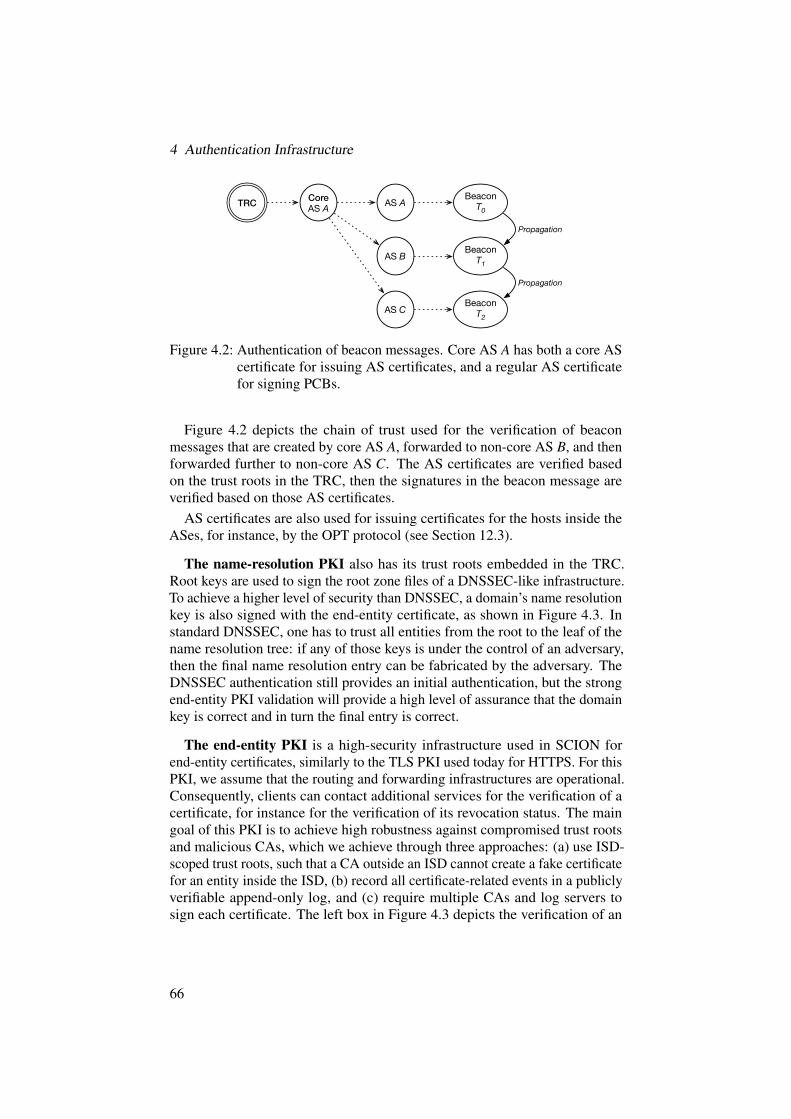
4 Authentication Infrastructure
TRC Core AS A
Beacon T0
AS B
AS C
Beacon T1
Beacon T2
Propagation
Propagation
AS A
Figure 4.2: Authentication of beacon messages. Core AS A has both a core AScertificate for issuing AS certificates, and a regular AS certificatefor signing PCBs.
Figure 4.2 depicts the chain of trust used for the verification of beaconmessages that are created by core AS A, forwarded to non-core AS B, and thenforwarded further to non-core AS C. The AS certificates are verified basedon the trust roots in the TRC, then the signatures in the beacon message areverified based on those AS certificates.
AS certificates are also used for issuing certificates for the hosts inside theASes, for instance, by the OPT protocol (see Section 12.3).
The name-resolution PKI also has its trust roots embedded in the TRC.Root keys are used to sign the root zone files of a DNSSEC-like infrastructure.To achieve a higher level of security than DNSSEC, a domain’s name resolutionkey is also signed with the end-entity certificate, as shown in Figure 4.3. Instandard DNSSEC, one has to trust all entities from the root to the leaf of thename resolution tree: if any of those keys is under the control of an adversary,then the final name resolution entry can be fabricated by the adversary. TheDNSSEC authentication still provides an initial authentication, but the strongend-entity PKI validation will provide a high level of assurance that the domainkey is correct and in turn the final entry is correct.
The end-entity PKI is a high-security infrastructure used in SCION forend-entity certificates, similarly to the TLS PKI used today for HTTPS. For thisPKI, we assume that the routing and forwarding infrastructures are operational.Consequently, clients can contact additional services for the verification of acertificate, for instance for the verification of its revocation status. The maingoal of this PKI is to achieve high robustness against compromised trust rootsand malicious CAs, which we achieve through three approaches: (a) use ISD-scoped trust roots, such that a CA outside an ISD cannot create a fake certificatefor an entity inside the ISD, (b) record all certificate-related events in a publiclyverifiable append-only log, and (c) require multiple CAs and log servers tosign each certificate. The left box in Figure 4.3 depicts the verification of an
66

4.1 Overview
TRC
CA 2
.
TLD
CA 1 LS
DomainPolicy
Name Resolution
End Entity
DomainKey
DomainName Entry
DomainCertificate
Figure 4.3: Authentication of an end-entity certificate and a name-resolutionentry.
end-entity certificate, which in this case relies on signatures by two distinctCAs, and certificate registration by one log server (LS).
Through such a construction our PKI provides the following property for aclient-server communication: if the client has a TRC set as its trust root, anadversary can spoof the server’s identity only if she is able to compromise athreshold number of trusted entities (set in the TRC). In the case of a nameresolution pointing to another ISD, the client has to obtain a proof (asserted bythe threshold number of trusted entities) that the server’s domain does not havea registered policy in the local ISD.
4.1.3 Catastrophe Prevention and Recovery
In case of catastrophic events, such as several private root keys being discloseddue to a critical vulnerability in a cryptographic library, SCION is equippedwith a recovery procedure. The procedure consists in creating a new TRC withfresh trustworthy keys (and potentially new algorithms), and re-sending theTRC to all entities in the ISD and cross-signing entities.
No single malicious entity (e.g., AS, name trust root, CA, log server) cantake down the entire SCION network or impersonate an end entity, since criticalactions require signatures from multiple parties. Even in the event of severalentities forming a coalition to carry out an attack, the effects of that attackwould be limited to one or a few ISDs. Moreover, all actions are publiclyvisible, which will deter participants from misbehaving.
67

4 Authentication Infrastructure
4.2 Control-Plane Authentication
The goal of the control-plane PKI is to enable the verification of control-planemessages, even if the network is only partially available — and even in theextreme case where the entire Internet is rebooted. To this end, the control-planePKI provides certificates that bind public keys to ASes, and handles all aspectsof the certificate life cycle (creation, revocation, update). The control-planePKI is operated by each ISD independently, so that no external ISD can affectinternal operations. The roots of trust are held by core ASes and by selectedCAs that are directly connected to a core AS or deploy their equipment withtheir roots of trust within a core AS. The public root keys are embedded in theTRC. The update and revocation of root keys occurs via signing a new TRCwith a quorum of root keys. The control-plane PKI also provides authenticationfor path revocation messages (described in detail in Section 7.3) and SCIONControl Message Protocol (SCMP) messages (overview in Section 4.2.5 anddescribed in detail in Section 7.6).
4.2.1 Trust Root Configuration (TRC) Life Cycle
In this section, we describe the life cycle and management of trust root con-figurations (TRCs), i.e., we illustrate how TRCs are created, updated, anddisseminated, and we show how consistency is enforced.
Creating a TRC
Initially, a TRC is created when an ISD is created and joins the SCION network.Details on how a new ISD can join the network are provided in Chapter 5. Inshort, the process of creating a new TRC is conducted as follows:
1. A new ISD sets trust anchors for the authentication ofa) control-plane messages (the root keys of core ASes),b) names (the key of the name resolution root zone),c) end entities (the keys of root CAs and log servers).
2. The ISD specifies all TRC parameters (see Section 16.1 on Page 369).In particular, the ISD sets the value of the QuorumTRC parameter, whichdefines how many of the current core ASes will need to sign the nextTRC. The ISD also sets the quorum required to change end-entity trustroots (i.e., QuorumCAs). The version number of the first TRC is set to 0.
3. The TRC is first signed by at least a quorum of core ASes in the ISD(with their online root keys), which is represented by the QuorumTRC
parameter. At this point, the TRC is operational within the local ISD.4. To be accepted by external entities, the TRC is signed by trust roots of
other ISDs. Specifically, at least one core AS, one root CA, and a name
68

4.2 Control-Plane Authentication
trust root from a remote ISD sign the TRC. As chains of trust follownetworking paths every neighbor ISD has to sign the TRC. Non-neighborISDs can sign the TRC as well, to create shortcut trust chains.
5. Similarly, to accept external TRCs, the ISD (i.e., at least one core AS,one root CA, and the name trust root) signs the TRCs of its neighboring(and optionally non-neighboring) ISDs after verifying the identities ofthe ISDs. This and the previous steps can be combined, and may be partof a cross-signing ceremony, where administrators physically meet eachother, or may be executed through out-of-band verifications.
The initial TRC should be delivered to all ASes and end hosts (by a trustedsoftware vendor or a local ISP, for example) via an authentic channel.
Updating a TRC
A TRC update can be conducted for recovery or operational reasons, such aschanges in an ISD core or key updates. Updating a TRC is similar to creating it.The only difference is that the version number of the new TRC is the versionnumber of the current TRC plus one, and the new TRC must be signed by atleast a quorum of core ASes as specified in the current TRC.
TRCs are signed with online root keys. However, any change to the section ofthe TRC related to core ASes (i.e., the list of AS keys and quorum parameters)must be approved with offline keys. Such changes can happen in case of keyrollover, loss, or compromise, or in case of addition/removal of a core AS. Todo so, special requests called update tickets must be sent to a quorum of coreASes who will sign the ticket (if they approve it) with their offline key. Once asufficient number of offline keys have signed them, the update ticket(s) mustbe attached to the new version of the TRC, which will itself be signed withonline keys. Update tickets enable two properties to be efficiently achieved:(a) simultaneous updates (e.g., of several root keys, to decrease the number ofTRC updates and thus to keep the overhead low), and (b) asynchronous updates(obtaining all the required signatures might take some time; in the meantime,other updates can be applied to the TRC). During the TRC verification pro-cedure, if any ticket is attached to the TRC, one must check that the ticketis signed by a sufficient number of legitimate entities and that the update iscompatible with the previous version of the TRC.
Parameters of naming and end-entity PKIs are governed by a naming trustroot and CAs, respectively. To update the parameters, again update tickets areused. If CAs want to change their section in a TRC (e.g., by adding/removing aCA or log server), an update ticket is sent to root CAs, and if QuorumCAs manyof them sign it, the ticket is passed to the core ASes that check the quorum andsign the new TRC (with the proposed change). In the case of a change in thename resolution section of the TRC, a ticket is created and signed by the nametrust root (as there is a single name trust root key, no quorum is required).
69

4 Authentication Infrastructure
If the new TRC is signed according to the quorum parameters of the previousTRC, the new TRC is valid. However, to allow verification of remote messagesand entities, the new TRC has to be cross-signed with neighbor TRCs. Trustroots (ASes, CAs, and name roots) use their online keys for cross-signing, andthe process of cross-signing updated TRCs can be automated in most cases. Inparticular, provided trust anchors are unmodified or added, the new TRC canbe submitted to neighboring ISDs, which verify whether the TRC is signed inaccordance with the value of the current QuorumTRC parameter of the currentTRC. Note that in this case, trust roots of the new TRC do not have to signneighbors’ TRCs (as their keys remain unchanged). For instance, when anISD A updates its TRC from TRCA
i to TRCAi`1 by adding a new AS, all neighbor
ISDs of A have to sign TRCAi`1, but A does not need to sign their TRCs as the
previous signatures are still valid (no trust root of A was removed with the TRCupdate).
However, TRC updates enable an ISD to remove trust anchors that wereinvolved in signing neighbor TRC(s). In such a case, the TRC update must becombined with re-signing all TRCs that were signed by the removed anchor(s).In both cases, the new TRC has to be signed by trust anchors of neighbor ISDs.However, to automate that process, ASes, CAs, and name roots can implementa default policy to sign a remote new TRC if the parameters they are interestedin are unchanged (e.g., for instance a CA can immediately sign the TRC if itsCAs remain unchanged). In extraordinary cases, remote ISDs can refuse thecross-signing request and negotiate the TRC update process out of band.
After the new TRC is created and cross-signed, it is first loaded onto the corecertificate servers, which propagate the TRC among the beacon servers. NewTRCs are then disseminated via the beaconing process. The TRC update canremove trust anchors used in routing, name, and end-entity validation; thus itcan create potential availability issues within the ISD. To maintain availability,an old TRC can be used for a grace period as specified by the GracePeriodparameter. Certificates issued within this period by a removed trust anchor arestill valid, but should be re-issued (see details on Page 74). Grace periods alsolimit the time between TRC updates. Two consecutive TRC updates cannot beconducted until the previous TRC grace period expires. For example, TRCi`2cannot update TRCi`1 while TRCi can be used. This rule restricts the numberof TRCs that can simultaneously be used in the validation to two.
Quorum Size for TRC Update
The approach for the TRC update is designed to withstand one malicious coreAS. Although it is possible to extend the approach to tolerate multiple com-promised core ASes, the system would need more complex operations, suchas consensus algorithms, which would impact availability. In the interest ofkeeping our description simple and short, we defer more complex attacker mod-
70

4.2 Control-Plane Authentication
els to subsequent efforts. We emphasize that for the system we describe here,even in the catastrophic case of a complete compromise of all cryptographickeys, SCION provides insulation of all other ISDs and enables a new TRC to bebootstrapped. As long as only a single core AS is compromised, integrity andconsistency of the sequence of TRC updates is not affected. Since we assumethat core ASes are going to be a relatively small number of entities maintainingactive business relationships with each other, misbehavior against each otheris expected to be rare and can be handled through an out-of-band mechanism.In particular, if a core AS misbehaves, another core AS can collect evidence,convince other core ASes of the misbehavior, and exclude the malicious ASfrom the ISD core. For these reasons, we assume that core ASes extend acertain level of trust toward each other. Despite being competing entities, coreASes benefit from cooperation to keep the network operational. Moreover, thecontrol-plane PKI operations are accountable as all operations are signed, sothat misbehavior will lead to a trail of evidence that can be used in remediation.It is reasonable to assume that a certain degree of mutual trust can exist ina small group of entities that are cooperating in an economic environment.However, we stress that SCION does not require strict consensus as requiredin the current Internet. Due to the introduction of isolation domains with localTRCs, core ASes that disagree on fundamental parts of their TRC (such as rootCAs) can form their own ISD.
We now discuss how to pick the quorum size, i.e., the number of entitiesneeded to perform certain operations. Let G represent the number of legitimate“good” core ASes, B the number of malicious “bad” core ASes we want to beable to tolerate, and U the number of unavailable good core ASes we want tobe able to tolerate. Then we obtain the following formulas for the quorum size:QS“ G´U , QSě PG`1
2
T`B, andPG`1
2
Tą B. The rationale is as follows. Ifnot all good ASes participate, the quorum size needs to be smaller than thetotal number of good ASes. In the case of simultaneous quorums [148], toensure that there is at least one good node that participates in all quorums, weneed to have at least
PG`12
T
good nodes per quorum. In the worst case, allbad ASes always participate in each quorum, thus the quorum size is at leastthe number of required good ASes plus the number of bad ASes. The thirdinequality ensures that, when taking the majority of responders, the bad ASescannot outnumber the good ones.
Consequently, to tolerate one malicious AS and one unavailable good AS,we would need at least six core ASes with G“ 5, B“ 1, U “ 1, and QS “ 4,so even if the bad AS refuses to participate, we can ensure that progress canbe made. With fewer than six core ASes, we cannot tolerate a malicious coreAS and one unavailable good core AS. Assuming that all good core ASes areavailable, a satisfactory assignment is G“ 3, B“ 1, U “ 0, and QS“ 3.
71

4 Authentication Infrastructure
Disseminating TRCs
We assume that all entities within an ISD are pre-loaded with a recent TRC.Moreover, on startup, all servers and end hosts obtain all missing TRCs (fromthe TRC they possess to the most recent TRC) of their own ISD from a localcertificate server. However, we impose a restriction on this catching-up opera-tion: it can only start from a TRC that is at most 1 year old. Then, the TRCs arevalidated (i.e., to verify whether subsequent TRCs respect their update policies),and the most recent TRC is employed for all subsequent operations. There aretwo main requirements for the dissemination of TRCs: (a) efficiency, a newTRC must be rapidly disseminated (to all other parties that need it); and (b)avoiding circular dependencies, an unverified path should not be used to fetcha TRC. The first requirement is met by tying TRC dissemination to the bea-coning, path registration, and path lookup processes. The second requirementis achieved by applying the following rule: a party that sends a signed object(beacon, path segment, name resolution entry, or end-entity certificate) musthave the complete trust information (i.e., TRCs and certificates) required tosuccessfully verify it.
More precisely, TRCs are disseminated via SCION’s beaconing process andverified based on the current or the previous TRC. While beaconing, each ASadds to the beacon the version number of the TRC it is currently using. Abeacon server receiving a new beacon checks the version number contained inthe beacon against its locally stored TRC. If the TRC version number withinthe received beacon is higher than the locally stored TRC, the beacon serversends a request to the beacon server that sent the beacon to request the newTRC. Similarly, the sender can be asked for the missing TRCs of remote ISDs,as they are required to verify beacons. The sender returns the new TRC, whichis then verified by the receiving beacon server. The conditions under which thenew TRC is accepted depend on the ISD that updated it. If the local ISD hasupdated the TRC, then the new TRC is accepted if
1. it contains at least the required quorum number (i.e., QuorumTRC) ofcorrect signatures of trust roots defined in the current TRC, and
2. the receiving AS’s certificate is valid against the new TRC.As a beacon server has previous TRCs from its ISD, it is able to verify theirconsistency. If the last condition is not met, the AS postpones the TRC accep-tance until its own certificate is re-issued and valid against the new TRC. Insuch a case, the AS continues beaconing using its current TRC and certificate,meanwhile contacting its core to obtain a new certificate. Note that other ASeswill learn about the new TRC, as the version is in the beacon (at least in the firstAS entry, i.e., the AS entry of the core AS that initiated the beaconing).
In the case of a new TRC from a remote ISD, the update is accepted if1. it contains at least the required quorum number (i.e., QuorumTRC) of
correct signatures of trust roots defined in the previous TRC; and
72

4.2 Control-Plane Authentication
2. there exists a chain of trust from (a) the local TRC to the new TRC, and(b) from the new TRC to the local TRC.
Note that TRC cross-signing follows the physical network connections, thusthe latter condition is satisfied when all subsequent TRCs in the core beaconare cross-signed.
After the new TRC is accepted, it is submitted by the beacon server to a localcertificate server. Finally, the TRC is re-distributed internally. To this end thebeacon server replicates the TRC among all beacon servers within its AS, andsimilarly the certificate server replicates the TRC among all local certificateservers.
Path servers discover new TRCs via path-segment registration messages (seeSections 7.1 and 4.2.3). This occurs when the beacon server registers pathsegments (authenticated with the new TRC) with its local path server and acore path server. The path servers check the version of the TRC with which thesegments were authenticated. If a new TRC is detected, the path servers querythe beacon server for this TRC. After the new TRC is returned, the TRC andpath segments are validated accordingly, and after a successful validation theTRC and path segments are saved.
Similarly, end hosts learn about new TRCs through the path lookup process(see Sections 7.2 and 4.2.3). End hosts, at the end of the process, obtain a set ofpath segments that can be combined into a forwarding path to the destination.For a path segment authenticated with an unknown TRC, this TRC is requestedfrom the local path server, which has returned the path segments. The pathserver is obliged to possess all TRCs needed to verify every path in the set.
An example of TRC dissemination is presented below in Section 4.2.4.
TRC Update Frequency
Revocation of root keys happens through TRC updates. The update frequencyof the TRC should be very low, for the following reasons:
• Each update requires a TRC dissemination to all entities that intend tocommunicate with a host inside that ISD.
• If a host was offline for a while and has an old TRC, it needs to fetch allintermediate TRCs to verify the current one.
• By making the TRC update a rare operation, we can make minimal useof the TRC signing keys and shield them from regular operations, whichenhances security.
We thus aim for a TRC update that occurs at most on a weekly basis, ideally ona monthly or longer frequency. However, TRCs have to be updated before theyexpire (expiration timestamps are set by ISDs themselves).
73

4 Authentication Infrastructure
TRC Lifetime
TRC updates can create inconsistencies in chains of trust. For instance,• a beacon server receives a beacon where ASes use different TRC versions
for authentication,• an end host fetches up-segments and down-segments authenticated using
TRCs with different version numbers,• an end host possessing a new TRC obtains a name resolution response
authenticated with an old TRC.To achieve high availability, such inconsistencies have to be handled without
breaking validation. To this end, an ISD can define a grace period (duringwhich a previous TRC can still be used). This period is defined in the TRC withthe GracePeriod field. Then, TRCi is valid effectively until
TRCi`1.CreationTime`TRCi.GracePeriod . (4.1)
4.2.2 AS Keys and Certificates
To achieve a high level of security for the control-plane PKI operation, wepropose that core ASes have online and offline asymmetric key pairs. In thisdesign, offline keys are used for infrequent safety-critical operations that willrequire administrator involvement to cross an air gap, and online keys are usedfor frequent automated operations that do not require administrator involvement.
The renewal of AS certificates is an example of a fully automated operationthat occurs every few days and only requires online keys. For the additionor removal of a core AS, offline keys are required to ensure human operatorinvolvement and that even a complete compromise of all online keys does notpermit sensitive changes to the TRC. So even for an event such as the Heartbleedvulnerability [75], which may simultaneously compromise all online keys, thebasic infrastructure (i.e., the control-plane PKI) remains safe and all online keyscan efficiently be updated to fresh keys after the vulnerability has been patched.
The revocation of AS certificates is challenging. As AS certificates areinvolved in the availability-critical operation of beacon dissemination andbeacon validation, checking the revocation status of an AS certificate wouldresult in a deadlock. Consider a revocation service operated by the ISD core,which keeps a list of revoked AS certificates. When verifying an upstream AS’ssignature contained in a beacon, a downstream AS would need to contact therevocation service to ensure that the certificate is still valid. In the case of anetwork reboot, however, an AS has no paths yet to the core and thus cannotvalidate the first beacon message it receives. If one used an unverified path toreach the revocation service, then the system would not operate safely in theinitial phase. We propose a more elegant approach: short-lived certificates,
74

4.2 Control-Plane Authentication
which do not need any revocation if we can tolerate a short period of continuedvalidity when a certificate is compromised [212].
Table 4.1 gives an overview of the different keys and certificates used in thecontrol-plane PKI. The TRC contains the offline and online keys of all coreASes and is signed with a quorum of root keys (online or offline, depending onthe context); as such, it can be considered to be a self-signed root certificate,except that multiple parties are involved. Online and offline root keys areincluded in TRCs while other keys are authenticated via certificates. All ASes(including the core ASes) use short-lived AS certificates to carry out theirregular operations (such as signing beacons and path segments). Core ASeshold an additional certificate whose only purpose is to authenticate (other ASes’and their own) AS certificates.
Name Notation Auth.1 Validity2 Usage
Offline Ki,offline TRC 5 years Critical TRC update:root key - Addition/removal of core ASes
- AS quorum parameter change- Update of root keys
Online Ki,online TRC 1 year Signing core AS certificatesroot key TRC creation, non-critical update
Cross-signing
Core AS Ki,core Ci,core 6 months Signing AS certificateskey
AS key Ki Ci 3 months Beacon authenticationPath-segment authenticationDRKey (used within SCMP)
(a) Private Keys
Name Notation Signed by Associated Key Validity
Core AS certificate Ci,core Ki,online Ki,core 1 week
AS certificate Ci Ki,core Ki 3 days
(b) Certificates
Table 4.1: Summary of keys and certificates used in the control-plane PKI.
The TRC and certificate lifetimes are selected in such a way that frequentlyused online keys that are more exposed to potential compromise are rolled morefrequently than infrequently used offline keys. The root key pairs of an ASmust be updated regularly through TRC updates. To ensure that key update is a
1Location of the corresponding (authenticated) public key.2Recommended usage period before key update (best practice).
75

4 Authentication Infrastructure
periodically practiced function (for good security hygiene), all keys are updatedat least every few years. Also, we suggest a validity period of three days forregular AS certificates and one week for core AS certificates. (Please note thatthe key validity period indicates the key lifetime, whereas the certificate validityperiod indicates how often the certificate needs to be re-signed.)
When an AS joins an ISD, it obtains from the ISD core:1. a unique and permanent AS identifier (within the ISD),2. a certificate for the AS’s public key.
The AS certificate is issued by a core AS, which is obliged to check the identityof the AS. AS certificates are short-lived, by default valid for 3 days, althougheach ISD can set different policies on the certificate lifetime. This design de-cision is motivated by simplicity and availability requirements, as short-livedcertificates can be validated without any additional information (such as certifi-cate revocation status information) and no revocation system is required [212].
On the other hand, a consequence of short-lived certificates is a need forfrequent re-issuing of certificates before they expire. This process is automatedin SCION. An AS that needs to re-issue its certificate contacts the core AS thatissued it before, with a re-issuance request. The re-issuance request proves thatthe requesting AS still possesses the private key that corresponds to the publickey included in the current certificate. The core AS verifies the request, copiesthe fields of the current certificate, sets a new lifetime for the new certificate,and signs it.
Only the core AS that issued a certificate can re-issue it. With such anapproach, every core AS keeps a one-to-one mapping between ASes and theircurrent public keys (that were certified by this core AS). The re-issuancerequests are introduced to prove that this mapping is still valid. However, inthe case of key loss or key compromise, an affected AS has to contact thecorresponding core AS to change its mapping as the old public key should nolonger be used. The AS generates a new key pair and contacts the core AS(out of band). The core AS checks the identity of the AS, and subsequentlyissues a new certificate (with the new public key), and changes the mappingso that old certificates cannot be re-issued anymore. We emphasize that short-lived certificates are irrevocable during their lifetime; thus if a private keyis compromised, the adversary can use the corresponding certificate until itexpires.
Although core ASes have core AS certificates, these are only used for issuingother certificates. To separate certificate and key usage, control-plane operations(such as beacon and path-segment signing) are performed by core ASes withAS keys and corresponding AS certificates. To this end, a core AS periodicallycreates its own AS certificate and signs it with its core AS key. The format ofAS certificates is presented in Section 16.2 on Page 370.
76

4.2 Control-Plane Authentication
A TRC update may invalidate an AS certificate, e.g., when a certificate-issuing core AS has been removed from the TRC. In such a case, the affectedAS can still use its certificate in combination with an old TRC. However, thisis possible only during a grace period as described above, and thereafter, theAS has to obtain a new certificate from one of the current core ASes. In caseof large-scale compromise, the core AS can revoke its online root key that wasused to sign the core AS key that signed the AS key. Revocation of the onlineroot key through a TRC update would thus invalidate all the underlying ASkeys.
4.2.3 Control-Plane Authentication
PCBs and path segments are authenticated with AS certificates. We nowdescribe these operations in more detail.
Beacon Authentication
The authentication of PCBs is especially important as PCBs are used in buildingpath segments. The details of PCB creation and the PCB format are describedin Section 7.1.1 on Page 120 and Section 15.3 on Page 356.
The beaconing process is initiated by a core beacon server, which createsa PCB, appends its AS entry, and signs the PCB with a private key that cor-responds to an AS certificate that can be validated based on the current TRC.Certificate and TRC versions are included within the AS entry; thus they aresigned as well. Then, the PCB is sent to a beacon server of a neighboring AS.The receiving beacon server first checks whether it has the TRC and certificatewith the versions announced in the PCB. If the TRC is new, then the beaconserver updates it. If the certificate version is unknown to the receiving bea-con server, the sending beacon server is queried, and the correct certificate isreturned. (New certificates are replicated across the AS’s certificate servers.)At this point, the receiving beacon server has all the information necessary toverify the PCB. It verifies the certificate based on the TRC, and finally verifiesthe PCB’s signature based on the certificate.
The receiving beacon server continues the beaconing process by appendingits own AS entry. As before, the beacon server states versions of the used TRCand certificate. Finally, the beacon is signed and sent to neighboring ASes. Thenext receiving beacon server checks the versions of all TRCs and certificatesinvolved in the beacon authentication. If any TRC or certificate is missing,the sender is queried. With such a beaconing design, the relevant TRCs andcertificates are disseminated step by step with the beacon dissemination. Thebeacon server continues the validation (and beaconing) after all necessary TRCsand certificates are provided. Namely, it verifies the signature of each AS entryindividually. The beacon continues to propagate until it reaches a leaf AS‹.
77

4 Authentication Infrastructure
Path-Segment Authentication
Beacon servers turn PCBs into path segments in every registration period (seedetails in Section 7.1 on Page 119). Path segments have the same format asPCBs, except they may be without some optional metadata. Each AS entrywithin a path segment is signed, and it contains information about the TRC andcertificate used to protect the entry.
When a beacon server registers path segment(s) with a path server (localand/or core), the path server(s) can query the beacon server for the TRC(s) orthe certificate(s) (if any are missing). Path servers accept path segments if theirauthenticity is verified, i.e., if
1. the required TRC(s) and certificate(s) are provided,2. if there is a new TRC, it is consistent with the previous one,3. the certificate(s) are valid with respect to the corresponding TRCs,4. the path segment’s signatures are valid with respect to the certificates.
Note that through such a registration process, path servers learn new TRCs andcertificates.
The way in which end hosts verify path segments is similar to the way pathservers do so. An end host sends a path request to its local path server, whichthen resolves the request recursively (see details in Section 7.2 on Page 132).For the path segments obtained from the local path server, the end host conductsthe verification. Hence, it first asks for all missing TRCs and certificates used inthe authentication of any path segment. Then, it verifies each path segment asdescribed above. Similarly, in this way, the end host learns new TRCs, whichfinally replace the old ones.
Besides path registration, SCION allows for removal of path segments fromthe path servers and end hosts that cache them. The path revocation mechanismis described in Section 7.3 on Page 138.
4.2.4 Authentication Examples
Intra-ISD Beaconing
An example of intra-ISD beacon authentication is presented in Figure 4.4. CoreASes update the TRC from TRCi´1 to TRCi, after AS F has been removed fromthe core. The figure shows how this update is disseminated across the ISD usinga single beacon.
First, core AS D initiates the beaconing process, by creating a fresh PCB withD’s entry. The entry includes the version number of the new TRC (i.e., i) andthe version number of D’s certificate. The entry is signed with D’s AS privatekey, and the corresponding public key is included within D’s certificate CD,which in turn can be validated based on TRCi. When AS C receives the PCB,it learns that there is a new TRC. C asks D for TRCi (and for D’s certificate if
78

4.2 Control-Plane Authentication
ISD core
D’s blockC’s block
PCB
ISD
D’s blockPCB
D’s blockC’s block
PCB
B’s block
D’s blockC’s block
PCB
B’s blockA’s block
E FD E FD
B
AC
F
A
C
B
ED
TRC i-1 TRC i
Figure 4.4: Example of intra-ISD beacon authentication.
it is missing), and then verifies whether the TRC update was correct. Further,C verifies the signature over the PCB using D’s public key contained in D’scertificate, and validates this certificate with the new TRC. The PCB is accepted,and the new TRC is propagated among C’s PCB and certificate servers. Finally,AS C appends its own entry to the PCB, and signs it. C’s certificate is issuedby D, which is in the new TRC, so C uses i as the TRC version number for itsentry.
Then, the PCB is sent to AS B, which verifies the new TRC (obtained fromC), and the first entry in the same way as C. Then B verifies the next (i.e., C’s)entry, which is signed with C’s key, and which can be successfully validatedbased on the new i-th TRC. Finally, B creates its own entry; however this entrycannot be marked with TRCi’s version number because B’s certificate is signedby AS F , which was removed from the core by the TRC update. In such acase, B is forced to temporarily use TRCi´1 (this is possible during a graceperiod — see Page 74) for the propagation, and contacts an active core AS toobtain a new certificate. Although AS B cannot sign objects (e.g., PCBs orpath segments) with the new TRCi, it replicates this TRC among its PCB andcertificate infrastructure.
Finally, AS A receives the PCB, and although the latest AS entry is signedbased on TRCi´1, A learns about the new TRC from the previous entries. AS Averifies and updates the TRC similarly to how the previous ASes did.
Path servers learn the new TRCs from the path registrations and lookups,which are conducted on demand. For instance, if A’s beacon server registers a
79

4 Authentication Infrastructure
ISD core
ISD coreISD core
A D
B C
TRC i-1
TRCTRC
TRC i
D
BC
AA’s blockB’s blockC’s blockD’s block
PCB
A’s blockB’s blockC’s block
PCB
A’s blockB’s block
PCBA’s blockPCB
ISD 1ISD 2
ISD 3
Figure 4.5: Example of core beacon authentication.
path segment that was built upon the new TRC, a receiving path server asks thebeacon server to send this new TRC. However, after path servers learn aboutnew TRCs, they still accept (during a grace period) registrations signed on thebasis of an old TRC.
Inter-ISD Beaconing
An example of inter-ISD beacon authentication is presented in Figure 4.5,where a core PCB is disseminated from AS A towards AS D. In our scenario anintermediate ISD contains two core ASes (i.e., B and C) that have TRCs withdifferent versions (such a situation can happen for example due to disseminationdelays within an ISD core).
First, a beacon server in AS A initiates beaconing by creating the first ASentry. The entry is signed with A’s AS private key, and the corresponding publickey is included within A’s AS certificate, which in turn can be validated withthe TRC of ISD 1 (denoted TRC1). A sends the PCB to AS B, which is inanother ISD. AS B uses TRC2
i´1 and verifies the PCB. If TRC1 or A’s certificateis missing, B’s beacon server asks A to provide that. AS B verifies A’s entrybased on TRC1, and verifies whether TRC1 is cross-signed by TRC2
i´1, which iscurrently used by AS B. Then, B creates and signs a PCB including its entryand disseminates the PCB to AS C. AS C verifies the PCB, validating A’s andB’s entries. As B used an old TRC, C checks whether the grace period is notviolated. C also verifies whether TRC1 is cross-signed with TRC2
i , which iscurrently used by AS C. Next, C appends its entry and signs the PCB with itsown AS key, which can be verified based on TRC2
i . Then, the PCB is forwardedto ISD 3. AS D receives the PCB and obtains all missing (if any) TRCs and
80

4.2 Control-Plane Authentication
ISD core
TRC
ISD coreISD core
B
A
G
I
TRC
DE
F
H
C
core-segmentup
-seg
men
t down-segm
ent
ISD 1
ISD 2
ISD 3
up-segment core-segment
B
C
TRC
G
H
down-segment
A
D E F
I
Figure 4.6: Example of path-segment authentication.
certificates from the sender (i.e., AS C). As ISD 1 is not a neighbor of ISD 3,D must verify that there is a chain of trust from TRC3 to TRC1. To this end, Dverifies cross-signatures between TRC3 and TRC2
i , TRC3 and TRC2i´1, TRC2
i´1and TRC1. Additionally, D verifies that the update from TRC2
i´1 to TRC2i was
consistent.
Path-Segment Authentication
An example scenario of path-segment authentication is presented in Figure 4.6.The topology consists of three ISDs, where an end host from AS A wishes toconnect to an end host from AS I.
The first step is the beaconing process. In our example, the following pathsegments are created:
• an up-segment between source AS A and core AS C,• a core-segment between core AS C and core AS G, and• a down-segment between core AS G and destination AS I.
AS C starts beaconing by sending a new PCB, which eventually is receivedby A’s beacon server (an example of this process is presented on Page 78). AS Areceives and verifies the PCB, and converts the PCB into an up-segment. To thisend, the AS creates its own AS-level information, appends it, and finally signsit (using the current TRC and A’s certificate). This path segment is registered
81

4 Authentication Infrastructure
with a local path server as an up-segment. During the registration, the pathserver verifies the up-segment. If a TRC or certificate is missing, the path serverrequests it from the beacon server. (Note that new TRCs and certificates aredisseminated during the beaconing process.) After a successful verification, thepath segment from A to C is saved. The beacon server also registers this pathsegment (as a down-segment) with a core path server (e.g., in AS C).
Similarly, AS I creates and registers the up- and down-segments betweenASes G and I (the up-segment is registered at the local path server and the down-segment at the core path server). The TRC(s) and certificate(s) are disseminated(if needed) accordingly.
The core-segment is created in a slightly different way. A core PCB, dissemi-nated from G to C, is validated by C’s beacon server. To validate it, the beaconserver needs to have TRCs of ISD 2 and ISD 3. To create a core-segment, Cappends to the PCB its own AS-level information, and then signs the PCB.Finally, the core-segment is registered with a local path server (i.e., path serverof C), which will request any missing TRC(s) or certificate(s).
After paths are created and registered, end hosts can successfully conductpath lookups. In our example, an end host from AS A asks its local path serverfor a path to AS I. The path server does not have such a path segment cached,so a core path server in AS C is contacted. The core path server likewise doesnot have the path segment, hence the core of I’s ISD is queried. The core pathserver of AS G returns the G–I down-segment (which was registered by I’sbeacon server) to the core path server in C. C’s path server can query I’s pathserver for TRCs and certificates used to authenticate the G–I down-segment(e.g., TRC3 or I’s certificate can be queried if C’s path server does not alreadyhave it). The down-segment is then verified, and returned to A’s path server.Along with this down-segment, a core-segment (C–G) is added. A’s path servertries to validate the returned path segments. To this end, the TRCs TRC2 andTRC3, and all certificates involved in path segment authentication are needed.More specifically, TRC2 is required to establish a chain of trust between TRC1
and TRC3 (note that TRC2 cross-signs these TRCs). At the end of the lookupprocess, A’s path server returns the core-segment and down-segment to the endhost, accompanied with the A–C up-segment. Finally, the end host obtains thepath segments (and asks for missing TRCs or certificates), and verifies all pathsand trust chains between TRCs.
4.2.5 SCION Control Message Protocol (SCMP)
Security of a control message protocol is essential for the security of higher-levelprotocols. For instance, the Internet Control Message Protocol (ICMP) does notprovide any form of authentication. Consequently, the Internet transport proto-cols (such as TCP) suffer from attacks caused by maliciously generated ICMPpackets [99]. However, providing security for control protocols is particularly
82

4.3 Name Authentication
challenging, as control packets are often created and processed by routers; thusthe authentication and verification process has to be highly efficient.
TRC
AS B
AS A KABDRKey
Figure 4.7: Verification of an SCMP message authenticated via MAC.
SCION provides a framework for authenticating SCMP packets, and twodistinct authentication schemes are available. The first scheme is symmetric andbased on the DRKey protocol (see Section 12.5 on Page 291). In this scheme,SCMP packets are protected by their sources and verified by their destinations.A symmetric key used to authenticate SCMP packets is derived from a secretsymmetric key local to the AS, and is exchanged securely using AS certificates,as illustrated in Figure 4.7. In the second scheme, SCMP packets are signed inbatches by border routers, and receiving end hosts verify signatures by usingthe corresponding AS certificates. More details on the authentication of SCMPare provided in Section 7.6.3 on Page 156.
4.3 Name Authentication
The goal of the name authentication infrastructure is to authenticate bindingsbetween SCION addresses and human-readable names. To this end, nameresolution responses have to be authenticated — for which SCION relies ona DNSSEC-like infrastructure. However, to achieve a higher level of securitythan DNSSEC, the validity of name resolution keys is additionally asserted byend-entity certificates.
4.3.1 Name-Resolution Key Infrastructure
SCION defines its own name resolution protocol, called RAINS, which isdescribed in Chapter 6. RAINS provides an authentication infrastructure thatis similar to DNSSEC [13], with one main difference that is important forauthentication purposes. Assertions about names in RAINS are explicitlybound to an assertion context (see Section 6.3.3 on Page 109), which definesthe chain of signatures used to verify the validity of a given assertion. Each ISDhas its own native isolation context, at which signature chains for names lookedup from within that ISD are rooted. This is analogous to the current DNSSECtree with one root per ISD (instead of a single global root).
83

4 Authentication Infrastructure
The root keys for each ISD’s native isolation context are included and dis-tributed with TRCs, as opposed to software updates in DNSSEC. Through theTRC cross-signing framework (see Section 4.2.1) clients can resolve names inother (than native) isolation contexts. RAINS assertions are natively signed(replacing DNSSEC’s RRSIG resource record type), and delegation occurs viaa digital signature, as opposed to via name-server redirection. For the sakeof simplicity, we leave further details aside for now and refer the reader toChapter 6.
Within a native isolation context, the chain of trust is tied to the domainnamespace hierarchy. For instance, a domain ‘ethz.ch.’, which wishes tosign its name resolution records, first has to obtain a signature for its key fromits parent in the namespace hierarchy, i.e., from the ‘ch.’ domain. Similarly,ch. has to have its key signed with the root key (i.e., by the root domain ‘.’).Figure 6.3 on Page 110 shows such chains for various assertion contexts. Thename resolution root key is contained in the TRC.
Key updates in RAINS are similar to those in DNSSEC, i.e., every changeof a domain’s name resolution key affects the superordinate and subordinatedomains according to the namespace hierarchy of the domain. Namely, thedomain’s parent has to sign the domain’s new key, and then the domain hasto re-sign the keys of each child. RAINS allows multiple keys to be valid fordelegation to a zone at once; operational practices for overlapping validity canreduce the potential for disruption of verification during a key rollover.
To improve security of the standard DNSSEC trust model, we supplementRAINS authentication with our highly secure end-entity PKI. More specifically,domain public keys are additionally asserted by a special end-entity certificate.We call this special certificate a subject certificate policy (SCP); its detailsare presented below in Section 4.4.3. SCPs are certificates issued by multipletrusted parties (namely, certification authorities — CAs) and used by domainsto govern their public-key certificates and secure connections. There is a uniqueactive SCP per domain, and SCPs are published as RAINS assertions.1 Thedomain asserts its own name resolution key by signing this key with its SCP’sprivate key and publishing this signature within its name resolution zone. Thepublic key of this certificate is also published as a RAINS assertion for cross-verification.
4.3.2 Validation of Name Resolution Entries
As part of a successful name lookup, the obtained assertions are validated asfollows: (a) The signature chain is validated according to the assertion contextfor the entry; by default, for globally significant names, this chain is rooted atthe current TRC (i.e., the TRC trusted by the user). (b) Once the assertion is
1SCPs are accompanied by proofs from the end-entity PKI that they are logged and fresh. If adomain does not have an SCP, the domain publishes an assertion with an absence proof.
84

4.3 Name Authentication
validated, the last step is to verify the domain’s SCP and the additional signatureover the domain’s name resolution key. (c) The client verifies whether the SCPbelongs to the correct domain and whether it is correct (i.e., signed by therequired number of trusted CAs and asserted by a trusted log — more on SCPvalidation can be found in Section 4.4.3). (d) The SCP is validated according tothe TRC trusted by the user. (e) Finally, the client verifies whether the domain’sname resolution key is signed with the SCP’s key. This is the last check whichensures that name resolution responses are authentic. As the SCP is used inTLS connections, it can be stored by the client, so the client does not have tofetch it again over the potential TLS connection with the domain. In the casewhen the domain does not have an SCP, the domain asserts in RAINS a proofthat claims that there is no SCP registered for this domain.
Note that, as in the previous cases, inconsistencies may occur while TRCsare updated. For instance, a client can have a new TRC while some nameresolution entries (signed with an old one) are cached locally. However, theinconsistencies influence the entry validation only when the new TRC changesthe root name resolution key. In such a case, the validation can be conductedusing an old TRC as long as it is compliant with the specified grace period (seeEquation 4.1 on Page 74).
Example. Consider an address lookup for the following name:
‘simplon.inf.ethz.ch’
Assume the name is iteratively resolved, within the native isolation context,by a query server without any existing state. The query server performs thefollowing steps:
1. Retrieve valid public keys for the naming root in the native isolationcontext from the TRC, and cache them for the limit of their validity.
2. Issue a query for the delegation key for the name ‘ch.’ in the nativeisolation context using an intermediary server storing root assertionsdiscovered through service anycast (see Section 7.5 on Page 153).
3. Verify the signatures on the resulting assertions against the root publickeys in the TRC, and cache the delegation keys for ‘ch.’ for the limitof their validity.
4. Issue a query for the delegation for the name ‘ethz.ch.’ in the nativeisolation context.
5. Verify the signatures on the resulting assertions against the stored keysfor the ‘ch.’ zone, and cache the delegation keys for ‘ethz.ch.’ forthe limit of their validity.
6. Issue a query for the delegation for the name ‘inf.ethz.ch.’ in thenative isolation context.
85

4 Authentication Infrastructure
7. Verify the signatures on the resulting assertions against the stored keys forthe ‘ethz.ch.’ zone, and cache the delegation keys for ‘inf.ethz.ch.’for the limit of their validity.
8. Issue a query for addresses for ‘simplon.inf.ethz.ch.’ in the nativeisolation context.
9. Verify the signatures on the resulting assertions against the stored keysfor ‘inf.ethz.ch.’
10. Additionally verify the signatures on the resulting assertions against theSCP key for ‘inf.ethz.ch.’, if available.
Note that while the iterative verification of the delegation chain requires eachof the public keys to be available and the signatures thereon verified, all of thequeries can be issued in parallel.
4.3.3 Name Consistency
Each ISD maintains its own root zone for name resolution. This root zonecontains delegations to the authority for each TLD. Each TLD authority thenserves and authenticates assertions about second-level names, and so on. In thetypical case, for a given TLD, each ISD will delegate to the same authority, andthe chain of signatures will be identical beyond the ISD root signature of theTLD authority. There are two important deviations from the typical case:
• Isolated TLD: An ISD may delegate authority for a TLD otherwise notpresent in the root zone, creating a TLD that is available only in thatISD. Care must be taken with isolated TLDs, since they may lead toconflicts between ISDs, which can only be resolved through nontechnicalprocesses (see Section 3.5 on Page 51).
• Isolated subordinate TLD authority: An ISD may delegate authorityfor a TLD to a registry other than the globally recognized registry forthat TLD. This isolated subordinate authority tracks changes to the glob-ally recognized registry, providing additional vetting of assertions aboutsecond-level domains and potentially declining to include those that areused for network abuse (e.g., malware domains).
The mechanism for ensuring consistency in a multiple-root environmentusing RAINS is described in detail in Section 6.5 on Page 116.
4.4 End-Entity Authentication
The TLS protocol is used globally to secure online communications (HTTPand SMTP communications, in particular). TLS enables the creation of end-to-end encrypted and authenticated channels. To authenticate entities (usuallyidentified by domain names), TLS relies on certificates, which can be obtained
86

4.4 End-Entity Authentication
from hundreds of geographically and administratively distinct CAs. In the tra-ditional TLS PKI, a single CA can issue a certificate for any domain and boguscertificates can go unnoticed for long time periods due to a lack of transparency.Given that the security of the majority of web-based financial and commercialtransactions relies on TLS, one would hope that its security is commensuratewith its widespread acceptance and use. Unfortunately, although CAs wieldsignificant power in the TLS ecosystem, their trustworthiness has recently beentarnished by several events. Operational mistakes, social-engineering attacks,and governmental compulsion have resulted in the issuance of fraudulent certifi-cates for many high-profile sites [166, 167, 225]. In these cases, adversaries canimpersonate domains to clients by performing active man-in-the-middle attacks,intercepting secure connections and stealing potentially sensitive information.Software vendors also hold significant power in the TLS ecosystem, since theymanage the list of CA certificates that serve as the roots of trust.
For the SCION end-entity authentication PKI, we leverage a combination ofARPKI [23,24] and PoliCert [235], which address the above issues and provideprovable security guarantees. ARPKI provides the basis for a transparentand resilient infrastructure, while PoliCert allows domains to specify policiesgoverning the use of their certificates to achieve additional security objectivesand address the shortcomings of previous systems. The system we present isdeployable (in an incremental manner) both inside and outside of SCION. Inthe inside case, however, SCION allows roots of trust to be defined at the ISDlevel, through TRCs, instead of being distributed independently by differentsoftware vendors. SCION allows the scope of these trust roots to be limited toISDs, unlike current systems that rely on global trust.
4.4.1 Background
For the issuance of illegitimate certificates to be detected, the operations ofCAs need to be transparent. Google’s Certificate Transparency (CT) frame-work [149] proposed the use of append-only public logs to provide CA ac-countability. The goal is to make all issued certificates visible in order to alertdomain owners and clients of any possible misbehavior. CT creates a system ofpublic logs, which maintain a database of observed certificates issued by trustedCAs. The log can then provide evidence that it contains a given certificate, andthe proof can be checked by clients during the TLS handshake. Additionally,the log is publicly auditable so that any party can fetch proofs of presence orconsistency. However, CT has several drawbacks. Specifically, CT’s main goalis to detect suspicious behavior, and thus it does not actively protect clientsfrom ongoing attacks if an adversary successfully registers a bogus certificateat a public log [167]. Nevertheless, public logs similar to those used by CT canbe employed to build systems such as ARPKI and PoliCert to provide strongsecurity guarantees.
87

4 Authentication Infrastructure
h1234
h34
h4
C4
h3
C3
h12
h2
C2
h1
C1
h12345678
h5678
h78
h8
C8
h7
C7
h56
h6
C6
h5
C5
h1234
h34
h4
C4
h3
C3
h12
h2
C2
h1
C1
Figure 4.8: Example of appending entries in chronological order to a Merklehash tree. The tree on the left-hand side represents the initial stateof the log, and the tree on the right-hand side represents the state ofthe log after addition of certificates C5–C8.
Merkle hash trees‹ are generally used to implement public logs. Typically,hash trees are binary trees in which leaves contain certificate-related data, andnon-leaf nodes contain the hashes of their two child nodes [174]. This structurecan be leveraged to efficiently prove that a leaf is part of the tree. Only one nodeper level is needed in a proof of presence; hence, the proof size is proportionalto the tree height, which is Oplog2pnqq for n leaves. If leaf nodes are ordered(e.g., lexicographically), the tree can additionally provide proofs of absence.If nodes are appended chronologically, then the tree can also provide proofsof consistency showing that the tree is indeed maintained in an append-onlymanner. Proofs are based on tree roots, which are lightweight cryptographicrepresentations of the log at a certain point in time.
Example. Two Merkle hash trees are shown in Figure 4.8. It is possible, forexample, to prove to someone who holds h1234 and h12345678 that the tree on theleft-hand side was extended (without removing any existing entry) to obtain thetree on the right-hand side, by providing h5678.
4.4.2 Problem Definition
In this setting, the adversary’s goal is to obtain a valid certificate and thecorresponding private key for a domain that is not owned by the adversary (e.g.,in order to obtain secret information through a man-in-the-middle attack). Tothis end, the adversary can either directly compromise the server in questionto obtain its private key (in which case the PKI does not play any role in theattack; it is the server administrator’s responsibility to protect the private key)or the adversary can try to produce a new valid certificate for that domain bycompromising a number of trusted entities. However, for a PKI to satisfy anynontrivial security property, we assume that the adversary cannot compromiseall entities. We also assume that the network is not trusted and, therefore, that
88

4.4 End-Entity Authentication
the adversary can eavesdrop, modify, and insert messages at will. The mainproperties we seek are the following:
• Compromise Resilience: Unless more than a threshold number oftrusted entities are compromised, it should be impossible for an adversaryto impersonate a domain by forging a certificate or policy that would beaccepted by clients.
• Balanced Control: All parties should be able to contribute towards de-termining whether or not a domain’s certificate is valid, whether throughsigning information or specifying parameters for connection establish-ment.
4.4.3 ARPKI and PoliCert
Although ARPKI and PoliCert were initially developed as independent systems,they are compatible and are combined into the authentication infrastructure thatwe present in this section. We give a high-level description of these two systemsand refer the reader to the academic papers for more details [23, 24, 235]. Westart by listing the relevant entities in our infrastructure:
• Clients (usually browsers) can initiate TLS connections with serversin any domain. Depending on the authentication data provided by theserver, a client can either accept the connection or display a warning/errormessage.
• Domains are identified by names unique within a given isolation context,and their servers respond to TLS requests from the clients. Domainsauthenticate themselves to their clients by presenting their certificate(s)and by using the corresponding private key(s).
• Certification authorities (CAs) are trusted entities responsible for issu-ing certificates for public keys that are associated with a domain. CAsmust verify that the certificate requester is the legitimate owner of thedomain in question. Clients must have access to a list of trusted rootCAs, while intermediate CAs are certified by other CAs. CAs are alsoresponsible for monitoring logs to detect their misbehavior.
• Log servers maintain a tree-based record of valid certificates and policies.Logs are able to prove that they behave in a consistent manner.
Subject certificate policies (SCPs) are central elements of the SCION end-entity PKI. An SCP contains parameters regarding the usage and validation ofa domain’s certificate, such as the list of CAs authorized to sign the domain’send-entity certificate. Each SCP has an associated key pair, and at a given pointin time each domain can have only a single valid SCP. The policy private key isused to (a) sign the policy binding in a domain’s certificate and (b) authorizecertificate revocations and policy updates. Because the parameters in an SCPare bound to a domain’s identity and policy key pair, we encode an SCP as a
89
4 Authentication Infrastructure
series of standard X.509 certificates (signed by distinct CAs), where each X.509certificate authenticates the policy public key and lists the policy’s parametersin an X.509 extension.
Let n be a security parameter that denotes the minimum number of parties(i.e., CAs and logs) that must be actively involved in asserting that an SCP hasbeen registered. Then, an SCP must be confirmed and signed by at least n´1CAs, and it must be registered by at least one log server to be considered valid.This n parameter is specific to each ISD and is defined in the TRC with theThresholdEEPKI field.
Since domains are expected to only infrequently change their policy, SCPsare assumed to be stable (barring catastrophic events such as a weakness in awidely used encryption scheme). Therefore, we require that SCPs be valid foran extended period (of the order of months). Besides the end-entity PKI, SCPsare also used to certify RAINS keys (i.e., a policy key can sign the domain’sRAINS key).
To provide some resilience against CA compromise, we use multi-signaturecertificates (MSCs), which allow multiple CA signatures to authenticate asingle public key and require only a certain threshold of the signatures to bevalid. Similarly to SCPs, an MSC is encoded as a series of standard X.509certificates (signed by distinct CAs) authenticating domain D’s public key.These standard certificates are followed by a special certificate that we referto as a policy binding certificate. The policy binding certificate is signed withan SCP’s private key controlled by domain D itself, and contains the currentversion number of D’s SCP and an X.509 extension that lists the hashes ofall certificates within the MSC. This allows the domain owner to change thecertificates within an MSC. Because the policy binding can be generated byD independently of any CA, these changes can be made quickly. In order foran MSC to be considered valid, a threshold number of its certificates (definedin the policy) must be valid. An MSC with one certificate is equivalent to aregular certificate, but contains an additional policy binding certificate.
Log servers are highly available entities that monitor issued certificates, re-vocations, and policies. Each log maintains a certificate tree, which trackscertificates (MSCs); a policy tree, which tracks policies (SCPs); and a consis-tency tree, used to prove the append-only property of the log. The consistencytree contains all MSC and SCP registrations, updates, and revocations in chrono-logical order. Additionally, upon each update the log appends the concatenationof the root hashes of the current certificate and policy trees to the consistencytree. Merkle hash trees allow the log server to produce efficient proofs that aleaf is present in or absent from the tree. These proofs can demonstrate that acertificate is logged, not revoked, and compliant with all applicable SCPs. Toavoid frequent updates to the trees and thus to the proofs, objects are batch-added periodically (e.g., every hour). The update frequencies of log serversare public information, allowing clients to query them after each update or as
90

4.4 End-Entity Authentication
needed. When an object is accepted for insertion into a tree, the log serverschedules it and returns a signed receipt with the time at which the object isguaranteed to be present in the log’s database. Log servers are required toproduce a proof for a specific entry (certificate or policy) on request, whichcertifies the current validity of that entry. A log server is also required to providea proof of consistency by showing that its database has been correctly extendedfrom a previous version.
Client(Browser)
Domain CA 1
CA n – 1 Log Server Log Servers
CAs
1.
…
2.
3.
4.
5.
synchronization
TLS connection
Figure 4.9: Overview of the SCP registration process.
SCP registration. At a high level, the SCP registration process (see alsoFigure 4.9) works as follows:
1. The domain creates a registration request along with a list of CAs thatwill confirm the registration. The request is sent to the first CA in the list.
2. The request is passed to the log, which performs verifications, synchro-nizes with other logs and CAs, and returns a receipt.
3. The receipt is then sent to the second CA, which checks that the registra-tion was carried out correctly and passes it to the next CA.
4. The first CA receives the receipt and performs similar verifications.5. The domain receives the log receipt confirmed by n´1 trusted entities.
Thereafter, the domain can create a key pair with which it will authenticateitself to clients. Then, the domain obtains standard X.509 certificates fromauthorized CAs (specified in the policy) and combines them, along with apolicy binding (signed with its policy private key), into an MSC. The MSC isregistered and confirmed by multiple entities, similarly to the SCP registration.A TLS connection can then be established.
After a successful SCP or MSC registration, the log returns a registrationreceipt promising that the certificate or policy will be added to its databasewithin a certain amount of time. This registration receipt can be used as ashort-term confirmation that an SCP or MSC is in the log, but proofs are morecommonly used for this purpose. To successfully establish a connection to thedomain, the client needs proofs that the policy is registered, as well as proofs
91

4 Authentication Infrastructure
that the MSC is registered and not revoked. While anyone can request suchproofs from a log, they should be periodically retrieved by the domain andstapled to the MSC and SCP. To request a proof, the domain sends a requestcontaining a hash of its MSC. The log uses this hash to locate the appropriateleaf node in its certificate tree and generates a proof of presence or absence.The log also produces a proof of presence for the domain’s policy, as well as aproof that the policy and certificate trees’ root hashes are the most recent ones.Additionally, proofs are confirmed by n´1 entities. The domain can then passthese proofs and hashes on to the client. There is also a possibility that the logdoes not have a proof for an SCP or MSC. It may be the case that the MSC,SCP, or both do not have a corresponding log proof because the log has not yetupdated its database to reflect a registration. In this case, a registration receiptfrom the log suffices as a proof of presence so that domains that newly registera certificate and policy can begin serving customers as soon as possible.
4.4.4 Security Discussion
We now conduct an informal security discussion of our end-entity authenticationinfrastructure. We assume that a domain D has correctly registered its policyand certificate at the logs. We consider an adversary who is able to capturetrusted entities of the system and whose goal is to impersonate the domain.
First, we observe that an adversary without the private key corresponding toa valid SCP for D cannot create a valid MSC for D and thus cannot impersonateit. Constructing an MSC requires a policy binding. Because the policy bindingmust be signed with D’s policy private key, an adversary without that key cannotcreate any valid MSC. An adversary can either try to obtain that key directlyfrom the domain or produce a fake SCP, but this second option would requirecompromising n entities. Even if we assume that the adversary has accessto the original policy’s private key, then the adversary cannot impersonate Dwithout compromising at least a threshold number of D’s trusted CAs. Thisis due to the MSC validation process, which requires a valid MSC to containat least a number (specified in the policy) of valid certificates. An adversarywho has compromised the required number of trusted CAs and D’s policyprivate key can impersonate D by creating a malicious MSC and serving itto clients. However, to mount this man-in-the-middle attack the adversarymust receive confirmations (a registration receipt or log proof) from the log.This requires registering the malicious MSC, which would make the fraudulentcertificate publicly visible. The adversary could also attempt to update theSCP, but this would require compromising the number of CAs specified in thepolicy. MSCs by design remove single points of failure, which mitigates otherthreats such as too-big-to-be-revoked CAs [234]. If we assume that logs are notmalicious, then the above attacks can be detected since the adversary’s actionswill become publicly visible. If we consider that logs might be misbehaving,gossip protocols [52] can be used as a last line of defense.
92
5 ISD Coordination
LAURENT CHUAT, ADRIAN PERRIG,RAPHAEL M. REISCHUK, PAWEL SZALACHOWSKI
In this chapter, we describe how ISDs are discovered and how they coordinatewith each other, especially when a new ISD is created. The goal is for each ISDto have a list of all other ISDs — specifically, an identifier and a description foreach ISD along with the roots of trust that enable authentication. An authoritycould create such a list and distribute it, but this would conflict with SCION’sgoal that each ISD can operate independently and communicate with other ISDswithout any globally trusted entity. A global authority could also introduce a killswitch to take down parts of the Internet, so instead we present a decentralizedapproach.
In short, when an ISD joins the SCION network, its neighbors must announceit through dedicated beacon extensions. This prevents situations in which twonew ISDs are created with the same identifier, as other ISDs have time to detectwhether an ISD is being created under a misleading identity (intentionallyor not). As ISD coordination is realized through beaconing, operations aretransparent and accountable. To cover the possibility that conflicts might happendespite those preventive measures (due to negligence or malicious intent), wepropose mechanisms to detect and resolve such conflicts. We also describehow ISDs are globally identified and how ISD descriptions (i.e., short textualrepresentations of the entity running the ISD) can be specified and updated.
Chapter Contents
5.1 Motivation and Objectives . . . . . . . . . . . . . . . . . . . . . 94
5.2 Announcing and Discovering New ISDs . . . . . . . . . . . . . 97
5.3 Local Resolution of Conflicts . . . . . . . . . . . . . . . . . . . 100
93
5 ISD Coordination
5.1 Motivation and Objectives
As we describe in other chapters, core beacons (Section 7.1.3 on Page 127)and TRCs (Section 4.2.1 on Page 68) can be used to construct authenticatedcore-segments across ISDs that already know of each other. However, we havenot described how new ISDs are announced or how conflicts are preventedwhen two ISDs claim the same identity but have different TRCs. New ISDswill indeed be created over time, and they should not be required to exchangekeys — out of band — with all other ISDs before joining the network. Also,our assumptions regarding the honesty and cooperation of participants differfor the intra-ISD and inter-ISD case. Inside an ISD, we can expect ASes tocollaborate, as they share a geographical, political, or organizational framework.At a larger scale, however, we cannot expect all ISDs to fully trust anyone, sowe want to avoid a situation in which any single entity is responsible for themanagement of the whole SCION network. For these reasons, we have deviseda process (described in this chapter) to announce, discover, and identify newISDs without any central authority. But first, we discuss existing solutions andshow why they are insufficient for our purposes.
Public-key certificates could be attributed to each ISD, but this would requirethat a trusted authority takes part in the initial issuance process, and such anauthority could impersonate the entities for which it is responsible. Although animpersonation attack would eventually become visible, it cannot be prevented.Moreover, an attack can not only be caused by an ill-intentioned authority,but can also be the result of a key compromise or an honest administrativemistake. Self-certifying identifiers [7, 180] initially appear to be a promisingdirection, but on closer consideration, the difficulty of revoking or updatingkeys (to recover from key loss or compromise, for example) renders their useimpractical in this context.
Blockchains are often presented as a way to achieve global consensus andimplement a fully decentralized database. As decentralization and coordinationon a global scale are the main properties we seek here, it may seem that wecould build upon such a technology to achieve our goals in the context of ISDcoordination, but there would be drawbacks. A blockchain is computationallyexpensive to maintain, peers need to be able to communicate with each other(which we cannot assume here, since we are defining the architecture uponwhich communication will be based), and consensus, when achieved through aproof-of-work system, also raises issues: with the majority of computing power,one can effectively manipulate the blockchain [200].
An absolute consensus is not needed to attribute identifiers to all ISDs.Consensus might not even be possible or desirable on a global scale. Instead,the system we describe tolerates ISDs having different views of the world,but encourages them to find an agreement and deters misbehavior throughtransparent operation. Besides, the information upon which ISDs must agree
94

5.1 Motivation and Objectives
is minimal: only the binding between a globally unique identifier and an ISD(represented by a set of keys) must be determined, so we expect inconsistenciesto be extremely rare.
Given that we employ a decentralized approach, different ISDs may usedifferent methods, and this allows migration to new approaches over time.At a high level, the approach we propose for ISD coordination consists ofthree phases. In the first phase, a new ISD is announced in advance by allits future neighbors, which allows detection of colliding identifiers and givesadministrators time to contact each other to resolve potential conflicts. In thesecond phase, the neighbors of the new ISD propagate their final announcement.During the last phase, if conflicts still exist, then each ISD can set some rulesand pick which entity is to be trusted for building its own list of ISDs.
5.1.1 Potential Attacks and Undesirable Behavior
To provide insight into why ISD coordination is needed, we consider someunwanted situations. The difference between an attack and suspicious butbenign behavior is often small; the scenarios we present can be the result ofan error or malice, but we do not need to know the exact cause of abnormalbehavior to prevent it from disrupting normal operations.
Identifier Squatting
The first type of undesirable misbehavior happens when an ISD is created withthe same identifier as an already existing ISD. This situation is illustrated inFigure 5.1a and can occur in different cases:
• A newcomer ISD 11 is intentionally trying to replace ISD 1 by advertisingthe same identifier with a different path and different keys. To do so,it needs the cooperation of ISD 4, which is already connected to thenetwork.
• ISD 4 is pretending to be connected to ISD 11 (although ISD 11 mightnot even exist) and is making an announcement in order to replace theexisting ISD 1.
• ISD 2 and ISD 4 are both announcing — almost simultaneously — thecreation of new ISDs (ISD 1 and ISD 11, respectively) with the sameidentifier, which results in a conflict.
The first two attacks are equivalent — from the victim’s (i.e., ISD 1’s)standpoint — and can be prevented by attributing an identifier to the first ISDwho claims it. The result of doing so is that an attack cannot be successfullycarried out as long as private keys are not compromised, since updating aTRC requires valid signatures. The third case, however, is more plausible and
95

5 ISD Coordination
will be addressed in the remainder of this chapter, in particular, through earlyannouncements.
Spurious ISDs
The second type of misbehavior concerns the situation in which many ISDsare created with new identifiers and arbitrary descriptions in a short period,as illustrated in Figure 5.1b. In that particular example, ISD 1’s announce-ments might be legitimate, but the ISDs could also be fake and created withthe intention of disturbing communication in the rest of the network. Thissituation is problematic, mainly for the following reason: an exhaustion orovercrowding of the identifier space is possible (since identifiers are positiveintegers). This could create conflicts and prevent someone who desires to createa new legitimate ISD from doing so.
To address this problem, the number of ISDs that any existing ISD canannounce during a defined period should be limited. This makes an exhaustionattack infeasible if the creation period is chosen such that it takes a few days tocreate a single new ISD, and if the identifiers are represented with a sufficientlylarge number of bits. This safeguard slows down the ISD creation process, butthis is desirable, since ISDs are the largest and most important structural unit inSCION. As such, ISDs are expected to take time to build and stabilize.
ISD 2 ISD 4
ISD 1 ISD 1’
ISD 3
(a) Identifier squatting
ISD 1
ISD 3
ISD 2 ISD 4
ISD n
…
(b) Spurious ISDs
Figure 5.1: Examples of misbehavior in the context of ISD coordination.
Inappropriate Descriptions
The ISD descriptions could be misleading. Specifically, a new ISD couldbe created with an available identifier but a deceptive description in orderto impersonate an existing ISD (e.g., a new ISD could be announced withthe description “USA” when an ISD with the description “United States ofAmerica” already exists). Preventing inappropriate descriptions is more difficultthan preventing colliding identifiers, because uniqueness is not sufficient: two
96

5.2 Announcing and Discovering New ISDs
descriptions might be highly similar without being identical. Therefore, theintervention of administrators is required to resolve such cases.
5.2 Announcing and Discovering New ISDs
In this section, we describe how new ISDs are identified, announced, anddiscovered.
5.2.1 Identifiers and Descriptions
ISDs are globally identified by unique positive integers. These identifiers arespecified in the TRC and must be chosen with the help of neighboring ISDsthat are already part of the network and know the list of existing identifiers.It is recommended that identifiers be picked in order, although this is notstrictly enforced (as it would make the resolution of identifier collisions morecomplicated).
In addition to identifiers, all TRCs must also contain a human-readabledescription field that briefly describes the entity running the ISD (e.g., a countryor a company name). Descriptions should not be misleading, and it is theneighboring ISDs’ duty to verify that this condition holds before propagatingan announcement. Descriptions can be changed through TRC updates (ifneighboring ISDs approve the description change); identifiers, however, cannotbe updated.
5.2.2 Announcements
A new ISD must be advertised to the whole network through a dedicated corebeacon extension called an announcement that contains the TRC (version 0) ofthe new ISD, which contains an identifier and a description. Announcementscontaining invalid TRCs (e.g., with an insufficient number of signatures) mustbe ignored. Newcomer ISDs should collaborate with their neighbors to createtheir first TRC. Once the new TRC is created, it must be sent to all neighboringISDs, so they can start generating announcements.
The advantage of this approach is that beacons (and thus beacon extensions)are signed by ASes from each ISD along the propagation path. Signaturesconstitute evidence that these ISDs have seen or generated the content of thebeacon extension.
97

5 ISD Coordination
Early Announcement
During the early announcement phase, the announced TRC is valid but mustnot be used until a 7-day period has elapsed, and the TRC must come with aquarantine flag set to true.
Early announcements are produced by all the neighboring ISDs of the newISD for at least one week and, as beacon extensions, are propagated throughall core ASes of all ISDs. The recipients of an announcement set a timer to7 days when the announcement is first received and they do not allow furthersteps (i.e., the final announcement) to take place until this timer expires. Thisgives some time to administrators to notice if another ISD is being announcedunder an existing identifier. As ISD creation is expected to be a fairly rareevent, and as core PCBs propagate rapidly, unintentional identifier collisionsare unlikely to occur. Nevertheless, if a collision happens, administrators cancontact each other, agree to use different identifiers, and thus resolve the issue.By “different” here we mean that the new identifiers must be both differentfrom the conflicting identifier(s) previously announced and different from eachother.
When an announcement is modified in any way and propagated again, a newtimer must be set by all receivers. ISDs are limited to making at the most fiveconcurrent early announcements. This means that other ISDs only maintain amaximum of five running timers per source ISD. Also, an early announcementis only valid for 14 days. After that period, if the second phase has not started,an early announcement must be transmitted again to proceed.
Inappropriate descriptions should be detected by ISD administrators in this7-day period, and the corresponding early announcements should be blacklistedto avoid the propagation of unwanted final announcements in the next phase.
During the announcement period, the new ISD must start building its ownlist of TRCs. For this to be possible, neighboring ISDs must provide an initiallist and/or start forwarding core PCBs to the new ISD.
Final Announcement
A final announcement (still in the form of a beacon extension) must be gen-erated by all neighbors of the new ISD and contain its initial TRC — withthe quarantine flag set to false — when the 7-day period has ended. Becauseeach ISD has its own timer, and because announcements take some time topropagate, final announcements should be generated and sent repeatedly 7 daysafter the first early announcement was sent. This constitutes the second phaseof ISD creation. When a final announcement is received by a core AS, thecorresponding TRC is added to the local list and propagated further, if thefollowing conditions are met:
1. an early announcement containing the same TRC was received before,
98
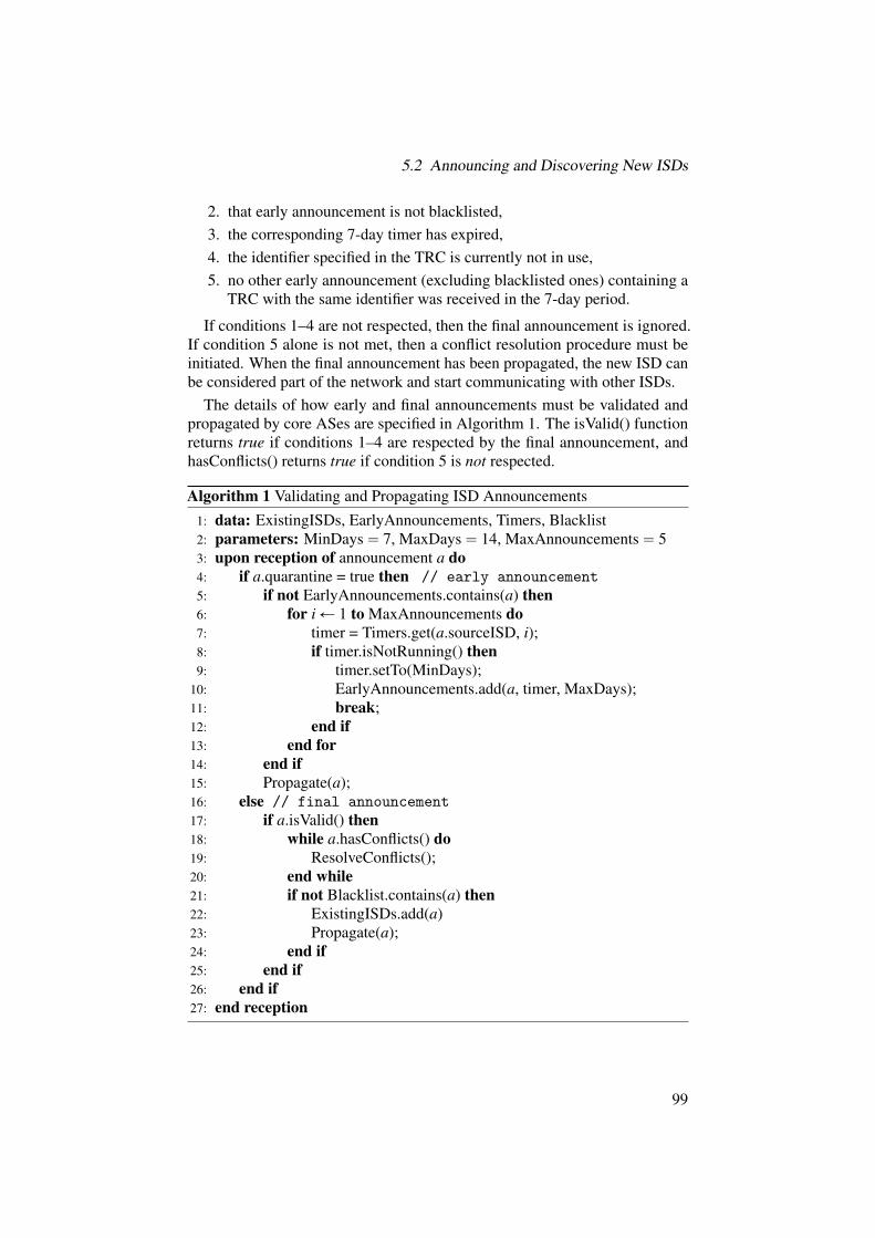
5.2 Announcing and Discovering New ISDs
2. that early announcement is not blacklisted,3. the corresponding 7-day timer has expired,4. the identifier specified in the TRC is currently not in use,5. no other early announcement (excluding blacklisted ones) containing a
TRC with the same identifier was received in the 7-day period.
If conditions 1–4 are not respected, then the final announcement is ignored.If condition 5 alone is not met, then a conflict resolution procedure must beinitiated. When the final announcement has been propagated, the new ISD canbe considered part of the network and start communicating with other ISDs.
The details of how early and final announcements must be validated andpropagated by core ASes are specified in Algorithm 1. The isValid() functionreturns true if conditions 1–4 are respected by the final announcement, andhasConflicts() returns true if condition 5 is not respected.
Algorithm 1 Validating and Propagating ISD Announcements1: data: ExistingISDs, EarlyAnnouncements, Timers, Blacklist2: parameters: MinDays“ 7, MaxDays“ 14, MaxAnnouncements“ 53: upon reception of announcement a do4: if a.quarantine = true then // early announcement
5: if not EarlyAnnouncements.contains(a) then6: for iÐ 1 to MaxAnnouncements do7: timer = Timers.get(a.sourceISD, i);8: if timer.isNotRunning() then9: timer.setTo(MinDays);
10: EarlyAnnouncements.add(a, timer, MaxDays);11: break;12: end if13: end for14: end if15: Propagate(a);16: else // final announcement
17: if a.isValid() then18: while a.hasConflicts() do19: ResolveConflicts();20: end while21: if not Blacklist.contains(a) then22: ExistingISDs.add(a)23: Propagate(a);24: end if25: end if26: end if27: end reception
99

5 ISD Coordination
5.3 Local Resolution of Conflicts
After the first two phases (i.e., early and final announcements), which take atleast one week, any remaining conflict is either intentional or the indicationthat ISDs failed to coordinate to avoid picking the same identifiers. We nowdescribe how each ISD can resolve conflicts locally and we discuss measuresthat can be taken if misbehavior is observed.
In this context, we define a conflict as follows: a number n of ISDs has cor-rectly generated announcements for a new ISD with identifier i during a givenperiod, while a number m of other ISDs has correctly announced a differentISD (i.e., with a different TRC) with the same identifier i during an overlap-ping period, and at least one of the two corresponding final announcements isreceived.1 There are several possibilities to resolve such a conflict:
• The decision can be based on the opinion of the majority (i.e., based onmaxpn,mq), but this might not be possible (i.e., if n“ m).
• Certain ISDs might be more trusted than others: by looking at whichgroup (n or m) the most trusted ISD is in, a decision can be made.
• The conflict can be manually resolved on a case-by-case basis.
In case of conflict, it is up to each ISD to make a decision based on the aboveparameters. Conflicts may also concern similar descriptions, but such situationsnecessarily require human judgment in order to be detected and resolved. Aconflict resolution procedure must result in incriminated early announcement(s)being blacklisted.
5.3.1 Conflict Resolution Policy
A policy can be specified to automatically resolve conflicts involving identicalidentifiers or descriptions. The policy must indicate whether the resolutionshould follow the majority of ISDs (if applicable), or instead use a completelist of ISDs ordered in terms of trust to make a decision. By default, new ISDsare placed at the end of the list and thus older ISDs are more trusted. However,administrators can arrange the list as they desire. Also, new ISDs are freeto re-order the list they initially obtained. Alternatively, more elaborate trustmetrics could be computed over time based on observed events.
1There might be even more conflicting groups, but we consider only two groups here for thesake of simplicity.
100

6 Name Resolution
DANIELE ASONI, YIH-CHUN HU,RAPHAEL M. REISCHUK, BRIAN TRAMMELL
While the path resolution process is necessary to turn a destination address intoa set of paths, this is not sufficient for establishing communication betweenSCION-connected endpoints: we also need a way to turn an Internet nameinto a SCION address. As name resolution and path establishment are separateprocesses, with different timescales and triggered by separate events, we designa dedicated infrastructure that is optimized for each purpose.
We begin with an analysis of what a name resolution service is good for. Atits core a naming service must provide a few basic functions, but in essenceassociate a human-understandable name with machine-understandable infor-mation. Although the Internet’s Domain Name System (DNS) has been usedand abused as a general-purpose distributed database, a useful Internet namingservice need only provide information that is necessary to establish and main-tain communication with an Internet-connected entity: addresses, namespacedelegations, service information, certificates, and auxiliary information. Thereare two entities in this ideal naming service: (a) The querier is a client thatwants to establish communication across the Internet with a named entity. Thatclient uses the naming service to retrieve the necessary information. (b) Theauthority is an entity with the right to make assertions about names within partsof the Internet namespace. Before looking at the specific interplay betweenqueriers and authorities, we start by discussing various possible resolutiontypes.
Chapter Contents
6.1 Background . . . . . . . . . . . . . . . . . . . . . . . . . . . . . 102
6.2 Name Resolution Architecture . . . . . . . . . . . . . . . . . . 104
6.3 Naming Information Model . . . . . . . . . . . . . . . . . . . . 106
6.4 The RAINS Protocol . . . . . . . . . . . . . . . . . . . . . . . . 114
6.5 The Naming Consistency Observer (NCO) . . . . . . . . . . . . 116
101

6 Name Resolution
6.1 Background
6.1.1 Resolution Types
The assertions for name resolution are essentially mappings of various forms:
• Name-to-address: given a name, return associated addresses.• Name-to-name: given a name, return equivalent names.• Name-to-service: given a name representing a service, return a name
and transport-layer ports for connecting to the service.• Name-to-certificate: given a name representing a host or service, return
an end-entity certificate representing the named entity, for authenticationof a subsequent connection attempt with the named entity.
• Name-to-delegation: given a name representing a zone within the name-space, return the public key used to verify assertions in the zone.
• Name-to-auxiliary-information: given a name representing an organi-zation-level zone within the namespace, return information about thezone and the organization behind it, analogous to the WHOIS service;as well as any restrictions on names in the zone (e.g., for confusabilityreduction).
• Address-to-name: given an address, return associated names, analo-gously to reverse DNS.
6.1.2 Properties of an Ideal Naming Service
We consider a set of properties of an ideal Internet naming service as backgroundto selecting a design for SCION name resolution. A more in-depth discussionof these properties, enumerated below, is given in an IETF draft [239]. An idealnaming service must
• provide for names which are meaningful to human users;• guarantee that different names are distinguishable by its users;• allow for authority over names to be federated;• allow a unitary authority for any given name to be transparently deter-
mined;• operate without requiring trust in the operators of the name server infras-
tructure;• provide for revocation of authority over a given name;• allow assertions about names, and the nonexistence of a mapping for a
name, to be unambiguously authenticated;• provide for consistency, and predictability in the presence of changes to
assertions about names, but
102

6.1 Background
• allow for explicit inconsistency when necessary, and global transparencyof this inconsistency;
• perform acceptably, in terms of availability, latency, and bandwidthefficiency;
• allow clients to specify tradeoffs between privacy and performance.
Since an Internet naming service is designed to provide information aboutInternet-connected hosts and services for the purposes of establishing a connec-tion, note that assertion confidentiality (usually referred to in DNS literaturein terms of zone enumeration) is a non-goal of our ideal naming service. Ifassertion confidentiality is required, an alternative service can be establishedthat provides access control to the information that should remain secret.
6.1.3 Notation
Throughout the chapter, we make use of the terms, abbreviations, and resourcerecord (RR) types defined in Table 6.1.
Term Definition
Assertion Mapping between a name and a property of that nameShard Set of assertions for some authority and contextZone Set of all shards and assertions for some authority and context
NCO Naming Consistency Observer (see Page 116)RR Resource Record (fundamental data unit, see table below)TLD Top-Level Domain (such as .ch or .com)ZK Zone Key (key to sign assertions for the respective zone)RZK Root Zone Key (special zone key used for the root zone)
(a) Terms and Abbreviations
RR Type Content
A 32-bit IPv4 addressAAAA 128-bit IPv6 addressCNAME Canonical name for a given aliasNS Responsible name serverPTR Pointer to domain name (e.g., address-to-name mapping)SRV Service locator (locates service/protocol for a given domain)TLSA Certificate or public-key association (see DANE [61])
(b) Resource Record (RR) Types
Table 6.1: Notation used in the context of name resolution.
103

6 Name Resolution
6.2 Name Resolution Architecture
We now turn our attention to designing protocols to provide this ideal namingservice, which we call RAINS (a recursive acronym for “RAINS, anotherInternet naming service”) [240].
Why not just use DNS?
We note that the DNS protocol as used in the present Internet, when de-ployed with the mandatory usage of DNS Security Extensions (DNSSEC)and one root per ISD, meets most of the properties of our ideal namesystem. Only explicit tradeoffs and explicit inconsistency are not wellsupported by DNS with DNSSEC. An initial approach to providing nameresolution for SCION could therefore be to borrow DNS.Using DNS would have the following advantages:
• It leverages an existing, widely deployed protocol, with which thereis widespread operational experience.
• It allows names for SCION-enabled nodes to be registered in thesame name resolution system as the non-SCION Internet, whichshould make incremental deployment easier.
It would also have some serious disadvantages:• DNS has no concept of explicit inconsistency or explicit tradeoff,
especially for privacy.• Even with DNSSEC, DNS has poor operational security properties,
specifically lack of query anonymity and vulnerability to abuse asan amplification attack vector.
• Since DNSSEC would be mandatory for SCION RRs, SCION-enabled nodes could only use signed top-level domains (TLDs).Many country-code TLDs remain unsigned.
• Support for extension mechanisms for DNS (EDNS0) and DNSSECvaries widely among stub and recursive resolvers, which negates theincremental deployment advantage above: lack of interoperability ofthe minimum DNS required for SCION and other DNS-supportingsoftware and hardware would lead to difficult-to-debug issues.
The final disadvantage is the most troubling, and led to our decision tobuild a new name resolution protocol for SCION.
The RAINS architecture is simple, and resembles the architecture of DNS.A RAINS server is an entity that provides transient and/or permanent storagefor assertions about names, and a lookup function that finds assertions for agiven query about a name, either by searching local storage or by delegating toanother RAINS server. RAINS servers can take on any or all of three roles:
• authority service, acting on behalf of an authority to ensure properlysigned assertions are made available to the system;
• query service, acting on behalf of a client to answer queries with relevantassertions, and to validate assertions on the client’s behalf; and/or
104

6.2 Name Resolution Architecture
• intermediary service, acting on behalf of neither but providing storageand lookup for assertions with certain properties for query and authorityservers.
RAINS servers use the RAINS protocol, described in this section, to exchangequeries and assertions. RAINS clients use a subset variant of the RAINSprotocol (called the RAINS client protocol) to interact with RAINS serversproviding query services on their behalf. RAINS protocol connections betweenservers are encrypted and authenticated. RAINS client protocol connectionsbetween clients and query servers are encrypted and optionally authenticated. Inaddition, the RAINS protocol provides object-level authentication. Section 6.4.1provides details on bootstrapping trust using RAINS.
Authority service in RAINS resembles the role of authoritative servers in thepresent DNS. Query service resembles the role of recursive resolvers. Intermedi-ate service resembles the role of caching resolvers. RAINS is therefore a drop-inreplacement for the present DNS with better support for contexts and tradeoffsand with mandatory delegation and authentication by signature chain. As withDNS, a given RAINS server may play both the authority server and queryserver roles at any given time, depending on configuration. However, futureimplementations of RAINS could use other mechanisms for matching queriesand assertions, and moving assertions to where they can be most efficientlymatched with queries.
From the basic building blocks of these three services, any number of namingservice architectures could be built. Within SCION, RAINS authority servicesare generally operated by TLDs (as isolation context root authority servers) aswell as domain name registrants or ISPs acting on their behalf. Intermediateand query services are operated by ISPs and enterprise networks, and ASesmake query servers available via service anycast (see Section 7.5 on Page 153).
RAINS also integrates into SCION’s authentication infrastructure. End-entitycertificates for named hosts can be stored in RAINS, and RAINS intermediaryand query services support assertions signed via ARPKI (see Section 4.4).
There is an inherent tension between SCION’s architectural principle ofisolation and the need for a globally consistent namespace. RAINS on SCIONresolves this by supporting isolation transparency. Queries and assertions cancross ISD boundaries, which is the basis of the Naming Consistency Observer(NCO) described in detail in Section 6.5 on Page 116.
105

6 Name Resolution
So what is new in RAINS?
Though designed as a drop-in replacement, RAINS makes several radicaldepartures from DNS as presently specified and implemented:
• Delegation from a superordinate zone to a subordinate zone isaccomplished solely with cryptography: a superordinate defines thekey(s) that are valid for signing assertions in the subordinate duringa particular time interval. Assertions about names can thereforesafely be served from any infrastructure.
• All time references in RAINS are absolute: instead of a time tolive, each assertion’s temporal validity is defined by the temporalvalidity of the signature(s) on it.
• All assertions have validity within a specific context. A contextdetermines the rules for chaining signatures to verify the validityof an assertion. Within SCION, publicly available names within anISD exist within that ISD’s native isolation context. The use of con-text explicitly separates global usage of the DNS from local usagethereof, and allows other application-specific naming constraints tobe bound to names; see Section 6.3.3.
• Explicit information about registrars and registrants is availablein the naming system at runtime, combining the functionality ofWHOIS with the naming service.
• Sets of valid characters and rules for valid names are defined on aper-zone basis, and can be verified at runtime.
• Reverse lookups are performed on a completely separate tree, sup-porting delegations of any prefix length, in accordance with classlessinter-domain routing (CIDR) and the IPv6 addressing architecture.
6.3 Naming Information Model
Here we describe the information model for messages in the RAINS protocols.For simplicity of description, we omit details on error handling and parts of theinformation model necessary for protocol implementation and operation. Thedetailed protocol specification is in our IETF draft [240].
RAINS operates on two different basic types of information: assertions(Section 6.3.1) are mappings between a name and some property of the name,which can be grouped into shards and zones (Section 6.3.2) for performanceand operational optimizations; and queries (Section 6.3.5) are expressions ofinterest about certain types of information about a name. RAINS matchesqueries to assertions that answer them.
6.3.1 Assertions
An assertion consists of the following elements:
106

6.3 Naming Information Model
• Context: name of the isolation context in which the assertion is valid.Section 6.3.3 provides more details.
• Subject: the non-qualified name about which the assertion is made. Anon-qualified name is a local, not necessarily globally unambiguousidentifier (e.g., ‘foo’), which — in combination with the zone name(e.g., ‘example.com’) — yields the fully qualified (i.e., unambiguous)name (e.g., ‘foo.example.com’). The domain name separator here is‘.’ and separates subject and zone.
• Zone: the name of the zone (e.g., ‘example.com’) in which the asser-tion is made.
• Object: the data associated with the name of the given type.• Type: the type of information about the subject contained in the assertion.
Each assertion is about a single type of data. Supported types include:
– Delegation: the authority associated with the zone identified by thename (replaces the NS DNS record type for cryptographic delega-tion; see below).
– Redirection: the authority servers for the zone identified by thename (analogous to the NS DNS record type).
– Address: one or more addresses associated with the name, givenan address family (analogous to the A and AAAA DNS record types).
– Service-info: one or more layer-4 ports associated with the name,if the name identifies a service (analogous to the SRV DNS recordtype).
– Name: one or more names associated with the name (analogous tothe CNAME and the PTR DNS record types: a PTR-analog lookup isdefined by the zone in which the lookup is made).
– Certificate: an end-entity certificate representing the named entity,for authentication of a subsequent connection attempt with thenamed entity (analogous to the TLSA DNS record type).
– Nameset: an expression of the set of names allowed within a zone;e.g., Unicode scripts or codepages in which names in the zone maybe issued. An assertion about a subject within a zone whose nameis not allowed by a valid signed nameset expression is taken to beinvalid.
– Registrar: a string identifying the registrar responsible for theappearance of a delegation within a zone, for TLDs that allowmultiple organizations to modify their zones.
– Registrant: a string containing information about the registrant ofa zone within a TLD (analogous to the WHOIS service).
– Infrastructure-key: a public key by which a RAINS server can beidentified, for object security on RAINS messages.
107

6 Name Resolution
– External-key: a public key by which assertions in a zone canbe verified outside the delegation hierarchy, e.g., via an SCP asdescribed in Section 4.4.3.
• Issued: a timestamp at which the assertion was made.• Expires: a timestamp after which the assertion is no longer valid.• Signature: a signature generated by the authority, to authenticate the
assertion. This signature covers all elements within the assertion exceptthe signatures themselves. An assertion may have multiple concurrentlyvalid signatures.
Issued and expired timestamps are always expressed in terms of UTC. Sincethe signature protects the timestamps as well, it is necessary to sign new as-sertions before old ones expire. At a single point in time, it is possible tohave multiple active valid assertions with overlapping validity times for a givenxsubject, zone, context, typey tuple. The union of the object values of all ofthese assertions is considered to be the set of valid values at that point in time.
6.3.2 Grouping Assertions: Shards and Zones
Assertion Space
Zone Zone Zone Zone
Sh
Sh
Sh
Sh
Sh
Sh
Sh
Sh
Sh
Sh
Sh
Zone Zone.com.ch
example.ch foo.ch bar.com baz.com
my.example.chsrv.foo.ch
Figure 6.1: Hierarchical zones with shards and assertions.
An authenticated assertion with a valid signature provides a proof of ex-istence of a name. Another mechanism is necessary to provide a proof of
108

6.3 Naming Information Model
nonexistence; otherwise, malicious intermediary and query services could causefalse negatives for queries by simply refusing to forward matching assertions.RAINS provides shards for this purpose.
A shard is a set of assertions for the same authority within the same context,protected by an additional signature over all assertions within the shard, whichhas the property that, given a subject and an authenticated shard, then either anassertion of a given type exists within the shard, or does not exist at all. Weachieve this property by associating the shard with an exclusive shard range ofnames appearing in a shard: a shard with the range ‘a’ to ‘b’ contains all namesin the zone and context that sort after ‘a’ and before ‘b’. This property allowsefficient verification of the nonexistence of an assertion for a given name at thequery.
Example. Consider a zone containing the names ‘aaa’, ‘aab’, ‘baa’,‘cat’, ‘dog’, ‘nap’, ‘yyz’, and ‘zzz’, as illustrated in Figure 6.2. Thiszone could be split into three shards: {aaa, aab, baa}, {cat, dog, nap},and {yyz, zzz}. To ensure that a proof of nonexistence can be given for anyname other than these eight using only one of these shards, the shard rangesoverlap: the first shard has the range null–cat, the second the range baa–yyz,and the third the range nap–null. Note that names falling between the namesin the shards can be disproved using either of the neighboring shards.
A zone is the entire set of shards and assertions for a given authority withina given context. Figure 6.1 shows two zones (‘.ch’ and ‘.com’) with twosubordinate zones each. A zone may also contain assertions about the zoneitself; this is especially useful for self-signing root zones.
6.3.3 Isolation Contexts
All assertions are held to be valid within an explicitly named assertion context.Assertion contexts are used to determine the validity of the signature by thedeclared authority. There are two broad uses for assertion contexts: isolation
aaa aab baa cat dog nap yyz zzz
null — cat baa — yyz nap — null
cat
yyz
nullnull
baa
nap
Figure 6.2: Eight assertions aligned in three shards with overlapping ranges.
109

6 Name Resolution
and local assertion. Isolation contexts allow assertions and queries about anISD other than that from which a query was made.
Native isolation context Remote isolation context
RZK
RZKZK
ZK
ZK
ZK
ZK
ZK
ISD n ISD n
ISD r
. isd--r-
Figure 6.3: Isolation Contexts. RZK is the root zone key for an ISD; ZK is thezone key for a given zone.
There are two kinds of isolation context (as illustrated in Figure 6.3):
• The native isolation context is identified by the special context name‘.’. Assertions in the native isolation context are signed by the authorityfor the subject name, with a signature chain rooted at the root authorityfor the ISD in which the assertion is made, such that the authority resideswithin that ISD (see also Figure 3.1 on Page 49).
• A remote isolation context is identified by the special context name‘isd--r-’, where r is the number of the ISD at which the context isrooted. Assertions in a remote isolation context are signed by the authorityfor the subject name, with a signature chain rooted at the root authorityfor the isolation domain identified by the context, such that the authorityresides within that ISD. Remote isolation contexts can be used to makeassertions about names as seen within other ISDs.
Assertions in an isolation context are intended to be publicly availablethroughout the Internet. Since these assertions are made available to sup-port connections to public services, resistance to zone enumeration is explicitlynot a design goal of the RAINS protocol.
Example. The following examples illustrate how contexts work. Considerthe name ‘simplon.inf.ethz.ch’ in the (default) context ‘.’. This contextis the native isolation context, so the signature chain is determined from thename itself, rooted at the TRC for the current ISD. If the assertion is issued by
110
6.3 Naming Information Model
an authority in ISD 33, the chain is as follows:
TRC33 Ñ RZK33 Ñ ZKchÑ ZKethzÑ ZKinfÑ assertion
where TRC33 denotes the TRC of ISD 33, RZK33 its root zone key, and ZK thezone key for a given delegation.
Now consider the name ‘simplon.inf.ethz.ch’ in the context ‘isd--44-’.This is the remote isolation context for ISD 44, so the signature chain is againdetermined from the name itself, but rooted at ISD 44’s TRC, as authenticatedagainst the current ISD’s TRC, as follows:
TRC33 Ñ TRC44 Ñ RZK44 Ñ ZKchÑ ZKethzÑ ZKinfÑ assertion
Note that both ISD 33 and ISD 44 use the same authority for the top-leveldomain ‘.ch’, but the verification path depends on the initial root of trust foreach ISD. Other arrangements are possible; see Section 6.5 for more.
6.3.4 Local Assertion Contexts
Isolation contexts are useful for names pertaining to services made available tothe Internet at large. The basic mechanism isolation context uses — providingan alternate signature chain to the root of a namespace — can be generalized.RAINS provides for local assertion contexts so that intentional inconsistency(often implemented in the current DNS) is transparent and can be authenticated.
A local assertion context is equivalent to a RAINS subject name designatingthe namespace within which the assertion is made. When a local assertioncontext is present on an assertion, the assertion is verified by following thedelegation chain from the root through the names in the context before followingthe delegation chain for the name. Each context is then essentially an alternateroot for a new namespace. While the same effect could be achieved simply byconcatenating names together, separating this information into explicit subjectname and context name allows the semantically meaningful part, which shouldbe presented to the user (the subject name), to be separated from the namespacedesignator, which should be user-accessible but otherwise is a matter of systemconfiguration.
Example: Split DNS. Consider an organization that places its workstationsin their own top-level namespace. A workstation named simplon might carrythe full name simplon.workstations. In the current DNS, this would beachieved through “split DNS”, i.e., answering queries about the workstationszone only on certain networks. This arrangement, however, is operationallybrittle and can lead to leakage of both queries and names beyond their intendedscope.
111

6 Name Resolution
To implement this split within RAINS, ETH Informatik could place assertionsabout its workstations in the local assertion context isg.ethz.ch, in essencecreating a local root namespace containing the workstations zone. Thesignature chain for these assertions starts with the name components in thecontext before considering the subject name:
TRC33 Ñ RZK33 Ñ ZKchÑ ZKethzÑ ZKisgÑ ZKworkstationsÑ assertion
Note that the zone key for workstations above is local to isg.ethz.ch,unrelated to the zone key for the TLD workstations, if it exists.
Additional information can be placed in a context beyond the name of thelocal root. This additional information is separated from the authority part by acontext marker, the special name cx--. Additional information in a context isused to group assertions signed by the same local root, and to provide a way toattach contextual information to queries.
Example: CDN zones. Consider a content delivery network (CDN) sepa-rating content into zones (data centers from which content is served) based ongeography. It creates a local assertion context some-cdn.com, and places in-formation about the zone in the additional context part: e.g., the local assertioncontext zrh.cx--.some-cdn.com names servers hosting content in a CDN’sZurich data center. A client could represent its desire to find content nearby bymaking queries in the zrh.cx--.some-cdn.com, fra.cx--.some-cdn.com(Frankfurt), and ams.cx--.some-cdn.com (Amsterdam) contexts. Note that,in this case, assertions in each of these content zones will be signed by the samedelegation chain .some-cdn.com.
Local assertion contexts can be combined with remote isolation contexts, aswell; here, the remote isolation is inserted into the signature chain before thename components in the context.
Example: Combining local and isolation contexts. Consider the nameexample.com within the context zrh.cx--.some-cdn.com.isd--44-, as-serted within ISD 33. Here, the signature chain for the context is rooted at ISD44’s TRC, then follows the authority part of the local isolation context beforelooking for names in the root:
TRC33 Ñ TRC44 Ñ RZK44 Ñ ZK1comÑ ZKsome´cdnÑ ZK2
comÑ assertion
Here ZK1com is the zone key for the top-level domain .com, while ZK2
com is alocal key signed by some-cdn.com.
112

6.3 Naming Information Model
6.3.5 Queries
A query is a request for a set of assertions, shards, and zones supporting aconclusion about a given subject-object mapping. It consists of the followinginformation elements:
• Context: the isolation context or local context in which responses willbe accepted. A query may also name a special any context, signifying awillingness to receive information about names in any context availableat the query server.
• Subject: the name about which the query is made; in contrast to asser-tions, the subject name here is fully qualified.
• Types: a list of the types of information about the subject that the queryrequests.
• Valid-until: a client-generated timestamp for the query after which itexpires and should not be answered.
• Token: a client-generated token for the query, which can be used in theresponse to refer to the query.
• Options: a set of options by which a client may specify tradeoffs (e.g.,reduced performance for improved privacy).
A response to a query consists of a message containing a set of assertionsbound to the token supplied by the client in the query.
When used with the RAINS client protocol, the query server performingverification may sign the entire response; this is an assertion that the queryserver has verified the signatures from the appropriate roots, leaving the clientonly to verify the query server’s signature on the whole response.
6.3.6 Registrar and Registrant Assertions
The registrant object type in the RAINS data model associates civil informationabout a name’s registrant (organization or legal personality owning an entryunder a top-level domain), and in essence integrates WHOIS into the namingservice. The presence of a registrant object on a name identifies that name as aregistrant-level domain, i.e., a name that exists due to a contractual relationshipwith a domain name registrar. This integration has two advantages: first, itprovides authentication of WHOIS information. Second, it allows operationaldecisions to be taken based on WHOIS information.
The registrar object type identifies the registrar responsible for a given name’sexistence. This allows operational decisions to be taken based on the registrar,e.g., to block a registrar that is predominantly responsible for malware domains.
113

6 Name Resolution
6.3.7 Augmented Assertion Authentication
To verify the authenticity of an assertion, a client or a query server can verifythe signature against the delegation for the zone containing the assertion. Thedelegation assertion for that zone can be verified against the delegation fromthe zone containing it, and so on all the way back to the root delegation fromthe TRC for the isolation context. This delegation chain authentication hasidentical properties to the verification of an RRSIG in DNSSEC. It also hasidentical drawbacks: each level of delegation must be trusted in order to verifya name at the leaf.
RAINS provides for signatures by external keys on assertions, i.e., those out-side the delegation hierarchy, to provide additional and/or parallel verificationof the authenticity of the assertion. This facility, together with the certificateobject type for storage of end-entity certificates, provides two-way integrationbetween RAINS and ARPKI (see Section 4.3.2 on Page 84).
6.3.8 Address-to-Name Mapping
Information about addresses in RAINS is stored in a separate tree, indexed byaddress and prefix. An address assertion is similar to a name assertion, but isindexed by subject address as opposed to subject name, and the hierarchy ofnames is built upon delegation from less-specific to more-specific prefixes. Ad-dress assertions may only contain delegation, redirection, name, and registranttype objects.
Contexts are also available for address assertions, but the native isolationcontext may only contain assertions for SCION addresses within its ISD, remoteisolation contexts may only contain assertions for SCION addresses within theremote ISD, and local contexts may only contain assertions for non-routableaddresses within the address family (e.g., RFC 1918 [210] or unique localaddresses (ULAs) [110]).
6.4 The RAINS Protocol
The details of the RAINS Protocol and the RAINS Client Protocol are specifiedin an Internet-Draft [240]), and consist of a relatively simple mapping of theinformation model in Section 6.3 to messages encoded in the Concise BinaryObject Representation (CBOR) data format [39] that can negotiate operationover any underlying transport protocol that provides reliable, confidential,and authenticated message or stream transport. Our initial implementationexperience with RAINS uses TLS over TCP.
RAINS is fundamentally a message-exchange protocol. A client sendsqueries to a configured query server (by default, this service is listening on anAS-level service anycast address), and expects responses. A query server may
114

6.4 The RAINS Protocol
send queries to other query servers and/or authority servers to express interestin information about a given name. A query server sends assertions, shards, andzones to other servers in response to queries, or based on some other interestpresumed by the query server.
Within SCION at present, query and intermediary servers are organized in ahierarchical cache. Each AS runs a service anycast query server, and queriesthat cannot be served out of that query server’s cache are delegated to the serviceanycast query server of one or more upstream ASs. Query and intermediaryservers may also recurse to the authority server for the zone, according to theirconfiguration. However, the architecture of RAINS does not necessarily implyhierarchical caching: intermediary servers may connect to each other via aweighted distributed hash tree, for example, and authority servers may pushassertions to intermediary and query servers without having been asked. Thisflexibility allows different networks to use different inter-server topologies fordifferent performance tradeoffs.
6.4.1 Query Server Discovery and Bootstrapping Trust
When a RAINS client first connects to a network, it has no information aboutthe available RAINS servers or the keys used to establish the authenticity ofassertions it will receive from them. We assume that both the TRC and theaddress of a local RAINS query server are made available to a host duringthe host’s initial configuration process. The TRC is available from the pathdissemination process (see Section 4.2.3), and refers to the naming root keyfor its isolation domain. The address of the local RAINS server is provided atendpoint configuration time.
The TRC contains the public key for the naming root for the ISD’s localisolation context. With this root, and the address of a local query server, theclient can now begin using the query server for name resolution. Whether theclient trusts the query server to verify the authenticity of names, or does theauthenticity verification itself with the naming root key taken from the TRC,is a matter of the client’s configuration: in general, clients will be configuredto trust their “home” query servers, and optionally to perform verification ofassertions received from local query servers on unknown networks.
Note that since the naming root key for an isolation domain is containedwithin that ISD’s TRC, it cannot be forged by a malicious access network.
Clients may be configured to trust specific query servers other than the localquery server. In this case, the client performs a name resolution for the nameof its trusted query server using the local query server, verifying the signaturechain itself. If the trusted query server is in a different ISD, it issues this queryin the remote isolation context for that ISD. It then connects to the trusted queryserver, verifying the TLS certificate against a pinned certificate for that server.
115
6 Name Resolution
Example. A mobile client, associated with giant-enterprise.co.uk andusually connected via AS 337 in ISD 2, roams on to AS 404 in ISD 7. Duringassociation with this network, it makes a service anycast query to find a queryserver in AS 337 in ISD 2 for the address of rains-query.giant-enter-prise.co.uk in the remote isolation context isd--9-, without delegatingassertion authentication to the anycast query server. It also queries for thecertificate of rains-query.giant-enterprise.co.uk, if this is not pinnedor otherwise available through ARPKI. Once it has the address and certificateof the trusted query server, it connects, authenticates the trusted query serverusing the certificate, and begins issuing queries, delegating authentication tothis trusted server.
6.5 The Naming Consistency Observer (NCO)
Isolation, as noted, is a fundamental principle of the SCION architecture. Atthe same time, most users of naming systems expect global consistency in nameresolution: even if a name does not resolve to a given address everywhere,the name should always point to the same service or content. “Owners” ofnames in the global namespace further expect exclusion: that their publicationof assertions of a given namespace precludes other entities from publishingassertions about the same namespace. Global consistency and exclusion areimpossible without a single global root of trust for naming, which runs counterto the principle of isolation.
To reconcile this conflict, RAINS provides naming isolation transparency.Entities connected to one ISD can observe name assertions in any remote ISD.An additional facility built on top of RAINS, the naming consistency observer(NCO), provides continuous monitoring of inconsistencies among assertionsignature chains in different ISDs, which ensures that any violation of globalconsistency and/or exclusion is publicly observable. The NCO operates on theprinciple of deterrence: since illegitimate behavior is made public, it should berare.
Recall from Section 3.4 on Page 48 that, in the normal case, different ISDshave different root zones signed with different keys (derived from the ISD’sTRC), but each root zone delegates to the same key for each TLD as shownin Figure 3.1 on Page 49. However, there are certain cases where an isolationdomain might want to “edit” a TLD, by providing delegation to a different setof registrant-level domains (RLDs) (the level below the TLD, corresponding toorganizations or other “owners” of names that have paid a registrar to place anentry in a name registry) than that provided by the primary operator of the TLD,or by failing to sign a delegation to a TLD. It does this by operating a shadowauthority for that TLD, which may implement one of the following policies foreach TLD or RLD:
116

6.5 The Naming Consistency Observer (NCO)
• New TLD adoption and TLD quarantine: New TLDs created withina set of ISDs may be held over for some period of time while the TLDoperator’s practices are evaluated by the ISD.
• RLD quarantine: Newly created RLDs may only be available within anISD’s native isolation context after some period of time has passed, e.g.,to ensure that they are not primarily used for abusive purposes (such asphishing landing pages or malware command and control).
• RLD blacklist: RLDs that are exclusively or primarily used for abusecan have their delegations from the TLD removed by an ISD after havingthis abuse demonstrated according to some policy followed by each ISD.
In any case, edits to TLDs are limited to either delegating to the RLD thatthe TLD operator delegates to, temporarily failing to delegate to an RLD (in thecase of quarantine), or permanently failing to delegate to an RLD (in the caseof blacklisting). Delegation to a different RLD key than that delegated to bythe TLD operator — completely inconsistent naming — is treated as an errorcondition.
The purpose of the NCO is to make all such inconsistencies in native isolationcontexts in different ISDs globally transparent, to detect and allow ISDs tocorrect unintentional inconsistencies, and to detect and repair error conditions.The NCO consists of a distributed service, run on servers in each ISD. For eachISD, it provides an authoritative view of that ISD’s naming consistency policy(whether it performs RLD quarantine and what its timeouts are, its enumer-ated set of TLD delegations, and its enumerated RLD blacklist), and acceptsRAINS delegation assertions sampled from various points in the infrastructureto compare against those policies. Sampled delegation assertions are sharedwith NCO servers in other ISDs, to be compared with those ISDs’ views of thesame delegations in their own native isolation context.
Sources of sampled delegation assertions include:• Query servers can be configured to send a sampled set of delegation
assertions used in verifying assertions on behalf of clients to the NCOserver for their ISD.
• TLD authority servers can bulk-transfer delegation assertions to the NCOservers for each ISD on any change.
• RLD authority servers can send their public keys (in the form of a self-signed delegation assertion inside a local context) to the NCO servers forthe ISD(s) providing their connectivity on any change.
• Specially deployed NCO clients can query for RLD assertions and reportthe resulting delegation assertions to designated NCO servers. The set ofquery targets can be derived from other sources of data available to theNCO.
Since inconsistencies uncovered by the NCO generally require human inter-vention and/or policy decisions to correct, the output of this process is made
117

6 Name Resolution
available via a RESTful API and a web front end, also operated by each ISD.Remedies for correction of intentional errors and undeclared inconsistency area matter for inter-ISD coordination (see Section 3.5 on Page 51).
Since the NCO operates primarily through deterrence, it is not necessarythat sampled delegation assertions cover every inconsistency with policy withinsome bounded time. It is enough that ISD operators know that edits they maketo TLD delegations are visible, and that someone is watching. The samplingrate for sampled assertions at a query server should be selected to balance thetradeoff between the likelihood that maliciously transient inconsistency goesundetected with the overhead of sending assertions to the NCO.
118

7 Control Plane
SAMUEL HITZ, ADRIAN PERRIG,STEPHEN SHIRLEY, PAWEL SZALACHOWSKI
In this chapter, we discuss SCION’s control plane, whose main purpose is tocreate and manage path segments, which can be combined into forwardingpaths to transmit packets in the data plane.
We first describe how path exploration is realized through beaconing, then wediscuss the management of path segments (registration, lookup, and revocation),failure resilience, and the use of anycast to enable services to communicate witheach other. We also show how SCION allows AS-level hierarchical anycastservices to be built, and finally we describe the SCION Control MessageProtocol (SCMP).
Chapter Contents
7.1 Path Exploration and Registration . . . . . . . . . . . . . . . . 119
7.2 Path Lookup . . . . . . . . . . . . . . . . . . . . . . . . . . . . 132
7.3 Secure Path Revocation . . . . . . . . . . . . . . . . . . . . . . 138
7.4 Failure Resilience and Service Discovery . . . . . . . . . . . . . 146
7.5 AS-Level Anycast Service . . . . . . . . . . . . . . . . . . . . . 153
7.6 SCION Control Message Protocol (SCMP) . . . . . . . . . . . 155
7.7 Time Synchronization . . . . . . . . . . . . . . . . . . . . . . . 159
7.1 Path Exploration and Registration
In this section, we go into the details of generating and propagating path-segment construction beacons in SCION. We describe the control-plane formatof a path, how beacon construction is initiated and propagated, and how ASesgenerate diverse paths.
119

7 Control Plane
7.1.1 Path-Segment Construction Beacons (PCBs)
SCION introduces path-segment construction beacons (PCBs) to enable pathexploration and registration. PCBs are used for intra-ISD and inter-ISD (core)path exploration, and contain topology and authentication information. Theycan include additional metadata that helps with path management and selection.Broadly speaking, a PCB represents a single path segment that can be used toconstruct end-to-end forwarding paths. Formally, a PCB is defined as
PCB“ x INF } ASE0 } ASE1 } . . . } ASEn y (7.1)
where INF is an info field, and each ASEi represents an AS entry that containsall information about a particular AS on the path segment represented by thePCB.
In the following, we describe all elements included in a PCB. The actual wireformat of a PCB is presented in Figure 15.13 on Page 357.
Info Field (INF)
The first component of every PCB is the info field (INF), which provides basicinformation about the PCB. Specifically, the info field contains the followingelements:
INF“ x FlagsINF } TS } ISD } SegLen y (7.2)
where FlagsINF is used in the forwarding path to describe the type and thedirection of the constructed end-to-end path, TS is a timestamp that denoteswhen the PCB’s propagation started, ISD is an identifier of the isolation domainwithin which the beaconing was initiated, and SegLen denotes the length of theforwarding path’s segment (this field is set to 0 during the beaconing).
More information about the format of the info field is provided in Sec-tion 15.1.3 on Page 347.
AS Entry (ASE)
The complete information about an AS in a PCB is called an AS entry and isdefined as follows:
ASE “ xMeta }HE } PE0 } PE1 } . . . } PEm } RevToken } Ext } Σ y (7.3)
The Meta field contains metadata describing the AS that generated a given entry.It contains ISD and AS identifiers (which together globally identify the AS),followed by the TRCVersion and CertVersion fields, which specify the TRCand certificate version number that the AS uses. It also signals what size ofinterface identifiers is used by the AS and the size of the maximum transmissionunit (MTU) within the AS’s network. Then, an AS entry consists of a single
120

7.1 Path Exploration and Registration
hop entry HE, a list of optional peer entries PEi, a revocation token RevToken,which enables revocation of any interface of the entry in an authenticatedfashion (as we describe in Section 7.3), and optional beacon extensions Ext.
Each AS entry is signed with a private key that corresponds to the public keycertified by the AS’s certificate with version CertVersion. The correspondingsignature Σ includes the PCB’s metadata INF, the current AS entry ASEi (with-out signature), and all previous AS entries in the PCB. Formally, the signatureΣi of AS entry ASEi in a PCB is defined as follows:
Σi “ SignKpINF } ASE0 } ASE1 } . . . } ASEi-1 } ASE1iq (7.4)
where ASE1i is the AS entry ASEi without its signature, and K is the AS’s privatekey (the corresponding certificate can be identified through the CertVersionfield). Beacon extensions can contain unprotected fields, which are not includedduring the signature creation.
More information about the AS entry is presented in Section 15.3.1 onPage 357.
Hop Entry (HE)
A hop entry has the following format:
HE“ x InISDAS } EgISDAS } InIF } EgIF } InMTU }HFH y (7.5)
where InISDAS is a concatenation of the ISD and AS identifiers of an ingress(i.e., the previous) AS, while EgISDAS identifies an egress (i.e., the next) AS.If a hop entry belongs to the first/last AS entry, then the ingress/egress ISD andAS identifiers are set to 0. The InIF and EgIF fields denote an identifier of theingress and egress AS’s interface, respectively, and the InMTU field specifiesthe MTU of the ingress interface. These fields help an end host to identifypaths at the interface-level granularity and their MTUs. The last field HFH is ahop field that includes the authenticated information of the ingress and egressinterfaces.
To allow end hosts to explicitly select paths to reach other end hosts, the hopfields are propagated with the corresponding topology information to the endhosts (see below).
Details of hop entries are discussed in Section 15.3.2 on Page 358.
Peer Entry (PE)
Through the peer entry, an AS announces that it has a peering connection toanother AS. Peer entries have the same format as hop entries, however, the firstPeerISDAS pair identifies a peer AS (not an ingress AS):
PE “ x PeerISDAS } EgISDAS } PeerIF } EgIF } PeerMTU }HFP y (7.6)
121

7 Control Plane
The PeerIF and EgIF fields describe interface identifiers of the peer and egressASes, and the PeerMTU field is an MTU value of the peer interface. Contrary tothe hop field HFH in a hop entry, the hop field HFP in a peer entry authenticatesthe permission to use the peering between the peer and an egress interface.
More details on peer entries can be found in Section 15.3.2 on Page 358.
Hop Field (HF)
Finally, we introduce the hop field (HF), which is contained in hop entries andpeer entries. A hop field is used directly in the data plane for packet forwarding:it specifies the incoming and outgoing interfaces of the ASes on the forwardingpath. To prevent forgery, this information is authenticated.
A hop field encodes one of three cases for connecting adjacent ASes:1. customer Ñ provider: the egress interface connects the provider (who
created the hop field) with its customer,2. core ASÑ core AS: the hop field encodes information for the forwarding
performed between core ASes,3. peering links: the peer interface connects the AS (that created the hop
field) with its peer AS over a peering link.A hop field can be part of a hop entry or of a peer entry. We first discuss the
case in which the hop field is contained in a hop entry. The hop field is thenrepresented as follows:
HFH “ x FlagsHF } ExpTime } InIF } EgIF } σH y (7.7)
where the FlagsHF field describes the purpose of the hop field (thanks to thisfield, it is possible to encode forwarding cases other than the ones listed above,see Section 8.2), ExpTime defines for how long the hop field is valid (anexpiration time of a hop field is an offset relative to the PCB’s info fieldtimestamp TS), InIF identifies the ingress interface (according to the directionof the beaconing), EgIF identifies the egress interface, and σH is a messageauthentication code (MAC) computed as
σH “MACKpTS } Flags1HF } ExpTime } InIF } EgIF } HF1q (7.8)
where Flags1HF is the FlagsHF field with only immutable flags set (see Sec-tion 8.1 on Page 162), HF1 is the hop field of the previous AS (according tothe direction of the beaconing) without its flag field included, and K is a localsymmetric key, known only to the AS that creates the hop field.
In case the hop field is contained in a peer entry, the structure is slightlydifferent:
HFP “ x FlagsHF } ExpTime } PeerIF } EgIF } σP y (7.9)
122

7.1 Path Exploration and Registration
The differences to the previous case are (a) replacing the InIF field with thePeerIF field identifying the ingress interface of the peering link, and (b) theauthentication code σP, which is now computed as
σP “MACKpTS } Flags1HF } ExpTime } PeerIF } EgIF } HF1Hq (7.10)
where Flags1HF is the FlagsHF field with only immutable flags set (see Sec-tion 8.1 on Page 162), and HF1H is the hop field from Equation 7.7 without itsflag field included. In other words, the verification of a peering link requires alocally generated provider-customer hop field.
More details on the format of hop fields is provided in Section 15.1.3 onPage 348.
7.1.2 Intra-ISD Beaconing and Path-Segment Registration
Paths in SCION are made available through the following two procedures:1. beaconing (i.e., path exploration), which builds and propagates PCBs
(from which path segments are created); and2. registration of path segments to make them available to other entities.The PCB generation process is initiated by each core AS, once per propa-
gation period. The propagation of PCBs immediately follows PCB generation.When a PCB is received by an AS, its beacon server registers the containedpath segment at the path servers, extends the PCB, and propagates the PCBfurther downstream. These steps are presented in Figure 7.1 on the next page.The propagation period is a parameter specified by each AS; its default value is5 seconds in our current implementation.
Initiating Beaconing
Intra-ISD beacons are disseminated top-down (i.e., from core ASes to leafASes). Each core AS, through its beacon server, initiates the path explorationprocess by creating an initial PCB and propagating it downstream to each of itscustomer ASes. A core beacon server propagates a PCB to each customer. Theprocess is repeated every propagation period. The beacon server inserts (amongother information) the initial AS entry ASE0 in the PCB. In this case, ASE0’shop entry HE includes an initial hop field with ingress interface identifier set to‚ (indicating an empty value)
HF0 “ x FlagsHF } ExpTime } ‚ } EgIF } σ0 y (7.11)
since HF0 represents the first hop and as such has no ingress interface (seeEquation 7.7). We also use the empty value null for the previous hop-fieldentry:
σ0 “MACKpTS } Flags1HF } ExpTime } ‚ } EgIF } nullq
123

7 Control Plane
Upstream
Beacon Server
Local
Beacon Server
Local
Path Server
Remote (Core)
Path Server
Downstream
Beacon Server
beacons
TRC/Cert Req
TRC/Cert verify/cache
Periodically select k up-paths
k selected up-paths
TRC/Cert Req
TRC/Cert verify/cache
Periodically select k down-paths
k selected down-paths
TRC/Cert Req
TRC/Cert verify/cache
Periodically select ℓ beacons
ℓ selected beacons
TRC/Cert Req
TRC/Cert verify/cache
Figure 7.1: Message sequence chart illustrating the beaconing and path-segmentregistration process.
since no previous hop field exists (see Equation 7.10).Using the combination of the info field’s absolute timestamp TS and the hop
field’s relative duration ExpTime, each AS computes the absolute expirationtime of the hop field. When the expiration time is exceeded, the hop field isconsidered expired and an AS’s border router (the one assigned to EgIF) willdrop packets with expired hop fields. The initial hop field denotes the beginningof a path and authenticates a forwarding decision for every packet that
• enters the AS through the interface EgIF and terminates inside the AS;• originates from the AS and exits through the interface EgIF; or• at this AS, switches to another path (which has to begin at this AS as
well).
124

7.1 Path Exploration and Registration
Finally, the beacon server signs the beacon and sends it to a border router(which corresponds to the EgIF identifier as specified in the hop field). Thebeacon server knows the mapping between interface identifiers and borderrouter addresses from the AS discovery service (see Section 7.4.6).
PCBs are disseminated within packets addressed to the beacon service.1
Initial PCB packets have to be processed differently from data packets as theydo not contain full forwarding paths. To enable communication between twobeacon servers in neighboring ASes a special one-hop path is created (seeSection 15.1.4 on Page 351). The PCB is sent to the egress router, which thenforwards it to the neighboring border router of the downstream AS.
Beaconing by Non-core ASes
The ingress border router of the downstream AS receives the PCB packet,detects that the destination is a SCION service address, and sends it to oneof its beacon servers.2 The beacon server verifies the structure and the sig-nature of the PCB. The PCB contains the version numbers of used TRC(s)and certificate(s). It enables the beacon server to check whether it has therelevant TRC(s)/certificate(s); if not, it can be requested from the upstreambeacon server, and then forwarded to a local certificate server. After the PCBverification is successful, the beacon server adds the PCB to its local database.The process is depicted in Figure 7.1.
Every propagation period (the time interval is configured by the AS), thebeacon server selects the ` best PCBs from its database and continues pathexploration by sending the PCBs to its downstream ASes (in our current imple-mentation `“ 5). PCB selection criteria are set according to local AS policies.The selection process is presented in detail below in Section 7.1.4.
For every selected PCB and for every interface that connects to a downstreamAS, the AS creates a new PCB by adding a new AS entry. The AS entryincludes an HF that authenticates the permission to send traffic between ingressand egress interfaces (see Equation 7.7), and HFs that authenticate forwardingbetween the peer interfaces and the egress interface (see Equation 7.9). (TheAS can set an HF as forward-only, which denotes that the HF can be used onlyfor transit, i.e., cannot be used to deliver a packet to the AS’s end hosts.) Theset of ` created PCBs are sent to the border router corresponding to the egressinterface and forwarded to the downstream AS (see Figure 7.1).
1SCION introduces service addresses to address a service instance (with unknown actualaddress) in a remote AS. See details in Section 7.4.7 and Section 15.2.
2If there are several beacon servers in the AS, the PCB is sent to only one. The details arepresented in Section 7.4.7 on Page 152.
125

7 Control Plane
Path-Segment Registration
Intra-ISD beaconing provides ASes with paths to communicate with theircore ASes. To make paths accessible to their own and remote end hosts,the paths need to be published. Every time interval (called a registrationperiod, determined by the AS, and set by default to 5 seconds in our currentimplementation), a beacon server selects two sets of path segments:
1. up-segments: to allow a local end host to contact core ASes, and2. down-segments: to allow remote end hosts to fetch paths from core ASes
towards a target AS.An AS can set different selection policies for these two sets (see Section 7.1.4).
More specifically, in every registration period, beacon servers execute thefollowing:
1. From the cached PCBs, select k PCBs that will be used as up-segments,and another k PCBs that will be registered as down-segments. As adefault value, we use k “ 5.
2. Remove all unprotected (i.e., non-signed) fields from the beacon exten-sions.
3. To every selected PCB, add a new AS entry with a final hop field of thefollowing format:
HFH “ x FlagsHF } ExpTime } InIF } ‚ } σ y (7.12)
Only the ingress interface identifier is specified (i.e., EgIF is set to ‚)since the path ends at the AS.
4. If the AS has peering links, for each peering link add to the AS entry ahop field of the following format:
HFP “ x FlagsHF } ExpTime } PeerIF } ‚ } σ y (7.13)
Only the peer interface identifier is specified (i.e., EgIF is set to ‚) sincethe path ends at the AS.
5. Sign every selected beacon and append the computed signature. Suchmodified PCBs are then called path segments.
6. Register the resulting up-segments with a local AS’s path server, and thedown-segments with a core path server from a local ISD.
Unprotected fields of beacon extensions are removed for efficiency reasons(to reduce the size of the path segments). Path-segment registrations are sent aspackets addressed to the path service (see Section 15.2 on Page 355). The formatof the path registration message is presented in Section 15.4. Up-segments areregistered at a local AS’s path server, while down-segments are registered at acore path server from a local ISD. We note that the down-segment registrationprocess is more complex since the core path server, which received a down-segment, has to replicate the segment among all core ASes within its ISD. Due
126

7.1 Path Exploration and Registration
to such replication, all core ASes can serve down-segments for all non-coreASes from the same ISD.
7.1.3 Inter-ISD Beaconing and Path-Segment Registration
The inter-ISD (or core) beaconing process is conducted only by core ASes inorder to create core-segments, which enable two core ASes to communicate.The structure of inter-ISD beacons is identical to the structure of intra-ISD PCBs(see Section 7.1.1). However, the process of core beaconing differs slightly fromthe intra-ISD process. The main difference is that every core AS periodicallyinitiates core beaconing by sending beacons to all its neighbor core ASes (notto its customers, as in the intra-ISD case). In inter-ISD beaconing the corePCB from each core AS is flooded to all other core ASes (forming a completeflooding tree), whereas in intra-ISD beaconing only PCBs originating fromcore ASes are disseminated along provider-customer links (forming a morelimited distribution tree compared to core PCBs). For inter-ISD beaconing, ourimplementation sets the same default parameters as in the intra-ISD case (i.e.,propagation and dissemination periods are 5 seconds long, and `“ k “ 5).
Initiating Core Beaconing
Inter-ISD PCBs (also referred to as core PCBs) are disseminated from everycore AS to all other core ASes. Each core AS, through its beacon servers:(a) initiates the path exploration process by creating an initial core PCB andpropagates it to all neighbor core ASes, and (b) propagates PCBs originatedby other core ASes. The process is repeated in every propagation period (theperiod can be adjusted by every core AS, as before).
Among other information, the beacon server adds the following informationto a core PCB: the current timestamp, the version of the used TRC and certificate,and the first AS entry, which contains only a single hop entry (peer entries arenot added). This hop entry contains the ISD and AS identifiers of the current andthe next ASes, and carries the hop field in the format presented in Equation 7.11.Similarly to the intra-ISD exploration process, the hop field denotes a beginning(or an end) of a path and authenticates a forwarding decision for every packetthat
• comes from the interface EgIF and terminates inside the AS, or• originates from the AS and exits through the interface EgIF, or• at this AS, switches to another path (which has to begin at this AS as
well).Finally, the beacon server signs the PCB and sends it to the border router,
which processes it similarly to the intra-ISD case (i.e., the PCB is finally passedto a neighbor beacon server). Note that the neighboring AS can be in the same
127

7 Control Plane
or in a different ISD, and consequently, the ISD identifier included in the infofield describes only the ISD of the PCB originator.
Beaconing by Core ASes
After an ingress border router passes a core PCB to a beacon server, the beaconserver verifies the PCB, and similarly to the intra-ISD case, the beacon serversexchange TRC(s) and/or certificate(s) (if the TRC and/or certificate version haschanged). As beaconing in the cores is based on flooding, it is necessary toavoid loops during path creation. A core beacon server avoids loops at both theAS and ISD levels as follows:
• it discards PCBs that include an AS entry created by itself,• it discards PCBs that re-enter an already visited ISD.
Finally, the beacon server adds the PCB to its local database, as beacon serverscollect PCBs to all seen ASes.
In every propagation period, the beacon server selects the ` best PCBs forevery core AS from its database. PCBs are selected per unique core AS, as thegoal of core beaconing is to have path(s) that connect every pair of core ASes.The selection criteria are set according to local AS policies, which are presentedin detail in the next section. For every such selected PCB and for every interfacethat connects to a core AS, the beacon server creates a new PCB by adding anew AS entry. The AS entry includes only a single hop field that authenticatesforwarding between ingress and egress interfaces (see Equation 7.7). The setof such created PCBs is sent to the border router corresponding to the egressinterface and finally to the neighbor core AS.
Core Path-Segment Registration
The core beaconing process creates core AS path(s) to other core ASes. Thesepaths have to be registered at local ASes’ path servers so that local and remoteend hosts can obtain and use them. In contrast to the intra-ISD registrationprocedure, there is no need to register core-segments with other ASes (as eachcore AS will receive PCBs originated by every other core AS).
In every registration period, a core beacon server1. selects the k best PCBs towards each core AS observed so far, from the
cached core PCBs;2. removes all unprotected fields from the beacon extensions;3. adds a new AS entry to every selected PCB with a hop field of the
following format:
HF “ x FlagsHF } ExpTime } InIF } ‚ } σ y (7.14)
128

7.1 Path Exploration and Registration
(only the ingress interface identifier is specified (i.e., EgIF is set to ‚)since the core path ends here);
4. signs every selected PCB and appends the computed signature. Suchmodified PCBs are called core-segments;
5. registers the resultant core-segments with a local AS’s path server.
7.1.4 Beacon and Path-Segment Selection
As an AS receives a series of intra-ISD or core PCBs, it must select the PCBsit will use to continue beaconing and to register path segments at path servers.A non-core AS must select (a) a subset of PCBs to propagate downstream, (b)up-segments to register at a local AS path server, (c) down-segments to registerat a core path server. A core AS must select (a) a subset of PCBs to propagateto neighbor core ASes, and (b) core-segments to register at a local AS pathserver. Core ASes do not register core-segments at remote AS path servers, asdue to core beaconing (see Section 7.1.3) all core ASes find a set of paths to allother core ASes.
The selection process is based on path properties (e.g., length, disjointnessacross different paths) as well as PCB properties (e.g., age, last transmissiontime). In this section, we describe the process by which an AS evaluates andselects PCBs. The beacon server of an AS maintains a data structure of receivedPCBs under consideration for downstream propagation and registration at pathservers. Each AS can specify how PCBs are evaluated or eliminated fromconsideration through a local policy.
Although the policy-based selection process presented here enables a varietyof path choices, ASes may need to express more sophisticated routing policies.In Section 10.9 we discuss how SCION can support routing policies fittingtoday’s Internet business models.
Beacon Store
Each time a beacon server receives a PCB, it chooses whether or not the PCBwill be stored as a candidate (i.e., under consideration for propagation andregistration). To manage the set of candidate PCBs, the beacon server maintainsa database of PCBs called the beacon store. The beacon store has a fixedcapacity n and supports the following operations:
• add: add a new PCB to the beacon store if it complies with the selectionpolicy. If the beacon store already contains n PCBs, remove the leastdesirable PCB.
• remove: remove a PCB from the beacon store.• select: select a number (specified as a parameter) of PCBs.
129

7 Control Plane
ISD
ISD Core
ISD
ISD Core
ISD
ISD Core
(a) Path Length (b) Peering Links (c) Disjointness
D
F
A
B
H
J
C
E
G
I
DE
A
B
HI
GF
C
JK
L
D
A
B
G
F
E
C
Figure 7.2: Example graphs to illustrate beacon and path-segment selectionbased on different path properties.
Through the above operations, the beacon store is thus implicitly responsiblefor applying the AS’s selection policy (described below). In addition to storingPCBs, the beacon store also stores metadata for each PCB, such as when thePCB arrived at the beacon store and when it was most recently forwarded to adownstream AS.
Selection Properties
We propose a set of metrics that represent a range of desirable properties in apath or PCB:
• Path length: The first property we consider is path length. In this case,path length is defined as the number of hops from the originator AS tothe local AS. This can give an indication of the path’s latency (althoughthere are many other factors affecting latency).In Figure 7.2a, we can see that AS G will receive the paths AG, BDG,and CEFG, which have lengths of 1, 2, and 3 hops, respectively. Basedpurely on length, G would prefer AG first, followed by BDG and CEFG.
• Peering ASes: We also consider peering ASes, defined as the number ofpeering ASes from all non-core ASes on the PCB. The number of peeringASes is important because a greater number of peering ASes on a PCBincreases the likelihood of finding a shortcut using that segment.In Figure 7.2b, AS L receives seven distinct PCBs, all of which start at Band are three hops long. However, the number of peering ASes in thesepaths range from none (in BGKL) to four (in BEIL).
130
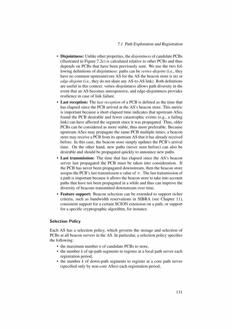
7.1 Path Exploration and Registration
• Disjointness: Unlike other properties, the disjointness of candidate PCBs(illustrated in Figure 7.2c) is calculated relative to other PCBs and thusdepends on PCBs that have been previously sent. We use the two fol-lowing definitions of disjointness: paths can be vertex-disjoint (i.e., theyhave no common upstream/core AS for the AS the beacon store is in) oredge-disjoint (i.e., they do not share any AS-to-AS link). Both definitionsare useful in this context: vertex-disjointness allows path diversity in theevent that an AS becomes unresponsive, and edge-disjointness providesresilience in case of link failure.
• Last reception: The last reception of a PCB is defined as the time thathas elapsed since the PCB arrived at the AS’s beacon store. This metricis important because a short elapsed time indicates that upstream ASesfound the PCB desirable and fewer catastrophic events (e.g., a failinglink) can have affected the segment since it was propagated. Thus, olderPCBs can be considered as more stable, thus more preferable. Becauseupstream ASes may propagate the same PCB multiple times, a beaconstore may receive a PCB from its upstream AS that it has already receivedbefore. In this case, the beacon store simply updates the PCB’s arrivaltime. On the other hand, new paths (never seen before) can also bedesirable and should be propagated quickly to announce new paths.
• Last transmission: The time that has elapsed since the AS’s beaconserver last propagated the PCB must be taken into consideration. Ifthe PCB has never been propagated downstream, then the beacon storeassigns the PCB’s last transmission a value of8. The last transmission ofa path is important because it allows the beacon store to take into accountpaths that have not been propagated in a while and thus can improve thediversity of beacons transmitted downstream over time.
• Feature support: Beacon selection can be extended to support richercriteria, such as bandwidth reservations in SIBRA (see Chapter 11),consistent support for a certain SCION extension on a path, or supportfor a specific cryptographic algorithm, for instance.
Selection Policy
Each AS has a selection policy, which governs the storage and selection ofPCBs at all beacon servers in the AS. In particular, a selection policy specifiesthe following:
• the maximum number n of candidate PCBs to store,• the number k of up-path segments to register at a local path server each
registration period,• the number k of down-path segments to register at a core path server
(specified only by non-core ASes) each registration period,
131
7 Control Plane
• the number ` of PCBs to propagate (downstream or to core ASes) eachpropagation period,
• a list of blacklisted ASes that must not appear in any PCB sent down-stream or registered,
• a set of minimum and maximum allowable values for properties, and• a set of weights representing the relative importance of the previously
mentioned properties in evaluating and selecting PCBs.Beacon policies are local to the AS and it might be in the commercial interestof the AS to keep them private.
Filtering Beacons
When the beacon server receives a PCB, the beacon store first checks thepath against a series of filters defined by a selection policy. These filterscheck whether any ASes in the segment are blacklisted, and whether the pathproperties fall between the minimum and maximum allowable values specifiedin the selection policy. The latter type of filtering allows paths with certainundesirable properties, such as being longer than a threshold number of hops,to be ignored as a candidate PCB.
Selecting PCBs and Path Segments
The beacon store computes the overall quality of a PCB as a weighted sum,using the weights specified in the selection policy. Once it has computedthe quality of all candidate PCBs, the beacon server selects the top-rankedPCBs. Time-based path properties, such as age and transmission time, mustbe recomputed when the beacon store selects PCBs. Disjointness is based onprevious operations and must also be computed when PCBs are selected (i.e.,every propagation or registration period).
7.2 Path Lookup
Path lookup is a fundamental building block of SCION’s path managementarchitecture. It enables end hosts to obtain path segments found during pathexploration. End hosts can then construct end-to-end paths from a set of possiblepath segments returned by the path lookup process.
7.2.1 Requirements and Design Goals
We considered the following requirements and design goals that led to thedesign of SCION’s path lookup infrastructure.
132

7.2 Path Lookup
Low Latency
In the absence of a cached path at end hosts, a path lookup needs to be performedbefore a packet can be sent to a new destination. It is therefore performance-critical that a path lookup can be performed as fast as possible.
Effective caching is critical for the performance and scalability of path lookup,as it can decrease the latency of path lookups. To minimize the number of pathlookups, path servers and end hosts should also cache paths for a short periodof time to exploit the temporal locality of network destinations.
Scalability
Path lookup not only has to scale with respect to the number of users, but alsoto an increasing number of paths available in an ever-expanding network suchas the Internet.
Caching can help with scalability with respect to an increasing number ofrequests. To ensure scalability with respect to the number of paths, the pathlookup infrastructure can only contain a subset of all available Internet paths. Itis also crucial that the amount of state needed to store and serve paths be as lowas possible.
Availability
If the path lookup infrastructure experiences outages, end hosts might be unableto look up new paths, thus crippling the entire communication infrastructure.The path lookup infrastructure should therefore be distributed and replicatedto guarantee high availability even when single parts of the system fail or areunder attack, e.g., during a DDoS attack.
Cache Consistency
We argued that the use of caching is critical for path lookup with respectto performance, scalability, and availability. However, caching introducesconsistency problems. If a cache delivers stale paths, then the performance ofthe path lookup and all upper layers are negatively impacted; the severity ofthis problem increases the more distributed the path lookup infrastructure is.
Security
In terms of security, the following properties are critical for the path lookupinfrastructure to function properly in the presence of an attacker.
First, end hosts should be able to verify the authenticity of paths they receivefrom path lookup, i.e., that path segments were registered by the true destination
133
7 Control Plane
and have not been altered since registration. This prevents an attacker fromtricking an end host into using a fake path (similar to cache-poisoning attacksin DNS [177]).
Second, a path should only be removed from the path lookup infrastructurewith proper authorization (apart from expiration). Otherwise, an attacker coulddisconnect an AS from the Internet by repeatedly revoking all paths to that AS.
Third, not all paths should be public. While path servers facilitate the retrievalof paths, it should be possible to distribute paths out of band directly to potentialsenders. SCION supports non-registered (or hidden) paths, which can serve asan important ingredient in DDoS attack defense.
7.2.2 Path Lookup Process
End-to-end communication is enabled by a combination of up to three pathsegments that form an end-to-end path. The goal of the path lookup process isto provide a source end host with diverse path segments and at least one set ofconnecting path segments, i.e., path segments that can be combined towardsthe destination by simply joining their corresponding endpoints. Depending onthe location of source and destination end hosts, the path lookup process differsslightly.
Source and Destination from Non-core ASes
A source end host initiates a path lookup by issuing a path request, containingthe destination ISD and AS identifiers, to a local path server. The local pathserver then forwards the request to one of the core path servers, using anup-segment that was previously registered by the beacon server (if the lookupsucceeds, the local path server will append this up-segment to the correspondingresponse). At this point there are two possible scenarios:
1. The destination is in the same ISD as the source. In this case the corepath server knows the down-segments to reach the destination and returnsup to k segments to the local path server.
2. The destination is in a different ISD than the source. In this case, thecore path server requests the down-segments from a core path server inthe destination ISD (using a core-segment), before returning them to thelocal path server.
In both cases, the first core path server (the one requested by the local pathserver) returns up to k core-segments, which connect its AS and the ASes thatoriginated the down-segments. If a down-segment originates in the core pathserver’s AS, then the core-segment is not required as the up- and down-segmentsdirectly connect. However, it is guaranteed that if path lookup succeeds (i.e.,
134

7.2 Path Lookup
an end host receives a set of path segments), then there is at least one set ofconnecting path segments; thus the end host is able to build a forwarding path.
The local path server then returns up to k up- and k down-segments (andoptionally up to k core-segments — if required) to the source. The up-segmentused for querying the core path server is included in the response. If the sourcewishes to communicate through the core and the received core-segments areunsatisfactory, then additional core-segments may be fetched (by asking anothercore AS). Depending on the received segments, there are different ways a sourcecan combine them to create an end-to-end path. We describe these options indetail in Section 8.2.
End hosts and path servers accept path segments only when they are verified.This verification may require contacting the server that sent the given path. Thedetails of this process are described in Section 4.2.3.
Example. An example of the entire path lookup process is depicted in Fig-ure 7.3. In this example, we assume that the desired paths are not yet cachedin the path servers. First, an end host from AS p1,10q (ISD 1, AS number 10)that wishes to contact a host from AS p2,23q contacts its own local path server,requesting path segments connecting source AS p1,10q with the destinationAS p2,23q. The local path server, using an up-segment, contacts a core pathserver inside the local ISD (i.e., AS p1,1q), requesting path segments from thecore path server’s AS p1,1q to the destination AS p2,23q. (Note that the localpath server postpones this request if it has no up-segment.) The core path serverof p1,1q takes any core-segment to an AS from the destination ISD 2, andqueries this AS’s path server. (This request is postponed until a core-segment isavailable.) In our example, the path server in AS p2,2q is asked about down-segments of the destination AS p2,23q. We emphasize that the down-segmentsof AS p2,23q do not have to originate from AS p2,2q, they can originate fromany other core AS from ISD 2. As soon as the core path server from ISD 2 hasappropriate down-segments, up to k of them are returned to the core path serverin AS p1,1q, which verifies the path segments (it can query the origin corepath server for certificates or TRCs if locally cached information is missing oroutdated). Next, this core path server has to find up to k core-segments betweenits AS p1,1q and ASes that originated the received down-segments. At leastone such core-segment has to be found, otherwise the path server waits for it.Then, down-segments with the corresponding core-segments are returned to thelocal path server of AS p1,10q (which verifies the path segments as well). Thelocal path server adds up-segments to the set of obtained paths, adds additionalcore-segments (if they are cached) connecting up- and down-segments, andsends the entire response to the end host. The up-segment to the core AS p1,1qhas to be within this response. Finally, the end host verifies the received pathsegments.
135

7 Control Plane
End host
(1, 10, 1.2.3.4)
Local path server
(1, 10, 1.1.1.3)
Core path server
(1, 1, 1.1.1.1)
Core path server
(2, 2, 2.2.2.1)
Path req.: (1, 10) → (2, 23)
Wait for up-segment
Path req.: (1, 1) → (2, 23)
Wait for core-segment
Path req.: ∗ → (2, 23)
Wait for (2, 23)’s down-seg.
Create (2, 23)’s path reply
Path(s)
TRC/cert req.
TRC/certVerify paths
Add core-segments to reply
Paths
TRC/cert req.
TRC/certVerify paths
Add up- and core-segments to reply
Paths
TRC/cert req.
TRC/certVerify paths
Figure 7.3: A path lookup example.
Source and/or Destination from Core AS(es)
When source and destination end hosts reside in the core, the queried path serverreturns up to k core-segments towards the destination. When the source is withina core AS, while the destination is within a non-core AS, the source receivesup to k down-segments, and up to k core-segments between the source AS andthe originators of the down-segments (to guarantee that there exist connectingpath segments). Similarly, for a source in a non-core AS and the destinationwithin a core AS, the source is provided with sets of up to k up-segments, andup to k core-segments between the requested core path server’s AS and the
136
7.2 Path Lookup
destination AS. As in the previous cases, received path segments are verified bythe receivers.
7.2.3 Caching
To reduce path lookup latency, path servers form a hierarchical caching in-frastructure. Every path server internally maintains a cache of path segmentsreceived during path lookup. There are three events that trigger the removal ofa path segment from a path server’s cache:
1. The cache fills up completely. Path servers use the least-frequently-usedreplacement strategy to replace path segments if the cache completelyfills up.
2. A path segment expires. Each path segment contains an expiration time(up to 24 hours) after which a path server evicts the path segment fromits local cache. The expiration time of a path segment is the minimum ofall hop-field expiration times contained in the path segment.
3. A path segment is explicitly revoked. Path revocation is covered in detailin Section 7.3.
Using a least-frequently-used replacement strategy ensures that the mostfrequently requested path segments are kept in a path server’s cache. This isespecially important for down-segments toward popular destinations or core-segments frequently involved in transit. Similarly, end hosts also cache obtainedpath segments.
7.2.4 Path-Segment Authenticity
Path segments are signed in the same way as beacons, i.e., by every AS on thepath. Each path server (and end host) can verify a path segment regardless of itsorigin. By tying together path segments with information required for their veri-fication (i.e., certificates and TRCs), we decouple verification of a path segmentfrom the path server that delivers the segment during path lookup. Such anapproach provides availability of the authenticity verification, as path segmentscan be freely distributed throughout the entire path lookup infrastructure. Thedetails of the authentication process are described in Section 4.2.3.
7.2.5 Non-registered Path Segments
Public services typically want their servers to be reachable by as many hostsas possible. In these cases, maintaining an up-to-date set of path segmentsfor that service’s AS achieves this goal. However, certain use cases requireservices to be accessed only by authorized senders. While authorization canbe achieved at the application layer, denial-of-service attacks may exhaust
137

7 Control Plane
resources, preventing the data from reaching the authorization application oroverwhelming the application so that it cannot process all requests. In thesecases, it would be beneficial to make the path segment available only to specificauthorized senders, and not allow attackers or unauthorized parties to evenestablish a connection to the service.
Non-registered (or hidden) path segments fulfill this need. Instead of regis-tering the path segment to a path server, the path segment is communicated outof band (e.g., in person, via secure messaging, or posted encrypted to a publicsite) to authorized senders. Consequently, only authorized senders may thenbegin to use that path segment for communication.
7.3 Secure Path Revocation
In this section, we describe the SCION path revocation mechanism, whichaddresses the problem of removing faulty or undesired path segments from thepath infrastructure. In SCION, path segments must be revoked, i.e., removedfrom path servers, in two cases:
1. due to changes in routing policies, i.e., proactively;2. due to a link failure on the path, i.e., reactively.The first case is usually not time-critical and can be addressed through
expiration timestamps on path segments in conjunction with ASes ceasing toadvertise these paths. An AS can always unregister its previously registeredpath segments in the core path server, which prevents end hosts in ASes thatdo not have a cached copy of the path from using it. However, cached copieswill still be usable for as long as the path is valid. We assume that an AS iscommitted to a path segment it registers for the entirety of its lifetime.
For reactively revoking a path segment due to a link failure on the path, timeplays a critical role; the faster a faulty path segment can be revoked, the fewersources will try to make use of the faulty path segment and the quicker thesystem will converge to a state without stale (non-functioning) path segments.Thus, a path revocation system needs to be tuned to rapidly and efficientlyremove faulty path segments.
Efficiency and scalability. To ensure scalability and also to prevent denial-of-service (DoS) attacks by malicious entities in the network infrastructure, it iscritical to achieve low computational, storage, and bandwidth overhead. Thus,a revocation must not require involved network elements to keep an excessiveamount of state or to generate a large number of additional messages within thenetwork.
138

7.3 Secure Path Revocation
Additionally, a revocation must be efficiently verifiable to prevent overwhelm-ing verifiers through many (possibly forged) revocations. Finally, revocationsshould be short, to minimize communication overhead.
Security. Path revocation is designed to remove a path segment from thepath infrastructure. Therefore, the system needs to prevent unauthorized ormalicious parties from revoking path segments. The system must thus ensurethat revocations are authentic, i.e., only the operator of an interface should beable to revoke that interface.
Finally, it must be impossible to replay a recorded revocation with the effectof removing a valid path segment (resistance against replay attacks).
7.3.1 Design
The main task of the revocation system is to rapidly remove cached copiesof path segments containing a failed link. The first design decision to makeis whether the revocation system should be active or passive. An example ofa passive design is the time-to-live (TTL)-based expiration of cached DNSrecords [178]. While simple in design, passive revocation suffers from con-flicting goals: on the one hand, path segments should be cached for as long aspossible, but on the other hand, failed path segments should be removed fromcaches as quickly as possible. TTL-based revocation cannot simultaneouslyachieve both goals.
With active revocation, long path segment retention can be achieved, whilealso enabling fast removal of failed path segments. The main design decisionfor active revocation lies in a suitable choice for revocation dissemination. Inthe following, we describe the salient features of SCION’s path revocationsystem.
Our design is motivated by the observation that a cached but unused pathsegment does not have to be removed, because a faulty path segment willbe detected with usage, which can trigger removal. While using a stale pathsegment leads to some overhead to detect the failure and recover from it,immediately removing it from path servers is not critical. We can exploit this tocreate a system with a loose consistency requirement, i.e., as long as a failedpath segment is not used, then there is no point in expending effort to revokeit, but once a path segment is used, then the system revokes it, thus benefitingothers who may want to use it at a later point.
Another design aspect is the granularity of revocations. Our revocationscheme works on the granularity of interfaces. To revoke a path segment, anAS simply revokes the interface corresponding to the failed link, i.e., its endof the link. This way, only a single revocation message is needed to revoke allpath segments that contain a failed interface.
139

7 Control Plane
ISD coreISD core
I
Data Flow
PSPS
A
B
Core AS
Non-Core AS
Revocation Flow (end hosts)
Revocation Flow (path servers)
Failed Link
BS
Figure 7.4: Overview of the path revocation system.
Figure 7.4 depicts an overview of SCION’s revocation system:• Whenever an AS needs to revoke an interface, the beacon server of
that AS informs each border router about the revoked interface; thus aborder router is always aware of all the revoked interfaces within its AS.Additionally, the beacon server sends the revocation to a core path serverin its ISD (green arrows in the orange ISD).
• Whenever a packet with a forwarding path containing the interface IDof a revoked interface arrives at a border router, the border router issuesa SCION control message protocol (SCMP) packet containing the revo-cation that is sent back to the sender along the reverse direction of theforwarding path contained in the packet header (blue arrows).
• The ingress border router in the AS of the source forwards the SCMPpacket to the source, and additionally to the local path server. The localpath server verifies and processes the revocation, and forwards it to a corepath server in its ISD. That core path server then forwards the revocationto all other core path servers in the ISD (green arrows in the yellow ISD).
• If the SCMP packet travels downstream (away from the ISD Core),then border routers in that ISD downstream of the failed link send anadditional SCMP packet to the local beacon server (AS I and AS B). Thisis to prevent beacon servers from disseminating beacons containing afailed link.
• End hosts receiving a revocation can verify it and immediately switch to(or request) an alternative path.
140

7.3 Secure Path Revocation
Algorithm 2 Initiate revocation at a beacon server1: procedure ISSUEREVOCATION(IFx)2: revMsgÐ BuildRevMsg(IFx)3: for all router P BorderRouters do4: SendTo(router, revMsg)5: end for6: SendTo(CPS, revMsg)7: RegisterNewDownSegments(CPS)8: SendTo(LPS, revMsg)9: RegisterNewUpSegments(LPS)
10: end procedure
• To meet our security goal, we propose a lightweight and efficient authenti-cation scheme that allows each AS to prove to anyone in the network thatit is the owner of the revoked interface and thus authorized to performthe revocation. Replayability of revocations is limited to 10 seconds, thelifetime of a revocation. (More details will be given in Section 7.3.3.)
• Due to the short lifetime of revocations, each network element can keepa map of all processed revocations and thus it can easily drop duplicates.Each entry in this map needs be kept for at most 10 seconds.
7.3.2 Processing of Revocations
Beacon Servers
The beacon server keeps track of the state of all interfaces within its AS throughperiodic keep-alive messages sent between adjacent border routers. If a link oran interface to a neighboring AS fails, the beacon server initiates the followingrevocation process (Algorithm 2):
1. For a failed interface IFx, the beacon server creates a revocation messageby calling the build revocation message algorithm (Algorithm 5).
2. The beacon server then sends a status update to all border routers in theAS, informing them about the status of the interface and installing therevocation message to revoke the interface.
3. It then sends the revocation to the core path servers in its ISD togetherwith a new set of down-segments.
4. Finally, the beacon server sends the revocation together with a new set ofup-segments to the local path server.
A beacon server that receives a revocation for an upstream interface checkswhether any of its currently registered paths are affected, and if so, immediatelyregisters a new set of up/down-segments with the local and core path servers.
141

7 Control Plane
Algorithm 3 Process revocation at a border router1: procedure SENDREVOCATION(pkt, IFx)2: revMsgÐ GetRevMsg(IFx)3: SCMPPacketÐ SCMPPacket(this.addr, pkt.src, ReversedPath(pkt))4: SCMPPacket.payloadÐ revMsg5: NormalForward(SCMPPacket)6: end procedure
7: procedure FORWARDREVOCATION(rev)8: NormalForward(rev)9: if FromLocalAS(rev) or AlreadySeen(rev) then
10: return11: end if12: if ToLocalAS(rev) then13: ForwardTo(LPS, rev)14: end if15: if rev.ISD == this.ISD and FromUpstream(rev) then16: ForwardTo(BS, rev)17: end if18: AlreadySeen(rev)Ð True19: end procedure
Border Routers
Border routers perform different functions with respect to revocation processing,depending on their position on the path of the packet that triggers a revocationmessage (Algorithm 3):
• If the current or next hop interface of the packet’s forwarding path isrevoked within the local AS, a border router sends an SCMP packetcontaining the corresponding revocation back to the source host. To thatend, a border router reverses the path of the packet that triggered therevocation message.
• An ingress border router in the AS of the source host forwards the SCMPrevocation packet to the source host, and also sends it to the local pathserver.
• An ingress border router downstream of the failed link forwards theSCMP revocation packet toward the destination and also sends it to thelocal beacon server. This prevents beacon servers from disseminatingbeacons containing failed links.
• If none of these conditions apply, a border router simply forwards arevocation message along the path in its header.
142

7.3 Secure Path Revocation
Algorithm 4 Process revocation at a non-core path server1: procedure PROCESSREVOCATION(rev)2: if AlreadySeen(rev) then3: return4: end if5: x, P, RTi´1 , RTi`1 Ð ExtractProof(rev)6: for all segment P tseg P PathSegments |rev.IFx P segu do7: revTokenÐ segmentrrev.IFxs.token8: if Verify(x, P, RTi´1 , RTi`1 , revToken) then9: Remove(segment)
10: end if11: end for12: if rev.src‰ BS and rev.ISD‰ sel f .ISD then13: SendTo(CPS, rev)14: end if15: AlreadySeen(rev)Ð True16: end procedure
Non-core Path Servers
Non-core path servers either receive revocations from the local beacon server orfrom a border router if the path server is in the same AS as the source host thattriggered the SCMP revocation packet. The revocation message is processed asfollows (Algorithm 4):
1. The path server first checks whether it has already received this revocationand if so, stops processing it.
2. The path server then verifies the revocation against the token includedin path segments that contain the revoked interface (using Algorithm 6),to ensure that it was issued by the interface’s owner. If the verificationsucceeds, the path server removes all path segments that contain therevoked interface. More details on revocation authentication can befound in Section 7.3.3.
3. Finally, the local path server forwards the revocation to a core path serverif the revocation message originated from a remote ISD.
Core Path Servers
Core path servers receive revocations either from a non-core path server down-stream, from a border router if the path server is in the same AS as the sourcehost that triggered the SCMP revocation packet, or from another core pathserver in the same ISD. In any case, core path servers process the revocation inthe same way as non-core path servers (Algorithm 4). Additionally, a core pathserver also forwards the revocation to all other core path servers in the same
143

7 Control Plane
IF1 IF2
RT
(IF2, t2, n2,2)(IF1, t2, n1,2)
Figure 7.5: A hash tree for two interfaces with T “ rt1, t2, t3, t4s. Squares containthe triples pIFx, ti,nx,iq. To revoke IF2 in epoch t2, an AS revealspIF2, t2,n2,2q (red square) along with the green nodes.
ISD, unless it received the revocation from another core path server in the sameISD.
End Hosts
Much like the path servers, end hosts can perform the Verifypq procedure andif it succeeds they remove all path segments containing the revoked interfacefrom their cache. Revocations received by an end host in response to a sentpacket immediately allow packet retransmission on a different path withouthaving to wait for a timeout.
7.3.3 Revocation Authentication
To efficiently authenticate revocations we designed an authentication mecha-nism based on hash trees [174]. The idea is the following: given a time intervalT , divide T into m equal, smaller intervals t1, t2, ..., tm. Each AS constructs ahash tree, whose leaves are of the form:
HpIFx } ti }nx,iq,where IFx is the interface identifier, ti is a time interval of T , and nx,i is a secretnonce. For each interface IFx of an AS, there are m such leaves, i.e., in total thehash tree contains n ¨m leaves, where n denotes the total number of interfacesof an AS. Such a tree is only valid within time interval T . Figure 7.5 shows agraphical representation of such a tree.
With the authentic root RT distributed to verifiers (see below), an AS canrevoke an interface IFx for a given epoch ti by revealing x“ pIFx, ti,nx,iq together
144

7.3 Secure Path Revocation
RTi,Ti+1RTi�1,Ti
Ti
RTi+1
Ti�1 Ti+1
RTiRTi�1
……
tij
Figure 7.6: Hash trees for a time interval Ti are connected by introducing anew root node that connects two subsequent trees. To revoke IFx atepoch t i
j P Ti, an AS reveals pIFx || t ij ||ni
x, jq together with the labelsof the nodes of the hash tree rooted in RTi and the roots of the hashtrees for Ti´1 and Ti`1, RTi´1 resp. RTi`1 (red path).
with the hash values of the siblings of the nodes on the path from Hpxq to theroot RT (see Figure 7.5 and Algorithm 5, lines 4–11). Let P be this set of hashvalues. Using x and P, a verifier can compute R1T (Algorithm 6, lines 5–12). Toverify a revocation, a verifier checks the freshness of the revocation by executingVerifyEpoch (Algorithm 7) and then ensures R1T
?“ RT . An expired revocationmessage must be ignored to prevent replays of old revocations. When verifyingthe freshness of the revocation, a tolerance ε is added to account for imperfectlysynchronized clocks as well as the propagation time of revocations.
Connecting Hash Trees
A hash tree, as described above, is only valid for time interval T , but clearly,revocation authentication needs to be possible over an arbitrary amount of time.To achieve this property, we consider time as an infinite series of time intervalsTi. To each Ti we associate a corresponding hash tree with root RTi . To achievecontinuity between the time ranges, we propose connecting two consecutivetrees with roots RTi , RTi`1 by making them the left and right subtree of a newroot node RTi,Ti`1 (see Figure 7.6).
With this enhancement, we can present our complete scheme. During bea-coning, an AS adds RTi,Ti`1 (the revocation token) to the PCB, assuming thepath expires in Ti`1. Selecting T to be at least as long as the longest lifetime ofa PCB, then in epoch t i
j P Ti, there exist only PCBs containing either RTi´1,Ti orRTi,Ti`1 . Thus, to revoke an interface IFx at t i
j P Ti, the AS reveals pIFx || t ij ||ni
x, jqtogether with the hash values of the nodes of the hash tree rooted in RTi and theroots of the hash trees for Ti´1 and Ti`1, i.e., RTi´1 and RTi`1 .
145

7 Control Plane
Algorithm 5 Building a revocation message.1: procedure BUILDREVMSG(IFx, RTi´1 , RTi`1 )2: xÐ pIFx } t i
j }niIFx, jq
3: mÐH(x)4: for l Ð 1..heightpTiq do5: PÐ P } sibling(m)6: if IsLeftSibling(m) then7: mÐH(m } sibling(m))8: else9: mÐH(sibling(m) } m)
10: end if11: end for12: return (x, P, RTi´1 , RTi`1 )13: end procedure
Verification proceeds similarly. First, a verifier checks the freshness of therevocation. Then, the verifier computes R1Ti
and checks whether:
HpRTi´1 ||R1Tiq ?“ RTi´1,Ti or
HpR1Ti||RTi`1q ?“ RTi,Ti`1 .
Note that an AS, at any point t ij P Ti, only needs to store the hash trees with
roots RTi and RTi`1 . From the previous hash tree, only the root RTi´1 needs to bestored.
To provide a conservative estimate of the size of a revocation message, weset T “ 24 h and each epoch t i
j “ 10 s. Thus there are m“ 24 ¨60 ¨6“ 8,640epochs in T . Additionally, we set n “ 10,000, which is considerably morethan the maximum number of links to neighboring ASes for any AS in today’sInternet [77]. In total, the entire hash tree contains about 86 million leaves andthus has a height of 28, i.e., a revocation message has to include an additional28 hash values to enable verification.
7.4 Failure Resilience and Service Discovery
The path infrastructure is a fundamental piece of the SCION architecture whoseavailability is crucial for basic communication. In this section, we describe howwe achieve high availability for services that are part of the path infrastructure.We note that ASes can use other techniques than the ones we describe here, butthe default strategies below are sufficient to provide high availability.
The control-plane infrastructure is based on a consistency service that pro-vides the following primitives:
• a distributed database that allows entities connected to the service toshare information,
146

7.4 Failure Resilience and Service Discovery
Algorithm 6 Verifying a revocation message.1: procedure VERIFY(x, P, RTi´1 , RTi`1 , y)2: if not VerifyEpoch(x) then3: return False4: end if5: R1Ti
ÐHpxq6: for p in P do7: if IsleftSibling(p) then8: R1Ti
ÐHpp}R1Tiq
9: else10: R1Ti
ÐHpR1Ti} pq
11: end if12: end for13: if HpRTi´1 }R1Ti
q == y or HpR1Ti}RTi`1q == y then
14: return True15: end if16: return False17: end procedure
Algorithm 7 Verifying an epoch.1: procedure VERIFYEPOCH(x)2: eÐCurrentEpoch()3: if e == x.t i
j or4: (e == x.t i
j´1 and TimeSinceEpoch() ă ε) then5: return True6: end if7: return False8: end procedure
• a leader election to elect an entity that acts as a master, and• a group membership primitive to discover which instances are currently
alive.In the current SCION implementation, Apache ZooKeeper [11] provides theabove primitives, though any software providing the three primitives listedabove can be used to implement the consistency service.
7.4.1 Beacon Service
The path exploration process within an AS relies on the availability of a beaconserver. In order to prevent a beacon server being a single point of failure, theAS can run multiple, coordinated beacon server instances.
All beacon server instances in an AS connect to the consistency service andappear as group members. An instance that gets disconnected from the servicefor any reason will no longer appear as a group member. Upon joining, each
147

7 Control Plane
instance tries to become a leader, which makes the instance a master beaconserver until the leader terminates (e.g., due to failure or shutdown). When theleader terminates a new election process takes place.
When a border router receives a new PCB, the router finds a running beaconserver instance (as described in Section 7.4.7) and forwards the PCB to thatinstance. The beacon server instance can then share the PCB with the otherinstances by writing the PCB into a specified location of the distributed database.All beacon server instances watch this location and copy any new PCBs intotheir caches. Every new beacon server instance populates its cache with PCBsfrom the distributed database.
Once per propagation and registration period, the master beacon serverinitiates the beaconing and path-segment registration processes, respectively.If the master beacon server fails, a new master is elected and the new masterstarts the beaconing and path registration.
Although we assume that network partitions in an AS or failures of theconsistency service are unlikely, the beacon servers can also handle thesefailures. If a beacon server instance is disconnected from the consistency service,it will initiate the beaconing and the registration at a planned interval. Whilethis approach may cause several beacon server instances to simultaneouslypropagate PCBs, it guarantees that the beaconing and path-segment registrationprocesses can continue even under catastrophic failures.
7.4.2 Path Service in Core ASes
We now describe how we achieve high availability for the path service in coreASes. Similarly to beacon servers, we deploy multiple coordinated instancesof path servers that elect a master (via leader election) and share a distributeddatabase containing registered down- and core-segments. However, due to load,the core AS path servers cannot replicate all registered path segments as beaconservers do with PCBs. Despite this limitation, each core AS must be able torespond to queries for down-segments. We thus propose a two-level replicationscheme to meet these requirements: non-master path servers cache registereddown-segments and replicate them only with a master path server (that cachesall seen down-segments).
Down-Segment Registration
When an AS registers a down-segment at a core AS with replicated path servers,registration proceeds as follows:
1. A down-segment is sent to a running path server instance as determinedby the group membership protocol. The instance is selected randomly bythe last border router as described in Section 7.4.7.
2. The path server instance verifies and registers the down-segment.
148

7.4 Failure Resilience and Service Discovery
3. If the path server instance is not a master, it forwards the segment to themaster path server instance of that AS.
4. The path server instance forwards the path segment to all other ISD coreASes. Each AS processes the segment in the same manner.
Each ISD core AS thus has a master path server instance that keeps all registeredsegments, and a copy of the database is also distributed among the running pathserver instances in the AS.
Down-Segment Request
A down-segment request is handled differently depending on the destination’slocation. Regardless of the destination’s location, a path server instance in anAS is randomly selected as described in Section 7.4.7.
If the destination is within the local ISD then the request is handled asfollows:
• If a down-segment to the requested destination exists in the path server’slocal cache, the server responds with the segment.
• If no down-segment to the destination exists in the path server’s localcache and the server is not the master instance, the path server instanceasks the master instance of the AS, which responds to the query. Theanswer is cached by the non-master server and used to serve the initialrequest.
If the requested destination is in a remote ISD, then the request is handled asabove, except the path server forwards the request to a path server in the remoteISD rather than to its local master path server instance. The remote path serverthen processes the requests using the above steps.
Core-Segment Registration and Request
Core-segments are only registered with path server instances within a core ASand are not sent to other ASes. The core-segments are replicated among pathserver instances based on their destination. In particular, if a core-segment’sdestination is an AS in the local ISD, then the segment is stored in the distributeddatabase where each path server instance within that core AS can access it. If acore-segment’s destination is in a remote ISD, the core-segment is cached atthe path server and forwarded to the master path server instance of the core AS.
A core AS’s path server instance handles a path request for a core AS (andthus for a core-segment) as follows:
• If a core-segment for the AS exists in the local cache, return it.• If not, and the target AS is from the local ISD, wait for the appropriate
core-segments (timing out after a waiting period).
149
7 Control Plane
• If the target AS is within a remote ISD, query the local master path serverfor a core-segment, timing out after a set waiting period.
Failure of a Core Master Path Server
When a core master path server fails, the following procedure is executed:• A new master path server is elected from the group members (i.e., from
all active path servers within the AS).• All non-master path servers from the AS send the following to the new
master:– their locally cached down-segments (i.e., down-segments from the
local ISD), and– their locally cached core-segments to ASes in remote ISDs.
For efficiency reasons, the number of replicated paths per destination ASis limited. Note that the distributed database stores all core-segments thatoriginated within the local ISD, so there is no need to send those path segmentsto the new master.
7.4.3 Path Service in Non-core ASes
In non-core ASes, path server instances join the consistency service and accessthe distributed database, but do not participate in master election.
Up-segment registrations are handled by all path servers in a non-core ASand are fully replicated through the distributed database. Since up-segmentsare accessible to all path servers in a non-core AS, a path request can behandled by any path server. By default, paths to remote ASes (core- and down-segments) are only cached by path servers that have received them (i.e., there isno replication of these path segments for scalability reasons).
If a path server is disconnected from the consistency service, it serves therequests as usual, but for all new up-segments obtained, an attempt is madeto synchronize them via direct communication with all remaining path servers(known from the discovery service — see details in Section 7.4.6).
7.4.4 Certificate Service
The certificate service in both core and non-core ASes has a similar architecturefor high availability to that of the path service in non-core ASes, in that theinstances do not participate in master election. New TRCs and certificatesare replicated across all instances via the distributed database, providing allservers with the same view of TRCs and certificates. Thus each certificateserver instance can serve TRC and certificate requests independently.
150

7.4 Failure Resilience and Service Discovery
If a certificate server is disconnected from the consistency service, it servesthe requests as usual, but attempts to replicate new TRCs and certificates viadirect communication with other certificate servers.
7.4.5 Inactive Interfaces
PCBs (through their AS entries) should reflect an accurate state of the networkwithin an AS, and thus interfaces that are down should not be added to PCBs.To achieve this accuracy, every AS implements an interface failure detectionmechanism. In a nutshell, every border router periodically sends a keep-alivemessage with the respective interface identifier to its neighboring router, whichpropagates this message to all the beacon servers in its AS. The interval betweenthese keep-alive messages is known in advance, allowing an AS to detect that ithas missed a keep-alive message. After a threshold number of missed messages,a master beacon server can consider the interface inactive; such interfaceswill no longer be added to new PCBs. An AS can also revoke an inactiveinterface from all paths that contain information on the interface, as describedin Section 7.3.
7.4.6 Service Discovery
Both infrastructure elements and end hosts need to be able to find instances ofservices they require for their operation. To facilitate this, a SCION AS runsa discovery service. The discovery service gathers information from severalsources and exposes it in a standard format in a standardized set of URLs(presented in Section 16.3 on Page 374).
The discovery service exports two views of the information: a full viewintended for infrastructure servers and routers, and a reduced view for end hosts.The AS can make a policy decision on which part of the infrastructure is visiblein the reduced view, e.g., the entries for beacon servers may be excluded.
The main source of information for the discovery service is the consistencyservice employed by the AS. The discovery service connects to the consistencyservice and reads the membership information created by the group membershipprimitive. In this way, the discovery service obtains the list of instances of agiven service — IP addresses and ports — and updates the exported informationaccordingly. If the consistency service detects that a server has failed, it isremoved from the corresponding group. Since this change is visible to thediscovery service, it can then update the dynamic view it exports.
Additional information, such as the addresses and ports of border routersand the MTUs of links, is configured statically for the discovery service, sincethis information will rarely change and is typically gathered from additionalconfiguration files.
151

7 Control Plane
Finally, the discovery service augments all the exported records with atimestamp of the last update. This timestamp can vary between services, but notservice instances. That is, there is one timestamp for all listed certificate servers,another for all path servers and so on. The discovery service also exports a TTLfor the information it provides.
As a fallback, the discovery service exports static versions of both the fulland reduced views. This information is exported on a different path of the URL,so clients have discretion in when to switch between the dynamic and staticviews. The static view will typically have a longer TTL than the dynamicallygenerated view.
All views (static or dynamic, full or reduced) are signed by the discoveryservice with the AS’s private key (the same key that is used for signing control-plane messages). The minimal information that end hosts have to be providedwith is an address of a discovery server.
If an end host discovers that for a given service there are no instances listedin the dynamic view, it can choose to use the content of the static view. If bothare empty, it can either fall back to a copy it has cached earlier, or use a staticconfiguration that was provided by other means. It can also choose to switch toa different discovery service instance it knows about. Note that the informationprovided by a discovery service will typically include all the discovery serviceinstances an AS wants to be used by end hosts or infrastructure elements.
If a discovery service instance has stale information (i.e., the TTL has passedwith no updates), it must still export this stale information. The decision whatto do with stale information is entirely up to the client.
7.4.7 Service Instance Selection
In order to facilitate control-plane anycast communication, SCION introduces adedicated service-addressing scheme. For instance, a beacon server that wishesto register segments with a remote AS’s path service does not have to know theactual address of a remote path server. Instead, the SCION service address ofthe path service suffices, so that the SCION border router in the remote AS canselect an alive instance of the service to deliver the packet to.
To implement this primitive, all border routers, through the discovery service,keep lists of alive instances for all supported services within their ASes. Theselists are frequently updated by the discovery service. When a border routerdetects a packet addressed to a supported service, an instance of the service isselected pseudo-randomly, and the packet is sent to the instance. To supportconnectionless protocols, the selection process has to be deterministic, suchthat two consecutive packets sent from the same application to the same serviceare delivered to the same instance of that service.3
3In the case of TCP connections, only the first packet (i.e., SYN) is addressed to a given service.
152

7.5 AS-Level Anycast Service
7.5 AS-Level Anycast Service
SCION deploys anycast as a standard communication model for control-planerequests. In essence, the service anycast system provides a service-orientedcommunication infrastructure, enabling a request to be routed to the nearestserver. Due to the hierarchical nature of caching infrastructures, service lookupsshould progress through subsequent servers at increasing levels in the hierarchy.SCION intrinsically supports this primitive by embedding an up-segment inthe anycast request, further enabling the requester to specify which of theASes on the path to the core should invoke the anycast primitive to establishwhether an internal service can answer the request. This flexibility endowsthe SCION service infrastructure with powerful primitives to implement avariety of services, without introducing dedicated service-oriented stacks andlayers [186, 256]. In this section, we describe this infrastructure in more detail.
By default, all control-plane requests are sent within a requested AS asanycast packets through a SCION service destination address. Within an AS,server instances of a given service are discovered and tracked by the consistencyservice, catalogued by the discovery service, and exported to all SCION borderrouters through a server list (see the previous section). Moreover, SCIONintroduces a separate anycast mechanism that works at the AS level. It allowsan anycast request to a service’s server to be sent to any intermediate AS on apath to the ISD core.
Figure 7.7 presents several examples of SCION anycast requests. Eachservice that is accessible via anycast has a dedicated anycast address thatis globally registered via an organization like IANA. Additionally, servicediscovery (or anycast routing) has to be implemented within an AS (as describedin Section 7.4.7).
Case 1 in Figure 7.7 is the standard request to a server in the core (e.g., a pathrequest). The requester, using an up-segment to the ISD core, sends the request,which traverses the ASes toward the core. The last border router on the pathsends an anycast packet to a pseudo-randomly selected server that implementsthe service. The server responds to the requester using the reversed path fromthe request packet.
For some services it is preferred (mainly for efficiency reasons) to send a re-quest to servers within intermediate ASes instead of contacting ISD core servers,to benefit from hierarchical caching. To satisfy this requirement, SCION intro-duces service anycast that can be targeted to specific intermediate ASes. Themechanism is implemented by a dedicated extension (see Page 354) and canbe enabled by an end host that wishes to request intermediate servers. The endhost simply marks a hop field that corresponds to a requested (intermediate) ASas an anycast hop field. The bit informs the border router of the selected ASthat this packet should be forwarded to the service’s server within the AS.
153

7 Control Plane
1)
AS A(core)
AS C
AS B
AS D
2a)
AS A(core)
AS C
AS B
AS D
2b)
AS A(core)
AS C
AS B
AS D
path: INF HFD HFC HFB HFA path: INF HFD HFC HFB HFA path: INF HFD HFC HFB HFA
ANYCAST ANYCAST
Figure 7.7: Examples of service anycast, where solid lines indicate a requestand dashed lines indicate a response. Case 1 shows a request toa server in the ISD core. Cases 2a and 2b demonstrate a requestwhere either a server inside AS B, or a server in the ISD core isrequested to respond, respectively. In Case 2a, the server in ASB responds directly. In Case 2b, the server in AS B forwards therequest to the server in the core. The path header diagram indicatesthe HFs that are marked as anycast; in this example only the HFcorresponding to AS B is set as anycast in Cases 2a and 2b.
After the packet is received by the server, it can handle the request in severalways. The processing logic depends on the contacted service, but we distinguishthe cases where the intermediate contacted service’s server
• can serve the request, and respond to the requester reversing the path(Case 2a in Figure 7.7);
• cannot serve the request, and passes the request upstream sending it tothe next border router (Case 2b in Figure 7.7);
• can serve the request partially, and respond to the request in the packetpayload, but passes the request upstream (Case 2b in Figure 7.7).
Only the hop field that is processed by the ingress router of the AS thatshould handle the anycast is marked as anycast.
The SCION AS-level anycast service enables design and implementation ofservices that leverage a hierarchical caching infrastructure to minimize latency(e.g., content distribution), or services that need to perform an action by everyAS on the path (e.g., on-path key agreement). Additionally, through the beaconextension mechanism ASes can announce which services they support.
154

7.6 SCION Control Message Protocol (SCMP)
7.6 SCION Control Message Protocol (SCMP)
The SCION Control Message Protocol (SCMP) is analogous to ICMP in thecurrent Internet and provides the following functionalities:
• Network diagnostic: allows debugging tools such as the SCION equiva-lents of ping or traceroute to be built.
• Error messages: signal problems with packet processing or inform endhosts about network-layer problems.
The SCMP protocol is the first instance of a secure control message protocolin a network infrastructure we are aware of. The main challenges includescalable Internet-wide key distribution and highly efficient generation of au-thentication information at line speed. In this section, we describe the design,goals, and use cases of SCMP. Low-level details, such as packet headers, arepresented in Section 15.6.
7.6.1 Goals and Design
SCMP must be flexible as it is used for many purposes in various applications.For instance, (a) some SCMP messages are processed by intermediate routerson the path, while other messages are end-to-end, (b) there are various typesof SCMP messages (for various types of diagnostics or network errors), and(c) the messages can influence different parts of the SCION stack (such as thetransport protocol or the beacon selection mechanism).
SCMP packets can carry either error messages or non-error messages. Onebasic rule of SCMP is that an error packet should never generate another SCMPpacket (to prevent loops), thus border routers must be able to efficiently checkwhether a packet is an SCMP error message. To this end, each SCMP packetcontains a mandatory and easily accessible SCMP extension header (see detailsin Section 15.6.1 on Page 363). The extension header indicates whether thepacket should be processed by every router on the path (i.e., hop-by-hop flag),and whether the packet contains an SCMP error message (i.e., error flag).
An SCMP packet has a simple SCMP layer-4 header that contains the lengthof the carried SCMP message, describes its class and type, and contains themessage creation timestamp.
Finally, SCMP packets contain an SCMP payload, which carries the ac-tual content of the message, necessary for interpreting a given message classand type specified in the SCMP layer-4 header. In particular, it can containinformation about the SCION packet that triggered the SCMP message.
SCMP is implemented by network devices and end-host stacks. Usually,SCMP packets are generated in response to a SCION data packet (that triggeredan SCMP message). As the SCMP packet has to be delivered back to theinitiator, it contains the reversed path and address from the initial packet. SCMP
155

7 Control Plane
packets also contain information to identify the source application (such as alayer-4 header).
7.6.2 Supported Message Classes and Types
SCMP supports messages of the following generic classes:• Forwarding: errors that can happen during packet forwarding or delivery.
This class contains message types that represent problems such as end-host unreachability (e.g., unreachable ports), network issues (e.g., MTUexceeded), or administrative decisions (e.g., destination denied).
• SCION common header: errors that can be found during basic packetparsing; for instance, types such as wrong packet or header length, incor-rect path pointers, or invalid address type.
• Path: errors related to the processing of the packet’s forwarding path.This class can signal problems such as expired hop field, revoked inter-face, invalid interface, or wrong MAC.
• Extension: errors that can happen while processing SCION packet ex-tensions (e.g., unsupported extension or too many extensions).
• General: messages that do not fall into any other class; for instance,types such as echo request/reply and traceroute.4
Besides generic messages, SCMP is also able to handle specific errors of SCIONextensions such as SIBRA (see Section 15.6.3 on Page 365).
7.6.3 Authentication
All SCMP packets are authenticated, thus it is infeasible to perform attacksanalogous to ICMP-based attacks on TCP/IP [99]. To the best of our knowledge,SCMP is the first control message protocol to provide an authentication property.
SCION provides two means of SCMP authentication, using symmetric orasymmetric cryptography. The methods can be used interchangeably, and theyboth deploy a SCION packet security extension (see details in Section 15.1.4);consequently, they protect the entire SCMP packet (not only its payload). Thesymmetric authentication method uses AS-level keys to compute a messageauthentication code (MAC) — while this approach offers high speed and scal-ability, the disadvantage is that only the destination AS infrastructure or thedestination end host can verify the SCMP message. The asymmetric authenti-cation mechanism is based on digital signatures, enabling any AS on the pathand end hosts to verify the SCMP message using the appropriate public key.
4SCION implements its own (more verbose) version of traceroute (note that in SCION theforwarding topology is known by the source). Details can be found in Section 15.6.3 onPage 365.
156

7.6 SCION Control Message Protocol (SCMP)
However, the disadvantage of the asymmetric approach is the much slowerspeed for signature generation.
SCION border routers take an active role in creating SCMP packet authenti-cators. If an SCMP packet is generated by a border router, the router decideswhich authentication approach to use. For SCMP packets generated by endhosts, the end host decides how the packet is protected, by setting a chosenoption for the SCION packet security extension for this packet. The extensionindicates an authentication method, and — if asymmetric authentication is used— the first border router on the packet’s path authenticates the packet.
Symmetric Authentication
The first method of SCMP authentication leverages symmetric cryptography.In this method, SCMP packets are authenticated by the router that generatesthem, and verified by the final SCION border router on the path (i.e., the borderrouter of the SCMP message’s receiver). Thus, this method provides AS-levelauthentication, i.e., the receiving AS can be sure that the packet was indeedcreated by the sending AS.
To efficiently create authenticated SCMP messages, we use the DRKeyprotocol (as described in Section 12.5 on Page 291). The DRKey protocollets each router derive a symmetric key for the receiving AS or end host onthe fly. This symmetric key will be used to compute a MAC of the SCMPmessage. Upon receiving an authenticated SCMP message, the receiver AShas most likely already cached the verification key from a previously verifiedSCMP message (originated from the sending AS). If the key is not available, thereceiving AS contacts the AS that generated the SCMP message and engages ina key exchange protocol to fetch the current MAC key.
AS A
A
Border router
Source
AS
AS
AS B
Destination
B
Data packet (from source to destination)
SCMP packet (from border router B to source)
AS C
Figure 7.8: An example of SCMP authentication using MACs.
157

7 Control Plane
Example. In Figure 7.8, the source host from AS A sends a data packet to thedestination in AS C, but forwarding fails (e.g., due to an expired hop field) atthe ingress interface of AS B’s border router BRB. The router creates an SCMPmessage, which describes the problem and uses the source address and the pathfrom the original data packet to build an SCMP packet destined for the source.When the packet is created, then BRB (a) derives a key for authenticating packetsdestined for the source based on the key shared with AS A, (b) computes aMAC over the packet and puts it into the packet, and (c) sends the SCMP packetback to the source. If the source has a key shared with AS B, then the packetis verified and (on success) delivered. If the key is not established, then thecertificate server is contacted and queried for the missing key. The certificateserver derives the requested key from a shared secret between AS A and AS Band returns it to the source, which can then verify the SCMP packet.
The main advantage of this approach is that the authentication process isextremely efficient. A router can efficiently derive a key for any AS and use it toauthenticate packets to this AS. Moreover, it does not need coordination withinan AS. If all routers within an AS share a secret SCMP key, each of them canlocally and efficiently re-create the SCMP key using the DRKey protocol forany destination AS, without any additional communication and without storingany per-AS state.
Asymmetric Authentication
The second form of authentication is based on digital signatures, which providesa stronger security property than symmetric authentication — SCMP packetsare again authenticated by routers, but can be verified by any entity includingother on-path entities. However, even fast digital signature schemes are afew orders of magnitude slower than symmetric primitives, and it would beprohibitively inefficient to sign every SCMP packet created.
To remedy this problem, routers sign SCMP packets in batches. We useMerkle hash trees (introduced in Section 4.4.1) to implement batch signing, asthis structure can be leveraged to efficiently prove that a leaf is part of the tree.
In this approach, every router has a queue of SCMP packets that need to beauthenticated using the asymmetric approach. The queue is limited by a fixedsize (e.g., it can store up to 4,096 packets) and is restricted by a time limit (e.g.,the oldest packet in the queue can have been created at most 20 millisecondsbefore). Specifically, when the size of the queue or its time limit is reached, therouter
1. builds the Merkle hash tree from the queued packets and signs the root ofthe tree (using the same key used by beacon servers to authenticate PCBsand path segments);
158

7.7 Time Synchronization
h12345678
h5678
h78
h8
P8
h7
P7
h56
h6
P6
h5
P5
h1234
h34
h4
P4
h3
P3
h12
h2
P2
h1
P1
Figure 7.9: Queue of the SCMP packets and the corresponding Merkle hashtree.
2. creates a proof for each packet that belongs to the tree (see Figure 7.9,where packet P4 is authenticated via values h3,h12,h5678, and the signedroot value h12345678);
3. extends each packet by its proof and sends all packets towards theirdestination; and
4. clears the queue.Although this scheme introduces higher overhead (proofs are longer than
MACs and the signing is less efficient than MAC creation) it has several advan-tages. First, the packets can be verified by any entity, not only by the destinationAS or end host. Moreover, in this scheme, a source host does not need toconduct any certificate or key lookup. The connection initiator that receives anSCMP packet can immediately verify it, as it already has the required certificate(the SCMP is sent via a forwarding path derived from the signed path segments).If the certificate is missing, however, an end host can obtain it from its localcertificate server. Finally, the digital signature offers non-repudiation, a strongerproperty than authentication offered by the MAC.
7.7 Time Synchronization
A standard assumption in security protocols is synchronized time. SCIONprotocols also rely on this assumption. It is required that end hosts, servers,and border routers are synchronized with at least second-level precision, al-though some protocols may still work effectively when time is less preciselysynchronized.
To provide reliable time information, SCION proposes a time synchronizationframework as follows.
1. Each core AS runs a public time synchronization service that is accessibleto anyone inside its ISD.
159

7 Control Plane
2. The core time synchronization services are stratum-1, i.e., they synchro-nize with a stratum-0 source.
3. A non-core AS may run a time synchronization service, synchronizedwith at least a stratum-1 source time (e.g., with its core time synchroniza-tion service).
4. The infrastructure (servers and routers) of each AS is synchronized witha time synchronization service from a core AS of its ISD.
5. Finally, end hosts should be synchronized with a core (or, if possible,with a local) time synchronization service.
The time synchronization service has its own service address. As the defaultprotocol we propose the use of the Roughtime protocol [101]. Roughtime is anovel protocol that provides higher security than currently deployed time syn-chronization protocols (such as NTP [175]). Every response from a Roughtimetime server is signed, and the protocol allows misbehavior on the part of timeservers to be cryptographically proven.
160

8 Data Plane
CHRISTOS PAPPAS, ADRIAN PERRIG, RAPHAEL M. REISCHUK,STEPHEN SHIRLEY, PAWEL SZALACHOWSKI
In this chapter, we discuss the SCION data plane. The purpose of the data planeis to forward packets containing a SCION header. In SCION, inter-domainforwarding decisions are encoded as a sequence of hop fields (HFs), whichencode AS-level hops augmented with ingress and egress interfaces.
Two important aspects of the SCION data plane are HF integrity (to preventforgery or alteration of HFs) and efficiency (to enable high-speed processing).SCION provides a data plane that, despite its secure operation, is more efficientthan the current Internet infrastructure in several aspects: processing time,router complexity, scalability to large networks, and energy consumption. Inparticular, our investigations suggest that the cryptographic verification of HFinformation can be made faster and more power-efficient than the longest-prefixmatching by current routers. (The power efficiency is discussed in Chapter 14.)The absence of inter-domain routing tables improves scalability. Finally, theimplementation of cryptographic functions is well understood today, and canlead to simple router implementations, helping to reduce the complexity ofcurrent routers.
In this chapter, we discuss, among other things, the format of hop fields,how path segments are combined to create forwarding paths, and how routerscompute a forwarding decision.
Chapter Contents
8.1 Path Format . . . . . . . . . . . . . . . . . . . . . . . . . . . . 162
8.2 Creation of Forwarding Paths . . . . . . . . . . . . . . . . . . . 164
8.3 Efficient Path Construction . . . . . . . . . . . . . . . . . . . . 174
161

8 Data Plane
8.1 Path Format
We start with the description of the data-plane path format used in SCION. Apath in this format is called a forwarding path and is placed directly into aSCION header. It is considered by all SCION border routers on the path tomake forwarding decisions. To determine when to terminate the packet, borderrouters check the destination address, which is also present in the SCIONheader.
In contrast to the verbose control-plane path format (see Section 7.1), theforwarding-path format includes minimal information that is needed to forwardpackets. The rationale behind this design is that the path construction operationis infrequent (compared to forwarding), and SCION’s control plane offers pathtransparency so that end hosts obtain detailed path information when theycompose paths. However, only a fragment of this information is needed forpacket forwarding, which in turn is a very frequent operation and thus needs tobe highly efficient. Roughly speaking, a forwarding path is created once perconnection, and then it is processed by each border router on the path, for everypacket sent. For local communication (i.e., within an AS) a forwarding path isnot necessary (i.e., the path within the SCION header is empty).
A path in the data-plane format (i.e., a forwarding path) can be defined as aconcatenation of at most three lists of hop fields, which are extracted from anup-segment, a core-segment, and a down-segment, respectively. Each list of hopfields is optional, but hop fields have to be inserted into a packet in the correctorder (i.e., hop fields from a down-segment cannot precede hop fields from acore- or up-segment, and core-segment hop fields cannot precede up-segmenthop fields). An example of how a forwarding path is constructed from pathsegments is presented in Figure 8.1. The hop fields obtained from each pathsegment are prepended with an info field corresponding to the path segment,which includes the following information:
• a timestamp used for hop field freshness verification (each hop field of agiven path segment is verified against the corresponding timestamp);
• the identifier of the ISD that initiated the propagation of the path;• the length of a given segment; and• FlagsINF, which describes the type and the direction of the constructed
forwarding path with the following flags:– UP: describes a forwarding path’s orientation (as forwarding paths
are bidirectional, the orientation information is required for correctprocessing). When a packet travels in the direction of beaconpropagation, the flag is set to false; otherwise it is set to true.
– SHORTCUT: describes whether the constructed forwarding pathis of non-core AS shortcut type. This flag is set when up- and
162

8.1 Path Format
ISD core
BA C D E
source destination
core-segment(core PCB)
down-segment(intra-ISD PCB)
up-segment(intra-ISD PCB)
INF
HF…
AS C’s entry…
HF…
AS B’s entry…
HF…
AS A’s entry…
CO
NTR
OL
PLAN
ED
ATA
PLAN
E
INF
HF…
AS D’s entry…
HF…
AS C’s entry…
INF
HF…
AS D’s entry…
HF…
AS E’s entry…
forwarding path(in SCION header)
INFHF
HFHF
INFHFHFINFHFHF
Figure 8.1: Example of the path construction.
down-segments have a common AS through which the forwardingpath is constructed (see Section 8.2 and Figure 8.5).
– PEER: describes whether the constructed forwarding path is ofpeering shortcut type (see Section 8.2).
The values for these flags are set by an end host that constructs theforwarding path.
Similarly, each hop field has a FlagsHF field that describes the purpose of thehop field. It contains the following flags:
• XOVER: used to signal that this hop field is at a cross-over point betweenhop fields from different path segments, and needs special processing. Aborder router that processes the hop field will advance to the next infofield and thus switch to the next list of hop fields (i.e., hop fields from thenext path segment).
163

8 Data Plane
• VRFY-ONLY: used to mark hop fields that are not used for making aforwarding decision, but are used only for MAC verification.
• FWD-ONLY: used by an AS to disallow local delivery of packets (i.e., aforward-only AS). This flag is included in the MAC calculation, thus it isimmutable (i.e., its value cannot be altered).
The value of the FWD-ONLY flag is set by an AS during beaconing, and thevalues of the other flags are set by the end host that constructs the forwardingpath.
The flag fields enable fast forwarding at border routers since the forwardingdecision is directly expressed by the flag fields, requiring minimal additionalvalidation.
Beside the flag field, a hop field contains the following information:• the expiration time field denoting when the hop field expires,• ingress and egress interface identifiers between which a packet is to be
forwarded, and• the MAC field that authenticates the hop field.
The forwarding path format can be described as follows:
INFup } HF0up } HF1
up } . . .} INFcore } HF0
core } HF1core } . . .
} INFdown } HF0down } HF1
down } . . .
To forward SCION packets, the current position on the path is encoded inthe SCION header with two pointers:
• CurrINF: points to the current info field,• CurrHF: points to the current hop field.
Details on the forwarding path format are presented in Section 15.1.3. Thenext section describes how an end host transforms a combination of pathsegments into an actual forwarding path.
8.2 Creation of Forwarding Paths
In this section, we illustrate path combination, i.e., how an end host constructsa forwarding (end-to-end) path under different topologies. The forwarding pathconstruction process is executed when an end host establishes a connection withanother end host. Prior to the path construction process, the path lookup processreturns a set of path segments that are later combined by the end host to reachthe desired destination (see Section 7.2). The packet-forwarding process usingthe constructed forwarding paths is demonstrated by an end-to-end example
164

8.2 Creation of Forwarding Paths
(including updates of the CurrINF and CurrHF fields) in Section 10.8 onPage 223.
p
c c c
1a 1b 1c 1d 1e 2 3 4
Figure 8.2: SCION forwarding paths created by an end host. The blue circlesrepresent the end hosts; the shaded gray circles represent core ASes,possibly in different ISDs; blue lines without arrow heads denotehops of created forwarding paths; the dashed blue line denotesa peering link (labeled “p”); orange lines with arrows stand forPCBs and indicate their dissemination direction; dashed orangelines represent core beacons exchanged over core links (labeled“c”). All created forwarding paths in cases 1a–1e traverse the ISDcore(s), whereas the paths in cases 2–4 do not enter the ISD core.
In the following, we assume that the source and destination end hosts arein different ASes, as end hosts from the same AS use an empty forwardingpath to communicate with each other. We stress that although end hosts enjoyfreedom in composing their forwarding paths, the possible combinations (i.e.,the provided path segments) follow AS routing policies and rules such as thevalley-free property (discussed in Section 10.9). The possible combinations arethe following:
• Communication through the ISD core (Case 1 in Figure 8.2): Weconsider five scenarios in Case 1, grouped in two blocks as follows:
– Core-segment combination (Cases 1a, 1b, 1d): the last AS ofthe up-segment is different from the first AS of the down-segment.This case requires a core-segment that connects the up- and down-segment. The final forwarding path then consists of the combinationof up-, core-, and down-segments. The case works analogously ifthe two end hosts are in different ISDs.
– Immediate path segment combination (Cases 1c, 1e): the lastAS on the up-segment (ending at a core AS) is the same as thefirst AS on the down-segment (starting at the core AS). In this case,a simple combination of up- and down-segments creates a validforwarding path.
• Peering shortcut (Case 2 in Figure 8.2): a peering link exists betweenthe up- and down-segment. The extraneous path segments to the core
165

8 Data Plane
are cut off. We note that the peering link could also be traversing to adifferent ISD.
• AS shortcut (Case 3 in Figure 8.2): the up- and down-segments inter-sect at a non-core AS. This is the case of a shortcut where an up-segmentand a down-segment meet below the ISD core. In this case, a shorter pathis made possible by removing the extraneous part of the path to the core.
• On-path (Case 4 in Figure 8.2): in the case where the source’s up-segment contains the destination AS, the up-segment of the source issufficient to construct a forwarding path. The ISD core is again not partof the final path. If delivery is not permitted to the destination AS onthe up-segment (as specified in the hop field), a down-segment needsto be combined with the up-segment, resulting in the AS-shortcut casediscussed above.
In the following sections, we describe these cases in detail. We begin with thecommon case, in which two communicating end hosts are located in non-coreASes. We then describe communication between end hosts located in coreASes.
Notation
We use the following notation in this section: HF ABC stands for a hop field thatwas generated by AS A, and that can be used for packet forwarding throughAS A, with ASes B and C as preceding or succeeding ASes (resulting in theAS sequence BAC or CAB). If A is the first or last AS in a path segment, theabsence of either the preceding or succeeding AS is indicated by the symbol ‚.Arrows in the figures are oriented according to the direction of beaconing.
8.2.1 End Hosts in Non-core ASes
The common case for end-to-end communication is when two communicatingend hosts reside in non-core ASes. Depending on the location of the two hosts,there are four possible types of path composition, which will be described inthis section. We assume that after the path lookup process (see Section 7.2 onPage 132), an end host is provided with sets of up-segments, core-segments,and down-segments.
Paths Through the Core
It is always possible to construct forwarding paths that traverse core AS(es).However, this option is not preferred and is used as a last resort path sincesuch a path is usually longer than its alternatives (e.g., peering or shortcutpaths). In order to construct a path that traverses a core AS, the source needs anup-segment, a core-segment, and a down-segment, which are connecting, i.e.,
166
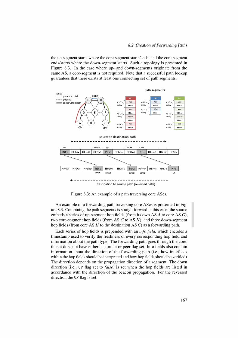
8.2 Creation of Forwarding Paths
the up-segment starts where the core-segment starts/ends, and the core-segmentends/starts where the down-segment starts. Such a topology is presented inFigure 8.3. In the case where up- and down-segments originate from thesame AS, a core-segment is not required. Note that a successful path lookupguarantees that there exists at least one connecting set of path segments.
INF1 HFAD● HFDGA HFG●D INF2 HFGH● HFH●G INF3 HFH●F HFFHC HFCF●
source to destination path
HFAD● HFDGA HFG●D INF1 HFGH● HFH●G INF2 HFH●F HFFHC HFCF● INF3
destination to source path (reversed path)
D E F
A B C
INF3
AS H
HFH●F
AS F
HFFHC
Peer: E
HFFEC
AS C
HFCF●
AS G’sentry
AS C’sentry
AS F’sentry
src dst
Path segments:
coreparent – childpeeringconstructed path
Links:
HG
UP XOVER UP XOVER DOWN
DOWN XOVER DOWN XOVER UP
INF1
AS G
HFG●D
AS D
HFDGA
Peer: E
HFDEA
AS A
HFAD●
AS G’sentry
AS A’sentry
AS D’sentry
INF2
AS H
HFH●G
AS G
HFGH●
AS H’sentry
AS G’sentry
Figure 8.3: An example of a path traversing core ASes.
An example of a forwarding path traversing core ASes is presented in Fig-ure 8.3. Combining the path segments is straightforward in this case: the sourceembeds a series of up-segment hop fields (from its own AS A to core AS G),two core-segment hop fields (from AS G to AS H), and three down-segmenthop fields (from core AS H to the destination AS C) as a forwarding path.
Each series of hop fields is prepended with an info field, which encodes atimestamp used to verify the freshness of every corresponding hop field andinformation about the path type. The forwarding path goes through the core;thus it does not have either a shortcut or peer flag set. Info fields also containinformation about the direction of the forwarding path (i.e., how interfaceswithin the hop fields should be interpreted and how hop fields should be verified).The direction depends on the propagation direction of a segment: The downdirection (i.e., UP flag set to false) is set when the hop fields are listed inaccordance with the direction of the beacon propagation. For the reverseddirection the UP flag is set.
167

8 Data Plane
Hop fields within each series are ordered according to the order of traversedASes. The source marks the last hop fields in each series with a dedicatedcrossover flag XOVER, to indicate that hop fields of another path segment startat this AS. Thus a border router that processes this hop field should switch toanother hop-field series.
The destination end host can reverse the received forwarding path (lowerhalf of Figure 8.3), by reversing the info and hop fields, switching the values ofUP flags and by setting the XOVER flags for the new crossover points (i.e., thelast hop fields of the first and the second path segments, to indicate to borderrouters that read these fields that they should switch to another series of hopfields here).
Peering Path
With the proliferation of Internet exchange points (IXPs), communicationthrough peering links is becoming more common. To check whether the des-tination can be reached via a peering link, the source tries to find a commonpeering link between the obtained up-segments and down-segments. If such alink exists, a peering forwarding path can be constructed.
Figure 8.4 presents an example of a path crossing over a peering link. Inthis example, the two path segments contain the hop fields for the peering linkbetween ASes E and F (i.e., HF EFB and HF FEC, correspondingly).
Besides the corresponding peer hop fields, a peering path includes hopfields that precede them (HF EGB and HF FGC in our example). These fieldsare included as they are necessary for the verification of the peer hop fields.However, to minimize traffic overhead, forwarding-irrelevant hop fields are notadded to the path. In particular, a core-segment and its hop fields are not usedto construct a peering path. In Section 8.3, we show an efficient algorithm tofind a common peering link in two path segments.
In the example presented in Figure 8.4, the source specifies its intent touse the shortcut by setting a special flag (i.e., PEER flag) on the info fields. Italso sets the direction (i.e., UP) flag of the hop-field segments. The hop fieldsHF EFB and HF FEC are marked with a crossover flag XOVER, which indicatesthat ASes corresponding to these hop fields need to process the hop fields in aspecial way. Specifically, border routers verify whether hop fields are createdcorrectly, i.e., whether their ASes permitted the use of the mentioned peeringlink. For example, for a packet sent from the source to the destination, AS Bfirst verifies whether the forwarding encoded within HF BE‚ is allowed forthe packet. To this end, a hop field HF EGB of the parent is needed (as itwas chained to HF BE‚’s generation in the computation of the MAC field ofHF BE‚). When AS E receives the packet, the hop field HF EGB is needed forthe verification of HF EFB, but is not used for the actual forwarding. Such hopfields are marked with a special VRFY-ONLY flag. The AS verifies that HF EFB
168

8.2 Creation of Forwarding Paths
INF5 HFBE● HFEFB HFEGB INF3 HFFGC HFFEC HFCF●
source to destination path
destination to source path (reversed path)
G
D E F
A B C
INF3
AS G
HFG●F
AS F
HFFGC
Peer: E
HFFEC
AS C
HFCF●
AS G’sentry
AS C’sentry
AS F’sentry
src dst
Path segments:
coreparent – childpeeringconstructed path
Links: INF5
AS G
HFG●E
AS E
HFEGB
Peer: D
HFEDB
Peer: F
HFEFB
AS B
HFBE●
AS G’sentry
AS B’sentry
AS E’sentry
HFBE● HFEFB HFEGB INF5 HFFGC HFFEC HFCF● INF3
PEERUP XOVER
PEERDOWN VRFY-ONLY
PEERDOWN
XOVER PEERUP
VRFY-ONLY
VRFY-ONLY XOVER
VRFY-ONLYXOVER
Figure 8.4: Path composition with a peering link.
was created correctly (i.e., that it is chained to HF EGB), and forwards traffic tothe peer AS.
A similar procedure applies to the processing of hop fields on the down-segment (i.e., AS F executes analogous steps). The reversed path is analogousto the original one, except that the UP flags are inverted and the info fields aremoved.
Peering links are allowed between ASes from different ISDs and peeringpaths with such links are created in the same way as presented.
Shortcut Path (Common AS on Paths)
The up- and down-segments obtained may contain a common upstream AS.The example in Figure 8.5 shows such a case, where an end-to-end shortcutpath can be constructed through AS D.
In this case, packets do not need to traverse the ISD core, but can be directlyforwarded from the common AS D to destination AS B. A shortcut path is
169

8 Data Plane
similar to a peering path in that it includes some hop fields that are used onlyfor the verification of the crossover hop fields (see below).
INF1 HFAD● HFDGA HFG●D1 INF4 HFG●D2 HFDGB HFBD●
source to destination path
HFAD● HFDGA HFG●D1 INF1 HFG●D2 HFDGB HFBD● INF4
destination to source path (reversed path)
G
D E F
A B C
src dst
Path segments:coreparent – child
peeringconstructed path
Links:
INF4
AS G
HFG●D2
AS D
HFDGB
Peer: E
HFDEB
AS B
HFBD●
AS G’sentry
AS B’sentry
AS D’sentry
SHORTCUTUP XOVER VRFY-ONLY XOVER
SHORTCUTDOWN VRFY-ONLY
SHORTCUTUP
XOVER VRFY-ONLY XOVERSHORTCUTDOWN
VRFY-ONLY
INF1
AS G
HFG●D1
AS D
HFDGA
Peer: E
HFDEA
AS A
HFAD●
AS G’sentry
AS A’sentry
AS D’sentry
Figure 8.5: The path composition through a common AS.
To establish such a shorter path, the source specifies the path type as shortcut(i.e., it marks the info fields with the SHORTCUT flag), and marks the hop fieldsHF DGA and HF DGB as crossover points (i.e., it marks them with the XOVERflag). Similarly to the peering case, hop fields HF G‚D1 and HF G‚D2 are addedonly for verification purposes, and are marked with the VRFY-ONLY flag. Thereversed path is analogous.
Destination AS on Path
In the last case, the destination is an AS on the up-segment. No forwardingpath for this case should go through a core AS. Also, the up-segment (onwhich the destination is placed) alone should be sufficient to forward packetsto the destination. However, the ingress router of the destination AS has to beinformed that a packet can be terminated at the AS.
An example of such a path construction is presented in Figure 8.6, wherethe destination is within AS D, which is on the up-segment. In this case, the
170
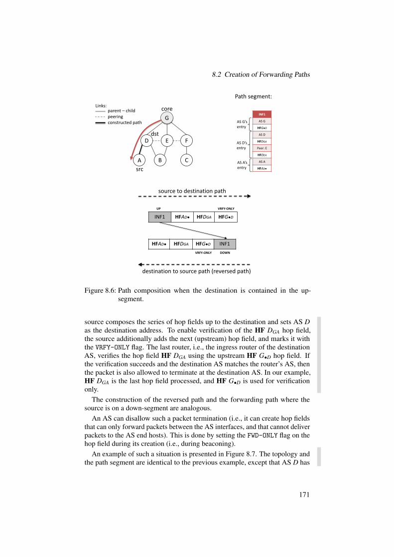
8.2 Creation of Forwarding Paths
INF1 HFAD● HFDGA HFG●D
source to destination path
HFAD● HFDGA HFG●D INF1
destination to source path (reversed path)
G
D E F
A B C
INF1
AS G
HFG●D
AS D
HFDGA
Peer: E
HFDEA
AS A
HFAD●
AS G’sentry
AS A’sentry
AS D’sentry
src
dst
Path segment:
coreparent – childpeeringconstructed path
Links:
UP
VRFY-ONLY DOWN
VRFY-ONLY
Figure 8.6: Path composition when the destination is contained in the up-segment.
source composes the series of hop fields up to the destination and sets AS Das the destination address. To enable verification of the HF DGA hop field,the source additionally adds the next (upstream) hop field, and marks it withthe VRFY-ONLY flag. The last router, i.e., the ingress router of the destinationAS, verifies the hop field HF DGA using the upstream HF G‚D hop field. Ifthe verification succeeds and the destination AS matches the router’s AS, thenthe packet is also allowed to terminate at the destination AS. In our example,HF DGA is the last hop field processed, and HF G‚D is used for verificationonly.
The construction of the reversed path and the forwarding path where thesource is on a down-segment are analogous.
An AS can disallow such a packet termination (i.e., it can create hop fieldsthat can only forward packets between the AS interfaces, and that cannot deliverpackets to the AS end hosts). This is done by setting the FWD-ONLY flag on thehop field during its creation (i.e., during beaconing).
An example of such a situation is presented in Figure 8.7. The topology andthe path segment are identical to the previous example, except that AS D has
171
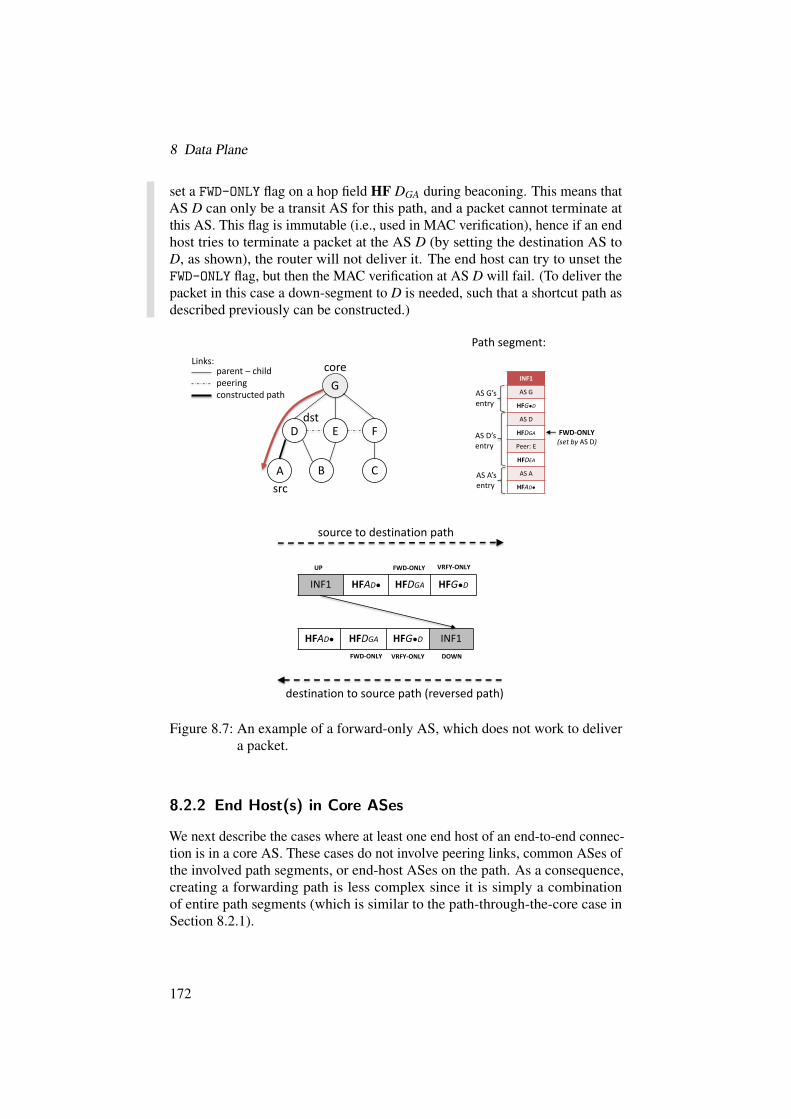
8 Data Plane
set a FWD-ONLY flag on a hop field HF DGA during beaconing. This means thatAS D can only be a transit AS for this path, and a packet cannot terminate atthis AS. This flag is immutable (i.e., used in MAC verification), hence if an endhost tries to terminate a packet at the AS D (by setting the destination AS toD, as shown), the router will not deliver it. The end host can try to unset theFWD-ONLY flag, but then the MAC verification at AS D will fail. (To deliver thepacket in this case a down-segment to D is needed, such that a shortcut path asdescribed previously can be constructed.)
INF1 HFAD● HFDGA HFG●D
source to destination path
HFAD● HFDGA HFG●D INF1
destination to source path (reversed path)
G
D E F
A B C
INF1
AS G
HFG●D
AS D
HFDGA
Peer: E
HFDEA
AS A
HFAD●
AS G’sentry
AS A’sentry
AS D’sentry
src
dst
Path segment:
coreparent – childpeeringconstructed path
Links:
UP VRFY-ONLY
VRFY-ONLY
FWD-ONLY (set by AS D)
FWD-ONLY
FWD-ONLY DOWN
Figure 8.7: An example of a forward-only AS, which does not work to delivera packet.
8.2.2 End Host(s) in Core ASes
We next describe the cases where at least one end host of an end-to-end connec-tion is in a core AS. These cases do not involve peering links, common ASes ofthe involved path segments, or end-host ASes on the path. As a consequence,creating a forwarding path is less complex since it is simply a combinationof entire path segments (which is similar to the path-through-the-core case inSection 8.2.1).
172


8 Data Plane
Both End Hosts in the ISD Core
Path construction between two core ASes is straightforward since path prop-agation in the core guarantees that there is always a direct core-segment thatconnects two core ASes. Thus, the source simply obtains a core-segment anduses it directly.
An example of such a case is presented in Figure 8.9. The source just extractsthe hop fields from the core-segment and concatenates them to construct aforwarding path.
INF2 HFGH● HFH●G
source to destination path
HFGH● HFH●G INF2
destination to source path (reversed path)
D E F
A B C
src dstPath segment:coreparent – child
peeringconstructed path
Links:
HG
UP
DOWN
INF2
AS H
HFH●G
AS G
HFGH●
AS H’sentry
AS G’sentry
Figure 8.9: An example of a forwarding path between two core ASes.
8.3 Efficient Path Construction
In this section, we present an efficient path-construction algorithm, whichallows an end host to find and build the shortest forwarding path towards adestination AS. The algorithm is executed by the end host once it has obtainedthe corresponding up-, core-, and down-segments to the destination AS.
A path segment consists of a list of ASes, where each AS is identified by itsISD and AS identifiers (ISD ID, AS ID) and a list of entries with ingress andegress interfaces. Thus, even if two paths contain the same list of (ISD:AS)tuples, they can differ at the granularity of interfaces (e.g., when two ASes
174

8.3 Efficient Path Construction
share more than one link). Naively, an end host can try to join all possiblecombinations of up-, core-, and down-segments and select the best end-to-end path among them. However, exhaustive exploration is inefficient if pathsegments contain many peering links, or if there are many path segmentsavailable. We resolve this issue by designing an efficient path-constructionalgorithm that finds the shortest path(s) in terms of AS hops. The algorithmoperates in two steps: the graph-construction step and the path-constructionstep.
8.3.1 Graph Construction
In the first step, the source host creates a weighted and directed graph, basedon the up-, core-, and down-segments. Each path segment contains a list of(ISD ID, AS ID) tuples; each tuple uniquely identifies an AS. The graph is thenconstructed as follows:
1. For each up-segment of the source host’s AS, the algorithm traversesthe ASes starting from the source AS and creates a node in the graphfor every new AS encountered in the up-segment. The algorithm adds adirected edge from the source AS to the encountered AS, annotated withthe hop distance from the source AS. Furthermore, a path identifier isalso used to annotate the edge.If the encountered AS already has a node in the graph, a new edge isadded from the source AS node to the encountered AS node, and theedge is annotated with the same information as described earlier. Thus,multiple edges can exist between two nodes.If an AS has a peering link with another peer AS, a new edge is similarlyadded between the nodes for the source and the peer AS. In this case, theedge is additionally annotated as a peering link.
2. The same procedure is followed for each down-segment of the destination,with two differences. First, the direction of the edge is reversed, so thatthe edge points towards the destination AS. Second, peering links arenot added, since a valid end-to-end path can traverse at most one peeringlink; if a peering link is traversed, it has already been added in step 1 ofthe algorithm.
3. For core-segments, the algorithm complements the graph as follows.First, it selects only the segments that connect the core ASes of the up-segments to the core ASes of the down-segments. Then, it traverses everyAS in the selected core-segments and adds an edge from the core AS ofthe up-segment to the encountered core AS, similarly to the previous twosteps. Also, it annotates the edge with the hop distance and with a corepath flag.
175

8 Data Plane
A
B
C
D E
F
G
H
core
J
p1p2 p3
Figure 8.10: An example topology, with up-segments (p1, p2) and down-segments (p3) obtained by the source (placed in AS F) towards thedestination (placed in AS J).
Example. We provide an example to explain how the graph is constructed.Figure 8.10 shows an example topology with the up-segments (p1 and p2) of thesource AS F, and the down-segments of the destination AS J; for simplicity, weomit the core-segments. The source host in AS F obtains the path segments p1,p2, and p3 and constructs the graph in Figure 8.11, according to the proceduredescribed earlier.
All outgoing edges from F point to an AS that is either on an up-segment ofF or has a peering relationship with an AS that is on an up-segment of F (e.g.,AS H). Note that the edges do not correspond to physical links (as shown inFigure 8.10) and that the weight of each edge denotes the hop distance from thesource AS to the corresponding AS. The reason the graph is constructed in thisway is that the source host should not combine valid path segments to create anew path segment. For instance, the combination F Ñ E ÑCÑ BÑ A is notvalid, as it is a combination of p1 and p2.
The same procedure is followed for the down-segments, but the direction ofthe edges is reversed. Thus, all edges point towards the destination AS (AS J inFigure 8.11).
The algorithmic complexity of the graph-construction step is linear withrespect to the number of received path segments (whether up-, down-, or core-segments), since the algorithm processes every received path segment once.The intermediate nodes in the graph of Figure 8.11 can be added to a hash tablefor efficient lookup, i.e., lookup in constant amortized time, when they haveto be looked up in order to add the corresponding edges in the graph; this ispossible as the number of paths is relatively small.
176

8.3 Efficient Path Construction
F H
B
C
D
G
E
A
J
1, p1
2, p1
2, p2
3, p1
4, p1, peer4, p11, p2
3, p2
1, p3
2, p3
Figure 8.11: Constructed graph based on the up- and down-segments. Edgesare annotated with the hop distance between the correspondingASes, a path identifier, and a peering-link flag in case a peeringlink is traversed.
8.3.2 Path Construction
The construction of the graph turns path construction into a simple graphtraversal problem. The source host can use existing algorithms to discover theshortest path, all shortest paths, or all paths to the destination. For example,using Dijkstra on the graph in Figure 8.11 yields the shortest path F Ñ H Ñ J,with a total cost of 5.
The paths that are discovered on the constructed graph do not corresponddirectly to physical paths. However, the edges of the constructed graph areannotated with all the required information so that the source host can discoverthe actual path and set up the hop fields. For example, the edges of the pathF Ñ H Ñ J inform the source host that the end-to-end path is formed bycombining p1 and p3 and that it traverses a peering link.
Using Dijkstra for path construction yields an algorithmic complexity ofOp|L|`|V | log |V |q, where |V | is the number of distinct AS nodes in the receivedpath segments and |L| is the number of distinct links in the received pathsegments; recall that a link is uniquely identified by the interface identifiersand not by the AS identifiers. However, note that the graph-construction stepgenerates a directed acyclic graph (DAG), which enables an even faster shortest-path algorithm: with topological sorting on the DAG, the single-source shortestdistances can be calculated in Op|L|` |V |q.
177


9 Host Structure
JASON LEE, ADRIAN PERRIG, PAWEL SZALACHOWSKI
This chapter introduces the host software components that enable applicationsto communicate via SCION. An overview is given in Figure 9.1.
The central point of the host structure is the SCION dispatcher, which handlesall incoming and outgoing packets and interacts with the higher-layer protocols.The SCION daemon handles control-plane messages, e.g., obtaining paths toremote ASes. Currently, SCION supports the following transport protocols:TCP, UDP, and the SCION Stream Protocol (SSP). The last is SCION’s nativemultipath transport protocol. UDP and SSP data is handled by the SCIONsocket library. Implementations of all three protocols provide an API similar tothe Berkeley Socket API. Since the host structure is under active development,we expect many changes in this area over the coming years. For example, weare currently working on a SCION extension of the QUIC protocol [105].
Chapter Contents
9.1 SCION Dispatcher . . . . . . . . . . . . . . . . . . . . . . . . . 179
9.2 SCION Daemon . . . . . . . . . . . . . . . . . . . . . . . . . . 183
9.3 Transmission Control Protocol (TCP/SCION) . . . . . . . . . . 185
9.4 SCION Stream Protocol (SSP) . . . . . . . . . . . . . . . . . . 188
9.1 SCION Dispatcher
The initial version of the SCION host stack follows two design choices, whichaffect how packets are handled: (a) the host stack runs over an IP/UDP over-lay to communicate within an AS, and (b) all code executes in userspace.1
Consequently, we designate a UDP port through which all SCION packets are
1In a future release of SCION, the functionality of the dispatcher will execute inside a kernelmodule.
179

9 Host Structure
TCPApplication
RPC Middleware
control plane
data
UDP / SSPApplication
SCION Socket LibraryRPC Middleware
control plane
SCIONDaemon
incoming / outgoingnetwork packets
control plane
data
TCPStack
RPC Middleware
SCION Dispatcher
UDP / SSP State
SCIONen-/decapsulation
Figure 9.1: Overview of SCION’s end-host software structure.
communicated and define a single process (within each host) that handles allincoming SCION packets.
The dispatcher performs two tasks: (a) handling encapsulation and decap-sulation of the IP/UDP overlay and the SCION headers, and (b) interactingwith the transport protocol stacks. That is, the dispatcher mediates betweenapplications and transport protocol implementations to process incoming andoutgoing packets.
More specifically, for outgoing packets, the TCP stack and UDP/SSP appli-cations send their data along with the packet’s metadata. The metadata includesa forwarding path and an address of the first SCION hop (i.e., border router)on the path. The dispatcher, upon receiving the data and its metadata, encap-sulates the data and sends the packets to the specified border router. The pathand the first-hop address are provided to applications by the SCION daemon,which has the required control-plane information from the discovery service(Section 7.4.6).
For incoming packets, the dispatcher decapsulates the overlay header andparses the SCION header to identify the transport protocol. The dispatcherprocesses packets differently for different transport protocols. All TCP packetsare passed to the TCP stack; for UDP and SSP packets, the dispatcher parsesthe identifier associated with the incoming packet and delivers the packet to theapplication that is registered for that identifier.
180

9.1 SCION Dispatcher
9.1.1 Application-to-Dispatcher Communication
Communication between the dispatcher and applications is implemented viareliable Unix domain sockets. However, depending on the transport protocol,the communication between applications and the dispatcher differs.
TCP Applications
TCP applications and the dispatcher communicate through a remote procedurecall (RPC) middleware which consists of interacting parts: (a) the applicationsside (to send calls and receive responses), and (b) the TCP stack (to receivecalls, execute them, and send responses back).
For each application-level socket there is a corresponding Unix socket andnative TCP state. For example, an application executing the connect() systemcall sends an RPC message to the RPC middleware of the TCP stack, whichreceives the message, executes the native TCP connect() call on the corre-sponding TCP socket, and returns to the application the results of the call (e.g.,a success or an error code).
For connected sockets, i.e., after a successful connect() or accept(), theRPC middleware enters pipe mode, in which it simply passes the data betweenan application socket and the corresponding TCP socket.
UDP and SSP Applications
The interaction between the dispatcher and UDP/SSP applications is simplerthan in TCP, as the UDP and SSP stacks are implemented within the SCIONsocket library. All UDP and SSP applications must register with the dispatcherto send and receive packets. The format of the registration message depends onthe transport protocol used by the application.
UDP registration messages have the following format:• addr represents the address bound by the application (its length depends
on the type).• SVC is an optional 2-byte field that specifies the service type to register
for (e.g., beacon servers register for SVC 0).SSP registration messages have the following format:
• flowID is an 8-byte identifier for the connection used by the application.• addr is a variable-length address bound by the application.• SVC is an optional 2-byte SVC address type to register for.
We emphasize that SCION addresses are triples: (ISD,AS,ADDR), whereADDR is an address that has significance only within the host’s AS. BecauseIP addresses need to be unique only within an AS, the ISD-AS informationis needed in the registration message to correctly identify the receiver. For
181

9 Host Structure
example, an application that registers for the address (1,1,1.2.3.4) shouldnot receive packets with destination address (2,1,1.2.3.4), even thoughboth addresses may belong to the same host.
9.1.2 Outgoing Packets
TCP
When the TCP stack sends TCP segments to the dispatcher, they are passedalong with their metadata. A segment’s metadata includes the informationrequired to encapsulate the segment into a SCION packet (i.e., source anddestination addresses, a forwarding path, and optionally extensions). The TCPstack also passes the first-hop information, which is necessary to encapsulatethe SCION packet within a UDP (overlay) packet. The dispatcher creates theSCION packet, then encapsulates it within a UDP packet, and finally sends it tothe first-hop address.
UDP and SSP
Data sent by UDP and SSP applications is processed by the SCION socketlibrary. When the library sends a chunk of data it is encapsulated within aSCION packet. Next, outgoing SCION packets are sent to the dispatcher alongwith the first-hop information only (forwarding path and optional extensionsare already included within the SCION packet). Upon receiving a data packetfrom an application, the dispatcher parses the first-hop information, creates aUDP packet and sends the packet to the first-hop host.
9.1.3 Incoming Packets
The dispatcher receives incoming packets by listening on the SCION UDPport. Upon receiving a packet and decapsulating the overlay IP/UDP header,the dispatcher obtains a SCION packet. When a SCION packet arrives at thehost, the dispatcher first checks whether both ISD-AS identifier and IP addressindeed identify that host. If not, the packet is dropped. Then, the dispatcherparses the SCION header (see details in Section 15.1.1 on Page 343) to identifythe layer-4 protocol. To this end, the protocol number (encoded in the NextHdrfield inside the SCION common header, see Section 15.1.1) is used. Then,depending on the protocol, the data is passed either to the TCP stack or to theUDP or SSP stack.
182

9.2 SCION Daemon
TCP
If the TCP protocol (i.e., protocol number 6) is used, the SCION header isdecapsulated. The obtained TCP segment is then passed to the TCP stack forfurther processing. Along with the segment, the following metadata is passedto the stack: source and destination addresses, forwarding path, and optionallyextensions. The processed payload (if any) is delivered to an application’ssocket through the RPC middleware.
UDP and SSP
For the UDP and SSP packets, the dispatcher identifies the protocol-dependentapplication identifier. For UDP packets (protocol number 17), the applicationidentifier is the port number. For SSP (protocol number 152), the applicationidentifier is the 8-byte flow ID. If the flow ID has not been registered, thedispatcher will look for a wildcard entry that accepts all incoming flows on agiven port number. The SCION packet is not decapsulated at the dispatcher,and is entirely passed to the listening application, where the SCION socketlibrary further processes the packet.
9.2 SCION Daemon
The SCION daemon is a background process running on end hosts with thegoals of (a) handling SCION control-plane messages, and (b) providing an APIfor applications and libraries to interact with the SCION control plane. Morespecifically, the SCION daemon implements the following services:
• Path lookup: provides path lookup functionality for host applications.The path lookup process is described in Section 7.2, and the path creationprocess is described in Section 8.2.
• Name resolution: provides name resolution functionality, i.e., a trans-lation from a human-readable domain name to a SCION address. Thedetails of name resolution are described in Chapter 6.
• Trust management: stores received certificates and TRCs, and checkstheir authenticity and consistency (when a new certificate/TRC is re-ceived). Certificates and TRCs can be provided to applications on de-mand.
• Topology information: provides information about the topology of thelocal AS. Topology information includes addresses of border routers(with their interface identifiers) and information on running services (e.g.,RAINS or path servers). The topology information is obtained from thelocal AS through the discovery service (see Section 7.4.6). If an end hostis multi-homed, the information is provided for all local ASes.
183

9 Host Structure
• Extensions: various SCION extensions and sub-protocols, such as SIBRA(Chapter 11) and OPT (Chapter 12), implement their control plane aspart of the SCION daemon and extend its API.
To start, the SCION daemon contacts the discovery service(s) of its AS(es)(Section 7.4), parses the TRC(s) of its ISD(s) (Section 16.1), and optionallyparses the corresponding certificate(s).
9.2.1 API
The SCION daemon exposes its API through a reliable Unix domain socketwith a pre-defined path, which allows userspace applications to interact directlywith it.
Request and Responses
We next describe the most important API calls with their expected results.To support multi-homed end hosts (i.e., residing in multiple ASes) each APIrequest can be accompanied by an ISD and AS identifier to specify the ASwhose infrastructure should be used to handle the request.
• Path request: Consider a process that wishes to obtain a forwardingpath to a destination AS. In this case, it queries the SCION daemon witha path request specifying the destination.Upon receiving such a request, the SCION daemon attempts to buildforwarding paths to the destination using locally cached path segments.If it fails, the SCION daemon contacts a local path server, which initiatesthe path lookup process (see details in Section 7.2 on Page 132). In thecase of a successful path lookup, the SCION daemon returns a list offorwarding paths with their metadata. The metadata includes
– the local address of the first border router on the path (in case therequester process encapsulates and sends a SCION packet on itsown),
– the maximum transmission unit (MTU) of the path, and– a list of interface identifiers that provide a path-requesting process
with the information about the path’s ASes (and their interfaces).• Name resolution: Consider a process that needs to resolve a human-
readable domain name to a SCION address (as described in Chapter 6).The request to the SCION daemon includes the domain name and an op-tional resolution context, while the response consists of a list of SCIONaddresses and additional optional information associated with the re-quested domain name.
• Topology discovery: Some processes might need topological informa-tion about the local AS(es). To this end, a process can send a topology
184

9.3 Transmission Control Protocol (TCP/SCION)
discovery request to the SCION daemon. The SCION daemon returns thetopology information (see details in Section 16.3) including addresses ofborder routers and their interface identifiers, and information on runningservices.
• TRC request: To request a TRC, a process sends a request that specifiesthe requested version of the TRC for a given ISD. Without specifying theversion, the most recent TRC (that the SCION daemon has) is requested.To serve the request, the SCION daemon first searches its local cache,and if absent, it contacts the local certificate server. We note that theSCION daemon is pre-loaded with the first TRC.
• Certificate request: Similarly to TRCs, AS certificates can be requestedfrom the SCION daemon by sending a request that specifies the targetAS (i.e., its ISD and AS identifiers) and the version of the requestedcertificate (the field can be empty if the most recent certificate that theSCION daemon has is requested). To serve the request, the SCIONdaemon first searches for the certificate in its local cache; if absent, itcontacts the local certificate server.
Error Codes
In case of a failure of any of the above requests, the SCION daemon returns anappropriate error code. The most frequent error codes are as follows:
• the requested object does not exist,• the SCION daemon encountered a problem while processing the request
(this message is followed by a more detailed error description),• the local recursive server (i.e., path or certificate server) encountered a
problem while processing the request (this message can be followed by amore detailed error description).
9.3 Transmission Control Protocol (TCP/SCION)
To make TCP available in SCION, TCP was modified by adding (a) SCIONaddresses, (b) SCION forwarding paths, and (c) SCION packet extensions, andby extending the standard TCP checksum algorithm.
Regarding the first modification, the TCP stack was extended to handleSCION addresses (in addition to IPv4 or IPv6 addresses). A SCION addressis a 3-tuple of the form (ISD, AS, ADDR). SCION addresses introduce thenotion of special service addresses, which are used for SCION service anycastcommunication (see details in Section 15.1.2). As implemented via TCP, theservice addresses have to be handled by the TCP/SCION stack.
TCP/SCION sockets listen on the 5-tuple
pISD, AS, ADDR, port, SVCq
185

9 Host Structure
where the first three fields specify the SCION address, the port field denotesthe standard TCP port, and the SVC field specifies the service that is bound tothat socket (e.g., the path service, when a path server listens on the socket). Forstandard (non-SCION service) sockets, the SVC field is set to None.
Socket(1, 19, 10.1.2.1)port=6093svc=PATH_SVC
Source App…connect(1, 19, PATH_SVC)…
Socket Selector
SCIONNetwork
TCP SYN
Socket(1, 19, 10.1.2.1)port=220svc=None
Socket(1, 19, 10.1.2.1)port=6091svc=PATH_SVC
Path Server…bind(…, svc=PATH_SVC)…
Applications
TCP/SCION Stack
App…bind(…, port=220, svc=None)…
Path Server…bind(…, svc=PATH_SVC)…
Host
Figure 9.2: An example of SCION TCP service communication.
Example. An example of an initiation of a TCP/SCION service connection ispresented in Figure 9.2. The source application from a remote AS (depicted atthe bottom left) wishes to connect with a path service of another AS, for examplep1,19q in this case. The initial SYN packet that the source sends contains theSVC address, but has an unspecified port (i.e., set to 0), as the source does notknow the ports that are used by the path servers of the destination AS.
The ingress border router at the destination AS forwards the packet to a hostthat is designated to serve the path service (see details in Section 7.4). Thepacket then reaches the designated host, where two instances of the path serverapplication are running. Both instances have sockets that are listening to theservice address SVC=PATH SVC. As SVC communication is anycast, the socketselector (which pairs the packets with the corresponding TCP states) selectsone of the two listening service sockets at random and directs the packet there.(The socket selector ignores the port field of this packet.)
In the response, a TCP SYN-ACK packet is generated. In the presentedexample, this responding SYN-ACK packet will have set the source SCIONaddress to (1,19,10.1.2.1) and the source port to 6093. The socket selectorat the source is modified to associate the responding SYN-ACK packet with thecorrect TCP state. The socket selector on the host is modified to handle the
186

9.3 Transmission Control Protocol (TCP/SCION)
initiation of SVC connections. For all other cases, i.e., if a SYN packet has adestination address different from SVC, the socket selector associates it as instandard TCP/IP.
An established end-to-end TCP/SCION connection is identified by the 9-tuple
psrc ISD, src AS, src ADDR, src port,
dst ISD, dst AS, dst ADDR, dst port, protocolqwhere the protocol field is set to the TCP protocol number (i.e., 6).
As another consequence of modifying the TCP stack with the SCION ad-dresses, TCP’s checksum algorithm needs to be extended. In TCP/SCION,the checksum algorithm accounts for different address sizes due to new SVCaddresses and SCION’s flexible destination addressing.
Our implementation of TCP/SCION offers flexibility with respect to pathmanagement: forwarding paths can be specified by an application or can beobtained by the stack itself. The former option allows path-aware applicationsto select optimal forwarding paths.
Another modified element of the TCP protocol is the calculation of TCP’smaximum segment size (MSS). As an effective MSS depends on the path and onthe extensions that are used, it must thus be calculated dynamically. The MSScomputation algorithm is modified to incorporate the MTU of the currentlyused forwarding path and extensions used in a given packet. We also added anextension through which communicating parties can inform each other abouttheir respective MTUs (see Section 15.1.4).
Currently, TCP/SCION is implemented using the userspace lwIP stack [74].Our implementation exposes a high-level API for Python. An example of aclient-server application is presented in the listing below. One difference fromthe standard (TCP/IP) API is that SCION uses triples as network addresses.Thus client and server have to bind and connect to instances of a specialSCIONAddr class. Another difference is that a client, before calling connect(),has to obtain a path to initiate communication with a server. To this end, theget paths() call is used, which communicates with the SCION daemon andreturns a forwarding path with its metadata (e.g., the first-hop address, pathMTU). Consequently, the connect() call is extended to pass a path and itsmetadata to the TCP/SCION stack.
from lib.packet.host_addr import haddr_parsefrom lib.packet.scion_addr import ISD_AS , SCIONAddrfrom lib.tcp.socket import SCIONTCPSocketimport lib.app.sciond as lib_sciond
# Set the server ’s addresssrv_isd_as = ISD_AS("1-18")srv_ip = haddr_parse("IPV4", "12.10.61.177")srv_addr = SCIONAddr.from_values(srv_isd_as , srv_ip)srv_port = 5000
187
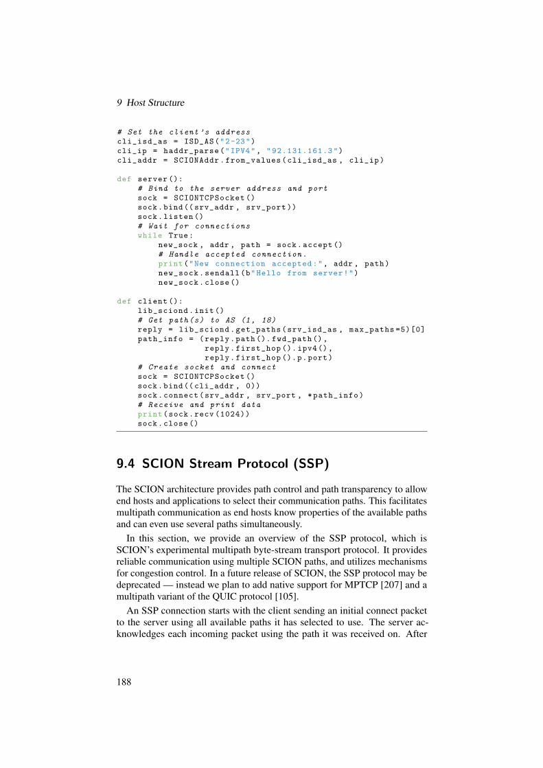
9 Host Structure
# Set the client ’s addresscli_isd_as = ISD_AS("2-23")cli_ip = haddr_parse("IPV4", "92.131.161.3")cli_addr = SCIONAddr.from_values(cli_isd_as , cli_ip)
def server ():# Bind to the server address and portsock = SCIONTCPSocket ()sock.bind((srv_addr , srv_port ))sock.listen ()# Wait for connectionswhile True:
new_sock , addr , path = sock.accept ()# Handle accepted connection.print("New connection accepted:", addr , path)new_sock.sendall(b"Hello from server!")new_sock.close ()
def client ():lib_sciond.init()# Get path(s) to AS (1, 18)reply = lib_sciond.get_paths(srv_isd_as , max_paths =5)[0]path_info = (reply.path (). fwd_path(),
reply.first_hop (). ipv4(),reply.first_hop ().p.port)
# Create socket and connectsock = SCIONTCPSocket ()sock.bind((cli_addr , 0))sock.connect(srv_addr , srv_port , *path_info)# Receive and print dataprint(sock.recv (1024))sock.close()
9.4 SCION Stream Protocol (SSP)
The SCION architecture provides path control and path transparency to allowend hosts and applications to select their communication paths. This facilitatesmultipath communication as end hosts know properties of the available pathsand can even use several paths simultaneously.
In this section, we provide an overview of the SSP protocol, which isSCION’s experimental multipath byte-stream transport protocol. It providesreliable communication using multiple SCION paths, and utilizes mechanismsfor congestion control. In a future release of SCION, the SSP protocol may bedeprecated — instead we plan to add native support for MPTCP [207] and amultipath variant of the QUIC protocol [105].
An SSP connection starts with the client sending an initial connect packetto the server using all available paths it has selected to use. The server ac-knowledges each incoming packet using the path it was received on. After
188

9.4 SCION Stream Protocol (SSP)
this initial exchange, the client knows which paths are available and has aninitial round-trip time (RTT) estimate for each available path. A subset (bydefault, two) of these paths will be used as active paths, while the rest are keptas backup paths in case one of the active paths fails.
For sending data, SSP uses one send buffer and one receive buffer perconnection. These buffers contain all packets that were sent and received overall paths in a given connection. Internally, the send buffer includes both a list offreshly queued packets and a list of lost packets that need to be retransmitted.Retransmissions take priority over new packets in the scheduler. This behaviormay change in the future when new scheduling strategies are implemented.
Under some conditions it is possible that a sender resends a packet eventhough the original packet was not lost, for instance if an acknowledgment waslost. In such cases of duplicate data, the receiver keeps the data that arrivedfirst.
Due to the use of multiple paths with varying latencies, packet reorderingwill likely occur. SSP uses an in-order packet queue and a separate out-of-order queue. In-order packets are placed at the tail of the in-order queue whileout-of-order packets are inserted in order into the out-of-order queue. When anew in-order packet arrives, the out-of-order queue is additionally scanned todetermine whether the new packet has filled a hole in the data space.
A single scheduler thread is used to send a packet. The current default policyis to send the first available packet on the first available path. In the future, moresophisticated scheduling strategies will be available (e.g., to minimize latency).
Each path performs independent congestion control. The schemes currentlyimplemented are Constant Bit Rate, PCC [71], TCP Reno, and TCP Cubic.Future work will include an integrated congestion control scheme such as thatused by MPTCP [206, 207] to ensure fairness for flows that traverse the samephysical link.
Figure 9.3 shows SSP’s packet header format. All SSP packets contain acommon header, then an optional acknowledgment header, and an optional pathheader.
SCION header
SSP common headerSSP ACK header (optional)
SSP path header (optional)
,
/
/
.
/
/
-
SSP header
Payload
Figure 9.3: High-level layout of an SSP packet.
189

9 Host Structure
The mandatory SSP common header contains the flow ID field, which identi-fies the connection. Any packet on any path is identified with its connectionusing this ID. Because the identifier is independent of either endpoint’s address,each host can use not only multiple paths but also multiple addresses withmultiple ISD/AS associations. The header contains also the port field (which isidentical to port fields used in TCP and UDP), and information about the datain the packet and connection state (e.g., sequence number, flag fields).
Acknowledgment packets contain the SSP ACK header, which informs theother communicating party about the received data. Another optional header isthe SSP path header. For each connection, the first packet sent on each pathwill carry (within the path header) the list of hops that are traversed on thepath. Each hop is represented by a concatenation of ISD, AS, and interfaceidentifiers.
The SCION host network stack provides the fully implemented SSP protocol,and the implementation exposes high-level APIs for Python and C. SSP isa connection-oriented protocol; it thus provides calls such as connect(),listen(), and accept(). In SSP an application does not need to explicitlyfetch forwarding path(s), as the SSP stack transparently takes care of pathselection.
190

10 Deployment and Operation
YIH-CHUN HU, TOBIAS KLAUSMANN, ADRIAN PERRIG,RAPHAEL M. REISCHUK, STEPHEN SHIRLEY,PAWEL SZALACHOWSKI, ERCAN UCAN
How can the deployment of SCION be initiated? Which ISDs exist in thebeginning? How can an ISP or end domain start using SCION and what benefitsare obtained? This chapter discusses deployment and operation aspects ofSCION and provides answers to these questions.
More precisely, this chapter makes two important points: (a) contrary towhat might be expected of a future Internet architecture, the deployment of theSCION infrastructure requires surprisingly little effort for ISPs and domains, asfew servers and routers need to be installed since SCION re-uses the existingintra-domain communication network, and (b) even early adopters can benefitfrom SCION’s features.
Chapter Contents
10.1 ISP Deployment . . . . . . . . . . . . . . . . . . . . . . . . . . 191
10.2 End-Domain Deployment . . . . . . . . . . . . . . . . . . . . . 199
10.3 The SCION-IP Gateway (SIG) . . . . . . . . . . . . . . . . . . 201
10.4 How to Try Out SCION . . . . . . . . . . . . . . . . . . . . . . 211
10.5 SCION AS Management Framework . . . . . . . . . . . . . . . 215
10.6 Deploying a New AS . . . . . . . . . . . . . . . . . . . . . . . . 218
10.7 The SCIONLab Experimentation Environment . . . . . . . . . 220
10.8 Example: Life of a SCION Data Packet . . . . . . . . . . . . . 223
10.9 SCION Path Policy . . . . . . . . . . . . . . . . . . . . . . . . . 230
10.1 ISP Deployment
From a global perspective, we envision three stages for deployment of SCION:early, intermediate, and full.
191

10 Deployment and Operation
In the ideal, full deployment case, each ISP and each domain in the worldwould deploy SCION. Before that happens, however, achieving an early deploy-ment ranging from the current 20 domains to about 100 domains with dozensof deploying ISPs will be an important stage in maturing the technology andinfrastructure, and creating a critical mass of users. The early deployment islikely to be characterized by highly specialized communication patterns, suchas those involving corporations that desire high availability for safety-criticalcommunications. During its early deployment, SCION will largely operate asan overlay network, making extensive use of the current Internet to connectdeploying entities. When SCION operates as an overlay, the BGP routingsystem is used. The security guarantees offered by such an overlay deploymentare discussed in Section 13.9.
Between early and full deployment lies a long stretch of intermediate deploy-ment, which will be characterized by an increase in the diversity of applicationsthat benefit from SCION’s features. Teleconferencing and bitcoin mining poolsmay be among the applications to benefit from SCION’s high availability [12].Section 10.1.2 provides further details and discussion of this intermediatedeployment phase, which we also refer to as incremental deployment.
We envision that high-availability applications will drive the initial phase ofdeployment. We discuss the details of incentives for deployment that will drivethis process in Section 2.5. In the long term, we anticipate that deployments willdiminish in their requirement for high availability over time, with an increasein demand for other features (e.g., SD-WAN).
In this context, the goal for SCION is to achieve a widely dispersed globaldeployment by domains and ISPs, providing the advantage of high availabilitydue to path diversity [8]. A dispersed deployment will also provide kernelsaround which SCION islands can grow, steadily strengthening the propertiesthat can be achieved locally. In the following sections, we discuss differentoptions for ISPs to deploy SCION.
10.1.1 ISP Deployment Scenarios
An ISP that deploys SCION needs to first find other SCION ISPs to connectto. The connection can happen over an existing network link or ideally througha dedicated link, as we explain further in this section. The ISP then needs toobtain a certificate for their AS for each ISD it participates in. The details ofthis operation are explained in Section 10.6.
A deploying ISP needs to set up SCION border routers and services. Fig-ure 10.1 contrasts the minimal, intermediate, and ideal deployment scenarios.In the minimal deployment case, it can have a single SCION border router andservices all deployed at a single location, perhaps even on a single physicalhost. The minimal deployment places more reliance on the existing networkinfrastructure and therefore fewer guarantees are achieved, as an adversary
192

10.1 ISP Deployment
might overload the legacy network with legacy traffic, clogging the same linksthat SCION traffic would use — we discuss such attacks in more detail in Sec-tion 13.9. In the intermediate deployment case, the ISP would deploy severalSCION border routers adjacent to existing legacy border routers, along withmultiple servers distributed over their network to achieve tolerance to failures.In the ideal deployment case, in addition to having multiple servers distributedover the network, the SCION border routers would be directly connected to theneighboring ISPs’ SCION border routers.
C
P
BS
PBC
Path serverBeacon serverCertificate server
SCurrent border router
SCION border router
a) Minimal ISP deployment b) Intermediate ISP deployment
P
B CP
B
S
S
S
c) Ideal ISP deployment
P
B CP
B
S
S
S
C
Figure 10.1: ISP Deployment: minimal, intermediate, and ideal.
The deploying ISPs can install their border routers in two different ways.Figure 10.2 shows the possible types of connections that can be establishedbetween border routers: a) depicts a simple deployment model with a “router-on-a-stick” configuration, where the SCION border router is attached to anexisting legacy border router and communicates with the neighboring SCIONborder router over a short overlay connection. The advantage of this deploymentis that the SCION border router does not interfere with legacy IP traffic, butthe disadvantage is that legacy IP traffic may interfere with SCION traffic incase the legacy link is congested. b) shows the ideal type of SCION routerdeployment, where the two SCION border routers are directly connected via across-connect between the deploying ISPs, achieving the strongest security andavailability properties.
193

10 Deployment and Operation
a) Router-on-a-stick b) Ideal, cross-connect
SCION border router Current border router
SSS S
S
Figure 10.2: Different types of connections between border routers of differentdeploying ISPs.
We continue our deployment discussion by providing details of two comple-mentary scenarios: incremental deployment to provide path diversity and globalconnectivity through overlay paths (ensuring partial security and availabilityproperties), and an island of connected SCION ISPs to provide full SCIONsecurity and availability guarantees for communication within the island.
10.1.2 Early and Intermediate Deployment
During the early stages of deployment, SCION islands (see Section 10.1.3) maynot be directly connected, i.e., ASes that deploy SCION may not be contiguous.To enable connectivity between such ASes, we inter-connect SCION ASesvia overlay tunnels utilizing the current Internet infrastructure. One commonapproach for creating an overlay network is to encapsulate the new network’straffic into packets that can be routed over the legacy network. This is commonlydone today using IP tunnels (i.e., encapsulating traffic inside IP packets).
When relying on properties of the legacy network, it is clear that the avail-ability guarantees of the overlay network depend on the reliability of the IPtunnels. That is, IP tunnels should be resilient to failure, but should also berobust if exposed to any attack that degrades availability. In particular, thetunnels themselves should be robust when facing IP-prefix-hijacking attacks.To achieve this, tunnel IP addresses are ideally announced using /24 prefixblocks via BGP, which are very specific prefixes and thus cannot be hijacked aspart of a more general, less specific announcement. Through a series of large-scale simulations, we show in Section 13.9 that IP tunnels are more resilient tohijacking attacks than end-to-end paths on the current Internet. Peter et al. [199]propose a similar high-availability strategy by using IP tunnels, albeit designedfor the current Internet.
For our deployment strategy, we define the following tunnel types:
(a) Access tunnel: A tunnel with which a deploying ISP D1 can offer high-availability services to customers whose ISPs do not support SCION.
194

10.1 ISP Deployment
ND1 D1Internet
/24 Prefixannouncem.
A B
(a) Access tunnel
D2Internet
/24 Prefixannouncem.
D1
/24 Prefixannouncem.
A B
(b) Inter-site tunnel
Figure 10.3: Tunnels used for incrementally deploying SCION. In each subfig-ure, circles marked Di represent ASes that have deployed SCION,and the circle marked ND1 represents a non-deploying AS. Colorsare used to differentiate the different tunnel types.
As shown in Figure 10.3a, to protect the tunnel between A and D1 fromhijacking, the deploying AS D1 announces a /24 prefix via BGP thatcontains the IP address used for that tunnel. This announcement reducesthe probability of an adversary successfully hijacking this tunnel if theadversary is further away from A than D1.
(b) Inter-site tunnel: A tunnel that connects two non-adjacent deployingASes D1 and D2 over the Internet (see Figure 10.3b). The ASes need toprotect the tunnels that link deploying sites from prefix-hijacking attacks.As with the access tunnels above, each of the two ASes would ideallyannounce a /24 prefix block that contains the IP address used as its tunnelend-point address.
We note that the /24 prefix announcements cannot always prevent all hi-jacking attacks, including hijacking attacks against the tunnels. As the length(measured in the number of AS-level hops) of the tunnel increases, the resilienceto hijacking decreases. This is because BGP’s path selection algorithm givespreference to shorter paths. From the attacker’s perspective, hijacking a pathrequires the announcement of a shorter or more specific path than the advertisedtunnel paths. Short tunnels thus reduce the possible locations from where anattacker can launch a successful hijacking attack. In Section 13.9, we verifythis observation through BGP simulations.
One might argue that end domains could also announce /24 prefixes in BGPto achieve higher resilience to prefix hijacking. However, if every end domainwere to announce a /24 prefix for higher availability, the BGP routing tableswould become too large. Instead, in our approach, since only a few initiallydeploying ASes announce /24 prefixes to protect their tunnels, the overheadon BGP routing tables is small. Furthermore, beyond initial deployment, ourapproach benefits from a natural scalability property; as more ISPs deploySCION, fewer /24 announcements are needed, since two contiguous ISPs thatdeploy SCION can communicate directly through a static route. Consequently,
195

10 Deployment and Operation
we expect the number of announced /24 tunnel prefixes to increase during theearly stage of deployment and then decrease as more ISPs deploy.
10.1.3 Full Deployment: SCION Islands
A full or native SCION deployment means a SCION network that does notrely on any BGP-based information to provide end-to-end connectivity. Thus,connectivity is assured irrespective of the state of the BGP system.
In a full deployment, the security and availability properties that SCIONoffers are ideal, as has been discussed in earlier chapters. Therefore, a fullSCION deployment at one or several directly connected ISPs will result instrong communication properties amongst their respective customers. We referto such contiguous deployments as SCION islands.
AS S
S
B
S SCION border router
S
S
S
SS
Figure 10.4: A SCION island consisting of two directly connected ASes.
In our early deployment phase, we already have one such SCION islandin Switzerland, with the ISPs Swisscom and SWITCH. In this setting, severalcorporations interested in highly available and secure communication havestarted test deployments using this local infrastructure. We describe the currentdeployment status in the next section.
10.1.4 Current SCION Deployment
SCION is being tested by several ISPs, and is being evaluated by severalcorporations. The largest contiguously deployed infrastructure is currently inSwitzerland. Before describing the deployment path we took in Switzerland,we would like to mention that there also is a growing SCION infrastructure onother continents, mainly in North America and Asia. In addition to the physicalinfrastructure, several ASes are running on the Amazon Web Services (AWS)EC2 platform in the US, Japan, Ireland, Australia, and Brazil.
In order to display the installed machines across the world, SCION provides aGoogle Maps API to show the various locations and data centers where SCION
196

10.1 ISP Deployment
machines have been installed. Figure 10.5 shows the March 2017 map centeredon Zurich city. The map is located at http://www.scion-architecture.net/status/.
(Copyright Map Data © 2017 Google)
Figure 10.5: Map of deployed SCION routers, March 2017, Zurich, Switzer-land.
Equipment
SCION services and routers run on all PC platforms supporting Ubuntu Linux16.04. The high-speed version of the border router requires Intel DPDK andthe hardware required for DPDK. For our initial deployment, we used a systembased on an HPE ProLiant DL20 Gen9 Server. The DL20 is a commodity 1Urack-mounted server. It is powered by an Intel E3-1220 v5 processor. Theserver has 16 GB of RAM, and two 1 Gb/s network interfaces. Where necessary(depending on inter-connections to other locations), we additionally equippedthe DL20s with dual 10 Gb/s Intel NICs (X520 series). These NICs, as well asthe on-board NICs (Broadcom BCM5720), support DPDK.
Our codebase is designed for Ubuntu 16.04. Most code is written in Python,but the performance-critical parts are written in C, C++, and Go.
The infrastructure services run on servers that are distributed throughout anAS, to achieve fault tolerance to local (internal to the AS) network outages.Services can also run in a virtualized environment, e.g., in an internal cloudenvironment where available.
197

10 Deployment and Operation
Deployment in Switzerland
We next discuss the details of the deployment path we have taken in Switzerland.We believe the Swiss success story can serve as a role model for fosteringdeployment elsewhere.
In Switzerland, Swisscom is the largest ISP and telecommunications provider.Swisscom has been the first adopter of SCION. Currently, Swisscom has severalSCION routers and servers installed in its backbone network.
SWITCH is a non-profit Swiss ISP that provides connectivity to universitiesand other research institutions (e.g., CERN and EPFL). Since SWITCH is ETHZurich’s ISP, deploying SCION nodes within their ASes enables SWITCHand ETH border routers to connect directly, removing the requirement of IPencapsulation when sending ETH SCION traffic to SWITCH’s SCION borderrouter. Figure 10.6 shows a recent snapshot of SCION-supporting ASes inSwitzerland and their connectivity with each other.
Swisscom SWITCH
ETH Zurich
SCION Service (beacon, path, certificate server)
SCION Border Router
ETH Network
10G Fiber 1G Copper
SWITCH Engines
ETH LEE
CERN CIXP
Equinix ZH1
BE Ittigen
ZH Herdern
Irchel
Höngg
Zürcher Kantonalbank
ZKB SCION Services
Physical Location
SCION ASOverlay Link
BIT
BIT SCION Services
Figure 10.6: Native Deployment ISD Topology, March 2017, Switzerland.
SWITCH also peers with Swisscom and other ISPs, allowing us to incre-mentally add SCION partners at entities that peer with SWITCH. For thisdeployment, all the dedicated routers we deployed within SWITCH were pro-visioned as border routers, while beacon, path, and certificate servers weredeployed in a virtualized infrastructure running on SWITCH’s cloud-basedcompute and storage service called SWITCHEngines.
198

10.2 End-Domain Deployment
As shown in Figure 10.6, the SCION network in Switzerland features severalcross-connects (direct physical connections) between the ASes. Hence, noBGP routing is required for communication within this infrastructure. TheSwisscom SCION network peers directly with the SWITCH SCION networkat two different locations: Zurich and Geneva. The SWITCH infrastructurealso peers with the ETH infrastructure in two different locations in Zurich,offering genuine multipath communication even though ETH only has a singleprovider. We are continuously growing this infrastructure to provide strongcommunication properties to an increasing number of entities.
10.2 End-Domain Deployment
This section discusses the strategy, results, and lessons learned from deployingSCION-capable routers and servers at domains and ISPs. While certain aspectsof the deployment (e.g., evangelism, coordination, troubleshooting) are beyondthe scope of this book, we hope that the details provided herein will help thereader recognize the simplicity of deploying SCION.
10.2.1 End-Host Operation with Native SCION Support
Native SCION support for end hosts is available in the Ubuntu 16.04 operatingsystem. Chapter 9 describes the host environment in detail where SCIONcommunication is enabled via SCION’s built-in UDP, TCP, and SSP protocols.
10.2.2 End-Host Operation Without Native SCION Support
SCION offers two operation methods that do not require end hosts to upgrade.The first method is based on HTTP(S) proxies, the second on VPN tunneling.A more general approach is called the SCION-IP gateway, which we present inSection 10.3.
SCION HTTP(S) Forward and Reverse Proxy
The SCION HTTP(S) Proxy, as depicted in Figure 10.7, is an approach thatenables a legacy host to browse the web over the SCION infrastructure. TheSCION proxy consists of two parts: Forward (Bridge) Proxy and ReverseProxy. The forwarding proxy, which runs on an end host, receives the incomingHTTP(S) requests from a standard web browser, such as Chrome or Firefox, andcommunicates these requests through a SCION multipath socket to the reverseproxy across the SCION network. The reverse proxy fetches the HTTP(S)requests from the desired web site on the standard Internet, or from a SCIONweb server running on the same machine.
199

10 Deployment and Operation
Browser Web Server
SCIONForward Proxy
SCIONReverse Proxy
SCIONNetwork
Figure 10.7: Deployment via SCION proxy.
The SCION proxy can communicate with a Chrome browser extensionrunning on the legacy host, which is developed as a command and controlcenter and a visualization tool for the proxy and the multipath socket. First,the extension is used to visualize the traffic statistics of the multipath socket.It records the data for every HTTP(S) session performed on the proxy, andshows the multiple paths used for each session on a graphical AS topologyor on a Google Maps API with the locations of the relevant ASes and ISDs.Second, the extension can also be used for route control. The extension offersan easy-to-use control panel for ISD white- and black-listing, which allowsselection of ISDs to be used for the communication between the forward andreverse proxies.
VPN-Based Deployment
SCION offers a gateway appliance to route VPN traffic between two VPNservers over the SCION network. This VPN gateway, which was developed incollaboration with Swisscom, encapsulates a VPN’s UDP packets and sendsthem over a SCION multipath-UDP (MPUDP) connection, and at the other enddecapsulates the packets back into UDP packets. The advantage is that the VPNserver does not need to be changed in any way, yet the VPN connection canbenefit from SCION’s higher availability and the dynamic route optimizationof the multipath socket.
Corporations with remote offices benefit from connecting their networks tounify IT services and general communications. One way to connect remotesites is through a leased line, which is a point-to-point connection betweentwo networks. Leased lines are expensive because, unlike traditional Internetconnections, their use is not shared among several customers. Instead, theconnection is always on, forwarding traffic exclusively for the leaseholder.
An alternative to leased lines is to set up a virtual private network betweenthe remote locations over the SCION network (see Figure 10.8) using a pair ofSCION VPN gateways. A set of persistent connections can be made betweensites, carrying encrypted traffic between virtual private network (VPN) end-points. The benefits of this deployment are cost and management; it is cheaper
200

10.3 The SCION-IP Gateway (SIG)
Site A Site BVPN
End-pointVPN
End-point
SCIONVPN
Gateway
SCIONVPN
Gateway
SCIONNetwork
Figure 10.8: Site-to-site SCION VPN.
to deploy than a leased line, and it requires no coordination or interaction witha third party (i.e., the leased-line provider).
While discussing SCION deployment with various organizations, we havefound that site-to-site VPNs are pervasive across organizations of all types.Companies using site-to-site VPNs can begin using the SCION network trans-parently by adding the SCION VPN gateways in front of their VPN endpointsas depicted in Figure 10.8. In this deployment scenario both endpoints areassumed to be known, so the SCION VPN gateways are configured to forwardthe VPN traffic between themselves. With SCION, resilience to DDoS attacks,high availability thanks to multipath communication, and path control can allbe achieved without paying the high cost of a leased line.
10.3 The SCION-IP Gateway (SIG)
Successfully deploying a new Internet architecture requires being able to in-teroperate with the existing Internet. This section describes the SCION-IPGateway and illustrates how it enables SCION to interoperate with the legacyIP world. In particular, our mechanism enables legacy IP end hosts to benefitfrom a SCION deployment by transparently obtaining improved security andavailability properties.
We first describe the challenges we faced when solving the problems that arisewhen designing any new Internet architecture: ensuring interoperability withthe current Internet through minimally invasive changes, enabling transparentoperation, and preventing downgrade attacks to the legacy Internet shouldthe more secure SCION Internet be available for a given destination. Wethen introduce the SCION-IP gateway (SIG) and explain our mechanisms foraddressing the challenges presented. We show hands-on examples on a case-by-case basis to demonstrate how interoperability is achieved. Finally, we discusssome rare cases that are not covered by the current design, simply because thedesign goal was to enable efficient operation for the common communicationcases.
201

10 Deployment and Operation
10.3.1 Overview of the Problem Space
We first describe the requirements of the SCION-IP gateway and provide anoverview of the problems we intended to address with our design.
IP-in-SCION Encapsulation
Transporting legacy IP traffic over a SCION network requires encapsulating theIP traffic in SCION packets. The encapsulation protocol should be specificallynon-reliable, to avoid problems with stacking retransmission timers.1
Recall that the maximum payload size of a SCION packet varies dependingon the path length and MTU, and other factors (e.g., extensions used). As IP-path MTU discovery only allows an MTU to be decreased (it has no mechanismto increase an MTU again), the IP MTU for an encapsulated connection willdecrease over time as paths change, which results in wasted bandwidth. Thus,the encapsulation protocol should insulate the IP traffic from the underlyingSCION maximum payload size.
Routing and Connectivity
Providing proper interoperability requires that legacy IP connectivity shouldbe transparently supported (i.e., communicating legacy hosts should not beaware that SCION is involved, nor should their connectivity be impacted bySCION’s involvement). This means that traffic routing must be fully supportedbetween two legacy IP hosts — one in a legacy (i.e., non-SCION) AS and onein a SCION AS. The same applies to traffic exchanged between two legacy IPhosts that both reside in SCION ASes.
As a consequence, the same routeability rules apply regarding public andprivate (RFC 1918 [210]) IP ranges. Hosts in SCION ASes that wish to bereachable by legacy hosts in other ASes must have public IP addresses.
Addressing
As legacy hosts (and clients) will not have support for SCION’s name resolutionservice (RAINS), they will still rely on the legacy name resolution service(DNS). The latter does not provide any specific routing information to the legacyhost, as the SCION AS is not mentioned in DNS; nor would a legacy host knowhow to route to a SCION AS in any case. As a consequence, interoperabilityrequires that bare IP addresses are sufficient for legacy addressing of hosts inSCION ASes.
1Tunneling a reliable protocol over another reliable protocol can cause retransmission stormsin the event of packet loss.
202

10.3 The SCION-IP Gateway (SIG)
BA
SCIO
NLE
GAC
Y IP
1.0.0.0/8C
D E F
I SI SI
IISISISI
I
(2,1,2.0.0.0/8) (3,1,3.0.0.0/8)
(6,1,6.0.0.0/8)(5,1,5.0.0.0/8)(4,1,4.0.0.0/8)
SCION Internet
IP Internet
SIG
SIG
SIG
6.0.0.0/8
5.0.0.0/8
4.0.0.0/8
1.0.0.0/8
Figure 10.9: Types of networks we consider, differing in whether they connectto the SCION Internet, and whether they deploy a SCION-IPGateway (SIG) service. The SCION components appear in blue,and the legacy IP components appear in red.
Support for Layer-4 Protocols
The legacy Internet heavily uses TCP and UDP, but it also uses many other layer-4 protocols (such as SCTP, L2TPv3, IPIP, ICMP2, etc.). Any interoperabilitysolution for SCION must be layer-4 agnostic, i.e., it must work for any layer-4protocol that is in use by legacy traffic.
Support for SCION-only ASes
Some SCION ASes (e.g., AS E in Figure 10.9) may decide to be directlyconnected to both the legacy IP Internet and the SCION Internet. Other networks(e.g., AS F) may decide they do not want (or need) a direct connection to the IPInternet. Both of these cases should be fully supported.
10.3.2 Interoperability Between SCION and IP
The SCION-IP gateway (SIG) service is responsible for providing interoperabil-ity between SCION and the legacy IP world. Every SCION AS that wants toenable legacy IP connectivity between its legacy hosts and those in other ASes
2ICMP is counted as layer-4 in this context.
203

10 Deployment and Operation
deploys a SIG service. The service takes care of routing and encapsulationof legacy inter-AS traffic. All legacy traffic between SCION ASes is handledby the SIG service, with the sending side encapsulating the traffic, and thereceiving side decapsulating it again back into regular IP packets.
All legacy traffic into (or out of) a SCION AS goes through the SIG service,by means of legacy IP routing rules. This means that the SIG service must befast, in order to keep up with the traffic flow. It must also be robust, and able todeal with any packet loss in the encapsulated traffic.
Routing
In the simplest case, that of a SCION AS having a direct connection to the IPInternet (e.g., AS E in Figure 10.9), all outgoing legacy traffic is sent via theSIG service by setting it as the default IP gateway inside the AS.3 For incominglegacy traffic, the AS advertises its local IP allocations via its IP border routers(see solid red arrows in Figure 10.9). Those routers’ local routing tables havethe SIG service set up as the next hop for the local IP allocations, and forwardthe incoming traffic there.
In the case of a SCION AS without direct connection to the legacy Internet(e.g., AS F in Figure 10.9), connectivity is achieved by having another SCIONAS (e.g., AS E) offer the use of its SIG service and legacy connection. Outgoinglegacy traffic in F is routed to the local SIG service, which encapsulates thelegacy traffic and sends it to the SIG in E, which decapsulates it into regularIP packets and sends it over its connection to the legacy IP Internet. Incominglegacy traffic is handled in an analogous way; AS E advertises F’s IP allocationson the legacy Internet, and forwards incoming legacy traffic to F via E’s SIGservice.
Mapping Legacy IP Addresses to SCION ASes
When the SIG service receives a legacy IP packet, it needs to determine theSCION AS to which the destination IP belongs, if any. This mapping frompublic IP to SCION AS needs to be verifiable, to prevent an AS from claimingIP space it does not own (either maliciously, or through misconfiguration). Suchverifiability is achieved by each SCION AS exporting an IP allocation config(IAC) via its certificate service. The IAC contains a list of IP allocations the ASowns, together with the public key of the AS. Figure 10.10 shows the IACs ofthree different ASes.
Each list of IP prefixes is signed by the corresponding RPKI authority, i.e.,by the IANA, by a regional Internet registry (RIR), or by a local Internetregistry (LIR). (The IAC additionally contains the SCION ISD-AS identifier
3Briefly as background, the default gateway in IP is the default router to which a host sends anIP packet if the destination host is outside the local network.
204

10.3 The SCION-IP Gateway (SIG)
IP Allocation ConfigISD-AS: 13-559
IP Allocation ConfigISD-AS: 7-3303
IP Allocation ConfigISD-AS: 8-8447
SIG
IP ranges:- 82.130.64.0/18- 86.119.0.0/16- 89.206.64.0/18Public key:- af92fcc32a3..
RIR
AS
IP ranges:- 92.104.0.0/14- 95.152.96.0/19- 2a06:d581:3000::/36Public key:- 356fee66f7df6..
RIR
AS
IP ranges:- 193.187.224.0/20- 2001:67c:211c::/48Public key:- 0c2ec54e018ec..
RIR
AS
IPv4/IPv6 ISD-AS82.130.64.0/18 13-55986.119.0.0/16 13-55989.206.64.0/18 13-55992.104.0.0/14 7-330395.152.96.0/19 7-3303193.187.224.0/20 8-84472001:67c:211c::/48 8-84472a06:d581:3000::/36 7-3303... ...
Figure 10.10: IACs of three ASes collected by the SIG service, and compiledinto a mapping from IP address ranges to SCION ISD-AS num-bers.
and timestamps, which we omit here for brevity’s sake.) Each IAC is finallysigned with the AS’s private key, which is the private key that corresponds tothe public key contained in the signed IP prefix list.
The SIG service periodically fetches an updated IAC from every remoteSCION AS, by sending a request to the SIG service address for each AS.4 TheSIG also offers its IAC to the remote SIG, announcing its presence to quicklyenable operation after a SIG is set up. Each SIG then verifies the signatures onthe IAC. Based on all the received and valid IACs, the SIG service constructsa local mapping of IP ranges to SCION ASes. The SIG service makes thismapping available for query by local SCION clients, in case they want to lookup the SCION AS for a given IP address.
If a legacy IP packet arrives with a destination address that is not covered bythe map, it is assumed to be in a legacy (i.e., non-SCION) AS, and is routed tothe legacy Internet.
Encapsulation
The SIG encapsulation protocol is built on top of UDP/SCION. It convertslegacy IP packets into a byte stream to the remote SIG service (see Figure 10.12).The stream contains the original layer-3 (i.e., IP) and above contents of the en-
4To assemble the necessary list of all ASes, the coordination protocol among ISDs (as describedin Chapter 5) is used to provide a list of all ISDs, and the core certificate servers of the ISDsprovide information about the ASes inside the ISDs.
205

10 Deployment and Operation
capsulated IP packet(s). Each encapsulated packet starts on an 8-byte boundary,with padding after the payload of the previous encapsulated packet if necessary.
The SIG service communicates with a single stream per remote SCION AS(i.e., all legacy traffic from one SCION AS to another is transported in the samestream).
Each SIG payload starts with a SIG header: a 4-byte sequence number, a2-byte index field, and two unused bytes.
0 32 48 64
sequence number index unused
Figure 10.11: Format of the SIG header.
• The sequence number is used by a receiving SIG service to detectpacket reordering and loss. It starts from zero for a given direction oftraffic and pair of SIG services, and increases monotonically by one withevery SIG packet. It resets whenever the sending SIG service restarts orthe value reaches 232. Figure 10.12 shows increasing sequence numbersfor the encapsulation of five IP packets in four UDP/SCION packets.
• The index field is used to allow the receiver to be resynchronized in theevent of packet loss. It points to the next start of an encapsulated packetin the SIG payload, if any. The index is multiplied by eight to get the byteoffset from the start of the SIG payload. If no encapsulated packets startin this payload, the value is zero (e.g., the packet with sequence number2 in Figure 10.12). An index value of one indicates that the encapsulatedpacket starts at the beginning of the payload.
P1 P2 P3 P4 P5
IP
TCP
Payload
IP
TCP
Payload
IP
UDP
Payload
IP
UDP
Payload
IP
ICMP
seq: 0 index: 1 seq: 1 index: seq: 2 index: 0 seq: 3 index:
Figure 10.12: Encapsulation of five IP packets.
With the combination of sequence number and index, packet loss can bedetected and the receiving SIG service can resume operation at the start of thenext encapsulated packet in the stream, ensuring efficient recovery.
SIG Negotiation
When a SIG service wants to send encapsulated traffic to another AS, it needsto determine to which address and port to send the traffic. While it can contact
206

10.3 The SCION-IP Gateway (SIG)
the remote SIG service by sending a message to the SIG SVC address for thatremote AS, this is not the intended procedure for high-volume traffic.5
Instead, the sending SIG service first sends a query to the remote SIG SVCaddress, and the remote instance responds with its own address, SCION controlport, and dedicated encapsulation port. The latter is used because encapsulationtraffic cannot be distinguished from SCION control traffic.
This query is sent every 500 ms, for as long as the sending SIG service desiresto send traffic to the remote AS. If no response is received to two consecutivequeries, the sending SIG service will use the remote SIG SVC address again,and start sending packets to the new address it receives in response. This allowsfailover in case the remote SIG instance becomes unreachable.
If there is no SIG service in the remote AS (or there are no instances running),the remote border router will send an SCMP Unknown Host error in response.
Client Protocol Negotiation
When faced with a name to resolve or a bare IP address, client end hostssupporting SCION need to decide what type of connection to try first, possiblynecessitating additional lookups. In general, we assume a legacy host doesnot have access to RAINS data and cannot extract information from SCIONaddresses. Below, we therefore only consider SCION-enabled clients and theirbehavior.
Recall that where we mention SCION hosts, it is implied that the host isdual-stacked, i.e., the host supports both IP and SCION networking. Also notethat for local traffic within an AS, the SIG is not involved.
Without DNS/RAINS. A SCION client presented with a SCION addressfirst tries to make a SCION connection. If this fails, it tries a legacy IP connec-tion. When presented with an IP address, a client queries the IAC of the SIGfor the corresponding ISD-AS. If a mapping is found, the client tries to make aSCION connection. If this fails, or if there is no mapping, the client attempts toconnect using legacy IP.
With DNS/RAINS. In the case where the destination is identified by ahost name (i.e., not by a SCION or IP address), the SCION client performsboth RAINS and DNS lookups on the host name. The client always prefersthe RAINS answer over the DNS answer for positive entries. That is, if bothRAINS and DNS have an entry for a name, the client uses the RAINS answer.If there is no entry for the name in RAINS, the client can fall back to using theDNS answer, if any. If the RAINS answer contains a bare IP (i.e., not a SCION
5Border routers perform heavier processing on packets with local SVC destinations, in order toselect a specific service instance.
207
10 Deployment and Operation
address), the client treats it as a legacy host. If the answer is a SCION addressor if it only gets a positive answer from DNS, the client then treats this case asif it had just been given the address directly.
Protocol mismatch. In some cases, a client tries to connect with a proto-col the destination does not support. In these cases, errors must be handledunambiguously and the client must be informed appropriately.
• IP client Ñ SCION service: The destination host generates an errordepending on the protocol used (for example ICMP port unreachable
for UDP). The reply is routed back to the source (if the destination isremote, its SIG service is used), and the client is informed by its operatingsystem.
• SCION clientÑ IP service on IP host: The destination host will gen-erate an ICMP protocol unreachable reply, which is routed to theclient in the same way as in the previous case. The ICMP error does notcontain enough information to match it to a specific application or socketon the client host. However, the error applies to all SCION connections tothe destination host. Thus, the operating system or network stack deliversit to all applications that have outstanding connection attempts to thelegacy IP host.
• SCION client Ñ IP service on SCION host: The destination hostgenerates an SCMP port unreachable error, which is routed back tothe client host as normal SCION traffic, and the client is informed by itsoperating system.
10.3.3 Scenarios (Life of a Packet)
We next discuss the most frequent scenarios that occur in the translation betweenSCION and IP. We refer to Figure 10.9 throughout the description of thescenarios. To enhance the clarity of the discussion, the SCION componentsappear in blue, whereas the legacy IP components appear in red.
1) IP Host in SCION AS Ñ IP Host in SCION AS
We begin with the case of two IP hosts in two different SCION ASes communi-cating with each other. In Figure 10.9, this could be E.IÑ F.I (or vice versa).We do not consider connections from/to AS D in this scenario since D does notdeploy a SIG.
We assume that client host E.I connects to a web server, say F.I, and thatE.I knows the corresponding destination IP address, say 6.6.6.6, (possiblythrough a DNS lookup beforehand). The web server listens on port 80 and usesTCP as transport protocol. E.I uses E’s SIG service as its default gateway.
208
10.3 The SCION-IP Gateway (SIG)
Once the first packet from E.I arrives at the source SIG service (in AS E), theaddress and port of the destination SIG service (in AS F) is needed to send theencapsulated traffic. To request that address and port, E’s SIG service queriesits aggregated IAC table (see Figure 10.10) to look up the SCION ISD-ASidentifier that corresponds to F.I’s IP address, and sends a query to the remoteSIG SVC address. The remote SIG service instance responds with its ownaddress, say (6,1,6.0.0.1), a SCION control port P, and an encapsulationport Q. E’s SIG service will then encapsulate E.I’s IP packets as shown inFigure 10.12 and send them to (6,1,6.0.0.1) on the encapsulation port Q.
If there is no SIG service in the remote AS (as for example in AS D), theremote border router will send an SCMP Unknown Host error in response. Inthis case, the packet will be sent via the legacy Internet.
The remote SIG service instance decapsulates the traffic and forwards theresponse to the web server F.I on port 80. The web server replies using thesource address of client E.I and the specified client port. In particular, thelegacy web server does not notice any encapsulation steps that have occurredon the way from the client. It simply sets the local SIG service as its default IPgateway.
2) IP Host in SCION AS w/ IP Connectivity Ñ IP Host in IP AS
In this case, a connection from an IP host in a SCION AS (with direct IPconnectivity, such as AS E) is established to an IP host in a non-SCION AS(such as AS A). The SIG service in source AS E acting as default gateway forthe IP hosts in AS E tries to map the destination IP address, say 1.1.1.1, to aSCION ISD-AS identifier. It fails to do so since AS A is not aware of SCION.
The SIG service in AS E thus needs to fall back to IP routing: since AS A
has announced its IP prefixes through its BGP-speaking border routers, the SIGservice in AS E uses the legacy inter-domain IP link to send (non-encapsulated)IP packets to AS A.
3) IP Host in IP AS Ñ IP Host in SCION AS w/ IP Connectivity
In this case, we model the reverse direction of the connection setup describedin the previous case: a connection from an IP host in a non-SCION AS (such asAS A) is established to an IP host in a SCION AS with direct IP connectivity(such as AS E). As above, since AS E has announced its IP prefixes using itsBGP-speaking IP border routers, AS A sends (non-encapsulated) packets toAS E.
The incoming packets at AS E are routed through E’s SIG service. As thedestination of the packets is within AS E, the SIG service will not modify orencapsulate the packets, but forward them inside AS E to the specified recipient.
209

10 Deployment and Operation
4) IP Host in IP AS Ñ IP Host in SCION AS w/o IP Connectivity
We next extend Case 3 above and assume that AS A connects to a SCION ASthat has no direct IP connectivity, say AS F. In this case, AS F relies on someother SCION AS with direct IP connectivity, say AS E, to advertise IP prefixeson F’s behalf to other legacy ASes.
Neither the client in AS A nor AS A itself notices the proxy and thus theysend the IP packets destined for a client in AS F, say host F.I with IP address6.6.6.6, to AS E. The border router at AS E forwards such proxy traffic to aSIG service instance, which then encapsulates the legacy traffic and forwards itto a SIG service instance in AS F. The negotiation protocol is similar to the onedescribed in Case 1.
The return traffic is covered in the description of Case 5.
5) IP Host in SCION AS w/o IP Connectivity Ñ IP Host in IP AS
This case models the return traffic of Case 4. The destination address of A.I,say 1.1.1.1, does not appear in the default gateway’s IAC table, which letsthe SIG encapsulate the return traffic and send it to its proxy AS E. The SIGservice in AS E uses its IP connectivity to forward the (decapsulated) returntraffic to legacy IP AS A.
10.3.4 Cases not Covered
Some possible combinations of IP and SCION networking are not covered bythe functionality of the SIG service. Typically, these are rare cases or oneswhere there is only minimal gain in supporting them.
SCION Hosts Without IP Stack
A SCION host without an IP stack is a special case that adds a lot of complexitywhen communicating with IP hosts. The SIG service described in this chapteris designed for SCION hosts with IP stacks, which we expect to be the defaultcase. Hence, SCION hosts without IP stacks are currently not supported.
Transparent Layer-3 Translation (AS Level)
The SIG service only offers transparent layer-3 translation under the followingconditions:
• The connection to the remote side needs a fixed maximum payload size(meaning either fixed path, or a small payload size). See the aboveEncapsulation requirement section for more details.
210

10.4 How to Try Out SCION
• There is an L4 protocol the involved SIG services understand and cantranslate (so the SIG service(s) can update checksums, for example).
• All application traffic/logic above layer-3 is completely L3-independent(i.e., not something like IPSEC in AH mode, nor something which em-beds layer-3 addresses).
The SIG service is unable to support these conditions for general traffic, andthe last one in particular is unknowable, so this case is not covered by the SIGdesign.
Transparent Layer-3 Translation (Service Level)
In order to support connections between hosts in the IP Internet and hostsin SCION ASes, the translation would need to be done on the SCION host.However, doing the translation at that point provides no benefits over simplyconnecting via IP.
10.4 How to Try Out SCION
This section describes the different ways in which users can download theSCION source code for inspection, run it on a local system, and contribute tothe project.
Retrieving the Code
SCION runs on Ubuntu 16.04 LTS operating systems. The SCION codebase ishosted on GitHub (https://github.com/netsec-ethz/scion). The repos-itory is open-source and users are encouraged to clone a copy of the repository,test the software, deploy it, and submit pull requests with enhancements.
The main repository contains a detailed README.md file (in the root directory),which provides all the necessary instructions for installation and system setup.Users are encouraged to use the most up-to-date version, as the code constantlyevolves and therefore parts of the system may deviate from the information inthis book.
At the time of writing, the directory structure of the source code is laid outas follows:‚ docker/ provides a self-contained image for testing SCION builds‚ endhost/ the parts of the code used on end hosts (e.g., SCION daemon)‚ go/ contains parts of the system written in GoLang (e.g., border router,
RAINS server, discovery service)‚ infrastructure/ contains the code of the SCION infrastructure imple-
mented in Python (e.g., beacon server, path server, certificate server, andborder router)
211

10 Deployment and Operation
‚ lib/ shared libraries used across SCION components‚ proto/ Cap’n Proto [218] definitions for SCION packets and messages‚ sphinx-doc/ definitions for building a Sphinx documentation from the
SCION codebase‚ sub/ the submodules used by SCION‚ supervisor/ code for the supervisor engine, which helps run and manage
SCION processes‚ test/ unit tests and integration tests‚ tools/ Wireshark plugin to parse SCION packets‚ topology/ scripts to generate the SCION configuration and topology files;
also includes scripts for running SCION on Mininet
Installing Required Dependencies
The README.md file in the root directory includes instructions for downloadingand installing all needed external dependencies. In general, this involves addingnecessary locations to the user’s PATH, and then running the provided script toretrieve and install dependencies.
Topology Generation
For development and testing purposes, we have created several complete SCIONtopologies to run locally on a commodity machine. Such an infrastructureprovides end-to-end communication across many autonomous systems insideseveral isolation domains. The default topology is shown in Figure 10.13. Itincludes core ASes, provider-customer links, and peering relationships, bothintra- and inter-ISD.
Note that running all the services and routers of the default topology on asingle host requires at least 4 GB of RAM. Users running SCION with lessRAM may try our smaller alternative topology (topology/Tiny.topo). Thesetopologies suffice to use basic SCION features, but will not be representative ofInternet-scale topologies.
Before the SCION infrastructure is run locally (see below), the chosentopology is loaded from disk (topology/Default.topo). From this layout,configuration files are built for all ASes in the topology. These configurationfiles include IP addresses, port numbers, certificates, and process identifiersthrough which the process supervisor system will manage the overall status ofSCION processes.
Running SCION Locally
It is possible to start up a complete SCION infrastructure by running all elementsof a selected topology on the local system. This is the fastest and easiest way
212

10.4 How to Try Out SCION
ISD 1
2-23
AS
Prov.-Cust. link
Peering link
Core link
ISD 2
ISDcore
2-25 2-26
2-24
1-16
1-10
1-17
1-181-19
ISDcore
1-11
1-13 1-12
1-14
1-15
2-222-21
Figure 10.13: Default topology used in SCION test and development. ASes in-side gray areas form the ISD core in each of the ISDs. Bold solidlines represent links between core ASes, solid lines representcustomer-provider links, and dashed lines are peering links.
to get started; however, users should remember that real SCION networks willdeploy separate physical systems for each of the infrastructure elements. Ourcodebase is designed such that each service is bound to an IP address and port,which allows us to run all services on a single machine (i.e., binding all servicesto the loopback interface), or connect physically remote systems provided thereis IP connectivity between them.
The local infrastructure can be started via the scion.sh run command.This launches one process per infrastructure element, binds each process toan IP and port, and begins beaconing, path exploration, and path registration.Once the local infrastructure is up and running, applications may begin usingthe SCION daemon for retrieving paths and establishing sockets with servers.When run on a single machine, all the traffic will be forwarded through severalprocesses, each of which corresponds to a SCION infrastructure element, beforearriving at its final destination. After testing, the local infrastructure can bestopped by executing the scion.sh stop command.
The SCION local infrastructure works well for testing different topologiesand ensuring that changes to the codebase work. Due to its loopback-interface-bound architecture, however, all services will appear to be directly connectedto all other services with no packet loss, very high throughput, and near-zerolatency.
213

10 Deployment and Operation
SCION on Mininet
Mininet is a network emulator that allows emulation of hosts, switches, con-trollers, and links. We have provided Mininet compatibility for SCION. Oneof the main advantages of using Mininet to run SCION is that Mininet linkcharacteristics (such as latency, bandwidth, and loss) can be configured withspecific values. This enables more comprehensive network modeling and localtesting of SCION components, for example in the presence of link failures ornetwork attacks.
When running SCION on Mininet, instead of binding each service to theloopback interface, Mininet will create a new virtual host that will run theservice independently. For example, an AS with a beacon and path server willbe run by two virtual hosts, each running one process (the beacon and pathserver, respectively). Each host will be assigned a distinct IP address in thesame broadcast domain (one per AS), and all hosts in an AS will connect toeach other via a virtual switch. The link characteristics for any link can bespecified via a configuration file (see topology/mininet/links.conf foran example).
One of the caveats of running SCION on Mininet is that due to the additionalemulation layer, more resources are required to run large topologies. The defaulttopology requires around 8 GB of RAM to run on Mininet on a single host.
Contributing to SCION
The SCION codebase is hosted on GitHub as an open-source repository andemploys the standard GitHub workflow for development. In order to contributeto the project, a collaborator follows the procedure below:
• Create a fork of the repository in your GitHub account using the GitHubweb interface at https://github.com/netsec-ethz/scion.
• Clone the forked SCION repository into your local development environ-ment (see also “Retrieving the Code” earlier in this section).
• Develop a new feature, enhancement, or bug fix in your local environmenton a Git branch. When done, push the changes to your fork on GitHub.
• Create a pull request from your fork against the master branch of theSCION repository using the GitHub web interface.
The pull request with the suggested modifications will then be reviewed bythe SCION team. Once approved, the pull request will be merged into the mainrepository.
214

10.5 SCION AS Management Framework
10.5 SCION AS Management Framework
SCION offers an intuitive and easy-to-use web interface for setting up andmanaging ASes. The SCION AS Management Framework also enables an ASto establish native and overlay connections to other ASes that support SCION.
The architecture of the framework consists of two main components: a localcomponent per authority managing an AS (the Local Management Service)and a coordination component (the SCIONLab Coordination Service), whichmediates between ASes. These components are presented in the followingsections.
Figure 10.14 shows a general overview of the framework. Each AS is man-aged through a Local Management Service. The Local Management Serviceof each AS communicates with other ASes’ management services via theSCIONLab Coordination Service, for operations such as joining an ISD, send-ing/approving connection requests, etc. Section 10.5.1 describes the SCIONLabCoordination Service, and Section 10.5.2 describes the Local ManagementService. The information and screen shot presented in this section reflect thecurrent state of the system, which is likely to be extended in the future as theimplementation continues to evolve.
P B CPath server Beacon server Certificate serverS Border router
Local AS Manager
Ansible
S P B C
Local AS Manager
Ansible
S P B C
Local AS Manager
Ansible
S P B C
SCIONLab Coordination Service
Figure 10.14: Deployment architecture overview.
215

10 Deployment and Operation
10.5.1 The SCIONLab Coordination Service
The main role of the SCIONLab Coordination service (also referred to asthe Coordination Service throughout this section) is to enable communicationbetween instances of Local Management Services that belong to different ASes.It provides a public interface to obtain an overview of the existing ISDs andASes, to facilitate creation of new ASes, and to mediate establishing connectionsbetween ASes. In addition, the coordination service also provides user accountcreation facilities for parties who want to register, manage, and deploy SCION.
The SCIONLab Coordination Service also assists with the operation ofSCIONLab, which enables researchers to experiment with the SCION infras-tructure. Section 10.7 describes SCIONLab in more detail.
The coordination service is not a requirement for running SCION, but merelyfacilitates operation during the early stages of deployment. With increasing de-ployment when more ISPs adopt SCION, the connections between neighboringISDs and ASes will be established directly between the administrating partiesof each entity. Therefore, at a later stage we expect that there will be no needany more for a centralized coordination mechanism, except for the purpose ofSCIONLab.
10.5.2 The Local Management Service
The purpose of the Local Management Service is to provide a web interface toconfigure SCION AS components (i.e., border routers and servers). The servicefacilitates AS configuration and deployment. The main functionalities offeredby the Local Management Service are as follows:
• sending and receiving requests for joining an existing ISD,• obtaining a certificate and the TRC from the core AS of the ISD facilitated
by the coordination service,• defining the local SCION AS components (i.e., local topology),• generating the configuration to be deployed on the local servers and
border routers.The web interface provides an overview page of ISDs joined, a detail page
for each ISD with its associated ASes, and an AS overview panel for eachindividual AS. The AS overview panel (Figure 10.15) contains information onSCION servers and border routers for a given AS.
The AS overview panel also allows for easy navigation between the ASesmanaged by an administrator by providing a hyperlink to the AS to which aborder router connects. Useful visualization options include the ability to viewthe AS topology as a graph, with clickable nodes to navigate between ASes.Further details on the operation of the local management service for deployingan AS are discussed in Section 10.6.
216

10.5 SCION AS Management Framework
Figure 10.15: AS overview panel.
10.5.3 Communication between Local Management Serviceand SCIONLab Coordination Service
The SCIONLab Coordination Service mediates communication between ASes,for the purpose of registering a new AS in an ISD and establishing inter-AS connections. When an AS administrator creates an account using theSCIONLab Coordination Service, a set of credentials will be created connectedto this account. These credentials will be used by the Local ManagementService to communicate securely with the coordination service. The maintypes of interaction between the Local Management Service and the SCIONLabCoordination Service consist of the following:
• sending requests to join existing ISDs,• sending connection requests to other ASes,• sending status updates about the services running in the AS (e.g., path
server, beacon server, certificate server, SIBRA server, etc.),• receiving status updates about previous requests (pending/rejected/ac-
cepted),• receiving notifications about new SCION versions.
217

10 Deployment and Operation
10.5.4 Communication Between Local Management Serviceand Ansible
Ansible [118] is a platform for configuration management, application deploy-ment, and task automation. SCION offers a suite of scripts, which are calledplaybooks and roles in Ansible’s terminology. These playbooks are responsiblefor the deployment of SCION ASes, which requires configuring the involvedhosts with the necessary Ubuntu packages, copying the configuration for eachcomponent of the AS into relevant locations on the designated hosts, cloningthe SCION source code from the GitHub repository, compiling, and finallystarting the processes.
The Local Management Service provides a simple front-end for users toinput their AS configuration. Based on this information, the Local ManagementService generates the necessary AS configuration (e.g., topology, process con-figuration files) for each server and border router, and finally packages themtogether with the already obtained certificate and TRC for the AS. The endresult consists of deployable folder structures and hostfiles, which are usedto perform the deployment. The hostfiles are used by Ansible to deploy eachcomponent onto the appropriate machine by relating the generated folders tothe hosts to deploy.
Once the AS configuration is generated via the Local Management Service,Ansible deployment can be invoked via the command-line console, from thesame host running the Local Management Service.
10.6 Deploying a New AS
This section describes the steps involved in deploying a new AS.
10.6.1 Obtaining an AS Identifier, Certificate, and TRC
AS certificates are generated by core ASes and are verified with a TRC. Cer-tificate creation and distribution is facilitated via the SCIONLab coordinationservice as follows. The administrator of the AS to be registered sends a requestto join an ISD using its Local Management Service. The request is sent tothe SCIONLab Coordination Service, which then relays it to the core ASes ofthe relevant ISD. When a core AS approves the join request, it assigns an ASIdentifier (e.g., AS1-3) to the new AS, creates the certificate, and uploads itto the Coordination Service, together with the TRC of the ISD, as part of theresponse. Upon receiving the response, the new AS obtains its certificate andthe TRC, and saves it in its local database, ready to be copied into the relevantfolders for Ansible to deploy the AS.
218
10.6 Deploying a New AS
10.6.2 Creating the Discovery Service Configuration
The discovery service (described in Section 7.4.6) needs a configuration (moredetails in Section 16.3). The following fields are added for the creation of thediscovery service configuration:
• the MTU (maximum transmission unit) for links within the AS, and• the Overlay Type (e.g., IP, UDP/IPv4, UDP/IPv6) to be used in the AS.
In addition, the AS components need to be defined. For a functional deploy-ment, at least one entry for each of the following components is necessary:beacon server, certificate server, path server, SIBRA server, and a border router.Each of the entries should be declared with the following information:
• a server name, which uniquely identifies the server through a combinationof type prefix, ISD identifier, AS identifier, and instance number;
• a public server address and public server port; and• a private server address and private server port, in case the component
is running on a host behind a NAT.
The border routers need to be defined with additional information about theirinterfaces as follows:
• the ISD-AS identifier of the AS to which they connect,• the interface identifier,• the type of the link (e.g., PARENT, CHILD, PEER, CORE) to the neigh-
bor AS,• the link bandwidth (in kbit/s),• the link MTU (which might be different from the AS MTU),• the address and port of the remote border router,• the address and port it exposes to the remote border router.
When creating the discovery service configuration of an AS, the administratoris also given the option to enter additional related information. The LocalManagement Service lists the addresses of the AS components and allows theuser to specify a hostname for each address, as well as which cloud engineconfiguration Ansible should use to configure the machine, in case the host is avirtual machine in the cloud.
10.6.3 Establishing a Connection to an Existing AS
When an administrator provisions and configures a new border router withthe Local Management Service, this router becomes available to create a newconnection request to the neighboring AS. The connection request contains afree-text form to provide a motivation for the connection request as well the rele-vant parameters of the border router and link through which the interconnectionis to happen, such as the following:
219

10 Deployment and Operation
• the address and port of the border router,• the overlay type,• the bandwidth, and• the maximum transmission unit (MTU).
The connection request is then sent to the SCIONLab Coordination Service,which relays the request to the remote AS. The request can have pending,accepted, or rejected status. When the connection request is approved by theremote AS, the initiating AS receives the border router parameters for theremote side of the connection. The option to update the configuration appearsaccordingly. The user can then confirm these settings and deploy the ASconnection by invoking Ansible.
10.6.4 Initiating the Deployment
The deployment is performed via a series of Ansible playbooks correspondingto the deployment of the current AS. As Ansible playbooks are idempotent forthe same input, no adverse effect arises when an AS is mistakenly deployedmultiple times. After a successful deployment, all the AS components are inthe running state and their status can be observed via the SCION monitoringapplication based on Prometheus [159], which is a monitoring service andtimeseries database. When deployed, each AS component exports metrics tothe Prometheus system, whereby the status of each component can be observed.
10.7 The SCIONLab Experimentation Environment
SCIONLab is an ongoing project that enables researchers to quickly and easilyinterface with the SCION network and perform experiments. The main ideaof SCIONLab is that participants join the SCION network environment withtheir own computation resources and set up their own ASes, which get con-nected to the actual SCION network. The new ASes will actively participate inrouting inside the SCION network. Consequently, SCIONLab enables realisticexperimentation with the unique properties of SCION.
Figure 10.16 presents an example use case of SCIONLab. A researcherbecomes a SCIONLab user by creating an account via the SCIONLab Coordi-nation Service, creates ASes (in this example two) in her research institution,either on dedicated hosts or inside virtual machines, and connects these ASesto SCIONLab ASes, which are a subset of SCION ASes with the capability toaccept (or auto-accept) connections from SCIONLab users. The user can thenstart sending and receiving packets through the SCION network.
The operation of SCIONLab leverages the existing mechanisms and theframework developed for SCION’s deployment, such as the Local Manage-ment Service, the SCIONLab Coordination Service, and Ansible. Moreover,
220

10.7 The SCIONLab Experimentation Environment
SCIONNetwork
SCIONLab User
SCION AS
Prov.-Cust. link
Peering link
Core link
SCIONLab AS
Figure 10.16: SCIONLab’s vision is to form a unique testbed environment forresearchers.
SCIONLab also aims at hosting test versions of SCION, with new and ex-perimental features, and also to enable SCIONLab users to connect to oneanother.
10.7.1 SCIONLab Goals
SCIONLab targets the following goals:
• Novel experiments: SCIONLab enables researchers to actively partici-pate in the SCION network and perform secure, fine-grained inter-domainroute control, a property which cannot be achieved today by existingtestbed platforms such as PlanetLab [58]. This property is available as abuilt-in feature of SCION. The ASes created by the users of SCIONLabare first-class citizens, which participate actively in the SCION routinginfrastructure.
• Allow organic growth: SCIONLab aims to enable organic growth ofSCION’s deployment by opening up the existing SCION infrastructureto researchers.
• Low management overhead: SCIONLab is designed to require lowadministration overhead. The aim is to enable research personnel in uni-versities and institutions that adopt SCION to easily join and experimentwith SCIONLab with a minimal amount of human intervention, throughan easy-to-use web interface.
221

10 Deployment and Operation
• Short- and long-lived research experiments: In addition to providingeasy setup, SCIONLab also aims to enable short-lived and long-livedexperiments, depending on the nature of the research. For instance,SCIONLab allows a researcher to set up his own SCIONLab AS(es) onher local premises, connect it to the SCION network, perform experimentsand later disconnect. Alternatively, SCIONLab also allows a researcherat an institute to set up a group of SCION ASes in the institution’s datacenter, connect them to the SCION network, and be part of the networkin the long term.
10.7.2 SCIONLab Use Cases
The following use cases are envisioned to be supported by SCIONLab.
Education
SCION’s path transparency and control can help to teach networking conceptsto students. The unpredictability of current-generation routing architectures(e.g., due to load balancing or traffic engineering), prevents students fromclearly visualizing network paths. Network-monitoring and troubleshootingtools such as Traceroute do not always provide the correct paths [15], and oftenrequire hacks to get around the infrastructure and to manipulate packets at lowerlayers.
With SCION’s source-selected paths, teachers and students gain explicitcontrol over the ASes traversed by a packet. The routing information embeddedin the packet helps users to explore and utilize the network topology.
Moreover, many existing routing protocols do not allow test domains toactively participate in the control plane. With SCION’s isolation and scalabilityproperties, the nodes in SCIONLab can also fully participate in the routing. Thiscreates an experimentation ground for participation in the SCION inter-domainrouting protocol, which is not possible in today’s testbed platforms such asPlanetLab.
DDoS Defense Research
One of SCION’s extensions is its bandwidth reservation architecture SIBRA(see Chapter 11). SIBRA allows SCIONLab users to obtain guaranteed qualityof service on specified paths, which in turn enables reproducible networkexperiments. With SCIONLab, researchers can also leverage SIBRA to testDDoS attacks and defenses.
222

10.8 Example: Life of a SCION Data Packet
Multipath Communication Research
The current Internet does not natively support multipath communication at thenetwork layer. The main problem today is that there is no deployed architecturethat provides a meaningful multitude of path choices, on the order of a dozendiverse end-to-end paths. Although recent research has enabled multipath atthe transport layer (MPTCP [207]), its use requires endpoints to enable thismodified transport in their network stacks. To make matters more complex,MPTCP may not work as expected if middleboxes on the network path interferewith TCP headers. Currently, multipath researchers design and test features indatacenters [206] or virtualized environments, which precludes experimentingwith multipath communication in a real-world context.
The SCION streaming protocol (SSP) socket supports multipath by default(Section 9.4), and enables a wide range of multipath experiments. With the useof SCIONLab, users can design experiments involving multipath communica-tion.
Building SCION Extensions
As SCION is designed to be modular, new extensions can be written to extendits functionality. This design enables SCIONLab users to perform rapid proto-typing of new network protocols that can leverage SCION’s features. They canachieve this by modifying the open-source SCION codebase, and deployingthis version on their hosts.
10.8 Example: Life of a SCION Data Packet
We describe the complete life cycle of a SCION packet: crafted at its sourcehost, passing through a number of routers and middleboxes, and finally reachingits destination host. To this end, we assume that both source and destinationare native SCION hosts (i.e., they both run a native SCION network stack). Wenote that the following description is also valid in the case where a SCION-IPgateway connects non-SCION hosts (as described in Section 10.3) and sendsSCION packets on behalf of non-SCION hosts.
We start off with an intra-ISD case, i.e., all communication happens within asingle ISD. We later extend this simplified example to the inter-ISD case.
10.8.1 Intra-ISD Case
Considering the topology depicted in Figure 10.17, we follow a SCION packetsent from B to H and we observe how it will be processed by each router onthe path. We show simplified snapshots of the packet header after each such
223

10 Deployment and Operation
processing step. The packet header figures below show the most relevantinformation of the header, i.e., the SCION path, and IP encapsulation for localcommunication.
H
B
client subnet(1,3,5.0.0.2)
h.com
AS 3
ISD 1
AS 1
AS 2 C
F1 F2
E1
(1,3,5.0.0.7)
(1,2,3.4.5.6)
(1,2,3.4.5.17)
i2ai1a i1b
i3a
G
(1,3,5.0.0.34)
D E2
Figure 10.17: Sample topology to illustrate the intra-ISD life cycle of a SCIONpacket. AS 1 is a core AS of ISD 1, and AS 2 and AS 3 are non-core ASes. The red part of the path indicates a traditional IPconnection between AS 1 and AS 3.
End host B first queries its local RAINS service (see Chapter 6) for the SCIONaddress of h.com, which B obtains as (1,3,5.0.0.7). Next, B queries its localpath server for a down-segment to AS 3, in which destination host H is located.The local path server (possibly after connecting to a core path server) returns upto k down-segments from the ISD core down to AS 3 (where the default value ofk “ 5). Figure 10.17 shows only a single path. Moreover, the local path serverreturns up to k up-segments from AS 2 to the ISD core. A path segment consistsof the interfaces that each AS uses internally to refer to its inter-AS links. Theinterfaces have no significance outside the AS.
End host B selects and combines one up-segment with one down-segment,namely (‚,i2a)(i1a,‚) up and (‚,i1b)(i3a,‚) down. These two seg-ments are combined to obtain an end-to-end forwarding path from B’s ASto the destination AS. In our example, the resulting SCION forwarding pathis IF1(‚,i2a)(i1a,‚) IF2(‚,i1b)(i3a,‚). It consists of two info fields,IF1 and IF2, and a series of hop fields that carry the ingress and egress inter-faces of each AS, as described in Section 15.1.3.
224

10.8 Example: Life of a SCION Data Packet
1) BÑ C
TCP PS=35417, PD=80
SC
SRC=B@(1,2,3.4.5.6)
DST=H@(1,3,5.0.0.7)
PATH=IF1(::::‚,i2a)(i1a,‚)
IF2(‚,i1b)(i3a,‚)
Eth SRC=B, DST=C
2) CÑ D
TCP PS=35417, PD=80
SC
SRC=B@(1,2,3.4.5.6)
DST=H@(1,3,5.0.0.7)
PATH=IF1(‚,i2a)(:::::i1a,‚)
IF2(‚,i1b)(i3a,‚)
Eth SRC=C, DST=D
3) DÑ E2
TCP PS=35417, PD=80
SC
SRC=B@(1,2,3.4.5.6)
DST=H@(1,3,5.0.0.7)
PATH=IF1(‚,i2a)(i1a,‚)IF2(
::::‚,i1b)(i3a,‚)
IPSRC=DDST=E2
Eth SRC=D, DST=E2
4) E2Ñ E1
TCP PS=35417, PD=80
SC
SRC=B@(1,2,3.4.5.6)
DST=H@(1,3,5.0.0.7)
PATH=IF1(‚,i2a)(i1a,‚)IF2(‚,i1b)(
:::::i3a,‚)
Eth SRC=E2, DST=E1
5) E1Ñ F1
TCP PS=35417, PD=80
SC
SRC=B@(1,2,3.4.5.6)
DST=H@(1,3,5.0.0.7)
PATH=IF1(‚,i2a)(i1a,‚)IF2(‚,i1b)(
:::::i3a,‚)
Eth SRC=E1, DST=F1
6) F1Ñ F2
TCP PS=35417, PD=80
SC
SRC=B@(1,2,3.4.5.6)
DST=H@(1,3,5.0.0.7)
PATH=IF1(‚,i2a)(i1a,‚)IF2(‚,i1b)(
:::::i3a,‚)
Eth SRC=F1, DST=F2
7) F2Ñ F1
TCP PS=35417, PD=80
SC
SRC=B@(1,2,3.4.5.6)
DST=H@(1,3,5.0.0.7)
PATH=IF1(‚,i2a)(i1a,‚)IF2(‚,i1b)(
:::::i3a,‚)
Eth SRC=F2, DST=F1
8) F1Ñ G
TCP PS=35417, PD=80
SC
SRC=B@(1,2,3.4.5.6)
DST=H@(1,3,5.0.0.7)
PATH=IF1(‚,i2a)(i1a,‚)IF2(‚,i1b)(
:::::i3a,‚)
Eth SRC=F1, DST=G
225

10 Deployment and Operation
9) GÑ H
TCP PS=35417, PD=80
SC
SRC=B@(1,2,3.4.5.6)
DST=H@(1,3,5.0.0.7)
PATH=IF1(‚,i2a)(i1a,‚)IF2(‚,i1b)(
:::::i3a,‚)
Eth SRC=G, DST=H
Step-by-Step Explanations
We next explain the packet header modifications at each router, by using thetable above. Regarding the notation used in the table, each SRC and DST entryshould be read as router (or host) followed by its address, separated by the @symbol.
1. BÑ C SCION-enabled end host B creates a new SCION packet destinedfor H with payload P. B learns from the SCION discovery service (seeSection 7.4.6) the mapping from interface fields to IP addresses of thecorresponding border routers. For example, the interface i2a (as con-tained in the combined forwarding path) is mapped to border router C’sIP address 3.4.5.17. Based on this information, B knows that it needsto send its packets (for the chosen forwarding path) to border router C,which will then consider the SCION path that B has added to the packet’sSCION header. B adds a temporary IP header for the local delivery to C,utilizing AS 2’s internal routing protocol.The info field pointer in the SCION header is set to IF1, which is indi-cated in the packet header figures above by a line below it. The pointer tothe current hop field is indicated by a
::::wave below it. Once the information
in the path is consumed, the pointers are moved forward.
2. CÑ D Router C inspects the SCION header and considers the info fieldof the specified SCION path that is pointed at by the current info fieldpointer. In this case, it is the first info field IF1 with its first hop field,which instructs the router to forward the packet on its interface i2a.After reading the current hop field, C moves the pointer forward by oneposition.Note that, at this point, no IP header is necessary, since the routers C andD are directly connected.
3. DÑ E2 When receiving the packet, router D checks whether the packethas been received through the ingress interface i1a as specified by thecurrent hop field. Otherwise, the packet is dropped by D. The router
226

10.8 Example: Life of a SCION Data Packet
notices that it has consumed the last hop field of the current path segment,and hence moves the pointer of the current info field to the next info field.There, it starts processing the first hop field, which instructs the routerto perform intra-domain routing to transport the packet to the specifiedegress interface i1b, which is on router E2.
4. E2Ñ E1 The dual setup with E1/E2 and F1/F2 models a router-on-a-stick configuration, in which AS 1 and AS 3 are connected through BGP-speaking IP routers E1 and F1. This rather conservative setup guaranteesthat legacy IP traffic is not affected if one of the SCION routers (E2 orF2) fails.E2 inspects the current hop field in the SCION header, uses interfacei1b to forward the packet to F2 (which is part of a static configurationbetween AS 1 and AS 3), and moves the current hop-field pointer forward.It adds an IP header to reach F2.
5. E1Ñ F1 Router E1 forwards the IP packet to the IP border router ofAS 3, according to its IP forwarding table.
6. F1Ñ F2 Router F1 performs intra-domain forwarding of the IP packetto F2.
7. F2Ñ F1 SCION router F2 detects the SCION header and realizes thatthe packet has reached the last hop in its SCION path. Therefore, insteadof stepping up the pointers to the current info or hop field, F2 inspects theSCION destination address and extracts the end-host address 5.0.0.7.It creates a fresh IP header with this address as destination and with F2
as source. The intra-domain forwarding will first send the IP packet torouter F1.
8. F1Ñ G Router F1 continues the intra-domain forwarding and sends thepacket to the next router on the path to H, which in this case is G.
9. GÑ H Router G delivers the packet to end host H.When H sends an answer to the sender, it will flip the source and destination
addresses in the SCION header, reverse the SCION path, and set the pointers tothe info and hop fields to the beginning. H sends a response via border routerF2, which has been used for the inbound direction. The address of F2 can belearned either from the source IP address of the inbound packet or from theSCION discovery service.
10.8.2 Intra-ISD Case with Private Addresses Behind a NAT
We next consider a slightly modified topology as depicted in Figure 10.18,where we assume that SCION host A sends a packet to H. The packet header
227

10 Deployment and Operation
will be processed by each router on the path, as before, but here additionallywith a network address translation (NAT) step at router B.
H
A
client subnet(1,3,5.0.0.2)
h.com
AS 3
B
ISD 1
(1,2,3.4.5.6)
AS 1
AS 2C
client subnet
F1 F2
E1
(1,3,5.0.0.7)
(1,2,192.168.1.1)
(1,2,192.168.1.3)NAT
(1,2,3.4.5.17)
i2ai1a i1b
i3a
G
(1,3,5.0.0.34)
D E2
Figure 10.18: Sample topology (similar to that of Figure 10.17) with the differ-ence that the source host resides in a subnet, which uses networkaddress translation (NAT) to connect to AS 2.
As in the case before, end host A first queries its local RAINS service forthe SCION address of h.com, which A obtains as (1,3,5.0.0.7). In thefollowing, we will only show the differences to the case in Section 10.8.1without NAT. These two differences occur in the first two hops.
1) AÑ B
TCP PS=22741, PD=80
SC
SRC=A@(1,2,192.168.1.3)
DST=H@(1,3,5.0.0.7)
PATH=IF1(::::‚,i2a)(i1a,‚)
IF2(‚,i1b)(i3a,‚)
Eth SRC=A, DST=B
2) BÑ C
TCP PS=35417, PD=80
SC
SRC=B@(1,2,3.4.5.6)
DST=H@(1,3,5.0.0.7)
PATH=IF1(::::‚,i2a)(i1a,‚)
IF2(‚,i1b)(i3a,‚)
Eth SRC=B, DST=C
Step-by-Step Explanations
1. AÑ B SCION-enabled end host A creates a new SCION packet destinedfor H with payload P. A learns from the SCION discovery service thatit needs to contact the border router C that will consider the SCIONpath that A added to the SCION header of the packet. The packet’s IP
228

10.8 Example: Life of a SCION Data Packet
header thus points to router C. To reach border router C, the packet isfirst sent to router B, which is the default gateway for host A. The intra-domain forwarding inside AS 2 will then deliver the packet to router C (asexplained in Step 2).The SCION header has its pointer to the current info field set to IF1
(which is again indicated in the packet header figures above with a line,and the pointer to the current hop field is again indicated with a
:::::wave).
Once the information in the path is consumed, the pointers are movedforward.
2. BÑ C Router B performs network address translation (NAT) since endhost A resides in a sub-network with a private address space. More pre-cisely, router B replaces A’s private IP address with B’s public IP address,and assigns a fresh transport-layer port number. Router B maintains aNAT table as follows:
NAT table at Bdst address dst port temp. src port src port src address
(1,3,5.0.0.7) 80 35417 22741 (1,2,192.168.1.3)...
......
......
It is important that the destination address of the NAT entry is the SCIONaddress of H; the IP address of H or the IP address of C are not sufficientas they might not uniquely identify answers from H: The IP address of Hmay not have significance outside AS 3, and the IP address of C may beuseless if the reverse path(s) from H to A do not go through router C.
When H sends an answer to the sender, it will flip the source and destinationaddresses in the SCION header, reverse the SCION path, and set the pointersto the info and hop fields to the beginning. H sends a response via F2, whichhas been used for the inbound direction. Router B will translate the addressesaccordingly and deliver the packet to A.
10.8.3 Inter-ISD Case
We next discuss the case in which a SCION packet travels from one ISD toanother, as depicted in Figure 10.19.
This inter-ISD case is slightly more complex than the previous case inside anISD. The increased complexity is not due to the forwarding process (it worksexactly as before with a longer path descriptor), but it comes with a slightlymore complex path resolution process, which we will explain next.
The source end host A requests a path to the destination AS, AS 4 in ISD 2,from its local path server. The local path server may have a cached path to thedestination AS, or requests one from the core path server located in its ISDcore, AS 1. In this case, the core path server returns up to k down-segments. Asthe destination AS resides within a different ISD, the core path server requests
229

10 Deployment and Operation
J
Bclient subnet(2,4,5.0.0.2)
j.com
ISD 2
AS 4
ISD 1
(1,2,3.4.5.6)
AS 3AS 1
AS 2C
(2,4,5.0.0.1)
FE
GD
core link
H
I(2,4,5.0.0.7)
Figure 10.19: Sample topology to illustrate the inter-ISD life cycle of a SCIONpacket.
the down-segments from the remote (destination) ISD’s core path server andreturns these segments to the local path server, together with core-segmentsconnecting ISD 1 to ISD 2.
10.9 SCION Path Policy
SCION can support a rich set of path policies, providing ISPs with fine-grainedcontrol over permissible paths. This is an important property, as ISPs needmechanisms that implement their traffic flow policies to match their businessmodel. In today’s Internet, ISPs define their routing policies through BGP; soin this section, we will highlight the differences between BGP routing policiesand SCION path policies.
Before we discuss the differences in more detail, we would like to makean observation. BGP is sometimes described as the gold standard for routingpolicies. However, BGP is mainly able to express destination-based policies,but no general source-based policy. It might be concluded from this that currentInternet routing policies have evolved towards what is expressible by BGP, andprobably not that BGP has evolved to accommodate the most-desired routingpolicies. In fact, we anticipate that familiarity with SCION path policies mayraise awareness of BGP’s inadequate expressiveness.
Three fundamental points complicate the definition of SCION path policies.First, because SCION’s path exploration is fundamentally different from BGP,policy construction differs from that in today’s Internet. Second, announcingmultiple paths creates a challenge (compared to the current situation where
230

10.9 SCION Path Policy
ISPs only need to approve and provide a single path to each destination). To ourknowledge, there are currently no multipath policy definitions available. Third,client-based path selection can disrupt an ISP’s business model, as a client mayselect a more expensive path, incurring a higher cost for the ISP.
In the remainder of this section, we will first explain the fundamental dif-ferences between BGP routing policy and SCION path policy in terms ofexpressiveness. We will then describe the SCION path policy framework, il-lustrate with specific examples how BGP policies can be translated, and whatpolicies SCION can naturally express that BGP cannot. Finally, we discuss howclient-based path selection interacts with ISP-based traffic engineering.
10.9.1 Differences Between SCION Path Policy and BGPRouting Policy
Path exploration in SCION starts from core ASes and extends paths towardsthe leaf ASes — whereas paths in BGP are constructed from leaf ASes towardsall other ASes. This difference suggests that SCION can express a different setof path policies from BGP (but as we describe below, beacon extensions andhop-field encryption can enable a full set of policies).
Example. To illustrate the differences between BGP routing policies andSCION path policies, we present an example in Figure 10.20. In BGP, therouting updates originate at the destination and are flooded through the network.For instance, AS E sends a BGP update message to its provider D, whichfurther disseminates it upstream to A and C. Similarly, C further disseminatesthe update to A and B, and B sends it on to A. At this point, A can decide howE will be reached. Traffic follows the reverse path of the updates, so trafficdestined for E can traverse path A-D-E, or path A-C-D-E, or path A-B-C-D-E.This example demonstrates the limitation that an AS can only control overwhich downstream path traffic is sent, but has no upstream control. Specifically,traffic destined for E cannot be controlled by E; it will flow over the link that Aselects. Moreover, BGP cannot express source-based policies (except the nexthop to which an update is sent) as we are going to illustrate later in this section.
Due to the bidirectional nature of SCION paths, simply expressible policiesare neither source nor destination based. Instead, SCION policies relate to thepaths towards the ISD core. Consider that AS A in Figure 10.20 is part of theISD core and initiates PCBs that it sends to B, C, and D. B and C continue tosend the PCB to D. D can now decide which beacon to send on to E based onits path policy. Since SCION is a multipath architecture, D would most likelyforward the three PCBs, but to illustrate the policy options we assume it onlysends a single PCB. This PCB represents both the path towards the destination(used as a down-segment), as well as the path from the source (used as an
231

10 Deployment and Operation
A
B
CD
E
(a) BGP
A
B
CD
E
(b) SCION
ISD
ISD core
A
E
A
A
A–B
A–C
A–B–C
A–C–D
A–B–C–D
A–D
E–D
E–D
E–D–C
E–D–C
E–D–C–B
Figure 10.20: Simple network topology and two path exploration approaches:BGP (destination emits BGP update) and SCION (ISD core emitsbeacons).
up-segment). Thus, it is challenging to compare the policy expressiveness ofSCION directly with that of BGP.
Another difference is that BGP routing policies can be based on IP prefixes,but since in the SCION data plane neither the source nor destination addressinfluences inter-domain forwarding, the end host addresses in the SCIONheader can be selected from private address space (e.g., RFC 1918 [210]).Consequently, SCION path policies are purely based on ASes and ISDs.
10.9.2 Approaches to Implementing Path Policies
SCION offers three approaches to implementing path policies:
• Beaconing control: An AS decides which beacons to send on and whichpeering links to add to the beacon. This enables implementation of afirst basic level of path policy. An AS can decide which upstream ASesshould be avoided when propagating beacons to downstream ASes, orwhich path properties are preferred (see Section 7.1.4).
• Explicit path policy transmitted as beacon extension: An AS addsinformation to the PCB to explicitly indicate which paths are permissi-ble. This can include a list of downstream ASes which are (or are not)permitted to use the PCB’s path. The granularity of path policy can befine grained to the level of per-link policies, so even peering links can be
232

10.9 SCION Path Policy
annotated with a policy in the PCB (see Section 15.3.4). DownstreamASes that violate usage policy are accountable for their actions as theysign the PCB and a policy violation is detectable when the path is regis-tered. When the path is only used against the explicit path policy but notregistered, detection is more challenging. To detect such misuse, an AScan monitor hop fields (HFs) used in traffic and in the case of HFs thatwere not registered by any of the downstream ASes, it can verify whetherthe source or destination AS is allowed to use the path. Furthermore, vio-lation by an intermediate AS can be detected by tracing the intermediateASes in a sequence of HFs and verifying compliance with the explicitpath policy. Although detection requires operational effort, it is likely tobe a sufficient deterrent for misbehavior.
• Hop field encryption with explicit path activation: An AS that intendsto encode more sophisticated policies can encrypt the hop field in thePCB to make it unavailable unless it is activated by the end domain.Activation requires sending a special packet through the network with theentire end-to-end path, so that on-path ASes can inspect and activate thepath by decrypting the hop field if they permit the path. A unique policyidentifier can be added to the PCB to enable end domains to optimizewhich paths are attempted to be activated.
At the time of printing, the current implementation of SCION supports basicbeaconing control and explicit policies, but not yet explicit path activation,which will be included in a future release.
We observe that if an ISP only announces encrypted hop fields that requireexplicit path activation, end-to-end path setup is slowed down and in the worstcase requires several attempts to find a working path. We thus require that eachAS must make at least one upstream path available, called the default path,that supports arbitrary end-to-end paths. This ensures quick establishment ofan end-to-end path that is supported by all upstream ASes. To achieve highavailability and rapid failover, two disjoint paths that support arbitrary end-to-end paths should be made available. The multipath system will then continueto seek additional paths as the connection progresses, finding new paths thatoptimize latency, bandwidth, loss rate, ASes traversed, etc.
10.9.3 Sample Path Policies
To demonstrate how one can express path policies in SCION, we will considersome popular routing policies that are used in BGP, and present some policiesthat cannot be expressed in BGP. For the current BGP policies, we discussthe policies presented by Gill et al. [94]: the GR model, next-hop routing,consistent export, and most stable path. We also discuss hot-potato routing, anexample of a complex BGP policy, and finally a source-based policy that BGPcannot express.
233

10 Deployment and Operation
Gao-Rexford Model
The Gao-Rexford (GR) model [91] captures BGP routing policies that arebelieved to be realistic due to commercial relationships between ASes. A policyis compliant with the GR model if it implements the two following sub-policies:
• GR preference: The preference policy is based on the observation thatISPs want to maximize profits: when an ISP has a choice of where tosend traffic to, then the preferred order is first towards a customer, secondover a peering link, or finally to a transit provider. The reason is thattraffic sent to a customer earns a profit from the customer, traffic sent overa peering link has zero marginal cost, but traffic sent to a transit providerincurs a cost. In BGP, the way these preferences are expressed is throughthe LocalPref setting, which is assigned a different value depending onwhether the update was received from a customer, a peering link, or aprovider. Gill et al. report that over 85% of ISPs utilize this policy [94].In SCION, paths are usually bidirectional, so once a path is announced, itcan be used in both directions and it thus incurs costs if it is used for traffictowards a provider. Moreover, SCION traffic makes use of multipathcommunication, and thus a multitude of paths are simultaneously used.We discuss how an ISP can influence the flow of traffic to maximize itsrevenue in Section 10.9.5.
• GR export: The export policy is needed for route stability. Customerroutes are announced everywhere, but routes learnt over peer and providerlinks are only announced to the customer. This policy ensures valley-free routing [91], where traffic never flows “down” the AS hierarchy to acustomer and back “up” towards the destination. By following this simplepolicy, Gao and Rexford were able to show that BGP converges [91]. Gillet al. find that over 70% of ISPs enable this policy.Since SCION has no convergence problems, this policy is not required.However, domains can still ensure that they do not re-send PCBs to anyof their providers and peers.
Next-Hop Routing Policy
Gill et al. conducted a study where they investigate the various BGP routingpolicies used in practice [94]. It was found that the majority of ISPs usesimple routing policies that are easy to configure and maintain. For instance,around 60% of ISPs use a next-hop routing policy, which implies that the BGPLocalPref setting is solely based on the next hop (i.e., the incoming link ofthe BGP update) and the destination, and not on the intermediate path. Thiscreates a predictable, simple routing policy, and enables implementation of theGR preference policy.
234

10.9 SCION Path Policy
SCION enables control over which PCBs are sent to which next-hop ASes,allowing for policies that take the previous and next hop into account. AsSCION paths are bidirectional, both source- and destination-based policies canbe expressed, rather than only destination-based policies as in BGP.
Consistent Export Routing
Gill et al. also report that consistent export routing is a popular policy, with 65%of the ISPs deploying it [94]. In this policy, if a route with LocalPref“ ` isexported, then routes with LocalPrefě ` are also exported. This represents amonotonicity property, which again leads to predictable behavior.
The reason why policies in BGP need to be simple and predictable lies in thedanger of connectivity loss in case a link fails or another ISP changes its policyand withdraws a route. With complex policies, outages and loss of connectivityare common [54, 103, 172, 243]. SCION does not need such a rule — given itspath exploration mechanism and the default path, which always guarantees atleast one working path.
Route Along the Most Stable Path
BGP supports a preference for more stable paths, which is expressed based onthe age of a path. Such an approach is not critical in SCION as several pathscan be active simultaneously, and one of them can be a path that has been stableover an extended time period.
Hot-Potato Routing
Hot-potato routing denotes the strategy of sending a packet off as quickly aspossible to the next AS, limiting the amount of resources consumed within theAS. This strategy can lead to asymmetric paths, as packets traveling from Ato B may thus take a different path than packets traveling from B to A. SinceSCION defines the specific ingress and egress links, hot-potato routing cannotbe achieved by standard SCION. However, if two neighboring ISPs do want toperform hot-potato routing, they can assign the same interface identifier to twodifferent links, and send packets across the closer link. This approach wouldsacrifice opportunities for multipath communication, so we do not expect it tobe used in practice.
Example of Complex BGP Policy
Consider the example depicted in Figure 10.21, where B is an educationalnetwork that only permits traffic with either a source or a destination that isalso inside an educational network. Since F is an educational network, traffic
235

10 Deployment and Operation
destined for it can traverse B. In BGP, D learns the path originated by F (i.e.,F-E-D), and the path originated by G (i.e., G-E-D). D has a choice of whichlinks to propagate the updates to. Since F is an educational network, its updatecan be sent to both B and C, but G is a corporate network so its update canonly be sent on to C. Traffic follows the reverse path of the updates, so trafficdestined for F can come to D from B or C, but traffic destined for G cannotflow across link B-D.
Such a policy can be expressed in SCION, although the path explorationprocess is conducted in a top-down manner. Considering A is in the ISDcore, then D receives PCBs with paths A-B and A-C, extends them (by addinginformation about itself), and propagates them downstream to E. The beaconssent contain a path policy extension, where D states that only F can use thepath A-B-D. This policy is enforced at several points:
• E, on learning D’s statement, does not send the beacon containing B toG.
• Core path servers refuse path registrations attempted by entities otherthan permitted ASes (i.e., other than F in our example).
• D can sample traffic to check whether the policy is violated (since SCIONaddresses contain AS identifiers).
A
CB
D
E
GF
Figure 10.21: Network topology, where AS B represents an educational network(e.g., Internet2) that provides transit only to educational entities.AS F is an educational institution, which is allowed to receivetraffic through B. All other entities are commercial ASes. In thecase of SCION, we consider AS A to be a core AS.
Source-Based Downstream Path Policy
For a given destination, BGP can only announce a single update, preventinga diversified routing policy based on the source of the packet. In SCION,path exploration is realized top-down and an AS receives several beacons with
236

10.9 SCION Path Policy
diverse paths. Moreover, a provider has better control in SCION over pathslearned by its customers.
For instance, consider the topology in Figure 10.21. Using BGP, D mustselect which path to A it will forward to E, either D-B-A or D-C-A. Even if Eknew of both paths, all traffic destined for A would either traverse B or C. Thus,E has no choice but to forward the relevant BGP update for A on to F or G —it cannot have F use path E-D-B-A and G use path E-D-C-A.
With SCION, both F and G can use paths through B or C, as long as D hassent one beacon with the path A-B-D and another with A-C-D to E, and E inturn has extended the beacons and passed them to F and G. However, if it isdesired, D can decide not to reveal the connection with B (if, for instance, it isa backup link), and can keep sending to E only beacons with the path A-C-D.Similarly, if E has beacons with the two paths, it can send both PCBs (i.e.,traversing B and C) to F , and send only one PCB to G, the one traversing C.
10.9.4 Secrecy of Routing Policies
Routing policies are often sensitive information for an ISP’s business. ISPsthus guard their policies, even though the actual routing decisions leak someinformation about their policy. An important question is whether SCIONleaks more policy information than BGP. In the case of explicit path policies,the policy is directly published in the PCB. We anticipate that non-sensitivepolicies will be published this way. Standard beaconing also discloses policyinformation, and as a natural consequence of multipath path discovery, SCIONdiscloses more information than BGP — as any multipath routing protocolwould naturally disclose more information. If ISPs were to use encrypted hopfields to hide their policy (even though encrypted hop fields require a higheroverhead for path setup), then extensive probing of paths with encrypted hopfields would reveal the policy. However, in that case an ISP can monitor howmuch probing is performed and which paths it intends to permit.
So in summary, despite SCION revealing more policy information than BGP,ISPs can monitor and control the amount of disclosed information. Much of therevealed information is a fundamental consequence of multipath communication.We believe that this is a worthwhile tradeoff to make, given the advantagesoffered by multipath communication.
10.9.5 Conflict Between End-Host Path Control and ISPs’Traffic Flow Policies
SCION end hosts have more control over paths than in today’s Internet. Thiscan represent a problem for ISPs, as clients may select communication pathsthat incur a higher cost than a default path.
237
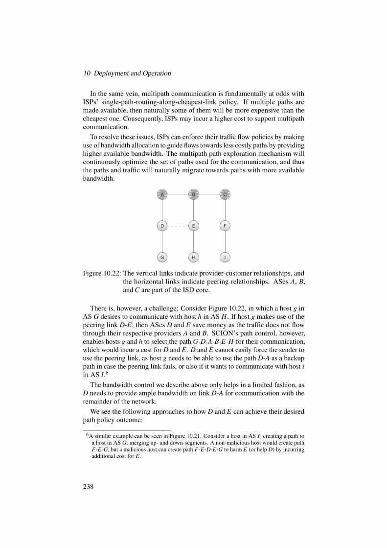
10 Deployment and Operation
In the same vein, multipath communication is fundamentally at odds withISPs’ single-path-routing-along-cheapest-link policy. If multiple paths aremade available, then naturally some of them will be more expensive than thecheapest one. Consequently, ISPs may incur a higher cost to support multipathcommunication.
To resolve these issues, ISPs can enforce their traffic flow policies by makinguse of bandwidth allocation to guide flows towards less costly paths by providinghigher available bandwidth. The multipath path exploration mechanism willcontinuously optimize the set of paths used for the communication, and thusthe paths and traffic will naturally migrate towards paths with more availablebandwidth.
A CB
D E
G
F
H I
Figure 10.22: The vertical links indicate provider-customer relationships, andthe horizontal links indicate peering relationships. ASes A, B,and C are part of the ISD core.
There is, however, a challenge: Consider Figure 10.22, in which a host g inAS G desires to communicate with host h in AS H. If host g makes use of thepeering link D-E, then ASes D and E save money as the traffic does not flowthrough their respective providers A and B. SCION’s path control, however,enables hosts g and h to select the path G-D-A-B-E-H for their communication,which would incur a cost for D and E. D and E cannot easily force the sender touse the peering link, as host g needs to be able to use the path D-A as a backuppath in case the peering link fails, or also if it wants to communicate with host iin AS I.6
The bandwidth control we describe above only helps in a limited fashion, asD needs to provide ample bandwidth on link D-A for communication with theremainder of the network.
We see the following approaches to how D and E can achieve their desiredpath policy outcome:
6A similar example can be seen in Figure 10.21. Consider a host in AS F creating a path toa host in AS G, merging up- and down-segments. A non-malicious host would create pathF-E-G, but a malicious host can create path F-E-D-E-G to harm E (or help D) by incurringadditional cost for E.
238

10.9 SCION Path Policy
• An ISP could inspect the source and destination and decide on the amountof bandwidth granted for each flow. Unfortunately, this approach incurshigh overhead on the router and is thus not recommended.
• Hop-field encryption with explicit path activation can be used to denypaths that should instead traverse a peering link. Since this approachimposes additional overhead for path establishment, its use is not recom-mended for the majority of traffic. Perhaps a hybrid approach can be used,where best-effort traffic can obtain a small amount of bandwidth, and ad-ditional bandwidth is only available for activated paths or SIBRA-basedpaths described in Chapter 11.
• An ISP may charge more for SCION than for a traditional Internetconnection. As domains obtain benefits, such as obtaining better servicethanks to multipath communication and path control, they should bewilling to pay a higher price.
• Per-path pricing can be used to accurately reflect the cost of each path.We are working on a pricing architecture for SCION, which will becomeavailable in a future version.
From our interactions with ISPs, we have made the following observations.ISPs’ cost structures have changed over the past decade, so the cost is largelydue to the fixed costs of maintaining the infrastructure, while the marginalcost of sending a packet is becoming negligible. Evidence for this observa-tion is that transit costs have greatly declined over the past decade, and thatutilization-based billing is being replaced with alternate pricing models. An-other observation is that in modern networks, the path quality is inverselycorrelated with the price, so the best path is often also the cheapest. Therefore,rational senders will automatically pick the best paths and thus also reduce theISPs’ costs.
In conclusion, while there is a conflict between end-host path control andISPs’ traffic flow policies, SCION offers mechanisms to mitigate the conflict.However, based on the economics of modern ISP networks, the conflict seemsto be vanishing. Consequently, we anticipate that clients will be able to benefitfrom path control and multipath communication without incurring higher cost.
239


Part III
Extensions
241


11 SIBRA
ADRIAN PERRIG, RAPHAEL M. REISCHUK,STEPHEN SHIRLEY, PAWEL SZALACHOWSKI
This chapter presents SIBRA, the Scalable Internet Bandwidth ReservationArchitecture, which enables global bandwidth resource allocation. End hosts canuse resource allocations to obtain end-to-end bandwidth guarantees to defendagainst DDoS attacks, which continue to be a menace on today’s Internet.
SIBRA provides scalable inter-domain resource allocations and botnet-sizeindependence — two important properties that prior DDoS defense systemscould not achieve. Intuitively, botnet-size independence enables two end hoststo set up communication regardless of the size of distributed botnets. SIBRAthus ends the arms race between DDoS attackers and defenders.
SIBRA can be implemented with per-flow stateless fastpath operations ontransit routers for reservation renewal, flow monitoring, and policing, whichresults in highly efficient data-plane operation on core routers. SIBRA en-ables dynamic inter-domain leased lines (DILLs), which offer new businessopportunities for ISPs.
The text in this chapter is based on the paper “SIBRA: Scalable InternetBandwidth Reservation Architecture” by Cristina Basescu, Raphael M. Reis-chuk, Pawel Szalachowski, Adrian Perrig, Yao Zhang, Hsu-Chun Hsiao, AyumuKubota, and Jumpei Urakawa, which was published in the Proceedings of theSymposium on Network and Distributed System Security (NDSS), 2016 [22].Some concepts have been revised or extended, such as bandwidth allocationamong core ASes.
Chapter Contents
11.1 Motivation and Introduction . . . . . . . . . . . . . . . . . . . 244
11.2 Goals and Adversary Model . . . . . . . . . . . . . . . . . . . . 245
11.3 Design Overview . . . . . . . . . . . . . . . . . . . . . . . . . . 247
11.4 SIBRA Core Paths . . . . . . . . . . . . . . . . . . . . . . . . . 250
11.5 SIBRA Steady Paths . . . . . . . . . . . . . . . . . . . . . . . . 259
243

11 SIBRA
11.6 SIBRA Ephemeral Paths . . . . . . . . . . . . . . . . . . . . . . 261
11.7 Priority Traffic Monitoring and Policing . . . . . . . . . . . . . 268
11.8 Use Cases . . . . . . . . . . . . . . . . . . . . . . . . . . . . . . 272
11.9 Discussion . . . . . . . . . . . . . . . . . . . . . . . . . . . . . . 273
11.10 Further Reading . . . . . . . . . . . . . . . . . . . . . . . . . . 276
11.1 Motivation and Introduction
A recent discussion among network administrators on the NANOG mailinglist [187] pointedly reflects the current state of DDoS attacks and the trick-iness of suitable defenses: defenses typically perform traffic scrubbing inupstream ASes or in the cloud, but attacks surpassing 20–40 Gbps can stilloverwhelm the upstream link bandwidth and cause congestion that traffic scrub-bing cannot handle. Amplification attacks of up to 400 Gbps [202] and direct,non-amplified attacks from a large army of Internet-of-Things (IoT) devicesof up to 620 Gbps [140] and 1,156 Gbps [188] have been witnessed recently,plaguing websites and critical infrastructures, without any viable solution on thehorizon that can defend the network against such large-scale flooding attacks.
Quality of Service (QoS) architectures at different granularities, such asIntServ [254] and DiffServ [16], fail to provide end-to-end traffic guaranteesat Internet scale: with billions of flows traversing the network core, routerscannot handle the per-flow state required by IntServ, whereas the behaviorof DiffServ’s traffic classification across different domains cannot guaranteeconsistent end-to-end connectivity.
Network capabilities [10, 150, 183, 258, 260] are not effective against at-tacks such as Coremelt [231] that build on legitimate low-bandwidth flows toswamp core network links. FLoc [150] in particular considers bot-contaminateddomains, but it is ineffective in the case of dispersed botnets.
Fair resource reservation mechanisms (per source [181], per flow [65, 254,258], per destination [260], per computation [196], and per class [16]) arenecessary to resolve link-flooding attacks, but are not sufficient: none of themprovides botnet-size independence, a critical property for viable DDoS defense.
Botnet-size independence is the property in which a legitimate flow’s allo-cated bandwidth does not diminish below a guaranteed allocation when thenumber of bots in other ASes increases. Per-flow and per-computation resourceallocation, for instance, will reduce their allocated bandwidth towards 0 whenthe number of bots that share the corresponding resources increases.
244

11.2 Goals and Adversary Model
To illustrate the importance of botnet-size independence, we observe howprevious systems suffer from the tragedy of the network-link commons,1 whichrefers to the problem that the allocation of a shared resource will diminishtoward an infinitesimally small allocation when many entities have the incentiveto increase their “fair share”. In particular, per-flow fair-sharing allocations(including per-class categorization of flows) suffer from this fate, as each sourcehas an incentive to increase its share by simply creating more flows. However,even when the fair-sharing system is not abused, the resulting allocations canbe too small to be useful.
To explain in more detail, denoting by N the number of end hosts in theInternet, per-source or per-destination schemes could ideally conduct fair shar-ing of Op1{Nq based on all potential sources or destinations that traverse agiven link. However, with increasing hop-count distance of the link from thesource or to the destination, the number of potential sources or destinations thattraverse that link increases exponentially. Per-flow reservation performs evenmore poorly, allocating a bandwidth slice of only Op1{M2q in the case of aCoremelt attack [231] between M bots, and only Op1{pMPqq during a Crossfireattack [129] with P destination servers that can be contacted. In the presenceof billions of end hosts engaged in end-to-end communication, the allocatedbandwidth becomes too small to be useful.
SIBRA’s novel bandwidth allocation system operates at Internet scale andresolves the drawbacks of prior systems. In a nutshell, SIBRA provides inter-domain bandwidth allocations (which enable the construction of dynamic inter-domain leased lines (DILLs), and in turn enable new ISP business models).SIBRA’s bandwidth reservations let an AS guarantee a minimal amount ofbandwidth to its end hosts by limiting the possible paths in end-to-end com-munication. An important property of SIBRA is its per-flow stateless fastpathoperation on transit routers for reservation renewal, monitoring, and policing,which results in scalable and efficient router operation.
11.2 Goals and Adversary Model
The goal of SIBRA is to defend against link-flooding attacks, in which dis-tributed attackers collude by sending traffic to each other (Coremelt [231]) or topublicly accessible servers (Crossfire [129]) in order to exhaust the bandwidthof targeted servers and Internet backbone links. In the case of Coremelt, itmay be impossible to limit the traffic volume (e.g., by TCP congestion control)since the participating hosts are under adversarial control and can thus run anyprotocol. In the case of Crossfire, distributed attackers collude by sending traffic
1We use this term following Garrett Hardin’s Tragedy of the Commons [107], which accordingto the author has no technical solution, but instead “requires a fundamental extension inmorality.” As we should not expect attackers to show any of the latter, we believe in atechnical solution — at least for the Internet!
245

11 SIBRA
to legitimate hosts in order to congest network links leading towards selectedservers. We note that many other known attacks constitute a combination of thetwo cases above.
Adversary Model
We assume that ASes may be malicious and misbehave by sending largeamounts of traffic (bandwidth requests and data packets). We furthermoreassume any AS in the world can contain malicious end hosts (e.g., as partsof larger botnets). In particular, there is no constraint on the distribution ofcompromised end hosts. However, attacks launched by routers that intentionallymodify, delay, or drop traffic cannot be handled by SIBRA.
Desired Properties
Under the defined adversary model, we postulate the following properties alink-flooding-resilient bandwidth reservation mechanism should satisfy:
• Botnet-size independence: The amount of guaranteed bandwidth perAS does not diminish (below a reserved cap) with an increasing numberof bots in ASes other than source or destination.
• Per-flow stateless operation: The mechanism’s overhead on routersshould be small. In particular, border routers of transit ASes should notrequire per-flow, per-source, or per-destination state in the fastpath, whichcan lead to state exhaustion attacks. Our analysis of real packet traces oncore links (see Section 11.9.2) supports the validity of this property.
• Scalability: The overhead of the system should scale to the size ofthe Internet, including management and setup, AS contracts, router andend-host computation and memory, as well as communication bandwidth.
To achieve the above properties, SIBRA directly uses SCION’s concepts ofisolation and path control, and performs a hierarchical bandwidth decompositionat the granularity of ASes: Figure 11.1 depicts an example of four ISDs, inwhich the two end hosts S and D in different ISDs are connected by stitchingthree types of path segments together: an up-segment from S to its ISD core,a core-segment within the Internet core (from source ISD to destination ISD),and a down-segment from D’s ISD core to end host D. Intuitively, SCION’sisolation property applied to SIBRA enables ASes inside an ISD to establishpaths with bandwidth guarantees: SIBRA steady paths inside the ISDs, andSIBRA core paths between ISD cores. The SIBRA steady paths are set upindependently of bandwidth reservations in other ISDs. Finally, a third type,end-to-end bandwidth reservation, called SIBRA ephemeral paths, will thenbe based on the reservations inside and between the ISDs, but will be lower-bounded for each AS. In particular, malicious entities will not be able to reducethe guaranteed long-term allocation of other ASes.
246

11.3 Design Overview
SIBRA scales to the size of the Internet because the SCION network containsonly a small number of ISDs, each with a small number of core ASes. Therefore,it is possible to perform resource allocation per neighboring core AS. Similarly,within an ISD, resources can be allocated based on customer-provider contracts.
11.3 Design Overview
This section describes the design of SIBRA, in particular bandwidth reservationsand their enforcement. After a brief overview, we describe SIBRA’s reservationtypes in detail.
A key insight of SIBRA is that hierarchical decomposition of the bandwidthallocation problem can make allocation management and configuration scale tothe size of the Internet. Specifically, SIBRA uses three types of paths:
SIBRA Core Paths
between core ASesacross ISDs
SIBRA Ephemeral Paths
between end hostsfor end-to-end communication
SIBRA Steady Paths
between ASesinside ISD
SIBRA core paths (the double continuous lines in Figure 11.1) can scalablybe established between core ASes due to their relatively small number. Withineach ISD, providers sell bandwidth to their customers, and customers canestablish intermediate-term reservations for specific intra-ISD paths, which wecall SIBRA steady paths (the dashed lines in Figure 11.1). Steady paths areused for connection setup traffic: core and steady paths in conjunction enablethe creation of short-term end-to-end reservations across ISDs, which we callSIBRA ephemeral paths (the solid green lines in Figure 11.1). Ephemeral paths,in contrast to steady paths, are used for the transmission of high-throughputdata traffic.
SIBRA paths are established over SCION links with the following allocation(see also Figure 11.2): 85% of the bandwidth of each SIBRA link is allocatedfor SIBRA traffic (i.e., steady and ephemeral traffic), and the remaining 15%for best-effort traffic. These proportions are flexible system parameters; wediscuss the current choice in Section 11.9.1. Note that the proportion forsteady and ephemeral traffic constitutes an upper bound: in case the steady andephemeral bandwidth is not fully utilized, it is allocated to best-effort traffic(see Section 11.6).
An important feature of SIBRA is that steady paths, besides carrying thecontrol traffic of links inside an ISD, also limit the bandwidth for ephemeral
247

11 SIBRA
D4 A3 S ISD
Austria
ISD Japan
ISD Germany
A2
D1
C1
D2
A1
D3
D
ISD United States
B1
core pathsteady pathephemeral path
provider-to-customer linkpeering link
!
!!
!
!
!
Figure 11.1: Sample topology with four ISDs and their ASes (the core ASesare drawn in dark blue, non-core ASes in light blue). The SIBRAephemeral path (green) from end host S to D is created along aSIBRA steady up-path, a SIBRA core path, and a SIBRA steadydown-path. The attack traffic (red) cannot diminish the reservedbandwidth on SIBRA ephemeral paths.
paths: an ephemeral path is created by launching a request through existingsteady paths, whose amounts of bandwidth limit the bandwidth of the requestedephemeral paths. More precisely, an ephemeral path is created through thecombination of (a) a SIBRA steady up-path in the source ISD, (b) a SIBRAcore path, and (c) a SIBRA steady down-path in the destination ISD.2 Theephemeral path request uses only steady and core paths, while the actual datatraffic uses only the ephemeral path. The more bandwidth on steady (and core)paths is purchased locally within an ISD (and between ISDs), the larger thefraction of ephemeral bandwidth an end host can obtain to any other end hoston the Internet.
If an AS is dissatisfied with its reservation, it can purchase more bandwidthfor its SIBRA steady paths, as well as request its core AS to purchase a largerallocation for the SIBRA core path, which the AS would likely need to pay
2For instance, Figure 11.1 shows an ephemeral path from host S in AS A3 to host D in AS D4.If the source and destination are located in the same ISD, then the SIBRA core path may notbe necessary.
248

11.3 Design Overview
best-effort
D3 D4
D1
steadypath
ephemeralpath
D
SIBRAsteady + ephemeral85%
15%
corepath
D2
C1C1
Figure 11.2: The anatomy of SIBRA links: 85% of the link bandwidth is usedfor SIBRA traffic (i.e., core/steady/ephemeral traffic), and 15% forbest-effort traffic. In case the 85% SIBRA traffic is not fully used,the remaining bandwidth can be utilized by best-effort flows.
for. Alternatively, a different core path that provides higher bandwidth could beused instead.
Based on these ideas, it becomes intuitively clear how botnet-size indepen-dence is achieved and how the tragedy of the network-link commons is resolved:each pair of ASes can obtain a guaranteed bandwidth allocation, based on therespective SIBRA steady paths and based on the SIBRA core paths. A botnetcannot influence this guaranteed allocation, no matter what its size and distribu-tion. A bot can only use up the bandwidth allocated to the AS it resides in, butnot lower the guaranteed allocation of any other AS. It is thus the responsibilityof an AS to manage its allocations, and thereby to prevent bots from exhaustingthe resources of other hosts within that AS.
To make SIBRA viable for practical applications, it is important to ensure thatall aspects of the system are scalable and efficient, which holds in particular forfrequent operations such as flow admission, reservation renewal, and monitoringand policing. For instance, all fastpath operations are per-flow stateless ontransit border routers to avoid state-exhaustion attacks and to simplify the routerarchitecture. The SIBRA service in each deploying AS relieves the SCIONborder routers from dealing with the setup of SIBRA steady/core paths; itprocesses steady/core reservation requests and updates accounting and policingtables at the border routers.
249

11 SIBRA
To protect the SIBRA control plane, we mandate that a requester authenticatesits requests. A request contains a list of MACs, each corresponding to an on-path AS (the requester derives the corresponding keys through the DRKeyprotocol (Section 12.5).
11.4 SIBRA Core Paths
Core ASes establish SIBRA core paths to determine a guaranteed amount ofbandwidth for ephemeral traffic (see Figure 11.2, between AS C1 and AS D2).If one of the core ASes sends more traffic than agreed on, the AS is heldaccountable, according to the established contracts.
A SIBRA core path between two core ASes is established by either of the twoASes and provides reciprocal reservations (i.e., in both directions with possiblydiffering bandwidth amounts). The approach relies on two main techniques,which are aliasing and telescoping.
Telescoping and Aliasing
Telescoping permits a SIBRA core path to be nested inside another corepath. An AS can leverage telescoping to extend a given reservation byadding an AS at the reservation’s end, e.g., a reservation on the path pA1 ÑC1q can be extended to pA1 ÑC1 Ñ D1q, and then to pA1 ÑC1 Ñ D1 ÑD2q, as well as to pA1 ÑC1 Ñ D1 ÑC2q, assuming sufficient bandwidthcapacities (see below). To enable efficient policing, the telescopicallyextended core path is said to be nested within its base core path, e.g.,pA1 ÑC1 Ñ D1q is nested inside pA1 ÑC1q.The way the bandwidth accounting is implemented is through aliasing, sothat different nested paths are accounted to the same reservation. Aliasingpermits a requester to use multiple identifiers to refer to reserved bandwidthon a link, which naturally models the fact that multiple end-to-end pathsshare some of the links between the core ASes. For example, in Figure 11.3,the three paths pA1 Ñ C1q, pA1 Ñ C1 Ñ D1q, and pA1 Ñ C1 Ñ C2q allshare the link A1-C1, thus aliasing enables the reservations for pathspA1 Ñ C1 Ñ D1q and pA1 Ñ C1 Ñ C2q to utilize the same reservationas pA1 ÑC1q. Aliasing of identifiers simplifies accounting and enablestelescoping.
Reservations are usually reciprocal, that is, every request contains (a) ademand for outgoing bandwidth, and (b) suggestions for incoming bandwidththe requester accepts (which can be zero). This ensures atomic requests, i.e.,requests are either accepted and immediately valid; or requests are denied, inwhich case hints are given that enable a quick follow-up request with modifiedbandwidth values. If accepted, reservations have a lifetime of a few minutes (3minutes in the current design).
250

11.4 SIBRA Core Paths
peering linkp2c link
2 Tbps to C1
D2D1
bw requestconfirmation
A1
C2
C1
1(rev: 5
00 - 800
Mbps)
ack + 700 Mbps
2
1 Tbp
s to
D1
(rev:
400 -
600 M
bps)
3
ack
+ 50
0 M
bps
4
B1
Figure 11.3: SIBRA core path established between core AS A1 and AS D2.
We differentiate between the renewal and the extension of a SIBRA core path.A renewal prolongs the lifetime of an existing core path (i.e., the reservationvalidity duration), but keeps its structure (i.e., the order of the involved coreASes); an extension extends the core path by one (or more) hops (i.e., theinvolved core ASes), but retains its validity time.
Setup of SIBRA Core Paths
The setup of SIBRA core paths is best explained by means of the exampleprovided in Figure 11.3. The SIBRA core path from core AS A1 to core AS D2is established by A1 when requesting bandwidth to D2 (using the correspondingcore-segment between A1 and D2). More specifically, A1 has two options forsending a SIBRA core path request along the path to D2:
• initial: AS A1 sends an initial request directly to AS D2, which each coreAS on the path acknowledges or denies (see below), or
• telescope: AS A1 first sets up a SIBRA core path to AS C1 (using aninitial request as in Step ¬ in Figure 11.3) and later extends the estab-lished core path by sending a telescope request (Step ®) such that theextended SIBRA core path includes the next core AS, D1 in this case.This extension step is repeated until the core path terminates at D2.
We note that an initial request can span one or multiple hops (e.g., A1’s initialrequest can terminate at C1, but also at C1, D1, or D2). Likewise, a telescope
251

11 SIBRA
request can span one or multiple hops (e.g., an initial request to C1 can beextended to D1 or C2, but also to D2).
In the following, we first describe the telescope procedure. A1’s initialrequest (Step ¬) specifies the amount of outgoing traffic (a value of 2 Tbps)and suggests the desired amount of incoming traffic it would accept (a rangebetween 500 Mbps and 800 Mbps). C1 can now decide to accept the requestand send a confirmation message (“ack”) back to A1 (Step ), which includesa return request of, say 700 Mbps, that A1 will accept and confirm since theoffered bounds are respected. A1 can then immediately start sending traffic ofup to 2 Tbps, and receive traffic of up to 700 Mbps from C1.
C1 can also deny the request from A1, in which case C1 would proposedifferent bandwidth values to be used instead, for instance 1.5 Tbps (insteadof 2 Tbps) and up to 900 Mbps on the return path. This case is not shown inFigure 11.3. A1 would have to send a second request that is adapted accordingly,if it agrees with the suggested values.
We note that in practice, for efficient operation, an AS does not specify arbi-trary bandwidth values (or ranges); instead the AS chooses from a predefinedset of bandwidth classes.
Telescope Extension
If AS A1 wants to extend its SIBRA core path (so that it terminates at AS D1),it sends a new SIBRA core path request, say of 1 Tbps, along the path to AS D1(Step ®), and declares that the new path should be an alias (on the link A1-C1)for the previously established core path to AS C1. For the sake of illustration,we introduce core path identifiers such as xA1C1y for the SIBRA core path fromrequest ¬, and xA1C1D1y for its first extension.3
In this context, xA1C1D1y is an alias for xA1C1y on the link A1-C1, whichmeans that from the perspective of the ingress border router at AS C1, any datapacket that contains either xA1C1y or xA1C1D1y will be treated equally withrespect to checking that the base reservation on the ingress link, in this case2 Tbps, is not exceeded. This is irrespective of whether xA1C1y or xA1C1D1yis used. We annotate base identifiers with a small rectangle n , and aliasedidentifiers with a star ˚ in front of the identifier:
Link A1-C1, at ingress C1
nxA1C1y 2 Tbps˚xA1C1D1y /
However, to let A1’s border router correctly police the outgoing traffic, itconsiders the extended identifier xA1C1D1y nested inside the base identifier
3Our implementation uses fixed-length, non-guessable randomized identifiers, which we omithere for the sake of readability.
252

11.4 SIBRA Core Paths
xA1C1y. This entails not only the constraint that 2 Tbps of its base reservationare met, but also that A1’s traffic to D1 stays within the reserved 1 Tbps. Weannotate nested identifiers with an arrow ë as follows:
Link A1-C1, at egress A1
nxA1C1y 2 TbpsëxA1C1D1y 1 Tbps
C1’s egress border router on C1- D1, however, does not consider the twoidentifiers as aliases or nested when policing the outgoing traffic to D1. It willforward only the traffic that contains the identifier xA1C1D1y and only up to1 Tbps.
Link C1- D1, at egress C1
nxA1C1D1y 1 Tbps
The SIBRA core path can be extended further (not shown in Figure 11.3):AS A1 can send yet another extension request for a new path xA1C1D1D2y of800 Mbps and declare xA1C1D1D2y an alias of xA1C1D1y. Consequently, onthe link A1-C1, all three core paths are aliases of the same reserved 2 Tbps.A1’s border router considers the identifiers to be nested (left table). On the linkC1- D1, there are only two aliased identifiers for the reserved bandwidth (righttable).
Link A1-C1, at egress A1
nxA1C1y 2 TbpsëxA1C1D1y 1 TbpsëxA1C1D1D2y 800 Mbps
Link C1- D1, at egress C1
nxA1C1D1y 1 Tbps˚xA1C1D1D2y /
The rule of thumb here is that egress border routers of the source ASes usenested identifiers to ensure that outgoing traffic does not exceed the reservedbandwidth margins. The same applies to ingress border routers of the destinationASes. All transit border routers, however, enable more efficient operation inthat aliases are used instead. We provide more examples of aliasing and nestinglater in this section.
Initial Requests
In the case of an initial request that is sent directly to the destination AS, sayD2, every transit AS on the path accepts or denies, as above. In the denial case,modified bandwidth values are suggested by each transit AS and collected in therequest packet (see also Case (d) in Figure 11.6 on Page 260). The destinationwill return the suggested bandwidth values to the requester, who can then issuea second request with bandwidth values adjusted accordingly.
253

11 SIBRA
Algorithm 8 Bandwidth determination at a transit core AS.1: demandLinkAS: a map that stores demanded bandwidth per a (link, AS) pair.2: demandTransit: a map that stores demanded bandwidth between two links.3: reservedLinkAS: a map that stores reserved bandwidth per a (link, AS) pair.4: limit: a map that for a (link1, link2) pair stores a bandwidth limit (ď
minplink1.capacity,link2.capacity)). This map can express a traffic matrix (de-rived from average traffic patterns) or can be configured by an AS operator.
5: δ P p0,1q: an AS’s parameter.
6: procedure HANDLEREQUEST(req)7: bwReq = min(req.BW, limit[req.inLink, req.outLink])8: demandLinkAS[req.inLink, req.src] += bwReq9: demandLinkAS[req.outLink, req.src] += bwReq
10: demandTransit[req.inLink, req.outLink] += bwReq11: bwDet = DetermineBW(bwReq, req.inLink, req.outLink)12: if bwDet == req.BW then13: Reserve the bandwidth14: else15: Send bwDet as a hint16: end if17: end procedure18: procedure DETERMINEBW(bwReq, inLink, outLink)19: inAvailable = inLink.capacity - sum(reservedLinkAS[inLink, any])20: propIn = bwReq / sum(demandLinkAS[inLink, any])21: bwInIdeal = inLink.capacity*propIn22: bwIn = min(bwReq, bwInIdeal, inAvailable˚δ )23: totalTransitDemand = 024: for inLinkT , val P demandTransit[any, outLink] do25: totalTransitDemand += min(val, inLinkT .capacity, outLink.capacity)26: end for27: linkDemand = min(demandTransit[inLink, outLink], limit[inlink, outLink]) /28: totalTransitDemand29: outAvailable = outLink.capacity - sum(reservedLinkAS[any, outLink])30: bwOutIdeal = (bwReq / demandTransit[inLink, outLink])*linkDemand31: bwOut = min(bwOutIdeal, outAvailable˚δ )32: return min(bwIn, bwOut)33: end procedure
Algorithm 8 describes how a transit core AS could decide how much band-width a given request should be granted. To enable scaling, decisions are madeper neighbor link. The first step of the algorithm is to normalize a requestand to add the demand to the bandwidth demand maps.4 Then, the bandwidthdetermination procedure is executed. First, bandwidth for an incoming link(bwIn) is computed. This is the minimum of the weighted available bandwidthof the incoming link5 and the proportion between the demanded amount and
4The algorithm operates on 3-minute request windows, and bandwidth reserved and stored inthe maps automatically expires at the end of its request window.
254

11.4 SIBRA Core Paths
the sum of all demands on the incoming link. The bandwidth for the outgoinglink (bwOut) is computed in a similar way, but the proportion is calculatedbetween the demand for the pair of incoming and outgoing links and the sum ofall demands that use the outgoing link. The offered bandwidth is the minimumof bwIn and bwOut. If that value equals the requested bandwidth, then thebandwidth can be reserved. Otherwise, the requester AS is informed about theoffered bandwidth. The requested bandwidth for link pairs can be limited by anAS through the limit map.
In case all ASes have agreed, a successful request is delivered back to the re-quester (Case (c) in Figure 11.6). This message contains all necessary identifiersso that the request is considered active and the requester can instantaneouslyuse the reserved bandwidth until its expiration.
Requests for the Reverse Direction
As previously mentioned, a SIBRA core path request contains not only thefixed bandwidth value that the sending core AS requests to the destination coreAS but also a bandwidth range, which the destination core AS uses as a guideto choose a bandwidth value and then to set up a reservation in the reversedirection.
Figure 11.4 shows how bandwidth in the reverse direction is established:with the confirmation (“ack”) to the initial request (“req”), a reciprocal requestis issued that reserves bandwidth in the reverse direction. After both requestshave been confirmed, the border routers are updated to perform policing andaccounting for traffic carrying the request identifiers. In Figure 11.4, theborder routers are updated twice: once after the first request, and once afterthe telescopic extension. The changes from the previous allocation table arehighlighted in blue.
Example: Nesting and Aliasing at SCION Border Routers
In the following, we will explain each step shown in Figure 11.4. A1 requests acore path to its neighbor C1, according to the topology shown in Figure 11.3. A1thus issues a request of 2000 Mbps using a fresh identifier xA1C1y. A1 specifiesa range of 500 to 800 Mbps as a suggestion for traffic in the reverse direction.The bullet ‚ indicates an empty value for reference identifiers, meaning that therequest is an initial request: it neither extends an existing core path, nor does itcreate an alias.
C1 accepts the request and issues a reverse request of 700 Mbps, for whichit chooses a fresh identifier xC1A1y. As the identifier serves as a response tothe first request, C1 links its new identifier to the received identifier xA1C1y (as
5The available bandwidth on incoming and outgoing links is weighted by the parameter δ toleave some amount of bandwidth for new requests.
255

11 SIBRA
A1 C1 D1
req(2000,xA1C1y,‚,500,800)
ackxA1C1y + req(700,xC1A1y,‚,‚,‚)
ackxC1A1y
Ingress:■ xC1A1y@700˚xA1C1yEgress:■ xA1C1y@2000˚xC1A1y
Ingress:■ xA1C1y@2000˚xC1A1yEgress:■ xC1A1y@700˚xA1C1y
req(1000,xA1C1D1y,xA1C1y,500,700) req(1000,xA1C1D1y,‚,500,700)
ackxA1C1D1y + req(600,xD1C1A1y,‚,‚,‚)ackxA1C1D1y + req(600,xD1C1A1y,‚,‚,‚)
ackxD1C1A1y ackxD1C1A1y
Ingress:■ xC1A1y@700˚xA1C1yëxD1C1A1y@600˚xA1C1D1yEgress:■ xA1C1y@2000˚xC1A1yëxA1C1D1y@1000˚xD1C1A1y
Ingress:■ xA1C1y@2000˚xC1A1y˚xA1C1D1y˚xD1C1A1yEgress:■ xC1A1y@700˚xA1C1y˚xD1C1A1y˚xA1C1D1y
Ingress:■ xD1C1A1y@600˚xA1C1D1y
Egress:■ xA1C1D1y@1000˚xD1C1A1y
Ingress:■ xA1C1D1y@1000˚xD1C1A1yEgress:■ xD1C1A1y@600˚xA1C1D1y
Figure 11.4: SIBRA core path request messages. Within each AS, the SIBRAservice sends and processes requests.
specified in the acknowledgment). This link contains sufficient informationfor the SIBRA service to update the border routers that the requested identifierxC1A1y has the alias xA1C1y. The reverse request does not contain a suggestedbandwidth range since it has been set up with the first request.
A1 accepts the reverse request and sends an acknowledgement back to C1.Thereafter, both A1 and C1 update their border routers as specified in the boxesin Figure 11.4: overall, there are eight entries, but — thanks to the aliasing ofidentifiers — only four of them (the base reservations, marked with a rectanglen) are necessary for accounting and policing purposes. The aliases (markedwith a star ˚) identify the reverse data traffic that uses the same identifier asthe original traffic. For example, traffic initiated at C1 and sent to A1 will usethe identifier xC1A1y and can send at up to 700 Mbps. When A1 replies, it willkeep the identifier xC1A1y, but can send at a rate of 2000 Mbps.
A1 next establishes a core path to D1. As it extends its existing reservationto C1, it will also specify (in addition to a fresh identifier xA1C1D1y and the
256

11.4 SIBRA Core Paths
bandwidth of 1000 Mbps) the reference to the existing core path that it extends;in this case xA1C1y.
When the request arrives at C1, it will remove the reference to the extendedcore path xA1C1y, since it terminates at C1. In other words, the referenceidentifier will not be useful beyond C1. After removing the reference, therequest is forwarded to D1. We assume that D1 agrees and chooses 600 Mbpsfor the reverse reservation back to A1, which confirms the reservation. All threeASes update their border routers as highlighted in blue in Figure 11.4.
Egress border routers use nested identifiers (a) when referenced identifiersare specified, and (b) when the border router is in the source AS (example:xA1C1D1y for A1.Egress on the link to C1). The ingress border router of thetransit AS C1 uses an alias instead (example: xA1C1D1y for C1.Ingress on thelink from A1). Ingress border routers use nested identifiers when located in thedestination AS (example: xD1C1A1y for A1.Ingress on the link from C1). Alltransit ASes use aliases or base identifiers.
Example: Telescoping After Two-Side Reservations
We next explain a more involved scenario, as depicted in Figure 11.5. The maindifference to the example shown in Figure 11.4 is that both A1 and D1 establishreservations with C1 before A1 telescopically requests bandwidth to D1.
A1 sets up a reservation with C1 as before. D1 requests bandwidth to C1 of3000 Mbps. It creates a fresh identifier xD1C1y and accepts 1400 Mbps fromC1. This identifier is used in request ² when D1 sends its reverse request to A1.In this case, D1 knows it has a reservation with C1 and thus creates a telescopicextension for it. To this end, it includes the base identifier as a reference. Thisreference will be removed by C1 in the forwarded request ³ since xD1C1yterminates at C1. Similarly, and as in the previous example, C1 removes thereference identifier xA1C1y when forwarding request ° to D1.
As a consequence, the border routers are updated by the SIBRA service asshown in Figure 11.5.
Lifetime and Renewal
SIBRA core reservations have a lifetime of 3 minutes; this is a SIBRA systemparameter that we chose to enable rapid adjustment to changing network con-ditions. Within the lifetime of a SIBRA core path, the core AS (that has beengranted the corresponding reservation) has guaranteed access to the forwardsteady bandwidth as reserved. Client end hosts can obtain ephemeral bandwidthaccording to the steady bandwidth as described in Section 11.6 below.
257

11 SIBRA
A1 C1 D1
① req(2000,xA1C1y,‚,500,800)
② ackxA1C1y + req(700,xC1A1y,‚,‚,‚)
ackxC1A1y
Ingress:■ xC1A1y@700˚xA1C1yEgress:■ xA1C1y@2000˚xC1A1y
Ingress:■ xA1C1y@2000˚xC1A1yEgress:■ xC1A1y@700˚xA1C1y
③ req(3000,xD1C1y,‚,1200,1500)
④ ackxD1C1y + req(1400,xC1D1y,‚,‚,‚)
ackxC1D1y
Ingress:■ xA1C1y@2000˚xC1A1yEgress:■ xC1A1y@700˚xA1C1y
Ingress:■ xD1C1y@3000˚xC1D1yEgress:■ xC1D1y@1400˚xD1C1y
Ingress:■ xC1D1y@1400˚xD1C1yEgress:■ xD1C1y@3000˚xC1D1y
⑤ req(1000,xA1C1D1y,xA1C1y,500,700) ⑥ req(1000,xA1C1D1y,‚,500,700)
⑦ ackxA1C1D1y + req(600,xD1C1A1y,xD1C1y,‚,‚)⑧ ackxA1C1D1y + req(600,xD1C1A1y,‚,‚,‚)
ackxD1C1A1y ackxD1C1A1y
Ingress:■ xC1A1y@700˚xA1C1yëxD1C1A1y@600˚xA1C1D1yEgress:■ xA1C1y@2000˚xC1A1yëxA1C1D1y@1000˚xD1C1A1y
Ingress:■ xA1C1y@2000˚xC1A1y˚xA1C1D1y˚xD1C1A1yEgress:■ xC1A1y@700˚xA1C1y˚xD1C1A1y˚xA1C1D1y
Ingress:■ xD1C1y@3000˚xC1D1y˚xD1C1A1y@600˚xA1C1D1yEgress:■ xC1D1y@1400˚xD1C1y■ xA1C1D1y@1000˚xD1C1A1y
Ingress:■ xC1D1y@1400˚xD1C1y■ xA1C1D1y@1000˚xD1C1A1yEgress:■ xD1C1y@3000˚xC1D1yëxD1C1A1y@600˚xA1C1D1y
Figure 11.5: SIBRA core path request messages.
Authentication
SIBRA core path requests are authenticated using public-key signatures thatstate the requests’ validity at AS-level granularity. The SIBRA service checksthe signed requests using SCION’s AS certificates.
As we will discuss later in the chapter, SIBRA relies on efficient messageauthentication codes (MACs) to enable stateless fastpath operation on transitborder routers.
258

11.5 SIBRA Steady Paths
Payment
Core paths not only guarantee bandwidth between ISDs, they also regulate thetraffic-related money flow between core ASes according to existing provider-to-customer (p2c) or peering (p2p) relationships (e.g., p2c between AS D1 andAS D2, and p2p between AS C1 and AS D1).
In line with today’s state of affairs, we believe that market forces create aconvergence of allocations and prices when ASes balance bandwidth with theirpeers and adjust contracts such that direct core AS neighbors are satisfied. Theneighbors, in turn, recursively adapt their contracts to satisfy the bandwidthrequirements of their customers. Paying customers thus indirectly indicate tocore ASes the destination ISDs of core paths and their desired bandwidth.
Path Format
SIBRA paths are created using SCION paths and have a similar structure. Inorder to construct a SIBRA path, an AS creates cryptographically authenticatedreservation tokens (RTs), which are similar to hop fields. A SIBRA pathis a series of RTs prepended with an info field. An RT generated by ASi isauthenticated using a cryptographic key Ki known only to ASi, by which ASi canlater verify if an RT embedded in the data packet is authentic. More specifically,the RT contains the authenticated ingress and egress interfaces of ASi, andthe reservation request information (such as reservation lifetime or amount ofreserved bandwidth). In order to prevent an attacker from crafting a path frompartial RT chunks, the RTs are onion-authenticated:
RTASi “ ingressASi ‖ egressASi ‖MACKipingressASi ‖ egressASi ‖ Request ‖ RTASi´1q
(11.1)
where Request is defined as BWreq ‖ ExpTime ‖ FlowID ‖ ResvID.The same path format is used by steady and ephemeral paths (described
throughout the following sections).
11.5 SIBRA Steady Paths
Steady paths are intermediate-term reservations that are established by ASeswithin an ISD. For example, in Figure 11.1, AS A3 sets up a steady path toA1, and D4 sets up a steady path to D2. Steady paths expire, but their validityperiods can be periodically extended (in our current implementation the defaultvalidity period is 3 minutes). An endpoint AS can voluntarily tear down itssteady path before expiration and set up a new steady path. Steady paths areset up similarly to core paths, though not between core ASes across ISDs,but between ASes inside an ISD. SIBRA uses steady paths (in addition to
259

11 SIBRA
core paths) as building blocks for ephemeral paths: to guarantee availabilityduring connection setup and to perform weighted bandwidth reservations, aswe explain in more detail below.
Reservation Request
SIBRA leverages SCION’s PCBs (Sections 2.1 and 7.1.1), which disseminatetop-down from the ISD core to the ASes. On their journey downstream, theycollect AS-level path information as well as information about the currentamount of available bandwidth for each link. When a leaf AS receives such abeacon with information about a path segment, the AS can decide to submita reservation request for a steady path on that segment. In this case, the leafAS (e.g., AS A3 in Figure 11.1, or S3 in Figure 11.6) computes a new flowID, chooses the amount of bandwidth and the expiration time, and sends asteady path reservation message up the path to the core. The requested amountof bandwidth can be chosen from a number of predefined bandwidth classes,introduced for monitoring-optimization purposes (Section 11.7). The actualrequest messages for steady paths are established similarly to the way SIBRAcore paths are established (Section 11.4).
(Step III) RT generation
flowID1
flowID2
flowID3
(Step I)Admission control
temporary reserv. actual reserv. failed reserv.
(Step IV) Actual reservation
(Step II)Temporaryreservation
a
b
c
ingressrouter
SIBRA SERVICE
egressrouter
S2
S1source
source
destinationS3
source
d
D
Figure 11.6: A transit AS processing reservation requests from sources S1, S2,S3 to destination D.6 Steady/core path requests are processed bythe SIBRA service, while ephemeral path requests are efficientlyprocessed by the border routers.
Each intermediate AS on the path to the core performs admission controlby verifying the availability of steady bandwidth to its neighbors on the path(Step I in Figure 11.6). Given the fact that inbound traffic from multiple ingressrouters may converge at a single egress router, admission control is performedat both ingress and egress routers. Specifically, the ingress router of ASi checks
260

11.6 SIBRA Ephemeral Paths
the availability of steady bandwidth on the link ASi´1 Ñ ASi, and the egressrouter of ASi on the link ASi Ñ ASi`1. If enough bandwidth is available atboth the ingress and the egress router (Case (a) in Figure 11.6), both routerstemporarily reserve the requested bandwidth (Step II). Subsequently, the egressrouter of ASi issues a cryptographically authenticated reservation token (RT)(see Equation 11.1) encoding the positive admission decision (Step III).
If at least one of the routers of ASi cannot meet the request (Case (b) inFigure 11.6), it suggests an amount of bandwidth that could be offered instead,and adds this suggestion to the packet header. Although already failed, therequest is still forwarded to the ISD core to collect suggested amounts ofbandwidth from subsequent ASes. This information helps the source make aninformed and direct decision in a potential bandwidth re-negotiation. At thesame time, the denying AS immediately sends a denial response back to therequester to enable early notification.
As steady paths are only infrequently updated, scalability and efficiency ofsteady path updates are of secondary importance. However, ASi can still performan efficient admission decision by simply considering the current utilization ofits directly adjacent AS neighbors. Such an efficient mechanism is necessary forreservation requests (and renewals) to be fastpath operations, avoiding accessingper-path state. In case of a positive admission decision, ASi needs to account forthe steady path individually per leaf AS from which the reservation originates.Only slowpath‹ operations, such as policing of misbehaving steady paths, needto access this per-path information about individual steady paths.
Confirmation and Usage
When the reservation request reaches the destination6, the destination D repliesto the requesting source (e.g., S3) either with a confirmation message (Case (c)in Figure 11.6) containing the RTs accumulated in the request packet header,or with a rejection message (Case (d) in Figure 11.6) containing the suggestedbandwidth information collected before. As the confirmation message travelsback to the source, every ingress and egress router accepts the reservationrequest and switches the reservation status from temporary to active (Step IV).
11.6 SIBRA Ephemeral Paths
Ephemeral paths are short-lived end-to-end reservations for high-bandwidthcommunication between end hosts (unlike core/steady paths, which are estab-lished between ASes). In the spirit of fair allocation of joint resources, the
6 We use the term destination in the following (and also in Figure 11.6) to stay as general aspossible. For steady-path reservation requests, the destination is the ISD core; for ephemeral-path reservation requests, the destination will be another end host (Section 11.6).
261

11 SIBRA
lifetime of ephemeral paths is limited to 16 seconds in order to curtail the timeof resource over-allocation; they thus require continuous renewals throughoutthe life of the connection. The source, the destination, and any on-path AScan rapidly re-negotiate the allocations. Figure 11.1 on Page 248 shows twoephemeral paths, one inside an ISD, and one across three ISDs — from endhost S in AS A3 to end host D in AS D4.
Ephemeral Paths from Steady and Core Paths
An ephemeral path reservation is launched by an end host (as opposed to asteady path reservation, which is launched by an AS). The end host (e.g., host Sin Figure 11.1) first obtains a steady up-path starting at its AS (e.g., A3) to theISD core, and a steady down-path starting at the destination ISD core (e.g., D2)to the destination AS (e.g., D4). Joining these steady paths with a SIBRA corepath (e.g., from A1 to D2) results in an end-to-end path P, which is used to sendthe ephemeral path request from the source end host S to the destination endhost D using the allocated steady bandwidth.
More specifically, S first generates a fresh, randomized flow ID of length 64bits, say x A3 || D4 y (we omit the randomness here for the sake of illustration),then chooses an amount of bandwidth from SIBRA’s predefined ephemeralbandwidth classes, and sends the ephemeral path request along path P. TheAS in which the source host resides (e.g., AS A3) may decide to block therequest in some cases, for instance if the client requires too much bandwidth.Each intermediate AS on path P performs admission control. Source anddestination AS ensure through a weighted fair-sharing mechanism that theephemeral bandwidth is split among all end hosts (who wish to obtain ephemeralreservations). The bandwidth reservation continues similarly to the steady pathcase, except that instead of the ASes’ SIBRA service, the ASes’ border routersprocess the reservation request for ephemeral paths (see Figure 11.6).
If bots infest source and destination ASes, these bots may try to exceed theirfair share by requesting excessively large amounts of bandwidth. To thwartthis attack, each AS is responsible for splitting its purchased bandwidth amongits end hosts according to its local policy, and for subsequently monitoring theusage.
Efficient Weighted Bandwidth Fair Sharing
The intuition behind SIBRA’s weighted fair-sharing approach for ephemeralbandwidth allocation is that purchasing steady bandwidth on a link enablesephemeral bandwidth to be requested on that link. We explain the details basedon Figure 11.7: the bandwidth of the ephemeral path from end host S to Ddepends on the reserved bandwidth of the steady up-path from A3 up to A1,on the reserved bandwidth of the steady down-path from D2 down to D4, and
262

11.6 SIBRA Ephemeral Paths
also on the reserved bandwidth of the core path from A1 to D2. We explainthe details of the three cases of intra-source-ISD links, core links, and intra-destination-ISD links in the following. In each case, we discuss how muchephemeral bandwidth can be given to the entirety of end hosts inside the sourceAS, that is, we do not differentiate between individual end hosts for admissioncontrol by on-path ASes.
D4 A3 S
A2
D1
C1
D2
A1
D3
100 kbps
2 Mbps
400 kbps
D
core pathsteady pathephemeral path
provider-to-customer linkpeering link
500 kb
ps
200 k
bps
1 Mbps
300 kbps
Figure 11.7: Ephemeral bandwidth amounts depend on steady bandwidth andthe ratio with respect to other steady reservations.
Ephemeral bandwidth in the source ISD. Assuming A3 has a SIBRAsteady up-path of 500 kbps to its core A1, then A3 can offer its end hostsephemeral bandwidth of up to 500 kbps on the link up to A1 — regardless ofthe ephemeral path requests from any other AS to A1:
eBWA3ÑA1 “ sBWA3ÑA1 (11.2)
The ephemeral bandwidth is shared among the end hosts of A3, but not sharedwith the end hosts of other ASes. This sharing is at the discretion of A3, thatis, A3 decides how much ephemeral bandwidth each end host should obtain(assuming that no more than 500 kbps is used in total). As every intermediate
263

11 SIBRA
AS on the path has to accept (or deny) the ephemeral request, a request can stillfail, even if A3 has accepted it. This, however, should only happen in case offailures or over-subscription.
In the case of a denied request, the procedure is the same as for steady pathrequests: if one of the routers cannot meet the request, it suggests an amount ofbandwidth that could be offered instead, and adds this suggestion to the packetheader (see Figure 11.6). Although already failed, the request is still forwardedtowards the destination end host to collect suggested amounts of bandwidthfrom subsequent ASes. This information helps the requesting end host make aninformed and direct decision in a potential second request. At the same time,the denying AS immediately sends a denial response back to the requester toenable early notification.
Ephemeral bandwidth on core links. To provide bandwidth guarantees onevery link to a destination, SIBRA extends the influence of the steady up-pathbandwidth along the path to the destination AS. In fact, SIBRA’s weightedfair sharing for ephemeral bandwidth on core paths weights the steady up-pathbandwidth, as explained in the following.
Let sBW˚ÑA1 be the total amount of steady bandwidth sold by a core AS,say A1, for all steady paths in A1’s ISD. In accordance with Figure 11.7, thisyields 800 kbps. To be precise, sBW˚ÑA1 includes another 200 kbps for thehosts inside AS A1.
Let sBWA3ÑA1 be the reserved bandwidth sold for a particular steady up-pathin this ISD, say A3 Ñ A1 with 500 kbps.
Let cBWA1ÑD2 be the bandwidth reserved on the SIBRA core path from A1to D2, 2 Mbps in this case.
Then, the sum of ephemeral reservations on the SIBRA core path launchedby the end hosts in A3 (which are competing against other hosts whose ASeshave steady reservations to the ISD core) can be up to
eBWA1ÑD2 “sBWA3ÑA1
sBW˚ÑA1
¨ cBWA1ÑD2 (11.3)
which amounts to 1 Mbps for the example of Figure 11.7.In other words, the ephemeral bandwidth on a SIBRA core path (reservable by
the end hosts of a particular AS A3) depends not only on the reserved bandwidthon the core path, but also on A3’s steady up-path bandwidth in relation to thetotal amount of steady up-path bandwidth purchased by other ASes in the ISD.
Thus, even if all end hosts in each AS of the source ISD, say A, establishreservations to hosts in one destination core AS, say D2, then the total trafficwill not exceed the reservation of 2 Mbps on the core path to D2.
264

11.6 SIBRA Ephemeral Paths
Ephemeral bandwidth in the destination ISD. In the destination ISD,the weighted fair sharing is slightly more complex, but follows the ideas ofthe previous cases: the weighting includes the ratio of steady bandwidth of allsteady up-paths in the source ISD, the ratio of core bandwidth of the core pathsending in the core AS of the destination ISD, and the steady bandwidth downto the destination AS.
More precisely, the ephemeral path requests from A3 to D4 can obtainephemeral bandwidth in the destination ISD of up to
eBWD2ÑD4 “sBWA3ÑA1
sBW˚ÑA1
¨ cBWA1ÑD2
cBW˚ÑD2
¨ sBWD2ÑD4 (11.4)
where cBW˚ÑD2 is the total amount of bandwidth negotiated in the core pathsbetween any core AS and D2, and sBWD2ÑD4 is the steady bandwidth reservedfrom D2 down to D4. In our example, we obtain eBWD2ÑD4 “ 500 kbps
1000 kbps ¨ 2 Mbps3 Mbps ¨
300 kbps“ 100 kbps.Equation 11.4 looks similar to Equation 11.3, with an additional factor in
the weighting that reflects the ratio of incoming traffic from other core ASes.Intuitively, this factor ensures that traffic from every other core AS obtains itsshare based on the bandwidth negotiated. This means that even if all hoststhat have steady/core reservations to D4 reserve ephemeral bandwidth to D4,then: (a) no more traffic than the steady down-path reservation to D4 will bereceived by D4, and (b) every such host obtains its fair proportion according tothe established reservations on steady and core paths.
There is one problem, though. The above equation takes into account reser-vations from hosts located in ASes outside D2’s ISD, i.e., ASes that have corepaths set up to D2. ASes inside D2’s ISD, however, (as they obviously have nocore paths set up to D2) are not considered. We thus extend the equation byadding a term to the denominator of the second fraction:
eBWD2ÑD4 “sBWA3ÑA1
sBW˚ÑA1
¨ cBWA1ÑD2
cBW˚ÑD2 ` sBW˚ÑD2
¨ sBWD2ÑD4 (11.5)
where sBW˚ÑD2 represents the steady up-paths to core AS D2. To be precise,this value does not include the steady up-paths from D4, a detail that we omithere for brevity’s sake. D4 would not set up ephemeral reservations to itselfthrough the ISD core.
In order to give D2 more fine-grained control for balancing traffic, the calcu-lated value eBWD2ÑD4 can be weighted by a factor α P p0,1q.
Finally, the total bandwidth for all ephemeral paths between the end hosts inA3 and D4 can be up to
eBWA3ÑD4 “ minpeBWA3ÑA1 ,eBWA1ÑD2 ,eBWD2ÑD4q (11.6)
265

11 SIBRA
Processing Ephemeral Path Requests
Upon receiving a SIBRA ephemeral path request, each border router on thepath inspects the specified identifiers of the underlying steady/core paths. Forexample, assume end host S inside A3 requests 50 kbps to end host D inside D4,and uses the ephemeral path identifier x A3 || D4 || f09a . . .c y to uniquely labelthe new ephemeral path. Figure 11.8 shows the steady/core paths, on whichthe ephemeral path request is based. We note that all identifiers are 64 bits andrandomized, which is omitted from the figure.
The egress border router of A3 compares the requested 50 kbps with theavailable bandwidth on the steady up-path. The router performs a table lookupfor the identifier of the underlying steady path, x A3 || A1 y in this case, andfinds that 150 kbps of ephemeral BW are in use.
Path ID Reserved steady BW Used ephemeral BW
x A3 || A1 y 500 kbps 150 kbps
As more than 50 kbps is available, the router grants the request and adds50 kbps to the used ephemeral bandwidth. It also remembers to release the50 kbps at the time when the ephemeral path expires. The expiration time isexpressed in SIBRA ticks and one SIBRA tick is 4 seconds. Assuming that therequested ephemeral path has a lifetime of four SIBRA ticks (i.e., 16 seconds),then the router performs the following operations:
usedEphBW += 50
releaseBW[cur+4] += 50
The array release is a cyclic data structure that stores the amounts ofbandwidth to be released in the future (time is expressed in SIBRA ticks).After each epoch, the pointer cur is stepped by one position, the bandwidth isreleased, and the data structure is reset:
cur += 1
usedEphBW -= releaseBW[cur]
releaseBW[cur] = 0
All operations referring to epochs are computed modulo the number ofepochs.
The request is forwarded along the path and reaches the ingress border routerof A2, which will perform the same operations as A3.
If a border router further along the path denies the request, the denying routerwill send a deny message back to all previous routers. The egress router of A3
266

11.6 SIBRA Ephemeral Paths
D4 A3 S
A2
D1
C1
D2 A1
D3
D
core pathsteady pathephemeral path
provider-to-customer linkpeering link
hA3||A1i hD2||D4i
hA1||D2i hA3||D4||f09a..ci2 Mbps
500 kbps 300 kbps
Figure 11.8: Identifiers for steady, core, and ephemeral paths.
will then subtract the 50 kbps from its used bandwidth and will also remove thefuture release value.
For the sake of simplicity, we have omitted the bandwidth values for thereverse direction. Requests and table entries also carry the reverse bandwidthvalues.
Fair Sharing of Steady Paths
A challenging question is whether a fair-sharing mechanism is necessary forsteady bandwidth. A steady up-path is used solely by the AS that requested it,and its use is monitored by the AS, which splits the steady up-path bandwidthbetween its end hosts. In contrast, steady down-paths need to be revealedto several potential source ASes, either as private steady down-paths (e.g.,for a company’s internal services), or as public steady down-paths (e.g., forpublic services). To prevent a botnet residing in malicious source ASes fromflooding steady down-paths, SIBRA uses a weighted fair-sharing scheme similarto ephemeral paths: each AS using a steady down-path obtains a fair shareproportional to its steady up-path, and its ISD’s core path.
267

11 SIBRA
Efficient Bandwidth Usage via Statistical Multiplexing
Internet traffic often exhibits a cyclical pattern, with alternating levels of utilizedbandwidth. In situations of low utilization, fixed allocations of bandwidth forsteady and ephemeral paths that are unused would result in a waste of bandwidth.SIBRA reduces such bandwidth waste through statistical multiplexing, i.e.,unused steady and ephemeral bandwidth is temporarily given to best-effortflows. A small amount of unallocated steady and ephemeral bandwidth stillremains to accommodate new steady and ephemeral bandwidth requests. Asmore and more entities demand steady paths and their fair share of ephemeralpaths, SIBRA gradually squeezes best-effort flows and releases the borrowedsteady and ephemeral bandwidth up to the default allocations.
Renewal
End hosts can launch ephemeral path renewals to increase the reserved band-width and/or extend the expiration time of the ephemeral path. Since ephemeralreservations have a short lifetime, they are frequently renewed. Renewalsare launched using the old reservation, which contains the bandwidth classof the reservation; therefore routers can rapidly decide on the fastpath howmuch bandwidth they should allocate for the renewal, for instance if the band-width increased, decreased, or remained the same. Reservations are given areservation index, incremented for each renewal of a specific ephemeral path.Reservations can be renewed anytime before they expire, and the end host isallowed to switch to the newer reservation at any time. However, the end hostis not allowed to use both the old and the renewed reservation at the same time;Section 11.7.1 shows a mechanism to detect such misbehavior.
11.7 Priority Traffic Monitoring and Policing
Flows that exceed their reservations may undermine the guarantees of otherlegitimate flows. An ideal monitoring algorithm should immediately catchevery such malicious flow. This, however, would be too expensive for line-ratetraffic in the Internet core. Instead, as the first line of defense, SIBRA relieson edge ASes to perform fine-grained traffic monitoring. Edge ASes rely onflow IDs to check each flow’s bandwidth usage and compare it against thereserved bandwidth for that flow ID, which is stored by each AS locally duringthe reservation request. Previous research has shown that per-flow slowpathoperations are feasible at the edge of the network [230].
Monitoring on transit ASes, however, needs to be processed on the fastpath.To detect misbehaving ASes that purposely fail to regulate their own traffic,SIBRA deploys a lightweight monitoring mechanism in transit ASes. First,each AS monitors the bandwidth usage of incoming traffic from each neighbor
268

11.7 Priority Traffic Monitoring and Policing
AS and compares it against the total bandwidth reserved for that neighbor. Suchcoarse-grained monitoring promptly detects a misbehaving neighbor that hasfailed to correctly police its traffic.
Why Per-Neighbor Monitoring Is Insufficient
There are cases, though, when per-neighbor monitoring in transit ASes isinsufficient. Figure 11.9 depicts two flows originating in AS0, each havingreserved 5 Mbps. Flow 1 is malicious and sends traffic with 8 Mbps, whileflow 2 underuses its reservation. AS0 hence does not properly monitor its flows.When AS1 performs per-neighbor monitoring, it can only notice that, in theaggregate, it receives 10 Mbps from AS0 and sends 10 Mbps to AS2. However,when the two flows diverge, AS2 detects flow 1 as malicious and holds AS1responsible, although AS1 properly performed per-neighbor monitoring.
AS 1 AS 2
AS 3
AS 4
Reservation/Sending: 5/8 MbpsReservation/Sending: 5/2 Mbps
AS 0
flow 1
flow 2
Figure 11.9: Per-neighbor monitoring may label benign AS1 malicious.
For this reason, SIBRA additionally utilizes fine-grained probabilistic moni-toring of individual flows at the transit ASes, using a recently proposed tech-nique [255]. Each transit AS monitors, per given time interval, all the flows ina number of randomly chosen bandwidth classes. Recall that the bandwidthclass of a flow is authenticated by the RTs in the packet header. If the averagebandwidth utilization of a flow during that time interval exceeds the flow’sbandwidth class, the flow is classified as malicious and added to a blacklist,preventing its renewal.
To localize the origin AS of the malicious flow, an AS informs the previousAS of the misbehaving flow. In response, the previous AS can simply monitorthat specific flow explicitly. If the violation persists, the suspicious previous-hopneighbor is likely to be malicious. Then, the AS can punish it, for instance, byterminating their contract.
11.7.1 Flow Renewal Monitoring and Policing
A successful ephemeral path renewal replaces the old reservation, therefore therenewal receives the same flow ID as the old reservation. However, SIBRApaths allow for RTs with overlapping validity periods. Therefore, if multiplerenewals were to occur before the ephemeral path expires, the source wouldbe in possession of multiple sets of valid RTs: some corresponding to the
269
11 SIBRA
ephemeral path with the previous bandwidth class and old expiration time, andthe others corresponding to the new values for bandwidth class and expirationtime, along the same path. Since all sets of RTs are associated with the sameflow ID, routers would overwrite their per-flow entries with the new bandwidthclass.
A malicious end host could thus exploit renewals by using both sets of RTs,old and new, during the overlapping validity time of the RTs, thus using morebandwidth than the reserved amount. To prevent such misuse, end hosts arenot allowed to use old RTs after having used the renewed RTs. When renewalsuse the same bandwidth class as the old reservation, simultaneous use of oldand new RTs is detected by the per-class monitoring mechanism (as describedabove) since the usage is jointly accounted under the same flow ID.
We now consider the case when the renewed bandwidth class is differentfrom the old one. The edge AS performs per-flow stateful inspection and issupposed to filter out traffic that violates the sending rule. Therefore, the edgeAS can be held accountable by other ASes for improperly filtering traffic. Intransit ASes, however, we propose a probabilistic approach for detecting thistype of misbehavior. ASes maintain one Bloom filter [36] per currently activeexpiration time and bandwidth class. Since an RT is valid for at most 16 secondsand the time granularity is 4 seconds (i.e., SIBRA tick), four Bloom filters areneeded per bandwidth class to record flow IDs that use the bandwidth classwithin that time period. The details about time discretization are discussed inthe SIBRA paper [22]. For an incoming packet with a reservation in a monitoredclass C, ASes simply store the tuple xflow ID, reservation indexy in the Bloomfilter of C. By checking these Bloom filters, each AS can notice whether a flowID uses two different bandwidth classes during a time period.
The monitoring algorithm is further optimized as follows. SIBRA selectsa small number of classes to monitor at a given moment in time, thereforeASes store Bloom filters only for the few monitored traffic classes. In addition,SIBRA does not investigate all Bloom filters: we observe that, when the renewedbandwidth is much higher or much lower than the previous bandwidth, usingboth the old and new reservations would incur an insignificant bandwidthoveruse. Therefore, if a certain reservation index is used in class C, SIBRAinvestigates only the Bloom filters of the classes whose bandwidth values arecomparable to C’s bandwidth (the comparability of classes is discussed in theSIBRA paper [22]). SIBRA investigates whether in these Bloom filters an indexreservation index` i is present, where i P t0,1, . . . ,15u chosen randomly (i“ 0detects whether the end host maliciously reuses the same reservation index). Iffound, ASes increment a violation counter for the source of that flow ID. Theviolation counter allows for Bloom filter false positives. When the violationcounter exceeds a threshold, an alarm is raised for that sender. Therefore, themore packets an attacker sends, the higher the probability of detection.
270

11.7 Priority Traffic Monitoring and Policing
11.7.2 Dealing with Failures
While bandwidth guarantees along fixed network paths allow for a scalabledesign, link failures can still disrupt these paths and thus render the reservationsfutile. In fact, leaf ASes and end hosts are interested in obtaining a bandwidthguarantee rather than obtaining a specific network path for their traffic.
SIBRA deals with link failures using two mechanisms: (a) a failure detectiontechnique to remove reservations along faulty paths, and (b) a failure tolerancetechnique to provide guarantees in the presence of failures. For (a), SIBRAuses short expiration times for reservations and keep-alive mechanisms. Steadypaths expire within 3 minutes of creation, but leaf ASes can extend the steadypaths’ lifetime using keep-alive messages. Ephemeral paths have a defaultlifetime of 16 seconds, which can be extended by source end hosts throughrenewals. Unless keep-alive messages or renewals are used, reservations areremoved from the system within their default expiration time. By construction,a new reservation cannot be created on top of faulty paths. For (b), SIBRAallows leaf ASes to register multiple disjoint steady paths. We also envisionsource end hosts being able to use multiple disjoint ephemeral paths to the samedestination.
11.7.3 Dynamic Inter-domain Leased Lines (DILLs)
Businesses use leased lines to achieve highly reliable communication links.ISPs implement leased lines virtually through reserved resources on existingnetworks, or physically separated through dedicated network links. Leasedlines are very costly, can take weeks to set up, and are challenging to establishacross several ISPs.
A natural desire is to achieve properties similar to traditional leased lines,but more efficiently. GEANT offers a service called “Bandwidth on Demand”(BoD), which is implemented through the Inter-Domain Controller Protocol [67]to perform resource allocations across the participating providers [92]. AlthoughBoD is a promising step, the allocations are still heavyweight and require per-flow state.
With SIBRA’s properties, ISPs can offer lightweight dynamic inter-domainleased lines (DILLs). A DILL can be composed of two longer-lived steadypaths, connected through a core path, or dynamically set up with an ephemeralpath that is constantly renewed. Thanks to the lightweight operation of SIBRA,DILLs can be set up within a packet round-trip (source-destination-source)setup message and are immediately usable. Our discussions with operators ofavailability-critical services have revealed that the DILL model has sparkedtheir interest.
To enable long-term DILLs, valid on the order of weeks, the concept ofephemeral paths in SIBRA could be reframed: long-term DILLs could use
271

11 SIBRA
the same techniques for monitoring and policing as ephemeral paths, but theywould also introduce new challenges. To enable long-term DILLs, ISPs needto ensure bandwidth availability even when DILLs are not actively used, asopposed to ephemeral bandwidth, which can be temporarily used by best-effortflows. For this purpose, ISPs could allocate a percentage of their link bandwidthfor DILLs, besides steady, ephemeral, and best-effort paths. Additionally, foravailability in the face of link failures, ISPs would need to consider activefailover mechanisms. For instance, in architectures that provide path choice,ISPs could leverage disjoint multipath reservations concentrated in a highlyavailable DILL. We leave a detailed design to our future work.
11.8 Use Cases
With the flexible lifetime of DILLs, ranging from tens of seconds to weekson-demand, SIBRA brings immediate benefits to applications where guaranteedavailability matters. These applications comprise critical infrastructures, suchas financial services and smart electric grids, as well as business applications,such as videoconferencing and reliable data sharing in health care. Setting upleased lines in many cases may take several weeks and may be prohibitivelyexpensive: it is costly to install leased lines between each pair of domains, andalso to connect each domain through a leased line to a central location in orderto build up a star topology.
Critical Infrastructures
Financial services, for instance transaction processing from payment terminals,would become more reliable when using SIBRA DILLs: since DILLs guaranteeavailability even in the presence of adversarial traffic, payment requests and theirconfirmations would always obtain a guaranteed minimum bandwidth. Otheruse cases are connections to ATMs, which would be too costly to realize withleased lines. DILLs could also be used for remote monitoring of power grids:a guaranteed minimum bandwidth would be suitable to deliver the monitoredparameters, independent of malicious hosts exchanging traffic. Telemedicine isanother use case of practical relevance: the technology uses telecommunicationto provide remote health care — often in critical cases or emergency situationswhere interruptions could have severe consequences.
Business-Critical Applications
Videoconferencing between the remote sites of a company gains importanceas a convenient way to foster collaboration while reducing travel costs. Short-lived and easily installable DILLs provide the necessary guaranteed on-demandbandwidth for reliably exchanging video traffic. Another application is reliable
272

11.9 Discussion
on-demand sharing of biomedical data for big-data processing, complementingthe efforts to improve health care quality and cost in initiatives such as Big Datato Knowledge launched by the US National Institutes of Health (NIH) [164].
11.9 Discussion
11.9.1 The Choice of Bandwidth Ratios on SIBRA Links
Recall that in Section 11.3, for the setting where a SIBRA connection is thedefault one, we assigned 85% of a link’s capacity to SIBRA, and left 15%to best-effort traffic. The reason for this choice is that the majority of trafficconstitutes persistent high-bandwidth connections: for example in Australia,Netflix’s video connections contribute to more than 50% of the entire Internettraffic [104]. Given an additional amount of traffic from other large videoproviders such as YouTube and Facebook, we estimate ephemeral paths torequire roughly 70–90% of a link’s bandwidth.
Best-effort, however, is still important for some types of low-bandwidthconnections: email, news, and part of the SSH traffic could continue as best-effort traffic, totaling 3.69% of the Internet traffic [146], as could DNS traffictotaling 0.17% of the Internet traffic [146]. In addition, very short-lived flows(that is flows with a lifetime less than 256 ms) with very few packets (the medianflow contains 37 packets [241]) are unlikely to establish SIBRA reservations,simply to avoid the additional setup latency. Such flows amount to 5.6% of theInternet traffic [241] and can thus also be categorized under best-effort.
Since it is hard to specify the actual bandwidth proportions precisely, we use85% and 15% as initial values and note that these values can be re-adjusted atany point in the future.
We recall from Section 11.6 that, in addition to the parameter choice, SIBRA’sstatistical multiplexing between the traffic classes helps to dynamically balancethe traffic. We expect that in particular the long-lived reservations are notalways fully utilized, in which case best-effort traffic can be transmitted instead.Consequently, an end host can by default use SIBRA (with constant bit rate)and multipath best-effort (with congestion control) to use up the remainingbandwidth.
11.9.2 Per-Flow Stateless Operations Are Necessary
To understand the amount of per-flow storage state required on the fastpath, weinvestigate the number of active flows per second as seen by a core router intoday’s Internet. We used anonymized one-hour Internet traces from CAIDA,collected in July 2014. The traces contain all the packets that traversed a
273

11 SIBRA
160 000
180 000
200 000
220 000
240 000
0 50 100 150 200 250 300 350 400 450 3
3.5
4
4.5
5
Nr o
f flo
ws
Thro
ughp
ut (G
bps)
Time (s)
Nr of flows over timeAverage throughput over time
Figure 11.10: The number of active flows every second and their throughput,observed on a 10 Gbps Internet core link.
10 Gbps Internet core link of a tier-1 ISP in the United States, between San Joseand Los Angeles.
Figure 11.10 depicts our findings as the number of active flows on the corelink at a granularity of 1 second, for a total duration of 412 seconds. We observethat the number of flows varies around 220,000, with a boundary effect at thebeginning of the data set. These flows amount to a throughput between 3 and4 Gbps — a link load of 30% to 40%. A large core router switching 1 Tbps(with 100 such 10 Gbps links) would thus observe 22ˆ106 flows per secondin the normal case, considering a link load of only 40%. In an attack case,adversaries could greatly inflate the number of flows by launching connectionsbetween bots, as in Coremelt [231]. Schuchard et al. already analyzed attacksthat can exhaust the router memory [219]. All these results suggest that storingper-flow state in the fastpath can be vulnerable to resource exhaustion attacks.
11.9.3 Case Study: Ephemeral Bandwidth on Core Links
A central point of SIBRA is to guarantee a sufficient amount of bandwidthusing today’s infrastructure, even for reservations that span multiple ISDs.A central question is how much bandwidth an end domain could minimallyobtain if globally all domains attempt to obtain their maximum fair share. Toinvestigate this point, we considered a scenario with Australia as destination,and all non-Australian leaf ASes in the world reserving ephemeral bandwidthto Australia. We picked Australia because with its 24 million inhabitants,it represents a major economy, and it has already experienced infrastructure
274

11.9 Discussion
1
2
3
4
5
67
8
1280 960
2560
6000640
3600
Capacity (Gbps)
(2) Australia - Papua(1) SEA-ME-WE 3
(3) PIPE - Pacific Cable-1(4) Australia - Japan Cable(5) Gondwana-1(6) Southern Cross Cable Network(7) Telstra Endeavor(8) Tasman-2
New Guinea-2
1.12 1.12
Figure 11.11: Australia submarine link map, including link capacities.
congestion in today’s Internet [104]. While its geographical location hinderslaying new cables, Australia is well suited for our study aiming to determinea lower bound on the amount of bandwidth SIBRA core links can expect.Other countries, especially those situated on larger continents, typically featurehigher-bandwidth connectivity, as laying cables on land is easier than in theocean.
Figure 11.11 illustrates the current submarine link map of Australia, includingthe name and capacity of the links.7 The entire traffic traverses these links.For simplicity, we assume guaranteed bandwidth is split equally between leafASes. In practice, however, the bandwidth is proportional to the size of thesteady paths of the leaf ASes (Section 11.3). We considered two cases: (a) theworst case, i.e., when all reservations are squeezed over the same link — in ourcase, we chose the highest-bandwidth cable, namely the Australia-Japan Cable(6 Tbps), and (b) the best case, i.e., when the reservations are distributed acrossall cables (totaling 15.04 Tbps). In contrast to other architectures, SIBRA’s
7http://www.submarinecablemap.com/ illustrates the submarine link map. The link ca-pacities were obtained from various resources, e.g., the Australia-Japan Cable capacity fromhttp://www.ajcable.com/company-history/.
275

11 SIBRA
underlying architecture, SCION, enables the use of multipath communicationfor the traffic between a source and a destination, along several core links.
We have determined the number of leaf ASes in the world, using the AStopology from CAIDA8, and counted 32,428 non-Australian leaf ASes using theAS number and location9. After the analysis, we found that each non-Australianleaf AS obtains a fair share of (a) 185.02 Mbps («157 Mbps for SIBRA traffic),or (b) 463.86 Mbps («394 Mbps for SIBRA traffic) for traffic to/from Australia.We thus conclude that SIBRA’s fair-sharing scheme offers a substantial amountof bandwidth through an efficient use of the current Internet infrastructure.Should this amount be insufficient, an AS could purchase additional bandwidthfor a specific destination from its core AS.
The prospects are even brighter: considering the planned undersea physicalinfrastructure development, the capacity of the cables connecting Australia withthe rest of the world will increase by 168 Tbps by the beginning of 2018. Withsuch an increase, the fair share on SIBRA’s core links becomes 5.64 Gbps perleaf AS in Case (b).
11.10 Further Reading
We review some major capability-based DDoS protections, and summarizeresource allocation and reservation mechanisms.
Capability-Based Mechanisms
Capability-based mechanisms [10, 114, 150, 183, 196, 258, 260] aim at isolatinglegitimate flows from malicious DDoS attack traffic. Network capabilities areaccess tokens issued by on-path entities (e.g., routers and destination) to thesource. Only packets carrying such network capabilities are allowed to usea privileged channel. Capability-based schemes, however, require additionaldefense mechanisms against denial-of-capability (DoC) attacks [14] and againstattacks with colluding hosts or legitimate-looking bots [129, 231]. To addressDoC attacks, TVA [260] tags each packet with a path identifier based on theingress interface of the traversing ASes. The path identifier is used to performfair queueing of the request packets at the routers. However, sources residingfurther away from the congested link will suffer a significant disadvantage.Portcullis [196] deploys computational puzzles to provide per-computationfair sharing of the request channel. Such proof-of-work schemes, however,are too expensive to protect every data packet. Moreover, Portcullis does notprovide the property of botnet-size independence. Floc [150] fair-shares linkbandwidth of individual flows and differentiates between legitimate and attack
8http://www.caida.org/data/as-relationships/9http://data.caida.org/datasets/as-organizations/
276

11.10 Further Reading
flows for a given link. However, such coarse-grained per-AS fair sharing maynot always be effective; in particular, low-rate attack flows can often not beprecisely differentiated. CoDef [151] is a collaborative defense mechanismin which a congested AS asks the source ASes to limit their bandwidth to aspecific upper bound and to use a specific path. Source ASes that continuesending flows that exceed their requested quota are classified as malicious.CoDef does not prevent congestion in the first place, but instead responsivelyhandles one congested link at a time. Since congestion can still occur on links,sources cannot be given a guarantee of reaching a destination. STRIDE [114] isa capability-based DDoS protection architecture that builds on several conceptsfrom SCION. Although STRIDE shares similarities with SIBRA (steady pathsand ephemeral paths), STRIDE lacks intra-core and inter-ISD communicationguarantees; STRIDE’s intra-domain guarantees are built on the assumptionof congestion-free core networks. Moreover, STRIDE lacks monitoring andpolicing mechanisms, as well as an implementation.
Resource Allocation
Several queuing protocols [193, 222, 230] have been proposed to approximatefair bandwidth allocation at routers. Their correctness, however, relies onthe trustworthiness of the routers and flow identifiers. The Path ComputationElement (PCE) architecture [84, 244] computes inter-AS routes and enablesresource allocation across AS boundaries in Generalized Multi-Protocol LabelSwitching (GMPLS) Traffic Engineered networks. However, the discovery ofinter-AS PCE path fragments discloses information about other cooperatingASes, such as the internal topology. Some ASes will be reluctant to share thisinformation due to confidentiality concerns.
Resource Reservation
RSVP [264] is a signaling protocol for bandwidth reservation. Because RSVP isnot designed with security in mind, the reservation may fail due to DDoS attacks.RSVP requires the sender (e.g., a host or an AS when RSVP aggregation isused as specified in RFC 3175 [17]) to make an end-to-end reservation to thereceiver(s), causing a large number of control messages in the network andlarge state on intermediate routers.
277


12 OPT and DRKey
ADRIAN PERRIG, RAPHAEL M. REISCHUK,DOMINIK ROOS, PAWEL SZALACHOWSKI
This chapter presents Origin and Path Trace (OPT) — lightweight, scalable, andsecure protocols for shared key setup, source authentication, and path validation.In-network source authentication and path validation are fundamental primitivesfor constructing higher-level security mechanisms such as DDoS mitigation,path compliance, packet attribution, or protection against flow redirection.
We also describe an extension called Retroactive Path Trace that helps thedestination to perform path validation with retroactive key setup and to detectcoward attackers with small, constant overhead in the packet header, whichenables implementation on software routers with minimal performance impact.
We further introduce the Dynamically Recreatable Key (DRKey) protocol, animportant mechanism for enabling routers to efficiently derive secret keys “onthe fly” for any destination, without requiring per-destination state.
The present chapter is based on the paper “Lightweight Source Authenticationand Path Validation” by Tiffany Hyun-Jin Kim, Cristina Basescu, Limin Jia,Soo Bum Lee, Yih-Chun Hu, and Adrian Perrig, which was published in theProceedings of ACM SIGCOMM 2014 [132]. A formal analysis of the OPTprotocols discussed in the chapter was completed by Zhang et al. [263].
Chapter Contents
12.1 Introduction . . . . . . . . . . . . . . . . . . . . . . . . . . . . . 280
12.2 OPT Problem Definition . . . . . . . . . . . . . . . . . . . . . . 281
12.3 OPT Design Overview . . . . . . . . . . . . . . . . . . . . . . . 283
12.4 OPT Protocol Description . . . . . . . . . . . . . . . . . . . . . 286
12.5 Dynamically Recreatable Keys (DRKey) . . . . . . . . . . . . . 291
279

12 OPT and DRKey
12.1 Introduction
Source authentication and path validation are useful primitives to help mitigatevarious network-based attacks, such as DDoS, address spoofing, and flowredirection attacks [63]. Path validation, in particular, provides a way to enforcepath compliance according to the policies of ISPs, enterprises, and data centers.End hosts and ISPs desire to validate service level agreement complianceregarding data delivery in the network: Did the packet truly originate fromthe claimed client? Did the client select a path that complies with the serviceprovider’s policy? Did the packet indeed travel along the path selected by theclient?
Unfortunately, the current Internet provides almost no means for sourceauthentication and path validation by routers or end hosts, so numerous attacksurfaces are opened up. For example, a malicious ISP may forward a packeton an inferior path while claiming to its client that it forwarded the packet onthe premium path. Alternatively, a malicious router may inject packets with aspoofed source address to incriminate a victim source node as being responsiblefor having sent an excessive number of packets. A malicious router may simplyalter the contents of received packets as well. The inability to detect suchattacks near the point of deviation wastes downstream resources.
End-to-end encryption and authentication mechanisms, such as TLS, do notsolve any of the above issues, since they are agnostic regarding which path thepacket takes. A stronger approach is needed that enables routers and destinationsto perform source authentication and path validation. Existing solutions eitherrequire extensive overhead, or only partially address fundamental problems,affecting both feasibility and practicality in the existing network. For example,ICING [182] addresses both source authentication and path validation, but itrequires each intermediate router on a path to store and look up keys shared withother routers; ICING requires 42 bytes per verifying router in the packet header.Furthermore, ICING requires each router to calculate a message authenticationcode (MAC) for all other routers on the path.
In contrast, the OPT protocol suite does not require any per-client state onrouters; it requires only 16 bytes per AS hop, and a single MAC in the packetheader. The computational overhead for an on-path AS is a PRF computation,irrespective of the path length. Moreover, the Retroactive-PathTrace instan-tiation (Section 12.4.2) preempts coward attacks [161], where an adversaryonly attacks when it is certain that the attack will not be detected. The OPTprotocol suite, however, offers reduced security in the case of a malicious sendercolluding with a malicious AS on the path. Since in the common case senderand receiver trust each other, the performance gain of Op1qMAC operation perAS instead of Opnq is worth the tradeoff.
280

12.2 OPT Problem Definition
12.2 OPT Problem Definition
Desired Security Properties
• Source authentication and data authentication: The destination andeach intermediate AS should be able to determine whether the packetindeed originated from the claimed source and whether the packet contenthas not been altered en route. In this chapter, we let source authenticationinclude data authentication.
• Path validation: The source, intermediate ASes, and the destinationshould be able to validate that the packet has indeed traversed the pathselected by the source. Successful path validation ensures that the packethas traversed each honest AS on the path in the correct order.1
Elided Security Properties
• No packet delivery guarantee: As each router can decide at any pointwhether or not to forward packets, it is not the purpose of path validationto guarantee that packets will be delivered to the specified destination.
• No detection of packet siphoning: A misbehaving ASm on the source-selected path can siphon packets and send them over a separate channelto a remote entity. Since ASm can still forward the packet to ASm`1, thisattack is not detected. We consider ASm to be obeying the protocol aslong as it performs all protocol-compliant operations with the packet.
• No locating of packet-altering and packet-dropping routers: Locat-ing routers that alter or drop packets is not the goal of authentication orpath validation; it is the goal of fault localization — another challengingproblem especially in inter-domain settings [21, 265]. Since path valida-tion is a simpler problem than fault localization, the goal of this chapter isto present a more efficient protocol than heavier-weight fault-localizationprotocols.
1Unfortunately, stronger properties are challenging to achieve efficiently (e.g., without utilizingtrustworthy computing hardware on routers). Thus, a malicious AS could misbehave bysending a packet through an additional set of ASes, then removing all traces of theseadditional ASes, and finally sending the packet on the regular path toward the destination.Besides increased latency or additional traffic sent on the affected network links, suchmisbehavior does not leave any traces that are detectable by the end hosts. Also, colludingASes can misbehave: if malicious ASes ASm and AS1m exchange their secret keys with eachother, then they can perform seemingly valid cryptographic operations on behalf of eachother. Consequently, one malicious AS can perform the cryptographic computations onbehalf of the other and thus claim to have forwarded the packet in the place of the other.
281
12 OPT and DRKey
Adversary Model
We consider a computationally bounded network attacker that deviates from theprotocol and violates the protocol’s security goals by means of one (or more) ofthe following attacks.
• Packet alteration: A malicious AS can alter any part of the packet, suchas source address, header information, or the payload data.
• Packet injection: A malicious AS can fabricate packets and send themtowards destinations of its choice. A packet replay attack is a specialcase of packet injection.
• Path deviation: A malicious AS may cause packets to be forwardedalong a path other than the path previously selected by the source. Wesubdivide this attack as follows:
– Path detour: Malicious ASm causes a packet to deviate from theintended forwarding path, but the packet later returns to the correctdownstream ASm`1 to resume traversal of all ASes on the intendedpath.
– Router skipping: A malicious AS redirects the packet and skipsother AS(es) on the path. Thus, some ASes on the intended path donot forward the packet.
– Out-of-order traversal: An adversary causes path deviations suchthat ASes on the intended path are not traversed in the right order.
• Coward attack: A coward attack [161] is an attack that is launched byan adversary only when the adversary believes that the attack cannot bedetected. For example, an attacker diverts traffic only when the protocolis inactive.
• Denial-of-service (DoS) attack: As part of DoS attacks, we considermemory and computation exhaustion attacks on routers performingsource authentication and path validation.
• Collusion: Protocol participants may collude to carry out any of theattacks listed above. For example, two or more intermediate ASes maycollude to claim the use of an expensive path for monetary profit, or thesource may collude with an intermediate AS to spoof authenticators forits downstream ASes if the destination prefers/trusts skipped ASes. Also,both the source and the destination could collude with some intermediateASes to frame another AS on the path by not forwarding packets to it.
In the paper [132] potential attacks against OPT as well as defense mecha-nisms are explored. Additionally, Zhang et al. have performed a formal analysisof the OPT protocol suite [263].
282

12.3 OPT Design Overview
12.3 OPT Design Overview
We consider a setting in which source HS in AS S sends a packet to destinationHD in AS D along a sequence of ASes ASi. We refer to HS, HD, and the ASesASi as tracing entities.
One of OPT’s crucial requirements is to avoid storing per-flow state onthe intermediate routers; unlike prior approaches that require each router tomaintain a secret key for each flow, our design enables routers to derive thesecret keys on the fly using an efficient pseudorandom function in combinationwith local AS-level secrets that are stored at the routers.
In a nutshell, source authentication and path validation, without requiringrouters to maintain per-source or per-flow state, are achieved as follows:
1. In the packet header, source HS includes the hash of the packet payloadHpPq to help routers quickly verify or update OPT information, whileavoiding a hash computation over the entire packet.
2. On demand, a router in ASi generates a key KσASi
using an efficientsymmetric-cryptographic operation that requires as input only ASi’s localsecret SVASi and a special value called SESSIONIDσ , which the sourcehas added to the packet header. Consequently, generating deterministickeys this way is not only stateless, but can also be faster than storing orretrieving secrets from main memory.2
3. Each ASi extends a special authentication field in the packet header, thePath Verification Field (PVF), by performing one MAC operation usingthe key derived in the previous step. The resulting MACs are nested in averification chain that is later used for path validation.
Not storing per-source or per-flow state on intermediate routers makes OPTrobust against DoS attacks that are based on state exhaustion. Including the hashof the packet payload HpPq in the packet header enables a second importantoptimization: intermediate routers can parallelize the computation of MACsand packet hashes, or sporadically validate HpPq.
12.3.1 OPT Protocol Overview
We provide a brief overview of the OPT protocol in this section to provideintuition on how the protocol works. In Section 12.4 a more detailed view of
2Computing an efficient pseudorandom function (PRF) is faster than fetching a byte from mainmemory: a deterministic key derivation using Intel’s AESni takes around 50 cycles, whereasa main memory access requires on the order of 200 cycles.
283

12 OPT and DRKey
the OPT protocol is provided. The underlying DRKey key derivation protocolis described in Section 12.5. The notation used in this chapter is summarized inTable 12.1.
We assume that the source and destination entities that perform the tracingof intermediate ASes can establish a secret key between themselves. Severalapproaches exist for setting up an end-to-end secret key: TLS if one of the endhosts is an HTTPS server, or through IPsec. SCION offers a shared symmetrickey between end hosts (described in Section 12.5) to support such a key setup.Alternatively, trust on first use (TOFU) can be used in conjunction with SSH toset up a key, or self-certifying identifiers as public keys [7, 170, 179, 247], orself-validation using an anonymous communication service [93].
1. Key setup: OPT runs in sessions. In each session σ , source HS selects apath PATHσ over which it intends to send packets to destination HD. Thesource then generates a session with the identifier SESSIONIDσ .We assume that HS and HD share a secret key. To distinguish the keyshared via an out-of-band mechanism such as TLS and the key shared viathe DRKey infrastructure, we introduce two keys: Kσ
HSand Kσ
HSHD. Key
KσHS
is the key shared out-of-band, which would not require trusting theDRKey infrastructure. Key Kσ
HSHDis obtained via DRKey and derived as
shown in Equation 12.5. If the DRKey infrastructure is fully trusted, thenKσ
HScan be equal to Kσ
HSHD.
To obtain the keys KσASi
for each AS on the path, HS queries its local cer-tificate server. We assume a mechanism for encrypted and authenticatedcommunication between HS and its local certificate server.
2. Generation of verification fields: HS uses the path information to pre-compute for each ASi on PATHσ an origin verification field OVi. HSgenerates an additional common path verification field PVF that is ini-tialized using Kσ
HS.
3. Verification and update by intermediate routers: The source insertsSESSIONIDσ into the OPT extension header of packets within sessionσ so that each intermediate ASi on PATHσ can use the DRKey protocolto dynamically compute its symmetric key Kσ
ASishared with HS and HD
using SESSIONIDσ as shown in Equation 12.6.Using the symmetric key Kσ
ASiand PVF, each intermediate ASi can re-
compute and validate its verification field OVi — if it matches, ASi hassuccessfully validated the authenticity of the source and the content ofthe packet, and validated the path traversed so far. ASi then updates thecommon PVF field in the header by applying a MAC operation withthe corresponding key. This process helps subsequent ASes and thedestination validate that each AS on the path has indeed processed thepacket.
284

12.3 OPT Design Overview
HS Source entityHD Destination entityKσ
A Symmetric key shared among HS, HD, and AS A for a singlesession σ , derived as shown in Equation 12.6
KσHS
Symmetric key shared between HS and HD for a single session σ ,generated by HS
KσHSHD
Symmetric key shared between HS and HD for a single session σ ,generated by AS as shown in Equation 12.5
KAÑB Symmetric key shared between AS A and AS BKp
AÑB Symmetric key shared between AS A and AS B for protocol pKp
AÑB:HBSymmetric key shared between AS A and HB in AS B forprotocol p
KpA:HAÑB:HB
Symmetric key shared between HA in AS A and HB in AS B forprotocol p
KpAÑB:HB,C:HC
Symmetric key shared between AS A, HB in AS B and HC in AS Cfor protocol p
SVA AS A’s local secret valueSESSIONIDσ Session identifier of session σ
PATHσ Session σ ’s path informationPVF Field enabling HD to verify the path
PVFHS Field enabling ASi and HD to verify the pathPVFHD Field enabling HD to confirm the actual path
OVi Field enabling ASi to validate the packet senderOPVi Field enabling ASi to verify both the packet sender and path
PRFKp¨q Pseudorandom function using key KMACKp¨q Message authentication code using key K
Hp¨q Cryptographic hash operationP Network packet payload
DATAHASH Hash of the packet’s payload (i.e., HpPq)
Table 12.1: Notation used in this chapter. The arrow notation in the subscript ofkeys indicates the secret value used to derive the key — the secretkey associated with the entity on the left side of the arrow is usedfor key derivation. For all the keys with an arrow subscript listed inthe table, AS A’s secret value SVA is used for their derivation. Thedetailed key derivation operations are explained in Section 12.5.
4. Verification by the destination: The destination finally recomputes theverification fields using all the symmetric keys shared with the ASeson the path. Successful verification indicates source and packet contentauthentication as well as path validation.
285

12 OPT and DRKey
OriginValidation
DATAHASH (128 bits)
SESSIONID (128 bits)
OV1 (128 bits)
OV2 (128 bits)...
OVD (128 bits)
PathTrace
DATAHASH (128 bits)
SESSIONID (128 bits)
PVF (128 bits)
Figure 12.1: The packet header formats for OriginValidation (left) and Path-Trace (right).
12.4 OPT Protocol Description
The DRKey protocols and the techniques we introduce in this section spana protocol family of source authentication and path validation with varyingassumptions and properties. Unfortunately, exploring the entire design space isout of scope for this chapter; we thus present only three protocol instantiations:
1. OriginValidation: for source authentication by each AS (§12.4.1)(HS and HD trust each other)
2. PathTrace: for path validation by the destination (§12.4.2)(HS and HD trust each other)
3. Origin and Path Trace (OPT): for source authentication and path vali-dation by each AS and the destination (§12.4.3)(HS and HD may not trust each other)
12.4.1 OriginValidation
Origin validation enables each intermediate AS and the destination to performsource authentication using MACs computed over the hash of the packet. Forefficient authentication, the source includes the following fields in the packetheader (see left-hand side of Figure 12.1):
• DATAHASH : a hash HpPq of the packet payload P.
• SESSIONID : a value chosen by HS.
• OVi and OVD : the origin verification fields, message authenticationcodes that the source creates for each intermediate AS and the destination.We let OVi “MACKσ
ASipHpPqq be computed over DATAHASH using key
KσASi
that ASi shares with HS; and similarly OVD “MACKσHSpHpPqq.
286

12.4 OPT Protocol Description
Origin validation provides efficient MAC verification using the DATAHASHfield without requiring each intermediate AS to compute the hash over the entirepacket.
When intermediate AS1 receives a packet from source HS, it computes thesymmetric key Kσ
AS1that it shares with HS using SESSIONIDσ from the packet
header and its local secret SVAS1 . AS1 then computes MACKσAS1pDATAHASHq
and checks whether it is the same as OV1 (as contained in the packet header).If so, AS1 is assured that the packet indeed originated from the claimed sourceHS, and forwards the packet to AS2. The other intermediate ASes ASi and thedestination HD perform similar operations.
12.4.2 PathTrace
PathTrace helps the source and destination validate that a received packet indeedtraversed the source-selected path. This main objective is achieved by the pathvalidation field (PVF), a packet header field containing a nested MAC thatintermediate ASes update as they forward the packet. As indicated by theright-hand side of Figure 12.1, only the DATAHASH, SESSIONID, and PVFfields are used for PathTrace. Therefore, the packet overhead does not dependon the path length.
We next describe how PathTrace enables the source and the destination tovalidate the path. We start with the destination.
PathTrace for Destination
To enable only the destination to validate the path, the source generates theinitial PVF value, PVF0, which is a MAC of DATAHASH using the sharedsymmetric key between the source and the destination. The source initializesthe PVF value in the packet header with the initial PVF0:
PVF “ PVF0 “MACKσHSpDATAHASHq (12.1)
Each intermediate ASi on the path overrides the PVF field in the packet headerwith its own augmented PVFi value. To this end, the AS first fetches theprevious PVF value PVFi´1 from the packet header and then applies a MACusing its local key Kσ
ASi. More precisely, the AS updates the PVF field in the
packet header as:
PVF “ PVFi “MACKσASipDATAHASH } PVFi´1q (12.2)
The symmetric key KσASi
is shared with both the source and the destinationaccording to the key setup protocol in Section 12.5. Hence, upon receiving apacket, the destination first recreates the nested MACs (here shown for a path
287

12 OPT and DRKey
Origin and Path Trace
DATAHASH (128 bits)
SESSIONID (128 bits)
PVF (128 bits)
TIMESTAMP (32 bits)
OPV1 (128 bits)
OPV2 (128 bits)...
OPVD (128 bits)
Figure 12.2: OPT header. Source HS initializes all fields; intermediate ASesupdate only the PVF field.
of two ASes with keys KσAS1
and KσAS2
, respectively):
PVF1 “ MACKσAS2pDATAHASH } MACKσ
AS1pDATAHASH } MACKσ
HSpDATAHASHqqq
(12.3)If PVF1 is the same as PVF in the packet header, the destination can be surethat the packet was indeed delivered on the source-selected path. Otherwise,the destination drops the packet.
PathTrace for Source
To help the source authenticate that its packet is delivered to the intended desti-nation using the source-selected path, the destination forwards the final PVFvalue and hash from the received packet header back to the source, authenticatedwith a key shared between the source and destination:
DÑ S : DATAHASH,MACKσHSHD
pDATAHASH } PVFq (12.4)
Upon receiving this information, the source performs the validation by re-constructing the nested MACs using DATAHASH as shown in Equation 12.3 andby comparing it with the received value. A successful validation indicates thatthe packet was indeed delivered on the source-selected path to the destination.
Retroactive-PathTrace
Retroactive-PathTrace supports path validation without the apparent key setupprocess in advance. Instead, it utilizes Retroactive-DRKey (see Section 12.5),which can run after the session has started. This allows the source and destina-tion to immediately start sending traffic without initial latency caused by thekey setup.
288

12.4 OPT Protocol Description
Retroactive-PathTrace requires the destination to store information for eachreceived packet to enable later checking. More precisely, the destination storesthe tuple (SESSIONIDσ , DATAHASH, PVF) for each packet. When the desti-nation wants to validate the path, it requests the source to initiate Retroactive-DRKey so that intermediate ASes reveal the keys that were used for the receivedpackets. Then the destination can check the PVF fields and detect coward at-tacks. The source can independently initiate the retroactive process as well.
12.4.3 Origin Validation and Path Trace
In this section, we introduce OPT, which combines OriginValidation and Path-Trace such that all entities (including intermediate ASes) on the path canperform both source authentication and path validation when they trust thesource. We assume that all the ASes in a session are loosely time synchronized(within a few milliseconds), e.g., using NTP [175] or Roughtime [101]; seealso Section 7.7 on Page 159.
Figure 12.2 illustrates the OPT header format. In addition to DATAHASH,SESSIONID, and PVF, an OPT header includes the following fields to enableeach intermediate AS to perform path validation.
• TIMESTAMP : the time when HS creates the OPT packet. This mitigatestiming-based attacks (such as replay attacks).
• OPVi : Origin and Path Verification field. OPVi is a MAC that enablesall entities on the path to perform path validation.
The SOURCE INITIALIZATION function in Algorithm 9 on the next pagedescribes how the source initializes the OPT header fields. Each OPV fieldincludes the following as inputs.
• Previous OPV: Including OPVi´1 in the computation of OPVi supportsthe detection of malicious intermediate ASes that forward the packet to abenign AS, which is not specified by the source but follows the protocol.
• Previous AS identifier: the OPV field by itself cannot support entitiesin detecting the packet injection attack. Hence, we include the identifierof the previous AS from which each entity receives the packet.
• Timestamp: This field mitigates authenticator cloning attacks. Con-sider an example where packet Pcrt is expected to be sent along thesource-selected path PATHcrt , the source previously sent packet Pold onPATHold , and Pcrt and Pold have the same payload. Consider AS ASbadthat is in both PATHcrt and PATHold such that PATHcrt “ tAS1,AS2, . . . ,ASbad , ASbad`1, . . . ,ASnu and PATHold “ tAS11, AS12, . . . ,ASbad ,AS1bad`1,. . . ,ASmu. In this scenario, ASbad can replace tASbad`1, . . . ,ASnu withtAS1bad`1, . . . ,ASmu in PATHcrt and all the corresponding fields in thePcrt header with those in Pold . Therefore, without TIMESTAMP, thedestination cannot detect the misbehavior and ends up validating path
289

12 OPT and DRKey
Algorithm 9 OPT header initialization and validation pseudocode.1: function SOURCE INITIALIZATION
Require: KσASi
and KσHS
, which ASi’s and HD share with HS, respectively after runningkey setup. SESSIONIDσ chosen by HS.
2: DATAHASH Ð HpPq3: SESSIONIDσ Ð SESSIONIDσ
4: PVF Ð PVF0 “MACKσHSpDATAHASHq
5: l “ source-selected path length6: for each intermediate ASi, where 1ď iă l do7: PVFi = MACKσ
ASipPVFi´1q
8: OPVi ÐMACKσASipPVFi´1 } DATAHASH } ASi´1 } TIMESTAMPq
9: end for10: OPVD ÐMACKσ
HSpPVFl´1 } DATAHASH } ASl´1 } TIMESTAMPq
11: TIMESTAMP Ð current time12: end function
13: function VALIDATION AND UPDATE BY ASi14: (Note PVF in OPT header = PVFi´1)15: Compute OPV1i “MACKσ
ASipPVFi´1 } DATAHASH } ASi´1 } TIMESTAMPq
16: if OPV1i ““ OPVi and TIMESTAMP not expired then17: PVF Ð PVFi “MACKσ
ASipPVFi´1q
18: Forward the packet to ASi`119: else20: Drop the packet21: end if22: end function
23: function DESTINATION VALIDATION24: (Note PVF in OPT header = PVFl´1)25: l “ source-selected path length26: Compute PVF1 “MACKσ
ASl´1p. . .pMACKσ
AS1pMACKσ
HSpDATAHASHqqqq
27: Compute OPV1D “MACKσHSpPVFl´1 } DATAHASH } ASl´1 } TIMESTAMPq
28: if (PVF1 ““ PVF ) and (OPV1D ““ OPVD ) then29: Validation succeeds30: Prepare packet using Equation 12.4 and forward to source31: else32: Drop the packet33: end if34: end function
tAS1,AS2, . . . , ASbad , AS1bad`1, . . . , ASmu for Pcrt . By setting the TIME-STAMP field when the source sends out a packet, authenticator cloningattacks are mitigated with loose time synchronization between the sourceand ASes on the path.
290
12.5 Dynamically Recreatable Keys (DRKey)
The function VALIDATION AND UPDATE BY ASi and DESTINATION VALI-DATION in Algorithm 9 describe the OPT procedure that an intermediate ASiand the destination performs, respectively.
Distrusting Source and Destination
The previous protocols assume that the source and the destination are honestand trust each other. We now relax this assumption and present an extension thathandles distrusting entities. In OPT, the source can generate all PVFs by itselfsince it knows all Kσ
ASi’s. Consequently, a malicious source can collude with an
intermediate AS (e.g., AS2) and forward the packet on a path HS Ñ AS2 Ñ HDwithout going through AS1.
To prevent such an attack and address the problem of a distrusting source anddestination, we use the key setup protocol in Section 12.5 so that intermediateASes generate two separate shared keys for the source and the destination.Unlike OPT, the Extended-OPT header requires two PVF fields: PVFHS , whichenables intermediate ASes and the destination to validate the source, andPVFHD , which enables the destination to confirm the actual path, even ifthe source is malicious and colludes with (at least) one intermediate AS. Moredetails are presented in our technical papers [132, 263] on OPT.
12.5 Dynamically Recreatable Keys (DRKey)
When SCION border routers need to authenticate data-plane packets, highlyefficient authentication mechanisms are needed to avoid opportunities for DoSattacks. For efficient high-speed data-plane processing, only simple operationscan be performed, ruling out asymmetric cryptographic operations such asper-packet digital signature generation or verification. A tight processingbudget only permits efficient symmetric cryptographic operations, such as thecomputation or verification of MACs — but a challenge remains on how toobtain the keys for the MAC computations.
Generating keys for all destinations would require much effort for the router,and would require excessive state — both aspects could be exploited to mountDoS attacks. For instance, Schuchard et al. show how exhausting router statecan be used to mount attacks to paralyze the Internet [219].
Our approach is to offload the key setup to the AS’s certificate server, and toenable SCION border routers to efficiently derive keys on the fly. As a result,SCION border routers can operate at high speed for data-plane operations,while the complex control logic is outsourced to the AS’s services.
Efficient on-the-fly key establishment is useful in several SCION contexts.For example, due to the efficient key establishment on intermediate routers,SCION facilitates the first network control protocol (SCMP) that supports the
291

12 OPT and DRKey
authentication of network control messages (see Section 7.6 on Page 155 andSection 4.2.5 on Page 82). The naıve approach of adding digital signatures tocontrol messages could create a processing bottleneck at routers when manySCMP messages are created in response to a link failure. Thus, efficient sym-metric cryptographic keys are necessary and constitute an important buildingblock for the efficient and authentic propagation of network control messages.
A second example is SCION’s OPT protocol as described in this chapter.OPT not only benefits from an efficient key setup, but also from a retroactivesetup: the retroactive nature of the key setup allows the key setup to happen ona path P even after the first data packet has been sent along P. This enablesthe detection of sophisticated attacks such as coward attacks [161], in whichmalicious entities try to eschew detection.
The remainder of this chapter describes the Dynamically Recreatable Key(DRKey) setup protocols, which enable routers to derive symmetric crypto-graphic keys on the fly from a single local secret. More precisely, an AS usesone local secret key (known only to SCION border routers and servers in thatAS) to derive a symmetric key for another AS or end host on the fly (withoutkeeping per-AS/end-host state) using an efficient pseudorandom function (PRF).Hardware implementations of modern block ciphers enable faster key com-putation than memory lookup from DRAM, and therefore such dynamic keyderivation based on a single secret can even result in a speedup over fetchingkeys from main memory.
For the presented DRKey variants, we assume that each entity E has apublic/private key pair pPKE ,PK´E q, and that the public keys are correctly dis-tributed to all other parties. We use the SCION control-plane PKI (Section 4.2)to obtain authentic AS public-key certificates. Moreover, we assume that eachAS E has a local secret value SVE , which is renewed regularly. The currentimplementation envisions a daily renewal.
12.5.1 DRKey Suite
Both OPT and SCMP require DRKeys to be shared between different entities.To facilitate the exchange, SCION introduces the DRKey suite, which providesa unified way of requesting and exchanging desired DRKeys. The certificateservers in each AS form the backbone of the DRKey infrastructure.
The first-order DRKey KAÑB is the basis for the entire DRKey suite as higher-order keys are derived from it. The key KAÑB is derivable by AS A and onlydepends on the secret value SVA that is known only to infrastructure nodes inAS A.
KAÑB “ PRFSVApBq
292

12.5 Dynamically Recreatable Keys (DRKey)
Since AS B also needs to know KAÑB, we will later describe a key exchangeprotocol where a certificate server of AS B fetches the key from a certificateserver in AS A. Similarly, AS A will need to fetch the key KBÑA from ASB. These first-order symmetric keys shared between A and B are then used toderive higher-order DRKeys. Certificate servers in each AS are responsiblefor all aspects of DRKey management, for instance also for distribution ofsecond-order keys to local hosts.
Since the secret values SVi change regularly (in the current version they arevalid for 24 hours), certificate servers periodically prefetch first-order keyswith all other ASes. With an increasing number of SCION ASes, an AS wouldprefetch the most commonly used keys, and adopt a lazy key exchange approachfor infrequently used keys.
To fetch KAÑB, certificate server CSB in AS B starts the key exchange with acertificate server CSA in AS A by sending the request
signature“ tA } val time } timestampuPK´B
CSB Ñ CSA : A,B,val time, timestamp,signature
where timestamp denotes the current time, and val time specifies a point intime at which the requested key is valid. The requested key may not be validat the time of request, either because it is already expired or because it willbecome valid in the future.
If the request has a recent timestamp, CSA replies with the encrypted DRKey,where exp time denotes the actual expiration time of the key:
KAÑB “ PRFSVApBqciphertext “ tA,KAÑBuPKB
signature“ tciphertext } exp time } timestampuPK´A
CSA Ñ CSB : ciphertext,exp time, timestamp,signature
After CSB has received KAÑB, it is shared among all certificate servers inB to ensure a consistent view of the shared keys. Each CS can now answerrequests by local end hosts in the AS.
To avoid explicit key revocation, the shared DRKeys are short-lived. Eachkey has a validity period, which is based on the lifetime T of the secret value.Certificate servers prefetch keys ahead of the expiration of the current key, toallow for seamless transition to the next key. To avoid a key request storm, therequesting certificate servers randomize their prefetch times.
Second-order DRKeys are derived from first-order DRKeys. End hosts canrequest second-order DRKeys from their local certificate servers. A securechannel between the end host and the certificate server is assumed, to ensureauthenticity and secrecy of the request and response messages. The deriva-tion and availability of the second-order DRKeys is specific to the protocol.
293

12 OPT and DRKey
However, the certificate server provides a standard key request mechanismfor any protocol. A request has the form {type, requestID, protocol, source,destination, additional (optional)}. Following are the requests correspondingto the second-order DRKeys:
DRKey request
KpAÑB (0, requestID, p, A, B, )
KpAÑB:HB
(1, requestID, p, A, HB, )Kp
A:HAÑB:HB(2, requestID, p, HA, HB, )
KpAÑB:HB,C:HC
(3, requestID, p, A, HB, HC)
The exchange is initiated by the end host HA in AS A. It creates a requestaccording to the desired key and sends it to a local certificate server CSA
HA Ñ CSA : request,val time, timestamp
where val time denotes a point in time at which the requested key is valid.Similarly as above, the requested key may not be valid at the time of request,either because it is already expired or because it will become valid in the future.The timestamp is used to prevent message replay attacks.
CSA verifies that the request is valid and not expired. Additionally, it checksthat HA is authorized to request the key. This is only the case if either senderor destination is equal to A : HA. On success, CSA computes the requested keyK for protocol p and responds with the requested key K and its associatedexpiration time:
CSA Ñ HA : requestID,K,exp time, timestamp
12.5.2 DRKey Derivation Protocol for OPT
OPT requires that for source HS in AS S and destination HD in AS D: (a) eachASi on the path shares symmetric key Kσ
ASiwith both HS and HD, and (b) HS and
HD directly share symmetric key KσHSHD
. To accomplish this, the DRKey suite isused. The key setup is done independently for each direction of communicationand comes with the retroactivity property: HS and HD can request keys sharedwith the intermediate ASes to enable subsequent path validation even aftercommunication has begun.
The DRKeys used in OPT can be computed by certificate servers in AS S. Tominimize the number of requests, the source HS first creates a path descriptorPATHHSÑHD “ xHS,AS1,AS2, . . . ,HDy for the source-selected path from HS toHD. The source HS sends an OPT DRKey request to its local certificate server
294

12.5 Dynamically Recreatable Keys (DRKey)
CSS, where val time and timestamp are as before:
HS Ñ CSS : SESSIONIDσ ,PATHHSÑHD ,val time, timestamp
The request is handled by the local certificate server CSS by first checkingthe timestamp and the value of HS in PATHHSÑHD . On success, CSS derivesand returns all keys, along with their expiration time (the expiration times of allASes are aligned):
KoptS:HSÑD:HD
“ PRFKSÑDp“OPT” } HS } HDqKopt
ASi ÑS:HS,D:HD“ PRFKASiÑSp“OPT” } HS } HDq
KσHSHD
“ PRFKoptS:HSÑD:HD
pSESSIONIDσ q (12.5)
KσASi“ PRFKopt
ASi ÑS:HS ,D:HDpSESSIONIDσ q (12.6)
CSS Ñ HS : KσHSHD
,KσAS1
,KσAS2
, . . . ,exp time, timestamp
After HS has received the list of DRKeys, the key exchange with destinationHD can be initiated. The list is encrypted and authenticated using Kσ
HSHD. Note
that this key can be fetched by HD from its local certificate server CSD withoutinteraction with AS S.
ciphertext “ tKσAS1
,KσAS2
, . . .uKσHSHD
mac“ MACKσHSHD
pSESSIONIDσ } ciphertext } timestampqHS Ñ HD : SESSIONIDσ ,ciphertext, timestamp,mac
Both HS and HD are now in possession of all DRKeys in the direction fromHS to HD. The key setup for the other direction works analogously.
Running this key setup before starting the communication between HS andHD will result in increased latency. However, the setup can be run retroactively,such that the keys are deterministically chosen and can be requested evenafter the communication has started. As described in Section 12.4.2, there isa retroactive instantiation of PathTrace, which will directly benefit from thisproperty.
Attentive readers might notice that the presented key setup differs from theOPT paper [132]. There are multiple advantages over the original design:Introducing two tiers of keys allows derivation of all DRKeys by the localcertificate server. This reduces latency and stress on certificate servers in coreASes.
A protocol supporting a distrusting source and destination can be imple-mented similarly. More details on this point can be found in the original OPTpaper [132].
295

12 OPT and DRKey
12.5.3 DRKey Derivation Protocol for SCMP
Authenticating network control messages is an important component of a secureInternet architecture. To prevent DoS attacks on SCION infrastructure devices,the generation of authenticated SCMP messages needs to be efficient. UsingDRKey, SCION infrastructure devices can use efficient symmetric cryptographywithout the need for key lookups. End hosts benefit from the added security ofauthenticated SCMP messages, but have to perform an inexpensive key lookupon the local certificate server in case the validation key is not locally cached.
SCMP messages can be sent either by infrastructure nodes or by end hosts. Toprevent attacks, infrastructure nodes use a DRKey, which can be derived usingonly the local secret value. This entails different types of SCMP authenticationkeys, depending on the creating and verifying entity.
SCMP messages created by an AS S addressed to another AS D are authen-ticated using the DRKey Kscmp
SÑD. It is only dependent on KSÑD, which can bedynamically computed by S:
KscmpSÑD “ PRFKSÑDp“SCMP”q
SCMP messages created by an AS S addressed to host HD in AS D areauthenticated using the DRKey Kscmp
SÑD:HD. This also is only dependent on KSÑD
and can be dynamically computed by S. To verify, end host HD has to requestthe key from its local certificate server as described in Section 12.5.1, if it isnot present. Additionally, HD sending an SCMP message to S will use the samekey as well. This allows for fast verification on the AS side.
KscmpSÑD:HD
“ PRFKSÑDp“SCMP” } HDqSCMP messages created by end host HS in AS S designated for end host HD
in AS D are authenticated using the following key:
KscmpS:HSÑD:HD
“ PRFKSÑDp“SCMP” } HS } HDqBoth HS and HD have to request this key from a local certificate server.
The induced overhead is compensated by the security gain that is achieved byauthenticating SCMP messages.
As we envision local networks using network address translation (see Sec-tion 10.8.2), the addresses used in SCMP packets may be modified by NATdevices, causing authentication failures. To address this issue, a NAT devicehas to re-authenticate an SCMP packet by replacing the original authenticationinformation with new information created with a new key.3 To enable this,certificate servers are configured to return keys for local IP ranges [210] withloosened access control rules. The exact details need to be worked out, if NATturns out to find adoption in SCION.
3If the SCMP message contains the address and layer-4 headers, the NAT device has to rewritethem as well.
296

12.5 Dynamically Recreatable Keys (DRKey)
12.5.4 Optimizations
As border routers need to be able to create SCMP messages at line rate, theDRKey derivation has to be efficient. Thus, a hardware implementation ofAES can be used for the pseudorandom function. However, the input to deriveKscmp
SÑD:HDdoes not fit into one AES block if HD has an IPv6 address. To address
this issue, we introduce a separate secret value SV scmpS into the DRKey suite,
which is used to derive KscmpSÑD directly. Kscmp
SÑD is turned into a first-order key andis shared alongside the original first-order key KSÑD between certificate servers.Furthermore, the second-order key is redefined as follows:
KscmpSÑD:HD
“ PRFKscmpSÑDpHDq
Consequently, the input to derive KscmpSÑD:HD
does now fit into one AES blockeven if HD has an IPv6 address. Thus only one AES block operation instead oftwo is needed for this derivation step.
297


Part IV
Analysis and Evaluation
0
0.5
1
1.5
2
2.5
3
3.5
Abilene Geant Telstra Sprint NTT Verio Level3 AT&T
SCION w/o Cache IP w/ Edge CacheNDN NEBULA w/ Edge CachingSCION w/ Edge Caching
299


13 Security Analysis
DAVID BARRERA, TOBIAS KLENZE, ADRIAN PERRIG,RAPHAEL M. REISCHUK, BENJAMIN ROTHENBERGER,PAWEL SZALACHOWSKI
Evaluating the security of a network architecture, including its routing protocolsand supporting infrastructure, is an ambitious undertaking. Indeed, the securityguarantees afforded by the architecture, as well as the security of the architectureitself, depend on a number of factors. For example, should we assume correctimplementation and configuration of the protocol at all deploying nodes? Dowe consider an adversary that can eavesdrop on a large portion of networklinks? Can malware on end hosts send arbitrary traffic?
Even considering the multitude of factors, the vulnerability of one service orcomponent in the architecture may impact the security of another. It is thereforeimportant not only to analyze all major components independently, but also toanalyze their interactions.
This chapter aims to shed light on the overall security of SCION. We explainhow the architecture defends against existing network attacks (e.g., DDoSor source address spoofing), and how its design is resilient to new attacksthat become possible in the SCION architecture. The comparison with today’sInternet is slightly unbalanced as many of today’s flaws and attacks (for instancewith BGP and DNS) are not possible in SCION and will thus not be discussedin this chapter. The attacks that we will discuss, however, are mostly notpossible in today’s Internet. This mismatch could create the illusion thatSCION enables more attacks than the current Internet. However, for eachSCION attack we mention, we also provide either an argument why the attackis not possible, or we show how the attack can be countered. In the currentInternet, countermeasures for many of the ongoing attacks are either less likelyto be deployed or lead to further problems themselves. In the end, SCIONoffers dramatically improved security compared to today’s Internet.
In this chapter, we analyze the security of the control and data planes, aswell as the security of supporting infrastructure elements. The analysis doesnot cover the extensions SIBRA, RAINS, OPT, or DRKey, nor the PKIs orISD coordination. The security of these systems is discussed in their respectivepapers. As a methodology, we assume an attacker’s point of view and emulate
301
13 Security Analysis
a real-world adversary to analyze the design specification and source code ofSCION. For each attack, we describe the adversary’s goal and how SCION candefend against the attack. We also discuss several doomsday scenarios whereprivate keys for critical services are leaked, or powerful state-level adversariesattempt to monitor, or even disable, global and local communication.
While simplicity was one of the design goals of SCION, protocol design isan error-prone process and an informal analysis alone cannot provide the sameassurance as formal proofs. We thus aim to formally verify security propertiesat the protocol level. Some components of SCION have already been verified,such as ARPKI and OPT. We refer interested readers to the research papers[23, 24, 132], as reproducing the results here would go beyond the scope ofthis book. The verification of the core protocol (beaconing and data-planeforwarding) is still underway and does not feature in this book. Similarly, weare currently in the process of verifying the implementation, so we only brieflyreport on our approach in Section 13.3.
Besides our own analysis, we refer the reader to evaluations of SCION bythird and independent parties. Ding et al. [70] have evaluated five popular futureInternet architectures (FIAs) with a particular focus on the security propertiesprovided. After comparing the five FIAs, the authors conclude that SCIONoffers more security properties than the other four (see Section VII and Table 2of the study [70]).
Chapter Contents
13.1 Security Goals . . . . . . . . . . . . . . . . . . . . . . . . . . . . 302
13.2 Threat Model . . . . . . . . . . . . . . . . . . . . . . . . . . . . 304
13.3 Software Security . . . . . . . . . . . . . . . . . . . . . . . . . . 305
13.4 Control-Plane Path Manipulation . . . . . . . . . . . . . . . . . 307
13.5 Data-Plane Path Manipulation . . . . . . . . . . . . . . . . . . 312
13.6 Censorship and Surveillance . . . . . . . . . . . . . . . . . . . . 318
13.7 Attacks Against Availability . . . . . . . . . . . . . . . . . . . . 320
13.8 Absence of Kill Switches . . . . . . . . . . . . . . . . . . . . . . 325
13.9 Resilience to Path Hijacking . . . . . . . . . . . . . . . . . . . . 327
13.10 Summary . . . . . . . . . . . . . . . . . . . . . . . . . . . . . . 330
13.1 Security Goals
There are two groups of actors in SCION, and they have their own securitygoals. The first are autonomous systems (ASes), which have routing policies
302

13.1 Security Goals
based on business contracts and technological constraints. The second are endhosts, either machines offering certain services (e.g., web servers) or clientsmaking use of those services. In this section, we briefly describe the securityproperties that SCION should provide for both groups.
13.1.1 Overall Security Goals
Besides the particular concerns of actors, some security goals apply to the entirearchitecture. These are resilience to failures, availability, and support for aheterogeneous but global trust environment.
Availability is one of the most important security goals in today’s Internet,and is of concern to both ASes and end hosts in SCION. We show how SCIONachieves a high level of availability, and provides tools to protect against denial-of-service attacks.
Today’s heterogeneous trust environment is reflected in SCION through theconcepts of isolation and transparency. Routing within an ISD is independentof other ISDs. Nevertheless, global connectivity is achieved for packets thatneed to traverse ISD bounds.
13.1.2 Autonomous Systems
The overarching goal of ASes is to reliably and effectively achieve networkconnectivity to other entities connected to the Internet, and in case of ISPs,provide connectivity to their customers. In the control plane, an AS wantsto verify routing information it receives and ensure that routing informationit propagates cannot be altered by malicious entities. In the data plane, anhonest AS will forward packets only along locally valid segments. We define asegment as locally valid if the hop fields used for forwarding in the AS (the hopfield leading to its provider, plus additional hop fields in the case of peering orchange of segment) correspond to a PCB in the control plane.
13.1.3 End Hosts
The security goals of end hosts are diverse and manifold. Many of them shouldbe addressed on different levels of the network stack. We only discuss theproperties that are important at the network layer. End hosts have the followingcontrol-plane security goals:
• Reachability: The common case is for hosts to be reachable by any otherhost on the Internet and be able to reach other hosts.
• Path diversity: As disjoint paths improve availability, there should be adiverse set of paths available to choose from.
The following security goals concern the data plane:
303

13 Security Analysis
• Truthful forwarding: The path selected by the source is the path tra-versed during packet forwarding.
• Path transparency: End hosts should know or be able to infer the paththat the packet takes.
• Packet integrity: Receiving hosts should be able to verify that a packet,including its path, is the same as the one sent by the source.
• Source authentication: The receiving host should be able to authenticatethe origin of a packet.
• Weak and strong detectability: An on-path attacker, as an intermediatenode, cannot effectively disguise his own presence on the path, evenwhen changing the path information in the packet’s header. This propertyis strong when the destination is able to tell whether a disguise took place.Localization of the attacker is not required under this definition.
We note that packet integrity, source authentication, truthful forwarding, andstrong detectability are only provided when using the OPT extension describedin Chapter 12.
13.2 Threat Model
In the context of the control and data planes, we consider the following threatmodel. We assume that there exist hostile participants at arbitrary locationswithin the network. The adversary can not only passively eavesdrop on mes-sages, but also actively tamper with the communication, i.e., drop, delay, or alterpackets that it should forward, or inject packets into the network. For almost allattacks we will look at the network topology on an AS level, and assume thatthe adversary has compromised entire ASes (as opposed to just certain routerswithin an AS). All hostile nodes (ASes) are assumed to share a channel forinformation exchange outside of the current network. When discussing crypto-graphic primitives, we assume that the adversary is computationally boundedand has no efficient way of breaking cryptographic primitives.
Regarding SCION-specific capabilities, we assume the adversary is able toregister as an AS with the ISD core and perform regular operations. However,we expect registration operations in the core to be throttled and visible to othernodes within the ISD. In particular, we assume a mechanism that prevents largenumbers of malicious ASes from joining the ISD rapidly or automatically. Forincreased security, we expect that for each new AS registration, the necessaryamount of due diligence and verification is performed by core ASes, as weexplain in Section 4.2.3.
When an AS acts maliciously, we assume that the adversary can eavesdropon all control and data messages traversing the AS. By compromising anAS, the adversary learns all cryptographic keys and settings. He can alsocontrol how the AS behaves including redirection of traffic, fabrication, replay,
304

13.3 Software Security
and modification of packets. Data signed by the AS will be valid until thecorresponding certificates for that AS expire or are revoked.
Assuming the above-mentioned capabilities, the goal of the adversary is toprevent communication availability of other ASes, or eavesdrop on traffic thatis not traversing a malicious AS.
13.3 Software Security
A critical aspect of security in a system is software security. Exploiting softwaredefects allows a malicious entity to take over entire systems. Recently, the“Vault 7” revelations by WikiLeaks disclosed that over 300 types of Ciscoswitches are vulnerable to remote code execution [55], and MikroTik’s routerscan be exploited to gain root privileges [251]. Another example is JuniperNetworks discovering unauthorized backdoors in its firewalls such that anexternal adversary could decrypt traffic encrypted by the firewall [48, 246, 261,262]. These examples show that beside programming errors, rogue softwaredevelopers must also be considered.
In this section, we discuss software verification and analysis as a tool todetect vulnerabilities in the SCION codebase. Further, we outline how codecorrectness is ensured in the SCION implementation.
Threat Model
For software security, we consider a more specific threat model and assume thefollowing adversary capabilities. Since the attacker has full access to the publicsource code, he can therefore identify possible flaws in the implementation.He can run his own SCION nodes and infrastructure services (e.g., a beaconserver), incorporate entire ASes and participate in the SCION network. Theadversary is also aware of other publicly available exploits to compromise endhosts. By exploiting an end host, the adversary gets full control over that hostand learns all private keys stored on the host.
Verification Techniques
We use static and dynamic analysis to find implementation flaws and errors thathave not been detected by our unit and integration tests. Such code analysistools are designed to analyze source code or compiled versions of code in orderto find security flaws. The tools contribute to a secure codebase by identifyingsecurity-relevant portions of code, but are not enough to claim that code issecure. The SCION codebase has been analyzed using state-of-the-art analysissoftware. All detected issues have been fixed. Dynamic testing is an automatedtechnique based on invalid, unexpected, or random input data, which we use
305

13 Security Analysis
to reveal unexpected behavior such as failing assertions, crashes, or memoryleaks. We employ a mutation-based approach by altering existing data samplesto create test data. We will continue to adjust our test suite as the codebasematures.
Apart from software analysis, we are working on formal verification tech-niques to ensure the correctness of SCION components. We have started withthe verification of the SCION border router code and will expand our techniquesto other components such as certificate, beacon, and path servers.
Strengths of SCION Regarding Software Security
Regarding software security and correctness, SCION offers several advantagescompared to the current Internet. We discuss two specific advantages.
First, the design of SCION is publicly available and described in detail inthis book and in various scientific papers [20, 22, 49, 266]. Moreover, the imple-mentation of SCION is also freely available under the Apache License Version2.0 [89]. Interested researchers, developers, network operators, governments,non-profit organizations, and other stakeholders can thus inspect SCION’s spec-ification and source code in detail to convince themselves of its correctnessand backdoor-freeness. This is a tremendous benefit in comparison to today’sInternet, as, in particular, the semantics of commercial routers is opaque inits details, and correct behavior cannot easily be verified. By allowing a widepublic to see and test the code, we hope to publicly expose any flaws andpotential backdoors.
The second benefit stems from SCION’s simple data plane, leaving complexoperations to the control plane. For a high-speed network architecture, anefficient data plane is critical — consequently, a simple data plane is beneficialto facilitate construction of efficient code. In fact, SCION’s border routerimplementation in the Go programming language is about 10,000 lines of code.By comparison, modern network operating systems, such as CISCO’s IOS orJuniper’s JUNOS, are believed to have millions of lines of code [53, 73] as theyimplement numerous different protocols as well as control-plane operations.The SCION control plane is implemented as services. Since their operation isnot as performance-critical as the data plane, the services can be implemented inhigher-level languages that facilitate simple development. The current versionof SCION utilizes Python as the programming language for the services, butmore performance-critical services, such as the path servers, are planned to beimplemented in the Go programming language.
306
13.4 Control-Plane Path Manipulation
13.4 Control-Plane Path Manipulation
Path manipulation attacks try to alter the path chosen by a sender. The goalof the adversary is to attract traffic towards himself, towards another target, orto manipulate the paths available to and chosen by hosts in some other way(possibly without the sender or receiver noticing). For instance, he may wantto attract downstream traffic for financial gain (since as a provider, he willbe compensated based on traffic volume) or to perform man-in-the-middleattacks on transit traffic. On the control plane, he can attempt to attract trafficby selectively disseminating PCBs or by forging new PCBs. As shown in thefollowing examples, path manipulation attacks either have limited impact orrequire efficiently breaking the cryptographic primitives used in SCION.
In today’s Internet, researchers and network operators are noticing that theBorder Gateway Protocol (BGP) has numerous shortcomings [25, 117, 216,219] and especially lacks integrity protection for routing update messages.Maliciously acting routers can advertise IP prefixes from address spaces that areunused or that belong to other ASes, and effectively redirect traffic to hosts underthe control of the attacker. To address these problems, specific improvements(such as BGPsec) have been proposed [3, 44, 100, 116, 157, 158, 248], althoughnone of these improved protocols have seen widespread deployment.
SCION control-plane messages, unlike those of BGP, are authenticated andintegrity protected, paving the way for solving issues such as path hijacking.Moreover, SCION’s routing plane converges instantaneously, in stark contrastto BGP whose iterative refinement of routes can result in slow convergence. Assuch, recovery and path discovery times are shorter and more predictable inSCION.
In the following, we examine several approaches to manipulating paths in theSCION control plane, and show for each case how SCION’s design preventsthe corresponding attack, or helps to mitigate it.
13.4.1 Path Hijacking Through Interposition
To become on-path, an adversary might try to manipulate the path creationor beaconing process. More precisely, as illustrated in Figure 13.1, providerAS A sends two beacons to customer ASes B and M. A malicious AS M whocan eavesdrop on links between AS A and AS B could try to intercept anddisseminate the “better” beacon meant for B by injecting its own hop fields intothe PCB toward downstream ASes. This could offer B an attractive up-pathtraversing M to the core.
Similarly, assuming that the attacker has control over the path between A andB, he can block downstream PCBs from A such that the malicious AS M canposition itself as the only upstream path to the core for B.
307

13 Security Analysis
B
M
A
PCB
PCB
PCB
PCB
Figure 13.1: Interposition attack.
The attack is detectable by downstream ASes, because the PCBs disseminatedby A towards B contain B as an egress AS identifier. Therefore, verification ofinbound PCBs will fail, because the adversary’s PCBs are not signed with theexpected key.
Assuming that an adversary wants to interpose an AS by modifying an alreadyexisting path, he would need to modify the corresponding hop fields. As hopfields are integrity protected and include the previous hop field in the MACcalculation, malicious modifications of hop fields are prevented. However, ifthe adversary can block the traffic between A and B, then indeed he can forcetraffic redirection through M. This attack is fundamental and generally cannotbe prevented.
13.4.2 Creation of Spurious ASes
An adversary could try to spoof other ASes by introducing nonexistent entities.If he succeeds and traffic is sent upstream with the spoofed entity as a source,the traffic will appear to originate downstream from beyond the malicious AS.This allows the adversary to plausibly deny the misbehavior and complicatedetection of this attack.
However, this attack is difficult to execute, because spoofing a new ASrequires a registration of that AS with the ISD core. However, if a malicious ASM obtains a valid certificate, we cannot prevent it from announcing maliciouspaths traversing M. Therefore, each AS needs to be checked thoroughly duringthe registration process. In case the malicious AS M does not obtain a validcertificate, the adversary cannot craft valid PCBs and HFs.
Similarly to creating a fake AS, if an adversary wanted to introduce a newISD (possibly spoofed), it would need to generate its own TRC, and all cross-verifying ISDs would need to verify its legitimacy (see Chapter 5).
308

13.4 Control-Plane Path Manipulation
13.4.3 Peering Link Misuse
Downstream beacons may be recorded by on-path attackers (e.g., eavesdropon a link between ASes). By re-injecting that beacon into another link, theadversary can extend paths as long as the beacon is correctly forwarded.
BC
A
PCB
peering link
PCB
PCB
Figure 13.2: Beacon theft. AS A wants to selectively share access to the peeringlink with B, but not with AS C. An eavesdropping adversary readsthe beacon intended for AS B and re-injects it at his own AS C togain access to the peering link.
Consider the example in Figure 13.2. AS A wants to share its peering link onlywith one of its downstream neighbors, B, and therefore decides to selectivelyannounce the peering link in PCBs sent to B. The monitoring adversary misusesthis beacon to gain access to the peering link by prepending it to his ownpath. Apart from eavesdropping on the link, the adversary is able to obtainthe necessary hop fields by querying a path server and extracting them fromregistered paths.
SCION successfully mitigates this attack by including specific “next hop”information in the PCB before disseminating it further downstream (see Equa-tion 7.6). Furthermore, each hop field contains an egress interface. If a maliciousentity tries to misuse a stolen PCB by adding it to its own segments, verificationwill fail upstream as the egress interface mismatches. Therefore, the peeringlink can only be used by the intended AS.
13.4.4 Manipulation of the Path Selection Process
Path selection is one of the main benefits of SCION compared to the currentInternet, where hosts have no control over the forwarding paths that theirpackets traverse. With the benefits of freedom regarding path selection, however,comes the risk for hosts to choose non-optimal paths. In this section, wedemonstrate how an attacker can trick hosts downstream into choosing non-optimal paths. We argue that, compared to the current Internet, the path selectionin SCION offers higher security overall since (a) path transparency enables a
309

13 Security Analysis
path-selecting end host to identify the potentially malicious ASes on the path,and (b) path control enables the host to avoid such malicious ASes, even if thecost of such attacker-free paths appears higher.
In SCION, path selection is used in three cases. First, a beacon server selectswhich PCB to announce downstream. Second, the beacon server chooses whichpaths it wants to register at the local and core path servers. Third, the end hostperforms path selection from all available path segments. We now describe pathselection attacks (or path preference attacks), which aim at influencing the pathselection process in SCION. The goal of such attacks is to make paths that arecontrolled by the attacker more attractive than other available paths. A simpleexample is a low or even negative price in a pricing system, or announcing highbandwidth and low latency for a path.
The following attacks are only successful if the attacker is located withinthe same ISD and upstream relative to the victim AS. It is not possible toattract traffic away from the core as traffic travels upstream towards the core.Furthermore, the attack may be discovered downstream (e.g., by seeing largenumbers of paths become available), but also during path registrations. Afterdetection, paths traversing the adversary AS can be identified and avoided byregular ASes.
Fake Up-Link Announcement
In a fake up-link announcement attack, the attacker receives PCBs from itsupstream provider and announces the PCBs downstream (see Figure 13.3). Ifsuch an adversary-announced path complies with the policy of the downstreamASes, the corresponding fake PCBs may be added as one of the k paths availableto the end host. At this point, the end host may select such a fake link forcommunication.
The attacker controls a set of consecutive ASes and can also advertise fakelinks as possible upstream links to downstream entities. The advertised pathsmay selectively be crafted with good properties such as high bandwidth, longlifetime, low price, or any other desirable path property. This increases thechance for such a bogus path to be selected by the communicating parties. InFigure 13.3, an attacker floods mˆn path segments, which become available toD, and possibly to the victim.
While such bogus paths can have some desirable properties, they will need totraverse at least three malicious ASes. As there might exist other shorter paths,this decreases their chance of being chosen by a downstream server for PCBdissemination or by a host for construction of a forwarding path. Furthermore,without creating fake ASes, there would be no AS-level diversity.
310

13.4 Control-Plane Path Manipulation
A M1
M2
M3
B
C
D
Z
V
core
victim
n links
m links
Figure 13.3: Fake up-link announcement. Malicious ASes Mi advertise mˆnpath segments to increase the chance of selection by victim V .
Wormhole Attack
A malicious node M1 can send a PCB not only to his customers, but also outof band to another, colluding malicious node M2. This creates new segmentsto M2 and his customers, which may not correspond to actual paths in thenetwork topology. Similarly, a fake path can be announced through a fakepeering link and attract traffic even across ISDs. Without specific preventionmechanisms, such a wormhole attack is unavoidable in routing [115]. Todetect wormhole attacks, latency measurements with per-link timestamps areone potential approach. Each ISP would announce the latency of links in thePCB. In combination with a timestamping extension, this would help reveal thewormhole.
Fake Peering Link Announcement
As an instance of a wormhole attack, an adversary advertises fake peering links,thus offering short routes to many different destination ASes within and outsideits own ISD. Downstream ASes will likely have a policy of preferring pathswith many peering links and thus are more likely to disseminate PCBs from theadversary. Similarly, hosts are more likely to choose short routes that make useof peering links. However a peering link can only be used if the neighboring ASalso announces it. If the attacker is colluding with an external AS, a wormholebecomes possible. On the data plane, whenever a packet containing a fakepeering link is received by the adversary, he can transparently exchange thefake peering link hop fields with valid hop fields to the colluding AS (seeSection 13.5). To avoid detection of the path alteration by the receiver, the
311

13 Security Analysis
colluding AS can replace the added hop fields with the fake peering link hopfields the sender inserted.
To defend against this attack, methods to detect the wormhole attack areneeded [115]. As discussed above, link latency measurements can help revealthe wormhole and render the fake peering link suspicious or unattractive.
13.5 Data-Plane Path Manipulation
Besides manipulating the routing decisions on the control plane, adversaries canalso attempt to influence forwarding in the data plane. Because the forwardingpath selection has already been made in the control plane, an off-path attackeris limited in his abilities. The adversary can merely attempt to disrupt theconnectivity of the chosen path and force the host to select a new path. Wediscuss availability attacks in Section 13.7 and concentrate on the case of anon-path attacker in this section.
To differentiate these attacks from path manipulation attacks in the controlplane, we assume a static control plane. This means that path servers havea constant set of paths available, and attackers are restricted to engaging inattacks by receiving, manipulating, and sending data traffic as opposed tosending control messages. Adversaries may try to attract or divert traffic fromcertain points in the network, craft new hop fields and segments, or combineexisting ones in order to create new paths to influence the way outgoing datapackets are forwarded, to manipulate the routing history of the packet, and tocover up their own actions.
While some of these attacks seem to be quite severe, they are under the strongassumption of an on-path attacker. This is in contrast to most attacks consideredin protocols such as BGP, where attackers are less restricted. In addition, wewill show that the attacks presented here are, if not entirely preventable, atleast detectable, especially when using particular SCION extensions for pathintegrity protection.
We briefly review the SCION extensions that are relevant for this section.Using the end-to-end SCION packet security extension (see Section 15.1.4),the sender protects the header of a SCION packet with either a MAC or asignature, which can be checked by the receiver. All fields of the header areprotected, except for the CurrHF and CurrINF pointers, which are changed byrouters. Thus, the destination can detect tampering with the sender’s intendedpath. Origin and Path Trace (OPT; see Chapter 12) on the other hand providesguarantees for the path that the packet actually took. Each intermediate routeradds cryptographically secured information that malicious routers cannot pro-duce, thus making attacks detectable. It should be noted that neither of theseextensions are used by default for data packets.
312

13.5 Data-Plane Path Manipulation
13.5.1 Source Address Spoofing
A recent study has shown that more than 40% of all global ASes allow somelevel of IP address spoofing [33]. These ASes do not perform appropriatelevels of ingress filtering, which means that they forward outbound traffic thatclaims to have originated in another network or AS. In today’s Internet, sourceaddress spoofing is often used to hide the true origin of a packet. As shown inFigure 13.4, spoofing the origin of a packet allows an adversary, say 1.1.1.1,to redirect (or even amplify) traffic to the victim 3.3.3.3 by first sending arequest to an arbitrary host (or vulnerable service), say 2.2.2.2, whose answeris then sent to the alleged originator of the request 3.3.3.3 (instead of to thetrue originator 1.1.1.1).
adversary victim
host
Internet
IP address:
1.1.1.1
IP address:
2.2.2.2
IP address:
3.3.3.3
src: 3.3.3.3
dst: 2.2.2.2src: 2.2.2.2
dst: 3.3.3.3
Figure 13.4: Source address spoofing in today’s Internet. A malicious entityspoofs the source address of the packet, which will be reflectedtowards the victim by an arbitrary host, or even amplified by avulnerable service.
The address fields in a SCION packet header can be arbitrarily picked byan adversary as they are not integrity protected. However, as SCION does notforward the packet based on the destination address until the packet reaches thedestination AS, the effect of address spoofing is limited. Since SCION packetforwarding follows the hop fields, a packet needs a correct sequence of hopfields to be delivered to the destination.
In the simplest source address spoofing attack in SCION, the adversarysimply embeds the source address of a different host v that is located in thesame AS. The adversary embeds the hop fields required to reach the destinationhost h and sends off the packet. Since in SCION the receiver reverses the pathfor the response packet, v will receive the response.
In a more complicated case, the adversary wants the victim (who happensto be in a different AS) to obtain the response packet. Because of the way
313

13 Security Analysis
SCION forwarding operates, the victim host will need to be located in an ASon the path traversed by the hop fields, either before or after the adversary’sAS. If the adversary is located in AS A, the victim in AS V , and the host hin AS H, then the adversary can select a path V ´A´H (potentially withadditional intermediate ASes), set the current hop field pointer to the hop fieldcorresponding to AS A, and send the packet to the local egress border routerwhich will forward the packet on the path toward AS H. When h inverts thepath, the response will be delivered to v. This attack works if the adversary islocated in an AS on the up-segment of AS V , in an AS on a core-segment, or inan AS on the down-segment of AS H.
Since SCION border routers check whether the destination ISD and ASnumbers match their own ISD and AS numbers to determine if the packetshould be locally delivered, an adversary can also create a path A´V ´H tomount this attack. The response packet will be delivered to v if the hop fieldcorresponding to AS V does not have the forward-only flag set. Furthermore,to hide its traces and frame an innocent AS F , the adversary can use a path ofthe form F´A´V ´H.
The fact that the adversary has to be located in an AS encoded by the hopfields in the packet facilitates adversary localization. Moreover, the SCIONpacket security extension and the OPT extension can prevent these attacks.The SCION packet security extension in conjunction with the DRKey systemdescribed in Section 12.5 enables that even the first packet sent to a destinationprovides source authentication. The OPT extension enables the destination toverify that all the claimed ASes on the path were indeed traversed, preventing theattacks where the adversary’s initial packet only partially traverses the path. Incase a malicious AS creates many fake hosts to overwhelm a destination server,source authentication enables the server to perform per-AS load balancing.
In a special case where the destination needs to perform a path lookup toreturn a packet (e.g., if a path has just expired or if a uni-directional path wasused), the destination can insist on source authentication to prevent reflectionattacks as described in the beginning of this section.
Armed with these countermeasures, we conclude that source address spoofingis not effective in SCION.
13.5.2 Modification of Packet Metadata
Packet metadata (such as the header and its path) is only partially integrity pro-tected and thus vulnerable to unauthorized modifications. These modificationsmight have unwanted consequences in packet forwarding.
As part of the packet header, the SCION common header (see Figure 15.2on Page 343) contains pointers to the current info field and to the current hopfield. These pointers are updated as the packet traverses the network. If anunauthorized entity changes these pointers, there is a high probability that HF
314

13.5 Data-Plane Path Manipulation
verification will fail. An adversary can also extend the packet with arbitrarycontent, set the packet length accordingly, and adjust the pointers to a locationof his choice. This leads to a path extension attack, where an adversary addsarbitrary hop fields of his choice, modifies the pointer, and sends the packetfurther downstream. Similarly, modification of the destination type will makethe border router in the victim’s AS incapable of delivering the packet to thecorrect end host.
The packet metadata is protected by the SCION packet security extension andby OPT, so the use of either is sufficient to defend against metadata manipulationattacks.
Info-Field Manipulation
The metadata for each path segment is stored in the info field inside the path inthe SCION header (see Figure 15.5 on Page 347). They include a timestamp,which is set by the initiator of the PCB. This timestamp cannot be modified byan attacker as it is included in the calculation of the MAC for each hop field.Otherwise, the timestamp could be backdated (and make a path appear invalid)or set to a later date (and extend the validity of the path).
Hop-Field Manipulation
Hop fields are protected with MACs and if the corresponding key is unknown,the attacker can at best attempt to perform a brute-force attack to determinethe key. Candidate keys can be validated by checking the MAC contained insample hop fields. As SCION uses 128-bit keys by default, such an off-lineattack is computationally infeasible in practice. Furthermore, the keys for theMAC computation are short-lived, with a validity period of 24 hours.
MAC schemes are not generally specified by SCION and may thus be indi-vidually chosen by each AS. A hop field’s MAC is only checked by the AS thatcreated it, which enables algorithm agility for the MAC scheme. If a certainMAC algorithm is discovered to be weak or insecure, ASes can quickly switchto a secure algorithm without the need for coordination with other ASes.
The adversary might also try to directly brute-force a MAC (instead of theMAC’s key). However, one packet would need to be sent to verify each guess.For our `-bit MAC, the adversary is expected to generate 2` packets to forgeone correct MAC. For the relatively short 3-byte MACs currently used, theattacker would need to try « 17 million different MACs to successfully forgethe MAC of one hop field. For each incorrect hop field, the corresponding ASreturns an SCMP packet. Even though an attacker can observe whether a hopfield has been accepted, each incorrect guess is visible to a monitoring entityand thus the attack can be easily detected.
315

13 Security Analysis
13.5.3 Path Truncation and Extension
In the beaconing process, each AS extends the encoded SCION path with itsown information and authenticates it before forwarding the beacon. The MACused for authentication also takes the information of the previous hop field intoaccount (see Equation 7.8). Therefore, it seems possible to shorten a path byremoving hop fields from the end of the path. As long as the previous hop fieldis included (if it exists), verification in the current AS will succeed. Similarly,an adversary could try to extend an existing valid path by using its own hopfields.
Both these attacks are not possible in SCION since source and destination hopfields contain an empty ingress or egress interface identifier (see Equation 7.12),and delivery of packets using a hop field marked with the forward flag isprohibited. Hence a router can detect that a packet terminates at its AS.
13.5.4 Path Splicing
In a path-splicing attack, an adversary takes valid path segments of differentpaths and splices them together to obtain a new valid path.
A B
C
D
INF
......
HFA
HFC
HFD
INF
...
p1 p2
MAC
MAC
MAC ...
HFB
HFC
HFD
MAC
MAC
MAC
Figure 13.5: Path-splicing attack. A malicious AS C combines multiple pathsto trick a downstream entity.
As illustrated in Figure 13.5, assume there exist two valid paths p1 and p2,each containing an info field (INF) and a sequence of hop fields (HFs). All hopfields are chained by appending the previous hop field to the current hop fieldand then calculating the MAC. The integrity of the previous hop field cannot bechecked, since the MAC verification key is not available to entities other thanthe AS that generated the hop field.
Assume further that AS C is acting maliciously (active and on-path) andreplaces HFA with HFB (and the source AS if necessary) for an incoming
316

13.5 Data-Plane Path Manipulation
message and forwards it to AS D. From D’s point of view, the MAC validationis successful. D cannot determine that the path has been modified by C andthinks that the traffic is coming from B. On the reversed path, C reverts itspath changes and forwards the packet to A. MAC verification is still successfulbecause after reversing the path (indicated by the ‘up’ flag) the integrity isverified with the next hop field instead of the previous one.
SCION, nevertheless, provides weak path integrity to guard against errorsand misconfigurations, as well as simple path alterations. Without chainingof hop fields, any end host could simply splice valid paths by combining hopfields. The chaining prevents such attacks by end hosts, but does not preventactive path alterations by malicious routers on the path. However, an off-pathentity cannot attract or influence the flow.
Using OPT, SCION can provide a strong notion of path integrity. Thedestination can verify that the path has not been modified while traversing theintended hops.
13.5.5 Path Segment Replacement
In a manner similar to path splicing, an on-path attacker may replace one ormore entire path segments of a packet with different, valid segments, which hecan obtain for instance from path servers. The whole segment must be replacedas otherwise the next hop’s verification of its hop field will fail and the packetwill be dropped. This leads to an interesting property of on-path forwardingattacks, which we call weak detectability: an attacker cannot manipulate apacket’s path information to disguise her own presence on the path.1 Thisproperty is considered to be weak, since the receiving host does not knowwhich of the hops on the manipulated path is the attacker, and cannot even tellwhether a segment replacement attack has taken place. We can guarantee astronger detectability property by using the SCION packet security extensionor OPT. Since the SCION packet security extension provides end-to-end pathintegrity protection, and OPT provides origin and path validation, any segmentreplacement will be noticed at the receiving end host. Strong detectability inthis sense does not imply the ability to tell which of the nodes were actingmaliciously, only that some of them were (OPT provides no fault localizationmechanism).
This attack’s restriction that the path may only be replaced by a combinationof valid path segments can be partially lifted. The adversary can modifythe already traversed portion of the current segment and past segments in acompletely arbitrary manner (for instance, deleting and adding valid and invalidhop fields). There is some risk of detection for the attacker, since such a fake
1While hop fields do not contain globally valid AS identifiers, publicly available segments atpath servers can be used to map hop fields to AS names, and thus to extract the sequence ofASes that the packet claims to have traversed.
317

13 Security Analysis
segment will not be registered with the path servers. An unknown segmentbeing used implies that either that segment is non-registered (hidden) or asegment replacement attack has taken place. If the receiving host knows thatthe sender does not make use of any hidden segments, then such an attack isstrongly detectable.
In segment replacement attacks, the attacker is able to transparently revertany changes to the segments on replies by the destination. For instance, if anattacker M is an intermediate AS on the path of a packet from A to B, then Mcan replace the packet’s past path (leading up to, but not including M). The newpath may not be a valid end-to-end path. However, when B reverses the pathand sends a new packet, that packet would reach M, who can then transparentlychange the invalid path back to the valid path to A. The SCION packet securityextension and OPT make this attack strongly detectable.
Wormhole Attack
Similarly to wormhole attacks on the control plane (see Section 13.4.4), twocolluding attackers in the network topology can create a variety of differentwormhole attacks, if at least one of the attackers is on-path. We note thatthere are fundamental limits to path validation with respect to wormhole at-tacks, which also apply to SCION even when using the SCION packet securityextension and OPT. We refer the reader to Chapter 12 for more details.
13.6 Censorship and Surveillance
In this section, we discuss attacks that target the integrity and confidentiality ofcommunication traffic. If a malicious AS resides on the path between sourceand destination, it is able to inspect the traffic between the communicatingendpoints. On-path adversarial traffic inspection is inevitable in any networkinfrastructure, including today’s Internet. Therefore, endpoints need to useencryption to hide sensitive data. Otherwise, a cautious on-path adversary caneasily eavesdrop passively on the link. An active adversary can take a stepfurther and alter data of passing packets, or just drop them.
Increased Confidentiality Against Censorship and Surveillance
On-path traffic inspection is often referred to as surveillance. The scope of suchan attack can be scaled to target a large number of victims. A powerful attackercan either passively monitor traffic (possibly at multiple observation points) oractively try to redirect traffic for inspection.
318

13.6 Censorship and Surveillance
In contrast to today’s Internet, SCION has a number of built-in features thatnatively protect the confidentiality of data, even without employing encryptionof the data.
First, SCION’s ISDs prevent entities in remote ISDs from manipulating thelocal control plane, preventing adversaries from tricking other networks intosending traffic through them. Inside ISDs, the core may appear to be a goodvantage point for performing surveillance. Oppressive states may collude withor compel their local ASes to perform surveillance. However, peering linksoffer an alternative path out of the ISD without traversing the core. Due tosource-selected paths and path transparency, senders can select paths throughASes they trust.
Second, SCION’s native multipath communication hampers surveillance inthat an adversary would have to be present on all paths that a traffic flow isusing concurrently, which would result in a costly effort since path selectionin SCION is very agile and unpredictable, meaning that end hosts can selectpaths based on an arbitrary selection process and change this selection at anytime. Moreover, even if the adversary could eavesdrop on all the paths, it wouldneed to correlate the packets that traversed different links but originate from thesame user, which causes much higher overhead for the surveillance.
In addition to these basic mechanisms, SCION offers advanced techniquessuch as APNA [153], an architecture that provides strong source accountabilityand privacy-preserving communication. APNA appoints ISPs to authenticatehosts and their packets in the network and anonymize the identities of commu-nicating partners. Moreover, state-of-the-art encryption mechanisms such asTLS 1.3 are provided in SCION for encapsulation of data traffic.
Anonymous Communication Against User and Host Identification
The act of communication on the Internet inevitably leaks information. Inparticular, network headers reveal information (e.g., source address, flow infor-mation), which might threaten anonymous communication and privacy. Basedon this information, a state-level adversary could be enabled to enforce cen-sorship. To counteract identification of users and hosts, SCION proposes theextensions HORNET [49] and OTA [156].
HORNET is a low-latency onion routing system that operates at the networklayer and makes use of symmetric cryptography for data forwarding. It offerspayload protection by default using a shared secret key between endpoints androuters and can defend against attacks that exploit multiple network observationpoints. Instead of keeping state at each relay, connection state (including,e.g., onion layer decryption keys) is carried within packet headers, allowingintermediate nodes to quickly forward traffic without per-packet state lookup.
OTA uses per-packet one-time addresses, which are issued by ASes to theircustomer hosts. Each one-time address is only used once as either a source or a
319
13 Security Analysis
destination address. This eliminates flow information from packet headers —implicitly (e.g., the standard 5-tuple in TCP/UDP packets) and explicitly (e.g.,flow identifier) — while still allowing demultiplexing of seemingly unrelatedpackets to flows.
13.7 Attacks Against Availability
In this section, we discuss the effect of attacks targeting the availability of theSCION infrastructure using popular attacks also known in the current Internet,as well as SCION-specific attacks.
13.7.1 (Distributed) Denial-of-Service Attacks
Today’s Internet lacks native mechanisms to defend against denial-of-service(DoS) attacks. The configuration of many of today’s networks even facilitatesthe execution of DoS attacks. For instance, many ISPs on the Internet todaydo not enable protection against source address spoofing [7, 18, 33, 87]. TheInternet does not offer victims inbound path selection, precluding path agility(i.e., quickly switching to a better-provisioned path) in the event of an attack.In addition, due to the revenue model, ISPs lack incentives to address DoSattacks, which contributes to the pervasiveness and increasing occurrences ofDoS attacks on end hosts, servers, and network infrastructure. In fact, DoSattacks have become such a common occurrence [139] that they have spawnedan entire industry of content distribution networks, cloud-based DoS mitigationsystems, and a wide range of middleboxes aiming to help reduce the impact ofattacks. Unfortunately, even when these systems are used, networks may beunavailable if the adversary can generate sufficient traffic to cause congestionin the core of the network, or can exploit a flaw or limitation in the defensesystem.
SCION’s core defense against DoS is to enable inter-domain traffic man-agement and resource allocation. The five core mechanisms are: (a) pathannouncements with a short lifetime, (b) non-registered (or hidden) paths, (c)multipath communication, (d) source authentication using OPT, and (e) SIBRA.These mechanisms can guarantee communication for two benign communicat-ing entities and can mitigate the power of network-level congestion even for thecase of publicly accessible services. We will discuss these mechanisms in moredetail.
DoS on a Host and Application-Layer DoS
As an inter-domain routing architecture, SCION does not aim at providingspecific defenses for application-layer DoS attacks [163], such as exploiting
320

13.7 Attacks Against Availability
a vulnerability on a service. That is, if a publicly accessible SCION down-segment to the destination exists, any remote end host will be able to send trafficto that destination — just as in today’s Internet. However, the destination canannounce paths with limited lifetime that will not be renewed once an attack isdetected. Alternatively, the destination could insist on source authentication tofilter out unwanted hosts or source ASes, and preferentially handle requests byknown clients, or requests originating from trusted ASes.
DoS on a Domain and Volumetric DoS
Attackers may attempt to attack an entire AS by sending large amounts of traffic,specifically attacking the AS’s upstream links. On the Internet today, victimsare forced to over-provision upstream links to account for peak bandwidthutilization, or alternatively must be able to rapidly add additional capacity whenan attack is noticed. In SCION, victim ASes have control over inbound pathsthrough which they are reached, thus enabling the following options:
• The victim has the ability to end the attack, along with inbound con-nectivity, by removing the public down-segments from the path servers.Once the paths to the victim are no longer available, the attacker can onlycontinue to send traffic until the path expires, since an end-to-end pathcan no longer be built or used thereafter. To shorten the amount of time apath can be misused, the domain can announce paths with short lifetimes(e.g., 10 minutes).
• The previous option effectively terminates the attack, but also (deliber-ately) terminates connectivity to the victim AS. In cases where the victimwants to continue to make paths available, but only to a smaller set ofauthorized senders, the victim ceases publishing the paths to a path server,and temporarily distributes non-registered (or hidden) paths out of bandto authorized senders (see Section 7.2.5 on Page 137).
• High availability can be achieved through multipath communication: aswith today’s Internet, ASes may peer with multiple ISPs to increaseavailability in case of attack. However unlike today’s Internet, SCIONallows ASes to make use of multiple paths concurrently, requiring theadversary to simultaneously and continuously flood all upstream linksof a victim AS. This requirement greatly increases the attacker’s effort.Further, SCION makes it easy to be multi-homed.
• DoS attacks in today’s Internet often use packet reflection to redirectlarge volumes of traffic to a specific entity and hide the origin of theirattack. Using the SCION packet security extension or OPT extension,SCION can authenticate the source address of each packet, prioritizeauthenticated traffic, and thus effectively mitigate DoS attacks usingsource address spoofing.
321

13 Security Analysis
• Finally, SIBRA offers differentiated inter-domain resource allocationfor fine-grained bandwidth control of individual flows, as described inChapter 11.
DoS on a Link
Attacks such as Coremelt [231] and Crossfire [129] generate seemingly benigntraffic that traverses specific inter-AS links. These links are usually high-capacity and frequently used, so that their saturation (and hence lack of avail-ability) can impact large portions of Internet traffic. SCION’s source-selectedpaths may allow attackers to target specific links more effectively than in today’sInternet since the sender has more control over the end to end path. However,the current Internet route optimization process also introduces network bottle-necks [128].
SCION can defend against DoS by having core path servers keep track ofpath requests and by balancing responses across links as necessary. If SIBRA isactively deployed, then balancing is not strictly necessary. SIBRA will allocatea fair share of bandwidth to all authorized senders.
DoS on Essential Infrastructure Services
SCION’s operation depends on the availability of beacon servers, path servers,name servers, and certificate servers for regular network operations; if any oneof these services is not available within a domain, paths may fail to be created,disseminated, or authenticated. As such, the availability of these infrastructureservices is of paramount importance to SCION.
The simplest way to provide high availability of these services is by replica-tion. SCION’s current codebase uses a distributed consistency service based onApache’s ZooKeeper [11]. We use this service to share state amongst the vari-ous infrastructure elements, so that, for example, several path servers all knowthe up-to-date set of paths. Once the service is operational, a master server iselected automatically, while all standby servers replicate the master state. If themaster does not respond within a period of time, a new master becomes active.As additional capacity is needed, new standby servers can be added to the poolwithout downtime. Executing a DoS attack against infrastructure services thusrequires sufficient resources to continually exhaust resources of all standbyservers that are part of the pool. Moreover, for all requests, load-balancingamongst all the active servers is deployed by default. The details of SCIONserver failure resilience are described in Section 7.4 on Page 146.
In addition to replication, ASes within an ISD can rate-limit inbound requestsoriginating from outside the ISD. This can be done generally for all externalISDs based on internal server capacity, or on a per-source-ISD basis. For
322

13.7 Attacks Against Availability
requests that initiate from inside the ISD, SCION provides visibility and thussources of excessive traffic requests can be identified.
Packet Replication Attacks
In packet replication attacks, the adversary resends packets previously receivedfrom other nodes. Compared to sending random packets, this has the advantagethat replayed packets might bypass simple firewalls or intrusion detectionsystems. The replicated packets can be fresh or “stale” (packets that are delayedpast a certain time). With large numbers of packets replayed, both the bandwidthof the network and the computing power of the involved nodes are uselesslyconsumed. This can be used to perform a DoS attack on victims. Furthermore,if a network has an accounting mechanism deployed (e.g., for fair resourcesharing), a malicious entity could use packet replication to perform a framingattack. To prevent such replay attacks, we have designed a high-speed in-network replay detection system [155], which we plan to integrate into SCIONin a future version.
In today’s Internet, the attacker typically would need to attract traffic fromthe victim. The observed traffic could then be replicated and re-injected intothe network. In SCION, such attacks are harder since (a) an attacker must beon-path to successfully spam a victim with a replicated packet, and (b) SCION’spath transparency helps to identify the malicious entity.
13.7.2 Forwarding Loops
Forwarding loops occur when packets traverse the same subset of ASes multipletimes (see the dashed red line in Figure 13.6). Each AS in this subset istraversed twice. The optimal path (green dotted line) would not include theloop but instead use a shortcut. The impact of this attack might be limited whenconsidering a single attacker, but if a collaboration of malicious entities exploitsthis possibility, the availability of the intermediate ASes (e.g., on a network linkbetween source and destination ASes) can be affected.
Apart from enabling attacks, forwarding loops are a design flaw and should beavoided in a clean-slate design. SCION prevents forwarding loops through twomechanisms. First, loops within a path segment are prevented in the beaconingprocess, where an AS ensures not to send a beacon to another AS that is alreadypart of the path. Second, a valid SCION path is constructed by at most onepath segment of each type (up-segment, core-segment, and down-segment).Since the up-segment and down-segment contain at most one core AS, and thecore-segment is loop-free, no loop containing core ASes can be created by thecombination of the three path segments. The combination of an up-segment anda down-segment, however, can result in a single loop if the sender is maliciousand does not create a shortcut. This case is illustrated in Figure 13.6. Not only
323

13 Security Analysis
A B
Figure 13.6: A forwarding loop occurs if a packet is sent along the dashed redpath to get from source A to destination B. Using a shortcut asrepresented by the dotted green path avoids the loop.
can such maliciously constructed paths be detected, but also legitimate nodescan avoid such loops by constructing shortcut paths.
13.7.3 A Note on Resource Exhaustion in General
Today’s Internet suffers from various cases of resource exhaustion, some ofwhich stem from design decisions that no longer meet the requirements ofgrowth (e.g., the exhaustion of the IPv4 space), from misconfiguration errors(e.g., the advertisement of bogus IP prefixes that flood BGP border tables), orfrom malicious activities that explicitly aim at exhausting resources (e.g., DoSattacks against vulnerable services).
To circumvent resource exhaustion, SCION generally avoids keeping state inperformance-critical infrastructure wherever possible. For instance, to preventstate-exhaustion attacks and state inconsistencies, routers in SCION do notkeep any forwarding state. However, resource exhaustion at any point in theinfrastructure cannot fully be excluded. Hardware and computational power arelimited and will be exhausted at some point, if the queuing rate of incomingrequests is higher than the processing rate.
SCION extensions that use asymmetric cryptographic operations during ses-sion setup are susceptible to resource exhaustion, considering that asymmetriccryptographic operations are several orders of magnitude slower than symmetricones. Too many sessions initiated in a short period of time by an adversarycontrolling multiple endpoints can effectively exhaust memory and computationresources of a victim. Apart from extensions, SCION uses signatures in thecontrol plane. However, they are used only between infrastructure elements andthe number of messages is limited by the number of ASes.
324

13.8 Absence of Kill Switches
Asymmetric cryptography not only suffers from a (relatively) high overhead,but also requires the public keys of ASes and end hosts to be available. SCIONuses the Dynamically Recreatable Key (DRKey) protocol, as described inSection 12.5, which enables routers to derive symmetric cryptographic keyson the fly from a single local secret. A sample use of DRKey in SCION isSCMP (see Section 4.2.5), the SCION alternative to ICMP, where it is used toefficiently create authenticated SCMP messages.
13.8 Absence of Kill Switches
Monopolistic trust root architectures such as DNSSEC and BGPsec enableentities in possession of private keys to shut down portions of the namespacecontrolled by those keys. The introduction of these kill switches into DNS andBGP have created skepticism and concern over the potential outages that couldarise should private keys be misused or fall into the wrong hands [215].
Briefly, monopolistic trust architectures work by delegating trust from atop-level key to lower-level keys. Due to this hierarchical trust structure, eachkey has full control over keys beneath it in the hierarchy. Kill switches work byrevoking or maliciously substituting a public-key certificate at a specific point ofthe hierarchy (e.g., the certificate for the root zone in DNSSEC). The incorrectcertificate will cause downstream signature validations to fail. A compromiseof the top-level zone is the worst-case scenario; the entire namespace can beshut down. However, targeting specific zones lower in the hierarchy is alsopossible.
In DNSSEC and BGPsec, root keys are secured through multiple layersof physical security accompanied by a key rollover schedule. However, thephysical location and key management processes must still be performed ina known jurisdiction; for DNSSEC, key management ceremonies are heldquarterly at Verisign facilities in the United States. Even though the key rolloverceremony is monitored and logged, it may still be possible that a state-leveladversary can gain access to root-level keys.
We note that private keys can be leaked through several means. Attackersmight exploit a software vulnerability in a system with access to the key, oruse social engineering for access to that system. Employees may go rogueor be threatened/extorted to reveal the keys. Short asymmetric cryptographickeys (e.g., RSA keys shorter than 1,024 bits) are likely breakable today bywell-sponsored nation states actors, or can be broken in the future as computingspeeds continue to increase. The broad attack surface makes it challenging toimplement comprehensive protection mechanisms.
Even without key compromise, centralized architectures risk being unavail-able if one or more of their critical services becomes unavailable. For example,
325

13 Security Analysis
a denial of service on services publishing revocation lists will cause clients toreceive an incorrect view of currently valid certificates.
SCION’s trust architecture is fundamentally different from that in the casesdescribed above. In SCION, each ISD manages its own trust roots insteadof a single global entity providing those roots. This structure gives each ISDautonomy in terms of key management (i.e., all key management operationscan take place without contacting a parent authority) and in terms of trust. Allentities inside the ISD already subscribe to the ISD’s policies. What SCIONenables is trust transparency for entities to know what additional roots need tobe trusted for a given communication.
Despite not having centrally controlled trust, local kill switches are to someextent possible in SCION. The following sections explain these cases andpossible countermeasures.
13.8.1 Local ISD Kill Switch
As in the case of DNSSEC and BGPsec, executing a kill switch inside a localISD can be done at different levels of the AS-level hierarchy. One difference inSCION is that core ASes cannot be switched off by a parent authority since theymanage their own cryptographic trust roots (see below). Another difference isthat the attack vector of intra-ISD kill switches has only two entry levels; thecore certifies all ASes in the ISD, but ASes do not certify ASes below them. Aspecial case is the situation of nested ISDs (see Section 3.6 on Page 56), wherea non-core AS also acts as a core for another ISD, resulting in an even morelimited scope due to the isolation.
If the core’s root keys are compromised, or the core is acting maliciously, thenit is trivial to shut down communications traversing the core. Moreover, the coremight stop propagating PCBs, precluding the discovery of new paths. In thiscase, downstream ASes will notice that PCBs are no longer being propagated,but all previously discovered (and still valid) paths are still usable for data-planeforwarding until they expire.
Perhaps a more stealthy kill switch would be to shut down path serversin victim ASes. While this cannot be done remotely, an adversarial entitycontrolling an ISD (e.g., a government) might compel core and non-core ASesto stop replying to path requests. Alternatively, the compelled ASes might returnonly a subset of all available paths. If this attack were used in conjunction withblackholing, senders in the ISD would have difficulty getting traffic out of theISD. We would like to emphasize, however, that such attacks are even easier toperpetrate in today’s Internet. In SCION, existing paths can continue to be usedin the data plane as long as the traversed ASes allow the forwarding.
326

13.9 Resilience to Path Hijacking
13.8.2 Remote ISD/AS Kill Switch
Since SCION ISDs independently manage their own cryptographic keys andnamespace, it is not possible for a remote attacker (outside the target victim’sISD) to cause a kill switch in a different ISD. That is, without access to theprivate trust root keys in the remote ISD, the attacker is limited to data-planeattacks. Even if private keys became available to a remote attacker, they wouldneed access to an AS inside the remote ISD to inject faulty information.
13.8.3 Recovery from Kill Switches
In the event of a non-core AS kill switch, the impacted AS needs to obtain anew certificate from the core. This process will vary depending on internalissuance protocols.
If a core AS’s offline root key is compromised, the TRC must be re-issued,which could be time-consuming since it needs to be certified by a quorum ofcore ASes and cross-signed by neighboring ISDs. AS certificates may not needto be re-issued as long as the core AS’s online root key was not breached, inwhich case the existing online root key can be re-signed by the new offline rootkey.
If the core AS has not been compromised, but is instead acting maliciously(e.g., by not propagating beacons downstream or tampering with responsesfor paths or certificates), one way to recover is for downstream ASes to self-organize and form a new ISD. By now operating autonomously, the new ISDcan begin path discovery and traffic forwarding.
SCION, unlike BGP, has no notion of routing convergence. Instead, theflooding of beacons disseminates topology information. This means that in theworst case, if all paths must be re-created, fresh paths are established after asingle flood has reached all ASes.
13.9 Resilience to Path Hijacking
In this section, we analyze the capabilities of an attacker hijacking IP tunnelsthat are operating as an overlay on top of the legacy Internet (see Section 10.1.2on Page 194). More precisely, we discuss the properties that an incrementallydeployed SCION network can achieve, where different SCION ASes needto connect via inter-site tunnels with traffic traversing the current Internet.Our results show that SCION even deployed as an overlay-only network stillprovides better resilience to path hijacking than the legacy Internet. Furtheranalysis of partially deployed SCION is presented by Lee et al. [152].
327
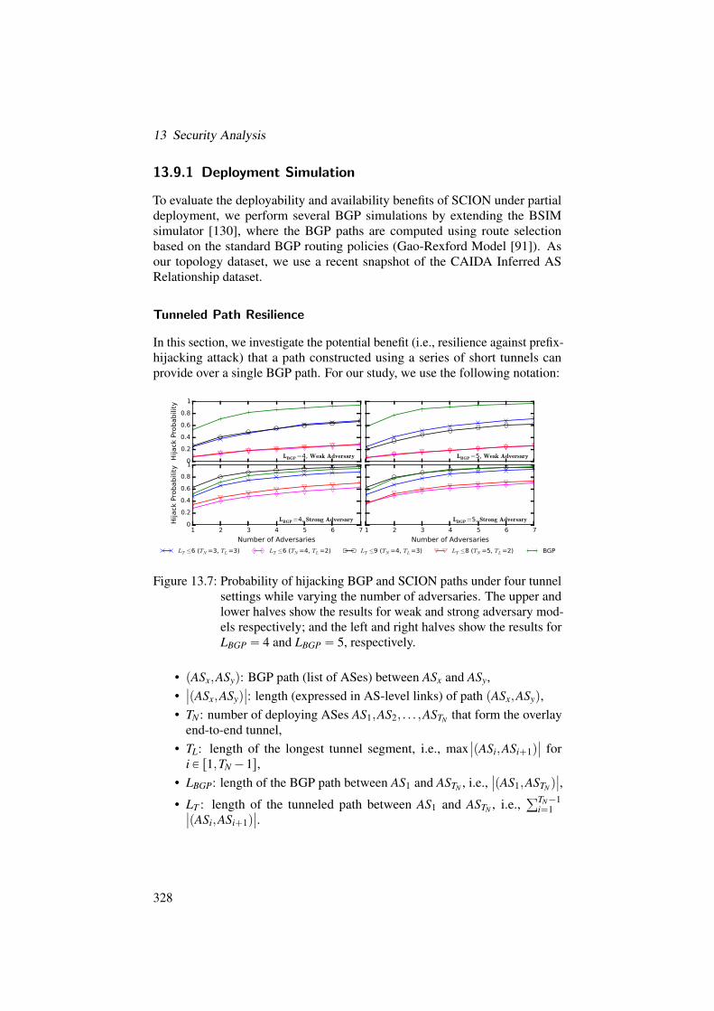
13 Security Analysis
13.9.1 Deployment Simulation
To evaluate the deployability and availability benefits of SCION under partialdeployment, we perform several BGP simulations by extending the BSIMsimulator [130], where the BGP paths are computed using route selectionbased on the standard BGP routing policies (Gao-Rexford Model [91]). Asour topology dataset, we use a recent snapshot of the CAIDA Inferred ASRelationship dataset.
Tunneled Path Resilience
In this section, we investigate the potential benefit (i.e., resilience against prefix-hijacking attack) that a path constructed using a series of short tunnels canprovide over a single BGP path. For our study, we use the following notation:
0
0.2
0.4
0.6
0.8
1
Hijack Probability
LBGP=4, Weak Adversary LBGP=5, Weak Adversary
1 2 3 4 5 6 7
Number of Adversaries
0
0.2
0.4
0.6
0.8
1
Hijack Probability
LBGP=4, Strong Adversary
1 2 3 4 5 6 7
Number of Adversaries
LBGP=5, Strong Adversary
LT ≤6 (TN=3, TL=3) LT ≤6 (TN=4, TL=2) LT ≤9 (TN=4, TL=3) LT ≤8 (TN=5, TL=2) BGP
Figure 13.7: Probability of hijacking BGP and SCION paths under four tunnelsettings while varying the number of adversaries. The upper andlower halves show the results for weak and strong adversary mod-els respectively; and the left and right halves show the results forLBGP “ 4 and LBGP “ 5, respectively.
• pASx,ASyq: BGP path (list of ASes) between ASx and ASy,•ˇ
ˇpASx,ASyqˇ
ˇ: length (expressed in AS-level links) of path pASx,ASyq,• TN : number of deploying ASes AS1,AS2, . . . ,ASTN that form the overlay
end-to-end tunnel,• TL: length of the longest tunnel segment, i.e., max
ˇ
ˇpASi,ASi`1qˇ
ˇ fori P r1,TN´1s,
• LBGP: length of the BGP path between AS1 and ASTN , i.e.,ˇ
ˇpAS1,ASTN qˇ
ˇ,
• LT : length of the tunneled path between AS1 and ASTN , i.e.,řTN´1
i“1ˇ
ˇpASi,ASi`1qˇ
ˇ.
328

13.9 Resilience to Path Hijacking
We assume that the first node of an end-to-end tunnel path (AS1) is the sourcewhile the last (ASTN ) is the destination. Then, LBGP expresses the length ofthe BGP path between source and destination. We also assume that trafficfrom source to destination over the end-to-end tunnel traverses overlay nodesAS2,AS3, . . . ,ASTN´1 in that order. The tunnel’s path on the AS-level is aconcatenation of BGP paths:
pAS1,AS2q,pAS2,AS3q, . . . ,pASTN´1,ASTN qFor our simulation, we consider two adversary strategies designed to hijacktraffic from source to destination: (a) a weak adversary, which announcesonly the destination’s prefix; and (b) a strong adversary, which announces allprefixes of AS2,AS3, . . . ,ASTN . In both cases an adversary launches attacks froma randomly compromised AS, however he cannot compromise ASes on the pathbetween source and destination.
Our experiment simulates eight scenarios by varying TN , TL, and LBGP toanalyze the resilience that tunnels can provide against prefix-hijacking attacks.For each scenario, while incrementing the number of adversarial ASes fromone to seven, we construct and simulate 1,000 random and unique tunneldeployments, where AS1 and ASTN are randomly chosen from multi-homed leafASes and the other tunnel nodes are chosen from all other ASes. We focus onmulti-homed ASes, as they are more likely to start deploying an availability-enhancing technology (according to a study [152], about 57% of all leaf ASesare multi-homed).
Figure 13.7 summarizes the results of our simulation. In each graph, thex-axis represents the number of adversaries (varied from one to seven) and they-axis represents probability values that an attack on the tunneled path willbe successful. The two figures on the left show the hijack probability of thetunneled path for source and destination AS pairs that are four BGP hops apart(LBGP “ 4); and, on the right five BGP hops apart (LBGP “ 5). Moreover, theupper two figures show the results against weak adversaries while the lowertwo figures show the results against strong adversaries. Lastly, each plot alsoshows hijack probability for the BGP paths (green line with plus markers).
As expected, our results show that the hijack probability increases as thenumber of adversaries increases, and that the probability is higher for the strongadversary model than the weak adversary model. Furthermore, against theweak adversary model, the probabilities of hijacking the tunneled paths aresimilar for the two cases that have the same tunnel segment length (i.e., TL) butdifferent total length (i.e., LT ) — on the upper two figures, the purple line withdiamond markers and the red line with inverted triangle markers almost overlapwith each other. This is because the weak adversary model can only attack thelast tunnel segment, i.e., (TN´1,TN), as the weak adversaries only announce theprefix of the destination (i.e., TN).
329

13 Security Analysis
The results show that the tunneled paths have lower hijack probability thanthe BGP paths even if the length of the tunneled path (i.e., LT ) is longer thanthat of the BGP paths (i.e., LBGP). However, the result also shows that if thelength of the tunneled paths becomes too long (e.g., twice the length of theBGP paths), the tunneled paths become more susceptible to hijacking attacks.However, in practice, it is highly unlikely that the tunneled paths would betwice the length of the BGP paths.
Lastly, the results show that the composition of the tunneled path affects theresilience against prefix-hijacking attacks: a tunneled path that is composedof shorter individual segments is more resilient than a path that is composedof longer individual segments. For the two cases where LT ď 6, the hijackprobability is significantly lower when the length of the individual tunnel iskept shorter. In Figure 13.7, this can be seen by comparing the blue line with‘x’ markers and the purple line with diamond markers. Moreover, the resultshows that the tunneled paths that have longer total length but shorter individualtunnel segments (i.e., LT ď 8, red lines with inverted triangle markers) aremore resilient than the tunneled paths that have shorter total length but longerindividual segments (i.e., LT ď 6, blue lines with ‘x’ markers).
13.10 Summary
In this chapter, we have compared various security aspects of today’s Internetwith their SCION counterparts. We have shown that SCION provides built-insecurity defenses against many well-known network attacks that plague today’sInternet operators and users. We have also examined specific attack vectorson SCION and showed that they either result in minimal impact or can easilybe detected and mitigated, especially when using the SCION packet securityextension or OPT.
We finally refer our readers to external evaluations of future Internet archi-tectures (FIAs), for instance to a recent study by Ding et al. [70], which alsodemonstrate that the security properties achieved by SCION are stronger thanthose of other FIAs.
330

14 Power Consumption
DAVID BARRERA, CHEN CHEN, ADRIAN PERRIG
The Internet, including user equipment, data transmission media, data centers,and access networks, requires a considerable amount of power, consumingnearly 1% of annual electricity production worldwide in 2010 [111]. Around 50GW of power is consumed by network equipment, and this number is expectedto double by 2020 [245]. Increased power consumption not only implies greatermonetary cost, but also has an expanding environmental impact in the formof carbon footprint and pollution [96]. Reversing the trend is imperative andwould pay off massively.
As a first step towards measuring and comparing the power consumption of IPnetworks and FIAs including SCION, we focus on the power consumption of thedata plane. Since data-plane traffic represents 83% of the total power consumedby the Internet (compared to 17% consumed by the control plane [38]), ouranalysis covers the largest component of power consumption in IP networksand FIAs.
We observe that the designs of several candidate network architectures mainlyvary in two dimensions: the design of packet-forwarding methods and the designof content cache methods. With respect to packet forwarding, SCION andNEBULA [9] both use packet-carried forwarding state (PCFS), which embedsforwarding information into each packet. In comparison, IP and NDN [184]routers maintain route tables and perform a route table lookup (RTL) to forwardeach packet. With respect to content-caching designs, NDN proposes pervasivecaching, which equips each NDN router with a content cache. IP, SCION,and NEBULA enforce no requirement for content caching and therefore canuse both end-to-end communication and edge caching, which is often seen incontent delivery networks (CDNs). We summarize the two design dimensionsin Table 14.1.
Accordingly, in addition to evaluating SCION’s power consumption, thischapter seeks to answer a more fundamental question: what impact do designchoices for packet forwarding and content caching exert on a network architec-ture’s power consumption? Answers to the question not only help us to considerSCION’s power consumption, but also guide us in designing a power-efficientnetwork architecture.
331
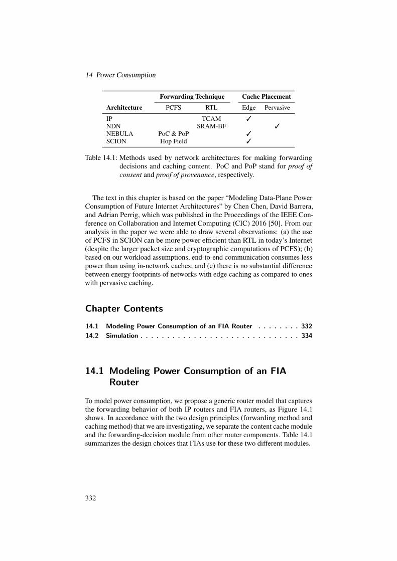
14 Power Consumption
Forwarding Technique Cache Placement
Architecture PCFS RTL Edge Pervasive
IP TCAM 3NDN SRAM-BF 3NEBULA PoC & PoP 3SCION Hop Field 3
Table 14.1: Methods used by network architectures for making forwardingdecisions and caching content. PoC and PoP stand for proof ofconsent and proof of provenance, respectively.
The text in this chapter is based on the paper “Modeling Data-Plane PowerConsumption of Future Internet Architectures” by Chen Chen, David Barrera,and Adrian Perrig, which was published in the Proceedings of the IEEE Con-ference on Collaboration and Internet Computing (CIC) 2016 [50]. From ouranalysis in the paper we were able to draw several observations: (a) the useof PCFS in SCION can be more power efficient than RTL in today’s Internet(despite the larger packet size and cryptographic computations of PCFS); (b)based on our workload assumptions, end-to-end communication consumes lesspower than using in-network caches; and (c) there is no substantial differencebetween energy footprints of networks with edge caching as compared to oneswith pervasive caching.
Chapter Contents
14.1 Modeling Power Consumption of an FIA Router . . . . . . . . 332
14.2 Simulation . . . . . . . . . . . . . . . . . . . . . . . . . . . . . . 334
14.1 Modeling Power Consumption of an FIARouter
To model power consumption, we propose a generic router model that capturesthe forwarding behavior of both IP routers and FIA routers, as Figure 14.1shows. In accordance with the two design principles (forwarding method andcaching method) that we are investigating, we separate the content cache moduleand the forwarding-decision module from other router components. Table 14.1summarizes the design choices that FIAs use for these two different modules.
332

14.1 Modeling Power Consumption of an FIA Router
Packets
Pfwd
Next Hop
Pcc
QueueManagement
PacketProcessing
MediaAccess
Routing SignalingControl System
Optical ModuleSerialization & Deserialization
Fabric WrapperFEC Accessory
Pbase
ContentCache
ForwardingDecision
Figure 14.1: Abstraction of the forwarding behavior of an FIA router. Wepresent a similar router-component dissection to Tamm et al. [236].
We group the rest of the router components, such as queue management andswitching fabric, which are common components for both IP and FIA routers,in Figure 14.1, and treat their power consumption as a baseline for our analysis.
We denote the total power consumed by an IP or FIA router (measured inwatts) to forward packets as Parch, the power consumption of the local content-caching system as Parch
cc , the power consumption of making forwarding decisionsas Parch
fwd , and the baseline power consumption of all the other components asPbase. The superscript “arch” is substituted by IP, NDN, SCION, or NEBULA.Accordingly, Parch “ Pbase`Parch
fwd `Parchcc .
Example. We take PSCIONfwd as an example and refer the interested reader to
our paper [50] for a complete description of packet forwarding and contentcache models of IP, NDN, and NEBULA.
SCION uses packet-carried state for finding the interface via which to forwarda packet. The forwarding decisions reside in the packet header and thus no inter-domain routing table needs to be stored on routers. The lack of routing tables(and thus lack of relatively expensive table lookup operations) helps reduce thepower consumption of packet forwarding, PSCION
fwd . However, SCION routersuse cryptographic primitives to verify the integrity of the routing decisionsembedded in the packet headers, which again adds to PSCION
fwd .
333

14 Power Consumption
Since the hop-field verification is the only computation-intensive operationin the forwarding process of SCION, we consider the computation of cryp-tographic verification when modeling PSCION
fwd . The verification process on aSCION border router only requires one AES-MAC computation to verify thehop field. As a result, the energy consumed by a SCION border router PSCION
fwdcan be expressed as follows:
PSCIONfwd “ I ¨EAES
spkt(14.1)
where I is the router’s throughput and spkt is the mean packet size. A typicalHelion AES core can achieve 128-bit AES throughput above 40 Gbps (320MAES ops/s) [108] based on an implementation using Virtex-7 FPGA with 6.6 Won-chip power consumption [257]. Thus, we choose EAES “ 20nJ{op.
14.1.1 Power Efficiency of SCION’s Forwarding Logic
To investigate the power efficiency of SCION packet-forwarding logic, wecompare the packet-forwarding logic of SCION with those of IP, NDN, andNEBULA using the complete model and parameter settings in the full pa-per [50].
Figure 14.2 illustrates the results when the link speed varies from 1 Gbpsto 40 Gbps. In general, regarding power consumption, the packet-forwardinglogic using PCFS holds advantages over that with RTL (except that NEBULArouters consume more power than NDN routers with small FIBs). Specifically,SCION’s packet-forwarding logic consumes 2–3 orders of magnitudes less thanthose of IP, NEBULA, and NDN with different FIB sizes. We can attributeSCION’s power efficiency to both usage of PCFS and its simple forwardinglogic.
14.2 Simulation
Based on the model of FIA routers in Section 14.1, we now use a holisticmethod to demonstrate the power consumption of SCION and other FIAs incontent distribution scenarios. We conduct our experiments by simulatingthe forwarding behavior of the IP network and FIAs when used for contentdistribution. We provide a sensitivity analysis that evaluates the impact ofchanging parameters in our paper [50].
14.2.1 Simulation Setup
The topology used in our simulations is based on the router-level topology ofeducation backbone networks (Abilene and Geant) and Rocketfuel (Telstra,
334

14.2 Simulation
0 5 10 15 20 25 30 35 40
Link Speed (Gbps)
10-1
100
101
102
103
104
Power Consumption (Watts)
IP@500K
NDN@500K
NDN@5M
NDN@50M
NEBULA
SCION
Figure 14.2: Pfwd under different link speeds for border routers. For the FIB sizeof NDN, Perino and Varvello have suggested 20M entries [197].Accordingly, we vary NDN’s FIB size from 500K entries to 50Mentries to demonstrate the influence of routing-table size on routers’power consumption.
Sprint, NTT, Verio, Level3, AT&T) [227]. We follow the methods proposed byFayazbakhsh et al. [86] to approximate access networks by trees appended toeach point of presence (PoP). The internal nodes of the trees are border routers.
For content access patterns, previous work has suggested that a Zipf dis-tribution closely approximates real-world content access from end hosts [86].We use synthesized content access traces with α “ 0.99 (which approximatesUS users’ behavior, as pointed out by Fayazbakhsh et al. [86]). For the querydistribution, we assume in our simulation that the leaf PoP generates queriesfor content, where the number of queries generated is linear in the populationof the city where the PoP is located.
To control the content cache capacity, we define a cache budget ratio. Let Rbe the number of routers capable of caching, C be the average cache capacityof each router, O be the total number of pieces of content that would benefitfrom caching, and s be the average size of each piece of content. We definethe cache budget ratio c “ RˆC
Oˆs . We choose c “ 5% as a baseline, which is
335

14 Power Consumption
0
0.5
1
1.5
2
2.5
3
3.5
Abilene Geant Telstra Sprint NTT Verio Level3 AT&T
SCION w/o Cache IP w/ Edge CacheNDN NEBULA w/ Edge CachingSCION w/ Edge Caching
Figure 14.3: Power consumption of end-to-end communication, edge caching,and pervasive caching with capacity ratio c“ 0.05. All results arenormalized by SCION without content caching.
observed as a relationship between the CDN cache provisioning and the totalrequested objects seen by a CDN server per day [86].
For edge caching used in IP, NEBULA, and SCION, we simply assume thatcontent requests are only served by each standalone cache server. We call thisstrategy simple edge caching. For pervasive caching, we assume on-path cachediscovery, in which only content cached by the on-path routers is returned. Forcache eviction, we select the least-recently used (LRU) method as our baselinestrategy. Note that designing an optimal or high-performance cache replacementstrategy is out of scope for this investigation.
14.2.2 Simulation Results
Figure 14.3 shows the power consumed by different network architectures withand without content caching. In particular, SCION without content cachingconsumes 15-50% less power than other network architectures. On one hand,SCION’s advantage arises from its efficient packet forwarding. On the otherhand, SCION’s design benefits from the fact that the small real-world locality
336

14.2 Simulation
of the content access pattern determines that caching content is less powerefficient.
Compared to SCION with edge caching, NDN with pervasive caching savesonly a marginal amount („2%) of power. Compared to IP with edge caching,NDN consumes up to 16% less power. The result implies that pervasive cachinghelps reduce power consumption, but the power reduction is limited. Thereason is twofold: (a) multiple-layer caching provides limited improvementover single-layer caching, as indicated by previous work [86]; (b) pervasivecaching requires more power-consuming caching devices, which further reducesthe small advantage in power consumption.
We summarize our main observations as follows:1. Network architectures that use packet-carried forwarding state instead of
routing-table lookups exhibit lower power consumption.2. FIAs without caching consume less overall power compared to those that
use caching.3. Under our workload assumptions, the use of pervasive caching results in
marginal reductions in power consumption.Although the variability of these results is nontrivial and depends on fu-
ture technology innovations, which cannot be predicted, our results show thatSCION’s design not only results in a more secure and transparent operation,but at the same time can be implemented without negative impact on powerconsumption.
337


Part V
Specifications
339


15 Packet and Message Formats
ADRIAN PERRIG, STEPHEN SHIRLEY, PAWEL SZALACHOWSKI
In this chapter, we describe the header formats of SCION control and datapackets. We start with the description of the generic SCION header, whichconsists of four parts: a common header, a forwarding path, an extensions chain,and a layer-4 protocol header.
Chapter Contents
15.1 SCION Packet . . . . . . . . . . . . . . . . . . . . . . . . . . . 341
15.2 Control Plane . . . . . . . . . . . . . . . . . . . . . . . . . . . . 355
15.3 PCB and Path Segment . . . . . . . . . . . . . . . . . . . . . . 356
15.4 Path Management Messages . . . . . . . . . . . . . . . . . . . 361
15.5 PKI Interactions . . . . . . . . . . . . . . . . . . . . . . . . . . 362
15.6 SCMP Packet . . . . . . . . . . . . . . . . . . . . . . . . . . . . 363
15.1 SCION Packet
A high-level layout of a SCION packet is presented in Figure 15.1. Beforediscussing its components in detail in the following sections, we give a briefoverview.
• Common header (Section 15.1.1): Every SCION packet contains amandatory common header in the first 8 bytes of the packet. The mostimportant information encoded within the common header is the lengthof the packet, the types of the source and destination address, the currentposition in a path, and the type of the next header (an extension or layer-4protocol).
• Addresses (Section 15.1.2): Source and destination addresses are placedright after the common header. A SCION address consists of an ISD
341

15 Packet and Message Formats
Common header (8 bytes)
Addresses (12–40 bytes)
Forwarding path (var. length)
,
/
/
/
/
/
/
/
.
/
/
/
/
/
/
/
-
SCIONheader
Extension header(s)
Layer-4 protocol and data
Figure 15.1: High-level layout of a SCION packet.
identifier, an AS identifier, and an end-host address. As end-host address-ing in SCION is local to an AS, it allows ASes to use different addressspaces (e.g., IPv4, IPv6, or MAC addresses) to address their end hosts.Consequently, SCION permits hybrid addressing, that is, source anddestination can have addresses of different types. The concatenation ofthe source and destination addresses has to be aligned to a multiple of 8bytes.
• Forwarding path (Section 15.1.3): The forwarding path consists of asequence of info fields (INF) and hop fields (HF), which contain informa-tion required by border routers for packet forwarding. The forwardingpath has to be aligned to a multiple of 8 bytes. The current INF and HFare indicated by pointers in the common header. Note that the forwardingpath is empty for SCION packets that do not leave the origin AS.The concatenation of common header, addresses, and forwarding pathconstitutes the SCION header.
• Extension headers (Section 15.1.4): A SCION packet can additionallycontain multiple extension headers. These are constructed as a chain (i.e.,one extension points to the next), and the final extension points to thelayer-4 header. There are two types of extension headers:
– hop-by-hop extensions, processed by source and destination endhosts, as well as by every border router on the path; and
– end-to-end extensions, processed only by source and destinationend hosts.
Extensions have to be aligned to a multiple of 8 bytes.
342

15.1 SCION Packet
• Layer-4 protocol and data (Section 15.1.5): The remaining data of thepacket is the payload, which is usually encapsulated within a layer-4protocol.
In the remainder of this section, we describe the elements of a SCION packetin detail.
15.1.1 SCION Common Header
The common header is an essential element that every SCION packet mustcontain. The common header contains various fields such as the length ofthe entire packet, the length of the SCION header, types of source and desti-nation addresses, next header (an extension or upper-layer protocol), and thecurrent position of the packet on the path. The detailed format is presented inFigure 15.2; its fields are described below.
0 1 2 3 4 5 6 7 8 9 10 11 12 13 14 15 16 17 18 19 20 21 22 23 24 25 26 27 28 29 30 31
Version DstType SrcType TotalLen
HdrLen CurrINF CurrHF NextHdr
Figure 15.2: The SCION common header (8 bytes).
• Version: The first common header field is the version number of theSCION protocol. The field is 4 bits long; the current version of SCIONhas version number 0.
• DstType / SrcType: As SCION is agnostic to the addressing schemeused within an AS, the DstType and SrcType fields define the typesof addresses that communicating end hosts use within their ASes. Theaddress type implicitly defines the address length, and within a singlepacket, the source and destination addresses can have different types(hybrid addressing). The current implementation supports the followingthree end-host address types:
– IPv4: IPv4 host address (4 bytes),– IPv6: IPv6 host address (16 bytes),– Service: The service address (2 bytes) is used to indicate the
desired SCION service (see Sections 7.4.6 and 15.1.2).The complete SCION address, besides an end-host address, includes ISDand AS identifiers, which are encoded within 4 bytes (the ISD identifieris encoded within the most significant 12 bits, and the AS identifier isencoded within the remaining 20 bits). Thus, the minimum size of asingle SCION address is 6 bytes, while the maximum is 20 bytes (seeSection 15.1.2). Each address type field is encoded within 6 bits, whichsupports up to 64 different address types.
• TotalLen: total packet length in bytes. This field is 16 bits long, hencethe maximum length of a SCION packet is 65,535 bytes.
343

15 Packet and Message Formats
• HdrLen: length of the SCION header in bytes (i.e., the sum of the lengthsof the common header, the source and destination addresses, and thepath). All SCION header fields are aligned to a multiple of 8 bytes. TheSCION header length is computed as
HdrLenˆ8 (15.1)
The 8 bits of the HdrLen field limit the SCION header to a maximumlength of 2,040 bytes.
• CurrINF: pointer to the current info field of a forwarding path. This fieldis used by a border router to identify (and verify) the current series ofhop fields (see Section 8.2). The pointer is updated by a router wheneverthe last hop field of a path segment has been processed, and thus the nextrouter will start processing the first hop field of the next path segment.The absolute byte offset to the current info field is computed as
CurrINFˆ8 (15.2)
For every SCION packet with non-empty forwarding path, we require
8`SrcLen`DstLen`AddrPadă CurrINFˆ8ă HdrLenˆ8 (15.3)
where 8 denotes the length of the common header, SrcLen and DstLen
are the lengths of the source and destination addresses respectively,and AddrPad is an optional padding added to align the concatenationof source and destination addresses to an 8-byte boundary (see Sec-tion 15.1.2). If the forwarding path is empty, the CurrINF field is set to0.
• CurrHF: pointer to the current hop field of a forwarding path. Thisfield is used by a border router to identify the current hop field, whichin combination with the corresponding info field allows packets to beforwarded. For more information, see Section 8.2 on Page 164. An end-to-end example of packet forwarding, including updates of the CurrHFand CurrINF fields, is provided in Section 10.8 on Page 223.The absolute byte offset to the current hop field is computed as
CurrHFˆ8 (15.4)
As above, for every SCION packet with non-empty forwarding path, werequire
CurrINFˆ8ă CurrHFˆ8ă HdrLenˆ8 (15.5)
As info and hop field pointers (CurrINF, CurrHF) are expressed within 8bits, the maximum offset is 2,040 bytes. If the forwarding path is empty,the CurrHF field is set to 0.
344

15.1 SCION Packet
• NextHdr: field that encodes the type of the first header after the SCIONheader. This can be either a SCION extension or a layer-4 protocol suchas TCP or UDP. Values of this field respect and extend IANA’s assignedinternet protocol numbers [120], (e.g., TCP and UDP have numbers 6and 17, correspondingly).
15.1.2 SCION Addresses
SCION addresses are placed in the SCION packet directly after the commonheader (see Figure 15.1 on Page 342). Every SCION address consists of ISDand AS identifiers, and an end-host address. The ISD identifier is globallyunique, the AS identifier is locally unique within the ISD, and the end-hostaddress is routable within the AS. We note that the local address assignmentshould respect the rules of the address type being used, e.g., in the case of IPv4the address space should either be RFC 1918 [210] private address space, orpublic address space that is owned by the network. See Section 10.3 for moredetails on the implications of the choice of end-host addresses.
The current SCION implementation uses 12 bits for the ISD identifier and 20bits for the AS identifier. This allows up to 4,096 ISDs globally, and 1,048,576ASes per ISD. However, the value 0 for both ISD and AS identifiers is reserved.The size of the end-host address is variable and depends on the address type.The length of a complete SCION address is thus also variable and is determinedas follows.
Type Size
IPv4 8 BIPv6 20 BService 6 B
Table 15.1: Size of a SCION address, which depends on the type of the end-hostaddress.
The types IPv4 and IPv6 are used for standard unicast end-to-end communi-cation. The combination of IPv4 or IPv6 as a source address and Service typefor a destination address is used for sending control-plane requests to a SCIONservice. The type Service is introduced to inform the destination AS that agiven packet should be sent as an anycast packet to an instance of the correctservice. However, SCION does not dictate how such an anycast mechanismshould be implemented. (Our reference implementation uses the discoveryservice — see details in Section 7.4.7 on Page 152.) As a concrete server isqueried through an anycast mechanism, a response to the request is sent as astandard data packet (i.e., the server uses its own IPv4 or IPv6 address in the
345

15 Packet and Message Formats
source SCION address). The defined types of Service addresses are presentedin Table 15.2.
SCION source and destination addresses are placed in a SCION packet ina way that enables border routers easy access to ISD-AS identifiers and thedestination address (which is read more frequently than the source address).Namely, first destination and source ISD-AS identifiers are placed, which arethen concatenated with destination and source host addresses. If necessary, thisconcatenation is padded to align the address block to an 8-byte boundary. Foruniform addressing with IPv4 or IPv6 end-host addresses, the padding is notnecessary as the concatenation of two SCION addresses is 16 and 40 byteslong, respectively. However, hybrid addressing, e.g., IPv6 as source and IPv4as destination host address, requires 4 bytes of padding. An example of howaddresses with different types are placed in a SCION packet is presented inFigure 15.3.
0 11 31 43 63
DstISD DstAS SrcISD SrcAS
DstHostAddr
(IPv6)
SrcHostAddr (IPv4) Padding
Figure 15.3: Example of hybrid addressing: SCION addresses with differenttypes for end-host addresses.
15.1.3 Forwarding Path
To construct a forwarding path, an end host needs to extract and concatenateinfo and hop fields, created during the path-segment construction process (seeSection 7.1). The forwarding path (i.e., in the data-plane format) is a list of suchfields placed in the SCION packet after the addresses. A high-level illustrationof a path is presented in Figure 15.4.
A single path can be composed of maximally three series of hop fields: seriesof HFs extracted from an up-segment (that leads toward a core AS), HFs froma core-segment (used for routing between core ASes), and HFs obtained from adown-segment (to forward a packet from a core AS to the destination). Noneof the series is mandatory, and the forwarding path is empty if a packet is sentwithin a local AS. However, if a packet is sent to a remote AS, the order of theseries has to be preserved (e.g., HFs from a down-segment cannot precede HFsfrom a core-segment, and HFs from a core-segment cannot precede HFs froman up-segment).
Each list of HFs starts with an info field and at least two consecutive hopfields. The current position of a packet on its path is determined through pointersplaced in the common header (see Section 15.1.1 for details).
346

15.1 SCION Packet
0 63
Info fieldHop field
Hop field. . .
,
/
/
/
/
.
/
/
/
/
-
Up-segment
Info fieldHop field
Hop field. . .
,
/
/
/
/
.
/
/
/
/
-
Core-segment
Info fieldHop field
Hop field. . .
,
/
/
/
/
.
/
/
/
/
-
Down-segment
Figure 15.4: High-level layout of a path.
Info Field (INF)
An info field (INF) starts every series of HFs from a given path segment inthe data-plane path format. It identifies the type of the path, and containsinformation required for hop-field validation. It also contains the length ofthe corresponding path segment, and it carries the identifier of the ISD whichinitiated the propagation of the path. The format of the info field is depicted inFigure 15.5.0 1 2 3 4 5 6 7 39 55 63
r r r r r P SU Timestamp ISD SegLen
Figure 15.5: Format of an info field.
The first field of every info field is called Flags and is eight bits long. Thebits of this field identify the type of a path as follows:
• r: unused and reserved for future use.• P: peering-shortcut flag. If set to true, then the forwarding path is built as
a peering-shortcut path (see Section 8.2.1). It is only valid if the shortcutflag is also set.
• S: shortcut flag. If set to true, then the forwarding path is built as ashortcut path (see Section 8.2.1).
• U: direction (up-segment) flag. If set to true, then the HFs from thecorresponding path segment have an up-segment orientation, otherwisethe HFs have a down-segment orientation.
347

15 Packet and Message Formats
The exact meaning and interpretation of the flags in a constructed forwardingpath is described in Section 8.2.
The second field of every info field is a timestamp created by the initiatorof the corresponding PCB. The timestamp is expressed in Unix time, and isencoded as an unsigned integer within 4 bytes with 1-second time granular-ity. This timestamp enables validation of the hop field by verification of theexpiration time and MAC. The next field uses 2 bytes for encoding the ISDidentifier. For up- or down-segments, this identifier denotes the ISD that hoststhe path segment, while for a core-segment, it identifies the ISD that initiatedthe propagation of the corresponding beacon. The last, a 1-byte field SegLen
encodes the length of HFs that were extracted from the corresponding pathsegment and placed within the forwarding path (the actual length in bytes iscomputed as SegLenˆ 8). Note that this field is different from SegLen in aPCB, which is set to 0 during the beaconing. On the data plane, SegLen denotesthe number of hop fields (including those used only for verification, and thoseused for peering links) in a segment, instead of the number of ASes which aretraversed. Its value is not changed during forwarding.
Hop Field (HF)
Hop fields contain information necessary for a border router to forward packets.They include encoded interfaces on which a packet is forwarded, the expirationtime set by the AS, and a MAC (to authenticate the HF). A sample hop field ispresented in Figure 15.6.0 1 2 3 4 5 6 7 15 27 39 63
C r r r r FVX ExpTime InIF EgIF MAC
Figure 15.6: Example format of a hop field.
The format of a hop field is not unified and its layout may depend on the AS;however, the size of a hop field must always be a multiple of 8 bytes. The firstfield of every hop field is a 1-byte Flags field that describes the hop field.
• C: continue/stop flag, used to encode hop fields longer than 8 bytes. Ifa hop field consists of multiple 8-byte lines, then the flag is set on thefirst and the last lines, to encode the beginning and the end of the hopfield accordingly (the intermediate lines have this flag set to 0). The otherflags are set only in the first line.
• r: unused and reserved for future use.• F: forward-only flag. It is set by the AS that created the HF to indicate
that delivery of packets to the AS’s end hosts is not permitted. This flagis set by an AS during beaconing and it is immutable (i.e., is included inthe MAC calculation and cannot be modified by end hosts).
348

15.1 SCION Packet
• V: verify-only flag. If set, it informs a router that the marked hop field isused only for MAC verification (not used in actual packet forwarding).
• X: cross-over flag. If set, it informs a border router that the path switchesto a new path segment in this AS.
The exact meaning and interpretation of the flags in a constructed forwardingpath is described in Section 8.2.
The next field inside the HF is the ExpTime field, which denotes when ahop field expires. The field is 1-byte long, thus there are 256 different valuesavailable to express an expiration time. The expiration time expressed by thevalue of this field is relative, and an absolute expiration time in seconds iscomputed in combination with the timestamp field (from the corresponding infofield) as follows:
TS`ˆ
p1`ExpTimeqˆZ
24ˆ60ˆ60256
^˙
(15.6)
where TS is the value of the corresponding timestamp field. Hence, the minimallifetime of a hop field is about 5 minutes, while the maximum validity of an HFis one day.
The following two fields, InIF and EgIF, represent ingress and egress in-terface identifiers between which a packet should be forwarded. The lengthof these fields is variable, and any encoding scheme can be implemented bythe AS. In our implementation, these fields have a length of 12 bits each. Thisbounds the number of AS interfaces to 4,096.
The last item in the hop field is an authentication tag (MAC). The length ofthis field is variable (in our implementation, a length of three bytes was chosen).The AS itself can freely decide how to generate MACs and what size theyshould have.
15.1.4 Extensions
The forwarding path is the last element of the SCION header, and extensionheaders are placed after the path. Extensions are optional, and if they arepresent, they form a chain (one extension defines the type of the next one, andso on). The type of the first extension header is defined in the SCION commonheader, and the last extension in the chain points to the layer-4 protocol (e.g.,UDP or TCP). For packets that do not contain any extension, the NextHdr fieldof the common header is set directly to the layer-4 protocol number.
SCION supports the following two classes of extension headers: (a) hop-by-hop extensions, and (b) end-to-end extensions. Every border router has toprocess hop-by-hop extensions, as do source and destination end hosts, and allhop-by-hop extensions must be placed before end-to-end extensions. End-to-end extensions are processed only by source and destination end hosts. The
349

15 Packet and Message Formats
number of extensions in a packet is limited only by the maximum packet length.However, for efficiency reasons, border routers are required to process only thefirst three hop-by-hop extensions.1
0 7 15 23 63
NextHdr ExtHdrLen ExtType ExtPayload
NextHdr ExtHdrLen ExtType
ExtPayload
NextHdr ExtHdrLen ExtType ExtPayload
...
Figure 15.7: An extension chain formed by the three extension headers.
An example of an extension chain is presented in Figure 15.7. NextHdr
is the first field of an extension header. It specifies the type of the extensionor protocol header that follows the extension header. Values for these fieldsare chosen according to IANA’s protocol numbers [120]. For hop-by-hopextensions, SCION uses the value 0x00 (that is the same value as IPv6’shop-by-hop extension) in the NextHdr field, while end-to-end extensions areindicated by the value 0xfd.
The second byte of every SCION extension header defines the length of thatheader. Extension headers have variable length, which must be a multiple of 8bytes. The length of a given extension is computed as follows:
ExtHdrLenˆ8 (15.7)
and ExtHdrLen‰ 0, which gives 8 bytes as a minimum length, and 2,040 bytesas a maximum. Space for an extension header must be allocated within a packetby the source, and intermediate routers may not increase the size of extensionheaders (or create additional ones).
The last common field of every SCION extension header defines the type ofextension within a given class (i.e., type within the hop-by-hop or end-to-endextension class). The field is 1-byte long, thus it is possible to define 256different SCION extensions per class.
SCION does not forbid multiple SCION extensions of the same class andtype to be put into a single packet. Hence, as the length of a single extensionis capped at 2,048 bytes, if necessary, an extension’s payload can be split intomultiple extension headers.
SCION by default supports the following extensions.
1An exception are SCMP packets, for which border routers may process up to four hop-by-hopextensions.
350

15.1 SCION Packet
Path Transport Extension
The path transport extension is an end-to-end extension that allows communicat-ing end hosts to pass or update a path. It is designed to transport a forwardingpath (i.e., a path in the data-plane format, see Section 15.1.3). The transportedpath can be accompanied with a SCION address, to indicate that the end hostcan be reached via another address and path to support host mobility. Thisextension has a multitude of uses, for example for DoS defense, where a servercan pass a secret SCION path to the client, after the user has been authenticatedand identified as benign.
The path transport extension that conveys a path in the data-plane format (setof info (INF) and hop (HF) fields) is depicted in Figure 15.8. The extension
Extension Type
0 7 15 23 31 63
NextHdr HdrLen 0x00 SrcType SrcAddr
SrcAddr (cont.) Padding
Path (data-plane format, var. length)
Figure 15.8: An example of a path transport extension. It is an end-to-endextension, thus the preceding NextHdr field has value 0xfd.
contains the field SrcType, which indicates what type of SCION address thepath is prepended with. A source can inform a destination that the source isreachable through another address via the SrcAddr field (ISD and AS identifiersconcatenated with a host address). If necessary, padding is added so that thefull path is aligned to an 8-byte boundary (Section 15.1.3 describes details ofthe data-plane path format). The Path field is not mandatory and an emptypath can be sent, and through such a construction a source can indicate a newSCION address.
One-Hop Path Extension
The one-hop path extension is a hop-by-hop extension introduced to handlecommunication between two entities from neighboring ASes that do not havea forwarding path. Currently, it is used only by beacon servers during thebeaconing process, and we present this extension in that context.
Beacons themselves are used for the creation forwarding paths, thus it is notpossible to use a forwarding path for the first packet sent. Moreover, whenevera beacon server receives a beacon, it has to know from which ingress interface(i.e., from which border router) the beacon was forwarded. Without such
351

15 Packet and Message Formats
information, the beacon server would not be able to create a valid hop field forthe beacon. Hence, an ingress router which forwards the beacon to the beaconserver needs to put its own interface identifier into the packet.
To enable communication in this case, the first packet sent (i.e., the TCP SYN
packet with the beacon service address specified as the destination address)carries the one-hop path extension. This packet also has a forwarding pathwhere the info field and the first hop field are created by the originating beaconserver, while the second hop field is empty. The first router (i.e., an egress routerof the sender AS), simply verifies and forwards the packet to its neighbor router(ignoring the extension), as it does for every data packet. The second router(i.e., an ingress router of the receiver AS), detects that this packet is special(i.e., it has the one-hop path extension and it is addressed to the beacon service),and contributes to the forwarding path by creating the second hop field andreplacing the empty hop field in the original path. Note that the router can createhop fields as it knows the secret key used for MAC generation/verification. Areceiving beacon server’s TCP stack removes the one-hop path extension, andthen treats the packet in a standard way, sending a SYN-ACK packet back. TheTCP stack of the sender beacon server reads the completed forwarding pathfrom the SYN-ACK packet. After that, an end-to-end one-hop path is known tothe two beacon servers, and can be used to communicate between them. Anysubsequent packet in the communication is sent using the created path. Theheader of the one-hop path extension is presented in Figure 15.9.
Extension Type
0 7 15 23 63
NextHdr HdrLen 0x03 Padding
Figure 15.9: The header of the one-hop path extension. It is a hop-by-hopextension, thus the preceding NextHdr field has value 0x00.
SCION Packet Security Extension
The SCION packet security extension is an end-to-end extension that allowscommunicating end hosts to protect sent data on the packet level. It has ageneric design that allows encryption and/or authentication of packets via eithersymmetric or asymmetric cryptography. The header of the SCION packetsecurity extension is presented in Figure 15.10.
The SecMode field indicates what kind of protection is applied to the packetthat carries the extension header. The content and size of the Metadata andAuthenticator fields depends on the value of the SecMode field. The meta-data field can include information such as timestamp or sequence number (the
352

15.1 SCION Packet
Extension Type
0 7 15 23 31 63
NextHdr HdrLen 0x01 SecMode Metadata (var. length)
Authenticator (var. length)
Figure 15.10: The header of the SCION packet security extension. It is anend-to-end extension, thus the preceding NextHdr field has value0xfd.
field is empty when metadata are unnecessary). The size of the authenticatorfield has to be aligned to a multiple of 8 bytes. Currently, we support thefollowing security modes (i.e., values of the SecMode field):
• AES-CMAC (0x00): MAC scheme [226] producing 16-byte authentica-tors.
• HMAC-SHA256 (0x01): MAC scheme [136] producing 32-byte authen-ticators.
• Ed25519 (0x02): digital signature scheme [30] with 64-byte signatures.• GCM-AES128 (0x03): authenticated encryption scheme [76] producing
16-byte authenticators.The metadata for all these modes is a Unix timestamp encoded as a 4-byteunsigned integer.
The SCION packet security extension can be used for encrypted and au-thenticated, or authenticated-only packets. However, as packets need to beprocessed and modified by intermediate routers the protection has to be realizedin a special way:
• Before protecting a packet, the authenticator field is filled-in with zero-valued bytes.
• When a packet is only authenticated (through a MAC or a digital signa-ture), then the entire packet is protected, except: the TotalLen, HdrLen,CurrHF, and CurrINF fields, and the sizes and payloads of hop-by-hopextensions.
• When a packet is encrypted and authenticated, then all end-to-end ex-tensions (excluding the SCION packet security extension itself) and thelayer-4 header with payload are encrypted, while the following are au-thenticated: SCION Header (except TotalLen, HdrLen, CurrHF, andCurrINF fields), types and order of all extensions, and all end-to-endextensions. (Hop-by-hop extensions are not protected, as they can bemodified by intermediate border routers.)
353

15 Packet and Message Formats
Additionally, when the one-hop path extension is used, the second hop fieldhas to be set to zero before verification (as that field was modified by a borderrouter).
The SCION packet security extension can be used by various protocols. Inour current implementation, it is used for protecting SCMP messages (seedetails in Section 4.2.5 on Page 82).
MTU Extension
The maximum transmission unit (MTU) extension is an end-to-end extensionthat helps communicating end hosts to coordinate the MTU used during trans-mission. As the MTU depends on the path used, the end hosts can pass the usedMTU for the first packet sent via a given path.
The standard procedure is as follows. The source obtains path segments,creates a forwarding path, and learns its MTU (the relevant information isencoded within the path segments). For the first packet sent, the effectiveMTU is indicated within the MTU extension. For the responding packet, thedestination indicates its MTU only if it is smaller than the received one (e.g.,when the destination’s LAN dictates a smaller MTU). Otherwise, the respondingpacket is sent without the MTU Extension.
Extension Type
0 7 15 23 39 63
NextHdr HdrLen 0x04 MTU Padding
Figure 15.11: The header of the MTU extension. It is an end-to-end extension,thus the preceding NextHdr field has value 0xfd.
The MTU extension can be integrated with transport protocols (such asTCP — see Section 9.3). The header of the MTU extension is presented inFigure 15.11.
AS-Level Anycast Extension
The AS-level anycast extension is a hop-by-hop extension that implements theAS-level anycast service mechanism presented in Section 7.5. The goal of theextension is to allow an anycast request to a service’s server to be sent to anyintermediate AS on a path to the core. Although the extension is hop-by-hop, itis processed only by ingress non-core border routers on the up-path (i.e., theforwarding path has the up direction).
The header of the extension is presented in Figure 15.12. The Flags fieldis reserved for future use, the Service field specifies the service that should
354
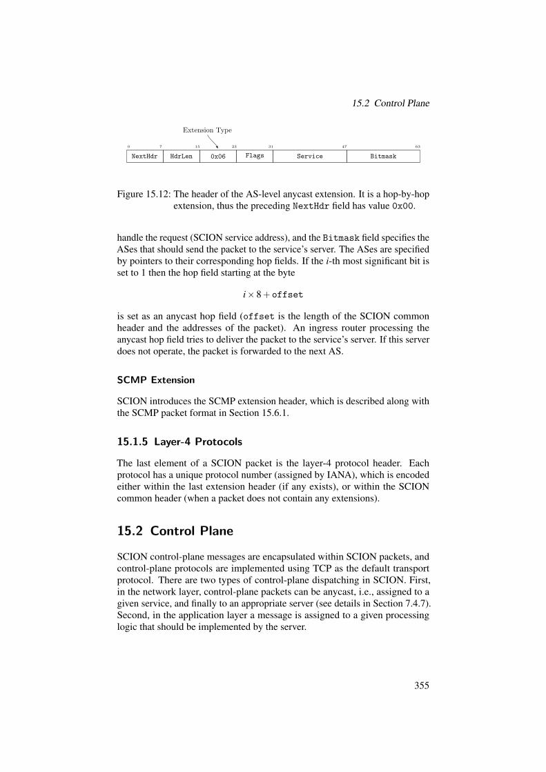
15.2 Control Plane
Extension Type
0 7 15 23 31 47 63
NextHdr HdrLen 0x06 Flags Service Bitmask
Figure 15.12: The header of the AS-level anycast extension. It is a hop-by-hopextension, thus the preceding NextHdr field has value 0x00.
handle the request (SCION service address), and the Bitmask field specifies theASes that should send the packet to the service’s server. The ASes are specifiedby pointers to their corresponding hop fields. If the i-th most significant bit isset to 1 then the hop field starting at the byte
iˆ8`offset
is set as an anycast hop field (offset is the length of the SCION commonheader and the addresses of the packet). An ingress router processing theanycast hop field tries to deliver the packet to the service’s server. If this serverdoes not operate, the packet is forwarded to the next AS.
SCMP Extension
SCION introduces the SCMP extension header, which is described along withthe SCMP packet format in Section 15.6.1.
15.1.5 Layer-4 Protocols
The last element of a SCION packet is the layer-4 protocol header. Eachprotocol has a unique protocol number (assigned by IANA), which is encodedeither within the last extension header (if any exists), or within the SCIONcommon header (when a packet does not contain any extensions).
15.2 Control Plane
SCION control-plane messages are encapsulated within SCION packets, andcontrol-plane protocols are implemented using TCP as the default transportprotocol. There are two types of control-plane dispatching in SCION. First,in the network layer, control-plane packets can be anycast, i.e., assigned to agiven service, and finally to an appropriate server (see details in Section 7.4.7).Second, in the application layer a message is assigned to a given processinglogic that should be implemented by the server.
355

15 Packet and Message Formats
As described in Section 15.1.2, the service type SCION address is encodedwithin 6 bytes, where the first 4 bytes are reserved for the ISD and AS pair,and the following 2 bytes identify a given service. The most significant bit ofa service address determines whether the address is multicast (the bit is set)or anycast. The addresses are assigned to the SCION services as presented inTable 15.2.
Service Anycast Address Multicast Address
Beacon Service 0x0000 0x8000
Path Service 0x0001 0x8001
Certificate Service 0x0002 0x8002
SIBRA Service 0x0003 0x8003
SIG Service 0x0004 0x8004
Discovery Service 0x0005 0x8005
RAINS Service 0x0006 0x8006
Time Service 0x0007 0x8007
Table 15.2: SCION services with corresponding service addresses.
The SCION network layer is able to dispatch control-plane messages tocorresponding services, while control-plane messages are dispatched in theapplication layer to corresponding processing logics. Every SCION control-plane message starts with a 4-byte field that indicates the length of the message.The length field is followed by an encoded payload. For the encoding weuse Cap’n Proto encoding [218], which enables language-neutral, platform-independent, extensible, and fast data serialization. As the exact encoding isdetermined by Cap’n Proto, message formats presented in this section are onlylogical.
The basic message types are presented in Table 15.3, while the correspondingcontrol message formats are described in the rest of this chapter.
15.3 PCB and Path Segment
The format of a PCB is presented in Figure 15.13. It consists of the infofield (created by a core AS that initiated the beacon creation) and a series ofAS entries that follows the order of propagation (i.e., each AS during beaconpropagation appends one entry). Details on the path construction process arepresented in Section 7.1.
356

15.3 PCB and Path Segment
Message Type Description
Beacon Path-Segment Construction BeaconIface Interface statePathSegRequest Path-segment requestPathSegReply Path-segment replyPathSegReg Path-segment registrationPathSegSync Path-segment synchronizationPathRev Path revocationCertRequest Certificate requestCertificate Certificate registration or replyTRCRequest TRC requestTRC TRC registration or replyDRKeyRequest DRKey key exchange requestDRKeyResponse DRKey key exchange response
Table 15.3: Message types in the application layer.
ASEntry1
Payload
InfoField
ASEntry0
Payload
Type
Type
Signature
Extensions
HopField
HopField
PeerEntry0
PeerEntry1
...
CertVersionISD
InIF EgIF InMTUInISD InAS EgISD EgAS
PeerIF EgIF PeerMTUPeerISD PeerAS EgISD EgAS
ASIFSize MTU
TRCVersion
HopEntry
RevocationToken
PCB
Figure 15.13: Format of the path-segment construction beacon (PCB), colorscheme as in Section 7.1.
15.3.1 AS Entry
The AS entry is the main information appended to a beacon by every AS thathas contributed to the beacon. Figure 15.13 depicts the format of the AS entry.It consists of metadata, a series of hop and peer entries, a revocation token,beacon extensions, and a signature.
Each AS entry starts with its ISD and AS identifiers. Next, the TRCVersionfield informs all downstream ASes of the current version of the TRC possessed
357

15 Packet and Message Formats
by the AS that created the entry. Similarly, CertVersion denotes the AS’scertificate version. The IFSize field describes how many bits are used toencode the AS’s interfaces within its hop fields, while MTU states the MTU ofthe AS’s internal network.
After this metadata, the list of entries that specify routing decisions start.There are two types of entries, and they have the same structure. The first entryis interpreted as a Hop Entry. This entry carries routing information requiredto forward packets between an ingress interface (connecting to a parent AS),and an egress interface (connecting to a child AS). All other entries withinan AS entry are called Peer Entries and they are optional. Every peer entrycarries routing information needed to forward packets between a peer interface(connecting to a peer AS) and an egress interface (connecting to a child AS).The structure of the entries is presented in Figure 15.13, and their details aredescribed in the following section.
AS entries include also the RevocationToken field (details on the revoca-tion mechanism are presented in Section 7.3) and beacon extensions. Extensionsare optional, and every AS can specify multiple extensions. Details on beaconextensions are presented in Section 15.3.4. The last element of every AS entryis the signature field, which an AS fills in with a signature created over theentire beacon (see Equation 7.4).
15.3.2 Hop and Peer Entry
Hop and peer entry fields have a similar format, which is depicted in Fig-ure 15.13. A hop entry starts with ISD and AS identifiers of the ingress, in thedirection of the propagation, AS (i.e., the AS of the previous AS entry). Then,ISD and AS identifiers of the egress AS are present (i.e., the AS of the nextAS entry). The next two fields of the hop entry are identifiers of ingress andegress interfaces used by the ingress and egress ASes accordingly. The hopentry also contains the InMTU field, which describes the MTU of the ingressinterface. The last element of the hop entry is the hop field, which is used forbuilding the full data-plane path, and forwarding traffic between ingress andegress interfaces of the AS (interfaces are specified within the hop field). Notethat interface identifiers of the hop field can be determined through the IFSizefield of the AS entry. Using this field, end hosts can use paths at interface-levelgranularity (i.e., end hosts can determine which interfaces a packet traverses).
Peer entries have a similar format; however ISD and AS identifiers identifya peer AS of the AS that created the entry, the interface identifiers fields areassigned to the peer and egress interface, and the PeerMTU field denotes theMTU of the peering link. The hop field allows forwarding of traffic betweenpeer and egress interfaces. Peer entries are optional for intra-ISD beacons andare not valid in core beacons.
358

15.3 PCB and Path Segment
15.3.3 Revocation Token
The RevocationToken field contains the information that allows authenti-cation of revocation messages issued by this AS (details of the revocationmechanism are presented in Section 7.3). More specifically, it contains a de-scriptor of the hash algorithm used, and a root value of the revocation hash tree.The root is required to verify whether a revocation message is authentic (anexample revocation message is presented in Figure 15.18 on Page 362).
15.3.4 Beacon Extensions
Beacons have their own extension mechanism as depicted in Figure 15.13.Beacon extensions are optional and are placed at the end of a beacon just beforethe signature field. Every AS entry can have multiple extensions, and eachbeacon extension starts with its Type encoded within 1 byte. The rest of anextension is its payload. Every extension is signed by the AS that created it, toprotect its integrity. However, extensions can have unprotected fields that arenot covered by the signature.
Announcement Extension
New ISDs must be announced in advance by their neighbors through a beaconextension (see Chapter 5). An announcement extension is presented in Fig-ure 15.14. It contains the first TRC (version 0) of the newcomer with the TRC’squarantine flag set to true or false depending on whether the extension consti-tutes an early announcement or a final announcement. This field is optional, butthe extension also contains an identifier of a hash algorithm and the hash of theTRC (these fields are mandatory). Each ISD is limited to making at most fiveearly announcements at any point in time. The TRC field is not included in thesignature calculation, although it is mandatory for PCBs (core ASes learn aboutnew ISDs through PCBs). When a PCB, with an announcement extension, istransformed into a path segment (see Section 15.3.6), the TRC field is removed(this is done for efficiency reasons, to avoid sending large TRCs during the pathlookup process).
HashAlg
Hash (of the TRC)
TRC (optional)
Figure 15.14: Format of announcement extensions.
359

15 Packet and Message Formats
Routing Policy Extension
A routing policy extension enables an AS to specify which ASes can (or cannot)use a beacon as a path segment. This mechanism allows expression of somesource-based routing policies (see Section 10.9.2 on Page 232). The extensionallows the permission to be set for either an entire beacon or an interfaceincluded in the beacon:
• If an AS is not permitted to use a beacon, the AS is not allowed to registerthe beacon as a path segment with the core ASes (a core path server hasto reject such a registration), hence the path segment is not visible toother ASes.
• If an AS is not permitted to use an interface, the AS still can registerthe beacon as a path segment, however forwarding packets through theforbidden interface can be disabled for this AS (the border router can justsample and drop packets).
ALLOW AS
DENY AS
ALLOW IF
DENY IF
Type IF (opt.) ISD0 AS0 ISD1 AS1 ISD2 AS2. . .
Figure 15.15: Format of routing policy extensions.
The format of a routing policy extension in presented in Figure 15.15. It listsASes whitelisted or blacklisted to use the interface or the entire beacon as apath segment. Since this extension is signed, policy integrity is achieved.
15.3.5 Signature
The last field of a PCB is the signature. The signature is calculated over theentire PCB, as presented in Equation (7.4) on Page 121. The signing algorithmand the public key required to verify the given signature are indicated by theAS’s certificate, which in turn is determined through the CertVersion field(see Figure 15.13).
15.3.6 Path Segments
Path segments are complete SCION paths containing all metadata required tobuild forwarding paths. They are registered with path servers and fetched byend hosts. Path segments use the same format as path-segment constructionbeacons, and the only changes are that: (a) unprotected fields of extensions arediscarded, and (b) the last AS entry terminates the path (setting egress ISD, AS,
360

15.4 Path Management Messages
and interface identifiers to zeros). To turn a PCB into a path segment, an ASconducts the following (note that this AS must be the last AS specified withinthis PCB):
1. Remove all unprotected fields of the PCB’s extensions.2. Add the new AS entry, which is also a termination entry (i.e., the PCB
with this entry cannot be extended anymore).3. Sign the PCB via the AS’s private key, and set the signature field of the
AS’s (i.e., the last) AS entry.
15.4 Path Management Messages
There are several types of path management messages. Table 15.3 on Page 357defines the different path management types. These types are encoded by threedifferent message formats, which we explain in this section.
The format of a path request is depicted in Figure 15.16. It contains sourceISD and AS identifiers, and destination ISD and AS identifiers. Throughthese values a requester requests a set of path segments from the source to thedestination AS. The requester can specify the empty destination AS (i.e., ASidentifier equals zero), which denotes a request for a path to any core AS withinthe destination ISD. The request messages contain the CacheOnly flag field. Ifthe flag is set then only the responder’s local cache is used to find requestedpath(s).
SrcISD SrcAS DstISD DstAS CacheOnly
Figure 15.16: Format of path request messages.
Path segments are encapsulated within a message that follows the structurefrom Figure 15.17. This message format is used in the following three cases:
• path replies (from a path server to a requester),• path registrations (from a beacon server to a path server),• path synchronization (between path servers from the same AS).
Payloads of these messages consist of a list of path segments, where every pathsegment is prepended with a field that represents the type of the path segment(type can be one of UP, DOWN, or CORE).
The final message format is used to propagate path revocation informationamong end hosts and the path infrastructure. The format of the message ispresented in Figure 15.18. The revocation message consists of the ISD and ASidentifier of the revocation message issuer, revoked interface identifier (IF),time period in which the interface is considered to be revoked (Epoch), andother fields (Nonce, Proof, PrevRoot, and NextRoot) that together prove that
361

15 Packet and Message Formats
UP
DOWN
CORE
SegType0
PathSegment0...
SegType1
PathSegment1...
SegType2
PathSegment2...
Figure 15.17: Format of path reply, registration, and synchronization messages.
the revocation is correct. Authenticity of the revocation message is verifiedagainst a revocation token contained in the path segment (see Section 15.3.3).The message also specifies a hash algorithm used to construct and verify theproof. The details of the SCION path revocation mechanism are described inSection 7.3.
HashAlg ISD AS
IF Epoch
Nonce
Proof...
PrevRoot
NextRoot
Figure 15.18: Format of path revocation messages.
15.5 PKI Interactions
To interact with the control-plane PKI, SCION provides the following messageformats.
The format of a certificate request message is depicted in Figure 15.19. Itconsists of ISD and AS identifiers and the certificate version field, which a
362

15.6 SCMP Packet
requester specifies to ask for a given certificate. By setting the version field tonull, the requester asks for the most recent certificate.
ISD AS CertVersion CacheOnly
Figure 15.19: Format of certificate request messages.
Similarly, the format of a TRC request message (presented in Figure 15.20)includes an ISD identifier and the requested TRC version. Again, a versionfield set to null is used to request the most recent TRC.
ISD TRCVersion CacheOnly
Figure 15.20: Format of TRC request messages.
Request messages contain the CacheOnly flag field. If the flag is set thenonly the responder’s local cache is used to find a requested certificate/TRC(without contacting any remote server).
Replies to these requests contain only the requested certificate or TRC.
15.6 SCMP Packet
15.6.1 SCMP Extension Header
Each SCMP packet contains a mandatory hop-by-hop SCMP extension header.For efficiency reasons, the header is always the first extension header, howeverit does not count towards the limit of hop-by-hop extensions, so that a packetthat is received with the maximum number of hop-by-hop extensions can stillbe replied to. By having SCMP as the first extension, any router on the pathcan efficiently check whether a packet is an SCMP packet (i.e., routers find itfrom the common header’s NextHdr field).
Extension Type
0 7 15 23 24 25 26 27 28 29 30 31 63
NextHdr HdrLen 0x02 r r r r r r HE Padding
Figure 15.21: The header of the SCMP extension. It is a hop-by-hop extension,thus the preceding NextHdr field has value 0x00.
The extension header is depicted in Figure 15.21. It contains a single byteencoding the following flags:
• H: hop-by-hop flag, set if this is a hop-by-hop SCMP message.• E: error flag, set if this is an SCMP error packet.
363

15 Packet and Message Formats
• r: unused bit, reserved for future use.The hop-by-hop flag tells the router on the path whether or not it needs to
process the layer-4 header and payload of the SCMP packet. In both cases therouter can make the decision only after processing the first extension header(which it can jump to directly through the HdrLen field in the common header).
The error flag indicates whether the SCMP message should be treated as anerror. Depending on the type of a basic error that happens while parsing thepacket, a router might not be able to reliably read the extension header, in whichcase it will treat all SCMP packets as if they were SCMP error packets. SCMPerror packets must never generate SCMP error packets. This simple safeguardensures that packet storms do not occur.
15.6.2 SCMP Layer-4 Header
An SCMP packet layout is presented in Figure 15.22. Each packet consists ofan SCMP Header and SCMP Payload.
0 7 15 23 31 39 47 55 63
Class Type Length Checksum
Timestamp
SCMPheader
{
InfoLen CmnHLen AddrLen PathLen ExtsLen L4Len L4Proto Padding} Payload
metadata
InfoBlock (var. length)
DataBlock (var. length)
SCMPpayload
Figure 15.22: The layout of an SCMP packet.
SCMP Header
The SCMP header is presented in Figure 15.22. It contains the following fields:• Class: SCMP message category.• Type: SCMP message subcategory.• Length: length (in bytes) of the SCMP header and SCMP payload.• Timestamp: time when the SCMP header was generated. Time is ex-
pressed in microseconds since the Unix epoch.• Checksum: Internet-style checksum [41] over the SCION address header,
layer-4 protocol type, SCMP layer-4 header, and SCMP payload.The classes and types of SCMP messages are described in Section 15.6.3.
364

15.6 SCMP Packet
SCMP Payload
The payload contains all the context required to interpret a message of the classand the type specified in the SCMP header. It has three parts (see Figure 15.22):Payload Metadata (mandatory field, 8 bytes), Info Block (optional field, variablelength), Data Block (optional field, variable length).
The payload metadata field contains a series of length fields that describe thelengths of the relevant blocks (info block and data block, which can contain:quoted SCION common header, quoted address header, quoted path header,quoted extension headers, quoted layer-4 header). A length of zero means thatthe field is not present. The L4Proto field is the protocol number of the quotedlayer-4 header, if it exists, and zero if it does not.
The class and type of the SCMP message defines the type of the info block,and which (if any) quoted blocks are present in the data block. The info blockcontains any additional information required to process the SCMP payload.The various classes and types, along with which info blocks and which quotedblocks are required are described in the next section.
15.6.3 Message Classes and Types
Below, we present classes and types of SCMP messages with their descriptions.
• GENERAL (0x00): General SCMP errors and echo request/replies.– UNSPECIFIED (0x00): Error that does not fall into any other
category. Only to be used until a more specific error code canbe allocated. InfoBlock includes: string describing the error.DataBlock includes: all headers.
– ECHO REQUEST (0x01): Echo request. InfoBlock includes:identifier (randomly generated per source app), sequence identifier(incremented for each packet). DataBlock can be user-supplied,set to a sequential byte string by default.
– ECHO REPLY (0x02): Echo reply. InfoBlock and DataBlock
are copied from the request message.– TRACEROUTE REQUEST (0x03): Traceroute request. Info-Block includes: identifier (randomly generated per source app).Traceroute request is sent towards destination and every borderrouter on the path detects it, generates a reply (see below), andforwards to the next hop.
– TRACEROUTE REPLY (0x04): Traceroute reply. InfoBlockis copied from the request message. DataBlock includes: interfaceidentifier of the router that generated the reply.
365

15 Packet and Message Formats
• FORWARDING (0x01): SCMP forwarding and delivery errors. Foreach type, the DataBlock consists of quoted: common header, addressheader, and layer-4 header (if exists).
– UNREACH NET (0x00): Destination network unreachable: alayer-2 error, when there is no route to the destination host’s net-work.
– UNREACH HOST (0x01): Destination host unreachable: a layer-2 error (e.g., the current machine is on the same segment as thedestination host, and gets no response from it).
– L2 ERROR (0x02): Layer-2 error not covered by other error types(e.g., TTL exceeded). InfoBlock includes: layer-2 error code(s).
– UNREACH PROTO (0x03): Destination host does not supportthe requested layer-4 protocol.
– UNREACH PORT (0x04): Destination host unable to parse layer-4 port number.
– UNKNOWN HOST (0x05): Destination host unknown (e.g., thedestination address is an SVC address, for which the router cannotretrieve any service instances).
– BAD HOST (0x06): Destination host is invalid (e.g., the destina-tion address is an unsupported SVC address).
– OVERSIZE PKT (0x07): Packet size is larger than MTU. Info-Block includes: packet size and MTU.
– ADMIN DENIED (0x08): Communication with destination hostadministratively denied.
• SCION COMMON HEADER (0x02): SCION common header errors.For each type, the DataBlock consists of quoted: common header, ad-dress header, and layer-4 header (if exists).
– BAD VERSION (0x00): Invalid SCION version. (e.g., the SCIONversion is deprecated). Only versions that are known but not allowedare signaled, as with an unknown version the packet then cannot beprocessed.
– BAD DST TYPE (0x01): Invalid destination address type. (e.g.,the address type is deprecated). Only types that are known butnot allowed are signaled, as with an unknown type the packet thencannot be processed.
– BAD SRC TYPE (0x02): Invalid source address type. (e.g., theaddress type is deprecated). Only types that are known but notallowed are signaled, as with an unknown type the packet thencannot be processed.
366

15.6 SCMP Packet
– BAD PKT LEN (0x03): TotalLen field in common header doesnot match the number of bytes received. InfoBlock includes:received bytes in packet.
– BAD IOF OFFSET (0x04): Invalid CurrINF offset in commonheader (e.g., offset is non-zero for an empty path).
– BAD HOF OFFSET (0x05): Invalid CurrHF offset in commonheader (e.g., offset is non-zero for an empty path).
• PATH (0x03): Forwarding-path-processing errors. For each type, theDataBlock consists of quoted: common header, address header, layer-4header (if exists), and path (except the first type).
– PATH REQUIRED (0x00): Packet cannot be routed as it has nopath.
– BAD MAC (0x01): MAC verification failed. InfoBlock includes:CurrINF, CurrHF.
– EXPIRED HOF (0x02): Hop field expired. InfoBlock includes:CurrINF, CurrHF.
– BAD IF (0x03): Invalid interface ID in HF. InfoBlock includes:CurrINF, CurrHF, direction flag.
– REVOKED IF (0x04): Revoked interface in path. InfoBlock
includes: CurrINF, CurrHF, direction flag, revocation info.– NON FORWARD HOF (0x05): Current HF not valid for for-
warding. (e.g., HF has the verify-only flag set). InfoBlock in-cludes: CurrINF, CurrHF.
– DELIVERY FWD ONLY (0x06): Delivery disallowed by theHF’s forward-only flag. InfoBlock includes: CurrINF, CurrHF.
– DELIVERY NON LOCAL (0x07): Delivery disallowed as desti-nation is not local. InfoBlock includes: CurrINF, CurrHF.
• EXTENSION (0x04): SCION-extension-processing errors. For eachtype the InfoBlock includes the extensions index, while the DataBlockconsists of quoted: common header, address header, layer-4 header (ifexists), and extension headers.
– TOO MANY HOPBYHOP (0x00): Too many hop-by-hop exten-sions.
– BAD EXT ORDER (0x01): Invalid extension order. (e.g., SCMPextension is not the first one).
– BAD HOPBYHOP (0x02): Unsupported hop-by-hop extension.– BAD END2END (0x03): Unsupported end-to-end extension.
• SIBRA (0x05): SIBRA errors. For each type, the DataBlock consistsof quoted: common header, address header, layer-4 header (if exists), and
367

15 Packet and Message Formats
the SIBRA extension header. (In a future release of SCION we plan toadd more SIBRA SCMP error types.)
– SIBRA BAD VERSION (0x00): Unsupported SIBRA version.– SIBRA SETUP NO REQ (0x01): Request flag not set in the
setup packet.
368

16 Configuration File Formats
TOBIAS KLAUSMANN, STEPHEN SHIRLEY, PAWEL SZALACHOWSKI
This chapter describes the details of SCION configuration files. All SCIONconfiguration files are represented in JSON [42] format.
Chapter Contents
16.1 Trust Root Configuration . . . . . . . . . . . . . . . . . . . . . 369
16.2 AS Certificates . . . . . . . . . . . . . . . . . . . . . . . . . . . 370
16.3 Discovery Service Configuration . . . . . . . . . . . . . . . . . . 374
16.4 Router, Server, and End-Host Configuration . . . . . . . . . . . 376
16.1 Trust Root Configuration (TRC)
The TRC format is introduced in Section 4.2.1. This section provides a moredetailed description of its structure. Every TRC consists of the following fields:
• ISD: ISD identifier as an integer from 1 to 4095.• Description: human-readable description of an ISD.• Version: version number of the TRC. An ISD assigns a consecutive
version number (nonnegative integer) to every new TRC.• CreationTime: Unix timestamp (integer) that expresses when the TRC
was created.• ExpirationTime: Unix timestamp (integer) that expresses when the
TRC expires.• CoreASes: dictionary of core ASes and their online and offline public
keys (see Section 4.2.2). The keys are represented by Base64-encodedstrings, and for each key a digital signature scheme is indicated.
• RootCAs: dictionary of root CAs and their public-key certificates. Cer-tificates are implemented in the X.509v3 format [60] (as today), and
369
16 Configuration File Formats
represented in the DER format [119] encoded as a Base64 string. EachCA has also an associated online key used for signing TRCs of remoteISDs (the key is encoded in the same format as AS online keys), and a listof servers that handle TRC signing requests. Additionally, CAs specifykeys and addresses of their ARPKI services.
• CertLogs: dictionary of end-entity certificate logs, and their addressesand public-key certificates (see details in Section 4.4). Certificates areimplemented in the X.509v3 format, and represented in the DER formatencoded as a Base64 string.
• ThresholdEEPKI: threshold number (nonnegative integer) of trustedparties (CAs and one log) that have to assert a domain’s policy (seedetails in Section 4.4).
• RAINS: RAINS root public key (encoded as a Base64 string) and anonline key used for signing TRCs of remote ISDs (the key has the sameformat as AS online keys). This section also includes a list of servers thathandle TRC signing requests.
• QuorumTRC: quorum (i.e., threshold number, nonnegative integer) of coreASes that must sign a new TRC.
• QuorumCAs: quorum of root CAs required to change RootCAs, CertLogs,ThresholdEEPKI, and QuorumCAs.
• GracePeriod: period during which the TRC is valid after the creationtime of a new TRC.
• Quarantine: Boolean flag defining whether the TRC is valid (quaran-tine = false) or an early announcement (quarantine = true). SeeChapter 5 for more details.
• Signatures: dictionary of signatures of trust roots (core ASes, rootCAs, and naming roots). This section also contains cross-signatures.The signatures are computed over the TRC, and are encoded as Base64strings.
An example of the TRC is presented in Figure 16.1.
16.2 AS Certificates
Certificates are used to prove ownership of a public key. SCION employscertificates for routing, name, and entity authentication, and details of certificatemanagement are given in Chapter 4. For end-entity authentication, standardTLS certificates (i.e., X.509v3 format [60]) are used, for name authenticationDNSSEC’s resource records [213] are deployed, while for routing authentica-tion SCION proposes the following simple certificate format.
• Subject: string representing the entity that owns the certificate and thecorresponding key pair. An AS is represented as a string ISD-AS.
370

16.2 AS Certificates
{"ISD": 1,"Description": "The first (test) ISD","Version": 2,"CreationTime": 1480927723,"ExpirationTime": 1483927723,"CoreASes": {"1-10": {"OnlineKeyAlg": "ed25519", "OfflineKeyAlg": "ed25519",
"OnlineKey": "vDlNRHdRI4TZrdhfKn2MgV5A1ewoDv6h4osFdylEyCQ=","OfflineKey": "S29jaGFtIEhlbmlhIGkgUGF1bGlua2UuIFBhd2VsLiA="},
"1-11": {"OnlineKeyAlg": "ed25519", "OfflineKeyAlg": "ed25519","OnlineKey": "5n33hhBRT86/lS6L0Oh0RUWweYranrnLkD8uqLzArB4=","OfflineKey": "k0ScqpNRFMsal54sjlgbFxENWJq6ofdPOiazjiK9ta0="},
"1-12": {"OnlineKeyAlg": "ed25519", "OfflineKeyAlg": "ed25519","OnlineKey": "tuJOOW5bNrlzhoyohdifXo70Zc8zFl4nFy0T4JlgP1I=","OfflineKey": "VYDONHZjckKqXHgprT9zmrDwGhL5dElakxNsGuxnd5I="},
"1-13": {"OnlineKeyAlg": "ed25519", "OfflineKeyAlg": "ed25519","OnlineKey": "cXRYKtY/L18KHs4dt8G6e4itodFhhj7f3LvBS5xo3as=","OfflineKey": "wUw9f9wFov/kWykV/T94lJu6dfJ2aeQDOtzmnIbo32E="}},
"RootCAs": {"VeriSign Class 3": {"Certificate": "MIID30wDQYJKoZIhvcNAQELBQA...",
"OnlineKeyAlg": "ed25519", "OnlineKey": "F4tLPPhdEygoXidQK...","TRCSrv": ["1-10 43.0.0.10"], "ARPKISrv": ["1-10 43.0.1.23"],"ARPKIKey": "LmvksbZlvZxYWv4qLusOGY..."},
"GeoTrust Global CA": {"Certificate": "MIID1jCCAr6gAwIBAgIIUuuzQL...","OnlineKeyAlg": "ed25519", "OnlineKey": "pW2wH8DzCRVw2KGH4...","TRCSrv": ["1-21 1.23.117.88"], "ARPKISrv": ["1-21 1.23.119.8"],"ARPKIKey": "Pilk7MYtx5mow4VZEY2Nww..."},
"DigiCert Root CA": {"Certificate": "MIIE0zCCA7ugAwIBAgIQGNrRni...","OnlineKeyAlg": "ed25519", "OnlineKey": "uppd7OMBMQGGHrNAk...","TRCSrv": ["1-98 83.13.1.19"], "ARPKISrv": ["1-98 33.13.19.18"],"ARPKIKey": "/NI04nIa/3pBu/dlEv9rIe..."}},
"CertLogs": {"ISD 1, Log1": {"1-11 1.1.2.3": "MIIH0zCCBbugAwI..."},"ISD 1, Log2": {"1-13 3.0.8.7": "MIIDbTCCAlWgAwI..."}},
"ThresholdEEPKI": 3,"RAINS": {"RootRAINSKey": "fQRbxC1lfznQgUy286dUV4otp6F01vvpX1FQHKOt...",
"OnlineKeyAlg": "ed25519", "OnlineKey": "VAsCtoEndLXAPtXVX...","TRCSrv": ["1-5 13.3.33.210", "1-12 8.8.8.8"]},
"QuorumTRC": 2,"QuorumCAs": 2,"GracePeriod": 18000,"Quarantine": false,"Signatures": {"1-11": "zQrFoqqaNfG62X5OyyraF8kQok4Ehh3POHooGemX+UwvhxhZnydw...","1-12": "7DEAyG1ldO3jQqems22y9RZmD87VgBnbcvR7YxRIq58eLDkekV20...","1-13": "D+Eg1O++oGfqKVXB/bxufdz5GbXY5CTQFGQbOSJCP07c8ebb3SzK...","2-1": "ufTuR26sWp53MHu5suyQuChxWhWQM7gmgkLKJJIl2KJPAdK98Ki8a...","ISD 2, RAINS": "2BwAtQ4mG9rdnpo1VGVIj96f/Ueq1TNgdXPI9YSlEREm...","ISD 2, CA: TestCA": "ZO9NkrvTJ/Vec8X5T9ja1IV+o2xvhTQ6FZatnsO..."}}
Figure 16.1: Example of a TRC.
371

16 Configuration File Formats
• Issuer: string identifying the entity that verified the binding betweenthe public key and the subject entity. The issuer is the entity that signedthe certificate. An AS is represented as a string ISD-AS.
• TRCVersion: version of the TRC that the issuer used at the time ofsigning the certificate.
• Version: version of the certificate. It has to be a unique (per subject)nonnegative integer.
• Comment: arbitrary and optional string used by the subject to describethe certificate.
• CanIssue: Boolean that describes whether the subject is allowed to issuecertificates for other ASes.
• IssuingTime: point in time when the certificate was created (time isexpressed as a Unix timestamp).
• ExpirationTime: expiration time of the certificate (Unix timestamp).• EncAlgorithm: cryptographic algorithm that must be used to encryp-
t/decrypt a message with the subject’s public/private key. An encryptionalgorithm is determined by a predefined string, and the list of supportedalgorithms is presented in Section 17.1.2.
• SubjectEncKey: subject’s encryption key, encoded in Base64.• SignAlgorithm: cryptographic algorithm that must be used to sign/ver-
ify a message with the subject’s private/public key. A signing algorithmis determined by a predefined string, and the list of supported algorithmsis presented in Section 17.1.2.
• SubjectSignKey: subject’s signature key, encoded in Base64.• Signature: issuer’s signature over the certificate. The signature is
encoded in Base64.
{"Subject": "1-16","Issuer": "1-13","TRCVersion": 2,"Version": 0,"Comment": "AS certificate","CanIssue": false,"IssuingTime": 1480927723,"ExpirationTime": 1512463723,"EncAlgorithm": "curve25519xsalsa20poly1305","SubjectEncKey": "Gfnet1MzpHGb3aUzbZQga+c44H+YNA6QM7b5p00dQkY=","SignAlgorithm": "ed25519","SubjectSignKey": "TqL566mz2H+uslHYoAYBhQeNlyxUq25gsmx38JHK8XA=","Signature": "IdI4DeNqwa5TPkYwIeBDk3xN36O5EJ/837mYyND1JcfwIOumhBK..."}
Figure 16.2: Example of an AS certificate.
372
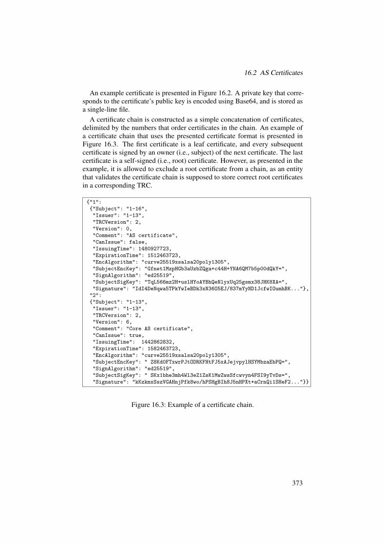
16.2 AS Certificates
An example certificate is presented in Figure 16.2. A private key that corre-sponds to the certificate’s public key is encoded using Base64, and is stored asa single-line file.
A certificate chain is constructed as a simple concatenation of certificates,delimited by the numbers that order certificates in the chain. An example ofa certificate chain that uses the presented certificate format is presented inFigure 16.3. The first certificate is a leaf certificate, and every subsequentcertificate is signed by an owner (i.e., subject) of the next certificate. The lastcertificate is a self-signed (i.e., root) certificate. However, as presented in theexample, it is allowed to exclude a root certificate from a chain, as an entitythat validates the certificate chain is supposed to store correct root certificatesin a corresponding TRC.
{"1":{"Subject": "1-16","Issuer": "1-13","TRCVersion": 2,"Version": 0,"Comment": "AS certificate","CanIssue": false,"IssuingTime": 1480927723,"ExpirationTime": 1512463723,"EncAlgorithm": "curve25519xsalsa20poly1305","SubjectEncKey": "Gfnet1MzpHGb3aUzbZQga+c44H+YNA6QM7b5p00dQkY=","SignAlgorithm": "ed25519","SubjectSigKey": "TqL566mz2H+uslHYoAYBhQeNlyxUq25gsmx38JHK8XA=","Signature": "IdI4DeNqwa5TPkYwIeBDk3xN36O5EJ/837mYyND1JcfwIOumhBK..."},"2":{"Subject": "1-13","Issuer": "1-13","TRCVersion": 2,"Version": 6,"Comment": "Core AS certificate","CanIssue": true,"IssuingTime": 1442862832,"ExpirationTime": 1582463723,"EncAlgorithm": "curve25519xsalsa20poly1305","SubjectEncKey": " Z8Kd0FTxwrPJtODRKFHtFJ5xAJejvpylHSYMbzaEbPQ=","SignAlgorithm": "ed25519","SubjectSigKey": " SKx1bhe3mh4Wl3eZ1ZsK1MwZwsSfcwvyn4FSI9yTvDs=","Signature": "kKzkmxSszVGAHnjPfk8wo/hPSHgBIh8J5nHPXt+aCrnQi1SHeF2..."}}
Figure 16.3: Example of a certificate chain.
373
16 Configuration File Formats
16.3 Discovery Service Configuration
Service discovery (described in Section 7.4.6) provides configuration files thatare a central element of an AS’s configuration. Although not all end hostsand servers of an AS receive all information from the AS’s discovery serviceconfiguration file, some parts of it are necessary to enable operation of thecontrol plane and data plane within an AS. A configuration file consists of thefollowing fields:
• ISD AS: ISD and AS identifiers in the “ISD-AS” format, where ISD is aninteger from 1 to 4,095, and AS is an integer from 1 to 1,048,575.
• MTU: integer that describes (in bytes) the maximum transmission unitwithin the AS.
• Overlay: overlay protocol used within the AS to implement SCION. Itcan be one of the following:
– IPv4: denotes an IPv4 overlay (i.e., SCION endpoints must haveIPv4 addresses assigned).
– IPv6: denotes an IPv6 overlay (i.e., SCION endpoints must haveIPv6 addresses assigned).
– IPv4+6: denotes that IPv4 and IPv6 overlays are deployed (i.e.,SCION endpoints must have IPv4 and IPv6 addresses assigned).
– UDP/IPv4: denotes a UDP/IPv4 overlay (i.e., SCION endpointsmust have IPv4 addresses assigned and must listen on a pre-definedoverlay UDP port).
– UDP/IPv6: denotes a UDP/IPv6 overlay (i.e., SCION endpointsmust have IPv6 addresses assigned and must listen on a pre-definedoverlay UDP port).
– UDP/IPv4+6: denotes that UDP/IPv4 and UDP/IPv6 overlays aredeployed (i.e., SCION endpoints must have IPv4 and IPv6 addressesassigned and must listen on a pre-defined overlay UDP port).
– MPLS: denotes an MPLS overlay (i.e., SCION endpoints must haveMPLS labels assigned).
• BorderRouters: dictionary of router identifiers (arbitrary unique strings),and their local end-host addresses with an interface configuration. Eachrouter’s section can have an optional list (InternalAddrs) of its inter-nally used addresses (i.e., addresses used when addressing the routeritself, not for forwarding). An entry of the list contains an address(IPv4/IPv6 address or MPLS label) accompanied with the port.The next dictionary (Interfaces) specifies information about interfacesthat the router supports (an interface connects with a border router ofa neighboring AS). Each interface has assigned an interface identifier
374

16.3 Discovery Service Configuration
(positive integer) which must be unique within the AS. An interfaceconfiguration consists of the following:
– InternalAddrIdx: index of the InternalAddrs list, which spec-ifies the internal address of the router. This address is used forreceiving local traffic (i.e., from the local AS).
– Overlay: overlay protocol used to communicate with a neighborAS’s border router. It can be IPv4, IPv6, UDP/IPv4, UDP/IPv6,or MPLS.
– Bind: address (and optionally port — if UDP encapsulation is used)that the router binds to.
– Public: address (and optionally port) used for receiving remotetraffic (i.e., from a neighbor AS’s border router).
– Remote: address (and optionally port) used by a neighbor AS’sborder router to receive traffic from the local AS.
– Bandwidth: integer that describes bandwidth (in bits per second)of the interface.
– ISD AS: ISD and AS identifiers of the neighbor AS in the “ISD-AS”format.
– LinkType: type of relation between local and neighbor ASes. Thevalue of this field can be PARENT, CHILD, PEER, or CORE (if bothASes are core ASes).
– MTU: integer that describes (in bytes) the maximum transmissionunit of the interface.
• ConsistencyService: dictionary of consistency server identifiers (ar-bitrary unique strings), and their local (end-host) addresses. In our imple-mentation, the consistency service is implemented with ZooKeeper [11],but this field is implementation-specific.
• BeaconService: dictionary of beacon server identifiers (arbitrary uniquestrings), and their address(es).
• CertService: dictionary of certificate server identifiers (arbitrary uniquestrings), and their addresses.
• PathService: dictionary of path server identifiers (arbitrary uniquestrings), and their addresses.
• SibraService: dictionary of SIBRA server identifiers (arbitrary uniquestrings), and their addresses.
• RAINSService: dictionary of RAINS server identifiers (arbitrary uniquestrings), and their addresses.
Addresses of servers can be specified within the two following sections. Eachentity must have a Public address section, which is used by
• the entity as the source address for messages it sends, and
375

16 Configuration File Formats
• all other entities as the destination address for packets sent to that entity.A Bind section is optional. If specified, it contains the address(es) that the
entity binds to. This is used in the case of NAT (a Bind section means that theentity will not bind to any addresses that are only listed in the Public section).Note that the address sections of servers can contain multiple addresses (incontrast to a router’s interface address sections).
If multiple SCION entities are behind a legacy NAT device, then Overlay-
Port should be specified in the Public section for each of them, and that portforwarded by the NAT device to the private address the entity runs on. (Notethat this configuration only works if a UDP-based overlay is deployed withinthe AS.) If the NAT device is SCION-aware, then this is not needed, as theSCION-NAT dispatcher can forward incoming packets appropriately, and theoverlay type does not matter.
Each address entry must contain Addr and L4Port fields. OverlayPort
is optional (and only relevant if the UDP overlay is used), and typically onlyneeded when running services behind a legacy NAT device as described above.If OverlayPort is not specified, then the default dispatcher port is used.
An example of a discovery service configuration file is presented in Fig-ure 16.4. We emphasize that an AS can restrict visibility of some parts of theconfiguration file to some entities. For instance, end hosts do not need to knowbeacon servers or detailed border router interface information.
16.4 Router, Server, and End-Host Configuration
In this section, we describe how SCION infrastructure elements are configuredand initialized.
Discovery Server
A discovery server needs an AS static configuration file that includes informa-tion on all SCION servers and border routers existing in the AS. As describedin Section 7.4.6, the discovery service provides both static and dynamicallygenerated information on the SCION services within its AS.
Since some of the information presented in the dynamic view cannot belearned from the consistency service, the values from the static configurationare mixed into the dynamic view. For example, the border routers do notregister with the consistency service, and thus, information about them needs tobe learned from the static configuration.
376

16.4 Router, Server, and End-Host Configuration
Border Router
In order to operate, a SCION border router requires the addresses of the localAS discovery servers, the AS’s static configuration file (optionally), and asymmetric key used for hop-field verification. Distribution of symmetric keyswithin an AS is up to the AS. In particular, the AS can distribute a master key,which is then used to derive other keys, such as a hop-field creation/verificationkey or keys used in extensions (e.g., SIBRA or OPT).
Beacon Server
On startup, a beacon server must be provided with the addresses of the localAS discovery servers, the AS’s static configuration file (optionally), a TRC (seeSection 16.1), the AS’s certificate (see Section 16.2), and a private key corre-sponding to the certificate (Section 16.2). The beacon server can additionallybe given certificates of upstream ASes, older TRCs, or TRCs of other ISDs.To operate properly, beacon servers are also configured with the followingparameters:
• Hop-field key: symmetric key used to authenticate hop fields. (The samekey has to be used by border routers to verify hop-field MACs.)
• Propagation period: denotes how often a beacon server initiates path-segment construction beacon propagation.
• Registration period: describes the frequency of path-segment registra-tion. Registration periods are configurable per path-segment type (i.e.,up, down, or core).
• Beaconing policy: applied when a beacon server selects beacons forpropagation. Details of the selection process are described in Sec-tion 7.1.4.
• Registration policy: applied when a beacon server selects beacons forup-, down-, or core-segment registration (each path-segment type has itsown policy).
As presented, beacon servers are configured with beacon selection policies.The selection process and SCION path policies are described in Sections 7.1.4and 10.9. In particular, the selection policy can implement the following factors:
• Beacon store parameters: internal configuration of a beacon store (seeSection 7.1.4), such as number of stored beacons, number of beacons toselect, number of stored selections, or how often the store is updated.
• Selection filters: factors to decide whether a given beacon is discarded.It can include a blacklist (or whitelist) of ASes or allowed ranges of thebeacon’s properties. In particular, these properties can include:
– Path length: number of hops from an originator AS to the localAS.
377

16 Configuration File Formats
– Last reception: time that has elapsed since the PCB arrived at theAS’s beacon store.
– Expiration time: time when the given path segment expires (i.e.,at least one of the hop fields expires).
– Last transmission: last time at which the beacon server propagatedthe beacon or registered it as a path segment.
– Peering ASes: number of peering ASes from the beacon.Disjointness can be another selection filter (an AS can specify how manycommon ASes/interfaces a candidate beacon can have with the previouslyselected beacons).
• Property weights: impact of different properties in the beacon selectionprocess.
• Policy parameters: used to implement the routing-policy extensions(see Section 15.3.4), applicable to beaconing policies only. For example,an AS can specify a list of ASes that can or cannot be used in pathsegments. Similarly, the AS can specify a list of interfaces that can (orcannot) be used to forward traffic.
Path Server
On start, a path server has to be provided with the current versions of the AS’sTRC, the certificate of the AS, addresses of discovery servers, and the AS’sstatic configuration file (optionally).
Certificate Server
A certificate server must be initialized with all TRCs of its ISD and all cer-tificates of its AS (with the corresponding private keys). Additionally, it canbe provided with TRCs and certificates of remote ISDs/ASes. Besides TRCsand certificates, a certificate server requires the addresses of the local AS’sdiscovery servers, the AS’s static configuration file (optionally), and symmetrickeys used in the DRKey and OPT protocols.
RAINS and SIBRA Servers
RAINS and SIBRA servers require the current TRC and the address(es) ofdiscovery server(s), as well as their own configuration file.
End Host
An end host must possess the current TRC and the address(es) of discoveryserver(s).
378

16.4 Router, Server, and End-Host Configuration
{"ISD_AS": "1-11","MTU": 1472,"Overlay": "UDP/IPv4+6","BorderRouters": {
"br1-11-1": {"InternalAddrs": [
{"Public": [{"Addr": "10.1.0.1", "L4Port": 30097},{"Addr": "2001:db8:a0b:1f::1", "L4Port": 30097}]},
{"Public": [{"Addr": "10.1.0.2", "L4Port": 30097},{"Addr": "2001:db8:a0b:1f::2", "L4Port": 30097}]}],
"Interfaces": {"1": {"InternalAddrIdx": 0, "Overlay": "UDP/IPv4",
"Bind": {"Addr": "10.0.0.1", "L4Port": 30090},"Public": {"Addr": "192.0.2.1", "L4Port": 44997},"Remote": {"Addr": "219.33.0.2", "L4Port": 1239},"Bandwidth": 500000000000, "ISD_AS": "1-12","LinkType": "CORE", "MTU": 1472},
"3": {"InternalAddrIdx": 0, "Overlay": "IPv6","Public": {"Addr": "2001:db8:a0b:1f::1", "L4Port": 50000},"Remote": {"Addr": "2a00:14:4a:807::2e", "L4Port": 33997},"Bandwidth": 500000000000, "ISD_AS": "1-12","LinkType": "CORE", "MTU": 4430},
"8": { "InternalAddrIdx": 1, "Overlay": "IPv4","Bind": {"Addr": "10.0.0.2", "L4Port": 40000},"Public": {"Addr": "192.0.2.2", "L4Port": 50000},"Remote": {"Addr": "156.3.22.37", "L4Port": 8112},"Bandwidth": 250000000000, "ISD_AS": "1-13","LinkType": "CHILD", "MTU": 1480}}}},
"ConsistencyService": {"1": {"Addr": "10.0.0.10", "L4Port": 2181},... },
"BeaconService": {"bs1-11-1": {
"Bind": [{"Addr": "192.168.0.1", "L4Port": 30045},{"Addr": "2001:db8:a0b:1f::100", "L4Port": 30045}],
"Public": [{"Addr": "10.1.0.100", "L4Port": 30045,"OverlayPort": 3004},{"Addr": "2001:db8:a0b:1f::100", "L4Port": 30045}]},
"bs1-11-2": {"Public": [{"Addr": "10.1.0.101", "L4Port": 30053},
{"Addr": "2001:db8:a0b:1f::101", "L4Port": 30053}]}},"CertificateService": {
... },"PathService": {
... },"SibraService": {
... },"RainsService": {
... }}
Figure 16.4: An example of a discovery service configuration file.
379


17 Cryptographic Algorithms
ADRIAN PERRIG, PAWEL SZALACHOWSKI
In this chapter, we describe the algorithm agility property provided by SCION,and the cryptographic algorithms used in the SCION architecture. Algorithmselection was motivated by two main requirements, security and efficiency,and was based on standards related to cryptography, recommendations, bestpractices, and performance evaluations [95, 190, 221, 224].
Chapter Contents
17.1 Algorithm Agility . . . . . . . . . . . . . . . . . . . . . . . . . . 381
17.2 Symmetric Primitives . . . . . . . . . . . . . . . . . . . . . . . 384
17.3 Asymmetric Primitives . . . . . . . . . . . . . . . . . . . . . . . 385
17.4 Post-Quantum Cryptography . . . . . . . . . . . . . . . . . . . 386
17.1 Algorithm Agility
Algorithm agility is a property that allows a protocol to easily migrate fromone algorithm to another one. It is especially important in the context ofcryptographic algorithms, which become weaker over time. Since it is notpossible to predict advances in cryptanalysis techniques, every future-proofprotocol that employs cryptographic algorithms should provide a mechanismfor algorithm agility.
In SCION, cryptographic algorithms are deployed extensively. However, insome cases algorithm selection is local to an AS and does not influence otherparties. The design of the SCION elements that require coordinated lists ofcryptographic algorithms follows the best current practice for cryptographicalgorithm agility [112] and provides powerful mechanisms to enhance algorithmagility.
381

17 Cryptographic Algorithms
17.1.1 Local Algorithms
Some cryptographic operations in SCION are performed locally, only within anAS’s infrastructure. This is an ideal case for algorithm agility, as the algorithmsused by an AS neither have to be synchronized with other parties, nor evenknown by other ASes or end hosts. In particular, these operations are:
• Key generation: An AS needs to generate its own keys. At least onesymmetric (master key) and asymmetric key pair are required. To gen-erate them, a strong pseudorandom number generator (PRNG) must beused.
• Key derivation: All symmetric keys used within an AS (e.g., keys usedfor hop-field authentication) are derived from the master key, which isshared among relevant infrastructure elements. ASes can freely selecttheir favorite key derivation algorithm, as this decision influences onlylocally used keys.
• Hop-field creation and verification: Hop fields are created (see Sec-tion 7.1) with a MAC algorithm involved. However, hop fields areprocessed only locally (within an AS), so the AS does not have to eveninform other parties which algorithm it is currently using. After hop fieldsare created, they are used in forwarding paths, where they are verifiedby border routers. Again, hop-field verification is local to the AS whichhas created the hop field. For verification, the same MAC scheme is usedthat has been used for hop-field creation.
As these operations use locally selected algorithms, ASes can change theirPRNG, MAC, and key derivation algorithms at any time, with no synchroniza-tion with the rest of the network. It is only required that the AS’s infrastructureelements use a consistent algorithm.
17.1.2 Mandatory-to-Implement Algorithms
In contrast to the locally used algorithms, some operations in SCION require aglobally coordinated list of supported cryptographic algorithms. These opera-tions are:
• TRC creation and verification: TRCs rely heavily on digital signatures.Each entity within a TRC is specified via its public-key certificate, whichin turn specifies the digital signature algorithm used. The list of usedalgorithms has to be specified globally, as TRCs are cross-signed by otherISDs and verified by remote end hosts.
• Beaconing: Similarly to TRCs, beacons are protected with digital sig-natures. Also, AS-level certificates are used to identify the deployedalgorithm. Note that each AS can use a different algorithm (as long asit is supported by other parties) to authenticate its AS entry. A beacon
382

17.1 Algorithm Agility
is only forwarded if every AS that received it can verify all signatures.However, to support algorithm agility, SCION permits ASes to add multi-ple signatures to beacons. This can result in beacons (and path segmentsconsequently) with different security properties.
• Path-segment registration and lookup: Every path segment is authen-ticated by a single AS, and similarly the algorithm used is determinedfrom the AS certificate.
• Path revocation: Path revocation messages are authenticated using hashtrees (see Section 7.3), which are built with cryptographic hash functions.As revocation messages can be verified by everyone, the algorithm usedhas to be standardized. However, each AS can pick (from the agreed list)its preferred hash function.
• SCMP authentication: SCMP packets are authenticated via the SCIONpacket security extension, which requires either a public-key encryptionand a hash algorithm or a MAC scheme.
• DRKey: The DRKey protocol requires that a public-key encryptionalgorithm and a key derivation algorithm are specified.
• Name authentication: As name authentication in SCION is built uponRAINS, SCION relies on RAINS’s algorithm suites [240].
• End-entity authentication: End-entity authentication relies on the TLSprotocol, which provides algorithm agility and defines its own algorithmsuites [68].
SCION defines a set of mandatory-to-implement cryptographic algorithms,and every allowed algorithm has a unique identifier assigned.
Authentication of TRCs, beacons, and path segments is based on AS-levelcertificates. (General information on AS-level certificates is provided in Sec-tion 4.2.3, while the detailed format of AS-level certificates is given in Sec-tion 16.2.) Every certificate contains the algorithm field, which specifies thedigital signature algorithm used. An identifier of the digital signature algorithmimplicitly determines the size of the private and public keys used, as well asthe size of signatures produced. The certificates are short-lived, so an AS thatwishes to change its digital signature scheme can do it with the next certificatere-issuance (up to a few days).
Path revocation messages are authenticated using a hash function. The hashalgorithm used is specified in beacons and path segments whose lifetime isshort, hence an AS can freely change the hash function used. An identifier ofthe hash function implicitly specifies its output length. More concretely, a hashfunction identifier is part of: (a) the RevocationToken field of every AS entry(see details in Section 15.3.3 on Page 359), and (b) each revocation message(see an example in Figure 15.18 on Page 362).
383

17 Cryptographic Algorithms
17.2 Symmetric Primitives
The only mandatory symmetric primitives in SCION are a cryptographic hashfunction and a MAC scheme. The other symmetric primitives are local to anAS, and do not have unique identifiers assigned. However, throughout thissection we list the algorithms supported in our current specification.
17.2.1 Pseudorandom Number Generator
Pseudorandom number generators (PRNGs) are used to generate AS symmetricand asymmetric keys. As a PRNG’s output is critical for the security of ASoperations, it has to be selected carefully. The most common PRNGs areprovided by underlying operating systems, and may be software or hardwarecomponents. By default, our implementation relies on the standard LinuxPRNG [147].
17.2.2 Key Derivation Function
Key derivation functions are used by ASes to generate temporary symmetrickeys used in production (e.g., for keys for hop-field generation). By default,our implementation deploys Password-Based Key Derivation Function 2 [126],with the following parameters: the output length is set to 16 bytes, the numberof iterations is 1,000, and its internal pseudorandom function is set to HMAC-SHA256 [136].
17.2.3 Cryptographic Hash Function
Cryptographic hash functions are often elements of digital signature schemes,however, in SCION they are also used as stand-alone primitives in path revoca-tion.
SCION supports two cryptographic hash functions. The first one is SecureHash Algorithm 2 (SHA2) [185]. The supported variants of SHA2 are SHA-256, SHA-384, and SHA-512, which produce a hash value of 256, 384, and512 bits, respectively.
The second algorithm supported is SHA3 (Keccak) [32, 203]. Similarly, thesupported versions of SHA3 are SHA3-256, SHA3-384, and SHA3-512, whichproduce a hash value of 256, 384, and 512 bits, respectively.
17.2.4 Message Authentication Codes (MACs)
Although the MAC scheme used for hop-field authentication/verification canbe freely selected by an AS, it is one of the most important cryptographic prim-
384

17.3 Asymmetric Primitives
itives in SCION. This function is executed by border routers for every packetforwarded. Hence, besides security, it has to provide outstanding performance.
In our implementation, we use an AES-based CMAC [226] as the defaultMAC scheme. This choice is motivated by efficiency. First, AES is commonlysupported in hardware. Second, CMAC requires a minimal number of AESexecutions for authentication tag computation.
17.3 Asymmetric Primitives
The mandatory asymmetric primitives are digital signatures and public-keyencryption (although other protocols built on top of SCION may require otherasymmetric primitives). Throughout this section we list the algorithms sup-ported in our current specification.
17.3.1 Digital Signatures
The requirements for digital signature schemes used in SCION are (a) security(as certificates, beacons, path segments, and TRCs are protected with them), (b)efficiency (as signature creation and verification are often executed), and (c)short signature and public key.
There are two digital signature algorithms used currently in SCION. Asthe default option the Edwards-curve Digital Signature Algorithm is used.More specifically, SCION deploys its instantiation called Ed25519 [30]. Thissignature scheme provides outstanding efficiency and signatures created arerelatively short (64 bytes).
An alternative to Ed25519 is the Elliptic Curve Digital Signature Algorithm(ECDSA). Following the current best practice, we use the ECDSA-256 andECDSA-384 algorithms. In comparison with Ed25519, the ECDSA algorithmsare slower and produce longer signatures; however, when compared to standarddigital signature algorithms (such as RSA), they provide higher efficiency andshorter signatures.
17.3.2 Public-Key Encryption
Public-key encryption in SCION is used only for key establishment in theDRKey protocol (see Section 12.5). The requirements for this primitive aresimilar to those for digital signatures, i.e., security (as the DRKey protocolprotects SCMP messages), and efficiency (as key establishment should not incursignificant overhead). In our current specification we use an Elliptic CurveIntegrated Encryption Scheme (ECIES) based on the curve Curve25519 [29].
385

17 Cryptographic Algorithms
17.4 Post-Quantum Cryptography
With advances in quantum computers, some asymmetric-cryptography systemsare threatened — as it becomes possible, for example, for a quantum computerto factor an RSA modulus with a lower computational overhead. Thanks toSCION’s algorithm agility, new crypto systems can be introduced to providea second layer of cryptography. This is relatively straightforward in the caseof digital signatures, hash functions, or message authentication codes, as forexample, a second signature can be computed with a different cryptographicscheme, the second signature can be added to the message, and the receiver canindependently verify the signatures.
Algorithm agility is harder to achieve for encryption. A message that isencrypted with two different encryption algorithms needs to be decrypted withboth algorithms; thus, if a receiver does not support an algorithm then it cannotdecrypt the message. Separately encrypting a message with different encryptionalgorithms is in vain, as one achieves weakest-link security: the final message isonly as secure as the weakest of the algorithms, and potentially even weaker ifthe encryption techniques compose unfavorably. In the case of digital signaturesand message authentication codes described above, the combination of multipleschemes composes favorably, and the resulting security strength is at least thatof the strongest algorithm, if implemented correctly.
We now discuss the quantum-resilient cryptographic algorithms that the basicSCION infrastructure can utilize.
Recently proposed symmetric-key cryptographic algorithms, such as PRFsfor key derivation, hash functions, encryption, or MACs, resist quantum com-puters as long as the key length is sufficiently long.
For post-quantum key exchange mechanisms, new protocols that are basedon hard problems in ideal lattices have recently been proposed [5, 40]. Theseapproaches are based on the Ring Learning With Errors (R-LWE) problem.
One-time signatures provide a promising mechanism for the construction ofpost-quantum signature algorithms [31,43]. These types of signatures are basedon one-way functions, which can be efficiently instantiated with cryptographichash functions.
The salient point here is that SCION is already prepared to accommodateand switch to any cryptographic algorithm, thus scaling with respect to crypto-graphic progress.
386

Bibliography
[1] Martın Abadi, Andrew Birrell, Ilya Mironov, Ted Wobber, and YinglianXie. Global authentication in an untrustworthy world. In Proceedingsof Workshop on Hot Topics in Operating Systems (HotOS), May 2013.Ź Page 10.
[2] Bernhard Ager, Nikolaos Chatzis, Anja Feldmann, Nadi Sarrar, SteveUhlig, and Walter Willinger. Anatomy of a large European IXP. InProceedings of the ACM SIGCOMM Conference, 2012. Ź Page 54.
[3] William Aiello, John Ioannidis, and Patrick McDaniel. Origin authen-tication in interdomain routing. In Proceedings of the ACM Confer-ence on Computer and Communications Security (CCS), October 2003.Ź Page 307.
[4] Kahraman Akdemir, Martin Dixon, Wajdi Feghali, Patrick Fay, VinodhGopal, Jim Guilford, Erdinc Ozturk, Gil Wolrich, and Ronen Zohar.Breakthrough AES performance with Intel AES New Instructions. Whitepaper, June, 2010. Ź Page 11.
[5] Erdem Alkim, Leo Ducas, Thomas Poppelmann, and Peter Schwabe.Post-quantum key exchange: A new hope. Technical Report 2015/1092,Cryptology ePrint Archive, March 2016. Ź Page 386.
[6] American Registry for Internet Numbers (ARIN). Resource Public KeyInfrastructure (RPKI). https://www.arin.net/resources/rpki/.Ź Page 61.
[7] David G. Andersen, Hari Balakrishnan, Nick Feamster, Teemu Kopo-nen, Daekyeong Moon, and Scott Shenker. Accountable Internet Pro-tocol (AIP). In Proceedings of the ACM SIGCOMM Conference, 2008.Ź Pages 25, 28, 94, 284, and 320.
[8] David G. Andersen, Hari Balakrishnan, M. Frans Kaashoek, and RobertMorris. Resilient overlay networks. In Proceedings of ACM Symposiumon Operating Systems Principles (SOSP), October 2001. Ź Pages 9, 24,and 192.
[9] Tom Anderson, Ken Birman, Robert Broberg, Matthew Caesar, Dou-glas Comer, Chase Cotton, Michael J. Freedman, Andreas Haeberlen,Zachary G. Ives, Arvind Krishnamurthy, William Lehr, BoonThau Loo,David Mazieres, Antonio Nicolosi, Jonathan M. Smith, Ion Stoica, Rob-bert Renesse, Michael Walfish, Hakim Weatherspoon, and Christopher S.Yoo. The NEBULA future Internet architecture. In The Future Internet,
387

Bibliography
Lecture Notes in Computer Science. Springer-Verlag, 2013. Ź Pages 14and 331.
[10] Tom Anderson, Timothy Roscoe, and David Wetherall. PreventingInternet denial-of-service with capabilities. ACM SIGCOMM ComputerCommunication Review, 2004. Ź Pages 244 and 276.
[11] Apache. ZooKeeper. http://zookeeper.apache.org. Ź Pages 147,322, and 375.
[12] Maria Apostolaki, Aviv Zohar, and Laurent Vanbever. Hijacking Bit-coin: Routing attacks on cryptocurrencies. In Proceedings of the IEEESymposium on Security and Privacy (S&P), 2017. Ź Pages 32 and 192.
[13] Roy Arends, Rob Austein, Matt Larson, Dan Massey, and Scott Rose.DNS security introduction and requirements. RFC 4033, March 2005.Ź Pages 10 and 83.
[14] Katerina Argyraki and David R. Cheriton. Network capabilities: Thegood, the bad and the ugly. In ACM HotNets, 2005. Ź Page 276.
[15] Brice Augustin, Xavier Cuvellier, Benjamin Orgogozo, Fabien Viger,Timur Friedman, Matthieu Latapy, Clemence Magnien, and Renata Teix-eira. Avoiding traceroute anomalies with Paris traceroute. In Proceedingsof the ACM Internet Measurement Conference (IMC), 2006. Ź Page 222.
[16] Jozef Babiarz, Kwok Chan, and Fred Baker. Configuration guidelinesfor DiffServ service classes. RFC 4594, August 2006. Ź Page 244.
[17] Fred Baker, Carol Iturralde, Francois Le Faucheur, and Bruce Davie. Ag-gregation of RSVP for IPv4 and IPv6 reservations. RFC 3175, September2001. Ź Page 277.
[18] Fred Baker and Pekka Savola. Ingress filtering for multihomed networks.RFC 3704, March 2004. Ź Page 320.
[19] Hitesh Ballani, Yatin Chawathe, Sylvia Ratnasamy, Timothy Roscoe,and Scott Shenker. Off by default! In Proceedings of ACM Workshop onHot Topics in Networks (HotNets), 2005. Ź Page 30.
[20] David Barrera, Laurent Chuat, Adrian Perrig, Raphael M. Reischuk, andPawel Szalachowski. The SCION Internet architecture. Communicationsof the ACM, 60(6), June 2017. Ź Page 306.
[21] Cristina Basescu, Yue-Hsun Lin, Haoming Zhang, and Adrian Perrig.High-speed inter-domain fault localization. In Proceedings of the IEEESymposium on Security and Privacy (S&P), May 2016. Ź Pages xviand 281.
[22] Cristina Basescu, Raphael M. Reischuk, Pawel Szalachowski, Adrian Per-rig, Yao Zhang, Hsu-Chun Hsiao, Ayumu Kubota, and Jumpei Urakawa.SIBRA: Scalable Internet bandwidth reservation architecture. In Pro-ceedings of the Symposium on Network and Distributed Systems Security(NDSS), February 2016. Ź Pages xvi, 39, 243, 270, and 306.
388
Bibliography
[23] David Basin, Cas Cremers, Tiffany Hyun-Jin Kim, Adrian Perrig, RalfSasse, and Pawel Szalachowski. ARPKI: Attack resilient public-keyinfrastructure. In Proceedings of the ACM Conference on Computer andCommunications Security (CCS), November 2014. Ź Pages xvi, 29, 40,87, 89, and 302.
[24] David Basin, Cas Cremers, Tiffany Hyun-Jin Kim, Adrian Perrig, RalfSasse, and Pawel Szalachowski. Design, analysis, and implementation ofARPKI: an attack-resilient public-key infrastructure. IEEE Transactionson Dependable and Secure Computing (TDSC), 2017. Ź Pages 40, 87,89, and 302.
[25] BBC. Asia communications hit by quake. http://news.bbc.co.uk/2/hi/asia-pacific/6211451.stm, December 2006. Ź Pages 10and 307.
[26] Stefan Bechtold and Adrian Perrig. Accountability in future Internetarchitectures: Can technical and legal aspects be happily intertwined?Communications of the ACM, 57(9):21–23, September 2014. Ź Page xvi.
[27] Steven Bellovin, David Clark, Adrian Perrig, and Dawn Song. A clean-slate design for the next-generation secure Internet. Report for NSFGlobal Environment for Network Innovations (GENI) workshop, July2005. Ź Page xvii.
[28] Mark Berman, Jeffrey S. Chase, Lawrence Landweber, Akihiro Nakao,Max Ott, Dipankar Raychaudhuri, Robert Ricci, and Ivan Seskar. GENI:A federated testbed for innovative network experiments. ComputerNetworks, 61:5–23, 2014. Ź Page 15.
[29] Daniel J. Bernstein. Cryptography in NaCl. Networking and Cryptogra-phy library, 3, 2009. Ź Page 385.
[30] Daniel J Bernstein, Niels Duif, Tanja Lange, Peter Schwabe, and Bo-YinYang. High-speed high-security signatures. Journal of CryptographicEngineering, 2(2):77–89, 2012. Ź Pages 353 and 385.
[31] Daniel J. Bernstein, Daira Hopwood, Andreas Hulsing, Tanja Lange,Ruben Niederhagen, Louiza Papachristodoulou, Michael Schneider, Pe-ter Schwabe, and Zooko Wilcox-O’Hearn. SPHINCS: practical statelesshash-based signatures. In Advances in Cryptology - EUROCRYPT, 2015.Ź Page 386.
[32] Guido Bertoni, Joan Daemen, Michael Peeters, and Gilles Van Assche.Keccak sponge function family main document. Submission to NIST(Round 2), 3:30, 2009. Ź Page 384.
[33] Robert Beverly, Ryan Koga, and KC Claffy. Initial longitudinal analysisof IP source spoofing capability on the Internet. Internet Society, 2013.Ź Pages 313 and 320.
[34] Bobby Bhattacharjee, Ken Calvert, Jim Griffioen, Neil Spring, and JamesSterbenz. Postmodern internetwork architecture. Technical Report ITTC
389

Bibliography
Technical Report ITTC-FY2006-TR-45030-01, University of Kansas,February 2006. Ź Pages 13 and 40.
[35] Andrew Birrell, Butler Lampson, Roger Needham, and MichaelSchroeder. A global authentication service without global trust. InProceedings of the IEEE Symposium on Security and Privacy (S&P),1986. Ź Pages 48 and 62.
[36] Burton H. Bloom. Space/time trade-offs in hash coding with allowableerrors. Communications of the ACM, 13(7):422–426, 1970. Ź Page 270.
[37] Rakesh Babu Bobba, Laurent Eschenauer, Virgil Gligor, and WilliamArbaugh. Bootstrapping security associations for routing in mobilead-hoc networks. In Proceedings of IEEE Global TelecommunicationsConference (Globecom), 2003. Ź Page 65.
[38] Raffaele Bolla, Roberto Bruschi, Franco Davoli, and Flavio Cucchietti.Energy efficiency in the future Internet: a survey of existing approachesand trends in energy-aware fixed network infrastructures. IEEE Commu-nications Surveys & Tutorials, 13(2):223–244, 2011. Ź Page 331.
[39] Carsten Bormann and Paul Hoffman. Concise binary object representa-tion (CBOR). RFC 7049, October 2013. Ź Page 114.
[40] Joppe Bos, Craig Costello, Leo Ducas, Ilya Mironov, Michael Naehrig,Valeria Nikolaenko, Ananth Raghunathan, and Douglas Stebila. Frodo:Take off the ring! Practical, quantum-secure key exchange from LWE.Technical Report 2016/659, Cryptology ePrint Archive, June 2016.Ź Page 386.
[41] R.T. Braden, D.A. Borman, and C. Partridge. Computing the Internetchecksum. RFC 1071, September 1988. Ź Page 364.
[42] Tim Bray. The JavaScript Object Notation (JSON) Data InterchangeFormat. RFC 7159, March 2014. Ź Page 369.
[43] Johannes Buchmann, Erik Dahmen, and Andreas Hulsing. XMSS - apractical forward secure signature scheme based on minimal securityassumptions. Technical Report 2011/484, Cryptology ePrint Archive,November 2011. Ź Page 386.
[44] Kevin Butler, Toni R. Farley, Patrick McDaniel, and Jennifer Rexford. ASurvey of BGP Security Issues and Solutions. Proceedings of the IEEE,98(1), 2010. Ź Page 307.
[45] Matthew Caesar and Jennifer Rexford. BGP routing policies in ISPnetworks. IEEE Network: The Magazine of Global Internetworking,2005. Ź Page 5.
[46] Kenneth L. Calvert, James Griffioen, and Leonid Poutievski. Separatingrouting and forwarding: A clean-slate network layer design. In Pro-ceedings of International Conference on Broadband Communications,Networks and Systems (BROADNETS), 2007. Ź Pages 13 and 40.
390

Bibliography
[47] Isidro Castineyra, Noel Chiappa, and Martha Steenstrup. The Nimrodrouting architecture. RFC 1992, August 1996. Ź Pages 13 and 40.
[48] Stephen Checkoway, Jacob Maskiewicz, Christina Garman, Joshua Fried,Shaanan Cohney, Matthew Green, Nadia Heninger, Ralf-Philipp Wein-mann, Eric Rescorla, and Hovav Shacham. A systematic analysis ofthe Juniper Dual EC incident. In Proceedings of the ACM Confer-ence on Computer and Communications Security (CCS), October 2016.Ź Page 305.
[49] Chen Chen, Daniele Enrico Asoni, David Barrera, George Danezis, andAdrian Perrig. HORNET: High-speed onion routing at the networklayer. In Proceedings of the ACM Conference on Computer and Com-munications Security (CCS), October 2015. Ź Pages xvi, 35, 39, 306,and 319.
[50] Chen Chen, David Barrera, and Adrian Perrig. Modeling data-planepower consumption of future Internet architectures. In Proceedings ofthe IEEE Conference on Collaboration and Internet Computing (CIC),November 2016. Ź Pages xvi, 332, 333, and 334.
[51] Chen Chen and Adrian Perrig. PHI: Path-hidden lightweight anonymityprotocol at network layer. In Proceedings on Privacy Enhancing Tech-nologies (PoPETs), July 2017. Ź Page xvi.
[52] Laurent Chuat, Pawel Szalachowski, Adrian Perrig, Ben Laurie, and EranMesseri. Efficient gossip protocols for verifying the consistency of cer-tificate logs. In Proceedings of the IEEE Conference on Communicationsand Network Security (CNS), 2015. Ź Pages xvi and 92.
[53] Cisco. Requirements for next-generation core routing systems. https://perma.cc/58AX-TAQJ. Ź Page 306.
[54] Cisco. Field notice: Endless BGP convergence problem in Cisco IOSsoftware releases, 2001. Ź Page 235.
[55] Cisco. IOS and IOS XE software cluster management protocol remotecode execution vulnerability. https://perma.cc/M7P8-FH26, March2017. Ź Page 305.
[56] David Clark, Robert Braden, Aaron Falk, and Venkata Pingali. FARA:Reorganizing the addressing architecture. In Proceedings of the ACMSIGCOMM Workshop on Future Directions in Network Architecture,2003. Ź Pages 13 and 40.
[57] David Clark, Karen Sollins, John Wroclawski, Dina Katabi, JoannaKulik, Xiaowei Yang, Robert Braden, Ted Faber, Aaron Falk, VenkataPingali, Mark Handley, and Noel Chiappa. NewArch: Future generationInternet architecture. Technical report, Air Force Research Labs, 2004.Ź Pages 13 and 40.
391

Bibliography
[58] The PlanetLab Consortium. PlanetLab, an open platform for devel-oping, deploying, and accessing planetary-scale services. https:
//www.planet-lab.org/, 2016. Ź Page 221.[59] Danny Cooper, Ethan Heilman, Kyle Brogle, Leonid Reyzin, and Sharon
Goldberg. On the risk of misbehaving RPKI authorities. In Proceedingsof the ACM Workshop on Hot Topics in Networks (HotNets), November2013. Ź Page 65.
[60] David Cooper, Stefan Santesson, Stephen Farrell, Sharon Boeyen, RussHousley, and William Polk. Internet X.509 public key infrastructurecertificate and certificate revocation list (CRL) profile. RFC 5280, May2008. Ź Pages 369 and 370.
[61] Miguel Medeiros Correia and Mustafa Tok. DNS-based Authenticationof Named Entities (DANE). Technical report, Universidade do Porto,2011–2012. Ź Page 103.
[62] Court of Justice of the European Union (CURIA). Personal data:Protection of individuals with regard to the processing of such data.https://perma.cc/J2T3-VD67. Ź Page 35.
[63] Jim Cowie. The new threat: Targeted Internet traffic misdi-rection. http://research.dyn.com/2013/11/mitm-internet-
hijacking/, November 2013. Ź Pages 7, 32, and 280.[64] Stephen E. Deering and Robert Hinden. Internet protocol, version 6
(IPv6) specification. RFC 2460, December 1998. Ź Page 4.[65] Alan Demers, Srinivasan Keshav, and Scott Shenker. Analysis and
simulation of a fair queueing algorithm. ACM SIGCOMM ComputerCommunication Review, 1989. Ź Page 244.
[66] Amogh Dhamdhere and Constantine Dovrolis. Twelve years in the evolu-tion of the Internet ecosystem. IEEE/ACM Transactions on Networking,19(5):1420–1433, Sep 2011. Ź Page 38.
[67] DICE Control Plane Working Group. Inter-Domain Controller (IDC)protocol specification. http://www.controlplane.net/, February 2010.Version 1.1. Ź Page 271.
[68] Tim Dierks and Eric Rescorla. The Transport Layer Security (TLS)protocol version 1.2. RFC 5246, August 2008. Ź Page 383.
[69] Daniel Eran Dilger. Oops: Microsoft leaks its golden key, unlockingWindows Secure Boot and exposing the danger of backdoors. https://perma.cc/444S-SPR6, 2016. Ź Page 44.
[70] Wenxiu Ding, Zheng Yan, and Robert H. Deng. A survey on futureInternet security architectures. IEEE Access, 4:4374–4393, July 2016.Ź Pages 302 and 330.
[71] Mo Dong, Qingxi Li, Doron Zarchy, P. Brighten Godfrey, and MichaelSchapira. PCC: Re-architecting congestion control for consistent high
392
Bibliography
performance. In Proceedings of the USENIX Symposium on NetworkedSystems Design and Implementation (NSDI), 2015. Ź Page 189.
[72] John R. Douceur. The Sybil attack. In First International Workshop onPeer-to-Peer Systems (IPTPS ’02), March 2002. Ź Page 48.
[73] Jim Duffy. Cisco’s IOS vs. Juniper’s JUNOS. https://perma.cc/
FY59-WV9D, April 2008. Network World. Ź Page 306.[74] Adam Dunkels. Design and implementation of the lwIP TCP/IP stack.
Swedish Institute of Computer Science, 2:77, 2001. Ź Page 187.[75] Zakir Durumeric, James Kasten, David Adrian, J. Alex Halderman,
Michael Bailey, Frank Li, Nicolas Weaver, Johanna Amann, JethroBeekman, Mathias Payer, and Vern Paxson. The matter of Heartbleed.In Proceedings of the ACM Internet Measurement Conference (IMC),2014. Ź Page 74.
[76] Morris J. Dworkin. SP 800-38D, Recommendation for block ciphermodes of operation: Galois/Counter Mode (GCM) and GMAC, 2007.Ź Page 353.
[77] Hurricane Electric. BGP peer report. http://bgp.he.net/report/peers, 2016. Ź Page 146.
[78] Electronic Frontier Foundation. SSL Observatory. https://www.eff.org/observatory, 2010. Ź Page 10.
[79] European Commission. FIRE: Future Internet research and experimenta-tion. https://www.ict-fire.eu. Ź Page 15.
[80] European Commission. FIWARE: Core platform of the future Internet.https://www.fiware.org. Ź Page 15.
[81] European Commission. FORWARD: Managing emerging threats in ICTinfrastructures. http://www.ict-forward.eu. Ź Page 14.
[82] European Commission. SysSec: A European network of excellencein managing threats and vulnerabilities in the future Internet. http:
//www.syssec-project.eu/. Ź Page 14.[83] Dino Farinacci, Vince Fuller, David Meyer, and Darrel Lewis. The loca-
tor/ID separation protocol (LISP). RFC 6830, January 2013. Ź Page 25.[84] Adrian Farrel, Jean-Philippe Vasseur, and Jerry Ash. A path computation
element (PCE)-based architecture. RFC 4655, August 2006. Ź Page 277.[85] Stephen Farrell and Hannes Tschofenig. Pervasive monitoring is an
attack. RFC 7258, May 2014. Ź Page xvii.[86] Seyed Kaveh Fayazbakhsh, Yin Lin, Amin Tootoonchian, Ali Ghodsi,
Teemu Koponen, Bruce Maggs, K.C. Ng, Vyas Sekar, and Scott Shenker.Less pain, most of the gain: incrementally deployable ICN. In Proceed-ings of the ACM SIGCOMM Conference, August 2013. Ź Pages 12, 335,336, and 337.
393

Bibliography
[87] Paul Ferguson and Daniel Senie. Network ingress filtering: Defeatingdenial of service attacks which employ IP source address spoofing. RFC2827, May 2000. Ź Page 320.
[88] Clarence Filsfils, Stefano Previdi, Bruno Decraene, Stephane Litkowski,and Rob Shakir. Segment routing architecture. Internet-draft, February2017. Ź Page 14.
[89] The Apache Software Foundation. Apache License Version 2.0, January2004. http://www.apache.org/licenses/LICENSE-2.0, 2016.Ź Page 306.
[90] Eva Galperin, Seth Schoen, and Peter Eckersley. A post mortem onthe Iranian DigiNotar attack. https://www.eff.org/deeplinks/
2011/09/post-mortem-iranian-diginotar-attack, October2011. Ź Page 7.
[91] Lixin Gao and Jennifer Rexford. Stable Internet routing without globalcoordination. Networking, IEEE/ACM Trans on, 9(6):681–692, 2001.Ź Pages 234 and 328.
[92] GEANT. Bandwidth on demand. http://geant3.archive.geant.
net/service/BoD/pages/home.aspx, 2015. Ź Page 271.[93] Yossi Gilad and Amir Herzberg. Plug-and-play IP security: Anonymity
infrastructure instead of PKI. In Proceedings of ESORICS, 2013.Ź Page 284.
[94] Phillipa Gill, Michael Schapira, and Sharon Goldberg. A survey of inter-domain routing policies. ACM SIGCOMM Computer CommunicationReview, 44(1):28–34, 2013. Ź Pages 233, 234, and 235.
[95] Damien Giry. Cryptographic key length recommendation. http://www.keylength.com, 2016. Ź Page 381.
[96] James Glanz. Power, pollution and the Internet. https://nyti.ms/
2k5AX0q, September 2012. The New York Times. Ź Page 331.[97] Virgil Gligor, Shyh-Wei Luan, and Joseph Pato. On inter-realm au-
thentication in large distributed systems. In Proceedings of the IEEESymposium on Security and Privacy (S&P), 1992. Ź Pages 48 and 62.
[98] P. Brighten Godfrey, Igor Ganichev, Scott Shenker, and Ion Stoica. Path-let routing. In Proceedings of the ACM SIGCOMM Conference, 2009.Ź Page 14.
[99] Fernando Gont. ICMP Attacks against TCP. RFC 5927, July 2010.Ź Pages 7, 82, and 156.
[100] Geoffrey Goodell, William Aiello, Timothy Griffin, John Ioannidis,Patrick D. McDaniel, and Aviel D. Rubin. Working around BGP: Anincremental approach to improving security and accuracy in interdomainrouting. In Proceedings of the Symposium on Network and DistributedSystems Security (NDSS), February 2003. Ź Page 307.
394

Bibliography
[101] Google. Roughtime. https://roughtime.googlesource.com,2016. Ź Pages 160 and 289.
[102] Google. IPv6 adoption statistics. https://perma.cc/ZR8C-4CJG,April 2017. Ź Page 4.
[103] Timothy G. Griffin, F. Bruce Shepherd, and Gordon Wilfong. The stablepaths problem and interdomain routing. IEEE/ACM Transactions onNetworking (ToN), 10(2):232–243, 2002. Ź Page 235.
[104] Ben Grubb. These graphs show the impact Netflix is having onthe Australian Internet. http://www.smh.com.au/digital-
life/digital-life-news/these-graphs-show-the-impact-
netflix-is-having-on-the-australian-internet-20150401-
1mdc1i, 2015. The Sydney Morning Herald. Ź Pages 273 and 275.[105] Ryan Hamilton, Janardhan Iyengar, Ian Swett, and Alyssa Wilk. QUIC:
A UDP-based secure and reliable transport for HTTP/2. Internet-Draft,January 2016. Ź Pages 179 and 188.
[106] Dongsu Han, Ashok Anand, Fahad Dogar, Boyan Li, HyeontaekLim, Michel Machado, Arvind Mukundan, Wenfei Wu, Aditya Akella,David G. Andersen, John W. Byers, Srinivasan Seshan, and PeterSteenkiste. XIA: Efficient support for evolvable internetworking. InProceedings of the USENIX Symposium on Networked Systems Designand Implementation (NSDI), 2012. Ź Page 14.
[107] Garrett Hardin. The tragedy of the commons. Science, 1968. Ź Page 245.[108] Helion Technology. Giga AES cores. http://www.heliontech.com/
aes giga.htm. Ź Page 334.[109] Stephen Herzog. Revisiting the Estonian cyber attacks: Digital threats
and multinational responses. Journal of Strategic Security, 4(2):49–60,2011. Ź Page 7.
[110] R. Hinden and B. Haberman. Unique local IPv6 unicast addresses. RFC4193, October 1995. Ź Page 114.
[111] Kerry Hinton, Jayant Baliga, Michael Feng, Robert Ayre, and Rodney S.Tucker. Power consumption and energy efficiency in the Internet. IEEENetwork, 25(2):6–12, 2011. Ź Page 331.
[112] Russ Housley. Guidelines for cryptographic algorithm agility and select-ing mandatory-to-implement algorithms. RFC 7696, 2015. Ź Page 381.
[113] Hsu-Chun Hsiao, Tiffany Hyun-Jin Kim, Adrian Perrig, Akira Yamada,Samuel C. Nelson, Marco Gruteser, and Wei Meng. LAP: Lightweightanonymity and privacy. In Proceedings of the IEEE Symposium onSecurity and Privacy (S&P), 2012. Ź Pages xvi and 39.
[114] Hsu-Chun Hsiao, Tiffany Hyun-Jin Kim, Sangjae Yoo, Xin Zhang,Soo Bum Lee, Virgil Gligor, and Adrian Perrig. STRIDE: Sanctuary trail– refuge from Internet DDoS entrapment. In Proceedings of the ACM
395

Bibliography
Asia Conference on Computer and Communications Security (AsiaCCS),2013. Ź Pages xvi, 276, and 277.
[115] Yih-Chun Hu, Adrian Perrig, and David Johnson. Wormhole attacks inwireless networks. IEEE Journal on Selected Areas in Communications(JSAC), 24(2), February 2006. Ź Pages 311 and 312.
[116] Yih-Chun Hu, Adrian Perrig, and Marvin Sirbu. SPV: Secure pathvector routing for securing BGP. In Proceedings of the ACM SIGCOMMConference, September 2004. Ź Page 307.
[117] Geoff Huston. BGP in 2014. http://www.potaroo.net/ispcol/
2015-01/bgp2014.html, January 2015. Ź Pages 10 and 307.[118] Red Hat Inc. Ansible, automation for everyone. https://www.
ansible.com, 2016. Ź Page 218.[119] International Telecommunication Union. Information technology —
ASN.1 encoding rules: Specification of basic encoding rules (BER),canonical encoding rules (CER), and distinguished encoding rules (DER).ITU-T Recommendation X.690, 2002. Ź Page 370.
[120] Internet Assigned Numbers Authority (IANA). Protocol numbers.https://perma.cc/FBE8-S2W5. Ź Pages 345 and 350.
[121] Internet Corporation for Assigned Names and Numbers (ICANN).Montevideo statement on the future of Internet cooperation. https:
//www.icann.org/news/announcement-2013-10-07-en, October2013. Ź Page 44.
[122] Internet Corporation for Assigned Names and Numbers (ICANN). Stew-ardship of IANA functions transitions to global Internet community ascontract with U.S. government ends. https://www.icann.org/news/announcement-2016-10-01-en, October 2016. Ź Page 44.
[123] Van Jacobson, Diana K. Smetters, James D. Thornton, Michael F. Plass,Nicholas H. Briggs, and Rebecca L. Braynard. Networking namedcontent. In Proceedings of the International Conference on EmergingNetworking Experiments and Technologies (CoNEXT), 2009. Ź Page 13.
[124] Sushant Jain, Alok Kumar, Subhasree Mandal, Joon Ong, LeonPoutievski, Arjun Singh, Subbaiah Venkata, Jim Wanderer, Junlan Zhou,Min Zhu, Jonathan Zolla, Urs Holzle, Stephen Stuart, and Amin Vahdat.B4: Experience with a globally-deployed software defined WAN. In Pro-ceedings of the ACM SIGCOMM Conference, August 2013. Ź Page 33.
[125] Petri Jokela, Andras Zahemszky, Christian Esteve Rothenberg, SomayaArianfar, and Pekka Nikander. LIPSIN: Line speed publish/subscribeinter-networking. In Proceedings of the ACM SIGCOMM Conference,2009. Ź Page 14.
[126] Burt Kaliski. PKCS #5: Password-based cryptography specificationversion 2.0. RFC 2898, 2000. Ź Page 384.
396

Bibliography
[127] Farouk Kamoun and Leonard Kleinrock. Stochastic performance eval-uation of hierarchical routing for large networks. Computer Networks,3:337–353, November 1979. Ź Pages 13 and 40.
[128] Min Suk Kang and Virgil D. Gligor. Routing bottlenecks in the Internet:Causes, exploits, and countermeasures. In Proceedings of the ACMConference on Computer and Communications Security (CCS), 2014.Ź Page 322.
[129] Min Suk Kang, Soo Bum Lee, and Virgil D. Gligor. The Crossfire attack.In Proceedings of the IEEE Symposium on Security and Privacy (S&P),May 2013. Ź Pages 39, 245, 276, and 322.
[130] Josh Karlin, Stephanie Forrest, and Jennifer Rexford. Pretty Good BGP:improving BGP by cautiously adopting routes. In Proceedings of theIEEE Conference on Network Protocols (ICNP), 2006. Ź Page 328.
[131] Ethan Katz-Bassett, Colin Scott, David Choffnes, Italo Cunha, VytautasValancius, Nick Feamster, Harsha Madhyastha, Thomas Anderson, andArvind Krishnamurthy. LIFEGUARD: Practical repair of persistent routefailures. In Proceedings of the ACM SIGCOMM Conference, August2012. Ź Page 24.
[132] Tiffany Hyun-Jin Kim, Cristina Basescu, Limin Jia, Soo Bum Lee, Yih-Chun Hu, and Adrian Perrig. Lightweight source authentication and pathvalidation. In Proceedings of the ACM SIGCOMM Conference, August2014. Ź Pages xvi, 279, 282, 291, 295, and 302.
[133] Tiffany Hyun-Jin Kim, Lin-Shung Huang, Adrian Perrig, Collin Jackson,and Virgil Gligor. Accountable key infrastructure (AKI): A proposal for apublic-key validation infrastructure. In Proceedings of the InternationalWorld Wide Web Conference (WWW), 2013. Ź Page xvi.
[134] Leonard Kleinrock and Farouk Kamoun. Hierarchical routing for largenetworks: Performance evaluation and optimization. Computer Net-works, 1:155–174, 1977. Ź Pages 13 and 40.
[135] Teemu Koponen, Scott Shenker, Hari Balakrishnan, Nick Feamster,Igor Ganichev, Ali Ghodsi, P. Brighten Godfrey, Nick McKeown, GuruParulkar, Barath Raghavan, Jennifer Rexford, Somaya Arianfar, andDmitriy Kuptsov. Architecting for innovation. ACM SIGCOMM Com-puter Communication Review, July 2011. Ź Page 14.
[136] Hugo Krawczyk, Mihir Bellare, and Ran Canetti. HMAC: Keyed-hashingfor message authentication. RFC 2104, 2000. Ź Pages 353 and 384.
[137] Brian Krebs. DDoS on Dyn impacts Twitter, Spotify, Red-dit. https://krebsonsecurity.com/2016/10/ddos-on-dyn-
impacts-twitter-spotify-reddit/, 2016. Ź Pages 7 and 30.[138] Brian Krebs. Hacked cameras, DVRs powered today’s massive In-
ternet outage. https://krebsonsecurity.com/2016/10/hacked-
397

Bibliography
cameras-dvrs-powered-todays-massive-internet-outage/,2016. Ź Page 30.
[139] Brian Krebs. Israeli online attack service ‘vDOS’ earned $600,000in two years. http://krebsonsecurity.com/2016/09/israeli-
online-attack-service-vdos-earned-600000-in-two-
years/, 2016. Ź Page 320.[140] Brian Krebs. KrebsOnSecurity Hit With Record DDoS.
https://krebsonsecurity.com/2016/09/krebsonsecurity-
hit-with-record-ddos/, 2016. Ź Pages 30 and 244.[141] Mirjam Kuhne and Vasco Asturiano. Update on AS Path Lengths
Over Time. https://labs.ripe.net/Members/mirjam/update-
on-as-path-lengths-over-time, 2012. Ź Page 38.[142] Sanjeev Kumar. Smurf-based distributed denial of service (DDoS) attack
amplification in Internet. In Second International Conference on InternetMonitoring and Protection (ICIMP), July 2007. Ź Page 7.
[143] Yi-Hsuan Kung, Tae-Ho Lee, Po-Ning Tseng, Hsu-Chun Hsiao, TiffanyHyun-Jin Kim, Soo Bum Lee, Yue-Hsun Lin, and Adrian Perrig. Apractical system for guaranteed access in the presence of DDoS attacksand flash crowds. In Proceedings of the IEEE Conference on NetworkProtocols (ICNP), October 2015. Ź Page xvi.
[144] Nate Kushman, Srikanth Kandula, and Dina Katabi. Can you hear menow?!: It must be BGP. ACM SIGCOMM Computer CommunicationReview, April 2007. Ź Pages 5 and 24.
[145] Craig Labovitz, Abha Ahuja, Abhijit Bose, and Farnam Jahanian. De-layed Internet routing convergence. In Proceedings of the ACM SIG-COMM Conference, 2000. Ź Page 5.
[146] Craig Labovitz, Scott Iekel-Johnson, Danny McPherson, Jon Oberheide,and Farnam Jahanian. Internet inter-domain traffic. Proceedings of theACM SIGCOMM Conference, 2010. Ź Page 273.
[147] Patrick Lacharme, Andrea Rock, Vincent Strubel, and Marion Videau.The Linux Pseudorandom Number Generator Revisited. https://hal.archives-ouvertes.fr/hal-01005441, 2012. Ź Page 384.
[148] Leslie Lamport, Robert Shostak, and Marshall Pease. The ByzantineGenerals Problem. ACM Transactions on Programming Languages andSystems (TOPLAS), 4(3):382–401, July 1982. Ź Page 71.
[149] Ben Laurie, Adam Langley, and Emilia Kasper. Certificate transparency.RFC 6962, June 2013. Ź Page 87.
[150] Soo Bum Lee and Virgil D. Gligor. FLoc: Dependable link access forlegitimate traffic in flooding attacks. In IEEE ICDCS, 2010. Ź Pages 244and 276.
398

Bibliography
[151] Soo Bum Lee, Min Suk Kang, and Virgil D. Gligor. CoDef: Collaborativedefense against large-scale link-flooding attacks. In Proceedings of theInternational Conference on Emerging Networking Experiments andTechnologies (CoNEXT), 2013. Ź Page 277.
[152] Tae-Ho Lee, Pawel Szalachowski, David Barrera, and Adrian Perrig.Bootstrapping real-world deployment of future Internet architectures.arXiv:1508.02240, August 2015. Ź Pages 327 and 329.
[153] Taeho Lee, Christos Pappas, David Barrera, Pawel Szalachowski, andAdrian Perrig. Source accountability with domain-brokered privacy. InProceedings of the International Conference on Emerging NetworkingExperiments and Technologies (CoNEXT), December 2016. Ź Pages xviand 319.
[154] Taeho Lee, Christos Pappas, Cristina Basescu, Jun Han, Torsten Hoefler,and Adrian Perrig. Source-based path selection: The data plane perspec-tive. In Proceedings of ACM Conference on Future Internet Technologies(CFI), June 2015. Ź Page xvi.
[155] Taeho Lee, Christos Pappas, Adrian Perrig, Virgil Gligor, and Yih-ChunHu. The case for in-network replay suppression. In Proceedings ofthe ACM Asia Conference on Computer and Communications Security(AsiaCCS), April 2017. Ź Pages xvi and 323.
[156] Taeho Lee, Christos Pappas, Pawel Szalachowski, and Adrian Perrig.Communication based on per-packet one-time addresses. In Proceedingsof the IEEE Conference on Network Protocols (ICNP), November 2016.Ź Pages xvi and 319.
[157] Matt Lepinski. BGPsec protocol specification. Internet-Draft, June 2016.Ź Pages 33 and 307.
[158] Matt Lepinski and Sean Turner. An overview of BGPsec. Internet-Draft,June 2016. Ź Pages 27, 33, and 307.
[159] SoundCloud Limited. Prometheus, from metrics to insight. https:
//prometheus.io/, 2016. Ź Page 220.[160] Pat Litke and Joe Stewart. BGP hijacking for cryptocurrency profit.
https://www.secureworks.com/research/bgp-hijacking-
for-cryptocurrency-profit, August 2014. Ź Page 32.[161] Bisheng Liu, Jerry T. Chiang, Jason J. Haas, and Yih-Chun Hu. Coward
attacks in vehicular networks. ACM SIGMOBILE Mobile Computingand Communications Review, 14(3):34–36, 2010. Ź Pages 280, 282,and 292.
[162] Doug Madory. Sprint, Windstream: Latest ISPs to hijack foreign net-works. http://research.dyn.com/2014/09/latest-isps-to-
hijack/, September 2014. Ź Page 32.
399

Bibliography
[163] Georgios Mantas, Natalia Stakhanova, Hugo Gonzalez, Hossein Ha-dian Jazi, and Ali A. Ghorbani. Application-layer denial of serviceattacks: taxonomy and survey. International Journal of Information andComputer Security, 7(2-4):216–239, 2015. Ź Page 320.
[164] Ronald Margolis, Leslie Derr, Michelle Dunn, Michael Huerta, JennieLarkin, Jerry Sheehan, Mark Guyer, and Eric D. Green. The NationalInstitutes of Health’s Big Data to Knowledge (BD2K) initiative: capitaliz-ing on biomedical big data. Journal of the American Medical InformaticsAssociation, 2014. Ź Page 273.
[165] Moxie Marlinspike. SSL and the future of authenticity. http://blog.thoughtcrime.org/ssl-and-the-future-of-authenticity,Apr 2011. Ź Page 10.
[166] Stephanos Matsumoto and Raphael M. Reischuk. Certificates-as-an-Insurance: Incentivizing accountability in SSL/TLS. In Workshop onSecurity of Emerging Networking Technologies (SENT), 2015. Ź Pages 7and 87.
[167] Stephanos Matsumoto and Raphael M. Reischuk. IKP: Turning a PKIaround with decentralized automated incentives. In Proceedings of theIEEE Symposium on Security and Privacy (S&P), 2017. Ź Pages 7and 87.
[168] Stephanos Matsumoto, Raphael M. Reischuk, Pawel Szalachowski,Tiffany Hyun-Jin Kim, and Adrian Perrig. Authentication Challengesin a Global Environment. ACM Transactions on Privacy and Security(TOPS), 20(1), 2017. Ź Page xvi.
[169] Stephanos Matsumoto, Samuel Steffen, and Adrian Perrig. CASTLE:CA signing in a touch-less environment. In Proceedings of AnnualComputer Security Applications Conference (ACSAC), December 2016.Ź Pages xvi and 37.
[170] David Mazieres, Michael Kaminsky, M. Frans Kaashoek, and EmmettWitchel. Separating key mangement from file system security. In Pro-ceedings of SOSP, 1999. Ź Page 284.
[171] Nick McKeown, Tom Anderson, Hari Balakrishnan, Guru Parulkar, LarryPeterson, Jennifer Rexford, Scott Shenker, and Jonathan Turner. Open-flow: enabling innovation in campus networks. ACM SIGCOMM Com-puter Communication Review, 38(2):69–74, March 2008. Ź Page 15.
[172] Danny McPherson, Vijay Gill, Daniel Walton, and Alvaro Retana. BorderGateway Protocol (BGP) Persistent Route Oscillation Condition. RFC3345, August 2002. Ź Page 235.
[173] Tom Mendelsohn. Secure Boot snafu: Microsoft leaksbackdoor key, firmware flung wide open [updated]. http:
//arstechnica.co.uk/security/2016/08/microsoft-secure-
boot-firmware-snafu-leaks-golden-key/, 2016. Ź Page 44.
400

Bibliography
[174] Ralph C. Merkle. A digital signature based on a conventional encryptionfunction. In Proceedings of Advances in Cryptology, 1988. Ź Pages 88and 144.
[175] David Mills, Jim Martin, Jack Burbank, and William Kasch. NetworkTime Protocol version 4: Protocol and algorithms specification. RFC5905, 2010. Ź Pages 160 and 289.
[176] Stephen A. Misel. Wow, AS7007! https://web.archive.org/web/
20151027055050/http://merit.edu/mail.archives/nanog/
1997-04/msg00340.html, April 1997. Ź Page 5.[177] Mitre Corporation. CVE-2008-1447: “DNS insufficient socket entropy
vulnerability” or “the Kaminsky bug”. https://cve.mitre.org/cgi-bin/cvename.cgi?name“CVE-2008-1447, 2008. Ź Page 134.
[178] Paul Mockapetris and Kevin J. Dunlap. Development of the DomainName System. ACM SIGCOMM Computer Communication Review,18(4):123–133, August 1988. Ź Page 139.
[179] Robert Moskowitz and Pekka Nikander. Host Identity Protocol (HIP)Architecture. RFC 4423, May 2006. Ź Page 284.
[180] Robert Moskowitz, Pekka Nikander, Petri Jokela, and Thomas R. Hen-derson. Host Identity Protocol (HIP). RFC 5201, 2008. Ź Pages 28and 94.
[181] John Nagle. On Packet Switches with Infinite Storage. RFC 970, De-cember 1985. Ź Page 244.
[182] Jad Naous, Michael Walfish, Antonio Nicolosi, David Mazieres, MichaelMiller, and Arun Seehra. Verifying and enforcing network paths withICING. In Proceedings of the International Conference on Emerging Net-working Experiments and Technologies (CoNEXT), 2011. Ź Page 280.
[183] Maitreya Natu and Jelena Mirkovic. Fine-grained capabilities for flood-ing DDoS defense using client reputations. In ACM LSAD, 2007.Ź Pages 244 and 276.
[184] NDN. Named Data Networking (NDN) - A Future Internet Architecture.http://www.named-data.net/, June 2015. Ź Pages 13 and 331.
[185] NIST. FIPS PUB 180-2, Secure Hash Standard (SHS), 2008. Ź Page 384.[186] Erik Nordstrom, David Shue, Prem Gopalan, Rob Kiefer, Matvey Arye,
Steven Ko, Jennifer Rexford, and Michael J. Freedman. Serval: Anend-host stack for service-centric networking. In Proceedings of theUSENIX Symposium on Networked Systems Design and Implementation(NSDI), 2012. Ź Pages 14 and 153.
[187] North American Network Operators’ Group (NANOG). Mailing list andarchives. https://www.nanog.org/list/archives. Ź Page 244.
[188] Octave Klaba / Oles. 1156 Gbps DDoS. https://twitter.com/
olesovhcom/status/778019962036314112, 2016. Ź Page 244.
401

Bibliography
[189] Open Networking Foundation. OpenFlow. https://www.
opennetworking.org/sdn-resources/openflow. Ź Page 15.[190] Hilarie Orman and Paul Hoffman. Determining strengths for public keys
used for exchanging symmetric keys. RFC 3766, April 2004. Ź Page 381.[191] Charlie Osborne. Microsoft Secure Boot key debacle causes secu-
rity panic. http://www.zdnet.com/article/microsoft-secure-boot-key-debacle-causes-security-panic/, 2016. Ź Page 44.
[192] Palo Alto Research Center (PARC). Project CCNx. http://blogs.
parc.com/ccnx. Ź Page 13.[193] Rong Pan, Balaji Prabhakar, and Konstantinos Psounis. CHOKe – a state-
less active queue management scheme for approximating fair bandwidthallocation. In IEEE INFOCOM, 2000. Ź Page 277.
[194] Christos Pappas, Katerina Argyraki, Stefan Bechtold, and Adrian Perrig.Transparency instead of neutrality. In Proceedings of the ACM Workshopon Hot Topics in Networks (HotNets), 2015. Ź Pages xvi and 35.
[195] Bryan Parno, Adrian Perrig, and David Andersen. SNAPP: Statelessnetwork-authenticated path pinning. In Proceedings of the ACM AsiaConference on Computer and Communications Security (AsiaCCS),March 2008. Ź Page 14.
[196] Bryan Parno, Dan Wendlandt, Elaine Shi, Adrian Perrig, Bruce Maggs,and Yih-Chun Hu. Portcullis: Protecting connection setup from denial-of-capability attacks. In Proceedings of the ACM SIGCOMM Conference,2007. Ź Pages 244 and 276.
[197] Diego Perino and Matteo Varvello. A reality check for content centricnetworking. In ACM SIGCOMM Workshop on Information-centricNetworking, 2011. Ź Page 335.
[198] Nicole Perlroth. Hackers used new weapons to disrupt major websitesacross U.S. https://nyti.ms/2oPyvhB, October 2016. Ź Page 7.
[199] Simon Peter, Umar Javed, Qiao Zhang, Doug Woos, Thomas Anderson,and Arvind Krishnamurthy. One tunnel is (often) enough. In Proceedingsof the ACM SIGCOMM Conference, 2014. Ź Pages 194 and 416.
[200] Nathaniel Popper. How China took center stage in Bitcoin’s civil war.https://nyti.ms/2k7L5lg, June 2016. Ź Page 94.
[201] Jon Postel. Internet Protocol. RFC 791, September 1981. Ź Page 4.[202] Matthew Prince. Technical details behind a 400Gbps NTP amplifica-
tion DDoS attack. https://perma.cc/9ZNP-TBHV, February 2014.Ź Page 244.
[203] Penny Pritzker and Patrick D. Gallagher. SHA-3 standard: Permutation-based hash and extendable-output functions. Information Tech Labora-tory National Institute of Standards and Technology, pages 1–35, 2014.Ź Page 384.
402

Bibliography
[204] Barath Raghavan and Alex C. Snoeren. A system for authenticated policy-compliant routing. In Proceedings of the ACM SIGCOMM Conference,2004. Ź Page 14.
[205] Barath Raghavan, Patric Verkaik, and Alex C. Snoeren. Secure andpolicy-compliant source routing. IEEE/ACM Transactions on Network-ing, 17(3), 2009. Ź Page 14.
[206] Costin Raiciu, Sebastien Barre, Christopher Pluntke, Adam Greenhalgh,Damon Wischik, and Mark Handley. Improving datacenter performanceand robustness with Multipath TCP. In Proceedings of the ACM SIG-COMM Conference, 2011. Ź Pages 189 and 223.
[207] Costin Raiciu, Christoph Paasch, Sebastien Barre, Alan Ford, MichioHonda, Fabien Duchene, Olivier Bonaventure, and Mark Handley. Howhard can it be? Designing and implementing a deployable multipathTCP. In Proceedings of the USENIX Symposium on Networked SystemsDesign and Implementation (NSDI), 2012. Ź Pages 188, 189, and 223.
[208] Dipankar Raychaudhuri, Kiran Nagaraja, and Arun Venkataramani. Mo-bilityFirst: A robust and trustworthy mobility-centric architecture for thefuture Internet. ACM SIGMOBILE Mobile Computing and Communica-tions Review, July 2012. Ź Page 14.
[209] Yakov Rekhter, Tony Li, and Susan Hares. A Border Gateway Protocol4 (BGP-4). RFC 4271, January 2006. Ź Page 4.
[210] Yakov Rekhter, Bob Moskowitz, Daniel Karrenberg, Geert Jan de Groot,and Eliot Lear. Address allocation for private internets. RFC 1918,February 1996. Ź Pages 114, 202, 232, 296, and 345.
[211] Reseaux IP Europeens Network Coordination Centre (RIPE NCC).YouTube hijacking: A RIPE NCC RIS case study. https://perma.
cc/4DK6-FKR3, March 2008. Ź Page 6.[212] Ronald Rivest. Can we eliminate certificate revocation lists? In Financial
Cryptography, 1998. Ź Pages 75 and 76.[213] Scott Rose. DNS Security (DNSSEC) DNSKEY Algorithm IANA
Registry Updates. RFC 6725, August 2012. Ź Page 370.[214] Christian Rossow. Amplification hell: revisiting network protocols
for DDoS abuse. In Proceedings of the Symposium on Network andDistributed Systems Security (NDSS), February 2014. Ź Page 31.
[215] Benjamin Rothenberger, Daniele E. Asoni, David Barrera, and AdrianPerrig. Internet kill switches demystified. In Proceedings of EuroSec,April 2017. Ź Page 325.
[216] Amit Sahoo, Krishna Kant, and Prasant Mohapatra. BGP convergence de-lay under large-scale failures: Characterization and solutions. ComputerCommunications, 32(7), May 2009. Ź Pages 10 and 307.
403
Bibliography
[217] Jerome H. Saltzer, David P. Reed, and David D. Clark. End-to-endarguments in system design. ACM Transactions on Computer Systems,2(4), November 1984. Ź Page 11.
[218] Sandstorm. Cap’n Proto data interchange format and RPC system.https://capnproto.org/. Ź Pages 212 and 356.
[219] Max Schuchard, Eugene Y. Vasserman, Abdelaziz Mohaisen, Denis FooKune, Nicholas Hopper, and Yongdae Kim. Losing control of the Internet:Using the data plane to attack the control plane. In Proceedings ofthe Symposium on Network and Distributed Systems Security (NDSS),February 2011. Ź Pages 5, 11, 274, 291, and 307.
[220] Abhigyan Sharma, Xiaozheng Tie, Hardeep Uppal, Arun Venkataramani,David Westbrook, and Aditya Yadav. A global name service for a highlymobile internetwork. In Proceedings of the ACM SIGCOMM Conference,August 2014. Ź Pages 14 and 34.
[221] Yaron Sheffer, Ralph Holz, and Peter Saint-Andre. Recommendations forSecure Use of Transport Layer Security (TLS) and Datagram TransportLayer Security (DTLS). RFC 7525, May 2015. Ź Page 381.
[222] Madhavapeddi Shreedhar and George Varghese. Efficient fair queuingusing deficit round-robin. IEEE/ACM Transactions on Networking, 1996.Ź Page 277.
[223] Karen E. Sirois and Stephen T. Kent. Securing the Nimrod routing archi-tecture. In Proceedings of the Symposium on Network and DistributedSystems Security (NDSS), February 1997. Ź Page 13.
[224] Nigel P. Smart, Vincent Rijmen, Bogdan Warinschi, Gaven Watson, andRodica Tirtea. Algorithms, key size and parameters report. Technicalreport, European Union Agency for Network and Information SecurityAgency (ENISA), November 2014. Ź Page 381.
[225] Christopher Soghoian and Sid Stamm. Certified lies: Detecting anddefeating government interception attacks against SSL. In FinancialCryptography and Data Security. Springer, 2012. Ź Page 87.
[226] Junhyuk Song, Radha Poovendran, Jicheol Lee, and Tetsu Iwata. TheAES-CMAC algorithm. RFC 4493, June 2006. Ź Pages 353 and 385.
[227] Neil Spring, Ratul Mahajan, and David Wetherall. Measuring ISP topolo-gies with Rocketfuel. ACM SIGCOMM Computer Communication Re-view, 32(4):133–145, 2002. Ź Page 335.
[228] Toby Sterling. Second firm warns of concern after Dutch hack. https://perma.cc/MUU3-W996, 2011. Ź Page 7.
[229] Ion Stoica, Daniel Adkins, Shelley Zhuang, Scott Shenker, and SoneshSurana. Internet indirection infrastructure. IEEE/ACM Transactions onNetworking, April 2004. Ź Page 14.
404

Bibliography
[230] Ion Stoica, Scott Shenker, and Hui Zhang. Core-stateless fair queueing:a scalable architecture to approximate fair bandwidth allocations in high-speed networks. IEEE/ACM Trans. Netw., 11(1):33–46, February 2003.Ź Pages 268 and 277.
[231] Ahren Studer and Adrian Perrig. The Coremelt attack. In Proceedings ofthe European Symposium on Research in Computer Security (ESORICS),September 2009. Ź Pages 39, 244, 245, 274, 276, and 322.
[232] Lakshminarayanan Subramanian, Matthew Caesar, Cheng Tien Ee, MarkHandley, Morley Mao, Scott Shenker, and Ion Stoica. HLP: A nextgeneration inter-domain routing protocol. In Proceedings of the ACMSIGCOMM Conference, 2005. Ź Pages 13 and 40.
[233] Pawel Szalachowski, Laurent Chuat, Taeho Lee, and Adrian Perrig.RITM: Revocation in the middle. In Proceedings of IEEE InternationalConference on Distributed Computing Systems (ICDCS), June 2016.Ź Page xvi.
[234] Pawel Szalachowski, Laurent Chuat, and Adrian Perrig. PKI safetynet (PKISN): Addressing the too-big-to-be-revoked problem of the TLSecosystem. In Proceedings of the IEEE European Symposium on Securityand Privacy (Euro S&P), April 2016. Ź Pages xvi and 92.
[235] Pawel Szalachowski, Stephanos Matsumoto, and Adrian Perrig. PoliCert:Secure and flexible TLS certificate management. In Proceedings of theACM Conference on Computer and Communications Security (CCS),November 2014. Ź Pages xvi, 29, 40, 87, and 89.
[236] Oliver Tamm, Christian Hermsmeyer, and Allen M. Rush. Eco-sustainable system and network architectures for future transport net-works. Bell Labs Technical Journal, 14(4):311–327, 2010. Ź Page 333.
[237] Sasu Tarkoma, Mark Ain, and Kari Visala. The Publish/Subscribe Inter-net Routing Paradigm (PSIRP): Designing the future Internet architecture.In Future Internet Assembly, 2009. Ź Page 13.
[238] Andree Toonk. Massive route leak causes Internet slow-down. http://www.bgpmon.net/massive-route-leak-cause-
internet-slowdown/, June 2015. Ź Page 31.[239] Brian Trammell. Properties of an ideal naming service. Internet-Draft,
September 2016. Ź Page 102.[240] Brian Trammell. RAINS (another Internet naming service) protocol
specification. Internet-Draft, September 2016. Ź Pages 104, 106, 114,and 383.
[241] Brian Trammell and Dominik Schatzmann. On flow concurrency in theInternet and its implications for capacity sharing. In ACM CSWS, 2012.Ź Page 273.
405

Bibliography
[242] Paul F. Tsuchiya. The landmark hierarchy: a new hierarchy for routing invery large networks. In Proceedings of the ACM SIGCOMM Conference,1988. Ź Pages 13 and 40.
[243] Kannan Varadhan, Ramesh Govindan, and Deborah Estrin. Persistentroute oscillations in inter-domain routing. Computer networks, 32(1):1–16, 2000. Ź Page 235.
[244] Jean-Philippe Vasseur and Jean-Louis Le Roux. Path computation ele-ment (PCE) communication protocol (PCEP). RFC 5440, March 2009.Ź Page 277.
[245] Willem Vereecken, Ward Van Heddeghem, Didier Colle, Mario Pickavet,and Piet Demeester. Overall ICT footprint and green communicationtechnologies. In International Symposium on Communications, Controland Signal Processing, 2010. Ź Page 331.
[246] Jai Vijayan. Juniper discovers unauthorized code in its firewall OS.http://www.darkreading.com/vulnerabilities---threats/
juniper-discovers-unauthorized-code-in-its-firewall-
os-/d/d-id/1323622, 2015. Ź Page 305.[247] Michael Walfish, Jeremy Stribling, Maxwell Krohn, Hari Balakrishnan,
Robert Morris, and Scott Shenker. Middleboxes no longer consideredharmful. In Proceedings of OSDI, 2004. Ź Page 284.
[248] Tao Wan, Evangelos Kranakis, and Paul C. van Oorschot. Pretty se-cure BGP, psBGP. In Proceedings of the Symposium on Network andDistributed Systems Security (NDSS), 2005. Ź Page 307.
[249] Yuefeng Wang, Flavio Esposito, Ibrahim Matta, and John Day. RINA: Anarchitecture for policy-based dynamic service management. TechnicalReport BUCS-TR-2013-014, November 2013. Ź Page 15.
[250] Dan Wendlandt, David G. Andersen, and Adrian Perrig. Perspectives: Im-proving SSH-style Host Authentication with Multi-Path Probing. In Pro-ceedings of USENIX Annual Technical Conference, June 2008. Ź Page 6.
[251] WikiLeaks. Vault 7: Working with MikroTik RouterOS6.X. https://wikileaks.org/ciav7p1/cms/page 44957707.
html, 2017. Ź Page 305.[252] Chris Williams. Bungling Microsoft singlehandedly proves that
golden backdoor keys are a terrible idea. http://www.theregister.co.uk/2016/08/10/microsoft secure boot ms16 100/, 2016.Ź Page 44.
[253] Tilman Wolf, James Griffioen, Kenneth L. Calvert, Rudra Dutta,George N. Rouskas, Ilia Baldine, and Anna Nagurney. ChoiceNet:toward an economy plane for the Internet. ACM SIGCOMM ComputerCommunication Review, 44(3):58–65, July 2014. Ź Page 14.
406

Bibliography
[254] John Wroclawski. The use of RSVP with IETF integrated services. RFC2210, September 1997. Ź Page 244.
[255] Hao Wu, Hsu-Chun Hsiao, and Yih-Chun Hu. Efficient large flow detec-tion over arbitrary windows: An algorithm exact outside an ambiguityregion. In Proceedings of the ACM Internet Measurement Conference(IMC), 2014. Ź Page 269.
[256] Qinghua Wu, Zhenyu Li, Jianer Zhou, Heng Jiang, Zhiyang Hu, YunjieLiu, and Gaogang Xie. Sofia: toward service-oriented information centricnetworking. IEEE Network, 28(3):12–18, 2014. Ź Page 153.
[257] Xilinx. Virtex-7 power estimator. https://www.xilinx.com/
products/technology/power/xpe.html. Ź Page 334.[258] Abraham Yaar, Adrian Perrig, and Dawn Song. SIFF: A stateless Internet
flow filter to mitigate DDoS flooding attacks. In Proceedings of the IEEESymposium on Security and Privacy (S&P), 2004. Ź Pages 244 and 276.
[259] Xiaowei Yang, David Clark, and Arthur W. Berger. NIRA: A new inter-domain routing architecture. IEEE/ACM Transactions on Networking,2007. Ź Pages 13, 14, and 40.
[260] Xiaowei Yang, David Wetherall, and Thomas Anderson. A DoS-limitingnetwork architecture. ACM SIGCOMM Computer Communication Re-view, 2005. Ź Pages 244 and 276.
[261] Kim Zetter. Secret code found in Juniper’s firewalls shows riskof government backdoors. https://www.wired.com/2015/12/
juniper-networks-hidden-backdoors-show-the-risk-of-
government-backdoors/, 2015. Ź Page 305.[262] Kim Zetter. New discovery around Juniper backdoor raises more
questions about the company. https://www.wired.com/2016/
01/new-discovery-around-juniper-backdoor-raises-more-
questions-about-the-company/, 2016. Ź Page 305.[263] Fuyuan Zhang, Limin Jia, Cristina Basescu, Tiffany Hyun-Jin Kim,
Yih-Chun Hu, and Adrian Perrig. Mechanized network origin and pathauthenticity proofs. In Proceedings of the ACM Conference on Computerand Communications Security (CCS), November 2014. Ź Pages xvi,279, 282, and 291.
[264] Lixia Zhang, Stephen Deering, Deborah Estrin, Scott Shenker, andDaniel Zappala. RSVP: A new resource reservation protocol. IEEENetwork, 1993. Ź Page 277.
[265] Xin Zhang. Secure and efficient network fault localization. PhD thesis,Carnegie Mellon University, 2012. Ź Page 281.
[266] Xin Zhang, Hsu-Chun Hsiao, Geoffrey Hasker, Haowen Chan, AdrianPerrig, and David Andersen. SCION: Scalability, Control, and Isolation
407

Bibliography
On Next-Generation Networks. In Proceedings of the IEEE Symposiumon Security and Privacy (S&P), May 2011. Ź Pages 3 and 306.
[267] Philip Zimmerman. PGP user’s guide. http://www.pa.msu.edu/
reference/pgpdoc1.html, October 1994. Ź Page 40.
408

Frequently Asked Questions
In this section, we answer frequently asked questions regarding the design,deployment, and operation of SCION. We start off with general questions, thenwe address more technical and deployment-related questions.
1. General Questions
Do you use countries as ISDs? Doesn’t this cause a lot of problems?
We are currently looking into the best way to partition the Internet into ISDs,so using countries as ISDs is only one possible option. Countries have theadvantage of providing a uniform legal environment, allowing misbehavior inan ISD to be handled according to the legal framework of that ISD.
Thanks to the possibility of overlapping ISDs, ASes in SCION can obtainadditional guarantees by joining ISDs with functional characteristics (e.g., anISD for financial transactions). For more information, we refer to Chapter 3, inparticular to Section 3.6 on Page 56 for overlapping ISDs, and to Section 3.5on Page 51 for ISD governance models.
Doesn’t SCION create opportunities for government interventionand censorship?
No, SCION makes it decidedly harder for a government to censor networks. Weare not aware of an attack that a government could perform on SCION that couldnot be performed on today’s Internet. On the other hand, many attacks that arepossible in today’s Internet do not work in SCION, for example route-hijackingattacks — a SCION path cannot be diverted due to the separation of control anddata planes, and packet-carried forwarding state. Moreover, the transparencyproperties of SCION reveal censorship actions, and the path control propertiesenable end hosts to avoid certain ASes. Finally, peering links that traverseto an AS in another ISD can allow communication to different ISDs withouttraversing any core ASes that may censor communications.
409

Frequently Asked Questions
Why partition the Internet into ISDs at all? Shouldn’t the Internetbe a globally connected entity?
Even with SCION’s ISDs, the Internet remains globally connected — entitiesanywhere in the world can communicate with one another using SCION. ISDsprovide isolation guarantees with respect to this communication, such that iftwo entities in the same ISD communicate, no traffic between them will everexit the ISD. Additionally, ISDs guarantee that their internal routing decisionsfor external destinations cannot affect the rest of the Internet, which would, forinstance, prevent an ISP in Pakistan from globally hijacking traffic to YouTube(as happened in February 2008).
To learn more about the role of isolation, see Section 3.1 on Page 43.
How is SCION different from source routing?
In source routing, an end host knows the network topology and selects a paththrough that topology to reach the destination. The path is embedded in thepacket header. Source routing does not scale to the size of the Internet becausethe source would need to know the entire network topology to determine paths.Source routing would not allow the receiver to control the path, nor does itenable path control at the ISPs.
In SCION, an end host cannot freely choose the path, but merely select it froma set of offered paths. Thus, the end host does not need to know the networktopology, although the offered paths provide a limited amount of networktopology information. So in contrast to source routing, source nodes in SCIONcan combine up to three path segments (an up-segment, a core-segment, and adown-segment) without requiring knowledge of the entire network topology.Moreover, SCION allows ISPs, sources, and destinations to control the end-to-end path. This approach is fundamentally different from source routing. SeeSection 8.2 on Page 164 for more details on how to construct paths.
Does SCION need flow state to be set up on intermediate routersbefore communication can occur?
No, SCION routers do not have any per-flow state. Senders can simply placehop fields from a path in a packet header and send the packet to the destinationwithout any required setup. See Section 8.2 on Page 164 for more details onhow to construct paths.
How does SCION overcome network configuration errors?
Configuration errors can affect the control plane or the data plane. In the controlplane of today’s Internet, a misconfiguration of BGP can result in a route hijack,
410

and traffic not intended for the misconfigured AS takes a detour and is sent tothat AS. SCION’s secure routing architecture prevents such misconfigurationsfrom affecting other ASes; they simply reject incorrect announcements due tothe absence of correct cryptographic authenticators. Another misconfigurationin today’s Internet is an incorrect BGP route filter, which can result in the hijackof the internal IP address space. SCION’s control-plane structure also makessuch misconfigurations impossible.
In the data plane of today’s Internet, a misconfiguration can result in incorrectforwarding tables. In SCION, ASes require correct hop fields to forward traffic,which contain a cryptographic token that each AS verifies. So without thecorrect hop fields, a packet cannot traverse the network and is dropped when itenters the network. Since both an AS’s ingress and egress points are containedin the hop field and are verified, packets can by design not be forwarded alongan incorrect path.
SCION’s PCBs reveal information about how ASes are willing toroute traffic (or some fraction of that information since only asubset of all paths are shared at a given time). Are ASes willing toshare such information broadly?
ASes in SCION can decide which links they want to announce to which down-stream customers. However, SCION provides more information about connec-tivity of an AS than BGP currently reveals. Nothing about an AS’s internalconnectivity is revealed in SCION; and even in today’s Internet, an analysisof BGP messages over a time period shows how an AS is connected to itsneighbors.
How does multipath communication conceal link failures fromapplications? A loss of some packets on some path will stillintroduce delays and retransmissions.
A SCION multipath socket will notice a lost packet after an RTT delay, basedon the lack of a (positive or negative) acknowledgment. The multipath socketcan then re-send the packet on a different working path, thus transparentlymasking a link failure.
Moreover, SCION’s secure link revocation system (see Section 7.3) enablesrapid failover to a working path.
How is SCION different from OSPF, SDN, or MPLS?
SCION is used for inter-domain communication, to scale to the size of theInternet. For intra-domain routing, each domain can use any protocol, such as
411

Frequently Asked Questions
OSPF, SDN, or MPLS-based forwarding. SCION’s hop fields may resembleMPLS tags, but they have authentication and integrity protection.
How is SCION different from SDN?
Most current work in SDN is primarily applicable to intra-domain commu-nication, while SCION is primarily concerned with improving inter-domaincommunication, with minimal changes to the network within each domain.SCION can make use of SDN to provide intra-domain communication. There-fore, the two approaches complement each other.
While some emerging SDN projects attempt to provide inter-domain proper-ties within the existing Internet architecture, such as explicit multipath support,they lack most of the security and scalability properties offered by SCION.
How is SCION different from Asynchronous Transfer Mode (ATM)?
Of the many differences, we will describe some of the main ones. First, ATMfaces inherent scalability problems due to fundamental design decisions. For-warding and label rewriting can lead to per-channel state at ATM switches. TheATM cell headers can identify up to 224 channels at an ingress switch (the UNIinterface) and up to 228 channels at a core switch (the NNI interface). Increasingthe length of the corresponding header fields would enable support for morechannels, but does not address the root of the problem: per-channel state isnot a scalable solution, especially for core switches. Furthermore, enablingmultipath communication would further harm scalability, since one pair of hostswould set up multiple virtual channels. In SCION, the required forwardingstate is embedded into packets, which in practice makes switches stateless forforwarding. This design decision makes SCION extremely scalable with respectto the end-point population. Furthermore, ATM’s design decision of havingshort cells (instead of larger packets) in order to support real-time voice trafficis obsolete in modern networks; full-length 1,500-byte packets do not incursignificant processing delays in practice.
Second, ATM was not designed with security in mind, which raises multipleproblems in an inter-domain deployment scenario. Quality of Service (QoS),which is one of the most attractive properties of ATM, cannot be guaranteedin an inter-domain environment where a channel traverses multiple domainswith conflicting interests. For example, channel setup signals could be modifieden route without being detected. Furthermore, a host has no control overthe selected path and cannot avoid potentially malicious domains. However,the lack of path control is also a feature of other architectures and protocols(e.g., IP). SCION treats security as an integral design principle, offering strongsecurity guarantees such as enforceable path control.
412

Would ISPs be happy with letting clients control theircommunication paths?
A detailed discussion of this aspect is in Section 10.9, which describes howISPs can define and enforce their path policies. SCION ISPs can also controlthe amount of bandwidth they let flow over a given link. With such bandwidthcontrol they can steer the traffic, and clients will automatically be divertedtoward paths with more bandwidth. Especially with the SIBRA extension (seeChapter 11 on Page 243), the ISP has fine-grained and explicit control over howmuch bandwidth is provided on each link.
2. Questions Regarding the Operation of SCION
What does a SCION address look like?
A SCION address is a 3-tuple of the form x I,A,e y, where I identifies the ISD,A identifies the AS in ISD I, and e identifies the end host inside AS A. For moredetails see Section 15.1.2 on Page 345. We note that, in contrast to a public IPaddress, a public SCION address of a host H does not enable a host outside ASA to communicate with H. Any host (in particular network adversaries) needs tohave at least one valid SCION path to the host’s AS in order to send packets toH.
Does SCION require public IP addresses?
A customer of a SCION-supporting ISP would not need a public IP address, asit can communicate with other SCION ASes via SCION paths. At the currentstage of SCION deployment, however, an AS without a SCION-supportingprovider ISP needs to have a public IP address in order to connect to otherSCION ASes using the current Internet as an underlay network.
Does SCION work for hosts behind NATs?
Yes. Section 10.3 on Page 201 illustrates how subnets behind NATs are con-nected in SCION. Section 10.8 on Page 223 shows the packet headers for anend-to-end example in which two hosts communicate over SCION.
Which ports does SCION run on?
The SCION protocol currently requires ports 30041 and 50000 to be open forUDP packets. Port numbers may change in the future.
413

Frequently Asked Questions
What is the operating system that SCION runs on?
SCION currently runs on Ubuntu 16.04. For more information, take a look atSection 10.4 on Page 211.
3. Questions Regarding the Deployment of SCION
Does the entire world need to switch to SCION at the same time,or can SCION be incrementally deployed?
SCION can be incrementally deployed at ISPs, who can make use of the SCIONfeatures to route traffic through the backbone of the Internet. This is done byencapsulating SCION packets inside IP packets (transparently to end users). Atthe edges, the encapsulation is removed and packets are routed as usual. If aSCION path exists between two or more ISPs, encapsulation is not needed.
We discuss the deployment of SCION in Chapter 10 on Page 191. In partic-ular, we illustrate various deployment scenarios in Section 10.1.1, talk aboutdeployment incentives in Section 2.5, and discuss incremental deploymentstrategies in Section 10.1.2.
Can SCION run on existing network hardware?
Since SCION re-uses communication within an AS, no changes to the internalnetwork infrastructure are needed. The border routers, however, do need tosupport SCION. We currently use standard PC hardware-based border routers,but we believe that hardware routers can be upgraded to efficiently processSCION packets. Sections 10.1 and 10.2 describe more details of SCIONdeployment for ISPs and end domains.
Assume my ISP has deployed SCION. Do I have to useTCP/SCION in my communication?
As part of SCION’s incremental deployment plan, you can still send legacytraffic in terms of standard TCP/IP packets. The SCION-IP gateway willautomatically encapsulate your traffic if needed. The details are described inSection 10.3 on Page 201.
I’d like to download and use SCION, what can I do?
Fetch the SCION codebase and its documentation from our GitHub repositoryhosted at https://github.com/netsec-ethz/scion. For more informa-tion, take a look at Section 10.4 on Page 211.
414

What are the benefits to an ISP of deploying SCION?
An ISP can offer new services to its customers, for example: (a) high availabilitythrough multipath communication; (b) secure paths that cannot be hijacked;(c) client path control, ensuring that a packet will only traverse ASes that werespecified in the forwarding path (this can help with communication compli-ance), and that sensitive traffic did not leave a jurisdiction; and (d) guaranteedcommunication despite DDoS attacks. We discuss deployment incentives indetail in Section 2.5 on Page 34.
My company would like to try out SCION. What are typical usecases and how can we get started?
In the initial stages of SCION deployment, we believe that the early use caseswill encompass corporations wanting to secure a point-to-point connection(where they control both endpoints) to achieve properties similar to a leasedline, but without the costs and time delays associated with setting up and runninga leased line. In this context, here are a few concrete use cases:
• Highly available communication: Many aspects of SCION providehigher availability, especially when multipath communication is used.SCION is immune to attacks such as prefix hijacking.
• Client path control, for example for compliance purposes: SCIONcan guarantee what path each packet takes; in particular, which ISPs arenot traversed.
• Secret paths that can only be used by selected communication part-ners: The cryptographic path protection enables path hiding even if anattacker knows the network topology, thus making the path impossible toDDoS.
• VPN link protection: A VPN link can be provided by the SCIONnetwork, providing all the properties listed above for the end-to-end VPNtunnel.
Companies in Switzerland can experience the benefits of a native SCIONdeployment if they are a customer of a SCION-deploying ISP (e.g., Swisscomor SWITCH at the moment) — in essence, one can communicate without anyreliance on BGP (therefore avoiding BGP vulnerabilities or weaknesses). Asadditional ISPs deploy SCION, these properties will also become available tocustomers of those ISPs.
For more information, take a look at Section 10.4 on Page 211.
415

Frequently Asked Questions
What properties can SCION offer if some of its links connectingdeploying ISPs are over the traditional Internet?
The properties that SCION achieves are weaker if some of the traffic traversesthe current Internet, but major benefits can still be achieved.
As our simulations reported in Section 13.9 (and independent research byPeter et al. [199]) show, paths composed of shorter tunnels are much moreresilient to BGP hijacking attacks than the longer end-to-end paths.
Another major benefit is that SCION’s source-based path selection andmultipath routing enables relatively fine-grained selection of paths. For instance,for traffic from Switzerland to Australia, the sender can select paths that goeastwards via Singapore or westwards via the US.
Many of the properties continue to hold, though in weakened form dependingon the deployment density and network topology. With steadily increasingdeployment density, the properties will continue to strengthen as well, furtherincreasing deployment incentives in a virtuous feedback cycle.
416

Glossary
Autonomous System (AS). An autonomous system is a locally connectednetwork under a common administrative control, e.g., the network at ETHZurich constitutes an AS. If an organizational entity operates multiple networksthat are not directly connected through a local area network, then the differentnetworks are considered different ASes in SCION.
Beacon Server. Beacon servers enable SCION’s path exploration mech-anism. Core beacon servers start beaconing (i.e., propagating path-segmentconstruction beacons (PCBs)‹) to allow the construction of path segments fromcore ASes to leaf ASes. Upon receiving a PCB, a beacon server can choose toregister the learned path with a core path server and a local path server. Thebeacon server then propagates the PCB to its downstream and peering ASesand appends a corresponding routing decision for each of these ASes, known asa hop field (HF). A beacon server located in a leaf AS only registers paths withthe local path server and the core path server, since PCBs are never propagatedupstream.
Certificate Server. SCION’s certificate servers keep cached copies of trustroot configurations (TRCs)‹ and AS certificates. Certificate servers are queriedby beacon servers when validating the authenticity of PCBs.
Certification Authority (CA). A certification authority is an entity issuingdigital certificates that bind information (most often a domain name) to a publickey. CAs have the responsibility of ensuring that the information-to-public-keybinding is correct. They also possess one or more key pairs used to sign andverify certificates. The term certificate authority is used interchangeably.
Control Plane. The control plane is responsible for the discovery of networkpaths, i.e., for the exchange of routing information between network nodes. Thecontrol plane thus makes decisions about where traffic is sent and deals withquestions such as how routes are established, which paths exist, what qualityindividual links offer, etc. After all routing-related tasks are completed, datapackets are forwarded in the data plane‹.
417

Glossary
Core AS. The ASes that manage an ISD are referred to as core ASes. Theyare typically operated by large ISPs that in the current Internet are the mainoperators in a given region.
Data Plane. The data plane (sometimes also referred to as the forwardingplane) is responsible for forwarding data packets that end hosts have injectedinto the network. After routes have been established in the control plane‹,packets are forwarded according to these routes in the data plane.
End Domain. See leaf AS‹.
Fastpath. A router’s fastpath handles packet processing and forwarding onthe line card, and is thus performance-critical. See also slowpath‹.
Forwarding Path. A forwarding path is a complete end-to-end path betweentwo SCION hosts. A forwarding path is used to transmit packets in the dataplane and can be created with a combination of up to three path segments‹ (anup-segment, a core-segment, and a down-segment). § 8.2 (Page 164)
IP Prefix. In an IP address, the prefix or network number is the group of mostsignificant bits that identifies the network or subnetwork. The remaining bits inthe IP address are used to identify hosts. For instance, in CIDR notation, theIPv4 prefix 10.0.0.0/8 denotes that only the first 8 bits are used to identifythe network, and the remaining 24 bits are used to address hosts within thenetwork. IPv6 prefixes are analogous.
ISD Core. The ISD core is the set of ASes within an isolation domain (ISD)‹
responsible for handling inter-ISD routing, quality of service within an ISD,and accountability management (e.g., disabling connectivity for misbehavingASes). § 3.2 (Page 47)
Isolation Domain (ISD). An isolation domain (ISD) is a hierarchical group-ing of networks under a common organizational domain. Networks within anISD should share a common jurisdiction. Each ISD designates a set of coreASes‹ that provide service to other ASes. § 3 (Page 43)
Leaf AS. Autonomous systems (ASes) that are not providers to any otherASes are referred to as leaf ASes or end domains.
418

Log Server. A log server records the operations (most commonly certificateissuance and/or revocation) of certification authorities (CAs)‹ in order to makeany misbehavior publicly visible. Operations are most commonly logged usingan append-only Merkle hash tree‹.
Merkle Hash Tree (MHT). Merkle hash trees, or just hash trees, are datastructures in which leaf nodes hold data objects and non-leaf nodes hold thehash of their child nodes. One can prove that a data object is present in the hashtree using a logarithmic number of nodes, and if the data is ordered in the leafnodes, one can also prove that a data object is absent from the tree.
Multihoming. An AS with more than one provider is referred to as a multi-homed AS. Multihoming is thus the action of obtaining Internet connectivitythrough multiple providers.
Name Server. Name servers in SCION are similar to DNS servers in today’sInternet; they translate a human-understandable name into an address. End-to-end paths can be looked up and created based on the (ISD, AS) tuple inthe SCION address‹ returned by the name server. The end-host address andend-to-end path are then placed in the SCION packet header to enable deliveryto a given destination.
Packet-Carried Forwarding State (PCFS). Packet forwarding informa-tion is contained in the packet — more precisely in its header — and may, forexample, specify the next hop on a path.
Path Segment. Path segments are derived from path-segment constructionbeacons (PCBs)‹ and registered at path servers. A path segment can be any ofthe following:
• up-segment (path between a non-core AS and a core AS in the same ISD)• down-segment (same as an up-segment, but in the opposite direction)• core-segment (path between core ASes)
Up to three path segments can be used to create an end-to-end forwarding path‹.
Path Server. End hosts register their up- and down-segments at path serverswithin their ISD. End hosts can also query path servers in order to obtain pathsegments to a destination. Path servers located in a core AS are called corepath servers. Beacon servers registers down-segments with core path servers.The core path server, when it receives a SCION destination address as inputfrom a local path server, returns down-segments to the destination AS. If the
419

Glossary
destination AS resides within a different ISD, the core path server requests thedown-segments from the remote (destination) ISD’s core path server beforereturning these paths to the local path server. All core path servers within asingle ISD run a consistency protocol to ensure a consistent view of intra-ISDpaths. Path servers located in non-core ASes are called local path servers.Local path servers, when they receive a SCION destination address as input(from a local client), return path segments between the AS where the localpath server resides and the destination’s AS. The local path server, as it cannotindependently resolve a full path across ISDs, may send queries to core pathservers.
Path-Segment Construction Beacon (PCB). Each core AS generatesinter-domain and intra-domain PCBs to explore inter- and intra-domain paths,respectively. Each AS further propagates selected PCBs to its neighboringASes. As a PCB traverses the network, it assembles a path segment, which cansubsequently be used as a component for traffic forwarding.
SCION Address. Network-level address of a device using SCION. A SCIONaddress is a 3-tuple of the form (I, A, e), where I identifies the ISD, A identifiesthe AS in ISD I, and e identifies the end host inside AS A. The end-host maybe identified using an IPv4 or IPv6 address, for example. § 15.1.2 (Page 345)
Slowpath. A router’s slowpath runs routing protocols and performs the net-work management and flow setup. Slowpath operations are typically executedon the router’s main CPU and are thus less performance-critical than fastpath‹
operations.
Ternary Content-Addressable Memory (TCAM). A content-addressablememory (CAM) is a special storage device that stores the address together witheach data entry. When retrieving the data entry, all the addresses are searchedand the matching data entry is returned. In contrast, a regular memory stores acontiguous address range. A TCAM is a special CAM where the address sup-ports a third state for each retrieval address bit, where the third state indicates“don’t care” — so an entry will match if all the stored address bits match thequery address, excluding the “don’t care” bits. The advantage of a TCAM isthat maximum-prefix-matching route table lookups can be performed efficiently.The disadvantage of TCAMs is their very high energy consumption.
Trust Root Configuration (TRC). The trust root configuration (TRC) ofan ISD defines the roots of trust (i.e., public keys) for verification of control-plane certificates, name resolution certificates, and end-entity certificates. TheTRC also contains the policy on how the TRC can be updated.
420

Abbreviations
AES Advanced Encryption StandardARPKI Attack-Resilient Public-Key InfrastructureAS Autonomous SystemASE AS EntryBGP Border Gateway ProtocolBGPsec BGP Security ExtensionBR Border RouterCA Certification AuthorityCDN Content Delivery NetworkCIDR Classless Inter-domain RoutingCT Certificate TransparencyDDoS Distributed Denial of ServiceDILL Dynamic Inter-domain Leased LineDNS Domain Name SystemDNSSEC DNS Security ExtensionsDoS Denial of ServiceDRKey Dynamically Recreatable KeyFIA Future Internet ArchitectureHE Hop EntryHF Hop FieldIAC IP Allocation ConfigurationIANA Internet Assigned Numbers AuthorityICANN Internet Corporation for Assigned Names and NumbersICMP Internet Control Message ProtocolIETF Internet Engineering Task ForceINF Info FieldIP Internet ProtocolISD Isolation DomainISP Internet Service ProviderIsSP Isolation Service ProviderITU International Telecommunication UnionIXP Internet Exchange PointLIR Local Internet RegistryMAC Message Authentication Code
421

Abbreviations
MHT Merkle Hash TreeMITM Man in the MiddleMPLS Multiprotocol Label SwitchingMSC Multi-Signature CertificateMTU Maximum Transmission UnitNAT Network Address TranslationNCO Naming Consistency ObserverOPT Origin and Path TraceOSPF Open Shortest Path FirstPCB Path-Segment Construction BeaconPCFS Packet-Carried Forwarding StatePKI Public-Key InfrastructurePoP Point of PresencePRF Pseudorandom FunctionPRNG Pseudorandom Number GeneratorPVF Path Verification FieldQoS Quality of ServiceRAINS RAINS, Another Internet Naming ServiceRIR Regional Internet RegistryRLD Registrant-Level DomainRPC Remote Procedure CallRPKI Resource Public Key InfrastructureRTT Round-Trip TimeRZK Root Zone KeySCP Subject Certificate PolicySDN Software-Defined NetworkingSIBRA Scalable Internet Bandwidth Reservation ArchitectureSIG SCION-IP GatewaySSP SCION Stream ProtocolTCAM Ternary Content-Addressable MemoryTCP Transmission Control ProtocolTLD Top-Level DomainTLS Transport Layer SecurityTOFU Trust on First UseTRC Trust Root ConfigurationTTL Time to LiveUDP User Datagram ProtocolVPN Virtual Private NetworkZK Zone Key
422

Index
AAbbreviations 421Address spoofing 280, 313, 320Adversary model see Security anal-
ysisAES 11, 297, 385¨AESni speed 283¨CMAC 353¨ energy cost 334¨GCM 353Algorithm agility 27, 62, 315, 381–
383Anonymity 35, 39Ansible 218Anycast service 41, 153–154¨ instance selection 152ARPKI 29, 89AS see Autonomous SystemAS certificate 74–76, 370¨ for core ASes 76¨ format 370¨ issuance 76¨ key compromise 76¨ key loss 76¨ revocation 74¨ validity 76AS entry (ASE) 120, 357AS identifier 76, 345AS interface 20, 22, 121, 122, 161,
224¨ identifier 184¨ inactive 151¨ revocation 138, 141AS key 74–76AS management framework 215–
220¨ local management service 216
¨SCIONLab coordination ser-vice 216
ATM 412Attack 6, 9¨ address spoofing 280¨ amplification 244¨ availability 320¨ beacon theft 309¨ certificate forgery 7¨ collusion 282¨Coremelt attack 245, 322¨ coward attack 280, 282¨ creation of spurious ASes 308¨Crossfire attack 245, 322¨ denial of service see Denial of Ser-
vice (DoS)¨ fake link announcement 310¨flow redirection 279, 280¨Heartbleed 74¨ ICMP 7¨ IP prefix hijacking 6, 32, 45, 327–
330¨ kill switch see Kill switch¨ link flooding 245¨man-in-the-middle 7, 29, 45¨ network attack 9¨ out-of-order traversal 282¨ packet alteration 282¨ packet injection 282¨ packet replay 282¨ packet replication 323¨ path detour 282¨ path deviation 282¨ path extension 315¨ path hijacking 307¨ path manipulation 307¨ path preference 309
423
Index
¨ path selection 309¨ path shortcut 316¨ path splicing 316¨ path truncation 316¨ prefix hijacking 6, 32, 45, 327–
330¨ router skipping 282¨ segment replacement 317¨ source address spoofing 313¨ volumetric attack 245Authentication 28, 40, 61–92¨ beaconing 66, 77, 78¨ certificates 67¨ control plane 28, 68–83¨ data 281¨ name resolution 66, 83–86¨ path segment 78, 81¨ public-key infrastructures 65¨SCMP 82¨ source authentication 281Autonomous system (AS) 17–19,
43, 417¨SCION AS 19, 22, 417¨SCION core AS 17, 18Availability 8, 28, 31, 33, 34¨ attacks 320
BBandwidth decomposition 246Beacon (PCB) 18, 19, 21, 28, 47,
120, 420¨ authentication 27, 66, 77¨ propagation see Beaconing¨ selection 23, 129–132Beacon extension 359¨ announcement extension 359¨ routing policy extension 360Beacon server 20, 21, 24, 417Beacon store 129Beaconing 18, 19, 21, 22, 24, 47,
63, 72, 77, 119, 123, 127,147
¨ authentication 66, 78
¨ core beaconing 127¨ inter-domain beaconing 21¨ inter-ISD beaconing 24, 80, 127¨ intra-domain beaconing 21¨ intra-ISD beaconing 22, 23, 78,
123, 125¨ non-core beaconing 125BGP see Border Gateway ProtocolBGP policy 231–237¨ comparison with SCION 231–232¨ consistent export routing pol-
icy 235¨Gao-Rexford 234¨ next-hop routing policy 234BGPsec 6, 61, 65Bitcoin 31Block cipher 11, 29, 292Blockchain xvii, 31, 94Border router 20Border Gateway Protocol (BGP) 5,
34, 45, 195, 307¨ prefix hijacking 6, 45¨ routing policies 7¨ stability issues 10Botnet-size independence 243, 244,
246, 249, 276Business-critical applications 272
CCA see Certification AuthorityCatastrophe prevention 67CDN see Content Delivery Net-
workCensorship 318, 409Certificate¨AS cert. see AS certificate¨multi-signature cert. 90¨ subject cert. policy (SCP) 89–92¨ registration 91¨ subject cert. policy (SCP)¨ registration 91
Certificate forgery 7Certificate server 20, 417
424

Index
Certificate Transparency (CT) 87Certification Authority (CA) 7, 10,
29, 89, 417¨ compromise 29CMAC 385Collusion attack 282Compliance 32Configuration files 369Consistency service 146Content delivery network 112, 331Content-centric networking 13Control message protocol see
SCMPControl plane 9, 21–24, 119–160,
417¨ authentication 28, 68–83¨ failure resilience 146¨message format 355¨ service discovery 151¨ services 146¨ beacon service 147¨ certificate service 150¨ path service 148, 150¨ time synchronization 159Core AS 17, 417Core path (SIBRA) 247, 250–259Coremelt attack 245, 322Coward attack 280, 282Critical infrastructures 32, 272Cross-signing 64Crossfire attack 245, 322Cryptographic algorithms 381¨ agility 381¨ asymmetric 385¨ post-quantum 386¨ symmetric 384
DData authentication 281Data plane 9, 25–27, 161–177, 418¨ efficient path construction 174¨ path construction 177¨ path format 162–164
Default gateway 208Denial of Service (DoS) 5, 7, 243,
245, 280, 282, 291, 320¨ application-layer attack 320¨Coremelt attack 245, 322¨Crossfire attack 245, 322¨ defense 30, 39, 243, 320¨ distributed DoS 244, 280¨ link-flooding attack 245¨ packet replication attack 323¨ SIBRA 30, 39, 222, 243–277, 322¨ volumetric attack 245, 321Deployment 12, 36–38, 191–239¨ challenges 37¨ current status 196¨ distributed deployment 191¨ early deployment 192¨ end-domain deployment 199¨ full deployment 191, 196¨ global deployment 191¨HTTP(S) proxy 199¨ incentives 12, 34–36¨ incremental 36¨ intermediate deployment 192¨ IP tunnels 194¨ local deployment 196¨ new AS 218¨ overlay tunnels 194¨ proxy-based 199¨SCION islands 194, 196¨SCION network 38¨SCIONLab 220–223¨Testbed 38¨VPN-based 200Diamond contributions 39–42¨ absence of kill switches 325¨ algorithm agility 381¨ AS-level anycast service 153¨ authentication infrastr. 61¨ control-plane PKI 77¨ DRKeys 291¨ efficient forwarding 161¨ end-entity PKI 86¨ ISD coordination 93
425

Index
¨ isolation domains 43¨ OPT 279¨ SCION path policy 230¨ SCION-IP gateway 201¨ SCMP 82, 155¨ secure path revocation 138¨ SIBRA 243¨ TRC 68DiffServ 244Discovery service 151¨ configuration 374–376¨ configuration file 379DNS 104, 202DNSSEC 6, 48, 66DoS see Denial of ServiceDPDK (Intel) 197DRKey protocol 29, 39, 157, 291–
297, 325¨ retroactive 294Dynamic inter-domain leased line
(DILL) 243, 271
EECDSA 385ECIES, curve25519 385Ed25519 353, 385Efficiency 10Encapsulation 194, 202, 205End domain 418End-host address 345End-to-end principle 11Energy consumption 331–337Ephemeral path (SIBRA) 247,
261–268Equipment 197Extension header 342
FFake link announcement 310FAQ 409–416Fastpath 246, 249, 261, 268, 418Financial services 31
Flow redirection 279, 280Forwarding loop 323Forwarding path 9, 25, 342, 346,
418¨ creation 25Forwarding plane see Data planeForwarding policy 9Forwarding table 4, 26¨TCAM 5, 420Frequently asked questions 409Future Internet architecture 13–15¨ power consumption compari-
son 331
GGateway see SCION-IP Gateway
(SIG)Global isolation domain 56Global trust 11, 40Glossary 417Governance models 51
HHardware 197Heartbleed 74Heterogeneous trust 11Hidden path 30, 33, 137, 320, 321HMAC-SHA256 353Hop entry (HE) 121, 358Hop field (HF) 18, 27, 122¨ current pointer 344¨ expiration time 27¨ format 348HORNET 39Host structure 179Hot-potato routing 235Hybrid addressing 25, 342, 343,
346
IIANA 51, 153ICANN 44, 50–52
426

Index
ICING 280ICMP 6, 7, 24, 29, 155Identifier squatting 95IETF 51, 52Incentives 12, 34–36¨ businesses 35¨ end users 34¨ governments 36¨ ISPs 35Incremental deployment 36Info field (INF) 120, 315¨ current pointer 344¨ format 347Information-centric networking 13Infrastructure 19, 36¨AS see AS¨ authentication 61–92¨ beacon server 20, 21, 24¨ border router 20¨ certificate server 20¨ discovery service 151¨ internal router 20¨ ISD see Isolation Domain¨ name server 20¨ path server 20, 21, 24¨SIBRA service see SIBRA¨ZooKeeper see ZooKeeperIntel DPDK 197Interface 20, 22, 27, 121, 122, 161,
224¨ identifier 184¨ inactive 151¨ revocation 138, 141International Telecommunication
Union see ITUInternet Assigned Numbers Author-
ity see IANAInternet Corporation for Assigned
Names and Numbers seeICANN
Internet Engineering TaskForce see IETF
Internet exchange point (IXP) 52,168, 198
Internet of Things (IoT) 30, 244Internet Protocol (IP) 4Internet service provider 9, 43IntServ 244IP see Internet ProtocolIP allocation config (IAC) 204, 205IP prefix 418¨ hijacking 6, 32, 45, 327–330¨ longest-prefix match 26IPv7 see SCIONISD see Isolation DomainISD coordination 93–100¨ conflict resolution 100ISD identifier 345Isolation context 109Isolation domain (ISD) 17–19, 40,
46, 43–57, 418¨ bottom-up governance model 51¨ coordination 48, 93–100¨ core 17–19, 47, 47, 418¨ discovery 97–99¨ global isolation domain 56¨ governance models 51–56¨ isolation 50¨ isolation service prov. model 54¨ naming consistency 50¨ nested 56¨ organic transition model 51¨ overlapping 56¨ related work 13¨ sovereign authority model 52¨ spurious 96¨ top-down governance model 52Isolation principle 43, 43–46, 50,
51¨ authentication 44¨ governance models 51¨ hidden isolation 57¨ routing 45¨ translucent isolation 57¨ transparent isolation 57Isolation service provider 54–56ISP see Internet Service ProviderIsSP see Isolation Service Provider
427

Index
ITU 53IXP see Internet exchange point
KKill switch 41, 45, 62, 325–327
LLAP 39Latency 34Leaf AS 418Leased line 243, 271Link failure 24Link-flooding attack 245Log server 87, 419
MMAC see Message auth. codeMan-in-the-middle attack 7, 29, 45Maximum packet length 343Maximum transmission unit
(MTU) 120–122, 156,184, 202, 219, 354, 358
¨ configuration file 379¨ discovery service 151, 374, 375,
379¨TCP/SCION 187Merkle hash tree 88, 419Message auth. code (MAC) 27, 384¨ algorithm agility 315¨ brute-force attack 315¨ efficient verification 334Mininet 214Mobility 34Monopoly model 44MPLS 24, 277, 411Multi-signature certificate 90Multihoming 33, 419Multipath communication 6, 9, 24,
30, 34, 179
NName resolution 18, 48, 66, 101–
118¨ assertion 106¨ assertion context 111¨ authentication 66, 83–86¨ consistency 86¨DNS 104, 202¨DNSSEC 6, 48, 66¨ interoperability 202¨ isolation context 109¨ query 113¨RAINS 48, 104–118, 202¨ registrant 113¨ registrar 113¨ shard 108–109¨ validation 84¨WHOIS 102, 106, 113¨ zone 108–109Name server 20, 419Naming Consistency Observer
(NCO) 50, 103, 116–118Naming Information Model 106NAT 228, 229, 413Nested isolation domain 56Network capabilities 244, 276Network configuration errors 410Network neutrality 35Non-registered path 30, 137, 320,
321
OOligopoly model 45OpenFlow 15Operation 191–239OPT 31, 39, 279–291, 292¨DRKey key derivation 294¨ origin validation 286¨ origin validation and path
trace 289¨ path trace 287OSPF 411Out-of-order traversal 282
428

Index
Overlapping isolation domain 56Overlay deployment 194, 416¨ security analysis 327
PPacket see SCION packetPacket alteration attack 282Packet attribution 279Packet header see SCION packetPacket injection attack 282Packet replay attack 282Packet-carried forwarding state
(PCFS) 18, 26, 27, 34, 38,419
¨ energy consumption 332, 334Path see SCION PathPath attack¨ fake link announcement 310¨ off-path adversary 8¨ on-path adversary 8¨ path detour 282¨ path deviation 282¨ path extension 315¨ path hijacking 307¨ path manipulation 307¨ path preference attack 309¨ path selection 309¨ path shortcut 316¨ path splicing 316¨ path truncation 316¨ segment replacement 317¨ source address spoofing 313Path combination see Path resolu-
tionPath compliance 279Path construction 174–177Path control 8, 32, 33, 309Path detour attack 282Path deviation attack 282Path exploration 18, 21, 47, 119,
119–132, 230, 231, 235,236, 238
Path lookup see Path resolution
Path registration 18, 21, 47, 72, 79,119, 119–132, 148, 361,377, 383
¨ core-segment 149¨ down-segment 148¨ inter-ISD 127, 128¨ intra-ISD 123, 126¨message 73, 78, 362¨ up-segment 150Path resolution 18, 47, 132–138,
164–174, 183¨ caching 137¨ path combination 19, 25, 164–174¨ path lookup 19, 23, 72, 73, 79, 82,
132, 132–138, 183, 184,383
Path revocation 24, 41, 78, 138–146, 383
¨message 361, 362¨ revocation token 359Path segment 19, 24, 360, 419¨ combination 25¨ core-segment 21, 26¨ down-segment 21¨ selection 23¨ up-segment 21Path selection 23, 129–132, 309Path server 20, 21, 24, 419Path transparency 8, 32Path validation 39, 279, 280, 281Path-seg. constr. beacon see Bea-
conPCB see BeaconPCFS see Packet-carried forward-
ing statePeer entry (PE) 121, 358Peering link 22, 25Peering path 168PKI see Public-key infrastructurePoliCert 89Post-quantum cryptography 386Power consumption 331–337Prefix see IP prefixPrivacy 39
429

Index
Prometheus 220Property 8¨ anonymity 35, 39¨ availability 8, 28, 31, 33, 34¨ deployability 12¨ efficiency 10¨ global trust 11¨ heterogeneous trust 11¨ path control 8¨ path transparency 8¨ privacy 39¨ scalability 9, 10¨ transparency 8, 36, 62¨ for paths 9, 32¨ for trust roots 10¨ trust agility 10, 28Protection¨ business continuity 31¨ critical infrastructures 32¨financial services 31¨ governments 32Protocol number 182, 187, 345Pseudorandom function (PRF) 29,
283, 285, 292, 384Pseudorandom number genera-
tor 382, 384Public-key infrastructure (PKI) 65,
61–92¨ARPKI 29, 89¨ control-plane 65, 68¨ certificates 75¨ keys 75¨ end-entity PKI 66, 86¨ name-resolution PKI 66, 83¨PoliCert 89¨TLS 10
QQuality of Service (QoS) 34, 244
RRAINS 48, 104–118, 202
¨ assertion 106¨ assertion context 111¨ isolation context 109¨Naming Consistency Observer
(NCO) 116–118¨ naming information model 106¨ protocol 114¨ query 113¨ registrant 113¨ registrar 113¨ shard 108–109¨WHOIS 106, 113¨ zone 107–109Re-creatable key see DRKey proto-
colRecovery 67Replicated services 322Reservation token (SIBRA) 259,
261Resource exhaustion 324Revocation¨AS certificates 74¨ paths see Path revocation¨ trust roots 28, 64Router on a stick 193, 227Router-skipping attack 282RPKI 6, 61, 65RSVP 277RT see Reservation token
SScalability 9, 10SCION address 341, 342, 345, 420¨AS identifier 345¨ end-host address 343, 345¨ ISD identifier 345¨ size 345SCION AS monitoring 220SCION codebase 211SCION daemon 179, 183SCION disadvantages 37–38SCION dispatcher 179, 179SCION equipment 197
430

Index
SCION extension 39¨ header 342SCION gateway 37, 223SCION hardware 197SCION islands 194, 196SCION packet 223, 341¨ common header 314, 341, 342,
343¨ extension header 342¨ header 223, 341, 343¨maximum packet length 343¨ payload 343SCION packet extension 349¨AS-level anycast extension 354¨MTU extension 354¨One-hop path extension 351¨Path transport extension 351¨SCMP extension 355¨Security extension 352SCION path¨ core path see SIBRA¨ ephemeral path see SIBRA¨ format 162–164¨ forwarding path 346, 418¨ hidden path 30, 33, 137, 320, 321¨ lookup 132–138¨multipath 30¨ non-registered path 30, 137, 320,
321¨ peering path 168¨ revocation 138–146¨ short-lived path 30¨ shortcut path 169¨ steady path see SIBRASCION path policy 230–239¨ beaconing control 232¨ explicit path policy 232¨ hop-field encryption 233¨ secrecy 237SCION software 211¨Github 211, 214¨ how to contribute 214¨ how to get started 211
SCION Stream Protocol (SSP) 179,188
SCION-IP Gateway (SIG) 201–211
¨ encapsulation 202, 205¨ IP allocation config (IAC) 204,
205¨ scenarios 208SCIONLab 220–223¨ coordination service 216, 217SCMP 24, 29, 82, 156, 155–159,
291¨ authentication 82, 156¨DRKey key derivation 296¨ goals 155¨message classes 156¨message format 363¨ types 156¨ verification 29SDN see Software-defined netw.Security analysis 301–330¨ availability 320¨ censorship 318¨ confidentiality 318¨ security goals 302¨ software 305¨ surveillance 318¨ threat model 304Segment routing 14Self-certifying identifiers 28, 65,
94, 284Service anycast 41, 153–154¨ instance selection 152Service discovery 151¨ configuration 374–376¨ configuration file 379Shard (RAINS) 108–109Shortcut path 169SIBRA 30, 39, 222, 243–277, 322¨ core path 247, 250–259¨ ephemeral path 247, 261–268¨ SIBRA service 249, 257, 260, 262¨ steady path 247, 259–261
431

Index
¨ traffic monitoring and polic-ing 268–272
SIG see SCION-IP GatewaySlowpath 261, 420Software security analysis 305Software-defined netw. (SDN) 15,
24, 33, 411, 412Source address spoofing 313, 320Source authentication 279–281Source routing 4, 410SSP see SCION Stream ProtocolSteady path (SIBRA) 247, 259–
261Subject certificate policy (SCP) 89–
92¨ registration 91Surveillance 318
TTCAM 5, 10, 332, 420TCP/SCION 185Time synchronization 159TLS 6, 7, 66¨PKI 10, 61¨ trust roots 10TOFU see Trust on first useTraffic engineering 33Tragedy of the commons 245Transmission Control Protocol
(TCP) 181–183, 185Transparency 8, 36, 62¨ for paths 9, 32¨ for trust roots 10TRC see Trust root configurationTrust
¨monopoly model 44¨ oligopoly model 45Trust agility 10, 28, 62Trust on first use (TOFU) 63Trust root configuration (TRC) 17,
20, 28, 47, 63, 68–74, 369,420
¨ control 10¨ creation 68¨ cross-signing 64¨ dissemination 63, 72¨ format 369¨ lifetime 74¨management 68¨ quorum size 70¨ revocation 28, 64¨ transparency 10¨ update 62–64, 69, 73¨ update frequency 73¨ verification 64
UUser Datagram Protocol
(UDP) 181–183
WWeb browsing 33WHOIS 102, 106, 113
ZZone (RAINS) 107–109ZooKeeper 147, 322, 375
432

Index
433