scm 012-130 din - hydraulika sił · pdf filemotor scm 012-130 din € 012 017 025 034 040...
TRANSCRIPT

Sunfab Hydraulics AB, Box 1094, SE-824 12 Hudiksvall, Sweden. Tel: +46 650-367 00, Fax: +46 650-367 27, E-mail: [email protected] Web: www.sunfab.com
SCM 012-130 DIN is a series of axial piston motors particularly suitable for mobile hydraulics. SCM 012-130 DIN is of the bent-axis type with spherical pistons.
The design gives a compact motor with few moving parts, high starting torque and high operational reliability. It covers the entire displacement range 12-130 cmᶟ/rev. with max. pressure 400 bar.
It´s high level of reliability is due to the choice of materials, hardening methods, surface structures and the quality assured manufacturing process.
Other advantages:
• Smooth operation over the entire speed range
• High efficiency
• Suitable for applications with high angular accelerations due to its high rotary stiffness
Motor SCM 012-130 DIN 012 017 025 034 040 047 056 064 084 108 130
Displacement cm3/rev 12.6 17.0 25.4 34.2 41.2 47.1 56.7 63.5 83.6 108.0 130.0
Working pressuremax intermittentmax continuous
MPa 4035
4035
4035
4035
4035
4035
4035
4035
4035
4035
3328
Revolutionsmax intermittentmax continuousmin continuous
rpm 30002400
300
30002400
300
30002400
300
30002400
300
25002000
300
25002000
300
25002000
300
25002000
300
20001600
300
20001600
300
20001600
300
Powermax intermittentmax continuous
kW 1814
2419
3629
4939
5746
6552
7862
8870
9374
12096
12499
Starting torque theoretical value Nm/MPa 2.0 2.7 4.0 5.4 6.6 7.5 8.9 10.0 13.3 17.2 20.7
Moment of inertia (x 10-3) kg m2 0.9 0.9 1.1 1.1 2.6 2.6 2.6 2.6 7.4 7.4 7.4
Max intermittent housing pressure MPa 0.5 0.5 0.5 0.5 0.5 0.5 0.5 0.5 0.5 0.5 0.5
Weight kg 8.4 8.4 8.6 8.6 13.0 13.0 13.0 13.0 18.2 18.2 18.2
Intermittent operation refers to a max of 6 seconds per minute, representing e.g. peaks in rotational speed during unloading and acceleration.
SCM 012-130 DIN
GB - Printed: 19/05/2014 22:32:21 - Page 1/7

Sunfab Hydraulics AB, Box 1094, SE-824 12 Hudiksvall, Sweden. Tel: +46 650-367 00, Fax: +46 650-367 27, E-mail: [email protected] Web: www.sunfab.com
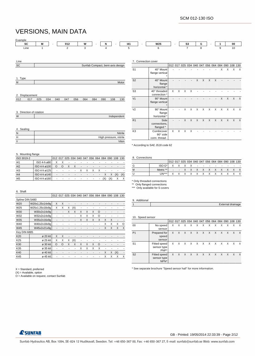
Line
SC Sunfab Compact, bent-axis design
1. Type
M Motor
2. Displacement
012 017 025 034 040 047 056 064 084 108 130
3. Direction of rotation
W Independent
4. Sealing
N Nitrile
5. Mounting flange
ISO 7653-D
DL4 ø 80
6. Shaft
DIN 5462 / ISO 14
L35 8x32x34.9
X = Standard, preferred (X) = Available, option O = Available on request, contact Sunfab
7. Connection cover
012 017 025 034 040 047 056 064 084 108 130
S1 40° Mount flange vertical
*
- - - - - - - - X X X
S2 40° Mount flange
horizontal *
- - - - X X X X - - -
S3 40° threaded connection *
X X X X - - - - - - -
V1 90° Mount flange vertical
*
- - - - - - - - X X X
V2 90° Mount flange
horizontal *
- - X X X X X X X X X
R1 Side connections,
flanged *
- - X X X X X X X X X
K3 Combicover 90° side conn.
thread .
X X X X - - - - - - -
* According to SAE J518 code 62
8. Connections
012 017 025 034 040 047 056 064 084 108 130
G ISO G* X X X X - - - - - - -
M Metric ** - - X X X X X X X X X
U UN*** - - X X X X X X X X X
* Only threaded connections ** Only flanged connections *** Only available for S covers
9. Additional
1 External drainage
10. Speed sensor
012 017 025 034 040 047 056 064 084 108 130
00 No speed sensor
X X X X X X X X X X X
P1 Prepared for speed sensor
X X X X X X X X X X X
S1 Fitted speed sensor type
PNP*
X X X X X X X X X X X
S2 Fitted speed sensor type
NPN*
X X X X X X X X X X X
* See separate brochure ”Speed sensor hall” for more information.
VERSIONS, MAIN DATA Example
SC M - 012 W - N - DL4 - L35 - S3 G - 1 00
Line 1 2 3 4 5 6 7 8 9 10
GB - Printed: 19/05/2014 22:32:21 - Page 2/7
SCM 012-130 DIN

Sunfab Hydraulics AB, Box 1094, SE-824 12 Hudiksvall, Sweden. Tel: +46 650-367 00, Fax: +46 650-367 27, E-mail: [email protected] Web: www.sunfab.com
GB - Printed: 19/05/2014 22:32:21 - Page 3/7
SCM 012-130 DIN

Sunfab Hydraulics AB, Box 1094, SE-824 12 Hudiksvall, Sweden. Tel: +46 650-367 00, Fax: +46 650-367 27, E-mail: [email protected] Web: www.sunfab.com
GB - Printed: 19/05/2014 22:32:21 - Page 4/7
SCM 012-130 DIN

Sunfab Hydraulics AB, Box 1094, SE-824 12 Hudiksvall, Sweden. Tel: +46 650-367 00, Fax: +46 650-367 27, E-mail: [email protected] Web: www.sunfab.com
GB - Printed: 19/05/2014 22:32:21 - Page 5/7
SCM 012-130 DIN

Sunfab Hydraulics AB, Box 1094, SE-824 12 Hudiksvall, Sweden. Tel: +46 650-367 00, Fax: +46 650-367 27, E-mail: [email protected] Web: www.sunfab.com
7 (8)
AF F20° 20°
B
D x n1000 x ηv
Q x 1000 x ηv
D
D x ∆p x ηhm
6.3
Q x ∆p x ηt
60
General instructions
Shaft loadsThe service life of the motor largely depends on the service life of the bearings. These are affected by the operating conditions such as speed, pressure, oil viscosity and degree of purification.
InstallationThe motor housing is filled with oil to at least 50% of the volume before start up. The drainage hose is connected to the drainage outlet positioned highest on the motor. The other end is connected below the oil level in the oil tank.
Radial load (N)
Bear
ing
serv
ice
life
(h)
Pressureclockwise
rotation
Pressureanti-clockwiserotation
Optimal angle of attackfor radial loads
External loading of the shaft, its size, direction and loca-tion also affect the service life of the bearings.
If a calculation of bearing service life is required for spe-cial applications, contact Sunfab Hydraulics.
D = displacement, cm3⁄rev
n = revolutions, rev ⁄min
P = power, kW
Q = flow, litre ⁄min
ηv = volumetric efficiency
ηhm = hydromechanical efficiency
ηt = total efficiency = ηv x ηhm
M = torque, Nm
∆p = pressure difference between inlet and outlet on the hydraulic motor, MPa
Hydraulic fluidsHigh performance oil meeting the specifications of ISO type HM, DIN 51524-2HLP or better must be used.Min. viscosity 10 cSt is required to guarantee lubrication. Ideal viscosity is 20 - 40 cSt.
Pipe dimensionsThe recommended flow velocity in the pressure line is max 7 m/sec.
FilteringCleanliness ISO norm 4406, code 16/13 is recommended.
Useful formulaes
Required flow rate Q = litres⁄min.
Speed n = RPM
Torque M = Nm
Power P = kW
GB - Printed: 19/05/2014 22:32:21 - Page 6/7
SCM 012-130 DIN

Sunfab Hydraulics AB, Box 1094, SE-824 12 Hudiksvall, Sweden. Tel: +46 650-367 00, Fax: +46 650-367 27, E-mail: [email protected] Web: www.sunfab.com
WARNINGWARNINGWARNINGWARNING
When the motor is in use:
1. Do not touch the pressure pipe
2. Beware of rotating parts
3. The motor and pipes can reach high temperatures
Sunfab reserves the right to make changes in design and dimensions without notice. Printing and typesetting errors reserved.
SCM 012-130 DIN
GB - Printed: 19/05/2014 22:32:21 - Page 7/7

Sunfab Hydraulics AB, Box 1094, SE-824 12 Hudiksvall, Sweden. Tel: +46 650-367 00, Fax: +46 650-367 27, E-mail: [email protected] Web: www.sunfab.com
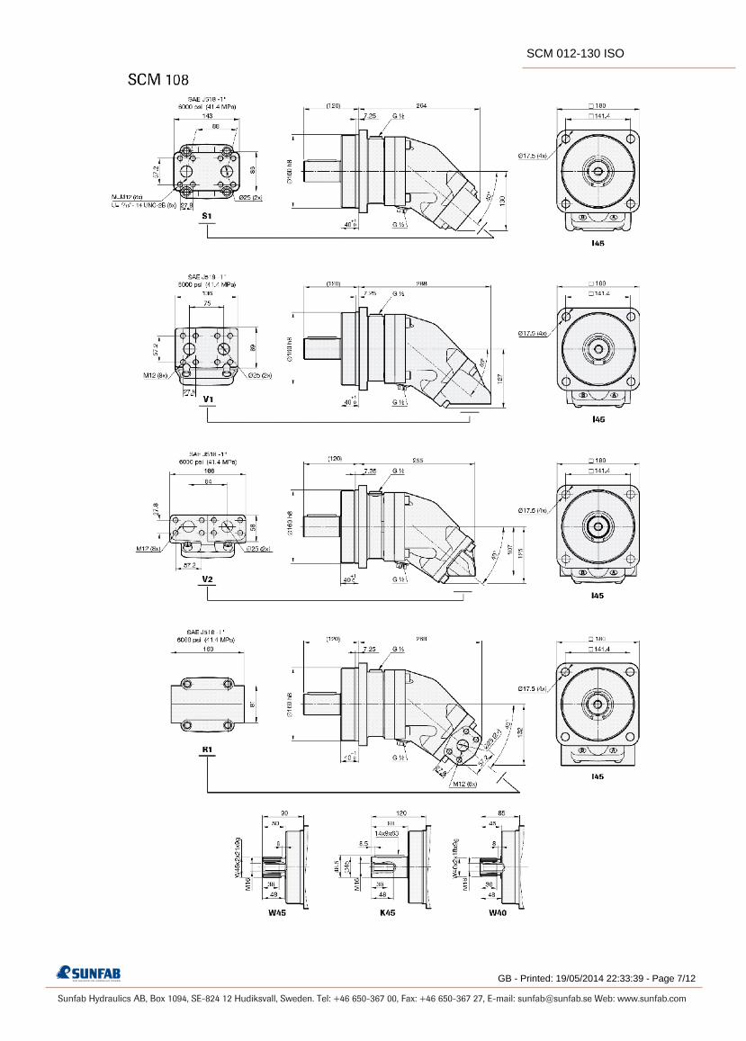
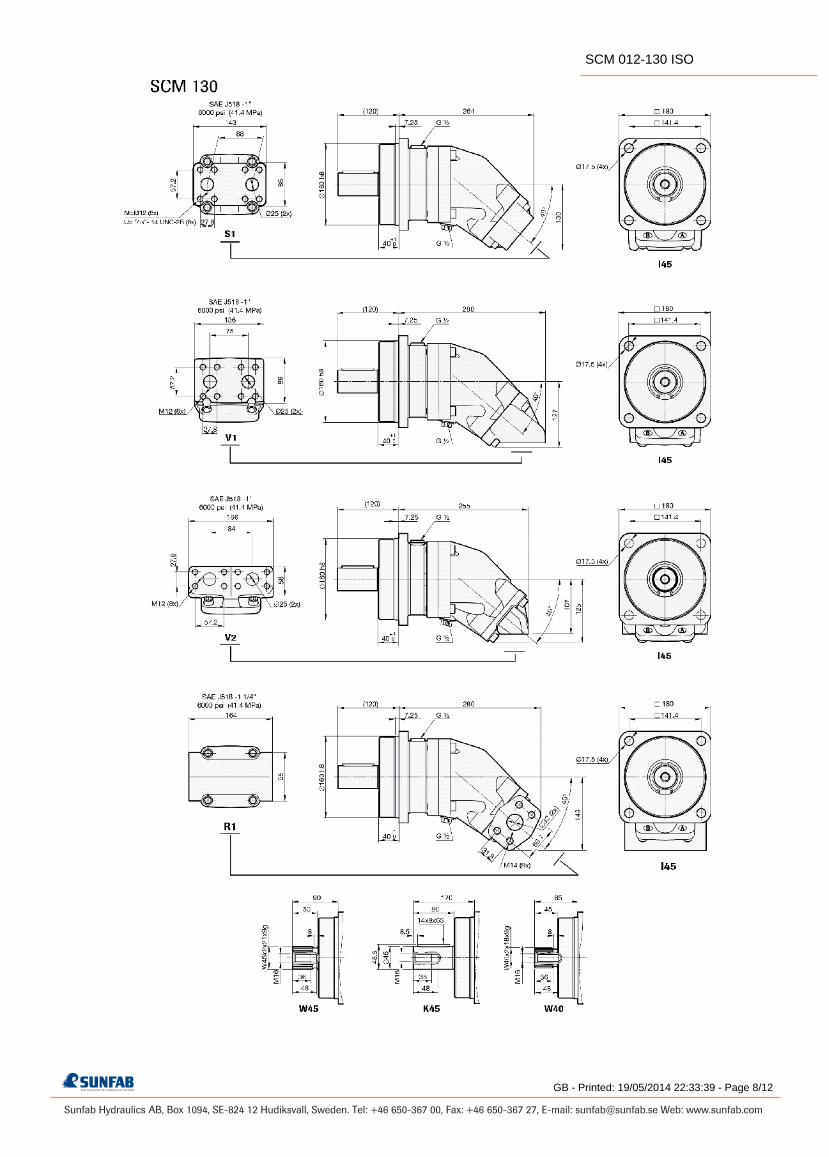
SCM 012-130 ISO is a range of robust axial piston motors especially suitable for mobile hydraulics.
SCM 012-130 ISO is of the bent-axis type with spherical pistons. The design results in a compact motor with few moving parts, high starting torque and high reliability. It covers the entire displacement range 12-130 cmᶟ ⁄rev. at a maximum pressure of 400 bar. It´s well dimensioned, double tapered roller bearings permit high shaft loads and lead to excellent speed characteristics. The motor´s high level of reliability is based on the choice of materials, hardening methods, surface structures and the quality assured manufacturing process.
Other advantages:
• High maximum speed
• Smooth operation over the entire speed range
• Available in many different configurations of shafts and connections
• High efficiency
• Speed sensor available as option
• Suitable for applications with high angular accelerations due to its high rotary stiffness
Motor SCM 012-130 ISO 012 017 025 034 040 047 056 064 084 090 108 130
Displacement cm3/rev 12.6 17.0 25.4 34.2 41.2 47.1 56.7 63.5 83.6 90.7 108.0 130.0
Working pressuremax intermittentmax continuous
MPa 4035
4035
4035
4035
4035
4035
4035
4035
4035
4035
4035
3530
Revolutionsmax intermittentmax continuousmin continuous
rpm 88008000
300
88008000
300
70006300
300
70006300
300
63005700
300
63005700
300
63005700
300
63005700
300
52004700
300
52004700
300
52004700
300
52004700
300
Powermax intermittentmax continuous
kW 5420
7425
8640
11555
12560
14565
17580
19590
215100
230110
275130
285135
Starting torque theoretical value Nm/MPa 2.0 2.7 4.0 5.4 6.6 7.5 8.9 10.0 13.3 14.4 17.1 20.5
Moment of inertia (x 10-3) kg m2 0.9 0.9 1.1 1.1 2.6 2.6 2.6 2.6 7.4 7.4 7.4 7.4
Weight kg 8.5 8.5 9.5 9.5 16.5 16.5 16.5 16.5 28.0 28.0 30.5 30.5
Data concerning RPM are based on maximum premitted peripheral velocity of the tapered roller bearing. Max intermittent power data may vary dependent on application. For further information please contact Sunfab. Continuous power data are based on maximum output power without external cooling of the motor housing. Intermittent duty is defined as follows: max 6 seconds per minute, e g peak RPM when unloading or accelerating.
SCM 012-130 ISO
GB - Printed: 19/05/2014 22:33:39 - Page 1/12
Sunfab Hydraulics AB, Box 1094, SE-824 12 Hudiksvall, Sweden. Tel: +46 650-367 00, Fax: +46 650-367 27, E-mail: [email protected] Web: www.sunfab.com
Line
SC Sunfab Compact, bent-axis design
1. Type
M Motor
2. Displacement
012 017 025 034 040 047 056 064 084 090 108 130
3. Direction of rotation
W Independent
4. Sealing
N Nitrile
H High pressure, nitrile
V Viton
5. Mounting flange
ISO 3019-2 012 017 025 034 040 047 056 064 084 090 108 130
I41 ISO 4-h ø80 X X - - - - - - - - - -
I42 ISO 4-h ø100 O O X X - - - - - - - -
I43 ISO 4-h ø125 - - - - X X X X - - - -
I44 ISO 4-h ø140 - - - - - - - - X X (X) (X)
I45 ISO 4-h ø160 - - - - - - - - (X) (X) X X
6. Shaft
012 017 025 034 040 047 056 064 084 090 108 130
Spline DIN 5480
W20 W20x1.25x14x9g X X - - - - - - - - - -
W25 W25x1.25x18x9g X X X (X) - - - - - - - -
W30 W30x2x14x9g - - X X X X X O - - - -
W32 W32x2x14x9g - - - - X X X O - - - -
W35 W35x2x16x9g - - - - X X X X X X - -
W40 W40x2x18x9g - - - - - - - - X X X O
W45 W45x2x21x9g - - - - - - - - X X X X
Key DIN 6885
K20 ø 20 k6 X X - - - - - - - - - -
K25 ø 25 k6 X X X (X) - - - - - - - -
K30 ø 30 k6 O O X X X X X O - - - -
K35 ø 35 k6 - - - - X X X X - - - -
K40 ø 40 k6 - - - - - - - - X X (X) -
K45 ø 45 k6 - - - - - - - - X X X X
X = Standard, preferred (X) = Available, option O = Available on request, contact Sunfab
7. Connection cover
012 017 025 034 040 047 056 064 084 090 108 130
S1 40° Mount flange vertical
*
- - - - - - - - X X X X
S2 40° Mount flange
horizontal *
- - - - X X X X - - - -
S3 40° threaded connection *
X X X X - - - - - - - -
V1 90° Mount flange vertical
*
- - - - - - - - X X X X
V2 90° Mount flange
horizontal *
- - X X X X X X X X X X
R1 Side connections,
flanged *
- - X X X X X X X X X X
K3 Combicover 90° side
conn. thread .
X X X X - - - - - - - -
* According to SAE J518 code 62
8. Connections
012 017 025 034 040 047 056 064 084 090 108 130
G ISO G* X X X X - - - - - - - -
M Metric ** - - X X X X X X X X X X
U UN*** X X X X X X X X X X X X * Only threaded connections ** Only flanged connections *** Only available for S covers
9. Additional
1 External drainage
10. Speed sensor
012 017 025 034 040 047 056 064 084 090 108 130
00 No speed sensor
X X X X X X X X X X X X
P1 Prepared for speed
sensor
X X X X X X X X X X X X
S1 Fitted speed sensor type
PNP*
X X X X X X X X X X X X
S2 Fitted speed sensor type
NPN*
X X X X X X X X X X X X
* See separate brochure ”Speed sensor hall” for more information.
VERSIONS, MAIN DATA Example
SC M - 012 W - N - I41 - W25 - S3 G - 1 00
Line 1 2 3 4 5 6 7 8 9 10
GB - Printed: 19/05/2014 22:33:39 - Page 2/12
SCM 012-130 ISO

Sunfab Hydraulics AB, Box 1094, SE-824 12 Hudiksvall, Sweden. Tel: +46 650-367 00, Fax: +46 650-367 27, E-mail: [email protected] Web: www.sunfab.com
GB - Printed: 19/05/2014 22:33:39 - Page 3/12
SCM 012-130 ISO

Sunfab Hydraulics AB, Box 1094, SE-824 12 Hudiksvall, Sweden. Tel: +46 650-367 00, Fax: +46 650-367 27, E-mail: [email protected] Web: www.sunfab.com
GB - Printed: 19/05/2014 22:33:39 - Page 4/12
SCM 012-130 ISO

Sunfab Hydraulics AB, Box 1094, SE-824 12 Hudiksvall, Sweden. Tel: +46 650-367 00, Fax: +46 650-367 27, E-mail: [email protected] Web: www.sunfab.com
GB - Printed: 19/05/2014 22:33:39 - Page 5/12
SCM 012-130 ISO

Sunfab Hydraulics AB, Box 1094, SE-824 12 Hudiksvall, Sweden. Tel: +46 650-367 00, Fax: +46 650-367 27, E-mail: [email protected] Web: www.sunfab.com
GB - Printed: 19/05/2014 22:33:39 - Page 6/12
SCM 012-130 ISO
Sunfab Hydraulics AB, Box 1094, SE-824 12 Hudiksvall, Sweden. Tel: +46 650-367 00, Fax: +46 650-367 27, E-mail: [email protected] Web: www.sunfab.com
GB - Printed: 19/05/2014 22:33:39 - Page 7/12
SCM 012-130 ISO
Sunfab Hydraulics AB, Box 1094, SE-824 12 Hudiksvall, Sweden. Tel: +46 650-367 00, Fax: +46 650-367 27, E-mail: [email protected] Web: www.sunfab.com
GB - Printed: 19/05/2014 22:33:39 - Page 8/12
SCM 012-130 ISO

Sunfab Hydraulics AB, Box 1094, SE-824 12 Hudiksvall, Sweden. Tel: +46 650-367 00, Fax: +46 650-367 27, E-mail: [email protected] Web: www.sunfab.com
9 (12)
A F F20° 20°
B
°C 1000 2000 3000 4000 5000 6000 7000 8000 9000
012-034 N 75 5.5 2.7 1.8 1.4 1.1 0.9 0.8 0.7 0.6 H 75 24.6 12.3 8.2 6.1 4.9 4.1 3.5 3.1 2.7 V 90 5.5 2.7 1.8 1.4 1.1 0.9 0.8 0.7 0.6
040-064 N 75 5.5 2.7 1.8 1.4 1.1 0.9 0.8 H 75 24.6 12.3 8.2 6.1 4.9 4.1 3.5 V 90 5.5 2.7 1.8 1.4 1.1 0.9 0.8
084-130 N 75 3.8 1.9 1.3 1.0 0.8 0.6 H 75 17.2 8.6 5.7 4.3 3.4 2.9 V 90 3.8 1.9 1.3 1.0 0.8 0.6
D
Fr
Fa+
Fa-
012 017 025 034 040 047 056 064 084 090 108 130kN 7 7 8 8 8.5 8.5 9 9 12 12.5 12.5 13
mm 45 45 50 50 60 60 60 60 65 65 70 70
kN 3 3 3 3 4 4 4 4 5 5 5 5
kN 4 5 7 7 7 7 10 11 13 14 16 19
kN 4 5 7 7 7 7 10 11 13 14 16 19
kN 0 0 0 0 0 0 0 0 0 0 0 0
General instructions
PressureClockwise
rotation
PressureAnticlockwiserotation
Temp. Max. housing pressure bar at rpm Motor SCM Code
Optimal force directionof radial load
Shaft loads
The life of the motor is highly dependent on the bearing life. The bearings are affected by operating conditions such as speed, pressure, oil viscosity and filtration.
External load on the shaft, as well as its size, direction and location also affects the bearing life.
Choice of shaft seal
SCM ISOMax recommended shaft loads
Fr (radial) max1
Distance D (to point of force)
Fa (axial) + (at standstill/ 0 bar pressure) max
Fa (axial) - (at standstill/ 0 bar pressure) max
Fa (axial) + (at 400 bar pressure) max2
Fa (axial) - (at 400 bar pressure) max2
¹) Fr (radial) max; Calculation based on running conditions: 300 bar / 2000 rpm¹) Fr (radial) max; Calculation based on optimal force direction (Fr max will be lower in other force directions) ¹) Fr (radial) max; In running conditions higher than 300 bar and/or 2000 rpm the max limits for Fr (radial) max will be lower
²) Fa (axial) + Will increase bearing life²) Fa (axial) - Will decrease bearing life
For other forces, please contact Sunfab for advice.
The drainage oil should have a maximum temperature of 75 °C with a Nitrile shaft seal and 90 °C with a Viton shaft seal. These temperatures must not be exceeded.The housing pressure must be equal to or greater than the external pressure on the shaft seal.
Code according to page 2, Versions, main data
Factors affecting the choice of shaft seal include the hydraulic motor housing pressure and the drainage oil temperature.
GB - Printed: 19/05/2014 22:33:39 - Page 9/12
SCM 012-130 ISO
Sunfab Hydraulics AB, Box 1094, SE-824 12 Hudiksvall, Sweden. Tel: +46 650-367 00, Fax: +46 650-367 27, E-mail: [email protected] Web: www.sunfab.com
10 (12)
Q
012-034 2-8 ≥ 2800 040-064 4-10 ≥ 2500 084-130 6-12 ≥ 2200
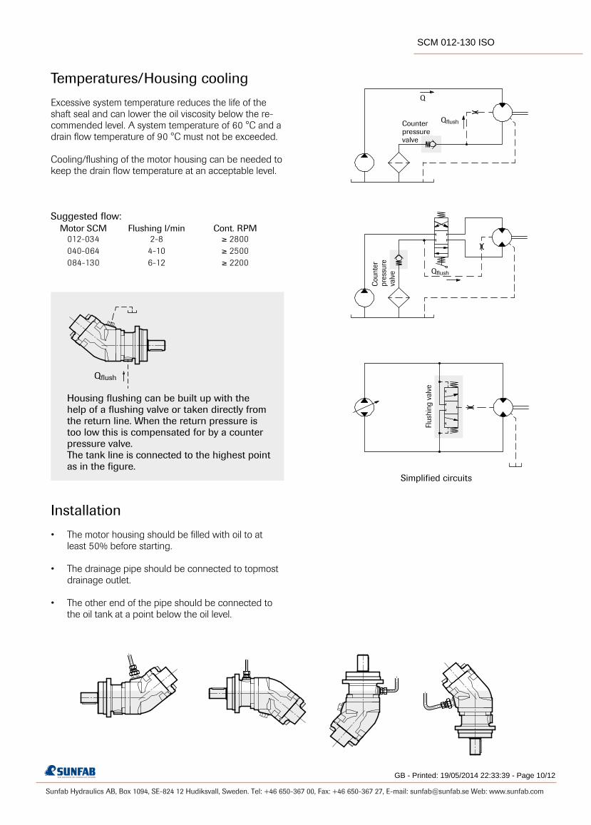
Temperatures/Housing cooling
Excessive system temperature reduces the life of the shaft seal and can lower the oil viscosity below the re-commended level. A system temperature of 60 °C and a drain flow temperature of 90 °C must not be exceeded. Cooling/flushing of the motor housing can be needed to keep the drain flow temperature at an acceptable level.
Suggested flow: Motor SCM Flushing l/min Cont. RPM
Installation
• Themotorhousingshouldbefilledwithoiltoat least 50% before starting.
• Thedrainagepipeshouldbeconnectedtotopmost drainage outlet.
• Theotherendofthepipeshouldbeconnectedto the oil tank at a point below the oil level.
Qflush
Qflush
Qflush
Housing flushing can be built up with the help of a flushing valve or taken directly from the return line. When the return pressure is too low this is compensated for by a counter pressure valve.The tank line is connected to the highest point as in the figure.
Simplified circuits
Flus
hing
val
ve
Cou
nter
pres
sure
valv
e
Counterpressurevalve
GB - Printed: 19/05/2014 22:33:39 - Page 10/12
SCM 012-130 ISO

Sunfab Hydraulics AB, Box 1094, SE-824 12 Hudiksvall, Sweden. Tel: +46 650-367 00, Fax: +46 650-367 27, E-mail: [email protected] Web: www.sunfab.com
11 (12)
D x n1000 x ηv
Q x 1000 x ηv
D
D x ∆p x ηhm
6.3
Q x ∆p x ηt
60
D = displacement, cm3⁄revolution
n = speed, revolution⁄min
P = power, kW
Q = flow rate, litres⁄min
ηv = volumetric efficiency
ηhm = hydraulic-mechanical efficiency
ηt = overall efficiency = ηv x ηhm
M = torque, Nm
∆p = pressure difference between the hydraulic motor inlet and outlet, MPa
Useful formulaes
Required flow rate Q = litres⁄min.
Speed n = RPM
Torque M = Nm
Power P = kW
Hydraulic fluids
High performance oils meeting ISO specifications – such as HM, DIN 51524-2 HLP, or better – must be used. A min. viscosity of 10 cSt is required to keep the lubrica-tion at a safe level.
The ideal viscosity is 20 - 40 cSt.
Additional technical data
Noise levels and bearing life calculations available on re-quest. Please contact Sunfab!
Piping
Recommended oil velocity in pressure line max. 7 m/sec
Filtering
Cleanliness according to ISO norm 4406, code16/13.
GB - Printed: 19/05/2014 22:33:39 - Page 11/12
SCM 012-130 ISO

Sunfab Hydraulics AB, Box 1094, SE-824 12 Hudiksvall, Sweden. Tel: +46 650-367 00, Fax: +46 650-367 27, E-mail: [email protected] Web: www.sunfab.com
WARNINGWARNINGWARNINGWARNING
When the motor is in use:
1. Do not touch the pressure pipe
2. Beware of rotating parts
3. The motor and pipes can reach high temperatures
Sunfab reserves the right to make changes in design and dimensions without notice. Printing and typesetting errors reserved.
SCM 012-130 ISO
GB - Printed: 19/05/2014 22:33:39 - Page 12/12
Sunfab Hydraulics AB, Box 1094, SE-824 12 Hudiksvall, Sweden. Tel: +46 650-367 00, Fax: +46 650-367 27, E-mail: [email protected] Web: www.sunfab.com
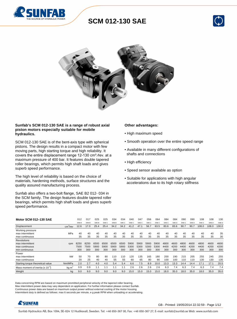
Sunfab’s SCM 012-130 SAE is a range of robust axial piston motors especially suitable for mobile hydraulics.
SCM 012-130 SAE is of the bent-axis type with spherical pistons. The design results in a compact motor with few moving parts, high starting torque and high reliability. It covers the entire displacement range 12-130 cm³ ⁄rev. at a maximum pressure of 400 bar. It features double tapered roller bearings, which permits high shaft loads and gives superb speed performance.
The high level of reliability is based on the choice of materials, hardening methods, surface structures and the quality assured manufacturing process.
Sunfab also offers a two-bolt flange, SAE B2 012- 034 in the SCM family. The design features double tapered roller bearings, which permits high shaft loads and gives superb speed performance.
Other advantages:
• High maximum speed
• Smooth operation over the entire speed range
• Available in many different configurations of shafts and connections
• High efficiency
• Speed sensor available as option
• Suitable for applications with high angular accelerations due to its high rotary stiffness
Motor SCM 012–130 SAE 012SAE B
017SAE B
025SAE B
025SAE C
034SAE B
034SAE C
040SAE C
047SAE C
056SAE C
064SAE C
084SAE C
084SAE D
090SAE C
090SAE D
108SAE C
108SAE D
130SAE D
Displacement cm3/rev 12.6 17.0 25.4 25.4 34.2 34.2 41.2 47.1 56.7 63.5 83.6 83.6 90.7 90.7 108.0 108.0 130.0
Working pressuremax intermittentmax continuous
MPa 4035
4035
4035
4035
4035
4035
4035
4035
4035
4035
4035
4035
4035
4035
4035
4035
3530
Revolutionsmax intermittentmax continuousmin continuous
rpm 82507500
300
82507500
300
65005900
300
65005900
300
65005900
300
65005900
300
59005300
300
59005300
300
59005300
300
59005300
300
48004400
300
46004200
300
48004400
300
46004200
300
48004400
300
46004200
300
46004200
300
Powermax intermittentmax continuous
kW 5020
7025
8040
8040
11055
11055
12060
13565
16580
18090
200100
190100
215110
205110
255130
245130
255135
Starting torque theoretical value Nm/MPa 2.0 2.7 4.0 4.0 5.4 5.4 6.6 7.5 8.9 10.0 13.3 13.3 14.4 14.4 17.1 17.1 20.5
Mass moment of inertia (x 10-3) kg m2 0.9 0.9 1.1 1.1 1.1 1.1 2.6 2.6 2.6 2.6 6.3 7.4 6.3 7.4 6.3 7.4 7.4
Weight kg 9.0 9.0 9.0 9.0 9.0 9.0 15.0 15.0 15.0 15.0 18.0 35.0 18.0 35.0 18.0 35.0 35.0
Data concerning RPM are based on maximum premitted peripheral velocity of the tapered roller bearing. Max intermittent power data may vary dependent on application. For further information please contact Sunfab. Continuous power data are based on maximum output power without external cooling of the motor housing. Intermittent duty is defined as follows: max 6 seconds per minute, e g peak RPM when unloading or accelerating.
SCM 012-130 SAE
GB - Printed: 19/05/2014 22:32:59 - Page 1/12

Sunfab Hydraulics AB, Box 1094, SE-824 12 Hudiksvall, Sweden. Tel: +46 650-367 00, Fax: +46 650-367 27, E-mail: [email protected] Web: www.sunfab.com
Line
SC Sunfab Compact, bent-axis design
1. Type
M Motor
2. Displacement
012 017 025 034 040 047 056 064 084 090 108 130
3. Direction of rotation
W Independent
4. Sealing
N Nitrile
H High pressure, nitrile
V Viton
5. Mounting flange
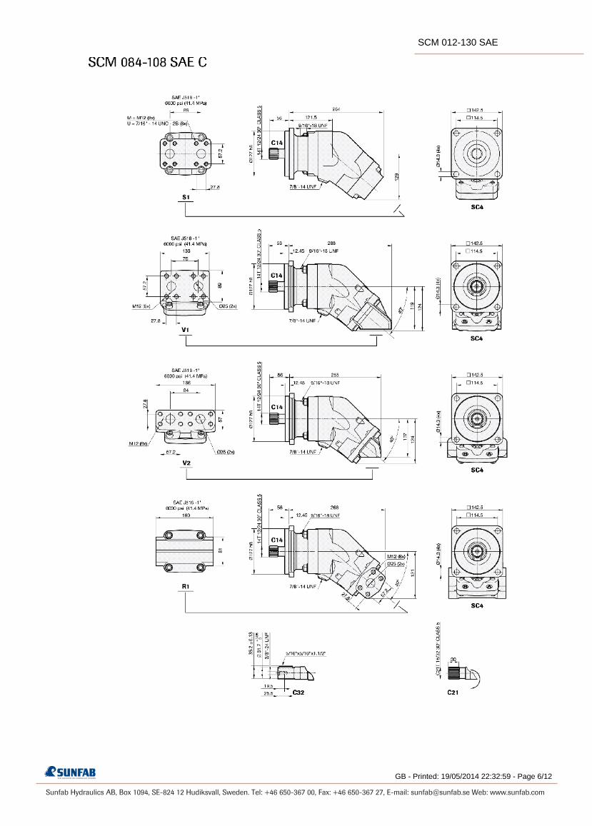
SAE J-744 012 017 025 034 040 047 056 064 084 090 108 130
SB2 SAE B-2 hole X X X X - - - - - - - -
SB4 SAE B-4 hole X X X X - - - - - - - -
SC4 SAE C-4 hole - - X X X X X X X X X -
SD4 SAE D-4 hole - - - - - - - - X X X X
6. Shaft
012 017 025 034 040 047 056 064 084 090 108 130
Spline SAE J498b 30° Class 5
B13 13T 16/32 X X X X - - - - - - - -
C14 14T 12/24* - - X X X X X X X O O -
C21 21T 16/32* - - - - X X X X X X X -
D13 13T 8/16** - - - - - - - - X X X X
Key SAE J744
B25 ø 25.4 X X X X - - - - - - - -
C32 ø 31.7* - - - - X X X X O O O -
D44 ø 44.45** - - - - - - - - X X X X
* Only with SC4 mounting flange ** Only with SD4 mounting flange
X = Standard, preferred (X) = Available, option O = Available on request, contact Sunfab
7. Connection cover
012 017 025 034 040 047 056 064 084 090 108 130
S1 40° Mount flange vertical
*
- - - - - - - - X X X X
S2 40° Mount flange
horizontal *
- - - - X X X X - - - -
S3 40° threaded connection
X X X X - - - - - - - -
V1 90° Mount flange vertical
*
- - - - - - - - X X X X
V2 90° Mount flange
horizontal *
- - X X X X X X X X X X
R1 Side connections,
flanged *
- - X X X X X X X X X X
K3 Combicover 90° side
conn. thread .
X X X X - - - - - - - -
* According to SAE J518 code 62
8. Connections
012 017 025 034 040 047 056 064 084 090 108 130
G ISO G* X X X X - - - - - - - -
M Metric ** - - X X X X X X X X X X
U UN*** X X X X X X X X X X X X
* Only threaded connections ** Only flanged connections *** Only available for S covers
9. Additional
1 External drainage
10. Speed sensor
012 017 025 034 040 047 056 064 084 090 108 130
00 No speed sensor
X X X X X X X X X X X X
P1 Prepared for speed
sensor
X X X X X X X X X X X X
S1 Fitted speed sensor type
PNP*
X X X X X X X X X X X X
S2 Fitted speed sensor type
NPN*
X X X X X X X X X X X X
* See separate brochure ”Speed sensor hall” for more information.
VERSIONS, MAIN DATA Example
SC M - 012 W - N - SB4 - B13 - S3 U - 1 00
Line 1 2 3 4 5 6 7 8 9 10
GB - Printed: 19/05/2014 22:32:59 - Page 2/12
SCM 012-130 SAE

Sunfab Hydraulics AB, Box 1094, SE-824 12 Hudiksvall, Sweden. Tel: +46 650-367 00, Fax: +46 650-367 27, E-mail: [email protected] Web: www.sunfab.com
GB - Printed: 19/05/2014 22:32:59 - Page 3/12
SCM 012-130 SAE

Sunfab Hydraulics AB, Box 1094, SE-824 12 Hudiksvall, Sweden. Tel: +46 650-367 00, Fax: +46 650-367 27, E-mail: [email protected] Web: www.sunfab.com
GB - Printed: 19/05/2014 22:32:59 - Page 4/12
SCM 012-130 SAE

Sunfab Hydraulics AB, Box 1094, SE-824 12 Hudiksvall, Sweden. Tel: +46 650-367 00, Fax: +46 650-367 27, E-mail: [email protected] Web: www.sunfab.com
GB - Printed: 19/05/2014 22:32:59 - Page 5/12
SCM 012-130 SAE
Sunfab Hydraulics AB, Box 1094, SE-824 12 Hudiksvall, Sweden. Tel: +46 650-367 00, Fax: +46 650-367 27, E-mail: [email protected] Web: www.sunfab.com
GB - Printed: 19/05/2014 22:32:59 - Page 6/12
SCM 012-130 SAE

Sunfab Hydraulics AB, Box 1094, SE-824 12 Hudiksvall, Sweden. Tel: +46 650-367 00, Fax: +46 650-367 27, E-mail: [email protected] Web: www.sunfab.com
GB - Printed: 19/05/2014 22:32:59 - Page 7/12
SCM 012-130 SAE

Sunfab Hydraulics AB, Box 1094, SE-824 12 Hudiksvall, Sweden. Tel: +46 650-367 00, Fax: +46 650-367 27, E-mail: [email protected] Web: www.sunfab.com
8 (12)
°C 1000 2000 3000 4000 5000 012-034 B N 75 0.55 0.27 0.18 0.14 0.11 H 75 2.46 1.23 0.82 0.61 0.51 V 90 0.55 0.27 0.18 0.14 0.11 040-108 C N 75 0.55 0.27 0.18 0.14 0.11 H 75 2.46 1.23 0.82 0.61 0.51 V 90 0.55 0.27 0.18 0.14 0.11 084-130 D N 75 0.35 0.17 0.12 H 75 1.56 0.78 0.52 V 90 0.35 0.17 0.12
A F F20° 20°
B
D
Fr
Fa+
Fa-
012SAE B
017SAE B
025SAE B
025SAE C
034SAE B
034SAE C
040SAE C4
047SAE C
056SAE C
064SAE C
084SAE C
084SAE D
108SAE C
108SAE D
130SAE D
kN 6.5 7 7.5 7.5 7.5 7 8.5 8.5 8.5 9 9 9 10 10 10.5
mm 40 40 40 45 40 45 45 45 45 45 45 60 45 60 60
kN 3 3 3 3 3 3 0,5 0,5 0,5 0,5 1 1 1 1 1
kN 4 5 7 7 7 7 7 7 10 11 13 13 16 16 19
kN 4 5 7 7 7 7 7 7 10 11 13 13 16 16 19
kN 0 0 0 0 0 0 0 0 0 0 0 0 0 0 0
Choice of shaft seal
Temp. Max. housing pressure MPa at rpm Motor SCM Code
PressureClockwise
rotation
PressureAnticlockwiserotation
Optimal force directionof radial load
Shaft loads
The life of the motor is highly dependent on the bearing life. The bearings are affected by operating conditions such as speed, pressure, oil viscosity and filtration.
General instructions
The drainage oil should have a maximum temperature of 75 °C with a Nitrile shaft seal and 90 °C with a Viton shaft seal. These temperatures must not be exceeded.The housing pressure must be equal to or greater than the external pressure on the shaft seal.
Code according to page 2, Versions, main data
Factors affecting the choice of shaft seal include the hydraulic motor housing pressure and the drainage oil temperature.
External load on the shaft, as well as its size, direction and location also affects the bearing life.
SCM SAEMax recommended shaft loads
Fr (radial) max1
Distance D (to point of force)
Fa (axial) + (at standstill/ 0 bar pressure) max
Fa (axial) - (at standstill/ 0 bar pressure) max
Fa (axial) + (at 400 bar pressure) max2
Fa (axial) - (at 400 bar pressure) max2
¹) Fr (radial) max; Calculation based on running conditions: 300 bar / 2000 rpm¹) Fr (radial) max; Calculation based on optimal force direction (Fr max will be lower in other force directions) ¹) Fr (radial) max; In running conditions higher than 300 bar and/or 2000 rpm the max limits for Fr (radial) max will be lower
²) Fa (axial) + Will increase bearing life²) Fa (axial) - Will decrease bearing life ²) When having a (high) axial force (Fa+) a sudden fall in pressure can negatively affect bearing life due to lack of compensating load and, if extreme, could lead to bearing failure.
For other forces, please contact Sunfab for advice.
GB - Printed: 19/05/2014 22:32:59 - Page 8/12
SCM 012-130 SAE

Sunfab Hydraulics AB, Box 1094, SE-824 12 Hudiksvall, Sweden. Tel: +46 650-367 00, Fax: +46 650-367 27, E-mail: [email protected] Web: www.sunfab.com
9 (12)
Q
012-034 2-8 ≥ 2800 040-064 4-10 ≥ 2500 084-130 6-12 ≥ 2200
Temperatures/Housing cooling
Excessive system temperature reduces the life of the shaft seal and can lower the oil viscosity below the re-commended level. A system temperature of 60 °C and a drain flow temperature of 90 °C must not be exceeded. Cooling/flushing of the motor housing can be needed to keep the drain flow temperature at an acceptable level.
Suggested flow: Motor SCM Flushing l/min Cont. RPM
Qflush
Qflush
Qflush
Housing flushing can be built up with the help of a flushing valve or taken directly from the return line. When the return pressure is too low this is compensated for by a counter pres-sure valve.The tank line is connected to the highest point as in the figure.
Simplified circuits
Flus
hing
val
ve
Coun
ter
pres
sure
valv
e
Counterpressurevalve
GB - Printed: 19/05/2014 22:32:59 - Page 9/12
SCM 012-130 SAE

Sunfab Hydraulics AB, Box 1094, SE-824 12 Hudiksvall, Sweden. Tel: +46 650-367 00, Fax: +46 650-367 27, E-mail: [email protected] Web: www.sunfab.com
10 (12)
Piping
Recommended oil velocity in pressure line max. 7 m/sec
Filtering
Cleanliness according to ISO norm 4406, code16/13.
Hydraulic fluids
High performance oils meeting ISO specifications – such as HM, DIN 51524-2 HLP, or better – must be used. A min. viscosity of 10 cSt is required to keep the lubrica-tion at a safe level.
The ideal viscosity is 20 - 40 cSt.
Installation
• Themotorhousingshouldbefilledwithoiltoat least 50% before starting.
• Thedrainagepipeshouldbeconnectedtotopmost drainage outlet.
• Theotherendofthepipeshouldbeconnectedto the oil tank at a point below the oil level.
Additional technical data
Noise levels and bearing life calculations available on re-quest. Please contact Sunfab!
GB - Printed: 19/05/2014 22:32:59 - Page 10/12
SCM 012-130 SAE

Sunfab Hydraulics AB, Box 1094, SE-824 12 Hudiksvall, Sweden. Tel: +46 650-367 00, Fax: +46 650-367 27, E-mail: [email protected] Web: www.sunfab.com
11 (12)
D x n1000 x ηv
Q x 1000 x ηv
D
D x ∆p x ηhm
6.3
Q x ∆p x ηt
60
Useful formulaes
Required flow rate Q = litres⁄min.
Speed n = RPM
Torque M = Nm
Power P = kW
D = displacement, cm3⁄revolution
n = speed, revolution⁄min
P = power, kW
Q = flow rate, litres⁄min
ηv = volumetric efficiency
ηhm = hydraulic-mechanical efficiency
ηt = overall efficiency = ηv x ηhm
M = torque, Nm
∆p = pressure difference between the hydraulic motor inlet and outlet, MPa
GB - Printed: 19/05/2014 22:32:59 - Page 11/12
SCM 012-130 SAE

Sunfab Hydraulics AB, Box 1094, SE-824 12 Hudiksvall, Sweden. Tel: +46 650-367 00, Fax: +46 650-367 27, E-mail: [email protected] Web: www.sunfab.com
WARNINGWARNINGWARNINGWARNING
When the motor is in use:
1. Do not touch the pressure pipe
2. Beware of rotating parts
3. The motor and pipes can reach high temperatures
Sunfab reserves the right to make changes in design and dimensions without notice. Printing and typesetting errors reserved.
SCM 012-130 SAE
GB - Printed: 19/05/2014 22:32:59 - Page 12/12

Sunfab Hydraulics AB, Box 1094, SE-824 12 Hudiksvall, Sweden. Tel: +46 650-367 00, Fax: +46 650-367 27, E-mail: [email protected] Web: www.sunfab.com
Sunfab’s SCM 025-108 M2 is a range of robust axial piston motors with cartridge flange especially suitable for winch-, slewing-, wheel- and track drives.
SCM 025-108 M2 is of the bent-axis type with spherical pistons. The design results in a compact motor with few moving parts, high starting torque and high reliability. The SCM 025-108 M2 covers the entire displacement range 25-108 cmᶟ ⁄rev. at a maximum pressure of 400 bar.
It´s well dimensioned, double tapered roller bearings permit high shaft loads and lead to excellent speed characteristics. It´s high level of reliability is based on the choice of materials, hardening methods, surface structures and the quality assured manufacturing process.
Other advantages:
• High maximum speed
• Smooth operation over the entire speed range
• High efficiency
• Suitable for applications with high angular accelerations due to its high rotary stiffness
Motor SCM 025-108 M2 025 034 040 047 056 064 084 090 108
Displacement cm3/rev 25.4 34.2 41.2 47.1 56.7 63.5 83.6 90.7 108.0
Working pressuremax intermittentmax continuous
MPa 4035
4035
4035
4035
4035
4035
4035
4035
3500
Revolutionsmax intermittentmax continuousmin continuous
rpm 70006300
300
70006300
300
63005700
300
63005700
300
63005700
300
63005700
300
52004700
300
52004700
300
52004700
300
Powermax intermittentmax continuous
kW 8640
11555
12560
14565
17580
19590
215100
230110
230110
Starting torque theoretical value Nm/MPa 4.0 5.4 6.6 7.5 8.9 10.0 13.3 14.4 17.1
Moment of inertia (x 10-3) kg m2 1.1 1.1 2.6 2.6 2.6 2.6 7.4 7.4 7.4
Weight kg 11.0 11.0 18.3 18.3 18.3 18.3 26.0 26.0 26.0
Data concerning RPM are based on maximum premitted peripheral velocity of the tapered roller bearing. Max intermittent power data may vary dependent on application. For further information please contact Sunfab. Continuous power data are based on maximum output power without external cooling of the motor housing. Intermittent duty is defined as follows: max 6 seconds per minute, e g peak RPM when unloading or accelerating.
SCM 025–108 M2
GB - Printed: 19/05/2014 22:34:20 - Page 1/8

Sunfab Hydraulics AB, Box 1094, SE-824 12 Hudiksvall, Sweden. Tel: +46 650-367 00, Fax: +46 650-367 27, E-mail: [email protected] Web: www.sunfab.com
Line
SC Sunfab Compact, bent-axis design
1. Type
M Motor
2. Displacement
025 034 040 047 056 064 084 090 108
3. Direction of rotation
W Independent
4. Sealing
N Nitrile
H High pressure, nitrile
V Viton
5. Mounting flange
025 034 040 047 056 064 084 090 108
M21 ø 135 X X - - - - - - -
M22 ø 160 - - X X X X - - -
M23 ø 190 - - - - - - X X X
6. Shaft
Spline DIN 5480 025 034 040 047 056 064 084 090 108
W30 W30x2x14x9g X X X X X X - - -
W35 W35x2x16x9g - - X X X X X X X
W40 W40x2x18x9g - - - - - - X X X
X = Standard, preferred (X) = Available, option O = Available on request, contact Sunfab
7. Connection cover
025 034 040 047 056 064 084 090 108
V1 90° Mount flange vertical
*
- - - - - - X X X
V2 90° Mount flange
horizontal *
X X X X X X X X X
* According to SAE J518 code 62
8. Connections
025 034 040 047 056 064 084 090 108
M Metric **
9. Additional
1 External drainage
10. Accessories
00 No accessories available
VERSIONS, MAIN DATA Example
SC M - 025 W - N - M21 - W30 - V2 M - 1 00
Line 1 2 3 4 5 6 7 8 9 10
GB - Printed: 19/05/2014 22:34:20 - Page 2/8
SCM 025–108 M2

Sunfab Hydraulics AB, Box 1094, SE-824 12 Hudiksvall, Sweden. Tel: +46 650-367 00, Fax: +46 650-367 27, E-mail: [email protected] Web: www.sunfab.com
GB - Printed: 19/05/2014 22:34:20 - Page 3/8
SCM 025–108 M2
Sunfab Hydraulics AB, Box 1094, SE-824 12 Hudiksvall, Sweden. Tel: +46 650-367 00, Fax: +46 650-367 27, E-mail: [email protected] Web: www.sunfab.com
GB - Printed: 19/05/2014 22:34:20 - Page 4/8
SCM 025–108 M2

Sunfab Hydraulics AB, Box 1094, SE-824 12 Hudiksvall, Sweden. Tel: +46 650-367 00, Fax: +46 650-367 27, E-mail: [email protected] Web: www.sunfab.com
5 (8)
°C 1000 2000 3000 4000 5000 6000 7000
025–064 N 75 0.55 0.27 0.18 0.14 0.11 0.09 0.08 H 75 2.46 1.23 0.82 0.61 0.49 0.41 0.35 V 90 0.55 0.27 0.18 0.14 0.11 0.09 0.08
084–108 N 75 0.38 0.19 0.13 0.10 0.08 0.06 H 75 1.72 0.86 0.57 0.43 0.34 0.29 V 90 0.38 0.19 0.13 0.10 0.08 0.06
A F F20° 20°
B
025 034 040 047 056 064 084 090 108kN 7.5 7.5 7.5 8 8.5 8.5 14.5 14.5 15
mm 100 100 110 110 110 110 120 120 120
kN 3 3 4 4 4 4 5 5 5
kN 7 7 7 7 10 11 13 14 16
kN 7 7 7 7 10 11 13 14 16
kN 0 0 0 0 0 0 0 0 0
D
Fr
Fa+
Fa-
Choice of shaft seal
PressureClockwise
rotation
PressureAnticlockwiserotation
Optimal force directionof radial load
Shaft loads
The life of the motor is highly dependent on the bearing life. The bearings are affected by operating conditions such as speed, pressure, oil viscosity and filtration.
General instructions
Temp. Max. housing pressure MPa at rpm Motor SCM Code
External load on the shaft, as well as its size, direction and location also affects the bearing life.
SCM M2Max recommended shaft loads
Fr (radial) max1
Distance D (to point of force)
Fa (axial) + (at standstill/ 0 bar pressure) max
Fa (axial) - (at standstill/ 0 bar pressure) max
Fa (axial) + (at 400 bar pressure) max2
Fa (axial) - (at 400 bar pressure) max2
¹) Fr (radial) max; Calculation based on running conditions: 300 bar / 2000 rpm¹) Fr (radial) max; Calculation based on optimal force direction (Fr max will be lower in other force directions) ¹) Fr (radial) max; In running conditions higher than 300 bar and/or 2000 rpm the max limits for Fr (radial) max will be lower
²) Fa (axial) + Will increase bearing life²) Fa (axial) - Will decrease bearing life
For other forces, please contact Sunfab for advice.
The drainage oil should have a maximum temperature of 75 °C with a Nitrile shaft seal and 90 °C with a Viton shaft seal. These temperatures must not be exceeded.The housing pressure must be equal to or greater than the external pressure on the shaft seal.
Code according to page 2, Versions, main data
Factors affecting the choice of shaft seal include the hydraulic motor housing pressure and the drainage oil temperature.
GB - Printed: 19/05/2014 22:34:20 - Page 5/8
SCM 025–108 M2

Sunfab Hydraulics AB, Box 1094, SE-824 12 Hudiksvall, Sweden. Tel: +46 650-367 00, Fax: +46 650-367 27, E-mail: [email protected] Web: www.sunfab.com
6 (8)
025-034 2-8 ≥ 2800 040-064 4-10 ≥ 2500 084-108 6-12 ≥ 2200
Q
Temperatures/Housing cooling
Excessive system temperature reduces the life of the shaft seal and can lower the oil viscosity below the re-commended level. A system temperature of 60 °C and a drain flow temperature of 90 °C must not be exceeded. Cooling/flushing of the motor housing can be needed to keep the drain flow temperature at an acceptable level.
Suggested flow: Motor SCM Flushing l/min Cont. RPM
Installation
• Themotorhousingshouldbefilledwithoiltoat least 50% before starting.
• Thedrainagepipeshouldbeconnectedtotopmost drainage outlet.
• Theotherendofthepipeshouldbeconnectedto the oil tank at a point below the oil level.
Qflush
Qflush
Qflush
Housing flushing can be built up with the help of a flushing valve or taken directly from the return line. When the return pressure is too low this is compensated for by a counter pressure valve.The tank line is connected to the highest point as in the figure.
Simplified circuits
Flus
hing
val
ve
Coun
ter
pres
sure
valv
e
Counterpressurevalve
GB - Printed: 19/05/2014 22:34:20 - Page 6/8
SCM 025–108 M2

Sunfab Hydraulics AB, Box 1094, SE-824 12 Hudiksvall, Sweden. Tel: +46 650-367 00, Fax: +46 650-367 27, E-mail: [email protected] Web: www.sunfab.com
7 (8)
D x n1000 x ηv
Q x 1000 x ηv
D
D x ∆p x ηhm
6.3
Q x ∆p x ηt
60
Useful formulaes
Required flow rate Q = litres⁄min.
Speed n = RPM
Torque M = Nm
Power P = kW
D = displacement, cm3⁄revolution
n = speed, revolution⁄min
P = power, kW
Q = flow rate, litres⁄min
ηv = volumetric efficiency
ηhm = hydraulic-mechanical efficiency
ηt = overall efficiency = ηv x ηhm
M = torque, Nm
∆p = pressure difference between the hydraulic motor inlet and outlet, MPa
Hydraulic fluids
High performance oils meeting ISO specifications – such as HM, DIN 51524-2 HLP, or better – must be used. A min. viscosity of 10 cSt is required to keep the lubrica-tion at a safe level.
The ideal viscosity is 20 - 40 cSt.
Additional technical data
Noise levels and bearing life calculations available on re-quest. Please contact Sunfab!
Piping
Recommended oil velocity in pressure line max. 7 m/sec
Filtering
Cleanliness according to ISO norm 4406, code16/13.
GB - Printed: 19/05/2014 22:34:20 - Page 7/8
SCM 025–108 M2

Sunfab Hydraulics AB, Box 1094, SE-824 12 Hudiksvall, Sweden. Tel: +46 650-367 00, Fax: +46 650-367 27, E-mail: [email protected] Web: www.sunfab.com
WARNINGWARNINGWARNINGWARNING
When the motor is in use:
1. Do not touch the pressure pipe
2. Beware of rotating parts
3. The motor and pipes can reach high temperatures
Sunfab reserves the right to make changes in design and dimensions without notice. Printing and typesetting errors reserved.
SCM 025–108 M2
GB - Printed: 19/05/2014 22:34:20 - Page 8/8