scon-cb series controller - iai-robot.co.jp · scon-cb series controller servo press function...
TRANSCRIPT

SCON-CB Series Controller Servo Press Function Instruction Manual
Fifth Edition CB-F Standard Type LC-F PLC Feature Equipped Type CGB-F Safety Category Complied TypeLCG-F Safety Categories Complying
PLC Feature Equipped Type
IAI Corporation


Please Read Before Use Thank you for purchasing our product. This Instruction Manual describes all necessary information items to operate this product safely such as the operation procedure, structure and maintenance procedure. Before the operation, read this manual carefully and fully understand it to operate this product safely. The enclosed DVD in this product package includes the Instruction Manual for this product. For the operation of this product, print out the necessary sections in the Instruction Manual or display them using the personal computer. After reading through this manual, keep this Instruction Manual at hand so that the operator of this product can read it whenever necessary.
[Important] This Instruction Manual is original. The product cannot be operated in any way unless expressly specified in this Instruction
Manual. IAI shall assume no responsibility for the outcome of any operation not specified herein.
Information contained in this Instruction Manual is subject to change without notice for the purpose of product improvement.
If you have any question or comment regarding the content of this manual, please contact the IAI sales office near you.
Using or copying all or part of this Instruction Manual without permission is prohibited. The company names, names of products and trademarks of each company shown in the
sentences are registered trademarks.


Construction of Instruction Manual for Each Controller Model and This Manual SCON-CB/CGB Servo Press Type
SCON-LC/LCG Servo Press Type
(Note) CC-Link, DeviceNet, PROFIBUS-DP, CompoNet, MECHATROLINK-�/�, EtherNet/IP, EtherCAT, PROFINET-IO
Basic Function • Press Program Operation SCON-CB-F/CGB-F (This Manual) ME0345 • Serial Communication Serial Communication [Modbus] ME0162
★Types to Select From
• PIO Control • Fieldbus Control
(i) CC-Link CC-Link ME0254 (ii) DeviceNet DeviceNet ME0256 (iii) PROFIBUS-DP PROFIBUS-DP ME0258 (iv)CompoNet CompoNet ME0220 (v) MECHATROLINK-/ MECHATROLINK -/ ME0221 (vi) EtherNet/IP EtherNet/IP ME0278 (vii) EtherCAT EtherCAT ME0273 (ix) PROFINET-IO PROFINET-IO ME0333 Teaching Tool • PC Software PC Software ME0155
●Basic Specifications ・Positioner Operation SCON-LC-F/LCG-F (This Manual) ME0345 ・Rudder Program Pro Programming Manual ME0329 ME0330 ★Types to Select From ・PIO Control ・Fieldbus I/O Communication ■Teaching Tool ・PC Software PC Software ME0155
Table of Overall Contents
Name for Each Parts and Their Functions In this chapter, explains name for each parts and their functions.
About SCON-LC Type
In this chapter, explains the outline of LC (equipped with PLC feature) type.
Chapter 1 Specifications Check
In this chapter, explains about the specifications, current amperage, model codes and so on for the products.
Chapter 2 Wiring
In this chapter, explains actuator, connecting external device side.
Chapter 3 Operation In this chapter, explains setting of press program and each operation mode.
3.1 Explain the Operation Mode 3.2 About Trial Run 3.3 About Operation with PIO
Chapter 4 Applicability to Fieldbus
In this chapter, explains applicable for fieldbus.
Chapter 5 Feature of Multi-Function Connector In this chapter, explains how to use.
Chapter 6 Absolute Type
In this chapter, explains the procedures for absolute reset and replacement of battery.
Chapter 7 Parameter
In this chapter, explains how to set up or fine-tune the controller settings.
Chapter 8 Troubleshooting
In this chapter, explains how to act in errors and contents of them.
Chapter 9 Appendix In this chapter, explains compliance with safety categories, model codes of connectable actuators, etc.
Chapter 10 Warranty
In this chapter, explains warranty.
12
21
133
137
142
178
145
197
221
45
103
18
Table of Contents Safety Guide ···································································································· 1 Precautions in Operation ···················································································· 8 International Standards Compliances ··································································· 11 Name for Each Parts and Their Functions ····························································· 12 About SCON-LC Type ······················································································· 18 Actuator Axes ·································································································· 20 Chapter 1 Specifications Check ······································································· 21
1.1 Product Check ································································································· 21 1.1.1 Parts ······································································································· 21 1.1.2 Teaching Tool ···························································································· 23 1.1.3 Instruction Manuals Related to this Product, which are Contained in the Instruction
Manual (DVD) ··························································································· 23 1.1.4 How to Read the Model Plate ········································································ 23 1.1.5 How to Read the Model ··············································································· 24
1.2 List of Basic Specifications ················································································· 25 1.2.1 Specification List ························································································ 25 1.2.2 Item for the Power Capacity and Heating Value ················································· 27 1.2.3 Selection of Circuit Breaker ·········································································· 27 1.2.4 Selection of Leakage Breaker ······································································· 27
1.3 External Dimensions ························································································· 28 1.3.1 SCON-CB/CGB/LC/LCG less than 400W ······················································ 28 1.3.2 SCON-CB/CGB/LC/LCG 400W to 750W ······················································· 28 1.3.3 SCON-CB/CGB/LC/LCG 3000W to 3300W ···················································· 29
1.4 External Interface Specifications ·········································································· 30 1.4.1 Standard Input Output Interface Specification (Multi-Function Connector) ··············· 30 1.4.2 Input Output Interface Specification dedicated for PIO Type ································· 31 1.4.3 Filedbus Type Specifications ········································································· 32
1.5 Options ·········································································································· 35 1.5.1 Regenerative Unit for Motors of up to 750W ····················································· 35 1.5.2 Regenerative Unit for Motors of up to 3000 to 3300W ········································· 36 1.5.3 Brake Box: RCB-110-RA13-0 ········································································ 37 1.5.4 Load Cell ·································································································· 38 1.5.5 Pulse Converter: JM-08 ··············································································· 39
1.6 Installation and Storage Environment ···································································· 40 1.7 Noise Elimination and Mounting Method ································································ 41
Chapter 2 Wiring ·························································································· 45
2.1 Servo Press Controller for Motors of up to 750W (PIO Control) ·································· 45 2.1.1 Wiring Diagram (Connection of Devices) ························································· 45 2.1.2 Wiring ······································································································ 46
2.2 Wiring for Controller for Motors of up to 750W ························································ 59 2.2.1 Wiring for Power Supply Circuit ····································································· 59 2.2.2 Wiring of Emergency Stop Circuit (System I/O) ················································· 64 2.2.3 Connection of Actuator ················································································ 66 2.2.4 Connection of PIO ······················································································ 68 2.2.5 Multi-function Connector ·············································································· 69 2.2.6 Connection of Regenerative Unit ··································································· 72 2.2.7 SIO Connector Connection ··········································································· 74
2.3 Servo Press Controller for Motors of up to 3000 to 3300W (PIO Contorl) ······················ 75 2.3.1 Wiring Diagram (Connection of Devices) ························································· 75 2.3.2 Wiring ······································································································ 76
2.4 Controller for Motors of up to 3000 to 3300W ························································· 88 2.4.1 Wiring for Power Supply Circuit ····································································· 88

2.4.2 Wiring of Emergency Stop Circuit (System I/O) ················································· 92 2.4.3 Connection of Actuator ················································································ 94 2.4.4 Connection of PIO ······················································································ 96 2.4.5 Multi-function Connector ·············································································· 97 2.4.6 Connection of Regenerative Unit ································································· 100 2.4.7 SIO Connector Connection ········································································· 102
Chapter 3 Operation ····················································································· 103
3.1 Explain the Operation Mode and Setting ····························································· 103 3.1.1 Power Supply and Cutoff ··········································································· 103 3.1.2 Explain the Operation Mode ······································································· 104 3.1.3 Basic Operation Setting ············································································· 108 3.1.4 Detailed Settings (Optional Settings) ····························································· 115
3.2 Trial Run ······································································································ 120 3.2.1 Manual Operation (Jog etc) ········································································ 120 3.2.2 Press Program Operation ··········································································· 121
3.3 Operation with PIO ························································································· 123 3.3.1 I/O Signal Controls ··················································································· 123 3.3.2 Operation Ready and Auxiliary Signals ·························································· 123 3.3.3 Operation ······························································································· 128
Chapter 4 Applicability to Fieldbus ·································································· 133 Chapter 5 Feature of Multi-function Connector ··················································· 137
5.1 Feedback Pulse Output ··················································································· 137 5.1.1 Setting ··································································································· 137
5.2 Analog Output of Load Data ············································································· 140 5.2.1 Specification ···························································································· 140 5.2.2 Setting ··································································································· 140 5.2.3 Rated Capacity of Loadcell Mounted to Each Actuator ······································ 140
5.3 Serial Communication 2 (SIO2) ········································································· 141 5.3.1 Specification ···························································································· 141 5.3.2 Setting ··································································································· 141
Chapter6 Absolute Type ··············································································· 142
6.1 Absolute Reset ······························································································ 142 6.2 Absolute Battery ···························································································· 143
6.2.1 Absolute Encoder Backup Specifications ······················································· 143 6.2.2 Replacement of Absolute Battery ································································· 143 6.2.2 Replacement of Absolute Battery ································································· 144
Chapter 7 Parameter ···················································································· 145
7.1 Parameter List ······························································································· 146 7.2 Detail Explanation of Parameters ······································································· 149 7.3 Servo Adjustment ··························································································· 176
Chapter 8 Troubleshooting ············································································ 178
8.1 Action Taken upon Occurence of Problem ··························································· 178 8.2 Fault Diagnosis ······························································································ 179
8.2.1 Impossible Operation of Controller ······························································· 179 8.2.2 Generation of Noise and/or Vibration ···························································· 179
8.3 Alarm Level ·································································································· 180 8.4 Alarm List ····································································································· 181
8.4.1 Controller Alarm (Excluding Program Alarm) ··················································· 181 8.4.2 Program Alarm (When Controller alarm 094 is issued) ······································ 191
Chapter 9 Appendix ····················································································· 197

9.1 Way to Set Multiple Controllers with 1 Teaching Tool ·············································· 197 9.1.1 Connecting Example ················································································· 197 9.1.3 Axis No. Setting ······················································································· 199 9.1.4 Handling of e-CON Connector (How to Connect) ············································· 200 9.1.5 SIO Converter ························································································· 201 9.1.6 Communications ······················································································ 203 9.1.7 External Dimension ··················································································· 203
9.2 Conformity to Safety Category of to 750W motor corresponding SCON ······················ 204 9.3 Maintenance ································································································· 215 9.4 List of Specifications of Connectable Actuators ····················································· 216
9.4.1 List of Specifications for Actuator Operation Conditions ····································· 216 9.4.2 Specifications and Limitations in Pressing Operation ········································ 216
Chapter 10 Warranty ······················································································ 221 Change History ······························································································ 223

Set pressing program is operated with built-in PLC
Actuator Controller PC software
Create Pressing Program
Actuator Controller PC software
(Reply)
(Command)
Pressing Program No.
Condition of Judgmentand so on
+
The host PLC selects the set pressing program and makes operation
Create Pressing Program
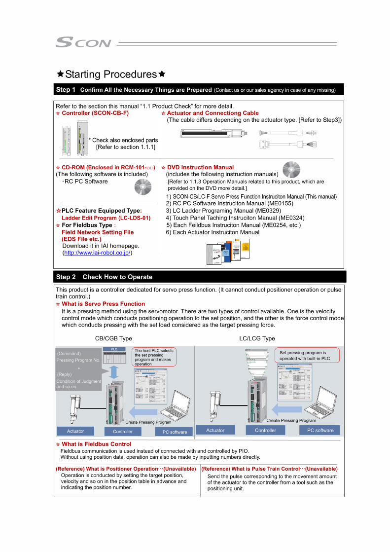
Starting Procedures Step 1 Confirm All the Necessary Things are Prepared (Contact us or our sales agency in case of any missing)
Refer to the section this manual “1.1 Product Check” for more detail. ☆ Controller (SCON-CB-F) ☆ Actuator and Connectiong Cable
(The cable differs depending on the actuator type. [Refer to Step3])
* Check also enclosed parts
[Refer to section 1.1.1]
☆ CD-ROM (Enclosed in RCM-101-□□) ☆ DVD Instruction Manual (The following software is included) (includes the following instruction manuals) ・RC PC Software [Refer to 1.1.3 Operation Manuals related to this product, which are
provided on the DVD more detail.] 1) SCON-CB/LC-F Servo Press Function Instruciton Manual (This manual)
2) RC PC Software Instruciton Manual (ME0155) ☆PLC Feature Equipped Type: 3) LC Ladder Programing Manual (ME0329)
Ladder Edit Program (LC-LDS-01) 4) Touch Panel Taching Instruciton Manual (ME0324) ☆ For Fieldbus Type: 5) Each Feildbus Instruciton Manual (ME0254, etc.)
Field Network Setting File 6) Each Actuator Instruciton Manual (EDS File etc.) Download it in IAI homepage. (http://www.iai-robot.co.jp/)
Step 2 Check How to Operate This product is a controller dedicated for servo press function. (It cannot conduct positioner operation or pulse train control.) ☆ What is Servo Press Function It is a pressing method using the servomotor. There are two types of control available. One is the velocity
control mode which conducts positioning operation to the set position, and the other is the force control mode which conducts pressing with the set load considered as the target pressing force.
CB/CGB Type LC/LCG Type
☆ What is Fieldbus Control
(Reference) What is Positioner Operation…(Unavailable) (Reference) What is Pulse Train Control…(Unavailable) Operation is conducted by setting the target position, velocity and so on in the position table in advance and indicating the position number.
Send the pulse corresponding to the movement amount of the actuator to the controller from a tool such as the positioning unit.
Fieldbus communication is used instead of connected with and controlled by PIO. Without using position data, operation can also be made by inputting numbers directly.
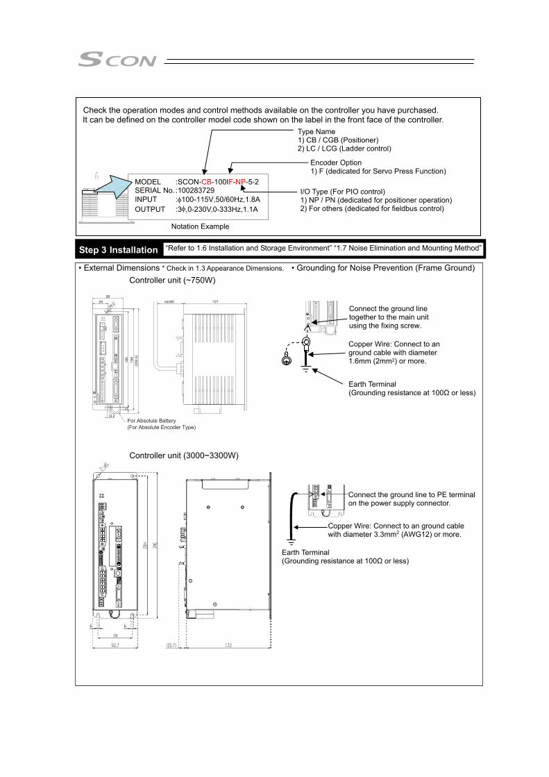
Check the operation modes and control methods available on the controller you have purchased.
It can be defined on the controller model code shown on the label in the front face of the controller. Notation Example Step 3 Installation • External Dimensions * Check in 1.3 Appearance Dimensions. • Grounding for Noise Prevention (Frame Ground)
Controller unit (~750W)
Controller unit (3000~3300W)
Earth Terminal (Grounding resistance at 100Ω or less)
Copper Wire: Connect to an ground cable with diameter 1.6mm (2mm2) or more.
Connect the ground line together to the main unit using the fixing screw.
MODEL :SCON-CB-100IF-NP-5-2 SERIAL No. :100283729 INPUT :100-115V,50/60Hz,1.8AOUTPUT :3,0-230V,0-333Hz,1.1A
Type Name 1) CB / CGB (Positioner) 2) LC / LCG (Ladder control)
I/O Type (For PIO control) 1) NP / PN (dedicated for positioner operation) 2) For others (dedicated for fieldbus control)
Encoder Option 1) F (dedicated for Servo Press Function)
“Refer to 1.6 Installation and Storage Environment” “1.7 Noise Elimination and Mounting Method”
For Absolute Battery (For Absolute Encoder Type)
Earth Terminal (Grounding resistance at 100Ω or less)
Copper Wire: Connect to an ground cable with diameter 3.3mm2 (AWG12) or more.
Connect the ground line to PE terminal on the power supply connector.

• Heat Radiation and Installation
Keep the ambient temperature of the controller at 40C or less. To fix the units in the control box, use the attachment holes on top and bottom of the unit for the screw-fixed type. Install in the orientation shown in the figure below for heat radiation.
For 3000 ~ 3300W type
Brake Box
Regeneration Unit
Air FlowFan
10mmor more
100mmor more
50mmor more
50mmor more
100mmor more
30mmor more
50mmor more
50mmor more
50mmor more
50mmor more
10mm or more
150mm or more
Air Flow
Air Flow
150mm or more
100mm or more
50mm or more 30mm or more 50mm or more 30mm or more

Power Supply for BrakeIt is necessary when actuator with brake
Absolute Battery(for Absolute Type)
PC Software(option) (Note1)
PLC (Note1)
Regenerative Resistor Unit(RESU-1 [for secondaryunit] : option)
Regenerative Resistor Unit(RESU-2 : option)Required dependingon usage condition
Power SupplyConnector
Flat Cable(Accessories)
CB-SC-REU010
CB-ST-REU010
FG ConnectionTerminal
24V DC
24V DC
PowerSource
SinglePhase
100V ACor
200V AC
Power Source for I/O Control (Note1)
Changeover Switch
Actuator
Step 4 Wiring Refer to Chapter 2 “Wiring” * Refer in Chapter 4 for Fieldbus Type. ●Example for Basic Connection 1 (~ 750W or less) ●Example for Basic Connection 2 (3000~ 3300W)
The connecting cable differs depending on the actuator [Refer to section 2.1.2 [4]]
Teaching Tool
Power Cutoff Breaker
As SCON-CGB for 3000 to 3300W does not havethe drive cutoff circuit, make sure to establish cutoff externally.

Step 5 Operation How you should look in the instruction manuals will differ depending on the operation modes and control methods you choose. Establish the settings for your operation needs. ● For Operation with PIO Control Chapter 3. Operation
● For Fieldbus Type
●For PLC Feature Equipped
Caution Set it away from the mechanical end or peripherals as much as possible when turning the servo ON. Move it apart when it interferes with peripherals. It may generate an alarm if it hits to the mechanical end or peripherals when the servo is turned ON. Also, in case the actuator is installed in vertical orientation, turning ON/OFF the servo at the same spot may cause a slight drop by the self-gravity. Pay attention not to pinch your finger or damage a work piece.
Caution Pay attention not to pinch your finger or damage a work piece by dropping the actuator with self-gravity when
it is released compulsorily with the brake release switch placed on the front panel of this controller. Caution This controller is equipped with a safety velocity function to make the operation in low speed compulsorily.
It is recommended to have this function activated in the first operation.
Instruction Manual for Each Fieldbus (Provided Separately, Refer to Chapter 4 for Manual Number)
Chapter 3. Operation
Operation with Fieldbus (provided separately, instruction manual for each fieldbus)
LC Ladder Programming Manual (provided separately ME0329)


1
Safety Guide “Safety Guide” has been written to use the machine safely and so prevent personal injury or property damage beforehand. Make sure to read it before the operation of this product.
Safety Precautions for Our Products The common safety precautions for the use of any of our robots in each operation.
No. Operation Description Description
1 Model Selection
● This product has not been planned and designed for the application where high level of safety is required, so the guarantee of the protection of human life is impossible. Accordingly, do not use it in any of the following applications. 1) Medical equipment used to maintain, control or otherwise affect
human life or physical health. 2) Mechanisms and machinery designed for the purpose of moving or
transporting people (For vehicle, railway facility or air navigation facility)
3) Important safety parts of machinery (Safety device, etc.) ● Do not use the product outside the specifications. Failure to do so may
considerably shorten the life of the product. ● Do not use it in any of the following environments.
1) Location where there is any inflammable gas, inflammable object or explosive
2) Place with potential exposure to radiation 3) Location with the ambient temperature or relative humidity exceeding
the specification range 4) Location where radiant heat is added from direct sunlight or other
large heat source 5) Location where condensation occurs due to abrupt temperature
changes 6) Location where there is any corrosive gas (sulfuric acid or
hydrochloric acid) 7) Location exposed to significant amount of dust, salt or iron powder 8) Location subject to direct vibration or impact
● For an actuator used in vertical orientation, select a model which is equipped with a brake. If selecting a model with no brake, the moving part may drop when the power is turned OFF and may cause an accident such as an injury or damage on the work piece.

2
No. Operation Description Description
2 Transportation ● When carrying a heavy object, do the work with two or more persons or utilize equipment such as crane.
● When the work is carried out with 2 or more persons, make it clear who is to be the leader and who to be the follower(s) and communicate well with each other to ensure the safety of the workers.
● When in transportation, consider well about the positions to hold, weight and weight balance and pay special attention to the carried object so it would not get hit or dropped.
● Transport it using an appropriate transportation measure. The actuators available for transportation with a crane have eyebolts attached or there are tapped holes to attach bolts. Follow the instructions in the instruction manual for each model.
● Do not step or sit on the package. ● Do not put any heavy thing that can deform the package, on it. ● When using a crane capable of 1t or more of weight, have an operator
who has qualifications for crane operation and sling work. ● When using a crane or equivalent equipments, make sure not to hang a
load that weighs more than the equipment’s capability limit. ● Use a hook that is suitable for the load. Consider the safety factor of the
hook in such factors as shear strength. ● Do not get on the load that is hung on a crane. ● Do not leave a load hung up with a crane. ● Do not stand under the load that is hung up with a crane.
3 Storage and Preservation
● The storage and preservation environment conforms to the installation environment. However, especially give consideration to the prevention of condensation.
● Store the products with a consideration not to fall them over or drop due to an act of God such as earthquake.
4 Installation and Start
(1) Installation of Robot Main Body and Controller, etc. ● Make sure to securely hold and fix the product (including the work part).
A fall, drop or abnormal motion of the product may cause a damage or injury. Also, be equipped for a fall-over or drop due to an act of God such as earthquake.
● Do not get on or put anything on the product. Failure to do so may cause an accidental fall, injury or damage to the product due to a drop of anything, malfunction of the product, performance degradation, or shortening of its life.
● When using the product in any of the places specified below, provide a sufficient shield. 1) Location where electric noise is generated 2) Location where high electrical or magnetic field is present 3) Location with the mains or power lines passing nearby 4) Location where the product may come in contact with water, oil or
chemical droplets
3
No. Operation Description Description
4 Installation and Start
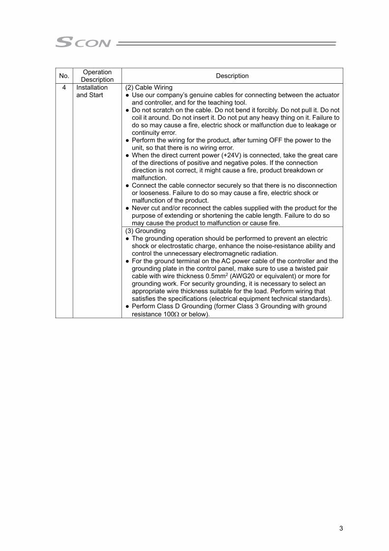
(2) Cable Wiring ● Use our company’s genuine cables for connecting between the actuator
and controller, and for the teaching tool. ● Do not scratch on the cable. Do not bend it forcibly. Do not pull it. Do not
coil it around. Do not insert it. Do not put any heavy thing on it. Failure to do so may cause a fire, electric shock or malfunction due to leakage or continuity error.
● Perform the wiring for the product, after turning OFF the power to the unit, so that there is no wiring error.
● When the direct current power (+24V) is connected, take the great care of the directions of positive and negative poles. If the connection direction is not correct, it might cause a fire, product breakdown or malfunction.
● Connect the cable connector securely so that there is no disconnection or looseness. Failure to do so may cause a fire, electric shock or malfunction of the product.
● Never cut and/or reconnect the cables supplied with the product for the purpose of extending or shortening the cable length. Failure to do so may cause the product to malfunction or cause fire.
(3) Grounding ● The grounding operation should be performed to prevent an electric
shock or electrostatic charge, enhance the noise-resistance ability and control the unnecessary electromagnetic radiation.
● For the ground terminal on the AC power cable of the controller and the grounding plate in the control panel, make sure to use a twisted pair cable with wire thickness 0.5mm2 (AWG20 or equivalent) or more for grounding work. For security grounding, it is necessary to select an appropriate wire thickness suitable for the load. Perform wiring that satisfies the specifications (electrical equipment technical standards).
● Perform Class D Grounding (former Class 3 Grounding with ground resistance 100 or below).

4
No. Operation Description Description
4 Installation and Start
(4) Safety Measures ● When the work is carried out with 2 or more persons, make it clear who
is to be the leader and who to be the follower(s) and communicate well with each other to ensure the safety of the workers.
● When the product is under operation or in the ready mode, take the safety measures (such as the installation of safety and protection fence) so that nobody can enter the area within the robot’s movable range. When the robot under operation is touched, it may result in death or serious injury.
● Make sure to install the emergency stop circuit so that the unit can be stopped immediately in an emergency during the unit operation.
● Take the safety measure not to start up the unit only with the power turning ON. Failure to do so may start up the machine suddenly and cause an injury or damage to the product.
● Take the safety measure not to start up the machine only with the emergency stop cancellation or recovery after the power failure. Failure to do so may result in an electric shock or injury due to unexpected power input.
● When the installation or adjustment operation is to be performed, give clear warnings such as “Under Operation; Do not turn ON the power!” etc. Sudden power input may cause an electric shock or injury.
● Take the measure so that the work part is not dropped in power failure or emergency stop.
● Wear protection gloves, goggle or safety shoes, as necessary, to secure safety.
● Do not insert a finger or object in the openings in the product. Failure to do so may cause an injury, electric shock, damage to the product or fire.
● When releasing the brake on a vertically oriented actuator, exercise precaution not to pinch your hand or damage the work parts with the actuator dropped by gravity.
5 Teaching ● When the work is carried out with 2 or more persons, make it clear who is to be the leader and who to be the follower(s) and communicate well with each other to ensure the safety of the workers.
● Perform the teaching operation from outside the safety protection fence, if possible. In the case that the operation is to be performed unavoidably inside the safety protection fence, prepare the “Stipulations for the Operation” and make sure that all the workers acknowledge and understand them well.
● When the operation is to be performed inside the safety protection fence, the worker should have an emergency stop switch at hand with him so that the unit can be stopped any time in an emergency.
● When the operation is to be performed inside the safety protection fence, in addition to the workers, arrange a watchman so that the machine can be stopped any time in an emergency. Also, keep watch on the operation so that any third person can not operate the switches carelessly.
● Place a sign “Under Operation” at the position easy to see. ● When releasing the brake on a vertically oriented actuator, exercise
precaution not to pinch your hand or damage the work parts with the actuator dropped by gravity.
* Safety protection Fence : In the case that there is no safety protection fence, the movable range should be indicated.
5
No. Operation Description Description
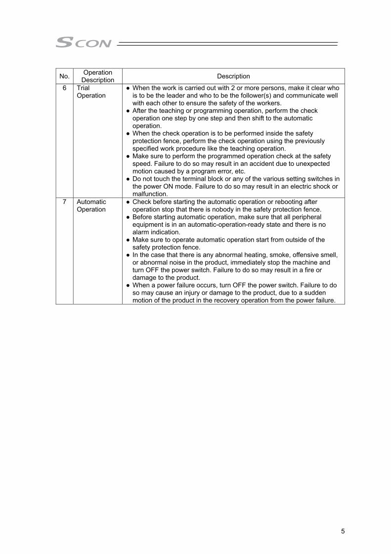
6 Trial Operation
● When the work is carried out with 2 or more persons, make it clear who is to be the leader and who to be the follower(s) and communicate well with each other to ensure the safety of the workers.
● After the teaching or programming operation, perform the check operation one step by one step and then shift to the automatic operation.
● When the check operation is to be performed inside the safety protection fence, perform the check operation using the previously specified work procedure like the teaching operation.
● Make sure to perform the programmed operation check at the safety speed. Failure to do so may result in an accident due to unexpected motion caused by a program error, etc.
● Do not touch the terminal block or any of the various setting switches in the power ON mode. Failure to do so may result in an electric shock or malfunction.
7 Automatic Operation
● Check before starting the automatic operation or rebooting after operation stop that there is nobody in the safety protection fence.
● Before starting automatic operation, make sure that all peripheral equipment is in an automatic-operation-ready state and there is no alarm indication.
● Make sure to operate automatic operation start from outside of the safety protection fence.
● In the case that there is any abnormal heating, smoke, offensive smell, or abnormal noise in the product, immediately stop the machine and turn OFF the power switch. Failure to do so may result in a fire or damage to the product.
● When a power failure occurs, turn OFF the power switch. Failure to do so may cause an injury or damage to the product, due to a sudden motion of the product in the recovery operation from the power failure.
6
No. Operation Description Description
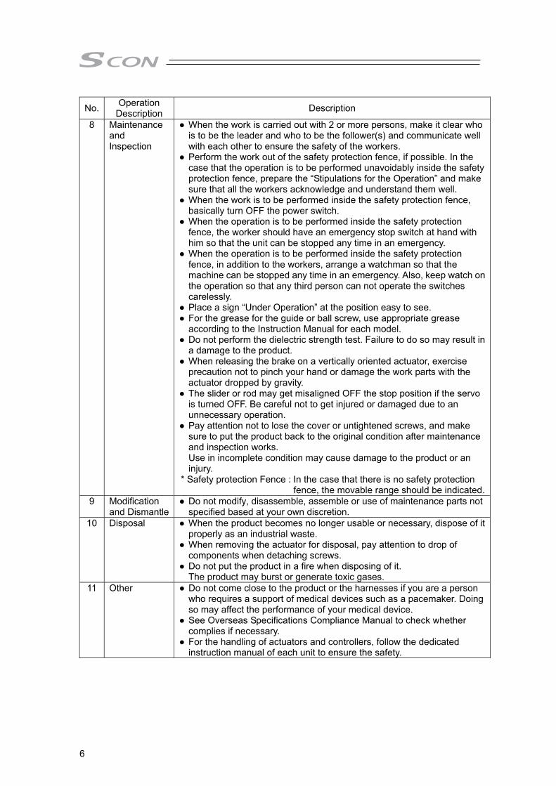
8 Maintenance and Inspection
● When the work is carried out with 2 or more persons, make it clear who is to be the leader and who to be the follower(s) and communicate well with each other to ensure the safety of the workers.
● Perform the work out of the safety protection fence, if possible. In the case that the operation is to be performed unavoidably inside the safety protection fence, prepare the “Stipulations for the Operation” and make sure that all the workers acknowledge and understand them well.
● When the work is to be performed inside the safety protection fence, basically turn OFF the power switch.
● When the operation is to be performed inside the safety protection fence, the worker should have an emergency stop switch at hand with him so that the unit can be stopped any time in an emergency.
● When the operation is to be performed inside the safety protection fence, in addition to the workers, arrange a watchman so that the machine can be stopped any time in an emergency. Also, keep watch on the operation so that any third person can not operate the switches carelessly.
● Place a sign “Under Operation” at the position easy to see. ● For the grease for the guide or ball screw, use appropriate grease
according to the Instruction Manual for each model. ● Do not perform the dielectric strength test. Failure to do so may result in
a damage to the product. ● When releasing the brake on a vertically oriented actuator, exercise
precaution not to pinch your hand or damage the work parts with the actuator dropped by gravity.
● The slider or rod may get misaligned OFF the stop position if the servo is turned OFF. Be careful not to get injured or damaged due to an unnecessary operation.
● Pay attention not to lose the cover or untightened screws, and make sure to put the product back to the original condition after maintenance and inspection works. Use in incomplete condition may cause damage to the product or an injury.
* Safety protection Fence : In the case that there is no safety protection fence, the movable range should be indicated.
9 Modification and Dismantle
● Do not modify, disassemble, assemble or use of maintenance parts not specified based at your own discretion.
10 Disposal ● When the product becomes no longer usable or necessary, dispose of it properly as an industrial waste.
● When removing the actuator for disposal, pay attention to drop of components when detaching screws.
● Do not put the product in a fire when disposing of it. The product may burst or generate toxic gases.
11 Other ● Do not come close to the product or the harnesses if you are a person who requires a support of medical devices such as a pacemaker. Doing so may affect the performance of your medical device.
● See Overseas Specifications Compliance Manual to check whether complies if necessary.
● For the handling of actuators and controllers, follow the dedicated instruction manual of each unit to ensure the safety.

7
Alert Indication The safety precautions are divided into “Danger”, “Warning”, “Caution” and “Notice” according to the warning level, as follows, and described in the Instruction Manual for each model.
Level Degree of Danger and Damage Symbol
Danger This indicates an imminently hazardous situation which, if the product is not handled correctly, will result in death or serious injury.
Danger
Warning This indicates a potentially hazardous situation which, if the product is not handled correctly, could result in death or serious injury.
Warning
Caution This indicates a potentially hazardous situation which, if the product is not handled correctly, may result in minor injury or property damage.
Caution
Notice This indicates lower possibility for the injury, but should be kept to use this product properly. Notice

8
Precautions in Operation
1. Use the following teaching tools. In this controller servo press function for only use the PC sotware. [Refer to 1.1.2 Teaching Tool.]
2. Backup the data to secure for breakdown. A non-volatile memory is used as the backup memory for this controller. All the registered press program and parameters are written into this memory and backed-up at the same time. Therefore, you will not usually lose the data even if the power is shut down. However, make sure to save the latest data so a quick recovery action can be taken in case when the controller is broken and needs to be replaced with another one. How to Save Data (1) Save the data to non-volatile memory with using the PC software.
3. Set the operation patterns. Servo press type controller processes 9 types of control logics to meet various ways of usage. To select the operation mode can be performed by using the PC software. [Refer to Chapter 3 Operation] Set the pressurize operation mode setting to the logic that suits to your use after the power is turned on.
4. Clock setting in calendar function
There may be a case that alarm code 069 [Real Time Clock Vibration Stop Detect] is issued at the first time to turn the power on after the product is delivered. In the case this happens, set the current time with a teaching tool. If the battery is fully charged, the clock data is retained for approximately 10 days after the power is turned off. Even though the time setting is conducted before the product is shipped out, the battery is not fully charged. Therefore, there may be a case that the clock data is lost even with fewer days than described above passed since the product is shipped out.
5. Actuator would not operate without servo-ON.
Servo ON signal (SON) is selectable from Enable or Disable by using a parameter. The setup can be performed by using the Parameter No. 21 [To select the servo-ON signal input disable]. [Refer to Chapter 7 Parameter] If it is set to Enable, the actuator would not operate unless turning this signal on. If parameter No.21 is set to “1”, SON is made disable. If it is set to Disable, the servo becomes on and the actuator operation becomes enabled as soon as the power supply to the controller is turned on and the emergency stop signal is cancelled. [Refer to 3.3.2 [1] Preparation for Operation and Supportive Signal] It is set to “0” (enable) at delivery. Establish the settings considering the using control systems.
Warning : SCON controller dedicated for the servo press function is to be operated with the dedicated press program. It cannot be operated with the positioner mode or pulse train control mode.
9
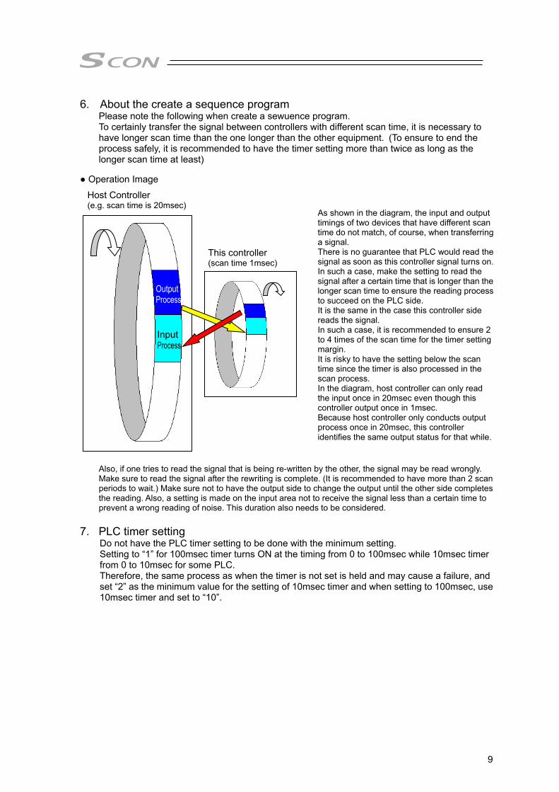
6. About the create a sequence program Please note the following when create a sewuence program. To certainly transfer the signal between controllers with different scan time, it is necessary to have longer scan time than the one longer than the other equipment. (To ensure to end the process safely, it is recommended to have the timer setting more than twice as long as the longer scan time at least)
● Operation Image
Also, if one tries to read the signal that is being re-written by the other, the signal may be read wrongly. Make sure to read the signal after the rewriting is complete. (It is recommended to have more than 2 scan periods to wait.) Make sure not to have the output side to change the output until the other side completes the reading. Also, a setting is made on the input area not to receive the signal less than a certain time to prevent a wrong reading of noise. This duration also needs to be considered.
7. PLC timer setting Do not have the PLC timer setting to be done with the minimum setting. Setting to “1” for 100msec timer turns ON at the timing from 0 to 100msec while 10msec timer from 0 to 10msec for some PLC. Therefore, the same process as when the timer is not set is held and may cause a failure, and set “2” as the minimum value for the setting of 10msec timer and when setting to 100msec, use 10msec timer and set to “10”.
This controller (scan time 1msec)
Host Controller (e.g. scan time is 20msec)
Output Process
Input Process
As shown in the diagram, the input and output timings of two devices that have different scan time do not match, of course, when transferring a signal. There is no guarantee that PLC would read the signal as soon as this controller signal turns on.In such a case, make the setting to read the signal after a certain time that is longer than the longer scan time to ensure the reading process to succeed on the PLC side. It is the same in the case this controller side reads the signal. In such a case, it is recommended to ensure 2 to 4 times of the scan time for the timer setting margin. It is risky to have the setting below the scan time since the timer is also processed in the scan process. In the diagram, host controller can only read the input once in 20msec even though this controller output once in 1msec. Because host controller only conducts output process once in 20msec, this controller identifies the same output status for that while.

10
8. Handling of built-in drive cutoff relay and cautions in caution in handling The product equips a built-in drive cutoff relay, and it is necessary to be careful in handling. Use the product with narrow understanding to the following notes. The drive cutoff relay built in our controllers is designed under assumption of limited frequency of use
such as a case to require emergency stop of a system, and frequent operation is not considered. Therefore, in a condition to require high frequency of use of the drive cutoff relay such as a case to turn ON/OFF the driving source in every setup change, the life of the relay may reach to the end in early stage.
The relay itself may not meet a sufficient safety demand level when it is used in a system that prioritizes safety in the drive cutoff system. It is necessary to construct a system to meet the safety demand level in a circuit that a customer prepares.
IAI products equip a built-in drive cutoff relay considering customer’s usage. However, as described above, whether it can be used or not relies on such facts as the safety demand level and frequency of drive cutoff. Please use it in limitation to the way to use as described below.
Do not expect reliability of the drive cutoff relay (Anything can do as long as driving source can be cut off.) Take around 5 times a day as a reference to turn ON/OFF the drive cutoff relay Thermistor type (which the resistance gets high and restrains in-rush current in low temperature, and
resistance gets low and reduce loss in high temperature) in-rush current limiter circuit is equipped. Therefore, to keep the thermistor temperature as low as possible when turning the power on is a key point to make degradation slower on such components as the drive cutoff relay. As a reference, it is preferred to have approximately 30 minutes for cooling after the driving source being cut off.
(Note) There is no built-in drive cutoff relay equipped in those types for 3000W or more. Establish the construction of the circuit to have an external cutoff.
9. Regarding Servo Press Equipment (Device) ● Regarding the safety circuit, make sure to establish the construction that satisfies the safety
requirements as the system by having the risk assessment conducted on the device by its own. ● Have the safety protection fences. Also, make sure to install safety equipment in order to cut off the
power supply when an operator gets into the working area. ● Install the controller inside the enclosure of the control panel. ● The circuit inside the controller is charged with high voltage. Do not attempt to touch it while the
electricity is conducted or after conduction (when Charge Status Display LED lamp is on). It may cause electric shock.
● The controller temperature gets high. Do not attempt to touch it.

11
International Standards Compliances This product comply with the following international standards: Refer to Overseas Standard Compliance Manual (ME0287) for more detailed information.
Controller RoHS Directive CE Marking UL
SCON-(For Servo Press) Please contact IAI
(to 750W)
(3000 to 3300W) UL 1. Use Environment
• It can be used in pollution degree 2 environment. • Maximum surrounding air temperature rating, 40°C ;
2. Solid State Motor Overload Protection Solid state motor overload protection in the SCON controller is provided. The overload protection works at 115% of the whole load current of the servomotor as the criteria.
3. Short Circuit Current Rating (SCCR) This product is to be used with a power supply of 5,000Arms or lower. The available maximum voltage is as shown below: 200V system products: 240V AC 100V system products: 120V AC
4. Branch Circuit Protection Integral solid state short circuit protection does not provide branch circuit protection. Branch circuit protection must be provided in accordance with the National Electric Code and any additional local codes.
5. Risk of Electric Shock Do not touch terminals within 10 minutes after disconnect the power. Risk of electric shock.

12
Name for Each Parts and Their Functions ● ~750W Type 1) FG Grounding Terminal [Refer to 1.7 Installation and Noise Prevention]
It is a terminal to connect the grounding line to prevent electric shock and noise. It is connected with the PE of the power connector in the controller.
2) Power Supply Connector (PWR) [Refer to 2.1.2 [1] Main Power Circuit]
It is the connector to supply the power to the controller and to the control board. 3) Motor Connector (MOT) [Refer to 2.1.2 [4] Motor • Encoder Circuit]
It is a connector to connecting the motor encoder cable of the actuator. 4) Regenerative Unit Connector (RB) [Refer to 2.1.2 [6] Regenerative Unit Circuit]
It is a connector to connecting regenerative unit. 5) System I/O Connector (SYS I/O) [Refer to 2.1.2 [3] Actuator Emergency Stop Circuit (System I/O
connector)] It is a connector to connecting the operation mode stop switch of the actuator.
2) Power Supply Connector
4) Regenerative Unit Connector
3) Motor Connector
5) System I/O Connector
6) Piano Switch (Not to use)
7) Axis No. Sttting Switch
8) Status Indicator LED
1) FG Grounding Terminal
10) PIO Connector
9) Multi-Function Connector
12) SIO Connector
11) Operation ModeSetting Switch
13) Brake Release Switch
14) Motor Power Supply Connector
15) Encoder Connector
16) Absolute Battery Connector
17) Absolute Battery Holder
13
6) Piano Switch Not to use.
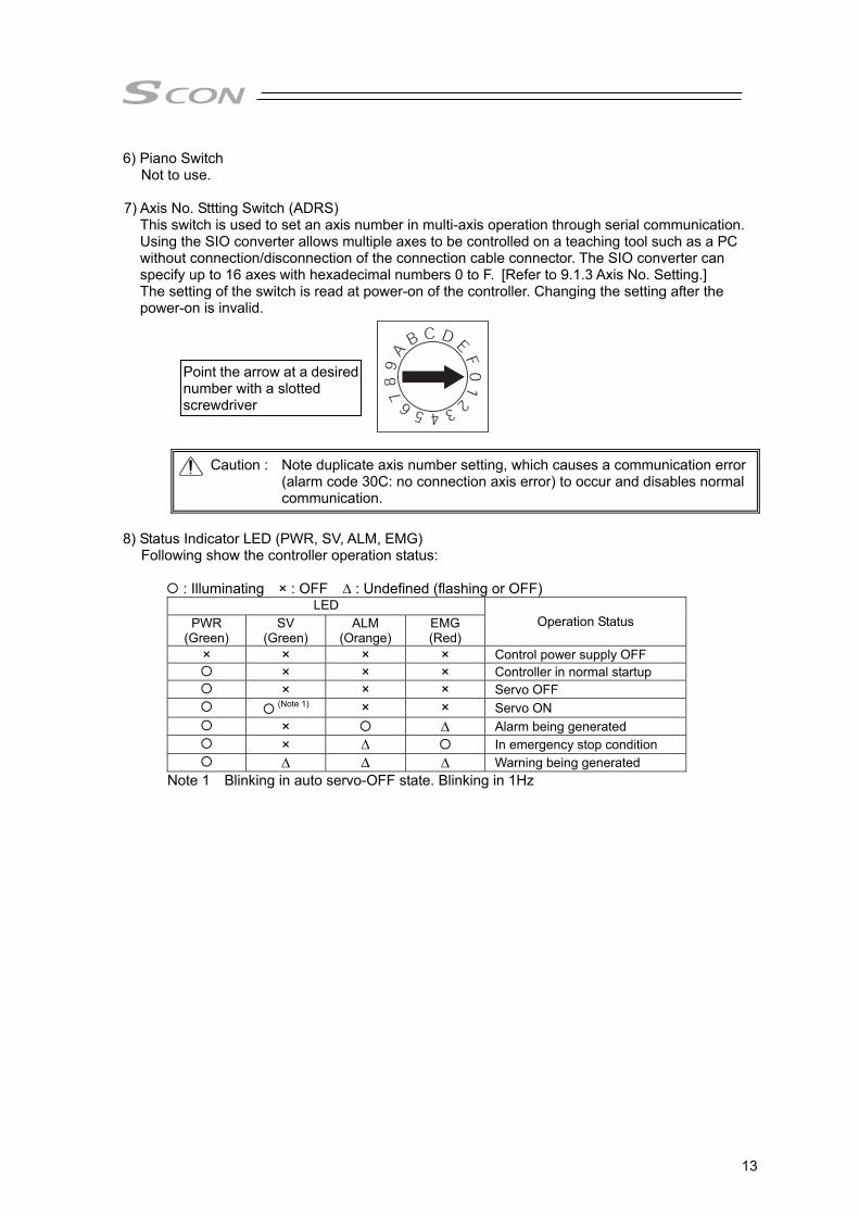
7) Axis No. Sttting Switch (ADRS)
This switch is used to set an axis number in multi-axis operation through serial communication. Using the SIO converter allows multiple axes to be controlled on a teaching tool such as a PC without connection/disconnection of the connection cable connector. The SIO converter can specify up to 16 axes with hexadecimal numbers 0 to F. [Refer to 9.1.3 Axis No. Setting.] The setting of the switch is read at power-on of the controller. Changing the setting after the power-on is invalid.
Caution : Note duplicate axis number setting, which causes a communication error (alarm code 30C: no connection axis error) to occur and disables normal communication.
8) Status Indicator LED (PWR, SV, ALM, EMG)
Following show the controller operation status:
: Illuminating × : OFF ∆ : Undefined (flashing or OFF) LED
Operation Status PWR (Green)
SV (Green)
ALM (Orange)
EMG (Red)
× × × × Control power supply OFF × × × Controller in normal startup × × × Servo OFF (Note 1) × × Servo ON × ∆ Alarm being generated × ∆ In emergency stop condition ∆ ∆ ∆ Warning being generated
Note 1 Blinking in auto servo-OFF state. Blinking in 1Hz
Point the arrow at a desirednumber with a slotted screwdriver
14
9) Multi-Function Connector (MF I/F) [Refer to 2.1.2 [7] Multi-Function Connector] It is a connector to use the feedback pulse output, analog output of loadcell load data and SIO communication function (SIO2).
10) PIO Connector (PIO) [Refer to 2.1.2 [5] PIO Circuit]
The PIO connector is used for control I/O signals. (Note) It is not mounted in fieldbus type.
11) Operation Mode Setting Switch (MANU/AUTO) The switch for interlock.
Setting to switch SCON-CB SCON-LC
AUTO Allows auto operation by PIO signals. The teaching tool can only operate the monitor.
Allows operation by Ladder. The teaching tool can only operate the monitor.
MANU Allows the teaching tool to operate the controller.
The ladder stops. Allows the teaching tool to operate the controller.
12) SIO Connector (SIO) [Refer to 2.2.7 SIO Connector]
The SIO connector is used to connect the controller with a teaching tool such as PC software or a gateway unit through a proper communication cable.
13) Brake Release Switch (BK RLS /NOM) For the actuator equipped with a brake, the switch is used to release the brake control.
14) Motor Power Supply Connector (BK PWR) [2.1.2 [2] Brake Power Supply Circuit]
For the actuator equipped with a brake, the connector supplies the power (24V DC) to release the brake.
15) Encoder Connector (PG) [Refer to 2.1.2 [4] Motor • Encoder Circuit] This connector is used to connect the encoder cable of the actuator.
16) Absolute Battery Connector In the absolute specification, the connector is connected with the absolute battery.
17) Absolute Battery Holder (enclosed in the absolute specification)
This is the holder of the absolute battery.
Warning : Always set the switch to NOM in normal operation. The brake would not work even with the servo OFF condition if the switch is on the RLS side. In the vertical oriented mount, the work may drop and cause an injury or the work to be damaged.

15
● ~3000W Type 1) FG Grounding Terminal [Refer to 1.7 Installation and Noise Prevention]
It is a terminal to connect the grounding line to prevent electric shock and noise. It is connected with the PE of the power connector in the controller.
2) Power Supply Connector (PWR) [Refer to 2.3.2 [1] Main Power Circuit]
It is the connector to supply the power to the controller and to the control board. 3) System I/O Connector (SYS I/O) [Refer to 2.3.2 [3] Actuator Emergency Stop Circuit (System I/O
connector)] It is a connector to connecting the operation mode stop switch of the actuator.
2) Power Supply Connector
7) Regenerative Unit Connector
6) Motor Connector
3) System I/O Connector
5) Piano Switch (Not to use)
1) FG Grounding Terminal
12) PIO Connector
11) Multi-Function Connector
14) SIO Connector
13) Operation Mode Setting Switch
15) Brake Release Switch
16) Motor Power Supply Connector
17) Encoder Connector
18) Absolute Battery Connector
19) Absolute Battery Holder
4) Axis No. Sttting Switch
8) Internal Regenerative Resistor Valid Connector
9) Charge Status Display LED
10) Status Indicator LED

16
4) Axis No. Sttting Switch (ADRS) This switch is used to set an axis number in multi-axis operation through serial communication. Using the SIO converter allows multiple axes to be controlled on a teaching tool such as a PC without connection/disconnection of the connection cable connector. The SIO converter can specify up to 16 axes with hexadecimal numbers 0 to F. [Refer to 9.1.3 Axis No. Setting.] The setting of the switch is read at power-on of the controller. Changing the setting after the power-on is invalid.
Caution : Note duplicate axis number setting, which causes a communication error (alarm code 30C: no connection axis error) to occur and disables normal communication.
5) Piano Switch
Not to use. 6) Motor Connector (MOT) [Refer to 2.3.2 [4] Motor • Encoder Circuit]
It is a connector to connecting the motor encoder cable of the actuator.
7) Regenerative Unit Connector (RB) [Refer to 2.3.2 [6] Regenerative Unit Circuit]
It is a connector to connecting regenerative unit.
8) Internal Regenerative Resistor Valid Connector Short-circuit cable is connected at delivery.
Caution : Make sure to use the unit in the condition that the short-circuit cable is connected. Use the unit without this connected may damage the device.
9) Charge Status Display LED
It shows the status of electric charge in the controller. Caution : While this LED lamp is on, do not attempt to touch controller or
regenerative resistor units to prevent electric shock. 10) Status Indicator LED (PWR, SV, ALM, EMG)
Following show the controller operation status:
: Illuminating × : OFF ∆ : Undefined (flashing or OFF) LED
Operation Status PWR (Green)
SV (Green)
ALM (Orange)
EMG (Red)
× × × × Control power supply OFF × × × Controller in normal startup × × × Servo OFF (Note 1) × × Servo ON × ∆ Alarm being generated × ∆ In emergency stop condition ∆ ∆ ∆ Warning being generated
Note 1 Blinking in auto servo-OFF state
Point the arrow at a desirednumber with a slotted screwdriver

17
11) Multi-Function Connector (MF I/F) [Refer to 2.3.2 [7] Multi-Function Connector] It is a connector to use the feedback pulse output, analog output of loadcell load data and SIO communication function (SIO2).
12) PIO Connector (PIO) [Refer to 2.3.2 [5] PIO Circuit]
The PIO connector is used for control I/O signals. (Note) It is not mounted in fieldbus type.
13) Operation Mode Setting Switch (MANU/AUTO) The switch for interlock.
Setting to switch SCON-CB SCON-LC
AUTO Allows auto operation by PIO signals. The teaching tool can only operate the monitor.
Allows operation by Ladder. The teaching tool can only operate the monitor.
MANU Allows the teaching tool to operate the controller.
The ladder stops. Allows the teaching tool to operate the controller.
14) SIO Connector (SIO) [Refer to 2.4.7 SIO Connector]
The SIO connector is used to connect the controller with a teaching tool as PC software through a proper communication cable.
15) Brake Release Switch (BK RLS /NOM) For the actuator equipped with a brake, the switch is used to release the brake control.
16) Motor Power Supply Connector (BK PWR) [2.3.2 [2] Brake Power Supply Circuit]
For the actuator equipped with a brake, the connector supplies the power (24V DC) to release the brake.
17) Encoder Connector (PG) [Refer to 2.3.2 [4] Motor • Encoder Circuit] This connector is used to connect the encoder cable of the actuator.
18) Absolute Battery Connector In the absolute specification, the connector is connected with the absolute battery.
19) Absolute Battery Holder (enclosed in the absolute specification)
This is the holder of the absolute battery.
Warning : Always set the switch to NOM in normal operation. The brake would not work even with the servo OFF condition if the switch is on the RLS side. In the vertical oriented mount, the work may drop and cause an injury or the work to be damaged.

18
■About SCON-LC Type■ LC Type is equipped with a built-in PLC feature, and is capable to control SCON with ladder programs instead of the host PLC if the programs are in small scale. ● PIO Type
Each signal of PIO is general input and output. Use it with connecting to internal relay, which each IO pattern is assigned to, with the ladder program if necessary.
SCON-LC/LCG ● Fieldbus Type
Each bit in fieldbus communication is general input and output. Use it with connecting to internal relay, which each IO pattern is assigned to, with the ladder program if necessary.
SCON-LC/LCG For fieldbus communication, the data volume transferred in one time of communication is restricted.
For CC-Link (1 station 1 time : Remote device station)
For those other than CC-Link (Input 8 bytes, output 8 bytes)
Master SCON Master SCON RX00~0F Not to Use RY00~0F Not to Use
PLC (Word) SCON
PLC (Word) SCON
RX10~1F Not to Use RY10~1F Not to Use Input 0 Y000~00F Output 0 X000~00FRWr0 Y000~00F RWw0 X000~00F Input 1 Y010~01F Output 1 X010~01FRWr1 Y010~01F RWw1 X010~01F Input 2 Y020~02F Output 2 X020~02FRWr2 Y020~02F RWw2 X020~02F
Input 3 Y030~03F Output 3 X030~03FRWr3 Y030~03F RWw3 X030~03F
CB Types are equipped with PLC feature
Control available with ladder programs instead of host PLC * * Programs in small
scale
PIO Signals
I/O Signals (PIO Connector)
Input (X), Output (Y)memory
Internal process along IO pattern
Internal relay (M)
Connet to
Ladder
Fieldbus board
Input (X), Output (Y)memory
Internal process along IO pattern
Internal relay (M)
Connet to
Ladder
Fieldbus Signals

19
●Operation Pattern (Assignment) 1) The operation pattern is to be set in Parameter No. 84 “Fieldbus Operation Mode”.
Parameter No.84 Setting Operation Pattern 0 Remote I/O mode 1 Full Functional Mode
The set operation patterns are assigned to the internal relay (input signals to M2048 to 2063, output signals to M2304 to M2319). Figure below shows an example for remote I/O mode (occupied 2 bytes).
☆Example of SCON input side Assignment
b15 b14 b13 b12 b11 b10 b9 b8 b7 b6 b5 b4 b3 b2 b1 b0
Control Signal
M23
19
M23
18
M23
17
M23
16
M23
15
M23
14
M23
13
M23
12
M23
11
M23
10
M23
09
M23
08
M23
07
M23
06
M23
05
M23
04
Control Signal Name SO
N
RES
HO
ME
RM
OD
BKR
L
CLB
R
FPST
ENM
V
PHO
M
PSTR
PC32
PC16
PC8
PC4
PC2
PC1
☆Example of SCON output side Assignment
Status Signal
M20
63
M20
62
M20
61
M20
60
M20
59
M20
58
M20
57
M20
56
M20
55
M20
54
M20
53
M20
52
M20
51
M20
50
M20
49
M20
48
Status Signal Name *A
LML
*ALM
SV
HEN
D
RM
DS
CEN
D
JDN
G
JDO
K
MPH
M
PSTP
PRSS
SER
C
APR
C
POR
G
PRU
N
PCM
P
Caution : It is not applicable for pulse train control.
Understand the features of SCON with this manual before creating a ladder program. [Refer to ME0329 LC Ladder Programming manual]

20
Actuator Axes Refer to the pictures below for the actuator axes that can be controlled. 0 defines the home position. * The home position cannot be set at the end that the rod is extended (home reversed type). Rod Type
0
+

1. Spedifications Check
21
Chapter 1 Specifications Check 1.1 Product Check 1.1.1 Parts
This product is comprised of the following parts if it is of standard configuration. If you find any fault in the contained model or any missing parts, contact us or our distributor.
No. Part Name Model Quantity
1 Controller Refer to “How to read the model plate”, “How to read the model”.
Accessories
2 I/O Flat Cable
CB-PAC-PIO□□□
□□□shows the cable length (Example) □□□: 020 = 2 [m]
3 Plug for Multi-Function Connector for Connector
Plug : 10114-3000PE (Supplier: 3M) Shell: 10314-52F0-008 (Supplier: 3M)
4 System I/O Connector (For ~ 750W Type)
FMC1.5/4-ST-3.5 (Supplier: Phoenix Contact)
Recommended cable size 1.25 to 0.5mm2
(AWG16 to 20)
5 Brake Power Supply Connector
MC1.5/2-ST-3.5 (Supplier: Phoenix Contact)
6 AC Power Supply Connector (For ~ 750W Type)
MSTB2.5/6-STF-5.08 (Supplier: Phoenix Contact)
Recommended cable size 2.0mm2
(AWG14)
7 Absolute Battery AB-5
Enclosed for Absolute Type
8 Dummy Plug DP-5
Enclosed for SCON-CGB/LCG
9 AC Power Supply Plug (For 3000 to 3300W Type)
PC5/6-STF-7.62 (Supplier: Phoenix Contact)
Recommended cable size Control : 075 mm2 (AWG18)Motor : 3.3 mm2 (AWG12)
10 System I/O Plug (For 3000 to 3300W Type)
FMC1.5/6-ST-3.5 (Supplier: Phoenix Contact)
Recommended cable size 1.25 to 0.5mm2
(AWG16 to 20)
1. S
pedi
ficat
ions
Che
ck
22
No. Part Name Model Quantity
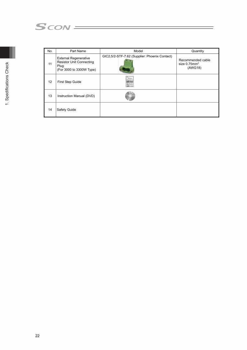
11
External Regenerative Resistor Unit Connecting Plug (For 3000 to 3300W Type)
GIC2,5/2-STF-7.62 (Supplier: Phoenix Contact)
Recommended cable size 0.75mm2
(AWG18)
12 First Step Guide
13 Instruction Manual (DVD)
14 Safety Guide

1. Spedifications Check
23
1.1.2 Teaching Tool
A teaching tool such as PC software is necessary when performing the setup for position setting, parameter setting, etc. that can only be done on the teaching tool. Please prepare either of the following teaching tools.
No. Part Name Model 1 PC Software (Includes RS232C Adapter + Peripheral Communication Cable) RCM-101-MW 2 PC Software (Includes USB Adapter + USB Cable + Peripheral Communication Cable) RCM-101-USB
1.1.3 Instruction Manuals Related to this Product, which are Contained in
the Instruction Manual (DVD)
No. Name Manual No.
1 SCON-CB-F/CGB-F/LC-F/LCG-F Servo Press Funciton Instruction Manual ME0345
2 PC Software RCM-101-MW/ RCM-101-USB Instruction Manual ME0155 3 DeviceNet Instruction Manual ME0256 4 CC-Link Instruction Manual ME0254 5 PROFIBUS-DP Instruction Manual ME0258 6 CompoNet Instruction Manual ME0220 7 MECHATROLINK-/Instruction Manual ME0221 8 EtherCAT Instruction Manual ME0273 9 EtherNet/IP Instruction Manual ME0278 10 PROFINET IO Instruction Manual ME0333 11 Instruction Manual for the Serial Communication [for Modbus] ME0162 12 LC Ladder Programming Manual ME0329 13 LC Ladder Edit Software Manual ME0330
1.1.4 How to Read the Model Plate
Model
Serial Number
MODEL : SCON-CB-200IF-NP-5-2 SERIALNo. :800056144 L11 INPUT :1,100-115V,50/60Hz,1.8A OUTPUT :3,0-90V,0-333Hz,1.10A
1. S
pedi
ficat
ions
Che
ck
24
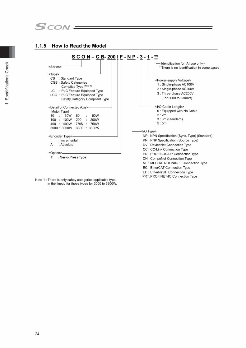
1.1.5 How to Read the Model Note 1 : There is only safety categories applicable type
in the lineup for those types for 3000 to 3300W.
S C O N – C B- 200 I F - N P - 3 - 1 - **
<Series> <Type>
CB : Standard Type CGB : Safety Categories
Complied Type (Note 1)
LC : PLC Feature Equipped Type LCG : PLC Feature Equipped Type
Safety Category Compliant Type <Detail of Connected Axis>
[Motor Type] 30 : 30W 60 : 60W 100 : 100W 200 : 200W 400 : 400W 750S : 750W 3000 : 3000W 3300 : 3300W
<Encoder Type> I : Incremental A : Absolute
<Option> F : Servo Press Type
<Identification for IAI use only> * There is no identification in some cases
<I/O Type> NP : NPN Specification (Sync. Type) (Standard) PN : PNP Specification (Source Type) DV : DeviceNet Connection Type CC : CC-Link Connection Type PR : PROFIBUS-DP Connection Type CN : CompoNet Connection Type ML : MECHATROLINK- Connection Type EC : EtherCAT Connection Type EP : EtherNet/IP Connection Type PRT : PROFINET-IO Connection Type
<Power-supply Voltage> 1 : Single-phase AC100V 2 : Single-phase AC200V 3 : Three-phase AC200V
(For 3000 to 3300W) <I/O Cable Length>
0 : Equipped with No Cable 2 : 2m 3 : 3m (Standard) 5 : 5m
1. Spedifications Check
25
1.2 List of Basic Specifications
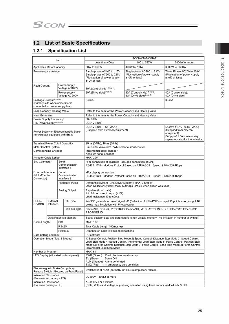
1.2.1 Specification List
Item SCON-CB-F/CGB-F
Less than 400W 400 to 750W 3000W or more Applicable Motor Capacity 30W to 399W 400W to 750W 3000W to 3300W Power-supply Voltage Single-phase AC100 to 115V
Single-phase AC200 to 230V (Fluctuation of power supply ±10%or less)
Single-phase AC200 to 230V (Fluctuation of power supply ±10% or less)
Three Phase AC200 to 230V (Fluctuation of power supply ±10% or less)
Rush Current Power-supply Voltage AC100V 30A (Control side) (Note 1),
80A (Drive side) (Note 1)
Power-supply Voltage AC200V
30A (Control side) (Note 1), 80A (Drive side) (Note 1)
40A (Control side), 40A (Drive side)
Leakage Current (Note 2)
(Primary side when noise filter is connected to power supply line)
3.0mA 3.5mA
Load Capacity, Heating Value Refer to the Item for the Power Capacity and Heating Value. Heat Generation Refer to the Item for the Power Capacity and Heating Value. Power Supply Frequency 50 / 60Hz PIO Power Supply (Note 3) DC24V ±10%
Power Supply for Electromagnetic Brake (for Actuator equipped with Brake)
DC24V ±10% 1A (MAX.) (Supplied from external equipment)
DC24V ±10% 0.1A (MAX.) (Supplied from external equipment) Supply of 1.5A is necessary separately also for the actuator.
Transient Power Cutoff Durability 20ms (50Hz), 16ms (60Hz) Motor Control System Sinusoidal Waveform PWM vector current control Corresponding Encoder Incremental serial encoder
Absolute serial encoder Actuator Cable Length MAX. 20m SIO Connector Serial
Communication Interface 1
・For connection of Teaching Tool, and connection of Link RS485: 1CH…Modbus Protocol Based on RTU/ASCII Speed: 9.6 to 230.4Kbps
External Interface (Multi-Function Connector)
Serial Communication Interface 2
・For display connection RS485: 1CH…Modbus Protocol Based on RTU/ASCII Speed: 9.6 to 230.4Kbps
Feedback Pulse Differential system (Line Driver System): MAX. 2.5Mpps Open Collector System: MAX. 500Kpps (JM-08 when option was used))
Analog Output 1 system (Load data) 4 to 20mA current output (±1%) Load resistance 10 to 600
SCON- CB/CGB
External Interface
PIO Type 24V DC general-purposed signal I/O (Selection of NPN/PNP) … Input 16 points max., output 16 points max. Insulation with Photocoupler
Fieldbus Type DeviceNet, CC-Link, PROFIBUS, CompoNet, MECHATROLINK-Ⅰ/Ⅱ, EtherCAT, EtherNet/IP, PROFINET IO
Data Retention Memory Saves position data and parameters to non-volatile memory (No limitation in number of writing.) Cable Length PIO MAX. 10m
RS485 Total Cable Length 100mor less Fieldbus Depends on each fieldbus specifications
Data Setting and Input PC software Operation Mode (Total 8 Modes) 1) Speed Control, Position Stop Mode 2) Speed Control, Distance Stop Mode 3) Speed Control,
Load Stop Mode 4) Speed Control, Incremental Load Stop Mode 5) Force Control, Position Stop Mode 6) Force Control, Distance Stop Mode 7) Force Control, Load Stop Mode 8) Force Control, Incremental Load Stop Mode
Number of Program MAX. 64 LED Display (allocated on front panel) PWR (Green) : Controller in normal startup
SV (Green) : Servo ON ALM (Orange) : Alarm generated EMG (Red) : In emergency stop condition
Electromagnetic Brake Compulsory Release Switch (Allocated on Front Panel) Switchover of NOM (normal) / BK RLS (compulsory release)
Insulation Resistance (Between secondary – FG) DC500V 10M or more
Insulation Resistance (Between primary – FG)
AC1500V For 1 minute. (Note) Withstand voltage of pressing operation using force sensor loadcell is 50V DC

1. S
pedi
ficat
ions
Che
ck
26
Item
SCON-CB-F/CGB-F Less than 400W 400 to 750W 3000W or more
Envi
ronm
ent
Surrounding Air Temperature 0 to 40C Surrounding Humidity 85%RH or less (non-condensing)Surrounding Environment [Refer to 1.6 Installation and Storage Environment]Surrounding Storage Temperature -20 to 70C (non-condensing) Usage Altitude 85%C or less (non-condensing) Protection Class XYZ Each direction 10 to 57Hz one-sided width 0.035mm (continuous) 0.075mm (intermittent)
57 to 150Hz 4.9m/s2 (continuous) 9.8m/s2 (intermittent) Mass Approx. 900g Approx. 1200g Approx. 2800g Cooling Method Natural air-cooling Forced Air-Cooling Forced Air-Cooling External Dimensions 58W × 194H × 121D [mm] 72W × 194H × 121D [mm] 92.7W × 300H × 187.7D [mm]
Note 1 In-rush current will flow for approximately 20msec after the power is turned on (at 40C). Note that the value of in-rush current differs depending on the impedance of the power supply line.
Note 2 Leak current varies depending on the capacity of connected motor, cable length and the surrounding environment. Measure the leak current at the point where a ground fault circuit interrupter is to be installed when leakage protection is conducted. Regarding the leakage breaker, it is necessary to have a clear purpose for selection such as a fire protection or protection of human body. Use the harmonic type (for inverter) for a leakage breaker.
Note 3 It is not necessary to supply power to PIO, SIO Converter without using PIO. In this case, set the parameter No.74 (PIO Power Supply Monitor) to “1” (Invalid). It will generate the error code No. 0CF (I/O 24V Power Supply Error) if the setting is not done.

1. Spedifications Check
27
1.2.2 Item for the Power Capacity and Heating Value Rated Power Capacity = Motor Power Capacity + Control Power Capacity Peek Max. Power Capacity = Peek Max. Motor Power Capacity + Control Power Capacity
Wattage of Actuator Motor
Motor Power Capacity [VA]
Peek Max. Motor Power Capacity [VA]
Control Power Capacity [VA]
Rated Power Capacity [VA]
Peek Max. Power Capacity [VA]
Heat Generation[W]
30 46 138
48
94 186 31
60 138 414 186 462 33
100 234 702 282 750 35
200 421 1263 469 1311 38
400 920 2760 968 2808 45
750S 1521 4563 1569 4611 58
3000 5657 16970 5705 17018 180
3300 6014 18041 6062 18089 182
1.2.3 Selection of Circuit Breaker For the selection of the circuit breaker, perform it according to the following items. 3 times of the rated current flows to the controller during the acceleration/deceleration. Select an
interrupter that does not trip with this value of current. If a trip occurs, select an interrupter that possesses the rated current of one grade higher. (Check the operation characteristics curves in the product catalog.)
Select an interrupter that does not trip with the in-rush current. (Check the operation characteristics curves in the product catalog.)
Consider the current that enables to cutoff the current even when a short circuit current is flown for the rated cutoff current. Rated Interrupting Current > Short Circuit Current = Primary Power Capacity / Power Voltage Consider margin for the rated current on the circuit breaker.
1.2.4 Selection of Leakage Breaker Regarding the leakage breaker, it is necessary to have a clear purpose for selection such as a fire
protection or protection of human body. Leak current varies depending on the capacity of connected motor, cable length and the
surrounding environment. Measure the leak current at the point where a ground fault circuit interrupter is to be installed when leakage protection is conducted.
Use the harmonic type for a leakage breaker.
● Calculation for Motors of up to 750W Rated Current for Circuit Interrupter > (Rated Motor Power Capacity [VA] + Control Power Capacity [VA]) / AC Input Voltage × Safety Margin (reference 1.2 to 1.4 times)
● Calculation for Motors of 3000 to 3300W Rated Current for Circuit Interrupter > (Rated Motor Power Capacity [VA] + Control Power Capacity [VA]) / AC Input Voltage × Safety Margin (reference 1.2 to 1.4 times) ÷√3

1. S
pedi
ficat
ions
Che
ck
28
1.3 External Dimensions 1.3.1 SCON-CB/CGB/LC/LCG less than 400W
58 121
184
5 19
4
4.2
In Absolute Battery Attachment(Absolute Encoder Type)It is not necessary when using Pulse Train Control because it does not comply with it.
(200
.5)
φ4.2 29 min80
1.3.2 SCON-CB/CGB/LC/LCG 400W to 750W
In Absolute Battery Attachment(Absolute Encoder Type)It is not necessary when using Pulse Train Control because it does not comply with it.
Fan
72 121 min80 43
184
5
194
(200
.5)
φ4.2
4.2

1. Spedifications Check
29
1.3.3 SCON-CB/CGB/LC/LCG 3000W to 3300W
92.7
284
6
2-φ6
70
6
(15.7) 172
300

1. S
pedi
ficat
ions
Che
ck
30
1.4 External Interface Specifications 1.4.1 Standard Input Output Interface Specification
(Multi-Function Connector) There are 3 types in the external interface mounted in the standard.
1) Serial Communication Interface 2 (For display device etc.) 2) Analog Output (Load of loadcell) 3) Encoder Feedback Pulse Output
1) Serial Communication Interface 2 (SIO2) Type Serial communication interface 2 is to be assigned to the multi-function connector, it is to be used for connection to a touch panel or display.
Item Specification Communication standard Based on EIA RS485 Baud rate 9600/14400/19200/28800/38400/57600/
76800/115200/230400bps Communication system Half duplex communication Connection format 1: N Disequilibrium Bus Connection (MAX. 16 untis) Communication cable length MAX. 100m Bit length 8 bit Parity None Stop bit 1 bit Protocol Modbus (RTU/ASCII: Automatic Identification)
Caution
Connect the PC software to serial communication interface 1 (SIO connector). When using the PC software and serial communication interface 2 (SIO2) at the same
time, use only the query (command) for data readout for SIO2. Using queries for writing or command may cause unexpected operation.
2) Analog Output Type
It outputs the load data as an analog signal from the loadcell. Item Specification
Output current 4 to 20mA Output in ratio to the loadcell rated capacity 4mA = -30% 7mA = 0% 17mA = 100% 20mA = 130%
Accuracy (*) ±1%FS Load resistance 10 to 600Ω
* It is the accuracy for analog output, and does not include loadcell accuracy.
3) Encoder Feedback Pulse Output Type Item Specification
Output pulse train Differential (Line driver Output: 26C32 or equiv.) Max. pulse frequency 2.5Mpps

1. Spedifications Check
31
1.4.2 Input Output Interface Specification dedicated for PIO Type [1] Signal I/O type dedicated for 24V (Note) The function of each signal is fixed and cannot be used for general purpose. Input Section Output Section
Specification
Input Voltage 24V DC ±10% Load Voltage DC24V
Input Current 4mA 1circuit Peak Load Electric Current 50mA/1circuit
ON/OFF Voltage
ON Volttage MIN. 18V DC OFF Volttage MAX. 6V DC Leakage Current MAX.0.1mA/1circuit
Insulation Insulation with Photocoupler
NPN
P24
680Ω
5.6kΩ
Controller
Inte
rnal
Pow
er C
ircui
t
Input Terminal
ExternalPowerSupply24V DC±10%
10Ω
N
P24
Controller
Inte
rnal
Pow
er S
ourc
e
Output TerminalExternalPowerCircuit24V DC±10%
Load
PNP 680Ω
5.6kΩ
N
Controller
Inte
rnal
Pow
er C
ircui
t
Input Terminal
ExternalPowerSupply24V DC±10%
ControllerP24
10Ω
N
Inte
rnal
Pow
er S
ourc
e
Output Terminal
ExternalPowerCircuit24V DC±10%Load
I/O Cable Refer to 2.1.2 [5] PIO Connector NPN Specification PNP Specification
Pin No. Pin No.
Load Load
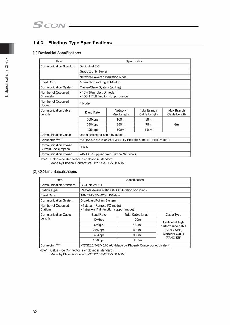
1. S
pedi
ficat
ions
Che
ck
32
1.4.3 Filedbus Type Specifications [1] DeviceNet Specifications
Item Specification Communication Standard DeviceNet 2.0
Group 2 only Server
Network-Powered Insulation Node Baud Rate Automatic Tracking to Master Communication System Master-Slave System (polling) Number of Occupied Channels
1CH (Remote I/O mode) 16CH (Full function support mode)
Number of Occupied Nodes 1 Node
Communication cable Length Baud Rate Network
Max.Length Total Branch Cable Length
Max Branch Cable Length
500kbps 100m 39m 6m 250kbps 250m 78m
125kbps 500m 156m Communication Cable Use a dedicated cable available. Connector (Note1) MSTB2.5/5-GF-5.08 AU (Made by Phoenix Contact or equivalent)
Communication Power Current Consumption 60mA
Communication Power 24V DC (Supplied from Device Net side.) Note1 Cable side Connector is enclosed in standard.
Made by Phoenix Contact: MSTB2.5/5-STF-5.08 AUM [2] CC-Link Specifications
Item Specification Communication Standard CC-Link Ver 1.1 Station Type Remote device station (MAX. 4station occupied) Baud Rate 10M/5M/2.5M/625K/156kbps Communication System Broadcast Polling System Number of Occupied Stations
1station (Remote I/O mode) 4stration (Full function support mode)
Communication Cable Length
Baud Rate Total Cable length Cable Type 10Mbps 100m
Dedicated high performance cable
(FANC-SBH) Standard Cable
(FANC-SB)
5Mbps 160m 2.5Mbps 400m 625kbps 900m 156kbps 1200m
Connector (Note1) MSTB2.5/5-GF-5.08 AU (Made by Phoenix Contact or equivalent) Note1 Cable side Connector is enclosed in standard.
Made by Phoenix Contact: MSTB2.5/5-STF-5.08 AUM

1. Spedifications Check
33
[3] PROFIBUS-DP Specifications
Item Specification Baud Rate Automatic Tracking to Master Communication System Hybrid System (Master-Slave System or Token Passing System) Number of Occupied Bytes 2byte (Remote I/O mode)
32byte (Full function support mode) Communication Cable Length
Max. Total Network Baud Rate Cable Type 100m 12,000/6,000/3,000kbps
Type A Cable 200m 1,500kbps 400m 500kbps
1000m 187.5kbps 1200m 9.6/19.2/93.75kbps
Communication Cable Twisted pair cable equipped with shield AWG18
Connector (Note1) 9Pin female D-sub connector
Transmission Path Format Bus/Tree/Star Note1 Prepare a 9Pin male D-sub connector for the cable side connector.
[4] CompoNet Specifications
Item Specification Communication Type Remote I/O Communication Baud Rate Automatic Tracking to Master Communication Cable Length
Depends on CompoNet specification
Slave Type Word Mix slave Number of Occupied Channels
1CH (Remote I/O mode) 16CH (Full function support mode)
Communication Cable (Note1) Round Cable (JIS C3306、VCTF 2cores) Flat cableⅠ (without sheath) Flat cableⅡ (with sheath)
Connector (Controller side) XW7D-PB4-R (Made by Omron or equivalent) Note1 Prepare a communication cable separately.
[5] MECHATROLINK-Ⅰ/ⅡSpecifications
Item Specification Slave Type Intelligent I/O
Baud Rate MECHATROLINK-Ⅰ 4Mbps MECHATROLINK-Ⅱ 10Mbps
Max. Transmission Distance 50m Min. Distance Between Stations 0.5m
Connecting Number of Slaves
MECHATROLINK-Ⅰ 15 station MECHATROLINK-Ⅱ 30 station (repeater required for 17stations and more)
Transmission Frequency 1 to 8ms Data Length MECHATROLINK 17/32 byte (* It is applicable only to remote I/O mode)
Communication Cable (Note1) Twisted pair cable equipped with shield (Characteristic impedance 130)
Connector Controller Side DUSB-ARB82-T11A-FA (Made by DDK or equivalent) Note1 Prepare a communication cable separately.

1. S
pedi
ficat
ions
Che
ck
34
[6] EtherNet/IP Specifications
Item Specification Baud Rate 10BASE-T/100BASE-T (It is recommended to Auto Negotiation setting)
Communication Cable Length Depends on EtherNet/IP specification (Distance between hub and each nodes: 100m max.)
Number of Connection Depends on master unit Applicable Node Address 0.0.0.0~255.255.255.255 Number of Occupied Bytes 2byte (Remote I/O mode)
32byte (Full function support mode)
Communication Cable (Note1) Category 5 or more (double-shielded cable braided with aluminum tape recommended)
Connector One RJ45 connector Note1 Prepare a communication cable separately.
[7] EtherCAT Specifications
Item Specification Physical Layer 100Base-TX (IEEE802.3) Baud Rate Automatic Tracking to Master
Communication Cable Length Depend on EtherCAT® spescification (Distance between nodes: 100m max.)
Slave Type I/O slave Number of Occupied Bytes 2byte (Remote I/O mode)
32byte (Full function support mode)
Communication Cable (Note1) Category 5e or more (double-shielded cable braided with aluminum tape recommended)
Connector Two RJ45 connectors (Input×1, Output×1) Connection Daisy chain connection only
Note1 Prepare a communication cable separately. [8] PROFINET-IO Specifications
Item Specification Baud Rate 100Mbps Communication Cable Length Distance between each segment: 100m max. Number of Connection Depends on master unit Applicable Node Address 0.0.0.0 to 255.255.255.255 Number of Occupied Bytes 2byte (Remote I/O mode)
32byte (Full function support mode)
Communication Cable (Note1) Category 5 or more (double-shielded cable braided with aluminum tape recommended)
Connector One RJ45 connector Note1 Prepare a communication cable separately.

1. Spedifications Check
35
16.8517.15
1.5φ54.5
145
154
136
R2.
5
4.5
106.5530.734
1.5
1.5φ54.5
145
154
136
4.5
115530.734
1.5
4
4
8.5
(77
from
DIN
rail
cent
er)
(9)
1.5 Options 1.5.1 Regenerative Unit for Motors of up to 750W
It is a unit to convert the regenerative current generated at motor deceleration into heat. Refer to 2.2.6 Connection of Regenerative Unit.
[Model, Accesories] Item Accesories
Screw affixed standard type REU-2 Screw affixed small type RESU-2 1st unit DIN rail affixed small type RESUD-2
SCON controller cable (Model: CB-SC-REU010) 1m enclosed
Screw affixed standard type REU-1 Screw affixed small type RESU-1
Mod
el
2nd unit or later
DIN rail affixed small type RESUD-1
Regenerative resitstor unit cable (Model: CB-ST-REU010) 1m enclosed
[Specifications]
REU-1, REU-2 RESU-1, RESU-2 RESUD-1, RESUD-2 Main Unit Dimension [mm] W34×H195×D126 W34×H154×D106.5 W34×H158×D115 Main Unit Mass Approx. 0.9kg Approx. 0.4kg Built-in Regenerative Resistor 235Ω 80W
[External Dimensions] REU-1, REU-2 (Screw affixed standard type)
RESU-1, RESU-2 (Screw affixed small type) RESUD-1, RESUD-2 (DIN rail affixed small type)
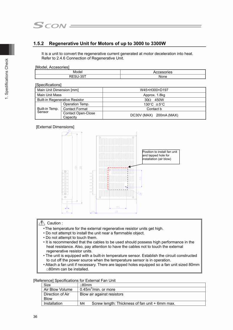
1. S
pedi
ficat
ions
Che
ck
36
1.5.2 Regenerative Unit for Motors of up to 3000 to 3300W It is a unit to convert the regenerative current generated at motor deceleration into heat. Refer to 2.4.6 Connection of Regenerative Unit.
[Model, Accesories] Model Accesories
RESU-35T None [Specifications]
Main Unit Dimension [mm] W45×H300×D197 Main Unit Mass Approx. 1.8kg Built-in Regenerative Resistor 30Ω 450W
Operation Temp. 130°C ±5°C Contact Format Contact b Built-in Temp.
Sensor Contact Open-Close Capacity DC30V (MAX) 200mA (MAX)
[External Dimensions]
Caution : • The temperature for the external regenerative resistor units get high. • Do not attempt to install the unit near a flammable object. • Do not attempt to touch them. • It is recommended that the cables to be used should possess high performance in the
heat resistance. Also, pay attention to have the cables not to touch the external regenerative resistor units.
• The unit is equipped with a built-in temperature sensor. Establish the circuit constructed to cut off the power source when the temperature sensor is in operation.
• Attach a fan unit if necessary. There are tapped holes equipped so a fan unit sized 80mm □80mm can be installed.
[Reference] Specifications for External Fan Unit Size □80mm Air Blow Volume 0.45m3/min. or more Direction of Air Blow
Blow air against resistors
Installation M4 Screw length: Thickness of fan unit + 6mm max.
Position to install fan unit and tapped hole for installation (air blow)

1. Spedifications Check
37
1.5.3 Brake Box: RCB-110-RA13-0
Brakes for two axes can be controlled with one brake box. This is necessary when connecting an actuator with indication to connect a brake box.
[Specifications]
Item Specification Main Unit Dimension 162×94×65.5mm
Power supply Voltage, Current DC24V±10% 1A Connection Cable Encoder Cable (Model CB-RCS2-PLA010) 1m
Number of Controlled Axes 2 [External Dimensions]
[24V Power Supply Connector] Connector on Cable Side
(Enclosed in standard package) MC1.5/2-STF-3.5 (Phoenix Contact)
Applicable Cable AWG28 to 16
Terminal Assignments
Pin No. Signal Explanation
1 0V Power Supply Grounding for Terminal Brake Excitation
2 24VIN For Brake Excitation and 24V Power Supply
[Brake Release Switch Connector for the Current 1, 2] Short circuit of pin No. 1 and 2 of this connector releases the brake compulsorily. Same as the brake release switch ON controller unit, it is possible to release the brake. Do not keep the compulsory release condition while in automatic operation.
Connected Equipment Brake Release Switch Connector on Cable Side
(Please prepare separately) XAP-02V-1
(Contact BXA-001T-P0.6) (J. S. T. Mfg. Co., Ltd.) Switch Rating DC30V Min. current 1.5mA
Terminal Assignment
Pin No. Signal Explanation 1 BKMRL Brake Release Switch Input
2 COM Power Supply Output for Brake Release Switch Input
min
100
94 7012
12
55 251261
241
-4 φ5
Encoder Output Connector
Limit switch connector
Encoder Input Connector
Connector 2 forExternal Brake ReleaseSwitch Connection(for the secondary shaft)
Connector 1 forExternal Brake ReleaseSwitch Connection(for the primary shaft)
Power SupplyInput Connector
POWER ON LED(turns in green while on)
PrimaryShaft
SecondaryShaft
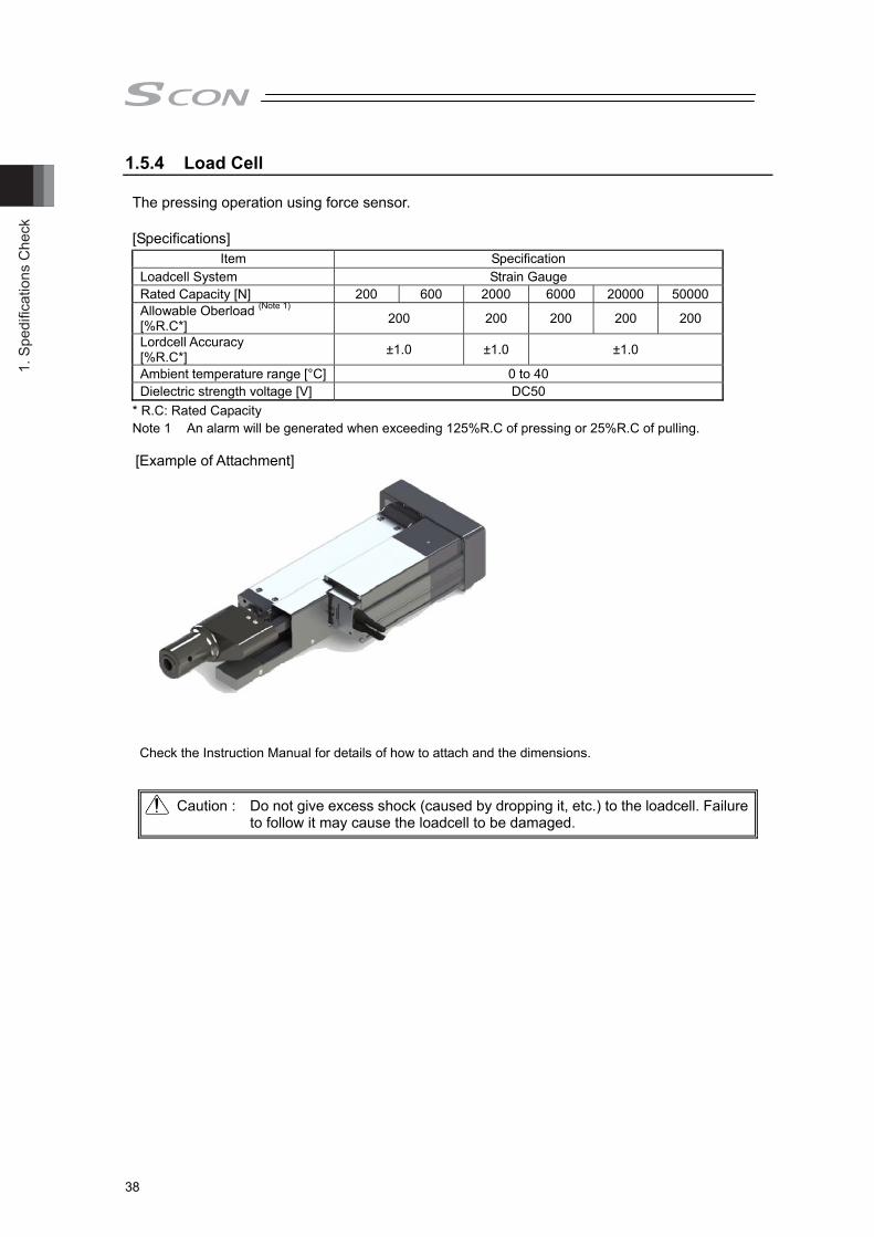
1. S
pedi
ficat
ions
Che
ck
38
1.5.4 Load Cell The pressing operation using force sensor. [Specifications]
Item Specification Loadcell System Strain Gauge Rated Capacity [N] 200 600 2000 6000 20000 50000 Allowable Oberload (Note 1) [%R.C*] 200 200 200 200 200 Lordcell Accuracy [%R.C*] ±1.0 ±1.0 ±1.0
Ambient temperature range [°C] 0 to 40 Dielectric strength voltage [V] DC50
* R.C: Rated Capacity Note 1 An alarm will be generated when exceeding 125%R.C of pressing or 25%R.C of pulling.
[Example of Attachment]
Check the Instruction Manual for details of how to attach and the dimensions.
Caution : Do not give excess shock (caused by dropping it, etc.) to the loadcell. Failure to follow it may cause the loadcell to be damaged.

1. Spedifications Check
39
1.5.5 Pulse Converter: JM-08
It converts the differential system feedback pulse into the open collector specification. Use this converter if the host controller sends pulses input in the open collector mode. [Specifications]
Item Specification Input Power Supply DC24V±10% (MAX. 50mA) Input Pulse Differential output equivalent to 26C32 (MAX. 10mA) Input Frequency 500KHz or less Output Pulse 24V DC open collector (Collector current MAX. 25mA) Mass 10g or less (excluding cable connector) Accessories 37104-3122-000FL (e-CON Connector) 2 Units
Applicable wire AWGNo.24 to 26 (Less than 0.14 to 0.3mm2, finished O.D. 1.0 to 1.2mm)
Caution : 1) Use the pulse converter in the surrounding temperature range between 0C to 40C. 2) The temperature increase of about 30C occurs during operation. Accordingly, neither
install several pulse converters in close contact nor install them within a duct. Do not install the pulse converter near other heating devices.
3) If more than one pulse converter are installed, set a pulse converter apart from another by 10mm or more.
External Dimension Drawing

1. S
pedi
ficat
ions
Che
ck
40
1.6 Installation and Storage Environment
This product is capable for use in the environment of pollution degree 2*1 or equivalent. *1 Pollution Degree 2 : Environment that may cause non-conductive pollution or transient
conductive pollution by frost (IEC60664-1) [1] Installation Environment Do not use this product in the following environment. Location where the surrounding air temperature exceeds the range of 0 to 40C Location where condensation occurs due to abrupt temperature changes Location where relative humidity exceeds 85%RH Location exposed to corrosive gases or combustible gases Location exposed to significant amount of dust, salt or iron powder Location subject to direct vibration or impact Location exposed to direct sunlight Location where the product may come in contact with water, oil or chemical droplets Environment that blocks the air vent [Refer to 1.7 Noise Elimination and Mounting Method]
When using the product in any of the locations specified below, provide a sufficient shield. Location subject to electrostatic noise Location where high electrical or magnetic field is present Location with the mains or power lines passing nearby
[2] Storage and Preservation Environment Storage and preservation environment follows the installation environment. Especially in a
long-term storage, consider to avoid condensation of surrounding air. Unless specially specified, moisture absorbency protection is not included in the package when the machine is delivered. In the case that the machine is to be stored in an environment where dew condensation is anticipated, take the condensation preventive measures from outside of the entire package, or directly after opening the package.
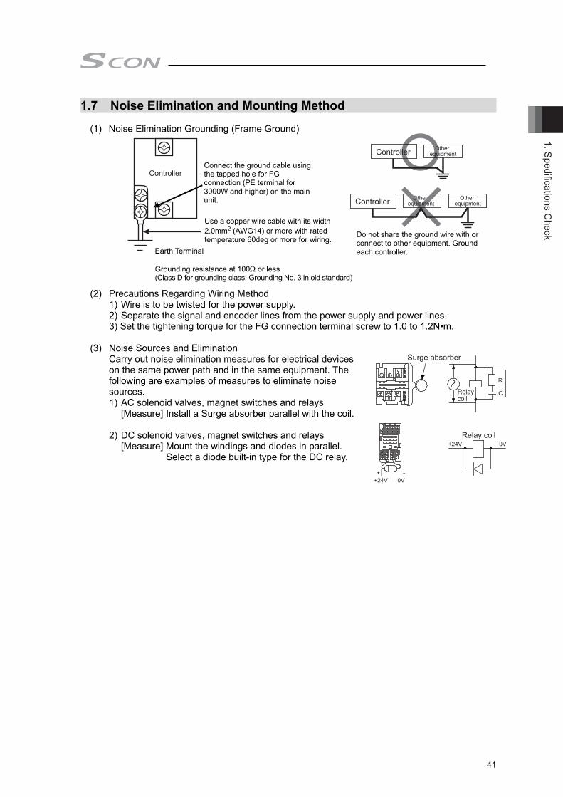
1. Spedifications Check
41
1.7 Noise Elimination and Mounting Method
(1) Noise Elimination Grounding (Frame Ground)
(2) Precautions Regarding Wiring Method
1) Wire is to be twisted for the power supply. 2) Separate the signal and encoder lines from the power supply and power lines. 3) Set the tightening torque for the FG connection terminal screw to 1.0 to 1.2N•m.
(3) Noise Sources and Elimination
Carry out noise elimination measures for electrical devices on the same power path and in the same equipment. The following are examples of measures to eliminate noise sources. 1) AC solenoid valves, magnet switches and relays
[Measure] Install a Surge absorber parallel with the coil.
2) DC solenoid valves, magnet switches and relays [Measure] Mount the windings and diodes in parallel.
Select a diode built-in type for the DC relay.
Do not share the ground wire with orconnect to other equipment. Groundeach controller. Earth Terminal
Grounding resistance at 100or less (Class D for grounding class: Grounding No. 3 in old standard)
Use a copper wire cable with its width 2.0mm2 (AWG14) or more with rated temperature 60deg or more for wiring.
Connect the ground cable using the tapped hole for FG connection (PE terminal for 3000W and higher) on the main unit.
Controller Other equipment
Controller Other equipment
Other equipment
Surge absorber
Relay coil
Relay coil
R
C
+24V 0V
+24V 0V+ -
Controller

1. S
pedi
ficat
ions
Che
ck
42
(4) Heat Radiation and Installation Design and Build the system considering the size of the controller box, location of the controller and cooling factors to keep the surrounding temperature around the controller below 40C. Also, set up a fan to keep the ambient temperature even.
●For Controller for Motors of up to 750W
150mm or more
Air Flow
Brake Box
Regeneration Unit
Air FlowFan
10mmor more
100mmor more
50mmor more
50mmor more
100mmor more
30mmor more
50mmor more
50mmor more
50mmor more
50mmor more
10mm or more

1. Spedifications Check
43
●For Controller for Motors of 3000W and above
30mm or more 50mm or more 30mm or more 50mm
or more
100mm or more
150mm or more
Air Flow

1. S
pedi
ficat
ions
Che
ck
44
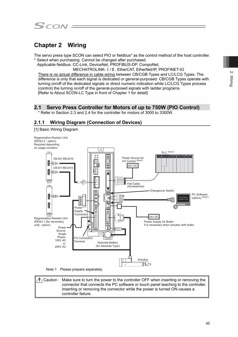
2. Wiring
45
Chapter 2 Wiring The servo press type SCON can select PIO or fieldbus* as the control method of the host controller. * Select when purchasing. Cannot be changed after purchased.
Applicable fieldbus: CC-Link, DeviceNet, PROFIBUS-DP, CompoNet, MECHATROLINK-Ⅰ/Ⅱ, EtherCAT, EtherNet/IP, PROFINET-IO
There is no actual difference in cable wiring between CB/CGB Types and LC/LCG Types. The difference is only that each signal is dedicated or general-purposed. CB/CGB Types operate with turning on/off of the dedicated signals or direct numeric indication while LC/LCG Types process (control) the turning on/off of the general-purposed signals with ladder programs. [Refer to About SCON-LC Type in front of Chapter 1 for detail]
2.1 Servo Press Controller for Motors of up to 750W (PIO Control)
* Refer in Section 2.3 and 2.4 for the controller for motors of 3000 to 3300W. 2.1.1 Wiring Diagram (Connection of Devices) [1] Basic Wiring Diagram
Power Supply for BrakeIt is necessary when actuator with brake
Absolute Battery(for Absolute Type)
PC Software(option) (Note1)
PLC (Note1)
Regenerative Resistor Unit(RESU-1 [for secondaryunit] : option)
Regenerative Resistor Unit(RESU-2 : option)Required dependingon usage condition
Power SupplyConnector
Flat Cable(Accessories)
CB-SC-REU010
CB-ST-REU010
FG ConnectionTerminal
24V DC
24V DC
PowerSource
SinglePhase
100V ACor
200V AC
Power Source for I/O Control (Note1)
Changeover Switch
Actuator
Note 1 Please prepare separately.
Caution : Make sure to turn the power to the controller OFF when inserting or removing the connector that connects the PC software or touch panel teaching to the controller. Inserting or removing the connector while the power is turned ON causes a controller failure.

2. W
iring
46
2.1.2 Wiring
[1] Main Power Circuit
Surge Protector
Noise FilterEarth Leakage Breaker
Circuit Breaker
PE
Motor Power Supply
Control Power Supply
L1 L2
L1L2L1C
L2C
SCONPower Supply Connector
Grounding resistance at 100Ω or less (Grounding Class D)
(Note) The power voltage of the controller (100V AC or 200V AC) cannot be changed.
[2] Brake Power Supply Circuit
(Note) Supply 24V DC if the used actuator is equipped with a brake.
Brake Power Supply ConnectorBK PWR
+ -
24V DC 0VSCON

2. Wiring
47
Wiring Conducted at Delivery
Drive Cutoff Circuit
SIO Connector Detection Circuit (contact opens when connected)
Short-circuit in PC Software Cable
SCON
Short-circuit in PC Software Cable
Dedicated for
Emergency Stop Circuit
Dedicated for
Emergency Stop Circuit
System I/OConnector
SIOConnector
System I/OConnector
SIOConnector
[3] Actuator Emergency Stop Circuit (System I/O connector) As an example of a circuit, cases of 3 conditions are shown. Select from 2) or 3) for CGB/LCG type. ★ Reference: Operate the actuator for try (Note: It is not emergency stop) 1) Operate actuator with the equipment and emergency stop of teaching tool input (EMG-) activated 2) Stop supplying external motor power at emergency stop input 3) Shut off the motor power externally by inputting the emergency stop with using two units of
controllers or more. ★ Reference: Operate the actuator with the PC software for try ● Example of a Circuit ● Image of Wiring
● Example of a Circuit ● Image of Wiring
Wiring Conducted at Delivery SIO Connector
Detection Circuit (contact opens when connected)
External EmergencyStop Switch
SCON
Drive Cutoff Circuit
External Emergency Stop Switch
System I/O Connector
SCON
SIO Connector
System I/O Connector
SCON
PC Software
(Note) It is not emergency stop switch.
SIO Connector
PC Software
1) Operate actuator with the equipment and emergency stop of teaching tool input (EMG-) activated
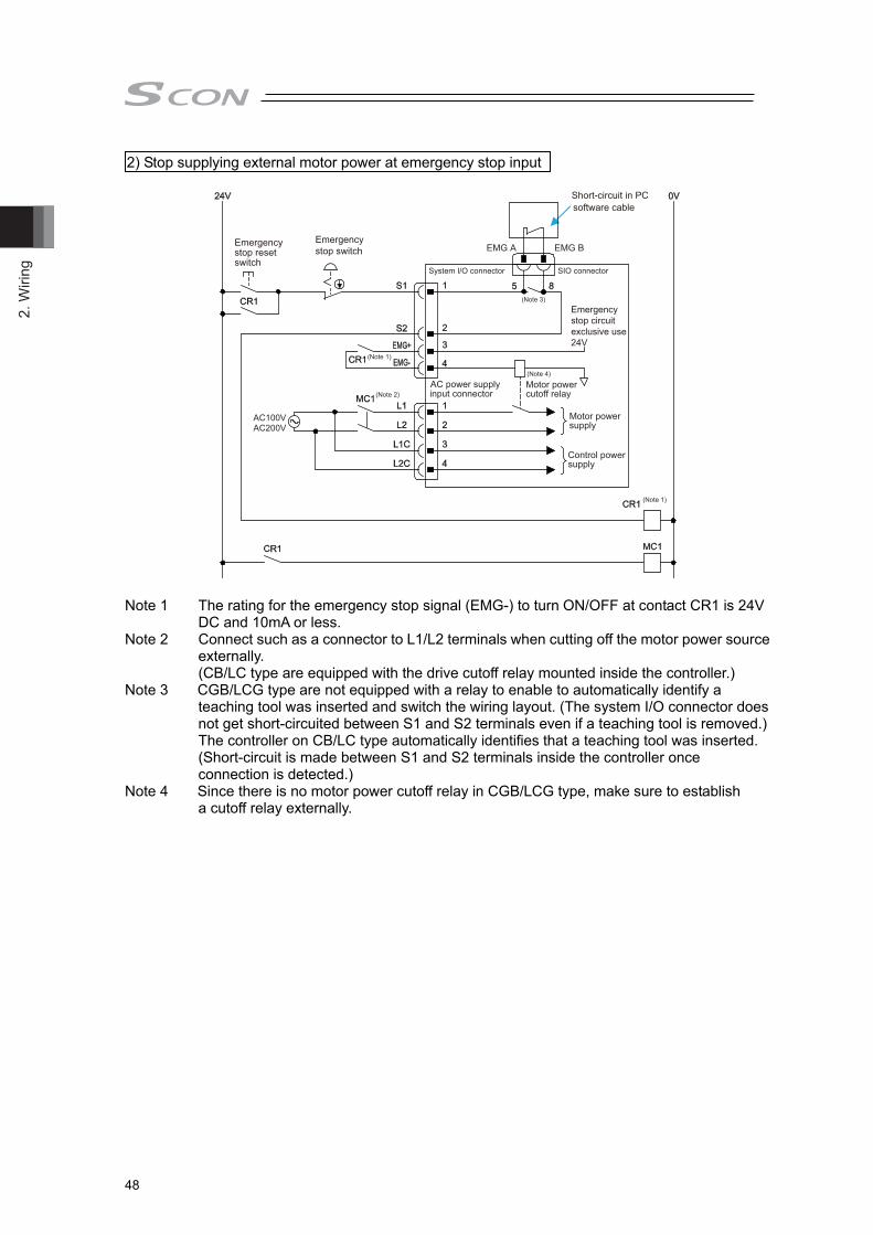
2. W
iring
48
Motor power cutoff relay
Motor power supply
Control power supply
(Note 3)
(Note 1)
(Note 1)
(Note 2)
(Note 4)
System I/O connector SIO connector
EMG A EMG BEmergency stop reset switch
Emergency stop switch
Emergency stop circuit exclusive use 24V
AC power supply input connector
Short-circuit in PC software cable
AC100VAC200V
Note 1 The rating for the emergency stop signal (EMG-) to turn ON/OFF at contact CR1 is 24V
DC and 10mA or less. Note 2 Connect such as a connector to L1/L2 terminals when cutting off the motor power source
externally. (CB/LC type are equipped with the drive cutoff relay mounted inside the controller.)
Note 3 CGB/LCG type are not equipped with a relay to enable to automatically identify a teaching tool was inserted and switch the wiring layout. (The system I/O connector does not get short-circuited between S1 and S2 terminals even if a teaching tool is removed.) The controller on CB/LC type automatically identifies that a teaching tool was inserted. (Short-circuit is made between S1 and S2 terminals inside the controller once connection is detected.)
Note 4 Since there is no motor power cutoff relay in CGB/LCG type, make sure to establish a cutoff relay externally.
2) Stop supplying external motor power at emergency stop input

2. Wiring
49
24V
Emergency stop reset switch
Emergency stop switch
CR1(Note 1)
0V
MC1
CR1
CR1
S1
S2
S1
S2
1 5 8
5 8
23
4
1
23
4
1
2
3
4
1
2
3
4
EMG A EMG B
CR1(Note 1)
MC1(Note 2)
AC100VAC200V
System I/O SIO connector
Emergency stop circuitexclusive use 24V
SIO connector
connecter
System I/Oconnecter
EMG+
EMG-
L1
L2
L1C
L2C
AC power supply Motor powercutoff relay
(Note 3)
(Note 4)
(Note 3)
input connector
AC power supply input connector
Motor power supply
Control power supply
CR1(Note 1)
MC1(Note 2)
AC100VAC200V
EMG+
EMG-
L1
L2
L1C
L2C
Short-circuit in PC software cable
Note 1 The rating for the emergency stop signal (EMG-) to turn ON/OFF at contact CR1 is 24V
DC and 10mA or less. Note 2 Connect such as a connector to L1/L2 terminals when cutting off the motor power source
externally. (CB/LC type are equipped with the drive cutoff relay mounted inside the controller.)
Note 3 CGB/LCG type are not equipped with a relay to enable to automatically identify a teaching tool was inserted and switch the wiring layout. (The system I/O connector does not get short-circuited between S1 and S2 terminals even if a teaching tool is removed.) The controller on CB/LC type automatically identifies that a teaching tool was inserted. (Short-circuit is made between S1 and S2 terminals inside the controller once connection is detected.)
Note 4 Since there is no motor power cutoff relay in CGB/LCG type, make sure to establish a cutoff relay externally.
3) Shut off the motor power externally by inputting the emergency stop with using two units ofcontrollers or more.

2. W
iring
50
[4] Motor • Encoder Circuit Use the dedicated connection cables for the connection between an actuator and controller. 1) Connecting the single axis robots (except for RCS2-RA13R) SCON
Note 1 Applicable Connection Cable Model Codes □□□ : Cable Length Example) 030 = 3m Actuator Series Name Cable
RCS3-RA6/RA7/RA8/RA10 CB-RCS2-PLDA□□□ CB-RCS2-PLDA□□□-RB (robot cable)
Note 2 Applicable Motor Cable Model Codes □□□ : Cable Length Example) 030 = 3m
Actuator Series Name Cable RCS3-RA6/RA7/RA8/RA10, RCS2-RA13R
CB-RCC-MA□□□ CB-RCC-MA□□□-RB (robot cable)
2) Connecting the RCS2-RA13R with loadcell (with no brake)
SCON RCS2-RA13R(Equipped with loadcell)
MOTMotorConnector
Brake Power Supply Connector
PGEncoder Connector
CB-RCS2-PLLA□□□
CB-RCC-MA□□□
CB-LDC-CTL□□□ (Cable in the cable track)
PG
Encoder Connector
MOT Motor
Connector
Encoder Cable (Note 1)
tor Cable (Note2)

2. Wiring
51
3) Connecting the RCS2-RA13R with loadcell (with brake)
SCON
Brake Box(RCB-110-RA13)
24VIN 0V
CONTROLLER1Encoder Input ConnectorLimit SwitchConnector
Limit SwitchConnector
ACTUATOR1Encoder Output Connector
V0CD V42
RCS2-RA13R(Equipped with brake and loadcell)
BK+
V0CD V42 CB-RCS2-PLA□□□
PWR-
CONTROLLER2Encoder Input Connector
ACTUATOR2Encoder Output Connector
MOTMotorConnector
Brake Power Supply Connector
PGEncoderConnector
CB-RCC-MA□□□
CB-RCS2-PLLA□□□
CB-LDC-CTL□□□-JY (only when force control is used)
CB-LDC-CTL□□□ (Cable in the cable track)
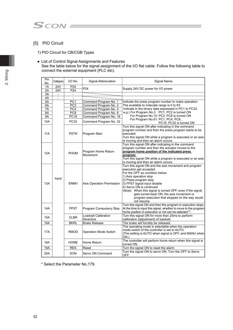
2. W
iring
52
[5] PIO Circuit 1) PIO Circuit for CB/CGB Types ● List of Control Signal Assignments and Features
See the table below for the signal assignment of the I/O flat cable. Follow the following table to connect the external equipment (PLC etc).
Pin No. Category I/O No. Signal Abbreviation Signal Name
1A 24V P24 P24 Supply 24V DC power for I/O power 2A 24V P24 3A - - 4A - - 5A
Input
PC1 Command Program No. 1 Indicate the press program number to make operation. The available to indecate range is 0 to 63. Indicate in the binary data expressed in PC1 to PC32. e.g.) For Program No.3 : PC1, PC2 is turned ON
For Program No.10: PC2, PC8 is turned ON For Program No.61: PC1, PC4, PC8,
PC16, PC32 is turned ON
6A PC2 Command Program No. 2 7A PC4 Command Program No. 4 8A PC8 Command Program No. 8 9A PC16 Command Program No. 16
10A PC32 Command Program No. 32
11A PSTR Program Start
Turn this signal ON after indicating in the command program number and then the press program starts to be executed. Turn this signal ON while a program is executed or an axis is moving and then an alarm occurs.
12A PHOM Program Home Return Movement
Turn this signal ON after indicating in the command program number and then the actuator moves to the program home position of the indicated press program. Turn this signal ON while a program is executed or an axis is moving and then an alarm occurs.
13A ENMV Axis Operation Permission
Turn this signal ON and the axis movement and program execution get accepted. For the OFF as condition below: 1) Axis operation stop 2) Press program stop 3) FPST signal input disable 4) Servo ON is continued (Note) When this signal is turned OFF, even if the signal
gets turned back ON, the axis movement or program execution that stopped on the way would not resume.
14A FPST Program Compulsory StopTurn this signal ON and then the program in execution stops.At the time to input this signal, whether to move to the program home position in execution or not can be selected (*).
15A CLBR Loadcell Calibration Derective
Turn this signal ON for more than 20ms to perform calibration (adjustment) of loadcell.
16A BKRL Brake Release The brake will forcibly be released.
17A RMOD Operation Mode Switch The operating mode is selectable when the operation mode switch of the controller is set to AUTO. (The setting is AUTO when signal is OFF, and MANU when ON.)
18A HOME Home Return The controller will perform home return when this signal is turned ON.
19A RES Reset Turn the signal ON to reset the alarm.
20A SON Servo ON Command Turn the signal ON to servo ON. Turn the OFF to Servo OFF.
* Select the Parameter No.179.
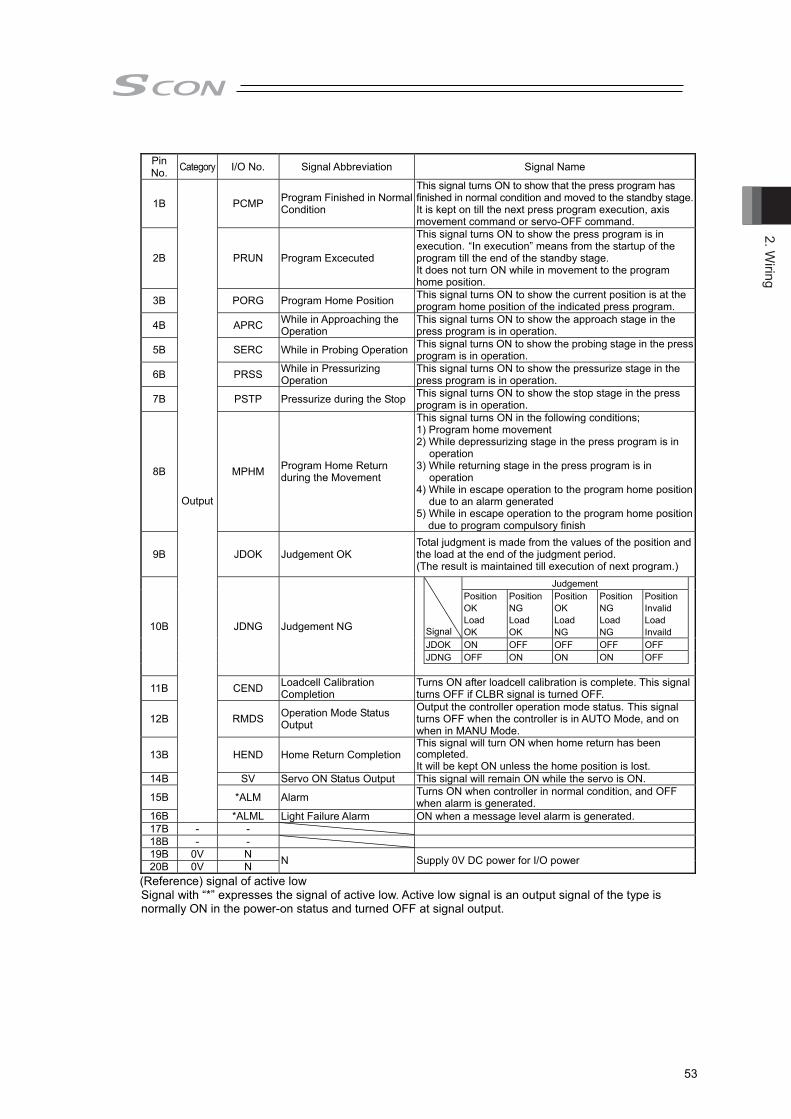
2. Wiring
53
Pin No. Category I/O No. Signal Abbreviation Signal Name
1B
Output
PCMP Program Finished in Normal Condition
This signal turns ON to show that the press program has finished in normal condition and moved to the standby stage.It is kept on till the next press program execution, axis movement command or servo-OFF command.
2B PRUN Program Excecuted
This signal turns ON to show the press program is in execution. “In execution” means from the startup of the program till the end of the standby stage. It does not turn ON while in movement to the program home position.
3B PORG Program Home Position This signal turns ON to show the current position is at the program home position of the indicated press program.
4B APRC While in Approaching the Operation
This signal turns ON to show the approach stage in the press program is in operation.
5B SERC While in Probing Operation This signal turns ON to show the probing stage in the press program is in operation.
6B PRSS While in Pressurizing Operation
This signal turns ON to show the pressurize stage in the press program is in operation.
7B PSTP Pressurize during the Stop This signal turns ON to show the stop stage in the press program is in operation.
8B MPHM Program Home Return during the Movement
This signal turns ON in the following conditions; 1) Program home movement 2) While depressurizing stage in the press program is in
operation 3) While returning stage in the press program is in
operation 4) While in escape operation to the program home position
due to an alarm generated 5) While in escape operation to the program home position
due to program compulsory finish
9B JDOK Judgement OK Total judgment is made from the values of the position and the load at the end of the judgment period. (The result is maintained till execution of next program.)
10B JDNG Judgement NG
Signal
Judgement Position OK Load OK
Position NG Load OK
Position OK Load NG
Position NG Load NG
Position Invalid Load Invaild
JDOK ON OFF OFF OFF OFF JDNG OFF ON ON ON OFF
11B CEND Loadcell Calibration Completion
Turns ON after loadcell calibration is complete. This signal turns OFF if CLBR signal is turned OFF.
12B RMDS Operation Mode Status Output
Output the controller operation mode status. This signal turns OFF when the controller is in AUTO Mode, and on when in MANU Mode.
13B HEND Home Return Completion This signal will turn ON when home return has been completed. It will be kept ON unless the home position is lost.
14B SV Servo ON Status Output This signal will remain ON while the servo is ON.
15B *ALM Alarm Turns ON when controller in normal condition, and OFF when alarm is generated.
16B *ALML Light Failure Alarm ON when a message level alarm is generated. 17B - - 18B - - 19B 0V N N Supply 0V DC power for I/O power 20B 0V N
(Reference) signal of active low Signal with “*” expresses the signal of active low. Active low signal is an output signal of the type is normally ON in the power-on status and turned OFF at signal output.
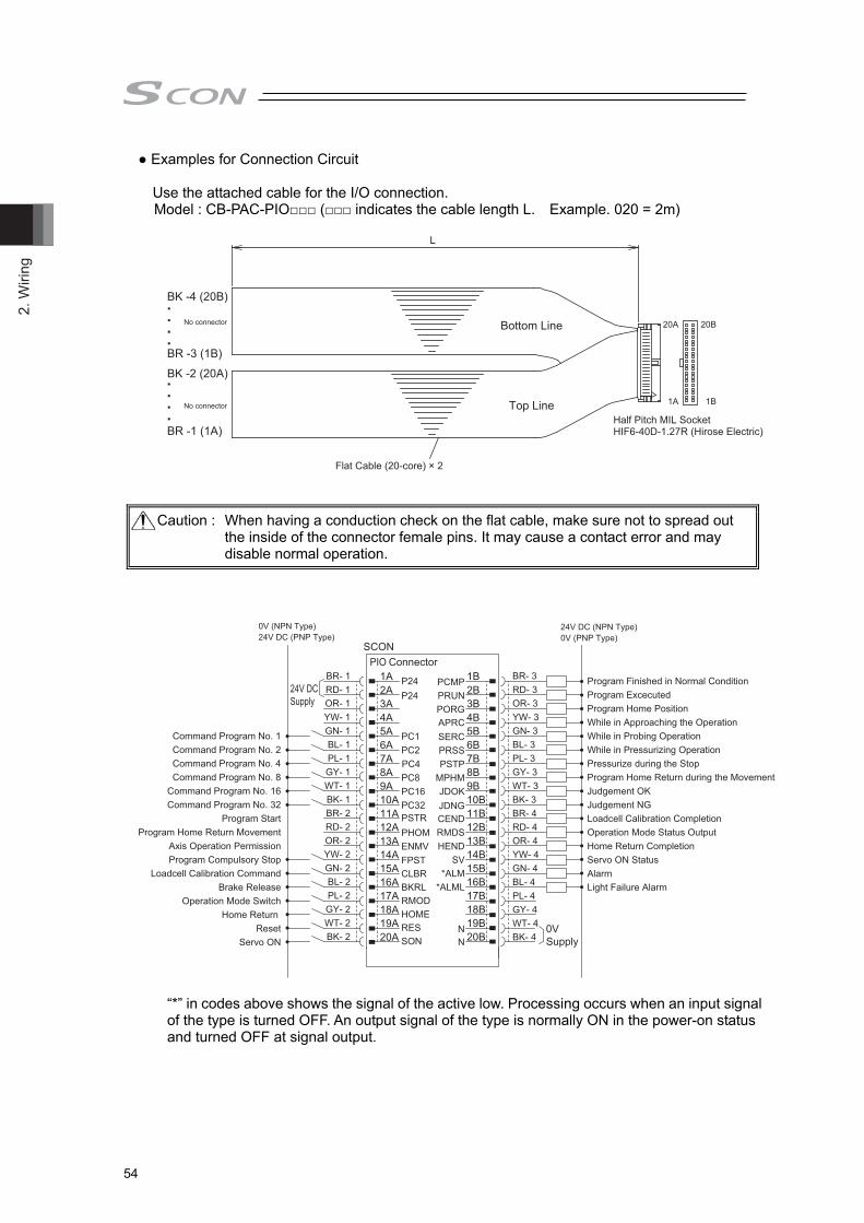
2. W
iring
54
● Examples for Connection Circuit Use the attached cable for the I/O connection. Model : CB-PAC-PIO□□□ (□□□ indicates the cable length L. Example. 020 = 2m)
Half Pitch MIL SocketHIF6-40D-1.27R (Hirose Electric)
Flat Cable (20-core) × 2
L
20A 20B
1A 1B
BK -4 (20B)
Bottom Line
Top Line
BK -2 (20A)
BR -3 (1B)
BR -1 (1A)
No connector
No connector
Caution : When having a conduction check on the flat cable, make sure not to spread out the inside of the connector female pins. It may cause a contact error and may disable normal operation.
0V (NPN Type)
24V DCSupply
BR- 1 1A P24 PCMP 1B BR- 3
0VSupply
24V DC (NPN Type)24V DC (PNP Type)
RD- 1 2A P24 PRUN 2B RD- 3
0V (PNP Type)
Command Program No. 1Command Program No. 2Command Program No. 4Command Program No. 8
Command Program No. 16Command Program No. 32
Program StartProgram Home Return Movement
Axis Operation PermissionProgram Compulsory Stop
Loadcell Calibration CommandBrake Release
Operation Mode SwitchHome Return
ResetServo ON
OR- 1 3A
PC1
PORGAPRC
3B OR- 3
Program Finished in Normal ConditionProgram ExcecutedProgram Home PositionWhile in Approaching the OperationWhile in Probing OperationWhile in Pressurizing OperationPressurize during the StopProgram Home Return during the MovementJudgement OKJudgement NGLoadcell Calibration CompletionOperation Mode Status OutputHome Return CompletionServo ON StatusAlarmLight Failure Alarm
YW- 1 4A
PC2SERC
4B YW- 3GN- 1 5A
PC4PRSS
5B GN- 3BL- 1 6A
PC8PSTP
6B BL- 3PL- 1 7A
PC16MPHM
7B PL- 3GY- 1 8A
PC32JDOKJDNG
8B GY- 3WT- 1 9A
FPST
PSTRPHOMENMV
9B WT- 3BK- 1 10A
CLBR
CEND
10B BK- 3BR- 2 11A
BKRL
RMDS
11B BR- 4RD- 2 12A
RMOD
HEND
12B RD- 4OR- 2 13A
HOME
SV
13B OR- 4YW- 2 14A
RES
14B YW- 4GN- 2 15A
SON
*ALM*ALML
15B GN- 4BL- 2 16A 16B BL- 4PL- 2 17A
N
17B PL- 4GY- 2 18A
N
18B GY- 4WT- 2 19A 19B WT- 4BK- 2 20A 20B BK- 4
SCONPIO Connector
“*” in codes above shows the signal of the active low. Processing occurs when an input signal of the type is turned OFF. An output signal of the type is normally ON in the power-on status and turned OFF at signal output.

2. Wiring
55
2) PIO Circuit for LC/LCG Types ●List of Control Signal Assignments and Features
The table below shows the signal assignment of the flat cable. Follow the following table connect the external equipment (such as PLC). Refer to LC Ladder Programing Manual (ME0329) provided separately for how to assign memories in built-in ladder or how to use it. Pin No. Category I/O No. Signal Name Function Description Relevant Sections
1A 24V Power Supply Power Supply for I/O +24V 2A 24V Power Supply Power Supply for I/O +24V 3A NC Not used 4A 5A
General Input
IN0 X000
They are 24V general-purposed terminals. Assign to the built-in ladder and use them if necessary.
Refer to LC ladder Programming
Manual provided separatery
6A IN1 X001 7A IN2 X002 8A IN3 X003 9A IN4 X004
10A IN5 X005 11A IN6 X006 12A IN7 X007 13A IN8 X008 14A IN9 X009 15A IN10 X00A 16A IN11 X00B 17A IN12 X00C 18A IN13 X00D 19A IN14 X00E 20A IN15 X00F 1B
General Output
OUT0 X000
They are 24V general-purposed terminals. Assign to the built-in ladder and use them if necessary.
2B OUT1 X001 3B OUT2 X002 4B OUT3 X003 5B OUT4 X004 6B OUT5 X005 7B OUT6 X006 8B OUT7 X007 9B OUT8 X008
X009 X00A X00B
10B OUT9 11B OUT10 12B OUT11 13B OUT12 X00C 14B OUT13 X00D 15B OUT14 X00E 16B OUT15 X00F 17B NC Not used - 18B 19B 0V Power Supply Power Supply for I/O 0V 20B 0V Power Supply Power Supply for I/O 0V

2. W
iring
56
● Examples for Connection Circuit Use the attached cable for the I/O connection. Model : CB-PAC-PIO□□□ (□□□ indicates the cable length L. Example. 020 = 2m)
Half Pitch MIL SocketHIF6-40D-1.27R (Hirose Electric)
Flat Cable (20-core) × 2
L
20A 20B
1A 1B
BK -4 (20B)
Bottom Line
Top Line
BK -2 (20A)
BR -3 (1B)
BR -1 (1A)
No connector
No connector
Caution : When having a conduction check on the flat cable, make sure not to spread out the inside of the connector female pins. It may cause a contact error and may disable normal operation.
24V DCSupply
1A P24 1B
0VSupply
2A P24 2B3A
X000X001X002X003X004X005X006X007X008X009X00AX00BX00CX00DX00EX00F
Y000Y001Y002Y003Y004Y005Y006Y007Y008Y009Y00AY00BY00CY00DY00EY00F
3B4A 4B5A 5B6A 6B7A 7B8A 8B9A 9B10A 10B11A 11B12A 12B13A 13B14A 14B15A 15B16A 16B17A
N
17B18A
N
18B19A 19B20A 20B
PIO ConnectorBR- 1RD- 1OR- 1YW- 1GN- 1BL- 1PL- 1GY- 1WT- 1BK- 1BR- 2RD- 2OR- 2YW- 2GN- 2BL- 2PL- 2GY- 2WT- 2BK- 2
BR- 3RD- 3OR- 3YW- 3GN- 3BL- 3PL- 3GY- 3WT- 3BK- 3BR- 4RD- 4OR- 4YW- 4GN- 4BL- 4PL- 4GY- 4WT- 4BK- 4
0V(NPN Type) 24V DC(NPN Type)24V DC(PNP Type) 0V(PNP Type)
“*” in codes above shows the signal of the active low. Processing occurs when an input signal of the type is turned OFF. An output signal of the type is normally ON in the power-on status and turned OFF at signal output.
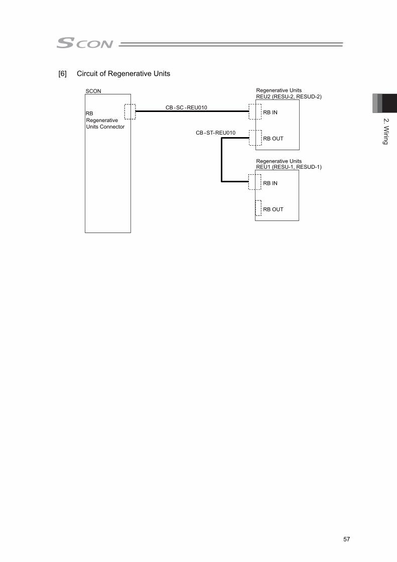
2. Wiring
57
[6] Circuit of Regenerative Units
SCON
RBRegenerative Units Connector
Regenerative UnitsREU2 (RESU-2, RESUD-2)
Regenerative Units REU1 (RESU-1, RESUD-1)
CB -SC -REU010
CB -ST
RB IN
RB OUT
RB IN
RB OUT
-REU010

2. W
iring
58
[7] Multi-function Connector 1) When Host Inputting Feedback Pulse with Line Receiver
(Note) Connect cable also to 0V if there is 0V (COM) on the host unit.
2) When Host Inputting Feedback Pulse with Open Collector
It is necessary to pulse converter (JM-08 : Option).
Caution: Use the same power source for the positioning unit of the host and JM-08.

2. Wiring
59
2.2 Wiring for Controller for Motors of up to 750W * Refer in Section 2.3 and 2.4 for the controller for motors of 3000 to 3300W.
2.2.1 Wiring for Power Supply Circuit
Power Supply Type Specifications Reference
Motor Power Supply 100V Specification : 100 to 115V AC ±10% 50/60Hz 200V Specification : 200 to 230V AC ±10% 50/60Hz Control Power Supply
2.2.1.1 Main Power Circuit (Power Supply Connector)
Supply the appropriate power from the following considering the controller type. Loaded current may differ depending on the connected actuators. Select a circuit breaker and leakage breaker that can apply to the specifications. [Refer to section 1.3]
● Image of Wiring
AC100 to 115V AC200 to 230V (Note) Voltage cannot be changed after purchased.
Note It is the model code when one unit of noise filter is connected to one unit of SCON.
Caution : For the noise filter in 1), it is recommended to have one unit connected to one unit of SCON. * Refer also to the [reference] in the next page. Attach 2) and 3) if necessary considering the noise environment and the power supply condition. It is recommended to attach them even though it is not mandatory.
Parts Name Model Supplier Position to attach
1) Noise Filter NAC-10-472 (Note) COSEL Attach in range of 300mm
or less from controller NF2010A-UP (Note) SOSHIN ELECTRIC CO.,LTD
2) Clamp Filter ZCAT3035-1330 TDK Attach as close as possible to controller
3) Surge Protector R • A • V-781BWZ-2A Okaya ELECTRIC CO.,LTD
Attach at the input terminal of noise filter
Circuit Breker (Please prepare separatery)
Leakage Breaker
(Please prepare
Noise Filter (Please prepare separatery)
Surge Protector (Please prepare separatery) Power Supply
Connector
Clamp Filter (Please prepare separatery)

2. W
iring
60
[Reference 1 Caution When Connecting Multiple SCON Units to One Unit of Noise Filter
Caution : When connecting several units of SCON to one unit of noise filter, make sure that each device in the equipment would not get any influence of noise. Also, considering the case that they get influence of noise, ensure space so noise filters or noise prevention component can be additionally allocated.
* The contents above are not something that guarantees normal operation of the
equipment. Check carefully in the actual operational conditions. [Reference 2] Caution When Selecting Noise Filter
Consider two points as stated below when you select a noise filter. Please contact the supplier of each noise filter for details.
1) Allowable Current : The power current (Note 1) of the controller should be in the range of the
allowable current of the noise filter.
◆ Allowable Current of Noise Filter ˃ ated Current Amperage of Connected Controller
Note 1 : Rated Current Amperage of SCON = Motor Current Amperage + Control Current Amperage
As the rated current amperage differs depending on the connected actuator (motor), it is required to check in the section of 1.2.2 Current Amperage and Heat Radiation for the necessary current value.
2) Attenuation Characteristics : A noise filter which possesses the similar attenuation
characteristics to the noise filter code stated in the previous page should be selected. The attenuation characteristics of each noise filter is open to the public by each supplier. For example, shown below is the graph of the attenuation characteristics of NAC-10-472 that IAI recommends.
NAC-10-472
■Attenuation Characteristics (Static Characteristics)
Frequency [MHz]
Normal Mode Common Mode
Atte
nuat
ion
Volu
me
[dB]
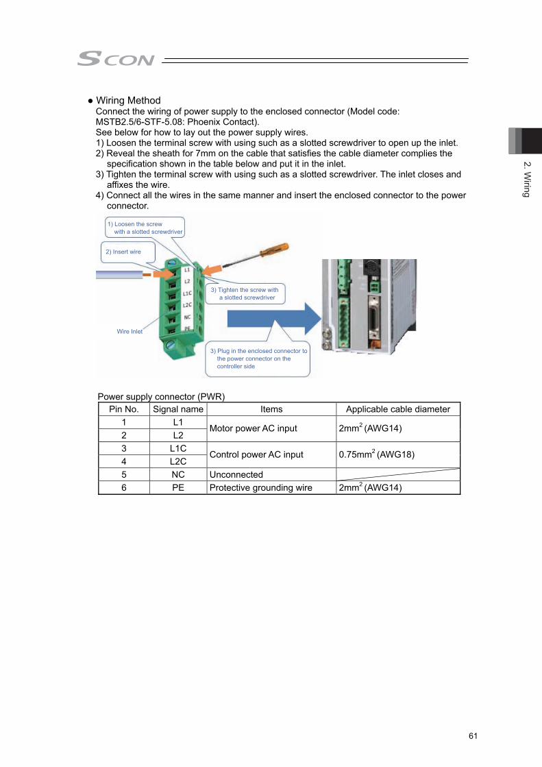
2. Wiring
61
● Wiring Method Connect the wiring of power supply to the enclosed connector (Model code: MSTB2.5/6-STF-5.08: Phoenix Contact). See below for how to lay out the power supply wires. 1) Loosen the terminal screw with using such as a slotted screwdriver to open up the inlet. 2) Reveal the sheath for 7mm on the cable that satisfies the cable diameter complies the
specification shown in the table below and put it in the inlet. 3) Tighten the terminal screw with using such as a slotted screwdriver. The inlet closes and
affixes the wire. 4) Connect all the wires in the same manner and insert the enclosed connector to the power
connector.
Power supply connector (PWR)
Pin No. Signal name Items Applicable cable diameter 1 L1 2 L2
Motor power AC input 2mm2 (AWG14)
3 L1C 4 L2C
Control power AC input 0.75mm2 (AWG18)
5 NC Unconnected 6 PE Protective grounding wire 2mm2 (AWG14)
1) Loosen the screw with a slotted screwdriver
2) Insert wire
Wire Inlet
3) Tighten the screw with a slotted screwdriver
3) Plug in the enclosed connector to the power connector on the controller side

2. W
iring
62
3) Tighten the screw with a slotted screwdriver
1) Loosen the screw with a slotted screwdriver
2) Insert wire
BK+PWR-
24V
0V
24V 0V
2.2.1.2 Brake Power Supply (Brake Power Connector) Supply 24V DC±10% and 1A max. when using an actuator equipped with a brake.
● Image of Wiring
● Wiring Method Connect the wiring of brake power supply to the enclosed connector (Model code: MC1.5/2-ST-3.5: Phoenix Contact). See below for how to lay out the power supply wires. 1) Loosen the terminal screw with using such as a slotted screwdriver to open up the inlet. 2) Reveal the sheath for 7mm on the cable that satisfies the cable diameter complies the
specification shown in the table below and put it in the inlet. 3) Tighten the terminal screw with using such as a slotted screwdriver. The inlet closes and
affixes the wire. 4) Connect all the wires in the same manner and insert the enclosed connector to the power
connector. Brake Power Supply Connector
Pin No. Signal name Items Applicable cable diameter BK+ 24V DC power input 0.5mm2 (AWG20) PWR- 24V DC ground
24VDC Power (Please prepare separately)

2. Wiring
63
● For Actuators Necessary to Have Brake Box When connecting RCS2-RA13R, it is necessary to have a brake box (RCB-110-RA13-0) connected.
[Refer to Section 1.5.3 for details of the brake box.] Supply 24V DC 1A max. as the power supply for the brake box.
24V 0V
24VIN 0V
24V 0V
The way to layout wires on the connector enclosed in the brake box (MC1.5/2-STF-3.5: Phoenix Contact) is the same as that described in breake power connector.

2. W
iring
64
2.2.2 Wiring of Emergency Stop Circuit (System I/O) Make sure to construct the wiring of the emergency stop circuit considering the suitability to the Safety Category of the whole system. ● Image of Wiring
Note 1 CGB/LCG type are not equipped with a relay to enable to automatically identify a teaching tool was inserted and switch the wiring layout. (The system I/O connector does not get short-circuited between S1 and S2 terminals even if a teaching tool is removed.) The controller on CB/LC type automatically identifies that a teaching tool was inserted. (When there is nothing plugged in, S1 and S2 are short-circuited inside the controller.)
Note 2 Construct the circuit considering the safety category of the whole equipment. Note 3 Make sure to construct the emergency stop circuit using the built-in 24V (EMG+
Terminal) output for EMG- Terminal. Note 4 There is no motor power cutoff relay in CGB/LCG type.
[Refer to Chapter 9.2 for conformance to Safety Category.]

2. Wiring
65
● Wiring Method Connect the wiring of operation stop (system I/O connector) to the enclosed connector (Model code: FMC1.5/4-ST-3.5: Phoenix Contact). See below for how to lay out the power supply wires. 1) Loosen the terminal screw with using such as a slotted screwdriver to open up the inlet. 2) Reveal the sheath for 10mm on the cable that satisfies the cable diameter complies the
specification shown in the table below and put it in the inlet. 3) Tighten the terminal screw with using such as a slotted screwdriver. The inlet closes and
affixes the wire. 4) Connect all the wires in the same manner and insert the enclosed connector to the power
connector. System I/O connector
Pin No. Signal name Items Applicable cable diameter
1 S1 Operation stop switch contact
0.5mm2 (AWG20) 2 S2 Operation stop switch contact 3 EMG+ Operation stop dedicated power output4 EMG- Operation stop input
1) Push in a slotted screwdriver to the protruded area
2) Insert wire
Wire Inlet
Protruded Area
Pin Number and Signal Name1. S12. S23. EMG+4. EMG-
Enclosed Part
3) Plug in the enclosed connector to the power connector on the controller side
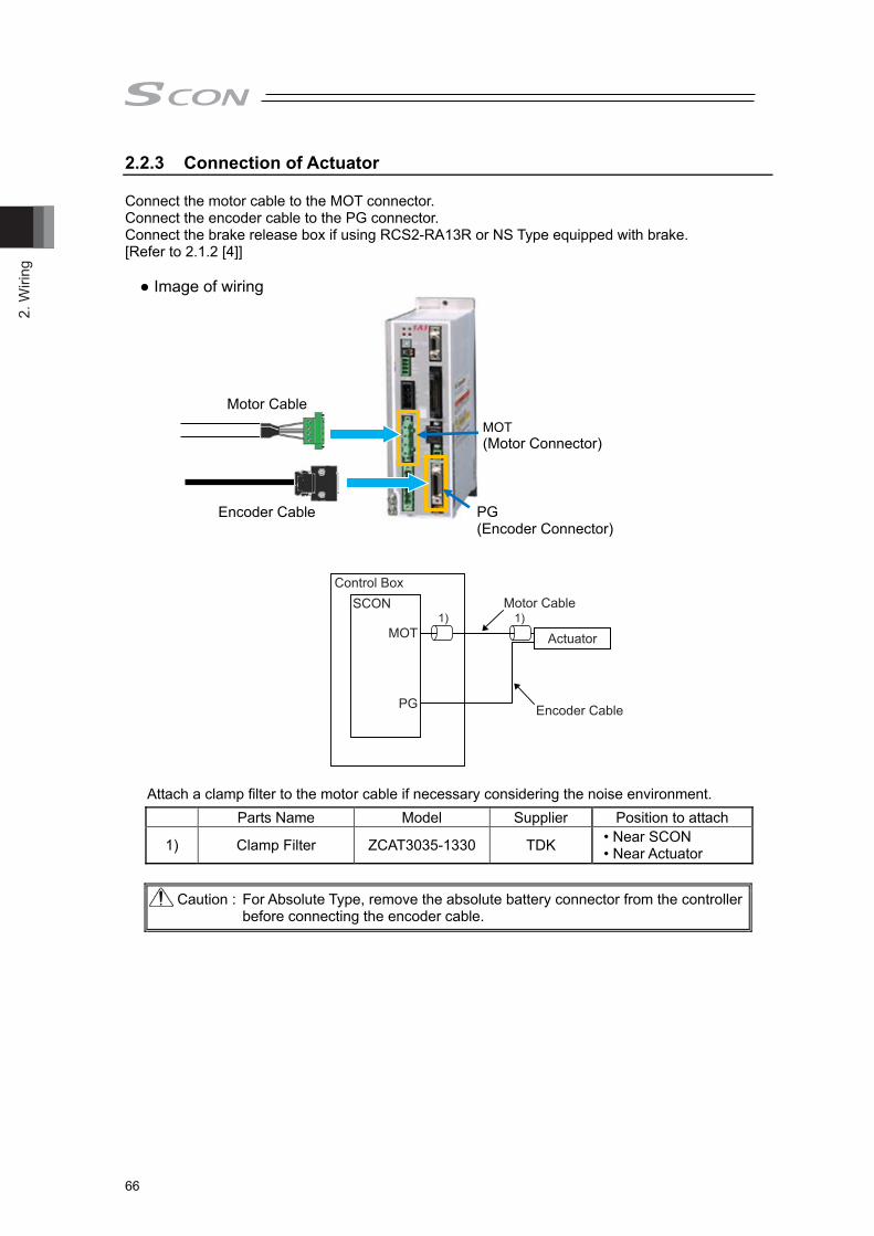
2. W
iring
66
2.2.3 Connection of Actuator Connect the motor cable to the MOT connector. Connect the encoder cable to the PG connector. Connect the brake release box if using RCS2-RA13R or NS Type equipped with brake. [Refer to 2.1.2 [4]]
● Image of wiring
Attach a clamp filter to the motor cable if necessary considering the noise environment. Parts Name Model Supplier Position to attach
1) Clamp Filter ZCAT3035-1330 TDK • Near SCON • Near Actuator
Caution : For Absolute Type, remove the absolute battery connector from the controller before connecting the encoder cable.
MOT (Motor Connector)
Motor Cable
Encoder Cable PG (Encoder Connector)
Control BoxSCON
MOT
PG
Motor Cable
Actuator
Encoder Cable
1) 1)

2. Wiring
67
Motor Connector (MOT) Model Remarks
Cable Side GIC2.5/4-STF-7.62 Controller Side GIC2.5/4-GF-7.62
Pin No. Signal name Items Applicable cable diameter 1 PE Protective grounding wire
Dedicated cable for IAI actuator 2 U Motor drive U-phase 3 V Motor drive V-phase 4 W Motor drive W-phase
Encoder Connector (PG)
Model Remarks Cable Side 10126-3000VE Controller Side 10226-6202JL
Pin No. Signal name Items Applicable cable diameter
1 A+ Phase A Difference + Input (Phase U+)
Cable dedicated for IAI encoders
2 A- Phase A Difference - Input (Phase U-) 3 B+ Phase B Difference + Input (Phase V+) 4 B- Phase B Difference - Input (Phase V-) 5 Z+ Phase Z Difference + Input (Phase W+) 6 Z- Phase Z Difference - Input (Phase W-)
7 SRD+ Send/Receive Difference + (Pulse/Magnetic Pole Changeover +)
8 SRD- Send/Receive Difference – (Pulse/Magnetic Pole Changeover -)
9 LC_SRD+ Loadcell Communication + 10 LC_SRD- Loadcell Communication - 11 NC Unconnected 12 E24V Sensor Power Output 13 0V 24V Power Supply GND 14 BAT+ Backup Battery Power Supply 15 BAT- Battery Ground 16 VCC Encoder Power 17 GND GND 18 LC_VCC Loadcell Power + 19 LC_GND Loadcell Power -
20 BKR- Brake Release Output Signal - (COM : Common to All Axes)
21 BKR+ Brake Release Output Signal + 22 NC Unconnected 23 RSV Sensor Input (Reserve) 24 OT Sensor Input (Over Travel) 25 CREEP Sensor Input (Creep sensor) 26 LS Sensor Input (limit switch)

2. W
iring
68
2.2.4 Connection of PIO For the signal assignment of each wire, refer to the following considering the operation mode. ● Image of wiring
* Indicate the enclosed I/O cable length in ”m” unit in the controller model code.
(MAX. 5m) Up to 10m is available at maximum with separate sold option.
(Model: CB-PAC-PIO□□□: □□□ is cable length L e.g. 020 = 2m)
No. Cable Color Wiring No. Cable
Color Wiring
1A BR-1
Flat Cable ○A (Solderless)
AWG28
1B BR-3
Flat Cable ○B (Solderless)
AWG28
2A RD-1 2B RD-3 3A OR-1 3B OR-3 4A YW-1 4B YW-3 5A GN-1 5B GN-3 6A BL-1 6B BL-3 7A PL-1 7B PL-3 8A GY-1 8B GY-3 9A WT-1 9B WT-3
10A BK-1 10B BK-3 11A BR-2 11B BR-4 12A RD-2 12B RD-4 13A OR-2 13B OR-4 14A YW-2 14B YW-4 15A GN-2 15B GN-4 16A BL-2 16B BL-4 17A PL-2 17B PL-4 18A GY-2 18B GY-4 19A WT-2 19B WT-4 20A BK-2 20B BK-4
● Wiring Method Conduct the connection of I/O to the controller is to be carried out using the dedicated I/O cable. Cable length is to be indicated in the controller model code. Please check the controller model code. A desired I/O cable can be selected from 2m (standard), 3m, and 5m cables. Up to 10m I/O cables are sold separately.
○A I/O output signal
○B I/O input signal
Flat Cable (AWG28, 20cores × 2)
Black-4 (20B) ・ ・ (Sheathed)
・ Brown-3 (1B)
L (*)
Black-2 (20A) ・ ・ (Sheathed)
・ Brown-1(1A)
Half-Pitched MIL Socket
PC
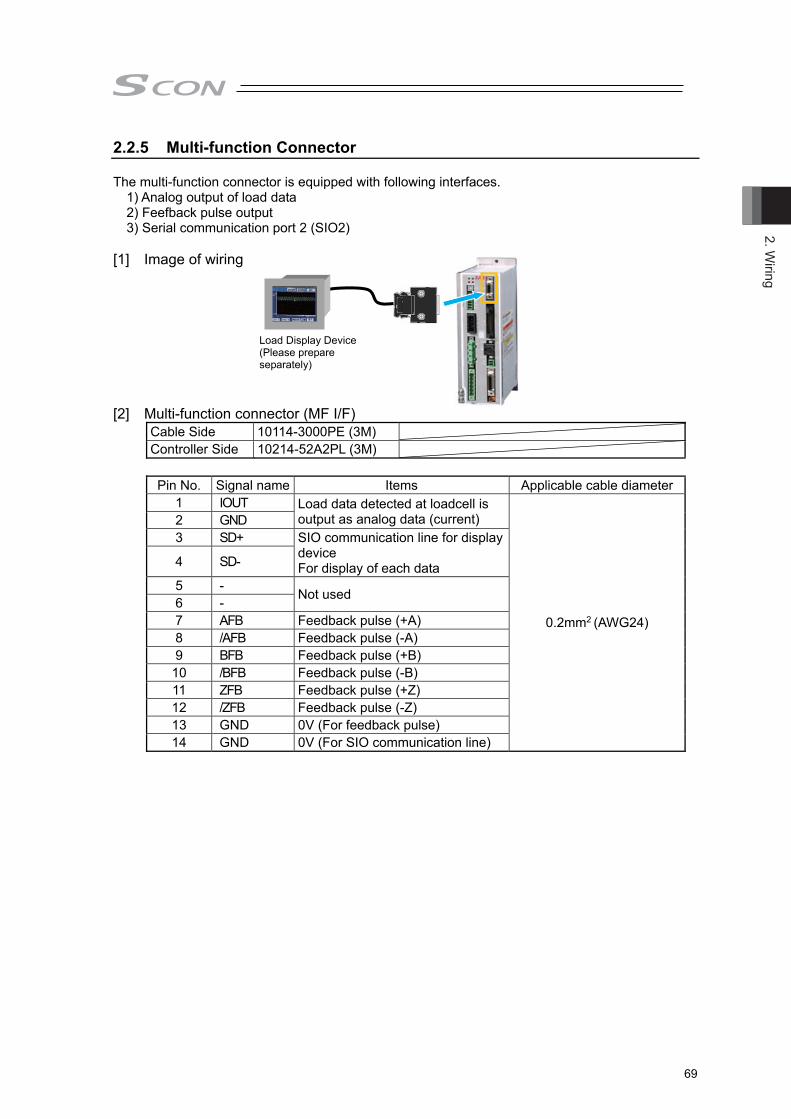
2. Wiring
69
2.2.5 Multi-function Connector The multi-function connector is equipped with following interfaces. 1) Analog output of load data 2) Feefback pulse output 3) Serial communication port 2 (SIO2) [1] Image of wiring
[2] Multi-function connector (MF I/F)
Cable Side 10114-3000PE (3M) Controller Side 10214-52A2PL (3M) Pin No. Signal name Items Applicable cable diameter
1 IOUT Load data detected at loadcell is output as analog data (current)
0.2mm2 (AWG24)
2 GND 3 SD+ SIO communication line for display
device For display of each data 4 SD-
5 - Not used 6 - 7 AFB Feedback pulse (+A) 8 /AFB Feedback pulse (-A) 9 BFB Feedback pulse (+B) 10 /BFB Feedback pulse (-B) 11 ZFB Feedback pulse (+Z) 12 /ZFB Feedback pulse (-Z) 13 GND 0V (For feedback pulse) 14 GND 0V (For SIO communication line)
Load Display Device(Please prepare separately)

2. W
iring
70
[3] Wiring Method
Connetct the multi-finction connector to the enclosed connector (Model: 10114-3000PE). See below for how to lay out the power supply wires. 1) Prepare a cable.
(Multiple twisted pair shielded cable with AWG24 (0.2mm2) or cable enclosed in the connected unit (host side)
2) Solder to the connector directly. Pay attention not to have short circuit with a terminal next to it by having pretinning and so on.
[4] Connector with Cable (Option) Model: CB-SC-PIOS□□□ □□□ is cable length: e.g. 020 = 2m
Cable length: For differential system, MAX. 10m For open collector, MAX. 2m
(Note) There is no connector equipped on the host controller (PLC, etc.) side. Make an appropriate treatment that suits the host controller (PLC, etc.). Also, to prevent the noise influence as much as possible, make the cable as short as possible.
IOUT 1 GND 2 SD+ 3 SD- 4 - 5 - 6
AFB 7 /AFB 8 BFB 9 /BFB 10 ZFB 11 /ZFB 12 GND 13
0.2mm2
(AWG24)
GND 14
Wiring Color Signal Name No.
Shield is connected to the cable clamp
Host System Side
Shield
Black White/Black
White/Red
White/Green
White/Yellow
White/Brown
White/Blue
White/Gray
Red
Green
Yellow
Brown
Blue
Gray
□□□
(Note) Enclosed only in plug and shell. Do the same wiring layout as the following option.
Solder
1st Pin
8th Pin
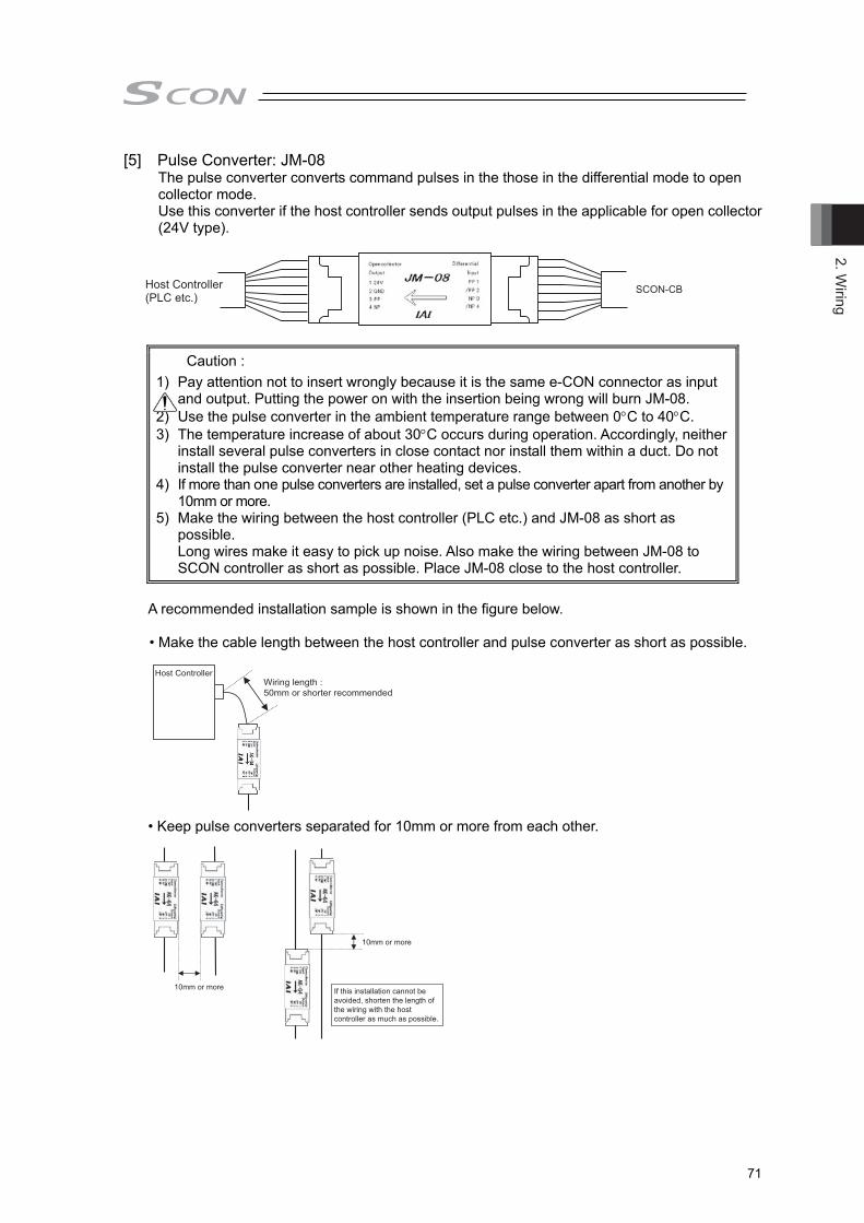
2. Wiring
71
[5] Pulse Converter: JM-08 The pulse converter converts command pulses in the those in the differential mode to open collector mode. Use this converter if the host controller sends output pulses in the applicable for open collector (24V type).
A recommended installation sample is shown in the figure below. • Make the cable length between the host controller and pulse converter as short as possible.
• Keep pulse converters separated for 10mm or more from each other.
Caution : 1) Pay attention not to insert wrongly because it is the same e-CON connector as input
and output. Putting the power on with the insertion being wrong will burn JM-08. 2) Use the pulse converter in the ambient temperature range between 0C to 40C. 3) The temperature increase of about 30C occurs during operation. Accordingly, neither
install several pulse converters in close contact nor install them within a duct. Do not install the pulse converter near other heating devices.
4) If more than one pulse converters are installed, set a pulse converter apart from another by 10mm or more.
5) Make the wiring between the host controller (PLC etc.) and JM-08 as short as possible. Long wires make it easy to pick up noise. Also make the wiring between JM-08 to SCON controller as short as possible. Place JM-08 close to the host controller.
Wiring length : 50mm or shorter recommended
Host Controller
10mm or more
10mm or more
If this installation cannot be avoided, shorten the length of the wiring with the host controller as much as possible.
Host Controller SCON-CB(PLC etc.)

2. W
iring
72
2.2.6 Connection of Regenerative Unit Connect regenerative unit (s) with attached cables as shown in the figure below. 1) When connecting 1 unit : Connect with enclosed cable (CB-SC-REU) 2) When connecting 2 or more units : Connect with enclosed cable (CB-ST-REU)
● Image of wiring
● Specification of connector for connecting external regenerative unit Conector Name External Regenerative Unit Connector (RB) Cable Side 1-178128-3 Controller Side 1-178138-5
Pin No. Signal name Items Applicable cable diameter
RB+ Regenerative resistor+ (Motor drive DC voltage) Dedicated cable is enclosed to
regenerative unit RB- Regenerative resistor- PE Grounding Terminal
● [Reference for the quantity to be connected: except for RCS2-RA13R]
Wattage of Motor Number of Connected Regenerative Units
Horizontal Orientation /Vertical Orientation
to 100W Not necessary 101 to 400W 1 401 to 750W 2
● [Reference for the quantity to be connected: RCS2-RA13R] Wattage of Motor Number of Connected Regenerative Units
Horizontal Orientation
Lead 1.25 Not necessary Lead 2.5 1
Vertical Orientation
Lead 1.25 1 Lead 2.5 1
RB IN
RB OUT
Regenerative Unit Connector
1)
2)

2. Wiring
73
[1] Connecting Cable
1) Regenerative resistor connection cable for SCON (CB-SC-REU□□□) □□□ is cable length (e.g.) 010 = 1m
2) Regenerative resistor connection cable for XSEL (CB-ST-REU□□□) □□□ is cable length (e.g.) 010 = 1m
Note : 1. The reference table for the number of connected units a reference assuming back and forth operation is made in rated acceleration/deceleration speed with rated load for 1000mm stroke with the actuator operation duty 50%.
2. Regenerative energy is absorbed inside the controller and when it exceeds the limit, error code “0CA” overheat error is generated. Add an external regenerative unit if this occurs. More units of regenerative unit than referred in the table for the number of connected units are required if the operation duty is higher than 50%. The maximum quantity of the external regenerative units that can be connected is as stated below: Less than 400W ∙ ∙ ∙ ∙ ∙2 units 400W or more ∙ ∙ ∙ ∙ ∙ ∙ 4 units (Never attempt to connect more than described above since it may cause a malfunction.)
3
1 3
1
123
RB-PE
RB+RB-PE
RB+KIV1.0mm2
(AWG17) 321
Controller Side
Wiring WiringColorLight Blue
BrownGreen/Yellow
ColorLight Blue
BrownGreen/Yellow
Signal SignalNo. No.
External RegenerativeResistor Unit Side
KIV1.0mm2
(AWG17)
Display of Cable Mode Code
KIV1.0mm2
(AWG17)
KIV1.0mm2
(AWG17)
3
1 3
1
123
RB-PE
RB+RB-PE
RB+
321
Controller Side
Wiring WiringColorLight Blue
BrownGreen/Yellow
ColorLight Blue
BrownGreen/Yellow
Signal SignalNo. No.
External RegenerativeResistor Unit Side
Display of Cable Mode Code

2. W
iring
74
2.2.7 SIO Connector Connection SIO connectors can be used not only for the connection of teaching tool, but also for the connection of the host controller (PLC, touch panel and PC). For the operation, refer to the instruction manual of each module.
SIO Connector Model Remarks Cable side miniDIN 8 Pin Controller side TCS7587-0121077
Pin No. Signal name Items Applicable cable diameter 1 SGA Teaching tool signal+
Dedicated connection cables provided by us
2 SGB Teaching tool signal- 3 5V Power supply for teaching tool4 ENB Enable signal input 5 EMGA Emergency stop signal A 6 24V Power supply for teaching tool7 0V 0V 8 EMGB Emergency stop signal B
Shell 0V 0V Caution : Removing the SIO connector while the power is ON causes a transient
emergency stop. Thus, the devices such as the actuator which are in operation will stop. Do not disconnect the SIO connector during the operation. For SCON-CGB, in case the SIO connector is not used, make sure to insert the dummy plug DP-5 for teaching pendant.
Dummy Plug DP-5
PC
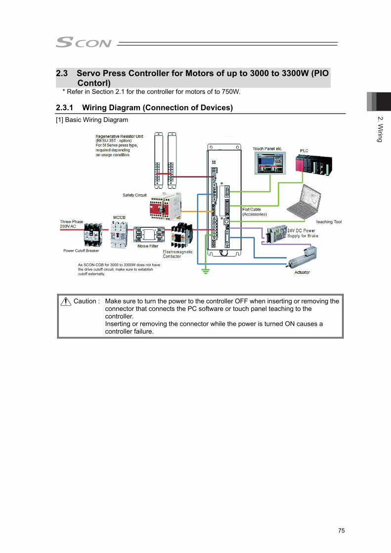
2. Wiring
75
2.3 Servo Press Controller for Motors of up to 3000 to 3300W (PIO Contorl)
* Refer in Section 2.1 for the controller for motors of to 750W. 2.3.1 Wiring Diagram (Connection of Devices) [1] Basic Wiring Diagram
Teaching Tool
Power Cutoff Breaker
As SCON-CGB for 3000 to 3300W does not havethe drive cutoff circuit, make sure to establish cutoff externally.
Caution : Make sure to turn the power to the controller OFF when inserting or removing the connector that connects the PC software or touch panel teaching to the controller. Inserting or removing the connector while the power is turned ON causes a controller failure.
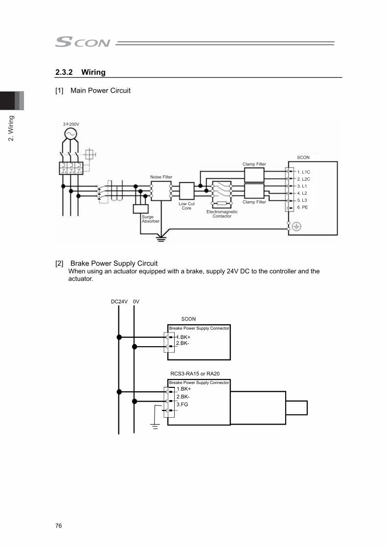
2. W
iring
76
2.3.2 Wiring
[1] Main Power Circuit
Noise Filter
Clamp Filter
SurgeAbsorber
Low CutCore
3 200V
SCON
1. L1C2. L2C3. L14. L25. L36. PE
Clamp Filter
ElectromagneticContactor
[2] Brake Power Supply Circuit
When using an actuator equipped with a brake, supply 24V DC to the controller and the actuator.
DC24V 0V
1.BK+2.BK-
Breake Power Supply Connector
RCS3-RA15 or RA20
1.BK+ 2.BK- 3.FG
8th PinBreake Power Supply Connector

2. Wiring
77
[3] Actuator Emergency Stop Circuit (System I/O Connector) As an example of a circuit, cases of 2 conditions are shown. * The controller for motors of 3000W and above is not equipped with the built-in SIO connector
connection detection circuit and drive cutoff circuit. ★ Reference: Operate the actuator for try (Note: It is not emergency stop) 1) Stop supplying external motor power at emergency stop input 2) Example for Wiring for Equivalent to Safety Category 4
★Reference: Make the emergency stop input (EMG-) of the device valid and have a trial drive of
the actuator.
● Example of a Circuit
● Image of Wiring
SIO Connector
System I/OConnector
Dedicated for
Emergency Stop Circuit
Circuit for StopExternal Emergency Stop Switch
Wiring Conducted at Delivery
S2 2
S1 1
SDN2 6
EMG+ 3
SDN1 5
EMG- 4
Short-circuit in PC Software Cable
External Emergency Stop Switch
System I/O Connector
SCON
SIO Connector
PC Software
PC Software Cable or Dummy plug
SCON

2. W
iring
78
Note 1 The rating for the emergency stop signal to turn ON/OFF at contact CR1 is 24V DC and
10mA or less. Note 2 Connect such as a connector to L1/L2/L3 terminals when cutting off the motor power
source externally. (This controller is not equipped with internal drive cutoff relay.)
Note 3 It is the contact output to control the drive cutoff device connected externally. The rating is 30V DC and 200mA or less. [Refer to 2.4.2 for detail]
Note 4 Connect the temperature sensor contact when external regenerative resistor units are connected.
0V24V
L1
EMG-
EMG+
S2
S1
L2
L1C
L2C
1
2
5
8
3
4
1
EMG A EMG B
2
3
4
CR16
6
SDN1
SDN2
AC200V5
TM1 TM2
L3
1) Stop supplying external motor power at emergency stop input
Contact Output for Drive Cutoff (Note 3)
Circuit for Stop
PC Software Cable or Dummy plug
SIO connector System I/O connector
Emergency stop circuit exclusive use 24V
Emergency stop switch
Short-circuit in PC software cable
CR1(Note 1)
Emergency stop reset switch
Motor power supply
MC1(Note 2)
Control power supply
CR1(Note 1)
AC power supply input connector
Temperature Sensor Contact for External Regenerative Resistor Unit (Note 4)
EMG A EMG B
MC1

2. Wiring
79
In order to construct a system applicable for the Safety Categories, use the TP adaptor (RCB-LB-TGS) and establish the circuit construction following the example below.
1.SGA
2.SGB
3.5V
4.ENBENBSTR
5.EMGA
6.T24V
7.GND
8.EMGB
9.Shell
TP Connection Detection
VP24
S
Three-Phase 200V AC
L2L3
VP5VP7
SCON-CGB (3000 to 3300W)
G9SA-301(O M RO N)
G9SA-301(O M RO N)
Controller Connector
System I/O Connector (Safety Unit Connection)
System I/O Connector
24V
24V
2.SGA
3.SGB
13.RTS
14.CTS
RY
9.EMG1-
12.EMG1+
6.EMG2-
5.EMG2+
23.ENB1-
24.ENB1+
25.ENB2-
22.ENB2+
7.DC24V+
26.DC24V-
1.EM
G1-
2.EM
G1+
3.EM
G2-
4.EM
G2+
5.EM
GIN
6.EM
GO
UT
7.EN
B1-
8.EN
B1+
9.EN
B2-
10.E
NB2+
11.E
NBIN
12.E
NBO
UT
1.SGRCB- LB- TGS TP
Emergency Stop Switch
Emergency Stop Switch
Enable Switch
Enable Switch
Shell
+
TP Connector
Reset Switch
24V24V
RectifierDC Bus
Connect with dedicated cable
5.SDN1
6.SDN2
L1
Electromagnetic Contactor
Electromagnetic Contactor
1.S1
2.S2
3.EMG+
4.EMG-
E24V
* EMGSTR
24V
RY
SDN1
SDN2
SDN1
SDN2
RY
*SDWN
VP24
Install it when external regenerative unit is connected
TM1
TM2
* Connect a dummy plug when TP is detached.
2) Example for Wiring for Equivalent to Safety Category 4
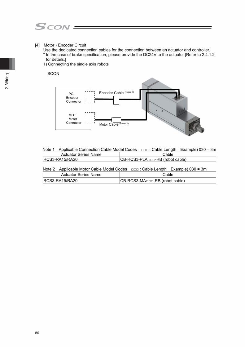
2. W
iring
80
[4] Motor • Encoder Circuit Use the dedicated connection cables for the connection between an actuator and controller. * In the case of brake specification, please provide the DC24V to the actuator [Refer to 2.4.1.2
for details.] 1) Connecting the single axis robots
SCON
Note 1 Applicable Connection Cable Model Codes □□□ : Cable Length Example) 030 = 3m Actuator Series Name Cable
RCS3-RA15/RA20 CB-RCS3-PLA□□□-RB (robot cable)
Note 2 Applicable Motor Cable Model Codes □□□ : Cable Length Example) 030 = 3m Actuator Series Name Cable
RCS3-RA15/RA20 CB-RCS3-MA□□□-RB (robot cable)
PG
Encoder Connector
MOT Motor
Connector
Encoder Cable (Note 1)
Motor Cable (Note 2)

2. Wiring
81
[5] PIO Circuit 1) PIO Circuit for CB/CGB Types ● List of Control Signal Assignments and Features
See the table below for the signal assignment of the I/O flat cable. Follow the following table to connect the external equipment (PLC etc).
Pin No. Category I/O No. Signal Abbreviation Signal Name
1A 24V P24 P24 Supply 24V DC power for I/O power 2A 24V P24 3A - - 4A - - 5A
Input
PC1 Command Program No. 1 Indicate the press program number to make operation. The available to indecate range is 0 to 63. Indicate in the binary data expressed in PC1 to PC32. e.g.) For Program No.3 : PC1, PC2 is turned ON
For Program No.10: PC2, PC8 is turned ON For Program No.61: PC1, PC4, PC8,
PC16, PC32 is turned ON
6A PC2 Command Program No. 2 7A PC4 Command Program No. 4 8A PC8 Command Program No. 8 9A PC16 Command Program No. 16
10A PC32 Command Program No. 32
11A PSTR Program Start
Turn this signal ON after indicating in the command program number and then the press program starts to be executed. Turn this signal ON while a program is executed or an axis is moving and then an alarm occurs.
12A PHOM Program Home Return Movement
Turn this signal ON after indicating in the command program number and then the actuator moves to the program home position of the indicated press program. Turn this signal ON while a program is executed or an axis is moving and then an alarm occurs.
13A ENMV Axis Operation Permission
Turn this signal ON and the axis movement and program execution get accepted. For the OFF as condition below: 1) Axis operation stop 2) Press program stop 3) FPST signal input disable 4) Servo ON is continued (Note) When this signal is turned OFF, even if the signal
gets turned back ON, the axis movement or program execution that stopped on the way would not resume.
14A FPST Program Compulsory StopTurn this signal ON and then the program in execution stops.At the time to input this signal, whether to move to the program home position in execution or not can be selected (*).
15A CLBR Loadcell Calibration Derective
Turn this signal ON for more than 20ms to perform calibration (adjustment) of loadcell.
16A BKRL Brake Release The brake will forcibly be released.
17A RMOD Operation Mode Switch The operating mode is selectable when the operation mode switch of the controller is set to AUTO. (The setting is AUTO when signal is OFF, and MANU when ON.)
18A HOME Home Return The controller will perform home return when this signal is turned ON.
19A RES Reset Turn the signal ON to reset the alarm.
20A SON Servo ON Command Turn the signal ON to servo ON. Turn the OFF to Servo OFF.
* Select the Parameter No.179.
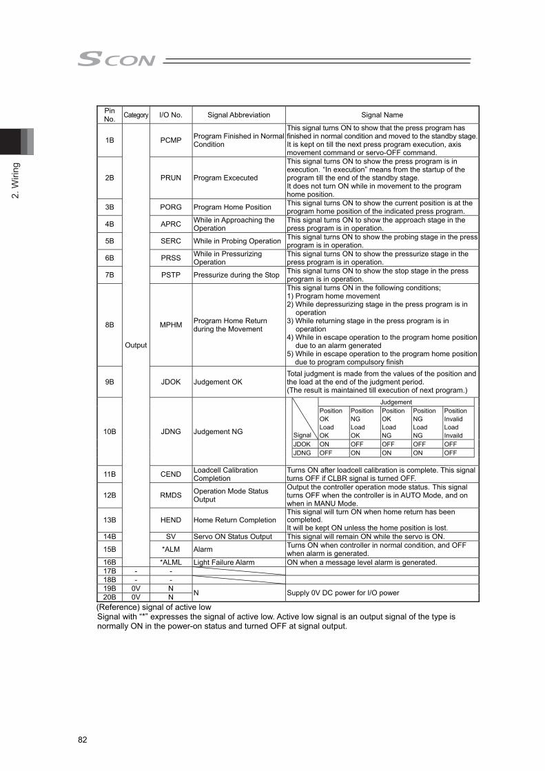
2. W
iring
82
Pin No. Category I/O No. Signal Abbreviation Signal Name
1B
Output
PCMP Program Finished in Normal Condition
This signal turns ON to show that the press program has finished in normal condition and moved to the standby stage.It is kept on till the next press program execution, axis movement command or servo-OFF command.
2B PRUN Program Excecuted
This signal turns ON to show the press program is in execution. “In execution” means from the startup of the program till the end of the standby stage. It does not turn ON while in movement to the program home position.
3B PORG Program Home Position This signal turns ON to show the current position is at the program home position of the indicated press program.
4B APRC While in Approaching the Operation
This signal turns ON to show the approach stage in the press program is in operation.
5B SERC While in Probing Operation This signal turns ON to show the probing stage in the press program is in operation.
6B PRSS While in Pressurizing Operation
This signal turns ON to show the pressurize stage in the press program is in operation.
7B PSTP Pressurize during the Stop This signal turns ON to show the stop stage in the press program is in operation.
8B MPHM Program Home Return during the Movement
This signal turns ON in the following conditions; 1) Program home movement 2) While depressurizing stage in the press program is in
operation 3) While returning stage in the press program is in
operation 4) While in escape operation to the program home position
due to an alarm generated 5) While in escape operation to the program home position
due to program compulsory finish
9B JDOK Judgement OK Total judgment is made from the values of the position and the load at the end of the judgment period. (The result is maintained till execution of next program.)
10B JDNG Judgement NG
Signal
Judgement Position OK Load OK
Position NG Load OK
Position OK Load NG
Position NG Load NG
Position Invalid Load Invaild
JDOK ON OFF OFF OFF OFF JDNG OFF ON ON ON OFF
11B CEND Loadcell Calibration Completion
Turns ON after loadcell calibration is complete. This signal turns OFF if CLBR signal is turned OFF.
12B RMDS Operation Mode Status Output
Output the controller operation mode status. This signal turns OFF when the controller is in AUTO Mode, and on when in MANU Mode.
13B HEND Home Return Completion This signal will turn ON when home return has been completed. It will be kept ON unless the home position is lost.
14B SV Servo ON Status Output This signal will remain ON while the servo is ON.
15B *ALM Alarm Turns ON when controller in normal condition, and OFF when alarm is generated.
16B *ALML Light Failure Alarm ON when a message level alarm is generated. 17B - - 18B - - 19B 0V N N Supply 0V DC power for I/O power 20B 0V N
(Reference) signal of active low Signal with “*” expresses the signal of active low. Active low signal is an output signal of the type is normally ON in the power-on status and turned OFF at signal output.

2. Wiring
83
● Examples for Connection Circuit Use the attached cable for the I/O connection. Model : CB-PAC-PIO□□□ (□□□ indicates the cable length L. Example. 020 = 2m)
Half Pitch MIL SocketHIF6-40D-1.27R (Hirose Electric)
Flat Cable (20-core) × 2
L
20A 20B
1A 1B
BK -4 (20B)
Bottom Line
Top Line
BK -2 (20A)
BR -3 (1B)
BR -1 (1A)
No connector
No connector
Caution : When having a conduction check on the flat cable, make sure not to spread out the inside of the connector female pins. It may cause a contact error and may disable normal operation.
0V (NPN Type)
24V DCSupply
BR- 1 1A P24 PCMP 1B BR- 3
0VSupply
24V DC (NPN Type)24V DC (PNP Type)
RD- 1 2A P24 PRUN 2B RD- 3
0V (PNP Type)
Command Program No. 1Command Program No. 2Command Program No. 4Command Program No. 8
Command Program No. 16Command Program No. 32
Program StartProgram Home Return Movement
Axis Operation PermissionProgram Compulsory Stop
Loadcell Calibration CommandBrake Release
Operation Mode SwitchHome Return
ResetServo ON
OR- 1 3A
PC1
PORGAPRC
3B OR- 3
Program Finished in Normal ConditionProgram ExcecutedProgram Home PositionWhile in Approaching the OperationWhile in Probing OperationWhile in Pressurizing OperationPressurize during the StopProgram Home Return during the MovementJudgement OKJudgement NGLoadcell Calibration CompletionOperation Mode Status OutputHome Return CompletionServo ON StatusAlarmLight Failure Alarm
YW- 1 4A
PC2SERC
4B YW- 3GN- 1 5A
PC4PRSS
5B GN- 3BL- 1 6A
PC8PSTP
6B BL- 3PL- 1 7A
PC16MPHM
7B PL- 3GY- 1 8A
PC32JDOKJDNG
8B GY- 3WT- 1 9A
FPST
PSTRPHOMENMV
9B WT- 3BK- 1 10A
CLBR
CEND
10B BK- 3BR- 2 11A
BKRL
RMDS
11B BR- 4RD- 2 12A
RMOD
HEND
12B RD- 4OR- 2 13A
HOME
SV
13B OR- 4YW- 2 14A
RES
14B YW- 4GN- 2 15A
SON
*ALM*ALML
15B GN- 4BL- 2 16A 16B BL- 4PL- 2 17A
N
17B PL- 4GY- 2 18A
N
18B GY- 4WT- 2 19A 19B WT- 4BK- 2 20A 20B BK- 4
SCONPIO Connector
“*” in codes above shows the signal of the active low. Processing occurs when an input signal of the type is turned OFF. An output signal of the type is normally ON in the power-on status and turned OFF at signal output.

2. W
iring
84
2) PIO Circuit for LC/LCG Types ●List of Control Signal Assignments and Features
The table below shows the signal assignment of the flat cable. Follow the following table connect the external equipment (such as PLC). Refer to LC Ladder Programing Manual (ME0329) provided separately for how to assign memories in built-in ladder or how to use it. Pin No. Category I/O No. Signal Name Function Description Relevant Sections
1A 24V Power Supply Power Supply for I/O +24V 2A 24V Power Supply Power Supply for I/O +24V 3A NC Not used 4A 5A
General Input
IN0 X000
They are 24V general-purposed terminals. Assign to the built-in ladder and use them if necessary.
Refer to LC ladder Programming
Manual provided separatery
6A IN1 X001 7A IN2 X002 8A IN3 X003 9A IN4 X004
10A IN5 X005 11A IN6 X006 12A IN7 X007 13A IN8 X008 14A IN9 X009 15A IN10 X00A 16A IN11 X00B 17A IN12 X00C 18A IN13 X00D 19A IN14 X00E 20A IN15 X00F 1B
General Output
OUT0 X000
They are 24V general-purposed terminals. Assign to the built-in ladder and use them if necessary.
2B OUT1 X001 3B OUT2 X002 4B OUT3 X003 5B OUT4 X004 6B OUT5 X005 7B OUT6 X006 8B OUT7 X007 9B OUT8 X008
X009 X00A X00B
10B OUT9 11B OUT10 12B OUT11 13B OUT12 X00C 14B OUT13 X00D 15B OUT14 X00E 16B OUT15 X00F 17B NC Not used - 18B 19B 0V Power Supply Power Supply for I/O 0V 20B 0V Power Supply Power Supply for I/O 0V
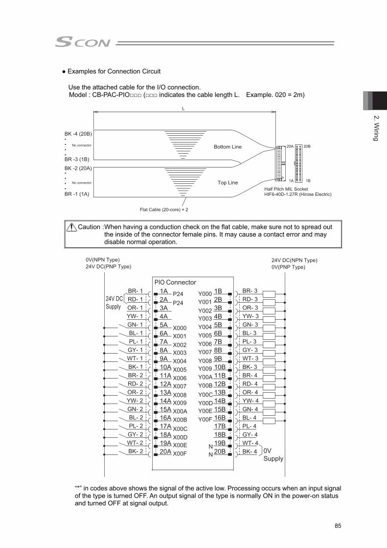
2. Wiring
85
● Examples for Connection Circuit
Use the attached cable for the I/O connection. Model : CB-PAC-PIO□□□ (□□□ indicates the cable length L. Example. 020 = 2m)
Half Pitch MIL SocketHIF6-40D-1.27R (Hirose Electric)
Flat Cable (20-core) × 2
L
20A 20B
1A 1B
BK -4 (20B)
Bottom Line
Top Line
BK -2 (20A)
BR -3 (1B)
BR -1 (1A)
No connector
No connector
Caution : When having a conduction check on the flat cable, make sure not to spread out the inside of the connector female pins. It may cause a contact error and may disable normal operation.
24V DCSupply
1A P24 1B
0VSupply
2A P24 2B3A
X000X001X002X003X004X005X006X007X008X009X00AX00BX00CX00DX00EX00F
Y000Y001Y002Y003Y004Y005Y006Y007Y008Y009Y00AY00BY00CY00DY00EY00F
3B4A 4B5A 5B6A 6B7A 7B8A 8B9A 9B10A 10B11A 11B12A 12B13A 13B14A 14B15A 15B16A 16B17A
N
17B18A
N
18B19A 19B20A 20B
PIO ConnectorBR- 1RD- 1OR- 1YW- 1GN- 1BL- 1PL- 1GY- 1WT- 1BK- 1BR- 2RD- 2OR- 2YW- 2GN- 2BL- 2PL- 2GY- 2WT- 2BK- 2
BR- 3RD- 3OR- 3YW- 3GN- 3BL- 3PL- 3GY- 3WT- 3BK- 3BR- 4RD- 4OR- 4YW- 4GN- 4BL- 4PL- 4GY- 4WT- 4BK- 4
0V(NPN Type) 24V DC(NPN Type)24V DC(PNP Type) 0V(PNP Type)
“*” in codes above shows the signal of the active low. Processing occurs when an input signal of the type is turned OFF. An output signal of the type is normally ON in the power-on status and turned OFF at signal output.
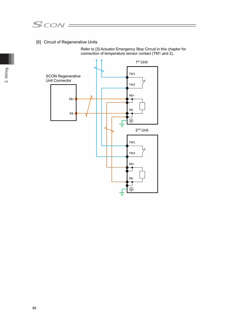
2. W
iring
86
[6] Circuit of Regenerative Units
RB+
RB‐
RB+
RB‐
TM1
TM2
RB+
RB‐
TM1
TM2
1台目
2台目
(駆動源遮断回路)
SCON‐CB大型
Refer to [3] Actuator Emergency Stop Circuit in this chapter for connection of temperature sensor contact (TM1 and 2).
SCON Regenerative Unit Connector
1st Unit
2nd Unit
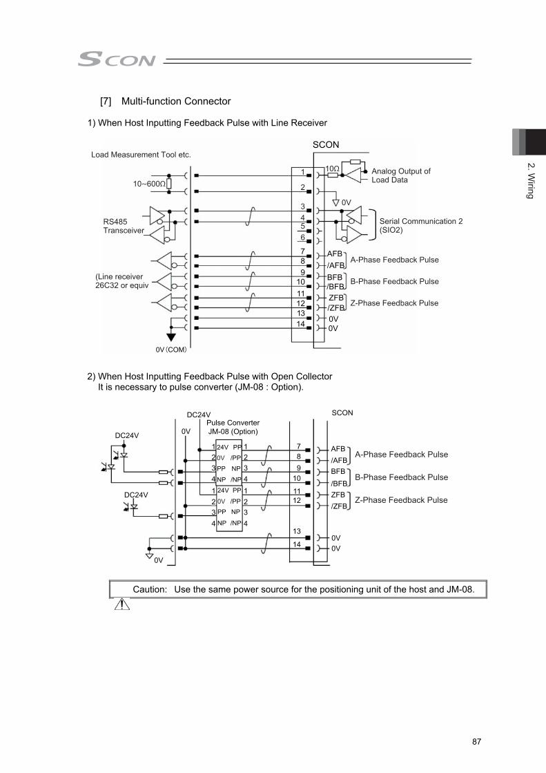
2. Wiring
87
[7] Multi-function Connector 1) When Host Inputting Feedback Pulse with Line Receiver
(Note) Connect cable also to 0V if there is 0V (COM) on the host unit.
2) When Host Inputting Feedback Pulse with Open Collector
It is necessary to pulse converter (JM-08 : Option).
Caution: Use the same power source for the positioning unit of the host and JM-08.
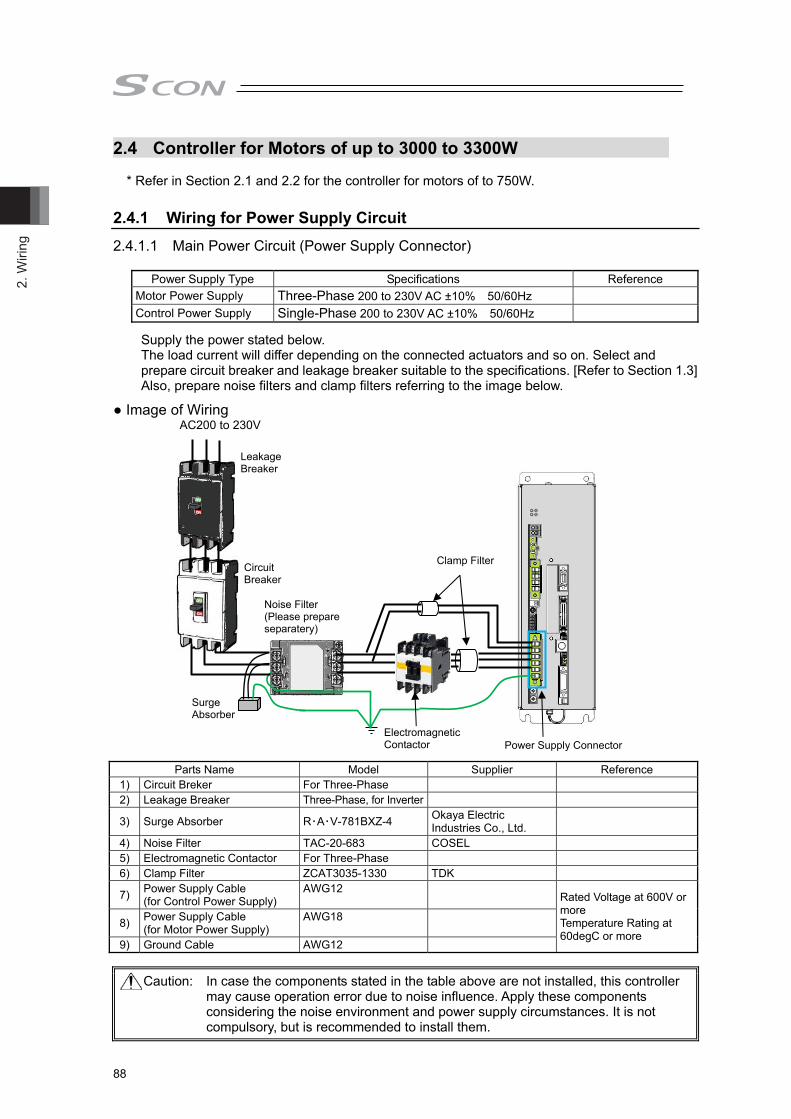
2. W
iring
88
2.4 Controller for Motors of up to 3000 to 3300W * Refer in Section 2.1 and 2.2 for the controller for motors of to 750W.
2.4.1 Wiring for Power Supply Circuit
2.4.1.1 Main Power Circuit (Power Supply Connector)
Power Supply Type Specifications Reference
Motor Power Supply Three-Phase 200 to 230V AC ±10% 50/60Hz Control Power Supply Single-Phase 200 to 230V AC ±10% 50/60Hz
Supply the power stated below. The load current will differ depending on the connected actuators and so on. Select and prepare circuit breaker and leakage breaker suitable to the specifications. [Refer to Section 1.3] Also, prepare noise filters and clamp filters referring to the image below.
● Image of Wiring AC200 to 230V
Caution: In case the components stated in the table above are not installed, this controller
may cause operation error due to noise influence. Apply these components considering the noise environment and power supply circumstances. It is not compulsory, but is recommended to install them.
Parts Name Model Supplier Reference 1) Circuit Breker For Three-Phase 2) Leakage Breaker Three-Phase, for Inverter
3) Surge Absorber R・A・V-781BXZ-4 Okaya Electric Industries Co., Ltd.
4) Noise Filter TAC-20-683 COSEL 5) Electromagnetic Contactor For Three-Phase 6) Clamp Filter ZCAT3035-1330 TDK
7) Power Supply Cable (for Control Power Supply)
AWG12 Rated Voltage at 600V or more Temperature Rating at 60degC or more
8) Power Supply Cable (for Motor Power Supply)
AWG18
9) Ground Cable AWG12
Leakage Breaker
Noise Filter (Please prepare separatery)
Surge Absorber
Power Supply Connector
Clamp Filter
Electromagnetic Contactor
Circuit Breaker

2. Wiring
89
● Wiring Method Connect the wiring of power supply to the enclosed connector (Model code: PC5/6-STF-7,62: Phoenix Contact). See below for how to lay out the power supply wires. 1) Loosen the terminal screw with using such as a slotted screwdriver to open up the inlet. 2) Reveal the sheath for 10mm on the cable that satisfies the cable diameter complies the
specification shown in the table below and put it in the inlet. 3) Tighten the terminal screw with using such as a slotted screwdriver. The inlet closes and
affixes the wire. 4) Connect all the wires in the same manner and insert the enclosed connector to the power
connector.
Power supply connector (PWR) Pin No. Signal name Items Applicable cable diameter
1 L1C 2 L2C
Control power AC input 0.75mm2 (AWG18)
3 L1 4 L2 5 L3
Motor power AC input 3.3mm2 (AWG12)
6 PE Protective grounding wire 3.3mm2 (AWG12)
1) Loosen the screw with a slotted screwdriver
2) Insert wire
Wire Inlet
4) Plug in the enclosed connector to the power connector on the controller side
3) Tighten the screw with a slotted screwdriver

2. W
iring
90
2.4.1.2 Brake Power Supply (Brake Power Connector) Supply 24V DC ±10% and 0.1A at maximum to the controller and 24V DC ±10% and 1.5A at maximum to the actuator when an actuator equipped with a brake is used.
● Image of Wiring
24VDC Power (Please prepare separately)
● Wiring Method Connect the power supply to the enclosed connector* (Model code: MC1.5/2-ST-3.5: Phoenix Contact). * Controller side : Model code : MC1.5/2-ST-3.5: Phoenix Contact
Actuator side : Model code : FMC1.5/3-STF-3.5: Phoenix Contact See below for how to lay out the power supply wires. 1) Loosen the terminal screw with using such as a slotted screwdriver to open up the inlet. 2) Reveal the sheath for 7mm (controller side) and 10mm (actuator side) on the cable that
satisfies the cable diameter complies the specification shown in the table below and put it in the inlet.
3) Tighten the terminal screw with using such as a slotted screwdriver. The inlet closes and affixes the wire.
4) Connect all the wires in the same manner and insert the enclosed connector to the power connector.
1) Loosen the screw with a slotted screwdriver
3) Tighten the screw with a slotted screwdriver
2) Insert wire
Brake Power Supply Connector Pin No. Signal name Items Applicable cable diameter
BK+ 24V DC power input PWR- 24V DC ground
0.5mm2 (AWG20)

2. Wiring
91
Brake Power Supply Connector Pin No. Signal name Items Applicable cable diameter
FG Frame ground 0V 24V DC ground 24V 24V DC power input
0.5mm2 (AWG20)
FG 0V 24V
← FG ← 0V
← 24V
1) Loosen the screw with a slotted screwdriver
2) Insert wire
3) Tighten the screw with a slotted screwdriver

2. W
iring
92
2.4.2 Wiring of Emergency Stop Circuit (System I/O) Make sure to construct the wiring of the emergency stop circuit considering the suitability to the Safety Category of the whole system.
● Image of Wiring
SCON
S1
S2
EMG+
EMG-
PC Software Connection Cable or Dummy Plug
Short-circuit in PC Software Cable
SDN1
SDN2
To Drive Cutoff Circuit
Emergency Stop Circuit
Built-in 24V
Stop Circuit
Note 1 It is not equipped with a relay that automatically identifies that a teaching tool was inserted and switches over the wiring layout. Connect a dummy plug to the SIO connector in normal operations.
Note 2 Construct the circuit considering the safety category of the whole equipment. Note 3 Make sure to construct the emergency stop circuit using the built-in 24V (EMG+
Terminal) output for EMG- Terminal. Note 4 As it is not equipped with the built-in motor drive cutoff relay, it is necessary to establish
external drive cutoff.
For the SDN terminal (Drive cutoff contact output)
SDN1, SDN2 • It is the contact output to control the drive cutoff device connected externally. • Configure the circuit in such a way that the drive source will never be turned on when these
contacts are open. When turning on the power, turn on the control power first, confirm that these contacts are closed, and then turn on the drive power.
• The rating of this contact is 30V max./200mA max. Conditions to Open SDN Contact 1) At stop signal input (when the dry contact connected between EMG+ and EMG- is open) 2) When an alarm is generated (Cold start level) 3) In disable condition

2. Wiring
93
● Wiring Method Connect the wiring of operation stop (system I/O connector) to the enclosed connector (Model code: FMC1.5/6-ST-3.5: Phoenix Contact). See below for how to lay out the power supply wires. 1) Loosen the terminal screw with using such as a slotted screwdriver to open up the inlet. 2) Reveal the sheath for 7mm on the cable that satisfies the cable diameter complies the
specification shown in the table below and put it in the inlet. 3) Tighten the terminal screw with using such as a slotted screwdriver. The inlet closes and
affixes the wire. 4) Connect all the wires in the same manner and insert the enclosed connector to the power
connector.
Enclosed Part
Pin Number and Signal Name
1) Push in a slotted screwdriver to the protruded area
3) Plug in the enclosed connector to the power connector on the controller side
2) Insert wire
Protruded Area
Wire Inlet1. S12. S23. EMG+4. EMG-5. SDN16. SDN2
System I/O connector
Pin No. Signal name Items Applicable cable diameter
1 S1 Operation stop switch contact
0.5mm2 (AWG20)
2 S2 Operation stop switch contact 3 EMG+ Operation stop dedicated power output4 EMG- Operation stop input 5 SDN1 Drive cutoff contact output 6 SDN2 Drive cutoff contact output

2. W
iring
94
2.4.3 Connection of Actuator Connect the motor cable to the MOT connector. Connect the encoder cable to the PG connector.
● Image of wiring
Caution : For Absolute Type, remove the absolute battery connector from the controller before connecting the encoder cable.
MOT (Motor Connector)
Motor Cable
Encoder Cable
PG (Encoder Connector)

2. Wiring
95
Motor Connector (MOT) Model Remarks
Cable Side IPC5/4-STF-7.62 Controller Side IPC5/4-GF-7.62
Pin No. Signal name Items Applicable cable diameter 1 PE Protective grounding wire
Dedicated cable for IAI actuator 2 U Motor drive U-phase 3 V Motor drive V-phase 4 W Motor drive W-phase
Encoder Connector (PG)
Model Remarks Cable Side 10126-3000PE Controller Side 10226-6202JL
Pin No. Signal name Items Applicable cable diameter
1 A+ Phase A Difference + Input (Phase U+)
Cable dedicated for IAI encoders
2 A- Phase A Difference - Input (Phase U-) 3 B+ Phase B Difference + Input (Phase V+) 4 B- Phase B Difference - Input (Phase V-) 5 Z+ Phase Z Difference + Input (Phase W+) 6 Z- Phase Z Difference - Input (Phase W-)
7 SRD+ Send/Receive Difference + (Pulse/Magnetic Pole Changeover +)
8 SRD- Send/Receive Difference – (Pulse/Magnetic Pole Changeover -)
9 LC_SRD+ Loadcell Communication + 10 LC_SRD- Loadcell Communication - 11 NC Unconnected 12 E24V Sensor Power Output 13 0V 24V Power Supply GND 14 BAT+ Backup Battery Power Supply 15 BAT- Battery Ground 16 VCC Encoder Power 17 GND GND 18 LC_VCC Loadcell Power + 19 LC_GND Loadcell Power -
20 BKR- Brake Release Output Signal - (COM : Common to All Axes)
21 BKR+ Brake Release Output Signal + 22 NC Unconnected 23 RSV Sensor Input (Reserve) 24 OT Sensor Input (Over Travel) 25 CREEP Sensor Input (Creep sensor) 26 LS Sensor Input (limit switch)
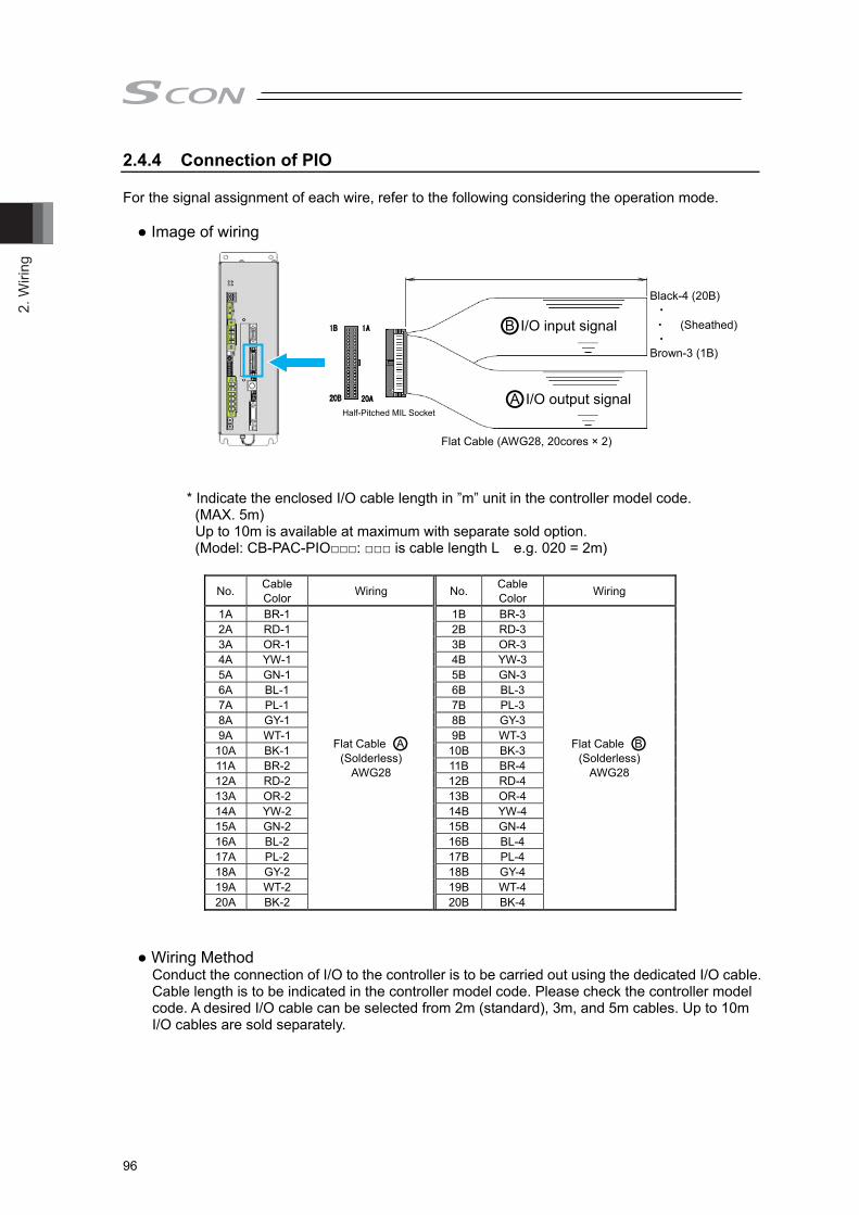
2. W
iring
96
2.4.4 Connection of PIO For the signal assignment of each wire, refer to the following considering the operation mode. ● Image of wiring
* Indicate the enclosed I/O cable length in ”m” unit in the controller model code. (MAX. 5m)
Up to 10m is available at maximum with separate sold option. (Model: CB-PAC-PIO□□□: □□□ is cable length L e.g. 020 = 2m)
No. Cable Color Wiring No. Cable
Color Wiring
1A BR-1
Flat Cable ○A (Solderless)
AWG28
1B BR-3
Flat Cable ○B (Solderless)
AWG28
2A RD-1 2B RD-3 3A OR-1 3B OR-3 4A YW-1 4B YW-3 5A GN-1 5B GN-3 6A BL-1 6B BL-3 7A PL-1 7B PL-3 8A GY-1 8B GY-3 9A WT-1 9B WT-3
10A BK-1 10B BK-3 11A BR-2 11B BR-4 12A RD-2 12B RD-4 13A OR-2 13B OR-4 14A YW-2 14B YW-4 15A GN-2 15B GN-4 16A BL-2 16B BL-4 17A PL-2 17B PL-4 18A GY-2 18B GY-4 19A WT-2 19B WT-4 20A BK-2 20B BK-4
● Wiring Method Conduct the connection of I/O to the controller is to be carried out using the dedicated I/O cable. Cable length is to be indicated in the controller model code. Please check the controller model code. A desired I/O cable can be selected from 2m (standard), 3m, and 5m cables. Up to 10m I/O cables are sold separately.
○A I/O output signal
○B I/O input signal
Flat Cable (AWG28, 20cores × 2)
Black-4 (20B) ・ ・ (Sheathed)
・ Brown-3 (1B)
Half-Pitched MIL Socket

2. Wiring
97
2.4.5 Multi-function Connector The multi-function connector is equipped with following interfaces. 1) Analog output of load data 2) Feefback pulse output 3) Serial communication port 2 (SIO2) [1] Image of wiring
[2] Multi-function connector (MF I/F)
Cable Side 10114-3000PE (3M) Controller Side 10214-52A2PL (3M) Pin No. Signal name Items Applicable cable diameter
1 IOUT Load data detected at loadcell is output as analog data (current)
0.2mm2 (AWG24)
2 GND 3 SD+ SIO communication line for display
device For display of each data 4 SD-
5 - Not used 6 - 7 AFB Feedback pulse (+A) 8 /AFB Feedback pulse (-A) 9 BFB Feedback pulse (+B) 10 /BFB Feedback pulse (-B) 11 ZFB Feedback pulse (+Z) 12 /ZFB Feedback pulse (-Z) 13 GND 0V (For feedback pulse) 14 GND 0V (For SIO communication line)
Load Display Device(Please prepare separately)
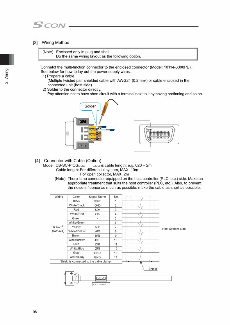
2. W
iring
98
[3] Wiring Method
Connetct the multi-finction connector to the enclosed connector (Model: 10114-3000PE). See below for how to lay out the power supply wires. 1) Prepare a cable.
(Multiple twisted pair shielded cable with AWG24 (0.2mm2) or cable enclosed in the connected unit (host side)
2) Solder to the connector directly. Pay attention not to have short circuit with a terminal next to it by having pretinning and so on.
[4] Connector with Cable (Option) Model: CB-SC-PIOS□□□ □□□ is cable length: e.g. 020 = 2m
Cable length: For differential system, MAX. 10m For open collector, MAX. 2m
(Note) There is no connector equipped on the host controller (PLC, etc.) side. Make an appropriate treatment that suits the host controller (PLC, etc.). Also, to prevent the noise influence as much as possible, make the cable as short as possible.
IOUT 1 GND 2 SD+ 3 SD- 4 - 5 - 6
AFB 7 /AFB 8 BFB 9 /BFB 10 ZFB 11 /ZFB 12 GND 13
0.2mm2
(AWG24)
GND 14
Wiring Color Signal Name No.
Shield is connected to the cable clamp
Host System Side
Shield
Black White/Black
White/Red
White/Green
White/Yellow
White/Brown
White/Blue
White/Gray
Red
Green
Yellow
Brown
Blue
Gray
□□□
(Note) Enclosed only in plug and shell. Do the same wiring layout as the following option.
Solder

2. Wiring
99
[5] Pulse Converter: JM-08 The pulse converter converts command pulses in the those in the differential mode to open collector mode. Use this converter if the host controller sends output pulses in the applicable for open collector (24V type).
A recommended installation sample is shown in the figure below. • Make the cable length between the host controller and pulse converter as short as possible.
• Keep pulse converters separated for 10mm or more from each other.
Caution : 1) Pay attention not to insert wrongly because it is the same e-CON connector as input
and output. Putting the power on with the insertion being wrong will burn JM-08. 2) Use the pulse converter in the ambient temperature range between 0C to 40C. 3) The temperature increase of about 30C occurs during operation. Accordingly, neither
install several pulse converters in close contact nor install them within a duct. Do not install the pulse converter near other heating devices.
4) If more than one pulse converters are installed, set a pulse converter apart from another by 10mm or more.
5) Make the wiring between the host controller (PLC etc.) and JM-08 as short as possible. Long wires make it easy to pick up noise. Also make the wiring between JM-08 to SCON controller as short as possible. Place JM-08 close to the host controller.
Wiring length : 50mm or shorter recommended
Host Controller
10mm or more
10mm or more
If this installation cannot be avoided, shorten the length of the wiring with the host controller as much as possible.
Host Controller SCON-CB(PLC etc.)

2. W
iring
100
2.4.6 Connection of Regenerative Unit Lay out necessary number of regenerative units.
● Image of wiring
[Reference for the quantity to be connected]
Actuator Model Cycle Time [sec] Number of Connected Regenerative Units [untis]
RCS3-RA15R (3t type) Not necessary
RCS3-RA20R (5t type)
12 to 0 6 to 11.9 1 3.5 to 5.9 2
Not Available for Setting The number of connectable units is the same regardless of the orientation of the actuator installation (horizontal / vertical).
The number of connectable regenerative units is two units at the maximum. In case “0CA” overheat alarm gets generated even with two units connected, adjust the operational conditions such as to make the standby duration longer or to make the velocity lower.
Caution : 1) Connecting three regenerative unit or more will cause malfunction.
2) Do not attempt to touch the regenerative units during use as the temperature gets very high.
3) Do not install them near a flammable object. 4) It is recommended to use cables with high heat resistance performance. Also,
consider wire layout so the cables would not touch the regenerative units. 5) The unit is equipped with a built-in temperature sensor. Establish the circuit
constructed to cut off the power source when the temperature sensor is in operation.
6) The number of connected units in the table is a reference for when a work piece of 10kg is mounted and the standby duration is set to 1 second.
To Drive Cutoff Circuit Temperature Sensor Contact (Contact opens when excessive temperature rise detected)
Regenerative Unit Connector
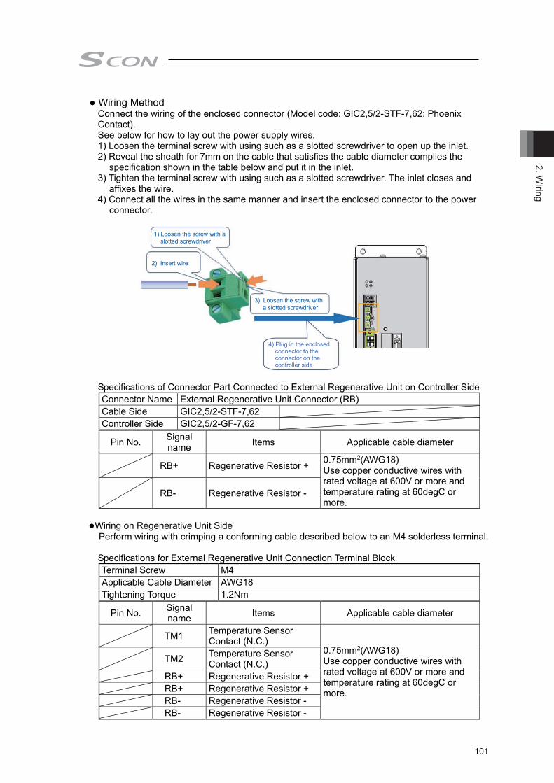
2. Wiring
101
● Wiring Method Connect the wiring of the enclosed connector (Model code: GIC2,5/2-STF-7,62: Phoenix Contact). See below for how to lay out the power supply wires. 1) Loosen the terminal screw with using such as a slotted screwdriver to open up the inlet. 2) Reveal the sheath for 7mm on the cable that satisfies the cable diameter complies the
specification shown in the table below and put it in the inlet. 3) Tighten the terminal screw with using such as a slotted screwdriver. The inlet closes and
affixes the wire. 4) Connect all the wires in the same manner and insert the enclosed connector to the power
connector.
1) Loosen the screw with a slotted screwdriver
3) Loosen the screw with a slotted screwdriver
2) Insert wire
4) Plug in the enclosed connector to the connector on the controller side
Specifications of Connector Part Connected to External Regenerative Unit on Controller Side Connector Name External Regenerative Unit Connector (RB) Cable Side GIC2,5/2-STF-7,62 Controller Side GIC2,5/2-GF-7,62
Pin No. Signal name Items Applicable cable diameter
RB+ Regenerative Resistor + 0.75mm2(AWG18) Use copper conductive wires with rated voltage at 600V or more and temperature rating at 60degC or more.
RB- Regenerative Resistor -
●Wiring on Regenerative Unit Side
Perform wiring with crimping a conforming cable described below to an M4 solderless terminal.
Specifications for External Regenerative Unit Connection Terminal Block Terminal Screw M4 Applicable Cable Diameter AWG18 Tightening Torque 1.2Nm
Pin No. Signal name Items Applicable cable diameter
TM1 Temperature Sensor Contact (N.C.)
0.75mm2(AWG18) Use copper conductive wires with rated voltage at 600V or more and temperature rating at 60degC or more.
TM2 Temperature Sensor Contact (N.C.)
RB+ Regenerative Resistor + RB+ Regenerative Resistor + RB- Regenerative Resistor - RB- Regenerative Resistor -
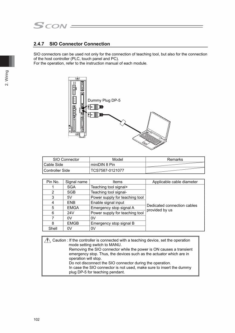
2. W
iring
102
2.4.7 SIO Connector Connection SIO connectors can be used not only for the connection of teaching tool, but also for the connection of the host controller (PLC, touch panel and PC). For the operation, refer to the instruction manual of each module.
SIO Connector Model Remarks Cable Side miniDIN 8 Pin Controller Side TCS7587-0121077
Pin No. Signal name Items Applicable cable diameter 1 SGA Teaching tool signal+
Dedicated connection cables provided by us
2 SGB Teaching tool signal- 3 5V Power supply for teaching tool4 ENB Enable signal input 5 EMGA Emergency stop signal A 6 24V Power supply for teaching tool7 0V 0V 8 EMGB Emergency stop signal B
Shell 0V 0V Caution : If the controller is connected with a teaching device, set the operation
mode setting switch to MANU. Removing the SIO connector while the power is ON causes a transient emergency stop. Thus, the devices such as the actuator which are in operation will stop. Do not disconnect the SIO connector during the operation. In case the SIO connector is not used, make sure to insert the dummy plug DP-5 for teaching pendant.
Dummy Plug DP-5
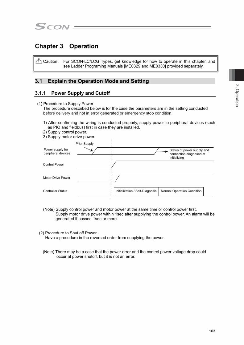
3. Operation
103
Power supply for peripheral devices
Chapter 3 Operation
Caution : For SCON-LC/LCG Types, get knowledge for how to operate in this chapter, and see Ladder Programing Manuals [ME0329 and ME0330] provided separately.
3.1 Explain the Operation Mode and Setting 3.1.1 Power Supply and Cutoff
(1) Procedure to Supply Power
The procedure described below is for the case the parameters are in the setting conducted before delivery and not in error generated or emergency stop condition. 1) After confirming the wiring is conducted properly, supply power to peripheral devices (such
as PIO and fieldbus) first in case they are installed. 2) Supply control power. 3) Supply motor drive power. Control Power Motor Drive Power Controller Status Initialization / Self-Diagnosis Normal Operation Condition
(Note) Supply control power and motor power at the same time or control power first.
Supply motor drive power within 1sec after supplying the control power. An alarm will be generated if passed 1sec or more.
(2) Procedure to Shut off Power Have a procedure in the reversed order from supplying the power. (Note) There may be a case that the power error and the control power voltage drop could
occur at power shutoff, but it is not an error.
Prior Supply
Status of power supply and connection diagnosed at initializing

3. O
pera
tion
104
3.1.2 Explain the Operation Mode [1] What is Servo Press Pressing direction is only the direction to press towards the work piece.
Caution : Pressing direction is only the direction to press towards the work piece. It is not applicable for pulling against the work piece.
Desired pressing operation can be easily realized with fine-tuning of pressurizing force, speed, etc. This controller is used with combination from two types of pressurizing modes and four types or five types of stopping systems. No. Pressurize Mode Stopping System Stop Status 1)
Speed Control
Potition Stop
Positioning Stop 2) Distance Stop 3) Load Stop 4) Incremental Load Stop 5)
Force Control
Potition Stop
Pressing Operation Continued 6) Distance Stop 7) Load Stop 8) Incremental Load Stop 9) Potition Stop 2 Positioning Stop
Caution : The speed control mode and and position stop 2 of the above 9) conducts the positioning at the set position. Therefore, the position after pressurizing is constant, but the pressing force may not be stable. The force control mode except for the position stop 2 above 9), conducts the pressing at the set load as target pressing force. Therefore, the pressing force after pressurizing is constant, but the position may not be stable.
1) Spped Control Position Stop With the position set in pressurizing condition as the target position, movement is conducted forward (press) with the pressurizing speed kept constant. After reaching the set position, stops with the position kept constant. Even if the load fluctuates while moving forward, the speed is kept as constant as possible. It should be used in the pressing operation that requires a stop after movement in the indicated distance. * Program alarm gets generated when reached the maximum load.
Apprch
Press Pressurizing operation
↓ (Constant spped Note 1)
↓ Stops at pressurizing
complete position Note 1
Stop Retains pressurizing complete position during stop time Note 1
Return
Search Deprs
Note 1 Value set in pressing program

3. Operation
105
2) Spped Control Distance Stop With the position set in pressurizing condition as the target distance, movement is conducted forward (press) with the pressurizing speed kept constant. After moving forward for the set distance, stops with the position kept constant. Even if the load fluctuates while moving forward, the speed is kept as constant as possible. It should be used in the pressing operation that requires a stop after movement in the indicated distance even if the pressurizing start position may change. * Program alarm gets generated when reached the maximum load.
3) Spped Control Load Stop
It moves forward till detecting the load that setting load, and the movement is conducted forward (press) with the pressurizing speed kept constant till detection. After detecting the setting load, it stops with the position kept constant. Even if the load fluctuates while moving forward, the speed is kept as constant as possible. It should be used in the pressing operation that requires a stop at the position that the indicate load detected. * Program alarm gets generated when reached the pressurizing limit position.
Apprch
Press Pressurizing operation
↓ (Constant spped Note 1)
↓ Actual position at transition
to pressuring stage +
Stops at pressurizing complete distance Note 1
Stop Retains position at transition to stop stage during stop time
Note 1
Deprs
Note 1 Value set in pressing program
Search
Apprch
Press Pressurizing operation
↓ (Constant spped Note 1)
↓ Stops at position that
pressurizing complete load Note 1 was detected
Stop Retains position at transition to stop stage during stop time Note 1
Deprs
Note 1 Value set in pressing program
Return
ReturnSearch

3. O
pera
tion
106
4) Spped Control IncrementalLoad Stop It moves forward till detecting the load that incremental load set in the pressurizing condition is added to the pressurizing start load, and the movement is conducted forward (press) with the pressurizing speed kept constant till detection. After detecting the added load, it stops with the position kept constant. Even if the load fluctuates while moving forward, the speed is kept as constant as possible. It should be used in the pressing operation that requires a stop at the position that the load that the set incremental load is added to the pressurizing start load is detected. * Program alarm gets generated when reached the pressurizing limit position.
5) Force Control Position Stop With the position set in pressurizing condition as the target position, movement is conducted forward (press) with the pressurizing speed kept constant up to set position (Note 1). With the load at the time of reaching the set position as the target load, stop (Note 2) is conducted with the pressing force kept constant. * Program alarm gets generated when reached the maximum load at pressurizing. The program
alarm also gets generated when the position exceeded the range of ±0.1mm at transition to stop stage.
Note 1: After transited to the force control, pressurizing speed would not be constant. (The condition of transition is to be set in Parameter No. 173 Force Control Transition Threshold)
Note 2: When a subject to be pressed (work piece) has moved away, the actuator chases for 0.1mm at maximum. Therefore, the actual stop position may exceed 0.1mm at maximum from the set position.
Apprch
Press Pressurizing operation
↓ (Constant spped Note 1)
↓ Actual position at transition
to pressuring stage +
Stops at position that pressurizing complete
incremental load Note 1 was detected
Stop Retains position at transition to stop stage during stop time
Note 1
Deprs
Note 1 Value set in pressing program
Return
Search
Apprch
Press Pressurizing operation
↓ (Constant spped Note 3, Note 4)
↓ Stops at pressurizing
complete position Note 3
Stop Retains pressurized condition at load at the complete of the pressurizing stage during stop time Note 3
Deprs
Note 3 Value set in pressing program Note 4 The velocity may not be
constant during the force control.
ReturnSearch

3. Operation
107
6) Force Control Distance Stop With the position set in pressurizing condition the target distance, movement is conducted forward (press) with the pressurizing speed kept constant up to set position (Note 1). With the load at the time that moving forward for the set distance is complete as the target load, stop (Note 2) is conducted with the pressing force kept constant. It should be used in the pressing operation that requires a stop in detection load of after movement position in the indicated distance even if the pressurizing start position may change. * Program alarm gets generated when reached the maximum load at pressurizing. The program
alarm also gets generated when the position exceeded the range of ±0.1mm at transition to stop stage.
Note 1: After transited to the force control, pressurizing speed would not be constant. (The condition of transition is to be set in Parameter No. 173 Force Control Transition Threshold)
Note 2: When a subject to be pressed (work piece) has moved away, the actuator chases for 0.1mm at maximum. Therefore, the actual stop position may exceed 0.1mm at maximum from the set position.
7) Force Control Load Stop
With the position set in pressurizing condition the target distance, movement is conducted forward (press) with the pressurizing speed kept constant up to set position (Note 1). Stop is conducted with the pressing force kept constant so it reaches the target load. It should be used in the pressing operation that requires a stop at the position that the indicate load detected. * Program alarm gets generated when reached the pressurizing limit position. Note 1: After transited to the force control, pressurizing speed would not be constant.
(The condition of transition is to be set in Parameter No. 173 Force Control Transition Threshold)
Apprch
Press Pressurizing operation
↓ (Constant spped Note 3, Note 4)
↓ Actual position at transition
to pressuring stage +
Acquires load at position that moved for pressurizing complete distance Note 3
Stop Retains pressurized condition at load at thecomplete of the pressurizing stage during stop time Note 3
Deprs
Note 3 Value set in pressing program Note 4 The velocity may not be
constant during the force control.
ReturnSearch
Apprch
Press Pressurizing operation
↓ (Constant spped Note 2, Note 3)
↓ Reached target load
Stop Retains pressurized condition at load at thecomplete of the pressurizing stage during stop time Note 2
Deprs
Note 2 Value set in pressing program Note 3 The velocity may not be
constant during the force control.
ReturnSearch

3. O
pera
tion
108
8) Force Control IncrementalLoad Stop With the position set in pressurizing condition the target distance, movement is conducted forward (press) with the pressurizing speed kept constant up to set position (Note 1). With the load at the time that moving forward for the set distance is complete as the target load, stop is conducted with the pressing force kept constant. It should be used in the pressing operation that requires a stop at the position that the load that the set incremental load is added to the pressurizing start load is detected. * Program alarm gets generated when reached the pressurizing limit position. Note 1: After transited to the force control, pressurizing speed would not be constant.
(The condition of transition is to be set in Parameter No. 173 Force Control Transition Threshold)
9) Force Control Position Stop 2
With the target load setting set in the pressurizing condition as the target, pressing operation is conducted under condition that the load reaches the target load by the pressurizing complete position. Once it reaches the setting position, stop is performed with the position retained constant. * Monitoring of load and position will not be conducted during stop after pressurizing is
complete. * Program alarm will be generated if the actuator has not reached the pressurizing target load
when it reached the pressurizing complete position.
Apprch
Press Pressurizing operation
↓ (Constant spped Note 2, Note 3)
↓ Actual position at transition to
pressuring stage +
Stops at position that pressurizing target incremental
load Note 2 was detected
Stop Retains pressurized condition at load at the complete of the pressurizing stage during stop time Note 2
Deprs
Note 2 Value set in pressing program Note 3 The velocity may not be constant
during the force control.
ReturnSearch
Apprch
Press Pressurizing operation
↓ (Load spped Note 1)
↓ Stops at pressurizing
complete position Note 1
Stop Retains pressurizing complete position during stop time Note 1
Deprs
Note 1 Value set in pressing program
Return
Search

3. Operation
109
[2] Press Program The operation of the servo press SCON is to be conducted by setting and executing the press program. Press program setting is to be conducted in the PC software applicable for servo press (*). Shown below is the flow of press program operation. * Refer to PC software (ME0155) provided separately for the applicable versions. The press program consists of the 5 stage. 1) Approach : High speed movement before touching the work piece 2) Probing : Detection of touching work piece 3) Pressurize ⇒ Stop : Stop for indicated period after pressurizing 4) Decompressing : Movement away from work piece (slow-speed) 5) Return : Return the program home (high-speed)
[3] Judgement Judgment is made by the result of load and position* at pressing work complete. * Setting is available also to judge only with load or position.
Judgment is held in every 1ms period for the duration from the moment of the pressurizing finish till the operation stop. If a value out of the judgment range is detected even for once in the timeframe of judgment, it is judged as a failure (program alarm).
Caution : 1) Judgment will not be started until pressurizing has completed in the normal condition.
2) In Force Control / Load (Incremental Load) Stop Mode, the pressurizing operation continues till the load gets in the specified range of the setting load. The program alarm will not be generated even if the load exceeds the setting load significantly at the moment of getting into the pressurizing stage. Also, judgment will not start until the load gets back in the setting load.
PrgHome
Pos.
[1] Apprch
[2] Search[5] Return
[3] Press ⇒ Stop [4] Deprs
Load judgment range
Position judgment range
Load
Position
Judgement only load
(pass range)
Judgement onlydistance
(pass range)
Judgement onlyload
(pass range)
Judgement onlydistance
(pass range)
Judgement both of load and distance
(pass range)
Time

3. O
pera
tion
110
3.1.3 Basic Operation Setting Select the pressurizing operation mode and set the five stages of the press program.
3.1.3.1 Prepare a Setting 1) Start PC software applicable for servo press. 2) Select the program section in the initial window, click on the required program number and the
program setting screen opens. 3.1.3.2 Select the Press Motion Mode Select the press motion mode on the setting window.
Simple Setting Window
Detailed Setting Window
Click it and the screen switches between the simple setting window and the detailed setting window displays.
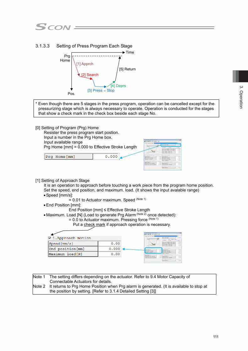
3. Operation
111
3.1.3.3 Setting of Press Program Each Stage * Even though there are 5 stages in the press program, operation can be cancelled except for the
pressurizing stage which is always necessary to operate. Operation is conducted for the stages that show a check mark in the check box beside each stage No.
[0] Setting of Program (Prg) Home Resister the press program start postion. Input a number in the Prg Home box. Input available range
Prg Home [mm] = 0.000 to Effective Stroke Length [1] Setting of Approach Stage It is an operation to approach before touching a work piece from the program home position. Set the speed, end position, and maximum. load. (It shows the input avalable range)
Speed [mm/s]: = 0.01 to Actuator maximum. Speed (Note 1)
End Position [mm]: End Position [mm] ≤ Effective Stroke Length
Maximum. Load [N] (Load to generate Prg Alarm (Note 2) once detected): = 0.0 to Actuator maximum. Pressing force (Note 1)
Put a check mark if approach operation is necessary.
Note 1 The setting differs depending on the actuator. Refer to 9.4 Motor Capacity of Connectable Actuators for details.
Note 2 It returns to Prg Home Position when Prg alarm is generated. (It is available to stop at the position by setting. [Refer to 3.1.4 Detailed Setting [3]]
PrgHome
Pos.
[1] Apprch
[2] Search [5] Return
[3] Press ⇒ Stop[4] Deprs
Time
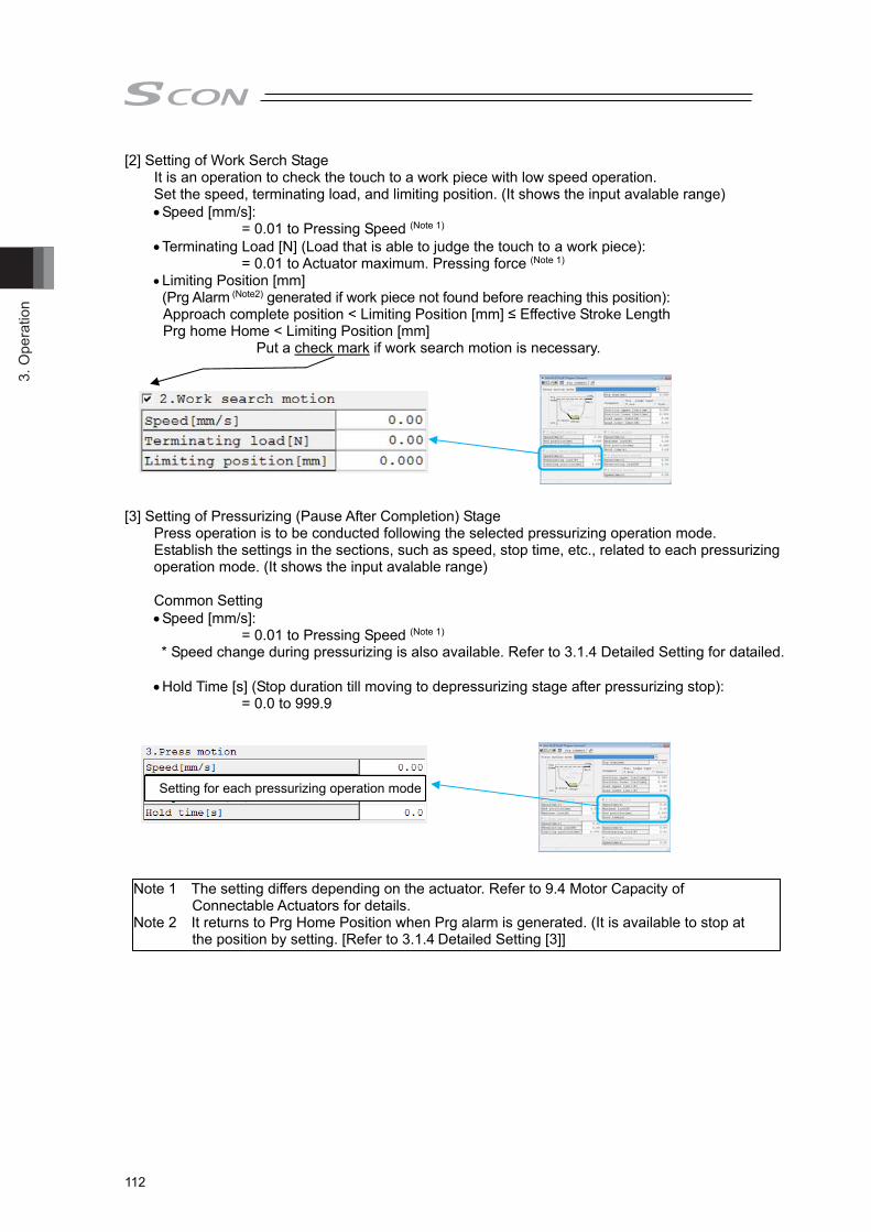
3. O
pera
tion
112
[2] Setting of Work Serch Stage It is an operation to check the touch to a work piece with low speed operation. Set the speed, terminating load, and limiting position. (It shows the input avalable range)
Speed [mm/s]: = 0.01 to Pressing Speed (Note 1)
Terminating Load [N] (Load that is able to judge the touch to a work piece): = 0.01 to Actuator maximum. Pressing force (Note 1)
Limiting Position [mm] (Prg Alarm (Note2) generated if work piece not found before reaching this position): Approach complete position < Limiting Position [mm] ≤ Effective Stroke Length Prg home Home < Limiting Position [mm]
Put a check mark if work search motion is necessary. [3] Setting of Pressurizing (Pause After Completion) Stage Press operation is to be conducted following the selected pressurizing operation mode. Establish the settings in the sections, such as speed, stop time, etc., related to each pressurizing
operation mode. (It shows the input avalable range) Common Setting
Speed [mm/s]: = 0.01 to Pressing Speed (Note 1)
* Speed change during pressurizing is also available. Refer to 3.1.4 Detailed Setting for datailed.
Hold Time [s] (Stop duration till moving to depressurizing stage after pressurizing stop): = 0.0 to 999.9
Setting for each pressurizing operation mode
Note 1 The setting differs depending on the actuator. Refer to 9.4 Motor Capacity of Connectable Actuators for details.
Note 2 It returns to Prg Home Position when Prg alarm is generated. (It is available to stop at the position by setting. [Refer to 3.1.4 Detailed Setting [3]]
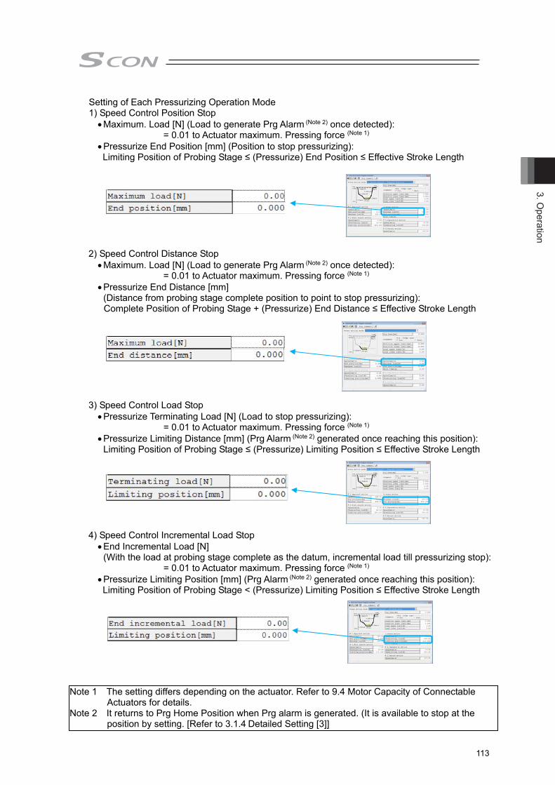
3. Operation
113
Setting of Each Pressurizing Operation Mode 1) Speed Control Position Stop
Maximum. Load [N] (Load to generate Prg Alarm (Note 2) once detected): = 0.01 to Actuator maximum. Pressing force (Note 1)
Pressurize End Position [mm] (Position to stop pressurizing): Limiting Position of Probing Stage ≤ (Pressurize) End Position ≤ Effective Stroke Length
2) Speed Control Distance Stop Maximum. Load [N] (Load to generate Prg Alarm (Note 2) once detected):
= 0.01 to Actuator maximum. Pressing force (Note 1) Pressurize End Distance [mm]
(Distance from probing stage complete position to point to stop pressurizing): Complete Position of Probing Stage + (Pressurize) End Distance ≤ Effective Stroke Length
3) Speed Control Load Stop Pressurize Terminating Load [N] (Load to stop pressurizing):
= 0.01 to Actuator maximum. Pressing force (Note 1) Pressurize Limiting Distance [mm] (Prg Alarm (Note 2) generated once reaching this position):
Limiting Position of Probing Stage ≤ (Pressurize) Limiting Position ≤ Effective Stroke Length
4) Speed Control Incremental Load Stop End Incremental Load [N]
(With the load at probing stage complete as the datum, incremental load till pressurizing stop): = 0.01 to Actuator maximum. Pressing force (Note 1)
Pressurize Limiting Position [mm] (Prg Alarm (Note 2) generated once reaching this position): Limiting Position of Probing Stage < (Pressurize) Limiting Position ≤ Effective Stroke Length
Note 1 The setting differs depending on the actuator. Refer to 9.4 Motor Capacity of Connectable Actuators for details.
Note 2 It returns to Prg Home Position when Prg alarm is generated. (It is available to stop at the position by setting. [Refer to 3.1.4 Detailed Setting [3]]

3. O
pera
tion
114
5) Force Control Position Stop Maximum. Load [N] (Load to generate Prg Alarm (Note 2) once detected):
= 0.01 to Actuator maximum. Pressing force (Note 1) Pressurize End Position [mm] (Position to stop pressurizing):
Limiting Position of Probing Stage ≤ Pressurize End Position ≤ Effective Stroke Length 6) Force Control Distance Stop
Maximum. Load (Load to generate Prg Alarm (Note 2) once detected): = 0.01 to Actuator maximum. Pressing force (Note 1)
Pressurize End Distance [mm] (Distance from probing stage complete position to point to stop pressurizing):
End Position of Probing Stage + (Pressurize) End Distance ≤ Effective Stroke Length 7) Force Control Load Stop
Target Load [N] (Load to stop pressurizing): =0.01 to Actuator maximum. Pressing force (Note 1)
Pressurize Limiting Position [mm] (Prg Alarm (Note 2) generated once reaching this position): Limiting Position of Probing Stage + Pressurize Limiting Position ≤ Effective Stroke Length 8) Force Control Incremental Stop
Target Incremental Load [N] (With the load at probing stage complete as the datum, incremental load till pressurizing stop):
= 0.01 to Actuator maximum. Pressing force (Note 1) Pressurize Limiting Position [mm] (Prg Alarm (Note 2) generated once reaching this position):
Limiting Position of Probing Stage < Pressurize Limiting Position ≤ Effective Stroke Length
Note 1 The setting differs depending on the actuator. Refer to 9.4 Motor Capacity of Connectable Actuators for details.
Note 2 It returns to Prg Home Position when Prg alarm is generated. (It is available to stop at the position by setting. [Refer to 3.1.4 Detailed Setting [3]]

3. Operation
115
9) Force Control Position Stop 2 Target Load [N] (Target load at pressurizing operation):
= 0.01 to Max. Pressing Force Pressurizing Complete Position [mm] (position to stop pressurizing):
Searching Stage Limit Position ≤ Pressurizing Complete Position ≤ Effective Stroke Length [4] Setting for Decompressing stage It is an operation to move away from a work piece in low speed. Set the speed, depression terminating load. (It shows the input avalable range)
Speed [mm/s]: = 0.01 to Pressing Speed (Note 1)
Depression Terminating Load [N] (judged as depressurizing complete once the load gets below this setting):
= 0.01 to Actuator maximum. Pressing force (Note 1) Put a check mark if Depression motion is necessary. [5] Setting for Probing Stage It is an operation to move away from a work piece in high speed and return to the program
home position. Set the speed. (It shows the input avalable range)
Speed [mm/s]: = 0.01 to Actuator maximum. Speed (Note 1)
Put a check mark if Return motion is necessary.
Note 1 The setting differs depending on the actuator. Refer to 9.4 Motor Capacity of Connectable Actuators for details.
Note 2 It returns to Prg Home Position when Prg alarm is generated. (It is available to stop at the position by setting. [Refer to 3.1.4 Detailed Setting [3]])

3. O
pera
tion
116
[6] Judgement Judgment can be conducted with the position (distance) and load while in stop time at the
pressurizing stage complete. Setting is available also to judge only with load or position. Set the upper and lower limits for the position and load. (It shows the input avalable range) Caution 1) Upper Limit = Judgment will not be executed if set to lower limit. 2) Upper Limit < Prg Alarm (Note 2) will be generated if set to Upper Limit < Lower Limit.
Position (distance) Upper Limit [mm]: = 0.000 to Effective Stroke Length
Position (distance) Lower limit [mm]: = 0.000 to Effective Stroke Length
Load Upper Limit [N]: = 0.01 to 100% of actuator maximum pressing force (Note 1)
Load Lower Limit [N]: = 0.01 to Actuator maximum pressing force (Note 1)
Judgment with Position
Judgment with Distance
This is the end of the press program basic setting. Transfer → Write in the set content to the controller.
To establish settings in detail such as to have a chained operation of several programs or operation at Prg Alarm generation, refer to the detailed setting in the following page.
Note 1 The setting differs depending on the actuator. Refer to 9.4 Motor Capacity of Connectable Actuators for details.
Note 2 It returns to Prg Home Position when Prg alarm is generated. (It is available to stop at the position by setting. [Refer to 3.1.4 Detailed Setting [3]]
Transfer Button Click it to transfer the setting to the controller.

3. Operation
117
3.1.4 Detailed Settings (Optional Settings) Set the following detailed items if necessary.
[1] Gain set [2] Continuous Prg No. [3] Return Motion of Prg Alarm [4] Acc and Dcl [5] Show Acc and Dcl Individually [6] Wait Time [7] Allowed Prg Operating Time [8] Detailed Settings for Pressurizing Stage (Allowable Operation Time, Speed Switchover)
Settings are to be established in the detailed setting window.
Click on the indicated button in the simple setting window, and the screen switches to the detailed setting window.
Simple Setting Window Detailed Setting Window
[1] Gain set The four types of servomotor gain settings registered in advance can be switched over for each
press program. [Servo adjustment refer to section 7.3]
Parameters to be contracted in 1 set
Servo Gain Number (Position Gain) Position Feed Forward Gain Speed Loop Proportional Gain Speed Loop Integral Gain Torque Filter Time Constant Current Control Band Number Force Gain
Set the indicated gain set number in the gain set box.
Setting Parameter Set Select Parameter No. 0 Gain set 0 7, 71, 31 to 33, 54, 94 1 Gain set 1 120 to 125, 174 2 Gain set 2 126 to 131, 175 3 Gain set 3 132 to 137, 176
Click it and the screen switches between the simple setting window and the detailed setting window displays.

3. O
pera
tion
118
Remove check marks on depressurizing and return stages which are to be cancelled
Remove check marks on approach and probing stages which are to be cancelled
[2] Continuous Prg No. If several press programs are required to be operated in a row, indicate the program
number that is desired to be executed. Programs can be chained infinitely. Also, the same program No. can be set.
e.g.) Using Press Program 1 only up to the pressurizing stage, and have Press Program 2 in charge for the pressurizing stage and returning stage to have a double pressing operation. (Set 2 to the chain Prg number of Press Program 1)
● Setting for Press Program 1: ● Setting for Press Program 2:
Press Program 1 Press Program 2 Press Program 1 ← → Press Program 2
[5] Return
Pos.
[1] Apprch
[2] Search
[3] Press ⇒ Stop
Pos.
[1] Apprch
[2] Search [5] Return
[3] Press ⇒ Stop [4] Deprs
[5] Return
[3] Press ⇒ Stop[4] Deprs
PrgHome
Pos.
[1] Apprch
[2] Search
[3] Press ⇒ Stop [4] Deprs
PrgHome
PrgHome

3. Operation
119
Press Show Acc and Dcl Individual Button, and the acceleration and deceleration items get displayed in the setting items for each stage and setting adjustment becomes available.
[3] Return Motion of Prg Alarm Select whether to return to Prg Home Position and turn the servo OFF or to stop at the
point without returning when Prg Alarm is generated.
Yes : To return No : Not to return
Note 1: When an alarm other than Prg Alarm is generated, operation to return to Prg Home Position would not be made. It stops at the point.
Note 2: When returning to Prg Home Position, Parameter No. 8 Speed Initial Value is used for speed and Parameter No. 9 Acceleration/Deceleration Initial Value for acceleration and deceleration.
[4] Acc and Dcl Establish the setting for acceleration when operating the actuator in the press program.
Check [5] Show Acc and Dcl Individually in the next section when setting the acceleration and deceleration individually for each stage. (It shows the input avalable range)
● Acc and Dcl [G]: = 0.01 to Actuator maximum. Acc and Dcl (Note 1)
[5] Show Acc and Dcl Individually Establish the setting for acceleration of the actuator for each stage in a press program.
(It shows the input avalable range) ● Acc and Dcl [G]:
= 0.01 to Actuator maximum. Acc and Dcl (Note 1)
(Reference) In here, explains acceleration. The concept is the same for deceleration. 1G = 9800mm/s2: Acceleration to accelerate up to 9800mm/s in 1 second 0.3G: Acceleration to accelerate up to 9800mm/s × 0.3 = 2940mm/s in 1 second
Note 1 The setting differs depending on the actuator. Refer to 9.4 Motor Capacity of Connectable Actuators for details.
Speed
Time
9800mm/s
1s
1G
2940mm/s
0.3G

3. O
pera
tion
120
[6] Wait Time Establish the setting for the wait time after a press program is completed in normal
condition till the next program start command or chained Prg start. (It shows the input avalable range)
● Wait Time [s]: = 0 to 999.9
[7] Allowed Prg Operating Time
Establish the setting for the allowable operation time for one program. When chained program is set, monitoring is conducted in the time set for each program. Prg alarm (Note 1) will be generated if a program does not finish in this time (wait time excluded).
Also, judgment will not take place if set to 0. (It shows the input avalable range) ● Allowed Prg Operating Time [s]:
= 0 to 999.9 Note 1 It returns to Prg Home Position when Prg alarm is generated. (It is available to stop
at the position by setting. [Refer to Detailed Setting (this chapter) [3]]
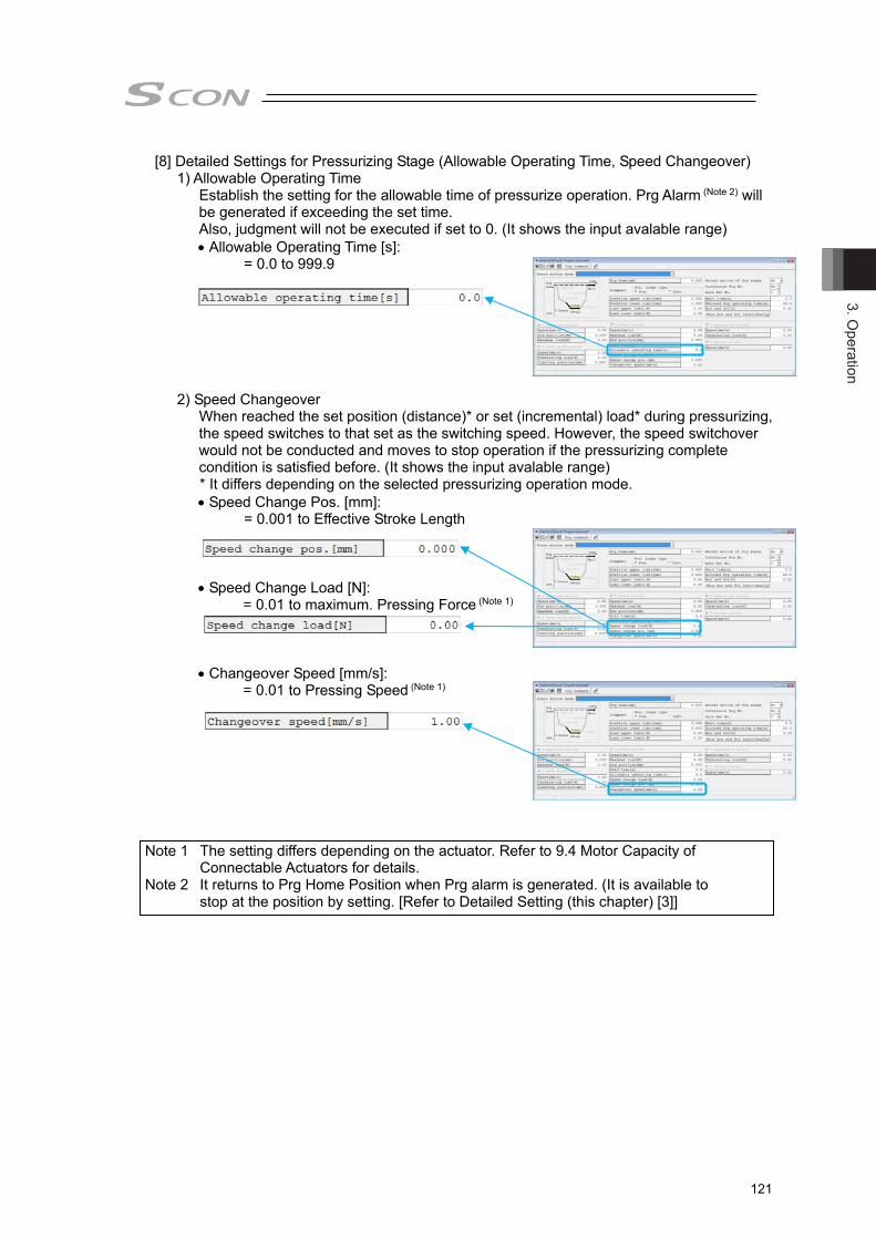
3. Operation
121
[8] Detailed Settings for Pressurizing Stage (Allowable Operating Time, Speed Changeover) 1) Allowable Operating Time
Establish the setting for the allowable time of pressurize operation. Prg Alarm (Note 2) will be generated if exceeding the set time. Also, judgment will not be executed if set to 0. (It shows the input avalable range) Allowable Operating Time [s]:
= 0.0 to 999.9
2) Speed Changeover When reached the set position (distance)* or set (incremental) load* during pressurizing,
the speed switches to that set as the switching speed. However, the speed switchover would not be conducted and moves to stop operation if the pressurizing complete condition is satisfied before. (It shows the input avalable range) * It differs depending on the selected pressurizing operation mode. Speed Change Pos. [mm]:
= 0.001 to Effective Stroke Length
Speed Change Load [N]: = 0.01 to maximum. Pressing Force (Note 1)
Changeover Speed [mm/s]: = 0.01 to Pressing Speed (Note 1)
Note 1 The setting differs depending on the actuator. Refer to 9.4 Motor Capacity of Connectable Actuators for details.
Note 2 It returns to Prg Home Position when Prg alarm is generated. (It is available to stop at the position by setting. [Refer to Detailed Setting (this chapter) [3]]

3. O
pera
tion
122
7) Direct ValueMovement
3.2 Trial Run
Have a trial operation of the program set in the PC software.
Caution: (1) Do not attempt to establish the setting that exceeds the rated acceleration/deceleration speed whish is stated in the catalog or an instruction manual of an actuator. Setting above the rated acceleration/deceleration may shorten the actuator life remarkably.
(2) In case there is impact or vibration on the actuator or work piece, decrease the acceleration and deceleration. Keeping using in such condition will shorten the actuator life remarkably.
3.2.1 Manual Operation (Jog etc)
Open the operation window by selecting Operation/Monitoring. 1) Select the trial operation tag, 2) turn the servo ON, 3) have a home-return operation, and then 4) press Jog/Inching Button to have the actuator drive back and forth. Input a number in 5) Position and 6) Speed and press to have the direct indication movement to the input position. 2) Servo ON 3) Home Return 5)Position 6) Speed
PIO Status Display ON 1) Trial Run Tag
4) Jog/Inching
Check the PIO signal statusCheck the actuator status
Jog/InchingSwitchover
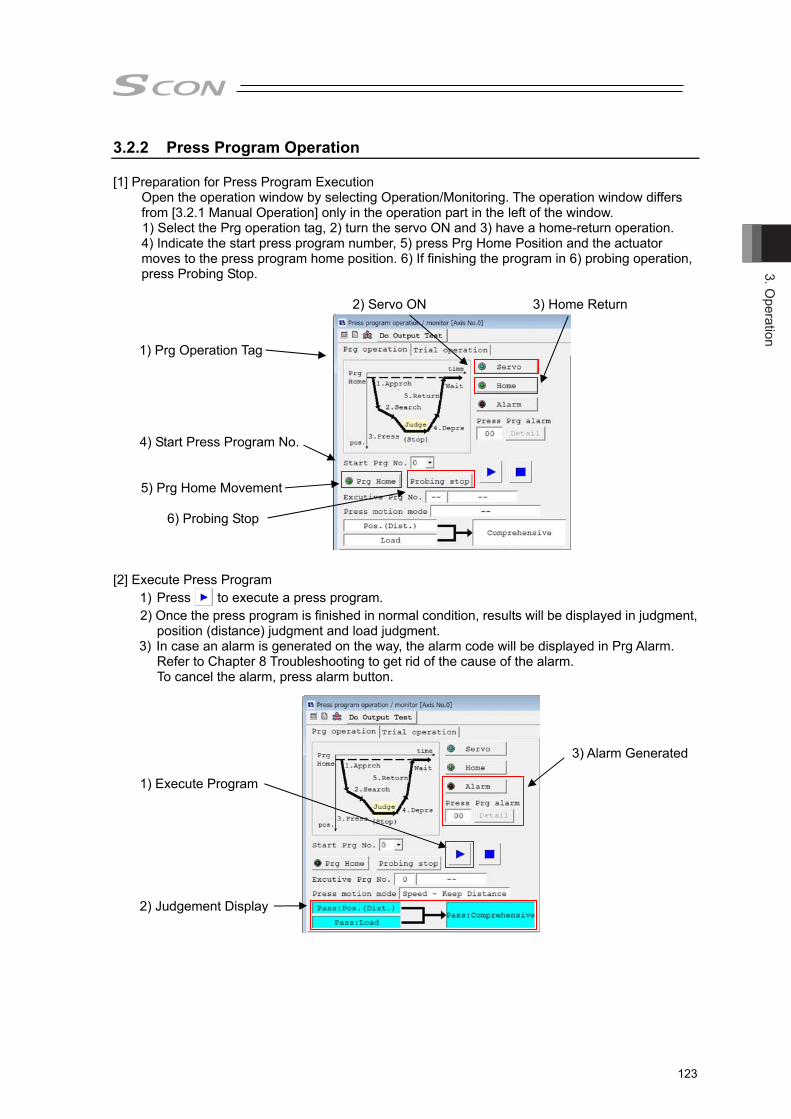
3. Operation
123
3.2.2 Press Program Operation
[1] Preparation for Press Program Execution Open the operation window by selecting Operation/Monitoring. The operation window differs from [3.2.1 Manual Operation] only in the operation part in the left of the window. 1) Select the Prg operation tag, 2) turn the servo ON and 3) have a home-return operation. 4) Indicate the start press program number, 5) press Prg Home Position and the actuator moves to the press program home position. 6) If finishing the program in 6) probing operation, press Probing Stop. 2) Servo ON 3) Home Return 1) Prg Operation Tag 4) Start Press Program No. 5) Prg Home Movement
6) Probing Stop
[2] Execute Press Program 1) Press to execute a press program. 2) Once the press program is finished in normal condition, results will be displayed in judgment,
position (distance) judgment and load judgment. 3) In case an alarm is generated on the way, the alarm code will be displayed in Prg Alarm.
Refer to Chapter 8 Troubleshooting to get rid of the cause of the alarm. To cancel the alarm, press alarm button.
3) Alarm Generated 1) Execute Program 2) Judgement Display
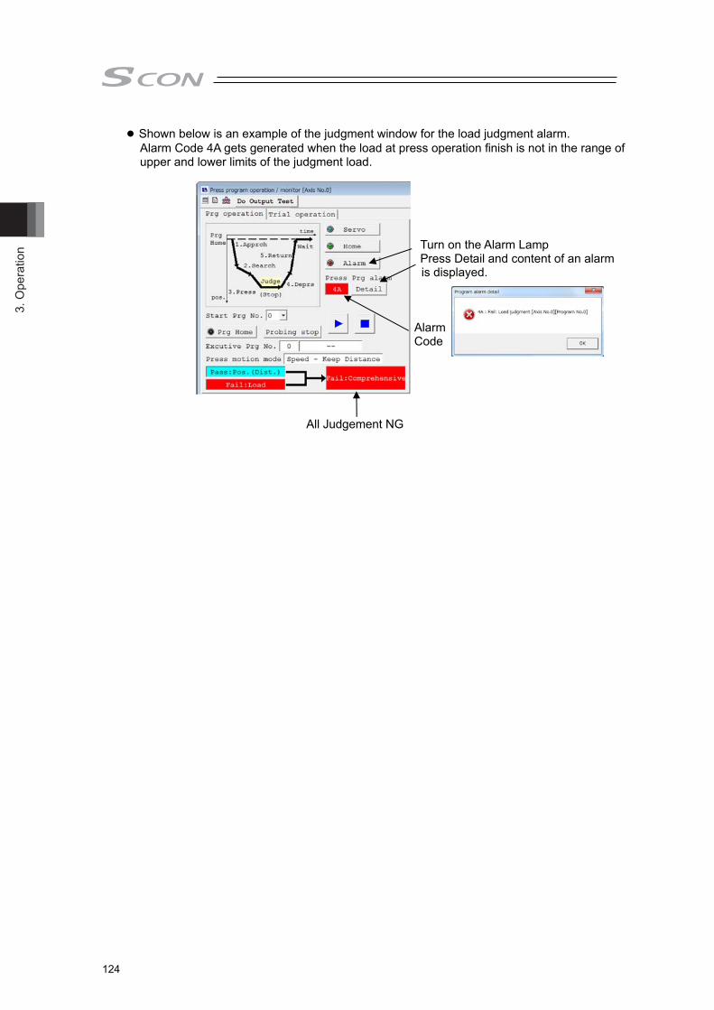
3. O
pera
tion
124
● Shown below is an example of the judgment window for the load judgment alarm. Alarm Code 4A gets generated when the load at press operation finish is not in the range of upper and lower limits of the judgment load.
Turn on the Alarm Lamp Press Detail and content of an alarm is displayed. Alarm Code All Judgement NG

3. Operation
125
3.3 Operation with PIO
3.3.1 I/O Signal Controls The input signal of this controller has the input time constant of 6ms considering the prevention of wrong operation by chattering and noise. Therefore, input each input signal for 6ms or more continuously. The signal cannot be identified if it is less than 6ms.
3.3.2 Operation Ready and Auxiliary Signals
[1] Operation Mode Switch (RMOD, RMDS)
PIO Signal Input RMOD Output RMDS
Two operation modes are provided so that the operation by PIO signals does not overlap with the operation by a teaching tool such as PC software through SIO (serial) communication. The mode change is normally done by the RMOD signal or operation mode setting switch ON the front panel of the controller.
AUTO ········ Operation by PIO signals is valid. MANU ······· Operation through teaching tool is valid.
The controller can be entered into the [MANU] mode by setting RMOD signal to ON. Because the RMOD signal is set to ON with the [MANU] mode selected by using the signal, make the operation sequence interlocked. The table below lists the switches ON the front panel, the modes selected by the RMOD signal and the corresponding output states of the RMDS signal.
: Selected or set to ON, × : Unselected or set to OFF Condition Status
Teaching tool such as PC software
PIO Operation Invalid (Note 1) × × × ×
PIO Operation Allowed (Note 1) × × × ×
Switches ON front panel
AUTO × × × × MANU × × × ×
PIO Input RMOD × × × × PIO Output RMDS × ×
PIO valid: , PIO invalid: ● ● ●
Note 1 [PIO Operation Allowed] or [PIO Operation Invalid] is the function to select a restriction while the teaching tool such as PC software is connected.
Operation by normal PIO
Input Signal
Input Signal
Identify
Not Identify
6ms

3. O
pera
tion
126
Caution: (1) Note that selecting [PIO Operation Allowed] by using the teaching tool such
as PC software makes all PIO signals valid to enable operation however the states of the switches and RMOD signal input may be. In this status, the actuator may be started depending on the signals from PLC.
(2) If the teaching tool such as PC software is disconnected from the controller, [PIO Operation Allowed] or [PIO Operation Invalid] holds the state selected before. After teaching operation or debugging is terminated, select [PIO Operation Allowed] and disconnect the teaching tool such as PC software from the controller.
[2] Servo ON (SON, SV)
PIO Signal Input SON Output SV
1) Servo ON signal SON is the input signal making the servo motor of the actuator operable. 2) If the servo ON is performed to enable operation, the SV output signal is turned ON. 3) With the power being supplied, then controller cannot be operated while the SV signal
remains OFF. If the SON signal is turned OFF under operation of the actuator, the actuator is decelerated and stopped with the forced stop torque. After the stop, the servo OFF occurs to enter the motor into the free running state. The brake (option) is of release-in-excitation type. Therefore, making the excitation on will release the brake (release) while making it OFF will lock the brake (lock).
SONDinamic Brake
BrakeExcitation
SV
LockRelease
Lock
20mm
50mm
50mm100mm
Release
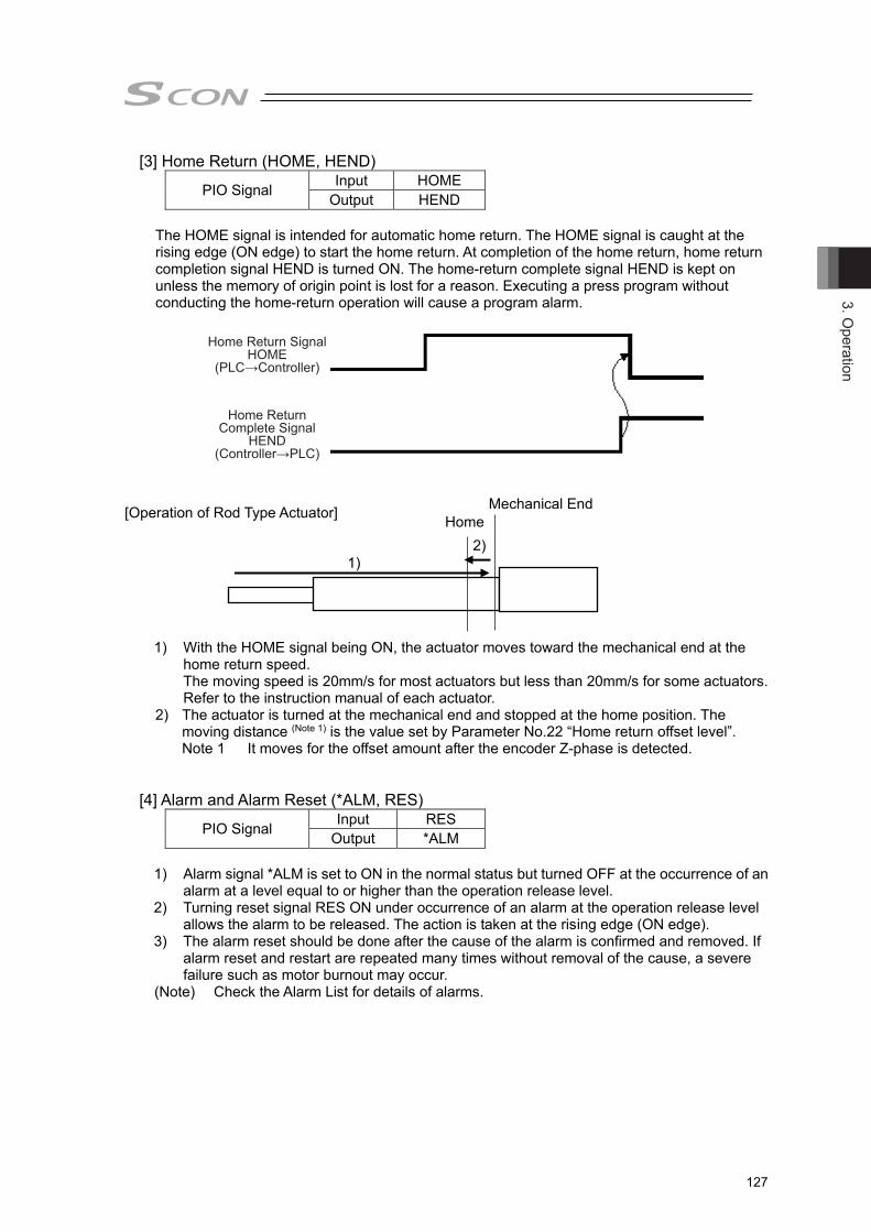
3. Operation
127
[3] Home Return (HOME, HEND)
PIO Signal Input HOME Output HEND
The HOME signal is intended for automatic home return. The HOME signal is caught at the rising edge (ON edge) to start the home return. At completion of the home return, home return completion signal HEND is turned ON. The home-return complete signal HEND is kept on unless the memory of origin point is lost for a reason. Executing a press program without conducting the home-return operation will cause a program alarm.
Home Return SignalHOME
(PLC→Controller)
Home Return Complete Signal
HEND(Controller→PLC)
[Operation of Rod Type Actuator]
1) With the HOME signal being ON, the actuator moves toward the mechanical end at the home return speed. The moving speed is 20mm/s for most actuators but less than 20mm/s for some actuators. Refer to the instruction manual of each actuator.
2) The actuator is turned at the mechanical end and stopped at the home position. The moving distance (Note 1) is the value set by Parameter No.22 “Home return offset level”. Note 1 It moves for the offset amount after the encoder Z-phase is detected.
[4] Alarm and Alarm Reset (*ALM, RES)
PIO Signal Input RES Output *ALM
1) Alarm signal *ALM is set to ON in the normal status but turned OFF at the occurrence of an
alarm at a level equal to or higher than the operation release level. 2) Turning reset signal RES ON under occurrence of an alarm at the operation release level
allows the alarm to be released. The action is taken at the rising edge (ON edge). 3) The alarm reset should be done after the cause of the alarm is confirmed and removed. If
alarm reset and restart are repeated many times without removal of the cause, a severe failure such as motor burnout may occur.
(Note) Check the Alarm List for details of alarms.
Home
1) 2)
Mechanical End

3. O
pera
tion
128
[5] Light Failure Alarm (*ALML) PIO Signal Output *ALML
The light malfunction alarm output (*ALML Signal) turns off if a message level alarm gets generated due to such reasons as number of movement times target exceeding or error in the calendar feature. This signal will be ON as long as the message level alarm is not issued. [Refer to 8.4 Alarm Level of Alarm List for details.]
[6] Breake Release (BKRL) PIO Signal Input BKRL
The brake can be released while BKRL signal is set to ON. For an actuator equipped with a brake, the brake is controlled automatically by ON/OFF of servo, but is necessary, in some cases such as for tuning which requires to move the rod manually by hand, to release the brake.This operation can be done by break release signal BKRL as well as the brake release switch ON the front panel of the controller.
Warning: (1) Take sufficient care to release the brake. Inappropriate drop of the slider or
rod may cause injury or malfunction of actuator body, work piece or system. (2) After the brake is released, always make the brake applied again. Any
operation with the brake remaining released is extremely dangerous. The slider or rod may drop to cause people to be injured and/or the actuator, the work and/or the machine to be damaged.

3. Operation
129
[7] Load Cell Calibration (CLBR, CEND)
PIO Signal Input CLBR Output CEND
A loadcell with no load is set to 0 [N] at shipment. Do not fail to conduct a calibration when the condition that a pressing tool such as a pusher is attached is set to the origin (0 [N]). Just before highly precise pressing, provide readjustment and inspection depending on the condition. (Set Parameter No. 117 to 1, and calibration is automatically conducted at the controller startup. Refer to explanations for parameter for details.)
1) Stop the operation. (Calibration cannot be performed while any axis is operating, pushing a work part or pause. If calibration signal CLBR is set to ON, alarm 0E1 Loadcell Calibration Error occurs).
2) Turn ON the load cell calibration signal (CLBR). 3) Once the calibration is complete, the calibration complete signal (CEND) turns ON.
Thereafter, turn OFF the CLBR signal. If the calibration was not successful, a 0E1 Loadcell Calibration Error alarm generates. Try the calibration again.
Caution: Normal operation commands are not accepted while the CLBR signal is ON.
Note 1 The time zone indicates the calibration signal check time (20ms). If CLBR is turned OFF
within the period, the calibration signal is ignored to cancel the calibration. Note 2 The calibration time depends on Parameter No.119 “Loadcell Calibration Time” (factory
setting: 10ms). However, if it is set to the automatic calibration at startup, the time should be fixed to 10ms no matter what the parameter setting is. If CLBR is turned OFF during the period before CEND is turned ON, alarm 0E1 “Loadcell Calibration Error” occurs.
[Reference] Loadcell is a delicate measurement tool. To maintain its accuracy, it is suggested to
have a calibration at regular intervals (conducted by the supplier). Please contact us for the details related to the calibration such as the calibration frequency.
Caution: The value to start calibration becomes (0 [N]) in the calibration. Therefore, make sure not to apply any load other than the weight of the tool attached on the loadcell at the calibration.
Calibration Signal CLBR
(PLC→Controller)
Calibration Complection Signal CEND
(Controller→PLC)
Calibration time (Note 2)Calibration signal check time (Note 1)
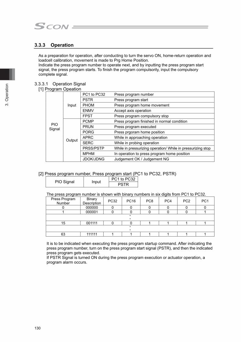
3. O
pera
tion
130
3.3.3 Operation As a preparation for operation, after conducting to turn the servo ON, home-return operation and
loadcell calibration, movement is made to Prg Home Position. Indicate the press program number to operate next, and by inputting the press program start signal, the press program starts. To finish the program compulsorily, input the compulsory complete signal.
3.3.3.1 Operation Signal
[1] Program Opeation
PIO Signal
Input
PC1 to PC32 Press program number PSTR Press program start PHOM Press program home movement ENMV Accept axis operation FPST Press program compulsory stop
Output
PCMP Press program finished in normal condition PRUN Press program executed PORG Press prgoram home position APRC While in approaching operation SERC While in probing operation PRSS/PSTP While in pressurizing operation/ While in pressurizing stop MPHM In operation to press program home position JDOK/JDNG Judgement OK / Judgement NG
[2] Press program number, Press program start (PC1 to PC32, PSTR)
PIO Signal Input PC1 to PC32PSTR
The press program number is shown with binary numbers in six digits from PC1 to PC32.
Press Program Number
Binary Description PC32 PC16 PC8 PC4 PC2 PC1
0 000000 0 0 0 0 0 0 1 000001 0 0 0 0 0 1
・・
15 001111 0 0 1 1 1 1 ・・
63 111111 1 1 1 1 1 1 It is to be indicated when executing the press program startup command. After indicating the
press program number, turn on the press program start signal (PSTR), and then the indicated press program gets executed. If PSTR Signal is turned ON during the press program execution or actuator operation, a program alarm occurs.

3. Operation
131
[3] Press Program Executed, Press Program Finished in Normal Condition (PRUN, PCMP)
PIO Signal Output PRUN PCMP
After the returning stage from the program start, PRUN signal turns ON to show the press program is executed until the standby time (setting established in detail settings) has passed. PCMP signal shows the press program has finished in normal condition. It turns on at the time that the returning stage is finished (standby time setting does not affect), and is kept ON until next press program execution, movement command or servo-OFF. PCMP signal would not turn ON at the press program home position movement complete.
[4] Press Program Home Movement, Press Program Home during Movement, Home
Position (PHOM, MPHM, PORG)
PIO Signal Input PC1 to PC32
PHOM
Output MPHM PORG
If the press program home position movement command signal (PHOM) is turned ON after displaying the press program number with binary numbers in six digits from PC1 to PC32, movement will be made to the program home position of the indicated press program. For the speed at the movement to the program home position, Parameter No. 8 Speed Initial Value is used. For acceleration and deceleration, Parameter No. 9 Acceleration/Deceleration Initial Value is used. MPHM signal (*) turns on during the program home position movement. It stops after reaching the program home position, and PORG signal turns ON during stop. The program alarm occurs if turning PHOM signal ON while executing the press program.
* MPHM signal turns ON also during depressurizing operation and returning operation.
[5] Accept Axis Operation (ENMV) PIO Signal Input ENMV
The actuator is accepted to operate while this signal is ON. The operation of the actuator and the press program stop when this signal is OFF. This signal cannot be used for pause of the press program. (The press program would not resume even if stopping the press program with this signal and turn it ON again.)
[6] Press Program Compulsory Stop (FPST)
PIO Signal Input FPST Turn this signal ON during the press program execution, and the press program in execution stops. When this signal is turned ON, operation to return or not to return to the program home position is executed following the setting in Parameter No. 179 Returning Operation at Press Program Compulsory Stop. For the speed to return, Parameter No. 8 Speed Initial Value is used. For acceleration and deceleration, Parameter No. 9 Acceleration/Deceleration Initial Value is used. This signal cannot be accepted during the press program home position movement.

3. O
pera
tion
132
[7] While in Approaching Operation (APRC) PIO Signal Output APRC
While in approaching operation, this signal turns ON.
[8] While in Probing Operation (SERC) PIO Signal Output SERC
While in probing operation, this signal turns ON.
[9] While in Pressurizing Operation (PRSS) PIO Signal Output PRSS
While in pressurizing operation, this signal turns ON.
[10] While in Pressurizing Stop (PSTP) PIO Signal Output PSTP
This signal turns on during stop after pressurizing complete.
[11] Judgement OK/ Judgement NG (APRC)
PIO Signal Output JDOK JDNG
Normal (JDOK) or error (JDNG) turns on following the result of pressing operation.
Judgement * is conducted after pressurizing finish.
(Judgement is available even if 0 is set to stop time.) * Judgement is to be conducted following the setting (basic setting) of the judgement stage.
[5] Returning
Prg home
Position
[1] Approach
[2] Probing
[3_1] Pressurize
⇒ [3_2] Stop [4] Decompressing
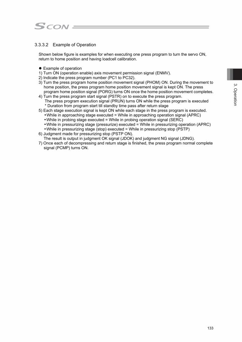
3. Operation
133
3.3.3.2 Example of Operation
Shown below figure is examples for when executing one press program to turn the servo ON, return to home position and having loadcell calibration.
Example of operation 1) Turn ON (operation enable) axis movement permission signal (ENMV). 2) Indicate the press program number (PC1 to PC32). 3) Turn the press program home position movement signal (PHOM) ON. During the movement to
home position, the press program home position movement signal is kept ON. The press program home position signal (PORG) turns ON once the home position movement completes.
4) Turn the press program start signal (PSTR) on to execute the press program. The press program execution signal (PRUN) turns ON while the press program is executed * Duration from program start till standby time pass after return stage 5) Each stage execution signal is kept ON while each stage in the press program is executed. While in approaching stage executed = While in approaching operation signal (APRC)
While in probing stage executed = While in probing operation signal (SERC) While in pressurizing stage (pressurize) executed = While in pressurizing operation (APRC) While in pressurizing stage (stop) executed = While in pressurizing stop (PSTP)
6) Judgment made for pressurizing stop (PSTP ON). The result is output in judgment OK signal (JDOK) and judgment NG signal (JDNG). 7) Once each of decompressing and return stage is finished, the press program normal complete
signal (PCMP) turns ON.
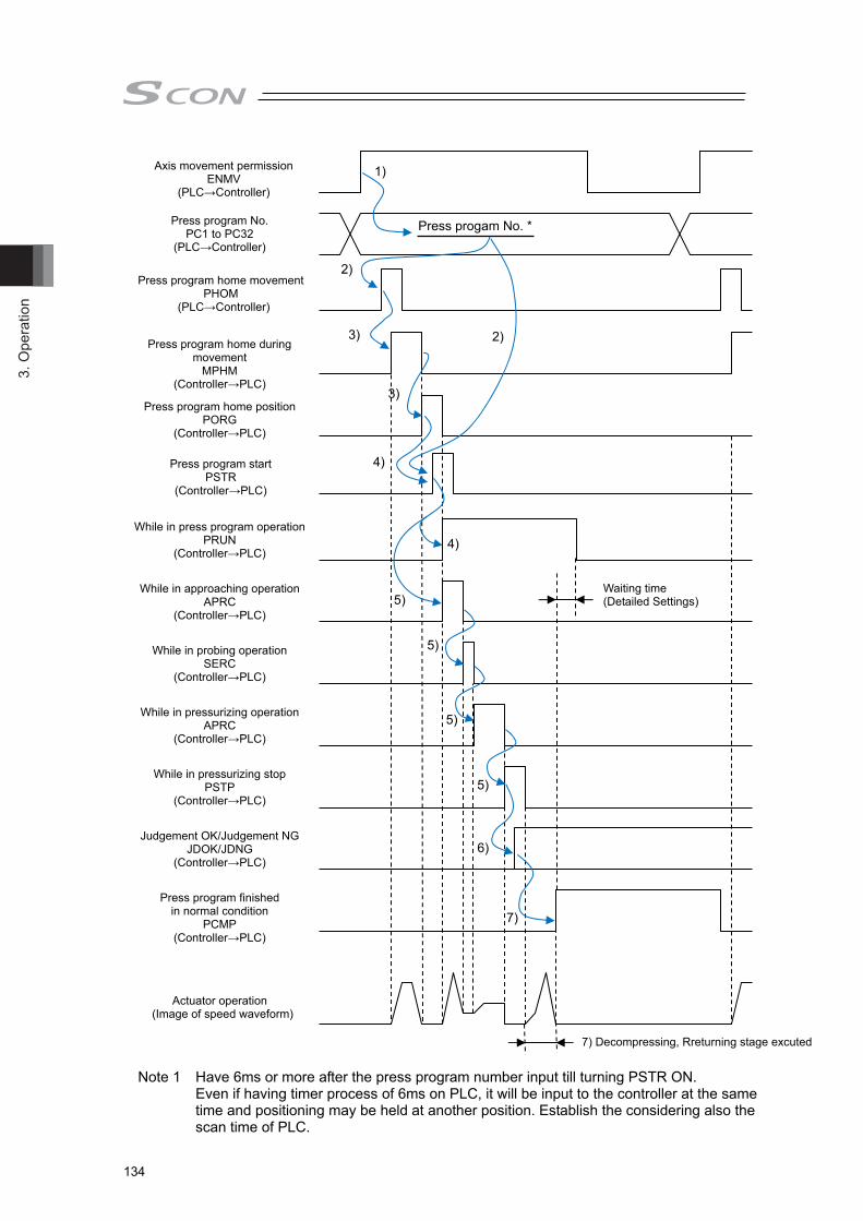
3. O
pera
tion
134
Note 1 Have 6ms or more after the press program number input till turning PSTR ON.
Even if having timer process of 6ms on PLC, it will be input to the controller at the same time and positioning may be held at another position. Establish the considering also the scan time of PLC.
軸移動許可 ENMV (PLC→コントローラ)
Press program No. PC1 to PC32
(PLC→Controller)
Press program start PSTR
(Controller→PLC)
Press program home movement PHOM
(PLC→Controller)
Press program home during movement
MPHM (Controller→PLC)
Press progam No. *
Press program home position PORG
(Controller→PLC)
While in press program operation PRUN
(Controller→PLC)
While in approaching operation APRC
(Controller→PLC)
While in probing operation SERC
(Controller→PLC)
While in pressurizing operation APRC
(Controller→PLC)
While in pressurizing stop PSTP
(Controller→PLC)
Judgement OK/Judgement NG JDOK/JDNG
(Controller→PLC)
Press program finished in normal condition
PCMP (Controller→PLC)
Actuator operation (Image of speed waveform)
7) Decompressing, Rreturning stage excuted
Waiting time (Detailed Settings)
1)
2)
3) 2)
4)
3)
4)
6)
5)
5)
5)
5)
7)
Axis movement permission ENMV
(PLC→Controller)

4. Applicability to Fieldbus
133
Chapter 4 Applicability to Fieldbus Are applicable for the fieldbus shown in the list below. (It is the option which can be selected when
purchasing) It cannot be changed after the product is delivered. Also, PIO cannot be equipped for the fieldbus type. Type of Fieldbus
Fieldbus Name Description Details DeviceNet
Control of the actuator is available with I/O communication using the control signals same as those for PIO or the numerical data communication.
Refer to the other ME0256 (Note1)
CC-Link Refer to the other ME0254 (Note1)
PROFIBUS-DP Refer to the other ME0258 (Note1)
CompoNet Refer to the other ME0220 (Note1)
EtherCAT Refer to the other ME0273 (Note1)
EtherNet/IP Refer to the other ME0278 (Note1)
PROFINET IO Refer to the other ME0333 (Note1)
MECHATROLINK-Ⅰ/Ⅱ(Note 2) Control of the actuator is available with I/O communication using the control signals same as those for PIO or the numerical data communication.
Refer to the other ME0221 (Note1)
Note 1 Handled as a slave unit. For details of each network, check the Instruction Manuals of the master unit provided by the manufacturer and that of the installed PLC.
The Instruction Manuals describing how to use fieldbus are provided separately. Read them together with this manual.
Note 2 It is applicable only to remote I/O mode.
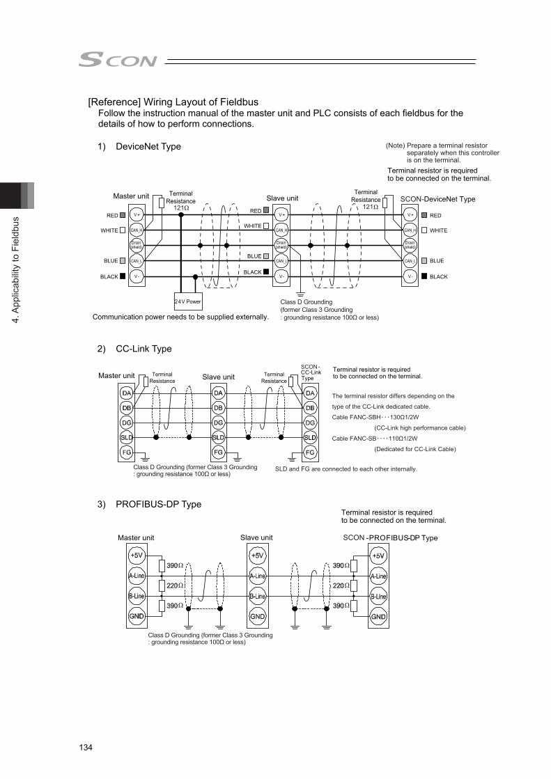
4. A
pplic
abilit
y to
Fie
ldbu
s
134
[Reference] Wiring Layout of Fieldbus Follow the instruction manual of the master unit and PLC consists of each fieldbus for the details of how to perform connections.
1) DeviceNet Type
2) CC-Link Type
3) PROFIBUS-DP Type

4. Applicability to Fieldbus
135
4) CompoNet Type
5) EtherNet/IP Type
6) EtherCAT Type
SCON
SCON

4. A
pplic
abilit
y to
Fie
ldbu
s
136
7) PROFINET-IO Type
8) MECHATROLINK- Type
TerminaterJEPMC-W6022
Master unit SCON
MECHATROLINK CableJEPMC-W6002-□□ JEPMC-W6003-□□
SCON
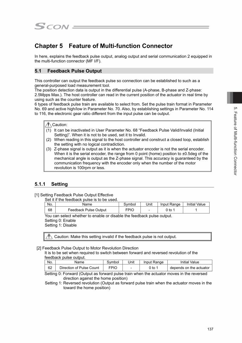
5. Feature of Multi-function C
onnector
137
Chapter 5 Feature of Multi-function Connector In here, explains the feedback pulse output, analog output and serial communication 2 equipped in the multi-function connector (MF I/F). 5.1 Feedback Pulse Output This controller can output the feedback pulse so connection can be established to such as a general-purposed load measurement tool. The position detection data is output in the differential pulse (A-phase, B-phase and Z-phase: 2.5Mpps Max.). The host controller can read in the current position of the actuator in real time by using such as the counter feature. 6 types of feedback pulse train are available to select from. Set the pulse train format in Parameter No. 69 and active high/low in Parameter No. 70. Also, by establishing settings in Parameter No. 114 to 116, the electronic gear ratio different from the input pulse can be output.
Caution: (1) It can be inactivated in User Parameter No. 68 “Feedback Pulse Valid/Invalid (Initial
Setting)”. When it is not to be used, set it to Invalid. (2) When reading in this signal to the host controller and construct a closed loop, establish
the setting with no logical contradiction. (3) Z-phase signal is output as it is when the actuator encoder is not the serial encoder.
When it is the serial encoder, the range from 0 point (home) position to ±0.5deg of the mechanical angle is output as the Z-phase signal. This accuracy is guaranteed by the communication frequency with the encoder only when the number of the motor revolution is 100rpm or less.
5.1.1 Setting [1] Setting Feedback Pulse Output Effective
Set it if the feedback pulse is to be used. No. Name Symbol Unit Input Range Initial Value 68 Feedback Pulse Output FPIO - 0 to 1 1
You can select whether to enable or disable the feedback pulse output. Setting 0: Enable Setting 1: Disable
Caution: Make this setting invalid if the feedback pulse is not output.
[2] Feedback Pulse Output to Motor Revolution Direction
It is to be set when required to switch between forward and reversed revolution of the feedback pulse output.
No. Name Symbol Unit Input Range Initial Value 62 Direction of Pulse Count FPIO - 0 to 1 depends on the actuator
Setting 0: Forward (Output as forward pulse train when the actuator moves in the reversed direction against the home position)
Setting 1: Reversed revolution (Output as forward pulse train when the actuator moves in the toward the home position)
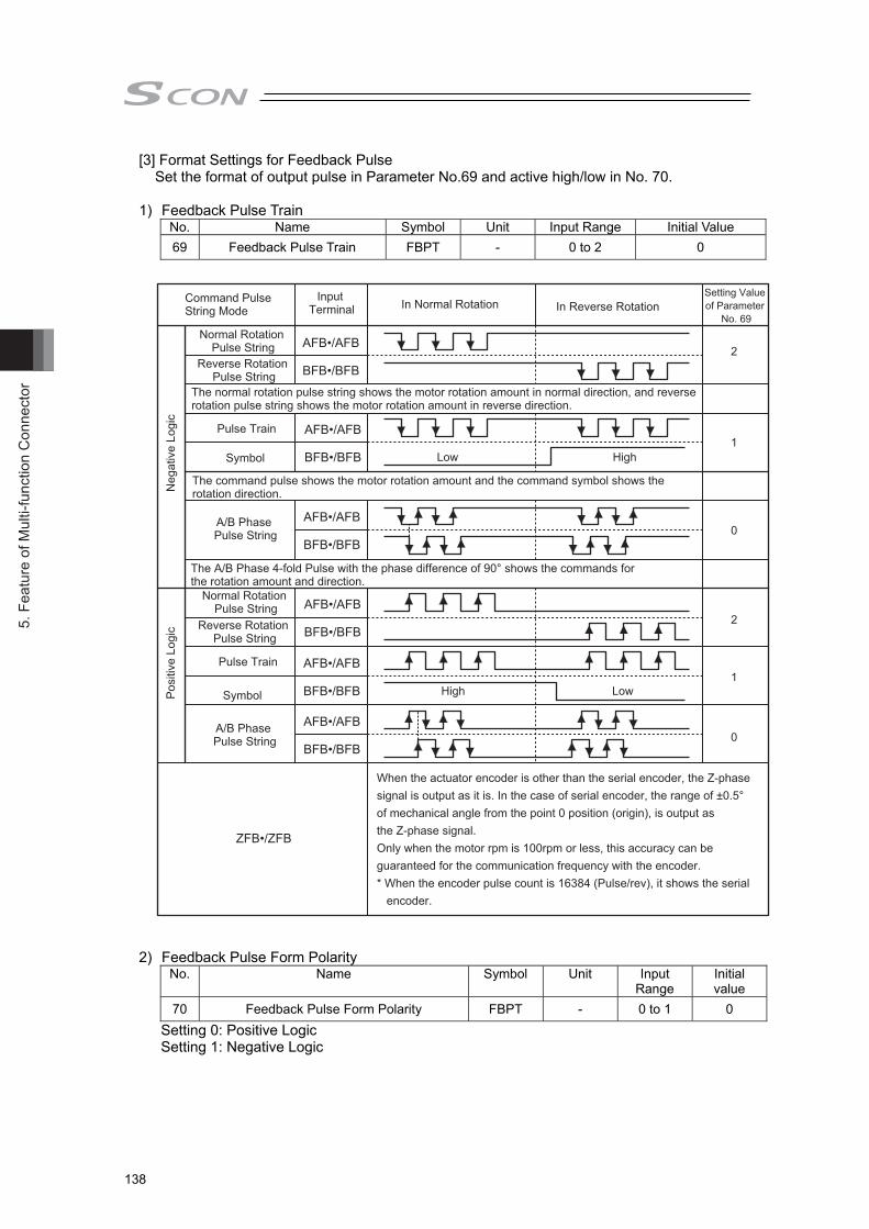
5. F
eatu
re o
f Mul
ti-fu
nctio
n C
onne
ctor
138
[3] Format Settings for Feedback Pulse Set the format of output pulse in Parameter No.69 and active high/low in No. 70.
1) Feedback Pulse Train
No. Name Symbol Unit Input Range Initial Value 69 Feedback Pulse Train FBPT - 0 to 2 0
2) Feedback Pulse Form Polarity
No. Name Symbol Unit Input Range
Initial value
70 Feedback Pulse Form Polarity FBPT - 0 to 1 0 Setting 0: Positive Logic Setting 1: Negative Logic
AFB•/AFB
BFB•/BFB
AFB•/AFB
BFB•/BFB
AFB•/AFB
BFB•/BFB
AFB•/AFB
BFB•/BFB
AFB•/AFB
BFB•/BFB
AFB•/AFB
BFB•/BFB
ZFB•/ZFB
High Low
High Low
2
1
0
2
1
0
Normal Rotation Pulse String
Normal Rotation Pulse String
Reverse Rotation Pulse String
Reverse Rotation Pulse String
The normal rotation pulse string shows the motor rotation amount in normal direction, and reverse rotation pulse string shows the motor rotation amount in reverse direction.
Pulse Train
Pulse Train
Symbol
Symbol
The command pulse shows the motor rotation amount and the command symbol shows the rotation direction.
A/B Phase Pulse String
A/B Phase Pulse String
The A/B Phase 4-fold Pulse with the phase difference of 90° shows the commands for the rotation amount and direction.
Command Pulse String Mode
Input Terminal In Normal Rotation In Reverse Rotation
Setting Value of Parameter
No. 69
Neg
ativ
e Lo
gic
Pos
itive
Log
ic
When the actuator encoder is other than the serial encoder, the Z-phase signal is output as it is. In the case of serial encoder, the range of ±0.5° of mechanical angle from the point 0 position (origin), is output as the Z-phase signal.Only when the motor rpm is 100rpm or less, this accuracy can be guaranteed for the communication frequency with the encoder.* When the encoder pulse count is 16384 (Pulse/rev), it shows the serial encoder.

5. Feature of Multi-function C
onnector
139
[4] Electric Gear Settings for Feedback Pulse This is the parameter to determine the output pulse corresponding to the actuator movement amount. Determine the movement amount per pulse to define how many millimeters you would like the actuator to move with the output of 1 pulse.
Movement in line axis per pulse = Minimum output unit (1, 0.1, 0.01mm etc.) / pulse
User Parameter No.115/116 Electronic Gear (Feedback Pulse) Numerator/Denominator
No. Name Symbol Unit Input Range Initial value (For reference)
115 Electronic Gear Numerator (Feedback Pulse) FNUM - 1 to 99999999 1
116 Electronic Gear Denominator (Feedback Pulse) FDEN - 1 to 99999999 1
The input range is from 1 to 4096 if the controller version is earlier than V0005.
Electronic Gear Formula:
Formula for velocity: The velocity of the actuator is in proportion to the frequency of the output pulse. Velocity = Movement amount per pulse × Output Pulse Frequency [Hz]
Examples of electronic gear calculations: When outputting the feedback pulse of the actuator equipped with an encoder with 10mm ball screw lead and 16384pulse/rev in 0.02mm movement per pulse:
The electric gear numerator (FNUM) = 125, electric gear denominator (FDEN) = 4096 will give the output of 1 pulse in 0.02mm of the actuator move.
Caution:
● The fraction has to be completely reduced so both the electric gear numerator (FNUM) and electric gear denominator (FDEN) can be 99999999 or less (4096 or less when the controller version is earlier than V0005) and make them to be integral numbers. (Do not stop reducing the fraction on the way.) (Do not stop reducing the fraction on the way.)
● FNUM and FDEN on the line axis have to satisfy the following relative formulas. Also, there are some limitations as follows when the controller version is earlier than V0005. ● Do not attempt to establish a setting that gives a condition that electronic gear numerator
(FNUM) > electronic gear denominator (FDEN). The formula is as shown above and the pulse output is based on the encoder pulse,
therefore evenly allocated feedback pulse responding to the velocity cannot be output.
Electronic Gear Numerator (FNUM)
Electronic Gear Denominator (FDEN)
= Ball Screw Lead Length [mm/rev] No. of Encoder Pulses [pulse/rev]
×Movement amount per pulse [mm]
1
Electronic Gear Denominator (FDEN)
Electronic Gear Numerator (FNUM) = Ball Screw Lead Length [mm/rev]
No. of Encoder Pluses [pulse/rev]× Movement amount per pulse [mm]
= 10
16384 ×100
2 =
1254096
231 ≥ Stroke Length [mm]
Ball Screw Lead Length [mm/rev] × No. of Encoder Pluses [pulse] × FNUM
231 ≥ Stroke Length [mm]
Ball Screw Lead Length [mm/rev] × No. of Encoder Pluses [pulse] × FDEN
1
227 ≥ Stroke Length [mm]
Ball Screw Lead Length [mm/rev] ×No. of Encoder Pluses [pulse] FDEN
FNUM ×

5. F
eatu
re o
f Mul
ti-fu
nctio
n C
onne
ctor
140
5.2 Analog Output of Load Data
This controller can output the loadcell measurement values in analog (ratio to the loadcell rated capacity) so connection can be established to such as a general-purposed load measurement tool. 5.2.1 Specification
Item Specification Unit Remarks Accuracy ±1.0 %FSR It is not include loadcell accuracy.
Load Resistance 10 to 600 Ω Output Current Value [mA] Load Value [%]*
20.00 130.00 19.00 120.00 18.00 110.00 17.00 100.00 16.00 90.00 15.00 80.00 14.00 70.00 13.00 60.00 12.00 50.00 11.00 40.00 10.00 30.00 9.00 20.00 8.00 10.00 7.00 0.00 6.00 -10.00 5.00 -20.00
Output current 4 to 20 mA
4.00 -30.00 * The ratio to the loadcell rated capacity is output in current. (Example) For rated capacity 20000[N] of the loadcell Load of 20000 [N] detected: Output current = 17.00 [mA] Load of 10000 [N] detected: Output current = 12.00 [mA] Load of 5000 [N] detected : Output current = 9.50 [mA] 5.2.2 Setting
Establish the setting when using the analog output of the load data. No. Name Symbol Unit Input Range Initial Value 180 DAC Output FPIO - 0 to 1 1
You can select whether to enable or disable the analog output. Setting 0: Enable Setting 1: Disable
5.2.3 Rated Capacity of Loadcell Mounted to Each Actuator
Actuator Model Loadcell Rated Capacity [N]RCS3-RA4R 200 RCS3-RA5R 600 RCS3-RA6R, RCS3-RA8R 2000 RCS3-RA10R 6000 RCS2-RA13R 20000 RCS3-RA15R, RCS3-RA20R 50000

5. Feature of Multi-function C
onnector
141
5.3 Serial Communication 2 (SIO2) This controller is equipped with SIO2 line as well as SIO line for teaching so connection can be established to such as a general-purposed touch panel. Communication conducted with Modbus protocol like one for teaching. 5.3.1 Specification
Item Specification Unit Remarks Communication System
Based on RS485
Baud Rate 9600, 14400, 19200, 28800, 38400, 57600, 76800, 115200, 230400
bps
Protocol Modbus Refer to MJ0162 Modbus Instruition Manual
Hot Swapping Unavailable Desorption of the multi-function connector while the power is on cannot be conducted.
5.3.2 Setting [1] Baud rate setting
Establish the SIO2 baud rate setting in Parameter No. 169. No. Name Symbol Unit Input Range Initial Value 169 Select the SIO2 Baud Rate BRS2 bps 9600 to 230400 38400
Apply the baud rate of the connecting unit.
[2] Unit Number Setting Set the unit number of SIO2 in Parameter No. 172.
No. Name Symbol Unit Input Range Initial Value 172 SIO2 Slave address MSA2 - 0 to 16 0
Setting 0: Unit number setting same as SIO1 (teaching port) Setting 1 to 16
Caution: When connecting the PC software and another device, connect the PC software to SIO connector (teaching port) and the other device to SIO2. In such a case, use the device connected to SIO2 only for data readout and monitoring. (Having it for operation command and data writing could cause operation error.)

6. A
bsol
ute
Type
142
Chapter6 Absolute Type 6.1 Absolute Reset
The controller of absolute specification holds encoder position information by battery backup. It is not necessary to perform the home-return operation every time the power is turned ON. In order to hold the encoder correct position information, absolute reset is required. Provide absolute reset in the following cases:
(1) Initial activation (2) Replacement of absolute battery (3) Disconnection of encoder cable from controller (4) Absolute encoder error (2) (alarm code: 0EE) is issued
The absolute reset is performed by using a PC software. Described below is the procedure.
[1] Absolute Reset Procedure 1) Connect the controller with the actuator. [Refer to Chapters 1 and 2.] 2) Connect the absolute battery (Enclosed battery if starting up for the first time, new battery if
replacing) to the absolute battery connecting connector on the front panel of the controller. [Refer to 6.2]
3) Connect the cable for PC software, set the operation mode setting switch on the front panel of the controller to MANU side, and then turn the controller ON.
4) The absolute encoder error appears. Perform alarm reset. 5) Perform home-return operation. Once the home return is complete, the point of origin is
memorized at the same time the origin point is established. Shown below is an procedure 4), and 5) of the screen.
1) An alarm window appears on the PC software screen. A message asking if you would like
to reset the alarm is shown. Press Yes button.
2) Select the operation/monitor window and press Servo → Home.

6. Absolute Type
143
6.2 Absolute Battery An absolute battery is enclosed with the absolute type controller. Connect the battery to the absolute battery connector on the front panel of the controller.
6.2.1 Absolute Encoder Backup Specifications
Item Specifications Battery classification Thionyl chloride lithium batteries Battery manufacturer’s name TOSHIBA HOME APPLIANCES CORP Battery model (IAI model) AB-5
(with Bettery Holder: AB-5-CS2) Battery nominal voltage 3.6V Current standard capacity 2000mAh Reference for battery replacing timing (Note 1)
(Ambient temperature 40°C) 2 years after use (If left unused without power supply to controller) 4 years after use (If 50% of time with power supply to controller)
Erro
r de
tect
ion Output of (*ALM (Note 2)) 2.5V (Reference value)
Output of warning (*ALML (Note 2)) 3.1V (Reference value) Warning → Reference for time suspended after alert till alarm
7 days if the controller is operated continuously at 20°C. 2.5 days if the controller is operated continuously at 40°C.
Absolute data retaining duration at battery replacement
15 minutes (Have the replacing work done within this time.)
Note 1 Replace the battery regularly. Note 2 * ALM and * ALML are the signals of active low.
After the power is supplied to the controller, they are usually ON and turned OFF when an error is detected. If the alarm is generated, it will be necessary to absolute reset after the battery replacement.
3.6V
Alarm occurred
Battery voltage
* ALM Signal ON
OFF
3.1V
2.5V
Normal
War
ning
occ
urre
d
* ALML Signal ON
OFF

6. A
bsol
ute
Type
144
6.2.2 Replacement of Absolute Battery For the battery replacement, remove the battery connector while keeping the power to the controller ON, and change the battery installed in the battery holder.
Caution : To replace the old absolute battery with a new one with the controller power being OFF, complete the replacement within 15 minutes from the removal of the old battery. The absolute data may get lost if it exceeds 15minutes.
[Removal]
[Attachment]
Disconnect the connector and pull out the battery.
Put battery into battery holder.
Plug in connector to absolute battery connector.

7. Parameter
145
Chapter 7 Parameter
Parameters are the data to set up considering the system and application. When a change is required to the parameters, make sure to back up the data before the change so the settings can be returned anytime. Also, for the purpose of rapid recovery after the investigation of failure unit or replacing the controller, keep data backup or memo also after the parameter change. The change to the parameters will be activated after they are edited, written to the flash FeRAM, then either software reset or reboot of the power. It will not be active only with writing on the teaching tool. Warning : Parameter setting has great influences on operations of the controller.
Incorrect parameter setting may not only cause malfunction or failure of the controller to occur but also people and assets to be exposed to risk. The controller is configured to be applicable to normal operation at shipment. Before providing certain change or setting for the controller to be fit to your system, understand the control methods of the controller sufficiently. Please contact us if you have anything unclear.
Do not turn OFF the power to the controller during the parameter writing.
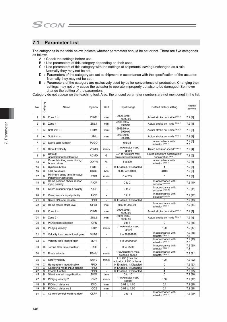
7. P
aram
eter
146
7.1 Parameter List
The categories in the table below indicate whether parameters should be set or not. There are five categories as follows:
A : Check the settings before use. B : Use parameters of this category depending on their uses. C : Use parameters of this category with the settings at shipments leaving unchanged as a rule.
Normally they may not be set. D : Parameters of the category are set at shipment in accordance with the specification of the actuator.
Normally they may not be set. E : Parameters of the category are exclusively used by us for convenience of production. Changing their
settings may not only cause the actuator to operate improperly but also to be damaged. So, never change the setting of the parameters.
Category do not appear on the teaching tool. Also, the unused parameter numbers are not mentioned in the list.
No.
Cat
egor
y
Name Symbol Unit Input Range Default factory setting Relevant sections
1 B Zone 1 + ZNM1 mm -9999.99 to 9999.99 Actual stroke on + side (Note 1) 7.2 [1]
2 B Zone 1 - ZNL1 mm -9999.99 to 9999.99 Actual stroke on - side (Note 1) 7.2 [1]
3 A Soft limit + LIMM mm -9999.99 to 9999.99 Actual stroke on + side (Note 1) 7.2 [2]
4 A Soft limit + LIML mm -9999.99 to 9999.99 Actual stroke on - side (Note 1) 7.2 [2]
7 C Servo gain number PLGO - 0 to 31 In accordance with actuator (Note 1)
7.2 [3] 7.3
8 B Default velocity VCMD mm/s 1 to Actuator max. speed Rated actuator speed (Note 1) 7.2 [4]
9 B Default acceleration/deceleration ACMD G 0.01 to Actuator's max.
acceleration/decelerationRated actuator's acceleration/
deceleration (Note 1) 7.2 [5]
13 C Current-limiting value during home return ODPW % 1 to 300 In accordance with
actuator (Note 1) 7.2 [6]
14 E Dynamic brake FSTP - 0: Enabled, 1: Disabled 1 7.2 [7] 16 B SIO baud rate BRSL bps 9600 to 230400 38400 7.2 [8]
17 B Minimum delay time for slave transmitter activation RTIM msec 0 to 255 5 7.2 [9]
18 E Home position check sensor input polarity AIOF - 0 to 2 In accordance with
actuator (Note 1) 7.2 [10]
19 E Overrun sensor input polarity AIOF - 0 to 2 In accordance with actuator (Note 1) 7.2 [11]
20 E Creep sensor input polarity AIOF - 0 to 2 In accordance with actuator (Note 1) 7.2 [12]
21 B Servo ON input disable FPIO - 0: Enabled, 1: Disabled 0 7.2 [13]
22 C Home return offset level OFST mm 0.00 to 9999.99 In accordance with actuator (Note 1) 7.2 [14]
23 B Zone 2 + ZNM2 mm -9999.99 to 9999.99 Actual stroke on + side (Note 1) 7.2 [1]
24 B Zone 2 - ZNL2 mm -9999.99 to 9999.99 Actual stroke on - side (Note 1) 7.2 [1]
25 E PIO pattern selection IOPN - 0 to 7 0 7.2 [16]
26 B PIO jog velocity IOJV mm/s 1 to Actuator max. speed 100 7.2 [17]
31 C Velocity loop proportional gain VLPG - 1 to 99999999 In accordance with actuator (Note 1)
7.2 [18] 7.3
32 C Velocity loop integral gain VLPT - 1 to 99999999 In accordance with actuator (Note 1)
7.2 [19] 7.3
33 C Torque filter time constant TRQF - 0 to 2500 In accordance with actuator (Note 1)
7.2 [20] 7.3
34 C Press velocity PSHV mm/s 1 to Actuator's max. pressing speed
In accordance with actuator (Note 1) 7.2 [21]
35 C Safety velocity SAFV mm/s 1 to 250 (max. for actuator of 250 or less) 100 7.2 [22]
40 C Home-return input disable FPIO - 0: Enabled, 1: Disabled 0 7.2 [23] 41 C Operating-mode input disable FPIO - 0: Enabled, 1: Disabled 0 7.2 [24] 42 C Enable function FPIO - 0: Enabled, 1: Disabled 1 7.2 [25] 45 B Silent interval magnification SIVM time 0 to 10 0 7.2 [26]
47 B PIO jog velocity 2 IOV2 mm/s 1 to Actuator max. speed 100 7.2 [17]
48 B PIO inch distance IOID mm 0.01 to 1.00 0.1 7.2 [28] 49 B PIO inch distance 2 IOD2 mm 0.01 to 1.00 0.1 7.2 [28]
54 C Current-control width number CLPF - 0 to 15 In accordance with actuator (Note 1) 7.2 [29]
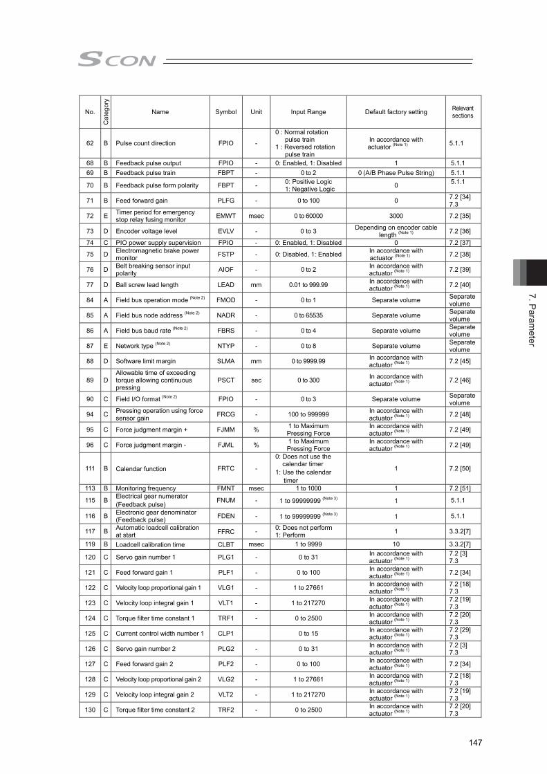
7. Parameter
147
No. C
ateg
ory
Name Symbol Unit Input Range Default factory setting Relevant sections
62 B Pulse count direction FPIO -
0 : Normal rotation pulse train
1 : Reversed rotation pulse train
In accordance with actuator (Note 1) 5.1.1
68 B Feedback pulse output FPIO - 0: Enabled, 1: Disabled 1 5.1.1 69 B Feedback pulse train FBPT - 0 to 2 0 (A/B Phase Pulse String) 5.1.1
70 B Feedback pulse form polarity FBPT - 0: Positive Logic 1: Negative Logic 0 5.1.1
71 B Feed forward gain PLFG - 0 to 100 0 7.2 [34] 7.3
72 E Timer period for emergency stop relay fusing monitor EMWT msec 0 to 60000 3000 7.2 [35]
73 D Encoder voltage level EVLV - 0 to 3 Depending on encoder cable length (Note 1)
7.2 [36]
74 C PIO power supply supervision FPIO - 0: Enabled, 1: Disabled 0 7.2 [37]
75 D Electromagnetic brake power monitor FSTP - 0: Disabled, 1: Enabled In accordance with
actuator (Note 1) 7.2 [38]
76 D Belt breaking sensor input polarity AIOF - 0 to 2 In accordance with
actuator (Note 1) 7.2 [39]
77 D Ball screw lead length LEAD mm 0.01 to 999.99 In accordance with actuator (Note 1) 7.2 [40]
84 A Field bus operation mode (Note 2) FMOD - 0 to 1 Separate volume Separate volume
85 A Field bus node address (Note 2) NADR - 0 to 65535 Separate volume Separate volume
86 A Field bus baud rate (Note 2) FBRS - 0 to 4 Separate volume Separate volume
87 E Network type (Note 2) NTYP - 0 to 8 Separate volume Separate volume
88 D Software limit margin SLMA mm 0 to 9999.99 In accordance with actuator (Note 1) 7.2 [45]
89 D Allowable time of exceeding torque allowing continuous pressing
PSCT sec 0 to 300 In accordance with actuator (Note 1) 7.2 [46]
90 C Field I/O format (Note 2) FPIO - 0 to 3 Separate volume Separate volume
94 C Pressing operation using force sensor gain FRCG - 100 to 999999 In accordance with
actuator (Note 1) 7.2 [48]
95 C Force judgment margin + FJMM % 1 to Maximum Pressing Force
In accordance with actuator (Note 1) 7.2 [49]
96 C Force judgment margin - FJML % 1 to Maximum Pressing Force
In accordance with actuator (Note 1) 7.2 [49]
111 B Calendar function FRTC -
0: Does not use the calendar timer
1: Use the calendar timer
1 7.2 [50]
113 B Monitoring frequency FMNT msec 1 to 1000 1 7.2 [51]
115 B Electrical gear numerator (Feedback pulse) FNUM - 1 to 99999999 (Note 3) 1 5.1.1
116 B Electronic gear denominator (Feedback pulse) FDEN - 1 to 99999999 (Note 3) 1 5.1.1
117 B Automatic loadcell calibration at start FFRC - 0: Does not perform
1: Perform 1 3.3.2[7]
119 B Loadcell calibration time CLBT msec 1 to 9999 10 3.3.2[7]
120 C Servo gain number 1 PLG1 - 0 to 31 In accordance with actuator (Note 1)
7.2 [3] 7.3
121 C Feed forward gain 1 PLF1 - 0 to 100 In accordance with actuator (Note 1) 7.2 [34]
122 C Velocity loop proportional gain 1 VLG1 - 1 to 27661 In accordance with actuator (Note 1)
7.2 [18] 7.3
123 C Velocity loop integral gain 1 VLT1 - 1 to 217270 In accordance with actuator (Note 1)
7.2 [19] 7.3
124 C Torque filter time constant 1 TRF1 - 0 to 2500 In accordance with actuator (Note 1)
7.2 [20] 7.3
125 C Current control width number 1 CLP1 0 to 15 In accordance with actuator (Note 1)
7.2 [29] 7.3
126 C Servo gain number 2 PLG2 - 0 to 31 In accordance with actuator (Note 1)
7.2 [3] 7.3
127 C Feed forward gain 2 PLF2 - 0 to 100 In accordance with actuator (Note 1) 7.2 [34]
128 C Velocity loop proportional gain 2 VLG2 - 1 to 27661 In accordance with actuator (Note 1)
7.2 [18] 7.3
129 C Velocity loop integral gain 2 VLT2 - 1 to 217270 In accordance with actuator (Note 1)
7.2 [19] 7.3
130 C Torque filter time constant 2 TRF2 - 0 to 2500 In accordance with actuator (Note 1)
7.2 [20] 7.3
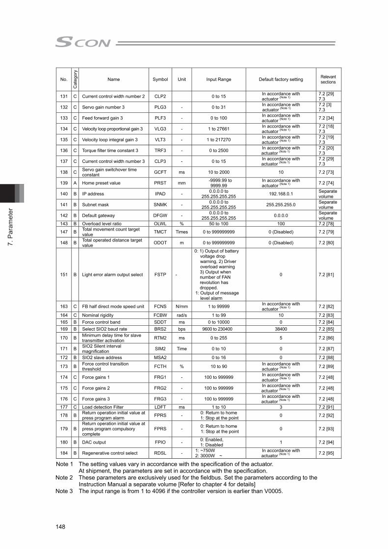
7. P
aram
eter
148
No. C
ateg
ory
Name Symbol Unit Input Range Default factory setting Relevant sections
131 C Current control width number 2 CLP2 0 to 15 In accordance with actuator (Note 1)
7.2 [29] 7.3
132 C Servo gain number 3 PLG3 - 0 to 31 In accordance with actuator (Note 1)
7.2 [3] 7.3
133 C Feed forward gain 3 PLF3 - 0 to 100 In accordance with actuator (Note 1) 7.2 [34]
134 C Velocity loop proportional gain 3 VLG3 - 1 to 27661 In accordance with actuator (Note 1)
7.2 [18] 7.3
135 C Velocity loop integral gain 3 VLT3 - 1 to 217270 In accordance with actuator (Note 1)
7.2 [19] 7.3
136 C Torque filter time constant 3 TRF3 - 0 to 2500 In accordance with actuator (Note 1)
7.2 [20] 7.3
137 C Current control width number 3 CLP3 - 0 to 15 In accordance with actuator (Note 1)
7.2 [29] 7.3
138 C Servo gain switchover time constant GCFT ms 10 to 2000 10 7.2 [73]
139 A Home preset value PRST mm -9999.99 to 9999.99
In accordance with actuator (Note 1) 7.2 [74]
140 B IP address IPAD - 0.0.0.0 to 255.255.255.255 192.168.0.1 Separate
volume
141 B Subnet mask SNMK - 0.0.0.0 to 255.255.255.255 255.255.255.0 Separate
volume
142 B Default gateway DFGW - 0.0.0.0 to 255.255.255.255 0.0.0.0 Separate
volume 143 B Overload level ratio OLWL % 50 to 100 100 7.2 [78]
147 B Total movement count target value TMCT Times 0 to 999999999 0 (Disabled) 7.2 [79]
148 B Total operated distance target value ODOT m 0 to 999999999 0 (Disabled) 7.2 [80]
151 B Light error alarm output select FSTP -
0: 1) Output of battery voltage drop warning, 2) Driver overload warning
3) Output when number of FAN revolution has dropped.
1: Output of message level alarm
0 7.2 [81]
163 C FB half direct mode speed unit FCNS N/mm 1 to 99999 In accordance with actuator (Note 1) 7.2 [82]
164 C Nominal rigidity FCBW rad/s 1 to 99 10 7.2 [83] 165 B Force control band SDDT ms 0 to 10000 0 7.2 [84] 169 B Select SIO2 baud rate BRS2 bps 9600 to 230400 38400 7.2 [85]
170 B Minimum delay time for slave transmitter activation RTM2 ms 0 to 255 5 7.2 [86]
171 B SIO2 Silent interval magnification SIM2 Time 0 to 10 0 7.2 [87]
172 B SIO2 slave address MSA2 0 to 16 0 7.2 [88]
173 B Force control transition threshold FCTH % 10 to 90 In accordance with
actuator (Note 1) 7.2 [89]
174 C Force gains 1 FRG1 - 100 to 999999 In accordance with actuator (Note 1) 7.2 [48]
175 C Force gains 2 FRG2 - 100 to 999999 In accordance with actuator (Note 1) 7.2 [48]
176 C Force gains 3 FRG3 - 100 to 999999 In accordance with actuator (Note 1) 7.2 [48]
177 C Load detection Filter LDFT ms 1 to 10 3 7.2 [91]
178 B Return operation initial value at press program alarm FPRS - 0: Return to home
1: Stop at the point 0 7.2 [92]
179 B Return operation initial value at press program compulsory complete
FPRS - 0: Return to home 1: Stop at the point 0 7.2 [93]
180 B DAC output FPIO - 0: Enabled, 1: Disabled 1 7.2 [94]
184 B Regenerative control select RDSL - 1: ~750W 2: 3000W ~
In accordance with actuator (Note 1) 7.2 [95]
Note 1 The setting values vary in accordance with the specification of the actuator. At shipment, the parameters are set in accordance with the specification.
Note 2 These parameters are exclusively used for the fieldbus. Set the parameters according to the Instruction Manual a separate volume [Refer to chapter 4 for details]
Note 3 The input range is from 1 to 4096 if the controller version is earlier than V0005.

7. Parameter
149
7.2 Detail Explanation of Parameters
Caution: If parameters are changed, provide software reset or reconnect the power to reflect the setting values.
[1] Zone 1+, Zone 1- (Parameter No.1, No.2)
Zone 2+, Zone 2- (Parameter No.23, No.24)
No. Name Symbol Unit Input Range Default factory setting
1 Zone 1+ ZNM1 mm(deg)
-9999.99 to 9999.99 Actual stroke on + side
2 Zone 1- ZNL1 mm(deg)
-9999.99 to 9999.99 Actual stroke on - side
23 Zone 2+ ZNM2 mm(deg)
-9999.99 to 9999.99 Actual stroke on + side
24 Zone 2- ZNL2 mm(deg)
-9999.99 to 9999.99 Actual stroke on - side
These parameters are used set the zone in which zone signal (ZONE1 or ZONE2) turns ON in a mode other than PIO patterns 1 to 3 (ZONE2 is valid only in the pulse-train control mode). The minimum setting unit is 0.01mm (deg). If a specific value is set to both zone setting + and zone setting -, the zone signal is not output. A setting sample is shown below.
Caution: The zone detection range would not output unless the value exceeds that of
the minimum resolution (actuator lead length / No. of Encoder Pluses).
0mm 30mm 70mm
ON
ON ON
100mmCurrent Position
Zone signal output
Zone signal output
Set ValueZone setting + : 70mmZone setting - : 30mm
Set ValueZone setting + : 30mmZone setting - : 70mm

7. P
aram
eter
150
[2] Soft limit +, Soft limit – (Parameter No.3, No.4)
No. Name Symbol Unit Input Range Default factory setting
3 Soft limit + LIMM mm (deg)
-9999.99 to 9999.99 Actual stroke on + side
4 Soft limit – LIML mm (deg)
-9999.99 to 9999.99 Actual stroke on - side
0.3mm (deg) is added to the outside of the effective actuator stroke for the setting at the delivery (since there would be an error at the end of effective stroke if set to 0). Change the setting if required for the cases such as when there is interference or to prevent a crash, or when using the actuator with slightly exceeding effective stroke in the operational range. An incorrect soft limit setting will cause the actuator to collide into the mechanical end, so exercise sufficient caution. The minimum setting unit is 0.01mm. (Note) To change a soft limit, set a value corresponding to 0.3mm outside of the effective stroke. Example) Set the effective stroke to between 0mm to 80mm
Parameter No.3 (positive side) 80.3 Parameter No.4 (negative side) -0.3
Approx. 0.3mm Approx. 0.3mm
Soft limits set in the parameter
Effective stroke
Allowable jogging/inching range after home return 0.2mm0.2mm
The operational range for jog and inching after the home return is 0.2mm less than the set value. Alarm Code 0D9 [Soft Limit Over Error] will be generated when the set value exceeded the value (0 when shipped out) set in Parameter No.88 [Software Limit Margin]. If the setting is not done in Parameter No.88, the value set in this parameter become the detection value for Alarm Code 0D9 [Soft Limit Over Error].

7. Parameter
151
[3] Servo Gain Number (Parameter No.7)
No. Name Symbol Unit Input Range Default factory setting
7 Servo gain number PLGO – 0 to 31 In accordance with actuator
The servo gain is also called position loop gain or position control system proportion gain. The parameter defines the response when a position control loop is used. Increasing the set value improves the tracking performance with respect to the position command. However, increasing the parameter value excessively increases the changes of overshooting. When the set value is too low, the follow-up ability to the position command is degraded and it takes longer time to complete the positioning. For a system of low mechanical rigidity or low natural frequency (every object has its own natural frequency), setting a large servo gain number may generate mechanical resonance, which then cause not only vibrations and/or noises but also overload error to occur.
[4] Default Velocity (Parameter No.8)
No. Name Symbol Unit Input Range Default factory
setting
8 Default velocity VCMD mm/s(deg/s)
1 to Actuator’s max. verocity
Rated actuator speed
The factory setting is the rated velocity of the actuator. This value will be written automatically to the speed setting of the press program as the initial value.
[5] Default Acceleration/Deceleration (Parameter No.9)
No. Name Symbol Unit Input Range Default factory
setting
9 Default acceleration/deceleration ACMD G
0.01 to actuator's max. acceleration/ deceleration
Rated actuator's acceleration/ deceleration
The factory setting is the rated acceleration/deceleration of the actuator. This value will be written automatically to the acceleration/deceleeration setting of the press program as the initial value.
When the set value is high (over-shoot)
When the set value is low
Velocity
Time

7. P
aram
eter
152
[6] Current-limiting Value during Home Return (Parameter No.13)
No. Name Symbol Unit Input Range Default factory setting
13 Current-limiting value during home return ODPW % 1 to 300 In accordance with
actuator The factory setting conforms to the standard specification of the actuator. Increasing this setting will increase the home return torque. Normally this parameter need not be changed. If the home return should be completed before the correct position depending on the affixing method, load condition or other factors when the actuator is used in a vertical application, the setting value must be increased. Please contact IAI.
[7] Dynamic Brake (Parameter No.14)
No. Name Symbol Unit Input Range Default factory setting
14 Dynamic brake FSTP – 0 : Disabled, 1 : Enabled 1
This parameter defines whether the dynamic brake is enabled or disabled while the actuator is at standstill. Normally it need not be changed.
[8] SIO Communication Speed (Parameter No.16)
No. Name Symbol Unit Input Range Default factory
setting 16 SIO communication speed BRSL bps 9600 to 230400 38400
Set the SIO baud rate for the startup. Set an appropriate value in accordance with the communication speed of the host. One of 9600, 14400, 19200, 28800, 38400, 76800, 115200 and 230400 bps can be selected as the communication speed.
Caution: The baud rate after the PC software is connected will be the rate of PC software. To make effective the value set in the parameter, turn off the power once and on it again.
[9] Minimum Delay Time for Slave Transmitter Activation (Parameter No.17)
No. Name Symbol Unit Input Range Default factory
setting
17 Minimum delay time for slave transmitter activation RTIM msec 0 to 255 5
In this setting, set the time from receiving the command (received data) during the SIO communication till the response (sent data) is returned to the host side.

7. Parameter
153
[10] Home Position Check Sensor Input Polarity (Parameter No.18)
No. Name Symbol Unit Input Range Default factory setting
18 Home position check sensor input polarity AIOF – 0 to 2 In accordance with
actuator The home sensor is an option.
Set Value Description 0 Standard specification (sensor not used) 1 Input is a contact 2 Input is b contact
[11] Overrun Sensor Input Polarity (Parameter No.19)
No. Name Symbol Unit Input Range Default factory
setting
19 Overrun sensor input polarity AIOF – 0 to 2 In accordance with actuator
This parameter is set properly prior to the shipment according to the specification of the actuator.
Set Value Description 0 Standard specification without sensor 1 Over travel detection sensor input is a contact2 Over travel detection sensor input is b contact
[12] Creep Sensor Input Polarity (Parameter No.20)
No. Name Symbol Unit Input Range Default factory
setting
20 Creep sensor input polarity AIOF – 0 to 2 In accordance with actuator
Even though the movement speed for most of the actuators at the home return is 20mm/s, there are some actuators with other settings. Refer to the instruction manual of each actuator. Even though the actuator with long stroke requires time to home-return if the power is shut at a point far from the home position, the required time can be improved with using the creep sensor. The actuator moves at the creep speed (100mm/s or less) until a creep sensor signal is detected, upon which the actuator will decelerate to the home return speed. Creep sensor is an option for the line axis type. This parameter is set properly prior to the shipment according to the specification of the actuator.
Set Value Description 0 Not to use 1 Input is a contact 2 Input is b contact
Home-return speed
Creep Sensor
Creep Speed
Power is turned on here.
Mechanical end
Actuator decelerates when creep sensor signal is detected

7. P
aram
eter
154
[13] Servo ON Input Disable (Parameter No.21)
No. Name Symbol Unit Input Range Default factory setting
21 Servo ON input disable FPIO – 0: Enabled, 1: Disabled 0
This parameter defines whether the servo ON input signal is disabled or enabled. When the servo ON input signal is disabled, the servo is turned ON as soon as the controller power is turned ON. Set this parameter to “1” if servo ON/OFF is not provided by PIO signals.
Set Value Description 0 Enabled (Use the input signal) 1 Disabled (Does not use the input signal)
[14] Home Return Offset Level (Parameter No.22)
No. Name Symbol Unit Input Range Default factory
setting
22 Home return offset level OFST mm(deg) 0.00 to 9999.99 In accordance with
actuator The distance from the encoder datum point (Z-phase) to the home position is set up. In this setting can set the distance from the mechanical end to the home position. An adjustment is available for the following cases. 1) Want to match the actuator home position and the mechanical origin of the system. 2) Want to set a new home after reversing the factory-set home direction. 3) Want to eliminate a slight deviation from the previous home position generated after
replacing the actuator. [Adjustment Process] 1) Homing execution 2) Offset check 3) Parameter setting change 4) If setting a number close to a multiple of the lead length (including home-return offset value
= 0) to the home offset value, there is a possibility to servo lock on Z-phase at absolute reset, thus the coordinates may get shifted for the lead length. For Absolute Type, do not attempt to set a value near a number that the lead length is multiplied by an integral number. Have enough margin. After the setting, repeat home return several times to confirm that the actuator always returns to the same home position.
Caution : If the home return offset has been changed, the soft limit parameters must
also be adjusted accordingly. In case the there is a necessity of setting a value more than the initial setting,
contact IAI.
[15] Zone 2+, Zone 2– (Parameter No.23, No.24)
[Refer to 7.2 [1]]

7. Parameter
155
[16] PIO Pattern Selection (Parameter No.25)
No. Name Symbol Unit Input Range Default factory setting
25 PIO pattern selection IOPN – 0 to 7 0 (Standard Type) It is not necessary to change from the initial value. (future expansion)
[17] PIO Jog Velocity (Parameter No.26), PIO Jog Velocity 2 (Parameter No.47)
No. Name Symbol Unit Input Range Default factory
setting
26 PIO jog velocity IOJV mm/s(deg/s)
1 to Actuator’s max. velocity (note1) 100
It is the velocity setting for when having JOG operation on the PC software. Set an appropriate value in Parameter No.26 in accordance with the purpose of use. Note 1 The maximum speed is limited to 250mm/s.
[18] Velocity Loop Proportional Gain (Parameter No.31)
No. Name Symbol Unit Input Range Default factory setting
31 Velocity loop proportional gain VLPG – 1 to 9999999 In accordance with actuator
This parameter determines the response of the speed control loop. When the set value is increased, the follow-up ability to the velocity command becomes better (the servo-motor rigidity is enhanced). The higher the load inertia becomes, the larger the value should be set. However, excessively increasing the setting will cause overshooting or oscillation, which facilitates producing the vibrations of the mechanical system.
When the set value is high (over-shoot)
When the set value is low
Velocity
Time

7. P
aram
eter
156
[19] Velocity Loop Integral Gain (Parameter No.32)
No. Name Symbol Unit Input Range Default factory setting
32 Velocity loop integral gain VLPT – 1 to 9999999 In accordance with actuator
Any machine produces frictions. This parameter is intended to cope with deviation generated by external causes including frictions. Increasing the setting value improves the reactive force against load change. That is, the servo rigidity increases. However, increasing the parameter value excessively may make the gain too high, which then cause the machine system to be vibrated due to overshoot or shaking. Tune it to obtain the optimum setting by watching the velocity response.
When the set value is high (over-shoot)
When the set value is low
Velocity
Time
[20] Torque Filter Time Constant (Parameter No.33)
No. Name Symbol Unit Input Range Default factory setting
33 Torque filter time constant TRQF – 0 to 2500 In accordance with actuator
This parameter decides the filter time constant for the torque command. When vibrations and/or noises occur due to mechanical resonance during operation, this parameter may be able to suppress the mechanical resonance. This function is effective for torsion resonance of ball screws (several hundreds Hz).
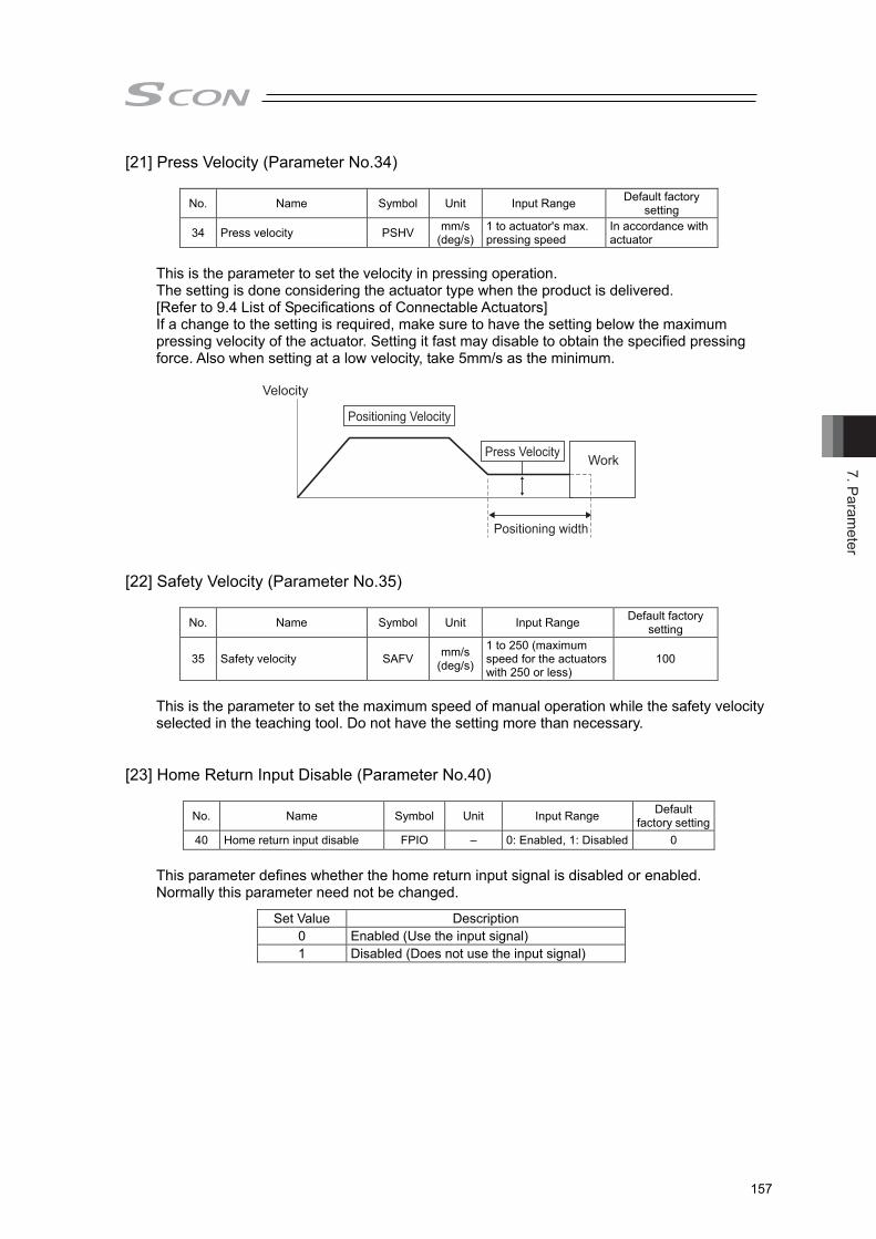
7. Parameter
157
[21] Press Velocity (Parameter No.34)
No. Name Symbol Unit Input Range Default factory setting
34 Press velocity PSHV mm/s(deg/s)
1 to actuator's max. pressing speed
In accordance with actuator
This is the parameter to set the velocity in pressing operation. The setting is done considering the actuator type when the product is delivered. [Refer to 9.4 List of Specifications of Connectable Actuators] If a change to the setting is required, make sure to have the setting below the maximum pressing velocity of the actuator. Setting it fast may disable to obtain the specified pressing force. Also when setting at a low velocity, take 5mm/s as the minimum.
Velocity
Press Velocity
Positioning width
Work
Positioning Velocity
[22] Safety Velocity (Parameter No.35)
No. Name Symbol Unit Input Range Default factory
setting
35 Safety velocity SAFV mm/s(deg/s)
1 to 250 (maximum speed for the actuators with 250 or less)
100
This is the parameter to set the maximum speed of manual operation while the safety velocity selected in the teaching tool. Do not have the setting more than necessary.
[23] Home Return Input Disable (Parameter No.40)
No. Name Symbol Unit Input Range Default
factory setting 40 Home return input disable FPIO – 0: Enabled, 1: Disabled 0
This parameter defines whether the home return input signal is disabled or enabled. Normally this parameter need not be changed.
Set Value Description 0 Enabled (Use the input signal) 1 Disabled (Does not use the input signal)

7. P
aram
eter
158
[24] Operating Mode Input Disable (Parameter No.41)
No. Name Symbol Unit Input Range Default factory setting
41 Operating mode input disable FPIO – 0: Enabled, 1: Disabled 0 This parameter defines whether the operation mode input signal is disabled or enabled. Normally this parameter need not be changed.
Set Value Description 0 Enabled (Use the input signal) 1 Disabled (Does not use the input signal)
[25] Enable Function (Parameter No.42)
No. Name Symbol Unit Input Range Default factory
setting 42 Enable function FPIO – 0: Enabled, 1: Disabled 1
Set valid/invalid the deadman switch function if the teaching pendant is equipped with a deadman switch.
Set Value Description 0 Enabled (Use the function) 1 Disabled (Does not use the function)
[26] Silent Interval Magnification (Parameter No.45)
No. Name Symbol Unit Input Range Default factory
setting 45 Silent interval magnification SIVM times 0 to 10 0
Use this parameter to set the silent interval (no communication) time by the time taken for communication of 3.5 characters or longer before command data transmission when the controller is operated via serial communication. This parameter need not be changed when a teaching tool such as PC software is used. If “0” is set, no multiplier is applied.
[27] PIO Jog Velocity 2 (Parameter No.47)
Refer to Section 7.2 [17] for details. [28] PIO Inch Distance, PIO Inch Distance 2 (Parameter No.48, No.49)
No. Name Symbol Unit Input Range Default factory
setting 48 PIO inch distance IOID mm 0.01 to 1.00 0.1
49 (Note1) PIO inch distance 2 IOD2 mm 0.01 to 1.00 0.1 Set the distance for when inching operation is indicated in the PC software. The maximum allowable value is 1mm. Note 1 Parameter No.49 [PIO inching distance 2] is not used for the controller.
7. Parameter
159
[29] Current Control width Number (Parameter No.54)
No. Name Symbol Unit Input Range Default factory setting
54 Current control width number CLPF – 0 to 15 In accordance with actuator
This parameter is for the manufacturer’s use only to determine the response capability of the current loop control. Therefore, do not change the settings in this parameter. If the parameter is changed carelessly, control safety may be adversely affected and a very dangerous situation may result.
[30] Pulse Count Direction (Parameter No.62)
This parameter is used for the feedback pulse. [Refer to 5.1.1 Settings]
[31] Feedback Pulse Output (Parameter No.68)
This parameter defines whether feedback pulse output is enabled or disabled. [Refer to 5.1.1 Settings]
[32] Feedback Pulse Train (Parameter No.69)
This parameter defines the output pattern of feedback pulses. [Refer to 5.1.1 Settings]
[33] Feedback Pulse Form Polarity (Parameter No.70)
Refer to 5.1.1 Output Settings of Feedback Pulse for the details.
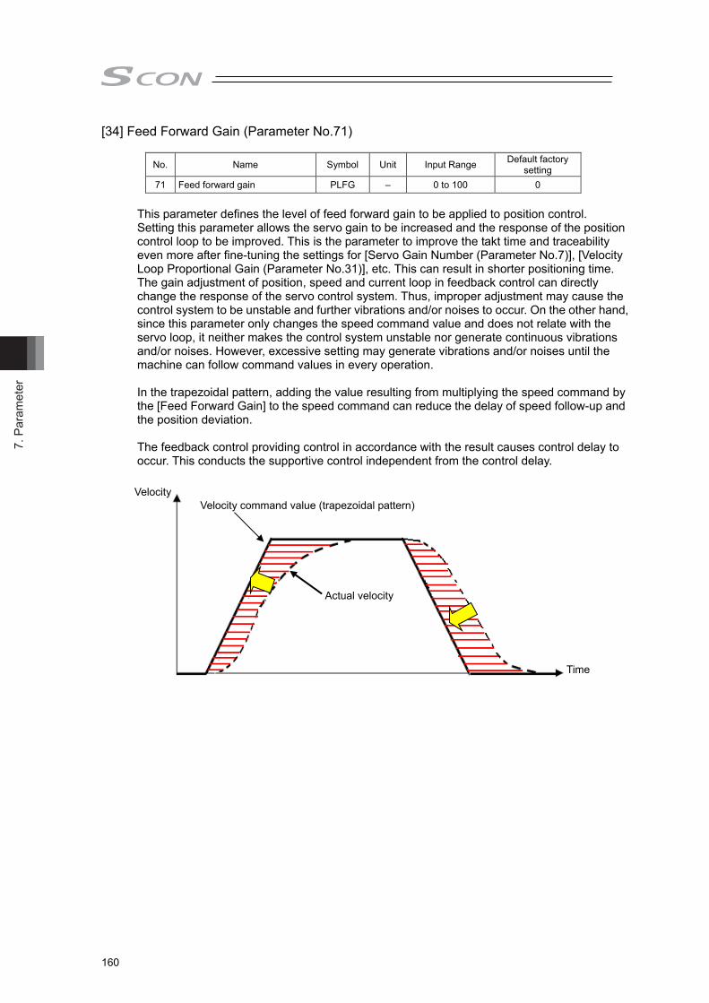
7. P
aram
eter
160
[34] Feed Forward Gain (Parameter No.71)
No. Name Symbol Unit Input Range Default factory setting
71 Feed forward gain PLFG – 0 to 100 0
This parameter defines the level of feed forward gain to be applied to position control. Setting this parameter allows the servo gain to be increased and the response of the position control loop to be improved. This is the parameter to improve the takt time and traceability even more after fine-tuning the settings for [Servo Gain Number (Parameter No.7)], [Velocity Loop Proportional Gain (Parameter No.31)], etc. This can result in shorter positioning time. The gain adjustment of position, speed and current loop in feedback control can directly change the response of the servo control system. Thus, improper adjustment may cause the control system to be unstable and further vibrations and/or noises to occur. On the other hand, since this parameter only changes the speed command value and does not relate with the servo loop, it neither makes the control system unstable nor generate continuous vibrations and/or noises. However, excessive setting may generate vibrations and/or noises until the machine can follow command values in every operation.
In the trapezoidal pattern, adding the value resulting from multiplying the speed command by the [Feed Forward Gain] to the speed command can reduce the delay of speed follow-up and the position deviation.
The feedback control providing control in accordance with the result causes control delay to occur. This conducts the supportive control independent from the control delay.
Actual velocity
Velocity command value (trapezoidal pattern) Velocity
Time
7. Parameter
161
[35] Timer Period for Emergency Stop Relay Fusing Monitor (Parameter No.72)
No. Name Symbol Unit Input Range Default factory setting
72 Timer period for emergency stop relay fusing monitor EMWT msec 0 to 60000 3000
This parameter defines the timer period in which fusing of the emergency stop relay for cutting off the motor drive power is detected. If the motor AC power is not cut off after elapse of the timer period set by this parameter following the cutoff of the driver power, the control will recognize that the relay has been fused and generate an alarm. Normally this parameter need not be changed. When a value between 0 and 9 is set, no fusing is detected.
[36] Encoder Voltage Level (Parameter No.73)
No. Name Symbol Unit Input Range Default factory
setting
73 Encoder voltage level EVLV – 0 to 3 Depending on encoder cable length
To stabilize encoder detection signals, this parameter defines the voltage supplied to the encoder circuit to one of four levels in accordance with the encoder type and the length of the encoder relay cable. Normally this parameter need not be changed. If you have changed the length of the encoder relay cable after the shipment, the value of the parameter may be changed. If you wish to change this parameter, always consult us in advance. If the setting is not optimum, it may cause an operation error of the actuator or malfunction of the encoder.
[37] PIO Power Supply Supervision (Parameter No.74)
No. Name Symbol Unit Input Range Default factory
setting
74 PIO power supply supervision(Note1) FPIO – 0: Enabled 1: Disabled 0
A power monitor function is provided to prevent incorrect operations, burning of the I/O board and/or breakdown of parts caused by an abnormal voltage of the 24V DC for PIO power supply. This parameter can be disabled in certain situations such as when the controller is operated by a teaching tool without connection of PIO during trail operation for adjustments. Do not forget put it back to “0” (Enabled) before starting the system operation after the test run for the adjustment is finished.
Set Value Description 0 Enabled 1 Disabled
Note 1 The power monitoring will not be conducted no matter the settings for the Fieldbus
types (CC-Link/DeviceNet, etc).
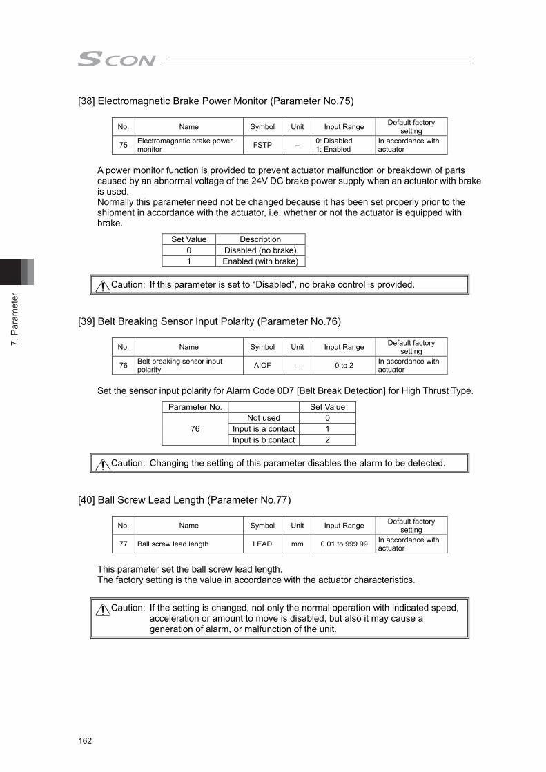
7. P
aram
eter
162
[38] Electromagnetic Brake Power Monitor (Parameter No.75)
No. Name Symbol Unit Input Range Default factory setting
75 Electromagnetic brake power monitor FSTP – 0: Disabled
1: Enabled In accordance with actuator
A power monitor function is provided to prevent actuator malfunction or breakdown of parts caused by an abnormal voltage of the 24V DC brake power supply when an actuator with brake is used. Normally this parameter need not be changed because it has been set properly prior to the shipment in accordance with the actuator, i.e. whether or not the actuator is equipped with brake.
Set Value Description 0 Disabled (no brake) 1 Enabled (with brake)
[39] Belt Breaking Sensor Input Polarity (Parameter No.76)
No. Name Symbol Unit Input Range Default factory setting
76 Belt breaking sensor input polarity AIOF – 0 to 2 In accordance with
actuator
Set the sensor input polarity for Alarm Code 0D7 [Belt Break Detection] for High Thrust Type.
Parameter No. Set Value
76 Not used 0
Input is a contact 1 Input is b contact 2
[40] Ball Screw Lead Length (Parameter No.77)
No. Name Symbol Unit Input Range Default factory setting
77 Ball screw lead length LEAD mm 0.01 to 999.99 In accordance with actuator
This parameter set the ball screw lead length. The factory setting is the value in accordance with the actuator characteristics.
Caution: If this parameter is set to “Disabled”, no brake control is provided.
Caution: Changing the setting of this parameter disables the alarm to be detected.
Caution: If the setting is changed, not only the normal operation with indicated speed, acceleration or amount to move is disabled, but also it may cause a generation of alarm, or malfunction of the unit.

7. Parameter
163
[41] Fieldbus Operation Mode (Parameter No.84) This parameter is exclusively used for the controller of fieldbus specification. Check the relevant Instruction Manual of each field bus.
[42] Fieldbus Node Address (Parameter No.85)
This parameter is exclusively used for the controller of fieldbus specification. Check the relevant Instruction Manual of each field bus.
[43] Fieldbus Baud Rate (Parameter No.86) This parameter is exclusively used for the controller of fieldbus specification. Check the relevant Instruction Manual of each field bus.
[44] Network Type (Parameter No.87)
This parameter is exclusively used for the controller of fieldbus specification. Check the relevant Instruction Manual of each field bus.
[45] Software Limit Margin (Parameter No.88)
No. Name Symbol Unit Input Range Default factory
setting
88 Software limit margin SLMA mm (deg) 0 to 9999.99 In accordance with
actuator This is the parameter to set the amount of over error detection against the soft limit errors set in Parameters No.3 and No.4. It is not necessary to change the setting in normal use.
[46] Allowable Time of Exceeding Torque Allowing Continuous Pressing (Parameter No.89)
No. Name Symbol Unit Input Range Default factory setting
89 Allowable time of exceeding torque allowing continuous pressing
PSCT sec 0 to 300 In accordance with actuator
This is the parameter to limit the continuous pressing time when using RCS2-RA13R with the pressing setting of 71% or more. When the unit is used beyond this limit, Alarm Code 0C4 “continuous pressing capable torque time over” will be generated to prevent the temperature rise on the motor due to the continuous pressing operation. [Refer to 9.4.2 Specifications and Limitations in Pressing Operation]
Parameter No.89 Description 0 Do not judge
1 to 300sec Allowable time of continuous pressing (when pressing setting of 71% or more is used in RCS2-RA13R)
Software limit margin
Software limit margin
Error detection area
Error detection area
Soft limit (Parameter No.3, No.4) setting area

7. P
aram
eter
164
[47] Fieldbus I/O Format (Parameter No.90) This parameter is exclusively used for the controller of field bus specification. Check the relevant Instruction Manual of each field bus.
[48] Force Gain (Parameter No.94)
No. Name Symbol Unit Input Range Default factory
setting
94 Pressing operation using force sensor gain FRCG – 100 to 999999 In accordance with
actuator This parameter defines the gain for pressing operation using force sensor. Adjust it considering the stiffness of the pressed object. When changing the setting, increase or decrease gradually referring to the following table. The relation among the rigidity of pressing target, the response of pressing operation using force sensor system and pressing operation using force sensor gain differs depending on the actuator, and is as shown in the table below.
RA13R, RA10R
Rigidity of pressing target Hard Rigidity Soft
Res
pons
iven
ess
of
Con
trol S
yste
m
Hig
h
Res
pons
e
Lo
w
1050 2100 4200 8400 16800 33600 1200 2400 4800 9600 19200 38400 1350 2700 5400 10800 21600 43200 1500 3000 6000 12000 24000 48000 1650 3300 6600 13200 26400 52800 1800 3600 7200 14400 28800 57600 1950 3900 7800 15600 31200 62400
RA8R
Rigidity of pressing target Hard Rigidity Soft
Res
pons
iven
ess
of
Con
trol S
yste
m
Hig
h
Res
pons
e
Lo
w
2100 4200 8400 16800 33600 67200 2400 4800 9600 19200 38400 76800 2700 5400 10800 21600 43200 86400 3000 6000 12000 24000 48000 96000 3300 6600 13200 26400 52800 105600 3600 7200 14400 28800 57600 115200 3900 7800 15600 31200 62400 124800
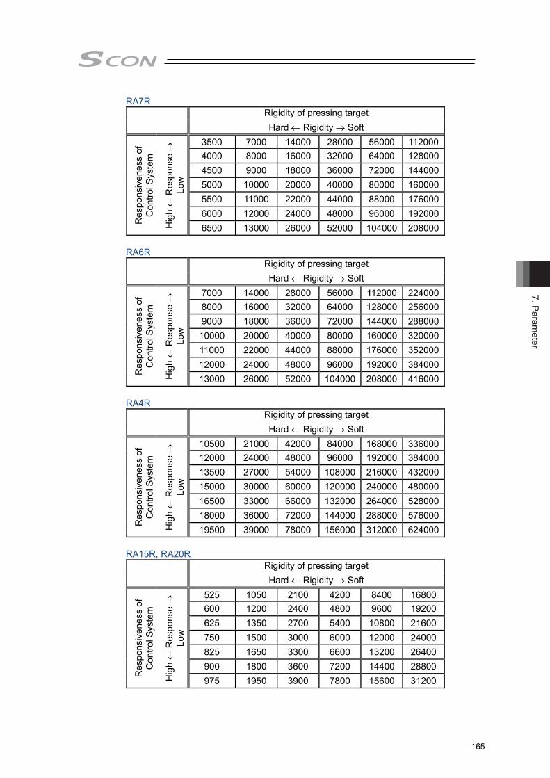
7. Parameter
165
RA7R
Rigidity of pressing target Hard Rigidity Soft
Res
pons
iven
ess
of
Con
trol S
yste
m
Hig
h
Res
pons
e
Lo
w
3500 7000 14000 28000 56000 112000 4000 8000 16000 32000 64000 128000 4500 9000 18000 36000 72000 144000 5000 10000 20000 40000 80000 160000 5500 11000 22000 44000 88000 176000 6000 12000 24000 48000 96000 192000 6500 13000 26000 52000 104000 208000
RA6R
Rigidity of pressing target Hard Rigidity Soft
Res
pons
iven
ess
of
Con
trol S
yste
m
Hig
h
Res
pons
e
Lo
w
7000 14000 28000 56000 112000 224000 8000 16000 32000 64000 128000 256000 9000 18000 36000 72000 144000 288000 10000 20000 40000 80000 160000 320000 11000 22000 44000 88000 176000 352000 12000 24000 48000 96000 192000 384000 13000 26000 52000 104000 208000 416000
RA4R
Rigidity of pressing target Hard Rigidity Soft
Res
pons
iven
ess
of
Con
trol S
yste
m
Hig
h
Res
pons
e
Lo
w
10500 21000 42000 84000 168000 336000 12000 24000 48000 96000 192000 384000 13500 27000 54000 108000 216000 432000 15000 30000 60000 120000 240000 480000 16500 33000 66000 132000 264000 528000 18000 36000 72000 144000 288000 576000 19500 39000 78000 156000 312000 624000
RA15R, RA20R
Rigidity of pressing target Hard Rigidity Soft
Res
pons
iven
ess
of
Con
trol S
yste
m
Hig
h
Res
pons
e
Lo
w
525 1050 2100 4200 8400 16800 600 1200 2400 4800 9600 19200 625 1350 2700 5400 10800 21600 750 1500 3000 6000 12000 24000 825 1650 3300 6600 13200 26400 900 1800 3600 7200 14400 28800 975 1950 3900 7800 15600 31200

7. P
aram
eter
166
[49] Force Judgment Margin + / - (Parameter No.95, No.96)
No. Name Symbol Unit Input Range Default factory setting
95 Force judgment margin + FJMM % 1 to Maximum Pressing Force
In accordance with actuator
96 Force judgment margin - FJML % 1 to Maximum Pressing Force
In accordance with actuator
Set the load range to judge the pressing operation. The value input in the press program setting window is to be registered. [Refer to chapter 3 Operation]
[50] Calendar Function (Parameter No.111)
No. Name Symbol Unit Input Range Default factory
setting
111 Calendar function FRTC –
0: Does not use the calendar timer
1: Use the calendar timer
1
This parameter defines whether the calendar function (RTC) is used or not. Set the current time with using a teaching tool when the calendar function is used. [Refer to the instruction manual of the teaching tool for the details.] In use of RTC, the alarm occurrence time in the alarm list is the time at which an alarm has occurred. If RTC is not used, the time of alarm issuance shown in the alarm list counts the time passed since the power is supplied to the controller counted as 0 second. The time data retainable duration with no power supply to the controller is approximately 10 days.
[51] Monitoring Frequency (Parameter No.113)
No. Name Symbol Unit Input Range Default factory
setting 113 Monitoring Frequency FMNT msec 1 to 1000 1
Set the time cycle (sampling frequency) to gather data when Monitoring Mode is selected. Setting a big number to this parameter will make the time cycle for data gathering longer. It is set to 1 msec. in the initial setting. Setting is available up to 1000 msec. in the 1 msec. unit.
1 msec. Cycle Setting 1000 msec. Cycle Setting In 4CH-30000 Record Mode:
30 sec. max. In 4CH-300000 Record Mode:
30000 sec. max. (500 min.) In 4CH-15000 Record Mode:
15 sec. max. In 8CH-150000 Record Mode:
15000 sec. max. (250 min.) In 2CH-60000 Record Mode:
60 sec. max. In 2CH-600000 Record Mode: 60000 sec. max. (1000 min.)
[52] Electrical Gear (Feedback Pulse) (Parameter No.115, No.116)
No. Name Symbol Unit Input Range Default factory
setting
115 Electronic gear numerator (Feedback pulse) FNUM – 1 to 99999999 1
116 Electronic gear denominator (Feedback pulse) FDEN – 1 to 99999999 1
The input range is from 1 to 4096 if the controller version is earlier than V0005. Refer to 5.1.1 Output Settings of Feedback Pulse for the details.

7. Parameter
167
[53] Automatic Loadcell Calibration at Start (Parameter No.117)
No. Name Symbol Unit Input Range Default factory setting
117 Automatic loadcell calibration at start FFRC – 0: Does not perform
1: Perform 1
This parameter is exclusively used for pressing operation using force sensor.
Set Value Description 0 Does not provide loadcell calibration automatically. 1 Provides loadcell calibration automatically. (initial value)
[Refer to 3.3.2 Operation Ready and Auxiliary Signals] [54] Loadcell Calibration Time (Parameter No.119)
No. Name Symbol Unit Input Range Default factory
setting 119 Loadcell calibration time CLBT msec 1 to 9999 10
This parameter is exclusively used for pressing operation using force sensor. This parameter defines the adjustment data acquisition time in loadcell calibration. Normally, setting change is not necessary. [Refer to chapter 3 Operation]
[55] Servo Gain Number 1 (Parameter No.120)
This parameter determines the response of the position control loop. [Refer to description of Parameter No.7.]
[56] Feed Forward Gain 1 (Parameter No.121)
This parameter defines the feed forward gain of the position control system. [Refer to description of Parameter No.71.]
[57] Velocity Loop Proportional Gain 1 (Parameter No.122)
This parameter determines the response of the speed control loop. [Refer to description of Parameter No.31.]
[58] Velosity Loop Integral Gain 1 (Parameter No.123)
This parameter determines the response of the speed control loop. [Refer to description of Parameter No.32.]
[59] Torque Filter Time Constant 1 (Parameter No.124)
This parameter decides the filter time constant for the torque command. [Refer to description of Parameter No.33.]
[60] Current Control width Number 1 (Parameter No.125) This parameter defines the control width of the current control system. [Refer to description of Parameter No.54.]
[61] Servo Gain Number 2 (Parameter No.126)
This parameter determines the response of the position control loop. [Refer to description of Parameter No.7.]
7. P
aram
eter
168
[62] Feed Forward Gain 2 (Parameter No.127) This parameter defines the feed forward gain of the position control system. [Refer to description of Parameter No.71.]
[63] Speed Loop Proportional Gain 2 (Parameter No.128)
This parameter determines the response of the speed control loop. [Refer to description of Parameter No.31.]
[64] Speed Loop Integral Gain 2 (Parameter No.129)
This parameter determines the response of the speed control loop. [Refer to description of Parameter No.32.]
[65] Torque Filter Time Constant 2 (Parameter No.130)
This parameter decides the filter time constant for the torque command. [Refer to description of Parameter No.33.]
[66] Current Control width Number 2 (Parameter No.131)
This parameter defines the control width of the current control system. [Refer to description of Parameter No.54.]
[67] Servo Gain Number 3 (Parameter No.132)
This parameter determines the response of the position control loop. [Refer to description of Parameter No.7.]
[68] Feed forward gain 3 (Parameter No.133)
This parameter defines the feed forward gain of the position control system. [Refer to description of Parameter No.71.]
[69] Velocity Loop Proportional Gain 3 (Parameter No.134)
This parameter determines the response of the speed control loop. [Refer to description of Parameter No.31.]
[70] Velocity Loop Integral Gain 3 (Parameter No.135)
This parameter determines the response of the speed control loop. [Refer to description of Parameter No.32.]
[71] Torque Filter Time Constant 3 (Parameter No.136)
This parameter decides the filter time constant for the torque command. [Refer to description of Parameter No.33.]
[72] Current Control width Number 3 (Parameter No.137)
This parameter defines the control width of the current control system. [Refer to description of Parameter No.54.]

7. Parameter
169
[73] Servo Gain Switchover Time Constant (Parameter No.138)
No. Name Symbol Unit Input Range Default factory setting
138 Servo gain switchover time constant GCFT ms 10 to 2000 10
When a switchover of the servo gain set is commanded in the detail setting of press program, the switchover process is completed after time more than 3 times of the time spent in the setting of this parameter is passed since the operation of the commanded position number has started.
[74] Home Preset Value (Parameter No.139)
No. Name Symbol Unit Input Range Default factory
setting
139 Home preset value PRST mm -9999.99 to 9999.99
In accordance with actuator
For the actuator of absolute specification, set this parameter so that (home return offset + value of this parameter) is within the range between 0 and the ball screw lead. (as it is necessary to register the Z-phase nearest to the mechanical end as the datum) The value should be an integer multiple of ±ball screw lead length including 0.00. (If the home return offset is within the range between 0 and ball screw lead length, the value of this parameter is 0.00.) Also, when a value other than 0.00 is set in this parameter, home-return complete position cannot be 0.00, and it gets to the positon of home position + this parameter.
For the actuator of incremental specification, always set this parameter to 0.00. <Setting example 1> With ball screw lead length 4mm and home return offset level 10mm, set this parameter to -8mm.
Caution: A time constant being rather short may cause the servo gain to change rapidly to have the operation of the actuator unstable.
Caution: If the above condition is not satisfied, the home position at restart after home return may shift by an integer multiple of the ball screw lead.
Home Return Offset Level (10mm)
Home position preset value (-8mm)
Home return completion position
[-8mm]
Ball Screw Lead Length (4mm) Ball Screw Lead Length (4mm) Ball Screw Lead Length (4mm)
Home Position[0mm]
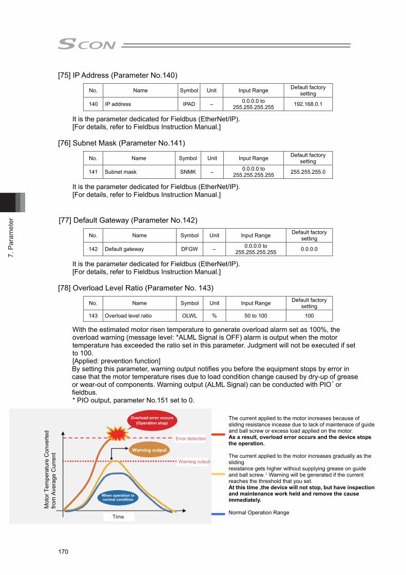
7. P
aram
eter
170
The current applied to the motor increases because of sliding resistance incease due to lack of maintenace of guide and ball screw or excess load applied on the motor. As a result, overload error occurs and the device stops the operation. The current applied to the motor increases gradually as the sliding resistance gets higher without supplying grease on guide
�and ball screw. Warning will be generated if the current reaches the threshold that you set. At this time ,the device will not stop, but have inspection and maintenance work held and remove the cause immediately. Normal Operation Range
[75] IP Address (Parameter No.140)
No. Name Symbol Unit Input Range Default factory setting
140 IP address IPAD – 0.0.0.0 to 255.255.255.255 192.168.0.1
It is the parameter dedicated for Fieldbus (EtherNet/IP). [For details, refer to Fieldbus Instruction Manual.]
[76] Subnet Mask (Parameter No.141)
No. Name Symbol Unit Input Range Default factory setting
141 Subnet mask SNMK – 0.0.0.0 to 255.255.255.255 255.255.255.0
It is the parameter dedicated for Fieldbus (EtherNet/IP). [For details, refer to Fieldbus Instruction Manual.]
[77] Default Gateway (Parameter No.142)
No. Name Symbol Unit Input Range Default factory setting
142 Default gateway DFGW – 0.0.0.0 to 255.255.255.255 0.0.0.0
It is the parameter dedicated for Fieldbus (EtherNet/IP). [For details, refer to Fieldbus Instruction Manual.]
[78] Overload Level Ratio (Parameter No. 143)
No. Name Symbol Unit Input Range Default factory setting
143 Overload level ratio OLWL % 50 to 100 100
With the estimated motor risen temperature to generate overload alarm set as 100%, the overload warning (message level: *ALML Signal is OFF) alarm is output when the motor temperature has exceeded the ratio set in this parameter. Judgment will not be executed if set to 100. [Applied: prevention function] By setting this parameter, warning output notifies you before the equipment stops by error in case that the motor temperature rises due to load condition change caused by dry-up of grease or wear-out of components. Warning output (ALML Signal) can be conducted with PIO
* or fieldbus. * PIO output, parameter No.151 set to 0.
Mot
or T
empe
ratu
re C
onve
rted
from
Ave
rage
Cur
rent
Overload error occurs(Operation stop)
Warning output
When operation in normal condition
Error detection
Warning output
Time

7. Parameter
171
[79] Total Movement Count Target Value (Parameter No.147)
No. Name Symbol Unit Input Range Default factory setting
147 Total movement count target value TMCT Times 0 to 999999999 0 (Disabled)
An alarm is generated when the total movement count exceeds the value set to this parameter. The judgment would not be made if the value is set to 0.
[80] Total Operated Distance Target Value (Parameter No.148)
No. Name Symbol Unit Input Range Default factory setting
148 Total operated distance target value ODOT m 0 to 999999999 0 (Disabled)
An alarm is generated when the total operation distance exceeds the value set to this parameter. The judgment would not be made if the value is set to 0.
[81] Light Error Alarm Output Select (Parameter No.151)
No. Name Symbol Unit Input Range Default factory setting
151 Light error alarm output select FSTP - Refer to table below 0
*ALML Signal is output following the output conditions below depending on the settings. The value set
in No. 151 ALML Signal Output Conditions
(when either of the conditions below is occurred)
0 1) Output of battery voltage drop warning 2) Driver overload warning (Message-level alarm 048) 3) Number of FAN revolution has dropped. (Message-level alarm 04C)
1 1) Output of battery voltage drop warning 2) Message-level alarm
[82] Nominal Rigidity (Parameter No.163)
No. Name Symbol Unit Input Range Default factory setting
163 Nominal rigidity FCNS N/mm 1 to 99999 In accordance with actuator
It is the value of rigidity for each actuator. Do not change the setting from the initial setting.
[83] Force Control Band (Parameter No.164)
No. Name Symbol Unit Input Range Default factory setting
164 Force control band FCBW rad/s 1 to 99 10 Setting is established for the band used as the force control. Do not change the setting from the initial setting.
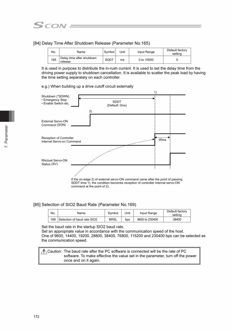
7. P
aram
eter
172
[84] Delay Time After Shutdown Release (Parameter No.165)
No. Name Symbol Unit Input Range Default factory setting
165 Delay time after shutdown release SDDT ms 0 to 10000 0
It is used in purpose to distribute the in-rush current. It is used to set the delay time from the driving power supply to shutdown cancellation. It is available to scatter the peak load by having the time setting separately on each controller. e.g.) When building up a drive cutoff circuit externally
External Servo-ONCommand (SON)
Reception of Controller Internal Servo-on Command
RActual Servo-ONStatus (SV)
If the on-edge 2) of external servo-ON command came after the point of passing SDDT time 1), the condition becomes reception of controller internal servo-ON command at the point of 2).
20ms
1)
2)
SDDT(Default: 0ms)
Shutdown (*SDWN)• Emergency Stop• Enable Switch etc.
[85] Selection of SIO2 Baud Rate (Parameter No.169)
No. Name Symbol Unit Input Range Default factory setting
169 Selection of baud rate SIO2 BRSL bps 9600 to 230400 38400
Set the baud rate in the startup SIO2 baud rate. Set an appropriate value in accordance with the communication speed of the host. One of 9600, 14400, 19200, 28800, 38400, 76800, 115200 and 230400 bps can be selected as the communication speed.
Caution: The baud rate after the PC software is connected will be the rate of PC software. To make effective the value set in the parameter, turn off the power once and on it again.
7. Parameter
173
[86] SIO2 Minimum Delay Time for Slave Transmitter Activation (Parameter No.170)
No. Name Symbol Unit Input Range Default factory setting
170 Minimum delay time for slave transmitter activation RTM2 msec 0 to 255 5
In this setting, set the time from receiving the command (received data) during the SIO2 communication till the response (sent data) is returned to the host side.
[87] SIO2 Silent Interval Magnification (Parameter No.171)
No. Name Symbol Unit Input Range Default factory setting
171 SIO2 silent interval magnification SIM2 Time 0 to 10 0
Use this parameter to set the silent interval (no communication) time by the time taken for communication of 3.5 characters or longer before command data transmission when the controller is operated via serial communication. This parameter need not be changed when a teaching tool such as PC software is used. If “0” is set, no multiplier is applied.
[88] SIO2 Slave Address (Parameter No.172)
No. Name Symbol Unit Input Range Default factory setting
172 SIO2 slave address MSA2 - 0 to 16 0
Set the slave addres when SIO2 communication. Set to 0, and it becomes the same as the standard SIO setting (set at the unit number setting switch on the front panel of the controller). (Note) Make sure to establish the setting to avoid duplication of the unit number to a device
connected to SIO2.
[89] Force Control Transition Threshold (Parameter No.173)
No. Name Symbol Unit Input Range Default factory setting
173 Force control transition threshold FCTH % 10 to 90 In accordance
with actuator
The threshold to transit from the ordinary movement to the force control movement considering loadcell load data is set. Set in this parameter the ratio to the target load, maximum load or target incremental load setting in the pressurizing stage setting. Conduct tuning with increase and decrease in 5 to 10 units.
[90] Force Gains 1 to 3 (Parameter No.174 to No.176)
Refer to 7.2 [48].

7. P
aram
eter
174
[91] Load Detection Filter (Parameter No.177)
No. Name Symbol Unit Input Range Default factory setting
177 Load detection filter LDFT ms 1 to 10 3 When reading the next load data from the loadcell, it is determined as the specified load detection if the conditions are satisfied for the time set in this parmeter. 1) Approach max. load 2) Probing complete load 3) Pressurizing maximum load in pressurizing operation and in stop 4) Pressurizing complete load in pressurizing operation 5) Pressurizing target load in pressurizing operation 6) Decompressing complete load
[92] Return Operation Initial Value at Press Program Alarm (Parameter No.178)
No. Name Symbol Unit Input Range Default factory setting
178 Return operation initial value at press program alarm FPRS - 0 to 1 0
Establish the setting for operation when a press program alarm is occurred.
Setting value Description
0 Return to the program home position and turn the servo OFF
1 Stop at the point of alarm generation and turn the servo OFF
[93] Return Operation Initial Value at Press Program Compulsory Complete (Parameter No.179)
No. Name Symbol Unit Input Range Default factory setting
179 Return operation initial value at press program compulsory complete
FPRS - 0 to 1 0
Establish the setting for operation when a press program is finished compulsorily.
Setting value Description
0 Return to the program home position and turn the servo OFF
1 Stop at the point of alarm generation and turn the servo OFF
[94] DAC Output (Parameter No.180)
No. Name Symbol Unit Input Range Default factory setting
180 DAC output FPIO - 0 to 1 1 Set if outputting in analog the load data from the multi-function connector. [Refer to 5.2 Analog Output of Load Data]
Setting value Description 0 Analog output enabled 1 Analog output disabled

7. Parameter
175
[95] Regenerative Control Select (Parameter No.184)
No. Name Symbol Unit Input Range Default factory setting
184 Regenerative Control Select RDSL - 1 to 2 1 Confirm the motor output of the actuator to be connected and set it.
Setting value Motor output 1 ~ 750W 2 3000W ~

7. P
aram
eter
176
7.3 Servo Adjustment
The parameters are preset at the factory before shipment so that the actuator operates stably within the rated (maximum) transportable weight. However, the preset setting cannot always be the optimum load condition in the actual use. In such cases, servo adjustment may be required. This section describes the basic servo adjustment method.
No. Situation that requires
adjustment How to Adjust 1 Overshooting or step
occurs at pressurizing (check the feedback value of the loadcell in the analog ouput or PC software)
1) Try to decrease the pressurizing speed. 2) Detail of Parameters to section 7.2 Adjust > register the force gain
(Parameter No. 94, 174 to 176) by referring to Section 7.2 [48]. Set the gain set number that makes the registered force gain valid in the detailed setting of the press program. [Refer to chapter 3 Press Program Detailed Settings]
3) If the condition would not improve with the tuning above, adjust Parameter No. 173 Force Control Threshold with following conditions. Conduct tuning with increase and decrease in 5 to 10 units.
When an overshoot is occurred, decrease the force control transition threshold.
When the stiffness of the work piece is low, increase the force control transition threshold.
2 Vibration is generated at acceleration/deceleration
The cause of the problem is excessive "acceleration/deceleration setting" or vulnerable structure of the unit on which the actuator is installed. If possible, reinforce the unit itself, first.
Decrease the values of “acceleration/deceleration setting”. Decrease the number of Parameter No.7 “Servo gain number”.
If the Parameter No.7 “Servo gain number” is too low, it takes long time to finish the positioning.
3 Speed is uneven during the movement
Increase the value of Parameter No.31 “Speed loop proportional gain”. By setting a larger value, the follow-up ability to the speed command becomes better. Setting too large value makes the mechanical components easy to vibrate. As a reference for the setting, increase the value little by little by 20% from the initial setting.
Caution: Rapid and excessive settings are dangerous. They may devices including the actuator to be damaged and/or people to be injured. Take sufficient note on the setting.
Record settings during servo adjustment so that prior settings can always be recovered.
When a problem arises and the solution cannot be found, please contact IAI.

7. Parameter
177
No. Situation that requires
adjustment How to Adjust 4 Abnormal noise is
generated. Especially, when stopped state and operation in low speed (less than 50mm/sec), comparatively high noise is generated.
Input the “Torque Filter Time Constant”. Try to increase by 50 as a reference for the setting. If the setting is too large, it may cause a loss of control system stability and lead the generation of vibration.
[Important] Prior to Adjustment: This phenomenon is likely to occur when the stiffness of the mechanical components is not sufficient. The actuator itself may also resonate if its stroke is over 600mm or it is belt-driven type. Before having an adjustment, check if: 1) The value for Parameter No.7 “Servo gain number”, Parameter
No.31 “Speed loop proportional gain”, or Parameter No.32 “Speed loop integral gain” are excessive.
2) The stiffness of the load is sufficient as much as possible, or the attachments are not loosened.
3) The actuator unit is mounted securely with a proper torque. 4) There is no waviness on the actuator mounting surface.
5 Large load inertia makes response of actuator low at start and stop.
Set parameter No.71 “Feed forward gain”. Select a value in the range from 10 to 50 roughly. The larger the setting value is, the smaller the deviation is. Then the response is improved. Setting a large value may cause vibrations and/or noises to occur. Set the feed forward gain in order to improve the response of the actuator further after adjusting Parameter No.7 “Servo gain number” and Parameter No.31 “Speed loop proportional gain”.
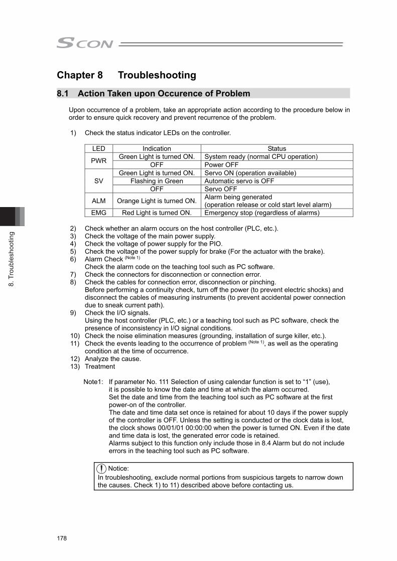
8. T
roub
lesh
ootin
g
178
Chapter 8 Troubleshooting
8.1 Action Taken upon Occurence of Problem
Upon occurrence of a problem, take an appropriate action according to the procedure below in order to ensure quick recovery and prevent recurrence of the problem.
1) Check the status indicator LEDs on the controller.
LED Indication Status
PWR Green Light is turned ON. System ready (normal CPU operation) OFF Power OFF
SV Green Light is turned ON. Servo ON (operation available)
Flashing in Green Automatic servo is OFF OFF Servo OFF
ALM Orange Light is turned ON. Alarm being generated (operation release or cold start level alarm)
EMG Red Light is turned ON. Emergency stop (regardless of alarms) 2) Check whether an alarm occurs on the host controller (PLC, etc.). 3) Check the voltage of the main power supply. 4) Check the voltage of power supply for the PIO. 5) Check the voltage of the power supply for brake (For the actuator with the brake). 6) Alarm Check (Note 1)
Check the alarm code on the teaching tool such as PC software. 7) Check the connectors for disconnection or connection error. 8) Check the cables for connection error, disconnection or pinching.
Before performing a continuity check, turn off the power (to prevent electric shocks) and disconnect the cables of measuring instruments (to prevent accidental power connection due to sneak current path).
9) Check the I/O signals. Using the host controller (PLC, etc.) or a teaching tool such as PC software, check the presence of inconsistency in I/O signal conditions.
10) Check the noise elimination measures (grounding, installation of surge killer, etc.). 11) Check the events leading to the occurrence of problem (Note 1), as well as the operating
condition at the time of occurrence. 12) Analyze the cause. 13) Treatment
Note1: If parameter No. 111 Selection of using calendar function is set to “1” (use), it is possible to know the date and time at which the alarm occurred. Set the date and time from the teaching tool such as PC software at the first power-on of the controller. The date and time data set once is retained for about 10 days if the power supply of the controller is OFF. Unless the setting is conducted or the clock data is lost, the clock shows 00/01/01 00:00:00 when the power is turned ON. Even if the date and time data is lost, the generated error code is retained. Alarms subject to this function only include those in 8.4 Alarm but do not include errors in the teaching tool such as PC software.
Notice:
In troubleshooting, exclude normal portions from suspicious targets to narrow down the causes. Check 1) to 11) described above before contacting us.
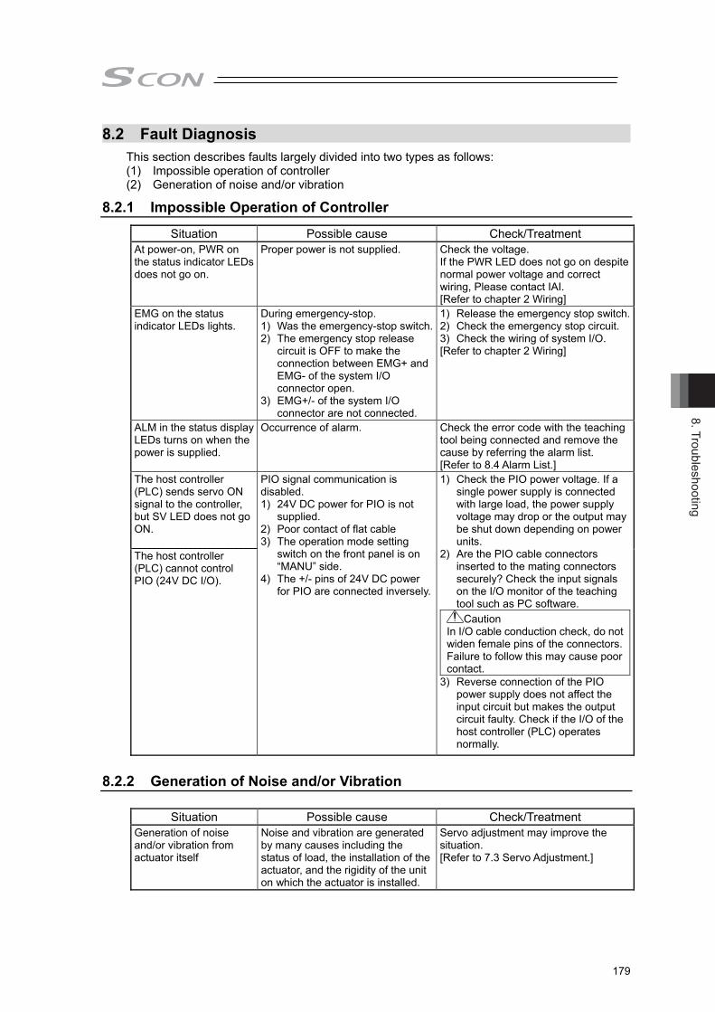
8. Troubleshooting
179
8.2 Fault Diagnosis This section describes faults largely divided into two types as follows: (1) Impossible operation of controller (2) Generation of noise and/or vibration
8.2.1 Impossible Operation of Controller Situation Possible cause Check/Treatment
At power-on, PWR on the status indicator LEDs does not go on.
Proper power is not supplied. Check the voltage. If the PWR LED does not go on despite normal power voltage and correct wiring, Please contact IAI. [Refer to chapter 2 Wiring]
EMG on the status indicator LEDs lights.
During emergency-stop. 1) Was the emergency-stop switch.2) The emergency stop release
circuit is OFF to make the connection between EMG+ and EMG- of the system I/O connector open.
3) EMG+/- of the system I/O connector are not connected.
1) Release the emergency stop switch.2) Check the emergency stop circuit. 3) Check the wiring of system I/O. [Refer to chapter 2 Wiring]
ALM in the status display LEDs turns on when the power is supplied.
Occurrence of alarm. Check the error code with the teaching tool being connected and remove the cause by referring the alarm list. [Refer to 8.4 Alarm List.]
The host controller (PLC) sends servo ON signal to the controller, but SV LED does not go ON.
PIO signal communication is disabled. 1) 24V DC power for PIO is not
supplied. 2) Poor contact of flat cable 3) The operation mode setting
switch on the front panel is on “MANU” side.
4) The +/- pins of 24V DC power for PIO are connected inversely.
1) Check the PIO power voltage. If a single power supply is connected with large load, the power supply voltage may drop or the output may be shut down depending on power units.
2) Are the PIO cable connectors inserted to the mating connectors securely? Check the input signals on the I/O monitor of the teaching tool such as PC software.
Caution In I/O cable conduction check, do not widen female pins of the connectors. Failure to follow this may cause poor contact.
3) Reverse connection of the PIO power supply does not affect the input circuit but makes the output circuit faulty. Check if the I/O of the host controller (PLC) operates normally.
The host controller (PLC) cannot control PIO (24V DC I/O).
8.2.2 Generation of Noise and/or Vibration
Situation Possible cause Check/Treatment Generation of noise and/or vibration from actuator itself
Noise and vibration are generated by many causes including the status of load, the installation of the actuator, and the rigidity of the unit on which the actuator is installed.
Servo adjustment may improve the situation. [Refer to 7.3 Servo Adjustment.]

8. T
roub
lesh
ootin
g
180
8.3 Alarm Level
The alarms are classified to 3 types of levels by the content of the error. Alarm level ALM
lamp *ALM signal Status when an error occurred Cancellation method
Message OFF No output No stop Alarm from teaching tool such as PC software [Refer to Instruction Manual of each tool for details.]
Operation release
ON Output Servo OFF after deceleration to stop
Reset the alarm by the teaching tool.
Operation release (program alarm)
Return to the program home position and turn the servo OFF, or stop at the point and turn the servo OFF
Cold start OFF Output Servo OFF after deceleration to stop
Alarm from teaching tool such as PC software [Refer to Instruction Manual of each tool for details.]
Caution: Reset each alarm after identifying and removing the cause. If the cause of the alarm cannot be removed or when the alarm cannot be reset after removing the cause, please contact IAI. If the same error occurs again after resetting the alarm, it means that the cause of the alarm has not been removed.

8. Troubleshooting
181
8.4 Alarm List 8.4.1 Controller Alarm (Excluding Program Alarm)
Alarm Code
Alarm Level Alarm Name Cause/Treatment
02E
Message
Calendar function related command in calendar function invalid status
Cause : An attempt was made to use the calendar in the state where the RTC (calendar) function was made ineffective.
Treatment : Set parameter No.111 (Selection of use of calendar function) to “1” (“0”: no use).
048 Driver overload alarm Cause : The load current exceeded the value set in Parameter No.143 “Overload Level Ratio”. This alarm is kept alarm condition until reset is made. This alarm turns ON when the load current exceeds the setting from a value below the setting.
Treatment : Lower the setting of acceleration/deceleration. Also, increase the frequency of pause.
04C Drop in number of FAN revolution
Cause : The number of the FAN revolution has dropped to the warning level.
Treatment : Degradation of the fan can be considered. Replace the FAN.
04D Excess FAN total operational duration
Cause : The total operation duration of the FAN has exceeded the reference timing for replacement. This alarm is not purposed to indicate an error.
Treatment : Utilize this alarm as a reference for the timing to replace the FAN.
04E Exceeded movement count target value
Cause : The total number of the operation times exceeded the value set in Parameter No.147 “Total Movement Count Threshold”.
04F Exceeded operated distance target value
Cause : The total number of the operation distance exceeded the value set in Parameter No.148 “Total Operated Distance Threshold”.
069 Detection of realtime clock oscillation stop
Cause : The calendar function is stopped and the current time data is lost.
Treatment : Set the time again. [Refer to the Instruction Manual of RC PC software.] (Note) This error is not registered in the alarm list.
06A Realtime clock access error Cause : The calendar function is not working properly because of noise or malfunction of consisting parts.
Treatment : 1) Take proper measures against noise. 2) When the calendar function is not used, set
parameter No.111 “Calendar function” to “0”. 3) If the operation is not improved in use of the
calendar function in spite of measures against noise, Please contact IAI.
06B Maintenance information data error
Cause : The maintenance information (total movement count, total operated distance) is lost.
Treatment : Please contact IAI.

8. T
roub
lesh
ootin
g
182
Alarm Code
Alarm Level Alarm Name Cause/Treatment
080 Move command in servo OFF
Cause : A move command was issued when the servo is OFF.
Treatment : Issue a movement command after confirming the servo is ON (servo ON signal (SV) or position complete signal (PEND) is ON).
083 Position command in incomplete home return
Cause : An absolute position command was issued by numerical specification before home return was completed (direct command from Fieldbus).
Treatment : Issue a numeric specification after performing home return operation and confirming the complete signal (HEND).
084 Numerical command in incomplete home return
Cause : A move command was issued when home return was still in progress.
Treatment : Issue a movement command after performing home return operation and confirming the complete signal (HEND).
087 Moving command during loadcell calibration
Cause : A move command was issued during loadcell calibration.
Treatment : After confirming the loadcell calibration is completed with the calibration complete (CEND) signal, and confirming CLBR Signal is turned OFF, perform the movement command.
090 Software reset during servo ON
Cause : A software reset command was issued when the servo was ON.
Treatment : Issue a software reset command after confirming that the servo is OFF (SV signal is 0).
094
Operation release
Press Program alarm detected
Cause : It shows there was an alarm issued during press program execution
Treatment : Refer to the press program alarm list below to have an appropriate treatment.[Refer to 8.4.2 Program Alarm]
0A1
Cold start
Parameter data error Cause : The data input range in the parameter area is not appropriate.
This error occurs when the magnitude relationship is apparently inappropriate such as when 300mm was incorrectly input as the value of the soft limit negative side while the value of the soft limit positive side was 200.3mm.
Treatment : Change the value to the appropriate one. 0A3 Position command data
error Cause : The command value during direct numeric
specification exceeded the maximum set value. Treatment : Exceeded command item code is displayed in the
detailed code. Input an appropriate value by referring to these values.
Detailed Code
(Command Item Code) Command Item
0 Target Position 2 Command Speed 4 Acceleration 6 Deceleration 8 Positioning Width C Pressing Current Limit Value D Control Signal
0A5
Operation release
Electromagnetic brake unreleased error
Cause : The brake cannot be released. Treatment : Supplied the 24V power unit for the
electromagnetic brake. 0A6
Cold start
Dynamic brake not released
Cause : The dynamic brake cannot be released when the servo is ON due to noise and electrostatic, etc.
Treatment : Implement measures to eliminate noise or electrostatic. There is a concern of circuit breakdown. Please contact IAI.

8. Troubleshooting
183
Alarm Code
Alarm Level Alarm Name Cause/Treatment
0A7
Operation release
Command deceleration error
Cause : Because there is not enough deceleration distance when the deceleration is changed to a lower setting during the operation, the actuator exceeded the soft limit when deceleration was made from the current position with the deceleration after the change.
Soft limit
Deceleration starting position not resulting in soft limit overshoot If a command is issued here,
soft limit overshoot will occur.
The cause is that the timing to make the next
movement command when the speed was changed during the operation was late.
Treatment : Make the timing earlier for the movement command for the deceleration speed change.
0A8
Cold start
Unsupported motor/encoder types
Cause : The motor connected to the controller is not applicable or the type of the encoder that the motor is connected is not applicable.
Treatment : Please contact us if the alarm is issued even with the applicable actuator and the same problem happens again even after rebooting the power.
0A9 Loadcell data error Cause : The data acquired from loadcell at power-on or software reset is incorrect.
Treatment : 1) Effect of noise is suspected. Check if there is a device radiating the noise and have a treatment to prevent receiving the noise.
2) The loadcell may be faulty. If the error keeps occurring even with the power reboot for several times, it is considered the loadcell is malfunctioned. Please contact IAI.
0AD
Operation release
Press program data error Cause : Program check was conducted at the controller startup, at the program start command and at the program home position movement command, and error was detected.
Treatment : As there is a program number stored in the detail code, check the applicable program setting.
0B4
Cold start
Electric angling mismatching
Cause : This alarm indicates that the position deviation counter has overflowed.
Treatment : The alarm occurs when the actuator cannot be operated. Confirm about the load conditions, that the work does not interfere with any object nearby or the brake has been released, etc. If the error occurs even when the servo is ON, the cable breakage or disconnection is considered. Check the cable connection. Please contact IAI if there is no failure in the cable and connector connections.
0B5 Operation
release
Z-Phase position error The position where the Z-phase is detected before the home return operation, is out of the specified range. Cause : Encoder error Treatment : Please contact IAI.

8. T
roub
lesh
ootin
g
184
Alarm Code Alarm Level Alarm Name Cause/Treatment
0BA
Operation release
Home sensor non-detection Cause : This indicates that the home-return operation of the actuator equipped with origin sensor (option except rotary actuator) is not completed in normal condition.1) Work is interfering with peripheral equipment in the
middle of home return. 2) Large slide resistance of the actuator itself 3) Installation failure, breakdown or disconnection of
the home sensor Treatment : In the case that the work does not interfere with
anything, the cause 2) or 3) is supposed. In such case, please contact IAI.
0BE
Operation release
Home return timeout Cause : Home return does not complete after elapse of a certain period after the start of home return.
Treatment : This error does not occur in normal operation. The combination of the controller and actuator may be incorrect. Please contact IAI.
0BF Creep sensor not detected Cause : This indicates the actuator detected the creep sensor (option) before detecting the origin sensor (option except for rotary actuator), or the actuator reached the mechanical end (or the actuator cannot move anymore because the load is too large).
1) The position to apply the creep sensor is not appropriate.
2) The creep sensor is faulty. 3) The cable is disconnected or the connector is not
plugged in properly. 4) The actuator cannot move due to heavy load caused
by interference. Treatment : 1) Readjust the sensor installation position. 2) Replace the creep sensor. 3) Perform continuity check to see if the connector is
plugged in properly. 4) Check the interference and the transportable weight
and make sure there is no external force applied. 0C0 Actual speed excessive Cause : This indicates the number of motor rotation exceeded
the number of allowable rotation. 1) The slide resistance of the actuator is locally high.
2) The load is increased too much due to a external force. With the reasons above, it can be considered a sudden speed increase has occurred before detecting the servo error.
Treatment : Even though this would not occur in normal operation, check if there is any abnormality in the parts assembly condition. Also check if there is a possibility that an external force may be applied in the direction of the actuator movement.
0C2 Overrun sensor detected Cause : This indicates that a signal from the OT sensor (option) installed at the mechanical end is detected.
1) The actuator was moved by hand or received external force while the servo was OFF (normal detection).
2) The actuator was jogged or operated by pulse-train in a condition where the home coordinates were not yet established and thus the soft stroke limit did not function correctly (normal detection).
3) The home position achieved by home return is not correct, or in the case of an absolute type controller the coordinates have shifted due to an inappropriate absolute reset position.
4) There is a mismatch between the sensor characteristics and the setting in Parameter No.19 [Overrun sensor input polarity], or the wiring layout is wrong.
5) There is a mistake in the mating of the controller and actuator, or the settings in Parameters No.3 and 4 [Soft limit value] and Parameter No.77 [Ball screw limit length] are not appropriate.
Treatment : If 1) or 2) is suspected, move the actuator in the opposite direction by hand. If this error occurred inside the effective stroke range, 3), 4), or 5) is a likely cause. If 3) is suspected, check the home position. Conduct the absolute reset again if it is the absolute type. If 4) or 5) is suspected, please contact IAI.

8. Troubleshooting
185
Alarm Code Alarm Level Alarm Name Cause/Treatment
0C4
Cold start
Exceeded allowable time of exceeding torque allowing continuous pressing
Cause : The continuous pressing time exceeds the time set for parameter No.89 [Allowable time of exceeding torque allowing continuous pressing].
Treatment : Check the sequence again. Set the pressing time to be within the setting time.
0C6 Torque current • Mismatching force feed back
Cause : The feedback from the loadcell has continuously been larger than the rating motor output for 256 ms or longer.
Treatment : 1) Check that there is no external force applied in the direction to push back from the load side.
2) Review wiring of actuator and loadcell cables. 3) The actuator, controller or loadcell may be faulty.
Please contact IAI. 0C8 Overcurrent Cause : The output current in the power circuit section is
increased abnormally. There is a concern of malfunction in controller component (IPM).
Treatment : This alarm will not be generated in normal operation. If it occurs, insulation of the motor coil may have deteriorated. Check if there is deterioration in the insulation by measuring the phase resistance between the monitor connection lines U, V and W. The values for the phase resistance should be almost the same. There is a concern the insulation is deteriorated if the values are different in large amount. Please contact IAI.
0CA Overheat Cause : This indicates overheat (95C or more) of the components inside the controller. 1) Operation is performed with the load condition
exceeding the specified range. 2) High temperature around the controller. 3) Load to the motor is high due to external force. 4) A faulty part inside the controller. Treatment : 1) Revise the operation condition such as decreasing
the acceleration/deceleration speed. 2) Lower the ambient temperature of the controller.
3) Confirm that there is no error in the mechanical part assembly condition.
(Note) This error would not normally occur. If it occurs, confirm there is not 1) or 2) above. If the same error is issued again even after confirming 1) or 2) is not in the condition, it is considered to be a malfunction. Please contact IAI.
0CB Current sensor offset adjustment error
Cause : An error was found to the sensor in the status check of the current detection sensor conducted at the initializing process in the startup.
1) The current detection sensor or any of its surrounding parts is faulty.
2) Inappropriate offset adjustment Treatment : A work (PC board) change or offset adjustment is
required. Please contact IAI. 0CD Emergency-stop relay Cause : A melt-down of the emergency stop relay inside the
controller. Treatment : The relay or controller must be replaced.
Please contact IAI. 0CE Drop in control supply voltage Cause : 1) The AC power supply voltage is low.
2) Faulty part inside the controller Treatment : Check the voltage of the input power supply.
In the case that the voltage is normal, please contact IAI.
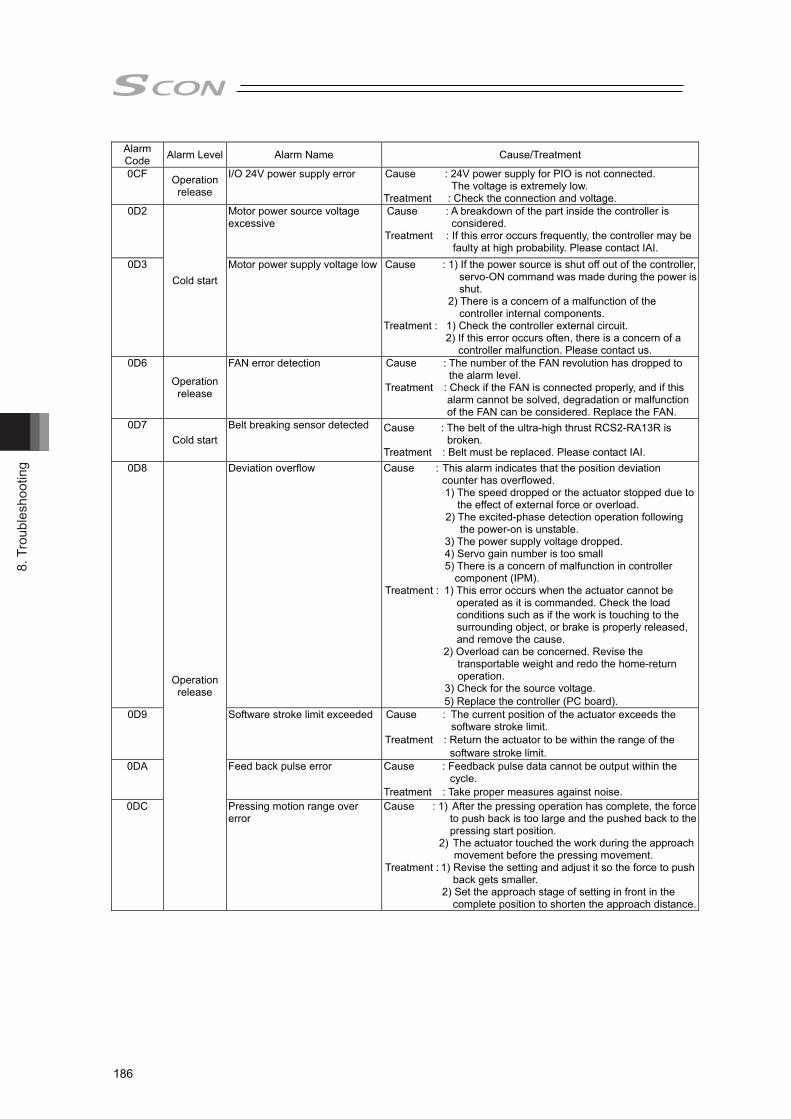
8. T
roub
lesh
ootin
g
186
Alarm Code Alarm Level Alarm Name Cause/Treatment
0CF Operation release
I/O 24V power supply error Cause : 24V power supply for PIO is not connected. The voltage is extremely low.
Treatment : Check the connection and voltage. 0D2
Cold start
Motor power source voltage excessive
Cause : A breakdown of the part inside the controller is considered.
Treatment : If this error occurs frequently, the controller may be faulty at high probability. Please contact IAI.
0D3 Motor power supply voltage low Cause : 1) If the power source is shut off out of the controller, servo-ON command was made during the power is shut.
2) There is a concern of a malfunction of the controller internal components.
Treatment : 1) Check the controller external circuit. 2) If this error occurs often, there is a concern of a
controller malfunction. Please contact us. 0D6
Operation release
FAN error detection Cause : The number of the FAN revolution has dropped to the alarm level.
Treatment : Check if the FAN is connected properly, and if this alarm cannot be solved, degradation or malfunction of the FAN can be considered. Replace the FAN.
0D7 Cold start
Belt breaking sensor detected Cause : The belt of the ultra-high thrust RCS2-RA13R is broken.
Treatment : Belt must be replaced. Please contact IAI. 0D8
Operation release
Deviation overflow Cause : This alarm indicates that the position deviation counter has overflowed.
1) The speed dropped or the actuator stopped due to the effect of external force or overload.
2) The excited-phase detection operation following the power-on is unstable.
3) The power supply voltage dropped. 4) Servo gain number is too small 5) There is a concern of malfunction in controller
component (IPM). Treatment : 1) This error occurs when the actuator cannot be
operated as it is commanded. Check the load conditions such as if the work is touching to the surrounding object, or brake is properly released, and remove the cause.
2) Overload can be concerned. Revise the transportable weight and redo the home-return operation.
3) Check for the source voltage. 5) Replace the controller (PC board).
0D9 Software stroke limit exceeded Cause : The current position of the actuator exceeds the software stroke limit.
Treatment : Return the actuator to be within the range of the software stroke limit.
0DA Feed back pulse error Cause : Feedback pulse data cannot be output within the cycle.
Treatment : Take proper measures against noise. 0DC Pressing motion range over
error Cause : 1) After the pressing operation has complete, the force
to push back is too large and the pushed back to the pressing start position.
2) The actuator touched the work during the approach movement before the pressing movement.
Treatment : 1) Revise the setting and adjust it so the force to push back gets smaller.
2) Set the approach stage of setting in front in the complete position to shorten the approach distance.
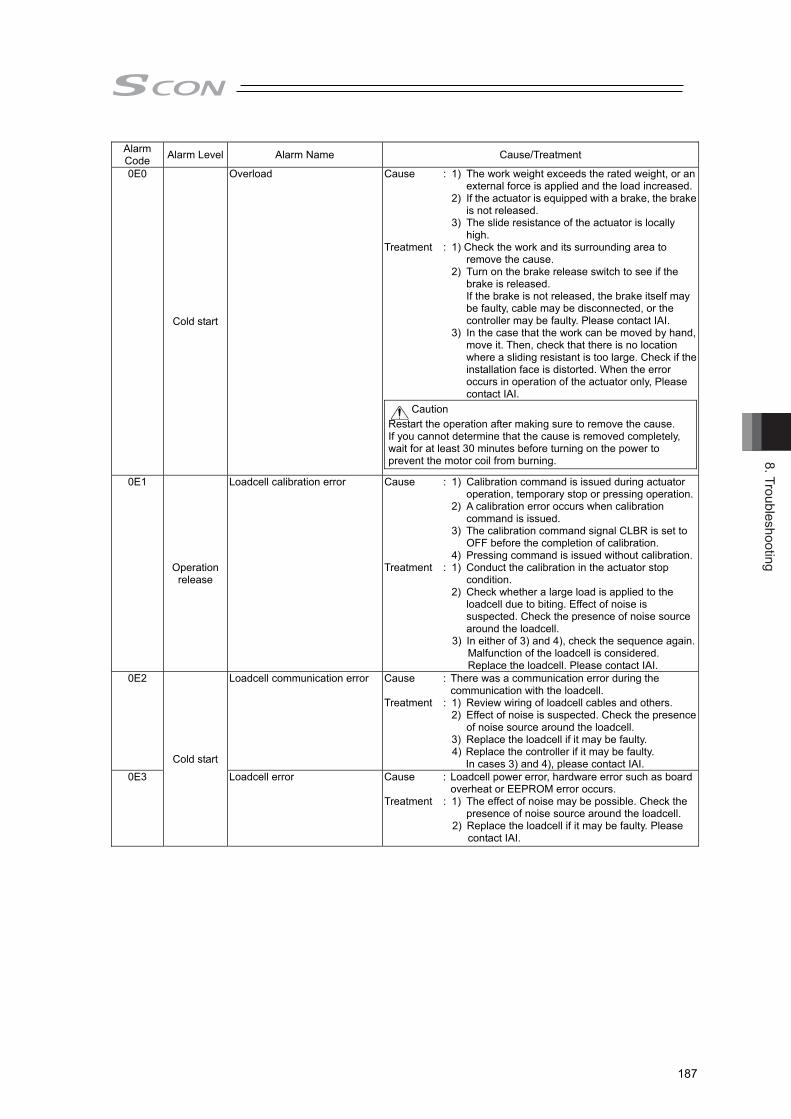
8. Troubleshooting
187
Alarm Code Alarm Level Alarm Name Cause/Treatment
0E0
Cold start
Overload Cause : 1) The work weight exceeds the rated weight, or an external force is applied and the load increased.
2) If the actuator is equipped with a brake, the brake is not released.
3) The slide resistance of the actuator is locally high.
Treatment : 1) Check the work and its surrounding area to remove the cause.
2) Turn on the brake release switch to see if the brake is released. If the brake is not released, the brake itself may be faulty, cable may be disconnected, or the controller may be faulty. Please contact IAI.
3) In the case that the work can be moved by hand, move it. Then, check that there is no location where a sliding resistant is too large. Check if the installation face is distorted. When the error occurs in operation of the actuator only, Please contact IAI.
Caution Restart the operation after making sure to remove the cause. If you cannot determine that the cause is removed completely, wait for at least 30 minutes before turning on the power to prevent the motor coil from burning.
0E1
Operation release
Loadcell calibration error Cause : 1) Calibration command is issued during actuator operation, temporary stop or pressing operation.
2) A calibration error occurs when calibration command is issued.
3) The calibration command signal CLBR is set to OFF before the completion of calibration.
4) Pressing command is issued without calibration.Treatment : 1) Conduct the calibration in the actuator stop
condition. 2) Check whether a large load is applied to the
loadcell due to biting. Effect of noise is suspected. Check the presence of noise source around the loadcell.
3) In either of 3) and 4), check the sequence again. Malfunction of the loadcell is considered. Replace the loadcell. Please contact IAI.
0E2
Cold start
Loadcell communication error Cause : There was a communication error during the communication with the loadcell.
Treatment : 1) Review wiring of loadcell cables and others. 2) Effect of noise is suspected. Check the presence
of noise source around the loadcell. 3) Replace the loadcell if it may be faulty. 4) Replace the controller if it may be faulty.
In cases 3) and 4), please contact IAI. 0E3 Loadcell error Cause : Loadcell power error, hardware error such as board
overheat or EEPROM error occurs. Treatment : 1) The effect of noise may be possible. Check the
presence of noise source around the loadcell. 2) Replace the loadcell if it may be faulty. Please
contact IAI.

8. T
roub
lesh
ootin
g
188
Alarm Code Alarm Level Alarm Name Cause/Treatment
0E4
Cold start
Encoder send error Cause : The data sending and receiving between the controller and encoder is conducted by the serial communication. This error indicates that the data sent from the controller was not received properly at the encoder side.
1) Effect of noise 2) One or more communication ICs installed on the
encoder board are faulty. 3) One or more communication Ics installed on the
controller board are faulty. Treatment : 1) Interrupt the power to the peripheral equipment
and activate only the actuator. If any error does not occur, it might be caused by noise. Take proper measures against noise.
If 2) or 3) is the case, the encoder or controller must be replaced. If the cause cannot be specified, please contact IAI.
0E5 Encoder receipt error Cause : This shows the data was not received in normal condition from the encoder side to the controller.
1) Cable breakage of encoder cable or connector connection failure or noise. (If the detail code in the error list of the teaching tool is 0001H.)
2) Effect of noise. (If the detail code in the error list of the teaching tool is 0002H.)
3) Malfunction of component (communication part) inside the actuator.
4) A faulty part inside the controller (communication part).
Treatment : 1) Check if any wire breakage on a connector and the condition of wire connections.
2) Interrupt the power to the peripheral equipment and activate only the actuator. If any error does not occur, it might be caused by noise. Take proper measures against noise.
If 3) or 4) is the case, it is necessary to replace the actuator (motor part) or controller. If the cause cannot be specified, please contact IAI.
0E6 Encoder count error Cause : This error code appears when the encoder cannot detect the position information properly.
1) The encoder relay cable or supplied actuator cable is disconnected or its connector is not plugged in correctly.
2) Foreign matter is deposited on the code wheel. 3) The position relationship between the code
wheel and photo sensor changed due to shaft center shift caused by application of excessive external force, etc.
4) Faulty encoder board component Treatment : 1) Check if any wire breakage on a connector and
the condition of wire connections. For the case of 2), 3) or 4), it is necessary either to
clean the code wheel, adjust the installation position, replace the motor unit or replace the actuator. In any case, please contact IAI.

8. Troubleshooting
189
Alarm Code Alarm Level Alarm Name Cause/Treatment
0E7
Cold start
A-, B- and Z-phase wire breaking
Cause : Encoder signals cannot be detected correctly. 1) The encoder relay cable or supplied actuator
cable is disconnected or its connector is not plugged in correctly.
2) The encoder itself is faulty. Treatment : 1) Check if any wire breakage on a connector and
the condition of wire connections. If the cables are normal, faulty encoder is
suspected. Please contact IAI. 0EE Absolute encoder error
detection 2 Cause : This is the condition where the position information
can not be detected in the absolute encoder. 1) Voltage drop of absolute battery. 2) The encoder relay cable or supplied actuator
cable is disconnected or its connector is not plugged in correctly.
Treatment : 1) Replace the absolute battery with new one. 2) Check if any wire breakage on a connector and
the condition of wire connections. Whichever action is taken under 1) or 2), an
absolute reset must be performed. If the cables are normal, faulty encoder is suspected. Please contact IAI.
0EF Absolute encoder error detection 3
Absolute encoder is not detecting the position information properly. (ABS encoder overspeed error) Cause : This error occurs in such cases as the speed
exceeded the tracing acceleration speed limit in the drop by the brake release at the power cutoff of the absolute type vertical axis. (This condition should not occur in normal conditions of use. Take sufficient note on forced brake release.)
Treatment : If the error is occurred, it is necessary to absolute reset.
0F0 Driver logic error Cause : Exceeded load, parameter (motor type) mismatched, noise, malfunction of controller, etc.
Treatment : Please contact IAI. 0F1
Operation release
Fieldbus link error Cause : This error occurs when the link of the fieldbus is disconnected in a fieldbus type controller.
Treatment : It can be considered that there is a setting error in a fieldbus related parameter, setting error in the master, connection error in fieldbus cable or interruption by noise.
0F2
Cold start
Fieldbus module error Cause : A Field bus Module error was detected. Treatment : Check the Field bus related parameters.
0F3 Fieldbus module not detected Cause : Field bus module not detected. Treatment : If the error cannot be resolved even after putting the
power on again, please contact us. 0F4 Mismatched PCB This controller uses a different print circuit board depending on the
motor capacity. The PCB is not applicable for the connected motor in the startup check. Cause : The actuator may not match the controller. Check
the model. Treatment : Should this error occur, please contact IAI.
0F5 Nonvolatile memory write verify error
It is verified at the data writing process to the nonvolatile memory that the data inside the memory and the data to be written are matched. There was a mismatch detected in this process. Cause : Faulty nonvolatile memory. Treatment : When the error is caused even when the power is
re-input, please contact IAI.
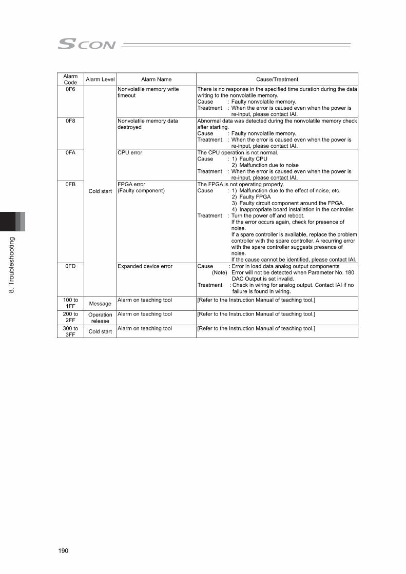
8. T
roub
lesh
ootin
g
190
Alarm Code Alarm Level Alarm Name Cause/Treatment
0F6
Cold start
Nonvolatile memory write timeout
There is no response in the specified time duration during the data writing to the nonvolatile memory. Cause : Faulty nonvolatile memory. Treatment : When the error is caused even when the power is
re-input, please contact IAI. 0F8 Nonvolatile memory data
destroyed Abnormal data was detected during the nonvolatile memory check after starting. Cause : Faulty nonvolatile memory. Treatment : When the error is caused even when the power is
re-input, please contact IAI. 0FA CPU error The CPU operation is not normal.
Cause : 1) Faulty CPU 2) Malfunction due to noise Treatment : When the error is caused even when the power is
re-input, please contact IAI. 0FB FPGA error
(Faulty component) The FPGA is not operating properly. Cause : 1) Malfunction due to the effect of noise, etc. 2) Faulty FPGA 3) Faulty circuit component around the FPGA. 4) Inappropriate board installation in the controller.Treatment : Turn the power off and reboot.
If the error occurs again, check for presence of noise. If a spare controller is available, replace the problem controller with the spare controller. A recurring error with the spare controller suggests presence of noise. If the cause cannot be identified, please contact IAI.
0FD Expanded device error Cause : Error in load data analog output components (Note) Error will not be detected when Parameter No. 180
DAC Output is set invalid. Treatment : Check in wiring for analog output. Contact IAI if no
failure is found in wiring. 100 to 1FF Message Alarm on teaching tool [Refer to the Instruction Manual of teaching tool.]
200 to 2FF
Operation release
Alarm on teaching tool [Refer to the Instruction Manual of teaching tool.]
300 to 3FF Cold start Alarm on teaching tool [Refer to the Instruction Manual of teaching tool.]

8. Troubleshooting
191
8.4.2 Program Alarm (When Controller alarm 094 is issued) A controller alarm (094: Press Program Alarm Detection) is issued when an alarm is generated during the press program execution. Also, the program alarm code and the alarm occurrence program number are stored in the detail code of 094 Alarm. Detail Code (Upper bytes): Alarm generation program No. Detail Code (Lower bytes): Alarm Code
The alarm codes are classified into three types. Genre1: Program execution condition error (Occurs at program start command) Genre2: Error in the setting to the program (Occurs at program start command and program
home position movement command) Genre3: Error in program execution (Occurs during program execution)
Alarm Code Name Genre Remarks
01 Program start at home-return incomplete 1
Cause : A position move command was issued before home return was completed.
Treatment : Issue a command after confirming that home return has been completed (HEND) is ON.
02 Program start at loadcell calibration incomplete 1
Cause : A program start command was input while the loadcell calibration is incomplete.
Treatment : After confirming the loadcell calibration is completed with the calibration complete (CEND) signal, and confirming CLBR Signal is turned OFF, perform the program startup.
03 Program start at axis operation 1
Cause : 1) A program start command was input while in actuator operation.
2) Actuator movement command was input at the same time as program start command.
Treatment : Check the command timing.
10 Command program No. error 2
Cause : The indicated program number was out of range from 0 to 63.
Treatment : Check the command program No. on the host side.
11 Invalid program indication 2
Cause : A program number was indicated which no program is set / registered.
Treatment : Check the command program No. on the host side.
12 Program home coordinate error 2
Cause : The set program home position is out of the range of the soft limit.
Treatment : Correct the program home coordinate so softlimit gets in the range
13 Approach speed error 2
Cause : The approach speed exceeds the max. speed of the actuator.
Treatment : Refer to the catalog and actuator instruction manual, and make sure not to exceed the max. speed.
(Note) Error detection will not take place if the approach stage is not held.
14 Approach acceleration error 2
Cause : The approach acceleration exceeds the actuator max. acceleration.
Treatment : Refer to the catalog and actuator instruction manual, and make sure not to exceed the max. acceleration.
(Note) Error detection will not take place if the approach stage is not held.
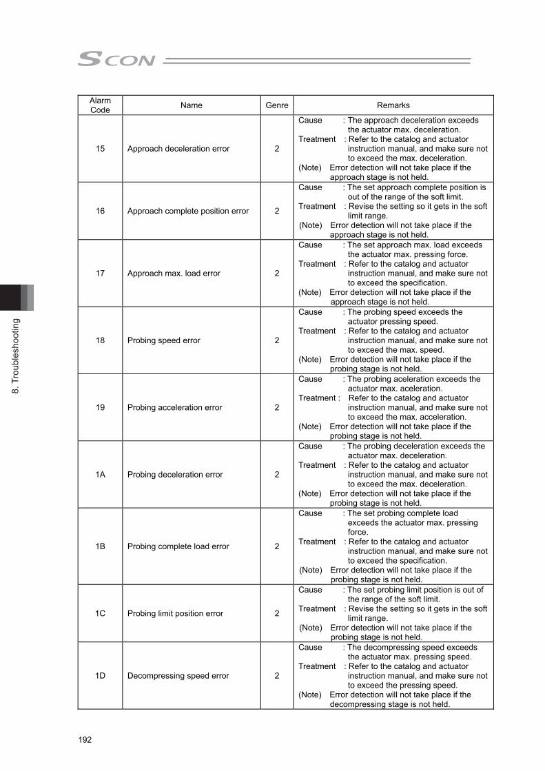
8. T
roub
lesh
ootin
g
192
Alarm Code Name Genre Remarks
15 Approach deceleration error 2
Cause : The approach deceleration exceeds the actuator max. deceleration.
Treatment : Refer to the catalog and actuator instruction manual, and make sure not to exceed the max. deceleration.
(Note) Error detection will not take place if the approach stage is not held.
16 Approach complete position error 2
Cause : The set approach complete position is out of the range of the soft limit.
Treatment : Revise the setting so it gets in the soft limit range.
(Note) Error detection will not take place if the approach stage is not held.
17 Approach max. load error 2
Cause : The set approach max. load exceeds the actuator max. pressing force.
Treatment : Refer to the catalog and actuator instruction manual, and make sure not to exceed the specification.
(Note) Error detection will not take place if the approach stage is not held.
18 Probing speed error 2
Cause : The probing speed exceeds the actuator pressing speed.
Treatment : Refer to the catalog and actuator instruction manual, and make sure not to exceed the max. speed.
(Note) Error detection will not take place if the probing stage is not held.
19 Probing acceleration error 2
Cause : The probing aceleration exceeds the actuator max. aceleration.
Treatment : Refer to the catalog and actuator instruction manual, and make sure not to exceed the max. acceleration.
(Note) Error detection will not take place if the probing stage is not held.
1A Probing deceleration error 2
Cause : The probing deceleration exceeds the actuator max. deceleration.
Treatment : Refer to the catalog and actuator instruction manual, and make sure not to exceed the max. deceleration.
(Note) Error detection will not take place if the probing stage is not held.
1B Probing complete load error 2
Cause : The set probing complete load exceeds the actuator max. pressing force.
Treatment : Refer to the catalog and actuator instruction manual, and make sure not to exceed the specification.
(Note) Error detection will not take place if the probing stage is not held.
1C Probing limit position error 2
Cause : The set probing limit position is out of the range of the soft limit.
Treatment : Revise the setting so it gets in the soft limit range.
(Note) Error detection will not take place if the probing stage is not held.
1D Decompressing speed error 2
Cause : The decompressing speed exceeds the actuator max. pressing speed.
Treatment : Refer to the catalog and actuator instruction manual, and make sure not to exceed the pressing speed.
(Note) Error detection will not take place if the decompressing stage is not held.
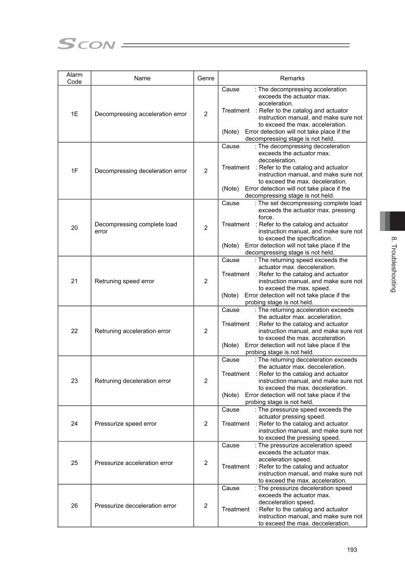
8. Troubleshooting
193
Alarm Code Name Genre Remarks
1E Decompressing acceleration error 2
Cause : The decompressing acceleration exceeds the actuator max. acceleration.
Treatment : Refer to the catalog and actuator instruction manual, and make sure not to exceed the max. acceleration.
(Note) Error detection will not take place if the decompressing stage is not held.
1F Decompressing deceleration error 2
Cause : The decompressing decceleration exceeds the actuator max. decceleration.
Treatment : Refer to the catalog and actuator instruction manual, and make sure not to exceed the max. deceleration.
(Note) Error detection will not take place if the decompressing stage is not held.
20 Decompressing complete load error 2
Cause : The set decompressing complete load exceeds the actuator max. pressing force.
Treatment : Refer to the catalog and actuator instruction manual, and make sure not to exceed the specification.
(Note) Error detection will not take place if the decompressing stage is not held.
21 Retruning speed error 2
Cause : The returning speed exceeds the actuator max. decceleration.
Treatment : Refer to the catalog and actuator instruction manual, and make sure not to exceed the max. speed.
(Note) Error detection will not take place if the probing stage is not held.
22 Retruning acceleration error 2
Cause : The returning acceleration exceeds the actuator max. acceleration.
Treatment : Refer to the catalog and actuator instruction manual, and make sure not to exceed the max. acceleration.
(Note) Error detection will not take place if the probing stage is not held.
23 Retruning deceleration error 2
Cause : The returning decceleration exceeds the actuator max. decceleration.
Treatment : Refer to the catalog and actuator instruction manual, and make sure not to exceed the max. deceleration.
(Note) Error detection will not take place if the probing stage is not held.
24 Pressurize speed error 2
Cause : The pressurize speed exceeds the actuator pressing speed.
Treatment : Refer to the catalog and actuator instruction manual, and make sure not to exceed the pressing speed.
25 Pressurize acceleration error 2
Cause : The pressurize acceleration speed exceeds the actuator max. acceleration speed.
Treatment : Refer to the catalog and actuator instruction manual, and make sure not to exceed the max. acceleration.
26 Pressurize decceleration error 2
Cause : The pressurize deceleration speed exceeds the actuator max. decceleration speed.
Treatment : Refer to the catalog and actuator instruction manual, and make sure not to exceed the max. decceleration.
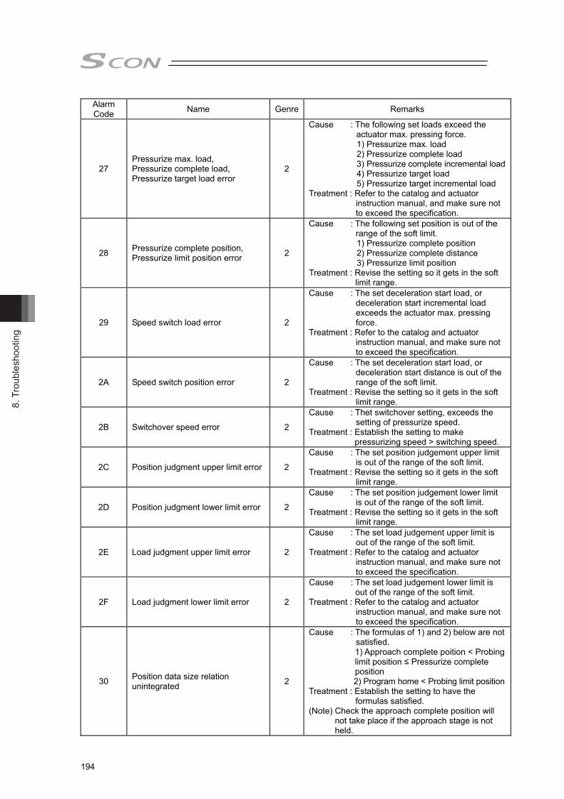
8. T
roub
lesh
ootin
g
194
Alarm Code Name Genre Remarks
27 Pressurize max. load, Pressurize complete load, Pressurize target load error
2
Cause : The following set loads exceed the actuator max. pressing force.
1) Pressurize max. load 2) Pressurize complete load 3) Pressurize complete incremental load 4) Pressurize target load 5) Pressurize target incremental load
Treatment : Refer to the catalog and actuator instruction manual, and make sure not to exceed the specification.
28 Pressurize complete position, Pressurize limit position error 2
Cause : The following set position is out of the range of the soft limit.
1) Pressurize complete position 2) Pressurize complete distance 3) Pressurize limit position
Treatment : Revise the setting so it gets in the soft limit range.
29 Speed switch load error 2
Cause : The set deceleration start load, or deceleration start incremental load exceeds the actuator max. pressing force.
Treatment : Refer to the catalog and actuator instruction manual, and make sure not to exceed the specification.
2A Speed switch position error 2
Cause : The set deceleration start load, or deceleration start distance is out of the range of the soft limit.
Treatment : Revise the setting so it gets in the soft limit range.
2B Switchover speed error 2
Cause : Thet switchover setting, exceeds the setting of pressurize speed.
Treatment : Establish the setting to make pressurizing speed > switching speed.
2C Position judgment upper limit error 2
Cause : The set position judgement upper limit is out of the range of the soft limit.
Treatment : Revise the setting so it gets in the soft limit range.
2D Position judgment lower limit error 2
Cause : The set position judgement lower limit is out of the range of the soft limit.
Treatment : Revise the setting so it gets in the soft limit range.
2E Load judgment upper limit error 2
Cause : The set load judgement upper limit is out of the range of the soft limit.
Treatment : Refer to the catalog and actuator instruction manual, and make sure not to exceed the specification.
2F Load judgment lower limit error 2
Cause : The set load judgement lower limit is out of the range of the soft limit.
Treatment : Refer to the catalog and actuator instruction manual, and make sure not to exceed the specification.
30 Position data size relation unintegrated 2
Cause : The formulas of 1) and 2) below are not satisfied. 1) Approach complete poition < Probing limit position ≤ Pressurize complete position 2) Program home < Probing limit position
Treatment : Establish the setting to have the formulas satisfied.
(Note) Check the approach complete position will not take place if the approach stage is not held.

8. Troubleshooting
195
Alarm Code Name Genre Remarks
31 Position judgment data size relation unintegrated 2
Cause : The set position judgement upper limit is less than position judgement lower limit.
Treatment : Establish the setting to make Position judgement upper limit > Position judgement lower limit
32 Load judgment data size relation unintegrated 2
Cause : The set load judgement upper limit is less than load judgement lower limit.
Treatment : Establish the setting to make Load judgement upper limit > Load judgement lower limit
33 Program allowable time error 2
Cause : The set allowable programing time is shorter than the stop time.
Treatment : Establish the setting to make Program allowable time > Stop time
40 Approach max. load over 3
Cause : The load exceeded the set max. approach load during approaching operation.
Treatment : Check the setting of approach max. load.Check the setting of approach end position. Check if there is any interference of the loadcell to peripheral equipment during actuator operation.
41 Probing limit position over 3
Cause : The actuator current position exceeded the probing limit position during probing operation.
Treatment : Check if a work piece is set on the equipment.
Check the setting of probing limit position.
42 Pressurizing complete absolute Position error 3
Cause : The final target position of pressurize operation is out of the range of the soft limit in select distance complete mode.
Treatment : Revise the setting so make sure not to exceed the soft limit.
43 Final target load error 3
Cause : The final target load in pressurizing operation exceeds the max. pressing force when the incremental load stop mode is selected.
Treatment : Refer to the catalog and actuator instruction manual, and make sure not to exceed the specification.
44 Pressurize max. load over 3
Cause : It has exceeded the max. load set during the pressurizing operation when the position stop or distance stop mode was selected.
Treatment : Have such an action as to revise the maximum load setting so it would not exceed the set load.
45 Pressurize limit poition over 3
Cause : It has exceeded the pressurizing limit position set during the pressurizing operation when the load stop or incremental load stop mode was selected.
Treatment : Have an adjustment to exceed pressurizing limit position.

8. T
roub
lesh
ootin
g
196
Alarm Code Name Genre Remarks
46 Pressurize allowable time over 3
Cause : Pressurizing does not finish even exceed operation allowable time during pressurize operation. Malfunction of the damage etc. on a work piece.
Treatment : Have an adjustment to finish pressurizing in the operation allowable time.
47 Force control stop range exceeded 3
Cause : Actuator exceeded the stop range at stop in the force control mode.
Treatment : Have an adjustment to finish pressurizing in the stop range.
48 Decompressing limit poition over 3
Cause : Depressurizing does not finish even after moving to the program home position. Malfunction of the loadcell or a work piece getting stuck is concerned.
Treatment : Check that a work piece does not interfere with the loadcell. After that, have the loadcell calibrated. Contact IAI if the problem does not get solved.
49 Position (distance) judgement NG 3 Cause : Failure was detected in the position (distance) judgment.
4A Load judgement NG 3 Cause : Failure was detected in the load judgment.
4B Program execution time exceeded 3 Cause : Program does not finish even after
allowable programing time. Treatment : Check the settings of each stages.
4C Movement command during the program execution. 3
Cause : A movement command (home-return, JOG, inching or program home position movement command) was detected during program execution.
Treatment : Have other movement command not to be input during the program execution.
4D Startup program during the program execution. 3
Cause : Start command of another program was detected during the program execution.
Treatment : Have other movement command not to be input during the program execution.
4E Allowable velocity exceeded at press motion before contacting work piece
3
Cause : In the press motion before detecting contact to a work piece, the pressing speed or switching speed has exceeded the maximum pressing velocity
Treatment : Decrease the velocity setting at the pressure motion or conduct the pressure motion after confirming contact to a work piece.

9. Appendix
197
Chapter 9 Appendix 9.1 Way to Set Multiple Controllers with 1 Teaching Tool
It is usually necessary to connect the teaching tool to the controllers one by one when making a setup to multiple controllers with one unit of teaching tool. In this section, explains how to perform the settings without connecting and disconnecting the plug. • Requisite devices : (1) SIO Converter (RCB-TU-SIO-A or RCB-TU-SIO-B) : 1 unit (2) Controller Link Cable (CB-RCB-CTL002) : Required by the number of controllers Accessories 1) 4-way junction (Manufactured by AMP 5-1473574-4) : 1 unit 2) e-CON Connector (Manufactured by AMP 4-1473562-4) : 1 unit 3) Terminal Resistance (220, with a e-CON connector) : 1 unit
Instead of the e-CON cable attached to the controller link cable, a terminal block may be used. In this configuration, disconnect the e-CON connector from the controller link cable.
9.1.1 Connecting Example
Shown below is an example of connection.
SIO Converter (with Terminal Resistor)<RCB-TU-SIO-A> Vertical<RCB-TU-SIO-B> Horizontal
e-CON Connector (Manufactured by AMP 4-1473562-4 : Housing Color Green)e-CON Connector (Manufactured by AMP 3-1473562-4 : Housing Color Orange)Junction (Manufactured by AMP 5-1473574-4)
GN GNGNTo be prepared by customer.
Terminal ResistanceR = 220Ω
Controller Link Cable<CB-RCB-CTL002>
Axis No. Setting : 0 Axis No. Setting : n-1Axis No. Setting : 1
1st unit nth unit2nd unit
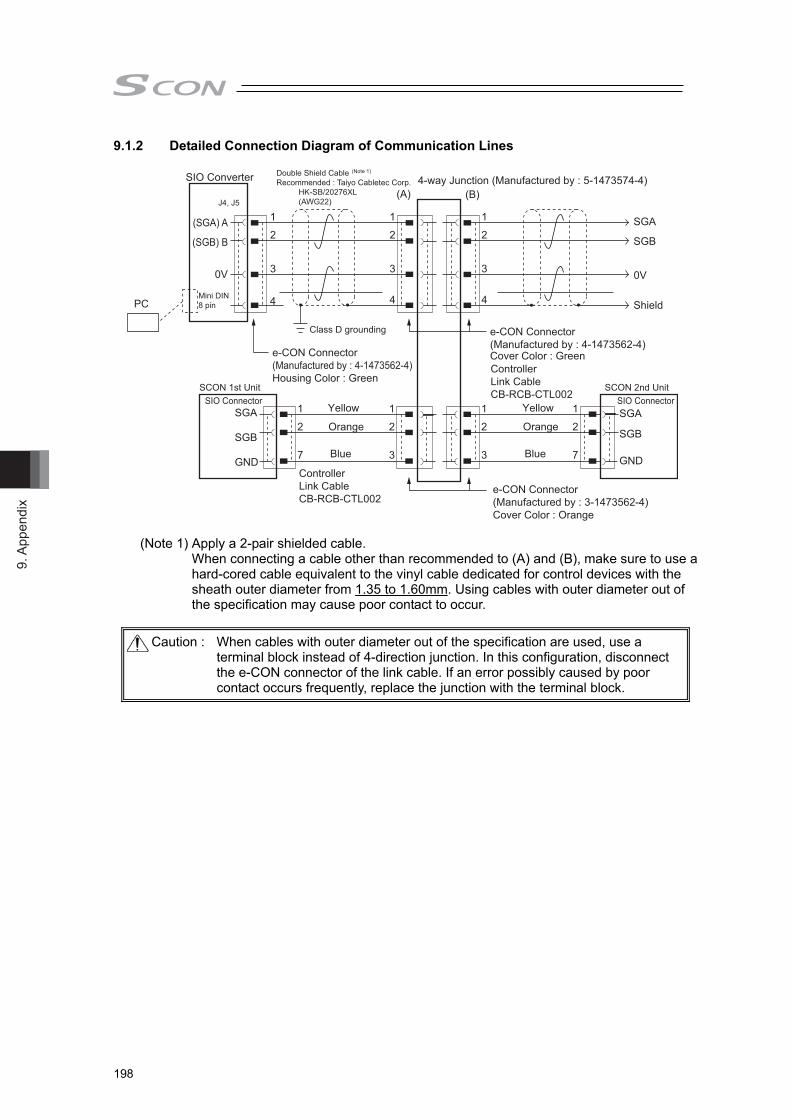
9. A
ppen
dix
198
9.1.2 Detailed Connection Diagram of Communication Lines
(Note 1) Apply a 2-pair shielded cable. When connecting a cable other than recommended to (A) and (B), make sure to use a hard-cored cable equivalent to the vinyl cable dedicated for control devices with the sheath outer diameter from 1.35 to 1.60mm. Using cables with outer diameter out of the specification may cause poor contact to occur.
Caution : When cables with outer diameter out of the specification are used, use a
terminal block instead of 4-direction junction. In this configuration, disconnect the e-CON connector of the link cable. If an error possibly caused by poor contact occurs frequently, replace the junction with the terminal block.
SIO Converter
PC
4-way Junction (Manufactured by : 5-1473574-4)
(SGA) A
(SGB) B
0V
1
2
3
1
2
7
1
2
7
1
2
3
1
2
3
4
1
2
3
4
1
2
3
4
J4, J5
Mini DIN 8 pin
Double Shield Cable (Note 1)
Recommended : Taiyo Cabletec Corp. HK-SB/20276XL (AWG22)
e-CON Connector(Manufactured by : 4-1473562-4)Cover Color : GreenController Link CableCB-RCB-CTL002
SCON 2nd Unit SIO Connector SIO Connector
Class D grounding
SCON 1st Unit
e-CON Connector(Manufactured by : 4-1473562-4)Housing Color : Green
e-CON Connector(Manufactured by : 3-1473562-4)Cover Color : Orange
Controller Link CableCB-RCB-CTL002
Yellow
Orange
Blue
Yellow
Orange
Blue
SGA
SGB
GND
SGA
SGB
GND
(A) (B)
SGA
SGB
0V
Shield

9. Appendix
199
9.1.3 Axis No. Setting Set an axis number by using the axis number setting switch on the front panel.
Caution : The axis number must be unique.
Adjust the arrow to a desiredposition using a slotted screwdriver.

9. A
ppen
dix
200
Wire
Wire
Clamp LeverPin No.
Press welding
Press welding
Press welding
Press welding
9.1.4 Handling of e-CON Connector (How to Connect) 1) Check the applicable cable size.
Check the applicable cable. If it is not applicable, it may cause a connection failure or a breakage of the connector.
2) Check the pin numbers, do not reveal the sheath, and insert the cable till it reaches the end. Revealing the sheath may cause a failure such as short circuit or cable fall out.
3) Use a (generally purposed) parallel plier with the width of 10mm or more to press-weld the cable from top and bottom. Use the parallel plier from the direction of
, grip it while checking the condition of press-welding to make sure the press is in right angle and press it until it becomes completely flat to the housing. If the inserting is not enough, it may not be able to attach to the socket or may cause a contact failure.
4) After finishing the press-welding, pull the cable lightly to confirm that won’t come out.
Caution : 1) e-CON connector cannot be reused once the press-welding is failed. Use a new connector
to retry the press-welding. 2) When connecting to the socket, hold the connector with care not to touch the clamp lever,
insert the connector in parallel to the socket until the clamp lever makes a “click” sound. 3) After joining to the socket, do not pull the cables or pull the connector without releasing the
lock of the clamp lever.

9. Appendix
201
9.1.5 SIO Converter The SIO converter converts the communication mode from RS232C to RS485 or vice versa.
(1) Power/Emergency Stop Terminal Board (TB2)
(2) Link-connection Terminal Board (TB1)
(3) D-sub, 9-pin Connector
(6) LED Indicators for Monitoring
(7) e-CON Connector
(4) Mini DIN, 8-pin Connector (5) PORT Switch
(1) Power/Emergency Stop Terminal Board (TB2) Symbol Description
EMG1, EMG2 Turn the PORT switch ON to output the emergency stop switch signal, OFF to short-circuit EMG1 and EMG2. When applying the emergency stop switch of the teaching pendant to the emergency stop of the system, obtain the signal from here.
24V Positive side of the 24V DC power supply (Power supply for the teaching pendant and conversion circuit.)
0V Negative side of the 24V DC power supply FG Frame ground
(Note) 0V is connected to the pin No. 7 (GND) on the communication connector for the controller.
● Connection method Use a connection cable satisfying the following specifications :
Item Specification Applicable wire Solid Wire : 0.8 to 1.2mm/Stranded : AWG Size 20 to 18
(0.5 to 0.75mm2) Stripped wire length 10mm
Use for Continuity Check
Insert a slotted scewdriver with a bit size of approx. 2.6mm.
Connection Cable

9. A
ppen
dix
202
(2) Link-connection Terminal Board (TB1) This is the connection port to obtain communication connection with the controller. Connect terminal “A” on the left side to communication line SGA of the controller. (Terminal A is connected to pin 1 of (7) internally.) Connect terminal “B” on the right side to communication line SGB of the controller. (Terminal B is connected to pin 2 of (7) internally.) Use a twisted pair shielded cable for the connection of SGA and SGB to TB1.
(3) D-sub, 9-pin connector
A connection port with the PC. (RS232C) It is used when the operation is conducted with using SIO communication.
(4) Mini DIN, 8-pin connector
This connector is connected to “PC software”, teaching pendant. (5) PORT Switch
The PORT switch is used to exchange enable/disable of connector (4). Set the switch to ON if connector (4) is used or OFF if not used. The switchover of valid/invalid on the teaching pendant is held at the same time as the emergency stop button switch signal output (between EMG1 and 2).
(6) LED Indicators for Monitoring
LED1 : Lights/blinks while the controller sends signals. LED2 : Lights/blinks while signals are sent from the RS232C connector.
(7) e-CON Connector
It is used when connecting to the controller with e-CON connector without using 2).

9. Appendix
203
9.1.6 Communications (1) Controller Link Cable (CB-RCB-CTL002)
Controller Side
e-CON Connector
Blue
OrangeYellow
3-1473562-4(Housing Color :Orange)
Mini DIN Connector
200mm
9.1.7 External Dimension
( 脚部エレメント下側 ) ( 脚部エレメント上側 )
4510
2
(45
)
(53
)
(Leg Element Bottom Side) (Leg Element Top Side)

9. A
ppen
dix
204
9.2 Conformity to Safety Category of to 750W motor corresponding SCON [1] System Configuration
Make sure to use the SCON-CGB controller if it is necessary to construct a system complied with Safety Categories (ISO12100-1). Also, when connecting teaching tool, using the PC software. Also, TP adapter (Model : RCB-LB-TGS), and Dummy plug (Model: DP-4S) is required. The system can conform to up to safety category B to 4 (ISO13849-1) by changing connections of system I/O connectors.
Dummy PlugDP-4S
PC software(Swap to it from TP adaptor at setting change)
ControllerAdaptor for the Teaching Pendant
RCB-LB-TGSSystem I/O Connector(Front (ENB) is bottom side, and rear (EMG) is rear side)
Safety Circuit(relay,safety relay)
Controller Adaptor-Connection CableModel:CB-CON-LB□□□

9. Appendix
205
[2] Wiring and Setting of Safety Circuit (1) Power supply
To use safety relays and/or contactors of 24V DC specification in the safety circuit, the control power supply should be used only for the circuit as much as possible. For instance, do not attempt to use the same power source as the driving power supply for ACON, and PCON which is the controller for ROBO Cylinder, the product of IAI. It is the risk prevention treatment preparing for the cases such as the operation error of the safety circuit caused by not enough power capacity.
(2) Specification of system I/O connector for TP adapter
Connector name System I/O Connector Applicable Wire Upper side (EMG side)
Cable side FMC1.5/6-ST-3.5 (Note 1)
Phoenix Contact AWG24 to 16 (0.2 to 1.25m2)
TP adapter side MCDN1.5/6-G1-3.5P26THR Lower side (ENB side)
Cable side FMC1.5/6-ST-3.5 (Note 1) TP adapter side MCDN1.5/6-G1-3.5P26THR
Pin No. Signal Name Description
Upper side (EMG side)
1 EMG1- Emergency stop contact 1 (30V DC or less, 100mA or less) 2 EMG1+
3 EMG2- Emergency stop contact 2 (30V DC or less, 100mA or less) 4 EMG2+
5 EMGIN Emergency stop detection input 6 EMGOUT 24V power supply output for emergency stop detection input
Lower side (ENB side)
7 ENB1- Enable contact 1 (30V DC or less, 100mA or less) 8 ENB1+
9 ENB2- Enable contact 2 (30V DC or less, 100mA or less) 10 ENB2+
11 ENBIN Enable detection input 12 ENBOUT 24V power supply output for enable detection input
Note 1 Connectors on the cable side are attached under conditions where initial wiring has been conducted. In order to support each category, remove the initial wiring and wire your safety circuit.
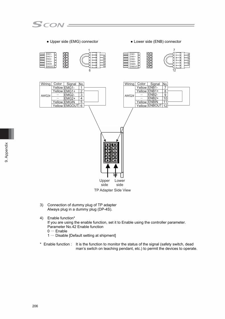
9. A
ppen
dix
206
● Upper side (EMG) connector ● Lower side (ENB) connector
EMG1-EMG1+EMG2-EMG2+EMGINEMGOUT
ENB1-ENB1+ENB2-ENB2+ENBINENBOUT
EMG1-EMG1+EMG2-EMG2+EMGINEMGOUT
1
6
7
12
Wiring ColorYellowYellow
YellowYellow
123456
Signal No.
AWG24
Wiring ColorYellowYellow
YellowYellow
789
101112
Signal No.
AWG24
ENB1-ENB1+ENB2-ENB2+ENBINENBOUT
Upperside
Lowerside
TP Adapter Side View
3) Connection of dummy plug of TP adapter Always plug in a dummy plug (DP-4S).
4) Enable function*
If you are using the enable function, set it to Enable using the controller parameter. Parameter No.42 Enable function 0 ··· Enable 1 ··· Disable [Default setting at shipment]
* Enable function : It is the function to monitor the status of the signal (safety switch, dead
man’s switch on teaching pendant, etc.) to permit the devices to operate.

9. Appendix
207
[3] Examples of Safety Circuits 1) In case of category 1
Connection cable CB-CON-LB□□□
RCB-LB-TGS
Dummy PlugDP-4S
Ena
ble
SW
Solenoid Conductor
Motor Power SupplySCON : AC100V/AC200V
ControllerSCON
Motor PowerSupply
Res
et E
mer
genc
y S
top
ENBO
UT
EN
BIN
EN
B2+
EN
B2-
EN
B1+
EN
B1-
EMG
OUT
EM
GIN
EM
G2+
EM
G2-
EM
G1+
EM
G1-
12 11 10 9
24V
L1
L2
0V
RY
RY
0V
24V SWSW
8 7 6 5 4 3 2 1
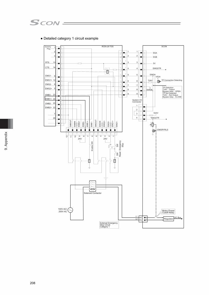
9. A
ppen
dix
208
● Detailed category 1 circuit example
RTS
CTS
EMG1-
EMG1+
EMG2-
EMG2+
EMB1-
EMB1+
EMB2-
EMB2+
EMBO
UT
EM
BIN
EM
B2+
EM
B2-
EM
B1+
EM
B1-
EMG
OUT
EM
GIN
EM
G2+
EM
G2-
EM
G1+
EM
G1-
1
2
3
4
5
6
7
8
9
1
2
3
4
System I/O Connector
Ena
ble
SW
SW Rese
tSW
Emer
genc
y S
top
24V24V
Solenoid Contactor
100V AC/200V AC
DC BusL1L2
E24V
*EMGSTR
EMGRYRLS
EMGSTR
VP24
SCON
TP Connection Detecting
TP DetectionT24V…OutputBypass relay…OPENTP Not DetectedT24V…Not OutputBypass relay…CLOSE
1
2
3
13
14
9
12
6
5
23
24
25
22
7
26
12 11 10 9 8 7 6 5 4 3 2 1
External Emergency Stop CircuitCategory 1
Motor Power Cutoff Relay
Regulator
RCB-LB-TGS
SGA
SGB
EMGA
T24V
EMGB
1
2
3
4
5
6
7
8
9
5V
Dummy Plug
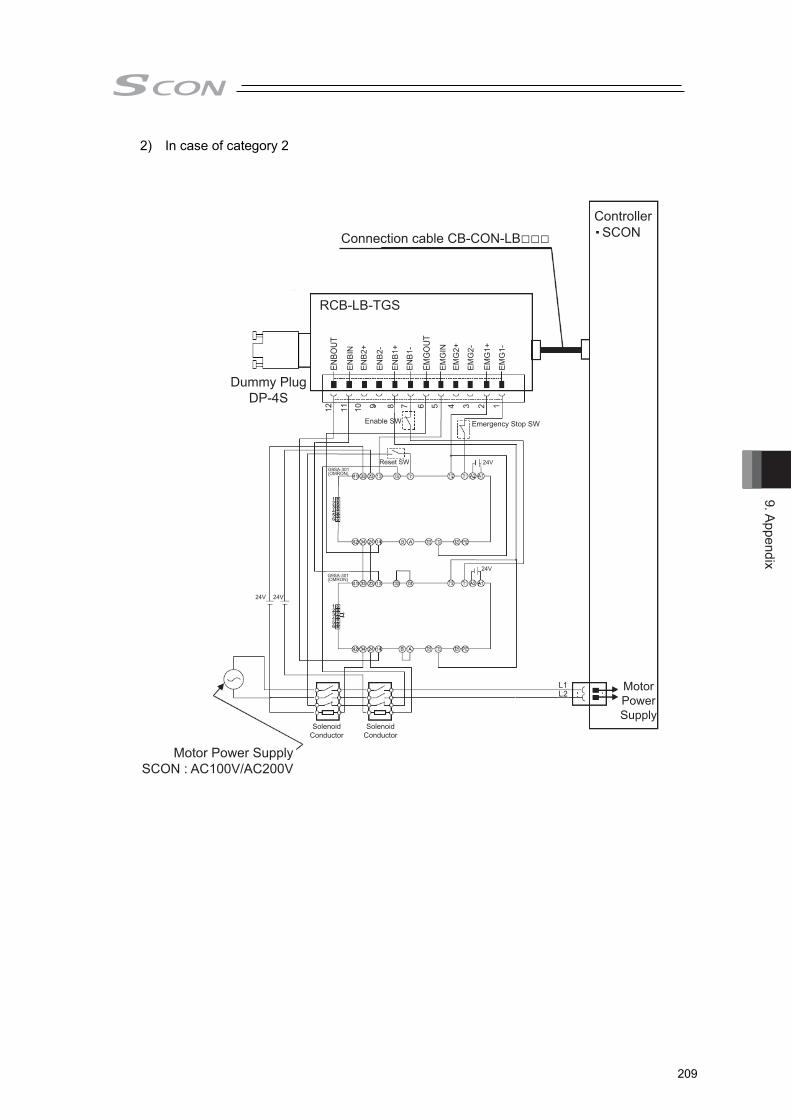
9. Appendix
209
2) In case of category 2
Connection cable CB-CON-LB□□□
Dummy PlugDP-4S
Enable SW
Reset SW
Solenoid Conductor
Solenoid Conductor
Controller
Motor PowerSupply
Emergency Stop SW
Motor Power SupplySCON : AC100V/AC200V
RCB-LB-TGS
SCON
L2L1
24V
24V
24V
24V
G9SA-301(OMRON)
G9SA-301(OMRON)
ENBO
UT
EN
BIN
EN
B2+
EN
B2-
EN
B1+
EN
B1-
EMG
OUT
EM
GIN
EM
G2+
EM
G2-
EM
G1+
EM
G1-
12 11 10 9 8 7 6 5 4 3 2 1

9. A
ppen
dix
210
● Detailed category 2 circuit example
EMBO
UT
EMBI
N
EMB2
+
EMB2
-
EMB1
+
EMB1
-
EMG
OUT
EMG
IN
EMG
2+
EMG
2-
EMG
1+
EMG
1-
1
2
3
4
5
6
7
8
9
1
2
3
4
System I/O Connector
DC BusL1L2
E24V
*EMGSTR
EMGRYRLS
EMGSTR
VP24
SCON
TP Connection Detecting
TP DetectionT24V…OutputBypass relay…OPENTP Not DetectedT24V…Not OutputBypass relay…CLOSE
1
2
3
13
14
9
12
6
5
23
24
25
22
7
26
12 11 10 9 8 7 6 5 4 3 2 1
Motor Power Cutoff Relay
Regulator
RCB-LB-TGS
SGA
SGB
EMGA
T24V
EMGB
1
2
3
4
5
6
7
8
9
5V
Enable SWEnable SWEmergency Stop SW
Reset SW
ControlCircuit
ControlCircuit
100V AC/200V AC
Solenoid Contactor Solenoid Contactor
External EmergencyStop Circuit category 2
RTS
CTS
EMG1-
EMG1+
EMG2-
EMG2+
EMB1-
EMB1+
EMB2-
EMB2+
Dummy Plug
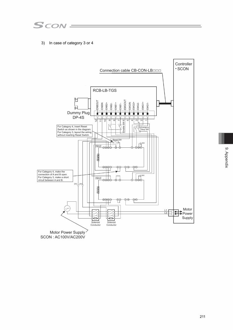
9. Appendix
211
3) In case of category 3 or 4
Connection cable CB-CON-LB□□□
Dummy PlugDP-4S
Ena
ble
SW
Reset SW
Solenoid Conductor
Solenoid Conductor
Controller
Motor PowerSupply
EmergencyStop SW
For Category 4, insert Reset Switch as shown in the diagram.For Category 3, layout the wiring without inserting Reset Switch.
For Category 4, make the connection of A and B open.For Category 3, make a short circuit between A and B.
Motor Power SupplySCON : AC100V/AC200V
SCON
24V
24VG9SA-301(OMRON)
G9SA-301(OMRON)
24V 24V
L2L1
ENBO
UT
EN
BIN
EN
B2+
EN
B2-
EN
B1+
EN
B1-
EMG
OUT
EM
GIN
EM
G2+
EM
G2-
EM
G1+
EM
G1-
12 11 10 9 8 7 6 5 4 3 2 1
RCB-LB-TGS

9. A
ppen
dix
212
● Detailed category 3 or 4 circuit example
EMBO
UT
EM
BIN
EM
B2+
EM
B2-
EM
B1+
EM
B1-
EMG
OUT
EM
GIN
EM
G2+
EM
G2-
EM
G1+
EM
G1-
1
2
3
4
5
6
7
8
9
1
2
3
4
System I/O Connector
DC BusL1L2
E24V
*EMGSTR
EMGRYRLS
EMGSTR
VP24
SCON
TP Connection Detecting
TP DetectionT24V…OutputBypass relay…OPENTP Not DetectedT24V…Not OutputBypass relay…CLOSE
1
2
3
13
14
9
12
6
5
23
24
25
22
7
26
Motor Power Cutoff Relay
Regulator
RCB-LB-TGS
SGA
SGB
EMGA
T24V
EMGB
1
2
3
4
5
6
7
8
9
5V
Reset SWReset SWEmergency Stop SWEmergency Stop SW
Reset SW
ControlCircuit
ControlCircuit
Solenoid Contactor Solenoid Contactor
External EmergencyStop Circuit category 4
For Category 4, insert Reset Switch as shown in the diagram.For Category 3, layout the wiring without inserting Reset Switch.
For Category 4, make the connection of A and B open.For category 3, make a short circuit between A and B.
RTS
CTS
EMG1-
EMG1+
EMG2-
EMG2+
EMB1-
EMB1+
EMB2-
EMB2+
Dummy Plug

9. Appendix
213
[4] TP Adapter and Related Components 1) TP adapter external dimensions
RCB-LB-TGS

9. A
ppen
dix
214
2) Connection Cable ● Controller/TP Adaptor Connection Cable
Use this cable to connect the controller and TP adapter (RCB-LB-TGS). Model : CB-CON-LB005 (standard cable length : 0.5m) Maximum cable length : 2.0m
Color Signal No. ColorSignalNo.BrownYellow
RedOrange
BlueGreenPurpleGray
BrownYellow
RedOrange
BlueGreenPurpleGray
Shield Shield
8PIN MIN DIN Connector (mold casting)Contact
Metal shellHousing AHousing B
Cover
: MD-SP2240 (J.S.T. Mfg.) ×8: MD-PS8T (J.S.T. Mfg.): MD-PI8A (J.S.T. Mfg.): MD-PI8B (J.S.T. Mfg.): MD-PCC8T-S2 (J.S.T. Mfg.)
8PIN MIN DIN Connector (mold casting)Contact
Metal shellHousing AHousing B
Cover
: MD-SP2240 (J.S.T. Mfg.) ×8: MD-PS8T (J.S.T. Mfg.): MD-PI8A (J.S.T. Mfg.): MD-PI8B (J.S.T. Mfg.): MD-PCC8T-S2 (J.S.T. Mfg.)
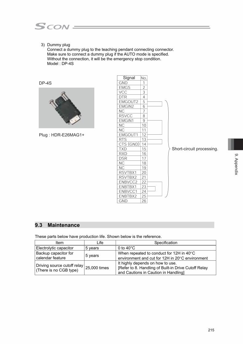
9. Appendix
215
3) Dummy plug Connect a dummy plug to the teaching pendant connecting connector. Make sure to connect a dummy plug if the AUTO mode is specified. Without the connection, it will be the emergency stop condition. Model : DP-4S
Plug : HDR-E26MAG1+
Signal
Short-circuit processing.
DP-4S
9.3 Maintenance These parts below have production life. Shown below is the reference.
Item Life Specification Electrolytic capacitor 5 years 0 to 40°C Backup capacitor for calendar feature 5 years When repeated to conduct for 12H in 40C
environment and cut for 12H in 20C environment
Driving source cutoff relay (There is no CGB type) 25,000 times
It highly depends on how to use. [Refer to 8. Handling of Built-in Drive Cutoff Relay and Cautions in Caution in Handling]
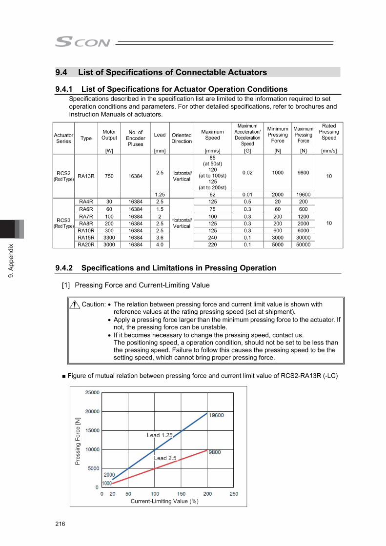
9. A
ppen
dix
216
9.4 List of Specifications of Connectable Actuators 9.4.1 List of Specifications for Actuator Operation Conditions
Specifications described in the specification list are limited to the information required to set operation conditions and parameters. For other detailed specifications, refer to brochures and Instruction Manuals of actuators.
Actuator Series Type
Motor Output
No. of Encoder Pluses
Lead Oriented Direction
Maximum Speed
Maximum Acceleration/Deceleration
Speed
Minimum Pressing
Force
Maximum Pressing
Force
Rated Pressing Speed
[W] [mm] [mm/s] [G] [N] [N] [mm/s]
RCS2 (Rod Type) RA13R 750 16384 2.5 Horizontal/
Vertical
85 (at 50st)
120 (at to 100st)
125 (at to 200st)
0.02 1000 9800 10
1.25 62 0.01 2000 19600
RCS3 (Rod Type)
RA4R 30 16384 2.5
Horizontal/Vertical
125 0.5 20 200
10
RA6R 60 16384 1.5 75 0.3 60 600 RA7R 100 16384 2 100 0.3 200 1200 RA8R 200 16384 2.5 125 0.3 200 2000
RA10R 300 16384 2.5 125 0.3 600 6000 RA15R 3300 16384 3.6 240 0.1 3000 30000 RA20R 3000 16384 4.0 220 0.1 5000 50000
9.4.2 Specifications and Limitations in Pressing Operation
[1] Pressing Force and Current-Limiting Value
■ Figure of mutual relation between pressing force and current limit value of RCS2-RA13R (-LC)
Caution: The relation between pressing force and current limit value is shown with reference values at the rating pressing speed (set at shipment).
Apply a pressing force larger than the minimum pressing force to the actuator. If not, the pressing force can be unstable.
If it becomes necessary to change the pressing speed, contact us. The positioning speed, a operation condition, should not be set to be less than the pressing speed. Failure to follow this causes the pressing speed to be the setting speed, which cannot bring proper pressing force.
Pre
ssin
g Fo
rce
[N]
Lead 1.25
Lead 2.5
Current-Limiting Value (%)

9. Appendix
217
■ Figure of mutual relation between pressing force and current limit value of RCS3-RA4R-LC
Pre
ssin
g Fo
rce
[N]
Current-Limiting Value [%]
200
150
100
50
00 20 40 60 80 100 120
■ Figure of mutual relation between pressing force and current limit value of RCS3-RA6R-LC
0
200
400
600
800
0 20 40 60 80 100 120
Pres
sing
For
ce [N
]
Current-Limiting Value (%)
■ Figure of mutual relation between pressing force and current limit value of RCS3-RA7R-LC
Pre
ssin
g Fo
rce
[N]
Current-Limiting Value (%)
0
250
500
750
1000
1250
0 20 40 60 80 100 120 140 160

9. A
ppen
dix
218
■ Figure of mutual relation between pressing force and current limit value of RCS3-RA8R-LC
Pre
ssin
g Fo
rce
[N]
Current-Limiting Value (%)
0
500
1000
1500
2000
2500
0 20 40 60 80 100 120 140 160
■ Figure of mutual relation between pressing force and current limit value of RCS3-RA10R-LC
0
1000
2000
3000
4000
5000
6000
7000
0 50 100 150 200 250
Pre
ssin
g Fo
rce
[N]
Current-Limiting Value (%) ■ Figure of mutual relation between pressing force and current limit value of RCS3-RA15R-LC
Pre
ssin
g Fo
rce
[N]
30
25
20
15
10
5
00
Current-Limiting Value [%]
20 40 60 80 100 120 140 180 200160

9. Appendix
219
■ Figure of mutual relation between pressing force and current limit value of RCS3-RA20R-LC
Pres
sing
For
ce [N
]
0
Current-Limiting Value [%]
20 40 60 80 100 120 140 180 200160
50
45
40
35
30
25
20
15
10
5
0

9. A
ppen
dix
220
[2] Limitation in Operation Keep following three conditions for operation. Condition 1. Pressing time should be within the determined duration. (e.g.: The current and time for pressing is restricted for RCS2-RA13R,
RCS3-RA15R, RCS3-RA20R.) Condition 2. The continuous operation thrust in one cycle should be within the rated thrust of
each actuator. Condition 3. There should be one time of pressing operation in one cycle. Refer to each actuator instruction manual for the details.

10. Warranty
221
Chapter 10 Warranty
10.1 Warranty Period
One of the following periods, whichever is shorter: • 18 months after shipment from our factory • 12 months after delivery to a specified location
10.2 Scope of the Warranty Our products are covered by warranty when all of the following conditions are met. Faulty products covered by warranty will be replaced or repaired free of charge:
(1) The breakdown or problem in question pertains to our product as delivered by us or our authorized dealer.
(2) The breakdown or problem in question occurred during the warranty period. (3) The breakdown or problem in question occurred while the product was in use for an
appropriate purpose under the conditions and environment of use specified in the instruction manual and catalog.
(4) The breakdown or problem in question was caused by a specification defect or problem, or by the poor quality of our product.
Note that breakdowns due to any of the following reasons are excluded from the scope of warranty:
[1] Anything other than our product [2] Modification or repair performed by a party other than us (unless we have approved
such modification or repair) [3] Anything that could not be easily predicted with the level of science and technology
available at the time of shipment from our company [4] A natural disaster, man-made disaster, incident or accident for which we are not liable [5] Natural fading of paint or other symptoms of aging [6] Wear, depletion or other expected result of use [7] Operation noise, vibration or other subjective sensation not affecting function or
maintenance Note that the warranty only covers our product as delivered and that any secondary loss arising from a breakdown of our product is excluded from the scope of warranty.
10.3 Honoring the Warranty
As a rule, the product must be brought to us for repair under warranty.
10.4 Limited Liability
(1) We shall assume no liability for any special damage, consequential loss or passive loss such as a loss of expected profit arising from or in connection with our product.
(2) We shall not be liable for any program or control method created by the customer to operate our product or for the result of such program or control method.

10. W
arra
nty
222
10.5 Conditions of Conformance with Applicable Standards/Regulations, Etc., and Applications
(1) If our product is combined with another product or any system, device, etc., used by the
customer, the customer must first check the applicable standards, regulations and/or rules. The customer is also responsible for confirming that such combination with our product conforms to the applicable standards, etc. In such a case we will not be liable for the conformance of our product with the applicable standards, etc.
(2) Our product is for general industrial use. It is not intended or designed for the applications specified below, which require a high level of safety. Accordingly, as a rule our product cannot be used in these applications. Contact us if you must use our product for any of these applications:
[1] Medical equipment pertaining to maintenance or management of human life or health [2] A mechanism or mechanical equipment intended to move or transport people (such
as a vehicle, railway facility or aviation facility) [3] Important safety parts of mechanical equipment (such as safety devices) [4] Equipment used to handle cultural assets, art or other irreplaceable items
(3) Contact us at the earliest opportunity if our product is to be used in any condition or environment that differs from what is specified in the catalog or instruction manual.
10.6 Other Items Excluded from Warranty
The price of the product delivered to you does not include expenses associated with programming, the dispatch of engineers, etc. Accordingly, a separate fee will be charged in the following cases even during the warranty period:
[1] Guidance for installation/adjustment and witnessing of test operation [2] Maintenance and inspection [3] Technical guidance and education on operating/wiring methods, etc. [4] Technical guidance and education on programming and other items related to programs

Change H
istory
223
Change History
Revision Date Revision Description
2015.08
2015.11
2016.02
2016.04
2016.07
2016.10
2016.11
2017.11
First Edition Edition1B
P12 Deleted 9 and � at Note to “Name for Each Parts and Their Functions”
Second Edition
The contents of the 3000 to 3300W type added
Third Edition The Transcription of the LC-F type added
Fourth Edition Force Control Position Stop 2 mode added
Fifth Edition Change made to input available range for electric gear setting (from V0006) Statement revised for regenerative unit Details added for drive cutoff contact output Statement added for 2CH Record Mode in monitoring cycle Note added for cause and treatment of alarm codes 0A3 and 0A4 Correction made to statement
5B Edition Contents revised in UL description Available range for input changed in electronic gear setting, correction made to description Connector pin numbers corrected for TP adapter and I/O connectors
5C Edition
The transcription of the temperature drift deleted


Manual No.: ME0345-5C (November 2017)
The information contained in this document is subject to change without notice for purposes of product improvement.Copyright © 2017. Nov. IAI Corporation. All rights reserved.
17.11.000
Head Office: 577-1 Obane Shimizu-KU Shizuoka City Shizuoka 424-0103, JapanTEL +81-54-364-5105 FAX +81-54-364-2589
website: www.iai-robot.co.jp/
Ober der Röth 4, D-65824 Schwalbach am Taunus, GermanyTEL 06196-88950 FAX 06196-889524
SHANGHAI JIAHUA BUSINESS CENTER A8-303, 808, Hongqiao Rd. Shanghai 200030, ChinaTEL 021-6448-4753 FAX 021-6448-3992
website: www.iai-robot.com
Technical Support available in USA, Europe and China
Head Office: 2690 W. 237th Street, Torrance, CA 90505TEL (310) 891-6015 FAX (310) 891-0815
Chicago Office: 110 East State Parkway, Schaumburg, IL 60173TEL (847) 908-1400 FAX (847) 908-1399
TEL (678) 354-9470 FAX (678) 354-9471website: www.intelligentactuator.com
Atlanta Office: 1220 Kennestone Circle, Suite 108, Marietta, GA 30066
825, PhairojKijja Tower 12th Floor, Bangna-Trad RD., Bangna, Bangna, Bangkok 10260, ThailandTEL +66-2-361-4458 FAX +66-2-361-4456