scoring load capacity of gears lubricated with ep- · pdf filefrom recalculation of practica~...
TRANSCRIPT
Scoring Load Capacity 0'£ Ge'ars,Lubricated With EP-Oils,
byH., Winter and. K., Michaelis
Technical University of Munich,
AbstnctThe lntegrlll Temperature Method for ,the evaluation of the scoring
load CIlpacity of gears is described. All necessary equations for thepractiCtll.app1ication .are presented. The limit scoring temperature forany oil can be obtained from a gear scoring test. For .the FZG- TestAJ8.3190 ace. DIN 51 354 and the R.yder Gear Test ace. FTM STDNr. 791, graphs for the direct evaluation at the scoring temperature asa /unction of oil viscosity and test scoring load are giver/.
The method is compared with the Total Contact Temperatu.reCriterionacc. Blok (V-the alternate procedure to the IntegralTemperature Method as standardized in ISO DP 6336 part IV-andthe Soaring Index Metlwd ace. ,Dudley (2). Comparative calculationstvr practical gears with andwitl!out sc:oringdamages showed goodcorrelation with experience for the .integra! Temperature Criter.ion.
,IntroductionIn d!iffellent fields of application, the load carrying
capacity of gears is limited-by scoring damage. . -In highly loaded, case earbunaed turbine gears, the
normally used mineral oils with rust and oxidationinhibitors do not always give sufficient scoring protec-tion. On the other hand, the necessaryiEP-additivesadversely affect the anti-Oxidation, anti-foam, etc. prop-erties, so' that the life of the oil may be reduced,
In the' case ofcarburized marine gears With dieselengine drives, motor oils are frequently also. used for thegears. These oils do not always provide sufficient scor-ing load capacity.
Also, in some types of locomotive drives, the samelubricant is used £or the hydraulic torque converter andthe gears.. For high efficiency of the hydraulics, low
AunIORS:D.R. KlAUSMICHAEUS studied machine engineering ,a.t
the Technic~l University of Munich.. Since 1970, he haswor:ked at the Labor;atory of Gear Research ,and Gear Design(FZ~) at ,this university:. In 1977 he became Chief Engineer.He specializes in lubrication, scoring, and wear of gears ..
PROF;OR..ING. HANS WINTER has studied as ,an associ-ate of Prof.Dr.-lng.h.c. Gustav Niemann. He r.earived hisDoctoral degree at the Technical University of Munich. In1956, he ,began. his work in the German gear industry:Zahnradfabrik. Friedrichshafen (Calculation, research,manufacturing), Demag,. Duisburg (Research, development,design, selling). Since .1969 he has been the head of the Labo-ratory of Gear Research and Gear Design. (FZG) at the Tech-nical University of Munich.
.20' GearTeehnol'ogy
.,' - '. ~- - -~. . . -....... ... ..~ t··'''· - .
warm scoring
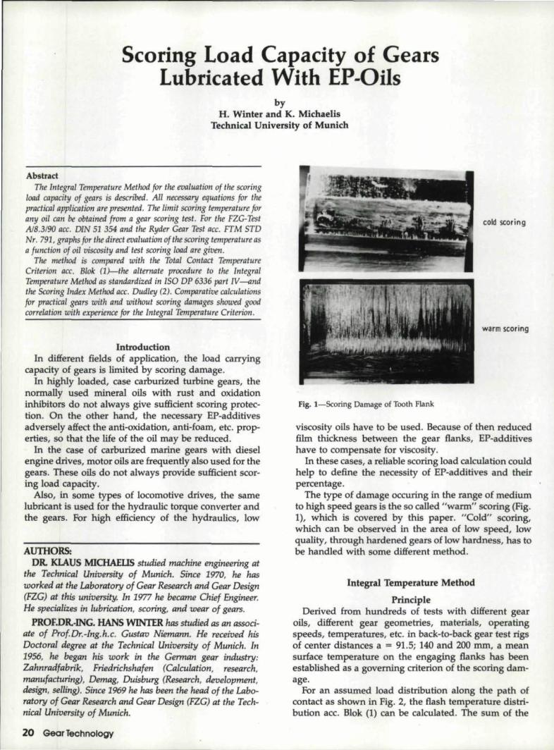
fig. i-Scoring Damage of Tooth Flank
viscosity oils have to be used. Because of then reducedfilm thickness between the gear flanks, EP'-additiveshave to compensate for viscosity.
In these cases, a.reliable scoring load calculation couldhelp to define the necessity of EP-adwtives and theirpercentage.
The type of damage occuring in the range of mediumto. .high speed gears ISthe soealled "warm" scoring (Fig.1), which is covered by this paper. "Cold" scoring,which can be observed in the area of low speed, I.oWquality, through hardened gears of low hardness, has tobe handled with some different method.
Integral Temperature Method
PrincipleDerived from hundreds of tests with different gear
oils, different gear geometries, mat'erials, operatingspeeds, temperatures, etc ..in back~to~back ,gear test rigsof center distances a ... 91.5; 140 and 200 mm, a meansurface temperature on the engaging flanks has beenestablished as a governing criterion of thescorlng dam-age.
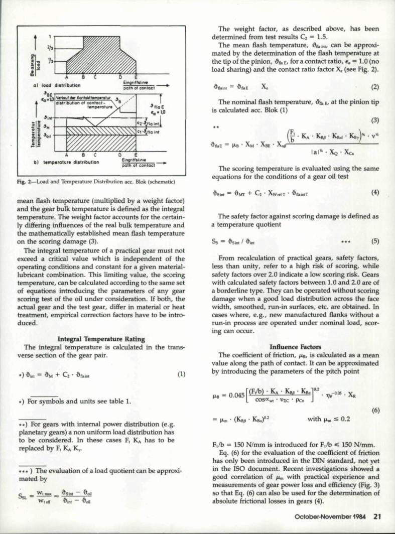
For an assumed load dlstrfbufionalong the path ofcontact as shown in Fig. 2, the flash temperature distri-bution ace .. Blok (1) can be calculated. The sum of the
,01 loa;d dislributi.QI!
b,) temp.ro,lun dlllUitiulionE
EinOl'I tr,h .. It, _pcllt 01 eDn,tClcl-
Fig. 2-Load and 'Iemperature Distribution ace.Blok (schelM'tk)
mean flash temperature (multiplied by a weight factor)'and the g:ear bulk temperature is defined as the integraltemperature. The weight factor accounts for the certain-ly differing influences of the real bulk temperature andthe mathema,ticaUy established mean Bash temperatureon the scoring damage' (3).
The integra~ temperature ofa practical gear must notexceed a criticall value which Is independent of theoperating eonditiens and constant for iii given mat,erial~lubricant combination. This limiting value, the scoringtemperature,can be calculated accordiogto the same setof equations introducing the parameters of any gearscoring test of the oil under consideration. If both, theactual gear and the test gear, differ in material or heattreatment, empiricaJ! correction factors have to be intro-duced.
Inb!'gra1i'Femperature Rating,The integral temperature is calculated in the trans-
verse section of the geaJ pair.
(1)
..) For symbols and units see table 1.
....) FOr gears with internal power disb:ibution (e.g.planetary ge~rs)aJ non uniform load distribution hasto be considered. In these eases FI KA has to bereplaced by F! KA 1<,..
...... ) The evaluation of iii load 'quotient can be approxi-mated by
The weight factor, as described above, has beendetermined fromtes! results C2. = 1.5.
The mean flash temperature, 1l'ta.1!\1I can be approxi-mated by the deterrrtination of the fiashtemperature atthe tip of the pinion, 1}1lo s, fur a.contact ratio, ,e" = 1.0 (noload sharing)' and the contact ratio' factor X. (see Fig. 2)"
x. (2)
The nominal! flash temperature, DlloE, at the pinion tip,iscalcu1ated ace, Hlok (I)
(3).'.(~ . KA •. KS/l • Ka. . Ks.,)- • vI'.!
.o&E= ....B . XM . XBE • x...,r=---------~--lal\fo • ~"Xc.
The scoring temperature is evahiated using the sameequations for the condjtions of a gear oil test
(4)
The safety factor against scoring damage is defined asa temperature quotient
Ss "" .osint I .ow •••
From recalculation of practica~ gears, slUety factors,less than urnty, reEer to ,8 high risk of SCi>ring,whilesafety factors over .2.0 indicate a.low scoring risk. Gearswith calculated safety factors between 1.0' and 2.0 are ofa borderline type. They can be operated without scoringdamage when a good load distribution across the facewidth, smoothed, run-in su_rfaces, etc. are obtained. Incases where, e.g., new manufactured flanks without arun-in prooess are operated under nominal load, scor-ing can occur.
[nOuence FadolSThe e,oefficient of friction,. #Jill' Is calculated as a. mean
value along the path. of contact, It can be approximatedby introducing the parameters of the pitch. point
~ 0 045 [(FJb) ..K" . Kul! . K.]0.2 -O'II5'X,111-11 = '. ' . 1J, . ., ~R005CX .. 1 'UI{; . Pen .
(6)with ILms 01.2
F,ib = 150 N/mm is introduced for Ftlb i!Sii 150 N/mm.Eq. (6,) for the evaluation of the ,coefficient .of friction
has only been introduced in the DIN standard, not yetin the ISO document. Recent lnvestigat:ionsshowed agood correlation of ILm with practical experience andmeasurements of gear power loss and efficiency (Fig. 3)so thatEq, '(6)ean also be used for the determinaoon ofabsolute frictional losses in g,ears (4)..
October~Novembef1984 21

The overload factors I<A, KBjland I<B~ can be deter-mined ace, ISO DP 6336 Part I tor surface durability I<H,Band I<Ho.
The rolling speed on the pitch circle is
(7)
FDr the speed range v below, 1 mls and above 50 m/sthe evaluation of f.J;obecomes uncertain and is no longerbased on experimental data. In this rangef.J;Bis assumedto be constant, with v = 1.0 mls ~or v < 1.0 m/s and v =50 mls for v> 50 mls to be introduced into Eq ..(7) ..Theradius of curvature in the normal section is
- tanOCwt uPCn = 0.5 --Q.- db! -+ 1
CDSl"b U .. _(8)
f I ~I
0..M9
io,0610.05
I0.04 I
0.03
0.02
rrl : i I I
,I
I ~ ,
I ~ !l-;I.J.c ~ ~:
I l J
! I !! l0.1
I I I
fig. 3-Comparison of Calculated Coefficient of Friction and TestResults
mm
Table 1: Symbo.ls, Te.nn5,. and Units
a pressure anglebase helix angleaddendum contact ratio of pinionaddendum contact ratio of wheeltransverse contact ratio.total contact ratioinstantaneous contact temperatureflash temperatureflash temperature, pinion tipmean flash temperatureintegral temperaturebulk temperatureoil temperaturescoring temperaturedynamic oil vicosity at itDllcoefficient of friction, scoringmean coefficient of friction
centre distancefacewidthmesh stiffness
ab nun
N/(.um mm)N/("",m mm)
c1
c'C.Cl.2ddbdNaiEPIFbI
I<AKBaKBt!KB,.
Ky
single stiffnessamount of tip reliefconstantsreference' diameterbase diametereffective tip diameterYoung's modulustangentiaI force, reference circletangential force, base circleapplication factortransverse load distribution factorlogitudinal load distribution factorhelical load distribution factorload distribution factor for more
m.mmmmm
N/mrnzNN
than one meshm module mmR.. arithmetic average roughness (CLA) .urn5B safety factor, flash temperatureSs safety factor, integral temperatureTt pinion torque N mu gear ratio. £1/6 ~ 1v linear speed at reference circle m/sVI lulling speed mlsWI specific load including overload N/mmXBE geometrical factor, pinion tipXc. tip relief factorXM thermal flash factor I< N·fOsl'zm·\lzmmXQ rotation factorXR roughnees factorXs lubrica tion factorXw welding factorXa/l angle factorX, contact ratio factorz number of teeth
10"
'£,
ita1'1&i}fla E
itllil ;nl
itinj
1'1M1'1oil1'1s in!
T/~J.LBILmII Poisson's ratio114() kinematic viscosity at 40 "Cp radius of curvature
Suffixesb base circleC pitch pointeff effective valuesE pinion tipmax maximumn normal sectiont transverse sectionT test gearw workingI pinion2 wheel
D
..
DCKI<I<..cDC"C°C
mPas
mm2/smm
22 Gear Technology

The roughness factor accounts for surface roughness
(9)
wiLh R.. = 0.5 .. (R.t! + ~ (10)
In Eq. (10) the eLA-values of the new manufacturedHank have to be introduced. An amount of normalrun-in is included inEq. (9).
The thermal flash factor XM depends on the elasticandthermal properties of the gear materials ..For gears madeout of steel, mean values of conductivity AM= 50N/(s.K); density.PM = 7.85 kg/dID), specific heat capacityeM = 485 N m/(kg.K); IE = 206,000 Nl.mro2, and" -= 0.3can be introduced
(11)
For non steel materials for pinion and/or gear see ISODP 6336.. Part IV...
The geometrical factor XSE takes account for theHertzian stress and the contact time at the piniontipE.
Xse - 0.5 ../'-~II(U+ I), ~ - ~V Z2 (PEl' IPELI)(12)
with PEl = 0.5 . VdF.t.. - d';l (13)
and PEZ = a . sinor:"" - PEl (14)
in the transverse section.lEqs. 02, 13. 14) are valid forinternal and external cylindrical. gears.
The angle factor )(.,.jlaoeount:s for the recalculation ofthe acting; normal load to the circumferential. load at thepitch cylinder.
(15)
For approximate calculations and a pressure anglea: = 20", x"jI can be set unity.
The helical. load distribution factor, KB,. accounts forthe empirical decrease of scoring load capacity formcreasingtotal contact ratio.
~or
- ,= 1 + 0.2 . Veer - 2)(5 - ey)for 2 < 67 < 3.5 (16)
Ka, = 1.3 for
The rotation factor, "0, considers the effect of a simulta-neous load impact and high slidiing a t the beginning of
the mesh .. Fo.r gears with normal addendum modifica-tion
i<Q = 1.0 £or 1/1.S -c eJez < 1.5 (17a)
- ith - IZ121 f(dNool.l) 2 1Wit, Btl;;;;; -a;- ·"dt.1,2 - - tanocwl (18)
In the case where' the approach path of contact of thedriving partner exceeds 1.5 times the recess pa til, "0 isset 0.6.
XQ == 0.6 for driving pinion and .E2 ~ 1.5EI
"0 = 0.6 for driving. whe -I. ande, ;a. 1.5E2(l7b)
In all other cases Xo = 1.0..
The tip relief factor Xc. accounts for the benefit of aproflle modification in the area of high stiding ,(Fig. 4)ace, Lechner(S). Tip relief is only effective up to theamount where it compensates tooth deflection underloadXc. = 1 + 1.55 . 10'2 . ~ __a " C.. (19)
with Emo. as the maximum valueof El or Ez ace.Eq. (18)
e • == max {BI}"" 82
(20)
The effective tip relief Cuff can be approximated by
C •., "" Fbt . KA/fb . c') for spur gearsC••II = Fbi . KAf(b ..cy) for helical gears
with the stiffness values c' resp, c, ace. to ISO DP 6336part t
~ ~ y U'"IIJ.IJ!!KII.r T"lubl1rdKltYfllll'9!'Od1 .• , 0(111' 1'2 -.mQlOllmum of _poItll1'll of !rCI:."~ COI\tad ,·abo '1 or c2
Fig. ·4-[Ilf!u nc of Tip Relier
October·November 1984 23

A profile modification increases scoring load capacityonly when it is applied to the area of highest risk. Ingears with norma] addendum modification, the ap-proach path wi.th the load impact of the ingoing mesh ismore dangerous. For extreme addendum modification,a tip relief has to be applied to the recess path.
For driving pinion:
C ,"- {Cal}= ml'- a -- __n I Cad
. _ .. {,C.2}C. = nun 'C ..
III
(22a)
For driving gear:
C . {'C01]1• == mm 'e·.'--aeff
e . {'Cal}• == nun tcI -aeff
(22b)
The contact ratio factor, X., recalculates a, mean flashtemperature along the path of contact from the maxi-mum temperature, t}fb E, at the pinion tip for Eo = 1.0.The equations are valid for a load distribution ace, (Fig ..5) and an approximately linear increase of the flashtemperature towards the tooth tip and tooth root(Fig. 2).
(23a)
For I :5 eo < 2.0: (23b)
X, ,,"= 2 1 [0.7(e[2 + el) - 0.22 . Ea + t13", • 131
0.52 - 0.661 . Ih]
x, == 2 1 [(0.18&1.2)2 + (0.7&2.1)2 + 0.82BI2- ----.1,:_80 • 8J . , T
0.5282.1 - O.3BIB2]i
with the first index for E! ;>- 1.0and the second index for€z ;>- I.O,
(23c)
For 2.0 T 6" < 3.0 and Bl and B2 less than 2.0X. = 2 [(0.44&1,2)2 + (0.59&2.1)2 + 0.3e12 - 0.3e2.1l
6" .• 61 •
0.1561 . 62]
with the firs! index for t;l > £2 and the second index for E2> E].
26 GearTechnology
~h:1.1, I <. • I
ACE1
Fig. 5-Approxirnated load Distribution as a Function of ContactRatio
The gear bulk temperature, itM, is the temperature ofthe tooth surface before the mesh. It can be measured orcalculated according to thermal network theory(6) orfinite element methods.
An approximation is given by
(24)
where C1 = 0.7 has been determined as a mean valuefrom test results. For gears with more than one engag,e-ment on their circumference, higher bulk temperaturesthan calculated may occur.
The lubrication factor Xs accounts for the better heattransfer in splash lubricated g,ears compared with jetlubricated. From experience it can be assumedXs = 1.01 for splash lubrication and
(25)Xs == 1,2. tor jet lubrication
The choice of the lubrication system, of course, has tobe made due to other considerations, e.g., pitch linevelocity.
Xw = 0.45 for austenitic steel (stainless steel)
Xw = 0.85 for steel with content of austenite more thanaverage
Xw = 1.00 for steel with normal content of austenite
Xw = 1.15 for steel with content of austenite less thanaverage
Xw = 1.50 for bath and gas nitrided steel
Xw = 1.50 for copper plated steel
Xw = 1.25 for phosphated steel
Xw = 1.00 for all other cases (e.g. through hardenedsteel)
Table 2-Estimation of Material Factor Xw
Scori~g Temperature EvaluationThe scoring temperature, (js ",I, can be determined
ac~ording, to' the same set of equations (2) through (25)'introdudng the actual parameters of a gear oil test runwith the oit!; under consideration. For differences be-tween the materials or heat treatments of the test andactual gears, a relative correction factor has to be Intro-duced.
(26)
with XWrrlT == Xw I Xwr (27)
Empirical data on the influence of the material resp.heat tr>eatment are summarized in the welding factor Xwace, table 2.
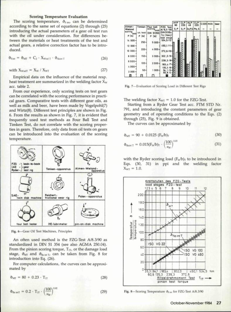
From our experience, only scoring tests on test gearcan be correlated with the sooring performance in. practi-cal geaJS. Comparative tests with different gear oils, aswell as mil,k and beer, have been made by Vogelpohl(7)and Wirtz{S). Different test principles are shown in Fig.6. From the results as shown in FWg.7, it is evident thatfrequently used test methods as Four Ball Test andTimken Test,. do not correlate with the scoring proper-ties in gears. Therefore, only data from oil tests on gear~can be introduced into the evaluation of the sc{lringtemperature.
I ~'
',11", .Y;},
,"~J
t",,"Imln. Wi,land·
Iilujaralul
I a ~~SAE. tP R.icftln.,
hlll,n dill! mIXh!n. I ,,",Idional _lIr rig Fall!! - appalalul
~ -t~:IFE·lUbmnl',rlour lball 'ul«
fig. 6-Gear Oil Tesl Machines, Principles
An often used method is the FZG-Test Af8.3!90 asstandardized in DIN 5~ 354 (see also AGMA 250.04).From. the pinion scoring torque, Trr. or the damage loadstage, :8MT and ,ao., Ill! TI can betaken from Fig. 8 forintr duction into, Eq. (26).
For computer calculations, the curves can be approxi-mated by
.aMI" = 80 + 0.23 " Tn (28)
(loo)n,az.allow. == 0.2 . Tn' lItO (29)
"_VI" Cll'1 Ml.I" CL\t I.. 2 .... milk 1"--,. to 2zt 'II UQI...·.. ---Al_- ·,.",11_" IF-J1~.~1"Z:1l f.'11 _ _ L ~-Wiekuod 11CO""I- ID<Ii!I .,"" to' '5,1,. 5,1", w.s 1'11,,'5 - - -, I
-""-' 0,'" _ DINI SUSC! IIIN SUS'!' I
II" 0'1,I II IN.I "(kl i 'IT, [I'L",lIl.- .,_ .tag_ .,.. +.: "0011- 250 S 000)1531"'5112 , I -, I I
12OlIO '10,1111 ' I
10 1000100 '000- ~7Z,'IIID~'
, 000 ISO- 1000 i 302,0 II,
1000- I 211,3/.-100 2 DOD ' IIJI.H7
135,3 "'10011' 14,1/5
~~'4"
I
I
'11~ ~
, 000, I'SOZ 000=
III n
Fig. 7-Evaluation of Scoring Load in Differ nt Test Rig
The welding factor Xwr = 1.0 for the FZG- Test.Starting from a Ryder Gear Test ace, FfM SID Nil'.
791, and introducing the constant parametrs of geargeometry and of operating conditions to the Eqs. (2)through (25), Fig. 9 is obtain d.
The curves can be approximated by
{)MT = 90 + 0.0125 (Fbl/bh (30)
(-- )0.03
{)&mtT = 0.015(Fb/b)r· ~:' (31)
w:ith the Ryder scoring load (fbllb)r ,to be introduced InEqs. (30, 31)1 in ppi and the welding factorXwr == 1..0.
K'l'Crtstutel'l des, FZG,- Tutsload stagu I~ZG·test123' 'S 6 7 6 9 10 11 12
i
Fig. ,8-Scoring Temperatur~ tiL .. , for fZG-Te t A/8.3J9Il
October-November 1984 27

100
1'40
I',~ 100
41'10.
I~ eo:I- ,-eI I'D10. t41 60,a.E IE41 ' ..
If- '- 40
-I
IGlOO 2000 3000 4000 Pilibezogene Zal'lMormaU(.roU (Fbtlb)r ..normal load :per face width
fig. g'-Scorin,g Temperature QS",J for Ryder-Gear-Test
Thus, test results of different test methods can beused as bask "strength" values. One of the majordifferences between FZG-Test and Ryder Gear Test is thepitch line velocity.
For high speed application, Ryder results obtained atv = 46 m/s and for low to medium speed application,FZG results at 8.3 mis are somewhat closer to practicalgear conditions and would be preferred, if available ..,
Comparisonwiith ,other Methods
GeneralAn often used method for the evaluation of the risk of
scoring damage is the Total Contact 'Iemperature Criteri-on ace. Blokrl), The method predicts scoring when amaximum, local, instantaneous contact temperature,-8D max, exceeds a critical value, ~oiI' The contact tempera-ture distributionalong the flank is given by the sum ofthe constant bulk temperature and the local flash temp-erature (Fig. 101)., The critical value is only dependent onthe oil-materia] combination and independent of geom-etry and operating conditions. It can be expressed as afunction of oil visoosity (Fig, 11). The total contacttemperature method is also standardized inmso OP6336, and should be applied in parallel whenever possi-ble. After some time of practical experience with. bothmethods, it should be decided which one can bedropped.
The Scoring Index Method ace. Dudley(2) is derivedfrom the Total Contact Temperature Criterion. It usesonly the flash temperature part in a simplified way..Therefore, our objections against the Total ContactTemperature Criterion are also valid lorth.e SooringIndex. Method, at least to the same degree, Table 3compares the field of application of the Total Contact
28 Gear Technology
Fig ..lO-1::emperature Distribution along the Path of Contact ace. Blok
0(;
300~--~-----r--~+-~--~--~~"'cl'll
t 200'+---+---:::~~~174""-:'9----l'"--i
100~----+-----+-~--~~----~-+--~
unlegierte Min,rQ'lo'll5tra.ight mineral oil.s
Fig. ll-Crltical Contact Temperature for Flash Temperature Method
Temperature Criterion to that of the Integral Tempera-ture Method.
In addition to the difficulties in the evaluation of localand instantanecus parameters of load-think of dynam-ic load distribution along the path of contact (Fig.12~oefficient of friction, radius of' curvature underload, etc. Quite a few test results indicate that a single
I
I
"rom i"r lunngl luif .. gI FZG or 1111,01.. Inil I
TOTAL CONTACTTOI,EfIIAfUfIIE
fSCORING I'NDEX I
liNm'I!GRALTI! ...'£R'. fUfIIE
ma.imU!l'l',loea', inl'alll'. !!Wall,welgllted lI"nllClMOUI 'colll'lIIcl l'lIIpertltUII' ".mIM'!'Cllur.1'''''01;11.01 'lIal" 1''''D'l'Olu,.I'
Fi,lell of IlrQig_' mlfttiral Otis.lPl!lIcQlion
lirellglli. mIld .n4 IE"!I'I,_al 0,"1,.lylllh.ltCall. ~
Table J-Comparison of Tot,alContact Temperature and Inl:egra\Temperature Criterion
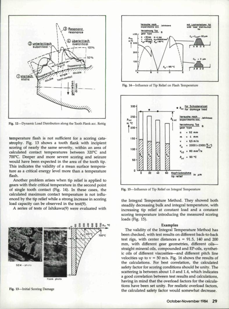
fig, ll-Dynamic Load Distribution along the Tooth Flank ace, Rettig
temperature' flash is not sufficient for a scoring cata-strophy, Fig, 13 shows a tooth fla:nkwith incipientscoring of nearly the same severity, within an area ofcalculated contact temperatures between 320"Cand700"C. Deeper and more severe scoring and seiizurewould have been expected in the area of the tooth tip.This indlcares the validity of a mean surface tempera-ture as a eritical ,energy level more than a temperatureflash.
Another problem arises when tip relief is applied togeerswith their critical temperature in the second pointof single tooth contact ,(Fig. 14). In these cases, thecalculated maximum contact temperature is not in£lu-eneed by the tip relief while' a strong increase in scoringload capacity c-an be observed in the test(9).
A series of ,tests of Ishikawa(9) were ,evaluated with
fig. 13-lnitial Scoring Damage
,mil L'II'''''' liUJiI...!!!.Wllfl!! LINd Gkltnl:u.!LiiMl,..
..... 101...... Tn III'11"' In. -'00
1
Jot••foIOC •-t'GOle
IZOO'
!
Fig. ll-Influenoe of Tip' Relief on Flash Tempera'ture
300
250
'i'",In ·c
FOOl150
~~~Jahlk_',xl!lrlm-"'I, G=. - -
",.,,1111\1'1,,", Trp I.1I1ar I,ll'.
G '. 92111111,
III ." ,mill'¥ • (1,5 ,m/"Cl'H • 20001-nOOI.!;;(
-:.0 • 110 ,mmZ".,
"0.' • 90·C'50
Fig. is-Influence of Tip Relief on Integral Temperature
the Integral 'Iemperature Method. They showed bothsteadily decreasing bulk and integral temperature, withincreasing tip r-elief at constant load and a constantscoring temperature introducing the measured scoringloads (Fig. 15).
ExamplesThe validity of the Integral Temperature Method has
been checked, with test results on diHefient back-to-baektest rigs, with center distaneesa = 9'1.5, 140 and 200mm, with different gear geometries, different oils-straight mineral oils, compounded and EP-oils, synthet-ic 'oils of different viscosities--and different pitch. linevelocities up to v = 50 mls ..Fig...16 shows the results ofthe calcalations. For best correlation, the calculatedsafety factor for scoring eenditions should be unity. Thescattering: is between about 1.0 and 1.4, which indicatesa good correlation between test results and calculations,having in mind that the overload factors ~or the calcula-nons have been set unity. For realistic .overload fador-s,the ca~culatedl safety factor wo~d somewhat decrease.
'October-November 1984 .29'
Min.I .... rt.meQnY(!IYI'
rt;~rt:ii~""'-~~~~:r'a~Ad'l$Qbsland'til'll ... dis taneeQ 91.5mm
+---i--+--+---+---I ..I~O,mma 200mm
10 20 30 LO 50Umfangsgescllwincllg,keit I
V in ms, .............prteh tine veloc:ily
Fig. 16-CaJculat,ed Scoring Resistance for Test Results acc.lntegra1Temperature Method
-----------r"5 It,,'
'-'-"""'T UQ'(;
Fig. 1.7-Companson of Scoring Load Capacity Rating for a. CondenserGea:r Drive Without Damage
But these were only test gears with scoring damages.It still remained open if the results are comparable withpractical gears of bigger dimensions, higher speeds etc.And also if gears without scoring problems would arriveat calculated safety factors significantly higher than 1.0.Imagine that it iis fairly easy to arrive at a value of 1.0,only extract often enough the square root of any figureand you will arrive at unity. .
Therefore" we collected data from all kinds of practicalgears with and without scoring damages. Anexample isshown in Fig. 17 for a condenser gear drive withoutscoring damages in service. The Total Contact Tempera-ture Method calculates a safety factor of 0.4, the IntegralTemperature Method of 1.5. A change of the unrealisticbulk temperature value, itM ;; 239°C of the Total ContactTemperature Method to 11M = 90 °C of the IntegralTemperature, doesn't make it any better. The safetyfactor, Sa = 0.5,. remains s~ far below 1.0, indicating ahigh scoring risk.
.30 Gear Technology
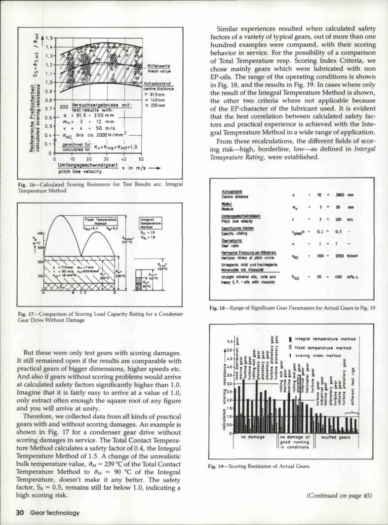
Similar experiences resulted when calculated safetyfactors of a variety of typical gears, out of more than onehundred examples were compared, with their scoringbehavior in service. Ior the possibility of a comparisonof Total Temperature resp. Scoring Index Criteria, wechose mainly gears which were lubricated with nonEP-oils. The range of the operating conditions is shownin Fig. 18, and the results in Fig. 19. In cases where onlythe result of the Integral Temperature Method is shown,the other two criteria where not applicable becauseof the EP-character of the lubricant used. It is evidentthat the best correlation between calculated safety fac-tors and practical experience is achieved with the Inte-gral 'lemperature Method in a wide range ofappllcation.
From these recalculations, the different fields of scor-ing risk-high, borderline, low-as defined inlntergalTemeprature Rating, were established.
AchllllsUndCll'lh distlnCl
Mockil~Umfm~hwln.1tPlI!;h IInl' WIOcIty
5p1z111Knts Cltitll1Sp!I;lIle sJlcllng'
llbtrSlbil !!<Ju
41 .. ZIlXI 1111
J .. 50 'IIQI
1 + L20 mls
0..1 .. '0,5
I • 7
300' .. Z200 N/lIImI'
stl'l~ !IIln,,,,1 Clih. 11!!l1d ,lI'IdIIII'q £., .• oils wIIn YilQlSiIy
G.lr rlllQ
Hlrtmh' PrM.wnglmWllz1llll~Hlmllll ItrMs • _ eire"
Unltoll,rt" ,mild und nocnlliJlrtlMinlulllit 'm~VIUoslIM
F.lg..1l8-Range of Significant Gear Parameters for Actual Gears in Fig. 19
Z ! I inl.gn:n tempe,ature methodIg!IQIi
~' lIall! templratur,. me1'hod
fig. 19-5co.ring Resistance of Actual Gears
(Continued on page 45)

Double Enveloping Worm 'Gears •..(Gmtil1ued (rom Pilg,e J b)
(2)redudions at .appro,ximately 92 % ·93 % overall efficiency orthree (3) redudionsat about ,89%·90% efficiency. The wonngearbox wifua 20; 1 ratio will have about 85 % ·87 % efficiency.A. 30:1 ratio helical reducer willgenerally require three (3)meshes wilh approximately 89%·90% efficiency. The 30:1wormgear speed reducer will have an efficiency of approxi-matety83 %.84! %. You can seethe h tical box is more effi-cient. but oertainly n t to the degree often claimed.
There are other inherent advant.ages in worm gearing whichmust be considered in evaluating the application and the typeof gearing intended for that application. Double envelopingworm gearing w,iIl take a, momentary overload of 300 % •whereas helical gearboxes aI" 'only designed for 200 %. rnornen-Iary overload. Helical gearboxes restrict motor starting capac-ity· to 200 %. whereas double enveloping worm gearboxes per-mit 300 % . Generally speaking, worm gearboxes are smaller inoverall size and weight and in terms of horsepower capacHy.generally less expensive, In ddltion, with compactness of thedouble enveloping wonngear principle, d uble enveloping gear-boxes are more eompactand weigh less. horsepower forhorsepower. than cylindrical gear reducers.
This pllptr was pli&lisl!td far tilt .Nllliallld Carlftrmct Oil POlVerTrtfllsmis5iolls 1979 and rtprirlfrd in 'Ttdlllical Asptcts of Dou-bl:e E'IUe!opi,lg Woml Grllrs. tl CC!1It Drio« Publiauion.
Design ,of the Involute ...(Ccmtilmed from pagt 44)
generally supposed. In other words, bearing pressures are not.gn!atlyaf~eded by an increase in the pressure within the usuallimits. This condition is graphically presented in Fig. 14. To. con-struct this diagram, draw a line A Bat right angles to the lineof centers and tangent to both pitch circles. Then draw a lineC D tangent to. the base circles and passing thro.ugh the pitchpoint E; this line representing the pressureangle. Now dropa perpendicelar at any point G on line A B, passing throughline C D at point F. W.ith E as a center and E F as a radiusscribe an arc. Increases in the load on th supporting bearingsdue to changes in pressure angle can be determined graphicallyby noting the changes in distance H. as the pressure anglechanges. It is apparent that ,the loa.d·increase is the ratio oflengths E G to E F, and is, Itherefore, proportional to the secantof ,the pressure angl .
The second column in Table II gives the secants of variouspressure angles listed in the IArstcolumn, and ranging from 14 'Ilup Ito and incl udmg 3D d grees,
The last column lists in terms of percentage. the increase inthe load as compared with 14 Ih degrees. It will be noticed thatan increase in the pressure angle from 14 Ih. to 20' degrees, resultsin an increased load on the supporting bearings of only .3percent.(Continued ott tilt ,uxf Pdge)
Scoring Load Capacity .•.(Continued from l'ag.e 30)
,Condusio,nA new method for scoring, load ,capacity rating r based
on the ,cakulation of a mean, weiighted .flanktempera·ture, the int,egraWtemperature, has been described. The[loUting temperatures necessary, l!or the defirution of ascoring safety factor. can be obtained from ,any availablegear oll test. The method is vaJid for all types of oils asstraight mineral, mild and EP~oils,as well as, syntheticoils where gear scoring tests are available. The methodwas checked with more than 300 coring tests on testrigs and mere than U)O practical gears with and withoutscoring damages, A good correlation was found for theIntegral Temperature Crit,erion,and it was obviouslysuperior to the Total Temperature Method, as wen as, tothe Scoring Index Method.
The method has been modified for bevel and hypoidgears(10) and even in this field of application ,al goodcorrelation between calculated scoring factors and fieldexperience was achieved.
Keferen.ces1. Blok, .H.: Theoretical Study of 'Iemperatuee Rise a,tSurface
of Actual Contact under Oi:liness Lubricating Conditions.Proc, Gen. Disc. Lubric, L Mech. Eng .• London,Bd.Z(1937) S. 225-235.
2. Dudley, D.W.: G ar Handbook, McGraw-Hill, New York,1962.:
3. Winter,. H.; Michaelis, K.: PI' sstragfaI-tig~eit ",on Stirn-radgetrieben, An.trieb technik 14 (197S) S. 405-409 und461465.
4. Winter, H.; Michaelis, K.: Investigations on the ThermalBalance 0'£ Gear Drives. In: Proceedings or the fifth WorldCongress on Theory of Machines and Mechanisms, Vol. 1.July 8-]3, 1979, Montreal, S. 354-358.
5. Lechn r, G.: Die Fress~Grenzlast bei Stirnr,;idern ausStahl. Diss. TH-Miinchen 1966.
6. Blok, H.: The Postulate about the 'Constancy IOf ScoringTemperature. Interdiscipt Approach to the Lubrication orConcentrated Contacts (ed. P.M.Ku), NASA SP-237, 1970'.
7. Vogelpohl, G.: VeI'SChleissin Maschin~n und die M~~lic~-keitenseiner Virmilnd rung mit Hille del' auf Olpru-fgerli.tengewonnen n Ergebnisse. Erda] und Kohl 141(1961) 5.824-829'.
8. Wirtz, H.: Schmierstoffe und anwendungsbewgene'Schmielstoffpri1fung. Vortrag, TA Wuppertal. Mai 1980.
9. Ishikawa, }.;'Hayash:i, K.; Yokoyama.•M.: Measurement ,ofSurface Temperatul!e on G~ar Teeth by Dynamic ThermO-couple M thod, Bull. Tokyo Inst, ] chn, 1]2 (1972) S.107-121-
10.. Winter, H.; Michaeli, K.: Berechnung der Fresstr.agfa-ldgkej't von Hypoidgetri~ben. Antriebstec.hnik 21 (1982)'S. 382-38,7.
E-4 'ONI READER RE~lY CARD
OCto'ber-November 1984 45