scorpion o-gauge live steam tank locos · scorpion o-gauge live steam tank locos by stuart...
TRANSCRIPT
Scorpion O-gauge Live Steam Tank Locos by Stuart Mangleson
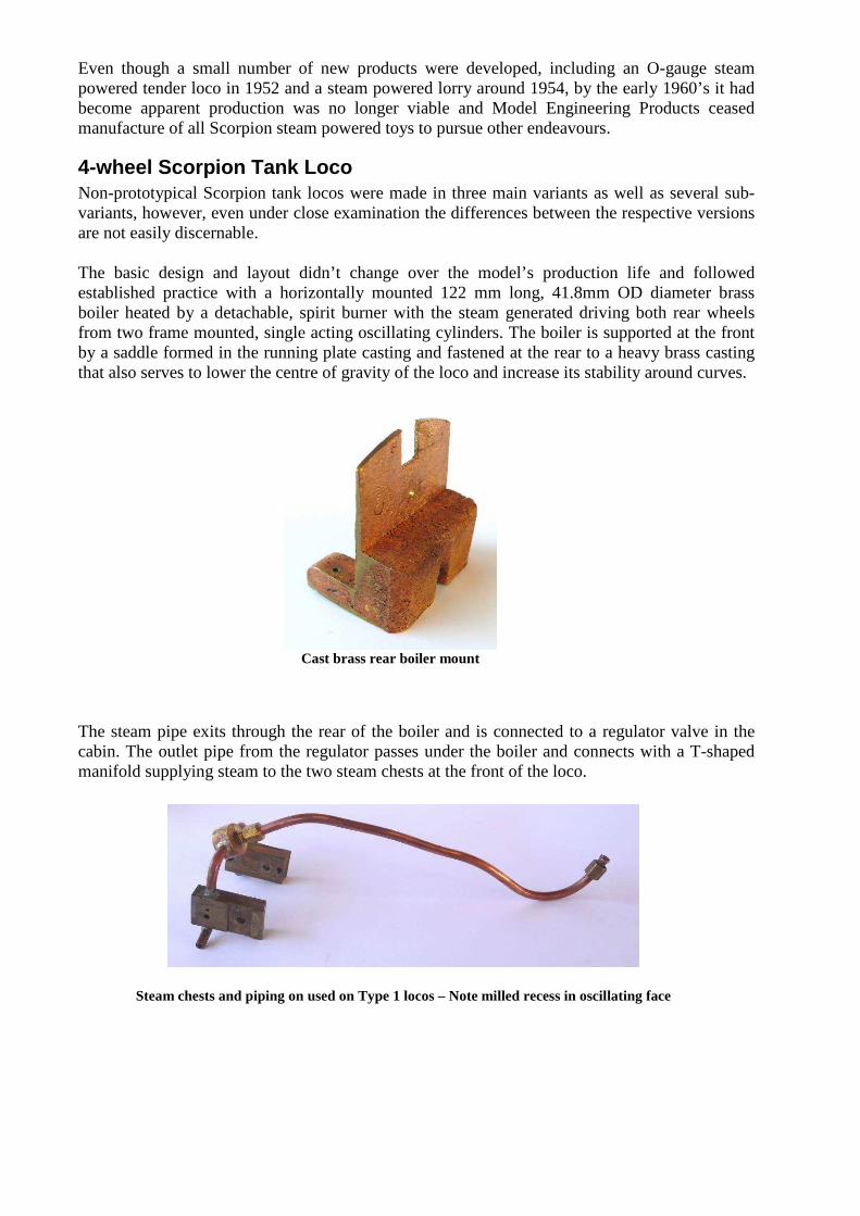
Background Ted Peell and Ted Wallis began manufacturing steam powered toys in 1944 on a part-time basis in a shed at Ted Peell’s home whilst they were employees of Amalgamated Wireless Australia (AWA) in Sydney. Their first product was a small model oscillating marine engine using material including scrap metal bought from AWA. It is understood cast components were supplied by Leichhardt Foundry. To complement the oscillating marine engine, a horizontal boiler was subsequently developed followed by a small steam plant with a horizontal boiler driving a flywheel from an oscillating cylinder. In 1946, the two partners resigned from AWA to embark on their toy making venture on a full time basis. Around this time they relocated their operation to the Sydney suburb of Lilyfield and over the next few years there were several more moves within the same general area. Even though the business traded as Model Engineering Products, the items carried a registered ‘Scorpion’ trade mark chosen after the proprietors discovered they both shared the Scorpio star sign. Approximately five years after production commenced, the Scorpion product line was further expanded to include a steam powered, O-gauge, 4-wheel tank locomotive followed by three complementary 4-wheel goods wagons. All of these items were available by way of individual purchase as well as packaged in a train set that included an oval of tinplate rails supplied by Baillie Munro of Sydney. Scorpion steam powered toys were sold through a number of stockists around Australia, including retailers Walther & Stevenson and Hobbyco in Sydney and The Model Dockyard in Melbourne.
Advertisement for 2nd version of the Scorpion tank loco in 5th edition of The Model Dockyard Model Railway
Catalogue
Even though a small number of new products were developed, including an O-gauge steam powered tender loco in 1952 and a steam powered lorry around 1954, by the early 1960’s it had become apparent production was no longer viable and Model Engineering Products ceased manufacture of all Scorpion steam powered toys to pursue other endeavours.
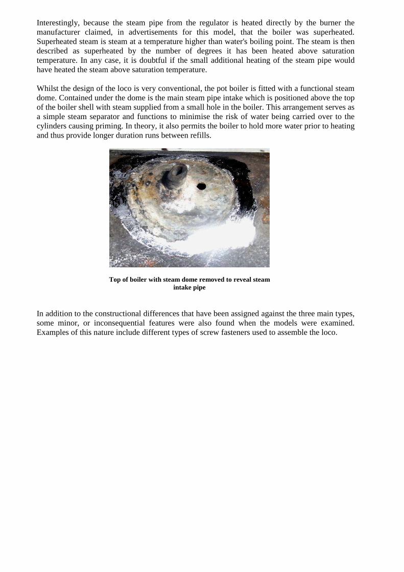
4-wheel Scorpion Tank Loco Non-prototypical Scorpion tank locos were made in three main variants as well as several sub-variants, however, even under close examination the differences between the respective versions are not easily discernable. The basic design and layout didn’t change over the model’s production life and followed established practice with a horizontally mounted 122 mm long, 41.8mm OD diameter brass boiler heated by a detachable, spirit burner with the steam generated driving both rear wheels from two frame mounted, single acting oscillating cylinders. The boiler is supported at the front by a saddle formed in the running plate casting and fastened at the rear to a heavy brass casting that also serves to lower the centre of gravity of the loco and increase its stability around curves. The steam pipe exits through the rear of the boiler and is connected to a regulator valve in the cabin. The outlet pipe from the regulator passes under the boiler and connects with a T-shaped manifold supplying steam to the two steam chests at the front of the loco.
Steam chests and piping on used on Type 1 locos – Note milled recess in oscillating face
Cast brass rear boiler mount
Interestingly, because the steam pipe from the regulator is heated directly by the burner the manufacturer claimed, in advertisements for this model, that the boiler was superheated. Superheated steam is steam at a temperature higher than water's boiling point. The steam is then described as superheated by the number of degrees it has been heated above saturation temperature. In any case, it is doubtful if the small additional heating of the steam pipe would have heated the steam above saturation temperature. Whilst the design of the loco is very conventional, the pot boiler is fitted with a functional steam dome. Contained under the dome is the main steam pipe intake which is positioned above the top of the boiler shell with steam supplied from a small hole in the boiler. This arrangement serves as a simple steam separator and functions to minimise the risk of water being carried over to the cylinders causing priming. In theory, it also permits the boiler to hold more water prior to heating and thus provide longer duration runs between refills. In addition to the constructional differences that have been assigned against the three main types, some minor, or inconsequential features were also found when the models were examined. Examples of this nature include different types of screw fasteners used to assemble the loco.
Top of boiler with steam dome removed to reveal steam intake pipe
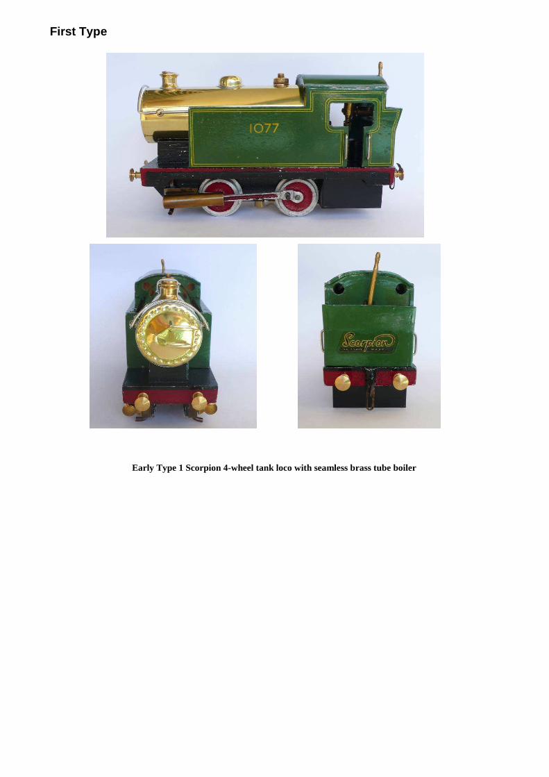
First Type
Early Type 1 Scorpion 4-wheel tank loco with seamless brass tube boiler
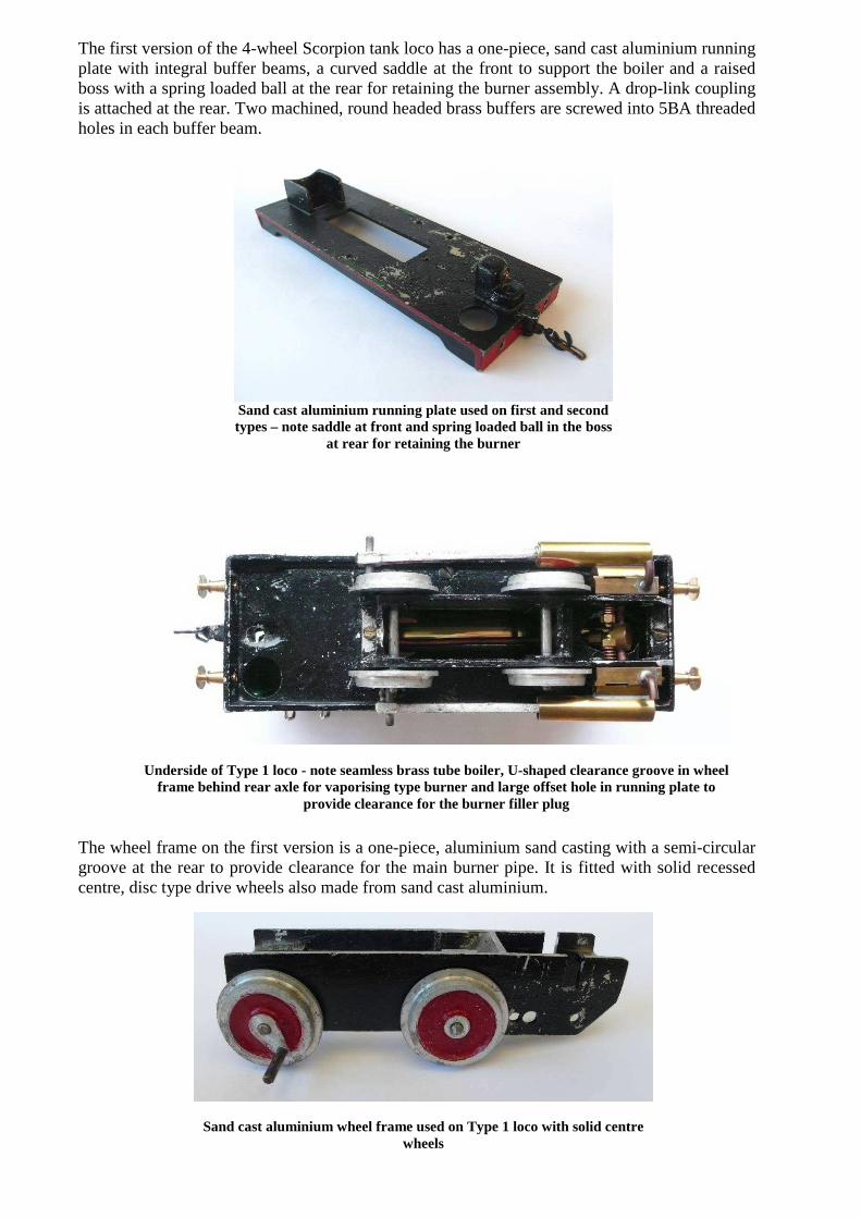
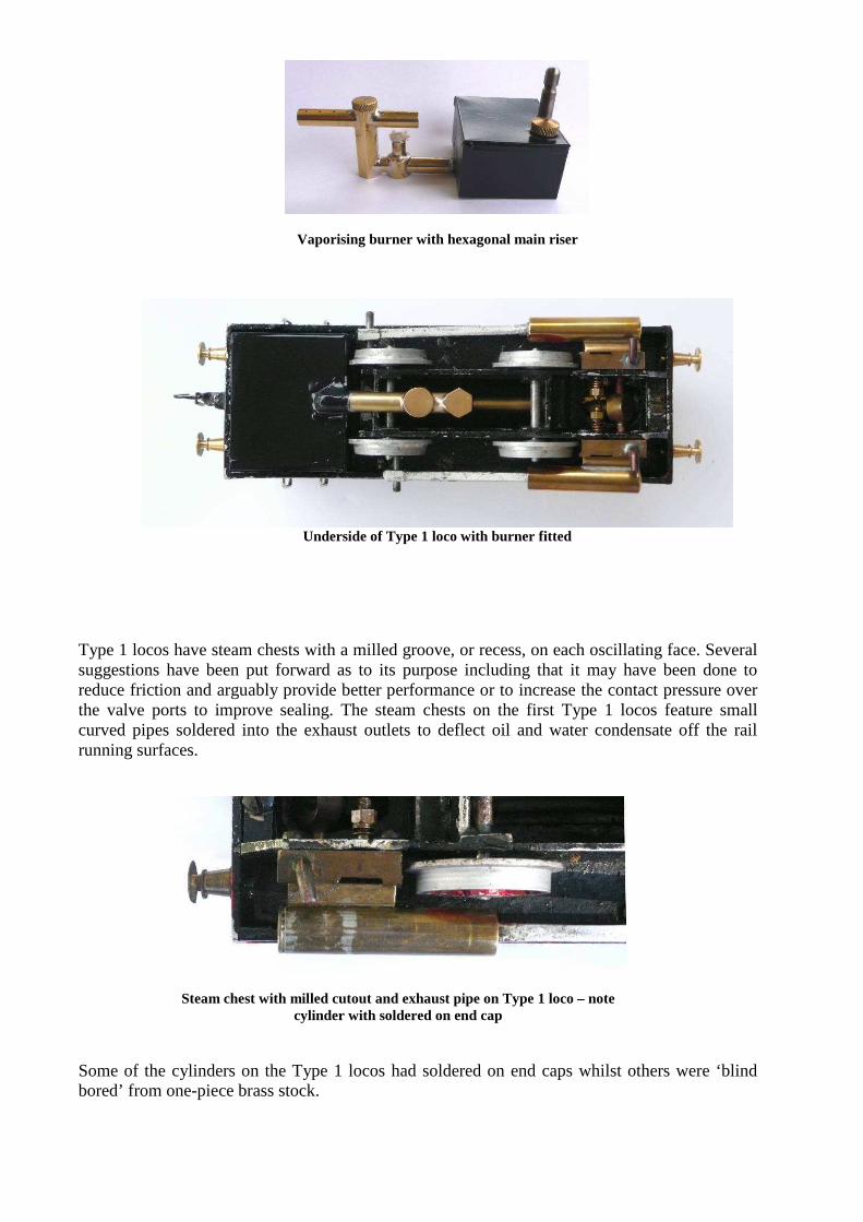
The first version of the 4-wheel Scorpion tank loco has a one-piece, sand cast aluminium running plate with integral buffer beams, a curved saddle at the front to support the boiler and a raised boss with a spring loaded ball at the rear for retaining the burner assembly. A drop-link coupling is attached at the rear. Two machined, round headed brass buffers are screwed into 5BA threaded holes in each buffer beam. The wheel frame on the first version is a one-piece, aluminium sand casting with a semi-circular groove at the rear to provide clearance for the main burner pipe. It is fitted with solid recessed centre, disc type drive wheels also made from sand cast aluminium.
Sand cast aluminium wheel frame used on Type 1 loco with solid centre wheels
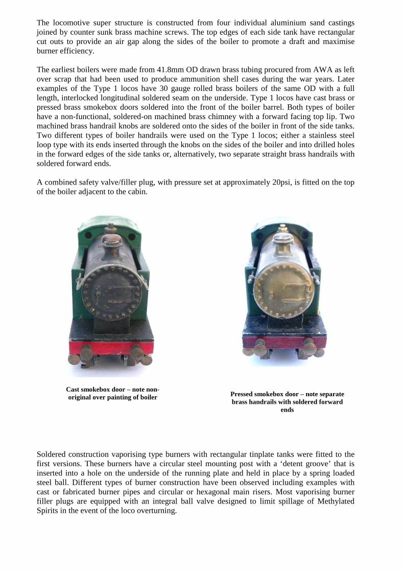
Underside of Type 1 loco - note seamless brass tube boiler, U-shaped clearance groove in wheel frame behind rear axle for vaporising type burner and large offset hole in running plate to
provide clearance for the burner filler plug
Sand cast aluminium running plate used on first and second types – note saddle at front and spring loaded ball in the boss
at rear for retaining the burner
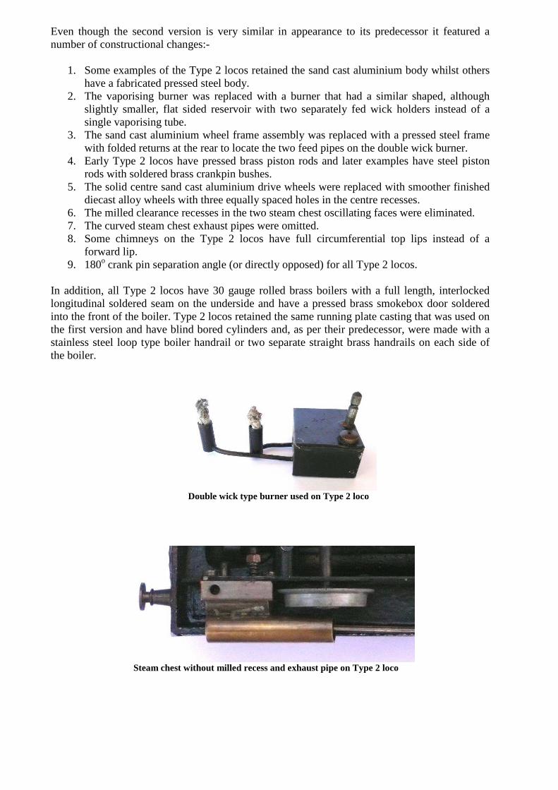
The locomotive super structure is constructed from four individual aluminium sand castings joined by counter sunk brass machine screws. The top edges of each side tank have rectangular cut outs to provide an air gap along the sides of the boiler to promote a draft and maximise burner efficiency. The earliest boilers were made from 41.8mm OD drawn brass tubing procured from AWA as left over scrap that had been used to produce ammunition shell cases during the war years. Later examples of the Type 1 locos have 30 gauge rolled brass boilers of the same OD with a full length, interlocked longitudinal soldered seam on the underside. Type 1 locos have cast brass or pressed brass smokebox doors soldered into the front of the boiler barrel. Both types of boiler have a non-functional, soldered-on machined brass chimney with a forward facing top lip. Two machined brass handrail knobs are soldered onto the sides of the boiler in front of the side tanks. Two different types of boiler handrails were used on the Type 1 locos; either a stainless steel loop type with its ends inserted through the knobs on the sides of the boiler and into drilled holes in the forward edges of the side tanks or, alternatively, two separate straight brass handrails with soldered forward ends. A combined safety valve/filler plug, with pressure set at approximately 20psi, is fitted on the top of the boiler adjacent to the cabin.
Soldered construction vaporising type burners with rectangular tinplate tanks were fitted to the first versions. These burners have a circular steel mounting post with a ‘detent groove’ that is inserted into a hole on the underside of the running plate and held in place by a spring loaded steel ball. Different types of burner construction have been observed including examples with cast or fabricated burner pipes and circular or hexagonal main risers. Most vaporising burner filler plugs are equipped with an integral ball valve designed to limit spillage of Methylated Spirits in the event of the loco overturning.
Cast smokebox door – note non-original over painting of boiler
Pressed smokebox door – note separate brass handrails with soldered forward
ends
Type 1 locos have steam chests with a milled groove, or recess, on each oscillating face. Several suggestions have been put forward as to its purpose including that it may have been done to reduce friction and arguably provide better performance or to increase the contact pressure over the valve ports to improve sealing. The steam chests on the first Type 1 locos feature small curved pipes soldered into the exhaust outlets to deflect oil and water condensate off the rail running surfaces. Some of the cylinders on the Type 1 locos had soldered on end caps whilst others were ‘blind bored’ from one-piece brass stock.
Steam chest with milled cutout and exhaust pipe on Type 1 loco – note cylinder with soldered on end cap
Underside of Type 1 loco with burner fitted
Vaporising burner with hexagonal main riser

The earliest Type 1 locos have sand cast aluminium piston rods and later examples have pressed brass piston rods. The ‘ideal’ crank pin separation angle for a steam loco with two, single acting oscillating cylinders is generally considered to be 180o (i.e. with the crank pins positioned directly opposite one another) to provide optimum valve timing and smooth running. However, some of the early Type 1 locos have their two crankpins ‘quartered’ with 90o crank angle separation.
Second Type
Type 2 Scorpion 4-wheel tank loco with fabricated sheet steel super
structure – note double lining on sides of body
Type 2 Scorpion 4-wheel tank loco with cast aluminium body
– note single lining on sides of body and loop type stainless steel boiler handrail
First type of piston rod made from sand cast aluminium
Even though the second version is very similar in appearance to its predecessor it featured a number of constructional changes:-
1. Some examples of the Type 2 locos retained the sand cast aluminium body whilst others have a fabricated pressed steel body.
2. The vaporising burner was replaced with a burner that had a similar shaped, although slightly smaller, flat sided reservoir with two separately fed wick holders instead of a single vaporising tube.
3. The sand cast aluminium wheel frame assembly was replaced with a pressed steel frame with folded returns at the rear to locate the two feed pipes on the double wick burner.
4. Early Type 2 locos have pressed brass piston rods and later examples have steel piston rods with soldered brass crankpin bushes.
5. The solid centre sand cast aluminium drive wheels were replaced with smoother finished diecast alloy wheels with three equally spaced holes in the centre recesses.
6. The milled clearance recesses in the two steam chest oscillating faces were eliminated. 7. The curved steam chest exhaust pipes were omitted. 8. Some chimneys on the Type 2 locos have full circumferential top lips instead of a
forward lip. 9. 180o crank pin separation angle (or directly opposed) for all Type 2 locos.
In addition, all Type 2 locos have 30 gauge rolled brass boilers with a full length, interlocked longitudinal soldered seam on the underside and have a pressed brass smokebox door soldered into the front of the boiler. Type 2 locos retained the same running plate casting that was used on the first version and have blind bored cylinders and, as per their predecessor, were made with a stainless steel loop type boiler handrail or two separate straight brass handrails on each side of the boiler.
Double wick type burner used on Type 2 loco
Steam chest without milled recess and exhaust pipe on Type 2 loco
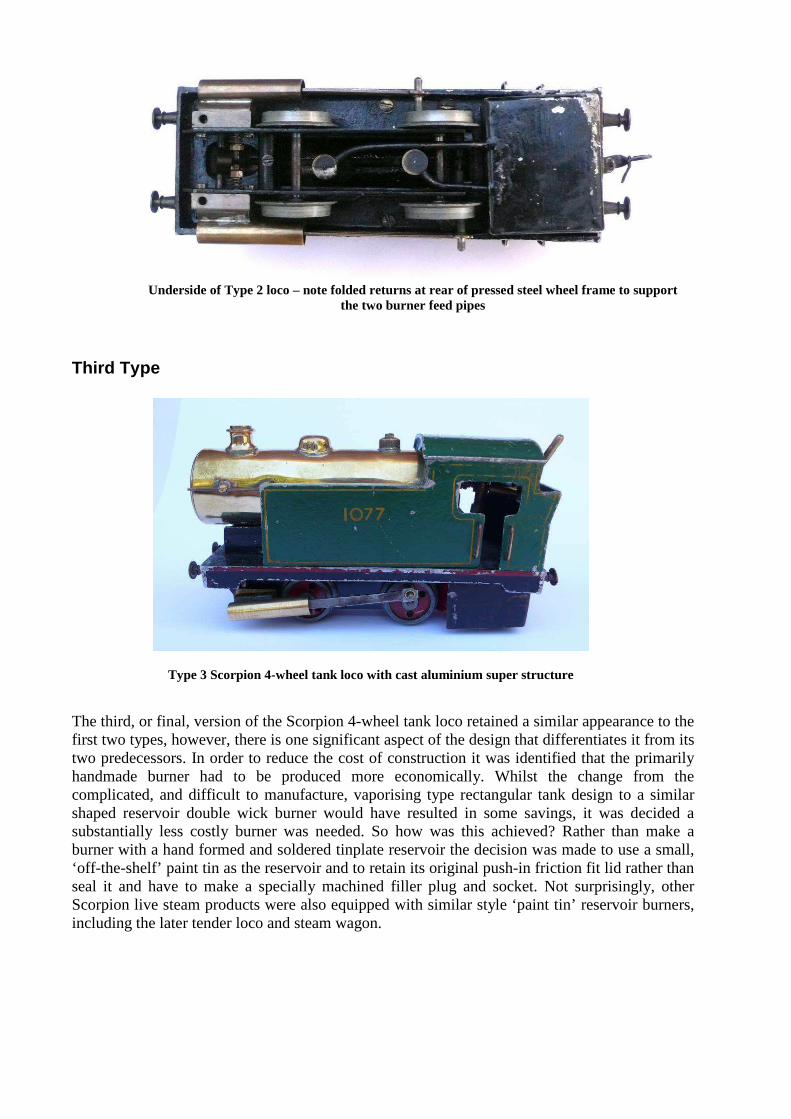
Third Type The third, or final, version of the Scorpion 4-wheel tank loco retained a similar appearance to the first two types, however, there is one significant aspect of the design that differentiates it from its two predecessors. In order to reduce the cost of construction it was identified that the primarily handmade burner had to be produced more economically. Whilst the change from the complicated, and difficult to manufacture, vaporising type rectangular tank design to a similar shaped reservoir double wick burner would have resulted in some savings, it was decided a substantially less costly burner was needed. So how was this achieved? Rather than make a burner with a hand formed and soldered tinplate reservoir the decision was made to use a small, ‘off-the-shelf’ paint tin as the reservoir and to retain its original push-in friction fit lid rather than seal it and have to make a specially machined filler plug and socket. Not surprisingly, other Scorpion live steam products were also equipped with similar style ‘paint tin’ reservoir burners, including the later tender loco and steam wagon.
Type 3 Scorpion 4-wheel tank loco with cast aluminium super structure
Underside of Type 2 loco – note folded returns at rear of pressed steel wheel frame to support
the two burner feed pipes
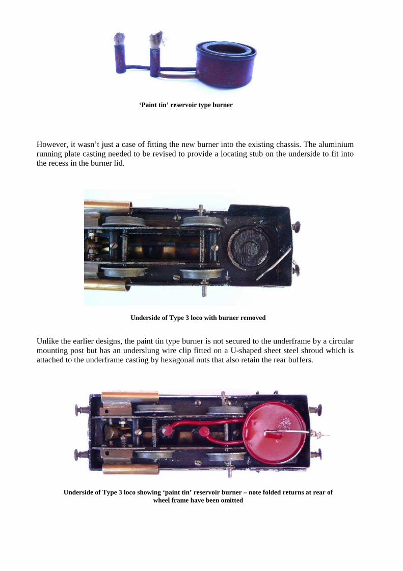
However, it wasn’t just a case of fitting the new burner into the existing chassis. The aluminium running plate casting needed to be revised to provide a locating stub on the underside to fit into the recess in the burner lid. Unlike the earlier designs, the paint tin type burner is not secured to the underframe by a circular mounting post but has an underslung wire clip fitted on a U-shaped sheet steel shroud which is attached to the underframe casting by hexagonal nuts that also retain the rear buffers.
‘Paint tin’ reservoir type burner
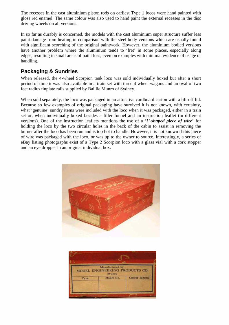
Underside of Type 3 loco with burner removed
Underside of Type 3 loco showing ‘paint tin’ reservoir burner – note folded returns at rear of
wheel frame have been omitted

Except for the revised underframe casting and the paint tin reservoir burner, the final type loco carries over most constructional aspects that applied to the second version, although the two returns at the rear of the steel wheel frame were omitted and all Type 3 locos have chimneys with a full circumferential top lip. All Type 3 locos have steel piston rods with soldered brass crankpin bushes. From examples observed, it appears all Type 3 locos have straight brass boiler handrails but they do not have soldered forward ends like the earlier versions. Although Type 3 locos have, thus far, only been observed with cast aluminium super structures it is conceivable they were also made with fabricated pressed steel bodies. Type 3 locos have cabin grab rails made from brass instead of stainless steel. Whilst most locos have lightly riveted regulator spindles, some Type 2 and 3 versions have spindles with small coil compression springs retained by either threaded nuts or a cotter pin, however, it is not known if they were manufactured this way at the factory, or the result of later day modifications.
Liveries The overall paint scheme, or livery, of the Scorpion 4-wheel tank locos did not change significantly over the time that they were manufactured and even though some minor colour differences have been observed it is considered they were the result of variations in paint batches from paint suppliers rather than a deliberate intention to alter the colour of the loco. Most of the individual major components that make up the loco were painted individually and prior to final assembly. The upper body assembly which comprises the side tanks, cabin and bunker was spray painted with mid-green gloss enamel and screen printed yellow lining and the number 1077 on the sides, which is said to have been the street number of Ted Wallis’ house. Examples with both double (early) and single (later) lining have been observed. The cabin grab rails on each side of the body were left unpainted and fitted after the body assembly was painted. A waterslide Scorpion trademark transfer is affixed to the rear of the bunker. The main running plate casting has a gloss black enamel finish with over painted (by hand) gloss red buffer beams. The upper raised edges on each side of the running plate are also over painted in gloss red enamel. The vaporising and wick type burners on the first two versions are painted with a satin black finish. The circular ‘paint tin’ burner that was fitted to the third type loco is painted with a satin red finish. The sheet steel burner shroud on the third type loco has a satin black finish.
Spring type regulator spindle
Riveted type regulator spindle
The recesses in the cast aluminium piston rods on earliest Type 1 locos were hand painted with gloss red enamel. The same colour was also used to hand paint the external recesses in the disc driving wheels on all versions. In so far as durably is concerned, the models with the cast aluminium super structure suffer less paint damage from heating in comparison with the steel body versions which are usually found with significant scorching of the original paintwork. However, the aluminium bodied versions have another problem where the aluminium tends to ‘fret’ in some places, especially along edges, resulting in small areas of paint loss, even on examples with minimal evidence of usage or handling.
Packaging & Sundries When released, the 4-wheel Scorpion tank loco was sold individually boxed but after a short period of time it was also available in a train set with three 4-wheel wagons and an oval of two feet radius tinplate rails supplied by Baillie Munro of Sydney. When sold separately, the loco was packaged in an attractive cardboard carton with a lift-off lid. Because so few examples of original packaging have survived it is not known, with certainty, what ‘genuine’ sundry items were included with the loco when it was packaged, either in a train set or, when individually boxed besides a filler funnel and an instruction leaflet (in different versions). One of the instruction leaflets mentions the use of a ‘U-shaped piece of wire’ for holding the loco by the two circular holes in the back of the cabin to assist in removing the burner after the loco has been run and is too hot to handle. However, it is not known if this piece of wire was packaged with the loco, or was up to the owner to source. Interestingly, a series of eBay listing photographs exist of a Type 2 Scorpion loco with a glass vial with a cork stopper and an eye dropper in an original individual box.
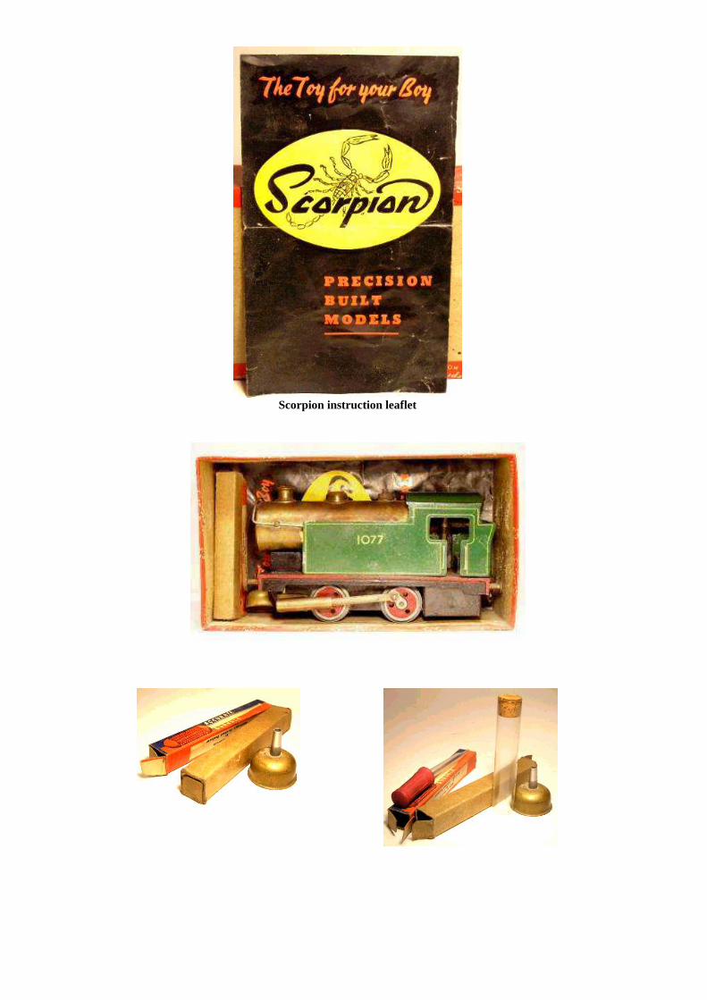
Scorpion instruction leaflet
If the glass vial and the eye dropper were factory supplied, it may be asked ‘What was their intended purpose?’ The small glass vial would be suitable for holding lubricating oil and the eye dropper could be used to draw up lubricating oil from the vial and deposit it on the appropriate points on the loco. Even so, it is possible that both of these items may have been put in the loco box many years ago by the original owner after purchasing them on his own accord. Therefore, and unless another example comes to light with the same accoutrements, the ‘genuineness’ of these sundry items must remain unconfirmed.
Operating a Scorpion 4-wheel Tank Loco The operation of serviceable 4-wheel Scorpion tank locos is relatively straight forward, however, they share a characteristic with similarly designed and constructed live steam locos. There are ‘good runners’ and other examples that do not perform nearly as well, and even instances where a particular example may perform satisfactorily one day but, inexplicably, run poorly the next. Even though some ‘regular’ poor performers can be improved after a careful strip-down and rebuild it is also found that a few still fail to yield any noticeable performance improvement even after all this work is performed. Various theories and reasons have been put forward including the poor performance being attributable to the construction of the loco from individual components that have been separately machined against upper and lower tolerance limits. This theory suggests that when an individual component is made at an upper manufacturing tolerance limit and then combined with another that was made at a lower tolerance limit the outcome may result in some performance degradation. One example cited is the piston to cylinder clearance where a piston may have been machined to a minimum tolerance diameter and fitted into a cylinder that was machined to the upper limit. In any case, 4-wheel Scorpion live steam locos don’t seem to be any better, or worse, in this regard to their contemporaries. Perhaps the single most important ingredient required for the successful running of a Scorpion live steam loco is the prevailing weather conditions because operation usually takes place outdoors. The best time to run any live steam loco, with a simple wick or vaporising burner, occurs when the conditions are very calm and even a slight breeze can play havoc with the operation of the burner. Two other very important considerations are the track on which on which the loco will be run and the ready access to a number of wagons to provide an adequate load to prevent loco runaway and derailment. The clip-together, tinplate, 2 feet radius Munro manufactured track that was supplied in Scorpion train sets is not ideal for optimum operation and far better, and more stable running, will be achieved when the loco is operated on a much wider radius circuit permanently fastened to a flat and level surface, as even a slight incline will seriously degrade performance. In order to run a live steam loco there are important safety considerations that need to be strictly adhered to including the use of heat protective gloves and a well dampened rag or fire extinguisher on hand in the event of a derailment.
Before the loco is run, a number of preparatory steps need to be performed including the correct lubrication of axle running surfaces, crankpins and regulator spindle with suitable light viscosity mineral oil. The steam chest rubbing surfaces and cylinders need to be lubricated with steam oil. Once the lubrication has been completed, the safety valve, which also serves as a filler plug, should be unscrewed from the top of the boiler. After removal, the safety valve should be inspected to ensure the spring is intact and the valve moves freely in its guide. The fibre sealing washer on the safety valve should also be inspected and replaced if necessary. The burner should now be detached to enable fuelling. If the burner is one of the earlier versions (either vaporising or wick type) with a flat sided reservoir, it can be removed by holding the reservoir and pulling it straight down to release the burner mounting post from the spring loaded ball in the underframe casting. If the loco is the later type with a circular burner reservoir, the wire retaining clip needs to be swung clear and the burner detached. The burner wicks should be checked and replaced if necessary. The burner is now filled with Methylated Spirits and put to one side. The next task is to ‘partially’ fill the boiler with clean demineralised or distilled water via the safety valve hole using the small funnel provided with the loco. It is found the loco can be brought up to steam far quicker if hot water is used, however, just how much water to add to a Scorpion loco boiler is not easy to quantify. Because the steam intake pipe is situated in the steam dome, and above the top of the boiler shell, it is theoretically possible to fill the boiler ‘to the brim’, or level with the top of the safety valve opening. However, to do so, would result in an excessive amount of time to get the loco to run smoothly, if in fact, it could be started at all. This is due to the fact that the small amount of steam being generated and available in the steam dome would be quickly consumed by the cylinders before it could be recharged. To alleviate this issue some manufacturers provide a small hand fitted plug part way up the front of the boiler that is unscrewed when the boiler is filled. As soon as water seeps from this opening, the boiler is filled to operational capacity and the plug is refitted. This arrangement ensures there is adequate space above the water in which steam can be generated. On the other hand, if too little water is added to the boiler, the loco will have a short run time and there is the possibility of damaging it due to the flame from the burner continuing to heat an empty boiler after the loco has stopped making steam. Once the boiler is filled with water, the safety valve is refitted and ‘finger tightened’. In the case of Scorpion 4-wheel tank locos, it is found that they ‘come up to steam’ best, when filled with approximately 110ml of very hot water, which represents around 80% of the total boiler capacity. There are different opinions on when the burner should be lit. Some operators consider it hazardous to handle an already lit burner and elect to light it only after the burner has been fitted to the loco. In addition, in normal daylight and especially so outdoors, the flame from a Methylated Spirits fuelled burner is almost invisible. On the other hand, some experienced operators prefer to light the burner and then fit it whilst already alight because they consider it difficult to light when installed under the loco. There is even a middle ground position, where some elect to pre-light the burner to ensure that it is working satisfactorily and then extinguish it, before refitting the burner to the loco and then relighting it once more. This later technique is also handy when a vaporising type burner is employed as it permits the pre-heating of the vaporising tube with the ignition source (usually a small gas filled fire lighter).
Once the loco is on the rails and the burner lit, the regulator in the bunker should be checked to ensure that it is closed. It is now a matter of waiting until the safety valve begins to ‘hiss and dribble’. At this stage, the regulator arm is positioned to the open position and the loco can often be set in motion by way of a gentle forward push, at the same time remembering that it is now quite hot to touch. It may take a few attempts, but it shouldn’t be long before the loco takes off with a gentle gate, under its own steam. Even so, it may come up to speed fairly quickly. How well it performs will determine whether a trailing load will be needed. Should the loco start to ‘gallop’, it is wise to stop it and couple one or more trailing wagons before setting it back in motion. The number of wagons to use is not prescribed but a case of trial and error. In addition, the tractive effort is often found to change during a typical run. Sometimes a loco will be found to circulate quite comfortably by itself for several laps before speed starts to build up as more steam is being generated than is being consumed. Once the speed starts to become excessive the loco is stopped and several wagons added, however, the process may have to be repeated several more times, progressively increasing the load until all of the fuel in the burner is exhausted. Three different 4-wheel Scorpion tank locos were tested to evaluate their performance and also to assess if there were any operational or performance differences between the respective types and, in particular, to determine if there was a discernable difference in performance between the first type with its 90o crank pin separation angle versus the other two locos with 180o (or directly opposed) crank pin angles. The versions tested were:-
1. Type 1 with cast aluminium body and square tank vaporising burner. 2. Type 2 with fabricated steel body and square tank double wick burner. 3. Type 3 with cast aluminium body and round tank double wick burner.
The test track consisted of a large radius permanently fixed, elevated oval with two 3.2 metre straights joined at each end by 2.16 metre radius curves. The total length of the circuit was 20.0 lineal metres. Ambient conditions were calm with no discernable breeze.
Test Results 1. The Type 1 loco ran for 16 minutes before the fuel was exhausted. During this time the
loco covered the first two laps without a load. Its speed rapidly increased and it was stopped and two 4-wheel Ferris open wagons added, after which it covered a further 10 laps with speed continuing to rise. It was stopped again and another two 4-wheel Ferris open wagons added which it continued to haul until the fuel in the burner was exhausted. In total, the loco covered a total of 40 circuits or 800 lineal metres. When it had completed its run the remaining water in the boiler was decanted and measured. It was found that approximately 60ml of water remained and 50ml had been consumed during the run.
2. The Type 2 loco ran for slightly less time (around 14 minutes) but the time difference was not significant and may have been attributable to a small reduction in burner reservoir capacity rather than differences in burner efficiency from a vaporising versus a wick flame. As it ran for less time, there was a slightly greater volume of water remaining in the boiler at the end of the run. There was no discernable difference in performance between the first two versions with both carrying similar loads for similar durations. This loco covered a total of 34 circuits or 680 lineal metres.
3. The Type 3 loco, with the much smaller capacity ‘paint tin’ reservoir wick type burner,
only ran for around 11 minutes, but performed comparably with the first two. It covered a total of 28 circuits or 560 lineal metres.
In summary, all three versions performed satisfactorily and the testing did not expose any discernable differences in operational performance between the respective versions. Aspects like the first version having milled clearance spaces in the steam chest rubbing surfaces and 90o crank pin separation did not translate to better (or poorer) operating characteristics. The omission of the exhaust condensate deflecting pipes on the later versions did not see any adverse change in running, nor was there any sign of wheel slip. Even the change from a more complex to manufacture vaporising burner to the final simple ‘paint tin’ wick type burner did not see a drop-off in performance, however, it should mentioned the ambient conditions were very benign and there may have been a difference, had there been a breeze. In any case, it appears that many of the design changes that were carried out between the first and the last versions were not undertaken to address operational inadequacies, or to improve performance, but were simply done to make the locos less complex and cheaper to manufacture. Even the minor change of not hand filing, or linishing, the rear half of the top chimney lip reduced manufacturing costs on the later versions.
Conclusion It is reasonable to conclude the Australian made live steam Scorpion 4-wheel tank loco was well designed and constructed. Furthermore, its overall appearance is aesthetically attractive, unlike some of the attempts of other manufacturers and resembles a small 0-4-0 industrial tank locomotive even though it wasn’t modelled on a real world prototype. Whilst the performance of the Scorpion 4-wheel tank loco is at least comparable with those made by competitors it is worth mentioning there are some minor aspects of the design and construction that could have been improved. The use of a working steam dome was a manufacturing complication that probably was unwarranted. It would have been simpler and more effective to provide a removable overflow fitting in the front of the boiler to control the amount of water that could be added to the boiler. Other manufacturers use this simple and effective system to ensure there is sufficient air space in the boiler to generate steam without water being carried over into the cylinders. The steam regulator, in all examples tested, did not properly control the speed of the loco. Instead, it simply provided an ‘OFF – ON’ function. In addition, on the first two versions tested, the regulator arms were lightly riveted to the valve body, so after years of use they had became loose. The regulator on final version that was tested had its regulator valve spindle retained by a threaded nut and a small coil spring, but, and as mentioned previously, it is not known if this was configured this way at the factory, or was later day modification. In any case, and even though it was more effective in holding the regulator arm in position rather than ‘flopping’ to one side, the valve still did not provide satisfactory control or regulation of steam to the cylinders. In all examples that were tested, it was found that steam flow increased during a typical running session necessitating the loco to be stopped and restarted with an increased load to prevent runaway and derailment. Another aspect of the design which had room for improvement was the way in which the wheels were secured to the axles by an interference fit. Examples were found where the rear driving wheels had rotated in relation to each other, thus altering the crank pin separation angle and, as a consequence, adversely affecting the valve timing and operational performance. Other examples were also found where the wheels had moved laterally across the axles, altering the optimum gauge width.

Acknowledgements & References The author would like to thank and acknowledge Tony Muir, Neil Baker, Glenn Ball, Harley Ferguson, Errol Godden, Greg Johnston, Bruce MacDonald, Laurie Mangleson, and Peter Watson for their encouragement and considerable assistance whilst putting this article together. Bruce MacDonald’s book ‘Spring, Spark and Steam’ ‘An illustrated guide to Australian toy & model trains’ was the primary reference for the introductory ‘Background’ section. An illustration taken from the 5th edition of The Model Dockyard Model Railway Catalogue was also included in the article.