scorpion safety products pc diagnosing and fixing system
TRANSCRIPT

SCORPION SAFETY PRODUCTS PC DIAGNOSING
AND FIXING SYSTEM
CARRINGTON T. MUCHINGAMI
(R137727E)

SCORPION SAFETY PRODUCTS PC DIAGNOSING
AND FIXING SYSTEM
BY
CARRINGTON TONDERAI MUCHINGAMI
(R137727E)
Submitted in partial fulfilment of the requirements for the degree of
BSc. Honors in Information Systems
Department of Computer Science and Information Systems
in the
Faculty of Science and Technology
at the
MIDLANDS STATE UNIVERSITY
GWERU
ZIMBABWE
OCTOBER 2017
Supervisor: MR. T MZIKANWI

i
ABSTRACT
The purpose of this research was to come up with a solution for problems that were identified at
Scorpion Safety Products. The main objectives of the system are to ensure that computer users at
Scorpion Safety Products are equipped with the knowledge to fix problem they encounter on a
day to day basis in the workplace. Users in various departments depended on an external
subcontractor for every little problem faced and this resulted in the company having to fork over
huge amounts of money for the upkeep of their computers. For this system, all users have to
login to access this information and a log is created whenever user logs in so as to increase
accountability of access.
Data gathering methodologies such as interviews, questionnaires and observations where used so
as to identify problems that were being faced by the staff at Scorpion Safety Products. For the
development of a system to fix these problems, the developer used development tools such as
Android Studio, Xampp, Adobe Photoshop and many others. As for further developments of the
system, the developer will add a communication panel where user can interact with the admin.

ii
DECLARATION
I, Carrington Muchingami, hereby declare that I am the sole author of this dissertation. I
authorize the Midlands State University to lend this dissertation to other institutes or individuals
for the purpose of scholarly research.
Signature: ……………………………... Date: …………………

iii
APPROVAL
This dissertation, entitled “Scorpion Safety Products PC Diagnosing and Fixing System” by
Carrington Muchingami meets the regulations governing the award of the degree of BSc
Honours Information Systems of the Midlands State University, and is approved for its
contribution to the knowledge and literary presentation.
Supervisor Signature: …………………………………….
Date: ………………………………………………………

iv
ACKNOWLEGEMENTS
First and foremost, I would to thank and give praise to the Almighty who made it possible for me
to accomplish this mission. I would also want to thank my supervisor Mr. Mzikanwi for assisting
me from the start of my dissertation up until to the end; I really benefited a lot from him. My
thanks also go to my friends, relatives and most importantly my parents for bringing me into this
world. I forward my appreciation to my friends Kudakwashe Magwenzi, Selous Nyamuhwe,
Melody Fakelo and Trymore Chimwe for their constructive criticism which shaped the
development of this dissertation.

v
DEDICATION
I dedicate this documentation to my mom who has always been an unwavering pillar of support
in all my travails.
vi
TABLE OF CONTENTS
ABSTRACT ..................................................................................................................................... i
DECLARATION ............................................................................................................................ ii
APPROVAL ................................................................................................................................... iii
ACKNOWLEGEMENTS .............................................................................................................. iv
DEDICATION ................................................................................................................................ v
LIST OF ACRONYMS .................................................................................................................. x
LIST OF FIGURES ....................................................................................................................... xi
LIST OF TABLES ........................................................................................................................ xii
LIST OF APPENDICIES ............................................................................................................. xiv
CHAPTER 1: INTRODUCTION ................................................................................................... 1
1.1 Introduction ...................................................................................................................... 1
1.2 Background of Study ............................................................................................................ 1
1.2.1 Background of the Organization .................................................................................... 1
1.2.2 Organizational Structure ................................................................................................ 2
1.2.3 Mission Statement .......................................................................................................... 2
1.2.4 Vision ............................................................................................................................. 2
1.3 Problem Definition ................................................................................................................ 2
1.4 Aim ........................................................................................................................................ 3
1.5 Objectives .............................................................................................................................. 3
1.6 Instruments and Methods ...................................................................................................... 3
1.7 Justification ........................................................................................................................... 3
1.8 Conclusion ............................................................................................................................ 4
CHAPTER 2: PLANNING PHASE ............................................................................................... 5
2.1 Introduction ........................................................................................................................... 5
2.2 Business Value ...................................................................................................................... 5
2.3 Feasibility Study ................................................................................................................... 6
2.3.1 Technical Feasibility ...................................................................................................... 6
2.3.2 Economic Feasibility ...................................................................................................... 7
2.3.3 Social Feasibility .......................................................................................................... 11
2.3.4 Operational Feasibility ................................................................................................. 11

vii
2.4 Risk Analysis ...................................................................................................................... 12
2.5 Stakeholder Feasibility ........................................................................................................ 13
2.6 Work Plan ........................................................................................................................... 14
2.7 Conclusion .......................................................................................................................... 15
CHAPTER 3: ANALYSIS PHASE .............................................................................................. 16
3.1 Introduction ......................................................................................................................... 16
3.2 Information Gathering Methodologies ................................................................................ 16
3.2.1 Interviews ..................................................................................................................... 16
3.2.2 Questionnaires .............................................................................................................. 17
3.2.3 Observations ................................................................................................................. 17
3.2.4 Summary of Findings ................................................................................................... 18
3.3 Analysis of the Existing System ......................................................................................... 18
3.4 Process Analysis ................................................................................................................. 18
3.4.1 Activity Diagram of Current System ........................................................................... 19
3.5 Data Analysis ...................................................................................................................... 20
3.5.1 Context Diagram of Current System ............................................................................ 20
3.5.2 Data Flow Diagram of Current System ........................................................................ 21
3.6 Weaknesses of Current System ........................................................................................... 22
3.7 Evaluation of Alternatives .................................................................................................. 22
3.7.1 Outsourcing .................................................................................................................. 23
3.7.2 Off-the-Shelf ................................................................................................................ 23
3.7.3 In-House Development ................................................................................................ 24
3.7.4 Verdict on Alternatives ................................................................................................ 24
3.8 Requirements Analysis ....................................................................................................... 25
3.8.1 Functional Requirements ............................................................................................. 25
3.8.2 Non-functional Requirements ...................................................................................... 26
3.9 Conclusion .......................................................................................................................... 26
CHAPTER 4: DESIGN PHASE ................................................................................................... 27
4.1 Introduction ......................................................................................................................... 27
4.2 System Design ..................................................................................................................... 27
4.2.1 Context Diagram of Proposed System ......................................................................... 28
4.2.2 Data Flow Diagram of Proposed System ..................................................................... 28

viii
4.3 Architectural Design ........................................................................................................... 30
4.3.1 Client Machines ........................................................................................................... 30
4.3.2 Server ........................................................................................................................... 30
4.3.3 Router ........................................................................................................................... 30
4.3.4 Network Cables ............................................................................................................ 30
4.3.5 Firewall ........................................................................................................................ 30
4.4 Physical Design ................................................................................................................... 30
4.5 Database Design .................................................................................................................. 31
4.5.1 Tables ........................................................................................................................... 32
4.5.2 Enhanced Entity Relationship Diagram ....................................................................... 33
4.6 Program Design ................................................................................................................... 35
4.6.1 Package Diagram ......................................................................................................... 35
4.6.2 Class Diagram .............................................................................................................. 36
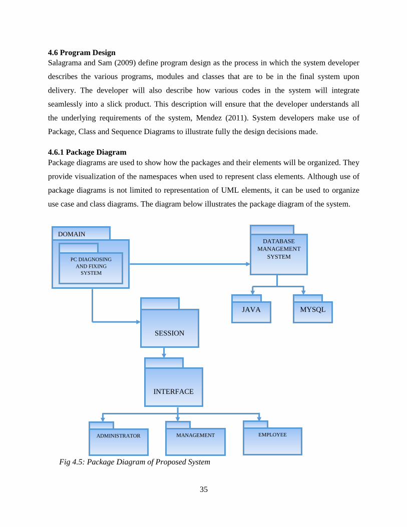
4.6.3 Sequence Diagram ....................................................................................................... 37
4.7 Interface Design .................................................................................................................. 38
4.7.1 Main Menu ................................................................................................................... 38
4.7.1.1 Sub-menus ................................................................................................................. 38
4.7.2 Input Design ................................................................................................................. 39
4.7.3 Output Design .............................................................................................................. 40
4.8 Pseudo Code ........................................................................................................................ 41
4.9 Security Design ................................................................................................................... 43
4.9.1 Physical Security .......................................................................................................... 43
4.9.2 Network Security ......................................................................................................... 43
4.9.3 Operational Security .................................................................................................... 44
4.10 Conclusion ........................................................................................................................ 44
CHAPTER 5: IMPLEMENTATION PHASE .............................................................................. 45
5.1 Introduction ......................................................................................................................... 45
5.2 Coding ................................................................................................................................. 45
5.3 Testing ................................................................................................................................. 45
5.3.1 Unit Testing .................................................................................................................. 46
5.3.2 Module Testing ............................................................................................................ 46
5.3.3 Integration testing ........................................................................................................ 47
ix
5.3.4 System Testing ............................................................................................................. 47
5.3.5 Acceptance Testing ...................................................................................................... 47
5.3.6 Test Cases .................................................................................................................... 48
5.4 Installation ........................................................................................................................... 49
5.4.1 User Training ............................................................................................................... 50
5.4.2 Changeover Strategies .................................................................................................. 51
5.5 Maintenance ........................................................................................................................ 53
5.6 Recommendations ............................................................................................................... 54
5.7 Conclusion .......................................................................................................................... 54
Reference List ............................................................................................................................... 55
Appendix A: User Manual ............................................................................................................ 57
Appendix B: Letter of Request for Research ................................................................................ 64
Appendix C: Interview Questions ................................................................................................. 65
Appendix D: Questionnaires ......................................................................................................... 66
Appendix E: Observation Score Sheet .......................................................................................... 68
Appendix F: Code Snippet ............................................................................................................ 69

x
LIST OF ACRONYMS
DFD Data Flow Diagram
ERD Entity Relationship Diagram
EERD Enhanced Entity Relationship Diagram
PHP Pre-Processor Hypertext PHP
HTML Hypertext Mark-Up Language
CSS Cascading Style Sheets
RDBMS Relational Database Management Systems
NPV Net Present Value
SQL Structured Query Language
xi
LIST OF FIGURES
Figure 1.1 Organizational Structure ............................................................................................... 2
Figure 2.1 Gantt Chart for The Project ..........................................................................................
14
Figure 3.1 Activity Diagram .........................................................................................................
19
Figure 3.2 Context Diagram ..........................................................................................................
21
Figure 3.3 Data Flow Diagram for The Current System ..............................................................
22
Figure 3.4 Use-Case Diagram …………………………...............................................................
26
Figure 4.1 Context Diagram of The Proposed System ..................................................................
29
Figure 4.2: Data Flow Diagram .....................................................................................................
30
Figure 4.3 Physical Design of The New System ...........................................................................
32
Figure 4.4 Enhanced Entity Relationship Diagram .......................................................................
35
Figure 4.5 Package Diagram .........................................................................................................
36
Figure 4.6 Class Diagram ..............................................................................................................
37
Figure 4.7 Sequence Diagram .......................................................................................................
38
Figure 4.8 Main Menu Activity.....................................................................................................
39
Figure 4.9 Menu Drawer................................................................................................................
40
Figure 4.10 Login Form ................................................................................................................
40
Figure 4.11 Registration Form ......................................................................................................
41
Figure 4.12 Show Lessons Activity...............................................................................................
41
Figure 4.13 Show Solution Activity...............................................................................................
42

xii
Figure 4.14 Changing Password Form...........................................................................................
42
Figure 5.1 Software Testing Process .............................................................................................
46
Figure 5.2-1 Unsuccessful Login Attempt.....................................................................................
48
Figure 5.2-2 Successful Login ......................................................................................................
48
Figure 5.3 Registration ..................................................................................................................49
Figure 5.9 Maintenance Process ...................................................................................................
58
LIST OF TABLES
Table 2.1 Hardware Requirements..................................................................................................
6
Table 2.2 Software Requirements……............................................................................................
6
Table 2.3 Network Requirements....................................................................................................
6
Table 2.4 Intangible Returns ...........................................................................................................
7
Table 2.5: Tangible Returns ............................................................................................................
8
Table 2.6: Development Costs ........................................................................................................
8
Table 2.7: Operational Costs............................................................................................................
9

xiii
Table 2.8: Cost Benefit Analysis ....................................................................................................
9
Table 2.9 Pay Back Period ............................................................................................................
10
Table 2.10 Net Present Value ........................................................................................................
11
Table 2.11 Project Work Plan
........................................................................................................14
Table 4.1 User Table .....................................................................................................................
32
Table 4.2 Usage Counter Table .....................................................................................................
32
Table 4.3 Suggestions Table .........................................................................................................
33
Table 4.4 Software Solution Table ................................................................................................
33 Table 4.5 Hardware Solutions Table
............................................................................................. 33
xiv
LIST OF APPENDICIES
Appendix A: User Manual ............................................................................................................
63
Appendix B: Letter of Request for Research..................................................................................
72
Appendix C: Interview ................................................................................................................. 73
Appendix D: Questionnaires .........................................................................................................
74
Appendix E: Observation Score Sheet ..........................................................................................
76
Appendix F: Code Snippet ........................................................................................................... 77

xv

1
CHAPTER 1: INTRODUCTION
1.1 Introduction
This chapter seeks to introduce Scorpion Safety Products, to delve into its background and its
daily functions which highlight the inconsistence of the existing system used within the company
which shall be defined and the proposed solution thereof, which requires a capable and problem
specific system to be designed. This chapter seeks to outline the aims, objectives and justification
of the new PC Trouble-shooter Android System.
1.2 Background of Study
In this study, it has come to the attention of the developer that Scorpion Safety Products has a
faced a rather drastic increase in the number of computer faults being faced on a day to day
basis. This is due to the increase in the number of transaction as a result of their growth over the
recent years. Therefore, use of computers to carter for all these transactions has resulted in the
decline of the mean time between computer faults. At the moment, the organization has been
hiring technicians from other organizations to solve all problems being faced. However, this has
resulted in a rather high bill for all repairs to be done. Therefore, due to the organization’s plans
to reduce costs, the developer has moved to develop an android pc diagnosing and fixing
application to help the average staff member to fix problems encountered.
1.2.1 Background of the Organization
Scorpion Safety Products is a company that was established in 1998 by two brothers Elias and
Brighton Jeche in Rusape. Their aim was to provide safety clothing for the workers who needed
protective clothing during their work schedules. They sought out to provide overalls, works suits,
hard helmets, gumboots and safety shoes. It wasn’t until 2002 that they moved to Mutare so a
have access to a larger customer base as Rusape didn’t have a large market. After the move, they
began importing some of their products such as gumboot, helmets and safety shoes from South
Africa whilst all the other products were sewn by their work force. In 2006, they expanded their
product range by adding bibs, maid attires, rubber gloves, dust coats, rain coats and cleaning
products such as brooms, mops, detergents, buckets and others.
Due to the growth of their company, they began using computers in most departments of the
company so as to be more efficient in 20011. The use of computers to receive orders from their
customers, record sales and purchases, keep records of employees and many other functions gave

2
them a competitive advantage over their competitors which made them expand more. As to date,
Scorpion Safety supplying schools, companies and individuals in and around Mutare.
1.2.2 Organizational Structure
1.2.3 Mission Statement
To manufacture and provide high quality safety products, allied products and related services
using environmentally friendly processes in a manner that is rewarding to customers, suppliers,
employees, shareholders and other stakeholders.
1.2.4 Vision
The company vision is to be a first-choice safety products provider that consistently supplies
high allied products of international standard.
1.3 Problem Definition
Fault diagnosis is very important in the field of computer science and information technology,
especially in personal computer (PC) troubleshooting. Today, the use of computers is
widespread, however, the knowledge in computer troubleshooting is limited, and this poses
difficulties amongst organizations when faced with computer problems. Thus, the development
Manager
Procurement
Manager
Sales
Manager Manufacturing
Manager
Products
Inspector
Accounts
Manager
Shop Floor
Workers
Sales
Clerks
Accounts
Departments Purchasing
Department
Fig 1.1: Organizational Structure

3
and presence of a system to troubleshoot simple and day-to-day computer faults and problems
can go a long way in oiling the process. The system will also assist and advise new technicians
with minimum experience in the troubleshooting of computer faults both hardware and software.
1.4 Aim
The aim of this proposed project is to develop an android based system that allows the users to
diagnose and fix all software and hardware related problems encountered.
1.5 Objectives
To develop a system that will have the knowledge of the trained personnel.
To allow authenticated users to identify various problems affecting Personal Computers
(PCs) and find quick and competent fixes.
To develop a system that can teach a non-qualified person how to deal with day-to-day
problems faced when using PCs.
To establish a system suitable to help users self-examine through the inference that the
system makes with its knowledge base.
To produce an effective application that offer benefit to technicians and make it easier to
troubleshoot PCs in a short time.
1.6 Instruments and Methods
The system developer will have to use various tools for the completion of the above defined
system. The following tools will be used.
Programming language: Android (Android Studio)
Database: SQL
Research: Internet
1.7 Justification
In troubleshooting Computer Systems, the two most common causes of delay are Trial and Error
and having Incomplete Information. The problems in Computer Systems will be fixed faster if
the solution to a problem is known and the symptoms of a particular problems are known. PC
trouble-shooter can also be utilized to train new technicians and computer users to troubleshoot
and fix computers without any expert’s assistance. Moreover, this system will save the company
thousands of dollars in expenses related to hiring of technicians to fix day to day PC problems.
4
1.8 Conclusion
The system is introduced to develop hardware fault detection for any computer system. Different
hardware system or electronics devices usually face application fault as well as hardware fault.
This application oriented formal reasoning applies to determine the problem in computer system.
This paper emphasizes an automated system that accepts the defects of any system and then after
consulting with an intelligent database, diagnoses and advises for probable rectification. It
proposes lot of new technological changes to make the system more perfective and an efficient
data handler.
5
CHAPTER 2: PLANNING PHASE
2.1 Introduction
A feasibility study will determine whether the proposed system is achievable and viable for the
organization in relation to the resources the organization can provide. It is determined in this
chapter whether the project can meet the set objectives. The questions below will be carefully
analyzed for the success of this phase:
Will the system be beneficial and contributory to the organization’s objectives?
Can the system be integrated to the current available technology?
Can it be achieved within set budget limits?
Does it not violate any government laws?
When the above questions have been adequately answered, the planning of this project can then
commence. In the planning stage, the following item have to be covered:
Business Value
Technical Feasibility
Economic Feasibility
Social Feasibility
Operational Feasibility
Risk Analysis
Stakeholder Analysis
2.2 Business Value
This stage looks at the effectiveness of the proposed system in carrying out its intended tasks. It
also highlights the benefits that will be enjoyed as a result of its implementation. The expected
returns from the system include:
Efficient use of time- rather than wait for the hired technicians to arrive, users can fix
problems by themselves and thus save valuable time.
Security- this system will only be accessed by users that have accounts.
Little training cost- this system will be very easy to use hence no need for multiple
training activities for staff to be proficient in using this system.
Reliability- the system will be reliable since several tests will be made to make sure that
the system performs as required by the user.
6
2.3 Feasibility Study
The main and most important purpose of a feasibility study is to determine the possibility of
doing the proposed project. The major areas of challenge are to be revealed and how they are to
be dealt with will also be determined. Four main areas of challenge have been identified and
these areas are:
Technical
Economic
Social
Operational
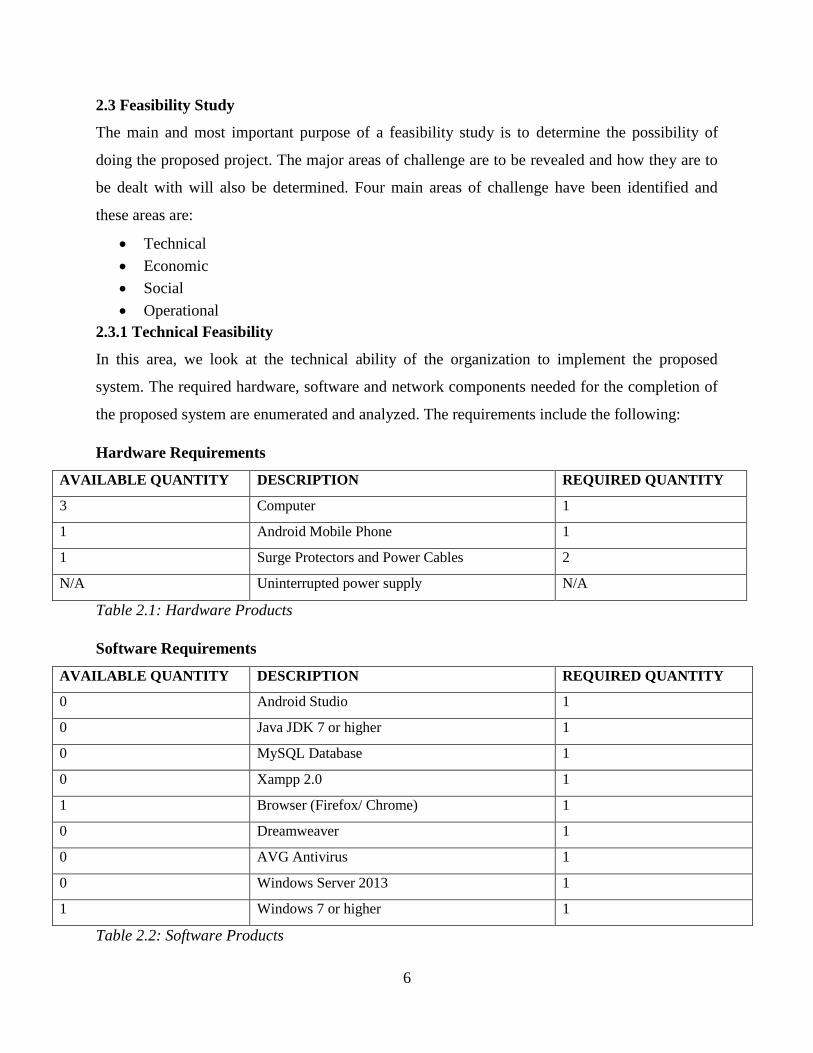
2.3.1 Technical Feasibility
In this area, we look at the technical ability of the organization to implement the proposed
system. The required hardware, software and network components needed for the completion of
the proposed system are enumerated and analyzed. The requirements include the following:
Hardware Requirements
AVAILABLE QUANTITY DESCRIPTION REQUIRED QUANTITY
3 Computer 1
1 Android Mobile Phone 1
1 Surge Protectors and Power Cables 2
N/A Uninterrupted power supply N/A
Table 2.1: Hardware Products
Software Requirements
AVAILABLE QUANTITY DESCRIPTION REQUIRED QUANTITY
0 Android Studio 1
0 Java JDK 7 or higher 1
0 MySQL Database 1
0 Xampp 2.0 1
1 Browser (Firefox/ Chrome) 1
0 Dreamweaver 1
0 AVG Antivirus 1
0 Windows Server 2013 1
1 Windows 7 or higher 1
Table 2.2: Software Products

7
Network Requirements
AVAILABLE QUANTITY DESCRIPTION REQUIRED QUANTITY
1 50-meter Reel Ethernet Cable CAT6 2
1 Server 4GB RAM, 200GB HDD, Dual Processor 1
0 Router 2
Table 2.3: Networking Products
From the above, it is evident that the organization already have some of the required components
required for the completion of this project. However, for the other components not available can
be purchased from the various vendors across the country.
2.3.2 Economic Feasibility
In this stage, we look at the costs and benefits expected to be derived from the completion of this
project. This study is mainly done to determine whether the expected benefits of the project will
outweigh the expected costs of the project and vice versa. The project is deemed economically
feasible if the benefits outweigh the costs and the organization can handle the sustained outflow
of cash until the project becomes profitable.
2.3.2.1 Benefits
The expected benefits of this project can be sub-divided into tangible and intangible benefits.
Intangible Benefits
These benefits refer to those enjoyed by the organization but cannot be quantified in monetary
form. However, the organization can put a monetary value on these intangible benefits to be
enjoyed. These benefits include:
Goodwill
Employees knowledge is increased
Self-sufficiency
Immaterial returns Cost (US$)
Total Value 4000
Table 2.4: Intangible Benefits

8
Tangible Benefits
These are the benefits the organization will enjoy that can be measured in monetary form. These
may include inflow of cash or rather the reduction in costs. The tangible benefits the organization
will enjoy are shown in the table below over a period of three years.
2.3.2.2 Costs
These are the costs that the organization is going to incur for the completion of this project.
These costs can be sub-divided into Developments and Operational Costs.
Development Costs
These costs are those incurred during the development of the system. These include costs used
for the purchase of all required components. Thus, these run up to the implementation stage of
the project. The table below will show all development costs to be incurred.

9
Operational Costs
These are costs that the organization is going to incur during the day to day operation of the
system. The operational costs of the proposed system for a period of three years are summarized
in the table below.
2.3.2.3 Cost Benefit Analysis
The following methods can be used to evaluate the financial feasibility of the project.
Payback Period
Net Profit
Return on Investment
Net Present Value
10
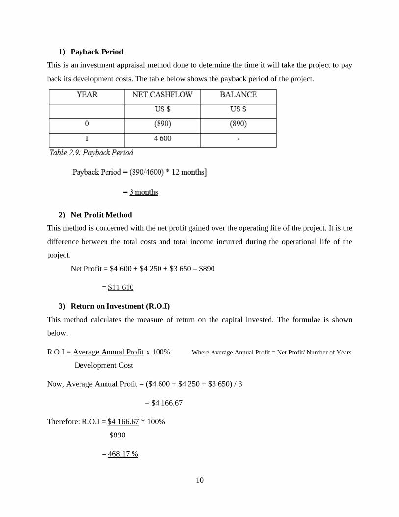
1) Payback Period
This is an investment appraisal method done to determine the time it will take the project to pay
back its development costs. The table below shows the payback period of the project.
2) Net Profit Method
This method is concerned with the net profit gained over the operating life of the project. It is the
difference between the total costs and total income incurred during the operational life of the
project.
Net Profit = $4 600 + $4 250 + $3 650 – $890
= $11 610
3) Return on Investment (R.O.I)
This method calculates the measure of return on the capital invested. The formulae is shown
below.
R.O.I = Average Annual Profit x 100% Where Average Annual Profit = Net Profit/ Number of Years
Development Cost
Now, Average Annual Profit = ($4 600 + $4 250 + $3 650) / 3
= $4 166.67
Therefore: R.O.I = $4 166.67 * 100%
$890
= 468.17 %

11
4) Net Present Value (NPV)
This method highlights the profitability of the project based upon the timing of the cash flows. It
works upon the basis that receiving a particular amount of money today is better than receiving
in in a year’s time. We are going to use 10% as our discount rate as the discount factor.
2.3.3 Social Feasibility
This refers to the analysis of how the proposed system may impact upon the various
stakeholders. These effects may be either negative or positive. The proposed system will help
users be more knowledgeable when it comes to troubleshooting and fixing computer related
problems. Users may take this knowledge and even apply it on other problems met outside the
organization.
2.3.4 Operational Feasibility
This part of the feasibility study is mainly concerned about how the proposed system will fit into
the current way the organization is carrying out its business activities. It shows exactly how
compatible the system will be with the current setup of the organization. If it is implemented.
The operational feasibility will be judged upon how the users of the system are enthusiastic
about the proposed system. This is achieved by comparing between the existing and the proposed
system in terms of how they operate in relation to the users of the system. The following are
taken into consideration:
Performance- response time, throughput and also system accuracy.
Controls - Sufficient measures to protect against system abuse.
12
System users are one of the most important stakeholders of the proposed system. The proposed
users of the proposed system are to be analyzed.
Developer
The developer of the proposed system understands the tools to be used for the development of
the proposed system. These tools include Android Studio, Xampp, MySQL Database and others.
These tools possess advanced design capabilities that are to be needed for the development of the
system.
The users
These are the end users of the system. These are the ones that will be using the system to fix PC
problems encountered.
I.T department
The organization currently does not have a dedicated I.T. department although steps are being
taken for the creation of this department. This department will be responsible for system support
in case a problem arises. They will focus on supporting, maintaining and upgrading the system.
They will also perform backup of the system.
The System Administrator
System administrator will be concerned with adding and managing users of the system.
2.4 Risk Analysis
Despite the project being deemed as a promising prospect, there are various risk that may be
faced during the development and implementation phases of the proposed system. These may
include:
Budgetary Risks- the development of the system is reliant upon the ability of the
organization to sustain cash outflows before completion of the system. Another risk is
that costs may end up being higher than budgeted for and this will pose problems if
the organization is not able to provide any additional funds.
Time Risks- the project’s development time has been forecasted to be twenty-three
weeks long. Due to the rise of unforeseen problems, the forecasted time may end up
not being enough. To be on the safe side, it is recommended that a float time of four

13
week being added upon the budgeted time to cover for any unplanned late delivery of
the system.
Hardware/Software Risks- these may arise as a result of system incompatibilities on
some of the mobile devices to be used by the users. These problems usually arise
during the implementation phase of the project.
Supplier Risks- the organization is reliant upon the timely delivery of components to
be used during the development of the system by the various suppliers engaged for
the provision of these components. Therefore, if the suppliers cannot deliver
components on agreed dates, the project’s implementation is to be delayed. To
counter this, the organization has to make early orders so as to have other alternatives
if components are not delivered
Environmental Risks- due to the ever-changing environment that the organization
operates in, the organization cannot in any way plan for particular risks as they will
be out of their control.
2.5 Stakeholder Feasibility
Kendall and Kendall (2000) defined a stakeholder as any person who has a stake in the outcome
of the project. The project may have either a positive or negative impact upon a particular
stakeholder. These stakeholders may be either internal or external to the organization. All these
must be identified and evaluated so as to make sure all needs are met. Early identification of
stakeholders is crucial to the success of the proposed project as all expectations must be
communicated. Some of these stakeholders include:
Performing Organization- this refers to the organization whose employees are
directly involved in the success of the project.
Organization Employees- this refers to the employees of the performing
organization.
Sponsor- this refers to the individual or group responsible for the financial resources
needed for the project’s completion.
The project is highly supported by all the listed stakeholders therefore the risk of them
having any negative influence on the project is very low.

14
2.6 Work Plan
This is the schedule that keeps track of all activities and stages that need to be followed
throughout the development of the proposed system. The project is going to be developed in a
period of twenty-four weeks.
Phase Start End Duration(weeks)
Proposal 24/04/17 07/05/17 2
Planning 08/05/17 28/05/17 3
Analysis 29/05/17 18/06/17 3
Design 19/06/17 27/08/17 10
Implementation 28/08/17 17/09/17 3
Maintenance 18/09/17 1/10/17 2
Table 2.11: Project work plan
The Work Plan can alternatively be illustrated using a Gantt chart as shown below:
The Gantt Chart
PHASE 1 2 3 4 5 6 7 8 9 10 11 12 13 14 15 16 17 18 19 20 21 22 23
Proposal
Planning
Analysis
Designing
Implementation
Maintenance
Documentation
KEY
WEEKS
15
2.7 Conclusion
After the preparation of a highly detailed feasibility study in this chapter, the proposed project is
deemed feasible based upon the measures measured against. The benefits to be enjoyed from the
implementation of the proposed system greatly outweigh the costs to be incurred during its
development. The next chapter, which is the analysis phase, will explain with great detail how
the current system has been analyzed, highlighting all processes carried out.

16
CHAPTER 3: ANALYSIS PHASE
3.1 Introduction
This chapter will focus on highlighting the weaknesses of the existing system, showing exactly
what the new system will improve on. The procedures that flow through the current system are
determined in this stage. Analysis of the users of the system, the data that flows through the
system and the use of that data is to be carried out in this stage. All this information will be used
in the designing of the new and improved system. For data gathering purposes, the researcher
used various data gathering techniques for the acquirement of this information. Techniques used
include:
Interviews
Questionnaires
Observations
3.2 Information Gathering Methodologies
Information gathering tools are defined as ways of gathering information from entities to be
affected by the change of the system. It is crucial and a key component of the analysis process in
the system analysis and design. Three methods which are interviews, questionnaires and
observations were used were chosen for this data gathering activity. These will give more insight
into the following.
System being currently used at Scorpion Safety Products.
Problems arising from current system.
Determining the best way to solve problems identified.
Expectations from the proposed system.
Technical skills that the personnel possess.
Whether personnel are willing to use the proposed system.
3.2.1 Interviews
An interview is a formal face-to-face meeting or conversation in which facts are elicited from an
interviewee by the interviewer. This was the primary data gathering methodology used by the
researcher to gather required information from the personnel at Scorpion Safety Products. The
researcher made use of tactics that ensured that all information gathered was accurate by

17
creating a conducive environment for the interview by ensuring no interferences, promise of
confidentiality, attentively listening to responses by interviewee and also by letting the
interviewee do much of the talking.
Results from Interviews
Interviews allowed for instant clarifications on all grey areas of the current system.
Relevant data was collected.
Most personnel were excited by the prospect of the proposed system.
3.2.2 Questionnaires
For the purpose of the research, a small but yet detailed questionnaire was drafted to be
completed by the personnel at Scorpion Safety Products. This method was chosen for its
confidentiality, which will result in respondents answering much truthfully than in person. After
carrying out of interviews, the researcher noted that some of the people interviewed censored
their responses as they feared that what they said will be shared with management. To counter
this, the researcher distributed questionnaires that gave respondents the opportunity to express
their opinions on the current and proposed system. The questionnaires were distributed by the
researcher personally and collected completed questionnaires after 48 hours.
Results from Questionnaires
Questions were correctly answered and at least 90% of personnel answered
questionnaires.
Respondents aired their opinions and their expectations of the proposed system.
Problems being faced by personnel were identified.
Managed to get response from management and other personnel who were on leave.
3.2.3 Observations
This refers to a data gathering methodology which involves observing how people currently use
the current system in place. Using this methodology, the researcher was able to observe the day
to day process that occurs at Scorpion Safety Products. Observations were done on a number of
intervals of work time at Scorpion Safety Products. This method can also be said to be a measure
of the other two methods to determine correctness of information given to researcher by the
respondents.

18
Results from Observations
This allowed the researcher to observe the processes that happen when there has been a
computer hardware of software fault.
There are little to no disruptions encountered with this methodology.
3.2.4 Summary of Findings
Form the gathered data, a conclusion can be reached about the way things are being done at
Scorpion Safety Products and what the expectations of the proposed system will be. Users are
fed up of the disruptions that occur when a computer fault occurs, which results in them having
to postpone all computer related activities for at least one working day for their computers to be
fixed by an external sub-contractor. Users have shown a zest to learn how to fix problems faced
on their own. Also, most users think the company is wasting a lot of money paying the sub-
contractor to fix even small menial problems.
3.3 Analysis of the Existing System
With the analysis of the results from the data gathering activities carried out, it can be concluded
that Scorpion Safety Products is using a rather redundant system to fix problems encountered in
their day to day activities. Having to rely on an external sub-contractor to fix faults encountered
has resulted in the organization paying through the nose to keep their computers operational. The
sub-contractor has to be called in even for a small task such as installation of simple software
such as Antivirus updates. Reliant on external sub-contractor has also resulted in less efficiency
as employees whose computers breakdown have to fill a form that has to be approved by
management for the sub-contractor to be called in. More time is even lost if the sub-contractor is
busy at another call-in. Some of the employees have begun using this as an excuse to not work as
they just point to their faulty computers when queried by management. Problems that take less
than five minutes to fix end up taking the better part of the day to be fixed. This has resulted in
less employee productivity. Employees also seem to be in agreement that there is a need to have
a dedicated Information Technology Department at the organization that is available at all times
to diagnose and fix problems encountered on a day to day basis.
3.4 Process Analysis
Process analysis is an approach used by managers to improve the performance of their business
activities. For this analysis, an activity diagram is an appropriate tool that can be used to
19
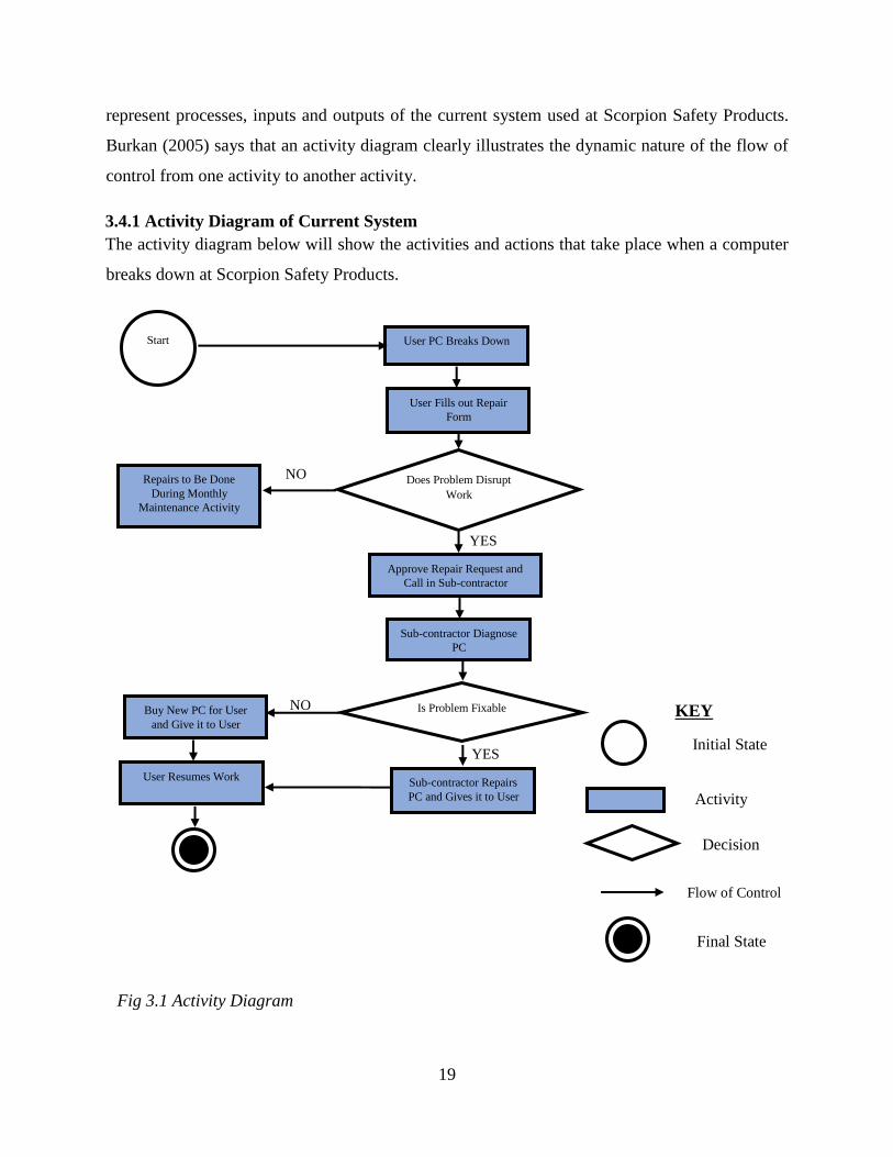
represent processes, inputs and outputs of the current system used at Scorpion Safety Products.
Burkan (2005) says that an activity diagram clearly illustrates the dynamic nature of the flow of
control from one activity to another activity.
3.4.1 Activity Diagram of Current System
The activity diagram below will show the activities and actions that take place when a computer
breaks down at Scorpion Safety Products.
YES
Fig 3.1 Activity Diagram
YES
NO
Start User PC Breaks Down
Does Problem Disrupt
Work
Repairs to Be Done
During Monthly
Maintenance Activity
Approve Repair Request and
Call in Sub-contractor
Sub-contractor Diagnose
PC
Is Problem Fixable NO Buy New PC for User
and Give it to User
Sub-contractor Repairs
PC and Gives it to User
User Resumes Work
KEY
Initial State
Activity
Decision
Flow of Control
Final State
User Fills out Repair
Form
20
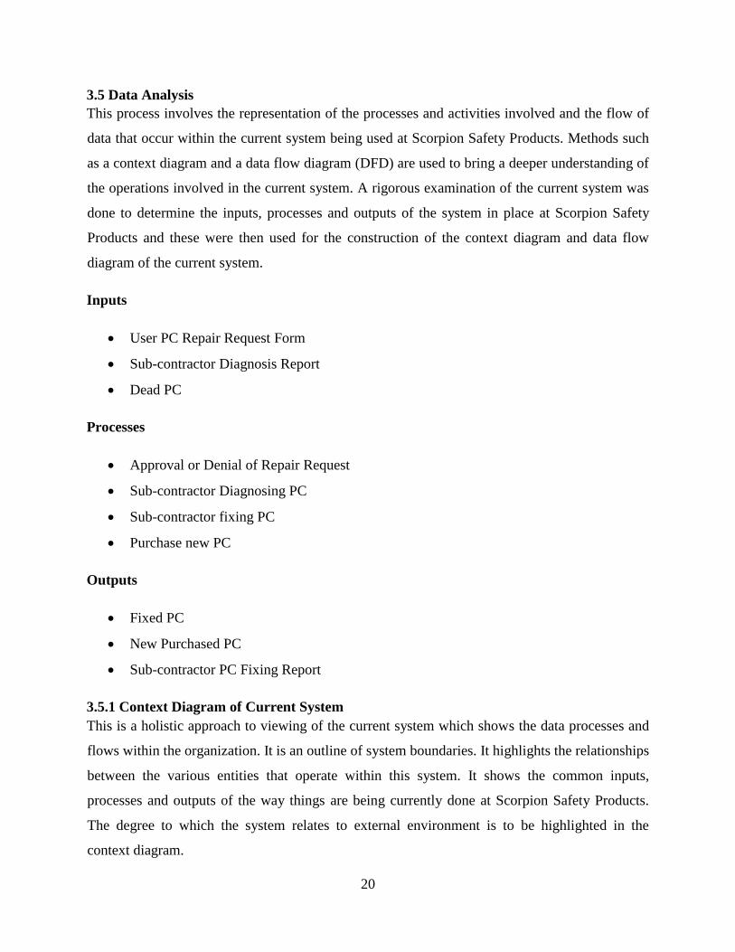
3.5 Data Analysis
This process involves the representation of the processes and activities involved and the flow of
data that occur within the current system being used at Scorpion Safety Products. Methods such
as a context diagram and a data flow diagram (DFD) are used to bring a deeper understanding of
the operations involved in the current system. A rigorous examination of the current system was
done to determine the inputs, processes and outputs of the system in place at Scorpion Safety
Products and these were then used for the construction of the context diagram and data flow
diagram of the current system.
Inputs
User PC Repair Request Form
Sub-contractor Diagnosis Report
Dead PC
Processes
Approval or Denial of Repair Request
Sub-contractor Diagnosing PC
Sub-contractor fixing PC
Purchase new PC
Outputs
Fixed PC
New Purchased PC
Sub-contractor PC Fixing Report
3.5.1 Context Diagram of Current System
This is a holistic approach to viewing of the current system which shows the data processes and
flows within the organization. It is an outline of system boundaries. It highlights the relationships
between the various entities that operate within this system. It shows the common inputs,
processes and outputs of the way things are being currently done at Scorpion Safety Products.
The degree to which the system relates to external environment is to be highlighted in the
context diagram.
21
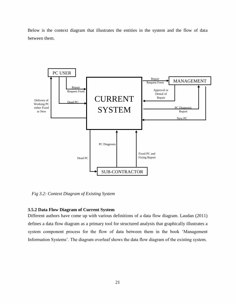
Below is the context diagram that illustrates the entities in the system and the flow of data
between them.….
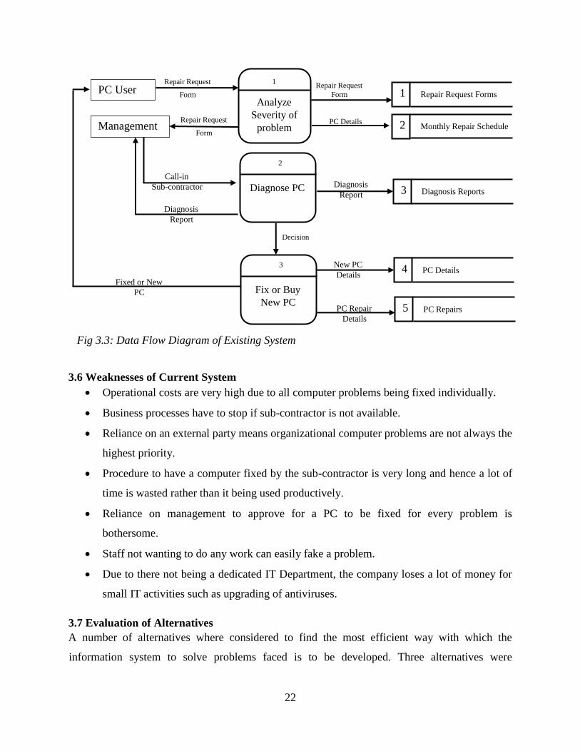
3.5.2 Data Flow Diagram of Current System
Different authors have come up with various definitions of a data flow diagram. Laudan (2011)
defines a data flow diagram as a primary tool for structured analysis that graphically illustrates a
system component process for the flow of data between them in the book ‘Management
Information Systems’. The diagram overleaf shows the data flow diagram of the existing system.
Fig 3.2: Context Diagram of Existing System
New PC
PC Diagnosis
Report
Delivery of
Working PC
either Fixed
or New
Fixed PC and
Fixing Report
PC Diagnosis
Dead PC
Dead PC
Repair
Request Form Repair
Request Form
CURRENT
SYSTEM
PC USER
MANAGEMENT
SUB-CONTRACTOR
Approval or
Denial of
Repair
request
22
3.6 Weaknesses of Current System
Operational costs are very high due to all computer problems being fixed individually.
Business processes have to stop if sub-contractor is not available.
Reliance on an external party means organizational computer problems are not always the
highest priority.
Procedure to have a computer fixed by the sub-contractor is very long and hence a lot of
time is wasted rather than it being used productively.
Reliance on management to approve for a PC to be fixed for every problem is
bothersome.
Staff not wanting to do any work can easily fake a problem.
Due to there not being a dedicated IT Department, the company loses a lot of money for
small IT activities such as upgrading of antiviruses.
3.7 Evaluation of Alternatives
A number of alternatives where considered to find the most efficient way with which the
information system to solve problems faced is to be developed. Three alternatives were
PC Repair
Details
New PC
Details
Diagnosis
Report
Decision
Fixed or New
PC
PC Details
Diagnosis
Report
Call-in
Sub-contractor
Repair Request
Form
Repair Request
Form Repair Request
Form
PC User 1
Analyze
Severity of
problem
1 Repair Request Forms
Management
2
Diagnose PC
2 Monthly Repair Schedule
Fig 3.3: Data Flow Diagram of Existing System
3
Fix or Buy
New PC
3 Diagnosis Reports
4 PC Details
5 PC Repairs
23
considered and their advantages and disadvantages were noted and the best solution was chosen.
These include Outsourcing, Off-the-Shelf and In-house Development.
3.7.1 Outsourcing
Raymond (2009), says that outsourcing is whereby the development of the required information
system is contracted to a third party outside the organization. With this option, Scorpion Safety
Products will have to find a software development company which will develop and deliver the
needed software solution. This option has a number of advantages and disadvantages that were
noted.
Advantages of Outsourcing
Rather low development costs.
Development will be done by experts.
Fewer technical staff required
New ideas will be injected into the software solution
Disadvantages of Outsourcing
Maintenance costs may be very high
Training costs to be incurred.
Wrong software solution may be delivered.
Control of some project aspects such as project implementation is reliant on third party.
3.7.2 Off-the-Shelf
Off-the-Shelf refers to the option whereby the organization has to buy an already made software
solution. The company will have to search for a vendor who has a software application that will
be a solution to the problem faced. This alternative also has various advantages and
disadvantages.
Advantages of Off-the-Shelf
Less risk of failing as it has been tried and tested by many people.
Time is saved as software is ready to be implemented.
Guarantees are on the package such that if a problem were to be found there will
be a refund from system developer

24
Disadvantages of Off-the-Shelf
Generic software will not meet the exact requirements of the organization.
Minimal support at all after purchase of software.
Training costs may be very high as you will require an external trainer to train all
users of the system.
3.7.3 In-House Development
This refers to the development of the required software solution inside the organization. This will
mean the solution will be developed used organizational resources and all aspects of the software
will be handled by the organization. This alternative also has some advantages and disadvantages
that were noted.
Advantages of In-House Development
Development of software will be done with the existing hardware components
hence no problem of incompatibility between hardware and software at
implementation.
Less chances of security being compromised due to information not being shared
with any external organization.
All aspects of the project such as implementation will be controlled by the
organization
Budgets can be easily controlled.
Disadvantages of In-house Development
Time may be wasted in creating custom made solution rather than get an off-the-
shelf product that is already available.
There is need for highly skilled developers.
3.7.4 Verdict on Alternatives
After consideration of the above alternatives, a decision has to be made on which is the best
alternative to be used for the development of the software solution. It is encouraged that
management at Scorpion Safety Products choose to develop the system In-house due to several
reasons listed below:
All control will stay with the organization

25
Organization can easily control budgets.
Software solution will be specific to user requirements as a developer have easy access to
users.
From the Feasibility Study done in the previous chapter, it can be clearly seen that this
option is Economically, Technically, Socially and Operationally feasible for the
organization.
3.8 Requirements Analysis
According to Malan (2010), requirement analysis refers to the process whereby a very detailed
understanding of the business functions is done and these are broken down into small
requirements that are clearly defined. These can be broken down into functional and non-
functional requirements.
3.8.1 Functional Requirements
These are the requirements that define the capabilities and functionalities that are expected to be
delivered by the proposed system. These may include calculations, data manipulations, data
processing and any others. The following will be provided by the proposed system:
Authentication- users can only access the software by provided correct user details.
Use a centralized database- this will result in all users accessing the same information.
Backup- periodic backups will be done in case a hardware or software error occurs.
Notifications- these will be given to users who would have inputted a query to the
administrator.
Intuitive interfaces- interfaces should lead user to correct information wanted.
Updating of solutions- solutions can be updated as and when there is need to.
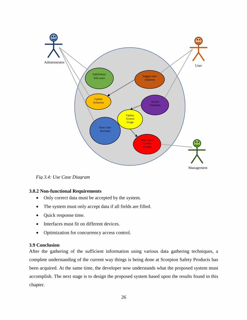
3.8.1.1 Use Case Diagram
A use case diagram is used to summarize all interactions that users have with the system. It also
helps in highlighting the system’s interactions with people, organizations and other systems. It
also helps users (actors) achieve set goals that the system can process.
26
3.8.2 Non-functional Requirements
Only correct data must be accepted by the system.
The system must only accept data if all fields are filled.
Quick response time.
Interfaces must fit on different devices.
Optimization for concurrency access control.
3.9 Conclusion
After the gathering of the sufficient information using various data gathering techniques, a
complete understanding of the current way things is being done at Scorpion Safety Products has
been acquired. At the same time, the developer now understands what the proposed system must
accomplish. The next stage is to design the proposed system based upon the results found in this
chapter.
Administrator User
Add/Delete/
Edit users
Update
Solutions
Suggest new
solutions
Access
Solutions
View User
Activities
Management
Read about
System
Reports
Update
System
Usage
Fig 3.4: Use Case Diagram
27
CHAPTER 4: DESIGN PHASE
4.1 Introduction
Roland (2012), says that the design phase is the application of different techniques to determine
the definition of a system in sufficient detail to foster its actual physical realization. This phase
will emphasize mostly on the inputs and output of the system. The relationships and data flows
between entities are determined in this phase. Designs that will be defined in this phase include
System Design, Architectural Design, Physical Design, Database Design, Interface Design and
Security Design.
4.2 System Design
System design refers to the in-depth description of the system’s capabilities in meeting the
different user requirements based upon the analysis of the existing system according to Laudon
(2005). An in-depth understanding of the user requirements document is required to be able to
meet all the functional and non-functional requirements. All user requirements that are deemed
impossible to meet or that do not add any functional purpose are made known to the prospective
system users. A well-designed system will have the following characteristics:
Security- System should be accessed only by authorized users.
User friendliness- users must be able to use the system without any consultation from
system administrator.
Reliability- System must provide consistent solutions to all users. Any changes made to
the system must be reflective to every user.
Efficiency- System’s main functions must not take a long time to load.
Maintainability- Maintenance of the system must be easy so as to keep up with the
technological advances.
The PC Diagnosing and Fixing System will have three types of users which are System
Administrators, Normal Users and Management. The system administrators will be responsible
with creating or editing accounts, updating solutions and also system support. Normal Users
refer to users who access the solutions on how to fix problems that they encounter on their
computers. These users can also suggest new solution for a particular problem that the System
Administrators will judge and add to the available solutions if it is correct. These suggested
solutions when added to the database can be viewed by every user. Management users refer to
those that will view user activity and frequency of use of the system by the Normal Users. Since

28
there isn’t a dedicated IT/IS Department in the organization, the Normal Users are being
encouraged to use the system by adopting an incentive reward system based on number of
problems solved and solutions suggested, the Management has access to required data.
4.2.1 Context Diagram of Proposed System
This is an illustration of the flow of data between various type of users in the information system,
modelling all procedure aspects. All the main requirements for the information system are shown
in a graphical system model showing interactions between the system and external entities.
4.2.2 Data Flow Diagram of Proposed System
A data flow diagram is a graphical representation of the processes and streams of data flowing
amongst them. According to Whitten (2014), it shows flow of data to, from and within the
various processes that use the data in the system.
System
Administrators Management
Employee
Sub-contractor
(External)
Deliver Dead PC
PC DIAGNOSING AND
FIXING SYSTEM
Deliver Fixed PC
Access Solutions
Suggest Solutions
Register/Delete Users
Enter New Solutions
System Usage
Deliver Fixed PC
Submit Unfixable PC
Evaluate Suggested
Solutions
Fig 4.1: Context Diagram of Proposed System
Unfixable PC
Access Lessons
Attempt Exam

29
Login Details
User Credit
Suggestion
Reports Reports
User Credits
User Repair Credit
Repair Form Repair Form
User Suggestion Credit
PC Lessons
PC Solutions
Repair Form
Approved Suggestions
Repair Details
Suggestion
Verified Details
Access Granted
Access Denied
Response
Login Details 1
AUTHENTICATE
Fig 4.2: Data Flow Diagram of Proposed System
USER
ADMIN
MANAGEMENT
5
ADD NEW
SOLUTIONS/ LESSONS
4
SUGGEST NEW
SOLUTIONS/
LESSONS
2
FIX PC USING
SOLUTIONS
6
ALLOCATE
USER CREDIT
1 User Details
3
GENERATE REPAIR FORM
7
GENERATE
CREDITS
REPORT
2 Repair Forms
3 PC Solutions
4 PC Lessons
5 User Credits
6 Reports

30
4.3 Architectural Design
Brinkman (2011) states that architectural design focuses on establishing a framework within
which a given system can work in. This can also be referred to as the High-Level Stack Design.
The descriptions of all the environments that the system will interact with are described in the
architectural design. Environments may include networks, system hardware, software,
dependencies and procedures. It generally describes how the system is to be setup in the
environment that it must function in. the proposed system will operate on a Local Area Network
(LAN) to enable communication between the server and user devices. Some of the components
to be used are described below.
4.3.1 Client Machines
This refers to desktops, laptops and smartphones that will be used by the different users of the
system which include system administrators, management users and normal users.
4.3.2 Server
This refers to the location where all documents and databases pertaining to the proposed system
will be stored. The database will be centralized hence there will be only one database.
4.3.3 Router
This is the entry point used to access data that will be in the server by the client machines.
Several packets received are distributed to their destinations based upon the set configuration
rules.
4.3.4 Network Cables
These are cables that are used to connect the client machines such as desktops and laptops to the
server. These consist of a CAT 6 cable that is terminated with an RJ45 connector.
4.3.5 Firewall
This is a primary security feature that protects against unauthorized access to the network. The
firewall selects which packets of data to let through and which ones to deny entry.
4.4 Physical Design
Crowhill (2013), states that the physical design primarily deals with physical transformation of a
logical abstract into a technical design. It shows how the physical hardware of the system will be
interconnected. The proposed system’s physical design has components such as a router, a server
and client machines. The diagram below shows the system’s physical design.

31
4.5 Database Design
According to Sommerville (2011), a database should allow the system users to have easy access
to all data that is in the database. Data must be entered, stored, manipulated and retrieve easily in
a database whenever it is required by the users. Since data can be termed as the lifeblood of a
business, it must be protected against unauthorized access. For management of all these database
SERVER
FIREWALL
SWITCH
LAN
ADMIN COMPUTERS USER SMARTPHONES
PRINTER
Fig 4.3: Physical Design of Proposed System

32
actions, a database management system (DBMS) is to be employed. Reasons for employing a
database to store data include:
Data Security
Data Independence
Backup and recovery of data
Data consistencies
Data Integrity
4.5.1 Tables
The structure of the tables in the database will be shown so as to give a clear understanding of
how data will be ordered and stored in the database.
Users Table
FIELD DATA TYPE DESCRIPTION
ID Integer Auto Generated ID Number
Username <<PK>> Varchar (50) User’s username
Password Varchar (50) User’s encrypted password
Salt Varchar (10) Password encryption key
Fullname Varchar (50) User full name
ProfPic Blob User profile pic
Access Integer User access level
Credit Curreny Amount of money to be paid out to user
ExamMark Integer User’s exam mark
UpdatedAt Date Last time user data was updated
Table 4.1: User Login Table
Usage Counter Table
FIELD DATA TYPE DESCRIPTION
ID Integer Auto Generated ID Number
Username Varchar (50) User’s username
NumberofSuggestions Integer Number of times user suggested anything
LastSuggestionDate Date Date of last Suggestion
DateLastAccessed Date Date user last accessed database
TimesAccessed Integer Number of times user has accessed
system
Table 4.2: Usage Counter Table

33
Suggestions Table
FIELD DATA TYPE DESCRIPTION
ID Integer Auto Generated ID Number
Username Varchar (50) Username of user who suggested solution
Suggestion Varchar (1000) User’s suggestion to new solutions
Date Date Date suggestion was made
Table 4.3: User Suggestions Table
Software Solutions Table
FIELD DATA TYPE DESCRIPTION
ID Integer Auto Generated ID Number
Type Varchar (50) Category of software problem
Problem Varchar (1000) Software problem encountered
Reason Varchar (1000) Reason why problem is occurring
Solution Varchar (1000) Solution for problem encountered
DateAdded Date Date solution was added
LastDateModified Date Date solution was modified
Table 4.4: Software Solutions Table
Hardware Solutions
FIELD DATA TYPE DESCRIPTION
ID Integer Auto Generated ID Number
Type Varchar (50) Category of hardware problem
Problem Varchar (1000) Hardware problem encountered
Reason Varchar (1000) Reason why problem is occurring
Solution Varchar (1000) Solution for problem encountered
DateAdded Date Date solution was added
LastDateModified Date Date solution was modified
Table 4.5: Hardware Solutions Table
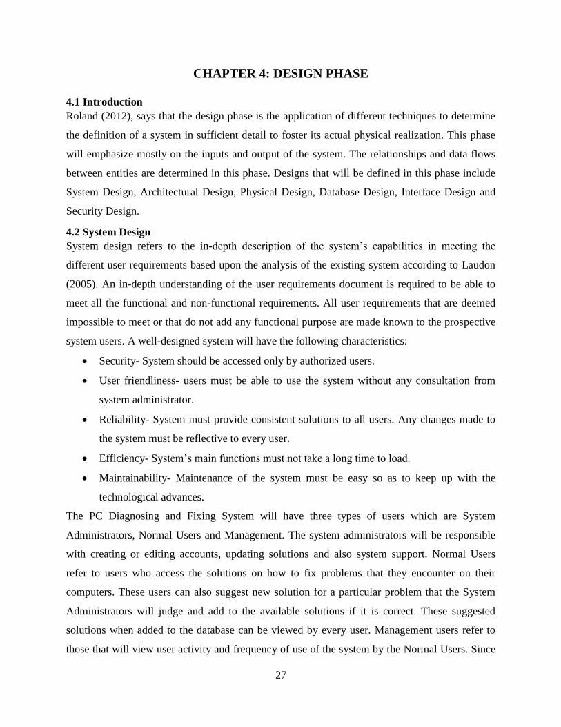
4.5.2 Enhanced Entity Relationship Diagram
Chen (2011) defined an enhanced entity relationship diagram (EERD) as the graphical
representation of any given entity and its relationship with other entities in the same given
database. An EER Diagram is used to model the database components in an easily understood
graphical manner. The main reason for its design is to show the entities will be interacting in the
actual database. The diagram shown overleaf shows the EER diagram for the proposed system.
34
Fig 4.4: Enhanced Entity Relationship Diagram of Proposed System
unique_id username access_level
fullname created_at
D
MANAGEMENT
Department
EXAMS
SOLUTIONS
LESSONS
Reads
updated_at
USERS
topic
EMPLOYEE
Attempts
answer question
Accesses
to fix PCs
Allocates
updated_at username
Notifies
View
Reports
credit
USER CREDITS
updated_at
type
solution
ADMIN
updates
35
4.6 Program Design
Salagrama and Sam (2009) define program design as the process in which the system developer
describes the various programs, modules and classes that are to be in the final system upon
delivery. The developer will also describe how various codes in the system will integrate
seamlessly into a slick product. This description will ensure that the developer understands all
the underlying requirements of the system, Mendez (2011). System developers make use of
Package, Class and Sequence Diagrams to illustrate fully the design decisions made.
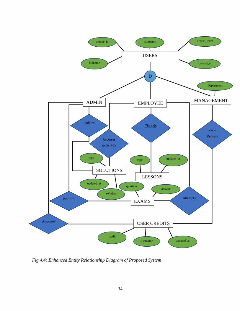
4.6.1 Package Diagram
Package diagrams are used to show how the packages and their elements will be organized. They
provide visualization of the namespaces when used to represent class elements. Although use of
package diagrams is not limited to representation of UML elements, it can be used to organize
use case and class diagrams. The diagram below illustrates the package diagram of the system.
Fig 4.5: Package Diagram of Proposed System
DOMAIN
PC DIAGNOSING
AND FIXING
SYSTEM
DATABASE
MANAGEMENT
SYSTEM
SESSION
INTERFACE
ADMINISTRATOR
MANAGEMENT
EMPLOYEE
JAVA
MYSQL

36
4.6.2 Class Diagram
A class diagram is a static structure diagram which describes a structure of a system, illustrating
all classes involved, how they interact and the relationships that exist within objects. The entity
types are fully described for purposes of clarity to system developers in class diagrams. The
figure below shows the class diagram of the PC Fixing and Diagnosing System.
Attempts
Learns
Suggests
Approves
Reads Updates Reads
(overlapping, complete)
USERS
id int <<PK>>
unique_id varchar (23)
name varchar (50)
username varchar (50)
access_level int (1)
encrypted_password varchar (80)
salt varchar(10)
created_at datetime
updated_at datetime
Add user () Update user ()
MANAGEMENT
position varchar (50)
ADMIN
date_added datetime
admin_number int (1)
EMPLOYEE
position varchar (50)
department varchar (50)
USER_ACTIVITIES
id int <<PK>>
username varchar (50)
activities varchar (50)
date_of_activity datetime
Add user_activity ()
SOLUTIONS
id int <<PK>>
type varchar (50)
problem varchar (1000)
reason varchar (10000)
solution varchar (10000)
updated_at datetime
Add solutions () Update solutions ()
SUGGESTIONS
id int <<PK>>
type varchar (50)
problem varchar (1000)
reason varchar (10000)
solution varchar (10000)
username varchar (50)
updated_at datetime
Add suggestions ()
LESSONS
id int <<PK>>
topic varchar (50)
lesson varchar (10000)
updated_at datetime
Add lessons ()
Update lessons ()
EXAMS
id int <<PK>>
questions varchar (100)
answer varchar (1)
attempts int (2)
username varchar (50)
attempted_at datetime
Add questions ()
Update questions ()
Fig 4.6: Class Diagram of Proposed System
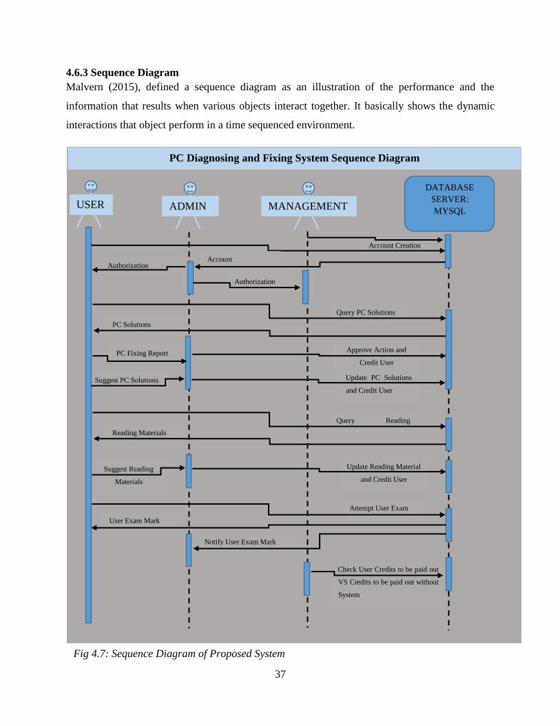
37
4.6.3 Sequence Diagram
Malvern (2015), defined a sequence diagram as an illustration of the performance and the
information that results when various objects interact together. It basically shows the dynamic
interactions that object perform in a time sequenced environment.
Approve Action and
Credit User PC Fixing Report
Check User Credits to be paid out
VS Credits to be paid out without
System
Notify User Exam Mark
User Exam Mark
Attempt User Exam
Suggest Reading
Materials
Update PC Solutions
and Credit User Suggest PC Solutions
PC Solutions Query PC Solutions
Authorization
Authorization
PC Diagnosing and Fixing System Sequence Diagram
USER ADMIN MANAGEMENT
DATABASE
SERVER:
MYSQL
Account Creation
Account
Confirmation
Update Reading Material
and Credit User
Reading Materials Query Reading
Materials
Fig 4.7: Sequence Diagram of Proposed System
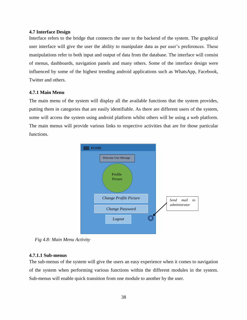
38
4.7 Interface Design
Interface refers to the bridge that connects the user to the backend of the system. The graphical
user interface will give the user the ability to manipulate data as per user’s preferences. These
manipulations refer to both input and output of data from the database. The interface will consist
of menus, dashboards, navigation panels and many others. Some of the interface design were
influenced by some of the highest trending android applications such as WhatsApp, Facebook,
Twitter and others.
4.7.1 Main Menu
The main menu of the system will display all the available functions that the system provides,
putting them in categories that are easily identifiable. As there are different users of the system,
some will access the system using android platform whilst others will be using a web platform.
The main menus will provide various links to respective activities that are for those particular
functions.
4.7.1.1 Sub-menus
The sub-menus of the system will give the users an easy experience when it comes to navigation
of the system when performing various functions within the different modules in the system.
Sub-menus will enable quick transition from one module to another by the user.
Change Profile Picture
Change Password
Welcome User Message
HOME
Profile
Picture
Fig 4.8: Main Menu Activity
Logout
Send mail to
administrator
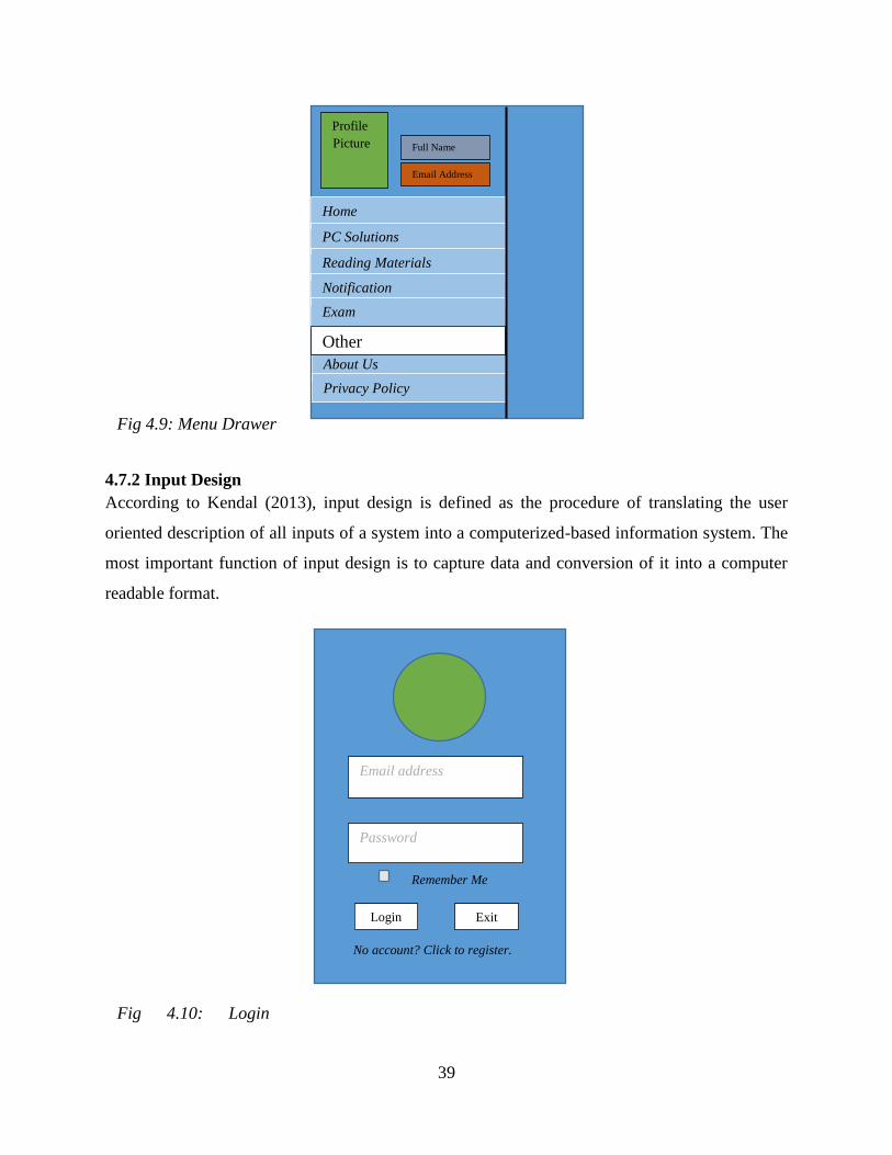
39
4.7.2 Input Design
According to Kendal (2013), input design is defined as the procedure of translating the user
oriented description of all inputs of a system into a computerized-based information system. The
most important function of input design is to capture data and conversion of it into a computer
readable format.
Email address
Login Exit
Password
No account? Click to register.
Remember Me
Fig 4.10: Login
Form
About Us
Privacy Policy
Full Name
Home
PC Solutions
Reading Materials
Notification
Exam
Other
Email Address
Profile
Picture
Fig 4.9: Menu Drawer
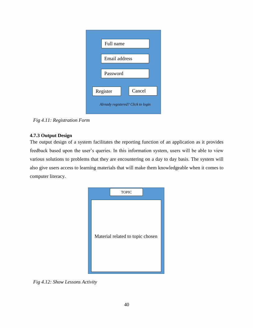
40
4.7.3 Output Design
The output design of a system facilitates the reporting function of an application as it provides
feedback based upon the user’s queries. In this information system, users will be able to view
various solutions to problems that they are encountering on a day to day basis. The system will
also give users access to learning materials that will make them knowledgeable when it comes to
computer literacy.
TOPIC
Material related to topic chosen
Fig 4.12: Show Lessons Activity
Full name
Email address
Password
Register Cancel
Already registered? Click to login
Fig 4.11: Registration Form
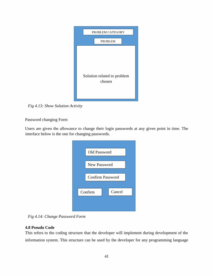
41
Password changing Form
Users are given the allowance to change their login passwords at any given point in time. The
interface below is the one for changing passwords.
4.8 Pseudo Code
This refers to the coding structure that the developer will implement during development of the
information system. This structure can be used by the developer for any programming language
Old Password
New Password
Confirm Password
Confirm Cancel
Fig 4.14: Change Password Form
PROBLEM
Solution related to problem
chosen
Fig 4.13: Show Solution Activity
PROBLEM CATEGORY

42
chosen as a development tool for this project. This is done without giving any details of the
system’s program implementation.
Create new User Account
Start
Enter new username, password, full name and access level
If username does not exist
Add new user and encrypt password
Else
Error (username already exists)
End
Login
Start
Enter username and user password
If credentials valid then
Read access level and show access level home menu
Else
Failed login attempt
End
Suggest new Solution
Start
Choose type of problem
Enter solution
If solution does not exist, then
Add new solution
Else
Error (solution already exist)
End

43
MySQL Database Connection
Start
Check if connection is open
If there is connection
Ignore
Else
Open new connection
End
4.9 Security Design
This is one of the most crucial phases of the design of an information system as all work done
will have been for naught if the system can be accessed by unauthorized individuals. Lawrence
(2010) says that the security design decisions to be made must be in line with the objectives of
the organization at large. Security design is broken down into physical, network and operational
security.
4.9.1 Physical Security
This refers to the securing of the physical components of the proposed system and the
components include servers, routers, personal computers and many others. Physical security
protocols will have to be implemented for these physical components of the system to be kept
safe. The server room will be under surveillance on constant basis and only authorized personnel
are to be granted access into the server room. Users will also have to be more responsible in
keeping their personal computers safe as they can lock their offices to make sure no one will gain
access inside without their express knowledge. As a recommendation to the organization, it must
look into investing in biometric technology as it is much more secure than the current locking
mechanisms being used.
4.9.2 Network Security
Network security is the protection of data packages as they move from one device to another and
the restriction of malicious activities over the network that may be from either inside or outside
the organization. Communication with outside networks will be monitored to ensure that
organizational data is not lost to outsiders. Measures such as firewalls and anti-viruses are to be
taken to scan all downloads and uplinks to the network.
44
4.9.3 Operational Security
Kendall and Mendez (2012) define operational security as the absence of security related failures
in an information system architecture. Focus is put upon the security issues that may arise during
the operating life of the proposed system. During the development phase of the system, the
developer should identify risk that may arise and seek ways to mitigate the problems. The
developer must also note down all problems that may be beyond the organization’s control and
these include natural disasters such as floods, earthquakes and others.
4.10 Conclusion
This chapter has given a vivid picture of what the system will be like. It has also given clear
information on all the necessary requisites of the system. All relationships between the users and
the system have been highlighted and discussed in detail showing both the enhanced entity
relational diagram and the data flow diagram of the system. The following phase will be about
the implementation of the system in the organization.

45
CHAPTER 5: IMPLEMENTATION PHASE
5.1 Introduction
The information system has been developed according to the guidelines set out in the previous
phases and is now ready for implementation. In this phase, the system is to be thoroughly tested
for any potential errors that may arise before it is installed for organization-wide use. Jacobs
(2013) emphasized how crucial this phase was as it looked into the activities that were to be
undertaken to ensure that a perfect information system was presented to the users. For quality
assurance purposes, many testing strategies were employed to gauge the quality of the system.
For testing purposes, a prototype of the system is to be installed on pilot devices.
5.2 Coding
Mendez et al (2005) highlighted that coding is what explains the input and output. Therefore, it is
the process of writing instruction in human readable language that will be converted it into code
which can be read by the machine. For the total achievement of all objectives set, different
programming languages were used as they all have different strength and functions which make
up the complete system. PHP was used for the web programming whilst android (Java) was used
for the android mobile platform. MySQL was used as the database to store all the data related to
the system. With reference to the guidelines outlined in the Database design, appropriate tables
were created and relevant primary keys assigned according to the database architecture rules.
Relevant MySQL queries were used for data manipulation in the database. These queries
include:
SELECT – this was used for the retrieval of data from the database.
INSERT – this query was used to insert new data into the database.
UPDATE – this query was used to edit data that was already in the database.
DELETE –this query was used to remove data permanently from the database.
5.3 Testing
Testing is defined as the process of executing software modules with the intention of finding
runtime errors and bugs by Mendez (2013). This exercise can also be used to ascertain whether
all functional and non-functional requirements are met. The testing process’ aim was to give a

46
framework that was to be used as a guideline for the whole testing procedure. The steps followed
during the testing process are shown in the diagram below.
5.3.1 Unit Testing
Unit testing refers to the process of breaking down software programs into the smallest possible
pieces and testing these pieces using various methods. This piece can either be a module or a
function of the information system. There are two approaches to unit testing and these are black
box testing and white box testing.
Black Box Testing – this refers to the testing of the inputs and the outputs that are produced by
the system. In this test, there is no need for the user to know the underlying details of the system.
Therefore, this test’s results are measured against the expected outputs of the system.
White Box Testing – this refers to the testing of the internal functions of the system. Therefore,
for this to be successfully carried out there is need for the user to have an understanding of the
system internal operations, Manes (2012). In this process the user will have to know which area
has an error if the expected outputs are not found.
5.3.2 Module Testing
A module can be referred to as a function or a collection of system components that are reliant
on each other. All dependent components are bundled together into a module and tested together
Unit Testing
Module Testing
Integration Testing
System Testing
Acceptance Testing
Fig 5.1: Testing Process
47
as one thing. Modules can be tested independently from other modules that are in the system.
Thorough testing is to be done to ensure that underlying code is doing its expected functions.
5.3.3 Integration testing
Integration testing, which can be termed link testing, refers to the testing done on a collection of
modules that have a relationship. This is done to ensure that data is flowing between different
modules of the system. This collection can be termed as a sub-system.it is during this test that
interface mismatches are identified and corrected.
5.3.4 System Testing
Sub-systems that are created during integration testing are combined into a single complete
system. This complete system is then tested to ensure that the joining of sub-system hasn’t
resulted in any errors. It is during this test that it is tested whether the system meets all functional
and non-functional requirements.
5.3.5 Acceptance Testing
This is the last stage of the Stepping Process before the complete, integrated system is handed
over to the end users. In this stage, the system is to be tested with real world data which is
supplied by the users rather that testing it using simulated and random data. The levels of
acceptance to be addressed are verification and validation.
Verification (Alpha Testing)
The question that is to be answered in this testing is whether the system is being built the
right way. Special attention is paid in looking for errors regarding end-user and design
specifications specified earlier but not incorporated into the system. The system is measured
up against the requirements specifications to ascertain whether the system meets all problems
identified. Additional features not in the requirement specifications can also be identified.
This test is mainly concerned with individuals who make use of the back-end of the system
and these include admins and managers.
Validation (Beta Testing)
This testing is mainly concerned with the end user. Testing is done whilst inputting only
valid data. The system will give warnings through alerts and toasts. Data is only accepted by
the system if it is correct. During testing, there is need to sometimes deliberately input

48
incorrect data to check whether the system will flag up the error or proceed the errors. This
process is repeated iteratively until system delivery.
5.3.6 Test Cases
A test case is defined as a set of conditions and variables under which the tester of the
information system determines whether the system works as expected. Various test cases where
used and these include user authentication, user creation, user knowledge suggestion and others.
Test Case 1: User Authentication
All entities within the system must be authenticated against its email and password. Whenever
wrong authentication credentials are used, a toast is displayed to show a login failure message.
The system checks whether the user credentials submitted are for which access level, either an
administrator or an employee user. When login is done using correct credentials on the wrong
platform, an alert is displayed telling the user to login using the correct platform. However, when
Fig 5.2: User Authentication

49
login is done with correct credentials not assigned any access level, the user is told to follow up
the issue to the system administrator for the account to be confirmed.
Test Case 2: User Registration
Users must register their credentials onto the server so as to access the system. As a measure
against unauthorized users from registering and accessing the system illegally, the system
administrators will have to confirm every account request.
5.4 Installation
System installation is a process whereby a system is deployed for official use by the end-users.
The changeover strategies for the implementation of the system are evaluated to determine the
Fig 5.3: User Registration
50
most appropriate method to be used during the change from old to new system. There are
however, various steps that must be followed for this procedure. Steps to be followed are as
shown below:
All necessary software and the database are to be loaded to the server and made available
to all users via the local network of the organization.
After completion of upload of the system to the server, appointed system administrator
will then log into the system and create user accounts for all management personnel
whilst mobile users can create their own user accounts using their android devices.
A check is then done to ensure that all android devices are able to communicate with the
server.
A check is then finally made to ensure that the recently installed system is the solutions to
all problems that were being faced before. After this, system use will then begin.
5.4.1 User Training
Duncan (2014), defines training as all effort that is put into educating the end-user on how to use
the system. This is a crucial exercise that must be carried out to ensure the successful use of a
new system by the end-users. This exercise can be divided into two levels which are Module
Level Training and System Level Training.
Module Level Training
This training is primarily focused on ensuring that users have the ability to use their
specific modules they have access to, based upon their access levels. For users to easily
grasp all information being taught, a step by step explanation of the system was
employed. Management enhanced this activity by implementing an incentive system
whereby users are rewarded based on how much they make use of the system to solve
computer related problems.
System Level Training
This refers to the training of a select few who will be the system administrators on how to
use all modules of the system regardless of their departments. The main reason for this
training is to give the selected individuals a broader picture of the system at large.

51
5.4.2 Changeover Strategies
A changeover strategy is a strategy that is used to replace the old system with the new system,
paying particular attention to the impact that will be made by the strategy. The correct strategy
has to be used based on the situation at hand as each strategy has advantages and drawbacks.
Four strategies are to be discussed and the best strategy is to be chosen for the implementation of
the new system. These systems include:
Phased conversion
Direct conversion
Pilot conversion
Parallel conversion
Phased Conversion
In this conversion strategy, the system is installed partially. This means there will be a stage by
stage installation of the system. Modules of the system will be implemented one by one and the
installed module will work together with the old existing system.
Advantages
Low chances of data loss.
Less costly to use.
Disadvantages
The architecture of the PC Fixing and Diagnosing System does not allow for the
implementation of modules but rather as a complete system.
Modules of the PC Fixing and Diagnosing System are inter-dependent and thus cannot
work individually.
There are higher chances of user resistance when users are given system in parts.
Direct Conversion (Recommended Strategy)
In this type of conversion strategy, the old system is completely replaced by the new system.
Users will migrate from the old system completely to the new system, capturing only the
essential closing balances from the old system. Direct conversion is ideal as it gives users the
opportunity to use the new system without any interruptions from the old system. This will give
the users the time to properly appreciate the system.
Advantages

52
Use of one system at a time is less costly.
There is no duplication of activities.
Better employee output due to total attention being on one system.
Disadvantages
There is need for intensive training for successful conversion
Pilot Conversion
In this type of conversion, the system is implemented for only one group of people in the
organization and if successful will be available to all employees. The system’s functionality will
be judged upon the reaction of that particular group of people. If the system is deemed to be
satisfactory, the system is then implemented organization wide.
Advantages
Minimized risk of failure.
Group that is using the system will be proficient user of the system when system is
implemented organization wide.
Disadvantages
The strategy is time consuming.
The PC Fixing and Diagnosing System cannot work whilst there is only one group of
people using it.
Parallel conversion
In this strategy, there is simultaneous operation of the old system and the new system. The new
system will be under observation for a limited time period and when it has been proved to be
acceptable, the old system will be done away with completely.
Advantages
Users given opportunity to judge which system is better.
Users have time to familiarize themselves with system.
Less risky as new system can be abolished if deemed unsuccessful.
Disadvantages
High operation and maintenance costs.

53
Duplication of activities.
5.5 Maintenance
System maintenance is defined as a focus on the discipline of improving a system after its initial
delivery. As is shown in the software program life cycle, the maintenance process is a very
important element that must be partaken in every software’s life cycle. There are three major
maintenance techniques that are mostly used and these are perfective, corrective and adaptive
maintenance. There are steps which must be followed during the maintenance process and these
are summarized in the diagram below.
Fig 5.9 Maintenance Process
5.6.1 Perfective Maintenance
Perfective maintenance is seen as process that takes place when features of the system are not to
change and this is usually done for the system to reach its optimum perfection. For example, the
PC Fixing and Diagnosing System can make use of a Firebase database where by rather than
depending on the database on the server, there can be an offline database in the system which can
be used when there is no access to the server. This type of maintenance does not correct errors
but rather make the system much more efficient.
Impact
Analysis Changes
Request
System
Release Plan Change
Implementation System
Release
Adaptive
Maintenance
Perfective
Maintenance
Corrective
Maintenance
54
5.6.2 Adaptive maintenance
This is usually done when some new environment has to be used. The system might need to be
modified or changed when implementing on different hardware platforms or software system.
This will be done frequently to make sure that the system always is compatible with the new
changes that arise. This maintenance is to be done on the PC Fixing and Diagnosing System so
as to make it compatible to any hardware or software changes made.
5.6.3 Corrective maintenance
This is mainly focused on correcting errors that have risen in the system and that are reported.
Errors range from wrong implementation of the system to complete incompatibility with some
interfaces. Once an error is reported trouble shooting is done and the error is corrected there and
there. Every correction is documented for future use and reference. Therefore, in the PC Fixing
and Diagnosing System, no new features will be added.
5.6 Recommendations
Following the completion of the implementation process, several areas of improvement were
identified by the developer. These areas will have to be taken into consideration when future
developments are to be done. These flaws came about as a result of time constraints faced during
the development of the system.
For efficient functioning of the system, a Firebase database must be incorporated into the
PC Fixing and Diagnosing to make it function in offline mode.
The web platform must be recoded using an Object-Oriented Programming (OOP)
language such as Java to enhance security of the system as it is susceptible to tampering
from hackers.
The mobile application must include a real-time chat facility to allow users to compare
their knowledge against other users.
5.7 Conclusion
Following the successful implementation and thorough testing of the PC Fixing and Diagnosis
and all objectives set being met, the system developer and system users concluded that the
system is innovative and is operating as expected. The implementation of the system was done
using the direct conversion strategy. Having explored all the security aspects and having set up
maintenance, the system maintenance will be executed throughout the system’s life time.
55
Reference List
Adair, J. (2008) Effective time management: How to save time and spend it wisely,
London: Pan Books.
Briedkamp, G. 2011 Software Engineering: Managing your Interfaces, New York:
New York City
Brinkman, L. 2011 Systems Design: Phased Analysis, Texas: Texas Book
Publishers
Brinkman, L. (2013), Decision Making: Corporate Decisions, London: London
Publishers.
Buffet, K. 2011 Computer Networks, 4th ed., London: Prentice-Hall PTR.
Crowhill, C. 2013 Database Architectures: ANSI SPARC: France: Paris Publishers
Garry, C. 2014 Systems Design: Deep look into designing, London, Pan Books
Gwendoline, T. 2013 Massive security on network: Computer Network Security,
Italy: Rome Publishers
Leonne, M. 2009, The Design of POSTGRES in SIGMOD, London: Pan Books.
Luther, S. 2010 A Semantic Association Model for Corporate and Scientific-
Statistical Databases: Information Science: London: London Publishers
Stanlake, S (2010) Economic analysis: Introduction to economic, Nottingham:
DFEE Publications
Stempson, P. (2012) Network diagrams: Introduction to business studies: London:
Pan Books.
Stonehouse, Q. 2013. Object-Relational DBMSs: The Next Great Wave, France:
Morgan Kaufmann
Sumnet M., ed. 2011 Readings in Database Systems, 2nd ed., Morgan Kaufmann,
2013, London: Century Business.
Kingsley, V. 2012 Computer Architecture: Constructing a Graphical User Interface,
London: Pan Books

56
Taylor, S (2011) Knowing your organization: study of organizations, Sydney: Allen
and Unwin IN
Thomas, G. (2012) Cultures in organizations: Introduction to organization and
organizational elements, London Pan Books
Thompson 2013, ORACLE 10g Programming: A Primer, Addison: Wesley.
Thornhill, T. And Homberg, S.2015, Knowing your project: Tips on projects,
Sydney: Allen and Unwin IN
Tomlin, L. (2010) Knowing priorities: Project Planning, Rock Hampton: CQU Press
Walsh, A and Sminoth, S (2012) Feasibility analysis: Choice of projects, London:
Century Business.
Whitten, B, Stonebreaker, M., Hanson, E., and Hong, C. 2013, The next Information
Wave, United Kingdom: Macmine Books.
Willbrick, E. 2009 A Logical Design Methodology for Relational Databases Using
the Extended Entity-Relationship Model, London: London Books
Wood, F (2000) Cash flows: Accounting, London: Pan Books.

57
Appendix A: User Manual
The user manual was created to assist and provide the user training to the users who
will be authenticated to interact and familiarize with the system, for future reference
and for further training of new users or during system maintenance.
About the System
This application was developed for the sole purpose of teaching Scorpion Safety
Products employees how to fix every day-to-day problem they might face on their
computers. This idea was brought forward as a means to decrease expenses that the
company is incurring due to computer maintenance costs. This system was
developed using Java and PHP programming languages whilst MySQL was used as
the database.
Getting Started
A user has to register his or her details on the android platform whilst connected to
the local area network.
Fig A1: Registration

58
After registration, the user’s account has to be confirmed by the system administrator
for the user to be able to log in into the system.
User will then enter email address and password and click the login button. If credentials are
wrong, a login error notification will pop up such as the one shown below.
Home Screen
If login is successful, the user is taken to the Home Screen shown below.
Fig A3: Login Error Notification
Fig A2: Login
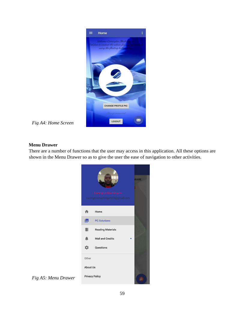
59
Menu Drawer
There are a number of functions that the user may access in this application. All these options are
shown in the Menu Drawer so as to give the user the ease of navigation to other activities.
Fig A5: Menu Drawer
Fig A4: Home Screen
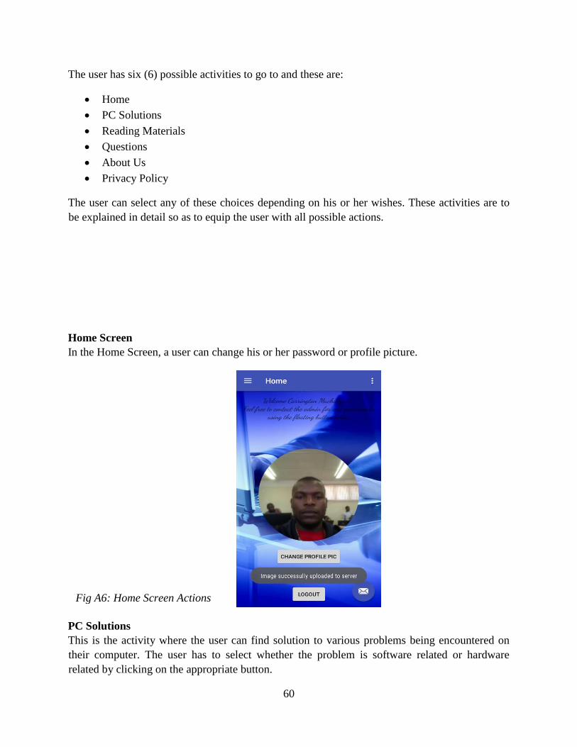
60
The user has six (6) possible activities to go to and these are:
Home
PC Solutions
Reading Materials
Questions
About Us
Privacy Policy
The user can select any of these choices depending on his or her wishes. These activities are to
be explained in detail so as to equip the user with all possible actions.
Home Screen
In the Home Screen, a user can change his or her password or profile picture.
PC Solutions
This is the activity where the user can find solution to various problems being encountered on
their computer. The user has to select whether the problem is software related or hardware
related by clicking on the appropriate button.
Fig A6: Home Screen Actions

61
After selection of problem category, a list of problems is displayed and the user has to select type
of problem being faced. The reason for the occurrence of the problem and the solution for that
problem is shown to the user.
The user can suggest new solutions or solutions they want added to the database by the system
administrator using the floating button at bottom right corner. The user will then have to name
the problem, reason for its occurrence and the solution to it.
Fig A8: Show Solution Activity
Fig A7: PC Solutions Activity
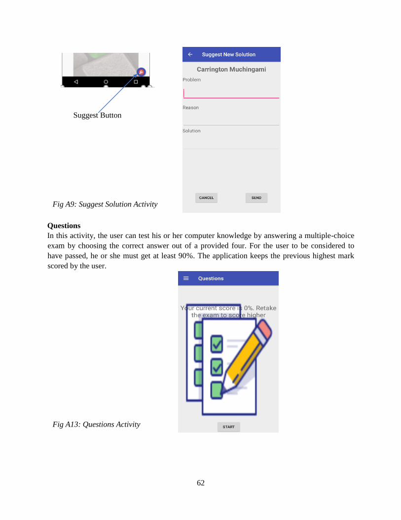
62
Questions
In this activity, the user can test his or her computer knowledge by answering a multiple-choice
exam by choosing the correct answer out of a provided four. For the user to be considered to
have passed, he or she must get at least 90%. The application keeps the previous highest mark
scored by the user.
Fig A13: Questions Activity
Suggest Button
Fig A9: Suggest Solution Activity

63
About Us
This activity displays information about the company such as contact details, physical address, a
brief history about the company, its organizational structure and about the application.
Fig A15: About Us Activity
Fig A14: Answer Questions Activity

64
Appendix B: Letter of Request for Research
Midlands State University
P. Bag 9055
Gweru
Zimbabwe
15 March 2017
To whom it may Concern
REF: REQUEST FOR CARRYING OUT ACADEMIC RESEARCH AT YOUR
ORGANIZATION
I hereby request for permission to carry out my academic research for my dissertation project
which I am doing at Midlands State University. The research would require the interviewing of
employees, observation of the day to day activities and distribute questionnaires. Information
that is gathered will be strictly used for academic purposes only and shall not be distributed.
Thank you in advance and I look forward to your support and participation.
Yours Sincerely
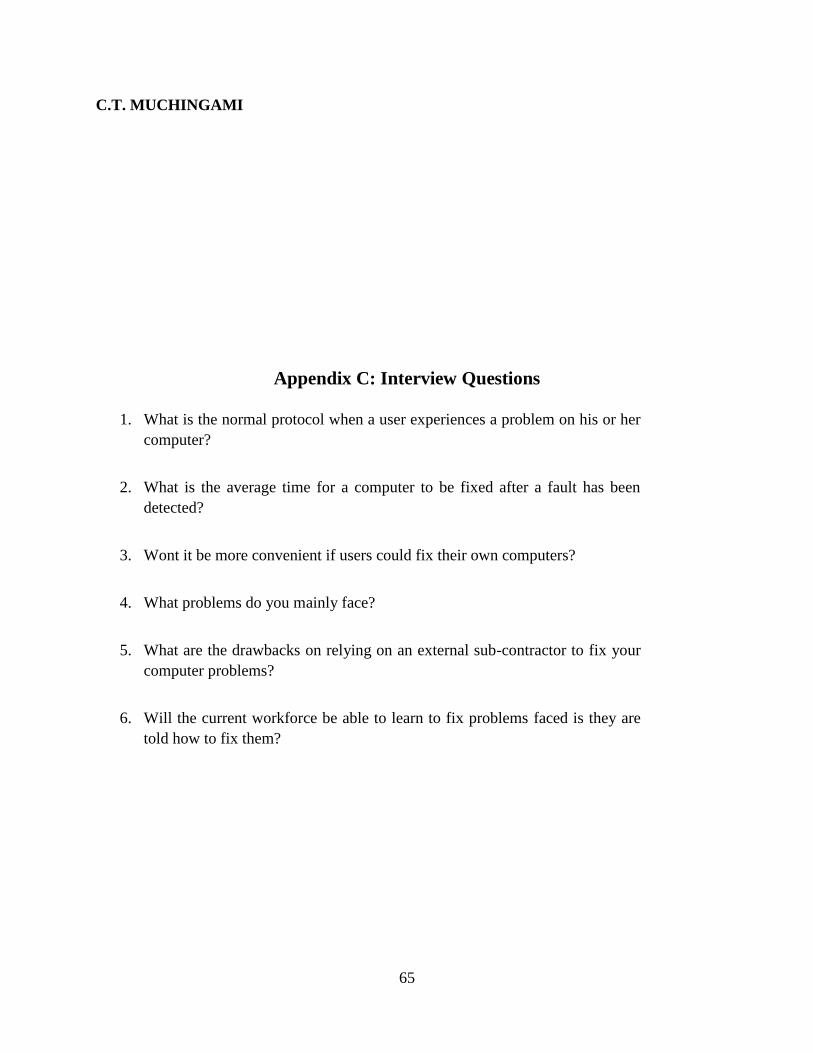
65
C.T. MUCHINGAMI
Appendix C: Interview Questions
1. What is the normal protocol when a user experiences a problem on his or her
computer?
2. What is the average time for a computer to be fixed after a fault has been
detected?
3. Wont it be more convenient if users could fix their own computers?
4. What problems do you mainly face?
5. What are the drawbacks on relying on an external sub-contractor to fix your
computer problems?
6. Will the current workforce be able to learn to fix problems faced is they are
told how to fix them?

66
Appendix D: Questionnaires
*NB: Information obtained will be used for academic purposes and henceforth shall not be
published.
Answer the following questions by either filling out the blank spaces or by ticking appropriate
response.
Questions
1. What Department do you work in?
……………………..……………………….………………………………………….
2. How many people work in your department?
……………………..……………………….………………………………………….
3. What are your duties in the organizations day to day activities?
…………………………………………………………………………………………
………….……………………………………………………………………………...
……………………..……………………….………………………………………….
……………………………………………………………….…………………………
……………………………………………………………………………….…………
4. What problems are you facing when trying to accomplish your duties? Briefly Describe.
…………………………………………………………………………………………
………….……………………………………………………………………………...

67
……………………..……………………….………………………………………….
……………………………………………………………….…………………………
YES
NO
Is waiting for computer to be fixed time consuming?
Is it to identify problem?
Are you willing to fix problem faced by yourself if you knew how?
On average how many problems do you face per week? ……….
5. Are there any incentives if you fix any problem encountered?
6. What improvements would you like to be done?
…………………………………………………………………………………………
………….……………………………………………………………………………...
……………………..……………………….………………………………………….

68
Appendix E: Observation Score Sheet
Observation Score Sheet
Department of Observation: ………………………………………………….
Date: …. /……../……
Observations
……………………………………………………………………………………………………………
….…………………………………………………………………………………………………………
…….………………………………………………………………………………………………………
……….……………………………………………………………………………………………………
………….…………………………………………………………………………………………………
…………….………………………………………………………………………………………………
……………….……………………………………………………………………………………………
………………….…………………………………………………………………………………………
…………………….………………………………………………………………………………………
……………………….……………………………………………………………………………………
………………………….…………………………………………………………………………………
…………………………….………………………………………………………………………………
……………………………….……………………………………………………………………………
………………………………….…………………………………………………………………………
…………………………………….………………………………………………………………………
……………………………………….……………………………………………………………………
Conclusion
……………………………………………………………………………………………………………
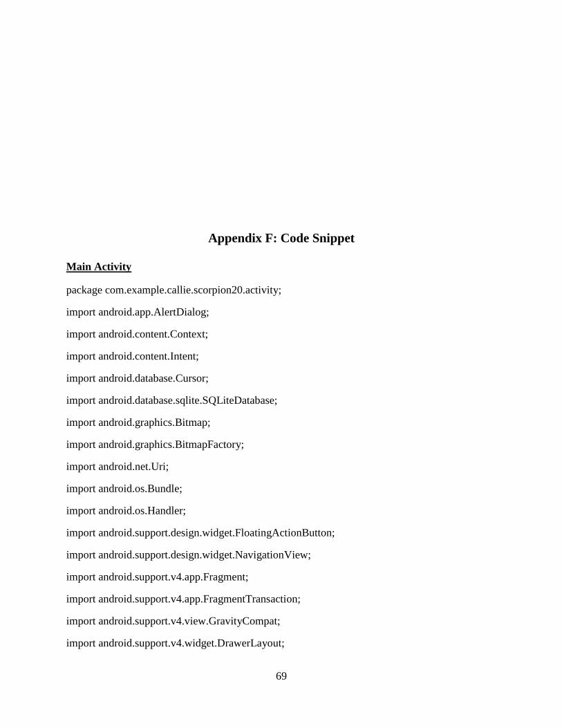
69
Appendix F: Code Snippet
Main Activity
package com.example.callie.scorpion20.activity;
import android.app.AlertDialog;
import android.content.Context;
import android.content.Intent;
import android.database.Cursor;
import android.database.sqlite.SQLiteDatabase;
import android.graphics.Bitmap;
import android.graphics.BitmapFactory;
import android.net.Uri;
import android.os.Bundle;
import android.os.Handler;
import android.support.design.widget.FloatingActionButton;
import android.support.design.widget.NavigationView;
import android.support.v4.app.Fragment;
import android.support.v4.app.FragmentTransaction;
import android.support.v4.view.GravityCompat;
import android.support.v4.widget.DrawerLayout;

70
import android.support.v7.app.ActionBarDrawerToggle;
import android.support.v7.app.AppCompatActivity;
import android.support.v7.widget.Toolbar;
import android.view.Menu;
import android.view.MenuItem;
import android.view.View;
import android.view.Window;
import android.view.WindowManager;
import android.widget.Button;
import android.widget.EditText;
import android.widget.ImageView;
import android.widget.TextView;
import android.widget.Toast;
import com.example.callie.scorpion20.R;
import com.example.callie.scorpion20.fragment.HomeFragment;
import com.example.callie.scorpion20.fragment.LessonsFragment;
import com.example.callie.scorpion20.fragment.NotificationsFragment;
import com.example.callie.scorpion20.fragment.SolutionsFragment;
import com.example.callie.scorpion20.fragment.ExamFragment;
import com.example.callie.scorpion20.helper.SQLiteHandler;
import com.example.callie.scorpion20.helper.SessionManager;
import com.example.callie.scorpion20.mail.SendMailActivity;
import com.example.callie.scorpion20.start.LoginActivity;
import java.util.HashMap;
import de.hdodenhof.circleimageview.CircleImageView;
public class MainActivity extends AppCompatActivity {
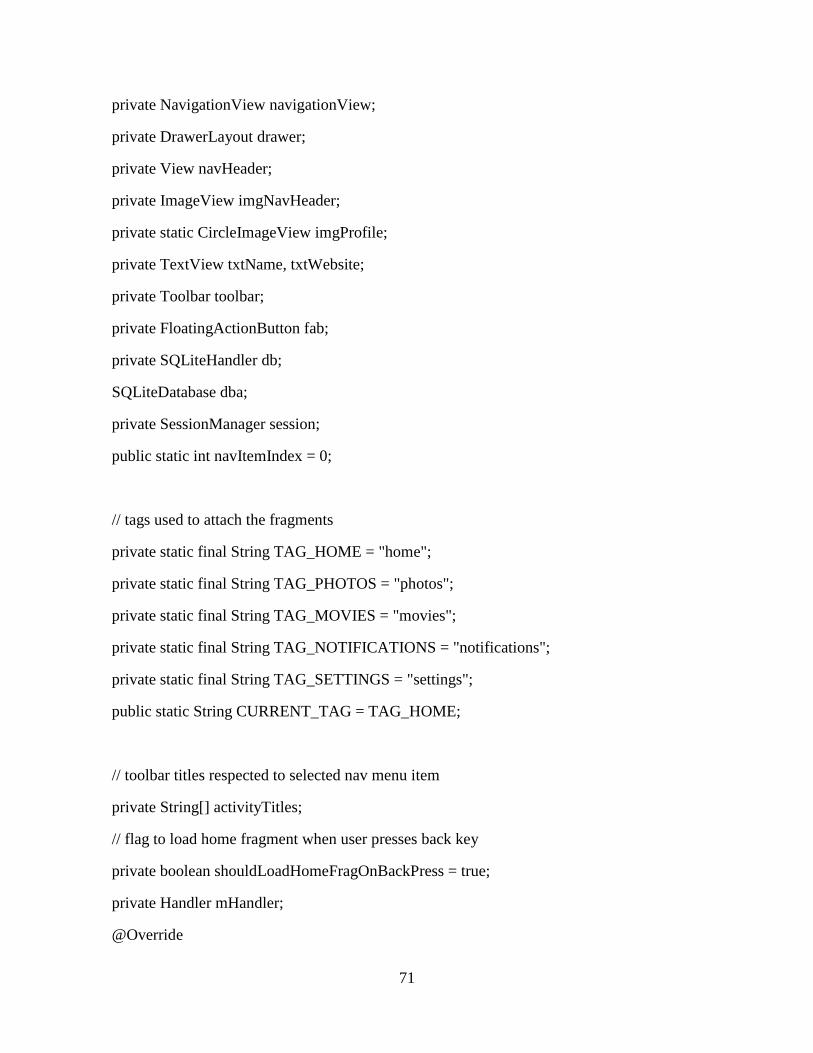
71
private NavigationView navigationView;
private DrawerLayout drawer;
private View navHeader;
private ImageView imgNavHeader;
private static CircleImageView imgProfile;
private TextView txtName, txtWebsite;
private Toolbar toolbar;
private FloatingActionButton fab;
private SQLiteHandler db;
SQLiteDatabase dba;
private SessionManager session;
public static int navItemIndex = 0;
// tags used to attach the fragments
private static final String TAG_HOME = "home";
private static final String TAG_PHOTOS = "photos";
private static final String TAG_MOVIES = "movies";
private static final String TAG_NOTIFICATIONS = "notifications";
private static final String TAG_SETTINGS = "settings";
public static String CURRENT_TAG = TAG_HOME;
// toolbar titles respected to selected nav menu item
private String[] activityTitles;
// flag to load home fragment when user presses back key
private boolean shouldLoadHomeFragOnBackPress = true;
private Handler mHandler;
@Override

72
protected void onCreate(Bundle savedInstanceState) {
super.onCreate(savedInstanceState);
requestWindowFeature(Window.FEATURE_NO_TITLE);
getWindow().setFlags(WindowManager.LayoutParams.FLAG_FULLSCREEN,
WindowManager.LayoutParams.FLAG_FULLSCREEN);
setContentView(R.layout.activity_main);
toolbar = (Toolbar) findViewById(R.id.toolbar);
setSupportActionBar(toolbar);
mHandler = new Handler();
drawer = (DrawerLayout) findViewById(R.id.drawer_layout);
fab = (FloatingActionButton) findViewById(R.id.fab);
// Navigation view header
navigationView = (NavigationView) findViewById(R.id.nav_view);
navHeader = navigationView.getHeaderView(0);
txtName = (TextView) navHeader.findViewById(R.id.name);
txtWebsite = (TextView) navHeader.findViewById(R.id.website);
imgProfile = (CircleImageView) navHeader.findViewById(R.id.img_profile);
dba = this.openOrCreateDatabase("test.db", Context.MODE_PRIVATE,null);
dba.execSQL("create table if not exists tb (a blob)");
// load toolbar titles from string resources
activityTitles = getResources().getStringArray(R.array.nav_item_activity_titles);
fab.setOnClickListener(new View.OnClickListener() {
@Override
public void onClick(View view) {
Intent intent = new Intent(MainActivity.this, SendMailActivity.class);
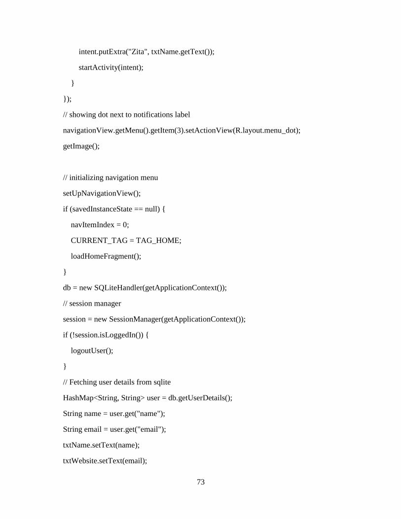
73
intent.putExtra("Zita", txtName.getText());
startActivity(intent);
}
});
// showing dot next to notifications label
navigationView.getMenu().getItem(3).setActionView(R.layout.menu_dot);
getImage();
// initializing navigation menu
setUpNavigationView();
if (savedInstanceState == null) {
navItemIndex = 0;
CURRENT_TAG = TAG_HOME;
loadHomeFragment();
}
db = new SQLiteHandler(getApplicationContext());
// session manager
session = new SessionManager(getApplicationContext());
if (!session.isLoggedIn()) {
logoutUser();
}
// Fetching user details from sqlite
HashMap<String, String> user = db.getUserDetails();
String name = user.get("name");
String email = user.get("email");
txtName.setText(name);
txtWebsite.setText(email);

74
}
private void logoutUser() {
session.setLogin(false);
db.deleteUsers();
final String TABLE_USER = "tb";
dba.execSQL("DROP TABLE IF EXISTS " + TABLE_USER);
// Launching the login activity
Intent intent = new Intent(MainActivity.this, LoginActivity.class);
startActivity(intent);
finish();
}
public void changepa(View view){
AlertDialog.Builder mBuilder = new AlertDialog.Builder(MainActivity.this);
View mView = getLayoutInflater().inflate(R.layout.activity_changepass, null);
mBuilder.setView(mView);
final EditText oldpass = (EditText) mView.findViewById(R.id.oldpass);
final EditText newpass = (EditText) mView.findViewById(R.id.newpass);
final EditText confirmpass = (EditText) mView.findViewById(R.id.confirmpass);
Button confirm = (Button) mView.findViewById(R.id.confirm);
Button cancel = (Button) mView.findViewById(R.id.cancel1);
confirm.setOnClickListener(new View.OnClickListener() {
public void onClick(View view) {
String pass1 = oldpass.getText().toString();
String pass2 = newpass.getText().toString();
String pass3 = confirmpass.getText().toString();
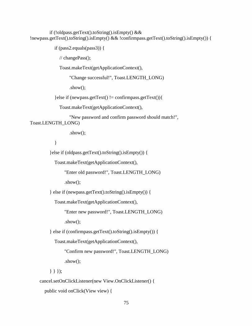
75
if (!oldpass.getText().toString().isEmpty() &&
!newpass.getText().toString().isEmpty() && !confirmpass.getText().toString().isEmpty()) {
if (pass2.equals(pass3)) {
// changePass();
Toast.makeText(getApplicationContext(),
"Change successful!", Toast.LENGTH_LONG)
.show();
}else if (newpass.getText() != confirmpass.getText()){
Toast.makeText(getApplicationContext(),
"New password and confirm password should match!",
Toast.LENGTH_LONG)
.show();
}
}else if (oldpass.getText().toString().isEmpty()) {
Toast.makeText(getApplicationContext(),
"Enter old password!", Toast.LENGTH_LONG)
.show();
} else if (newpass.getText().toString().isEmpty()) {
Toast.makeText(getApplicationContext(),
"Enter new password!", Toast.LENGTH_LONG)
.show();
} else if (confirmpass.getText().toString().isEmpty()) {
Toast.makeText(getApplicationContext(),
"Confirm new password!", Toast.LENGTH_LONG)
.show();
} } });
cancel.setOnClickListener(new View.OnClickListener() {
public void onClick(View view) {

76
}
});
AlertDialog dialog = mBuilder.create();
dialog.setCanceledOnTouchOutside(false);
dialog.show();
}
public void logout(View view) {
session.setLogin(false);
final String TABLE_USER = "tb";
dba.execSQL("DROP TABLE IF EXISTS " + TABLE_USER);
db.deleteUsers();
// Launching the login activity
Intent intent = new Intent(MainActivity.this, LoginActivity.class);
startActivity(intent);
finish();
}
public void getImage()
{
try {
Cursor c = dba.rawQuery("select * from tb", null);
if (c.moveToNext())
{
byte [] image = c.getBlob(0);
Bitmap bmp = BitmapFactory.decodeByteArray(image, 0, image.length);
imgProfile.setImageBitmap(bmp);
}
} catch (Exception e) {

77
Toast.makeText(this, "Profile picture not found", Toast.LENGTH_LONG).show();
}
}
public static void getImage1(Bitmap bmp)
{
try {
imgProfile.setImageBitmap(bmp);
} catch (Exception e) {
}
}
/***
* Returns respected fragment that user
* selected from navigation menu
*/
private void loadHomeFragment() {
// if user select the current navigation menu again, don't do anything
// just close the navigation drawer
if (getSupportFragmentManager().findFragmentByTag(CURRENT_TAG) != null) {
drawer.closeDrawers();
return;
}
// Sometimes, when fragment has huge data, screen seems hanging
// when switching between navigation menus
// So using runnable, the fragment is loaded with cross fade effect
// This effect can be seen in GMail app
Runnable mPendingRunnable = new Runnable() {
@Override

78
public void run() {
// update the main content by replacing fragments
Fragment fragment = getHomeFragment();
FragmentTransaction fragmentTransaction =
getSupportFragmentManager().beginTransaction();
fragmentTransaction.setCustomAnimations(android.R.anim.fade_in,
android.R.anim.fade_out);
fragmentTransaction.replace(R.id.frame, fragment, CURRENT_TAG);
fragmentTransaction.commitAllowingStateLoss();
}
};
// If mPendingRunnable is not null, then add to the message queue
if (mPendingRunnable != null) {
mHandler.post(mPendingRunnable);
}
//Closing drawer on item click
drawer.closeDrawers();
// refresh toolbar menu
invalidateOptionsMenu();
}
private Fragment getHomeFragment() {
switch (navItemIndex) {
case 0:
// home
HomeFragment homeFragment = new HomeFragment();

79
return homeFragment;
case 1:
// photos
SolutionsFragment SolutionsFragment = new SolutionsFragment();
return SolutionsFragment;
case 2:
// movies fragment
LessonsFragment lessonsFragment = new LessonsFragment();
return lessonsFragment;
case 3:
// notifications fragment
NotificationsFragment notificationsFragment = new NotificationsFragment();
return notificationsFragment;
case 4:
// settings fragment
ExamFragment examFragment = new ExamFragment();
return examFragment;
default:
return new HomeFragment();
}
}
private void setToolbarTitle() {
getSupportActionBar().setTitle(activityTitles[navItemIndex]);
}
private void selectNavMenu() {
navigationView.getMenu().getItem(navItemIndex).setChecked(true);

80
}
private void setUpNavigationView() {
//Setting Navigation View Item Selected Listener to handle the item click of the navigation
menu
navigationView.setNavigationItemSelectedListener(new
NavigationView.OnNavigationItemSelectedListener() {
// This method will trigger on item Click of navigation menu
@Override
public boolean onNavigationItemSelected(MenuItem menuItem) {
//Check to see which item was being clicked and perform appropriate action
switch (menuItem.getItemId()) {
//Replacing the main content with ContentFragment Which is our Inbox View;
case R.id.nav_home:
navItemIndex = 0;
CURRENT_TAG = TAG_HOME;
break;
case R.id.nav_photos:
navItemIndex = 1;
CURRENT_TAG = TAG_PHOTOS;
break;
case R.id.nav_movies:
navItemIndex = 2;
CURRENT_TAG = TAG_MOVIES;
break;
case R.id.nav_notifications:
navItemIndex = 3;
CURRENT_TAG = TAG_NOTIFICATIONS;

81
break;
case R.id.nav_settings:
navItemIndex = 4;
CURRENT_TAG = TAG_SETTINGS;
break;
case R.id.nav_about_us:
// launch new intent instead of loading fragment
startActivity(new Intent(MainActivity.this, AboutUsActivity.class));
drawer.closeDrawers();
return true;
case R.id.nav_privacy_policy:
// launch new intent instead of loading fragment
startActivity(new Intent(MainActivity.this, PrivacyPolicyActivity.class));
drawer.closeDrawers();
return true;
default:
navItemIndex = 0;
}
//Checking if the item is in checked state or not, if not make it in checked state
if (menuItem.isChecked()) {
menuItem.setChecked(false);
} else {
menuItem.setChecked(true);
}
menuItem.setChecked(true);
loadHomeFragment();
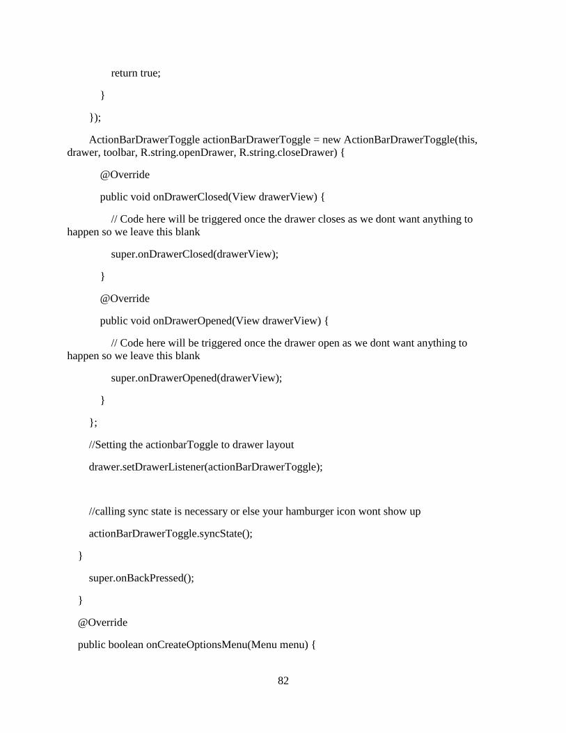
82
return true;
}
});
ActionBarDrawerToggle actionBarDrawerToggle = new ActionBarDrawerToggle(this,
drawer, toolbar, R.string.openDrawer, R.string.closeDrawer) {
@Override
public void onDrawerClosed(View drawerView) {
// Code here will be triggered once the drawer closes as we dont want anything to
happen so we leave this blank
super.onDrawerClosed(drawerView);
}
@Override
public void onDrawerOpened(View drawerView) {
// Code here will be triggered once the drawer open as we dont want anything to
happen so we leave this blank
super.onDrawerOpened(drawerView);
}
};
//Setting the actionbarToggle to drawer layout
drawer.setDrawerListener(actionBarDrawerToggle);
//calling sync state is necessary or else your hamburger icon wont show up
actionBarDrawerToggle.syncState();
}
super.onBackPressed();
}
@Override
public boolean onCreateOptionsMenu(Menu menu) {
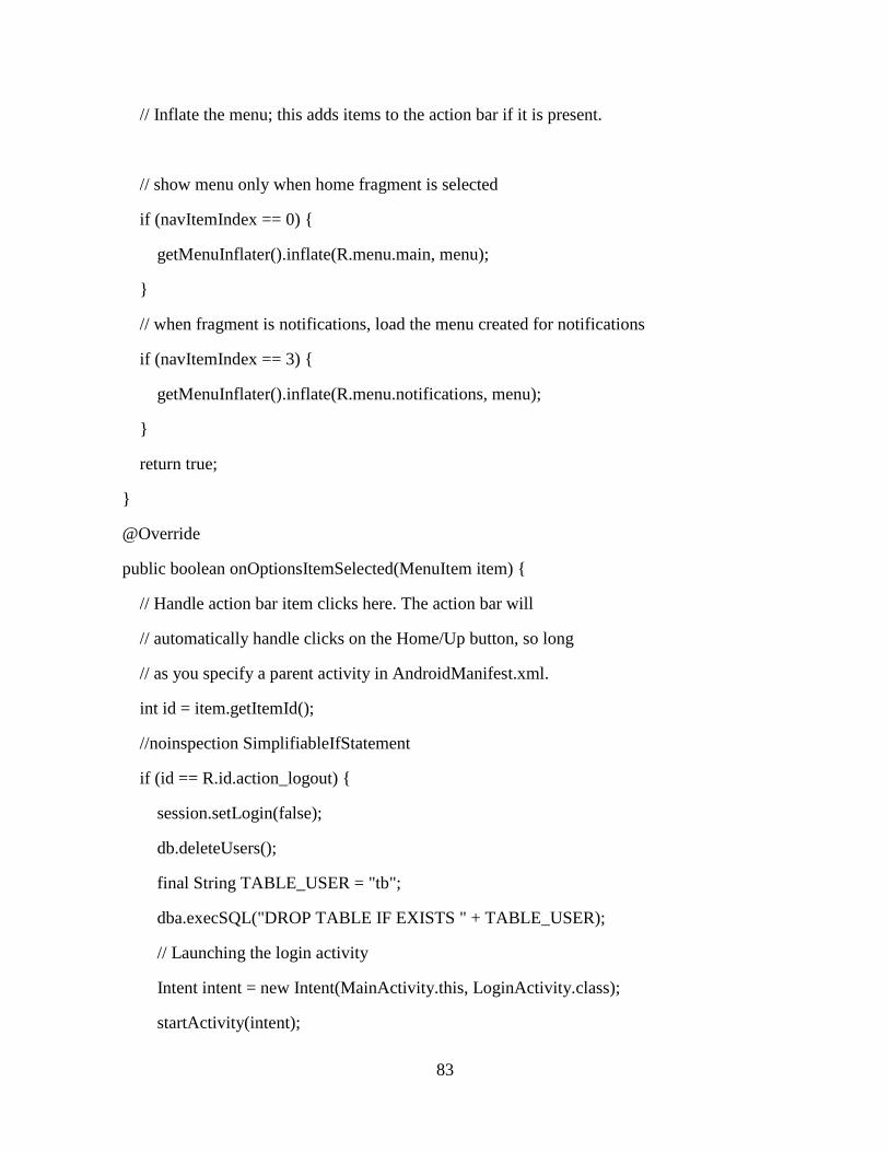
83
// Inflate the menu; this adds items to the action bar if it is present.
// show menu only when home fragment is selected
if (navItemIndex == 0) {
getMenuInflater().inflate(R.menu.main, menu);
}
// when fragment is notifications, load the menu created for notifications
if (navItemIndex == 3) {
getMenuInflater().inflate(R.menu.notifications, menu);
}
return true;
}
@Override
public boolean onOptionsItemSelected(MenuItem item) {
// Handle action bar item clicks here. The action bar will
// automatically handle clicks on the Home/Up button, so long
// as you specify a parent activity in AndroidManifest.xml.
int id = item.getItemId();
//noinspection SimplifiableIfStatement
if (id == R.id.action_logout) {
session.setLogin(false);
db.deleteUsers();
final String TABLE_USER = "tb";
dba.execSQL("DROP TABLE IF EXISTS " + TABLE_USER);
// Launching the login activity
Intent intent = new Intent(MainActivity.this, LoginActivity.class);
startActivity(intent);

84
finish();
Toast.makeText(getApplicationContext(), "Logout user!",
Toast.LENGTH_LONG).show();
return true;
}
// user is in notifications fragment
// and selected 'Mark all as Read'
if (id == R.id.action_mark_all_read) {
Toast.makeText(getApplicationContext(), "All notifications marked as read!",
Toast.LENGTH_LONG).show();
}
return super.onOptionsItemSelected(item);
}
}