screed - stephenson equipment
TRANSCRIPT

(P/N 499992523203) 22415 (6/03)
A Terex Company
FASTACH IIScreed
Operation & Maintenance Manual
A Terex Company
To the Owner & Operator
We have tried to provide information which will give you a clear understanding of equipment construction,function, capabilities and requirements. This information is based on the knowledge and experience ofhighly qualified people at our company and in our field organization. Proper use of this information willpromote high efficiency, maximum service life and low maintenance costs.
We strongly recommend that all persons directly involved with this equipment be familiar with thismanual.
The information contained in this manual should not be considered all-inclusive for every application.Questions about specific uses of this equipment should be directed to Cedarapids Inc. Anyone who usesthis equipment for any purposes other than its intended use assumes the risk of any danger in doing so.
Respectfully,
Cedarapids Inc.
Warning - The operators of this equipment must read, understand, and follow all OSHA,federal, state and local regulations regarding the operation of this equipment. This equipmentmust be used in accordance with all operation and maintenance instructions.
(1) Read all decals and instruction signs. Know what guards and protective devices are included and see that each is installed and in operational condition. Additional guards and protective devices may be required and must be installed before operating.
(2) Never maintain, lubricate or adjust equipment while in operation. Turn off key switch and remove the key before doing any maintenance, lubricating, or adjusting. In some cases it may be necessary to disconnect the battery terminals to prevent accidental starting of the equipment.
(3) Wear a protective mask whenever harmful air pollution exists.
(4) Use ear plugs whenever noise level is above established limits.
22415 (6/03) Fastach II Screed
A Terex Company
The following warning applies to Cedarapids equipment supplied with lead-acid batteries:
Warning: Battery posts, terminals and related accessories contain lead and lead compounds,chemicals known to the State of California to cause cancer and reproductive harm.Wash hands after handling.
22415 (6/03) Fastach II Screed

A Terex Company
22415 (6/03) Fastach II Screed
Table of Contents
Operation & Maintenance Manual
A Terex Company
Cedarapids Paver Manuals . . . . . . . . . . . . . . . . . . . . . . . . . . . . . . . . . . . . . .1
Hazard Levels . . . . . . . . . . . . . . . . . . . . . . . . . . . . . . . . . . . . . . . . . . . . . . . . .1
Identification Number Location . . . . . . . . . . . . . . . . . . . . . . . . . . . . . . . . . .3
Lockout Tagout . . . . . . . . . . . . . . . . . . . . . . . . . . . . . . . . . . . . . . . . . . . . . . . .5
General safety . . . . . . . . . . . . . . . . . . . . . . . . . . . . . . . . . . . . . . . . . . . . . . . . .5
Receiving New Equipment . . . . . . . . . . . . . . . . . . . . . . . . . . . . . . . . . . . . . . .8Principle Of Operation . . . . . . . . . . . . . . . . . . . . . . . . . . . . . . . . . . . . . . . . . .9
Equipment Description . . . . . . . . . . . . . . . . . . . . . . . . . . . . . . . . . . . . . . . . .10
Operation . . . . . . . . . . . . . . . . . . . . . . . . . . . . . . . . . . . . . . . . . . . . . . . . . . . .12Screed Heater Control Panel . . . . . . . . . . . . . . . . . . . . . . . . . . . . . . . . . . . . . . . . . . . . 12
Remote Controls . . . . . . . . . . . . . . . . . . . . . . . . . . . . . . . . . . . . . . . . . . . . . . . . . . . . . 13
Raising and Lowering Screed . . . . . . . . . . . . . . . . . . . . . . . . . . . . . . . . . . . . . . . . . . . 13
Supporting an elevated screed . . . . . . . . . . . . . . . . . . . . . . . . . . . . . . . . . . . . . . . . . . . 13
Detaching & Attaching Screed . . . . . . . . . . . . . . . . . . . . . . . . . . . . . . . . . . . . . . . . . . 14
Operating the Screed . . . . . . . . . . . . . . . . . . . . . . . . . . . . . . . . . . . . . . . . . .15Mat Thickness Control . . . . . . . . . . . . . . . . . . . . . . . . . . . . . . . . . . . . . . . . . . . . . . . . 15
Screed Pull Arms . . . . . . . . . . . . . . . . . . . . . . . . . . . . . . . . . . . . . . . . . . . . . . . . . . . . 16
Tow Point Cylinder Speed Test . . . . . . . . . . . . . . . . . . . . . . . . . . . . . . . . . . . . . . . . . 16
Tow Point Position . . . . . . . . . . . . . . . . . . . . . . . . . . . . . . . . . . . . . . . . . . . . . . . . . . . 17
Effects of Tow Points Positioned Too High . . . . . . . . . . . . . . . . . . . . . . . . . . . . . . . . 18
Effects of Pull Points Positioned Too Low . . . . . . . . . . . . . . . . . . . . . . . . . . . . . . . . . 18
Correct Tow Point Position . . . . . . . . . . . . . . . . . . . . . . . . . . . . . . . . . . . . . . . . . . . . . 18
Screed Adjustments . . . . . . . . . . . . . . . . . . . . . . . . . . . . . . . . . . . . . . . . . . . .19General . . . . . . . . . . . . . . . . . . . . . . . . . . . . . . . . . . . . . . . . . . . . . . . . . . . . . . . . . . . . 19
Position Tow Points . . . . . . . . . . . . . . . . . . . . . . . . . . . . . . . . . . . . . . . . . . . . . . . . . . 19
Nulling the Screed . . . . . . . . . . . . . . . . . . . . . . . . . . . . . . . . . . . . . . . . . . . . . . . . . . . . 19
Mat Crown Control . . . . . . . . . . . . . . . . . . . . . . . . . . . . . . . . . . . . . . . . . . . . . . . . . . . 19
Lead/Trail Crown . . . . . . . . . . . . . . . . . . . . . . . . . . . . . . . . . . . . . . . . . . . . . . . . . . . . 20
Final Crown Adjustment . . . . . . . . . . . . . . . . . . . . . . . . . . . . . . . . . . . . . . . . . . . . . . . 21
Screed Bottom Flatness . . . . . . . . . . . . . . . . . . . . . . . . . . . . . . . . . . . . . . . . . . . . . . . . 21
Match Height Adjustment . . . . . . . . . . . . . . . . . . . . . . . . . . . . . . . . . . . . . . . . . . . . . . 22
Independent Angle of Attack . . . . . . . . . . . . . . . . . . . . . . . . . . . . . . . . . . . . . . . . . . . 22
Independent Angle of Attack Adjustment - Original Version . . . . . . . . . . . . . . . . . . 22
Independent Angle of Attack Adjustment - Later Version . . . . . . . . . . . . . . . . . . . . . 23
Extending Screed Alignment . . . . . . . . . . . . . . . . . . . . . . . . . . . . . . . . . . . . . . . . . . . 24
22415 (6/03) i Fastach II Screed

Table of Contents
Operation & Maintenance Manual
A Terex Company
Screed Accessories . . . . . . . . . . . . . . . . . . . . . . . . . . . . . . . . . . . . . . . . . . . . .25Heaters . . . . . . . . . . . . . . . . . . . . . . . . . . . . . . . . . . . . . . . . . . . . . . . . . . . . . . . . . . . . 25
Screed Vibrators . . . . . . . . . . . . . . . . . . . . . . . . . . . . . . . . . . . . . . . . . . . . . . . . . . . . . 25
Operating Screed Vibrator . . . . . . . . . . . . . . . . . . . . . . . . . . . . . . . . . . . . . . . . . . . . . 25
Vibrator Weight Installation and Alignment . . . . . . . . . . . . . . . . . . . . . . . . . . . . . . . 26
Strike-Offs . . . . . . . . . . . . . . . . . . . . . . . . . . . . . . . . . . . . . . . . . . . . . . . . . . . . . . . . . . 27
Adjusting Strike-off . . . . . . . . . . . . . . . . . . . . . . . . . . . . . . . . . . . . . . . . . . . . . . . . . . 27
Changing Screed Bottom . . . . . . . . . . . . . . . . . . . . . . . . . . . . . . . . . . . . . . . . . . . . . . 28
Screed Bottom Removal . . . . . . . . . . . . . . . . . . . . . . . . . . . . . . . . . . . . . . . . . . . . . . . 28
Screed Bottom Installation . . . . . . . . . . . . . . . . . . . . . . . . . . . . . . . . . . . . . . . . . . . . . 29
Cleaning Screed . . . . . . . . . . . . . . . . . . . . . . . . . . . . . . . . . . . . . . . . . . . . . . .30
Lubrication . . . . . . . . . . . . . . . . . . . . . . . . . . . . . . . . . . . . . . . . . . . . . . . . . .31General . . . . . . . . . . . . . . . . . . . . . . . . . . . . . . . . . . . . . . . . . . . . . . . . . . . . . . . . . . . . 31
Depth Cranks . . . . . . . . . . . . . . . . . . . . . . . . . . . . . . . . . . . . . . . . . . . . . . . . . . . . . . . . 31
Vibrator Bearings . . . . . . . . . . . . . . . . . . . . . . . . . . . . . . . . . . . . . . . . . . . . . . . . . . . . 31
Match Height . . . . . . . . . . . . . . . . . . . . . . . . . . . . . . . . . . . . . . . . . . . . . . . . . . . . . . . . 31
Extending Screed Slope . . . . . . . . . . . . . . . . . . . . . . . . . . . . . . . . . . . . . . . . . . . . . . . 31
Crown . . . . . . . . . . . . . . . . . . . . . . . . . . . . . . . . . . . . . . . . . . . . . . . . . . . . . . . . . . . . . 31
Screed Generator Pump . . . . . . . . . . . . . . . . . . . . . . . . . . . . . . . . . . . . . . . .32Start-up After Initial Installation of Pump . . . . . . . . . . . . . . . . . . . . . . . . . . . . . . . . . 32
Set Pump Max Pressure . . . . . . . . . . . . . . . . . . . . . . . . . . . . . . . . . . . . . . . . . . . . . . . 33
Set Pump Standby Pressure . . . . . . . . . . . . . . . . . . . . . . . . . . . . . . . . . . . . . . . . . . . . . 33
Set Generator Motor Speed (Frequency) . . . . . . . . . . . . . . . . . . . . . . . . . . . . . . . . . . 33
22415 (6/03) ii Fastach II Screed
A Terex Company
Cedarapids Paver Manuals
Operation & Maintenance Manual
Cedarapids Paver Manuals
The following list represents the complete set ofmanuals available to the owner, operator, andmechanic of a Grayhound paver. All of thesemanuals are included with each new paver when itships from the factory. If your manuals are notincluded with your new paver or if you requireadditional copies of any of these manuals contactyour local Cedarapids dealer.
Operation and Maintenance Manual
The Operation and Maintenance manual isintended to be used by both the operator andmechanic.
The operation portion of this manual gives detailedoperating and safety instructions for both new andexperienced operators. It is intended to give moredetailed information than the Pocket Paver Guide.
The maintenance portion of this manual givesdetailed information on component locations, testprocedures, safety, and routine maintenance. Thisinformation expands on the information inTechnical manual and Wear Check Guide.
Technical Manual
The Technical manual is designed primarily for useby maintenance personnel. It provides detailedtroubleshooting procedures and schematics fordiagnosing paver breakdowns. Once a problem hasbeen diagnosed, refer to the Operation andMaintenance manual for information on makingthe repair.
Quality Paving Guide
The Quality Paving Guide should be used primarilyby paver operators. This manual gives detailedinformation on setting up the paver to produce themat surface needed.
Wear Check Guide
The Wear Check Guide should be used primarilyby maintenance personnel. It contains detailedinformation for determining when parts requirereplacement.
About the Pocket Paver Guide
The Pocket Paver Guide is a small referencemanual designed for use by experienced operators.It contains information needed by the operator forday-to-day operation, adjustment and maintenanceof the paver and screed.
CIMA Safety Manual
The CIMA Safety Manual is a general manualdesigned to be used by everyone on a paving jobsite. This would include operators, laborers,mechanics, truck drivers, etc.
Hazard Levels
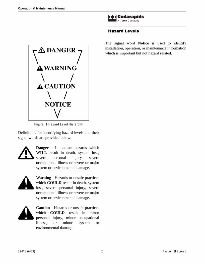
The signal words Danger, Warning and Cautionare used to identify hazard levels of in this manual.They may also be found on decals located on theequipment. (Figure 1)
22415 (6/03) 1 Fastach II Screed
A Terex Company
Hazard Levels
Operation & Maintenance Manual
Figure 1 Hazard Level Hierarchy
Definitions for identifying hazard levels and theirsignal words are provided below:
Danger - Immediate hazards whichWILL result in death, system loss,severe personal injury, severeoccupational illness or severe or majorsystem or environmental damage.
Warning - Hazards or unsafe practiceswhich COULD result in death, systemloss, severe personal injury, severeoccupational illness or severe or majorsystem or environmental damage.
Caution - Hazards or unsafe practiceswhich COULD result in minorpersonal injury, minor occupationalillness, or minor system orenvironmental damage.
The signal word Notice is used to identifyinstallation, operation, or maintenance informationwhich is important but not hazard related.
22415 (6/03) 2 Fastach II Screed
Identification Number Location
Operation & Maintenance Manual
A Terex Company
Identification Number Location
Tractor
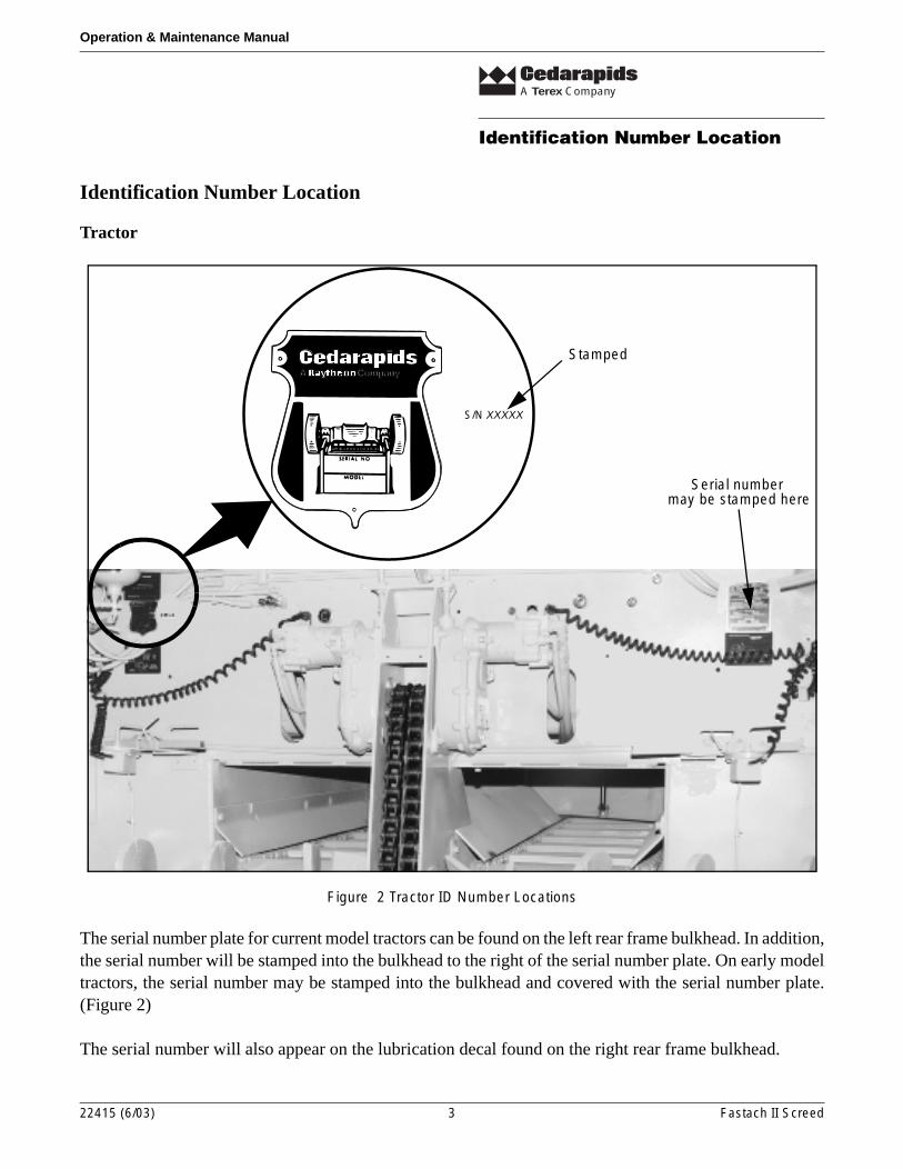
Figure 2 Tractor ID Number Locations
The serial number plate for current model tractors can be found on the left rear frame bulkhead. In addition,the serial number will be stamped into the bulkhead to the right of the serial number plate. On early modeltractors, the serial number may be stamped into the bulkhead and covered with the serial number plate.(Figure 2)
The serial number will also appear on the lubrication decal found on the right rear frame bulkhead.
Cedar Rapids, Iowa USA
CompanyCompanyA
S/N XXXXX
Stamped
Serial number may be stamped here
22415 (6/03) 3 Fastach II Screed
A Terex Company
Identification Number Location
Operation & Maintenance Manual
Screed
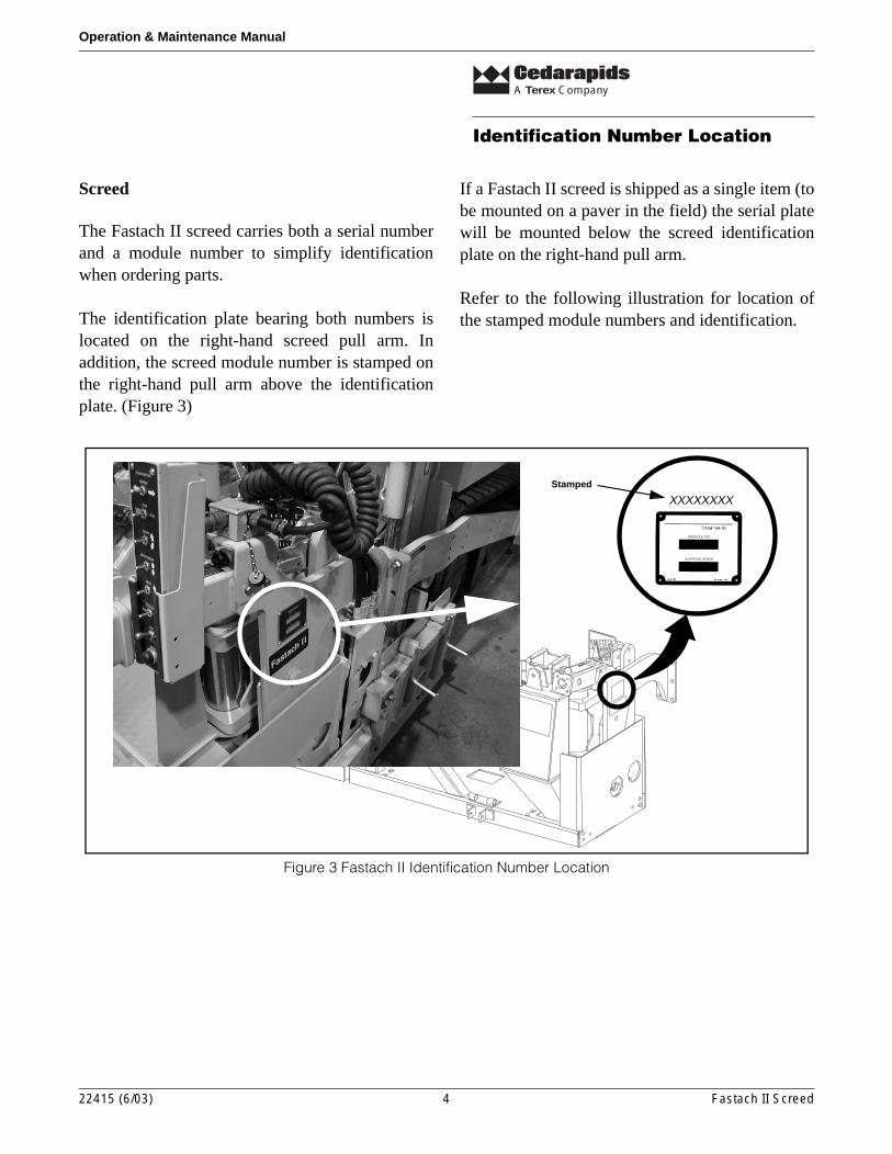
The Fastach II screed carries both a serial numberand a module number to simplify identificationwhen ordering parts.
The identification plate bearing both numbers islocated on the right-hand screed pull arm. Inaddition, the screed module number is stamped onthe right-hand pull arm above the identificationplate. (Figure 3)
If a Fastach II screed is shipped as a single item (tobe mounted on a paver in the field) the serial platewill be mounted below the screed identificationplate on the right-hand pull arm.
Refer to the following illustration for location ofthe stamped module numbers and identification.
Figure 3 Fastach II Identification Number Location
XXXXXXXXStamped
MODULE NO.
SHIPPING SERIALSHIPPING SERIAL
22415 (6/03) 4 Fastach II Screed
A Terex Company
Lockout Tagout
Operation & Maintenance Manual
Lockout Tagout
Warning - Failure to follow goodlockout and tagout procedures couldresult in serious injury or death.
What is the purpose of lockout /tagout?
• Prevent the unexpected or accidental start-upof equipment and to notify other workers whena piece of equipment is unsafe to operate.
• Prevent injury to personnel from energy that isstored in devices such as springs,accumulators, hydraulic systems, batteries, etc.
How do I lockout and tagout equipment?
• Turn the master key to the OFF position andremove the key.
• Disconnect the batteries.
• Regardless of which lockout method is used,place one or more tags on machine controls oraccess doors to let other workers know thatmaintenance is being performed on themachine and/or the machine is unsafe tooperate.
Who is responsible for establishing and administering a lockout /tagout program?
• The employer must establish a lockout /tagoutsystem of procedures, training and periodicinspection before any employee operates,services, or maintains a piece of equipment.
• All employees are responsible for seeing thatequipment is locked out and tagged outaccording to the employers policies.
When is lockout and tagout necessary?
• Any time repairs or maintenance on a machineare to be performed.
• When cleaning or lubricating the machine.
• While clearing blocked or jammedmechanisms.
• Any time that the equipment will be leftunattended.
Who should apply a lock or tag?
• Any maintenance person who will be workingon the equipment.
• The foreman or team leader responsible for thejob.
• Anyone who will be working on theequipment.
• If several people will be working on a piece ofequipment, each person must apply their owntag.
When can a lock or tag be removed?
• After all safety guards are back in place.
• After work is complete and tools are put away.
• After workers are positioned safely for start-up.
• After controls are positioned correctly forstart-up and machine is operation ready.
Who can remove a lock or tag?
• Only the person who applied a lock or tag canremove it.
General safety
This manual contains important informationregarding the operation of the screed with yourpaver. Carefully read the entire manual beforeattempting to operate the paver.
22415 (6/03) 5 Fastach II Screed
A Terex Company
General safety
Operation & Maintenance Manual
Danger
• Install all auger guards and vibrator coversbefore operating the paver.
• Never attempt to install or remove any part orassembly when the paver is running.
• Do not allow personnel to stand or walkbetween the front of the paver and the back ofthe truck while the paver is operating.
• Attach screed safety cables or lower the screedbefore performing any inspections, repairs oradjustments to the screed.
• All guards and protective devices must be inplace when the paver is being operated ormoved.
• Keep all personnel clear of augers when thepaver is operating.
• Do not refuel the paver with the engine orscreed heater system running. All sparks andopen flames must be kept a minimum of 50feet away from the paver when refueling.
• Do not wash or spray down the screed ortractor with the screed heater systemoperating.
Warning
• Do not operate this equipment until you havebeen trained in its operation or maintenance.This equipment may only be operated ormaintained by trained personnel, who havedemonstrated their ability to do so safely.
• Keep this manual for future reference.
• Read, understand and follow all currentOSHA, federal, state and local regulations thatare applicable to your job and equipment.
• This equipment must be used in accordancewith all operation and maintenanceinstructions.
• All persons involved with this equipment mustbe familiar with this manual.
• Read, understand, and follow all Danger,Warning, Caution and instruction decals in thisbook and on the paver.
• When changing the paver configuration oradding equipment to the paver, all additionalguards associated with the added equipmentmust be installed before operating or movingthe paver.
• Any changes made to the original design of thepaver or paver must be approved by qualifiedpersonnel to ensure that the changes includeappropriate guarding and provide a safeworking environment for all personnel.
• Wear clothing that fits snug to prevent gettingcaught in moving parts. Loose-fitting clothingshould never be worn.
• Mount and dismount the paver from the rearusing only the steps, handrails and walkwaysprovided.
• Do not mount the paver when it is moving.
• Allow only the operator on the operator’splatform when the paver is in operation.
• Before starting the paver, make sure the brakesare ON, all other systems are OFF and allpersonnel are clear.
• Before leaving operator’s seat, always placethe brake switch ON, and all other controls orswitches in OFF or NEUTRAL position.
• Reduce travel speed when going down stepgrades to prevent over-speeding.
22415 (6/03) 6 Fastach II Screed
A Terex Company
General safety
Operation & Maintenance Manual
• Do not allow personnel near the hopper areawhen the paver is running.
Caution
• Wear protective mask when harmful airpollution exists.
• Wear safety goggles, gloves and long-sleeveshirts when working near hot asphalt materials.
• Wear ear plugs while paver is running.
• Keep operator’s platform, steps and screedwalkways clear of all obstructions, tools andother items to prevent tripping or falling.
• To prevent fire hazards, keep the screed andengine basket area free of oil, asphalt and trashbuildup.
22415 (6/03) 7 Fastach II Screed
A Terex Company
Receiving New Equipment
Operation & Maintenance Manual
Receiving New Equipment
Before accepting and unloading a new paver and/orscreed, the consignee must inspect the equipmentfor evidence of damage or missing parts. Thisinspection process should be thorough, becauseonce the freight receipt is signed, it is assumed thatall of the equipment listed on the receipt wasreceived in good condition.
Make a thorough inventory of all loose componentspackaged in boxes. A check list is provided in eachbox listing the components in the box. Whileperforming the inventory, inspect all loosecomponents for damage which may have occurredduring transit. Any damage that happens to theequipment in transit is the responsibility of thecarrier not Cedarapids. Claims for damage must besubmitted to the carrier for settlement.
When evidence of damage or loss is discovered,have the driver make a notation on both thecarrier’s and consignees’ copies of the freight bill.Prior to signing the freight bill, take pictures of thedamage and identify the truck if possible. Theconsignee can then sign the bill to acknowledgedelivery. The consignee should then have thecarrier’s terminal manager or his authorizedrepresentative make an official inspection of thedamage or loss.
Equipment should not be moved from the originalreceiving point until this official inspection hasbeen made. Good clear photos will verify andexplain damage in any claim action which mayfollow. When the inspection is done, the consigneeshould file a written damage claim with thecarrier’s office and should report this action to thearea distributor for Cedarapids Inc.
If hidden damage is found after the carrier’srepresentative has gone, do not continue to unpackor move the equipment. Contact the carrier’s localoffice and have the terminal manger or authorizedrepresentative make an immediate personalinspection of the damage. Obtain a writtendescription of the damage, and photos if possible,signed by the representative as proof of a validclaim.
A packet of equipment warranty/start-upinformation will be sent to the distributor beforethe equipment leaves the factory. All warranty/start-up forms must be filled out and returned toCedarapids within 24 hours after the equipment isreceived.
22415 (6/03) 8 Fastach II Screed
A Terex Company
Principle Of Operation
Operation & Maintenance Manual
Principle Of Operation
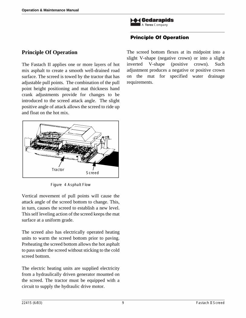
The Fastach II applies one or more layers of hotmix asphalt to create a smooth well-drained roadsurface. The screed is towed by the tractor that hasadjustable pull points. The combination of the pullpoint height positioning and mat thickness handcrank adjustments provide for changes to beintroduced to the screed attack angle. The slightpositive angle of attack allows the screed to ride upand float on the hot mix.
Figure 4 Asphalt Flow
Vertical movement of pull points will cause theattack angle of the screed bottom to change. This,in turn, causes the screed to establish a new level.This self leveling action of the screed keeps the matsurface at a uniform grade.
The screed also has electrically operated heatingunits to warm the screed bottom prior to paving.Preheating the screed bottom allows the hot asphaltto pass under the screed without sticking to the coldscreed bottom.
The electric heating units are supplied electricityfrom a hydraulically driven generator mounted onthe screed. The tractor must be equipped with acircuit to supply the hydraulic drive motor.
The screed bottom flexes at its midpoint into aslight V-shape (negative crown) or into a slightinverted V-shape (positive crown). Suchadjustment produces a negative or positive crownon the mat for specified water drainagerequirements.
TractorScreed
22415 (6/03) 9 Fastach II Screed
A Terex Company
Equipment Description
Operation & Maintenance Manual
Equipment Description
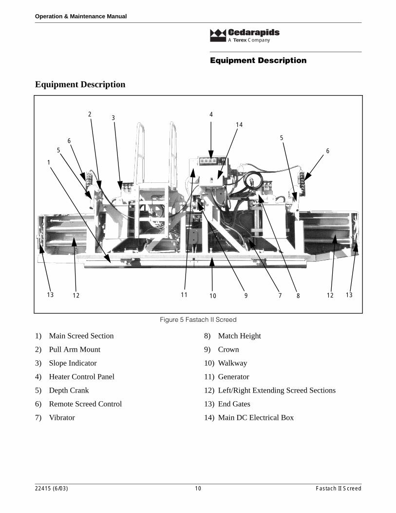
Figure 5 Fastach II Screed
1) Main Screed Section
2) Pull Arm Mount
3) Slope Indicator
4) Heater Control Panel
5) Depth Crank
6) Remote Screed Control
7) Vibrator
8) Match Height
9) Crown
10) Walkway
11) Generator
12) Left/Right Extending Screed Sections
13) End Gates
14) Main DC Electrical Box
1
2 3 4
5
6
7 8910111213 1312
6
5
14
22415 (6/03) 10 Fastach II Screed
A Terex Company
Equipment Description
Operation & Maintenance Manual
1) Main Screed Section
2) Pull Arm Mount - The screed is connected to the tractor at the pull arm mount.
3) Slope Indicator - The extending screed sections can be tilted independantly as needed to produce a sloping mat surface.
4) Heater Control Panel - Contains heater circuit breakers, 120/240V circuit breakers, generator on/off switch, heater on/off switch, and temperature control knob for preheating the screed bottoms.
5) Dual Rotation Depth Crank - Adjusts the angle of attack of the main screed bottom to increase or decrease the thickness of the mat.
6) Remote Screed Control - Portable control panel used to adjust match height, crown, slope, mat thickness, extention width, feed control, and berm control.
7) Vibrator - Vibrators increase the compaction produced by the screed. Vibrator frequency and amplitude can be adusted for mat and mix specifications.
8) Match Height - Extending screed sections can be raised or lowered as needed to match the height of the main screed bottom.
9) Crown - The main screed bottom can be deflected at the center to produce a positive or negative crown in the mat.
10) Walkway - Allows screed operator to move along the length of the main screed while the screed is in motion without walking on the newly placed mat.
11) Generator - Hydraulically powered generator provides the electricity necessary for the heating units to prevent asphalt from sticking to the screed bottom.
12) Extending Screed Sections - Extending screed sections can be adjusted hydraulically to any width from zero to three and one half feet (0-3 1/2’)on each side of the screed.
13) End Gates - Mounted on the end of the extending screed sections. The end gates prevent material from spilling out past the end of the extending screed section and produce a square or bevelled edge on the mat.
14) Main DC Electrical Box - Junction box for screed control cable electrical connections.
22415 (6/03) 11 Fastach II Screed
Operation
Operation & Maintenance Manual
A Terex Company
Operation
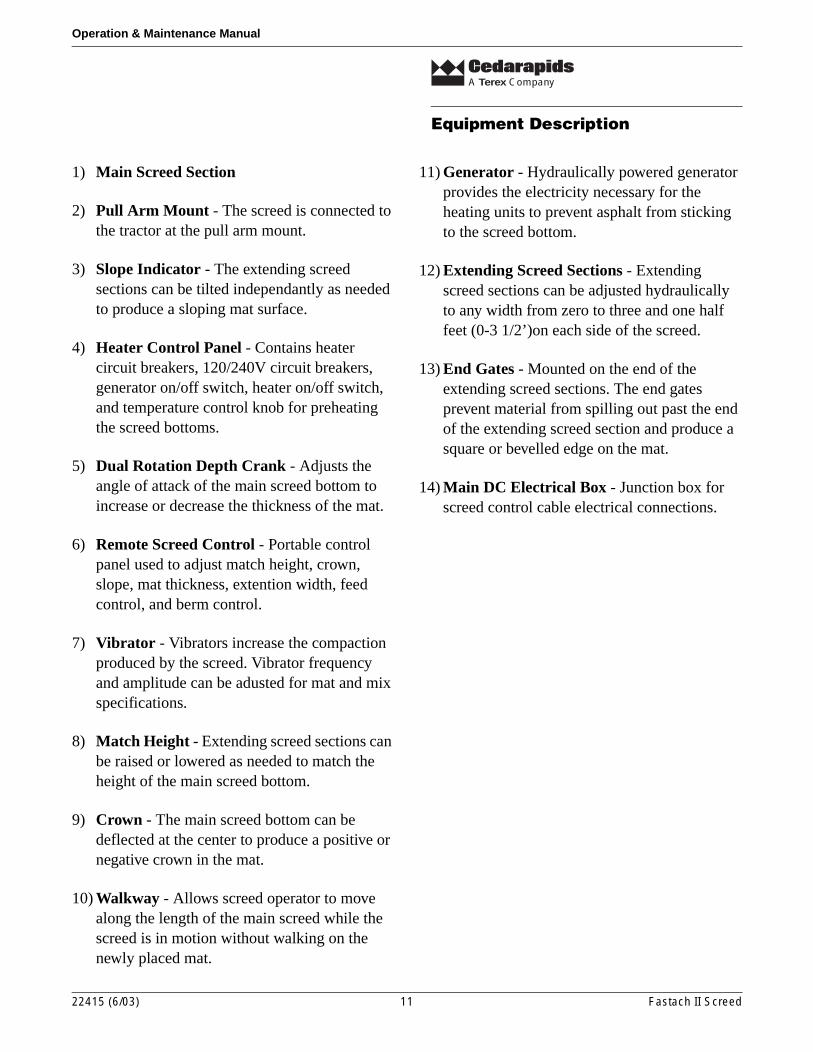
Figure 6 Heater Control Panel
50
˚F
482
450
400
350
300250
200
150
100
Load
WATLOW 102
Screed Temperature Control Dial
Individual Heat Section Circuit Breakers
Heat Switch
120/240V Convenience Outlet Circuit Breakers
Generator Switch
LED - (Actual Temp. vs Set Point Temp.)
22415 (6/03) 12 Fastach II Screed
Screed Heater Control Panel
The tractor main key switch must be ON before anyof the following controls will function.
Screed Temperature Control Dial - This dial setsthe temperature of all the heating units on thescreed by controlling a relay for each individualheat section.
LED - This red LED comes on when the actualtemperature of the heaters is less than thetemperature set on the control dial.
120/240V Convenience Outlet Circuit Breakers- Protect the 120 volt and 240 volt convenienceoutlets.
Heat Switch - Turns power on and off totemperature control dial. This switch is interlockedto generator main switch...the generator must be onbefore this switch is active.
Generator Switch - Turns power on and off tooperate generator and supplies power to heatswitch.
Heat Section Circuit Breakers - Protectindividual heater section.
A Terex Company
Operation
Operation & Maintenance Manual
Remote Controls
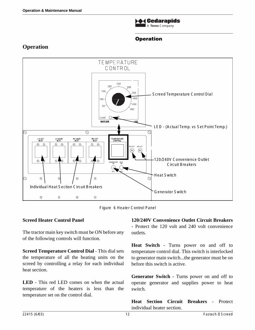
Figure 7 Remote Control Panel
Raising and Lowering Screed
Warning - Always make sure everyoneis clear of the screed before raising orlowering the screed.
Raising and lowering the screed is accomplishedby two double-acting hydraulic cylinders mountedon the rear of the pull arms. The cylinders arecontrolled by electric solenoid valves mounted on
the tractors rear bulkhead. The screed is raisedusing the Screed Lift switch on the tractor operatorconsole.
When engine is at FULL throttle and screed liftswitch is held in the RAISE position, the screedwill rise until it reaches maximum height or theswitch is released. When the switch is released itwill automatically return to the neutral positionwhere the screed is hydraulically locked at theexisting height. While paving the screed lift switchmust be in the LOWER/FLOAT position. Thisposition allows the screed to float over mix at thepreset mat thickness.
Supporting an elevated screed
Warning - Always make sure screed islocked in the up position or supportedusing blocks before working under oraround an elevated screed and whiletraveling with the screed elevated.
Figure 8 Screed Lock
To lock screed in up position, raise screed to theupper limit until lock engages. To lower, step onscreed release pedal and lower screed.
EXTEND
SLOPE
FEEDOVERRIDE
STOP
Cedarapids
MAN
SETUPAUTO
MAN
TOWPOINT
HORN
MATCH HEIGHT
BERM
Extention Control
Slope Control
Match Height Control
Mat Thickness Control
Mat Thickness Setup
Feed Control
Horn
Berm Control
Screed Release Pedal
Screed Lock
22415 (6/03) 13 Fastach II Screed
Operation
Operation & Maintenance Manual
A Terex Company
1 2 3 4 5 6 7 8 9 10
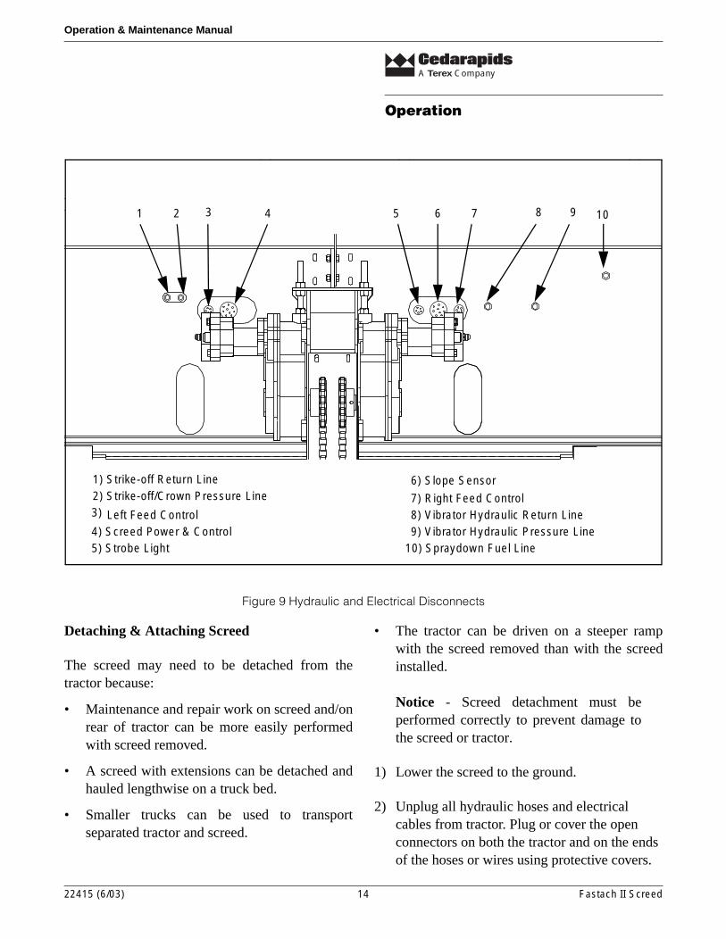
1) Strike-off Return Line2) Strike-off/Crown Pressure Line3)
4) Screed Power & Control5) Strobe Light
6) Slope Sensor
7) Right Feed Control8) Vibrator Hydraulic Return Line9) Vibrator Hydraulic Pressure Line
10) Spraydown Fuel Line
Left Feed Control
Figure 9 Hydraulic and Electrical Disconnects
Detaching & Attaching Screed
The screed may need to be detached from thetractor because:
• Maintenance and repair work on screed and/onrear of tractor can be more easily performedwith screed removed.
• A screed with extensions can be detached andhauled lengthwise on a truck bed.
• Smaller trucks can be used to transportseparated tractor and screed.
• The tractor can be driven on a steeper rampwith the screed removed than with the screedinstalled.
Notice - Screed detachment must beperformed correctly to prevent damage tothe screed or tractor.
1) Lower the screed to the ground.
2) Unplug all hydraulic hoses and electrical cables from tractor. Plug or cover the open connectors on both the tractor and on the ends of the hoses or wires using protective covers.
22415 (6/03) 14 Fastach II Screed
A Terex Company
Operating the Screed
Operation & Maintenance Manual
3) Remove the four bolts on each pull arm coupler and move tractor forward.
4) To attach screed, reverse above procedure.
Operating the Screed
Mat Thickness Control
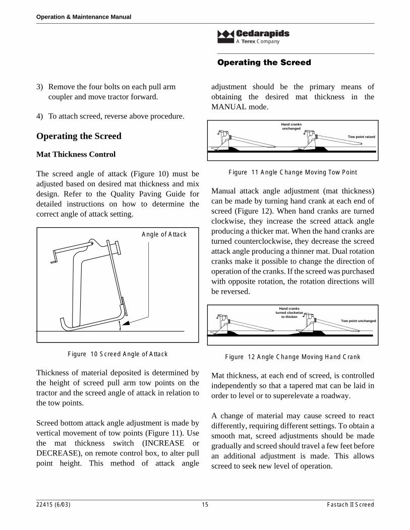
The screed angle of attack (Figure 10) must beadjusted based on desired mat thickness and mixdesign. Refer to the Quality Paving Guide fordetailed instructions on how to determine thecorrect angle of attack setting.
Figure 10 Screed Angle of Attack
Thickness of material deposited is determined bythe height of screed pull arm tow points on thetractor and the screed angle of attack in relation tothe tow points.
Screed bottom attack angle adjustment is made byvertical movement of tow points (Figure 11). Usethe mat thickness switch (INCREASE orDECREASE), on remote control box, to alter pullpoint height. This method of attack angle
adjustment should be the primary means ofobtaining the desired mat thickness in theMANUAL mode.
Figure 11 Angle Change Moving Tow Point
Manual attack angle adjustment (mat thickness)can be made by turning hand crank at each end ofscreed (Figure 12). When hand cranks are turnedclockwise, they increase the screed attack angleproducing a thicker mat. When the hand cranks areturned counterclockwise, they decrease the screedattack angle producing a thinner mat. Dual rotationcranks make it possible to change the direction ofoperation of the cranks. If the screed was purchasedwith opposite rotation, the rotation directions willbe reversed.
Figure 12 Angle Change Moving Hand Crank
Mat thickness, at each end of screed, is controlledindependently so that a tapered mat can be laid inorder to level or to superelevate a roadway.
A change of material may cause screed to reactdifferently, requiring different settings. To obtain asmooth mat, screed adjustments should be madegradually and screed should travel a few feet beforean additional adjustment is made. This allowsscreed to seek new level of operation.
Angle of Attack
Tow point raised
Hand cranksunchanged
Tow point unchanged
Hand cranksturned clockwise
to thicken
22415 (6/03) 15 Fastach II Screed
A Terex Company
Operating the Screed
Operation & Maintenance Manual
If a paver is equipped with automatic screedcontrol, the operator will normally set up the screedusing manual adjustments before switching on theautomatic system. Both tow points should beadjusted to the same height at start-up.
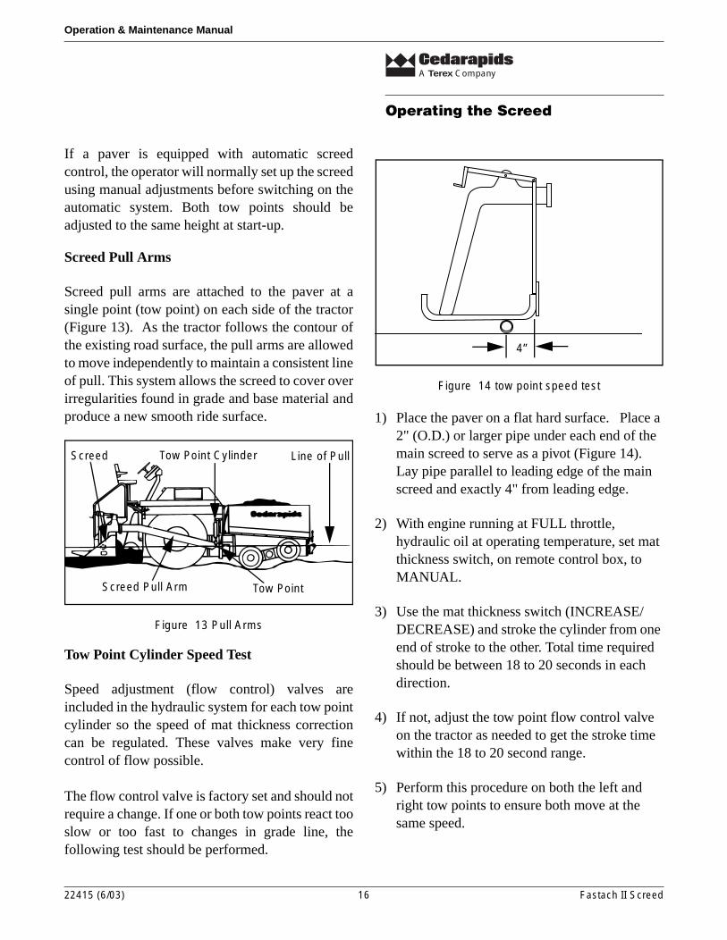
Screed Pull Arms
Screed pull arms are attached to the paver at asingle point (tow point) on each side of the tractor(Figure 13). As the tractor follows the contour ofthe existing road surface, the pull arms are allowedto move independently to maintain a consistent lineof pull. This system allows the screed to cover overirregularities found in grade and base material andproduce a new smooth ride surface.
Figure 13 Pull Arms
Tow Point Cylinder Speed Test
Speed adjustment (flow control) valves areincluded in the hydraulic system for each tow pointcylinder so the speed of mat thickness correctioncan be regulated. These valves make very finecontrol of flow possible.
The flow control valve is factory set and should notrequire a change. If one or both tow points react tooslow or too fast to changes in grade line, thefollowing test should be performed.
Figure 14 tow point speed test
1) Place the paver on a flat hard surface. Place a 2" (O.D.) or larger pipe under each end of the main screed to serve as a pivot (Figure 14). Lay pipe parallel to leading edge of the main screed and exactly 4" from leading edge.
2) With engine running at FULL throttle, hydraulic oil at operating temperature, set mat thickness switch, on remote control box, to MANUAL.
3) Use the mat thickness switch (INCREASE/DECREASE) and stroke the cylinder from one end of stroke to the other. Total time required should be between 18 to 20 seconds in each direction.
4) If not, adjust the tow point flow control valve on the tractor as needed to get the stroke time within the 18 to 20 second range.
5) Perform this procedure on both the left and right tow points to ensure both move at the same speed.
Screed Pull Arm
Tow Point Cylinder Line of Pull
Tow Point
Screed
4”
22415 (6/03) 16 Fastach II Screed
A Terex Company
Operating the Screed
Operation & Maintenance Manual
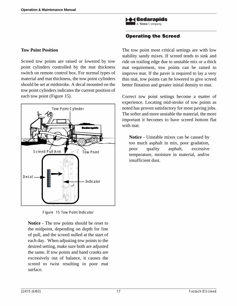
Tow Point Position
Screed tow points are raised or lowered by towpoint cylinders controlled by the mat thicknessswitch on remote control box. For normal types ofmaterial and mat thickness, the tow point cylindersshould be set at midstroke. A decal mounted on thetow point cylinders indicates the current position ofeach tow point (Figure 15).
Figure 15 Tow Point Indicator
Notice - The tow points should be reset tothe midpoint, depending on depth for lineof pull, and the screed nulled at the start ofeach day. When adjusting tow points to thedesired setting, make sure both are adjustedthe same. If tow points and hand cranks areexcessively out of balance, it causes thescreed to twist resulting in poor matsurface.
The tow point most critical settings are with lowstability sandy mixes. If screed tends to sink andride on trailing edge due to unstable mix or a thickmat requirement, tow points can be raised toimprove mat. If the paver is required to lay a verythin mat, tow points can be lowered to give screedbetter flotation and greater initial density to mat.
Correct tow point settings become a matter ofexperience. Locating mid-stroke of tow points asnoted has proven satisfactory for most paving jobs.The softer and more unstable the material, the moreimportant it becomes to have screed bottom flatwith mat.
Notice - Unstable mixes can be caused bytoo much asphalt in mix, poor gradation,poor quality asphalt, excessivetemperature, moisture in material, and/orinsufficient dust.
0
1
2
3
4
5
6
7
8
9
10
12
11
04418-617
Screed Pull Arm
Tow Point Cylinder
Tow Point
DecalIndicator
22415 (6/03) 17 Fastach II Screed
A Terex Company
Operating the Screed
Operation & Maintenance Manual
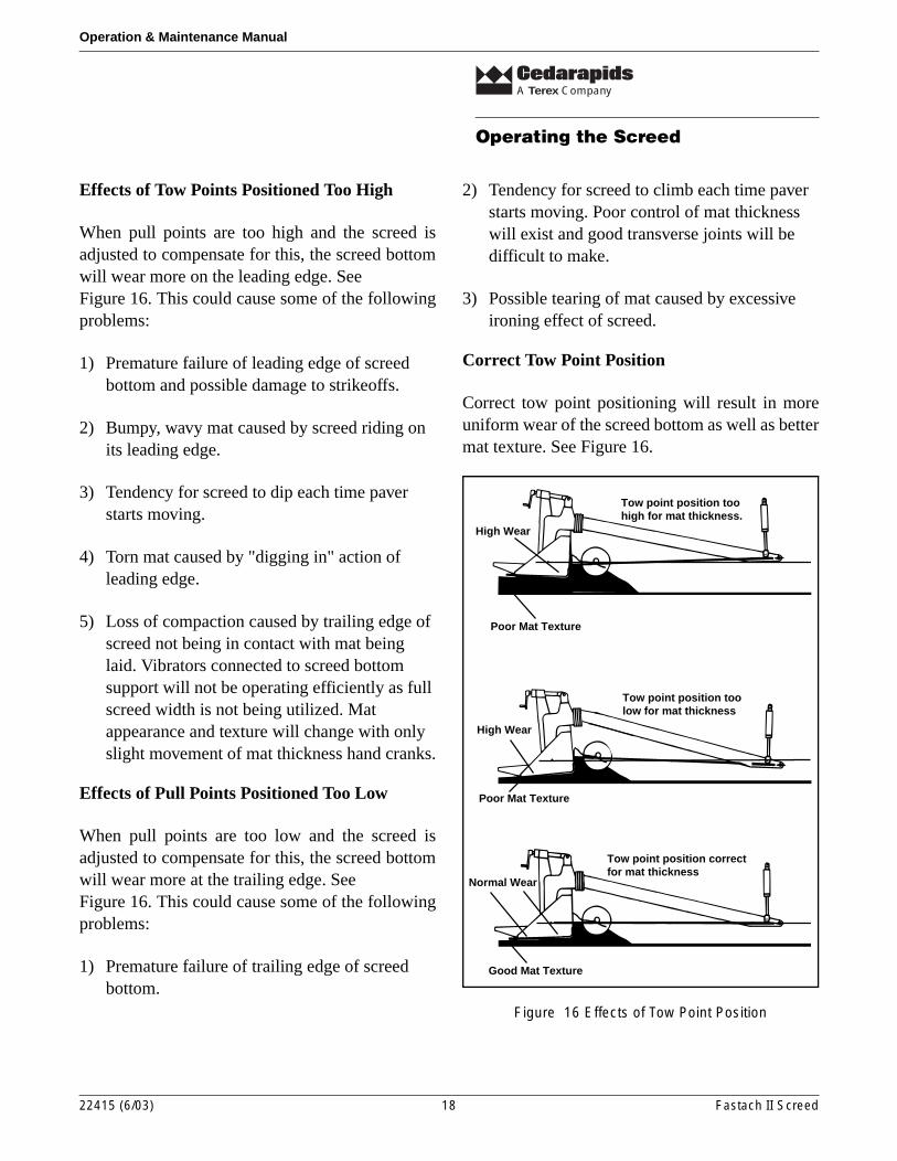
Effects of Tow Points Positioned Too High
When pull points are too high and the screed isadjusted to compensate for this, the screed bottomwill wear more on the leading edge. SeeFigure 16. This could cause some of the followingproblems:
1) Premature failure of leading edge of screed bottom and possible damage to strikeoffs.
2) Bumpy, wavy mat caused by screed riding on its leading edge.
3) Tendency for screed to dip each time paver starts moving.
4) Torn mat caused by "digging in" action of leading edge.
5) Loss of compaction caused by trailing edge of screed not being in contact with mat being laid. Vibrators connected to screed bottom support will not be operating efficiently as full screed width is not being utilized. Mat appearance and texture will change with only slight movement of mat thickness hand cranks.
Effects of Pull Points Positioned Too Low
When pull points are too low and the screed isadjusted to compensate for this, the screed bottomwill wear more at the trailing edge. SeeFigure 16. This could cause some of the followingproblems:
1) Premature failure of trailing edge of screed bottom.
2) Tendency for screed to climb each time paver starts moving. Poor control of mat thickness will exist and good transverse joints will be difficult to make.
3) Possible tearing of mat caused by excessive ironing effect of screed.
Correct Tow Point Position
Correct tow point positioning will result in moreuniform wear of the screed bottom as well as bettermat texture. See Figure 16.
Figure 16 Effects of Tow Point Position
Tow point position correctfor mat thickness
Tow point position toohigh for mat thickness.
High Wear
Poor Mat Texture
Tow point position toolow for mat thickness
Poor Mat Texture
High Wear
Normal Wear
Good Mat Texture
22415 (6/03) 18 Fastach II Screed
A Terex Company
Screed Adjustments
Operation & Maintenance Manual
Screed Adjustments
General
All screed adjustments in the following sectionsshould be made only after setting the tow pointcylinders to the same position, nulling screed, andzeroing the lead and trailing crown.
Position Tow Points
Use the Manual Jog switch to reposition both towpoints to the midpoint on the tow point gauge.
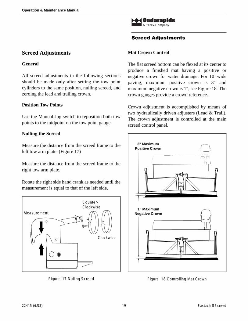
Nulling the Screed
Measure the distance from the screed frame to theleft tow arm plate. (Figure 17)
Measure the distance from the screed frame to theright tow arm plate.
Rotate the right side hand crank as needed until themeasurement is equal to that of the left side.
Figure 17 Nulling Screed
Mat Crown Control
The flat screed bottom can be flexed at its center toproduce a finished mat having a positive ornegative crown for water drainage. For 10’ widepaving, maximum positive crown is 3" andmaximum negative crown is 1", see Figure 18. Thecrown gauges provide a crown reference.
Crown adjustment is accomplished by means oftwo hydraulically driven adjusters (Lead & Trail).The crown adjustment is controlled at the mainscreed control panel.
Figure 18 Controlling Mat Crown
Clockwise
Counter-Clockwise
Measurement
3" MaximumPositive Crown
1" MaximumNegative Crown
22415 (6/03) 19 Fastach II Screed
A Terex Company
Screed Adjustments
Operation & Maintenance Manual
Lead/Trail Crown
The main screed crown has two adjusters, the lead& trail. The lead and trail crown can be adjustedsimultaneously to add a crown to the final mat. Thelead crown can be set independent of the trail, toallow a little extra material to pass into the centerarea of the main screed. This is necessary tocompensate for the void area created by the auger-conveyor drive case. Typically the lead crown is 1/16" to 1/8" above that of the trail. This range issufficient for most mixes.
The most common way to check the lead and trailcrown is to use a strong string line, two equalthickness spacers (new 1/2" NC nuts) and a tapemeasure.
The first check to be performed is checking andadjusting the trail crown.
1) Place two spacers near the outer edge of the screed bottom and just foreword of the trailing edge.
Important - A screed that has been used ina joint matching application may have afew inches on the outer edge of the screedbottom that is worn more than the rest of thescreed bottom. In such a situation thespacers will have to be placed inboard ofthe worn areas to get a propermeasurement.
2) Stretch a strong string line across the center of the spacers and pull tight.
3) Measure the distance from the string line to the screed bottom next to each spacer and in the center of the screed.
4) For initial setup purposes we adjust the lead and trail crown to 0" (flat). If the measurement in the center of the screed is less than or more than the measurement near the spacers, the trail crown must be adjusted.
5) To adjust, press the crown switch located on the main screed control panel to Increase or Decrease. Adjust until measurement at center area of screed is equal to the measurement near the spacers.
6) Once the trail crown is set to 0" (flat), move the spacers and string line forward to the leading edge of the screed bottom.
7) Measure the amount of lead crown.
8) To adjust the lead crown independent of the trail crown, remove the two clevis pins in the rear crowning sprocket. Press the crown switch to the increase or decrease position.
9) Adjust until measurement at center area of screed is equal to measurement at spacers.
10) Reinstall the two crown clevis pins in the rear sprocket.
11) Once the lead and trail crowns are set at 0" (flat), loosen and reset the crown indicator gauges to 0.
22415 (6/03) 20 Fastach II Screed
A Terex Company
Screed Adjustments
Operation & Maintenance Manual
Final Crown Adjustment
Final crown adjustment is made after paving hasstarted and actual mat crown can be accuratelychecked by taut string line. Final crown adjustmentis always made after checking; a) Behind thescreed before roller compaction; and b) After rollercompaction. Do this after enough mix has been laidto be certain the screed has stabilized. This allowsyou to check the screed as well as what effect theroller compaction has on the mat shape.
1) Place spacers (2 X 4s) near the edges of the newly rolled mat. The spacers must be of equal thickness and be thick enough to hold a stretched string line above the crown of the mat.
2) Stretch a string line across the spacers and pull the string line tight.
3) Measure the distance from the string line to the mat at the peak of the crown and at each side of the mat near the spacers.
4) Adjust the crown as needed recheck the crown of the rolled mat until it matches the specified profile.
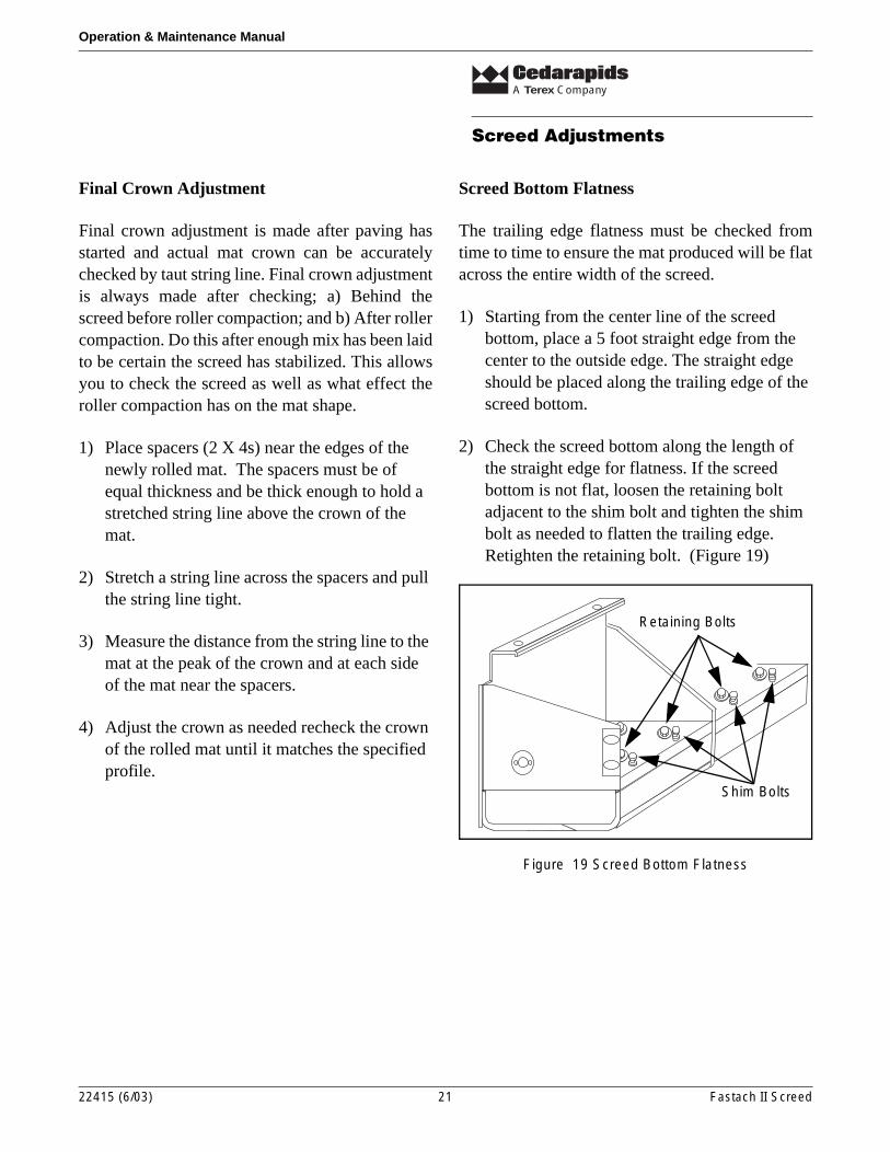
Screed Bottom Flatness
The trailing edge flatness must be checked fromtime to time to ensure the mat produced will be flatacross the entire width of the screed.
1) Starting from the center line of the screed bottom, place a 5 foot straight edge from the center to the outside edge. The straight edge should be placed along the trailing edge of the screed bottom.
2) Check the screed bottom along the length of the straight edge for flatness. If the screed bottom is not flat, loosen the retaining bolt adjacent to the shim bolt and tighten the shim bolt as needed to flatten the trailing edge. Retighten the retaining bolt. (Figure 19)
Figure 19 Screed Bottom Flatness
Shim Bolts
Retaining Bolts
22415 (6/03) 21 Fastach II Screed
A Terex Company
Screed Adjustments
Operation & Maintenance Manual
Match Height Adjustment
This adjustment is performed to make sure theextending screeds are positioned at the same heightas main screed. Procedures described below aredone for both extending screeds.
1) With the extending screeds fully retracted, check the match height across bottom of rear extending screed and main screed at outer edge. If the main and extending screed bottoms do not match, use the match height switch on the remote control to raise or lower the extending screed as needed.
2) When the outside edges of the screed bottoms are at the same height, check the height at inner edge. If the inner edges do not match, use the slope switch on the remote control to align the inner edges of the screed bottoms.
3) When both the inner and outer edges are matched, check match height scale pointer. If pointer is not at zero, loosen cap screws, align with zero, and re-tighten screws.
4) Extend the extending screed. Lay a straightedge across the main and extending screed bottoms. Both surfaces should be level if the preceding steps have been performed correctly.
Independent Angle of Attack
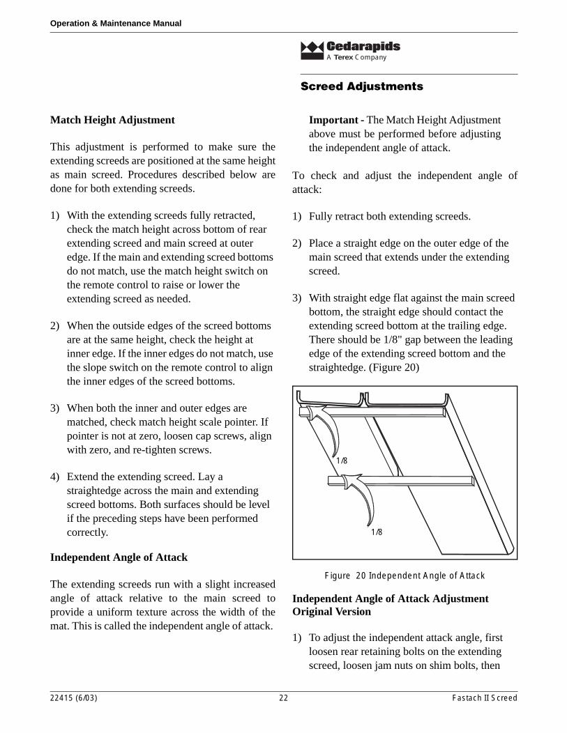
The extending screeds run with a slight increasedangle of attack relative to the main screed toprovide a uniform texture across the width of themat. This is called the independent angle of attack.
Important - The Match Height Adjustmentabove must be performed before adjustingthe independent angle of attack.
To check and adjust the independent angle ofattack:
1) Fully retract both extending screeds.
2) Place a straight edge on the outer edge of the main screed that extends under the extending screed.
3) With straight edge flat against the main screed bottom, the straight edge should contact the extending screed bottom at the trailing edge. There should be 1/8" gap between the leading edge of the extending screed bottom and the straightedge. (Figure 20)
Figure 20 Independent Angle of Attack
Independent Angle of Attack AdjustmentOriginal Version
1) To adjust the independent attack angle, first loosen rear retaining bolts on the extending screed, loosen jam nuts on shim bolts, then
1/8
1/8
22415 (6/03) 22 Fastach II Screed
A Terex Company
Screed Adjustments
Operation & Maintenance Manual
increase the attack angle by turning shim bolts clockwise or decrease the attack angle by turning shim bolts counterclockwise.
2) Once the desired angle is obtained, re-tighten jam nuts and retaining bolts. (Figure 21)
Figure 21 Adjusting Angle of Attack - Original Version
Independent Angle of Attack AdjustmentLater Version
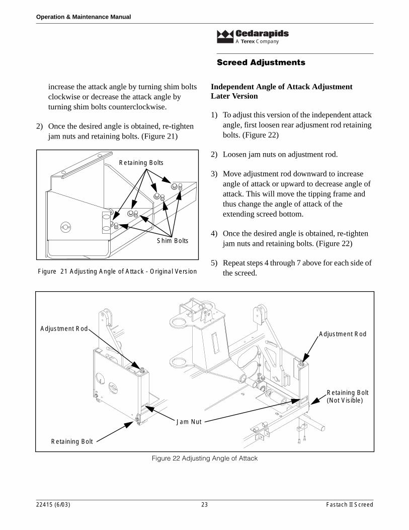
1) To adjust this version of the independent attack angle, first loosen rear adjusment rod retaining bolts. (Figure 22)
2) Loosen jam nuts on adjustment rod.
3) Move adjustment rod downward to increase angle of attack or upward to decrease angle of attack. This will move the tipping frame and thus change the angle of attack of the extending screed bottom.
4) Once the desired angle is obtained, re-tighten jam nuts and retaining bolts. (Figure 22)
5) Repeat steps 4 through 7 above for each side of the screed.
Figure 22 Adjusting Angle of Attack
Shim Bolts
Retaining Bolts
Retaining Bolt
Jam Nut
Adjustment RodAdjustment Rod
Retaining Bolt(Not Visible)
22415 (6/03) 23 Fastach II Screed
A Terex Company
Screed Adjustments
Operation & Maintenance Manual
Extending Screed Alignment
An extending screed that is not parallel with themain screed can still function properly. The mostobvious indicator that the extending screed is notparallel to the main screed will be that the extendertubes will be out-of-line. When retracting thescreed, tubes may rub or hit part of the structurenormally cleared or be noticeably misaligned withtubes of the opposite extending screed. (Figure 23)
Figure 23 Extending Screed Alignment
To realign the extending screeds:
1) Retract both extending screeds.
2) Loosen inner and outer keeper bolts.
3) Install a press bolt in threaded hole next to the outer keeper bolts and tighten. This causes the tipping frame block and extending screed to move.
4) Once the extending screed is aligned with the main screed, add shims between the tipping frame block and main screed frame.
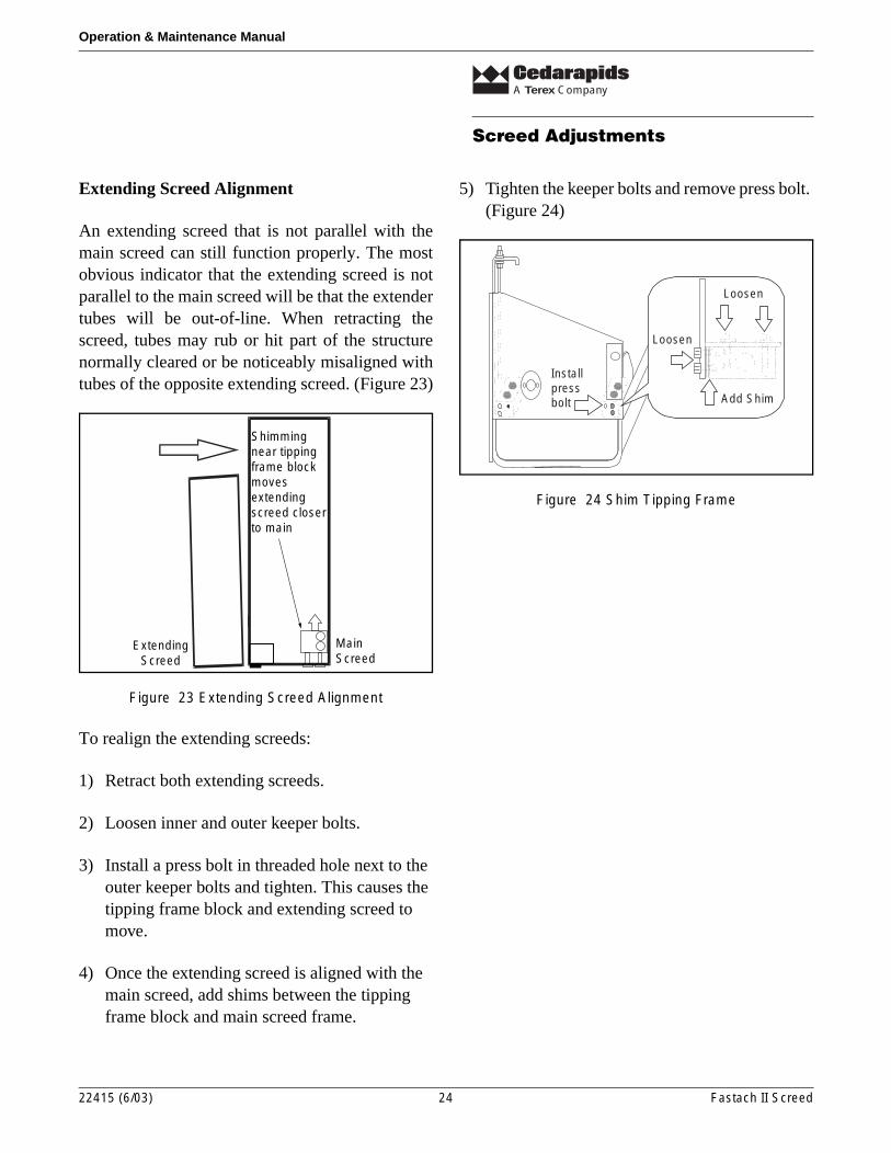
5) Tighten the keeper bolts and remove press bolt. (Figure 24)
Figure 24 Shim Tipping Frame
MainScreed
ExtendingScreed
Shimmingnear tippingframe blockmovesextendingscreed closerto main
Add Shim
Loosen
Loosen
Installpressbolt
22415 (6/03) 24 Fastach II Screed
A Terex Company
Screed Accessories
Operation & Maintenance Manual
Screed Accessories
Heaters
The purpose of the heaters is to raise thetemperature of the screed bottom to allow materialto flow under the screed bottom without stickingand produce a more uniform mat surface texture.The hot mix will usually maintain proper screedtemperature. Since the heaters are thermosaticallycontrolled, they will only come on when needed.
If material delivered to hopper has cooled toomuch, mat texture may be improved by runningheaters. When hauling long distances, it may benecessary to raise the temperature of the mix at themixing plant to restore efficient production of ahigh quality mat.
Usually the screed bottom will be heatedsufficiently by running heaters for 15 to 20 minutesbefore operation.
Notice - Excessive heat can cause screedbottom to warp.
Screed Vibrators
Hydraulic vibrators on screed, which help withinitial compaction and uniform smoothing of a highdensity mat, are activated by toggle switch onoperator’s console. Vibrators will only operatewhen travel lever(s) is FORWARD. This preventsextra compaction in one place on mat when paveris temporarily stopped.
Operating intensity of vibrators can be varied toproduce more or less vibration. The vibrator speedknob (flow control valve) is located adjacent toheater control panel. A recommended start-upsetting is 3/4 of range between zero and the highestdial marking.
Operating Screed Vibrator
1) With engine running, set paver speed dial to zero (MIN.).
2) Turn vibrator switch to ON, set brake switch to RELEASE, and move travel switch/lever forward.
3) To turn vibrators off, set vibrator switch to OFF, return travel lever(s) to neutral, and ENGAGE brake switch.
Warning - Do not work on vibratorswith engine running.
22415 (6/03) 25 Fastach II Screed
A Terex Company
Screed Accessories
Operation & Maintenance Manual
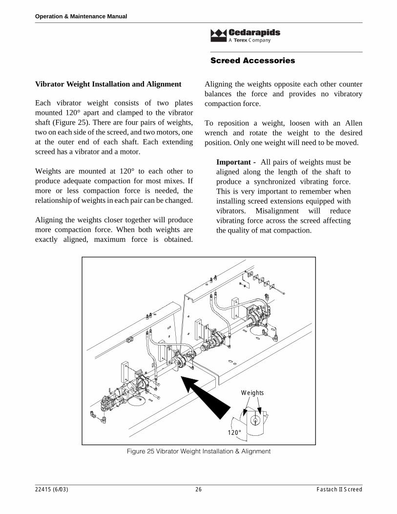
Vibrator Weight Installation and Alignment
Each vibrator weight consists of two platesmounted 120° apart and clamped to the vibratorshaft (Figure 25). There are four pairs of weights,two on each side of the screed, and two motors, oneat the outer end of each shaft. Each extendingscreed has a vibrator and a motor.
Weights are mounted at 120° to each other toproduce adequate compaction for most mixes. Ifmore or less compaction force is needed, therelationship of weights in each pair can be changed.
Aligning the weights closer together will producemore compaction force. When both weights areexactly aligned, maximum force is obtained.
Aligning the weights opposite each other counterbalances the force and provides no vibratorycompaction force.
To reposition a weight, loosen with an Allenwrench and rotate the weight to the desiredposition. Only one weight will need to be moved.
Important - All pairs of weights must bealigned along the length of the shaft toproduce a synchronized vibrating force.This is very important to remember wheninstalling screed extensions equipped withvibrators. Misalignment will reducevibrating force across the screed affectingthe quality of mat compaction.
Figure 25 Vibrator Weight Installation & Alignment
120°
Weights
22415 (6/03) 26 Fastach II Screed
A Terex Company
Screed Accessories
Operation & Maintenance Manual
Strike-Offs
Strike-offs bolted to front of main and extendingscreed bottoms meter material to screeds. Theyalso absorb wear which would otherwise take placeon leading edge of screed bottoms. If these strike-offs are not properly adjusted and maintained theycan cause operational difficulties.
Important - A silicone additive is oftenadded to asphalt to improve mix layingcharacteristics of hot sand or fine mixes.Use of this additive may require adjustmentof the strike-offs.
Adjusting Strike-off
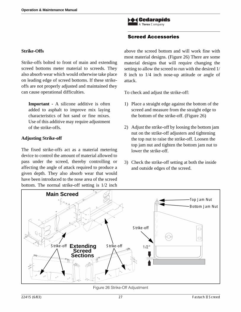
The fixed strike-offs act as a material meteringdevice to control the amount of material allowed topass under the screed, thereby controlling oraffecting the angle of attack required to produce agiven depth. They also absorb wear that wouldhave been introduced to the nose area of the screedbottom. The normal strike-off setting is 1/2 inch
above the screed bottom and will work fine withmost material designs. (Figure 26) There are somematerial designs that will require changing thesetting to allow the screed to run with the desired 1/8 inch to 1/4 inch nose-up attitude or angle ofattack.
To check and adjust the strike-off:
1) Place a straight edge against the bottom of the screed and measure from the straight edge to the bottom of the strike-off. (Figure 26)
2) Adjust the strike-off by loosing the bottom jam nut on the strike-off adjusters and tightening the top nut to raise the strike-off. Loosen the top jam nut and tighten the bottom jam nut to lower the strike-off.
3) Check the strike-off setting at both the inside and outside edges of the screed.
Figure 26 Strike-Off Adjustment
1/2"
Top Jam Nut
Bottom Jam Nut
Strike-off
Strike-off Strike-offExtending
Main Screed
SectionsScreed
22415 (6/03) 27 Fastach II Screed
A Terex Company
Screed Accessories
Operation & Maintenance Manual
Changing Screed Bottom
The screed bottoms will need to be removed fromtime-to-time for replacement. If the trailing edgeof the main screed is worn significantly more thanthe leading edge, the screed bottom can be removedand turned end-for-end and reinstalled to increasethe screed bottom’s useful life.
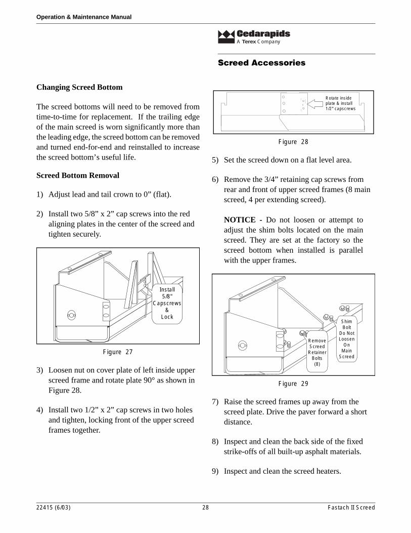
Screed Bottom Removal
1) Adjust lead and tail crown to 0” (flat).
2) Install two 5/8” x 2” cap screws into the red aligning plates in the center of the screed and tighten securely.
Figure 27
3) Loosen nut on cover plate of left inside upper screed frame and rotate plate 90° as shown in Figure 28.
4) Install two 1/2” x 2” cap screws in two holes and tighten, locking front of the upper screed frames together.
Figure 28
5) Set the screed down on a flat level area.
6) Remove the 3/4” retaining cap screws from rear and front of upper screed frames (8 main screed, 4 per extending screed).
NOTICE - Do not loosen or attempt toadjust the shim bolts located on the mainscreed. They are set at the factory so thescreed bottom when installed is parallelwith the upper frames.
Figure 29
7) Raise the screed frames up away from the screed plate. Drive the paver forward a short distance.
8) Inspect and clean the back side of the fixed strike-offs of all built-up asphalt materials.
9) Inspect and clean the screed heaters.
Install5/8"
Capscrews&
Lock
Rotate insideplate & install1/2" capscrews
ShimBolt
Do NotLoosen
OnMain
Screed
RemoveScreed
RetainerBolts(8)
22415 (6/03) 28 Fastach II Screed
A Terex Company
Screed Accessories
Operation & Maintenance Manual
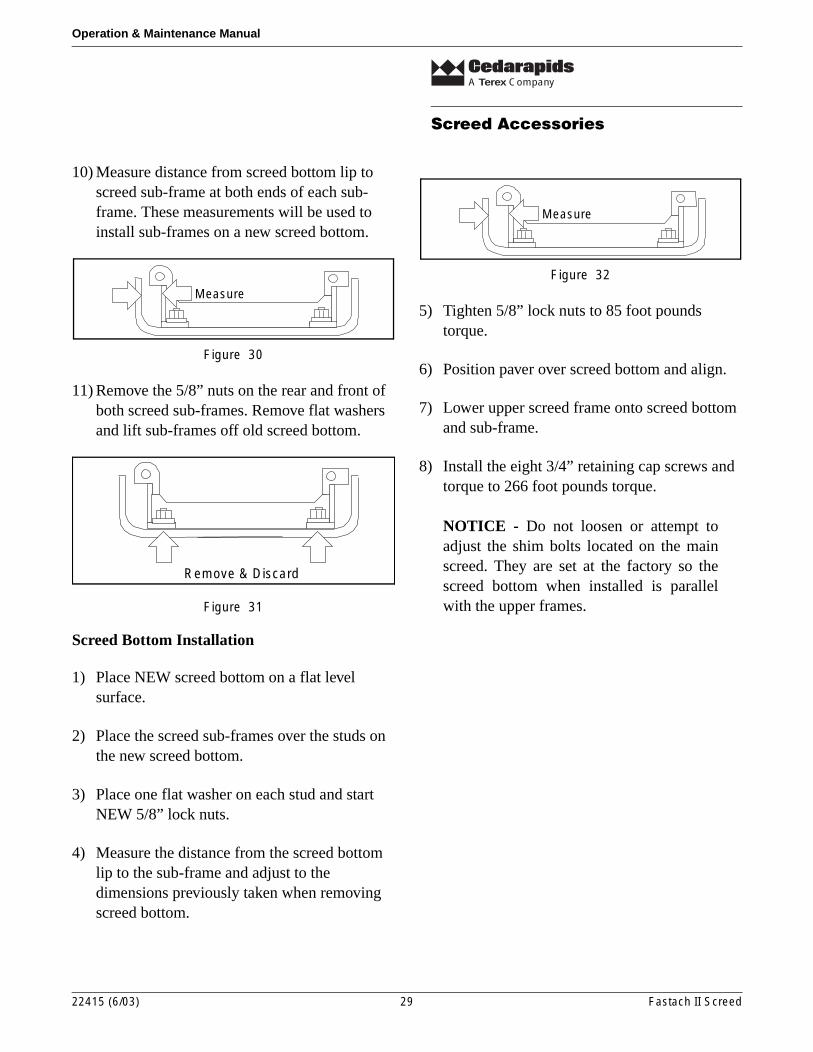
10) Measure distance from screed bottom lip to screed sub-frame at both ends of each sub-frame. These measurements will be used to install sub-frames on a new screed bottom.
Figure 30
11) Remove the 5/8” nuts on the rear and front of both screed sub-frames. Remove flat washers and lift sub-frames off old screed bottom.
Figure 31
Screed Bottom Installation
1) Place NEW screed bottom on a flat level surface.
2) Place the screed sub-frames over the studs on the new screed bottom.
3) Place one flat washer on each stud and start NEW 5/8” lock nuts.
4) Measure the distance from the screed bottom lip to the sub-frame and adjust to the dimensions previously taken when removing screed bottom.
Figure 32
5) Tighten 5/8” lock nuts to 85 foot pounds torque.
6) Position paver over screed bottom and align.
7) Lower upper screed frame onto screed bottom and sub-frame.
8) Install the eight 3/4” retaining cap screws and torque to 266 foot pounds torque.
NOTICE - Do not loosen or attempt toadjust the shim bolts located on the mainscreed. They are set at the factory so thescreed bottom when installed is parallelwith the upper frames.
Measure
Remove & Discard
Measure
22415 (6/03) 29 Fastach II Screed
A Terex Company
Cleaning Screed
Operation & Maintenance Manual
Cleaning Screed
It is extremely important that screed and paver bethoroughly cleaned at end of each day’s operation!A spray nozzle with 30’ hose is attached using aquick-disconnect to the pressure side of fuel pump.This permits operator to reach all areas of paverthat require cleaning and lubricating.
Warning - Do not operate spray downsystem when screed heaters are on orgenerator is operating.
1) Turn main key switch ON. If extensive cleaning is required, run engine at IDLE speed.
2) Remove hose assembly from tool box and connect to the quick-disconnect.
3) Turn fuel pump ON.
4) Fully extend extending screeds. Spray and clean the screed bottoms, strike-offs, and seal plate area. Periodically check for accumulation of asphalt that has spilled over extension moldboard.
5) Clean all parts of paver that come in contact with asphalt. Front, bogie assemblies, hopper, slat conveyors, augers, screed, etc. require cleaning at end of each day. This holds true even if paver was used only a short time. Many troubles can be traced to improper cleaning! Fuel oil on slat conveyors provide needed lubrication that prevents rapid wear. Slat conveyors should be operated during spraying to be sure chain and all slats are reached.
Notice - Keep oil spray away from allelectrical boxes. Avoid spraying rubberhoses and cables with fuel oil as this maycause some deterioration over a period oftime.
Warning - Keep open flame, sparks,welding arcs, etc. away from screedwhere there are flammable materialspresent such as fuel oil
22415 (6/03) 30 Fastach II Screed
A Terex Company
Lubrication
Operation & Maintenance Manual
Lubrication
General
Proper lubrication and daily cleaning are the mostimportant factors in bearing life. Follow therecommended lubrication intervals. Be sure toclean all grease zerks and grease gun tip beforegreasing. During your daily cleaning andlubrication procedures, inspect the seal area forsigns of a blown seal. Over-greasing or greasingwhen the bearings are cold is the biggest reason forblown seals.
Depth Cranks
The screed depth crank assemblies have twolubrication points on each, one on the threaded linkand the other on the screed depth crank bearinghousing. These should be lubricated every 40 hoursof operation. One to two pumps from a hand greasegun is all that is necessary.
Vibrator Bearings
The main screed vibrator assemblies have fourlubrication points, one on each vibrator bearing.The extending screed vibrator assembles have twolubrication points, one on each bearing. All shouldbe lubricated every 8 hours of operation. One totwo pumps from a hand grease gun is all that isnecessary.
Match Height
The match height assembles have two lubricationpoints on each, one on the threaded link and theother on the match height bearing housing. Theseshould be lubricated every 40 hours of operation.One to two pumps from a hand grease gun is all thatis necessary.
Extending Screed Slope
The extending screed slope assembles have twolubrication points on each, one on the threaded linkand the other on the slope shaft bearing housing.These should be lubricated every 40 hours ofoperation. One to two pumps from a hand greasegun is all that is necessary.
Crown
The crown has two lubrication points, one on eachturnbuckle assembly. They should be lubricatedevery 40 hours of operation. One to two pumpsfrom a hand grease gun is all that is necessary.
22415 (6/03) 31 Fastach II Screed
A Terex Company
Screed Generator Pump
Operation & Maintenance Manual
Screed Generator Pump
To properly operate the Fastach II screed electricheating units, it is necessary to set up the screedgenerator pump circuit. This set-up will typicallyonly be necessary for the first-time installation ofthe screed on a tractor with a generator pump.
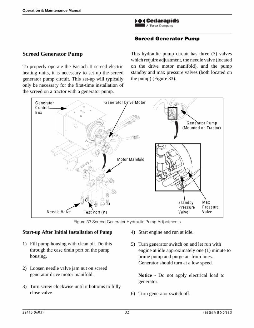
This hydraulic pump circuit has three (3) valveswhich require adjustment, the needle valve (locatedon the drive motor manifold), and the pumpstandby and max pressure valves (both located onthe pump) (Figure 33).
Figure 33 Screed Generator Hydraulic Pump Adjustments
Start-up After Initial Installation of Pump
1) Fill pump housing with clean oil. Do this through the case drain port on the pump housing.
2) Loosen needle valve jam nut on screed generator drive motor manifold.
3) Turn screw clockwise until it bottoms to fully close valve.
4) Start engine and run at idle.
5) Turn generator switch on and let run with engine at idle approximately one (1) minute to prime pump and purge air from lines. Generator should turn at a low speed.
Notice - Do not apply electrical load togenerator.
6) Turn generator switch off.
Generator Pump(Mounted on Tractor)
MaxPressureValve
StandbyPressureValve
Motor Manifold
Needle Valve Test Port (P)
Generator Drive MotorGeneratorControlBox
22415 (6/03) 32 Fastach II Screed

A Terex Company
Screed Generator Pump
Operation & Maintenance Manual
7) Shut off engine.
Set Pump Max Pressure
1) Start engine and run at 1400 rpm.
Notice - Make sure generator switch isturned OFF.
2) Install 6000 psi gauge on test port (P) of generator drive motor manifold. (Figure 33)
3) Remove cap from standby pressure adjustment screw and loosen jam nut.
4) Turn standby pressure adjustment screw clockwise until it bottoms to fully seat valve.
5) Note gauge pressure: Pressure will be approximately 500 - 2500 psi.
6) Remove cap from max pressure adjustment screw and loosen jam nut.
7) Turn max pressure adjustment screw clockwise until gauge reads 4000 psi.
8) Tighten jam nut on max pressure adjustment screw and reinstall cap.
Set Pump Standby Pressure
1) With engine still running at 1400 rpm as described above, turn standby pressure adjustment screw counter-clockwise until gauge reads approximately 400 psi.
Notice - Make sure generator switch isturned OFF.
2) Shut off engine.
3) Remove 6000 psi gauge and install 1000 psi gauge.
4) Re-start engine and run at 1400 rpm.
5) Re-check pressure to make sure standby pressure reads 400 psi. Adjust if necessary.
6) Tighten jam nut on standby pressure adjustment screw and reinstall cap.
7) Shut off engine.
Set Generator Motor Speed (Frequency)
1) Install a frequency (Hz) test meter into the 120 volt outlet on the generator control box. (Figure 34)
2) Start engine and run at 1400 rpm.
3) Turn generator switch on.
4) Turn needle valve screw counter-clockwise until test meter reads 62 Hz.
5) Tighten jam nut on needle valve.
6) Shut off engine.
Figure 34 Setting Generator Frequency
22415 (6/03) 33 Fastach II Screed

A Terex Company
Screed Generator Pump
Operation & Maintenance Manual
Screed generator pump and hydraulics are nowready to be put into operation.
22415 (6/03) 34 Fastach II Screed