screw conveyor catalog engineering manual · cema safety labels the cema safety labels shown below...
TRANSCRIPT
Phone: (308) 324-7591 Fax: (308) [email protected] www.conveyusa.comTOLL FREE:
1-877-664-2687
SCREW CONVEYORCATALOG&ENGINEERINGMANUAL


It is the responsibility of the contractor,instal ler, owner and user to instal l ,maintain and operate the conveyor,components and, conveyor assemblies insuch a manner as to comply with theWilliams-Steiger Occupational Safety andHealth Act and with all state and local lawsand ordinances and the American NationalStandards Institute (ANSI) B20.1 SafetyCode.
In order to avoid an unsafe or hazardouscondition, the assemblies or parts mustbe installed and operated in accordancewith the following minimum provisions.
1. Conveyors shall not be operatedunless all covers and/or guards for theconveyor and drive unit are in place. Ifthe conveyor is to be opened forinspection cleaning, maintenance orobservation, the electric power to themotor driving the conveyor must beLOCKED OUT in such a manner thatthe conveyor cannot be restarted byanyone; however remote from the area,until conveyor cover or guards anddrive guards have been properlyreplaced.
2. If the conveyor must have an openhousing as a condition of its use andapplication, the entire conveyor is thento be guarded by a railing or fence inaccordance with ANSI standardB20.1.(Request current edition andaddenda)
3. Feed openings for shovel, frontloaders or other manual or mechanicalequipment shall be constructed in sucha way that the conveyor opening iscovered by a grating. If the nature ofthe material is such that a gratingcannot be used, then the exposedsection of the conveyor is to be guardedby a railing or fence and there shall bea warning sign posted.
4. Do not attempt any maintenance orrepairs of the conveyor until power hasbeen LOCKED OUT.
5. Always operate conveyor inaccordance with these instructions andthose contained on the caution labelsaffixed to the equipment.
6. Do not place hands, feet, or any partof your body, in the conveyor.
7. Never walk on conveyor covers,grating or guards.
8. Do not use conveyor for any purposeother than that for which i t wasintended.
9. Do not poke or prod material into theconveyor with a bar or stick insertedthrough the openings.
10. Keep area around conveyor driveand control station free of debris andobstacles.
11. Eliminate all sources of storedenergy (materials or devices that couldcause conveyor components to movewithout power applied) before openingthe conveyor
12. Do not attempt to clear a jammedconveyor unti l power has beenLOCKED OUT.
13. Do not attempt field modification ofconveyor or components.
14. Conveyors are not normallymanufactured or designed to handlematerials that are hazardous topersonnel. These materials which arehazardous include those that areexplosive, f lammable, toxic orotherwise dangerous to personnel.Conveyors may be designed to handlethese materials. Conveyors are notmanufactured or designed to complywith local, state or federal codes forunfired pressure vessels. If hazardousmaterials are to be conveyed or if theconveyor is to be subjected to internalor external pressure, manufacturershould be consulted prior to anymodifications.
CEMA insists that disconnecting andlocking out the power to the motor drivingthe unit provides the only real protectionagainst injury. Secondary safety devicesare available; however, the decision as totheir need and the type required must bemade by the owner-assembler as we have
no information regarding plant wiring,plant environment, the interlocking of thescrew conveyor with other equipment,extent of plant automation, etc. Otherdevices should not be used as a substitutefor locking out the power prior to removingguards or covers. We caution that use ofthe secondary devices may causeemployees to develop a false sense ofsecurity and fail to lock out power beforeremoving covers or guards. This couldresult in a serious injury should thesecondary device fail or malfunction.
There are many kinds of electrical devicesfor interlocking of conveyors and conveyorsystems such that if one conveyor in asystem or process is stopped otherequipment feeding it, or following it canalso be automatically stopped.
Electrical controls, machinery guards,rai l ings, walkways, arrangement ofinstallation, training of personnel, etc., arenecessary ingredients for a safe workingplace. I t is the responsibi l i ty of thecontractor, installer, owner and user tosupplement the materials and servicesfurnished with these necessary items tomake the conveyor installation complywith the law and accepted standards.
Conveyor inlet and discharge openingsare designed to connect to otherequipment or machinery so that the flowof material into and out of the conveyor iscompletely enclosed.
One or more warning labels should bevisible on conveyor housings, conveyorcovers and elevator housings. If the labelsattached to the equipment becomeil legible, please order replacementwarning labels from the OEM or CEMA.
The Conveyor Equipment ManufacturersAssociation (CEMA) has produced anaudio-visual presentation entitled “SafeOperation of Screw Conveyors, DragConveyors, and Bucket Elevators.” CEMAencourages acquisition and use of thissource of safety information tosupplement your safety program.
SEE OTHER SIDE FORSAFETY LABELS
WARNING AND SAFETY REMINDERS FORSCREW , DRAG , AND BUCKET ELEVATOR CONVEYORS
NOTICE: This document is provided by CEMA as a service to the industry in the interest of promoting safety. It is advisory only and it is not a substitutefor a thorough safety program. Users should consult with qualified engineers and other safety professionals. CEMA makes no representations orwarranties, either expressed or implied, and the users of this document assume full responsibility for the safe design and operation of equipment.
APPROVED FOR DISTRIBUTION BY THE SCREW CONVEYOR SECTION OF THECONVEYOR EQUIPMENT MANUFACTURERS ASSOCIATION (CEMA)
CEMA Document: SC 2004-01

CEMA Safety LabelsThe CEMA safety labels shown below should be used on screw conveyors, drag conveyors, and bucket elevators.Safety labels should be placed on inlets, discharges, troughs, covers, inspection doors & drive guards. See CEMASafety Label Placement Guidelines on CEMA Web Site: http://www.cemanet.org/safety/guidelines.html
PROMINENTLY DISPLAYTHESE
SAFETY LABELSON
INSTALLED EQUIPMENT
SEE OTHER SIDE FOR SAFETY REMINDERS
Note: Labels alone do not substitute for a thorough in-plant safety training program centered on the hazardsassociated with operating your installed equipment.
Contact CEMA or Your Equipment Manufacturer forReplacement Labels
CONVEYOR EQUIPMENT MANUFACTURERS ASSOCIATION6724 Lone Oak Blvd., Naples, Florida 34109
239-514-3441
Exposed screw andmoving parts cancause severe injury
LOCK OUT POWERbefore removingcover or servicing
CVS930011
CHR930001
Exposed movingparts can causesevere injury
LOCK OUT POWERbefore removingguard
CHS991026
Walking or standing onconveyor covers orgratings can causesevere injury
STAY OFFExposed conveyorsand moving partscan cause severeinjury
LOCK OUT POWERbefore removingcover or servicing
CVS930010
Exposed buckets andmoving parts cancause severe injury
LOCK OUT POWERbefore removingcover or servicing
CVS930012
WARNINGExposed screw andmoving parts cancause severe injury
LOCK OUT POWERbefore removingcover or servicingCHR930011
CEMA Document: SC 2004-01

Page 1
Table of Contents
Materials Classification Code Chart Page 2 Materials Characteristics Page 3-14 Capacity Table Page 15-17 Lump Size Table Page 18 Horsepower Calculation Page 19-21 Horsepower Nomograph Page 22-23 Screw Conveyor Deflection Page 24 Torque Rating Page 25 Torque Nomograph Stainless Steel Page 26 Torque Nomograph Carbon Steel Page 27 Screw Flights with Cuts and Folds Page 28 Weld Finishes Page 29 Thermal Expansion Page 30 Descriptive Part Numbers Page 31 Component Selection Page 32 Part Two – Conveyor Components Page 33 Conveyor Layout Page 34-35 Hanger Bearings Page 36 Replacement Flighting Page 37 Sectional Screws Page 38-39 Sectional Flights Page 40 Sectional Screw Ribbons Page 41 Troughs Page 42-48 Discharges Page 49 Bulkheads Page 50 End Flanges Page 51 Clamps Page 52 Seals Page 53-54 Shrouds Page 55 Feet Page 56 Saddles Page 57 Shafts Page 58-60 Coupling Bolts, Internal Collars, End Lugs Page 61 Trough Ends Page 62-65 Trough End Bearings Page 66-67 Hanger Bearings Page 68 Hangers Page 69-73 Gates Page 74-79 Inlets Page 80 Hanger Pockets Page 81 Covers Page 82-83 Cover Clamps Page 84
Page 1
Materials Classification Code Chart ...................................................................Page 2Materials Characteristics ......................................................................................Page 3-14Capacity Table ........................................................................................................Page 15-17Lump Size Table ....................................................................................................Page 18 Horsepower Calculation .......................................................................................Page 19-21Horsepower Nomograph ......................................................................................Page 22-23Screw Conveyor Deflection ..................................................................................Page 24Torque Rating .........................................................................................................Page 25Torque Nomograph Stainless Steel ....................................................................Page 26Torque Nomograph Carbon Steel.......................................................................Page 27Screw Flights with Cuts and Folds .....................................................................Page 28Weld Finishes .........................................................................................................Page 29Thermal Expansion ................................................................................................Page 30Descriptive Part Numbers ....................................................................................Page 31Component Selection ............................................................................................Page 32Part Two – Conveyor Components .....................................................................Page 33Conveyor Layout ....................................................................................................Page 34-35Replacement Flighting ..........................................................................................Page 36Sectional Screws .....................................................................................................Page 37-38Sectional Flights .....................................................................................................Page 39Sectional Screw Ribbons ......................................................................................Page 40Troughs ....................................................................................................................Page 41-47Discharges ...............................................................................................................Page 48Bulkheads ................................................................................................................Page 49End Flanges .............................................................................................................Page 50Clamps ......................................................................................................................Page 51Seals ..........................................................................................................................Page 52-53Shrouds ....................................................................................................................Page 54Feet ............................................................................................................................Page 55Saddles .....................................................................................................................Page 56Shafts ........................................................................................................................Page 57-59Coupling Bolts, Internal Collars, End Lugs ......................................................Page 60Trough Ends ............................................................................................................Page 61-64Trough End Bearings .............................................................................................Page 65-66Hanger Bearings .....................................................................................................Page 67Hangers ....................................................................................................................Page 68-72Gates .........................................................................................................................Page 73-78Inlets .........................................................................................................................Page 79Hanger Pockets .......................................................................................................Page 80Covers .......................................................................................................................Page 81-82Cover Clamps ..........................................................................................................Page 83

Page 2
Material Classification Code Chart Major Class Material Characteristics Included Code
Designation
Density Bulk Density, Loose Actual Lbs/cu. ft.
Very FineNo. 200 Sieve (.0029”) And Under No. 100 Sieve (.0059”) And Under No. 40 Sieve (.016”) And Under
A200 A100 A40
Fine No. 6 Sieve (.132”) And Under B6
Granular½” And Under 3” And Under 7” And Under
C½ D3 D7
*Lumpy16 “ And Under Over 16” To Be Specified X = Actual Maximum Size
D16
DX
Size
Irregular Stringy, Fibrous, Cylindrical, Slabs, Etc. E
Flowability
Very Free Flowing – Flow Function > 10 Free Flowing – Flow Function > 4 But < 10 Average Flowability – Flow Function > 2 But < 4 Sluggish – Flow Function < 2
1 2 3 4
Abrasiveness Mildly Abrasive – Index 1-17 Moderately Abrasive – Index 18-67 Extremely Abrasive – Index 68-416
5 6 7
Miscellaneous
Properties
Or
Hazards
Builds Up and Hardens Generates Static Electricity Decomposes --- Deteriorates in Storage Flammability Becomes Plastic or Tends to Soften Very Dusty Aerates and Becomes Fluid Explosiveness Stickiness-Adhesion Contaminable, Affecting Use Degradable, Affecting Use Gives Off Harmful or Toxic Gas or Fumes Highly Corrosive Mildly Corrosive Hygroscopic Interlocks, Mats or Agglomerates Oils Present Packs Under Pressure Very Light and Fluffy – May Be Windswept Elevated Temperature
F G H J K L M N O P Q R S T U V W X Y Z
HOW TO READ THE MATERIAL CODE FROM MATERIAL CHARACTERISTICS TABLE. MATERIAL: CHIPS, PULPWOOD
Page 2
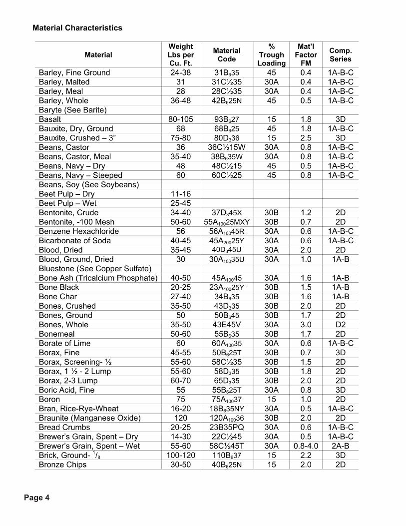
Material Characteristics
Material Weight Lbs per Cu. Ft.
Material Code
% Trough Loading
Mat’l Factor
FM Comp. Series
Acetylenogen (See Calcium Carbide) Adipic Acid 45 45A100 35 30A 0.8 2B Alfalfa Meal 14-22 18B645WY 30A 0.6 2D Alfalfa Pellets 41-33 42C½25 45 0.5 2D Alfalfa Seeds 10-15 13B615N 30B 0.4 1A-8-C Almonds, Broken 27-30 29C½35Q 30B 0.9 2D Almonds, Whole Shelled 28-30 29C½35Q 30B 0.9 2D Alum, Fine 45-50 48B635U 30A 0.6 1A-B-C Alum, Lumpy 50-60 55B625 30A 1.4 2A-B Alumina 55-65 58B627MY 15 1.8 3D Alumina, Fines 35 35A10027MY 15 1.6 3D Alumina, Seed or Briquette 65 65D337 15 2.0 3D Aluminate Gel (Aluminate Hydroxide) 45 45B635 30B 1.7 2D Aluminum Chips, Dry 7-15 11E45V 30A 1.2 2D Aluminum Chips, Oily 7-15 11E45V 30A 0.8 2D Aluminum Hydrate 13-20 17C½35 30A 1.4 1A-B-C Aluminum Ore (See Bauxite) Aluminum Oxide 60-120 90A10017M 15 1.8 3D Aluminum Silicate 49 49C½35S 45 0.8 3A-B Aluminum Sulfate 45-58 52C½25 30A 1.0 1A-B-C Amianthus (See Asbestos-Shredded) Ammonium Chloride, Crystalline 45-52 49A10045FRS 30A 0.7 3A-B Ammonium Nitrate 45-62 54A4035NTU 30A 1.3 3D Ammonium Sulfate 45-58 52C½35FOTU 30A 1.0 1A-B-C Andalvsite (Aluminum Silicate) 49 49C½35 45 0.8 3A-B Antimony Powder A10035 30B 1.6 2D Apple Pomace, Dry 15 15C½45Y 30B 1.0 2D Arsenate of Lead (See Lead Arsenate) Arsenic Oxide (Arsenolite) 100-120 110A10035R Arsenic Pulverized 30 30A10025R 45 0.8 2D Asbestos-Rock (Ore) 81 81D337R 15 1.2 3D Asbestos-Shredded 20-40 30E46XY 30B 1.0 2D Ash, Black, Ground 105 105B635 30A 2.0 1A-B-C Ashes, Coal - Dry - ½ 35-45 40C½46TY 30B 3.0 3D Ashes, Coal - Dry - 3 35-40 38D346T 15 2.5 3D Ashes, Coal - Wet - ½ 45-50 48C½46T 30B 3.0 3D Ashes, Coal - Wet - 3 45-50 48D346T 15 4.0 3D Asphalt, Crushed - ½ 45 45C½45 30A 2.0 1A-B-C Bagasse, Dry 7-10 9E45R/XY 30A 1.5 2A-B-C Bakelite, Fine 30-45 38B625 30A 1.4 1A-B-C Baking Powder 40-55 48A10035 30A 0.6 1B Baking Soda (Sodium Bicarbonate) 40-55 48A10025 30A 1.0 1B Barite (Barium Sulfate) + ½ - 3 120-180 150D336 15 2.6 3D Barite, Powder 120-180 150A10035X 30B 2.0 2D Barium Carbonate 72 72A10045R 30B 2.0 3D Bark, Wood, Refuse 10-20 15E45TYY 30B 2.0 3D
Page 3

Page 3
Material Characteristics
Material Weight Lbs per Cu. Ft.
Material Code
% Trough Loading
Mat’l Factor
FM Comp. Series
Acetylenogen (See Calcium Carbide) Adipic Acid 45 45A100 35 30A 0.8 2B Alfalfa Meal 14-22 18B645WY 30A 0.6 2D Alfalfa Pellets 41-33 42C½25 45 0.5 2D Alfalfa Seeds 10-15 13B615N 30B 0.4 1A-8-C Almonds, Broken 27-30 29C½35Q 30B 0.9 2D Almonds, Whole Shelled 28-30 29C½35Q 30B 0.9 2D Alum, Fine 45-50 48B635U 30A 0.6 1A-B-C Alum, Lumpy 50-60 55B625 30A 1.4 2A-B Alumina 55-65 58B627MY 15 1.8 3D Alumina, Fines 35 35A10027MY 15 1.6 3D Alumina, Seed or Briquette 65 65D337 15 2.0 3D Aluminate Gel (Aluminate Hydroxide) 45 45B635 30B 1.7 2D Aluminum Chips, Dry 7-15 11E45V 30A 1.2 2D Aluminum Chips, Oily 7-15 11E45V 30A 0.8 2D Aluminum Hydrate 13-20 17C½35 30A 1.4 1A-B-C Aluminum Ore (See Bauxite) Aluminum Oxide 60-120 90A10017M 15 1.8 3D Aluminum Silicate 49 49C½35S 45 0.8 3A-B Aluminum Sulfate 45-58 52C½25 30A 1.0 1A-B-C Amianthus (See Asbestos-Shredded) Ammonium Chloride, Crystalline 45-52 49A10045FRS 30A 0.7 3A-B Ammonium Nitrate 45-62 54A4035NTU 30A 1.3 3D Ammonium Sulfate 45-58 52C½35FOTU 30A 1.0 1A-B-C Andalvsite (Aluminum Silicate) 49 49C½35 45 0.8 3A-B Antimony Powder A10035 30B 1.6 2D Apple Pomace, Dry 15 15C½45Y 30B 1.0 2D Arsenate of Lead (See Lead Arsenate) Arsenic Oxide (Arsenolite) 100-120 110A10035R Arsenic Pulverized 30 30A10025R 45 0.8 2D Asbestos-Rock (Ore) 81 81D337R 15 1.2 3D Asbestos-Shredded 20-40 30E46XY 30B 1.0 2D Ash, Black, Ground 105 105B635 30A 2.0 1A-B-C Ashes, Coal - Dry - ½ 35-45 40C½46TY 30B 3.0 3D Ashes, Coal - Dry - 3 35-40 38D346T 15 2.5 3D Ashes, Coal - Wet - ½ 45-50 48C½46T 30B 3.0 3D Ashes, Coal - Wet - 3 45-50 48D346T 15 4.0 3D Asphalt, Crushed - ½ 45 45C½45 30A 2.0 1A-B-C Bagasse, Dry 7-10 9E45R/XY 30A 1.5 2A-B-C Bakelite, Fine 30-45 38B625 30A 1.4 1A-B-C Baking Powder 40-55 48A10035 30A 0.6 1B Baking Soda (Sodium Bicarbonate) 40-55 48A10025 30A 1.0 1B Barite (Barium Sulfate) + ½ - 3 120-180 150D336 15 2.6 3D Barite, Powder 120-180 150A10035X 30B 2.0 2D Barium Carbonate 72 72A10045R 30B 2.0 3D Bark, Wood, Refuse 10-20 15E45TYY 30B 2.0 3D
Page 3
Page 4
Material Characteristics
Material Weight Lbs per Cu. Ft.
Material Code
% Trough Loading
Mat’l Factor
FM Comp. Series
Barley, Fine Ground 24-38 31B635 45 0.4 1A-B-C Barley, Malted 31 31C½35 30A 0.4 1A-B-C Barley, Meal 28 28C½35 30A 0.4 1A-B-C Barley, Whole 36-48 42B625N 45 0.5 1A-B-C Baryte (See Barite) Basalt 80-105 93B627 15 1.8 3D Bauxite, Dry, Ground 68 68B625 45 1.8 1A-B-C Bauxite, Crushed – 3” 75-80 80D336 15 2.5 3D Beans, Castor 36 36C½15W 30A 0.8 1A-B-C Beans, Castor, Meal 35-40 38B635W 30A 0.8 1A-B-C Beans, Navy – Dry 48 48C½15 45 0.5 1A-B-C Beans, Navy – Steeped 60 60C½25 45 0.8 1A-B-C Beans, Soy (See Soybeans) Beet Pulp – Dry 11-16 Beet Pulp – Wet 25-45 Bentonite, Crude 34-40 37D345X 30B 1.2 2D Bentonite, -100 Mesh 50-60 55A10025MXY 30B 0.7 2D Benzene Hexachloride 56 56A10045R 30A 0.6 1A-B-C Bicarbonate of Soda 40-45 45A20025Y 30A 0.6 1A-B-C Blood, Dried 35-45 40D345U 30A 2.0 2D Blood, Ground, Dried 30 30A10035U 30A 1.0 1A-B Bluestone (See Copper Sulfate) Bone Ash (Tricalcium Phosphate) 40-50 45A10045 30A 1.6 1A-B Bone Black 20-25 23A10025Y 30B 1.5 1A-B Bone Char 27-40 34B635 30B 1.6 1A-B Bones, Crushed 35-50 43D335 30B 2.0 2D Bones, Ground 50 50B645 30B 1.7 2D Bones, Whole 35-50 43E45V 30A 3.0 D2 Bonemeal 50-60 55B635 30B 1.7 2D Borate of Lime 60 60A10035 30A 0.6 1A-B-C Borax, Fine 45-55 50B625T 30B 0.7 3D Borax, Screening- ½ 55-60 58C½35 30B 1.5 2D Borax, 1 ½ - 2 Lump 55-60 58D335 30B 1.8 2D Borax, 2-3 Lump 60-70 65D335 30B 2.0 2D Boric Acid, Fine 55 55B625T 30A 0.8 3D Boron 75 75A10037 15 1.0 2D Bran, Rice-Rye-Wheat 16-20 18B635NY 30A 0.5 1A-B-C Braunite (Manganese Oxide) 120 120A10036 30B 2.0 2D Bread Crumbs 20-25 23B35PQ 30A 0.6 1A-B-C Brewer’s Grain, Spent – Dry 14-30 22C½45 30A 0.5 1A-B-C Brewer’s Grain, Spent – Wet 55-60 58C½45T 30A 0.8-4.0 2A-B Brick, Ground- 1/8 100-120 110B637 15 2.2 3D Bronze Chips 30-50 40B625N 15 2.0 2D
Page 4

Page 5
Material Characteristics
Material Weight Lbs per Cu. Ft.
Material Code
% Trough Loading
Mat’l Factor
FM Comp. Series
Buckwheat 37-42 40B625N 45 0.4 1A-B-C Calcine, Flour 75-85 80A10035 30A 0.7 1A-B-C Calcium Carbide 70-90 80D325N 30B 2.0 2D Calcium Carbonate (See Limestone) Calcium Fluoride (See Fluospar) Calcium Hydrate (See Lime Hydrated) Calcium Hydroxide (See Lime Hydrated) Calcium Lactate 26-29 28D345QTR 30A 0.6 2A-B Calcium Magnesium Carbonate 90-100 30B 2.0 2D Calcium Oxide (See Lime, Unflaked) Calcium Phosphate 40-50 45A10045 30A 1.6 1A-B-C Calcium Sulfate (See Gypsum) Carbon, Activated - Dry 8-20 14A200 30B 1.2 2D Carbon Black – Fine 4-6 5A200 30A 0.4 1A-B-C Carbon Black – Pelleted 20-40 Carborundum 100 100D327 15 3.0 2D Casein 36 36B635 30B 1.6 3D Cashew Nuts 32-37 35C½45 30A 0.7 2D Cast Iron, Chips 130-200 165C½45 30B 4.0 2D Caustic Soda 88 88B635RSU 30B 1.8 2D Caustic Soda, Flakes 47 47C½45RSUX 30A 1.5 3D Celite (Diatomaceous Earth) 11-17 14A4036Y 15 1.6 2D Cement, Clinker 75-95 85D336 15 1.8 3D Cement, Mortar 133 133B635Q 30A 3.0 3D Cement, Portland 94 94A10026M 30B 1.4 2D Cement, Aerated (Portland) 60-75 68A10016M 30B 1.4 2D Cerrusite (See Lead Carbonate) Chalk, Crushed 75-95 85D325 30B 1.9 2D Chalk, Pulverized 67-75 71A10025MXY 30B 1.4 2D Charcoal, Ground 18-28 23A10045 30B 1.2 2D Charcoal, Lumps 18-28 23D345Q 30B 1.4 2D Chips, Pulpwood 12-25 19C½45T 30A 1.0 2B Chocolate, Cake Pressed 40-45 45D325 30A 1.5 2B Chrome Ore 125-140 133D336 15 2.5 3D Cinders, Blast Furnace 57 57D336T 15 1.9 3D Cinders, Coal 40 40D336T 15 1.8 3D Clay, Ceramic – Dry 60-80 70A10035P 30A 1.5 1A-B-C Clay, Calcined 80-100 90B636 30B 2.4 3D Clay, Brick – Dry, Fine 100-120 110C½36 30B 2.0 3D Clay – Dry, Lumpy 60-75 68D335 30A 1.8 2D Clinker, Cement (See Cement, Clinker)
Page 5

Page 6
Material Characteristics
Material Weight Lbs per Cu. Ft.
Material Code
% Trough Loading
Mat’l Factor
FM Comp. Series
Coal, Anthracite (River & Culm) 55-61 60B635TY 30A 1.0 2A-B Coal, Anthracite, - ½ 49-61 55C½25 30A 1.0 2A-B Coal, Bituminous Mined 40-60 50D335LNXY 30A 0.9 1A-B Coal, Bituminous, Mined, Sized 45-50 48D335QV 30A 1.0 1A-B Coal, Bituminous, Mined, Slack 43-50 47C½45T 30A 0.9 2A-B Coal, Lignite 37-45 41D335T 30A 1.0 2D Cocoa, Beans 30-45 38C½25Q 30A 0.5 1A-B Cocoa Nibs 35 35C½25 30A 0.5 1A-B Cocoa, Powdered 30-35 33A10045XY 30A 0.9 1A-B Coconut, Shredded 20-22 21E45 30A 1.5 2B Coffee, Chaff 20 20B625MY 30A 1.0 1A-B Coffee, Green Bean 25-32 29C½25PQ 30A 0.5 1A-B Coffee, Ground Dry 25 25A4035P 30A 0.6 1A-B Coffee, Ground Net 35-45 40A4045X 30A 0.6 1A-B Coffee, Roasted Bean 20-30 25C½PQ 45 0.4 1B Coffee, Soluble 19 19A4035PUY 15 0.8 1B Coke, Breeze 25-35 30C½37 15 1.2 3D Coke, Loose 23-35 30D737 15 1.2 3D Coke, Calcined 35-45 40D737 15 1.3 3D Compost 30-50 40D745TV 30A 1.0 3A-B Concrete, Pre Mix Dry 85-120 103C½36V 30B 3.0 3D Copper Ore 120-150 135Cx36 15 4.0 3D Copper Ore, Crushed 100-150 125D336 15 4.0 3D Copper Sulphate (Bluestone) 60-70 65C½35 30A 1.0 2A-B-C Copperas (See Ferrous Sulfate) Copra Cake Ground 40-45 43B645HW 30A 0.7 1A-B-C Copra, Cake Lumpy 25-30 28D335HW 30A 0.8 2A-B-C Copra, Lumpy 22 22E35HW 30A 1.0 2A-B-C Copra, Meal 40-45 42B635HW 30A 0.7 2D Cork, Ground Fine 5-15 10B635JNY 30A 0.5 1A-B-C Cork, Granulated 12-15 14C½35JY 30A 0.5 1A-B-C Corn, Cracked 40-50 45B625P 30A 0.7 1A-B-C Corn Cobs, Ground 17 17C½25Y 30A 0.6 1A-B-C Corn Cobs, Whole 12-15 14E35 30A 2A-B Corn Ear 56 56E35 30A 2A-B Corn Germ 21 21B635PY 30A 0.4 1A-B-C Corn/Grits 40-45 43B635P 30A 0.5 1A-B-C Cornmeal 32-40 43B635P 30A 0.5 1A-B Corn Oil, Cake 25 25D745HW 30A 0.6 1A-B Corn Seed 45 45C½25PQ 45 0.4 1A-B-C
Page 6

Page 7
Material Characteristics
Material Weight Lbs per Cu. Ft.
Material Code
% Trough Loading
Mat’l Factor
FM Comp. Series
Corn, Shelled 45 45C½25 45 0.4 1A-B-C Corn Sugar 30-35 33B635PU 30A 1.0 1B Cottonseed, Cake, Crushed 40-45 43C½45HW 30A 1.0 1A-B Cottonseed, Cake, Lumpy 40-45 43D745HW 30A 1.0 2A-B Cottonseed – Dry, Delinted 22-40 31C½25X 30A 0.6 1A-B Cottonseed – Dry, Undelinted 18-25 22C½35XY 30A 0.8 1A-B Cottonseed, Flakes 20-25 23C½35HWY 30A 0.8 1A-B Cottonseed, Hulls 12 12B645HW 30A 0.5 3A-B Cottonseed, Meal, Expeller 25-30 28B645HW 30A 0.5 3A-B Cottonseed, Meal, Extracted 35-40 37B635HW 30A 0.5 1A-B Cottonseed, Meats – Dry 40 40B635HW 30A 0.6 1A-B Cottonseed, Meats – Rolled 35-40 45D345HW 30A 1.3 2A-B-C Cracklings, Crushed 40-50 45D345HW 30A 1.3 2A-B-C Cryolite, Dust 75-90 83A10036 30B 2.0 2D Cryolite, Lumpy 90-110 100D1636 30B 2.0 2D Cullet, Fine 80-120 100C½37 15 2.0 3D Cullet, Lump 80-120 100D1637 15 2.5 3D Cupric Sulphate (See Copper Sulfate) Diatomaceous Earth 11-17 14A4036Y 30B 1.6 3D Dicalcium Phosphate 40-50 45A4035 30A 1.6 1A-B-C Disodium Phosphate 25-31 28A4035 30B 0.5 3D Dolomite (Calcium Magnesium Carbonate), Crushed 80-100 90C½26T 30B 2.0 2D Dolomite (Cal. Mag. Carbonite) 90-100 95Dx36 30B 2.0 2D Earth, Loam, Dry Loose 76 76C½36 30B 1.2 2D Ebonite, Crushed 63-70 67CY235 30A 0.8 1A-B-C Egg Powder 16 16A4035MPY 30A 1.0 1B Epsom Salt (Mag. Sulfate) 40-50 45A4035U 30A 0.8 1A-B-C Ethanedioic Acid (See Oxalic Acid) Feldspar, Ground 65-80 73A10037 30B 2.0 2D Feldspar, Powder 100 100A20036 30B 2.0 2D Feldspar, Lumps 90-100 95D737 30B 2.0 2D Feldspar, Screenings 75-80 78C½37 30B 2.0 2D Ferrous Sulfide – ½ 120-135 128C½26 30B 2.0 1A-B-C Ferrous Sulfide – 100M 105-120 113A10036 30B 2.0 1A-B-C Ferrous Sulfate 50-75 63C½35U 30B 1.0 2D Fish Meal 35-40 38C½45HP 30A 1.0 1A-B-C Fish Scrap 40-50 45D745H 30A 1.5 2A-B-C Flaxseed 43-45 44B635X 45 0.4 1A-B-C Flaxseed Cake (Linseed Cake) 48-50 49D745W 30A 0.7 2A-B
Page 7

Page 8
Material Characteristics
Material Weight Lbs per Cu. Ft.
Material Code
% Trough Loading
Mat’l Factor
FM Comp. Series
Flaxseed Meal (Linseed Meal) 25-45 35B645W 30A 0.4 1A-B Flour, Wheat 33-40 37A4045LP 30A 0.6 1B Flue Dust, Basic Oxygen Furnace 45-60 53A4036LM 15 3.5 3D Flue Dust, Blast Furnace 110-125 118A4036 15 3.5 3D Flue Dust, Boiler H. Dry 30-45 38A4036LM 15 2.0 3D Fluorspar, Fine 80-100 90B636 30B 2.0 2D Fluorspar, Lumps 90-110 100D736 30B 2.0 2D Flyash – Dry 30-45 38A4036M 15 3.5 3D Foundry Sand – Dry (See Sand) Fuller’s Earth – Dry Raw 30-40 35A4025 30B 2.0 2D Fuller’s Earth, Oily, Spent 60-65 63C½45OW 15 2.0 3D Fuller’s Earth Calcined 40 40A10025 15 2.0 3D Galena (See Lead Sulfide) Gelatin, Granulated 32 32B635PU 30A 0.8 1B Gilsonite 37 37C½35 30B 1.5 3D Glass, Batch 80-100 90C½35 30B 1.5 3D Glue, Ground 40 40B645U 30B 1.7 2D Glue, Pearl 40 40C½35U 45 0.5 1A-B-C Glue, Veg. Powdered 40 40A4045U 30A 0.6 1A-B-C Gluten, Meal 40 40B635P 30A 0.6 1B Grains, Distillery, Spent Dry 30 30D335 30A 0.5 2D Grains, Distillery, Spent Wet 40-60 50C½45V 30A 0.8 3A-B Graphite Flake 40 40B625LP 30A 0.5 1A-B-C Graphite Flour 28 28A10035LMP 45 0.5 1A-B-C Graphite Ore 65-75 70D35L 30A 1.0 2D Granite, Fine 80-90 85C½27 15 2.5 3D Grape Pomace 15-20 18D345U 30B 1.4 2D Grass Seed 10-32 11B625PY 30A 0.4 1A-B-C Guano – Dry 70 70C½35 30 2.0 3A-B Gypsum, Calcined 55-60 58B635U 30B 1.6 2D Gypsum, Calcined, Powdered 60-80 70A10035U 30B 2.0 2D Gypsum, Raw – 1 70-80 75D325 30B 2.0 2D Hay, Chopped 8-12 10C½35JY 30A 1.6 2A-B Hexanedioic Acid 45 45A10035 30A 0.8 2B Hominy 35-50 43C½25D 30A 0.4 1A-B-C Hops, Spent – Dry 35 35D335 30A 1.0 2A-B-C Hops, Spent – Wet 50-55 53D345V 30A 1.5 2A-B Ice, Crushed 35-45 40D335Q 30A 0.4 2A-B Ice, Flaked 40-45 43C½35Q 30A 0.6 1B Ice Cubes 33-35 34D335Q 30A 0.4 1B
Page 8

Page 9
Material Characteristics
Material Weight Lbs per Cu. Ft.
Material Code
% Trough Loading
Mat’l Factor
FM Comp. Series
Ice, Shell 33-35 34D345Q 30A 0.4 1B Ilmenite Ore 140-160 150D337 15 2.0 3D Iron Ore Concentrate 120-180 150A4037 15 2.2 3D Iron Oxide, Pigment 25 25A10036LMP 30B 1.0 1A-B-C Iron Oxide, Millscale 75 75C½36 30B 1.6 2D Iron Pyrites (See Ferrous Sulfide) Iron Sulphate (See Ferrous Sulphate) Iron Sulfide (See Ferrous Sulfide) Iron Vitriol (See Ferrous Sulphate) Kafir (Corn) 40-45 43C½25 30A 0.5 3D Kaolin Clay 63 63D325 30A 2.0 2D Kaolin Clay – Tale 42-56 49A4035LMP 30B 2.0 2D Kryalith (See Cryolith) Lactose 32 32A4035PU 30A 0.6 1B Lamp Black (See Carbon Black) Lead Arsenate 72 72A4035R 30A 1.4 1A-B-C Lead Arsenite 72 72A4035R 30A 1.4 1A-B-C Lead Carbonate 240-260 250A4035R 30B 1.0 2D Lead Ore – 1/8 200-270 235B636 15 1.4 3D Lead Ore – ½ 180-230 205C½36 15 1.4 3D Lead Oxide (Red Lead) 30-150 90A10035P 30B 1.2 2D Lead Oxide (Red Lead) 30-180 105A20035LP 30B 1.2 2D Lead Sulfide 240-260 250A10035R 30B 1.0 2D Lignite (See Coal Lignite) Limanite, Ore, Brown 120 120C½47 15 1.7 3D Lime, Ground, Unflaked 60-65 63B635U 30A 0.6 1A-B-C Lime Hydrated 40 40B635LM 30A 0.8 2D Lime, Hydrated, Pulverized 32-40 36A4035LM 30A 0.6 1A-B Lime, Pebble 53-56 55C½25HU 30A 2.0 2A-B Limestone, Agricultural 68 68B635 30B 2.0 2D Limestone, Crushed 85-90 88Dx36 30B 2.0 2D Limestone Dust 55-95 75A4046MY 30B 2.0 2D Lindane (See Benzene Hexachoride) Linseed (See Flaxseed) Litharge (See Lead Oxide) Lithopone 45-50 48A32535MR 30A 1.0 1A-B Maize (See Milo) Malt, Dry, Ground 20-30 25C635NP 30A 0.5 1A-B-C Malt, Dry, Whole 20-30 25C½35N 30A 0.5 1A-B-C Malt, Meal 36-40 38B625P 30A 0.4 1A-B-C
Page 9

Page 10
Material Characteristics
Material Weight Lbs per Cu. Ft.
Material Code
% Trough Loading
Mat’l Factor
FM Comp. Series
Malt, Sprouts 13-15 14C½35P 30A 0.4 1A-B-C Magnesium Chloride (Magnesite) 33 33C½45 30A 1.0 1A-B Manganese Dioxide 70-85 78A10035NRT 30A 1.5 2A-B Manganese Ore 125-140 133Dx37 15 2.0 3D Manganese Oxide 120 120A10036 30B 2.0 2D Manganese Sulfate 70 70C½37 15 2.4 3D Marble, Crushed 80-95 88B637 15 2.0 3D Marl, (Clay) 80 880Dx36 30B 1.6 2D Meat, Ground 50-55 53E45HQTX 30B 1.5 2A-B Meat, Scrap (w/bone) 40 40E46H 30B 1.5 2D Mica, Flakes 17-22 20B616MY 30B 1.0 2D Mica, Ground 13-15 14B636 30B 0.9 2D Mica, Pulverized 13-15 14A10036M 30B 1.0 2D Milk, Dried, Flake 5-6 6B635PUY 30A 0.4 1B Milk, Malted 27-30 29A4045PX 30A 0.9 1B Milk, Powdered 20-45 33B625PM 30A 0.5 1B Milk Sugar 32 32A10035PX 30A 0.6 1B Mill Scale (Steel) 120-125 123E46T 3.0 3D Milo, Ground 32-36 34B625 30A 0.5 1A-B-C Milo, Maize (Kafir) 40-45 43B615N 30A 0.4 1A-B-C Molybdenite Powder 107 107B626 30B 1.5 2D Monosodium Phosphate 50 50B636 30B 0.6/2.0 2D Mortar, Wet 150 150E46T 30B 3.0 3D Mustard Seed 45 45B615N 45 0.4 1A-B-C Naphthalene Flakes 45 45B635 30B 0.7 1A-B-C Niacin (Nicotinic Acid) 35 35A4035P 30B 0.8 2D Oat Hulls 8-12 10B635NY 30A 0.5 1A-B-C Oats 26 26C½25MN 45 0.4 1A-B-C Oats, Crimped 19-26 23C½35 45 0.5 1A-B-C Oats, Crushed 22 22B645NY 30A 0.6 1A-B-C Oats, Flour 35 35A10035 30A 0.5 1A-B-C Oats, Rolled 19-24 22C½35NY 30A 0.6 1A-B-C Oleo Margarine 59 59E45HKPWZ 30A 0.4 2A-B Orange, Peel, Dry 15 15E45 15 1.5 2A-B Oxalic Acid 60 60B635QS 30A 1.0 1A-B Oyster Shells, Ground 50-60 55C½36T 30B 2.0 3D Oyster Shells, Whole 80 80D336TV 30B 2.5 3D Paper Pulp (4% or less) 62 62E45 30A 2.0 2A-B Paper Pulp (6% to 15%) 60-62 61E45 30A 2.0 2A-B Paraffin Cake -- ½ 45 45C½45K 30A 0.6 1A-B Peanuts, Clean, In Shell 15-20 18D335Q 30A 0.6 2A-B
Page 10

Page 11
Material Characteristics
Material Weight Lbs per Cu. Ft.
Material Code
% Trough Loading
Mat’l Factor
FM Comp. Series
Peanut Meal 30 30B635P 30A 0.6 1B Peanuts, Raw, Unshelled 15-20 18D336Q 30A 0.7 3D Peanuts, Shelled 35-45 40C½35Q 30A 0.4 1B Peas, Dried 45-50 48C½15NQ 45 0.5 1A-B-C Perlite, Expanded 8-12 10C½36 30B 0.6 2D Phosphate Acid Fertilizer 60 60B625T 30A 1.4/2.5 2A-B Phosphate Disodium (See Sod. Phosphate) Phosphate Rock, Broken 75-85 80D36 30B 2.5 2D Phosphate Rock, Pulverized 60 60B636 30 1.7 2D Phosphate Sand 90-100 95B637 15 2.5 3D Plaster of Paris (See Gypsum) Plumbago (See Graphite) Polystyrene Beads 40 40B635PQ 30A 0.4 1B Polyvinyl, Chloride Powder 20-30 25A10045KT 30A 1.0 2B Polyvinyl, Chloride Pellets 20-30 25E45KT 30A 1.0 2B Polyethylene, Resin Pellets 30-35 33C½45Q 30A 0.4 1A-B Potash (Muriate of Potash) 70 70B637 15 2.0 3D Potash (Muriate Mine Run) 75 75Dx37 15 2.0 3D Potassium Carbonate 51 51B636 30B 1.0 2D Potassium Chloride, Pellets 120-130 125C½25TU 30B 1.6 3D Potassium Nitrate -½ 76 76C½16NT 30B 1.2 3D Potassium Nitrate – 1/8 80 80B626NT 30A 1.2 3D Potassium Sulfate 42-48 45B646X 30B 1.0 2D Potato Flour 48 48A20035MNP 30A 0.5 1A-B Pumice – 1/8 42-48 45B646 15 1.5 3D Pyrite, Pellets 120-130 125C½26 30B 2.0 3D Quartz – 100 Mesh 70-80 75A10027 15 1.7 3D Quartz - ½ 80-90 85C½27 15 2.0 Rice, Bran 20 20B635NY 30A 0.4 1A-B-C Rice, Grits 42-45 44B635P 30A 0.4 1A-B-C Rice, Polished 30 30C½15P 30A 0.4 1A-B-C Rice, Hulled 45-49 47C½25P 45 0.4 1A-B-C Rice, Hulls 20-21 21B635NY 45 0.4 1A-B-C Rice, Rough 32-36 34C½35N 30A 0.6 1A-B-C Rosin - ½ 65-68 67C½45Q 30A 1.5 1A-B-C Rubber, Reclaimed, Ground 23-50 37C½45Q 30A 0.8 1A-B-C Rubber, Pelleted 50-55 53D345 30A 1.5 2A-B-C Rye 42-48 45B615N 45 0.4 1A-B-C Rye Bran 15-20 18B635Y 45 0.4 1A-B-C Rye Feed 33 33B635 30A 0.5 1A-B-C Rye Meal 45-50 38B635 30A 0.5 1A-B-C Rye, Middlings 42 42B635 30A 0.5 1A-B-C
Page 11

Page 12
Material Characteristics
Material Weight Lbs per Cu. Ft.
Material Code
% Trough Loading
Mat’l Factor
FM Comp. Series
Rye, Shorts 32-33 33C½35 30A 0.5 2A-B Safflower, Cake 50 50D326 30A 0.6 2D Safflower, Meal 50 50B635 30A 0.6 1A-B-C Safflower, Seed 45 45B615N 45 0.4 1A-B-C Saffron (See Safflower) Salt Ammoniac (See Ammonium Chloride) Salt Cake, Dry, Coarse 85 85B636TU 30B 2.1 3D Salt Cake, Dry, Pulverized 65-85 75B636TU 30B 1.7 3D Salicylic Acid 29 29B637U 30A 0.6 3D Salt, Dry, Coarse 45-60 53C½36TU 30B 1.0 3D Salt, Dry, Fine 70-80 75B636TU 30B 1.7 3D Saltpeter (See Potassium Nitrate) Sand, Dry Bank (Damp) 110-130 120B647 15 2.8 3D Sand, Dry Bank (Dry) 90-110 100B637 15 1.7 3D Sand, Dry Silica 90-100 95D337Z 15 2.6 3D Sand, Foundry (Shake Out) 90-100 95D337Z 15 2.6 3D Sand (Resin Coated) Silica 104 104B627 15 2.0 3D Sand (Resin Coated) Ziron 115 115A10027 15 2.3 3D Sawdust, Dry 10-13 12B645UX 30A 0.7 1A-B-C Sea-Coal 65 65B636 30B 1.0 2D Sesame Seed 27-41 34B626 30B 0.6 2D Shale, Crushed 85-90 88C½36 30B 2.0 2D Shellac, Powdered or Granulated 31 31B635P 30A 0.6 1B Silicon Dioxide (See Quartz) Silica, Flour 80 80A4046 30B 1.5 2D Silica, Gel 45 45D337HKQU 15 2.0 3D Slag, Blast Furnace 130-180 155D337Y 15 2.4 3D Slag, Furnace, Granular-Dry 60-65 63C½37 15 2.2 3D Slate, Crushed - ½ 80-90 85C½36 30B 2.0 2D Slate, Ground – 1/8 82-85 84B636 30B 1.6 2D Sludge, Sewage, Dried 40-50 45E47TW 30B 0.8 3D Soap, Beads or Granules 15-35 25B635Q 30A 0.6 2D Soap, Chips 15-25 20C½35Q 30A 0.6 1A-B-C Soap, Detergent 15-50 33B635FQ 30A 0.8 1A-B-C Soap, Flakes 5-15 10B635QXY 30A 0.6 1A-B-C Soap, Powder 20-25 23B625X 30A 0.9 1A-B-C Soapstone, Talc, fine 40-50 45A20045XY 30B 2.0 1A-B-C Soda Ash, Heavy 55-65 60B636 30B 1.0 2D Soda Ash, Light 20-35 28A4036Y 30B 0.8 2D Sodium Aluminate, Ground 72 72B636 30B 1.0 2D Sodium Aluminate Fluoride (See Cryolite) Sodium Aluminum Sulphate 75 75A10036 30B 1.0 2D Sodium Bentonite(See Bentonite) Sodium Bicarbonate (See Baking Soda)
Page 12

Page 13
Material Characteristics
Material Weight Lbs per Cu. Ft.
Material Code
% Trough Loading
Mat’l Factor
FM Comp. Series
Sodium Chloride ( See Salt) Sodium Carbonate (See Soda Ash) Sodium Hydrate (See Caustic Soda) Sodium Hydroxide (See Caustic Soda) Sodium Borate (See Borax) Sodium Nitrate 70-80 75D325NS 30A 1.2 2A-B Sodium Phosphate 50-60 55A35 30B 0.9/2.0 1A-B Sodium Sulfate (See Salt Cake) Sodium Sulfite 96 96B646X 30B 1.5 2D Sorghum, Seed (See Kafir or Milo) Soybean Cake 40-43 42D335W 30A 1.0 2A-1B-1C Soybean, Cracked 30-40 35C½36NW 30B 0.5 2D Soybean, Flake, Raw 18-25 22C½35Y 30A 0.8 1A-B-C Soybean, Flour 27-30 29A4035MN 30A 0.8 1A-B-C Soybean, Meal – Cold 40 40B635 30A 0.5 1A-B-C Soybean, Meal – Hot 40 40B635T 30A 0.5 1A-B-C Soybean, Whole 45-50 48C½26NW 15 1.0 3D Starch 25-50 38A4015M 45 1.0 1A-B-C Steel Turnings, Crushed 100-150 125D346WY 15 3.0 3D Sugar Beet, Pulp – Dry 12-15 14C½26 30B 0.9 2D Sugar Beet, Pulp – Wet 25-45 35C½35X 30B 1.2 1A-B-C Sugar, Refined, Granulated – Dry 50-55 53B635PU 30A 1.2 1B Sugar, Refined, Granulated – Wet 55-65 60C½35X 30A 2.0 1B Sugar, Powdered 50-60 55A10035PX 30A 0.8 1B Sugar, Raw 55-65 60B635PX 30A 2.0 1B Sulphur, Crushed – ½ 50-60 55C½35N 30A 0.8 1A-B Sulphur, Lumpy – 3” 80-85 83D335N 30A 0.8 2A-B Sulphur, Powdered 50-60 55A4035MN 30A 0.8 1A-B Sunflower Seed 19-38 29C½15 30 0.5 1A-B-C Talcum – ½ 80-90 85C½36 30B 0.9 2D Talcum Powder 50-60 55A20036M 30B 0.9 2D Tanbark, Ground 55 55B645 30A 0.6 1A-B-C Timothy Seed 36 36B635NY 30A 0.6 1A-B-C Titanium Dioxide (See Ilmenite Ore) Tobacco, Scraps 15-25 20D345Y 30A 0.8 2A-B Tobacco Snuff 30 30B645MQ 30B 0.9 1A-B-C Tricalcium Phosphate 40-50 45A4045 30A 1.6 1A-B Triple Super Phosphate 50-55 53B636RS 30B 2.0 3D Trisodium Phosphate, Granular 60 60B636 30B 1.7 2D Trisodium Phosphate, Pulverized 50 50A4036 30B 1.6 2D
Page 13

Page 14
Material Characteristics
Material Weight Lbs per Cu. Ft.
Material Code
% Trough Loading
Mat’l Factor
FM Comp. Series
Tung Nut Meats, Crushed 28 28D325W 30A 0.8 2A-B Tung Nuts 25-30 28D315 30A 0.7 2A-B Urea Prills, Coated 43-46 45B625 45 1.2 1A-B-C Vermiculite, Expanded 16 16C½35Y 30B 0.5 1A-B Vermiculite, Ore 80 80D336 30B 1.0 2D Vetch 48 48B616N 30B 0.4 1A-B-C Walnut Shells, Crushed 35-45 40B636 15 1.0 2D Wheat 45-48 47C½25N 45 0.4 1A-B-C Wheat, Cracked 40-45 43B625N 30A 0.4 1A-B-C Wheat, Germ 18-28 23B625N 30A 0.4 1A-B-C White Lead, Dry 75-100 88A4036MR 30B 1.0 2D Wood Chips, Screened 10-30 20D345VY 30A 0.6 2A-B Wood Flour 16-36 25B635N 30A 0.4 1A-B Wood Shavings 8-16 12E45VY 30B 1.5 2A-B Zinc Concentrate Residue 75-80 78B637 15 1.0 3D Zinc Oxide, Heavy 30-35 33A10045X 30A 1.0 1A-B Zinc Oxide, Light 10-15 13A10045XY 30A 1.0 1A-B
Page 14

Page 15
Screw Conveyors – Capacity Table
Capacity in Cu. Ft. Per Hr.* Trough Loading
Screw Dia.
Pipe Size (Nom. Dia.)
Used for Capacity Tables
Maximum RPM At
Maximum RPM At
1 RPM
45%
6 9 12 14 16 18 20 24 30
2 2 ½
3 3 ½ 3 ½
4 4 4 4
165 155 145 140 130 120 110 100
90
368 1240 2813 4330 6126 8052 10253 16368 29150
2.23 8.00 19.40 30.93 47.12 67.10 93.21 163.68 323.89
30%A
6 9 12 14 16 18 20 24 30
2 2 ½
3 3 ½ 3 ½
4 4 4 4
120 100
90 85 80 75 70 65 60
180 536 1164 1753 2514 3355 4350 7093 12955
1.50 5.36 12.93 20.62 31.42 44.73 62.14 109.12 215.92
30%B
6 9 12 14 16 18 20 24 30
2 2 ½
3 3 ½ 3 ½
4 4 4 4
60 55 50 50 45 45 40 40 35
90 295 647 1031 1414 2013 2486 4365 7557
1.50 5.36 12.93 20.62 31.42 44.73 62.14
109.12 215.92
15%
6 9 12 14 16 18 20 24 30
2 2 ½
3 3 ½ 3 ½
4 4 4 4
60 55 50 50 45 45 40 40 35
45 147 323 516 707 1006 1242 2182 3779
.75 2.68 6.46 10.31 15.70 22.36 31.06 54.56 107.96
*Capacities shown are for full pitch screws. Consult factory for inclined conveyors. Dimensions are in inches. See Page 18 for Lump Size Limitations
Page 15

Page 16
Screw Conveyors – Capacity Screw Conveyor Speed Conveyor speed may be determined by reviewing your selection or the capacity table and obtaining the ft3 conveyed at 1 RPM. The speed is then: C CFH @ 1 RPM N = Conveyor Speed C = Required Capacity in ft3/Hr When hard iron bearings are used with hardened shafts, then the following limitations will apply: 120 Shaft Diameter in Inches Shaft size to be equal or smaller than calculated size. Check torsional ratings. Sample Screw Conveyor Calculation A horizontal screw conveyor is required to move 8 TPH of Potassium Carbonate over a 36’ length. *From the material table the weight is 51 PCF, component series is 2D, trough loading 30%B. A nominal amount of other additives are to be added and require some mixing as well as conveying. For this purpose, cut and folded flights are to be used.
The required capacity is:
16,000 lbs/hr
51 PCF
Sizing Capacity B:
SC = 314 • 3.75 = 1178 ft3
The 3.75 is from Table (CF2 ) The conveyor size selected is a 16” from the capacity table based on a sizing capacity of 1178 ft3 with a 30%B trough load. Actual conveyor speed required is: 1178 ft3
31.42 ft3/hr at 1RPM The lump size from the material table and the lump size chart:
(B6 = five material) indicate no adjustments are necessary. Maximum Shaft Diameter Is:
120
37.49 RPM The closest standard shaft often used that is smaller than 3.2” is a 3” shaft.
C = = 314 ft3
N =
N = = 37.49 RPMN =
Shaft Dia. = = 3.20”
Page 16

Page 17
HORIZONTAL SCREW CONVEYORS – Capacity SPECIAL SCREW PITCH CAPACITY
FACTORS (CF1)
Pitch Description Capacity Factor
Standard Short Half Long
Pitch = Diameter Pitch = 2/3 Diameter Pitch = ½ Diameter Pitch = 1½ Diameter
1.00 1.50 2.00 0.67
SPECIAL SCREW FLIGHT CAPACITY FACTORS (CF2)
Conveyor Loading Type
15% 30% 45%Cut Flight 1.95 1.57 1.43Cut-and-folded flight N.R.♦ 3.75 2.54
♦NOT RECOMMENDED RIBBON SCREW CAPACITY
FACTORS (CF3) Conveyor Loading Screw
Dia. RibbonWidth 15% 30% 45%
6 1 1.03 1.32 1.85
9 1 ½ 1.06 1.40 1.76
2 1.06 1.41 1.75 12
2 ½ 1.00 1.20 1.55
14 2 ½ 1.02 1.32 1.67
16 2 ½ 1.09 1.47 1.85
18 3 1.06 1.41 1.75
20 3 1.12 1.52 1.90
24 3 1.42 1.77 2.20 Factors for Screws with Paddles♦ (CF4)
Sizing a normal horizontal screw conveyor requires: 1. Required capacity in cubic feet per hour
based on material as it is conveyed. 2. Percentage of trough loading 3. Maximum lump size DETERMINATION OF CONVEYOR SIZE Review the material in the materials table toobtain the suggested trough loading.Referring to the capacity table, locate thesize of screw conveyor at the maximumRPM that will exceed your requirements. If your process has surges of materialfrom time to time, it may be better toupsize your conveyor to accommodatethese surges. Finally, review the lump size chart after youhave made your selection to see if it offsetsyour choice. This should be the minimumsize selected. MODIFIED FLIGHT CAPACITIES Screw Conveyor flights can be modified inseveral ways that will affect the capacity.The modifications must be taken intoaccount when sizing a screw conveyor.
SC = C x CF SC = Selection Capacity (Cu. Ft. Per Hour) Also Referred to as Equivalent Capacity C = Required Capacity in Cubic Feet Per Hour CF = Capacity Factor (CF1 x CF3 x CF4)
Paddles per Pitch 1 2 3 4 Factor
1.08 1.16 1.24 1.32
♦Standard paddles at 45° reverse pitch.
Page 17

Page 18
LUMP SIZE LIMITATIONS When sizing a screw conveyor, the lump sizeof the material and percentages of the lumpsas a proportion to the total amount of materialconveyed may be a consideration in the finalsize selection of a screw conveyor. Whenfiguring the lump size the largest dimensionshould be used. If the material lumps are friable, that is, easilycrumbled, then they would not pose anyserious limitation to the screw conveyor andcould usually be discounted in calculating theconveyor size. Three classes of lump sizes apply as follows: Class 1. A mixture of lumps and fines in
which not more than 10% arelumps ranging from maximum sizeto one half of the maximum; and90% are lumps smaller than onehalf of the maximum size.
Class 2. A mixture of lumps and fines in which not more than 25% are lumps ranging from the maximum size to one half of the maximum; and 75% are lumps smaller than one half of the maximum size.
Class 3. A mixture of lumps only in which 95% or more are lumps ranging from maximum size to one half of the maximum size; and 5% or less are lumps less than one tenth of the maximum size.
The lump ratio, LR, is indicated to show the usual screw conveyor sizes and may be used as a guide in sizing conveyors. Unusual products and sizes should be referred to Orthman Conveying Systems for evaluation.
MAXIMUM LUMP SIZE TABLE
Screw Dia. (in.)
Pipe OD (in.)
*Radial Clearance
(in.)
Class 1 10% lumps
Ratio R = 1.75 Max lump (in.)
Class 2 25% lumps
Ratio R = 2.5 Max lump (in.)
Class 3 95% lumps
Ratio R = 4.5 Max lump (in.)
6 2 3/8 2 5/16 1 ¼ ¾ ½ 2 3/8 3 13/16 9 2 7/8 3 9/16
2 ¼ 1 ½ ¾
2 7/8 5 1/16 3 ½ 4 ¾ 12 4 4 ½
2 ¾
2
1
3 ½ 5 ¾ 14 4 5 ½
3 ¼
2 ½
1 ¼
4 6 ½ 16 4 ½ 6 ½
3 ¾
2 ¾
1 ½
4 7 ½ 18 4 ½ 7 ½
4 ¼
3
1 ¾
4 8 ½ 20 4 ½ 8 ½
4 ¾
3 ½
2
24 4 ½ 10 ¼ 6 3 ¾ 2 ½ 30 4 ½ 13 ¼ 7 ½ 5 3
*Radial clearance is distance between bottom of the trough and the bottom of screw pipe.
Page 18

Page 19
Horizontal Screw Conveyors – Horsepower Calculation
HORIZONTAL SCREW CONVEYORS This formula for horizontal screw conveyors is based on a uniformly fed screw conveyor that has been properly sized and installed.
C = Capacity in cubic feet per hour. (Required capacity) e = Drive efficiency. See Table. Fb = Hanger bearing factor. See Table. Fd = Conveyor diameter factor. See Table. Ff = Flight factor. See Table. *Use 1.0 for standard flights. Fm = Material factor. See Material Characteristics Table. Fo = Overload factor. See graph. Fp = Paddle factor. See Table. L = Total length of conveyor, feet. N = Operating speed, RPM (revolutions per minute). W = Weight of the material AS CONVEYED, lbs. per cubic foot. HPf = Frictional horsepower HPm = Material horsepower HP = Total horsepower LN Fd Fb HPf = = (Horsepower to run an empty conveyor)
1,000,000
CLW Ff Fm Fp 1,000,000
(HPf + HPm) Fo
HPm = = (Horsepower to move the material)
Total HP = (If HPf + HPm is greater than 5.2, use 1.0 for Fo)
e
Hanger Bearing Factor, Fb
Bearing Type Bearing Factor,Fb
Ball 1.0 Babbitt Bronze, Plain *Bronze, Graphite *Bronze, Oil-Impregnated *Canvas Base Phenolic *Wood, Oil Impregnated
1.7
*Nylon •UHMW 2.0
*Hard Iron *Hard Surfaced 4.4
*Non-lubricated, or bearings not additionally lubricated. •Ultra-High Molecular Weight Polymer Dimensions in inches
Page 19

Page 20
Horizontal Screw Conveyors – Horsepower Calculation Calculation Tables (Cont’d) Diameter Factor, Fd
Diameter Factor, Fd 6 9
12 14 16 18 20 24 30
18 31 55 78 106 135 165 235 360
Modified Flight Factor, Ff
Conveyor Loading Flight Type
15% 30% 45% 95%
Cut Flight Cut-and-Folded Flight Ribbon Flight
1.10 NR* 1.05
1.15 1.5 1.14
1.20 1.7 1.20
1.3 2.2 —
*Not Recommended
Paddle Factor, Fp
*Paddles per Pitch 1 2 3 4 Factor, Fp
1.29 1.58 1.87 2.16 *Standard paddles at 45° reverse pitch If no paddles, Fp = 1.0
Drive Efficiency Factor, e
Screw Drive or Shaft Mount With V-Belt
V-Belt to Helical Reducer With Coupling
Motor Reducer With
Chain Drive
Motor Reducer With
Coupling 0.85 0.85 0.85 0.95
Page 20

Page 21
Fo — OVERLOAD FACTOR
HORSEPOWER HPf + HPm
FOR VALUES OF HPf + HPm GREATER THAN 5.2, Fo IS 1.0 TRACE THE VALUE OF HPf + HPm VERTICALLY TO THE DIAGONAL LINE, THEN ACROSS TO THE LEFT WHERE THE Fo VALUE IS LISTED.
Fact
or F
o
EXAMPLE FOR HORSEPOWER CALCULATION Use same example problem from pg. 16 operating Cut-and-Fold flights. Known data from problem: C = Capacity: 314 Ft³ e = Drive efficiency: 0.85 Fb = Hanger bearing factor: 4.4 Fd = Conveyor diameter factor: 106 Ff = Flight factor: 1.5 Fm = Material factor: 1.0 Fp = Paddle factor: 1.0 L = Total length of conveyor: 36 N = Conveyor speed: 37.49 W = Wt of potassium carbonate as conveyed: 51 Frictional Horsepower is:
X 37.49 X 106 X 4.4 1,000,000
Material Horsepower is: 314 X 36 X 51 X 1.5X 1.0 X 1.0 1,000,000
= .86
= .63
HPm =
36 HPf =
Total Horsepower is: HPf + HPm = .63 + .82 = 1.45HP Since this total is less than 5.2, the overloadfactor of Fo must be used. Total Horsepower is: (HPf + HPm) X 1.75 = (.63 + .82) X 1.75 = 2.53 HP
Consider drive efficiency: Motor horsepower: 2.53 .85 A 3 HP motor could be used for the example.However, actual plant conditions andoperations might warrant the use of a 5 HPmotor to insure operation of the conveyorunder adverse conditions.
= 2.97
Page 21

Page 22

Page 23
Horsepower Calculation Fr
ictio
nal H
orse
pow
er N
omog
raph

Page 24
Screw Conveyor Deflection Screw conveyor deflection is usually kept to ¼” (.25) or less. Standard length screws are normally within this measurement. When longer than standard length screws are needed then deflection must be checked. Deflection can be calculated at mid-point by use of the following formula: DEF = 5WL3 384 E I Example: Calculate the deflection of a 16” diameter screw mounted on a 3 ½” Schedule 40 pipe with full pitch flights and length of 15’- 0”. Where: DEF = Deflection at mid-span, inches W = Total weight of screw & pounds. L = Screw length, inches I = Moment of inertia for pipe or shaft, inches4. Table below list values for commonly used pipe sizes. E = Modulus of elasticity. Use 28,000,000 for stainless steel pipe.
W = 325 # L = 180” I = 4.788 DEF = 5 X 325 X 1803
384 X 29,000 X 4.788
This deflection of .178 would be acceptable. Usually a larger pipe will reduce the deflection much better than a heavier pipe. Very often the problem of excessive deflection can be solved by using a conveyor screw section with a larger diameter pipe or a thicker wall pipe (Sch. 80). Usually the larger diameter pipe is more effective than thicker wall pipe in reducing deflection and is usually more cost effective. Applications where the calculated deflection of screw exceeds .25 inches and correction is not apparent can be referred to Orthman Conveying Systems for further recommendations.
= .178”
CONVEYOR SCREW PIPES
SCHEDULE 40 SCHEDULE 80 NOM. PIPE SIZE
NOM. O.D.
NOM. I.D. WT #/FT I IN4 NOM. I.D. WT #/FT I IN4
1 ¼ 1.660 1.380 2.27 .1947 1.278 3.0 .2418
2 2.375 2.067 3.65 .666 1.939 5.02 .8769
2 ½ 2.875 2.469 5.79 1.53 2.323 7.66 1.924
3 3.5 3.068 7.58 3.017 2.9 10.25 3.894
3 ½ 4.0 3.548 9.11 4.788 3.364 12.51 6.28
4 4.5 4.026 10.79 7.233 3.826 14.98 9.61
5 5.563 5.047 14.62 15.16 4.813 20.78 20.67
6 6.625 6.065 18.97 28.14 5.761 28.57 40.49
8 8.625 8.071 28.70 72.49 7.625 43.39 105.7
10 10.75 10.02 161.00 212.0 Page 24

Page 25
In our example, we have: TORQUE = 63025 X 3 HP = 5043 in. lbs 37.49 Selecting a 16” screw with a 3” shaft and 3½” pipe shows that our limitation is 15,435in. lbs., which is 2 coupling bolts in bearing.There would be no torsional problem withthis selection. Other methods can be used to increasetorsional values. Consult with OrthmanConveying Systems for these methods.
Torque and Screw Conveyor Components After all size selections have been made theactual ability if the components to handle themotor horsepower must be considered. Thisadditional consideration takes the form of torque. TORQUE = 63025 X Motor Horsepower N (Speed of Conveyor) When reviewing the torque table, the smallestvalue of all components (in parenthesis) must becompared to the torque that your conveyor willexperience.
TORQUE RATINGS IN INCH – POUNDS
BOLTS SHAFTS BEARING SHEAR PIPE ➄ ➂ ➁
STANDARD SAE GRADE 2
HIGH TORQUE SAE GRADE 5
PIP
E D
IAM
ETE
R ➀
B
OLT
DIA
ME
TER
2 BOLT 3 BOLT 2 BOLT 3 BOLT 2 BOLT 3 BOLT
SCH 40
SCH 80
GCC STD
(C1045)
CEMA STD
(C1018)
1 ¼ 3/8 1915 2873 1369 2054 2945 4417 3143 3903 (1031) 822
½ 2 ½ 4970 7454 (3652) 5478 7852 11778 7512 9794 3852 3069
½ 5/8 7815 11723 (7609) 11413 16358 24538 14258 17937 9542 7603
7/16 3 5/8 11606 17409 (9273) 13909 19937 29905 23103 29819 18858 15026
3 ½ ¾ (15435) 23152 16434 24652 35334 53001 32078 42076 35580 28351
4 ¾ 24975 37463 (16434) 24652 35334 53001 43074 57236 35580 28351
7/16 4 7/8 (21721) 32582 25631 38447 55107 82661 43074 57236 53296 42467
15/16 5 1 45759 68639 (38347) 57521 82446 123670 73044 99582 80286 63973
7/16 6 1 ¼ 89917 134876 (67526) 101289 140181 217771 113843 163796 110706 88212
15/16 6 1 ¼ (72302) 108453 73135 112702 161539 242309 113843 163796 158818 126548
SH
AFT
DIA
. ➃
1
1
2 2
2
3
3
3
3
4
4
➀ Nominal Pipe Size ➁ Includes Coupling & Drive Shafts ➂ Hardened shafts should be selected for wear characteristics. Use OCS standard C-1045 for torque values. ➃ Shaft dia. 1” thru 3 7/16” are standard CEMA sizes. Larger sizes shown for special screws exceeding CEMA standards. ➄ CEMA standard is sch. 40 pipe. Sch. 80 shown for special screw applications.
Page 25

Page 26
or Stainless Steel Torque Capacities F
Coupling bolt sizes based on conveyor shaft diameters. Conveyor pipe listed as nominal pipe size.
Page 26

Page 27
For Carbon Steel Torque Capacities
*Listed sizes based on conveyor shaft diameter S = standard carbon steel 40 = pipe schedule (standard) H = high-tensile steel 80 = pipe schedule (high capacity)
Page 27

Page 28
First two cuts eliminated each end of screw.
Screw Dia. & Pitch A B C Screw Dia. & Pitch A B C
Inches Inches 6 2 1 ½ 7/8
6 2 1 ½ 7/8 9 3 2 1/8 1 ½ 9 3 2 1/8 1 ½ 10 3 3/8 2 ¼ 1 ¾ 10 3 3/8 2 ¼ 1 ¾ 12 4 2 ¾ 2 12 4 2 ¾ 2 14 4 5/8 3 1/8 2 ½ 14 4 5/8 3 1/8 2 ½ 16 5 ¼ 3 ½ 3 16 5 ¼ 3 ½ 3 18 6 3 7/8 3 3/8 18 6 3 7/8 3 3/8 20 6 5/8 4 ¼ 3 7/8 20 6 5/8 4 ¼ 3 7/8 24 7 7/8 4 7/8 4 7/8 24 7 7/8 4 7/8 4 7/8
Flights are cut to a depth of ½ of the flight width. There are 5 cuts per pitch on eachflight.
Flights are cut to a depth of ½ of the flight width. There are 5 cuts per pitch on each flight.
First two cuts eliminated each end of crew. First two cuts eliminated each end of screw.
SCREW WITH CUT FLIGHTS
5 cuts per pitch 5 cuts per pitch
Page 28

Page 29
SCREW CONVEYOR WELD FINISH CLASSIFICATIONS
Screw conveyor welds are frequently required to be “ground smooth”, particularly for applications in the food industry. Since the term ground smooth can have various interpretations, the following classifications are used to define ground smooth: 1A — Weld spatter and Slag removed (CEMA I)
1B — Weld Spatter and Slag removed and Sand Blasted 2A — Weld Spatter and Slag removed and rough grind welds to remove heavy weld ripple
or unusual roughness (equivalent to a 40-50 grit finish) (CEMA II)
2B — Weld Spatter and Slag removed and rough grind welds to remove heavy weld ripple or unusual roughness (equivalent to a 40-50 grit finish) and sandblasted. 3A — Weld Spatter and Slag removed and medium grind welds — leaving some pits and crevices (equivalent to an 80-100 grit finish) (CEMA III) 3B — Weld Spatter and Slag removed and medium grind welds — leaving some pits and crevices (equivalent to an 80-100 grit finish) and sandblasted 4 — Weld Spatter and Slag removed and fine grind welds — no pits or crevices permissible (equivalent to a 140-150 grit finish) (CEMA IV) 5 — Weld Spatter and Slag removed and fine grind weld — no pits or crevices permissible (equivalent to a 140-150 grit finish) and polish to a bright uniform finish (CEMA V).
Page 29

Page 30
THERMAL EXPANSION OF SCREW CONVEYORS FOR HOT MATERIALS Screw conveyors are often used to convey hot materials. When they are employed in this manner, allowances must be made for the expansion of the trough and screws. Allowances must also be made for the different expansion between the troughs and screws. The recommended method is to provide supports for the trough sections that will allow movement of the trough end feet during the expansion and contractions. The drive end of the conveyor is usually fixed, allowing the movement in the balance of the conveyor. If multiple discharge spouts are in a fixed position, the expansion type of trough may be required. The following formula can be used to determine the change in length of the conveyor: ∆L = L (t1 –t2) C Where: ∆L = increment of change in length, inch L = overall conveyor length in inches t1 = upper limit of temperature, degrees Fahrenheit t2 = lower limit of temperature, degrees Fahrenheit, (or lowest ambient temperature expected) C = coefficient of linear expansion, inches per inch per degree Fahrenheit. This coefficient has the following values for various metals:
(a) Hot rolled carbon steel — 6.5 x 10⁻⁶ (.0000065) (b) Stainless steel — 9.9 x 10⁻⁶ (.0000099) (c) Aluminum — 12.8 x 10⁻⁶ (.0000128)
Example Problem: A 60-foot screw conveyor is to convey hot ash at a temperature of 450° F that will raise the metal temperature to 400° F from an original 90° F. t1 = 400 t2 = 90 t1 – t2 = 310° ∆L = (720) (310) (6.5 x 10⁻⁶ ) = 1.45” In this example, the use of expansion hangers would be required and provisions made for trough movement.
Page 30

Page 31Page 31
DESCRIPTIVE PART NUMBERS FOR STANDARD SCREWS SCREW DIAMETER COUPLING DIAMETER
14 H 6 14
COMPARISON TABLE – HELICOID AND SECTIONAL SCREWS
PIPE SIZE HELICOID SECTIONAL
FLIGHTTHICKNESS
SCR
EWD
IAM
ETER
CO
UPL
ING
SIZE
NO
MIN
AL
O.D. SIZE
DES
IGN
ATI
ON
ROOT TIP SIZE
DES
IGN
ATI
ON
FLIG
HT
THIC
KN
ESS
10 G
AU
GE
6H304 1/8 1/16 — —
6H308 ¼ 1/8 6S309 3/16 6 1 ½ 2 2 3/8 6H312 3/8 3/16 6S312 3/16
9H306 3/163/32 9S312 3/161 ½ 2 2 3/8
9H312 3/8 3/16 9S316 ¼
9H406 3/161/32 9S412 3/16
9H412 3/8 3/16 9S412 3/16
9 2 2 ½ 2 7/8
9H414 7/167/32 9S416 ¼
12H408 ¼ 1/8 12S412 3/16 2 2 ½ 2 7/8 12H412 3/8 3/16 12S412 3/16
12H508 ¼ 1/8 12S512 3/162 7/16 3 3 ½ 12H512 3/8 3/16 12S512 3/16
12
3 3 ½ 4 12H614 7/167/32 12S616 ¼
2 7/16 3 3 ½ 14H508 ¼ 1/8 14S512 3/16 14 3 3 ½ 4 14H614 7/16
7/32 14S616 ¼
3 ½ 4 16H610 5/165/32 16S612 3/16 16 3
4 4 ½ 16H614 7/167/32 16S616* ¼
18 3 3 ½ 4 18H610 5/165/32 18S612 3/16
SCREW TYPE
H = HELICOID S = SECTIONAL R = RIBBON
FLIGHT THICKNESS (OUTER EDGE)
04 = 1/16” 12 = 3/16”06 = 3/32” 14 = 7/32”08 = 1/8” 16 = 1/4”09 = 9/64” 24 = 3/8”10 = 5/32” 32 = ½”

Page 32
Bearing and Coupling Shaft Series
Series Coupling Shaft
Bearing Material
A Standard Ball
B Standard
Babbitt, Bronze, *Graphite bronze, *Canvas base phenolic, *Oil impregnated bronze, *Oil impregnated wood
C Standard *Plastic, *Nylon, *Teflon
D Hardened
Or Hard
Surfaced
*Chilled hard iron, *Hardened alloy sleeve
Component Selection The chart, along with the materialtable, illustrates suggested screwconveyor components. They may beused as a guide. Recommendations for highlyabrasive, corrosive, explosive,and/or unusual materials shouldbe referred to Orthman ConveyingSystems for evaluation.
*Non-lubricated bearings, or bearings not additionally lubricated.
Component Series Table
Series 1 Series 2 Series 3
Screw Number
Screw Number
Screw Number
Scre
w D
iam
eter
Shaf
t Dia
met
er
Cov
er T
hick
ness
(Ga)
Hel
icoi
d
Sect
iona
l
Tube
or T
roug
h Th
ickn
ess
(Ga)
Hel
icoi
d
Sect
iona
l
Tube
or T
roug
h Th
ickn
ess
Hel
icoi
d
Sect
iona
l
Tube
or T
roug
h Th
ickn
ess
6 1 ½ 16 6H304 6S309 16 6H308 6S309 14 ga 6H312 6S316 10 ga
1 ½ 9H306 9H312 9H312 9S316 9
2 16
9H406 14
9H412 10 ga
9H414 9S416 3/16
2 12H408 12H412 12S412 12H412 12S524
2 7/16 12H508 12H512 12S512 12H512 12S624 12
3
14
12H614
12
12H614 12S612
3/16
12H614
¼
2 7/16 14H508 14H508 14S512 14H508 14
3 14
14H614
12 14H614 14S612
3/16 14H614
14S624 ¼
16 3 14 16H610 16S612 12 16H614 16S616 3/16 16H614 16S624 ¼
3 18S624 18
3 7/16 14 18H610 18S612 12 18S616 3/16
18S724 ¼
3 20S616 20S624 20
3 7/16 14 10
20S716 3/16
20S724 ¼
24 3 7/16 12
10
24S716 3/16
24S724 ¼
Page 32

Page 33
Page 33

Page 34
Orthman Conveying Systems Screw Conveyors
The fastest way to put a screw conveyor to work for you. Quickly Easily Completely
Equipment that pays its own way.
Drive Group
Engineering for Every Type of Service No one can match our ability to give you the rightequipment for your application. ORTHMAN CONVEYINGSYSTEMS’ screw conveyors serve industry in a widevariety of applications: conveying, distributing, collecting,mixing, heating, cooling, elevating, batching, blending,aerating and providing crystallization or coagulantaction. Screw conveyor hangers are precision formed and haveslotted mounting hole. Wide top-bars support the coverat trough joints, and the semi-flanged trough covershave spring clamps attached. ORTHMAN screw conveyors and components areaccurately and ruggedly built. All components meetCEMA specifications and are interchangeable for fast,easy assembly, and don’t require special tools orspecially trained personnel.
Unmatched Versatility You’ll find reliable ORTHMAN CONVEYINGSYSTEMS’ screw conveyors hard at work in abroad range of applications, handlingeverything from alfalfa meal to zinc oxide –over 250 types of materials ORTHMANCONVEYING SYSTEMS’ screw conveyors canhandle it effectively and economically. ORTHMAN delivers more than products – it’s atotal program. Standardized dimensions,simplified selection, prompt ordering anddeliver all play a part. Efficiencies all downthe line combine to make our conveyors yourcompany’s best investment.
Page 34

Page 35
Tail End Group
NOTE: Photographs and diagrams of screwconveyors in this catalog are shown withoutcovers or have exposed screws or shafting andare shown for illustration purposes only. Screwconveyors should never be used without covers,guards, or protective equipment.
Our experienced Material HandlingSpecialists welcome the opportunityto assist you and to provide solutionsto your bulk material handlingrequirements. Start improving theproductivity of your operation withOrthman Conveying Systemsconveyors and components.
Orthman screw conveyors can be furnished with all your necessary power transmission components – V-belts, sheaves, motors and guards, all precision designed to work with the screw conveyor drive.
Reliable Service When You Need It
The productivity of your bulk materialhandling operations could ultimately dependon the speed and efficiency of yourequipment supplies. That’s why so manycompanies rely on Orthman ConveyingSystems’ screw conveyors andcomponents. We understand that qualityproducts must be supported by aresponsive service network.
Equipment that pays
its own way.
Page 35

Page 36
CONVEYOR SCREWS
DIMENSIONS STD SECTIONS FLIGHT THICKNESSD
SCREW DIA. & PITCH
CPLG. DIA. PART #
STD LENGTH
WT. EACH
E ROOT
G TIP
PIPE O.D.
6H304 14 1/8 1/16 6H308 27 ¼ 1/8 6 1 ½ 6H312
9’ 10” 34 3/8 3/16
2 3/8
9H306 33 3/16 3/32 1 ½ 9H312
9’ 10” 60 3/8 3/16
2 3/8
9H406 33 3/16 3/32 9H412 68 3/8 3/16
9 2
9H414 9’ 10”
71 7/16 7/32 2 7/8
12H408 75 ¼ 1/8 2 12H412
11’ 10” 108 3/8 3/16
2 7/8
12H508 78 ¼ 1/8 2 7/16 12H512
11’ 9” 110 3/8 3/16
3 ½ 12
3 12H614 113 7/16 7/32 4 2 7/16 14H508
11’ 9” 80 ¼ 1/8 3 ½ 14
3 14H614 11’ 9” 140 7/16 7/32 4 3** 16H610 11’ 9” 120 5/16 5/32 4 16 3 16H614 11’ 9” 160 7/16 7/32 4 ½
18 3 18H610 11’ 9” 149 5/16 5/32 4 *STANDARD-MOUNTED TO SCHEDULE 40 PIPE **RIGHT HAND FLIGHTING IS STANDARD
Page37

Page 37
CONVEYOR SCREWS
DIMENSIONS
MTD. CONVEYOR– STD SECTIONS PIPE SIZE
SCR
EW D
IA.
& P
ITC
H
CO
UPL
ING
D
IA.
STD LENGTH FL
IGH
T TH
ICK
NES
S
INSIDE OUTSIDE BEA
RIN
G
LEN
GTH
CO
UPL
ING
B
OLT
S
D B CO
NV.
SIZ
E D
ESIG
NA
TIO
N
L
AVE. WEIGHT
EACH E * F C H
6S309 63 10 GA 6S312 70 3/16 6 1 ½ 6S316
9’ 10” 80 ¼
2 2 3/8 2 ½ X 3
9S312 89 3/16 1 ½ 9S316
9’ 10” 106 ¼
2 2 3/8 2 ½ X 3
9S412 109 3/16 9S416 124 ¼
9 2
9S424 9’ 10”
155 3/8 2 ½ 2 7/8 2 5/8 X 3 5/8
2 7/16 12S524 11’ 9” 249 3/8 3 3 ½ 3 5/8 X 4 5/8 12S612 189 3/16 12S616 212 ¼
12 3
12S624 11’ 9”
260 3/8 3 ½ 4 3 ¾ X 5
*STANDARD-MOUNTED 40 SCHEDULE 40 PIPE **RIGHT HAND FLIGHTING IS STANDARD
Page 38

Page 38
CONVEYOR SCREWS SECTIONAL (CONT’D)
MTD CONVEYOR STD SECTIONS PIPE SIZE
SCR
EW D
IA. &
PI
TCH
CO
UPL
ING
D
IA.
STD LENGTH FL
IGH
T TH
ICK
NES
S
INSIDE OUTSIDE BEA
RIN
G
LEN
GTH
CO
UPL
ING
B
OLT
S
D B CO
NV.
SIZ
E D
ESIG
NA
TIO
N
L
AVE. WT.
EACH E * F C H 14S512 191 3/16 2 7/16 14S516
11’ 9” 222 ¼
3 3 ½ 3 5/8 X 4
14S612 207 3/16 14S616 236 ¼
14 3
14S624 11’ 9”
295 3/8 3 ½ 4 3 ¾ X 5
16S612 220 3/16 16S616 254 ¼ 16S624 321 3/8
16 3
16S632
11’ 9”
402 ½
3 ½ 4 3 ¾ X 5
18S612 239 3/16 18S616 279 ¼ 18S624 359 3/8
3
18S632
11’ 9”
450 ½
3 ½ 4 3 ¾ X 5
18S724 376 3/16
18
3 7/16 18S732
11’ 8” 456 ¼
4 4 ½ 4 7/8 X 5 ½
20S612 258 3/16 20S616 306 ¼ 20S624 104 3/8
3
20S632
11’ 9”
496 ½
3 ½ 4 3 ¾ X 5 ½
20S712 274 3/16 20S716 320 ¼ 20S724 412 3/8
20
3 7/16
20S732
11’ 8”
503 ½
4 4 ½ 4 7/8 X 5 ½
24S712 309 3/16
24S716 367 ¼ 24S724 482 3/8
24 3 7/16
24S732
11’ 8”
597 ½
4 4 ½ 4 7/8 X 5 ½
*STANDARD MOUNTED TO SCHEDULE 40 PIPE ALL SECTIONAL CONVEYOR SCREWS MADE TO ORDER. ALL SECTIONAL CONVEYOR SCREWS AVAILABLE IN STAINLESS STEEL, AR STEEL, ALUMINUM, OR TITANIUM. SECTIONAL FLIGHT CONVEYOR REGULARLY FURNISHED BUTT WELDED. RH FLIGHTING WILL BE FURNISHED UNLESS OTHERWISE SPECIFIED.
Page 39

Page 39
CONVEYOR SCREWS
SCREW DIA. & PITCH
COUPLING DIAMETER PART #
FLIGHT THICKNESS
WT PER FLIGHT
FLIGHTING I.D.
6S309 10 GA 1.2 6S312 3/16 1.6 6 1 ½ 6S316 ¼ 2.1
2 3/8
9S312 3/16 4.0 1 ½ 9S316 ¼ 5.4 2 3/8 9S412 3/16 3.9 9S416 ¼ 5.1
9 2
9S424 3/8 7.7 2 7/8
12S412 3/16 7.3 2 12S416 ¼ 9.7 2 7/8 12S512 3/16 6.9 12S516 ¼ 9.2 2 7/16 12S524 3/8 13.8
3 ½
12S612 3/16 6.7 12S616 ¼ 8.9
12
3 12S624 3/8 13.4
4
14S512 3/16 14.4 2 7/16 14S516 ¼ 19.2 3 ½ 14S612 3/16 9.6 14S616 ¼ 12.8
14 3
14S624 3/8 19.2 4
16S612 3/16 12.8 16S616 ¼ 17.1 16S624 3/8 25.5 16 3 16S632 ½ 34.0
4
18S612 3/16 16.8 18S616 ¼ 22.4 18S624 3/8 33.6 3 18S632 ½ 44.8
4
18S724 3/8 32.5
18
3 7/16 182732 ½ 43.4 4 ½ 20S612 3/16 21.1 20S616 ¼ 28.1 20S624 3/8 42.2 3 20S632 ½ 56.3
4
20S712 3/16 20.3 20S716 ¼ 27.0 20S724 3/8 40.6
20
3 7/16 20S732 ½ 54.1
4 ½
24S712 3/16 31.0 24S716 ¼ 41.3 24S724 3/8 62.1 24 3 7/16 24S732 ½ 82.7
4 ½
*Sectional flights constructed from a variety of materials, including stainless steel, abrasion-resistant steel, aluminum & titanium.
Page 40

Page 40
CONVEYOR SCREWS
DIMENSIONS STD SECTIONS FLIGHT PIPE SIZE
SCR
EW
DIA
. & P
ITC
H
STD
LE
NG
TH
WID
TH
THIC
K.
INSI
DE
OU
TSID
E
BEA
RIN
G
WID
TH
CO
UPL
ING
B
OLT
S D C
OU
PLIN
G
DIA
MET
ER
PART NUMBER L
AVE. WT
EACH A E F C H 6 1 ½ 6SR312 9’ 10” 65 1 3/16 2 2 3/8 2 ½ X 3 9 1 ½ 9SR316 9’ 10” 100 1 ½ ¼ 2 2 3/8 2 ½ X 3
12SR416 180 2 ¼ 2
12SR424 11’ 10”
216 2 ½ 2 7/8 2 5/8 X 3 5/8
12
2 7/16 12SR524 11’ 9” 240 2 ½ 3/8
3 3 ½ 3 5/8 X 4 3/8 2 7/16 14SR516 224 2 1/4 3 3 ½ 3 2 7/16 14SR524 264 2 ½ 3/8 3 3 ½ 3
5/8 X 4 3/8
14
3 14SR624
11’ 9”
288 2 ½ 3/8 3 ½ 4 3 ¾ X 5 16SR616 11’ 9” 276 2 ½ ¼
16 3 16SR624 11’ 9” 324 2 ½ 3/8
3 ½ 4 3 ¾ X 5
18 3 18SR624 11’ 9” 384 3 3/8 4 4 ½ 3 ¾ X 5 20 3 7/16 20SR724 11’ 8” 408 3 3/8 4 4 ½ 4 7/8 X 5 ½
Page 41

Page 41
TROUGHS U-TROUGH
Double Formed Flange The top flange of the double-formed flangetrough is formed from the same sheet as thetrough, and its unique design addsconsiderable strength and rigidity to the trough.The double-formed flange provides aneffective dust-tight seal when used inconjunction with flange type covers andappropriate gasket material.
Formed Flange The top flange is formed from the samesheet as the trough, resulting in alightweight, yet rigid housing section.End flanges are jig-welded for perfectalignment with other sections.
Channel The channel U-Trough is well suited forapplications requiring long distances betweentrough supports. Upper trough sides arefabricated with structural steel channels towhich the lower contoured section may bebolted or spring clamped. Is useful for abrasiveapplications where frequent replacement of thelower formed section is anticipated.
Drop Bottom Intended for applications where quick,convenient access to the conveyor interior isrequired. The drop bottom trough consists ofrigid upper sections to which a lowercontoured section is attached. One side ofthe lower formed section is hinged while theother is attached by use of spring clamps orother type of quick opening device.
All Orthman Conveying Systems’
conveyor troughs are available instainless steel. All troughs may also be furnishedin hot dipped galvanized. For specific alloy materials available,consult Orthman Conveying Systems.
Angle Flanged The top flange is fabricated with heavy-dutystructural steel angles welded to the top troughedge. End flanges are jig-welded to insureproper alignment with the other troughsections.
Page 42

Page 42
TROUGHS RECTANGULAR TROUGH
Angle Flanged
Rectangular Troughs are well suited forhighly abrasive applications. The materialis allowed to form on the trough bottom,thus preventing abrasion directly againstthe trough wall. Top flanges arefabricated of structural steel angle,welded flush with the top trough edge.
Formed Flange The top flange for this type trough isformed from the same sheet as thetrough, providing a rigid yet lightertrough.
Standard
Tubular troughs are inherently dustand weather-tight, rigid and may bereadily loaded to a full cross section.The standard tubular trough is rolledfrom a single sheet and continuouslywelded at the seam.
Formed Flange This type is similar to the angle flangeexcept the flanges are formed from thesame sheet as the contoured halfsections, resulting in a rigid lightweighttubular section. The halves are boltedtogether to form the complete housing.
All Orthman Conveying Systems’ conveyor troughs are available in stainless steel. All troughs may also be furnished as hot dipped galvanized. For specific alloy materials available, consult Orthman Conveying Systems.
Formed Flange Intended primarily for sticky or slightlyviscous materials, the flared trough ismost often employed with ribbonscrews. Top flanges are formed fromthe same sheet as the trough. Endflanges are jig-welded for perfectalignment with other sections.
Page 43

Page 43Page 44
CONVEYOR TROUGHS
ANGLE FLANGE FORMED FLANGESCREW DIA.
TROUGH THICK. PART # *WT PART # *WT A B C D
16 6TU16A 67 6TU16F 55 9 5/814 6TU14A 78 6TU14F 67 9 11/16
12 6TU12A 123 6TU12F 91 9 ¾ 10 6TU10A 127 6TU10F 110 9 ¼
63/16 6TU7A 159 6TU7F 145
7 4 ½ 1 ¼
9 3/812 9TU12A 156 9TU12F 132 13 3/16
10 9TU10A 176 9TU10F 164 13 ¼ 3/16 9TU7A 230 9TU7F 214 13 3/8
9¼ 9TU3A 281 9TU3F 270
10 6 1/8 1 ½ 13 ½
12 12TU12A 256 12TU12F 215 17 3/16
10 12TU10A 305 12TU10F 266 17 ¼ 3/16 12TU7A 371 12TU7F 342 17 3/8
12¼ 12TU3A 462 12TU3F 443
13 7 ¾ 2 17 ½
12 14TU12A 276 14TU12F 234 19 3/16
10 14TU10A 330 14TU10F 292 19 ¼ 3/16 14TU7A 407 14TU7F 378 19 3/8
14¼ 14TU3A 515 14TU3F 496
15 9 ¼ 2 19 ½
12 16TU12A 320 16TU12F 277 21 3/16
10 16TU10A 373 16TU10F 334 21 ¼ 3/16 16TU7A 458 16TU7F 428 21 3/8
16¼ 16TU3A 580 16TU3F 559
17 10 5/8 2 21 ½
12 18TU12A 373 18TU12F 334 24 3/16
10 18TU10A 443 18TU10F 408 24 ¼ 3/16 18TU7A 558 18TU7F 534 24 3/8
18¼ 18TU3A 684 18TU3F 672
19 12 1/8 2 ½ 24 ½
10 20TU10A 503 20TU10F 463 26 ¼ 3/16 20TU7A 622 20TU7F 587 26 3/820¼ 20TU3A 763 20TU3F 751
21 13 ½ 2 ½ 26 ½
10 24TU10A 529 24TU10F 461 30 ¼ 3/16 24TU7A 702 24TU7F 702 30 3/824¼ 24TU3A 899 24TU3F 899
25 16 ½ 2 ½ 30 ½
*Standard Lengths: 6” and 9” diameter – 10’-0” 12” through 24” diameter – 12’-0” ALL SIZES MADE TO ORDER

Page 44
CONVEYOR TROUGHS Rectangular Troughs
ANGLE FLANGE FORMED FLANGE SCREW
DIA.
TROUGH THICK.
(Ga) PART # *WT PART # *WT A B C D 16 6TR16A 89 6TR16F 51 9 5/8 6 14 6TR14A 103 6TR14F 66
7 4 ½ 1 ¼ 9 11/16
14 9TR14A 130 9TR14F 98 13 11/16 9 12 9TR12A 161 9TR12F 134
10 6 1/8 1 ½ 13 3/16
12 12TR12A 262 12TR12F 204 17 3/16 10 12TR10A 312 12TR10F 270 17 ¼ 12 3/16 12TR7A 387 12TR7F 343
13 7 ¾ 2 17 3/8
12 14TR12A 288 14TR12F 230 19 3/16 10 14TR10A 346 14TR10F 294 19 ¼ 14 3/16 14TR7A 434 14TR7F 406
15 9 ¼ 2 19 3/8
12 16TR12A 314 16TR12F 257 21 3/16 10 16TR10A 379 16TR10F 328 21 ¼ 16 3/16 16TR7A 493 16TR7F 450
17 10 5/8 2 21 3/8
12 18TR12A 373 18TR12F 298 24 3/16 10 18TR10A 448 18TR10F 378 24 ¼ 18 3/16 18TR7A 578 18TR7F 518
19 12 1/8 2 ½ 24 3/8
12 20TR12A 415 20TR12F 340 26 3/16 10 20TR10A 502 20TR10F 432 26 ¼ 20 3/16 20TR7A 653 20TR7F 594
21 13 ½ 2 ½ 26 3/8
12 24TR12A 521 24TR12F 449 30 3/16 10 24TR10A 636 24TR10F 570 30 ¼ 24 3/16 24TR7A 838 24TR7F 784
25 16 ½ 2 ½ 30 3/8
*Standard lengths: 6” and 9” diameter – 10’- 0” 12” through 24” diameter – 12’ 0” ALL SIZES MADE TO ORDER.
Page 45

Page 45
CONVEYOR TROUGHS
Drop Bottom Screw
Diameter Trough
Thickness Part # *WT A B C D 16 6TU16DB 106 9 5/8 14 6TU14DB 117 9 11/16 6 12 6TU12DB 140
7 4 ½ 1 ¼ 9 ¾
12 9TU12DB 203 13 3/16 10 9TU10DB 223 13 ¼ 9 3/16 9TU7DB 277
10 6 1/8 1 ½13 1/8
12 12TU12D 332 17 3/16 10 12TU10D 382 17 ¼ 3/16 12TU7DB 448 17 3/8
12
¼ 12TU3DB 539
13 7 ¾ 2
17 ½ 12 14TU12D 353 19 3/16 10 14TU10D 407 19 ¼ 3/16 14TU7DB 484 19 3/8
14
¼ 14TU3DB 593
15 9 ¼ 2
19 ½ 12 16TU12D 397 21 3/16 10 16TU10D 450 21 ¼ 3/16 16TU7DB 535 21 3/8
16
¼ 16TU3DB 656
17 10 5/8 2
21 ½ 12 18TU12D 472 24 3/16 10 18TU10D 541 24 ¼ 3/16 18TU7DB 656 24 3/8
18
¼ 18TU3DB 782
19 12 1/8 2 ½
24 ½ 10 20TU10D 601 26 ¼ 3/16 20TU7DB 720 26 3/8 20 ¼ 20TU3DB 862
21 13 ½ 2 ½26 ½
3/16 24TU7DB 800 30 3/8 24
¼ 24TU3DB 99725 16 ½ 2 ½
30 ½ *Standard Lengths: 6” and 9” diameter – 10’-0” *12” through 24” diameter – 12’-0”
Page 46 ALL SIZES MADE TO ORDER
Page 46
CONVEYOR TROUGHS
Screw Diameter
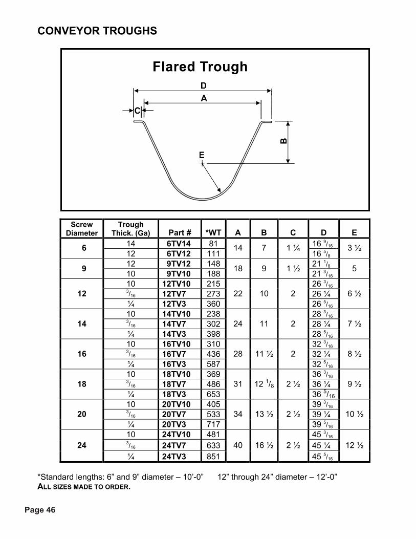
Trough Thick. (Ga) Part # *WT A B C D E
14 6TV14 81 16 9/16 6 12 6TV12 111
14 7 1 ¼ 16 5/8
3 ½
12 9TV12 148 21 1/8 9 10 9TV10 188 18 9 1 ½ 21 3/16 5
10 12TV10 215 26 3/16 3/16 12TV7 273 26 ¼ 12 ¼ 12TV3 360
22 10 2 26 5/16
6 ½
10 14TV10 238 28 3/16 3/16 14TV7 302 28 ¼ 14 ¼ 14TV3 398
24 11 2 28 5/16
7 ½
10 16TV10 310 32 3/16 3/16 16TV7 436 32 ¼ 16 ¼ 16TV3 587
28 11 ½ 2 32 5/16
8 ½
10 18TV10 369 36 3/16 3/16 18TV7 486 36 ¼ 18 ¼ 18TV3 653
31 12 1/8 2 ½ 36 5/16
9 ½
10 20TV10 405 39 3/16 3/16 20TV7 533 39 ¼ 20 ¼ 20TV3 717
34 13 ½ 2 ½ 39 5/16
10 ½
10 24TV10 481 45 3/16 3/16 24TV7 633 45 ¼ 24 ¼ 24TV3 851
40 16 ½ 2 ½ 45 5/16
12 ½
*Standard lengths: 6” and 9” diameter – 10’-0” 12” through 24” diameter – 12’-0” ALL SIZES MADE TO ORDER.
Page 47

Page 47
CONVEYOR TROUGHS
Std. Housing Split Tube Screw Dia.
Trough Thick. Part # *WT Part # *WT
A Inside C D
16 6TO16 50 6TO16ST 60 9 5/8 14 6TO14 62 6TO14ST 75 9 11/16 12 6TO12 85 6TO12ST 103 9 11/16 10 6TO10 110 6TO10ST 133 9 ¾
6
3/16 6TO7 — 6TO7ST 168
7 1 ¼
9 7/8 14 9TO14 89 9TO14ST 104 13 3/16 12 9TO12 122 9TO12ST 143 13 3/16 10 9TO10 155 9TO10ST 182 13 ¼ 3/16 9TO7 208 9TO7ST 245 13 3/8
9
¼ 9TO3 — 9TO3ST 324
10 1 ½
13 ½ 12 12TO12 196 12TO12ST 232 17 3/16 10 12TO10 250 12TO10ST 296 17 ¼ 3/16 12TO7 330 12TO7ST 394 17 3/8
12
¼ 12TO3 434 12TO3ST 518
13 2
17 ½ 12 14TO12 224 14TO12ST 260 19 3/16 10 14TO10 283 14TO10ST 330 19 ¼ 3/16 14TO7 379 14TO7ST 443 19 3/8
14
¼ 14TO3 499 14TO3ST 523
15 2
19 ½ 12 16TO12 254 16TO12ST 290 21 3/16 10 16TO10 321 16TO10ST 368 21 ¼ 3/16 16TO7 430 16TO7ST 493 21 3/8
16
¼ 16TO3 566 16TO3ST 650
17 2
21 ½ 12 18TO12 290 18TO12ST 336 24 3/16 10 18TO10 365 18TO10ST 424 24 ¼ 3/16 18TO7 486 18TO7ST 566 24 3/8
18
¼ 18TO3 640 18TO3ST 746
19 2 ½
24 ½ 10 20TO10 402 20TO10ST 458 26 ¼ 3/16 20TO7 535 20TO7ST 612 26 3/8 20 ¼ 20TO3 703 20TO3ST 806
21 2 ½ 26 ½
10 24TO10 479 24TO10ST 535 30 ¼ 3/16 24TO7 637 24TO7ST 714 30 3/8 24 ¼ 24TO3 839 24TO3ST 942
25 2 ½ 30 ½
*Standard Lengths: 6” and 9” diameter – 10’ 0” *12” through 24” diameter – 12’ 0” *ALL SIZES MADE TO ORDER.
Page 48

Page 48
B Dimension
Scre
w
Dia
met
er
A *Flush End
Spout Standard
Spout C D E K
(Ga) 6 7 3 ½ 6 5 5 5/8 14 3/8
14 12
9 10 5 8 7 1/8 7 1/8 19 1/16 14 10
12 13 6 ½ 10 ½ 8 7/8 9 24 7/8 12 3/16
14 15 7 ½ 11 ½ 10 1/8 10 27 ¾ 12 3/16
16 17 8 ½ 13 ½ 11 1/8 12 30 11/16 12 3/16
18 19 9 ½ 14 ½ 12 3/8 13 3/8 33 5/8 12 3/16
20 21 10 ½ 15 ½ 13 3/8 15 36 5/8 12 3/16
24 25 12 ½ 17 ½ 15 3/8 18 1/8 42 5/8 12 3/16
Flush End Spout Spout Less Slide Spout With Slide Screw Dia.
Trough Thickness
Discharge Thickness Part # WT Part # WT Part # WT
16-14-12 14 6DC14F 3 6DC14 4 6DC14S 11 6 10- 3/16 12 6DC12F 5 6DC12 6 6DC12S 13 16-14-12-10 14 9DC14F 6 9DC14 8 9DC14S 18 9 3/16 - ¼ 10 9DC10F 10 9DC10 13 9DC10S 22 12-10 12 12DC121F 13 12DC12 17 12DC12S 36 12 3/16 - ¼ 3/16 12DC7F 22 12DC7 29 12DC7S 48 12-10 12 14DC12F 17 14DC12 22 14DC12S 46 14 3/16 - ¼ 3/16 14DC7F 29 14DC7 38 14DC7S 62 12-10 12 16DC12F 16 16DC12 21 16DC12S 49 16 3/16 - ¼ 3/16 16DC7F 30 16DC7 40 16DC7S 68 12-10 12 18DC12F 23 18DC12 32 18DC12S 69 18 3/16 - ¼ 3/16 18DC7F 45 18DC7 60 18DC7S 97 10 12 20DC12F 30 20DC12 40 20DC12S 91 20 3/16 - ¼ 3/16 20DC7F 50 20DC7 67 20DC7S 118 10 12 24DC12F 39 24DC12 52 24DC12S 116
24 3/16 - ¼ 3/16 24DC7F 65 24DC7 87 24DC7S 151 *Flush End Discharges should be same gauge as trough for uniform fit.
Page 49

Page 49
Bulkheads
BULKHEADS MAY BE USED WHEN CONVEYING HIGH-TEMPERATURE MATERIALS. THE VOID AREA SHOULD BE PACKED WITH NON-COMBUSTIBLE MATERIAL TO DISSIPATE HEAT FROM THE BEARING OR DRIVE.
SCREW DIA (“) PART # A B C D (GA) E F BOLT
6 6SBH 6 15/16 4 ½ 2 10 * 3/8
9 9SBH 9 15/16 6 1/8 2 3/16 * 3/8
12 12SBH 12 15/16 7 ¾ 2 3/16 * ½ 14 14SBH 14 15/16 9 ¼ 2 3/16 * ½ 16 16SBH 16 15/16 10 5/8 2 3/16 * 5/8
18 18SBH 18 15/16 12 1/8 2 3/16 * 5/8
20 20SBH 20 15/16 13 1/8 2 ½ ¼ * 5/8
24 24SBH 24 15/16 16 1/8 2 ½ ¼ * 5/8 *VARIES WITH PIPE SIZE
Page 50

Page 50
END FLANGES
TUBULAR-TROUGH
A Trough Thickness
Scre
w
Dia
met
er
Part # THRU 10 GA
3/16 -¼ C D H
BOLTS WT. 6 6EF-O 7 ¼ 7 3/8 1 ¼ ¼ 3/8 1.8 9 9EF-O 10 ¼ 10 ½ 1 ½ ¼ 3/8 3 12 12EF-O 13 ¼ 13 ½ 2 ¼ ½ 6.9 14 14EF-O 15 ¼ 15 ½ 2 ¼ ½ 7.8 16 16EF-O 17 ¼ 17 ½ 2 ¼ 5/8 8.7 18 18EF-O 19 ¼ 19 ½ 2 ½ ¼ 5/8 12.3 20 20EF-O 21 ¼ 21 ½ 2 ½ ¼ 5/8 13.4 24 24EF-O 25 ¼ 25 ½ 2 ½ ¼ 5/8 15.6
RECTANGULAR-TROUGH A
TROUGH THICK.E
TROUGH THICK.
SCR
EW D
IA.
PART # B C D THRU 10 GA
3/16 -¼ THRU 10 GA
3/16 –¼ H
BOLT WT 6 6EF-R 7 ¼ 1 ¼ ¼ 7 ¼ 7 3/8 3 5/8 3 11/16 3/8 1.7 9 9EF-R 10 ¼ 1 ½ ¼ 10 ¼ 10 ½ 5 1/8 5 ¼ 3/8 2.9 12 12EF-R 13 ¼ 2 ¼ 13 ¼ 13 ½ 6 5/8 6 ¾ ½ 6.6 14 14EF-R 15 ½ 2 ¼ 15 ¼ 15 ½ 7 5/8 7 ¾ ½ 7.6 16 16EF-R 17 ¼ 2 ¼ 17 ¼ 17 ½ 8 5/8 8 ¾ 5/8 8.5 18 18EF-R 19 ¼ 2 ½ ¼ 19 ¼ 19 ½ 9 5/8 9 ¾ 5/8 12.1 20 20EF-R 21 ¼ 2 ½ ¼ 21 ¼ 21 ½ 10 5/8 10 ¾ 5/8 13.3 24 24EF-R 25 ¼ 2 ½ ¼ 25 ¼ 25 ½ 12 5/8 12 5/8 5/8 15.8
Page 51

Page 51
END FLANGES
U-TROUGH A
Trough Thickness
Scre
w
Dia
met
er
Part #
THRU 10 GA
3/16-1/4
B
C
D
H
BOLTS
WT. 6 6EF-U 7 ¼ 7 3/8 4 ½ 1 3/8 ¼ 3/8 1.5 9 9EF-U 10 ¼ 10 ½ 6 1/8 1 11/16 ¼ 3/8 2.4 12 12EF-U 13 ¼ 13 ½ 7 ¾ 2 ¼ ½ 5.5 14 14EF-U 15 ¼ 15 ½ 9 ¼ 2 ¼ ½ 6.5 16 16EF-U 17 ¼ 17 ½ 10 5/8 2 ¼ 5/8 7.4 18 18EF-U 19 ¼ 19 ½ 12 1/8 2 ½ ¼ 5/8 10.4 20 20EF-U 21 ¼ 21 ½ 13 ½ 2 ½ ¼ 5/8 11.5 24 24EF-U 25 ¼ 25 ½ 16 ½ 2 ½ ¼ 5/8 13.5
FLARED-TROUGH F
TROUGH THICK.
A/2
SCR
EW
DIA
.
PART#
B
C
D
THRU 10 GA
3/16-1/4
THRU 10 GA
3/16-1/4
H
BOLT
WT
6 6EF-F 7 1 3/8 ¼ 14 ¼ 14 ½ 3 5/8 3 11/16 3/8 1.9 9 9EF-F 9 1 11/16 ¼ 18 ¼ 18 ½ 5 1/8 5 ¼ 3/8 3 12 12EF-F 10 2 ¼ 22 ¼ 22 ½ 6 5/8 6 ¾ ½ 6.4 14 14EF-F 11 2 ¼ 24 ¼ 24 ½ 7 5/8 7 ¾ ½ 7.3 16 16EF-F 11 ½ 2 ¼ 28 ¼ 28 ½ 8 5/8 8 ¾ 5/8 7.9 18 18EF-F 12 3/8 2 ½ ¼ 31 ¼ 31 ½ 9 5/8 9 ¾ 5/8 11 20 20EF-F 13 ½ 2 ½ ¼ 34 ¼ 34 ½ 10 5/8 10 ¾ 5/8 11 24 24EF-F 16 1/2 2 1/2 ¼ 40 ¼ 40 ½ 12 5/8 12 5/8 5/8 13
Page 52

Page 52

Page 53
SEALS
PART # C SHAFT DIA.(“) LIP WASTE PACK FELT A B MIN. MAX.
D BOLTS WT
1 SWP2-L SWP2 SWP2-F 3 ¾ 1 ¾ 2 ¾ 2 ¾ 3/8 4 1 ½ SWP3-L SWP3 SWP3-F 5 3/8 1 ¾ 4 4 1/8 ½ 6 2 SWP4-L SWP4 SWP4-F 6 ½ 1 ¾ 4 3/8 5 1/8
5/8 8 2 7/16 SWP5-L SWP5 SWP5-F 7 3/8 1 ¾ 5 3/8 5 5/8
5/8 9 3 SWP6-L SWP6 SWP6-F 7 ¾ 1 ¾ 6 6 ¾ 13 3 7/16 SWP7-L SWP7 SWP7-F 9 ¼ 2 ¼ 6 ¾ 7 ¾ 17
PART # A
SHAFT DIA.(“) GRAPHITE
AIR PURGED
SEAL B C D
BOLTS E WT 1 SPG2 SPG2-A 4 2 ¾ ½ 3/8 10 1 ½ SPG3 SPG3-A 5 3/8 4 ½ 3/8 14 2 SPG4 SPG4-A 6 ½ 5 1/8 ½ 3/8 18
2 7/16 SPG5 SPG5-A 7 3/8 5 5/8 ½ 3/8 21 3 SPG6 SPG6-A 7 ¾ 6 ½ 3/8 27
3 7/16 SPG7 SPG7-A 9 ¼ 6 ¾ 5/8 ½ 30 3 15/16 SPG8 SPG8-A 10 ¼ 7 ¾ 5/8 ½ 35
4 7/16 SPG9 SPG9-A 10 ¾ 8 ¼ 5/8 ½ 40 4 15/16 SPG10 SPG10-A 11 ½ 9 5/8 ½ 45
5 7/16 SPG11 SPG11-A 11 ½ 9 5/8 ½ 50
Page 54

Page 54
COMPONENT SELECTION Shrouds are used in trough sections of screw feeders to decrease the clearance between the cover and feeder screw to obtain proper feed regulation. Lengths are sufficient to prevent flushing of the majority of materials being handled and gauges are proportioned to trough size and gauge. SHROUDS
Part Number Wt. (lbs) A B C
Scre
w
Dia
(“)
Shro
ud
Thic
k. (G
A)
U-Trough Flared U-T
roug
h
Flar
ed
U-T
roug
h
Flar
ed
U-T
roug
h
Flar
ed
Leng
th
12 6SHD12U 6SHD12V 11 16 7 13 ¾ 2 11/16 6 ¾ 14 6 7 6SHD7U 6SHD7V 7 13 7 13 ¼ 2 11/16 6 ¾ 14
12 9SHD12U 9SHD12V 17 28 10 17 ¾ 3 13/16 8 9/16 18 9 7 9SHD7U 9SHD7V 13 23 10 17 ¾ 3 13/16 8 9/16 18
12 10SHD12U 10SHD12V 19 — 11 — 3 13/16 — 2010 7 10SHD7U 10SHD7V 14 — 11 — 3 13/16 — 20
12 12SHD12U 12SHD12V 28 41 13 21 ¾ 4 ¾ 9 ½ 2412 7 12SHD7U 12SHD7V 20 32 13 21 ¾ 4 ¾ 9 ½ 24
12 14SHD12U 14SHD12V 37 54 15 23 ¾ 5 13/16 10 5/16 2814 7 14SHD7U 14SHD7V 30 42 15 23 ¾ 5 13/16 10 5/16 28
12 16SHD12U 16SHD12V 47 68 17 27 ¾ 6 13/16 11 1/8 3216 7 16SHD7U 16SHD7V 35 52 17 27 ¾ 6 13/16 11 1/8 32
12 18SHD12U 18SHD12V 60 82 19 30 ¾ 7 7/8 11 7/8 3618 7 18SHD7U 18SHD7V 45 63 19 30 ¾ 7 7/8 11 7/8 36
20 7 20SHD7U 20SHD7V 71 100 21 33 ¾ 8 11/16 13 1/8 4024 7 24SHD7U 24SHD7V 100 142 25 39 ¾ 10 7/8 15 15/16 48
Page 55

Page 55
SADDLES & FEET
H
J
SCR
EW
DIA
. (“)
PART # A B C D E F BOLTS BOLTS WT 6 6SFF 8 1/8 5 5/8 10 3/16 1 ¾ 1 3/8 3/8 2.0 9 9SFF 9 3/8 7 7/8 12 3/16 2 5/8 1 ½
3/8 ½ 3.0
12 12SFF 12 ¼ 9 5/8 15 3/16 2 ¾ 1 5/8 ½ 5/8 6.0
14 14SFF 13 ½ 10 7/8 16 ½ ¼ 2 7/8 1 5/8 ½ 5/8 7.0
16 16SFF 14 7/8 12 18 ¼ 3 ¼ 2 5/8 5/8 7.5
18 18SFF 16 13 3/8 19 1/8 ¼ 3 ¼ 2 5/8 5/8 9.5
20 20SFF 19 ¼ 15 22 ¾ 5/16 3 ¼ 2 ¼ 5/8 ¾ 12.5
24 24SFF 20 18 1/8 24 5/16 4 1/8 2 ½ 5/8 ¾ 14.5
Page 56

Page 56
SCREW DIA (“) PART # A B C D E F* G* H I J
6 6FF-S 10 8 1/8 3/16 5 5/8 3 13/16 3/8 3/8 1 ¾ 1 1 ½ 9 9FF-S 12 9 3/8 3/16 7 7/8 5 5/16 ½ 3/8 2 5/8 1 ½ 2 12 12FF-S 15 12 ¼ 3/16 9 5/8 6 7/8 5/8 ½ 2 ¾ 1 5/8 2 14 14FF-S 16 ½ 13 ½ ¼ 10 7/8 7 7/8 5/8 ½ 2 7/8 1 5/8 2 16 16FF-S 18 14 7/8 ¼ 12 8 7/8 5/8 5/8 3 ¼ 2 2 ½ 18 18FF-S 19 1/8 16 ¼ 13 3/8 9 7/8 5/8 5/8 3 ¼ 2 2 ½ 20 20FF-S 22 ¾ 19 ¼ 5/16 15 10 7/8 ¾ 5/8 3 ¾ 2 ¼ 2 ½ 24 24FF-S 24 20 5/16 18 1/8 12 7/8 ¾ 5/8 4 1/8 2 ½ 2 ½
SCREW DIA. (“)
PART # K L M N O P Q DETAIL “A”
6 6FF-S 1 ¼ 5/8 13/16 9/32 7/8 7/16 X 9/16 1 ½ 1 ½ X 1 ½ X 3/16
9 9FF-S 1 ½ ¾ 1 3/8 1 1/8 7/16 X 7/8 1 ½ 2 X 1 ½ X 3/16
12 12FF-S 1 ½ ¾ 1 3/8 1 5/16 9/16 X 7/8 1 ½ 2 X 1 ½ X 3/16
14 14FF-S 1 ½ ¾ 1 3/8 1 5/16 9/16 X 7/8 1 ½ 2 X 1 ½ X 3/16
16 16FF-S 1 ½ ¾ 1 ¼ 7/16 1 5/16 11/16 X 11/16 2 2 X 1 ½ X 3/16
18 18FF-S 1 ½ ¾ 1 ¼ 7/16 1 5/16 11/16 X 11/16 2 2 X 1 ½ X 3/16
20 20FF-S 1 ½ ¾ 1 ¼ 7/16 1 5/16 11/16 X 11/16 2 2 X 1 ½ X 3/16
24 24FF-S 1 ½ ¾ 1 ¼ 7/16 1 5/16 11/16 X 11/16 2 2 X 1 ½ X 3/16
Page 57

Page 57
DRIVE SHAFTS
A
Dimension Part Number
SHA
FT
DIA
MET
ER
With Seal
Without Seal
With Seal
Without Seal B C D E F G H
BO
LTS
I J
1 ½ 13 ½ 11 ½ DS3-D DS3-E 4 1/8 5 3/8 4 3 ¼ 3 5 15/16 ½ 1 ¾ 1 3/16
2 15 13 ¼ DS4-D DS4-E 4 3/8 5 5/8 4 1/8 4 ¼ 4 6 ½ 1 ¾ 1 ¼
2 7/16 17 15 ¼ DS5-D DS5-E 5 3/8 6 7/8 4 11/16 5 ¼ 5 6 1/8 5/8 2 1 ¾
3 18 ½ 16 ¾ DS6-D DS6-E 6 7 ¾ 5 3/16 6 ¼ 6 6 13/16 ¾ 2 1/8 1 13/16
3 7/16 23 20 ¾ DS7-D DS7-E 7 9 ¼ 5 7/8 7 ¼ 7 9 1/8 ¾ 2 ½ 2 3/8
WEIGHT Shaft Diameter (inches)
WITH SEAL
WITHOUT SEAL
1 ½ 19 16
2 28 24
2 7/16 46 40
3 69 58
3 7/16 109 93
Page 58

Page 58
COUPLING SHAFTS
PART # A SHAFT
DIA. STD
# HRD # F G H
BOLTS L M N WT 1 ½ CS3 CS3H 11 ½ 2 ½ 7/8 3 7/8 5.8 2 CS4 CS4H 11 ½ 2 5/8 7/8 3 7/8 10.3 2 7/16 CS5 CS5H 12 ¾ 3 5/8 15/16 3 15/16 15.6 3 CS6 CS6H 13 3 ¾ 1 3 1 26 3 7/16 CS7 CS7H 17 ½ 4 7/8 1 ½ 4 1 ½ 47
A SHAFT DIA
PART # F
H BOLTS L M N WT
1 ½ CCS3 9 ½ ½ 7/8 3 7/8 4.8 2 CCS4 9 ½ 5/8 7/8 3 7/8 8.5 2 7/16 CCS5 9 ¾ 5/8 15/16 3 15/16 12.9 3 CCS6 10 ¾ 1 3 1 20 3 7/16 CCS7 13 ½ 7/8 1 ¼ 4 1 ½ 37 3 15/16 CCS8 13 ½ 1 1 ¼ 4 1 ½ 48
Page 59

Page 59
SHAFTS
B A Dimensions Ball Bearing Ball Bearing
Shaft Dia.
With Seal
Part # Without Seal
Part #C D E F
H Bolts G I J
1 ½ 10 ES3-S 8 ½ ES3 7/8 3 1 1 ¾ ½ 7/8 3/16 5 ¾2 10 ½ ES4-S 8 ¾ ES4 7/8 3 1 1 ¾ 5/8 7/8 ¼ 5 ¾2 7/16 11 ½ ES5-S 9 ¾ ES5 15/16 3 1 ½ 1 ¾ 5/8 15/16 ¼ 6 3/83 12 ½ ES6-S 10 ¾ ES6 1 3 1 ½ 1 ¾ ¾ 1 5/16 6 ½3 7/16 15 ¾ ES7-S 13 ½ ES7 1 ¼ 4 2 2 ¼ 7/8 1 ½ 3/8 8 ¾
B A Dimensions Ball Bearing
Shaft Dia.
With Seal Part # C D E H Bolts F G I J
1 ½ 16 ¾ ES3-O 7/8 3 1 ½ 5 7/8 3/16 5 ¾ 2 167/8 ES4-O 7/8 3 1 5/8 5 ½ 7/8 ¼ 5 ¾ 2 7/16 17¾ ES5-O 15/16 3 1 ½ 5/8 6 ½ 15/16 ¼ 6 3/8 3 187/8 ES6-O 1 3 1 ½ ¾ 7 1 5/16 6 ½ 3 7/16 23 ES7-O 1 ¼ 4 2 7/8 7 ¾ 1 ½ 3/8 8 ¾
Page 60

Page 60
End Lugs, Internal Collars, Coupling Bolts
Part Numbers
Intake End Lug Part Numbers
Discharge End Lug Screw Dia. Right Hand Left Hand Right Hand Left Hand
Weight Each (LBS)
6 EL6RI EL6LI EL6RD EL6LD .06 9 EL9RI EL9LI EL9RD EL9LD .15 12 EL12RI EL12LI EL12RD EL12LD .43 14 EL14RI EL14LI EL14RD EL14LD .43 16 EL16RI EL16LI EL16RD EL16LD .68 18 EL18RI EL18LI EL18RD EL18LD .68 20 EL20RI EL20LI EL20RD EL20LD .68 24 EL24RI EL24LI EL24RD EL24LD .68
Coupling Dia. Nominal
Pipe Size* Part
Number L Weight
Each (LBS) 1 ½ 2 IC3 4 ¾ 2.2
2 2 ½ IC4 4 ¾ 2.4 2 7/16 3 IC5 5 4.1 3 3 ½ IC6 5 4.3 3 4 IC6A 5 8.3 3 7/16 4 IC7 6 ¾ 7.3
* Schedule 40 Pipe
Coupling Dia.
Outside Pipe Dia.
Nominal Pipe Size* Bolt Size
Part No. Standard
Part No. High
Torque
Weight Each (LBS)
1 ½ 2 3/8 2 ½ X 3 CB3-x.xx CB3HT .25 2 2 2 ½ 5/8 X 3 5/8 CB4-x.xx CB4HT .50 2 7/16 3 3 ½ 5/8 X 4 1/4 CB5-x.xx CB5HT .56 3 3 ½ 4 ¾ X 5 CB6-x.xx CB6HT .75 3 4 4 ½ ¾ X 5 ½ CB6A-x.xx CB6AHT .88 3 7/16 4 4 ½ 7/8 X 5 ½ CB7-x.xx CB7HT 1.25
* Schedule 40 Pipe Page 61

Page 61Page 62
TROUGH ENDS – WITH FEET
PART NUMBER BSCREWDIA (“) U-TROUGH TUBULAR A U-TROUGH TUBULAR C D E
6 6EP3-U 6EP3-O 1 ¾ 4 ½ 4 7/8 5 5/8 8 1/8 9 ¾ 9EP3-U 9EP3-O 1 ¾9 9EP4-U 9EP4-O 2 ¼ 6 1/8 6 ¾ 7 7/8 9 3/8 13 ½
12EP4-U 12EP4-O 2 ¼ 12EP5-U 12EP5-O 2 5/812 12EP6-U 12EP6-O 3 ¼
7 ¾ 8 5/8 9 5/8 12 ¼ 17 ¼
14EP5-U 14EP5-O 2 5/814 14EP6-U 14EP6-O 3 ¼ 9 ¼ 9 5/8 10 7/8 13 ½ 19 ¼
16 16EP6-U 16EP6-O 3 ¼ 10 5/8 10 5/8 12 14 7/8 21 ¼ 18EP6-U 18EP6-O 3 ¼ 18 18EP7-U 18EP7-O 3 5/8
12 1/8 12 1/8 13 3/8 16 24 ¼
20EP6-U 20EP6-O 3 ¼ 20 20EP7-U 20EP7-O 3 5/813 ½ 13 1/8 15 19 ¼ 26 ¼
24 24EP7-U 24EP7-O 3 5/8 16 ½ 15 1/8 18 1/8 20 30 ¼
F K-BOLT PATTERN WEIGHT SCREWDIA (“)
U-TROUGH G H BALL BEARING ROLLER BEARING M
NHOLEDIA (“) U TUB.
6 1 ½ 1 3/16 4 4 1/8 1 ¾ 9/16 12 11 1 ½ 4 4 1/8 18 15 9 2
1 5/8 ¼ 5 1/8 4 3/8
2 5/8 9/16 21 18
2 5 1/8 4 3/8 36 29 2 7/16 5 7/8 5 3/8 38 31 12
3 2 ¼
6 6 2 ¾ 9/16
50 43 2 7/16 5 7/8 5 3/8 45 39 14
3 2 5/16 6 6
2 7/8 9/16 57 51
16 3 2 1/2 5/16 6 6 3 ¼ 11/16 75 65 3 6 6 89 78 18 3 7/16
2 1/2 3/8 6 ¾ 7 3 ¼ 11/16 99 89
3 6 6 126 115 203 7/16
2 1/2 3/8 6 ¾ 7 3 ¾ 11/16 132 127
24 3 7/16 2 1/2 3/8 6 ¾ 7 4 1/811/16 169 157

Page 62
TROUGH ENDS – WITH FEET
PART NUMBER B D E F
SCR
EW
DIA
(“)
FLARED RECT. A FLARE RECT C FLARE RECT FLARE RECT FLARE RECT
6 6EP3-F 6EP3-R 1 ¾ 7 4 ½ 5 5/8 8 1/8 8 1/8 9 ¾ 9 ¾ 1 ½ 1 ½ 9EP3-F 9EP3-R 1 ¾ 9 9EP4-F 9EP4-R 2 ¼
9 6 1/8 7 7/8 9 3/8 9 3/8 13 ½ 13 ½ 1 5/8 1 5/8
12EP4-F 12EP4-R 2 5/8 12EP5-F 12EP5-R 2 5/8 12 12EP6-F 12EP6-R 3 ¼
10 7 ¾ 9 5/8 12 ¼ 12 ¼ 17 ¼ 17 ¼ 2 2
14EP5-F 14EP5-R 3 ¼ 14 14EP6-F 14EP6-R 3 ¼ 11 9 ¼ 10 7/8 13 ½ 13 ½ 19 ¼ 19 ¼ 2 2
16 16EP6-F 16EP6-R 3 ¼ 11 ½ 10 5/8 12 14 7/8 14 7/8 21 ¼ 21 ¼ 2 ½ 2 ½ 18EP6-F 18EP6-R 3 ¼ 18 18EP7-F 18EP7-R 3 5/8
12 1/8 12 1/8 13 3/8 16 16 24 ¼ 24 ¼ 2 ½ 2 ½
20EP6-F 20EP6-R 3 ¼ 20 20EP7-F 20EP7-R 3 5/8 13 ½ 13 ½ 15 19 ¼ 19 ¼ 26 ¼ 26 ¼ 2 ½ 2 ½
24 24EP7-F 24EP7-R 3 5/8 16 ½ 16 ½ 18 1/8 20 20 30 ¼ 30 ¼ 2 ½ 2 ½
PART NUMBER K-BOLT PTTRN WEIGHT
SCR
EW
DIA
(“)
FLARED RECT G H J RLLR BALL L-SLOT M N SHA
FT
DIA
(“)
FLARE RECT
6 6EP3-F 6EP3-R 1 3/16 16 5/8 4 4 1/8 7/16 X 1 1 ¾ 7/16 1 ½ 15 13 9EP3-F 9EP3-R 5 1/8 4 1/8 1 ½ 22 19 9 9EP4-F 9EP4-R
1 ½ ¼ 21 ¼ 6 4 3/8
9/16 X 1 2 5/8
7/16 2 27 24
12EP4-F 12EP4-R 5 1/8 4 3/8 2 43 39 12EP4-F 12EP5-R 5 5/8 5 3/8 2 7/16 33 40 12
12EP5-F 12EP6-R
1 5/8 ¼
26 3/8
6 6
1/16 X 1 1/8
2 ¾
9/16
3 56 58 14EP5-F 14EP5-R 5 5/8 5 3/8 2 7/16 52 48 14 14EP6-F 14EP6-R
1 5/8 5/16
28 3/8 6 6
1/16 X 1 1/8
2 7/8
9/16 3 64 66
16 16EP6-F 16EP6-R 2 5/16 32 ½ 6 6 1/16 X 1 1/8 3 ¼ 11/16 3 85 85 18EP6-F 18EP6-R 6 6 3 98 94 18 18EP7-F 18EP7-R
2 3/8 36 ½
6 ¾ 7
1/16 X 1 1/8
3 ¼
11/16 3 7/16 104 101
20EP6-F 20EP6-R 6 6 3 133 134 20 20EP7-F 20EP7-R
2 ¼ 3/8 39 ½
6 ¾ 7
13/16 X 1 1/8
3 ¾
11/16 3 7/16 139 140
24 24EP7-F 24EP7-R 2 ½ 3/8 45 ½ 6 ¾ 7 13/16 X 1 1/8 4 1/8 11/16 3 7/16 173 179
Page 63

Page 63
TROUGH ENDS WITHOUT FEET
PART NUMBER B SCREW DIA (“) U-TROUGH TUBULAR A U-TROUGH TUBULAR C D E
6 6EP3-U 6EP3-O 1 ¾ 4 ½ 4 7/8 4 7/8 2 27/32 9 ¾ 9EP3-U 9EP3-O 1 ¾ 9 9EP4-U 9EP4-O 2 ¼
12 1/8 6 ¾ 6 ¾ 3 15/16 13 ½
12EP4-U 12EP4-O 2 ¼ 12EP5-U 12EP5-O 2 5/8 12 12EP6-U 12EP6-O 3 ¼
7 ¾ 8 5/8 8 5/8 5 1/16 17 ¼
14EP5-U 14EP5-O 2 5/8 14 14EP6-U 14EP6-O 3 ¼ 9 ¼ 9 5/8 9 5/8 5 1/8 19 ¼
16 16EP6-U 16EP6-O 3 ¼ 10 5/8 10 5/8 10 5/8 6 7/32 21 ¼ 18EP6-U 18EP6-O 3 ¼18 18EP7-U 18EP7-O 3 5/8
12 1/8 12 5/8 12 1/8 7 3/32 24 ¼
20EP6-U 20EP6-O 3 ¼20 20EP7-U 20EP7-O 3 5/8 13 ½ 13 5/8 13 1/8 7 11/16 26 ¼
24 24EP7-U 24EP7-O 3 5/8 15 1/8 15 5/8 15 1/8 8 27/32 30 ¼
F K-BOLT PATTERN WEIGHT SCREW DIA. (“) U-TROUGH H BALL BEARING ROLLER BEARING N-HOLE DIA. U-TROUGH TUBULAR
6 1 ½ 3/16 4 4 1/8 9/16 10 9 ¼ 5 1/8 4 1/8 9/16 15 12 9 1 5/8 ¼ 6 4 3/8 9/16 18 15 ¼ 5 1/8 4 3/8 11/16 29 22 ¼ 5 5/8 5 3/8 11/16 31 24 12 2 ¼ 6 6 11/16 43 36
5/16 5 5/8 5 3/8 11/16 36 30 14 2 5/16 6 6 11/16 48 42 16 2 ½ 5/16 6 6 13/16 62 52
3/8 6 6 13/16 74 63 18 2 ½ 3/8 6 ¾ 7 13/16 84 74 3/8 6 6 13/16 96 85 20 2 ½ 3/8 6 ¾ 7 13/16 102 97
24 2 ½ 3/8 6 ¾ 7 13/16 128 116
Page 64

Page 64
Trough Ends
PART NUMBER SCREW DIA (“) SHAFT DIA. U-TROUGH RECT
A DIA. B C E F G
6 1 ½ 6EPF3-U 6EPF3-R 1 ¾ 4 ½ 5 5/8 10 1 ½ 1 ½ 1 ½ 9EPF3-U 9EPF3-R 1 ¾ 9 2 9EPF4-U 9EPF4-R 2 ¼
6 1/8 7 7/8 13 1 5/8 1 ½
2 12EPF4-U 12EPU4-R 2 ¼ 2 7/16 12EPF5-U 12EPF5-R 2 5/8 12 3 12EPF6-U 12EPF6-R 3 ¼
7 ¾ 9 5/8 17 ¼ 2 2
2 7/16 14EPF5-U 14EPF5-R 2 5/8 14 3 14EPF6-U 14EPF6-R 3 ¼
9 ¼ 10 7/8 19 ¼ 2 2
16 3 16EPF6-U 16EPF6-R 3 ¼ 10 5/8 12 21 ¼ 2 ½ 2 3 18EPF6-U 18EPF6-R 3 ¼ 18 3 7/16 18EPF7-U 18EPF7-R 3 5/8
12 1/8 13 3/8 24 ¼ 2 ½ 2 ½
3 20EPF6-U 20EPF6-R 3 ¼ 20 3 7/16 20EPF7-U 20EPF7-R 3 5/8
13 ½ 15 26 ¼ 2 ½ 2 ½
24 3 7/16 24EPF7-U 24EPF7-R 3 5/8 16 ½ 18 1/8 30 ¼ 2 ½ 2 ½
K WEIGHT SCREW DIA (“)
SHAFT DIA. H BALL
BEARINGROLLER BEARING
N DIA. U-TROUGH RECT.
6 1 ½ 3/16 4 4 1/8 9/16 12 13 1 ½ ¼ 4 4 1/8 9/16 18 19 9 2 ¼ 5 1/8 4 3/8 9/16 21 24 2 ¼ 5 1/8 4 3/8 11/16 36 39 2 7/16 ¼ 5 5/8 5 3/8 11/16 38 40 12 3 ¼ 6 6 11/16 50 58 2 7/16 5/16 5 5/8 5 3/8 11/16 45 48 14 3 5/16 6 6 11/16 57 66
16 3 5/16 6 6 13/16 75 85 3 3/8 6 6 13/16 89 94 18 3 7/16 3/8 6 ¾ 7 13/16 99 101 3 3/8 6 6 13/16 126 134 20 3 7/16 3/8 6 ¾ 7 13/16 132 140
24 3 7/16 3/8 6 ¾ 7 13/16 169 179
Page 65

Page 65
TROUGH END BEARINGS
A BORE PART # B C D E F G H BOLTS WEIGHT 1 ½ BBPB-3 7 ¾ 1 5/16 5 7/8 2 1/8 1 5/16 2 1/8 ½ 5.6 2 BBPB-4 8 7/8 1 ½ 6 7/8 2 ½ 1 9/16 2 3/8 5/8 8 2 7/16 BBPB-5 10 ¾ 1 3/16 8 3 1 7/8 2 7/8 ¾ 13.5 3 BBPB-6 12 1 7/8 9 3 ½ 2 3/16 3 ¼ 7/8 18.4 3 7/16 BBPB-7 14 2 1/16 11 4 2 ½ 3 7/16 7/8 28.4
A BORE PART # B C D E F G H BOLTS WEIGHT 1 ½ RBPB-3 7 7/8 3 3/8 6 ¼ 2 1/8 1 ¼ 2 3/8 ½ 9.5
2 RBPB-4 8 7/8 3 ½ 7 2 ¼ 1 3/8 2 ½ 5/8 11
2 7/16 RBPB-5 10 ½ 4 8 ½ 2 ¾ 1 5/8 2 7/85/8 19
3 RBPB-6 12 4 ½ 9 ½ 3 1/8 1 7/8 3 1/8 ¾ 26
3 7/16 RBPB-7 14 5 11 3 5/8 2 ¼ 3 5/87/8 44
BRONZE AVAILABLE UPON REQUEST
Page 66

Page 66
A BORE PART # B C D E
H BOLTS WEIGHT
1 ½ BBF-3 5 1/8 2 4 9/16 ½ 4.8 2 BBF-4 6 ½ 2 3/8 5 1/8 11/16 5/8 9.6 2 7/16 BBF-5 7 2 ½ 5 5/8 11/16 5/8 11 3 BBF-6 7 ¾ 3 3/8 6 7/8 ¾ 23 3 7/16 BBF-7 8 ½ 3 7/8 6 ¾ 1 ¾ 29
ROLLER BEARING, FLANGED
A BORE PART # B C D E
H BOLTS WEIGHT
1 ½ RBF-3 5 3/8 3 ½ 4 1/8 1 ¼ ½ 10 2 RBF-4 5 5/8 3 5/8 4 3/8 1 ¼ ½ 12 2 7/16 RBF-5 6 7/8 4 ¼ 5 3/8 1 ½ 5/8 21 3 RBF-6 7 ¾ 4 ¾ 6 1 5/8 ¾ 28 3 7/16 RBF-7 9 ¼ 5 ¼ 7 1 7/8 ¾ 46
Page 67
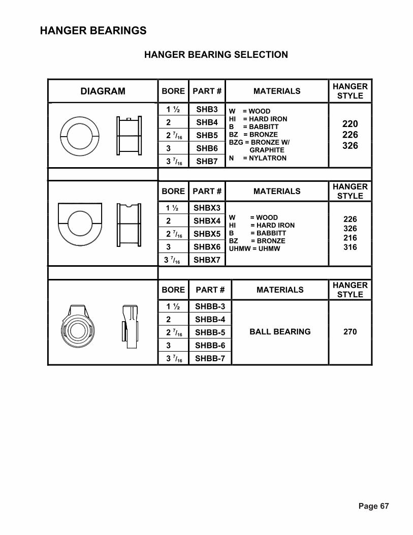
Page 67
HANGER BEARINGS
HANGER BEARING SELECTION
DIAGRAM BORE PART # MATERIALS HANGER STYLE
1 ½ SHB3 2 SHB4 2 7/16 SHB5 3 SHB6 3 7/16 SHB7
W = WOOD HI = HARD IRON B = BABBITT BZ = BRONZE BZG = BRONZE W/
GRAPHITE N = NYLATRON
220 226 326
BORE PART # MATERIALS HANGER STYLE
1 ½ SHBX3 2 SHBX4 2 7/16 SHBX5 3 SHBX6 3 7/16 SHBX7
W = WOOD HI = HARD IRON B = BABBITT BZ = BRONZE UHMW = UHMW
226 326 216 316
BORE PART # MATERIALS HANGER STYLE
1 ½ SHBB-3 2 SHBB-4 2 7/16 SHBB-5 3 SHBB-6 3 7/16 SHBB-7
BALL BEARING 270
Page 36

Page 68
HANGERS
Screw Dia. Part #
Shaft Dia. A B C D E F G
H BOLTS WT
6 6SH2203 1 ½ 8 ¾ 4 ½ 2 9 ¾ 2 ½ 4 ¼ 3/8 7 9SH2203 1 ½ 10 9 9SH2204 2 12 ¾ 6 1/8 2 13 ½ 2 ½ 4 ¼ 3/8 12
12SH2204 2 2 20 12SH2204 2 7/16 3 25 12 12SH2206 3
15 ¾ 7 ¾ 3
17 ½ 2 ½ 4 3/8 ½ 26
14SH2205 2 7/16 28 14 14SH2206 3 17 ¾ 9 ¼ 3 19 ½ 2 ½ 4 ½ ½ 30 16 16SH2206 3 19 ¾ 10 5/8 3 21 ½ 2 ½ 4 ½ ½ 33
18SH2206 3 3 45 18 18SH2207 3 7/16 22 ¼ 12 1/8 4 24 ½ 3 ½ 5 5/8 5/8 53
20SH2206 3 3 52 20 20SH2207 3 7/16 24 ¼ 13 ½ 4 26 ½ 3 ½ 5 5/8 5/8 66
24 24SH2207 3 7/16 28 ¼ 16 ½ 4 30 ½ 3 ½ 5 5/8 5/8 81
Screw Dia. Part #
Shaft Dia. A B C D E F G
H BOLTS K WT
6 6SH2703 1 ½ 7 4 ½ 2 9 ¾ 2 ½ 4 ¾ 3/8 ¼ 6 9SH2703 1 ½ 7 9 9SH2704 2 10
6 1/82 13 ½ 2 ½ 4 1 3/8 ¼
8 12SH2704 2 2 13 12SH2705 2 7/16 3 19 12 12SH2706 3
13 7 ¾ 3
17 ½ 2 ½ 4 1 ¼ ½ 3/8 24
14SH2705 2 7/16 20 14 14SH2706 3 15
9 ¼3 19 ½ 2 ½ 4 1 3/8 ½ ½
25 16 16SH2706 3 17 10 5/8 3 21 ½ 2 ½ 4 1 3/8 5/8 ½ 31
18SH2706 3 3 33 ½ 18 18SH2707 3 7/16
19 12 1/8 4
24 ½ 3 ½ 5 1 5/8 5/8 ½ 47
20SH2706 3 3 ½ 39 20 20SH2707 3 7/16
21 13 ½ 4
26 ½ 3 ½ 5 1 5/8 5/8 ¾ 52 24 24SH2707 3 7/16 25 16 ½ 4 30 ½ 3 ½ 5 1 5/8 5/8 ¾ 60
Page 69

Page 69
HANGERS
SCR
EW
DIA
. (“)
PART NUMBER SH
AFT
D
IA. (
“)
A B C E F G H
BOLTS K WT 6 6SH2263 1 ½ 7 4 ½ 2 2 ½ 4 ¾ 3/8 ¼ 7
9SH2263 1 ½ 2 9 9
9SH2264 2 10 6 1/8 2
2 ½ 4 1 3/8 ¼ 11
12SH2264 2 2 15 12SH2265 2 7/16 3 23 12 12SH2266 3
13 7 ¾3
2 ½ 4 1 ½ ½ 3/8 24
14SH2265 2 7/16 3 24 14
14SH2266 3 15 9 ¼
3 2 ½ 4 1 3/8 ½ ½
26 16 16SH2266 3 17 10 5/8 3 2 ½ 4 1 3/8 ½ ½ 29
18SH2266 3 3 39 18
18SH2267 3 7/16 19 12 1/8 4
3 ½ 5 1 5/8 5/8 ½ 52
20SH2266 3 3 42 20
20SH2267 3 7/16 21 13 ½
4 3 ½ 5 1 5/8 5/8 ¾
55
24 24SH2267 3 7/16 25 16 ½ 4 3 ½ 5 1 5/8 5/8 ¾ 65
Page 70

Page 70
HANGERS
SCR
EW
DIA
( " )
PART # SHA
FT
DIA
( "
)
A B C E F G
H
BO
LTS
K WT6 6SH3263 1 ½ 7 4 ½ 2 2 ½ 6 ¾ 3/8 1/8 7
9SH3263 1 ½ 2 9 9 9SH3264 2
10 6 1/8 2 2 ½ 6 1 3/8 3/16 10
12SH3264 2 2 14 12SH3265 2 7/16 3 19 12 12SH3266 3
13 7 ¾ 3
2 ½ 6 ½ 1 ¼ ½ 3/16
25 14SH3265 2 7/16 3 23 14 14SH3266 3
15 9 ¼ 3
2 ½ 6 ½ 1 3/8 ½ 3/16 31 16 16SH3266 3 17 10 5/8 3 2 ½ 8 1 3/8 ½ ¼ 36
18SH3266 3 3 36 18 18SH3267 3 7/16
19 12 1/8 4 3 ½ 8 1 5/8 5/8 ¼
48 20SH3266 3 3 38 20 20SH3267 3 7/16
21 13 ½ 4
3 ½ 8 1 5/8 5/8 ¼ 51
24 24SH3267 3 7/16 25 16 ½ 4 3 ½ 8 1 ¾ 5/8 3/8 58
Page 71

Page 71
HANGERS
SCR
EW
DIA
. (“)
PART # SHA
FT
DIA
(“)
A B C E F G H
BOLTS K WT 6 6SH2163 1 ½ 7 4 ½ 2 2 ½ 4 ¾ 3/8 ¼ 5
9SH2163 1 ½ 2 7 9
9SH2164 2 10 6 1/8 2
2 ½ 4 1 3/8 ¼ 9
12SH2164 2 2 14 12SH2165 2 7/16 3 18 12 12SH2166 3
13 7 ¾ 3
2 ½ 4 1 ½ ½ 3/8 21
14SH2165 2 7/16 3 23 14
14SH2166 3 15 9 ¼
3 2 ½ 4 1 3/8 ½ ½
25 16 16SH2166 3 17 10 5/8 3 2 ½ 4 1 3/8 ½ ½ 28
18SH2166 3 3 34 18
18SH2167 3 7/16 19 12 1/8 4
3 ½ 5 1 5/8 5/8 ½ 44
20SH2166 3 3 36 20
20SH2167 3 7/16 21 13 ½
4 3 ½ 5 1 5/8 1 5/8 ¾
47 24 24SH2167 3 7/16 25 16 ½ 4 3 ½ 5 1 5/8 1 5/8 ¾ 53
Page 72

Page 72
HANGERS
SCR
EW
DIA
( “ )
PART # SHA
FT
DIA
( “
)
A B C E F G
H
BO
LTS
K WT 6 6SH3163 1 ½ 7 4 ½ 2 2 ½ 6 ¾ 3/8 1/8 7
9SH3163 1 ½ 2 9 9 9SH3164 2
10 6 1/8 2 2 ½ 6 1 3/8 3/16 10
12SH3164 2 2 14 12SH3165 2 7/16 3 19 12 12SH3166 3
13 7 ¾3
2 ½ 6 ½ 1 ¼ ½ 3/16 25
14SH3165 2 7/16 3 23 14 14SH3166 3
15 9 ¼3
2 ½ 6 ½ 1 3/8 ½ 3/16 31 16 16SH3166 3 17 10 5/8 3 2 ½ 8 1 3/8 ½ 3/16 36
18SH3166 3 3 36 18 18SH3167 3 7/16
19 12 1/8 4 3 ½ 8 1 5/8 5/8 ¼
48 20SH3166 3 3 38 20 20SH3167 3 7/16
21 13 ½ 4
3 ½ 8 1 5/8 5/8 ¼ 51
24 24SH3167 3 7/16 25 16 ½ 4 3 ½ 8 1 5/8 5/8 ¼ 58
Page 73

Page 73
DISCHARGE GATES
DIMENSIONS
CO
NV.
SIZ
E
PART # A B C D E F G H J K P A
IR C
YL. B
OR
E
6 6CVGT-A-E 13 ½ 7 10 30 4/9 11/16 2 13/16 — 3 19 4 7/16 2
9 9CVGT-A-E 17 1/8 10 13 39 4/9 ½ 4 — 4 25 5 7/16 2
12 12CVGT-A-E 19 ¾ 13 17 ¼ 48 9/16 7/8 5 1/8 — 5 ¼ 31 6 7/16 2 ½
14 14CVGT-A-E 22 ¼ 15 19 ¼ 54 9/16 7/8 3 ½ 3 ½ 3 ½ 35 6 7/16 2 ½
16 16CVGT-A-E 24 5/8 17 21 ¼ 61 3/8 7/8 3 ¾ 4 4 39 7 7/16 3 ¼
18 18CVGT-A-E 27 7/8 19 24 ¼ 67 3/8 1 1/8 4 7/16 4 3/8 4 3/8 43 7 9/16 3 ¼
20 20CVGT-A-E 29 ½ 21 26 ¼ 73 3/8 1 1/8 4 7/8 4 ¾ 4 ¾ 47 8 9/16 3 ¼
24 24CVGT-A-E 34 ½ 25 20 ¼ 85 3/8 1 1/8 5 5/8 5 5/8 5 ½ 55 9 9/16 3 ¼
Page 74

Page 74
DISCHARGE GATES
DIMENSIONS
CO
NV.
SI
ZE
PART # A B C D E F G H J A
IR C
YL.
BO
RE
6 6CVGT-A 13 ½ 7 19 11 30 7/16 3 HOLES – 4 ½ C-C=9 4 HOLES-4.333 C-C=13 14 ¼ 22 ¼ 2
9 9CVGT-A 17 1/8 10 25 14 39 7/16 4 HOLES – 4 C-C=12 4 HOLES-5.333 C-C=16 17 ¼ 28 ¼ 2
12 12CVGT-A 19 ¾ 13 31 17 48 9/16 4 HOLES – 5 C-C=15 4 HOLES-6.333 C-C=19 20 ¼ 34 ¼ 2 ½
14 14CVGT-A 22 ¼ 15 35 19 54 9/16 5 HOLES – 4 ¼ C-C=17 6 HOLES-4.2 C-C=21 22 ¼ 34 ¼ 2 ½
16 16CVGT-A 24 5/8 17 39 21 61 3/8 5 HOLES – 4 ¾ C-C=19 6 HOLES-4.6 C-C=23 24 ¼ 38 ¼ 3 ¼
18 18CVGT-A 27 1/8 19 43 23 67 3/8 5 HOLES – 5 ¼ C-C=21 6 HOLES-D C-C=25 26 ¼ 42 ¼ 3 ¼
20 20CVGT-A 29 ½ 21 47 25 73 3/8 5 HOLES – 5 ¾ C-C=23 6 HOLES-5.4 C-C=27 28 ¼ 50 ¼ 3 ¼
24 24CVGT-A 34 ½ 25 55 29 85 3/8 7 HOLES – 4 ½ C-C=27 6 HOLES-6.2 C-C=31 32 ¼ 58 ¼ 3 ¼
Page 75

Page 75
DISCHARGE GATES
DIMENSIONS
CO
NV.
SIZ
E
PART # A B C D E F G H J
6 6CVGT-RP 13 ½ 7 19 11 11 3 HOLES-4 ½ C-C=9 4 HOLES-4.333 C-C=13 14 ¼ 22 ¼
9 9CVGT-RP 17 1/8 10 25 14 14 4 HOLES-4 C-C=12 4 HOLES-5.333 C-C=16 17 ¼ 28 ¼
12 12CVGT-RP 19 ¾ 13 31 17 17 4 HOLES-5 C-C=15 4 HOLES-6.333 C-C=19 20 ¼ 34 ¼
14 14CVGT-RP 22 ¼ 15 35 19 19 5 HOLES-4 ¼ C-C=17 6 HOLES-4.2 C-C=21 22 ¼ 38 ¼
16 16CVGT-RP 24 5/8 17 39 21 21 5 HOLES-4 ¾ C-C=19 6 HOLES-4.6 C-C=23 24 ¼ 42 ¼
18 18CVGT-RP 27 1/8 19 43 23 23 5 HOLES-5 ¼ C-C=21 6 HOLES-5 C-C=25 26 ¼ 46 ¼
20 20CVGT-RP 29 ½ 21 47 25 25 5 HOLES-5 ¾ C-C=23 6 HOLES-5.4 C-C=27 28 ¼ 50 ¼
24 24CVGT-RP 34 ½ 25 55 29 29 7 HOLES-4 ½ C-C=27 6 HOLES-6.2 C-C=31 32 ¼ 58 ¼
Page 76

Page 76
DISCHARGE GATES
RACK & PINION GATE
SIZE PART # A B C D E F G H J K L M N P
5 5FLGT-RP 7 ½ 5 17 ½ 4 3/8 2 ¼ — 2 ¼ 10 2 15/32 1 5/16 17 5/8 25 13/16 6 6FLGT-RP 9 6 20 4 9/19 3 15/16 — — 11 ½ 2 15/32 1 7/16 20 1/8 29 1/16 7 7FLGT-RP 10 7 22 4 11/16 2 13/16 — 3 12 ½ 2 15/32 1 7/16 22 1/8 32 1/16 8 8FLGT-RP 11 8 24 4 9/16 3 3/16 — 3 ½ 13 ½ 2 15/32 1 7/16 24 1/8 35 1/16
10 10FLGT-RP 13 10 28 4 ½ 4 — 4 15 ½ 2 15/32 1 7/16 28 ½ 41 9/16 11 11FLGT-RP 14 ¼ 11 30 ¼ 4 5/8 4 5/16 — 4 3/8 16 5/8 2 15/32 1 7/16 30 ¾ 44 11/16 12 12FLGT-RP 16 ¼ 12 33 ¼ 4 7/8 4 ¾ — 5 18 1/8 1 7/8 1 ¼ 7/16 33 ¾ 48 3/16 13 13FLGT-RP 17 ¼ 13 35 ¼ 4 7/8 5 1/8 — 5 ¼ 19 1/8 1 7/8 1 ¼ 7/16 35 ¾ 51 3/16 14 14FLGT-RP 18 ¼ 14 37 ¼ 4 7/8 4 1/8 4 1/8 — 20 1/8 1 7/8 1 ¼ 7/16 37 ¾ 54 3/16 15 15FLGT-RP 19 ¼ 15 39 ¼ 4 7/8 3 ½ 3 ½ 3 ½ 21 1/8 1 7/8 1 ¼ 7/16 39 ¾ 57 3/16 16 16FLGT-RP 20 ¼ 16 41 ¼ 4 7/8 3 5/8 3 5/8 4 22 1/8 1 7/8 1 ¼ 7/16 41 ¾ 60 ¼ 17 17FLGT-RP 21 ¼ 17 43 ¼ 4 7/8 3 ¾ 4 4 23 1/8 1 7/8 1 ¼ 7/16 43 ¾ 63 ¼ 18 18FLGT-RP 23 ¼ 18 46 ¼ 4 1/8 4 ½ 4 4 24 1/8 2 15/32 1 9/16 46 ¾ 66 ¾ 19 19FLGT-RP 24 ¼ 19 48 ¼ 4 1/8 4 7/16 4 3/8 4 3/8 25 1/8 2 15/32 1 9/16 48 ¾ 70 9/16 20 20FLGT-RP 25 ¼ 20 50 ¼ 4 1/8 4 ¾ 4 ½ 4 ½ 26 1/8 2 15/32 1 9/16 50 ¾ 73 9/16 21 21FLGT-RP 26 ¼ 21 52 ¼ 4 1/8 4 7/8 4 ¾ 4 ¾ 27 1/8 2 15/32 1 9/16 52 ¾ 76 9/16 22 22FLGT-RP 27 ¼ 22 54 ¼ 4 1/8 5 5 5 28 1/8 2 15/32 1 9/16 54 ¾ 79 9/16 24 24FLGT-RP 29 ¼ 24 58 ¼ 4 1/8 5 3/8 5 3/8 5 3/8 30 1/8 1 7/8 1 ¼ 9/16 58 ¾ 85 9/16 25 25FLGT-RP 30 ¼ 25 60 ¼ 4 1/8 5 5/8 5 ½ 5 ½ 31 1/8 1 7/8 1 ¼ 9/16 60 ¾ 88 9/16
Page 77

Page 77
DISCHARGE GATES
SIZE PART # A B C D E F G H J K L M N P
5 5FLGT-A 7 ½ 5 17 ½ 4 3/8 2 ¼ — 2 ¼ 10 2 15/32 1 5/16 17 5/8 25 13/16 6 6FLGT-A 9 6 20 4 9/19 3 15/16 — — 11 ½ 2 15/32 1 7/16 20 1/8 29 1/16
7 7FLGT-A 10 7 22 4 11/16 2 13/16 — 3 12 ½ 2 15/32 1 7/16 22 1/8 32 1/16
8 8FLGT-A 11 8 24 4 9/16 3 3/16 — 3 ½ 13 ½ 2 15/32 1 7/16 24 1/8 35 1/16
10 10FLGT-A 13 10 28 4 ½ 4 — 4 15 ½ 2 15/32 1 7/16 28 ½ 41 9/16
11 11FLGT-A 14 ¼ 11 30 ¼ 4 5/8 4 5/16 — 4 3/8 16 5/8 2 15/32 1 7/16 30 ¾ 44 11/16
12 12FLGT-A 16 ¼ 12 33 ¼ 4 7/8 4 ¾ — 5 18 1/8 1 7/8 1 ¼ 7/16 33 ¾ 48 3/16
13 13FLGT-A 17 ¼ 13 35 ¼ 4 7/8 5 1/8 — 5 ¼ 19 1/8 1 7/8 1 ¼ 7/16 35 ¾ 51 3/16
14 14FLGT-A 18 ¼ 14 37 ¼ 4 7/8 4 1/8 4 1/8 — 20 1/8 1 7/8 1 ¼ 7/16 37 ¾ 54 3/16
15 15FLGT-A 19 ¼ 15 39 ¼ 4 7/8 3 ½ 3 ½ 3 ½ 21 1/8 1 7/8 1 ¼ 7/16 39 ¾ 57 3/16
16 16FLGT-A 20 ¼ 16 41 ¼ 4 7/8 3 5/8 3 5/8 4 22 1/8 1 7/8 1 ¼ 7/16 41 ¾ 60 ¼
17 17FLGT-A 21 ¼ 17 43 ¼ 4 7/8 3 ¾ 4 4 23 1/8 1 7/8 1 ¼ 7/16 43 ¾ 63 ¼
18 18FLGT-A 23 ¼ 18 46 ¼ 4 1 1/8 4 ½ 4 4 24 5/8 2 15/32 1 9/16 46 ¾ 66 ¾
19 19FLGT-A 24 ¼ 19 48 ¼ 4 1 1/8 4 7/16 4 3/8 4 3/8 25 5/8 2 15/32 1 9/16 48 ¾ 70 9/16
20 20FLGT-A 25 ¼ 20 50 ¼ 4 1 1/8 4 ¾ 4 ½ 4 ½ 26 5/8 2 15/32 1 9/16 50 ¾ 73 9/16
21 21FLGT-A 26 ¼ 21 52 ¼ 4 1 1/8 4 7/8 4 ¾ 4 3/16 27 5/8 2 15/32 1 9/16 52 ¾ 76 9/16
22 22FLGT-A 27 ¼ 22 54 ¼ 4 1 1/8 5 5 5 28 5/8 2 15/32 1 9/16 54 ¾ 79 9/16
24 24FLGT-A 29 ¼ 24 58 ¼ 4 1 1/8 5 7/16 5 3/8 5 3/8 30 5/8 1 7/8 1 ¼ 9/16 58 ¾ 85 9/16
25 25FLGT-A 30 ¼ 25 60 ¼ 4 1 1/8 5 5/8 5 ½ 5 ½ 31 5/8 1 7/8 1 ¼ 9/16 60 ¾ 88 9/16
Page 78

Page 78
DISCHARGE GATES Curved Gate – Rack & Pinion – Dust-Tight Enclosure
DIMENSIONS
CO
NV.
SI
ZE
PART # A B C D E F G H J K P
6 6CVGT-RP-E 17 ½ 7 19 11 11/16 2 13/16 — 3 19 4 7/16
9 9CVGT-RP-E 22 1/8 10 13 14 ½ 4 — 4 25 5 7/16
12 12CVGT-RP-E 25 ¾ 13 17 ¼ 17 7/8 5 1/8 — 5 ¼ 31 6 7/16
14 14CVGT-RP-E 28 ¼ 15 19 ¼ 19 7/8 3 ½ 3 ½ 3 ½ 35 6 7/16
16 16CVGT-RP-E 31 5/8 17 21 ¼ 21 7/8 3 ¾ 4 4 39 7 7/16
18 18CVGT-RP-E 34 1/8 19 24 ¼ 23 1 1/8 4 7/16 4 3/8 4 3/8 43 7 9/16
20 20CVGT-RP-E 37 ½ 21 26 ¼ 25 1 1/8 4 7/8 4 ¾ 4 ¾ 47 8 9/16
24 24CVGT-RP-E 43 ½ 25 30 ¼ 29 1 1/8 5 5/8 5 5/8 5 ½ 55 9 9/16
Page 79

Page 79
COMPONENT SELECTION: INLETS
FLA
NG
E TH
ICK
NES
S
SCR
EW
DIA
MET
ER
PART # WEI
GH
T- L
BS
A B C E F G H P 6 6SCI 4.2 12 GA 7 10 11/16 2 13/16 — 3 3/8 (1)
9 9SCI 7.8 10 GA 10 13 ½ 4 — 4 3/8 (1)
10 10SCI 8.6 10 GA 11 14 ¼ 5/8 4 5/16 — 4 3/8 3/8 (1)
12 12SCI 11 10 GA 13 17 ¼ 7/8 5 1/8 — 5 ¼ 3/8 (1)
14 14SCI 13 10 GA 15 19 ¼ 7/8 3 ½ 3 ½ 3 ½ 3/8 (2)
16 16SCI 14 10 GA 17 21 ¼ 7/8 3 ¾ 4 4 3/8 (2)
18 18SCI 20 10 GA 19 24 ¼ 1 1/8 4 7/16 4 3/8 4 3/8 ½ (2)
20 20SCI 22 10 GA 21 26 ¼ 1 1/8 4 7/8 4 ¾ 4 ¾ ½ (2)
24 24SCI 23 10 GA 25 30 ¼ 1 1/8 5 5/8 5 5/8 5 ½ ½ (2)
ALL DIMENSIONS ARE IN INCHES.
(1) 12 BOLTS (2) 20 BOLTS
Page 80

Page 80
HANGER POCKETS
Hanger Pocket For Tubular Trough
Screw Dia. Part # A C D E WT. 6SHP14 14 7 6 6SHP10
7 5 10
9 ¾ 9
9SHP14 14 8 9SHP12 12 10 9SHP10 10 13 9
9SHP7
10 7 1/8 3/16
13 1/8
18 12SHP12 12 15 12SHP10 10 20 12SHP7 3/16 27 12
12SHP3
13 8 7/8
¼
17 ¼
36 14SHP12 12 19 14SHP10 10 24 14SHP7 3/16 33 14
14SHP3
15 10 1/8
¼
19 ¼
44 16SHP12 12 23 16SHP10 10 30 16SHP7 3/16 41 16
16SHP3
17 11 1/8
¼
21 ¼
55 18SHP12 12 30 18SHP10 10 37 18SHP7 3/16 58 18
18SHP3
19 12 3/8
¼
24 ¼
68 20SHP10 10 46 20SHP7 3/16 63 20 20SHP3
21 13 3/8 ¼
26 ¼ 84
24SHP10 10 61 24SHP7 3/16 83 24 24SHP3
25 15 3/8 ¼
30 ¼ 111
Page 81

Page 81
CONVEYOR COVERS
SCR
EW
DIA
. (“)
C
OVE
R
THIC
K.
FLANGED PART # W
T ST
D
LEN
GTH
FLAT PART # WT
STD
LE
NG
TH
C D G 6 16 6SCF16 24 6SCNF16 20 9 ¾ 9 7/8 ½
16 9SCF16 32 9SCNF16 30 ½ 9 10 9SCF10 72 9SCNF10 62
13 3/8 13 3/8 5/8 14 12SCF14 60 12SCNF14 54 ½ 12 10 12SCF10 109 12SCNF10 96
17 ½ 17 ½ 5/8 14 14SCF14 67 14SCNF14 60 ½ 14 10 14SCF10 120 14SCNF10 108
19 ½ 19 ½ 5/8 14 16SCF14 73 16SCNF14 66 ½ 16 10 16SCF10 132 16SCNF10 119
21 ½ 21 ½ 5/8 14 18SCF14 85 18SCNF14 76 ½ 18 10 18SCF10 149 18SCNF10 136
24 ½ 24 ½ 5/8 14 20SCF14 90 20SCNF14 84 ½ 20 10 20SCF10 161 20SCNF10 148
26 ½ 26 ½ 5/8 12 24SCF12 142 24SCNF12 132 5/8 24 10 24SCF10 182 24SCNF10 170
30 ½ 30 ½ 5/8
Page 82

Page 82
CONVEYOR COVERS
SCR
EW
DIA
. (“)
C
OVE
R
THIC
K.
SEMI-FLANGED PART # W
T ST
D
LEN
GTH
HIP-ROOF PART # W
T ST
D
LEN
GTH
D E F G
6 16 6SCSF16 24 6SCH16 20 9 7/8 9 ¾ ½ ½
16 9SCSF16 32 9SCH16 30 ½ 9
10 9SCSF10 72 9SCH10 62 13 3/8 13 3/8 ½ 5/8
14 12SCSF14 60 12SCH14 54 ½ 12
10 12SCSF10 109 12SCH10 96 17 ½ 17 ½ ½ 5/8
14 14SCSF14 67 14SCH14 60 ½ 14
10 14SCSF10 120 14SCH10 108 19 ½ 19 ½ ½ 5/8
14 16SCSF14 73 16SCH14 66 ½ 16
10 16SCSF10 132 16SCH10 119 21 ½ 21 ½ ½ 5/8
14 18SCSF14 85 18SCH14 76 ½ 18
10 18SCSF10 149 18SCH10 136 24 ½ 24 ½ ½ 5/8
14 20SCSF14 90 20SCH14 84 ½ 20
10 20SCSF10 161 20SCH10 148 26 ½ 26 ½ ½ 5/8
12 24SCSF12 142 24SCH12 132 5/8 24
10 24SCSF10 182 24SCH10 170 30 ½ 30 ½ ½ 5/8
Page 83

Page 83
CLAMPS
SPRING CLAMP
PRODUCT PART #
CLAMP ONLY SCSPC
CLAMP W/ BRACKET SCSPC-B
Spring clamps are manufactured fromheavy gauge steel. Clamps with bracketsare welded to flat covers and rotated tofasten to the trough. These clamps may beused with a variety of gasket material suchas red rubber, neoprene, or spong rubber.
Screw clamps are used with flat or flanged covers on screw conveyors up to 24”. Used on 24” centers, they provide a secure method of fastening the covers to the trough.
SCREW CLAMP
PRODUCT PART #
CLAMP ONLY SCSC
CLAMP W/ BRACKET SCSC-B
TOGGLE CLAMPS
PRODUCT PART #
CLAMP ONLY SCTC
CLAMP W/ BRACKET SCTC-B
Toggle clamps are used when quick access isneeded and secure fastening is possiblewithout any tools. The base of the clamp iswelded to the trough with the top moving a full90ْ to provide the clamping action. These areavailable in carbon or stainless steel.
Page 84


BUCKET ELEVATOR CATALOG
& ENGINEERING
MANUAL
Phone: (308) 324-7591 Fax: (308) [email protected] TOLL FREE: www.conveyusa.com
1-877-664-2687
Phone: (308) 324-7591 Fax: (308) [email protected] www.conveyusa.comTOLL FREE:
1-877-664-2687


2
CONTENTSWarning & Safety reminders 3-4Introduction 5SELECTIONHow to Select 6Material Classifications 6-7
CENTRIFUGAL DISCHARGESeries 1000 Chain drive 8Series 2000 Belt drive 12Series 7000 High Capacity 32
CONTINUOUS DISCHARGESeries 3000 Chain drive 16Series 4000 Belt drive 20Series 5000 Dual chain, high capacity 24Series 6000 Dual chain, max capacity 28
COMPONENTSService platforms & Ladders 36Industrial duty buckets 37Bucket Punching 40-41
Data requirements form 42


3
WARNING & SAFETY REMINDERSFOR SCREW, DRAG, AND BUCKET ELEVATOR CONVEYORSAPPROVED FOR DISTRIBUTION BY THE SCREW CONVEYOR SECTION OF THE CONVEYOR EQUIPMENT MANUFACTURERS ASSOCIATION (CEMA) CEMA Document: SC 2004-01
It is the responsibility of the contractor, installer, owner and user to install, maintain and operate the conveyor, com-ponents and, conveyor assemblies in such a manner as to comply with the Williams-Steiger Occupational Safety and Health Act and with all state and local laws and ordinances and the American National Standards Institute (ANSI) B20.1 Safety Code.
In order to avoid an unsafe or hazardous condition, the assemblies or parts must be installed and operated in accord-ance with the following minimum provisions:
1. Conveyors shall not be operated unless all covers and/or guards for the conveyor and drive unit are in place. If the conveyor is to be opened for inspection cleaning, maintenance or observation, the electric power to the motor driving the conveyor must be LOCKED OUT in such a manner that the conveyor cannot be restarted by anyone; however remote from the area, until conveyor cover or guards and drive guards have been properly replaced.
2. If the conveyor must have an open housing as a condition of its use and application, the entire conveyor is then to be guarded by a railing or fence in accordance with ANSI standard B20.1. (Request current edition and addenda)
3. Feed openings for shovel, front loaders or other manual or mechanical equipment shall be constructed in such a way that the conveyor opening is covered by a grating. If the nature of the material is such that a grating cannot be used, then the exposed section of the conveyor is to be guarded by a railing or fence and there shall be a warning sign posted.
4. Do not attempt any maintenance or repairs of the conveyor until power has been LOCKED OUT.
5. Always operate conveyor in accordance with these instructions and those contained on the caution labels affixed to the equipment.
6. Do not place hands, feet, or any part of your body, in the conveyor.
7. Never walk on conveyor covers, grating or guards.
8. Do not use conveyor for any purpose other than that for which it was intended.
9. Do not poke or prod material into the conveyor with a bar or stick inserted through the openings.
10. Keep area around conveyor drive and control station free of debris and obstacles.
11. Eliminate all sources of stored energy (materials or devices that could cause conveyor components to move without power applied) before opening the conveyor.
12. Do not attempt to clear a jammed conveyor until power has been LOCKED OUT.
13. Do not attempt field modification of conveyor or components.
14. Conveyors are not normally manufactured or designed to handle materials that are hazardous to personnel. These materials which are hazardous include those that are explosive, flammable, toxic or otherwise dangerous to personnel. Conveyors may be designed to handle these materials. Conveyors are not manufactured or designed to comply with lo-cal, state or federal codes for unfired pressure vessels. If hazardous materials are to be conveyed or if the conveyor is to be subjected to internal or external pressure, manufacturer should be consulted prior to any modifications.
Introduction&
SafetyStd C
apacity1000 series
Std Capacity
2000 seriesStd C
apacity3000 series
Std Capacity
4000 seriesH
igh Capacity
5000 seriesH
igh Capacity
6000 seriesH
igh Capacity
7000 seriesB
uckets &A
ccessories

4
The Conveyor Equipment Manufacturers Association (CEMA) insists that disconnecting and locking out the power to the motor driving the unit provides the only real protection against injury. Secondary safety devices are available; however, the decision as to their need and the type required must be made by the owner-assembler as we have no information regarding plant wiring, plant environment, the interlocking of the screw conveyor with other equipment, extent of plant automation, etc. Other devices should not be used as a substitute for locking out the power prior to removing guards or covers. We caution that use of the secondary devices may cause employees to develop a false sense of security and fail to lock out power before removing covers or guards. This could result in a serious injury should the secondary device fail or malfunction. There are many kinds of electrical devices for interlocking of conveyors and conveyor systems such that if one conveyor in a system or process is stopped other equipment feeding it, or following it can also be automatically stopped. Electrical controls, machinery guards, railings, walkways, arrangement of installation, training of personnel, etc., are necessary ingredients for a safe working place.
It is the responsibility of the contractor, installer, owner and user to supplement the materials and services furnished with these necessary items to make the conveyor installation comply with the law and accepted standards.
Conveyor inlet and discharge openings are designed to connect to other equipment or machinery so that the flow of mate-rial into and out of the conveyor is completely enclosed.
CEMA has produced an audio-visual presentation entitled “Safe Operation of Screw Conveyors, Drag Conveyors, and Bucket Elevators.” CEMA encourages acquisition and use of this source of safety information to supplement your safety program.
This document is provided by CEMA as a service to the industry in the interest of promoting safety. It is advisory only and it is not a substitute for a thorough safety program. Users should consult with qualified engineers and other safety pro-fessionals. CEMA makes no representations or warranties, either expressed or implied, and the users of this document assume full responsibility for the safe design and operation of equipment.
CEMA Safety LabelsThe CEMA safety labels shown below should be used on screw conveyors, drag conveyors, and bucket elevators.Safety labels should be placed on inlets, discharges, troughs, covers, inspection doors & drive guards. See CEMA Safety Label Placement Guidelines on CEMA Web Site: http://www.cemanet.org/safety/guidelines.html
PROMINENTLY DISPLAY THESE SAFETY LABELS ON INSTALLED EQUIPMENTNote: Labels alone do not substitute for a thorough inplant safety training program centered on the hazardsassociated with operating your installed equipment.
Contact CEMA or Orthman Manufacturing for Replacement Labels
Exposed screw andmoving parts cancause severe injury
LOCK OUT POWERbefore removingcover or servicing
CVS930011
CHR930001
Exposed movingparts can causesevere injury
LOCK OUT POWERbefore removingguard
CHS991026
Walking or standing onconveyor covers orgratings can causesevere injury
STAY OFFExposed conveyorsand moving partscan cause severeinjury
LOCK OUT POWERbefore removingcover or servicing
CVS930010
Exposed buckets andmoving parts cancause severe injury
LOCK OUT POWERbefore removingcover or servicing
CVS930012
WARNINGExposed screw andmoving parts cancause severe injury
LOCK OUT POWERbefore removingcover or servicingCHR930011
CONVEYOR EQUIPMENT MANUFACTURERS ASSOCIATION6724 Lone Oak Blvd., Naples, Florida 34109 Telephone 239-514-3441

5
INDUSTRIAL BUCKET ELEVATORSBucket elevators are designed to move flowing powders or bulk solids vertically. The typical elevator consists of a series of buckets mounted on a chain or belt operating over a sprocket or pulley. Take-ups are provided as a means to compensate for variations in length of chain or belt due to temperature changes, atmospheric conditions, or wear. A steel casing encloses the bucket line. Head sections and boot sections house integral transmission components.
Material is fed into an inlet hopper. Buckets (or cups) dig into the Material, and convey it up to and over the head sprocket/pulley, then throwing the material out the discharge throat. The emptied buckets then continue back down to the boot to continue the cycle.
ORTHMAN CONVEYING’S Industrial Bucket Elevators are made in a variety of shapes, weights and sizes, utilizing centrifugal buckets or continuous buckets.
Centrifugal Bucket Elevators are most commonly used to convey free-flowing, powdered bulk solids such as grains, animal feed, sand, minerals, sugar, aggregates, chemicals and more. They operate at high speeds, which throw the materials out the buckets into discharge throat by centrifugal force.
Industrial type elevators operate at slower speeds than standard duty-type elevators. Generally, Style AA buckets are used, which are widely spaced on a chain or belt and operate at speeds up to 305 FPM for handling the heaviest of industrial materials up to 1213 pounds per cubic foot.
Continuous Bucket Elevators have buckets spaced continuously and operate at slower speeds. The continuous bucket placement allows the force of gravity to discharge their load onto the inverted front of the preceding bucket. The bucket then guides that material into the discharge throat on the descending side of the elevator.
Continuous elevators are used to handle friable, fragile materials because they minimize product damage or are used to handle light, fluffy materials where aeration of the product must be avoided. Speeds average 120 FPM for handling up to 775 tons per hour.
Because every bucket application is unique, ORTHMAN CONVEYING offers a broad series of industrial elevator designs. Selection of the proper type elevator depends largely on capacity requirements and the characteristics of the material to be handled.
Introduction&
SafetyStd C
apacity1000 series
Std Capacity
2000 seriesStd C
apacity3000 series
Std Capacity
4000 seriesH
igh Capacity
5000 seriesH
igh Capacity
6000 seriesH
igh Capacity
7000 seriesB
uckets &A
ccessories

6
Material Classification Code Chart
SIZE
Very fine (100 mesh and under) AFine (1/8” and under) BGranular (Under 1/2”) CLumpy (containing lumps over 1/2”) DIrregular (Stringy, interlocking, mats together) E
FLOW-ABILITYVery free flowing 1Free flowing 2
Average flowing 3
Sluggish 4
ABRASIVENESSNon-abrasive 5Abrasive 6Very abrasive 7
MISCELLANEOUS CHARACTERISTICS (More than one may apply)
Becomes plastic or tends to soften KVery dusty LAerates & develops fluid characteristics MContains explosive dust NContaminable, affecting use or saleability PDegrading, affecting use or saleability QGives off harmful fumes or dust RHighly corrosive SMildly corrosive THygroscopic UInterlocks or mats VOils/chemicals present which affect rubber products WPacks under pressure XVery light & fluffy; may be wind-swept YElevated temperature Z
Example: A very fine material that is free-flowing and contains explosive dust would be designated as code A26N.
Elevator Selection procedureEXAMPLE:Material: loose coke(crushed 50%, minus 1”)Density: 23-35 lbs/ft3Capacity required: 30 tons/hourElevator ht: 40’-0” floor-discharge
Loose coke is shown in the Material Classification Chart (see pg 7) and is classified as a D47QNT material. The chart recommends a “2000” series of elevator, which desig-nates centrifugal discharge buckets mounted on belting.
For size selection, first convert the required capacity to cubic feet per hour. Referring to the Series 2000 eleva-tor, page 12, the smallest elevator that can be used is the 2006, which has a rated capacity of 1,718 ft3/hr.
The allowable lump size in this size
elevator bucket (16 X 8) is 1 1/4”, see page 13. This minus 1” mate-rial can therefore be handled in this size bucket.
The next step is to convert the height requirement into shaft cent-ers for computation of Horsepower. If shaft centers are known, proceed to next step. Discharge height plus dimension ‘H’ (see 2000 series, table 4 on page 15) will give ap-proximate shaft centers.
For this example, 40’0” + 33¼” = 42’9¼” (use 43’ centers).
To determine horsepower require-ments, multiply shaft centers by horsepower per foot and add termi-nal horsepower (see Series 2000 Elevators table 5 on page 15).
Therefore, the horsepower required for this example is 43 X .040 + .82 which equals 2.54.
The total calculated horsepower must be further corrected for power transmission and drive loss. Drive efficiency is usually 85%; therefore, the minimum required operating horsepower is 2.54 divided by .85 = 2.98 HP: so a 3-HP motor is the smallest that can be recommended that will give continued trouble free operation. This calculated horsepower is also dependent on a continuous even flow of material, not exceeding under any conditions, flow rate used in the calculation.
7
Material Lb/Cub Ft
Mat’l Code
Elev. Series
Flaxseed 43-45 B25NW 2000Flaxseed, cake 48-50 D35W 1000Flaxseed, meal 25-45 B35W 1 & 3000Fluorspar, fine 80-100 C46 1 & 3000Fullers’ Earth raw 30-40 D36 2000Fullers’ Earth spent 60-65 B37WX 2000Glass Batch 80-100 D37Z 2000Glue, ground 1/8” or less 40 B45U 1000Glue, pearl 40 C35U 1000Grains, distillery 30 E35 1000Granite, broken 95-100 3, 5, 6Grass seed 10-12 B25NY 3000Gravel, under 1” 90-100 D36 1,3,5,6,7Gypsum, calcined 55-60 C36 1,3,5,6,7Gypsum, crushed 1” or less 70-100 D36 1,3,5,6,7Gypsum, powder 60-80 A46 1, 3, 7Hops, spent (dry) 35 E45 1000Hops, spent (wet) 50-55 E45T 1000Ice, Crushed 35-45 D15 1 & 3000Limenite ore 140-160 D37 1,3,5,6,7Lignite, air dry 45-55 D35T 1 & 3000Lime, ground 1/8” or less 60-65 B45X 1,3,5,6,7Lime, hydrated 40 B36MX 3,5,6Lime, pebble 53-56 D45 1,3,4,6,7Lime, over ½” 53 C25HU 3,5,6,7Limestone, Agric 68 B36 1,3,5,6,7Limestone, crushed 85-90 D36 3,5,6,7Linseed (see Flaxseed)Marble, crushed over ½” 80-95 C37 3,5,6,7Milk, malted 27-30 A45PX 1000Muriate of potash 70 B37 1 & 3000Oxalic acid crystal 60 B45U 2000Phosphate, acid fertilizer 60 B25T 1000Phosphate, sand 90-100 B37 1000Pumice, ground less 1/8” 42-48 B47 3000Rice, hulled 45-49 B25 2000Rice, rough 32-36 B35N 2000Rice, bran 20 B35NY 1000Rice, grits 42-45 B35 1000Roofing granules 1, 3, 7Rubber, ground 23-50 C45 1 & 3000Rye 42-48 B15N 2000Salt, dry, fine 70-80 B36TU 1, 3, 7Salt, dry, coarse 45-60 C36TU 1, 3, 7Salt, cake coarse 85 B36TU 1 & 3000Sand, damp bank 110-130 B47 2 & 7000Sand, dry bank 90-110 B37 2& 7000Sand, foundry prep 90-100 D37Z 2000Sand, foundry shake-out 90-100 D37Z 2000Shale, crushed 85-90 C36 2, 7, 8Slag, furnace granular 60-65 C37 3, 5, 6Slate, crushed ½” or less 80-90 C36 2, 3, 5, 6Slate, ground 1/8” or less 82-85 2000Soda ash, light 20-35 A36Y 3000Soda ash, heavy 55-65 B36 1 & 3000Soybeans, cracked 30-40 C36NW 1000Soybeans, whole 45-50 C26NW 2000Soybean cake, ½” or more 40-43 D35W 1000Soybean flakes, raw 18-26 C35Y 1000Soybean flour 27-30 A35MN 2000Soybean Meal 40 B35 1000Steel chips, crushed 100-150 D47WXZ 3000Sugar beet, dry pulp 12-15 C26 3000Tanbark, ground 55-65 B35PX 1000Timothy Seed 36 B35NY 3000Wood chips 10-30 E45VY 2000
Material Lb/Cub Ft
Mat’l Code
Elev. Series
Alfalfa, meal 14-22 B46Y 3000Almonds, broken 27-30 C36 1 & 3000Almonds, whole 28-30 D36Q 3000Alum, lumpy 50-60 D35U 1 & 3000Alum, pulverized 45-50 B35U 1 & 3000Aluminum chips 7-15 E46V 3000Aluminum oxide 60-120 A17M 3000Ashes, coal 35-40 C46T 1000Asphalt, crushed 45 C35 1 & 3000Bakelite, powdered 30-45 B25 3000Baking powder 40-55 A35 3000Barley, whole 36-48 B25H 2000Bauxite, crushed 75-85 D37 1 & 3000Beans, castor 36 C25W 1 & 3000Beans, navy 48 C25 1 & 3000Bones, crushed 35-50 D46 1 & 3000Bones, powdered 50 B36 1 & 3000Boneblack 20-25 A25Y 3000Bonemeal 50-60 B36 1000Borax, powdered 45-55 B26T 1000Bran 16-20 B35NY 1000Brewer’s grain, dry 14-30 C35 1000Brewer’s grain, wet 55-60 C45T 1000Buckwheat 37-42 B25N 2000Carbon black, pelletized 4000Carbon black, powder 1000Carborundum 100 D27 3000Cast iron boring 130-200 C46 1 & 3000Cement, portland 65-85 A26M 1, 3, 7Cement, clinker 75-95 D37 1,3,5,6,7Chalk, crushed 75-95 D26 3000Chalk, 100 mesh/pulverized 67-75 A26MXY 3000Charcoal 18-28 D46Q 3000Cinders, coal 40 1 & 3000Clay, brick dry fire 100-120 C37 2000Coal, anthracite 50 mesh to 1/8” 60 D35TY 1,3,7Coal, bituminous less than 1/2” 50 D36LNXY 3000Coal, bituminous more than 1/2” 50 C35QVST 3,5,6,7Cocoa beans 30-40 C35Q 1 & 3000Coffee, green beans 25-32 C35Q 1 & 3000Coffee, roasted 20-30 B45DQU 1 & 3000Coke, loose 23-35 D47QVT 2000Coke, petroleum 45-45 D37Y 2000Coke, breeze 25-35 C47Y 2 & 7000Copra, lumpy 22 D35 1 & 3000Copra, cake lumpy 25-30 D35 1 & 3000Copra, cake ground 40-45 B35W 1 & 3000Copra, meal 40-45 B26 1 & 3000Cork, fine/ground 5-15 B45MY 3000Corn, cracked 40-50 C35W 3000Corn, shelled 45- C25 2000Corn germs 21 B35W 1000Corn grits 40-45 B35 1000Corn sugar 30-35 B35 1000Cornmeal 32-40 B35W 1000Cottonseed, delinted 22-40 C35W 2000Cottonseed, with lint 18-25 C45W 2000Cottonseed, cake lumpy 40-45 D35W 1000Cottonseed hulls 12 B45Y 3000Cottonseed meal 35-40 B45Y 1000Cottonseed meats 40 B35W 1000Cullet 80-120 D37 2000Dolomite, crushed 80-100 80-100 C36 1,3,5,6,7Ebonite, crushed less than 1/2” 65-70 C35 1 & 3000Feldspar, ground 65-80 B36 1 & 3000Feldspar, powder 100 A46 3000
Introduction&
SafetyStd C
apacity1000 series
Std Capacity
2000 seriesStd C
apacity3000 series
Std Capacity
4000 seriesH
igh Capacity
5000 seriesH
igh Capacity
6000 seriesH
igh Capacity
7000 seriesB
uckets &A
ccessories

8
Series 1000 Bucket ElevatorCentrifugal discharge, chain drive, standard capacity
1. Head sections are completely factory assembled (drive removed for shipment). Split hood insures easy access or removal for maintenance. S-2000 spherical roller bearings are engineered for maxi-mum load requirements which reduce friction, and insure smooth operation. Head shafts are fixed. Hood contoured to minimize corrosion and material packing in corners.
2. Discharge spout has 90° flange and convenient, quick clamped, inspection door furnished as stand-ard. 45° discharge spout available as an option.
3. Elevators of this design are ideal for the bulk handling of free flowing, fine and loose materials with small to medium size lumps. The centrifugal style discharge meets a majority of service requirements for industrial applications.
4. Style AA buckets are bolted onto heavy-duty sin-gle strand chain.
5. “X” braced casing embossments on our trunk sec-tions provide exceptional strength, and dimensional stability. Inspection sections have bolted on inspec-tion doors that provide easy access for inspection and maintenance of buckets and chain. All trunks and inspection sections have continuous seam welds on the outside.
6. Boot sections are completely factory assembled.Heavy-duty ball bearing pillow blocks are mountedon acme thread take-ups and adjusted for securetension on the belt. Clean-out doors on both sidesof boot are bolted to provide easy access inside.Screw take-ups are standard. Gravity take-ups(Internal and External) are available as an option.Drum pulleys for elevator boots are standard withoptions for wing pulleys with replaceable wear strips.
Series 1000 industrial elevators feature 3/16” plate head, boot and discharge spout as standard; trunks and inspection section of 10 gauge, and hood of 12 gauge. Guy wires are not included.
Stainless steel construction of housing, shafts, buck-ets, bucket bolts, pulleys and other fabricated parts are available for special applications.
1
2
3
6
4
5

9
Table 1 Series 1000 Bucket elevators / Centrifugal discharge, chain drive
Elevator Number 1
Bucket2Chain Speed (FPM)4
Max lump size (inches) Capacity3
Size Spacing 100% lumps
10% lumps
Cub Ft per Hour
Tons/Hr (35lb/ft3
material)4
Tons/Hr (50lb/ft3
material)
Tons/Hr (75lb/ft3
material)
Tons/Hr (100lb/ft3
material)1001 6”x4” 13” 225 1/2” 2-1/2” 280 5 7 11 141002 8”x5” 16” 230 3/4” 3” 543 10 14 20 271003 8”x5” 16” 260 3/4” 3” 614 11 15 23 311004 10”x6” 16” 230 1” 3-1/2” 931 16 23 35 471005 10”x6” 18” 268 1” 3-1/2” 970 17 24 36 48
1006 12”x7” 16” 260 1-1/4” 4” 1718 30 43 64 861007 12”x7” 18” 306 1-1/4” 4” 1752 31 44 66 871008 14”x7” 18” 268 1-1/4” 4” 1858 33 46 70 931009 14”x7” 18” 306 1-1/4” 4” 2122 37 53 80 1061010 16”x8” 18” 248 1-1/2” 4-1/2” 2552 45 64 96 1281011 16”x8” 18” 306 1-1/2” 4-1/2” 3137 55 78 110 157
Table 2 Series 1000 Bucket elevators / Centrifugal discharge, chain drive
Elevator Number 1 Chain Number Casing
Inside Size
Steel Casing Gauge Approx Weights5
Hood Intermediate sections
Head & Boot Section
Discharge spout
Head &Boot
Casing, bucket & chain
(per ft, centers)1001 6188M-K-2 9-3/4”X35” 12 10 3/16” 10 686 lb 58 lb1002 6102BM-K-2 11-3/4”X39” 12 10 3/16” 10 801 lb 74 lb1003 6102BM-K-2 11-3/4”X42” 12 10 3/16” 10 906 lb 82 lb1004 6102BM-K-2 13-3/4”X42” 12 10 3/16” 10 891 lb 88 lb1005 6110MB-K-2 13-3/4”X48” 12 10 3/16” 10 1035 lb 91 lb1006 6102BM-K-2 15-3/4”X48” 12 10 3/16” 10 1062 lb 100 lb1007 6102BM-K-2 15-34/”X54” 12 10 3/16” 10 1352 lb 105 lb1008 6110MB-K-2 17-34/”X48” 12 10 3/16” 10 1329 lb 102 lb1009 6110MB-K-2 17-3/4”X54” 12 10 3/16” 10 1525 lb 107 lb1010 6110MB-K-2 19-3/4”X48” 12 10 3/16” 10 1454 lb 120 lb1011 6110MB-K-2 19-34/”54” 12 10 3/16” 10 1734 lb 120 lb
1 Elevators regularly include head shaft machinery, boot shaft machinery, chain, buckets, and casings with discharge spouts. Specify elevator number, discharge height or shaft centers. Ball and roller bearing pillow blocks and takeups, internal or external gravity take-ups, drives, feed hoppers, service platforms and ladders can be furnished.
2 Style AA buckets. Style AA urethane buckets recommended for wet or sticky material. Capacity and horsepower using Style AA urethane buckets is directly proportional to volume and weight of material carried in buckets.
3 Based on buckets filled to 75% of theoretical capacity. Capacity is directly proportional to volume and weight of material carried in buckets and chain speed. Free-flowing material cannot be carried as high in the buckets as heavier or less fluffy materials.
4 Lightweight, fluffy, or pulverized materials require 15% to 20% lower chain speed than those shown for proper dis-charge.
5 Head or boot weight is based on avg size head shaft. Weight adjustment is necessary if casing gauge is different than shown. Head/boot weights are approximate, and include discharge spout but no feed hopper.
Introduction&
SafetyStd C
apacity1000 series
Std Capacity
2000 seriesStd C
apacity3000 series
Std Capacity
4000 seriesH
igh Capacity
5000 seriesH
igh Capacity
6000 seriesH
igh Capacity
7000 seriesB
uckets &A
ccessories
Larger capacities available; call for details.

10
1 Based on buckets filled to 100% of theoretical capacity. Horsepower is directly proportional to volume and weight of material carried in buckets and chain speed.
2 Head shaft for Series 1000 elevator provided with S-2000 pillow blocks.
Table 3 Series 1000 Bucket elevators / Centrifugal discharge, chain drive
Elevator Number
Horsepower at Head Shaft1 Head Shaft2 Boot ShaftMaterial weight
Sprocket wheel
diameter
Speed RPM
Sprocket wheel
diameter
Shaft size
35 lb 50 lb 75 lb 100 lb
Terminals Per ft centers Terminals Per ft
centers Terminals Per ft centers Terminals Per ft
centers
1001 .12 .007 .16 .010 .24 .014 .32 .019 20” 43 15” 1-7/161002 .20 .013 .27 .019 .41 .028 .56 .037 20-1/2” 43 13” 1-7/161003 .30 .015 .43 .021 .64 .031 .86 .041 24-1/4” 41 18” 1-15/161004 .40 .022 .57 .032 .85 .047 1.13 .063 20-1/2” 43 15-1/2” 1-15/161005 .55 .023 .79 .033 1.18 .049 1.58 .065 25” 41 21-1/4” 1-15/161006 .82 .040 1.18 .057 1.77 .085 2.36 .113 24-1/4” 41 18” 1-15/161007 1.11 .041 1.81 .059 2.72 .089 3.62 .118 30-3/4” 38 23-1/4” 2-3/161008 .88 .044 1.25 .063 2.00 .094 2.50 .125 25” 41 17-1/2” 2-3/161009 1.35 .050 1.92 .072 2.88 .107 3.84 .143 30-3/4” 38 23-1/4” 2-3/161010 1.10 .060 1.57 .086 2.35 .128 3.14 .171 23” 41 15-3/4” 2-3/161011 1.81 .074 2.62 .106 3.93 .158 5.24 .211 30-3/4” 38 21-1/4” 2-3/16
Table 4 Series 1000 Bucket elevators / Centrifugal discharge, chain drive
Elevator Number
Maximum elevator centers for various-size head shaftsMaterial weight, pounds per cubic foot
35 lb / cub ft 50 lb / cub ft 75 lb / cub ft 100 lb / cub ftHead shaft diameter
1-15/16 2-7/16 2-15/16 1-15/16 2-7/16 2-15/16 3-7/16 1-15/16 2-7/16 2-15/16 3-7/16 1-15/16 2-7/16 2-15/16 3-7/16
1001 60’ 60’ 60’ 60’1002 60’ 60’ 60’ 60’1003 60’ 60’ 60’ 60’1004 60’ 55’ 60’ 50’ 60’ 40’ 60’1005 60’ 60’ 50’ 60’ 40’ 60’1006 40’ 60’ 35’ 60’ 25’ 60’ 20’ 50’1007 80’ 70’ 80’ 55’ 80’ 45’ 80’1008 70’ 80’ 65’ 80’ 50’ 80’ 40’ 80’1009 65’ 80’ 55’ 80’ 40’ 80’ 30’ 70’1010 80’ 75’ 80’ 60’ 45’1011 80’ 70’ 75’ 50’ 60’ 40’ 45’

11
Table 5 Series 1000 Bucket elevators / Centrifugal discharge, chain driveElevator Number A B C D E F G H J K L M N P Q R
1001 9-3/4 35 5 1-1/2 17-1/2 30-1/2 19-1/2 27-1/4 10 2-1/2 24-1/2 6-3/4 6 14-1/2 5 120
1002 11-3/4 39 7 1-1/2 19-1/2 32-1/2 21-1/2 29 10 3 24-1/2 7-3/4 6 16-1/2 7 120
1003 11-3/4 42 7 2 21 36-1/4 24 30-1/4 13 3 28-1/2 7-3/4 8 18 7 120
1004 13-3/4 42 9 2 21 36-1/4 24 30-1/4 13 3 28-1/2 8-3/4 8 18 9 120
1005 13-3/4 48 9 2 24 40-5/8 27-1/2 33-1/4 15 3 31 8-3/4 8 21 9 120
1006 15-3/4 48 11 2 24 40-5/8 27-1/2 33-1/4 15 3 31 9-3/4 8 21 11 120
1007 15-3/4 54 11 2 27 45 31 35-3/4 17 4 35-1/2 9-3/4 10 24 11 120
1008 17-3/4 48 13 2 24 40-5/8 27-1/2 33-1/4 15 3 33 10-3/4 10 21 13 120
1009 17-3/4 54 13 2 27 45 31 35-3/4 17 4 36-1/2 10-3/4 10 24 13 120
1010 19-3/4 48 15 2 24 40-5/8 27-1/2 33-1/4 15 3 33 11-3/4 10 21 15 120
1011 19-3/4 54 15 2 27 45 31 35-3/4 17 4 36-1/2 11-3/4 10 24 15 120
Have dimensions verified for installation purposes.
S
10'
2.00
G
H
DISCHARGEHEIGHT
B
CENTERS
L
6'-0"
P P
E F
N K
A A A
A+4"
M M
C
Q
A
J
D
BOOTINLET
SIDE VIEW END VIEW
SHAFT MOUNTDRIVE PACKAGEWITH TORQUE ARM
SECTION A-A
R
72”
Introduction&
SafetyStd C
apacity1000 series
Std Capacity
2000 seriesStd C
apacity3000 series
Std Capacity
4000 seriesH
igh Capacity
5000 seriesH
igh Capacity
6000 seriesH
igh Capacity
7000 seriesB
uckets &A
ccessories

12
Series 2000 Bucket ElevatorCentrifugal discharge, belt drive, standard capacity1. Factory assembled head section insures troublefree installation. Split head provides easy accessfor removal and maintenance. Spherical rollerbearings are engineered for maximum loadrequirements which reduce friction and insuresmooth operation. Hood contoured to minimizecorrosion and material packing in corners.
2. Discharge spout has 90° flange and convenientinspection door furnished as standard.45° discharge spout available as an option.
3. The ORTHMAN CONVEYING Series 2000 industrialelevators are similar to the ORTHMAN CONVEYINGSeries 1000 except belting is used instead ofchain. These are ideal for handling all types of freeflowing powdered bulk solids. They operate at highspeeds, which throw the materials out of thebuckets into the discharge throats by centrifugalforce. Style AA malleable iron cups are bolted ontobelting.
5. “X” braced casing embossments on our inspectionsections provide exceptional strength, anddimensional stability. Inspection sections ofcontinuous seam weldments. Bolted-oninspection doors provide easy access forinspection and maintenance of buckets andbelting.
6. Boot sections are completely factory assembled.Heavy-duty ball bearing pillow blocks are mountedon acme thread take-ups and adjusted for securetension on the belt. Clean-out doors on both sidesof boot are bolted to provide easy access inside.Screw take-ups are standard. Gravity take-ups(Internal and External) are available as an option.Drum pulleys for elevator boots are standard withoptions for wing pulleys with replaceable wear strips.
Series 2000 industrial elevators feature 3/16” plateboots and discharge spout as standard; head andcasings of 10 gauge, and hood of 12 gauge.Guy wires are not included.
Stainless steel construction of housing, shafts,buckets, bucket bolts, pulleys and other fabricatedparts are available for special applications
1
2
3
6
4
5

13
Table 1 Series 2000 Bucket elevators / Centrifugal discharge, belt drive
Elevator Number 1
Bucket2Belt
Speed (FPM)4
Max lump size (inches) Capacity3
Size Spacing 100% lumps
10% lumps
Cub Ft per Hour
Tons/Hr (35lb/ft3
material)4
Tons/Hr (50lb/ft3
material)
Tons/Hr (75lb/ft3
material)
Tons/Hr (100lb/ft3
material)2001 6”x4” 13” 225 1/2” 2-1/2” 280 5 7 11 142002 8”x5” 16” 230 3/4” 3” 543 10 14 20 272003 8”x5” 16” 260 3/4” 3” 614 11 15 23 312004 10”x6” 16” 230 1” 3-1/2” 931 16 23 35 472005 10”x6” 18” 268 1” 3-1/2” 970 17 24 36 48
2006 12”x7” 16” 260 1-1/4” 4” 1718 30 43 64 862007 12”x7” 18” 306 1-1/4” 4” 1752 31 44 66 872008 14”x7” 18” 268 1-1/4” 4” 1858 33 46 70 932009 14”x7” 18” 306 1-1/4” 4” 2122 37 53 80 1062010 16”x8” 18” 248 1-1/2” 4-1/2” 2552 45 64 96 1282011 16”x8” 18” 306 1-1/2” 4-1/2” 3137 55 78 110 157
Table 2 Series 2000 Bucket elevators / Centrifugal discharge, belt drive
Elevator Number 1 Belt Width Casing
Inside Size
Steel Casing Gauge Approx Weights5
Hood Intermediate sections
Head & Boot Section
Discharge spout
Head or Boot
Casing, bucket & belt
(per ft, centers)2001 7” 11-3/4”X35” 12 10 3/16” 3/16” 926 lb 72 lb2002 9” 13-3/4”X39” 12 10 3/16” 3/16” 1096 lb 91 lb2003 9” 13-3/4”X42” 12 10 3/16” 3/16” 1223 lb 102 lb2004 11” 15-3/4”X42” 12 10 3/16” 3/16” 1203 lb 110 lb2005 11” 15-3/4”X48” 12 10 3/16” 3/16” 1397 lb 113 lb2006 13” 17-3/4”X48” 12 10 3/16” 3/16” 1434 lb 125 lb2007 13” 17-3/4”X54” 12 10 3/16” 3/16” 1959 lb 130 lb2008 15” 19-3/4”X48” 12 10 3/16” 3/16” 1794 lb 127 lb2009 15” 19-3/4”X54” 12 10 3/16” 3/16” 2058 lb 133 lb2010 18” 21-3/4”X48” 12 10 3/16” 3/16” 1963 lb 150 lb2011 18” 21-3/4”54” 12 10 3/16” 3/16” 2341 lb 150 lb
1 Elevators regularly include head shaft machinery, boot shaft machinery, chain, buckets, and casings with discharge spouts. Specify elevator number, discharge height or shaft centers. Ball and roller bearing pillow blocks and takeups, in-ternal or external gravity take-ups, Salem buckets, drives, feed hoppers, backstops, service platforms and ladders can be furnished.
2 Style AA buckets. Style AA urethans buckets recommended for wet or sticky material. Capacity and horsepower using Style C buckets is directly proportional to volume and weight of material carried in buckets.
3 Based on buckets filled to 75% of theoretical capacity. Capacity is directly proportional to volume and weight of material carried in buckets and chain speed. Free-flowing material cannot be carried as high in the buckets as heavier or less fluffy materials.
4 Lightweight, fluffy, or pulverized materials require 15% to 20% lower chain speed than those shown for proper discharge.
5 Terminal weight is based on average size head shaft. Weight adjustment is necessary if casing gauge is different than shown. Terminal weight includes discharge spout but no feed hopper.
Introduction&
SafetyStd C
apacity1000 series
Std Capacity
2000 seriesStd C
apacity3000 series
Std Capacity
4000 seriesH
igh Capacity
5000 seriesH
igh Capacity
6000 seriesH
igh Capacity
7000 seriesB
uckets &A
ccessories
Larger capacities available; call for details.

14
1 Based on buckets filled to 100% of theoretical capacity. Horsepower is directly proportional to volume and weight of material carried in buckets and chain speed.
2 Head shaft for Series 2000 elevator provided with S-2000 pillow blocks.
Table 3 Series 2000 Bucket elevators / Centrifugal discharge, belt drive
Elevator Number
Horsepower at Head Shaft1 Head Shaft2 Boot ShaftMaterial weight
Pulley diameter
Speed RPM
Pulley diameter
Shaft size
35 lb / cub ft 50 lb / cub ft 75 lb / cub ft 100 lb / cub ft
Terminals Per ft centers Terminals Per ft
centers Terminals Per ft centers Terminals Per ft
centers
2001 .12 .007 .16 .010 .24 .014 .32 .019 20” 43 16” 1-7/162002 .20 .013 .27 .019 .41 .028 .56 .037 20” 43 16” 1-7/162003 .30 .015 .43 .021 .64 .031 .86 .041 24” 41 20” 1-13/142004 .40 .022 .57 .032 .85 .047 1.13 .063 20” 43 16” 1-15/162005 .55 .023 .79 .033 1.18 .049 1.58 .065 24” 41 20” 1-15/162006 .82 .040 1.18 .057 1.77 .085 2.36 .113 24” 41 20” 1-15/162007 1.11 .041 1.81 .059 2.72 .089 3.62 .118 30” 38 24” 2-3/162008 .88 .044 1.25 .063 2.00 .094 2.50 .125 24” 41 20” 2-3/162009 1.35 .050 1.92 .072 2.88 .107 3.84 .143 30” 38 24” 2-3/162010 1.10 .060 1.57 .086 2.35 .128 3.14 .171 24” 41 20” 2-3/162011 1.81 .074 2.62 .106 3.93 .158 5.24 .211 30” 38 24” 2-3/16
Table 4 Series 2000 Bucket elevators / Centrifugal discharge, belt drive
Elevator Number
Maximum elevator centers for various-size head shaftsMaterial weight, pounds per cubic foot
35 lb / cub ft 50 lb / cub ft 75 lb / cub ft 100 lb / cub ftHead shaft diameter
1-15/16 2-7/16 2-15/16 1-15/16 2-7/16 2-15/16 3-7/16 1-15/16 2-7/16 2-15/16 3-7/16 1-15/16 2-7/16 2-15/16 3-7/16
2001 60’ 60’ 60’ 60’2002 60’ 60’ 60’ 60’2003 60’ 60’ 60’ 60’2004 60’ 55’ 60’ 50’ 60’ 40’ 60’2005 60’ 60’ 50’ 60’ 40’ 60’2006 40’ 60’ 35’ 60’ 25’ 60’ 20’ 50’2007 80’ 70’ 80’ 55’ 80’ 45’ 80’2008 70’ 80’ 65’ 80’ 50’ 80’ 40’ 80’2009 65’ 80’ 55’ 80’ 40’ 80’ 30’ 70’2010 80’ 75’ 80’ 60’ 45’2011 80’ 70’ 75’ 50’ 60’ 40’ 45’

15
Table 5 Series 2000 Bucket elevators / Centrifugal discharge, belt driveElevator Number A B C D E F G H J K L M N P Q R
2001 9-3/4 35 5 1-1/2 17-1/2 30-1/2 19-1/2 27-1/4 10 2-1/2 24-1/2 6-3/4 6 14-1/2 5 120
2002 11-3/4 39 7 1-1/2 19-1/2 32-1/2 21-1/2 29 10 3 24-1/2 7-3/4 6 16-1/2 7 120
2003 11-3/4 42 7 2 21 36-1/4 24 30-1/4 13 3 28-1/2 7-3/4 8 18 7 120
2004 13-3/4 42 9 2 21 36-1/4 24 30-1/4 13 3 28-1/2 8-3/4 8 18 9 120
2005 13-3/4 48 9 2 24 40-5/8 27-1/2 33-1/4 15 3 31 8-3/4 8 21 9 120
2006 15-3/4 48 11 2 24 40-5/8 27-1/2 33-1/4 15 3 31 9-3/4 8 21 11 120
2007 15-3/4 54 11 2 27 45 31 35-3/4 17 4 35-1/2 9-3/4 10 24 11 120
2008 17-3/4 48 13 2 24 40-5/8 27-1/2 33-1/4 15 3 33 10-3/4 10 21 13 120
2009 17-3/4 54 13 2 27 45 31 35-3/4 17 4 36-1/2 10-3/4 10 24 13 120
2010 19-3/4 48 15 2 24 40-5/8 27-1/2 33-1/4 15 3 33 11-3/4 10 21 15 120
2011 19-3/4 54 15 2 27 45 31 35-3/4 17 4 36-1/2 11-3/4 10 24 15 120
Have dimensions verified for installation purposes. Backstop not included.
S
10'
2.00
G
H
DISCHARGEHEIGHT
B
CENTERS
L
6'-0"
P P
E F
N K
A A A
A+4"
M M
C
Q
A
J
D
BOOTINLET
SIDE VIEW END VIEW
SHAFT MOUNTDRIVE PACKAGEWITH TORQUE ARM
SECTION A-A
R
72”
Introduction&
SafetyStd C
apacity1000 series
Std Capacity
2000 seriesStd C
apacity3000 series
Std Capacity
4000 seriesH
igh Capacity
5000 seriesH
igh Capacity
6000 seriesH
igh Capacity
7000 seriesB
uckets &A
ccessories

16
Series 3000 Bucket ElevatorContinuous discharge, chain drive, standard capacity1. Factory assembled head section insures troublefree installation. Split head provides easy accessfor removal and maintenance. S-2000 Spherical rollerbearings are engineered for maximum loadrequirements that reduce friction and insuresmooth operation. Hood contoured to minimizecorrosion and material packing in corners.
2. Standard discharge spout has 90° flange andconvenient inspection door, 45° discharge spoutavailable as an option.
3. Elevators of this design are ideal for the bulkhandling of materials ranging from light to heavyand from fine to large lumps. Buckets arespaced continuously and loaded by directedfeeding. Their close spacing prevents spillagebetween cups. As the bucket discharges, thematerial falls over the preceding bucket front andside, forming a chute into the dischargespout.
4. Medium-front continuous steel buckets arebolted onto steel bushed rollerless chain forheavy-duty conveying.
5. “X” braced casing embossments on ourinspection sections provide exceptional strength,and dimensional stability. Inspection sections ofcontinuous seam weldments. Quick clampedinspection doors provide easy access forinspection and maintenance of buckets andchain.
6. Boot sections are completely factory assembled.Heavy-duty ball bearing pillow blocks are mountedon acme thread take-ups and adjusted for securetension on the belt. Clean-out doors on both sidesof boot are bolted to provide easy access inside.Screw take-ups are standard. Gravity take-ups(Internal and External) are available as an option.Drum pulleys for elevator boots are standard withoptions for wing pulleys with replaceable wear strips.
Series 3000 industrial elevators feature 3/16” platefor the boot and discharge spout; 10 gauge headsection and casings, and 12 gauge hood.Guy wires are not included.
Stainless steel construction of housing, shafts,buckets, bucket bolts, pulleys and other fabricatedparts are available for special applications.
1
23
4
5
6

17
Table 1 Series 3000 Bucket elevators / Continuous buckets, chain drive
Elevator Number 1
Bucket2 MF Chain Speed (FPM)4
Max lump size (inches) Capacity3
Size Steel gauge Spacing 100%
lumps10%
lumpsCub Ft
per HourTons/Hr (35lb/ft3
material)4
Tons/Hr (50lb/ft3
material)
Tons/Hr (75lb/ft3
material)
Tons/Hr (100lb/ft3
material)
3001 8x5x7-3/4 12 8” 125 3/4” 2-1/2” 675 12 17 25 343002 10x5x7-3/4 12 8” 125 3/4” 2-1/2” 843 15 21 32 423003 10x7x11-5/8 12 12” 125 1” 3” 1080 19 27 41 543004 12x7x11-5/8 10 12” 125 1” 3” 1293 23 32 48 653005 14x7x11-5/8 10 12” 125 1” 3” 1518 27 38 57 76
3006 14x8x11-5/8 10 12” 125 1-1/4” 4” 1816 32 45 68 913007 16x8x11-5/8 10 12” 125 1-1/2” 4-1/2” 2081 36 52 78 1043008 18x8x11-5/8 10 12” 125 1-1/2” 4-1/2” 2334 41 58 88 117
Table 2 Series 3000 Bucket elevators / Continuous buckets, chain drive
Elevator Number 1 Chain Number Casing
Inside Size
Steel Casing Gauge Approx Weights5
HoodHead &
Intermediate sections
Boot Section
Discharge spout Terminals
Casing, bucket & chain
(per ft, centers)3001 6102BM-K-2 11-3/4”X39” 12 10 3/16” 3/16” 1172 lb 104 lb3002 6102BM-K-2 13-3/4”X39” 12 10 3/16” 3/16” 1118 lb 117 lb3003 6110MB-K-2 13-3/4”X48” 12 10 3/16” 3/16” 1528 lb 124 lb3004 6110MB-K-2 15-3/4”X48” 12 10 3/16” 3/16” 1609 lb 142 lb3005 6110MB-K-2 17-3/4”X48” 12 10 3/16” 3/16” 1702 lb 148 lb3006 6110MB-K-2 17-3/4”X48” 12 10 3/16” 3/16” 1891 lb 150 lb3007 6110MB-K-2 19-3/4”X48” 12 10 3/16” 3/16” 2253 lb 177 lb3008 6110MB-K-2 21-3/4”X48” 12 10 3/16” 3/16” 2295 lb 185 lb
1 Elevators regularly include head shaft machinery, boot shaft machinery, chain, buckets, and casings with discharge spouts. Specify elevator number, discharge height or shaft centers. Ball and roller bearing pillow blocks and takeups, drives, drives, feed hoppers, backstops, service platforms and ladders can be furnished.
2 Style MF, medium front, continuous buckets.
3 To provide greater capacity when handling lightweight, fluffy, or pulverized materials, chain speeds may be increased to 160 to 175 FPM according to the fluffy nature of the material.
4 Based on buckets filled to 75% of theoretical capacity. Capacity is directly proportional to volume and weight of mate-rial carried in buckets and chain speed. Free-flowing materials cannot be carried as high in the buckets as heavier of less fluffy materials.
5 Terminal weight is based on average size head shaft. Weight adjustment is necessary if casing gauge is different than shown. Terminal weight includes discharge spout but no feed hopper.
Introduction&
SafetyStd C
apacity1000 series
Std Capacity
2000 seriesStd C
apacity3000 series
Std Capacity
4000 seriesH
igh Capacity
5000 seriesH
igh Capacity
6000 seriesH
igh Capacity
7000 seriesB
uckets &A
ccessories
Larger capacities available; call for details.

18
1 Based on buckets filled to 100% of theoretical capacity. Horsepower is directly proportional to volume and weight of material carried in buckets and chain speed.
2 Head shaft for Series 1000 elevator provided with S-2000 pillow blocks.
Table 3 Series 3000 Bucket elevators / Continuous buckets, chain drive
Elevator Number
Horsepower at Head Shaft1 Head Shaft2 Boot ShaftMaterial weight
Sprocket wheel
diameter
Speed RPM
Sprocket wheel
diameter
Shaft size
35 lb / cub ft 50 lb / cub ft 75 lb / cub ft 100 lb / cub ft
Terminals Per ft centers Terminals Per ft
centers Terminals Per ft centers Terminals Per ft
centers
3001 .226 .014 .275 .020 .357 .030 .439 .040 20-1/2” 23.4 14-1/4” 1-7/163002 .269 .018 .332 .026 .438 .038 .541 .051 20-1/2” 23.4 14-1/4” 1-7/163003 .384 .024 .500 .034 .685 .051 .875 .068 25” 19.1 19-1/2” 1-15/163004 .469 .029 .605 .041 .833 .062 1.058 .083 25” 19.1 19-1/2” 1-15/163005 .529 .034 .686 .048 .954 .072 1.212 .096 25” 19.1 19-1/2” 1-15/163006 .609 .043 .790 .062 1.098 .093 1.400 .1231 25” 19.1 17-1/2” 2-3/163007 .749 .049 .959 .070 1.313 .1055 1.669 .1406 25” 19.1 17-3/4” 2-3/163008 .821 .055 1.055 .078 1.450 .1180 1.848 .1570 25” 19.1 17-3/4” 2-3/16
Table 4 Series 3000 Bucket elevators / Continuous buckets, chain drive
Elevator Number
Maximum elevator centers for various-size head shaftsMaterial weight, pounds per cubic foot
35 lb / cub ft 50 lb / cub ft 75 lb / cub ft 100 lb / cub ftHead shaft diameter
1-15/16
2-7/16
2-15/16
3-7/16
3-15/16
1-15/16
2-7/16
2-15/16
3-7/16
3-15/16
1-15/16
2-7/16
2-15/16
3-7/16
3-15/16
1-15/16
2-7/16
2-15/16
3-7/16
3-15/16
3001 45 60 45 60 40 60 35 603002 35 60 35 60 30 60 30 55 603003 35 60 30 55 60 25 50 60 20 40 603004 25 45 60 20 40 60 20 35 60 30 453005 20 40 60 20 35 55 30 45 25 403006 35 55 30 45 25 40 20 303007 25 40 60 20 35 55 60 20 30 50 60 30 45 553008 20 35 55 60 20 30 50 60 30 45 60 25 40 50

19
Table 5 Series 3000 Bucket elevators / Continuous buckets, chain driveElevator Number A B C D E F G H J K L M N P Q R
3001 11-3/4 39 7 1-1/2 19-1/2 32-1/2 21-1/2 29 10 3 37-1/2 7-3/4 6 16-1/2 7 120
3002 13-3/4 39 9 1-1/2 19-1/2 32-1/2 21-1/2 29 10 3 37-1/2 8-3/4 8 16-1/2 9 120
3003 13-3/4 48 9 2 24 40-5/8 27-1/2 33-1/4 15 3 49-1/2 8-3/4 8 21 9 120
3004 15-3/4 48 11 2 24 40-5/8 27-1/2 33-1/4 15 3 49-1/2 9-3/4 10 21 11 120
3005 17-3/4 48 13 2 24 40-5/8 27-1/2 33-1/4 15 3 49-1/2 10-3/4 12 21 13 120
3006 17-3/4 48 13 2 24 40-5/8 27-1/2 33-1/4 15 3 49-1/2 10-3/4 12 21 13 120
3007 19-3/4 48 15 2 24 40-5/8 27-1/2 33-1/4 15 3 51-1/2 11-3/4 14 21 15 120
3008 21-3/4 48 17 2 24 40-5/8 27-1/2 33-1/4 15 3 51-1/2 12-3/4 16 21 17 120
Have dimensions verified for installation purposes.
S
10'
2.00
G
H
DISCHARGEHEIGHT
B
CENTERS
L
6'-0"
P P
E F
N K
A A A
A+4"
M M
C
Q
A
J
D
BOOTINLET
SIDE VIEW END VIEW
SHAFT MOUNTDRIVE PACKAGEWITH TORQUE ARM
SECTION A-A
R
82”
Introduction&
SafetyStd C
apacity1000 series
Std Capacity
2000 seriesStd C
apacity3000 series
Std Capacity
4000 seriesH
igh Capacity
5000 seriesH
igh Capacity
6000 seriesH
igh Capacity
7000 seriesB
uckets &A
ccessories

20
Series 4000 Bucket ElevatorContinuous discharge, belt drive, standard capacity
1. Head section completely factory assembled fortrouble free installation. Split head insures easyaccess or removal for maintenance. S-2000 Sphericalroller bearings are engineered for maximum loadrequirements that reduce friction and insuresmooth operation. Hood contoured to minimizecorrosion and material packing in corners.
2. Discharge spout has 90° flange and convenientinspection door furnished as standard.45° discharge spout available as an option.
3. The ORTHMAN CONVEYING Series 4000 elevatorsare ideal for the handling of fine or crushedmaterials with lumps not exceeding ½”. TheORTHMAN CONVEYING Series 4000 is similar tothe ORTHMAN CONVEYING Series 3000 exceptbelting is used instead of chain – ideal for fine orcrushed particles. Medium-front continuous steelbuckets are bolted continuously on belting.
5. “X” braced casing embossments on ourinspection sections provide exceptional strength,and dimensional stability. Inspection sections ofcontinuous seam weldments. Quick clampedinspection doors provide easy access forinspection and maintenance of belting andbuckets.
6. Boot sections are completely factory assembled.Heavy-duty ball bearing pillow blocks are mountedon acme thread take-ups and adjusted for securetension on the belt. Clean-out doors on both sidesof boot are bolted to provide easy access inside.Screw take-ups are standard. Gravity take-ups(Internal and External) are available as an option.Drum pulleys for elevator boots are standard withoptions for wing pulleys with replaceable wear strips.
Series 4000 industrial elevators feature standardconstruction of 3/16” plate steel boots and dischargespout; head section and casings of 10 gauge, andhood of 12 gauge. Guy wires are not included.
Stainless steel construction of housing, shafts,buckets, bucket bolts, pulleys and other fabricatedparts are available for special applications.
1
3
4
5
6
2

21
Table 2 Series 4000 Bucket elevators / Continuous buckets, belt drive
Elevator Number 1 Belt Width Casing
Inside Size
Steel Casing Gauge Approx Weights5
HoodHead &
Intermediate sections
Boot Section
Discharge spout Terminals
Casing, bucket & belt
(per ft, centers)4001 9” 13-3/4”X39” 12 10 3/16” 3/16” 1172 lb 104 lb4002 11” 15-3/4”X39” 12 10 3/16” 3/16” 1118 lb 117 lb4003 11” 15-3/4”X48” 12 10 3/16” 3/16” 1528 lb 124 lb4004 13” 17-3/4”X48” 12 10 3/16” 3/16” 1609 lb 142 lb4005 15” 19-3/4”X48” 12 10 3/16” 3/16” 1702 lb 148 lb4006 15” 19-3/4”X48” 12 10 3/16” 3/16” 1891 lb 150 lb4007 17” 21-3/4”X48” 12 10 3/16” 3/16” 2253 lb 177 lb4008 19” 24-3/4”X48” 12 10 3/16” 3/16” 2295 lb 185 lb
Table 1 Series 4000 Bucket elevators / Continuous buckets, belt drive
Elevator Number 1
Bucket2Chain Speed (FPM)4
Max lump size (inches) Capacity3
Size Steel gauge Spacing 100%
lumps10%
lumpsCub Ft
per HourTons/Hr (35lb/ft3
material)4
Tons/Hr (50lb/ft3
material)
Tons/Hr (75lb/ft3
material)
Tons/Hr (100lb/ft3
material)
4001 8x5x7-3/4 12 8” 125 3/4” 2-1/2” 675 12 17 25 344002 10x5x7-3/4 12 8” 125 3/4” 2-1/2” 843 15 21 32 424003 10x7x11-5/8 12 12” 125 1” 3” 1080 19 27 41 544004 12x7x11-5/8 10 12” 125 1” 3” 1293 23 32 48 654005 14x7x11-5/8 10 12” 125 1” 3” 1518 27 38 57 76
4006 14x8x11-5/8 10 12” 125 1-1/4” 4” 1816 32 45 68 914007 16x8x11-5/8 10 12” 125 1-1/2” 4-1/2” 2081 36 52 78 1044008 18x8x11-5/8 10 12” 125 1-1/2” 4-1/2” 2334 41 58 88 117
1 Elevators regularly include head shaft machinery, boot shaft machinery, belt, buckets, and casings with discharge spouts, Specify elevator number, discharge height or shaft centers. Ball and roller bearing pillow blocks and take-ups, drives, feed hoppers, backstops, service platforms and ladders can be furnished.
2 Style MF, medium front, continuous steel buckets.
3 To provide greater capacity when handling lightweight, fluffy or pulverized materials, chain speeds may be increased to 160 to 175 FPM according to the fluffy nature of the material.
4 Based on buckets filled to 75% of theoretical capacity. Capacity directly proportional to volume and weight of mate-rial carried in buckets and belt speed. Free-flowing materials cannot be carried as high in the buckets as heavier or less fluffy materials.
5 Terminal weight is based on average size head shaft. Weight adjustment necessary if casing thickness is other than listed above. Terminal weight includes discharge spout and loading leg but not feed hopper.
Introduction&
SafetyStd C
apacity1000 series
Std Capacity
2000 seriesStd C
apacity3000 series
Std Capacity
4000 seriesH
igh Capacity
5000 seriesH
igh Capacity
6000 seriesH
igh Capacity
7000 seriesB
uckets &A
ccessories
Larger capacities available; call for details.

22
Table 3 Series 4000 Bucket elevators / Continuous buckets, belt drive
Elevator Number
Horsepower at Head Shaft1 Head Shaft2 Boot ShaftMaterial weight
Pully diameter
Speed RPM
Pully diameter
Shaft size
35 lb / cub ft 50 lb / cub ft 75 lb / cub ft 100 lb / cub ft
Terminals Per ft centers Terminals Per ft
centers Terminals Per ft centers Terminals Per ft
centers
4001 .226 .014 .275 .020 .357 .030 .439 .040 20” 24 16” 1-7/164002 .269 .018 .332 .026 .438 .038 .541 .051 20” 24 16” 1-7/164003 .384 .024 .500 .034 .685 .051 .875 .068 24” 20 20” 1-15/164004 .469 .029 .605 .041 .833 .062 1.058 .083 24” 20 20” 1-15/164005 .529 .034 .686 .048 .954 .072 1.212 .096 24” 20 20” 1-15/164006 .609 .043 .790 .062 1.098 .093 1.400 .1231 24” 20 20” 2-3/164007 .749 .049 .959 .070 1.313 .1055 1.669 .1406 24” 20 20” 2-3/164008 .821 .055 1.055 .078 1.450 .1180 1.848 .1570 24” 20 20” 2-3/16
Table 4 Series 4000 Bucket elevators / Continuous buckets, belt drive
Elevator Number
Maximum elevator centers for various-size head shaftsMaterial weight, pounds per cubic foot
35 lb / cub ft 50 lb / cub ft 75 lb / cub ft 100 lb / cub ftHead shaft diameter
1-15/16
2-7/16
2-15/16
3-7/16
3-15/16
1-15/16
2-7/16
2-15/16
3-7/16
3-15/16
1-15/16
2-7/16
2-15/16
3-7/16
3-15/16
1-15/16
2-7/16
2-15/16
3-7/16
3-15/16
4001 45 60 45 60 40 60 35 604002 35 60 35 60 30 60 30 55 604003 35 60 30 55 60 25 50 60 20 40 604004 25 45 60 20 40 60 20 35 60 30 454005 20 40 60 20 35 55 30 45 25 404006 35 55 30 45 25 40 20 304007 25 40 60 20 35 55 60 20 30 50 60 30 45 554008 20 35 55 60 20 30 50 60 30 45 60 25 40 50
1 Elevators regularly include head shaft machinery, boot shaft machinery, belt, buckets, and casings with dischargespouts. Specify elevator number, discharge height or shaft centers. Ball and roller bearing pillow blocks, internal orexternal gravity take-ups, drives, feed hoppers, backstops, service platforms and ladders can be furnished.
2 Based on buckets filled to 100% of theoretical capacity. Horsepower directly proportional to volume and weight ofmaterial carried in buckets and belt speed.
3 Head shaft for Series 4000 elevator provided with S-2000 bearing pillow blocks.

23
Table 5 Series 4000 Bucket elevators / Continuous buckets, belt driveElevator Number A B C D E F G H J K L M N P Q R
4001 13-3/4 39 7 1-1/2 19-1/2 32-1/2 21-1/2 29 10 3 37-1/2 7-3/4 6 16-1/2 7 120
4002 15-3/4 39 9 1-1/2 19-1/2 32-1/2 21-1/2 29 10 3 37-1/2 8-3/4 8 16-1/2 9 120
4003 15-3/4 48 9 2 24 40-5/8 27-1/2 33-1/4 15 3 49-1/2 8-3/4 8 21 9 120
4004 17-3/4 48 11 2 24 40-5/8 27-1/2 33-1/4 15 3 49-1/2 9-3/4 10 21 11 120
4005 19-3/4 48 13 2 24 40-5/8 27-1/2 33-1/4 15 3 49-1/2 10-3/4 12 21 13 120
4006 19-3/4 48 13 2 24 40-5/8 27-1/2 33-1/4 15 3 49-1/2 10-3/4 12 21 13 120
4007 21-3/4 48 15 2 24 40-5/8 27-1/2 33-1/4 15 3 51-1/2 11-3/4 14 21 15 120
4008 24-3/4 48 17 2 24 40-5/8 27-1/2 33-1/4 15 3 51-1/2 12-3/4 16 21 17 120
Have dimensions verified for installation purposes.
S
10'
2.00
G
H
DISCHARGEHEIGHT
B
CENTERS
L
6'-0"
P P
E F
N K
A A A
A+4"
M M
C
Q
A
J
D
BOOTINLET
SIDE VIEW END VIEW
SHAFT MOUNTDRIVE PACKAGEWITH TORQUE ARM
SECTION A-A
R
82”
Introduction&
SafetyStd C
apacity1000 series
Std Capacity
2000 seriesStd C
apacity3000 series
Std Capacity
4000 seriesH
igh Capacity
5000 seriesH
igh Capacity
6000 seriesH
igh Capacity
7000 seriesB
uckets &A
ccessories

24
Series 5000 Bucket ElevatorContinuous discharge, dual chain, hi-capacity1. Head section completely factory assembled.Split head insures easy access or removal formaintenance. Spherical roller bearings areengineered for maximum load requirements,which reduce friction and insure smoothoperation. Head shafts are fixed.
2. Discharge spout, 90° flange and convenientinspection door are furnished as standard.45° discharge spout available as an option.
3. ORTHMAN CONVEYING Series 5000 furnishedwith continuous buckets discharge using dualchain – ideal for handling friable, heavy, orabrasive materials, ranging from fines to largelumps. Continuous buckets are end-mountedbetween dual strands of steel roller chain tocombine maximum capacity and long life. Steelloading legs guide material into buckets.
4. Buckets available are made of super-capacitysteel for the continuous discharge elevators,providing maximum longevity.
5. “X” braced casing embossments on ourinspection sections provide exceptional strength,and dimensional stability. Inspection sections ofcontinuous seam weldments. Two largeinspection doors provide easy access formaintenance.
6. Boot sections are completely factory assembled.Heavy-duty ball bearing pillow blocks are mountedon acme thread take-ups and adjusted for securetension on the belt. Clean-out doors on both sidesof boot are bolted to provide easy access inside.Screw take-ups are standard. Gravity take-ups(Internal and External) are available as an option.Drum pulleys for elevator boots are standard withoptions for wing pulleys with replaceable wear strips.
Series 5000 industrial elevator for high capacitiesfeature standard construction of 3/16” plate for the bootand casing. Head section and discharge spout aremade of 10 gauge; hood section of 12 gauge.Guy wires not included.
Stainless steel construction of housing, shafts,buckets, bucket bolts, pulleys and other fabricatedparts available for special applications.
1
3
4
6
2
5

25
Table 1 Series 5000 Bucket elevators / Continuous buckets, dual chain drive
Elevator Number 1
Bucket2Chain Speed (FPM)3
Max lump size (inches) 4
Capacity5
Size Steel gauge Spacing Cub Ft
per HourTons/Hr (50lb/ft3
material)
Tons/Hr (75lb/ft3
material)
Tons/Hr (100lb/ft3
material)
Tons/Hr (125lb/ft3
material)
5001 12x8-3/4x11-5/8 12 12” 100 6” 2,400 60 90 120 1505002 14x8-3/4x11-5/8 12 12” 100 6” 2,800 70 105 140 1755003 16x8-3/4x11-5/8 12 12” 100 6” 3,200 80 120 160 2005004 18x8-3/4x11-5/8 10 12” 100 6” 3,600 90 135 180 2255005 20x8-3/4x11-5/8 10 12” 100 6” 4,000 100 150 200 250
5006 16x12-5/8x17-5/8 3/16” 18” 120 8” 5,600 140 210 280 3505007 20x12-5/8x17-5/8 3/16” 18” 120 8” 6,800 170 255 340 4255008 24x12-5/8x17-5/8 3/16” 18” 120 8” 8,400 210 315 420 5255009 30x12-5/8x17-5/8 3/16” 18” 120 8” 10,000 250 375 500 6255010 36x12-5/8x17-5/8 3/16” 18” 120 8” 12,400 310 465 620 775
Table 2 Series 5000 Bucket elevators / Continuous buckets, dual chain driveElevator Number 1 Boot Shaft
Chain Number6
CasingInside Size
Steel Casing Gauge Approx Weights7
Sprocket pitch
diameterDiameter Hood
Head &Intermediate sections
Boot Section
Discharge spout Terminals
Casing, bucket & chain
(per ft, centers)
5001 31.36” 2-7/16” RS122P 26” x 54” 12 10 3/16” 3/16” 2,874 lb 250 lb5002 31.36” 2-7/16” RS122P 28” x 54” 12 10 3/16” 3/16” 2,922 lb 254 lb5003 31.36” 2-7/16” RS122P 30” x 54” 12 10 3/16” 3/16” 2,982 lb 260 lb5004 31.36” 2-7/16” RS122P 32” x 54” 12 10 3/16” 3/16” 3,038 lb 265 lb5005 31.36” 2-7/16” RS122P 34” x 54” 12 10 3/16” 3/16” 3,039 lb 271 lb5006 29.12” 2-15/16” RS933P 31” x 60” 12 10 1/4” 3/16” 3,179 lb 289 lb5007 29.12” 2-15/16” RS933P 35” x 60” 12 10 1/4” 3/16” 3,316 lb 301 lb5008 29.12” 2-15/16” RS933P 39” x 60” 12 10 1/4” 3/16” 3,443 lb 311 lb5009 29.12” 2-15/16” RS933P 45” x 60” 12 10 1/4” 3/16” 3,637 lb 330 lb5010 29.12” 2-15/16” RS933P 51” x 60” 12 10 1/4” 3/16” 3,826 lb 346 lb
1 Elevators regularly include head shaft machinery, boot shaft machinery, chain, buckets, and casings with loading legs, guide angles, and discharge spouts. Specify elevator number and shaft centers. Ball and roller bearing pillow blocks and take-ups, gravity take-ups, drives, feed hoppers, service platforms and ladders can be furnished.
2 Super capacity continuous steel buckets.
3 Based on handling mildly abrasive materials. Recommended speed 10% higher for nonabrasive materials and 10% lower for very abrasive materials.
4 Maximum size lumps not to exceed 10% of the total volume and at least 75% of the total volume to be less than one-half of the maxi-mum lump size. For handling materials containing higher percentages of lumps and for sharp, wedge-shaped and shale-like materials, inclined boots are recommended.
5 Based on buckets filled to 75% of theoretical capacity. Capacity directly proportional to volume and weight of material carried in buck-ets and chain speed. Free-flowing materials cannot be carried as high in the buckets as heavier or less fluffy materials.
6 In handling extremely abrasive or corrosive materials, consult ORTHMAN CONVEYING for chain recommendations.
7 Terminal weight based on average size head shaft. Weight adjustments necessary if thickness of casing is other than listed above. Terminal weight includes loading leg, discharge spout and backstop, but not feed hopper.
Introduction&
SafetyStd C
apacity1000 series
Std Capacity
2000 seriesStd C
apacity3000 series
Std Capacity
4000 seriesH
igh Capacity
5000 seriesH
igh Capacity
6000 seriesH
igh Capacity
7000 seriesB
uckets &A
ccessories
Larger capacities available; call for details.

26
Table 3 Series 5000 Bucket elevators / Continuous buckets, dual-chain drive
Elevator Number 1
Horsepower at Head Shaft2 Head Shaft3
Material weightSprocket
pitch diameter
Speed RPM
50 lb / cub ft 75 lb / cub ft 100 lb / cub ft 125 lb / cub ft
Terminals Per ftcenters Terminals Per ft
centers Terminals Per ftcenters Terminals Per ft
centers
5001 2.04 .08 2.65 .12 3.27 .16 3.91 .20 31.36 12.55002 2.23 .09 2.96 .14 3.69 .19 4.46 .24 31.36 12.55003 2.46 .11 3.28 .16 4.14 .22 4.98 .27 31.36 12.55004 2.65 .12 3.61 .18 4.55 .24 5.51 .30 31.36 12.55005 2.87 .13 3.92 .20 5.03 .27 6.07 .34 31.36 12.55006 4.00 .19 5.3 .28 6.75 .38 8.14 .47 29.12 16.05007 4.83 .23 6.22 .34 7.91 .46 9.65 .57 29.12 16.05008 5.30 .28 7.45 .42 9.59 .57 11.74 .71 29.12 16.05009 6.38 .34 8.67 .51 11.20 .67 13.78 .84 29.12 16.05010 7.30 .42 10.39 .63 13.61 .83 16.75 1.05 29.12 16.0
Table 4 Series 5000 Bucket elevators / Continuous buckets, dual-chain drive
Elevator Number1
Maximum elevator centers for various-size head shaftsMaterial weight, pounds per cubic foot
50 lb / cub ft 75 lb / cub ft 100 lb / cub ft 125 lb / cub ftHead shaft diameter
2-15/16” 3-7/16” 3-15/16” 4-7/16” 2-15/16” 3-7/16” 3-15/16” 4-7/16” 3-7/16” 3-15/16” 4-7/16” 3-7/16” 3-15/16” 4-7/16”
5001 25 40 55 80 20 35 50 70 30 45 60 25 35 505002 25 35 55 75 20 30 45 60 25 40 55 20 35 455003 20 35 50 70 30 40 60 25 35 50 20 30 455004 20 30 45 65 25 40 55 20 30 45 20 25 405005 20 30 45 60 25 35 50 20 30 40 25 355006 25 40 55 20 30 45 25 35 20 305007 20 35 45 25 35 20 30 20 255008 20 30 40 25 30 20 25 205009 25 35 20 25 20 20 205010 20 30 25
1 Elevators regularly include head shaft machinery, boot shaft machinery, chain, buckets, casings with loading legs, guide angles, and discharge spouts. Specify elevator number, and shaft centers. Ball and roller bearing pillow blocks and take-ups, gravity take-ups, drives, feed hoppers, service platforms and ladders can be furnished.
2 Based on buckets filled to 100% of theoretical capacity. Horsepower directly propor-tional to volume and weight of mate-rial carried in buckets and chain speed.
3 Head shaft for Series 5000 elevator provided with S-2000 pillow block spherical roller bearings.

27
Table 5 Series 5000 Bucket elevators / Continuous buckets, dual-chain driveElevator Number A B C D E F G H J K L M N P Q R S
5001 26 54 30-3/8 2 27 45-3/4 31 35-3/4 18 0 57 14-7/8 9 24 18 120 96
5002 28 54 32-3/8 2 27 45-3/4 31 35-3/4 18 0 57 15-7/8 9 24 18 120 96
5003 30 54 34-3/8 2 27 45-3/4 31 35-3/4 18 0 57 16-7/8 9 24 18 120 96
5004 32 54 36-3/8 2 27 45-3/4 31 35-3/4 18 0 57 17-7/8 9 24 18 120 96
5005 34 54 38-3/8 2 27 45-3/4 31 35-3/4 18 0 57 18-7/8 9 24 18 120 96
5006 31 60 36-1/2 2-1/2 30 48-3/4 34 39-1/2 18 0 78 17-3/8 12 27 18 120 114
5007 35 60 40-1/2 2-1/2 30 48-3/4 34 39-1/2 18 0 78 19-3/8 12 27 18 120 114
5008 39 60 44-1/4 2-1/2 30 48-3/4 34 39-1/2 18 0 78 21-3/8 12 27 18 120 114
5009 45 60 50-1/2 2-1/2 30 48-3/4 34 39-1/2 18 0 78 24-3/8 12 27 18 120 114
5010 51 60 56-1/2 2-1/2 30 48-3/4 34 39-1/2 18 0 78 27-3/8 12 27 18 120 114
Have dimensions verified for installation purposes.
S
10'
2.00
G
H
DISCHARGEHEIGHT
B
CENTERS
L
6'-0"
P P
E F
N K
A A A
A+4"
M M
C
Q
A
J
D
BOOTINLET
SIDE VIEW END VIEW
SHAFT MOUNTDRIVE PACKAGEWITH TORQUE ARM
SECTION A-A
R
114”
Introduction&
SafetyStd C
apacity1000 series
Std Capacity
2000 seriesStd C
apacity3000 series
Std Capacity
4000 seriesH
igh Capacity
5000 seriesH
igh Capacity
6000 seriesH
igh Capacity
7000 seriesB
uckets &A
ccessories

28
Series 6000 Bucket ElevatorContinuous discharge, dual chain, max-capacity1. Head section completely factoryassembled. Split head insures easyaccess or removal for maintenance.Spherical roller bearings are engineeredfor maximum load requirements thatreduce friction and insure smoothoperation. Head shafts are fixed.
2. Discharge spout has 90º flange andconvenient inspection door furnished asstandard. 45º discharge spout availableas an option.
3. The ORTHMAN CONVEYING Series 6000elevators are similar to the ORTHMANCONVEYING Series 5000 design, exceptthe ORTHMAN CONVEYING Series 6000handles greater capacities and havelarger centers — for heavy, abrasiveproducts. Super-capacity cast ironbuckets are mounted on dual strands ofsteel roller chain. Internal angles guidechain.
5. “X” braced casing embossments on ourinspection sections provide exceptionalstrength, and dimensional stability.Inspection sections of continuous seamweldments. Two large inspection doorsprovide easy access for maintenance ofchains and buckets.
6. Boot sections are completely factory assembled.Heavy-duty ball bearing pillow blocks are mountedon acme thread take-ups and adjusted for securetension on the belt. Clean-out doors on both sidesof boot are bolted to provide easy access inside.Screw take-ups are standard. Gravity take-ups(Internal and External) are available as an option.Drum pulleys for elevator boots are standard withoptions for wing pulleys with replaceable wear strips.
Series 6000 industrial bucket elevators feature 3/16”plate boots; discharge spout of ¼” plate; headsection and casings of 10 gauge steel; and hoodof 12 gauge. Guy wires are not included.
Stainless steel construction of housing,shafts, buckets, bucket bolts, pulleys, andother fabricated parts available for specialapplications.
1
3
4
6
2
5

29
Table 1 Series 6000 Bucket elevators / Continuous buckets, dual chain drive
Elevator Number 1
Bucket2Chain Speed (FPM)3
Max lump size (inches) 4
Capacity5
Size Steel gauge Spacing Cub Ft
per HourTons/Hr (50lb/ft3
material)
Tons/Hr (75lb/ft3
material)
Tons/Hr (100lb/ft3
material)
Tons/Hr (125lb/ft3
material)
6001 16x12-5/8x17-5/8 3/16” 18” 120 8” 5,600 140 210 280 3506002 20x12-5/8x17-5/8 3/16” 18” 120 8” 6,800 170 255 340 4256003 24x12-5/8x17-5/8 3/16” 18” 120 8” 8,400 210 315 420 5256004 30x12-5/8x17-5/8 3/16” 18” 120 8” 10,000 250 375 500 6256005 36x12-5/8x17-5/8 3/16” 18” 120 8” 12,400 310 465 620 775
6006 16x12-5/8x17-5/8 3/16” 18” 120 8” 5,600 140 210 280 3506007 20x12-5/8x17-5/8 3/16” 18” 120 8” 6,800 170 255 340 4256008 24x12-5/8x17-5/8 3/16” 18” 120 8” 8,400 210 315 420 5256009 30x12-5/8x17-5/8 3/16” 18” 120 8” 10,000 250 375 500 6256010 36x12-5/8x17-5/8 3/16” 18” 120 8” 12,400 310 465 620 775
Table 2 Series 6000 Bucket elevators / Continuous buckets, dual chain drive
Elevator Number 1
Boot ShaftChain
Number6Casing
Inside Size
Steel Casing Gauge Approx Weights7
Sprocket pitch
diameterDiameter Hood
Head &Intermediate sections
Boot Section
Dis-charge spout
TerminalsCasing, bucket
& chain(per ft, centers)
6001 29.12” 2-15/16” RS122P 31” x 60” 12 10 3/16” 3/16” 2,874 lb 289 lb6002 29.12” 2-15/16” RS122P 35” x 60” 12 10 3/16” 3/16” 2,922 lb 301 lb6003 29.12” 2-15/16” RS122P 39” x 60” 12 10 3/16” 3/16” 2,982 lb 311 lb6004 29.12” 2-15/16” RS122P 45” x 60” 12 10 3/16” 3/16” 3,038 lb 330 lb6005 29.12” 2-15/16” RS122P 51” x 60” 12 10 3/16” 3/16” 3,039 lb 346 lb6006 29.12” 2-15/16” S4004 32-1/2” x 60” 12 10 3/16” 3/16” 3,179 lb 346 lb6007 29.12” 2-15/16” S4004 36-1/2” x 60” 12 10 3/16” 3/16” 3,316 lb 356 lb6008 29.12” 2-15/16” S4004 40-1/2” x 60” 12 10 3/16” 3/16” 3,443 lb 366 lb6009 29.12” 2-15/16” S4004 46-1/2” x 60” 12 10 3/16” 3/16” 3,637 lb 386 lb6010 29.12” 2-15/16” S4004 52-1/2” x 60” 12 10 3/16” 3/16” 3,826 lb 407 lb
1 Elevators regularly include head shaft machinery, boot shaft machinery, chain, buckets, and casings with loading legs, guide angles, and discharge spouts. Specify elevator number and shaft centers. Ball and roller bearing pillow blocks and take-ups, gravity take-ups, drives, feed hoppers, service platforms and ladders can be furnished.
2 Super capacity continuous steel buckets.
3 Based on handling mildly abrasive materials. Recommended speed 10% higher for nonabrasive materials and 10% lower for very abrasive materials.
4 Maximum size lumps not to exceed 10% of the total volume and at least 75% of the total volume to be less than one-half of the maxi-mum lump size.
5 Based on buckets filled to 75% of theoretical capacity. Capacity directly proportional to volume and weight of material carried in buckets and chain speed. Free-flowing materials cannot be carried as high in the buckets as heavier or less fluffy materials.
6 In handling extremely abrasive or corrosive materials, consult ORTHMAN CONVEYING for chain recommendations.
7 Terminal weight based on average size head shaft. Weight adjustments necessary if thickness of casing is other than listed above. Terminal weight includes loading leg, discharge spout and backstop, but not feed hopper.
Introduction&
SafetyStd C
apacity1000 series
Std Capacity
2000 seriesStd C
apacity3000 series
Std Capacity
4000 seriesH
igh Capacity
5000 seriesH
igh Capacity
6000 seriesH
igh Capacity
7000 seriesB
uckets &A
ccessories
Larger capacities available; call for details.

30
Table 3 Series 6000 Bucket elevators / Continuous buckets, dual-chain drive
Elevator Number 1
Horsepower at Head Shaft2 Head Shaft3
Material weightSprocket
pitch diameter
Speed RPM
50 lb / cub ft 75 lb / cub ft 100 lb / cub ft 125 lb / cub ft
Terminals Per ft cent-ers Terminals Per ft
centers Terminals Per ftcenters Terminals Per ft
centers
6001 4.54 .19 6.18 .28 7.50 .38 8.85 .47 29.12 16.0
6002 5.36 .23 6.98 .34 8.64 .46 10.32 .57 29.12 16.06003 6.22 .28 8.18 .42 10.27 .57 12.31 .71 29.12 16.06004 7.04 .34 9.50 .51 11.91 .67 14.27 .84 29.12 16.06005 8.17 .42 11.18 .63 14.20 .83 17.35 1.05 29.12 16.06006 4.91 .19 6.57 .28 8.22 .38 9.59 .47 29.12 16.06007 5.74 .23 7.79 .34 9.43 .46 11.12 .57 29.12 16.06008 6.77 .28 9.04 .42 11.01 .57 14.99 .71 29.12 16.06009 7.88 .34 10.26 .51 12.71 .67 15.14 .84 29.12 16.06010 8.95 .42 11.92 .63 14.99 .83 18.04 1.05 29.12 16.0
Table 4 Series 6000 Bucket elevators / Continuous buckets, dual-chain drive
Elevator Number1
Maximum elevator centers for various-size head shaftsMaterial weight, pounds per cubic foot
50 lb / cub ft 75 lb / cub ft 100 lb / cub ft 125 lb / cub ftHead shaft diameter
4-15/16”
5-7/16”
5-15/16”
6-1/2” 7” 4-
15/16”5-
7/16”5-
15/16”6-
1/2” 7” 4-15/16”
5-7/16”
5-15/16”
6-1/2” 7” 4-
15/16”5-
7/16”5-
15/16”6-
1/2” 7”
6001 55 70 90 45 60 80 40 50 80 35 45 606002 45 60 90 40 50 70 35 45 70 30 40 506003 40 55 75 35 45 60 30 40 60 25 30 406004 35 50 65 30 40 50 25 30 50 20 30 356005 30 40 55 25 35 45 20 30 45 20 25 306006 45 60 80 100 120 40 55 70 80 95 35 45 70 80 95 30 40 55 70 856007 40 55 70 90 115 35 45 60 65 85 30 40 60 65 85 25 35 45 60 706008 35 50 65 85 105 30 40 55 60 70 25 35 55 60 70 20 30 30 50 606009 30 45 55 70 90 25 35 45 50 60 20 30 45 50 60 20 25 35 45 506010 30 40 50 65 80 25 30 40 45 50 20 25 40 45 50 20 30 40 45
1 Elevators regularly include head shaft machinery, boot shaft machinery, chain, buckets, casings with loading legs, guide angles, and discharge spouts. Specify elevator number, and shaft centers. Ball and roller bearing pillow blocks and take-ups, gravity take-ups, drives, feed hoppers, service platforms and ladders can be furnished.
2 Based on buckets filled to 100% of theoretical capacity. Horsepower is directly proportional to volume and weight of material carried in buckets and chain speed.
3 Head shaft for Series 6000 elevator provided with pillow block spherical roller bearings.

31
Table 5 Series 6000 Bucket elevators / Continuous buckets, dual-chain driveElevator Number A B C D E F G H J K L M N P Q R S
6001 31 60 36-1/2 2-1/2 30 48-3/4 38 37-1/2 18 0 78 17-3/8 12 27 18 120 114
6002 35 40-1/2 2-1/2 30 48-3/4 38 37-1/2 18 0 78 19-3/8 12 27 18 120 114
6003 39 44-1/2 2-1/2 30 48-3/4 38 37-1/2 18 0 78 21-3/8 12 27 18 120 114
6004 45 50-1/2 2-1/2 30 48-3/4 38 37-1/2 18 0 78 24-3/8 12 27 18 120 114
6005 51 56-1/2 2-1/2 30 48-3/4 38 37-1/2 18 0 78 27-3/8 12 27 18 120 114
6006 32-1/2 38 2-1/2 30 48-3/4 38 37-1/2 18 0 78 18-1/8 12 27 18 120 114
6007 36-1/2 42 2-1/2 30 48-3/4 38 37-1/2 18 0 78 20-1/8 12 27 18 120 114
6008 40-1/2 46 2-1/2 30 48-3/4 38 37-1/2 18 0 78 22-1/8 12 27 18 120 114
6009 46-1/2 52 2-1/2 30 48-3/4 38 37-1/2 18 0 78 25-1/8 12 27 18 120 114
6010 52-1/2 58 2-1/2 30 48-3/4 38 37-1/2 18 0 78 28-1/8 14 27 18 120 114
Have dimensions verified for installation purposes.
S
10'
2.00
G
H
DISCHARGEHEIGHT
B
CENTERS
L
6'-0"
P P
E F
N K
A A A
A+4"
M M
C
Q
A
J
D
BOOTINLET
SIDE VIEW END VIEW
SHAFT MOUNTDRIVE PACKAGEWITH TORQUE ARM
SECTION A-A
R
72”
Introduction&
SafetyStd C
apacity1000 series
Std Capacity
2000 seriesStd C
apacity3000 series
Std Capacity
4000 seriesH
igh Capacity
5000 seriesH
igh Capacity
6000 seriesH
igh Capacity
7000 seriesB
uckets &A
ccessories

32
Series 7000 Bucket ElevatorCentrifugal discharge, chain drive, high capacity1. Head section completely factoryassembled. Split head insures easyaccess or removal for maintenance.S-2000 spherical roller bearings areengineered for maximum load requirementsthat reduce friction and insure smoothoperation. Head shafts are fixed.
2. Discharge spout has 90o flange andconvenient inspection door furnished asstandard. 45o discharge spout availableas an option.
3. The ORTHMAN CONVEYING Series 7000— cement mill duty — has discharge.Style AC buckets with hooded design areused. The super-capacity steel bucketsare welded at spaced intervals on singlestrand SS bushed steel chain formaximum strength and life.
5. “X” braced casing embossments on ourinspection sections provide exceptionalstrength, and dimensional stability.Inspection sections of continuous seamweldments. Two large inspection doorsprovide easy access for cleaning andmaintenance of chains and buckets.
6. Boot sections are completely factory assembled.Heavy-duty ball bearing pillow blocks are mountedon acme thread take-ups and adjusted for securetension on the belt. Clean-out doors on both sidesof boot are bolted to provide easy access inside.Screw take-ups are standard. Gravity take-ups(Internal and External) are available as an option.Drum pulleys for elevator boots are standard withoptions for wing pulleys with replaceable wear strips.
Series 7000 industrial elevators with high capacities(ideal for cement mills) feature standard constructionof ¼” plate boots and discharge spout; head section andcasings of 10 gauge steel; and hood of 12 gauge.Guy wires are not included.
Stainless steel construction of housing,shafts, buckets, bucket bolts, pulleys, andother fabricated parts available for specialapplications.
1
2
3
4
5
6

33
Table 1 Series 7000 Bucket elevators / Centrifugal buckets, chain drive
Elevator Number 1
Type AC Bucket Chain Speed (FPM)4
Max lump size (inches) Capacity2
Size Spacing 100% lumps
10% lumps
Cub Ft per Hour
Tons/Hr (50lb/ft3
material)4
Tons/Hr (75lb/ft3
material)
Tons/Hr (100lb/ft3
material)
Tons/Hr (125lb/ft3
material)
7001 12x8 19” 250 1-1/2” 2” 2,000 50 75 100 1257002 16x8 18” 250 1-1/2” 2” 2,800 70 105 140 1757003 16x8 12” 250 1-1/2” 2” 4,200 105 157 210 2627004 18x10 18” 250 1-1/2” 2-1/2” 4,600 115 172 230 2877005 18x10 18” 250 1-1/2” 2-1/2” 4,600 225 172 230 287
7006 18x10 12” 250 1-1/2” 2-1/2” 6,900 272 258 345 4307007 18x10 12” 250 1-1/2” 2-1/2” 6,900 172 258 345 4307008 24x10 18” 250 1-1/2” 2-1/2” 6,350 159 238 317 3977009 24x10 12” 250 1-1/2” 2-1/2” 9,500 238 356 475 5947010 27x12 21” 250 1-1/2” 3” 8,500 213 319 425 5327011 27x12 14” 250 1-1/2” 3” 12,750 318 477 635 795
Table 2 Series 7000 Bucket elevators / Centrifugal buckets, chain drive
Elev
ator
Num
ber 1 Boot Shaft
Chain &attachment
numberCasing Size
Steel Casing Gauge Approx Weights5
Diam-eter
Sprocket Traction Wheel
Hoo
d
Hea
d &
Inte
rme-
diat
e se
ctio
ns
Boot
Sec
tion
Dis
char
ge s
pout
Term
inal
s
Cas
ing,
buc
ket &
ch
ain
(per
ft, c
ente
rs)
Teeth P.D. O.D. P.D.
7001 2-7/16” 16 24.4” 22” 23.5” 6111M-K2 19-3/4”X55-1/2” 12 10 1/4” 1/4” 3,015 1567002 2-15/16” 13 25.07” 22” 23.75” 6856M-K3 23-3/4”X55-1/2” 12 10 1/4” 1/4” 3,325 1887003 2-15/16” 13 25.07” 22” 23.75” 6856M-K3 23-3/4”X55-1/2” 12 10 1/4” 1/4” 3,390 2177004 2-15/16” 13 25.07” 22” 23.75” 6856M-K3 25-3/4”X64” 12 10 1/4” 1/4” 4,065 2307005 2-15/16” 13 25.07” 22” 24.38” 6869R-K44 25-3/4”X64” 12 10 1/4” 1/4” 4,255 2787006 2-15/16” 13 25.07” 22” 23.75” 6867R-K44 25-3/4”X64” 12 10 1/4” 1/4” 4,455 2927007 2-15/16” 13 25.07” 22” 24.38” 6869R-K44 32-3/4”X64” 12 10 1/4” 1/4” 4,630 3297008 2-15/16” 13 25.07” 22” 24.38” 6869R-K44 32-3/4”X64” 12 10 1/4” 1/4” 4,880 3157009 2-15/16” 13 25.07” 22” 24.38” 6869R-K44 32-3/4”X64” 12 10 1/4” 1/4” 5,105 3807010 2-15/16” 11 24.76” 22” 24.38” 6864R-K44 35-3/4”X68” 12 10 1/4” 1/4” 5,340 3187011 2-15/16” 11 24.76” 22” 24.38” 6864R-K44 35-3/4”X68” 12 10 1/4” 1/4” 5,875 382
1 Elevators regularly include head shaft machinery with sprocket, boot shaft machinery with traction wheel, gravity take-up, chain, buckets, and casing with discharge spout. Specify elevator number, discharge height or shaft centers. Drives, feed hoppers, backstops, service platforms and ladders can be furnished.
2 Capacity based on buckets filled to 75% of theoretical capacity. Horsepower based on buckets filled to 100% of theo-retical capacity. Capacity and horsepower directly proportional to volume and weight of material carried in buckets and chain speed.
3 Terminal weight based on an average size head shaft. Weight adjustment necessary if thickness of casing is other than listed above. Terminal weight includes loading leg, discharge spout and backstop, but not feed hopper.
Introduction&
SafetyStd C
apacity1000 series
Std Capacity
2000 seriesStd C
apacity3000 series
Std Capacity
4000 seriesH
igh Capacity
5000 seriesH
igh Capacity
6000 seriesH
igh Capacity
7000 seriesB
uckets &A
ccessories
Larger capacities available; call for details.

34
Table 3 Series 7000 Bucket elevators / Centrifugal buckets, chain drive
Elevator Number 1
Horsepower at Head Shaft2
Material weight Head Shaft3
50 lb / cub ft 75 lb / cub ft 100 lb / cub ft 125 lb / cub ft Sprocket Traction WheelTe
rmin
als
Per f
t cen
ters
Term
inal
s
Per f
t cen
ters
Term
inal
s
Per f
t cen
ters
Term
inal
s
Per f
t cen
ters
No. Teeth
P.D. inches RPM O.D. P.D.
inches RPM
7001 2.07 .068 2.95 .103 3.82 .137 4.69 .171 18 27.41 36 26 27.5 36
7002 3.04 .098 4.32 .147 5.61 .196 6.91 .245 14 26.96 36 26 27.75 357003 4.45 .147 6.38 .220 8.32 .294 10.23 .367 14 26.96 36 26 27.75 357004 4.69 .157 6.76 .235 8.83 .313 10.9 .392 15 28.86 34 26 27.75 357005 4.92 .157 6.97 .235 9.05 .313 11.12 .392 15 28.86 34 26 28.38 347006 7.02 .235 10.13 .352 13.25 .469 16.13 .579 15 28.86 34 26 27.75 35
7007 7.18 .235 10.30 .352 13.4 .469 16.30 .579 15 28.86 34 26 28.38 347008 6.56 .215 9.4 .322 12.23 .430 15.03 .536 15 28.86 34 26 28.38 347009 9.68 .322 13.93 .483 18.2 .644 22.40 .805 15 28.86 34 26 28.38 347010 8.85 .306 12.83 .458 16.65 .610 20.75 .765 13 29.16 33 26 28.38 347011 13.10 .459 19.05 .687 25.00 .918 31.00 1.148 13 29.16 33 26 28.38 34
Table 4 Series 7000 Bucket elevators / Centrifugal buckets, chain drive
Elev
ator
Num
ber1 Maximum elevator centers for various-size head shafts
Material weight, pounds per cubic foot50 lb / cub ft 75 lb / cub ft 100 lb / cub ft 125 lb / cub ft
2-7/
16”
2-15
/16”
3-7/
16”
3-15
/16”
4-7/
16”
2-7/
16”
2-15
/16”
3-7/
16”
3-15
/16”
4-7/
16”
2-7/
16”
2-15
/16”
3-7/
16”
3-15
/16”
4-7/
16”
2-7/
16”
2-15
/16”
3-7/
16”
3-15
/16”
4-7/
16”
7001 35 60 80 30 55 80 25 45 75 80 25 45 707002 60 80 50 75 80 50 70 80 45 65 807003 40 60 35 55 70 35 50 60 30 45 55
3-15
/16”
4-7/
16”
4-15
/16”
5-7/
16”
5-15
/16”
6-1/
2”
3-15
/16”
4-7/
16”
4-15
/16”
5-7/
16”
5-15
/16”
6-1/
2”
3-15
/16”
4-7/
16”
4-15
/16”
5-7/
16”
5-15
/16”
6-1/
2”
3-15
/16”
4-7/
16”
4-15
/16”
5-7/
16”
5-15
/16”
6-1/
2”7004 55 80 50 70 45 60 45 507005 45 60 80 40 55 70 80 35 50 65 80 35 50 60 70 807006 35 55 65 70 30 50 60 30 45 50 30 40 457007 35 45 60 80 30 40 55 70 80 25 40 50 60 75 25 35 45 50 65 657008 40 55 70 80 40 50 65 80 35 45 60 75 80 35 45 55 70 757009 30 40 55 70 75 30 35 50 60 65 25 30 45 55 25 30 40 45 507010 35 40 65 80 35 45 55 70 80 30 40 50 60 70 25 35 40 50 607011 25 35 45 60 70 25 30 40 50 55 25 35 35 45 20 25 30 35
1 Elevators regularly include head shaft machinery with sprockets, boot shaft machinery with traction wheel. Gravity take-up, chain, buckets and casing with discharge spout. Specify elevator number, discharge height or shaft centers. Drive, feed hoppers, backstops, service platforms and ladders can be furnished.
2 Capacity based on buckets filled to 75% of theoretical capacity. Horsepower based on buckets filled to 100% of theoretical capacity. Capacity and horsepower directly proportional to volume & weight of material carried in buckets & chain speed.

35
Table 5 Series 7000 Bucket elevators / Centrifugal buckets, chain driveElevator Number A B C D E F G H J K L M N P Q R S
7001 19-3/4 55-1/2 24-3/4 2-1/2 28 46 36 45 17 1 53 11-1/8 12 27 18 120 114
7002 23-3/4 55-1/2 28-3/4 2-1/2 28 46 36 45 17 1 53 13-1/8 12 27 18 120 114
7003 23-3/4 55-1/2 28-3/4 2-1/2 28 46 36 45 17 1 53 13-1/8 12 27 18 120 114
7004 25-3/4 64 31-3/4 3 32-1/4 51 40 49 17 2 60 14-3/8 12 27 18 120 114
7005 25-3/4 64 31-3/4 3 32-1/4 51 40 49 18 2 60 14-3/8 12 27 18 120 114
7006 25-3/4 64 31-3/4 3 32-1/4 51 40 49 18 2 60 14-3/8 12 27 18 120 114
7007 25-3/4 64 31-3/4 3 32-1/4 51 40 49 18 2 60 14-3/8 12 27 18 120 114
7008 32-3/4 64 38-3/8 3 32-1/4 51 40 49 18 2 60 17-7/8 12 27 18 120 114
7009 32-3/4 64 38-3/8 3 32-1/4 51 40 49 18 2 60 17-7/8 12 27 18 120 114
7010 35-3/4 68 41-3/4 3 32-1/4 51 41-1/2 50 18 2 60 19-3/8 14 27 18 120 114
7011 32-3/4 68 41-3/4 3 32-1/4 51 41-1/2 50 18 2 60 19-3/8 14 27 18 120 114
Have dimensions verified for installation purposes.
S
10'
2.00
G
H
DISCHARGEHEIGHT
B
CENTERS
L
6'-0"
P P
E F
N K
A A A
A+4"
M M
C
Q
A
J
D
BOOTINLET
SIDE VIEW END VIEW
SHAFT MOUNTDRIVE PACKAGEWITH TORQUE ARM
SECTION A-A
R
72”
Introduction&
SafetyStd C
apacity1000 series
Std Capacity
2000 seriesStd C
apacity3000 series
Std Capacity
4000 seriesH
igh Capacity
5000 seriesH
igh Capacity
6000 seriesH
igh Capacity
7000 seriesB
uckets &A
ccessories

36
Service PlatformsLadders & safety cages
Standard service platformswith ladders and safety cagesare available for all of thebucket elevators in this book.Platforms provide readyaccess to drives and headterminals for inspection,lubrication and servicing.Each platform is made tosuit your installation. It issupported by the elevatorcasing and extends aroundthree sides of the elevator.Flooring for the platform maybe either steel grating, safetysteel plate, or wood.Safety cages are recommendedfor all ladders.Ladders and cages are madeto conform to local safetycodes.
NOTES:1 Platforms for other than listed sizes can be furnished.
Have dimensions certified for installation purposes.
Platforms are regularly furnished with steel frames and handrails. Flooring, toe plates, ladders and safety cagescan be furnished.
Elevator casing 1
inside size
Avg weight
A B C D
9-3/4x35 430 68 76 35-1/4 3811-3/4x35 435 68 76 35-1/4 3811-3/4x39 440 72 76 39-1/4 3811-3/4x42 450 75 76 42-1/4 3813-3/4x39 445 72 78 39-1/4 3913-3/4x42 455 75 78 42-1/4 3913-3/4x48 480 81 80 48-1/4 4015-3/4x42 480 82 82 42-1/4 4115-3/4x48 485 81 82 48-1/4 4115-3/4x54 490 87 82 54-1/4 4117-3/4x48 487 81 84 48-1/4 4217-3/4x54 505 87 84 54-1/4 4219-3/4x48 495 81 86 48-1/4 4319-3/4x54 515 87 86 54-1/4 4320-1/2x30 450 63 86-3/4 30-1/4 43-3/821-3/4x48 505 81 88 48-1/4 4422-1/2x30 460 63 88-3/4 30-1/4 44-3/822-3/4x54 540 87 89-1/4 54-1/4 44-5/824-1/2x30 470 63 90 30-1/4 4528-1/2x42 520 82 94 42-1/4 4730-1/2x42 530 82 96 42-1/4 4832-1/2x42 540 82 98 42-1/4 4934-1/2x42 550 82 100 42-1/4 5038-1/2x42 590 82 104 42-1/4 52
BC
A
D
D

37
Elevator Buckets
Cast Iron Elevator Buckets
BENEFITS:• Long wearing digging edge• Stronger than steel of the same gauge• Smooth surface to ensure proper filling• Strong impact and abrasion resistance for long life.
FEATURES:• Mill duty, thick walls and reinforced corners.• Wear and high impact resistant• Uniform wall thickness• Application up to 600 degrees• Available in heat treated for more durability• Vent holes in bottom of bucket releases trapped air for better filling and discharging (on request)• Designed to handle sand, glass cullet, stone, shot blast, rock, concrete, and other abrasive products
M-LItem No.
LLength
PProjection
DDepth
Wall thickness Weight
Capacity (ft3) Max lump size when lumps is:
H2O X-X Gross X-Y
Under 10% 10-75% Over
75%4”x3” AA 4” 2-3/4” 3” 5/64 2lb .006 .01 1-3/4” 1” 1-1/2”6”x4” AA 6” 4” 4-1/4” 3/32 3lb .018 .03 2-1/2” 2” 2”8”x5” AA 8” 5” 5-1/2” 3/32 6lb .042 .07 3” 2-1/2” 1-1/4”10”x6” AA 10” 6” 6-1/4” 7/64 10lb .072 .12 3-1/2” 3” 1-1/2”12x7” AA 12” 7” 7-1/4” 9/64 13lb .114 .19 4” 3-1/2” 1-3/4”12”x8” AC 12” 8” 8-1/2” 7/16 28lb .210 .28 - - -14”x7” AA 14” 7” 7-1/4” 9/64 18lb .138 .23 4” 3-1/2” 1-3/4”14”x8” AA 14” 8” 8-1/2” 11/64 23lb .180 .30 4-1/2” 4” 2”16”x8” AA 16” 8” 8-1/2” 11/64 25lb .204 .34 4-1/2” 4” 2”16”x8” AC 16” 8” 8-1/2” 7/16 34lb .280 .38 - - -18”x8” AA 18” 8” 8-1/2” 3/16 30lb .234 .39 4-1/2” 4” 2”18”x8” AC 18” 10” 10-1/2” 1/2 52lb .490 .62 - - -18”x10” AA 18” 10” 10-1/2” 13/64 39lb .366 .61 5” 4-1/2” 2-1/4”
AAAC
Introduction&
SafetyStd C
apacity1000 series
Std Capacity
2000 seriesStd C
apacity3000 series
Std Capacity
4000 seriesH
igh Capacity
5000 seriesH
igh Capacity
6000 seriesH
igh Capacity
7000 seriesB
uckets &A
ccessories

38
For 6000 and 7000 series elevatorsBucket Size Weight (lb) Capacity (ft3)
Leng
th “
L”
Proj
ectio
n “P
”
Dep
th “
D”
Angl
e di
stan
ce
“A”
10 g
a st
eel
3/16
” ste
el
1/4”
ste
el
5/16
” ste
el
Fille
d to
X-X
Fille
d to
X-Y
12” 8-3/4” 11-5/8” 4-9/16” 22 29 39 49 .35 .5414” 8-3/4” 11-5/8” 4-9/16” 23 31 41 51 .41 .6316” 8-3/4” 11-5/8” 4-9/16” 25 34 45 56 .46 .7216” 12” 17-5/8” 6-1/2” 43 58 76 95 1.11 1.5518” 8-3/4” 11-5/8” 4-9/16” 27 36 48 60 .52 .8120” 8-3/4” 11-5/8” 4-9/16” 29 39 52 65 .58 .920” 12” 17-5/8” 6-1/2” 49 67 88 110 1.4 1.9424” 12” 17-5/8” 6-1/2” 55 75 104 130 1.68 2.3330” 12” 17-5/8” 6-1/2” 65 88 117 146 2.11 2.9136” 12” 17-5/8” 6-1/2” 73 99 132 165 2.53 3.49
For 3000 and 4000 series elevatorsBucket Size Weight (lb) Capacity (ft3)
Leng
th “
L”
Proj
ectio
n “P
”
Dep
th “
D”
Angl
e di
stan
ce
“A”
10 g
a st
eel
3/16
” ste
el
1/4”
ste
el
5/16
” ste
el
Fille
d to
X-X
Fille
d to
X-Y
12” 8-3/4” 11-5/8” 4-9/16” 22 29 39 49 .35 .5414” 8-3/4” 11-5/8” 4-9/16” 23 31 41 51 .41 .6316” 8-3/4” 11-5/8” 4-9/16” 25 34 45 56 .46 .7216” 12” 17-5/8” 6-1/2” 43 58 76 95 1.11 1.5518” 8-3/4” 11-5/8” 4-9/16” 27 36 48 60 .52 .8120” 8-3/4” 11-5/8” 4-9/16” 29 39 52 65 .58 .920” 12” 17-5/8” 6-1/2” 49 67 88 110 1.4 1.9424” 12” 17-5/8” 6-1/2” 55 75 104 130 1.68 2.3330” 12” 17-5/8” 6-1/2” 65 88 117 146 2.11 2.9136” 12” 17-5/8” 6-1/2” 73 99 132 165 2.53 3.49
SC Welded steel• Mounted between two strands of chain• Suitable for the heaviest materials• Designed for super capacity elevators• Typical in asphalt and concrete applications• Design offers increased capacity• Options: carbon, plated, stainless steel, AR plate, wear lips, hardened surfaces and hard bead weld
MF Welded steel• Continuous discharge for gentler handling• Mounted on chain or belt• Suitable for fluffy and free-flowing materials or materials requiring gentler handling• Options: carbon, plated, stainless steel, AR plate, wear lips, hardened surfaces and hard bead weld

39
For 1000 and 2000 series elevatorsBucket Size Weight (lb) Capacity
(ft3)
Leng
th “
L”
Proj
ectio
n “P
”
Dep
th “
D”
12 g
a st
eel
10 g
a st
eel
3/16
” ste
el
1/4”
ste
el
Fille
d to
X-X
Fille
d to
X-Y
4” 2-3/4” 3” 1.15 1.48 1.95 .006 .0095” 3-1/2” 3-3/4” 1.81 2.33 3.15 .013 .0226” 4” 4-1/4” 2.35 3.02 3.96 5.27 .020 .0327” 4-1/2” 5” 3.17 4.08 5.35 7.12 .034 .0518” 5” 5-1/2” 4.15 5.33 7.06 9.39 .047 .07210” 6” 6-1/4” 5.73 7.37 9.79 13.02 .076 .12011” 6” 6-1/4” 6.16 7.93 10.46 13.91 .084 .13312” 6” 6-1/4” 6.6 8.49 11.29 15.02 .091 .14512” 7” 7-1/4” 8.11 10.42 13.93 18.53 .124 .19914” 7” 7-1/4” 11.72 15.70 20.88 .145 .23214” 8” 8-1/2” 13.9 18.64 24.80 .202 .31615” 7” 7-1/4” 12.37 16.58 22.05 .155 .24816” 7” 7-1/4” 13.03 17.47 23.24 .165 .26516” 8” 8-1/2” 15.41 20.67 27.49 .231 .36218” 8” 8-1/2” 16.92 22.7 30.19 .260 .407
18” 10” 10-1/12” 21.48 28.88 38.41 .336 .632
20” 8” 8-1/2” 18.42 24.74 32.9 .289 .45224” 8” 8-1/2” 21.43 28.91 38.32 .347 .543
For 7000 series elevatorsBucket Size Bucket
Weight1Capacity
(ft3)
Leng
th “
L”
Proj
ectio
n “P
”
Dep
th “
D”
3/16
” ste
el
1/4”
ste
el
Fille
d to
X-X
Fille
d to
X-Y
12” 8” 8-1/2” 18.25 24.3 .231 .30314” 8” 8-1/2” 20.3 27 .271 .35616” 8” 8-1/2” 22.48 29.98 .311 .40818” 10” 10-1/2” 31.15 38.95 .488 .69120” 10” 10-1/2” 33.69 42.10 .542 .76824” 10” 10-1/2” 39.67 52.69 .651 .92127” 12” 12-1/2” 53.84 71.46 1.072 1.4741 Weights do not include bolt-reinforcing plates, recommended if less than 8 bolts are used.Bent holes are option in style AC buckets
AA bucket• Available cast iron, ductele iron, nylon or urethan• Thick reinforced lip for abrasion resistance• Resistant to distortion from scooping heavyor packed materials• Typical in sand, glass, or gravel• Mounted on chain or belt• Options: carbon, plated, stainless steel, AR plate, wear lips, hardened surfaces, and hard bead weld.
AC Welded steel• High front for greater capacity• Hooded back for closer spacing• Typical in cement, gypsum, and other powery materials• Venting available for clean filling / discharge• Mounted on chain or belt• Options: Carbon, plated, stainless steel, AR plate, wear lips, hardended surfaces, and hard bead welded
Introduction&
SafetyStd C
apacity1000 series
Std Capacity
2000 seriesStd C
apacity3000 series
Std Capacity
4000 seriesH
igh Capacity
5000 seriesH
igh Capacity
6000 seriesH
igh Capacity
7000 seriesB
uckets &A
ccessories

40
Bucket punching for beltsB B B B BB B B B B B B B
B B B
B B B
B B
B B B B B
B
B BB
Type HFO & MLF continuous elevator bucketsBucket size,
inches
Punc
hing
Belt
wid
th Inches
Length
LProjec-
tion
PDepth
D B D Bolt size F
8 5 7-3/4 P7 9-10 3 1 1/4 3-3/88 5 8-1/2 P7 9-10 3 1 1/4 3-3/49 6 9-1/4 P7 10 3 1 1/4 4-1/810 5 7-3/4 P7 11-12 3-1/2 1 5/16 3-3/810 5 8-1/2 P7 11-12 3-1/2 1 5/16 3-3/410 6 9-1/4 P7 11-12 3-1/2 1 5/16 4-1/810 6 10 P7 11-12 3-1/2 1 5/16 4-1/210 7 11-5/8 P7 11-12 3-1/2 1 5/16 5-5/1610 7 12-1/2 P7 11-12 3-1/2 1 5/16 4-1/810 8 11-5/8 P7 11-12 3-1/2 1 5/16 5-5/1611 6 9-1/4 P7 12 4 1 5/16 4-1/812 5 7-3/4 P7 13-14 4-1/2 1 5/16 3-3/812 6 9-1/4 P7 13-14 4-1/2 1 5/16 4-1/812 6 10 P7 13-14 4-1/2 1 5/16 4-1/212 7 11-5/8 P7 13-14 4-1/2 1 5/16 5-5/1612 7 11-3/4 P7 13-14 4-1/2 1 5/16 5-3/812 7 12-1/2 P7 13-14 4-1/2 1 5/16 5-3/412 8 11-5/8 P7 13-14 4-1/2 1 5/16 5-5/1612 8 12-1/2 P7 13-14 4-1/2 1 5/16 5-3/414 7 11-5/8 P8 15-16 4 1 5/16 5-5/1614 7 12-1/2 P8 15-16 4 1 5/16 5-3/414 8 11-5/8 P8 15-16 4 1 5/16 5-5/1614 8 11-3/4 P8 15-16 4 1 5/16 5-3/814 8 12-1/2 P8 15-16 4 1 5/16 5-3/416 7 11-3/4 P8 18 4-1/2 1 5/16 5-3/816 8 11-5/8 P8 18 4-1/2 1 5/16 5-5/1616 8 12-1/2 P8 18 4-1/2 1 5/16 5-3/416 12 17-5/8 P8 18 4-1/2 1 5/16 8-5/1616 12 18-5/8 P8 18 4-1/2 1 5/16 8-13/1618 8 11-5/8 P8 20 5 1 5/16 5-5/1618 10 15 P9 20 5 1 5/16 720 8 11-5/8 P9 22 4 1 5/16 5-5/1620 12 17-5/8 P9 22 4 1 5/16 8-5/1620 12 18-5/8 P9 22 4 1 5/16 8-13/1624 10 11-5/8 P9 26 5 1 5/16 5-5/1624 12 17-5/8 P9 26 5 1 5/16 8-5/1624 12 18-5/8 P9 26 5 1 5/16 5-13/16
Type AA & AA-RB discharge elevator buckets
Nominal bucket length,
inches Punc
hing
Belt
wid
th B D Bolt size F
3 P1 4 1-3/8 - 1/4 3/44 P1 5 2-5/16 - 1/4 3/45 P1 6 3-3/16 - 1/4 16 P1 7-8 4-3/8 - 1/4 17 P2 8 2-1/2 - 1/4 18 P7 9-10 3 1 1/4 19 P7 10 3 1 1/4 7/810 P7 11-12 3-1/2 1 5/16 7/811 P7 12 4 1 5/16 7/812 P7 13-14 4-1/2 1 5/16 7/813 P8 14 3-1/2 1 5/16 7/814 P8 15-16 4 1 5/16 7/815 P8 16 4 1 5/16 7/816 P8 18 4-1/2 1 5/16 7/817 P8 18 4-1/2 1 5/16 7/818 P8 20 5 1 5/16 7/819 P9 20 4 1 5/16 7/820 P9 22 4 1 5/16 7/821 P9 22 4-1/2 1 5/16 7/822 P9 24 4-1/2 1 5/16 7/823 P9 24 5 1 5/16 7/824 P9 26 5 1 5/16 7/8
Have all dimensions certified for installation purpos-es.
Punching P1 Punching P2 Punching P3 Punching P4 Punching P5 Punching P7 Punching P8 Punching P9
FD

41
Bucket punching for chains
Centrifugal discharge elevator buckets on K attachments
Chainattachment
number
Nominal bucket size, inches
Punc
hing
B D Bolt size FTypes AA, AA-RB Type AC Type SC
MIN MAX MIN MAX MIN MAX77-K1 6x4 10x6 - - 8x6 10x8 P1 3 - 1/4 177-K2 6x4 10x6 - - 8x6 10x8 P10 3 13/16 1/4 1
C 77-K1 6x4 10x6 - - 8x6 10x8 P1 3 - 3/8 178-K1 6x4 10x6 - - 8x6 10x8 P1 3-3/8 - 1/4 3/4
H 78-K1 6x4 12x6 - - 8x6 12x8 P1 4 - 3/8 1H 78-K2 6x4 12x6 - - 8x6 12x8 P10 4 1-1/8 3/8 5/8
C 102B-K2 8x5 16x7 - - 8x6 16x8 P10 5-5/16 1-3/4 3/8 3/4SS 102B-K2 7x4-1/2 16x7 - - 8x6 16x8 P10 5-5/16 1-3/4 3/8 3/4C 102-1/2 K2 8x5 16x7 - - 8x6 16x8 P10 5-5/16 1-3/4 1/2 3/4
SS 102-1/2 K2 8x5 16x7 - - 8x6 16x8 P10 5-5/16 1-3/4 1/2 3/4C 110-K2 8x5 16x8 - - 8x6 16x8 P10 5-5/16 1-3/4 3/8 7/8
SS 110-K2 8x5 16x8 - - 8x6 16x8 P10 5-5/16 1-3/4 3/8 3/4C 111-K2 9x6 18x8 - - 8x6 16x8 P10 6-1/4 2-5/16 1/2 3/4
SS 111-K2 10x6 18x8 - - 10x8 16x8 P10 6-1/4 2-5/16 1/2 3/4C 132-K2 12x6 20x8 - - 10x8 16x8 P10 7-1/2 2-3/4 1/2 1188-K1 6x4 12x6 - - 12x8 16x8 P1 3-3/4 - 3/8 1
C 188-K2 6x4 14x7 - - 8x6 12x8 P10 4-3/16 1-1/4 3/16 3/4SS 188-K1 6x4 12x6 - - 8x6 14x8 P1 3-3/4 - 3/8 1SS 188-K2 8x5 14x7 - - 8x6 12x8 P10 4-3/16 1-1/4 5/16 3/4SS 856-K2 10x6 18x10 - - 10x8 14x8 P10 6-5/16 2-1/4 1/2 1SS 856-K24 - - 18x10 24x10 16x8 P10 7-1/4 2-1/2 3/8 5-1/4SS 2857-K44 - - 18x10 24x10 P13 12 3-1/2 1/2 1-3/8
Continous elevator buckets on K attachmentsChain attachment # Punching B D Bolt size G
C 102B-K2 P10 5-5/16 1-3/4 3/8 1-7/8SS 102B-K2 P10 5-5/16 1-3/4 3/8 1-7/8
C 102-1/2 -K2 P10 5-5/16 1-3/4 1/2 1-7/8SS 102-1/2 -K2 P10 5-5/16 1-3/4 1/2 1-7/8
C 110-K2 P10 5-5/16 1-3/4 3/8 3-3/8SS 110-K2 P10 5-5/16 1-3/4 3/8 3-3/8C 111-K2 P10 6-1/4 2-5/16 1/2 2-3/32
SS 111-K2 P10 6-1/4 2-5/16 1/2 2-3/32C 132-K2 P10 7-1/2 2-3/4 1/2 2-7/8
SS 150plus-K2 P10 7-1/2 2-3/4 1/2 2-7/8SS 856-K2 P10 6-5/16 2-3/4 3/8 3-1/8
B B
Punching P1 Punching P10 Punching P13
FD
B7”
B
Punching P10
FD
Introduction&
SafetyStd C
apacity1000 series
Std Capacity
2000 seriesStd C
apacity3000 series
Std Capacity
4000 seriesH
igh Capacity
5000 seriesH
igh Capacity
6000 seriesH
igh Capacity
7000 seriesB
uckets &A
ccessories

42
Data Requirements
Date
Name
Telephone
Destination
Elevator Requirements
Material
Weight (lb/ft3)
Temp (oF)
Max lump size
Capacity or feed rate (TPH)
Surge capacity or feed rate (TPH)
Material characteristics(sticky, free-flowing, etc)
How is elevator fed?
Operating conditions(8, 12, 24 hr, etc)
Elevator Specifications
Elevator Number
Drive type
Take-up location(circle one) Discharge style(circle one)
Lift Distance
Shaft Centers
Head shaft diameter
Bearing type
Inspection door(circle one)
Drive support
Drive system
Check if supplied by other:
Gear motor O-shaft mount reducer
Size gear motor Shaft mount reducer
Motor HP
Motor frame no.
V-belt size
Roller chain/sprocket size
Guard Casing
Casing type
Service(8, 12, 24 hr, etc)
Drive assembly(when viewing discharge)
Hold Back(if req)
Options
Dust-tight casing Weather-tight casing
Galvanized casing Stainless steel casing
Galvanized buckets Stainless steel buckets
Standard inlet Special inlet (furnish sketch)
Service platform Checkered plate floor
Ladder lengthft & inches, extend 3’ above platform
Safety cage lengthft & inches, starts 7’ above ladder base
Internal gravity takeup External gravity takeup
Access door in boot Access door inter. section
Access door specific location
No. additional access door(s)
Add’l access door(s) location
Curved boot plate Head takeup furnished as standard
Extra heavy gauge (specify:)
Head traction wheel Segmental rim wheel
Clean up hopper: Head Foot
Air vents drilled in buckets Slat wing pulley
Other bucket type (specify)
Head Boot
Type 1 Type 2
Feet Inches
Feet Inches
Near side Far side
Yes No
LH RH
Integral External

Phone: (308) 324-7591 Fax: (308) [email protected] www.conveyusa.comTOLL FREE:
1-877-664-2687
BELT CONVEYORCATALOG


It is the responsibility of the contractor,instal ler, owner and user to instal l ,maintain and operate the conveyor,components and, conveyor assemblies insuch a manner as to comply with theWilliams-Steiger Occupational Safety andHealth Act and with all state and local lawsand ordinances and the American NationalStandards Institute (ANSI) B20.1 SafetyCode.
In order to avoid an unsafe or hazardouscondition, the assemblies or parts mustbe installed and operated in accordancewith the following minimum provisions.
1. Conveyors shall not be operatedunless all covers and/or guards for theconveyor and drive unit are in place. Ifthe conveyor is to be opened forinspection cleaning, maintenance orobservation, the electric power to themotor driving the conveyor must beLOCKED OUT in such a manner thatthe conveyor cannot be restarted byanyone; however remote from the area,until conveyor cover or guards anddrive guards have been properlyreplaced.
2. If the conveyor must have an openhousing as a condition of its use andapplication, the entire conveyor is thento be guarded by a railing or fence inaccordance with ANSI standardB20.1.(Request current edition andaddenda)
3. Feed openings for shovel, frontloaders or other manual or mechanicalequipment shall be constructed in sucha way that the conveyor opening iscovered by a grating. If the nature ofthe material is such that a gratingcannot be used, then the exposedsection of the conveyor is to be guardedby a railing or fence and there shall bea warning sign posted.
4. Do not attempt any maintenance orrepairs of the conveyor until power hasbeen LOCKED OUT.
5. Always operate conveyor inaccordance with these instructions andthose contained on the caution labelsaffixed to the equipment.
6. Do not place hands, feet, or any partof your body, in the conveyor.
7. Never walk on conveyor covers,grating or guards.
8. Do not use conveyor for any purposeother than that for which i t wasintended.
9. Do not poke or prod material into theconveyor with a bar or stick insertedthrough the openings.
10. Keep area around conveyor driveand control station free of debris andobstacles.
11. Eliminate all sources of storedenergy (materials or devices that couldcause conveyor components to movewithout power applied) before openingthe conveyor
12. Do not attempt to clear a jammedconveyor unti l power has beenLOCKED OUT.
13. Do not attempt field modification ofconveyor or components.
14. Conveyors are not normallymanufactured or designed to handlematerials that are hazardous topersonnel. These materials which arehazardous include those that areexplosive, f lammable, toxic orotherwise dangerous to personnel.Conveyors may be designed to handlethese materials. Conveyors are notmanufactured or designed to complywith local, state or federal codes forunfired pressure vessels. If hazardousmaterials are to be conveyed or if theconveyor is to be subjected to internalor external pressure, manufacturershould be consulted prior to anymodifications.
CEMA insists that disconnecting andlocking out the power to the motor drivingthe unit provides the only real protectionagainst injury. Secondary safety devicesare available; however, the decision as totheir need and the type required must bemade by the owner-assembler as we have
no information regarding plant wiring,plant environment, the interlocking of thescrew conveyor with other equipment,extent of plant automation, etc. Otherdevices should not be used as a substitutefor locking out the power prior to removingguards or covers. We caution that use ofthe secondary devices may causeemployees to develop a false sense ofsecurity and fail to lock out power beforeremoving covers or guards. This couldresult in a serious injury should thesecondary device fail or malfunction.
There are many kinds of electrical devicesfor interlocking of conveyors and conveyorsystems such that if one conveyor in asystem or process is stopped otherequipment feeding it, or following it canalso be automatically stopped.
Electrical controls, machinery guards,rai l ings, walkways, arrangement ofinstallation, training of personnel, etc., arenecessary ingredients for a safe workingplace. I t is the responsibi l i ty of thecontractor, installer, owner and user tosupplement the materials and servicesfurnished with these necessary items tomake the conveyor installation complywith the law and accepted standards.
Conveyor inlet and discharge openingsare designed to connect to otherequipment or machinery so that the flowof material into and out of the conveyor iscompletely enclosed.
One or more warning labels should bevisible on conveyor housings, conveyorcovers and elevator housings. If the labelsattached to the equipment becomeil legible, please order replacementwarning labels from the OEM or CEMA.
The Conveyor Equipment ManufacturersAssociation (CEMA) has produced anaudio-visual presentation entitled “SafeOperation of Screw Conveyors, DragConveyors, and Bucket Elevators.” CEMAencourages acquisition and use of thissource of safety information tosupplement your safety program.
SEE OTHER SIDE FORSAFETY LABELS
WARNING AND SAFETY REMINDERS FORSCREW , DRAG , AND BUCKET ELEVATOR CONVEYORS
NOTICE: This document is provided by CEMA as a service to the industry in the interest of promoting safety. It is advisory only and it is not a substitutefor a thorough safety program. Users should consult with qualified engineers and other safety professionals. CEMA makes no representations orwarranties, either expressed or implied, and the users of this document assume full responsibility for the safe design and operation of equipment.
APPROVED FOR DISTRIBUTION BY THE SCREW CONVEYOR SECTION OF THECONVEYOR EQUIPMENT MANUFACTURERS ASSOCIATION (CEMA)
CEMA Document: SC 2004-01
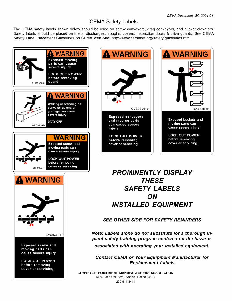
CEMA Safety LabelsThe CEMA safety labels shown below should be used on screw conveyors, drag conveyors, and bucket elevators.Safety labels should be placed on inlets, discharges, troughs, covers, inspection doors & drive guards. See CEMASafety Label Placement Guidelines on CEMA Web Site: http://www.cemanet.org/safety/guidelines.html
PROMINENTLY DISPLAYTHESE
SAFETY LABELSON
INSTALLED EQUIPMENT
SEE OTHER SIDE FOR SAFETY REMINDERS
Note: Labels alone do not substitute for a thorough in-plant safety training program centered on the hazardsassociated with operating your installed equipment.
Contact CEMA or Your Equipment Manufacturer forReplacement Labels
CONVEYOR EQUIPMENT MANUFACTURERS ASSOCIATION6724 Lone Oak Blvd., Naples, Florida 34109
239-514-3441
Exposed screw andmoving parts cancause severe injury
LOCK OUT POWERbefore removingcover or servicing
CVS930011
CHR930001
Exposed movingparts can causesevere injury
LOCK OUT POWERbefore removingguard
CHS991026
Walking or standing onconveyor covers orgratings can causesevere injury
STAY OFFExposed conveyorsand moving partscan cause severeinjury
LOCK OUT POWERbefore removingcover or servicing
CVS930010
Exposed buckets andmoving parts cancause severe injury
LOCK OUT POWERbefore removingcover or servicing
CVS930012
WARNINGExposed screw andmoving parts cancause severe injury
LOCK OUT POWERbefore removingcover or servicingCHR930011
CEMA Document: SC 2004-01
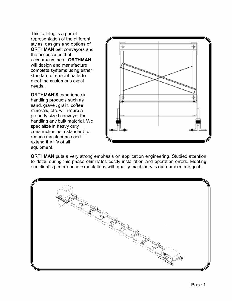
This catalog is a partial representation of the different styles, designs and options of ORTHMAN belt conveyors and the accessories that accompany them. ORTHMAN will design and manufacture complete systems using either standard or special parts to meet the customer’s exact needs. ORTHMAN’S experience in handling products such as sand, gravel, grain, coffee, minerals, etc. will insure a properly sized conveyor for handling any bulk material. We specialize in heavy duty construction as a standard to reduce maintenance and extend the life of all equipment.
ORTHMAN puts a very strong emphasis on application engineering. Studied attentionto detail during this phase eliminates costly installation and operation errors. Meetingour client’s performance expectations with quality machinery is our number one goal.
Page 1

DESIGN CONSIDERATIONS: Belt Widths: 18”, 24”, 30”, 36”, 48”
Belt Speeds: 18” B. W. 400 FPM max. 24” B. W. 500 FPM max. 30” B. W. 600 FPM max. 36” B. W. 650 FPM max. 48” B. W. 700 FPM max.
Carrying Idlers: CEMA B, CEMA C, flat steel, 20 degree troughing, 35 degree troughing, impact and training
Idler Spacing: Carrying: 5’ – 0” Return: 10’ – 0”
Drives: Standard drives include: 1750 rpm, TEFC, NEMA B motor with a 1.15 S.F. Class II shaft mounted gear reducer “V” type sheaves and belts Motor Mount Belt Guard Integral Backstop (if required)
BASIC DESIGN STEP 1: Compile the Basic Design Information Required Length of Conveyor: Measured in feet from center to center of pulleys, parallel to belt line. Inclination of conveyor: Measured in degrees off the horizontal, consult the CEMA Belt Conveyor Manual or ORTHMAN CONVEYING Engineering Department to determine the maximum angle at which the particular material may be conveyed. Maximum and Minimum Material Density: Measured in pounds per cubic foot (PCF), the maximum density is used for power calculations while the minimum density is used in the conveyor calculations. Peak Capacity: Measured in tons per hour (TPH), the capacity used should be the peak capacity at which the conveyor is expected to perform, not a lesser average capacity.
Page 2

STEP 2: Determine Belt Width Using Table 1 (pg. 3), determine the conveyor belt width required in inches.
TABLE 1
Capacity in Tons per Hour at 100 FPM Belt Speed
Maximum Lump Size
Inches Maximum Recommended
Belt Speed, FPM*
Weight of Material, Pounds per cu. ft (PCF)
BELT WIDTH INCHES
50 75 100 Sized Unsized
50% Max. Size
Lumps
100% Max. Size
Lumps
18 27 41 54 3 5 400 300 24 50 75 100 4 ½ 8 500 400 30 81 122 162 7 10 600 450 36 117 176 235 8 12 650 500
*Certain materials should not be handled at maximum belt speeds. Consult the CEMA Belt conveyor manual or Orthman Engineering Department. STEP 3: Determine Operating Speed Using Table 2 (below), determine the conveyor operating speed in feet per minute (FPM) TABLE 2
Capacity, Tons per Hour (TPH) Belt Speed, Feet per minute (FPM)
Material Density
PCF
BELT WIDTH, INCHES 100 150 200 250 300 350 400 450 500 550 600 650
18 27 41 54 68 81 95 108 24 50 75 100 125 150 175 200 225 250 30 81 122 162 203 243 284 324 365 405 446 486
50
36 118 176 235 294 353 411 470 529 588 646 705 764 18 41 61 81 101 122 142 162 24 75 113 150 188 225 263 300 338 375 30 122 182 243 304 365 425 486 547 608 668 729
75
36 176 264 353 441 529 617 705 793 881 969 1058 114618 54 81 108 135 162 189 216 24 100 150 200 250 300 350 400 450 500 30 162 243 324 405 486 567 648 729 810 891 972
100
36 235 352 470 587 705 822 940 1057 1175 1292 1410 1527 STEP 4: Calculate the Horsepower Required Using Table 3, determine the horsepower required to drive the empty conveyor per each 100 FPM of belt speed, HPo. then, HPe= (Belt Speed/100) X HPo.
TABLE 3 Horsepower to drive empty conveyor for each 100 FPM of belt speed
Conveyor centers, feet BELT
WIDTH, INCHES 50 100 150 200 300 400 500 600 700 800 900 1000
18 0.20 0.37 0.45 0.52 0.67 0.82 1.00 1.20 1.40 1.50 1.60 1.70 24 0.30 0.47 0.57 0.66 0.88 1.10 1.20 1.40 1.60 1.80 2.00 2.20 30 0.40 0.60 0.75 0.90 1.20 1.40 1.70 2.00 2.30 2.60 2.80 3.00 36 0.65 0.80 0.95 1.10 1.50 1.80 2.10 2.40 2.70 3.00 3.40 3.80
Using Table 4 (pg.4) determine the horsepower required to convey the material horizontally, HPm.
Page 3

TABLE 4 Horsepower to convey material horizontally*
Conveyor Centers, feet Tons Per
Hour (TPH) 50 100 150 200 300 400 500 600 700 800 900 1000
50 0.3 0.4 0.5 0.6 0.7 0.8 1.0 1.1 1.3 1.4 1.6 1.7 100 0.6 0.8 0.9 1.1 1.4 1.7 2.0 2.3 2.6 2.9 3.2 3.5 150 0.9 1.1 1.4 1.6 2.0 2.5 3.0 3.4 3.9 4.3 4.8 5.2 200 1.2 1.5 1.8 2.1 2.7 3.3 3.9 4.5 5.2 5.8 6.4 7.0 300 1.8 2.3 2.7 3.2 4.1 5.0 5.9 6.8 7.7 8.6 9.6 10.5 400 2.4 3.0 3.6 4.2 5.5 6.7 7.9 9.1 10.3 11.5 12.7 13.9 500 3.0 3.8 4.5 5.3 6.8 8.3 9.8 11.4 12.9 14.4 15.9 17.4 600 3.6 4.5 5.5 6.4 8.2 10.0 11.8 3.6 15.5 17.3 18.7 21.0 700 4.2 5.3 6.4 7.4 9.5 11.7 13.8 15.9 18.0 20.0 22.0 24.0 800 4.8 6.1 7.3 8.5 10.9 13.3 15.8 18.2 21.0 23.0 25.5 28.0 900 5.5 6.8 8.2 9.5 12.3 15.0 17.7 20.0 23.0 26.0 28.5 31.0
1000 6.1 7.6 9.1 10.6 13.6 16.7 19.7 23.0 25.0 29.0 32.0 35.0 1100 6.7 8.3 10.0 11.7 15.0 18.3 22.0 25.0 27.0 32.0 35.0 38.0 1200 7.3 9.1 10.9 12.7 16.4 20.0 24.0 27.0 31.0 35.0 38.5
*For any speed and any material Using Table 5, determine the horsepower required to elevate the material, HPj.
TABLE 5 Horsepower to elevate the material
Conveyor lift, feet Tons Per
Hour (TPH) 10 20 30 40 50 60 70 80 90 100
50 0.5 1.0 1.5 2.0 2.5 3.0 3.5 4.0 4.6 5.1 100 1.0 2.0 3.0 4.0 5.1 6.1 7.1 8.1 9.1 10.1 150 1.5 3.0 4.5 6.1 7.6 9.1 10.6 12.1 13.7 15.2 200 2.0 4.0 6.1 8.1 10.1 12.1 14.2 16.2 18.1 20.0 300 3.0 6.1 9.1 12.1 15.2 18.2 21.2 24.0 27.0 30.0 400 4.0 8.1 12.1 16.2 20.0 24.0 28.0 32.0 36.0 40.0 500 5.1 10.1 15.2 20.0 25.0 30.0 35.0 40.0 600 6.1 12.1 18.2 24.0 30.0 36.0 700 7.1 14.1 21.0 28.0 35.0 800 8.1 16.2 24.0 32.0 40.0 900 9.1 18.2 27.0 36.0
1000 10.1 20.0 30.0 40.0 1100 11.1 22.0 33.0 1200 12.1 24.0 36.0
To calculate the Horsepower required, use the following equation:
HPreq=HPe+HPm+HPj. STEP 5: Determine the Motor Horsepower Motor HPmin = HPreq/Drive Efficiency Motor HP = next standard Motor HP greater than Motor HPmin STEP 6: Identify the Conveyor Layout Identify the conveyor layout. See following sections to determine channel or truss construction, gravity or screw take-up, sideboards, covers, etc. STEP 7: Complete the Request for Quotation form included in this catalog.
Page 4

CHANNEL STRINGER CONVEYORS Conveyors designed with channel stringers are available in 10’ 0”, and 20’ 0” standardsections. Depending on the required conveyor length, an additional, nonstandard lengthsection will be supplied. A bolted splice plate connection joins and stiffens each joint.Channel stringer sections can be joined to truss sections by special lateral frames forspanning distances that require a truss section, while still enabling channel stringers tobe used where the spanned distance does not require a truss. Channel stringers rangein size from C4x5.4 to C10x20, depending on load, capacity and span requirements.Schedule 40 pipe or carbon steel angles are used for cross-members, supplying addedstrength and rigidity. Steel channel or fabricated bents are used for supports. Thechannel frame design is especially suited to any application where overhead clearanceis limited.
Page 5

TRUSS FRAME CONVEYORS Truss frame conveyors are available in 24” deep and 42” deep sections. The 24” deep sections are available in lengths of 6’– 0”, 15’– 0”, 18’– 0”, and 20’– 0”. The 42” deep sections are available in 16’– 0”, 20’– 0”, and 24’– 0” lengths. As with the channel frame conveyors, a non-standard section may be required to meet the customers’ required conveyor length. The truss frame conveyors are used in applications where a channel frame conveyor cannot span an unsupported distance required by the customer. Please refer to the following chart for permissible spans:
MAXIMUM TRUSS SECTION SPANS – FEET Truss Depth,
Inches Belt Width,
Inches
Allowable Span w/o walkway,
Feet
Allowable Span w/ walkway,
Feet 24 18 48 33 24 24 44 31 24 30 40 29 24 36 36 27 42 18 55 46 42 24 52 43 42 30 49 40 42 36 49 37
OTHER CONVEYOR OPTIONS Slider Bed Conveyors: 14 to 10 ga. Plate is used for conveyor decking depending on conveyor loads. Heavy, conservative design insures long life while also minimizing the number of intermediate supports needed for industries whose light bulk material densities allow their use. Conveyors requiring moderate incline (23 degrees or less) may be supplied with special cleated belts. U-Trough Slider Conveyors: Used to provide better material containment on the carrying run. Minimizes fallback and increases efficiency in inclined applications when used with wood chips to provide more inter-meshing of material.
Page 6

Flat Slide Conveyors Used when weighing of the material is necessary, when the belt serves as a feeder, or when limited overhead clearance requires a flat slide design. Totally Enclosed Conveyors Sealed covers and drip pans allow for virtually dust-free material conveyance. Corrugated or non-corrugated covers are available. Drip pans are constructed of 14 ga. steels, standard. Custom Engineered Conveyors If none of the standard conveyor designs fits the customer’s needs, ORTHMAN will be pleased to design a custom conveyor application. By supplying ORTHMAN with specifications and/or drawings illustrating the particular application, the engineering department will be able to produce general arrangement drawings for the customer’s approval. ORTHMAN CONVEYING DISCHARGE CHUTES
The standard ORTHMAN Discharge Chutesare constructed of 14 ga. to ¼” plate,depending on application. Chutes may beconstructed of a range of materials dependingon usage, including: stainless steel,aluminum, and carbon steel (standard). Chuteoptions also include abrasion resistant orUHMW liners. Access panels may also beadded to facilitate pulley maintenance. Clipangles allow for easy removal of DischargeChute. These chutes may be fitted with the standardORTHMAN belt cleaner or with severalcommercially available belt cleaners, includingbrush type belt cleaners. Customer shouldspecify what type of belt cleaner, if any, isapplicable to their requirements.
Custom chute extensions or flange connections may be specified by the customer. Standard discharge angle is 60 degrees, but customer may specify required discharge angle. Please note that some materials require a steeper discharge angle than others to prevent material from sticking to inside of chute. Consult ORTHMAN CONVEYOR SYSTEMS to determine the optimum angle for the material to be conveyed.
Page 7

FIXED TAIL TERMINALS This style is used when the conveyor hasa gravity take-up arrangement. The unitconsists of a fabricated steel frame, ballor roller type pillow block bearings, awing-type tail pulley (unless otherwisespecified), and a fabricated expandedmetal tail pulley guard. For a totallyenclosed conveyor, the tail pulley guard ismade with solid sheet metal. The unit canalso be welded to the last stringer section
f or easy maintenance. The tail terminal shown is designed to bolt to a truss section. Terminals for channel stringers are also available.
TAIL SECTIONS – FIXED PULLEY Belt Width, in Pulley Dia., in Shaft Dia., in Frame Ht., in Weight, lbs
18 14 1 15/16 24 190 18 14 2 7/16 24 195 18 14 2 15/16 24 210 18 14 1 15/16 42 220 18 14 2 7/16 42 225 18 14 2 15/16 42 240 24 14 1 15/16 24 205 24 14 2 7/16 24 210 24 14 2 15/16 24 225 24 14 1 15/16 42 230 24 14 2 7/16 42 235 24 14 2 15/16 42 250 30 16 1 15/16 24 220 30 16 2 7/16 24 225 30 16 2 15/16 24 240 30 16 3 7/16 24 255 30 16 1 15/16 42 250 30 16 2 7/16 42 255 30 16 2 15/16 42 270 36 16 3 7/16 42 285 36 16 2 7/16 24 245 36 16 2 15/16 24 260 36 16 3 7/16 24 275 36 16 2 7/16 42 270 36 16 2 15/16 42 285 36 16 3 7/16 42 300
Notes: 1. Weight values are frame-weights only; tail pulley guard weight is not included. 2. Pulley and shaft diameters will change with excessive loads and/or capacities.
Page 8

GRAVITY TAKE-UP This illustration shows a standard gravity take-up. Depending on the specific conveyor requirements, design changes may be made to accommodate them. The standard gravity take-up includes two drum bend pulleys with ¼” plain lagging and one wing-type take-up pulley. The bearings are ball or roller type pillow blocks. The frame is fabricated carbon steel that is designed to either weld or bolt to the conveyor structure, depending on customer requirements. There is also a counterweight box, not shown for clarity. A take-up guard may be required for certain conveyors. Gravity take-ups have a travel of 18”, 24” and 30” depending on conveyor length. Longer travel lengths may be designed if required. The chart shows values for standard gravity take-ups. Pulley diameters, shaft diameters and weights may change if there are excessive loads and/or capacities.
GRAVITY TAKE-UP SPECIFICATION – STANDARD
Belt Width, in Pulley Diameter, in Shaft Diameter, in Weight, lbs
18 16 1 15/16 285 18 16 2 7/16 365 18 16 2 15/16 395 18 16 3 7/16 440 24 16 1 15/16 325 24 16 2 7/16 380 24 16 2 15/16 455 24 16 3 7/16 515 30 16 2 7/16 410 30 16 2 15/16 515 30 16 3 7/16 605 36 16 2 7/16 500 36 16 2 15/16 550 36 16 3 7/16 690 36 16 3 15/16 740
Page 9

SCREW TAKE-UP TAIL TERMINALS These terminals are also made offabricated steel construction. Theseinclude screw-type take-up frames, ballor roller type pillow block bearings,wing-type tail pulleys, and expandedmetal tail guards. Take-up lengths canbe 12”, 18”, 24”, or 36”. Standard unitsare designed to be welded to the laststringer section, but a bolted connectioncan also be supplied.
The terminal shown is designed to be welded to a channel type stringer.
Notes: 1. Weight Values are frame-weights only; tail pulley guard weight is not included.
TAIL SECTIONS – SCREW TAKE-UPS Belt Width, in Pulley Diam, in Shaft Dia, in Frame Ht, in T-U Travel, in Weight, lbs
18 14 1 15/16 24 12-30 190-260 18 14 2 7/16 24 12-30 195-280 18 14 2 15/16 24 12-30 210-310 18 14 1 15/16 42 12-30 220-290 18 14 2 7/16 42 12-30 225-310 18 14 2 15/16 42 12-30 240-340 24 14 1 15/16 24 12-30 205-275 24 14 2 7/16 24 12-30 210-295 24 14 2 15/16 24 12-30 225-325 24 14 1 15/16 42 12-30 230-305 24 14 2 7/16 42 12-30 235-325 24 14 2 15/16 42 12-30 250-355 30 16 1 15/16 24 12-36 220-295 30 16 2 7/16 24 12-36 225-315 30 16 2 15/16 24 12-36 240-345 30 16 3 7/16 24 12-36 255-365 30 16 1 15/16 42 12-36 250-315 30 16 2 7/16 42 12-36 255-335 30 16 2 15/16 42 12-36 270-365 30 16 3 7/16 42 12-36 285-385 36 16 2 7/16 24 12-36 245-310 36 16 2 15/16 24 12-36 260-330 36 16 3 7/16 24 12-36 275-350 36 16 2 7/16 42 12-36 270-340 36 16 2 15/16 42 12-36 285-360 36 16 3 7/17 42 12-36 300-380
2. Pulley and shaft diameters will change with excessive loads and/or capacities. 3. The amount of take-up required is dependant on the length of the conveyor. Please consult the ORTHMAN Engineering Department to determine your specific take-up needs.
Page 10

CONVEYOR ACCESSORIES BELT CLEANERS ORTHMAN has several different styles of industrial and food grade belt cleaners. The most standard design is a spring-loaded belt cleaner with either a rubber or UHMW scraper blade. This type cleaner is the most often used and will provide adequate cleaning in most applications. Motor driven brush type cleaners are also available for applications where the scraper type cleaner does not remove enough material. Please consult the Engineering Staff at ORTHMAN to determine what type of belt cleaner best suits your application. The chart below shows the most standard belt cleaners available:
SCRAPER-TYPE BELT CLEANERS, STANDARD
Belt Width, In Blade Material Weight, lbs 18 Standard Rubber 25 24 Standard Rubber 30 30 Standard Rubber 35 36 Standard Rubber 40 18 UHMW 25 24 UHMW 30 30 UHMW 35 36 UHMW 40
These inlets provide a guide for incomingflow for covered conveyors. The flange maybe the ORTHMAN standard or specified bythe customer to attach to already existingchuting. The inlet chute itself is made of 14ga. steel metal, standard. The chute isdesigned to be welded to a standardORTHMANS curved cover. This same typeof cover may be adapted for a box-typecover. UHMW or abrasion-resistant liningmay be added if required. For applicationswhere conveyors must be dust-proof, agasket will be supplied with the flange.
FLANGED INLETS LOAD HOPPERS (FOR COVERED CONVEYORS) Load hoppers are available for non-enclosed conveyors. A load hopper is able to guide the incoming flow of material properly onto the belt. The unit consists of structural steel chute walls, adjustable rubber or UHMW skirt seals and an optional downstream cover. The load hopper bolts directly to the top of any of ORTHMAN’S conveyor structures. If needed, impact idlers or a load section is located under the hopper’s discharge point. The chute sides may be inclined or vertical to suit customers’ applications.
Page 11

STANDARD CONVEYOR COVERS
ORTHMAN offers a variety of standard conveyorcovers. These covers are designed to protectthe belt, material and idlers from the weatherand other contaminants. Conveyor covers alsoprotect the belt from being sun dried anddamaged, and offers protection from wind andrain. Shown here is a non-hinged, smoothcurved cover. This standard cover consists ofsteel, galvanized steel or aluminum coversections supported on bands of heavier gaugesteel or aluminum. The support bands boltdirectly to the foot brackets which aresubsequently bolted to the top chord of trussframes or to the top of channel stringers.
Curved covers are available in hinged, full, ¾ styles. Both smooth and corrugated sheet metal are used. BULK SYSTEMS also offers a box (non-curved) type cover. All cover types may be ordered if galvanized, dust-proof conveyors will need full covers with
Curved covers are available in hinged, full, ¾ styles. Both smooth and corrugated sheet metals are used. ORTHMAN also offers a box (non-curved) type cover. All cover types may be ordered galvanized; dust-proof conveyors will need full covers with gaskets. gaskets included.
The chart below gives some specifications on the curved covers: STANDARD CONVEYOR COVERS – WEIGHTS
Weight per 4’ – 0” Section, Lbs Belt Width, inches Full, galvanized Full, aluminum ¾, galvanized
18” 52 22 42 24” 58 25 47 30” 65 28 52 36” 71 30 55 48” 84 36 72 60” 97 41 84 72” 109 47 93
CONVEYOR DECK PLATES Deck plates for the conveyors are an optional feature used to deflect any material from the carrying run of the belting from falling on the return run of the belting. Typically, 16 ga. material is used, although the customer may specify thicker material if it is needed. Inclined conveyor decking is designed to shed water and debris, while still protecting the belt and return idlers.
DRIP PANS Essential for conveyors running in areas where delicate machinery or people may be underneath the conveyors, the fabricated drip pans are designed to keep any material on the carrying and return runs from falling below the conveyors. The drip pans are made of 14 ga. carbon steel and are joined together with bolted splice sections. For totally enclosed conveyors, gaskets will be provided to ensure the drip pans are dust-proof.
Page 12

WALKWAYS AND HANDRAILS ORTHMAN offers walkways and handrails for one or both sides of their conveyors to provide maintenance access to the full length of the conveyor. Standard walkways are either 36” or 48” wide. Walkways are designed to bolt to the conveyor supports of channel frame conveyors, or directly to the lower cord angles of truss sections. The handrails may either be welded directly to the walkway support frame, or may be designed to bolt together at the job site, depending on shipping and installation needs. Standard walkway flooring is 1 ¼” X 3/16” bar grating, and standard handrails are 1 ¼” Sch 40 pipe. Walkway sections are available in 10’-0” or 20’-0” lengths. Galvanized walkway is non-standard, but is available in 10’-0” sections. Ladders and cages are also available if needed. In addition, ORTHMAN can provide the customer with service platforms and support steel needed at critical maintenance areas, such as the head and tail sections.
This picture shows a conveyor installation by ORTHMAN already in the field. The walkways, handrails, platforms, ladders and/or steps are tailored to the individual customer’s application. Please note that a safety stop switch is recommended on conveyors where workers will be near a running conveyor. Some welding and/or assembly may be required in the field for installation of walkways and handrails. ORTHMAN will supply any installation instructions that are needed.
Page 13

OTHER ORTHMAN PRODUCTS BUCKET ELEVATORS Designed to move flowing powders or bulk solids vertically. Series of buckets mounted on chain or belt operating over a sprocket or pulley is the typical elevator configuration. Take-ups are provided as a means to compensate for variation in conditions, or belt or chain wear. A steel casing encloses the bucket line. Boot sections can be designed for various angles and heights of inlet material. Discharge hoods can be designed to accommodate specific customer applications. Please contact the ORTHMAN CONVEYOR SYSTEMS Sales Department for a complete catalog of standard bucket elevators. SCREW CONVEYORS Industrial and food grade screw conveyors are available for conveying a variety of different materials. ORTHMAN offers a wide range of standard screw conveyors and options shown in our Screw Conveyor catalog. This catalog is also available through contacting the Sales Department at our home office or through your local sales representative. ORTHMAN provides a full line of screw conveyors and related components from water-jacketed heat-transferring models to multiple-screw “live bottom” type feeder units.
GATES ORTHMAN offers gates of virtually any configuration. Electric-actuated, air-operated, and manual Y flop gates, flat slide gates, as well as made-to-order gates of the customers’ design are available. Our general catalog shows many types of gates already in use in the field. A wide range of materials is available for fabrication of the gates including steel, stainless steel, and aluminum. Gates lined with abrasion resistant steel or UHMW are available to suit customer requirements.
DRAG CONVEYORS Drag conveyors are typically a chain-driven series of solid or perforated flights. This type of conveyor is used for material retrieval where there is little overhead room, such as under a casting line. They are also used for material retrieval in an oil or water pit after a wash procedure. These conveyors are designed per customer requirements and are tailored to fit customer needs. Because these conveyors are usually installed in areas where maintainance access is usually difficult, they are built ruggedly. As with all ORTHMAN products, these conveyors are built with the highest level of quality to avoid frequent maintainance.
CUSTOM FABRICATION From support steel structures to custom conveyors and mass flow hoppers, ORTHMAN’S fabrication, welding and machine departments are able to supply just about any type of fabricated steel structure, designed to suit customer requirements. Page 14
BELT CONVEYOR BENT SUPPORTS HEIGHT PIPE BENTS BRACED BENTS
H STEEL WT/LB WT/FT STEEL WT/LB WT/FT 10 800 80 800 80 20 1600 80 1700 85 30 3800 127 2500 83 40 5000 125 3200 80 50 6500 130 4700 94 60 8000 133 7000 117 70 12000 171 11000 157 80 16000 200 15000 225 90 20000 222 20000 222 100 23000 230 22000 220 110 26000 236 27000 245 120 29000 242 32000 266 130 36000 277 37000 284 140 39000 278 41000 292 150 42000 280 47000 313 160 45000 281 53000 331 170 47000 276 59000 347
*Bents designed for 40° wind sheer and 90° DL & LL (per col.) GENERAL DIMENSIONS – FOR CONVEYORS 12” THROUGH 42” IN WIDTH
CONVEYOR WIDTHS BENT
HEIGHT 18” AND 24” A B C WT/LBS
4 6 8
4’ 3 ½” 4’ 8 ½” 5’ 1”
3’ 6” 3’ 6” 3’ 6”
159 190 281
10 12 14
5’ 6” 5” 11” 6” 3 ½”
3’ 6” 3’ 6” 3’ 6”
324 459 516
16 18 20
6’ 8 ½” 7’ 1” 7’ 6”
3’ 6” 3’ 6” 3’ 6”
634 671 723
22 24 26
7’ 11” 8’ 3 ½” 8’ 8 ½”
3’ 6” 3’ 6” 3’ 6”
774 858
1177
28 30 32
9” 1” 9’ 6” 9’ 11”
3’ 6” 3’ 6” 3’ 6”
1232 1225 1384
34 36 38
10’ 4” 10’ 5 ½” 11’ 1”
3’ 6” 3’ 6” 3’ 6”
1656 1759 1998
40 42 44
11’ 6” 11’ 11” 12’ 4”
3’ 6” 3’ 6” 3’ 6”
2064 2507 2593
46 48 50
12’ 8 ½” 13’ 1” 13’ 6”
3’ 6” 3’ 6” 3’ 6”
2677 3722 3844
CONVEYOR WIDTHS CONVEYOR WIDTHS BENT HT 30”, 36” AND 42”
BENT HT 30”, 36” AND 42”
A B C WT/LBS A B C WT/LBS
4 6 8
5’ 3 ½” 5’ 8 ½” 6’ 1”
4’ 6” 4’ 6” 4’ 6”
178 219 312
28 30 32
10’ 1” 10’ 6” 10’ 11”
4’ 6” 4’ 6” 4’ 6”
1282 1354 1435
10 12 14
6’ 6” 6’ 11” 7’ 3 ½”
4’ 6” 4’ 6” 4’ 6”
351 486 543
34 36 38
11’ 4” 11’ 8 ½” 12’ 1”
4’ 6” 4’ 6” 4’ 6”
1732 1806 2053
16 18 20
7’ 8 ½” 8’ 1” 8” 6”
4’ 6” 4’ 6” 4’ 6”
863 7-5 775
40 42 44
12’ 6” 12’ 11” 13’ 4”
4’ 6” 4’ 6” 4’ 6”
2129 2618 2673
22 24 26
8’ 11” 9’ 3 ½” 9’ 8 ½”
4’ 6” 4’ 6” 4’ 6”
798 870
1222
46 48 50
13’ 8 ½” 14’ 1” 14’ 8”
4’ 6” 4’ 6” 4’ 6”
2781 3783 3907
Page 15
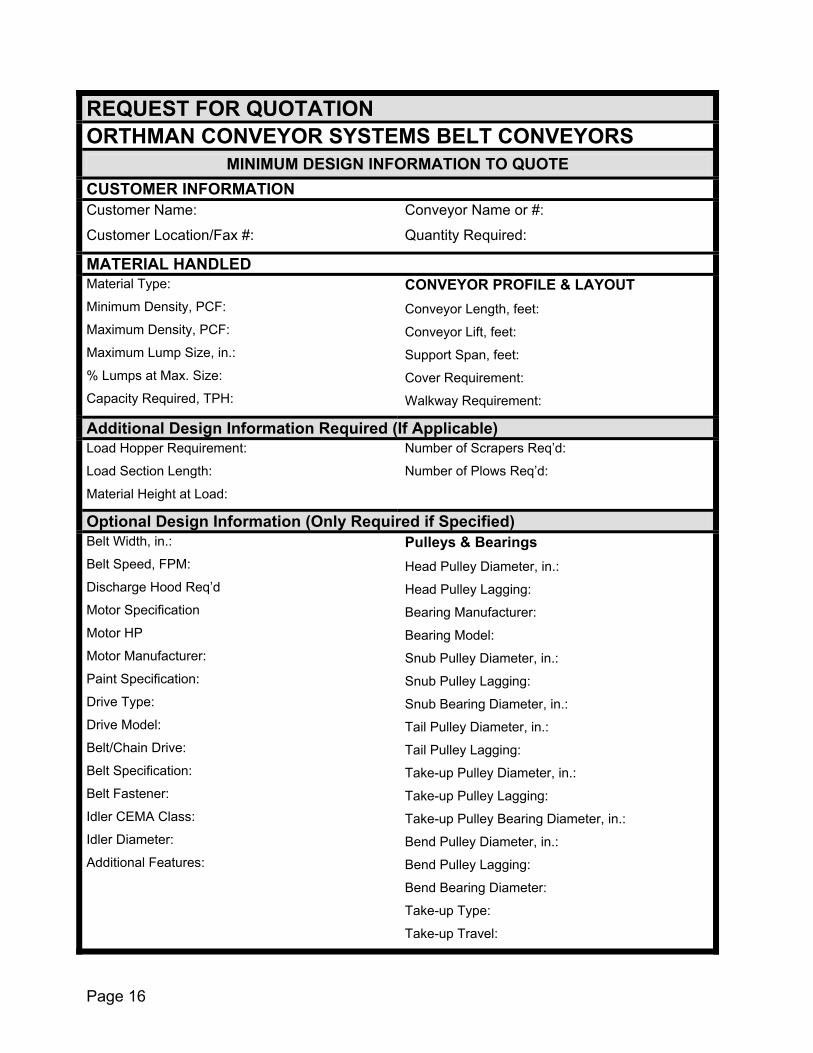
REQUEST FOR QUOTATION ORTHMAN CONVEYOR SYSTEMS BELT CONVEYORS
MINIMUM DESIGN INFORMATION TO QUOTE CUSTOMER INFORMATION Customer Name:
Customer Location/Fax #:
Conveyor Name or #:
Quantity Required:
MATERIAL HANDLED Material Type:
Minimum Density, PCF:
Maximum Density, PCF:
Maximum Lump Size, in.:
% Lumps at Max. Size:
Capacity Required, TPH:
CONVEYOR PROFILE & LAYOUT Conveyor Length, feet:
Conveyor Lift, feet:
Support Span, feet:
Cover Requirement:
Walkway Requirement:
Additional Design Information Required (If Applicable) Load Hopper Requirement:
Load Section Length:
Material Height at Load:
Number of Scrapers Req’d:
Number of Plows Req’d:
Optional Design Information (Only Required if Specified) Belt Width, in.:
Belt Speed, FPM:
Discharge Hood Req’d
Motor Specification
Motor HP
Motor Manufacturer:
Paint Specification:
Drive Type:
Drive Model:
Belt/Chain Drive:
Belt Specification:
Belt Fastener:
Idler CEMA Class:
Idler Diameter:
Additional Features:
Pulleys & Bearings Head Pulley Diameter, in.:
Head Pulley Lagging:
Bearing Manufacturer:
Bearing Model:
Snub Pulley Diameter, in.:
Snub Pulley Lagging:
Snub Bearing Diameter, in.:
Tail Pulley Diameter, in.:
Tail Pulley Lagging:
Take-up Pulley Diameter, in.:
Take-up Pulley Lagging:
Take-up Pulley Bearing Diameter, in.:
Bend Pulley Diameter, in.:
Bend Pulley Lagging:
Bend Bearing Diameter:
Take-up Type:
Take-up Travel:
Page 16

