scs 440 - loup electronicsloupelectronics.com/wp-content/uploads/2011/08/raven-440-manual.pdf ·...
TRANSCRIPT
SCS 440SERIAL INTERFACE
INSTALLATIONAND
SERVICE MANUAL

N O T I C E
The use of the suspension type fertilizers and lime slurrieswill significantly reduce the life of the plastic parts inthe Flow Meter and motorized Control Valve. Check the rotorand inlet hub assembly in the Flow Meter frequently for wornparts. Excessive wear can affect accuracy.
Do not attempt to modify or lengthen any of the three-wireSpeed Sensor or Flow Meter cables. Extension cables areavailable from your Dealer.
W A R N I N G
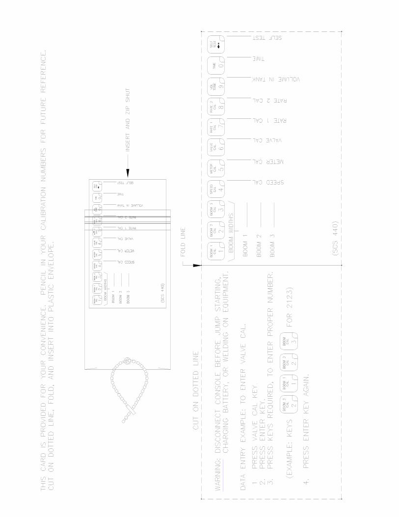
Disconnect console before jump starting, charging, orwelding on equipment.

RAVEN INDUSTRIES
LIMITED WARRANTY
WHAT IS COVERED?
This warranty covers all defects in workmanship or materialsin your Raven Flow Control Product under normal use,maintenance, and service.
HOW LONG IS THE COVERAGE PERIOD?
This warranty coverage runs for 12 months from the purchase dateof your Raven Flow Control Product. This warranty coverageapplies only to the original owner and is not transferrable.
HOW CAN YOU GET SERVICE?
Bring the defective part, and proof of date of purchase, to yourlocal dealer. If your dealer agrees with the warranty claim,he will send the part, and proof of purchase to his distributoror to Raven for final approval.
WHAT WILL RAVEN INDUSTRIES DO?
When our inspection proves the warranty claim, we will, at ouroption, repair or replace the defective part and pay for returnfreight.
WHAT DOES THIS WARRANTY NOT COVER?
Raven Industries will not assume any expense or liability forrepairs made outside our plant without written consent. We arenot responsible for damage to any associated equipment orproduct and will not be liable for loss of profit or otherspecial damages. The obligation of this warranty is in lieuof all other warranties, expressed or implied, and no personis authorized to assume for us any liability. Damages causedby normal wear and tear, mis-use, abuse, neglect, accident, orimproper installation and maintenance are not covered by thiswarranty.

Manual Rev. B, SCS 440 S.I.,11/00 #016-0159-822
1
TABLE OF CONTENTS
SYMBOL DEFINITION .............................................................................................................................................. 2INTRODUCTION ....................................................................................................................................................... 3INSTALLATION ......................................................................................................................................................... 4
1. MOUNTING THE RAVEN RADAR SPEED SENSOR .................................... 42. MOUNTING THE FLOW METER AND OPTIONAL PRESSURE TRANSDUCER................. 53. MOUNTING THE CONTROL VALVE ................................................ 64. MOUNTING THE CONSOLE AND CABLING.......................................... 7
BATTERY CONNECTIONS ...................................................................................................................................... 8CONSOLE FEATURES............................................................................................................................................. 9CONSOLE CALIBRATION ...................................................................................................................................... 10
1. CALCULATING "BOOM CAL" ....................................................102. CALCULATING "SPEED CAL" ...................................................113. CALCULATING "METER CAL" ...................................................114. CALCULATING "VALVE CAL" ...................................................125. CALCULATING "RATE 1 AND RATE 2 CAL" ......................................13
CONSOLE PROGRAMMING .................................................................................................................................. 141. INITIAL CONSOLE PROGRAMMING ...............................................142. OTHER DISPLAY FEATURES ....................................................183. SELF TEST FEATURE .........................................................184. VOLUME/MINUTE RATE FAULT ..................................................195. VOLUME/AREA RATE ALARM ....................................................196. LOW TANK FAULT ............................................................197. AUTOMATIC RATE +/- ........................................................198. CONTROL VALVE DELAY .......................................................209. ZERO SPEED SHUT-OFF .......................................................2010. DATA MENU.................................................................2011. DECIMAL SHIFT ............................................................27
INITIAL SYSTEM SET-UP ...................................................................................................................................... 28INITIAL SYSTEM FIELD TEST............................................................................................................................... 29PREVENTIVE MAINTENANCE .............................................................................................................................. 29TROUBLESHOOTING GUIDE ................................................................................................................................ 30
APPENDIXES
1. WHEEL DRIVE SPEED SENSOR INSTALLATION AND CALIBRATION ........................................................ 332. SPEEDOMETER DRIVE SPEED SENSOR INSTALLATION AND CALIBRATION ......................................... 363. ALTERNATE BY-PASS LINE PLUMBING SYSTEM ........................................................................................ 384. PROCEDURE TO TEST SPEED SENSOR EXTENSION CABLES ................................................................. 405. PROCEDURE TO TEST FLOW METER CABLES ............................................................................................ 416. FLOW METER MAINTENANCE AND ADJUSTMENT PROCEDURE.............................................................. 427. PROCEDURE TO RE-CALIBRATE FLOW METER .......................................................................................... 438. REMOTE SWITCH OPTION ............................................................................................................................... 449. SERIAL INTERFACE .......................................................................................................................................... 4510. SCS 440 COMMUNICATION STRINGS .......................................................................................................... 46
REPLACEMENT PARTS SHEETS
016-0159-82211/00

2
SYMBOL DEFINITION
METER CAL CONVERSIONS
To convert the METER CAL number simply divide the original number (number printed onFlow Meter label) by the desired conversion factor.
FOR EXAMPLE:
Original METER CAL No. = METER CAL No. for displays in Fluid Ounces 128
Original METER CAL No. = METER CAL No. for displays in Liters 3.785
Original METER CAL No. = METER CAL No. for displays in PoundsWeight of one gallon
LIQUID CONVERSIONSU.S. Gallons x 128 = Fluid OuncesU.S. Gallons x 3.785 = LitersU.S. Gallons x 0.83267 = Imperial GallonsU.S. Gallons x 8.34 = Pounds (Water)
LENGTH1 millimeter (mm) = 0.039 inch1 centimeter (cm) = 0.393 inch1 meter (m) = 3.281 feet1 kilometer (km) = 0.621 mile1 inch = 25.4 millimeters; 2.54 centimeters1 mile = 1.609 kilometers
PRESSURE1 psi = 6.89 kPa1 kPa = 0.145 psi
AREA1 square meter = 10.764 square feet1 hectare (ha) = 2.471 acres; 10,000 square meters1 acre = 0.405 hectare; 43,560 square feet1 square mile = 640 acres; 258.9 hectares
GPM - Gallons per minutelit/min - Liters per minutedl/min - Deciliter per minutePSI - Pounds per square inchkPa - KilopascalGPA - Gallon per acrelit/ha - Liter per hectareml/ha - Milliliter per hectareGPK - Gallons per 1,000 sq. ft.mm - Millimeters
cm - Centimetersdm - Decimetersm - MeterMPH - Miles per hourkm - Kilometerskm/h - Kilometers per hourUS - Volume per acreSI - Volume per hectareTU - Volume per 1,000 sq. ft.[] - Metric numbers{} - 1,000 sq. ft. numbers

3
INTRODUCTIONThe Raven SCS 440 (SPRAYER CONTROL SYSTEM) is designed to improve the uniformity of sprayapplications. Its performance relies on the installation and preventive maintenanceof the complete sprayer. It is important that this Installation and Service Manual bereviewed thoroughly before operating the system. This manual provides a simple step-by-step procedure for installing and operating.
The SCS 440 system consists of a computer-based control Console, a Speed Sensor, a turbinetype Flow Meter and a motorized Control Valve. The Console mounts directly in the cabof the vehicle for easy operator use. The Radar Speed Sensor is mounted to the frameof the vehicle or implement (Wheel Drive and Speedometer Drive Speed Sensors are alsoavailable). The motorized Control Valve and Flow Meter mount to the framework supportingthe boom. Appropriate cabling is furnished for field installation.
The operator sets the target volume per area to be sprayed and the SCS 440 automaticallymaintains the flow regardless of vehicle speed or gear selection. A manual overrideswitch allows the operator to manually control flow for system check-out and spotspraying. Actual volume per area being applied is displayed at all times. The SCS 440additionally functions as an area monitor, speed monitor, and volume totalizer.

4
INSTALLATION1. MOUNTING THE RAVEN RADAR SPEED SENSOR
See Appendix 1 for Wheel Drive Speed Sensor installation instructions.See Appendix 2 for Speedometer Drive Speed Sensor installation instructions.
For mounting the radar, the following guidelines will assure proper installation:It is suggested that a large heavy mounting bracket, (P/N 107-0159-693) be attachedto the vehicle frame for mounting the radar.
1) Park vehicle on level surface.
2) Select mounting site by considering the following:a) The line of sight from the lens to the ground must not be obstructed by
structures or tires. Obstructions must not come closer than 20 inches tothe bottom of the radar. See Figures 1 and 2.
b) The radar lens must be parallel to the ground from front to back. Radarcan be tilted out 0-15 degrees to provide more clearance and missobstructions. See Figure 2.
c) The radar should be mounted so that the length of the radar is parallel withdirection of vehicle travel.
3) Use carpenters level to verify that mounting bracket is parallel to the ground.
4) Bolt mounting bracket to implement.
5) Bolt radar to mounting bracket using mounting hardware. See Figure 3.
6) Connect radar with Radar Interface Cable (P/N 115-0159-539), to the console. TheRed wire should be connected to the Orange cable wire. The White wire should beconnected to the White cable wire (See "BATTERY CONNECTIONS").
CAUTION: The connection of the radar power in reverse polarity could resultin damage to the radar.
FIGURE 1 FIGURE 3
FIGURE 2

5
2. MOUNTING THE FLOW METER AND OPTIONAL PRESSURETRANSDUCER
FLOWMETER1) Mount Flow Meter in the area of the boom valves per Figure 4. All flow through
Flow Meter must go to booms only, i.e., no return line to tank or pump after FlowMeter.
2) Mount Flow Meter horizontal to the ground. Use the bracket to secure the FlowMeter.
3) For best results, allow a minimum of 7 1/2 inches [20 cm] of straight hose on inletof Flow Meter. Bend radius of hose on outlet of Flow Meter should be gradual.
4) Flow must be in direction of arrow on Flow Meter.
FIGURE 4FIGURE 4FIGURE 4FIGURE 4FIGURE 4
NOTE: It is essential, when using suspensions, that the system be thoroughlyrinsed out each day after use.
OPTIONAL PRESSURE TRANSDUCER1) Mount optional pressure transducer, part #422-0000-059, on desired location.
Use cables 115-0171-152 (or 115-0171-153) and 115-0171-151.
2) With pump turned off and 0 PSI [kPa] on the lines, enter 0 for pressure calibration(cal pressure) under Data Menu Key.
3) When system is operating, system PSI [kPa] will be displayed when the
or key is depressed.

6
3. MOUNTING THE CONTROL VALVE
1) Mount the motorized Control Valve in the main hose line between the Flow Meterand the booms, with motor in the upright position. (For flow less than 3 GPM[11 lit/min] the motorized Control Valve is mounted in a by-pass line. Refer toAppendix 3 for alternate plumbing diagram).
2) Connect the Flow Control Cable connectors to boom valves, Flow Meter, and motorizedControl Valve. (Black wire to boom valve #1, Brown wire to boom valve #2 and Bluewire to boom valve #3).
7
4. MOUNTING THE CONSOLE AND CABLING
1) Mount the Console to a secure support inside the cab of the vehicle.
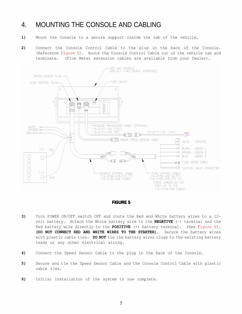
2) Connect the Console Control Cable to the plug in the back of the Console.(Reference Figure 5). Route the Console Control Cable out of the vehicle cab andterminate. (Flow Meter extension cables are available from your Dealer).
3) Turn POWER ON/OFF switch OFF and route the Red and White battery wires to a 12-volt battery. Attach the White battery wire to the NEGATIVE (-) terminal and theRed battery wire directly to the POSITIVE (+) battery terminal. (See Figure 6).(DO NOT CONNECT RED AND WHITE WIRES TO THE STARTER). Secure the battery wireswith plastic cable ties. DO NOT tie the battery wires close to the existing batteryleads or any other electrical wiring.
4) Connect the Speed Sensor Cable to the plug in the back of the Console.
5) Secure and tie the Speed Sensor Cable and the Console Control Cable with plasticcable ties.
6) Initial installation of the system is now complete.
FIGURE 5FIGURE 5FIGURE 5FIGURE 5FIGURE 5

8
FIGURE 6FIGURE 6FIGURE 6FIGURE 6FIGURE 6
BATTERY CONNECTIONS

9
CONSOLE FEATURESIMPORTANT: This Console requires selection of US (VOLUME PER ACRE), SI [VOLUMEPER HECTARE], or TU {1,000 SQ. FT.} area; SP1 WHEEL DRIVE, or SP2 RADAR SPEEDSENSOR; and C-SD STANDARD VALVE, C-F FAST VALVE, C-FC FAST CLOSE VALVE, C-P PWMVALVE or C-PC PWM CLOSE VALVE. Hold SELF TEST key to view selections.
Console Revision can be determined by theletter stamped in REV box on label.
Console Program can be determined by theletter stamped in PGM box on label.
FUNCTION KEYS -- Used to Display Data
TOTAL AREA -- Total Area AppliedFIELD AREA -- Field Area AppliedFIELD VOLUME -- Volume Applied to FieldDISTANCE -- Distance TraveledSPEED -- Speed of VehicleVOLUME/TANK -- Volume Remaining in Carrier TankTIME -- 24 Hour Clock (Military Time)DATA MENU -- Printer Option
CALIBRATION KEYS -- Used to enter data into theConsole to calibrate the system.
BOOM 1 CAL -- Length of Boom 1BOOM 2 CAL -- Length of Boom 2BOOM 3 CAL -- Length of Boom 3SPEED CAL -- Determined by Speed SensorMETER CAL -- Meter Calibration NumberVALVE CAL -- Valve Response TimeRATE 1 CAL -- Target Application RateRATE 2 CAL -- Target Application RateSELF TEST -- Simulates Vehicle Speed
Selects manual or fully automaticcontrol.
CE -Use like you do the CE key ona calculator.
Selects POWER ON or OFF.
Displays actual rate of application,calibration, and function data.
Booms can be controlled individu-ally, or all at once with MASTERON/OFF switch.
Manual override control providescapability for spot spraying.
ENTER -Used only to enter data intothe Console.
10
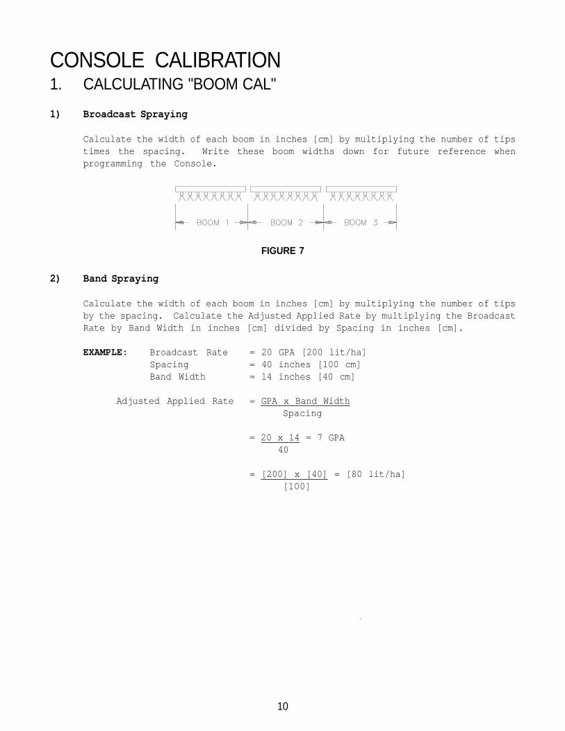
CONSOLE CALIBRATION1. CALCULATING "BOOM CAL"
1) Broadcast Spraying
Calculate the width of each boom in inches [cm] by multiplying the number of tipstimes the spacing. Write these boom widths down for future reference whenprogramming the Console.
FIGURE 7
2) Band Spraying
Calculate the width of each boom in inches [cm] by multiplying the number of tipsby the spacing. Calculate the Adjusted Applied Rate by multiplying the BroadcastRate by Band Width in inches [cm] divided by Spacing in inches [cm].
EXAMPLE: Broadcast Rate = 20 GPA [200 lit/ha]Spacing = 40 inches [100 cm]Band Width = 14 inches [40 cm]
Adjusted Applied Rate = GPA x Band WidthSpacing
= 20 x 14 = 7 GPA 40
= [200] x [40] = [80 lit/ha][100]

11
2. CALCULATING "SPEED CAL"
Initial SPEED CAL is 598 [152] when using the Raven radar. Complete Steps 1 thru6 to refine this number after "INITIAL CONSOLE PROGRAMMING" has been completed.
1) Set POWER switch to ON, all other switches to OFF.
2) Enter "0" in .
3) Drive 1 mile [1 kilometer]. To achieve the most accurate calibration, accelerateand decelerate slowly.
CAUTION: Do not use vehicle odometer to determine distance. Use sectionlines or highway markers.
4) Read DISTANCE by depressing .
DISTANCE should read a value of approximately 5280 [1000]. If it reads between5260-5300 [990-1010], the SPEED CAL for the vehicle is 598 [152]. If the DISTANCEdisplay reads any other value, perform the following calculation:
EXAMPLE: Assume DISTANCE reads 5000 [980].
Corrected SPEED CAL = Old SPEED CAL x 5280DISTANCE
ENGLISH UNITS: METRIC UNITS:= 598 x 5280 = 631.48 = [152] x [1000] = [155] 5000 [980]
5) The number to enter for SPEED CAL is 631 [155].
6) Recheck the new SPEED CAL derived in Step 5 by repeating Steps 2 thru 4.
3. CALCULATING "METER CAL"
The Flow Meter calibration number is stamped on the tag attached to each Flow Meter.Write down this number for future reference when programming the Console.
12
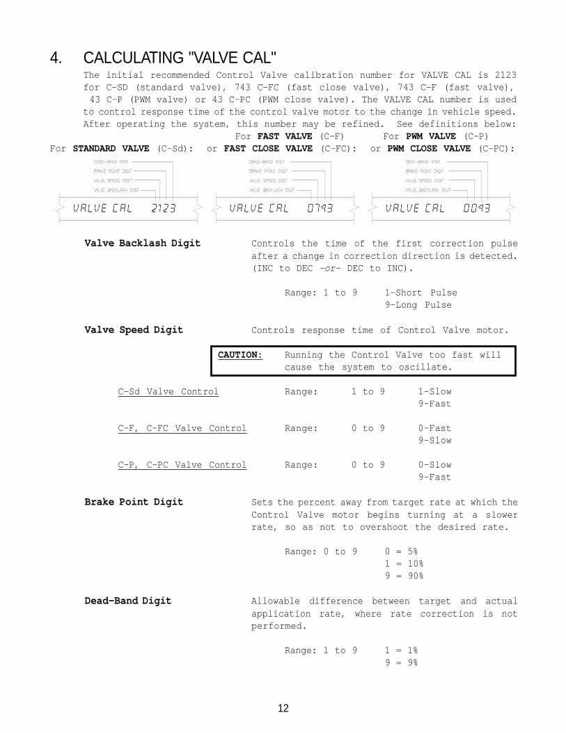
Valve Backlash Digit Controls the time of the first correction pulseafter a change in correction direction is detected.(INC to DEC -or- DEC to INC).
Range: 1 to 9 1-Short Pulse9-Long Pulse
Valve Speed Digit Controls response time of Control Valve motor.
CAUTION: Running the Control Valve too fast willcause the system to oscillate.
C-Sd Valve Control Range: 1 to 9 1-Slow9-Fast
C-F, C-FC Valve Control Range: 0 to 9 0-Fast9-Slow
C-P, C-PC Valve Control Range: 0 to 9 0-Slow9-Fast
Brake Point Digit Sets the percent away from target rate at which theControl Valve motor begins turning at a slowerrate, so as not to overshoot the desired rate.
Range: 0 to 9 0 = 5%1 = 10%9 = 90%
Dead-Band Digit Allowable difference between target and actualapplication rate, where rate correction is notperformed.
Range: 1 to 9 1 = 1%9 = 9%
4. CALCULATING "VALVE CAL"The initial recommended Control Valve calibration number for VALVE CAL is 2123for C-SD (standard valve), 743 C-FC (fast close valve), 743 C-F (fast valve), 43 C-P (PWM valve) or 43 C-PC (PWM close valve). The VALVE CAL number is usedto control response time of the control valve motor to the change in vehicle speed.After operating the system, this number may be refined. See definitions below:
For FAST VALVE (C-F) For PWM VALVE (C-P)For STANDARD VALVE (C-Sd): or FAST CLOSE VALVE (C-FC): or PWM CLOSE VALVE (C-PC):
13
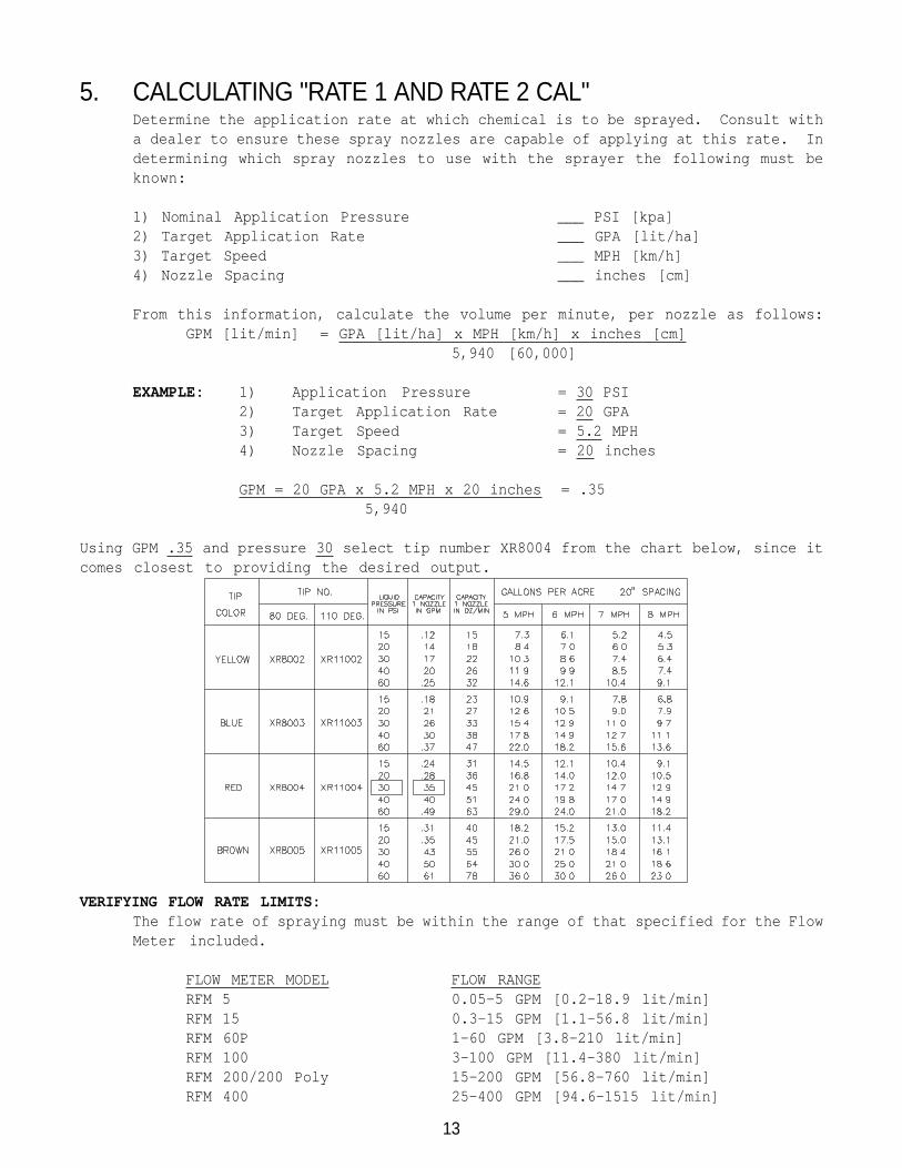
5. CALCULATING "RATE 1 AND RATE 2 CAL"Determine the application rate at which chemical is to be sprayed. Consult witha dealer to ensure these spray nozzles are capable of applying at this rate. Indetermining which spray nozzles to use with the sprayer the following must beknown:
1) Nominal Application Pressure ___ PSI [kpa]2) Target Application Rate ___ GPA [lit/ha]3) Target Speed ___ MPH [km/h]4) Nozzle Spacing ___ inches [cm]
From this information, calculate the volume per minute, per nozzle as follows:GPM [lit/min] = GPA [lit/ha] x MPH [km/h] x inches [cm]
5,940 [60,000]
EXAMPLE: 1) Application Pressure = 30 PSI2) Target Application Rate = 20 GPA3) Target Speed = 5.2 MPH4) Nozzle Spacing = 20 inches
GPM = 20 GPA x 5.2 MPH x 20 inches = .35 5,940
Using GPM .35 and pressure 30 select tip number XR8004 from the chart below, since itcomes closest to providing the desired output.
VERIFYING FLOW RATE LIMITS:The flow rate of spraying must be within the range of that specified for the FlowMeter included.
FLOW METER MODEL FLOW RANGERFM 5 0.05-5 GPM [0.2-18.9 lit/min]RFM 15 0.3-15 GPM [1.1-56.8 lit/min]RFM 60P 1-60 GPM [3.8-210 lit/min]RFM 100 3-100 GPM [11.4-380 lit/min]RFM 200/200 Poly 15-200 GPM [56.8-760 lit/min]RFM 400 25-400 GPM [94.6-1515 lit/min]

14
CONSOLE PROGRAMMINGWhen entering data into the Console, the entry sequence is always the same.
NOTE: DATA MUST BE ENTERED INTO KEYS 1 THRU 8.
Complete the entry by againdepressing the ENTER key.
Depress the keys correspond-ing to the number you wish toenter (i.e. "2","1","2","3").The numbers will be dis-played as they are entered.
Depress the key in whichyou wish to enter data.
Depress the ENTER key. An"E" will illuminate in thedisplay.
1. INITIAL CONSOLE PROGRAMMINGWhen Console power is turned on, after all installation procedures have beencompleted, the Console will flash CAL and US VOLUME PER ACRE. This meansthe console must be "calibrated", or programmed, before it can be operated. Thisis a one-time operation which does not have to be repeated. Turning OFF the POWERON/OFF switch does not affect the Console memory. All data is retained.

15
NOTE: If an entry selection error is made during steps 1-6, place the power ON/OFF
switch to OFF. Depress and hold while placing the power ON/OFF switch toON. This will reset the console.
The display will show CAL US VOLUME PER ACRE. The following steps mustbe followed:
1) Display US-VOLUME PER ACRE, SI-VOLUME PER HECTARE, or TU-VOLUME PER 1000
SQ FT.
a) Depressing momentarily steps the display fromUS-VOLUME PER ACRE to SI-VOLUME PER HECTARE.
b) Depressing momentarily steps the display fromSI-VOLUME PER HECTARE to TU-VOLUME PER 1000 SQ FT.
c) Depressing momentarily steps the display fromTU-VOLUME PER 1000 SQ FT to US-VOLUME PER ACRE.
2) Selecting US, SI, or TU.
a) To select US, SI, or TU, step until the desired code is displayed.
b) Momentarily depress , the display will now displayCAL SP1-WHEEL DRIVE.
3) Display SP1-WHEEL DRIVE or SP2-RADAR SPEED SENSOR.
a) Depressing momentarily steps the display from SP1 to SP2.
b) Depressing momentarily steps the display from SP2 to SP1.
4) Selecting SP1 or SP2.
a) To select SP1 or SP2, step until desired code is displayed.
b) Momentarily depress , the display will now displayCAL C-SD-STANDARD VALVE.
5) Display C-SD-STANDARD VALVE, C-F-FAST VALVE, C-FC-FAST CLOSE VALVE, C-P-PWM VALVE, or C-PC-PWM CLOSE VALVE.
a) Depressing momentarily steps the display from C-SD to C-F.
b) Depressing momentarily steps the display from C-F to C-FC.
c) Depressing momentarily steps the display from C-FC to C-P.
d) Depressing momentarily steps the display from C-P to C-PC.
e) Depressing momentarily steps the display from C-PC to C-SD.
16
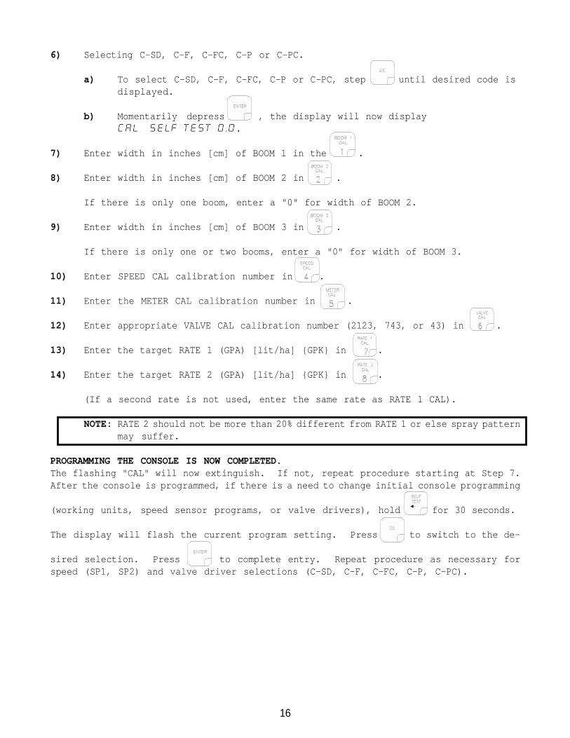
6) Selecting C-SD, C-F, C-FC, C-P or C-PC.
a) To select C-SD, C-F, C-FC, C-P or C-PC, step until desired code isdisplayed.
b) Momentarily depress , the display will now displayCAL SELF TEST 0.0.
7) Enter width in inches [cm] of BOOM 1 in the .
8) Enter width in inches [cm] of BOOM 2 in .
If there is only one boom, enter a "0" for width of BOOM 2.
9) Enter width in inches [cm] of BOOM 3 in .
If there is only one or two booms, enter a "0" for width of BOOM 3.
10) Enter SPEED CAL calibration number in .
11) Enter the METER CAL calibration number in .
12) Enter appropriate VALVE CAL calibration number (2123, 743, or 43) in .
13) Enter the target RATE 1 (GPA) [lit/ha] {GPK} in .
14) Enter the target RATE 2 (GPA) [lit/ha] {GPK} in .
(If a second rate is not used, enter the same rate as RATE 1 CAL).
NOTE: RATE 2 should not be more than 20% different from RATE 1 or else spray patternmay suffer.
PROGRAMMING THE CONSOLE IS NOW COMPLETED.The flashing "CAL" will now extinguish. If not, repeat procedure starting at Step 7.After the console is programmed, if there is a need to change initial console programming
(working units, speed sensor programs, or valve drivers), hold for 30 seconds.
The display will flash the current program setting. Press to switch to the de-
sired selection. Press to complete entry. Repeat procedure as necessary forspeed (SP1, SP2) and valve driver selections (C-SD, C-F, C-FC, C-P, C-PC).

17
ENTERING ADDITIONAL DATA:
Data may be entered in the and although it is not required for the
operation of the system.
1) ENTERING VOLUME:Enter the estimated VOLUME in the TANK in . Each time the tank is refilled,this number must be re-entered.
2) ENTERING TIME, DATE, AND POWER DOWN:Definition of Time, Date, and Power Down Key:
Depressing this key displays selected Time.EXAMPLE: Display will display RATE 0.0 and TIME 0:00.
Depressing this key again after selecting TIME increments through desiredfeatures.EXAMPLE: TIME, MONTH, DAY, YEAR, and POWER DOWN DAY.
3) Enter TIMEa) Select TIMEb) Enter TIME when display shows RATE 0.0 TIME 0:00.
NOTE: This is a 24 hour clock. Therefore, all time after 12:59 p.m., add12 hours. Thus, 8:30 a.m. is entered as 8:30, but 1:30 p.m. is enteredas 13:30 in the keyboard.
4) Enter MONTHa) Select MONTHb) Enter MONTH when display shows RATE 0.0 MONTH 1.
5) Enter DAYa) Select DAYb) Enter DAY when display shows RATE 0.0 DAY 1.
6) Enter YEARa) Select YEARb) Enter YEAR when display shows RATE 0.0 YEAR 00.
7) POWER DOWN FEATUREIf the Console is not used for 10 days, it will go into a power down (low power)mode of operation. In this mode, all data will be retained, but the time of dayclock will reset to 0:00. The delay time is initially set at 10 days, but canbe changed by the user.
a) Enter POWER DOWN1) Select POWER DOWN2) Enter POWER DOWN when display shows POWERDOWN DAY 10.
18
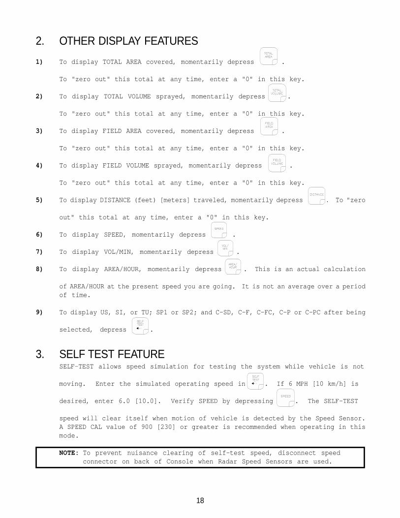
2. OTHER DISPLAY FEATURES
1) To display TOTAL AREA covered, momentarily depress .
To "zero out" this total at any time, enter a "0" in this key.
2) To display TOTAL VOLUME sprayed, momentarily depress .
To "zero out" this total at any time, enter a "0" in this key.
3) To display FIELD AREA covered, momentarily depress .
To "zero out" this total at any time, enter a "0" in this key.
4) To display FIELD VOLUME sprayed, momentarily depress .
To "zero out" this total at any time, enter a "0" in this key.
5) To display DISTANCE (feet) [meters] traveled, momentarily depress . To "zero
out" this total at any time, enter a "0" in this key.
6) To display SPEED, momentarily depress .
7) To display VOL/MIN, momentarily depress .
8) To display AREA/HOUR, momentarily depress . This is an actual calculation
of AREA/HOUR at the present speed you are going. It is not an average over a periodof time.
9) To display US, SI, or TU; SP1 or SP2; and C-SD, C-F, C-FC, C-P or C-PC after being
selected, depress .
3. SELF TEST FEATURESELF-TEST allows speed simulation for testing the system while vehicle is not
moving. Enter the simulated operating speed in . If 6 MPH [10 km/h] is
desired, enter 6.0 [10.0]. Verify SPEED by depressing . The SELF-TEST
speed will clear itself when motion of vehicle is detected by the Speed Sensor.A SPEED CAL value of 900 [230] or greater is recommended when operating in thismode.
NOTE: To prevent nuisance clearing of self-test speed, disconnect speedconnector on back of Console when Radar Speed Sensors are used.

19
4. VOLUME/MINUTE RATE FAULT
Depress until display shows SET LOW LIMIT 0. A low limit flow rate maynow be entered. If the actual volume per minute falls below this limit, the ControlValve stops closing, an alarm sounds, and the display flashes LOW LIMIT. Thelow limit value should be determined with all booms ON. This value is automaticallyproportional to the percentage of booms that are ON. (i.e. If the entered lowlimit is 4 and half the total boom length is shut off, the Console automaticallyreduces the low limit to 2).
NOTE: Go to DATA MENU to silence alarm.
5. VOLUME/AREA RATE ALARMConsole alarm sounds if the application rate is 30% or more away from the targetapplication rate for more than 5 seconds.
NOTE: Go to DATA MENU to silence alarm.
7. AUTOMATIC RATE +/-This feature sets the increment at which flow is increased or decreased
in RATE 1 or RATE 2 operation. Enter rate change value by depressing
until display shows RATE +/- 0.0. To enter a value depress
, then the increment value, and .
EXAMPLE: If rate is to change by "1.0":Enter a value of 1.0 for RATE +/-. When in RATE 1 or RATE 2, each time theINC/DEC switch is positioned to INC the RATE CAL for that rate will increase by"1.0". Likewise, when positioned to DEC the RATE CAL will decrease by "1.0".
6. LOW TANK FAULTThis feature will sound the alarm when the volume in the tank drops below an enteredvalue. The alarm will intermittently beep every 15 seconds and the display willflash LOW LEVEL. The alarm will stop when a value equal to or greater thanthe LOW TANK ALARM is entered into VOL/TANK or the booms are turned OFF. Entering"0" into LOW TANK ALARM disables it.
To select LOW TANK ALARM depress until display shows SET LOW LEVEL 0.
To enter value depress ,then LOW TANK ALARM value, and .
NOTE: Go to DATA MENU to silence alarm.
20
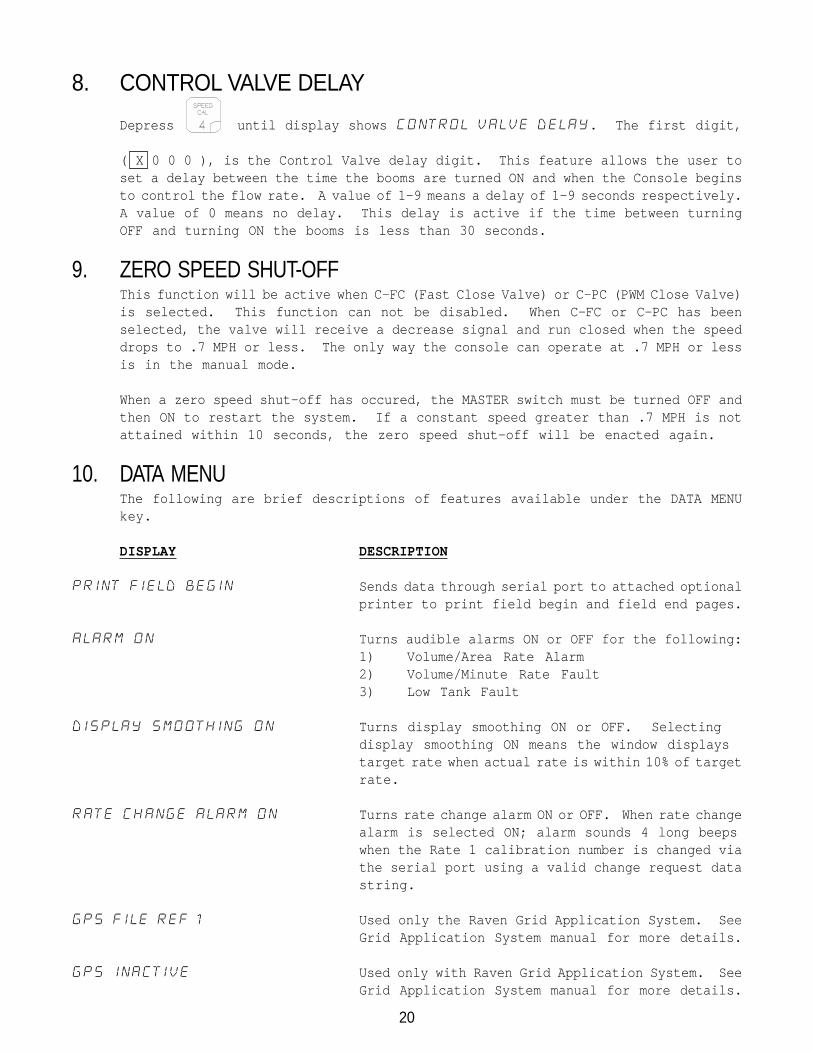
8. CONTROL VALVE DELAY
Depress until display shows CONTROL VALVE DELAY. The first digit,
( X 0 0 0 ), is the Control Valve delay digit. This feature allows the user toset a delay between the time the booms are turned ON and when the Console beginsto control the flow rate. A value of 1-9 means a delay of 1-9 seconds respectively.A value of 0 means no delay. This delay is active if the time between turningOFF and turning ON the booms is less than 30 seconds.
9. ZERO SPEED SHUT-OFFThis function will be active when C-FC (Fast Close Valve) or C-PC (PWM Close Valve)is selected. This function can not be disabled. When C-FC or C-PC has beenselected, the valve will receive a decrease signal and run closed when the speeddrops to .7 MPH or less. The only way the console can operate at .7 MPH or lessis in the manual mode.
When a zero speed shut-off has occured, the MASTER switch must be turned OFF andthen ON to restart the system. If a constant speed greater than .7 MPH is notattained within 10 seconds, the zero speed shut-off will be enacted again.
10. DATA MENUThe following are brief descriptions of features available under the DATA MENUkey.
DISPLAY DESCRIPTION
PRINT FIELD BEGIN Sends data through serial port to attached optionalprinter to print field begin and field end pages.
ALARM ON Turns audible alarms ON or OFF for the following:1) Volume/Area Rate Alarm2) Volume/Minute Rate Fault3) Low Tank Fault
DISPLAY SMOOTHING ON Turns display smoothing ON or OFF. Selectingdisplay smoothing ON means the window displaystarget rate when actual rate is within 10% of targetrate.
RATE CHANGE ALARM ON Turns rate change alarm ON or OFF. When rate changealarm is selected ON; alarm sounds 4 long beepswhen the Rate 1 calibration number is changed viathe serial port using a valid change request datastring.
GPS FILE REF 1 Used only the Raven Grid Application System. SeeGrid Application System manual for more details.
GPS INACTIVE Used only with Raven Grid Application System. SeeGrid Application System manual for more details.

21
DISPLAY DESCRIPTION
BAUD RATE 9600 Used in GPS mode and data logging mode. Selectablebetween 1200 or 9600 baud.
DATA LOG TRIGGER VALUE 0 Used in data logging mode. The trigger determineshow often actual rate data string (See Appendix 10for Data Communication String Formats) is sent tothe serial port. The trigger may be either feet[meters] or seconds.
DATA LOG TRIGGER UNITS FEET Used in data logging mode. The trigger unit isselectable between feet [meters] or seconds.
DATA LOG OFF Turns data logger ON or OFF.
PRESS ENTER TO CAL PRESSURE Used to set the zero point of the pressuretransducer for pressure display.
OFF RATE PERCENT 30 Used to set the percent of off target value. Alarmsounds when the actual rate is off from the targetrate by a specified percent. The off target valueis preset to 30%, but may be changed to a differentnumber.
HIGH PWM OFFSET 253 Used to set the maximum desired RPM or hydraulicoutput of Pulse Width Modulated control valve.
LOW PWM OFFSET 1 Used to set the minimum desired RPM or hydraulicoutput of control valve. Used to set the zero pointor shut-off point of Pulse Width Modulated controlvalve.
PWM FREQUENCY 122 Enter the coil frequency of the PWM type valve beingused (default is 122 Hz).
PRESS ENTER FOR DATA-LOCK Sequence to activate DATA-LOCK CODE (featureprohibits the entry of data without first enteringthe DATA-LOCK CODE). Enter 4-digit code within 15seconds.
FIELD REF 0 Allows user to enter up to a four-digit number torepresent a field. Field reference is included infield begin and field end pages and the data loggertime/date string.
22
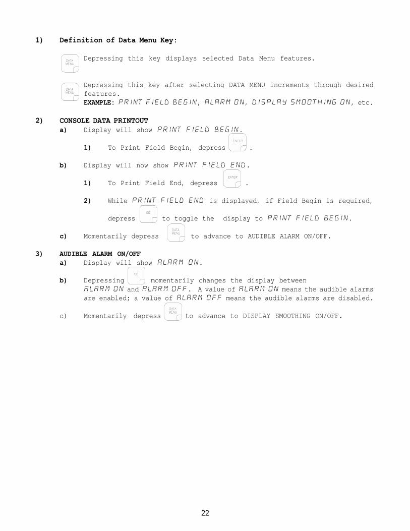
1) Definition of Data Menu Key:
Depressing this key displays selected Data Menu features.
Depressing this key after selecting DATA MENU increments through desiredfeatures.EXAMPLE: PRINT FIELD BEGIN, ALARM ON, DISPLAY SMOOTHING ON, etc.
2) CONSOLE DATA PRINTOUTa) Display will show PRINT FIELD BEGIN.
1) To Print Field Begin, depress .
b) Display will now show PRINT FIELD END.
1) To Print Field End, depress .
2) While PRINT FIELD END is displayed, if Field Begin is required,
depress to toggle the display to PRINT FIELD BEGIN.
c) Momentarily depress to advance to AUDIBLE ALARM ON/OFF.
3) AUDIBLE ALARM ON/OFFa) Display will show ALARM ON.
b) Depressing momentarily changes the display betweenALARM ON and ALARM OFF. A value of ALARM ON means the audible alarmsare enabled; a value of ALARM OFF means the audible alarms are disabled.
c) Momentarily depress to advance to DISPLAY SMOOTHING ON/OFF.

23
4) DISPLAY SMOOTHING ON/OFFa) Display will show DISPLAY SMOOTHING ON.
b) Depressing momentarily changes the display between DISPLAY
SMOOTHING ON and OFF. A value of ON means smoothing is enabled; a valueof OFF means smoothing is disabled. Selecting DISPLAY SMOOTHING ON meansthe display shows target rate when actual rate is within 10% of the targetrate. Selecting DISPLAY SMOOTHING OFF means the display shows actual targetrate.
c) Momentarily depress to advance to RATE CHANGE ALARM ON/OFF.
5) RATE CHANGE ALARM ON/OFFa) Display will show RATE CHANGE ALARM ON.
b) Depressing momentarily changes the display between RATE CHANGE
ALARM ON and OFF. A value of ON means alarm is enabled; a value of OFF
means alarm is disabled.
c) Momentarily depress to advance to GPS FILE REFERENCE.
6) GPS FILE REFERENCEa) Display will show GPS FILE REF 1.
b) Enter the GPS file number.
c) Momentarily depress to advance to GPS OPTIONS.
7) GPS OPTIONSa) GPS is inactive when the display shows GPS INACTIVE. The GPS features
are explained further in the GRID APPLICATION SYSTEM MANUAL.
b) Momentarily depress to advance to FIELD REFERENCE.
8) FIELD REFERENCEa) Display will show FIELD REF 0.
b) Enter the field number.
c) Momentarily depress to advance to BAUD RATE.
9) BAUD RATEa) Display will show BAUD RATE 9600.
b) Depressing momentarily changes the display between BAUD RATE 9600
and 1200.
c) Momentarily depress to advance to DATA LOGGER TRIGGER VALUE.
NOTE: The TRIGGER VALUE default value is "zero". This value must be changedto a desired number ranging from 1-9999. The DATA LOGGER features willnot work if this number is not changed.

24
10) DATA LOGGER TRIGGER VALUEa) Display will show DATA LOG TRIGGER VALUE 0.
b) Enter the TRIGGER VALUE.
c) Momentarily depress to advance to DATA LOGGER TRIGGER UNITS.
11) DATA LOGGER TRIGGER UNITSa) Display will show DATA LOG TRIGGER UNITS FEET [METER].
b) Depressing momentarily changes the display between DATA LOG
TRIGGER UNITS FEET [METER] and SEC. A value that has been chosenas the unit of measurement for the TRIGGER VALUE programmed previously. (Secmeans seconds has been chosen as the unit of measure.)
c) Momentarily depress to advance to DATA LOGGER.
12) DATA LOGGER ON/OFFa) The DATA LOGGER uses the communications strings listed in Appendix 10 to
pass data out through the serial port. The data is sent at a set time intervalor a set distance traveled, as determined by the values entered in the DATALOGGER TRIGGER VALUE and DATA LOGGER TRIGGER UNITS. Upon each trigger, theActual Rate string, Data Strings 1, 2, and 3, and the Time/Date string aresent, in that order. When a Console calibration value is changed, theConsole will automatically send out the Cal 1, 2, and 3 strings. When aConsole switch is changed, the Data 1, 2, 3, Time/Date, and Cal 1, 2, 3strings will be sent by the Console. The Data, (with Time/Date stringincluded) and Cal strings can also be requested by the data logger usingthe request strings shown in Appendix 10.
NOTE: Some options within the DATA MENU LISTINGS may be unavailable if certainfeatures are on or active. The options affected are:
CONSOLE DATA PRINTOUT: Console Data Printout will not be available when DATALOGGER is ON or when GPS functions are active.
GPS OPTIONS: GPS options will not be available when DATA LOGGER is ON.
DATA LOGGER: DATA LOGGER will not be available when GPS functions areactive.
b) Display will show DATA LOG OFF.
c) Depressing momentarily changes the display between DATA LOG OFF
and ON. A value of OFF means DATA LOGGER is disabled; a value of ON meansDATA LOGGER is enabled.
d) Momentarily depress to advance to PRESSURE CALIBRATION.
25
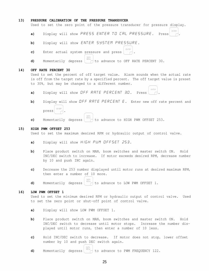
13) PRESSURE CALIBRATION OF THE PRESSURE TRANSDUCERUsed to set the zero point of the pressure transducer for pressure display.
a) Display will show PRESS ENTER TO CAL PRESSURE. Press .
b) Display will show ENTER SYSTEM PRESSURE.
c) Enter actual system pressure and press .
d) Momentarily depress to advance to OFF RATE PERCENT 30.
14) OFF RATE PERCENT 30Used to set the percent of off target value. Alarm sounds when the actual rateis off from the target rate by a specified percent. The off target value is presetto 30%, but may be changed to a different number.
a) Display will show OFF RATE PERCENT 30. Press .
b) Display will show OFF RATE PERCENT E. Enter new off rate percent and
press .
c) Momentarily depress to advance to HIGH PWM OFFSET 253.
15) HIGH PWM OFFSET 253Used to set the maximum desired RPM or hydraulic output of control valve.
a) Display will show HIGH PWM OFFSET 253.
b) Place product switch on MAN, boom switches and master switch ON. HoldINC/DEC switch to increase. If motor exceeds desired RPM, decrease numberby 10 and push INC again.
c) Decrease the 253 number displayed until motor runs at desired maximum RPM,then enter a number of 10 more.
d) Momentarily depress to advance to LOW PWM OFFSET 1.
16) LOW PWM OFFSET 1Used to set the minimum desired RPM or hydraulic output of control valve. Usedto set the zero point or shut-off point of control valve.
a) Display will show LOW PWM OFFSET 1.
b) Place product switch on MAN, boom switches and master switch ON. HoldINC/DEC switch to decrease until motor stops. Increase the number dis-played until motor runs, then enter a number of 10 less.
c) Hold INC/DEC switch to decrease. If motor does not stop, lower offsetnumber by 10 and push DEC switch again.
d) Momentarily depress to advance to PWM FREQUENCY 122.
26
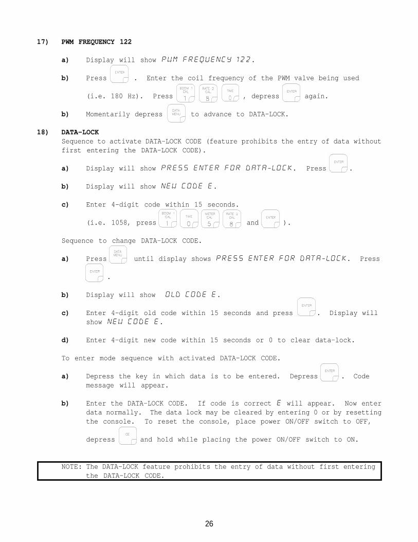
17) PWM FREQUENCY 122
a) Display will show PWM FREQUENCY 122.
b) Press . Enter the coil frequency of the PWM valve being used
(i.e. 180 Hz). Press , depress again.
b) Momentarily depress to advance to DATA-LOCK.
18) DATA-LOCKSequence to activate DATA-LOCK CODE (feature prohibits the entry of data withoutfirst entering the DATA-LOCK CODE).
a) Display will show PRESS ENTER FOR DATA-LOCK. Press .
b) Display will show NEW CODE E.
c) Enter 4-digit code within 15 seconds.
(i.e. 1058, press and ).
Sequence to change DATA-LOCK CODE.
a) Press until display shows PRESS ENTER FOR DATA-LOCK. Press
.
b) Display will show OLD CODE E.
c) Enter 4-digit old code within 15 seconds and press . Display willshow NEW CODE E.
d) Enter 4-digit new code within 15 seconds or 0 to clear data-lock.
To enter mode sequence with activated DATA-LOCK CODE.
a) Depress the key in which data is to be entered. Depress . Codemessage will appear.
b) Enter the DATA-LOCK CODE. If code is correct E will appear. Now enterdata normally. The data lock may be cleared by entering 0 or by resettingthe console. To reset the console, place power ON/OFF switch to OFF,
depress and hold while placing the power ON/OFF switch to ON.
NOTE: The DATA-LOCK feature prohibits the entry of data without first enteringthe DATA-LOCK CODE.
27
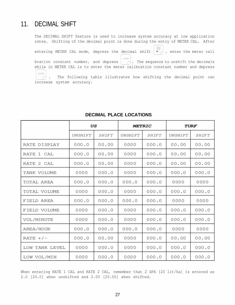
DECIMAL PLACE LOCATIONS
11. DECIMAL SHIFT
The DECIMAL SHIFT feature is used to increase system accuracy at low applicationrates. Shifting of the decimal point is done during the entry of METER CAL. After
entering METER CAL mode, depress the decimal shift , enter the meter cali
bration constant number, and depress . The sequence to unshift the decimalswhile in METER CAL is to enter the meter calibration constant number and depress
. The following table illustrates how shifting the decimal point canincrease system accuracy.
US METRIC TURF
UNSHIFT SHIFT UNSHIFT SHIFT UNSHIFT SHIFT
RATE DISPLAY 000.0 00.00 0000 000.0 00.00 00.00
RATE 1 CAL 000.0 00.00 0000 000.0 00.00 00.00
RATE 2 CAL 000.0 00.00 0000 000.0 00.00 00.00
TANK VOLUME 0000 000.0 0000 000.0 000.0 000.0
TOTAL AREA 000.0 000.0 000.0 000.0 0000 0000
TOTAL VOLUME 0000 000.0 0000 000.0 000.0 000.0
FIELD AREA 000.0 000.0 000.0 000.0 0000 0000
FIELD VOLUME 0000 000.0 0000 000.0 000.0 000.0
VOL/MINUTE 0000 000.0 0000 000.0 000.0 000.0
AREA/HOUR 000.0 000.0 000.0 000.0 0000 0000
RATE +/- 000.0 00.00 0000 000.0 00.00 00.00
LOW TANK LEVEL 0000 000.0 0000 000.0 000.0 000.0
LOW VOL/MIN 0000 000.0 0000 000.0 000.0 000.0
When entering RATE 1 CAL and RATE 2 CAL, remember that 2 GPA [20 lit/ha] is entered as2.0 [20.0] when unshifted and 2.00 [20.00] when shifted.
28
INITIAL SYSTEM SET-UP1) Fill tank with water only. (If positive displacement pump is used, open pressure
relief valve, PRV).
2) Place MASTER ON/OFF switch to ON and BOOM ON/OFF switches to OFF.
3) Place RATE 1/RATE 2/MAN switch to MAN.
4) Place POWER ON/OFF switch to ON.
5) Verify that Boom Widths, SPEED CAL, METER CAL, VALVE CAL, and RATE CALS have beenentered correctly into the Console. In SELF TEST mode, enter the normal sprayeroperating speed.
6) Run pump at normal operating RPM.
7) If centrifugal pump is used, proceed with Step 8. If positive displacement pumpis used, set pressure relief valve (PRV) to 65 PSI [450 kPa].
8) Verify that boom valves operate and that no nozzles are plugged by operating theBOOM ON/OFF switches.
9) Place all BOOM ON/OFF switches to ON.
10) Hold the FLOW CONTROL switch in INC position until pressure is at its maximum.This assures that the motorized Control Valve is fully open. Verify maximumpressure and RATE. (Pressure gauge is not supplied).
NOTE: A pressure gauge MUST be installed to properly monitor the system.
11) Adjust agitator line hand valve for desired agitation. Verify maximum pressureis still present.
12) Hold the FLOW CONTROL switch to DEC position until pressure is at its minimum.This assures that the motorized Control Valve is fully closed. Verify minimumpressure and RATE. If minimum pressure and RATE can not be obtained, considerby-pass plumbing system in Appendix 3.
29
INITIAL SYSTEM FIELD TEST1) Drive down field or road at target speed with sprayer booms off, to verify SPEED
readout on Console.
2) Turn on sprayer and booms and place the RATE 1/RATE 2/MAN switch to RATE 1.Increase or decrease speed by one MPH [2 km/h]. The system should automaticallycorrect to the target application rate.
3) If for any reason, the system is unable to correct to the desired RATE, checkfor an empty tank, a plugged line, a malfunctioning pump, improper vehicle speed,or a defect in the system.
4) If the system does not appear to be correcting properly, first review INITIALSYSTEM SET-UP, then refer to TROUBLESHOOTING GUIDE.
5) At the end of each row, switch the MASTER ON/OFF to OFF to shut off flow. Thisalso shuts off the area totalizer.
6) Verify area covered and volume used.
PREVENTIVE MAINTENANCEPreventive maintenance is most important to assure long life of the system. The followingmaintenance procedures should be followed on a regular basis:
1) Flush entire system with water after use of suspension type chemicals. Failureto clean system can result in crystallization of chemicals which may plug theFlow Meter, lines, and/or tips.
2) Flush and drain sprayer before storing. FREEZING TEMPERATURES MAY DAMAGE FLOWMETER IF WATER IS NOT DRAINED.
3) Remove Flow Meter at the end of each spraying season. Clean Flow Meter turbineand inlet hub. Clean off all metal filings and wettable powders which have hardenedon the plastic and metal parts. Check the inlet hub and turbine assembly for wornor damaged turbine blades and bearings. Flush Flow Meter with clear water anddrain.
KEEP FROM FREEZING
4) Remove Console when not in use for extended periods.
30
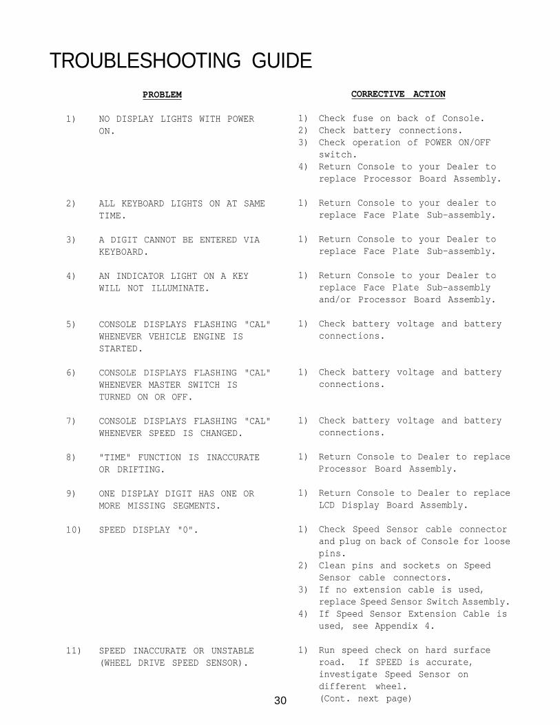
TROUBLESHOOTING GUIDECORRECTIVE ACTION
1) Check fuse on back of Console.2) Check battery connections.3) Check operation of POWER ON/OFF
switch.4) Return Console to your Dealer to
replace Processor Board Assembly.
1) Return Console to your dealer toreplace Face Plate Sub-assembly.
1) Return Console to your Dealer toreplace Face Plate Sub-assembly.
1) Return Console to your Dealer toreplace Face Plate Sub-assemblyand/or Processor Board Assembly.
1) Check battery voltage and batteryconnections.
1) Check battery voltage and batteryconnections.
1) Check battery voltage and batteryconnections.
1) Return Console to Dealer to replaceProcessor Board Assembly.
1) Return Console to Dealer to replaceLCD Display Board Assembly.
1) Check Speed Sensor cable connectorand plug on back of Console for loosepins.
2) Clean pins and sockets on SpeedSensor cable connectors.
3) If no extension cable is used,replace Speed Sensor Switch Assembly.
4) If Speed Sensor Extension Cable isused, see Appendix 4.
1) Run speed check on hard surfaceroad. If SPEED is accurate,investigate Speed Sensor ondifferent wheel.(Cont. next page)
PROBLEM
1) NO DISPLAY LIGHTS WITH POWERON.
2) ALL KEYBOARD LIGHTS ON AT SAMETIME.
3) A DIGIT CANNOT BE ENTERED VIAKEYBOARD.
4) AN INDICATOR LIGHT ON A KEYWILL NOT ILLUMINATE.
5) CONSOLE DISPLAYS FLASHING "CAL"WHENEVER VEHICLE ENGINE ISSTARTED.
6) CONSOLE DISPLAYS FLASHING "CAL"WHENEVER MASTER SWITCH ISTURNED ON OR OFF.
7) CONSOLE DISPLAYS FLASHING "CAL"WHENEVER SPEED IS CHANGED.
8) "TIME" FUNCTION IS INACCURATEOR DRIFTING.
9) ONE DISPLAY DIGIT HAS ONE ORMORE MISSING SEGMENTS.
10) SPEED DISPLAY "0".
11) SPEED INACCURATE OR UNSTABLE(WHEEL DRIVE SPEED SENSOR).
31
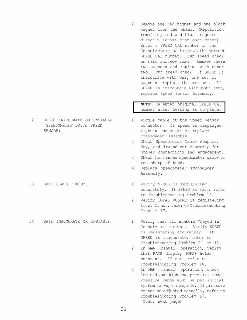
12) SPEED INACCURATE OR UNSTABLE(SPEEDOMETER DRIVE SPEEDSENSOR).
13) RATE READS "0000".
14) RATE INACCURATE OR UNSTABLE.
2) Remove one red magnet and one blackmagnet from the wheel. (Repositionremaining red and black magnetsdirectly across from each other).Enter a SPEED CAL number in theConsole twice as large as the correctSPEED CAL number. Run speed checkon hard surface road. Remove thesetwo magnets and replace with othertwo. Run speed check. If SPEED isinaccurate with only one set ofmagnets, replace the bad set. IfSPEED is inaccurate with both sets,replace Speed Sensor Assembly.
NOTE: Re-enter original SPEED CALnumber after testing is complete.
1) Wiggle cable at the Speed Sensorconnector. If speed is displayed,tighten connector or replaceTransducer Assembly.
2) Check Speedometer Cable Adapter,Key, and Transducer Assembly forproper connections and engagement.
3) Check for kinked speedometer cable ortoo sharp of bend.
4) Replace Speedometer TransducerAssembly.
1) Verify SPEED is registeringaccurately. If SPEED is zero, referto Troubleshooting Problem 10.
2) Verify TOTAL VOLUME is registeringflow. If not, refer to TroubleshootingProblem 17.
1) Verify that all numbers "keyed in"Console are correct. Verify SPEEDis registering accurately. IfSPEED is inaccurate, refer toTroubleshooting Problem 11 or 12.
2) In MAN (manual) operation, verifythat RATE display (GPA) holdsconstant. If not, refer toTroubleshooting Problem 18.
3) In MAN (manual) operation, checklow end and high end pressure range.Pressure range must be per initialsystem set-up on page 26. If pressurecannot be adjusted manually, refer toTroubleshooting Problem 17.(Cont. next page)
32
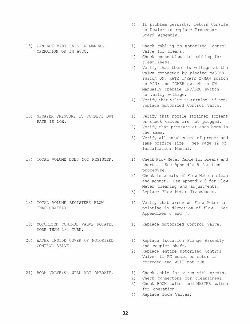
15) CAN NOT VARY RATE IN MANUALOPERATION OR IN AUTO.
16) SPRAYER PRESSURE IS CORRECT BUTRATE IS LOW.
17) TOTAL VOLUME DOES NOT REGISTER.
18) TOTAL VOLUME REGISTERS FLOWINACCURATELY.
19) MOTORIZED CONTROL VALVE ROTATESMORE THAN 1/4 TURN.
20) WATER INSIDE COVER OF MOTORIZEDCONTROL VALVE.
21) BOOM VALVE(S) WILL NOT OPERATE.
4) If problem persists, return Consoleto Dealer to replace ProcessorBoard Assembly.
1) Check cabling to motorized ControlValve for breaks.
2) Check connections in cabling forcleanliness.
3) Verify that there is voltage at thevalve connector by placing MASTERswitch ON; RATE 1/RATE 2/MAN switchto MAN; and POWER switch to ON.Manually operate INC/DEC switchto verify voltage.
4) Verify that valve is turning, if not,replace motorized Control Valve.
1) Verify that nozzle strainer screensor check valves are not plugged.
2) Verify that pressure at each boom isthe same.
3) Verify all nozzles are of proper andsame orifice size. See Page 12 ofInstallation Manual.
1) Check Flow Meter Cable for breaks andshorts. See Appendix 5 for testprocedure.
2) Check internals of Flow Meter; cleanand adjust. See Appendix 6 for FlowMeter cleaning and adjustments.
3) Replace Flow Meter Transducer.
1) Verify that arrow on Flow Meter ispointing in direction of flow. SeeAppendixes 6 and 7.
1) Replace motorized Control Valve.
1) Replace Isolation Flange Assemblyand coupler shaft.
2) Replace entire motorized ControlValve, if PC board or motor iscorroded and will not run.
1) Check cable for wires with breaks.2) Check connectors for cleanliness.3) Check BOOM switch and MASTER switch
for operation.4) Replace Boom Valves.
33
APPENDIX 1WHEEL DRIVE SPEED SENSOR INSTALLATION AND CALIBRATION
PROCEDURE
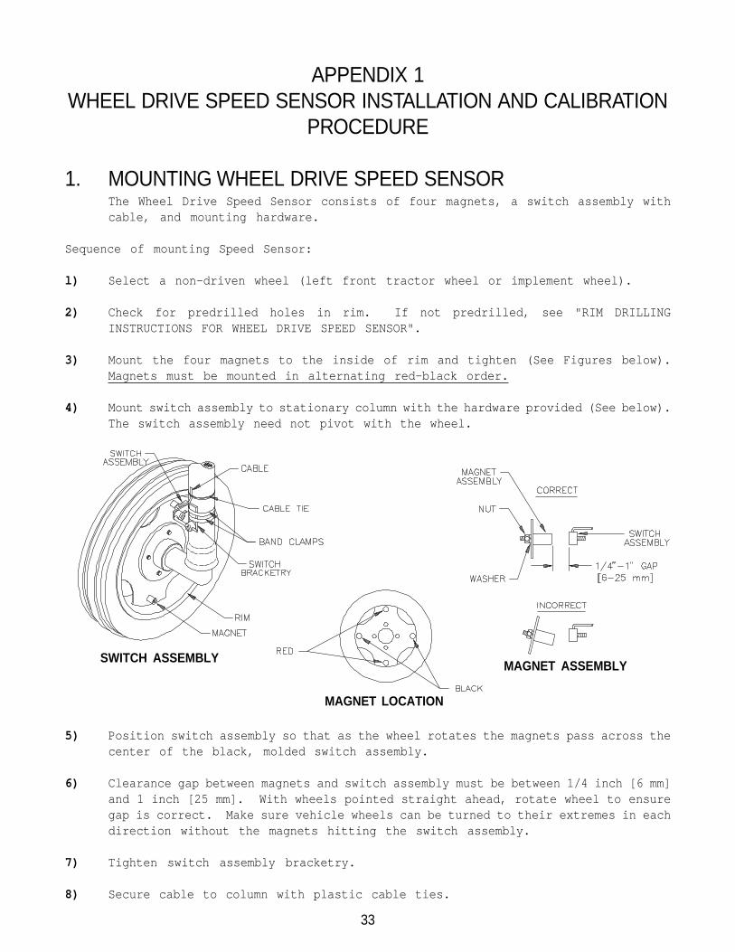
1. MOUNTING WHEEL DRIVE SPEED SENSORThe Wheel Drive Speed Sensor consists of four magnets, a switch assembly withcable, and mounting hardware.
Sequence of mounting Speed Sensor:
l) Select a non-driven wheel (left front tractor wheel or implement wheel).
2) Check for predrilled holes in rim. If not predrilled, see "RIM DRILLINGINSTRUCTIONS FOR WHEEL DRIVE SPEED SENSOR".
3) Mount the four magnets to the inside of rim and tighten (See Figures below).Magnets must be mounted in alternating red-black order.
4) Mount switch assembly to stationary column with the hardware provided (See below).The switch assembly need not pivot with the wheel.
5) Position switch assembly so that as the wheel rotates the magnets pass across thecenter of the black, molded switch assembly.
6) Clearance gap between magnets and switch assembly must be between 1/4 inch [6 mm]and 1 inch [25 mm]. With wheels pointed straight ahead, rotate wheel to ensuregap is correct. Make sure vehicle wheels can be turned to their extremes in eachdirection without the magnets hitting the switch assembly.
7) Tighten switch assembly bracketry.
8) Secure cable to column with plastic cable ties.
MAGNET LOCATION
MAGNET ASSEMBLYSWITCH ASSEMBLY
34
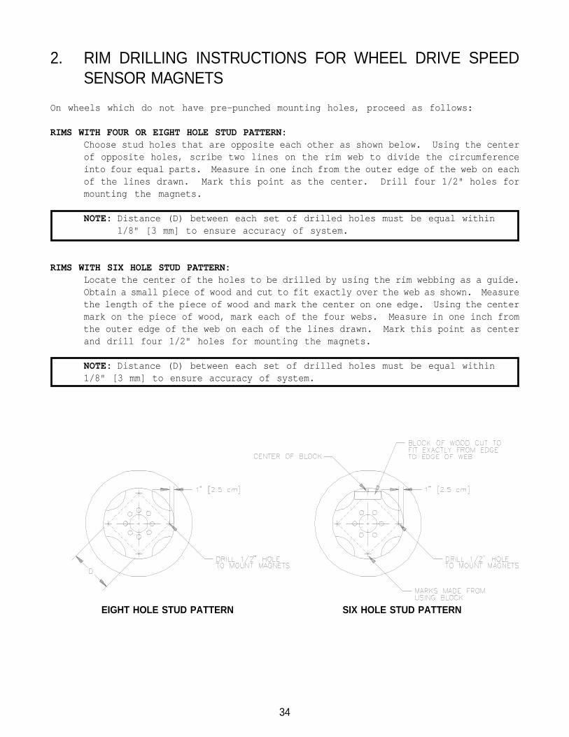
2. RIM DRILLING INSTRUCTIONS FOR WHEEL DRIVE SPEEDSENSOR MAGNETS
On wheels which do not have pre-punched mounting holes, proceed as follows:
RIMS WITH FOUR OR EIGHT HOLE STUD PATTERN:Choose stud holes that are opposite each other as shown below. Using the centerof opposite holes, scribe two lines on the rim web to divide the circumferenceinto four equal parts. Measure in one inch from the outer edge of the web on eachof the lines drawn. Mark this point as the center. Drill four 1/2" holes formounting the magnets.
NOTE: Distance (D) between each set of drilled holes must be equal within1/8" [3 mm] to ensure accuracy of system.
RIMS WITH SIX HOLE STUD PATTERN:Locate the center of the holes to be drilled by using the rim webbing as a guide.Obtain a small piece of wood and cut to fit exactly over the web as shown. Measurethe length of the piece of wood and mark the center on one edge. Using the centermark on the piece of wood, mark each of the four webs. Measure in one inch fromthe outer edge of the web on each of the lines drawn. Mark this point as centerand drill four 1/2" holes for mounting the magnets.
NOTE: Distance (D) between each set of drilled holes must be equal within1/8" [3 mm] to ensure accuracy of system.
EIGHT HOLE STUD PATTERN SIX HOLE STUD PATTERN
35
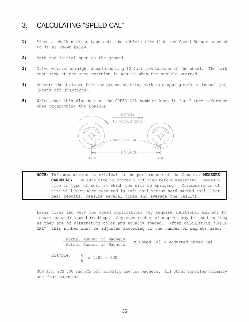
3. CALCULATING "SPEED CAL"
1) Place a chalk mark or tape onto the vehicle tire that the Speed Sensor mountedto it as shown below.
2) Mark the initial spot on the ground.
3) Drive vehicle straight ahead counting 10 full revolutions of the wheel. The markmust stop at the same position it was in when the vehicle started.
4) Measure the distance from the ground starting mark to stopping mark in inches [dm](Round off fractions).
5) Write down this distance as the SPEED CAL number; keep it for future referencewhen programming the Console.
NOTE: This measurement is critical to the performance of the Console. MEASURECAREFULLY. Be sure tire is properly inflated before measuring. Measuretire in type of soil in which you will be spraying. Circumference oftire will vary when measured in soft soil versus hard packed soil. Forbest results, measure several times and average the results.
Large tires and very low speed applications may require additional magnets toinsure accurate speed readings. Any even number of magnets may be used as longas they are of alternating color and equally spaced. After calculating "SPEEDCAL", this number must be adjusted according to the number of magnets used.
Normal Number of MagnetsActual Number of Magnets
Example: 46
SCS 330, SCS 500 and SCS 550 normally use two magnets. All other consoles normallyuse four magnets.
x Speed Cal = Adjusted Speed Cal
x 1200 = 800

36
APPENDIX 2SPEEDOMETER DRIVE SPEED SENSOR INSTALLATION AND
CALIBRATION PROCEDURE
1. MOUNTING THE SPEEDOMETER DRIVE SPEED SENSOR
1) Remove the existing speedometer cable from the back of the vehicle speedometer.Pull cable through fire wall into engine compartment.
2) Install adapter and key on speedometer cable and connect to Transducer Assembly.(Some units do not use adapter and key).
3) Connect Extension Cable to Transducer Assembly.
4) Push Extension Cable through fire wall and re-install on speedometer.
5) Connect the cable on the Transducer Assembly to the Console.
6) Secure all cables with plastic cable ties.
You are now ready to calibrate the Speedometer Drive Speed Sensor.
37
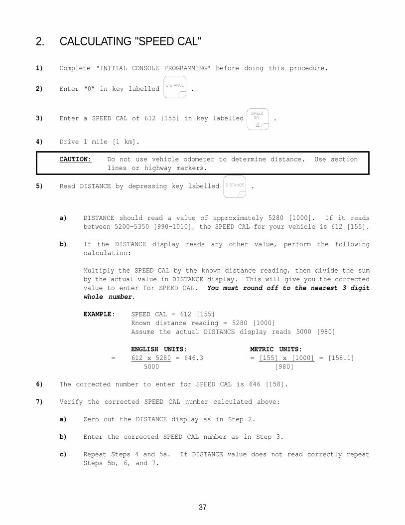
2. CALCULATING "SPEED CAL"
1) Complete "INITIAL CONSOLE PROGRAMMING" before doing this procedure.
2) Enter “0” in key labelled .
3) Enter a SPEED CAL of 612 [155] in key labelled .
4) Drive 1 mile [1 km].
CAUTION: Do not use vehicle odometer to determine distance. Use sectionlines or highway markers.
5) Read DISTANCE by depressing key labelled .
a) DISTANCE should read a value of approximately 5280 [1000]. If it readsbetween 5200-5350 [990-1010], the SPEED CAL for your vehicle is 612 [155].
b) If the DISTANCE display reads any other value, perform the followingcalculation:
Multiply the SPEED CAL by the known distance reading, then divide the sumby the actual value in DISTANCE display. This will give you the correctedvalue to enter for SPEED CAL. You must round off to the nearest 3 digitwhole number.
EXAMPLE: SPEED CAL = 612 [155]Known distance reading = 5280 [1000]Assume the actual DISTANCE display reads 5000 [980]
ENGLISH UNITS: METRIC UNITS: = 612 x 5280 = 646.3 = [155] x [1000] = [158.1]
5000 [980]
6) The corrected number to enter for SPEED CAL is 646 [158].
7) Verify the corrected SPEED CAL number calculated above:
a) Zero out the DISTANCE display as in Step 2.
b) Enter the corrected SPEED CAL number as in Step 3.
c) Repeat Steps 4 and 5a. If DISTANCE value does not read correctly repeatSteps 5b, 6, and 7.
38
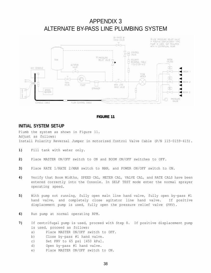
APPENDIX 3ALTERNATE BY-PASS LINE PLUMBING SYSTEM
FIGURE 11FIGURE 11FIGURE 11FIGURE 11FIGURE 11
INITIAL SYSTEM SET-UPPlumb the system as shown in Figure 11.Adjust as follows:Install Polarity Reversal Jumper in motorized Control Valve Cable (P/N 115-0159-415).
1) Fill tank with water only.
2) Place MASTER ON/OFF switch to ON and BOOM ON/OFF switches to OFF.
3) Place RATE 1/RATE 2/MAN switch to MAN, and POWER ON/OFF switch to ON.
4) Verify that Boom Widths, SPEED CAL, METER CAL, VALVE CAL, and RATE CALS have beenentered correctly into the Console. In SELF TEST mode enter the normal sprayeroperating speed.
5) With pump not running, fully open main line hand valve, fully open by-pass #1hand valve, and completely close agitator line hand valve. If positivedisplacement pump is used, fully open the pressure relief valve (PRV).
6) Run pump at normal operating RPM.
7) If centrifugal pump is used, proceed with Step 8. If positive displacement pumpis used, proceed as follows:a) Place MASTER ON/OFF switch to OFF.b) Close by-pass #1 hand valve.c) Set PRV to 65 psi [450 kPa].d) Open by-pass #1 hand valve.e) Place MASTER ON/OFF switch to ON.

39
8) Verify that each boom valve operates and that no nozzles are plugged by operatingthe BOOM ON/OFF switches.
9) Place all BOOM ON/OFF switches to ON.
10) Hold the FLOW CONTROL switch to INC position for approximately 12 seconds. Thisassures motorized Control Valve is fully closed. (Pressure gauge is not supplied).
NOTE: A pressure gauge MUST be installed to properly adjust the system.
11) Adjust agitator line hand valve for desired agitation.
12) Close the main line hand valve, if necessary, to set the desired maximumoperating pressure. Maximum pressure should be approximately 10 psi [70 kPa] abovenormal spraying pressure. EXAMPLE: If normal spraying pressure is 30 psi [210kPa],set maximum pressure at approximately 40 psi [280 kPa].
13) Hold the INC/DEC switch to DEC position for approximately 12 seconds. This assuresmotorized Control Valve is fully open.
14) Close by-pass #1 hand valve to set the desired minimum operating pressure. Minimumpressure should be approximately one half the normal spraying pressure.EXAMPLE: If normal spraying pressure is 30 psi [210 kPa], set minimum pressureat approximately 15 psi [105 kPa].
15) Verify maximum and minimum pressures and RATE by repeating Steps 11 and 14.
INITIAL SYSTEM FIELD TEST
1) Drive down field or road at target speed with sprayer booms OFF, to verify SPEEDreadout on Console.
2) Turn on sprayer and booms and place the RATE 1/RATE 2/MAN switch to RATE 1 or RATE2. Increase or decrease speed by one (1) MPH [2 km/h]. The system shouldautomatically correct to the target application rate.
3) If for any reason, the system is unable to correct to the desired RATE, check foran empty tank, a plugged line, a malfunctioning pump, improper vehicle speed ora defect in the system.
4) If the system does not appear to be correcting properly, first review INITIALSYSTEM SET-UP, then refer to TROUBLESHOOTING GUIDE.
5) At the end of each row, switch the MASTER ON/OFF to OFF to shut off flow. Thisalso shuts off the area totalizer.
6) Verify area covered and volume used.
40
APPENDIX 4PROCEDURE TO TEST SPEED SENSOR EXTENSION CABLES
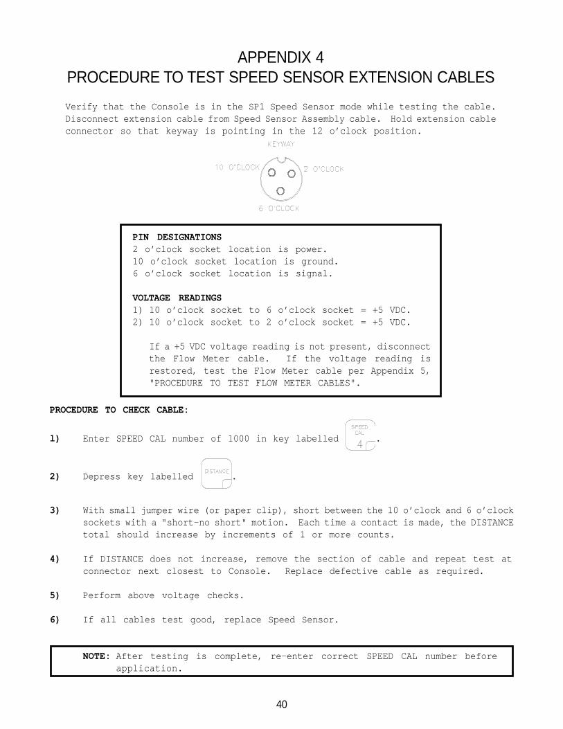
Verify that the Console is in the SP1 Speed Sensor mode while testing the cable.Disconnect extension cable from Speed Sensor Assembly cable. Hold extension cableconnector so that keyway is pointing in the 12 o’clock position.
PROCEDURE TO CHECK CABLE:
l) Enter SPEED CAL number of 1000 in key labelled .
2) Depress key labelled .
3) With small jumper wire (or paper clip), short between the 10 o’clock and 6 o’clocksockets with a "short-no short" motion. Each time a contact is made, the DISTANCEtotal should increase by increments of 1 or more counts.
4) If DISTANCE does not increase, remove the section of cable and repeat test atconnector next closest to Console. Replace defective cable as required.
5) Perform above voltage checks.
6) If all cables test good, replace Speed Sensor.
NOTE: After testing is complete, re-enter correct SPEED CAL number beforeapplication.
PIN DESIGNATIONS2 o’clock socket location is power.10 o’clock socket location is ground.6 o’clock socket location is signal.
VOLTAGE READINGS1) 10 o’clock socket to 6 o’clock socket = +5 VDC.2) 10 o’clock socket to 2 o’clock socket = +5 VDC.
If a +5 VDC voltage reading is not present, disconnectthe Flow Meter cable. If the voltage reading isrestored, test the Flow Meter cable per Appendix 5,"PROCEDURE TO TEST FLOW METER CABLES".

41
APPENDIX 5PROCEDURE TO TEST FLOW METER CABLES
Disconnect cable from Flow Meter. Hold Flow Meter cable so that the keyway ispointing in the 12 o’clock position:
PROCEDURE TO CHECK CABLE:
1) Enter a METER CAL number of one (1) in key labelled .
2) Depress key labelled .
3) Place BOOM switches and MASTER switch to ON.
4) With small jumper wire (or paper clip), short between the 2 o’clock and 6 o’clocksockets with a "short-no short" motion. Each time a contact is made, the TOTALVOLUME should increase by increments of 1 or more counts.
5) If TOTAL VOLUME does not increase, remove the section of cable and repeat testat connector next closest to Console. Replace defective cable as required.
6) Perform above voltage checks.
7) If all cables test good, replace Flow Meter.
NOTE: After testing is complete, re-enter correct METER CAL numbers beforeapplication.
PIN DESIGNATIONS2 o’clock socket location is ground.10 o’clock socket location is power.6 o’clock socket location is signal.
VOLTAGE READINGS1) 2 o’clock socket to 6 o’clock socket = +5 VDC.2) 2 o’clock socket to 10 o’clock socket = +5 VDC.
If a +5 VDC voltage reading is not present, disconnectthe Speed Sensor cable. If the voltage reading isrestored, test the Speed Sensor cable per Appendix 4,"PROCEDURE TO TEST SPEED SENSOR EXTENSION CABLES".
42
APPENDIX 6FLOW METER MAINTENANCE AND ADJUSTMENT PROCEDURE
1) Remove Flow Meter from sprayer and flush with clean water to remove any chemicals.
NH3 WARNING: Thoroughly bleed nurse tank hose and all other system lines prior
to disassembling the Flow Meter, fittings, and hoses.
2) Remove flange bolts or clamp from the Flow Meter.
3) Remove the turbine hub and turbine from inside Flow Meter.
4) Clean turbine and turbine hub of metal filings or any other foreign material, suchas wettable powders. Confirm that the turbine blades are not worn. Hold turbineand turbine hub in your hand and spin turbine. The turbine should spin freelywith very little drag inside the turbine hub.
5) If transducer assembly is replaced or if turbine stud is adjusted or replaced,verify the turbine fit before reassembling. Hold turbine hub with turbine ontransducer. Spin turbine by blowing on it. Tighten turbine stud until turbinestalls. Loosen turbine stud 1/3 turn. The turbine should spin freely.
6) Re-assemble Flow Meter.
7) Using a low pressure (5 psi) [34.5 kPa] jet of air, verify the turbine spins freely.If there is drag, loosen hex stud on the bottom of turbine hub 1/16 turn untilthe turbine spins freely.
8) If the turbine spins freely and cables have been checked per Appendix "PROCEDURETO TEST FLOW CABLES", but Flow Meter still is not totalizing properly, replaceFlow Meter transducer.

43
APPENDIX 7PROCEDURE TO RE-CALIBRATE FLOW METER
1) Enter a METER CAL number of 10 [38] in the key labelled .
2) Enter a TOTAL VOLUME of 0 in the key labelled .
3) Switch OFF all booms.
4) Remove a boom hose and place it into a calibrated 5 gallon [19 liter] container.
5) Switch ON appropriate boom switch (for the hose that was just placed into the 5gallon container) and the MASTER switch. Pump exactly 10 gallons [38 liters].
6) Readout in TOTAL VOLUME is the new METER CAL number. This number should be within+/- 3% of the calibration number stamped on the tag of the Flow Meter.
7) Repeat this procedure several times to confirm accuracy. (Always "zero out" theTOTAL VOLUME display before retesting).
NOTE: For greatest precision, set METER CAL to 100 and pump 100 gallons (378liters) of water.
8) To verify Flow Meter calibration, fill applicator tank with a predetermined amountof measured liquid (i.e. 250 gallons). DO NOT RELY ON GRADUATION NUMBERS MOLDEDINTO APPLICATOR TANK. Empty the applicator tank under normal operatingconditions. If the number displayed under TOTAL VOLUME is different from thepredetermined amount of measured liquid by more than +/- 3%, complete the followingcalculation:
EXAMPLE:METER CAL = 720 [190]TOTAL VOLUME = 260 [984]Predetermined amount of measured liquid = 250 [946]
Corrected METER CAL = METER CAL x TOTAL VOLUME Predetermined amount of measured liquid
ENGLISH UNITS: METRIC UNITS:= 720 x 260 = 749 = [190] x [984] = [198]
250 [946]
Corrected METER CAL = 749 [198]
9) Enter corrected METER CAL before resuming application.

44
APPENDIX 8REMOTE SWITCH OPTION
FIGURE 12FIGURE 12FIGURE 12FIGURE 12FIGURE 12
The REMOTE switch when installed is in parallel with the MASTER switch; thereforeswitching on the REMOTE switch OR the MASTER switch will energize the boom valves.

45
3) Optional 9 pin to 9 pin cable pinout (P/N 115-0159-822).
DSR 6 4CTS 8DTR 4 6
8TXD 3 2RXD 2 3GND 5 5
APPENDIX 9SERIAL INTERFACE
1) Cable pinout (P/N 115-0159-994), supplied with Thermal Printer Kit(P/N 117-0159-529).
DSR 6 5CTS 8DTR 4 6TXD 3 2RXD 2 3GND 5 7
2) Changing RATE 1 CAL by remote computer.a) Configuration of RS-232C serial port:
1200 or 9600 Baud RateNO Parity8 Data Bits2 Stop Bits
b) Data stream to Raven Console.
EXAMPLE: Change RATE 1 to 123.4
$R,RC,1234<CR><LF>
Decimal point is not sent from Remote Computer to Raven Console.
Printer25 Pin
Communicationstring
Rate Cal
Line Feed
Carriage ReturnRATE 1= 123.4
RAVENCONSOLE9 PIN
COMPUTER/GPS
9 Pin
RAVENCONSOLE9 PIN

46
APPENDIX 10SCS 440 COMMUNICATION STRINGS
REMOTE COMPUTER TO SCS 440 CONSOLEAll request strings begin with $R, to indicate a Raven communication string.
Rate 1 Change Request:$R,RC,<rate_1_cal><CR><LF>
Calibration String Values Request:$R,CR<CR><LF>
Data String Request:$R,DR<CR><LF>
SCS 440 CONSOLE TO REMOTE COMPUTERAll console output strings begin with $R123K, the $R indicates a Ravencommunication string, the 123 is the last three digits of the current SCS 440programmed chip part number and K is the software revision number.
Calibration Strings:$R123K,C1,<switch_byte_1>,<switch_byte_2>,<boom_1_cal>,
<boom_2_cal>,<boom_3_cal>,<speed_cal> <CR><LF>$R123K,C2,<meter_cal>,<CR><LF>$R123K,C3,<valve_cal>,<rate_1_cal>,<rate_2_cal><CR><LF>
Bit Switch Byte 1 Switch Byte 20 boom 1 01 boom 2 02 boom 3 03 0 rate 14 0 rate 25 0 06 0 07 1 1
Data Strings:$R123K,D1,<total_area>,<field_area><CR><LF>$R123K,D2,<total_volume>,<field_volume><CR><LF>$R123K,D3,<tank_volume>,<distance><CR><LF>
Actual Rate:$R123K,AR,<actual_rate><CR><LF>
Time/Date:$R123K,TD,<hr:min>,<month/day/year>,<field_reference><CR><LF>
NOTE:NOTE:NOTE:NOTE:NOTE: If rate 1 and rate 2 are both zero,the console is in Manual. For switchByte Bits; 0 = off and 1 = on.