scsi block commands - 2 (sbc-2) - o3one · scsi block commands - 2 (sbc-2) ... obsolete extent...
TRANSCRIPT

T10 Working Draft
Working Draft T10 American National Standard Project 1417-D
Revision 4 28 July 2001 Information Technology - SCSI Block Commands - 2 (SBC-2) This is an internal working document of T10, a Technical Committee of Accredited Standards Committee NCITS (National Committee for Information Technology Standards). As such this is not a completed standard and has not been approved. The contents may be modified by the T10 Technical Committee. The contents are actively being modified by T10. This document is made available for review and comment only. Permission is granted to members of NCITS, its technical committees, and their associated task groups to reproduce this document for the purposes of NCITS standardization activities without further permission, provided this notice is included. All other rights are reserved. Any commercial or for-profit duplication is strictly prohibited.
T10 Technical Editor: Robert C Elliott MC 150801 Compaq Computer Corporation P.O. Box 692000 Houston, TX 77269-2000 USA Telephone: (281) 518-5037 Email: [email protected]
Reference number
ISO/IEC 14776-322:200x ANSI NCITS.***:200x

T10 Working Draft
Points of Contact: T10 Chair John B. Lohmeyer LSI Logic 4420 Arrows West Drive Colorado Springs, CO 80907-3444 USA Telephone: (719) 533-7560 Email: [email protected]
T10 Vice-Chair George O. Penokie Tivoli Systems MS 2C6 3605 Highway 52 N. Rochester, MN 55901 USA Telephone: (507) 253-5208 Email: [email protected]
NCITS T10 Committee Web Site: http://www.t10.org E-mail reflector: Server: [email protected] To subscribe, send e-mail with ‘subscribe t10’ in the message body To unsubscribe, send e-mail with ‘unsubscribe t10’ in the message body National Committee for Information Technology Standards (NCITS) Secretariat Suite 200 1250 Eye Street, NW Washington, DC 20005 USA Telephone: (202) 737-8888 Web site: http://www.ncits.org Email: [email protected] Information Technology Industry Council Web site: http://www.itic.org Document Distribution NCITS Online Store managed by Techstreet 1327 Jones Drive Ann Arbor, MI 48105 USA Web site: http://www.techstreet.com/ncits.html Telephone: (734) 302-7801 or (800) 699-9277 Global Engineering Documents, an HIS Company 15 Inverness Way East Englewood, CO 80112-5704 USA http://global.ihs.com Telephone: (303) 397-7956 or (303) 792-2181 or (800) 854-7179

T10 Working Draft
Revision History Revision 0 (5 July 2000): • Converted to ISO/IEC style. • Incorporated the following proposals:
o 98-202r1 - Obsolete Extent Reservations o 98-202r1 - Obsolete Change Definition o 98-203r9 - Persistent Reseration Changes o 99-189r0 - ECC correction span spec for 255 o 99-259r4 - 2 Terabyte Changes. Note that the proposal had *, **, or *** on
several commands but no explanation of the *, **, or ***. o 00-125r0 - Large LBA address using variable length CDB structure
Revision 1 (27 August 2000): • Incorporated the following proposal:
o 99-258r2 - List lengths that exceed the maximum with wording changes approved at the 7/2000 meeting.
• Added note after reservation conflict tables per prior editor’s note and 7/2000 meeting.
• Added “may not” to key words per 7/2000 meeting.
Revision 2 (4 October 2000): • Added missing operation code for XDREAD in Table 68 • Incorporated the following proposals:
o 00-248r2 - SBC-2 issues - Item 6 - Initialization Pattern using the least significant 4 bytes of the LBA
o 00-333r0 - SCSI is a functional standard o 00-248r2 - SBC-2 issues - Editorial changes
Revision 3 (17 May 2001): • Added GEM dedication page. • Corrected spelling, cross reference, and formatting errors throughout the document. • Deleted about 12,000 extraneous spaces. • Reformatted tables to follow SPI-4 style. • Generated PDF with bookmarks enabled. • Changed Times-Roman font to Arial in the few places it was used. • Made small-caps use more consistent. • Updated front material based on SPI-3 revision 14. • Added hierarchy to annexes. • Fixed sense key/additional sense code mixup in Logical blocks section 4.2.1.3. • Fixed VERIFY (16) and WRITE SAME (16) (they only had 10 CDB bytes). • Moved all READ, VERIFY, WRITE, WRITE AND VERIFY commands into section 5.1.
Added text explaining that the BLKVFY or EBP bits are considered reserved for direct access devices. This addresses Gene’s editorial note 1 asking whether optical VERIFY (16) and WRITE AND VERIFY (16) should point to optical or direct access versions of the CDBs.
• Added notes in WRITE (6) and WRITE (10) about their different handling of transfer length of 0.
• Added READ (16) and LOCK UNLOCK CACHE (16) to list of supported commands for optical and write-once devices, since the write commands were already added. The preface to 99-259r4 only requested new large LBA commands for direct access devices, but provided reservation tables for all 3 types. SBC-2 revision 2 included most of them; it seems appropriate to allow the rest as well.
• Changed PRE-FETCH to PRE-FETCH (10) since there is now a PRE-FETCH (16) too.

T10 Working Draft
• Merged all the reservation tables into one to avoid duplication of most of the rows (and potential conflicts).
• Reconciled with SPC-2 revision 19: o In variable length CDBs, changed ENCRYPTION IDENTIFICATION to
Reserved to match SPC-2 revision 19. o Removed CHANGE DEFINITION, COMPARE, COPY, and COPY AND
VERIFY references, since they are obsolete in SPC-2. o Removed the power condition mode page. SPC-2 marks page code 0Dh as
obsolete, since it incorporated the entire page under code 1Ah per these proposals:
• 95-222r2 Power condition mode page code • 95-265r1 T10 plenary minutes July 1995 item 10.6 Power Condition
mode page • Incorporated the following proposals:
o 00-315r1 - Bidirectional XDWRITEREAD command for SBC-2 o 00-395r1 - Increased defect list lengths for SBC-2 o 00-375r1 - November 2000 T10 plenary minutes - motion 10.4.4: “READ (16)
and WRITE (16) [shall] be made mandatory for the direct-access device type”. Noted that WRITE (16) is only mandatory if any WRITE command is implemented.
Revision 4 (28 July 2001): • Obsoleted 0Dh and moved Power Condition page to 1Ah in optical drives table 122. • Corrected opcodes in READ (16) and WRITE SAME (16) • Incorporated the following proposals:
o 00-425r4 Long Identifiers in SPC-3, SAM-2, SBC-2 and other XOR issues o 01-134r2 WAKEUP and RESET cleanup o 01-210r0 Reassign Blocks 2 TB support
Pending proposals (as of 28 July 2001): • 01-199 Sense Data INFORMATION field for long LBAs and bidirectional commands • 01-276 Long LBA PMI support for Read Capacity

T10 Working Draft
American National Standard for Information Technology
SCSI Block Commands - 2 (SBC-2)
Secretariat
Information Technology Industry Council Approved mm dd yyyy American National Standards Institute, Inc. Abstract This standard specifies the functional requirements for the SCSI Block Commands - 2 (SBC-2) command set. SBC-2 permits SCSI block logical units such as flexible disks, rigid disks, optical disks, etc., to attach to computers and provides the definition for their use.
This standard maintains a high degree of compatibility with the SCSI Block Commands set (SBC) command set, NCITS.306:1998, and while providing additional functions, is not intended to require changes to presently installed devices or existing software.

T10 Working Draft
Working Draft SCSI Block Commands - 2 (SBC-2) ii
American National Standard
Approval of an American National Standard requires review by ANSI that the requirements for due process, consensus, and other criteria for approval have been met by the standards developer. Consensus is established when, in the judgment of the ANSI Board of Standards Review, substantial agreement has been reached by directly and materially affected interests. Substantial agreement means much more than a simple majority, but not necessarily unanimity. Consensus requires that all views and objections be considered, and that effort be made towards their resolution. The use of American National Standards is completely voluntary; their existence does not in any respect preclude anyone, whether he has approved the standards or not, from manufacturing, marketing, purchasing, or using products, processes, or procedures not conforming to the standards. The American National Standards Institute does not develop standards and will in no circumstances give interpretation on any American National Standard. Moreover, no person shall have the right or authority to issue an interpretation of an American National Standard in the name of the American National Standards Institute. Requests for interpretations should be addressed to the secretariat or sponsor whose name appears on the title page of this standard. CAUTION NOTICE: This American National Standard may be revised or withdrawn at any time. The procedures of the American National Standards Institute require that action be taken periodically to reaffirm, revise, or withdraw this standard. Purchasers of American National Standards may receive current information on all standards by calling or writing the American National Standards Institute.
CAUTION: The developers of this standard have requested that holders of patents that may be required for the implementation of the standard, disclose such patents to the publisher. However, neither the developers nor the publisher have undertaken a patent search in order to identify which, if any, patents may apply to this standard. As of the date of publication of this standard, following calls for the identification of patents that may be required for the implementation of the standard, no such claims have been made. No further patent search is conducted by the developer or the publisher in respect to any standard it processes. No representation is made or implied that licenses are not required to avoid infringement in the use of this standard.
Published by American National Standards Institute 11 W. 42nd Street, New York, New York 10036 Copyright 200n by Information Technology Industry Council (ITI) All rights reserved. No part of this publication may by reproduced in any form, in an electronic retrieval system or otherwise, without prior written permission of ITI, 1250 Eye Street NW, Washington, DC 2005. Printed in the United States of America


T10 Working Draft
Working Draft SCSI Block Commands - 2 (SBC-2) ii
Dedication
This standard is dedicated to the memory of Gene E. Milligan, who was the original editor.
Mr. Milligan was a dedicated and energetic participant on several NCITS Technical Committees, including T10, T11, T12, and T13. He chaired both T12 and T13 and was the International Representative for T10, T11, and T12.
Mr. Milligan graduated in 1959 from UCLA with a degree in Electrical Engineering and was employed by Seagate Technology for over 30 years. His interests included flying, water and snow skiing, and tinkering with anything that needed repair. He was also an avid sports fan.
Memorial gifts may be made to Habitat for Humanity.

T10 Working Draft
Working Draft SCSI Block Commands - 2 (SBC-2) iii
Contents 1 Scope ............................................................................................................................... 1 2 Normative References ....................................................................................................... 3
2.1 Normative references overview................................................................................. 3 2.2 Approved references ................................................................................................ 3 2.3 References under development ................................................................................ 3
3 Definitions, symbols, abbreviations, keywords, and conventions......................................... 4 3.1 Definitions................................................................................................................ 4
3.1.1 Definitions specific to direct access devices.................................................. 4 3.1.1.1 block device: ...................................................................................... 4 3.1.1.2 cache memory: .................................................................................. 4 3.1.1.3 check data: ........................................................................................ 4 3.1.1.4 data-in buffer: .................................................................................... 4 3.1.1.5 data-out buffer: .................................................................................. 4 3.1.1.6 domain:.............................................................................................. 4 3.1.1.7 exclusive-or: ...................................................................................... 4 3.1.1.8 extent: ............................................................................................... 4 3.1.1.9 hard reset: ......................................................................................... 4 3.1.1.10 host: ................................................................................................ 4 3.1.1.11 logical block: .................................................................................... 4 3.1.1.12 logical unit reset:.............................................................................. 5 3.1.1.13 logical unit reset event: .................................................................... 5 3.1.1.14 non-volatile medium: ........................................................................ 5 3.1.1.15 notch: .............................................................................................. 5 3.1.1.16 power cycle:..................................................................................... 5 3.1.1.17 power on .......................................................................................... 5 3.1.1.18 redundancy group: ........................................................................... 5 3.1.1.19 reset event ....................................................................................... 5 3.1.1.20 storage array controller: ................................................................... 5 3.1.1.21 storage array conversion layer (SACL): ............................................ 5 3.1.1.22 third party: ....................................................................................... 5 3.1.1.23 user-accessible: ............................................................................... 5 3.1.1.24 user data: ........................................................................................ 5 3.1.1.25 volatile medium: ............................................................................... 6 3.1.1.26 wakeup ............................................................................................ 6 3.1.1.27 wakeup event ................................................................................... 6
3.1.2 Definitions specific to optical memory block devices and write-once block devices .................................................................................... 6
3.1.2.1 blank: ................................................................................................ 6 3.1.2.2 generation: ........................................................................................ 6 3.1.2.3 read-only medium: ............................................................................. 6 3.1.2.4 update: .............................................................................................. 6 3.1.2.5 write-once medium: ............................................................................ 6
3.2 Symbols and abbreviations....................................................................................... 6 3.3 Keywords ................................................................................................................. 7
3.3.1 Keywords overview....................................................................................... 7

T10 Working Draft
Working Draft SCSI Block Commands - 2 (SBC-2) iv
3.3.2 expected: ..................................................................................................... 7 3.3.3 mandatory: ................................................................................................... 7 3.3.4 may: ............................................................................................................. 7 3.3.5 may not: ....................................................................................................... 7 3.3.6 obsolete: ...................................................................................................... 7 3.3.7 optional: ....................................................................................................... 7 3.3.8 reserved: ...................................................................................................... 7 3.3.9 shall: ............................................................................................................ 7 3.3.10 should: ....................................................................................................... 7 3.3.11 vendor-specific: .......................................................................................... 7
3.4 Conventions ............................................................................................................. 7 4 Models .............................................................................................................................. 9
4.1 General .................................................................................................................... 9 4.2 SCSI block device models ...................................................................................... 10
4.2.1 Direct-access device type model................................................................. 10 4.2.1.1 Direct-access device type model overview........................................ 10 4.2.1.2 Removable medium.......................................................................... 10 4.2.1.2.1 Removable medium overview ........................................................ 10 4.2.1.2.2 Removable medium with an attached medium changer .................. 10 4.2.1.3 Logical blocks .................................................................................. 11 4.2.1.4 Ready state ..................................................................................... 11 4.2.1.5 Initialization ..................................................................................... 11 4.2.1.6 Medium defects................................................................................ 12 4.2.1.7 Cache memory................................................................................. 12 4.2.1.8 Reservations.................................................................................... 13 4.2.1.9 Seek (10) ......................................................................................... 16 4.2.1.10 Notched devices ............................................................................ 16 4.2.1.11 Rotational position locking.............................................................. 16 4.2.1.12 Relative addressing........................................................................ 16 4.2.1.13 Error reporting ............................................................................... 16
4.2.2 Examples ................................................................................................... 17 4.2.2.1 Examples ......................................................................................... 17 4.2.2.2 Rotating media................................................................................. 17 4.2.2.3 Sequential media ............................................................................. 18 4.2.2.4 Memory media ................................................................................. 18
4.2.3 Model for XOR commands .......................................................................... 18 4.2.3.1 Overview of model for XOR commands............................................. 18 4.2.3.2 Storage array controller supervised XOR operations......................... 19 4.2.3.2.1 Overview of storage array controller supervised XOR
operations .................................................................................. 19 4.2.3.2.2 Update write operation .................................................................. 19 4.2.3.2.3 Regenerate operation.................................................................... 19 4.2.3.2.4 Rebuild operation .......................................................................... 20 4.2.3.3 Third party XOR operations .............................................................. 20 4.2.3.3.1 Overview of third party XOR operations ......................................... 20 4.2.3.3.2 Update write operation .................................................................. 20 4.2.3.3.3 Regenerate operation.................................................................... 21

T10 Working Draft
Working Draft SCSI Block Commands - 2 (SBC-2) v
4.2.3.3.4 Rebuild operation .......................................................................... 21 4.2.3.4 Hybrid subsystem XOR operations ................................................... 22 4.2.3.4.1 Overview of hybrid subsystem XOR operations .............................. 22 4.2.3.4.2 Update write operation .................................................................. 22 4.2.3.4.3 Regenerate operation.................................................................... 22 4.2.3.4.4 Rebuild operation .......................................................................... 23 4.2.3.5 Additional array subsystem considerations ....................................... 24 4.2.3.5.1 Overview of additional array subsystem considerations.................. 24 4.2.3.5.2 Buffer full status handling .............................................................. 24 4.2.3.5.3 Access to an inconsistent stripe .................................................... 24 4.2.3.6 Error handling considerations ........................................................... 25 4.2.3.6.1 Overview of error handling considerations ..................................... 25 4.2.3.6.2 Errors during third party XOR operations ....................................... 25 4.2.3.6.3 Primary errors - errors resulting directly from the primary
command ................................................................................... 25 4.2.3.6.4 Secondary errors - errors resulting from the secondary
command ................................................................................... 26 4.2.3.7 XOR data retention requirements ..................................................... 27
4.3 Model for optical memory block devices.................................................................. 27 4.3.1 Overview of model for optical memory block devices ................................... 27 4.3.2 Defect management ................................................................................... 28 4.3.3 Error reporting............................................................................................ 28
4.4 Model for write-once block devices ......................................................................... 29 4.4.1 Model for write-once block devices ............................................................. 29 4.4.2 Logical blocks ............................................................................................ 29 4.4.3 Initialization ................................................................................................ 30 4.4.4 Physical medium defects ............................................................................ 30 4.4.5 Error reporting............................................................................................ 30
5 Commands for block devices ........................................................................................... 32 5.1 Commands for direct-access block devices............................................................. 32
5.1.1 FORMAT UNIT command ........................................................................... 34 5.1.1.1 FORMAT UNIT command overview .................................................. 34 5.1.1.2 Defect list formats ............................................................................ 40 5.1.1.3 Initialization pattern option ............................................................... 42
5.1.2 LOCK UNLOCK CACHE (10) command ...................................................... 43 5.1.3 LOCK UNLOCK CACHE (16) command ...................................................... 44 5.1.4 PRE-FETCH (10) command ........................................................................ 44 5.1.5 PRE-FETCH (16) command ........................................................................ 45 5.1.6 READ (6) command.................................................................................... 46 5.1.7 READ (10) command .................................................................................. 47 5.1.8 READ (12) command .................................................................................. 48 5.1.9 READ (16) command .................................................................................. 48 5.1.10 READ CAPACITY command ..................................................................... 49 5.1.11 READ DEFECT DATA (10) command........................................................ 51 5.1.12 READ DEFECT DATA (12) command........................................................ 53 5.1.13 READ LONG command............................................................................. 54 5.1.14 REASSIGN BLOCKS command................................................................. 55

T10 Working Draft
Working Draft SCSI Block Commands - 2 (SBC-2) vi
5.1.15 REBUILD (16) Command .......................................................................... 57 5.1.16 REBUILD (32) Command .......................................................................... 60 5.1.17 REGENERATE (16) command .................................................................. 62 5.1.18 REGENERATE (32) command .................................................................. 63 5.1.19 SEEK (10) command ................................................................................ 64 5.1.20 SET LIMITS (10) command ....................................................................... 64 5.1.21 SET LIMITS (12) command ....................................................................... 65 5.1.22 START STOP UNIT command .................................................................. 65 5.1.23 SYNCHRONIZE CACHE (10) command .................................................... 67 5.1.24 SYNCHRONIZE CACHE (16) command .................................................... 68 5.1.25 VERIFY (10) command ............................................................................. 69 5.1.26 VERIFY (12) command ............................................................................. 70 5.1.27 VERIFY (16) command ............................................................................. 70 5.1.28 WRITE (6) command ................................................................................ 71 5.1.29 WRITE (10) command .............................................................................. 72 5.1.30 WRITE (12) command .............................................................................. 72 5.1.31 WRITE (16) command .............................................................................. 73 5.1.32 WRITE AND VERIFY (10) command ......................................................... 73 5.1.33 WRITE AND VERIFY (12) command ......................................................... 74 5.1.34 WRITE AND VERIFY (16) command ......................................................... 75 5.1.35 WRITE LONG command ........................................................................... 76 5.1.36 WRITE SAME (10) command .................................................................... 76 5.1.37 WRITE SAME (16) command .................................................................... 77 5.1.38 XDREAD (10) command ........................................................................... 78 5.1.39 XDREAD (32) command ........................................................................... 79 5.1.40 XDWRITE (10) command .......................................................................... 79 5.1.41 XDWRITE (32) command .......................................................................... 80 5.1.42 XDWRITEREAD (10) command................................................................. 81 5.1.43 XDWRITEREAD (32) command................................................................. 82 5.1.44 XDWRITE EXTENDED (16) command....................................................... 83 5.1.45 XDWRITE EXTENDED (32) command....................................................... 85 5.1.46 XDWRITE EXTENDED (64) command....................................................... 85 5.1.47 XPWRITE (10) command .......................................................................... 86 5.1.48 XPWRITE (32) command .......................................................................... 87
5.2 Commands for optical memory block devices.......................................................... 89 5.2.1 ERASE (10) command ................................................................................ 90 5.2.2 ERASE (12) command ................................................................................ 91 5.2.3 MEDIUM SCAN command .......................................................................... 92 5.2.4 READ GENERATION command .................................................................. 93 5.2.5 READ UPDATED BLOCK command............................................................ 94 5.2.6 UPDATE BLOCK command ........................................................................ 95
5.3 Commands for write-once block devices ................................................................. 96 6 Parameters for block devices........................................................................................... 98
6.1 Parameters for direct-access block devices ............................................................ 98 6.1.1 Diagnostic parameters ................................................................................ 98
6.1.1.1 Diagnostic parameters overview ....................................................... 98 6.1.1.2 Translate address page - SEND DIAGNOSTIC ................................. 98

T10 Working Draft
Working Draft SCSI Block Commands - 2 (SBC-2) vii
6.1.1.3 Translate address page - RECEIVE DIAGNOSTIC............................ 99 6.1.1.4 Device status page - SEND DIAGNOSTIC ...................................... 101 6.1.1.5 Device status page - RECEIVE DIAGNOSTIC................................. 101
6.1.2 Log parameters ........................................................................................ 103 6.1.3 Format status page................................................................................... 103
6.2 Mode parameters ................................................................................................. 104 6.2.1 Mode parameters overview ....................................................................... 104 6.2.2 Caching page ........................................................................................... 106 6.2.3 Flexible disk page .................................................................................... 110 6.2.4 Format device page .................................................................................. 114 6.2.5 Medium types supported page .................................................................. 117 6.2.6 Notch and partition page........................................................................... 118 6.2.7 Read-write error recovery page ................................................................ 119 6.2.8 Rigid disk device geometry page .............................................................. 125 6.2.9 Verify error recovery page ........................................................................ 127 6.2.10 XOR control mode page.......................................................................... 128
6.3 Parameters for optical memory block devices ....................................................... 130 6.3.1 Diagnostic parameters .............................................................................. 130 6.3.2 Log parameters ........................................................................................ 130 6.3.3 Mode parameters ..................................................................................... 130
6.3.3.1 Mode parameters overview ............................................................ 130 6.3.3.2 Optical memory page ..................................................................... 132
6.3.4 Parameters for write-once block devices ................................................... 133 A XOR command examples .............................................................................................. 134
A.1 XOR command examples overview ...................................................................... 134 A.2 Storage array controller supervised XOR operations............................................. 134
A.2.1 Update write operation ............................................................................. 134 A.2.2 Regenerate operation............................................................................... 135 A.2.3 Rebuild operation ..................................................................................... 136
A.3 Third-party XOR operations.................................................................................. 137 A.3.1 Update write operation ............................................................................. 137 A.3.2 Regenerate operation............................................................................... 138 A.3.3 Rebuild operation ..................................................................................... 139
A.4 Hybrid subsystem XOR operations ....................................................................... 140 A.4.1 Regenerate operation............................................................................... 140 A.4.2 Rebuild operation ..................................................................................... 141
B Bibliography.................................................................................................................. 143

T10 Working Draft
Working Draft SCSI Block Commands - 2 (SBC-2) viii
Tables
Table 1 - Service action code assignments ............................................................................... 9 Table 2 - SBC commands that are allowed in the presence of various reservations ..................15 Table 3 - Example error conditions ..........................................................................................17 Table 4 - Error condition examples ..........................................................................................29 Table 5 - Error condition examples ..........................................................................................30 Table 6 - Commands for direct-access block devices ..............................................................33 Table 7 - FORMAT UNIT command .........................................................................................35 Table 8 - FORMAT UNIT parameter list ...................................................................................36 Table 9 - SHORT DEFECT LIST HEADER ........................................................................................36 Table 10 - LONG DEFECT LIST HEADER ........................................................................................37 Table 11 - FORMAT UNIT defect descriptor format and requirements ......................................38 Table 12 - DEFECT DESCRIPTOR - Block format (000b) ................................................................40 Table 13 - DEFECT DESCRIPTOR - Block format (011b) ................................................................40 Table 14 - DEFECT DESCRIPTOR - Bytes from index format .........................................................41 Table 15 - DEFECT DESCRIPTOR - Physical sector format ...............................................................41 Table 16 - INITIALIZATION PATTERN DESCRIPTOR ..........................................................................42 Table 17 - Initialization pattern modifier ...................................................................................42 Table 18 - Initialization pattern type .........................................................................................43 Table 19 - LOCK UNLOCK CACHE (10) command...................................................................43 Table 20 - LOCK UNLOCK CACHE (16) command...................................................................44 Table 21 - PRE-FETCH (10) command ....................................................................................45 Table 22 - PRE-FETCH (16) command ....................................................................................46 Table 23 - READ (6) command ................................................................................................46 Table 24 - READ (10) command ..............................................................................................47 Table 25 - READ (12) command ..............................................................................................48 Table 26 - READ (16) command ..............................................................................................49 Table 27 - READ CAPACITY command....................................................................................49 Table 28 - Short read capacity data .........................................................................................50 Table 29 - Long read capacity data..........................................................................................51 Table 30 - READ DEFECT DATA (10) command ......................................................................51 Table 31 - READ DEFECT DATA (10) defect list ......................................................................52 Table 32 - READ DEFECT DATA (12) command ......................................................................53 Table 33 - READ DEFECT DATA (12) list header.....................................................................54 Table 34 - READ LONG command ...........................................................................................54 Table 35 - REASSIGN BLOCKS command...............................................................................55 Table 36 - REASSIGN BLOCKS defect list ...............................................................................56 Table 37 - REASSIGN BLOCKS short defect header ................................................................56 Table 38 - REASSIGN BLOCKS long defect header .................................................................56 Table 39 - REBUILD (16) command .........................................................................................57 Table 40 - PORT CONTROL field .................................................................................................58 Table 41 - REBUILD (16) and REGENERATE (16) parameter data...........................................59 Table 42 - REBUILD (16) and REGENERATE (16) SOURCE DESCRIPTOR format .........................59 Table 43 - REBUILD (32) command .........................................................................................60 Table 44 - REBUILD (32) and REGENERATE (32) parameter data...........................................61 Table 45 - REBUILD (32) and REGENERATE (32) source descriptor format.............................62 Table 46 - REGENERATE (16) command ................................................................................62 Table 47 - REGENERATE (32) command ................................................................................63 Table 48 - SEEK (10) command...............................................................................................64 Table 49 - SET LIMITS (10) command .....................................................................................64 Table 50 - SET LIMITS (12) command .....................................................................................65 Table 51 - START STOP UNIT command.................................................................................66 Table 52 - POWER CONDITIONS field ...........................................................................................66 Table 53 - SYNCHRONIZE CACHE (10) command ..................................................................68 Table 54 - SYNCHRONIZE CACHE (16) command ..................................................................69 Table 55 - VERIFY (10) command ..........................................................................................69 Table 56 - VERIFY (12) command ...........................................................................................70
T10 Working Draft
Working Draft SCSI Block Commands - 2 (SBC-2) ix
Table 57 - VERIFY (16) command ..........................................................................................71 Table 58 - WRITE (6) command...............................................................................................71 Table 59 - WRITE (10) command.............................................................................................72 Table 60 - WRITE (12) command.............................................................................................73 Table 61 - WRITE (16) command.............................................................................................73 Table 62 - WRITE AND VERIFY (10) command .......................................................................74 Table 63 - WRITE AND VERIFY(12) command ........................................................................75 Table 64 - WRITE AND VERIFY (16) command .......................................................................75 Table 65 - WRITE LONG command ........................................................................................76 Table 66 - WRITE SAME (10) command ..................................................................................77 Table 67 - WRITE SAME (16) command ..................................................................................78 Table 68 - XDREAD (10) command..........................................................................................78 Table 69 - XDREAD (32) command..........................................................................................79 Table 70 - XDWRITE (10) command ........................................................................................80 Table 71 - XDWRITE (32) command ........................................................................................81 Table 72 - XDWRITEREAD (10) command...............................................................................82 Table 73 - XDWRITEREAD (32) command...............................................................................83 Table 74 - XDWRITE EXTENDED (16) command.....................................................................84 Table 75 - XDWRITE EXTENDED (32) command.....................................................................85 Table 76 - XDWRITE EXTENDED (64) command.....................................................................86 Table 77 - XPWRITE (10) command ........................................................................................87 Table 78 - XPWRITE (32) command ........................................................................................88 Table 79 - Commands for optical memory block devices ..........................................................89 Table 80 - ERASE (10) command ............................................................................................91 Table 81 - ERASE (12) command ............................................................................................91 Table 82 - MEDIUM SCAN command.......................................................................................92 Table 83 - MEDIUM SCAN parameter list.................................................................................93 Table 84 - READ GENERATION command ..............................................................................94 Table 85 - Maximum generation data block ..............................................................................94 Table 86 - READ UPDATED BLOCK command ........................................................................94 Table 87 - UPDATE BLOCK command.....................................................................................95 Table 88 - Commands for write-once block devices..................................................................96 Table 89- Diagnostic page codes.............................................................................................98 Table 90 - Translate address page - SEND DIAGNOSTIC ........................................................99 Table 91 - Translate address page - RECEIVE DIAGNOSTIC ................................................100 Table 92 - Device status page - SEND DIAGNOSTIC.............................................................101 Table 93 - Device status page - RECEIVE DIAGNOSTIC .......................................................102 Table 94 - SYNCHRONIZATION field ...........................................................................................102 Table 95 - Log page codes ....................................................................................................103 Table 96 - Format status log page parameter codes...............................................................103 Table 97 - Direct-access medium-type codes.........................................................................105 Table 98- Device specific parameter ......................................................................................105 Table 99- Mode page codes for direct-access block devices ..................................................106 Table 100- Caching page ......................................................................................................107 Table 101 - Demand read retention priority and write retention priority ...................................108 Table 102 - Flexible disk page ...............................................................................................111 Table 103 - Examples of transfer rates ..................................................................................112 Table 104 - PIN 34 field ..........................................................................................................113 Table 105 - PIN 4 field ............................................................................................................114 Table 106 - PIN 1 field ............................................................................................................114 Table 107 - Format device page ............................................................................................115 Table 108 - Reporting of default sector formatting support .....................................................117 Table 109 - Reporting of changeable sector formatting support ..............................................117 Table 110 - Medium types supported page.............................................................................117 Table 111 - Notch page .........................................................................................................118 Table 112 - Read-write error recovery page ...........................................................................119 Table 113 - Error recovery bit definitions ...............................................................................121 Table 114 - Combined error recovery parameter descriptions.................................................122 Table 115 - Rigid disk device geometry page .........................................................................126

T10 Working Draft
Working Draft SCSI Block Commands - 2 (SBC-2) x
Table 116 - Rotational position locking ..................................................................................127 Table 117 - Verify error recovery page...................................................................................128 Table 118 - XOR control mode page ......................................................................................129 Table 119 - Diagnostic page codes for optical memory block devices .....................................130 Table 120 - Log page codes for optical memory block devices ...............................................130 Table 121 - Optical memory medium-type codes ....................................................................131 Table 122 - Optical memory block device specific parameter .................................................131 Table 123 - Optical memory density codes.............................................................................132 Table 124 - Mode page codes for optical memory block devices ............................................132 Table 125 - Optical memory page ..........................................................................................133
Figures
Figure 1 - SCSI standards - general structure ........................................................................... 1 Figure A.1 - Update write operation .......................................................................................135 Figure A.2 - Regenerate operation.........................................................................................136 Figure A.3 - Rebuild operation ...............................................................................................137 Figure A.4 - Update write operation .......................................................................................138 Figure A.5 - Regenerate operation.........................................................................................139 Figure A.6 - Rebuild operation ...............................................................................................140 Figure A.7 - Regenerate operation.........................................................................................141 Figure A.8 - Rebuild operation ...............................................................................................142

T10 Working Draft
Working Draft SCSI Block Commands - 2 (SBC-2) xi
Foreword (This foreword is not part of this standard)
Requests for interpretation, suggestions for improvement and addenda, or defect reports are welcome. They should be sent to the NCITS Secretariat, ITI, 1250 Eye Street, NW, Suite 200, Washington, DC 20005-3922. This standard was processed and approved for submittal to ANSI by National Committee for Information Technology Standards (NCITS). Committee approval of this standard does not necessarily imply that all committee members voted for approval. At the time it approved this standard, NCITS had the following members: Karen Higginbottom, Chair David Michael, Vice-chair Monica Vago, Secretary (NCITS Membership to be inserted)

T10 Working Draft
Working Draft SCSI Block Commands - 2 (SBC-2) xii
Technical Committee T10 on Lower Level Interfaces, that developed this standard, had the following members: John B. Lohmeyer, Chair George O. Penokie, Vice-Chair Ralph O. Weber, Secretary (member list to be added at start of first public review)

T10 Working Draft
Working Draft SCSI Block Commands - 2 (SBC-2) xiii
Introduction
This standard is divided into the following clauses:
Clause 1 is the scope. Clause 2 lists the normative references that apply to this standard. Clause 3 describes the definitions, symbols, conventions, and abbreviations used in
this standard. Clause 4 provides an overview of the block device class and the command set. This
clause also specifies the conventions used throughout the standard. Clause 5 describes models for the various categories of block devices. Clause 6 provides the definitions of all commands unique to block devices. This
clause also provides references to the SPC-2 standard for primary commands used with this logical unit class.
Clause 7 provides the definition of all parameters unique to this logical unit class. Annex A provides XOR command examples. Annex B is the bibliography.
Annexes A and B are for informational purposes only.

T10 Working Draft
Working Draft SCSI Block Commands - 2 (SBC-2) 1
AMERICAN NATIONAL STANDARD BSR NCITS TBD
American National Standard for Information Technology - SCSI Block Commands - 2 (SBC-2)
1 Scope
This standard defines the command set extensions to facilitate operation of SCSI block devices. The clauses of this standard pertaining to the SCSI block device class, implemented in conjunction with the applicable clauses of the ANSI NCITS 301-1998 SCSI-3 Primary Commands (SPC), fully specify the standard command set for SCSI block devices.
The objective of this standard is to provide the following:
a) Permit an application client to communicate with a logical unit that declares itself to be a direct-access device, write-once device, and optical memory device in the device type field of the INQUIRY command response data over an SCSI service delivery subsystem;
b) Define commands unique to the type of SCSI block devices; c) Define commands to manage the operation of SCSI block devices; d) Define the differences between types of SCSI block devices.
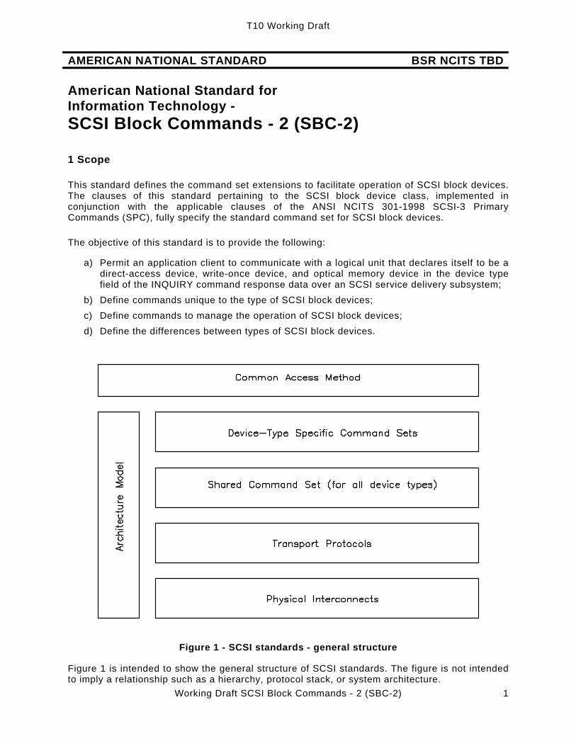
Figure 1 - SCSI standards - general structure
Figure 1 is intended to show the general structure of SCSI standards. The figure is not intended to imply a relationship such as a hierarchy, protocol stack, or system architecture.

T10 Working Draft
Working Draft SCSI Block Commands - 2 (SBC-2) 2
At the time this standard was generated examples of the SCSI general structure included: Physical Interconnects:
Fibre Channel Arbitrated Loop [ANSI X3.272-1996] Fibre Channel Arbitrated Loop -2 [ANSI NCITS.332-1999] Fibre Channel - Physical and Signaling Interface [ANSI X3.230-1994] High Performance Serial Bus [IEEE 1394-1995] SCSI Parallel Interface -2 [ANSI NCITS 302-1999] SCSI Parallel Interface -3 [ANSI NCITS TBD -200X] Serial Storage Architecture Physical Layer 1 [ANSI X3.293-1996] Serial Storage Architecture Physical Layer 2 [ANSI NCITS 307-1998]
Transport Protocols:
Serial Storage Architecture Transport Layer 1 [ANSI X3.295-1996] SCSI-3 Fibre Channel Protocol [ANSI X3.269-1996] SCSI-3 Fibre Channel Protocol - 2 [NCITS T10/1144D] SCSI Serial Bus Protocol -2 [ANSI NCITS.325.1998] Serial Storage Architecture SCSI-2 Protocol [ANSI X3.294-1996] Serial Storage Architecture SCSI-3 Protocol [ANSI NCITS 309-1998] Serial Storage Architecture Transport Layer 2 [ANSI NCITS 308-1998]
Shared Command Set:
SCSI-3 Primary Commands [ANSI NCITS 301-1997] SCSI Primary Commands - 2 [NCITS T10/1236D]
Device-Type Specific Command Sets:
SCSI-3 Block Commands (ANSI NCITS 306-1998) SCSI Block Commands - 2 (this standard) SCSI-3 Enclosure Services [ANSI NCITS 305-1998] SCSI-3 Stream Commands [NCITS T10/997D] SCSI-3 Medium Changer Commands [ANSI NCITS 314-1998] SCSI-3 Controller Commands [ANSI X3.276-1997] SCSI-3 Controller Commands - 2 [ANSI NCITS 318-1998]] SCSI-3 Multimedia Command Set [ANSI NCITS 304-1997] SCSI-3 Multimedia Command Set - 2 [NCITS T10/1228D]
Architecture Model:
SCSI-3 Architecture Model [ANSI X3.270-1996] SCSI-3 Architecture Model - 2 [NCITS T10/1157D]
Common Access Method: SCSI Common Access Method [ANSI X3.232-1996]
The term SCSI is used wherever it is not necessary to distinguish between the versions of SCSI and for versions since SCSI-3. The Small Computer System Interface -2 (ANSI X3.131-1994) is

T10 Working Draft
Working Draft SCSI Block Commands - 2 (SBC-2) 3
referred to herein as SCSI-2. The term SCSI-3 in this standard refers to versions of SCSI defined as the first versions since SCSI-2.
The set of SCSI standards specifies the interfaces, functions, and operations necessary to ensure interoperability between conforming SCSI implementations. This standard is a functional description. Conforming implementations may employ any design technique that does not violate interoperability.
2 Normative References
2.1 Normative references overview
The following standards contain provisions that, by reference in the text, constitute provisions of this standard. At the time of publication, the editions indicated were valid. All standards are subject to revision, and parties to agreements based on this standard are encouraged to investigate the possibility of applying the most recent editions of the standards listed below.
Copies of the following documents may be obtained from ANSI: approved ANSI standards, approved and draft international and regional standards (ISO, IEC, CEN/CENELEC, ITUT), and approved and draft foreign standards (including BSI, JIS, and DIN). For further information, contact ANSI Customer Service Department at 212-642-4900 (phone), 212-302-1286 (fax) or via the World Wide Web at http://www.ansi.org.
Additional availability contact information is provided below as needed.
2.2 Approved references ANSI X3.270-1996, Information technology - SCSI-3 Architecture Model (SAM) ANSI NCITS.301:1998, Information technology - SCSI-3 Primary Commands (SPC) ANSI X3.276-1997, Information technology - SCSI-3 Controller Commands (SCC) ANSI NCITS.318:1998, Information technology - SCSI-3 Controller Commands - 2 (SCC-
2) ANSI NCITS.314:1998, Information technology - SCSI-3 Medium Changer Commands
(SMC)
2.3 References under development
At the time of publication, the following referenced standards were still under development. For information on the current status of the documents, or regarding availability, contact the relevant standards body as indicated.
[NCITS T10/1157-D] SCSI Architecture Model - 2 [NCITS T10/1236-D] SCSI Primary Commands - 2 [NCITS T10/1416-D] SCSI Primary Commands - 3
Note 1 - For more information on the current status of the document, contact the NCITS Secretariat at 202-737-8888 (telephone), 202-638-4922 (fax) or via Email at [email protected]. To obtain copies of this document, contact Global Engineering at 15 Inverness Way East Englewood, CO 80112-5704 at 800-854-7179 (telephone), 303-792-2181 (telephone), or 303-792-2192 (fax).

T10 Working Draft
Working Draft SCSI Block Commands - 2 (SBC-2) 4
3 Definitions, symbols, abbreviations, keywords, and conventions
3.1 Definitions
3.1.1 Definitions specific to direct access devices
3.1.1.1 block device: A device that is capable of containing data stored in blocks that have a unique logical
block address.
3.1.1.2 cache memory: A temporary (and often volatile) data storage area outside the user-accessible area that
may contain a subset of the data stored in the non-volatile data storage area. A cache memory is usually faster to access than the medium and thus has the effect of increasing data throughput by reducing the number of accesses to the medium.
3.1.1.3 check data: Information contained within a redundancy group that allows lost or destroyed user data
to be recreated.
3.1.1.4 data-in buffer: The buffer identified by the application client to receive data from the device server
during the execution of a command.
3.1.1.5 data-out buffer: The buffer identified by the application client to supply data that is sent from the
application client to the device server during the execution of a command.
3.1.1.6 domain: An I/O system consisting of a set of SCSI devices that interact with one another by
means of a service delivery subsystem.
3.1.1.7 exclusive-or: A logical function that combines two logical inputs producing a logical output true state if
one but not both inputs are true. This function is used in error correction algorithms. In this standard the term encompasses the entire algorithm but does not define the specific polynomial. The exclusive-or operation may be performed by the storage array controller or by the storage device.
3.1.1.8 extent: An extent is a specified number of logical blocks and all or part of a block device.
3.1.1.9 hard reset: A target action in response to a reset event in which the target port performs the
operations described in SCSI Architecture Model-2.
3.1.1.10 host: Any combination of initiators and application clients that form a device managing one or
more peripheral devices.
3.1.1.103.1.1.11 logical block: A unit of data supplied or requested by an initiator.

T10 Working Draft
Working Draft SCSI Block Commands - 2 (SBC-2) 5
3.1.1.12 logical unit reset: A logical unit action in response to a logical unit reset event in which the logical unit
performs the operations described in SCSI Architecture Model-2.
3.1.1.13 logical unit reset event: An event that triggers a logical unit reset from a logical unit as described in SCSI
Architecture Model–2.
3.1.1.14 non-volatile medium: A physical storage medium that retains data written to it for a subsequent read operation
through power off/on cycles. An example of this is a disk within a device that stores data as magnetic field changes that do not require device power to exist.
3.1.1.123.1.1.15 notch: A notch refers to all or part of the medium having a consistent set of geometry
parameters. Notches are used to increase storage capacity by optimizing the number of bytes per track between the inner and outer tracks.
3.1.1.16 power cycle: Power off followed by power on.
3.1.1.17 power on Power being applied.
3.1.1.133.1.1.18 redundancy group: A grouping of protected space and associated check data into a single type of data
redundancy (see ANSI X3.276 SCC). This standard only supports the exclusive-or type of redundancy.
3.1.1.19 reset event An event that triggers a hard reset from a SCSI device as described in the protocol
standard. Reset events include power on and other protocol-specific events.
3.1.1.143.1.1.20 storage array controller: Any combination of an initiator and application clients (see ANSI X3.270 SAM) that
originates SCSI command descriptor blocks and performs the services of a SACL. A storage array controller organizes a group of storage devices into various objects (e.g., redundancy groups, volume sets, etc.).
3.1.1.153.1.1.21 storage array conversion layer (SACL): Converts input logical unit numbers to output logical unit numbers and may convert input
logical block addresses to output logical block addresses.
3.1.1.163.1.1.22 third party: When used in conjunction with exclusive-or operations refers to the operations performed
by a primary target with a secondary target on behalf of the host storage array controller.
3.1.1.173.1.1.23 user-accessible: The area of the medium that can be read from or written to by READ and WRITE
commands.
3.1.1.183.1.1.24 user data: The addressable logical blocks that are input to the SACL. Check data is not part of the
addressable logical blocks.
T10 Working Draft
Working Draft SCSI Block Commands - 2 (SBC-2) 6
3.1.1.193.1.1.25 volatile medium: Medium that does not retain data written to it for a subsequent read operation through
power off/on cycles. An example of this is a silicon memory device that loses data written to it if device power is lost.
3.1.1.26 wakeup A target port returning from the sleep power condition to the active power condition (see
SPC-3).
3.1.1.27 wakeup event An event that triggers a wakeup from a target port as described in SPC-3.
3.1.2 Definitions specific to optical memory block devices and write-once block devices
3.1.2.1 blank: The logical block contains no information detectable by the block device, or is written
with a pattern that appears to the block device as no data present. The logical block is considered ready for a write operation.
3.1.2.2 generation: Indicates a relative revision level of a logical block that has been updated via the
UPDATE BLOCK command. A logical block that has never been updated has only one generation associated with it.
3.1.2.3 read-only medium: This is medium that is not to be written by the application client. The medium contains
data prepared in a manner not defined by this standard.
3.1.2.4 update: To write new data to a logical block without destroying the previous data. After a block
has been updated, a normal read returns the most recent generation of the data. Earlier generations are still available after the update.
3.1.2.5 write-once medium: This is medium that is to be written only once by any application client. Logical blocks on
write-once media that have not been written are considered blank. Logical blocks on write-once media that have been written are not to be written again.
3.2 Symbols and abbreviations CDB command descriptor block I/O input/output ID identifier LBA logical block address LSB least significant bit MMC SCSI-3 Multimedia Command Set [ANSI NCITS 304] MSB most significant bit SAM SCSI-3 Architecture Model [ANSI X3.270] SCC SCSI-3 Controller Commands [ANSI X3.276] SCSI either SCSI-2 or SCSI-3 SCSI-2 the Small Computer System Interface-2 [X3.131] [ISO/IEC 9316-1:1996] SCSI-3 the Small Computer System Interface-3 SMC SCSI-3 Medium Changer Commands standard [ANSI NCITS.348;1998] SPC SCSI-3 Primary Commands standard [ANSI NCITS.301:1998] XOR exclusive-or

T10 Working Draft
Working Draft SCSI Block Commands - 2 (SBC-2) 7
3.3 Keywords
3.3.1 Keywords overview Several keywords are used to differentiate between different levels of requirements and optionality, as follows: 3.3.2 expected:
Used to describe the behavior of the hardware or software in the design models assumed by this standard. Other hardware and software design models may also be implemented.
3.3.3 mandatory: Indicates items required to be implemented as defined by this standard.
3.3.4 may: A keyword that indicates flexibility of choice with no implied preference (equivalent to
"may or may not").
3.3.5 may not: A keyword that indicates flexibility of choice with no implied preference (equivalent to
"may or may not").
3.3.6 obsolete: Indicates items that were defined in prior SCSI standards but have been removed from
this standard.
3.3.7 optional: Describes features that are not required to be implemented by this standard. However, if
any optional feature defined by the standard is implemented, it shall be implemented as defined by this standard.
3.3.8 reserved: A keyword referring to bits, bytes, words, fields and code values that are set aside for
future standardization. A reserved bit, byte, word or field shall be set to zero, or in accordance with a future extension to this standard. Recipients are not required to check reserved bits, bytes, words or fields for zero values. Receipt of reserved code values in defined fields shall be reported as error.
3.3.9 shall: Indicates a mandatory requirement. Designers are required to implement all such
mandatory requirements to ensure interoperability with other standard conformant products.
3.3.10 should: Indicates flexibility of choice with a strongly preferred alternative. Equivalent to the
phrase “it is recommended.”
3.3.11 vendor-specific: Items (e.g., a bit, field, code value, etc.) that are not defined by this standard and may be
vendor defined.
3.4 Conventions
Lower case is used for words having the normal English meaning. Certain words and terms used in this standard have a specific meaning beyond the normal English meaning. These words and terms are defined either in clause 3 or in the text where they first appear.

T10 Working Draft
Working Draft SCSI Block Commands - 2 (SBC-2) 8
An alphanumeric list (e.g., a,b,c or A,B,C) of items indicate the items in the list are unordered.
A numeric list (e.g., 1,2,3) of items indicate the items in the list are ordered (i.e., item 1 must occur or complete before item 2).
In the event of conflicting information the precedence for requirements defined in this standard is: 1) text, 2) tables, then 3) figures. Not all tables or figures are fully described in text. Tables show data format and values.
The ISO convention of numbering is used (i.e., the thousands and higher multiples are separated by a space and a comma is used as the decimal point as in 65 536 or 0,5).
The additional conventions are:
a) The names of abbreviations, commands, and acronyms used as signal names are in all uppercase (e.g., IDENTIFY DEVICE);
b) Fields containing only one bit are referred to as the "NAME" bit instead of the "NAME" field; c) Field names are in SMALL CAPS to distinguish them from normal English; d) Numbers that are not immediately followed by lower-case b or h are decimal values; e) Numbers immediately followed by lower-case b (xxb) are binary values; f) Numbers immediately followed by lower-case h (xxh) are hexadecimal values; g) The most significant bit of a binary quantity is shown on the left side and represents the
highest algebraic value position in the quantity; h) If a field is specified as not meaningful or it is to be ignored, the entity that receives the
field shall not check that field.

T10 Working Draft
Working Draft SCSI Block Commands - 2 (SBC-2) 9
4 Models
4.1 General
SCSI devices that conform to this standard are referred to as SCSI block devices. This includes the category of logical units commonly referred to as flexible disks, rigid disks, removable rigid disks, erasable optical discs, write once optical discs, and read only optical discs. The ANSI NCITS 304, Information technology - SCSI-3 Multimedia Command Set (MMC) standard is typically used by CD-ROM devices.
The common attribute of block devices is that they are block addressable (i.e., the data are addressed on the block device in groups referred to as logical blocks). The number of bytes of data contained in a single logical block is the block length. The block length is almost always greater than one byte and may be a multiple of 512 bytes. In addition, a logical block is not required to bear any relation to the physical block size of the storage medium.
Each logical block has a block length associated with it. This means that the block length for the medium can change from logical block to logical block. However, for simplicity the block length typically remains constant over the entire capacity of the medium.
This standard is intended to be used in conjunction with the ANSI X3.270, Information technology - SCSI-3 Architecture Model (SAM) standard, the ANSI NCITS 301, Information technology - SCSI-3 Primary Command Set (SPC) standard, with the XOR functions of the ANSI NCITS 276, Information technology - SCSI-3 Controller Commands Set (SCC) standard, and where specified ANSI NCITS 314-1998, Information technology - SCSI-3 Medium Changer Commands (SMC).
Some commands defined since ANSI NCITS 306-1998 Information technology - SCSI-3 Block Commands (SBC) use the variable length command format defined in SPC-2. These commands are differentiated by service action codes. See Table 1.
Table 1 - Service action code assignments
Service Action Codes Description Reference 0000h Reserved for Direct-access devices 0001h REBUILD (32) command 5.1.16 0002h REGENERATE (32) command 5.1.18 0003h XDREAD (32) command 5.1.39 0004h XDWRITE (32) command 5.1.41 0005h XDWRITE EXTENDED (32) command 5.1.45 0006h XPWRITE (32) command 5.1.48 0007h XDWRITEREAD (32) 5.1.43 0008h XDWRITE EXTENDED (64) command 5.1.46
00087h - 07FFh Reserved for Direct-access devices 0800h - 0FFFh Reserved for other devices SPC-2 1000h - 1FFFh Reserved for other device types SPC-2 2000h - 27FFh Reserved for Write-once devices 2800h - 2FFFh Reserved for other device types SPC-2 3800h - 3FFFh Reserved for Optical memory devices 4000h - FFFFh Reserved for other device types SPC-2

T10 Working Draft
Working Draft SCSI Block Commands - 2 (SBC-2) 10
4.2 SCSI block device models
4.2.1 Direct-access device type model
4.2.1.1 Direct-access device type model overview
Direct-access block devices store blocks of data for later retrieval. Each block of data is stored at a unique logical block address. An application client issues WRITE commands to store the blocks of data (write operations) and READ commands to retrieve the blocks of data (read operations). Other commands issued by the application client may also cause write and read operations to occur. A write operation causes one or more blocks of data to be written on the medium. A read operation causes one or more blocks of data to be read from the medium. A verify operation confirms that one or more blocks of data were correctly written and can be read without error from the medium.
Blocks of data are stored by a process that causes localized changes or transitions within the medium. The changes made to the medium to store the blocks of data may be volatile (i.e., not retained through off/on power cycles) or non-volatile (i.e., retained through power off/on cycles). The medium may be divided in parts that are used for data blocks, parts that are reserved for defect management, and parts that are reserved for use by the controller for the management of the block device.
4.2.1.2 Removable medium
4.2.1.2.1 Removable medium overview
The medium may be removable (e.g., used in a floppy disk device) or non-removable (e.g., used in a fixed disk device). The removable medium may be contained within a cartridge (or jacket) to prevent damage to the recording surfaces. The combination of medium and cartridge is often called a removable volume.
A removable volume has an attribute of being mounted or de-mounted on a suitable transport mechanism. A removable volume is mounted when the direct access block device is capable of performing write or read operations to the medium. A mounted removable volume may not be accessible by an initiator if it is reserved by another initiator. A removable volume is de-mounted at any other time (e.g., during loading, unloading, or storage).
An application client may check whether a removable volume is mounted by issuing a TEST UNIT READY command. A volume that is loaded may need a START STOP UNIT command issued to become accessible for write or read operations.
The PREVENT ALLOW MEDIUM REMOVAL command allows an application client to restrict the demounting of the removable volume. This is useful in maintaining system integrity. If the direct-access block device implements cache memory, it ensures that all logical blocks of the medium contain the most recent data prior to permitting demounting of the removable volume. If the application client issues a START STOP UNIT command to eject the removable volume, and the direct-access block device is prevented from demounting by the PREVENT ALLOW MEDIUM REMOVAL command, the START STOP UNIT command is rejected by the device server.
4.2.1.2.2 Removable medium with an attached medium changer
When a block device is served by a medium changer, control over a media transport element may be done using media changer commands sent to the logical unit.
The block device indicates its ability to support these commands by setting the MCHNGR bit to one in its standard INQUIRY data. An MCHNGR bit of one indicates that the MOVE MEDIA and READ

T10 Working Draft
Working Draft SCSI Block Commands - 2 (SBC-2) 11
ELEMENT STATUS commands are supported. Only one medium transport element is permitted (element 0) and only one data transfer element is permitted.
4.2.1.3 Logical blocks
Blocks of data are stored on the medium along with additional information that the medium controller uses to manage the storage and retrieval. The format of the additional information is defined by other standards or is vendor-specific and is hidden from the application client during normal read or write operations. This additional information may be used to identify the physical location of the blocks of data and the address of the logical block, and to provide protection against the loss of user data.
The address of the first logical block is zero. The address of the last logical block is [n-1], where [n] is the number of logical blocks available to the application client on the medium. A READ CAPACITY command may be issued to determine the value of [n-1]. If a command is issued that requests access to a logical block not within the capacity of the medium, the command is terminated with CHECK CONDITION status and the sense key is set to ILLEGAL REQUEST with the additional sense code set to LOGICAL BLOCK ADDRESS OUT OF RANGE.
The number of bytes of data contained in a logical block is the block length. Each logical block has a block length associated with it. The block descriptor in the MODE SENSE data describes the block lengths that are used on the medium. The FORMAT UNIT command may be required to change the block length of block devices that support variable block lengths.
The location of a logical block on the medium is not required to have a relationship to the location of any other logical block. However, in a typical block device the logical blocks are located in an ascending order. The time to access the logical block at address [x] and then the logical block at address [x+1] need not be less than time to access [x] and then [x+100]. The READ CAPACITY issued with a PMI bit of one may be useful in determining where longer access times occur.
4.2.1.4 Ready state
A direct-access block device is ready when medium access commands can be executed. A block device using removable media is not ready until a volume is mounted. Such a block device, with a volume not mounted, shall terminate medium access commands with CHECK CONDITION status and the sense key shall be set to NOT READY with the appropriate additional sense code for the condition.
Some direct-access block devices may be switched from being ready to being not ready by using the START STOP UNIT command. An application client may need to issue a START STOP UNIT command with a START bit set to bring a block device ready.
4.2.1.5Power conditions
The optional power conditions permit the application client to modify the behavior of a block device in a manner that may reduce the required power. There is no notification to the application client that a block device has entered one of the power conditions. The power conditions may be controlled by the START STOP UNIT command or the power condition page of the MODE SELECT command. If both methods are being used on the same target/logical unit combination then any START STOP UNIT commands power condition request shall override the power condition page’s power control. See the START STOP UNIT command description and the power condition mode page description for more information. (See 5.1.22 and SPC-2.)
No power condition shall affect the SCSI bus.

T10 Working Draft
Working Draft SCSI Block Commands - 2 (SBC-2) 12
The lowest power consumption, with power applied, occurs in the Sleep condition. When in the Sleep condition a block device requires a WAKEUP task management function to be activated.
In the Standby condition a block device is capable of accepting commands, but media is not immediately accessible (e.g., the spindle is stopped).
In the Idle condition a block device is capable of responding quickly to media access requests. However, a block device in the idle condition may take longer, than in the active condition, to complete the execution of a command because it may have to activate some circuitry.
In the Active condition a block device is capable of responding immediately to media access requests, and operations complete execution in the shortest time compared to the other power conditions.
Block devices that contain cache memory shall implicitly perform a SYNCHRONIZE CACHE command for the entire medium prior to entering any power condition that prevents access the media (e.g., the spindle being stopped).
If implemented, the block device shall use the optional power condition page to control the power conditions after a power on or a WAKEUP task management function until a START STOP UNIT command is received with the POWER CONDITIONS field set to a value other than 0h or 7h. See 5.1.22 and SPC-2.
Figure 2 shows the flow control between the different power conditions in a device that is setup to adjust itself automatically to the power condition that allows any command to execute.

T10 Working Draft
Working Draft SCSI Block Commands - 2 (SBC-2) 13
5
7
3
5
2
5
4 4
1
Idle
Sleep
Active
Standby
6
(Active, Idle, or Standby - see (f)) Path 1: An idle time-out or a START STOP UNIT command with a power condition code of Ah. Path 2: Any command that can be executed within the power constraints of the Idle power condition. Path 3: A standby time-out, or a START STOP UNIT command with a power condition code of Bh. Path 4: Any command that exceeds the power constraints of the Idle power condition. Path 5: A START STOP UNIT command with a power condition code of 5h. Path 6: A WAKEUP task management function returns the device to the state defined by the saved power mode page parameters. Path 7: This path only occurs if the idle bit is set equal to zero.
Figure 2 - SCSI power conditions flow control (automatic switching)
Figure 3 shows the flow control between the different power conditions in a device that is setup to only allow changing of the power condition by the application client. Any command received that requires more power than allowed by the most recent power condition setting shall be terminated with a CHECK CONDITION status with the sense key set to ILLEGAL REQUEST with the additional sense code set to LOW POWER CONDITION ACTIVE.

T10 Working Draft
Working Draft SCSI Block Commands - 2 (SBC-2) 14
5
3
5
2
5
44
1
Idle
Sleep
Active
Standby
6
3
(Active, Idle, or Standby - see (f)) Path 1: A START STOP UNIT command with a power condition code of 2h. Path 2: A START STOP UNIT command with a power condition code of 2h. Path 3: A START STOP UNIT command with a power condition code of 3h. Path 4: A START STOP UNIT command with a power condition code of 1h. Path 5: A START STOP UNIT command with a power condition code of 5h. Path 6: A WAKEUP task management function returns the device to the state defined by the saved power mode parameters.
Figure 3 - SCSI power conditions flow control (controlled switching)
4.2.1.64.2.1.5 Initialization
Direct-access block devices may require initialization prior to write or read operations. This initialization is performed by a FORMAT UNIT command. Parameters related to the geometry and performance characteristics may be set with the MODE SELECT command prior to the format operation. Some block devices are initialized by means not specified in this standard. The time when the initialization occurs is specific to the implementation of the direct-access block device.
Block devices using a non-volatile medium may save the parameters and only need to be initialized once. However, some mode parameters may need to be initialized after each power-on and/or logical unit reset. A catastrophic failure of the direct-access block device may require the FORMAT UNIT command to be reissued.
Block devices that use a volatile medium may need to be initialized at after each power-on and/orlogical unit reset prior to the execution of read or write operations. Mode parameters may also need initialization.
4.2.1.74.2.1.6 Medium defects
Any medium has the potential for defects that can cause user data to be lost. Therefore, each logical block may contain information that allows the detection of changes to the user data caused by defects in the medium or other phenomena, and may also allow the data to be reconstructed following the detection of such a change. Some block devices provide the application client control through use of the mode parameters. Some block devices allow the application client to examine and modify the additional information by using the READ LONG and WRITE LONG commands.

T10 Working Draft
Working Draft SCSI Block Commands - 2 (SBC-2) 15
Defects may also be detected and managed during execution of the FORMAT UNIT command. The FORMAT UNIT command defines four sources of defect information. These defects may be reassigned or avoided during the initialization process so that they do not appear in a logical block.
Defects may also occur after initialization. The application client issues a REASSIGN BLOCKS command to request that the specified LOGICAL BLOCK ADDRESS be reassigned to a different part of the medium. This operation may be repeated if a new defect appears at a later time. The total number of defects that may be handled in this manner can be specified in the mode parameters.
Defect management on direct-access block devices is vendor-specific. Block devices not using a removable medium may optimize the defect management for capacity or performance or both. Some block devices that use a removable medium do not support defect management (e.g., some floppy disk devices) or use defect management that does not impede the ability to interchange the medium.
4.2.1.84.2.1.7 Cache memory
Some direct-access block devices implement cache memory. A cache memory is usually an area of temporary storage in the direct-access block device with a fast access time that is used to enhance performance. It exists separately from the blocks of stored data and is not directly accessible by the application client. Use of cache memory for write or read operations may reduce the access time to a logical block and can increase the overall data throughput.
During read operations, the direct-access block device uses the cache memory to store blocks of data that the application client may request at some future time. The algorithm used to manage the cache memory is not part of this standard. However, parameters are provided to advise the device server about future requests, or to restrict the use of cache memory for a particular request.
During write operations, the direct-access block device uses the cache memory to store data that is written to the medium at a later time. This is called write-back caching. The command may complete prior to blocks of data being written to the medium. As a result of using a write-back caching there is a period of time when the data may be lost if power to the device is lost or a hardware failure occurs. There is also the possibility of an error occurring during the subsequent write operation. If an error occurred during the write, it may be reported as a deferred error on a later command. The application client may request that write-back caching be disabled to prevent detected write errors from being reported by deferred errors. Even with write-back caching disabled undetected write errors may occur. In order to detect these errors, verify commands are provided.
When the cache memory fills up with blocks of data that are being kept for possible future access, new blocks of data that are to be kept replace those currently in cache memory. The disable page out (DPO) bit allows the application client to influence the replacement of logical blocks in the cache. For write operations, setting this bit to one advises the device server to not replace existing blocks in the cache memory with the write data. For read operations, setting this bit to one causes blocks of data that are being read to not replace existing ones in the cache memory.
Sometimes the application client may want to have the blocks of data read from the medium instead of from the cache memory. The force unit access (FUA) bit is used to indicate that the device server shall access the physical medium. For a write operation, setting FUA to one causes the device server to complete the data write to the physical medium before completing the command. For a read operation, setting FUA to one causes the logical blocks to be retrieved from the physical medium.

T10 Working Draft
Working Draft SCSI Block Commands - 2 (SBC-2) 16
When the DPO and FUA bits are both one, write and read operations, in effect, bypass the cache memory.
When a VERIFY command is executed, a forced unit access is implied, since the blocks of data stored on the medium are being verified. Furthermore, a SYNCHRONIZE CACHE operation is also implied to write unwritten blocks of data still in the cache memory. These blocks of data are stored on the medium before the verify operation begins. The DPO bit is provided since the VERIFY command may cause the replacement of blocks in the cache. The caching rules also applies to the WRITE AND VERIFY command.
Commands may be implemented by the device server that allow the application client to control other behavior of the cache memory:
a) the LOCK UNLOCK CACHE command controls whether certain logical blocks shall be held in the data cache for future use. Locking a logical block prevents its replacement by a future access. Unlocking a logical block exposes it to possible replacement by a future access (see 5.1.2);
b) the PRE-FETCH command causes a set of logical blocks requested by the application client to be read into the data cache for possible future access. The blocks fetched are subject to later replacement unless they are locked (see 0);
c) the SYNCHRONIZE CACHE command forces any pending write data in the requested set of logical blocks to be stored in the physical medium. This command may be used to ensure that the data was written and any detected errors reported (see 5.1.23);
d) the MODE SELECT command defines a page for the control of cache behavior and handles certain basic elements of cache replacement algorithms (see SPC-2).
4.2.1.94.2.1.8 Reservations
The access enabled or access disabled condition determines when an application client may store or retrieve user data on all or part of the medium. Access may be restricted for read operations, write operations, or both. This attribute may be controlled by an external mechanism or by the RESERVE and RELEASE commands (see SPC-2).
The RESERVE and RELEASE commands define how different types of restricted access may be achieved, and to whom the access is restricted. This subclause describes the interaction of the application client that requested the reservation, and the other application clients.
Reservations are further controlled by the optional PERSISTENT RESERVE IN and PERSISTENT RESERVE OUT commands. For the requirements of this standard, reservations and releases made by use of the PERSISTENT RESERVE IN and PERSISTENT RESERVE OUT commands are the same as those using the RESERVE and RELEASE commands. See the SPC-2 standard for a description and the requirements of the various reservation commands.
An application client uses reservations to gain a level of exclusivity in access to all or part of the medium for itself or another application client. It is expected that the reservation is retained until released. The device server ensures that the application client with the reservation is able to access the reserved media within the operating parameters established by that application client.
Reservation restrictions are placed on commands as a result of access qualifiers associated with the type of reservation. The details of commands that are allowed under what types of reservations are described in Table 2. For the reservation restrictions placed on commands for the Reserve/Release management method see Table 2 column [A]. For the reservation restrictions placed on commands for the Persistent Reservations management method, see the columns under [B] in Table 2.

T10 Working Draft
Working Draft SCSI Block Commands - 2 (SBC-2) 17
Commands from initiators holding a reservation should complete normally. The behavior of commands from registered initiators when a registrants only persistent reservation is present is specified in Table 2. A command that does not explicitly write the medium shall be checked for reservation conflicts before the command enters the current task state for the first time. Once the command has entered the current task state, it shall not be terminated with a RESERVATION CONFLICT due to a subsequent reservation. A command that explicitly writes the medium shall be checked for reservation conflicts before the device server modifies the medium or cache as a result of the command. Once the command has modified the medium, it shall not be terminated with a RESERVATION CONFLICT due to a subsequent reservation.
For each command, this standard or SPC-2 defines the conditions that result in RESERVATION CONFLICT.
Extent reservations have been made obsolete in SPC-2 and in SBC-2.
Note 2: When a system is integrated with more than one application client, agreement is required between the application clients as to how media is reserved and released during operations, otherwise, an application client may be locked out of access to a logical unit in the middle of an operation.

T10 Working Draft
Working Draft SCSI Block Commands - 2 (SBC-2) 18
Table 2 - SBC commands that are allowed in the presence of various reservations Addressed LU has this type of persistent reservation
Held by another initiator [B] From any initiator From initiator not
registered
Command
Addressed LU is
reserved by another
initiator [A]
Write Excl
Excl Access
From registered
initiator (RO all types)
Write Excl -
RO
Exclusive Access -
RO ERASE (10)/(12) Conflict Conflict Conflict Allowed Conflict Conflict
FORMAT UNIT Conflict Conflict Conflict Allowed Conflict Conflict
LOCK/UNLOCK CACHE (10)/(16) Conflict Conflict Conflict Allowed Conflict Conflict
MEDIUM SCAN Conflict Allowed Conflict Allowed Allowed Conflict
PRE-FETCH (10)/(16) Conflict Allowed Conflict Allowed Allowed Conflict
READ (6)/(10)/(12)/(16) Conflict Allowed Conflict Allowed Allowed Conflict
READ CAPACITY Allowed Allowed Allowed Allowed Allowed Allowed
READ DEFECT DATA (10)/(12) Conflict Conflict Conflict Allowed Conflict Conflict
READ GENERATION Conflict Allowed Conflict Allowed Allowed Conflict
READ LONG Conflict Conflict Conflict Allowed Conflict Conflict
READ UPDATED BLOCK Conflict Allowed Conflict Allowed Allowed Conflict
REASSIGN BLOCKS Conflict Conflict Conflict Allowed Conflict Conflict
REBUILD (16)/(32) Conflict Conflict Conflict Allowed Conflict Conflict
REGENERATE (16)/(32) Conflict Conflict Conflict Allowed Conflict Conflict
SEEK (10) Conflict Conflict Conflict Allowed Conflict Conflict
SET LIMITS (10)/(12) Allowed Allowed Allowed Allowed Allowed Allowed
START/STOP UNIT START=1 and POWER CONDITION=0
Allowed Allowed Allowed Allowed Allowed Allowed
START/STOP UNIT START=0 or POWER CONDITION<>0
Conflict Conflict Conflict Allowed Conflict Conflict
SYNCHRONIZE CACHE (10)/(16) Conflict Conflict Conflict Allowed Conflict Conflict
UPDATE BLOCK Conflict Conflict Conflict Allowed Conflict Conflict
VERIFY (10)/(12)/(16) Conflict Allowed Conflict Allowed Allowed Conflict
WRITE (6)/(10)/(12)/(16) Conflict Conflict Conflict Allowed Conflict Conflict
WRITE AND VERIFY (10)/(16) Conflict Conflict Conflict Allowed Conflict Conflict
WRITE LONG Conflict Conflict Conflict Allowed Conflict Conflict
WRITE SAME (10)/(16) Conflict Conflict Conflict Allowed Conflict Conflict
XDREAD (10)/(32) Conflict Allowed Conflict Allowed Allowed Conflict
XDWRITE (10)/(32) Conflict Conflict Conflict Allowed Conflict Conflict
XDWRITE EXTENDED (16)/(32)/(64)
Conflict Conflict Conflict Allowed Conflict Conflict
XDWRITEREAD (10)/(32) Conflict Conflict Conflict Allowed Conflict Conflict
XPWRITE (10)/(32) Conflict Conflict Conflict Allowed Conflict Conflict
Key: [A] = Reserve/Release, [B] = Persistent Reservations LU = Logical Unit, Excl = Exclusive, RO = Registrants Only, <> Not Equal
Allowed = Commands issued by initiators not holding the reservation or by initiators not registered when a registrants only persistent reservation is present should complete normally.
Conflict: Commands issued by initiators not holding the reservation or by initiators not registered when a registrants only persistent reservation is present shall not be performed and the device server shall terminate the command with a RESERVATION CONFLICT status.
T10 Working Draft
Working Draft SCSI Block Commands - 2 (SBC-2) 19
4.2.1.104.2.1.9 Seek (10)
The SEEK (10) command provides a way for the application client to position the actuator of the block device in preparation for access to a particular logical block at some later time. Since this positioning action is implicit in other commands, the SEEK (10) command may not be useful with some direct-access block devices.
4.2.1.114.2.1.10 Notched devices
A notched (also known as zoned) device has areas of the medium with geometry changes. In the simplest case, the entire medium consists of a single notch. Multiple notches are often used to increase capacity of the device. On a disk, the inner tracks are physically shorter than the outer tracks. As a result, if each track is made to store the same number of data bits, the data is packed more densely on the inner tracks than the outer tracks. By using notches, the outer tracks may contain a different number of sectors than the inner tracks, while balancing the data density. This results in increased capacity.
The notch page is used to indicate the notch for assignment of values to the parameters in the format device page. By sequencing the notch page through each notch, the format device parameters of each notch are set. This may be done prior to initialization by the FORMAT UNIT command.
4.2.1.124.2.1.11 Rotational position locking
Rotational position locking is an optional feature implemented in some direct-access block devices to allow the synchronization of spindles between a number of logical units. The rotational position offset feature allows block devices to synchronize spindles at offsets from index. This may be useful in improving performance in systems that implement arrays of logical units.
4.2.1.134.2.1.12 Relative addressing
Relative addressing is a technique that may be useful in accessing structured data in a uniform manner. Relative addressing may be used when commands are linked.
The SET LIMITS command (see 5.1.20) is provided to define the limits of a linked chain of relative addressing commands. This protects against exceeding the specified set of blocks. The SET LIMITS command has no effect on any other initiator.
4.2.1.144.2.1.13 Error reporting
If any of the following conditions occur during the execution of a command, the command shall be terminated with CHECK CONDITION status and the sense key shall be set to the appropriate sense key with the appropriate additional sense code for the condition. Some errors may occur after the completion status has already been reported. For such errors, SPC-2 defines a deferred error reporting mechanism. Table 3 illustrates some error conditions and the applicable sense keys. The list does not provide an exhaustive enumeration of all conditions that may cause the CHECK CONDITION status.

T10 Working Draft
Working Draft SCSI Block Commands - 2 (SBC-2) 20
Table 3 - Example error conditions
Condition Sense key Invalid logical block address ILLEGAL REQUEST Unsupported option requested ILLEGAL REQUEST Logical unit reset or medium change since last command from this application client
UNIT ATTENTION
Self diagnostic failed HARDWARE ERROR Unrecovered read error MEDIUM ERROR or HARDWARE ERROR Recovered read error RECOVERED ERROR Overrun or other error that might be resolved by repeating the command
ABORTED COMMAND
Attempt to write on write protected medium DATA PROTECT In the case of an invalid logical block address, the sense data INFORMATION field shall be set to the logical block address of the first invalid address.
In the case of an attempt to read a blank or previously unwritten block, the sense data INFORMATION field shall be set to the logical block address of the first blank block encountered. The data read up to that block shall be transferred (optical memory and write-once block devices only).
In the case of an attempt to write a previously written block when blank checking is enabled, the sense data INFORMATION field shall be set to the logical block address of the first non-blank block encountered (optical memory and write-once block devices only).
[Editor’s note: see 01-199 for changes to the INFORMATION field]
4.2.2 Examples
4.2.2.1 Examples
The following examples show some typical variations of the direct-access block device. Other variations are possible.
4.2.2.2 Rotating media
The typical application of a direct-access block device is a disk device. The medium is a disk coated with a material that allows flux changes to be induced. The disk device allows direct and random access to the medium. This is done with an actuator that positions the read-write head, and a rotating disk. Data is stored and retrieved through the interaction of the read-write head and the disk.
The disk(s) may be divided into cylinders. Each cylinder may be divided into tracks. Each track may be divided into sectors. A cylinder is a set of tracks that can be accessed without movement of the actuator. A track is a recording path that the read-write head travels over during one rotation of the disk. A sector is a part of a track that contains the stored data blocks.
A logical block is stored in one or more sectors, or a sector may store more than one logical block. A sector may be made up of a header, data, and a trailer. The header, if any, may contain a preamble used to synchronize read circuits to the data, an address field to identify the sector, flags to use for defect management, and a checksum that validates or corrects the header. The data field begins with a synchronizing field and a data area that contains user data. The trailer

T10 Working Draft
Working Draft SCSI Block Commands - 2 (SBC-2) 21
may contain checksum or error correction information. The checksum or the error correction information allows the correction of data for medium defects.
A disk device is ready when the disks are rotating at the correct speed and the read-write circuitry is powered and ready to access the data. Some disks, particularly removable disks, require the user to issue load or start commands to bring the disk device to the ready state.
A disk device may have to be formatted prior to the initial access. Exceptions to this are devices that are formatted at the factory and some optical devices with pre-formatted media. A disk device format may create headers for each sector and initialize the data field. The MODE SELECT command is often used prior to formatting to establish the geometry (number of heads and tracks, sectors per track, etc.) and defect management scheme. Disk devices are usually non-volatile.
The defect management scheme of a disk device may not be discernible by the user through the interface, though some aspects can be evaluated and controlled by the application client. The device server may reserve some sectors and tracks for recording defect lists and for reassigning defective blocks. The READ LONG and WRITE LONG commands may access the user data and checksum portions of the data field so that defects may be induced by the application client to test the defect detection logic of the device server. WRITE LONG commands may also be used to emulate unrecoverable logical blocks when generating “mirror copies.”
4.2.2.3 Sequential media
Some tape logical units are implemented as a direct access block device so that they may be used in disk oriented operating system environments. These logical units are sometimes referred to as random access tape or floppy tape. These logical units might be thought of as a disk device with one or more long tracks. Access time to a logical block is usually longer than for a disk device, since the tape requires that it be fast forwarded or rewound to the block. As a result, the SEEK command often is more useful for a tape than for a disk. The only way an application client may determine if a direct-access block device is a tape is by using the medium type code returned by the MODE SENSE command.
4.2.2.4 Memory media
Memory media includes logical units that are traditionally used for primary storage within computer systems, such as solid state static or dynamic random access memories (e.g., SRAM, DRAM, or Flash).
These logical units may be non-mechanical, and therefore the entire physical medium may be accessed in virtually the same access time. The data may be accessed as a bit or byte and this also speeds access time. Memory block devices may store less data than disks or tapes, and are usually volatile (except Flash) when not protected by battery backup.
4.2.3 Model for XOR commands
4.2.3.1 Overview of model for XOR commands
In storage arrays, a storage array controller organizes a group of storage devices into objects. The type of object used by this model is the redundancy group. Some areas within the address space of the storage array are used for check data. The check data is generated by performing a cumulative exclusive-or (XOR) operation with the data from other areas within the address space of the storage array known as protected data. The XOR operation may be performed by the storage array controller or by the storage device.
Performing the XOR operation in the storage device may result in a reduced number of data transfers across the interconnect. For example, when the XOR operation is done within the

T10 Working Draft
Working Draft SCSI Block Commands - 2 (SBC-2) 22
storage array controller four data transfer operations are needed for a typical update write sequence: a read transfer from the device containing protected data, a write transfer to the device containing protected data, a read transfer from the device containing check data, and a write transfer to the device containing check data. The storage array controller also does two internal XOR operations in this sequence. In contrast, during storage array controller supervised XOR operations (see 4.2.3.2) only three data transfer operations are needed: a write transfer to the device containing protected data; a read transfer from the device containing protected data; and a write transfer to the device containing check data. During third party XOR operations (see 4.2.3.3) only two data transfer operations are needed: a write transfer from the storage array controller to the device containing protected data and a write transfer from the device containing protected data to the device containing check data.
Performing the XOR operation in the device eliminates the need for the storage array controller to perform any XOR operations. A storage array controller supervises three basic operations that require XOR functionality. These are the update write, regenerate, and rebuild operations. A command sequence for each of these operations is defined for the following operating modes. The command sequences use the device server to perform the XOR functions needed for the major operations.
4.2.3.2 Storage array controller supervised XOR operations
4.2.3.2.1 Overview of storage array controller supervised XOR operations
Three XOR commands are needed to implement storage array controller supervised XOR operations: XDWRITE, XPWRITE, and XDREAD. The XDWRITEREAD command may be used in place of a sequence of XDWRITE followed by XDREAD. The storage array controller also uses READ and WRITE commands for certain operations. The XOR functionality may be used when all of the devices are in the same domain, when all devices are in separate domains, or any combination thereof, as long as the domains are accessible by the storage array controller.
4.2.3.2.2 Update write operation
The update write operation writes user data to a device containing protected user data and updates the parity information on the device containing check data. The sequence is:
1) An XDWRITE command is sent to the device containing protected user data. This transfers the user write data to that device. The device reads the old user data, performs an XOR operation using the old user data and the received user data, retains the intermediate XOR result, and writes the received user data to the medium;
2) An XDREAD command is sent to the device containing protected user data. This command transfers the intermediate XOR data from the XOR device to the storage array controller; and
3) An XPWRITE command is sent to the device containing check data. This transfers the intermediate XOR data (received in the previous XDREAD command) to the device containing check data. The device reads the old XOR data, performs an XOR operation using the old XOR data and the intermediate XOR data, and writes the new XOR result to the medium.
In place of steps 1) and 2), a single XDWRITEREAD command may be sent to the device containing protected data.
4.2.3.2.3 Regenerate operation
The regenerate operation is used to recreate a data block that has an error. This is done by reading the associated data block from each of the other devices within the redundancy group and performing an XOR operation with each of these data blocks. The last XOR result is the data that should have been present on the unreadable device. The number of steps is dependent on the number of devices in the redundancy group, but the sequence is as follows:

T10 Working Draft
Working Draft SCSI Block Commands - 2 (SBC-2) 23
1) A READ command is sent to the first device. This transfers the data from the device to the storage array controller;
2) An XDWRITE command with the DISABLE WRITE bit set is sent to the next device. This transfers the data from the previous read operation to the device. The device reads its data, performs an XOR operation on the received data and its data, and retains the intermediate XOR result;
3) An XDREAD command is sent to the same device as in step 2. This transfers the intermediate XOR data from the device to the storage array controller; and
4) Steps 2 and 3 are repeated until all devices (except the failed device) in the redundancy group have been accessed. The intermediate XOR data returned by the last XDREAD command is the regenerated user data for the failed device.
In place of steps 2) and 3), a single XDWRITEREAD command may be sent to the device.
4.2.3.2.4 Rebuild operation
The rebuild operation is similar to the regenerate operation, except that the last XOR result is written to the replacement device. This function is used when a failed device is replaced and the storage array controller is writing the rebuilt data to the replacement device. The sequence is as follows:
1) A READ command is sent to the first device. This transfers the data from the device to the storage array controller;
2) An XDWRITE command with the DISABLE WRITE bit equal one is sent to the next device. This transfers the data from the previous read operation to the device. The device reads its data, performs an XOR operation using the received data and its data, and retains the intermediate XOR result;
3) An XDREAD command is sent to the same device as in step 2. This transfers the intermediate XOR data from the device to the storage array controller;
4) Steps 2 and 3 are repeated until all devices (except the replacement device) in the redundancy group have been accessed. The intermediate XOR data returned by the last XDREAD command is the regenerated user data for the replacement device; and.
5) A WRITE command is sent to the replacement device. This transfers the regenerated user data from step 4 to the replacement device. The replacement device writes the regenerated user data to the medium.
In place of steps 2) and 3), a single XDWRITEREAD command may be sent to the device.
4.2.3.3 Third party XOR operations
4.2.3.3.1 Overview of third party XOR operations
Five XOR commands are needed to implement the third party XOR operations: XDWRITE EXTENDED, XPWRITE, XDREAD, REGENERATE, and REBUILD. The storage array controller also uses READ and WRITE commands for certain operations. Third party XOR operations are restricted to systems where all devices involved in the operations are located in the same SCSI domain since direct interaction between those devices is required.
4.2.3.3.2 Update write operation
The update write operation is used to write user data to a device containing protected data and updates the parity information on a different device containing check data.
1) An XDWRITE EXTENDED command is sent to the device containing protected data. This transfers the new write data to that device. The device reads its old user data, performs

T10 Working Draft
Working Draft SCSI Block Commands - 2 (SBC-2) 24
an XOR operation using the old user data and the received user data, temporarily stores the XOR result, and writes the received user data to the medium;
2) The device containing protected data becomes a temporary initiator and sends an XPWRITE command to the device containing check data. This transfers the resulting XOR data from the device containing protected data to the device containing check data. The device containing check data reads its check data, performs an XOR operation using the check data and the received XOR data, and writes the resulting XOR result to the medium; and
3) After the device containing protected data receives status for its XPWRITE command, it returns ending status for the XDWRITE EXTENDED command to the storage array controller. This indicates that the operations on both the device containing protected data and the device containing check data have completed.
4.2.3.3.3 Regenerate operation
The regenerate operation is used to recreate a data block that is not readable from a data device. This is done by reading the associated data block from each of the other devices within the redundancy group and performing an XOR operation with each of these data blocks. The last XOR result is the regenerated data that had the error. The number of steps is dependent on the number of devices in the redundancy group, but the sequence is as follows (since XOR operands are commutable the XOR order is irrelevant, and the order of steps 2 and 3 is interchangeable):
1) A REGENERATE command is sent to a valid device in the redundancy group (a valid device is any device in the group other than the failed device). This transfers the regenerate parameter list from the storage array controller to the device;
2) The device reads the requested data from its own medium. The device retains the requested data for a subsequent XOR operation;
3) The device becomes a temporary initiator and sends a READ command to another device included in the regenerate parameter list. That target device transfers the requested data to the temporary initiator. The temporary initiator performs an XOR operation between the read data from the previous step and the read data received in this step. The resulting XOR data is retained for the next step;
4) Step 3 is repeated until all devices listed in the regenerate parameter list have been accessed. The last XOR data result is retained by the temporary initiator. The temporary initiator returns completion status for the REGENERATE command to the storage array controller when this regenerated user data is available; and
5) An XDREAD command is sent from the storage array controller to the device that had been a temporary initiator in the above steps. This transfers the regenerated user data from the last XOR data result from the device to the storage array controller.
4.2.3.3.4 Rebuild operation
The rebuild operation is similar to the regenerate operation, except that the last XOR result is written to the replacement device. This is used when a failed device is replaced and rebuilt data is written to that replacement device. The sequence is as follows:
1) A REBUILD command is sent to the replacement device in the redundancy group (the device that replaces a failed device). This transfers the rebuild parameter list from the storage array controller to the device;
2) The device becomes a temporary initiator and sends a READ command to a device included in the rebuild parameter list. That target device transfers the requested data to the temporary initiator. The temporary initiator retains this data for a subsequent XOR operation;
3) The temporary initiator sends a READ command to another device included in the rebuild parameter list. That device transfers the requested data to the temporary initiator. The

T10 Working Draft
Working Draft SCSI Block Commands - 2 (SBC-2) 25
temporary initiator performs an XOR operation between the read data from the previous step and the read data received in this step. The resulting XOR data is retained for the next step; and
4) Step 3 is repeated until all devices listed in the rebuild parameter list have been accessed. The last XOR data result is written to the replacement device’s medium, then the device returns completion status for the REBUILD command to the storage array controller.
4.2.3.4 Hybrid subsystem XOR operations
4.2.3.4.1 Overview of hybrid subsystem XOR operations
In a hybrid subsystem the redundancy group is divided between two or more domains (see 4.2.3.2) and at least one of those domains contains two or more of the devices in the redundancy group. Such a system could do its XOR operations as described in 4.2.3.2 (Storage array controller supervised XOR operations) but it may choose to use third party XOR commands for parts of the XOR operation where all the involved devices are in the same domain. This subclause describes use of the third party XOR operations on a hybrid system with two domains. For illustration the redundancy group has six devices, with three devices in each domain.
4.2.3.4.2 Update write operation
When the update write operation involves two devices that are in different domains, the storage array controller uses the technique described in storage array controller supervised XOR operations. When the update write operation involves two devices that are in the same domain the storage array controller may use either the storage array controller supervised operation or the third party XOR operation.
4.2.3.4.3 Regenerate operation
The regenerate operation, for the illustrated case, always involves five XOR devices (all but the failed device) where three devices are in one domain (referred to as domain A) and two devices are in the other domain (referred to as domain B). The sequence is as follows (since XOR operands are commutable the XOR order is irrelevant, and the order of steps 2 and 3 is interchangeable; likewise, the order of steps 7 and 8 is interchangeable):
1) A REGENERATE command is sent to a device in domain A. This transfers the regenerate parameter list (containing the other two valid devices and data extents) from the storage array controller to the device;
2) The device reads the requested data from its own medium. The device retains the requested data for a future XOR operation;
3) The device becomes a temporary initiator and sends a READ command to another device included in the regenerate parameter list. That device transfers the requested data to the temporary initiator. The temporary initiator performs an XOR operation between the read data from the previous step and the read data received in this step. The resulting XOR data is retained for the next step;
4) Step 3 is repeated until all devices listed in the regenerate parameter list have been accessed. The last XOR data result is retained by the temporary initiator. The temporary initiator returns completion status for the REGENERATE command to the storage array controller when this partially regenerated user data is available;
5) An XDREAD command is sent from the storage array controller to the temporary initiator device. This transfers the partially regenerated user data from the last XOR data result from the device to the storage array controller;
6) A REGENERATE command with the intermediate data bit set is sent to a device in domain B. This transfers the regenerate parameter list (containing the other valid device

T10 Working Draft
Working Draft SCSI Block Commands - 2 (SBC-2) 26
and data extent) from the storage array controller to the device. The partially regenerated user data received in step 5 is sent as the intermediate data;
7) The device reads the requested data from its own medium. The device performs an XOR operation between the intermediate data and its own data. The resulting XOR data is retained for the next step;
8) The device becomes a temporary initiator and sends a READ command to the other device included in the regenerate parameter list. That target device transfers the requested data to the temporary initiator. The temporary initiator performs an XOR operation between the XOR data from step 7 and the read data received in this step. The last XOR data result is retained by the temporary initiator. The temporary initiator returns completion status for the REGENERATE command to the storage array controller when this regenerated user data is available; and
9) An XDREAD command is sent from the storage array controller to the device that had been a temporary initiator device in the above steps. This transfers the regenerated user data from the last XOR data result from the device to the storage array controller.
4.2.3.4.4 Rebuild operation
The rebuild operation, for this illustration, involves five valid devices and the replacement device where three valid devices are in one domain (referred to as domain A) and two valid devices and the replacement device are in the other domain (referred to as domain B). The sequence is as follows (since XOR operands are commutable the XOR order is irrelevant, and the order of steps 2 and 3 is interchangeable):
1) A REGENERATE command is sent to a device in domain A. This transfers the regenerate parameter list (containing the other two valid devices and data extents) from the storage array controller to the device;
2) The device reads the requested data from its own medium. The device retains this data for a future XOR operation;
3) The device becomes a temporary initiator and sends a READ command to another device included in the regenerate parameter list. That device transfers the requested data to the temporary initiator. The temporary initiator performs an XOR operation between the read data from the previous step and the read data received in this step. The resulting XOR data is retained for the next step;
4) Step 3 is repeated until all devices listed in the regenerate parameter list have been accessed. The last XOR data result is retained by the temporary initiator. The temporary initiator returns completion status for the REGENERATE command to the storage array controller when the data is available;
5) An XDREAD command is sent from the storage array controller to the temporary initiator device. This transfers the partially regenerated data from the device to the storage array controller;
6) A REBUILD command with the intermediate data bit set is sent to the replacement device in domain B. This transfers the rebuild parameter list (containing the two valid devices and data extents) from the storage array controller to the device. The partially rebuilt data received in step 5 is sent as the intermediate data;
7) The device becomes a temporary initiator and sends a READ command to a device included in the rebuild parameter list. That target device transfers the requested data to the temporary initiator. The temporary initiator performs an XOR operation between the intermediate data and the read data received in this step. The resulting XOR data is retained for the next step;
8) The temporary initiator sends a READ command to the other device included in the rebuild parameter list. That device transfers the requested data to the temporary initiator. The temporary initiator performs an XOR operation between the read data from the previous step and the read data received in this step; and
T10 Working Draft
Working Draft SCSI Block Commands - 2 (SBC-2) 27
9) The last XOR data result is written to the replacement device’s medium, then the device returns completion status for the REBUILD command to the storage array controller.
4.2.3.5 Additional array subsystem considerations
4.2.3.5.1 Overview of additional array subsystem considerations
This subclause lists considerations that apply to any array subsystem, but describes how use of the XOR commands may affect handling of those situations.
4.2.3.5.2 Buffer full status handling
When the storage array controller sends an XDWRITE or REGENERATE command to a device, the device has an obligation to retain the resulting XOR data until the storage array controller issues a matching XDREAD command to retrieve the data. This locks up part or all (depending on the size of the device’s buffer and the size of the XOR data block) of the device’s buffer space. When all of the device’s buffer is allocated for XOR data, it may not be able to accept new media access commands other than valid XDREAD commands and it may not be able to begin execution of commands that are already in the task set.
When the device is not able to accept a new command because there is not enough space in the buffer, the device shall terminate that command with a CHECK CONDITION status and the sense key shall be set to ILLEGAL REQUEST with the additional sense code set to BUFFER FULL.
When a storage array controller receives this status, it may issue any matching XDREAD commands needed to satisfy any previous XDWRITE or REGENERATE commands. This results in buffer space being freed for other commands. If it is a multi-initiator system and the storage array controller has no XDREAD commands to send, the storage array controller may assume the buffer space has been allocated to another initiator. The storage array controller may retry the command in the same manner that a command ending with TASK SET FULL status would be retried including not retrying the command too frequently.
The storage array controller may use command linking to avoid a buffer full condition. For example, a storage array controller supervised update write operation would consist of an XDWRITE command linked to an XDREAD command.
The bidirectional XDWRITEREAD command avoids the buffer full condition. The storage array controller may issue multiple XDWRITEREAD commands, since the device controls when it accepts more write data and provides read data.
4.2.3.5.3 Access to an inconsistent stripe
A stripe is a set of corresponding strips of consecutively addressed storage from two or more block devices. A strip is an equal division of the storage capacity in a set of consecutively addressed LBAs on a single block device. When the storage array controller issues an update write to a device, the data in the device has been updated when successful status is returned for the command. Until the device containing check data has been updated, however, the associated stripe in the redundancy group is not consistent (e.g., performing an XOR operation on the protected data does not produce the check data). The storage array controller shall keep track of this window of inconsistency and make sure that a regenerate or rebuild operation for any data extent within the stripe is not attempted until after the device containing check data has been updated (making the stripe consistent again). For multi-initiator systems, tracking the updates may be more complex because each storage array controller needs to ensure that a second storage array controller is not writing to a stripe that the first storage array controller is regenerating or rebuilding. The coordination between storage array controllers is system specific and is beyond the scope of this standard. The following list identifies cases where a storage array controller needs to prevent data corruption due to a temporarily inconsistent stripe:

T10 Working Draft
Working Draft SCSI Block Commands - 2 (SBC-2) 28
a) When an XDWRITE or XDWRITEREAD command has been issued and completed, the device containing protected data has been updated but the device containing check data has not. The stripe is inconsistent until the XPWRITE command to the device containing check data returns completion status;
b) When an XDWRITE EXTENDED command has been issued, the device containing protected data and the device containing check data are updated at different times during the course of the command. The stripe should be treated as inconsistent between the time the storage array controller issues the XDWRITE EXTENDED command and the completion status for the command is received; and
c) Any time a regenerate or rebuild operation is in progress for a given stripe, update writes to that stripe should be avoided.
4.2.3.6 Error handling considerations
4.2.3.6.1 Overview of error handling considerations
If any of the XOR commands end with CHECK CONDITION status and an unrecovered error is indicated, an inconsistent stripe may result. It is the storage array controller’s responsibility to identify the failing device and the extent of the failure, then limit access to the inconsistent stripe. In the case of third party XOR operations the failing device may be a device containing protected data or a device containing check data. The storage array controller may identify the failing device from the resulting sense data, or it may access the devices directly to determine the condition of the affected devices. The recovery procedures that the storage array controller implements are not addressed by this standard.
4.2.3.6.2 Errors during third party XOR operations
Third party operations involve the processing of several commands exchanged among three or more devices. For the purposes of this clause, a command that causes the recipient of that command to generate one or more other commands to another device (or devices) is referred to as a primary command and the recipient of a primary command is referred to as a primary target. All commands generated by a primary target (based on the receipt of a primary command) are referred to as secondary commands and are sent to a secondary target or secondary targets. The definitions of primary command, primary target, secondary command, and secondary target are temporary, for this clause only, and should not be associated with the more general “SCSI Primary Command” or “SCSI Target” usage.
The primary target of an XDWRITE EXTENDED primary command generates an XPWRITE secondary command; the primary target of a REBUILD primary command generates one or more READ secondary commands. The primary command shall not be completed until the primary target is prepared to report the completion status or implied completion status of the secondary commands. Two classes of exception conditions may occur during these commands. One class consists of those resulting directly from the primary command. The other class consists of those resulting from a secondary command. Either or both of these classes of exception may occur during a third party operation.
4.2.3.6.3 Primary errors - errors resulting directly from the primary command
The first class of errors consists of exception conditions that are detected by the device that received the primary command (primary target) and are not due to the failure of a resulting secondary command. These conditions include, but are not limited to, invalid parameters in the primary command, inability of the primary target to continue operating, and parity errors while transferring the primary command, data, or status byte. In the event of such an exception condition, the primary target shall:
1) Terminate the primary command with CHECK CONDITION status; 2) Build sense data according to the exception condition.

T10 Working Draft
Working Draft SCSI Block Commands - 2 (SBC-2) 29
4.2.3.6.4 Secondary errors - errors resulting from the secondary command
The second class of errors consists of exception conditions resulting from the failure of a secondary command. The sense data for such errors shall be passed to the initiator of the primary command in the additional sense code field of the sense data.
If the primary target detects the exception (i.e., by some means other than receiving CHECK CONDITION status from the secondary target) it shall:
1) terminate the primary command with CHECK CONDITION status; 2) set the sense key to ABORTED COMMAND if there are no primary errors to report.
Otherwise, the sense key shall be set according to the primary error; 3) set the first byte of the COMMAND SPECIFIC INFORMATION field of the sense data to the
starting byte number, relative to the first byte of sense data, of an area that contains the primary target’s sense data for the secondary error. A zero value in this byte indicates no secondary error has been detected by the primary target. The secondary sense data shall be built in the standard sense data format as defined for the REQUEST SENSE command; and
4) in the case of a REBUILD or REGENERATE primary command, set the third byte of the COMMAND SPECIFIC INFORMATION field of the sense data to an index value indicating the target identifier of the failing secondary target. This value shall be an index into the source descriptor entries of the parameter data of the primary command, and shall point to the entry containing the target identifier of the failing device; 0 points to the first entry, 1 points to the second entry, etc. This byte shall be ignored if the primary command is not a REBUILD or REGENERATE.
If the secondary target detects the exception, the primary target receives CHECK CONDITION status from the secondary target. The primary target shall recover the sense data associated with the exception condition, clear any exception conditions associated with the CHECK CONDITION status, and shall:
1) terminate the primary command with CHECK CONDITION status; 2) set the sense key to ABORTED COMMAND if there are no primary errors to report.
Otherwise, the sense key shall be set according to the primary error; 3) set the second byte of the COMMAND SPECIFIC INFORMATION field of the sense data to the
starting byte number, relative to the first byte of sense data, of an area that contains (unchanged) the secondary target’s status byte followed by its sense data. A zero value in this byte indicates no secondary error has been reported by the secondary target; and
4) in the case of a REBUILD or REGENERATE (primary) command, set the third byte of the COMMAND SPECIFIC INFORMATION field of the sense data to an index value indicating the target identifier of the failing secondary target. This value shall be an index into the source descriptor entries of the parameter data of the primary command, and shall point to the entry containing the target identifier of the failing device; 0 points to the first entry, 1 points to the second entry, etc. This byte is invalid and shall be ignored if the primary command is not a REBUILD or REGENERATE.
For a given primary command, if errors are generated by more than one secondary command, the sense data shall contain error information for the secondary error first obtained by the primary target.
Since, for secondary errors, the sense key is set to ABORTED COMMAND only if there are no primary errors to report (see item 2 above), the first and second bytes of the COMMAND SPECIFIC INFORMATION field should be checked, even when the sense key is a value other than ABORTED COMMAND, to determine if any secondary errors have occurred.

T10 Working Draft
Working Draft SCSI Block Commands - 2 (SBC-2) 30
Note 3 - All three of the above error types might occur during the same third party operation. If this happens, there are three unique pieces of error information contained in the sense data: one for the primary error (starting at byte 0), and two for the secondary errors (in the additional sense code).
4.2.3.7 XOR data retention requirements
The target shall retain XOR data while awaiting retrieval by an XDREAD command until performing one of the following events: a matching XDREAD command, TARGET RESET, power cyclelogical unit reset, CLEAR TASK SET, ABORT TASK if the task matches the pending XDREAD, or ABORT TASK SET.
4.3 Model for optical memory block devices
4.3.1 Overview of model for optical memory block devices
An optical memory block device is a logical unit that can potentially support a variety of optical media, (e.g., read-only, write-once, erasable, or reversible). In several respects, an optical memory block device is similar to a direct-access block device. However, optical memory block devices may offer features that are not available with other logical units, including large capacity removable media.
These logical units often require the functions that are not found in direct-access block devices such as logical block update, pre-erasure before writing, or scanning for blank medium and twelve-byte command descriptor blocks. This standard includes specific device types for write-once and CD-ROM block devices that also use optical media, but are not capable of supporting several types of optical media. A logical unit that uses write-once media can be an optical memory block device. Logical units that use read-only media can be optical memory block devices; however, logical units using CD-ROM media have certain unique characteristics and should not be implemented as optical memory block devices.
A model of optical memory block devices is complicated by the nature of one of its potential advantages, that it can support media that has different characteristics. There are three types of optical media in general use, read-only, write-once, and reversible. Read-only media are used for publishing applications requiring dissemination of large amounts of data, since the data may be replicated on a disk at low cost. Write-once media are used in applications that have large backup or archiving requirements. It is also used in applications that need large amounts of on-line reference information. Reversible media is used in applications that need large amounts of temporary storage (e.g., a graphics workstation), and can take advantage of removable media. In some applications, reversible media devices are used in place of direct-access block devices.
Reversible media usually need to be reversed (erased, blanked) before new data can be written. In such cases an erase operation is required before data can be written. Some optical memory block devices perform this erase operation implicit with each write operation that impacts the data throughput. Some block devices can perform the erase separately. The ERASE command may be used to erase areas of the medium with a corresponding increase in data throughput on subsequent write operations. Products using optical media should not be implemented as direct-access block devices, due to the overhead penalty on performance from the emulation and the lack of support in direct-access block devices to take advantage of the features specifically available with optical memory block devices.
The type of medium supported by the block device and the type of medium currently loaded may be determined by examining the MODE SENSE data. One unique feature of optical memory block devices is support of media with mixed types (e.g., media with read-only and write-once areas). The INQUIRY command informs the application client that the logical unit is an optical memory block device; the application client should then determine the medium type from the MODE SENSE data. The application client needs to be cognizant of the medium type since the logical unit’s characteristics may change when the media are changed.

T10 Working Draft
Working Draft SCSI Block Commands - 2 (SBC-2) 31
Write-once media can have valid data written to a logical block once. This is an important feature where audit trails and permanent archives are needed. Optical memory block devices supporting write-once media may have the ability to update a logical block, preserving the previous generation of data. These logical units may provide a means to recover the previous data through use of commands that allow read access to the different generations of data that are stored at the same logical block address.
An important requirement in dealing with optical media is determining if logical blocks contain written data and or if they are blank. A blank logical block is one that is properly initialized so that data subsequently written to it can be recovered. The logical blocks may have a flag associated with each that indicates whether they have been written or not.
Strategies used to manage write once and erasable media may depend on being able to determine the boundary between written and blank areas of the medium. The MEDIUM SCAN command is useful in finding blank areas for subsequent write operations.
4.3.2 Defect management
Defect management may be performed on logical blocks by updating in a manner similar to that used by direct-access block devices with the REASSIGN BLOCKS command. The advantage of using the updating (that is not supported by direct-access block devices) is access to the previous data.
The update operation assigns an alternate physical block to the logical block while simultaneously writing the data to the block. Commands are provided to allow the recovery of previous generations of updated blocks.
Defect management on optical-memory block devices may be vendor-specific. However there are standards for some types of optical-memory media that specify defect management techniques. These standards may supersede the requirements pertaining to error and defect reporting in this standard.
4.3.3 Error reporting
If any of the following conditions occur during the execution of a command the device server shall return CHECK CONDITION status and the appropriate sense key shall be set with the appropriate additional sense code for the condition. Table 4 illustrates some error conditions and the applicable sense keys. The list does not provide an exhaustive enumeration of all conditions that may cause the CHECK CONDITION status.

T10 Working Draft
Working Draft SCSI Block Commands - 2 (SBC-2) 32
Table 4 - Error condition examples
Condition Sense key Invalid logical block address ILLEGAL REQUEST Unsupported option requested ILLEGAL REQUEST Logical unit reset or medium change since last command from this application client
UNIT ATTENTION
Self diagnostic failed HARDWARE ERROR Unrecovered read error MEDIUM ERROR or HARDWARE
ERROR Recovered read error RECOVERED ERROR Overrun or other error that might be resolved by repeating the command
ABORTED COMMAND
Attempt to write on write protected medium DATA PROTECT Attempt to read a blank or previously unwritten block BLANK CHECK Attempt to write a previously written block and blank checking is enabled
BLANK CHECK
Attempt to write on read-only medium DATA PROTECT In the case of an invalid logical block address, the sense data INFORMATION field shall be set to the logical block address of the first invalid address.
In the case of an attempt to read a blank or previously unwritten block, the sense data INFORMATION field shall be set to the logical block address of the first blank block encountered. The data read up to that block shall be transferred.
In the case of an attempt to write a previously written block when blank checking is enabled, the sense data INFORMATION field shall be set to the logical block address of the first non-blank block encountered.
[Editor’s note: The INFORMATION field is only 4 bytes long so does not support long LBAs. 01-199 proposes to fix the problem.]
4.4 Model for write-once block devices
4.4.1 Model for write-once block devices
The model for the write-once block device is a variation on the optical memory model. Most of the aspects of a write-once block device are similar to optical memory block devices. The differences are summarized in this subclause.
4.4.2 Logical blocks
Data may be written to a logical block only once. A subsequent write to a logical block already written may or may not be corrupted, depending on the implementation. Write-once physical media is non-volatile.
SCSI write-once block devices are intended to be archival in nature. Data at a logical block address is not expected to change once it is written. The update commands are not recommended for this device type. Logical units that require the update function should use the optical memory device type.
Block devices may be able to determine the state of a logical block prior to access. These block devices can determine whether a block is blank or written. This is useful in detecting previously

T10 Working Draft
Working Draft SCSI Block Commands - 2 (SBC-2) 33
written blocks, and preventing a destructive overwrite. This is also useful in finding blank areas for later writing. The MEDIUM SCAN command may be used to find blank and written areas prior to WRITE and READ commands.
4.4.3 Initialization
The FORMAT UNIT command is not used by write-once block devices. Write-once media is shipped pre-formatted by the manufacturer and is ready for use when mounted.
4.4.4 Physical medium defects
The raw defect rate may be higher for optical medium than for magnetic medium. Data may or may not be recovered through the use of sophisticated error correction algorithms. The level of error correction used for data recovery may be selectable. However, write-once block devices may have a minimum level that is always used and is not changeable through the error recovery mode parameter. Control of the error correction algorithms and level of correction is vendor-specific.
Defect management on write-once block devices may be vendor-specific. However, there are standards for some types of write-once media that specify defect management techniques. These standards, may supersede the implementation requirements pertaining to error and defect reporting in this standard.
4.4.5 Error reporting
If any of the following conditions occur during the execution of a command the device server shall return CHECK CONDITION status and the appropriate sense key shall be set with the additional sense code for the condition. Table 5 illustrates some error conditions and the applicable sense keys. The list does not provide an exhaustive enumeration of all conditions that may cause the CHECK CONDITION status.
Table 5 - Error condition examples
Condition Sense key Invalid logical block address ILLEGAL REQUEST Unsupported option requested ILLEGAL REQUEST Logical unit reset or medium change since last command from this application client
UNIT ATTENTION
Self diagnostic failed HARDWARE ERROR Unrecovered read error MEDIUM ERROR or HARDWARE
ERROR Recovered read error RECOVERED ERROR Overrun or other error that might be resolved by repeating the command
ABORTED COMMAND
Attempt to write on write protected medium DATA PROTECT Attempt to read a blank or previously unwritten block BLANK CHECK Attempt to write a previously written block and blank checking is enabled
BLANK CHECK
In the case of an invalid logical block address, the sense data INFORMATION field shall be set to the logical block address of the first invalid address.
In the case of an attempt to read a blank or previously unwritten block, the sense data INFORMATION field shall be set to the logical block address of the first blank block encountered. The data read up to that block shall be transferred.

T10 Working Draft
Working Draft SCSI Block Commands - 2 (SBC-2) 34
In the case of an attempt to write a previously written block and blank checking is enabled, the sense INFORMATION field shall be set to the logical block address of the first non-blank block encountered.

T10 Working Draft
Working Draft SCSI Block Commands - 2 (SBC-2) 35
5 Commands for block devices
5.1 Commands for direct-access block devices
The commands for direct-access block devices shall be as shown in Table 6.

T10 Working Draft
Working Draft SCSI Block Commands - 2 (SBC-2) 36
Table 6 - Commands for direct-access block devices
Command name Operation code Type Subclause FORMAT UNIT 04h M 5.1.1 INQUIRY 12h M SPC-2 LOCK-UNLOCK CACHE (10) 36h O 5.1.2 LOCK-UNLOCK CACHE (16) 92h O 5.1.3 LOG SELECT 4Ch O SPC-2 LOG SENSE 4Dh O SPC-2 MODE SELECT (6) 15h O SPC-2 MODE SELECT (10) 55h O SPC-2 MODE SENSE (6) 1Ah O SPC-2 MODE SENSE (10) 5Ah O SPC-2 MOVE MEDIUM A7h O SMC PERSISTENT RESERVE IN 5Eh O1 SPC-2 PERSISTENT RESERVE OUT 5Fh O1 SPC-2 PRE-FETCH (10) 34h O 5.1.4 PRE-FETCH (16) 90h O 5.1.5 PREVENT-ALLOW MEDIUM REMOVAL 1Eh O SPC-2 READ (6) 08h M 5.1.6 READ (10) 28h M 5.1.7 READ (12) A8h O 5.1.8 READ (16) 88h M 5.1.9 READ BUFFER 3Ch O SPC-2 READ CAPACITY 25h M 5.1.10 READ DEFECT DATA (10) 37h O 5.1.11 READ DEFECT DATA (12) B7h O 5.1.12 READ ELEMENT STATUS B4h O SMC READ LONG 3Eh O 5.1.13 REASSIGN BLOCKS 07h O 5.1.14 REBUILD (16) 81h O 5.1.15 REBUILD (32) 7Fh O 5.1.16 RECEIVE DIAGNOSTIC RESULTS 1Ch O SPC-2 REGENERATE (16) 82h O 5.1.17 REGENERATE (32) 7Fh O 5.1.18 RELEASE (6) 17h O2 SPC-2 RELEASE (10) 57h M SPC-2 REPORT LUNS A0h O SPC-2 REQUEST SENSE 03h M SPC-2 RESERVE (6) 16h O2 SPC-2 RESERVE (10) 56h M SPC-2 SEEK (10) 2Bh O 5.1.19 SEND DIAGNOSTIC 1Dh M SPC-2 SET LIMITS (10) 33h O 5.1.20 SET LIMITS (12) B3h O 5.1.21 START STOP UNIT 1Bh O 5.1.22 SYNCHRONIZE CACHE (10) 35h O 5.1.23 SYNCHRONIZE CACHE (16) 91h O 5.1.24 TEST UNIT READY 00h M SPC-2 VERIFY (10) 2Fh O 5.1.25 VERIFY (12) AFh O 5.1.26 VERIFY (16) 8Fh O 5.1.27
(continued)

T10 Working Draft
Working Draft SCSI Block Commands - 2 (SBC-2) 37
Table 6 - Commands for direct-access block devices (continued)
Command name Operation code Type Subclause WRITE (6) 0Ah O 5.1.28 WRITE (10) 2Ah O 5.1.29 WRITE (12) AAh O 5.1.30 WRITE (16) 8Ah O3 5.1.31 WRITE AND VERIFY (10) 2Eh O 5.1.32 WRITE AND VERIFY (12) AEh O 5.1.33 WRITE AND VERIFY (16) 8Eh O 5.1.34 WRITE BUFFER 3Bh O SPC-2 WRITE LONG 3Fh O 5.1.35 WRITE SAME (10) 41h O 5.1.36 WRITE SAME (16) 93h O 5.1.37 XDREAD (10) 52h O 5.1.38 XDREAD (32) 7Fh O 5.1.39 XDWRITE (10) 50h O 5.1.40 XDWRITE (32) 7Fh O 5.1.41 XDWRITEREAD (10) 53h O 5.1.42 XDWRITEREAD (32) 7Fh O 5.1.43 XDWRITE EXTENDED (16) 80h O 5.1.44 XDWRITE EXTENDED (32) 7Fh O 5.1.45 XDWRITE EXTENDED (64) 7Fh O 5.1.46 XPWRITE (10) 51h O 5.1.46 XPWRITE (32) 7Fh O 5.1.48 Key: M = Command implementation is mandatory. O = Command implementation is optional. SPC-2 = SCSI-3 Primary Commands - 2 SMC = SCSI-3 Medium Changer Commands Notes: (1) Optional PERSISTENT RESERVE Commands if implemented shall both be implemented as a group. (2) Optional RELEASE (6) and RESERVE (6) Commands if implemented shall both be implemented as a group. (3) If any of WRITE (6)/(10)/(12) is implemented, WRITE(16) shall also be implemented. The following operation codes are obsolete: 01h, 18h, 30h, 31h, 32h, 39h, 3Ah, 40h. The following operation codes are vendor-specific: 02h, 05h, 06h, 09h, 0Ch, 0Dh, 0Eh, 0Fh, 10h, 13h, 14h, 19h, 20h, 21h, 22h, 23h, 24h, 26h, 27h, 29h, 2Ch, 2Dh, and C0h through FFh. All remaining operation codes for direct-access block devices are reserved for future standardization. 5.1.1 FORMAT UNIT command
5.1.1.1 FORMAT UNIT command overview
The FORMAT UNIT command (see Table 7) formats the medium into application client addressable logical blocks per the application client defined options. In addition, the medium may be certified and control structures may be created for the management of the medium and defects. The degree that the medium is altered by this command is vendor-specific.

T10 Working Draft
Working Draft SCSI Block Commands - 2 (SBC-2) 38
Table 7 - FORMAT UNIT command
Bit Byte
7 6 5 4 3 2 1 0
0 OPERATION CODE (04h) 1 Reserved LONGLIST FMTDATA CMPLST DEFECT LIST FORMAT 2 VENDOR-SPECIFIC 3 (MSB) 4 INTERLEAVE (LSB) 5 CONTROL
The simplest mandatory form of the FORMAT UNIT command (with no format data) accomplishes medium formatting with little application client control over defect management. The device server implementation determines the degree of defect management that is to be performed. Two additional mandatory forms of this command increase the application client's control over defect management. Several optional forms of this command further increase the application client's control over defect management, by allowing the application client to specify: defect list(s) to be used; defect locations (in several formats); that logical unit certification be enabled; and exception handling in the event that defect lists are not accessible.
See 4.2.1.8 for reservation requirements for this command.
During the format operation, the device server shall respond to commands as follows:
a) In response to all commands except REQUEST SENSE and INQUIRY, the device server shall return CHECK CONDITION status unless a reservation conflict exists, in that case RESERVATION CONFLICT status shall be returned;
b) In response to the INQUIRY command, the device server shall respond as commanded; and
c) In response to the REQUEST SENSE command, unless an error has occurred, the device server shall return a sense key of NOT READY with the additional sense code set to LOGICAL UNIT NOT READY FORMAT IN PROGRESS, with the sense key specific bytes set for progress indication (as described in the SPC-2 standard). Refer to SPC-2 for a description of deferred error handling that may occur during the format operation.
Note 4 - The MODE SELECT parameters (if any) should be set prior to issuing the FORMAT UNIT command.
During the execution of the FORMAT UNIT command, the device server may perform a medium defect management algorithm (that may be controlled by the application client, using optional forms of this command). Four sources of defect location information (hereafter called defects) are defined as follows:
a) Primary defect list (PLIST). This is the list of defects, that may be supplied by the original manufacturer of the device or medium, that are considered permanent defects. The PLIST is located outside of the application client-accessible logical block space. The PLIST is accessible by the device server (to reference while formatting), but it is not accessible by the application client except through the READ DEFECT DATA command. Once created, the original PLIST shall not be subject to change;
b) Logical unit certification list (CLIST). This list includes defects detected by the device server during an optional certification process executed during the FORMAT UNIT command. This list shall be added to the GLIST;
c) Data defect list (DLIST). This list of defect descriptors may be supplied to the device server by the application client in the data-out buffer transfer of the FORMAT UNIT command. This list shall be added to the GLIST. The DEFECT LIST LENGTH in the defect list header may be zero, in that case there is no DLIST; and

T10 Working Draft
Working Draft SCSI Block Commands - 2 (SBC-2) 39
d) Grown defect list (GLIST). The GLIST includes all defects sent by the application client or detected by the device server. The GLIST does not include the PLIST. If the CMPLST bit is zero, the GLIST shall include DLISTs provided to the device server during the previous and the current FORMAT UNIT commands. The GLIST shall also include: a) defects detected by the format operation during medium certification; b) defects previously identified with a REASSIGN BLOCKS command; and c) defects previously detected by the device server and automatically reallocated.
A format data (FMTDATA) bit of zero indicates that data-out buffer shall not be transferred. The source of defect information is not specified.
A FMTDATA bit of one indicates that the FORMAT UNIT parameter list (see Table 8) shall be in the data-out buffer transfer. The data-out buffer transfer consists of a defect list header, followed by an initialization pattern descriptor, followed by zero or more defect descriptors. Each defect descriptor identifies a location on the medium that the device server shall map out of the user-accessible area.
A LONGLIST bit of zero indicates that the defect list header follows the short format in Table 9. A LONGLIST bit of one indicates that the defect list header follows the long format in Table 10.
Table 8 - FORMAT UNIT parameter list
Bit Byte
7 6 5 4 3 2 1 0
DEFECT LIST HEADER INITIALIZATION PATTERN DESCRIPTOR (if any) DEFECT DESCRIPTOR(s) (if any)
0 DEFECT DESCRIPTOR 0 n (See specific table for length.)
:
0 DEFECT DESCRIPTOR x n (See specific table for length.)
The defect list headers (see Table 9 and Table 10) provide several optional format control bits. Device servers that implement these bits provide the application client additional control over the use of the four defect sources, and the formatting operation. If the application client attempts to select any function not implemented by the device server, the device server shall terminate the command with CHECK CONDITION status and the sense key shall be set to ILLEGAL REQUEST with the additional sense code set to INVALID FIELD IN PARAMETER LIST.
Table 9 - SHORT DEFECT LIST HEADER
Bit Byte
7 6 5 4 3 2 1 0
0 Reserved 1 FOV DPRY DCRT STPF IP DSP IMMED VS 2 (MSB) 3 DEFECT LIST LENGTH (LSB)

T10 Working Draft
Working Draft SCSI Block Commands - 2 (SBC-2) 40
Table 10 - LONG DEFECT LIST HEADER
Bit Byte
7 6 5 4 3 2 1 0
0 Reserved 1 FOV DPRY DCRT STPF IP DSP IMMED VS 2 Reserved 3 Reserved 4 (MSB) 5 6 7
DEFECT LIST LENGTH
(LSB)
A complete list (CMPLST) bit of zero indicates that the defect list sent by the application client is an addition to the existing list of defects. As a result a new GLIST is constructed that contains the existing GLIST, the DLIST (if it is sent by the application client), and the CLIST (if certification is enabled). The device server may add any defects it detects during the format operation to this DLIST.
A CMPLST bit of one indicates that the defect list sent by the application client is a complete list of defects. Any existing defect list except the PLIST shall be ignored by the device server. As a result, a new GLIST is constructed that contains the DLIST (if it is sent by the application client), and the CLIST (if certification is enabled). The device server may add any defects it detects during the format operation to this DLIST.
Table 11 defines the defect descriptor requirements for the FORMAT UNIT command.

T10 Working Draft
Working Draft SCSI Block Commands - 2 (SBC-2) 41
Table 11 - FORMAT UNIT defect descriptor format and requirements
FMTDAT
CMPLST
Defect list format
Defect list length
Type
Comments
0 0 000b N/A M Vendor-specific defect information SHORT BLOCK FORMAT:
1 0 000b Zero M See notes (1) and (3) 1 1 000b Zero M See notes (1) and (4) 1 0 000b >0 O See notes (2) and (3) 1 1 000b >0 O See notes (2) and (4)
LONG BLOCK FORMAT: 1 0 011b >0 O See notes (2) and (3) 1 1 011b >0 O See notes (2) and (4)
BYTES FROM INDEX FORMAT 1 0 100b Zero O See notes (1) and (3) 1 1 100b Zero O See notes (1) and (4) 1 0 100b >0 O See notes (2) and (3) 1 1 100b >0 O See notes (2) and (4)
PHYSICAL SECTOR FORMAT 1 0 101b Zero 000b See notes (1) and (3) 1 1 101b Zero 000b See notes (1) and (4) 1 0 101b >0 000b See notes (2) and (3) 1 1 101b >0 000b See notes (2) and (4)
VENDOR-SPECIFIC FORMAT: 1 0 110b 1 1 110b
All remaining codes are reserved. Key: M = Command implementation is mandatory. O = Command implementation is optional. Notes: 1 No DLIST is transferred to the device server during the data-out buffer transfer. 2 A DLIST is transferred to the device server during the data-out buffer transfer. Add the DLIST
new GLIST. 3 Use the existing GLIST as a defect source. Add existing GLIST defects to the new GLIST. 4 Discard the existing GLIST. Do not add existing GLIST defects to the new GLIST. 5 All the options described in this table cause a new GLIST to be created during execution of the command as described in the text.
The DEFECT LIST FORMAT field specifies the defect descriptor to be used if the FMTDATA bit is one (see Table 11).
The INTERLEAVE field specifies the interleave that is used when performing the format operation. This allows the logical blocks to be related in a way that may facilitate matching the transfer rate between the application client and the peripheral. An interleave of zero specifies that the device server use its default interleave. An interleave of one specifies that consecutive logical blocks be placed in contiguous ascending order. All other values are vendor-specific.
A format options valid (FOV) bit of zero indicates that the device server shall use its default settings for the DPRY, DCRT, STPF, IP and DSP bits (see below). If FOV is zero, the application client shall set these bits to zero. If FOV is zero and any of the other bits in this paragraph are not zero, the device server shall terminate the command with CHECK CONDITION status and the sense

T10 Working Draft
Working Draft SCSI Block Commands - 2 (SBC-2) 42
key shall be set to ILLEGAL REQUEST with the additional sense code set to INVALID FIELD IN PARAMETER LIST.
A FOV bit of one indicates that the device server shall examine the setting of the DPRY, DCRT, STPF, IP and DSP bits. When the FOV bit is one, the DPRY, DCRT, STPF, IP, and DSP bits are defined as follows.
A disable primary (DPRY) bit of zero indicates that the device server shall not use portions of the medium identified as defective in the primary defect PLIST for application client addressable logical blocks. If the device server is not able to locate the PLIST or it is not able to determine whether a PLIST exists, it shall perform the action specified by the STPF bit. A DPRY bit of one indicates that the device server shall not use the PLIST to identify defective areas of the medium. The PLIST is not deleted.
A disable certification (DCRT) bit of zero indicates that the device server shall perform a vendor-specific medium certification operation to generate a CLIST. A DCRT bit of one indicates that the device server shall not perform any vendor-specific medium certification process or format verification operation while executing the FORMAT UNIT command.
The stop format (STPF) bit controls the behavior of the device server when one of the following events occurs:
a) The device server has been requested to use the primary defect list (DPRY is zero), or the grown defect list (CMPLST is zero) and the device server is not able to locate the list nor determine whether the list exists; or
b) The device server has been requested to use the primary defect list (DPRY is zero) or the grown defect list (CMPLST is zero), and the device server encounters an error while accessing the defect list.
A STPF bit of zero indicates that, if one or both of the above conditions occurs, the device server shall continue to execute the FORMAT UNIT command. The device server shall return CHECK CONDITION status at the completion of the FORMAT UNIT command and the sense key shall be set to RECOVERED ERROR with the additional sense code set to either DEFECT LIST NOT FOUND if the first condition occurred, or DEFECT LIST ERROR if the second condition occurred.
A STPF bit of one indicates that, if one or both of the above conditions occurs, the device server shall terminate the FORMAT UNIT command with CHECK CONDITION status and the sense key shall be set to MEDIUM ERROR with the additional sense code set to either DEFECT LIST NOT FOUND if the first condition occurred, or DEFECT LIST ERROR if the second condition occurred.
Note 5 - The use of the FMTDATA bit, the CMPLST bit, and the defect header allow the application client to control the source of the defect lists used by the FORMAT UNIT command. Setting the DEFECT LIST LENGTH to zero allows the application client to control the use of PLIST and CLIST without having to specify a DLIST.
An initialization pattern (IP) bit of zero indicates that an initialization pattern descriptor is not included and that the device server shall use its default initialization pattern. An IP bit of one indicates that an initialization pattern descriptor (see 5.1.1.3) is included in the FORMAT UNIT parameter list immediately following the defect list header.
A disable saving parameters (DSP) bit of zero specifies that the device server shall save all the MODE SELECT savable parameters for all application clients to non-volatile memory during the format operation. A DSP bit of one specifies that the device server shall not save the MODE SELECT savable parameters to non-volatile memory during the format operation. Pages that are not reported as savable are not affected by the DSP bit.

T10 Working Draft
Working Draft SCSI Block Commands - 2 (SBC-2) 43
An immediate (IMMED) bit of zero indicates that status shall be returned after the format operation has completed. An IMMED bit value of one indicates that the device server shall return status as soon as the command descriptor block has been validated, and the entire defect list has been transferred.
The bit designated VS is vendor-specific.
The DEFECT LIST LENGTH field in the defect list header specifies the total length in bytes of the defect descriptors that follow and does not include the initialization pattern descriptor or initialization pattern, if any. The length of the defect descriptors varies with the format of the defect list. The three formats for the defect descriptor(s) field in the defect lists are shown in 5.1.1.2.
5.1.1.2 Defect list formats
This subclause describes the defect list formats used in the FORMAT UNIT, READ DEFECT DATA and translate page of the SEND DIAGNOSTIC and RECEIVE DIAGNOSTIC RESULTS commands.
Note 6 - The selected reporting format accounts for variables that impact the information in the returned data. For example, the specific location of a defect, while constant in angular and radial location on the block device, may change in reported location if a format operation with different geometry parameters is performed. It is the responsibility of the application client to use a defect list format appropriate for the intended operation with the current or future geometry parameters. If the device server is able to detect that the selected defect list format would provide inconsistent results, the device server may return CHECK CONDITION status.
Each block format defect descriptor specified as 000b (see Table 12) specifies a four-byte defective block address that contains the defect.
Table 12 - DEFECT DESCRIPTOR - Block format (000b)
Bit Byte
7 6 5 4 3 2 1 0
0 (MSB) 1 2 3
DEFECTIVE BLOCK ADDRESS
(LSB) Each block format defect descriptor format specified as 011b (see Table 13) specifies an eight-byte defective block address that contains the defect. Use of the Block format is vendor-specific.
Table 13 - DEFECT DESCRIPTOR - Block format (011b)
Bit Byte
7 6 5 4 3 2 1 0
0 (MSB) 1 2 3 4 5 6 7
DEFECTIVE BLOCK ADDRESS
(LSB)
The DEFECT LIST LENGTH is equal to four times the number of defect descriptors.

T10 Working Draft
Working Draft SCSI Block Commands - 2 (SBC-2) 44
The defect descriptors should be in ascending order. More than one physical or logical block may be affected by each defect descriptor. A device server may return CHECK CONDITION if the defect descriptors are not in ascending order.
Each byte from index defect descriptor (see Table 14) specifies the location of a defect that is no more than eight bytes long.
Table 14 - DEFECT DESCRIPTOR - Bytes from index format
Bit Byte
7 6 5 4 3 2 1 0
0 (MSB) 1 2
CYLINDER NUMBER OF DEFECT (LSB)
3 HEAD NUMBER OF DEFECT 4 (MSB) 5 6 7
DEFECT BYTES FROM INDEX
(LSB)
The DEFECT LIST LENGTH is equal to eight times the number of defect descriptors.
Each descriptor comprises the cylinder number of the defect, the head number of the defect, and the defect bytes from index to the defect. The defect descriptors shall be in ascending order. The cylinder number of the defect is the most significant part of the address and the defect bytes from index is the least significant part of the address. More than one logical block may be affected by each defect. If the defect bytes from index has a value of FFFFFFFFh, this indicates that the entire track shall be considered defective.
Each physical sector defect descriptor (see Table 15) specifies the location of a defect that is the length of a sector.
Table 15 - DEFECT DESCRIPTOR - Physical sector format
Bit Byte
7 6 5 4 3 2 1 0
0 (MSB) 1 2
CYLINDER NUMBER OF DEFECT (LSB)
3 HEAD NUMBER OF DEFECT 4 (MSB) 5 6 7
DEFECT SECTOR NUMBER
(LSB)
The DEFECT LIST LENGTH is equal to eight times the number of defect descriptors.
Each descriptor comprises a cylinder number of the defect, the head number of the defect, and the defect’s sector number. The defect descriptors shall be in ascending order. The cylinder number of the defect is the most significant part of the address and the defect’s sector number is the least significant part of the address. More than one logical block may be affected by each defect descriptor. A defect’s sector number of FFFFFFFFh indicates that the entire track shall be considered defective.
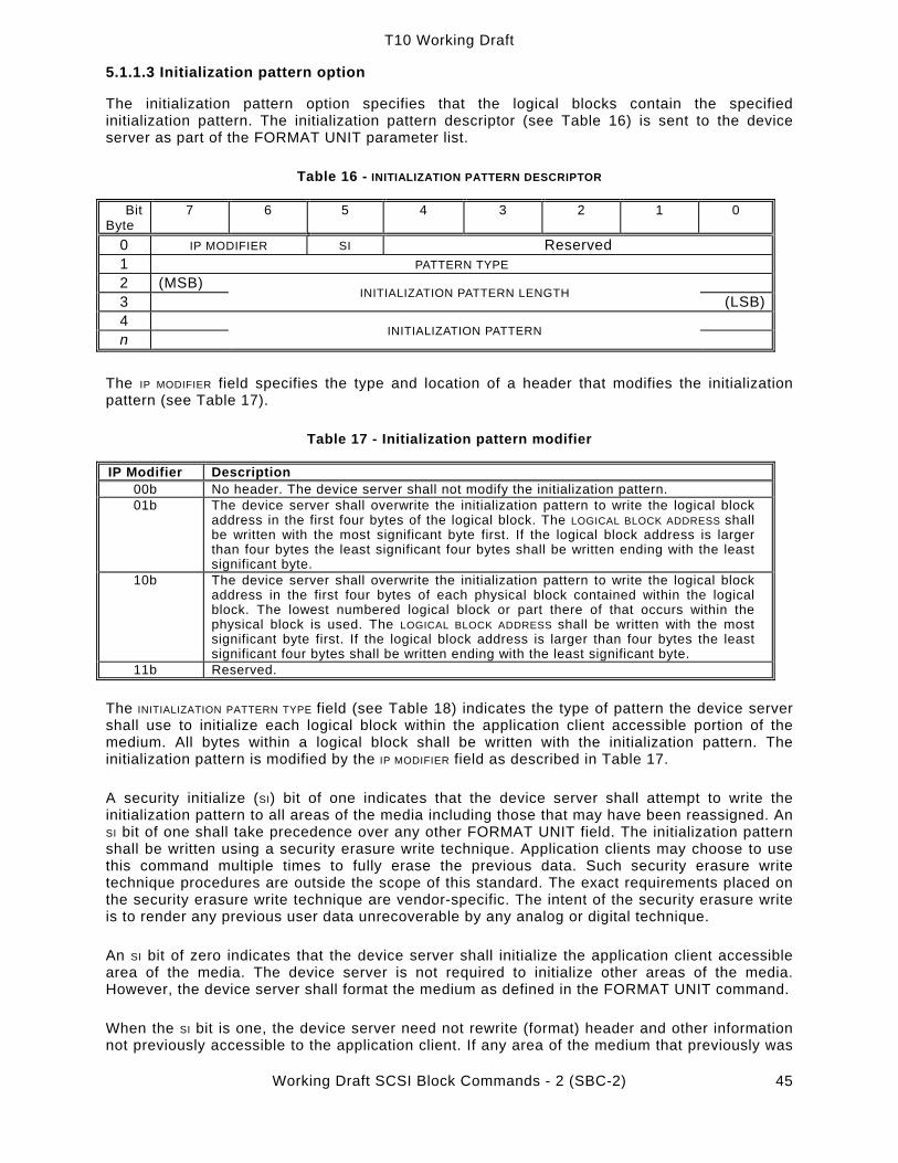
T10 Working Draft
Working Draft SCSI Block Commands - 2 (SBC-2) 45
5.1.1.3 Initialization pattern option
The initialization pattern option specifies that the logical blocks contain the specified initialization pattern. The initialization pattern descriptor (see Table 16) is sent to the device server as part of the FORMAT UNIT parameter list.
Table 16 - INITIALIZATION PATTERN DESCRIPTOR
Bit Byte
7 6 5 4 3 2 1 0
0 IP MODIFIER SI Reserved 1 PATTERN TYPE 2 (MSB) 3 INITIALIZATION PATTERN LENGTH (LSB)4 n INITIALIZATION PATTERN
The IP MODIFIER field specifies the type and location of a header that modifies the initialization pattern (see Table 17).
Table 17 - Initialization pattern modifier
IP Modifier Description 00b No header. The device server shall not modify the initialization pattern. 01b The device server shall overwrite the initialization pattern to write the logical block
address in the first four bytes of the logical block. The LOGICAL BLOCK ADDRESS shall be written with the most significant byte first. If the logical block address is larger than four bytes the least significant four bytes shall be written ending with the least significant byte.
10b The device server shall overwrite the initialization pattern to write the logical block address in the first four bytes of each physical block contained within the logical block. The lowest numbered logical block or part there of that occurs within the physical block is used. The LOGICAL BLOCK ADDRESS shall be written with the most significant byte first. If the logical block address is larger than four bytes the least significant four bytes shall be written ending with the least significant byte.
11b Reserved. The INITIALIZATION PATTERN TYPE field (see Table 18) indicates the type of pattern the device server shall use to initialize each logical block within the application client accessible portion of the medium. All bytes within a logical block shall be written with the initialization pattern. The initialization pattern is modified by the IP MODIFIER field as described in Table 17.
A security initialize (SI) bit of one indicates that the device server shall attempt to write the initialization pattern to all areas of the media including those that may have been reassigned. An SI bit of one shall take precedence over any other FORMAT UNIT field. The initialization pattern shall be written using a security erasure write technique. Application clients may choose to use this command multiple times to fully erase the previous data. Such security erasure write technique procedures are outside the scope of this standard. The exact requirements placed on the security erasure write technique are vendor-specific. The intent of the security erasure write is to render any previous user data unrecoverable by any analog or digital technique.
An SI bit of zero indicates that the device server shall initialize the application client accessible area of the media. The device server is not required to initialize other areas of the media. However, the device server shall format the medium as defined in the FORMAT UNIT command.
When the SI bit is one, the device server need not rewrite (format) header and other information not previously accessible to the application client. If any area of the medium that previously was

T10 Working Draft
Working Draft SCSI Block Commands - 2 (SBC-2) 46
accessible to the application client cannot be written, the device server shall terminate the command with CHECK CONDITION status and the sense key shall be set to MEDIUM ERROR with the appropriate additional sense code for the condition.
Table 18 - Initialization pattern type
Initialization pattern type
Description
00h Use default pattern. (note 1) 01h Repeat the initialization pattern as required to fill the logical block. (note 2)
02h - 7Fh Reserved 80h - FFh Vendor-specific
Notes:
(1) If the initialization pattern length is not zero the device server shall terminate the command with CHECK CONDITION status and the sense key shall be set to ILLEGAL REQUEST with the additional sense code set to INVALID FIELD IN PARAMETER LIST.
(2) If the initialization pattern length is zero the device server shall terminate the command with CHECK CONDITION status and the sense key shall be set to ILLEGAL REQUEST with the additionalsense code set to INVALID FIELD IN PARAMETER LIST.
The INITIALIZATION PATTERN LENGTH field indicates the number of bytes contained in the initialization pattern. If the length exceeds the current logical block size the device server shall terminate the command with CHECK CONDITION status and the sense key shall be set to ILLEGAL REQUEST with the additional sense code set to INVALID FIELD IN PARAMETER LIST. The pattern is modified by the IP MODIFIER field.
5.1.2 LOCK UNLOCK CACHE (10) command
The LOCK UNLOCK CACHE (10) command (see Table 19) requests that the device server disallow or allow logical blocks within the specified range to be removed from the cache memory by the device server's cache replacement algorithm. Locked logical blocks may be written to the medium when modified, but a copy of the modified logical block shall remain in the cache memory.
Table 19 - LOCK UNLOCK CACHE (10) command
Bit Byte
7 6 5 4 3 2 1 0
0 OPERATION CODE (36h) 1 Reserved LOCK RELADR 2 (MSB) 3 4 5
LOGICAL BLOCK ADDRESS
(LSB) 6 Reserved 7 (MSB) 8 NUMBER OF BLOCKS (LSB) 9 CONTROL
See 4.2.1.8 for reservation requirements for this command. A LOCK bit of zero indicates that all logical blocks in the specified range that are currently locked into the cache memory shall be unlocked, but may not be removed. A LOCK bit of one indicates that any logical block in the specified range that is currently present in the cache memory shall be locked into cache memory. Only logical blocks that are already present in the cache memory are actually locked.

T10 Working Draft
Working Draft SCSI Block Commands - 2 (SBC-2) 47
A relative address (RELADR) bit of zero indicates that the LOGICAL BLOCK ADDRESS field specifies the first logical block of the range of logical blocks for this command.
A RELADR bit of one indicates that the LOGICAL BLOCK ADDRESS field is a two's complement displacement. This negative or positive displacement shall be added to the logical block address last accessed on the block device to form the LOGICAL BLOCK ADDRESS for this command. This feature is only available with linked commands. This feature also requires that a previous command in the linked group has accessed a block of data on the block device.
The NUMBER OF BLOCKS field specifies the total number of contiguous logical blocks within the range. A NUMBER OF BLOCKS field of zero indicates that all remaining logical blocks on the block device shall be within the range.
Multiple locks may be in effect from more than one application client. Locks from different application clients may overlap. An unlock of an overlapped area does not release the lock of another initiator.
5.1.3 LOCK UNLOCK CACHE (16) command
The LOCK UNLOCK CACHE (16) command (see Table 20) requests that the device server disallow or allow logical blocks within the specified range to be removed from the cache memory by the device server's cache replacement algorithm.
Table 20 - LOCK UNLOCK CACHE (16) command
Bit Byte
7 6 5 4 3 2 1 0
0 OPERATION CODE (92h) 1 Reserved LOCK RELADR 2 (MSB) 3 4 5 6 7 8 9
LOGICAL BLOCK ADDRESS
(LSB) 10 (MSB) 11 12 13
NUMBER OF BLOCKS
(LSB) 14 Reserved 15 CONTROL
See 4.2.1.8 for reservation requirements for this command. See the LOCK UNLOCK CACHE (10) command (5.1.2) for a description of the fields in this command.
5.1.4 PRE-FETCH (10) command
The PRE-FETCH (10) command (see Table 21) requests that the device server transfer the specified logical blocks to the cache memory. No data shall be transferred to the application client.

T10 Working Draft
Working Draft SCSI Block Commands - 2 (SBC-2) 48
Table 21 - PRE-FETCH (10) command
Bit Byte
7 6 5 4 3 2 1 0
0 OPERATION CODE (34h) 1 Reserved IMMED RELADR 2 (MSB) 3 4 5
LOGICAL BLOCK ADDRESS
(LSB) 6 Reserved 7 (MSB) 8 TRANSFER LENGTH (LSB) 9 CONTROL
See 4.2.1.8 for reservation requirements for this command.
An immediate (IMMED) bit of zero indicates that status shall be returned after the operation is complete. An IMMED bit of one indicates that status shall be returned as soon as the command descriptor block has been validated.
See the LOCK UNLOCK CACHE (10) command (5.1.2) for a definition of the RELADR bit and the LOGICAL BLOCK ADDRESS field.
The TRANSFER LENGTH field specifies the number of contiguous logical blocks of data that shall be transferred to the block device's cache memory. A TRANSFER LENGTH of zero indicates that the contiguous logical blocks up to and including the last logical block of the block device shall be transferred to the block device's cache memory. Any other value indicates the number of logical blocks that shall be transferred. The device server may elect to not transfer logical blocks that already are contained in the cache memory.
If the IMMED bit is zero and the specified logical blocks were successfully transferred to the cache memory, the device server shall return CONDITION MET status. If the LINK BIT (see SPC-2) is one, the device server shall return INTERMEDIATE-CONDITION MET status.
If IMMED is one, and the unlocked cache memory has sufficient capacity to accept all of the specified logical blocks, the device server shall return CONDITION MET status. If the LINK bit is one, and the unlocked cache memory has sufficient capacity to accept all of the specified logical blocks, the device server shall return INTERMEDIATE-CONDITION MET status.
If IMMED is one, and the unlocked cache memory does not have sufficient capacity to accept all of the specified logical blocks, the device server shall return GOOD status. The device server shall transfer to cache memory as many logical blocks that fit. If the LINK bit is one, the device server shall return INTERMEDIATE status.
5.1.5 PRE-FETCH (16) command
The PRE-FETCH (16) command (see Table 22) requests that the device server transfer the specified logical blocks to the cache memory. No data shall be transferred to the application client.

T10 Working Draft
Working Draft SCSI Block Commands - 2 (SBC-2) 49
Table 22 - PRE-FETCH (16) command
Bit Byte
7 6 5 4 3 2 1 0
0 OPERATION CODE (90h) 1 Reserved IMMED RELADR 2 (MSB) 3 4 5 6 7 8 9
LOGICAL BLOCK ADDRESS
(LSB) 10 (MSB) 11 12 13
TRANSFER LENGTH
(LSB) 14 Reserved 15 CONTROL
See 4.2.1.8 for reservation requirements for this command. See the PRE-FETCH (10) command (5.1.4) for a description of the fields in this command.
5.1.6 READ (6) command
The READ (6) command (see Table 23) requests that the device server transfer data to the application client. The most recent data value written, or to be written if cached, in the addressed logical block shall be returned.
Table 23 - READ (6) command
Bit Byte
7 6 5 4 3 2 1 0
0 OPERATION CODE (08h) 1 Reserved (MSB) 2 LOGICAL BLOCK ADDRESS 3 (LSB) 4 TRANSFER LENGTH 5 CONTROL
See 4.2.1.8 for reservation requirements for this command.
The cache control bits (see 5.1.7) are not provided for this command. Block devices with cache memory may have values for the cache control bits that affect the READ (6) command; however, no default value is defined by this standard. If explicit control is required, the READ (10) command should be used.
The LOGICAL BLOCK ADDRESS field specifies the logical block where the read operation shall begin.
The TRANSFER LENGTH field specifies the number of contiguous logical blocks of data to be transferred. A TRANSFER LENGTH of zero indirectly indicates that 256 logical blocks shall be transferred. Any other value directly indicates the number of logical blocks that shall be transferred.

T10 Working Draft
Working Draft SCSI Block Commands - 2 (SBC-2) 50
Note 7 - Although the READ (6) command is limited to directly addressing logical blocks up to a capacity of 2 Gigabytes, for logical block sizes of 512 bytes, this command has been maintained as mandatory since some system initialization routines require that the READ (6) command be used. Application clients should migrate from the READ (6) command to the READ (10) command which may address 2 Terabytes with logical block sizes of 512 bytes, or the READ (16) command to address more than 2 Terabytes. Note 8 - For the READ (10) command, a TRANSFER LENGTH of zero indicates that no logical blocks are transferred.
5.1.7 READ (10) command
The READ (10) command (see Table 24) requests that the device server transfer data to the application client. The most recent data value written in the addressed logical block shall be returned.
Table 24 - READ (10) command
Bit Byte
7 6 5 4 3 2 1 0
0 OPERATION CODE (28h) 1 Reserved DPO FUA Reserved RELADR 2 (MSB) 3 4 5
LOGICAL BLOCK ADDRESS
(LSB) 6 Reserved 7 (MSB) 8 TRANSFER LENGTH (LSB) 9 CONTROL
See 4.2.1.8 for reservation requirements for this command. See the LOCK UNLOCK CACHE (10) command (5.1.2) for a definition of the RELADR bit and the LOGICAL BLOCK ADDRESS field.
A disable page out (DPO) bit of zero indicates the priority shall be determined by the RETENTION PRIORITY fields in the caching page. A DPO bit of one indicates that the device server shall assign the logical blocks accessed by this command the lowest priority for being fetched into or retained by the cache. A DPO bit of one overrides any retention priority specified in the caching page (see 6.2.2). All other aspects of the algorithm implementing the cache memory replacement strategy are not defined by this standard.
Note 9 - The DPO bit is used to control replacement of logical blocks in the cache memory when the host has information on the future usage of the logical blocks. If the DPO bit is one, the host is indicating that the logical blocks accessed by the command are not likely to be accessed again in the near future and should not be put in the cache memory nor retained by the cache memory. If the DPO bit is zero, the host is indicating that the logical blocks accessed by this command are likely to be accessed again in the near future.
A force unit access (FUA) bit of zero indicates that the device server may satisfy the command by accessing the cache memory. For read operations, any logical blocks that are contained in the cache memory may be transferred to the application client directly from the cache memory. For write operations, logical blocks may be transferred directly to the cache memory. GOOD status may be returned to the application client prior to writing the logical blocks to the medium. Any error that occurs after the GOOD status is returned is a deferred error, and information regarding the error is not reported until a subsequent command.
A (FUA) bit of one indicates that the device server shall access the media in performing the command prior to returning GOOD status. Read commands shall access the specified logical

T10 Working Draft
Working Draft SCSI Block Commands - 2 (SBC-2) 51
blocks from the media (i.e., the data is not directly retrieved from the cache). If the cache contains a more recent version of a logical block than the media, the logical block shall first be written to the media. Write commands shall not return GOOD status until the logical blocks have actually been written on the media (i.e., the data is not write cached). Read commands that cause data to be written to the media from cache and that encounter an error shall cause a deferred error to be reported. See SPC-2.
The TRANSFER LENGTH field specifies the number of contiguous logical blocks of data that shall be transferred. A TRANSFER LENGTH of zero indicates that no logical blocks shall be transferred. This condition shall not be considered an error. Any other value indicates the number of logical blocks that shall be transferred.
Note 10 - For the READ (6) command, a TRANSFER LENGTH of zero indicates that 256 logical blocks are transferred.
5.1.8 READ (12) command
The READ (12) command (see Table 25) requests that the device server transfer data to the application client from the medium.
Table 25 - READ (12) command
Bit Byte
7 6 5 4 3 2 1 0
0 OPERATION CODE (A8h) 1 Reserved DPO FUA Reserved RELADR 2 (MSB) 3 4 5
LOGICAL BLOCK ADDRESS
(LSB) 6 (MSB) 7 8 9
TRANSFER LENGTH
(LSB) 10 Reserved 11 CONTROL
See 4.2.1.8 for reservation requirements for this command. See the READ (10) command (5.1.7) for a complete description of the fields in this command.
5.1.9 READ (16) command
The READ (16) command (see Table 26) requests that the device server transfer data to the application client.

T10 Working Draft
Working Draft SCSI Block Commands - 2 (SBC-2) 52
Table 26 - READ (16) command
Bit Byte
7 6 5 4 3 2 1 0
0 OPERATION CODE (28h88h) 1 Reserved DPO FUA Reserved RELADR 2 (MSB) 3 4 5 6 7 8 9
LOGICAL BLOCK ADDRESS
(LSB) 10 (MSB) 11 12 13
TRANSFER LENGTH
(LSB) 14 Reserved
15 CONTROL
See 4.2.1.8 for reservation requirements for this command. See the READ (10) command (5.1.7) for a description of the fields in this command.
5.1.10 READ CAPACITY command
The READ CAPACITY command (see Table 27) provides a means for the application client to request information regarding the capacity of the block device.
Table 27 - READ CAPACITY command
Bit Byte
7 6 5 4 3 2 1 0
0 OPERATION CODE (25h) 1 Reserved LONGLBA RELADR 2 (MSB) 3 4 5
LOGICAL BLOCK ADDRESS
(LSB) 6 Reserved 7 Reserved 8 Reserved PMI 9 CONTROL
See 4.2.1.8 for reservation requirements for this command. See the LOCK UNLOCK CACHE (10) command (5.1.2) for a definition of the RELADR bit and the LOGICAL BLOCK ADDRESS field.
A long LBA (LONGLBA) bit of zero indicates the target shall return the read capacity data as defined in Table 28. A LONGLBA bit of one indicates the target shall return the read capacity data as defined in Table 29. If the LONGLBA bit is one the PMI bit shall be zero.
[Editor’s note: 01-267 proposes to eliminate the LONGLBA bit here in favor of a separate READ CAPACITY (16) command.]
The LOGICAL BLOCK ADDRESS shall be zero if the PMI bit is zero. If the PMI bit is zero and the LOGICAL BLOCK ADDRESS is not zero, the device server shall return a CHECK CONDITION status and the

T10 Working Draft
Working Draft SCSI Block Commands - 2 (SBC-2) 53
sense key shall be set to ILLEGAL REQUEST with the additional sense code set to ILLEGAL FIELD IN CDB.
A partial medium indicator (PMI) bit of zero indicates that the RETURNED LOGICAL BLOCK ADDRESS and the BLOCK LENGTH IN BYTES are those of the last logical block on the block device.
A PMI bit of one indicates that the RETURNED LOGICAL BLOCK ADDRESS and BLOCK LENGTH IN BYTES are those of the last logical block address before a substantial delay in data transfer may be encountered. This returned LOGICAL BLOCK ADDRESS shall be greater than or equal to the logical block address specified by the RELADR and LOGICAL BLOCK ADDRESS fields in the command descriptor block.
Note 11 - This function is intended to assist storage management software in determining whether there is sufficient space on the current track, cylinder, etc., to contain a frequently accessed data structure, such as a file directory or file index, without incurring an access delay.
If the LONGLBA bit is zero, the short read capacity data (see Table 28) shall be sent during the data-in buffer transfer of the command. The maximum value that shall be returned in the returned logical block address field is FFFFFFFEh.
Table 28 - Short read capacity data
Bit Byte
7 6 5 4 3 2 1 0
0 (MSB) 1 2 3
RETURNED LOGICAL BLOCK ADDRESS
(LSB) 4 (MSB) 5 6 7
BLOCK LENGTH IN BYTES
(LSB)
If the LONGLBA bit is zero and the number of logical blocks exceeds the maximum value that may be specified in the RETURNED LOGICAL BLOCK ADDRESS field the device server shall transfer FFFFFFFFh in the LOGICAL BLOCK ADDRESS field. The initiator should then issue a READ CAPACITY command with a LONGLBA bit of one.
If the LONGLBA bit is one the long read capacity data (see Table 29) shall be sent during the data-in buffer transfer of the command.

T10 Working Draft
Working Draft SCSI Block Commands - 2 (SBC-2) 54
Table 29 - Long read capacity data
Bit Byte
7 6 5 4 3 2 1 0
0 (MSB) 1 2 3 4 5 6 7
RETURNED LOGICAL BLOCK ADDRESS
(LSB) 8 (MSB) 9
10 11
BLOCK LENGTH IN BYTES
(LSB)
5.1.11 READ DEFECT DATA (10) command
The READ DEFECT DATA (10) command (see Table 30) requests that the device server transfer the medium defect data to the application client.
Table 30 - READ DEFECT DATA (10) command
Bit Byte
7 6 5 4 3 2 1 0
0 OPERATION CODE (37h) 1 Reserved 2 Reserved PLIST GLIST DEFECT LIST FORMAT 3 Reserved 4 Reserved 5 Reserved 6 Reserved 7 (MSB) 8 ALLOCATION LENGTH (LSB) 9 CONTROL
See 4.2.1.8 for reservation requirements for this command. If the device server is unable to access the medium defect data, it shall terminate the command with CHECK CONDITION status and the sense key shall be set to either MEDIUM ERROR, if a medium error occurred, or NO SENSE, if the list does not exist; with the additional sense code set to DEFECT LIST NOT FOUND.
Note 12 - Some device servers may not be able to return medium defect data until after a FORMAT UNIT command has been completed successfully.
A primary defect list (PLIST) bit of zero requests that the device server not return the primary list of defects. A PLIST bit of one requests that the device server return the primary list of defects.
A grown defect list (GLIST) bit of zero requests that the device server not return the grown defect list. A GLIST bit of one requests that the device server return the grown defect list.
A PLIST bit of zero and a GLIST bit of zero requests that the device server return only the defect list header.

T10 Working Draft
Working Draft SCSI Block Commands - 2 (SBC-2) 55
A PLIST bit of one and a GLIST bit of one requests that the device server return the primary and the grown defect lists. The order the lists are returned in is vendor-specific. Whether the lists are merged or not is vendor-specific.
The DEFECT LIST FORMAT field is used by the application client to indicate the preferred format for the defect list. This field is intended for those device servers capable of returning more than one format, as defined in the FORMAT UNIT command (see 5.1.1.2, defect list format). A device server unable to return the requested format shall return the defect list in its default format (see the DEFECT LIST FORMAT field in the defect list header below).
If the requested defect list format and the returned defect list format are not the same, the device server shall transfer the defect data and then terminate the command with CHECK CONDITION status and the sense key shall be set to RECOVERED ERROR with the additional sense code set to DEFECT LIST NOT FOUND.
The READ DEFECT DATA (10) defect list (see Table 31) contains a four-byte header, followed by zero or more defect descriptors.
Table 31 - READ DEFECT DATA (10) defect list
Bit Byte
7 6 5 4 3 2 1 0
0 Reserved 1 Reserved PLIST GLIST DEFECT LIST FORMAT 2 (MSB) 3
DEFECT LIST LENGTH (LSB)
DEFECT DESCRIPTOR(s) (if any)
4 …
4 + n - 1
DEFECT DESCRIPTOR 0 (See specific table for length n.)
…
4 + n …
4+nx
DEFECT DESCRIPTOR x (See specific table for length n.)
A PLIST bit of zero indicates that the data returned does not contain the primary defect list. A PLIST bit of one indicates that the data returned contains the primary defect list.
A GLIST bit of zero indicates that the data returned does not contain the grown defect list. A GLIST bit of one indicates that the data returned contains the grown defect list.
The DEFECT LIST FORMAT field indicates the format of the defect descriptors returned by the device server. This field is defined in the FORMAT UNIT command (see 5.1.1.2).
Note 13 - The use of the block format is not recommended. There is no standard model that defines the meaning of the logical block address of a defect. In the usual case, a defect that has been reassigned no longer has a logical block address.
Defect descriptors returned in the block format are vendor-specific. Defect descriptors returned in the physical sector format may or may not include defects in areas not accessible to the application client. Defect descriptors returned in bytes-from-index format shall comprise a complete list of the defects. A complete list of the defects may include defects in areas not within the capacity returned in the READ CAPACITY command.

T10 Working Draft
Working Draft SCSI Block Commands - 2 (SBC-2) 56
The DEFECT LIST LENGTH field specifies the length in bytes of the defect descriptors that follow. The DEFECT LIST LENGTH is equal to four or eight times the number of the defect descriptors, depending on the format of the returned descriptors (see 5.1.1.2).
If the number of defect descriptors the SCSI device has assigned does not exceed the capability of the ALLOCATION LENGTH field size but contains a value that is insufficient to transfer all of the defect descriptors the defect list length shall not be adjusted to reflect the truncation and the device server shall not create a CHECK CONDITION status. The application client is responsible for comparing the defect list length and the allocation length to determine that a partial list was received. If the number of defect descriptors the SCSI device has assigned exceeds the capability of the ALLOCATION LENGTH field size the device server shall transfer no data and return a CHECK CONDITION status and the sense key shall be set to ILLEGAL REQUEST and the additional sense code set to INVALID FIELD IN CDB.
Note 14 - The application client may determine the length of the defect list by sending the READ DEFECT DATA (10) command with an ALLOCATION LENGTH of four. The device server returns the defect list header that contains the length of the defect list.
The defect descriptors may or may not be sent in ascending order. The application client may determine the exact number of the defects by dividing the DEFECT LIST LENGTH by the length of a single defect descriptor for the returned format.
5.1.12 READ DEFECT DATA (12) command
The READ DEFECT DATA (12) command (see Table 32) requests that the device server transfer the medium defect data to the application client.
Table 32 - READ DEFECT DATA (12) command Bit
Byte 7 6 5 4 3 2 1 0
0 OPERATION CODE (B7h) 1 Reserved PLIST GLIST DEFECT LIST FORMAT
2 Reserved 3 Reserved 4 Reserved 5 Reserved 6 (MSB) 7 8 9
ALLOCATION LENGTH
(LSB) 10 Reserved 11 CONTROL
See 4.2.1.8 for reservation requirements for this command. See the READ DEFECT DATA (10) command (5.1.11) for a description of the fields in this command.
The READ DEFECT DATA (12) list header (see Table 33) contains an eight byte header, followed by zero or more defect descriptors.

T10 Working Draft
Working Draft SCSI Block Commands - 2 (SBC-2) 57
Table 33 - READ DEFECT DATA (12) list header Bit
Byte 7 6 5 4 3 2 1 0
0 Reserved 1 Reserved PLIST GLIST DEFECT LIST FORMAT 2 Reserved 3 Reserved 4 (MSB) 5 6 7
DEFECT LIST LENGTH
(LSB)
DEFECT DESCRIPTOR(s) (if any)
4 …
4+n - 1
DEFECT DESCRIPTOR 0 (length n)
…
4+n …
4+nx - 1 DEFECT DESCRIPTOR X (length n)
See the description of the READ DEFECT DATA (10) list header (5.1.11) for a description of the fields in this header.
5.1.13 READ LONG command
The READ LONG command (see Table 34) requests that the device server transfer data to the application client. The data passed during the READ LONG command is vendor-specific, but shall include the data bytes and the ECC bytes recorded on the medium. The most recent data written, or to be written, in the addressed logical block shall be returned. READ LONG is independent of the read-write error recovery page but does allow retries.
Table 34 - READ LONG command
Bit Byte
7 6 5 4 3 2 1 0
0 OPERATION CODE (3Eh) 1 Reserved CORRCT RELADR 2 (MSB) 3 4 5
LOGICAL BLOCK ADDRESS
(LSB) 6 Reserved 7 (MSB) 8
BYTE TRANSFER LENGTH (LSB)
9 CONTROL
See 4.2.1.8 for reservation requirements for this command. See the LOCK UNLOCK CACHE (10) command (5.1.2) for a definition of the RELADR bit and the LOGICAL BLOCK ADDRESS field.

T10 Working Draft
Working Draft SCSI Block Commands - 2 (SBC-2) 58
Any other bytes that can be corrected by ECC should be included (e.g., data synchronization mark within the area covered by ECC). It is not required for the ECC bytes to be at the end of the data bytes; however, they should be in the same order as they are on the media.
A correct (CORRCT) bit of zero requests that a logical block be read without any correction made by the device server. A CORRCT bit of 0 should result with GOOD status unless data is not transferred for some reason other than that the data is non-correctable. In this case the appropriate status and/or sense data shall be set. A CORRCT bit of one requests that the data be corrected by ECC before being transferred to the application client.
The BYTE TRANSFER LENGTH field species the number of bytes of data that should be transferred. If a non-zero BYTE TRANSFER LENGTH does not match the available data length, the device server shall terminate the command with CHECK CONDITION status and the sense key shall be set to ILLEGAL REQUEST with the additional sense code set to INVALID FIELD IN CDB. The valid and ILI bits (see SPC-2) shall be set to one and the INFORMATION field shall be set to the difference (residue) of the requested length minus the actual length in bytes. Negative values shall be indicated by two's complement notation.
A BYTE TRANSFER LENGTH of zero indicates that no bytes shall be transferred and shall not be considered an error.
5.1.14 REASSIGN BLOCKS command
The REASSIGN BLOCKS command (see Table 35) requests the device server to reassign the defective logical blocks to another area on the medium set aside for this purpose. The device server should also record the location of the defective logical blocks to the grown defect list if such a list is supported. More than one physical or logical block may be relocated by each defect descriptor sent by the application client. This command does not alter the contents of the PLIST (see 5.1.1, FORMAT UNIT command).
Table 35 - REASSIGN BLOCKS command
Bit Byte
7 6 5 4 3 2 1 0
0 OPERATION CODE (07h) 1 Reserved LONGLBA LONGLIST 2 Reserved 3 Reserved 4 Reserved 5 CONTROL
See 4.2.1.8 for reservation requirements for this command.
The application client transfers a defect list that contains the logical block addresses to be reassigned. The device server shall reassign the physical medium used for each LOGICAL BLOCK ADDRESS in the list. The data contained in the logical blocks specified in the defect list may be altered, but the data in all other logical blocks on the medium shall be preserved.
Note 15 - The effect of specifying a logical block to be reassigned that previously has been reassigned is to reassign the block again. Although not likely, over the life of the medium, a logical block may be assigned to multiple physical addresses until no more spare locations remain on the medium.

T10 Working Draft
Working Draft SCSI Block Commands - 2 (SBC-2) 59
A long LBA (LONGLBA) bit of zero requests that four byte defect descriptors be returned in the REASSIGN BLOCKS defect list. A LONGLBA bit of one requests thateight byte defect descriptors be returned in the REASSIGN BLOCKS defect list.
The REASSIGN BLOCKS defect list (see Table 36) contains a four-byte header followed by one or more defect descriptors. The length of each defect descriptor is four bytes. If LONGLIST is set to zero, the header is defined in Table 37. If LONGLIST is set to one, the header is defined in Table 38.
Table 36 - REASSIGN BLOCKS defect list
Bit Byte
7 6 5 4 3 2 1 0
0 1 2 3
DEFECT LIST LENGTH HEADER
DEFECT DESCRIPTOR(s)
0 (MSB) …2
3 or 7
DEFECT LOGICAL BLOCK ADDRESS 0
(LSB) … n-(3 or 7)
(MSB)
n-1… n
DEFECT LOGICAL BLOCK ADDRESS x
(LSB)
If LONGLIST is set to zero, the header is defined in Table 37.
Table 37 - REASSIGN BLOCKS short defect header
Bit Byte
7 6 5 4 3 2 1 0
0 1
Reserved
2 (MSB) 3
DEFECT LIST LENGTH (LSB)
If LONGLIST is set to one, the header is defined in Table 38.
Table 38 - REASSIGN BLOCKS long defect header
Bit Byte
7 6 5 4 3 2 1 0
0 (MSB) 1 2 3
DEFECT LIST LENGTH
(LSB)
The DEFECT LIST LENGTH field specifies the total length in bytes of the defect descriptors that follow. The DEFECT LIST LENGTH is equal to four times (if LONGLBA is set to zero) or eight times (if LONGLBA

T10 Working Draft
Working Draft SCSI Block Commands - 2 (SBC-2) 60
is set to one) the number of defect descriptors and does not include the defect list header length.
The defect descriptor specifies a four-byte defect logical block address that contains the defect.The defect descriptor contains the logical block address of the defect. The logical block address is a four-byte field if the LONGLBA bit is set to zero or an eight-byte field if the LONGLBA bit is set to one. The defect descriptors shall be in ascending order.
If the block device has insufficient capacity to reassign all of the logical blocks specified in the defect descriptors, the command shall terminate with CHECK CONDITION status and the sense key shall be set to HARDWARE ERROR with the additional sense code set to NO DEFECT SPARE LOCATION AVAILABLE.
If the block device is unable to successfully complete a REASSIGN BLOCKS command, the command shall terminate with CHECK CONDITION status with the appropriate sense information. The logical block address of the first defect descriptor not reassigned shall be returned in the COMMAND-SPECIFIC INFORMATION field of the sense data. If information about the first defect descriptor not reassigned is not available, or if all the defects have been reassigned, this field shall be set to FFFFFFFFh if LONGLBA is set to zero or FFFFFFFF FFFFFFFFh if LONGLBA is set to one.
If the REASSIGN BLOCKS command failed due to an unexpected unrecoverable read error that would cause the loss of data in a block not specified in the defect list, the logical block address of the unrecoverable block shall be returned in the INFORMATION field of the sense data and the valid bit shall be set to one.
Note 16 - If the REASSIGN BLOCKS command returns CHECK CONDITION status and the sense data COMMAND-SPECIFIC INFORMATION field contains a valid logical block address, the application client should remove all defect descriptors from the defect list prior to the one returned in the COMMAND-SPECIFIC INFORMATION field. If the sense key is MEDIUM ERROR and the valid bit is one (the INFORMATION field contains the valid block address) the application client should insert that new defective logical block address into the defect list and reissue the REASSIGN BLOCKS command with the new defect list. Otherwise, the application client should perform any corrective action indicated by the sense data and then reissue the REASSIGN BLOCKS command with the new defect list.
5.1.15 REBUILD (16) Command The REBUILD (16) command (see Table 39) requests that the target write to the medium the XOR data generated from the specified source devices. The target, acting as a temporary initiator, issues READ commands to retrieve the specified data. READ (10) should be used for accesses to SCSI devices supporting less than 2 Terabytes, and READ (16) should be used for accesses to SCSI devices supporting greater than or equal to 2 Terabytes.

T10 Working Draft
Working Draft SCSI Block Commands - 2 (SBC-2) 61
Table 39 - REBUILD (16) command
Bit Byte
7 6 5 4 3 2 1 0
0 OPERATION CODE (81h) 1 Reserved DPO FUA INTDATA PORT CONTROL 2 (MSB) 3 4 5
LOGICAL BLOCK ADDRESS
(LSB)6 (MSB) 7 8 9
REBUILD LENGTH
(LSB)10 (MSB) 11 12 13
PARAMETER LIST LENGTH
(LSB)14 Reserved 15 CONTROL
See 4.2.1.8 for reservation requirements for this command. See the READ (10) command (5.1.7) for a definition of the DPO and FUA bits.
If the intermediate data (INTDATA) bit is zero, then intermediate data is not sent with the rebuild parameter list (see Table 41). If the bit is one, the rebuild parameter list includes intermediate data. The length of the intermediate data may be calculated by multiplying the REBUILD LENGTH times the block size. This data shall be treated as an additional source, and an XOR operation performed with it and the data from the specified sources.
The PORT CONTROL field is defined in Table 40. If the PORT CONTROL field has a value of 01b and the target is not a multiple port device the command shall be terminated with a CHECK CONDITION status and the sense data shall be set to ILLEGAL REQUEST with the additional sense code set to INVALID FIELD IN CDB.
Table 40 - PORT CONTROL field
Value Description 00b The target transfers the data using the same port that received the command. 01b The target transfers the data using a different port than the one that received the command. 10b The target transfers the data using one port of the target’s choice. 11b The target transfers the data using one or more ports of the target’s choice.
Note 17 - The target that receives the REBUILD command is not one of the source devices. If only one source is specified, then an XOR operation does not occur. This case may occur in disk mirroring applications.
If the command terminates with CHECK CONDITION status the sense data shall contain the logical block address of the failed block with the lowest logical block address. All logical blocks affected by the command and having a logical block address lower than that of the reported failing block shall have been rebuilt and written to the medium.
The LOGICAL BLOCK ADDRESS field specifies the starting logical block address where the target shall write the XOR result data on its own medium. The REBUILD LENGTH field specifies the number of blocks to be written to the medium. It also specifies the number of blocks that are read from each source.

T10 Working Draft
Working Draft SCSI Block Commands - 2 (SBC-2) 62
The PARAMETER LIST LENGTH field specifies the length in bytes of the parameter list that shall be transferred from the initiator to the target. The REBUILD (16) parameter data is described in Table 41.
Table 41 - REBUILD (16) and REGENERATE (16) parameter data
Bit Byte
7 6 5 4 3 2 1 0
0 NUMBER OF SOURCE DESCRIPTORS (X) 1 Reserved 2 (MSB) 3 SOURCE DESCRIPTOR/PAD LENGTH (LSB)
SOURCE DESCRIPTOR(s) (if any) 4 … 19
SOURCE DESCRIPTOR 0
… … 16x - 12
… 16x + 3
SOURCE DESCRIPTOR x
PAD (if any) 16x + 4
… 16x+y+3
PAD (length y)
INTERMEDIATE DATA, if any 16x+y+4
… 16x+y+z+3
INTERMEDIATE DATA (length z)
The number of SOURCE DESCRIPTOR field indicates the number of SOURCE DESCRIPTORs in the parameter data.
The SOURCE DESCRIPTOR/PAD LENGTH specifies the sum of the lengths in bytes of all of the source descriptors and the PAD.
The SOURCE DESCRIPTORs identify the source device target identifiers and starting logical block addresses on the devices for the regenerate or rebuild operation. See Table 42 for the SOURCE DESCRIPTOR format.
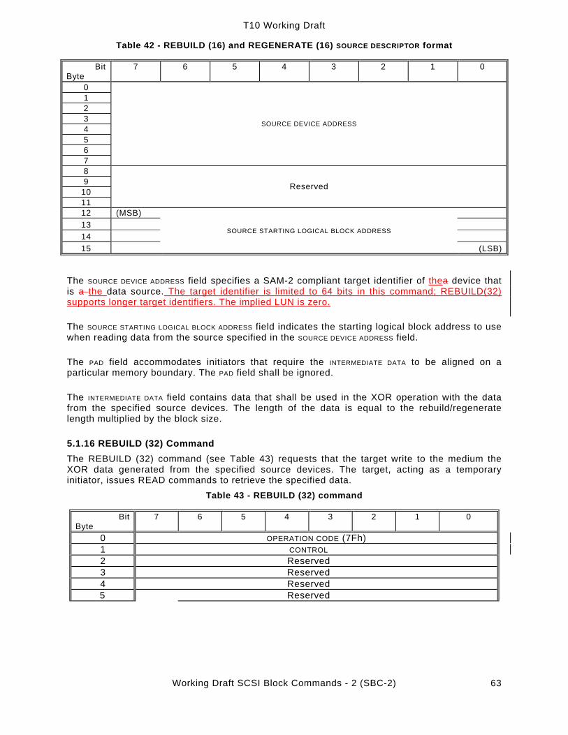
T10 Working Draft
Working Draft SCSI Block Commands - 2 (SBC-2) 63
Table 42 - REBUILD (16) and REGENERATE (16) SOURCE DESCRIPTOR format
Bit Byte
7 6 5 4 3 2 1 0
0 1 2 3 4 5 6 7
SOURCE DEVICE ADDRESS
8 9
10 11
Reserved
12 (MSB) 13 14 15
SOURCE STARTING LOGICAL BLOCK ADDRESS
(LSB)
The SOURCE DEVICE ADDRESS field specifies a SAM-2 compliant target identifier of thea device that is a the data source. The target identifier is limited to 64 bits in this command; REBUILD(32) supports longer target identifiers. The implied LUN is zero.
The SOURCE STARTING LOGICAL BLOCK ADDRESS field indicates the starting logical block address to use when reading data from the source specified in the SOURCE DEVICE ADDRESS field.
The PAD field accommodates initiators that require the INTERMEDIATE DATA to be aligned on a particular memory boundary. The PAD field shall be ignored.
The INTERMEDIATE DATA field contains data that shall be used in the XOR operation with the data from the specified source devices. The length of the data is equal to the rebuild/regenerate length multiplied by the block size.
5.1.16 REBUILD (32) Command The REBUILD (32) command (see Table 43) requests that the target write to the medium the XOR data generated from the specified source devices. The target, acting as a temporary initiator, issues READ commands to retrieve the specified data.
Table 43 - REBUILD (32) command
Bit Byte
7 6 5 4 3 2 1 0
0 OPERATION CODE (7Fh) 1 CONTROL 2 Reserved 3 Reserved 4 Reserved 5 Reserved

T10 Working Draft
Working Draft SCSI Block Commands - 2 (SBC-2) 64
6 Reserved 7 ADDITIONAL CDB LENGTH (18h) 8 (MSB) 9 SERVICE ACTION (0001h) (LSB) 10 Reserved DPO FUA IDATA PORT CONTROL 11 Reserved 12 (MSB) 13 14 15 16 17 18 19
LOGICAL BLOCK ADDRESS
(LSB) 20 21 22 23
Reserved
24 (MSB) 25 26 27
REBUILD LENGTH
(LSB) 28 (MSB) 29 30 31
PARAMETER LIST LENGTH
(LSB)
See 4.2.1.8 for reservation requirements for this command. See the REBUILD (16) command (5.1.15), Table 44, Table 45, and SPC-2 for a description of the fields in this command.
The REBUILD (32) parameter data is described in Table 44.
Table 44 - REBUILD (32) and REGENERATE (32) parameter data
Bit Byte
7 6 5 4 3 2 1 0
0 NUMBER OF SOURCE DESCRIPTORS (X) 1 Reserved 2 (MSB) 3 SOURCE DESCRIPTOR/PAD LENGTH (LSB)
SOURCE DESCRIPTOR(s) (if any) 4 … 43
SOURCE DESCRIPTOR 0
… … 40x - 36
… 40x + 3
SOURCE DESCRIPTOR x
PAD (if any) 40x + 4
… 40x+y+3
PAD (length y)
INTERMEDIATE DATA, if any 40x+y+4
… 40x+y+z+3
INTERMEDIATE DATA (length z)

T10 Working Draft
Working Draft SCSI Block Commands - 2 (SBC-2) 65
The SOURCE DESCRIPTOR format is specified in Table 45. All other fields in the parameter data are as defined in 5.1.15.
Table 45 - REBUILD (32) and REGENERATE (32) source descriptor format (8 Byte LBA version)
Bit Byte
7 6 5 4 3 2 1 0
0 (MSB) 3… 731
SOURCE DEVICE ADDRESS (LSB)
832 (MSB) 933
1034 1135 1236 1337 1438 1539
SOURCE STARTING LOGICAL BLOCK ADDRESS
(LSB)
The SOURCE DEVICE ADDRESS specifies the third party logical unit to use as the data source. The format of this conforms to one of the target descriptor formats of the EXTENDED COPY command specified in SPC-3.
5.1.17 REGENERATE (16) command
The REGENERATE (16) command (see Table 46) requests that the target write to the buffer the XOR data generated from its own medium and the specified source devices. The target, acting as a temporary initiator, issues READ commands to retrieve the specified data. The resulting XOR data is retained in the target’s buffer until it is retrieved by an XDREAD command with a starting LOGICAL BLOCK ADDRESS and TRANSFER LENGTH that match, or are a subset of, the LOGICAL BLOCK ADDRESS and REGENERATE LENGTH of this command.
Table 46 - REGENERATE (16) command
Bit Byte
7 6 5 4 3 2 1 0
0 OPERATION CODE (82h) 1 Reserved DPO FUA INTDATA PORT CONTROL 2 (MSB) 3 4 5
LOGICAL BLOCK ADDRESS
(LSB)6 (MSB) 7 8 9
REGENERATE LENGTH
(LSB)10 (MSB) 11 12 13
PARAMETER LIST LENGTH
(LSB)14 Reserved 15 CONTROL
See 4.2.1.8 for reservation requirements for this command. See 5.1.7 for a definition of the DPO & FUA bits and 5.1.15 for a definition of the INTDATA and PORT CONTROL fields.

T10 Working Draft
Working Draft SCSI Block Commands - 2 (SBC-2) 66
The LOGICAL BLOCK ADDRESS field specifies the starting logical block address for the target to read data from its own medium. This data is a source for the regenerate operation.
The REGENERATE LENGTH field indicates the length in logical blocks of the resulting XOR data. It also specifies the length in logical blocks that is transferred from each of the specified sources.
The parameter data for the REGENERATE command is defined in Table 41. The parameter data describes the other devices that are sources for the regenerate operation. The target receiving the REGENERATE command is implicitly a source, and is not included in the parameter data.
5.1.18 REGENERATE (32) command
The REGENERATE (32) command (see Table 47) requests that the target write to the buffer the XOR data generated from its own medium and the specified source devices. The target, acting as a temporary initiator, issues READ commands to retrieve the specified data.
Table 47 - REGENERATE (32) command
Bit Byte
7 6 5 4 3 2 1 0
0 OPERATION CODE (7Fh) 1 CONTROL 2 Reserved 3 Reserved 4 Reserved 5 Reserved 6 Reserved 7 ADDITIONAL CDB LENGTH (18h) 8 (MSB) 9 SERVICE ACTION (0002h) (LSB)
10 Reserved DPO FUA IDATA PORT CONTROL 11 Reserved 12 (MSB) 13 14 15 16 17 18 19
LOGICAL BLOCK ADDRESS
(LSB) 20 21 22 23
Reserved
24 (MSB) 25 26 27
REGENERATE LENGTH
(LSB) 28 (MSB) 29 30 31
PARAMETER LIST LENGTH
(LSB)
See 4.2.1.8 for reservation requirements for this command. See the REGENERATE (16) command (5.1.17), Table 44, Table 45, and SPC-2 for a description of the fields in this command.

T10 Working Draft
Working Draft SCSI Block Commands - 2 (SBC-2) 67
5.1.19 SEEK (10) command
The SEEK (10) (see Table 48) command requests that the block device seek to the specified logical block address. This command is included for device types based on the MMC standard. This command allows the host to provide advanced notification that particular data may be requested in a subsequent command.
Table 48 - SEEK (10) command
Bit Byte
7 6 5 4 3 2 1 0
0 OPERATION CODE (2Bh) 1 Reserved 2 (MSB) 3 4 5
LOGICAL BLOCK ADDRESS
(LSB) 6 Reserved 7 Reserved 8 Reserved 9 CONTROL
See 4.2.1.8 for reservation requirements for this command.
The LOGICAL BLOCK ADDRESS field specifies the logical block address to which the block device should seek.
5.1.20 SET LIMITS (10) command
The SET LIMITS (10) command (see Table 49) defines the range where subsequent linked commands may operate. A second SET LIMITS command shall not be linked to a chain of commands if a SET LIMITS (10) command has already been issued in the chain. If a second SET LIMITS (10) command within a linked list of commands is detected, the command shall be rejected with CHECK CONDITION status and the sense key shall be set to DATA PROTECT with the appropriate additional sense code for the condition.
Table 49 - SET LIMITS (10) command
Bit Byte
7 6 5 4 3 2 1 0
0 OPERATION CODE (33h) 1 Reserved RDINH WRINH 2 (MSB) 3 4 5
LOGICAL BLOCK ADDRESS
(LSB) 6 Reserved 7 (MSB) 8
NUMBER OF BLOCKS (LSB)
9 CONTROL
See 4.2.1.8 for reservation requirements for this command.
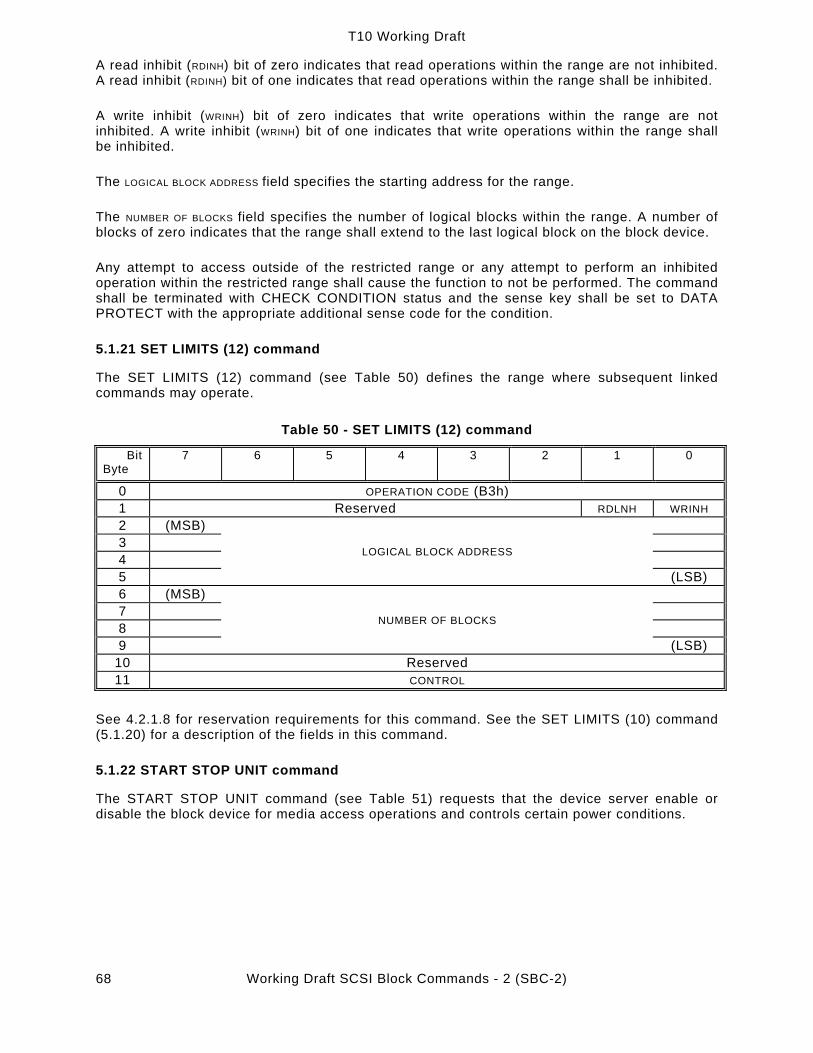
T10 Working Draft
Working Draft SCSI Block Commands - 2 (SBC-2) 68
A read inhibit (RDINH) bit of zero indicates that read operations within the range are not inhibited. A read inhibit (RDINH) bit of one indicates that read operations within the range shall be inhibited.
A write inhibit (WRINH) bit of zero indicates that write operations within the range are not inhibited. A write inhibit (WRINH) bit of one indicates that write operations within the range shall be inhibited.
The LOGICAL BLOCK ADDRESS field specifies the starting address for the range.
The NUMBER OF BLOCKS field specifies the number of logical blocks within the range. A number of blocks of zero indicates that the range shall extend to the last logical block on the block device.
Any attempt to access outside of the restricted range or any attempt to perform an inhibited operation within the restricted range shall cause the function to not be performed. The command shall be terminated with CHECK CONDITION status and the sense key shall be set to DATA PROTECT with the appropriate additional sense code for the condition.
5.1.21 SET LIMITS (12) command
The SET LIMITS (12) command (see Table 50) defines the range where subsequent linked commands may operate.
Table 50 - SET LIMITS (12) command
Bit Byte
7 6 5 4 3 2 1 0
0 OPERATION CODE (B3h) 1 Reserved RDLNH WRINH 2 (MSB) 3 4 5
LOGICAL BLOCK ADDRESS
(LSB) 6 (MSB) 7 8 9
NUMBER OF BLOCKS
(LSB) 10 Reserved 11 CONTROL
See 4.2.1.8 for reservation requirements for this command. See the SET LIMITS (10) command (5.1.20) for a description of the fields in this command.
5.1.22 START STOP UNIT command
The START STOP UNIT command (see Table 51) requests that the device server enable or disable the block device for media access operations and controls certain power conditions.

T10 Working Draft
Working Draft SCSI Block Commands - 2 (SBC-2) 69
Table 51 - START STOP UNIT command
Bit Byte
7 6 5 4 3 2 1 0
0 OPERATION CODE (1Bh) 1 Reserved IMMED 2 Reserved 3 Reserved 4 POWER CONDITIONS Reserved LOEJ START 5 CONTROL
See 4.2.1.8 for reservation requirements for this command.
An immediate (IMMED) bit of zero indicates that status shall be returned after the operation is completed. An IMMED bit of one indicates that status shall be returned as soon as the command descriptor block has been validated.
The POWER CONDITIONS field requests the block device to be placed in the power condition defined in Table 52. If this field has a value other than 0h then the START and the LOEJ bits shall be ignored.
Table 52 - POWER CONDITIONS field
Code Description 0h No change in power conditions or in the device that is controlling power
conditions 1h Place device into the Active condition 2h Place device into Idle condition 3h Place device into Standby condition 4h Reserved 5h Place device into Sleep condition 6h Reserved 7h Transfer control of power conditions to block device
8h-9h Reserved Ah Force Idle Condition Timer to zero Bh Force Standby Condition Timer to zero
Ch-Fh Reserved There shall be no indication from the block device that it has entered the requested power condition. An application client may determine if a power condition is active by issuing a request sense command to the logical unit (see 1.1.1.1).
If the START STOP UNIT command is issued with the POWER CONDITIONS field set to 1h, 2h, or 3h the block device shall:
a) change power conditions only on receipt of another START STOP UNIT command or a RESET task management function or RESET SERVICE DELIVERY SUBSYSTEMlogical unit reset;
b) suspend any Power Condition timers (see SPC-2) that are active on receipt of the START STOP UNIT command until another START STOP UNIT command is received that returns control of the power condition to the block device or a RESET task management function or RESET SERVICE DELIVERY SUBSYSTEMlogical unit reset occurs;
c) terminate any command received that requires more power than allowed by the START STOP UNIT command’s most recent power condition setting with a CHECK CONDITION

T10 Working Draft
Working Draft SCSI Block Commands - 2 (SBC-2) 70
status and with the sense key shall be set to ILLEGAL REQUEST with and the additional sense code set to LOW POWER CONDITION ACTIVE.
If the START STOP UNIT command is issued with the POWER CONDITION field set to 5h the device server shall:
a) suspend any Power Condition timers that are active on receipt of the START STOP UNIT command until a WAKEUP task management function is received by the device serverwakeup;
b) not respond to a commands and task requests management functions until a WAKEUP task management function is received by the device serverwakeup.
On receipt of a WAKEUP task management functionwakeup any previously active power conditions timers shall be restored to those values indicated by the saved power condition mode page parameters. Before returning a function complete response the target port shall place itself into a condition capable of receiving commands and task management functions and shall create a unit attention condition for all initiators. The sense key shall be set to UNIT ATTENTION with the additional sense code set to LOW POWER CONDITION ACTIVE.
If the START STOP UNIT command is issued with the POWER CONDITIONS field set Ah or Bh the block device shall:
a) force the selected timer(s) to zero. Forcing the timer(s) to zero shall place the block device into the same power condition that would have occurred if the timer(s) would have timed out. After the timer(s) are set to zero control of the power conditions is returned to the block device;
b) terminate any START STOP UNIT command that selects a timer that is not supported by the block device or a timer that has been disabled with a CHECK CONDITION status and with the sense key shall be set to ILLEGAL REQUEST with and the additional sense code set to INVALID FIELD IN CDB.
It is not an error to request the block device be placed into a power condition that already exists.
In the Sleep sleep power condition the device server shall only respond to a WAKEUP task management functionwakeup. When a target port has multiple logical units attached it shall enter the Sleep sleep power condition only after all the logical units have been placed into a Sleep sleep power condition.
A load eject (LOEJ) bit of zero requests that no action be taken regarding loading or ejecting the medium. A LOEJ bit of one requests that the medium shall be unloaded if the START bit is zero. A LOEJ bit of one requests that the medium is to be loaded if the START bit is one.
A START bit of zero requests that the block device be stopped (media shall not be accessed by the application client). A START bit of one requests the block device be made ready for use.
Block devices that contain cache memory shall implicitly perform a SYNCHRONIZE CACHE command for the entire medium prior to executing the STOP UNIT command.
5.1.23 SYNCHRONIZE CACHE (10) command
The SYNCHRONIZE CACHE (10) command (see Table 53) ensures that logical blocks in the cache memory, within the specified range, have their most recent data value recorded on the physical medium. If a more recent data value for a logical block within the specified range exists in the cache memory than on the physical medium, then the logical block from the cache memory shall be written to the physical medium. Logical blocks may not be removed from the cache memory as a result of the synchronize cache operation. The synchronize cache function is also required implicitly by other SCSI functions as defined in other clauses of this standard.

T10 Working Draft
Working Draft SCSI Block Commands - 2 (SBC-2) 71
Table 53 - SYNCHRONIZE CACHE (10) command
Bit Byte
7 6 5 4 3 2 1 0
0 OPERATION CODE (35h) 1 Reserved IMMED RELADR 2 (MSB) 3 4 5
LOGICAL BLOCK ADDRESS
(LSB) 6 Reserved 7 (MSB) 8
NUMBER OF BLOCKS (LSB)
9 CONTROL
See 4.2.1.8 for reservation requirements for this command.
An immediate (IMMED) bit of zero indicates that the status shall not be returned until the operation has been completed. An IMMED bit of one indicates that the device server shall return status as soon as the command descriptor block has been validated. If the IMMED bit is one and the device server does not support the IMMED bit, the command shall terminate with CHECK CONDITION status and the sense key shall be set to ILLEGAL REQUEST with the additional sense code set to INVALID FIELD IN CDB.
See the LOCK UNLOCK CACHE (10) command (5.1.2) for a definition of the RELADR bit and the LOGICAL BLOCK ADDRESS field.
The NUMBER OF BLOCKS field specifies the total number of contiguous logical blocks within the range. A number of blocks of zero indicates that all remaining logical blocks on the block device shall be within the range.
A logical block within the specified range that is not in cache memory is not considered an error.
5.1.24 SYNCHRONIZE CACHE (16) command
The SYNCHRONIZE CACHE (16) command (see Table 54) ensures that logical blocks in the cache memory, within the specified range, have their most recent data value recorded on the physical medium. If a more recent data value for a logical block within the specified range exists in the cache memory than on the physical medium, then the logical block from the cache memory shall be written to the physical medium. Logical blocks may not be removed from the cache memory as a result of the synchronize cache operation. The synchronize cache function is also required implicitly by other SCSI functions as defined in other clauses of this standard.

T10 Working Draft
Working Draft SCSI Block Commands - 2 (SBC-2) 72
Table 54 - SYNCHRONIZE CACHE (16) command
Bit Byte
7 6 5 4 3 2 1 0
0 OPERATION CODE (91h) 1 Reserved IMMED RELADR 2 (MSB) 3 4 5 6 7 8 9
LOGICAL BLOCK ADDRESS
(LSB) 10 (MSB) 11 12 13
NUMBER OF BLOCKS
(LSB) 14 Reserved 15 CONTROL
See 4.2.1.8 for reservation requirements for this command. See the SYNCHRONIZE CACHE (10) command (5.1.23) for a description of the fields in this command.
5.1.25 VERIFY (10) command
The VERIFY (10) command (see Table 55) requests that the device server verify the data written on the medium.
Table 55 - VERIFY (10) command
Bit Byte
7 6 5 4 3 2 1 0
0 OPERATION CODE (2Fh) 1 Reserved DPO Reserved BLKVFY BYTCHK RELADR 2 (MSB) 3 4 5
LOGICAL BLOCK ADDRESS
(LSB) 6 Reserved 7 (MSB) 8
VERIFICATION LENGTH (LSB)
9 CONTROL
See 4.2.1.8 for reservation requirements for this command. See 5.1.7 for a description of the cache control bit (DPO). See the LOCK UNLOCK CACHE (10) command (5.1.2) for a definition of the RELADR bit and the LOGICAL BLOCK ADDRESS field.
If the MODE SELECT command is implemented, and the verify error recovery parameters page is also implemented, then the current settings in that page specifies the verification criteria. If

T10 Working Draft
Working Draft SCSI Block Commands - 2 (SBC-2) 73
the verify error recovery parameters page is not implemented, then the verification criteria is vendor-specific.
If the byte check (BYTCHK) bit is zero, a medium verification shall be performed with no data comparison. If the BYTCHK bit is one, a byte-by-byte comparison of data written on the medium and the data transferred from the application client shall be performed. If the comparison is unsuccessful for any reason, the device server shall return CHECK CONDITION status and the sense key shall be set to MISCOMPARE with the appropriate additional sense code for the condition.
For direct access block devices, the blank verify (BLKVFY) bit shall be considered reserved. For optical and write-once block devices, the BLKVFY BIT is defined as follows. If the BLKVFY bit is zero, the device server shall not verify that the blocks are blank. If the BLKVFY bit is one, the device server shall verify that the blocks are blank. If the BYTCHK is one and the BLKVFY bit is one the device server shall return CHECK CONDITION status and the sense key shall be set to ILLEGAL REQUEST with the additional sense code set to INVALID FIELD IN CDB.
The VERIFICATION LENGTH field specifies the number of contiguous logical blocks of data or blanks that shall be verified. A TRANSFER LENGTH of zero indicates that no logical blocks shall be verified. This condition shall not be considered as an error. Any other value indicates the number of logical blocks that shall be verified.
5.1.26 VERIFY (12) command
The VERIFY (12) command (see Table 56) requests that the device server verify the data on the medium.
Table 56 - VERIFY (12) command Bit
Byte 7 6 5 4 3 2 1 0
0 OPERATION CODE (AFh) 1 Reserved DPO Reserved BLKVFY BYTCHK RELADR 2 (MSB) 3 4 5
LOGICAL BLOCK ADDRESS
(LSB) 6 (MSB) 7 8 9
VERIFICATION LENGTH
(LSB) 10 Reserved 11 CONTROL
See 4.2.1.8 for reservation requirements for this command. See the VERIFY (10) command (5.1.25) for a description of the fields in this command.
5.1.27 VERIFY (16) command
The VERIFY (16) command (see Table 57) requests that the device server verify the data written on the medium.
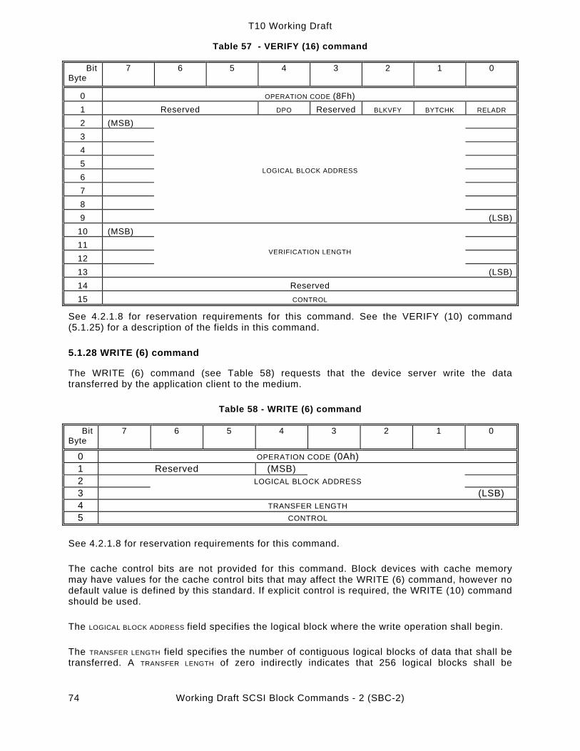
T10 Working Draft
Working Draft SCSI Block Commands - 2 (SBC-2) 74
Table 57 - VERIFY (16) command
Bit Byte
7 6 5 4 3 2 1 0
0 OPERATION CODE (8Fh) 1 Reserved DPO Reserved BLKVFY BYTCHK RELADR 2 (MSB) 3 4 5 6 7 8 9
LOGICAL BLOCK ADDRESS
(LSB)10 (MSB) 11 12 13
VERIFICATION LENGTH
(LSB)14 Reserved 15 CONTROL
See 4.2.1.8 for reservation requirements for this command. See the VERIFY (10) command (5.1.25) for a description of the fields in this command.
5.1.28 WRITE (6) command
The WRITE (6) command (see Table 58) requests that the device server write the data transferred by the application client to the medium.
Table 58 - WRITE (6) command
Bit Byte
7 6 5 4 3 2 1 0
0 OPERATION CODE (0Ah) 1 Reserved (MSB) 2 LOGICAL BLOCK ADDRESS 3 (LSB) 4 TRANSFER LENGTH 5 CONTROL
See 4.2.1.8 for reservation requirements for this command.
The cache control bits are not provided for this command. Block devices with cache memory may have values for the cache control bits that may affect the WRITE (6) command, however no default value is defined by this standard. If explicit control is required, the WRITE (10) command should be used.
The LOGICAL BLOCK ADDRESS field specifies the logical block where the write operation shall begin.
The TRANSFER LENGTH field specifies the number of contiguous logical blocks of data that shall be transferred. A TRANSFER LENGTH of zero indirectly indicates that 256 logical blocks shall be

T10 Working Draft
Working Draft SCSI Block Commands - 2 (SBC-2) 75
transferred. Any other value directly indicates the number of logical blocks that shall be transferred.
Note 18 - For the WRITE (10) command, a TRANSFER LENGTH of zero indicates that no logical blocks are transferred.
5.1.29 WRITE (10) command
The WRITE (10) command (see Table 59) requests that the device server write the data transferred by the application client to the medium.
Table 59 - WRITE (10) command
Bit Byte
7 6 5 4 3 2 1 0
0 OPERATION CODE (2Ah) 1 Reserved DPO FUA EBP Reserved RELADR 2 (MSB) 3 4 5
LOGICAL BLOCK ADDRESS
(LSB) 6 Reserved 7 (MSB) 8 TRANSFER LENGTH
(LSB) 9 CONTROL
See 4.2.1.8 for reservation requirements for this command. See the READ (10) command (5.1.7) for a definition of the cache control bits (DPO and FUA). See the LOCK UNLOCK CACHE (10) command (5.1.2) for a definition of the RELADR bit and the LOGICAL BLOCK ADDRESS field.
An erase by-pass (EBP) bit of zero indicates that the block device shall default to the normal write operation. An EBP bit of one indicates that the device server is allowed to by-pass the erase operation prior to writing the data. For direct access block devices and write-once block devices, the EBP bit shall be considered reserved.
The TRANSFER LENGTH field specifies the number of contiguous logical blocks of data that shall be transferred. A TRANSFER LENGTH of zero indicates that no logical blocks shall be transferred. This condition shall not be considered an error and no data shall be written. Any other value indicates the number of logical blocks that shall be transferred.
Note 19 - For the WRITE (6) command, a TRANSFER LENGTH of zero indicates that 256 logical blocks are transferred.
5.1.30 WRITE (12) command
The WRITE (12) command (see Table 60) requests that the device server write the data transferred from the application client to the medium.

T10 Working Draft
Working Draft SCSI Block Commands - 2 (SBC-2) 76
Table 60 - WRITE (12) command
Bit Byte
7 6 5 4 3 2 1 0
0 OPERATION CODE (AAh) 1 Reserved DPO FUA Reserved Reserved RELADR 2 (MSB) 3 4 5
LOGICAL BLOCK ADDRESS
(LSB) 6 (MSB) 7 8 9
TRANSFER LENGTH
(LSB) 10 Reserved 11 CONTROL
See 4.2.1.8 for reservation requirements for this command. See the WRITE (10) command (5.1.29) for a description of the fields in this command.
5.1.31 WRITE (16) command
The WRITE (16) command (see Table 61) requests that the device server write the data transferred by the application client to the medium.
Table 61 - WRITE (16) command
Bit Byte
7 6 5 4 3 2 1 0
0 OPERATION CODE (8Ah) 1 Reserved DPO FUA Reserved RELADR 2 (MSB) 3 4 5 6 7 8 9
LOGICAL BLOCK ADDRESS
(LSB) 10 (MSB) 11 12 13
TRANSFER LENGTH
(LSB) 14 Reserved 15 CONTROL
See 4.2.1.8 for reservation requirements for this command. See the WRITE (10) command (5.1.29) for a description of the fields in this command.
5.1.32 WRITE AND VERIFY (10) command
The WRITE AND VERIFY (10) command (see Table 62) requests that the device server write the data transferred from the application client to the medium and then verify that the data is

T10 Working Draft
Working Draft SCSI Block Commands - 2 (SBC-2) 77
correctly written. The data is only transferred once from the application client to the device server.
Table 62 - WRITE AND VERIFY (10) command
Bit Byte
7 6 5 4 3 2 1 0
0 OPERATION CODE (2Eh) 1 Reserved DPO Reserved EBP BYTCHK RELADR 2 (MSB) 3 4 5
LOGICAL BLOCK ADDRESS
(LSB) 6 Reserved 7 (MSB) 8
TRANSFER LENGTH (LSB) 9 CONTROL
See 4.2.1.8 for reservation requirements for this command. See the LOCK UNLOCK CACHE (10) command (5.1.2) for a definition of the RELADR bit and the LOGICAL BLOCK ADDRESS field. See WRITE (10) command (5.1.29) for a definition of the TRANSFER LENGTH field. See 5.1.7 for a description of the cache control bit (DPO). See WRITE (10) (5.1.29) for a description of the EBP bit.
If the MODE SELECT command is implemented, and the verify error recovery page is also implemented (see 6.2.9), then the current settings in that page ((along with the AWRE bit from the read-write error recovery page)) specify the verification error criteria. If these pages are not implemented, then the verification criteria is vendor-specific.
A byte check (BYTCHK) bit of zero requests a medium verification to be performed with no data comparison. A BYTCHK bit of one requests a byte-by-byte comparison of data written on the medium and the data transferred from the application client. If the comparison is unsuccessful for any reason, the device server shall return CHECK CONDITION status with the sense key set to MISCOMPARE with the appropriate additional sense code for the condition.
Note 20 - The WRITE AND VERIFY command specifically states that the data are not to be transferred twice (i.e., once for the write pass, and once for the verify pass) when performing a byte compare. If there is a need for two transfers to occur (e.g., to ensure the integrity of the path to the media), then the application client should issue a WRITE command with a LINK bit of one followed by a VERIFY command with a BYTCMP bit of one, transferring the same data on each command.
5.1.33 WRITE AND VERIFY (12) command
The WRITE AND VERIFY (12) command (see Table 63) requests that the device server write the data transferred from the application client to the medium and then verify that the data is correctly written.

T10 Working Draft
Working Draft SCSI Block Commands - 2 (SBC-2) 78
Table 63 - WRITE AND VERIFY(12) command
Bit Byte
7 6 5 4 3 2 1 0
0 OPERATION CODE (AEh) 1 Reserved DPO Reserved EBP BYTCHK RELADR 2 (MSB) 3 4 5
LOGICAL BLOCK ADDRESS
(LSB) 6 (MSB) 7 8 9
TRANSFER LENGTH
(LSB) 10 Reserved 11 CONTROL
See 4.2.1.8 for reservation requirements for this command. See the WRITE AND VERIFY (10) command (5.1.32) for a description of the bits in this command.
5.1.34 WRITE AND VERIFY (16) command
The WRITE AND VERIFY (16) command (see Table 63) requests that the device server write the data transferred from the application client to the medium and then verify that the data is correctly written. The data is only transferred once from the application client to the device server.
Table 64 - WRITE AND VERIFY (16) command
Bit Byte
7 6 5 4 3 2 1 0
0 OPERATION CODE (8Eh) 1 Reserved DPO Reserved EBP BYTCHK RELADR 2 (MSB) 3 4 5 6 7 8 9
LOGICAL BLOCK ADDRESS
(LSB) 10 (MSB) 11 12 13
TRANSFER LENGTH
(LSB) 14 Reserved 15 CONTROL
See 4.2.1.8 for reservation requirements for this command. See the WRITE AND VERIFY (10) command (5.1.32) for a description of the fields in this command.

T10 Working Draft
Working Draft SCSI Block Commands - 2 (SBC-2) 79
5.1.35 WRITE LONG command
The WRITE LONG command (see Table 65) requests that the device server write the data transferred by the application client to the medium. The data passed during the WRITE LONG command is implementation specific, but shall include the data bytes and the ECC bytes.
Table 65 - WRITE LONG command
Bit Byte
7 6 5 4 3 2 1 0
0 OPERATION CODE (3Fh) 1 Reserved RELADR 2 (MSB) 3 4 5
LOGICAL BLOCK ADDRESS
(LSB) 6 Reserved 7 (MSB) 8 TRANSFER LENGTH (LSB) 9 CONTROL
See 4.2.1.8 for reservation requirements for this command. See the LOCK UNLOCK CACHE (10) command (5.1.2) for a definition of the RELADR bit and the LOGICAL BLOCK ADDRESS field.
Note 21 - Any other bytes that can be corrected by ECC should be included (e.g., a data synchronization mark within the area covered by ECC). The READ LONG command may be issued before issuing a WRITE LONG command. The WRITE LONG data should be the same length and in the same order as the data returned by the READ LONG command.
The BYTE TRANSFER LENGTH field should specify the number of bytes of data that the device server would return for the READ LONG command. If a non-zero BYTE TRANSFER LENGTH does not exactly match the data length the device server would return for the READ LONG command, then the device server shall terminate the command with CHECK CONDITION status and the sense key shall be set to ILLEGAL REQUEST with the additional sense code set to INVALID FIELD IN CDB. The ILI and VALID bits shall be set to one and the INFORMATION field shall be set to the difference (residue) of the requested length minus the actual length in bytes. Negative values shall be indicated by two's complement notation. A TRANSFER LENGTH of zero indicates that no bytes shall be transferred and shall not be considered an error.
5.1.36 WRITE SAME (10) command
The WRITE SAME (10) command (see Table 66) requests that the device server write the single block of data transferred by the application client to the medium multiple times to consecutive multiple logical blocks.

T10 Working Draft
Working Draft SCSI Block Commands - 2 (SBC-2) 80
Table 66 - WRITE SAME (10) command
Bit Byte
7 6 5 4 3 2 1 0
0 OPERATION CODE (41h) 1 Reserved PBDATA LBDATA RELADR 2 (MSB) 3 4 5
LOGICAL BLOCK ADDRESS
(LSB) 6 Reserved 7 (MSB) 8 NUMBER OF BLOCKS (LSB) 9 CONTROL
See 4.2.1.8 for reservation requirements for this command. See the LOCK UNLOCK CACHE (10) command (5.1.2) for a definition of the RELADR bit and the LOGICAL BLOCK ADDRESS field.
Note 22 - This command may be useful if large areas of the medium need to be written, prepared for certification, or otherwise initialized without the application client having to transfer all the data.
A logical block data (LBDATA) bit of zero and a physical block data (PBDATA) bit of zero indicates that the single block of data transferred by the application client shall be used without modification. A LBDATA bit of one requests that the device server replace the first four bytes of the data to be written to the current logical block with the logical block address of the block currently being written.
A PBDATA bit of one requests that the device server replace the first eight bytes of the data to be written to the current physical sector with the physical address of the sector currently being written using the physical sector format (see 5.1.1.2).
If PBDATA and LBDATA are one the command shall be terminated with CHECK CONDITION status and the sense key shall be set to ILLEGAL REQUEST with the appropriate additional sense code for the condition.
The NUMBER OF BLOCKS field specifies the number of contiguous logical blocks to be written. A NUMBER OF BLOCKS field of zero requests that all the remaining logical blocks on the medium be written.
5.1.37 WRITE SAME (16) command
The WRITE SAME (16) command (see Table 67) requests that the device server write the single block of data transferred by the application client to the medium multiple times to consecutive multiple logical blocks.

T10 Working Draft
Working Draft SCSI Block Commands - 2 (SBC-2) 81
Table 67 - WRITE SAME (16) command
Bit Byte
7 6 5 4 3 2 1 0
0 OPERATION CODE (41h93h) 1 Reserved PBDATA LBDATA RELADR 2 (MSB) 3 4 5 6 7 8 9
LOGICAL BLOCK ADDRESS
(LSB) 10 (MSB) 11 12 13
NUMBER OF BLOCKS
(LSB) 14 Reserved 15 CONTROL
See 4.2.1.8 for reservation requirements for this command. See the WRITE SAME (10) command (5.1.36) for a description of the fields in this command.
5.1.38 XDREAD (10) command
The XDREAD (10) command (see Table 68) requests that the target transfer to the initiator the XOR data generated by an XDWRITE or REGENERATE command.
Table 68 - XDREAD (10) command
Bit Byte
7 6 5 4 3 2 1 0
0 OPERATION CODE (52h) 1 Reserved 2 (MSB) 3 4 5
LOGICAL BLOCK ADDRESS
(LSB) 6 Reserved 7 (MSB) 8 TRANSFER LENGTH (LSB) 9 CONTROL
See 4.2.1.8 for reservation requirements for this command.
The XOR data transferred is identified by the LOGICAL BLOCK ADDRESS and TRANSFER LENGTH. The LOGICAL BLOCK ADDRESS and TRANSFER LENGTH shall be the same as, or a subset of, those specified in a prior XDWRITE or REGENERATE command. If a match is not found the command is terminated with a CHECK CONDITION status and the sense key shall be set to ILLEGAL REQUEST with the additional sense code set to INVALID FIELD IN CDB.

T10 Working Draft
Working Draft SCSI Block Commands - 2 (SBC-2) 82
5.1.39 XDREAD (32) command
The XDREAD (32) command (see Table 69) requests that the target transfer to the initiator the XOR data generated by an XDWRITE or REGENERATE command.
Table 69 - XDREAD (32) command
Bit Byte
7 6 5 4 3 2 1 0
0 OPERATION CODE (7Fh) 1 CONTROL 2 Reserved 3 Reserved 4 Reserved 5 Reserved 6 Reserved 7 ADDITIONAL CDB LENGTH (18h) 8 (MSB) 9 SERVICE ACTION (0003h) (LSB)
10 Reserved 11 Reserved 12 (MSB) 13 14 15 16 17 18 19
LOGICAL BLOCK ADDRESS
(LSB) 20 21 22 23 24 25 26 27
Reserved
28 (MSB) 29 30 31
TRANSFER LENGTH
(LSB)
See 4.2.1.8 for reservation requirements for this command. See the XDREAD (10) command (5.1.38) and SPC-2 for a description of the fields in this command.
5.1.40 XDWRITE (10) command
The XDWRITE (10) command (see Table 70) requests that the target XOR the data transferred with the data on the medium. The resulting XOR data is stored by the target until it is retrieved by an XDREAD (10) command.

T10 Working Draft
Working Draft SCSI Block Commands - 2 (SBC-2) 83
Table 70 - XDWRITE (10) command
Bit Byte
7 6 5 4 3 2 1 0
0 OPERATION CODE (50h) 1 Reserved DPO FUA DISABLE
WRITE Reserved
2 (MSB) 3 4 5
LOGICAL BLOCK ADDRESS
(LSB) 6 Reserved 7 (MSB) 8 TRANSFER LENGTH (LSB) 9 CONTROL
See 4.2.1.8 for reservation requirements for this command. See the READ (10) command (5.1.7) for a definition of the cache control bits (DPO and FUA).
A DISABLE WRITE bit of zero indicates that the data transferred from the initiator shall be written to the medium after the XOR operation is complete. A DISABLE WRITE bit of one indicates that the data shall not be written to the medium.
The LOGICAL BLOCK ADDRESS specifies the starting logical block address of the data on which an XOR operation shall be performed with the data from the medium.
The TRANSFER LENGTH field specifies the number of logical blocks that shall be transferred to the XDWRITE target and the number of logical blocks on which an XOR operation shall be performed with the data from the medium.
The resulting XOR data is retrieved by an XDREAD command with starting LOGICAL BLOCK ADDRESS and TRANSFER LENGTH fields that match, or is a subset of, the starting LOGICAL BLOCK ADDRESS and TRANSFER LENGTH of this command.
5.1.41 XDWRITE (32) command
The XDWRITE (32) command (see Table 71) requests that the target XOR the data transferred with the data on the medium. The resulting XOR data is stored by the target until it is retrieved by an XDREAD (32) command.

T10 Working Draft
Working Draft SCSI Block Commands - 2 (SBC-2) 84
Table 71 - XDWRITE (32) command
Bit Byte
7 6 5 4 3 2 1 0
0 OPERATION CODE (7Fh) 1 CONTROL 2 Reserved 3 Reserved 4 Reserved 5 Reserved 6 Reserved 7 ADDITIONAL CDB LENGTH (18h) 8 (MSB) 9 SERVICE ACTION (0004h) (LSB)
10 Reserved DPO FUA DISABLE WRITE
Reserved
11 Reserved 12 (MSB) 13 14 15 16 17 18 19
LOGICAL BLOCK ADDRESS
(LSB) 20 21 22 23 24 25 26 27
Reserved
28 (MSB) 29 30 31
TRANSFER LENGTH
(LSB)
See 4.2.1.8 for reservation requirements for this command. See the XDWRITE (10) command (5.1.40) and SPC-2 for a description of the fields in this command.
5.1.42 XDWRITEREAD (10) command The XDWRITEREAD (10) command (see Table 72) requests that the target XOR the data transferred (data-out) with the data on the medium and return the resulting XOR data (data-in). This is the equivalent to an XDWRITE (10) followed by an XDREAD (10) with the same Logical Block Address and Transfer Length. This command is only available on transport protocols supporting bidirectional commands.

T10 Working Draft
Working Draft SCSI Block Commands - 2 (SBC-2) 85
Table 72 - XDWRITEREAD (10) command
Bit Byte
7 6 5 4 3 2 1 0
0 OPERATION CODE (53h) 1 Reserved DPO FUA DISABLE
WRITE Reserved
2 (MSB) 3 4 5
LOGICAL BLOCK ADDRESS
(LSB) 6 Reserved 7 (MSB) 8 TRANSFER LENGTH (LSB) 9 CONTROL
See 4.2.1.8 for reservation requirements for this command. See the XWRITE (10) command (5.1.40) and XDREAD (10) command (5.1.38) for a description of the fields in this command.
5.1.43 XDWRITEREAD (32) command The XDWRITEREAD (32) command (see Table 73) requests that the target XOR the data transferred (data-out) with the data on the medium and return the resulting XOR data (data-in). This is the equivalent to an XDWRITE (32) followed by an XDREAD (32) with the same Logical Block Address and Transfer Length. This command is only available on transport protocols supporting bidirectional commands.

T10 Working Draft
Working Draft SCSI Block Commands - 2 (SBC-2) 86
Table 73 - XDWRITEREAD (32) command
Bit Byte
7 6 5 4 3 2 1 0
0 OPERATION CODE (7Fh) 1 CONTROL 2 Reserved 3 Reserved 4 Reserved 5 Reserved 6 Reserved 7 ADDITIONAL CDB LENGTH (18h) 8 (MSB) 9 SERVICE ACTION (0007h) (LSB)
10 Reserved DPO FUA DISABLE WRITE
Reserved
11 Reserved 12 (MSB) 13 14 15 16 17 18 19
LOGICAL BLOCK ADDRESS
(LSB) 20 21 22 23 24 25 26 27
Reserved
28 (MSB) 29 30 31
TRANSFER LENGTH
(LSB)
See 4.2.1.8 for reservation requirements for this command. See the XDWRITEREAD (10) command (5.1.40) and SPC-2 for a description of the fields in this command.
5.1.44 XDWRITE EXTENDED (16) command
The XDWRITE EXTENDED (16) command (see Table 74) requests that the target XOR the data transferred with the data on the medium. The resulting XOR data may subsequently be sent to a secondary device using an XPWRITE (10) or XPWRITE (32) command. The target, acting as a temporary initiator, issues XPWRITE commands to retrieve the specified data. XPWRITE (16) should be used for access to SCSI devices supporting less than 2 Terabytes, and XPWRITE (32) should be used for accesses to SCSI devices supporting greater than or equal to 2 Terabytes.

T10 Working Draft
Working Draft SCSI Block Commands - 2 (SBC-2) 87
Table 74 - XDWRITE EXTENDED (16) command
Bit Byte
7 6 5 4 3 2 1 0
0 OPERATION CODE (80h) 1 TABLE
ADDRESSRsvd
Reserved DPO FUA DISABLE WRITE
PORT CONTROL
2 (MSB) 3 4 5
LOGICAL BLOCK ADDRESS
(LSB) 6 (MSB) 7 8 9
SECONDARY LOGICAL BLOCK ADDRESS
(LSB) 10 (MSB) 11 12 13
TRANSFER LENGTH
(LSB) 14 SECONDARY ADDRESS 15 CONTROL
See 4.2.1.8 for reservation requirements for this command. See 5.1.7 for a definition of the DPO and FUA bits.
A TABLE ADDRESS bit of zero indicates that tThe SECONDARY ADDRESS field contains the target identifier of the target that will receive the XOR data transfer. The implied LUN of the secondary target shall be zero. If the transport protocol requires more than one byte for the target identifier and the TABLE ADDRESS bit is zero, the SECONDARY ADDRESS field specifies the least significant byte of the secondary target identifier. T, and the upper bytes of the secondary target identifier shall be equal to the upper bytes of the target identifier of the XDWRITE EXTENDED target.
A TABLE ADDRESS bit of one indicates that the SECONDARY ADDRESS field contains a pointer to a look up table of SAM-2 compliant target identifiers. The look up table is reserved for future definition.
A DISABLE WRITE bit of zero indicates that the data transferred from the initiator shall be written to the medium after the XOR operation is complete. A DISABLE WRITE bit of one indicates that the data shall not be written to the medium.
See 5.1.15 for a definition of the PORT CONTROL field. If the PORT CONTROL field has a value of 01b and the target is not a multiple port device the command shall be terminated with a CHECK CONDITION status and the sense data shall be set to ILLEGAL REQUEST with the additional sense code set to INVALID FIELD IN CDB.
The TRANSFER LENGTH field specifies the number of logical blocks that shall be transferred to the XDWRITE EXTENDED target, and to the XPWRITE target.
The XOR data transfer to the secondary target is performed using an XPWRITE command. The XPWRITE command shall be sent to the device specified in the SECONDARY ADDRESS field. The SECONDARY LOGICAL BLOCK ADDRESS field value shall be placed in the LOGICAL BLOCK ADDRESS field of the XPWRITE command. The TRANSFER LENGTH field value shall be placed in the TRANSFER LENGTH field of the XPWRITE command. The completion status of the XDWRITE EXTENDED command shall not be returned to the initiator until the completion status of the XPWRITE command has been received.

T10 Working Draft
Working Draft SCSI Block Commands - 2 (SBC-2) 88
Note 23 - The XOR data transfer to the secondary target may be broken into multiple XPWRITE commands. If this is done, the XDWRITE EXTENDED target calculates the logical block addresses and transfer lengths for the individual XPWRITE commands. Also, the completion status of the XDWRITE EXTENDED command is not returned to the initiator until the completion status of all XPWRITE commands have been received.
If the prior XPWRITE command terminates with a CHECK CONDITION status and the sense key is not set to RECOVERED ERROR the XDWRITE EXTENDED command shall return CHECK CONDITION status.
5.1.45 XDWRITE EXTENDED (32) command
The XDWRITE EXTENDED (32) command (see Table 75) requests that the target XOR the data transferred with the data on the medium. The resulting XOR data may subsequently be sent to a secondary device using an XPWRITE (32) command.
Table 75 - XDWRITE EXTENDED (32) command
Bit Byte
7 6 5 4 3 2 1 0
0 OPERATION CODE (7Fh) 1 CONTROL 2 Reserved 3 Reserved 4 Reserved 5 Reserved 6 Reserved 7 ADDITIONAL CDB LENGTH (18h) 8 (MSB) 9 SERVICE ACTION (0005h) (LSB)
10 TABLE ADDRESS
Rsvd
Reserved DPO FUA DISABLE WRITE PORT CONTROL
11 SECONDARY ADDRESS 12 (MSB) 13 14 15 16 17 18 19
LOGICAL BLOCK ADDRESS
(LSB) 20 (MSB) 21 22 23 24 25 26 27
SECONDARY LOGICAL BLOCK ADDRESS
(LSB) 28 (MSB) 29 30 31
TRANSFER LENGTH
(LSB)
See 4.2.1.8 for reservation requirements for this command. See the XWRITE EXTENDED (16) command (5.1.44) and SPC-2 for a description of the fields in this command.

T10 Working Draft
Working Draft SCSI Block Commands - 2 (SBC-2) 89
5.1.46 XDWRITE EXTENDED (64) command
The XDWRITE EXTENDED (64) command (see Table 75) requests that the target XOR the data transferred with the data on the medium. The resulting XOR data may subsequently be sent to a secondary device using an XPWRITE (32) command.
Table 76 - XDWRITE EXTENDED (64) command
Bit Byte
7 6 5 4 3 2 1 0
0 OPERATION CODE (7Fh) 1 CONTROL 2 Reserved 3 Reserved 4 Reserved 5 Reserved 6 Reserved 7 ADDITIONAL CDB LENGTH (38h) 8 (MSB) 9 SERVICE ACTION (0007h) (LSB)
10 Reserved DPO FUA DISABLE WRITE PORT CONTROL
11 Reserved 12
43
SECONDARY ADDRESS DESCRIPTOR
44 (MSB) 45 46 47 48 49 50 51
LOGICAL BLOCK ADDRESS
(LSB) 52 (MSB) 53 54 55 56 57 58 59
SECONDARY LOGICAL BLOCK ADDRESS
(LSB) 60 (MSB) 61 62 63
TRANSFER LENGTH
(LSB)
See 4.2.1.8 for reservation requirements for this command.
The SECONDARY ADDRESS DESCRIPTOR field contains the logical unit identifier of the logical unit that will receive the XOR data transfer. The format of this field conforms to one of the target descriptor formats of the EXTENDED COPY command as specified in SPC-3.
See the XWRITE EXTENDED (16) command (5.1.44) and SPC-2 for a description of the other fields in this command.

T10 Working Draft
Working Draft SCSI Block Commands - 2 (SBC-2) 90
5.1.47 XPWRITE (10) command
The XPWRITE (10) command (see Table 77) requests that the target XOR the data transferred with the data on the medium and then write the XOR data to the medium.
Table 77 - XPWRITE (10) command
Bit Byte
7 6 5 4 3 2 1 0
0 OPERATION CODE (51h) 1 Reserved DPO FUA Reserved 2 (MSB) 3 4 5
LOGICAL BLOCK ADDRESS
(LSB) 6 Reserved 7 (MSB) 8 TRANSFER LENGTH (LSB) 9 CONTROL
See 4.2.1.8 for reservation requirements for this command. See 5.1.7 for a definition of the DPO and FUA bits.
The LOGICAL BLOCK ADDRESS field specifies the starting logical block address where the target shall read data from its medium. It also specifies the starting logical block address where the XOR result data shall be written to the medium.
The TRANSFER LENGTH field specifies the number of blocks that shall be read from the medium. It also specifies the number of blocks that shall be written to the medium.
5.1.475.1.48 XPWRITE (32) command
The XPWRITE (32) command (see Table 78) requests that the target XOR the data transferred with the data on the medium and then write the XOR data to the medium.

T10 Working Draft
Working Draft SCSI Block Commands - 2 (SBC-2) 91
Table 78 - XPWRITE (32) command
Bit Byte
7 6 5 4 3 2 1 0
0 OPERATION CODE (7Fh) 1 CONTROL 2 Reserved 3 Reserved 4 Reserved 5 Reserved 6 Reserved 7 ADDITIONAL CDB LENGTH (18h) 8 (MSB) 9 SERVICE ACTION (0006h) (LSB)
10 Reserved DPO FUA Reserved 11 Reserved 12 (MSB) 13 14 15 16 17 18 19
LOGICAL BLOCK ADDRESS
(LSB) 20 21 22 23 24 25 26 27
Reserved
28 (MSB) 29 30 31
TRANSFER LENGTH
(LSB)
See 4.2.1.8 for reservation requirements for this command. See the XPWRITE (10) command (5.1.46) and SPC-2 for a description of the fields in this command.

T10 Working Draft
Working Draft SCSI Block Commands - 2 (SBC-2) 92
5.2 Commands for optical memory block devices The commands for optical memory block devices shall be as shown in Table 79.
Table 79 - Commands for optical memory block devices
Command name Operation code Type Subclause ERASE (10) 2Ch O 5.2.1 ERASE (12) ACh O 5.2.2 FORMAT UNIT 04h O 5.1.1 INQUIRY 12h M SPC-2 LOCK-UNLOCK CACHE (10) 36h O 5.1.2 LOCK-UNLOCK CACHE (16) 92h O 5.1.3 LOG SELECT 4Ch O SPC-2 LOG SENSE 4Dh O SPC-2 MEDIUM SCAN 38h O 5.2.3 MODE SELECT (6) 15h O SPC-2 MODE SELECT (10) 55h O SPC-2 MODE SENSE (6) 1Ah O SPC-2 MODE SENSE (10) 5Ah O SPC-2 MOVE MEDIUM A5h O SMC PERSISTENT RESERVE IN 5Eh O1 SPC-2 PERSISTENT RESERVE OUT 5Fh O1 SPC-2 PRE-FETCH (10) 34h O 5.1.4 PRE-FETCH (16) 90h O 5.1.5 PREVENT-ALLOW MEDIUM REMOVAL 1Eh O SPC-2 READ (6) 08h O 5.1.6 READ (10) 28h M 5.1.7 READ (12) A8h O 5.1.8 READ (16) 88h O 5.1.9 READ BUFFER 3Ch O SPC-2 READ CAPACITY 25h M 5.1.10 READ DEFECT DATA (10) 37h O 5.1.11 READ DEFECT DATA (12) B7h O 5.1.12 READ ELEMENT STATUS B8h O SMC READ GENERATION 29h O 5.2.4 READ LONG 3Eh O 5.1.13 READ UPDATED BLOCK 2Dh O 5.2.5 REASSIGN BLOCKS 07h O 5.1.14 RECEIVE DIAGNOSTIC RESULTS 1Ch O SPC-2 RELEASE (6) 17h O2 SPC-2 RELEASE (10) 57h M SPC-2 REQUEST SENSE 03h M SPC-2 RESERVE (6) 16h O2 SPC-2 RESERVE (10) 56h M SPC-2
(continued)

T10 Working Draft
Working Draft SCSI Block Commands - 2 (SBC-2) 93
Table 79 - Commands for optical memory block devices (continued)
Command name Operation code Type Subclause SEEK (10) 2Bh O 5.1.19 SEND DIAGNOSTIC 1Dh M SPC-2 SET LIMITS (10) 33h O 5.1.20 SET LIMITS (12) B3h O 5.1.21 START STOP UNIT 1Bh O 5.1.22 SYNCHRONIZE CACHE (10) 35h O 5.1.23 SYNCHRONIZE CACHE (16) 91h O 5.1.24 TEST UNIT READY 00h M SPC-2 UPDATE BLOCK 3Dh O 5.2.6 VERIFY (10) 2Fh O 5.1.25 VERIFY (12) AFh O 5.1.26 VERIFY (16) 8Fh O 5.1.27 WRITE (6) 0Ah O 5.1.28 WRITE (10) 2Ah M 5.1.29 WRITE (12) AAh O 5.1.30 WRITE (16) 8Ah O 5.1.31 WRITE AND VERIFY (10) 2Eh O 5.1.32 WRITE AND VERIFY (12) AEh O 5.1.33 WRITE AND VERIFY (16) 8Eh O 5.1.34 WRITE BUFFER 3Bh O SPC-2 WRITE LONG 3Fh O 5.1.35 Key: M = Command implementation is mandatory. O = Command implementation is optional. SPC-2 = SCSI-3 Primary Commands - 2 SMC = SCSI-3 Medium Changer Commands Notes: (1) Optional PERSISTENT RESERVE Commands if implemented shall both be implemented as a group. (2) Optional RELEASE (6) and RESERVE (6) Commands if implemented shall both be implemented as a group. The following operation codes are obsolete: 01h, 0Bh, 18h, 30h, 31h, 32h, 39h, 3Ah, 40h, B0h, B1h, B2h. The following operation codes are vendor-specific: 20h, 21h, 22h, 23h, and C0h through FFh. All remaining codes for optical memory block devices are reserved for future standardization. 5.2.1 ERASE (10) command
The ERASE (10) command (see Table 80) requests that the device server erase the specified number of blocks starting at the specified logical block address on the medium. As used here, erased means either the medium shall be erased, or a pattern shall be written on the medium that appears to the device server as no data present. The blocks erased shall be considered blank for purposes of blank checking (see 4.3). The previous data recorded on the medium, if any, shall not be recoverable.

T10 Working Draft
Working Draft SCSI Block Commands - 2 (SBC-2) 94
Table 80 - ERASE (10) command
Bit Byte
7 6 5 4 3 2 1 0
0 OPERATION CODE (2Ch) 1 Reserved ERA Reserved RELADR 2 (MSB) 3 4 5
LOGICAL BLOCK ADDRESS
(LSB) 6 Reserved 7 (MSB) 8 TRANSFER LENGTH
(LSB) 9 CONTROL
See 4.2.1.8 for reservation requirements for this command. See the LOCK UNLOCK CACHE (10) command (5.1.2) for a definition of the RELADR bit and the LOGICAL BLOCK ADDRESS field.
An erase all (ERA) bit of one indicates that all remaining blocks on the medium shall be erased. If the ERA bit is one and if the number of blocks is not zero, the device server shall return CHECK CONDITION, and the sense key shall be set to ILLEGAL REQUEST with the additional sense code set to INVALID FIELD IN CDB.
The TRANSFER LENGTH specifies the number of contiguous logical blocks that shall be erased when the ERA bit is zero. If the ERA bit is zero a TRANSFER LENGTH of zero indicates that no blocks shall be erased. This condition shall not be considered an error and no data shall be erased. Any other value indicates the number of logical blocks that shall be erased.
Note 24 - This command allows the user to separate the erase and write operations. This may increase system performance in certain applications.
5.2.2 ERASE (12) command
The ERASE (12) command (see Table 81) requests that the device server erase the specified number of blocks starting at the specified logical block address on the medium.
Table 81 - ERASE (12) command
Bit Byte
7 6 5 4 3 2 1 0
0 OPERATION CODE (ACh) 1 Reserved ERA Reserved RELADR 2 (MSB) 3 4 5
LOGICAL BLOCK ADDRESS
(LSB) 6 (MSB) 7 8 9
TRANSFER LENGTH
(LSB) 10 Reserved 11 CONTROL

T10 Working Draft
Working Draft SCSI Block Commands - 2 (SBC-2) 95
See 4.2.1.8 for reservation requirements for this command. See the ERASE (10) command (5.2.1) for a description of the fields in this command.
5.2.3 MEDIUM SCAN command
The MEDIUM SCAN command (see Table 82) requests that the device server scan the medium for a contiguous set of written or blank logical blocks.
Table 82 - MEDIUM SCAN command
Bit Byte
7 6 5 4 3 2 1 0
0 OPERATION CODE (38h) 1 Reserved WBS ASA RSD PRA RELADR 2 (MSB) 3 4 5
LOGICAL BLOCK ADDRESS
(LSB) 6 Reserved 7 Reserved 8 PARAMETER LIST LENGTH 9 CONTROL
See 4.2.1.8 for reservation requirements for this command. See the LOCK UNLOCK CACHE (10) command (5.1.2) for a definition of the RELADR bit and the LOGICAL BLOCK ADDRESS field.
A written block search (WBS) bit of zero indicates that the scan is for blank blocks. A WBS bit of one indicates that the scan is for written blocks.
An advanced scan algorithm (ASA) bit of zero indicates that the scan area is scanned in sequential order (as selected by the RSD bit). An ASA bit of one indicates to the device server that the written and blank areas within the scan area form contiguous extents (as opposed to scattered blocks). This indication is advisory to the device server.
Note 25 - The purpose of the ASA bit is to allow the device server to use a more advanced algorithm (such as a binary search) to locate the requested blocks.
A reverse scan direction (RSD) bit of zero indicates the scan shall begin with the first logical block of the scan area. A RSD bit of one indicates the scan shall begin with the last logical block of the scan area.
A partial results acceptable (PRA) bit of zero indicates that the scan shall not be considered satisfied until a contiguous set of blocks is found within the scan area that is at least equal in size to the number of blocks requested, and meets the other criteria specified in the command descriptor block. A PRA bit of one indicates that the scan may be satisfied by a contiguous set of blocks within the scan area that is less than the number of blocks requested, and meets the other criteria specified in the command descriptor block.
The PARAMETER LIST LENGTH specifies the length in bytes of the parameter list that shall be transferred during the data-out buffer transfer. A PARAMETER LIST LENGTH of zero indicates that the NUMBER OF BLOCKS REQUESTED field has a value of one, and the NUMBER OF BLOCKS TO SCAN field has a value of zero. This condition shall not be considered an error. The contents of the parameter list are specified in Table 83.

T10 Working Draft
Working Draft SCSI Block Commands - 2 (SBC-2) 96
Table 83 - MEDIUM SCAN parameter list
Bit Byte
7 6 5 4 3 2 1 0
0 (MSB) 1 2 3
NUMBER OF BLOCKS REQUESTED
(LSB) 4 (MSB) 5 6 7
NUMBER OF BLOCKS TO SCAN
(LSB)
A LINK BIT of zero indicates a non-linked command; if the scan is satisfied, the command shall be terminated with a CONDITION MET status. A REQUEST SENSE command may then be issued to determine the starting logical block address of the area that meets the request. If the scan is not satisfied and no error occurs, the command shall be terminated with GOOD status.
A LINK BIT of one indicates that a command is linked to the MEDIUM SCAN command; if the search is satisfied, CONDITION MET status is returned and the next command is executed. If the RELADR bit in the next command is one, the LOGICAL BLOCK ADDRESS of the next command is used as a displacement from the logical block address where the search was satisfied. If a linked scan is not satisfied, the command is terminated with a CHECK CONDITION status. A REQUEST SENSE command may then be issued.
A REQUEST SENSE command following a satisfied MEDIUM SCAN command shall:
a) return a sense key of EQUAL if the scan was satisfied by a contiguous set of blocks equal in size to the number of blocks requested. If the PRA bit is one and the scan was satisfied by a contiguous set of blocks less than the number of blocks requested, then a sense key of NO SENSE shall be returned;
b) return the valid bit set to one; c) return the logical block address of the first logical block of the contiguous set of blocks
that satisfied the scan criteria in the information bytes; d) return the number of contiguous logical blocks meeting the scan criteria in the command
specific information bytes.
A REQUEST SENSE command following an unsatisfied MEDIUM SCAN command shall:
a) return a sense key of NO SENSE if no errors occurred during the command execution; b) return the VALID bit set to zero.
The NUMBER OF BLOCKS REQUESTED field specifies the number of blocks that meet the specified requirements. The NUMBER OF BLOCKS REQUESTED field, if zero, indicates that the scan shall not take place. This shall not be considered an error condition.
The NUMBER OF BLOCKS TO SCAN field specifies the length in blocks of the area to be scanned on the medium. The NUMBER OF BLOCKS TO SCAN field, if zero, indicates that the scan shall continue for all remaining blocks on the medium or until the scan is satisfied. See 4.3.3 for a description of error reporting.
5.2.4 READ GENERATION command
The READ GENERATION command (see Table 84) requests that the device server transfer to the application client the maximum generation address for the logical block specified.

T10 Working Draft
Working Draft SCSI Block Commands - 2 (SBC-2) 97
Table 84 - READ GENERATION command
Bit Byte
7 6 5 4 3 2 1 0
0 OPERATION CODE (29h) 1 Reserved RELADR 2 (MSB) 3 4 5
LOGICAL BLOCK ADDRESS
(LSB) 6 Reserved 7 Reserved 8 ALLOCATION LENGTH 9 CONTROL
See 4.2.1.8 for reservation requirements for this command. See the LOCK UNLOCK CACHE (10) command (5.1.2) for a definition of the RELADR bit and the LOGICAL BLOCK ADDRESS field.
The READ GENERATION data is defined in Table 85.
Table 85 - Maximum generation data block
Bit Byte
7 6 5 4 3 2 1 0
0 (MSB) 1
MAXIMUM GENERATION ADDRESS (LSB)
2 Reserved 3 Reserved
The MAXIMUM GENERATION ADDRESS field defines the maximum generation address available for the LOGICAL BLOCK ADDRESS specified.
5.2.5 READ UPDATED BLOCK command
The READ UPDATED BLOCK command (see Table 86) requests that the device server transfer data to the application client from the specified generation and logical block.
Table 86 - READ UPDATED BLOCK command
Bit Byte
7 6 5 4 3 2 1 0
0 OPERATION CODE (2Dh) 1 Reserved DPO FUA Reserved RELADR 2 (MSB) 3 4 5
LOGICAL BLOCK ADDRESS
(LSB) 6 LATEST (MSB) 7 GENERATION ADDRESS (LSB) 8 Reserved 9 CONTROL

T10 Working Draft
Working Draft SCSI Block Commands - 2 (SBC-2) 98
See 4.2.1.8 for reservation requirements for this command. See 5.1.7 for a description of the cache control bits (DPO and FUA). See the LOCK UNLOCK CACHE (10) command (5.1.2) for a definition of the RELADR bit and the LOGICAL BLOCK ADDRESS field.
One block of data is transferred during the data-in buffer transfer.
The LATEST bit determines the meaning of the GENERATION ADDRESS field. A LATEST bit of zero indicates that the GENERATION ADDRESS is specified relative to the first generation of the block; GENERATION ADDRESS zero specifies the first generation. Increasing generation addresses specify later generations.
A LATEST bit of one indicates that the GENERATION ADDRESS is specified relative to the latest generation of the block; GENERATION ADDRESS zero specifies the most recent generation. Increasing generation addresses specify earlier generations.
If the requested generation does not exist, the command shall be terminated with CHECK CONDITION status and the sense key shall be set to BLANK CHECK with the additional sense code set to GENERATION DOES NOT EXIST.
5.2.6 UPDATE BLOCK command
The UPDATE BLOCK command (see Table 87) requests that the device server logically replace data on the medium with the data sent during the data-out buffer transfer.
Table 87 - UPDATE BLOCK command
Bit Byte
7 6 5 4 3 2 1 0
0 OPERATION CODE (3Dh) 1 Reserved RELADR 2 (MSB) 3 4 5
LOGICAL BLOCK ADDRESS
(LSB) 6 Reserved 7 Reserved 8 Reserved 9 CONTROL
See 4.2.1.8 for reservation requirements for this command. See the LOCK UNLOCK CACHE (10) command (5.1.2) for a definition of the RELADR bit and the LOGICAL BLOCK ADDRESS field.
One block of data is transferred during the data-out buffer transfer.
Note 26 - See the MODE Parameters (0) for a description of the behavior of the UPDATE BLOCK command relative to the enable blank check (EBC) bit.
This standard does not define the result of a WRITE command issued to a block previously updated by an UPDATE BLOCK command when blank checking is disabled. It is recommended that the device server inhibit this behavior.
A logical block may be updated until the alternate block area is exhausted. The alternate blocks used for the update operation shall not be reported in the READ CAPACITY data. If the alternate block area is exhausted, the command shall be terminated with CHECK CONDITION and the

T10 Working Draft
Working Draft SCSI Block Commands - 2 (SBC-2) 99
sense key shall be set to MEDIUM ERROR with the additional sense code set to NO DEFECT SPARE LOCATION AVAILABLE.
If the report updated block read (RUBR) bit specifies posting of recovered errors for a read operation of a logical block that has had a successful update operation performed, and a recovered error occurs the command shall terminate with a CHECK CONDITION status and the sense key shall be set to RECOVERED ERROR with the additional sense code set to UPDATED BLOCK READ. See 6.3.3.2 for a description of the RUBR bit.
5.3 Commands for write-once block devices The commands for write-once block devices shall be as shown in Table 88.
Table 88 - Commands for write-once block devices
Command name Operation code Type Subclause INQUIRY 12h M SPC-2 LOCK-UNLOCK CACHE (10) 36h O 5.1.2 LOCK-UNLOCK CACHE (16) 92h O 5.1.3 LOG SELECT 4Ch O SPC-2 LOG SENSE 4Dh O SPC-2 MEDIUM SCAN 38h O 5.2.3 MODE SELECT (6) 15h O SPC-2 MODE SELECT (10) 55h O SPC-2 MODE SENSE (6) 1Ah O SPC-2 MODE SENSE (10) 5Ah O SPC-2 MOVE MEDIUM A5h O SMC PERSISTENT RESERVE IN 5Eh O1 SPC-2 PERSISTENT RESERVE OUT 5Fh O1 SPC-2 PRE-FETCH (10) 34h O 5.1.4 PRE-FETCH (16) 90h O 5.1.5 PREVENT-ALLOW MEDIUM REMOVAL 1Eh O SPC-2 READ (6) 08h O 5.1.6 READ (10) 28h M 5.1.7 READ (12) A8h O 5.1.8 READ (16) 88h O 5.1.9 READ BUFFER 3Ch O SPC-2 READ CAPACITY 25h M 5.1.10 READ ELEMENT STATUS B8h O SMC READ LONG 3Eh O 5.1.13 REASSIGN BLOCKS 07h O 5.1.14 RECEIVE DIAGNOSTIC RESULTS 1Ch O SPC-2 RELEASE (6) 17h O2 SPC-2 RELEASE (10) 57h M SPC-2 REQUEST SENSE 03h M SPC-2 RESERVE (6) 16h O2 SPC-2 RESERVE (10) 56h M SPC-2 SEEK (10) 2Bh O 5.1.19 SEND DIAGNOSTIC 1Dh M SPC-2 SET LIMITS (10) 33h O 5.1.20 SET LIMITS (12) B3h O 5.1.21 START STOP UNIT 1Bh O 5.1.22 SYNCHRONIZE CACHE (10) 35h O 5.1.23 SYNCHRONIZE CACHE (16) 91h O 5.1.24 TEST UNIT READY 00h M SPC-2
(continued)

T10 Working Draft
Working Draft SCSI Block Commands - 2 (SBC-2) 100
Table 88- Commands for write-once block devices (Continued)
Command name Operation code Type Subclause VERIFY (10) 2Fh O 5.1.25 VERIFY (12) AFh O 5.1.26 VERIFY (16) 8Fh O 5.1.27 WRITE (6) 0Ah O 5.1.28 WRITE (10) 2Ah M 5.1.29 WRITE (12) AAh O 5.1.30 WRITE (16) 8Ah O 5.1.31 WRITE AND VERIFY (10) 2Eh O 5.1.32 WRITE AND VERIFY (12) AEh O 5.1.33 WRITE AND VERIFY (16) 8Eh O 5.1.34 WRITE BUFFER 3Bh O SPC-2 WRITE LONG 3Fh O 5.1.35 Key: M = Command implementation is mandatory. O = Command implementation is optional. SPC-2 = SCSI-3 Primary Commands - 2 SMC = SCSI-3 Medium Changer Commands Notes: (1) Optional PERSISTENT RESERVE Commands if implemented shall both be implemented as a group. (2) Optional RELEASE (6) and RESERVE (6) Commands if implemented shall both be implemented as a group. The following operation codes are obsolete: 01h, 0Bh, 18h, 30h, 31h, 32h, 39h, 3Ah, 40h, B0h, B1h, and B2h. The following command codes are vendor-specific: 02h, 05h, 06h, 09h, 0Ch, 0Dh, 0Eh, 0Fh, 10h, 11h, 13h, 14h, 19h, 20h, 21h, 22h, 23h, 24h, 26h, 27h, 29h, and C0h through FFh. All remaining command codes for write-once block devices are reserved for future standardization.

T10 Working Draft
Working Draft SCSI Block Commands - 2 (SBC-2) 101
6 Parameters for block devices
6.1 Parameters for direct-access block devices
6.1.1 Diagnostic parameters
6.1.1.1 Diagnostic parameters overview
This subclause defines the descriptors and pages for diagnostic parameters used with direct-access block devices. The diagnostic page codes for direct-access block devices are defined in Table 89.
Table 89- Diagnostic page codes
Page code Description Subclause
00h Supported diagnostic pages Vendor-specific pages 01h - 3Fh Reserved (for pages that apply to all device types) SPC-2
40h Translate address page - SEND DIAGNOSTIC 6.1.1.2 40h Translate address page - RECEIVE DIAGNOSTIC 6.1.1.3 41h Device status page - SEND DIAGNOSTIC 6.1.1.4 41h Device status page - RECEIVE DIAGNOSTIC 6.1.1.5
42h - 7Fh Reserved (for this standard) SPC-2 80h - FFh Vendor-specific pages
6.1.1.2 Translate address page - SEND DIAGNOSTIC
The translate address page allows the application client to translate a logical block address, physical sector address, or physical bytes from index address into any one of the other formats. The address to be translated is passed to the device server with the SEND DIAGNOSTIC command and the results are returned to the application client by the RECEIVE DIAGNOSTIC RESULTS command. The format of the translate address page - SEND DIAGNOSTIC is shown in Table 90. The translated address is returned in the translate address page - RECEIVE DIAGNOSTIC RESULTS (see Table 91).

T10 Working Draft
Working Draft SCSI Block Commands - 2 (SBC-2) 102
Table 90 - Translate address page - SEND DIAGNOSTIC
Bit Byte
7 6 5 4 3 2 1 0
0 PAGE CODE (40h) 1 Reserved 2 (MSB) 3
PAGE LENGTH (000Ah) (LSB)
4 Reserved SUPPLIED FORMAT 5 Reserved TRANSLATE FORMAT 6 (MSB) 7 8 9
10 11 12 13
ADDRESS TO TRANSLATE
(LSB)
The SUPPLIED FORMAT field specifies the format of ADDRESS TO TRANSLATE field. Valid values for this field are defined in the DEFECT LIST FORMAT field of the FORMAT UNIT command (see 5.1.1). If the device server does not support the requested format it shall terminate the SEND DIAGNOSTIC command with CHECK CONDITION status and the sense key shall be set to ILLEGAL REQUEST with the additional sense code set to INVALID FIELD IN PARAMETER LIST.
The TRANSLATE FORMAT field specifies the format the application client requests for the result of the address translation. Valid values for this field are defined in the DEFECT LIST FORMAT field of the FORMAT UNIT command (see 5.1.1). If the device server does not support the requested format it shall terminate the command with CHECK CONDITION status and the sense key shall be set to ILLEGAL REQUEST with the additional sense code set to INVALID FIELD IN PARAMETER LIST.
The ADDRESS TO TRANSLATE field contains a single address the application client is requesting the device server to translate. The format of this field depends on the value in the SUPPLIED FORMAT field. The formats are described in 5.1.1.2. If the logical block format is specified the block address shall be in the first four bytes of the field with the remaining bytes set to zero for four byte addesses and in the ADDRESS TO TRANSLATE field for eight byte addresses.
6.1.1.3 Translate address page - RECEIVE DIAGNOSTIC
The translate address page allows the application client to translate a logical block address, physical sector address, or physical bytes from index address into any one of the other formats. The address to be translated is passed to the device server with the SEND DIAGNOSTIC command and the results are returned to the application client by the RECEIVE DIAGNOSTIC RESULTS command. The translated address is returned in the translate address page - RECEIVE DIAGNOSTIC (see Table 91).

T10 Working Draft
Working Draft SCSI Block Commands - 2 (SBC-2) 103
Table 91 - Translate address page - RECEIVE DIAGNOSTIC
Bit Byte
7 6 5 4 3 2 1 0
0 PAGE CODE (40h) 1 Reserved 2 (MSB) 3
PAGE LENGTH (LSB)
4 Reserved SUPPLIED FORMAT 5 RAREA ALTSEC ALTTRK Reserved TRANSLATED FORMAT
TRANSLATED ADDRESS(ES)
6 (MSB) 7 8 9
10 11 12 13
TRANSLATED ADDRESS 1
(LSB) …
n-7 (MSB) n-6 n-5 n-4 n-3 n-2 n-1 n
TRANSLATED ADDRESS x (if required)
(LSB)
The translate address page contains a four-byte page header that specifies the page code and length followed by two bytes that describe the translated address followed by zero or more translated address(s).
The PAGE LENGTH field contains the number of parameter bytes that follow.
The SUPPLIED FORMAT field contains the value from the SEND DIAGNOSTIC command SUPPLIED FORMAT field (see 6.1.1.2).
A reserved area (RAREA) bit of zero indicates that no part of the translated address falls within a reserved area of the medium. A RAREA bit of one indicates that all or part of the translated address falls within a reserved area of the medium (e.g., speed tolerance gap, alternate sector, vendor reserved area, etc.). If the entire translated address falls within a reserved area, the device server may not return a translated address.
An alternate sector (ALTSEC) bit of zero indicates that no part of the translated address is located in an alternate sector of the medium or that the device server is unable to determine this information. An ALTSEC bit of one indicates that the translated address is physically located in an alternate sector of the medium. If the device server is unable to determine if all or part of the translated address is located in an alternate sector it shall set this bit to zero.

T10 Working Draft
Working Draft SCSI Block Commands - 2 (SBC-2) 104
An alternate track (ALTTRK) bit of zero indicates that no part of the translated address is located on an alternate track of the medium. An ALTTRK bit of one indicates that part or all of the translated address is located on an alternate track of the medium or the device server is unable to determine if all or part of the translated address is located on an alternate track.
The TRANSLATED FORMAT field contains the value from the SEND DIAGNOSTIC command TRANSLATE FORMAT field (see 6.1.1.2).
The TRANSLATED ADDRESS field contains the address(es) the device server translated from the address supplied by the application client in the SEND DIAGNOSTIC command. This field shall be in the format specified in the TRANSLATE FORMAT field. The different formats are described in 5.1.1.2. If the logical block format is specified, the block address shall be in the first four bytes of the field and the remaining bytes shall be set to zero for four byte addesses and in the TRANSLATED FORMAT field for eight byte addresses.
If the returned data is in the logical block or physical sector format and the address to be translated covers more than one address after it has been translated (e.g., accounting for speed tolerance or multiple physical sectors within a single logical block or multiple logical blocks within a single physical sector) the device server shall return all possible addresses that are contained in the area specified by the address to be translated.
If the returned data is in bytes from index format, the device server shall return a pair of translated values for each of the possible addresses that are contained in the area specified by the ADDRESS TO TRANSLATE field. Of the pair of translated values returned, the first indicates the starting location and the second the ending location of the area.
6.1.1.4 Device status page - SEND DIAGNOSTIC
The device status page allows the application client to query the device regarding operational status of the device. The format of the device status page - SEND DIAGNOSTIC is shown in Table 92. The device status information is returned in the device status page - RECEIVE DIAGNOSTIC.
Table 92 - Device status page - SEND DIAGNOSTIC
Bit Byte
7 6 5 4 3 2 1 0
0 PAGE CODE (41h) 1 Reserved 2 (MSB) 3
PAGE LENGTH (0008h) (LSB)
4 5 6 7 8 9
10 11
Reserved
6.1.1.5 Device status page - RECEIVE DIAGNOSTIC
The device status page allows the application client to query the device regarding operational status of the device. The format of the device status page - RECEIVE DIAGNOSTIC is shown in Table 93.

T10 Working Draft
Working Draft SCSI Block Commands - 2 (SBC-2) 105
Table 93 - Device status page - RECEIVE DIAGNOSTIC
Bit Byte
7 6 5 4 3 2 1 0
0 PAGE CODE (41h) 1 Reserved 2 (MSB) 3 PAGE LENGTH (n-3) (LSB) 4 5 Reserved 6 Reserved SYNCHRONIZATION RPL 7 Reserved SSIS SSIE SSSL 8 ,,, 47
Reserved
Vendor-specific 48 n
Reserved
The SYNCHRONIZATION field is used to report whether or not the spindle has synchronized with the reference signal or to report that the synchronization is in progress. The definitions of values in this field are shown in Table 94.
Table 94 - SYNCHRONIZATION field
Value Description
00b Synchronization status reporting is not supported or the status is not determined. 01b Spindle is synchronized with the reference signal. 10b Spindle is not able to synchronize with the reference signal or no reference signal is
present. 11b Spindle is in process of synchronizing with the reference signal.
If the logical unit has not been selected as a master, master control, or slave or if the reporting of synchronous status is not supported, the synchronous status shall be set to 00b.
If no reference signal is being received but the logical unit is currently a master, slave, or master control, the sYNCHRONIZATION field is set to 10b.
Once the reference signal is received, the logical unit shall begin its internal synchronization, attempting to match the device's spindle speed to the reference signal. During this time, the SYNCHRONIZATION field shall be set to 11b. The amount of time required to achieve synchronization is not defined by this standard.
If the logical unit is unable to synchronize to the reference signal, the logical unit shall set the SYNCHRONIZATION field to 10b. The sense key shall be set to UNIT ATTENTION with the additional sense code set to RPL STATUS CHANGE.
Once the logical unit successfully synchronizes to the reference signal, if the synchronization signal is lost due to a loss of the reference signal or a malfunction, unit attention conditions shall be generated for all application clients and the SYNCHRONIZATION field shall be set to 10b. The sense key shall be set to UNIT ATTENTION. If the logical unit has successfully achieved synchronization and then loses synchronization while executing a task and no other error occurs, then the device server shall return CHECK CONDITION status. The sense key shall be set to RECOVERED ERROR if the logical unit is able to complete the task or HARDWARE

T10 Working Draft
Working Draft SCSI Block Commands - 2 (SBC-2) 106
ERROR if the logical unit is unable to complete the task, with the additional sense code set to RPL STATUS CHANGE. The rotational position locking (RPL) field shall be returned as the current value found in the rigid disk geometry page (see Table 115).
An synchronous spindle invalid signal (SSIS) bit of zero indicates no signal is present or a valid synchronization signal is being received. A SSIS bit of one indicates that the synchronous spindle signal received by the device was invalid or not recognized by the device as a valid synchronization signal. An example of this event is the receipt of synchronous signals from multiple masters.
A synchronous spindle internal error (SSIE) bit of zero indicates no internal electronic failure has been detected by the device. A SSIE bit of one indicates that the synchronization spindle electronics has detected an internal failure and the spindle is not synchronized with the synchronization signal.
A synchronization spindle signal loss (SSSL) bit of zero indicates that a spindle synchronization signal is being received. A SSSL bit of one indicates that the device detects receiving no synchronization signal.
The above three synchronization status error reporting fields, SSIS, SSIE, and SSSL, are used to indicate error conditions of a device set to master or slave spindle synchronization mode using the rigid disk geometry MODE SELECT page RPL field. A device not set as master or slave shall report zero in these fields.
6.1.2 Log parameters
This subclause defines the descriptors and pages for log parameters used with direct-access block devices. See SPC-2 for a detailed description of logging operations. The log page codes for direct-access block devices are defined in Table 95.
Table 95 - Log page codes
Page code Description Subclause
00h Supported log pages SPC-2 01h Buffer overrun/under-run page SPC-2 02h Error counter page (write) page SPC-2 03h Error counter page (read) page SPC-2 04h Error counter page (read reverse) page SPC-2 05h Error counter page (verify) page SPC-2 06h Non-medium error page SPC-2 07h Last n error events page SPC-2 08h Format status page 6.1.3
09h - 2Fh Reserved 30h - 3Eh Vendor-specific pages
3Fh Reserved 6.1.3 Format status page
This page (page code 08h) captures the state of the block device since the most recent successful FORMAT UNIT command was completed. Additionally, this page provides Defect Management information for the device server. Table 96 defines the parameter codes for the format status log page.
Table 96 - Format status log page parameter codes

T10 Working Draft
Working Draft SCSI Block Commands - 2 (SBC-2) 107
Parameter code Description
0000h Format DATA OUT 0001h Grown defects during certification 0002h Total blocks reallocated during format 0003h Total new blocks reallocated 0004h Power on minutes since format
0005h - 7FFFh Reserved 8000h - FFFFh Vendor-specific parameters
Event counts are returned as a result of the LOG SENSE command. LOG SELECT shall not pre-set (a value other than zero) for any of the event counts listed in Table 96. Attempts to change these event counts by issuing a LOG SELECT with these fields set to non-zero values is not considered an error and shall have no effect on the saved values.
All of the log parameters described above shall be reported as the value -1 (FFh in all bytes of the log parameter) if the most recent FORMAT UNIT command failed. Individual log parameters described above shall be reported as the value -1 if no such information is available.
The FORMAT DATA OUT field contains the entire data-out buffer transfer of the most recently successful FORMAT UNIT operation completed. This includes the DEFECT LIST HEADER (4 bytes), the INITIALIZATION PATTERN DESCRIPTOR(s) if any (variable number of bytes), and the DEFECT DESCRIPTOR(s) if any (variable number of bytes). Refer to 5.1.1.2 for details about these fields.
The GROWN DEFECTS DURING CERTIFICATION field is a count of the number of defects detected as a result of performing Certification during execution of a FORMAT UNIT command. This count reflects only those defects detected and replaced that were not already part of the PLIST or GLIST. If a Certification pass was not performed this field shall be returned with a zero value.
The TOTAL BLOCKS REALLOCATED DURING FORMAT field is a count of the total number of blocks that have been reallocated since the completion of the last successful FORMAT UNIT command.
The POWER ON MINUTES SINCE FORMAT field represents the unsigned number of usage minutes (power applied regardless of power state) that have elapsed since the most recently successful FORMAT UNIT command.
Upon receiving the FORMAT UNIT command, the device server should set all fields within the format status log page to reflect no such information being available. Only upon successful completion of the FORMAT UNIT command should the device server update the affected fields.
The target save disable (TSD) bit is always returned as 0 to indicate that the device server shall provide an implicit saving frequency.
Note 27 - Removable media device servers may save log page information with the media in a vendor-specific manner and location.
6.2 Mode parameters
6.2.1 Mode parameters overview
This subclause defines the descriptors and pages for mode parameters used with direct-access device types.
The mode parameter list, including the mode parameter header and mode block descriptor are described in SPC-2.

T10 Working Draft
Working Draft SCSI Block Commands - 2 (SBC-2) 108
The MEDIUM-TYPE CODE field is contained in the mode parameter header (see SPC-2). Table 97 defines this field for direct-access block devices.
Table 97 - Direct-access medium-type codes
Code value
Medium type
00h Default medium type (currently mounted medium type) 01h Flexible disk, single-sided; unspecified medium 02h Flexible disk, double-sided; unspecified medium
Flexible disks Diameter
mm (in) Bit density bits/radian
Track density /mm (/in)
Number of sides
Reference standard
05h 200 (8,0) 6631 1,9 (48) 1 ANSI X3.73 06h 200 (8,0) 6631 1,9 (48) 2 None 09h 200 (8,0) 13262 1,9 (48) 1 None 0Ah 200 (8,0) 13262 1,9 (48) 2 ANSI X3.121 0Dh 130 (5,25) 3979 1,9 (48) 1 ANSI X3.82 12h 130 (5,25) 7958 1,9 (48) 2 ANSI X3.125 16h 130 (5,25) 7958 3,8 (96) 2 ANSI X3.126 1Ah 130 (5,25) 13262 3,8 (96) 2 ISO IS 8630 1Eh 90 (3,5) 7958 5,3 (135) 2 ANSI X3.137
Direct access magnetic tapes Width
mm (in) Tracks Density
ftpmm (ftpi) Reference standard
40h 6,3 (0,25) 12 394 (10000) None 44h 6,3 (0,25) 24 394 (10000) None
80h - FFh
Vendor-specific
Other Reserved Notes: See Annex B for a bibliography with further information on standards.
The DEVICE SPECIFIC PARAMETER field (see Table 98) is contained in the mode parameter header (see SPC-2).
Table 98- Device specific parameter
Bit 7 6 5 4 3 2 1 0 WP Reserved DPOFUA Reserved
When used with the MODE SELECT command the write protect (WP) bit is not defined.
When used with the MODE SENSE command a WP bit of zero indicates that the medium is write enabled. A WP bit of one indicates that the medium is write protected.
When used with the MODE SELECT command, the DPOFUA bit is not used and the field is reserved.
When used with the MODE SENSE command, a DPOFUA bit of zero indicates that the device server does not support the DPO and FUA bits. When used with the MODE SENSE command, a DPOFUA bit of one indicates that the device server supports the DPO and FUA bits (see 5.1.7).
The DENSITY CODE field is contained in the mode parameter block descriptor (see SPC-2). This field is reserved for direct-access block devices.

T10 Working Draft
Working Draft SCSI Block Commands - 2 (SBC-2) 109
The mode page codes for direct-access block devices are shown in Table 99.
Table 99- Mode page codes for direct-access block devices
Page code Description Subclause
00h Vendor-specific (does not require page format) 01h Read-write error recovery page 6.2.7 02h Disconnect-reconnect page SPC-2 03h Format device page 6.2.4 04h Rigid disk geometry page 6.2.8 05h Flexible disk page 6.2.3 06h Reserved 6.2.2 07h Verify error recovery page 6.2.9 08h Caching page 6.2.2 09h Peripheral device page SPC-2 0Ah Control mode page SPC-2 0Bh Medium types supported page 6.2.5 0Ch Notch and partition page 6.2.6 0Dh Obsolete
0Eh- 0Fh Reserved 10h XOR control page 6.2.10
11h - 19h Reserved 1Ah Power condition page SPC-2 1Bh Reserved 1Ch Informational exceptions page SPC-2
1Dh - 1Fh Reserved 20h - 3Eh Vendor-specific (page format required)
3Fh Return all pages (valid only for the MODE SENSE command)
In some cases the mode pages do not apply to the entire logical unit (see the notch page 6.2.6)
6.2.2 Caching page The caching parameters page (see Table 100) defines the parameters that affect the use of the cache.

T10 Working Draft
Working Draft SCSI Block Commands - 2 (SBC-2) 110
Table 100- Caching page
Bit Byte
7 6 5 4 3 2 1 0
0 PS Reserved PAGE CODE (08h) 1 PAGE LENGTH (12h) 2 IC ABPF CAP DISC SIZE WCE MF RCD 3 DEMAND READ RETENTION PRIORITY WRITE RETENTION PRIORITY 4 (MSB) 5
DISABLE PRE-FETCH TRANSFER LENGTH (LSB)
6 (MSB) 7
MINIMUM PRE-FETCH (LSB)
8 (MSB) 9
MAXIMUM PRE-FETCH (LSB)
10 (MSB) 11
MAXIMUM PRE-FETCH CEILING (LSB)
12 FSW LBCSS DRA VS VS Reserved 13 NUMBER OF CACHE SEGMENTS 14 (MSB) 15
CACHE SEGMENT SIZE (LSB)
16 Reserved 17 (MSB) 18 19
NON CACHE SEGMENT SIZE (LSB)
The parameters savable (PS) bit is only used with the MODE SENSE command. This bit is reserved with the MODE SELECT command. A PS bit of one indicates that the device server is capable of saving the page in a non-volatile vendor-specific location. If the PS is one in MODE SENSE data then the page shall be savable by issuing a MODE SELECT command with the SP bit of one.
The initiator control (IC) enable bit, when one, requests that the device server use the number of CACHE SEGMENTS or CACHE SEGMENT SIZE fields, dependent upon the Size bit, to control the caching algorithm rather than the device server’s own adaptive algorithm.
The abort pre-fetch (ABPF) bit, when one, with the DRA bit equal to zero, requests that the device server abort the pre-fetch upon receipt of a new command. The ABPF bit of one takes precedence over the Minimum Pre-fetch bytes. When the ABPF bit is zero, with the DRA bit equal to zero, the termination of any active pre-fetch is dependent upon caching page bytes 4 through 11 and is operation and/or vendor-specific.
The caching analysis permitted (CAP) bit, when one, requests that the device server perform caching analysis during subsequent operations. When zero, CAP requests that caching analysis be disabled to reduce overhead time or to prevent nonpertinent operations from impacting tuning values.
The discontinuity (DISC) bit, when one, requests that the device server continue the pre-fetch across time discontinuities, such as across cylinders (or tracks in an embedded servo device), up to the limits of the buffer, or segment, space available for the pre-fetch. When zero, the DISC requests that pre-fetches be truncated (or wrapped) at time discontinuities.

T10 Working Draft
Working Draft SCSI Block Commands - 2 (SBC-2) 111
The size enable (SIZE) bit, when one, indicates that the CACHE SEGMENT SIZE is to be used to control caching segmentation. When SIZE equals zero, the application client requests that the NUMBER OF CACHE SEGMENTS is to be used to control caching segmentation. Simultaneous use of both the number of segments and the segment size is vendor-specific.
A write cache enable (WCE) bit of zero specifies that the device server shall return GOOD status for a WRITE command after successfully writing all of the data to the medium. A WCE bit of one specifies that the device server may return GOOD status for a WRITE command after successfully receiving the data and prior to having successfully written it to the medium.
A multiplication factor (MF) bit of zero specifies that the device server shall interpret the MINIMUM and MAXIMUM PRE-FETCH fields in terms of the number of logical blocks for each of the respective types of pre-fetch. An MF bit of one specifies that the device server shall interpret the MINIMUM and MAXIMUM PRE-FETCH fields to be specified in terms of a scalar number that, when multiplied by the number of logical blocks to be transferred for the current command, yields the number of logical blocks for each of the respective types of pre-fetch.
A read cache disable (RCD) bit of zero specifies that the device server may return data requested by a READ command by accessing either the cache or media. A RCD bit of one specifies that the device server shall transfer all of the data requested by a READ command from the medium (i.e., data shall not be transferred from the cache).
The DEMAND READ RETENTION PRIORITY field (see Table 101) advises the device server the retention priority to assign for data read into the cache that has also been transferred from the logical unit to the application client.
Table 101 - Demand read retention priority and write retention priority
Value Description
0h Indicates the device server should not distinguish between retaining the indicated data and data placed into the cache memory by other means (e.g., pre-fetch)
1h Demand read retention priority; Data put into the cache via a READ command should be replaced sooner (has lower priority) than data placed into the cache by other means (e.g., pre-fetch) Write retention priority: Data put into the cache during a WRITE or WRITE AND VERIFY command should be replaced sooner (has lower priority) than data placed into the cache by other means (e.g., pre-fetch)
2h -Eh Reserved Fh Demand read retention priority: Data put into the cache via a READ command should
not be replaced if there is other data in the cache that was placed into the cache by other means (e.g., pre-fetch) and it may be replaced (i.e., it is not locked). Write retention priority: Data put into the cache during a WRITE or WRITE AND VERIFY command should not be replaced if there is other data in the cache that was placed into the cache by other means (e.g., pre-fetch) and it may be replaced (i.e., it is not locked).
The WRITE RETENTION PRIORITY field advises the device server the retention priority to assign for data written into the cache that has also been transferred from the cache memory to the medium.
An anticipatory pre-fetch occurs when data is placed in the cache that has not been requested. This may happen in conjunction with the reading of data that has been requested. All the following parameters give an indication to the device server how it should manage the cache based on the last READ command. An anticipatory pre-fetch may occur based on other information. All the remaining caching parameters are only recommendations to the device

T10 Working Draft
Working Draft SCSI Block Commands - 2 (SBC-2) 112
server and should not cause a CHECK CONDITION to occur if the device server is not able to satisfy the request.
The DISABLE PRE-FETCH TRANSFER LENGTH field specifies the selective disabling of anticipatory pre-fetch on long transfer lengths. The value in this field is compared to the number of blocks requested by the current READ command. If the number of blocks is greater than the disable pre-fetch transfer length, then an anticipatory pre-fetch is not done for the command. Otherwise the device server should attempt an anticipatory pre-fetch. If the pre-fetch disable transfer length is zero, then all anticipatory pre-fetching is disabled for any request for data, including those for zero logical blocks.
The MINIMUM PRE-FETCH field indicates either a number of blocks or a scalar multiplier of the TRANSFER LENGTH, depending upon the setting of the MF bit. In either case, the resulting number of blocks is the number to pre-fetch regardless of the delays it might cause in executing subsequent commands.
The pre-fetching operation begins at the logical block immediately after the last logical block of the previous READ command. Pre-fetching shall always halt before exceeding the end of the media. Errors that occur during the pre-fetching operation shall not be reported to the application client unless the device server is unable to, as a result of the error, execute subsequent commands correctly. In this case the error may be reported either immediately as an error for the current READ command, or as a deferred error, at the discretion of the device server and according to the rules for reporting deferred errors.
If the pre-fetch has read more than the amount of data indicated by the MINIMUM PRE-FETCH then pre-fetching should be terminated whenever another command is ready to execute. This consideration is ignored when the MINIMUM PRE-FETCH is equal to the MAXIMUM PRE-FETCH.
The MAXIMUM PRE-FETCH field indicates either a number of blocks or a scalar multiplier of the TRANSFER LENGTH, depending upon the setting of the MF bit. In either case, the resulting number of blocks is the number to pre-fetch if the pre-fetch does not delay executing subsequent commands.
The MAXIMUM PRE-FETCH field contains the maximum amount of data to pre- fetch into the cache as a result of one READ command. It is used in conjunction with the DISABLE PRE-FETCH TRANSFER LENGTH and MAXIMUM PRE- FETCH CEILING parameters to trade off pre-fetching new data with displacing old data already stored in the cache.
The MAXIMUM PRE-FETCH CEILING field specifies an upper limit on the number of logical blocks computed as the maximum pre-fetch. If this number of blocks is greater than the MAXIMUM PRE-FETCH, then the number of logical blocks to pre-fetch shall be truncated to the value stored in the MAXIMUM PRE-FETCH CEILING field.
Note 28 - If the MF bit is one the MAXIMUM PRE-FETCH CEILING field is useful in limiting the amount of data to be pre-fetched.
The force sequential write (FSW) bit when one, indicates that multiple block writes are to be transferred over the SCSI bus and written to the media in an ascending, sequential, logical block order. When the FSW bit equals zero, the device server is allowed to reorder the sequence of writing addressed logical blocks in order to achieve a faster command completion.
The logical block cache segment size (LBCSS) bit when one, indicates that the CACHE SEGMENT SIZE field units shall be interpreted as logical blocks. When the LBCSS bit equals zero the CACHE SEGMENT SIZE field units shall be interpreted as bytes. The LBCSS shall not impact the units of other fields.

T10 Working Draft
Working Draft SCSI Block Commands - 2 (SBC-2) 113
The disable read-ahead (DRA) bit, when one, requests that the device server not read into the buffer any logical blocks beyond the addressed logical block(s). When the DRA bit equals zero, the device server may continue to read logical blocks into the buffer beyond the addressed logical block(s).
The vendor-specific (VS) bits may optionally be used for vendor-specific purposes.
The NUMBER OF CACHE SEGMENTS advises the device server how many segments the host requests that the cache be divided into.
The CACHE SEGMENT SIZE field indicates the requested segment size in bytes. This standard defines that the CACHE SEGMENT SIZE field is valid only when the SIZE bit is one.
If the NON CACHE BUFFER SIZE field is greater than zero, this field advises the device server how many bytes the application client requests that the device server allocate for a buffer function when all other cache segments are occupied by data to be retained. If the number is at least one, caching functions in the other segments need not be impacted by cache misses to perform the SCSI buffer function. The impact of the NON CACHE BUFFER SIZE equals 0 or the sum of this field plus the CACHE SEGMENT SIZE greater than the buffer size is vendor-specific.
6.2.3 Flexible disk page
The flexible disk page (see Table 102) contains parameters for control and reporting of flexible disk device parameters.

T10 Working Draft
Working Draft SCSI Block Commands - 2 (SBC-2) 114
Table 102 - Flexible disk page
Bit Byte
7 6 5 4 3 2 1 0
0 PS Reserved PAGE CODE (05h) 1 PAGE LENGTH in bytes (1Eh) 2 (MSB) 3 TRANSFER RATE (LSB) 4 NUMBER OF HEADS 5 SECTORS PER TRACK 6 (MSB) 7 DATA BYTES PER SECTOR (LSB) 8 (MSB) 9 NUMBER OF CYLINDERS (LSB)
10 (MSB) 11 STARTING CYLINDER-WRITE PRECOMPENSATION (LSB) 12 (MSB) 13 STARTING CYLINDER-REDUCED WRITE CURRENT (LSB) 14 (MSB) 15 DEVICE STEP RATE (LSB) 16 DEVICE STEP PULSE WIDTH 17 (MSB) 18 HEAD SETTLE DELAY (LSB) 19 MOTOR ON DELAY 20 MOTOR OFF DELAY 21 TRDY SSN MO Reserved 22 Reserved SPC 23 WRITE COMPENSATION 24 HEAD LOAD DELAY 25 HEAD UNLOAD DELAY 26 PIN 34 PIN 2 27 PIN 4 PIN 1 28 (MSB) 29 MEDIUM ROTATION RATE (LSB) 30 Reserved 31 Reserved
The parameters savable (PS) bit is only used with the MODE SENSE command. This bit is reserved with the MODE SELECT command. A PS bit of one indicates that the device server is capable of saving the page in a non-volatile vendor-specific location.
Note 29 - This page is mainly intended for defining parameters of flexible disk devices, but may be used for other logical units, if applicable.
The transfer rate indicates the data rate of the peripheral block device. See Table 103 for examples of common transfer rates.

T10 Working Draft
Working Draft SCSI Block Commands - 2 (SBC-2) 115
Table 103 - Examples of transfer rates
Value Transfer rate
00FAh 250 kbit/s transfer rate 012Ch 300 kbit/s transfer rate 01F4h 500 kbit/s transfer rate 03E8h 1 Mbit/s transfer rate 07D0h 2 Mbit/s transfer rate 1388h 5 Mbit/s transfer rate
The NUMBER OF HEADS field specifies the number of heads used for reading and writing data on the medium. Heads used exclusively for servo information are excluded.
The SECTORS PER TRACK field specifies the number of sectors per revolution per head.
The DATA BYTES PER SECTOR field specifies the number of bytes of data per sector that an application client can read or write.
The NUMBER OF CYLINDERS field specifies the number of cylinders used for data storage.
The STARTING CYLINDER FOR WRITE PRECOMPENSATION field specifies the cylinder where write precompensation is to begin. Cylinders are numbered starting with zero. If the starting cylinder for write precompensation is equal to the value in the NUMBER OF CYLINDERS field, write precompensation shall be disabled by the device server.
The STARTING CYLINDER FOR REDUCED WRITE CURRENT field specifies cylinder where write current is reduced. Cylinders are numbered starting with zero. If the starting cylinder for reduced write current is equal to the value in the NUMBER OF CYLINDERS field, reduced write current shall be disabled by the device server.
The DEVICE STEP RATE field specifies the step rate in units of 100 us. This value may be rounded as defined in SPC-2. A value of zero requests the device server to set its default value.
The DEVICE STEP PULSE WIDTH field specifies the width of the step pulse in microseconds. This value may be rounded as defined in SPC-2. A value of zero requests the device server to set its default value.
The HEAD SETTLE DELAY field specifies the head settle time in units of 100 us. This value may be rounded as defined in SPC-2. A value of zero requests the device server to set its default value.
If a true ready signal is not available, the MOTOR ON DELAY field specifies in tenths of a second the time that the device server shall wait before attempting to access the medium after the motor on signal is asserted. If a true ready signal is available, the MOTOR ON DELAY field specifies in tenths of a second the time that the device server shall wait for device ready status before aborting an attempt to access the medium. This value may be rounded as defined in SPC-2.
The MOTOR OFF DELAY field specifies in tenths of a second the time that the device server shall wait before releasing the motor on signal after an idle condition exists. A value of FFh indicates that the motor on signal shall not be released. The START STOP UNIT command is not affected by this parameter. This value may be rounded as defined in SPC-2.
A true ready (TRDY) bit of one specifies that a signal is provided that indicates the medium is ready to be accessed.

T10 Working Draft
Working Draft SCSI Block Commands - 2 (SBC-2) 116
An start sector number (SSN) bit of zero specifies that sectors are numbered starting with zero. A SSN bit of one specifies that sectors are numbered starting with one.
An motor on (MO) bit of zero indicates that pin 16 (motor on) shall be asserted. A MO bit of one specifies that pin 16 (motor on) shall remain released. This bit shall be set to one when using high capacity (192 tracks per inch) devices and their pre-formatted diskettes.
The step pulse per cylinder (SPPC) field is used to specify the number of additional step pulses required per cylinder. Non-zero values allow a device to read a diskette formatted on a device with a lower number of tracks per inch. For example, a value of one allows a 96 track-per-inch device to access tracks on a diskette that was formatted for 48 tracks per inch.
The WRITE COMPENSATION field is used to specify the amount of write compensation to be used starting at the cylinder specified in the STARTING CYLINDER FOR WRITE PRECOMPENSATION field. The correlation of any values used in this field to actual write precompensation time values is vendor-specific. If a zero is specified in this field, the device server shall use its default write precompensation value. This value may be rounded as defined in SPC-2.
The HEAD LOAD DELAY field specifies the head loading time in milliseconds. This value may be rounded as defined in SPC-2. A value of zero requests the device server to set its default value.
The HEAD UNLOAD DELAY field specifies the head unloading time in milliseconds. This value may be rounded as defined in SPC-2. A value of zero requests the device server to set its default value.
The PIN 34 field defines the usage of pin 34 of the flexible disk device interface. The use of this pin varies among flexible disk vendors and flexible disk devices. The settings allow the application client to select how pin 34 shall be used by the flexible disk interface. See Table 104.
Table 104 - PIN 34 field
Bit 7 6 5 4
Description of pin 34 use
P 0 0 0 Open P 0 0 1 Ready P 0 1 0 Disk changed Notes: 1 P is a polarity bit, where 0 is active low and 1 is active high 2 All undefined values are reserved.
The PIN 2 field definition is vendor specific.
The PIN 4 field defines the usage of pin 4 of the flexible disk device interface. The use of this pin varies among flexible disk device vendors and flexible disk devices. The settings allow the application client to specify how pin 4 shall be used by the flexible disk interface. See Table 105.

T10 Working Draft
Working Draft SCSI Block Commands - 2 (SBC-2) 117
Table 105 - PIN 4 field
Bit 7 6 5 4
Description of pin 4 use
P 0 0 0 Open P 0 0 1 In use P 0 1 0 Eject P 1 0 0 Head load Notes: 1 P is a polarity bit, where 0 is active low and 1 is active high 2 All undefined values are reserved.
The PIN 1 field defines the usage of pin 1 of the flexible disk device interface. This use of this pin varies among flexible disk vendors and flexible disk devices. The settings allow the application client to specify how pin 1 shall be used by the flexible disk interface. See Table 106.
Table 106 - PIN 1 field
Bit 7 6 5 4
Description of pin 1 use
P 0 0 0 Open P 0 0 1 Disk change reset Notes: 1 P is a polarity bit, where 0 is active low and 1 is active high 2 All undefined values are reserved.
The MEDIUM ROTATION RATE field specifies the speed where the medium rotates. The unit of measure is rotations per minute (e.g., 2 400 rpm). This field shall not be changed by a MODE SELECT command.
6.2.4 Format device page
The format device page (see Table 107) contains parameters that specify the medium format.
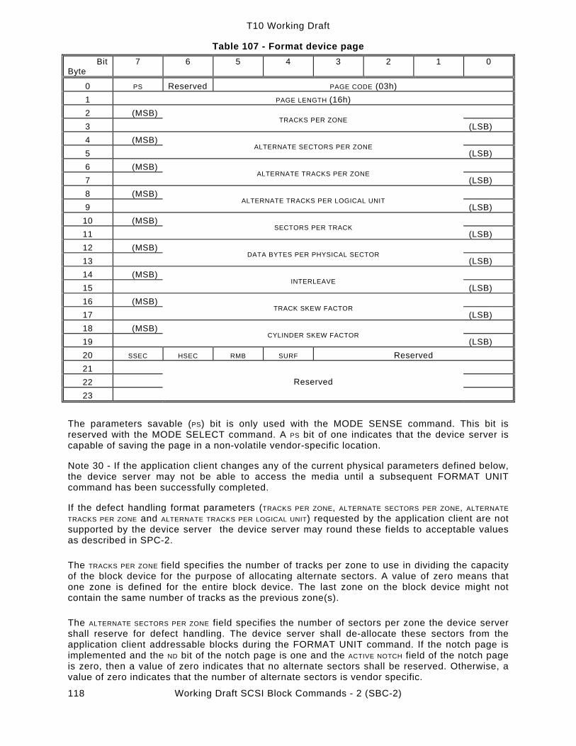
T10 Working Draft
Working Draft SCSI Block Commands - 2 (SBC-2) 118
Table 107 - Format device page Bit
Byte 7 6 5 4 3 2 1 0
0 PS Reserved PAGE CODE (03h) 1 PAGE LENGTH (16h) 2 (MSB) 3
TRACKS PER ZONE (LSB)
4 (MSB) 5
ALTERNATE SECTORS PER ZONE (LSB)
6 (MSB) 7
ALTERNATE TRACKS PER ZONE (LSB)
8 (MSB) 9
ALTERNATE TRACKS PER LOGICAL UNIT (LSB)
10 (MSB) 11
SECTORS PER TRACK (LSB)
12 (MSB) 13
DATA BYTES PER PHYSICAL SECTOR (LSB)
14 (MSB) 15
INTERLEAVE (LSB)
16 (MSB) 17
TRACK SKEW FACTOR (LSB)
18 (MSB) 19
CYLINDER SKEW FACTOR (LSB)
20 SSEC HSEC RMB SURF Reserved 21 22 23
Reserved
The parameters savable (PS) bit is only used with the MODE SENSE command. This bit is reserved with the MODE SELECT command. A PS bit of one indicates that the device server is capable of saving the page in a non-volatile vendor-specific location.
Note 30 - If the application client changes any of the current physical parameters defined below, the device server may not be able to access the media until a subsequent FORMAT UNIT command has been successfully completed.
If the defect handling format parameters (TRACKS PER ZONE, ALTERNATE SECTORS PER ZONE, ALTERNATE TRACKS PER ZONE and ALTERNATE TRACKS PER LOGICAL UNIT) requested by the application client are not supported by the device server the device server may round these fields to acceptable values as described in SPC-2.
The TRACKS PER ZONE field specifies the number of tracks per zone to use in dividing the capacity of the block device for the purpose of allocating alternate sectors. A value of zero means that one zone is defined for the entire block device. The last zone on the block device might not contain the same number of tracks as the previous zone(s).
The ALTERNATE SECTORS PER ZONE field specifies the number of sectors per zone the device server shall reserve for defect handling. The device server shall de-allocate these sectors from the application client addressable blocks during the FORMAT UNIT command. If the notch page is implemented and the ND bit of the notch page is one and the ACTIVE NOTCH field of the notch page is zero, then a value of zero indicates that no alternate sectors shall be reserved. Otherwise, a value of zero indicates that the number of alternate sectors is vendor specific.

T10 Working Draft
Working Draft SCSI Block Commands - 2 (SBC-2) 119
The ALTERNATE TRACKS PER ZONE field specifies the number of tracks per zone the device server shall reserve for defect handling. The device server shall de-allocate these tracks from the application client addressable blocks during the FORMAT UNIT command. If the notch page is implemented and the ND bit of the notch page is one and the ACTIVE NOTCH field of the notch page is zero, then a value of zero indicates that no alternate tracks shall be reserved. Otherwise, a value of zero indicates that the number of alternate tracks is vendor specific.
The ALTERNATE TRACKS PER LOGICAL UNIT field specifies the number of tracks per logical unit the device server shall reserve for defect handling. The device server shall de-allocate these tracks from the application client addressable blocks during the FORMAT UNIT command. If the notch page is implemented and the ND bit of the notch page is one and the ACTIVE NOTCH field of the notch page is zero, then a value of zero indicates that no alternate tracks shall be reserved. Otherwise, a value of zero indicates that the number of alternate tracks is vendor-specific.
The SECTORS PER TRACK field specifies the number of physical sectors included within each track. This number includes any alternate sectors the device server may allocate. A value of zero in this field during MODE SELECT indicates that the device server shall define the number of sectors per track. For block devices with a variable number of sectors per track, the value in MODE SELECT shall be zero and the value reported in MODE SENSE for the number of sectors per track is vendor specific.
The DATA BYTES PER PHYSICAL SECTOR field specifies the number of data bytes per physical sector that the device server shall use. This value may be different than the logical block size reported in the MODE SELECT data. The device server shall return CHECK CONDITION status if it determines that the combination of this field and the SECTORS PER TRACK field exceed the capability of the medium. A value of zero indicates that the data bytes per physical sector is defined by the device server.
For MODE SENSE the INTERLEAVE field returns the same parameter that was used in the last completed format unit operation, The device server shall report this field as defined in the corresponding MODE SENSE command. For MODE SELECT this field shall be ignored. The INTERLEAVE field shall be marked non-changeable and application clients shall send the value returned in MODE SENSE.
The TRACK SKEW FACTOR field specifies the number of physical sectors between the last logical block of one track and the first logical block on the next sequential track of the same cylinder.
The CYLINDER SKEW FACTOR field specifies the number of physical sectors between the last logical block of one cylinder and the first logical block on the next sequential cylinder.
The SSEC bit of one indicates that the device server shall use soft sector formatting.
The HSEC bit of one indicates that the device server shall use hard sector formatting. The HSEC bit and the SSEC bit are mutually exclusive in MODE SELECT commands.
The combinations of sector formatting supported that are reported in response to a request for default values are defined in Table 108.

T10 Working Draft
Working Draft SCSI Block Commands - 2 (SBC-2) 120
Table 108 - Reporting of default sector formatting support
SSEC HSEC Description 0 0 Device server shall not return this combination 1 0 Device server supports soft sector formatting only 0 1 Device server supports hard sector formatting only 1 1 Device server supports both soft and hard sector formatting
The combinations sector formatting supported that are reported in response to a request for changeable values are defined in Table 109.
Table 109 - Reporting of changeable sector formatting support
SSEC HSEC Description 0 0 Sector formatting not changeable 1 0 Device server shall not return this combination 0 1 Device server shall not return this combination 1 1 Device server supports both soft and hard sector formatting
The removable (RMB) bit of one indicates that the block device supports removable media. A RMB bit of zero indicates that the block device does not support removable media. The status of this bit shall be reflected in the INQUIRY command removable media bit (RMB).
The surface (SURF) bit of zero indicates that the device server shall allocate progressive addresses to all logical blocks within a cylinder prior to allocating addresses on the next cylinder. A SURF bit of one indicates that the device server shall allocate progressive addresses to all logical blocks on a surface prior to allocating sector addresses on the next surface.
Note 31 - If the device server supports savable parameters, all savable parameters for this application client, including those in page codes 3, 4, and 5, are saved to non-volatile memory when the save parameters bit (SP) in the command descriptor block is one. The savable parameters may also be saved to non-volatile memory during a FORMAT UNIT command (see 6.1.1)
6.2.5 Medium types supported page
The medium types supported page (see Table 110) contains a list of the medium types implemented by the device server for logical units.
Table 110 - Medium types supported page
Bit Byte
7 6 5 4 3 2 1 0
0 PS Reserved PAGE CODE (0Bh) 1 PAGE LENGTH (06h) 2 Reserved 3 Reserved 4 MEDIUM TYPE ONE SUPPORTED 5 MEDIUM TYPE TWO SUPPORTED 6 MEDIUM TYPE THREE SUPPORTED 7 MEDIUM TYPE FOUR SUPPORTED
The parameters savable (PS) bit is only used with the MODE SENSE command. This bit is reserved with the MODE SELECT command. A PS bit of one shall indicate that the device server is capable of saving the page in a non-volatile vendor-specific location.

T10 Working Draft
Working Draft SCSI Block Commands - 2 (SBC-2) 121
The code values for each medium type supported by the device server (up to four maximum), are reported in ascending order. If only the default medium type is supported, zero is reported. If less than four medium types are supported the unused entries shall be returned as zero.
6.2.6 Notch and partition page
The notch page (see Table 111) contains parameters for direct-access block devices that implement a variable number of blocks per cylinder and support this page. Each section of the block device with a different number of blocks per cylinder, than other sections, is referred to as a notch.
Table 111 - Notch page
Bit Byte
7 6 5 4 3 2 1 0
0 PS Reserved PAGE CODE (0Ch) 1 PAGE LENGTH (16h) 2 ND LPN Reserved 3 Reserved 4 (MSB) 5
MAXIMUM NUMBER OF NOTCHES (LSB)
6 (MSB) 7
ACTIVE NOTCH (LSB)
8 (MSB) 11
STARTING BOUNDARY (LSB)
12 (MSB) 15
ENDING BOUNDARY (LSB)
16 (MSB) 23
PAGES NOTCHED (LSB)
The parameters savable (PS) bit is only used with the MODE SENSE command. This bit is reserved with the MODE SELECT command. A PS bit of one shall indicate that the device server is capable of saving the page in a non-volatile vendor-specific location.
A notched device (ND) bit of zero shall indicate that the block device is not notched and that all other parameters in this page shall be returned as zero by the device server. A ND bit of one shall indicate that the block device is notched. For each supported active notch value this page defines the starting and ending boundaries of the notch.
A logical or physical notch (LPN) bit of zero indicates that the boundaries are based on the physical parameters of the block device. The cylinder is considered most significant, the head least significant. A LPN bit of one indicates that the notch boundaries are based on logical blocks of the block device.
The MAXIMUM NUMBER OF NOTCHES field indicates the maximum number of notches supported by the logical unit. This field shall be reported as unchangeable.
The ACTIVE NOTCH field indicates the notch that this and subsequent MODE SELECT and MODE SENSE commands shall refer to, until the active notch is changed by a subsequent MODE SELECT command. The value of the active notch shall be greater than or equal to 0000h and less than or equal to the maximum number of notches. An active notch value of zero indicates that this and subsequent MODE SELECT and MODE SENSE commands refer to the parameters that apply across all notches.
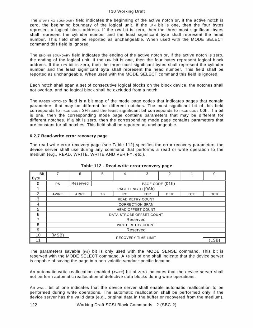
T10 Working Draft
Working Draft SCSI Block Commands - 2 (SBC-2) 122
The STARTING BOUNDARY field indicates the beginning of the active notch or, if the active notch is zero, the beginning boundary of the logical unit. If the LPN bit is one, then the four bytes represent a logical block address. If the LPN bit is zero, then the three most significant bytes shall represent the cylinder number and the least significant byte shall represent the head number. This field shall be reported as unchangeable. When used with the MODE SELECT command this field is ignored.
The ENDING BOUNDARY field indicates the ending of the active notch or, if the active notch is zero, the ending of the logical unit. If the LPN bit is one, then the four bytes represent logical block address. If the LPN bit is zero, then the three most significant bytes shall represent the cylinder number and the least significant byte shall represent the head number. This field shall be reported as unchangeable. When used with the MODE SELECT command this field is ignored.
Each notch shall span a set of consecutive logical blocks on the block device, the notches shall not overlap, and no logical block shall be excluded from a notch.
The PAGES NOTCHED field is a bit map of the mode page codes that indicates pages that contain parameters that may be different for different notches. The most significant bit of this field corresponds to PAGE CODE 3Fh and the least significant bit corresponds to PAGE CODE 00h. If a bit is one, then the corresponding mode page contains parameters that may be different for different notches. If a bit is zero, then the corresponding mode page contains parameters that are constant for all notches. This field shall be reported as unchangeable.
6.2.7 Read-write error recovery page
The read-write error recovery page (see Table 112) specifies the error recovery parameters the device server shall use during any command that performs a read or write operation to the medium (e.g., READ, WRITE, WRITE AND VERIFY, etc.).
Table 112 - Read-write error recovery page
Bit Byte
7 6 5 4 3 2 1 0
0 PS Reserved PAGE CODE (01h) 1 PAGE LENGTH (0Ah) 2 AWRE ARRE TB RC EER PER DTE DCR 3 READ RETRY COUNT 4 CORRECTION SPAN 5 HEAD OFFSET COUNT 6 DATA STROBE OFFSET COUNT 7 Reserved 8 WRITE RETRY COUNT 9 Reserved
10 (MSB) 11 RECOVERY TIME LIMIT (LSB)
The parameters savable (PS) bit is only used with the MODE SENSE command. This bit is reserved with the MODE SELECT command. A PS bit of one shall indicate that the device server is capable of saving the page in a non-volatile vendor-specific location.
An automatic write reallocation enabled (AWRE) bit of zero indicates that the device server shall not perform automatic reallocation of defective data blocks during write operations.
An AWRE bit of one indicates that the device server shall enable automatic reallocation to be performed during write operations. The automatic reallocation shall be performed only if the device server has the valid data (e.g., original data in the buffer or recovered from the medium).

T10 Working Draft
Working Draft SCSI Block Commands - 2 (SBC-2) 123
The valid data shall be placed in the reallocated block. Error reporting as required by the error recovery bits (EER, PER, DTE, and DCR) shall be performed only after completion of the reallocation. The reallocation operation shall report any failures that occur. See the REASSIGN BLOCKS command (5.1.14) for error procedures.
An automatic read reallocation enabled (ARRE) bit of zero indicates that the device server shall not perform automatic reallocation of defective data blocks during read operations.
An ARRE bit of one indicates that the device server shall enable automatic reallocation of defective data blocks during read operations. All error recovery actions required by the error recovery bits (TB, EER, PER, DTE, and DCR) shall be executed. The automatic reallocation shall then be performed only if the device server successfully recovers the data. The recovered data shall be placed in the reallocated block. Error reporting as required by the error recovery bits shall be performed only after completion of the reallocation. The reallocation process shall present any failures that occur. See the REASSIGN BLOCKS command (5.1.14) for error procedures.
A transfer block (TB) bit of zero indicates that such a data block shall not be transferred to the application client. A TB bit of one indicates that a data block that is not recovered within the recovery limits specified shall be transferred to the application client before CHECK CONDITION status is returned. The TB bit does not affect the action taken for recovered data.
Note 32 - Fabricated data may be data already in the buffer or any other vendor-specific data. This bit may be used in image processing, audio, or video applications.
A read continuous (RC) bit of zero indicates that error recovery operations that cause delays are acceptable during the data transfer. Data shall not be fabricated.
A RC bit of one indicates the device server shall transfer the entire requested length of data without adding delays to perform error recovery procedures. This implies that the device server may send data that is erroneous or fabricated in order to maintain a continuous flow of data. The device server shall assign priority to this bit over conflicting error control bits (EER, DCR, DTE, and PER) within this byte.
The individual bit definitions for EER, PER, DTE and DCR are contained in Table 113. The combinations of these bits are explained in Table 114.

T10 Working Draft
Working Draft SCSI Block Commands - 2 (SBC-2) 124
Table 113 - Error recovery bit definitions
EER PER DTE DCR Description 1 - - - An enable early recovery (EER) bit of one indicates that the
device server shall use of the most expedient form of error recovery first. This bit only applies to data error recovery and it does not affect positioning retries and the message system error recovery procedures.
0 - - - An EER bit of zero indicates that the device server shall use as error recovery procedure that minimizes the risk of mis-detection or mis-correction.
- 1 - - A post error (PER) bit of one indicates that the device server shall report recovered errors.
- 0 - - A PER bit of zero indicates that the device server shall not report recovered errors. Error recovery procedures shall be performed within the limits established by the error recovery parameters.
- - 1 - A DTE bit of one indicates that the device server shall terminate the data-in or data-out buffer transfer upon detection of a recovered error.
- - 0 - A DTE bit of zero indicates that the device server shall not terminate the data-in or data-out buffer transfer upon detection of a recovered error.
- - - 1 A disable correction (DCR) bit of one indicates that error condition codes shall not be used for data error recovery.
- - - 0 A DCR bit of zero allows the use of error condition codes for data error recovery.
Note 33 - An EER bit of one may imply an increase in the probability of mis-detection or mis-correction. An EER bit of zero allows the specified retry limit to be exhausted prior to using error correction codes.
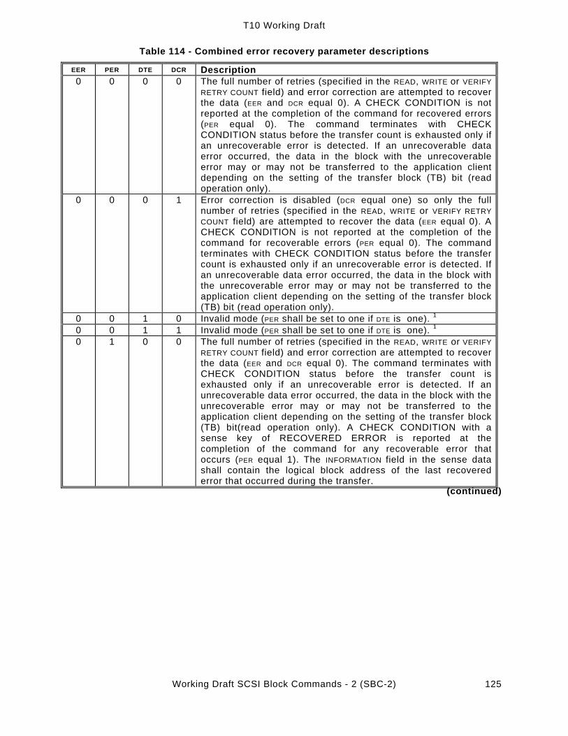
T10 Working Draft
Working Draft SCSI Block Commands - 2 (SBC-2) 125
Table 114 - Combined error recovery parameter descriptions
EER PER DTE DCR Description 0 0 0 0 The full number of retries (specified in the READ, WRITE or VERIFY
RETRY COUNT field) and error correction are attempted to recover the data (EER and DCR equal 0). A CHECK CONDITION is not reported at the completion of the command for recovered errors (PER equal 0). The command terminates with CHECK CONDITION status before the transfer count is exhausted only if an unrecoverable error is detected. If an unrecoverable data error occurred, the data in the block with the unrecoverable error may or may not be transferred to the application client depending on the setting of the transfer block (TB) bit (read operation only).
0 0 0 1 Error correction is disabled (DCR equal one) so only the full number of retries (specified in the READ, WRITE or VERIFY RETRY COUNT field) are attempted to recover the data (EER equal 0). A CHECK CONDITION is not reported at the completion of the command for recoverable errors (PER equal 0). The command terminates with CHECK CONDITION status before the transfer count is exhausted only if an unrecoverable error is detected. If an unrecoverable data error occurred, the data in the block with the unrecoverable error may or may not be transferred to the application client depending on the setting of the transfer block (TB) bit (read operation only).
0 0 1 0 Invalid mode (PER shall be set to one if DTE is one). 1 0 0 1 1 Invalid mode (PER shall be set to one if DTE is one). 1 0 1 0 0 The full number of retries (specified in the READ, WRITE or VERIFY
RETRY COUNT field) and error correction are attempted to recover the data (EER and DCR equal 0). The command terminates with CHECK CONDITION status before the transfer count is exhausted only if an unrecoverable error is detected. If an unrecoverable data error occurred, the data in the block with the unrecoverable error may or may not be transferred to the application client depending on the setting of the transfer block (TB) bit(read operation only). A CHECK CONDITION with a sense key of RECOVERED ERROR is reported at the completion of the command for any recoverable error that occurs (PER equal 1). The INFORMATION field in the sense data shall contain the logical block address of the last recovered error that occurred during the transfer.
(continued)

T10 Working Draft
Working Draft SCSI Block Commands - 2 (SBC-2) 126
Table 114 - Combined error recovery parameter descriptions (continued)
EER PER DTE DCR Description 0 1 0 1 Error correction is disabled (DCR equal one) so only the full
number of retries (specified in the READ, WRITE or VERIFY RETRY COUNT field) are attempted to recover the data (EER equal 0). The command terminates with CHECK CONDITION status before the transfer count is exhausted only if an unrecoverable error is detected. If an unrecoverable data error occurred, the data in the block with the unrecoverable error may or may not be transferred to the application client depending on the setting of the transfer block (TB) bit (read operation only). A CHECK CONDITION with a sense key of RECOVERED ERROR is reported at the completion of the command for any recoverable error that occurs (PER equal 1). The INFORMATION field in the sense data shall contain the logical block address of the last recovered error that occurred during the transfer.
0 1 1 0 The full number of retries (specified in the READ, WRITE or VERIFY RETRY COUNT field) and error correction are attempted to recover the data (EER and DCR equal 0). The command terminates with CHECK CONDITION status before the transfer count is exhausted if any error (recoverable or unrecoverable) is detected (DTE equal 1). The INFORMATION field in the sense data shall contain the logical block address of the block in error. If an unrecoverable data error occurs the data in the block with the error may or may not be transferred to the application client depending on the setting of the transfer block (TB) bit (read operation only.)
0 1 1 1 Error correction is disabled (DCR equal one) so only the full number of retries (specified in the READ, WRITE or VERIFY RETRY COUNT field) are attempted to recover the data (EER equal 0). The command terminates with CHECK CONDITION status before the transfer count is exhausted if any error (recoverable or unrecoverable) is detected (DTE equal 1). The INFORMATION field in the sense data shall contain the logical block address of the block in error. If an unrecoverable data error occurs the data in the block with the error may or may not be transferred to the application client depending on the setting of the transfer block (TB) bit (read operation only).
1 0 0 0 The fewest possible retries and error correction are attempted to recover the data (EER equal one and DCR equal 0). A CHECK CONDITION is not reported at the completion of the command for recoverable errors (PER equal 0). The command terminates with CHECK CONDITION status before the transfer count is exhausted only if an unrecoverable error is detected. If an unrecoverable data error occurred, the data in the block with the unrecoverable error may or may not be transferred to the application client depending on the setting of the transfer block (TB) bit (read operation only).
1 0 0 1 Invalid mode (DCR shall be set to zero if EER is one).1 1 0 1 0 Invalid mode (PER shall be set to one if DTE is one). 1 1 0 1 1 Invalid mode (PER shall be set to one if DTE is one). 1
(continued)

T10 Working Draft
Working Draft SCSI Block Commands - 2 (SBC-2) 127
Table 114 - Combined error recovery parameter descriptions (continued) EER PER DTE DCR Description
1 1 0 0 The fewest possible retries and error correction are attempted to recover the data (EER equal one and DCR equal 0). The command terminates with CHECK CONDITION status before the transfer count is exhausted only if an unrecoverable error is detected. If an unrecoverable data error occurred, the data in the block with the unrecoverable error may or may not be transferred to the application client depending on the setting of the transfer block (TB) bit (read operation only). A CHECK CONDITION with a sense key of RECOVERED ERROR is reported at the completion of the command for any recoverable error that occurs (PER equal 1). The INFORMATION field in the sense data shall contain the logical block address of the last recovered error that occurred during the transfer.
1 1 0 1 Invalid mode (DCR shall be set to zero if EER is one). 1 1 1 1 0 The fewest possible retries and error correction are attempted to
recover the data (EER equal one and DCR equal 0). The command terminates with CHECK CONDITION status before the transfer count is exhausted if any error (recoverable or unrecoverable) is detected (DTE equal 1). The INFORMATION field in the sense data shall contain the logical block address of the block in error. If an unrecoverable data error occurs the data in the block with the error may or may not be transferred to the application client depending on the setting of the transfer block (TB) bit (read operation only).
1 1 1 1 Invalid mode (DCR shall be set to zero if EER is one). 1 Note (1) If an invalid mode for the error recovery combination is sent by the application client the device server shall return CHECK CONDITION status and the sense key shall be set to ILLEGAL REQUEST with the additional sense code set to INVALID FIELD IN PARAMETER LIST The READ and WRITE RETRY COUNT fields specify the number of times that the device server shall attempt its recovery algorithm during read and write operations, respectively. If the RETRY COUNT field and the RECOVERY TIME LIMIT field are both specified in a MODE SELECT command, the field that requires the least time for data error recovery actions shall have priority.
The CORRECTION SPAN field specifies the size, in bits, of the largest data error burst that data error correction may be attempted. A correction span of zero specifies that the device server shall use its default value or that this field is not supported. A correction span of 255 indicates that the SCSI devices is capable of correcting a burst of 255 or more bits.
The HEAD OFFSET COUNT field specifies in two’s-complement notation an incremental offset position from the track center to the radial position the heads shall be moved. The effect of this field on write operations is unspecified. A HEAD OFFSET COUNT of zero indicates that no offset is specified. A positive value indicates moving in the direction of increasing logical block addresses. A negative value indicates moving in the direction of decreasing logical block addresses. Any value specified in this field does not preclude the device server from using positive or negative head offset during error recovery. However, after any error recovery is completed the device server shall return the head offset to the value specified in this field.
Note 34 - The degree of offset for each incremental value and the number of valid values are vendor-specific. The number of valid values should be equal for the positive and negative head offset counts.
The device server shall return CHECK CONDITION status and set the sense key to ILLEGAL REQUEST with the appropriate additional sense code for the condition if an unsupported head offset value is specified. The valid bit shall be set to one and the INFORMATION field shall be set to

T10 Working Draft
Working Draft SCSI Block Commands - 2 (SBC-2) 128
the positive value of the maximum head offset count that is supported. The device server shall set the valid bit to zero if the device server is unable to determine the maximum head offset count supported.
Note 35 - If the device server does not support this field, it returns a zero value in the MODE SENSE command).
The DATA STROBE OFFSET COUNT field specifies in two’s-complement notation an incremental position to where the recovered data strobe shall be adjusted from its nominal setting. The effect of this field on write operations is unspecified. A value of zero indicates that no data strobe offset is specified. A positive value indicates movement in a positive direction as defined by the device server. A negative value indicates movement in the negative direction as defined by the device server. Any value specified in this field does not preclude the device server from using positive or negative data strobe offset during error recovery. However, after any error recovery is completed the device server shall return the data strobe offset to the value specified in this field.
Note 36 - The degree of offset for each incremental value and the number of valid values are vendor-specific. The number of valid values should be equal for the positive and negative data strobe offset counts.
The device server shall return CHECK CONDITION status and shall set the sense key to ILLEGAL REQUEST with the appropriate additional sense code for the condition if an unsupported data strobe offset count value is specified. The valid bit shall be set to one and the INFORMATION field shall be set to the positive value of the maximum data strobe offset count that is supported. The device server shall set the valid bit to zero if the device server is unable to determine the maximum data strobe offset supported.
Note 37 - If the device server does not support the DATA STROBE OFFSET COUNT field, it returns a zero value in the MODE SENSE command.
The RECOVERY TIME LIMIT field specifies in increments of one millisecond the maximum time duration that the device server shall use for data error recovery procedures. The device server may round this value as described in SPC-2. The limit in this field specifies the maximum error recovery time allowed for any individual logical block. A RECOVERY TIME LIMIT of zero specifies that the device server shall use its default value.
If both RETRY COUNT and RECOVERY TIME LIMIT are specified, the field that specifies the recovery action of least duration shall have priority.
6.2.8 Rigid disk device geometry page
The rigid disk device geometry page (see Table 115) specifies parameters for direct-access block devices employing a rigid disk device.

T10 Working Draft
Working Draft SCSI Block Commands - 2 (SBC-2) 129
Table 115 - Rigid disk device geometry page Bit
Byte 7 6 5 4 3 2 1 0
0 PS Reserved PAGE CODE (04h) 1 PAGE LENGTH (16h) 2 (MSB) 3 4
NUMBER OF CYLINDERS (LSB)
5 NUMBER OF HEADS 6 (MSB) 7 8
STARTING CYLINDER-WRITE PRECOMPENSATION (LSB)
9 (MSB) 10 11
STARTING CYLINDER-REDUCED WRITE CURRENT (LSB)
12 (MSB) 13 DEVICE STEP RATE (LSB) 14 (MSB) 15 16
LANDING ZONE CYLINDER (LSB)
17 Reserved RPL 18 ROTATIONAL OFFSET 19 Reserved 20 (MSB) 21 MEDIUM ROTATION RATE (LSB) 22 Reserved 23 Reserved
The parameters savable (PS) bit is only used with the MODE SENSE command. This bit is reserved with the MODE SELECT command. A PS bit of one shall indicate that the device server is capable of saving the page in a non-volatile vendor-specific location.
Note 38 - This page is intended to define device geometry parameters of rigid disk devices. It may be used for other logical units if applicable.
The NUMBER OF CYLINDERS field defines the number of physical cylinders used for data storage.
The NUMBER OF HEADS field defines the physical number of heads used for data storage. Heads used exclusively for servo information are excluded.
The STARTING CYLINDER FOR WRITE PRECOMPENSATION field is the physical cylinder where write precompensation is to begin. The first cylinder is number zero. If the STARTING CYLINDER FOR WRITE PRECOMPENSATION is equal to the value in the NUMBER OF CYLINDERS field, write precompensation shall be disabled by the device server.
The STARTING CYLINDER FOR REDUCED WRITE CURRENT field is the physical cylinder where write current is reduced. The first cylinder is number zero. If the STARTING CYLINDER FOR REDUCED WRITE CURRENT is equal to the value in the NUMBER OF CYLINDERS field, reduced write current shall be disabled by the device server.
The DEVICE STEP RATE field indicates the step rate in 100 ns increments. The device server shall use the device step rate, greater than or equal to the device step rate specified. If the device server rounds this field it shall terminate the command as described in SPC-2. A value of zero requests the device server to set its default value.
The LANDING ZONE CYLINDER field indicates two's complement location where the device server shall position the disk heads. A negative value indicates that the heads are positioned below cylinder

T10 Working Draft
Working Draft SCSI Block Commands - 2 (SBC-2) 130
zero by that number of cylinders. A positive value greater than the NUMBER OF CYLINDERS indicates that the heads are positioned beyond the cylinders used for data storage at the cylinder location specified. A zero indicates that the default should be used.
The rotational position locking (RPL) field is used for spindle synchronization as defined in Table 116.
Table 116 - Rotational position locking
RPL Description 00b Indicates that spindle synchronization is disabled or not supported 01b The device server operates as a synchronized-spindle slave 10b The device server operates as a synchronized-spindle master 11b The device server operates as a synchronized-spindle master control
Note 39 - The signals and connectors used for rotational position locking are external to the SCSI bus and are not part of this American National Standard.
If a device server fails to achieve synchronization it shall create a unit attention condition to all application clients. The sense key shall be set to UNIT ATTENTION with the additional sense code set to RPL STATUS CHANGE.
If subsequent to achieving synchronization the device server detects a change of synchronization:
a) and, if the logical unit task set currently does not contain any task for the initiator, the device server shall create a unit attention condition. The sense key shall be set to UNIT ATTENTION with the additional sense code set to RPL STATUS CHANGE;
b) and, if the logical unit task set currently contains a task for the initiator, the device server shall return CHECK CONDITION status and the sense key shall be set to RECOVERED ERROR if the device server is able to complete the task or HARDWARE ERROR if the device server is unable to complete the task with the additional sense code set to RPL STATUS CHANGE.
The rotational offset indicates the amount of rotational skew that the device server shall use when synchronized. The rotational skew is applied in the retarded direction (lagging the synchronized spindle master control). The value in the field is the numerator of a fractional multiplier that has 256 as its denominator (e.g., a value of 128 indicates a one-half revolution skew). A value of zero indicates that rotational offset shall not be used. This value may be rounded as defined in SPC-2. The rotational offset is not used when a device server is configured as the synchronized-spindle master.
The medium rotation rate indicates the speed of medium rotation. The unit of measure is rotations per minute (e.g., 3 600 rpm).
6.2.9 Verify error recovery page
The verify error recovery page (see Table 117) specifies the error recovery parameters the device server shall use during the VERIFY command and the verify operation of the WRITE AND VERIFY command.

T10 Working Draft
Working Draft SCSI Block Commands - 2 (SBC-2) 131
Table 117 - Verify error recovery page Bit
Byte 7 6 5 4 3 2 1 0
0 PS Reserved PAGE CODE (07h) 1 PARAMETER LENGTH (0Ah) 2 Reserved EER PER DTE DCR 3 VERIFY RETRY COUNT 4 VERIFY CORRECTION SPAN 5 Reserved 6 Reserved 7 Reserved 8 Reserved 9 Reserved
10 (MSB) 11 VERIFY RECOVERY TIME LIMIT (LSB)
The parameters savable (PS) bit is only used with the MODE SENSE command. This bit is reserved with the MODE SELECT command. A PS bit of one shall indicate that the device server is capable of saving the page in a non-volatile vendor-specific location.
The AWRE bit as defined in the read-write error recovery page (see 6.2.7) applies to the WRITE AND VERIFY command. The VERIFY command shall not perform automatic reallocation.
The EER, PER, DTE, and DCR bits are defined in 6.2.7. The combinations of these bits are defined in Table 114.
The VERIFY RETRY COUNT field specifies the number of times that the device server shall attempt its recovery algorithm during a verify operation. If the verify retry count and the VERIFY RECOVERY TIME LIMIT are both specified, the one that requires the least time for data error recovery actions shall have priority.
The VERIFY CORRECTION SPAN field specifies the size, in bits, of the largest burst data error that data error correction may be attempted. If the device server does not implement this field, a value of zero is returned in MODE SENSE data.
The VERIFY RECOVERY TIME LIMIT field specifies in increments of one millisecond the maximum time duration that the device server shall use error recovery procedures to recover data for an individual logical block. The device server may round this value as described in SPC-2. If the VERIFY RETRY COUNT and the VERIFY RECOVERY TIME LIMIT are both specified, the one that requires the least time for data error recovery actions shall have priority.
Note 40 - To disable all types of correction and retries the application client should set the EER bit to zero, the PER, DTE, and DCR bits to one and the number of retries and recovery time limit to zero.
6.2.10 XOR control mode page
The XOR control mode page (see Table 118) provides the initiator with the means to obtain or modify certain XOR operating parameters of the target.

T10 Working Draft
Working Draft SCSI Block Commands - 2 (SBC-2) 132
Table 118 - XOR control mode page
Bit Byte
7 6 5 4 3 2 1 0
0 PS Reserved PAGE CODE (10h) 1 PAGE LENGTH (16h) 2 Reserved XORDIS Reserved3 Reserved 4 (MSB) 5 6 7
MAXIMUM XOR WRITE SIZE
(LSB) 8 9
10 11
Reserved
12 (MSB) 13 14 15
MAXIMUM REGENERATE SIZE
(LSB) 16 (MSB) 17 18 19
MAXIMUM REBUILD READ SIZE
20 21 Reserved 22 (MSB) 23 REBUILD DELAY (LSB)
The parameters savable (PS) bit is only used with the MODE SENSE command. This bit is reserved with the MODE SELECT command. A PS bit of one shall indicate that the device server is capable of saving the page in a non-volatile vendor-specific location.
An XOR disable (XORDIS) bit of zero enables the XOR operations within a device. An XORDIS bit of one disables the XOR operations within a device. If the XORDIS bit is one and an XOR command is sent to the target the command shall be terminated with CHECK CONDITION status and the sense data shall be set to ILLEGAL REQUEST with the additional sense code set to INVALID COMMAND OPERATION CODE.
The MAXIMUM XOR WRITE SIZE field specifies the maximum transfer length in blocks that the target accepts for a single XDWRITE EXTENDED, XDWRITE, or XPWRITE command.
The MAXIMUM REGENERATE SIZE field specifies the maximum REGENERATE LENGTH in blocks that the target accepts for the REGENERATE command.
The MAXIMUM REBUILD READ SIZE field specifies the maximum transfer length in blocks that the target shall use for READ commands during a rebuild operation. This field does not limit the rebuild size.
The REBUILD DELAY field is provided to allow allocation of the SCSI interconnect subsystem bandwidth. The REBUILD DELAY field specifies the minimum time in milliseconds between successive READ commands during a rebuild operation.

T10 Working Draft
Working Draft SCSI Block Commands - 2 (SBC-2) 133
6.3 Parameters for optical memory block devices
6.3.1 Diagnostic parameters
This subclause defines the descriptors and pages for diagnostic parameters used with optical memory block devices.
The diagnostic page codes for optical memory block devices are defined in Table 119.
Table 119 - Diagnostic page codes for optical memory block devices
Page code Description Subclause
00h Supported diagnostic pages 01h - 3Fh Reserved (for all device type pages)
40h Translate address page - SEND DIAGNOSTIC 6.1.1.2 40h Translate address page - RECEIVE DIAGNOSTIC 6.1.1.3 41h Device status page - SEND DIAGNOSTIC 6.1.1.4 41h Device status page - RECEIVE DIAGNOSTIC 6.1.1.5
42h - 7Fh Reserved 80h - FFh Vendor-specific pages
6.3.2 Log parameters
This subclause defines the descriptors and pages for log parameters used with optical memory block devices.
The log page codes for optical memory block devices are defined in Table 120.
Table 120 - Log page codes for optical memory block devices
Page code Description Subclause
00h Supported log pages SPC-2 01h Buffer overrun/under-run page SPC-2 02h Error counter page (write) page SPC-2 03h Error counter page (read) page SPC-2 04h Error counter page (read reverse) page SPC-2 05h Error counter page (verify) page SPC-2 06h Non-medium error page SPC-2 07h Last n error events page SPC-2 08h Format status page 6.1.3
09h - 2Fh Reserved 30h - 3Eh Vendor-specific pages
3Fh Reserved 6.3.3 Mode parameters
6.3.3.1 Mode parameters overview
This subclause defines the descriptors and pages for mode parameters used with optical memory block devices.
The mode parameter list, including the mode parameter header and mode block descriptor, are defined in SPC-2.

T10 Working Draft
Working Draft SCSI Block Commands - 2 (SBC-2) 134
The MEDIUM-TYPE CODE field is contained in the mode parameter header (see SPC-2). Table 121 defines the medium-type code values used for optical memory block devices. FIXFIX
Table 121 - Optical memory medium-type codes
Code Description
00h Default (only one medium type supported) 01h Optical read-only medium 02h Optical write-only medium 03h Optical reversible or erasable medium 04h Combination of read-only and write-only medium 05h Combination of read-only and reversible or erasable medium 06h Combination of write-once and reversible or erasable medium
07h - 7Fh Reserved 80h - FFh Vendor-specific
The DEVICE SPECIFIC PARAMETER field is contained in the mode parameter header (see SPC-2). Table 122 defines the device specific parameter values used for optical memory block devices.
Table 122 - Optical memory block device specific parameter
Bit 7 6 5 4 3 2 1 0 WP Reserved DPOFUA Reserved EBC
When used with the MODE SELECT command the WP bit is not defined. When used with the MODE SENSE command, a write protected (WP) bit of zero shall indicate that the medium is write enabled. A WP bit of one shall indicate that the medium is write protected. For read-only media the WP bit is reserved.
When used with the MODE SELECT command, the DPOFUA bit is reserved. When used with the MODE SENSE command, a DPOFUA bit of one indicates that the device server supports the DPO and FUA bits (see 5.1.7).
For the MODE SELECT command, an enable blank check (EBC) bit of zero advises the device server to disable the blank checking operation of the medium during write operations or during an UPDATE BLOCK command. An EBC bit of one enables blank checking. If a non-blank block is found during a write operation, the command shall be terminated with a CHECK CONDITION and the sense key shall be set to BLANK CHECK with the appropriate additional sense code for the condition. If a blank block is found during an UPDATE BLOCK command, the command shall be terminated with a CHECK CONDITION status and the sense key shall be set to BLANK CHECK with the appropriate additional sense code for the condition. For read-only media, the EBC bit is reserved.
For the MODE SENSE command, an EBC bit of zero indicates that blank checking of the medium during write operations is disabled. An EBC bit of one indicates that blank checking during write and update operations is enabled. For read-only media, the EBC bit is reserved.
The DENSITY CODE field is contained in the mode parameter block descriptor (see SPC-2). Table 123 defines the density code values used for optical memory block devices.

T10 Working Draft
Working Draft SCSI Block Commands - 2 (SBC-2) 135
Table 123 - Optical memory density codes
Code Diameter mm (in)
Type Sector size Tracks Sides Servo Reference Standard
Notes
00h Default density (currently mounted density) 01h 86 (3,5) R/W 512/1024 12500 1 ISO/IEC 10090 03h 130 (5,25) R/W 512/1024 18750 2 CS ANSI X3.212 04h 130 (5,25) W-O 512/1024 30000 2 SS ANSI X3.191 05h 130 (5,25) W-O 512/1024 20000 2 SS ANSI X3.214 1 06h 130 (5,25) W-O 512/1024 18750 2 CS ANSI X3.211 2 08h 300 (12,0) 1024 2 ISO/IEC 13614 09h 356 (14,0) 1024 56350 2 ANSI X3.200
80h - FFh
Vendor-specific
Other Reserved Key: Type Description Servo Description R/W Erasable CS Continuous servo W-O Write once SS Sampled servo R/O Read only Notes: (1) R2 modulation. (2) 4/15 modulation. The mode page codes for optical memory block devices are shown in Table 124.
Table 124 - Mode page codes for optical memory block devices
Page code Description Subclause
00h Vendor-specific (does not require page format) 01h Read-write error recovery page 6.2.7 02h Disconnect-reconnect page SPC-2
03h - 05h Reserved 06h Optical memory page 6.2.2 07h Verify error recovery page 6.2.9 08h Caching page 6.2.2 09h Peripheral device page SPC-2 0Ah Control mode page SPC-2 0Bh Medium types supported page 6.2.5 0Ch Reserved 0Dh Power condition pageObsolete SPC-2
0Eh - 1Bh19h Reserved 1Ah Power condition page SPC-2 1Bh Reserved 1Ch Informational exceptions page SPC-2
1Dh - 1Fh Reserved 20h - 3Eh Vendor-specific (page format required)
3Fh Return all pages (valid only for the MODE SENSE command)
6.3.3.2 Optical memory page
The optical memory page (see Table 125) defines parameters for control of optical memory block devices.

T10 Working Draft
Working Draft SCSI Block Commands - 2 (SBC-2) 136
Table 125 - Optical memory page Bit
Byte 7 6 5 4 3 2 1 0
0 PS Reserved PAGE CODE (06h) 1 PARAMETER LENGTH (02h) 2 Reserved RUBR 3 Reserved
The parameters savable (PS) bit is only used with the MODE SENSE command. This bit is reserved with the MODE SELECT command. A PS bit of one shall indicate that the device server is capable of saving the page in a non-volatile, vendor-specific location.
A report updated block read (RUBR) bit of zero indicates the device server shall not report an error when a command performs a successful read of a block that has been updated. A RUBR bit of one indicates the device server shall terminate a command that performs a read of a block that has been updated with CHECK CONDITION status and the sense key shall be set to RECOVERED ERROR with the additional sense code set to UPDATED BLOCK READ. The data shall be transferred to the application client. The default state of the RUBR bit for write-once block devices (as reported in the INQUIRY command) shall be one.
6.3.4 Parameters for write-once block devices
Refer to the parameters for optical memory block devices (see 6.3).

T10 Working Draft
Working Draft SCSI Block Commands - 2 (SBC-2) 137
Annex A (informative)
XOR command examples
A XOR command examples
A.1 XOR command examples overview
This annex provides XOR command examples in various redundancy group configurations.
A.2 Storage array controller supervised XOR operations
A.2.1 Update write operation
Figure A.1 illustrates a read-modify-write operation supervised by a storage array controller. The example uses a supervising storage array controller, a data disk device (holding protected user data), and a parity disk device (holding check data). In this example, the data and parity devices are on separate SCSI physical interconnects, and thus are not capable of peer-to-peer interaction. Three SCSI commands are used: XDWRITE, XDREAD, and XPWRITE. XDWRITEREAD may be used in place of any sequence of XDWRITE followed by XDREAD.
The supervising storage array controller begins by sending user data to the data disk device using an XDWRITE command. It also initiates an XPWRITE command to the parity disk device (the supervising storage array controller does not yet have the intermediate XOR data for this command; the purpose of issuing the XPWRITE command at this time is to cause the parity disk device to begin reading XOR data from its medium to its buffer memory).
The data disk device reads old user data from its medium, performs an XOR operation using the old user data and the user data from the supervising storage array controller, stores the resulting intermediate XOR data in its buffer memory, and writes the user data from the supervising storage array controller to its medium. The supervising storage array controller reads the resulting intermediate XOR data from the buffer memory by sending the data disk device an XDREAD command.
The supervising storage array controller makes the resulting intermediate XOR data (read with the XDREAD command) available to the parity disk device for the already issued XPWRITE command. The parity disk device performs an XOR operation using the intermediate XOR data and the XOR data in its buffer memory. The resulting new XOR data is written to the medium.

T10 Working Draft
Working Draft SCSI Block Commands - 2 (SBC-2) 138
+
+
Disk
Disk
Intermediate XOR Data
User Data Old User Data
XOR Data
New XOR Data
XDWRITE
XDREAD
Port 1
Port 2
XPWRITE
User Data
Intermediate XOR Data
Parity Disk Device
Data Disk Device Supervising Array Controller
Figure A.1 - Update write operation
A.2.2 Regenerate operation
Figure A.2 illustrates a regenerate operation supervised by a storage array controller. The example uses a supervising storage array controller and three disk devices. In this example, all three disk devices are on separate SCSI physical interconnects, and thus are not capable of peer-to-peer interaction. Three SCSI commands are used: READ, XDWRITE, and XDREAD. XDWRITEREAD may be used in place of any sequence of XDWRITE followed by XDREAD.
The supervising storage array controller begins by issuing a READ command to disk device 1. The data received from this command is sent by the supervising storage array controller to disk device 2 using an XDWRITE command with a DISABLE WRITE bit of one. Disk device 2 reads data from its medium, performs an XOR operation using that data and the data received from the supervising storage array controller, and stores the resulting intermediate XOR data in its buffer memory. The supervising storage array controller retrieves the intermediate XOR data from the buffer memory by issuing an XDREAD command to disk device 2. The supervising storage array controller issues XDWRITE and XDREAD commands in the same manner to disk device 3.
The resulting data from disk device 3 is the regenerated user data.

T10 Working Draft
Working Draft SCSI Block Commands - 2 (SBC-2) 139
Disk
XDWRITE or XDWRITEREAD
XDREAD or XDWRITEREAD
Port 1
Port 2
Data
Intermediate XOR Data
+ Disk
Interm. XOR
Data
+ Disk
Interm. XOR
Data Regenerated User Data
Disk Device 1
Disk Device 2
Disk Device 3
Port 3
XDWRITE or XDWRITEREAD
XDREAD or XDWRITEREAD
READ
Supervising Array Controller
Figure A.2 - Regenerate operation
A.2.3 Rebuild operation
Figure A.3 illustrates a rebuild operation supervised by a storage array controller. The example uses a supervising storage array controller, two disk devices as the source devices, and one disk device as the rebuild device. In this example, all three disk devices are on separate SCSI physical interconnects, and thus are not capable of peer-to-peer interaction. Four SCSI commands are used: READ, XDWRITE, XDREAD, and WRITE. XDWRITEREAD may be used in place of any sequence of XDWRITE followed by XDREAD.
The supervising storage array controller begins by issuing a READ command to disk device 1. The data received from the READ command is sent by the supervising storage array controller to disk device 2 using an XDWRITE command with a DISABLE WRITE bit of one. Disk device 2 reads data from its medium, performs an XOR operation using that data and the data received from the supervising storage array controller, and stores the resulting intermediate XOR data in its buffer memory. The supervising storage array controller retrieves the intermediate XOR data by sending an XDREAD command to disk device 2.
The resulting data from disk device 2 is the "rebuilt" data and is sent to the device being rebuilt (disk device 3) using a WRITE command.

T10 Working Draft
Working Draft SCSI Block Commands - 2 (SBC-2) 140
Disk Rebuilt Data
Disk
XDWRITE or XDWRITEREAD
Port 1
Port 2
Data
Intermediate XOR Data
Host
+ Disk
Interm. XOR
Data
Disk Device 1
Disk Device 2
Disk Device 3
Port 3
WRITE
XDREAD or XDWRITEREAD
READ Data
Supervising Array Controller
Figure A.3 - Rebuild operation
A.3 Third-party XOR operations
A.3.1 Update write operation
Figure A.4 illustrates a third-party read-modify-write operation. The example uses a host, a data disk device (holding protected user data), and a parity disk device (holding check data). In this example, the data and parity devices are on the same SCSI physical interconnect, and thus are capable of peer-to-peer interaction. Two SCSI commands are used: XDWRITE EXTENDED and XPWRITE.
The host begins by sending user data to the data disk device using an XDWRITE EXTENDED command. The data disk device assumes initiator role and sends an XPWRITE command to the parity disk device (the data disk device does not yet have the intermediate XOR data for this command; the purpose of issuing the XPWRITE command at this time is to cause the parity disk device to begin reading XOR data from its medium to its buffer memory).
The data disk device reads old user data from its medium, performs an XOR operation using the old user data and the user data from the host, stores the resulting intermediate XOR data in its buffer memory, and writes the user data from the host to its medium.
The data disk device makes the resulting intermediate XOR data (from its buffer memory) available to the parity disk device for the already issued XPWRITE command. The parity disk device performs an XOR operation using the intermediate XOR data and the XOR data in its buffer memory. The resulting new XOR data is written to the medium.

T10 Working Draft
Working Draft SCSI Block Commands - 2 (SBC-2) 141
+ Disk
Intermediate XOR
Old User Data
User Data
+ Disk
XOR Data
New XOR Data
XDWRITE EXTENDED
XPWRITE
User Data
Parity Disk Device
Data Disk Device Host
Figure A.4 - Update write operation
A.3.2 Regenerate operation
Figure A.5 illustrates a third-party regenerate operation. The example uses a host and three disk devices. In this example, all three disk devices are on the same SCSI physical interconnect, and thus are capable of peer-to-peer interaction. Three SCSI commands are used: REGENERATE, READ, and XDREAD.
The host begins by issuing a REGENERATE command to disk device 1. Disk device 1 assumes initiator role and sends READ commands to disk device 2 and disk device 3. It also concurrently reads data from its own medium. Disk device 1 performs an XOR operation on the data from all three disk devices and stores the resulting intermediate XOR data (regenerated user data) in its buffer memory. The host retrieves this regenerated user data by sending an XDREAD command to disk device 1.

T10 Working Draft
Working Draft SCSI Block Commands - 2 (SBC-2) 142
Host
+ Disk
Intermediate XOR
Data Regenerated User Data
Disk
Disk Device 2
XDREAD
READ
Disk
Disk Device 3
Data
READ
Data
REGENERATE
Disk Device 1
Figure A.5 - Regenerate operation
A.3.3 Rebuild operation
Figure A.6 illustrates a third-party rebuild operation. The example uses a host, two disk devices as the source devices, and one disk device as the device being rebuilt. In this example, all three disk devices are on the same SCSI physical interconnect, and thus are capable of peer-to-peer interaction. Two SCSI commands are used: REBUILD and READ.
The host begins by issuing a REBUILD command to the device being rebuilt (disk device 1). Disk device 1 assumes the initiator role and issues READ commands to the source devices (disk device 2 and disk device 3). Disk device 1 performs an XOR operation on the data received from these two commands and writes the resulting rebuilt data to its medium.

T10 Working Draft
Working Draft SCSI Block Commands - 2 (SBC-2) 143
Host
+ DiskRebuilt Data
Disk
Disk Device 2
REBUILD
READ
Disk
Disk Device 3
Data
READ
Data
Disk Device 1
Figure A.6 - Rebuild operation
A.4 Hybrid subsystem XOR operations
A.4.1 Regenerate operation
Figure A.7 illustrates a regenerate operation on a hybrid system. The example uses a host and four disk devices as source devices. In this example, two of the disk devices are on one SCSI physical interconnect, and thus are capable of peer-to-peer interaction between themselves. The two other disk devices are on a different SCSI physical interconnect and are also capable of peer-to-peer interaction between themselves. Three SCSI commands are used: REGENERATE, READ, and XDREAD.
The host begins by issuing a REGENERATE command to disk device 1. Disk device 1 assumes initiator role and sends a READ command to disk device 2. Disk device 1 also concurrently reads data from its own medium. Disk device 1 performs an XOR operation on the data from the two disk devices and stores the resulting partially regenerated user data in its buffer memory. The host retrieves this partially regenerated user data by sending an XDREAD command to disk device 1.
The host then issues a REGENERATE command to disk device 3 with the partially regenerated user data that was obtained from disk device 1 (with the XDREAD command). Disk device 3 assumes the initiator role and sends a READ command to disk device 4. Disk device 3 also concurrently reads data from its own medium. Disk device 3 performs an XOR operation on the data from disk device 3, disk device 4, and the partially regenerated user data (from disk device 1). The host retrieves this regenerated user data by sending an XDREAD command to disk device 3.

T10 Working Draft
Working Draft SCSI Block Commands - 2 (SBC-2) 144
XDREAD
Port 1 Partially Regenerated User Data
Host
Regenerated User Data
Disk
Disk Device 2
Port 2
XDREAD
READ
+ Disk
Interm.XOR
Data
Disk Device 1
REGENERATE
Disk
Disk Device 4
+ Disk
Interm.XOR
Data
Disk Device 3
REGENERATE READ Data
Data
Figure A.7 - Regenerate operation
A.4.2 Rebuild operation
Figure A.8 illustrates a rebuild operation on a hybrid system. In this example, two of the disk devices are on one SCSI physical interconnect, and thus are capable of peer-to-peer interaction between themselves. The two other disk devices are on a different SCSI physical interconnect and are also capable of peer-to-peer interaction between themselves. Four SCSI commands are used: REGENERATE, READ, XDREAD, and REBUILD.
The host begins by issuing a REGENERATE command to a source device (disk device 1). Disk device 1 assumes the initiator role and issues a READ command to disk device 2. Disk device 1 also concurrently reads data from its own medium. Disk device 1 performs an XOR operation on the data from the two disk devices and stores the resulting partially rebuilt data to its buffer memory. The host retrieves this partially rebuilt data by sending disk device 1 an XDREAD command.
The host then issues a REBUILD command to disk device 3 (device being rebuilt) with the partially rebuilt data that was obtained from disk device 1 (with the XDREAD command). Disk device 3 assumes the initiator role and sends a READ command to disk device 4. Disk device 3 also concurrently reads data from its own medium. Disk device 3 performs an XOR operation on the data from disk device 3, disk device 4, and the partially rebuilt data (from disk device 1). The resulting rebuilt data is written to the medium in disk device 3.

T10 Working Draft
Working Draft SCSI Block Commands - 2 (SBC-2) 145
Port 1 Partially Rebuilt User Data
Host Disk
Disk Device 2
Port 2
XDREAD
READ
+ Disk
Interm.XOR
Data
Disk Device 1
REGENERATE
Disk
Disk Device 4
+ DiskRebuilt Data
Disk Device 3
REBUILD READ Data
Data
Figure A.8 - Rebuild operation
T10 Working Draft
Working Draft SCSI Block Commands - 2 (SBC-2) 146
Annex B (informative) Bibliography
B Bibliography
ANSI X3.131-1994, Information systems - Small Computer Systems Interface - 2 (SCSI-2) ISO/IEC 9316-1:1996, Information systems - Small Computer Systems Interface - 2 (SCSI-2) ANSI X3.272-1996, Information technology - Fibre Channel Arbitrated Loop ANSI X3.230-1994, Information technology - Fibre Channel - Physical and Signaling Interface IEEE 1394-1995, High Performance Serial Bus ANSI X3.253-1995, Information technology - SCSI-3 Parallel Interface ANSI X3.277.1996, Information technology - SCSI-3 Fast-20 Parallel Interface ANSI NCITS 302-199X, Information technology - SCSI Parallel Interface -2 ANSI X3.293-1996, Information technology - Serial Storage Architecture Physical Layer 1 ANSI NCITS 307-199X, Information technology - Serial Storage Architecture Physical Layer 2 ANSI X3.292-1997, Information technology - SCSI-3 Interlocked Protocol ANSI X3.295-1996, Information technology - Serial Storage Architecture Transport Layer 1 ANSI X3.269-1996, Information technology - SCSI-3 Fibre Channel Protocol NCITS T10/1144D, Information technology - SCSI-3 Fibre Channel Protocol - 2 ANSI NCITS X3.268-Withdrawn, Information technology - SCSI-3 Serial Bus Protocol NCITS T10/1155D, Information technology - SCSI Serial Bus Protocol -2 ANSI X3.294-1996, Information technology - Serial Storage Architecture SCSI-2 Protocol ANSI NCITS 309-199X, Information technology - Serial Storage Architecture SCSI-3 Protocol ANSI NCITS 308-199X, Information technology - Serial Storage Architecture Transport Layer 2 ANSI NCITS 301-199X, Information technology - SCSI-3 Primary Commands ANSI NCITS 305-199X, Information technology - SCSI-3 Enclosure Services NCITS T10/997D, Information technology - SCSI-3 Stream Commands NCITS T10/999D, Information technology - SCSI-3 Medium Changer Commands ANSI X3.276-1997, Information technology - SCSI-3 Controller Commands NCITS T10/1255D, Information technology - SCSI-3 Controller Commands - 2 ANSI NCITS 304-199X, Information technology - SCSI-3 Multimedia Command Set NCITS T10/1228D, Information technology - SCSI-3 Multimedia Command Set - 2 ANSI X3.270-1996, Information technology - SCSI-3 Architecture Model NCITS T10/1157D, Information technology - SCSI-3 Architecture Model - 2 ANSI X3.232-1996, Information technology - SCSI Common Access Method NCITS T10/990D, Information technology - SCSI Common Access Method - 3 ANSI X3.73-1980 (R1992), Cartridge, Single-Sided Unformatted Flexible Disk (for 6631 BPR
Use) ANSI X3.121-1984 (R1996), Two-Sided Unformatted 8-Inch (200-mm) Double Density Flexible
Disk Cartridge ANSI X3.82-1980 (R1996), Cartridge, One-Sided Single-Density Unformatted 5.25 Inch Flexible
Disk

T10 Working Draft
Working Draft SCSI Block Commands - 2 (SBC-2) 147
ANSI X3.125-1985 (R1991), Two-Sided Double Density Unformatted 5.25 Inch (130 mm) 48 Tracks per Inch
ANSI X3.126-1986 (R1992), One- and Two-Sided Double Density Unformatted 5.25 Inch (130 mm) 96 Tracks per Inch
ISO 8630-1:1987, Information processing -- Data interchange on 130 mm (5.25 in) flexible disk cartridges using modified frequency modulation recording at 13 262 ftprad, on 80 tracks on each side -- Part 1: Dimensional, physical and magnetic characteristics
ISO 8630-2:1987 Information processing -- Data interchange on 130 mm (5.25 in) flexible disk cartridges using modified frequency modulation recording at 13 262 ftprad, on 80 tracks on each side -- Part 2: Track format A for 77 tracks
ISO 8630-3:1987 Information processing -- Data interchange on 130 mm (5.25 in) flexible disk cartridges using modified frequency modulation recording at 13 262 ftprad, on 80 tracks on each side -- Part 3: Track format B for 80 tracks
ANSI X3.137-1988 (R1994), Information Systems - One- and Two-sided, Unformatted, 90-mm (3.5-in)
ISO/IEC 10090:1992 Information technology -- 90 mm optical disk cartridges, rewritable and read only, for data interchange
ANSI X3.212-1992,Information Systems - 130-mm Rewritable Optical Disk Cartridge for Information Interchange
ANSI X3.191-1991, Recorded Optical Media Unit for Digital Information Interchange - 130-mm Write-Once
ANSI X3.214-1992, Information Systems - 130-mm Write-Once Optical Disk Cartridge Using Sampled Servo
ANSI X3.211-1992, Information Systems - 130-mm Write-Once Optical Disk Cartridge Using Continuous Servo
ISO/IEC 13614:1995 Information technology - Interchange on 300 mm optical disk cartridges of the write once, read multiple (WORM) type using the SSF method
ANSI X3.200-1992, Information Systems - Unrecorded Optical Media Unit for Digital Information Interchange