scsi object-based storage devices (osd) · scsi object-based storage device commands (osd) this is...
TRANSCRIPT

Working ProjectDraft T10/1355-D
Revision 1030 July 2004
Information technology -SCSI Object-Based Storage Device Commands (OSD)
This is an internal working document of T10, a Technical Committee of Accredited Standards Committee INCITS(InterNational Committee for Information Technology Standards). As such this is not a completed standard and hasnot been approved. The contents may be modified by the T10 Technical Committee. The contents are activelybeing modified by T10. This document is made available for review and comment only.
Permission is granted to members of INCITS, its technical committees, and their associated task groups toreproduce this document for the purposes of INCITS standardization activities without further permission, providedthis notice is included. All other rights are reserved. Any duplication of this document for commercial or for-profituse is strictly prohibited.
T10 Technical Editor: Ralph O. WeberENDL Texas18484 Preston RoadSuite 102 PMB 178Dallas, TX 75252USA
Telephone: 214-912-1373Facsimile: 972-596-2775Email: [email protected]
Funded by Seagate Technology
Reference numberISO/IEC 14776-391 : 200x
ANSI INCITS.***:200x
Printed Friday, July 30, 2004 6:57 AM

Points of Contact:
T10 Chair T10 Vice-ChairJohn B. Lohmeyer George O. PenokieLSI Logic IBM4420 Arrows West Drive 3605 Highway 52 NColorado Springs, CO 80907-3444 MS: 2C6Tel: (719) 533-7560 Rochester, MN 55901Fax: (719) 533-7183 Tel: (507) 253-5208Email: [email protected] Fax: (507) 253-2880
Email: [email protected]
INCITS SecretariatINCITS Secretariat Telephone: 202-737-8888 1250 Eye Street, NW Suite 200 Facsimile: 202-638-4922 Washington, DC 20005 Email: [email protected]
T10 Web Site www.t10.org
T10 Reflector To subscribe send e-mail to [email protected] with ‘subscribe’ in message bodyTo unsubscribe send e-mail to [email protected] with ‘unsubscribe’ in message body
Document DistributionINCITS Online Store http://www.techstreet.com/incits.htmlmanaged by Techstreet Telephone: 1-734-302-7801 or1327 Jones Drive 1-800-699-9277Ann Arbor, MI 48105 Facsimile: 1-734-302-7811
or
Global Engineering http://global.ihs.com/15 Inverness Way East Telephone: 1-303-792-2181 orEnglewood, CO 80112-5704 1-800-854-7179
Facsimile: 1-303-792-2192

ANSI (r)INCITS.***:200x
American National Standardsfor Information Systems -
SCSI Object-Based Storage Device Commands (OSD)
SecretariatInterNational Committee for Information Technology Standards
Approved mm dd yy
American National Standards Institute, Inc.
Abstract
This SCSI command set is designed to provide efficient operation of input/output logical units that manage theallocation, placement, and accessing of variable-size data-storage containers, called objects. Objects are intendedto contain operating system and application constructs.
Draft
Draft

AmericanNationalStandard
Approval of an American National Standard requires verification by ANSI that the require-ments for due process, consensus, and other criteria for approval have been met by thestandards developer. Consensus is established when, in the judgment of the ANSI Boardof Standards Review, substantial agreement has been reached by directly and materiallyaffected interests. Substantial agreement means much more than a simple majority, butnot necessarily unanimity. Consensus requires that all views and objections be consideredand that effort be made toward their resolution.
The use of American National Standards is completely voluntary; their existence does notin any respect preclude anyone, whether he or she has approved the standards or not,from manufacturing, marketing, purchasing, or using products, processes, or proceduresnot confirming to the standards.
The American National Standards Institute does not develop standards and will in nocircumstances give interpretation on any American National Standard in the name of theAmerican National Standards Institute. Requests for interpretations should be addressedto the secretariat or sponsor whose name appears on the title page of this standard.
CAUTION NOTICE: This American National Standard may be revised or withdrawn at anytime. The procedures of the American National Standards Institute require that action betaken periodically to reaffirm, revise, or withdraw this standard. Purchasers of AmericanNational Standards may receive current information on all standards by calling or writingthe American National Standards Institute.
CAUTION: The developers of this standard have requested that holders of patents that may be required for theimplementation of the standard, disclose such patents to the publisher. However, neither the developers northe publisher have undertaken a patent search in order to identify which, if any, patents may apply to thisstandard.
As of the date of publication of this standard, following calls for the identification of patents that may berequired for the implementation of the standard, notice of one or more claims has been received.
By publication of this standard, no position is taken with respect to the validity of this claim or of any rights inconnection therewith. The known patent holder(s) has (have), however, filed a statement of willingness to granta license under these rights on reasonable and nondiscriminatory terms and conditions to applicants desiringto obtain such a license. Details may be obtained from the publisher.
No further patent search is conducted by the developer or the publisher in respect to any standard itprocesses. No representation is made or implied that licenses are not required to avoid infringement in the useof this standard.
Published byAmerican National Standards Institute11 West 42nd Street, New York, NY 10036
Copyright 7/30/04 by American National Standards InstituteAll rights reserved.
Printed in the United States of America
Draft

30 July 2004 T10/1355-D Revision 10
ContentsPage
Foreword................................................................................................................................................................. xiii
Introduction ............................................................................................................................................................. xvi
1 Scope..................................................................................................................................................................... 1
2 Normative references............................................................................................................................................. 42.1 Normative references ................................................................................................................................... 42.2 Approved ISO references ............................................................................................................................. 42.3 Approved FIPS references ........................................................................................................................... 42.4 Approved IETF References .......................................................................................................................... 42.5 References under development ................................................................................................................... 5
3 Definitions, symbols, abbreviations, and conventions ............................................................................................ 63.1 Definitions..................................................................................................................................................... 63.2 Acronyms...................................................................................................................................................... 93.3 Keywords...................................................................................................................................................... 93.4 Conventions................................................................................................................................................ 103.5 Bit and byte ordering .................................................................................................................................. 113.6 Notation conventions .................................................................................................................................. 113.6.1 Notation for byte encoded character strings............................................................................................ 113.6.2 Notation for procedure calls..................................................................................................................... 123.7 Data field requirements .............................................................................................................................. 133.7.1 ASCII data field requirements.................................................................................................................. 133.7.2 Data field termination and padding requirements.................................................................................... 13
4 SCSI OSD Model ................................................................................................................................................. 144.1 The request-response model...................................................................................................................... 144.2 OSD type devices....................................................................................................................................... 144.3 OSD object abstraction............................................................................................................................... 154.4 Elements of the example configuration ...................................................................................................... 164.5 Description of the OSD Architecture........................................................................................................... 174.6 Stored data objects..................................................................................................................................... 174.6.1 Stored data object types.......................................................................................................................... 174.6.2 Identifying OSD objects ........................................................................................................................... 184.6.3 Root object .............................................................................................................................................. 184.6.4 Partitions.................................................................................................................................................. 184.6.5 User objects............................................................................................................................................. 194.6.6 Collections ............................................................................................................................................... 194.7 OSD object attributes ................................................................................................................................. 204.7.1 Overview.................................................................................................................................................. 204.7.2 Command function ordering for commands that get and/or set attributes............................................... 204.7.3 Attributes pages....................................................................................................................................... 214.7.4 Attributes ................................................................................................................................................. 224.7.5 Attributes directories................................................................................................................................ 234.8 Quotas ........................................................................................................................................................ 234.8.1 Introduction.............................................................................................................................................. 234.8.2 Quota errors ............................................................................................................................................ 244.8.3 Quota testing ........................................................................................................................................... 244.8.4 Changing quotas ..................................................................................................................................... 244.9 Policy/storage management ....................................................................................................................... 25
dpANS SCSI Object-Based Storage Device Commands (OSD) v

T10/1355-D Revision 10 30 July 2004
4.9.1 Overview.................................................................................................................................................. 254.9.2 Capabilities .............................................................................................................................................. 254.9.2.1 Introduction........................................................................................................................................... 254.9.2.2 Capability format................................................................................................................................... 264.9.2.2.1 Introduction........................................................................................................................................ 264.9.2.2.2 U/C capability object descriptor ......................................................................................................... 304.9.2.2.3 PAR capability object descriptor........................................................................................................ 314.9.2.3 Capabilities and commands allowed .................................................................................................... 324.9.3 Policy access tags ................................................................................................................................... 364.10 Security..................................................................................................................................................... 374.10.1 Basic security model.............................................................................................................................. 374.10.2 Trust assumptions ................................................................................................................................. 394.10.3 Preparing credentials............................................................................................................................. 404.10.4 Security methods................................................................................................................................... 414.10.4.1 Introduction......................................................................................................................................... 414.10.4.2 The NOSEC security method ............................................................................................................. 424.10.4.3 The CAPKEY security method ........................................................................................................... 434.10.4.4 The CMDRSP security method .......................................................................................................... 434.10.4.5 The ALLDATA security method .......................................................................................................... 444.10.5 Credentials ............................................................................................................................................ 474.10.5.1 Credential format ................................................................................................................................ 474.10.5.2 Capability key ..................................................................................................................................... 474.10.6 OSD device server security algorithms ................................................................................................. 484.10.6.1 Credential validation ........................................................................................................................... 484.10.6.2 Reconstructing the credential ............................................................................................................. 484.10.6.3 Computing the credential integrity check value .................................................................................. 494.10.6.4 Invalidating credentials ....................................................................................................................... 494.10.7 Request nonces..................................................................................................................................... 504.10.7.1 Request nonce format ........................................................................................................................ 504.10.7.2 Device server validation of request nonces........................................................................................ 504.10.7.3 Lists of previously used request nonces............................................................................................. 514.10.7.3.1 Introduction...................................................................................................................................... 514.10.7.3.2 Freezing capability audit fields ........................................................................................................ 514.10.7.3.3 Freezing working keys..................................................................................................................... 524.10.8 Integrity check values ............................................................................................................................ 524.10.9 Secret keys............................................................................................................................................ 534.10.9.1 Introduction......................................................................................................................................... 534.10.9.2 Computing updated generation keys and new authentication keys ................................................... 544.10.10 OSD security interactions with SPC-3 commands and SAM-3 task management functions .............. 554.11 Data persistence model............................................................................................................................ 554.12 Data-In and Data-Out Buffer model.......................................................................................................... 564.12.1 Bidirectional data transfers .................................................................................................................... 564.12.2 OSD meta data...................................................................................................................................... 564.12.3 OSD Data-In Buffer format .................................................................................................................... 574.12.4 OSD Data-Out Buffer format ................................................................................................................. 584.12.5 Data-In and Data-Out buffer offsets ...................................................................................................... 594.13 Interactions between concurrently processed commands........................................................................ 594.14 Error reporting .......................................................................................................................................... 604.14.1 Introduction............................................................................................................................................ 604.14.2 OSD-specific sense data descriptors .................................................................................................... 614.14.2.1 OSD error identification sense data descriptor................................................................................... 614.14.2.2 OSD response integrity check value sense data descriptor ............................................................... 634.14.2.3 OSD attribute identification sense data descriptor ............................................................................. 634.14.3 Auto contingent allegiance .................................................................................................................... 64
vi dpANS SCSI Object-Based Storage Device Commands (OSD)

30 July 2004 T10/1355-D Revision 10
4.15 Linked commands .................................................................................................................................... 644.16 Reservations............................................................................................................................................. 64
5 Common Formats ................................................................................................................................................ 675.1 OSD CDB format ........................................................................................................................................ 675.2 Fields commonly used in OSD commands................................................................................................. 685.2.1 Overview.................................................................................................................................................. 685.2.2 Get and set attributes parameters ........................................................................................................... 695.2.2.1 Get and set attributes CDB format selection ........................................................................................ 695.2.2.2 Get an attributes page and set an attribute value................................................................................. 695.2.2.3 Get and set attributes lists .................................................................................................................... 715.2.3 Length...................................................................................................................................................... 725.2.4 Options byte ............................................................................................................................................ 725.2.5 Partition_ID.............................................................................................................................................. 735.2.6 Security parameters ................................................................................................................................ 735.2.7 Starting byte address............................................................................................................................... 745.2.8 Timestamps control ................................................................................................................................. 745.2.9 User_Object_ID ....................................................................................................................................... 74
6 Commands for OSD type devices........................................................................................................................ 756.1 Summary of commands for OSD type devices........................................................................................... 756.2 APPEND..................................................................................................................................................... 776.3 CREATE ..................................................................................................................................................... 796.4 CREATE AND WRITE................................................................................................................................ 816.5 CREATE COLLECTION ............................................................................................................................. 836.6 CREATE PARTITION................................................................................................................................. 856.7 FLUSH........................................................................................................................................................ 866.8 FLUSH COLLECTION................................................................................................................................ 886.9 FLUSH OSD ............................................................................................................................................... 896.10 FLUSH PARTITION.................................................................................................................................. 916.11 FORMAT OSD.......................................................................................................................................... 926.12 GET ATTRIBUTES................................................................................................................................... 946.13 LIST .......................................................................................................................................................... 956.14 LIST COLLECTION .................................................................................................................................. 986.15 PERFORM SCSI COMMAND ................................................................................................................ 1016.16 PERFORM TASK MANAGEMENT FUNCTION..................................................................................... 1036.17 READ...................................................................................................................................................... 1056.18 REMOVE ................................................................................................................................................ 1076.19 REMOVE COLLECTION ........................................................................................................................ 1086.20 REMOVE PARTITION............................................................................................................................ 1096.21 SET ATTRIBUTES ................................................................................................................................. 1106.22 SET KEY ................................................................................................................................................ 1116.23 SET MASTER KEY ................................................................................................................................ 1136.23.1 Introduction.......................................................................................................................................... 1136.23.2 Seed exchange.................................................................................................................................... 1146.23.3 Change master key ............................................................................................................................. 1156.24 WRITE .................................................................................................................................................... 117
7 Parameters for OSD type devices...................................................................................................................... 1197.1 Attributes parameters ............................................................................................................................... 1197.1.1 Attributes parameter formats ................................................................................................................. 1197.1.2 OSD attributes pages ............................................................................................................................ 1197.1.2.1 Attributes pages overview .................................................................................................................. 1197.1.2.2 Attribute number 0h in all attributes pages ......................................................................................... 121
dpANS SCSI Object-Based Storage Device Commands (OSD) vii

T10/1355-D Revision 10 30 July 2004
7.1.2.3 Attribute number 0h for unidentified attributes pages......................................................................... 1217.1.2.4 Root Directory attributes page............................................................................................................ 1227.1.2.5 Partition Directory attributes page ...................................................................................................... 1237.1.2.6 Collection Directory attributes page.................................................................................................... 1247.1.2.7 User Object Directory attributes page ................................................................................................ 1257.1.2.8 Root Information attributes page ........................................................................................................ 1267.1.2.9 Partition Information attributes page................................................................................................... 1287.1.2.10 Collection Information attributes page .............................................................................................. 1297.1.2.11 User Object Information attributes page........................................................................................... 1307.1.2.12 Root Quotas attributes page............................................................................................................. 1317.1.2.13 Partition Quotas attributes page ....................................................................................................... 1337.1.2.14 User Object Quotas attributes page ................................................................................................. 1357.1.2.15 Root Timestamps attributes page..................................................................................................... 1367.1.2.16 Partition Timestamps attributes page ............................................................................................... 1387.1.2.17 Collection Timestamps attributes page ............................................................................................ 1407.1.2.18 User Object Timestamps attributes page ......................................................................................... 1427.1.2.19 Collections attributes page ............................................................................................................... 1437.1.2.20 Root Policy/Security attributes page................................................................................................. 1467.1.2.21 Partition Policy/Security attributes page ........................................................................................... 1517.1.2.22 Collection Policy/Security attributes page ........................................................................................ 1557.1.2.23 User Object Policy/Security attributes page ..................................................................................... 1567.1.2.24 Current Command attributes page ................................................................................................... 1587.1.2.25 Null attributes page........................................................................................................................... 1607.1.3 OSD attributes lists................................................................................................................................ 1607.1.3.1 Attributes lists overview ...................................................................................................................... 1607.1.3.2 List entry format for retrieving attributes for this OSD object.............................................................. 1617.1.3.3 List entry format for retrieved attributes and for setting attributes for this OSD object ....................... 1627.1.3.4 List entry format for attributes retrieved by CREATE command that creates multiple user objects ... 1637.2 Diagnostic parameters.............................................................................................................................. 1647.3 Log parameters ........................................................................................................................................ 1647.4 Mode parameters ..................................................................................................................................... 1647.5 Vital product data parameters .................................................................................................................. 1657.5.1 Overview................................................................................................................................................ 1657.5.2 OSD Information VPD page .................................................................................................................. 1657.5.2.1 Overview............................................................................................................................................. 1657.5.2.2 OSD logical unit security methods information descriptor .................................................................. 1667.5.3 Security Token VPD page ..................................................................................................................... 167
Annex A (Normative) Attributes page numbers assigned by other standards ...................................................... 168A.1 Attributes page numbers assigned by other standards............................................................................ 168
Annex B (Informative) Numeric order codes......................................................................................................... 169B.1 Service action codes ................................................................................................................................ 169
Annex C (Informative) Examples of OSD Operation............................................................................................. 170C.1 Preparing a device for OSD operation ..................................................................................................... 170C.2 Example of accessing data on an OSD ................................................................................................... 171
viii dpANS SCSI Object-Based Storage Device Commands (OSD)

30 July 2004 T10/1355-D Revision 10
TablesPage
1 OSD model objects .............................................................................................................................................. 172 Partition_ID and User_Object_ID value assignments .......................................................................................... 183 Attributes page numbers...................................................................................................................................... 214 Attributes page number sets ................................................................................................................................ 225 Attributes directory pages .................................................................................................................................... 236 Capability format .................................................................................................................................................. 267 Capability format values....................................................................................................................................... 268 Created time for OSD objects by type ................................................................................................................. 279 Object type values ............................................................................................................................................... 2810 Permissions bit mask format .............................................................................................................................. 2811 Object descriptor types ...................................................................................................................................... 2912 User object/collection descriptor format ............................................................................................................. 3013 Policy access tag usage for OSD object types and commands......................................................................... 3014 Partition descriptor format .................................................................................................................................. 3115 Commands allowed by specific capability field values....................................................................................... 3216 Attribute retrieving and setting function allowed by specific capability field values............................................ 3417 Policy access tag format .................................................................................................................................... 3618 Security manager communications trust requirements ...................................................................................... 3919 OSD security methods ....................................................................................................................................... 4120 Security methods and threats thwarted ............................................................................................................. 4221 Data-out integrity information format.................................................................................................................. 4522 Data-in integrity information format .................................................................................................................... 4623 Credential format ............................................................................................................................................... 4724 Request nonce format........................................................................................................................................ 5025 OSD secret key hierarchy .................................................................................................................................. 5326 OSD Data-In Buffer and Data-Out Buffer model ................................................................................................ 5627 OSD Data-In Buffer format................................................................................................................................. 5728 Summary of OSD Data-In Buffer offsets ............................................................................................................ 5729 OSD Data-Out Buffer format .............................................................................................................................. 5830 Summary of OSD Data-Out Buffer offsets ......................................................................................................... 5831 CDB Data-In Buffer and Data-Out Buffer offset field format .............................................................................. 5932 OSD object identification sense data descriptor format ..................................................................................... 6133 Command functions bits .................................................................................................................................... 6234 Command functions indicated by the command functions bits .......................................................................... 6235 Command functions bits combinations .............................................................................................................. 6236 OSD response integrity check value sense data descriptor format ................................................................... 6337 OSD attribute identification sense data descriptor format.................................................................................. 6338 Sense data attribute descriptor format ............................................................................................................... 6439 OSD commands that are allowed in the presence of various reservations........................................................ 6640 Basic OSD CDB................................................................................................................................................. 6741 OSD service action specific fields ...................................................................................................................... 6842 Get and set attributes CDB format code values................................................................................................. 6943 Page oriented get and set attributes CDB parameters format ........................................................................... 6944 List oriented get and set attributes CDB parameters format .............................................................................. 7145 Option byte format ............................................................................................................................................. 7246 Security parameters format................................................................................................................................ 7347 Timestamps control values ................................................................................................................................ 7448 Commands for OSD type devices...................................................................................................................... 7549 APPEND command ........................................................................................................................................... 7750 CREATE command............................................................................................................................................ 7951 CREATE AND WRITE command....................................................................................................................... 8152 CREATE COLLECTION command.................................................................................................................... 83
dpANS SCSI Object-Based Storage Device Commands (OSD) ix

T10/1355-D Revision 10 30 July 2004
53 CREATE PARTITION command ....................................................................................................................... 8554 FLUSH command .............................................................................................................................................. 8655 User object flush scope values .......................................................................................................................... 8756 FLUSH COLLECTION command ...................................................................................................................... 8857 Collection flush scope values............................................................................................................................. 8858 FLUSH OSD command...................................................................................................................................... 8959 Root object flush scope values .......................................................................................................................... 9060 FLUSH PARTITION command .......................................................................................................................... 9161 Partition flush scope values ............................................................................................................................... 9162 FORMAT OSD command .................................................................................................................................. 9263 GET ATTRIBUTES command ........................................................................................................................... 9464 LIST command................................................................................................................................................... 9565 LIST sort order values........................................................................................................................................ 9566 LIST command parameter data ......................................................................................................................... 9767 LIST COLLECTION command........................................................................................................................... 9868 LIST COLLECTION command parameter data ................................................................................................. 9969 PERFORM SCSI COMMAND command......................................................................................................... 10170 Request CDBs allowed in the PERFORM SCSI COMMAND.......................................................................... 10271 PERFORM TASK MANAGEMENT FUNCTION command.............................................................................. 10372 Task management function values .................................................................................................................. 10473 READ command .............................................................................................................................................. 10574 REMOVE command......................................................................................................................................... 10775 REMOVE COLLECTION command................................................................................................................. 10876 REMOVE PARTITION command .................................................................................................................... 10977 SET ATTRIBUTES command.......................................................................................................................... 11078 SET KEY command ......................................................................................................................................... 11179 Key to set code values..................................................................................................................................... 11280 SET MASTER KEY command ......................................................................................................................... 11381 Diffie-Hellman exchange step values............................................................................................................... 11382 Seed exchange device server DH_data format ............................................................................................... 11483 Change master key DH_data format ............................................................................................................... 11684 WRITE command............................................................................................................................................. 11785 Attributes pages defined by this standard........................................................................................................ 12086 Attribute number 0h format for all attributes pages.......................................................................................... 12187 Example Root Directory attributes page contents............................................................................................ 12288 Example Partition Directory attributes page contents ...................................................................................... 12389 Example Collection Directory attributes page contents.................................................................................... 12490 Example User Object Directory attributes page contents ................................................................................ 12591 Root Information attributes page contents ....................................................................................................... 12692 Partition Information attributes page contents ................................................................................................. 12893 Collection Information attributes page contents............................................................................................... 12994 User Object Information attributes page contents............................................................................................ 13095 Root Quotas attributes page contents ............................................................................................................. 13196 Root Quotas attributes page format ................................................................................................................. 13297 Partition Quotas attributes page contents........................................................................................................ 13398 Partition Quotas attributes page format ........................................................................................................... 13499 User Object Quotas attributes page contents .................................................................................................. 135100 User Object Quotas attributes page format ................................................................................................... 135101 Root Timestamps attributes page contents ................................................................................................... 136102 Timestamp bypass attribute values ............................................................................................................... 136103 Root Timestamps attributes page format ....................................................................................................... 137104 Partition Timestamps attributes page contents .............................................................................................. 138105 Partition Timestamps attributes page format ................................................................................................. 139106 Collection Timestamps attributes page contents ........................................................................................... 140
x dpANS SCSI Object-Based Storage Device Commands (OSD)

30 July 2004 T10/1355-D Revision 10
107 Collection Timestamps attributes page format............................................................................................... 141108 User Object Timestamps attributes page contents ........................................................................................ 142109 User Object Timestamps attributes page format............................................................................................ 143110 Collections attributes page contents .............................................................................................................. 143111 Collections attributes page format ................................................................................................................. 145112 Root Policy/Security attributes page contents ............................................................................................... 146113 Supported security methods attribute format ................................................................................................. 147114 Supported integrity check value algorithm codes .......................................................................................... 148115 Root Policy/Security attributes page format ................................................................................................... 149116 Partition Policy/Security attributes page contents.......................................................................................... 151117 Frozen working key bit mask attribute format ................................................................................................ 152118 Partition Policy/Security attributes page format ............................................................................................. 154119 Collection Policy/Security attributes page contents ....................................................................................... 155120 Collection Policy/Security attributes page format........................................................................................... 156121 User Object Policy/Security attributes page contents .................................................................................... 156122 User Object Policy/Security attributes page format........................................................................................ 157123 Current Command attributes page contents .................................................................................................. 158124 Current Command attributes page format ..................................................................................................... 159125 Null attributes page format ............................................................................................................................. 160126 Attributes list format ....................................................................................................................................... 160127 List type values .............................................................................................................................................. 161128 List entry format for retrieving attributes for this OSD object ......................................................................... 161129 List entry format for retrieved attributes and for setting attributes for this OSD object................................... 162130 List entry format for attributes retrieved by a CREATE command creating multiple user objects.................. 163131 OSD specific VPD page codes ...................................................................................................................... 165132 OSD Information VPD page format................................................................................................................ 165133 OSD information descriptor format ................................................................................................................ 166134 OSD information descriptor type values ........................................................................................................ 166135 OSD logical unit security methods information descriptor format .................................................................. 166136 Security Token VPD page.............................................................................................................................. 167A.1 Attributes page numbers assigned by other standards .................................................................................. 168B.1 Numerical order OSD service action codes.................................................................................................... 169C.1 OSD initialization sequence ........................................................................................................................... 170C.2 OSD command sequence for creating a file................................................................................................... 171C.3 OSD command sequence using CREATE AND WRITE................................................................................ 171
dpANS SCSI Object-Based Storage Device Commands (OSD) xi

T10/1355-D Revision 10 30 July 2004
xii dpANS SCSI Object-Based Storage Device Commands (OSD)
FiguresPage
1 SCSI document relationships................................................................................................................................. 12 Comparison of traditional and OSD storage models............................................................................................ 153 Example OSD Configuration................................................................................................................................ 164 OSD security model transactions......................................................................................................................... 38

30 July 2004 T10/1355-D Revision 10
Foreword
This foreword is not part of American National Standard INCITS.***:200x.
This SCSI command set is designed to provide efficient operation of input/output logical units that manage theallocation, placement, and accessing of variable-size data-storage containers, called objects. Objects are intendedto contain operating system and application constructs.
This SCSI command set provides multiple operating systems concurrent control over one or more logical units.However, the multiple operating systems are assumed to properly coordinate their actions to prevent datacorruption. This SCSI standard provides commands that assist with coordination between multiple operatingsystems. However, details of the coordination are beyond the scope of this SCSI command set.
This standard defines a logical unit model for Object-Based Storage Device logical units. Also defined are SCSIcommands that apply to Object-Based Storage Device logical units.
Objects designate entities in which computer systems store data. The purpose of this abstraction is to assign to thestorage device the responsibility for managing where data is located on the device.
This standard was developed by T10 in cooperation with industry groups during 1999 through 2004.
With any technical document there may arise questions of interpretation as new products are implemented. INCITShas established procedures to issue technical opinions concerning the standards developed by INCITS. Theseprocedures may result in SCSI Technical Information Bulletins being published by INCITS.
These Bulletins, while reflecting the opinion of the Technical Committee that developed the standard, are intendedsolely as supplementary information to other users of the standard. This standard, ANSI INCITS.***:200x, asapproved through the publication and voting procedures of the American National Standards Institute, is not alteredby these bulletins. Any subsequent revision to this standard may or may not reflect the contents of these TechnicalInformation Bulletins.
Current INCITS practice is to make Technical Information Bulletins available through:
INCITS Online Store http://www.techstreet.com/incits.htmlmanaged by Techstreet Telephone: 1-734-302-7801 or1327 Jones Drive 1-800-699-9277Ann Arbor, MI 48105 Facsimile: 1-734-302-7811
or
Global Engineering http://global.ihs.com/15 Inverness Way East Telephone: 1-303-792-2181 orEnglewood, CO 80112-5704 1-800-854-7179
Facsimile: 1-303-792-2192
Requests for interpretation, suggestions for improvement and addenda, or defect reports are welcome. Theyshould be sent to the INCITS Secretariat, InterNational Committee for Information Technology Standards, Infor-mation Technology Institute, 1250 Eye Street, NW, Suite 200, Washington, DC 20005-3922.
This standard was processed and approved for submittal to ANSI by the InterNational Committee for InformationTechnology Standards (INCITS). Committee approval of the standard does not necessarily imply that all committeemembers voted for approval. At the time of it approved this standard, INCITS had the following members:
<<Insert INCITS member list>>
dpANS SCSI Object-Based Storage Device Commands (OSD) xiii

T10/1355-D Revision 10 30 July 2004
Technical Committee T10 on SCSI Storage Interfaces, which developed and reviewed this standard, had thefollowing members:
John B. Lohmeyer, ChairGeorge O. Penokie, Vice-ChairRalph O. Weber, Secretary
The T10 Technical Committee expresses its appreciation to the Storage Networking Industry Association (SNIA,see http://www.snia.org) OSD Technical Working Group (TWG) for their contributions to this standard. The SNIAOSD TWG members were:
Mr. Julian Satran, IBM Co-ChairDr. Erik Riedel, Seagate Technology, Co-Chair
Paul D. AloisiDexter AndersonYutaka ArakawaDan ColegrovePhil CollineRoger CummingsZane DaggettClaudio DeSantiRob ElliottPaul EntzelMark EvansAshlie FanMike FitzpatrickBill GallowayNathan HastadDavid HawksEmily HillGerald HoulderSkip JonesJames A. Lott, Jr.Kevin MarksRon MathewsWilliam P. McFerrinJay NeerTerence J. Nelson
Robert H. NixonVit NovakErich OettingElwood ParsonsDavid PetersonGary S. RobinsonRobert SheffieldRobert SnivelyTim SymonsPat ThalerRachelle TrentDouglas WagnerMichael Wingard
I. Dal Allan (Alt)Dennis Appleyard (Alt)Charles Binford (Alt)David Black (Alt)Craig W. Carlson (Alt)Doug Cole (Alt)Jim Coomes (Alt)Martin Czekalski (Alt)Werner Glinka (Alt)Mike Guzman (Alt)
William Ham (Alt)Kenneth Hirata (Alt)Keith Holt (Alt)Jim Jones (Alt)Jerry Kachlic (Alt)Robert Kando (Alt)Tasuku Kasebayashi (Alt)Ben-Koon Lin (Alt)Bill Lye (Alt)Tim Mackley (Alt)Fabio Maino (Alt)John Majernik (Alt)Ron Martin (Alt)Jeff Mastro (Alt)Andy Nowak (Alt)Niels Reimers (Alt)Elizabeth Rodriguez (Alt)John P. Scheible (Alt)Phil Shelton (Alt)Cris Simpson (Alt)John Tyndall (Alt)Rudolf Vitti (Alt)Dean Wallace (Alt)Steven Wilson (Alt)
AdaptecMr. Alex Elder
ADICMr. Terence Kelleher
Advanced Technology and Systems Co., Ltd.
Mr. Kozo Hisano
AMCCMr. Kadir Acharya
Candera, Inc.Mr. Kumar Gajjar
Crossroads SystemsMr. Bill Moody
Carnegie Mellon UniversityMr. Andrew KlostermanMr. Eno Thereska
Computer AssociatesMr. Steven Hwang
CreekPath SystemsMr. Ravi Srinivasan
Data Storage InstituteMr. Xiong Hui
Data Storage Institute (cont.)Mr. Yan JieMrs. Renuga KanagaveluMs. Cheng-Ann TanMr. Wilson WangDr. Yaolong Zhu
EMCDr. Kamesh AiyerMr. Ronen ArtziMr. George EricsonMr. Larry KrantzMr. Fernando OliveiraMr. Lee VanTineMr. Mikhail Zelikov
xiv dpANS SCSI Object-Based Storage Device Commands (OSD)

30 July 2004 T10/1355-D Revision 10
Emulex Corp.Mr. Kevin BowmanMr. James Smart
ENDL TexasMr. Ralph Weber
Exabyte Corp.Mr. Joe Breher
HCL TechnologiesMs. Geetha GopalanMr. Vasan SriniMr. Asai Thambi
Hewlett-PackardMr. Mallikarjun ChadalapakaMr. Robert ElliottMr. Arun LakshmipathyMr. John McCarthyMr. Nava NavaruparajahMr. Alvin NguyenMr. Santosh RaoMr. David ThielMr. Gary ThunquestMr. Kyle WalczakMr. John Wilkes
Hitachi Data SystemsMr. Vincent FranceschiniMr. Shoji KodamaMr. Norio ShimozonoMr. Ken Wood
IBMMr. Alain AzaguryMr. Duane BaldwinMr. Jim CarlsonMr. Mike ChristieDr. Michael FactorMr. Richard GoldingMr. Jim HafnerMr. Ealan HenisMr. Deepak KenchammanaDr. Dalit NaorMr. Liran SchourMrs. Miriam Sivan-ZimetMr. Mike Walker
Intel Corp.Mr. Sanjay BakshiMr. Michael MesnierMr. Sandeep Nair
Intel Corp. (cont.)Mr. Cris SimpsonMr. Dancil Strickland
Iomega Corp.Mr. Tim Bradshaw
John Hopkins UniversityMr. Randal Burns
Lawrence Berkeley National LabsMr. Cary Whitney
LeftHand NetworksMr. John Spiers
Legato SystemsMs. Yogita BijaniMr. Rangarajan Suryanarayanan
LSI LogicMr. Jerry Fredin
Maxtor Corp.Mr. Steve Byan
McDATA Corp.Mr. Jagadeesh KasaraneniMr. Srinivasan Ramani
NEC Corp.Mr. Yoshihiro HasebeMr. Yoshihide Kikuchi
Panasas, Inc.Dr. Garth GibsonMr. Larry JonesMr. David Nagle
QLogicMr. Hue Nguyen
Sandia National LaboratoriesMr. Dov Cohen
Seagate TechnologyMr. Dave AndersonDr. Sami IrenMr. Daniel MessingerMr. Gary MoorheadMr. Wayne RickardMr. Lynne VanArsdaleMr. John WordenMr. Qiong Zhang
Stonefly Networks, Inc.Mr. Bill Huber
Storage Networking Industry Associ-ation
Ms. Hope Hines
StorageTekMr. Kochen ChangMs. Marcia MartinMr. Charles Milligan
Sun MicrosystemsMr. Mark CarlsonMr. Keith SmithMr. Michael Yatziv
Tsinghua UniversityMr. Jia He
University of MinnesotaMr. Yongdae KimMr. Keqiang WuMr. Lu YingpingMr. Xianbo Zhang
VERITAS Software Corp.Dr. Guy BunkerMr. Roger CummingsMr. Thomas LanzatellaMr. Philippe NicolasMs. Georgina Russell
XyratexMr. Tim PearceMr. Rich Ramos
No Affiliation ListedMr. Mark ConradMr. Patrick ConroyMs. Mary HintonMr. Sajjad KhazipuraMr. Jim NortonMr. Chandramouli KavalipatiMr. Vishal KherMr. Thomas RuwartMr. Kenneth SamarraMr. Steven UmbehockerMr. Feng Zhou
dpANS SCSI Object-Based Storage Device Commands (OSD) xv

T10/1355-D Revision 10 30 July 2004
Introduction
The SCSI Object-Based Storage Device Commands (OSD) standard is divided into the following clauses andannexes:
Clause 1 is the scope.Clause 2 enumerates the normative references that apply to this standard.Clause 3 describes the definitions, symbols, and abbreviations used in this standard.Clause 4 describes the model for an OSD device and the conceptual relationship between this document and
the SCSI Architecture Model.Clause 5 describes the CDB formats used throughout this standard.Clause 6 describes commands that may be implemented by a SCSI device that conforms to this standard.Clause 7 defines the parameter data formats that may be implemented by a SCSI device that conforms to this
standard.Annex A lists attributes page numbers assigned by other standards.Annex B lists OSD service actions in numerical order.Annex C gives examples of OSD usage.
xvi dpANS SCSI Object-Based Storage Device Commands (OSD)

30 July 2004 T10/1355-D Revision 10
American National Standard INCITS.***:200x
American National Standard for Information Systems -Information Technology -SCSI Object-Based Storage Device Commands (OSD)
1 Scope
This standard defines the command set extensions to control operation of Object-Based Storage devices. Theclause(s) of this standard pertaining to the SCSI Object-Based Storage Device class, implemented in conjunctionwith the applicable clauses of the ISO/IEC 14776-453 SCSI Primary Commands -3 (SPC-3), specify the standardcommand set for SCSI Object-Based Storage devices.
The objective of this standard is to provide the following:
a) Permit an application client to communicate with a logical unit that declares itself to be a Object-BasedStorage device in the PERIPHERAL DEVICE TYPE field of the INQUIRY command response data over a SCSIservice delivery subsystem;
b) Enable construction of a shared storage processor cluster with equipment and software from manydifferent vendors;
c) Define commands unique to the type of SCSI Object-Based Storage devices;d) Define commands to manage the operation of SCSI Object-Based Storage devices.
The set of SCSI standards specifies the interfaces, functions, and operations necessary to ensure interoperabilitybetween conforming SCSI implementations. This standard is a functional description. Conforming implementationsmay employ any design technique that does not violate interoperability.
Figure 1 shows the relationship of this standard to the other standards and related projects in the SCSI family ofstandards as of the publication of this standard.
Figure 1 is intended to show the general relationship of the documents to one another. Figure 1 is not intended toimply a relationship such as a hierarchy, protocol stack, or system architecture. It indicates the applicability of astandard to the implementation of a given transport.
Figure 1 — SCSI document relationships
Arc
hit
ectu
re M
od
el
Physical Interconnects
Transport Protocols
Shared Command Set (for all device types)
Device-Type Specific Command Sets
dpANS SCSI Object-Based Storage Device Commands (OSD) 1

T10/1355-D Revision 10 30 July 2004
At the time this standard was generated, examples of the SCSI general structure included:
Interconnects:Fibre Channel Arbitrated Loop - 2 FC-AL-2 [ISO/IEC 14165-122]
[ANSI NCITS.332-1999][ANSI NCITS.332-1999/AM1]
Fibre Channel Physical Interfaces FC-PI [ISO/IEC 14165-115][ANSI INCITS.352-2002]
Fibre Channel Physical Interfaces - 2 FC-PI-2 [T11/1506-D]Fibre Channel Framing and Signaling Interface FC-FS [ISO/IEC 14165-251]
[ANSI INCITS.373-2003]High Performance Serial Bus [ANSI IEEE 1394-1995]High Performance Serial Bus [ANSI IEEE 1394a-2000](supplement to ANSI/IEEE 1394-1995)
SCSI Parallel Interface - 2 SPI-2 [ISO/IEC 14776-112][ANSI X3.302-1999]
SCSI Parallel Interface - 3 SPI-3 [ISO/IEC 14776-113][ANSI NCITS.336-2000]
SCSI Parallel Interface - 4 SPI-4 [ISO/IEC 14776-114][ANSI INCITS.362-2002]
SCSI Parallel Interface - 5 SPI-5 [ISO/IEC 14776-115][ANSI INCITS.367:2003]
Serial Storage Architecture Physical Layer 1 SSA-PH [ANSI X3.293-1996]Serial Storage Architecture Physical Layer 2 SSA-PH-2 [ANSI NCITS.307-1998]Serial Attached SCSI SAS [ISO/IEC 14776-150]
[ANSI INCITS.376:2003]Serial Attached SCSI - 1.1 SAS-1.1 [ISO/IEC 14776-151]
[T10/1601-D]
SCSI Transport Protocols:Automation/Drive Interface - Transport Protocol ADT [ISO/IEC 14776-191]
[T10/1557-D]Serial Storage Architecture Transport Layer 1 SSA-TL-1 [ANSI X3.295-1996]Serial Storage Architecture Transport Layer 2 SSA-TL-2 [ANSI NCITS.308-1998]SCSI-3 Fibre Channel Protocol FCP [ISO/IEC 14776-221]
[ANSI X3.269-1996]SCSI Fibre Channel Protocol - 2 FCP-2 [ISO/IEC 14776-222]
[ANSI NCITS.350-2003]SCSI Fibre Channel Protocol - 3 FCP-3 [ISO/IEC 14776-223]
[T10/1560-D]Serial Bus Protocol - 2 SBP-2 [ISO/IEC 14776-232]
[ANSI NCITS.325-1999]Serial Bus Protocol - 3 SBP-3 [ISO/IEC 14776-233]
[T10/1467-D]Serial Storage Architecture SCSI-3 Protocol SSA-S3P [ANSI NCITS.309-1998]SCSI RDMA Protocol SRP [ISO/IEC 14776-241]
[T10/1415-D]SCSI RDMA Protocol - 2 SRP-2 [ISO/IEC 14776-242]
[T10/1524-D]
Shared Command Sets:SCSI-3 Primary Commands SPC [ANSI X3.301-1997]SCSI Primary Commands - 2 SPC-2 [ISO/IEC 14776-452]
[ANSI NCITS.351-2001]
2 dpANS SCSI Object-Based Storage Device Commands (OSD)

30 July 2004 T10/1355-D Revision 10
SCSI Primary Commands - 3 SPC-3 [ISO/IEC 14776-453][T10/1416-D]
Device-Type Specific Command Sets:SCSI-3 Block Commands SBC [ISO/IEC 14776-321]
[ANSI NCITS.306-1998]SCSI Block Commands - 2 SBC-2 [ISO/IEC 14776-322]
[T10/1417-D]SCSI-3 Stream Commands SSC [ISO/IEC 14776-331]
[ANSI NCITS.335-2000]SCSI Stream Commands - 2 SSC-2 [ISO/IEC 14776-332]
[ANSI INCITS.380-2003]SCSI Stream Commands - 3 SSC-3 [ISO/IEC 14776-333]
[T10/1611-D]SCSI-3 Medium Changer Commands SMC [ISO/IEC 14776-351]
[ANSI NCITS.314-1998]SCSI Media Changer Commands - 2 SMC-2 [ISO/IEC 14776-352]
[T10/1383-D]SCSI-3 Multimedia Command Set MMC [ANSI X3.304-1997]SCSI Multimedia Command Set - 2 MMC-2 [ISO/IEC 14776-362]
[ANSI NCITS.333-2000]SCSI Multimedia Command Set - 3 MMC-3 [ISO/IEC 14776-363]
[ANSI INCITS.360-2002]SCSI Multimedia Command Set - 4 MMC-4 [ISO/IEC 14776-364]
[T10/1545-D]SCSI Multimedia Command Set - 5 MMC-5 [ISO/IEC 14776-365]
[T10/1675-D]SCSI Controller Commands - 2 SCC-2 [ISO/IEC 14776-342]
[ANSI NCITS.318-1998]SCSI Reduced Block Commands RBC [ISO/IEC 14776-326]
[ANSI NCITS.330-2000]SCSI-3 Enclosure Services Commands SES [ISO/IEC 14776-371]
[ANSI NCITS.305-1998]SCSI Enclosure Services Commands - 2 SES-2 [ISO/IEC 14776-372]
[T10/1559-D]SCSI Specification for Optical Card Reader/Writer OCRW [ISO/IEC 14776-381]Object-based Storage Device Commands OSD [ISO/IEC 14776-391]
[T10/1355-D]SCSI Management Server Commands MSC [ISO/IEC 14776-511]
[T10/1528-D]Automation/Drive Interface - Commands ADC [ISO/IEC 14776-356]
[T10/1558-D]
Architecture Model:SCSI-3 Architecture Model SAM [ISO/IEC 14776-411]
[ANSI X3.270-1996]SCSI Architecture Model - 2 SAM-2 [ISO/IEC 14776-412]
[ANSI INCITS.366-2003]SCSI Architecture Model - 3 SAM-3 [ISO/IEC 14776-413]
[T10/1561-D]SCSI Architecture Model - 4 SAM-4 [ISO/IEC 14776-414]
[T10/1683--D]
The term SCSI is used to refer to the family of standards described in this clause.
dpANS SCSI Object-Based Storage Device Commands (OSD) 3

T10/1355-D Revision 10 30 July 2004
2 Normative references
2.1 Normative references
The standards identified in this subclause contain provisions that, by reference in the text, constitute provisions ofthis standard. At the time of publication, the editions indicated were valid. All standards are subject to revision, andparties to agreements based on this standard are encouraged to investigate the possibility of applying the mostrecent editions of the standards listed in this subclause.
2.2 Approved ISO references
Copies of the following documents may be obtained from ANSI:
a) Approved ANSI standards;b) Approved and draft international and regional standards (ISO, IEC, CEN/CENELEC, ITUT); andc) Approved and draft foreign standards (including BSI, JIS, and DIN).
For further information, contact ANSI Customer Service Department at 212-642-4900 (phone), 212-302-1286 (fax)or via the World Wide Web at http://www.ansi.org. In the event that the ANSI World Wide Web site is no longeractive, access may be possible via the INCITS World Wide Web site (http://www.incits.org), the IEC site (http://www.iec.ch/), the ISO site (http://www.iso.ch/), or the ISO/IEC JTC 1 web site (http://www.jtc1.org/).
2.3 Approved FIPS references
Copies of Federal Information Processing Standards (FIPS) document may be obtained via the World Wide Website (http://www.itl.nist.gov/fipspubs/). In the event that FIPS World Wide Web site is no longer active, access maybe possible via the Information Technology Laboratory World Wide Web site (http://www.itl.nist.gov/) or the NationalInstitute of Standards and Technology site (http://www.nist.gov/).
FIPS 180-1 (1995), Secure Hash Standard (i.e., SHA1)
FIPS 198 (2002), The Keyed-Hash Message Authentication Code (HMAC)
2.4 Approved IETF References
Copies of the following approved IETF standards may be obtained through the Internet Engineering Task Force(IETF) at http://www.ietf.org.
RFC 1750, Randomness Recommendations for Security
RFC 2401, Security Architecture for the Internet Protocol
RFC 2409, The Internet Key Exchange
RFC 3526, More Modular Exponential (MODP) Diffie-Hellman groups for Internet Key Exchange
4 dpANS SCSI Object-Based Storage Device Commands (OSD)
30 July 2004 T10/1355-D Revision 10
2.5 References under development
At the time of publication, the following referenced standards were still under development by T10 (http://www.t10.org). For information on the current status of the document, or regarding availability, contact the T10Technical Committee or INCITS (http://www.incits.org).
ISO/IEC 14776-413, SCSI Architecture Model - 3 (SAM-3) [T10/1561-D]
ISO/IEC 14776-453, SCSI Primary Commands - 3 (SPC-3) [T10/1416-D]
dpANS SCSI Object-Based Storage Device Commands (OSD) 5
T10/1355-D Revision 10 30 July 2004
3 Definitions, symbols, abbreviations, and conventions
3.1 Definitions
3.1.1 additional sense code: A combination of the ADDITIONAL SENSE CODE field and ADDITIONAL SENSE CODE
QUALIFIER field in the sense data (see 3.1.43).
3.1.2 application client: An object that is the source of SCSI commands. See SAM-3.
3.1.3 attributes: Data, sometimes called meta data, that is associated with an OSD object (see 3.1.28) that is notaccessible via read or write command functions (see 3.1.10). See 4.7.
3.1.4 capability: The fields in a CDB that specify what command functions (see 3.1.10) the command mayrequest (e.g., what OSD object (see 3.1.28) may be accessed). The contents of capabilities may be managed forapplication clients by a policy/storage manager (see 3.1.33) and secured in credentials (see 3.1.11) by a securitymanager (see 3.1.40). See 4.9.2.
3.1.5 capability key: The value in the CREDENTIAL INTEGRITY CHECK VALUE field (see 3.1.12) that is used by anapplication client to compute integrity check values for a single OSD command. See 4.10.5.2.
3.1.6 collection: An OSD object (see 3.1.28) in which references to one or more user objects from a singlepartition (see 3.1.30) may be collected. See 4.6.6.
3.1.7 Collection_Object_ID: The identifier for one collection (see 3.1.6).
3.1.8 command: A request describing one or more command functions (see 3.1.10) to be performed by a deviceserver. See SAM-3.
3.1.9 command descriptor block (CDB): The structure used to communicate commands from an applicationclient to a device server. See SPC-3.
3.1.10 command function: One unit of work within a single command (see 3.1.8). This standard extends theSAM-3 definition of command to allow multiple command functions to be requested by a single command.
3.1.11 credential: A data structure that is prepared by the security manager (see 3.1.40) and protected by anintegrity check value (see 3.1.18) that is sent to an application client in order to grant defined access to an OSDlogical unit for specific command functions (see 3.1.10) performed on specific OSD objects. The credentialincludes a capability (see 3.1.4) that is prepared by the policy/storage manager (see 3.1.33) that the applicationclient copies to each CDB that requests the specified command functions. See 4.10.5.1.
3.1.12 credential integrity check value: The integrity check value (see 3.1.18) protecting a credential (see3.1.11). When the application client uses the credential integrity check value to compute integrity check values fora single OSD command, the value is called a capability key (see 3.1.5). See 4.10.5.1.
3.1.13 Data-In Buffer: The buffer identified by the application client to receive data from the device server duringthe processing of a command. See SAM-3.
3.1.14 Data-Out Buffer: The buffer identified by the application client to supply data that is sent from the appli-cation client to the device server during the processing of a command. See SAM-3.
3.1.15 device server: An object within a logical unit that processes SCSI tasks according to the rules of taskmanagement. See SAM-3.
6 dpANS SCSI Object-Based Storage Device Commands (OSD)

30 July 2004 T10/1355-D Revision 10
3.1.16 field: A group of one or more contiguous bits, a part of a larger structure such as a CDB (see 3.1.9) orsense data (see 3.1.43).
3.1.17 I_T nexus: A nexus between a SCSI initiator port and a SCSI target port. See SAM-3.
3.1.18 integrity check value: A value computed using a security algorithm (e.g., HMAC-SHA1), a secret key (see3.1.39), and an array of bytes. See 4.10.8.
3.1.19 left-aligned: A type of field containing ASCII data in which unused bytes are placed at the end of the field(i.e., highest offset). See 3.7.1.
3.1.20 logical unit: An externally addressable entity within a SCSI device that implements a SCSI device modeland contains a device server. See SAM-3.
3.1.21 meta data: Information associated with an object that is not user data (e.g., attributes (see 3.1.3)).
3.1.22 nexus: A relationship between two SCSI devices, and the SCSI initiator port and SCSI target port objectswithin those SCSI devices. See SAM-3.
3.1.23 nonce: A value that is used one and only one time and thus uniquely identifies a single instance ofsomething (e.g., an individual OSD command, or one credential) transacted between an application client, deviceserver, and security manager.
3.1.24 null-padded: A type of field in which unused bytes are filled with ASCII null (00h) characters. See 3.7.2.
3.1.25 object: 1: An ordered set of bytes within an object-based storage device that is associated with a uniqueidentifier. Data in the object is referenced by the identifier and offset information within the object. Objects areallocated and placed on the media by the OSD logical unit. 2: When used in relationship to SAM-3, a SCSI archi-tecture model object. See SAM-3.
3.1.26 object-based storage device (OBSD): A SCSI device that implements this standard in which data isorganized and accessed as objects.
3.1.27 OSD logical unit: A logical unit within an OBSD (see 3.1.26).
3.1.28 OSD object: A root object (see 3.1.35), a partition (see 3.1.30), a collection (see 3.1.6), or user object (see3.1.50).
3.1.29 page: A regular parameter structure or format used by several commands. These pages are identified witha value known as a page code or page number.
3.1.30 partition: An OSD object (see 3.1.28) used for creating distinct management domains (e.g., for naming,security, quota management). See 4.6.3.
3.1.31 Partition_ID: The identifier for one partition (see 3.1.30).
3.1.32 partition zero: The partition with the Partition_ID (see 3.1.31) zero. The partition that represents the rootobject (see 3.1.35).
3.1.33 policy/storage manager: The component of an OSD configuration (see 4.4) that manages prevention ofunsafe or temporarily undesirable utilization of OBSD (see 3.1.26) storage, coordinates access policies, andprepares capabilities (see 3.1.4) that specify what command functions (see 3.1.10) the command may request(e.g., what OSD object (see 3.1.28) may be accessed). See 4.9.
dpANS SCSI Object-Based Storage Device Commands (OSD) 7

T10/1355-D Revision 10 30 July 2004
3.1.34 request nonce: A nonce (see 3.1.23) having the format used by OSD command requests and responses.See 4.10.7.
3.1.35 root object: An OSD object (see 3.1.28) that is always present whose attributes contain global character-istics for the OSD logical unit. Each OSD logical unit has one and only one root object. See 4.6.3.
3.1.36 SCSI device: A device that contains one or more SCSI ports that are connected to a service deliverysubsystem and supports a SCSI application protocol. See SAM-3.
3.1.37 SCSI initiator port: A SCSI initiator device object that acts as the connection between application clientsand the service delivery subsystem through which requests and confirmations are routed. See SAM-3.
3.1.38 SCSI target port: A SCSI target device object that contains a task router and acts as the connectionbetween device servers and task managers and the service delivery subsystem through which indications andresponses are routed. See SAM-3.
3.1.39 secret key: A value that is known to only a limited set of at least two entities (e.g., the device server andsecurity manager) and serves as input for an integrity check value (see 3.1.18) computation.
3.1.40 security manager: The component of an OSD configuration (see 4.4) that manages secret keys (see3.1.39) and prepares secure credentials (see 3.1.11) containing capabilities (see 3.1.4) thus granting applicationclients specified access to a specified OSD logical unit. See 4.10.
3.1.41 security method: A set of zero or more security features and algorithms from the OSD security model thatare enabled as a group to thwart zero or more security threats. See 4.10.4.
3.1.42 security token: A value representing an I_T nexus (see 3.1.17) known to both the application client anddevice server. See 4.10.4.2.
3.1.43 sense data: Data describing an error or exceptional condition that a device server delivers to an appli-cation client. See SPC-3.
3.1.44 sense key: The contents of the SENSE KEY field in the sense data (see 3.1.43).
3.1.45 space-padded: A type of field in which unused bytes are filled with ASCII space (20h) characters. See3.7.2.
3.1.46 stable storage: Storage that survives all the events that may result in the loss of data in the volatile cache(see 3.1.53). See 4.11.
3.1.47 status: One byte of response information sent from a device server to an application client uponcompletion of each command. See SAM-3.
3.1.48 task: A SCSI architecture model object within a logical unit that represents the work associated with acommand. See SAM-3.
3.1.49 universal time (UT): The time at longitude zero, colloquially known as Greenwich Mean Time. Seehttp://aa.usno.navy.mil/faq/docs/UT.html.
3.1.50 user object: An OSD object (see 3.1.28) that contains user data (see 4.6.1) that is referenced by byteoffset within the OSD object.
3.1.51 User_Object_ID: The identifier for one user object (see 3.1.50).
8 dpANS SCSI Object-Based Storage Device Commands (OSD)

30 July 2004 T10/1355-D Revision 10
3.1.52 vendor specific: Something (e.g., a bit, field, code value, behavior) that is not defined by this standard andmay be vendor defined.
3.1.53 volatile cache: Storage that Is lost after a power on or reset event (see SAM-3) and may be lost after anI_T nexus loss or logical unit reset event (see SAM-3). See 4.11.
3.1.54 zero-padded: A type of field in which unused bytes are filled with zeros. See 3.7.2.
3.2 Acronyms
* arithmetic multiplicationC A constant equal to 6000 0000h used in describing object attribute page numbers (see 4.7.3)CDB Command Descriptor Block (see 3.1.9)DH Diffie-Hellman (see 2.4, RFC 2409 and RFC 3526)FIPS Federal Information Processing Standard (see 2.3)HMAC-SHA1 Keyed-Hash Message Authentication Code - Secure Hash Algorithm 1 (see 2.3)I/O Input/OutputIANA Internet Assigned Numbers Authority (see http://www.iana.org)ID IdentifierINCITS InterNational Committee for Information Technology StandardsISO Organization for International StandardsLSB Least Significant BitMODP Modular Exponential (see 2.4, RFC 3526)MSB Most Significant Bitn/a not applicableOBSD An Object-Based Storage Device, a SCSI device that implements this standard (see 3.1.26)OSD Object-based Storage Device Commands (this standard, see clause 1)P A constant equal to 3000 0000h used in describing object attribute page numbers (see 4.7.3)R A constant equal to 9000 0000h used in describing object attribute page numbers (see 4.7.3)RAID Redundant Array of Independent DisksSAM-3 SCSI Architecture Model -3 (see clause 1)SAN Storage Area Network (see Storage Networking Industry Association web site, www.snia.org)SBC SCSI-3 Block Commands (see clause 1)SCSI The architecture defined by the family of standards described in clause 1SPC-2 SCSI Primary Commands -2 (see clause 1)SPC-3 SCSI Primary Commands -3 (see clause 1)UT Universal Time (see 3.1.49)VPD Vital Product Data (see SPC-3)
3.3 Keywords
3.3.1 expected: A keyword used to describe the behavior of the hardware or software in the design modelsassumed by this standard. Other hardware and software design models may also be implemented.
3.3.2 ignored: A keyword used to describe an unused bit, byte, word, field or code value. The contents or value ofan ignored bit, byte, word, field or code value shall not be examined by the receiving SCSI device and may be set toany value by the transmitting SCSI device.
3.3.3 invalid: A keyword used to describe an illegal or unsupported bit, byte, word, field or code value. Receipt ofan invalid bit, byte, word, field or code value shall be reported as an error.
dpANS SCSI Object-Based Storage Device Commands (OSD) 9
T10/1355-D Revision 10 30 July 2004
3.3.4 mandatory: A keyword indicating an item that is required to be implemented as defined in this standard.
3.3.5 may: A keyword that indicates flexibility of choice with no implied preference (equivalent to "may or maynot").
3.3.6 may not: A keyword that indicates flexibility of choice with no implied preference (equivalent to "may or maynot").
3.3.7 obsolete: A keyword indicating that an item was defined in prior SCSI standards but has been removed fromthis standard.
3.3.8 optional: A keyword that describes features that are not required to be implemented by this standard.However, if any optional feature defined by this standards is implemented, then it shall be implemented as definedin this standard.
3.3.9 reserved: A keyword referring to bits, bytes, words, fields and code values that are set aside for futurestandardization. A reserved bit, byte, word or field shall be set to zero, or in accordance with a future extension tothis standard. Recipients are not required to check reserved bits, bytes, words or fields for zero values. Receipt ofreserved code values in defined fields shall be reported as error.
3.3.10 restricted: A keyword referring to bits, bytes, words, and fields that are set aside for use in other SCSIstandards. A restricted bit, byte, word, or field shall be treated as a reserved bit, byte, word or field for the purposesof the requirements defined in this standard.
3.3.11 shall: A keyword indicating a mandatory requirement. Designers are required to implement all suchmandatory requirements to ensure interoperability with other products that conform to this standard.
3.3.12 should: A keyword indicating flexibility of choice with a strongly preferred alternative; equivalent to thephrase "it is strongly recommended".
3.3.13 x or xx: The value of the bit or field is not relevant.
3.4 Conventions
Certain words and terms used in this standard have a specific meaning beyond the normal English meaning.These words and terms are defined either in 3.1 or in the text where they first appear. Names of commands,statuses, sense keys, and additional sense codes are in all uppercase (e.g., IDENTIFY DEVICE). Lowercase isused for words having the normal English meaning.
The names of fields are in small uppercase (e.g., STARTING BYTE ADDRESS). Normal case is used when the contentsof a field are being discussed. Fields containing only one bit are usually referred to as the NAME bit instead of theNAME field.
The most significant bit of a binary quantity is shown on the left side and represents the highest algebraic valueposition in the quantity.
Numbers that are not immediately followed by lower-case b or h are decimal values.
Numbers immediately followed by lower-case b (xxb) are binary values.
Numbers or upper case letters immediately followed by lower-case h (xxh) are hexadecimal values.
10 dpANS SCSI Object-Based Storage Device Commands (OSD)

30 July 2004 T10/1355-D Revision 10
When the value of the bit or field is not relevant, x or xx appears in place of a specific value.
Lists sequenced by letters (e.g., a-red, b-blue, c-green) show no priority relationship between the listed items.Numbered lists (e.g., 1-red, 2-blue, 3-green) show a priority ordering between the listed items.
If a conflict arises between text, tables, or figures, the order of precedence to resolve the conflicts is text; thentables; and finally figures. Not all tables or figures are fully described in the text. Tables show data format andvalues. Notes do not constitute any requirements for implementors.
The ISO/IEC convention of numbering is used (i.e., the thousands and higher multiples are separated by a spaceand a comma is used as the decimal point as in 65 536 or 0,5).
3.5 Bit and byte ordering
This subclause describes the representation of fields in a table that defines the format of a SCSI structure (e.g., theformat of a CDB).
If a field consists of more than one bit and contains a single value (e.g., a number), the least significant bit (LSB) isshown on the right and the most significant bit (MSB) is shown on the left (e.g., in a byte, bit 7 is the MSB and isshown on the left; and bit 0 is the LSB and is shown on the right). The MSB and LSB are not labeled if the fieldconsists of 8 or fewer bits.
If a field consists of more than one byte and contains a single value, the byte containing the MSB is stored at thelowest address and the byte containing the LSB is stored at the highest address (i.e., big-endian byte ordering).The MSB and LSB are labeled.
If a field consists of more than one byte and contains multiple fields each with their own values (e.g., a descriptor),there is no MSB and LSB of the field itself and thus there are no MSB and LSB labels. Each individual field has anMSB and LSB that are labeled as appropriate in the table (if any) that describes the format of the sub-structurehaving multiple fields.
If a field contains a text string (e.g., ASCII), the MSB label is the MSB of the first character and the LSB label is theLSB of the last character.
When required for clarity, multiple byte fields may be represented with only two rows in a table. This condition isrepresented by values in the byte number column not increasing by one in each subsequent table row, thusindicating the presence of additional bytes.
3.6 Notation conventions
3.6.1 Notation for byte encoded character strings
When this standard requires one or more bytes to contain specific encoded characters, the specific characters areenclosed in double quotation marks. The double quotation marks identify the start and end of the characters thatare required to be encoded but the quotation marks are not to be encoded. The characters that are to be encodedare shown in exactly the case that is to be encoded.
The encoded characters and the double quotation marks that enclose them are preceded by text that specifies thecharacter encoding methodology and the number of characters required to be encoded.
dpANS SCSI Object-Based Storage Device Commands (OSD) 11

T10/1355-D Revision 10 30 July 2004
Using the notation described in this subclause, stating that eleven ASCII characters "SCSI device" are to beencoded would be the same as writing out the following sequence of byte values: 53h 43h 53h 49h 20h 64h 65h76h 69h 63h 65h.
3.6.2 Notation for procedure calls
In this standard, the model for functional interfaces between objects is a procedure call. Such interfaces arespecified using the following notation:
[Result =] Procedure Name (IN ([input-1] [,input-2] …]), OUT ([output-1] [,output-2] …))
Where:
Result: A single value representing the outcome of the procedure call.
Procedure Name: A descriptive name for the function modeled by the procedure call. When the procedure call model is used to describe a SCSI transport protocol service, the procedure name is the same as the service name.
Input-1, Input-2, …: A comma-separated list of names identifying caller-supplied input arguments.
Output-1, Output-2, …: A comma-separated list of names identifying output arguments to be returned by the procedure call.
[ …]: Brackets enclosing optional or conditional arguments.
This notation allows arguments to be specified as inputs and outputs. The following is an example of a procedurecall specification:
Found = Search (IN (Pattern, Item List), OUT ([Item Found]))
Where:
Found = FlagFlag: if set to one, indicates that a matching item was located.
Input Arguments:
Pattern = … /* Definition of Pattern argument */Argument containing the search pattern.
Item List = Item<NN> /* Definition of Item List as an array of NN Item arguments*/Contains the items to be searched for a match.
Output Arguments:
Item Found = Item … /* Item located by the search procedure call */This argument is only returned if the search succeeds.
12 dpANS SCSI Object-Based Storage Device Commands (OSD)

30 July 2004 T10/1355-D Revision 10
3.7 Data field requirements
3.7.1 ASCII data field requirements
ASCII data fields shall contain only ASCII graphic codes (i.e., code values 20h through 7Eh) and may be termi-nated with one or more ASCII null (00h) characters.
3.7.2 Data field termination and padding requirements
A data field that is described as being null-terminated shall have one byte containing an ASCII null (00h) characterin the last used byte (i.e., highest offset) of the field and no other bytes in the field shall contain the ASCII nullcharacter.
A data field may be specified to be a fixed length that may be larger than the contents need or a data field may bespecified to have a length that is a multiple of a given value (e.g., a multiple of four bytes).
When such fields are described as being space-padded, the bytes at the end of the field that are not needed tocontain the field data shall contain ASCII space (20h) characters.
When such fields are described as being null-padded, the bytes at the end of the field that are not needed tocontain the field data shall contain ASCII null (00h) characters.
When such fields are described as being zero-padded, the bytes at the end of the field that are not needed tocontain the field data shall contain zeros.
NOTE 1 - There is no difference between the pad byte contents in null-padded and zero-padded fields. Thedifference is in the format of the other bytes in the field.
A data field that is described as being both null-terminated and null-padded shall have at least one byte containingan ASCII null (00h) character in the end of the field (i.e., highest offset) and may have more than one bytecontaining ASCII null characters if needed to meet the specified field length requirements. If more than one byte ina null-terminated, null-padded field contains the ASCII null character, all the bytes containing the ASCII nullcharacter shall be at the end of the field (i.e., only the highest offsets).
dpANS SCSI Object-Based Storage Device Commands (OSD) 13

T10/1355-D Revision 10 30 July 2004
4 SCSI OSD Model
4.1 The request-response model
The SCSI command set assumes an underlying request-response protocol. The fundamental properties of therequest-response protocol are defined in SAM-3. Action on OSD commands shall not be deemed completed until aresponse is received. The response shall include a status that indicates the final disposition of the command. Asper SAM-3, the request-response protocol may be modeled as a procedure call, specifically:
Service response = Execute Command (IN (I_T_L_x Nexus, CDB, Task Attribute, [Data-In Buffer Size], [Data-Out Buffer], [Data-Out Buffer Size], [Command Reference Number]), OUT ([Data-In Buffer], [Sense Data], [Sense Data Length], Status))
SAM-3 defines all of the inputs and outputs in the procedure call above. As they apply to an OBSD (see 3.1.26),this standard defines the contents of the following procedure inputs and outputs; CDB, Data-Out Buffer, Data-OutBuffer Size, Data-In Buffer, Data-In Buffer Size, and Sense Data. This standard does not define all possibleinstances of these procedure inputs and outputs. This standard defines only those instances that apply to anOBSD.
This standard references values returned via the Status output parameter. Examples of such status values areGOOD and CHECK CONDITION. Status values are not defined by this standard. SAM-3 defines all Status values.
The entity that makes the procedure call via a SCSI initiator port is an application client, as defined in SAM-3. Theprocedure call's representation arrives at the SCSI target port in the form of a device service request. The entitythat performs the work of the procedure call is a device server, an object within a logical unit as defined in SAM-3.
4.2 OSD type devices
An OBSD (see 3.1.26) contains one or more logical units that return the OSD peripheral device type value inresponse to an INQUIRY command (see SPC-3). From the perspective of the application client, an OBSD logicalunit contains OSD objects (see 3.1.28), not logical blocks (see 4.5). All stored data objects (see 4.6) haveassociated attributes (see 4.7).
14 dpANS SCSI Object-Based Storage Device Commands (OSD)

30 July 2004 T10/1355-D Revision 10
4.3 OSD object abstraction
The OSD object abstraction is designed to re-divide the responsibility for managing the access to data on a storagedevice by assigning to the storage device additional responsibilities in the area of space management. Figure 2shows the relationship between the OSD model and a traditional SBC-based model for a file system.
The user component of the file system contains such functions as:
a) Hierarchy management;b) Naming; andc) User access control.
The storage management component is focused on mapping logical constructs (e.g., files or database entries) tothe physical organization of the storage media. In the OSD model, the logical constructs are called user objects(see 4.6.5). The root object (see 4.6.3), partitions (see 4.6.4), and collections (see 4.6.6) provide additional naviga-tional aids for user objects.
In addition to mapping data, the storage management component maintains other information about the OSDobjects that it stores (e.g., size, and usage quotas, and associated username) in attributes (see 4.7). The usercomponent may have the ability to influence the properties of object data through the specification of attributes(e.g., directing that the location of an object to be in close proximity to another object or to have some higher perfor-mance characteristic) via mechanisms that are outside the scope of this standard.
In this model, the OBSD (see 3.1.26) makes the decisions as to where to allocate storage capacity for individualdata entities and managing free space.
Figure 2 — Comparison of traditional and OSD storage models
Applications
Traditional Model OSD Model
Applications
System Call Interface System Call Interface
File SystemUser Component
FileSystem Storage
Management
File SystemUser Component
Sector/LBA Interface
Block I/O Manager Block I/O Manager
OSD Storage Management
OSD Interface
Medium Medium
dpANS SCSI Object-Based Storage Device Commands (OSD) 15

T10/1355-D Revision 10 30 July 2004
4.4 Elements of the example configuration
The example in this subclause (see figure 3) illustrates the three mandatory and two optional constituents of anOSD configuration:
a) Object-Based Storage Devices;b) Service delivery subsystem;c) Host systems (i.e., initiator devices);d) Optionally, a security manager; ande) Optionally, a policy/storage manager.
The OBSDs are the storage components of the system to be shared (i.e., disc drives, RAID subsystems, tapedrives, tape libraries, optical drives, jukeboxes, or other storage devices).
Application clients using multiple SCSI initiator ports share directly access an OBSD (see 3.1.26) via the servicedelivery subsystem. The service delivery subsystem is used by the components in the OSD model, except possiblypolicy/storage manager and/or the security manager, to intercommunicate. The OSD security model (see 4.10)does not require the service delivery subsystem to provide security-related services (i.e., authentication and confi-dentiality), but is designed to take advantage of whatever security-related services are provided.
The policy/storage manager (see 4.9), if present, coordinates access constraints between OSD device servers andapplication clients, preparing the capabilities application clients place in CDBs to gain access to OSD objects andcommand functions.
The security manager (see 4.10), if present, secures capabilities in cryptographically protected credentials for OSDdevice servers and application clients.
The policy/storage manager and security manager may reside in the OBSDs, in application clients, or as aseparate entities.
The policy/storage manager and security manager may use the service delivery subsystem and be an applicationclient, but they also may use another mechanism to communicate with the OSD device servers and applicationclients. Security-related requirements on the communications mechanisms used by the security manager aredescribed in 4.10.2.
Figure 3 — Example OSD Configuration
Service Delivery
Subsystem
OBSD
OBSD
OBSD
Initiator device
Initiator device
Initiator device
Policy/Storage Manager
Security Manager
16 dpANS SCSI Object-Based Storage Device Commands (OSD)

30 July 2004 T10/1355-D Revision 10
4.5 Description of the OSD Architecture
Data is stored in abstract containers by the OBSD (see 3.1.26) logical unit. Data in the abstract containers is notaddressable using LBAs (Logical Block Addresses). The OSD logical unit allocates space for data and delivers aunique identifier to the application client. The application client uses the same unique identifier for subsequentaccesses to the data.
In addition to the objects defined in SAM-3, this standard provides the OSD model objects listed in table 1.
4.6 Stored data objects
4.6.1 Stored data object types
An OBSD contains one or more logical units with the following types of stored data objects:
a) Root object: Each OSD logical unit contains one and only one root object. Its attributes (see 4.7) containglobal characteristics for the OSD logical unit (e.g., the total capacity of the logical unit and number of parti-tions that it contains). The root object contains a list of Partition_IDs for the partitions in the logical unit thatmay be retrieved using the LIST command (see 6.13).
b) Partition: This OSD object is created by specific commands from an application client. It contains a set ofcollections and user objects that share common security requirements and attributes (e.g., the defaultsecurity method and a capacity quota). The default values for some partition attributes are copied fromspecified attributes in the root object. Each par tition contains a list of User_Object_IDs andCollection_Object_IDs contained in the partition that may be retrieved using the LIST command (see 6.13)and LIST command (see 6.14) command, respectively.
c) Collection: This OSD object is created by commands from an application client. It is used for fast indexingof user objects. A collection is contained within one partition. A partition may contain zero or more collec-tions. A user object may be a member of zero or more collections concurrently. Support for collections isoptional. Default values for some collection attributes are copied from specified attributes of the partition inwhich it is listed. Each collection contains a list of User_Object_IDs contained in the collection that may beretrieved using the LIST COLLECTION command (see 6.14).
d) User object: This OSD object contains end-user data (e.g., file or database data). Its attributes include thelogical size of the user data and timestamps for creation, access, and modification of the end user data.Default values for some user object attributes are copied from specified attributes of the partition in which itis listed.
An OSD logical unit shall always contain a root object and an OSD object for partition zero (see 3.1.32) with at leastthe attributes (see 4.7) defined by this standard.
Table 1 — OSD model objects
OSD model objects representingstored data
OSD model objects representing transient application client activities
OSD Object Reference OSD Object Reference
Root Object 4.6.3 Capability 4.9.2.2
Partition 4.6.4 Credential 4.10.5.1
Collection 4.6.6
User Object 4.6.5
Associated Data Reference
Attributes 4.7
dpANS SCSI Object-Based Storage Device Commands (OSD) 17

T10/1355-D Revision 10 30 July 2004
4.6.2 Identifying OSD objects
The combination of Partition_ID and User_Object_ID uniquely identifies the root object, each partition, eachcollection, and each user object. Partition_ID and User_Object_ID values are assigned as shown in table 2.
4.6.3 Root object
There is one root object per OSD logical unit. The root object is addressed by setting both Partition_ID value andUser_Object_ID value to zero. The root object is the starting point for navigation of the structure on an OSD logicalunit.
The root object does not contain a read/write data area. The device server shall terminate all READ commands,WRITE commands, and APPEND commands sent to the root object with a CHECK CONDITION status, setting thesense key to ILLEGAL REQUEST and the additional sense code to INVALID FIELD IN CDB.
4.6.4 Partitions
User objects are collected into partitions, that are represented by partition OSD objects. There may be any numberof partitions, up to a specified quota or the capacity of the OSD logical unit.
A Partition_ID uniquely identifies each partition. Partitions have a User_Object_ID of zero and a Partition_ID (see4.6.2) that is assigned by the OSD logical unit when the partition is created. The partition with Partition_ID zerorepresents the root object and is called partition zero.
When a partition is created using the CREATE PARTITION command (see 6.6), a partition OSD object shall becreated to provide navigation among user objects in the partition.
To obtain a list of the valid Partition_IDs, an application client sends the LIST command (see 6.13) to the deviceserver specifying the root object.
A partition does not contain a read/write data area. The device server shall terminate all READ commands, WRITEcommands, and APPEND commands sent to a partition with a CHECK CONDITION status, setting the sense keyto ILLEGAL REQUEST and the additional sense code to INVALID FIELD IN CDB.
Table 2 — Partition_ID and User_Object_ID value assignments
Partition_ID User_Object_ID Description
0h 0h Root object
0h 1h - FFFF FFFF FFFF FFFFh Reserved
1h to FFFFh 0h - FFFF FFFF FFFF FFFFh Reserved
10000h to FFFF FFFF FFFF FFFFh 0h Partition a
10000h to FFFF FFFF FFFF FFFFh 1h to FFFFh Reserved
10000h to FFFF FFFF FFFF FFFFh 10000h to FFFF FFFF FFFF FFFFh Collection or
User object b
a Partition_ID values assigned by the OSD logical unit in response to application client requests.b Collection_Object_ID values and User_Object_ID values assigned by the OSD logical unit in
response to application client requests.
18 dpANS SCSI Object-Based Storage Device Commands (OSD)
30 July 2004 T10/1355-D Revision 10
4.6.5 User objects
User objects contain end-user data (i.e., the content of this data is owned by the applications that cause thecreation, writing and reading the user objects). User objects have the Partition_ID of the partition to which theybelong and a User_Object_ID (see 4.6.2) that is assigned by the OSD logical unit when the user object is created.A user object is a member of only one partition.
Within a single par tit ion, no user object shall be assigned the same User_Object_ID value as anyCollection_Object_ID and no collection shall be assigned the same Collection_Object_ID as any User_Object_ID(i.e., collections and user objects share the same number space for their identifier values).
A user object may be made a member of one or more collections (see 4.6.6) by setting attribute values in the userobject’s Collections attributes page (see 7.1.2.19).
4.6.6 Collections
Support for collections is optional. If collections are not supported:
a) The length of attribute number 4h in the User Object Directory attributes page (see 7.1.2.7) shall be zerofor every user object (i.e., no Collections attributes pages identified); and
b) Zero shall be returned as the length of attribute number 0h in every Collections attributes page (see7.1.2.19).
A partition may contain zero or more collections each of which may contain zero or more user objects. One userobject may be a member of zero or more collections. User objects are added to or removed from the membershipof a collection by setting attribute values in the user object’s Collections attributes page (see 7.1.2.19).
Collections have the Partition_ID of the partition to which they belong and a Collection_Object_ID (see 4.6.2) thatis assigned by the OSD logical unit when the collection is created. A collection is a member of only one partition.
Within a single partition, no collection shall be assigned the same Collection_Object_ID as any User_Object_IDand no user object shall be assigned the same User_Object_ID value as any Collection_Object_ID (i.e., collectionsand user objects share the same number space for their identifier values).
A collection is created using the CREATE COLLECTION command (see 6.5) and deleted using the REMOVECOLLECTION command (see 6.19). The page format of the Collections attributes page (see 7.1.2.19) lists all thecollections in which a user object is a member. The LIST COLLECTION command (see 6.14) lists all the collec-tions in a partition or all the user objects that are members of a collection.
A collection does not contain a read/write data area. The device server shall terminate all READ commands,WRITE commands, and APPEND commands sent to the collection with a CHECK CONDITION status, setting thesense key to ILLEGAL REQUEST and the additional sense code to INVALID FIELD IN CDB.
dpANS SCSI Object-Based Storage Device Commands (OSD) 19

T10/1355-D Revision 10 30 July 2004
4.7 OSD object attributes
4.7.1 Overview
File systems and other systems based on the traditional storage model (see 4.3) store both user data and metadata. OSD object attributes allow the association of meta data with any OSD object (i.e., root, partition, collection,or user). Attributes may be used to describe specific characteristics of an OSD object (e.g., the total amount ofbytes occupied by the OSD object (including attributes), logical size of the OSD object, and the time the OSDobject was last modified).
Any OSD command may retrieve attributes and any OSD command may store attributes.
The GET ATTRIBUTES command (see 6.12) and SET ATTRIBUTES command (see 6.21) allow attributes to beretrieved and stored without performing other command functions (see 3.1.10).
An OSD command may only retrieve or store attributes in the attributes pages associated with the OSD objectaddressed by the command.
Attributes are organized in pages for identification and reference. The attributes within a page have similar sourcesor uses. Within each attributes page, attributes are identified by an attribute number. Each attributes page isassociated with one of the following:
a) The root object;b) A partition;c) A collection;d) A user object; ore) Any OSD object type (see table 3 in 4.7.3).
With the exception of attributes pages in the attributes page number range assigned to any OSD object types, thesame attributes page shall not be associated with more than one OSD object type.
The structures of attributes pages are defined by standards (e.g., this standard, other American NationalStandards, ISO standards), by OSD applications specifications (e.g., SAN file systems, data base systems, fixeddata repositories), by publicly available manufacturer specifications, and by other documentation. A range ofvendor specific attributes pages is defined for which the usage is not restricted by this standard.
4.7.2 Command function ordering for commands that get and/or set attributes
OSD commands provide the application client with the ability to get and set attributes as part of processing thecommand (e.g., a WRITE command may also retrieve the user object logical length attribute). This subclausedefines the relative order of the command functions (see 3.1.10) processing within a single command.
Commands other than GET ATTRIBUTES, SET ATTRIBUTES, REMOVE, REMOVE PARTITION, and REMOVECOLLECTION that include getting or setting attributes shall be processed in the following order:
1) Process those command functions not related to attributes (e.g., writing data to a user object);2) Process any set attributes command functions resulting from the processing of the command (e.g.,
changes due to a WRITE command);3) Process any set attributes command functions specified in the CDB; and4) Process any get attributes command functions specified in the CDB.
20 dpANS SCSI Object-Based Storage Device Commands (OSD)

30 July 2004 T10/1355-D Revision 10
A GET ATTRIBUTES command shall be processed in the following order:
1) Process any set attributes command functions resulting from the processing of the command (e.g.,updating the attributes related timestamps);
2) Process any get attributes command functions specified in the CDB; and3) Process any set attributes command functions specified in the CDB.
A SET ATTRIBUTES command shall be processed in the following order:
1) Process any set attributes command functions resulting from the processing of the command (e.g.,updating the attributes related timestamps);
2) Process any set attributes command functions specified in the CDB; and3) Process any get attributes command functions specified in the CDB.
A REMOVE command, a REMOVE PARTITION command, or a REMOVE COLLECTION command that includesgetting or setting attributes shall be processed in the following order:
1) Process any set attributes command functions specified in the CDB;2) Process any get attributes command functions specified in the CDB;3) Process those command functions not related to attributes; and4) Process any set attributes command functions resulting from the processing of the command (e.g.,
updating timestamps).
4.7.3 Attributes pages
Each attributes page contains attributes with similar sources or uses. Identifying numbers are assigned toattributes pages with ranges of page numbers (see table 3) indicating the type of OSD object with which anattributes page is associated.
For attributes pages associated with partitions, collections, or the root object, the following constant values areused in this standard:
a) P is equal to 3000 0000h (e.g., P+5h means 3000 0005h);b) C is equal to 6000 0000h (e.g., C+3h means 6000 0003h); andc) R is equal to 9000 0000h (e.g., R+2h means 9000 0002h).
No constant is needed for attributes pages that are associated with user objects.
Table 3 — Attributes page numbers
Page Number OSD object type with which the attributes page is associated
0h to 2FFF FFFFh User
3000 0000h to 5FFF FFFFh Partition
6000 0000h to 8FFF FFFFh Collection
9000 0000h to BFFF FFFFh Root
C000 0000h to EFFF FFFFh Reserved
F000 0000h to FFFF FFFEh Any OSD object type (i.e., root, partition, collection, or user)
FFFF FFFFh Any OSD object type a
a Attributes page number FFFF FFFFh is used to request the retrieval of all attributes pages for a given OSD object type.
dpANS SCSI Object-Based Storage Device Commands (OSD) 21

T10/1355-D Revision 10 30 July 2004
Except for the attributes page numbers that apply to any OSD object type (i.e., F000 0000h through FFFF FFFFh),the ranges of attributes page numbers shown in table 3 are subdivided as shown in table 4.
Attributes pages contain attributes (see 4.7.4). For an example of an attributes page containing attributes see7.1.2.16.
See 7.1.2 for information about attributes pages defined by this standard, including attributes page numbers thatapply to any OSD object type.
4.7.4 Attributes
Each attribute within an attributes page (see 4.7.3) has a unique number between 0h and FFFF FFFEh. Thedescription of each attribute defines the format and usage of that attribute. For examples of attribute definitions see7.1.2.
The attribute with the attribute number 0h contains the name of the page in the format described in 7.1.2.2. Theattribute number FFFF FFFFh may be used to request the retrieval of all the attributes in a page having a non-zeroattribute length (see 7.1.3).
If an attributes list specifies the setting of attribute number FFFF FFFFh, the command shall be terminated with aCHECK CONDITION status, the sense key shall be set to ILLEGAL REQUEST, and the additional sense codeshall be set to INVALID FIELD IN PARAMETER LIST.
Table 4 — Attributes page number sets
Page Number Within Range Description
0h to 7Fh Defined by this standard
80h to 7FFFh Reserved
8000h to EFFFh Defined by other standards (see Annex A)
F000h to FFFFh Defined by publicly available manufacturer specifications
1 0000h to 1FFF FFFFh Assigned by the OSD logical unit a
2000 0000h to 2FFF FFFFh Vendor specifica The attributes in these pages are not defined until they are set using CDB set attributes
parameters (see 5.2.2). The attribute number 0h should be set as specified in 7.1.2.2 to maintain correct attribute directory information. The attributes in these pages may be set repeatedly and the OSD logical unit shall maintain the most recently set values for retrieval using the CDB get attributes parameters. The OSD logical unit shall not modify attribute values in these pages except in response to information provided in the set attributes parameters in a CDB.
22 dpANS SCSI Object-Based Storage Device Commands (OSD)

30 July 2004 T10/1355-D Revision 10
4.7.5 Attributes directories
The root object, partitions, collections, and user objects shall have associated attributes directory pages as definedin table 5.
Attributes directory pages shall be maintained by the OSD logical unit.
Application clients may modify an attributes directory page by modifying the contents of attribute number 0h in anattributes page other than the attributes directory page. The definitions for attributes pages with page numbers thatare not assigned by the OSD logical unit may prohibit changes in attribute number 0h in order to make theirdirectory entries unchangeable. Any command that attempts to modify an attributes directory page in any othermanner shall be terminated with a CHECK CONDITION status. The sense key shall be set to ILLEGAL REQUESTand the additional sense code shall be set to INVALID FIELD IN CDB or INVALID FIELD IN PARAMETER LIST asappropriate.
Attributes pages that are not associated with any object type (i.e., attributes pages with page numbers betweenF000 0000h and FFFF FFFFh inclusive) do not appear in any attributes directory.
4.8 Quotas
4.8.1 Introduction
The root, partition, and user objects include attributes pages (see 4.7) that define limits on an application client’sability to consume OSD logical unit resources. The attributes pages are the:
a) Root Quotas attributes page (see 7.1.2.12);b) Partition Quotas attributes page (see 7.1.2.13); andc) User Object Quotas attributes page (see 7.1.2.14).
The command and attributes definitions in this standard (see 5.2.2, clause 6, and 7.1.2) specify which quotas areto be tested and how they are to be tested for each command or attribute capable of generating a quota error.
Table 5 — Attributes directory pages
Page Number Page Name Attributes Page Contents Reference
R+0h Root Directory Contains one attribute for every attributes page associated with the root object.
7.1.2.4
P+0h Partition Directory Contains one attribute for every attributes page associated with the partition.
7.1.2.5
C+0h Collection Directory
Contains one attribute for every attributes page associated with the collection.
7.1.2.6
0h User Object Directory
Contains one attribute for every attributes page associated with the user object.
7.1.2.7
dpANS SCSI Object-Based Storage Device Commands (OSD) 23

T10/1355-D Revision 10 30 July 2004
4.8.2 Quota errors
If one of the quota error conditions described in 5.2.2, clause 6, or 7.1.2 occurs, the command shall be terminatedwith a CHECK CONDITION status, with the sense key set to DATA PROTECT and the additional sense code set toQUOTA ERROR. The sense data shall include the OSD attribute identification sense data descriptor (see 4.14.2.3)with one or more attribute descriptors identifying the quota attribute or attributes that have been exceeded.
The device server shall not terminate a command for quota errors after any user data or attributes have beenmodified.
4.8.3 Quota testing
The device server may implement a vendor specific margin in the tests related to any quota and generate a quotaerror if a command attempts to consume resources within the margin adjusted quota limit. The size of the vendorspecific margin may vary over time in a vendor specific manner.
4.8.4 Changing quotas
The quota values are contained in attributes that may be set by a command with an appropriate capability (see4.9.2). The device server may constrain the values to which a quota attribute may be set and return CHECKCONDITION status if an attempt is made to set a quota to an unsupported value.
Setting a quota to a value that is less than the applicable resources already consumed in the OSD logical unit:
a) Shall not be an error; andb) Shall not result in the truncation or removal of any information (e.g., user data or attribute values) already
stored by the OSD logical unit.
As long as the quota value remains set to a value that is less than the applicable resources already consumed, allcommands that attempt to consume additional applicable resource shall be terminated with a quota error.
24 dpANS SCSI Object-Based Storage Device Commands (OSD)

30 July 2004 T10/1355-D Revision 10
4.9 Policy/storage management
4.9.1 Overview
The policy/storage manager:
a) Provides access policy controls to application clients via preparation of policy-coordinated capabilities (see4.9.2); and
b) In concert with the OSD logical unit, prevents unsafe or temporarily undesirable utilization of OBSDstorage (see 4.9.3).
4.9.2 Capabilities
4.9.2.1 Introduction
Each CDB defined by this standard includes a capability (see 4.9.2.2) whose contents specify the commandfunctions (see 3.1.10) that the device server is allowed to process in response to the command.
The device server validates that the requested command functions are allowed by the capability based on:
a) The type of functions (e.g., read, write, attributes setting, attributes retrieval); andb) The OSD object on which the command functions are to be processed.
The policies that determine which capabilities are provided to which application clients are outside the scope of thisstandard.
The policy/storage manager shall coordinate the delivery of capabilities to application clients with the securitymanager (see 4.10) as follows:
a) If the security method for all partitions in the OSD logical unit is NOSEC (see 4.10.4.2), then thepolicy/storage manager may:A) Allow application clients to prepare their own capabilities;B) Coordinate the preparation of capabilities for multiple application clients in response to requests, the
format and transport mechanisms for which are outside the scope of this standard; orC) Coordinate the preparation of capabilities with the security manager as described in item b); or
b) If a security method other than NOSEC is in use by any partition in the OSD logical unit, then thepolicy/storage manager shall coordinate the preparation of capabilities with the security manager by:A) Requiring application clients to request credentials and capabilities from the security manager; andB) Preparing capabilities only is response to requests from the security manager.
dpANS SCSI Object-Based Storage Device Commands (OSD) 25

T10/1355-D Revision 10 30 July 2004
4.9.2.2 Capability format
4.9.2.2.1 Introduction
A capability (see table 6) is included in a CDB to enable the device server to verify that the sender is allowed toperform the command functions (see 3.1.10) described by the CDB.
The CAPABILITY FORMAT field (see table 7) specifies the format of the capability. If capabilities are coordinated withthe security manager, the capability format also is the credential format. The policy/storage manager shall set theCAPABILITY FORMAT field to 1h (i.e., the format defined by this standard).
If the CAPABILITY FORMAT field contains 1h, the device server shall verify that the command functions requested bya CDB are permitted by the capability as described in this subclause. The device server may verify that a commandfunction is permitted after other command functions are completed. The device server shall verify that a command
Table 6 — Capability format
BitByte
7 6 5 4 3 2 1 0
0 Reserved CAPABILITY FORMAT (1h)
1 KEY VERSION INTEGRITY CHECK VALUE ALGORITHM
2 Reserved SECURITY METHOD
3 Reserved
4 (MSB)CAPABILITY EXPIRATION TIME
9 (LSB)
10AUDIT
29
30 (MSB)CAPABILITY DISCRIMINATOR
41 (LSB)
42 (MSB)OBJECT CREATED TIME
47 (LSB)
48 OBJECT TYPE
49PERMISSIONS BIT MASK
53
54 Reserved
55 OBJECT DESCRIPTOR TYPE Reserved
56 OBJECT DESCRIPTOR
79
Table 7 — Capability format values
Value Description
0h No capability
1h The format defined by this standard
2h - Fh Reserved
26 dpANS SCSI Object-Based Storage Device Commands (OSD)

30 July 2004 T10/1355-D Revision 10
function is permitted before any part of the command function is performed. (E.g., the device server may delayverifying that the set attributes command functions specified by a set attributes list are allowed until the requestedread command function is completed, but all the capability permissions concerning the setting attributes are to beverified before any attribute values are changed.)
The KEY VERSION field, INTEGRITY CHECK VALUE ALGORITHM field, and SECURITY METHOD field are used by the securitymanager. If capabilities are not coordinated with the security manager, the KEY VERSION field, INTEGRITY CHECK
VALUE ALGORITHM field, and SECURITY METHOD field are reserved.
If CDB contains a non-zero value in the SECURITY METHOD field, the integrity of the CDB shall be validated (see4.10.6.1) before any other command processing actions are undertaken (i.e., before verifying that commandfunctions requested in the CDB are permitted by the capability).
The command shall be terminated with a CHECK CONDITION status, with the sense key set to ILLEGALREQUEST, and the additional sense code set to INVALID FIELD IN CDB, if the CDB SECURITY METHOD field orCAPABILITY FORMAT field contains zero and one of the following is true:
a) The command is SET KEY (see 6.22) or SET MASTER KEY (see 6.23); orb) The security method attribute in the Partition Policy/Security attributes page (see 7.1.2.21) specifies a
default security method other than NOSEC for the partition identified as follows:A) For the CREATE PARTITION command (see 6.6), FLUSH OSD command (see 6.9), FORMAT OSD
command (see 6.11), the identified partition is partition zero (see 3.1.32);B) For any command not listed in item A), the partition is identified by the contents of the CDB
PARTITION_ID field.
The CAPABILITY EXPIRATION TIME field specifies the value of the clock attribute in the Root Information attributespage (see 7.1.2.8) after which this capability is no longer valid. If a CDB CAPABILITY EXPIRATION TIME field contains avalue other than zero and the value of the clock attribute in the Root Information attributes page (see 7.1.2.8) isgreater than the value in the CAPABILITY EXPIRATION TIME field, the command shall be terminated with a CHECKCONDITION status, the sense key shall be set to ILLEGAL REQUEST, and the additional sense code shall be setto INVALID FIELD IN CDB.
Successful use of the capability expiration time requires some degree of synchronization between the clocks of thedevice server, policy/storage manager, and security manager. The protocol for synchronizing the clocks is outsidethe scope of this standard.
The AUDIT field is a vendor specific value that the policy/storage manager and/or security manager may use toassociate the capability and credential with a specific application client.
The CAPABILITY DISCRIMINATOR field contains a nonce (see 3.1.23) that differentiates one capability and credentialfrom another.
The OBJECT CREATED TIME field specifies the contents of the created time attribute for the OSD object (see table 8)to which the capability applies. A value of zero specifies that any object created time is allowed.
Table 8 — Created time for OSD objects by type
Object Type(see table 9)
Attributes page containing created time attribute to whichthe capability OBJECT CREATED TIME field is applies
ROOT Partition Timestamps attributes page (see 7.1.2.16) for partition zero (see 3.1.32)
PARTITION Partition Timestamps attributes page
COLLECTION Collection Timestamps attributes page (see 7.1.2.17)
USER User Object Timestamps attributes page (see 7.1.2.18)
dpANS SCSI Object-Based Storage Device Commands (OSD) 27

T10/1355-D Revision 10 30 July 2004
If a CDB OBJECT CREATED TIME field contains a value other than zero and the value in the OBJECT CREATED TIME fieldis not identical to the value in the created time attribute from the associated timestamps attributes page (see table8), then the command shall be terminated with a CHECK CONDITION status, the sense key shall be set toILLEGAL REQUEST, and the additional sense code shall be set to INVALID FIELD IN CDB.
The OBJECT TYPE field (see table 9) specifies the type of OSD object to which this capability allows access and aidsin the determination of how to validate the capability. If capabilities are coordinated with the security manager, theOBJECT TYPE field is used to select the secret key that is used in validating the credential.
If the command functions specified by the CDB are not allowed for the OSD object type specified in the CDBOBJECT TYPE field, the command shall be terminated with a CHECK CONDITION status, the sense key shall be setto ILLEGAL REQUEST, and the additional sense code shall be set to INVALID FIELD IN CDB.
The PERMISSIONS BIT MASK field (see table 10) specifies which functions are allowed by this capability. More thanone permissions bit may be set within the constraints specified in 4.9.2.3 resulting in a single capability that allowsmore than one command function.
A READ bit set to one allows read access to the data in an OSD object, but not to the attributes. For the root object,partitions, and collections the data in the OSD object is the list of other objects contained in the OSD object. A READ
bit set to zero prohibits read access to the data in an OSD object.
A WRITE bit set to one allows processing of the WRITE command (see 6.24), but not access to user objectattributes. A WRITE bit set to zero prohibits processing of the WRITE command.
A GET_ATTR (get attributes) bit set to one allows retrieval of (i.e., read access to) the attributes associated with anOSD object. A GET_ATTR bit set to zero prohibits retrieval of attributes except for the attributes in the CurrentCommand attributes page (see 7.1.2.24).
Table 9 — Object type values
Value Name
OSD object type to which access
is allowed
01h ROOT Root object
02h PARTITION Partition
40h COLLECTION Collection
80h USER User objects
all other values Reserved
Table 10 — Permissions bit mask format
BitByte
7 6 5 4 3 2 1 0
31 READ WRITE GET_ATTR SET_ATTR CREATE REMOVE OBJ_MGMT APPEND
32 DEV_MGMT GLOBAL POL/SEC Reserved
33 Reserved
34 Reserved
35 Reserved
28 dpANS SCSI Object-Based Storage Device Commands (OSD)

30 July 2004 T10/1355-D Revision 10
A SET_ATTR (set attributes) bit set to one allows the setting of (i.e., write access to) the attributes associated with anOSD object except for attributes located in the OSD object’s policy/security attributes page (e.g., the User ObjectPolicy/Security attributes page (see 7.1.2.23) if the OSD object is a user object). The setting of attributes located inthe OSD object’s policy/security attributes page is allowed only if both the SET_ATTR bit and the POL/SEC bit are setto one. A SET_ATTR bit set to zero prohibits the setting of the attributes associated with an OSD object.
A CREATE bit set to one allows the creation of OSD objects. A CREATE bit set to zero prohibits the creation of OSDobjects.
A REMOVE bit set to one allows the removal of OSD objects. A REMOVE bit set to zero prohibits the removal of OSDobjects.
An OBJ_MGMT (object management) bit set to one allows command functions that may change how the OSD logicalunit handles an OSD object without affecting the stored data, stored attributes, commands in the task set, policies,or security for the OSD object. A OBJ_MGMT bit set to zero prohibits such command functions.
An APPEND bit set to one allows processing of the APPEND command (see 6.2), but not access to user objectattributes. A APPEND bit set to zero prohibits processing of the APPEND command.
A DEV_MGMT (device management) bit set to one allows command functions that affect the OSD logical unit. ADEV_MGMT bit set to zero prohibits command functions that affect the OSD logical unit.
A GLOBAL bit set to one allows command functions that may affect all the OSD objects in the OSD logical unit. AGLOBAL bit set to zero prohibits command functions that may affect all the OSD objects in the OSD logical unit.
A POL/SEC bit set to one allows command functions that affect the policy/security functions performed for one ormore OSD objects. A POL/SEC bit set to zero prohibits command functions that affect the policy/security functionsperformed for one or more OSD objects.
The OBJECT DESCRIPTOR TYPE field (see table 11) specifies the format of information that appears in the OBJECT
DESCRIPTOR field.
Table 11 — Object descriptor types
Object Descriptor
Type Name Description Reference
0h NONE The OBJECT DESCRIPTOR field shall be ignored
1h U/C A single collection or user object 4.9.2.2.2
2h PAR A single partition, including partition zero 4.9.2.2.3
3h - Fh Reserved
dpANS SCSI Object-Based Storage Device Commands (OSD) 29

T10/1355-D Revision 10 30 July 2004
4.9.2.2.2 U/C capability object descriptor
If the object descriptor type is U/C (i.e., 1h), the OBJECT DESCRIPTOR field shall have the format shown in table 12,specifying a single collection or user object to which the capability allows access.
If the POLICY ACCESS TAG field contains a value other than zero, the policy access tag attribute identified by thecommand and OBJECT TYPE field (see table 13) is compared to the POLICY ACCESS TAG field contents as part ofverifying the capability. If the POLICY ACCESS TAG field contains zero, then no comparison is made to any policyaccess tag attribute. The policy/storage manager or OSD logical unit changes the policy access tag to preventunsafe or temporarily undesirable accesses to an OSD object (see 4.9.3).
If the non-zero value in the CDB POLICY ACCESS TAG field is not identical to the value in the policy access tagattribute from the associated policy/security attributes page (see table 13), then the command shall be terminatedwith a CHECK CONDITION status, the sense key shall be set to ILLEGAL REQUEST, and the additional sensecode shall be set to INVALID FIELD IN CDB.
Table 12 — User object/collection descriptor format
BitByte
7 6 5 4 3 2 1 0
56 (MSB)POLICY ACCESS TAG
59 (LSB)
60 (MSB)ALLOWED PARTITION_ID
67 (LSB)
68 (MSB)ALLOWED OBJECT_ID
75 (LSB)
76Reserved
79
Table 13 — Policy access tag usage for OSD object types and commands
CommandObject Type(see table 9)
Attributes page containing policy access tag attribute to which CDB POLICY ACCESS TAG field is compared
CREATE PARTITION PARTITION Partition Policy/Security attributes page (see 7.1.2.21) for partition zero (see 3.1.32)
CREATE COLLECTION COLLECTION Partition Policy/Security attributes page
CREATE orCREATE AND WRITE
USER Partition Policy/Security attributes page
All other commands
ROOT Partition Policy/Security attributes page for partition zero
PARTITION Partition Policy/Security attributes page
COLLECTION Collection Policy/Security attributes page (see 7.1.2.22)
USER User Object Policy/Security attributes page (see 7.1.2.23)
30 dpANS SCSI Object-Based Storage Device Commands (OSD)

30 July 2004 T10/1355-D Revision 10
The ALLOWED PARTITION_ID field specifies the Partition_ID (see 4.6.4) of the partition to which access is allowed.The command shall be terminated with a CHECK CONDITION status, with the sense key set to ILLEGALREQUEST, and the additional sense code set to INVALID FIELD IN CDB, if:
a) The ALLOWED PARTITION_ID field contains zero; orb) The ALLOWED PARTITION_ID field contents do not match the contents of the PARTITION_ID field in the CDB.
The ALLOWED OBJECT_ID field specifies the Collection_Object_ID (see 4.6.6) or User_Object_ID (see 4.6.5) of theOSD object to which the capability allows access. The command shall be terminated with a CHECK CONDITIONstatus, with the sense key set to ILLEGAL REQUEST, and the additional sense code set to INVALID FIELD INCDB, if:
a) The command is not CREATE, CREATE AND WRITE, or CREATE COLLECTION and the ALLOWED
OBJECT_ID field contains zero;b) The OBJECT TYPE field contains 40h (i.e., COLLECTION) and the ALLOWED OBJECT_ID field contents do not
match the contents of the CDB COLLECTION_OBJECT_ID field or REQUESTED COLLECTION_OBJECT_ID field; orc) The OBJECT TYPE field contains 80h (i.e., USER) and the ALLOWED OBJECT_ID field contents do not match
the contents of the CDB USER_OBJECT_ID field or REQUESTED USER_OBJECT_ID field.
4.9.2.2.3 PAR capability object descriptor
If the object descriptor type is PAR (i.e., 2h), the OBJECT DESCRIPTOR field shall have the format shown in table 14,specifying a single partition to which the capability allows access.
The POLICY ACCESS TAG field is described in 4.9.2.2.2.
The ALLOWED PARTITION_ID field specifies the partition to which access is allowed. The command shall be termi-nated with a CHECK CONDITION status, with the sense key set to ILLEGAL REQUEST, and the additional sensecode set to INVALID FIELD IN CDB, if:
a) The CDB USER_OBJECT_ID field, REQUESTED USER_OBJECT_ID field, COLLECTION_OBJECT_ID field orREQUESTED COLLECTION_OBJECT_ID field, if any, contains a value other than zero;
b) The OBJECT TYPE field contains 02h (i.e., PARTITION) and one of the following is true:A) The command is not CREATE PARTITION and the ALLOWED PARTITION_ID field contains zero; orB) The ALLOWED PARTITION_ID field contents do not match the contents of the CDB PARTITION_ID field or
REQUESTED PARTITION_ID field;or
c) The OBJECT TYPE field contains 01h (i.e., ROOT) and one of the following is true:A) The ALLOWED PARTITION_ID field contains a value other than zero; orB) The CDB PARTITION_ID field, if any, contains a value other than zero.
Table 14 — Partition descriptor format
BitByte
7 6 5 4 3 2 1 0
56 (MSB)POLICY ACCESS TAG
59 (LSB)
60 (MSB)ALLOWED PARTITION_ID
67 (LSB)
68Reserved
79
dpANS SCSI Object-Based Storage Device Commands (OSD) 31

T10/1355-D Revision 10 30 July 2004
4.9.2.3 Capabilities and commands allowed
The validity of a specific command and some of the command function (see 3.1.10) related fields in that commandis determined by the presence of specific combinations of values in capability fields as shown in table 15. Acommand function is allowed if at least one row in table 15 allows it, even if a different row that applies does notallow it.
Any command may retrieve or set attributes. The combinations of capability fields that allow those functions areshown in table 16. Retrieving or setting attributes is allowed if at least one row in table 16 allows it, even if adifferent row that applies does not allow it.
A single capability for a single object type may allow processing of multiple command functions (e.g., read andwrite) as well as the retrieving and setting of attributes by combining the permission bits values described inmultiple rows of table 15 and table 16.
Table 15 — Commands allowed by specific capability field values (part 1 of 2)
Commands allowedandCDB fields whose contents are restricted by capability field contents, if any
Capability Field valuesthat allow a command
Object Type Name
Permission Bits That
Are Set To One
Object Descriptor
Name
An APPEND command USER APPEND U/C
A CREATE command USER CREATE U/C
A CREATE AND WRITE command USER CREATE
andWRITE
U/C
A CREATE COLLECTION command COLLECTION CREATE U/C
A CREATE PARTITION command PARTITION CREATE PAR
A FLUSH command USER OBJ_MGMT U/C
A FLUSH COLLECTION command COLLECTION OBJ_MGMT U/C
A FLUSH PARTITION command PARTITION OBJ_MGMT PAR
A FLUSH OSD command ROOT OBJ_MGMT PAR
A FORMAT OSD command ROOT OBJ_MGMT and GLOBAL
PAR
A GET ATTRIBUTES command addressed to a user object USER see table 16 U/C
A GET ATTRIBUTES command addressed to a collection COLLECTION see table 16 U/C
A GET ATTRIBUTES command addressed to a partition PARTITION see table 16 PAR
A GET ATTRIBUTES command addressed to the root object ROOT see table 16 PAR
A LIST command addressed to a partition PARTITION READ PAR
A LIST command with addressed to the root object ROOT READ PAR
Combinations of OBJECT TYPE field, PERMISSION BITS field, and OBJECT DESCRIPTOR TYPE field values not shown in this table and table 16 are reserved.The capability fields not shown in this table may place additional limits on the objects that are allowed to be accessed.
32 dpANS SCSI Object-Based Storage Device Commands (OSD)

30 July 2004 T10/1355-D Revision 10
A LIST COLLECTION command addressed to a collection COLLECTION READ U/C
A LIST COLLECTION command addressed to a partition PARTITION READ PAR
A PERFORM TASK MANAGEMENT command with function code of ABORT TASK or QUERY TASK addressed to a user object
USER DEV_MGMT U/C
A PERFORM TASK MANAGEMENT command with function code of ABORT TASK or QUERY TASK addressed to a collection
COLLECTION DEV_MGMT U/C
A PERFORM TASK MANAGEMENT command with function code of ABORT TASK or QUERY TASK addressed to a partition
PARTITION DEV_MGMT PAR
A PERFORM TASK MANAGEMENT command with function code of ABORT TASK or QUERY TASK addressed to the root object
ROOT DEV_MGMT PAR
A PERFORM TASK MANAGEMENT command or a PERFORM SCSI COMMAND command.
ROOT DEV_MGMT and GLOBAL
PAR
A READ command USER READ U/C
A REMOVE command USER REMOVE U/C
A REMOVE COLLECTION COLLECTION REMOVE U/C
A REMOVE PARTITION command PARTITION REMOVE PAR
A SET ATTRIBUTES command addressed to a user object USER see table 16 U/C
A SET ATTRIBUTES command addressed to a collection COLLECTION see table 16 U/C
A SET ATTRIBUTES command addressed to a partition PARTITION see table 16 PAR
A SET ATTRIBUTES command addressed to the root object ROOT see table 16 PAR
A SET KEY command with KEY TO SET field equal to 10b or 11b PARTITION DEV_MGMT and
POL/SEC
PAR
Any SET KEY command with KEY TO SET field equal to 01b ROOT DEV_MGMT and
POL/SEC
PAR
Any SET MASTER KEY command. ROOT DEV_MGMT, POL/SEC,
and GLOBAL
PAR
A WRITE command USER WRITE U/C
Table 15 — Commands allowed by specific capability field values (part 2 of 2)
Commands allowedandCDB fields whose contents are restricted by capability field contents, if any
Capability Field valuesthat allow a command
Object Type Name
Permission Bits That
Are Set To One
Object Descriptor
Name
Combinations of OBJECT TYPE field, PERMISSION BITS field, and OBJECT DESCRIPTOR TYPE field values not shown in this table and table 16 are reserved.The capability fields not shown in this table may place additional limits on the objects that are allowed to be accessed.
dpANS SCSI Object-Based Storage Device Commands (OSD) 33

T10/1355-D Revision 10 30 July 2004
Table 16 — Attribute retrieving and setting function allowed by specific capability field values (part 1 of 3)
Attribute-Related Functions Allowed
Capability Field values that allow attribute-related functions
Object Type Name
Permission Bits That
Are Set To One
Object Descriptor
Name
Retrieval of attributes from the Current Command attributes page (see 7.1.2.24)
USER or COLLECTION
GET_ATTR U/C
Retrieval of attributes from the Current Command attributes page PARTITION or ROOT
GET_ATTR PAR
Retrieval of attributes from any attributes page associated with the addressed user object
USER GET_ATTR U/C
As part of a CREATE command or CREATE AND WRITE command, the retrieval of attributes from any attributes page associated with any user object created by the command
USER GET_ATTR U/C
Retrieval of attributes from any attributes page associated with the addressed collection
COLLECTION GET_ATTR U/C
As part of a CREATE COLLECTION command, the retrieval of attributes from any attributes page associated with the collection
COLLECTION GET_ATTR U/C
Retrieval of attributes from any attributes page associated with the addressed partition
PARTITION GET_ATTR PAR
As part of a CREATE PARTITION command, the retrieval of attributes from any attributes page associated with the created partition
PARTITION GET_ATTR PAR
Retrieval of attributes from any attributes page associated with the root object or in any attributes page associated with partition zero (see 3.1.32)
ROOT GET_ATTR PAR
Setting attributes in any attributes page associated with the addressed user object, except attributes in a User Object Policy/Security attributes page (see 7.1.2.23)
USER SET_ATTR U/C
As part of a CREATE command or CREATE AND WRITE command, the setting of attributes in any attributes page associated with any user object created by the command, except attributes in a User Object Policy/Security attributes page
USER SET_ATTR U/C
Setting attributes in any attributes page associated with the addressed collection, except attributes in a Collection Policy/Security attributes page (see 7.1.2.22)
COLLECTION SET_ATTR U/C
Combinations of OBJECT TYPE field, PERMISSION BITS field, and OBJECT DESCRIPTOR TYPE field values not shown in this table and table 15 are reserved.The capability fields not shown in this table may place additional limits on the objects that are allowed to be accessed.
34 dpANS SCSI Object-Based Storage Device Commands (OSD)

30 July 2004 T10/1355-D Revision 10
As part of a CREATE COLLECTION command, the setting of attributes in any attributes page associated with the collection created by the command, except attributes in the Collection Policy/Security attributes page
COLLECTION SET_ATTR U/C
Setting attributes in any attributes page associated with the addressed partition, except attributes in a Partition Policy/Security attributes page (see 7.1.2.21)
PARTITION SET_ATTR PAR
As part of a CREATE PARTITION command, the setting of attributes in any attributes page associated with the partition created by the command, except attributes in the Partition Policy/Security attributes page
PARTITION SET_ATTR PAR
Setting attributes in any attributes page associated with the root object, except attributes in a Root Policy/Security attributes page, or setting attributes in any attributes page associated with partition zero, except attributes in a Partition Policy/Security attributes page
ROOT SET_ATTR PAR
Setting attributes in any attributes page associated with the addressed user object
USER SET_ATTR and
POL/SEC
U/C
As part of a CREATE command or CREATE AND WRITE command, the setting of attributes in any attributes page associated with any user object created by the command
USER SET_ATTR and
POL/SEC
U/C
Setting attributes in any attributes page associated with the addressed collection
COLLECTION SET_ATTR and
POL/SEC
U/C
As part of a CREATE COLLECTION command, the setting of attributes in any attributes page associated with the collection created by the command
COLLECTION SET_ATTR and
POL/SEC
U/C
Setting attributes in any attributes page associated with the addressed partition
PARTITION SET_ATTR and
POL/SEC
PAR
Table 16 — Attribute retrieving and setting function allowed by specific capability field values (part 2 of 3)
Attribute-Related Functions Allowed
Capability Field values that allow attribute-related functions
Object Type Name
Permission Bits That
Are Set To One
Object Descriptor
Name
Combinations of OBJECT TYPE field, PERMISSION BITS field, and OBJECT DESCRIPTOR TYPE field values not shown in this table and table 15 are reserved.The capability fields not shown in this table may place additional limits on the objects that are allowed to be accessed.
dpANS SCSI Object-Based Storage Device Commands (OSD) 35

T10/1355-D Revision 10 30 July 2004
4.9.3 Policy access tags
The policy access tag (see table 17) allows the coordinated actions of both the OSD logical unit and policy/storagemanager to prevent unsafe or temporarily undesirable utilization of OBSD storage that is assigned to the OSDlogical unit.
During normal operation the value of the FENCE bit is zero.
If the OSD logical unit detects a condition that would make further accesses to one or more OSD objects unsafe, itshall set the FENCE bit to one in the policy access tag attributes in the Policy/Security attributes pages associatedwith those objects (e.g., the User Object Policy/Security attributes page (see 7.1.2.23) if the OSD object is a userobject) and notify the policy/storage manager of a condition needing attention. The OSD logical unit, policy/storagemanager, or both act to correct whatever conditions are making accesses to the OSD objects unsafe. After theconditions making accesses to the OSD objects unsafe are corrected the policy/storage manager sets the FENCE
bit to zero.
If a set attributes list (see 5.2.2.3) contains a request to set the FENCE bit to one, the command shall be terminatedwith a CHECK CONDITION status, with the sense key set to ILLEGAL REQUEST and the additional sense codeset to INVALID FIELD IN PARAMETER LIST. If the CDB SET ATTRIBUTE NUMBER field contains 4000 0001h (i.e., thepolicy access tag attribute) and the set attributes data specified by the SET ATTRIBUTES OFFSET field (see 5.2.2.2)specifies that the FENCE bit be set to one, the command shall be terminated with a CHECK CONDITION status,with the sense key set to ILLEGAL REQUEST and the additional sense code set to INVALID FIELD IN CDB.
As part of a CREATE PARTITION command, the setting of attributes in any attributes page associated with the partition created by the command
PARTITION SET_ATTR and
POL/SEC
PAR
Setting attributes in any attributes page associated with the root object or setting attributes in any attributes page associated with partition zero
ROOT SET_ATTR and
POL/SEC
PAR
Table 17 — Policy access tag format
BitByte
7 6 5 4 3 2 1 0
0 FENCE (MSB)
VERSION1
2
3 (LSB)
Table 16 — Attribute retrieving and setting function allowed by specific capability field values (part 3 of 3)
Attribute-Related Functions Allowed
Capability Field values that allow attribute-related functions
Object Type Name
Permission Bits That
Are Set To One
Object Descriptor
Name
Combinations of OBJECT TYPE field, PERMISSION BITS field, and OBJECT DESCRIPTOR TYPE field values not shown in this table and table 15 are reserved.The capability fields not shown in this table may place additional limits on the objects that are allowed to be accessed.
36 dpANS SCSI Object-Based Storage Device Commands (OSD)

30 July 2004 T10/1355-D Revision 10
To block capability-based access to one or more OSD objects, the policy/storage manager changes the VERSION
field in the policy access tag attributes in the Policy/Security attributes pages associated with those objects. Theconditions under which the policy/storage manager may be called on to do this include:
a) Recovery from errors other than those detected by the OSD logical unit that make accesses to one or moreOSD object unsafe; and
b) Receipt of a request to change the policy access tag from the security manager (see 4.10.6.4).
If a set attributes list (see 5.2.2.3) contains a request to set the VERSION field to zero, the command shall be termi-nated with a CHECK CONDITION status, with the sense key set to ILLEGAL REQUEST and the additional sensecode set to INVALID FIELD IN PARAMETER LIST. If the CDB SET ATTRIBUTE NUMBER field contains 4000 0001h(i.e., the policy access tag attribute) and the set attributes data specified by the SET ATTRIBUTES OFFSET field (see5.2.2.2) specifies that the VERSION field be set to zero, the command shall be terminated with a CHECKCONDITION status, with the sense key set to ILLEGAL REQUEST and the additional sense code set to INVALIDFIELD IN CDB.
The OSD logical unit shall not modify the contents of a policy access tag VERSION field.
The device server terminates any command received with a capability whose POLICY ACCESS TAG field contains anon-zero value that differs from the policy access tag attribute value in the Policy/Security attributes pageassociated with the object (see 4.9.2.2).
4.10 Security
4.10.1 Basic security model
The OSD security model is a credential-based access control system composed of the following components:
a) An OBSD (see 3.1.26);b) A policy/storage manager (see 4.9);c) A security manager; and d) Application clients.
The principal function of the security manager is preparing credentials in response to application client requests. Acredential is a data structure containing a capability prepared by the policy/storage manager (see 4.9) andprotected by an integrity check value (see 3.1.18), having the following properties:
a) The capability in the credential grants defined access to an OSD logical unit for specific commandfunctions (see 3.1.10); and
b) The integrity check value in the credential protects the capability and commands that include the capabilityfrom various attacks described in (see 4.10.4).
dpANS SCSI Object-Based Storage Device Commands (OSD) 37

T10/1355-D Revision 10 30 July 2004
Figure 4 shows the flow of transactions between the components of the OSD security model.
The security manager generates credentials, including capabilities prepared by the policy/storage manager, forauthorized application clients at the request of an application client. The security manager returns a capability keywith each credential. The credential gives the application client access to specific OSD components. The capabilitykey allows the application client and device server to authenticate the commands and data they exchange with anintegrity check value (see 4.10.8).
The protocol between the application client and the security manager is not defined by this standard. However, thestructure of the credential returned from the security manager to the application client is.
If any security method except NOSEC is used, the device server validates each command received from an appli-cation client to confirm that:
a) The credential has not been tampered with (i.e., that the credential was generated by the security managerand includes an integrity check value using a secret key known only to the security manager and OSDdevice server); and
b) The credential was rightfully obtained by the application client from the security manager or throughdelegation by another application client (i.e., that the application client knows the capability key that isassociated with the credential and has used the capability key to provide a proper integrity check value orvalues for the command); and
c) The requested command function is permitted by the capability in the credential as described in 4.9.2.
The capability key allows the OSD device server to validate that an application client rightfully obtained a credentialand that the capability has not been tampered with. An application client that has just the capability (e.g., obtainedby monitoring CDBs sent to the OSD device server) but not the capability key is unable to generate commands withvalid integrity check value, meaning that application client is denied access to the OSD logical unit. This protocolallows delegation of a credential if a application client delegates both the credential and the capability key.
The application client requests credentials and capability keys from the security manager for the commandfunctions it needs to perform and sends those capabilities in those credentials to the OSD device server as part ofcommands that include an integrity check value using the capability key. While the application client is not trustedto follow this protocol, an application client that does not follow the protocol is unlikely to receive service from theOSD device server.
Figure 4 — OSD security model transactions
OBSD
Application Client
SecurityManager
Request Credential
Return Credential Including Capability Key
Send Capability from Credential to device server as part of a request for service
Shared Secret
SET KEY andSET MASTER KEY
Policy/StorageManager
Request Capability
Return Capability
38 dpANS SCSI Object-Based Storage Device Commands (OSD)
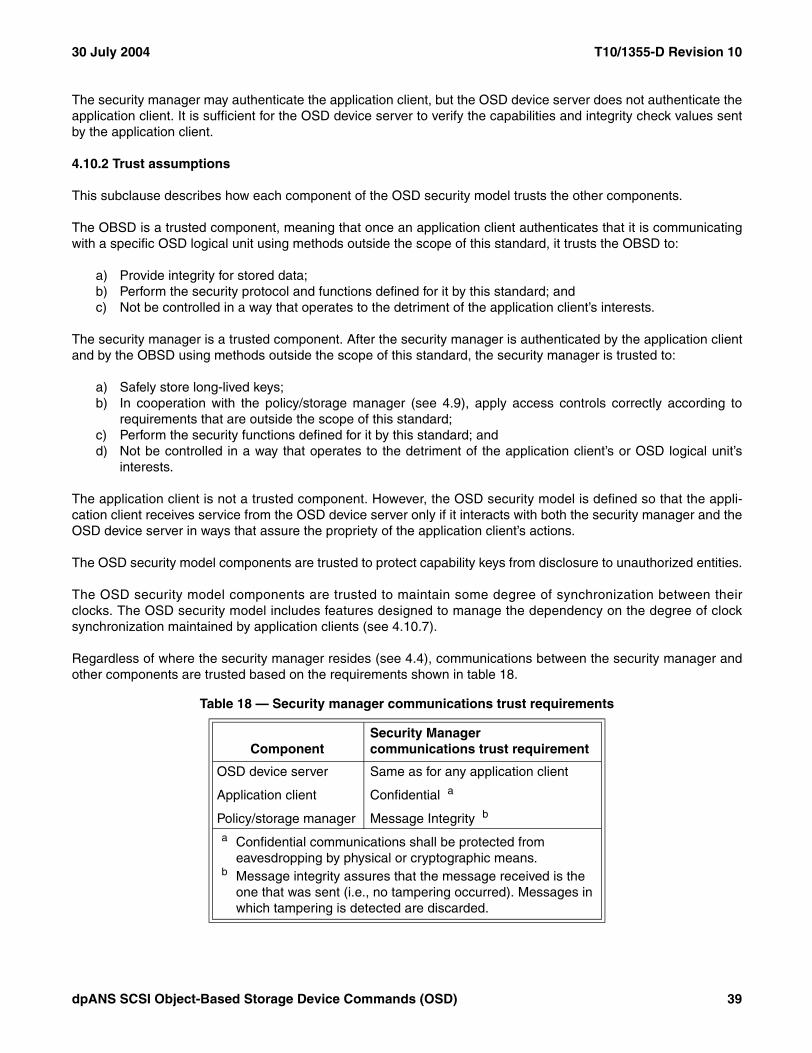
30 July 2004 T10/1355-D Revision 10
The security manager may authenticate the application client, but the OSD device server does not authenticate theapplication client. It is sufficient for the OSD device server to verify the capabilities and integrity check values sentby the application client.
4.10.2 Trust assumptions
This subclause describes how each component of the OSD security model trusts the other components.
The OBSD is a trusted component, meaning that once an application client authenticates that it is communicatingwith a specific OSD logical unit using methods outside the scope of this standard, it trusts the OBSD to:
a) Provide integrity for stored data;b) Perform the security protocol and functions defined for it by this standard; andc) Not be controlled in a way that operates to the detriment of the application client’s interests.
The security manager is a trusted component. After the security manager is authenticated by the application clientand by the OBSD using methods outside the scope of this standard, the security manager is trusted to:
a) Safely store long-lived keys;b) In cooperation with the policy/storage manager (see 4.9), apply access controls correctly according to
requirements that are outside the scope of this standard;c) Perform the security functions defined for it by this standard; andd) Not be controlled in a way that operates to the detriment of the application client’s or OSD logical unit’s
interests.
The application client is not a trusted component. However, the OSD security model is defined so that the appli-cation client receives service from the OSD device server only if it interacts with both the security manager and theOSD device server in ways that assure the propriety of the application client’s actions.
The OSD security model components are trusted to protect capability keys from disclosure to unauthorized entities.
The OSD security model components are trusted to maintain some degree of synchronization between theirclocks. The OSD security model includes features designed to manage the dependency on the degree of clocksynchronization maintained by application clients (see 4.10.7).
Regardless of where the security manager resides (see 4.4), communications between the security manager andother components are trusted based on the requirements shown in table 18.
Table 18 — Security manager communications trust requirements
ComponentSecurity Managercommunications trust requirement
OSD device server Same as for any application client
Application client Confidential a
Policy/storage manager Message Integrity b
a Confidential communications shall be protected from eavesdropping by physical or cryptographic means.
b Message integrity assures that the message received is the one that was sent (i.e., no tampering occurred). Messages in which tampering is detected are discarded.
dpANS SCSI Object-Based Storage Device Commands (OSD) 39
T10/1355-D Revision 10 30 July 2004
4.10.3 Preparing credentials
In response to a request from an application client, the security manager shall prepare and return a credential asfollows:
1) Forward the access requests from the application client to the policy/storage manager. If the policy/storagemanager denies the forwarded request an error shall be returned to the requesting application client;
2) Insert the capability returned by the policy/storage manager in the credential;3) Set the credential OSD SYSTEM ID field to the value in the OSD system ID attribute in the Root Information
attributes page (see 7.1.2.8) of the OSD logical unit to which the credential applies; 4) Set the capability SECURITY METHOD field as follows:
A) Select a security method other than the partition default:a) If the application client requested use of a specific security method, and use of the requested
security method is allowed by both the addressed partition and the maintained security policyinformation, set the capability SECURITY METHOD field to the requested value;
b) If the maintained security policy information requires use of a specific security method for therequesting application client, set the capability SECURITY METHOD field to that value;
orB) Use the partition default:
a) If the application client requested a credential to be used in a SET KEY command (see 6.22) or aSET MASTER KEY command (see 6.23), set the capability SECURITY METHOD field to the value inthe default security method attribute in the Root Policy/Security attributes page (see 7.1.2.20);
b) Otherwise, set the capability SECURITY METHOD field to the value in the default security methodattribute in the Partition Policy/Security attributes page (see 7.1.2.21) for the partition whosePartition ID is contained in the capability ALLOWED PARTITION_ID field;
5) If the SECURITY METHOD field contains NOSEC, place zero in the CREDENTIAL INTEGRITY CHECK VALUE fieldand return the credential to the application client;Otherwise:
6) Set the capability KEY VERSION field to the number of the working key secret key used to compute thecredential integrity check value. If a secret key other than a working key is used to compute the credentialintegrity check value (e.g. for a SET KEY command (see 6.22) or a SET MASTER KEY command (see6.23)), then set the capability KEY VERSION field to zero;
7) Set the capability INTEGRITY CHECK VALUE ALGORITHM field to the value that specifies the algorithm used tocompute all integrity check values related to this credential. The algorithm shall be one of those identifiedby the supported integrity check value algorithm attributes in the Root Policy/Security attributes page (see7.1.2.20);
8) As specified by the maintained security policy information, modify other capability fields, including but notlimited to the following:A) Setting the CAPABILITY EXPIRATION TIME field to a value that is consistent with the policy;B) Ensuring that the capability AUDIT field and CAPABILITY DISCRIMINATOR field contain non-zero values;C) Setting the capability OBJECT CREATED TIME field to a non-zero value that is consistent with 4.9.2.2.1
usage; andD) Ensuring that the POL/SEC bit in the PERMISSIONS BIT MASK field is set to zero, if appropriate;
9) Compute the credential integrity check value as described in 4.10.6.3, placing the result in the CREDENTIAL
INTEGRITY CHECK VALUE field in the credential; and10) Return the credential thus constructed to the application client with the credential integrity check value
serving as the capability key.
Successful use of the capability expiration time (see item A) in step 8)) requires some degree of synchronizationbetween the clocks of the device server and security manager. The protocol for synchronizing the clocks is outsidethe scope of this standard, however, the protocol should be implemented in a secure manner (e.g., it should not bepossible for an adversary to set the clock in the device server backwards to enable the reuse of expired creden-tials).
40 dpANS SCSI Object-Based Storage Device Commands (OSD)

30 July 2004 T10/1355-D Revision 10
4.10.4 Security methods
4.10.4.1 Introduction
This standard defines several security methods (see table 19).
The security method used by one partition may be different from the security method used by another partition.
A command prepared for a security mode other than the one specified in the CDB SECURITY METHOD field maycomplete without errors (e.g., a command prepared for the ALLDATA security method may complete without errorsreported by the device server if the CMDRSP security method is in use because the preparations for the ALLDATAsecurity method include the preparations that are necessary for the CMDRSP security method).
Table 19 — OSD security methods
Security Method DescriptionSecurity Method coded value a Reference
NOSEC No security 0h 4.10.4.2
CAPKEY Integrity of capabilities 1h 4.10.4.3
CMDRSP Integrity of CDB, status, and sense data 2h 4.10.4.4
ALLDATA Integrity of all data in transit 3h 4.10.4.5a Security method coded values are used in the capability SECURITY METHOD field and least
significant four bits of default security method attributes (e.g., the default security method attribute in the Partition Policy/Security attributes page (see 7.1.2.21)).Security method values 4h to Fh are reserved.
dpANS SCSI Object-Based Storage Device Commands (OSD) 41

T10/1355-D Revision 10 30 July 2004
The OSD security methods are designed to address zero or more specific security threats (see table 20).
4.10.4.2 The NOSEC security method
In the NOSEC security method, no OSD security features or algorithms are used by the device server. If the rootobject and all partitions in the OSD logical unit use the NOSEC security method, then:
a) Specific SPC-3 commands (e.g., LOG SENSE) may be sent (see table 48 in 6.1) without encapsulatingthem in the PERFORM SCSI COMMAND command (see 6.15); and
b) Persistent reservations (see 4.16) are allowed for the logical unit.
Table 20 — Security methods and threats thwarted
Threat
Threat thwarted by security method
NOSEC
CAPKEY
CMDRSP ALLDATA
Over secure channel a
No Yes
Forgery of credential No Yes Yes Yes Yes
Alteration of capabilities No Yes Yes Yes Yes
Use of credential by unauthorized application client No Yes b Yes c Yes Yes
Replay of command or status No No Yes c Yes Yes
Alteration of command or status No No Yes c Yes Yes
Replay of data No No Yes c No Yes
Alteration of data No No Yes c No Yes
Inspection of command, status or data No No Yes/No d No No
a This model assumes that one secure channel supports no more than one I_T nexus and that I_T nexus is not shared by multiple application clients. If a SCSI initiator device allows multiple application clients to share an I_T nexus, then the SCSI initiator device implementation and/or application clients shall provide security guarantees equivalent to those provided by a secure channel.
b If more than one application client has access to an I_T nexus, then credentials are not protected from use by unauthorized application clients.
c A secure channel provides the following security guarantees:a) Cryptographic integrity: Any message received is the one was sent (i.e., no tampering occurred).
Messages in which tampering is detected are discarded;b) Data origin authentication: The message received originated from the authenticated originator within
the limits of the secure channel authentication mechanism; andc) Replay protection: The same message is not delivered multiple times and that there is a limited
number of out-of-order messages.d Optionally, a secure channel may provide a Data Confidentiality guarantee that if a message is read, it
cannot be understood other than by the unauthorized parties.
42 dpANS SCSI Object-Based Storage Device Commands (OSD)

30 July 2004 T10/1355-D Revision 10
4.10.4.3 The CAPKEY security method
The CAPKEY security method validates the integrity of the capability information in each CDB.
The application client computes the CDB REQUEST INTEGRITY CHECK VALUE field (see 5.2.6) contents using:
a) The algorithm specified in the capability INTEGRITY CHECK VALUE ALGORITHM field (see 4.9.2.2);b) The security token returned in the Security Token VPD page (see 7.5.3); andc) The credential capability key (see 4.10.5.2).
The device server validates the credential as described in 4.10.6.1.
The CAPKEY security method is useful when the service delivery subsystem between the OSD device server andapplication client is secured via methods specified in the applicable SCSI transport protocol, with both the CAPKEYsecurity method and SCSI transport protocol secure channel contributing to securing communications as shown intable 20 (see 4.10.4.1).
4.10.4.4 The CMDRSP security method
The CMDRSP security method validates the integrity of the CDB, status, and sense data for each command.
The application client computes the CDB REQUEST INTEGRITY CHECK VALUE field (see 5.2.6) contents using:
a) The algorithm specified in the capability INTEGRITY CHECK VALUE ALGORITHM field (see 4.9.2.2);b) All the bytes in the CDB with the bytes in the REQUEST INTEGRITY CHECK VALUE field set to zero; andc) The credential capability key (see 4.10.5.2).
The device server validates the credential as described in 4.10.6.1.
If the credential validation process successfully validates the integrity check value associated with the command,the device server shall:
1) Compute an integrity check value for the response data using:A) The algorithm specified in the capability INTEGRITY CHECK VALUE ALGORITHM field (see 4.9.2.2);B) The following array of bytes:
1) The request nonce from the CDB (see 5.2.6);2) The status byte; and 3) If the status is CHECK CONDITION, the sense data with the RESPONSE INTEGRITY CHECK VALUE
field in the OSD response integrity check value sense data descriptor (see 4.14.2.2) set to zero;and
C) The capability key (see 4.10.5.2) for the reconstructed credential (see 4.10.6.2);and
2) Place the computed integrity check value in the following location:A) If the status is not CHECK CONDITION, the computed integrity check value shall be placed in the
response integrity check value attribute in the Current Command attributes page (see 7.1.2.24); orB) If the status is CHECK CONDITION, the computed integrity check value shall be placed in the
RESPONSE INTEGRITY CHECK VALUE field in the OSD response integrity check value sense datadescriptor (see 4.14.2.2) in the sense data.
If the credential validation process fails to validate the integrity check value associated with the command, thedevice server shall place zero in the RESPONSE INTEGRITY CHECK VALUE field in the OSD response integrity checkvalue sense data descriptor in the sense data.
dpANS SCSI Object-Based Storage Device Commands (OSD) 43

T10/1355-D Revision 10 30 July 2004
If the status is not CHECK CONDITION, the application client validates the response integrity check value byrecomputing it as described in this subclause and comparing the result to the value of the response integrity checkvalue attribute in the Current Command attributes page.
If the status is CHECK CONDITION, the application client validates the response integrity check value by:
1) Saving the response integrity check value found in the RESPONSE INTEGRITY CHECK VALUE field in the OSDresponse integrity check value sense data descriptor in the sense data;
2) Placing zero in the RESPONSE INTEGRITY CHECK VALUE field in the OSD response integrity check valuesense data descriptor (see 4.14.2.2);
3) Recomputing the response integrity check value as described in this subclause; and4) Comparing the result to the value saved in step 1).
If the application client fails in validating the response integrity check value as described in this subclause, it shouldtake a recovery action not specified by this standard (e.g., one possible action is to request a new credential fromthe security manager and retry the command). If the error reoccurs, alternate recovery actions should beconsidered and the presence of malicious entities perpetrating a denial of service attack should be considered.
The CMDRSP security method may be used when the service delivery subsystem between the OSD device serverand application client is not secured. The CMDRSP security method protects against corruption of the commandcommand parameter data, status, and sense data while avoiding the overhead that may be required to protect alltransferred data. Use of the CMDRSP security method prevents an untrusted application client from forging,modifying or replaying a capability.
4.10.4.5 The ALLDATA security method
The ALLDATA security method validates the integrity of all data in transit between an application client and deviceserver.
The application client computes the CDB REQUEST INTEGRITY CHECK VALUE field (see 5.2.6) contents using thesame algorithm specified for the CMDRSP security method (see 4.10.4.4). The device server validates thecredential as described in 4.10.6.1.
The application client also computes the data-out integrity check value using:
a) The algorithm specified in the capability INTEGRITY CHECK VALUE ALGORITHM field (see 4.9.2.2);b) The used bytes in the following Data-Out Buffer segments (see 4.12.4):
1) Command data or parameter data;2) Set attributes; and3) Get attributes;and
c) The credential capability key (see 4.10.5.2).
44 dpANS SCSI Object-Based Storage Device Commands (OSD)
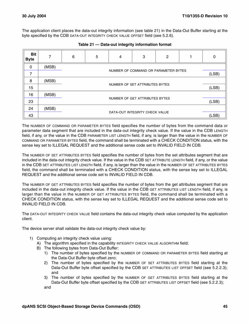
30 July 2004 T10/1355-D Revision 10
The application client places the data-out integrity information (see table 21) in the Data-Out Buffer starting at thebyte specified by the CDB DATA-OUT INTEGRITY CHECK VALUE OFFSET field (see 5.2.6).
The NUMBER OF COMMAND OR PARAMETER BYTES field specifies the number of bytes from the command data orparameter data segment that are included in the data-out integrity check value. If the value in the CDB LENGTH
field, if any, or the value in the CDB PARAMETER LIST LENGTH field, if any, is larger than the value in the NUMBER OF
COMMAND OR PARAMETER BYTES field, the command shall be terminated with a CHECK CONDITION status, with thesense key set to ILLEGAL REQUEST and the additional sense code set to INVALID FIELD IN CDB.
The NUMBER OF SET ATTRIBUTES BYTES field specifies the number of bytes from the set attributes segment that areincluded in the data-out integrity check value. If the value in the CDB SET ATTRIBUTE LENGTH field, if any, or the valuein the CDB SET ATTRIBUTES LIST LENGTH field, if any, is larger than the value in the NUMBER OF SET ATTRIBUTES BYTES
field, the command shall be terminated with a CHECK CONDITION status, with the sense key set to ILLEGALREQUEST and the additional sense code set to INVALID FIELD IN CDB.
The NUMBER OF GET ATTRIBUTES BYTES field specifies the number of bytes from the get attributes segment that areincluded in the data-out integrity check value. If the value in the CDB GET ATTRIBUTES LIST LENGTH field, if any, islarger than the value in the NUMBER OF GET ATTRIBUTES BYTES field, the command shall be terminated with aCHECK CONDITION status, with the sense key set to ILLEGAL REQUEST and the additional sense code set toINVALID FIELD IN CDB.
The DATA-OUT INTEGRITY CHECK VALUE field contains the data-out integrity check value computed by the applicationclient.
The device server shall validate the data-out integrity check value by:
1) Computing an integrity check value using:A) The algorithm specified in the capability INTEGRITY CHECK VALUE ALGORITHM field;B) The following bytes from Data-Out Buffer:
1) The number of bytes specified by the NUMBER OF COMMAND OR PARAMETER BYTES field starting atthe Data-Out Buffer byte offset zero;
2) The number of bytes specified by the NUMBER OF SET ATTRIBUTES BYTES field starting at theData-Out Buffer byte offset specified by the CDB SET ATTRIBUTES LIST OFFSET field (see 5.2.2.3);and
3) The number of bytes specified by the NUMBER OF GET ATTRIBUTES BYTES field starting at theData-Out Buffer byte offset specified by the CDB GET ATTRIBUTES LIST OFFSET field (see 5.2.2.3);
and
Table 21 — Data-out integrity information format
BitByte
7 6 5 4 3 2 1 0
0 (MSB)NUMBER OF COMMAND OR PARAMETER BYTES
7 (LSB)
8 (MSB)NUMBER OF SET ATTRIBUTES BYTES
15 (LSB)
16 (MSB)NUMBER OF GET ATTRIBUTES BYTES
23 (LSB)
24 (MSB)DATA-OUT INTEGRITY CHECK VALUE
43 (LSB)
dpANS SCSI Object-Based Storage Device Commands (OSD) 45
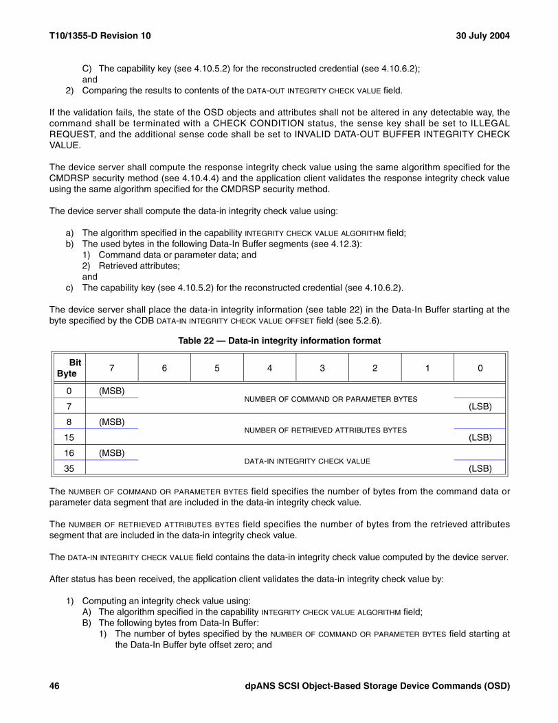
T10/1355-D Revision 10 30 July 2004
C) The capability key (see 4.10.5.2) for the reconstructed credential (see 4.10.6.2);and
2) Comparing the results to contents of the DATA-OUT INTEGRITY CHECK VALUE field.
If the validation fails, the state of the OSD objects and attributes shall not be altered in any detectable way, thecommand shall be terminated with a CHECK CONDITION status, the sense key shall be set to ILLEGALREQUEST, and the additional sense code shall be set to INVALID DATA-OUT BUFFER INTEGRITY CHECKVALUE.
The device server shall compute the response integrity check value using the same algorithm specified for theCMDRSP security method (see 4.10.4.4) and the application client validates the response integrity check valueusing the same algorithm specified for the CMDRSP security method.
The device server shall compute the data-in integrity check value using:
a) The algorithm specified in the capability INTEGRITY CHECK VALUE ALGORITHM field;b) The used bytes in the following Data-In Buffer segments (see 4.12.3):
1) Command data or parameter data; and2) Retrieved attributes;and
c) The capability key (see 4.10.5.2) for the reconstructed credential (see 4.10.6.2).
The device server shall place the data-in integrity information (see table 22) in the Data-In Buffer starting at thebyte specified by the CDB DATA-IN INTEGRITY CHECK VALUE OFFSET field (see 5.2.6).
The NUMBER OF COMMAND OR PARAMETER BYTES field specifies the number of bytes from the command data orparameter data segment that are included in the data-in integrity check value.
The NUMBER OF RETRIEVED ATTRIBUTES BYTES field specifies the number of bytes from the retrieved attributessegment that are included in the data-in integrity check value.
The DATA-IN INTEGRITY CHECK VALUE field contains the data-in integrity check value computed by the device server.
After status has been received, the application client validates the data-in integrity check value by:
1) Computing an integrity check value using:A) The algorithm specified in the capability INTEGRITY CHECK VALUE ALGORITHM field;B) The following bytes from Data-In Buffer:
1) The number of bytes specified by the NUMBER OF COMMAND OR PARAMETER BYTES field starting atthe Data-In Buffer byte offset zero; and
Table 22 — Data-in integrity information format
BitByte
7 6 5 4 3 2 1 0
0 (MSB)NUMBER OF COMMAND OR PARAMETER BYTES
7 (LSB)
8 (MSB)NUMBER OF RETRIEVED ATTRIBUTES BYTES
15 (LSB)
16 (MSB)DATA-IN INTEGRITY CHECK VALUE
35 (LSB)
46 dpANS SCSI Object-Based Storage Device Commands (OSD)

30 July 2004 T10/1355-D Revision 10
2) The number of bytes specified by the NUMBER OF RETRIEVED ATTRIBUTES BYTES field starting at theData-In Buffer byte offset specified by the CDB RETRIEVED ATTRIBUTES OFFSET field (see 5.2.2);
andC) The credential capability key (see 4.10.5.2);and
2) Comparing the results to contents of the DATA-IN INTEGRITY CHECK VALUE field.
If the application client fails in validating the data-in integrity check value, it should take a recovery action notspecified by this standard (e.g., one possible action is to request a new credential from the security manager andretry the command). If the error reoccurs, alternate recovery actions should be considered and the presence ofmalicious entities perpetrating a denial of service attack should be considered.
The ALLDATA security method provides for applying integrity check values to every byte exchanged between theapplication client and OSD device server. Protection is provided against network attacks similar to those protectedagainst by the security architecture for the internet protocol when confidentiality is not used (see RFC 2401), at theexpense of computing and validating numerous integrity check values.
4.10.5 Credentials
4.10.5.1 Credential format
A credential (see table 23) is transferred from the security manager to an application client over a communicationsmechanism that meets the requirements specified in 4.10.2.
The capability is described in 4.9.2.2.
The OSD SYSTEM ID field specifies the value in the OSD system ID attribute in the Root Information attributes page(see 7.1.2.8) of the OSD logical unit to which the credential applies.
The CREDENTIAL INTEGRITY CHECK VALUE field contains an integrity check value (see 4.10.8) that is computed usingthe algorithm, inputs, and secret key specified in 4.10.6.3.
4.10.5.2 Capability key
All security methods except the NOSEC security method require the computation of one or more integrity checkvalues using a capability key as the secret key (see 3.1.39).
For application clients, the capability key is the contents of the CREDENTIAL INTEGRITY CHECK VALUE field (see4.10.5.1).
Table 23 — Credential format
BitByte
7 6 5 4 3 2 1 0
0 Capability (see 4.9.2.2)
79
80 OSD SYSTEM ID
99
100 (MSB)CREDENTIAL INTEGRITY CHECK VALUE
119 (LSB)
dpANS SCSI Object-Based Storage Device Commands (OSD) 47

T10/1355-D Revision 10 30 July 2004
The device server processing of each command relies on only the capability portion of the credential (see 4.10.5.1)that the application client has copied into the CDB. Since the capability does not include the CREDENTIAL INTEGRITY
CHECK VALUE field, the device server needs to compute the capability key for each processed command by:
1) Reconstructing the credential containing the CDB capability as described in 4.10.6.2; and2) Computing the credential integrity check value for the reconstructed credential using the algorithm, inputs,
and secret key specified in 4.10.6.3.
NOTE 2 The two steps used by the device server to compute capability key are the first two steps that the deviceserver uses to validate a credential (see 4.10.6.1). The device server may perform these two steps only once forevery command processed.
4.10.6 OSD device server security algorithms
4.10.6.1 Credential validation
The processes described in this subclause do not apply if the CDB SECURITY METHOD field specifies the NOSECsecurity method (i.e., if the CDB SECURITY METHOD field contains zero).
If the CDB SECURITY METHOD field specifies the CMDRSP security method or the ALLDATA security method, thedevice server shall validate the CDB REQUEST NONCE field as described in 4.10.7.2.
The device server shall validate the credential associated with a CDB by:
1) Reconstructing the credential containing the capability as described in 4.10.6.2;2) Computing the credential integrity check value for the reconstructed credential using the algorithm, inputs,
and secret key specified in 4.10.6.3;3) Computing the request integrity check value using:
A) The algorithm specified by the INTEGRITY CHECK VALUE ALGORITHM field in the capability;B) Based on the contents of the CDB SECURITY METHOD field, one of the following arrays of bytes:
a) For the CAPKEY security method, the security token (see 4.10.4.3); orb) For the CMDRSP security method and the ALLDATA security method, all the bytes in the CDB with
the bytes in the REQUEST INTEGRITY CHECK VALUE field set to zero;and
C) The credential integrity check value computed in step 2) as the secret key;and
4) Verifying that the request integrity check value matches the contents of the CDB REQUEST INTEGRITY CHECK
VALUE field (see 5.2.6). If the contents in the REQUEST INTEGRITY CHECK VALUE field in the CDB do not matchthe computed integrity check value, the command shall be terminated with a CHECK CONDITION status,the sense key shall be set to ILLEGAL REQUEST, and the additional sense code shall be set to INVALIDFIELD IN CDB
If the validation of a credential results in a CHECK CONDITION status being returned, the state of the OSD objectsand attributes shall not be altered in any detectable way.
4.10.6.2 Reconstructing the credential
The device server reconstructs a credential from a CDB capability by:
1) Copying the value in the OSD system ID attribute in the Root Information attributes page (see 7.1.2.8) tothe OSD SYSTEM ID field of the reconstructed credential; and
2) Copying the capability from the CDB to the reconstructed credential.
The CREDENTIAL INTEGRITY CHECK VALUE field is not used in a reconstructed credential.
48 dpANS SCSI Object-Based Storage Device Commands (OSD)

30 July 2004 T10/1355-D Revision 10
4.10.6.3 Computing the credential integrity check value
The credential integrity check value shall be computed using:
a) The algorithm specified by the INTEGRITY CHECK VALUE ALGORITHM FIELD in the capability;b) The following bytes:
A) All of the bytes in all of the fields defined for the credential (see 4.10.5.1);B) Except the bytes in the CREDENTIAL INTEGRITY CHECK VALUE field;and
c) The secret key selected as follows;A) If the OBJECT TYPE field in the capability (see 4.9.2.2) contains COLLECTION or USER, the secret key
is the authentication working key:a) Identified by the KEY VERSION field in the capability; andb) Associated with the partition identified by the PARTITION_ID field in the CDB;
B) If the OBJECT TYPE field in the capability contains ROOT or PARTITION and the command is not SETKEY and not SET MASTER KEY, the secret key is the authentication working key for partition zeroidentified by the KEY VERSION field in the capability;
C) If the command is SET KEY (see 6.22), the secret key that is selected as follows:a) If the KEY TO SET field in the CDB contains 01b (i.e., update root key), the authentication master
key;b) If the KEY TO SET field in the CDB contains 10b (i.e., update partition key), the authentication root
key; orc) If the KEY TO SET field in the CDB contains 11b (i.e., update working key), the authentication
partition key for the partition identified by the PARTITION_ID field in the CDB;or
D) For the SET MASTER KEY command:a) For the SEED EXCHANGE step (see 6.23.2), the authentication master key; orb) For the CHANGE MASTER KEY step (see 6.23.3), the next authentication master key computed
after GOOD status has been returned by the SEED EXCHANGE step (see 6.23.2).
4.10.6.4 Invalidating credentials
The security manager may invalidate the credentials for one OSD object by requesting that the policy/storagemanager change the policy access tag attribute in the policy/security attributes page associated with that OSDobject (see 4.9.3) to a value other than the policy access tag value that is contained in the credential’s capability.
The security manager may invalidate credentials for an entire partition by using the SET KEY command (see 6.22)to update the working key version used to compute the credential integrity check value in those credentials.
dpANS SCSI Object-Based Storage Device Commands (OSD) 49

T10/1355-D Revision 10 30 July 2004
4.10.7 Request nonces
4.10.7.1 Request nonce format
For some security methods (see 4.10.4), an application client generated request nonce (see table 24) is included inthe input data for each integrity check value computation (see 4.10.8) to thwart attempts to capture OSDcommands (e.g., FORMAT OSD) and replay them.
The TIMESTAMP field contains the number of milliseconds that have elapsed since midnight, 1 January 1970 UT(see 3.1.49). Timestamp values should be coordinated with the contents of the clock attribute in the Root Infor-mation attributes page (see 7.1.2.8) using techniques that are outside the scope of this standard.
The RANDOM NUMBER field contains a random number generated from a good source of entropy (e.g., as describedin RFC 1750).
If the security method being used does not require generation of request nonce values, the nonce TIMESTAMP fieldshould contain zero.
4.10.7.2 Device server validation of request nonces
If the command is being processed using the CMDRSP security method or the ALLDATA security method (see4.10.4) and a request nonce with zero in the TIMESTAMP field is received, the command shall be terminated with aCHECK CONDITION status, the sense key shall be set to ILLEGAL REQUEST, and the additional sense codeshall be set to INVALID FIELD IN CDB.
If the inputs to an integrity check value computation include a non-zero request nonce that is listed (see 4.10.7.3)as having been used in any previous integrity check value computation, the command shall be terminated with aCHECK CONDITION status, the sense key shall be set to ILLEGAL REQUEST, and the additional sense codeshall be set to NONCE NOT UNIQUE. The command shall be terminated regardless of the success or failure of theprevious command in which the duplicate request nonce appeared (e.g., the request nonce appearing in a WRITEcommand that ultimately fails due to insufficient quota or the request nonce appearing in a CREATE command thatultimately fails because the computed credential integrity check value is wrong shall not be accepted a secondtime).
If the request nonce timestamp is less than the contents of the clock attribute in the Root Information attributespage (see 7.1.2.8) minus the value in the oldest valid nonce attribute in the Partition Policy/Security attributes page(see 7.1.2.21), then the command shall be terminated with a CHECK CONDITION status, with the sense key set toILLEGAL REQUEST, and with the additional sense code set to NONCE TIMESTAMP OUT OF RANGE. If acommand is terminated in this way, the current contents of the clock attribute in the Root Information attributespage shall be returned left-aligned and zero-padded (see 3.7.2) in the COMMAND-SPECIFIC INFORMATION field of thecommand-specific information sense data descriptor.
Table 24 — Request nonce format
BitByte
7 6 5 4 3 2 1 0
0 (MSB)TIMESTAMP
5 (LSB)
6 (MSB)RANDOM NUMBER
11 (LSB)
50 dpANS SCSI Object-Based Storage Device Commands (OSD)

30 July 2004 T10/1355-D Revision 10
If the request nonces timestamp is greater than the contents of the clock attribute in the Root Information attributespage plus the value in the newest valid nonce attribute in the Partition Policy/Security attributes page, then thecommand be terminated with a CHECK CONDITION status, the sense key shall be set to ILLEGAL REQUEST,and the additional sense code shall be set to NONCE TIMESTAMP OUT OF RANGE. If a command is terminatedin this way, the current contents of the clock attribute in the Root Information attributes page shall be returnedleft-aligned and zero-padded (see 3.7.2) in the COMMAND-SPECIFIC INFORMATION field of the command-specific infor-mation sense data descriptor.
Successful use of the request nonces requires some degree of synchronization between the clocks of the deviceserver and security manager. The protocol for synchronizing the clocks is outside the scope of this standard,however, the protocol should be implemented in a secure manner (i.e., it should not be possible for an adversary toset the clock in the device server backwards to enable the replay of expired request nonces).
4.10.7.3 Lists of previously used request nonces
4.10.7.3.1 Introduction
The device server shall maintain a list of all request nonces used in integrity check value computations. Failure ofthe integrity check value computation shall not result in exclusion from the list.
A request nonce shall appear in the list from the time it is received until:
a) The time in the request nonce timestamp field is less than the value in the clock attribute in the Root Infor-mation attributes page (see 7.1.2.8) minus the value in the oldest valid nonce limit attribute in the RootPolicy/Security attributes page (see 7.1.2.20);
b) The working key used to compute the integrity check value in which the request nonce was used is invali-dated by a SET KEY command (see 6.22);
c) Optionally, the capability audit field is frozen (see 4.10.7.3.2); ord) Optionally, the working key is frozen (see 4.10.7.3.3).
For the SET KEY command and the SET MASTER KEY command (see 6.23), the request nonce shall appear inthe list from the time it is received until the time in the request nonce timestamp field is less than the value in theclock attribute in the Root Information attributes page minus the value in the oldest valid nonce limit attribute in theRoot Policy/Security attributes page (i.e., only item a) applies to these commands).
The request nonce list depth attribute in the Root Policy/Security attributes page shall indicate the minimumnumber of request nonce list entries available to one application client.
4.10.7.3.2 Freezing capability audit fields
The device server may refuse to accept any additional commands containing a specific combination of capabilityAUDIT field and capability KEY VERSION field values (see 4.9.2.2). If the device server takes this action, it shouldterminate the selected command and all future commands containing the selected combination of capability AUDIT
field and capability KEY VERSION field values with a CHECK CONDITION status, a sense key set to ILLEGALREQUEST, and an additional sense code set to SECURITY AUDIT VALUE FROZEN.
The device server may repeat the process described in this subclause as often as necessary to reduce the amountof resources required to implement the nonce listing requirements (see 4.10.7.3.1).
dpANS SCSI Object-Based Storage Device Commands (OSD) 51

T10/1355-D Revision 10 30 July 2004
4.10.7.3.3 Freezing working keys
The device server may refuse to accept any additional commands with a capability KEY VERSION field (see 4.9.2.2)specifying a certain working key version value. If the device server takes this action, it:
a) Should terminate the selected command and all future commands having the selected capability keyversion value with a CHECK CONDITION status, a sense key set to ILLEGAL REQUEST, and anadditional sense code set to SECURITY WORKING KEY FROZEN; and
b) Shall set to one the bit in the frozen working key bit mask attribute in the Partition Policy/Security attributespage (see 7.1.2.21) that corresponds to the working key version thus selected.
The device server may repeat the process described in this subclause as often as necessary to reduce the amountof resources required to implement the nonce listing requirements (see 4.10.7.3.1).
4.10.8 Integrity check values
An integrity check value is a value produced by a cryptographic function (e.g., HMAC-SHA1) based on a secret key(see 4.10.9) that is able to be computed and verified by the entities knowing the secret key. Integrity check valuesare used to verify that:
a) A collection of data fields contain correct values; andb) The values in those data fields were prepared by the entity that created the integrity check value.
52 dpANS SCSI Object-Based Storage Device Commands (OSD)

30 July 2004 T10/1355-D Revision 10
4.10.9 Secret keys
4.10.9.1 Introduction
The hierarchy of secret keys and the mechanisms for updating them are described in:
a) This subclause;b) The definition of the SET MASTER KEY command (see 6.23); andc) The definition of the defining the SET KEY command (see 6.22).
In the OSD security model, the security of transactions depends on a hierarchy of secret keys as shown in table 25,with the highest key in the hierarchy (i.e., the master key) shown at the top of the table and the lowest keys in thehierarchy (i.e., the capability keys) shown at the bottom of the table.
Each master, root, and partition key represents two secret key values as follows:
a) An authentication key that is used to compute the credential integrity check values; andb) A generation key that is used by future SET KEY commands and SET MASTER KEY commands to
compute the updated generation key and new authentication key values.
Table 25 — OSD secret key hierarchy
Key Name Key Shared Using Key Used To Key Update Frequency
Keys shared between the security manager and the OSD device server
Master SET MASTER KEY command
Update Root key Change of logical unit owner
Root SET KEYcommand
Update Partition key When Partition key may have been compromised (i.e., very infrequently)
Partition a SET KEYcommand
Update Working keys When Working key updates may have been compromised (i.e., infrequently)
Working b SET KEYcommand
Create Capability keys When normal key use affords too much chance that the working key might be reverse engineered (i.e., regularly)
Keys shared between the security manager and the application client c
Capability d Credentials and mechanisms not specified
in this standard
Secure commands, responses, and data
New with each new Credential
a For the purposes of the secret key hierarchy, the root object is treated the same as any other partition OSD object using partition zero.
b For each partition, up to sixteen working keys may be active at any time, uniquely identified by the capability KEY VERSION field (see 4.9.2.2).
c The device server is capable of computing the capability key (see 4.10.6.3) using the reconstructed credential (see 4.10.6.2).
d As a dual purpose number, the capability key is different from other keys in the hierarchy. The capability key is the credential integrity check value. Even though the security manager computes it, the computation is based on values beyond the security manager’s control (e.g., the user object to which the credential allows access). While changing the working key used to construct the credential integrity check value invalidates the capability key, the credential may expire before that, making the capability key invalid.
dpANS SCSI Object-Based Storage Device Commands (OSD) 53

T10/1355-D Revision 10 30 July 2004
When an OBSD is manufactured, both the master authentication key and master generation key values shall beprovided for each logical unit. The two values may be identical. The initial master keys should be generated asspecified by FIPS 198 and the length of initial master keys should comply with FIPS 198.
The secret keys shared between the security manager and OSD device server are very secret information. Theyshould be protected from being discovered by an adversary. They should be stored in a tamper resistant non-vol-atile manner and may be protected by a tamper resistant software shield. The master key shall be stored in atamper resistant manner.
The seeds that have been used to create all secret keys other than the master key may be saved in nonvolatilememory for later use in recomputing the secret key values. The OSD logical unit should not store the commandssent to set the master key in a manner that has the potential for being externally accessible.
4.10.9.2 Computing updated generation keys and new authentication keys
The SET KEY command (see 6.22) and SET MASTER KEY command (see 6.23) shall perform the stepsdescribed in this subclause to compute new generation and authentication keys.
The inputs to the process are:
a) The input key value is one of the following:A) For a SET KEY command, the generation key from the next higher level in the key hierarchy shall be
used (e.g., the root key generation key is used to create the first partition keys for a newly createdpartition), as selected by the KEY TO SET field in the CDB of that command; or
B) For a SET MASTER KEY command, the previous master key generation key shall be used;b) The seed value is one of the following:
A) For a SET KEY command, the contents of the SEED field of the CDB for the command; orB) For a SET MASTER command key, the value computed after GOOD status has been returned in the
SEED EXCHANGE step (see 6.23.2) and updated by CHANGE MASTER KEY step (see 6.23.3);and
c) The integrity check value algorithm, as specified in the INTEGRITY CHECK VALUE ALGORITHM field in thecapability in the CDB for the command.
The updated generation key shall be computed by performing the specified integrity check algorithm with thefollowing inputs:
a) Input key value; andb) Seed value.
The new authentication key shall be computed by performing the specified integrity check algorithm with thefollowing inputs:
a) Input key value; andb) Seed value with the least significant bit changed as follows:
A) If the seed value least significant bit is zero, then it is changed to one; orB) If the seed value least significant bit is one, then it is changed to zero.
54 dpANS SCSI Object-Based Storage Device Commands (OSD)

30 July 2004 T10/1355-D Revision 10
4.10.10 OSD security interactions with SPC-3 commands and SAM-3 task management functions
Persistent reservations (see 4.16) are incompatible with an OSD logical unit in which the root object or any partitionis using any security method other than NOSEC (see 4.10.4).
Except for the INQUIRY command, the REPORT LUNS command, the REQUEST SENSE command, and theTEST UNIT READY command, all SPC-3 commands are invalid if addressed to an OSD logical unit in which anypartition is using any security method other than NOSEC (see table 48 in 6.1). The PERFORM SCSI COMMANDcommand (see 6.15) allows SPC-3 commands other than persistent reservations commands to be processedunder the protection of the current security method.
If the root object or any partition in the OSD logical unit is using any security method other than NOSEC, all SAM-3task management functions except QUERY TASK shall be ignored and responded to as if they have been success-fully processed. The PERFORM TASK MANAGEMENT FUNCTION command (see 6.16) allows SAM-3 taskmanagement functions to be processed under the protection of the current security method.
4.11 Data persistence model
The OSD data persistence model contains a two level memory hierarchy:
a) Volatile cache – storage is:A) Lost after a power on or reset event (see SAM-3); andB) May be lost after an I_T nexus loss or logical unit reset event (see SAM-3);and
b) Stable storage – storage that survives all the events that may result in the loss of data in the volatile cache.
Individual OBSD (see 3.1.26) implementations may use whatever technologies they choose to implement stablestorage (e.g., an OBSD may implement stable storage as a combination of non-volatile random access memoryand disk devices).
Implementation of a volatile cache is optional. Support for volatile cache, including support for the FUA bit and theDPO bit, may be indicated by setting the v_sup bit to one in the Extended INQUIRY Data VPD page (see SPC-3).
The device server may transfer data from the volatile cache to stable storage after status has been returned for thecommand that placed the data in the volatile cache. Errors that occur during such data transfer operations shall bereported as deferred errors (see SPC-3).
Two bits in the OPTIONS BYTE field (see 5.2.4) provide per-command controls over the use of stable storage andvolatile cache:
a) The FUA (Force Unit Access) bit controls whether or not the results of a command shall be written to stablestorage before status is returned to the application client; and
b) The DPO (Disable Page Out) bit recommends against the use of the volatile cache.
dpANS SCSI Object-Based Storage Device Commands (OSD) 55

T10/1355-D Revision 10 30 July 2004
4.12 Data-In and Data-Out Buffer model
4.12.1 Bidirectional data transfers
All commands defined by this standard use both the Data-In Buffer and Data-Out Buffer.
4.12.2 OSD meta data
A single command may include the following types of data:
a) Traditional command data or parameter data;b) OSD object meta data; and/orc) Integrity check values computed over all the other types of data.
The presence of generalized object meta data differentiates communications in the OSD model from those used bytraditional block structured devices (i.e., SBC devices).
NOTE 3 The output meta data is too large to fit in the CDB, the single status byte returned by traditional SCSIdevices is unable to accommodate the input meta data, and the ALLDATA security method (see 4.10.4.5) providesfor the computation of integrity check values for all bytes exchanged between the application client and deviceserver.
OSD meta data and integrity check values share the Data-In Buffer and Data-Out Buffer with the traditionalcommand or parameter data as shown in table 26.
The Data-In Buffer format is described in 4.12.3. The Data-Out Buffer format is described in 4.12.4.
Offset values (see 4.12.5) for each segment except the first are provided in CDB fields. The segments of theData-In Buffer and Data-Out Buffer should not overlap. If they do, the results are unpredictable.
Table 26 — OSD Data-In Buffer and Data-Out Buffer model
BitByte
7 6 5 4 3 2 1 0
0Command data or parameter data segment, if any
i-1
iUnused bytes, if any
k-1
kMeta data segments, if any
m-1
mUnused bytes, if any
n-1
nIntegrity check value segment, if any
n+11
56 dpANS SCSI Object-Based Storage Device Commands (OSD)

30 July 2004 T10/1355-D Revision 10
4.12.3 OSD Data-In Buffer format
The Data-In Buffer has the format shown in table 27.
The CDB offset fields that assist in locating the Data-In Buffer segments are shown in table 28.
The device server shall not send data to the initiator device that causes unused bytes in the Data-In Buffer to beoverwritten.
Table 27 — OSD Data-In Buffer format
BitByte
7 6 5 4 3 2 1 0
0Command data or parameter data segment, if any
i-1
iUnused bytes, if any
k-1
kRetrieved attributes segment, if any
p-1
pUnused bytes, if any
m-1
m Data-In Buffer integrity check value segment, if any (see 4.10.4.5)
n
Table 28 — Summary of OSD Data-In Buffer offsets
CDB Data-In Buffer offset field Reference Buffer segment
none Command data or parameter data
RETRIEVED ATTRIBUTES OFFSET 5.2.2 Retrieved attributes data
DATA-IN INTEGRITY CHECK VALUE OFFSET 5.2.6 Data-In Buffer integrity check value
dpANS SCSI Object-Based Storage Device Commands (OSD) 57
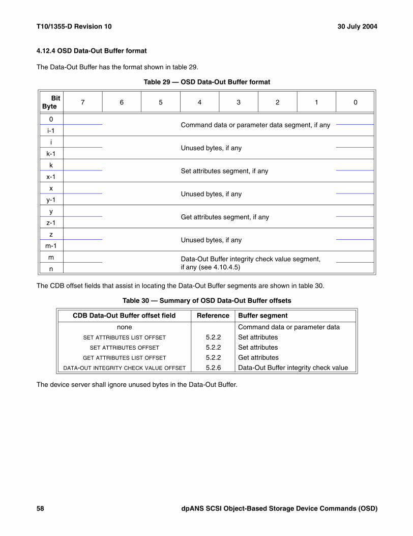
T10/1355-D Revision 10 30 July 2004
4.12.4 OSD Data-Out Buffer format
The Data-Out Buffer has the format shown in table 29.
The CDB offset fields that assist in locating the Data-Out Buffer segments are shown in table 30.
The device server shall ignore unused bytes in the Data-Out Buffer.
Table 29 — OSD Data-Out Buffer format
BitByte
7 6 5 4 3 2 1 0
0Command data or parameter data segment, if any
i-1
iUnused bytes, if any
k-1
kSet attributes segment, if any
x-1
xUnused bytes, if any
y-1
yGet attributes segment, if any
z-1
zUnused bytes, if any
m-1
m Data-Out Buffer integrity check value segment, if any (see 4.10.4.5)
n
Table 30 — Summary of OSD Data-Out Buffer offsets
CDB Data-Out Buffer offset field Reference Buffer segment
none Command data or parameter data
SET ATTRIBUTES LIST OFFSET 5.2.2 Set attributes
SET ATTRIBUTES OFFSET 5.2.2 Set attributes
GET ATTRIBUTES LIST OFFSET 5.2.2 Get attributes
DATA-OUT INTEGRITY CHECK VALUE OFFSET 5.2.6 Data-Out Buffer integrity check value
58 dpANS SCSI Object-Based Storage Device Commands (OSD)

30 July 2004 T10/1355-D Revision 10
4.12.5 Data-In and Data-Out buffer offsets
Offset fields (see table 31) in the CDB (e.g., the retrieved attributes offset field described in 4.12.3 and the SETATTRIBUTES LIST OFFSET field described in 4.12.4) specify the starting byte of segments of the Data-In Buffer orData-Out Buffer other than the command data or parameter data segment.
The EXPONENT field specifies the power of two to be used in computing the byte offset. The power of two shall bethe value in the EXPONENT field plus eight.
The MANTISSA field specifies the value to be multiplied by two raised to the power specified by the EXPONENT field.
The byte offset represented by a field having the format described in this subclause shall be:
byte offset = mantissa * (2(exponent+8))
An offset field containing zero specifies a byte offset value of zero.
If the offset field for a Data-In Buffer or Data-Out Buffer segment that is not being used is not set to FFFF FFFFh,the results are unpredictable
4.13 Interactions between concurrently processed commands
The interactions between commands that the device server processes concurrently may be modified using fields inthe Control mode page (see SPC-3). This standard defines no other restrictions on the interactions betweenconcurrently processed commands.
Application clients should ensure that the device server is not requested to process two or more commandsconcurrently if the interactions between those commands might adversely affect the information returned to theapplication client by future commands.
Table 31 — CDB Data-In Buffer and Data-Out Buffer offset field format
BitByte
7 6 5 4 3 2 1 0
0 EXPONENT (MSB)
1
MANTISSA2
3 (LSB)
dpANS SCSI Object-Based Storage Device Commands (OSD) 59

T10/1355-D Revision 10 30 July 2004
4.14 Error reporting
4.14.1 Introduction
OSD logical units shall use descriptor format sense data (see SPC-3) to report all errors.
All sense data returned by OSD device servers shall include the OSD error identification sense data descriptor(see 4.14.2.1) to identify the OSD object in which the reported error was detected.
If it is possible to identify a specific byte or range of bytes within a user object as being associated with an error, theinformation sense data descriptor (see SPC-3) shall be included in the sense data with the INFORMATION field set tothe byte within the user object associated with the error or the first byte in the range of bytes within the user objectassociated with the error.
If a READ command (see 6.17) attempts to read bytes both before and beyond a user object’s logical length, thecommand-specific information sense data descriptor (see SPC-3) shall be included in the sense data with theCOMMAND-SPECIFIC INFORMATION field set to the number of bytes transferred before the user object’s logical lengthwas reached.
If the CMDRSP security method or the ALLDATA security method (see 4.10.4) is used to process the command,the sense data shall include the OSD response integrity check value sense data descriptor (see 4.14.2.2). If thestatus is not CHECK CONDITION and no sense data is transferred, the response integrity check value is returnedin the response integrity check value attribute in the Current Command attributes page (see 7.1.2.24).
The OSD CDB is very large. To reduce uncertainty in determining errors in CDB field settings or in parameter data,any sense data having the sense key set to ILLEGAL REQUEST should include the sense key specific sense datadescriptor (see SPC-3) with the field pointer sense key specific data.
Errors other than those defined in this standard may be reported as needed. The sense data shall include theappropriate sense key and additional sense code (see SPC-3) to identify the condition.
Errors may occur after the command has completed. For such errors, SPC-3 defines a deferred error reportingmechanism.
60 dpANS SCSI Object-Based Storage Device Commands (OSD)

30 July 2004 T10/1355-D Revision 10
4.14.2 OSD-specific sense data descriptors
4.14.2.1 OSD error identification sense data descriptor
The OSD object identification sense data descriptor (see table 32) provides information that identifies the OSDobject associated with the error reported in the sense data (see OSD).
The NOT INITIATED COMMAND FUNCTIONS field contains the command functions bits (see table 33) that indicate (seetable 35) which command functions had not been initiated at the time the error reported in the sense data wasdetected.
The COMPLETED COMMAND FUNCTIONS field contains the command functions bits (see table 33) that indicate (seetable 35) which command functions had been completed at the time the error reported in the sense data wasdetected.
The PARTITION_ID field contains the Partition_ID (see 4.6.4) of the partition that is associated with the error beingreported.
The OBJECT_ID field contains the Collection_Object_ID (see 4.6.6) or User_Object_ID (see 4.6.5) of the object thatis associated with the error being reported.
Table 32 — OSD object identification sense data descriptor format
BitByte
7 6 5 4 3 2 1 0
0 DESCRIPTOR TYPE (06h)
1 ADDITIONAL LENGTH (1Eh)
2Reserved
7
8NOT INITIATED COMMAND FUNCTIONS
11
12COMPLETED COMMAND FUNCTIONS
15
16 (MSB)PARTITION_ID
23 (LSB)
24 (MSB)OBJECT_ID
31 (LSB)
dpANS SCSI Object-Based Storage Device Commands (OSD) 61

T10/1355-D Revision 10 30 July 2004
The command functions bits (see table 33) are contained in the NOT INITIATED COMMAND FUNCTIONS field andCOMPLETED COMMAND FUNCTIONS field (see table 32).
The command functions bits and the command functions that they indicate are listed in table 34.
The interpretation of the combinations of the command functions bits in the NOT INITIATED COMMAND FUNCTIONS fieldand COMPLETED COMMAND FUNCTIONS field is shown in table 35.
Table 33 — Command functions bits
BitByte
7 6 5 4 3 2 1 0
0 VALIDATION Reserved CMD_CAP_V COMMAND Reserved Reserved Reserved Reserved
1 Reserved Reserved Reserved IMP_ST_ATT Reserved Reserved Reserved Reserved
2 Reserved Reserved SA_CAP_V SET_ATT Reserved Reserved Reserved Reserved
3 Reserved Reserved GA_CAP_V GET_ATT Reserved Reserved Reserved Reserved
Table 34 — Command functions indicated by the command functions bits
Command functions
bit Command function indicated
VALIDATION Validation of the command, including security parameters
CMD_CAP_V Capability verification for those command functions not related to attributes (e.g., writing data to a user object)
COMMAND Processing of those command functions not related to attributes
IMP_ST_ATT Processing of any set attributes command functions resulting from the processing of the command (e.g.,changes due to a WRITE command)
SA_CAP_V Capability verification for all set attributes command functions specified in the CDB
SET_ATT Processing of any set attributes command functions specified in the CDB
GA_CAP_V Capability verification for all get attributes command functions specified in the CDB
GET_ATT Processing of any get attributes command functions specified in the CDB
Table 35 — Command functions bits combinations
NOT INITIATED COMMAND FUNCTIONS
bit
COMPLETED COMMAND FUNCTIONS
bitStatus of the indicated command function at the time the error reported by the sense data was detected
1 0 Processing was requested, but was not initiated and not completed
0 0 Processing was not requested, or processing was in progress
0 1 Processing was requested and completed
1 1 Reserved
62 dpANS SCSI Object-Based Storage Device Commands (OSD)

30 July 2004 T10/1355-D Revision 10
4.14.2.2 OSD response integrity check value sense data descriptor
The OSD response integrity check value sense data descriptor (see table 36) contains the response integrity checkvalue used when the OSD security method is CMDRSP or ALLDATA (see 4.10.4).
The RESPONSE INTEGRITY CHECK VALUE field contains the response integrity check value (see 4.10.8) that iscomputed as described in 4.10.4.4 for the command for which the error being reported.
4.14.2.3 OSD attribute identification sense data descriptor
The OSD attribute identification sense data descriptor (see table 37) identifies one or more attributes (see 7.1)associated with the error reported in the sense data.
Table 36 — OSD response integrity check value sense data descriptor format
BitByte
7 6 5 4 3 2 1 0
0 DESCRIPTOR TYPE (07h)
1 ADDITIONAL LENGTH (14h)
2 (MSB)RESPONSE INTEGRITY CHECK VALUE
21 (LSB)
Table 37 — OSD attribute identification sense data descriptor format
BitByte
7 6 5 4 3 2 1 0
0 DESCRIPTOR TYPE (08h)
1 ADDITIONAL LENGTH (n-2)
2 Reserved
3 Reserved
Attribute descriptors
4Attribute descriptor 0 (see table 38)
...
Attribute descriptor x (see table 38)n
dpANS SCSI Object-Based Storage Device Commands (OSD) 63

T10/1355-D Revision 10 30 July 2004
Each attribute descriptor (see table 38) identifies one attribute associated with the error reported in the sense data.
The ATTRIBUTE PAGE field contains the attribute page number (see 4.7.3) for the attributes page containing theattribute associated with the error reported in the sense data.
The ATTRIBUTE NUMBER field contains the attribute number (see 4.7.4) of the attribute associated with the errorreported in the sense data.
4.14.3 Auto contingent allegiance
OSD logical units that are not capable of accepting a command with the ACA task attribute (see SAM-3) at anytime and performing all data transfer operations that the command requests shall set the NORMACA bit to zero inthe Standard INQUIRY data (see SPC-3).
4.15 Linked commands
OSD device servers shall not support linked commands.
4.16 Reservations
The access enabled or access disabled condition determines when an application client may store or retrieve userdata on all or part of the medium. Access may be restricted for read command functions, write command functions,or both. This attribute may be controlled by an external mechanism or by the PERSISTENT RESERVE INcommand and PERSISTENT RESERVE OUT command (see SPC-3). The OSD logical unit shall not support theRESERVE command or the RELEASE command.
The credential-based system defined by the OSD security model (see 4.10) provides access controls that are moreappropriate to an OBSD (see 3.1.26) than persistent reservations. Use of persistent reservations is permitted onlyif use of the OSD security model is not activated. If the security method in effect for the root or any partition in theOSD logical unit is not NOSEC (see 4.10.4), the PERSISTENT RESERVE IN command and PERSISTENTRESERVE OUT command shall be treated as invalid commands (see SPC-3).
If a persistent reservation is in effect or any registrations are established when the security method in effect for theroot or any partition changes from the NOSEC security method to any other security method, the persistent reser-vation, if any, shall be released and all registrations shall be unregistered. A unit attention condition (see SAM-3)shall be established for the initiator port associated with every registered I_T nexus. The sense key shall be set toUNIT ATTENTION and the additional sense code shall be set to RESERVATIONS RELEASED.
Table 38 — Sense data attribute descriptor format
BitByte
7 6 5 4 3 2 1 0
0 (MSB)ATTRIBUTE PAGE
3 (LSB)
4 (MSB)ATTRIBUTE NUMBER
7 (LSB)
64 dpANS SCSI Object-Based Storage Device Commands (OSD)

30 July 2004 T10/1355-D Revision 10
The PERSISTENT RESERVE IN command and the PERSISTENT RESERVE OUT command define how differenttypes of restricted access may be achieved, and to whom the access is restricted. This subclause describes theinteraction of the application client that requested the reservation, and the other application clients.
An application client uses reservations to gain a level of exclusivity in access to all or part of the medium for itself oranother application client. It is expected that the reservation is retained until released. The device server ensuresthat the application client with the reservation is able to access the reserved media within the operating parametersestablished by that application client.
Reservation restrictions are placed on commands as a result of access qualifiers associated with the type of reser-vation. The details of commands that are allowed under what types of reservations are described in table 39.
Commands from initiator ports holding a reservation should complete normally. The behavior of commands fromregistered initiator ports when a registrants only or all registrants persistent reservation is present is specified intable 39.
A command shall be checked for reservation conflicts before the task containing that command enters the enabledtask state.
dpANS SCSI Object-Based Storage Device Commands (OSD) 65

T10/1355-D Revision 10 30 July 2004
For each command, this standard or SPC-3 defines the conditions that result in RESERVATION CONFLICT.
Table 39 — OSD commands that are allowed in the presence of various reservations
OSD Command
Addressed LU has this type of persistent reservation held by another I_T nexus
From any I_T nexus
From registered I_T nexus
(RR all types)
From I_T nexus not registered
Write Excl
Excl Access
Write Excl RR
Excl Acc- ess – RR
APPEND Conflict Conflict Allowed Conflict Conflict
CREATE Conflict Conflict Allowed Conflict Conflict
CREATE AND WRITE Conflict Conflict Allowed Conflict Conflict
CREATE COLLECTION Conflict Conflict Allowed Conflict Conflict
CREATE PARTITION Conflict Conflict Allowed Conflict Conflict
FLUSH Conflict Conflict Allowed Conflict Conflict
FLUSH COLLECTION Conflict Conflict Allowed Conflict Conflict
FLUSH OSD Conflict Conflict Allowed Conflict Conflict
FLUSH PARTITION Conflict Conflict Allowed Conflict Conflict
FORMAT OSD Conflict Conflict Allowed Conflict Conflict
GET ATTRIBUTES Allowed Conflict Allowed Allowed Conflict
LIST Allowed Conflict Allowed Allowed Conflict
LIST COLLECTION Allowed Conflict Allowed Allowed Conflict
PERFORM SCSI COMMAND Conflict Conflict Allowed Conflict Conflict
PERFORM TASK MANAGEMENT FUNCTION Conflict Conflict Allowed Conflict Conflict
READ Allowed Conflict Allowed Allowed Conflict
REMOVE Conflict Conflict Allowed Conflict Conflict
REMOVE COLLECTION Conflict Conflict Allowed Conflict Conflict
REMOVE PARTITION Conflict Conflict Allowed Conflict Conflict
SET ATTRIBUTES Conflict Conflict Allowed Conflict Conflict
SET KEY Conflict Conflict Allowed Conflict Conflict
SET MASTER KEY Conflict Conflict Allowed Conflict Conflict
WRITE Conflict Conflict Allowed Conflict Conflict
Any command that retrieves attributes see the command entry in this table
Any command that sets attributes Conflict Conflict Allowed Conflict Conflict
Key: LU=Logical Unit, Excl=Exclusive, RR=Registrants Only or All Registrants
66 dpANS SCSI Object-Based Storage Device Commands (OSD)

30 July 2004 T10/1355-D Revision 10
5 Common Formats
5.1 OSD CDB format
The OSD CDB is comprised of a 10-byte header followed by service action specific fields.
An application client sends a CDB to the device server. If a device server receives a CDB containing an operationcode that is invalid or not supported, it shall return CHECK CONDITION status with the sense key set to ILLEGALREQUEST and an additional sense code set to INVALID COMMAND OPERATION CODE. If a device serverreceives a CDB containing a service action that is invalid or not supported, it shall return CHECK CONDITIONstatus with the sense key set to ILLEGAL REQUEST and an additional sense code set to INVALID FIELD IN CDB.
The OSD commands defined in this standard use the variable length CDB format (see SPC-3). In the variablelength CDB (see table 40), an OPERATION CODE field containing 7Fh is the first byte and a CONTROL byte is thesecond byte. The general structure of the OPERATION CODE field and CONTROL byte are defined in SAM-3.
The ADDITIONAL CDB LENGTH field specifies the number of bytes following it in the variable length CDB. If the value inthe ADDITIONAL CDB LENGTH field is not 192, the command shall be terminated with a CHECK CONDITION status,the sense key shall be set to ILLEGAL REQUEST, and the additional sense code shall be set to INVALID FIELD INCDB.
The SERVICE ACTION field indicates the action being requested by the application client. Each service action codedescription defines the service action specific fields that are needed for that service action.
Table 40 — Basic OSD CDB
BitByte
7 6 5 4 3 2 1 0
0 OPERATION CODE (7Fh)
1 CONTROL
2 Reserved
3 Reserved
4 Reserved
5 Reserved
6 Reserved
7 ADDITIONAL CDB LENGTH (192)
8 (MSB)SERVICE ACTION
9 (LSB)
10Service action specific fields (see 5.2.1)
199
dpANS SCSI Object-Based Storage Device Commands (OSD) 67
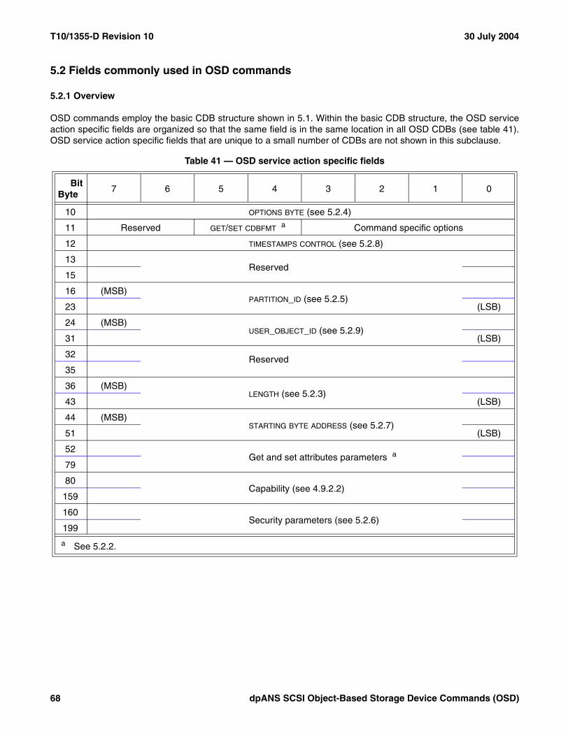
T10/1355-D Revision 10 30 July 2004
5.2 Fields commonly used in OSD commands
5.2.1 Overview
OSD commands employ the basic CDB structure shown in 5.1. Within the basic CDB structure, the OSD serviceaction specific fields are organized so that the same field is in the same location in all OSD CDBs (see table 41).OSD service action specific fields that are unique to a small number of CDBs are not shown in this subclause.
Table 41 — OSD service action specific fields
BitByte
7 6 5 4 3 2 1 0
10 OPTIONS BYTE (see 5.2.4)
11 Reserved GET/SET CDBFMT a Command specific options
12 TIMESTAMPS CONTROL (see 5.2.8)
13Reserved
15
16 (MSB)PARTITION_ID (see 5.2.5)
23 (LSB)
24 (MSB)USER_OBJECT_ID (see 5.2.9)
31 (LSB)
32 Reserved
35
36 (MSB)LENGTH (see 5.2.3)
43 (LSB)
44 (MSB)STARTING BYTE ADDRESS (see 5.2.7)
51 (LSB)
52 Get and set attributes parameters a
79
80 Capability (see 4.9.2.2)
159
160 Security parameters (see 5.2.6)
199
a See 5.2.2.
68 dpANS SCSI Object-Based Storage Device Commands (OSD)

30 July 2004 T10/1355-D Revision 10
5.2.2 Get and set attributes parameters
5.2.2.1 Get and set attributes CDB format selection
The GET/SET CDBFMT (get and set attributes CDB format) field (see table 42) specifies the format of the get and setattributes parameters in the CDB.
5.2.2.2 Get an attributes page and set an attribute value
The page oriented get and set attributes parameters CDB format (see table 43) allows the retrieval of one attributespage and the setting of one attribute value.
The GET ATTRIBUTES PAGE field specifies the attributes page number (see 7.1.2) to be retrieved. Zero specifies thatno attributes page is to be retrieved.
Table 42 — Get and set attributes CDB format code values
Value Description Reference
00b - 01b Reserved
10b Get an attributes page and set an attribute value 5.2.2.2
11b Get and set attributes using lists 5.2.2.3
Table 43 — Page oriented get and set attributes CDB parameters format
BitByte
7 6 5 4 3 2 1 0
... Other CDB fields51
52 (MSB)GET ATTRIBUTES PAGE
55 (LSB)
56 (MSB)GET ATTRIBUTES ALLOCATION LENGTH
59 (LSB)
60RETRIEVED ATTRIBUTES OFFSET
63
64 (MSB)SET ATTRIBUTES PAGE
67 (LSB)
68 (MSB)SET ATTRIBUTE NUMBER
71 (LSB)
72 (MSB)SET ATTRIBUTE LENGTH
75 (LSB)
76SET ATTRIBUTES OFFSET
79
80 ... Other CDB fields
dpANS SCSI Object-Based Storage Device Commands (OSD) 69

T10/1355-D Revision 10 30 July 2004
The GET ATTRIBUTES ALLOCATION LENGTH field specifies the number of bytes allocated to receive retrieved attributespage.
If the get attributes allocation length is not sufficient to accommodate all bytes in the specified attributes page, thetransfer of attributes data shall be truncated at the specified get attributes allocation length and this shall not beconsidered to be an error. If get attributes data is truncated, all the get attributes data that is transferred shall betransferred as if no error occurred (i.e., length fields in the transferred get attributes data shall not be modified toreflect the truncation).
The RETRIEVED ATTRIBUTES OFFSET field specifies the byte offset of the first Data-In Buffer byte to contain theretrieved attributes page. The format of the RETRIEVED ATTRIBUTES OFFSET field is described in 4.12.5. The format ofthe Data-In Buffer when attributes are being retrieved is described in 4.12.3.
The SET ATTRIBUTES PAGE field and SET ATTRIBUTE NUMBER field specify one attribute value to be set. A zero in theSET ATTRIBUTES PAGE field specifies that no attribute value is to be set.
The SET ATTRIBUTE LENGTH field specifies the number of bytes in the attribute being set.
The SET ATTRIBUTES OFFSET field specifies the byte offset of the first Data-Out Buffer byte containing the value ofthe attribute to be set. The format of the SET ATTRIBUTES OFFSET field is described in 4.12.5. The format of theData-Out Buffer when attributes are being set is described in 4.12.4.
If the set attributes page is non-zero and setting of the attribute specified by the SET ATTRIBUTES PAGE field and SET
ATTRIBUTE NUMBER field is not prohibited, the attribute length shall be set to the value in the SET ATTRIBUTE LENGTH
field and the value of the attribute shall be set to the contents of the Data-Out Buffer starting at the byte offsetspecified by the SET ATTRIBUTES OFFSET field and continuing for the number of bytes specified by the SET ATTRIBUTE
LENGTH field. If the attribute specified by the SET ATTRIBUTES PAGE field and SET ATTRIBUTE NUMBER field has notbeen defined previously setting it shall not be considered an error.
If setting an attribute value causes the value in the used capacity attribute in the Partition Information attributespage (see 7.1.2.9) to exceed the value in the capacity quota attribute in the Partition Quotas attributes page (see7.1.2.13), then a quota error shall be generated (see 4.8.2). The quota testing principles described in 4.8.3 apply tothe testing of the capacity quota.
70 dpANS SCSI Object-Based Storage Device Commands (OSD)
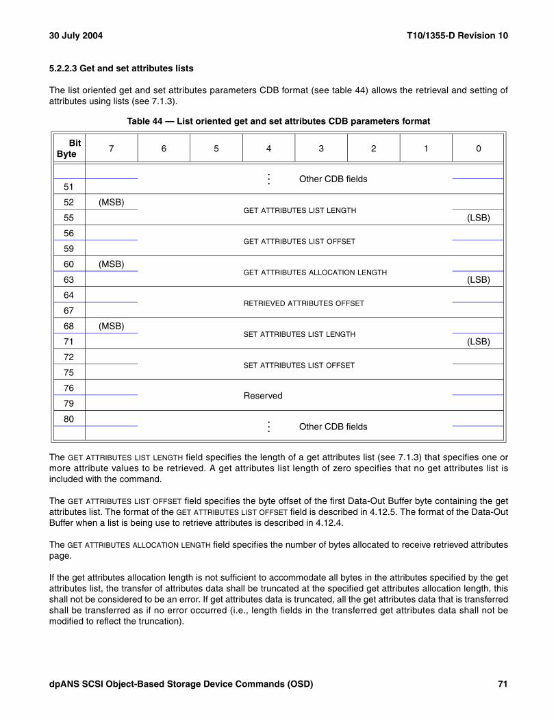
30 July 2004 T10/1355-D Revision 10
5.2.2.3 Get and set attributes lists
The list oriented get and set attributes parameters CDB format (see table 44) allows the retrieval and setting ofattributes using lists (see 7.1.3).
The GET ATTRIBUTES LIST LENGTH field specifies the length of a get attributes list (see 7.1.3) that specifies one ormore attribute values to be retrieved. A get attributes list length of zero specifies that no get attributes list isincluded with the command.
The GET ATTRIBUTES LIST OFFSET field specifies the byte offset of the first Data-Out Buffer byte containing the getattributes list. The format of the GET ATTRIBUTES LIST OFFSET field is described in 4.12.5. The format of the Data-OutBuffer when a list is being use to retrieve attributes is described in 4.12.4.
The GET ATTRIBUTES ALLOCATION LENGTH field specifies the number of bytes allocated to receive retrieved attributespage.
If the get attributes allocation length is not sufficient to accommodate all bytes in the attributes specified by the getattributes list, the transfer of attributes data shall be truncated at the specified get attributes allocation length, thisshall not be considered to be an error. If get attributes data is truncated, all the get attributes data that is transferredshall be transferred as if no error occurred (i.e., length fields in the transferred get attributes data shall not bemodified to reflect the truncation).
Table 44 — List oriented get and set attributes CDB parameters format
BitByte
7 6 5 4 3 2 1 0
... Other CDB fields51
52 (MSB)GET ATTRIBUTES LIST LENGTH
55 (LSB)
56GET ATTRIBUTES LIST OFFSET
59
60 (MSB)GET ATTRIBUTES ALLOCATION LENGTH
63 (LSB)
64RETRIEVED ATTRIBUTES OFFSET
67
68 (MSB)SET ATTRIBUTES LIST LENGTH
71 (LSB)
72SET ATTRIBUTES LIST OFFSET
75
76Reserved
79
80 ... Other CDB fields
dpANS SCSI Object-Based Storage Device Commands (OSD) 71

T10/1355-D Revision 10 30 July 2004
The RETRIEVED ATTRIBUTES OFFSET field specifies the byte offset of the first Data-In Buffer byte to contain theretrieved attributes list. The format of the RETRIEVED ATTRIBUTES OFFSET field is described in 4.12.5. The format ofthe Data-In Buffer when attributes are being retrieved is described in 4.12.3.
The SET ATTRIBUTES LIST LENGTH field specifies the length of a set attributes list (see 7.1.3) that specifies one ormore attribute values to be set. A set attributes list length of zero specifies that there is no set attributes listincluded with the command.
If the set attributes parameter list length causes the truncation of the attribute value or entry in the set attributes list,the command shall be terminated with a CHECK CONDITION, with the sense key set to ILLEGAL REQUEST, andthe additional sense code set to INVALID FIELD IN CDB.
The SET ATTRIBUTES LIST OFFSET field specifies the byte offset of the first Data-Out Buffer byte containing the firstbyte of the set attributes list. The format of the SET ATTRIBUTES OFFSET field is described in 4.12.5. The format of theData-Out Buffer when attributes are being set is described in 4.12.4.
If setting an attribute value causes the value in the used capacity attribute in the Partition Information attributespage (see 7.1.2.9) to exceed the value in the capacity quota attribute in the Partition Quotas attributes page (see7.1.2.13), then a quota error shall be generated (see 4.8.2). The quota testing principles described in 4.8.3 apply tothe testing of the capacity quota.
5.2.3 Length
The LENGTH field specifies the number of bytes to be transferred by a read or write.
The format of the Data-In Buffer and Data-Out Buffer is described in 4.12
5.2.4 Options byte
The options byte is a set of fields (see table 45) used to modify or control the command.
The DPO (disable page out) bit allows the application client to influence the use of volatile cache (see 4.11). If theDPO bit is set to zero, the use of volatile cache should proceed without influence caused by the DPO bit value. If theDPO bit is set to one, the device server should not place data transferred as a result of this command in the volatilecache.
The FUA (force unit access) bit controls whether or not the results of a command shall be written to stable storage(see 4.11) before status is returned to the application client. If the FUA bit is set to zero, the device server mayreturn status as soon as the data transferred by this command is in the volatile cache. If the FUA bit is set to one, thedevice server shall not return status until the data transferred by this command (i.e., either read data or write data)has been written to stable storage.
The direction of data transfer has no effect on the meaning of the DPO and FUA bits. The DPO and FUA bits affect theprocessing of both OSD object data and attributes.
Table 45 — Option byte format
Bit 7 6 5 4 3 2 1 0
Reserved DPO FUA Reserved
72 dpANS SCSI Object-Based Storage Device Commands (OSD)

30 July 2004 T10/1355-D Revision 10
5.2.5 Partition_ID
The PARTITION_ID field contains the Partition_ID (see 4.6.4) that the command is to act upon. If the partitionidentified by the PARTITION_ID field does not exist, the command shall be terminated with a CHECK CONDITIONstatus, with the sense key set to ILLEGAL REQUEST and the additional sense code set to INVALID FIELD INCDB.
5.2.6 Security parameters
The CDB security parameters (see table 46) contain the security information needed for each command.
The REQUEST INTEGRITY CHECK VALUE field contains an integrity check value (see 4.10.8) for the request sent by theapplication client. The REQUEST INTEGRITY CHECK VALUE field is used only by the CAPKEY security method, theCMDRSP security method, and the ALLDATA security method (see 4.10.4).
The CAPKEY security method for computing the request integrity check value is described in 4.10.4.3. TheCMDRSP security method and ALLDATA security method for computing the request integrity check value isdescribed in 4.10.4.4.
The device server shall validate the request integrity check value as described in 4.10.6.1.
For the CMDRSP security method and the ALLDATA security method (see 4.10.4), the REQUEST NONCE fieldcontains a security nonce (see 4.10.7). Otherwise, the REQUEST NONCE field should contain zero.
The device server shall validate the request nonce as described in 4.10.7.2 and 4.10.6.1.
The DATA-IN INTEGRITY CHECK VALUE OFFSET field specifies the byte offset of the first Data-In Buffer byte containingintegrity check value information for the Data-In Buffer. If the command is not prepared for processing using theALLDATA security method (see 4.10.4), the DATA-IN INTEGRITY CHECK VALUE OFFSET field contains FFFF FFFFh.Otherwise, the DATA-IN INTEGRITY CHECK VALUE OFFSET field contains an offset value (see 4.12.5) that specifies thefirst byte of the data-in integrity information that is prepared and validated as described in 4.10.4.5. The format ofthe Data-In Buffer when the data-in integrity check information is present is described in 4.12.3.
The DATA-OUT INTEGRITY CHECK VALUE OFFSET field specifies the byte offset of the first Data-Out Buffer bytecontaining integrity check value information for the Data-Out Buffer. If the command is not prepared for processing
Table 46 — Security parameters format
BitByte
7 6 5 4 3 2 1 0
... Other CDB fields159
160 (MSB)REQUEST INTEGRITY CHECK VALUE
179 (LSB)
180REQUEST NONCE
191
192DATA-IN INTEGRITY CHECK VALUE OFFSET
195
196DATA-OUT INTEGRITY CHECK VALUE OFFSET
199
dpANS SCSI Object-Based Storage Device Commands (OSD) 73

T10/1355-D Revision 10 30 July 2004
using the ALLDATA security method, the DATA-OUT INTEGRITY CHECK VALUE OFFSET field contains FFFF FFFFh.Otherwise, the DATA-OUT INTEGRITY CHECK VALUE OFFSET field contains an offset value (see 4.12.5) that specifiesthe first byte of the data-out integrity information that is prepared and validated as described in 4.10.4.5. The formatof the Data-Out Buffer when the data-out integrity check information is present is described in 4.12.4.
5.2.7 Starting byte address
The STARTING BYTE ADDRESS field specifies the location where the read or write is to commence in the specifiedobject relative to the first byte (i.e., byte zero) of the user object.
The format of the Data-In Buffer and Data-Out Buffer is described in 4.12
5.2.8 Timestamps control
The TIMESTAMPS CONTROL field specifies the timestamp update policy (see table 47) if the following conditions aremet:
a) If the bypass timestamps attribute in the Root Timestamps attributes page (see 7.1.2.15) contains FFh andthe command is:A) A CREATE PARTITION command;B) A FLUSH OSD command;C) A FORMAT OSD command;D) A GET ATTRIBUTES command addressed to the root object;E) A LIST command addressed to the root object;F) A PERFORM SCSI COMMAND command addressed to the root object;G) A PERFORM TASK MANAGEMENT FUNCTION command addressed to the root object;H) A REMOVE PARTITION command;I) A SET ATTRIBUTES command addressed to the root object;J) A SET KEY command with the KEY TO SET field set to 01b; orK) A SET MASTER KEY command;or
b) If the command is not one of those listed in item a) and bypass timestamps attribute in the Partition Times-tamps attributes page (see 7.1.2.16) contains FFh.
A timestamp attribute (see 7.1) that has never been updated shall have a length of six and a value of zero.
Bypassing a timestamp update shall not affect any previously established timestamp attribute values.
5.2.9 User_Object_ID
The USER_OBJECT_ID field contains the User_Object_ID of the user object (see 4.6.5) upon which the command isto act. If the user object identified by the USER_OBJECT_ID field does not exist, the command shall be terminatedwith a CHECK CONDITION status, with the sense key set to ILLEGAL REQUEST and the additional sense codeset to INVALID FIELD IN CDB.
Table 47 — Timestamps control values
Value Description
0h Timestamps shall updated as described in the subclause that defines them
01h to 7Eh Reserved
7Fh Timestamps shall not be updated
80h to DFh Reserved
E0h to FFh Vendor specific
74 dpANS SCSI Object-Based Storage Device Commands (OSD)

30 July 2004 T10/1355-D Revision 10
6 Commands for OSD type devices
6.1 Summary of commands for OSD type devices
The commands for OSD type devices are listed in table 48. For the commands defined by this standard, theSERVICE ACTION field in the CDB uniquely identifies each command function. The referenced subclauses describethe service provided by each command function and the information that shall be passed to the OSD logical unit inorder for it to perform that function.
Table 48 — Commands for OSD type devices (part 1 of 2)
Command nameOperation
codeService action a Type Reference
APPEND 7Fh 8807h M 6.2
CREATE 7Fh 8802h M 6.3
CREATE AND WRITE 7Fh 8812h M 6.4
CREATE COLLECTION 7Fh 8815h O 6.5
CREATE PARTITION 7Fh 880Bh M 6.6
FLUSH 7Fh 8808h M 6.7
FLUSH COLLECTION 7Fh 881Ah M 6.8
FLUSH OSD 7Fh 881Ch M 6.9
FLUSH PARTITION 7Fh 881Bh M 6.10
FORMAT OSD 7Fh 8801h O 6.11
GET ATTRIBUTES 7Fh 880Eh M 6.12
INQUIRY 12h M SPC-3
LIST 7Fh 8803h M 6.13
LIST COLLECTION 7Fh 8817h O 6.14
LOG SELECT b 4Ch O SPC-3
LOG SENSE b 4Dh O SPC-3
MODE SELECT(10) b 55h O SPC-3
MODE SENSE(10) b 5Ah O SPC-3
PERFORM SCSI COMMAND 7Fh 8F7Eh M 6.15
PERFORM TASK MANAGEMENT FUNCTION 7Fh 8F7Fh M 6.16
Type Key: M = Command implementation is mandatory.O = Command implementation is optional.X = Command implementation requirements given in SPC-3.
a No entry in the service action column means that the SERVICE ACTION field does not apply to the command. Service action codes values between 8800h and 8F7Fh that are not listed in this table are reserved for future standardization. Service action code values between 8F80h and 8FFFh may have vendor specific command assignments.
b Unless the security method in effect for the root object and every partition in the OSD logical unit is NOSEC (see 4.10.1), this command shall be terminated with a CHECK CONDITION status, the sense key shall be set to ILLEGAL REQUEST, and the additional sense code shall be set to INVALID COMMAND OPERATION CODE. If the security method in effect for the root object or any partition in the OSD logical unit is not NOSEC, this command may be performed only by using the PERFORM SCSI COMMAND command (see 6.15).
c The effects on established persistent reservations and registrations if the security method in effect for the root object or any partition changes from NOSEC to any other security method are described in 4.16.
dpANS SCSI Object-Based Storage Device Commands (OSD) 75

T10/1355-D Revision 10 30 July 2004
PERSISTENT RESERVE IN b, c 5Eh O SPC-3
PERSISTENT RESERVE OUT b, c 5Fh O SPC-3
PREVENT ALLOW MEDIUM REMOVAL b 1Eh O SPC-3
READ 7Fh 8805h M 6.17
READ BUFFER b 3Ch O SPC-3
RECEIVE DIAGNOSTIC RESULTS b 1Ch O SPC-3
REMOVE 7Fh 880Ah M 6.18
REMOVE COLLECTION 7Fh 8816h O 6.19
REMOVE PARTITION 7Fh 880Ch M 6.20
REPORT LUNS A0h X SPC-3
REPORT SUPPORTED OPERATION CODES b A3h 0Ch O SPC-3
REPORT SUPPORTED TASK MANAGEMENT
FUNCTIONS bA3h 0Dh O SPC-3
REPORT TARGET PORT GROUPS b A3h 0Ah O SPC-3
REQUEST SENSE 03h M SPC-3
SEND DIAGNOSTIC b 1Dh M SPC-3
SET ATTRIBUTES 7Fh 880Fh M 6.21
SET KEY 7Fh 8818h M 6.22
SET MASTER KEY 7Fh 8819h M 6.23
SET TARGET PORT GROUPS b A4h 0Ah O SPC-3
TEST UNIT READY 00h M SPC-3
WRITE 7Fh 8806h M 6.24
WRITE BUFFER b 3Bh O SPC-3
Table 48 — Commands for OSD type devices (part 2 of 2)
Command nameOperation
codeService action a Type Reference
Type Key: M = Command implementation is mandatory.O = Command implementation is optional.X = Command implementation requirements given in SPC-3.
a No entry in the service action column means that the SERVICE ACTION field does not apply to the command. Service action codes values between 8800h and 8F7Fh that are not listed in this table are reserved for future standardization. Service action code values between 8F80h and 8FFFh may have vendor specific command assignments.
b Unless the security method in effect for the root object and every partition in the OSD logical unit is NOSEC (see 4.10.1), this command shall be terminated with a CHECK CONDITION status, the sense key shall be set to ILLEGAL REQUEST, and the additional sense code shall be set to INVALID COMMAND OPERATION CODE. If the security method in effect for the root object or any partition in the OSD logical unit is not NOSEC, this command may be performed only by using the PERFORM SCSI COMMAND command (see 6.15).
c The effects on established persistent reservations and registrations if the security method in effect for the root object or any partition changes from NOSEC to any other security method are described in 4.16.
76 dpANS SCSI Object-Based Storage Device Commands (OSD)
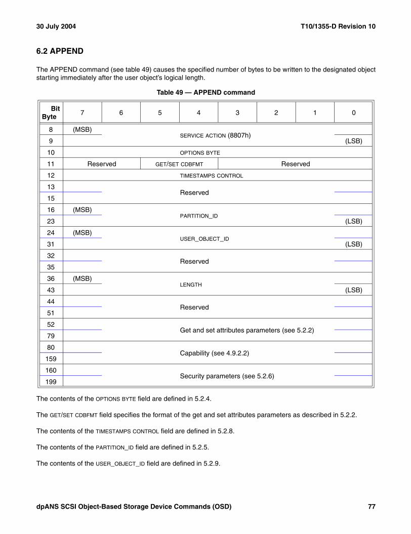
30 July 2004 T10/1355-D Revision 10
6.2 APPEND
The APPEND command (see table 49) causes the specified number of bytes to be written to the designated objectstarting immediately after the user object’s logical length.
The contents of the OPTIONS BYTE field are defined in 5.2.4.
The GET/SET CDBFMT field specifies the format of the get and set attributes parameters as described in 5.2.2.
The contents of the TIMESTAMPS CONTROL field are defined in 5.2.8.
The contents of the PARTITION_ID field are defined in 5.2.5.
The contents of the USER_OBJECT_ID field are defined in 5.2.9.
Table 49 — APPEND command
BitByte
7 6 5 4 3 2 1 0
8 (MSB)SERVICE ACTION (8807h)
9 (LSB)
10 OPTIONS BYTE
11 Reserved GET/SET CDBFMT Reserved
12 TIMESTAMPS CONTROL
13Reserved
15
16 (MSB)PARTITION_ID
23 (LSB)
24 (MSB)USER_OBJECT_ID
31 (LSB)
32Reserved
35
36 (MSB)LENGTH
43 (LSB)
44Reserved
51
52 Get and set attributes parameters (see 5.2.2)
79
80 Capability (see 4.9.2.2)
159
160 Security parameters (see 5.2.6)
199
dpANS SCSI Object-Based Storage Device Commands (OSD) 77

T10/1355-D Revision 10 30 July 2004
The contents of the LENGTH field are defined in 5.2.3. The data to be written to the user object shall be placed in theData-Out Buffer as described in 4.12.4.
The get and set attributes parameters are defined in 5.2.2. The format of the Data-In Buffer and Data-Out Bufferwhen attributes are being retrieved or set is described in 4.12.
The capability is defined in 4.9.2.2.
The security parameters are defined in 5.2.6.
If an APPEND command causes the value in the user object logical length attribute in the User Object Informationattributes page (see 7.1.2.11) to exceed the value in the maximum user object length attribute in the User ObjectQuotas attributes page (see 7.1.2.14), then a quota error shall be generated (see 4.8.2). The quota testingprinciples described in 4.8.3 apply to the testing of the maximum user object length quota.
If an APPEND command causes the value in the used capacity attribute in the Partition Information attributes page(see 7.1.2.9) to exceed the value in the capacity quota attribute in the Partition Quotas attributes page (see7.1.2.13), then a quota error shall be generated (see 4.8.2). The quota testing principles described in 4.8.3 apply tothe testing of the capacity quota.
78 dpANS SCSI Object-Based Storage Device Commands (OSD)

30 July 2004 T10/1355-D Revision 10
6.3 CREATE
The CREATE command (see table 50) causes the OSD device server to allocate and initialize one or more userobjects.
The contents of the OPTIONS BYTE field are defined in 5.2.4.
The GET/SET CDBFMT field specifies the format of the get and set attributes parameters as described in 5.2.2.
The contents of the TIMESTAMPS CONTROL field are defined in 5.2.8.
The contents of the PARTITION_ID field are defined in 5.2.5. If the PARTITION_ID field contains zero, the commandshall be terminated with a CHECK CONDITION status, with the sense key set to ILLEGAL REQUEST and theadditional sense code set to INVALID FIELD IN CDB.
Table 50 — CREATE command
BitByte
7 6 5 4 3 2 1 0
8 (MSB)SERVICE ACTION (8802h)
9 (LSB)
10 OPTIONS BYTE
11 Reserved GET/SET CDBFMT Reserved
12 TIMESTAMPS CONTROL
13Reserved
15
16 (MSB)PARTITION_ID
23 (LSB)
24 (MSB)REQUESTED USER_OBJECT_ID
31 (LSB)
32Reserved
35
36 (MSB)NUMBER OF USER OBJECTS
37 (LSB)
38Reserved
51
52 Get and set attributes parameters (see 5.2.2)
79
80 Capability (see 4.9.2.2)
159
160 Security parameters (see 5.2.6)
199
dpANS SCSI Object-Based Storage Device Commands (OSD) 79

T10/1355-D Revision 10 30 July 2004
The contents of the REQUESTED USER_OBJECT_ID field specify the User_Object_ID (see 4.6.5) to be assigned to thecreated user object. If the REQUESTED USER_OBJECT_ID field contains zero, any User_Object_ID may be assigned.If the REQUESTED USER_OBJECT_ID field contains any value other than zero and the device server is unable toassign the requested User_Object_ID to the created user object, the user object shall not be created and thecommand shall be terminated with a CHECK CONDITION status, with the sense key set to ILLEGAL REQUESTand the additional sense code set to INVALID FIELD IN CDB.
Within a partition, the device server shall not allow:
a) The same User_Object_ID to be associated with more than one user object at any point in time; orb) A User_Object_ID to have the same value as any assigned Collection_Object_ID.
The NUMBER OF USER OBJECTS field specifies the number of user objects to be created. If the NUMBER OF USER
OBJECTS field contains zero or one, one user object shall be created. Otherwise:
a) The number of user objects created shall equal the value in the NUMBER OF USER OBJECTS field;b) The user objects created shall be assigned consecutive valued User_Object_IDs; andc) The lowest valued User_Object_ID shall be placed in the created User_Object_ID attribute of the Current
Command attributes page (see 7.1.2.24).
If the NUMBER OF USER OBJECTS field contains a value that is greater than one and the requested User_Object_ID isnot zero, the command shall be terminated with a CHECK CONDITION status, with the sense key set to ILLEGALREQUEST and the additional sense code set to INVALID FIELD IN CDB.
The command shall be terminated with a CHECK CONDITION status, with the sense key set to ILLEGALREQUEST and the additional sense code set to INVALID FIELD IN CDB if:
a) If the NUMBER OF USER OBJECT field contains a value that is greater than one;b) The GET/SET CDBFMT field contains 10b; andc) The GET ATTRIBUTES PAGE field (see 5.2.2.2) contains a value other than FFFF FFFEh (i.e., the Current
Command attributes page).
The get and set attributes parameters are defined in 5.2.2. The format of the Data-In Buffer and Data-Out Bufferwhen attributes are being retrieved or set is described in 4.12.
If the get and set attributes parameters request the retrieval of attributes from pages other than the CurrentCommand attributes page, the attributes for every created user object shall be returned using list type Fh (see7.1.3).
The capability is defined in 4.9.2.2.
The security parameters are defined in 5.2.6.
The highest valued assigned User_Object_ID shall be placed in the Collection_Object_ID or User_Object_IDattribute in the Current Command attributes page (see 7.1.2.24).
If a CREATE command causes the value in the number of collections and user objects attribute in the PartitionInformation attributes page (see 7.1.2.9) to exceed the value in the object count attribute in the Partition Quotasattributes page (see 7.1.2.13), then a quota error shall be generated (see 4.8.2). The quota testing principlesdescribed in 4.8.3 apply to the testing of the object count quota.
If a CREATE command causes the value in the used capacity attribute in the Partition Information attributes page(see 7.1.2.9) to exceed the value in the capacity quota attribute in the Partition Quotas attributes page (see7.1.2.13), then a quota error shall be generated (see 4.8.2). The quota testing principles described in 4.8.3 apply tothe testing of the capacity quota.
80 dpANS SCSI Object-Based Storage Device Commands (OSD)

30 July 2004 T10/1355-D Revision 10
6.4 CREATE AND WRITE
The CREATE AND WRITE command (see table 50) causes the OSD device server to allocate and initialize oneuser object and then write data to the newly created user object.
The contents of the OPTIONS BYTE field are defined in 5.2.4.
The GET/SET CDBFMT field specifies the format of the get and set attributes parameters as described in 5.2.2.
The contents of the TIMESTAMPS CONTROL field are defined in 5.2.8.
The contents of the PARTITION_ID field are defined in 5.2.5. If the PARTITION_ID field contains zero, the commandshall be terminated with a CHECK CONDITION status, with the sense key set to ILLEGAL REQUEST and theadditional sense code set to INVALID FIELD IN CDB.
Table 51 — CREATE AND WRITE command
BitByte
7 6 5 4 3 2 1 0
8 (MSB)SERVICE ACTION (8812h)
9 (LSB)
10 OPTIONS BYTE
11 Reserved GET/SET CDBFMT Reserved
12 TIMESTAMPS CONTROL
13Reserved
15
16 (MSB)PARTITION_ID
23 (LSB)
24 (MSB)REQUESTED USER_OBJECT_ID
31 (LSB)
32Reserved
35
36 (MSB)LENGTH
43 (LSB)
44 (MSB)STARTING BYTE ADDRESS
51 (LSB)
52 Get and set attributes parameters (see 5.2.2)
79
80 Capability (see 4.9.2.2)
159
160 Security parameters (see 5.2.6)
199
dpANS SCSI Object-Based Storage Device Commands (OSD) 81
T10/1355-D Revision 10 30 July 2004
The contents of the REQUESTED USER_OBJECT_ID field specify the User_Object_ID (see 4.6.5) to be assigned to thecreated user object. If the REQUESTED USER_OBJECT_ID field contains zero, any User_Object_ID may be assigned.If the REQUESTED USER_OBJECT_ID field contains any value other than zero and the device server is unable toassign the requested User_Object_ID to the created user object, the user object shall not be created and thecommand shall be terminated with a CHECK CONDITION status, with the sense key set to ILLEGAL REQUESTand the additional sense code set to INVALID FIELD IN CDB.
Within a partition, the device server shall not allow:
a) The same User_Object_ID to be associated with more than one user object at any point in time; orb) A User_Object_ID to have the same value as any assigned Collection_Object_ID.
The contents of the LENGTH field are defined in 5.2.3. The data to be written to the user object shall be placed in theData-Out Buffer as described in 5.2.3.
The contents of the STARTING BYTE ADDRESS field are defined in 5.2.7.
The get and set attributes parameters are defined in 5.2.2. The format of the Data-In Buffer and Data-Out Bufferwhen attributes are being retrieved or set is described in 4.12. The User_Object_ID assigned by the CREATE ANDWRITE command may be obtained from the Current Command attributes page (see 7.1.2.24).
The capability is defined in 4.9.2.2.
The security parameters are defined in 5.2.6.
The assigned User_Object_ID shall be placed in the Collection_Object_ID or User_Object_ID attribute in theCurrent Command attributes page (see 7.1.2.24).
If a CREATE AND WRITE command causes the value in the number of collections and user objects attribute in thePartition Information attributes page (see 7.1.2.9) to exceed the value in the object count attribute in the PartitionQuotas attributes page (see 7.1.2.13), then a quota error shall be generated (see 4.8.2). The quota testingprinciples described in 4.8.3 apply to the testing of the object count quota.
If a CREATE AND WRITE command causes the value in the user object logical length attribute in the User ObjectInformation attributes page (see 7.1.2.11) to exceed the value in the maximum user object length attribute in theUser Object Quotas attributes page (see 7.1.2.14), then a quota error shall be generated (see 4.8.2). The quotatesting principles described in 4.8.3 apply to the testing of the maximum user object length quota.
If a CREATE AND WRITE command causes the value in the used capacity attribute in the Partition Informationattributes page (see 7.1.2.9) to exceed the value in the capacity quota attribute in the Partition Quotas attributespage (see 7.1.2.13), then a quota error shall be generated (see 4.8.2). The quota testing principles described in4.8.3 apply to the testing of the capacity quota.
82 dpANS SCSI Object-Based Storage Device Commands (OSD)

30 July 2004 T10/1355-D Revision 10
6.5 CREATE COLLECTION
The CREATE COLLECTION command (see table 52) initializes a new collection (see 4.6.6).
The contents of the OPTIONS BYTE field are defined in 5.2.4.
The GET/SET CDBFMT field specifies the format of the get and set attributes parameters as described in 5.2.2.
The contents of the TIMESTAMPS CONTROL field are defined in 5.2.8.
The contents of the PARTITION_ID field (see 5.2.5) specify the Partition_ID of the partition in which the collection isto be created.
The contents of the REQUESTED COLLECTION_OBJECT_ID field specify the Collection_Object_ID (see 4.6.6) to beassigned to the created user object. If the REQUESTED COLLECTION_OBJECT_ID field contains zero any Collection_Object_ID may be assigned. If the REQUESTED COLLECTION_OBJECT_ID field contains any value other than zero andthe device server is unable to assign the requested Collection_Object_ID to the created collection, the collectionshall not be created and the command shall be terminated with a CHECK CONDITION status, with the sense keyset to ILLEGAL REQUEST and the additional sense code set to INVALID FIELD IN CDB.
Table 52 — CREATE COLLECTION command
BitByte
7 6 5 4 3 2 1 0
8 (MSB)SERVICE ACTION (8815h)
9 (LSB)
10 OPTIONS BYTE
11 Reserved GET/SET CDBFMT Reserved
12 TIMESTAMPS CONTROL
13Reserved
15
16 (MSB)PARTITION_ID
23 (LSB)
24 (MSB)REQUESTED COLLECTION_OBJECT_ID
31 (LSB)
32Reserved
51
52 Get and set attributes parameters (see 5.2.2)
79
80 Capability (see 4.9.2.2)
159
160 Security parameters (see 5.2.6)
199
dpANS SCSI Object-Based Storage Device Commands (OSD) 83

T10/1355-D Revision 10 30 July 2004
Within a partition, the device server shall not allow:
a) The same Collection_Object_ID to be associated with more than one collection at any point in time; orb) A Collection_Object_ID to have the same value as any assigned User_Object_ID.
The get and set attributes parameters are defined in 5.2.2. The format of the Data-In Buffer and Data-Out Bufferwhen attributes are being retrieved or set is described in 4.12. The Collection_Object_ID assigned by the CREATECOLLECTION command may be obtained from the Current Command attributes page (see 7.1.2.24).
The capability is defined in 4.9.2.2.
The security parameters are defined in 5.2.6.
The assigned Collection_Object_ID shall be placed in the Collection_Object_ID or User_Object_ID attribute in theCurrent Command attributes page (see 7.1.2.24).
If a CREATE COLLECTION command causes the value in the number of collections and user objects attribute inthe Partition Information attributes page (see 7.1.2.9) to exceed the value in the object count attribute in thePartition Quotas attributes page (see 7.1.2.13), then a quota error shall be generated (see 4.8.2). The quota testingprinciples described in 4.8.3 apply to the testing of the object count quota.
If a CREATE COLLECTION command causes the value in the used capacity attribute in the Partition Informationattributes page (see 7.1.2.9) to exceed the value in the capacity quota attribute in the Partition Quotas attributespage (see 7.1.2.13), then a quota error shall be generated (see 4.8.2). The quota testing principles described in4.8.3 apply to the testing of the capacity quota.
84 dpANS SCSI Object-Based Storage Device Commands (OSD)

30 July 2004 T10/1355-D Revision 10
6.6 CREATE PARTITION
The CREATE PARTITION command (see table 53) allocates and initialize a new partition.
The contents of the OPTIONS BYTE field are defined in 5.2.4.
The GET/SET CDBFMT field specifies the format of the get and set attributes parameters as described in 5.2.2.
The contents of the TIMESTAMPS CONTROL field are defined in 5.2.8.
The contents of the REQUESTED PARTITION_ID field specify the Partition_ID (see 4.6.4) to be assigned to the createdpartition. If the REQUESTED PARTITION_ID field contains zero any Partition_ID may be assigned. If the REQUESTED
PARTITION_ID field contains any value other than zero and the device server is unable to assign the requestedPartition_ID to the created partition, the partition shall not be created and the command shall be terminated with aCHECK CONDITION status, with the sense key set to ILLEGAL REQUEST and the additional sense code set toINVALID FIELD IN CDB.
The device server shall not allow the same Partition_ID to be associated with more than one partition at any pointin time.
The get and set attributes parameters are defined in 5.2.2. The format of the Data-In Buffer and Data-Out Bufferwhen attributes are being retrieved or set is described in 4.12. The Partition_ID assigned by the CREATEPARTITION command may be obtained from the Current Command attributes page (see 7.1.2.24).
Table 53 — CREATE PARTITION command
BitByte
7 6 5 4 3 2 1 0
8 (MSB)SERVICE ACTION (880Bh)
9 (LSB)
10 OPTIONS BYTE
11 Reserved GET/SET CDBFMT Reserved
12 TIMESTAMPS CONTROL
13Reserved
15
16 (MSB)REQUESTED PARTITION_ID
23 (LSB)
24Reserved
51
52 Get and set attributes parameters (see 5.2.2)
79
80 Capability (see 4.9.2.2)
159
160 Security parameters (see 5.2.6)
199
dpANS SCSI Object-Based Storage Device Commands (OSD) 85

T10/1355-D Revision 10 30 July 2004
The capability is defined in 4.9.2.2.
The security parameters are defined in 5.2.6.
The assigned Partition_ID shall be placed in the Partition_ID attribute in the Current Command attributes page(see 7.1.2.24). The Collection_Object_ID or User_Object_ID attribute in the Current Command attributes pageshall be set to zero.
If a CREATE PARTITION command causes the value in the number of partitions attribute in the Root Informationattributes page (see 7.1.2.8) to exceed the value in the partition count attribute in the Root Quotas attributes page(see 7.1.2.12), then a quota error shall be generated (see 4.8.2). The quota testing principles described in 4.8.3apply to the testing of the partition count quota.
6.7 FLUSH
The FLUSH command (see table 54) ensures that the specified data and attribute bytes for the specified userobject are written to stable storage (see 4.11).
Table 54 — FLUSH command
BitByte
7 6 5 4 3 2 1 0
8 (MSB)SERVICE ACTION (8808h)
9 (LSB)
10 Reserved FLUSH SCOPE
11 Reserved GET/SET CDBFMT Reserved
12 TIMESTAMPS CONTROL
13Reserved
15
16 (MSB)PARTITION_ID
23 (LSB)
24 (MSB)USER_OBJECT_ID
31 (LSB)
32Reserved
51
52 Get and set attributes parameters (see 5.2.2)
79
80 Capability (see 4.9.2.2)
159
160 Security parameters (see 5.2.6)
199
86 dpANS SCSI Object-Based Storage Device Commands (OSD)

30 July 2004 T10/1355-D Revision 10
The FLUSH SCOPE field (see table 55) specifies the scope of the data and attribute bytes that are written to stablestorage.
The GET/SET CDBFMT field specifies the format of the get and set attributes parameters as described in 5.2.2.
The contents of the TIMESTAMPS CONTROL field are defined in 5.2.8.
The contents of the PARTITION_ID field are defined in 5.2.5.
The contents of the USER_OBJECT_ID field are defined in 5.2.9.
The get and set attributes parameters are defined in 5.2.2. The format of the Data-In Buffer and Data-Out Bufferwhen attributes are being retrieved or set is described in 4.12.
The capability is defined in 4.9.2.2.
The security parameters are defined in 5.2.6.
Table 55 — User object flush scope values
ValueScope of data and attributes that shall be written to stable storage
00b User object data and attributes
01b User object attributes only
10b to 11b Reserved
dpANS SCSI Object-Based Storage Device Commands (OSD) 87

T10/1355-D Revision 10 30 July 2004
6.8 FLUSH COLLECTION
The FLUSH COLLECTION command (see table 56) ensures that the specified collection information and attributebytes for the specified collection are written to stable storage (see 4.11).
The FLUSH SCOPE field (see table 57) specifies the scope of the collection information and attribute bytes that arewritten to stable storage.
The GET/SET CDBFMT field specifies the format of the get and set attributes parameters as described in 5.2.2.
The contents of the TIMESTAMPS CONTROL field are defined in 5.2.8.
Table 56 — FLUSH COLLECTION command
BitByte
7 6 5 4 3 2 1 0
8 (MSB)SERVICE ACTION (881Ah)
9 (LSB)
10 Reserved FLUSH SCOPE
11 Reserved GET/SET CDBFMT Reserved
12 TIMESTAMPS CONTROL
13Reserved
15
16 (MSB)PARTITION_ID
23 (LSB)
24 (MSB)COLLECTION_OBJECT_ID
31 (LSB)
32Reserved
51
52 Get and set attributes parameters (see 5.2.2)
79
80 Capability (see 4.9.2.2)
159
160 Security parameters (see 5.2.6)
199
Table 57 — Collection flush scope values
Value Scope of data and attributes that shall be written to stable storage
00b List of user objects contained in the collection
01b Collection attributes only
10b a) List of user objects contained in the collection; andb) Collection attributes
11b Reserved
88 dpANS SCSI Object-Based Storage Device Commands (OSD)

30 July 2004 T10/1355-D Revision 10
The contents of the PARTITION_ID field are defined in 5.2.5.
The COLLECTION_OBJECT_ID field specifies Collection_Object_ID (see 4.6.6). If the collection identified by theCOLLECTION_OBJECT_ID field does not exist, the command shall be terminated with a CHECK CONDITION status,with the sense key set to ILLEGAL REQUEST and the additional sense code set to INVALID FIELD IN CDB.
The get and set attributes parameters are defined in 5.2.2. The format of the Data-In Buffer and Data-Out Bufferwhen attributes are being retrieved or set is described in 4.12.
The capability is defined in 4.9.2.2.
The security parameters are defined in 5.2.6.
6.9 FLUSH OSD
The FLUSH OSD command (see table 58) ensures that the specified data and attribute bytes for the OSD logicalunit are written to stable storage (see 4.11).
Table 58 — FLUSH OSD command
BitByte
7 6 5 4 3 2 1 0
8 (MSB)SERVICE ACTION (881Ch)
9 (LSB)
10 Reserved FLUSH SCOPE
11 Reserved GET/SET CDBFMT Reserved
12 TIMESTAMPS CONTROL
13Reserved
51
52 Get and set attributes parameters (see 5.2.2)
79
80 Capability (see 4.9.2.2)
159
160 Security parameters (see 5.2.6)
199
dpANS SCSI Object-Based Storage Device Commands (OSD) 89

T10/1355-D Revision 10 30 July 2004
The FLUSH SCOPE field (see table 59) specifies the scope of the data and attribute bytes that are written to stablestorage.
The GET/SET CDBFMT field specifies the format of the get and set attributes parameters as described in 5.2.2.
The contents of the TIMESTAMPS CONTROL field are defined in 5.2.8.
The get and set attributes parameters are defined in 5.2.2. The format of the Data-In Buffer and Data-Out Bufferwhen attributes are being retrieved or set is described in 4.12.
The capability is defined in 4.9.2.2.
The security parameters are defined in 5.2.6.
Table 59 — Root object flush scope values
Value Scope of data and attributes that shall be written to stable storage
00b List of partitions contained in the OSD logical unit
01b Root object attributes only
10b a) List of partitions contained in the OSD logical unit;b) Root object attributes;c) Lists of user objects and collections contained in the every partition in the OSD logical unit;d) Partition attributes for every partition in the OSD logical unit;e) User object data for every user object in the OSD logical unit;f) User object attributes for every user object in the OSD logical unit;g) List of user objects contained in every the collection in the OSD logical unit; andh) Collection attributes for every collection in the OSD logical unit
11b Reserved
90 dpANS SCSI Object-Based Storage Device Commands (OSD)

30 July 2004 T10/1355-D Revision 10
6.10 FLUSH PARTITION
The FLUSH PARTITION command (see table 60) ensures that the specified data and attribute bytes for thespecified user object are written to stable storage (see 4.11).
The FLUSH SCOPE field (see table 55) specifies the scope of the data and attribute bytes that are written to stablestorage.
The GET/SET CDBFMT field specifies the format of the get and set attributes parameters as described in 5.2.2.
Table 60 — FLUSH PARTITION command
BitByte
7 6 5 4 3 2 1 0
8 (MSB)SERVICE ACTION (881Bh)
9 (LSB)
10 Reserved FLUSH SCOPE
11 Reserved GET/SET CDBFMT Reserved
12 TIMESTAMPS CONTROL
13Reserved
15
16 (MSB)PARTITION_ID
23 (LSB)
24Reserved
51
52 Get and set attributes parameters (see 5.2.2)
79
80 Capability (see 4.9.2.2)
159
160 Security parameters (see 5.2.6)
199
Table 61 — Partition flush scope values
Value Scope of data and attributes that shall be written to stable storage
00b List of user objects and collections contained in the partition
01b Partition attributes only
10b a) List of user objects and collections contained in the partition;b) Partition attributes;c) User object data for every user object in the partition;d) User object attributes for every user object in the partition;e) List of user objects contained in every the collection in the partition; andf) Collection attributes for every collection in the partition
11b Reserved
dpANS SCSI Object-Based Storage Device Commands (OSD) 91
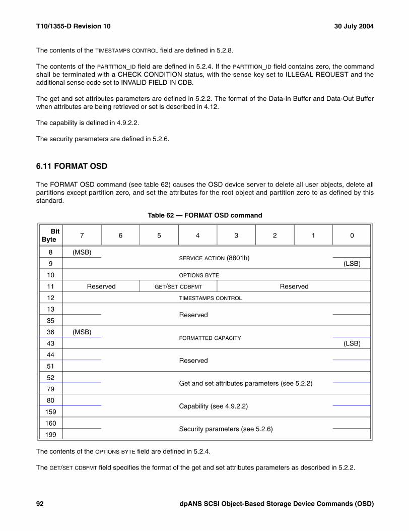
T10/1355-D Revision 10 30 July 2004
The contents of the TIMESTAMPS CONTROL field are defined in 5.2.8.
The contents of the PARTITION_ID field are defined in 5.2.4. If the PARTITION_ID field contains zero, the commandshall be terminated with a CHECK CONDITION status, with the sense key set to ILLEGAL REQUEST and theadditional sense code set to INVALID FIELD IN CDB.
The get and set attributes parameters are defined in 5.2.2. The format of the Data-In Buffer and Data-Out Bufferwhen attributes are being retrieved or set is described in 4.12.
The capability is defined in 4.9.2.2.
The security parameters are defined in 5.2.6.
6.11 FORMAT OSD
The FORMAT OSD command (see table 62) causes the OSD device server to delete all user objects, delete allpartitions except partition zero, and set the attributes for the root object and partition zero to as defined by thisstandard.
The contents of the OPTIONS BYTE field are defined in 5.2.4.
The GET/SET CDBFMT field specifies the format of the get and set attributes parameters as described in 5.2.2.
Table 62 — FORMAT OSD command
BitByte
7 6 5 4 3 2 1 0
8 (MSB)SERVICE ACTION (8801h)
9 (LSB)
10 OPTIONS BYTE
11 Reserved GET/SET CDBFMT Reserved
12 TIMESTAMPS CONTROL
13Reserved
35
36 (MSB)FORMATTED CAPACITY
43 (LSB)
44Reserved
51
52 Get and set attributes parameters (see 5.2.2)
79
80 Capability (see 4.9.2.2)
159
160 Security parameters (see 5.2.6)
199
92 dpANS SCSI Object-Based Storage Device Commands (OSD)

30 July 2004 T10/1355-D Revision 10
The contents of the TIMESTAMPS CONTROL field are defined in 5.2.8.
The FORMATTED CAPACITY field specifies the total capacity of the formatted OSD logical unit in bytes. If theFORMATTED CAPACITY field is set to zero, the entire logical unit is formatted as one OSD logical unit and the logicalunit capacity established accordingly. If value in the FORMATTED CAPACITY field is greater than the maximum OSDlogical unit capacity, the formatting command function shall process as if the FORMATTED CAPACITY field containedzero. This shall not be considered an error.
The get and set attributes parameters are defined in 5.2.2. The format of the Data-In Buffer and Data-Out Bufferwhen attributes are being retrieved or set is described in 4.12.
The capability is defined in 4.9.2.2.
The security parameters are defined in 5.2.6.
During the processing of a FORMAT OSD command, the device server shall respond to commands as follows:
a) In response to all commands except REQUEST SENSE and INQUIRY, the device server shall returnCHECK CONDITION status unless a reservation conflict exists, in which case RESERVATION CONFLICTstatus shall be returned;
b) In response to the INQUIRY command, the device server shall respond as specified in SPC-3; andc) In response to the REQUEST SENSE command, unless an error has occurred, the device server shall
return GOOD status with parameter data containing the sense key set NOT READY and the additionalsense code set to LOGICAL UNIT NOT READY FORMAT IN PROGRESS.
Upon successful completion of a FORMAT OSD command, the OSD logical unit shall contain:
a) A root object;b) One partition OSD object for partition zero (see 3.1.32);c) Zero collections;d) Zero user objects;e) Root object attributes and partition zero attributes as defined by this standard;f) Vendor specific additional root object attributes and partition zero attributes;g) Root object attributes and partition zero attributes updated as specified by the CDB parameters;h) Zero collection attributes, if supported;i) Zero user object attributes;j) Zero attributes pages with page numbers between P + 1 0000h and P + 1FFF FFFFh; andk) Zero attributes pages with page numbers between R + 1 0000h and R + 1FFF FFFFh.
Processing of the FORMAT OSD command shall not alter the master key, root key, or any keys associated partitionzero (see 4.10.9).
dpANS SCSI Object-Based Storage Device Commands (OSD) 93

T10/1355-D Revision 10 30 July 2004
6.12 GET ATTRIBUTES
The GET ATTRIBUTES command (see table 63) instructs the device server to return the specified attributes for thespecified root object, partition, collection, or user object before setting the attributes, if any, specified by thecommand (see 4.7.2).
The contents of the OPTIONS BYTE field are defined in 5.2.4.
The GET/SET CDBFMT field specifies the format of the get and set attributes parameters as described in 5.2.2.
The contents of the TIMESTAMPS CONTROL field are defined in 5.2.8.
The contents of the PARTITION_ID field are defined in 5.2.5.
The contents of the USER_OBJECT_ID field are defined in 5.2.9.
The get and set attributes parameters are defined in 5.2.2. The format of the Data-In Buffer and Data-Out Bufferwhen attributes are being retrieved or set is described in 4.12.
The capability is defined in 4.9.2.2.
The security parameters are defined in 5.2.6.
Table 63 — GET ATTRIBUTES command
BitByte
7 6 5 4 3 2 1 0
8 (MSB)SERVICE ACTION (880Eh)
9 (LSB)
10 OPTIONS BYTE
11 Reserved GET/SET CDBFMT Reserved
12 TIMESTAMPS CONTROL
13Reserved
15
16 (MSB)PARTITION_ID
23 (LSB)
24 (MSB)USER_OBJECT_ID
31 (LSB)
32Reserved
51
52 Get and set attributes parameters (see 5.2.2)
79
80 Capability (see 4.9.2.2)
159
160 Security parameters (see 5.2.6)
199
94 dpANS SCSI Object-Based Storage Device Commands (OSD)
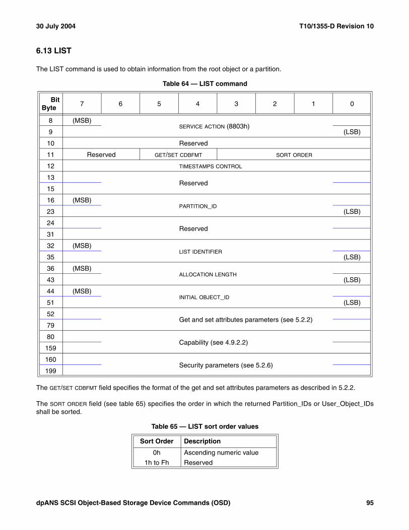
30 July 2004 T10/1355-D Revision 10
6.13 LIST
The LIST command is used to obtain information from the root object or a partition.
The GET/SET CDBFMT field specifies the format of the get and set attributes parameters as described in 5.2.2.
The SORT ORDER field (see table 65) specifies the order in which the returned Partition_IDs or User_Object_IDsshall be sorted.
Table 64 — LIST command
BitByte
7 6 5 4 3 2 1 0
8 (MSB)SERVICE ACTION (8803h)
9 (LSB)
10 Reserved
11 Reserved GET/SET CDBFMT SORT ORDER
12 TIMESTAMPS CONTROL
13Reserved
15
16 (MSB)PARTITION_ID
23 (LSB)
24Reserved
31
32 (MSB)LIST IDENTIFIER
35 (LSB)
36 (MSB)ALLOCATION LENGTH
43 (LSB)
44 (MSB)INITIAL OBJECT_ID
51 (LSB)
52 Get and set attributes parameters (see 5.2.2)
79
80 Capability (see 4.9.2.2)
159
160 Security parameters (see 5.2.6)
199
Table 65 — LIST sort order values
Sort Order Description
0h Ascending numeric value
1h to Fh Reserved
dpANS SCSI Object-Based Storage Device Commands (OSD) 95

T10/1355-D Revision 10 30 July 2004
The contents of the TIMESTAMPS CONTROL field are defined in 5.2.8.
The contents of the PARTITION_ID field are defined in 5.2.5. If the PARTITION_ID field contains zero, the Partition_IDs(see 4.6.4) in the root object shall be returned. If the PARTITION_ID field contains a non-zero value, the User_Object_IDs in the specified partition shall be returned.
The LIST IDENTIFIER field contains zero if the INITIAL OBJECT_ID field contains Partition_ID or User_Object_ID (see4.6.2). Otherwise, the LIST IDENTIFIER field contains the list identifier returned by a previous LIST command.
The ALLOCATION LENGTH field specifies the maximum number of bytes that an application client has allocated for thereturned list. An allocation length of zero indicates that no data shall be transferred. This condition shall not beconsidered as an error.
The allocation length is used to limit the maximum amount of the list returned to an application client. The deviceserver shall terminate transfers to the Data-In Buffer if the number of bytes specified by the ALLOCATION LENGTH
field have been transferred or if all available data have been transferred, whichever is less. If the information beingtransferred is truncated, the contents of the ADDITIONAL LENGTH field (see table 66) shall not be altered to reflect thetruncation.
The contents of the INITIAL OBJECT_ID field depend on the contents of the LIST IDENTIFIER field. If the LIST IDENTIFIER
field contains zero, the INITIAL OBJECT_ID field specifies the lowest valued Partition_ID or User_Object_ID to bereturned. If the LIST IDENTIFIER field contains any value other than zero, the INITIAL OBJECT_ID field contains thevalue in the CONTINUATION OBJECT_ID field from the same returned parameter data that contained the value in theLIST IDENTIFIER field.
The get and set attributes parameters are defined in 5.2.2. The format of the Data-In Buffer and Data-Out Bufferwhen attributes are being retrieved or set is described in 4.12.
The capability is defined in 4.9.2.2.
The security parameters are defined in 5.2.6.
96 dpANS SCSI Object-Based Storage Device Commands (OSD)

30 July 2004 T10/1355-D Revision 10
The parameter data returned by the LIST command (see table 66) contains the requested list of partitions or userobjects.
The ADDITIONAL LENGTH field indicates the number of bytes of LIST command parameter data that follow. If theparameter data is truncated due to insufficient allocation length, the ADDITIONAL LENGTH field shall not be altered toreflect the truncation (i.e., the additional length indicates the number of bytes that would follow if the allocationlength had been infinite). If the untruncated number of bytes that follow is greater than FFFF FFFF FFFF FFFFh theadditional length shall be set to FFFF FFFF FFFF FFFFh.
The CONTINUATION OBJECT_ID field provides information that may be used to continue a truncated list with a newLIST command. If the CONTINUATION OBJECT_ID field contains zero, the parameter data contains all of the list resultsand no further LIST commands are needed. If a new LIST command is sent to continue a truncated list, thecontents of the CONTINUATION OBJECT_ID field are copied to the INITIAL OBJECT_ID field of that new command.
The LIST IDENTIFIER field contains an identifier required for continuing a truncated list in a new LIST command. If anew LIST command is sent to continue a truncated list, the contents of the LIST IDENTIFIER field are copied to theLIST IDENTIFIER field of that new command.
A LSTCHG (list has changed) bit set to zero indicates that the entries in the list of OSD objects in the parameter datahas not changed since the first LIST command identified by the list identifier. A LSTCHG bit set to one indicates thatthe entries in the list of OSD objects in the parameter data has changed since the first LIST command identified bythe list identifier and that starting the list over at the original initial object_id may be necessary in order to obtain acomplete list.
A ROOT bit set to zero indicates that the OSD object IDs in the parameter data are from a partition and are User_Object_IDs. A ROOT set to one indicates that the OSD object IDs in the parameter data are from the root object andare Partition_IDs.
The list of User_Object_IDs or Partition_IDs contains one entry for each user object or partition identified by theLIST command. If the list is truncated based on allocation length, the truncation shall not occur in the middle of aUser_Object_ID or Partition_ID.
The list shall not contain Collection_Object_IDs. Lists of Collection_Object_IDs may be obtained using the LISTCOLLECTION command (see 6.14).
Table 66 — LIST command parameter data
BitByte
7 6 5 4 3 2 1 0
0 (MSB)ADDITIONAL LENGTH (n-7)
7 (LSB)
8 (MSB)CONTINUATION OBJECT_ID
15 (LSB)
16 (MSB)LIST IDENTIFIER
19 (LSB)
20Reserved
22
23 Reserved LSTCHG ROOT
24List of User_Object_IDs or Partition_IDs
n
dpANS SCSI Object-Based Storage Device Commands (OSD) 97

T10/1355-D Revision 10 30 July 2004
6.14 LIST COLLECTION
The LIST COLLECTION command (see table 67) is used to get information from a collection.
The GET/SET CDBFMT field specifies the format of the get and set attributes parameters as described in 5.2.2.
The contents of the TIMESTAMPS CONTROL field are defined in 5.2.8.
The contents of the PARTITION_ID field are defined in 5.2.5.
The COLLECTION_OBJECT_ID field specifies Collection_Object_ID (see 4.6.6) for which a list of member User_Object_IDs shall be returned. If the COLLECTION_OBJECT_ID field contains zero, the Collection_Object_IDs of allcollections in the partition shall be returned. If the collection identified by the COLLECTION_OBJECT_ID field does notexist, the command shall be terminated with a CHECK CONDITION status, with the sense key set to ILLEGALREQUEST and the additional sense code set to INVALID FIELD IN CDB.
Table 67 — LIST COLLECTION command
BitByte
7 6 5 4 3 2 1 0
8 (MSB)SERVICE ACTION (8817h)
9 (LSB)
10 Reserved
11 Reserved GET/SET CDBFMT Reserved
12 TIMESTAMPS CONTROL
13Reserved
15
16 (MSB)PARTITION_ID
23 (LSB)
24 (MSB)COLLECTION_OBJECT_ID
31 (LSB)
32 (MSB)LIST IDENTIFIER
35 (LSB)
36 (MSB)ALLOCATION LENGTH
43 (LSB)
44 (MSB)INITIAL OBJECT_ID
51 (LSB)
52 Get and set attributes parameters (see 5.2.2)
79
80 Capability (see 4.9.2.2)
159
160 Security parameters (see 5.2.6)
199
98 dpANS SCSI Object-Based Storage Device Commands (OSD)

30 July 2004 T10/1355-D Revision 10
The LIST IDENTIFIER field contains zero if the INITIAL OBJECT_ID field contains Collection_Object_ID or User_Object_ID (see 4.6.5). Otherwise, the LIST IDENTIFIER field contains the list identifier returned by a previous LISTCOLLECTION command.
The ALLOCATION LENGTH field specifies the maximum number of bytes that an application client has allocated for thereturned list. An allocation length of zero indicates that no data shall be transferred. This condition shall not beconsidered as an error.
The allocation length is used to limit the maximum amount of the list returned to an application client. The deviceserver shall terminate transfers to the Data-In Buffer if the number of bytes specified by the ALLOCATION LENGTH
field have been transferred or if all available data have been transferred, whichever is less. If the information beingtransferred is truncated, the contents of the ADDITIONAL LENGTH field (see table 68) shall not be altered to reflect thetruncation.
The contents of the INITIAL OBJECT_ID field depend on the contents of the LIST IDENTIFIER field. If the LIST IDENTIFIER
field contains zero, the INITIAL OBJECT_ID field specifies the lowest valued Collection_Object_ID or User_Object_IDto be returned. If the LIST IDENTIFIER field contains any value other than zero, the INITIAL OBJECT_ID field contains thevalue in the CONTINUATION OBJECT_ID field from the same returned parameter data that contained the value in theLIST IDENTIFIER field.
The get and set attributes parameters are defined in 5.2.2. The format of the Data-In Buffer and Data-Out Bufferwhen attributes are being retrieved or set is described in 4.12.
The capability is defined in 4.9.2.2.
The security parameters are defined in 5.2.6.
The parameter data returned by the LIST COLLECTION command (see table 68) contains the requested infor-mation about the collections in the specified partition or user objects in the specified collection.
Table 68 — LIST COLLECTION command parameter data
BitByte
7 6 5 4 3 2 1 0
0 (MSB)ADDITIONAL LENGTH (n-7)
7 (LSB)
8 (MSB)CONTINUATION OBJECT_ID
15 (LSB)
16 (MSB)LIST IDENTIFIER
19 (LSB)
20Reserved
22
23 Reserved LSTCHG COLTN
24List of User_Object_IDs or Collection_Object_IDs
n
dpANS SCSI Object-Based Storage Device Commands (OSD) 99
T10/1355-D Revision 10 30 July 2004
The ADDITIONAL LENGTH field indicates the number of bytes of LIST COLLECTION command parameter data thatfollow. If the parameter data is truncated due to insufficient allocation length, the ADDITIONAL LENGTH field shall notbe altered to reflect the truncation (i.e., the additional length indicates the number of bytes that would follow if theallocation length had been infinite). If the untruncated number of bytes that follow is greater than FFFF FFFF FFFFFFFFh the additional length shall be set to FFFF FFFF FFFF FFFFh.
The CONTINUATION OBJECT_ID field provides information that may be used to continue a truncated list with a newLIST COLLECTION command. If the CONTINUATION OBJECT_ID field contains zero, the parameter data contains allof the list results and no further LIST COLLECTION commands are needed. If a new LIST COLLECTIONcommand is sent to continue a truncated list, the contents of the CONTINUATION OBJECT_ID field are copied to theINITIAL OBJECT_ID field of that new command.
The LIST IDENTIFIER field contains an identifier required for continuing a truncated list in a new LIST COLLECTIONcommand. If a new LIST COLLECTION command is sent to continue a truncated list, the contents of the LIST
IDENTIFIER field are copied to the LIST IDENTIFIER field of that new command.
A LSTCHG (list has changed) bit set to zero indicates that the entries in the list of OSD objects in the parameter datahas not changed since the first LIST COLLECTION command identified by the list identifier. A LSTCHG bit set to oneindicates that the entries in the list of OSD objects in the parameter data has changed since the first LISTCOLLECTION command identified by the list identifier and that starting the list over at the original initial object_idmay be necessary in order to obtain a complete list.
A COLTN bit of zero indicates that the OSD object IDs in the parameter data are from a collection and are User_Object_IDs. A COLTN bit of one indicates that the OSD object IDs in the parameter data are from the partition andare Collection_Object_IDs.
The list of User_Object_IDs or Collection_Object_IDs contains one entry for each user object or collectionidentified by the LIST COLLECTION command. If the list is truncated based on allocation length, the truncationshall not occur in the middle of a User_Object_ID or Collection_Object_ID.
100 dpANS SCSI Object-Based Storage Device Commands (OSD)
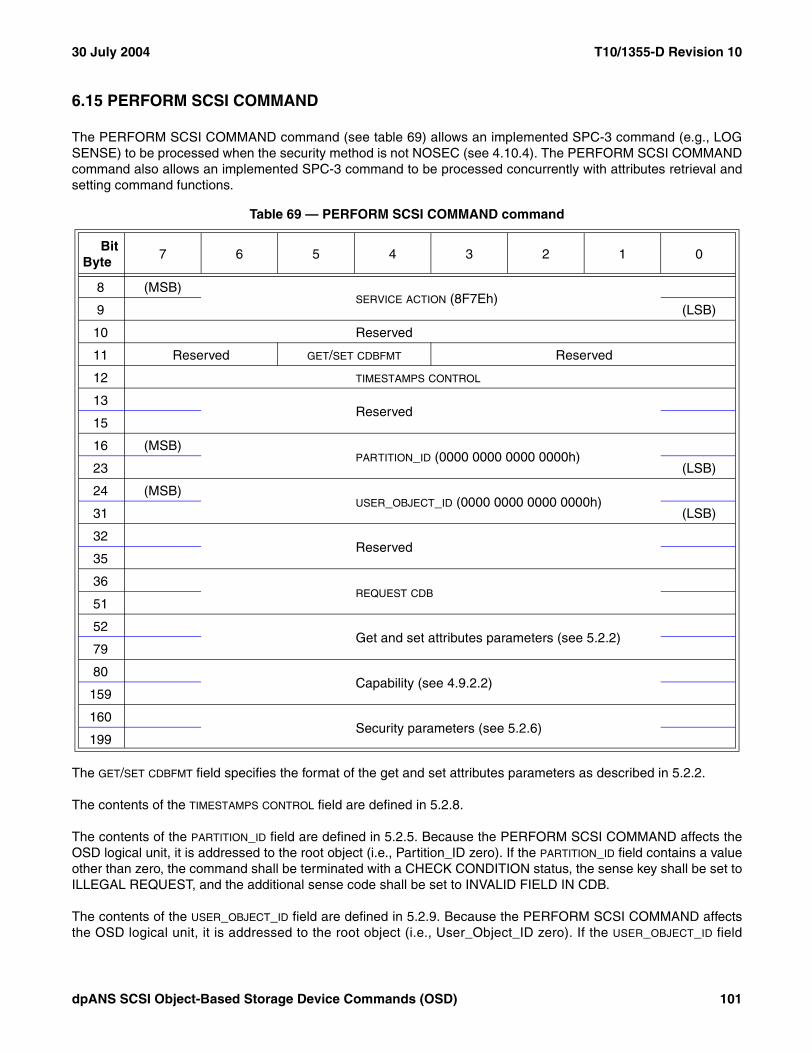
30 July 2004 T10/1355-D Revision 10
6.15 PERFORM SCSI COMMAND
The PERFORM SCSI COMMAND command (see table 69) allows an implemented SPC-3 command (e.g., LOGSENSE) to be processed when the security method is not NOSEC (see 4.10.4). The PERFORM SCSI COMMANDcommand also allows an implemented SPC-3 command to be processed concurrently with attributes retrieval andsetting command functions.
The GET/SET CDBFMT field specifies the format of the get and set attributes parameters as described in 5.2.2.
The contents of the TIMESTAMPS CONTROL field are defined in 5.2.8.
The contents of the PARTITION_ID field are defined in 5.2.5. Because the PERFORM SCSI COMMAND affects theOSD logical unit, it is addressed to the root object (i.e., Partition_ID zero). If the PARTITION_ID field contains a valueother than zero, the command shall be terminated with a CHECK CONDITION status, the sense key shall be set toILLEGAL REQUEST, and the additional sense code shall be set to INVALID FIELD IN CDB.
The contents of the USER_OBJECT_ID field are defined in 5.2.9. Because the PERFORM SCSI COMMAND affectsthe OSD logical unit, it is addressed to the root object (i.e., User_Object_ID zero). If the USER_OBJECT_ID field
Table 69 — PERFORM SCSI COMMAND command
BitByte
7 6 5 4 3 2 1 0
8 (MSB)SERVICE ACTION (8F7Eh)
9 (LSB)
10 Reserved
11 Reserved GET/SET CDBFMT Reserved
12 TIMESTAMPS CONTROL
13Reserved
15
16 (MSB)PARTITION_ID (0000 0000 0000 0000h)
23 (LSB)
24 (MSB)USER_OBJECT_ID (0000 0000 0000 0000h)
31 (LSB)
32Reserved
35
36REQUEST CDB
51
52 Get and set attributes parameters (see 5.2.2)
79
80 Capability (see 4.9.2.2)
159
160 Security parameters (see 5.2.6)
199
dpANS SCSI Object-Based Storage Device Commands (OSD) 101

T10/1355-D Revision 10 30 July 2004
contains a value other than zero, the command shall be terminated with a CHECK CONDITION status, the sensekey shall be set to ILLEGAL REQUEST, and the additional sense code shall be set to INVALID FIELD IN CDB.
The REQUEST CDB field contains the fixed-length CDB for the SPC-3 command to be processed. Any bytes betweenthe end of the CDB for the SPC-3 command and the end of the REQUEST CDB field shall be ignored (e.g., a ten-byteCDB occupies the first ten bytes of the REQUEST CDB field and the remaining six bytes are ignored).
If SPC-3 command specified by the REQUEST CDB field is not one of the commands listed in table 70, thePERFORM SCSI COMMAND command shall be terminated with a CHECK CONDITION status, the sense keyshall be set to ILLEGAL REQUEST, and the additional sense code shall be set to INVALID FIELD IN CDB.
Only those commands specified as mandatory to implement in table 48 (see 6.1) are mandatory to implement inthis command. If the SPC-3 command specified by the REQUEST CDB field is not implemented, the PERFORM SCSICOMMAND command shall be terminated with a CHECK CONDITION status, the sense key shall be set toILLEGAL REQUEST, and the additional sense code shall be set to INVALID FIELD IN CDB.
If the SPC-3 command specified by the REQUEST CDB field transfers data to the Data-In Buffer, the data bytes shallbe placed in the traditional command or parameter data segment of the Data-In Buffer (see 4.12). If the SPC-3command specified by the REQUEST CDB field transfers data from the Data-Out Buffer, the data bytes shall beretrieved from the traditional command or parameter data segment of the Data-Out Buffer.
The get and set attributes parameters are defined in 5.2.2. The format of the Data-In Buffer and Data-Out Bufferwhen attributes are being retrieved or set is described in 4.12.
The capability is defined in 4.9.2.2.
The security parameters are defined in 5.2.6.
Table 70 — Request CDBs allowed in the PERFORM SCSI COMMAND
Command nameOperation
codeService action
(if any)
INQUIRY 12hLOG SELECT 4ChLOG SENSE 4DhMODE SELECT(10) 55hMODE SENSE(10) 5AhPREVENT ALLOW MEDIUM REMOVAL 1EhREAD BUFFER 3ChRECEIVE DIAGNOSTIC RESULTS 1ChREPORT LUNS A0hREPORT SUPPORTED OPERATION CODES A3h 0ChREPORT SUPPORTED TASK MANAGEMENT FUNCTIONS A3h 0DhREPORT TARGET PORT GROUPS A3h 0AhREQUEST SENSE 03hSEND DIAGNOSTIC 1DhSET TARGET PORT GROUPS A4h 0AhTEST UNIT READY 00hWRITE BUFFER 3Bh
102 dpANS SCSI Object-Based Storage Device Commands (OSD)

30 July 2004 T10/1355-D Revision 10
If the PERFORM SCSI COMMAND is terminated with a CHECK CONDITION status, the sense key is ILLEGALREQUEST, the sense key specific sense data descriptor (see SPC-3) is included in the sense data, and the C/D bitis set to one, then values in the FIELD POINTER field shall be based on the PERFORM SCSI COMMAND CDB (i.e.,not on the CDB in the REQUEST CDB field).
6.16 PERFORM TASK MANAGEMENT FUNCTION
The PERFORM TASK MANAGEMENT FUNCTION command (see table 71) allows a SAM-3 task managementfunction (e.g., ABORT TASK) to be processed when the security method is not NOSEC (see 4.10.4). ThePERFORM TASK MANAGEMENT FUNCTION command also allows a SAM-3 task management function to beprocessed concurrently with attributes retrieval and setting command functions.
The GET/SET CDBFMT field specifies the format of the get and set attributes parameters as described in 5.2.2.
The contents of the TIMESTAMPS CONTROL field are defined in 5.2.8.
Table 71 — PERFORM TASK MANAGEMENT FUNCTION command
BitByte
7 6 5 4 3 2 1 0
8 (MSB)SERVICE ACTION (8F7Fh)
9 (LSB)
10 Reserved
11 Reserved GET/SET CDBFMT Reserved
12 TIMESTAMPS CONTROL
13Reserved
15
16 (MSB)PARTITION_ID
23 (LSB)
24 (MSB)USER_OBJECT_ID
31 (LSB)
32Reserved
42
43 TASK MANAGEMENT FUNCTION
44TASK TAG
51
52 Get and set attributes parameters (see 5.2.2)
79
80 Capability (see 4.9.2.2)
159
160 Security parameters (see 5.2.6)
199
dpANS SCSI Object-Based Storage Device Commands (OSD) 103

T10/1355-D Revision 10 30 July 2004
The contents of the PARTITION_ID field are defined in 5.2.5.
The contents of the USER_OBJECT_ID field are defined in 5.2.9.
The TASK MANAGEMENT FUNCTION field (see table 72) specifies the SAM-3 task management function to beprocessed.
If the TASK MANAGEMENT FUNCTION field contains a value that table 72 lists as being addressed to the root objectand either the PARTITION_ID field or the USER_OBJECT_ID field contains a value other than zero, the command shallbe terminated with a CHECK CONDITION status, the sense key shall be set to ILLEGAL REQUEST, and theadditional sense code shall be set to INVALID FIELD IN CDB.
The TASK TAG field contains the task tag that identifies the task to be managed if the TASK MANAGEMENT FUNCTION
field contains a value listed as specifying a task tag in table 72. If table 72 lists a task management function as notspecifying a task tag, then the contents of the task tag field shall be ignored.
The format of the task tag is specified in the applicable SCSI transport protocol standard and the length of the tasktag may be less than eight bytes. Any bytes between the end of the task tag and the end of the TASK TAG field shallbe ignored (e.g., a two-byte task tag occupies the first two bytes of the TASK TAG field and the remaining six bytesare ignored).
The get and set attributes parameters are defined in 5.2.2. The format of the Data-In Buffer and Data-Out Bufferwhen attributes are being retrieved or set is described in 4.12.
The capability is defined in 4.9.2.2.
The security parameters are defined in 5.2.6.
Table 72 — Task management function values
ValueSAM-3 Task Management Function
Addressed OSD Object
Task Tag Specified
01h ABORT TASK Any Yes
02h ABORT TASK SET Root No
04h CLEAR TASK SET Root No
08h LOGICAL UNIT RESET Root No
40h CLEAR ACA Any No
80h QUERY TASK Any Yes
All values not listed in this table are reserved.
104 dpANS SCSI Object-Based Storage Device Commands (OSD)

30 July 2004 T10/1355-D Revision 10
6.17 READ
The READ command (see table 73) requests that the device server return data to the application client from thespecified user object.
The contents of the OPTIONS BYTE field are defined in 5.2.4.
The GET/SET CDBFMT field specifies the format of the get and set attributes parameters as described in 5.2.2.
The contents of the TIMESTAMPS CONTROL field are defined in 5.2.8.
The contents of the PARTITION_ID field are defined in 5.2.5.
The contents of the USER_OBJECT_ID field are defined in 5.2.9.
Table 73 — READ command
BitByte
7 6 5 4 3 2 1 0
8 (MSB)SERVICE ACTION (8805h)
9 (LSB)
10 OPTIONS BYTE
11 Reserved GET/SET CDBFMT Reserved
12 TIMESTAMPS CONTROL
13Reserved
15
16 (MSB)PARTITION_ID
23 (LSB)
24 (MSB)USER_OBJECT_ID
31 (LSB)
32Reserved
35
36 (MSB)LENGTH
43 (LSB)
44 (MSB)STARTING BYTE ADDRESS
51 (LSB)
52 Get and set attributes parameters (see 5.2.2)
79
80 Capability (see 4.9.2.2)
159
160 Security parameters (see 5.2.6)
199
dpANS SCSI Object-Based Storage Device Commands (OSD) 105

T10/1355-D Revision 10 30 July 2004
The contents of the LENGTH field are defined in 5.2.3. The data read from the user object shall be placed in theData-In Buffer as described in 5.2.3.
The contents of the STARTING BYTE ADDRESS field are defined in 5.2.7.
If the STARTING BYTE ADDRESS field specifies a byte that is beyond the user object logical length attribute value inthe User Object Information attributes page (see 7.1.2.11), then:
a) No bytes shall be transferred; andb) The command shall be terminated with a CHECK CONDITION status, with the sense key set to ILLEGAL
REQUEST and the additional sense code set to INVALID FIELD IN CDB.
If the values in the LENGTH field and STARTING BYTE ADDRESS field result an attempt to read a byte that is beyond theuser object logical length attribute value in the User Object Information attributes page, then:
a) The bytes between the starting byte address and the user object logical length shall be transferred;b) The command shall be terminated with a CHECK CONDITION status, with the sense key shall be set to
RECOVERED ERROR and the additional sense code set to READ PAST END OF USER OBJECT;c) The command-specific information sense data descriptor (see SPC-3) shall be included in the sense data;
andd) The COMMAND-SPECIFIC INFORMATION field shall contain the number of bytes transferred.
Attempts to read bytes that have never been written shall result in zeros being returned.
The get and set attributes parameters are defined in 5.2.2. The format of the Data-In Buffer and Data-Out Bufferwhen attributes are being retrieved or set is described in 4.12.
The capability is defined in 4.9.2.2.
The security parameters are defined in 5.2.6.
106 dpANS SCSI Object-Based Storage Device Commands (OSD)

30 July 2004 T10/1355-D Revision 10
6.18 REMOVE
The REMOVE command (see table 74) deletes a user object.
The contents of the OPTIONS BYTE field are defined in 5.2.4.
The GET/SET CDBFMT field specifies the format of the get and set attributes parameters as described in 5.2.2.
The contents of the TIMESTAMPS CONTROL field are defined in 5.2.8.
The contents of the PARTITION_ID field are defined in 5.2.5.
The contents of the USER_OBJECT_ID field are defined in 5.2.9.
The get and set attributes parameters are defined in 5.2.2. The format of the Data-In Buffer and Data-Out Bufferwhen attributes are being retrieved or set is described in 4.12.
The capability is defined in 4.9.2.2.
The security parameters are defined in 5.2.6.
Table 74 — REMOVE command
BitByte
7 6 5 4 3 2 1 0
8 (MSB)SERVICE ACTION (880Ah)
9 (LSB)
10 OPTIONS BYTE
11 Reserved GET/SET CDBFMT Reserved
12 TIMESTAMPS CONTROL
13Reserved
15
16 (MSB)PARTITION_ID
23 (LSB)
24 (MSB)USER_OBJECT_ID
31 (LSB)
32Reserved
51
52 Get and set attributes parameters (see 5.2.2)
79
80 Capability (see 4.9.2.2)
159
160 Security parameters (see 5.2.6)
199
dpANS SCSI Object-Based Storage Device Commands (OSD) 107

T10/1355-D Revision 10 30 July 2004
6.19 REMOVE COLLECTION
The REMOVE COLLECTION command (see table 52) removes a collection (see 4.6.6) from a partition.
The contents of the OPTIONS BYTE field are defined in 5.2.4.
The FCR (force collection removal) bit specifies the actions to be taken if the collection contains user objects. If theFCR bit is set to one, the collection shall be removed even if it contains user objects and the attributes pages of theuser objects in the collection shall be modified to indicate that the user object no longer is a member of thecollection. If the FCR bit is set to zero and the collection contains user objects, the command shall be terminatedwith a CHECK CONDITION status, the sense key shall be set to ILLEGAL REQUEST, and the additional sensecode shall be set to PARTITION OR COLLECTION CONTAINS USER OBJECTS.
The GET/SET CDBFMT field specifies the format of the get and set attributes parameters as described in 5.2.2.
The contents of the TIMESTAMPS CONTROL field are defined in 5.2.8.
The contents of the PARTITION_ID field (see 5.2.5) specify the Partition_ID of partition from which the collection is tobe removed.
Table 75 — REMOVE COLLECTION command
BitByte
7 6 5 4 3 2 1 0
8 (MSB)SERVICE ACTION (8816h)
9 (LSB)
10 OPTIONS BYTE
11 Reserved GET/SET CDBFMT Reserved FCR
12 TIMESTAMPS CONTROL
13Reserved
15
16 (MSB)PARTITION_ID
23 (LSB)
24 (MSB)COLLECTION_OBJECT_ID
31 (LSB)
32Reserved
51
52 Get and set attributes parameters (see 5.2.2)
79
80 Capability (see 4.9.2.2)
159
160 Security parameters (see 5.2.6)
199
108 dpANS SCSI Object-Based Storage Device Commands (OSD)

30 July 2004 T10/1355-D Revision 10
The contents of the COLLECTION_OBJECT_ID field specify the Collection_Object_ID (see 4.6.6) the collection to beremoved.
The get and set attributes parameters are defined in 5.2.2. The format of the Data-In Buffer and Data-Out Bufferwhen attributes are being retrieved or set is described in 4.12.
The capability is defined in 4.9.2.2.
The security parameters are defined in 5.2.6.
6.20 REMOVE PARTITION
The REMOVE PARTITION command deletes a partition from the OSD logical unit. If there are any collections oruser objects in the partition, the command shall be terminated with a CHECK CONDITION status, the sense keyshall be set to ILLEGAL REQUEST, and the additional sense code shall be set to PARTITION OR COLLECTIONCONTAINS USER OBJECTS.
The contents of the OPTIONS BYTE field are defined in 5.2.4.
The GET/SET CDBFMT field specifies the format of the get and set attributes parameters as described in 5.2.2.
The contents of the TIMESTAMPS CONTROL field are defined in 5.2.8.
Table 76 — REMOVE PARTITION command
BitByte
7 6 5 4 3 2 1 0
8 (MSB)SERVICE ACTION (880Ch)
9 (LSB)
10 OPTIONS BYTE
11 Reserved GET/SET CDBFMT Reserved
12 TIMESTAMPS CONTROL
13Reserved
15
16 (MSB)PARTITION_ID
23 (LSB)
24Reserved
51
52 Get and set attributes parameters (see 5.2.2)
79
80 Capability (see 4.9.2.2)
159
160 Security parameters (see 5.2.6)
199
dpANS SCSI Object-Based Storage Device Commands (OSD) 109

T10/1355-D Revision 10 30 July 2004
The contents of the PARTITION_ID field are defined in 5.2.5. If the Partition_ID is zero, the command shall be termi-nated with a CHECK CONDITION status, the sense key shall be set to ILLEGAL REQUEST, and the additionalsense code shall be set to INVALID FIELD IN CDB.
The get and set attributes parameters are defined in 5.2.2. The format of the Data-In Buffer and Data-Out Bufferwhen attributes are being retrieved or set is described in 4.12.
The capability is defined in 4.9.2.2.
The security parameters are defined in 5.2.6.
6.21 SET ATTRIBUTES
The SET ATTRIBUTES command (see table 77) sets the specified attributes for the specified root object, partition,collection, or user object before attributes are retrieved (see 4.7.2).
The contents of the OPTIONS BYTE field are defined in 5.2.4.
The GET/SET CDBFMT field specifies the format of the get and set attributes parameters as described in 5.2.2.
Table 77 — SET ATTRIBUTES command
BitByte
7 6 5 4 3 2 1 0
8 (MSB)SERVICE ACTION (880Fh)
9 (LSB)
10 OPTIONS BYTE
11 Reserved GET/SET CDBFMT Reserved
12 TIMESTAMPS CONTROL
13Reserved
15
16 (MSB)PARTITION_ID
23 (LSB)
24 (MSB)USER_OBJECT_ID
31 (LSB)
32Reserved
51
52 Get and set attributes parameters (see 5.2.2)
79
80 Capability (see 4.9.2.2)
159
160 Security parameters (see 5.2.6)
199
110 dpANS SCSI Object-Based Storage Device Commands (OSD)
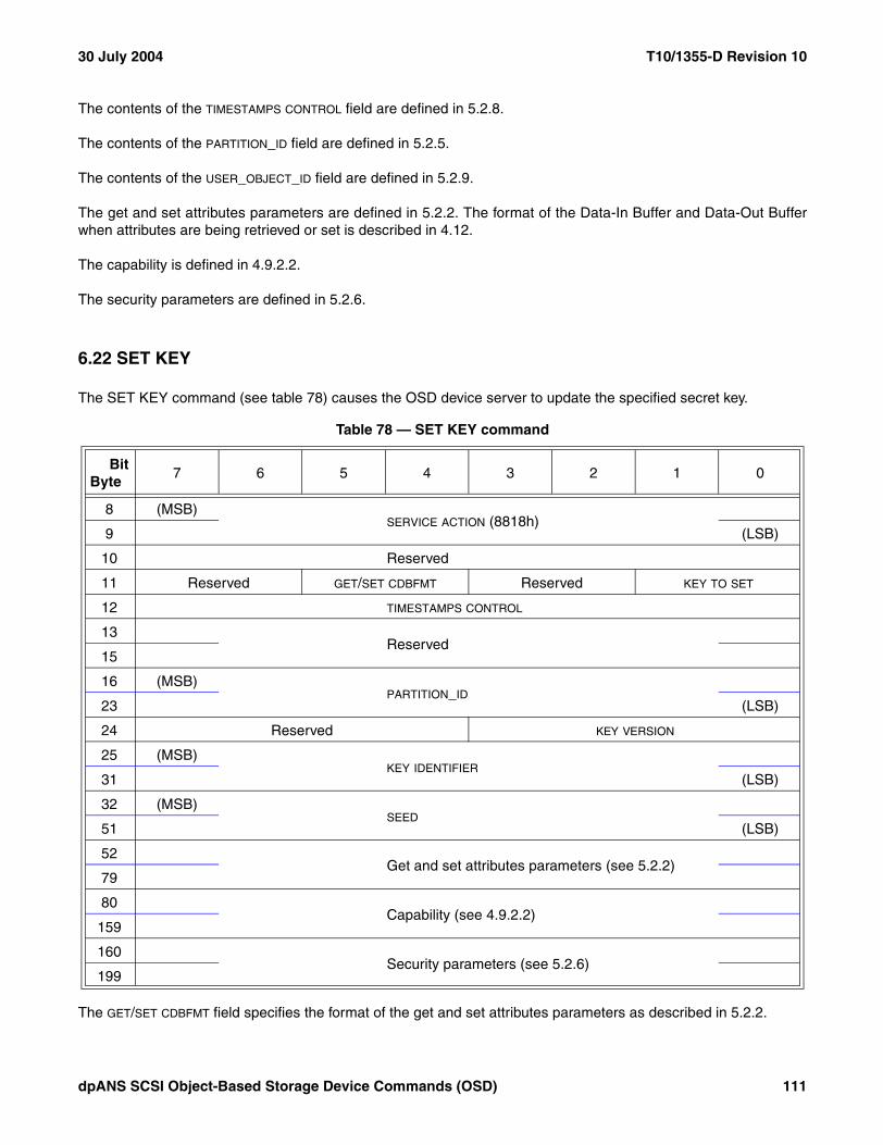
30 July 2004 T10/1355-D Revision 10
The contents of the TIMESTAMPS CONTROL field are defined in 5.2.8.
The contents of the PARTITION_ID field are defined in 5.2.5.
The contents of the USER_OBJECT_ID field are defined in 5.2.9.
The get and set attributes parameters are defined in 5.2.2. The format of the Data-In Buffer and Data-Out Bufferwhen attributes are being retrieved or set is described in 4.12.
The capability is defined in 4.9.2.2.
The security parameters are defined in 5.2.6.
6.22 SET KEY
The SET KEY command (see table 78) causes the OSD device server to update the specified secret key.
The GET/SET CDBFMT field specifies the format of the get and set attributes parameters as described in 5.2.2.
Table 78 — SET KEY command
BitByte
7 6 5 4 3 2 1 0
8 (MSB)SERVICE ACTION (8818h)
9 (LSB)
10 Reserved
11 Reserved GET/SET CDBFMT Reserved KEY TO SET
12 TIMESTAMPS CONTROL
13Reserved
15
16 (MSB)PARTITION_ID
23 (LSB)
24 Reserved KEY VERSION
25 (MSB)KEY IDENTIFIER
31 (LSB)
32 (MSB)SEED
51 (LSB)
52 Get and set attributes parameters (see 5.2.2)
79
80 Capability (see 4.9.2.2)
159
160 Security parameters (see 5.2.6)
199
dpANS SCSI Object-Based Storage Device Commands (OSD) 111

T10/1355-D Revision 10 30 July 2004
The contents of the TIMESTAMPS CONTROL field are defined in 5.2.8.
The KEY TO SET field (see table 79) specifies which key shall be updated, which key identifier shall be stored, andwhich keys shall be invalid following the SET KEY command.
For every key that is invalidated by a SET KEY command, the associated key identifier attribute shall have itsattribute length set to zero.
The contents of the PARTITION_ID field are defined in 5.2.5. If the KEY TO SET field contains 01b and the PARTITION_ID field contains a value other than zero, the command shall be terminated with a CHECK CONDITION status, thesense key shall be set to ILLEGAL REQUEST, and the additional sense code shall be set to INVALID FIELD INCDB.
The KEY VERSION field specifies the working key version to be updated. If the KEY TO SET field contains 01b or 10b,the KEY VERSION field shall be ignored.
The KEY IDENTIFIER field specifies a unique identifier to be associated with the new key. Successful processing ofthe SET KEY command shall include storing the key identifier value in the attribute specified in table 79.
The SEED field contains a random number generated from a good source of entropy (e.g., as described in RFC1750). The updated key values shall be computed as described in 4.10.9.2.
The get and set attributes parameters are defined in 5.2.2. The format of the Data-In Buffer and Data-Out Bufferwhen attributes are being retrieved or set is described in 4.12.
The capability is defined in 4.9.2.2.
The security parameters are defined in 5.2.6. The secret key whose authentication key shall be used to computethe capability key for this SET KEY command is specified in 4.10.6.3.
Table 79 — Key to set code values
Value Key to update Key identifier attribute to store Keys to invalidate
00b Reserved
01b Root The root key identifier attribute in the Root Policy/Security attributes page (see 7.1.2.20)
Previous root key, and all partition and working keys
10b Partition The partition key identifier attribute in the Partition Policy/Security attributes page (see 7.1.2.21)
Previous partition key, and all working keys
11b Working The working key identifier attribute in the Partition Policy/Security attributes page selected by the KEY VERSION field in the CDB
None
112 dpANS SCSI Object-Based Storage Device Commands (OSD)

30 July 2004 T10/1355-D Revision 10
6.23 SET MASTER KEY
6.23.1 Introduction
The SET MASTER KEY command (see table 80) causes the OSD device server to update the master key secretkey.
The DH_STEP (Diffie-Hellman step) field (see table 81) specifies which step in the Diffie-Hellman exchange toprocess.
Table 80 — SET MASTER KEY command
BitByte
7 6 5 4 3 2 1 0
8 (MSB)SERVICE ACTION (8819h)
9 (LSB)
10 Reserved
11 Reserved GET/SET CDBFMT Reserved DH_STEP
12 TIMESTAMPS CONTROL
13Reserved
23
24 DH_GROUP
25 (MSB)KEY IDENTIFIER
31 (LSB)
32 (MSB)PARAMETER LIST LENGTH
35 (LSB)
36 (MSB)ALLOCATION LENGTH
39 (LSB)
40Reserved
51
52 Get and set attributes parameters (see 5.2.2)
79
80 Capability (see 4.9.2.2)
159
160 Security parameters (see 5.2.6)
199
Table 81 — Diffie-Hellman exchange step values
Value Name Reference
00b SEED EXCHANGE 6.23.2
01b CHANGE MASTER KEY 6.23.3
10b to 11b Reserved
dpANS SCSI Object-Based Storage Device Commands (OSD) 113

T10/1355-D Revision 10 30 July 2004
If a SET MASTER KEY command is received with the DH_STEP field set to CHANGE MASTER KEY and no SETMASTER KEY command has been received with the DH_STEP field set to SEED EXCHANGE on the same I_T_Lnexus during the past ten seconds, the command shall be terminated with a CHECK CONDITION status, thesense key shall be set to ILLEGAL REQUEST, and the additional sense code shall be set to INVALID FIELD INCDB.
A device server that receives a SET MASTER KEY command on one I_T_L nexus while the processing the DH_steps on a different I_T_L nexus is incomplete may terminate the second SET MASTER KEY command with aCHECK CONDITION status, setting the sense key to ILLEGAL REQUEST and the additional sense code toSYSTEM RESOURCE FAILURE.
The usage of other CDB fields is specified in the description of each Diffie-Hellman step.
6.23.2 Seed exchange
The GET/SET CDBFMT field specifies the format of the get and set attributes parameters as described in 5.2.2.
The contents of the TIMESTAMPS CONTROL field are defined in 5.2.8.
The DH_GROUP field specifies the coded value selected from the Group Description list of coded values maintainedby IANA (see http://www.iana.org/assignments/ipsec-registry) that identifies the DH_generator and DH_primevalues to be used for the SEED EXCHANGE step. If the value in the DH_GROUP field does not appear in one of theDH group attributes in the Root Policy/Security attributes page (see 7.1.2.20) the command shall be terminatedwith a CHECK CONDITION status, the sense key shall be set to ILLEGAL REQUEST, and the additional sensecode shall be set to INVALID FIELD IN CDB.
The KEY IDENTIFIER field is reserved for the SEED EXCHANGE step.
The PARAMETER LIST LENGTH field specifies the number of bytes of application client DH_data to be sent to thedevice server. The application client DH_data is computed as follows:
1) A random number, x, is generated having a value between 0 and DH_prime minus one observing therequirements in RFC 1750; and
2) The application client DH_data is equal to DH_generatorx modulo DH_prime, where the DH_generator andDH_prime values are identified by the code value in the CDB DH_GROUP field.
The ALLOCATION LENGTH field specifies the number of bytes available to receive the device server DH_data (seetable 27) sent in response to the SET MASTER KEY command. If the allocation length is not sufficient to containdevice sever DH_data, the command shall be terminated with a CHECK CONDITION status, the sense key shallbe set to ILLEGAL REQUEST, and the additional sense code shall be set to INVALID FIELD IN CDB.
The RESPONSE LENGTH field indicates the number of bytes of device server DH_data that follow.
Table 82 — Seed exchange device server DH_data format
BitByte
7 6 5 4 3 2 1 0
0 (MSB)RESPONSE LENGTH (n-3)
3 (LSB)
4DEVICE SERVER DH_DATA
n
114 dpANS SCSI Object-Based Storage Device Commands (OSD)
30 July 2004 T10/1355-D Revision 10
The DEVICE SERVER DH_DATA field contains the DH_data computed by the device server as follows:
1) A random number, y, is generated having a value between 0 and DH_prime minus one observing therequirements in RFC 1750; and
2) The device server DH_data is equal to DH_generatory modulo DH_prime, where the DH_generator andDH_prime values are identified by the code value in the CDB DH_GROUP field.
The get and set attributes parameters are defined in 5.2.2. The format of the Data-In Buffer and Data-Out Bufferwhen attributes are being retrieved or set is described in 4.12.
The capability is defined in 4.9.2.2.
The security parameters are defined in 5.2.6. The master key authentication key shall be used to compute thecapability key for this SET MASTER KEY command (see 4.10.6.3).
After GOOD status has been returned for the SET MASTER KEY command SEED EXCHANGE step and beforethe SET MASTER KEY command CHANGE MASTER KEY step is processed, the next authentication master keyand next generation master key shall be computed as described in 4.10.9.2, using a seed value that is the concat-enation of the following:
1) DH_generatorxy modulo DH_prime;2) The contents of the OSD system ID attribute in the Root Information attributes page (see 7.1.2.8);3) The contents of the product model attribute in the Root Information attributes page;4) The contents of the serial number attribute in the Root Information attributes page;5) The contents of the OSD name attribute in the Root Information attributes page; and6) The contents of the username attribute in the Partition Information attributes page (see 7.1.2.9) for partition
zero (see 3.1.32).
6.23.3 Change master key
The GET/SET CDBFMT field specifies the format of the get and set attributes parameters as described in 5.2.2.
The contents of the TIMESTAMPS CONTROL field are defined in 5.2.8.
The DH_GROUP field is reserved for the CHANGE MASTER KEY step.
The KEY IDENTIFIER field specifies a unique identifier to be associated with the new master key. Successfulprocessing of the SET MASTER KEY command CHANGE MASTER KEY step shall include storing the keyidentifier value in the master key identifier attribute in the Root Policy/Security attributes page (see 7.1.2.20).
The PARAMETER LIST LENGTH field specifies the number of bytes in the CHANGE MASTER KEY parameter list (seetable 83). If the parameter list length causes truncation of any field in the CHANGE MASTER KEY parameter list,the command shall be terminated with a CHECK CONDITION status, the sense key shall be set to ILLEGALREQUEST, and the additional sense code shall be set to PARAMETER LIST LENGTH ERROR.
The get and set attributes parameters are defined in 5.2.2. The format of the Data-In Buffer and Data-Out Bufferwhen attributes are being retrieved or set is described in 4.12.
The capability is defined in 4.9.2.2.
dpANS SCSI Object-Based Storage Device Commands (OSD) 115

T10/1355-D Revision 10 30 July 2004
The security parameters are defined in 5.2.6. The next authentication master key computed after the return ofGOOD status for the most recent SET MASTER KEY command SEED EXCHANGE step (see 6.23.2) shall beused to compute the capability key for this SET MASTER KEY command CHANGE MASTER KEY step (see4.10.6.3).
The APPLICATION CLIENT DATA LENGTH field specifies the number of bytes that follow in the APPLICATION CLIENT DH_DATA field.
The APPLICATION CLIENT DH_DATA field contains the application client DH_data from the SEED EXCHANGE step.
The DEVICE SERVER DATA LENGTH field specifies the number of bytes that follow in the DEVICE SERVER DH_DATA field.
The DEVICE SERVER DH_DATA field contains the device server DH_data from the SEED EXCHANGE step.
The command shall be terminated with a CHECK CONDITION status, the sense key shall be set to ILLEGALREQUEST, and the additional sense code shall be set to INVALID FIELD IN PARAMETER LIST if CHANGEMASTER KEY parameter data fails to compare in any of the following ways with the data exchanged in the SEEDEXCHANGE step that was most recently processed on this I_T_L nexus since a I_T nexus loss event, logical unitreset event, or reset event (see SAM-3), if any:
a) The contents of the APPLICATION CLIENT DATA LENGTH field do not match the contents of the PARAMETER LIST
LENGTH field in the SEED EXCHANGE step;b) The contents of the APPLICATION CLIENT DH_DATA field do not match the contents of the parameter data in
the SEED EXCHANGE step;c) The contents of the DEVICE SERVER DATA LENGTH field do not match the contents of the RESPONSE LENGTH
field in the SEED EXCHANGE step; ord) The contents of the DEVICE SERVER DH_DATA field do not match the contents of the DEVICE SERVER DH_DATA
field in the SEED EXCHANGE step.
Successful processing of a SET MASTER KEY command CHANGE MASTER KEY step shall:
a) Replace the authentication master key with the next authentication master key computed after the return ofGOOD status for the most recent SET MASTER KEY command SEED EXCHANGE step (see 6.23.2);
b) Replace the generation master key with the next generation master key computed after the return ofGOOD status for the most recent SET MASTER KEY command SEED EXCHANGE step;
c) Invalidate all of the following keys (see 4.10.9):A) The root key;
Table 83 — Change master key DH_data format
BitByte
7 6 5 4 3 2 1 0
0 (MSB)APPLICATION CLIENT DATA LENGTH (k-3)
3 (LSB)
4APPLICATION CLIENT DH_DATA
k
k+1 (MSB)DEVICE SERVER DATA LENGTH (n-(k+4))
k+4 (LSB)
k+5DEVICE SERVER DH_DATA
n
116 dpANS SCSI Object-Based Storage Device Commands (OSD)

30 July 2004 T10/1355-D Revision 10
B) The partition key for every partition on the OSD logical unit; andC) Every working key in every partition on the OSD logical unit.
For every key that is invalidated by a SET MASTER KEY command CHANGE MASTER KEY step, the associatedkey identifier attribute shall have its attribute length set to zero.
6.24 WRITE
The WRITE command (see table 84) causes the specified number of bytes to be written to the specified user objectat the specified relative location.
The contents of the OPTIONS BYTE field are defined in 5.2.4.
The GET/SET CDBFMT field specifies the format of the get and set attributes parameters as described in 5.2.2.
Table 84 — WRITE command
BitByte
7 6 5 4 3 2 1 0
8 (MSB)SERVICE ACTION (8806h)
9 (LSB)
10 OPTIONS BYTE
11 Reserved GET/SET CDBFMT Reserved
12 TIMESTAMPS CONTROL
13Reserved
15
16 (MSB)PARTITION_ID
23 (LSB)
24 (MSB)USER_OBJECT_ID
31 (LSB)
32Reserved
35
36 (MSB)LENGTH
43 (LSB)
44 (MSB)STARTING BYTE ADDRESS
51 (LSB)
52 Get and set attributes parameters (see 5.2.2)
79
80 Capability (see 4.9.2.2)
159
160 Security parameters (see 5.2.6)
199
dpANS SCSI Object-Based Storage Device Commands (OSD) 117

T10/1355-D Revision 10 30 July 2004
The contents of the TIMESTAMPS CONTROL field are defined in 5.2.8.
The contents of the PARTITION_ID field are defined in 5.2.5.
The contents of the USER_OBJECT_ID field are defined in 5.2.9.
The contents of the LENGTH field are defined in 5.2.3. The data to be written to the user object shall be placed in theData-Out Buffer as described in 5.2.3.
The contents of the STARTING BYTE ADDRESS field are defined in 5.2.7.
A WRITE to a byte that is greater than the value in the user object logical length attribute in the User Object Infor-mation attributes page (see 7.1.2.11) shall implicitly increase the value in the user object logical length attribute tothe largest byte written.
The get and set attributes parameters are defined in 5.2.2. The format of the Data-In Buffer and Data-Out Bufferwhen attributes are being retrieved or set is described in 4.12.
The capability is defined in 4.9.2.2.
The security parameters are defined in 5.2.6.
If a CREATE command causes the value in the user object logical length attribute in the User Object Informationattributes page (see 7.1.2.11) to exceed the value in the maximum user object length attribute in the User ObjectQuotas attributes page, then a quota error shall be generated (see 4.8.2). The quota testing principles described in4.8.3 apply to the testing of the maximum user object length quota.
If a CREATE command causes the value in the used capacity attribute in the Partition Information attributes page(see 7.1.2.9) to exceed the value in the capacity quota attribute in the Partition Quotas attributes page (see7.1.2.13), then a quota error shall be generated (see 4.8.2). The quota testing principles described in 4.8.3 apply tothe testing of the capacity quota.
118 dpANS SCSI Object-Based Storage Device Commands (OSD)

30 July 2004 T10/1355-D Revision 10
7 Parameters for OSD type devices
7.1 Attributes parameters
7.1.1 Attributes parameter formats
The following formats shall be provided for attributes parameter data:
a) Page format (see 7.1.2); andb) List format (see 7.1.3).
Page format parameter data allows retrieval of attributes in formatted pages where only the attribute values appearin the parameter data.
Those attributes pages that do not have a defined page format are not accessible via page format parameter data(e.g., the Root Directory attributes page defined in 7.1.2.4).
List format parameter data handles individual attributes in an identifier, length, value format, allowing access to anygroup of attributes in any order.
Attribute access is limited to the:
a) Attributes associated with the OSD object addressed by the command; andb) Attributes in the Current Command attributes page (see 7.1.2.24).
NOTE 4 Addressing the root object allows access to the attributes associated with the root object and partition zero(see 3.1.32)
The format of the Data-In Buffer and Data-Out Buffer when attributes meta data is being used is described in 4.12.
A get attributes request for an attribute or attributes page having no previously established value shall not beconsidered an error. If an attribute value that has not been previously established is requested by specific attributenumber, a list entry format value (see 7.1.3.3) having FFFF FFFFh in the ATTRIBUTE LENGTH field shall be returned.If an attributes page that has no established definition is requested, a null attributes page (see 7.1.2.25) shall bereturned.
7.1.2 OSD attributes pages
7.1.2.1 Attributes pages overview
Every attributes page is identified by a page number (see 4.7.3). Every attributes page includes attribute number0h whose contents are defined in 7.1.2.2.
In addition to attribute number 0h, an attributes page is composed of attribute values numbered 1h through FFFFFFFEh.
dpANS SCSI Object-Based Storage Device Commands (OSD) 119
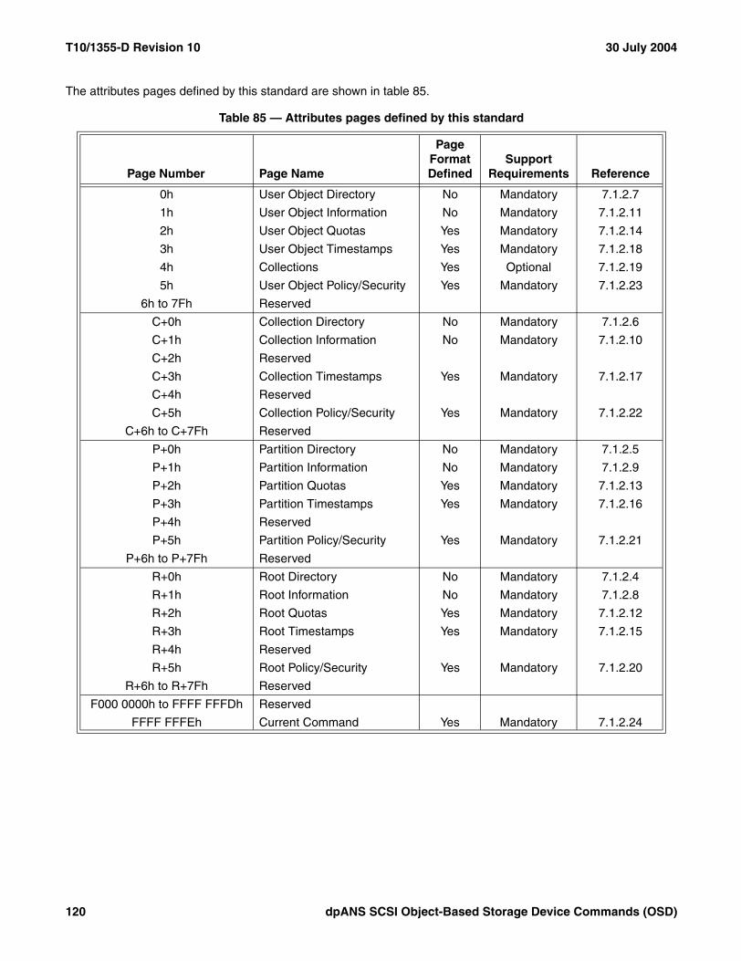
T10/1355-D Revision 10 30 July 2004
The attributes pages defined by this standard are shown in table 85.
Table 85 — Attributes pages defined by this standard
Page Number Page Name
Page Format Defined
Support Requirements Reference
0h User Object Directory No Mandatory 7.1.2.7
1h User Object Information No Mandatory 7.1.2.11
2h User Object Quotas Yes Mandatory 7.1.2.14
3h User Object Timestamps Yes Mandatory 7.1.2.18
4h Collections Yes Optional 7.1.2.19
5h User Object Policy/Security Yes Mandatory 7.1.2.23
6h to 7Fh Reserved
C+0h Collection Directory No Mandatory 7.1.2.6
C+1h Collection Information No Mandatory 7.1.2.10
C+2h Reserved
C+3h Collection Timestamps Yes Mandatory 7.1.2.17
C+4h Reserved
C+5h Collection Policy/Security Yes Mandatory 7.1.2.22
C+6h to C+7Fh Reserved
P+0h Partition Directory No Mandatory 7.1.2.5
P+1h Partition Information No Mandatory 7.1.2.9
P+2h Partition Quotas Yes Mandatory 7.1.2.13
P+3h Partition Timestamps Yes Mandatory 7.1.2.16
P+4h Reserved
P+5h Partition Policy/Security Yes Mandatory 7.1.2.21
P+6h to P+7Fh Reserved
R+0h Root Directory No Mandatory 7.1.2.4
R+1h Root Information No Mandatory 7.1.2.8
R+2h Root Quotas Yes Mandatory 7.1.2.12
R+3h Root Timestamps Yes Mandatory 7.1.2.15
R+4h Reserved
R+5h Root Policy/Security Yes Mandatory 7.1.2.20
R+6h to R+7Fh Reserved
F000 0000h to FFFF FFFDh Reserved
FFFF FFFEh Current Command Yes Mandatory 7.1.2.24
120 dpANS SCSI Object-Based Storage Device Commands (OSD)

30 July 2004 T10/1355-D Revision 10
7.1.2.2 Attribute number 0h in all attributes pages
With the exception of the Root Directory, Partition Directory, and Collection Directory attributes pages, all attributespages defined by this standard shall contain an identification of the page in attribute number 0h. All attributespages should contain an identification of the page in attribute number 0h.
The format of the page identification shall be a 40 byte fixed length value with the format shown in table 86.
The left-aligned, space-padded (see 3.7.2) VENDOR IDENTIFICATION field shall contain eight bytes of ASCII data (see3.7) identifying the organization that has defined the contents of the attributes page. The format of the VENDOR
IDENTIFICATION field is identical to the format of the VENDOR IDENTIFICATION field in the standard INQUIRY data (seeSPC-3).
NOTE 5 It is intended that the VENDOR IDENTIFICATION field provide a unique identification of the organization thatdefined the attributes page contents. In the absence of a formal registration procedure, T10 maintains a list ofvendor identification codes in use (see SPC-3). Organizations are requested to voluntarily submit their identifi-cation codes to T10 to prevent duplication of codes. The T10 web site, www.t10.org, provides a convenient meansto request an identification code.
The left-aligned, null-terminated, null-padded (see 3.7.2) ATTRIBUTES PAGE IDENTIFICATION field shall contain 32bytes of ASCII data identifying the attributes page in which it appears.
If the VENDOR IDENTIFICATION field contains the ASCII characters "INCITS", the first characters in the ATTRIBUTES
PAGE IDENTIFICATION field shall identify the INCITS technical committee that has defined the contents of theattributes page (e.g., attributes pages defined by this standard have the ASCII characters "T10" as the firstcharacters in the ATTRIBUTES PAGE IDENTIFICATION field).
NOTE 6 Using the User Object Directory attributes page as an example, the VENDOR IDENTIFICATION field containsthe ASCII characters "INCITS" and the ATTRIBUTES PAGE IDENTIFICATION field contains the ASCII characters "T10User Object Information". The attribute number 0h attribute value is "INCITS T10 User Object Directory".
7.1.2.3 Attribute number 0h for unidentified attributes pages
Certain attributes pages may be created dynamically making them subject to programming errors that fail to definean attribute number 0h for the attributes page as recommended by this standard. For such attributes pages, deviceservers use the unidentified page identification attribute value specified in this subclause.
The unidentified page identification attribute shall have the format described in 7.1.2.2 with the VENDOR IDENTIFI-CATION field containing eight ASCII space characters (i.e., 20h) and the ATTRIBUTES PAGE IDENTIFICATION fieldcontaining the ASCII characters "unidentified attributes page".
Table 86 — Attribute number 0h format for all attributes pages
BitByte
7 6 5 4 3 2 1 0
0 (MSB)VENDOR IDENTIFICATION
7 (LSB)
8 (MSB)ATTRIBUTES PAGE IDENTIFICATION
39 (LSB)
dpANS SCSI Object-Based Storage Device Commands (OSD) 121

T10/1355-D Revision 10 30 July 2004
7.1.2.4 Root Directory attributes page
The Root Directory attributes page (R+0h) shall contain one attribute for every root attributes page number acces-sible via the logical unit.
Within the Root Directory attributes page:
a) The attribute number of each attribute shall be equal to the page number of the accessible attributes pagethat it represents;
b) The attribute value shall be equal to:A) If the length of the attribute numbered 0h in the attributes page identified by the root directory attribute
number is not zero, then the value of the attribute numbered 0h in the identified attributes page; orB) If the length of the attribute numbered 0h in the attributes page identified by the root directory attribute
number is zero, then:a) If there are no attributes with a non-zero length in the attributes page identified by the root
directory attribute number, then the root directory attribute value shall have a length of zero; orb) If there are one or more attributes with a non-zero length in the attributes page identified by the
root directory attribute number, then the root directory attribute shall have the unidentified pageidentification attribute value specified in 7.1.2.3.
The Root Directory page identification attribute (number R+0h) shall have the format described in 7.1.2.2 with theVENDOR IDENTIFICATION field containing the ASCII characters "INCITS" and the ATTRIBUTES PAGE IDENTIFICATION
field containing the ASCII characters "T10 Root Directory".
Attribute values in the Root Directory attributes page have the format described in 7.1.2.2.
Table 87 shows the attributes in the Root Directory attributes page when only the attributes pages defined in thisstandard are accessible via the logical unit.
The contents of the Root Directory attributes page shall be maintained by the OSD logical unit.
If a set attributes list (see 5.2.2.3) contains an entry specifying the Root Directory attributes page (R+0h), thecommand shall be terminated with a CHECK CONDITION status, with the sense key set to ILLEGAL REQUESTand the additional sense code set to INVALID FIELD IN PARAMETER LIST. If the CDB SET ATTRIBUTES PAGE field(see 5.2.2.2) contains R+0h (i.e., the Root Directory attributes page number), the command shall be terminatedwith a CHECK CONDITION status, with the sense key set to ILLEGAL REQUEST and the additional sense codeset to INVALID FIELD IN CDB.
Table 87 — Example Root Directory attributes page contents
Attribute Number Attribute Value (ASCII characters)
R+0h "INCITS T10 Root Directory"
R+1h "INCITS T10 Root Information"
R+2h "INCITS T10 Root Quotas"
R+3h "INCITS T10 Root Timestamps"
R+5h "INCITS T10 Root Policy/Security"
122 dpANS SCSI Object-Based Storage Device Commands (OSD)

30 July 2004 T10/1355-D Revision 10
7.1.2.5 Partition Directory attributes page
The Partition Directory attributes page (P+0h) shall contain one attribute for every partition attributes page numberaccessible to the partition.
Within the Partition Directory attributes page:
a) The attribute number of each attribute shall be equal to the page number of the accessible attributes pagethat it represents;
b) The attribute value shall be equal to:A) If the length of the attribute numbered 0h in the attributes page identified by the partition directory
attribute number is not zero, then the value of the attribute numbered 0h in the identified attributespage; or
B) If the length of the attribute numbered 0h in the attributes page identified by the partition directoryattribute number is zero, then:a) If there are no attributes with a non-zero length in the attributes page identified by the partition
directory attribute number, then the partition directory attribute value shall have a length of zero; orb) If there are one or more attributes with a non-zero length in the attributes page identified by the
partition directory attribute number, then the partition directory attribute shall have the unidentifiedpage identification attribute value specified in 7.1.2.3.
The Partition Directory page identification attribute (number P+0h) shall have the format described in 7.1.2.2 withthe VENDOR IDENTIFICATION field containing the ASCII characters "INCITS" and the ATTRIBUTES PAGE IDENTIFICATION
field containing the ASCII characters "T10 Partition Directory".
Attribute values in the Partition Directory attributes page have the format described in 7.1.2.2.
Table 88 shows the attributes in the Partition Directory attributes page when only the attributes pages defined inthis standard are accessible via the logical unit.
The contents of the Partition Directory attributes page shall be maintained by the OSD logical unit.
If a set attributes list (see 5.2.2.3) contains an entry specifying the Partition Directory attributes page (P+0h), thecommand shall be terminated with a CHECK CONDITION status, with the sense key set to ILLEGAL REQUESTand the additional sense code set to INVALID FIELD IN PARAMETER LIST. If the CDB SET ATTRIBUTES PAGE field(see 5.2.2.2) contains P+0h (i.e., the Partition Directory attributes page number), the command shall be terminatedwith a CHECK CONDITION status, with the sense key set to ILLEGAL REQUEST and the additional sense codeset to INVALID FIELD IN CDB.
Table 88 — Example Partition Directory attributes page contents
Attribute Number Attribute Value (ASCII characters)
P+0h "INCITS T10 Partition Directory"
P+1h "INCITS T10 Partition Information"
P+2h "INCITS T10 Partition Quotas"
P+3h "INCITS T10 Partition Timestamps"
P+5h "INCITS T10 Partition Policy/Security"
dpANS SCSI Object-Based Storage Device Commands (OSD) 123

T10/1355-D Revision 10 30 July 2004
7.1.2.6 Collection Directory attributes page
The Collection Directory attributes page (C+0h) shall contain one attribute for every collection attributes pagenumber accessible to the collection.
Within the Collection Directory attributes page:
a) The attribute number of each attribute shall be equal to the page number of the accessible attributes pagethat it represents;
b) The attribute value shall be equal to:A) If the length of the attribute numbered 0h in the attributes page identified by the collection directory
attribute number is not zero, then the value of the attribute numbered 0h in the identified attributespage; or
B) If the length of the attribute numbered 0h in the attributes page identified by the collection directoryattribute number is zero, then:a) If there are no attributes with a non-zero length in the attributes page identified by the collection
directory attribute number, then the collection directory attribute value shall have a length of zero;or
b) If there are one or more attributes with a non-zero length in the attributes page identified by thecollection directory attribute number, then the collection directory attribute shall have the uniden-tified page identification attribute value specified in 7.1.2.3.
The Collection Directory page identification attribute (number C+0h) shall have the format described in 7.1.2.2 withthe VENDOR IDENTIFICATION field containing the ASCII characters "INCITS" and the ATTRIBUTES PAGE IDENTIFICATION
field containing the ASCII characters "T10 Collection Directory".
Attribute values in the Collection Directory attributes page have the format described in 7.1.2.2.
Table 89 shows the attributes in the Collection Directory attributes page when only the attributes pages defined inthis standard are accessible via the logical unit.
The contents of the Collection Directory attributes page shall be maintained by the OSD logical unit.
If a set attributes list (see 5.2.2.3) contains an entry specifying the Collection Directory attributes page (C+0h), thecommand shall be terminated with a CHECK CONDITION status, with the sense key set to ILLEGAL REQUESTand the additional sense code set to INVALID FIELD IN PARAMETER LIST. If the CDB SET ATTRIBUTES PAGE field(see 5.2.2.2) contains C+0h (i.e., the Collection Directory attributes page number), the command shall be termi-nated with a CHECK CONDITION status, with the sense key set to ILLEGAL REQUEST and the additional sensecode set to INVALID FIELD IN CDB.
Table 89 — Example Collection Directory attributes page contents
Attribute Number Attribute Value (ASCII characters)
C+0h "INCITS T10 Collection Directory"
C+1h "INCITS T10 Collection Information"
C+3h "INCITS T10 Collection Timestamps"
C+5h "INCITS T10 Collection Policy/Security"
124 dpANS SCSI Object-Based Storage Device Commands (OSD)
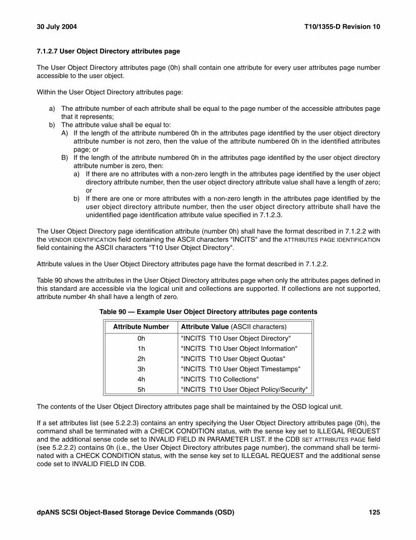
30 July 2004 T10/1355-D Revision 10
7.1.2.7 User Object Directory attributes page
The User Object Directory attributes page (0h) shall contain one attribute for every user attributes page numberaccessible to the user object.
Within the User Object Directory attributes page:
a) The attribute number of each attribute shall be equal to the page number of the accessible attributes pagethat it represents;
b) The attribute value shall be equal to:A) If the length of the attribute numbered 0h in the attributes page identified by the user object directory
attribute number is not zero, then the value of the attribute numbered 0h in the identified attributespage; or
B) If the length of the attribute numbered 0h in the attributes page identified by the user object directoryattribute number is zero, then:a) If there are no attributes with a non-zero length in the attributes page identified by the user object
directory attribute number, then the user object directory attribute value shall have a length of zero;or
b) If there are one or more attributes with a non-zero length in the attributes page identified by theuser object directory attribute number, then the user object directory attribute shall have theunidentified page identification attribute value specified in 7.1.2.3.
The User Object Directory page identification attribute (number 0h) shall have the format described in 7.1.2.2 withthe VENDOR IDENTIFICATION field containing the ASCII characters "INCITS" and the ATTRIBUTES PAGE IDENTIFICATION
field containing the ASCII characters "T10 User Object Directory".
Attribute values in the User Object Directory attributes page have the format described in 7.1.2.2.
Table 90 shows the attributes in the User Object Directory attributes page when only the attributes pages defined inthis standard are accessible via the logical unit and collections are supported. If collections are not supported,attribute number 4h shall have a length of zero.
The contents of the User Object Directory attributes page shall be maintained by the OSD logical unit.
If a set attributes list (see 5.2.2.3) contains an entry specifying the User Object Directory attributes page (0h), thecommand shall be terminated with a CHECK CONDITION status, with the sense key set to ILLEGAL REQUESTand the additional sense code set to INVALID FIELD IN PARAMETER LIST. If the CDB SET ATTRIBUTES PAGE field(see 5.2.2.2) contains 0h (i.e., the User Object Directory attributes page number), the command shall be termi-nated with a CHECK CONDITION status, with the sense key set to ILLEGAL REQUEST and the additional sensecode set to INVALID FIELD IN CDB.
Table 90 — Example User Object Directory attributes page contents
Attribute Number Attribute Value (ASCII characters)
0h "INCITS T10 User Object Directory"
1h "INCITS T10 User Object Information"
2h "INCITS T10 User Object Quotas"
3h "INCITS T10 User Object Timestamps"
4h "INCITS T10 Collections"
5h "INCITS T10 User Object Policy/Security"
dpANS SCSI Object-Based Storage Device Commands (OSD) 125

T10/1355-D Revision 10 30 July 2004
7.1.2.8 Root Information attributes page
The Root Information attributes page (R+1h) shall contain the attributes listed in table 91.
The page identification attribute (number 0h) shall have the format described in 7.1.2.2 with the VENDOR IDENTIFI-CATION field containing the ASCII characters "INCITS" and the ATTRIBUTES PAGE IDENTIFICATION field containing theASCII characters "T10 Root Information".
The left-aligned, zero-padded (see 3.7.2) OSD system ID attribute (number 3h) shall contain an identificationdescriptor using the same format as defined for the Device Identification VPD page (see SPC-3) with the followingadditional requirements on the fields in the identification descriptor:
a) The CODE SET field shall contain 1h (i.e., binary valued identifier);b) The PROTOCOL IDENTIFIER field shall contain Fh (i.e., not applicable to any specific protocol);c) The IDENTIFIER TYPE field shall contain one of the following values:
A) 1h (i.e., T10 vendor identification);B) 2h (i.e., EUI-64 based); orC) 3h (i.e., NAA);
d) The ASSOCIATION field shall contain 0h (i.e., logical unit); ande) The identifier length shall be less than 17.
If the Device Identification VPD page contains an identification descriptor that meets the requirements for OSDSystem ID attribute value described in this subclause, the same identification descriptor should be used as theOSD System ID attribute value.
Table 91 — Root Information attributes page contents
AttributeNumber
Length (bytes) Attribute
Application Client
SettableOSD Logical Unit Provided
0h 40 Page identification No Yes
1h to 2h Reserved No Yes
3h 20 OSD System ID No Yes
4h 8 Vendor identification No Yes
5h 16 Product identification No Yes
6h 32 Product model No Yes
7h 4 Product revision level No Yes
8h variable Product serial number No Yes
9h variable OSD name Yes No
Ah to 7Fh Reserved No
80h 8 Total capacity No Yes
81h 8 Used capacity No Yes
82h to BFh Reserved No
C0h 8 Number of partitions No Yes
C1h to FFh Reserved No
100h 6 Clock No Yes
101h to FFFF FFFEh Reserved No
126 dpANS SCSI Object-Based Storage Device Commands (OSD)

30 July 2004 T10/1355-D Revision 10
The vendor identification attribute (number 4h) shall contain the vendor identification of the manufacturer of theOBSD (see 3.1.26) in the same format as the VENDOR IDENTIFICATION field in the standard INQUIRY data (seeSPC-3).
The product identification attribute (number 5h) shall contain the product identification of the OBSD in the sameformat as the PRODUCT IDENTIFICATION field in the standard INQUIRY data (see SPC-3).
The left-aligned, space-padded (see 3.7.2) product model attribute (number 6h) shall contain 32 bytes of ASCIIcharacters (see 3.7.1) identifying the model of the OBSD.
The product revision level attribute (number 7h) shall contain the product revision level of the OBSD in the sameformat as the PRODUCT REVISION LEVEL field in the standard INQUIRY data (see SPC-3).
The product serial number attribute (number 8h) shall contain the product serial number of the OBSD in the sameformat as the PRODUCT SERIAL NUMBER field in the Unit Serial Number VPD page (see SPC-3).
The OSD name attribute (number 9h) shall contain an identification of the OSD logical unit specified by the appli-cation client. The OSD name attribute length shall be set to zero by a FORMAT OSD command (see 6.11).
The total capacity attribute (number 80h) shall contain the total number of bytes on the OSD logical unit.
The used capacity attribute (number 81h) shall contain the number of bytes used by all root object attributes, parti-tions, collections and user objects stored by the OSD logical unit including attributes bytes for the partition, collec-tions, and user objects.
The number of partitions attribute (number C0h) shall contain the number of partitions present in the OSD logicalunit.
The clock attribute (number 100h) shall contain the current time in use by the OSD device server represented asthe count of the number of milliseconds elapsed since midnight, 1 January 1970 UT (see 3.1.49). The value shallbe identical to the value of the adjustable clock attribute in the Root Policy/Security attributes page (see 7.1.2.20).
If a set attributes list (see 5.2.2.3) contains an entry specifying the number of an attribute that table 91 states is notapplication client settable, the command shall be terminated with a CHECK CONDITION status, with the sense keyset to ILLEGAL REQUEST and the additional sense code set to INVALID FIELD IN PARAMETER LIST. If the CDBSET ATTRIBUTE NUMBER field (see 5.2.2.2) specifies the number of an attribute that table 91 states is not applicationclient settable, the command shall be terminated with a CHECK CONDITION status, with the sense key set toILLEGAL REQUEST and the additional sense code set to INVALID FIELD IN CDB.
dpANS SCSI Object-Based Storage Device Commands (OSD) 127

T10/1355-D Revision 10 30 July 2004
7.1.2.9 Partition Information attributes page
The Partition Information attributes page (P+1h) shall contain the attributes listed in table 92.
The page identification attribute (number 0h) shall have the format described in 7.1.2.2 with the VENDOR IDENTIFI-CATION field containing the ASCII characters "INCITS" and the ATTRIBUTES PAGE IDENTIFICATION field containing theASCII characters "T10 Partition Information".
The Partition_ID attribute (number 1h) shall contain the Partition_ID of the partition with which the Partition Infor-mation attributes page is associated.
The username attribute (number 9h) shall contain a binary valued identification of the user of the partition specifiedby the application client. A CREATE PARTITION command (see 6.5) shall copy the username attribute from thePartition Information attributes page for partition zero (see 3.1.32) to the new Partition Information attributes page.
For all partitions except partition zero, the used capacity attribute (number 81h) shall contain the number of bytesused by the partition, all collections, and all user objects within the partition including attributes bytes. For partitionzero, the used capacity attribute shall contain the number of bytes used by partition zero and all other partitions, allcollections, and all user objects within all partitions including attributes bytes.
For all partitions except partition zero, the number of collections and user objects attribute (number C1h) shallcontain the sum of the number of collections and the number of user objects in the partition. For partition zero, thenumber of collections and user objects attribute shall contain zero.
If a set attributes list (see 5.2.2.3) contains an entry specifying the number of an attribute that table 92 states is notapplication client settable, the command shall be terminated with a CHECK CONDITION status, with the sense keyset to ILLEGAL REQUEST and the additional sense code set to INVALID FIELD IN PARAMETER LIST. If the CDBSET ATTRIBUTE NUMBER field (see 5.2.2.2) specifies the number of an attribute that table 92 states is not applicationclient settable, the command shall be terminated with a CHECK CONDITION status, with the sense key set toILLEGAL REQUEST and the additional sense code set to INVALID FIELD IN CDB.
Table 92 — Partition Information attributes page contents
AttributeNumber
Length (bytes) Attribute
Application Client
SettableOSD Logical Unit Provided
0h 40 Page identification No Yes
1h 8 Partition_ID No Yes
2h to 8h Reserved No
9h variable Username Yes No
Ah to 80h Reserved No
81h 8 Used capacity No Yes
82h to C0h Reserved No
C1h 8 Number of collections and user objects No Yes
C2h to FFFF FFFEh Reserved No
128 dpANS SCSI Object-Based Storage Device Commands (OSD)

30 July 2004 T10/1355-D Revision 10
7.1.2.10 Collection Information attributes page
The Collection Information attributes page (C+1h) shall contain the attributes listed in table 93.
The page identification attribute (number 0h) shall have the format described in 7.1.2.2 with the VENDOR IDENTIFI-CATION field containing the ASCII characters "INCITS" and the ATTRIBUTES PAGE IDENTIFICATION field containing theASCII characters "T10 Collection Information".
The Partition_ID attribute (number 1h) shall contain the Partition_ID of the collection with which the Collection Infor-mation attributes page is associated.
The Collection_Object_ID attribute (number 2h) shall contain the Collection_Object_ID (see 4.6.6) of the collectionwith which the Collection Information attributes page is associated.
The username attribute (number 9h) shall contain a binary valued identification of the user for the collectionspecified by the application client. A CREATE COLLECTION command (see 6.5) shall copy the username attributefrom the Partition Information attributes page (see 7.1.2.9) to the new Collection Information attributes page.
The used capacity attribute (number 81h) shall contain the number of bytes used by the collection includingattributes bytes.
If a set attributes list (see 5.2.2.3) contains an entry specifying the number of an attribute that table 93 states is notapplication client settable, the command shall be terminated with a CHECK CONDITION status, with the sense keyset to ILLEGAL REQUEST and the additional sense code set to INVALID FIELD IN PARAMETER LIST. If the CDBSET ATTRIBUTE NUMBER field (see 5.2.2.2) specifies the number of an attribute that table 93 states is not applicationclient settable, the command shall be terminated with a CHECK CONDITION status, with the sense key set toILLEGAL REQUEST and the additional sense code set to INVALID FIELD IN CDB.
Table 93 — Collection Information attributes page contents
AttributeNumber
Length (bytes) Attribute
Application Client
SettableOSD Logical Unit Provided
0h 40 Page identification No Yes
1h 8 Partition_ID No Yes
2h 8 Collection_Object_ID No Yes
3h to 8h Reserved No
9h variable Username Yes No
Ah to 80h Reserved No
81h 8 Used capacity No Yes
82h to FFFF FFFEh Reserved No
dpANS SCSI Object-Based Storage Device Commands (OSD) 129

T10/1355-D Revision 10 30 July 2004
7.1.2.11 User Object Information attributes page
The User Object Information attributes page (1h) shall contain the attributes listed in table 94.
The page identification attribute (number 0h) shall have the format described in 7.1.2.2 with the VENDOR IDENTIFI-CATION field containing the ASCII characters "INCITS" and the ATTRIBUTES PAGE IDENTIFICATION field containing theASCII characters "T10 User Object Information".
The Partition_ID attribute (number 1h) shall contain the Partition_ID of the user object with which the User ObjectInformation attributes page is associated.
The User_Object_ID attribute (number 2h) shall contain the User_Object_ID of the user object with which the UserObject Information attributes page is associated.
The username attribute (number 9h) shall contain a binary valued identification of the user for the user objectspecified by the application client. A CREATE command (see 6.3) or CREATE AND WRITE command (see 6.4)shall copy the username attribute from the Partition Information attributes page (see 7.1.2.9) to the new UserObject Information attributes page.
The used capacity attribute (number 81h) shall contain the number of bytes used by the user object includingattributes bytes.
The user object logical length attribute (number 82h) specifies the largest valued byte number written in theassociated user object. Setting the user object logical length attribute to a value that is smaller than the userobject’s logical length known to the OSD device server shall cause the user object to be truncated to the specifiedlength. Setting the user object logical length attribute to a value that is larger than the user object’s logical lengthknown to the OSD device server shall cause unwritten bytes to be added at the end of the user object.
At attempt to set the user object logical length attribute a value that is larger than the value in the maximum userobject length attribute in the User Object Quotas attributes page (see 7.1.2.14) shall generate a quota error (see4.8.2). The quota testing principles described in 4.8.3 apply to the testing of the maximum user object length quota.
Table 94 — User Object Information attributes page contents
AttributeNumber
Length (bytes) Attribute
Application Client
SettableOSD Logical Unit Provided
0h 40 Page identification No Yes
1h 8 Partition_ID No Yes
2h 8 User_Object_ID No Yes
3h to 8h Reserved No
9h variable Username Yes No
Ah to 80h Reserved No
81h 8 Used capacity No Yes
82h 8 User object logical length Yes Yes
83h to FFFF FFFEh Reserved No
130 dpANS SCSI Object-Based Storage Device Commands (OSD)

30 July 2004 T10/1355-D Revision 10
If setting the user object logical length attribute to a value that is larger than the user object’s logical length knownto the OSD device server causes the value in the used capacity attribute in the Partition Information attributes page(see 7.1.2.9) to exceed the value in the capacity quota attribute in the Partition Quotas attributes page (see7.1.2.13), then a quota error shall be generated (see 4.8.2). The quota testing principles described in 4.8.3 apply tothe testing of the capacity quota.
If a set attributes list (see 5.2.2.3) contains an entry specifying the number of an attribute that table 94 states is notapplication client settable, the command shall be terminated with a CHECK CONDITION status, with the sense keyset to ILLEGAL REQUEST and the additional sense code set to INVALID FIELD IN PARAMETER LIST. If the CDBSET ATTRIBUTE NUMBER field (see 5.2.2.2) specifies the number of an attribute that table 94 states is not applicationclient settable, the command shall be terminated with a CHECK CONDITION status, with the sense key set toILLEGAL REQUEST and the additional sense code set to INVALID FIELD IN CDB.
7.1.2.12 Root Quotas attributes page
The Root Quotas attributes page (R+2h) shall contain the attributes listed in table 95. Except for attribute number0h, all attributes in the Root Quotas attributes page are quotas (see 4.8).
The page identification attribute (number 0h) shall have the format described in 7.1.2.2 with the VENDOR IDENTIFI-CATION field containing the ASCII characters "INCITS" and the ATTRIBUTES PAGE IDENTIFICATION field containing theASCII characters "T10 Root Quotas".
The default maximum user object length attribute (number 1h) specifies the value to be copied to the defaultmaximum user object length attribute in the Partition Quotas attributes page (see 7.1.2.13) for each partition, whenit is created. The FORMAT OSD command (see 6.11) shall set the default maximum user object length attribute toFFFF FFFF FFFF FFFFh.
The partition capacity quota attribute (number 1 0001h) specifies the value to be copied to the capacity quotaattribute in the Partition Quotas attributes page for each partition, when it is created. The FORMAT OSD commandshall set the partition capacity quota attribute to FFFF FFFF FFFF FFFFh.
Table 95 — Root Quotas attributes page contents
AttributeNumber
Length (bytes) Attribute
Application Client
SettableOSD Logical Unit Provided
0h 40 Page identification No Yes
1h 8 Default maximum user object length Yes No
2h to 1 0000h Reserved No
1 0001h 8 Partition capacity quota Yes No
1 0002h 8 Partition object count Yes No
1 0003h to 1 0080h Reserved No
1 0081h 4 Partition collections per user object Yes No
1 0082h to 2 0001h Reserved No
2 0002h 8 Partition count Yes No
2 0003h to FFFF FFFEh Reserved No
dpANS SCSI Object-Based Storage Device Commands (OSD) 131

T10/1355-D Revision 10 30 July 2004
The partition object count attribute (number 1 0002h) specifies the value to be copied to the object count attributein the Partition Quotas attributes page for each partition, when it is created. The FORMAT OSD command shall setthe partition object count attribute to FFFF FFFF FFFF FFFFh.
The partition collections per user object attribute (number 1 0081h) specifies the value to be copied to the collec-tions per user object attribute in the Partition Quotas attributes page for each partition, when it is created. TheFORMAT OSD command shall set the partition collections per user object attribute to FFFF FFFFh.
The partition count attribute (number 2 0001h) specifies the maximum value allowed in the number of partitionsattribute in the Root Information attributes page (see 7.1.2.8). If a CREATE PARTITION command (see 6.6)attempts to exceed the partition count quota, a quota error (see 4.8.2) shall be generated. The FORMAT OSDcommand shall set the partition count attribute to FFFF FFFF FFFF FFFFh. A command that attempts to set thepartition count attribute value to zero shall be terminated with a CHECK CONDITION status, the sense key set toILLEGAL REQUEST, the additional sense code set to INVALID FIELD IN CDB, and the value in the partition countattribute shall not be changed.
If a set attributes list (see 5.2.2.3) contains an entry specifying the number of an attribute that table 95 states is notapplication client settable, the command shall be terminated with a CHECK CONDITION status, with the sense keyset to ILLEGAL REQUEST and the additional sense code set to INVALID FIELD IN PARAMETER LIST. If the CDBSET ATTRIBUTE NUMBER field (see 5.2.2.2) specifies the number of an attribute that table 95 states is not applicationclient settable, the command shall be terminated with a CHECK CONDITION status, with the sense key set toILLEGAL REQUEST and the additional sense code set to INVALID FIELD IN CDB.
The page format for the Root Quotas attributes page is shown in table 96.
The PAGE NUMBER field contains the attributes page number of the Root Quotas attributes page.
The PAGE LENGTH field contains the number of additional bytes in the page format of the Root Quotas attributespage.
Table 96 — Root Quotas attributes page format
BitByte
7 6 5 4 3 2 1 0
0 (MSB)PAGE NUMBER (R+2h)
3 (LSB)
4 (MSB)PAGE LENGTH (24h)
7 (LSB)
8 (MSB)DEFAULT MAXIMUM USER OBJECT LENGTH
15 (LSB)
16 (MSB)PARTITION CAPACITY QUOTA
23 (LSB)
24 (MSB)PARTITION OBJECT COUNT
31 (LSB)
32 (MSB)PARTITION COLLECTIONS PER USER OBJECT
35 (LSB)
36 (MSB)PARTITION COUNT
43 (LSB)
132 dpANS SCSI Object-Based Storage Device Commands (OSD)

30 July 2004 T10/1355-D Revision 10
The DEFAULT MAXIMUM USER OBJECT LENGTH field contains the value of the default maximum user object lengthattribute.
The PARTITION CAPACITY QUOTA field contains the value of the partition capacity quota attribute.
The PARTITION OBJECT COUNT field contains the value of the partition object count attribute.
The PARTITION COLLECTIONS PER USER OBJECT field contains the value of the partition collections per user objectattribute.
The PARTITION COUNT field contains the value of the partition count attribute.
7.1.2.13 Partition Quotas attributes page
The Partition Quotas attributes page (P+2h) shall contain the attributes listed in table 97. Except for attributenumber 0h, all attributes in the Partition Quotas attributes page are quotas (see 4.8).
The page identification attribute (number 0h) shall have the format described in 7.1.2.2 with the VENDOR IDENTIFI-CATION field containing the ASCII characters "INCITS" and the ATTRIBUTES PAGE IDENTIFICATION field containing theASCII characters "T10 Partition Quotas".
The default maximum user object length attribute (number 1h) specifies the value to be copied to the maximumuser object length attribute in the User Object Quotas attributes page (see 7.1.2.14) for each user object, when it iscreated. The CREATE PARTITION command (see 6.6) shall set this attribute to the value in the default maximumuser object length attribute in the Root Quotas attributes page (see 7.1.2.12). For partition zero, the FORMAT OSDcommand (see 6.11) shall set the default maximum user object length attribute value to zero.
The capacity quota attribute (number 1 0001h) specifies the maximum value allowed in the used capacity attributeof the Partition Information attributes page (see 7.1.2.9). If the setting of an attribute value (see 5.2.2), an APPENDcommand (see 6.2), a CREATE command (see 6.3), a CREATE AND WRITE command (see 6.4), a CREATECOLLECTION command (see 6.5), or a WRITE command (see 6.24) attempts to exceed the capacity quota, aquota error (see 4.8.2) shall be generated. The CREATE PARTITION command shall set this attribute to the valuein the partition capacity quota attribute in the Root Quotas attributes page.
The object count attribute (number 1 0002h) specifies the maximum value allowed in the number of collections anduser objects attribute of the Partition Information attributes page. If a CREATE command (see 6.3), a CREATE
Table 97 — Partition Quotas attributes page contents
AttributeNumber
Length (bytes) Attribute
Application Client
SettableOSD Logical Unit Provided
0h 40 Page identification No Yes
1h 8 Default maximum user object length Yes No
2h to 1 0000h Reserved No
1 0001h 8 Capacity quota Yes No
1 0002h 8 Object count Yes No
1 0003h to 1 0080h Reserved No
1 0081h 4 Collections per user object Yes No
1 0082h to FFFF FFFEh Reserved No
dpANS SCSI Object-Based Storage Device Commands (OSD) 133
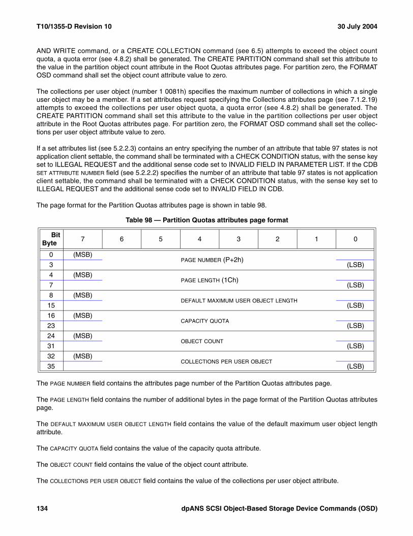
T10/1355-D Revision 10 30 July 2004
AND WRITE command, or a CREATE COLLECTION command (see 6.5) attempts to exceed the object countquota, a quota error (see 4.8.2) shall be generated. The CREATE PARTITION command shall set this attribute tothe value in the partition object count attribute in the Root Quotas attributes page. For partition zero, the FORMATOSD command shall set the object count attribute value to zero.
The collections per user object (number 1 0081h) specifies the maximum number of collections in which a singleuser object may be a member. If a set attributes request specifying the Collections attributes page (see 7.1.2.19)attempts to exceed the collections per user object quota, a quota error (see 4.8.2) shall be generated. TheCREATE PARTITION command shall set this attribute to the value in the partition collections per user objectattribute in the Root Quotas attributes page. For partition zero, the FORMAT OSD command shall set the collec-tions per user object attribute value to zero.
If a set attributes list (see 5.2.2.3) contains an entry specifying the number of an attribute that table 97 states is notapplication client settable, the command shall be terminated with a CHECK CONDITION status, with the sense keyset to ILLEGAL REQUEST and the additional sense code set to INVALID FIELD IN PARAMETER LIST. If the CDBSET ATTRIBUTE NUMBER field (see 5.2.2.2) specifies the number of an attribute that table 97 states is not applicationclient settable, the command shall be terminated with a CHECK CONDITION status, with the sense key set toILLEGAL REQUEST and the additional sense code set to INVALID FIELD IN CDB.
The page format for the Partition Quotas attributes page is shown in table 98.
The PAGE NUMBER field contains the attributes page number of the Partition Quotas attributes page.
The PAGE LENGTH field contains the number of additional bytes in the page format of the Partition Quotas attributespage.
The DEFAULT MAXIMUM USER OBJECT LENGTH field contains the value of the default maximum user object lengthattribute.
The CAPACITY QUOTA field contains the value of the capacity quota attribute.
The OBJECT COUNT field contains the value of the object count attribute.
The COLLECTIONS PER USER OBJECT field contains the value of the collections per user object attribute.
Table 98 — Partition Quotas attributes page format
BitByte
7 6 5 4 3 2 1 0
0 (MSB)PAGE NUMBER (P+2h)
3 (LSB)
4 (MSB)PAGE LENGTH (1Ch)
7 (LSB)
8 (MSB)DEFAULT MAXIMUM USER OBJECT LENGTH
15 (LSB)
16 (MSB)CAPACITY QUOTA
23 (LSB)
24 (MSB)OBJECT COUNT
31 (LSB)
32 (MSB)COLLECTIONS PER USER OBJECT
35 (LSB)
134 dpANS SCSI Object-Based Storage Device Commands (OSD)

30 July 2004 T10/1355-D Revision 10
7.1.2.14 User Object Quotas attributes page
The User Object Quotas attributes page (2h) shall contain the attributes listed in table 99. Except for attributenumber 0h, all attributes in the User Object Quotas attributes page are quotas (see 4.8).
The page identification attribute (number 0h) shall have the format described in 7.1.2.2 with the VENDOR IDENTIFI-CATION field containing the ASCII characters "INCITS" and the ATTRIBUTES PAGE IDENTIFICATION field containing theASCII characters "T10 User Object Quotas".
The maximum user object length attribute (number 1h) specifies the maximum value allowed in the user objectlogical length attribute of the User Object Information attributes page (see 7.1.2.11). If an APPEND command (see6.2), a CREATE AND WRITE command (see 6.4), a WRITE command (see 6.24), or setting the user object logicallength in the User Object Information attributes page (see 7.1.2.11) attempts to exceed the maximum user objectlength quota, a quota error (see 4.8.2) shall be generated. The CREATE command (see 6.3) and CREATE ANDWRITE command shall set this attribute to the value in the default maximum user object length attribute in thePartition Quotas attributes page (see 7.1.2.13).
If a set attributes list (see 5.2.2.3) contains an entry specifying the number of an attribute that table 99 states is notapplication client settable, the command shall be terminated with a CHECK CONDITION status, with the sense keyset to ILLEGAL REQUEST and the additional sense code set to INVALID FIELD IN PARAMETER LIST. If the CDBSET ATTRIBUTE NUMBER field (see 5.2.2.2) specifies the number of an attribute that table 99 states is not applicationclient settable, the command shall be terminated with a CHECK CONDITION status, with the sense key set toILLEGAL REQUEST and the additional sense code set to INVALID FIELD IN CDB.
The page format for the User Object Quotas attributes page is shown in table 100.
The PAGE NUMBER field contains the attributes page number of the User Object Quotas attributes page.
The PAGE LENGTH field contains the number of additional bytes in the page format of the User Object Quotasattributes page.
The MAXIMUM USER OBJECT LENGTH field contains the value of the maximum user object length attribute.
Table 99 — User Object Quotas attributes page contents
AttributeNumber
Length (bytes) Attribute
Application Client
SettableOSD Logical Unit Provided
0h 40 Page identification No Yes
1h 8 Maximum user object length Yes No
2h to FFFF FFFEh Reserved No
Table 100 — User Object Quotas attributes page format
BitByte
7 6 5 4 3 2 1 0
0 (MSB)PAGE NUMBER (2h)
3 (LSB)
4 (MSB)PAGE LENGTH (8h)
7 (LSB)
8 (MSB)MAXIMUM USER OBJECT LENGTH
15 (LSB)
dpANS SCSI Object-Based Storage Device Commands (OSD) 135

T10/1355-D Revision 10 30 July 2004
7.1.2.15 Root Timestamps attributes page
The Root Timestamps attributes page (R+3h) shall contain the attributes listed in table 101. The updating oftimestamp attributes in this page is controlled by the TIMESTAMPS CONTROL field (see 5.2.8) in the CDB.
The page identification attribute (number 0h) shall have the format described in 7.1.2.2 with the VENDOR IDENTIFI-CATION field containing the ASCII characters "INCITS" and the ATTRIBUTES PAGE IDENTIFICATION field containing theASCII characters "T10 Root Timestamps".
The attributes accessed time attribute (number 2h) shall contain the value of the clock attribute in the Root Infor-mation attributes page at the completion of the most recent command whose CDB get and set attributes param-eters (see 5.2.2) transferred any attributes pages or values associated with the root object to the application client.
The attributes modified time attribute (number 3h) shall contain the value of the clock attribute in the Root Infor-mation attributes page at the completion of the most recent command whose CDB get and set attributes param-eters (see 5.2.2) set any attribute values associated with the root object.
The timestamp bypass attribute (number FFFF FFFEh) specifies the default timestamp update policy (see table102) for the Root Timestamps page that is used under the control of the TIMESTAMPS CONTROL (see 5.2.8) field inthe CDB.
Table 101 — Root Timestamps attributes page contents
AttributeNumber
Length (bytes) Attribute
Application Client
SettableOSD Logical Unit Provided
0h 40 Page identification No Yes
1h Reserved No
2h 6 Attributes accessed time No Yes
3h 6 Attributes modified time No Yes
4h to FFFF FFFDh Reserved No
FFFF FFFEh 1 Timestamp bypass Yes No
Table 102 — Timestamp bypass attribute values
Value Description
00h Timestamps shall be updated as described in the subclause that defines them
01h to 7Eh Reserved
7Fh Timestamps shall not be updated a
80h to DFh Reserved
E0 to FEh Vendor specific
FFh Timestamps shall be updated as specified by the TIMESTAMPS CONTROL field in the CDB (see 5.2.8)
a A timestamp attribute that has never been updated shall have a length of six and a value of zero. Bypassing a timestamp update shall not affect any previously established timestamp attribute values.
136 dpANS SCSI Object-Based Storage Device Commands (OSD)

30 July 2004 T10/1355-D Revision 10
The FORMAT OSD command (see 6.11) shall set the timestamp bypass attribute to zero.
All commands received in the task set subsequent to the completion of a command that changes timestampbypass attribute value shall be processed according to the new timestamp bypass attribute value. Each commandin the task set concurrently with a command that changes the timestamp bypass attribute value may be processedwith either the old or the new timestamp bypass attribute value in a vendor specific manner.
If a set attributes list (see 5.2.2.3) contains an entry specifying the number of an attribute that table 101 states isnot application client settable, the command shall be terminated with a CHECK CONDITION status, with the sensekey set to ILLEGAL REQUEST and the additional sense code set to INVALID FIELD IN PARAMETER LIST. If theCDB SET ATTRIBUTE NUMBER field (see 5.2.2.2) specifies the number of an attribute that table 101 states is not appli-cation client settable, the command shall be terminated with a CHECK CONDITION status, with the sense key setto ILLEGAL REQUEST and the additional sense code set to INVALID FIELD IN CDB.
The page format for the Root Timestamps attributes page is shown in table 103.
The PAGE NUMBER field contains the attributes page number of the Root Timestamps attributes page.
The PAGE LENGTH field contains the number of additional bytes in the page format of the Root Timestampsattributes page.
The ATTRIBUTES ACCESSED TIME field contains the value of the attributes accessed time attribute.
The ATTRIBUTES MODIFIED TIME field contains the value of the attributes modified time attribute.
The TIMESTAMP BYPASS field contains the value of the timestamp bypass attribute.
Table 103 — Root Timestamps attributes page format
BitByte
7 6 5 4 3 2 1 0
0 (MSB)PAGE NUMBER (R+3h)
3 (LSB)
4 (MSB)PAGE LENGTH (Dh)
7 (LSB)
8 (MSB)ATTRIBUTES ACCESSED TIME
13 (LSB)
14 (MSB)ATTRIBUTES MODIFIED TIME
19 (LSB)
20 TIMESTAMP BYPASS
dpANS SCSI Object-Based Storage Device Commands (OSD) 137

T10/1355-D Revision 10 30 July 2004
7.1.2.16 Partition Timestamps attributes page
The Partition Timestamps attributes page (P+3h) shall contain the attributes listed in table 104. The updating oftimestamp attributes in this page is controlled by the TIMESTAMPS CONTROL field (see 5.2.8) in the CDB.
The page identification attribute (number 0h) shall have the format described in 7.1.2.2 with the VENDOR IDENTIFI-CATION field containing the ASCII characters "INCITS" and the ATTRIBUTES PAGE IDENTIFICATION field containing theASCII characters "T10 Partition Timestamps".
For all partitions except partition zero, the created time attribute (number 1h) shall contain the value of the clockattribute in the Root Information attributes page (see 7.1.2.8) at the completion of the CREATE PARTITIONcommand (see 6.5) that created the partition. For partition zero, the created time attribute shall contain the value ofthe clock attribute in the Root Information attributes page at the completion of the most recent FORMAT OSDcommand (see 6.11).
The attributes accessed time attribute (number 2h) shall contain the value of the clock attribute in the Root Infor-mation attributes page at the completion of the most recent command whose CDB get and set attributes param-eters (see 5.2.2) transferred any attributes pages or values associated with the partition to the application client.
The attributes modified time attribute (number 3h) shall contain the value of the clock attribute in the Root Infor-mation attributes page at the completion of the most recent command whose CDB get and set attributes param-eters (see 5.2.2) set any attribute values associated with the partition.
For partition zero, the data accessed time attribute shall contain the value of the clock attribute in the Root Infor-mation attributes page at the completion of the most recent LIST command that transferred a list of partitions in theroot object to the application client. For all partitions except partition zero, the data accessed time attribute (number4h) shall contain the value of the clock attribute in the Root Information attributes page at the completion of themost recent:
a) LIST command (see 6.13) that transferred a list of user objects in the partition to the application client; orb) LIST COLLECTION command (see 6.14) that transferred a list of collections in the partition to the appli-
cation client.
For partition zero, the data modified time attribute shall contain the value of the clock attribute in the Root Infor-mation attributes page at the completion of the most recent CREATE PARTITION command (see 6.6) or REMOVEPARTITION command (see 6.20) that created or removed a partition. For all partitions except partition zero, the
Table 104 — Partition Timestamps attributes page contents
AttributeNumber
Length (bytes) Attribute
Application Client
SettableOSD Logical Unit Provided
0h 40 Page identification No Yes
1h 6 Created time No Yes
2h 6 Attributes accessed time No Yes
3h 6 Attributes modified time No Yes
4h 6 Data accessed time No Yes
5h 6 Data modified time No Yes
6h to FFFF FFFDh Reserved No
FFFF FFFEh 1 Timestamp bypass Yes No
138 dpANS SCSI Object-Based Storage Device Commands (OSD)

30 July 2004 T10/1355-D Revision 10
data modified time attribute (number 5h) shall contain the value of the clock attribute in the Root Informationattributes page at the completion of the most recent CREATE command (see 6.3), CREATE AND WRITEcommand (see 6.4), CREATE COLLECTION command (see 6.5), REMOVE command (see 6.18), or REMOVECOLLECTION command (see 6.19) that created or removed a collection or user object in the partition.
The timestamp bypass attribute (number FFFF FFFEh) specifies the default timestamp update policy (see table102 in 7.1.2.15) that is used for the following timestamp attributes pages used under the control of the TIMESTAMPS
CONTROL (see 5.2.8) field in the CDB:
a) Partition Timestamps page;b) Collection Timestamps attributes page (see 7.1.2.17); andc) User Object Timestamps attributes page (see 7.1.2.18).
All commands received in the task set subsequent to the completion of a command that changes timestampbypass attribute value shall be processed according to the new timestamp bypass attribute value. Each commandin the task set concurrently with a command that changes the timestamp bypass attribute value may be processedwith either the old or the new timestamp bypass attribute value in a vendor specific manner.
The CREATE PARTITION command (see 6.6) shall set this attribute to the value in the timestamp bypass attributein the Root Timestamps attributes page (see 7.1.2.15).
If a set attributes list (see 5.2.2.3) contains an entry specifying the number of an attribute that table 104 states isnot application client settable, the command shall be terminated with a CHECK CONDITION status, with the sensekey set to ILLEGAL REQUEST and the additional sense code set to INVALID FIELD IN PARAMETER LIST. If theCDB SET ATTRIBUTE NUMBER field (see 5.2.2.2) specifies the number of an attribute that table 104 states is not appli-cation client settable, the command shall be terminated with a CHECK CONDITION status, with the sense key setto ILLEGAL REQUEST and the additional sense code set to INVALID FIELD IN CDB.
The page format for the Partition Timestamps attributes page is shown in table 105.
Table 105 — Partition Timestamps attributes page format
BitByte
7 6 5 4 3 2 1 0
0 (MSB)PAGE NUMBER (P+3h)
3 (LSB)
4 (MSB)PAGE LENGTH (1Fh)
7 (LSB)
8 (MSB)CREATED TIME
13 (LSB)
14 (MSB)ATTRIBUTES ACCESSED TIME
19 (LSB)
20 (MSB)ATTRIBUTES MODIFIED TIME
25 (LSB)
26 (MSB)DATA ACCESSED TIME
31 (LSB)
32 (MSB)DATA MODIFIED TIME
37 (LSB)
38 TIMESTAMP BYPASS
dpANS SCSI Object-Based Storage Device Commands (OSD) 139

T10/1355-D Revision 10 30 July 2004
The PAGE NUMBER field contains the attributes page number of the Partition Timestamps attributes page.
The PAGE LENGTH field contains the number of additional bytes in the page format of the Partition Timestampsattributes page.
The CREATED TIME field contains the value of the created time attribute.
The ATTRIBUTES ACCESSED TIME field contains the value of the attributes accessed time attribute.
The ATTRIBUTES MODIFIED TIME field contains the value of the attributes modified time attribute.
The DATA ACCESSED TIME field contains the value of the data accessed time attribute.
The DATA MODIFIED TIME field contains the value of the data modified time attribute.
The TIMESTAMP BYPASS field contains the value of the timestamp bypass attribute.
7.1.2.17 Collection Timestamps attributes page
The Collection Timestamps attributes page (C+3h) shall contain the attributes listed in table 106. The updating oftimestamp attributes in this page is controlled by the TIMESTAMPS CONTROL field (see 5.2.8) in the CDB.
The page identification attribute (number 0h) shall have the format described in 7.1.2.2 with the VENDOR IDENTIFI-CATION field containing the ASCII characters "INCITS" and the ATTRIBUTES PAGE IDENTIFICATION field containing theASCII characters "T10 Collection Timestamps".
The created time attribute (number 1h) shall contain the value of the clock attribute in the Root Informationattributes page (see 7.1.2.8) at the completion of the CREATE COLLECTION command (see 6.5) that created theassociated collection.
The attributes accessed time attribute (number 2h) shall contain the value of the clock attribute in the Root Infor-mation attributes page at the completion of the most recent command whose CDB get and set attributes param-eters (see 5.2.2) transferred any attributes pages or values associated with the collection to the application client.
The attributes modified time attribute (number 3h) shall contain the value of the clock attribute in the Root Infor-mation attributes page at the completion of the most recent command whose CDB get and set attributes param-eters (see 5.2.2) set any attribute values associated with the collection.
Table 106 — Collection Timestamps attributes page contents
AttributeNumber
Length (bytes) Attribute
Application Client
SettableOSD Logical Unit Provided
0h 40 Page identification No Yes
1h 6 Created time No Yes
2h 6 Attributes accessed time No Yes
3h 6 Attributes modified time No Yes
4h 6 Data accessed time No Yes
5h 6 Data modified time No Yes
6h to FFFF FFFEh Reserved No
140 dpANS SCSI Object-Based Storage Device Commands (OSD)

30 July 2004 T10/1355-D Revision 10
The data accessed time attribute (number 4h) shall contain the value of the clock attribute in the Root Informationattributes page at the completion of the most recent LIST COLLECTION command (see 6.14) that transferred a listof user objects in the collection to the application client.
The data modified time attribute (number 5h) shall contain the value of the clock attribute in the Root Informationattributes page at the completion of the most recent set attributes command function to a user object Collectionsattributes page (see 7.1.2.19) that added or removed a member from the collection.
If a set attributes list (see 5.2.2.3) contains an entry specifying the number of an attribute that table 106 states isnot application client settable, the command shall be terminated with a CHECK CONDITION status, with the sensekey set to ILLEGAL REQUEST and the additional sense code set to INVALID FIELD IN PARAMETER LIST. If theCDB SET ATTRIBUTE NUMBER field (see 5.2.2.2) specifies the number of an attribute that table 106 states is not appli-cation client settable, the command shall be terminated with a CHECK CONDITION status, with the sense key setto ILLEGAL REQUEST and the additional sense code set to INVALID FIELD IN CDB.
The page format for the Collection Timestamps attributes page is shown in table 107.
The PAGE NUMBER field contains the attributes page number of the Collection Timestamps attributes page.
The PAGE LENGTH field contains the number of additional bytes in the page format of the Collection Timestampsattributes page.
The CREATED TIME field contains the value of the created time attribute.
The ATTRIBUTES ACCESSED TIME field contains the value of the attributes accessed time attribute.
The ATTRIBUTES MODIFIED TIME field contains the value of the attributes modified time attribute.
The DATA ACCESSED TIME field contains the value of the data accessed time attribute.
The DATA MODIFIED TIME field contains the value of the data modified time attribute.
Table 107 — Collection Timestamps attributes page format
BitByte
7 6 5 4 3 2 1 0
0 (MSB)PAGE NUMBER (C+3h)
3 (LSB)
4 (MSB)PAGE LENGTH (1Eh)
7 (LSB)
8 (MSB)CREATED TIME
13 (LSB)
14 (MSB)ATTRIBUTES ACCESSED TIME
19 (LSB)
20 (MSB)ATTRIBUTES MODIFIED TIME
25 (LSB)
26 (MSB)DATA ACCESSED TIME
31 (LSB)
32 (MSB)DATA MODIFIED TIME
37 (LSB)
dpANS SCSI Object-Based Storage Device Commands (OSD) 141

T10/1355-D Revision 10 30 July 2004
7.1.2.18 User Object Timestamps attributes page
The User Object Timestamps attributes page (3h) shall contain the attributes listed in table 108. The updating oftimestamp attributes in this page is controlled by the TIMESTAMPS CONTROL field (see 5.2.8) in the CDB.
The page identification attribute (number 0h) shall have the format described in 7.1.2.2 with the VENDOR IDENTIFI-CATION field containing the ASCII characters "INCITS" and the ATTRIBUTES PAGE IDENTIFICATION field containing theASCII characters "T10 User Object Timestamps".
The created time attribute (number 1h) shall contain the value of the clock attribute in the Root Informationattributes page (see 7.1.2.8) at the completion of the CREATE command (see 6.3) or CREATE AND WRITEcommand (see 6.4) that created the associated user object.
The attributes accessed time attribute (number 2h) shall contain the value of the clock attribute in the Root Infor-mation attributes page at the completion of the most recent command whose CDB get and set attributes param-eters (see 5.2.2) transferred any attributes pages or values associated with the user object to the application client.
The attributes modified time attribute (number 3h) shall contain the value of the clock attribute in the Root Infor-mation attributes page at the completion of the most recent command whose CDB get and set attributes param-eters (see 5.2.2) set any attribute values associated with the user object.
The data accessed time attribute (number 4h) shall contain the value of the clock attribute in the Root Informationattributes page at the completion of the most recent READ command (see 6.17) that transferred data from the userobject to the application client.
The data modified time attribute (number 5h) shall contain the value of the clock attribute in the Root Informationattributes page at the completion of the most recent command that changed the value of the user object logicallength attribute in the User Object Information attributes page (see 7.1.2.11) or that stored data in the user object(i.e., a WRITE command (see 6.24), an APPEND command (see 6.2), or a CREATE AND WRITE command (see6.4)).
If a set attributes list (see 5.2.2.3) contains an entry specifying the number of an attribute that table 108 states isnot application client settable, the command shall be terminated with a CHECK CONDITION status, with the sensekey set to ILLEGAL REQUEST and the additional sense code set to INVALID FIELD IN PARAMETER LIST. If theCDB SET ATTRIBUTE NUMBER field (see 5.2.2.2) specifies the number of an attribute that table 108 states is not appli-cation client settable, the command shall be terminated with a CHECK CONDITION status, with the sense key setto ILLEGAL REQUEST and the additional sense code set to INVALID FIELD IN CDB.
Table 108 — User Object Timestamps attributes page contents
AttributeNumber
Length (bytes) Attribute
Application Client
SettableOSD Logical Unit Provided
0h 40 Page identification No Yes
1h 6 Created time No Yes
2h 6 Attributes accessed time No Yes
3h 6 Attributes modified time No Yes
4h 6 Data accessed time No Yes
5h 6 Data modified time No Yes
6h to FFFF FFFEh Reserved No
142 dpANS SCSI Object-Based Storage Device Commands (OSD)

30 July 2004 T10/1355-D Revision 10
The page format for the User Object Timestamps attributes page is shown in table 109.
The PAGE NUMBER field contains the attributes page number of the User Object Timestamps attributes page.
The PAGE LENGTH field contains the number of additional bytes in the page format of the User Object Timestampsattributes page.
The CREATED TIME field contains the value of the created time attribute.
The ATTRIBUTES ACCESSED TIME field contains the value of the attributes accessed time attribute.
The ATTRIBUTES MODIFIED TIME field contains the value of the attributes modified time attribute.
The DATA ACCESSED TIME field contains the value of the data accessed time attribute.
The DATA MODIFIED TIME field contains the value of the data modified time attribute.
7.1.2.19 Collections attributes page
The Collections attributes page (4h) shall contain the attributes listed in table 110.
Table 109 — User Object Timestamps attributes page format
BitByte
7 6 5 4 3 2 1 0
0 (MSB)PAGE NUMBER (3h)
3 (LSB)
4 (MSB)PAGE LENGTH (1Eh)
7 (LSB)
8 (MSB)CREATED TIME
13 (LSB)
14 (MSB)ATTRIBUTES ACCESSED TIME
19 (LSB)
20 (MSB)ATTRIBUTES MODIFIED TIME
25 (LSB)
26 (MSB)DATA ACCESSED TIME
31 (LSB)
32 (MSB)DATA MODIFIED TIME
37 (LSB)
Table 110 — Collections attributes page contents
AttributeNumber
Length (bytes) Attribute
Application Client
SettableOSD Logical Unit Provided
0h 0 or 40 Page identification No Yes
1h to FFFF FF00h 0 or 8 Collection pointer Yes No
FFFF FF01h to FFFF FFFEh Reserved No
dpANS SCSI Object-Based Storage Device Commands (OSD) 143
T10/1355-D Revision 10 30 July 2004
If collections are supported, the page identification attribute (number 0h) shall have the format described in 7.1.2.2with the VENDOR IDENTIFICATION field containing the ASCII characters "INCITS" and the ATTRIBUTES PAGE IDENTIFI-CATION field containing the ASCII characters "T10 Collections". If collections are no supported, the length of thepage identification attribute shall be zero.
Each collection pointer attribute (1h to FFFF FF00h) may be:
a) A zero length attribute (i.e., contain no value); or b) The Collection_Object_ID of a collection (see 4.6.6) to which the user object belongs.
A user object is made a member of a collection by setting one of its collection pointer attribute values to theCollection_Object_ID of that collection.
A user object is removed from the membership of a collection by:
a) Changing the collection pointer attribute identifying that collection to have a length of zero; orb) Setting the collection pointer attribute identifying that collection to the Collection_Object_ID of a different
collection.
The command shall be terminated with a CHECK CONDITION status, with the sense key set to ILLEGALREQUEST and the additional sense code set to INVALID FIELD IN PARAMETER LIST if a set attributes list (see5.2.2.3) contains an entry that sets:
a) The same Collection_Object_ID in more than one collection pointer attribute;b) A collection pointer attribute to a value that is not a Collection_Object_ID; orc) A collection pointer attribute to any length other than zero or eight.
The command shall be terminated with a CHECK CONDITION status, with the sense key set to ILLEGALREQUEST and the additional sense code set to INVALID FIELD IN CDB if:
a) The CDB SET ATTRIBUTE NUMBER field and the set attributes data specified by the SET ATTRIBUTES OFFSET
field (see 5.2.2.2) sets:A) The same Collection_Object_ID in more than one collection pointer attribute; orB) A collection pointer attribute to a value that is not a Collection_Object_ID;or
b) The CDB SET ATTRIBUTE LENGTH field contains a value other than zero or eight.
If setting a collection pointer attribute causes the number of collection pointer attributes with non-zero attributelengths to exceed the value in the collections per user object attribute in the Partition Quotas attributes page (see7.1.2.13), then a quota error shall be generated (see 4.8.2). The quota testing principles described in 4.8.3 apply tothe testing of the object count quota.
If a set attributes list contains an entry specifying the number of an attribute that table 110 states is not applicationclient settable, the command shall be terminated with a CHECK CONDITION status, with the sense key set toILLEGAL REQUEST and the additional sense code set to INVALID FIELD IN PARAMETER LIST. If the CDB SET
ATTRIBUTE NUMBER field specifies the number of an attribute that table 110 states is not application client settable,the command shall be terminated with a CHECK CONDITION status, with the sense key set to ILLEGALREQUEST and the additional sense code set to INVALID FIELD IN CDB.
144 dpANS SCSI Object-Based Storage Device Commands (OSD)

30 July 2004 T10/1355-D Revision 10
The page format for the Collections attributes page is shown in table 111.
The PAGE NUMBER field contains the attributes page number of the Collection attributes page.
The PAGE LENGTH field contains the number of additional bytes in the page format of the Collection attributes page.
The first collection pointer attribute value shall contain the attribute value for the lowest numbered collection pointerattribute with a length of eight.
The second collection pointer attribute value shall contain the attribute value for the second lowest numberedcollection pointer attribute with a length of eight.
Additional collection pointer attribute values shall be added to the page format for each collection pointer attributewith a length of eight.
The last collection pointer attribute value shall contain the attribute value for the highest numbered collectionpointer attribute with a length of eight.
Table 111 — Collections attributes page format
BitByte
7 6 5 4 3 2 1 0
0 (MSB)PAGE NUMBER (4h)
3 (LSB)
4 (MSB)PAGE LENGTH (n-7)
7 (LSB)
8 (MSB)First collection pointer attribute value
15 (MSB)
16 (MSB)Second collection pointer attribute value
23 (MSB) ...
n-7 (MSB)Last collection pointer attribute value
n (MSB)
dpANS SCSI Object-Based Storage Device Commands (OSD) 145

T10/1355-D Revision 10 30 July 2004
7.1.2.20 Root Policy/Security attributes page
The Root Policy/Security attributes page (R+5h) shall contain the attributes listed in table 112.
The page identification attribute (number 0h) shall have the format described in 7.1.2.2 with the VENDOR IDENTIFI-CATION field containing the ASCII characters "INCITS" and the ATTRIBUTES PAGE IDENTIFICATION field containing theASCII characters "T10 Root Policy/Security".
The default security method attribute (number 1h) specifies the security method (see 4.10.4) used for theprocessing of the SET KEY command (see 6.22) and SET MASTER KEY command (see 6.23) in the absence ofconditions that specify a different security method (see 4.10.3). The value of the default security method attributeshall not be changed by a FORMAT OSD command (see 6.11). The value placed in the default security methodattribute when the OBSD (see 3.1.26) is manufactured is vendor specific. If the value of the default security methodattribute is changed, the application client should invalidate the working keys for partition zero using the SET KEYcommand.
The oldest valid nonce limit attribute (number 2h) specifies the largest value allowed in the oldest valid nonceattribute in any Partition Policy/Security attributes page (see 7.1.2.21) (i.e., the maximum number of millisecondsprior to the value in the clock attribute in the Root Information attributes page (see 7.1.2.8) to which the deviceserver constrains the contents of the TIMESTAMP field in a request nonce (see 4.9.6)).
The newest valid nonce limit attribute (number 3h) specifies the largest value allowed in the newest valid nonceattribute in any Partition Policy/Security attributes page (i.e., the maximum number of milliseconds subsequent to
Table 112 — Root Policy/Security attributes page contents
AttributeNumber
Length (bytes) Attribute
Application Client
SettableOSD Logical Unit Provided
0h 40 Page identification No Yes
1h 1 Default security method Yes Yes
2h 6 Oldest valid nonce limit No Yes
3h 6 Newest valid nonce limit No Yes
4h to 5h Reserved No
6h 1 Partition default security method Yes Yes
7h 2 Supported security methods No Yes
8h Reserved No
9h 6 Adjustable clock Yes Yes
Ah to 7FFCh Reserved No
7FFDh 0 or 7 Master key identifier No Yes
7FFEh 0 or 7 Root key identifier No Yes
7FFFh to 7FFF FFFFh Reserved No
8000 0000h to 8000 000Fh 1 Supported integrity check value algorithm
No Yes
8000 0010h to 8000 001Fh 1 Supported DH group No Yes
8000 0020h to FFFF FFFEh Reserved No
146 dpANS SCSI Object-Based Storage Device Commands (OSD)

30 July 2004 T10/1355-D Revision 10
the value in the clock attribute in the Root Information attributes page to which the device server constrains thecontents of the TIMESTAMP field in a request nonce).
The partition default security method attribute (number 6h) specifies the value to be placed in the default securitymethod attribute of each partition, when it is created. The value of the partition default security method attributeshall not be changed by a FORMAT OSD command (see 6.11). The value placed in the partition default securitymethod attribute when the OBSD is manufactured is vendor specific.
The supported security methods attribute (number 7h) indicates which security methods (see 4.10.4) aresupported by the OSD logical unit (see table 113).
The NOSEC (NOSEC security method supported) bit is set to zero if the NOSEC security method is not supported.The NOSEC bit is set to one if the NOSEC security method is supported.
The CAPKEY (CAPKEY security method supported) bit is set to zero if the CAPKEY security method is notsupported. The CAPKEY bit is set to one if the CAPKEY security method is supported.
The CMDRSP (CMDRSP security method supported) bit is set to zero if the CMDRSP security method is notsupported. The CMDRSP bit is set to one if the CMDRSP security method is supported.
The ALLDATA (ALLDATA security method supported) bit is set to zero if the ALLDATA security method is notsupported. The ALLDATA bit is set to one if the ALLDATA security method is supported.
The adjustable clock attribute (number 9h) shall contain the current time in use by the OSD device server repre-sented as the count of the number of milliseconds elapsed since midnight, 1 January 1970 UT (see 3.1.49). Thevalue shall be set to the UT when the OBSD (see 3.1.26) is manufactured and may be modified by the applicationclient after that. The mechanism used to maintain the adjustable clock attribute value is outside the scope of thestandard. The adjustable clock attribute value should not gain or lose more than one second in any 24-hourinterval.
The master key identifier attribute (number 7FFDh) contains the key identifier value from the most recentsuccessful SET MASTER KEY command (see 6.23). If a SET MASTER KEY command has never beenprocessed, the master key identifier attribute length shall be seven and the master key identifier attribute valueshall be the ASCII characters "1st key".
The root key identifier attribute (number 7FFEh) contains the key identifier value from the most recent successfulSET KEY command (see 6.22) with the KEY TO SET field set to 01b (i.e., update root key). If the root key is invalid(i.e., never set or invalidated by a SET MASTER KEY command), the root key identifier attribute length shall bezero. Regardless of the root key identifier attribute length, the used capacity attribute in the Partition Informationattributes page (see 7.1.2.9) for partition zero (see 3.1.32) shall reflect an attribute length of seven (i.e., it shall notbe possible for a SET KEY command to cause the partition zero used capacity attribute value to exceed thecapacity quota attribute in the Partition Quotas attributes page (see 7.1.2.13) for partition zero and generate aquote error).
Table 113 — Supported security methods attribute format
BitByte
7 6 5 4 3 2 1 0
0 Reserved ALLDATA CMDRSP CAPKEY NOSEC
1 Reserved
dpANS SCSI Object-Based Storage Device Commands (OSD) 147

T10/1355-D Revision 10 30 July 2004
The supported integrity check value algorithm attributes (numbers 8000 0000h to 8000 000Fh) contain codedvalues (see table 114) identifying the supported algorithms that the OSD device server supports for computingintegrity check values.
The supported integrity check value algorithm with the lowest valued attribute number (i.e., 8000 0000h) identifiesthe most preferred integrity check value algorithm and the highest valued attribute number (i.e., 8000 000Fh)identifies the least preferred algorithm. If a supported integrity check value algorithm attribute contains zero, thenall supported integrity check value algorithm attributes with higher valued attribute numbers also shall contain zero.
The low order four bits of the attribute number are the value that appears in the capability INTEGRITY CHECK VALUE
ALGORITHM field (see 4.9.2.2) in each capability (e.g., attribute number 8000 0007h identifies the integrity checkvalue algorithm used if the INTEGRITY CHECK VALUE ALGORITHM field contains seven).
The supported DH group attributes (numbers 8000 0010h to 8000 001Fh) contain coded values identifying thesupported values in the DH_GROUP field of a SET MASTER KEY command (see 6.23). The values of the supportedDH group attributes are the values associated with the Group Description class (i.e., class code value 4) in theInternet Key Exchange Attr ibutes registry maintained by IANA (see http:/ /www.iana.org/assign-ments/ipsec-registry). The DH group indicated by each value is as specified by IANA in that registry.
Every DH group identified by a supported DH group attribute shall be a MODP DH group. The code values 1h (i.e.,the 768-bit MODP DH group defined by RFC 2409) and 2h (i.e., the 1024-bit MODP DH group defined by RFC2409) shall not appear in any supported DH group attribute.
NOTE 7 The constraint to MODP DH groups eliminates usage of all elliptic curve DH groups (e.g., the DH groupshaving code values 3, 4, and 6 through 13, inclusive).
One of the supported DH group attributes shall contain Dh (i.e., 14) indicating the 2048-bit MODP DH groupdefined by RFC 3526.
The supported DH group with the lowest valued attribute number (i.e., 8000 0000h) identifies the most preferredDH group and the highest valued attribute number (i.e., 8000 000Fh) identifies the least preferred DH group. If asupported DH group attribute contains zero, then all supported DH group attributes with higher valued attributenumbers also shall contain zero
If a set attributes list (see 5.2.2.3) contains an entry specifying the number of an attribute that table 112 states isnot application client settable, the command shall be terminated with a CHECK CONDITION status, with the sensekey set to ILLEGAL REQUEST and the additional sense code set to INVALID FIELD IN PARAMETER LIST. If theCDB SET ATTRIBUTE NUMBER field (see 5.2.2.2) specifies the number of an attribute that table 112 states is not appli-cation client settable, the command shall be terminated with a CHECK CONDITION status, with the sense key setto ILLEGAL REQUEST and the additional sense code set to INVALID FIELD IN CDB.
Table 114 — Supported integrity check value algorithm codes
Value Algorithm Reference
00h No algorithm supported
01h HMAC-SHA1 FIPS 180-1 (1995) and FIPS 198 (2002)
02h - DFh Reserved
E0h - FFh Vendor specific
148 dpANS SCSI Object-Based Storage Device Commands (OSD)

30 July 2004 T10/1355-D Revision 10
The page format for the Root Policy/Security attributes page is shown in table 115.
The PAGE NUMBER field contains the attributes page number of the Root Policy/Security attributes page.
The PAGE LENGTH field contains the number of additional bytes in the page format of the Root Policy/Securityattributes page.
The DEFAULT SECURITY METHOD field contains the value of the default security method attribute.
The PARTITION DEFAULT SECURITY METHOD field contains the value of the partition default security method attribute.
Table 115 — Root Policy/Security attributes page format
BitByte
7 6 5 4 3 2 1 0
0 (MSB)PAGE NUMBER (R+5h)
3 (LSB)
4 (MSB)PAGE LENGTH (3Fh)
7 (LSB)
8 DEFAULT SECURITY METHOD
9 PARTITION DEFAULT SECURITY METHOD
10 SUPPORTED SECURITY METHODS
11
12 (MSB)OLDEST VALID NONCE LIMIT
17 (LSB)
18 (MSB)NEWEST VALID NONCE LIMIT
23 (LSB)
24 Reserved MKI_VALID RKI_VALID
25 (MSB)MASTER KEY IDENTIFIER
31 (LSB)
32 (MSB)ROOT KEY IDENTIFIER
38 (LSB)
39Most preferred SUPPORTED INTEGRITY CHECK VALUE ALGORITHM
(attribute number 8000 0000h)...
54Least preferred SUPPORTED INTEGRITY CHECK VALUE ALGORITHM
(attribute number 8000 000Fh)
55Most preferred SUPPORTED DH_GROUP
(attribute number 8000 0010h)...
70Least preferred SUPPORTED DH_GROUP
(attribute number 8000 001Fh)
dpANS SCSI Object-Based Storage Device Commands (OSD) 149
T10/1355-D Revision 10 30 July 2004
The SUPPORTED SECURITY METHODS field contains the value of the supported security methods attribute.
The OLDEST VALID NONCE LIMIT field contains the value of the oldest valid nonce limit attribute.
The NEWEST VALID NONCE LIMIT field contains the value of the newest valid nonce limit attribute.
The MKI_VALID (master key identifier valid) bit shall be set to zero if the master key identifier attribute length is zero.Otherwise, the MKI_VALID bit shall be set to one.
The RKI_VALID (root key identifier valid) bit shall be set to zero if the root key identifier attribute length is zero.Otherwise, the RKI_VALID bit shall be set to one.
If the MKI_VALID bit is set to one, the MASTER KEY IDENTIFIER field contains the value of the master key identifierattribute. Otherwise, the contents of the MASTER KEY IDENTIFIER field are undefined.
If the RKI_VALID bit is set to one, the ROOT KEY IDENTIFIER field contains the value of the root key identifier attribute.Otherwise, the contents of the ROOT KEY IDENTIFIER field are undefined.
The sixteen SUPPORTED INTEGRITY CHECK VALUE ALGORITHM fields contain the supported integrity check valueattribute values in ascending attribute number order. The SUPPORTED INTEGRITY CHECK VALUE ALGORITHM field withthe smallest byte offset in the page identifies the most preferred integrity check value algorithm. The SUPPORTED
INTEGRITY CHECK VALUE ALGORITHM field with the largest byte offset in the page identifies the least preferredalgorithm.
The sixteen SUPPORTED DH GROUP fields contain the supported DH group attribute values in ascending attributenumber order. The SUPPORTED DH GROUP field with the smallest byte offset in the page identifies the most preferredDH group to be used by the SET MASTER KEY command (see 6.23). The SUPPORTED DH GROUP field with thelargest byte offset in the page identifies the least preferred DH group.
150 dpANS SCSI Object-Based Storage Device Commands (OSD)

30 July 2004 T10/1355-D Revision 10
7.1.2.21 Partition Policy/Security attributes page
The Partition Policy/Security attributes page (P+5h) shall contain the attributes listed in table 116.
The page identification attribute (number 0h) shall have the format described in 7.1.2.2 with the VENDOR IDENTIFI-CATION field containing the ASCII characters "INCITS" and the ATTRIBUTES PAGE IDENTIFICATION field containing theASCII characters "T10 Partition Policy/Security".
The default security method attribute (number 1h) specifies the security method (see 4.10.4) used for theprocessing of all commands except the SET KEY command and SET MASTER KEY command in the absence ofconditions that specify a different security method (see 4.10.3). The value of the default security method attributefor partition zero shall not be changed by a FORMAT OSD command (see 6.11). The value placed in the defaultsecurity method attribute for partition zero when the OBSD (see 3.1.26) is manufactured is vendor specific. If thevalue of the default security method attribute is changed, the working keys for affected partition should be invali-dated using the SET KEY command (see 6.22).
A CREATE PARTITION command (see 6.6) shall copy the partition default security method attribute from the RootPolicy/Security attributes page (see 7.1.2.20) to the default security method attribute in new PartitionPolicy/Security attributes page.
The oldest valid nonce attribute (number 2h) indicates the number of milliseconds prior to the value in the clockattribute in the Root Information attributes page (see 7.1.2.8) to which the device server constrains the contents ofthe TIMESTAMP field in a request nonce (see 4.10.7) received in a command addressed to the partition, a collectionin the partition, or a user object in the partition. The processing of request nonces affected by this constraint isdescribed in 4.10.7.2.
If a set attributes list (see 5.2.2.3) contains a request to set the oldest valid nonce attribute to a value that is largerthan the value in the oldest valid nonce limit attribute in the Root Policy/Security attributes page (see 7.1.2.20), thecommand shall be terminated with a CHECK CONDITION status, with the sense key set to ILLEGAL REQUEST
Table 116 — Partition Policy/Security attributes page contents
AttributeNumber
Length (bytes) Attribute
Application Client
SettableOSD Logical Unit Provided
0h 40 Page identification No Yes
1h 1 Default security method Yes Yes
2h 6 Oldest valid nonce Yes Yes
3h 6 Newest valid nonce Yes Yes
4h 2 Request nonce list depth No Yes
5h 2 Frozen working key bit mask No Yes
6h to 7FFEh Reserved No
7FFFh 0 or 7 Partition key identifier No Yes
8000h to 800Fh 0 or 7 Working key identifier No Yes
8010h to 4000 0000h Reserved No
4000 0001h 4 Policy access tag Yes Yes
4000 0002h 4 User object policy access tag Yes Yes
4000 0003h to FFFF FFFEh Reserved No
dpANS SCSI Object-Based Storage Device Commands (OSD) 151

T10/1355-D Revision 10 30 July 2004
and the additional sense code set to INVALID FIELD IN PARAMETER LIST. If the CDB SET ATTRIBUTE NUMBER fieldcontains 2h (i.e., the oldest valid nonce attribute) and the set attributes data specified by the SET ATTRIBUTES
OFFSET field (see 5.2.2.2) contains a value that is larger than the value in the oldest valid nonce limit attribute in theRoot Policy/Security attributes page, the command shall be terminated with a CHECK CONDITION status, with thesense key set to ILLEGAL REQUEST and the additional sense code set to INVALID FIELD IN CDB.
The newest valid nonce attribute (number 3h) indicates the number of milliseconds laster than the value in theclock attribute in the Root Information attributes page to which the device server constrains the contents of theTIMESTAMP field in a request nonce (see 4.10.7) received in a command addressed to the partition, a collection inthe partition, or a user object in the partition. The processing of request nonces affected by this constraint isdescribed in 4.10.7.2.
If a set attributes list (see 5.2.2.3) contains a request to set the newest valid nonce attribute to a value that is largerthan the value in the newest valid nonce limit attribute in the Root Policy/Security attributes page, the commandshall be terminated with a CHECK CONDITION status, with the sense key set to ILLEGAL REQUEST and theadditional sense code set to INVALID FIELD IN PARAMETER LIST. If the CDB SET ATTRIBUTE NUMBER fieldcontains 3h (i.e., the newest valid nonce attribute) and the set attributes data specified by the SET ATTRIBUTES
OFFSET field (see 5.2.2.2) contains a value that is larger than the value in the newest valid nonce limit attribute inthe Root Policy/Security attributes page, the command shall be terminated with a CHECK CONDITION status, withthe sense key set to ILLEGAL REQUEST and the additional sense code set to INVALID FIELD IN CDB.
The request nonce list depth attribute (number 4h) shall contain the minimum number of request nonce list entries4.10.7.3.1 available to one application client.
The frozen working key bit mask attribute (number 5h) indicates which working key versions (see table 117) havebeen frozen as part of request nonce list processing (see 4.10.7.3.3).
A WK00_FZN (working key 0h frozen) bit set to zero indicates that device server is not rejecting commands thatcontain capabilities with the working key with a key version of zero as part of request nonce list processing. AWK00_FZN bit set to one indicates that device server is rejecting commands that contain capabilities with theworking key with a key version of zero as part of request nonce list processing (see 4.10.7.3.3). Once theWK00_FZN bit is set to one, it shall not be set to zero until a new working key with key version zero is establishedusing the SET KEY command (see 6.22).
The WK01_FZN bit, WK01_FZN bit, WK02_FZN bit, WK03_FZN bit, WK04_FZN bit, WK05_FZN bit, WK06_FZN bit,WK07_FZN bit, WK08_FZN bit, WK09_FZN bit, WK0A_FZN bit, WK0B_FZN bit, WK0C_FZN bit, WK0D_FZN bit, WK0E_FZN
bit, and WK0F_FZN have the same bit value definitions as the WK00_FZN bit, except that the definitions apply to theworking keys with key versions one to fifteen, respectively.
The partition key identifier attribute (number 7FFFh) contains the key identifier value from the most recentsuccessful SET KEY command (see 6.22) with the KEY TO SET field set to 10b (i.e., update partition key). If thepartition key is invalid (i.e., never set, invalidated by a SET MASTER KEY command (see 6.23), or invalidated by aSET KEY command), the partition key identifier attribute length shall be zero. Regardless of the partition keyidentifier attribute length, the used capacity attribute in the Partition Information attributes page (see 7.1.2.9) shallreflect an attribute length of seven (i.e., it shall not be possible for a SET KEY command to cause the partition’s
Table 117 — Frozen working key bit mask attribute format
BitByte
7 6 5 4 3 2 1 0
0 WK07_FZN WK06_FZN WK05_FZN WK04_FZN WK03_FZN WK02_FZN WK01_FZN WK00_FZN
1 WK0F_FZN WK0E_FZN WK0D_FZN WK0C_FZN WK0B_FZN WK0A_FZN WK09_FZN WK08_FZN
152 dpANS SCSI Object-Based Storage Device Commands (OSD)

30 July 2004 T10/1355-D Revision 10
used capacity attribute value to exceed the capacity quota attribute in the Partition Quotas attributes page (see7.1.2.13) and generate a quote error).
The working key identifier attributes (numbers 8000h to 800Fh) contain the key identifier value from the mostrecent successful SET KEY command with:
a) The KEY TO SET field set to 11b (i.e., update working key); andb) The KEY VERSION field set to the attribute number minus 8000h (e.g., a version key of three sets attribute
8003h and a version key of eight sets attribute 8008h).
If a working key is invalid (i.e., never set, invalidated by a SET MASTER KEY command, or invalidated by a SETKEY command), the working key identifier attribute length for the associated working key shall be zero. Regardlessof the lengths of any of the working key identifier attributes, the used capacity attribute in the Partition Informationattributes page shall reflect an attribute length of seven for all sixteen working key identifier attributes (i.e., it shallnot be possible for a SET KEY command to cause the partition’s used capacity attribute value to exceed thecapacity quota attribute in the Partition Quotas attributes page and generate a quote error).
The policy access tag attribute (number 4000 0001h) specifies the expected non-zero contents of the POLICY
ACCESS TAG field in any capability (see 4.9.2) that allows access to this partition. The format, use, and attributesetting restrictions for the policy access tag attribute are described in 4.9.3. A CREATE PARTITION command (see6.6) shall set the policy access tag attribute to 7FFF FFFFh.
The user object policy access tag attribute (number 4000 0002h) specifies the value to be placed in the policyaccess tag attribute of each collection or user object, when it is created. A CREATE PARTITION command shall setthe user object policy access tag attribute to 7FFF FFFFh.
If a set attributes list contains an entry specifying the number of an attribute that table 116 states is not applicationclient settable, the command shall be terminated with a CHECK CONDITION status, with the sense key set toILLEGAL REQUEST and the additional sense code set to INVALID FIELD IN PARAMETER LIST. If the CDB SET
ATTRIBUTE NUMBER field specifies the number of an attribute that table 116 states is not application client settable,the command shall be terminated with a CHECK CONDITION status, with the sense key set to ILLEGALREQUEST and the additional sense code set to INVALID FIELD IN CDB.
dpANS SCSI Object-Based Storage Device Commands (OSD) 153

T10/1355-D Revision 10 30 July 2004
The page format for the Partition Policy/Security attributes page is shown in table 118.
The PAGE NUMBER field contains the attributes page number of the Partition Policy/Security attributes page.
The PAGE LENGTH field contains the number of additional bytes in the page format of the Partition Policy/Securityattributes page.
Table 118 — Partition Policy/Security attributes page format
BitByte
7 6 5 4 3 2 1 0
0 (MSB)PAGE NUMBER (P+5h)
3 (LSB)
4 (MSB)PAGE LENGTH (8Fh)
7 (LSB)
8Reserved
10
11 DEFAULT SECURITY METHOD
12 (MSB)OLDEST VALID NONCE
17 (LSB)
18 (MSB)NEWEST VALID NONCE
23 (LSB)
24 (MSB)REQUEST NONCE LIST DEPTH
25 (LSB)
26FROZEN WORKING KEY BIT MASK
27
28 (MSB)POLICY ACCESS TAG
31 (LSB)
32 (MSB)USER OBJECT POLICY ACCESS TAG
35 (LSB)
36 Reserved PKI_VALID
37 WKI07_VLD WKI06_VLD WKI05_VLD WKI04_VLD WKI03_VLD WKI02_VLD WKI01_VLD WKI00_VLD
38 WKI0F_VLD WKI0E_VLD WKI0D_VLD WKI0C_VLD WKI0B_VLD WKI0A_VLD WKI09_VLD WKI08_VLD
39 (MSB)PARTITION KEY IDENTIFIER
45 (LSB)
46 (MSB) WORKING KEY IDENTIFIER
(for attribute number 8000h)
64 (LSB)...
144 (MSB) WORKING KEY IDENTIFIER
(for attribute number 800Fh)
150 (LSB)
154 dpANS SCSI Object-Based Storage Device Commands (OSD)

30 July 2004 T10/1355-D Revision 10
The DEFAULT SECURITY METHOD field contains the value of the default security method attribute.
The OLDEST VALID NONCE field contains the value of the oldest valid nonce attribute.
The NEWEST VALID NONCE field contains the value of the newest valid nonce attribute.
The REQUEST NONCE LIST DEPTH field contains the value of the request nonce list depth attribute.
The FROZEN WORKING KEY BIT MASK field contains the value of the frozen working key bit mask attribute.
The POLICY ACCESS TAG field contains the value of the policy access tag attribute.
The USER OBJECT POLICY ACCESS TAG field contains the value of the user object policy access tag attribute.
The PKI_VALID (partition key identifier valid) bit shall be set to zero if the partition key identifier attribute length iszero. Otherwise, the PKI_VALID bit shall be set to one.
The WKI00_VLD (working key identifier 0h valid) bit shall be set to zero if the working key identifier attribute number8000h has a length of zero. Otherwise, the WKI00_VLD bit shall be set to one.
The WKI01_VLD bit, WKI01_VLD bit, WKI02_VLD bit, WKI03_VLD bit, WKI04_VLD bit, WKI05_VLD bit, WKI06_VLD bit,WKI07_VLD bit, WKI08_VLD bit, WKI09_VLD bit, WKI0A_VLD bit, WKI0B_VLD bit, WKI0C_VLD bit, WKI0D_VLD bit,WKI0E_VLD bit, and WKI0F_VLD have the same bit value definitions as the WKI00_VLD bit, except that the definitionsapply to the attributes with numbers 8001h to 800Fh, respectively.
The sixteen WORKING KEY IDENTIFIER fields contain the working key identifier attribute values in ascending attributenumber order. If a working key identifier valid bit is set to one, the corresponding WORKING KEY IDENTIFIER fieldcontains the value of the working key identifier attribute. Otherwise, the contents of the WORKING KEY IDENTIFIER
field are undefined.
7.1.2.22 Collection Policy/Security attributes page
The Collection Policy/Security attributes page (C+5h) shall contain the attributes listed in table 119.
The page identification attribute (number 0h) shall have the format described in 7.1.2.2 with the VENDOR IDENTIFI-CATION field containing the ASCII characters "INCITS" and the ATTRIBUTES PAGE IDENTIFICATION field containing theASCII characters "T10 Collection Policy/Security".
The policy access tag attribute (number 4000 0001h) specifies the expected non-zero contents of the POLICY
ACCESS TAG field in any capability (see 4.9.2) that allows access to this collection. The format, use, and attributesetting restrictions for the policy access tag attribute are described in 4.9.3. A CREATE COLLECTION command
Table 119 — Collection Policy/Security attributes page contents
AttributeNumber
Length (bytes) Attribute
Application Client
SettableOSD Logical Unit Provided
0h 40 Page identification No Yes
1h to 4000 0000h Reserved No
4000 0001h 4 Policy access tag Yes Yes
4000 0002h to FFFF FFFEh Reserved No
dpANS SCSI Object-Based Storage Device Commands (OSD) 155

T10/1355-D Revision 10 30 July 2004
(see 6.5) shall copy the user object policy access tag attribute from the Partition Policy/Security attributes page(see 7.1.2.21) to the policy access tag attribute in new Collection Policy/Security attributes page.
If a set attributes list contains an entry specifying the number of an attribute that table 119 states is not applicationclient settable, the command shall be terminated with a CHECK CONDITION status, with the sense key set toILLEGAL REQUEST and the additional sense code set to INVALID FIELD IN PARAMETER LIST. If the CDB SET
ATTRIBUTE NUMBER field specifies the number of an attribute that table 119 states is not application client settable,the command shall be terminated with a CHECK CONDITION status, with the sense key set to ILLEGALREQUEST and the additional sense code set to INVALID FIELD IN CDB.
The page format for the Collection Policy/Security attributes page is shown in table 120.
The PAGE NUMBER field contains the attributes page number of the Collection Policy/Security attributes page.
The PAGE LENGTH field contains the number of additional bytes in the page format of the Collection Policy/Securityattributes page.
The POLICY ACCESS TAG field contains the value of the policy access tag attribute.
7.1.2.23 User Object Policy/Security attributes page
The User Object Policy/Security attributes page (5h) shall contain the attributes listed in table 121.
The page identification attribute (number 0h) shall have the format described in 7.1.2.2 with the VENDOR IDENTIFI-CATION field containing the ASCII characters "INCITS" and the ATTRIBUTES PAGE IDENTIFICATION field containing theASCII characters "T10 User Object Policy/Security".
Table 120 — Collection Policy/Security attributes page format
BitByte
7 6 5 4 3 2 1 0
0 (MSB)PAGE NUMBER (C+5h)
3 (LSB)
4 (MSB)PAGE LENGTH (4h)
7 (LSB)
8 (MSB)POLICY ACCESS TAG
11 (LSB)
Table 121 — User Object Policy/Security attributes page contents
AttributeNumber
Length (bytes) Attribute
Application Client
SettableOSD Logical Unit Provided
0h 40 Page identification No Yes
1h to 4000 0000h Reserved No
4000 0001h 4 Policy access tag Yes Yes
4000 0002h to FFFF FFFEh Reserved No
156 dpANS SCSI Object-Based Storage Device Commands (OSD)

30 July 2004 T10/1355-D Revision 10
The policy access tag attribute (number 4000 0001h) specifies the expected non-zero contents of the POLICY
ACCESS TAG field in any capability (see 4.9.2) that allows access to this user object. The format, use, and attributesetting restrictions for the policy access tag attribute are described in 4.9.3. A CREATE command (see 6.3) orCREATE AND WRITE command (see 6.4) shall copy the user object policy access tag attribute from the PartitionPolicy/Security attributes page (see 7.1.2.21) to the policy access tag attribute in new User Object Policy/Securityattributes page.
If a set attributes list contains an entry specifying the number of an attribute that table 121 states is not applicationclient settable, the command shall be terminated with a CHECK CONDITION status, with the sense key set toILLEGAL REQUEST and the additional sense code set to INVALID FIELD IN PARAMETER LIST. If the CDB SET
ATTRIBUTE NUMBER field specifies the number of an attribute that table 121 states is not application client settable,the command shall be terminated with a CHECK CONDITION status, with the sense key set to ILLEGALREQUEST and the additional sense code set to INVALID FIELD IN CDB.
The page format for the User Object Policy/Security attributes page is shown in table 122.
The PAGE NUMBER field contains the attributes page number of the User Object Policy/Security attributes page.
The PAGE LENGTH field contains the number of additional bytes in the page format of the User ObjectPolicy/Security attributes page.
The POLICY ACCESS TAG field contains the value of the policy access tag attribute.
Table 122 — User Object Policy/Security attributes page format
BitByte
7 6 5 4 3 2 1 0
0 (MSB)PAGE NUMBER (5h)
3 (LSB)
4 (MSB)PAGE LENGTH (4h)
7 (LSB)
8 (MSB)POLICY ACCESS TAG
11 (LSB)
dpANS SCSI Object-Based Storage Device Commands (OSD) 157

T10/1355-D Revision 10 30 July 2004
7.1.2.24 Current Command attributes page
The Current Command attributes page (FFFF FFFEh) shall contain the attributes listed in table 123.
The page identification attribute (number 0h) shall have the format described in 7.1.2.2 with the VENDOR IDENTIFI-CATION field containing the ASCII characters "INCITS" and the ATTRIBUTES PAGE IDENTIFICATION field containing theASCII characters "T10 Current Command".
If the NOSEC security method or the CAPKEY security method (see 4.10.4) is used to process the command or ifstatus returned for the command is CHECK CONDITION, the response integrity check value attribute (number 1h)shall contain zero. Otherwise, the response integrity check value attribute shall contain an integrity check value(see 4.10.8) that is computed as described in 4.10.4.4.
NOTE 8 If a command terminates with a CHECK CONDITION status, the response integrity check value isreturned in the sense data (see 4.14).
The object type attribute (number 2h) shall identify the type of OSD object on which the current command isoperating using the code values shown in table 9 (see 4.9.2.2).
The Partition_ID attribute (number 3h) shall contain the Partition_ID (see 4.6.4) of partition containing the OSDobject on which the current command is operating.
If the object type attribute contains COLLECTION (see table 9 in 4.9.2.2), the Collection_Object_ID orUser_Object_ID attribute (number 4h) shall contain the Collection_Object_ID (see 4.6.6) of the collection on whichthe current command is operating. Otherwise, the Collection_Object_ID or User_Object_ID attribute shall containthe User_Object_ID (see 4.6.5) of the user object on which the current command is operating.
If the current command is an APPEND (see 6.2), the starting byte address of append attribute (number 5h) shallcontain the starting byte address used for the append command function. If the current command is not anAPPEND, the starting byte address of append attribute shall contain zero.
If a set attributes list (see 5.2.2.3) contains an entry specifying the number of an attribute that table 123 states isnot application client settable, the command shall be terminated with a CHECK CONDITION status, with the sensekey set to ILLEGAL REQUEST and the additional sense code set to INVALID FIELD IN PARAMETER LIST. If theCDB SET ATTRIBUTE NUMBER field (see 5.2.2.2) specifies the number of an attribute that table 123 states is not appli-cation client settable, the command shall be terminated with a CHECK CONDITION status, with the sense key setto ILLEGAL REQUEST and the additional sense code set to INVALID FIELD IN CDB.
Table 123 — Current Command attributes page contents
AttributeNumber
Length (bytes) Attribute
Application Client
SettableOSD Logical Unit Provided
0h 40 Page identification No Yes
1h 20 Response integrity check value No Yes
2h 1 Object Type No Yes
3h 8 Partition_ID No Yes
4h 8 Collection_Object_ID or User_Object_ID No Yes
5h 8 Starting byte address of append No Yes
6h to FFFF FFFEh Reserved No
158 dpANS SCSI Object-Based Storage Device Commands (OSD)

30 July 2004 T10/1355-D Revision 10
The page format for the Current Command attributes page is shown in table 124.
The PAGE NUMBER field contains the attributes page number of the Current Command attributes page.
The PAGE LENGTH field contains the number of additional bytes in the page format of the Current Commandattributes page.
The RESPONSE INTEGRITY CHECK VALUE field contains the value of the response integrity check value attribute.
The OBJECT TYPE field contains the value of the object type attribute.
The PARTITION_ID field contains the value of the Partition_ID attribute.
The COLLECTION_OBJECT_ID OR USER_OBJECT_ID field contains the value of the Collection_Object_ID orUser_Object_ID attribute.
The STARTING BYTE ADDRESS OF APPEND field contains the value of the starting byte address of append attribute.
Table 124 — Current Command attributes page format
BitByte
7 6 5 4 3 2 1 0
0 (MSB)PAGE NUMBER (FFFF FFFEh)
3 (LSB)
4 (MSB)PAGE LENGTH (30h)
7 (LSB)
8 (MSB)RESPONSE INTEGRITY CHECK VALUE
27 (LSB)
28 OBJECT TYPE
29Reserved
31
32 (MSB)PARTITION_ID
39 (LSB)
40 (MSB)COLLECTION_OBJECT_ID OR USER_OBJECT_ID
47 (LSB)
48 (MSB)STARTING BYTE ADDRESS OF APPEND
55 (LSB)
dpANS SCSI Object-Based Storage Device Commands (OSD) 159

T10/1355-D Revision 10 30 July 2004
7.1.2.25 Null attributes page
The page format for the null attributes page is shown in table 125.
The PAGE NUMBER field contains the attributes page number of the requested attributes page.
The PAGE LENGTH field contains zero.
7.1.3 OSD attributes lists
7.1.3.1 Attributes lists overview
An attributes list acts on one or more individual attribute values using attributes page and attribute number valuesto specify the attribute values to be retrieved or set.
The format of an attributes list is shown in table 126.
Table 125 — Null attributes page format
BitByte
7 6 5 4 3 2 1 0
0 (MSB)PAGE NUMBER
3 (LSB)
4 (MSB)PAGE LENGTH (00h)
7 (LSB)
Table 126 — Attributes list format
BitByte
7 6 5 4 3 2 1 0
0 Reserved LIST TYPE
1 Reserved
2 (MSB)LIST LENGTH (n-3)
3 (LSB)
Attributes list entries
4Attributes list entry 0
...
Attributes list entry xn
160 dpANS SCSI Object-Based Storage Device Commands (OSD)

30 July 2004 T10/1355-D Revision 10
The LIST TYPE field (see table 127) specifies the format of all attributes list entries in the attributes list.
If list type 1h (see 7.1.3.2) is used to retrieve attributes for this OSD object, the list type of the list containing theretrieved objects shall be:
a) Fh (see 7.1.3.4) for a CREATE command that creates more than one user object; orb) 9h (see 7.1.3.3) for all other commands and for a CREATE command that creates only one user object.
The LIST LENGTH field indicates the number of bytes of attributes list entries that follow. The LIST LENGTH field maycontain zero.
For an attributes list sent from the device server to the application client, a list length of zero indicates that all of therequested attributes have an attribute length of zero.
The application client should set the list length to zero in any attributes list that it sends to the device server. Thedevice server shall use the length of the list specified in the CDB and shall ignore the contents of the LIST LENGTH
field.
7.1.3.2 List entry format for retrieving attributes for this OSD object
The attributes list entry format shown in table 128 is used for specifying the attributes to be retrieved by a GETATTRIBUTES command (see 6.12) or equivalent command function.
Table 127 — List type values
List Type Description
Support Require-
ment Reference
Allowed Use
Get Attributes Set Attributes
ListList Response
0h Reserved No No No
1h Retrieve attributes for this OSD object
Mandatory 7.1.3.2 Yes No No
2h - 8h Reserved No No No
9h Retrieved/Set attributes for this OSD object
Mandatory 7.1.3.3 No Yes Yes
Ah - Eh Reserved No No No
Fh Retrieved attributes for a CREATE command (see 6.3) that creates more than one user object
Mandatory 7.1.3.4 No Yes No
Table 128 — List entry format for retrieving attributes for this OSD object
BitByte
7 6 5 4 3 2 1 0
0 (MSB)ATTRIBUTES PAGE
3 (LSB)
4 (MSB)ATTRIBUTE NUMBER
7 (LSB)
dpANS SCSI Object-Based Storage Device Commands (OSD) 161

T10/1355-D Revision 10 30 July 2004
The ATTRIBUTES PAGE field specifies the page number of one attribute to be returned. If the specified attributespage number is not associated with the user object specified by a command, the command shall be terminatedwith a CHECK CONDITION, with the sense key set to ILLEGAL REQUEST and the additional sense code set toINVALID FIELD IN PARAMETER LIST.
The ATTRIBUTE NUMBER field specifies:
a) The attribute number within the attributes page specified by the ATTRIBUTES PAGE field of the one attributevalue to be returned; or
b) The value FFFF FFFFh to request the return of each attribute having a non-zero attribute length in theattributes page specified by the ATTRIBUTES PAGE field.
If the attribute specified by the ATTRIBUTES PAGE field and ATTRIBUTE NUMBER field has no defined value, an attributevalue having a length of FFFF FFFFh shall be returned.
Specifying attributes page and attribute numbers values of FFFF FFFFh causes all defined attributes values in alldefined pages associated with the OSD object specified by a command to be returned. Specifying an attributenumbers value of FFFF FFFFh causes all defined attributes values in the specified attributes page to be returned.
If FFFF FFFFh is used as an attributes page number or attribute number value, only those attributes with non-zerolengths shall be returned.
7.1.3.3 List entry format for retrieved attributes and for setting attributes for this OSD object
The attributes list entry format shown in table 129 is used for returning the each attribute value to be retrieved by aGET ATTRIBUTES command (see 6.12) and for specifying each attribute value to be set by a SET ATTRIBUTEScommand (see 6.21) or equivalent command functions.
The ATTRIBUTES PAGE field specifies the page number of the attribute value.
The ATTRIBUTE NUMBER field specifies the attribute number within the attributes page specified by the ATTRIBUTES
PAGE field of the attribute value.
The ATTRIBUTE LENGTH field specifies the length of the attribute value in bytes.
The ATTRIBUTE VALUE field specifies the attribute value.
If the attribute specified by the ATTRIBUTES PAGE field and ATTRIBUTE NUMBER field in a set command function has adefined value, the value shall be replaced by the value specified by the ATTRIBUTE LENGTH field and ATTRIBUTE
Table 129 — List entry format for retrieved attributes and for setting attributes for this OSD object
BitByte
7 6 5 4 3 2 1 0
0 (MSB)ATTRIBUTES PAGE
3 (LSB)
4 (MSB)ATTRIBUTE NUMBER
7 (LSB)
8 (MSB)ATTRIBUTE LENGTH (n-9)
9 (LSB)
10 (MSB)ATTRIBUTE VALUE
n (LSB)
162 dpANS SCSI Object-Based Storage Device Commands (OSD)

30 July 2004 T10/1355-D Revision 10
VALUE field. Otherwise, a new attribute shall be created with the attribute number specified by the ATTRIBUTE
NUMBER field in the attributes page specified by the ATTRIBUTES PAGE field.
If the ATTRIBUTES PAGE or ATTRIBUTE NUMBER field contains FFFF FFFFh for a set command function, the commandshall be terminated with a CHECK CONDITION, with the sense key set to ILLEGAL REQUEST and the additionalsense code set to INVALID FIELD IN PARAMETER LIST.
7.1.3.4 List entry format for attributes retrieved by CREATE command that creates multiple user objects
The attributes list entry format shown in table 130 is used for returning each attribute value for each user objectrequested by a CREATE command (see 6.3) that creates more than one user object.
The USER_OBJECT_ID field indicates the User_Object_ID of the user object (see 4.6.5) associated with the attributevalue.
The ATTRIBUTES PAGE field indicates the page number of the attribute value.
The ATTRIBUTE NUMBER field indicates the attribute number within the attributes page specified by theUSER_OBJECT_ID field and ATTRIBUTES PAGE field of the attribute value.
The ATTRIBUTE LENGTH field indicates the length of the attribute value in bytes.
The ATTRIBUTE VALUE field indicates the attribute value.
The list entry format described in this subclause shall not be returned for any command other than a CREATEcommand that creates more than one user object.
If the list entry format described in this subclause appears in a SET ATTRIBUTES command (see 6.21) or equiv-alent command function, the command shall be terminated with a CHECK CONDITION, with the sense key set toILLEGAL REQUEST and the additional sense code set to INVALID FIELD IN PARAMETER LIST.
Table 130 — List entry format for attributes retrieved by a CREATE command creating multiple user objects
BitByte
7 6 5 4 3 2 1 0
0 (MSB)USER_OBJECT_ID
7 (LSB)
8 (MSB)ATTRIBUTES PAGE
11 (LSB)
12 (MSB)ATTRIBUTE NUMBER
15 (LSB)
16 (MSB)ATTRIBUTE LENGTH (n-17)
17 (LSB)
18 (MSB)ATTRIBUTE VALUE
n (LSB)
dpANS SCSI Object-Based Storage Device Commands (OSD) 163

T10/1355-D Revision 10 30 July 2004
7.2 Diagnostic parameters
This subclause defines the descriptors and pages for diagnostic parameters used with OSD type devices.
The diagnostic parameter list is described in SPC-3.
See SPC-3 for diagnostic pages used with all device types.
No diagnostic pages are defined for specific use by OSD type devices.
7.3 Log parameters
This subclause defines the descriptors and pages for log parameters used with OSD type devices.
The log parameter list is described in SPC-3.
See SPC-3 for log parameter pages used with all device types.
No log parameter pages are defined for specific use by OSD type devices.
7.4 Mode parameters
This subclause defines the descriptors and pages for mode parameters used with OSD type devices.
The mode parameter list, including the mode parameter header and mode block descriptor, are described inSPC-3.
OSD type devices shall reserve the following mode parameter header fields (see SPC-3):
a) MEDIUM TYPE;b) DEVICE-SPECIFIC PARAMETER; andc) LONGLBA.
OSD type devices shall set the BLOCK DESCRIPTOR LENGTH field to zero and shall return a CHECK CONDITIONstatus for any command that attempts to set the block descriptor length to a value other than zero.
See SPC-3 for mode pages used with all device types.
No mode pages are defined for specific use by OSD type devices.
164 dpANS SCSI Object-Based Storage Device Commands (OSD)
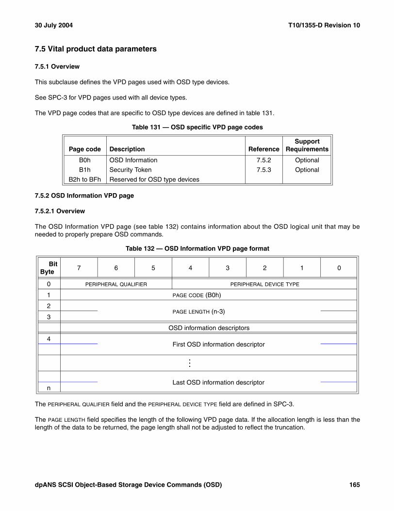
30 July 2004 T10/1355-D Revision 10
7.5 Vital product data parameters
7.5.1 Overview
This subclause defines the VPD pages used with OSD type devices.
See SPC-3 for VPD pages used with all device types.
The VPD page codes that are specific to OSD type devices are defined in table 131.
7.5.2 OSD Information VPD page
7.5.2.1 Overview
The OSD Information VPD page (see table 132) contains information about the OSD logical unit that may beneeded to properly prepare OSD commands.
The PERIPHERAL QUALIFIER field and the PERIPHERAL DEVICE TYPE field are defined in SPC-3.
The PAGE LENGTH field specifies the length of the following VPD page data. If the allocation length is less than thelength of the data to be returned, the page length shall not be adjusted to reflect the truncation.
Table 131 — OSD specific VPD page codes
Page code Description ReferenceSupport
Requirements
B0h OSD Information 7.5.2 Optional
B1h Security Token 7.5.3 Optional
B2h to BFh Reserved for OSD type devices
Table 132 — OSD Information VPD page format
BitByte
7 6 5 4 3 2 1 0
0 PERIPHERAL QUALIFIER PERIPHERAL DEVICE TYPE
1 PAGE CODE (B0h)
2PAGE LENGTH (n-3)
3
OSD information descriptors
4First OSD information descriptor
...
Last OSD information descriptorn
dpANS SCSI Object-Based Storage Device Commands (OSD) 165

T10/1355-D Revision 10 30 July 2004
Each OSD information descriptor (see table 133) contains information about the OSD logical unit that may beneeded to properly prepare OSD commands.
The DESCRIPTOR TYPE field (see table 134) indicates the format of and information in the OSD informationdescriptor.
The ADDITIONAL LENGTH field specifies the length of the following OSD information descriptor data. If the allocationlength causes an OSD information descriptor to be truncated, the additional length shall not be adjusted to reflectthe truncation.
The format and content of the descriptor-specific information depends on the descriptor type.
7.5.2.2 OSD logical unit security methods information descriptor
Each OSD logical unit security methods information descriptor (see table 135) contains information about the OSDlogical unit security methods that may need to be obtained in order to properly prepare OSD commands.
Table 133 — OSD information descriptor format
BitByte
7 6 5 4 3 2 1 0
0 DESCRIPTOR TYPE
1 Reserved
2ADDITIONAL LENGTH (n-3)
3
4Descriptor-specific information
n
Table 134 — OSD information descriptor type values
Value ReferenceSupport
Requirements
00h OSD logical unit security methods 7.5.2.2 Optional
01h to F0h Reserved
F1 to FFh Vendor specific
Table 135 — OSD logical unit security methods information descriptor format
BitByte
7 6 5 4 3 2 1 0
0 DESCRIPTOR TYPE (00h)
1 Reserved
2ADDITIONAL LENGTH (0002h)
3
4 ROOT SECURITY METHOD
5 PARTITION ZERO SECURITY METHOD
166 dpANS SCSI Object-Based Storage Device Commands (OSD)

30 July 2004 T10/1355-D Revision 10
The DESCRIPTOR TYPE field set to 00h indicates that this is an OSD logical unit security methods informationdescriptor.
The ADDITIONAL LENGTH field specifies the length of the following OSD information descriptor data.
The ROOT SECURITY METHOD field contains the value in the security method attribute in the Root Policy/Securityattributes page (see 7.1.2.20).
The PARTITION ZERO SECURITY METHOD field contains the value in the security method attribute in the PartitionPolicy/Security attributes page (see 7.1.2.21) associated with partition zero.
7.5.3 Security Token VPD page
The Security Token VPD page (see table 132) contains a security token for use in the CAPKEY security method(see 4.10.4.3).
The PERIPHERAL QUALIFIER field and the PERIPHERAL DEVICE TYPE field are defined in SPC-3.
The PAGE LENGTH field indicates the length of the following VPD page data. The page length shall be at leastsixteen. If the allocation length is less than the length of the data to be returned, the page length shall not beadjusted to reflect the truncation.
The SECURITY TOKEN field contains a value that is unique to the I_T_L nexus that sent the INQUIRY command. Thesecurity token shall be random as defined by RFC 1750. An I_T nexus loss event, logical unit reset event, or resetevent (see SAM-3) shall cause the security token to change.
Table 136 — Security Token VPD page
BitByte
7 6 5 4 3 2 1 0
0 PERIPHERAL QUALIFIER PERIPHERAL DEVICE TYPE
1 PAGE CODE (B1h)
2PAGE LENGTH (n-3)
3
4SECURITY TOKEN
n
dpANS SCSI Object-Based Storage Device Commands (OSD) 167
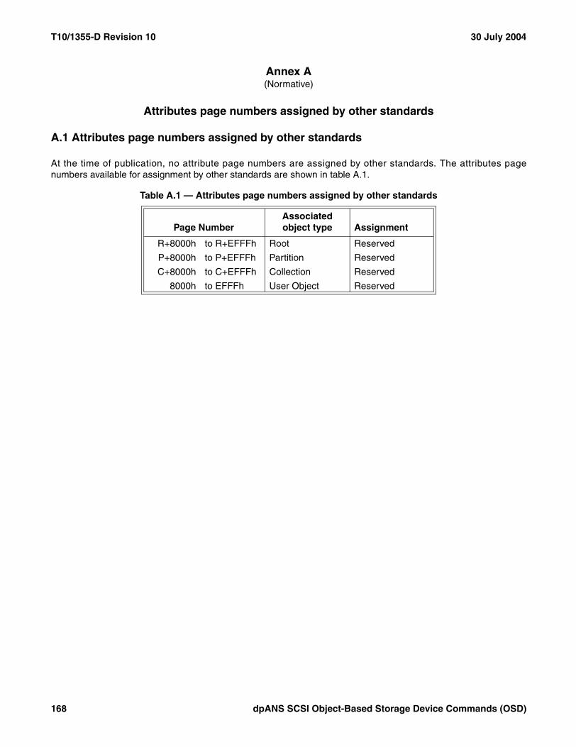
T10/1355-D Revision 10 30 July 2004
Annex A (Normative)
Attributes page numbers assigned by other standards
A.1 Attributes page numbers assigned by other standards
At the time of publication, no attribute page numbers are assigned by other standards. The attributes pagenumbers available for assignment by other standards are shown in table A.1.
Table A.1 — Attributes page numbers assigned by other standards
Page NumberAssociated object type Assignment
R+8000h to R+EFFFh Root Reserved
P+8000h to P+EFFFh Partition Reserved
C+8000h to C+EFFFh Collection Reserved
8000h to EFFFh User Object Reserved
168 dpANS SCSI Object-Based Storage Device Commands (OSD)

30 July 2004 T10/1355-D Revision 10
Annex B (Informative)
Numeric order codes
B.1 Service action codes
The variable length CDB service action codes assigned by this standard are shown in table B.1.
Table B.1 — Numerical order OSD service action codes
Service Action Command
8801h FORMAT OSD
8802h CREATE
8803h LIST
8804h Reserved
8805h READ
8806h WRITE
8807h APPEND
8808h FLUSH
8809h Reserved
880Ah REMOVE
880Bh CREATE PARTITION
880Ch REMOVE PARTITION
880Dh Reserved
880Eh GET ATTRIBUTES
880Fh SET ATTRIBUTES
8810h to 8811h Reserved
8812h CREATE AND WRITE
8813h to 8814h Reserved
8815h CREATE COLLECTION
8816h REMOVE COLLECTION
8817h LIST COLLECTION
8818h SET KEY
8819h SET MASTER KEY
881Ah FLUSH COLLECTION
881Bh FLUSH PARTITION
881Ch FLUSH OSD
881Dh to 8F7Dh Reserved
8F7Eh PERFORM SCSI COMMAND
8F7Fh PERFORM TASK MANAGEMENT FUNCTION
8F80h to 8FFFh Vendor specific
dpANS SCSI Object-Based Storage Device Commands (OSD) 169

T10/1355-D Revision 10 30 July 2004
Annex C(Informative)
Examples of OSD Operation
C.1 Preparing a device for OSD operation
Before an OSD logical unit may accept and process OSD commands, it needs to be initialized as an OSD logicalunit. An application client issues the commands in table C.1 to initialize an OSD logical unit.
Upon completion of these commands the storage device is an OSD logical unit with security established.
Table C.1 — OSD initialization sequence
Action Parameters Description
SET MASTER KEY SEED EXCHANGE, DH_Group, DH_Data Exchange DH seed
SET MASTER KEY CHANGE MASTER KEY, DH_Data Initialize master key
SET KEY Root, Seed Initialize root key
SET KEY Partition, Seed Initialize partition zero key
SET KEY Working, Key Version, Seed Initialize partition zero working key
FORMAT OSD Length (optional) Construct OSD control structures
CREATE PARTITION Partition_ID (optional) Initialize partition in which user objects may be created
SET KEY Partition Key, Working Keys Initialize partition keys
170 dpANS SCSI Object-Based Storage Device Commands (OSD)
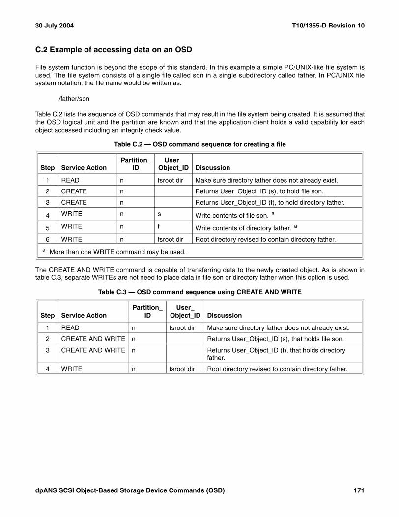
30 July 2004 T10/1355-D Revision 10
C.2 Example of accessing data on an OSD
File system function is beyond the scope of this standard. In this example a simple PC/UNIX-like file system isused. The file system consists of a single file called son in a single subdirectory called father. In PC/UNIX filesystem notation, the file name would be written as:
/father/son
Table C.2 lists the sequence of OSD commands that may result in the file system being created. It is assumed thatthe OSD logical unit and the partition are known and that the application client holds a valid capability for eachobject accessed including an integrity check value.
The CREATE AND WRITE command is capable of transferring data to the newly created object. As is shown intable C.3, separate WRITEs are not need to place data in file son or directory father when this option is used.
Table C.2 — OSD command sequence for creating a file
Step Service ActionPartition_
IDUser_
Object_ID Discussion
1 READ n fsroot dir Make sure directory father does not already exist.
2 CREATE n Returns User_Object_ID (s), to hold file son.
3 CREATE n Returns User_Object_ID (f), to hold directory father.
4 WRITE n s Write contents of file son. a
5 WRITE n f Write contents of directory father. a
6 WRITE n fsroot dir Root directory revised to contain directory father.
a More than one WRITE command may be used.
Table C.3 — OSD command sequence using CREATE AND WRITE
Step Service ActionPartition_
IDUser_
Object_ID Discussion
1 READ n fsroot dir Make sure directory father does not already exist.
2 CREATE AND WRITE n Returns User_Object_ID (s), that holds file son.
3 CREATE AND WRITE n Returns User_Object_ID (f), that holds directory father.
4 WRITE n fsroot dir Root directory revised to contain directory father.
dpANS SCSI Object-Based Storage Device Commands (OSD) 171