sd-01-333 bendix tu-flo 550 air compressor · bendix® tu-flo® 550 air compressor cross section...
TRANSCRIPT
1
®
SD-0
1-33
3
Bendix® Tu-Flo® 550 Air Compressor
Cross SectionExterior
Air DischargeWater Outlet
Piece No.Tag
GovernorMounting
PadCrankcase
Piston Rings
Piston
Crankshaft
ConnectingRod
Inlet Valve Seat
Unloader
Inlet Valve
CylinderHead
End View Of Cylinder Head
DischargeValve Spring
DischargeValve
Discharge Upper & Lower Valve Stop
Air Inlet
Crankcase
Inlet
Inlet ValveSpring
DischargeValve Seat
UnloaderCover
WaterInlet
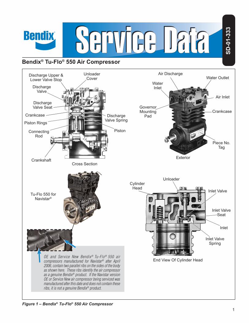
Figure 1 – Bendix® Tu-Flo® 550 Air Compressor
OE and Service New Bendix® Tu-Flo® 550 air compressors manufactured for Navistar® after April 2006, contain two parallel ribs on the sides of the body as shown here. These ribs identify the air compressor as a genuine Bendix® product. If the Navistar version OE or Service New air compressor being serviced was manufactured after this date and does not contain these ribs, it is not a genuine Bendix® product.
Tu-Flo 550 for Navistar®
2
GENERAL SAFETY GUIDELINESWARNING! PLEASE READ AND FOLLOW THESE INSTRUCTIONS
TO AVOID PERSONAL INJURY OR DEATH:When working on or around a vehicle, the following guidelines should be observed AT ALL TIMES:
▲ Park the vehicle on a level surface, apply the parking brakes and always block the wheels. Always wear personal protection equipment.
▲ Stop the engine and remove the ignition key when working under or around the vehicle. When working in the engine compartment, the engine should be shut off and the ignition key should be removed. Where circumstances require that the engine be in operation, EXTREME CAUTION should be used to prevent personal injury resulting from contact with moving, rotating, leaking, heated or electrically-charged components.
▲ Do not attempt to install, remove, disassemble or assemble a component until you have read, and thoroughly understand, the recommended procedures. Use only the proper tools and observe all precautions pertaining to use of those tools.
▲ If the work is being performed on the vehicle’s air brake system, or any auxiliary pressurized air systems, make certain to drain the air pressure from all reservoirs before beginning ANY work on the vehicle. If the vehicle is equipped with a Bendix® AD-IS® air dryer system, a Bendix® DRM™ dryer reservoir module, or a Bendix® AD-9si® air dryer, be sure to drain the purge reservoir.
▲ Fo l lowing the vehic le manufac turer ’s recommended procedures, deactivate the electrical system in a manner that safely removes all electrical power from the vehicle.
▲ Never exceed manufacturer’s recommended pressures.
▲ Never connect or disconnect a hose or line containing pressure; it may whip and/or cause hazardous airborne dust and dirt particles. Wear eye protection. Slowly open connections with care, and verify that no pressure is present. Never remove a component or plug unless you are certain all system pressure has been depleted.
▲ Use only genuine Bendix® brand replacement parts, components and kits. Replacement hardware, tubing, hose, fi ttings, wiring, etc. must be of equivalent size, type and strength as original equipment and be designed specifi cally for such applications and systems.
▲ Components with stripped threads or damaged parts should be replaced rather than repaired. Do not attempt repairs requiring machining or welding unless specifi cally stated and approved by the vehicle and component manufacturer.
▲ Prior to returning the vehicle to service, make certain all components and systems are restored to their proper operating condition.
▲ For vehicles with Automatic Traction Control (ATC), the ATC function must be disabled (ATC indicator lamp should be ON) prior to performing any vehicle maintenance where one or more wheels on a drive axle are lifted off the ground and moving.
▲ The power MUST be temporarily disconnected from the radar sensor whenever any tests USING A DYNAMOMETER are conducted on a vehicle equipped with a Bendix® Wingman® system.
▲ You should consult the vehicle manufacturer's operating and service manuals, and any related literature, in conjunction with the Guidelines above.
DESCRIPTIONThe function of the air compressor is to provide and maintain air under pressure to operate devices in the air brake and/or auxiliary air systems. The Bendix® Tu-Flo® 550 compressor is a two cylinder single stage, reciprocating compressor with a rated displacement of 13.2 cubic feet per minute at 1250 RPM.
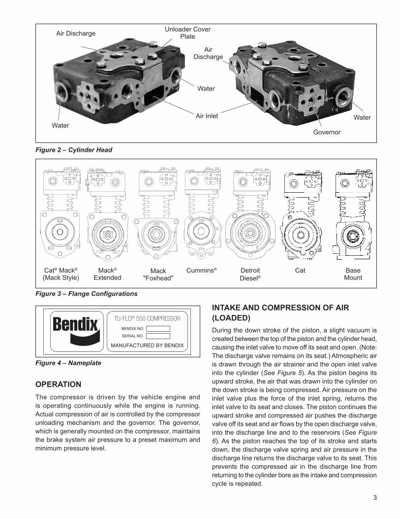
The compressor assembly consists of two major subassemblies, the cylinder head and the crankcase. The cylinder head is an iron casting which houses the inlet, discharge, and unloader valves. (See Figure 1). The cylinder head contains the air inlet port and is designed with both top and side air discharge ports. Three water
coolant ports provide a choice of coolant line connections. Governor mounting surfaces are provided at both the front and the rear of the cylinder head. The head is mounted on the crankcase and is secured by six cap screws. The Tu-Flo 550 compressor is designed such that the cylinder head can be installed in one of two positions which are 180° apart. The crankcase houses the cylinder bores, pistons, crankshaft and main bearings, and provides the flange or base mounting surface.
Various mounting and drive configurations, as shown in Figure 3, are supplied as required by the vehicle engine designs. A nameplate identifying the compressor piece number and serial number is attached to the side of the crankcase. (See Figure 4).
3
OPERATIONThe compressor is driven by the vehicle engine and is operating continuously while the engine is running. Actual compression of air is controlled by the compressor unloading mechanism and the governor. The governor, which is generally mounted on the compressor, maintains the brake system air pressure to a preset maximum and minimum pressure level.
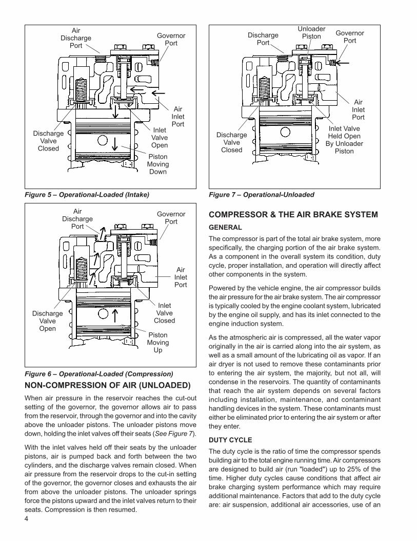
INTAKE AND COMPRESSION OF AIR (LOADED)During the down stroke of the piston, a slight vacuum is created between the top of the piston and the cylinder head, causing the inlet valve to move off its seat and open. (Note: The discharge valve remains on its seat.) Atmospheric air is drawn through the air strainer and the open inlet valve into the cylinder (See Figure 5). As the piston begins its upward stroke, the air that was drawn into the cylinder on the down stroke is being compressed. Air pressure on the inlet valve plus the force of the inlet spring, returns the inlet valve to its seat and closes. The piston continues the upward stroke and compressed air pushes the discharge valve off its seat and air flows by the open discharge valve, into the discharge line and to the reservoirs (See Figure 6). As the piston reaches the top of its stroke and starts down, the discharge valve spring and air pressure in the discharge line returns the discharge valve to its seat. This prevents the compressed air in the discharge line from returning to the cylinder bore as the intake and compression cycle is repeated.
Cat® Mack®
(Mack Style)DetroitDiesel®
Air InletWater
Unloader Cover PlateAir Discharge
Water
AirDischarge
Governor
Water
MANUFACTURED BY BENDIX
TU-FLO® 550 COMPRESSOR
BENDIX NO.
SERIAL NO.
Mack"Foxhead"
Cummins®Mack®
Extended
Figure 3 – Flange Configurations
Figure 4 – Nameplate
Figure 2 – Cylinder Head
Cat BaseMount
4
COMPRESSOR & THE AIR BRAKE SYSTEMGENERALThe compressor is part of the total air brake system, more specifically, the charging portion of the air brake system. As a component in the overall system its condition, duty cycle, proper installation, and operation will directly affect other components in the system.
Powered by the vehicle engine, the air compressor builds the air pressure for the air brake system. The air compressor is typically cooled by the engine coolant system, lubricated by the engine oil supply, and has its inlet connected to the engine induction system.
As the atmospheric air is compressed, all the water vapor originally in the air is carried along into the air system, as well as a small amount of the lubricating oil as vapor. If an air dryer is not used to remove these contaminants prior to entering the air system, the majority, but not all, will condense in the reservoirs. The quantity of contaminants that reach the air system depends on several factors including installation, maintenance, and contaminant handling devices in the system. These contaminants must either be eliminated prior to entering the air system or after they enter.
DUTY CYCLEThe duty cycle is the ratio of time the compressor spends building air to the total engine running time. Air compressors are designed to build air (run "loaded") up to 25% of the time. Higher duty cycles cause conditions that affect air brake charging system performance which may require additional maintenance. Factors that add to the duty cycle are: air suspension, additional air accessories, use of an
GovernorPort
AirInletPort
InletValveOpen
PistonMovingDown
DischargeValve
Closed
GovernorPort
InletValve
Closed
PistonMoving
Up
Figure 5 – Operational-Loaded (Intake)
Figure 6 – Operational-Loaded (Compression)
GovernorPort
DischargePort
AirInletPort
Figure 7 – Operational-Unloaded
DischargeValve
Closed
DischargeValveOpen
AirInletPort
NON-COMPRESSION OF AIR (UNLOADED) When air pressure in the reservoir reaches the cut-out setting of the governor, the governor allows air to pass from the reservoir, through the governor and into the cavity above the unloader pistons. The unloader pistons move down, holding the inlet valves off their seats (See Figure 7).
With the inlet valves held off their seats by the unloader pistons, air is pumped back and forth between the two cylinders, and the discharge valves remain closed. When air pressure from the reservoir drops to the cut-in setting of the governor, the governor closes and exhausts the air from above the unloader pistons. The unloader springs force the pistons upward and the inlet valves return to their seats. Compression is then resumed.
Inlet ValveHeld Open
By UnloaderPiston
AirDischarge
Port
AirDischarge
Port
Unloader Piston
5
undersized compressor, frequent stops, excessive leakage from fittings, connections, lines, chambers or valves, etc. Refer to Table A in the Troubleshooting section for a guide to various duty cycles and the consideration that must be given to maintenance of other components.
COMPRESSOR INSTALLATIONWhile the original compressor installation is usually completed by the vehicle manufacturer, conditions of operation and maintenance may require additional consideration. The following presents base guidelines.
DISCHARGE LINEThe discharge line allows the air, water- and oil-vapor mixture to cool between the compressor and air dryer or reservoir. The typical size of a vehicle's discharge line, (see column 2 of Table A in the Troubleshooting section) assumes a compressor with a normal (less than 25%) duty cycle, operating in a temperate climate. See Bendix and/or other air dryer manufacturer guidelines as needed.
The discharge line must maintain a constant slope down from the compressor to the air dryer inlet fitting or reservoir to avoid low points where ice may form and block the flow. If, instead, ice blockages occur at the air dryer or reservoir inlet, insulation may be added here, or if the inlet fitting is a typical 90° fitting, it may be changed to a straight or 45° fitting. Shorter discharge line lengths or insulation may be required in cold climates.
While not all compressors and charging systems are equipped with a discharge line safety valve, this component is recommended. The discharge line safety valve is installed in the cylinder head (Tu-Flo® 550/750) or close to the compressor discharge port and protects against over pressurizing the compressor in the event of a discharge line freeze up.
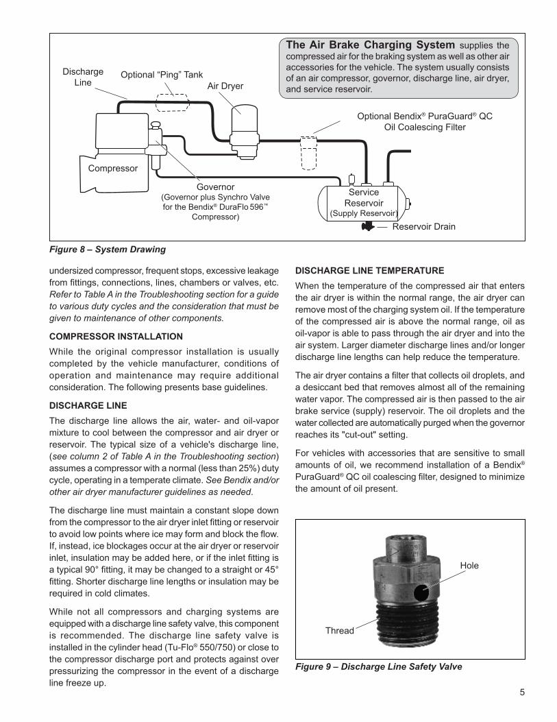
Figure 8 – System Drawing
Figure 9 – Discharge Line Safety Valve
Hole
Thread
DISCHARGE LINE TEMPERATUREWhen the temperature of the compressed air that enters the air dryer is within the normal range, the air dryer can remove most of the charging system oil. If the temperature of the compressed air is above the normal range, oil as oil-vapor is able to pass through the air dryer and into the air system. Larger diameter discharge lines and/or longer discharge line lengths can help reduce the temperature.
The air dryer contains a filter that collects oil droplets, and a desiccant bed that removes almost all of the remaining water vapor. The compressed air is then passed to the air brake service (supply) reservoir. The oil droplets and the water collected are automatically purged when the governor reaches its "cut-out" setting.
For vehicles with accessories that are sensitive to small amounts of oil, we recommend installation of a Bendix® PuraGuard® QC oil coalescing filter, designed to minimize the amount of oil present.
Air Dryer
Reservoir Drain
Service Reservoir
(Supply Reservoir)
Compressor
Governor(Governor plus Synchro Valve for the Bendix® DuraFlo 596™
Compressor)
Discharge Line
Optional “Ping” Tank
Optional Bendix® PuraGuard® QCOil Coalescing Filter
The Air Brake Charging System supplies the compressed air for the braking system as well as other air accessories for the vehicle. The system usually consists of an air compressor, governor, discharge line, air dryer, and service reservoir.
6
Figure 10 – Lubrication
OilInlet
3. Pressurized induction - Compressor inlet is connected to the pressure side of the supercharger or turbocharger.
See the tabulated technical data on page 18 of this manual for specific requirements for steps 2 and 3.
If a previously unturbocharged compressor is being turbocharged, it is recommended that the inlet cavity screen (238948) be installed with an inlet gasket (291909N) on both sides of the screen.
WaterIn
WaterOut
or (1 PortOnly)
Water Out
WaterOut
WaterIn
WaterIn
Figure 11 – Cooling
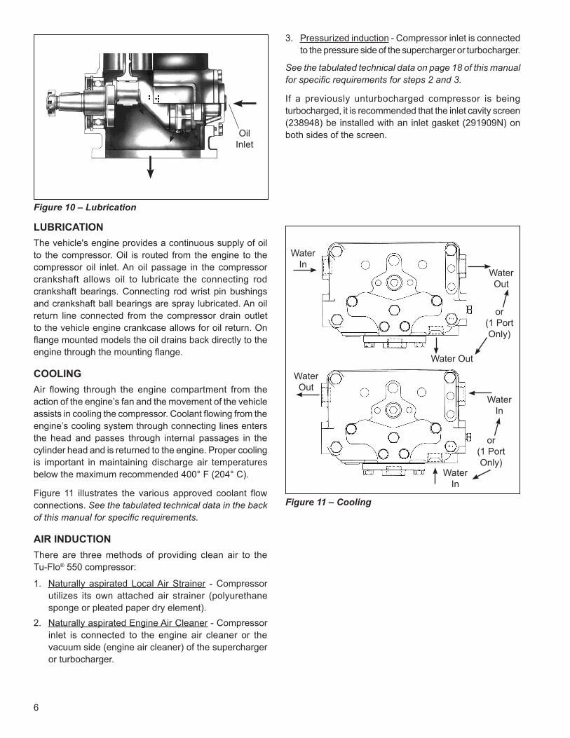
LUBRICATIONThe vehicle's engine provides a continuous supply of oil to the compressor. Oil is routed from the engine to the compressor oil inlet. An oil passage in the compressor crankshaft allows oil to lubricate the connecting rod crankshaft bearings. Connecting rod wrist pin bushings and crankshaft ball bearings are spray lubricated. An oil return line connected from the compressor drain outlet to the vehicle engine crankcase allows for oil return. On flange mounted models the oil drains back directly to the engine through the mounting flange.
COOLINGAir flowing through the engine compartment from the action of the engine’s fan and the movement of the vehicle assists in cooling the compressor. Coolant flowing from the engine’s cooling system through connecting lines enters the head and passes through internal passages in the cylinder head and is returned to the engine. Proper cooling is important in maintaining discharge air temperatures below the maximum recommended 400° F (204° C).
Figure 11 illustrates the various approved coolant flow connections. See the tabulated technical data in the back of this manual for specific requirements.
AIR INDUCTIONThere are three methods of providing clean air to the Tu-Flo® 550 compressor:
1. Naturally aspirated Local Air Strainer - Compressor utilizes its own attached air strainer (polyurethane sponge or pleated paper dry element).
2. Naturally aspirated Engine Air Cleaner - Compressor inlet is connected to the engine air cleaner or the vacuum side (engine air cleaner) of the supercharger or turbocharger.
or (1 PortOnly)
7
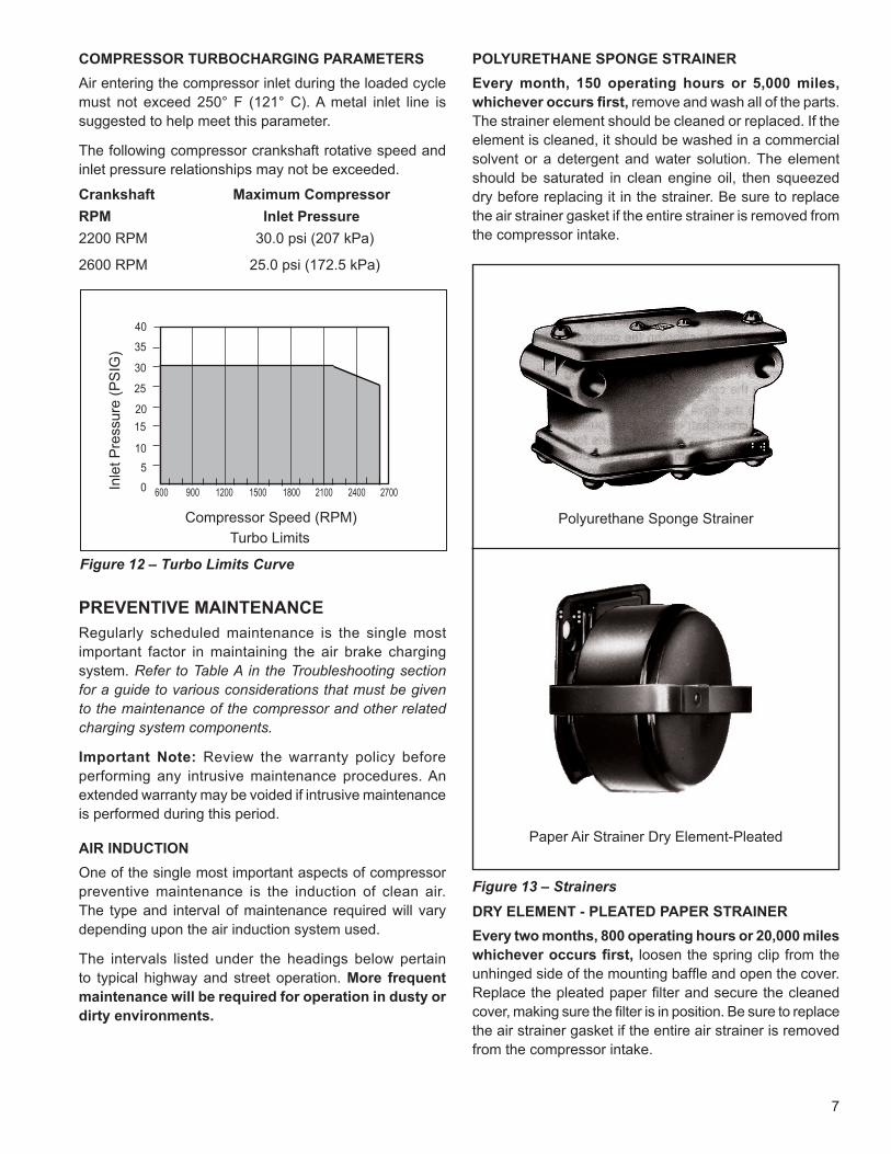
COMPRESSOR TURBOCHARGING PARAMETERS Air entering the compressor inlet during the loaded cycle must not exceed 250° F (121° C). A metal inlet line is suggested to help meet this parameter.
The following compressor crankshaft rotative speed and inlet pressure relationships may not be exceeded.
Crankshaft Maximum Compressor RPM Inlet Pressure 2200 RPM 30.0 psi (207 kPa)
2600 RPM 25.0 psi (172.5 kPa)
POLYURETHANE SPONGE STRAINER Every month, 150 operating hours or 5,000 miles, whichever occurs first, remove and wash all of the parts. The strainer element should be cleaned or replaced. If the element is cleaned, it should be washed in a commercial solvent or a detergent and water solution. The element should be saturated in clean engine oil, then squeezed dry before replacing it in the strainer. Be sure to replace the air strainer gasket if the entire strainer is removed from the compressor intake.
Paper Air Strainer Dry Element-Pleated
Polyurethane Sponge Strainer
Figure 13 – Strainers
PREVENTIVE MAINTENANCERegularly scheduled maintenance is the single most important factor in maintaining the air brake charging system. Refer to Table A in the Troubleshooting section for a guide to various considerations that must be given to the maintenance of the compressor and other related charging system components.
Important Note: Review the warranty policy before performing any intrusive maintenance procedures. An extended warranty may be voided if intrusive maintenance is performed during this period.
AIR INDUCTION One of the single most important aspects of compressor preventive maintenance is the induction of clean air. The type and interval of maintenance required will vary depending upon the air induction system used.
The intervals listed under the headings below pertain to typical highway and street operation. More frequent maintenance will be required for operation in dusty or dirty environments.
DRY ELEMENT - PLEATED PAPER STRAINER Every two months, 800 operating hours or 20,000 miles whichever occurs first, loosen the spring clip from the unhinged side of the mounting baffle and open the cover. Replace the pleated paper filter and secure the cleaned cover, making sure the filter is in position. Be sure to replace the air strainer gasket if the entire air strainer is removed from the compressor intake.
0
20
25
15
35
5
30
270024002100180015001200900600
10
Compressor Speed (RPM)Turbo Limits
40
Figure 12 – Turbo Limits Curve
Inle
t Pre
ssur
e (P
SIG
)
8
INTAKE ADAPTER When the engine air cleaner is replaced: Some compressors are fitted with compressor intake adapters, which allow the compressor intake to be connected to the engine air induction system. In this case, the compressor receives a supply of clean air from the engine air cleaner. When the engine air filter is changed, the compressor intake adapter should be checked. If it is loose, remove the intake adapter, clean the strainer plate, if applicable, and replace the intake adapter gasket, and reinstall the adapter securely. Check line connections both at the compressor intake adapter and at the engine. Inspect the connecting line for ruptures and replace it if necessary.
COMPRESSOR COOLING Every 6 months, 1800 operating hours or after each 50,000 miles whichever occurs first, inspect the compressor discharge port, inlet cavity and discharge line for evidence of restrictions and carboning. If excessive build-up is noted, thoroughly clean or replace the affected parts and closely inspect the compressor cooling system. Check all compressor coolant lines for kinks and restrictions to flow. Minimum coolant line size is 3/8" I.D. Check coolant lines for internal clogging from rust scale. If coolant lines appear suspicious, check the coolant flow and compare to the tabulated technical data present in the back of this manual. Carefully inspect the air induction system for restrictions.
LUBRICATION Every six months, 1800 operating hours or 50,000 miles whichever occurs first, check external oil supply and return lines, if applicable, for kinks, bends, or restrictions to flow. Supply lines must be a minimum of 3/16" I.D. and return lines must be a minimum of 1/2" I.D. Oil return lines should slope as sharply as possible back to the engine crankcase and should have as few fittings and bends as possible. Refer to the tabulated technical data in the back of this manual for oil pressure minimum values.
Check the exterior of the compressor for the presence of oil seepage and refer to the TROUBLESHOOTING section for appropriate tests and corrective action.
OIL PASSINGAll reciprocating compressors currently manufactured will pass a minimal amount of oil. Air dryers will remove the majority of oil prior to entrance into the air brake system. For particularly oil sensitive systems, the Bendix® PuraGuard®
QC oil coalescing filter can be used in conjunction with a Bendix air dryer.
If compressor oil passing is suspected, refer to the TROUBLESHOOTING section and TABLE A for the symptoms and corrective action to be taken. In addition, Bendix has developed the "Bendix Air System Inspection Cup" or BASIC™ test to help substantiate suspected excessive oil passing. The steps to be followed when using the BASIC test are presented in APPENDIX A at the end of the TROUBLESHOOTING section.
COMPRESSOR DRIVE Every six months, 1800 operating hours or 50,000 miles, whichever occurs first, check for noisy compressor operation, which could indicate a worn drive gear coupling, a loose pulley or excessive internal wear. Adjust and/or replace as necessary.
If the compressor is belt driven, check for proper belt and pulley alignment and belt tension. Check all compressor mounting bolts and retighten evenly if necessary. Check for leakage and proper unloader mechanism operation. Repair or replace parts as necessary.
Every 24 months, 7200 operating hours, or after each 200,000 miles, perform a thorough inspection, and depending upon the results of this inspection or experience, disassemble the compressor, clean and inspect all parts thoroughly, replace all worn or damaged parts using only genuine Bendix® replacements or replace the compressor with a genuine Bendix remanufactured unit.
9
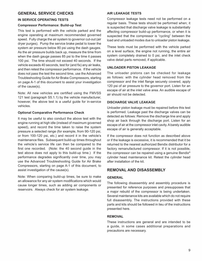
GENERAL SERVICE CHECKS IN SERVICE OPERATING TESTSCompressor Performance: Build-up Test This test is performed with the vehicle parked and the engine operating at maximum recommended governed speed. Fully charge the air system to governor cut-out (air dryer purges). Pump the service brake pedal to lower the system air pressure below 80 psi using the dash gauges. As the air pressure builds back up, measure the time from when the dash gauge passes 85 psi to the time it passes 100 psi. The time should not exceed 40 seconds. If the vehicle exceeds 40 seconds, test for (and fix) any air leaks, and then retest the compressor performance. If the vehicle does not pass the test the second time, use the Advanced Troubleshooting Guide for Air Brake Compressors, starting on page A-1 of this document to assist your investigation of the cause(s).
Note: All new vehicles are certified using the FMVSS 121 test (paragraph S5.1.1) by the vehicle manufacturer, however, the above test is a useful guide for in-service vehicles.
Optional Comparative Performance Check
It may be useful to also conduct the above test with the engine running at high idle (instead of maximum governed speed), and record the time taken to raise the system pressure a selected range (for example, from 90-120 psi, or from 100-120 psi, etc.) and record it in the vehicle’s maintenance files. Subsequent build-up times throughout the vehicle’s service life can then be compared to the first one recorded. (Note: the 40 second guide in the test above does not apply to this build-up time.) If the performance degrades significantly over time, you may use the Advanced Troubleshooting Guide for Air Brake Compressors, starting on page A-1 of this document, to assist investigation of the cause(s).
Note: When comparing build-up times, be sure to make an allowance for any air system modifications which would cause longer times, such as adding air components or reservoirs. Always check for air system leakage.
AIR LEAKAGE TESTS Compressor leakage tests need not be performed on a regular basis. These tests should be performed when; it is suspected that discharge valve leakage is substantially affecting compressor build-up performance, or when it is suspected that the compressor is “cycling” between the load and unloaded modes due to unloader piston leakage.
These tests must be performed with the vehicle parked on a level surface, the engine not running, the entire air system completely drained to 0 psi, and the inlet check valve detail parts removed, if applicable.
UNLOADER PISTON LEAKAGE The unloader pistons can be checked for leakage as follows: with the cylinder head removed from the compressor and the inlet flange securely covered, apply 120 psi of air pressure to the governor port. Listen for an escape of air at the inlet valve area. An audible escape of air should not be detected.
DISCHARGE VALVE LEAKAGE Unloader piston leakage must be repaired before this test is performed. Leakage past the discharge valves can be detected as follows: Remove the discharge line and apply shop air back through the discharge port. Listen for an escape of air at the compressor inlet cavity. A barely audible escape of air is generally acceptable.
If the compressor does not function as described above or if the leakage is excessive, it is recommended that it be returned to the nearest authorized Bendix distributor for a factory remanufactured compressor. If it is not possible, the compressor can be repaired using a genuine Bendix® cylinder head maintenance kit. Retest the cylinder head after installation of the kit.
REMOVAL AND DISASSEMBLY
GENERAL The following disassembly and assembly procedure is presented for reference purposes and presupposes that a major rebuild of the compressor is being undertaken. Several maintenance kits are available which do not require full disassembly. The instructions provided with these parts and kits should be followed in lieu of the instructions presented here.
REMOVAL These instructions are general and are intended to be a guide, in some cases additional preparations and precautions are necessary.
10
1. Block the wheels of the vehicle and drain the air pressure from all the reservoirs in the system.
2. Drain the engine cooling system and the cylinder head of the compressor. Identify and disconnect all air, water, and oil lines leading to the compressor.
3. Remove the governor and any supporting bracketry attached to the compressor and note their positions on the compressor to aid in reassembly.
4. Remove the discharge and inlet fittings, if applicable, and note their position on the compressor to aid in reassembly.
5. Remove the flange or base mounting bolts and remove the compressor from the vehicle.
6. Remove the crankshaft nut (45), cotter pin (44), and seal (43) if applicable. Remove the drive gear(s) or pulley from the compressor crankshaft using a gear puller. Inspect the pulley or gear and associated parts for visible wear or damage. Since these parts are precision fitted, they must be replaced if they are worn or damaged.
PREPARATION FOR DISASSEMBLY Remove road dirt and grease from the exterior of the compressor with a cleaning solvent. Before the compressor is disassembled, the following items should be marked to show their relationship when the compressor is assembled. Mark the rear end cover in relation to the crankcase. Mark the base plate or base adapter in relation to the crankcase.
A convenient method to indicate the above relationships is to use a metal scribe to mark the parts with numbers or lines. Do not use marking methods such as chalk that can be wiped off or obliterated during rebuilding.
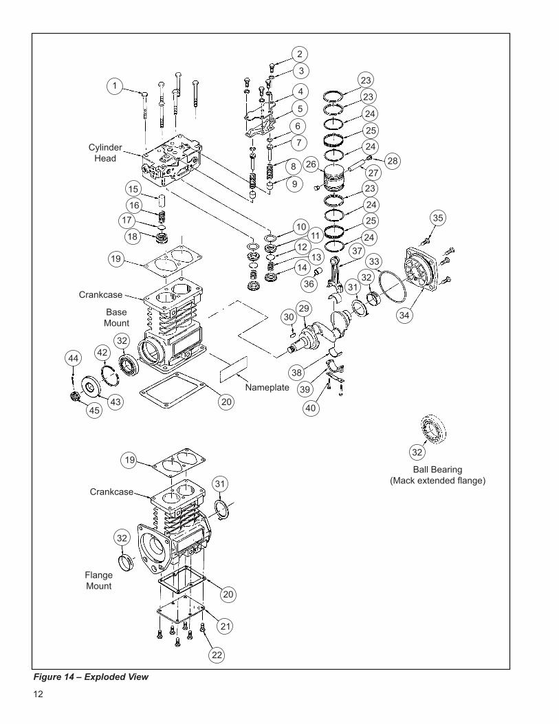
CYLINDER HEAD Remove the six cylinder head cap screws (1) and tap the head with a soft mallet to break the gasket seal. Remove the unloader cover plate cap screws (2), lock washers (3), and the unloader cover plate (4). Scrape off any gasket material (5) from the cover plate, cylinder head, and crankcase.
1. Remove the unloader pistons (7), o-rings (6), and springs (8).
2. Inspect the unloader piston bushings (9) for nicks, wear, corrosion, and scoring. It is recommended that the compressor be replaced if it is determined that the unloader bushing is damaged or worn excessively.
Before disassembling the discharge valve mechanism, measure and record the discharge valve travel (from closed to completely open).
3. If the measured discharge valve travel exceeds .046 inches, the compressor should be replaced. If the discharge valve travel does not exceed .046, using a 9/16" Allen wrench, remove the discharge valve seats (18), valves (17), and valve springs (16).
4. Remove the inlet valve stops (14), valves (17), valve seats (11), valve springs (12), and gaskets (10). It is recommended that a tool such as a J-25447-B, produced by Kent Moore Tool Division Roseville, Michigan phone 1-800-328-6657, be used to remove the inlet valve stop.
CRANKCASE BOTTOM COVER OR ADAPTER DISASSEMBLY 1. Remove the cap screws (22) securing the bottom cover
or adapter (21). Tap with a soft mallet to break the gasket seal. Scrape off any gasket material (20) from the crankcase and bottom cover or adapter.
11
CONNECTING ROD DISASSEMBLY Before removing the connecting rod, mark the connecting rods (37) and their caps (39) to ensure correct reassembly. The connecting rod and cap are a matched set, therefore, the caps must not be switched or rotated end for end.
1. Remove the connecting rod bolts (40) and bearing caps (39).
2. Push the pistons (26) with the connecting rods (37) attached out the top of the cylinder bore of the crankcase. Replace the bearing caps on the connecting rods.
3. Remove the piston rings (23-25) from the piston. If the piston is to be removed from the connecting rod, remove the wrist pin Teflon plugs (28) and press the wrist pin (27) from the piston and connecting rod.
4. If the piston is removed from the rod, inspect the wrist pin bore in the piston and bronze wrist pin bushing (36) in the connecting rod. If excessive wear is noted or suspected, replace the connecting rod and piston.
COMPRESSOR CRANKCASE DISASSEMBLY 1. Remove the key or keys (30) from the crankshaft (29)
and any burrs from the crankshaft where the key or keys were removed. (Note: Through drive compressors may have a crankshaft key at both ends.)
2. Remove the four cap screws (35) and lock washers or nuts and lock washers that secure the rear end cover (34) to the crankcase.
3. Remove the rear end cover (34), thrust washer (31), and end cover oil seal ring (33), taking care not to damage the bearing if present in the end cover.
4. If the compressor has ball type main bearings (32), press the crankshaft (29) and ball bearings from the crankcase, then press the ball bearings from the crankshaft.
5. Press the oil seal out of the compressor crankcase, if so equipped.
CLEANING OF PARTS
GENERAL All parts should be cleaned in a good commercial grade of solvent and dried prior to inspection.
CYLINDER HEAD Remove carbon deposits from the discharge cavity and rust and scale from the cooling cavities of the cylinder head body. Scrape all foreign matter from the body surfaces and use shop air pressure to blow the dirt particles from the cavities. Clean carbon and dirt from the inlet and unloader passages. Use shop air to blow the carbon and dirt deposits from the unloader passages.
OIL PASSAGES Thoroughly clean all oil passages through the crankshaft, crankcase, end covers, base plate, or base adapter. Inspect the passages with a wire to be sure it is clean. Blow the loosened foreign matter out with air pressure.
INSPECTION OF PARTS
CYLINDER HEAD BODY Inspect the cylinder head for cracks or damage. With the cylinder head and head gasket secured to a flat surface or crankcase, apply shop air pressure to one of the coolant ports with all others plugged, and check for leakage by applying a soap solution to the exterior of the body. If leakage is detected, replace the compressor.
12
2
4
5
6
7
8
9
Ball Bearing(Mack extended flange)
Nameplate
3
26
23
23
24
25
2428
27
35
3733
3236
1112
1314
10
29
38
39
40
1
CylinderHead
15
1617
18
19
32
22
21
20
31Crankcase
19
4244
FlangeMount
BaseMount
32
32
20
Crankcase
30 34
24
24
23
25
4345
31
Figure 14 – Exploded View
13
Kit Contents (Refer to Figure 14)Item No.
Description Qty. Item No.
Description Qty. Item No.
Description Qty.
1 Cylinder Head Cap Screws 6 16 Discharge Valve Spring 2 31 Thrust Washer 22 Unloader Plate Cap Screws 4 17 Discharge Valve 2 32 Sleeve (or Ball) Bearing 23 Unloader Plate Lock Washers 4 18 Discharge Valve Stop 2 33 End Cover Seal 14 Unloader Plate 1 19 Cylinder Head Gasket 1 34 End Cover 15 Unloader Plate Gasket 1 20 Base Gasket 1 35 End Cover Cap Screws 46 O-Ring 2 21 Base Plate 1 36 Wrist Pin Bushing 27 Unloader 2 22 Base Plate Cap Screws 6 37 Connecting Rod 28 Spring 2 23 Standard Piston Rings 6 38 Conn. Rod Inserts (Sets) 29 Unloader Bushing 2 24 Oil Ring 8 39 Connecting Rod Caps 2
10 Gasket 2 25 Expander Ring 4 40 Connecting Rod Bolts 411 Inlet Valve Seat 2 26 Piston 2 41 Ball Bearing 112 Inlet Valve 2 27 Wrist Pin 2 42 Retaining Ring 113 Inlet Valve Spring 2 28 Wrist Pin Button 4 43 Seal 114 Inlet Valve Stop 2 29 Crankshaft 1 44 Cotter Pin 115 Discharge Valve Stop 2 30 Crankshaft Key 1 45 Locknut 1
14
END COVERS Check for cracks and external damage. If the crankshaft main bearing (32) is installed in the end cover (34), check for excessive wear and flat spots and replace if necessary.
CRANKCASE Check all crankcase surfaces for cracks and damage. On compressors where ball bearing main bearings are used, the difference between the O.D. of the outer race and the I.D. of the crankcase hole should be .0003 in. tight to .0023 in. loose. This is to maintain the correct fit. The compressor must be replaced if the fit is too loose.
On compressors fitted with precision, sleeve main bearings, the difference between the O.D. of the crankshaft journal and the main bearing l.D. must not exceed .005 in. If the clearance is greater than .005 in., the bearing must be replaced.
The cylinder bores should be checked with inside micrometers or calipers. Cylinder bores which are scored or out of round by more than .0005 in. or tapered more than .0005 in. should be re-bored or honed oversize. Oversized pistons and piston rings are available in .010 in., .020 in., and .030 in. oversizes. Cylinder bores must be smooth, straight, and round. Clearance between the cast iron pistons and cylinder bores should be between .002 in. minimum and .004 in. maximum.
PISTON RINGSCheck the pistons for scores, cracks, or enlarged ring grooves; replace the pistons if any of these conditions are found. Measure each piston with a micrometer in relation to the cylinder bore diameter to be sure the diametrical clearance is between .002 in. minimum and .004 in. maximum.
Check the fit of the wrist pins to the pistons and connecting rod bushings. The wrist pin should be a light press fit in the piston. If the wrist pin is a loose fit, the piston and pin assembly should be replaced. Check the fit of the wrist pin in the connecting rod bushing by rocking the piston. This clearance should not exceed .0007 in. Replace the connecting rod and cap assembly which includes the wrist pin bushings if excessive clearance is found. Check the fit of the rings in the piston ring grooves. Check the ring gap with the rings installed in the cylinder bores. See Figure 15 for correct gap and groove clearances.
CRANKSHAFT Check the crankshaft threads, keyways, tapered ends, and all machined and ground surfaces for wear, scores, or damage. Standard crankshaft journals are 1.1242 - 1.1250 inches in diameter. If the crankshaft journals are excessively scored or worn or out of round and cannot be reground, the compressor must be replaced. Connecting rod bearing inserts are available in .010 in., .020 in., and .030 in. undersizes for compressors with reground crankshafts. Main bearing journals must be maintained so the ball bearings are a snug fit or so that no more than .005 in. clearance exists between the precision sleeve main bearing and the main bearing journals on the crankshaft. Check to be sure the oil passages are open through the crankshaft.
CONNECTING ROD BEARINGS Used bearing inserts must be replaced. The connecting rod and cap are a matched set and therefore the caps must not be switched or rotated end for end. The solid inserts must be installed in the rod and the slotted inserts into the cap. Make sure the locating tangs on the inserts engage with the locating notches in the rod and cap. Clearance between the connecting rod journal and the connecting rod bearing must not be less than .0003 in. or more than .0021 in. after rebuilding.
SIDE CLEARANCE
Figure 15 – Ring Configuration
End Gap
.002
.004.000 .006
Bevel
Pip Mark
Ring End Gap
Compression .002
.013
Segment .010
.040
15
To convert inch pounds of torque to foot pounds of torque, divide inch pounds by 12.
inch pounds ÷ 12 = foot pounds (ft-lbs)
To convert foot pounds of torque to inch pounds of torque, multiply foot pounds by 12.
foot pounds x 12 = inch pounds (in-lbs)
INSTALLING CRANKSHAFT Press new sleeve bearings in the end cover and crankcase. Ensure that the slot in the bearings line up with the oil passages in the end cover or crankcase. If you have a model with no oil passage present in the crankcase, press the sleeve bearing into the crankcase with the slot located 90° from vertical.
Install the front thrust washer with the tang inserted in the slot toward the flange. Insert the crankshaft and the rear thrust washer with the tang toward the rear of the compressor.
Place the oil seal ring on the boss of the rear end cover and install the end cover making sure not to pinch the seal ring. Ensure the tang of the thrust washer is inserted in the slot of the end cover. Fasten the end cover to the crankcase with the four cover cap screws. Torque the cap screws to 175-225 in-lbs in a cross pattern.
REPAIRS
UNLOADERA new cylinder head maintenance kit should be used when rebuilding. Note: The entire contents of this kit must be used. Failure to do so may result in compressor failure. The unloader pistons in the kit are prelubricated with a special lubricant piece number 239379 and need no additional lubrication. Install the springs and unloader pistons in their bores being careful not to cut the o-rings. Install the unloader cover gasket and unloader cover and secure the cover cap screws. Tighten the cap screws to 175-225 in-lbs in a crossing pattern after first snugging all screws.
DISCHARGE VALVES, VALVE STOPS, AND SEATS
If the discharge valve seats merely show signs of slight wear, they can be dressed by using a lapping stone, grinding compound, and grinding tool, however, it is recommended that a cylinder head maintenance kit be used. Install new discharge valve springs and valves. Screw in the discharge valve seats, and tighten to 70-90 ft.-lbs. Discharge valve travel should be between .030 in. to .046 in. To test for leakage by the discharge valves, apply 100 psi to the cylinder head discharge port and apply a soap solution to the discharge valve and seats. Leakage in the form of soap bubbles is permissible. If excessive leakage is found, leave the air pressure applied and with the use of a fiber or hardwood dowel and a hammer, tap the discharge valves off their seats several times. This will help the valves to seat and should reduce the leakage. With the air pressure still applied at the discharge port of the cylinder head, check for leakage around the discharge valve stop on the top of the cylinder head casting. No leakage is permitted.
INLET VALVES AND SEATS Inlet valves and springs should be replaced. However, if the inlet valve seats show signs of slight nicks or scratches, they can be redressed with a fine piece of emery cloth or by lapping with a lapping stone, grinding compound, and grinding tool. If the seats are damaged to the extent that they cannot be reclaimed, they must be replaced.
ASSEMBLY General Note: All torques specified in this manual are assembly torques and typically can be expected to fall off after assembly is accomplished. Do not retorque after initial assembly torques fall unless instructed otherwise. A compiled listing of torque specifications is presented in this manual.
16
PISTONS AND CONNECTING RODS If the pistons are to be replaced, ensure that the correct pistons are being installed. Note that the pistons for the Tu-Flo® 550 compressor are similar to those of other Bendix® compressor models but may be identified by the piston diameter and the distance to the center of the wrist pin from the top of the piston as shown in Figure 16.
PISTON RINGS Check each ring end gap in a cylinder bore before installation. Place the ring in the top of the cylinder bore and using the piston, push the ring to the midpoint of the cylinder bore and check the ring gap. If the end gaps are incorrect either the wrong repair size has been purchased or the compressor is worn beyond specification and should be replaced.
Install the rings on the pistons per the following instructions starting at the center of the piston and moving outward.
1. Install the spacer and segment rings as follows. Place the spacer ring (25) in the piston groove, the ends of the spacer must butt and not overlap. Install the top segment (24) by inserting one end above the spacer in the ring groove, 120° from the spacer ends and wind the segment into position. Install the bottom segment in the same manner beneath the spacer making sure the gap is staggered 120° from both the top ring segment and the spacer end gaps. Before using, be sure both painted ends of the spacer are visible and butted.
2. Install the compression rings (23) in the proper grooves with the “pip” mark toward the top of the piston. (See Figure 17).
Check the ring side clearance of each ring in the piston ring groove. (See Figure 17). If the side clearance is too large, the piston ring groove is worn beyond specifications and the piston must be replaced.
Rotate the piston rings in their respective groove so that each end gap is at least 90° from the previous ring’s end gap.
Lubricate the wrist pin (22) and wrist pin bushing in the connecting rod with engine oil. Assemble the upper portion of the connecting rods and the pistons with the wrist pins. Insert the wrist pin buttons (28) in the ends of the wrist pin. Lubricate the pistons and rings with engine oil. Using a ring compression tool, return the piston to the cylinder bore.
Turn the crankshaft so that one of its connecting rod journals is in the downward, center position. Install the crankshaft journal bearing segments (38) on the connecting rod (37) and connecting rod cap (39). Tighten the connecting rod bolts (40) evenly and torque to 150 -170 in-lbs. Install the other connecting rod and piston in the same manner. It is recommended that new connecting rod cap screws be used.
Before replacing the cylinder head on the crankcase, ensure the correct pistons have been used by turning the crankshaft one complete revolution such that each piston moves to its maximum upward stroke. At the maximum upward stroke position each piston should move to the top of the crankcase. If the piston does not approach the top of the crankcase, the piston is incorrect and if not replaced could result in compressor damage.
Figure 17 – Piston & Rings
Compression Ring (23)Segment Ring (24)
Spacer Ring (25)
Segment Ring (24)
Figure 16 – Piston Comparison
2.78
2.17
1.061.25
Other Bendix® Tu-Flo® Air Compressors
Tu-Flo® 550 Air Compressor
PISTON COMPARISON
17
BASE PLATE OR BASE ADAPTER Position the base plate or base adapter gasket (20) on the crankcase and install the base plate or base adapter (21) as marked before disassembly. Tighten the six cap screws (22), securing the cast iron base adapter evenly to a torque of 175-225 in-lbs for base plate or cover in a crossing pattern after first snugging all 6 screws.
CYLINDER HEAD Place the cylinder head gasket (19) and cylinder head on the compressor crankcase and install the six cylinder head cap screws. Snug the cylinder head cap screws prior to torquing the cap screws to 300-360 in-lbs in a cross pattern. Retorque the unloader cover cap screws to 170-225 in-Ibs.
FINAL COMPRESSOR ASSEMBLY Install all crankshaft keys making certain to support the crankshaft to avoid bearing damage. Install the crankshaft nut where applicable. When installing drive couplings or gears, do not exceed 120 ft-lbs of torque on the crankshaft nut.
Use covers, plugs, or masking tape to protect all ports if compressor is not to be installed immediately. Protect the ends of the crankshaft against damage by wrapping with masking tape or friction tape.
TESTING REBUILT COMPRESSOR In order to properly test a compressor under operating conditions, a test rack for correct mounting, cooling, lubricating, and driving the compressor is necessary. Such tests are not compulsory if the unit has been carefully rebuilt by an experienced person. A compressor efficiency or build up test can be run which is not too difficult. An engine lubricated compressor must be connected to an oil supply line of at least 15 psi. pressure during the test and an oil return line must be installed to keep the crankcase drained.
Connect to the compressor discharge port, a reservoir with a volume of 1500 cubic inches, including the volume of the connecting line. With the compressor operating at 2100 RPM, the time required to raise the reservoir(s) pressure from 85 psi to 100 psi should not exceed seven (7) seconds. During this test, the compressor should be checked for gasket leakage and noisy operation, as well as unloader operation and leakage.
If the compressor functions as indicated, reinstall on the vehicle connecting all lines as marked in the disassembly procedure.
MAINTENANCE KITS AND AVAILABLE SERVICE PARTSCylinder Maintenance KitPiston Ring Kit (standard and oversizes)Piston and Rod Kit (standard and oversizes)Crankshaft Bearing KitGasket & Seal Kit
COMPRESSOR TROUBLESHOOTING
IMPORTANT
The troubleshooting contained in this section considers the compressor as an integrated component of the overall air brake charging system and assumes that an air dryer is in use. The troubleshooting presented will cover not only the compressor itself, but also other charging system devices as they relate to the compressor.
18
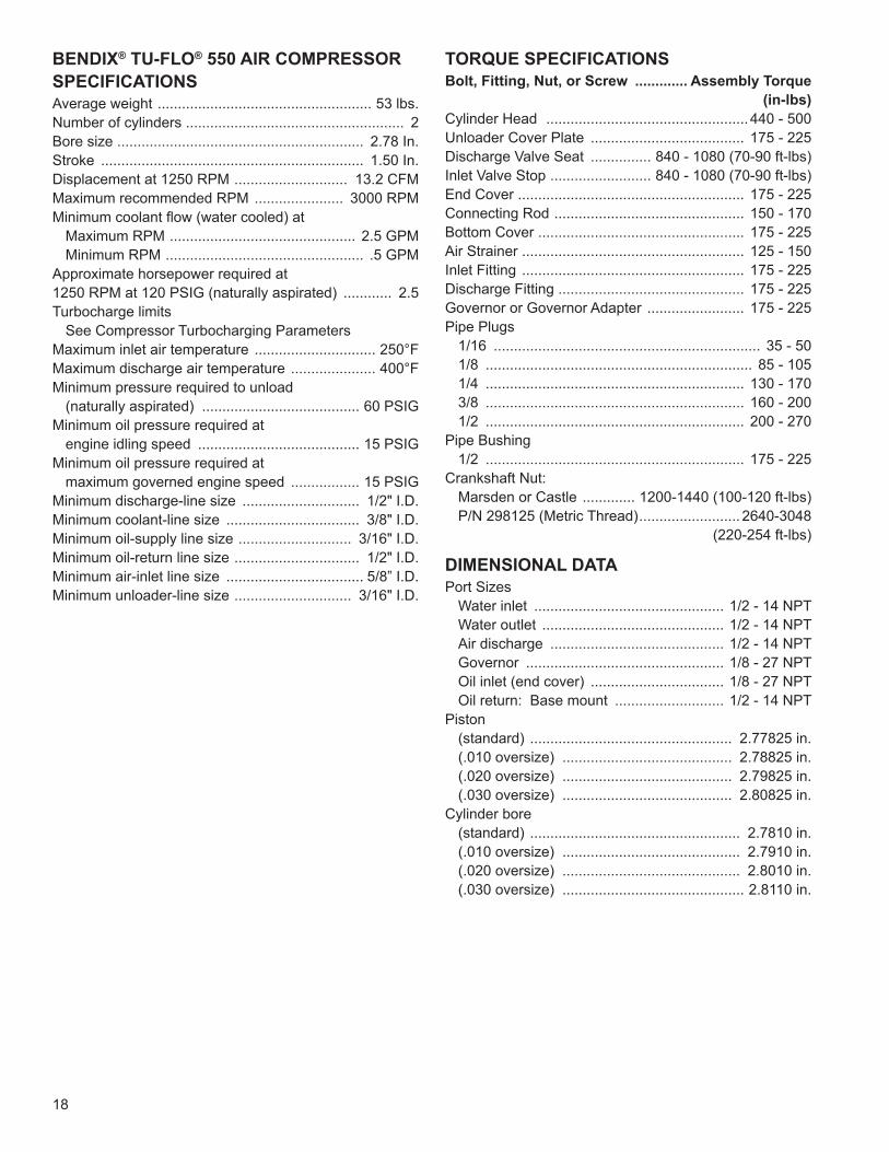
BENDIX® TU-FLO® 550 AIR COMPRESSOR SPECIFICATIONSAverage weight ..................................................... 53 lbs.Number of cylinders ...................................................... 2Bore size ............................................................. 2.78 In.Stroke ................................................................. 1.50 In.Displacement at 1250 RPM ............................ 13.2 CFMMaximum recommended RPM ...................... 3000 RPMMinimum coolant flow (water cooled) at
Maximum RPM .............................................. 2.5 GPMMinimum RPM ................................................. .5 GPM
Approximate horsepower required at1250 RPM at 120 PSIG (naturally aspirated) ............ 2.5Turbocharge limits
See Compressor Turbocharging Parameters Maximum inlet air temperature .............................. 250°FMaximum discharge air temperature ..................... 400°FMinimum pressure required to unload
(naturally aspirated) ....................................... 60 PSIGMinimum oil pressure required at
engine idling speed ........................................ 15 PSIGMinimum oil pressure required at
maximum governed engine speed ................. 15 PSIGMinimum discharge-line size ............................. 1/2" I.D.Minimum coolant-line size ................................. 3/8" I.D.Minimum oil-supply line size ............................ 3/16" I.D.Minimum oil-return line size ............................... 1/2" I.D.Minimum air-inlet line size .................................. 5/8” I.D.Minimum unloader-line size ............................. 3/16" I.D.
TORQUE SPECIFICATIONSBolt, Fitting, Nut, or Screw ............. Assembly Torque
(in-lbs)Cylinder Head .................................................. 440 - 500Unloader Cover Plate ...................................... 175 - 225Discharge Valve Seat ............... 840 - 1080 (70-90 ft-lbs)Inlet Valve Stop ......................... 840 - 1080 (70-90 ft-lbs)End Cover ........................................................ 175 - 225Connecting Rod ............................................... 150 - 170Bottom Cover ................................................... 175 - 225Air Strainer ....................................................... 125 - 150Inlet Fitting ....................................................... 175 - 225Discharge Fitting .............................................. 175 - 225Governor or Governor Adapter ........................ 175 - 225Pipe Plugs
1/16 .................................................................. 35 - 501/8 .................................................................. 85 - 1051/4 ................................................................ 130 - 1703/8 ................................................................ 160 - 2001/2 ................................................................ 200 - 270
Pipe Bushing1/2 ................................................................ 175 - 225
Crankshaft Nut:Marsden or Castle ............. 1200-1440 (100-120 ft-lbs)P/N 298125 (Metric Thread) ......................... 2640-3048
(220-254 ft-lbs)
DIMENSIONAL DATAPort Sizes
Water inlet ............................................... 1/2 - 14 NPTWater outlet ............................................. 1/2 - 14 NPTAir discharge ........................................... 1/2 - 14 NPTGovernor ................................................. 1/8 - 27 NPTOil inlet (end cover) ................................. 1/8 - 27 NPTOil return: Base mount ........................... 1/2 - 14 NPT
Piston(standard) .................................................. 2.77825 in.(.010 oversize) .......................................... 2.78825 in.(.020 oversize) .......................................... 2.79825 in.(.030 oversize) .......................................... 2.80825 in.
Cylinder bore(standard) .................................................... 2.7810 in.(.010 oversize) ............................................ 2.7910 in.(.020 oversize) ............................................ 2.8010 in.(.030 oversize) ............................................. 2.8110 in.
19
NOTES:
A-1
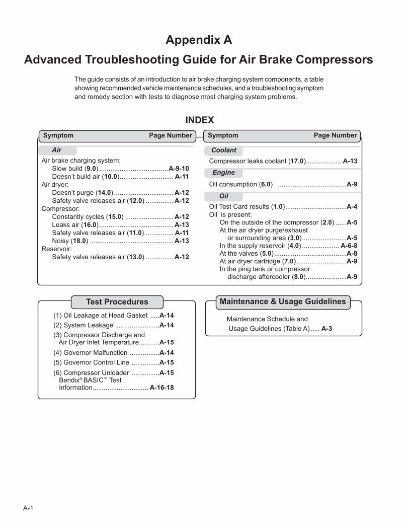
Appendix AAdvanced Troubleshooting Guide for Air Brake Compressors
Air brake charging system: Slow build (9.0) .....................................A-9-10 Doesn’t build air (10.0) ............................. A-11Air dryer: Doesn’t purge (14.0) ................................ A-12 Safety valve releases air (12.0) ............... A-12Compressor: Constantly cycles (15.0) .......................... A-12 Leaks air (16.0) ........................................ A-13 Safety valve releases air (11.0) ............... A-11 Noisy (18.0) ............................................ A-13Reservoir: Safety valve releases air (13.0) ............... A-12
INDEX
Air Coolant
Engine
Oil
Compressor leaks coolant (17.0)....................A-13
Oil consumption (6.0) ......................................A-9
Oil Test Card results (1.0) .................................A-4Oil is present: On the outside of the compressor (2.0) ......A-5 At the air dryer purge/exhaust or surrounding area (3.0) ........................A-5 In the supply reservoir (4.0) .................... A-6-8 At the valves (5.0) .......................................A-8 At air dryer cartridge (7.0) ...........................A-9 In the ping tank or compressor discharge aftercooler (8.0) ......................A-9
Symptom Page Number
(1) Oil Leakage at Head Gasket .....A-14(2) System Leakage .......................A-14(3) Compressor Discharge and Air Dryer Inlet Temperature ...........A-15(4) Governor Malfunction ................A-14(5) Governor Control Line ...............A-15(6) Compressor Unloader ...............A-15 Bendix® BASIC™ Test Information .............................. A-16-18
Test Procedures
Maintenance Schedule and Usage Guidelines (Table A) ..... A-3
Symptom Page Number
Maintenance & Usage Guidelines
The guide consists of an introduction to air brake charging system components, a table showing recommended vehicle maintenance schedules, and a troubleshooting symptom and remedy section with tests to diagnose most charging system problems.
A-2
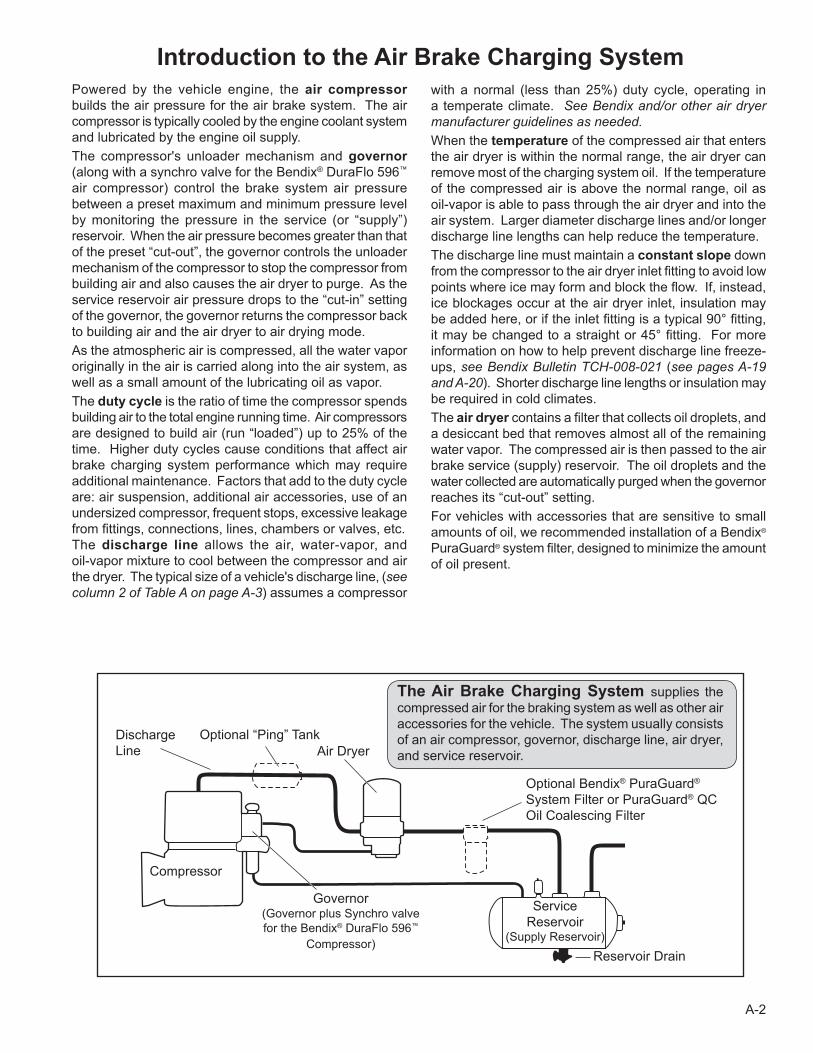
Introduction to the Air Brake Charging SystemPowered by the vehicle engine, the air compressor builds the air pressure for the air brake system. The air compressor is typically cooled by the engine coolant system and lubricated by the engine oil supply.The compressor's unloader mechanism and governor (along with a synchro valve for the Bendix® DuraFlo 596™
air compressor) control the brake system air pressure between a preset maximum and minimum pressure level by monitoring the pressure in the service (or “supply”) reservoir. When the air pressure becomes greater than that of the preset “cut-out”, the governor controls the unloader mechanism of the compressor to stop the compressor from building air and also causes the air dryer to purge. As the service reservoir air pressure drops to the “cut-in” setting of the governor, the governor returns the compressor back to building air and the air dryer to air drying mode. As the atmospheric air is compressed, all the water vapor originally in the air is carried along into the air system, as well as a small amount of the lubricating oil as vapor.The duty cycle is the ratio of time the compressor spends building air to the total engine running time. Air compressors are designed to build air (run “loaded”) up to 25% of the time. Higher duty cycles cause conditions that affect air brake charging system performance which may require additional maintenance. Factors that add to the duty cycle are: air suspension, additional air accessories, use of an undersized compressor, frequent stops, excessive leakage from fittings, connections, lines, chambers or valves, etc.The discharge line allows the air, water-vapor, and oil-vapor mixture to cool between the compressor and air the dryer. The typical size of a vehicle's discharge line, (see column 2 of Table A on page A-3) assumes a compressor
with a normal (less than 25%) duty cycle, operating in a temperate climate. See Bendix and/or other air dryer manufacturer guidelines as needed. When the temperature of the compressed air that enters the air dryer is within the normal range, the air dryer can remove most of the charging system oil. If the temperature of the compressed air is above the normal range, oil as oil-vapor is able to pass through the air dryer and into the air system. Larger diameter discharge lines and/or longer discharge line lengths can help reduce the temperature. The discharge line must maintain a constant slope down from the compressor to the air dryer inlet fitting to avoid low points where ice may form and block the flow. If, instead, ice blockages occur at the air dryer inlet, insulation may be added here, or if the inlet fitting is a typical 90° fitting, it may be changed to a straight or 45° fitting. For more information on how to help prevent discharge line freeze-ups, see Bendix Bulletin TCH-008-021 (see pages A-19 and A-20). Shorter discharge line lengths or insulation may be required in cold climates. The air dryer contains a filter that collects oil droplets, and a desiccant bed that removes almost all of the remaining water vapor. The compressed air is then passed to the air brake service (supply) reservoir. The oil droplets and the water collected are automatically purged when the governor reaches its “cut-out” setting. For vehicles with accessories that are sensitive to small amounts of oil, we recommended installation of a Bendix® PuraGuard® system filter, designed to minimize the amount of oil present.
Air Dryer
Reservoir Drain
Service Reservoir
(Supply Reservoir)
Compressor
Governor(Governor plus Synchro valve for the Bendix® DuraFlo 596™
Compressor)
Discharge Line
Optional “Ping” Tank
Optional Bendix® PuraGuard® System Filter or PuraGuard® QC Oil Coalescing Filter
The Air Brake Charging System supplies the compressed air for the braking system as well as other air accessories for the vehicle. The system usually consists of an air compressor, governor, discharge line, air dryer, and service reservoir.
A-3
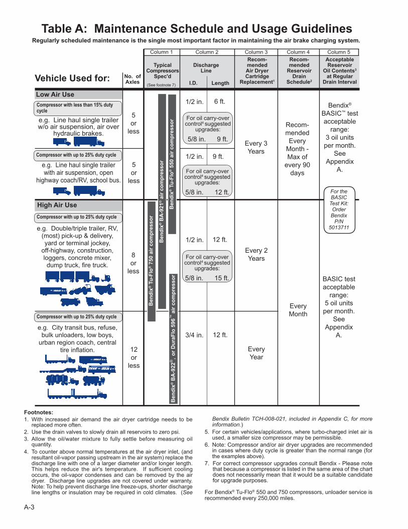
Compressor with up to 25% duty cycle
Footnotes: 1. With increased air demand the air dryer cartridge needs to be
replaced more often.2. Use the drain valves to slowly drain all reservoirs to zero psi.3. Allow the oil/water mixture to fully settle before measuring oil
quantity.4. To counter above normal temperatures at the air dryer inlet, (and
resultant oil-vapor passing upstream in the air system) replace the discharge line with one of a larger diameter and/or longer length. This helps reduce the air's temperature. If sufficient cooling occurs, the oil-vapor condenses and can be removed by the air dryer. Discharge line upgrades are not covered under warranty. Note: To help prevent discharge line freeze-ups, shorter discharge line lengths or insulation may be required in cold climates. (See
Recom- Recom- Acceptable Typical Discharge mended mended Reservoir Compressors Line Air Dryer Reservoir Oil Contents3
No. of Spec'd Cartridge Drain at Regular Axles Replacement1 Schedule2 Drain Interval
High Air Use
Low Air Use
e.g. Double/triple trailer, RV, (most) pick-up & delivery, yard or terminal jockey,
off-highway, construction, loggers, concrete mixer, dump truck, fire truck.
e.g. Line haul single trailer w/o air suspension, air over
hydraulic brakes.
e.g. Line haul single trailer with air suspension, open
highway coach/RV, school bus.
5or
less
5or
less
8or
less
12or
less
Table A: Maintenance Schedule and Usage Guidelines
Recom-mendedEvery
Month - Max of
every 90 days
EveryMonth
Every 3Years
Every 2Years
EveryYear
I.D.Vehicle Used for:
Column 1 Column 2 Column 3 Column 4 Column 5
Regularly scheduled maintenance is the single most important factor in maintaining the air brake charging system.
Length
6 ft.1/2 in.
9 ft.1/2 in.
12 ft.1/2 in.
3/4 in. 12 ft.
BASIC testacceptable
range:5 oil unitsper month.
See Appendix
A.
For oil carry-over control4 suggested
upgrades:
5/8 in. 15 ft.
For oil carry-over control4 suggested
upgrades:
5/8 in. 9 ft.
For oil carry-over control4 suggested
upgrades:
5/8 in. 12 ft.
Compressor with less than 15% duty cycle
Compressor with up to 25% duty cycle
Compressor with up to 25% duty cycleB
endi
x® B
A-9
21® a
ir co
mpr
esso
r
Ben
dix®
Tu-
Flo®
550
air
com
pres
sor
Ben
dix®
Tu-
Flo®
750
air
com
pres
sor
Ben
dix®
BA
-922
®, o
r Dur
aFlo
596
™ ai
r com
pres
sor
Bendix®
BASIC™ testacceptable
range:3 oil unitsper month.
See Appendix
A.
For theBASIC
Test Kit:OrderBendix
P/N 5013711
e.g. City transit bus, refuse, bulk unloaders, low boys,
urban region coach, central tire inflation.
(See footnote 7)
Bendix Bulletin TCH-008-021, included in Appendix C, for more information.)
5. For certain vehicles/applications, where turbo-charged inlet air is used, a smaller size compressor may be permissible.
6. Note: Compressor and/or air dryer upgrades are recommended in cases where duty cycle is greater than the normal range (for the examples above).
7. For correct compressor upgrades consult Bendix - Please note that because a compressor is listed in the same area of the chart does not necessarily mean that it would be a suitable candidate for upgrade purposes.
For Bendix® Tu-Flo® 550 and 750 compressors, unloader service is recommended every 250,000 miles.
A-4
Air Brake Charging System Troubleshooting
1.0 Oil Test Card Results
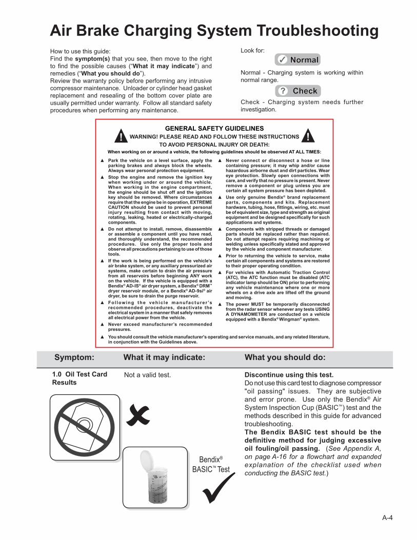
Not a valid test. Discontinue using this test. Do not use this card test to diagnose compressor "oil passing" issues. They are subjective and error prone. Use only the Bendix® Air System Inspection Cup (BASIC™) test and the methods described in this guide for advanced troubleshooting.The Bendix BASIC test should be the definitive method for judging excessive oil fouling/oil passing. (See Appendix A, on page A-16 for a flowchart and expanded explanation of the checklist used when conducting the BASIC test.)
Symptom: What it may indicate: What you should do:
How to use this guide:Find the symptom(s) that you see, then move to the right to find the possible causes (“What it may indicate”) and remedies (“What you should do”).Review the warranty policy before performing any intrusive compressor maintenance. Unloader or cylinder head gasket replacement and resealing of the bottom cover plate are usually permitted under warranty. Follow all standard safety procedures when performing any maintenance.
Look for:
Normal - Charging system is working within normal range.
Check - Charging system needs further investigation.
Bendix® BASIC™ Test
GENERAL SAFETY GUIDELINESWARNING! PLEASE READ AND FOLLOW THESE INSTRUCTIONS
TO AVOID PERSONAL INJURY OR DEATH:When working on or around a vehicle, the following guidelines should be observed AT ALL TIMES:
▲ Park the vehicle on a level surface, apply the parking brakes and always block the wheels. Always wear personal protection equipment.
▲ Stop the engine and remove the ignition key when working under or around the vehicle. When working in the engine compartment, the engine should be shut off and the ignition key should be removed. Where circumstances require that the engine be in operation, EXTREME CAUTION should be used to prevent personal injury resulting from contact with moving, rotating, leaking, heated or electrically-charged components.
▲ Do not attempt to install, remove, disassemble or assemble a component until you have read, and thoroughly understand, the recommended procedures. Use only the proper tools and observe all precautions pertaining to use of those tools.
▲ If the work is being performed on the vehicle’s air brake system, or any auxiliary pressurized air systems, make certain to drain the air pressure from all reservoirs before beginning ANY work on the vehicle. If the vehicle is equipped with a Bendix® AD-IS® air dryer system, a Bendix® DRM™ dryer reservoir module, or a Bendix® AD-9si® air dryer, be sure to drain the purge reservoir.
▲ Fo l lowing the vehic le manufac turer ’s recommended procedures, deactivate the electrical system in a manner that safely removes all electrical power from the vehicle.
▲ Never exceed manufacturer’s recommended pressures.
▲ Never connect or disconnect a hose or line containing pressure; it may whip and/or cause hazardous airborne dust and dirt particles. Wear eye protection. Slowly open connections with care, and verify that no pressure is present. Never remove a component or plug unless you are certain all system pressure has been depleted.
▲ Use only genuine Bendix® brand replacement parts, components and kits. Replacement hardware, tubing, hose, fi ttings, wiring, etc. must be of equivalent size, type and strength as original equipment and be designed specifi cally for such applications and systems.
▲ Components with stripped threads or damaged parts should be replaced rather than repaired. Do not attempt repairs requiring machining or welding unless specifi cally stated and approved by the vehicle and component manufacturer.
▲ Prior to returning the vehicle to service, make certain all components and systems are restored to their proper operating condition.
▲ For vehicles with Automatic Traction Control (ATC), the ATC function must be disabled (ATC indicator lamp should be ON) prior to performing any vehicle maintenance where one or more wheels on a drive axle are lifted off the ground and moving.
▲ The power MUST be temporarily disconnected from the radar sensor whenever any tests USING A DYNAMOMETER are conducted on a vehicle equipped with a Bendix® Wingman® system.
▲ You should consult the vehicle manufacturer's operating and service manuals, and any related literature, in conjunction with the Guidelines above.
A-5
(a)
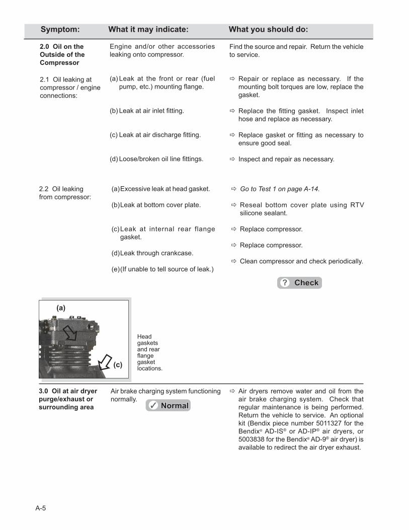
2.2 Oil leaking from compressor:
(a) Excessive leak at head gasket.
(b)Leak at bottom cover plate.
(c)Leak at internal rear flange gasket.
(d)Leak through crankcase.
(e) (If unable to tell source of leak.)
Go to Test 1 on page A-14.
Reseal bottom cover plate using RTV silicone sealant.
Replace compressor.
Replace compressor.
Clean compressor and check periodically.
Air brake charging system functioning normally.
Air dryers remove water and oil from the air brake charging system. Check that regular maintenance is being performed. Return the vehicle to service. An optional kit (Bendix piece number 5011327 for the Bendix® AD-IS® or AD-IP® air dryers, or 5003838 for the Bendix® AD-9® air dryer) is available to redirect the air dryer exhaust.
3.0 Oil at air dryer purge/exhaust or surrounding area
2.0 Oil on the Outside of the Compressor
Find the source and repair. Return the vehicle to service.
Repair or replace as necessary. If the mounting bolt torques are low, replace the gasket.
Replace the fitting gasket. Inspect inlet hose and replace as necessary.
Replace gasket or fitting as necessary to ensure good seal.
Inspect and repair as necessary.
Engine and/or other accessories leaking onto compressor.
(a)Leak at the front or rear (fuel pump, etc.) mounting flange.
(b) Leak at air inlet fitting.
(c) Leak at air discharge fitting.
(d) Loose/broken oil line fittings.
2.1 Oil leaking at compressor / engine connections:
Head gaskets and rear flange gasket locations.(c)
Symptom: What it may indicate: What you should do:
A-6
Symptom: What it may indicate: What you should do:
4.0 Oil in Supply or Service Reservoir(air dryer installed)(If a maintained Bendix® PuraGuard® system filter or Bendix® PuraGuard® QC oil coalescing filter is installed, call 1-800-AIR-BRAKE (1-800-247-2725) and speak to a Tech Team member.)
(a) If air brake charging system mainte-nance has not been performed.
That is, reservoir(s) have not been drained per the schedule in Table A on page A-3, Column 4 and/or the air dryer maintenance has not been performed as in Column 3.
(b) If the vehicle maintenance has been performed as recommended in Table A on page A-3, some oil in the reservoirs is normal.
Drain all air tanks and check vehicle at next service interval using the Bendix® BASIC™ test. See Table A on page A-3, column 3 and 4, for recommended service schedule.
Drain all air tanks into Bendix BASIC test cup (Bendix Air System Inspection Cup). If less than one unit of reservoir contents is found, the vehicle can be returned to service. Note: If more than one oil unit of water (or a cloudy emulsion mixture) is present, change the vehicle's air dryer, check for air system leakage (Test 2, on page A-14), stop inspection and check again at the next service interval.
See the BASIC™ test kit for full details. If less than one "oil unit" of water (or water/
cloudy emulsion mixture) is present, use the BASIC™cup chart on the label of the cup to determine if the amount of oil found is within the acceptable level.
If within the normal range, return the vehicle to service. For vehicles with accessories that are sensitive to small amounts of oil, consider a Bendix PuraGuard QC oil coalescing filter.
If outside the normal range, go to Symptom 4.0(c).
Also see the Table A on page A-3, column 3 for recommended air dryer cartridge replacement schedule.
Maintenance
Go to Test 2 on page A-14.
See Table A, column 1, on page A-3 for recommended compressor sizes.
If the compressor is "too small" for the vehicle's role (for example, where a vehicle's use has changed or service conditions exceed the original vehicle or engine OE spec's) then upgrade the compressor. Note: The costs incurred (e.g. installing a larger capacity compressor, etc.) are not covered under original compressor warranty.
If the compressor is correct for the vehicle, go to Symptom 4.0 (e).
Duty cycle too high
See Table A, on page A-3, for maintenance schedule information.
Drain all air tanks (reservoirs) into the Bendix BASIC test cup. (Bendix kit P/N 5013711).
The duty cycle is the ratio of time the compressor spends building air to total engine running time. Air compressors are designed to build air (to "run loaded") up to 25% of the time. Higher duty cycles cause conditions that affect air brake charging system performance which may require additional maintenance. Factors that add to the duty cycle are: air suspension, additional air accessories, use of an undersized compressor, frequent stops, excessive leakage from fittings, connections, lines, chambers, or valves, etc.
(c) Air brake system leakage.
(d) Compressor may be undersized for the application.
(a)
A-7
(e) Air compressor discharge and/or air dryer inlet temperature too high.
(f) Insufficient coolant flow.
(g) Restricted discharge line.
Check temperature as outlined in Test 3 on page A-14. If temperatures are normal go to 4.0(h).
Inspect coolant line. Replace as necessary (I.D. is 1/2").
Inspect the coolant lines for kinks and restrictions and fittings for restrictions. Replace as necessary.
Verify coolant lines go from engine block to compressor and back to the water pump. Repair as necessary.
If discharge line is restricted or more than 1/16" carbon build-up is found, replace the discharge line. See Table A, column 2, on page A-3 for recommended size. Replace as necessary.
The discharge line must maintain a constant slope down from the compressor to the air dryer inlet fitting to avoid low points where ice may form and block the flow. If, instead, ice blockages occur at the air dryer inlet, insulation may be added here, or if the inlet fitting is a typical 90° fitting, it may be changed to a straight or 45° fitting. For more information on how to help prevent discharge line freeze-ups, see Bendix Bulletin TCH-008-021 (Appendix B). Shorter discharge line lengths or insulation may be required in cold climates.
Temperature
Other
Check compressor air inlet line for restric-tions, brittleness, soft or sagging hose conditions, etc. Repair as necessary. Inlet line size is 3/4 ID. Maximum restriction requirement for compressors is 25 inches of water.
Check the engine air filter and service if necessary (if possible, check the air filter usage indicator).
(h) Restricted air inlet (not enough air to compressor).
(g)
4.0 Oil in Supply or Service Reservoir*(air dryer installed)(continued)
Kinked discharge line shown.
Partly collapsed inlet line shown.
Testing the temperature at the discharge fitting.
Inspecting the coolant hoses.
*If a maintained Bendix® PuraGuard® system filter or Bendix® PuraGuard® QC oil coalescing filter is installed, call 1-800-AIR-BRAKE (1-800-247-2725) and speak to a Tech Team member.
(g)
(e) (f)
(h)
Symptom: What it may indicate: What you should do:
A-8
(i) Poorly filtered inlet air (poor air quality to compressor).
(j) Governor malfunction or setting.
(k) Compressor malfunction.
4.0 Oil in Supply or Service Reservoir*(air dryer installed)
(continued)
Check for leaking, damaged, or defective compressor air inlet components (e.g. induction line, fittings, gaskets, filter bodies, etc.). Repair inlet components as needed. Note: Dirt ingestion will damage compressor and is not covered under warranty.
Go to Test 4 on page A-15.
If you found excessive oil present in the service reservoir in step 4.0 (b) above and you did not find any issues in steps 4.0 (c) through 4.0 (j) above, the compressor may be passing oil.
Replace compressor. If still under warranty, follow normal warranty process. Note: After replacing a compressor, residual oil may take a considerable period of time to be flushed from the air brake system.
Other (cont.)
Inspect the engine aircleaner.
** SAE J2024 outlines the tests that all air brake system pneumatic components need to be able to pass, including minimum levels of tolerance to contamination.
5.0 Oil present at valves (e.g. at exhaust, or seen during servicing).
Air brake system valves are required to tolerate a light coating of oil.
A small amount of oil does not affect SAE J2024** compliant valves.
Check that regular maintenance is being performed and that the amount of oil in the air tanks (reservoirs) is within the accept-able range shown on the Bendix® BASIC™ test cup (also see column 5 of Table A on page A-3). Return the vehicle to service.
For oil-sensitive systems, see page A-2.
Genuine Bendix valves are all SAE J2024 compliant.
*If a maintained Bendix® PuraGuard® system filter or Bendix® PuraGuard® QC oil coalescing filter is installed, call 1-800-AIR-BRAKE (1-800-247-2725) and speak to a Tech Team member.
Crankcase FloodingConsider installing a compressor bottom drain kit (where available) in cases of chronic oil passing where all other operating conditions have been investigated. Bendix compressors are designed to have a 'dry' sump and the presence of excess oil in the crankcase can lead to oil carryover.
Symptom: What it may indicate: What you should do:
A-9
8.0 Oil in ping tank or compressor dis-charge aftercooler.
Air brake charging system is functioning normally.
Air dryers remove water and oil from the air brake charging system. A small amount of oil is normal. Check that regular maintenance is being performed and that the amount of oil in the air tanks (reservoirs) is within the acceptable range shown by the BASIC™ test (also see column 5 of Table A on page A-3). Replace the air dryer cartridge as needed and return the vehicle to service.
7.0 Oil present at air dryer cartridge during maintenance.
A problem with engine or other engine accessory.
See engine service manual.6.0 Excessive oil consumption in engine.
Air brake charging system is functioning normally.
Fo l l ow veh i c l e O E ma in tenanc e recommendation for these components.
(a) Air brake charging system functioning normally.
(b) Air brake system leakage.
(c) Compressor may be undersized for the application.
(d) Compressor unloader mechanism malfunction.
(e) Damaged compressor head gasket.
Using dash gauges, verify that the compressor builds air system pressure from 85-100 psi in 40 seconds or less with engine at full governed rpm. Return the vehicle to service.
Go to Test 2 on page A-14.
See Table A, column 1, on page A-3 for some typical compressor applications. If the compressor is "too small" for the vehicle's role, for example, where a vehicle's use has changed, then upgrade the compressor. Note: The costs incurred (e.g. installing a larger capacity compressor, etc.) are not covered under original compressor warranty.
Go to Test 6 on page A-15.
An air leak at the head gasket may indicate a downstream restriction such as a freeze-up or carbon blockage and/or could indicate a defective or missing safety valve. Find blockage (go to 9.0(f) for details) and then replace the compressor. Do not reuse the safety valve without testing. See Symptom 12.0(a).
9.0 Air brake charging system seems slow to build pressure.
The engine service manual has more information.
Oil shown leaking from an air dryer cartridge.
Symptom: What it may indicate: What you should do:
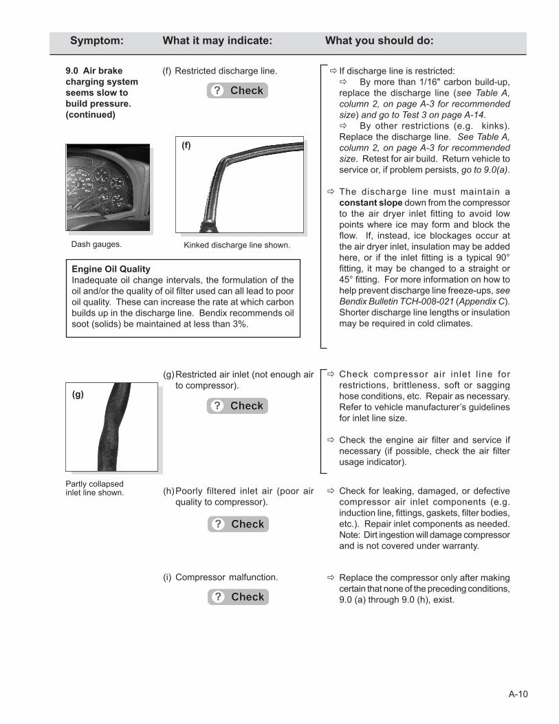
A-10
(g) Restricted air inlet (not enough air to compressor).
Check compressor air inlet l ine for restrictions, brittleness, soft or sagging hose conditions, etc. Repair as necessary. Refer to vehicle manufacturer’s guidelines for inlet line size.
Check the engine air filter and service if necessary (if possible, check the air filter usage indicator).
(i) Compressor malfunction. Replace the compressor only after making certain that none of the preceding conditions, 9.0 (a) through 9.0 (h), exist.
(h) Poorly filtered inlet air (poor air quality to compressor).
Check for leaking, damaged, or defective compressor air inlet components (e.g. induction line, fittings, gaskets, filter bodies, etc.). Repair inlet components as needed. Note: Dirt ingestion will damage compressor and is not covered under warranty.
9.0 Air brake charging system seems slow to build pressure. (continued)
(f) Restricted discharge line. If discharge line is restricted: By more than 1/16" carbon build-up,
replace the discharge line (see Table A, column 2, on page A-3 for recommended size) and go to Test 3 on page A-14.
By other restrictions (e.g. kinks). Replace the discharge line. See Table A, column 2, on page A-3 for recommended size. Retest for air build. Return vehicle to service or, if problem persists, go to 9.0(a).
The discharge line must maintain a constant slope down from the compressor to the air dryer inlet fitting to avoid low points where ice may form and block the flow. If, instead, ice blockages occur at the air dryer inlet, insulation may be added here, or if the inlet fitting is a typical 90° fitting, it may be changed to a straight or 45° fitting. For more information on how to help prevent discharge line freeze-ups, see Bendix Bulletin TCH-008-021 (Appendix C). Shorter discharge line lengths or insulation may be required in cold climates.
Kinked discharge line shown.Dash gauges.
Partly collapsed inlet line shown.
(f)
(g)
Engine Oil QualityInadequate oil change intervals, the formulation of the oil and/or the quality of oil filter used can all lead to poor oil quality. These can increase the rate at which carbon builds up in the discharge line. Bendix recommends oil soot (solids) be maintained at less than 3%.
Symptom: What it may indicate: What you should do:
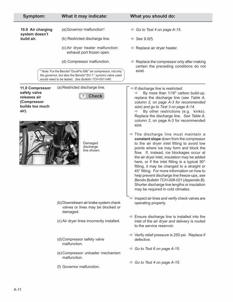
A-11
10.0 Air charging system doesn’t build air.
(a) Governor malfunction*.
(b) Restricted discharge line.
(c) Air dryer heater malfunction: exhaust port frozen open.
(d) Compressor malfunction.
Go to Test 4 on page A-15.
See 9.0(f).
Replace air dryer heater.
Replace the compressor only after making certain the preceding conditions do not exist.
11.0 Compressor safety valve releases air (Compressor builds too much air).
(a) Restricted discharge line. If discharge line is restricted: By more than 1/16" carbon build-up,
replace the discharge line (see Table A, column 2, on page A-3 for recommended size) and go to Test 3 on page A-14.
By other restrictions (e.g. kinks). Replace the discharge line. See Table A, column 2, on page A-3 for recommended size.
The discharge line must maintain a constant slope down from the compressor to the air dryer inlet fitting to avoid low points where ice may form and block the flow. If, instead, ice blockages occur at the air dryer inlet, insulation may be added here, or if the inlet fitting is a typical 90° fitting, it may be changed to a straight or 45° fitting. For more information on how to help prevent discharge line freeze-ups, see Bendix Bulletin TCH-008-021 (Appendix B). Shorter discharge line lengths or insulation may be required in cold climates.
Inspect air lines and verify check valves are operating properly.
Ensure discharge line is installed into the inlet of the air dryer and delivery is routed to the service reservoir.
Verify relief pressure is 250 psi. Replace if defective.
Go to Test 6 on page A-15.
Go to Test 4 on page A-15.
Damaged discharge line shown.
* Note: For the Bendix® DuraFlo 596™ air compressor, not only the governor, but also the Bendix® SV-1™ synchro valve used would need to be tested. See Bulletin TCH-001-048.
(b) Downstream air brake system check
valves or lines may be blocked or damaged.
(c) Air dryer lines incorrectly installed.
(d) Compressor safety valve malfunction.
(e) Compressor unloader mechanism malfunction.
(f) Governor malfunction.
Symptom: What it may indicate: What you should do:
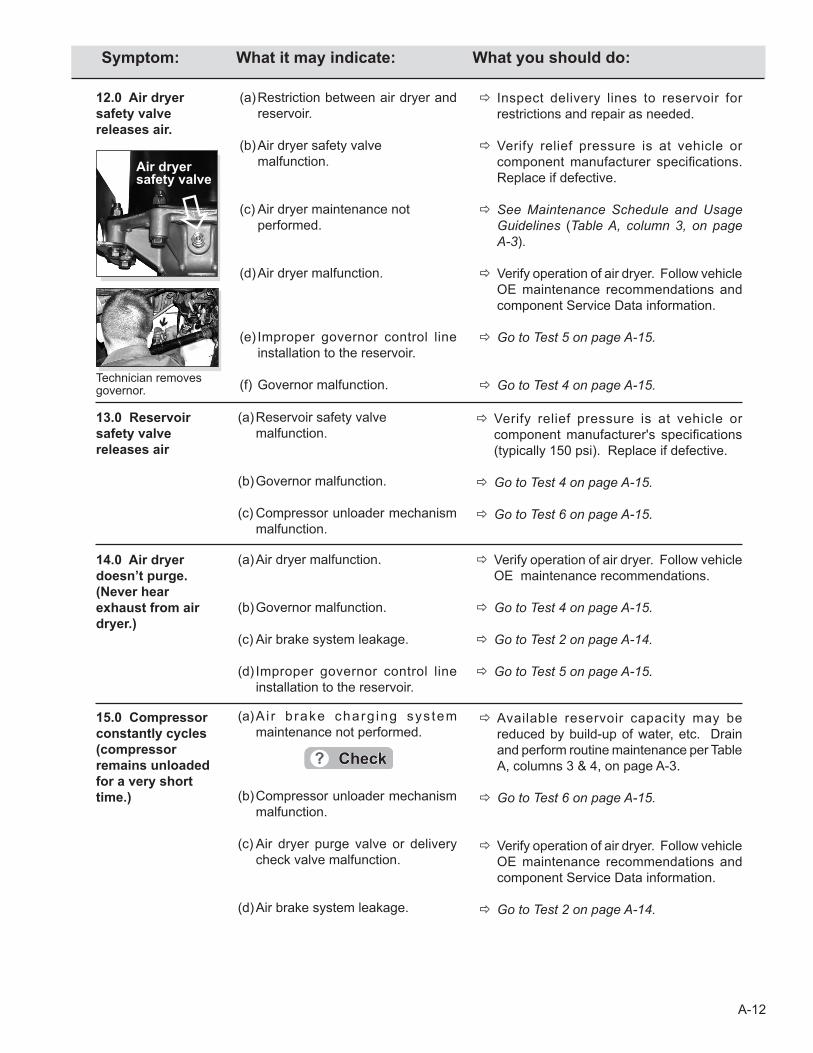
A-12
15.0 Compressor constantly cycles (compressor remains unloaded for a very short time.)
(a) A i r b rake charg ing sys tem maintenance not performed.
(b) Compressor unloader mechanism malfunction.
(c) Air dryer purge valve or delivery check valve malfunction.
(d) Air brake system leakage.
Available reservoir capacity may be reduced by build-up of water, etc. Drain and perform routine maintenance per Table A, columns 3 & 4, on page A-3.
Go to Test 6 on page A-15.
Verify operation of air dryer. Follow vehicle OE maintenance recommendations and component Service Data information.
Go to Test 2 on page A-14.
14.0 Air dryer doesn’t purge. (Never hear exhaust from air dryer.)
(a) Air dryer malfunction.
(b) Governor malfunction.
(c) Air brake system leakage.
(d) Improper governor control line installation to the reservoir.
Verify operation of air dryer. Follow vehicle OE maintenance recommendations.
Go to Test 4 on page A-15.
Go to Test 2 on page A-14.
Go to Test 5 on page A-15.
12.0 Air dryer safety valve releases air.
(a) Restriction between air dryer and reservoir.
(b) Air dryer safety valve malfunction.
(c) Air dryer maintenance not performed.
(d) Air dryer malfunction.
(e) Improper governor control line installation to the reservoir.
(f) Governor malfunction.
Inspect delivery lines to reservoir for restrictions and repair as needed.
Verify relief pressure is at vehicle or component manufacturer specifications. Replace if defective.
See Maintenance Schedule and Usage Guidelines (Table A, column 3, on page A-3).
Verify operation of air dryer. Follow vehicle OE maintenance recommendations and component Service Data information.
Go to Test 5 on page A-15.
Go to Test 4 on page A-15.
13.0 Reservoir safety valve releases air
(a) Reservoir safety valve malfunction.
(b) Governor malfunction.
(c) Compressor unloader mechanism malfunction.
Verify relief pressure is at vehicle or component manufacturer's specifications (typically 150 psi). Replace if defective.
Go to Test 4 on page A-15.
Go to Test 6 on page A-15.
Technician removes governor.
Air dryer safety valve
Symptom: What it may indicate: What you should do:
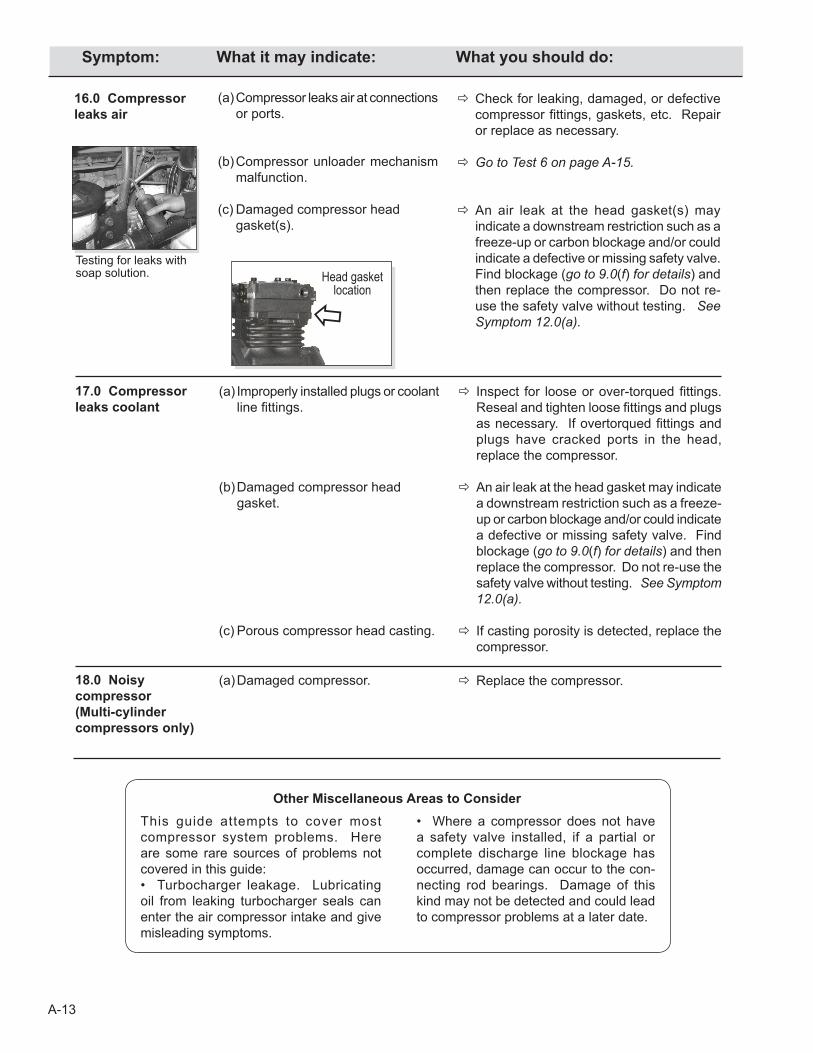
A-13
This guide attempts to cover most compressor system problems. Here are some rare sources of problems not covered in this guide:• Turbocharger leakage. Lubricating oil from leaking turbocharger seals can enter the air compressor intake and give misleading symptoms.
• Where a compressor does not have a safety valve installed, if a partial or complete discharge line blockage has occurred, damage can occur to the con-necting rod bearings. Damage of this kind may not be detected and could lead to compressor problems at a later date.
17.0 Compressor leaks coolant
(a) Improperly installed plugs or coolant line fittings.
(b) Damaged compressor head gasket.
(c) Porous compressor head casting.
Inspect for loose or over-torqued fittings. Reseal and tighten loose fittings and plugs as necessary. If overtorqued fittings and plugs have cracked ports in the head, replace the compressor.
An air leak at the head gasket may indicate
a downstream restriction such as a freeze-up or carbon blockage and/or could indicate a defective or missing safety valve. Find blockage (go to 9.0(f) for details) and then replace the compressor. Do not re-use the safety valve without testing. See Symptom 12.0(a).
If casting porosity is detected, replace the compressor.
18.0 Noisy compressor(Multi-cylindercompressors only)
(a) Damaged compressor. Replace the compressor.
Testing for leaks with soap solution.
16.0 Compressor leaks air
(a) Compressor leaks air at connections or ports.
(b) Compressor unloader mechanism malfunction.
(c) Damaged compressor head gasket(s).
Check for leaking, damaged, or defective compressor fittings, gaskets, etc. Repair or replace as necessary.
Go to Test 6 on page A-15.
An air leak at the head gasket(s) may indicate a downstream restriction such as a freeze-up or carbon blockage and/or could indicate a defective or missing safety valve. Find blockage (go to 9.0(f) for details) and then replace the compressor. Do not re-use the safety valve without testing. See Symptom 12.0(a).
Other Miscellaneous Areas to Consider
Head gasket location
Symptom: What it may indicate: What you should do:
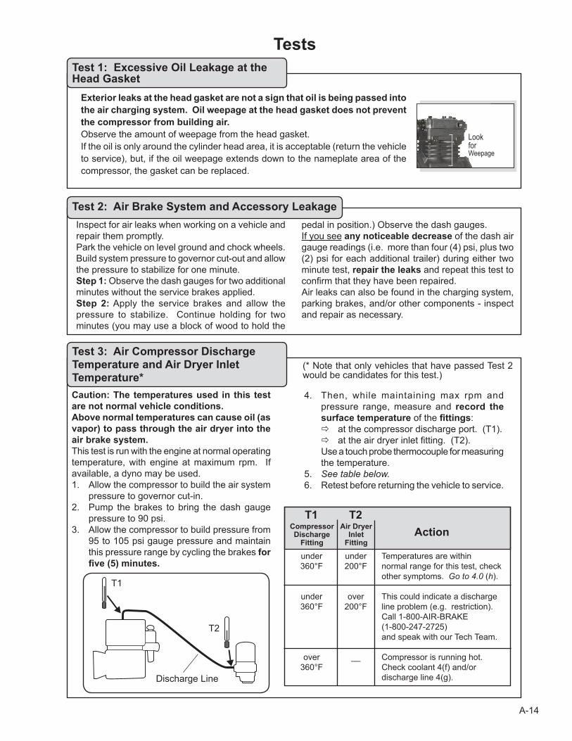
A-14
Tests
Exterior leaks at the head gasket are not a sign that oil is being passed into the air charging system. Oil weepage at the head gasket does not prevent the compressor from building air. Observe the amount of weepage from the head gasket. If the oil is only around the cylinder head area, it is acceptable (return the vehicle to service), but, if the oil weepage extends down to the nameplate area of the compressor, the gasket can be replaced.
Test 1: Excessive Oil Leakage at the Head Gasket
Inspect for air leaks when working on a vehicle and repair them promptly. Park the vehicle on level ground and chock wheels. Build system pressure to governor cut-out and allow the pressure to stabilize for one minute. Step 1: Observe the dash gauges for two additional minutes without the service brakes applied. Step 2: Apply the service brakes and allow the pressure to stabilize. Continue holding for two minutes (you may use a block of wood to hold the
pedal in position.) Observe the dash gauges.If you see any noticeable decrease of the dash air gauge readings (i.e. more than four (4) psi, plus two (2) psi for each additional trailer) during either two minute test, repair the leaks and repeat this test to confirm that they have been repaired.Air leaks can also be found in the charging system, parking brakes, and/or other components - inspect and repair as necessary.
Test 2: Air Brake System and Accessory Leakage
Caution: The temperatures used in this test are not normal vehicle conditions.Above normal temperatures can cause oil (as vapor) to pass through the air dryer into the air brake system. This test is run with the engine at normal operating temperature, with engine at maximum rpm. If available, a dyno may be used.1. Allow the compressor to build the air system
pressure to governor cut-in. 2. Pump the brakes to bring the dash gauge
pressure to 90 psi.3. Allow the compressor to build pressure from
95 to 105 psi gauge pressure and maintain this pressure range by cycling the brakes for five (5) minutes.
4. Then, while maintaining max rpm and pressure range, measure and record the surface temperature of the fittings:
at the compressor discharge port. (T1). at the air dryer inlet fitting. (T2). Use a touch probe thermocouple for measuring
the temperature.5. See table below.6. Retest before returning the vehicle to service.
Test 3: Air Compressor Discharge Temperature and Air Dryer Inlet Temperature*
Compressor Air Dryer Discharge Inlet Fitting Fitting
Action
under under Temperatures are within 360°F 200°F normal range for this test, check other symptoms. Go to 4.0 (h). under over This could indicate a discharge 360°F 200°F line problem (e.g. restriction). Call 1-800-AIR-BRAKE (1-800-247-2725) and speak with our Tech Team. over __ Compressor is running hot. 360°F Check coolant 4(f) and/or discharge line 4(g).
T1 T2
(* Note that only vehicles that have passed Test 2 would be candidates for this test.)
Discharge Line
T1
T2
LookforWeepage
A-15
1. Ensure that the governor control line from the reservoir is located at or near the top of the res-ervoir. (This line, if located near the bottom of the reservoir, can become blocked or restricted by the reservoir contents e.g. water or ice.)
Bendix® Compressors: Park vehicle, chock wheels, and follow all standard safety procedures. Remove the governor and install a fitting to the unloader port. Add a section of air hose (min. 1 ft long for a 1/2" diameter line) and a gauge to the fitting followed by a shut-off valve and an air source (shop air or small air tank). Open the shut-off and
Test 5: Governor Control Line
Test 6: Compressor Unloader Leakage
1. Inspect control lines to and from the governor for restrictions (e.g. collapsed or kinked). Repair as necessary.
2. Using a calibrated external gauge in the supply
reservoir, service reservoir, or reservoir port of the Bendix® D-2® governor, verify cut-in and cut-out pressures are within vehicle OEM specification.
3. If the governor is malfunctioning, replace it.
Tests (continued)Test 4: Governor Malfunction
2. Perform proper reservoir drain intervals and air dryer cartridge maintenance per Maintenance Schedule and Usage Guidelines (Table A on page A-3).
3. Return the vehicle to service.
charge the unloader port by allowing air pressure to enter the hose and unload the compressor. Shut off the air supply and observe the gauge. A steady reading indicates no leakage at the unloader port, but a falling reading shows that the unloader mechanism is leaking and needs to be serviced.
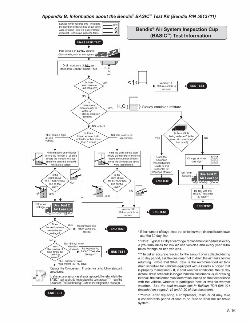
A-16
Drain contents of ALL air tanks into Bendix® Basic™ cup
Bendix® Air System Inspection Cup (BASIC™) Test Information
Appendix B: Information about the Bendix® BASIC™ Test Kit (Bendix P/N 5013711)
* If the number of days since the air tanks were drained is unknown - use the 30 day line.** Note: Typical air dryer cartridge replacement schedule is every 3 yrs/300K miles for low air use vehicles and every year/100K miles for high air use vehicles.*** To get an accurate reading for the amount of oil collected during a 30 day period, ask the customer not to drain the air tanks before returning. (Note that 30-90 days is the recommended air tank drain schedule for vehicles equipped with a Bendix air dryer that is properly maintained.) If, in cold weather conditions, the 30 day air tank drain schedule is longer than the customer's usual draining interval, the customer must determine, based on their experience with the vehicle, whether to participate now, or wait for warmer weather. See the cold weather tips in Bulletin TCH-008-021 (included on pages A-19 and A-20 of this document).****Note: After replacing a compressor, residual oil may take a considerable period of time to be flushed from the air brake system.
Replace the Compressor. If under warranty, follow standard procedures. If, after a compressor was already replaced, the vehicle fails the BASIC™ test again, do not replace the compressor**** - use the Advanced Troubleshooting Guide to investigate the cause(s).
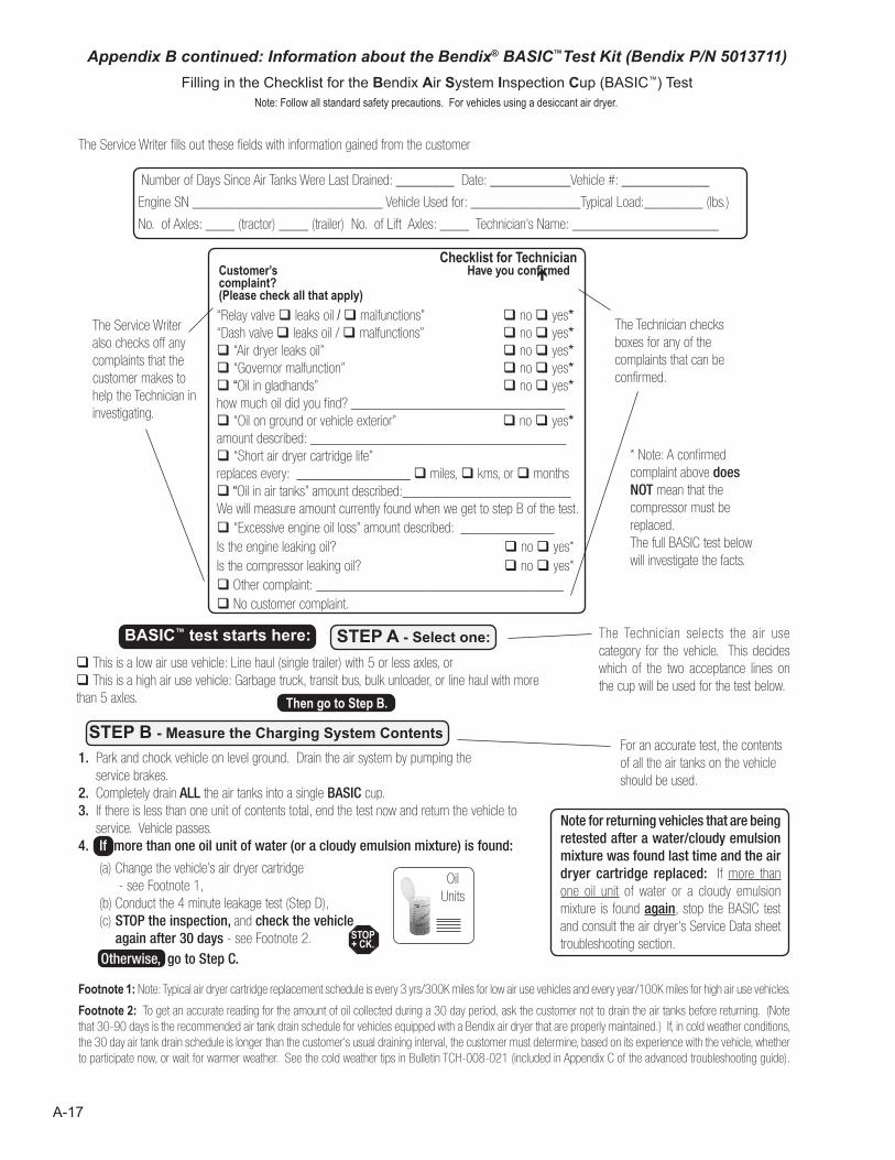
A-17
Footnote 1: Note: Typical air dryer cartridge replacement schedule is every 3 yrs/300K miles for low air use vehicles and every year/100K miles for high air use vehicles.
Footnote 2: To get an accurate reading for the amount of oil collected during a 30 day period, ask the customer not to drain the air tanks before returning. (Note that 30-90 days is the recommended air tank drain schedule for vehicles equipped with a Bendix air dryer that are properly maintained.) If, in cold weather conditions, the 30 day air tank drain schedule is longer than the customer's usual draining interval, the customer must determine, based on its experience with the vehicle, whether to participate now, or wait for warmer weather. See the cold weather tips in Bulletin TCH-008-021 (included in Appendix C of the advanced troubleshooting guide).
Note for returning vehicles that are being retested after a water/cloudy emulsion mixture was found last time and the air dryer cartridge replaced: If more than one oil unit of water or a cloudy emulsion mixture is found again, stop the BASIC test and consult the air dryer's Service Data sheet troubleshooting section.
* Note: A confirmed complaint above does NOT mean that the compressor must be replaced. The full BASIC test below will investigate the facts.
Customer’s Have you confirmed complaint? (Please check all that apply)
“Relay valve leaks oil / malfunctions” no yes*“Dash valve leaks oil / malfunctions” no yes* “Air dryer leaks oil” no yes* “Governor malfunction” no yes* “Oil in gladhands” no yes* how much oil did you find? ________________________________ “Oil on ground or vehicle exterior” no yes*amount described: ______________________________________ “Short air dryer cartridge life” replaces every: _________________ miles, kms, or months “Oil in air tanks” amount described:_______________________We will measure amount currently found when we get to step B of the test. “Excessive engine oil loss” amount described: ______________Is the engine leaking oil? no yes* Is the compressor leaking oil? no yes* Other complaint: _____________________________________ No customer complaint.
Checklist for Technician
The Service Writer fills out these fields with information gained from the customer
The Service Writer also checks off any complaints that the customer makes to help the Technician in investigating.
The Technician checks boxes for any of the complaints that can be confirmed.
STEP A - Select one:BASIC™ test starts here:
STEP B - Measure the Charging System Contents
The Technician selects the air use category for the vehicle. This decides which of the two acceptance lines on the cup will be used for the test below.
For an accurate test, the contents of all the air tanks on the vehicle should be used.
Then go to Step B.
Number of Days Since Air Tanks Were Last Drained: ________ Date: ___________Vehicle #: ____________
Engine SN __________________________ Vehicle Used for: _______________Typical Load:________ (lbs.)
No. of Axles: ____ (tractor) ____ (trailer) No. of Lift Axles: ____ Technician’s Name: ____________________
This is a low air use vehicle: Line haul (single trailer) with 5 or less axles, or This is a high air use vehicle: Garbage truck, transit bus, bulk unloader, or line haul with more than 5 axles.
1. Park and chock vehicle on level ground. Drain the air system by pumping the service brakes.
2. Completely drain ALL the air tanks into a single BASIC cup.3. If there is less than one unit of contents total, end the test now and return the vehicle to
service. Vehicle passes.4. If more than one oil unit of water (or a cloudy emulsion mixture) is found:
Otherwise, go to Step C.
Filling in the Checklist for the Bendix Air System Inspection Cup (BASIC™) TestNote: Follow all standard safety precautions. For vehicles using a desiccant air dryer.
Appendix B continued: Information about the Bendix® BASIC™Test Kit (Bendix P/N 5013711)
(a) Change the vehicle’s air dryer cartridge - see Footnote 1,(b) Conduct the 4 minute leakage test (Step D),(c) STOP the inspection, and check the vehicle again after 30 days - see Footnote 2. STOP
+ CK.
Oil Units
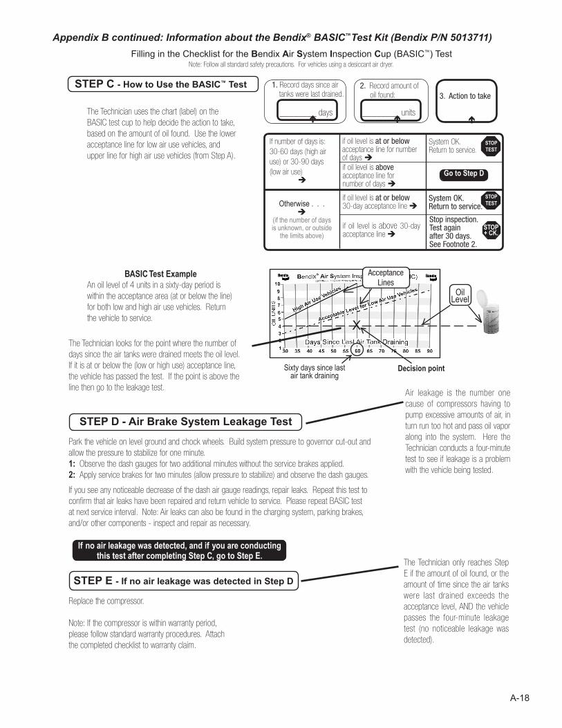
A-18
Park the vehicle on level ground and chock wheels. Build system pressure to governor cut-out and allow the pressure to stabilize for one minute. 1: Observe the dash gauges for two additional minutes without the service brakes applied. 2: Apply service brakes for two minutes (allow pressure to stabilize) and observe the dash gauges.
If you see any noticeable decrease of the dash air gauge readings, repair leaks. Repeat this test to confirm that air leaks have been repaired and return vehicle to service. Please repeat BASIC test at next service interval. Note: Air leaks can also be found in the charging system, parking brakes, and/or other components - inspect and repair as necessary.
STEP E - If no air leakage was detected in Step D
STEP D - Air Brake System Leakage Test
STEP C - How to Use the BASIC™ Test
Sixty days since last air tank draining
Decision point
The Technician uses the chart (label) on the BASIC test cup to help decide the action to take, based on the amount of oil found. Use the lower acceptance line for low air use vehicles, and upper line for high air use vehicles (from Step A).
If no air leakage was detected, and if you are conducting this test after completing Step C, go to Step E.
BASIC Test ExampleAn oil level of 4 units in a sixty-day period is within the acceptance area (at or below the line) for both low and high air use vehicles. Return the vehicle to service.
1. Record days since air tanks were last drained.
3. Action to take 2. Record amount of
oil found:
If number of days is: 30-60 days (high air use) or 30-90 days (low air use)
if oil level is at or below acceptance line for number of days if oil level is above acceptance line fornumber of days
System OK.Return to service.
Otherwise . . .
(if the number of days is unknown, or outside
the limits above)
if oil level is at or below 30-day acceptance line
if oil level is above 30-day acceptance line
STOPTEST
Stop inspection.Test again after 30 days. See Footnote 2.
________ days ________ units
Go to Step D
System OK.Return to service.
STOPTEST
STOP+ CK.
The Technician looks for the point where the number of days since the air tanks were drained meets the oil level. If it is at or below the (low or high use) acceptance line, the vehicle has passed the test. If the point is above the line then go to the leakage test.
Air leakage is the number one cause of compressors having to pump excessive amounts of air, in turn run too hot and pass oil vapor along into the system. Here the Technician conducts a four-minute test to see if leakage is a problem with the vehicle being tested.
The Technician only reaches Step E if the amount of oil found, or the amount of time since the air tanks were last drained exceeds the acceptance level, AND the vehicle passes the four-minute leakage test (no noticeable leakage was detected).
Replace the compressor.
Note: If the compressor is within warranty period, please follow standard warranty procedures. Attach the completed checklist to warranty claim.
Filling in the Checklist for the Bendix Air System Inspection Cup (BASIC™) TestNote: Follow all standard safety precautions. For vehicles using a desiccant air dryer.
Appendix B continued: Information about the Bendix® BASIC™Test Kit (Bendix P/N 5013711)
Oil Level
X
AcceptanceLines
A-19
Appendix C
Technical BulletinBulletin No: Effective Date: Cancels: Page: 1 of
Subject:
© 2007 Bendix Commercial Vehicle Systems LLC All rights reserved. 4/2007 Printed in U.S.A.
TCH-008-021 5-22-2017 3-5-2010 2
Air Brake System - Cold Weather Operation Tips
As the cold weather approaches, operators and fleets alike begin to look to their vehicles with an eye toward winterization, and particularly what can be done to guard against air system freeze-up. Here are some basic tips for operation in the cold weather.
Engine IdlingAvoid idling the engine for long periods of time. In addition to the fact that most engine manufacturers warn that long idle times are detrimental to engine life, winter idling is a big factor in compressor discharge line freeze-up. Discharge line freeze-ups account for a significant number of compressor failures each year. The discharge line recommendations shown under “Discharge Lines” are important for all vehicles, but are especially so when some periods of extended engine idling can not be avoided.
Discharge LinesThe discharge line should slope downward from the compressor discharge port without forming water traps, kinks, or restrictions. Cross-overs from one side of the frame rail to the other, if required, should occur as close as possible to the compressor. Dryer Inlet TemperatureThe dryer inlet air temperature should typically be within the range of no more than 160°F and no less than 45°F above low ambient (surrounding) temperature to prevent freeze-ups. (For example, if low ambient is minus 40°F, the dryer inlet must be above 5°F.) Lower dryer inlet temperatures should be avoided to minimize the risk of freeze-up upstream of the air dryer. Higher temperatures should also be avoided to minimize the risk of heat damage to the air dryer seals and to avoid a loss of drying performance.
Compressor Line SizeThe line size and length is established by the vehicle manufacturer and should not be altered without the vehicle manufacturers approval. As a reference, the line length from the compressor to the air dryer should be less than 16 feet and the minimum line sizes should be as follows:
Line InsulationTo guard against freeze-ups in low duty cycle applications, the discharge line can be insulated if it is greater than 9 feet in length. The line can only be insulated back to 9 feet and a maximum of 3 feet. For example, if the line is 10 feet in length, insulate the fitting and the last one foot of the line. If the line is 15 feet, insulate the fitting and the last 3 feet of the line.
Minimum Length
Minimum I.D. Application
6 ft. 1/2 in. Low Compressor Duty Cycle Applications (0-20%)10 ft. 5/8 in. High Compressor Duty Cycle Applications (20-40%)
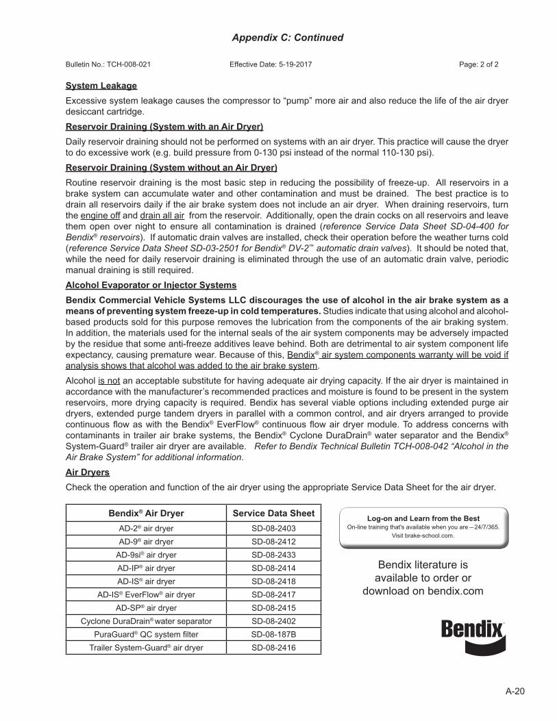
A-20
Appendix C: Continued
Bulletin No.: TCH-008-021 Effective Date: 5-19-2017 Page: 2 of 2
System Leakage Excessive system leakage causes the compressor to “pump” more air and also reduce the life of the air dryer desiccant cartridge.Reservoir Draining (System with an Air Dryer)Daily reservoir draining should not be performed on systems with an air dryer. This practice will cause the dryer to do excessive work (e.g. build pressure from 0-130 psi instead of the normal 110-130 psi).Reservoir Draining (System without an Air Dryer)Routine reservoir draining is the most basic step in reducing the possibility of freeze-up. All reservoirs in a brake system can accumulate water and other contamination and must be drained. The best practice is to drain all reservoirs daily if the air brake system does not include an air dryer. When draining reservoirs, turn the engine off and drain all air from the reservoir. Additionally, open the drain cocks on all reservoirs and leave them open over night to ensure all contamination is drained (reference Service Data Sheet SD-04-400 for Bendix® reservoirs). If automatic drain valves are installed, check their operation before the weather turns cold (reference Service Data Sheet SD-03-2501 for Bendix® DV-2™ automatic drain valves). It should be noted that, while the need for daily reservoir draining is eliminated through the use of an automatic drain valve, periodic manual draining is still required.Alcohol Evaporator or Injector SystemsBendix Commercial Vehicle Systems LLC discourages the use of alcohol in the air brake system as a means of preventing system freeze-up in cold temperatures. Studies indicate that using alcohol and alcohol-based products sold for this purpose removes the lubrication from the components of the air braking system. In addition, the materials used for the internal seals of the air system components may be adversely impacted by the residue that some anti-freeze additives leave behind. Both are detrimental to air system component life expectancy, causing premature wear. Because of this, Bendix® air system components warranty will be void if analysis shows that alcohol was added to the air brake system.Alcohol is not an acceptable substitute for having adequate air drying capacity. If the air dryer is maintained in accordance with the manufacturer’s recommended practices and moisture is found to be present in the system reservoirs, more drying capacity is required. Bendix has several viable options including extended purge air dryers, extended purge tandem dryers in parallel with a common control, and air dryers arranged to provide continuous flow as with the Bendix® EverFlow® continuous flow air dryer module. To address concerns with contaminants in trailer air brake systems, the Bendix® Cyclone DuraDrain® water separator and the Bendix®
System-Guard® trailer air dryer are available. Refer to Bendix Technical Bulletin TCH-008-042 “Alcohol in the Air Brake System” for additional information.Air DryersCheck the operation and function of the air dryer using the appropriate Service Data Sheet for the air dryer.
Bendix® Air Dryer Service Data SheetAD-2® air dryer SD-08-2403AD-9® air dryer SD-08-2412
AD-9si® air dryer SD-08-2433AD-IP® air dryer SD-08-2414AD-IS® air dryer SD-08-2418
AD-IS® EverFlow® air dryer SD-08-2417AD-SP® air dryer SD-08-2415
Cyclone DuraDrain® water separator SD-08-2402PuraGuard® QC system filter SD-08-187B
Trailer System-Guard® air dryer SD-08-2416
Bendix literature is available to order or
download on bendix.com
Log-on and Learn from the BestOn-line training that's available when you are 24/7/365.
Visit brake-school.com.
40SD-01-333 Rev. 004 © 2019 Bendix Commercial Vehicle Systems LLC • 03/19 • All Rights Reserved Printed on recycled paper
Log-on and Learn from the BestOn-line training that's available when you are 24/7/365.
Visit brake-school.com.