sd -3 interiaminar properties of five plastic laminates
TRANSCRIPT
/SD -3
INTERIAMINAR PROPERTIES Of
FIVE PLASTIC LAMINATES
December 1962
No. 1890
This Report Is One of a SeriesIssued in Cooperation uiith the
ANC-17 PANEL (A PLASTICS MR ILIGI1T VEHICLESof the Departments of theAIR ECRU, NAVY, AND COMMERCE
FOREST PRODUCTS LABORATORY
MADISON 5, WISCONSIN
UNITED STATES DEPARTMENT OF AGRICULTURE
FOREST SERVICE
fa Cooperation with the University of Wisconsin

• INTERLAMINAR PROPERTIES OF FIVE PLASTIC LAMINATES-
By
KENNETH E. KIMBALL, Engineer
Forest Products Laboratory,? Forest ServiceU.S. Department of Agriculture
Abstract
Laminates of phenolic and silicone resins reinforced with 181 glass fabric andlaminates of an epoxy resin reinforced with 181 glass fabric or with glassfilaments in either a unidirectional or a crossply pattern were evaluated fortheir interlaminar properties. Results of evaluation in tension, compression,and shear in the interlaminar plane are shown for each of the five laminates.
Introduction
Design data for tensile, compressive, and flexural properties of reinforcedplastic laminates are reasonably adequate, but there is a need for furtherinformation on the shear properties. Edgewise shear properties can be calcu-lated with reasonable success from tension test values parallel to and at 45°to the orthotropic axes. Data on interlaminar properties, however, arelimited, even though it is known that failures quite often occur in thisplane. The interlaminar shear properties and tensile and compressive strengthsnormal to the interlaminar plane are sometimes important in fastening plasticlaminates to similar or other types of materials. It was the purpose of thisstudy to obtain data on (1) the interlaminar shear strength and shear modulusand (2) the tensile and compressive strengthsand modulus of elasticity normalto the interlaminar plane of several reinforced plastic laminates.
-This progress report is one of a series (ANC-17, Item 60-2) prepared anddistributed by the Forest Products Laboratory under U.S. Air Force Contract33(616)61-06 and Bureau of Naval Weapons Order 19-61-8041-WEPS. Tradenames have been given at the October 6, 1955, request of Wright AirDevelopment Center. Results reported here are preliminary and may berevised as additional data become available.
?Maintained at Madison, Wis., in cooperation with the University of Wisconsin.
Report No. 1890

•Description of Materials
Phenolic, epoxy, and silicone resin laminates reinforced with glass fibers infabric and filament form were evaluated in this study. The silicone laminateswere fabricated at the Forest Products Laboratory, while the other laminateswere fabricated by the respective suppliers. All of the laminates, exceptthose with unidirectional or crossplied filament orientation, were originally
supplied for use in other studiese2P4
A brief summation of the fabrication procedures for the various laminatesfollows:
Silicone Laminates
Silicone laminates of 24 and 72 plies were fabricated previously at the Forest
Products Laboratorye2 These laminates were made by the dry layup method withthe warp of the fabric parallel. The layup was made with randomized sheetsof 181-112 glass fabric that had been preimpregnated with DC-2106 siliconeresin by U.S. Polymeric Corporation. The layups were placed in a hot pressat 347° F. and cured at a pressure of 35 to 40 pounds per square inch for30 minutes. The panels were cooled to 100° F. under pressure before removalfrom the press. Later they were postcured in an oven for 24 hours at 480° F.The postcured panels measured 18 inches in the warp direction and 12 incheswide.
Because of a lack of material thick enough to provide specimens for test pur-poses, sections of the above-described panels were glued together. Three ofthe 24-ply panels were glued together, with the warp direction of eachparallel, to form a 72-ply panel for the shear tests. Two of the 72-plysections were glued together, with the warp direction of each parallel, tosupply material thick enough for the other tests. The adhesive that was usedwas Epibond 122, which is an epoxy resin that can be cured at room temperature.
Epoxy Laminates (Glass Fabric)
The glass-fabric-base epoxy panel was 1.469 inches thick and was fabricatedwith 156 plies of 181-Volan A glass fabric impregnated with Scotchply 1002
epoxy resin.-3- Fabric impregnation and laminate fabrication were done by the
Reinforced Plastics Division of Minnesota Mining and Manufacturing Co.,St. Paul, Minn. The panel was fabricated by dry layup of randomized
-Youngs, Robert L. Effect of Thickness on the Mechanical Properties of Glass-Fabric-Base Plastic Laminates. U.S. Forest Prod. Lab. Rept. No. 1873, 1960.
AKimball, Kenneth E. Relationship Between Thickness and Mechanical Propertiesof Several Glass-Fabric-Base Plastic Laminates. U.S. Forest Prod. Lab.Rept. No. 1885, 1962.
Report No. 1890 -2-
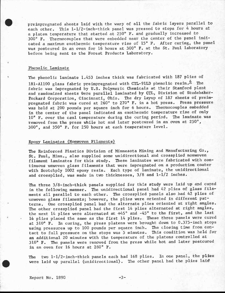
preimpregnated sheets laid with the warp of all the fabric layers parallel toeach other. This 1-1/2-inch-thick panel was pressed to stops for 4 hours ata platen temperature that started at 250° F. and gradually increased to300° F. Thermocouples that were embedded near the center of the panel indi-cated a maximum exothermic temperature rise of 15° F. After curing, the panelwas postcured in an oven for 16 hours at 300° F. at the St. Paul laboratorybefore being sent to the Forest Products Laboratory.
Phenolic Laminate
The phenolic laminate 1.453 inches thick was fabricated with 187 plies of
181-A1100 glass fabric preimpregnated with CTL-91LD phenolic resinA Thefabric was impregnated by U.S. Polymeric Chemicals at their Stamford plantand randomized sheets *ere parallel laminated by CTL, Division of Studebaker-Packard Corporation, Cincinnati, Ohio. The dry layup of 187 sheets of preim-pregnated fabric was cured at 260° to 270° F. in a hot press. Press pressurewas held at 200 pounds per square inch for 6 hours. Thermocouples embeddedin the center of the panel indicated an exothermic temperature rise of only10° F. over the caul temperature during the curing period. The laminate wasremoved from the press while hot and later postcured in an oven at 250°,300°, and 350° F. for 250 hours at each temperature level.
Epoxy Laminates (Nonwoven Filaments)
The Reinforced Plastics Division of Minnesota Mining and Manufacturing Co.,St. Paul, Minn., also supplied some unidirectional and crossplied nonwovenfilament laminates for this study. These laminates were fabricated with con-tinuous unwoven glass filaments that were impregnated on a production coaterwith Scotchply 1002 epoxy resin. Each type of laminate, the unidirectionaland crossplied, was made in two thicknesses, 3/8 and 1-1/2 inches.
The three 3/8-inch-thick panels supplied for this study were laid up and curedin the following manner. The unidirectional panel had 42 plies of glass fila-ments all parallel to each other. The crossplied panels also had 42 plies ofunwoven glass filaments; however, the plies were oriented in different pat-terns. One crossplied panel had the alternate plies oriented at right angles.The other crossplied panel had the first 14 plies alternated at right angles,the next 14 plies were alternated at +45° and -45° to the first, and the last14 plies placed the same as the first 14 plies. These three panels were curedat 310° F. In curing, the press platens were brought down to 0.375-inch stopsusing pressures up to 100 pounds per square inch. The closing time from con-tact to full pressure on the stops was 5 minutes. This condition was held foran additional 20 minutes with the temperature of the platens controlled at310' F. The panels were removed from the press while hot and later postcuredin an oven for 16 hours at 280° F.
The two 1-1/2-inch-thick panels each had 168 plies. In one panel, the plies
•were laid up parallel (unidirectional). The other panel had the plies laid
Report No. 1890 -3-

alternately at right angles to each other. The cure used for the two panelsand the temperatures recorded at the center of the panels are given intables 1 and 2. The postcure treatment for both of these panels was a 16-hourexposure at 280° F. in an oven.
Methods of Evaluation
Tension Tests Normal to the Interlaminar Plane
Five specimens 1 by 1 by 1-1/2 inches were cut from blocks of each laminate.The planes of reinforcement were parallel to the 1- by 1-inch dimension.These specimens were necked down to 1/2 inch wide and 1 inch thick over a3/4-inch-long net section at midheight with an arc of 1/4-inch radius in thetransition portion. The warp of the glass fabric or the direction of theunidirectional filaments was parallel to the 1-inch dimension of the net sec-tion. Aluminum blocks, approximately 1-inch cubes, were bonded with Epibond122 adhesive to the ends of these specimens so that they could be gripped inthe testing machine. A sketch of a typical necked-down tension specimen withthe blocks attached is shown in figure 1A.
A comparative set of five specimens each was also prepared from the glass-fabric-reinforced epoxy and phenolic resin laminates. These specimens werealso blocks 1 by 1 by 1-1/2 inches but were not necked down or machined.They were sawed from a large block with a high-speed, metal-cutting bandsaw.Aluminum loading blocks were also bonded to these specimens. Before tensiontests were run, these specimens were loaded in compression to a stress of500 pounds per square inch to obtain data for determining a compressivemodulus of elasticity value.
These specimens were all loaded to failure in tension in a mechanical testingmachine equipped with swivel-type heads. Head speeds were controlled at0.005 inch per minute. Deformation measurements were made with Marten'smirror extensometers of 1/2-inch gage length on the necked-down specimens ofepoxy laminates reinforced with glass fabric and crossplied filaments. Thedeformation on the necked-down specimens of the other three laminates wasmeasured with 1/2-inch SR-4 strain gages. Deformations on the straight-sidedspecimens of epoxy and phenolic glass-fabric-reinforced laminates weremeasured with Tuckerman extensometers of 1/2-inch gage length. Tensilemodulus of elasticity values and strength normal to the interlaminar planewere calculated for these specimens.
Compression Tests Normal to the Interlaminar Plane
The compression specimens were all cut 1 by 1 inch square from 1-1/2-inch-thick laminates (fig. 1B). The specimens were loaded perpendicular to theplane of the plies in a mechanical testing machine with spherical heads.
Report No. 1890 -4-

• Head speeds were controlled at 0.015 inch per minute. Five specimens of eachlaminate were tested to failure. Deformation measurements were taken at mid-height of these specimens with Marten's mirror extensometers of 1/2-inch gagelength. Modulus of elasticity and compressive strength values were alsocalculated for these specimens.
Five additional specimens of the epoxy and phenolic glass-fabric-reinforcedlaminates that were later tested for tensile properties were loaded to astress of 500 pounds per square inch to determine their compressive modulusof elasticity. The deformations of these specimens were measured withTuckerman extensometers of 1/2-inch gage length.
Interlaminar Shear Strength Tests
The interlaminar shear specimens were of the same general type used in testingthe shear strength of glue joints in blocks of wood. Sketches of the methodof loading and the test specimens are shown in figure 2. The specimens werenotched as shown in figure 2B with the bearing edges carefully machined toinsure flat and parallel loading surfaces. The planes of shear were parallelto the warp direction of the fabric in the laminates where fabric was used asthe reinforcement. In the unidirectional laminates made with unwoven fila-ments, the planes of shear tested were at 0°, 45°, and 90° to the filaments.In the crossply filament laminates, the two planes of shear that were testedwere at 0° or 90°, and at 45° to the filaments.
The interlaminar shear strength tests were made with the apparatus withguided loading heads shown in figure 3. Loads were applied with a mechanicaltesting machine with the head speed controlled at 0.01 inch per minute. Ingeneral the failures followed the line between adjacent layers of reinforce-ment. Interlaminar shear strength values were calculated from the dataobtained.
Modulus of Rigidity Tests
Values for modulus of rigidity associated with shear strains in a plane nor-mal to the laminate surface were obtained by using the plate shear test
method for veneer and plywood. 5— The apparatus was modified to fit the small-size specimens that were available. This test best fit the material availableto obtain a modulus of rigidity.
Blocks approximately 1-1/2 by 1-1/2 by 7 inches were cut from the thickestlaminates. The warp or filament direction was the 7-inch dimension of theblock. The silicone laminate had a glue line through the center since two72-ply panels had been glued together to provide the 1-1/2-inch thickness.Thin wafers, approximately 0.065 inch thick, were then cut perpendicular to
-American Society for Testing and Materials. Tests for Plywood, Veneer, andWood-Base Materials. ASTM Standard D 805-47, Part 4, 1949.
Report No. 1890 -5-

the 7-inch direction of each block. These wafers were machined on the twofaces to a uniform overall thickness. The specimens were stored for at least2 weeks under normal conditions of 73° F. and 50 percent relative humidityprior to testing.
For test, these thin wafers were positioned on rounded supports on the oppo-site ends of a diagonal drawn between corners and were loaded in a similarmanner on the opposite ends of the other diagonal of the wafer. Figure 4shows the arrangement of the loading and supporting frames. Loads wereapplied in a mechanical testing machine at a head speed controlled at 0.0038inch per minute.
Specimen deflection was measured with a dial gage that was read to 0.0001inch. The diagonal distance between the legs of the gage support was 1.25inches. Without stressing the wafer beyond the elastic range, a group ofapproximately 20 load-deflection readings were taken. The load was thenreleased, the wafer was rotated 90° on the supports and a second group of20 readings taken. The two groups were averaged for calculation of a modulusof rigidity value.
Presentation of Data
Table 3 presents general information and the physical properties of thelaminates tested in the different phases of this study. The data shown forthe silicone, epoxy, and phenolic laminates reinforced with glass fabric weretaken from the reports of the studies for which these laminates were origin-
ally fabricated.3'4
Table 4 presents the tensile and compressive values of modulus of elasticity,proportional limit stress, and maximum stress normal to the interlaminarplane of the five laminates. Typical tension stress-strain curves are shownin figure 5.
Table 5 presents the data obtained for straight-sided tension specimens ofglass-fabric-reinforced laminates. Included are compressive and tensileelastic moduli and tensile proportional limit and maximum stresses.
Interlaminar shear and modulus of rigidity values for the laminates are shownin table 6. Interlaminar shear tests were only made parallel to the warpdirection on the glass-fabric laminates. On the laminate with unidirectionalfilaments as the reinforcement, tests were made at 0°, 45°, and 90° to thefilament direction. In the crossply filament laminates, values of interlam-inar shear are presented for the 0° or 90° and 45° directions.
Report No. 1890 -6-

Discussion of Results
Information on the mechanical properties in interlaminar shear, tension, andcompression normal to the interlaminar plane of reinforced plastic laminatesis somewhat limited. The data presented and the discussion that follows pro-vide some information on the strength values in this plane that might beexpected for several different types of plastic laminates.
Since appreciable physical variations such as resin content and specificgravity may occur within a laminated panel, a few tests such as were conductedfor this study cannot be expected to represent other materials of the sameclass.
Tension
The tension tests for the laminates in this study provided for loads to beapplied perpendicular to the planes of the reinforcements. In a test of thistype, the reinforcement adds little or no appreciable strength to the lamin-ate. The type of resin, the finish on the reinforcement, the bond betweenthe resin and reinforcement, and the percentage of voids are factors affectingthe magnitude of the tensile properties.
The straight-sided phenolic resin laminate showed an average tensile stress of2,790 pounds per square inch. This value was approximately four times greaterthan the value obtained for the necked-down laminates of phenolic and siliconeresins reinforced with glass fabric.
Necked-down specimens of laminates of epoxy resin with the different types ofreinforcements, namely glass fabric, unidirectional filaments, and crosspliedfilaments, showed the effect of these different layups in the results obtainedfor tensile strength. Considering the tensile strength (2,230 pounds persquare inch) of the glass-fabric-reinforced laminate as a base, the unidirec-tional filament laminates showed tensile strength values that were about 60percent higher and the crossplied filament laminates had tensile strengthvalues 50 percent higher.
The modulus of elasticity values for the epoxy resin laminates reinforcedwith glass fabric or unidirectional filaments were about the same (1,300,000pounds per square inch). The values for the crossplied filament epoxy resinand the phenolic resin laminate reinforced with glass fabric were about 50percent higher than the above value; the silicone resin glass fabric laminateshowed a value only about 25 percent as large as for the epoxy resin laminateswith glass fabric or unidirectional filament.
Apparently little advantage is gained by necking down a tension specimentested normal to the planes of reinforcement. Failure usually occurred inthe central portion of both the straight-sided and necked-down specimens.
Report No. 1890 -7-

Compression
The compression tests in this study were made by applying loads perpendicularto the planes of the reinforcements. In this test, the reinforcements prob-ably contribute to strength. Also, as in the tension tests, the type of resin,finish, bond between the reinforcements and resin, and percent of voids may befactors affecting the values obtained.
In general, the failures occurred suddenly and appeared to be shear failuresthat passed through the layers of reinforcements at an angle of about 45 0 to
the direction of load. The failures in the unidirectional filament laminatesdid not appear to cross the filaments but to parallel them through the layers,literally spreading the filaments apart.
From the ultimate stress values obtained during the tests, a comparison be-tween the laminates reinforced with glass fabric showed the phenolic resinlaminate had the greatest compressive strength (80,400 pounds per squareinch). Using this value as a base, the epoxy resin laminate was only 62percent as strong and the silicone resin laminate only 35 percent as strong.
The different types of reinforcing media with the same epoxy resin show theireffects on the strength values of the laminates. The crossplied filamentswere found to provide greater strength qualities to the laminates than theother types of reinforcements. A comparison between values for these differ-ent reinforcements showed the crossplied filament laminate had a compressivestrength value of 93,800 pounds per square inch, with the glass-fabric lamin-ate 53 percent as great; the unidirectional filament laminate was the weakestwith only 23 percent of the crossplied filament value. This low value forthe unidirectional filament material may have been due to the lack of rein-forcement in both directions, thereby permitting greater bulging to takeplace with subsequent reduction in strength. No attempt was made to measurePoisson's ratios or the magnitude of the bulge.
The modulus of elasticity values showed the phenolic resin laminate reinforcedwith glass fabric to be the stiffest (2,070,000 pounds per square inch); theunidirectional filament, crossplied filament, and glass-fabric epoxy resinlaminates all had about 65 to 90 percent as great a stiffness value. Thesilicone resin glass-fabric laminate showed only about 14 percent of thestiffness of the phenolic laminate.
The values of modulus of elasticity were essentially the same in tension andcompression normal to the layers of reinforcement for each material evaluated.However, when the phenolic resin laminate reinforced with glass fabric wasnecked down, its tensile modulus became only about one-half its compressivemodulus. It appears that necking down and machining a specimen with thebrittle characteristics of a phenolic resin laminate destroys some of theinherent strength properties of the composite specimen under load.
Report No. 1890 -8-

410 Interlaminar Shear
The interlaminar shear tests were made by the same procedures employed in theblock glue line test for wood that has been previously described. In general,all of the failures appeared to be shear failures occurring along or betweenadjacent planes of reinforcements.
The results of the tests shown in table 6 indicate that the values of inter-laminar shear strength were about the same for all of the laminates exceptthose fabricated with the silicone resin. These results further show that inmost instances the difference in individual values for a laminate was as largeor larger than between laminates. The silicone resin glass-fabric laminateshowed a strength value of less than 25 percent of the value found for theother laminates.
In the tests on the epoxy resin unidirectional and crossplied filament lamin-ates conducted at 45° to the filament directions, the average strength of theunidirectional filament laminate was about 19 percent lower than in the 0°tests, while the crossplied filament laminate was about 7 percent higher thanin the 0° tests.
The epoxy resin unidirectional filament laminate was also tested at 90° tothe filament direction. The results were 23 percent less than valuesobtained parallel, or at 0°, to the filaments.
The average values for interlaminar shear strength shown in table 5 and those
previously reported6 for similar laminates reinforced with parallel 181 glassfabric and the corresponding resins varied somewhat. Previously reportedaverage values were: Epoxy resin, 6,820 pounds per square inch; phenolicresin, 5,150 pounds per square inch; and silicone resin, 1,160 pounds persquare inch.
Modulus of Rigidity
The modulus of rigidity values were determined by the plate shear test proce-dure previously described.
A comparison of the modulus of rigidity values obtained on the three laminatesreinforced with glass fabric shows the phenolic resin laminate as having thegreatest stiffness (832,000 pounds per square inch). The epoxy resin laminatewas about 75 percent as stiff, while the silicone resin laminate was only17 percent as stiff.
The moduli of rigidity of the three laminates fabricated with the same type ofepoxy resin, but with different reinforcements, were also compared. The lam-inate with the crossplied filament reinforcement showed the highest modulusof rigidity value (722,000 pounds per square inch). The glass-fabric-reinforced laminate was about 85 percent as stiff, while the unidirectionalfilament laminate was only 65 percent as stiff.6–U.S. Department of Defense. Plastics for Flight Vehicles, Part I, Reinforced
Plastics, Military Handbook 17, 1959.
Report No. 1890 -9-

Table 1.--Cure cycle for 1-1/2-inch-thickunidirectional panel
•
Time : Cure : Platen : Center of panel: pressure : temperature .. temperature
Min. : P.s.i. : °F. : °F.
0 : 0 : 250 •
5 : 25 : 250
10 : 25 : 250 : 90
15 : 50 : 250 : 130
20 : 50 : 250 : 165
25 : 50 : 250 : 190
30 : 50 : 250 : 215
35 : 50 : 250 : 235
40 : 50 : 250 : 245
45 : 50 : 260 : 255
50 : 50 : 260 : 290
55 : 50 : 260 : 340
60 : 50 : 260 •. 345
75 : 50 : 260 -. 320
80 : 50 : 260 •. 310
85 : 50 : 310 : 300120 Removed from press while hot
Report No. 1890 •

Table 2.--Cure cycle for 1-1/2-inch-thickcrossplied panel
•
Time : Cure Platen : Center of panel: pressure : temperature : temperature
Min. • P.s.i. °F. °F.
0 : 0 250
5 : 25 250
10 : 25 250 100
15 : 50 250 12525 : 50 250 180
30 : 50 250 • 196
35 : 50 250 217
40 : 50 250 235
45 : 50 250 245
50 : 50 260 255
55 : 50 260 275
60 : 50 260 320
65 : 50 : 260 •. 360
70 : 50 260 : 350
75 : 50 260 : 335
80 : 50 : 260 : 325
85 : 50 : 260 : 315
90 : 50 : 310 : 300
125 • Removed from press while hot
411 Report No. 1890

•• •• •• •• •• •• •• •• •• •• ••
0 0 Nr--
1-4 r-11•n
• • •• •• •• •• •• •• •• •• s• ••
In N 0 NO 1.0
CO CO ON 00 00• • • • •
r1 11-1 1-4 1-4
•• •• •• •• •• •• • • •• • • • • ••
•• •• •• •• •• •• •• •• •• •• ••
1••• 1/40 e.-1 C`Jn VI 0 co ONen en un Crl Cr)• • • • •
1-1 r•4
•• •• •• •• •• • • •• •• •• ••N 00 00 NN
‘6,-I
••
cn• •
•4 C14Cr) Cr)
0 0•0
0 0-0 -0
•• •• • • •• • • •• •• •• ••
C•slOO
0 0 0 00 (:). •0
U -OU
• • •• • •• •• •• • •
al a)L u IEl .-^, cd 0 a-}
.-L 00 * tr) c:11-1 o •-,IrW I ...1-rd al cr,
O ".1.s 4-I ,--1-4 rd 4.)O -r I
4-4 • cd • rd al
PI P2)U 0 ,-, 0 r) •-n ...1- 0 ^ Uu CI 0 it' .- ...1- Lin oO q
di14 1-1 00 1--1 01
la-, r-4 1 01
•,-.1 R. W fa, 41 ^ 1 u) ,-i
CI) 1-1 0 --d7:7 Cl] -.-i
O 0 Rn 0N, -a.1 2-N `,':.
n 14 14o t.]
•r-1 •cd 0
•• •• •• •• •• •• •• • •• •• •• •• •• •• •• ••CO
1-1 IV0 a)
O es. r-1 co st el
1u.4 •0 00 Crl Cr1 %/3 CO
cd 14 •...41110 al
.0•• •• •• •• •• • •• • •• •• •• •• •• •• •• ••C./
4-1
144 4-1 1.4 ...1. CNI CO
4-1 4•1 ...... ICI 11) co al
N FOr,•...,•
•r•-1 r-1.-1,-•t,-)
0. IAc0 60
•• •• •• •• •• • •• • •• •• ••
4.) 4.1
g ...•n 100)
ND 00• •
CO to
1:0 4-1 N.0 U 4 on 1-1 t•••
g g •..../ 14a)
cr) ce)
" 1 ,..ii -. stil1.1
•• •• •• •• •• • •• • •• •• •• •• •• •• •• ••
01W CO 1•••• 01 Cr)
gU
•••••
%.4In
14
CO •N 00• • *4
NO4U"1
•1-1 0 1.4 1-4
A•• •• •• •• •• • •• •• •• •• •• •• •• •• •• ••
coa) es. st esi 6.0 cs.
..-1 -4 es) I-• 64-6 cov-1 1-1 I-104•• •• •• •• •• •• •• •• •• •• •• •• •• •• ••
8)C.) .1-1
01-1 i•I$.1 ••0.0 tdal 04
t1-1 <4 O•?-1 W
01 g 14 01CV 0)
.0••• CV 1..4 cd r..140cf.) c.-4 0 0 1-1-1
N./ 00 10 t>I V) 0
N 1-4 01 0,-1 00 cd ,-.4r-1 r-1 1-1 1-1
I 00 <41-1 e00 r-4r4 00
v-I
•• • • Oa •• •• • •• • •• • • •• • •• •• •• ••...%cs)0
0 r••nW r••n t-•1 410 0
5NO
• •••••n 00 1-1 0
›, ›, 1-4 1-4
M 1-1 0 ONt11 N 4.1 N'C70 O. 0 I0 .....4 1-1 -1 •0 A
C4 •r1 8 Pc.1 c)u
..•.0 0 ..../C.)
CO5...••• •• •• •• •• •• •• • •• • • • n • •• • .
/1 •1 4.1 4-I 0 0co U u Zcu 0 td .••••n 01-1 N N co O, 0 1•1 N
v--1 r-1 (NI c-rNN
ro VI..... , N , , , ,
,....,r MI %.0
44401)0
0 'CI
.i1-1 g.IN
1-) gtd
a) •-1
.0 caIII 01
0)/4
O El.-1
5 ucd•-iH 0
a) 0
4.i ri
•co0a)
144 4-1
O 44
to 04-)
ca ca
a) u
.0 coal
P k0
144 140
H 44CV $.4
4.1 a)
a) 4
60 4.)O a)
4-1 ba0
•10 4.1a)
0 •0
,--) a)Po 1-4
a) (30H
cu a)• 1.4
a)
a)
A 5
4J a)
44 4J
O 144
a) 0cu
14 p
.c:l •4) aJ H
4-)
a) al alH 0 k0 •H 0
14-1 0 44W
0) CO•otn ,-; X
-0 W
.-1 al ,-6a) 4 W
to g-,1 cd
a. 41 P...-4
1-I 44 ir4
4 0 ▪44-4 84-4 '14 ."
OI'0
O 0 ',-14.i
m .?-44co XPO ).4
g "-t 3° 1.14O ;j 0 °4 4VI 0 ca ,0
o 0
rn rn 1-1O -o .a)
, ,, u 0i 50 ctna 5 , 4r n :2
> Pa >1 c•-11 c'll
O1_1
01.4RJ
5.1
1-4al
alto
rn
C11•r1
0astd
14-1
tdp--1
r-11.0
cci
1-1 H r-10 0 0 0)
N4 a,
tocn4).0
•Report No. 1890

Table 4.--Tensile and compressive properties normal to the interlaminar plane for five reinforced plastic laminates
Tension Compression
1 •Panel No.- :Modulus of:Proportional:Maximum:Modulus of:Proportional:Maximum
:elasticity:limit stress: stress:elasticity:limit stress: stress
1,000 : P.s.i. :▪ P.s.i. : 1,000 : P.s.i. : P.s.i.
2221Lit •
SILICONE (DC 2106) RESIN WITH 181-112 GLASS FABRIC
711 • 740 : 280 : 1,540 : 28,600
330 : 280 : 920 : 280 : 1,740 : 29,100
340 :
310 : 810 : 290 : 1,290 : 27,900•300 : 320 : 700 : 300 : 1,500 : 28,800
• 300 : 1,300 : 27,200
Average 320 : 300 : 790 : 290 : 1,470 : 28,300
EPDXY (SCOTCHPLY 1002) RESIN WITH 181-VOLAN A GLASS FABRIC
697 : 1,420 : 1,960 : 2,640 : 1,440 : 8,000 : 50,500
1,310 : 1,280 : 1,870 : 1,400 9,000 : 49,500
: 1,270 : 1,470 : 2,110 : 1,410 : 11,030 : 50,100
1,400 : 1,560 : 2,310 : 1,450 9,010 : 49,800
1,340 : 1,680 : 2,200 : 1,410 9,000 : 50,200
Average • 1,350 : 1,590 : 2,230: 1,420 : 9,210 : 50,000
PHENOLIC (CTL-91LD) RESIN WITH 181-A1100 GLASS FABRIC
727 : 1,330 : 400 850: 2,060 : 10,040 : 79,000
1,100 : 610 820 : 2,260 : 12,050 : 87,100: 930 : 160 : 540 : 2,060 : 13,950 : 76,800
: 1,110 : 180 : 480 : 2,020 : 13,980 : 77,100
: 1,180 : 380 : 870 : 1,930 : 15,010 : 81,800
Average • 1,130 350 : 710: 2,070 : 13,010 : 80,400
EPDXY (SCOTCHPLY 1002) RESIN WITH UNIDIRECTIONAL GLASS FILAMENTS
729 : 1,270 : 2,260 : 3,820 : 1,340 : 7,960 : 21,600
: 1,360 : 2,720 : 3,580 : 1,290 : 6,970 : 21,400
: 1,080 t 2,170 : 3,550 : 1,340 : 8,560 : 21,600
: 1,300 : 2,570 : 3,440 : 1,330 : 7,980 : 21,800
: 1,210 : 2,580 : 3,560: 1,330 : 7,960 : 21,700
Average • 1,240 : 2,460 : 3,590: 1,330 : 7,890 : 21,600
EPDXY (SCOTCHPLY 1002) RESIN WITH CROSSPLIED GLASS FILAMENTS AT 90°
730 • • 4,300 : 1,820 12,000 : 95,200
: 1,870 : 2,240 : 2,390 : 1,830 9,980 : 95,200
: 1,910 : 2,440 : 3,920 : 1,830 10,970 : 91,400
: 1,930 : 2,280 : 2,900 : 1,840 11,000 : 94,700
: 1,930 : 2,250 : 3,410 : 1,880 10,080 : 92,300
Average • 1,910 : 2,300 : 3,380: 1,840 10,810 : 93,800
-Tension specimens necked down in center, compression specimens straightedged.
Report No. 1890

Table 5.--Tensile and compressive properties normal to the interlaminar,plane of two plastic laminates reinforced with glass fabric-
•
Tension Compression
Panel No.Modulus of : Proportional : Maximum : Modulus of
: elasticity : limit stress : stress : elasticity
1,000 p.s.i. P.s.i. : P.s.i.
1,000 p.s.i.
EPDXY (SCOTCHPLY 1002) RESIN WITH 181-VOLAN A GLASS FABRIC
697 1,4001,3701,3901,3501,390
Average 1,380
1,7201,9301,6701,7301,440
1,700
2,450 : 1,180: 2,280 : 1,270
2,250 : 1,370
2,110 : 1,460
1,740 : 1,370
2,170 : 1,330
PHENOLIC (CTL-91LD) RESIN WITH 181-A1100 GLASS FABRIC
727 2,050 :
2,010 :•
2,020 :: 1,860 :: 2,080 •: :
Average • 2,000 :
1,4601,4001,2301,810
1,480
: 3,200: 2,470
2,900: 2,260• 3,130
2,790
2,0602,0502,1801,9301,860
2,020
1-Straight-sided specimens.
Report No. 1890

Table 6.--Interlaminar shear properties for five reinforced plastic laminates
:: :• Shear strength-- : Modulus :: : Shear strength-- : ModulusPanel No.: : of .:Panel No.. . of: 0° : 45° : 90° : rigidity :: : 0° : 45° : 90° : rigidity : : : .: : : : :P.s.i. :P.s.i. :P.s.i. : 1 000 :: : .n, . :P.s.i. :P.s.i. : I 000
: : : p.s.i. :: : : p.s.i.
SILICONE (DC 2106) RESIN WITH 181-112 :: EPDXY (SCOTCHPLY 1002) RESIN WITHGLASS FABRIC :: UNIDIRECTIONAL GLASS FILAMENTS
::710 : 1,300 • " 728 7,280 • 5,360 • 5,590 •
: 1,500 • .. 6,590 • 5,870 • 4,810 : 1,530 • : .. : 6,120 • 5,850 • 4,850 : 1,620 • •• • 8,440 • 4,820 • 5,510 : 1,060 • • .. • 5,180 • 5,380 • 5,200 : : :: .
Average..: 1,400 • • "Average..: 6,720 • 5,460 • 5,190 ::
711 • • 169 " 729 • • 467• • 120 :: • • • 474
• 143 - • • • • 463• • 136 • • • • 443
•• • 158 •• • • 492•. : : :: : : : :Average • • • • 145 .:Average • • • • 468
::EPDXY (SCOTCHPLY 1002) RESIN WITH :: EPDXY (SCOTCHPLY 1002) RESIN WITH
181-VOLAN A GLASS FABRIC :: CROSSPLIED GLASS FILAMENTS
:: 1697 : 7,340 • • 645 :: 731 • 4,380 • -5,810 • : 5,490 • 645 :• • 3,600 • 6,770 -: 6,100 • 592 •• • 6,890 • 6,360 • : 5,970 • 594 :: • 8,170 • 6,220 . : 6,380 574 •• • 7,220 • 7,190 - : : :: : . ..Average..: 6,260 • 610 ::Average... 6,050 • 6,470 •
::PHENOLIC (CTL-91LD) RESIN WITH :: 730 • • 716
181-A1100 GLASS FABRIC T! • 746:: • 692727 : 5,830 • • 806 " • 743
: 5,630 • • 911 " • 712: 6,520 837 :: :: 6,680 836 -:Average 722: 6,120 • • 768 ::•• : : ::
Average..: 6,160 . • 832 ::
1
-Specimens for this test were cut from panel No. 732.
Report No. 1890
•


Figure 4, --Modulus of rigidity test setup, showing supports and loadingframe, and the gage jig to measure deformations.
•
• ZM 119 833
