sdc publications © 2012 chapter one autocad fundamentals learning objectives: create and save...
TRANSCRIPT

SDCPUBLICATIONS
© 2012
Chapter One AutoCAD Fundamentals
Learning Objectives:• Create and Save AutoCAD drawing files• Use the AutoCAD visual reference commands• Draw, using the LINE and CIRCLE commands• Use the ERASE command• Define Positions using the Basic Entry methods• Use the AutoCAD Pan Realtime option
SDCPUBLICATIONS
© 2012
Tools For Design:AutoCAD® & Autodesk Inventor
Drawing in AutoCAD
Learning to use a CAD system is similar to learning a new language. It is necessary to begin with the basic alphabet and learn how to use it correctly and effectively through practice. This will require learning some new concepts and skills as well as learning a different vocabulary. All CAD systems create designs using basic geometric entities. The method and number of operations that are required to accomplish the constructions are different from one system to another.
In learning to use a CAD system, lines and circles are the first two, and perhaps the most important two, geometric entities that one should master the skills of creating and modifying. Straight lines and circles are used in almost all technical designs. In examining the different types of planar geometric entities, the importance of lines and circles becomes obvious. Triangles and polygons are planar figures bounded by straight lines. Ellipses and splines can be constructed by connecting arcs with different radii. As one gains some experience in creating lines and circles, similar procedures can be applied to create other geometric entities.

SDCPUBLICATIONS
© 2012
Tools For Design:AutoCAD® & Autodesk Inventor
Getting started with AutoCAD® 2013

SDCPUBLICATIONS
© 2012
Tools For Design:AutoCAD® & Autodesk Inventor
AutoCAD® 2013 Screen LayoutQuick Access ToolbarQuick Access Toolbar InfoCenter InfoCenter
ViewCubeViewCube
Command Line areaCommand Line area
Status BarStatus Bar
Graphics Window
Application menuApplication menu
Ribbon Tabs and PanelsRibbon Tabs and Panels
Graphics CursorGraphics Cursor
Cursor Coordinates DisplayCursor Coordinates Display
Assorted Quick Access Toolbars
Assorted Quick Access Toolbars
Navigation ToolbarNavigation Toolbar

SDCPUBLICATIONS
© 2012
Tools For Design:AutoCAD® & Autodesk Inventor
Drawing Units Setup

SDCPUBLICATIONS
© 2012
Tools For Design:AutoCAD® & Autodesk Inventor
Drawing Area Setup

SDCPUBLICATIONS
© 2012
Tools For Design:AutoCAD® & Autodesk Inventor
Drawing lines

SDCPUBLICATIONS
© 2012
Tools For Design:AutoCAD® & Autodesk Inventor
Visual reference The Status Bar area is located at the bottom of the AutoCAD drawing screen. The Snap, Grid, Ortho, Polar, ObjectSnap, ObjectTracking, Dynamic UCS, Line Weight and Model icons appearing to the right of the coordinates are buttons that we can left-click to turn these special options ON and OFF. When the corresponding button is highlighted, the specific option is turned ON. These buttons act as toggle switches; each click of the button will toggle the option ON or OFF. Using the buttons is a quick and easy way to make changes to these drawing aid options. We can toggle the options on and off in the middle of another command.
SDCPUBLICATIONS
© 2012
Tools For Design:AutoCAD® & Autodesk Inventor
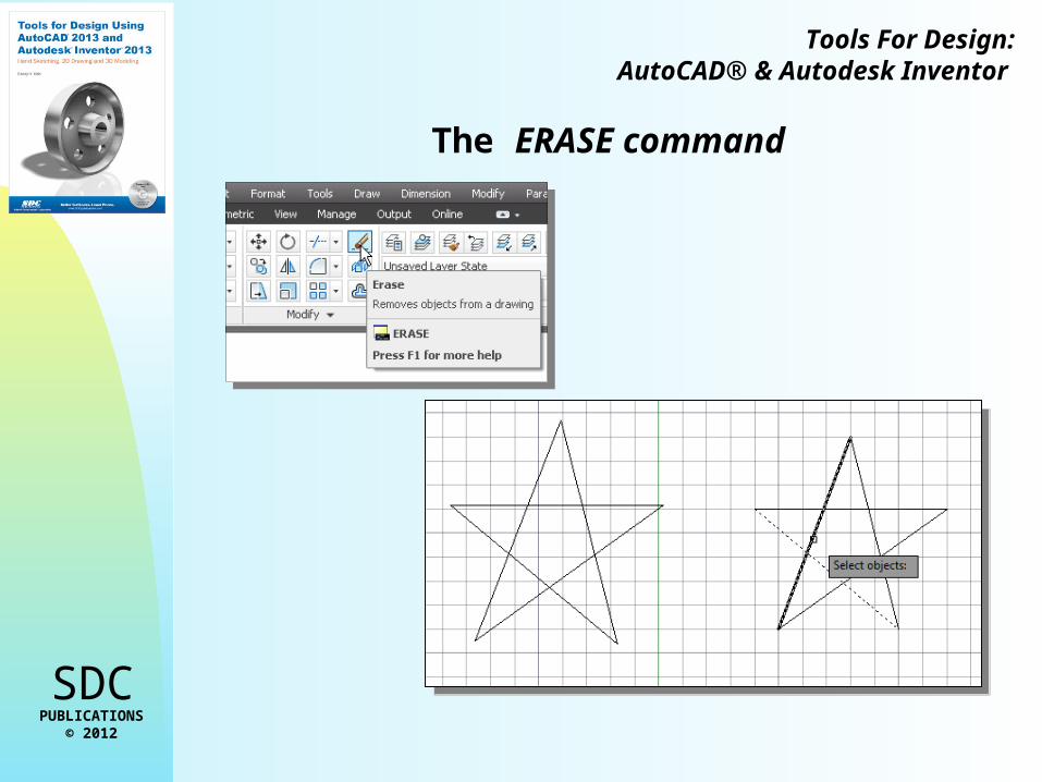
The ERASE command

SDCPUBLICATIONS
© 2012
Tools For Design:AutoCAD® & Autodesk Inventor
The CAD Database and the User Coordinate System
The icon near the bottom left corner of the default AutoCAD graphics window shows the positive X-direction and positive Y-direction of the coordinate system that is active. In AutoCAD, the coordinate system that is used to create entities is called the user coordinate system (UCS). By default, the user coordinate system is aligned to the world coordinate system (WCS). The world coordinate system is a coordinate system used by AutoCAD as the basis for defining all objects and other coordinate systems defined by the users.
3D UCS icon3D UCS icon

SDCPUBLICATIONS
© 2012
Tools For Design:AutoCAD® & Autodesk Inventor
Cartesian and Polar Coordinate Systems
In a two-dimensional space, a point can be represented using different coordinate systems. The point can be located, using a Cartesian coordinate system, as X and Y units away from the origin. The same point can also be located using the polar coordinate system, as r and units away from the origin.

SDCPUBLICATIONS
© 2012
Tools For Design:AutoCAD® & Autodesk Inventor
Defining Positions
In AutoCAD, there are five methods for specifying the locations of points when we create planar geometric entities.
Interactive method: Use the cursor to select on the screen.
Absolute coordinates (Format: X,Y): Type the X and Y coordinates to locate the point on the current coordinate system relative to the origin.
Relative rectangular coordinates (Format: @X,Y): Type the X and Y coordinates relative to the last point.
Relative polar coordinates (Format: @Distance<angle): Type a distance and angle relative to the last point.
Direct Distance entry technique: Specify a second point by first moving the cursor to indicate direction and then entering a distance.

SDCPUBLICATIONS
© 2012
Tools For Design:AutoCAD® & Autodesk Inventor
The GuidePlate Design

SDCPUBLICATIONS
© 2012
Tools For Design:AutoCAD® & Autodesk Inventor
The Spacer Design