sdh interconnect between uk licensed operators
TRANSCRIPT
NICC Document ND1128:2001/07
ND1128:2001/07DWDM Interconnect Between UK
Licensed Operators
INTEROPERABILITY &COMMISSIONING RECOMMENDATION
Issue 1
Network Interoperability Consultative CommitteeOfcomRiverside House,2a Southwark Bridge Road,LondonSE1 9HAUKhttp://www.nicc.org.uk

NICC Document ND1128:2001/07
24/7/01 Issue 1 2
Normative Information© 2001 Crown Copyright
NOTICE OF COPYRIGHT AND LIABILITY
CopyrightAll right, title and interest in this document are owned by the Crown and/or the contributors to the documentunless otherwise indicated (where copyright be owned or shared with a third party). Such title and interest isprotected by United Kingdom copyright laws and international treaty provisions.
The contents of the document are believed to be accurate at the time of publishing, but no representation orwarranty is given as to their accuracy, completeness or correctness. You may freely download, copy, store ordistribute this document provided it is not modified in any way and it includes this copyright and liabilitystatement.
You may not modify the contents of this document. You may produce a derived copyright work based on thisdocument provided that you clearly indicate that it was created by yourself and that it was derived from thisdocument and provided further that you ensure that any risk of confusion with this document is avoided.
Liability
Whilst every care has been taken in the preparation and publication of this document, NICC, nor any committeeacting on behalf of NICC, nor any member of any of those committees, nor the companies they represent, norany person contributing to the contents of this document (together the “Generators”) accepts liability for anyloss, which may arise from reliance on the information contained in this document or any errors or omissions,typographical or otherwise in the contents.
Nothing in this document constitutes advice. Nor does the transmission, downloading or sending of thisdocument create any contractual relationship. In particular no licence is granted under any intellectual propertyright (including trade and service mark rights) save for the above licence to copy, store and distribute thisdocument and to produce derived copyright works.
The liability and responsibility for implementations based on this document rests with the implementer, and notwith any of the Generators. If you implement any of the contents of this document, you agree to indemnify andhold harmless the Generators in any jurisdiction against any claims and legal proceedings alleging that the useof the contents by you or on your behalf infringes any legal right of any of the Generators or any third party.
None of the Generators accepts any liability whatsoever for any direct, indirect or consequential loss or damagearising in any way from any use of or reliance on the contents of this document for any purpose.
If you have any comments concerning the accuracy of the contents of this document, please write to:
The Technical Secretary,Network Interoperability Consultative Committee,Ofcom,Riverside House,2a Southwark Bridge Road,London,SE1 9HA,UK.
NICC Document ND1128:2001/07
24/7/01 Issue 1 3
TABLE OF CONTENTS
1. INTRODUCTION 5
1.1 Document History 5
1.2 Normative References 4
1.3 Definitions and Abbreviations 5
1.4 Scope 6
1.5 Purpose 7
2. PRE-REQUISITES 9
2.1 Test Entry Criteria 9
2.2 Test equipment 9
2.3 Safety 10
2.4 Precautions against Electrostatic Discharge (ESP) 10
2.5 Inspection and Cleaning of Optical Connectors 11
2.6 Documentation 12
3. TEST AND COMMISSIONING PROCEDURES 12
3.1 Testing of the interconnect link. 123.1.1 Test options. 12
3.1.2 Power and path continuity test. 123.1.3 Alarm Tests at Operator A and Operator B Sites 153.1.4 Automatic Laser Shutdown/Power Reduction Test 15
3.2 Testing of the traffic paths 173.2.1 Test Options 173.2.2 Error free traffic on STM-16 tributaries 18
3.3 Stability Test 19
4 TEST EXIT CRITERIA 20
NICC Document ND1128:2001/07
24/7/01 Issue 1 4
5. TEST RESULTS 21
5.1 Test Check List 21
5.2 Test Results Sheets 22
ANNEX A (Informative)
Recommended testing prior to commissioning 32
A.1 Test equipment 32 A.2 Essential test requirements 32
A.2.1 Transmit eye maskA.2.2 Spectrum analysis
ANNEX B (Informative)
Laser safety – Proposed changes to BS EN 60825-1 35
ANNEX C (Informative)
Partially equipped systems 36

NICC Document ND1128:2001/07
24/7/01 Issue 1 5
1. INTRODUCTION
1.1 Document History
Draft A January 2001
(for 17th PNO-TIG DWDM TG meeting 4-1-01).
Draft B 9-1-01
Draft C for 19th PNO-TIG meeting 2-5-01 Draft D for agreement by correspondence Draft E for agreement by correspondence (post meeting 5-7-01). Issue 1 24-7-01
1.2 Normative References
PNO-TIG DWDM Interconnect Documents:
DWDM Interconnect between UK Licensed Operators – Overview Issue 1. – Technical Recommendation Issue 1.
PNO-TIG SDH Interconnect Documents:
SDH Interconnect between UK Licensed Operators – Overview (version 6).- Technical Recommendation (version 6).
- Installation & Commissioning (version 6). British Standards:
BS EN 60825: Radiation Safety of Laser ProductsPart 1:Equipment Classification, Requirements and User Guide (1994). (see annex B).Part 2: Safety of Optical Fibre Communications Systems (2000).Part 4: Laser guards.
BS IEC 61340-5-1: Electrostatics. Protection of electronic devices for electrostaticphenomena. General requirements (1998).
ITU-T Recommendations:
G.664 Optical safety procedures and requirementsfor optical transport systems (06/99).
G.959.1 Optical transport network physical layer Interfaces (02/01).
G.652 Characteristics of single-mode optical fibre cable (10/00).G.655 Characteristics of non-zero dispersion-shifted single-mode optical fibre cable
(10/00).G.957 Optical interfaces for equipment and systems relating to the SDH (06/99).
NICC Document ND1128:2001/07
24/7/01 Issue 1 6
G.707 Network node interface for the SDH (10/00).M.2101.1 Performance limits for bringing into service and maintenance of SDH paths
and multiplex sections (04/97).
O.151 Error performance measuring equipment operating at the primary rate and above (10/92).
1.3 Definitions and Abbreviations
1.3.1 Interconnection Types
For the purposes of this Recommendation the terminology used shall be as follows:
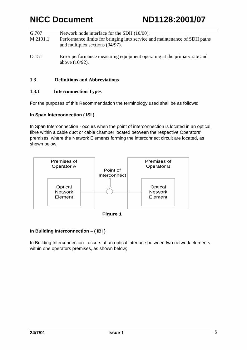
In Span Interconnection ( ISI ).
In Span Interconnection - occurs when the point of interconnection is located in an opticalfibre within a cable duct or cable chamber located between the respective Operators’premises, where the Network Elements forming the interconnect circuit are located, asshown below:
Premises ofOperator A
OpticalNetworkElement
Premises ofOperator B
OpticalNetworkElement
Point ofInterconnect
Figure 1
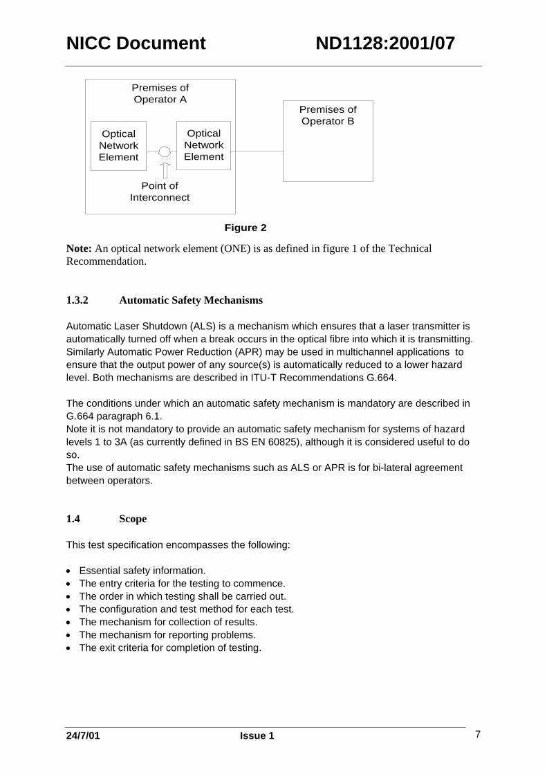
In Building Interconnection – ( IBI )
In Building Interconnection - occurs at an optical interface between two network elementswithin one operators premises, as shown below;
NICC Document ND1128:2001/07
24/7/01 Issue 1 7
Premises ofOperator A
Premises ofOperator B
OpticalNetworkElement
OpticalNetworkElement
Point ofInterconnect
Figure 2
Note: An optical network element (ONE) is as defined in figure 1 of the TechnicalRecommendation.
1.3.2 Automatic Safety Mechanisms
Automatic Laser Shutdown (ALS) is a mechanism which ensures that a laser transmitter isautomatically turned off when a break occurs in the optical fibre into which it is transmitting.Similarly Automatic Power Reduction (APR) may be used in multichannel applications toensure that the output power of any source(s) is automatically reduced to a lower hazardlevel. Both mechanisms are described in ITU-T Recommendations G.664.
The conditions under which an automatic safety mechanism is mandatory are described inG.664 paragraph 6.1.Note it is not mandatory to provide an automatic safety mechanism for systems of hazardlevels 1 to 3A (as currently defined in BS EN 60825), although it is considered useful to doso.The use of automatic safety mechanisms such as ALS or APR is for bi-lateral agreementbetween operators.
1.4 Scope
This test specification encompasses the following:
• Essential safety information.• The entry criteria for the testing to commence.• The order in which testing shall be carried out. • The configuration and test method for each test.• The mechanism for collection of results.• The mechanism for reporting problems.• The exit criteria for completion of testing.
NICC Document ND1128:2001/07
24/7/01 Issue 1 8
The configuration of interconnect covered in this document can be defined as aninterdomain interface (or IrDI), comprising a multichannel DWDM signal of the followingform:
P16 S1-1D2.Where :P = pre-OTN16 = number of optical channels or wavelengths.S = short haul (indicating 11dB span attenuation).First 1 = number of spans in interconnect.Second 1 = NRZ 2.5Gbit/s.D = neither pre, boost, nor line amplifier in circuit.2 = 1550nm source using G.652 fibre
(See companion Technical Recommendation document and ITU-T RecommendationG.959.1.
In the first instance the composition of the client signals used over the IrDI and defined in thecompanion Technical Recommendation document as “digital data streams” shall be SDHoperating at the STM-16 rate of 2.488320 Gbit/s . The combination of tests carried out will in general follow the sequence below:
At the link level:1. Power and continuity test.2. Alarm test.3. Automatic laser shutdown or power reduction.
At the channel level :1. Error free traffic.
In addition a stability test is included (see section 3.3).
Some of the tests described in this recommendation may have to be modified or omitted ifthey are likely to have an adverse effect on live network traffic. Any changes to the testingprogram should be agreed between the two operators, and service level agreements shouldbe taken into account.
If bit error rate tests are carried out, recognition should be given to the principles outlined inITU-T Recommendation M.2101.1 for STM-16 multiplex sections. Note these tests howeverare optional at this level and operators may prefer to carry them out during the SDH testingstage (see companion PNO-TIG SDH documents).
1.5 Purpose
This document specifies a commissioning procedure for establishing the correct operation ofa DWDM interconnect between two independent optical domains (networks), and the

NICC Document ND1128:2001/07
24/7/01 Issue 1 9
operation of circuits carried across that interconnect. The document assumes that the twonetworks are linked via a single unamplified multichannel span. In-Span Interconnect (ISI),or In-Building Interconnect (IBI) may be used (see section 1.3).
The recommendation is applicable both to DWDM interconnects using equipment suppliedby a single vendor, and also to DWDM interconnects involving equipment supplied bydifferent vendors.
This recommendation does not address the issue of equipment conformance testing.Operators are expected to demonstrate that their equipment is capable of meeting therequirements of the Technical Recommendation (see companion TechnicalRecommendation document) before undertaking the tests described herein. Where theinterconnect is being implemented using equipment supplied by more than one vendor,operators should carry out compatibility testing before undertaking the tests described in thisdocument. Compatibility testing will subsequently be required after hardware, firmware orsoftware upgrades.
Conformance and compatibility testing generally requires specialist staff/test equipment. Forexample transmit eye mask and spectrum analysis tests should be carried out during theconformance and compatibility testing stage. They may also be carried out at the in-stationtesting stage immediately prior to commissioning.
Such tests do not form part of the commissioning procedure described in this document.
Essential details of such tests however are given in Annex A.N.B. full in-station test details shall be in accordance with individual operators’/vendors’internal procedures.
NICC Document ND1128:2001/07
24/7/01 Issue 1 10
2 PRE-REQUISITES
2.1 Test Entry Criteria
• Equipments shall have successfully completed conformance testing.• Interworking between the two network element types providing the interconnect, at the
relevant build levels, shall have been proven.• The network elements at each end of the link must have been commissioned in
standalone mode in accordance with the respective operator’s internal test procedures. • The equipment should be set to a known state, and any active alarms should be noted. • All necessary fibres and other connections shall have been provided and commissioned
in accordance with the respective operators’ internal procedures.• A means of detecting alarm signals shall be available at both ends of the interconnection.• Appropriate company documentation shall be available as described in Section 2.4.• All staff involved in testing shall be trained in accordance with the respective company
procedures.• Staff involved in testing shall have access to the appropriate Equipment User Manual(s). • Optical line losses to be agreed and verified. 2.2 Test equipment The following test equipment will be required to enable the tests described in thisrecommendation to be performed. It would be expected that such test equipment is suitablycalibrated and subject to the operator’s internal calibration procedures. • Bit error rate tester (BERT). The tester used must be capable of analysing an STM-16
signal in the optical domain. Test patterns shall conform to ITU-T RecommendationO.151.
• Optical Power Meter.
• Optical Spectrum Analyser. This instrument must be capable of single channel powermeasurement within a multichannel signal of 200GHz spaced channels in the C band
• Variable Optical Attenuator • Local Terminal with software and appropriate cables. • Appropriate optical patch cords. 2.3 Optical Safety All work on network elements employing lasers shall be conducted in accordance with therespective operators Optical Safety procedures. The following minimum requirements shallapply;

NICC Document ND1128:2001/07
24/7/01 Issue 1 11
BEFORE POWER IS APPLIED TO ANY OPTICAL EQUIPMENT AT EITHER END,PERSONNEL AT EACH END OF THE LINK SHALL CONFIRM TO PERSONNEL AT THEOTHER END THAT THEY ARE READY TO BEGIN TESTING, AND THAT THEY HAVETAKEN THE NECESSARY PRECAUTIONS. ALL STAFF WORKING ON OPTICAL SYSTEMS MUST BE ADEQUATELY TRAINED. Under normal operating conditions, the optical fibre equipment forms part of a closedsystem, i.e., the invisible radiation produced is contained within closed paths. However,when the path is broken, (e.g., during testing) exposure to the radiation is possible. The focusing ability of the eye makes it susceptible to damage, and safe working practicemust be adopted to minimise the risk of exposure. All optical interconnections should be designed, installed and operated in accordance withthe safety requirements detailed in Reference 3 (BS EN 60825 Parts 1 and 2). It istheoretically possible under fault conditions that the level of power emitted by the equipmentcould exceed the class limit for a brief period. The owner of the transmission equipmentwho has exclusive access to that equipment should use internal company safety proceduresappropriate to the classification of the laser sources. See also section 1.3.2. 2.4 Precautions against Electrostatic Discharge (ESP) Precautions shall be taken in accordance with respective operators’ procedures. Thefollowing minimum requirements shall apply; i) All personnel shall wear conductive and bonded wrist straps (which conform to BS IEC
61340-5-1)) and be connected to an electrostatic protection bonding point or, if there isno point available, to a suitable earth point via an ESP adapter.
ii) Always connect the ESP wrist strap to the equipment rack ESP bonding point before
removing covers, cards or connectors. iii) The ESP wrist strap shall be in contact with the wearer's skin. iv) All test equipment and trolleys should be connected to the ESP bonding point. 2.5 Inspection and Cleaning of Optical Connectors Optical connectors shall be inspected and cleaned in accordance with respective operatorsprocedures. As a minimum the following shall apply; Before any inspection of an optical connector, ensure that the optical power source isremoved. Confirm this by the use of an optical power meter to check that no power ispresent at the connector, before a microscope is used.

NICC Document ND1128:2001/07
24/7/01 Issue 1 12
Note: Inspection and cleaning of optical connectors may have been performed duringequipment commissioning. 2.6 Documentation Staff involved in testing should be aware of the following documents in addition to therelevant Health and Safety procedures required by the circumstances: Procedure Necessary Documentation Ensuring Optical Safety BS EN 60825 Parts 1,2 and
Internal Company Procedures (see also Section 2.3)
Protection Against Electrostatic Discharge(ESP)
Internal Company Procedures (see also Section 2.4)
Inspection and Cleaning of OpticalConnectors
Internal Company Procedures (see also Section 2.5)

NICC Document ND1128:2001/07
24/7/01 Issue 1 13
3. TESTING AND COMMISSIONING PROCEDURES 3.1 Testing of the interconnect link. 3.1.1 Test options. This test sequence confirms the operation of the interconnecting DWDM link andterminal equipment ALS/APR and equipment alarms. These tests are designed to ensurethat a useable signal on each wavelength is being received at each end of theinterconnecting link. Where ALS or APR, is implemented, test sequences 3.1.2, and 3.1.4should be used. Where ALS or APR is not implemented, test sequences 3.1.2 and 3.1.3should be used. The test sequences below should be repeated for each interconnect transmit/receive pair inthe interconnect network. Likely scenarios are still under discussion but will probably consider the following:• Point to point interconnect using one receive and one transmit fibre only.• 1+1 dual fibre pairs to provide a protected interconnect.• Two separate fibre pairs, forming two sections of an interconnect ring or other network.• A second interconnect pair to provide diversity to an existing interconnect carrying live
traffic (Underlying protection will be provided by the SDH layer). The tests will - • Give confidence in the end-to-end continuity and quality of the fibre connection
(particularly at joints), and the desired signal strength through the fibre. • Ensure distant alarms are reported correctly. • Demonstrate correct operation of ALS or APR (where applicable). • Allow all other tests to be carried out.
NICC Document ND1128:2001/07
24/7/01 Issue 1 14
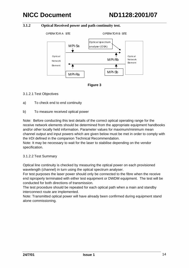
3.1.2 Optical Received power and path continuity test.
Op tic a l
Network
Element
Op tic a lNetworkElement
OPERATOR B SITEOPERATOR A SITE
Optic a l spec trum
ana lyser (OSA)MPI-Sa
MPI-Rb
MPI-Ra MPI-Sb
Figure 3 3.1.2.1 Test Objectives a) To check end to end continuity b) To measure received optical power Note: Before conducting this test details of the correct optical operating range for thereceive network elements should be determined from the appropriate equipment handbooksand/or other locally held information. Parameter values for maximum/minimum meanchannel output and input powers which are given below must be met in order to comply withthe IrDI defined in the companion Technical Recommendation. Note: It may be necessary to wait for the laser to stabilise depending on the vendorspecification. 3.1.2.2 Test Summary Optical line continuity is checked by measuring the optical power on each provisionedwavelength (channel) in turn using the optical spectrum analyser. For test purposes the laser power should only be connected to the fibre when the receiveend isproperly terminated with either test equipment or DWDM equipment. The test will beconducted for both directions of transmission. The test procedure should be repeated for each optical path when a main and standbyinterconnect route are implemented. Note: Transmitted optical power will have already been confirmed during equipment standalone commissioning.

NICC Document ND1128:2001/07
24/7/01 Issue 1 15
3.1.2.3 Test Procedure Steps Actions Measurement/Pass Criteria Operator A to Operator B direction . 1. Operator A records local transmit power at point
MPI-Sa for each wavelength in turn (see noteabove).
A Tx channel output Power–4/-10dBm
2. Operator B records local transmit power at pointMPI-Sb for each wavelength in turn (see noteabove).
B Tx channel output Power–4/-10dBm
3 Operator A disables it’s transmit signal. 4 Operator B connects its Optical Spectrum
Analyser at point MPI-Rb.
5 Operator A enables it’s transmit signal andOperator B measures and notes the receivedpower at point MPI-Rb for each wavelength inturn.
B Rx channel input Power-6/-21dBm
6 Operator A disables it’s transmit signal.
7 Operator B reconnects it’s receive fibre to theDWDM equipment.
8 Operator A enables it’s transmit signal. Bothoperators check that the link is established.
Link is operational in bothdirections.
Operator B to Operator A direction . 9 Operator B disables it’s transmit signal. 10 Operator A connects its Optical Spectrum
Analyser at point MPI-Ra.
11 Operator B enables it’s transmit signal andOperator A measures and notes the receivedpower at point MPI-Ra for each wavelength inturn.
A Rx channel input Power-6/-21dBm
12 Operator B disables it’s transmit signal. 13 Operator A reconnects it’s receive fibre to the
DWDM equipment.
14 Operator B enables it’s transmit signal. Bothoperators check that the link is established.
Link is operational in bothdirections.
Note: blanked out box indicates an instruction to enable the test to be conducted.

NICC Document ND1128:2001/07
24/7/01 Issue 1 16
3.1.3 Distant Alarm Tests at Operator A and Operator B Sites
3.1.3.1 Test Objective
This test confirms end to end alarm signalling between network elements and is applicableto both interconnection types as described in Section 1.3.1. The test is only required if ALSor APR is not used.
3.1.3.2 Test SummaryThe output of each wavelength (channel) at each end of the link is interrupted and the farend alarm indications noted.3.1.3.3 Test Procedure
Steps Actions Measurements/Pass Criteria1 Disable each equipped channel (DWDM laser
source) in turn at the Operator A end and checkthat the network element terminating theOperator B end of the interconnecting sectionreports "Loss of Signal" alarm for thatwavelength (channel).
LOS alarm present at B end.
2 Restore the channel output at the A end andestablish error free traffic.
No System Alarms reported.
3 Disable each equipped channel (DWDM lasersource) in turn at the Operator B end and checkthat the network element terminating theOperator A end of the interconnecting sectionreports "Loss of Signal" alarm for thatwavelength (channel).
LOS alarm present at A end.
4 Restore the network element B outputconnection and establish error free traffic.
No System Alarms reported.
3.1.4 Automatic Laser Shutdown/Power Reduction Test
Optical
NetworkElement
Optical
NetworkElement
OPERATOR B SITEOPERATOR A SITE
OPTICAL
ATTENUATOR
MPI-Ra MPI-Sb
MPI-Sa MPI-Rb
Figure 4
NICC Document ND1128:2001/07
24/7/01 Issue 1 17
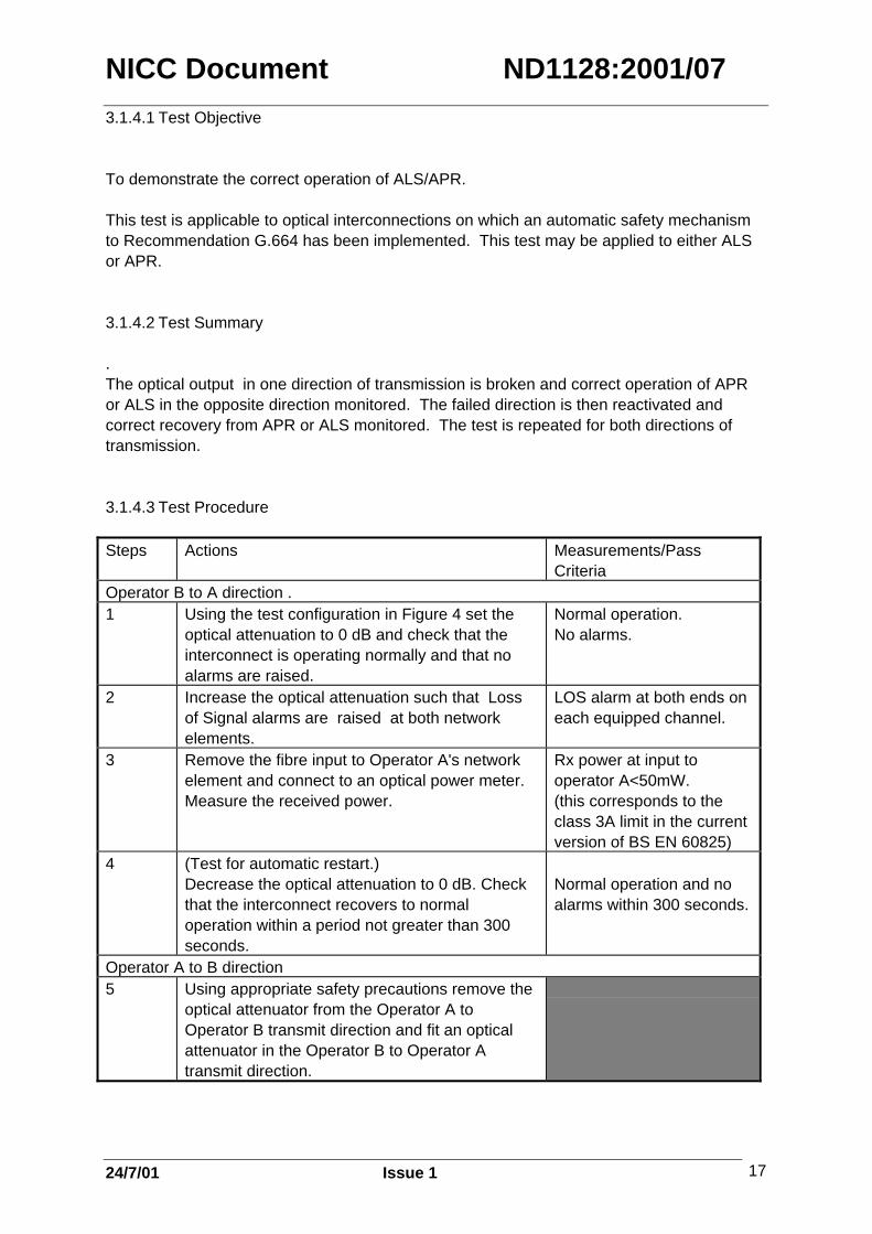
3.1.4.1 Test Objective
To demonstrate the correct operation of ALS/APR.
This test is applicable to optical interconnections on which an automatic safety mechanismto Recommendation G.664 has been implemented. This test may be applied to either ALSor APR.
3.1.4.2 Test Summary
.The optical output in one direction of transmission is broken and correct operation of APRor ALS in the opposite direction monitored. The failed direction is then reactivated andcorrect recovery from APR or ALS monitored. The test is repeated for both directions oftransmission.
3.1.4.3 Test Procedure
Steps Actions Measurements/PassCriteria
Operator B to A direction .1 Using the test configuration in Figure 4 set the
optical attenuation to 0 dB and check that theinterconnect is operating normally and that noalarms are raised.
Normal operation.No alarms.
2 Increase the optical attenuation such that Lossof Signal alarms are raised at both networkelements.
LOS alarm at both ends oneach equipped channel.
3 Remove the fibre input to Operator A's networkelement and connect to an optical power meter.Measure the received power.
Rx power at input tooperator A<50mW.(this corresponds to theclass 3A limit in the currentversion of BS EN 60825)
4 (Test for automatic restart.)Decrease the optical attenuation to 0 dB. Checkthat the interconnect recovers to normaloperation within a period not greater than 300seconds.
Normal operation and noalarms within 300 seconds.
Operator A to B direction 5 Using appropriate safety precautions remove the
optical attenuator from the Operator A toOperator B transmit direction and fit an opticalattenuator in the Operator B to Operator Atransmit direction.
NICC Document ND1128:2001/07
24/7/01 Issue 1 18
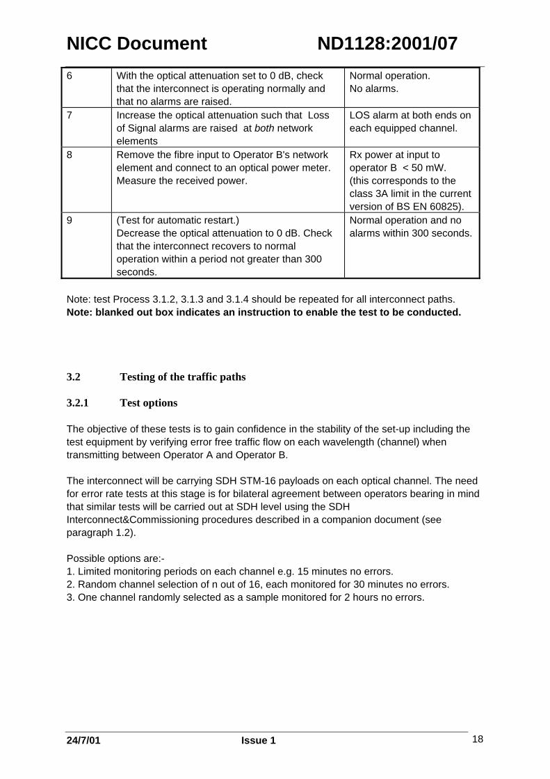
6 With the optical attenuation set to 0 dB, checkthat the interconnect is operating normally andthat no alarms are raised.
Normal operation.No alarms.
7 Increase the optical attenuation such that Lossof Signal alarms are raised at both networkelements
LOS alarm at both ends oneach equipped channel.
8 Remove the fibre input to Operator B's networkelement and connect to an optical power meter.Measure the received power.
Rx power at input tooperator B < 50 mW.(this corresponds to theclass 3A limit in the currentversion of BS EN 60825).
9 (Test for automatic restart.)Decrease the optical attenuation to 0 dB. Checkthat the interconnect recovers to normaloperation within a period not greater than 300seconds.
Normal operation and noalarms within 300 seconds.
Note: test Process 3.1.2, 3.1.3 and 3.1.4 should be repeated for all interconnect paths.Note: blanked out box indicates an instruction to enable the test to be conducted.
3.2 Testing of the traffic paths
3.2.1 Test options
The objective of these tests is to gain confidence in the stability of the set-up including thetest equipment by verifying error free traffic flow on each wavelength (channel) whentransmitting between Operator A and Operator B.
The interconnect will be carrying SDH STM-16 payloads on each optical channel. The needfor error rate tests at this stage is for bilateral agreement between operators bearing in mindthat similar tests will be carried out at SDH level using the SDHInterconnect&Commissioning procedures described in a companion document (seeparagraph 1.2).
Possible options are:-1. Limited monitoring periods on each channel e.g. 15 minutes no errors.2. Random channel selection of n out of 16, each monitored for 30 minutes no errors.3. One channel randomly selected as a sample monitored for 2 hours no errors.
NICC Document ND1128:2001/07
24/7/01 Issue 1 19
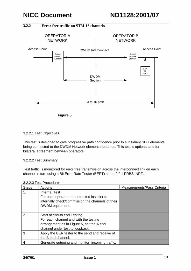
3.2.2 Error free traffic on STM-16 channels
Figure 5
3.2.2.1 Test Objectives
This test is designed to give progressive path confidence prior to subsidiary SDH elementsbeing connected to the DWDM Network element tributaries. This test is optional and forbilateral agreement between operators.
3.2.2.2 Test Summary
Test traffic is monitored for error free transmission across the interconnect link on eachchannel in turn using a Bit Error Rate Tester (BERT) set to 223-1 PRBS NRZ.
3.2.2.3 Test ProcedureSteps Actions Measurements/Pass Criteria1. Internal Test
For each operator or contracted installer tointernally check/commission the channels of theirDWDM equipment.
2 Start of end-to end TestingFor each channel and with the testingarrangement as in Figure 5, set the A endchannel under test to loopback,
3 Apply the BER tester to the send and receive ofthe B end channel.
4 Generate outgoing and monitor incoming traffic.
OpticalNetworkElement
OpticalNetworkElement
STM-16
BERT
OPERATOR ANETWORK
OPERATOR BNETWORK
DWDM InterconnectAccess Point Access Point
DWDMSection
STM-16 path

NICC Document ND1128:2001/07
24/7/01 Issue 1 20
5 Monitor the system for the selected period,checking that there are no errors recorded on theBit Error Rate Tester and that no alarms arereported by the network elements.
No errors.No alarms.
6 Repeat for the other direction of transmission. No errorsNo alarms
Note: blanked out box indicates an instruction to enable the test to be conducted.
3.3 Stability
3.3.1 Test Objective
The objective of these tests is to ensure that the interconnection path is stable under normaloperating conditions.
3.3.2 Test Summary
Stability of the optical connectors is tested by percussion testing and overall path stability bymeans of a period of error free operation. Where protection is employed error free operationof both main and protection path is monitored.
3.3.3 Test Procedure
Step Action Measurements/Pass Criteria.1 With the testing arrangement as in Figure 5, set
the Bit Error Rate Tester to transmit theappropriate pattern for a chosen channel. SeeSection 3.2.2.2.
2 Carry out a percussion test by gently tapping allfibre connectors at both A & B ends. Check thatno alarms are reported, or errors generated.Repeat for the other channels as required.
No alarms.
No errors.
3a If no protection is employed carry out a 2 hourstability run on the system. Check that there areno alarms reported on the system and that noerrors occur in the 24 hours, in either direction oftransmission.
No alarms.
No errors.

NICC Document ND1128:2001/07
24/7/01 Issue 1 21
OR3b
If protection is employed carry out a stability runof approximately 12 hours with traffic configuredon the main path and then not less than 3 hourswith traffic configured on the protection path.Check that there are no alarms reported on thesystem and that no errors occur in the total testperiod, in either direction of transmission.Note: The detailed arrangements for performingthis test will need to be agreed between the twooperators.
No alarms.
No errors.
Note: blanked out box indicates an instruction to enable the test to be conducted.
4 TEST EXIT CRITERIA
The test exit criteria are as follows:
i) All relevant tests have been carried out.ii) All results have been gathered.iii) All problems have been documented and resolved.
As each test in this document is performed, the test case on the Test Results Sheet (seesection 5.2) must be completed to indicate pass or fail. Deviations from the anticipatedresults should be noted in the Test Results Comments section for each test on the sheet. A specific test will be deemed to have failed if the result does not comply with therequirements stated in this test specification. A pass may be recorded if after correctiveaction the result is compliant. Where corrective action is necessary the test shall berepeated and the results noted on a new Test Results Sheet. The details of the correctiveaction must be recorded on the new Test Results Sheet. Care must be taken to ensure thatthe corrective action remains valid after any regular maintenance activity, eg replacement ofa faulty card.
NICC Document ND1128:2001/07
24/7/01 Issue 1 22
5. TEST RESULTS
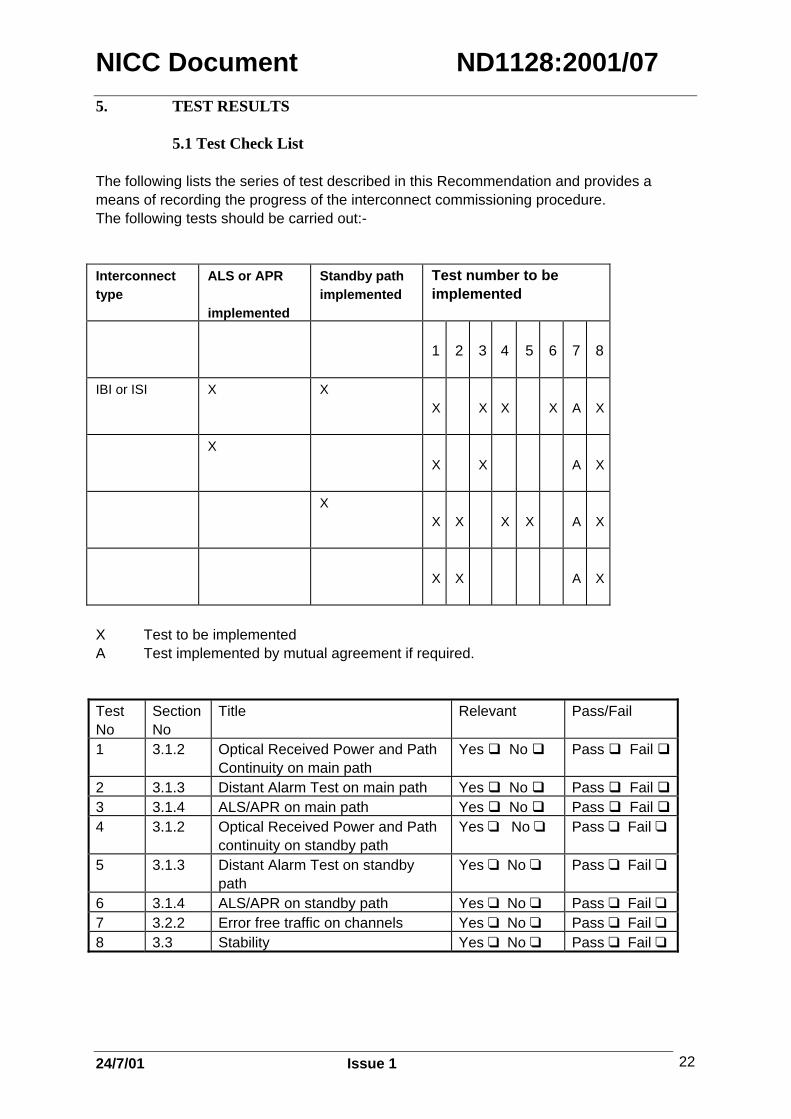
5.1 Test Check List
The following lists the series of test described in this Recommendation and provides ameans of recording the progress of the interconnect commissioning procedure.The following tests should be carried out:-
Interconnecttype
ALS or APR
implemented
Standby pathimplemented
Test number to beimplemented
1 2 3 4 5 6 7 8
IBI or ISI X XX X X X A X
XX X A X
XX X X X A X
X X A X
X Test to be implementedA Test implemented by mutual agreement if required.
TestNo
SectionNo
Title Relevant Pass/Fail
1 3.1.2 Optical Received Power and PathContinuity on main path
Yes No Pass Fail
2 3.1.3 Distant Alarm Test on main path Yes No Pass Fail 3 3.1.4 ALS/APR on main path Yes No Pass Fail 4 3.1.2 Optical Received Power and Path
continuity on standby pathYes No Pass Fail
5 3.1.3 Distant Alarm Test on standbypath
Yes No Pass Fail
6 3.1.4 ALS/APR on standby path Yes No Pass Fail 7 3.2.2 Error free traffic on channels Yes No Pass Fail 8 3.3 Stability Yes No Pass Fail

NICC Document ND1128:2001/07
24/7/01 Issue 1 23
The relevance of each test will depend upon the interconnect configuration. Details areassociated with the test descriptions.

NICC Document ND1128:2001/07
24/7/01 Issue 1 24
5.2 Test Results Sheets
The following test results sheets refer to the test cases contained within this document.They can be used to record the results of the tests conducted in accordance with thisrecommendation.
In cases where the procedure is not a measurement, a tick in the Pass/Fail column shall beused to indicate that the activity has been successfully or unsuccessfully carried out.
Where tests are conducted from more than one location in each operators network separateTest Results Sheets shall be completed for each site.
Test Information
Operator A: Operator B:
Site A Address: Site B Address:
Site A Test Equipment
Manufacturer Type Serial Number
Optical spectrumanalyser
STM-16 Bit errorrate tester (note 1)Optical power meterVariable opticalattenuatorLocal terminal withsoftware andappropriate cablesAppropriate opticalpatch cords
note 1: As appropriate. See Section 2.2. Use blank entry for any other BERT type.

NICC Document ND1128:2001/07
24/7/01 Issue 1 25
Site B Test Equipment
Manufacturer Type Serial Number
Optical spectrumanalyserSTM-16 Bit errorrate tester (note1)Optical power meter
Variable OpticalAttenuatorLocal Terminal withsoftware andappropriate cablesAppropriate opticalpatch cords
note 1: As appropriate. See Section 2.2. Use blank entry for any other BERT type.
Network Element at Site A Network Element at Site B
Optical NetworkElementManufacturer
Type
Serial Number
Software Version No.
Hardware Version No.

NICC Document ND1128:2001/07
24/7/01 Issue 1 26
Test Results Sheet
Test 1 (Described in section 3.1.2) - Optical Received Power and Path Continuity onmain path.
Operator: Test Engineer:
Test Conducted: Yes No
Step Measurement Pass/Fail Comments1 dBm Pass Fail
2 dBm Pass Fail
5 dBm Pass Fail
8 Pass Fail
11 dBm Pass Fail
14 Pass Fail
Test Result: Pass Fail
Corrective Action:
Test Engineer Signature:
Date:
Operator A Representative:
Operator B Representative:

NICC Document ND1128:2001/07
24/7/01 Issue 1 27
Test Results Sheet
Test 2 (Described in section 3.1.3) - Distant Alarm Tests at Operator A and Operator BSites on main path
Operator: Test Engineer:
Test Conducted: Yes No
Step Pass/Fail Comments1 Pass Fail 2 Pass Fail 3 Pass Fail 4 Pass Fail
Test Result: Pass Fail
Corrective Actions:
Test Engineer Signature:
Date:
Operator A Representative:
Operator B Representative:

NICC Document ND1128:2001/07
24/7/01 Issue 1 28
Test Results Sheet
Test 3 (Described in section 3.1.4) – ALS/APR Test on main path
Operator: Test Engineer:
Test Conducted: Yes No
Step Pass/Fail Comments1 Pass Fail 2 Pass Fail 3 Pass Fail 4 Pass Fail 6 Pass Fail 7 Pass Fail 8 Pass Fail 9 Pass Fail
Test Result: Pass Fail
Corrective Actions:
Test Engineer Signature:
Date:
Operator A Representative:
Operator B Representative:

NICC Document ND1128:2001/07
24/7/01 Issue 1 29
Test Results Sheet
Test 4 (Described in section 3.1.2) - Optical Received Power and Path Continuity onstandby path.
Operator: Test Engineer:
Test Conducted: Yes No
Step Measurement Pass/Fail Comments1 dBm Pass Fail
2 dBm Pass Fail
5 dBm Pass Fail
8 Pass Fail
11 dBm Pass Fail
14 Pass Fail
Test Result: Pass Fail
Corrective Action:
Test Engineer Signature:
Date:
Operator A Representative:
Operator B Representative:

NICC Document ND1128:2001/07
24/7/01 Issue 1 30
Test Results Sheet
Test 5 (Described in section 3.1.3) - Distant Alarm Tests at Operator A and Operator BSites on standby path
Operator: Test Engineer:
Test Conducted: Yes No
Step Pass/Fail Comments1 Pass Fail 2 Pass Fail 3 Pass Fail 4 Pass Fail
Test Result: Pass Fail
Corrective Actions:
Test Engineer Signature:
Date:
Operator A Representative:
Operator B Representative:

NICC Document ND1128:2001/07
24/7/01 Issue 1 31
Test Results Sheet
Test 6 (Described in section 3.1.4) – ALS/APR Test on standby path
Operator: Test Engineer:
Test Conducted: Yes No
Step Pass/Fail Comments1 Pass Fail 2 Pass Fail 3 Pass Fail 4 Pass Fail 6 Pass Fail 7 Pass Fail 8 Pass Fail 9 Pass Fail
Test Result: Pass Fail
Corrective Actions:
Test Engineer Signature:
Date:
Operator A Representative:
Operator B Representative:
NICC Document ND1128:2001/07
24/7/01 Issue 1 32
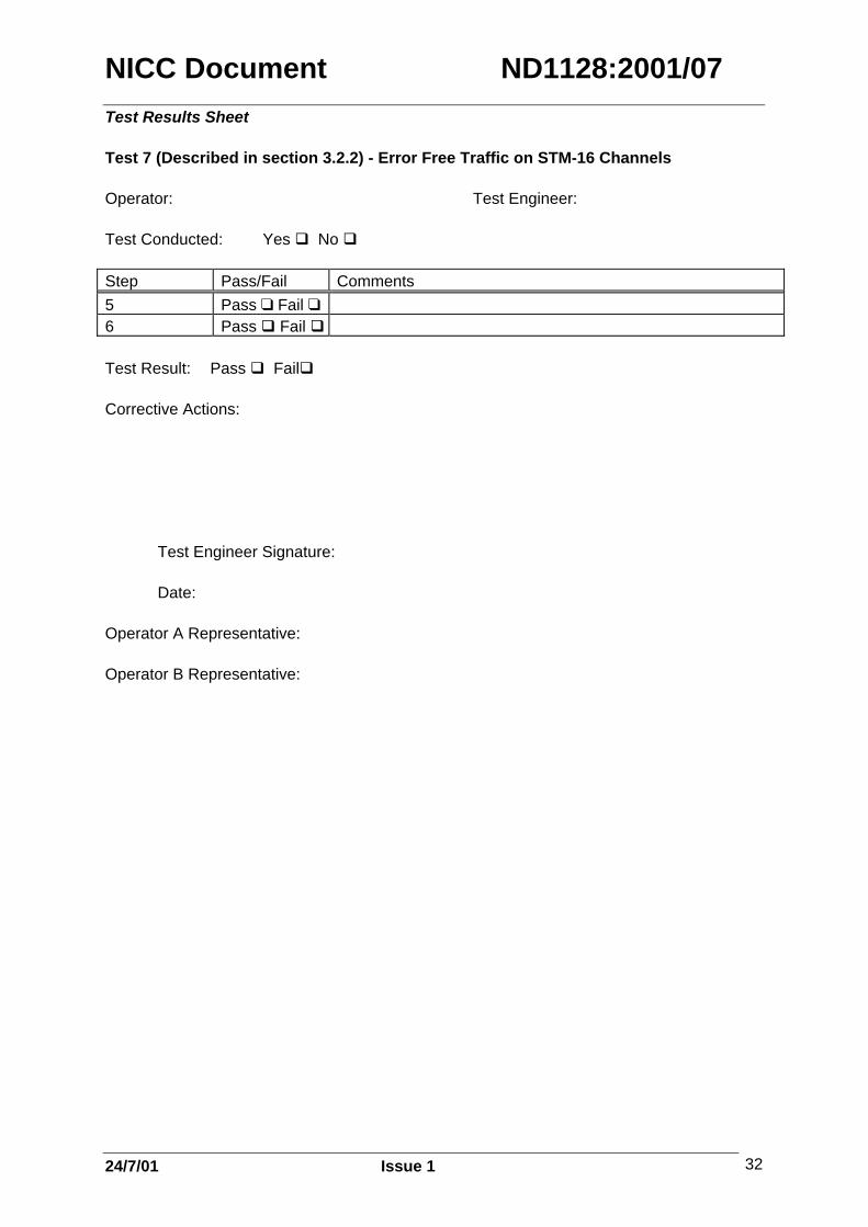
Test Results Sheet
Test 7 (Described in section 3.2.2) - Error Free Traffic on STM-16 Channels
Operator: Test Engineer:
Test Conducted: Yes No
Step Pass/Fail Comments5 Pass Fail 6 Pass Fail
Test Result: Pass Fail
Corrective Actions:
Test Engineer Signature:
Date:
Operator A Representative:
Operator B Representative:

NICC Document ND1128:2001/07
24/7/01 Issue 1 33
Test Results Sheet
Test 8 (Described in section 3.3) Stability
Operator: Test Engineer:
Test Conducted: Yes No
Step Pass/Fail Comments2 Pass Fail 3a Pass Fail OR3b Pass Fail
Test Result: Pass Fail
Corrective Actions:
Test Engineer Signature:
Date:
Operator A Representative:
Operator B Representative:
NICC Document ND1128:2001/07
24/7/01 Issue 1 34
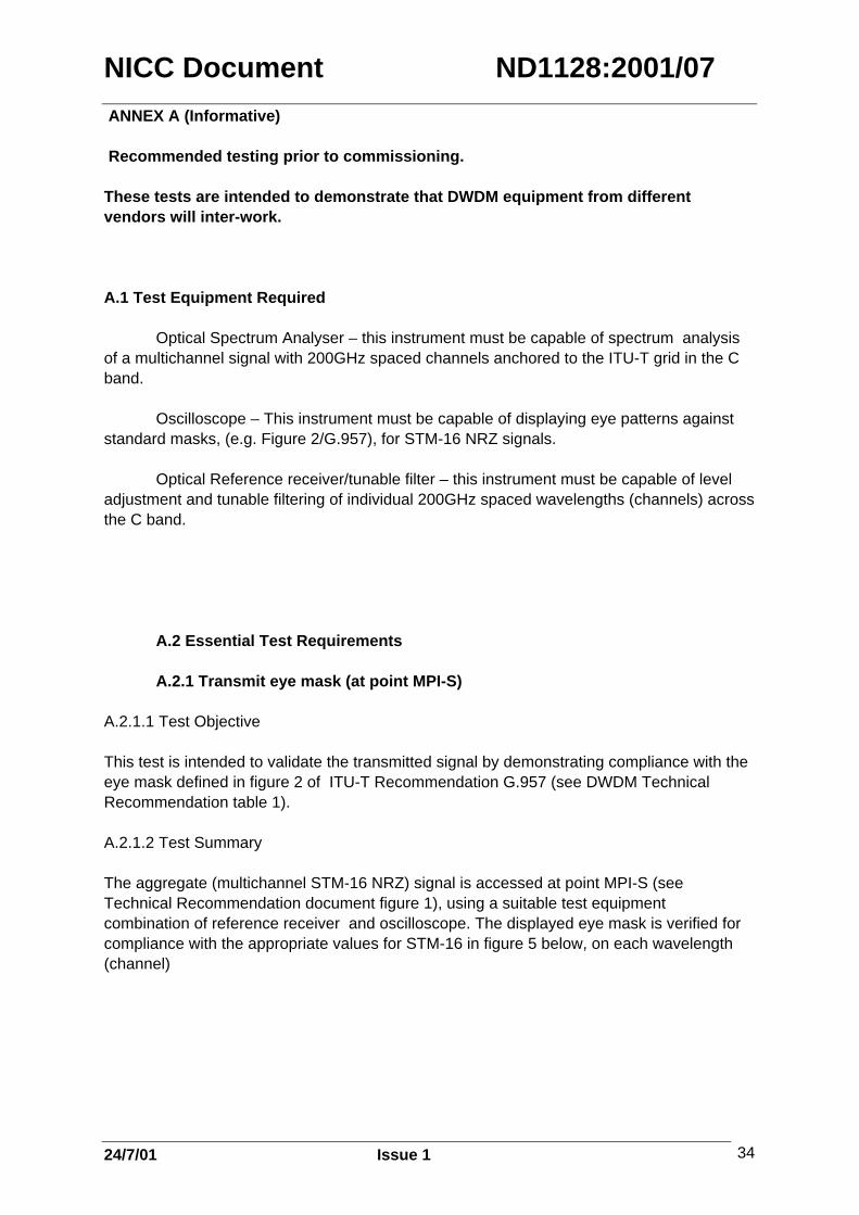
ANNEX A (Informative)
Recommended testing prior to commissioning.
These tests are intended to demonstrate that DWDM equipment from differentvendors will inter-work.
A.1 Test Equipment Required
Optical Spectrum Analyser – this instrument must be capable of spectrum analysisof a multichannel signal with 200GHz spaced channels anchored to the ITU-T grid in the Cband.
Oscilloscope – This instrument must be capable of displaying eye patterns againststandard masks, (e.g. Figure 2/G.957), for STM-16 NRZ signals.
Optical Reference receiver/tunable filter – this instrument must be capable of leveladjustment and tunable filtering of individual 200GHz spaced wavelengths (channels) acrossthe C band.
A.2 Essential Test Requirements
A.2.1 Transmit eye mask (at point MPI-S)
A.2.1.1 Test Objective
This test is intended to validate the transmitted signal by demonstrating compliance with theeye mask defined in figure 2 of ITU-T Recommendation G.957 (see DWDM TechnicalRecommendation table 1).
A.2.1.2 Test Summary
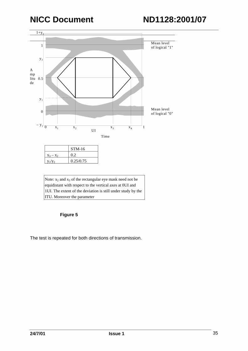
The aggregate (multichannel STM-16 NRZ) signal is accessed at point MPI-S (seeTechnical Recommendation document figure 1), using a suitable test equipmentcombination of reference receiver and oscilloscope. The displayed eye mask is verified forcompliance with the appropriate values for STM-16 in figure 5 below, on each wavelength(channel)
NICC Document ND1128:2001/07
24/7/01 Issue 1 35
0 x 1 1
0
1
x2 x3 x4– y 1
y 1
y 2
1+y 1
UI
0.5
Amplitude
Time
Mean levelof logical "1"
Mean levelof logical "0"
STM-16x3 – x2 0.2y1/y2 0.25/0.75
Note: x2 and x3 of the rectangular eye mask need not beequidistant with respect to the vertical axes at 0UI and1UI. The extent of the deviation is still under study by theITU. Moreover the parameter
Figure 5
The test is repeated for both directions of transmission.

NICC Document ND1128:2001/07
24/7/01 Issue 1 36
A2.2 Spectrum Analysis (at point MPI-S)
A.2.2.1 Test Objective.
This test is used to validate the transmitted signal by demonstrating compliance with thewavelength grid defined in ITU-T Recommendation G.959.1.
A.2.2.2 Test Summary
Using an optical spectrum analyser with C Band capability, check on each optical channel inturn and measure the central frequency deviation and channel separation. The deviation should be within +/-40GHz of the nominal frequency shown in the table belowand the channel spacing should be at least 200GHz between channel maxima. This shouldnot change over a 24 hour period.
Channel No Nominal FrequencyTHz
Measured deviationGHz
Channel spacingn/n+1 GHz
1 192.12 192.33 192.54 192.75 192.96 193.17 193.38 193.59 193.710 193.911 194.112 194.313 194.514 194.715 194.916 195.1
Table 1

NICC Document ND1128:2001/07
24/7/01 Issue 1 37
ANNEX B (Informative)
Laser Safety – Proposed Changes to BS EN 60825-1.
BS EN 60825-1 (1994) is still current although 2 amendments have been incorporated anda third is due to be published in March 2002. Work started on the revision of this documentin 1997.
The principal changes affecting telecommunications systems are those being made to thelaser classes or hazard levels.
It is anticipated that current laser classes 1,2 and 3a will be replaced by new classes 1,1M,2, 2M. Those lasers currently classified as class 1 or class 2 however will be unaffected.Additionally the power levels associated with these classes are also likely to change. Anindication of this is shown below:
Wavelength Class/Hazard Level Power limit (approx)
1300nm 1 15mW (was 10mW)1300nm 1M (was 3A) 50mW (was 22mW)1550nm 1 10mW (unchanged)1550nm 1M (was 3A) 150mW(previously
50mW now wavelengthdependent).
Classes 3B and 4 will be unchanged but some laser and led products currently falling intoclass 3B will in future be included in classes 1M and 2M.
Another new class, 3R covers lasers with accessible emission less than five times the class2 limit between 400nm and 700nm, or less than five times the class 1 limit at otherwavelengths. There is no class 3R for the range 180nm to 302.5nm.

NICC Document ND1128:2001/07
24/7/01 Issue 1 38
ANNEX C
Partially equipped systems
Where partial equipping of wavelengths (channels) occurs tests should be carried out onthose that are equipped in accordance with the procedures outlined in this document. Whenadditional channels are added at a later date test and measurement at the MPI-S, R pointsin-service is only possible if suitable monitoring points exist. Operators will need to reconcilethe inconvenience of planned outages against transponder reliability in such situations.
Moreover in some vendor implementations power level adjustment is necessary asadditional channels are added. In this situation operators will need to balance theinconvenience of planned outages against the up-front cost of fully equipping from theoutset.