sdi: technology, survivability, and software (may 1988)
TRANSCRIPT
SDI: Technology, Survivability, and Software
May 1988
NTIS order #PB88-236245

Recommended Citation:U.S. Congress, Office of Technology Assessment, SDI: Technology, Survivability,and Software, OTA-ISC-353 (Washington, DC: U.S. Government Printing Office,May 1988).
Library of Congress Catalog Card Number 87-619857
For sale by the Superintendent of DocumentsU.S. Government Printing Office, Washington, DC 20402-9325
(order form can be found in the back of this report)

Foreword
In its 1985 report, New Ballistic Missile Defense Technologies, OTA attemptedto place those technologies against a useful policy background for the Congress.While that report introduced the major subject areas of Strategic Defense Initia-tive research, the amount of detailed technical evaluation it could offer was limited.The chief limitations were the relative newness of the SDI program and the lackof specific BMD system architectures to examine. Since that report, the SDIOhas conducted enough additional research and, in particular, identified a suffi-ciently specific system architecture that a more detailed OTA review of the rele-vant technologies should be helpful to Congress.
Public Law 99-190 (continuing appropriations for fiscal year 1986) called forthe Office of Technology Assessment to conduct a”. . . comprehensive classifiedstudy . . . together with an unclassified version . . . to determine the technologi-cal feasibility and implications, and the ability to survive and function despitea preemptive attack by an aggressor possessing comparable technology, of theStrategic Defense Initiative Program. ” In addition, the accompanying Confer-ence Report specified that . . . “This study shall include an analysis of the feasibil-ity of meeting SDI computer software requirements. ”
This unclassified report completes OTA’s response to that mandate. It putsSDI technologies in context by reporting the kinds of ballistic missile defense(BMD) system architectures that the SDI organization has considered for “phaseddeployment. ” It reviews the status of the various SDI technologies and systemcomponents. It analyzes the feasibility of producing dependable software of thecomplexity that advanced BMD systems would require. Finally, it summarizeswhat is now known—and unknown—about the probable survivability of such sys-tems against concerted enemy attacks of various kinds.
The study found that major uncertainties remain concerning the probable cost,effectiveness, and survivability of the kinds of BMD system (which rely on kineticrather than directed-energy weapons) that might be deployable in the “phase-one’proposed for the mid to late 1990s. In addition, OTA believes several more yearsof SDI research would be needed to determine whether it is feasible to constructthe kinds of directed-energy weapons contemplated as follow-ons to SDIO’s “phaseone” BMD system. The survivability of both short-term and longer-term BMDsystems would depend heavily on the outcome of a continuing competition in weap-ons and countermeasures between the United States and the Soviet Union. Fi-nally, developing dependable software for advanced BMD will be a formidablechallenge because of the difficulty of testing that software realistically.
OTA gratefully thanks the hundreds of individuals whose contributions oftime and effort helped make this report possible. OTA, of course, bears the finalresponsibility for the contents of the report.
Director
Ill

Advisory Panel on SDI: Technology, Survivability, and Software
H. Guyford Stever, ChairmanForeign Secretary, National Academy of Engineering
Robert ClemDirector of Systems SciencesSandia National Laboratories
Malcolm CurrieExecutive Vice PresidentHughes Aircraft Company
Gerald P. DinneenCorporate Vice President for Science &
TechnologyHoneywell, Inc.
Peter FrankenProfessorOptical Sciences CenterUniversity of Arizona
John GardnerVice President for Engineering &
OperationsMcDonnell Douglas Astronautics Co.
Richard L. GarwinIBM fellowIBM T. J. Watson Research Center
O’Dean Judd1
Chief Scientist for Defense Research &Applications
Los Alamos National Laboratory
Michael M. MayAssociate Director at LargeLawrence Livermore National Laboratory
Stephen MeyerAssociate ProfessorCenter for International StudiesMassachusetts Institute of Technology
David ParnasDepartment of Computing and Information
ScienceQueens University
Charles SeitzProfessorComputer SciencesCalifornia Institute of Technology
John ShoreDirectorWashington Research LabEntropic Processing, Inc.
Jeremiah D. SullivanProfessorDepartment of PhysicsUniversity of Illinois
Samuel TennantVice PresidentThe Aerospace Corporation
Victor VyssotskyDirectorCambridge Research LaboratoryDigital Equipment Corporation
Gerold YonasVice PresidentThe Titan Corporation
Charles A. ZraketPresidentThe MITRE Corporation
Invited Observer:Chief ScientistStrategic Defense Initiative Organization
‘Currently, Chief Scientist, Strategic Defense Initiative Organization.
NOTE: OTA appreciates and is grateful for the valuable assistance and thoughtful critiques provided by the AdvisoryPanel members. The views expressed in this OTA report, however, are the sole responsibility of the Officeof Technology Assessment. Participation on the Advisory Panel does not imply endorsement of the report.
iv
OTA Project Staff—SDI: Technology, Survivability, and Software
Lionel S. Johns, Assistant Director, OTAEnergy, Materials, and International Security Division
Peter Sharfman, International Security and Commerce
Thomas H. Karas, Project Director
Program Manager
Anthony Fainberg
C. E. “Sandy” Thomas
David Weiss
Administrative Staff
Jannie Coles Cecile Parker Jackie
Acknowledgments
Robinson
The following organizations generously made their personnel available to provide OTAwith information and ideas
Aerospace CorporationAmerican Physical Society,AT&T Bell LaboratoriesAvco Systems/TextronBoeingBooz-Allen & HamiltonFord Aerospace and CommunicationsGeneral Research CorporationHughes Aircraft CompanyLawrence Livermore National LaboratoryLockheed Missiles & Space CompanyLos Alamos National LaboratoryLTVMartin-MariettaMcDonnell-DouglasM.I.T. Lincoln LaboratoryMITRE CorporationNichols Research
Rockwell InternationalSAICSandia National LaboratorySpartaStrategic Defense Initiative OrganizationSystem Planning CorporationTRWUniversity of Texas, Center for Electro-
mechanical EngineeringU.S. Air Force Electronic Systems
DivisionU.S. Air Force Space DivisionU.S. Air Force Weapons LaboratoryU.S. Army Strategic Defense CommandU.S. Naval Research LaboratoryU.S. Naval Sea Systems CommandW. J. Schafer & AssociatesWestinghouse Marine Division

Workshop on Soviet Response to SDI, January 1987
Sidney Graybeal, Chairman Robert NurickVice President, System Planning Co-Director RAND-UCLA, Soviet Studies—
Corporation
Alex Gliksman, Convener/RapporteurConsultant
Arthur AlexanderThe RAND Corporation
Mark M. LowenthalDirector, INR/SFAUS Department of State
Arthur F. Manfredi, Jr.Assistant National Intelligence OfficerCentral Intelligence Agency
John A. MartensITA/Office of Foreign AvailabilityU.S. Department of Commerce
Stephen MeyerProfessorCenter for International StudiesMassachusetts Institute of Technology
Workshop on SDI Software, January
Larry Druffel, ChairmanDirector, Software Engineering InstituteCarnegie-Mellon University
Speakers
William AinsleyLogicon, Inc.
Mack AlfordSenior Software ScientistGeneral Electric Corporation
Karl DahlkeTechnical StaffAT&T Bell Laboratories
Discussants
Bruce ArdenDean of Engineering & Applied ScienceUniversity of Rochester
Richard KemmererDepartment of Computer ScienceUniversity of California, Santa Barbara
CenterThe RAND Corporation
Sayre StevensPresident, System Planning Corporation
Keith Taggart1
Assistant Director/CountermeasuresStrategic Defense Initiative OrganizationU.S. Department of Defense
Robert D. TurnacliffPrincipal Director, Threat Analysis OfficeThe Aerospace Corporation
Vann H. Van DiepenINR/SFAU.S. Department of State
‘Currently with SAIC, Inc.
1987
Butler LampsonCorporate Consulting EngineerDigital Equipment Corporation
Brian ReidConsulting EngineerDigital Equipment Corporation
Panelists
David ParnasProfessorDepartment of Computing and Information
ScienceQueens University
John ShoreDirector, Washington Research LabEntropic Processing, Inc.
Victor VyssotskyDirector, Cambridge Research LaboratoryDigital Equipment Corporation
vi
—
Contents
Chapter Page1.
2.
3.
4.
5.
6.
7.
8.
9.
10.
11.
12.
Summary . . . . . . . . . . . . . . . . . . . . . . . . . . . . . . . . . . . . . . . . . . . . . . . . . . . . . . . . 3
Introduction . . . . . . . . . . . . . . . . . . . . . . . . . . . . . . . . . . . . . . . . . . . . . . . . . . . . . 31
Designing a Ballistic Missile Defense (BMD) System:Architecture and Trade-Off Studies . . . . . . . . . . . . . . . . . . . . . . . . . . . . . . . . . . 49
Status and Prospects of Ballistic Missile Defense Technologies,Part I: Sensors . . . . . . . . . . . . . . . . . . . . . . . . . . . . . . . . . . . . . . . . . . . . . . . . . . . 73
Status and Prospects of Ballistic Missile Defense Technologies,Part II: Weapons, Power, Communication, and Space Transportation .. ...105
System Development, Deployment and Suport . .......................159
System Integration and Battle Management . .........................179
Computing Technology . . . . . . . . . . . . . . . . . . . . . . . . . . . . . . . . . ...........199
Software. . . . . . . . . . . . . . . . . . . . . . . . . . . . . . . . . . . . . . . . . . . . .............221
Nondestructive Countermeasures Against Ballistic Missile Defense. .. ....251
Defense Suppression and System Survivability . .......................253
Defense Suppression Initiative . . . . . . . . . . . . . . . . . . . . . .................255
Appendix A: Technology for Producing Dependable Software . . . . . . .........259
Appendix B: Glossary . . . . . . . . . . . . . . . . . . . . . . . . . . . . . . . .................270
vii
Preface
This report is the unclassified version of a classified document delivered toCongress at the end of August 1987. In attempting to reach agreement with theDepartment of Defense on what information could be included in an unclassifiedreport, OTA found the wheels of bureaucracy to turn very slowly—when they turnedat all. Only through the active intervention of the Strategic Defense InitiativeOrganization, beginning in late in November 1987, and extending to the end ofMarch, 1988, was a partial resolution of the problem achieved.
OTA, with assistance from SDIO staff, revised the entire report to producea complete version that both agreed should not be considered classified. The De-partment of Defense concurred on all but the final three chapters. These latterchapters deal-in a general way and without the kind of specific detail that mightbe useful to an adversary-with a variety of potential countermeasures to BMDsystems. In particular, chapters 11 and 12 deal with defining and countering threatsto the survivability of space-based BMD systems.
Chapter 1 offers a brief review of the “bottom lines” of chapters 10 through12. But apparently some in the Defense Department wish to assert that it is im-possible to present an unclassified analytical discussion that would enable thereader to understand the issues and form his own judgments. In OTA’s judgment,this position does not deprive potential adversaries of any information they donot already have: rather, it stifles rational public debate in the United States overthe pros and cons of proceeding with ballistic missile defense. To give the readerat least some appreciation of the scope of the deleted material, the tables of con-tents of chapters 10 through 12 appear at the end of this volume. In addition,the major conclusions of these chapters (without, of course, the supporting analy-sis) are summarized in chapter 1.
OTA thanks the SDIO for the additional substantive comments and informa-tion it provided on the final drafts of the report. Thus, despite the many monthsof delay since original completion of the report, this unclassified version is reason-ably up to date. OTA, not SD IO, is responsible for the contents and conclusionsof the report.
A further note on the subject of classified information is in order. Any reportwhich attempts to analyze the feasibility and survivability of prospective ballis-tic missile defense systems must refer to possible measures an adversary couldtake to counter the system. OTA sought the views of a variety of experts on So-viet military research, development, and deployment about potential responsesto the SDI. It also sought to understand the technical feasibility of various coun-termeasures. It did not seek out or report on the official judgments of the U.S.intelligence community on what countermeasures the Soviet Union would or couldtake against SDI-derived systems. Therefore, nothing said in this report shouldbe construed as an “intelligence” judgment of Soviet intentions or capabilities.
viii

Chapter 1
Summary
CONTENTS
Principal Findings . . . . . . . . . . . . . . . . . . . . . . . . . . . . . . . . . . . . . . . . . . . . . . . . . . .Introduction . . . . . . . . . . . . . . . . . . . . . . . . . . . . . . . . . . . . . . . . . . . . . . . . . . . . . . . .
Origin of This Study. . . . . . . . . . . . . . . . . . . . . . . . . . . . . . . . . . . . . . . . . . . . . . . .Goals of the SDI.. . . . . . . . . . . . . . . . . . . . . . . . . . . . . . . . . . . . . . . . . . . . . . . . . .Nature of This Report . . . . . . . . . . . . . . . . . . . . . . . . . . . . . . . . . . . . . . . . . . . . . .
First-Phase Technologies and Systems . . . . . . . . . . . . . . . . . . . . . . . . . . . . . . . . . .Goals of First-Phase System . . . . . . . . . . . . . . . . . . . . . . . . . . . . . . . . . . . . . . .Technical Feasibility of Sensors and Weapons . . . . . . . . . . . . . . . . . . . . . . . . . .Software Feasibility . . . . . . . . . . . . . . . . . .Survivability of a First-Phase System . . .
Second-Phase Technologies and Systems. . .Goals . . . . . . . . . . . . . . . . . . . . . . . . . . . . . . .Technical Feasibility . . . . . . . . . . . . . . . . . .Software Feasibility . . . . . . . . . . . . . . . . .Phase-Two Survivability. . . . . . . . . . . . . . .
Third-Phase Technologies and Systems . . . .Goals . . . . . . . . . . . . . . . . . . . . . . . . . . . . . . .Technical Feasibility . . . . . . . . . . . . . . . . . .Software Feasibility . . . . . . . . . . . . . . . . . .Phase-Three Survivability . . . . . . . . . . . . .
Important General Issues . . . . . . . . . . . . . . .costs . . . . . . . . . . . . . . . . . . . . . . . . . . . . . .Timing and Evolution. . . . . . . . . . . . . . . . .Competition in anti-Satellite Weapons . . .
B o xBoxl-A. Adaptive Preferential Defense . . . . . . .
. . . . . . . . . . . . . . . . . . . . . . . . . . . . . .
. . . . . . . . . . . . . . . . . . . . . . . . . . . . . .
. . . . . . . . . . . . . . . . . . . . . . . . . . . . . .
. . . . . . . . . . . . . . . . . . . . . . . . . . . . . .
. . . . . . . . . . . . . . . . . . . . . . . . . . . . . .
. . . . .
. . . . .
. . . . .
. . . . .
. . . . .
. . . . .
. . . . .
. . . . .
. . . . .
. . . . .
. . . . .
. . . . .
FiguresFigure No.
. . . . . . . . . . . ... .. . . . . . . . .
. . . . . . . . . . . . . . . . . . . . . . . . .
. . . . . . . . . . . . . . . . . . . . . . . .,
. . . . . . . . . . . . . . . . . . . . . . . . .
. . . . . . . . . . . . . . . . . . . . . . . . .
. . . . . . . . . . . . . . . . . . . . . . . . .
.,..., . . . . . . . . . . . . . . . . . . .
. . . . . . . . . . . . . . . . . . . . . . . . .
. . . . . . . . . . . . . . . . . . . . . . . . .
. . . . . . . . . . . . . . . . . . . . . . . .,
. . . . . . . . . . . . . . . . . . . . . . . . .
3555788
1213141717171920212121222223232427
Page. . . . . . . . . . . . . . . . . . . . . . . . . 11
1-2.1-3.1-4.1-5.
l-1. The Path to “Thoroughly Reliable” DefensesDevelopment Decision Content . . . . . . . . . . . .Mission Effectiveness Improves With Phased Deployment . . . . . . . . . . . . . .
. . . . . . . . . . . . . . . . . . . . . . . . .
. . . . . . . . . . . . . . . . . . . . . . . . .
Page
OTA Understanding of Pojected Roles of BMD Deployment Phases . . . . .SDIO Proposal for Development and Deployment . . . . . . . . . . . . . . . . . . . . .
677
1225
Table No. Pagel-1. SDIO’s Phase One Space- and Ground-Based BMD Architecture . . . . . . . . 9l-2. OTA’s Projections of Evolution of Ground-and Space-Based BMD
Architecture . . . . . . . . . . . . . . . . . . . . . . . . . . . . . . . . . . . . . . . . . . . . . . . . . . . . . 10
—
Chapter 1
Summary
PRINCIPAL FINDINGS
The Strategic Defense Initiative Organiza-tion (SDIO) currently advocates planning fora three-part “phased deployment” of ballisticmissile defense (BMD) systems, with eachphase providing an increment of strategic ben-efits while preparing the way for the nextphase. The first phase would be intended to“ . . . compel Soviet operational adjustmentsand compromises by reducing the confidenceof Soviet planners in predicting the outcomeof a ballistic missile attack. ” The second phasewould be intended to negate Soviet abilitiesto destroy many strategic targets, and thethird to “eliminate the threat posed by nuclearballistic missiles.” The exact composition andtiming of each phase are still under study, butsome tentative system “architectures” haveundergone preliminary analysis.
Finding 1: After 30 years of BMD research,including the first few years of the StrategicDefense Initiative (SDI), defense scientists andengineers have produced impressive technicalachievements, but questions remain about thefeasibility of meeting the goals of the SDI. TheSDIO has identified most of the gaps betweentoday’s technology and that needed for highlyeffective ballistic missile defenses; it has ini-tiated programs to address those gaps. Itshould surprise no one that many technical is-sues remain unresolved, especially when oneconsiders that the SD I has so far had time andauthorization to spend only a fraction of themoney that the Fletcher Commission esti-mated would be necessary to assess BMD fea-sibility. The SDIO argues that application ofsufficient resources will resolve the outstand-ing issues.
Finding 2: Given optimistic assumptions(e.g., extraordinarily fast rates of research, de-velopment, and production), the kind of first-
Note: Complete definitions of acronyms and initialismsare listed in Appendix B of this report.
phase system that SDIO is considering mightbe technically deployable in the 1995-2000period. Such a system might include:
● space-based hit-to-kill vehicles for attack-ing missile boosters and post-boost vehi-cles (PBVs) and
● ground-based rockets for attacking war-heads before reentry into the atmosphere.
Depending on whether U.S. deploymentschedules could be met, the effectiveness ofcountermeasures that should be available tothe Soviets in that period, the numbers ofoffensive weapons they had deployed, and thenature of the attack, such a system might de-stroy anywhere from a few up to a modest frac-tion of attacking Soviet intercontinental bal-listic missile (ICBM) warheads.
Again depending on the effectiveness of So-viet countermeasures, the BMD system mightbe able to carry out a strategy of “adaptivepreferential defense,” allowing it to protectsuccessfully a useful fraction of certain setsof U.S. military targets.1
Additional defense capabilities would soonbe needed to sustain this level of defenseagainst either increased or more advanced, butclearly feasible, Soviet offenses.
One key to sustaining and improving defensecapabilities in the 2000-10 period would be de-velopment of technologies to discriminate be-tween missile warheads and decoys so thatground- and satellite-based rockets could ef-fectively attack warheads in space. Assuringfunctional survivability of space-based sys-tems would also be essential (see Finding 4).
1SDIO officials argue that denial to the Soviets of high confi-dence of destroying as many of these targets they would like(as estimated by U.S. planners) would enhance deterrence ofan aggressive nuclear attack.
3

— — — — -—— —— ———
4
As the Soviets phased in faster burning, fasterweapon-dispensing ballistic missiles, it wouldprobably be necessary to develop and deploydirected-energy weapons to intercept missilesin the boost phase and post-boost phases.
Given higher annual funding levels than sofar appropriated, the SDI research and tech-nology program might establish in the mid-to-late 1990s whether the components neededfor warhead/decoy discrimination in a second-phase system would be feasible for deploymentin the 2000-10 period. Also assuming higherfunding levels than in the past, by the mid-to-late 1990s the SDI may determine the techni-cal feasibility of deploying BMD directed-energy weapons in the 2005-15 period. The costand survivability of such weapons will beamong the key issues.
Finding 3: A rational commitment to a “phase-one” development and deployment of BMDbefore the second and third phases had beenproven feasible, affordable, and survivablewould imply: a) belief that the outstandingtechnical issues will be favorably resolvedlater; b) willingness to settle for interim BMDcapabilities that would decline as Soviet of-fenses improved; or, c) belief that U.S. effortswill persuade the Soviets to join in reducingoffensive forces and moving toward a defense-dominated world.
Finding 4: The precise degree of BMD sys-tem survivability is hard to anticipate, becauseit would depend on the details of measures foroffensive attack on the BMD system and defen-sive countermeasures, on the tactics employedby each side, and on the inevitable uncertain-ties of battle. It appears that direct-ascentnuclear anti-satellite weapons (DANASATs)would pose a significant threat to all three de-fense system phases, but particularly to thefirst two. Numerous DANASATs could beavailable to the Soviets in the mid-1990s (e.g.,ballistic missiles relying on mature technology,could probably be adapted to this role.) Suchweapons deployed in quantity, especially withmultiple decoys, would threaten to degrade se-verely the performance of a first- or second-phase BMD system. SDIO officials say, how-
ever, that adequate survivability measurescould meet this threat. If the Soviets chose toattack the U.S. BMD satellites during em-placement, they might prevent full system de-ployment and operation altogether.
Finding 5: There has been little analysis ofany kind of space-based threats to BMD sys-tem survivability. SDIO analyses assume thatU.S. BMD technologies will remain superiorto Soviet technologies (although such superi-ority would not necessarily guarantee U.S.BMD system survivability). In particular,SDIO and its contractors have conducted noserious study of the situation in which theUnited States and the Soviet Union both oc-cupy space with comparable BMD systems.Such a situation could place a high premiumon striking first at the other side’s defenses.The technical (as well as political) feasibilityof an arms control agreement to avoid suchmutual vulnerability remains uncertain.
Finding 6: The survivability of BMD sys-tems now under consideration implies unilat-eral U.S. control of certain sectors of space.Such control would be necessary to enforce“keep-out” zones against Soviet anti-satelliteweapons or space mines during and after U.S.BMD deployment. Most BMD weapon tech-nologies would be useful in an anti-satellite rolebefore they reached the levels of power and pre-cision needed for BMD. Thus, the Sovietswould not need to achieve BMD capabilitiesto begin to challenge U.S. control of, or evenaccess to, space.
Finding 7: The nature of software and ex-perience with large, complex software systemsindicate that there may always be irresolva-ble questions about how dependable BMD soft-ware would be and about the confidence theUnited States could place in dependability esti-mates. Existing large software systems, suchas the long-distance telephone system, havebecome highly dependable only after extensiveoperational use and modification. In OTA'sjudgment, there would be a significant prob-ability (i.e., one large enough to take seriously)that the first (and presumably only) time theBMD system were used in a real war, it would

5
suffer a catastrophic failure.1 The complexityof BMD software, the changing nature of sys-tem requirements, and the novelty of the tech-nology to be controlled raise the possibilitythat the system may not even be able to passthe more realistic of the peacetime tests thatcould be devised for it. The relatively slow rateof improvement in software engineering tech-nology makes it appear unlikely to OTA thatthis situation will be substantially alleviatedin the foreseeable future. SDIO officials assert,however, that SDI software problems will bemanageable, that adequate testing will be pos-sible, and that previous military systems havebeen deployed without complete system test-ing (e.g., the Minuteman missile system, theNavy’s AEGIS ship defense system.)
Finding 8: No adequate models for the de-velopment, production, test, and maintenanceof software for full-scale BMD systems exist.Systems such as long-distance telephone net-works, early missile defense systems such asSAFEGUARD, the AEGIS ship defense sys-tem, and air traffic control all differ signifi-cantly from full-scale BMD.
The only kind of BMD system for which theUnited States has software development experi-
1In ch. 9 catastrophic failure is arbitrarily defined as a de-cline of 90 percent or more in system performance, and thereis a discussion of alternative approaches to the concept.
ence is a terminal defense system. Incorporat-ing a boost-phase defense would add complex-ity to the software and require the inclusionof technologies hitherto untried in battle. Add-ing a mid-course defense would probably in-crease the software complexity beyond thatof any existing systems.
Experts agree that new methods for produc-ing and safely testing the system would beneeded. Evolution would be key to system de-velopment, requiring new methods of control-ling and disseminating software changes andassuring that each change would not increasethe potential for catastrophic failure. OTA hasfound little evidence of significant progress inthese areas.
Finding 9: There is broad agreement in thetechnical community that significant parts ofthe research being carried out under the SDIare in the national interest. There is disagree-ment about whether or not this research is bestcarried out within a program that is stronglyoriented toward supporting an early 1990sBMD deployment decision, and that includessystem development as well as research ele-ments. This question was outside the scope ofOTA’s mandate and is not addressed in thisreport.
INTRODUCTION
Origin of This Study
The appropriations continuing resolution forfiscal year 1986 (Public Law 99-190) called forthe Office of Technology Assessment to pro-duce a “comprehensive classified study . . .together with an unclassified version. . . to de-termine the technological feasibility and im-plications, and the ability to survive and func-tion despite a preemptive attack by an aggressorpossessing comparable technology, of the Stra-tegic Defense Initiative Program. ” In addition,the conference report accompanying this leg-islation specified that “this study shall includean analysis of the feasibility of meeting SDIcomputer software requirements. ” This reportresponds to that legislation.
After 30 years of BMD research, includingthe first few years of the Strategic Defense Ini-tiative, the dedication and ingenuity of thou-sands of U.S. scientists and engineers haveproduced many impressive technical achieve-ments. Such achievements may someday cu-mulate to form the basis for a highly effectiveBMD system. For now, however, many ques-tions remain about the feasibility of meetingSDI goals.
Goals of the SDI
According to SDIO’s annual report toCongress:
From the very beginning, the SDIO hasmaintained the same goal-to conduct a vig-

6
orous research and technology developmentprogram that could help to eliminate thethreat of ballistic missiles and provide in-creased U.S. and allied security. Within thisgoal, the SDIO's task is to demonstrate SDItechnology and to provide the widest rangeof defense options possible to support a deci-sion on whether to develop and deploy stra-tegic defenses.’
Such defenses might, to a greater or lesser de-gree, protect the American population from nu-clear weapons. But, contrary to the perceptionsof many, SDIO has never embraced the goalof developing a leakproof shield against an un-constrained Soviet nuclear weapon threat. Itis the position of SDIO that President Rea-gan has not embraced that goal either.3
Rather, the organization, in its first 4 years,worked out a scenario that it argues could leadto President Reagan’s stated “ultimate goalof eliminating the threat posed by strategicnuclear missiles . . . [which could] . . . pave theway for arms control measures to eliminate theweapons themselves.”4 The scenario, para-phrased from the SDIO report, is as follows:
1.
2.
3.
a research and development program con-tinues until the early 1990s, when a deci-sion could be made by a future Presidentand Congress on whether to enter into full-scale BMD engineering development;the Defense Department begins full-scaledevelopment of a “first-phase” systemwhile continuing advanced technologywork;the United States begins “phased deploy-ment” of defensive systems, “designed sothat each added increment of defensewould enhance deterrence and reduce therisk of nuclear war”; although this “tran-sition period” would preferably be jointlymanaged by the United States and the So-viet Union, U.S. deployments would pro-ceed anyway; then
‘Strategic Defense Initiative Organization, Report to the Con-gress on the Stzategicllefense Im”thtive (Washington, DC: April1987), p. 11-13.
‘Lt. General James Abraharnson, personal communication toOTA staff, July 7, 1987.
4Ronald Reagan, televised speech, Mar. 23, 1983.
4. the United States completes deploymentof “highly effective, multilayered defen-sive systems, ” which ‘could enhance sig-nificantly the prospects for negotiatedreductions, or even the elimination, ofoffensive ballistic missiles. ”
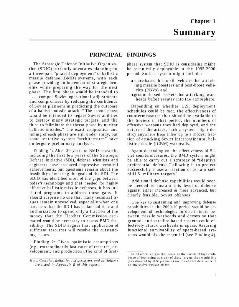
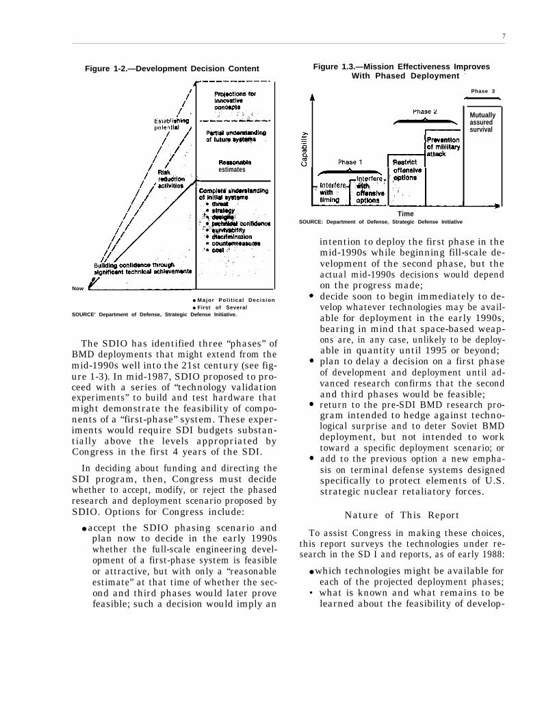
Figures 1-1 and 1-2 are SDIO graphic repre-sentations of its development and deploymentpolicies. Figure 1-1 illustrates that, as timegoes on, newer, more capable BMD systemswould be necessary to respond to advancedSoviet missile threats. Alternatively, it is ar-gued, the prospect of such new systems mightpersuade the Soviets to accept U.S. proposalsfor joint reductions of offensive forces whichmight, in turn, obviate the need for new systems.
Figure 1-2 lists the kinds of informationSDIO seeks to provide for BMD developmentdecisions. According to this figure, SDIO doesnot see “complete understanding” of later sys-tem phases as prerequisite to initial commit-ments to develop and deploy BMD. Instead,it proposes to seek a “partial understanding”of the issues surrounding the follow-on phaseand provide “reasonable estimates” that thenecessary systems could be available as needed.
SDIO has affirmed the so-called “Nitze cri-teria” as requirements for the BMD optionsit offers: that the defenses be militarily effec-tive, adequately survivable, and “cost-effec-tive” at the margin, that is, “able to maintaintheir defensive capabilities more easily thancountermeasures could be taken to try to de-feat them.’”
5SDIOop. cit., footnote 2, p. IV-3,
Figure 1-1.—The Path to“Thoroughly Reliable” Defenses
Time
SOURCE: Department of Defense, Strategic Defense Initiative.
— —.
7
Now
Figure 1-2.—Development Decision Content
estimates
● Major Pol i t ica l Decis ion● First of Several
SOURCE’ Department of Defense, Strategic Defense Initiative.
The SDIO has identified three “phases” ofBMD deployments that might extend from themid-1990s well into the 21st century (see fig-ure 1-3). In mid-1987, SDIO proposed to pro-ceed with a series of “technology validationexperiments” to build and test hardware thatmight demonstrate the feasibility of compo-nents of a “first-phase” system. These exper-iments would require SDI budgets substan-tially above the levels appropriated byCongress in the first 4 years of the SDI.
In deciding about funding and directing theSDI program, then, Congress must decidewhether to accept, modify, or reject the phasedresearch and deployment scenario proposed bySDIO. Options for Congress include:
● accept the SDIO phasing scenario andplan now to decide in the early 1990swhether the full-scale engineering devel-opment of a first-phase system is feasibleor attractive, but with only a “reasonableestimate” at that time of whether the sec-ond and third phases would later provefeasible; such a decision would imply an
Figure 1.3.—Mission Effectiveness ImprovesWith Phased Deployment -
Phase 3
Mutuallyassuredsurvival
TimeSOURCE: Department of Defense, Strategic Defense Initiative
intention to deploy the first phase in the
●
●
●
mid-1990s while beginning fill-scale de-velopment of the second phase, but theactual mid-1990s decisions would dependon the progress made;decide soon to begin immediately to de-velop whatever technologies may be avail-able for deployment in the early 1990s,bearing in mind that space-based weap-ons are, in any case, unlikely to be deploy-able in quantity until 1995 or beyond;plan to delay a decision on a first phaseof development and deployment until ad-vanced research confirms that the secondand third phases would be feasible;return to the pre-SDI BMD research pro-gram intended to hedge against techno-logical surprise and to deter Soviet BMDdeployment, but not intended to worktoward a specific deployment scenario; oradd to the previous option a new empha-sis on terminal defense systems designedspecifically to protect elements of U.S.strategic nuclear retaliatory forces.
Nature of This Report
To assist Congress in making these choices,this report surveys the technologies under re-search in the SD I and reports, as of early 1988:
● which technologies might be available foreach of the projected deployment phases;
• what is known and what remains to belearned about the feasibility of develop-

.
8
ing those technologies and manufactur-ing and deploying weapons based on them;
• what can now be said about how surviva-ble against enemy attack space-basedBMD systems themselves may be; and
● what can now be said about the feasibil-ity of producing the computer softwareof the requisite performance and depend-ability.
Most experts would agree that the techni-cal issues for BMD present severe challenges.Thus, in attempting to provide the above in-formation, this report identifies numerousdemanding technical problems. The technicalchallenges to the SDI have been variously in-terpreted:
●
●
●
From the point of view of SDI officialsand contractors, questions of feasibilityare challenges that the application of suffi-cient time and resources can overcome.They are working on most, if not all, theissues identified in this report.In another view, the obstacles to effectiveBMD are great, and may not be overcomefor several decades; nevertheless, the kindof research SDIO is sponsoring will havesome long-term military and economicbenefits for the United States whateverthe SDI outcome. In addition research onBMD is necessary to avoid technologicalsurprise and to hedge against Sovietbreakout from the Anti-Ballistic Missile(ABM) Treaty.From a third point of view, the obstaclesto accomplishment of the SDI’s ultimategoals are so complex and so great thatSDIO’s goals are simply implausible.Therefore, although the United Statesshould conduct some BMD research to
avoid technological surprise and to hedgeagainst Soviet break out from the ABMTreaty, research needed for other militaryor civilian purposes should be carried outunder other auspices.
OTA attempts in this report to present real-istically the available evidence about SDI fea-sibility. The reader must decide how optimis-tic or pessimistic the evidence should lead oneto be and which approach to BMD researchwould be best for the nation.
This summary organizes OTA’s findingsaround the kinds of system designs, or “ar-chitectures,” for the three phases that SDIOhas recently been studying and discussing. Itshould be recognized, however, that, except forthe first phase, these architectures are illus-trative, not definitive. They provide a meansof thinking about and understanding how vari-ous BMD technologies might be integratedinto working systems and in what timeframes.Only the first represents SDIO’s proposal foractual systems to develop and deploy.
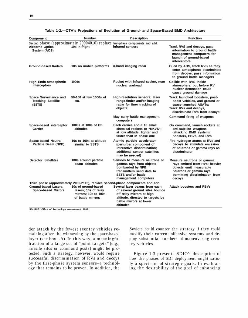
Table 1-1 outlines SDIO’s suggested firstphase of deployment; the timeframe 1995-2000is strictly an OTA assessment of a very op-timistic but arguably plausible period for thebeginning and completion of deployments ofthe various elements of the system phase. Ta-ble 1-2 outlines OTA’s projections of the sec-ond and third phases of BMD deployment,based on SDIO descriptions of the technologiesit is researching. The overlapping timeframes(2000-10 and 2005-15) reflect-OTAassessmentsof very optimistic but arguably plausibleperiods for the beginning and completion ofdeployments of the various elements of eachsystem phase.
FIRST-PHASE TECHNOLOGIES AND SYSTEMS(OTA Estimates Approximately 1995-2000)
Goals of a First-Phase System systems that the Nation might select in thelate 1980s for initial deployments in the early
In the fall of 1986 SDIO and its contractors 1990s. OTA estimates that as a practical mat-began to study options for “first-phase” de- ter—given the development, manufacturing,ployment of BMD. They attempted to design and space transportation needs—deployment

—
9
Table 1-1.—SDIO’s Phase One Space. and Ground-Based BMD Architecture
Component Number Description Function
First phase (approximately 1995-2000):Battle Management Variable
Computers
Boost Phase Several at high altitudeSurveillance andTracking Satellite
Space-based Interceptor 100s at several 100s ofCarrier Satellite km altitudes
Probe 10s
orSpace Surveillance and 10s
Tracking System
orSpace-based Interceptor
Carrier Satellites loos
Exe-atmospheric 1000s on ground-basedInterceptors (ERIS) rockets
May be carried on sensorplatforms, weapon platforms,or separate platforms; ground-based units may be mobile
Infrared sensors
Each would carry about 10 smallchemical rockets or “SBIs”;might carry sensors fortracking post-boost vehicles
Ground-launched rocket-borneinfrared sensors
Satellite-borne infrared sensors
Satellite-borne infrared sensorsRocket booster, hit-to-kill
warhead with infrared seeker
Coordinate track data; controldefense assets; selectstrategy; select targets;command firing of weapons
Detect ballistic or ASAT missilelaunches by observing hotrocket plumes; passinformation to trackingsatellites
On command, launch rockets atanti-satellite weapons(attacking BMD system),boosters, possibly PBVs.
Acquire RV tracks, pass on toERIS interceptors
Cued by satellite-borne orrocket-borne infrared sensors,home in on and collide withRVs in late mid-course
SOURCE: Off Ice of Technology Assessment, 1988
of the systems discussed could not begin un-til 1995 or later and would probably take atleast until the end of the 1990s to complete.
The first-phase options generally excludespace-based attack on Soviet reentry vehiclesin mid-course (see table l-l). While limiting theeffectiveness of a BMD system, this omissioneases the sensing, discrimination, and battlemanagement tasks.
Depending on the nature of the Soviet at-tack assumed, and depending on the effective-ness of Soviet countermeasures, the kind ofsystem described by SDIO officials systemmight destroy anywhere from a few up to amodest fraction of the (now predicted numberof) Soviet reentry vehicles in a full-scale attack.The SDIO has suggested such a system as onlythe first phase of what in the longer term wouldexpand to a more effective system. However,the organization cites as “an intermediate mil-itary purpose”
. . . denying the predictability of Soviet at-tack outcome and. . . imposing on the Sovietssignificant costs to restore their attack con-fidence. These first phases could severely re-strict Soviet attack timing by denying themcross-targeting flexibility, imposing launch-window constraints, and confounding weap-on-to-target assignments, particularly of theirhard-target kill capable weapons. Such re-sults could substantially enhance the deter-rence of Soviet aggression.6
SDIO officials assert that the military ef-fectiveness of the first-phase system would behigher than indicated by the percentages ofreentry vehicles intercepted. They envisage astrategy of “adaptive preferential defense. ” Inthis strategy, first the space-based layer of de-fense disrupts the structure of the Soviet at-tack. Then the ground-based layer defends onlythose U.S. targets of the highest value and un-
‘Ibid., footnote 2, p. 11-11.
10
Table 1-2.—OTA’s Projections of Evolution of Ground- and Space-Based BMD Architecture
Component Number Description Function
Second phase (approximately 20004010) replace first-phase components and add:Airborne Optical
. . . .
System (AOS)10s in fright Infrared sensors
Ground-based Radars
High Endo-atmosphericInterceptors
Space Surveillance andTracking Satellite(SSTS)
Space-based interceptorCarrier
Space-based NeutralParticle Beam (NPB)
Detector Satellites
10s on mobile platforms
1000s
50-100 at few 1000s ofkm.
1000s at 100s of kmaltitudes
10s to 100s at aititudesimiiar to SSTS
100s around particlebeam altitudes
X-band imaging radar
Rocket with infrared seeker, nomnuclear warhead
High-resolution sensors; laserrange-finder and/or imagingradar for finer tracking ofobjects;
May carry battle managementcomputers
Each carries about 10 smallchemical rockets or “KKVS”;at low altitude; lighter andfaster than in phase one
Atomic particle accelerator(perturber component ofinteractive discrimination;additional sensor satellitesmay be needed)
Sensors to measure neutrons orgamma rays from objectsbombarded by NPB; -
transmitters send data toSSTS and/or battlemanagement computers
Third phase (approximately 2005-2115), replace second-phase components and add:Ground-based Lasers, 10s of ground-based Several laser beams from each
Space-based Mirrors lasers; 10s of relay of several ground sites bouncemirrors; 10s to 100s off relay mirrors at highof battle mirrors altitude, directed to targets by
battle mirrors at loweraltitudes
Track RVS and decoys, passinformation to ground battlemanagement computers forlaunch of ground-basedinterceptors
Cued by AOS, track RVS as theyenter atmosphere; discriminatefrom decoys, pass informationto ground battle managers
Collide with RVS insideatmosphere, but before RVnuclear detonation couldcause ground damage
Track launched boosters, post-boost vehicles, and ground orspace-launched ASATs;
Track RVs and decoys,discriminate RVs from decoys;
Command firing of weapons
On command, launch rockets atanti-satellite weapons(attacking BMD system),boosters, PBVs, and RVs
Fire hydrogen atoms at RVs anddecoys to stimulate emissionof neutrons or gamma rays asdiscriminator
Measure neutrons or gammarays emitted from RVs: heavierobjects emit measurableneutrons or gamma rays,permitting discrimination fromdecoys
Attack boosters and PBVs
SOURCE: Office of Technology Assessment, 1988.
der attack by the fewest reentry vehicles re-maining after the winnowing by the space-basedlayer (see box l-A). In this way, a meaningfulfraction of a large set of “point targets” (e.g.,missile silos or command posts) might be pro-tected. Such a strategy, however, would requiresuccessful discrimination of RVs and decoysby the first-phase system sensors–a technol-ogy that remains to be proven. In addition, the
Soviets could counter the strategy if they couldmodify their current offensive systems and de-ploy substantial numbers of maneuvering reen-try vehicles.
Figure 1-3 presents SDIO’s description ofhow the phases of SDI deployment might satis-fy a spectrum of strategic goals. In evaluat-ing the desirability of the goal of enhancing

—
11
Box l-A.—Adaptive Preferential DefenseThe SDIO has proposed that a first-phase ballistic missile defense system (see table l-l) employ a tactic
of “adaptive preferential defense. ” If successfully executed, this tactic could give an outnumbered defensesome leverage against a large attack.
“Preferential defense” means defending only a selected set of high-value targets out of a larger numberof targets under attack, thus concentrating the defensive forces. In essence, some targets would be sacrificedto increase the chances of survival of others.
“Adaptive preferential defense” means deciding during the course of the battle which targets to defendby adapting to the distribution of the attacking RVs (missile warheads) that survive earlier layers of defense.Of the high-value targets under attack, those with the fewest RVs coming at them are defended first.
Two Layers of DefenseA first-phase Strategic Defense System (SDS) would include orbiting interceptors and land-based intercep-
tors. The orbiting interceptors would first destroy a small fraction of the rising Soviet missile boosters andpost-boost vehicles. Since the SDS could not at this stage predict the targets of the Soviet missiles, the defensewould not be preferential: instead, it would merely subtract at random some warheads from the Soviet attack.Even if the Soviets had initially aimed the same number of RVs at each target, some would have been filteredsout by the first layer of defense.
Land-based rockets would carry other interceptors into space to destroy RVs that survived the space-basedattack. Tracking sensors would determine the targets of the RVs to within several kilometers. Battle manage-ment computers would determine which high-value targets were under attack by only one RV and launch ground-based interceptors against them first, until all were covered, Then the computers would determine which tar-gets were under attack by two RVs and assign interceptors to them, and so on. In this way, few interceptorswould be wasted defending targets that would later be destroyed anyway by additional, unintercepted RVs.
A Simple ExampleSuppose, for example, that 2000 RVs were attacking 1000 targets, with 1 RV aimed at each of 500 targets
and 3 RVs aimed at each of another 500 targets. Assume that the defense had only 1000 interceptors (eachwith a 100 percent chance of interception). If the defense assigned interceptors randomly to 1000 of the 2000attacking RVs, about 312 targets would be expected to survive (50 percent of those under single-RV attackand 12.5 percent of those under 3-RV attack). But if it assigned 500 interceptors to defend the targets undera single-RV attack, and then assigned 3 interceptors each to-defend the next-
might be saved.
The SDI CaseAnalysts for SDIO have concluded that a first-phase system applying
fraction of selected U.S. targets against the kind of attack the Soviets arein the mid-1990s.
Some Qualifying Considerations
166 targets, a total of 666 targets
this tactic could protect a usefulpredicted to be able to carry out
If feasible, an adaptive preferential defense would be suitable mainly for protecting fractions of redundant,single-aimpoint targets, such as missile silos, command posts, or other isolated military installations. Large-area, soft targets (such as cities or large military installations), would present so many potential aimpointsthat defending, say, a third or a half of the aimpoints in a given area would be unlikely to assure survivalof the that area. In addition, the aimpoints that could be defended would be small enough that the blast andfires from exploding nuclear weapons would affect neighboring “soft” target areas.
Serious questions also remain about whether SDIO’s proposed phase-one BMD system could, in fact, suc-cessfully execute a strategy of adaptive preferential defense. In particular, if the infrared sensors of the track-ing system could not discriminate between Soviet RVs and decoys, many of the ground-launched interceptorswould be wasted on decoys. And if the Soviets could deploy many maneuvering reentry vehicles during theoperational period of the first-phase defense system, the targets could not be accurately predicted and defended.
12
deterrence by forcing modification of Sovietattack plans, Congress should also be awareof the counter-arguments to that position:
●
●
●
●
Many believe that, given the awesomeconsequences of nuclear war for the So-viet Union as well as for the United States,deterrence does not require enhancementbecause the U.S. threat of nuclear retali-ation is already strong enough and can bekept so with timely strategic offensivemodernization.Soviet military planners already face oper-ational uncertainties, such as the unrelia-bility of some percentage of deployedmissiles.Other, less costly, more clearly feasible,methods of complicating Soviet attackplans, such as increased mobility for U.S.strategic forces, may be available.A corresponding Soviet deployment ofBMD would impose uncertainties andcosts on U.S. retaliatory attack plans.
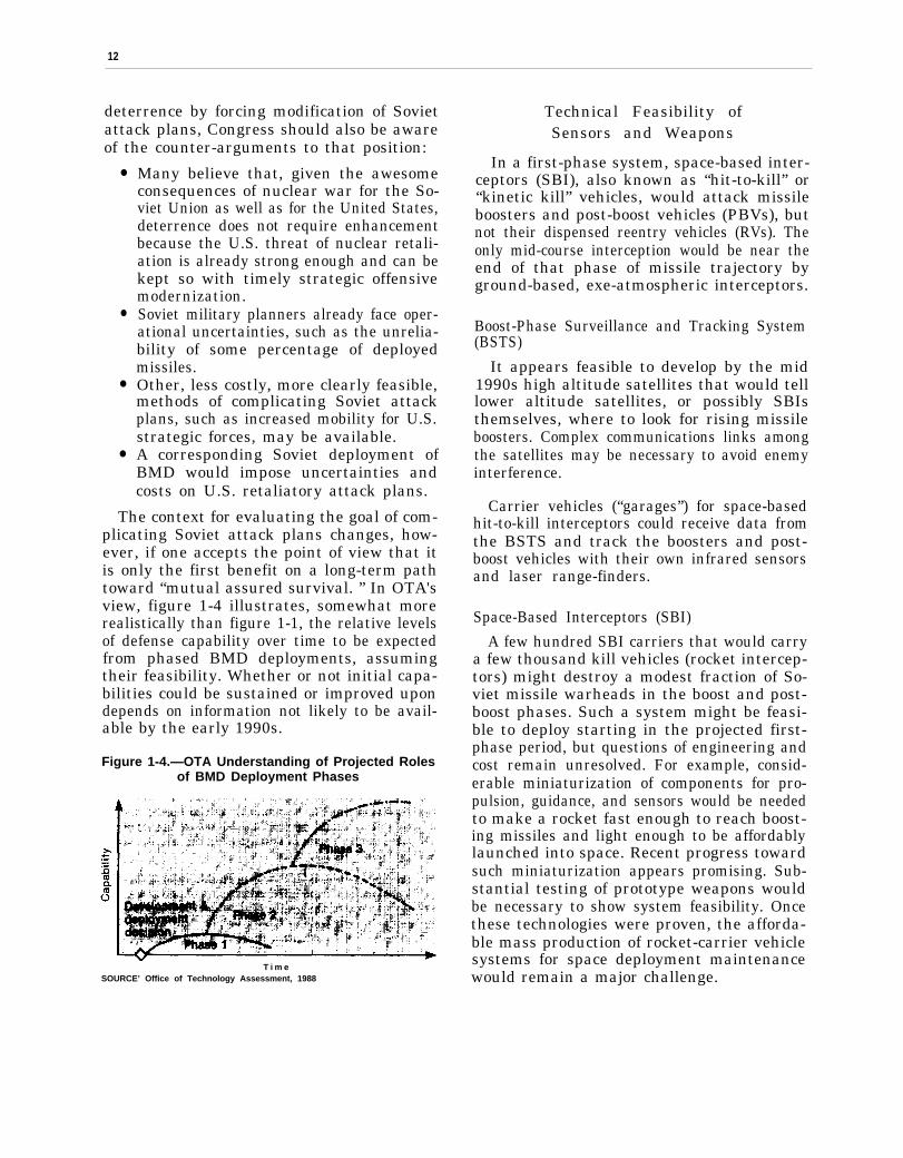
The context for evaluating the goal of com-plicating Soviet attack plans changes, how-ever, if one accepts the point of view that itis only the first benefit on a long-term pathtoward “mutual assured survival. ” In OTA'sview, figure 1-4 illustrates, somewhat morerealistically than figure 1-1, the relative levelsof defense capability over time to be expectedfrom phased BMD deployments, assumingtheir feasibility. Whether or not initial capa-bilities could be sustained or improved upondepends on information not likely to be avail-able by the early 1990s.
Figure 1-4.—OTA Understanding of Projected Rolesof BMD Deployment Phases
T i m eSOURCE’ Office of Technology Assessment, 1988
Technical Feasibility ofSensors and Weapons
In a first-phase system, space-based inter-ceptors (SBI), also known as “hit-to-kill” or“kinetic kill” vehicles, would attack missileboosters and post-boost vehicles (PBVs), butnot their dispensed reentry vehicles (RVs). Theonly mid-course interception would be near theend of that phase of missile trajectory byground-based, exe-atmospheric interceptors.
Boost-Phase Surveillance and Tracking System(BSTS)
It appears feasible to develop by the mid1990s high altitude satellites that would telllower altitude satellites, or possibly SBIsthemselves, where to look for rising missileboosters. Complex communications links amongthe satellites may be necessary to avoid enemyinterference.
Carrier vehicles (“garages”) for space-basedhit-to-kill interceptors could receive data fromthe BSTS and track the boosters and post-boost vehicles with their own infrared sensorsand laser range-finders.
Space-Based Interceptors (SBI)
A few hundred SBI carriers that would carrya few thousand kill vehicles (rocket intercep-tors) might destroy a modest fraction of So-viet missile warheads in the boost and post-boost phases. Such a system might be feasi-ble to deploy starting in the projected first-phase period, but questions of engineering andcost remain unresolved. For example, consid-erable miniaturization of components for pro-pulsion, guidance, and sensors would be neededto make a rocket fast enough to reach boost-ing missiles and light enough to be affordablylaunched into space. Recent progress towardsuch miniaturization appears promising. Sub-stantial testing of prototype weapons wouldbe necessary to show system feasibility. Oncethese technologies were proven, the afforda-ble mass production of rocket-carrier vehiclesystems for space deployment maintenancewould remain a major challenge.
.
13
Exe-atmospheric Reentry Interceptor System(ERIS)
The Homing Overlay Experiment of 1984and subsequent development work suggestthat it is feasible to design a ground-launchedinterceptor capable of homing in on objects inspace under favorable conditions. Such weap-ons could make up an Exe-atmospheric Re-entry Interceptor System, or ERIS. More re-search, testing, and engineering remain to bedone before the United States will know if theinterceptor homing warheads can be producedcheaply enough to be affordable in large num-bers. The ERIS, however, is likely to be deploy-able before space-based BMD interceptors.
Under study are both space-based and ground-launched infrared sensor systems and ground-based radars to direct ERIS interceptors tothe vicinity of their targets. Both the satelliteand ground-based systems remain to be devel-oped, tested, and affordably produced. Up-graded versions of now existing ground-basedradars might also provide initial tracking in-formation to the interceptors.
In this first-phase architecture, the ERISwould rely on radars or on passive infrareddetection and tracking of potential targets.Whether or not these sensors could adequatelydiscriminate between decoys and RVs dis-guised as decoys remains to be demonstrated.Without such discrimination, decoys couldprobably cause serious problems for this latemid-course layer of defense. Developing a decoysystem like this is within Soviet capabilities.Even with good discrimination by external sen-sors, the homing sensor on the interceptor it-self would need to find the genuine RV if itwere traveling within tens of meters of other,closely spaced objects. In general, many sci-entists and engineers working on the SDI haveagreed that such countermeasures may wellbe feasible for the Soviets in the near term.However, both within and outside SDIO thereis some dissent on the potential type, quality,number, and deployment times of Soviet coun-termeasures.
There is widespread agreement that muchmore experimentation is needed on missile
“penetration aids” such as decoys. Very littleSDI money has gone to the design, construc-tion, and testing of penetration aids, althougha full understanding of their potential and limi-tations would be key to developing and evalu-ating the effectiveness of a BMD system.
Besides decoys, ERIS interceptors couldface many other false targets, particularlythose generated by debris from PBV activity,from intercepts made earlier in the boost phaseby the SBIs, or from deliberate Soviet coun-termeasures. Warm objects in the field of viewof the ERIS interceptor’s sensors might dis-tract it from its target RV, even if it had origi-nally been correctly pointed toward the RV bya probe or Space Surveillance and TrackingSystem (SSTS) sensor.
Software Feasibility
In the first-phase system designs now un-der consideration for SDI, hundreds of satel-lites would have to operate automatically and,at the same time, coordinate their actions withthose of other satellites. The battle manage-ment system would have to track hundreds ofthousands of objects and decide when and howto attack thousands of targets with little orno human intervention.
Among the most challenging software tasksfor such a first-phase system would be design-ing programs for the largely autonomous oper-ation of hundreds of satellites. But even forground-based components of the system, thenumber of objects, the volume of space, andthe brevity of time would preclude most hu-man participation in battle management. Hu-mans would decide at what alert status andstate of activation to place the system. Oncethe battle began, computers would decidewhich weapons to use when, and against whattargets.
A first-phase system would have the advan-tage of a simpler battle management problemthan that of more advanced BMD systems. Inparticular, the space-based segment of the sys-tem would not attempt to track and discrim-inate among hundreds of thousands of mid-
14
course objects, or to assign weapons to anyof them. The distribution of SBI carrier vehi-cles would be so sparse that the targets withinits range would not be in the range of neigh-boring carrier vehicles. It could, for the mostpart, safely shoot at a target within its ownrange without the risk that some other vehi-cle had shot at the same target. Some coordi-nation among carrier vehicles would still benecessary because the continual relative mo-tion of carriers and targets would leave someambiguities about which targets were mostappropriate for each carrier to fire interceptorsat.
Although a first-phase system would havesimpler tasks than a later system, its softwarewould still be extremely complex. The natureof software and experience with large, complexsoftware systems, including weapon systems,together indicate that there would always beirresolvable questions about how dependableBMD software was, and also about the confi-dence we could place in dependability esti-mates. Existing large, complex software sys-tems, such as the U.S. long-distance telephonesystem, have become highly dependable onlyafter extensive operational use and modifi-cation.
Extrapolating from past experience withsoftware, it appears to OTA that the complex-ity of BMD, the uncertainty and changeabil-ity of the requirements it must meet, and thenovelty of the technology it must control wouldimpose a significant probability of software-induced catastrophic failure in the system’sfirst real battle. The issue for SDI is the de-gree of confidence in the system that simula-tions and partial testing could provide. SDIOofficials argue that such tests will permit ade-quate confidence and that this issue is no moreserious for the SDI than for all advanced mili-tary systems developed to date.
Computer simulations would play a key rolein all phases of a BMD system’s life cycle. Bat-tle simulations on a scale needed to representrealistically a full battle have not yet been at-tempted. Whether or not sufficiently realisticsimulations can be created is a hotly debated
question. In particular, it is difficult for OTAto see how real-world data could be gatheredto validate simulations of the phenomena thatmust be accounted for, such as multiple enemymissile launches, nuclear explosion-inducedbackgrounds, and enemy choices of counter-measures. The differences between BMD soft-ware and previous complex software that isconsidered dependable suggests to some ex-perts that BMD software might never be ableto pass even its peacetime tests. It should alsobe noted, however, that both the United Statesand the Soviet Union now base deterrence onan offensive nuclear delivery system that hasnever been operationally tested either.
While the United States could not be cer-tain that a BMD system would work as in-tended, the Soviets could not be certain thatit would not.7 If they had at least some reasonto believe the U.S. BMD system might be ef-fective, they might be more deterred from at-tacking than before. On the other hand, theUnited States would not want to base a majorchange in its nuclear strategy on a BMD sys-tem in which it had little confidence. In thecase of a first-phase system, whose effect onthe strategic balance would be small anyway,the risk of software-induced system failuremight seem acceptable.
The SDIO sees software problems as chal-lenges to be overcome rather than as insur-mountable obstacles to effective BMD. It issupporting some software research intendedto address the challenges. Others argue thatthe limitations of software engineering tech-nology and its relatively slow rate of improve-ment make it unlikely that dependable BMDsoftware could be produced in the foreseeablefuture. Thus far, no new software engineeringdevelopments have appeared to contradict thelatter view.
Survivability of a First-Phase System
The survivability of any BMD system willnot be an all-or-nothing quality. The question
7Unless they had high confidence in the potential effective-ness of a secretly deployed countermeasure (perhaps a softwarebug planted by a saboteur programmer).
15
will be whether enough of a system’s assetswould survive for it to carry out its mission.The issue would then turn on whether the de-fense could make attacking the BMD systemtoo costly for the offense, or whether the of-fense could make defending the BMD systemto costly for the defense. (On the other hand,if the United States and the Soviet Unionagreed to coordinate offensive weapon reduc-tions and defensive deployments, they mightdo much to ameliorate BMD survivabilityproblems.)
To protect satellites, the defense might em-ploy combinations of such techniques as eva-sive maneuver, tracking denial, mechanicalshielding, radiation hardening, electronic andoptical countermeasures, and shoot-back. Cate-gorical statements that these techniques willor will not make any BMD system adequatelyand affordable survivable are not credible.Judgments on specific cases would depend onthe details of entire offensive and defensive sys-tems and estimates of the techniques and tac-tics that the opponent would employ.
Space Mines
A space mine is a satellite that would trailanother satellite and explode lethally either oncommand or when itself attacked. Space minesmay or may not prove a viable threat to space-based BMD systems. Although nuclear spacemines would be a very stressing threat, muchmore analysis would be needed to clarify thequestion of the viability of space mines. Afterrepeated attempts to locate such analysiswithin the SDIO or among its contractors,OTA concludes that it has not yet been ade-quately performed.
Anti-Satellite Weapons (ASATs)
There is widespread agreement among ex-perts on Soviet military practices that the ini-tial Soviet response to U.S. BMD deploymentswould not be to try to develop and deploy sys-tems based on similar technology. They wouldinstead attempt a variety of less sophisticatedcountermeasures. These might include exten-sions of their current co-orbital, pellet-warheadanti-satellite weapon (A SAT), or else aground-
launched nuclear-armed ASAT (or “DANASAT,”for “Direct Ascent Nuclear Anti-satellite”weapon).
The susceptibility of a BMD satellite sys-tem to degradation by DANASAT attackwould depend on many complex factors, in-cluding:
● the maneuvering and decoying capabil-ities and the structural hardness of theBMD satellites;
● the precision and reaction time of Sovietspace surveillance satellites; and
● the speed, numbers, decoying capabilities,and warhead power of the DANASATs.
Depending on target hardness, the radius oflethality of a nuclear warhead could be so greatthat the ASATs might need only inertial guid-ance (they need not home in on or be externallyguided to the BMD asset). Thus they wouldnot be susceptible to electronic countermeas-ures against homing sensors or command guid-ance systems. It appears that, at practicallevels, maneuvering or radiation shielding oflow-altitude satellites would not suffice againstplausible numbers of rapidly ascending nuclearASATs.
There appears to be no technical reason whythe Soviets, by the mid-1990s, could not de-ploy DANASATs with multiple decoys amongthe nuclear warheads. Multiple decoys wouldlikely exhaust the ability of the defenders toshoot back at the attack—unless extremelyrapid discrimination of decoys and warheadswere possible. It would be difficult to denytracking of or to decoy near-earth satellites,especially large sensor platforms, if they weresubjected to long periods of surveillance. If de-ployed while the satellites were under attack,satellite decoys would frequently not have timeto lure DANASATs far enough away from thereal targets.
If several SSTS satellites were a key elementof a first-phase BMD system, they would bethe most vulnerable elements. Otherwise, themost vulnerable elements of a first-phase BMDsystem would be the carrier vehicle satellitesfor the interceptors. The carrier vehicles, orCVs, as well as sensor satellites (BSTS and

— — —.—
16
SSTS) might employ combinations of variousdefense mechanisms against the ASAT threat.The SDIO argues that such combinations ofmeasures potentially offer a high degree of sur-vivability to space-based BMD system com-ponents.
For the near-term, however, no prototypesexist for carrier vehicles with these character-istics; the issue for SDI is whether in the 1990ssuch satellites could be developed, produced,and deployed. The Soviets, on the other hand,have already demonstrated the ability to fieldDANASATs by deploying rapidly accelerat-ing, nuclear-armed anti-ballistic missiles nearMoscow over 15 years ago and recently up-grading that system. Newer ballistic missiles,relying on mature technology, might also beadapted to this purpose. More advancedDANASATs appear feasible for the Sovietsby the mid-1990s.
DANASATs would be a stressing threatagainst first-phase BMD systems and couldprobably degrade severely the performance ofsuch systems. The SDIO argues, however, thatstrong survivability measures in the defensivesystem could successfully counter this threat.
The Soviets might also consider gradual at-trition of the system in “peacetime.” Theymight use co-orbital, non-nuclear ASATs orground-based laser ASAT weapons to take“potshots” at the carrier vehicles.
Attack During Deployment
Should the Soviets deem U.S. space-basedBMD deployments to be sufficiently threat-ening to their national security, they might re-sort to attack before the system was fully de-ployed. Whether they waited for full deploymentor not, in the first-phase architecture SBI car-rier vehicles would be so sparse that they wouldprobably have only limited abilities to help de-fend one another, although each might to someextent defend itself. Other survivability meas-ures, however, might offer some protection.
Attacks on Ground-Launched Systems
Insofar as the ERIS ground-launched inter-ceptor relied on fixed, ground-based early warn-ing radars for launch-commit information, itseffectiveness could be greatly reduced by nu-clear or jamming attacks on those radars.
Use of Comparable Technologies
Responses to threats from comparable So-viet weapon systems have not been defined bythe SDIO or its contractors. Indeed, a work-ing assumption of SDIO research and analy-sis has been that the United States could andwould maintain a consistent lead over the So-viet Union in BMD technologies for the indefi-nite future. Because the Soviets lag in someof the technologies required for a space-basedBMD system, it seems unlikely that theywould attempt to deploy SBIS for BMD in the1990s. A more attractive option for them mightbe to deploy kinetic-kill vehicles as a defensesuppression system rather than as a BMDsystem—a less difficult task.
They could then choose orbital configura-tions designed to give their weapons temporarylocal numerical advantages over the U.S. BMDsystem. In a shoot-out between the systems,at a time of their choosing, the Soviets mightthen eliminate or exhaust those SBI carrier ve-hicles within range of a Soviet ICBM launchsalvo. Effective non-nuclear ASATs would,however, require good space surveillance ca-pabilities. If a BMD system were to cohabitspace with a competent defense suppressionsystem (possibly embodying a lower technicalcapability), the side that struck first mighteliminate the other.
The fact that a lower level of technologywould be needed for defense suppression thanfor BMD could drive a race to control accessto space as soon as possible. For example, U.S.space-based ASATs might be needed to pre-vent Soviet ASAT deployments that could inturn interfere with U.S. BMD deployments.

SECOND-PHASE TECHNOLOGIES AND SYSTEMS(OTA Estimates Approximately 2000-10)
Goals
The goal of a phase-two system would be to“enhance deterrence, ” first by imposing un-certainty on Soviet strategic attack plans, thenby denying the Soviets the ability to destroy‘‘militarily significant portions of importantsets of targets (such as missile silos or com-mand and control nodes) in the United States.As a result, the Soviets would retain the abil-ity to inflict massive damage on the U.S. econ-omy and population, but would lack the abilityto accomplish certain precise military objec-tives. At least, such denial should decreasewhatever incentives may now exist for theSoviets to commit nuclear aggression (thoughanalysts disagree on whether such incentivesdo now exist); at best, the Soviets might beinduced to negotiate away their militarily ob-solescent missiles.
If the Soviets believed they could restoretheir compromised military capabilities at anacceptable price, they might attempt to do soby adding new offensive weapons and by at-tempting both active and passive countermeas-ures against the U.S. BMD system. Even ifthey did not believe they could recapture lostmilitary capabilities, but only believed thatthey were in danger of losing any credible nu-clear retaliatory power against the UnitedStates, they might still attempt to employBMD countermeasures. If, however, they con-cluded that countermeasures would be futile,they might, as conjectured in the “SDI sce-nario,” agree to mutual offensive arms reduc-tions as a way of containing the U.S. threat.In that case, BMD combined with effective airdefenses might offer much higher levels of pro-tection of military and even civilian targets.
Currently available BMD technology fornuclear-armed, ground-based interceptors wouldprobably allow the United States to build asystem that could deny the Soviets confidencein destroying substantial fractions of certain
sets of hardened or mobile targets.8 An SDI“phase-one,” non-nuclear system may also beable to provide such protection. This is morelikely to be the case if the defense could be con-figured to defend subsets of targets preferen-tially, and in such a way that the Soviets couldnot detect which targets were defended moreheavily. Moreover, if the Soviets continued toaim weapons at highly defended targets, theywould have fewer weapons left over to aim atsofter military and civilian targets.
There is less evidence that the United Statescould deny the Soviets the ability to strike withhigh confidence at many other kinds of militar-ily valuable, but more vulnerable, targets.There are, however, many ideas and somepromising technologies for pursuing this goal.
Achieving the strategic goals of this kindof system implies air defenses of comparablepotential. Otherwise, except for the most ur-gent targets, the Soviets could shift strategicmissions from ballistic to cruise missiles.
Technical Feasibility
Airborne Optical System (AOS)
An airborne infrared sensor system wouldtell ground-based radars where to look for re-entering objects. Such a system appears tech-nically feasible during the 1990s. The infraredsensors, however, might be subject to confu-sion by high-altitude light-scattering ice crys-tals created as debris reentered the atmos-phere, or by nuclear detonations intended toblind the system.
Ground-Based Radar (GBR)
Imaging radar systems would observe lighterdecoys slowing down more quickly than gen-
‘See U.S. Congress, Office of Technology Assessment, Bal-h%tic Missile Defense 7’echno]o@”es, OTA-ISC-254 (Washing-ton, DC: U.S. Government Printing Office, September 1985),pp. 33-34.
18
uine RVs.Computers using this informationwould launch very high acceleration rockets(HEDI) with infrared homing sensors towardthe RVs Tests to date indicate that such ra-dars are feasible, but unresolved questions in-clude their susceptibility to interference fromnuclear burst, to jamming by radio-frequencyjammers on incoming warheads, to signal-processing overloads created by many simul-taneously reentering objects, and to deceptionby carefully designed RV’s and decoys.
High Endo-atmospheric Interceptor (HEDI)
A rocket-borne high endo-atmospheric de-fense interceptor would attack incoming RVsafter they had begun to reenter the atmosphere.
Because the rising interceptor’s friction withthe atmosphere would cause it to heat up, acooled crystal window would have to protectits homing sensor. Experiments suggest thatsuch windows are feasible, although research-ers have not yet established whether they couldbe rapidly mass-produced.
Because the HEDI would have a limited “di-vert” capability, the sensor system would needto give it a very accurate target track. A rela-tively short-range ground-based radar, usingthe upper atmosphere as a discriminant againstdecoys, might be the easiest way to providesuch a track. This tracking method, however,would restrict each interceptor to protectinga relatively small area. Intensive coverage ofall U.S. territory would demand too many thou-sands of missiles. Instead, the HEDI missionwould be to “mop up” small numbers of war-heads leaking through the earlier defensivelayers. Thus the most useful mission for HEDImight be to protect specific, localized targets,such as ICBM silos.
SDIO officials point out, however, that pas-sive infrared sensors or long-range radars maybe able to discriminate between RVs and de-coys in space. Then the High Endo-AtmosphericInterceptor could be committed earlier andthus defend a much larger area. Nevertheless,in order to avoid the impression of providinga defense designed primarily to protect hard-ened strategic targets, rather than U.S. terri-
tory in general, the SDIO elected to omit theHEDI and its associated sensors (AOS and aterminal imaging radar or TIR) from itsproposals for a first-phase BMD system.9 Tech-nically, however, initial deployments in the late1990s period appear plausible.
SSTS and RV/Decoy Discrimination
A phase-two system would add to the first-phase architecture dozens of space-based sen-sors that could accurately track thousands ofRVs and decoys from the moment of their de-ployment from the PBVs. Such sensors wouldrequire electro-optical focal planes of unprece-dented size, or high-resolution laser radarsystems, and considerable signal processingability.
It seems likely that, by the time a substan-tial U.S. BMD system could be in place, theSoviets could deploy many reentry vehicle de-coys and RVs disguised as decoys. Unlessthese RVs and decoys could be destroyed ontheir boosters and post-boost vehicles, somemeans of distinguishing between them wouldhave to be developed. Otherwise, the defense’sammunition would be quickly exhausted.
In the terminal, “endo-atmospheric” phaseof interception, the atmosphere might filter outall but the heaviest and most sophisticated de-coys. But too many reentering objects mightoverwhelm local defensive sensors and weap-ons. In sum, effective discrimination in themid-course of ballistic missile trajectorieswould be necessary to a highly effective BMDsystem.
One proposed technique for RV/decoy dis-crimination is a laser radar system that mightobserve the movements of RVs and decoys as,or after, they were dispensed from PBVs. Sub-tle differences in the behaviors of the less mas-sive decoys might give them away. Conceal-ing deployments off PBVs or other tacticsmight counter this technique, but much re-search both on decoy technologies and space-borne laser radars will be needed to judge thepotential of either.
‘Lt. General James Abrahamson, personal communication toOTA staff, July 7, 1987.
—
19
Various methods of passive and active dis-crimination have been suggested, includingmultiple wavelength infrared sensors, laser ra-dar, and microwave radar. But if the Sovietscould build sufficiently sophisticated decoys,differentiating decoys and RVs might be im-possible without some means of externally per-turbing all the objects being tracked and ob-serving differences in how they react to suchperturbations. This technique is known as “in-teractive discrimination. ”
So far there is no proven candidate systemfor the task of interactive discrimination. Theprogram receiving the most funding has beenthe neutral particle beam (NPB). In this con-cept, a space-based atomic accelerator wouldfire high-energy neutral hydrogen or deuteriumatoms at suspect objects. A sensor would thendetect the neutrons or gamma rays emittedfrom heavier objects struck by the hydrogenatoms. A hundred or more NPB platforms, andperhaps several hundred sensor satellites,would be needed for a complete system. It maybe more appropriate to consider such a sys-tem for a phase-three, rather than phase-two,BMD architecture.
A space test of a subscale NPB platform wasscheduled for the early 1990s, although recentbudget cutbacks have made the experiment’sstatus unclear. Key issues determining the fea-sibility of NPB systems will include cost, therapid and precise ability to point the beamsat thousands of objects in a few tens of min-utes, and the ability to gather and correlatethe return information.
Other interactive discrimination ideas in-clude, for example, space-based high energylasers that would “tap” target objects. Thegreater recoil of lightweight decoys would givethem away.
Kinetic Energy Weapons
Missile boosters that completed their boostphase in about 120 to 140 seconds—slightlyfaster than current modern ICBMs–wouldgreatly reduce the effectiveness of rocket-propelled SBIs in the boost phase. They couldstill intercept post-boost vehicles. However,
fast RV dispensing technologies could reducekill in the post-boost phase. On the other hand,if such countermeasures had forced the Sovietsto greatly reduce missile payloads, mid-coursediscrimination might become easier: then theSoviets could only afford to deploy fewer, lesssophisticated decoys. Improved SBIs, eventhough ineffective against boosters, could beuseful in the mid-course. They would requirelong-wave infrared sensors for homing in onsmall, cold RVs. Alternatively, laser designa-tors on sensor satellites might illuminate RVswith light that SBI sensors could see and track.
It seems likely that by roughly the periodprojected for the first phase ERIS (Exe-atmos-pheric Reentry Interceptor System) missilescould be refined to the specifications now en-visioned. Provided that the challenge of RV-decoy discrimination had been overcome, theywould begin to provide an important layer ofmissile defense. If the discrimination problemcould not be solved, ERIS interceptors wouldbe of doubtful utility. If it could be solved,ERIS effectiveness in phase two would bemuch greater than in phase one.
The question for HEDI in the phase-twoperiod is whether the Soviets could deploymany maneuvering reentry vehicles to evadethe system and sophisticated reentry decoysto deceive it. The more effective the earlierdefensive layers might be, the less the Sovietscould afford to use precious missile payloadweights on heavier RVs and decoys. However,numerous, even slightly, maneuvering reentryvehicles, especially with depressed missiletrajectories, could probably evade HEDIs un-less the interceptors were equipped with nu-clear warheads.
Software Feasibility
A phase-two BMD system such as envisagedhere would need to account for hundreds ofthousands (or more) of objects as they weredispensed into space. It would require a highlycomplex communications net for keeping trackof all BMD space assets, boosters, PBVs, RVs,decoys, and space debris, then assigning weap-ons to intercept the selected targets. Concepts,

20
but so far no genuine designs, exist for “parti-tioning” the battle space into local networksof sensors and weapons (taking into accountthat different combinations of satellites wouldbe constantly shifting in and out of given re-gions of space).
In terms of sheer computing power, con-tinued advances seem likely to provide theprocessing capacities needed for advancedBMD. The most difficult hardware engineer-ing task will be to combine the qualities of highcapacity and radiation hardness in space-qual-ified electronics.
A BMD designed for boost, post-boost, mid-course, and terminal battle is likely to be themost complex system ever constructed. InOTA’s judgment, there would be no precedentsfor estimating the likelihood of the BMD soft-ware system’s working dependably the firsttime it was used in a real battle. Moreover, noadequate models for the development, produc-tion, test, and maintenance of software on thescale needed currently exist. The system’s com-plexity, coupled with the need to automate theuse of technologies previously unused in bat-tle, might result in unforeseen problems dom-inating the software life cycle. For example,large, complex systems that undergo contin-uous change sometimes reach states where newchanges introduce errors at a greater rate thanthey remove errors.
A BMD system–as has been the case withother strategic nuclear systems—could betested only with computer simulations andsome piecemeal hardware exercises. Further-more, no existing systems must operate au-tonomously (without human intervention) inthe face of deliberate enemy attempts to de-stroy them.
Whether the risks of catastrophic BMD fail-ure resulting from the inevitable software er-rors in a system of this magnitude would beunacceptable is a policy decision, not a techni-cal one, that the President and the Congresswould ultimately have to make. They wouldhave to weigh those risks against the perceivedrisks and benefits of not building a BMD sys-tem but deploying national resources else-
where. As with a first-phase system, anotherconsideration would be the likelihood that theSoviets could not be confident that the BMDsystem would not work as advertised, and thatthey might be deterred from trying to find outby attacking. (On the other hand, if the Sovietsfound away to break into and tamper with thesoftware system without U.S. knowledge, theymight be confident that they could defeat it.)
Phase-Two Survivability
More advanced BMD systems would be de-signed and deployed with more advanced self-protection or survivability measures. Ground-launched, nuclear-armed ASATs (DANASATs)would continue to be a threat. The additionalSBI carriers available after the year 2000, how-ever, could begin to provide mutual defensefor one another, which would not be possiblein the first-phase architecture.
By that time, on the other hand, the Sovietscould develop more advanced anti-satelliteweapons and space surveillance sensor sys-tems. Most BMD weapon technologies for usein space or against targets in space are likelyto achieve ASAT capabilities before they be-come applicable to BMD missions.
Direct-Ascent Nuclear ASATs
As with phase one, DANASATs would beparticularly threatening to a “phase-two” sys-tem. The U.S. Space Surveillance and Track-ing System and any associated interactive dis-crimination platforms would now be primarytargets for Soviet defense suppression attacks.Since many of these satellites would be athigher altitudes than the SBI garages, theywould have more time to maneuver away fromattackers. But they would also be heavier andtherefore more fuel-costly to maneuver. Theywould be more difficult to shield against nu-clear radiation.
Space Mines
The United States would have to considerthe possibility of Soviet attempts to co-orbitnuclear or non-nuclear space mines with these
— —
21
platforms as they were being deployed. Such“mining” might be carried concurrently withthe deployment of the BMD system assets.System designers have proposed “keep-out”zones to keep potential attacking weapons out-side their lethal ranges. Whether the UnitedStates (or any power) could achieve this kindof dominance of near-earth space remains tobe seen. In any case, very little analysis hasas yet been carried out by the SDIO or its con-tractors on interim and long-term space-basedthreats to BMD systems.
Comparable Technologies
If the Soviets could develop technologiescomparable to those of the United States, three
might be of special concern. One would be ad-vanced space-based surveillance systems per-mitting better-timed, more accurate ASAT at-tacks. Second would be the development ofspace-based neutral particle beam weapons,which could be very effective anti-satelliteweapons from great range. Third, even thoughlaser weapons might not have achieved thepower levels necessary for the BMD missions,laser ASATs could begin to pose substantialthreats to U.S. space assets. If only for self-defense, the United States might have to con-sider deploying directed-energy ASATs in thephase-two architecture period.
THIRD-PHASE TECHNOLOGIES AND SYSTEMS(OTA Estimates Approximately 2005-15)
Goals
In the SDI scenario, the first goal of a phase-three BMD system would be to sustain the ca-pabilities of the second-phase system as moreadvanced Soviet countermeasures came online. Eventually, the system might achieve stillhigher levels of protection. As originally pre-sented by the Administration, the SD I was toidentify a path to the “assured survival” ofthe U.S. population against nuclear attack. Anintermediate step on this path would be to de-sign a BMD system that would make nuclearballistic missiles “impotent and obsolete.” Inthis scenario, the Soviets would then be con-fronted with the choice of negotiating awayobsolescent missiles or engaging in a costlydefensive-offensive arms race that wouldsooner or later leave their offensive missilesunable to penetrate U.S. or allied territory. Ei-ther way, in the end few or no nuclear ballisticmissiles could reach U.S. territory.10
As with a second-phase system, extremelyeffective air defenses would be an essentialcomplement to an extremely effective BMDsystem. And, as with earlier phases, deep re-ductions in offensive forces (by arms controlagreement) could increase the effectiveness ofthe system.
Technical Feasibility
Directed-Energy Weapons
Directed-energy weapons for boost-phase in-terception are still far in the future. It is un-likely that confidence in their feasibility couldbe established by the early 1990s even withrequested SDIO budgets. OTA judges that ex-perimental evidence of the feasibility of BMDdirected-energy weapons (DEW) is at least adecade away.11 It is extremely unlikely thatconfidence in DE W could be established in thenext several years, given continuation of theactual appropriation pattern.
‘OSDIO reports to Congress make no mention of “assured sur-vival, ” and cite as the ultimate objective of the SDI to “securea defense-dominated strategic environment in which the U.S.and its allies can deny to any aggressor the military utility ofballistic missile attack.” SDIO, op. cit., footnote2,p.II-11. OtherSDIO documents, however, do still refer to the goal of “mutu-ally assured survival” (see figure 1-3).
1“A similar conclusion was reached by a committee of theAmerican Physical Society in 1987. Science and Technology ofDirected Energy Weapons: Report of the American PhysicalSociety Study Group (April 1987), p. 2.
22
Ultimately however, directed-energy weap-ons may be necessary to intercept long-rangeballistic missiles and direct-ascent ASATweapons in the boost and post-boost phases.If the Soviets could, over 15 or 20 years, de-velop and begin to deploy very fast-burn, laser-hardened boosters with single (or few) war-heads (and associated decoys) and if they de-ployed those boosters at concentrated launchsites, the burden even on directed-energy weap-ons would be great. In that case, the time avail-able for attacking each booster might be soshort as to drive very high the requirementsfor power levels, retargeting speed, and num-bers of directed-energy weapons. (However,PBVs would continue to be vulnerable toDEWs.)
Fast-burning Soviet boosters appear tech-nically plausible—the main issue would be cost.The Soviets would have to deploy enough ofthese boosters to continue to deliver hundredsof thousands of RV decoys into the mid-course,and they would have to be aware that, for ex-ample, if U.S. DEWs achieved significant im-provements in retargeting time, they mightneutralize a good fraction of the Soviets’ ex-pensive fast-burning fleet.
Although some work has continued on chem-ical lasers, and proposed future budgets wouldincrease the share going to them, most SDIlaser funding in 1987 went to the free electronlaser (FEL). The most likely way to deploy suchlasers would be on the ground, with orbitingrelay and battle mirrors to focus laser beamson Soviet boosters and PBVs. Scientists havemade significant progress in FEL research, butthey are a long way from having establishedthe feasibility of a weapon. The SDIO hassponsored construction of laboratory versionsof FELs and plans a major test facility atWhite Sands Missile Range. Among the out-standing issues to be studied with these ex-perimental lasers are whether FELs can bemade bright enough at useful wavelengths andthe feasibility of optical techniques for success-fully passing very high energy laser beams outof and back into the atmosphere. Other out-standing issues include: whether large, agilebeam directing optics can be affordably man-
ufactured and reliably based in space; the costof building and maintaining several large la-ser ground station complexes; and the surviv-ability of space mirrors and ground stationsagainst defense suppression attacks.
Other directed-energy concepts are underconsideration. Neutral particle beams (NPBs),which do not penetrate the atmosphere, mightengage those missile boosters and PBVs thatoperated above about 120 kilometers. Ad-vanced booster and warhead dispensing tech-nologies, however, might evade NPBs. (Unlikemost lasers, however, NPBs could penetrateand destroy reentry vehicles in the mid-course.)Another directed-energy weapon may be thenuclear-explosion pumped x-ray laser, whichalso could not penetrate far into the atmos-phere. For various reasons, the x-ray laserappears more promising as an anti-satelliteweapon than as an anti-missile weapon.
Software Feasibility
If an interactive discrimination system wereadded in the phase-two architecture, the phase-three architecture would not pose significantlydifferent software challenges and prospectsfrom the second phase. The very fine pointingand tracking needed for laser weapons couldimpose significant additional computing re-quirements on sensors.
As time went on, Soviet defense suppressionthreats-weapons aimed at the BMD systemitself-could grow more intense. The additionalburdens of self-defense for the BMD systemagainst advanced ASAT threats would add tothe complexity of software requirements. Thechallenges to producing dependable softwarecited above would persist in phase three.
Phase-Three Survivability
If large directed-energy weapon platformswere deployed in space (whether these were la-ser generators with beam directors or only re-lay and battle mirrors for ground-based lasers),they would themselves become prime high-value targets for defense suppression attacks.Unless they were powerful enough to be de-

23
ployed at rather high altitudes, they wouldhave a difficult time either denying trackingto enemy sensors or maneuvering out of theway of attacks. They would probably have todefend themselves (and one another) as wellas depend on “escort” interceptors. Third-phase directed-energy weapons systems couldbe survivable against the current or first-phaseSoviet DANASAT threat; the question is,would they be survivable against a laterDANASAT threat that might be in place bythe time the directed-energy weapons were de-ployed?
Directed-Energy ASATs
Long before directed-energy weapons suchas lasers or particle beams achieve the capa-bilities they would need as BMD weapons, theycould be effective anti-satellite weapons. Anti-satellite laser weapons, if placed in space be-fore more capable BMD laser weapons, mightsuccessfully attack the latter as they were be-ing deployed.
In some cases, such as the nuclear bomb-pumped x-ray laser, the most likely applica-tion of an advanced directed-energy weaponwould be as an ASAT. What little analysis hasbeen done so far indicates that x-ray laserASATs launched from the ground to fire fromthe upper atmosphere would be difficult, if notimpossible, to counter. However, the feasibil-
ity of x-ray laser weapons remains to be dem-onstrated.
Soviet Possession of Comparable Technologies
As one attempts to project various combi-nations of survivability techniques and vari-ous modes of anti-satellite attack into the farterm, the situation becomes even hazier. Itdoes appear that two DEW ballistic missiledefense systems occupying space could poserisks of crisis instability. The side that struckfirst in a simultaneous attack on all the other’sDEWS might seize an advantage. Much woulddepend on each side’s tactics and its abilityto jam, spoof, or disable the sensors on theother side. At best, each side might neutralizethe other’s BMD system, leaving both defense-less but with nuclear retaliatory capabilities(as is the case today). At worst, the side strik-ing first might unilaterally neutralize theother’s BMD (and other military space assets),leaving him open to nuclear blackmail. Mutualfears of this possibility might lead to crisis in-stability.
On the other hand, if the two sides could de-fine precisely balanced deployments and rulesfor ensuring the mutual survivability of theirsystems, and then arrive at verifiable armscontrol agreements providing for them, theymight avoid such instability.
IMPORTANT GENERAL ISSUESc o s t s
Some experts in space systems argue thatthe major cost driver of space-based BMDwould be the manufacture of hundreds or thou-sands of novel, yet highly reliable, spacecraft.The SDIO suggests that its research into newproduction techniques would result in substan-tially reduced costs. Until such techniqueshave actually been demonstrated in practice,this suggestion will be difficult to verify.
In any case, space transportation cost wouldbe a major challenge. The SDIO has spoken
of ultimately requiring launch operating costsone-tenth those existing today (not countingthe costs for development of such a system).For the nearer term (late 1990s) the goal ap-pears to be a threefold operating cost reduc-tion. For the very near term, planners are be-ing told to design systems that could evolveinto less costly ones, but there is little expec-tation of immediate first-phase savings.
Components today are conceptual, so relia-ble cost estimates are not possible. Efforts toimprove “producibility” and operations costsfor SBIs, ERIS, and HEDI are also conceptual.
24
System architects’ estimates put the costsof designs comparable to the second-phase ar-chitecture in the low hundreds of billions ofdollars. Given that the United States wouldhave to engineer, build, and deploy entirely newclasses of space systems, cost estimates todayare shaky at best. For any given component,unanticipated difficulties might increase costs,or technical breakthroughs might decreasecosts. The SDIO has produced a rough esti-mate for the cost of a phase-one system: $75billion to $150 billion.
Phase-three architectures are now so looselydefined and understood that few if any con-tractor cost estimates exist.
Nobody now knows how to calculate, letalone demonstrate to the Soviets, the cost-exchange ratio between offense and defense.Detailed defensive system designs and athoroughly researched understanding of po-tential offensive countermeasures may help.But unless the ratio appears obviously to bemuch greater than one-to-one, it will be ex-tremely difficult to determine whether the cri-terion of “cost-effectiveness at the margin”has been met by any proposed BMD system.At least in the first phase, it appears that theSoviets would have a strong incentive to addmissiles, warheads, and countermeasures to at-tempt to restore their strategic nuclear capa-bilities. The question would be whether theSoviets were persuaded that in the long runthe defense system would evolve into one thatcost less per Soviet RV destroyed.12
Timing and Evolution
The Strategic Defense Initiative Organiza-tion (SDIO) has not pursued the SDI as anopen-ended research program to be concludedonly when a certain level of knowledge was at-tained. Instead, the research has been stronglyoriented toward trying to provide the basis for
‘%s discussion does not address whether the Soviets wouldaccept the costiexchange ratio criterion for their own decisionsor whether they might simply do their best at improving theiroffense and hope the United States might not follow the ensu-ing offensive-defensive arms race through to its expensive con-clusion.
an ‘informed decision” on BMD full-scale engi-neering development by the early 1990s (theexact year, although it appears widely in thepress, is classified). Nevertheless, implied inthe SDI program was that whatever informa-tion might be available by the early 1990s,proposals for deployment would be offered.
Congress, however, has not funded the SDIat the level that the SDIO asserted was nec-essary to permit an informed decision aboutsuch proposals by the early 1990s. Nevertheless,by cutting back parallel technology programsand longer-term research while preserving pro-grams believed to have near-term promise, theSDIO has attempted to maintain the goal ofmaking detailed deployment proposals by only1 year later than the appointed date.
In late 1986 and in 1987 the SDIO begandeveloping the “phase-one” BMD system ar-chitecture described above. In its 1987 annualreport to Congress, the SDIO said that itsstudy of the first phase of a phased deploy-ment”. . . does not constitute a decision to de-ploy. Such a decision cannot be made now.”13
OTA concurs. First, the required space trans-portation system is unlikely to be available forearly 1990s deployment. Second, the reduc-tions in SBI weights essential to deploying sig-nificant numbers of effective weapons are notyet available. Third, the U.S. aerospace indus-try would have to engineer, mass produce, anddeploy entire new classes of satellite systems.Fourth, cost estimates for all these steps todayare shaky at best. The SDIO does argue thatthe first-phase option would lay the ground-work for the deployment of subsequent phases.This could be true if the subsequent phaseswere in fact known to be feasible, affordable,survivable, and cost-effective at the margin—and if the first-phase system retained some ca-pability against a responsive Soviet threat.
Every part of the complex development, pro-duction, and deployment scheme would haveto work well and on schedule. Otherwise, theSoviets could be well on the way to neutraliz-ing the first-phase architecture before it was
13SDIO, op. cit., foot note 2, p. 11-10.
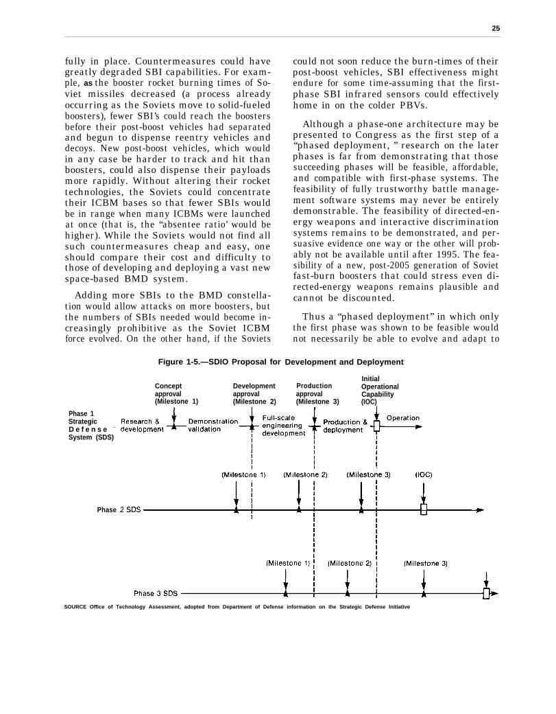
.
25
fully in place. Countermeasures could havegreatly degraded SBI capabilities. For exam-ple, as the booster rocket burning times of So-viet missiles decreased (a process alreadyoccurring as the Soviets move to solid-fueledboosters), fewer SBI’s could reach the boostersbefore their post-boost vehicles had separatedand begun to dispense reentry vehicles anddecoys. New post-boost vehicles, which wouldin any case be harder to track and hit thanboosters, could also dispense their payloadsmore rapidly. Without altering their rockettechnologies, the Soviets could concentratetheir ICBM bases so that fewer SBIs wouldbe in range when many ICBMs were launchedat once (that is, the “absentee ratio’ would behigher). While the Soviets would not find allsuch countermeasures cheap and easy, oneshould compare their cost and difficulty tothose of developing and deploying a vast newspace-based BMD system.
Adding more SBIs to the BMD constella-tion would allow attacks on more boosters, butthe numbers of SBIs needed would become in-creasingly prohibitive as the Soviet ICBMforce evolved. On the other hand, if the Soviets
Figure 1-5.—SDIO Proposal for
Concept Developmentapproval approval(Milestone 1) (Milestone 2)
Phase 1StrategicD e f e n s e —
System (SDS)
Phase
could not soon reduce the burn-times of theirpost-boost vehicles, SBI effectiveness mightendure for some time-assuming that the first-phase SBI infrared sensors could effectivelyhome in on the colder PBVs.
Although a phase-one architecture may bepresented to Congress as the first step of a“phased deployment, ” research on the laterphases is far from demonstrating that thosesucceeding phases will be feasible, affordable,and compatible with first-phase systems. Thefeasibility of fully trustworthy battle manage-ment software systems may never be entirelydemonstrable. The feasibility of directed-en-ergy weapons and interactive discriminationsystems remains to be demonstrated, and per-suasive evidence one way or the other will prob-ably not be available until after 1995. The fea-sibility of a new, post-2005 generation of Sovietfast-burn boosters that could stress even di-rected-energy weapons remains plausible andcannot be discounted.
Thus a “phased deployment” in which onlythe first phase was shown to be feasible wouldnot necessarily be able to evolve and adapt to
Development and Deployment
InitialProduction Operationalapproval Capability(Milestone 3) (IOC)
SOURCE Office of Technology Assessment, adopted from Department of Defense information on the Strategic Defense Initiative

26
a responsive Soviet threat. The SDIO plan callsfor completing “demonstration and validation”of phase-two concepts before actual produc-tion and deployment of phase one. Therefore,
● commitment in the early 1990s to a phase-one development would imply confidencethat phases two and three will ultimatelyprove feasible, and
● commitment in the mid-1990s to phase-onedeployment would require an act of faiththat phase three would prove feasible.
Otherwise, depending on how long deploy-ment actually took and how effective the So-viet response was, either the first- or second-phase systems could be reduced to only mod-est effectiveness or impotence even before de-ployment was completed.
SDIO officials and contractors have sur-mised that the technologies needed to main-tain and extend the defensive capabilities offirst- and second-phase systems into the far-ther term will in fact become available. If acontinuing, vigorous research and develop-ment program produced the necessary tech-nologies, and if Soviet offensive developmentscould not keep pace, the first-phase conceptmight evolve into a more advanced BMD sys-tem. If the Soviets responded to the SBI sys-tem by developing faster-burning PBVs thatcould carry only much reduced payloads, thenthe ultimate task of discriminating RVs anddecoys in the mid-course could be greatly sim-plified. (This conclusion assumes that theSoviets could not afford at the same time todouble the size of their missile fleet.) TheUnited States could add sophisticated SWTSsatellites and SBIs with improved sensors. IfSoviet decoys were few enough and simpleenough, the sensor satellites might be able totrack and discriminate RVs and decoys in mid-course, thus allowing improved hit-to-kill weap-ons to attack RVs individually after they weredispensed. Or, interactive discrimination tech-niques might turn out to make RV/decoy dis-crimination feasible.
OTA concludes that, if shown to be techni-cally feasible and desirable, second-phase sys-tem production and deployment could not be-
gin until around the year 2000 or be completedmuch before 2010. Soviet countermeasurescoming into deployment by then could includemore missiles, advanced RVs (possibly includ-ing maneuvering RVs or “MaRVs”) and de-coys, faster rocket boosters and post-boost ve-hicles, concentrated launch-sites for boosters,and advanced anti-satellite weapons. The util-ity of space-based SBIs for boost-phase inter-ception would then be severely limited. De-pending on whether and when the Sovietscould field faster-dispensing PBVs, the SBIsmight be of some utility for PBV interception.Overall system effectiveness, however, wouldprobably depend heavily on how well the mid-course discrimination challenge had been met.
If the Soviets developed high-payload, fast-dispensing PBVs, the United States mighthave to add laser weapons to the defense sys-tem to increase boost- and post-boost inter-cepts to reduce the mid-course discriminationburden. As is noted below, however, even thisstep might not suffice.
As of 1988, three uncertainties about the via-bility of a second-phase system especiallystand out:
1.
2.
3.
evidence demonstrating effective and af-fordable technology for discriminating So-viet nuclear warheads from decoys willprobably not be available before the mid-1990s, if then;a follow-on, directed-energy BMD systemwould be needed to restore or maintain de-fense effectiveness once faster-burningboosters were able to evade SBIs; butdirected-energy weapons for BMD mayormay not be technically feasible; such fea-sibility is very unlikely to have been de-termined by the early 1990s; if the Sovietswere able to field a few thousand very fast-burning boosters with one warhead andseveral decoys each, even directed-energyweapons might not suffice to maintain ahigh level of defense effectiveness;the survivability of a space-based systemitself against a defense suppression attackby Soviet weapons likely to be availableafter the year 2000 may not have been de-termined by the early 1990s.
27
Ballistic missile defense deployments of du-bious long-term effectiveness could stimulatethe Soviet Union to offensive countermeasuresand weapon deployments rather than to nego-tiations to reduce mutual offensive threats.
Competition in Anti-satellite Weapons
As noted above, the technologies applicablein exo-atmospheric weapons are, in most cases,liable to be applicable in ASAT weapons be-fore they are applicable in BMD. Thus therewill be pressures from the military establish-ments on both sides to field such weapons asthey become feasible, whether or not theyprove to have BMD potential. For example,the first mission for space-based SBIs maybeas defensive satellites, or DSATS, to protectthe BMD system as it is being deployed. Spacelasers may be attractive ASATs and DSATswhether they are adopted as BMD weaponsor not. Neutral particle beam discriminatorscould be powerful ASAT weapons. If the nu-clear-pumped x-ray laser can be developed asa weapon—which is far from proven—its mostpromising application may be as an ASAT. Nocredible answer to the x-ray laser as a BMDsuppression weapon has been developed.
As the United States or the Soviet Unionbegan to deploy substantial numbers of BMDweapons on the ground or in space, these weap-ons would greatly increase the anti-satellitethreat to the other’s space assets. (Space-basedweapons themselves would, of course, be amongthose space assets.) Neither side is liable to per-mit the other the kind of unilateral control ofspace that such unchallenged ASAT capabil-ities would provide. Therefore, in the absenceof arms control agreements to the contrary,we should expect from the beginning of BMDspace deployments an intense competition be-tween the superpowers for control of near-earthspace.
A frequently proposed survivability meas-ure for U.S. space-based BMD assets is the en-forcement of keep-out zones against any po-tentially threatening Soviet satellites. Whether,when, and how the Soviets might challengesuch assertions of U.S. exclusionary zones inspace has not been analyzed by those propos-ing this tactic. Indeed, the whole question ofthe mutual occupation of space by weaponsof comparable capability has not yet been ade-quately addressed by SDIO or its contractors.

Chapter 2
Introduction
CONTENTS
Organization of This Report . . . . . . . . . . . . . . . . . . . . . . . . . . . . . . . . . . . . . . . 31Chapter l: Summary . . . . . . . . . . . . . . . . . . . . . . . . . . . . . . . . . . . . . . . . . . . . 31Chapter 2: Introduction . . . . . . . . . . . . . . . . . . . . . . . . . . . . . . . . . . . . . . . . . 31Chapter 3: Designing a Ballistic Missile Defense (BMD) System:
Architecture and Trade-Off Studies . . . . . . . . . . . . . . . . . . . . . . . . . . . . . 31Chapter 4: Status and Prospects of Ballistic Missile Defense
Technologies, Part I: Sensors . . . . . . . . . . . . . . . . . . . . . . . . . . . . . . . . . . 31Chapter 5: Status and Prospects of Ballistic Missile Defense
Technologies, Part II: Weapons, Power, Communication, andSpace Transportation . . . . . . . . . . . . . . . . . . . . . . . . . . . . . . . . . . . . . . . . . 31
Chapter 6: System Development, Deployment, and Support . . . . . . . . . . . 32Chapter 7: System Integration and Battle Management . . . . . . . . . . . . . . 32Chapter 8: Computing Technology . . . . . . . . . . . . . . . . . . . . . . . . . . . . . . . . 32Chapter 9: Software . . . . . . . . . . . . . . . . . . . . . . . . . . . . . . . . . . . . . . . . . . . . 32Chapter 10: Nondestructive Countermeasures Against Ballistic
Missile Defense . . . . . . . . . . . . . . . . . . . . . . . . . . . . . . . . . . . . . . . . . . . . . . 32Chapter 11: Defense Suppression and System Survivability . . . . . . . . . . . 33Chapter 12: Defense Suppression Scenarios . . . . . . . . . . . . . . . . . . . . . . . . . 33
The Goals of the Strategic Defense Initiative. . . . . . . . . . . . . . . . . . . . . . . . 33Three Goals for Strategic Defense . . . . . . . . . . . . . . . . . . . . . . . . . . . . . . . . . . 33
Increase Attacker Uncertainty . . . . . . . . . . . . . . . . . . . . . . . . . . . . . . . . . . . 33Deny Military Objectives . . . . . . . . . . . . . . . . . . . . . . . . . . . . . . . . . . . . . . . . 34Assured Survival . . . . . . . . . . . . . . . . . . . . . . . . . . . . . . . . . . . . . . . . . . . . . . . 35The Soviet Ballistic Missile Threat . . . . . . . . . . . . . . . . . . . . . . . . . . . . . . . . 35Targets To Be Defended. . . . . . . . . . . . . . . . . . . . . . . . . . . . . . . . . . . . . . . . . 37The SDI Scenario . . . . . . . . . . . . . . . . . . . . . . . . . . . . . . . . . . . . . . . . . . . . . . 41Current SDI Goals . . . . . . . . . . . . . . . . . . . . . . . . . . . . . . . . . . . . . . . . . . . . . 42
The Criteria of Feasibility . . . . . . . . . . . . . . . . . . . . . . . . . . . . . . . . . . . . . . . . . 43Effectiveness . . . . . . . . . . . . . . . . . . . . . . . . . . . . . . . . . . . . . . . . . . . . . . . . . . 43Affordability . . . . . . . . . . . . . . . . . . . . . . . . . . . . . . . . . . . . . . . . . . . . . . . . . . 44Favorable Cost-Exchange Ratio . . . . . . . . . . . . . . . . . . . . . . . . . . . . . . . . . . 45Survivability . . . . . . . . . . . . . . . . . . . . . . . . . . . . . . . . . . . . . . . . . . . . . . . . . . 45
BoxBox Page
2-A. Potential Targets for a Soviet Nuclear Ballistic Missile Attack. . . . . . 38
FiguresFigure No. Page
2-1. Nuclear Forces-ICMBs . . . . . . . . . . . . . . . . . . . . . . . . . . . . . . . . . . . . . . . . 362-2. Modernization of Soviet ICBMs Warhead Mix . . . . . . . . . . . . . . . . . . . . 37
TableTable No. Page
2-1. Strategic Defense Initiative Scenario . . . . . . . . . . . . . . . . . . . . . . . . . . . . 42
Chapter 2
Introduction
ORGANIZATION
This report identifies questions to be an-swered before the technical feasibility ofachieving the goals set for the Strategic De-fense Initiative (SDI) can be determined. Thereport also offers a snapshot of how far re-searchers have come toward answering thesecritical questions and how much remainsunknown.
Chapter 1: Summary
Chapter 1 summarizes and explains the prin-cipal findings of this OTA study.
Chapter 2: Introduction
This introductory chapter devotes consid-erable attention to goals for the SDI, since thissubject continues to be a source of confusionand debate in the country. Various leaders inthe Administration and in Congress have atone time or another emphasized different goals,and which goals will ultimately prevail remainsuncertain. Clearly, some goals would be eas-ier to reach than others. This discussion doesnot include a critical analysis of the goals nordoes it attempt to resolve the debate aboutthem. Instead, this chapter tries to provide acontext for the issues of technical feasibility.
Chapter 3: Designing a Ballistic MissileDefense (BMD) System: Architecture
and Trade-off Studies
To assess the feasibility of a potential BMDsystem, the United States needs to know bothwhat the system’s elements and the systemas a whole might look like. To this end, theStrategic Defense Initiative Organization(SDIO) has awarded a series of contracts toseveral teams of defense companies to try todefine some candidate “system architectures”for BMD. Drawing on these studies, SDIO syn-Note: Complete definititions of acronyms and initialisms
are listed in Appendix B of this report.
OF THIS REPORT
thesized its own “reference architecture” tohelp SDI researchers understand the require-ments that the technologies being developedeventually must meet.
Late in 1986 and in the first half of 1987,system architecture analysis was in a state offlux as SDIO instructed its contractors to con-ceptualize the early stages of a BMD deploy-ment. In mid-1987, the SDIO proposed a first-phase architecture to the Defense AcquisitionBoard and in September the Secretary of De-fense approved a program of ‘demonstrationand validation” for this architecture. The proc-ess of evolving system architecture analysisand design is likely to continue throughout thelife of the program and into the period duringwhich defenses are actually deployed, if theyare. There should be continuing feedback be-tween system designers and technology devel-pers, balancing the desirable and the possible.This chapter introduces that process, discussesits importance, and describes where it has ledso far.
Chapter 4: Status and Prospects ofBallistic Missile Defense Technologies,
Part I: Sensors
Chapter 5: Status and Prospects ofBallistic Missile Defense Technologies,Part II: Weapons, Power, Communication,
and Space Transportation
These chapters are organized as referenceworks on several of the key technologies un-der research in the SDI program-describingthem, surveying the requirements they mustultimately meet, and reporting their status (in-cluding key unresolved issues) as of early 1988.The chapters also examine the requirementsfor combining those technologies into work-ing components of a BMD system, with em-phasis on the kinds of components needed forrecent SDIO “reference architecture” formu-
31
32
lations. Chapter 4 reviews technologies forfinding, tracking, and pointing weapons at mis-sile boosters, post-boost vehicles, and reentryvehicles and for discriminating between gen-uine targets and decoys. Chapter 5 reviews theweapon technologies for delivering lethal dosesof energy (kinetic or electromagnetic) to tar-gets. It also addresses the key technologies ofspace transportation, communication, andpower supplies for space assets.
Chapter 6: System Development,Deployment, and Support
If BMD is to play a role in U.S. nationalstrategy, the technologies described in the pre-vious chapters must be incorporated into work-ing weapon components. Those componentsmust be integrated into effective weapon sys-tems that are affordable, maintainable, andadaptable over time to possible adversary re-sponses. By focusing on some particularly chal-lenging issues, such as the development andengineering of a space-based space surveillancesystem and the logistics of space transporta-tion, chapter 6 attempts to give an apprecia-tion of the steps involved in these processes.
Chapter 7: System Integration andBattle Management
With variations on SDIO’s reference ar-chitecture for a BMD system as models, thischapter shows how the various components ofsuch a system would have to work togetherto intercept a ballistic missile attack in its sev-eral phases. The chapter attempts to give anappreciation of the complexities of integrat-ing BMD system components into a quicklyreacting system. It does so by presenting anoverview of the tasks a BMD system wouldhave to perform and examples of how it wouldperform them. It also exaxnines the conceptof BMD battle management and the roles ofhumans and computers in such a battle.
Chapter 8: Computing Technology
Computers would be crucial to any BMDsystem, from simulation testing of theoreti-
cal designs, through operation of most of thehardware, to management of the battle. Chap-ter 8 focuses on the roles of computers in BMDand on the computation capabilities needed tosatisfy SDI requirements. Computing technol-ogy encompasses both hardware and software.This chapter, however, emphasizes hardwarequestions while chapter 9 focuses on software.
Chapter 9: Software
The legislation mandating this study in-structed that it include an analysis of the fea-sibility of meeting SDI software requirements.Chapter 9 examines the question of whetherthe complex computer programs that BMDwill require could be made sufficiently depend-able. It analyzes the concepts of software trust-worthiness and reliability, as well as otherimportant software issues. It compares re-quirements and characteristics of BMD soft-ware to existing, trusted software systems.The chapter ends with conclusions about theprospects for producing trustworthy softwarefor the SDI.
NOTE: Chapters 10, 11, and 12 are now avail-able only the classified version of thisreport. The descriptions here are forreference.
Chapter 10: NondestructiveCountermeasures Against Ballistic
Missile Defense
Ballistic missile defense systems must be de-signed to cope with the kinds of countermeas-ures the Soviets might deploy against them.These include modified or new ballistic mis-siles, devices intended to make reentry vehi-cles harder to find or shoot at, and weaponsthat could attack the BMD system. This chap-ter examines the first two types of counter-measure, while chapter 11 describes the lat-ter, or “defense suppression” technologies andtheir counters. Estimates of physically possi-ble countermeasures must be refined by esti-mates of what is technically, economically, andstrategically feasible for the Soviet Union. Thechapter concludes with a review of the tech-

33
nologies that might provide responses to thepotential Soviet countermeasures.
Chapter 11: Defense Suppression andSystem Survivability
The legislation instructing OTA to carry outthis study placed special emphasis on the sur-vivability of an SDI-produced BMD systemin the face of an enemy attack on the systemitself. The chapter reviews the technologiesthat might be applied to defense suppression
and the technologies and tactics that mightcounter them.
Chapter 12: Defense SuppressionScenarios
In a variety of “scenarios,” chapter 12 iden-tifies the most stressing attack threats thatvarious BMD elements would be likely to faceand the methods a BMD system might use todefend itself, actively or passively.
THE GOALS OF THE STRATEGIC DEFENSE INITIATIVE
According to the Strategic Defense Initia-tive Organization in 1986:
The goal of the SD I is to conduct a programof vigorous research and technology develop-ment that may lead to strategic defense op-tions that would eliminate the threat posed byballistic missiles, and thereby:
● support a better basis for deterring ag-gression,
● strengthen strategic stability, and. increase the security of the United States
and its Allies.The SDI seeks, therefore, to provide the
technical knowledge required to support an in-formed decision in the early 1990s on whetheror not to develop and deploy a defense of theU.S. and its Allies against ballistic missiles.’
What does the phrase, “eliminate the threatposed by ballistic missiles, ” mean, and how
‘Strategic Defense Initiative Organization, Report to the Con-gress on the Strategic Defense Initiative, June 1986, p. IV-1.In its 1987 report, SDIO dropped “in the early 1990s” fromits goal; it also dropped the “not” from the phrase “whetheror not” in the above quotation.
might doing so enhance deterrence, stability,and security? Proponents of BMD have arguedthat increasing levels of defense could offer in-creasing benefits. Fairly modest levels ofBMD, they say, might improve deterrence ofa Soviet nuclear attack by increasing Sovietmilitary planners’ uncertainty about the effec-tiveness of such an attack. Higher levels of de-fense capability might actually deny theSoviets even the possibility of achieving what-ever military goals they might have for attack.Finally, extremely good defenses against alltypes of nuclear attack–including attacks byballistic missiles, cruise missiles, bombers, andother means of delivery-might essentially as-sure the survival of the U.S. population andsociety no matter what the Soviets tried to do.Then U.S. security would no longer rely on thethreat of retaliation to deter a nuclear attack.
SDIO officials emphasize that currently thepreponderance of their attention is focused onsystems and technologies intended to lead toearly accomplishment of the first goal of en-hancing deterrence.
THREE GOALS FOR STRATEGIC DEFENSE
Increase Attacker Uncertainty tended targets, Soviet military planners canWorking with assumptions about the ac- make some predictions about Soviet ability to
curacy, explosive power, and reliability of destroy a chosen set of targets. Just how con-weapons systems as well as the nature of in- fident Soviet planners would or should be
34
about the validity of their assumptions is ex-tremely difficult for U.S. analysts to determine.
Relatively modest amounts of strategic de-fense, 2 some argue, might add to the uncertain-ties that the potential attacker already faces.3
He would be forced to make additional assump-tions about how—and which-of his warheadswould be intercepted by the defenses. Insofaras a Soviet decision to launch a nuclear attackon the United States might depend on Sovietconfidence in their ability to destroy a givenset of targets, the protection added by mod-est U.S. strategic defenses might help detersuch a decision.4 Presumably, the larger fac-tor in a Soviet decision on whether to strikefirst is the current high probability that a U.S.retaliatory attack would devastate much of theSoviet Union.
In its 1987 report to Congress, SDIO sug-gested that relatively modest levels of defensemight begin to add to Soviet uncertainties by“denying the predictability of Soviet attackoutcome . . . and imposing on the Soviets sig-nificant costs to restore their attack con-fidence.”5
There are ways the Soviets might try to re-duce the uncertainties added by U.S. defenses.They might deploy offensive countermeasuresdesigned to restore their previous level of con-fidence in their weapons’ ability to reach anddestroy assigned targets. They might deploy
2This section addresses strategic defense generically -i.e.,goals for defense against all means of delivering nuclear weap-ons, not just against ballistic missiles. Since the SDI is directedat developing defenses only against ballistic missiles, we quicklyturn to that particular task for strategic defenses. Where rele-vant, the report will call attention to the relationships betweenballistic missile defense and other kinds of strategic defense.
3These would include uncertainties about: the accuracy of mis-siles over untested trajectories; the vulnerabilities of some kindsof targets, such as command and control systems; whether thevictim of the attack would launch his own missiles “on warn-ing, ” thus defeating the most critical objective of the attack;and the nature and results of the retaliation carried out bysubmarine-launched missiles, bombers, and cruise missiles thatescaped the attack.
4For a more detailed discussion of deterrent strategy, see U.S.Congress, Office of Technology Assessment, Bskh”stic MissileDefense Technologies, OTA-ISC-254 (Washington, DC: U.S.Government Printing Office, September 1985), pp. 67-132.
5Strategic Defense Initiative Organization, Report to the Con-gress on the Strate&”c Defense Im”tiative, April 1987, p. II-11.
additional weapons intended just to exhaustthe defenses, assuring that some weapons faceno defensive screen. They might attempt tocircumvent the BMD system by adding morebombers and cruise missiles to their arsenal.
On the other hand, the Soviets would haveto make new assumptions about how well theseresponses would work. The Soviets might alsochoose to give up some weapon capabilities topreserve others: for example, some counter-measures intended to assure that a given num-ber of nuclear warheads could penetrate thedefense might be traded against sacrifices inthe number, accuracy, or yield (explosivepower) of those warheads. If only because theoffensive task had become more complicated,at least some more uncertainty would existthan if the United States had no defenses atall.6 Opinions vary, however, on what marginof additional uncertainty the Soviets wouldface and whether there might be other, lesscostly, and earlier ways to complicate Sovietattack problems.
Deny Military Objectives
Some analysts have argued that an increasein attacker uncertainty as described above isitself a sufficient enhancement of deterrenceto justify deploying ballistic missile defenses.The SDIO, however, places a more rigorousrequirement on defense:
A defense against ballistic missiles mustbe able to destroy a sufficient portion of anaggressor’s attacking forces to deny him theconfidence that he can achieve his objectives.In doing so, the defense should have the po-tential to deny that aggressor the ability todestroy a militarily significant portion of thetarget base he wishes to attack.’
The goal here is not just to reduce the at-tacker’s confidence in achieving some set ofgoals, but to deny him any reasonable pros-
6Alternatively, some would argue that the Soviets might finda secret countermeasure that they were certain was capable oftotally disabling the U.S. BMD system; if they combined thiscountermeasure with expanded offensive forces, their net cer-tainty of attack success might be increased over what it is today.
7Strategic Defense Initiative Organization, op. cit., p. IV-2.
35
pect of doing so. Suppose, for example, thatthe Soviets have set for their strategic forcesthe goal of destroying 75 percent of a particu-lar target set. A U.S. strategic defense thatcould predictably allow them to destroy only50 percent of this set would therefore deny theSoviets their goal. If the difference betweenthe Soviets’ choosing to attack and refrainingfrom attack rested on their confidence in theirability to destroy 75 percent of the targets,they would be deterred.
An attack of thousands of nuclear weaponsthat failed in its purely military objectives,whatever they might be, would still wreakgreat, perhaps irreparable, damage on U.S. so-ciety. Such damage would include not only thedirect effects of nuclear weapons explodingnear U.S. cities, but the longer-term effects ofnuclear fallout and economic and social disrup-tion.8 Moreover, for purposes of intimidationor deterrence, the Soviets might change theirtarget plans to retain their ability to destroyU.S. cities intentionally. Thus we would stillneed to rely on the threat of retaliation to de-ter Soviet or other attacks (or, perhaps moreto the point, threats of attack) on our economyand society.
Assured Survival
In his speech of March 23, 1983, inaugurat-ing the SDI, President Reagan set an evenhigher goal for strategic defenses:
What if free people could live secure in theknowledge that their security did not restupon the threat of instant U.S. retaliation todeter a Soviet attack, that we could interceptand destroy strategic ballistic missiles beforethey reached our own soil or that of ourallies?’
This goal goes beyond denying the Sovietsan ability to destroy a “militarily significantportion” of some target base; it would be to
8See, for example, U.S. Congress, Office of Technology Assess-ment, The Effects of Nuclear War, OTA-NS-89 (Washington,DC: U.S. Government Printing Office, May 1979), esp. ch. 4,pp. 109-118.
‘Ronald Reagan, televised speech, Mar. 23, 1983.
protect people. As the President said over 3years later:
Our research is aimed at finding a way ofprotecting people, not missiles. And that’smy highest priority and will remain SO.10
The goals of increasing attacker uncertainty,denying military objectives, and assuring na-tional survival imply progressively more ca-pable defensive systems, and correspondinglymore difficult technical challenges. The follow-ing survey of the Soviet missile threat and thekinds of targets the United States would needto defend against that threat illustrates thescope of the strategic defense problem.
The Soviet Ballistic Missile Threat
The Soviets now have about 1400 intercon-tinental ballistic missiles (ICBMs) carryingabout 6300 nuclear-armed re-entry vehicles(RVs). They also have about 944 submarinelaunched ballistic missiles (SLBMs) with about2800 nuclear-armed RVs (see figure 2-l). TheSoviets also have several hundred interme-diate-range ballistic missiles based in the So-viet Union that can reach all or part of Eur-ope and Asia with about 1400 nuclear RVs—but these are to be eliminated under the Inter-mediate Nuclear Forces (INF) agreementsigned in December 1987. Several hundredshorter-range missiles can deliver single war-heads from tens to hundreds of kilometers;many are based in Soviet Bloc countries andcan reach important targets in NATO coun-tries. Under the terms of the INF agreement,the Soviets are also to eliminate their othermissiles with ranges above 500 km.
The composition of the Soviet ballistic mis-sile force will change over the years duringwhich BMD might be developed and deployed
‘“President Ronald Reagan, “SDI: Progress and Promise, ”briefing in Washington, D.C. on Aug. 6, 1986, Current PolicyNo. 858, U.S. Department of State, Bureau of Public Affairs,Washington, DC, p. 2. Secretary of Defense Caspar Weinbergerhas said, “When the President says that we are aiming at astrategic defense designed to protect people, that is exactly whathe means. ” Speech at Harvard University, Sept. 5,1986, quotedby David E. Sanger, “Weinberger Denies Antimissile Shift, ’’TheNew York Times, Sept. 6, 1986, p. 9.
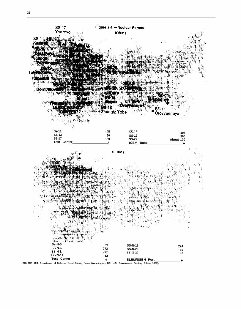
36
Ss-11 440 SS-18SS-13
30860 SS-19
SS-17360
150 SS-25 About 100Test Center A ICBM Base ●
Ss-N-5 39SS-N-6 272
SS-N-18 224SS-N-20 80
292 SS-N-23 48
SOURCE
Test Center A SLBM/SSBN Port ●U.S. Department of Defense, Soviet Military Power (Washington, DC: U.S. Government Printing Office, 1987),
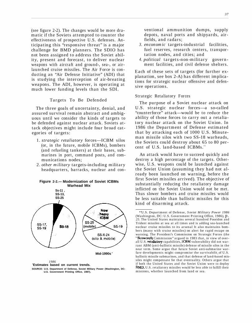
37
(see figure 2-2). The changes would be more dra-matic if the Soviets attempted to counter theeffectiveness of prospective U.S. defenses. An-ticipating this “responsive threat” is a majorchallenge for BMD planners. The SDIO hasnot been assigned to address the Soviet abil-ity, present and forecast, to deliver nuclearweapons with aircraft and ground-, sea-, or air-launched cruise missiles. The Air Force is con-ducting an “Air Defense Initiative” (ADI) thatis studying the interception of air-breatingweapons. The ADI, however, is operating atmuch lower funding levels than the SDI.
Targets To Be Defended
The three goals of uncertainty, denial, andassured survival remain abstract and ambig-uous until we consider the kinds of targets tobe defended against nuclear attack. Soviets at-tack objectives might include four broad cat-egories of targets:
1. strategic retaliatory forces—ICBM silos(or, in the future, mobile ICBMs), bombers(and refueling tankers) at their bases, sub-marines in port, command posts, and com-munications nodes;
2. other military targets-including militaryheadquarters, barracks, nuclear and con-
Figure 2-2.— Modernization of Soviet ICBMsWarhead Mix
Ss-11 ,SS-13,SS-25
(mobile
Mid-1990s a
1986aEstimates based on current trends.SOURCE: U.S. Department of Defense, Soviet Military Power (Washington, DC:
U.S. Government Printing Office, 1987),
3.
4.
ventional ammunition dumps, supplydepots, naval ports and shipyards, air-fields, and radars;enconomic targets-industrial facilities,fuel reserves, research centers, transpor-tation nodes, and cities; andpolitical targets-non-military govern-ment facilities, and civil defense shelters.
Each of these sets of targets (for further ex-planation, see box 2-A) has different implica-tions for strategic nuclear offensive and defen-sive operations.
Strategic Retaliatory Forces
The purpose of a Soviet nuclear attack onU.S. strategic nuclear forces—a so-called“counterforce” attack—would be to reduce theability of those forces to carry out a retalia-tory nuclear attack on the Soviet Union. In1986 the Department of Defense estimatedthat by attacking each of 1000 U.S. Minute-man missile silos with two SS-18 warheads,the Soviets could destroy about 65 to 80 per-cent of U.S. land-based ICBMs.11
An attack would have to succeed quickly anddestroy a high percentage of the targets. Other-wise, U.S. weapons could be launched againstthe Soviet Union (assuming they had not al-ready been launched on warning, before thefirst Soviet missiles arrived). The objective ofsubstantially reducing the retaliatory damageinflicted on the Soviet Union would not be met.Thus slower bombers and cruise missiles wouldbe less suitable than ballistic missiles for thiskind of disarming attack.
*’U.S. Department of Defense, Soviet Military Power 1986(Washington, DC: U.S. Government Printing Office, 1986), p.25. The United States maintains several hundred Poseidon andTrident missiles at sea at all times and is adding sea-launchednuclear cruise missiles to its arsenal It also maintains bom-bers (many with cruise missiles) on alert for rapid escape onwarning. The President’s Commission on Strategic Forces (the“Scowcroft Commission” argued in 1983 that, in view of over-all U.S. retaliatm-y capabilities, ICBM vulnerability did not war-rant ABM (anti-ballistic missile) defense of missile silos in thenear term. Some argue that future Soviet anti-submarine war-fare developments might compromise the survivability of U.S.ballistic missile submarines, and that defense of land-based mis-siles might compensate for that eventuality. Others argue thatif both the United States and the Soviet Union were to deployBMD, U.S. retaliatory missiles would be less able to fulfill theirmissions, whether launched from land or sea.

38
Box 2-A.—Potential Targets for a Soviet Nuclear Ballistic Missile Attack
Strategic Retaliatory ForcesLand-based ICBMs. -The United States has about 1,000 intercontinental ballistic missiles in
hardened silos. In the 1990s it may deploy “Midgetman” missiles on road-mobile carrier vehicles.It may deploy some MX “Peacekeeper” ICBMs on railroad cars within U.S. military lands. An at-tack on land-based ICBMs would have to be swift, well-coordinated, and accurate. Otherwise, manyof the missiles would remain available for striking back at the Soviets. (The Soviets would also haveto consider the risk that the United States would launch its ICBMs while they were under attack,with many escaping destruction to retaliate against the Soviet Union.
Bomber Bases. –About 350 strategic bombers, able to carry several thousand nuclear bombsand cruise missiles, are based at some tens of airfields around the United States. Additional aircraftare needed to refuel the bombers in flight. Normally, a substantial number of the U.S. strategicaircraft are on standby alert and might be expected to escape a Soviet missile attack given severalminutes of warning; in times of crisis, more bombers would be placed on alert. A Soviet attack mighttry to catch as many as possible of the U.S. bombers (and their refueling tankers) on the groundor just after take-off.
Submarine Bases. —Thirty-odd submarines with several hundred underwater-launched ballisticmissiles are based at just a few U.S. ports. By plan, in peacetime somewhat more than half thesesubmarines, with 2,500-3,000 nuclear warheads, are always at sea. Those in port would be easy,inviting targets for a Soviet strategic counterforce attack. During a crisis, some of the submarinesin port could be sent to join those already at sea.
Communications, Command, and Control Facilities.- Linking the above forces to U.S. NationalCommand Authorities is a network of underground command posts, mobile command posts, mobilecommunications (air, ground, and space) relays, and fixed communications transmitter and receiverstations. A Soviet nuclear attack is likely to try to disrupt this network by direct nuclear destruc-tion of the fixed land facilities or by means of nuclear-generated electromagnetic pulses intendedto interfere with the functioning of electronic devices.
Other Military TargetsMilitary Headquarters; Barracks, Nuclear and ConventionalAmmunition Dumps, Supply Depots,
Naval Ports and Shipyards, and Airfields.–Many other military facilities, while not directly sup-porting U.S. rapid-response strategic nuclear forces, would be essential to the conduct of conven-tional warfare or tactical nuclear warfare abroad. Many of these targets are “soft” . . . difficult toshelter from the effects of even relatively inaccurate nuclear weapons.
Economic TargetsFactories, Power Plants, Fuel Supplies, and Transportation Nodes. -These are sometimes called
“economic recovery” targets. The military purpose of attacking them might be to eliminate theeconomic base that supports U.S. military power. While the United States might be able to carryout a strategic nuclear retaliatory attack if its cities were destroyed, it could not carry on a conven-tional war abroad very long.Political Targets
Government Facilities and Civil Defense Shelters.–The Soviets might also attempt to disruptgovernment to hinder economic and political recovery.

39
The purpose of a U.S. ballistic missile de-fense against such an attack would be to pre-serve enough missiles and bombers to retali-ate successfully against the targets in theSoviet Union designated by U.S. military plan-ners.12 At a minimum, the United States mightwish defenses to add to current Soviet uncer-tainties about how well they could preventthose offensive weapons from reaching the So-viet Union. If these redundant, hardened tar-gets could be defended preferentially, that is,if defensive resources could be devoted to pro-tecting a sub-set of them that is unknown toSoviet planners, then Soviet confidence in be-ing able to destroy the whole force might bereduced to a very low level.13
At best, we would want defenses that per-suaded the Soviet Union of the certainty of fail-ure of any preemptive attack on our strategicforces that had the purpose of reducing sig-nificantly the damage we could do to the So-viet Union.
Other Military Targets
The purpose of attacking U.S. military tar-gets other than those connected with strate-gic nuclear forces would be to weaken or elim-inate the ability of the United States to projectmilitary power abroad (to fight conventionalor limited nuclear wars in Europe, Asia, or else-where), or even to defend its own territoryagainst invasion. Unlike sheltered ICBMs,most of these other military targets are rela-tively soft–each could be easily destroyed byone or a few moderately accurate nuclear weap-ons. Nor must they be destroyed instantane-ously, since they cannot be used for a promptnuclear retaliation against Soviet territory.
Since these other military targets can be de-stroyed more or less at leisure, strategic de-livery vehicles other than ballistic missiles can
“Opinions vary greatly on how many of what kinds of tar-gets the Soviets would have to betieve they would lose in sucha retaliation before they would be deterred from launching anattack on the United States. See OTA, %Zh”stic Missile DefenseTechnologies, op. cit., pp. 68-76.
‘sFor a more detailed explanation of the concept of preferen-tial defense, see OTA, Ballz”stic Missile Defense Technolo~”es,op. cit., pp. 94-98.
be used against them—bombers and cruisemissiles in particular. Therefore, a strategicdefense intended to protect these targets mustbe highly effective against “air breathing”weapons as well as against ballistic missiles.
The purpose of defending such targets wouldbe to decrease the probability that a nuclearattack on them could significantly weaken ourmilitary power; at best we would want theSoviets to be certain that such an attack wouldfail.
It is important to note that many of these‘‘other military targets” are located in or nearurban complexes, and an attack on them mightbe hard to distinguish from a punitive city at-tack. Fallout would reach extensive areas ofthe United States and millions of people mightdie.
Urban Economic and Political Targets
The main military purpose of attacking theU.S. industrial and political infrastructureswould be to remove the base from which theUnited States exerts military and economicpower abroad. Another purpose, however,might simply be to inflict punishment. Beforea war occurred, the purpose of having such anability to punish would be to deter actions (e.g.,nuclear or nonnuclear attacks) by threateningto impose a cost higher than the expected gainof such actions. For example, Britain andFrance maintain nuclear deterrent forces thatthey believe help deter the Soviet Union fromattacking them, even though the effects ofthose forces on Soviet military capabilitiesmight be more indirect than direct.14
Even a few tens of nuclear weapons landingon U.S. cities would cause unprecedented de-struction in this country. Extensive use of civildefense measures, if feasible, might amelioratethe effects of such destruction (e.g., if city pop-ulations could be evacuated and sheltered fromradioactive fallout and if industrial machinerycould be sheltered). But even more so than the
141t might k now, however, that the Moscow area has mwymilitary facilities; attacks on them would have widespread mil-itary as well as civilian consequences.

40
kinds of “soft” military targets describedabove, cities are vulnerable to attacks overhours and days by bombers and cruise missilesas well as by ballistic missiles. Defending cit-ies, then, would require extremely effective airdefenses as well as missile defenses.
The purpose of defending against attacks onurban industrial targets would be primarily tosave lives, property, and civilized society.Militarily, the purpose of having such defenseswould be to persuade potential attackers thatwe could so limit damage to our Nation thatwe would not have to constrain our own ac-tions out of fear of the effects of an enemy nu-clear attack.
From the standpoint of deterrence, variousconsiderations may affect just how much webelieve we need to limit damage to our Nation.One consideration might be relative damage:would the damage the United States is likelyto suffer in a nuclear war be more or less accept-able to us than the damage the Soviets arelikely to suffer would be to them? Anothermeasure might be absolute: regardless of howmuch damage we could inflict on the Soviets,under what conditions would we be willing toaccept the amount of damage they could in-flict on us (and vice-versa)?
An open question is just how limited the po-tential damage would have to be before theUnited States would decide to give up entirelyits own ability to carry out a nuclear retalia-tion against potential attackers. That is, atwhat point would we decide to rely on defenserather than the threat of retaliation for our ownsecurity?
The Special Case of Defense of Allies
Part of the stated mission of the SDI is todesign defenses to protect U.S. allies againstballistic missiles. But the purposes and tech-nical problems of doing so differ somewhatfrom those of defending the continental UnitedStates.
In the case of North Atlantic Treaty Orga-nization (NATO) allies, for example, the So-viet ability to deliver nuclear weapons ontoWestern European soil is massive and diverse.
Besides their land- and sea-based long-rangeballistic missiles, the Soviets might use hun-dreds of short-range ballistic missiles (inter-mediate and medium-range missiles withranges above 500 km are to be eliminated un-der the terms of the INF Treaty signed in De-cember 1987). Thousands of Soviet and War-saw Pact tactical aircraft are credited with theability to strike Western Europe. Air- andground-launched cruise missiles are or will beavailable.
The probability of being able to defend Eu-rope’s densely populated territory against allthe potential kinds of nuclear attacks on cit-ies and industries seems low. Therefore, mostproponents of BMD for the European theaterof war focus on the defense of what are abovecalled “other military targets’ ’-commandposts, communications nodes, sheltered weap-ons-storage sites (nuclear and nonnuclear), andairfields. Ballistic missile defenses might atleast disrupt and reduce the effectiveness ofSoviet nuclear missile attacks on such targets(though other means of delivery would alsoneed to be dealt with).
Moreover, some believe that as Soviet bal-listic missile accuracies increase, the Sovietsmight use those missiles to attack military tar-gets with nonnuclear explosive or chemicalwarheads. Stopping moderately high (and insome cases even modest) percentages of thewarheads in such attacks might make a mili-tary difference.16 Others argue, however, thatthe conventional tactical ballistic missilethreat, if it exists, is minor compared to othersNATO will have to contend within the future.16
Another mission for Soviet “theater” bal-listic missiles might be the delivery of chemi-cal weapons intended to incapacitate NATOtroops. Again, the interception of a significantpercentage of such missiles might make thedifference between some troops surviving achemical attack or not.
“see Manfred Woemer, “A Missile Defense for NATO Eur-ope,” Strategic Review, Winter 1986, pp. 13ff.
leFor a det~ed technical analysis, see Benoit Morel ~d The-odore A. Postol, “A Technical Assessment of The Soviet TBMThreat to NATO, ” to be published by the American Academyof Arts and Sciences, Cambridge, MA.

47
The shorter range Soviet ballistic missilesdiffer in flight characteristics from their largerrelatives: their trajectories are shorter and con-fined to lower altitudes. While they travel moreslowly, their shorter flight times also leave lesstime for them to be intercepted. On the otherhand, because these missiles spend a greaterpart of their flight time inside the atmosphere,reentry vehicle decoys present less of a prob-lem to the defense. Space-based BMD (espe-cially of the kinetic kill variety) would be oflimited utility, and ground-based rocket-inter-ceptors would be the likeliest BMD candidates.
The SDI Scenario
Various statements by Reagan Administra-tion officials over the first 4 years of the Stra-tegic Defense Initiative can be combined toform a scenario about how successively moreambitious goals for strategic defenses mightbe achieved.17 The expectation of the Admini-stration is that SDI research will show thatdeployment of ballistic missile defenses is fea-sible and desirable. As President Reagan hassaid, “When the time has come and the re-search is complete, yes, we’re going to de-ploy.’’”
In the early stages of deployment, accord-ing to the Administration scenario, Soviet at-tack uncertainties would increase, thus reduc-ing the probability of a Soviet first-strikedecision (though not the damage they mightinflict should they choose to attack). At first,minimal defense capabilities would only com-plicate Soviet attack plans. As strategicdefenses became more capable, the Sovietsought to be more persuaded that the militarypurposes of any attack would fail. Neverthe-less, as long as a substantial number of tar-gets in the United States were still vulnerableto attack, we would have to continue develop-ing and deploying offensive strategic nuclear
.—— —_.“For a list of statements prior to August, 1985, see OTA,
Balh”stic MissiJe Defense Technolo@”es,op. cit., App. I, pp.308-309.
“President Ronald Reagan, “SDI: Progress and Promise,”briefing in Washington, DC, on Aug. 6, 1986, Current PolicyNo. 858, U.S. Department of State, Bureau of Public Affairs,Washington, DC, p. 2.
weapons. As Secretary of Defense Weinbergerhas written:
From the outset, we have insisted thatprogress toward an effective SD I will have toproceed hand in hand with regaining an effec-tive offensive deterrent. . .19
The Administration hopes, however, thatultimately offensive deterrence can beabandoned:
As the United States has repeatedly madeclear, we are moving toward a future of greaterreliance upon strategic defense. The UnitedStates remains prepared to talk about how–under what ground rules and process-we andthe Soviet Union can do this cooperatively.Such strategic defenses, coupled with radicalreductions inoffensive forces, would representa safer balance and would give future states-men the opportunity to move beyond it—tothe ultimate elimination of nuclear weaponsfrom the face of the Earth.20
The key to this ultimate goal is seen to bethe development and deployment of defensesthat are unequivocally cheaper than corre-sponding amounts of offense. As SDIO puts it:
We seek defensive options–as with othermilitary systems–that are able to maintaincapability more easily than countermeasurescould be taken to try to defeat them. This cri-terion is couched in terms of cost-effectiveness.However, it is much more than an economicconcept. 21
— - - - -Waspa.r W. Weinberger, “U.S. Defense Strategy, ” Foreign
Affairs, Spring 1986, p. 678.Earlier in the same article Weinberger explained his concept
of a multi-leveled deterrent:If the adversary calculates that his aggression is likely to fail in
its own terms, he will not attack. Further, he must know that evenif his aggression should succeed in achieving its immediate objec-tives, he faces the threat of escalation to hostilities that would ex-act a higher cost than he is willing to pay. In addition to defenseand escalation, the third layer is retaliation: if the adversary con-fronts a credible. threat that eg ession will trigger attacks by asurviving U.S. retaliatory capa ilit against the attacker’s vltsl
‘&ganypossible@n, hewflinterests that result in losses excnot attack.
Ibid., p. 678.~O~sident Ron~d Reagm, Speech to the U.N. General As-
sembly, Sept. 22, 1986, reprinted in The Washington Post, Sept.23, 1986, p. A16.
zl&ra@$c Defense Initiative Organization, fipOrt @ tie COn-gress on the Strategic Defense Initiative, April 1987, p. IV-3.It should be added that not only should capability be maintain-able at the margin, but that our initial acquisition of defensecapability needs to be affordable in comparison with the costto the Soviets of upgrading their current offensive capabilitiesto counter our defenses. The offense, being already in place, hasa head start on defenses yet to be built.

42
Such a favorable “cost-exchange” ratio be-tween defenses and offenses would be intendedto persuade the Soviets of the futility of con-tinuing a competition in offensive arms. TheSDIO has stated that:
Program success in meeting its goal shouldbe measured in its ability both to counter anddiscourage the Soviets from continuing thegrowth of their offensive forces and to chan-nel longstanding Soviet propensities for de-fenses toward more stabilizing and mutuallybeneficial ends. . . It could provide new andcompelling incentives to the Soviet Union forserious negotiations on reductions in existingoffensive nuclear arsenals. ”22
Agreements on mutual offensive reductionscould make defensive tasks easier for each side.Thus the Soviets could be offered both a car-rot (possibility of their own effective defenses)and a stick (threat of losing an arms race be-tween offenses and defenses) as incentives tosubscribe to the U.S. scenario.
Current SDI Goals
The scenario shown in table 2-1 for the SDIsuggests the following official attitudes towardthe three goals of uncertainty, denial, and as-sured survival.
UncertaintyImposing greater uncertainty on Soviet at-
tack planners would bean initial benefit of de-ploying BMD, but, presumably is not in itselfsufficient to justify the SDI.
Denial
Denial of Soviet military objectives in a bal-listic missile would, in itself, justify deploy-ing BMD. Secretary Weinberger has said:
. . . our strategic defense need not be 100 per-cent leakproof in order to provide an extraordi-nary amount of deterrence. Even a partiallyeffective defense would convince Moscow thata first-strike was futile. And once we have ren-dered a Soviet first-strike obsolete and un-thinkable, we will have dramatically increased
Table 2=1.—Strategic Defense Initiative Scenario
Stage 1:SDI Research
Stage 2:Development and
production of BMDsystems
Stage 3:Initial BMD
deployments
Stage 4:Extensive deploy-
ment of highly ef-fective BMD
Stage 5:Deployment of ad-
vanced BMD sys-tems, combinedwith agreed deepreductions inoffenses
Leads to national decision in ear-ly 1990’s to proceed to full-scale engineering developmentaimed at deployment of BMD(reference to early 1990s datedropped by SDIO in 1987)
Preparation for deployment inmid-to-late 1990s (earlier initialdeployments raised as possi-bility by Secretary Weinbergerin 1987)
Introduces uncertainty intoSoviet strategic nuclear attackplanning; deployments prefera-bly coordinated by agreementwith Soviets on transition todefenses, but proceeds in anycase
Denies Soviet strategic forcesability to achieve military ob-jectives; demonstrates toSoviets futility of competitionin offensive strategic missiles
Deep reductions in all types ofoffensive strategic nuclearforces plus defenses allowsabandonment of threat ofnuclear retaliation for security:assured survival achieved
SOURCE: Compiled from U.S. Department of Defense, Report to the Congresson the Strategic Defense Inltlative, June 1986, p. IV-12 and other Ad-ministration statements.
stability and rested deterrence on a rock-solidbasis. But bear in mind that our goal remainsto make ballistic missiles-the most destabiliz-ing and dangerous weapons known to man—obsolete. 23
Assured Survival
The goal of assured survival may well requireSoviet cooperation in offensive nuclear disar-mament. A perfect defense against all ballis-tic missiles may not be possible, and:
Even a thoroughly reliable shield againstballistic missiles would still leave us vulner-able to other modes of delivery, or perhapseven to other devices of mass destruction. De-
~~Ibid., pp. IV-1-2.z~Remmks before the Ethics and Public Policy Center, Wash-
ington, DC, Sept. 26, 1986.

43
spite an essentially leakproof missile defense,we might still be vulnerable to terrorist at-tacks against our cities. Our vision of SDItherefore calls for a gradual transition to ef-fective defenses, including deep reductions inoffensive nuclear weapons.24
In the expressed Administration view, then,the SDI should aim ultimately for ballistic mis-
.- —.-——24Weinberger, “U.S. Defense Strategy, ” op. cit., p. 684.
sile defense systems that are nearly leakproof.One way of achieving assured survival mightbe to build defenses so effective that theywould succeed no matter what the Sovietsmight throw at them. Another way might beto build defenses that promise to be so effec-tive that the Soviets would prefer to negoti-ate offenses on both sides away rather thanembark on an offense-defense race that theyhave been persuaded they would lose techni-cally or economically.
THE CRITERIA OF FEASIBILITY
Supporters and critics of the SDI wouldprobably both agree that proposals for deploy-ing ballistic missile defense should meet atleast the four following criteria:
1. effectiveness,2. affordability,3. favorable cost-exchange ratio, and4. survivability.
Note that in each case, meeting the criterionwill beat least partly dependent on Soviet de-cisions and actions: the Soviets can make thejob harder or easier for the defense. In an un-constrained arms race, they would do whatthey could to make the job harder. In a coop-erative regime of mutual defensive deploy-ments and offensive reductions and controls,each side might make the BMD job easier forthe other.
Effectiveness
Obviously, before deciding to deploy a BMDsystem we would want to be confident that itwould be effective—that it would work wellenough to achieve the goals set for it. Effec-tiveness needs to be evaluated on two com-plementary levels. One level is technical per-formance: how well can the proposed BMDsystem perform against the missile threat ex-pected at the time of defense deployment? Ona higher level, would such performance provideabetter basis for deterrence, strengthen stra-tegic stability, and increase U.S. and Allied
security—the goals stated by SD IO? This sec-ond level of analyses received considerable at-tention in the 1985 OTA report on BallisticMissile Defense Technologies, so it will receivemuch less attention in this report.
On the level of technical performance, it isdifficult to decide what “effectiveness” means.For example, one frequently used criterion ofBMD effectiveness is “leakage rate”: what per-centage of a specified Soviet missile attackwould we expect to penetrate our defenses andwhat percentage could we stop? Given theenormous destructive power of nuclear weap-ons, though, leakage rates may only tell partof the story. A leakage rate of 10 percent mightsound worthwhile, and for some purposes itmay be. But under an attack of 10,000 nuclearwarheads, a 10 percent leakage rate wouldmean 1000 nuclear detonations on U.S. ter-ritory.
Another problem with leakage rate as ameasure of effectiveness is that it is likely tovary with the size and nature of attack. Forexample, a system that could stop only 50 per-cent of a massive, nearly instantaneous attackmight stop 100 percent of an attack consist-ing of two or three missiles. On the other hand,a system that could stop 50 percent of an at-tack of a certain size might not be expandablein such a way that it could stop 50 percent ofan expanded enemy missile force. In addition,to maintain damage at a fixed level, the de-fense would have to stop, for example, 75 per-cent of a doubled attack.

44
A slightly better indicator of effectiveness,then, might be the absolute number of nuclearwarheads penetrating the defense under theseverest plausible attack. Such an estimatewould give abetter indication of the maximumdamage a Soviet attack might inflict.
An even better indicator would be the num-bers of different types of targets that theUnited States would expect to survive a mis-sile attack. This approach would take into ac-count the numbers of attacking weapons, thenumbers of penetrating weapons, the numbersand types of targets attacked, and the num-bers and types of targets protected. Thesenumbers might be translated into percentagesof types of targets surviving-e. g., 70 percentof the land-based missile force.25 We mightcarry the analysis further by weighing thevalues of different types of targets. For exam-ple, one underground strategic command postmight be worth 10 missile silos.
All of the above indicators would be diffi-cult to apply with precision. And the more fac-tors an indicator has to take into account, themore imprecise it is likely to be. Indeed, therewould be no direct way to measure the poten-tial effectiveness of a BMD system: only anactual nuclear war would do so. Instead, wewould have to rely on estimates, based on as-sumptions about:
enemy offensive technical capabilities(numbers of weapons, accuracy, explosiveyields, ability to penetrate defenses);enemy target attack plans;defensive technical capabilities;vulnerability of targets defended; andthe objective and subjective relative val-ues of targets defended.
These factors would be difficult for U.S. plan-ners to assess. They would also be difficult forSoviet planners to estimate. Therefore, if theU.S. goal is mainly to introduce uncertaintiesinto Soviet strategic calculations, precise meas-ures of BMD effectiveness might not be nec-
‘6Note that plannin g to penetrate defenses may require theoffense to concentrate his attacks on higher-value targets, Inthat case, the targets which he no longer has enough weaponsto strike can be considered “saved” by the defense.
essary. On the other hand, if we wished to becertain of denying Soviet attack objectives, wemight need higher confidence in our estimates.
At the same time, if the Soviets decided,along with the United States, that defenseswere desirable, then each side could help makethem more effective by agreeing to deep cutsin offensive weapons and to restrictions oncountermeasures against defenses.
Affordability
If and when the Department of Defense even-tually presents its proposals for deployingBMD, the country will have to decide whetherthe expected benefits would be worth the ex-pected costs. Part of the SDI research programis to estimate costs for the proposed systems.For various reasons, the initial cost estimatesfor complex weapon systems tend to be inac-curate, and usually too low. Producing relia-ble cost estimates for future BMD systems willbe a challenging task.
Another part of the SDI program is to at-tempt to develop new, cheaper ways to manu-facture weapons and to deploy them in space.26
The ultimate weighing of costs and benefitswill be a political judgment made by the Presi-dent and Congress. But a critical part of thedemonstration of technical feasibility of BMDwill be that the proposed systems can be builtat a cost the country would, at least arguably,find reasonable.
As mentioned above, Soviet actions couldmake effective BMD more or less affordable.If they chose to invest heavily in offensivecountermeasures timed to take effect aboutwhen our defenses might be deployed, theycould make those defenses much more expen-sive than if they stabilized the threat they poseat today’s levels. Alternatively, in a coopera-tive regime they could make defenses cheaperby agreeing to decrease their offensive threat
~Unt~ a re-organization in 1987, the SDIO Systems End-neering Directorate was in charge of this program, among others.The Systems Engineering program element of the SDI budgetreceived $20.2 million in fiscal year 1987; $39 million was re-quested for fiscal year 1988.
45
in exchange for reductions in the U.S. offen-sive threat.
Favorable Cost-Exchange Ratio
The Nation must decide not only that a par-ticular defense system proposed at a particu-lar time is affordable, but whether the poten-tial long-run competition of U.S. defensesagainst Soviet offenses is likely to be afforda-ble in the future. In the absence of a long-termU.S. commitment to sustaining defensive ca-pabilities, the Soviets would have incentivesto stay in the “game” until the United States’will to spend flagged.
One way to try to persuade the Soviets toabandon efforts to maintain offensive capabil-ities would be to demonstrate clearly that ad-ditional increments of offense would be morecostly to the Soviets than corresponding in-crements of defense would be to the UnitedStates. Therefore, a corollary goal of the SDIis to design defenses that are cheaper “at themargin” than offenses. If the “cost-exchange”ratio were favorable to defenses, and if the twosides invested equal resources in defenses andoffenses respectively, then the side investingin offenses should find its capabilities inexora-bly declining.
Achieving this favorable cost-exchange ra-tio will be technically challenging. Accuratelyestimating the costs of defensive systemswould be difficult enough. Attaining high con-fidence that the ratio of U.S. defensive coststo Soviet offensive costs would be favorable,even before the United States deployed itsdefenses and before Soviet offensive counter-measures were known would be even more dif-ficult. Neither side may actually know the rela-tive costs of additional increments of defenseand offense until they actually buy them.27
———.*’It might be argued that, faced with these uncertainties, the
Soviets would accede to the U.S. proposal for a negotiated tran-sition that regulated offensive and defensive deployments. Onthe other hand, drafting such an agreement that both sides wouldfind equitable, given the asymmetries in forces and technologieson the two sides, would be a formidable task.
Because the United States and the SovietUnion have such different economies, it willbe difficult to quantify the cost-exchange ra-tio. Moreover, the effective cost-exchange ra-tio may differ from the technical one. That is,the ratio depends not only on what things cost,but also on what people are willing to pay. Ifthe Soviets are willing and able to pay for anincrement of offense that is more costly thanour corresponding increment of defense, forpractical purposes the cost-exchange ratio isat least even. The SDI objective, then, is to per-suade the Soviets that the defenses we can af-ford will more than offset the offenses they canafford. Thus the offense/defense cost-exchangeratio may have to be not just 1.5:1 or 2:1, butseveral-to-one.
On the other hand, if the Soviets were toagree with the United States that a mutual re-duction of offensive missile capabilities wasworthwhile and that defenses were desirable,then the technical challenge could be reduced.In effect, mutual political decisions could im-prove the cost-exchange ratio by mandatingreductions—rather than enhancements-ofoffensive capabilities, along with limitationson other offensive countermeasures.
Survivability
One of the many possible types of counter-measures against a BMD system is to attackthe system itself-which will be called “defensesuppression” in this report. Obviously, to carryout its defensive mission, the BMD systemmust survive such attacks. “Survivability”does not mean the ability of every element–each satellite, e.g.—to survive any attack.Rather, it means the ability of the system asa whole to perform acceptably despite attacksthat may disable some elements.
No BMD system will be either survivableor not survivable. The question will be, “Howsurvivable, at what cost?’ The cost-exchangeratio between defense and offense will have tobe calculated on the basis of the costs of allkinds of offensive response, including defensesuppression, compared to the costs of all kindsof defensive counter-countermeasures, includ-ing “survivability” measures.

46
The remainder of this report surveys what systems that would meet the effectiveness, af-was—and was not—known as of April 1988 fordability, cost-exchange, and survivabilityabout the potential of the SDI for developing criteria.

Chapter 3
Designing a BMD System:Architecture and Trade-off Studies
————
CONTENTS
The Importance of BMD Architecture Studies. . . . . . . . . . . . . . . . . . . . . . . . 49Overview of System Architecture Analyses . . . . . . . . . . . . . . . . . . . . . . . . . . 51
Goal Specification . . . . . . . . . . . . . . . . . . . . . . . . . . . . . . . . . . . . . . . . . . . . . . 51Threat Definition . . . . . . . . . . . . . . . . . . . . . . . . . . . . . . . . . . . . . . . . . . . . . . . 52System Requirements . . . . . . . . . . . . . . . . . . . . . . . . . . . . . . . . . . . . . . . . . . . 52Systems Designs . . . . . . . . . . . . . . . . . . . . . . . . . . . . . . . . . . . . . . . . . . . . . . . 52Technological Requirements . . . . . . . . . . . . . . . . . . . . . . . . . . . . . . . . . . . . . . 53Operational Requirements . . . . . . . . . . . . . . . . . . . . . . . . . . . . . . . . . . . . . . . 53costs . . . . . . . . . . . . . . . . . . . . . . . ! . . . . . . . . . . . . . . . . . . . . . . . . . . . . . . . . . 53
Nuclear Force Exchange Models: Deriving Requirements From Goals.... 53Some Conclusions Drawn From Nuclear Exchange Models. . . . . . . . . . . . 54Limitations of Nuclear Force Exchange Models . . . . . . . . . . . . . . . . . . . . . 58
System Designs and End-To-End Models . . . . . . . . . . . . . . . . . . . . . . . . . . . . 58Space- and Ground-Based Architectures . . . . . . . . . . . . . . . . . . . . . . . . . . . 59Battle Management Architecture . . . . . . . . . . . . . . . . . . . . . . . . . . . . . . . . . 61Some Important Results of the System Requirements
and Design Work . . . . . . . . . . . . . . . . . . . . . . . . . . . . . . . . . . . . . . . . . . . . . 64Important Systems Analysis Work Remaining . . . . . . . . . . . . . . . . . . . . . . . 65
Further Strategic Nuclear Force Exchange Work . . . . . . . . . . . . . . . . . . . . 65Further System Requirements and Design Work . . . . . . . . . . . . . . . . . . . . 68
TablesTable No. Page3-1. Two Perspectives on BMD Effectiveness and Strategic Goals . . . . . . . 553-23-33-43-5
3-6
Judgemental Assumptions in Nuclear Force Exchange Models ...’... 58Phases of Ballistic Missile Trajectory. . . . . . . . . . . . . . . . . . . . . . . . . . . . 59SDIO’s Phase One Space- and Ground-Based BMD Architecture . . . . 60OTA’s Projections of Evolution of Ground-and Space-BasedBMD Architecture . . . . . . . . . . . . . . . . . . . . . . . . . . . . . . . . . . . . . . . . . . . . 61Two Representative Battle Management Architectures . . . . . . . . . . . . . 62
Chapter 3
Designing a BMD System:Architecture and Trade-off Studies
THE IMPORTANCE OF BMD ARCHITECTURE STUDIES
Researchers have performed proof-of-prin-ciple experiments for some Strategic DefenseInitiative (SDI) technologies. But many of thebasic technologies for the SDI are still in anexperimental, or even theoretical, stage. There-fore it might seem premature to be designingfull-scale ballistic missile defense (BMD) sys-tems for deployment not only in the mid-1990s,but in the 21st century. In fact, such designsare key to assessing the feasibility of achiev-ing U.S. strategic goals through ballistic mis-sile defense. National decisionmakers can onlyfully evaluate proposed systems on the meritof system architectures, not on the promise ofone technology or another. If called upon toappropriate funds for BMD development and de-ployment, Congress will be asked to decide uponan architecture-a specific system design com-prising many technologies and components.
Attempting such designs, or “system ar-chitectures, as the Strategic Defense Initia-tive Organization (SD IO) calls them, compelssystematic analysis of all the factors that willaffect SDI feasibility. In the near term, suchanalysis helps guide the technology researcheffort. In the long term, it will provide the sub-stance of the national debate over whether todeploy BMD.
System architecture analysis, if done well,will provide some of the key elements of infor-mation upon which to base decisions aboutwhether to commit the Nation to deploying anyproposed BMD system:
● Specification of Goals. Explicit identifica-tion of the particular strategic goals thatBMD system designs will be expected toachieve (e.g., impose uncertainty on So-
●
●
●
●
●
●
Note: Complete definitions of acronyms and initialismsare listed in Appendix B of this report.
viet strategic planners); understanding ofthose goals in the larger context of U.S.national security; and cost-effectivenesscomparisons of alternate means, if any,of achieving the goals.Specification of Threat. Projections of fu-ture Soviet missile and BMD counter-measures that BMD system designswould be expected to overcome.System Requirements. Specification of themissile-interception tasks and sub-tasksthat effective BMD systems would haveto perform to meet the project threats;specification of passive and active surviv-ability measures for the system.System Designs. Proposals for integratingsensors, weapons, and command and con-trol arrangements into BMD systems thatwould likely meet system requirementsand that could be practicably modified tomeet changing threats; and specificationof how technologies under research wouldbe incorporated into a BMD system-sucha design is called a system architecture.Technology Requirements. Specification ofthe technologies needed to build theweapon systems required by the overallsystem design, by the deployment andmaintenance plans, and by plans foradaptive evolution of the system to meetchanges in the threat; and plan for bring-ing all technology developments to frui-tion when needed (full-scale engineeringdevelopment plan).Manufacturing Requirements. Specifica-tion of the materials, manufacturing fa-cilities, tools, and skilled personnel neededto manufacture all system elements.Deployment and Operations Analyses.Proposals for how the designed systemcan be put into place and maintained (in-
49
50
●
eluding space transportation require-ments); and schedules for doing so.Cost Estimates. Estimates for what devel-opment, procurement, deployment, andoperation of the proposed system designwill cost; and proposals for reducing sys-tem costs.
This chapter will focus on two particulartopics:
1. the ways in which system architects forSDIO have related strategic goals toBMD system performance needs, and
2. the general characteristics of the systemarchitectures studied for SDIO.
The concluding sections of the chapter willidentify areas of analysis within those topicswhere important work remains to be done.
It would be highly unrealistic now to expectsystem architecture studies to be definitive.Each category of analysis is subject to con-siderable uncertainty, some of which maynever be resolved by analysis and limited ex-perimentation. The architecture analysis willnecessarily be tentative and iterative: as newinformation and ideas emerge, modificationswill be inevitable. Moreover, the findings fromanal sea in each category will and should affectthe findings in other categories. For example,meeting a particular technology requirementmay be judged possible, but too expensive. Thesystem architecture design may have to bemodified to utilize another technology to carryout the same function. On the other hand, newtechnological developments may make it cheaperto carry out a function in a way that previousanalyses had shown to be too costly. For thatreason, the system architects attempt to de-sign “evolutionary” architectures into whichadvanced technical developments could bephased as they became available.
Even after a commitment had been made todevelop a particular technology into a weaponsystem, the process of full-scale engineeringdevelopment might prove more difficult thananticipated: alternate systems might have tobe designed and developed. Moreover, whileit is the goal of the architecture analyses to
provide options for meeting a range of poten-tial changes in the offensive missile threat, afully deployed BMD system might still haveto be modified in unanticipated ways if theSoviets were to deploy unforeseen counter-measures.
Despite the necessarily tentative nature ofsystem architecture analyses, they compel acoherence in thinking about BMD that wouldotherwise be missing. They also bring into theopen the assumptions implicit in the argu-ments for and against deploying BMD. Be-cause these analyses will inevitably includeassumptions and projections that reasonablepeople may disagree about, it is important thatthey be carried out competitively, by more thanone group of analysts. Such competition willgive both the Administration and Congress abasis for identifying the uncertainties, vary-ing assumptions, and alternative projectionsof the future that will underlie decisions aboutBMD. It will also be important, when these anal-yses are offered in justification of major deci-sions, that they be independently evaluated.
Recognizing the importance of system ar-chitecture studies, SDIO late in 1984 awardedcontracts to 10 teams of military systems anal-ysis contractors to provide competing analy-ses at a price of $1 million each. On the basisof that competition, five teams were chosenfor $5-million, “Phase II” architecture studies,which were largely completed in mid-1986. Inaddition, a sixth contractor provided SDIOwith analytic support to synthesize the find-ings of the five competitors into a “referencearchitecture” to help guide SDI research. Asof this writing, the five Phase II teams hadbeen awarded additional contracts to continuesome analytic work common to all and to per-form some tasks unique to each. Their reportswere due at the end of January 1988.1 It had
1 Three other sets of “architecture” contracts should also benoted. First, through the Air Force Electronic Systems Divi-sion, contracts were awarded to three firms to design battlemanagement and communications systems for a BMD systemwith land- and space-based elements. This work necessitateddefinitions of more or less complete BMD system architectures,thus to some extent paralleling the work of the general systemarchitecture contractors, The SDIO has subsequently attempted
51
been planned that the five would be narrowedto two competitors in a final phase, but thatdecision was postponed through 1987. Even-tually a single contractor team will be chosento design a BMD system in detail.2
to better coordinate the parallel work of the battle managementsystems analyses and the main system architecture studies.
Second, the Army Strategic Defense Command awarded threeother contracts for study of the battle management and com-munications systems for BMD composed primarily of ground-based components. Third, late in 1986 SDIO awarded sevencontracts to teams composed of U.S. and European firms tobegin designs of system architectures for European theater de-fense against intermediate-, medium-, and short-range ballisticmissiles.
‘For the future, SDIO has proposed two new organizationsfor carrying out work on system architectures. One organiza-tion would bean “SDI Institute, ” a federally (and, specifically,SD IO) funded “think tank” to monitor the work on the actualsystem architecture to be proposed for deployment by SD IO.The Institute would be independent of particular defense con-tractors, thus reducing the possibility that the interest of cur-rent defense firms in selling hardware to the government wouldplay a role in architecture designs.
A second new organization is to be a “National Test Bed, ”which would be a network of computers, communications links,and some sensor hardware for simulating ballistic missiledefenses. In some cases, the simulations would be purely con-ceptual, creating a computer “world” of BMD systems and offen-sive systems, and testing various assumptions about each. Inother cases, this imaginary world might, with simulated incom-ing and outgoing data, test computer software actually intendedfor use in a real BMD system. In yet other cases, actual BMD
This report will offer numerous examplesfrom the findings of the system architecturecontractors and of SDIO adaptations of suchfindings. With a few exceptions, we will notcite specific contractor sources for those ex-amples. OTA has not undertaken a systematicanalysis and comparison of all the dozens ofdocuments that emerged from the several con-tractor studies. Therefore, a few selected cita-tions might give an unfair impression of theoverall performance of any given contractor.Our purpose here is to convey an understand-ing of the system architecture analysis proc-ess and to report some of the results—not toconduct management oversight of any Depart-ment of Defense (DoD) contractor. In addition,the system architecture work is continuing,and constant revision of previous findings isboth necessary and desirable. Thus any givenconclusion might not reflect the current viewsof the particular contractor.
hardware tests might be conducted, with data from the com-puters being fed into an actual test sensor system, and the sen-sor system sending processed signals back into the computersimulation. If a full-scale BMD system were deployed, the Na-tional Test Bed might then be used for simulated battle exer-cises of the system.
OVERVIEW OF SYSTEMS ARCHITECTURE ANALYSESInitially, each of the system architects un-
dertook the same general task of designingBMD systems whose deployment might be-gin in the mid-1990s and that might evolve intomore advanced systems after the year 2000.Each group produced designs that it believedcould, when fully deployed, provide near-perfect interception of Soviet ballistic missilereentry vehicles (RVs) forecast for deploymentin the mid-1990s.3 Each also argued, however,
3A mid-1990s threat posed against a BMD system that couldnot be fully deployed until after the year 2000 is unrealistic.Not all architects used the same threat numbers for the sametime frames. The architects did, however, project this “base-line” threat into larger numbers of reentry vehicles and decoysfor later years. They also ran “excursions” on the baseline threatto explore the impacts of larger and smaller threats on defenseeffectiveness. The excursions into larger threats, with one ex-ception, do not generally appear in the summary documentsproduced by the contractors.
that lesser percentages of interception wouldachieve desirable military goals along the linesdescribed in chapter 2 of this report.
Goal Specification
As part of their analyses, the architects usedcomputerized strategic nuclear exchangemodels (see next section on this topic) to simu-late the numerical results of hypothetical nu-clear wars between the United States and theSoviet Union. These simulations assumed vari-ous levels of defense capability on the two sides(in general the projected offensive capabilitiesfor the mid-1990s were assumed at this stage)for the purpose of showing what differencesthose defenses might make.
52
From these simulations, the analysts drewconclusions about how defenses might contrib-ute to the goals of security and strategic sta-bility. In chapter 2, we described the kinds ofmeasures used to define BMD effectiveness.In this chapter we will further describe someof the assumptions that went into and conclu-sions that came out of these strategic exchangesimulations.
Threat Definition
A preliminary step to running the strategicexchange simulations was to state the Sovietoffensive threat that BMD systems would bedesigned to counter. The starting point wasan SDIO-supplied projection of the offensivemissile forces the Soviets might have in themid-1990s. From this starting point, the ar-chitects made varying “excursions,” positingpossible future Soviet missile developmentsand deployments. In addition, they hypothe-sized various types and numbers of anti-satel-lite weapons that the Soviets might conceiva-bly deploy to attack space-based componentsof BMD systems.
Subsequently, and under different programmanagers, SDIO began a “Red Team” pro-gram to attempt to anticipate possible Sovietresponses to U.S. BMD deployments. A ma-jor project of this program has been to bringtogether groups of experts to attempt to de-sign plausible Soviet countermeasures to thetechnologies under consideration in other partsof SD IO. These potential countermeasures arethen presented to SDIO “Blue Teams” so thatthey can adapt their technology research andsystem designs accordingly.
In mid-1987, SDIO presented to the DefenseAcquisition Board a proposal to proceed with“concept demonstration and validation”(“Milestone I“) for the first phase of a “Stra-tegic Defense System” (BMD system) to bedeployed in the mid-1990s. This presentationincluded an officially approved “threat”description for that period.
In reviewing DoD proposals for any BMD sys-tem, Congress should understand whether theofficially assumed Soviet threat is “responsive”
—i.e., whether it reflects plausible countermeas-ures that the Soviets could have taken by thetime the BMD system were full deployed.
System Requirements
In showing what numbers of nuclear weap-ons would have to be intercepted to providevarious levels of protection for different typesof targets (cf. ch. z), the strategic exchangemodels also yielded basic requirements for stra-tegic defense system performance. Additional“end-to-end” computer simulations helped de-fine requirements for interception at each stageof flight.
(In SDIO presentations accompanyingmid-1987 proposals for an initial, less effectiveBMD system, this process was reversed. First,a number of warheads to intercept was estab-lished, then the strategic goals that might beserved analyzed afterward.)
Systems Designs
The system architecture contractors de-signed BMD systems intended to intercept avery high percentage of the projected missilethreat. The working assumption was that earlystages of BMD deployment would be steppingstones to the ultimate goal of protecting cit-ies and people from nuclear ballistic missile at-tack. The designs were not optimized to lessambitious goals. For example, systems thatmight protect hardened missile silos but couldnot serve as elements of city defenses were notconsidered. Systems designed from the outsetto preserve nuclear deterrence might well lookmaterially different from those designed tore-place it altogether.
Each architect was asked to design:
1. a system that was both space-based andground-based;
2 one that was primarily ground-based; and3. one that was intended primarily for de-
fense of U.S. allies against intermediateand shorter range ballistic missiles.
In the second phase of system architecturecontracts, analysts placed greatest emphasis
53
on the first type of system, somewhat less onthe second, and least on the third. Each archi-tect considered systems that might be deploy-able in the mid-1990s, but each also offered con-cepts for more advanced systems that mightbe deployed against more advanced Sovietoffensive systems out to the year 2015 or so.For each case, analysts identified counter-countermeasures intended to neutralize Sovietattempts to penetrate or directly attack theBMD system.
The details of the systems designs (for ex-ample, a given type and number of space-basedrocket interceptors) were built into simulationmodels that expanded on the nuclear exchangemodels described above. These “end-to-end”simulations represented the details of inter-cepting ballistic missiles throughout all phasesof flight, from rocket boost to warhead reen-try. Some of the results of these “end-to-end”simulations are discussed below. These modelsalso aided “tradeoff” analyses of various typesof BMD system components arranged in vari-ous configurations. The models were also usedto evaluate excursions in the technological re-quirements forced by particular types of Soviet anti-BMD countermeasures.
Technological Requirements
The architects quantitatively analyzed therelative costs and effectiveness of various ap-proaches to each defensive task. For example,an analysis might examine trade-offs betweenhighly capable missile-tracking sensors on afew high altitude satellites and less capablesensors on many more low-altitude satellites.
Many of these “trades” are discussedsequent chapters of this report.
Operational Requirements
in sub-
Because system designs are still preliminary,it is difficult to specify their exact operationalrequirements. The system architects did at-tempt to estimate the continuing space trans-portation and maintenance requirements forspace-based systems over their lifetime. OtherSDI programs are conducting research on thelogistics of maintaining various space-basedand ground-based systems.
c o s t s
In general, system architects estimatedcosts for their nearer-term, “interim” designs—those not including directed-energy weaponsfor boost-phase missile interception. These sys-tems were estimated to cost on the order of$200 billion, depending on the projected needto respond to various types of Soviet counter-measure. Costs of complementary air defensesystems were not included. It should be rec-ognized that, given the conceptual nature ofthe architectures, accurate cost-estimating isvirtually impossible at this stage. It does ap-pear that, with thousands of space platformsenvisaged, considerable changes would beneeded in the way such equipment is now de-signed and manufactured if space-based BMDsystems were ever to be affordable. In addi-tion, a major new space transportation systemwould have to be designed, developed, manu-factured, and deployed.
NUCLEAR FORCE EXCHANGE MODELS:DERIVING REQUIREMENTS FROM GOALS
The SDI system architects-and several simulation models assume various U.S. and So-other groups as well-have run several types viet offensive nuclear force levels, beginningof strategic nuclear exchange computer simu- with U.S. Government estimates for 1995.lations to try to show how defenses might af- Then they assume various strategic targetingfeet the U.S.-Soviet nuclear balance. These plans on the two sides and analyze how the
54
attempted execution of those plans might beaffected by various levels of defense capabil-ity on the two sides.
The intermediate measure of defense effec-tiveness is usually the percentage of nuclearwarheads intercepted or its complement, thenumber of “leakers.” The models translate thenumbers of leakers in various cases into num-bers or percentages of different types of tar-gets surviving the attack. (For examples ofsuch target types, see ch. 2, box 2A.) Eachtype of target, in turn, is given a differentweight based on judgments about how U.S.and Soviet leaders might value them. Thus thenumbers of different types of targets surviv-ing are translated into “surviving strategicvalue.”4 The percentage of surviving strate-gic value on the two sides is then linked withparticular strategic goals. (For a discussion ofgoals for BMD and ways of measuring BMDeffectiveness, see ch. 2.) In some cases, “leak-age” rates were linked (via asset survival ex-pectations) to strategic goals to show whatkind of BMD system performance would beneeded given a particular assumed level ofoffensive threat (for example, see table 3-l).
Some Conclusions Drawn FromNuclear Exchange Models
Strategic Goals and Defense Leakages
The system architects’ strategic nuclear ex-change simulations provide a useful basis forstudying BMD performance goals. However,because each architect used a different com-puter model and different assumptions for thesizes and compositions of future U.S. and So-viet offensive nuclear forces, the results aredifficult to compare.
With that important qualification, here aresome conclusions drawn frequently (but notuniversally) by the different system architects.First, for a mid-1990s Soviet strategic nuclear
4In these models the Soviets are assumed to have a largernumber of strategic targets than the United States, and theSoviet targets are assumed to be harder to destroy. Part of thedifference is due to the existence of numerous nuclear-hardenedshelters for Soviet political leaders; see Soviet Military Power,1987, (Washington, D, C.: Department of Defense) p. 52,
threat, a BMD system that allowed a few thou-sand Soviet RVs to penetrate into the UnitedStates might complicate Soviet attack plans,but probably would not stop them from de-stroying most of their chosen targets.5
In support of SDIO’s mid-1987 proposal foran initial BMD system, other SDIO contrac-tors argued that a strategy of “adaptivepreferential defense” might prevent theSoviets from destroying as high a percentageof certain sets of targets as they would wish(as estimated by U.S. analysts).
A system that allowed fewer Soviet RVs toleak through would begin to deny the Sovietscertainty of destroying many of the militarytargets that their planners might have desig-nated. But if the Soviets chose to concentrateon economic targets in the United States, theymight still be able to deny the United Statesthe possibility of economic recovery from thenuclear war. (Compare this finding with thesecond set of projections in table 3-l.)
With yet lower leakage, the Soviets couldstill inflict immense damage on the UnitedStates. Note, for example, that 10 percent ofan attack with 10,000 nuclear weapons wouldstill result in 1,000 nuclear weapons explod-ing in the United States. But since the Sovietscould not be sure which 1,000 of the 10,000launched would reach which targets, confi-dence in achieving precise attack goals on agiven set of targets would be low.
Analyses also seem to show that if theUnited States had a relatively highly effectiveBMD system against a mid-1990s Soviet threatwhile the Soviets had no BMD, the Sovietswould improve their relative strategic situa-tion more by adding defenses to limit damageto themselves than by adding offensive weap-ons in hopes of increasing the damage theycould inflict on the United States.6 In attempt-“–s The exact percentages in this conclusion and the others be-low were apparently classified by the system architecture con-tractors because the computer simulations from which they werederived include classified estimates of U.S. and Soviet militarycapabilities.
6 This conclusion assumes that the addition of offenses couldnot improve the leakage rate—the same percentage of everyadded group of warheads would be intercepted, This is not nec-essarily a valid assumption: much would depend on the compo-sition of the offensive and defensive forces on the two sides.

55
Table 3-1.—Two Perspectives on BMD Effectiveness and Strategic Goals
Soviet warheadsleaking through Expected strategic consequences
A. One system architect’s strategic exchange model and conclusionsMany Increase in Soviet attack planning uncertainties. They are forced to launch all their strategic forces at
Fewer
Extremely few
Assumptions:
once or reduce their military objectives. A strategic exchange would result in more losses to Sovietsthan to the United States.
The Soviets could no longer reliably achieve the military goals of a strategic nuclear attack whilemaintaining a secure reserve of missiles for later attacks. Preserves full range of U.S. strategic offen-sive force retaliatory flexible response options. Each new Soviet ballistic missile has only a fractionalchance of being useful.
Survival of a large portion of the population and industrial base, a high proportion of military targetsother than strategic offensive forces, and sufficient strategic offensive forces to preseve full range ofU.S. retaliatory flexible response options. If Soviets attack only other military targets (not strategicoffensive forces), medium-high survival of those assets.
Would preserve the full range of U.S. “flexible response” options in war with the Soviets even ifSoviets devoted entire attack to U.S. strategic offensive forces (presumably only if Soviets do not havecomparable BMD capability —OTA).Assured survival of the Nation as a whole: 3 to 5°/0 U.S. casualties in population attack.
Assured survival: Soviet ability to put U.S. population at risk is negligible; the United States needs nostrategic nuclear retaliatory capability.
● Mid-1990s projections of Soviet and U.S. strategic forces.● Effectiveness of Soviet BMD not specified.• Status of air defenses not specified.
Alternate analysis: As U.S. strategic defenses improved, an option for the Soviets would be to change their offensive targetpriorities to maintain a deterrent “assured destruction’ capability. Instead of concentrating their forces on hardened missilesilos, for example, they might concentrate them on key military industries or other economic targets; they might even focuson cities per se. Various non-SDIO analysts have previously calculated potential consequences of such nuclear attacks, asindicated below.
B. If the Soviets retargeted to maintain assured destruction10 ”/0
30/0
1 to 2%
The Soviets attack industries in the 71 largest U.S. urban areas; the equivalent of 500 l-megaton and200 to 300 100-kiloton weapons get through. Of the U.S. population, 35 to 45 percent is killed or in-jured; 60 to 65°/0 of U.S. industry is destroyed.b
The Soviets attack industries in the 71 largest U.S. urban areas; the equivalent of 100 l-megaton and200 to 300 100-kiloton weapons get through. From prompt blast and radiation effects, 20 to 30°/0 ofU.S. population is killed or injured; 25 to 35% of U.S. industry is destroyed.c
Case 1: The Soviets attack 77 U.S. oil refineries; the equivalent of 80 l-megaton weapons get through.From prompt blast and radiation effects, 5 million Americans die. The U.S. economy iscrippled. d
Case 2: The Soviets attack 100 key military-industrial targets with the equivalent of 100 l-megatonweapons. Three million die of blast and radiation effects, another 8 million from fires; deadand injured total 10 to 16 million.e
Case 3: The Soviets attack 100 U.S. city centers with the equivalent of 100 l-megaton weapons. Four-teen million die from blast and radiation effects alone, a total of 42 million die from blast, radi-ation, and fires; total dead and injured are 32 to 51 million.f
● Total Soviet strategic attack of 10,000 weapons.● Air defenses equallv effective as BMD.
Assumptions:. .
aA@t~d from Martin Marietta Aer~~pace analyses, percentages of weapons leaking and assets SlJrviVl?19 deleted fOr SeCIJdty ClaSS\fiCatiOrl re&30nS.
bFrom us, congre~sj ~conom~c and Social Consequences of ~uclear Attacks On the (/rr/ted Sfates, A Study Prepared for the Joint Committee on Defense Production,
Published by the Committee on Banking, Housing, and Urban Affairs, U.S. Senate (Washington, D. C.: US. Government Printing Office, 1979), pp. 4-14,Clbid.dF rom us, congress, Office of Technology Assessment, ~tre ~ffects of Nuc/ear War(Washington, D, C.: U. S. Government printing Off iCe, May, 1979), pP 64-75. Calcula-
tions on casualties were performed for OTA by the the U.S. Defense Civil Defense Preparedness Agency. About 125 500-kiloton weapons would have the same blasteffects as 60 l-megaton weapons, but the pattern of distribution of blast might in fact do more damage.
‘William Daugherty et al., “The Consequences of ‘Limited’ Nuclear Attacks on the United States,” /rrternat/orra/ Security, spring 1966 (vol. 10, No. 4), p 5 F!ndingsbased on the authors’ computer simulations. About 160 500-kiloton weapons have about the same blast effects as 100 l-megaton weapons.
‘Ibid,
56
ing to assess the effect on deterrence of vari-ous levels of defense, the strategic analystscompared the amount of damage the Sovietsmight suffer (as a weighted percentage of giventypes of targets) with the amount the UnitedStates might suffer. Differences in surviving(value-weighted) percentages of military tar-gets were assumed to confer strategic advan-tages or disadvantages that would affect So-viet decisions about how to respond to U.S.weapon deployments, whether to go to war,or whether to escalate a conflict to nuclear ex-change.
Even very low leakage of the BMD system(and assuming comparable leakage of air-breathing nuclear weapon delivery vehicles)could still kill several million Americans, if thatwere the Soviet objective. (Note that the alter-native projections in table 3-1 suggest higherpossible casualties.) This level of protection(given the mid-1990s projected nuclear threat)might assure survival of the United States asa functioning nation but would not assure sur-vival of the whole population. Most of the sys-tem architects appeared to believe that in thelong run they could design systems capableof keeping out a very high percentage of So-viet ballistic missile RVs (assuming the mid-1990s projected threat); none appeared to be-lieve that leakage levels compatible with “as-sured survival” of the U.S. population wouldbe possible without negotiated limitations ofSoviet offensive nuclear forces.
U.S.-Soviet Asymmetries
With varying degrees of clarity, the systemarchitects’ use of nuclear exchange modelsbrought out the current-and likely future–asymmetries between U.S. and Soviet offen-sive nuclear forces. The Soviet Union has moreballistic missile RVs than the United States.More of the Soviet RVs are based on land thanon submarines, while the reverse is true of theU.S. RVs. The United States has more strate-gic nuclear bombers and air-and sea-launchedcruise missiles than the Soviet Union, whilethe Soviet Union has a more extensive air de-fense system than the United States.
If the Soviet Union had ballistic missiledefenses comparable to those of the UnitedStates, the net effect of trying to defend ourland-based missiles against a Soviet strikewould be to reduce the U.S. ability to carryout planned retaliatory missions. Here is why.If defended, a sizable number of U.S. land-based missiles that might otherwise have beendestroyed on the ground might survive a So-viet offensive strike. On the other hand, theywould then have to survive defensive attacksas they attempted to carry out their retalia-tory missions against Soviet territory. In addi-tion, the U.S. submarine-launched missiles(SLBMs), which would not benefit from the de-fense of land-based missiles, would also haveto face Soviet defenses. Furthermore, if the in-tercepted SLBMs were aimed in part at So-viet air defense assets, such as radar sites, theability of U.S. bombers and cruise missiles tocarry out their missions might also be im-paired.
Besides the asymmetries in weapons, thereare asymmetries in targets on the two sides.The Soviet Union, for example, reportedly hasmore than 1,500 hardened bomb shelters forits political leadership. The Soviets also aresaid to spend copious sums on other types ofcivil defense. The combination of passive de-fense measures and BMD might do more toprotect valued Soviet targets than BMD alonewould to protect valued U.S. targets.
Given the asymmetries in U.S. and Sovietweapons and defenses, then, the net effect ofmutual deployments of comparable levels ofdefense could be to weaken, not strengthendeterrence-if deterrence were still measuredprimarily by the penalty that we could imposeon Soviet aggression through nuclear retalia-tion. (If deterrence were measured by denialto the Soviets of some attack goals other thanreducing damage to the Soviet Union, then de-terrence might be strengthened.)
The United States might compensate forU.S.-Soviet asymmetries in three ways:
1. The United States could attempt to buildand maintain BMD that was notably su-
57
perior to that of the Soviet Union, so thata greater proportion of the smaller U.S.ballistic missile force could be expectedto reach its targets. This was the recom-mendation of at least one of the SDI sys-tem architects, who argued that until veryhigh defense effectiveness levels had beenreached, equal defensive capabilities onthe two sides might confer an exploitablestrategic advantage on the Soviet Union(SDIO officials disagree with thisassessment).
2. The United States could attempt to main-tain and improve the ability-of its air-breathing weapons (bombers and cruisemissiles) to penetrate Soviet air defensesso that the loss in effectiveness of our bal-listic missiles was offset by the othermeans of nuclear delivery. This course wasassumed in the calculations of a secondsystem architect.If U.S. strategic defenses against all types3.of nuclear threat (air-breathing as well asballistic missile) could be made extremelyeffective, we might not care about imbal-ances in punitive abilities on the two sides;the Soviets would have little or nothingto gain by threatening nuclear attack.Then, even a minimally destructive retal-iatory ability on the U.S. side should fullydeter the Soviets from even contemplat-ing attack. This was the ultimate goal hy-pothesized by all the system architects.(It should be noted that most, though notall, analysts believe that this kind of de-terrence now exists. If so, BMD would notsignificantly reduce the risk of nuclearwar.7)
However, some would argue that future So-viet “counterforce” capabilities, plus Sovietcivil defense and perhaps active (BMD and airdefense), could reduce prospective Soviet dam-age to levels acceptable to them. A U.S. BMDsystem, it is argued would either maintain the
survivability of the U.S. deterrent, or equal-ize the prospective damage on the two sides,or both.
In sum, the force exchange models employedby some of the SDI system architects seem toshow that BMD performance levels must be highto substantially alter the current U.S.-Sovietstrategic nuclear relationship:
●
●
●
●
Some increments of uncertainty could be im-posed on Soviet planners by defenses ableto intercept about half the Soviet missileforce. If an “adaptive preferential defense”strategy could be executed, significant frac-tions of some sets of “point” targets mightbe protected.The ability to intercept a high percentageof all Soviet strategic nuclear weapons in-cluding air-breathing ones (assuming threatsprojected for the mid-1990s) might actuallydeny the Soviets the ability to destroy manymilitary targets.However, at such levels of defensive capa-bility, because of asymmetries in U.S. andSoviet strategic postures, U.S. missile andair defenses might have to perform conspic-uously better than Soviet defenses to pre-vent the Soviets from holding an apparentstrategic advantage.8
The design of a system that could, in thelong term, protect U.S. cities from poten-tial nuclear destruction seems infeasiblewithout sizable, presumably negotiated, re-ductions in Soviet offensive forces.
At the conclusion of this chapter, we returnto the subject of nuclear force exchange modelsto indicate the scope of future work OTA be-lieves should be carried out if a decision onBMD development and deployment is to beconsidered fully informed.
‘That is, given the threat of retaliatory punishment, it wouldbe highly irrational for the Soviets to start a nuclear war. Inthis view, whatever calculations the Soviets may make aboutthe “military effectiveness’ of their ballistic missiles, the price(in damage to the Soviet Union) would be too high to justifya nuclear attack.
‘However, if the United States maintained a substantialbomber-cruise missile threat, if Soviet air defenses were ineffec-tive, and if the Soviets did not pose a substantial bomber-cruisemissile threat to the United States, such a Soviet advantagemight be avoided.
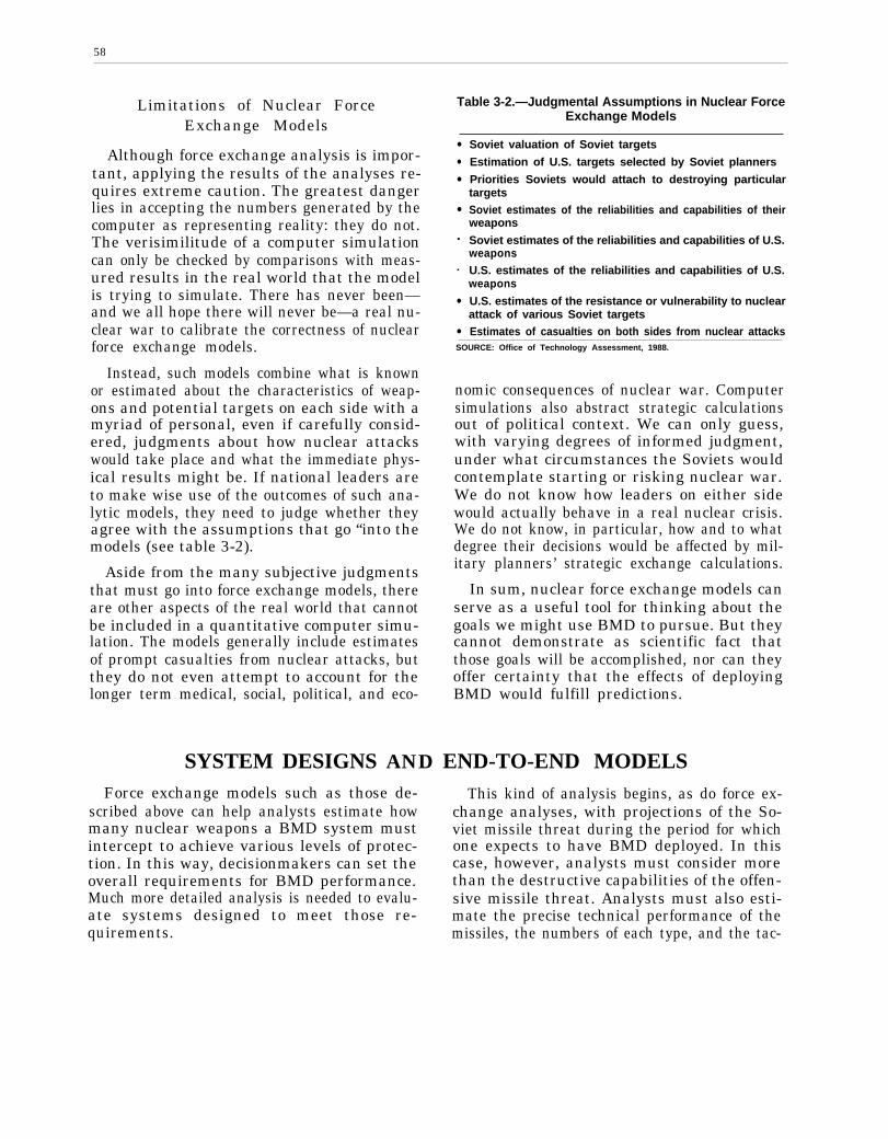
58
Limitations of Nuclear ForceExchange Models
Although force exchange analysis is impor-tant, applying the results of the analyses re-quires extreme caution. The greatest dangerlies in accepting the numbers generated by thecomputer as representing reality: they do not.The verisimilitude of a computer simulationcan only be checked by comparisons with meas-ured results in the real world that the modelis trying to simulate. There has never been—and we all hope there will never be—a real nu-clear war to calibrate the correctness of nuclearforce exchange models.
Instead, such models combine what is knownor estimated about the characteristics of weap-ons and potential targets on each side with amyriad of personal, even if carefully consid-ered, judgments about how nuclear attackswould take place and what the immediate phys-ical results might be. If national leaders areto make wise use of the outcomes of such ana-lytic models, they need to judge whether theyagree with the assumptions that go “into themodels (see table 3-2).
Aside from the many subjective judgmentsthat must go into force exchange models, thereare other aspects of the real world that cannotbe included in a quantitative computer simu-lation. The models generally include estimatesof prompt casualties from nuclear attacks, butthey do not even attempt to account for thelonger term medical, social, political, and eco-
Table 3-2.—Judgmental Assumptions in Nuclear ForceExchange Models
●
●
●
●
•
•
●
●
Soviet valuation of Soviet targets
Estimation of U.S. targets selected by Soviet planners
Priorities Soviets would attach to destroying particulartargetsSoviet estimates of the reliabilities and capabilities of theirweapons
Soviet estimates of the reliabilities and capabilities of U.S.weaponsU.S. estimates of the reliabilities and capabilities of U.S.weapons
U.S. estimates of the resistance or vulnerability to nuclearattack of various Soviet targetsEstimates of casualties on both sides from nuclear attacks
SOURCE: Office of Technology Assessment, 1988.
nomic consequences of nuclear war. Computersimulations also abstract strategic calculationsout of political context. We can only guess,with varying degrees of informed judgment,under what circumstances the Soviets wouldcontemplate starting or risking nuclear war.We do not know how leaders on either sidewould actually behave in a real nuclear crisis.We do not know, in particular, how and to whatdegree their decisions would be affected by mil-itary planners’ strategic exchange calculations.
In sum, nuclear force exchange models canserve as a useful tool for thinking about thegoals we might use BMD to pursue. But theycannot demonstrate as scientific fact thatthose goals will be accomplished, nor can theyoffer certainty that the effects of deployingBMD would fulfill predictions.
SYSTEM DESIGNS AND END-TO-END MODELSForce exchange models such as those de-
scribed above can help analysts estimate howmany nuclear weapons a BMD system mustintercept to achieve various levels of protec-tion. In this way, decisionmakers can set theoverall requirements for BMD performance.Much more detailed analysis is needed to evalu-ate systems designed to meet those re-quirements.
This kind of analysis begins, as do force ex-change analyses, with projections of the So-viet missile threat during the period for whichone expects to have BMD deployed. In thiscase, however, analysts must consider morethan the destructive capabilities of the offen-sive missile threat. Analysts must also esti-mate the precise technical performance of themissiles, the numbers of each type, and the tac-
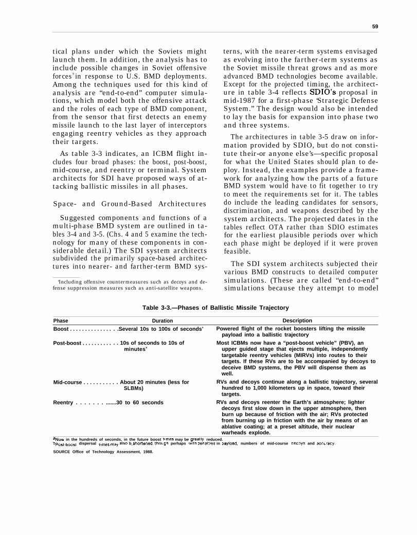
59
tical plans under which the Soviets mightlaunch them. In addition, the analysis has toinclude possible changes in Soviet offensiveforces9 in response to U.S. BMD deployments.Among the techniques used for this kind ofanalysis are “end-to-end” computer simula-tions, which model both the offensive attackand the roles of each type of BMD component,from the sensor that first detects an enemymissile launch to the last layer of interceptorsengaging reentry vehicles as they approachtheir targets.
As table 3-3 indicates, an ICBM flight in-cludes four broad phases: the boost, post-boost,mid-course, and reentry or terminal. Systemarchitects for SDI have proposed ways of at-tacking ballistic missiles in all phases.
Space- and Ground-Based Architectures
Suggested components and functions of amulti-phase BMD system are outlined in ta-bles 3-4 and 3-5. (Chs. 4 and 5 examine the tech-nology for many of these components in con-siderable detail.) The SDI system architectssubdivided the primarily space-based architec-tures into nearer- and farther-term BMD sys-
‘Including offensive countermeasures such as decoys and de-fense suppression measures such as anti-satellite weapons.
terns, with the nearer-term systems envisagedas evolving into the farther-term systems asthe Soviet missile threat grows and as moreadvanced BMD technologies become available.Except for the projected timing, the architect-ure in table 3-4 reflects SDIO’s proposal inmid-1987 for a first-phase ‘Strategic DefenseSystem.” The design would also be intendedto lay the basis for expansion into phase twoand three systems.
The architectures in table 3-5 draw on infor-mation provided by SDIO, but do not consti-tute their-or anyone else’s—specific proposalfor what the United States should plan to de-ploy. Instead, the examples provide a frame-work for analyzing how the parts of a futureBMD system would have to fit together to tryto meet the requirements set for it. The tablesdo include the leading candidates for sensors,discrimination, and weapons described by thesystem architects. The projected dates in thetables reflect OTA rather than SDIO estimatesfor the earliest plausible periods over whicheach phase might be deployed if it were provenfeasible.
The SDI system architects subjected theirvarious BMD constructs to detailed computersimulations. (These are called “end-to-end”simulations because they attempt to model
Table 3-3.—Phases of Ballistic Missile Trajectory
Phase Duration Description
Boost . . . . . . . . . . . . . . . .Several 10s to 100s of secondsa Powered flight of the rocket boosters lifting the missilepayload into a ballistic trajectory
Post-boost . . . . . . . . . . . . 10s of seconds to 10s of Most ICBMs now have a “post-boost vehicle” (PBV), anminutesb upper guided stage that ejects multiple, independently
targetable reentry vehicles (MIRVs) into routes to theirtargets. If these RVs are to be accompanied by decoys todeceive BMD systems, the PBV will dispense them aswell.
Mid-course . . . . . . . . . . . About 20 minutes (less for RVs and decoys continue along a ballistic trajectory, severalSLBMs) hundred to 1,000 kilometers up in space, toward their
targets.
Reentry . . . . . . . .......30 to 60 seconds RVs and decoys reenter the Earth’s atmosphere; lighterdecoys first slow down in the upper atmosphere, thenburn up because of friction with the air; RVs protectedfrom burning up in friction with the air by means of anablative coating; at a preset altitude, their nuclearwarheads explode.
af.Jow in the hundreds of seconds, in the future boost timeS may be 9reatlY reduced.bpo5t.boo5t dispersal tlme~ may a150 be shodened, though perhaps with penalties in payload, numbers of mid-course decoys, and aCCUraCY,
SOURCE Office of Technology Assessment, 1988.
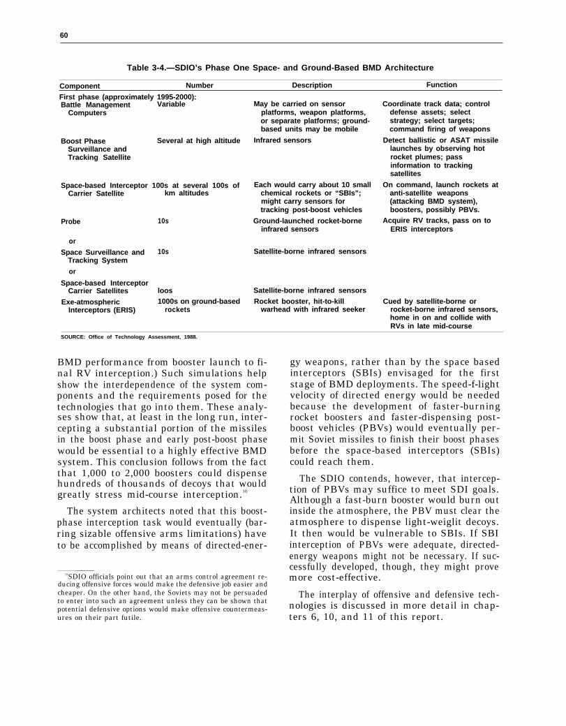
— —
60
Table 3-4.—SDIO’s Phase One Space- and Ground-Based BMD Architecture
Component Number Description Function
First phase (approximately 1995-2000):Battle Management Variable
Computers
Boost Phase Several at high altitudeSurveillance andTracking Satellite
Space-based Interceptor 100s at several 100s ofCarrier Satellite km altitudes
Probe 10s
or
Space Surveillance and 10sTracking System
or
Space-based InterceptorCarrier Satellites loos
Exe-atmospheric 1000s on ground-basedInterceptors (ERIS) rockets
May be carried on sensorplatforms, weapon platforms,or separate platforms; ground-based units may be mobile
Infrared sensors
Each would carry about 10 smallchemical rockets or “SBIs”;might carry sensors fortracking post-boost vehicles
Ground-launched rocket-borneinfrared sensors
Satellite-borne infrared sensors
Satellite-borne infrared sensorsRocket booster, hit-to-kill
warhead with infrared seeker
Coordinate track data; controldefense assets; selectstrategy; select targets;command firing of weapons
Detect ballistic or ASAT missilelaunches by observing hotrocket plumes; passinformation to trackingsatellites
On command, launch rockets atanti-satellite weapons(attacking BMD system),boosters, possibly PBVs.
Acquire RV tracks, pass on toERIS interceptors
Cued by satellite-borne orrocket-borne infrared sensors,home in on and collide withRVs in late mid-course
SOURCE: Office of Technology Assessment, 1988.
BMD performance from booster launch to fi-nal RV interception.) Such simulations helpshow the interdependence of the system com-ponents and the requirements posed for thetechnologies that go into them. These analy-ses show that, at least in the long run, inter-cepting a substantial portion of the missilesin the boost phase and early post-boost phasewould be essential to a highly effective BMDsystem. This conclusion follows from the factthat 1,000 to 2,000 boosters could dispensehundreds of thousands of decoys that wouldgreatly stress mid-course interception.10
The system architects noted that this boost-phase interception task would eventually (bar-ring sizable offensive arms limitations) haveto be accomplished by means of directed-ener-
10SDIO officials point out that an arms control agreement re-ducing offensive forces would make the defensive job easier andcheaper. On the other hand, the Soviets may not be persuadedto enter into such an agreement unless they can be shown thatpotential defensive options would make offensive countermeas-ures on their part futile.
gy weapons, rather than by the space basedinterceptors (SBIs) envisaged for the firststage of BMD deployments. The speed-f-lightvelocity of directed energy would be neededbecause the development of faster-burningrocket boosters and faster-dispensing post-boost vehicles (PBVs) would eventually per-mit Soviet missiles to finish their boost phasesbefore the space-based interceptors (SBIs)could reach them.
The SDIO contends, however, that intercep-tion of PBVs may suffice to meet SDI goals.Although a fast-burn booster would burn outinside the atmosphere, the PBV must clear theatmosphere to dispense light-weiglit decoys.It then would be vulnerable to SBIs. If SBIinterception of PBVs were adequate, directed-energy weapons might not be necessary. If suc-cessfully developed, though, they might provemore cost-effective.
The interplay of offensive and defensive tech-nologies is discussed in more detail in chap-ters 6, 10, and 11 of this report.
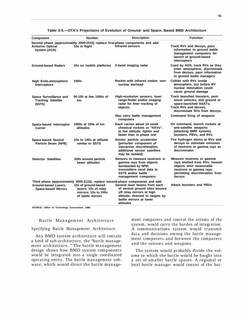
61
Table 3-5.—OTA’s Projections of Evolution of Ground- and Space. Based BMD Architecture
Component Number Description Function
Second phase (approximately 2000-2010) replace first-phase components and add:Airborne Optical 10s in flight Infrared sensors
System (AOS)
Ground-based Radars
High Endo-atmosphericInterceptors
Space Surveillance andTracking Satellite(SSTS)
Space-based InterceptorCarrier
Space-based NeutralParticle Beam (NPB)
Detector Satellites
10s on mobile platforms
1000s
50-100 at few 1000s ofkm.
1000s at 100s of kmaltitudes
10s to 100s at altitudesimilar to SSTS
100s around particlebeam altitudes
X-band imaging radar
Rocket with infrared seeker, non-nuclear warhead
High-resolution sensors; laserrange-finder and/or imagingradar for finer tracking ofobjects;
May carry battle managementcomputers
Each carries about 10 smallchemical rockets or “KKVs”.at low altitude; lighter andfaster than in phase one
Atomic particle accelerator(perturber component ofinteractive discrimination;additional sensor satellitesmay be needed)
Sensors to measure neutronsgamma rays from objectsbombarded by NPB;transmitters send data toSSTS and/or battlemanagement computers
1
or
Track RVs and decoys, passinformation to ground battlemanagement computers forlaunch of ground-basedinterceptors
Cued by AOS, track RVs as theyenter atmosphere; discriminatefrom decoys, pass informationto ground battle managers
Collide with RVs insideatmosphere, but before RVnuclear detonation couldcause ground damage
Track launched boosters, post-boost vehicles, and ground orspace-launched ASATs;
Track RVs and decoys,discriminate RVs from decoys;
Command firing of weapons
On command, launch rockets atanti-satellite weapons(attacking BMD system),boosters, PBVs, and RVs
Fire hydrogen atoms at RVs anddecoys to stimulate emissionof neutrons or gamma rays asdiscriminator
Measure neutrons or gammarays emitted from RVs: heavierobjects emit measurableneutrons or gamma rays,permitting discrimination fromdecoys
Attack boosters and PBVsThird phase (approximately 2005-2115), replace second-phase components and add:Ground-based Lasers, 10s of ground-based Several laser beams from each
Space-based Mirrors lasers; 10s of relay of several ground sites bouncemirrors; 10s to 100s off relay mirrors at highof battle mirrors altitude, directed to targets by
battle mirrors at loweraltitudes
SOURCE: Office of Technology Assessment, 1988.
Battle Management Architecture
Specifying Battle Management Architecture
Any BMD system architecture will containa kind of sub-architecture, the “battle manage-ment architecture. ” The battle managementdesign shows how BMD system componentswould be integrated into a single coordinatedoperating entity. The battle management soft-ware, which would direct the battle manage-
ment computers and control the actions of thesystem, would carry the burden of integration.A communications system would transmitdata and decisions among the battle manage-ment computers and between the computersand the sensors and weapons.
The system would probably divide the vol-ume in which the battle would be fought intoa set of smaller battle spaces. A regional orlocal battle manager would consist of the bat-

62
tle management software and computer withresponsibility for controlling the resourcesused to fight within a particular battle space.The battle manager and the resources it con-trolled would be known as a battle group. Thebattle management architecture specifies thefollowing:
●
●
●
●
●
●
the physical location of the battle man-agement computers and the nodes of thecommunications network;the method for partitioning resources intobattle groups so that battle managementcomputers have access to and control overappropriate numbers and kinds of sensorsand weapons;a hierarchical organization that specifiesthe authority and responsibility of the bat-tle managers, similar to a military chain-of-command;the role of humans in the battle manage-ment hierarchy;the method used for coordinating the ac-tions of the battle managers through thebattle management hierarchy and acrossthe different battle phases so that hand-over of responsibility, authority, and re-sources between boost, post-boost, mid-course, and terminal phases would takeplace smoothly and efficiently; andthe organization of and the method usedfor routing data and decisions through thecommunications network, probably orga-nized as a hierarchy that would governhow the nodes of the network were con-nected.
Battle management architectures proposedso far have varied widely in their approach tothese issues. For example, some architects pro-posed placing their space-based battle manage-ment computers on the same satellite plat-forms as the Space Surveillance and TrackingSystem (SSTS), some on the carrier vehicles,and some on separate battle management plat-forms; some proposed that the battle managersexchange track information only among neigh-bor battle managers at the same level of thebattle management hierarchy, while othersproposed that the same data also be exchangedbetween upper and lower levels; some ar-chitects permitted humans to intervene in themidst of battle to select different battle strat-egies while others allowed humans only to au-thorize weapons release.
Table 3-6 describes two different battle man-agement architectures that are representativeof those proposed. It shows the physical loca-tions of the battle managers, the criteria usedfor partitioning resources into battle groups,the data exchanged by the battle managers,the methods used for coordinating responsi-bility and authority between phases of the bat-tle, the degree to which human interventionwould be allowed during battle, and the struc-ture of the communications network.
Interaction Between Battle Managementand System Architecture
Battle management architectural decisionswould strongly affect the size, complexity, andorganization of the battle management soft-
Table 3-6.—Two Representative Battle Management Architectures
Design bylocation ofbattle Data exchanged by Method of coordinating Degree of Communicationsmanagers Partitioning criterion battle managers between battle phases human intervention network organization
Design i: Local battle groups Object tracks Regional battle Humans authorize Two-tiered hierarchyassigned to cover managers control weapons release at
SSTS specific Earth-based hand-over between start of battle; cangeographic areas phases switch strategies
during battleDesign ii: Initially geographic, Health (weapon status) All battle managers Humans authorize All nodes in line-of-
then by threat tube information use same criteria for weapons release at sight of each otherCarrier (the path along target allocation, start of battle are interconnected
vehicles which a group of taking into accountmissiles travels) locations of other
battle managersSOURCE: Office of Technology Assessment, 1988.
63
ware. Because of the close relationship betweenthe battle management computers and thecommunications network, such decisions alsowould strongly affect the software that con-trolled the computers forming the nodes of thecommunications network. A good example ofthe interaction among system architecture,battle management architecture, and battlemanagement and communications software isrepresented by the controversy over howwidely distributed battle management shouldbe. The two extremes of completely central-ized and completely autonomous battle man-agers and a range of intermediate options arediscussed in both the Fletcher and Eastportgroup reports and considered in all the architec-tural studies.11
Physical Organization v. Conceptual Design
Analyses often have reflected confusion be-tween the physical organization and the con-ceptual organization of the battle managers.The physical organization may be centralizedby putting all of the battle management soft-ware into one large computer system, or be dis-tributed by having battle management com-puters on every carrier vehicle. Similarly, thesoftware may be designed as:
1. a single, central battle manager that con-trols the entire battle;
2. a hierarchy of battle managers, with lo-cal battle managers each responsible fora small battle space, regional battle man-agers responsible for coordinating amonglocal battle managers, and a central bat-tle manager coordinating the actions ofthe regional battle managers; or
3. as a set of completely independent battlemanagers with no coordination amongeach other.
Any of these three software designs might beimplemented using either a centralized or dis-
“Report of the Study on Eliminating The Threat Posed byNuclear Balh”stic Missiles, Vol. V, Battle Management, Com-munications, and Data Processing, October 1983. This was theonly unclassified volume of the Fletcher commission report. Seealso “Eastport Study Group—A Report to the Director, Stra-tegic Defense Initiative Organization” (Eastport Study Group,Marina Del Rey, CA, 1985).
tributed physical organization. Variations onthe three designs, e.g., introducing more levelsinto the battle manager hierarchy, are possi-ble, but infrequently considered.
The physical organization and the concep-tual design would impose constraints on eachother, and factors such as survivability andreliability would drive both. A widely distrib-uted physical design, involving many inde-pendent computers, would impose too heavya synchronization and communications pen-alty among the physically distributed compo-nents of the software to permit use of a cen-tralized conceptual design: the attendantcomplications in the software would make thebattle manager unreliable and slow to react.Physical distribution requires the battle man-agement software on each computer to be rela-tively autonomous. A system with completelyautonomous battle managers would performless well than a system with communicatingbattle managers. Accordingly, even a widelydistributed physical organization would likelyrequire some communications and synchroni-zation among the battle managers.
A centralized physical design might not pro-vide sufficient computer processing power foracceptable performance, but would signifi-cantly improve communications among thebattle managers. The result might simplify thesoftware development, and lead to greater soft-ware reliability. On the other hand, such anorganization might result in a poorly surviva-ble system: if the central computer were dis-abled, the remainder of the system could notfunction.
Integrating Battle Management ArchitectureWith System Architecture
Since the system architecture, physical bat-tle management organization, and battle man-agement software design affect each other, allshould be considered together. The relation-ships and interfaces among the battle manag-ers should be defined either prior to or together-with definition of the physical organization ofthe battle managers and their requirements forcommunication with each other and with sen-sors and weapons. As the Fletcher report
64
stated, “The battle management system andits software must be designed as an integralpart of the BMD system as a whole, not as anapplique.“ 12
Most of the SDI architectures proposed sofar have shown little evidence of an integraldesign. Software design has been largely ig-nored, giving way to issues such as the loca-tion of the battle management computers andthe criteria for forming battle groups. TheSDIO has reported that it is attempting to bet-ter integrate overall system architecturestudies and battle management studies in itscurrent phase of system architecture contract-ing. However, the system proposed in mid-1987for “demonstration and validation” seemed toreflect no such integration.
Some Important Results of the SystemRequirements and Design Work
Systems analysis for SDI is still, necessarily,at a preliminary stage. Its most valuable con-tribution so far has probably been the iden-tification of key issues that research wouldhave to resolve satisfactorily before the Nationcould make a rational decision to proceed todevelopment and deployment of BMD. In par-ticular, the analyses have shown the following:
Boost-Phase Interception
Adequate boost-phase interception of mis-siles is essential to make the mid-course andterminal interception problems manageable;otherwise, the offense has the opportunity todeploy so many decoys and other penetrationaids that they could swamp the other defen-sive layers. However, an adequate boost-phaseinterception may, over time, be countered by
fnew of ensive weapons and still have done itsjob: after deploying all the faster burningboosters and PBVs it could afford to counterthe boost-phase defense, the offense may notbe able to deploy enough decoys to overwhelmthe mid-course defense.
12Ibid.
Ultimate Need for Directed-Energy Weapons
As a corollary to the need for effective boost-phase interception, it will be important to havea credible long-term system design which in-cludes directed-energy weapons based in spaceto carry out boost-phase interception againstboosters and PBVs that are too fast to bereached by kinetic energy weapons. Withoutsuch a credible plan, the boost-phase intercep-tors would face fairly predictable obsolescence.(It is possible, however, to imagine the devel-opment of new SBIs able to penetrate the up-per atmosphere; if launched quickly enough,they could then reach some boosters.)
Need for Interactive Discrimination
Because of the potential for Soviet deploy-ment of hundreds of thousands of decoys thatpassive sensors may not be able to differenti-ate from RVs disguised as decoys (“ anti-simu-lation”), mid-course interception is likely to re-quire means of perturbing RVs and decoys andhighly capable sensors to detect the differencesin the ways the two kinds of objects react. Suchmeans of “interactive discrimination” havebeen conceived but not yet built and tested.
Interdependence of Defensive Layers
Ideally, independent layers of sensors andweapons would carry out interception of eachphase of ballistic missile trajectory, thus elim-inating common failure modes and commonnodes of vulnerability to hostile action. In fact,for practical reasons, the system architectsgenerally produced designs with considerabledegrees of interdependence. In addition, asnoted above, even if the functions of each layerwere performed entirely independently, failurein one phase of interception (the boost-phase,for example) can severely affect the potentialperformance of succeeding phases.
Importance of Integrated Battle ManagementArchitecture
Initially, system architecture and battlemanagement architecture studies were sepa-rately contracted for, producing large dis-crepancies among those who had studied each
65
subject the most. The two sets of studies areapparently now being better integrated, andpresumably subsequent designs will reflectthat integration.
Distributed Battle ManagementAlthough considerable work on designing
BMD battle management remains, analysis sofar makes clear the importance of a battle man-agement system that make decisions in a dis-tributed, as opposed to centralized, fashion.Attempting to centralize the decisionmakingwould both impose excessive computing, soft-b ware engineering, and communications require-ments and make the system more vulnerableto enemy disruption.
Heavy Space Transportation RequirementsThe system architecture designs now permit
better forecasts of the requirements imposedby space-based systems for space transporta-tion capabilities-capabilities far beyond thosethe United States now possesses. (Primarilyground-based architectures do not share thisproblem.)
Requirements for Assured Survival
There appears to be general agreement onthe importance of significantly reducing offen-sive force developments if one hopes to pro-vide mutual assured survival for the U.S. andSoviet populations.
IMPORTANT SYSTEMS ANALYSIS WORK REMAINING
The SDI architecture studies have just be-gun to address the complex problems of de-signing a working, survivable BMD systemwith prospects for long-term viability againsta responsive Soviet threat. Thus far, the ar-chitecture studies have served the useful pur-pose of helping to identify the most criticaltechnologies needing further development. Fu-ture system designers would have to integratethe technologies actually available-and massproducible–into deployable and workableweapon systems.
Given that the system architects and SDIOare just over 2 to 3 years into an analytic ef-fort that will take many more years, it is nota criticism to say that much work remains.However, it appears to be the case that the anal-ysis supporting the first-phase architecture thatSDIO proposed in mid-1987 simply did not ad-dress many key questions. The following are fur-ther tasks that analysts should carry out to helpboth the executive and legislative branches judgethe potential effects of decisions on BMD.
Further Strategic Nuclear ForceExchange Work
The strategic nuclear exchange modelingdone so far by the SDI system architects pro-
vides a useful beginning to the larger andlengthier task of developing the informationthat will be needed for a national decision onwhether to deploy BMD. If the limitations ofthese kinds of simulations are borne carefullyin mind, they can help one to understand howBMD might affect the calculations of U.S. andSoviet national leaders, both indecisions aboutpeace and war and indecisions about long-termstrategic policies. They can also help to clar-ify the assumptions all participants bring tothe U.S. national debate about BMD.
Introduce Comparability Among Analyses
It is desirable to have competing sets of com-puter simulation models for analyzing the samequestions. In that way, decisionmakers couldcompare differing conclusions and identify theunderlying assumptions of each. (Comparisonscould also uncover errors in implementationof the models.) Analysts should run differentmodels using the same sets of data about theSoviet missile threat, the same configurationsof defensive systems, and the same offensiveand defensive strategies and tactics. Thus far,differences in these elements have made theanalyses of the system architects difficult tocompare and judge.
66
Further Analyses of SovietOffensive Responses
The simulations run so far have examinedonly limited variations on Soviet attack plansin the face of growing U.S. defensive capabil-ities: the assumption is made that the Sovietshave an inflexible list of targets. The Sovietsare assumed to optimize their exact attack planto destroy the highest possible number of thosetargets at some level of confidence. Suppose,however, that if defenses drastically reducedSoviet confidence in their ability to destroyhardened military targets, they concentratedon softer military and economic targets.Analysts must carry out further explorationof this possibility if decisionmakers are to un-derstand the full implications of BMD for alltypes of deterrence (see table 3-l).
Assumptions About Deterrence
An analytic focus on an inflexible Soviet tar-get plan seems to be related to a simplifiedmodel of potential Soviet motives for attack.The usual working assumption seems to bethat the Soviets would decide to launch a nu-clear strike on the United States on the basisof calculations about the probabilities of de-stroying certain percentages of various typesof targets. In this view, above a certain thresh-old for one or more of these probabilities, theSoviets would be willing to strike, and belowit they would not because they could not ac-complish their military purposes. One targetset would be the weapons and command-and-control facilities that would permit a U.S. nu-clear retaliation. But the exact role in Sovietdecisionmaking attributed to fear of retalia-tion–as opposed to accomplishment of othermilitary objectives—remains unclear. The nu-clear exchange models should make more explicittheir assumptions about the weighings givento denial of military objectives as opposed to thelikelihood and intensity of U.S. retaliation as en-forcers of deterrence.
Analysts should attempt to identify the in-crement of uncertainty added to the Soviet cal-culus of nuclear war provided by levels of defen-sive capability that might increase Sovietuncertainty about achieving attack objectives,
but that could not assure denial of those objec-tives. Many things could go wrong with a nu-clear attack precisely scheduled to achieve aspecific set of goals (such as knocking out agiven percentage of U.S. retaliatory capabil-ity). How much uncertainty would a given levelof BMD add to that which already exists?What are the potential Soviet responses to thisadditional uncertainty?13 To what extent wouldthe increment of uncertainty strengthen de-terrence? At what cost per increment ofstrengthened deterrence?
Strategic Stability Analyses
Closely related to the question of Soviet at-tack motivations is the question of strategicstability. In its 1985 report on BMD, OTA em-phasized the importance of exploring this ques-tion thoroughly.
A simplified approach to crisis stability isas follows: in a military confrontation with theUnited States, Soviet decisionmakers wouldcalculate whether or not they could achieve agiven set of military objectives by launchinga strategic nuclear first strike. If the objectivesseemed attainable, they would strike; if not,they would refrain. The system architects haveconsidered this scenario.
Another possibility they should address,however, is that Soviet perceptions of a likelyU.S. first strike might affect Soviet behavior.System architects have been understandablyreluctant to run or to report extensively onsimulations in which the United States is as-sumed to strike first. Such analyses might im-ply to some that a change is being contem-plated in U.S. policy not to launch a preemptivestrategic nuclear first strike. Nevertheless,such analysis needs to be done, not becausethe United States would launch such an attack,but because the Soviet Union might not be-lieve that it would not.
13A possibility suggested by one reviewer of the OTA studyis that the Soviets discover, unbeknownst to the United States,a way of disabling the U.S. BMD system (perhaps by spoofingits command and control system). Further, the Soviets validatetheir countermeasure with undetected techniques before actu-ally launching an attack. Certain that their technique will work,and their offensive forces augmented in response to the U.S.defensive deployments, the Soviets in this scenario end up morecertain about the probable success of their attack than before,
67
It is conceivable, for example, that Sovietstrategic exchange calculations could showthat a U.S. first strike, backed up by U.S.BMD, might allow the United States to reducesignificantly the damage from a Soviet “ragged”retaliation.14 On the other hand, a Soviet firststrike might have an analogous effect. If theSoviets believed that the United States, ex-pecting a Soviet strike, might strike first, thenthe Soviets might try to get in the first blow.Thus, they would not make their decision tostrike on the basis of accomplishing a clear setof military objectives, but instead on the ba-sis of choosing the less terrible of two cata-strophic outcomes.
Even if the Soviet Union and the United Statesavoided a nuclear crisis in which such calcula-tions might play a role, the calculations couldstill influence the longer-range Soviet responsesto U.S. BMD deployments. The Soviets mightdecide that it was extremely important to themto maintain a “credible” nuclear threat againstthe United States, and therefore be willing tospend more on maintaining offensive forces than“cost-exchange” ratios would seem to justify.
Administration officials have repeatedlystated their desire to negotiate (or find unilater-ally) a “stable transition” path to a world inwhich strategic defenses play a large role. Find-ing such a path would require careful analysisof the incentives presented to Soviet leaders byU.S. actions. Estimating the consequences of ahypothetical U.S. attack is one key part of suchan analysis. Only then might U.S. analystsidentify offensive and defensive force levelsthat both sides could believe served their secu-rity. Some of this analytic work has beenstarted, but more is necessary.
U.S. Responses to Soviet BMD
It is entirely possible that the Soviet Unionwill not wait until the United States decideswhether deploying BMD is a good idea or not,but instead will unilaterally choose to expand
14A “ragged” retaliation is one carried out after the first strikehas destroyed at least portions of the nation’s strategic forcesand possibly degraded its command and control system, result-ing in a relatively unstructured, diluted counter-attack.
its own BMD system.15 The United States con-ducts BMD research in part to be able to re-spond in kind to such a decision. The systemarchitects for SDI have conducted simulationsto show how a responding U.S. BMD deploy-ment might restore the U.S.-Soviet strategicbalance. Before the United States chose sucha response, however, two other kinds of anal-ysis are desirable. First, analysts should com-pare the BMD option with the option of circum-venting Soviet BMD by means of increasingU.S. air-breathing, low-flying cruise missileforces. Second, researchers should determinethe ability of U.S. technology to find adequateoffensive countermeasures to Soviet BMD.
These questions are partly amenable to thestrategic exchange modeling technique. In thefirst case, the model could assume variousnumbers of cruise missiles with varying levelsof probability of penetration in battle scenariosin which Soviet BMD was degrading the abil-ity of U.S. ballistic missiles to get through.Analysts could compare these outcomes tothose of similar scenarios in which the U.S. de-ployed BMD instead of additional cruise mis-siles. Then they could estimate quantities ofBMD and cruise missiles required to producesimilar outcomes. This information could pro-vide the basis for cost-effectiveness compari-sons between BMD and cruise missiles oncedata on the actual costs of the two types ofsystems became available.
Similarly, analysts could plug into the simu-lations the increases in warhead penetrationof Soviet defenses caused by U.S. offensivecountermeasures. Once estimates were avail-able for the costs of these countermeasures,analyses could develop some idea of the rela-tive cost-effectiveness of offense and defense.
lsAs ~fitt~ by the ABM Treaty, the Soviets have retaineda limited, nuclear-armed ballistic missile defense system in theMoscow area; they are currently expanding the system to thefull 100 interceptors permitted by the treaty, and could con-ceivably replicate the system elsewhere. They have also con-structed a series of phased array radars around the Soviet Unionwhich would provide warning and limited battle managementcapabilities for such an expanded system.
— — —
68
Analysis of Alternate Defensive Measures
The lesser goals of strategic defense–thatis, enhancing deterrence by increasing Sovietuncertainty or denial of various militaryobjectives—have thus far been considered aspreliminary benefits on the way toward ex-tremely high degrees of population protection.Therefore, alternate means of achieving thelesser goals as ends in themselves have notbeen analyzed. A few examples might clarifythis point.
Defense of Land-Based ICBMs.–If strength-ening deterrence by increasing the survivabil-ity of U.S. land-based retaliatory forces, espe-cially ICBMs were the goal of deploying BMD,then the system designs done for the SDImight not be optimal.18 Instead, ground-based,low-altitude interceptors located relativelynear the missiles to be defended might be lessexpensive (unlike cities, hardened missile silosor capsules might withstand low-altitude nu-clear explosions). In addition, the UnitedStates would want to consider how it could usevarious forms of mobile or deceptive basingof ICBMsin conjunction with limited BMDto make the enemy’s cost of attacking the mis-siles prohibitive.
Careful analysis of the goal of protectingstrategic bomber bases from SLBMs launchednot far off U.S. shores might also yield differ-ent BMD designs combined with differentbomber basing tactics.
Defense of Command, Control, and Commu-nications Facilities.—Similarly the strategicgoal of increasing the survivability of the U.S.command and control system for nuclear forcesmight be achieved by some form of BMD, butthe United States should also compare the costand effectiveness of BMD with those of othermeasures for making the system more resis-tant to nuclear attack. Further analysis mightshow that some combination of passive sur-vivability measures and BMD would be morecost-effective than either alone.
Defense Against Accidental or Terrorist Mis-sile Launches.—Protecting the country against10 or so incoming reentry vehicles is a muchdifferent task than protecting it against thou-sands. While SDI-designed systems might of-fer such protection as a side-benefit, if this kindof defense were to be the major goal of deploy-ing BMD, one would consider different, muchsimpler and cheaper architectures than those de-signed for the SDI.17
Further System Requirementsand Design Work
Analyze Additional Threats toBMD System Survivability
The SDI system architects recognized thatsurvivability would be a critical feature of anyBMD system. They devoted considerable ef-fort and ingenuity to inventing ways to reducesystem vulnerability to Soviet attack. Thechief threat to survivability they examined wasground-based, direct-ascent anti-satelliteweapons—rockets that the Soviets could “popup” from their territory to attack U.S. space-based BMD assets with nuclear or non-nuclearwarheads. This was a reasonable first approachto the survivability problem: such weaponsprobably represent the kind of defense suppres-sion weapon most immediately available to theSoviets. If the defense could not counter thisthreat, then there would be no point in explor-ing other, more sophisticated threats.
In the second round of their “horse race”competition the system architects did very lit-tle analysis of other potential threats to BMDsystem survivability, particularly longer-termspace-based threats. The threat of “spacemines, ” satellites designed specifically toshadow and destroy the various space-basedBMD components, was not considered indepth. Moreover, no analysis assumed that theSoviets might deploy in space a BMD system
Wee U.S. Congress, Office of Technology Assessment, AfXMissile Basing, OTA-ISC-140 (Washington, DC: U.S. Govern-ment Printing Office, September 1981).
“For example, a few ground-based, long-range interceptorslike the Exe-atmospheric Reentry Interceptor System (ERIS)–see ch. 5—could cover the continental United States; existingearly-warning radars could give initial track information anda few “pop-up” infrared sensor probes provide final track infor-mation.
69
comparable to that of the United States; thusthe potential vulnerabilities of such weapon sys-tems to one another were not considered. In-stead, it was assumed that the United Stateswould, for the most part, militarily dominatenear-Earth space. From the statement of workprovided to the SDI system architecture con-tractors late in 1986, it remained unclearwhether this assumption would be changed inthe follow-on studies to be completed early in1988.
Develop Realistic SchedulesThe system architects were originally in-
structed to design systems that might enterfull-scale engineering development in the early1990s and be deployed beginning in the m.id-1990s. The systems they designed would haverequired challenging technical achievementseven under the originally requested SDIbudgets. For example, one system architectpointed out that a vigorous technology pro-gram did not yet exist for an active space-basedsensor crucial to an “interim” defense intendedfor deployment in the mid-1990s. Or, to takeanother example, deployment in the mid-1990sof the space-based systems identified by thearchitects would require that the United Statesdecide almost immediately to begin acquiringthe massive space transportation system thatdeployment would require.18
Given the actual levels of SDI funding appro-priated by Congress thus far, mid-19% deploy-ment of the kinds of systems initially proposedby the system architects is clearly not feasible.Even with the requested funding, it is unlikelythat researchers could overcome all the tech-nological hurdles in time to permit confidentfull-scale engineering decisions in the early1990s. Nor is it clear that the full-scale engi-neering process, including establishment ofmanufacturing capabilities for the complexsystems involved, could be completed in just3 or 4 years. (For example, the most optimis-tic expert estimate OTA encountered for engi-neering full-scale SDI battle management soft-
18The SD1O rque~ $Z!jo million in SUPPleIIIWIt~ funds forfiscal year 1987 to develop technology for low-cost space trans-portation.
ware was 7 years.) In short, the systemsdesignated as “interim” (similar to those la-beled “Second Phase” in table 3-5) by the sys-tem architects would not be likely to reach fulloperational capability until well after the year2000.
Late in 1986, SDIO called on its contractorsto orient their work to a much scaled-back sys-tem architecture, with scaled-back strategicgoals (see the “First Phase” in table 3-4).Speculations emerged in the press about “earlydeployment” options under consideration.Analysis of the “phase one” designs, however,suggests that even they could not be ready forinitial space deployment until at least the mid-1990s. Nor could they be fully in place muchbefore the end of the century.
In the meantime, the Soviet Union might welldeploy practical countermeasures against suchsystems. Specifically, many in the defense com-munity believe that the Soviets could deploydecoys along with their reentry vehicles thatwould greatly stress the minimal mid-coursediscrimination capability of a phase-one sys-tem. In addition, the Soviets could at least be-gin to deploy new booster rockets that woulddrastically reduce the effectiveness of space-based interceptors (SBIs) in boost-phase defense.
Even if the United States could deploy SBIsbeginning in the mid-1990s, another questionremains: how confident do U.S. decisionmakerswish to be in the long-term viability of BMDbefore they decide to deploy such systems?Given the state of research on directed-energydevices for BMD, it is highly unlikely that U.S.leaders could have sufficient information bythe early 1990s to determine whether full-scaleengineering development of phases two andthree would be feasible in the following dec-ade. Thus, an early 1990s decision implies a com-mitment to a space-based BMD whose obsoles-cence would be made highly probable by theprospect of faster burning Soviet missileboosters, but whose replacement would remainunproven.
Develop Credible Cost Estimates
The SDIO has properly pointed out that try-ing to estimate total life-cycle costs for an un-

70
precedented system is difficult. The aerospaceindustry would have to manufacture new com-ponents and weapons in new ways. The Na-tion would need a new space transportationsystem for a space-based system. The SDIOhas agreed to estimate “cost goals” to indi-cate the kind of investment that the Nationwould have to make in proposed BMD architec-tures. The system architects were instructedto develop cost estimates in their 1987 studies.
Develop Methods for EstimatingCost-Exchange Ratios BetweenDefense and Offense
As this report pointed out in chapter 2, onekey criterion for the technical feasibility of theSDI scenario of transition to a “defense-dom-inated’ world is that there be a favorable cost-exchange ratio between defense and offense.The system architects did try to address thisissue in various ways, but there still seems tobe no systematic approach toward it. The prob-lem will be intrinsically difficult, because esti-mating in advance the costs of the U.S. BMDsystem will be difficult, estimating the costsof Soviet responses will be more difficult, andpredicting Soviet estimates of these quanti-ties will be most difficult of all. Nevertheless,
analyses should at least begin to specify whatinformation would permit sufficient confidencethat the defense/offense cost-exchange ratio ishigh enough to justify going ahead. The systemarchitecture contractor teams were instructedto address the problem in their 1987 work.
Assess the Role and Costs ofComplementary Air Defenses
The Strategic Defense Initiative Organiza-tion is specifically limited to defense againstballistic missiles. The Air Force has under-taken an “Air Defense Initiative, ” though atfunding levels far below that of the SDI. Never-theless, at least at the systems analysis level,U.S. decisionmakers need an integrated under-standing of the role that air defense would haveto play if ballistic missile defense were toachieve such goals as increasing Soviet uncer-tainty about attack success, denying Sovietabilities to destroy high percentages of certaintypes of targets, or protecting the populationfrom nuclear attack. Moreover, insofar asBMD requires air defense to accomplish itspurposes, the feasibility and affordability of airdefense against possible Soviet attempts to cir-cumvent BMD need to be included in any ulti-mate analysis of the feasibility of BMD.
Chapter 4
Status and Prospects of BallisticMissile Defense Sensor Technology
CONTENTSPage
Introduction. . . . . . . . . . . . . . . . . . . . . . . . . . . . . . . . . . . . . . . . . . . . . . . . . . . . . 73Sensors . . . . . . . . . . . . . . . . . . . . . . . . . . . . . . . . . . . . . . . . . . . . . . . . . . . . . . . . . 75
Proposed SDI Sensor Systems . . . . . . . . . . . . . . . . . . . . . . . . . . . . . . . . . . . 75Sensor Technology.. . . . . . . . . . . . . . . . . . . . . . . . . . . . . . . . . . . . . . . . . . . . . 85
Sensor Technology Conclusions . . . . . . . . . . . . . . . . . . . . . . . . . . . . . . . ......101Phase 1 . . . . . . . . . . . . . . . . . . . . . . . . . . . . . . . . . ......................101Phase 2....... . . . . . . . . . . . . . . . . . . . . . . . . . . . . . . . . . ...............101Phase . . . . . . . . . . . . . . . . . . . . . . . . . . . . . . . . . . . . . . . . ...............102
BoxBox Page
4-A. Sensor Resolution Limits . . . . . . . . . . . . . . . . . . . . . . . . . . . . . . . . . . . . . . 89
FiguresFigure No. Page
4-i.4-2.4-3.4-4.
4-5.4-6a4-6b4-7.
4-8.
Major SDI Sensors and Weapons . . . . . . . . . . . . . . . . . . . . . . . . . . . . . . 74Relations Between Temperature and Electromagnetic Radiation . . . . 75Scanning Pattern for Satellite Sensor. . . . . . . . . . . . . . . . . . . . . . . . . . . 77Illustration of Three Techniques for Estimating the Three-Dimensional Position of a Target in Space . . . . . . . . . . . . . . . . . . . . . . 83Spectral Response of Two Objects at Different Temperatures . . . . . . 87Diffraction-Limited Range for Ten-Meter Resolution . . . . . . . . . . . . . . 89Range Limitedly Number of Detectors for Ten-Meter Resolution . . 89Mirror Size Plotted v. the Operating Wavelength of aSensor System . . . . . . . . . . . . . . . . . . . . . . . . . . . . . . . . . . . . . . . . . . . . . . 90Illustration of an Imaging Radar Viewing a SpinningConical Target . . . . . . ........ .. .. .... .... . . . . . . . . . . . . . 93
TablesTable No. Page4-1. Summary of Typical Sensor Requirements. . . . . . . . . . . . . . . . . . . . . . . 844-2. Key Issues for Passive Sensors . . . . . . . . . . . . . . . . . . . . . . . . . . . . . . . . 884-3. Key Issues for Interactive Sensors . . . . . . . . . . . . . . . . . . . . . . . . . . . . . 99
Chapter 4
Status and Prospects of BallisticMissile Defense Sensor Technology
INTRODUCTION
Much of the public debate on ballistic missiledefense (BMD) technologies centers on futur-istic weapon systems such as lasers, rail guns,and particle beams. The Strategic Defense Ini-tiative Organization’s (SDIO) initial BMD sys-tem design, however, does not include any ofthese exotic weapons.1 Rather, it calls forspace-based interceptors (SBI) to collide withSoviet intercontinental ballistic missile (ICBM)boosters and post-boost vehicles (PBVs), andfor high acceleration ground-based missiles todestroy Soviet reentry vehicles (RVs) by di-rect impact. The sensor systems required todetect, identify, and track up to several hun-dred thousand targets may be more challeng-ing than the actual kinetic energy weapons:it may be more difficult to track targets thanto destroy them, once tracked.
The technical feasibility of a first-phase de-ployment, then, may depend primarily on ma-jor technical advances in the areas of sensorsand chemically propelled rockets, and less onthe availability of rail-gun or laser weapons sys-tems. Accordingly, this report emphasizesthese more conventional technologies.
Nonetheless, the more exotic weapons tech-nologies could become important in second-or
*Some BMD architecture contractors did, however, call forrather exotic beam sources for “interactive discrimination, ” inwhich targets would be exposed to sub-lethal doses of particlebeams or laser beams and their reactions measured to distin-guish between reentry vehicles and decoys. See section on in-teractive discrimination.
Recently, SDIO officials have spoken of “entry level” directed-energy weapons that might constitute part of second-phaseBMD deployments. The utility of such weapons would dependon the pace and scope of Soviet countermeasures.
Note: Complete definitions of acronyms and initialismsare listed in Appendix B of this report.
third-phase BMD systems deployed in re-sponse to Soviet countermeasures. For exam-ple, if the Soviet Union deployed fast-burnboosters that burned out and deployed theirRVs (and decoys) before they could be attackedby slow-moving chemically-propelled rockets,then laser weapons might be essential to at-tack ICBMs in their boost phase. These di-rected-energy weapons (DEW) would requireeven more accurate sensors, since their beamswould have to be directed with great precision.Thus, the required sensor technology improve-ments might continue to be at least as stress-ing as weapons technology requirements.
Some of the major sensor and weapon com-ponents proposed by Strategic Defense Initia-tive (SDI) system architects for both near- andfar-term deployments are listed in figure 4-1(also see ch. 3). This chapter describes sensors;weapons, power systems, communications sys-tems, and space transportation required to im-plement a global BMD system are describedin chapter 5. For each technology, chapters 4and 5 discuss:
● the type of system suggested by SDI ar-chitects,
● the technical requirements,● the basic operating principles,● the current status, and● the key issues for each technology.
The systems aspects of an integrated BMDsystem are discussed in chapter 6. Computingtechnologies are discussed in chapter 8. Tech-nologies for offensive countermeasures andcounter-countermeasures are deferred untilchapters 10 through 12 (as of this writing,available only in the classified version of thisreport).
73

74
Figure 4-1— Major SDI Sensors and Weapons
NPBdetector
SDI sensor systems:
BSTS-Boost Surveillance and Tracking System (infrared sensors)SSTS-Space Surveillance and Tracking System (infrared, visible, and possibly radar or laser radar sensors)AOS-Airborne Optical System (infrared and laser sensors)TIR-Terminal Imaging Radar (phased array radar)NPB-Neutral Particle Beam (interactive discrimination to distinguish reentry vehicles (RV’s) from decoys; includes separateneutron detector satellite)
SDI weapons systems:
SBI-Space-Based Interceptors or Kinetic Kill Vehicles (rocket-propelled hit to kill projectiles)SBHEL-Space-Based High Energy Laser (chemically pumped laser)GBFEL-Ground-Based Free Electron Laser (with space-based relay mirrors)NPB-Neutral Particle Beam weaponERIS-Exoatmospheric Reentry vehicle Interceptor System (ground-based rockets)HEDI-High Endoatmospheric Defense Interceptor (ground-based rockets)

75
SENSORS
Sensors are the eyes of a weapons system.In the past the human eye and brain have con-stituted the primary military sensor system.A soldier on the battlefield would:
●
●
●
●
●
●
●
look over the battlefield for possibleenemy action (surveillance);note any significant object or motion (ac-quisition);determine if the object was a legitimatetarget (discrimination);follow the enemy motion (tracking);Aim his rifle (weapon direction), fire;look to see if he had killed the target (killassessment); andif not, reacquire the target (retargeting),aim, and shoot again.
Ballistic missile defense entails these samefunctions of target surveillance, acquisition,discrimin ation, tracking, weapon direction, killassessment, and retargeting. BMD sensors,however, must have capabilities of resolution,range, spectral response, speed, and data stor-age and manipulation far beyond those of thehuman eye-brain system.
Proposed SDI Sensor Systems
The following sections describe five repre-sentative sensor systems. Most of the five SDIsystem architecture contractors (see ch. 3) rec-ommended some variation of these sensor sys-tems. The primary attack phase and recom-mended sensor platforms for each type aresummarized in tables 1-1 and 1-2.
Boost Surveillance and Tracking System(BSTS)
The BSTS would have to detect any missilelaunch, give warning, and begin to establishtrack files for the individual rockets. Most sys-tem architects proposed a constellation of sev-eral satellites in high orbit.
Typical BSTS characteristics are summa-rized in the classified version of this report.Each BSTS would carry a sensor suite thatwould monitor infrared (IR) emissions from the
Figure 4-2. - Relatlons Between Temperature andElectromagnetic Radiation
Target radiation bands
Temperature scales (Peak radiation wavelength)1 1 I
6,000 Kelvin (OK) 373 273
rocket plumes (see figure 4-2). From their veryhigh altitude, these sensors would have rela-tively poor optical resolution. Track files couldbe started, but the Space Surveillance andTracking System (SSTS) or other sensors atlower altitude might be required to achieve thetrack file accuracy needed for some BMDfunctions. 2
2Space-based interceptors (SBIs), formerly called “space-basedkinetic kill vehicles” (SBKKV), which have their own horningsensors, could operate with the resolution given by a BSTSsensor.
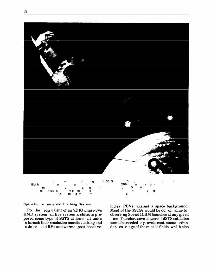
76
b rv d 9 mBSS o 9 b m 8M b wpm m
m d 9 9 m mASS S mg m d
b m 9 m m
Spa e Su e an e and T a king Sys em
Fo he equ valent of an SDIO phase-two BMD system all five system architects p 0-
posed some type of SSTS at lowe alt tudes o furnIsh finer resolution Illlssile tacking and ode ec 0 d RV s and warme post boost ve
CBM w m b m 9 S b
m 9 9 9
hicles PBV s agaInst a space background Most of the SSTSs would be ou of ange fo observ ng SovIet ICBM launches at any gIven
me Therefore seve al tens of SSTS satellites wou d be needed 0 p oVlde cont nuous edun dan co e age of the IlllSS Ie fields whi h also
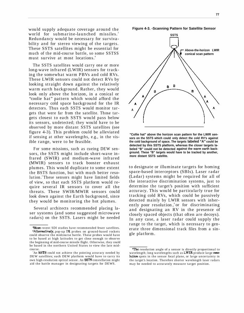
.
77
would supply adequate coverage around theworld for submarine-launched missiles.3
Redundancy would be necessary for surviva-bility and for stereo viewing of the targets.These SSTS satellites might be essential formuch of the mid-course battle, so some SSTSSmust survive at most locations.4
The SSTS satellites would carry one or morelong-wave infrared (LWIR) sensors for track-ing the somewhat warm PBVs and cold RVs.These LWIR sensors could not detect RVs bylooking straight down against the relativelywarm earth background. Rather, they wouldlook only above the horizon, in a conical or“coolie hat” pattern which would afford thenecessary cold space background for the IRdetectors. Thus each SSTS would monitor tar-gets that were far from the satellite. Those tar-gets closest to each SSTS would pass belowits sensors, undetected; they would have to beobserved by more distant SSTS satellites (seefigure 4-3). This problem could be alleviatedif sensing at other wavelengths, e.g., in the vis-ible range, were to be feasible.
For some missions, such as cueing DEW sen-sors, the SSTS might include short-wave in-frared (SWIR) and medium-wave infrared(MWIR) sensors to track booster exhaustplumes. This would duplicate to some extentthe BSTS function, but with much better reso-lution.5 These sensors might have limited fieldsof view, so that each SSTS platform would re-quire several IR sensors to cover all thethreats. These SWIR/MWIR sensors couldlook down against the Earth background, sincethey would be monitoring the hot plumes.
Several architects recommended placing la-ser systems (and some suggested microwaveradars) on the SSTS. Lasers might be needed
‘More recent SDI studies have recommended fewer satellites.4Akematively, pop-up IR probes on ground-based rockets
could observe the midcourse battle. These probes would haveto be based at high latitudes to get close enough to observethe beginning of mid-course missile flight. Otherwise, they couldbe based in the northern United States to view the late mid-course.
5An SSTS could not achieve the pointing accuracy needed byDEW satellites; each DEW platform would have to carry itsown high-resolution optical sensor. An SSTS constellation mightaid the battle manager in designating targets for DEWS.
Figure 4-3. -Scanning Pattern for Satellite Sensor
SSTS
Above-the-horizon LWIRconical scan pattern
A
"Collie hat” above the horizon scan pattern for the LWIR sen-sors on the SSTS which could only detect the cold RV's againstthe cold background of space. The targets labeled “A” could bedetected by this SSTS platform, whereas the closer targets la-beled “B” could not be detected against the warm earth back-ground. These “B” targets would have to be tracked by another,more distant SSTS satellite.
to designate or illuminate targets for homingspace-based interceptors (SBIs). Laser radar(Ladar) systems might be required for all ofthe interactive discrimination systems, just todetermine the target’s position with sufficientaccuracy. This would be particularly true fortracking cold RVs, which could be passivelydetected mainly by LWIR sensors with inher-ently poor resolution,6 or for discriminatingand designating an RV in the presence ofclosely spaced objects (that often are decoys).In any case, a laser radar could supply therange to the target, which is necessary to gen-erate three dimensional track files from a sin-gle platform.
‘The resolution angle of a sensor is directly proportional towavelength; long wavelengths such as LWIR produce large reselution spots in the sensor focal plane, or large uncertainty inthe target’s location. Therefore shorter wavelength laser radarsmay be needed to accurately measure target position.
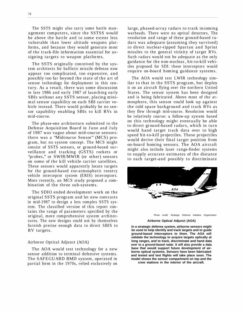
78
The SSTS might also carry some battle man-agement computers, since the SSTSS wouldbe above the battle and to some extent lessvulnerable than lower altitude weapons plat-forms, and because they would generate mostof the track-file information essential for as-signing targets to weapon platforms.
The SSTS originally conceived by the sys-tem architects for ballistic missile defense nowappear too complicated, too expensive, andpossibly too far beyond the state of the art ofsensor technology for deployment in this cen-tury. As a result, there was some discussionin late 1986 and early 1987 of launching earlySBIs without any SSTS sensor, placing mini-mal sensor capability on each SBI carrier ve-hicle instead. There would probably be no sen-sor capability enabling SBIs to kill RVs inmid-course.
The phase-one architecture submitted to theDefense Acquisition Board in June and Julyof 1987 was vague about mid-course sensors:there was a “Midcourse Sensor” (MCS) pro-gram, but no system concept. The MCS mightconsist of SSTS sensors, or ground-based sur-veillance and tracking (GSTS) rockets or“probes,” or SWIR/MWIR (or other) sensorson some of the kill vehicle carrier satellites.These sensors would apparently locate targetsfor the ground-based exe-atmospheric reentryvehicle interceptor system (ERIS) interceptors.More recently, an MCS study proposed a com-bination of the three sub-systems.
The SDIO ended development work on theoriginal SSTS program and let new contractsin mid-1987 to design a less complex SSTS sys-tem. The classified version of this report con-tains the range of parameters specified by theoriginal, more comprehensive system architec-tures. The new designs could not by themselvesfurnish precise enough data to direct SBIS toRV targets.
Airborne Optical Adjunct (AOA)
The AOA would test technology for a newsensor addition to terminal defensive systems.The SAFEGUARD BMD system, operated inpartial form in the 1970s, relied exclusively on
large, phased-array radars to track incomingwarheads. There were no optical detectors, Theresolution and range of these ground-based ra-dars was adequate (assuming they survived)to direct nuclear-tipped Spartan and Sprintmissiles to the general vicinity of target RVs.Such radars would not be adequate as the onlyguidance for the non-nuclear, hit-to-kill vehi-cles proposed for SDI: these interceptors wouldrequire on-board homing guidance systems.
The AOA would test LWIR technology sim-ilar to that in the SSTS program, but deployit on an aircraft flying over the northern UnitedStates. The sensor system has been designedand is being fabricated. Above most of the at-mosphere, this sensor could look up againstthe cold space background and track RVs asthey flew through mid-course. Resolution wouldbe relatively coarse: a follow-up system basedon this technology might eventually be ableto direct ground-based radars, which in turnwould hand target track data over to highspeed hit-to-kill projectiles. These projectileswould derive their final target position fromon-board homing sensors. The AOA aircraftmight also include laser range-finder systemsto supply accurate estimates of the distanceto each target-and possibly to discriminate
Photo credit: Strategic Defense Initiative Organization
Airborne Optical Adjunct (AOA)
In a strategic defense system, airborne sensors mightbe used to help identify and track targets and to guideground-based interceptors to them. The AOA willvalidate the technology to acquire targets optically atlong ranges, and to track, discriminate and hand dataover to a ground-based radar. It will also provide a database that would support future development of air-borne optical systems. Sensors have been fabricatedand tested and test flights will take place soon. Themodel shows the sensor compartment on top and the
crew stations in the interior of the aircraft.

79
decoys from RVs by measuring minute veloc-ity changes caused by drag in the upperatmosphere.
System architecture contractors proposedtens of AOA-like aircraft as part of a sensorsystem. Some proposed rocket-borne, pop-upprobes with LWIR sensors for rapid responsein a surprise attack until the aircraft couldreach altitude.
There is some uncertainty regarding the in-frared background that an airborne sensorsuch as AOA would see. Sunlight scatteredfrom either natural or (particularly) man-made“noctilucent clouds” might obscure the realRV targets. These clouds form at altitudesfrom 60 to 100 kilometers (km). During a bat-tle, the particles ablating from debris reenter-ing the atmosphere would form nucleationcenters. Long-lived ice crystals would grow atthese centers, possibly creating a noisy in-frared background that would obscure the realtargets arriving later. Intentional seeding ofthese clouds is also a possibility.7
Ground-Based Radar (GBR)
Large phased-array, ground-based X-band(8-12 GHz frequency) radars might work in con-junction with optical sensors to track and dis-criminate incoming warheads from decoys.These radars could receive target track datafrom those sensors and then use doppler proc-essing to create a pseudo-image of the war-heads by virtue of their spinning motion. Non-rotating decoys or decoys with different shapesor rotation rates would produce different ra-dar signatures.
Ground-based radars would also measure theeffects of the atmosphere, identifying light de-coys that would slow down more than theheavy RVs. These radars might guide or cuethe endoatmospheric HEDI and FLAGE-likeinterceptor rockets and the ERIS exoat-mospheric interceptors (see ch. 5).
‘See M.T. Sandford, II, A Review of Mesospheric CloudPhysics, Report No. LA-10866 (Los Alamos, NM: Los AlamosNational Laboratory, October 1986.)
The GBR concept very recently supplantedthe proposed Terminal Imaging Radar (TIR)system in SDIO planning. The latter wouldhave had a much shorter range (thereby notbeing useful for cueing the ERIS interceptor)and much less resistance to anti-radar coun-termeasures, such as jamming. Some radarconcepts call for deployment on railroad carsto evade enemy attack.
Neutral Particle Beam (NPB) InteractiveDiscrimination
While several interactive discriminationtechniques have been proposed (see section below on interactive discrimination), the NPB ap-proach has thus far received the most atten-tion and development funds.
A series of full space-based tests was plannedfor the early 1990s, but has been subjected tobudgetary cutbacks. A 50-MeV8 NPB sourcewas to be placed in orbit along with a sensorsatellite and a target satellite to measure beamcharacteristics and to begin interactive tests.The primary detection method would be tomonitor the neutrons emmitted by the targetafter irradiation by the NPB, although gammarays, x-rays, and ultraviolet radiation mightalso be useful for indicating whether targetshad been hit by the neutral particle beam. TheNPB accelerator might be located 1,000 kmfrom the target. The neutron detectors mightride on separate detector satellites closer totargets, although they could be collocated onthe NPB platform under some circumstances.A single NPB discrimination accelerator sys-tem might weigh 50,000 to 100,000 kilograms(kg), making it the heaviest element proposedfor a second-phase BMD.9 Over 100 NPB sat-ellites and several hundred neutron detector
‘The energy of a beam of particles is measured in ‘‘electronvolts” or “eV,” the energy that one electron would acquire trav-eling through an electric field with a potential of one volt. Theenergy of beam weapon particles would be so high that it ismeasured in rniUions of electron volts, or “MeV.” One MeV isequal to 1.6x1O –‘3 joules; each particle carries this amount ofenergy.
‘A far-term, robust BMD system might also include veryheavy directed-energy weapons.
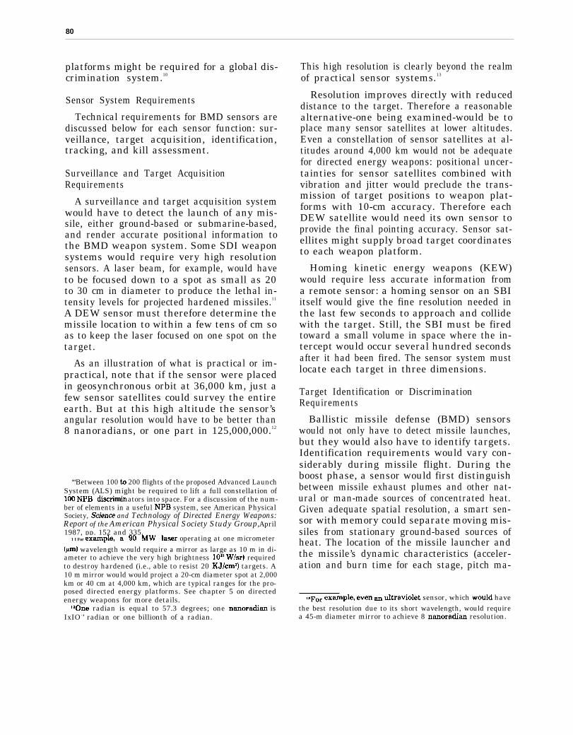
80
platforms might be required for a global dis-crimination system.10
Sensor System Requirements
Technical requirements for BMD sensors arediscussed below for each sensor function: sur-veillance, target acquisition, identification,tracking, and kill assessment.
Surveillance and Target AcquisitionRequirements
A surveillance and target acquisition systemwould have to detect the launch of any mis-sile, either ground-based or submarine-based,and render accurate positional information tothe BMD weapon system. Some SDI weaponsystems would require very high resolutionsensors. A laser beam, for example, would haveto be focused down to a spot as small as 20to 30 cm in diameter to produce the lethal in-tensity levels for projected hardened missiles.11
A DEW sensor must therefore determine themissile location to within a few tens of cm soas to keep the laser focused on one spot on thetarget.
As an illustration of what is practical or im-practical, note that if the sensor were placedin geosynchronous orbit at 36,000 km, just afew sensor satellites could survey the entireearth. But at this high altitude the sensor’sangular resolution would have to be better than8 nanoradians, or one part in 125,000,000.12
‘“Between 100 to 200 flights of the proposed Advanced LaunchSystem (ALS) might be required to lift a full constellation of100 NPB diSCIbliIl ators into space. For a discussion of the num-ber of elements in a useful NPB system, see American PhysicalSociety, Su”ence and Technology of Directed Energy Weapons:Report of the American Physical Society Study Group, April1987, pp. 152 and 335.
1 I For e~~ple, a 90 Mw laser operating at one micrometer(pm) wavelength would require a mirror as large as 10 m in di-ameter to achieve the very high brightness IOX’ W/sr) requiredto destroy hardened (i.e., able to resist 20 KJ/cm2) targets. A10 m mirror would would project a 20-cm diameter spot at 2,000km or 40 cm at 4,000 km, which are typical ranges for the pro-posed directed energy platforms. See chapter 5 on directedenergy weapons for more details.
“One radian is equal to 57.3 degrees; one nanoradian isIxIO -’ radian or one billionth of a radian.
This high resolution is clearly beyond the realmof practical sensor systems.13
Resolution improves directly with reduceddistance to the target. Therefore a reasonablealternative-one being examined-would be toplace many sensor satellites at lower altitudes.Even a constellation of sensor satellites at al-titudes around 4,000 km would not be adequatefor directed energy weapons: positional uncer-tainties for sensor satellites combined withvibration and jitter would preclude the trans-mission of target positions to weapon plat-forms with 10-cm accuracy. Therefore eachDEW satellite would need its own sensor toprovide the final pointing accuracy. Sensor sat-ellites might supply broad target coordinatesto each weapon platform.
Homing kinetic energy weapons (KEW)would require less accurate information froma remote sensor: a homing sensor on an SBIitself would give the fine resolution needed inthe last few seconds to approach and collidewith the target. Still, the SBI must be firedtoward a small volume in space where the in-tercept would occur several hundred secondsafter it had been fired. The sensor system mustlocate each target in three dimensions.
Target Identification or DiscriminationRequirements
Ballistic missile defense (BMD) sensorswould not only have to detect missile launches,but they would also have to identify targets.Identification requirements would vary con-siderably during missile flight. During theboost phase, a sensor would first distinguishbetween missile exhaust plumes and other nat-ural or man-made sources of concentrated heat.Given adequate spatial resolution, a smart sen-sor with memory could separate moving mis-siles from stationary ground-based sources ofheat. The location of the missile launcher andthe missile’s dynamic characteristics (acceler-ation and burn time for each stage, pitch ma-
ISFor exmple, even ~ titraviolet sensor, which would havethe best resolution due to its short wavelength, would requirea 45-m diameter mirror to achieve 8 nanoradian resolution.
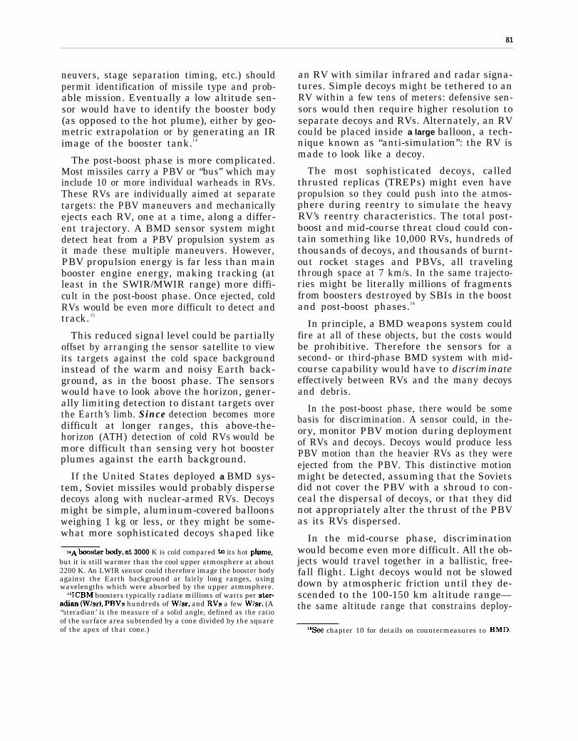
81
neuvers, stage separation timing, etc.) shouldpermit identification of missile type and prob-able mission. Eventually a low altitude sen-sor would have to identify the booster body(as opposed to the hot plume), either by geo-metric extrapolation or by generating an IRimage of the booster tank.14
The post-boost phase is more complicated.Most missiles carry a PBV or “bus” which mayinclude 10 or more individual warheads in RVs.These RVs are individually aimed at separatetargets: the PBV maneuvers and mechanicallyejects each RV, one at a time, along a differ-ent trajectory. A BMD sensor system mightdetect heat from a PBV propulsion system asit made these multiple maneuvers. However,PBV propulsion energy is far less than mainbooster engine energy, making tracking (atleast in the SWIR/MWIR range) more diffi-cult in the post-boost phase. Once ejected, coldRVs would be even more difficult to detect andtrack. 15
This reduced signal level could be partiallyoffset by arranging the sensor satellite to viewits targets against the cold space backgroundinstead of the warm and noisy Earth back-ground, as in the boost phase. The sensorswould have to look above the horizon, gener-ally limiting detection to distant targets overthe Earth’s limb. Since detection becomes moredifficult at longer ranges, this above-the-horizon (ATH) detection of cold RVS would bemore difficult than sensing very hot boosterplumes against the earth background.
If the United States deployed a BMD sys-tem, Soviet missiles would probably dispersedecoys along with nuclear-armed RVs. Decoysmight be simple, aluminum-covered balloonsweighing 1 kg or less, or they might be some-what more sophisticated decoys shaped like
14A boos~r body, at 3000 K is cold compared to its hot Plume,but it is still warmer than the cool upper atmosphere at about2200 K. An LWIR sensor could therefore image the booster bodyagainst the Earth background at fairly long ranges, usingwavelengths which were absorbed by the upper atmosphere.
“ICBM boosters typically radiate millions of watts per ster-adian (W/sr), PBVS hundreds of W/sr, and RVS a few W/sr. (A“steradian’ is the measure of a solid angle, defined as the ratioof the surface area subtended by a cone divided by the squareof the apex of that cone.)
an RV with similar infrared and radar signa-tures. Simple decoys might be tethered to anRV within a few tens of meters: defensive sen-sors would then require higher resolution toseparate decoys and RVs. Alternately, an RVcould be placed inside a large balloon, a tech-nique known as “anti-simulation”: the RV ismade to look like a decoy.
The most sophisticated decoys, calledthrusted replicas (TREPs) might even havepropulsion so they could push into the atmos-phere during reentry to simulate the heavyRV’s reentry characteristics. The total post-boost and mid-course threat cloud could con-tain something like 10,000 RVs, hundreds ofthousands of decoys, and thousands of burnt-out rocket stages and PBVs, all travelingthrough space at 7 km/s. In the same trajecto-ries might be literally millions of fragmentsfrom boosters destroyed by SBIs in the boostand post-boost phases.16
In principle, a BMD weapons system couldfire at all of these objects, but the costs wouldbe prohibitive. Therefore the sensors for asecond- or third-phase BMD system with mid-course capability would have to discriminateeffectively between RVs and the many decoysand debris.
In the post-boost phase, there would be somebasis for discrimination. A sensor could, in the-ory, monitor PBV motion during deploymentof RVs and decoys. Decoys would produce lessPBV motion than the heavier RVs as they wereejected from the PBV. This distinctive motionmight be detected, assuming that the Sovietsdid not cover the PBV with a shroud to con-ceal the dispersal of decoys, or that they didnot appropriately alter the thrust of the PBVas its RVs dispersed.
In the mid-course phase, discriminationwould become even more difficult. All the ob-jects would travel together in a ballistic, free-fall flight. Light decoys would not be sloweddown by atmospheric friction until they de-scended to the 100-150 km altitude range—the same altitude range that constrains deploy-
%ee chapter 10 for details on countermeasures to BMD.
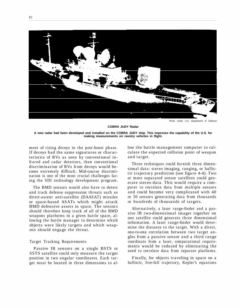
82
Photo credit: U.S. Department of Defense
COBRA JUDY Radar
A new radar had been developed and installed on the COBRA JUDY ship. This improves the capability of the U.S. formaking measurements on reentry vehicles in flight.
ment of rising decoys in the post-boost phase.If decoys had the same signatures or charac-teristics of RVs as seen by conventional in-frared and radar detectors, then conventionaldiscrimination of RVs from decoys would be-come extremely difficult. Mid-course discrimi-nation is one of the most crucial challenges fac-ing the SDI technology development program.
The BMD sensors would also have to detectand track defense suppression threats such asdirect-ascent anti-satellite (DAASAT) missilesor space-based ASATs which might attackBMD defensive assets in space. The sensorsshould therefore keep track of all of the BMDweapons platforms in a given battle space, al-lowing the battle manager to determine whichobjects were likely targets and which weap-ons should engage the threat.
Target Tracking Requirements
Passive IR sensors on a single BSTS orSSTS satellite could only measure the targetposition in two angular coordinates. Each tar-get must be located in three dimensions to al-
low the battle management computer to cal-culate the expected collision point of weaponand target.
Three techniques could furnish three dimen-sional data: stereo imaging, ranging, or ballis-tic trajectory prediction (see figure 4-4). Twoor more separated sensor satellites could gen-erate stereo data. This would require a com-puter to correlate data from multiple sensorsand could become very complicated with 40or 50 sensors generating data from thousandsor hundreds of thousands of targets.
Alternatively, a laser range-finder and a pas-sive IR two-dimensional imager together onone satellite could generate three dimensionalinformation. A laser range-finder would deter-mine the distance to the target. With a direct,one-to-one correlation between two target an-gles from a passive sensor and a third rangecoordinate from a laser, computational require-ments would be reduced by eliminating theneed to correlate data from separate platforms.
Finally, for objects traveling in space on aballistic, free-fall trajectory, Kepler’s equations

83
Figure 4-4. - Illustration of Three Techniques for Estimating the Three-Dimensional Position of a Target in Space
Stereo viewing IR angle/angle plus range finder
IR sensor B IR sensor A
#1
#2
Ballistic trajectory estimation(from one passive sensor)
Time T-3 Time T-2 Tme T-1
I
IR sensor
#2 .
In the first view Sensor A could not distinguish between Target # 1 and Target #2. Stereo viewing from two or more separate satellites withpassive IR sensors eliminates this ambiguity. Relatively complicated software is required to correlate data from each sensor. The othertwo techniques can predict three dimensional information from one platform, eliminating the requirement for multiple satellite sensordata correlation; a laser range finder determines the range or distance to a target by measuring the travel time for a pulse of light from theplatform to the target and back, uniquely determining position with one measurement. The ballistic trajectory prediction approach usesonly the passive IR sensor, but requires three or more measurements at different times to compute the target’s path through space.
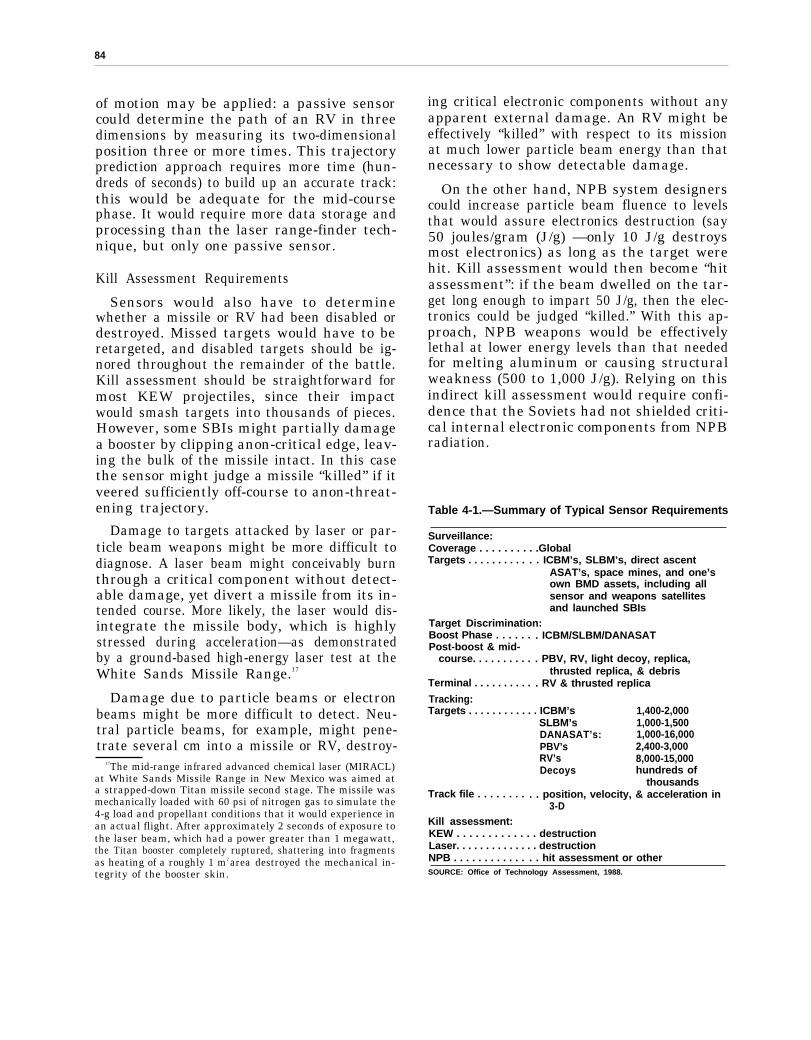
.
84
of motion may be applied: a passive sensorcould determine the path of an RV in threedimensions by measuring its two-dimensionalposition three or more times. This trajectoryprediction approach requires more time (hun-dreds of seconds) to build up an accurate track:this would be adequate for the mid-coursephase. It would require more data storage andprocessing than the laser range-finder tech-nique, but only one passive sensor.
Kill Assessment Requirements
Sensors would also have to determinewhether a missile or RV had been disabled ordestroyed. Missed targets would have to beretargeted, and disabled targets should be ig-nored throughout the remainder of the battle.Kill assessment should be straightforward formost KEW projectiles, since their impactwould smash targets into thousands of pieces.However, some SBIs might partially damagea booster by clipping anon-critical edge, leav-ing the bulk of the missile intact. In this casethe sensor might judge a missile “killed” if itveered sufficiently off-course to anon-threat-ening trajectory.
Damage to targets attacked by laser or par-ticle beam weapons might be more difficult todiagnose. A laser beam might conceivably burnthrough a critical component without detect-able damage, yet divert a missile from its in-tended course. More likely, the laser would dis-integrate the missile body, which is highlystressed during acceleration—as demonstratedby a ground-based high-energy laser test at theWhite Sands Missile Range.17
Damage due to particle beams or electronbeams might be more difficult to detect. Neu-tral particle beams, for example, might pene-trate several cm into a missile or RV, destroy-
17The mid-range infrared advanced chemical laser (MIRACL)at White Sands Missile Range in New Mexico was aimed ata strapped-down Titan missile second stage. The missile wasmechanically loaded with 60 psi of nitrogen gas to simulate the4-g load and propellant conditions that it would experience inan actual flight. After approximately 2 seconds of exposure tothe laser beam, which had a power greater than 1 megawatt,the Titan booster completely ruptured, shattering into fragmentsas heating of a roughly 1 m2 area destroyed the mechanical in-tegrity of the booster skin.
ing critical electronic components without anyapparent external damage. An RV might beeffectively “killed” with respect to its missionat much lower particle beam energy than thatnecessary to show detectable damage.
On the other hand, NPB system designerscould increase particle beam fluence to levelsthat would assure electronics destruction (say50 joules/gram (J/g) —only 10 J/g destroysmost electronics) as long as the target werehit. Kill assessment would then become “hitassessment”: if the beam dwelled on the tar-get long enough to impart 50 J/g, then the elec-tronics could be judged “killed.” With this ap-proach, NPB weapons would be effectivelylethal at lower energy levels than that neededfor melting aluminum or causing structuralweakness (500 to 1,000 J/g). Relying on thisindirect kill assessment would require confi-dence that the Soviets had not shielded criti-cal internal electronic components from NPBradiation.
Table 4-1.—Summary of Typical Sensor Requirements
Surveillance:Coverage . . . . . . . . . .GlobalTargets . . . . . . . . . . . . ICBM’s, SLBM’s, direct ascent
ASAT’s, space mines, and one’sown BMD assets, including allsensor and weapons satellitesand launched SBIs
Target Discrimination:Boost Phase . . . . . . . ICBM/SLBM/DANASATPost-boost & mid-
course. . . . . . . . . . . PBV, RV, light decoy, replica,thrusted replica, & debris
Terminal . . . . . . . . . . . RV & thrusted replica
Tracking:Targets . . . . . . . . . . . . ICBM’s 1,400-2,000
SLBM’s 1,000-1,500DANASAT’s: 1,000-16,000PBV’s 2,400-3,000RV’s 8,000-15,000Decoys hundreds of
thousandsTrack file . . . . . . . . . . position, velocity, & acceleration in
3-DKill assessment:KEW . . . . . . . . . . . . . destructionLaser. . . . . . . . . . . . . . destructionNPB . . . . . . . . . . . . . . hit assessment or otherSOURCE: Office of Technology Assessment, 1988.

85
Sensor Technology
Three types of sensors might satisfy portionsof these BMD requirements: passive, active,and interactive. Passive sensors rely on natu-ral radiation emitted by or reflected from thetarget. Active sensors, such as radars, il-luminate the target with radiation and detectthe reflected signal. “Interactive sensors” (aterm unique to the SDI) would use a strongbeam of energy or cloud of dust-like particlesto perturb targets in some measurable way(without necessarily disabling it) so that RVscould be discriminated from decoys. For ex-ample, the cloud might slow down light decoysmuch more than heavy RVs, or penetratingparticle beams might create a burst of neutronsor gamma rays from RVs but not from balloons.
Passive Sensors
How Passive Sensors Work.—Passive sensorsdetect military targets either by measuringtheir natural emission, or by detecting natu-ral light reflected from the targets. A typical
Photo credit: U.S. Department of Defense,Strategic Defense Initiative Organization
Infrared image of the moon from SDIO’s Delta 181experiment. That experiment took measurements of arocket booster and other objects in space to gatherinformation about the kinds of sensors that would beneeded in a space-based ballistic missile defensesystem. This may be the first long-wave infrared image
acquired from a platform in space.
sensor is similar to an ordinary camera. An op-tical element (the lens) forms an image, andalight sensitive surface records that image (thefilm).
In BMD infrared sensors, the optical lenswould be replaced by a system of reflecting mir-rors and the camera film by an array of dis-crete optical detectors in the focal plane whichconvert the optical image into electronic sig-nals for immediate computer processing. Manydetectors are required to record a detailed im-age. In a sense each detector substitutes forone grain of photographic film. Some sensorsuse a stationary two-dimensional “staring” ar-ray of detectors, in direct analogy to photo-graphic film. Others mechanically scan the im-age across an array of detectors that may beeither two-dimensional or linear.
Infrared Sensors. –Ordinary photographiccameras record the visible light reflected froma scene. For BMD, the IR energy emitted bythe target (particularly the hot exhaust gasesejected from a missile booster engine) is abet-ter source of information.
18 The sensor imagesthe infrared radiation from the target and back-ground onto a photosensitive array of detec-tors. These detectors generate a series of elec-trical signals that are processed by computersto detect and track the target.
There are three distinct target classes for theBMD mission: missiles with their rocket en-gines firing, post-boost vehicles with muchlower power engines, and cold objects such asRVs and decoys in space.” Each type of tar-get demands different IR sensors. Hot exhaustgas from a booster engine radiates primarilyin relatively narrow bands of short wavelengthIR. The exact wavelength of this radiation is
‘aAll objects with a temperature above absolute zero(–273C) emit energy in the form of electromagnetic waves, such aslight waves, infrared waves, microwaves, etc. For example, thehuman body continuously radiates infrared waves. To an in-frared camera, we all “glow in the dark”: our bodies would berecorded on infrared film as a group of “hot spots, even if thepicture were taken in absolute darkness. Similarly, any targetemits energy which can, in principle, be detected with appro-priate sensors, provided only that the target is warmer (or colder)than the background scene.
l~he RVS do heat up from friction as they enter theatmosphere.

86
determined by the particular gas constituents.The primary emission bands for gas plumesare near the water vapor and carbon dioxidelines at 2.7 micrometers20 (in the short waveIR or SWIR) and at 4.26 µm (in the middlewave IR or MWIR).21
Other specific radiation lines may help iden-tify some Soviet booster plumes: this will beinvestigated in the SDI research program.These plumes radiate hundreds of thousandsto millions of watts per steradian (W/sr) ofenergy. Post-boost vehicles also have propul-sion systems, but their smaller motors radi-ate only hundreds of W/sr.
Reentry vehicles remain near “room temper-ature” (20 o C or 2930 K) in mid-course, untilthey are heated by the friction of the atmos-phere on reentry. The maximum radiation forroom temperature objects is near 10 µm in theLWIR. Infrared detection of RVs is difficultbecause of their low level of radiation (typicallya few W/sr) and poor contrast against the earthbackground. That is, the earth is also near‘‘room temperature, ” with strong emission inthe 10-pm band. An IR sensor cannot “see”a red target against a red background. The sen-sor would generally have to wait until the tar-get RV was above the horizon to view it againstthe cold (4 o K) temperature of space. The sen-sor system would also have to filter out theIR energy from planets or bright stars in thefield of view.22
The technical feasibility of detecting rela-tively cold RVs against a space backgroundwas demonstrated on June 10, 1984, when anLWIR sensor on board the Army’s HomingOverlay Experiment (HOE) missile success-fully detected a simulated RV over the Pacific
—.— ---~oone ~crometer (w) is one millionth (10 ‘o) of a meter.ZIA~wpheric water vapor and carbon dioxide attenuate mOSt
of the IR radiation from a missile plume in the early stages offlight. However, the higher temperature and pressure of thewater and CO* in the plume produce a broader IR spectrum thanthe atmospheric absorption bands. Infrared energy will there-fore leak through on both sides of the 2.7 and 4.3pm lines, evenfrom rockets close to the surface of the Earth.
‘The Air Force has used a star as the “target” for tests ofthe U.S. F-15 launched ASAT, which uses a LWIR sensor tohome on its target.
Ocean.23 The sensor guided the HOE projec-tile into a collision course, destroying a targetlaunched earlier from Vandenberg AFB in Cali-fornia. This test demonstrated an ability to de-tect and track a single approaching RV in spaceat relatively close range. (The initial HOE mis-sile trajectory was specified by radar signalsfrom Kwajalein until the missile LWIR sen-sor could acquire the target.)
Tracking thousands of RVs and possiblyhundreds of thousands of decoys with space-based sensor satellites from distances of 5,000to 10,000 km would be more challenging, par-ticularly if the RVs were encapsulated in bal-loons and decoy balloons were tied (tethered)together or to an RV.
Three-Color Infrared Sensors. –Dependingon the offense’s countermeasures, discrimina-tion of RVs from decoys might be improvedif the object temperatures could be measuredaccurately. Long-wave IR sensors that detectone narrow wavelength band cannot determinetemperature. That is, a warm object with lowIR emissivity24 could produce the same radi-ance at one wavelength as a cooler object withhigh emissivity, as illustrated in figure 4-5.However, the shape of the blackbody (non-reflecting object) radiation curve as a functionof wavelength is distinct for objects at differ-ent temperatures. This suggests that two ormore LWIR sensors operating at differentwavelength bands within the 8- to 24-µm re-gion could estimate the temperature ofµpaceobjects, independent of their general emis-sivities.
Most SDI architects recommended three-color LWIR detectors to measure energy inthree separate wavelength bands or “colors.”Note that this complicates sensor design and
23To place this experiment in perspective, it should be notedthat this RV was significantly brighter than the radiance ex-pected from current RVs, while the Soviets may take steps tofurther reduce IR emissions.
24The emissivity of any object indicates its ability to radiateenergy. Emissivity is defined as the ratio of the energy radi-ated at any wavelength to the amount of energy radiated bya perfect blackbody at the same temperature. (A “blackbody”absorbs all energy reaching its surface.) Thus an object withlow emissivity will radiate less energy than a higher emissivityobject, even though they are both at the same temperature.
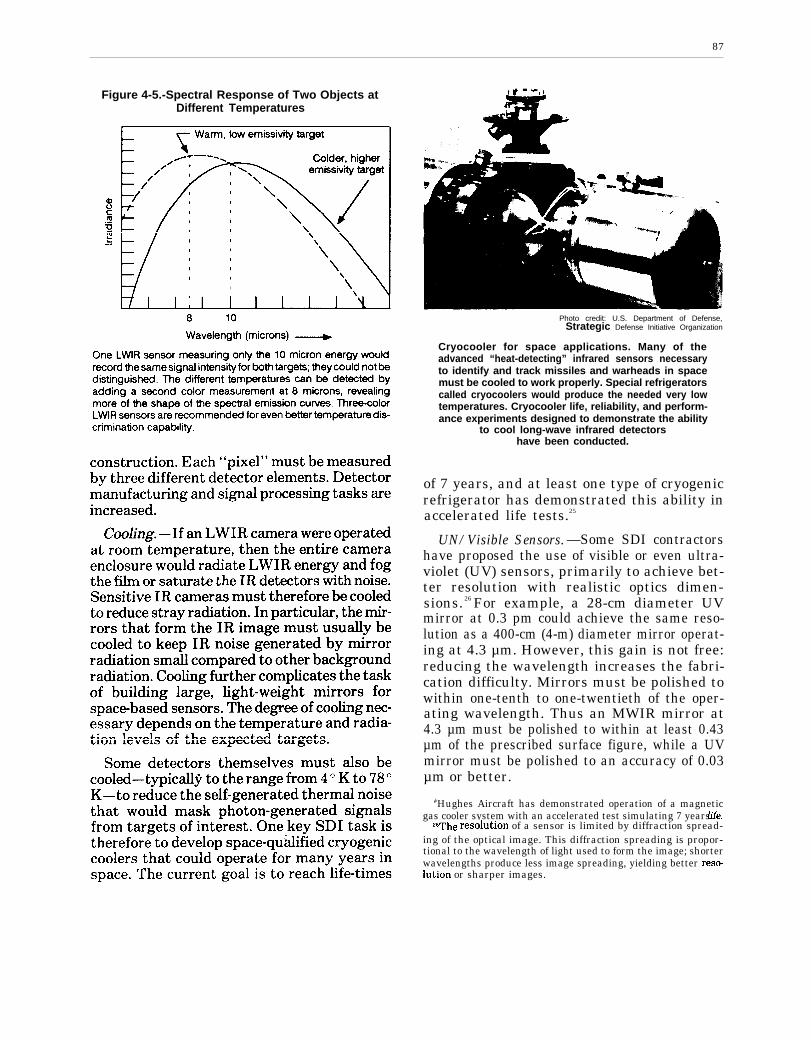
87
Figure 4-5.-Spectral Response of Two Objects atDifferent Temperatures
I
Photo credit: U.S. Department of Defense,Strategic Defense Initiative Organization
Cryocooler for space applications. Many of theadvanced “heat-detecting” infrared sensors necessaryto identify and track missiles and warheads in spacemust be cooled to work properly. Special refrigeratorscalled cryocoolers would produce the needed very lowtemperatures. Cryocooler life, reliability, and perform-ance experiments designed to demonstrate the ability
to cool long-wave infrared detectorshave been conducted.
of 7 years, and at least one type of cryogenicrefrigerator has demonstrated this ability inaccelerated life tests.25
UN/Visible Sensors. —Some SDI contractorshave proposed the use of visible or even ultra-violet (UV) sensors, primarily to achieve bet-ter resolution with realistic optics dimen-sions. 26 For example, a 28-cm diameter UVmirror at 0.3 pm could achieve the same reso-lution as a 400-cm (4-m) diameter mirror operat-ing at 4.3 µm. However, this gain is not free:reducing the wavelength increases the fabri-cation difficulty. Mirrors must be polished towithin one-tenth to one-twentieth of the oper-ating wavelength. Thus an MWIR mirror at4.3 µm must be polished to within at least 0.43µm of the prescribed surface figure, while a UVmirror must be polished to an accuracy of 0.03µm or better.
‘bHughes Aircraft has demonstrated operation of a magneticgas cooler system with an accelerated test simulating 7 years iife.
ZGThe resolution of a sensor is limited by diffraction spread-ing of the optical image. This diffraction spreading is propor-tional to the wavelength of light used to form the image; shorterwavelengths produce less image spreading, yielding better res~lution or sharper images.

88
Visible or UV sensors might detect energyfrom rocket plumes, although the visible radi-ation from liquid-fueled missiles is minimal.The atmosphere attenuates UV below an alti-tude of a few tens of km, but a post-boost ve-hicle propulsion system may generate ade-quate UV radiation. To see RVs, however,these sensors would have to rely on the reflec-tion of natural radiation (sunlight, moonlight,or Earthlight). Alternatively, they could beused in an active mode with a laser designatorilluminating the target (see next section).
Current Status of Passive Sensors.–Passiveinfrared sensors operate today in early warn-ing satellites. A few satellites at geosyn-chronous orbit, some 36,000 km above theearth, monitor the entire globe, searching formissile launches from the Soviet land mass orfrom the oceans. Several heat-seeking tacticalmissiles such as the air-to-air Sidewinder andthe ground-to-air Maverick missile also employinfrared sensors. This same sensor technologysupplied the terminal guidance for two success-ful space hit-to-kill experiments: the anti-satellite (ASAT) experiment in which a mis-sile fired from an F-15 aircraft destroyed a sat-ellite in space and the Homing Overlay Ex-periment.
Today’s operational infrared sensors haverelatively small optical systems, typically 20cm or less in diameter, and focal plane arraysof a few thousand detectors. Most detectorsare fabricated from bulk silicon and could notsurvive in a nuclear environment. Relativelyfew large detector arrays are built each year,
Table 4-2.—Key Issues
and the United States does not yet have themanufacturing technology to build large ar-rays economically.
Key Issues for Passive Sensors.—This reporthas identified five key issues for passive sen-sor technology development (see table 4-l).While driven by the space-based system re-quirements, these same sensor functions wouldbe required for effective ground-launchedweapons systems. Whether the sensors rodeon airborne or space-based platforms, these is-sues would have to be resolved to produce arobust BMD system.
Mirror Size. —A sensor system mirror mustbe large to collect enough energy, to resolveclosely spaced objects, and to accurately di-rect weapons systems (see box 4-A). The mir-ror size needed is determined by sensor oper-ating wavelength, distance to target, andtarget positional accuracy required by theweapon system. The resolution of any opticalsystem is given approximately by the wave-length divided by the diameter of the aperturemultiplied by the range.
Typical mirror sizes for adequate spot reso-lution from a passive sensor at 3,000 km alti-tude are shown in figure 4-6.27 To provide ade-quate aiming information to homing kineticenergy weapons, sensor resolutions from 10 m
ZTFig. 4.6 assumes a perfect, diffraction limited OptiCd sYs-tem. In practice other factors-such as vibration, i.nqxwfect mir-ror quality, and thermal distortions-would degrade resolution.This figure, therefore, represents the minimum allowable mir-ror size for a spot. Tracking resolution may only require mir-rors a factor of 10 smaller, as noted in the text.
for Passive Sensors
KEW DEW Current status
Mirror size (m) . . . . . . . . . . . . . . . . . . . . . about 0.1 about 1 0.1-2.4Number of detector elements (UV/visible)
(resolution limited)Geo/staring . . . . . . . . . . . . . . . . . . . . . . 106-108 N/A many tens of
thousandsGeo/scanning. . . . . . . . . . . . . . . . . . . . . 104-100 N/A3,000 km/staring (1 oFOV) . . . . . . . . . . . 103-105 10’3,000 km/scanning . ................10 3 105-10’
Detector manufacturing capacity. . . . . . 108-109/yr 107-108/yr IO6/yrSignal processing
Rates. . . . . . . . . . . . . . . . . . . . . . . . . . . . 10% 1010/s several x 107/sMemory. . . . . . . . . . . . . . . . . . . . . .. ...1 X 107 1 x 10⁸ 8x 10⁷
SOURCE: Office of Technology Assessment, 1988.
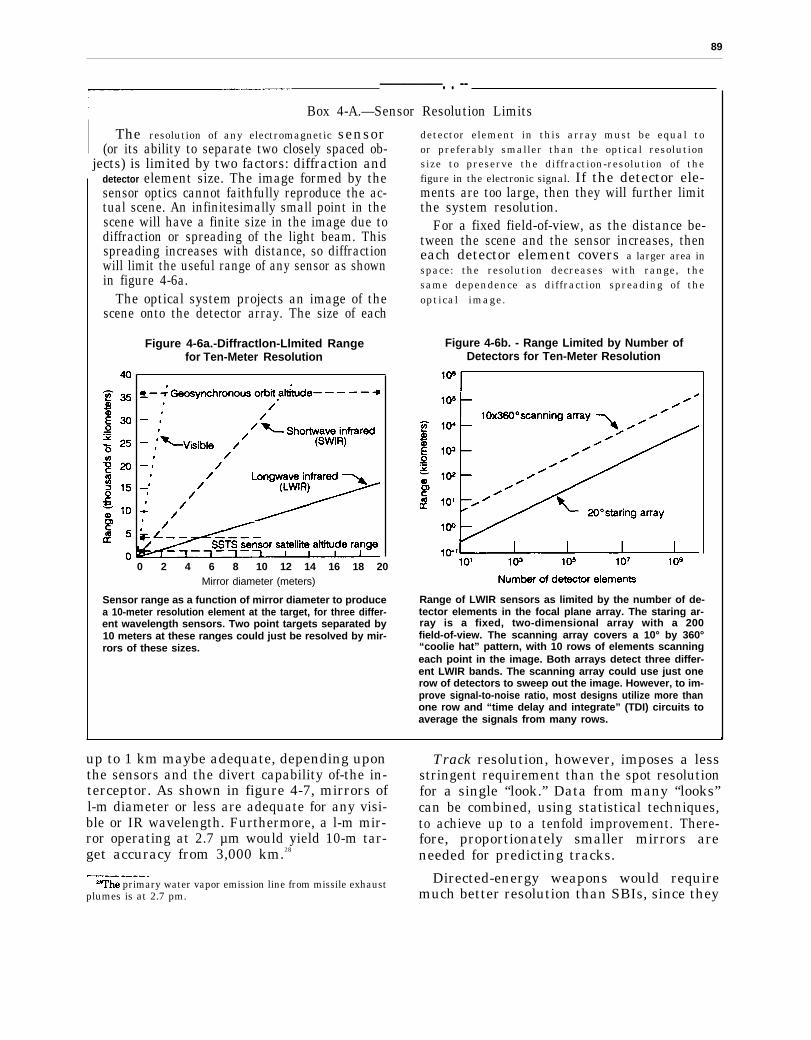
89
—————. . --Box 4-A.—Sensor Resolution Limits
The resolution of any electromagnetic sensor(or its ability to separate two closely spaced ob-
jects) is limited by two factors: diffraction anddetector element size. The image formed by thesensor optics cannot faithfully reproduce the ac-tual scene. An infinitesimally small point in thescene will have a finite size in the image due todiffraction or spreading of the light beam. Thisspreading increases with distance, so diffractionwill limit the useful range of any sensor as shownin figure 4-6a.
The optical system projects an image of thescene onto the detector array. The size of each
Figure 4-6a.-Diffractlon-Llmited Rangefor Ten-Meter Resolution
0 2 4 6 8 10 12 14 16 18 20Mirror diameter (meters)
Sensor range as a function of mirror diameter to producea 10-meter resolution element at the target, for three differ-ent wavelength sensors. Two point targets separated by10 meters at these ranges could just be resolved by mir-rors of these sizes.
detector element in this array must be equal toor preferably smaller than the optical resolutionsize to preserve the diffraction-resolution of thefigure in the electronic signal. If the detector ele-ments are too large, then they will further limitthe system resolution.
For a fixed field-of-view, as the distance be-tween the scene and the sensor increases, theneach detector element covers a larger area inspace: the resolution decreases with range, thesame dependence as diffraction spreading of theoptical image.
Figure 4-6b. - Range Limited by Number ofDetectors for Ten-Meter Resolution
Range of LWIR sensors as limited by the number of de-tector elements in the focal plane array. The staring ar-ray is a fixed, two-dimensional array with a 200field-of-view. The scanning array covers a 10° by 360°“coolie hat” pattern, with 10 rows of elements scanningeach point in the image. Both arrays detect three differ-ent LWIR bands. The scanning array could use just onerow of detectors to sweep out the image. However, to im-prove signal-to-noise ratio, most designs utilize more thanone row and “time delay and integrate” (TDI) circuits toaverage the signals from many rows.
up to 1 km maybe adequate, depending upon Track resolution, however, imposes a lessthe sensors and the divert capability of-the in- stringent requirement than the spot resolutionterceptor. As shown in figure 4-7, mirrors of for a single “look.” Data from many “looks”l-m diameter or less are adequate for any visi- can be combined, using statistical techniques,ble or IR wavelength. Furthermore, a l-m mir- to achieve up to a tenfold improvement. There-ror operating at 2.7 µm would yield 10-m tar- fore, proportionately smaller mirrors areget accuracy from 3,000 km.28 needed for predicting tracks.———-
26The primary water vapor emission line from missile exhaust Directed-energy weapons would requireplumes is at 2.7 pm. much better resolution than SBIs, since they
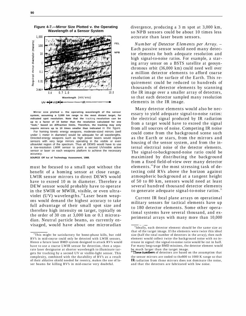
90
Figure 4-7.—Mirror Size Plotted v. the OperatingWavelength of a Sensor System
1,000
100
10
1
0.1
0.01
FEL
NPB
0.4 0.7 1.0 10.0Wavelength (mlc’ens)
Mirror size plotted v. the operating wavelength of the sensorsystem, assuming a 3,000 km range to the most distant target, forIndicated spot resolution. Note that the tracking resolution can beup to a factor of 10 better than the resolution calculated for one“look,” based on diffraction limits. Therefore, the tracking may onlyrequire mirrors up to 10 times smaller than indicated in the figure.
For homing kinetic energy weapons, moderate-sized mirrors (wellunder 1 meter in diameter) would be adequate for all wavelengths.Directed-energy weapons such as high power lasers would requiresensors with very large mirrors operating in the visible or evenultraviolet region of the spectrum. Thus all DEWS would have to usea Iow-resolution LWIR sensor to point a second UV/visible activesensor or laser on each weapons platform to achieve the necessaryaccuracy.SOURCE Off Ice of Technology Assessment, 1988.
must be focused to a small spot without thebenefit of a homing sensor at close range.LWIR sensor mirrors to direct DEWS wouldhave to exceed 10 m in diameter. Therefore aDEW sensor would probably have to operatein the SWIR or MWIR, visible, or even ultra-violet (UV) wavelengths.29 Laser beam weap-ons would demand the highest accuracy to takefull advantage of their small spot size andtherefore high intensity on target, typically onthe order of 30 cm at 3,000 km or 0.1 microra-dian. Neutral particle beams, as currently en-visaged, would have about one microradian
29This might be satisfactory for boost-phase kills, but coldRV’s in mid-course could only be detected with LWIR sensors.Hence a future laser BMD system designed to attack RV’s wouldhave to use a coarse LWIR sensor for detection, then a sepa-rate laser designator at shorter wavelength to illuminate tar-gets for tracking by a second UV or visible-light sensor. Thiscomplexity, combined with the durability of RV’s as a resultof their ablative shield needed for reentry, makes the use of la-ser beams for killing RV’s in mid-course very doubtful.
divergence, producing a 3 m spot at 3,000 km,so NPB sensors could be about 10 times lessaccurate than laser beam sensors.
Number of Detector Elements per Array. –Each passive sensor would need many detec-tor elements for both adequate resolution andhigh signal-to-noise ratios. For example, a star-ing array sensor on a BSTS satellite at geosyn-chronous orbit (36,000 km) could need well overa million detector elements to afford coarseresolution at the surface of the Earth. This re-quirement could be reduced to hundreds ofthousands of detector elements by scanningthe IR image over a smaller array of detectors,so that each detector sampled many resolutionelements in the IR image.
Many detector elements would also be nec-essary to yield adequate signal-to-noise ratios:the electrical signal produced by IR radiationfrom a target would have to exceed the signalfrom all sources of noise. Competing IR noisecould come from the background scene suchas the Earth or stars, from the mirrors andhousing of the sensor system, and from the in-ternal electrical noise of the detector elements.The signal-to-background-noise ratio could bemaximized by distributing the backgroundfrom a fixed field-of-view over many detectorelements.30 For the most stressing task of de-tecting cold RVs above the horizon againstatmospheric background at a tangent heightof 50 to 80 km, sensors would need at leastseveral hundred thousand detector elementsto generate adequate signal-to-noise ratios.31
Current IR focal plane arrays on operationalmilitary sensors for tactical elements have upto 180 detector elements. Some other opera-tional systems have several thousand, and ex-perimental arrays with many more than 10,000
——.30Ideally, each detector element should be the same size as
that of the target image. If the elements were twice this idealsize (half the total number of detectors in the array), then eachelement would collect twice the background noise with no in-crease in signal: the signal-to-noise ratio would be cut in half.For many long-range BMD missions, the detector element wouldbe much larger than the target image.slThese num~rs of detectors are based on the assumption thatthe sensor mirrors are cooled to the800 to 1000 K range so thatIR radiation from those mirrors does not dominate the noise,and that the detectors are fabricated with low noise.

91
●
●
Photo credit: Genera/ Electric Company
Sensor focal plane array of 128 by 128 detectorelements. These elements convert light energy intoelectrical signals. Focal plane arrays are the electro-optical equivalent of film in a camera. Some SDIsensors may require focal planes containing hundreds
of thousands of detector elements.
elements have been fabricated. The focal planearray (FPA) for the planned Airborne OpticalAdjunct (AOA) experiment will have a 38,400-element three-color FPA.32 However, none ofthese detectors was designed to the radiationhardness needed for BMD sensors.
Detector Radiation Hardness.—Ballisticmissile defense sensors must withstand radi-ation from distant nuclear explosions. Currentdetectors are fabricated from relatively thickbulk materials such as silicon or mercury cad-mium telluride (HgCdTe) which are suscepti-ble to radiation damage. Other materials, suchas gallium arsenide or germanium, or thinnerdetector structures would be needed to achieveradiation hardness goals. Impurity band con-ductor (IBC) detectors, which are only 10 to12 µm thick, can withstand 10 to 100 timesmore radiation than common bulk silicon de-
tectors. Arrays with up to 500 IBC elementshave been fabricated in the laboratory.
The electronic readout from FPAs must alsobe resistant to radiation damage. In the past,charge-coupled devices (CCD) were used to readout large detector arrays. To reduce suscepti-bility to radiation damage, researchers arebutt-bonding switching metal oxide semicon-ductor field effect transistor (MOSFET) read-outs to the detectors.
Detector Manufacturing Capacity.–Indus-try produces about 1 million IR detectors peryear. Many of these are small linear arrays of16 to 180 elements each, used for tactical IRmissiles or scanning IR imaging systems. The“Teal Ruby”33 experiment bulk-silicon arrayis the largest built so far. Production wouldhave to increase by one or two orders of mag-nitude to satisfy the ambitious BMD goals:very large, radiation-hard, low-noise arrayswould be required. For example, just one BMDsensor would require several, perhaps up to 10,times the current annual production capacity—and there could be many tens of sensors in asecond-phase space-based BMD system. TheSDIO has programs underway intended to
———‘gTeal Ruby is an experimental satellite designed to detect
aircraft from space with an LWIR detector array.
———- — - - —32 See Aviation Week and Space Technology, Nov. 10, 1986,
P. 87.
Photo credit: U.S. Department of Defense,Strategic Defense Initiative Organization
Impurity Band Conduction Long-WaveInfrared Detector Array
92
achieve these improvements in manufacturingcapability.
Conversion from laboratory fabrication tofull-scale manufacturing of the new IBC de-tectors-assuming they continue to be the pre-ferred detector–could limit BMD sensor de-ployment. Industry Performance in convertingto the manufacture of bulk silicon IR “com-mon module” arrays in the early 1980s wasnot good. Producing arrays of just 60, 120, or180 elements once held up the completion ofM-1 tanks that use forward looking IR (FLIR)sensors.
Manufacturing yield (the ratio of the num-ber of acceptable arrays to the number manu-factured) for IR detectors would have to be im-proved. The overall yield (including read-out)for the Teal Ruby array was about 2 percent.Since yield was so low, every element had tobe individually tested at cryogenic (10° K) tem-peratures: testing might be the limiting man-ufacturing process. The SDIO has initiatedprograms to address this problem in fiscal year1988.
Signal Processing Improvements.–Projectedsignal processing rates for BMD sensors wouldexceed current space-ebased operational capa-bilities by factors of a few hundred. Currentoperational signal processors can handle uptens of millions operations per second (MOPS),while BMD signal processing requirementsmight exceed 10 billion operations per second,or 10 giga-OPS (GOPS).
Projected on-board memory requirementsfor BMD sensors vary from 10 million to 100million bytes of information. Reaching thesememory and processing goals by the 1990sseems likely, given the progress in very highspeed integrated circuits (VHSIC).
Power consumption of signal processorsmust be reduced. The AOA experiment will re-quire less than 10 kilowatts (KW) of power todrive a 15 GOP processor, or over 1.5 MOPS/W.Hardened VHSIC technology offers the prom-ise of many times less power consumption (40MOPS/W) and good radiation resistance.
Active Sensors
How Active Sensors Work.—Active sensorsilluminate the target with radiation and mon-itor reflected energy. In general, active sen-sors have the advantage of adequate illumi-nation under all conditions: they do not haveto rely on radiation from the target or favora-ble natural lighting conditions. They suffer thedisadvantage, under some circumstances, ofbeing susceptible to jamming or spoofing: theopponent can monitor the illumination beamand retransmit a modified beam at the samefrequency to overpower or confuse the receiver.At the very least, the illumination beam canalert the enemy that he is under surveillanceor attack. This might be a concern for surveil-lance and tracking of defense suppressionweapons such as direct-ascent or orbitingASATs.
Microwave radar, an active sensor used sosuccessfully in tracking aircraft, might sup-port some phases of BMD, particularly for ter-minal defense. These ground-based radarsmight use advanced data processing tech-niques to generate pseudo-images of RVs todistinguish between RVs and decoys, as de-scribed below. Conventional microwave radarhas two serious limitations for most space-based BMD functions: limited resolution andlarge power requirements. Because of the largeantennae, large power requirements, and sur-vivability issues, microwave radar is not aprime candidate for BMD space applications.34
However, the SDIO still believes that micro-wave radar might be included in future BMDsystems.
SDI researchers are also investigating laserradar or ‘ladar” for applications such as meas-uring the range to a target and discriminat-ing RVs from decoys. In principle, ladar isequivalent to radar with much shorter (opti-
—.. --.—me SDIO had considered developing shorter millimeter wave
radar to provide better radar resolution and lower power requirements. With reduced funding, support for millimeter radar hasbeen reduced. Distributed antenna arrays are also being con-sidered to provide space surveillance of aircraft and cruise mis-siles for the Air Defense Initiative.

93
cal or infrared) wavelengths. With shorterwavelength, ladars generally would give bet-ter resolution with less power and weight. La-dars cannot operate in all weather conditionson earth. They are therefore better suited forspace applications.
Imaging Radars.– If an object is movingrelative to a radar, then the radar return sig-nal is shifted in frequency, similar to the Dop-pler frequency shift of a train whistle as itpasses by a stationary observer. For objectsthat rotate, such as spinning satellites or reen-try vehicles, pseudo-images can be generatedby processing the doppler frequency shifts ofradar signals stored over time. This is a proc-ess similar to synthetic aperture radar, some-times called inverse synthetic aperture radar(ISAR). 35
Consider a conical RV spinning about its axis(figure 4-8). The tip of the cone has no signifi-cant motion due to rotation, and little dopplerfrequency shift. The back edge of the cone hasa large motion (proportional to the radius ofthe cone and the angular velocity of the RV)and a large doppler frequency shift. A plot ofrange to target versus doppler frequency shiftwill therefore resemble the shape of the RV formost orientations of radar beam to spinningRV.36
The resolution of range/doppler pseudo-images does not depend on radar-beam spotsize. The beam floods the target area, so pre-cise beam pointing is unnecessary. Range reso-lution is inversely proportional to the band-—..—- .. —-.
~5An ~r~me synthetic aperture radar system generates ~image of the ground by measuring the doppler frequency shiftsof ail return radar signals. Targets directly ahead of the radaraircraft have maximum Doppler frequency shift because therelative velocity between the ground and the aircraft is a maxi-mum. Targets perpendicular to the aircraft flight path have norelative motion toward the aircraft and no Doppler frequencyshift. By storing all the radar returns and processing data overtime, a pseudo image of the ground is generated.
*If ~ fia~g radm were boresighted aiong the trajectoryof an RV, there would be no doppler tiquency shift and no im-age. Conversely, if the radar looked perpendicular to the RVflight path, there would be no information on the length of theRV: any range spread would be due to the radius of the cone,independent of length. For other radar look angles between theseextremes, the doppler frequency shift would be proportional tothe sine of the look angle, and the range spread would be propor-tional to the cosine of that angle.
Figure W.-l Illustration of an Imaging Radar Viewinga Spinning Conical Target
Spinning conein space
Radar beam
Range/doppler pseudoimage on radar screen
I
Point “A” on the base of the cone has the most motion toward theradar, producing the largest doppler frequency shift. The echofrom this point would appear at point ‘A” on a radar-generatedplot of range versus doppler frequency shift. Point “B”, at aboutthe same range as point “A”, is moving perpendicular to the ra-dar beam, and will have no doppler frequency shift; its echowould be plotted as shown. Similarly, point “C” is moving awayfrom the radar, and would have a negative doppler frequencyshift. Finally, points along the cone such as point “Dn have lowerfrequency shifts, since they are closer to the spinning axis. Theresulting range-doppler plot will therefore resemble the conicaltarget.
width of the transmitted signal. For example,a one gigahertz37 bandwidth radar signal couldhave a range resolution capability of 15 cm.Resolution in the cross-track direction (cor-responding to the radius of the spinning cone)is limited by the minimum doppler frequencyshift that can be detected, radar wavelength(smaller is better), and the rotation rate of theRV (larger is better).38 For microwave radars,typical doppler frequency shifts are in the tensto hundreds of hertz. Many radar pulses mustbe stored and analyzed to measure these lowfrequencies, which requires substantial dataprocessing.
—..~TGig~e~z is a unit of frequency equal to one billion cyCleS
per second.‘aNote that doppler (cross-track) resolution of these pseudo
images is not equivalent to positiomd accuracy. Object detailson the order of a few cm may be resolved in these images, butthe cross-track position of the object will not be known to bet-ter than the radar beam width, which might be tens of kms wide.

Ladar.—The short wavelength and veryshort pulse-length of a laser might prove veryuseful for several BMD functions. A laser ra-dar or ladar system would illuminate the tar-get cloud with a pulsed beam of light. An opti-cal receiver would detect the reflected echoes,in direct analogy to a microwave radar. Vari-ous types of ladars could supply one-dimen-sional range to the target (a laser range-finder),or they could generate 2- or 3-dimensionalimages.
Several modes of imaging operation arepossible:
● Scanning beam or “angle/angle” mode: apulsed laser beam is focused and scannedover the scene. A single optical detectorrecords the time sequence of reflectionsfrom each returned laser pulse, and a threedimensional map of target position is gen-erated in computer memory. Ladar reso-lution would depend on the beam spot size,which could be as small as 3 m at 3,000km with reasonably sized optics.39 Veryshort-wavelength lasers are preferred tominimize spot size. The range resolutionwould be on the order of 1.5 m with 10-nanosecond long laser pulses, which arecommercially available.
99A 0.5 ~m laser with a 60-cm mirror would produce adiffraction-limited spot 3 m in diameter at a distance of 3,000 km.
●
●
Focal plane array: a passive imager, simi-lar to the IR sensors, records the sceneilluminated by a laser. The laser is the“flash lamp”.Doppler ladar: the optical analog of amicrowave Doppler imaging radar mightbe feasible if lasers with adequate coher-ence could be built. Doppler resolution ofa coherent ladar could be excellent. A 30-cm RV rotating once per second wouldgenerate a 3.8 megahertz (million cycles/second—MHz) frequency shift in the la-dar return signal, compared to only 60hertz for an X-band imaging radar. Sincethe resolution of this pseudo-image wouldbe independent of spot size, there wouldbe no need to operate at short UV or visi-ble wavelengths. This fine image resolu-tion would not, however, yield good posi-tional information. A narrow beam (shortwavelength) angle/angle ladar would be re-quired for good angular resolution.
Active Discrimination. –A ladar might bevery useful for discriminating between RVsand decoys as they were ejected from a PBV.The PBV would perceptibly change its veloc-ity as each heavy RV was discharged, but notas light decoys were dispensed. A ladar couldbe designed with the spatial resolution to re-solve independently the PBV and the RV ordecoy and, in theory, to measure the differen-
95
tial velocities before and after each deploy-ment.40
Light decoys might inflate as they left thePBV. A high resolution imaging ladar couldin principle observe this inflation and so iden-tify balloon decoys.41 A precision doppler la-dar might also observe small vibration or nu-tation (wobbling) differences between an RVand a decoy. Light decoys might vibrate at tensto hundreds of kilohertz (kHz), heavier RVsat less than a few kHz. Over tens of seconds,the nose of a spinning RV also nutates a fewmillimeters: a very high resolution ladar mightdetect this motion, but long integration timesand high data storage rates would be nec-essary.
Current Status of Active Sensors.—Activesensor technologies have been tested and de-ployed in some form since the radars of WorldWar II. Considerable development remains,however, before active sensors will be readyfor advanced BMD systems.
Phased-array Search Radars. -Ground-basedphased-array radars are currently deployed inboth the United States and the Soviet Unionto detect objects in space and give early warn-ing of missile attack. The “PAVE PAWS” ra-dars now at Otis AFB on Cape Cod and atBeale AFB near Sacramento have two largefaces each, with active areas 22 m square, pro-viding 2400 coverage. Each face has 1,792 ac-tive antenna elements, with provisions to up-grade each face to 31 by 31 m active areas with5,354 elements. Two additional PAVE PAWSradars are being built in Georgia and Texas.
40Consider a PBV with 10 RVs. The PBV velocity wouldchange very little if a light decoy were ejected. Ejecting thefirst RV, if it weighed l/15th of the remairing PBV weight, wouldcause the PBV to slow by l/15th of the RV-PBV separationvelocity. That is, if the two objects were designed to move apartat a 15cm/sec rate, then the PBV would slow down by 1 cm-dsecand the RV would speed up by 14 cndsec after separation. LaterRV’S would cause the PBV to slow down more, as the ratio ofRV to remaining PBV weight increased. The ladar would there-fore need a velocity resolution of 1 cndsec in this example.
ilone Countermeasure to block the observation of decoy in-flation (as well as differential velocity detection) would be toinflate the decoys under a long shroud, although there is someconcern that the PBV rocket plume might interfere with ashroud. Alternatively, decoys and RVS could be tethered to-gether so that their rotation would confuse the sensor, whichcould not keep track of each object (see ch. 10.)
The United States plans to replace the threeexisting Ballistic Missile Early Warning Sys-tem (BMEWS) mechanically scanned radarsat Clear, Alaska; Thule, Greenland; and Fyling-dales Moor in England with phased array ra-dars. The old Distant Early Warning radarswill also be replaced by 52 new phased arrayNorth Warning System (NWS) radars. Theseradars, along with the mothballed phased ar-ray radar near Grand Forks, North Dakota,might supply RV target coordinates to anERIS exoatmospheric interceptor system.42
ImagingRadars. —Several radars have beenoperated in the rangedoppler imaging modesince the early 1970s. These ground-based ra-dars are used to image satellites, RVs, andother space objects. MIT’s Lincoln Labs oper-ates an L-band and an X-band imaging radarat Millstone Hill in Massachusetts.
Ladars.—Ladar systems have not beenplaced in operation, but they have been tested.In 1981 MIT Lincoln Laboratories built the“Firepond” CO, ladar, which had a 15 kW peakpower and 1.4 kW average power. With a onemicroradian resolution, this ladar could detecttargets spaced 3 m apart at a distance of 3,000km. This ladar has been reactivated for the SDIprogram. It will be operated in the range-dop-pler mode to investigate RV imaging in aground-based field test. Two other lasers areplanned. One will have a very short (nano-second), high peak power pulse to yield goodrange resolution. The other will use a lowerpeak power, frequency-chirped pulse. To re-cover good range resolution, this chirped pulseis compressed electronically in a data proces-sor. This same pulse compression techniquehas been used successfully to reduce the peakpower required in more conventional micro-wave radars.
‘zSDIO’s phaseone Strategic Defense System pkms one ormore optical sensors for cueing ERIS interceptors. However,Lockheed-the ERIS developer–and others have proposed an“early deployment” version of ERIS that would utilize exist-ing radars. The computing capabilities of these radars wouidhave to be improved to handle hundreds of targets. The sys-tems would be susceptible to electromagnetic pulse, microwavejamming, and blast damage in the event of nuclear war. At thistime, phased-array radars are the only sensors available for earlydeployment of ERIS-like BMD systems.
Work is also proceeding on diode-pumpedglass lasers, excimer lasers, and bistatic CO2
ladars. Glass lasers are typically pumped withflash lamps, resulting in very low efficiency(typically less than 0.2 percent), since the spec-trum of the flash lamp does not match the ab-sorption bands of the Nd:glass material. Bypumping the Nd:glass laser with an array ofincoherent laser diodes, efficiency can be in-creased significantly and the thermal distor-tion which normally limits these lasers to verylow repetition rates can be controlled.
Excimer lasers have the advantage of gen-erating UV radiation, which demands thesmallest mirrors for a given resolution.
Key Issues for Active Sensors.—Current SDIphase-two concepts call for ground-based ra-dars for directing late mid-course and termi-nal defense. Space-based ladars are suggestedfor boost-phase ranging, to observe PBV de-ployment, and for determining accurate tar-get position during mid-course discrimination.Ladars might also be used for air-borne rang-ing to assist terminal defense. Issues for theseactive sensors include the following.
Ground-based Radar.-Ground-based radarswould have to be large, phased-array devicesto focus adequate energy on many targets. Twokey issues would be survivability and dataprocessing. Surge fuses at each radiating di-ode in the array could probably protect largeantennas from nuclear burst-generated elec-tromagnetic pulse (EMP). Shielding the struc-ture and building could protect interior elec-tronics. Most EMP energy would be below 150MHz, so radar radio frequency (RF) circuitsat 10 GHz could be safe.
However, these antennas would be suscep-tible to in-band radiation from dedicated jam-mers. It might be a challenge to design effec-tive electronic counter-countermeasures toprotect these large and critical assets from elec-tronic jamming by Soviet satellites. Some sys-tem architects have suggested that these ra-dars be mobile, possibly on railroad cars.Mobility might reduce susceptibility tojamming.
Data processing might also be challenging.Consider an X-band (3-cm wavelength) radar.Its data processor might have to handle 5 mil-lion bits per second of incoming data for eachof 5,000 antenna dipoles, or a total of 25 bil-lion bits per second for the entire radar.43 Thesedata must be stored and processed to deter-mine the direction to each target (by phasingthe receiving array) and a Fast Fourier Trans-form (FFT) operation would have to be per-formed on each range bin to measure dopplerfrequency shift over many pulses.
Doppler imaging radars might be fooled ifRVs (and decoys) were covered with “fronds,”—strips painted with irregular patterns of vola-tile material. Attached at various places on anobject, these strips would move about at ran-dom in space as the volatile material evapo-rated. This motion would give different partsof the target different doppler velocities inde-pendent of their positions on the RV or decoycone. Such extraneous frequency shifts mightconfuse the radar processor, obscuring the im-age of the RV body.
Ladar Active Discrimination. –Significantadvances would be required in ladar technol-ogy before it could be utilized to observe PBVdeployment of RVs and decoys. Key issueswould be resolution, beam steering, and dataprocessing to handle the expected traffic.
Direct angle/angle ladar imaging of PBVswould take very large mirrors.44 The alterna-tive would be doppler processing to improvecross-track resolution. While microwave syn-
4~his data rate assumes that radar bandwidth is 1 GHz toyield a 15-cm range resolution. The radar tracks each targetto within 100-m accuracy before hand-over to an image modeProcessor, which maintains a shiingrange gati 100 m wide abouteach high-speed target. The radar pulse repetition rate is setby the highest expected doppler frequency shift produced byRV rotation. For clear images of a 20-cm radius RV rotatingat 3 hertz, the pulse rewtition frequency (PRF) must be 500hertz or higher. (This imaging doppler radar would be highlyambiguous with respect to RV velocity, which would requireMHz type PRFs to measure actual velocity.)
44T0 image a 30-cm diameter RV, a ladar designer would like10 resolution elements across the object to resolve shape or de-tails, or 3 cm resolution. Thus, an impractically large 60-m mir-ror would be required for 3 cm resolution at 3,000 km rangewith a visible laser.

97
thetic aperture radars have been successfullyoperated for over 20 years, this process hasnot been extended to optical wavelengths.Building stable but powerful space-basedlasers with the coherence necessary for dop-pler processing would be a major challenge.
Interactive Sensors
The consensus in the SDI technical commu-nity is that passive and active sensors may notbe adequate to discriminate between RVs anddecoys in the future. The Soviet Union prob-ably has the necessary technology to developdecoys and real RVs with nearly the same in-frared and radar signatures. Decoys would notbe extraordinarily difficult to fabricate and dis-perse in space, and they would weigh only asmall fraction of an RV. There is a serious ques-tion whether, once dispersed, they could be dis-tinguished from real RVs by any passive oractive sensor. If not, the offense could over-whelm a space-based or ground-based mid-course defense system with literally hundredsof thousands of false targets.
Mid-course decoy discrimination would be-come crucial if the Soviets could:
●
●
deny a phase-one boost-phase defensethrough countermeasures such as moder-ately fast-bum (e.g., 120- second) boosters,anddeny significant post-boost kills by mov-ing to faster PBV deployment times or tosingle warhead missiles.
If an initial U.S. deployment of kineticenergy weapons could no longer destroy manyICBMs in the boost or post-boost phase, andif directed-energy weapons were not yet avail-able, then mid-course discrimination would be-come indispensable to a viable BMD system.
There would be two possibilities for effec-tive mid-course discrimination under these cir-cumstances: ladar discrimination during post-boost decoy dispersal, or interactive discrimi-nation after the RVs and decoys were released.As discussed in the preceding section, ladardetection during decoy deployment would bevery challenging. Moreover, simple measure-ment of RV and PBV recoil velocities might
be thwarted completely if the Soviets could dis-perse decoys and RVs simultaneously in pairs.Even fine doppler imaging would be foiled ifthe Soviet PBV could obscure the deploymentoperation with a shroud. This would leave in-teractive discrimination as the main approachto keeping BMD viable in the long term.
How Interactive Discriminators Would Work.—In interactive discrimination, a sensor sys-tem would perturb each target and then meas-ure its reaction to determine if it were a decoyor an RV. For example, a dust cloud of suffi-cient density and uniformity could be placedin front of a group of objects. The resultingcollisions would slow down light decoys morethan heavy RVs. A ladar would monitor thechange of velocity of all objects, thereby iden-tifying real RVs.
Two general classes of discriminators havebeen proposed: kinetic energy and directedenergy perturbers.
Kinetic Energy Discriminators. —Two meth-ods have been proposed to project particles infront of an oncoming cloud of decoys and RVs:rocket-born particles and nuclear-explosion-projected particles. A rocket-borne cloud wouldbe limited to late mid-course, unless the rocketswere fired from submarines or based in Can-ada or the Arctic. Presumably one rocketwould be necessary for the cylindrical cluster(or “threat tube”) of RVs and decoys emanat-ing from each PBV. To slow down decoys meas-urably, a rocket would have to carry enoughmass to cover the full lateral extent of thethreat tube with a sufficiently dense cloud. Aladar would have to measure velocity changesin the 10-cm/sec to l-m/see range.
Directed-energy Discriminators. -Severalforms of directed energy have been proposedfor interactive discrimination. They would allhave the advantage of long range, extendingthe discrimination capability back to the be-ginning of the mid-course if not to the post-boost phase.
The laser is the best developed directed-energy perturber currently available, althoughfurther development would be needed to pro-duce lasers with the brightness required for

98
interactive discrimination. Lasers could heatunknown targets (called “thermal tagging”).Alternatively, a short pulse of laser light couldchange the velocities of targets (called “im-pulse tagging”).
In thermal tagging, a laser of the appropri-ate wavelength would heat a light-weight de-coy more than an RV—assuming they both ab-sorbed laser energy and radiated IR (thermal)energy to the same degree. A separate IR sen-sor, possibly mounted on SSTS satellites,would then detect the warmer decoy.
Pulsed lasers could shock the unidentifiedobjects. Energy would be deposited in micro-seconds instead of the milliseconds taken bythermal tagging. A high-power pulse wouldboil away material perpendicular to the sur-face of the target. The reaction of ablation prod-ucts would cause the target to change veloc-ity. A heavier RV would recoil less than adecoy, providing amass-dependent indicator.A separate ladar would monitor the change ofeach object’s velocity.
The SDIO has chosen the neutral particlebeam (NPB) as the most promising interactivediscrimination perturbation source. The par-ticle beam source is derived from well-establ-ished particle accelerators used for several dec-ades in physics research experiments aroundthe world. A neutral particle beam could becomposed of hydrogen atoms,45 accelerated tovelocities about half that of the speed of light.Since the particle beam would be relativelybroad, on the order of 2 microradian beamwidth, it would not require the pointing ac-curacy of 50-nanoradian-wide laser beams.
These energetic particles would be depositedseveral cm deep inside an RV.46 As they were
4SAn NpB could dso utilize deuterium or tritium, the heavierisotopes of hydrogen. These heavier isotopes would experienceless divergence in the beam neutralization process after acceler-ation. Tritium, the hydrogen isotope with two neutrons, mustbe produced in a nuclear reactor and is radioactive with a half-life of 12.3 years. Deuterium, the non-radioactive hydrogen iso-tope with one neutron, would most likely be used.
Another approach calls for cesium instead of hydrogen atomsin a “momentum rich beam. ” A heavy cesium beam would im-part a velocity change to the target, so it is more analogousto a laser impulse tagger than to a hydrogen NPB.
@The electron on each hydrogen atom would be stripped off,leaving the proton which penetrates into the target.
absorbed, these particles would producegamma rays and neutrons. Neutron or gamma-
ray detectors on many satellites-locatedcloser to the targets than the accelerator—might monitor the emissions coming from amassive RV. Light weight decoys, in contrast,would not emit much radiation.
High energy particles must be electricallyneutral to propagate through the Earth’s vari-able magnetic field (charged particles wouldbend in unpredictable paths.) But a particlemust be charged to be accelerated. Thereforethe NPB would first accelerate negativelycharged hydrogen ions. After acceleration toa few hundred MeV (million electron volts)energy, this beam would be aimed toward thetarget by magnetic steering coils. Once steered,the charged beam would be neutralized bystripping off the extra electron from each par-ticle. Thin foils or gas cells are currently usedto neutralize beams in laboratory experiments.
A relativistic (i.e., near-speed-of-light) elec-tron beam could also be used as a discrimina-tor. The detector in this scheme would moni-tor x-rays from the more massive RV. Sucha system might be ground-based, popping upon a rocket to monitor the mid-course phase.The main advantage would be the avoidanceof space-based assets for interactive discrimi-nation. However, an e-beam discriminatorwould need some air to form a laser-initiatedchannel, so it could only operate at altitudesbetween 80 to 600 km.
Current Status of Interactive Sensors. -Inter-active sensors have not yet been built for anymilitary mission. All the concepts describedabove have been invented to solve the severediscrimination problem unique to mid-courseballistic missile defense.
Key Issues for Interactive Discrimination.—The overriding issue for interactive discrimi-nation is effectiveness in the face of evolvingSoviet countermeasures. There are some com-mon issues for any discriminator and some is-sues unique to each approach.
Laser Radar. –Any discriminator would re-quire a high resolution laser radar to accuratelylocate and identify each object in space. One

—
99
Table 4-3.—Key Issues for Interactive Sensors
For all discriminators:●
●
For●
●
●
●
●
●
●
●
For●
●
For●
●
Laser radar required for accurate target location:(corner cube reflector is inexpensive counter-measure.)Rapid retargeting: 3-50 targets/second
NPB accelerator:Voltage and duty cycle must be increased withoutincreasing beam emittanceBeam expansionBeam sensing must be developedBeam pointing system must be developedBeam propagation in spaceSpace charge accumulationAccelerator arcing in spaceWeightNPB neutron detectors:RV detection with nuclear precursor backgroundMissed target indicatorlaser thermal tagger:Moderate to high power pulsed lasersThermal shroud on RV
For laser impulse tagger:● Needs Iadar imager to tell orientation● High to very high average power, microsecond-long
pulsed lasers. Thruster-compensated RVs
For dust cloud tagger:. Dispersal of dust cloud
SOURCE Office of Technology Assessment, 1988,
possible countermeasure to ladar would beaninexpensive corner-cube reflector on each RVand decoy. This corner cube would essentiallyswamp the ladar receiver: the beam would bereturned on itself and the ladar would be una-ble to measure target characteristics. A coun-ter-countermeasure would be a bistatic ladarwith a laser transmitter on one platform anda light detector on a separate satellite not faraway. Reflected energy from a corner cubewould travel harmlessly back to the transmit-ter; thus failing to blind the receiver. Bistaticoperation would be feasible, but it would com-plicate system design, construction, andoperation.
Beam Steering. —A directed-energy interac-tive discriminator would have to steer its beamrapidly from one object to the next. Beamsteering requirements are set by the numberof expected targets and the number of directed-energy satellites within range of those targets.Typical estimates are that hundreds of thou-sands of RVs and decoys might survive the
boost phase defense.47 Assuming that mid-course discrimination of sophisticated decoysmust be completed in 15 minutes, then eachplatform would have to interrogate 3 to 50 tar-gets per second. The directed-energy sourcewould have to be steered accurately from onetarget to the next in less than 20 to 300 milli-seconds. This would be a formidable challenge.
NPB Accelerator. –Neutral particle beamaccelerator development faces many key hur-dles. Beam energy must be increased by a fac-tor of 20, which should not be difficult. Dutycycle and beam diameter must be increased bya factor of 100 without degrading beam qual-ity or emittance—a more challenging task. Anaccelerator would have to operate in spacewithout electrical breakdown or arcing thatwould short out its electrical system. Commu-nications and electronic controls would haveto operate even with electrical charge build-up in space. An NPB would have to propagateover long distances in space with little diver-gence. To point accurately at targets, it wouldhave to be effectively boresighted to an opti-cal system.
These same issues would have to be resolvedfor an NPB weapon accelerator. A weapon-grade NPB would probably dwell longer oneach target to assure destruction of at leastthe internal electronics, but might otherwisebe very similar to one designed for interactivediscrimination. A more detailed discussion ofNPB accelerator issues appears in the DEWsection of chapter 5.
Neutron Detection. –Calculations indicatethat large neutron detectors placed on hun-dreds of separate satellites near the targetscould detect the neutron flux from RVs. Theoffense might intentionally detonate nuclearweapons in space before an attack to saturatethese neutron detectors. With sufficiently highparticle-beam energy (on the order of 200 MeV),
JTAn ~~ractive discriminator wouId not have to interrogateall objects in space. Unsophisticated decoys, discarded boosterstages and other debris could probably be identified by passiveor active sensors. With adequate battle management to keeptrack of extraneous objects, the process of “bulk filtering” wouldeliminate these objects from the interactive discriminator’s tar-get list.
—
100
the energy of some neutrons ejected from anRV would be higher than that expected of neu-trons emanating from nuclear detonations.Therefore an energy threshold circuit wouldeliminate most of the signal from the lattersource, allowing identification of the neutronsfrom RVs.
Another issue is how to confirm that targetshad been hit by an NPB, since the neutron de-tectors would receive no signal from decoys.How would a system distinguish between de-coys and RVs which were missed by the beam?One possibility, being tested in the laboratory,would be to monitor each object with a UV sen-sor on the assumption that the outer surfaceof the RVs (and the decoys) would emit UVlight when struck by the particle beam. ThisUV sensor simply would confirm that the par-ticle beam had hit a target.
If based on current technology, neutron-detector platform weights would be excessive.Each platform would weigh up to 30 tonnes.System designers hope that lighter detectorelements and power supplies can reduce thisweight to 5 tonnes per platform by the mid-1990s. If this goal were achieved, then the sev-eral hundred detector satellites could be or-bited with about 100 launches of the proposedAdvanced Launch System.
Laser Thermal Tagger.–Very high powerlasers would be required to tag space targetsfor an interactive discriminator. A laser ther-mal tagger, like all interactive sensors, wouldrequire a separate laser radar to locate targetsprecisely. For example, cold RVs (and decoys)would have to be tracked by long-wavelengthLWIR passive sensors. These sensors couldonly determine a target’s position to within18 m, assuming a 2-m sensor mirror at 3,000km.48 But the interrogating laser beam mighthave a spot size of only 1 or 2 m. A more ac-curate laser radar would be required to guidean HF laser beam to the target.
46A single target could be located to within less than the 18-mLWIR resolution element by a process called “beam-splitting”:the target is assumed to be in the center of the IR signal waveform. If there were two targets or a target and a decoy withinthe 18-m resolution element, however, then the sensor wouldfalsely indicate one target located between the two objects.
Detecting small temperature rises on sev-eral hundred thousand objects would alsostress LWIR sensor technology. Monitoringclosely spaced targets would demand largeLWIR mirrors. For example, to distinguish ob-jects spaced 10 m apart, a sensor 3,000 kmaway would need a 4-m mirror. Steering thislarge mirror to, say, 15 targets per secondwould be another major challenge.
Decoys might be modified to respond to ther-mal tagging as an RV would. Due to their lowermass, decoy surfaces should became hotterthan RV surfaces after laser illumination. How-ever, the outer layer of the decoys could in prin-ciple be built to absorb less laser light or toemit more IR heat. These decoys would thenreach the same temperature as an RV after ex-posure to laser light. Or, an RV could simplybe covered by an insulating blanket that woulddecouple the exterior thermal response fromthe internal RV mass. It appears that laserthermal tagging would have limited usefulnessagainst a committed adversary.
Laser-impulse Discriminator.–The energydensity required for laser impulse discrimina-tion would be in the range of 7 to 30 times morethan for thermal tagging. In addition, the la-ser pulses would have to be very short, on theorder of microseconds instead of milliseconds,which makes the peak laser power extraor-dinarily high. This high peak power would bedifficult to generate and handle, since mirrorsand other optical components would be sus-ceptible to damage by the intense pulses. Whileless powerful than proposed laser weapons,lasers for impulse discrimination would stillbe a major development.49
Laser impulse discrimination might be coun-tered by equipping RVs or decoys to react de-ceptively. Small thrusters on RVs might causethem to move as a decoy would under a laserimpulse. Alternatively, thrusters on relativelysophisticated decoys might counteract the la-ser impulse.
4YI’he primary measure of a laser’s effectiveness as a weaponis beam “brightness,” the average power radiated into a givensolid angle. An HF laser impulse tagger would be brighter thanany laser built to date, but still a factor of 2 to 200 less brightthan that needed for BMD against a responsive Soviet threat.

101
All interactive discriminators would prob-ably require an imaging ladar to provide ade-quate resolution both to hit targets with aprobe beam and to measure target responseaccurately. A laser impulse discriminatorwould bear the additional burden of determin-ing target (and particularly decoy) orientation.The orientation of a conical decoy, for exam-ple, could affect its reactive motion in responseto the laser pulse.
Dust-cloud Discriminator. –The key issuefor a dust cloud discriminator is how to posi-tion the cloud accurately in front of the oncom-ing
1.
2.
3.
If the particles were dispersed too widely, therequired amount would become excessive. Ifclustered too closely, they could miss some de-coys. As with any discriminator, a precisionladar would be required to measure velocitychanges accurately.
Laser impulse discrimination might be coun-tered by equipping RVs or decoys to react de-ceptively. Small thrusters on RVs might causethem to move as a decoy would under a laserimpulse; alternatively, thrusters on relativelysophisticated decoys might counteract theimpulse.
RV-decoy constellation at the proper time.
SENSOR TECHNOLOGY CONCLUSIONS
Phase 1
A boost surveillance and tracking satellite(.BSTS) could most probably be developed bythe mid-1990s. Short-wave and middle-waveinfrared (S/MWIR) sensors, could provideearly warning and coarse booster trackdata sufficient to direct SBI launches.50
Space surveillance and tracking system(SSTS) satellites would not be available fortracking individual RVs and decoys beforethe late 1990s. The ability to discriminatepossible decoys in this time frame is inquestion. Smaller but similar sensors fora phase-one system might be placed on in-dividual SBI platforms or on ground-based,pop-up probes.
An airborne optical system could probablybe available by the mid-1990s to detect andtrack RVs and decoys with IR sensors (al-though not to discriminate against a replicadecoy above the atmosphere). However, itsutility may be limited in performance andmission:
● Performance may be limited by thevulnerability and operating cost of itsaircraft platform, and IR sensors
600ne ~ncert~nty ig the protection of the BSTS sensors fromfuture airborne or spaceborne laser jarnmers which could per-manently darnage IR detector elements during peacetime.
4.
5.
●
might be confused during battle byIR-scattering ice crystals formed at 60to 80 km altitude by debris reenter-ing the atmosphere.The relatively short range of airborneIR sensors would limit the AOS mis-sion to supplying data on approach-ing objects for endo-atmospheric in-terceptor radars, and possibly forexe-atmospheric interceptors a shortwhile before RV reentry. Airborne IRsensors, unless very forward-based,could utilize only a small portion of thetime available in mid-course for dis-crimination and therefore could nottake full advantage of the fly-outrangeof ground-based exoatmospheric inter-ceptors.
In any case, an Airborne OpticalSystem is not now included in SDIOphase-one deployment plans.
Effective discrimination against more so-phisticated decoys and disguised RVs inspace is unlikely before the year 2000, if at all.
Phase 2
By the late 1990s at the earliest, a space sur-veillance and tracking system (SSTS) mightfurnish post-boost vehicle (PBV) and reen-
.
102
6.
7.
try vehicle (RV) track data with long-waveinfrared (LWIR) above-the-horizon (ATH)sensors suitable for directing SBI launchesin the mid-course. New methods would beneeded for the manufacture of large quan-tities of radiation-hardened focal plane ar-rays. Another issue is the operation ofLWIR sensors in the presence of precur-sor nuclear explosions (including thoseheaving atmosphere into the ATH field ofview) or other intentionally dispersedchemical aerosols. Effective mid-courseSBI capability is unlikely before the late1990s to early 2000s.
There are too many uncertainties in project-ing sensor capabilities and the level of So-viet countermeasures to specify a discrimi-nation capability for SSTS. It appears thatSoviet countermeasures (penetration aidsand decoys) could keep ahead of passiveIR discrimination techniques:
● Passive IR discrimination could beavailable by the mid-1990s, but prob-ably would have marginal utilityagainst determined Soviet counter-measures.
● Active laser radar (ladar) imaging ofPBV deployment offers some promiseof decoy discrimination, provided thatthe Soviets did not mask dispersal ofdecoys. Space-borne imaging ladarsprobably would not be available untilthe late 1990s at the earliest.
● Laser thermal tagging of RVs is un-likely to be practical given the needfor complex, agile steering systemsand given likely countermeasures suchas thermal insulation of RVs anddecoys.
● Laser impulse tagging is even lesslikely to succeed in this phase becausehigh-power pulsed lasers would be re-quired.
Ground-based radar (GBR) might be avail-able by the late 1990s to direct interceptorsto recentering warheads. There maybe some
8.
9.
10.
questions about its resistance to RF jam-mers. Signal processors may have diffi-culty handling large numbers of targets inreal-time.
Phase 3
Accurate IR sensors, UV ladar, or visibleladar would have to reside on each DEWplatform.
Interactive discrimination with neutral par-ticle beams (NPB) appears the most likelycandidate to reliably distinguish decoys fromRVs, since the particles would penetrate tar-gets, making shielding very difficult. Beforeone could judge the efficacy of a total NPBdiscrimination system, major engineeringdevelopments would be required in: weightreduction, space transportation, neutralparticle beam control and steering,5l auto-mated accelerator operation in space, andmulti-megawatt space power.
It is unlikely that a decision on the tech-nical feasibility of NPB discriminationcould be made before another decade of lab-oratory development and major space ex-periments. Given the magnitude of anNPB/detector satellite constellation, an ef-fective dismimination system against sophis-ticated decoys and disguised RVs would notlikely be fully deployed and available forBMD use until the 2010 to 2015 period at theearliest.
Nuclear bomb-projected particles might alsoform the basis of an effective interactive dis-criminator, if reliable spacebased ladar sys-tems were also developed and deployed tomeasure target velocity changes. There aretoo many uncertainties to project if or whenthis approach might succeed.
“Since the particle beams are invisible, novel approaches wouldbe required to sense the direction of the beam so that it couldbe steered toward the target.
Chapter 5
Ballistic Missile DefenseTechnology: Weapons, Power,
Communications, andSpace Transportation
CONTENTSPage
I n t r o d u c t i o n . . . . . . . . . . . . . . . . . . . . . . . 1 0 5W e a p o n s . . . . . . . . . . . . . . . . . . . , . . . . . . 1 0 5
Kinetic-Energy Weapons (KEW) ....106Directed-Energy Weapons . .........123
Power and Power Conditioning . ......142Space Power Requirements . ........142Space Power Generation Technology .143Power Conditioning . . . . . . . . . . . . .145
Communication Technology . .........14660-GHz Communication Links .. ....147Laser Communication Links . .......148
Space Transportation . ..............148Space Transportation
Requirements. . . . . . . . . . . . . . . . . . .149Space Transportation Alternatives ...149Space Transportation Cost
Reduction . . . . . . ................153Conclusions . . . . . . . . . . . . . . . . . . . . . . . .153
Weapon Technology Conclusions ....153Space Power Conclusions. . .........155Space Communications Conclusion. ..l55Space Transportation Conclusions ...156
FiguresFigure No. Page
5-1.5-2a.
5-2b.
5-2c.
5-2d.
5-3a.
5-3b.
5-4.
5-5.
5-6a,
Orientation of SDI to RV .. ....111Space-Based Interceptor Mass v.V e l o c i t y . . . . . . . . . . . . . . . . . . . . . 1 1 4Number of Satellites v. SBIV e l o c i t y . . . . . . . . . . . . . . . . . . . . . 1 1 4Number of Space-BasedInterceptors v. Velocity.. .. ....114Constellation Mass v. SBIV e l o c i t y . . . . . . . . . . . . . . . . . . . . . 1 1 4Number of Projectiles v. SBIV e l o c i t y . . . . . . . . . . . . . . . . . . . . . 1 1 5SBI Constellation Mass v. SBIV e l o c i t y . . . . . . . . . . . . . . . 4 . . . . . 1 1 5Total SBI Constellation Mass inOrbit v. Booster Bum Time ....116Boost and Post-Boost KillEffectiveness (l,400 ICBMs v.“Realistic ’ ’ SBIs) . . . . . . . . . . . . .116Boost and Post-Boost KillEffectiveness (500 single-RVICBMs at three sites)... . ......117
5-6b.
5-7.
5-8.
5-9.5-10.
5-11.5-12.
5-13a.5-13b.
Table5-1.
5-2.
5-3.
5-4.
5-5.
5-6.
5-7.
5-8.5-9.
5-10.
Boost and Post-Boost KillEffectiveness (500 single-RVICBMs atone site) . ...........117Boost and Post-Boost KillEffectiveness (200 “medium-bum-booster” ICBMs at onesite). . . . . . . . . . . . .............118Schematic of an ElectromagneticLauncher (EML) or “Railgun” ..119Lightweight Homing Projectile. .l2lIllustration of the RelationshipsBetween Laser Parameters andPower Density Projected on aTarget . . . . . . . . . . .............125FEL Waveforms . . . . . . . . . . . . . .125Schematic of a Neutral ParticleBeam Weapon.. . . . . . . . . . . . . . .129Annual Space Launch Capacity .152Space Transportation . .........152
TablesNo. PageKey Issues for ElectromagneticLaunchers (EML) . . . . . . . . . . . . . .120Characteristics of a Ground-BasedFEL Weapons System . .........124Characteristics of an HF LaserWeapons System. . .............127Characteristics of Directed EnergyWeapons Against a FullyResponsive Soviet Threat . ......130Possible Beam Steering andRetargeting Requirements forBoost-Phase Engagement . ......134Key Issues for Free ElectronLasers (FEL) . . . . . . . . . . . . . . . . . .136Key Issues for the HF ChemicalLaser . . . . . . . . . . ...............138Neutral Particle Beam Issues ....139Estimated Power Requirementsfor Space Assets . ..............142Current U.S. Space LaunchInventory . . . . . . . ..............150
BallisticWeapons,
Chapter 5
Missile Defense Technology:Power, Communications, and
Space Transportation
INTRODUCTION
This chapter reviews weapon technologies weapons, power systems, and communicationrelevant to ballistic missile defense (BMD). It systems of most interest for the Strategic De-emphasizes the chemically propelled hit-to-kill fense Initiative (SD I). Finally, it considers theweapons most likely to form the basis of any new space transportation system essential forfuture U.S BMD deployment in this century. a space-based defense.The chapter also covers the directed-energy
WEAPONS
A weapon system must transfer a lethal doseof energy from weapon to a target. All exist-ing weapons use some combination of kineticenergy (the energy of motion of a bullet, forexample), chemical energy, or nuclear energyto disable the target. The SDI research pro-gram is exploring two major new types ofweapon systems: directed-energy weapons andultra-high accuracy and high velocity hit-to-kill weapons. Not only have these weaponsnever been built before, but no weapon of anytype has been based in space. Operating manyhundreds or thousands of autonomous weap-ons platforms in space would itself be a majortechnical challenge.
Directed-energy weapons (DEW) would killtheir prey without a projectile. Energy wouldtravel through space via a laser beam or astream of atomic or sub-atomic particles. Speedis the main virtue. A laser could attack an ob-ject 1,000 km away in 3 thousandths of a sec-ond, while a high-speed rifle-bullet, for exam-ple, would have to be fired 16 minutes beforeimpact with such a distant target. Clearly,
Note: Complete defi”m”tions of acronyms and im”tial.z”smsare h“sted in Appen&”x B of this report.
DEW, if they reach the necessary power levels,would revolutionize ballistic missile defense.
DEWS offer the ultimate in delivery speed.But they are not likely to have sufficient de-ployed power in this century to destroy ballis-tic missiles, and they certainly could not killthe more durable reentry vehicles (RVs). Inhopes of designing a system deployable beforethe year 2000, the SDI research program hasemphasized increased speed and accuracy forthe more conventional kinetic-energy weapons(KEW), such as chemically propelled rockets.With speeds in the 4 to 7 km/s range, and withterminal or homing guidance to collide directlywith the target, these KEW could kill a sig-nificant number of today’s ballistic missiles.With sufficient accuracy, they would not re-quire chemical or nuclear explosives.
Although DEWS will not be available forhighly effective ballistic missile defense dur-ing this century, they could play a significantrole in an early 1990s decision on whether todeploy any ballistic missile defense system.That is, the deployment decision could hingeon our ability to persuade the Soviets (and our-selves) that defenses would remain viable forthe foreseeable future. Kinetic-energy weapons
105
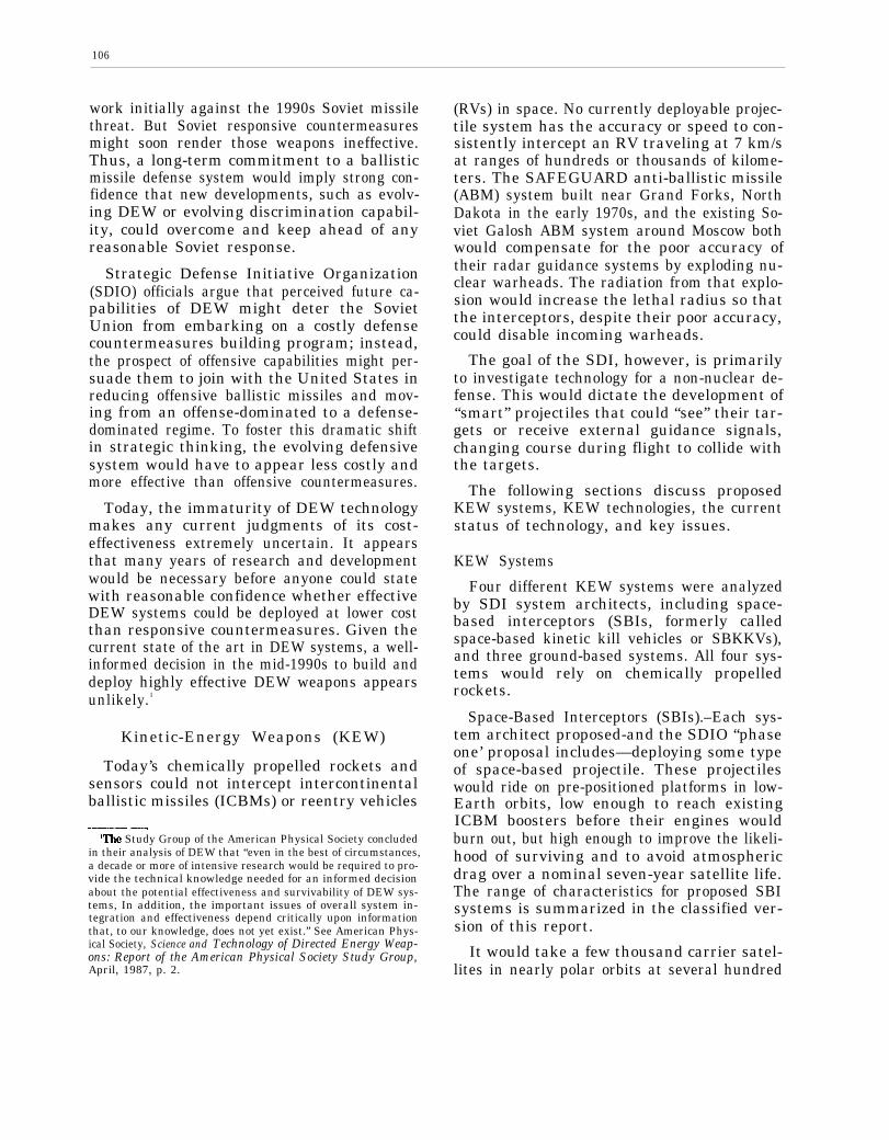
106
work initially against the 1990s Soviet missilethreat. But Soviet responsive countermeasuresmight soon render those weapons ineffective.Thus, a long-term commitment to a ballisticmissile defense system would imply strong con-fidence that new developments, such as evolv-ing DEW or evolving discrimination capabil-ity, could overcome and keep ahead of anyreasonable Soviet response.
Strategic Defense Initiative Organization(SDIO) officials argue that perceived future ca-pabilities of DEW might deter the SovietUnion from embarking on a costly defensecountermeasures building program; instead,the prospect of offensive capabilities might per-suade them to join with the United States inreducing offensive ballistic missiles and mov-ing from an offense-dominated to a defense-dominated regime. To foster this dramatic shiftin strategic thinking, the evolving defensivesystem would have to appear less costly andmore effective than offensive countermeasures.
Today, the immaturity of DEW technologymakes any current judgments of its cost-effectiveness extremely uncertain. It appearsthat many years of research and developmentwould be necessary before anyone could statewith reasonable confidence whether effectiveDEW systems could be deployed at lower costthan responsive countermeasures. Given thecurrent state of the art in DEW systems, a well-informed decision in the mid-1990s to build anddeploy highly effective DEW weapons appearsunlikely.1
Kinetic-Energy Weapons (KEW)
Today’s chemically propelled rockets andsensors could not intercept intercontinentalballistic missiles (ICBMs) or reentry vehicles.-—— —
‘The Study Group of the American Physical Society concludedin their analysis of DEW that “even in the best of circumstances,a decade or more of intensive research would be required to pro-vide the technical knowledge needed for an informed decisionabout the potential effectiveness and survivability of DEW sys-tems, In addition, the important issues of overall system in-tegration and effectiveness depend critically upon informationthat, to our knowledge, does not yet exist.” See American Phys-ical Society, Science and Technology of Directed Energy Weap-ons: Report of the American Physical Society Study Group,April, 1987, p. 2.
(RVs) in space. No currently deployable projec-tile system has the accuracy or speed to con-sistently intercept an RV traveling at 7 km/sat ranges of hundreds or thousands of kilome-ters. The SAFEGUARD anti-ballistic missile(ABM) system built near Grand Forks, NorthDakota in the early 1970s, and the existing So-viet Galosh ABM system around Moscow bothwould compensate for the poor accuracy oftheir radar guidance systems by exploding nu-clear warheads. The radiation from that explo-sion would increase the lethal radius so thatthe interceptors, despite their poor accuracy,could disable incoming warheads.
The goal of the SDI, however, is primarilyto investigate technology for a non-nuclear de-fense. This would dictate the development of“smart” projectiles that could “see” their tar-gets or receive external guidance signals,changing course during flight to collide withthe targets.
The following sections discuss proposedKEW systems, KEW technologies, the currentstatus of technology, and key issues.
KEW Systems
Four different KEW systems were analyzedby SDI system architects, including space-based interceptors (SBIs, formerly calledspace-based kinetic kill vehicles or SBKKVs),and three ground-based systems. All four sys-tems would rely on chemically propelledrockets.
Space-Based Interceptors (SBIs).–Each sys-tem architect proposed-and the SDIO “phaseone’ proposal includes—deploying some typeof space-based projectile. These projectileswould ride on pre-positioned platforms in low-Earth orbits, low enough to reach existingICBM boosters before their engines wouldburn out, but high enough to improve the likeli-hood of surviving and to avoid atmosphericdrag over a nominal seven-year satellite life.The range of characteristics for proposed SBIsystems is summarized in the classified ver-sion of this report.
It would take a few thousand carrier satel-lites in nearly polar orbits at several hundred

107
km altitude to attack effectively a high per-centage of the mid-1990s Soviet ICBM threat.There was a wide range in the number of in-terceptor rockets proposed by system archi-tects, depending on the degree of redundancydeemed necessary for functional survivability,on the number of interceptors assigned toshoot down Soviet direct-ascent anti-satelliteweapons (ASATs), and on the leakage rates ac-cepted for the boost-phase defense.
In late 1986, the SDIO and its contractorsbegan to examine options for 1990s deploy-ment which would include constellations ofonly a few hundred carrier vehicles (CVs) anda few thousand SBIs. This evolved into thephase-one design which, if deployed in the midto late 1990s, could only attack a modest frac-tion of the existing Soviet ICBMs in theirboost and post-boost phases.
Exe-atmospheric Reentry Interceptor System(ERIS).–The ERIS would be a ground-basedrocket with the range to attack RVs in the latemidcourse phase. Existing, but upgraded, ra-
dars such as BMEWS, PAVE PAWS, and thePAR radar north of Grand Forks, North Da-kota might supply initial track coordinates toERIS interceptors.2 (These radars might be theonly sensors available for near-term deploy-ments.) Alternatively, new radars or opticalsensors would furnish the track data. Up-graded radars would have little discriminationcapability (unless the Soviets were to refrainfrom using penetration aids); moreover, a sin-gle high altitude nuclear explosion could de-grade or destroy them.
Optical sensors might reside on a fleet ofspace surveillance and tracking system (SSTS)satellites or on ground-based, pop-up probesbased at higher latitudes. Such sensors mightsupply early enough infrared (IR) track data
..—‘The range of planned ground-based radars such as the Ter-
minal Imaging Radar (TIR), which could discriminate RVS fromdecoys, might be too short to aid ERIS long-range intercep-tors; the TIR was planned for the lower HEDI endoatmosphericsystem. A longer-range Ground-based Radar (GBR) system hasalso been proposed. This system may be capable of supportingERIS interceptors.
Photo Credit: Lockheed Missiles and Space Company
How ERIS would work.—The ERIS vehicle would be launched from the ground and its sensors would acquire and tracka target at long range, ERIS would then maneuver to intercept the target’s path, demolishing it on impact.
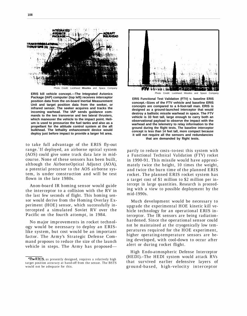
— —
108
Photo Credit: Lockheed Missiles and Space Company
ERIS kill vehicle concept.—The Integrated AvionicsPackage (IAP) computer (top left) receives interceptorposition data from the on-board Inertial MeasurementUnit and target position data from the seeker, orinfrared sensor. The seeker acquires and tracks theincoming warhead. The IAP sends guidance com-mands to the two transverse and two lateral thrusters,which maneuver the vehicle to the impact point. Heli-um is used to pressurize the fuel tanks and also as apropellant for the attitude control system at the aftbulkhead. The lethality enhancement device woulddeploy just before impact to provide a larger hit area.
to take full advantage of the ERIS fly-outrange. 3 If deployed, an airborne optical system(AOS) could give some track data late in mid-course. None of these sensors has been built,although the AirborneOptical Adjunct (AOA),a potential precursor to the AOS airborne sys-tem, is under construction and will be testflown in the late 1980s.
Anon-board IR homing sensor would guidethe interceptor to a collision with the RV inthe last few seconds of flight. This homing sen-sor would derive from the Homing Overlay Ex-periment (HOE) sensor, which successfully in-tercepted a simulated Soviet RV over thePacific on the fourth attempt, in 1984.
No major improvements in rocket technol-ogy would be necessary to deploy an ERIS-like system, but cost would be an importantfactor. The Army’s Strategic Defense Com-mand proposes to reduce the size of the launchvehicle in steps. The Army has proposed—
Whe ERIS, as presently designed, requires a relatively hightarget position accuracy at hand-off from the sensor. The BSTSwould not be adequate for this.
Photo Credit: Lockheed Missiles and Space Company
ERIS Functional Test Validation (FTV) v. baseline ERISconcept.–Sizes of the FTV vehicle and baseline ERISconcepts are compared to a 6-foot-tall man. ERIS isdesigned as a ground-launched interceptor that woulddestroy a ballistic missile warhead in space. The FTVvehicle is 33 feet tall, large enough to carry both anobservational payload to observe the impact with thewarhead and the telemetry to relay information to theground during the flight tests. The baseline interceptorconcept is less than 14 feet tall, more compact becauseit will not require all the sensors and redundancies
that are demanded by flight tests.
partly to reduce costs–to-test this system witha Functional Technical Validation (FTV) rocketin 1990-91. This missile would have approxi-mately twice the height, 10 times the weight,and twice the burn time of the planned ERISrocket. The planned ERIS rocket system hasa target cost of $1 million to $2 million per in-tercept in large quantities. Research is proceed-ing with a view to possible deployment by themid-1990s.
Much development would be necessary toupgrade the experimental HOE kinetic kill ve-hicle technology for an operational ERIS in-terceptor. The IR sensors are being radiation-hardened. Since the operational sensor couldnot be maintained at the cryogenically low tem-peratures required for the HOE experiment,higher operating-temperature sensors are be-ing developed, with cool-down to occur afteralert or during rocket flight.
High Endo-atmospheric Defense Interceptor(HEDI).–The HEDI system would attack RVsthat survived earlier defensive layers ofground-based, high-velocity interceptor

109
rockets. HEDI would take advantage of thefact that the atmosphere would slow downlight-weight decoys more than the heavierRVs. Since it would operate in the atmosphere,HEDI might attack depressed trajectory sub-marine-launched ballistic missile (SLBM) war-heads that would under-fly boost and mid-course defensive layers—provided it receivedadequate warning and sensor data.
According to one plan, an AOS would trackthe RVs initially, after warning from the boost-phase surveillance and tracking system (BSTS)and possible designation by SSTS (if available).The AOS would hand target track informationoff to the ground-based terminal imaging ra-dar (TIR). The TIR would discriminate RVsfrom decoys both on shape (via doppler imag-ing) and on their lower deceleration (comparedto decoys) upon entering the atmosphere.Interceptors would attack the RVs at altitudesbetween 12 and 45 km. The HEDI system thuswould combine passive optics (IR signature),atmospheric deceleration, and active radar(shape) to distinguish RVs from decoys.
The penalty for waiting to accumulate thesedata on target characteristics would be theneed for a large, high-acceleration missile. TheHEDI would have to wait long enough to pro-vide good atmospheric discrimination, but notso long that a salvage-fused RV would deto-nate a nuclear explosion close to the ground.To accelerate rapidly, the HEDI 2-stage mis-sile must weigh about five to six times morethan the ERIS missile.
The key technology challenge for the HEDIsystem would be its IR homing sensor. Thisnon-nuclear, hit-to-kill vehicle would have toview the RV for the last few seconds of flightto steer a collision course.4 But very high ac-celeration up through the atmosphere wouldseverely heat the sensor window. This heatedwindow would then radiate energy back to theIR sensor, obscuring the RV target. In addi-tion, atmospheric turbulence in front of thewindow could further distort or deflect the RV
——4The HEDI interceptor would probably include an explosively
driven “lethality enhancer. ”
image. No sensor has been built before to oper-ate in this environment.
The proposed solution is to use a sapphirewindow bathed with a stream of cold nitrogengas. A shroud would protect the window untilthe last few seconds before impact. Since reen-try would heat the RV to temperatures abovethat of the cooled window, detection would bepossible. Recent testing gives grounds for op-timism in this area.
Fabrication of the sapphire windows (cur-rently 12 by 33 cm) would be a major effortfor the optics industry. These windows mustbe cut from crystal boules, which take manyweeks to grow. At current production rates,it would take 20 years to make 1,000 windows.Plans are to increase the manufacturing capa-bility significantly.
The HEDI sensor suite also uses a Nd:YAG5
laser for range finding. Building a laser rangerto withstand the high acceleration could bechallenging.
As with ERIS, plans call for testing a HEDIFunctional Technical Validation missile, whichis 2 to 3 times larger than the proposed opera-tional vehicle. The proposed specifications ofHEDI are found in the classified version of thisreport.
Flexible Light-Weight Agile Experiment(FLAGE).–The weapon system expected toevolve from FLAGE research would be the lastline of defense, intercepting any RVs whichleaked through all the other layers. Its primarymission would be the defense of military tar-gets against short range missiles in a theaterwar such as in Europe or the Middle East. TheFLAGE type of missile would intercept RVsat altitudes up to 15 km. The homing sensorfor FLAGE would use an active radar insteadof the passive IR sensor proposed for on allother KEW homing projectiles.
5“Nd:YAG” is the designation for a common laser used inresearch and for military laser range-finders. The “Nd” repre-sents neodymium, the rare element that creates the lasing ac-tion, and “YAG” stands for yttrium-alumin urn-garnet, the glass-like host material that carries the neodymium atoms.

110
The FLAGE system was flown six times atthe White Sands Missile Range. On June 27,1986, the FLAGE missile successfully collidedwith an RV-shaped target drone which wasflown into a heavily instrumented flight space.The collision was very close to the planned im-pact point. Another FLAGE interceptor col-lided with a Lance missile on May 21, 1987.
The FLAGE program ended in mid-1987with the Lance intercept. A more ambitiousExtended Range Intercept Technology (ER-INT) program succeeds it. The ERINT inter-ceptors will have longer range and “a lethal-ity enhancer. ” FLAGE was a fire-and-forgetmissile; no information was transmitted fromany external sensor to the missile once it wasfired. The ERINT missiles are to receive mid-course guidance from ground-based radars. Sixtest launches are planned at the White SandsMissile Range.
KEW Technology
Three types of KEW propulsion have beenproposed for SDI: conventional projectilespowered by chemical energy, faster but lesswell-developed electromagnetic or “railgun”technology, and nuclear-pumped pellets. Allsystem architects nominated the more maturechemically propelled rockets for near-termBMD deployments.
How Chemical Energy KEWs Work.–Thereare three different modes of operation proposedfor chemically propelled KEWs:
● space-based rockets attacking boosters,post-boost vehicles (PBVs), RVs, anddirect-ascent ASATs;
● ground-based rockets attacking RVs inlate mid-course outside the atmosphere,and
● ground-based rockets attacking RVs in-side the atmosphere.
Two or more rocket stages would acceleratethe projectile toward the target. The projec-tile would be the heart of each system andwould entail the most development.
The smart projectile for the space-based mis-sion would need some remarkable features. It
would be fired at a point in space up to hun-dreds of seconds before the actual intercep-tion.6 After separation from the last rocketstage, the projectile would have to establishthe correct attitude in space to “see” the tar-get: in general the line-of-sight to the targetwould not correspond with the projectile flightpath. If it had a boresighted sensor that staredstraight ahead, then the projectile would haveto fly in an attitude at an angle to its flightpath to view the target (see figure 5-1).7
The projectile would have to receive and exe-cute steering instructions via a secure commu-nications channel from the battle manager.Usually just a few seconds before impact, theprojectile would need to acquire the target–either a bright, burning booster or a much dim-mer PBV—with an on-board sensor. It wouldthen make final path corrections to effect a col-lision. Fractions of a second before impact, itmight deploy a “lethality enhancement device’–like the spider-web structure used in theArmy’s Homing Overlay Experiment (HOE)–to increase the size of the projectile and there-fore its chance of hitting the target.
The SBI projectile must have these com-ponents:
an inertial guidance system,a secure communications system,a divert propulsion system,an attitude control system,a sensor for terminal homing (includingvibration isolation),a lethality enhancement device (optional?),anda computer able to translate signals fromthe sensor into firing commands to the di-vert propulsion system in fractions of asecond.
The on-board sensors envisaged by most sys-tem architects for more advanced “phase-two”
6A computer in the battle management system would esti-mate the actual interception aim-point in space by projectingthe motion or track of the target using the sensor track files.
7For non-accelerating targets, this look angle would notchange, even though the target and the projectile were travel-ing at different velocities. In this “proportional navigation”mode, the projectile orientation would be fixed once the sensorwas aimed at the target.
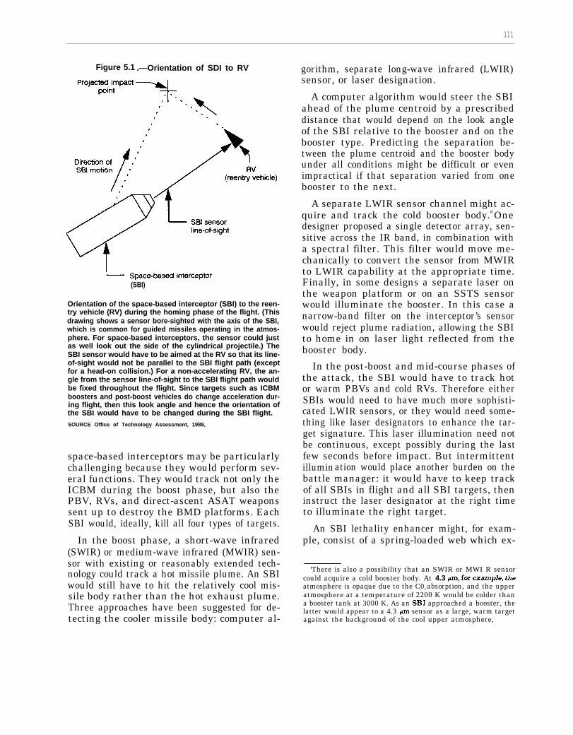
111
Figure 5.1 .—Orientation of SDI to RV
(SBI)
Orientation of the space-based interceptor (SBI) to the reen-try vehicle (RV) during the homing phase of the flight. (Thisdrawing shows a sensor bore-sighted with the axis of the SBI,which is common for guided missiles operating in the atmos-phere. For space-based interceptors, the sensor could justas well look out the side of the cylindrical projectile.) TheSBI sensor would have to be aimed at the RV so that its line-of-sight would not be parallel to the SBI flight path (exceptfor a head-on collision.) For a non-accelerating RV, the an-gle from the sensor line-of-sight to the SBI flight path wouldbe fixed throughout the flight. Since targets such as ICBMboosters and post-boost vehicles do change acceleration dur-ing flight, then this look angle and hence the orientation ofthe SBI would have to be changed during the SBI flight.SOURCE Office of Technology Assessment, 1988,
space-based interceptors may be particularlychallenging because they would perform sev-eral functions. They would track not only theICBM during the boost phase, but also thePBV, RVs, and direct-ascent ASAT weaponssent up to destroy the BMD platforms. EachSBI would, ideally, kill all four types of targets.
In the boost phase, a short-wave infrared(SWIR) or medium-wave infrared (MWIR) sen-sor with existing or reasonably extended tech-nology could track a hot missile plume. An SBIwould still have to hit the relatively cool mis-sile body rather than the hot exhaust plume.Three approaches have been suggested for de-tecting the cooler missile body: computer al-
gorithm, separate long-wave infrared (LWIR)sensor, or laser designation.
A computer algorithm would steer the SBIahead of the plume centroid by a prescribeddistance that would depend on the look angleof the SBI relative to the booster and on thebooster type. Predicting the separation be-tween the plume centroid and the booster bodyunder all conditions might be difficult or evenimpractical if that separation varied from onebooster to the next.
A separate LWIR sensor channel might ac-quire and track the cold booster body.8 Onedesigner proposed a single detector array, sen-sitive across the IR band, in combination witha spectral filter. This filter would move me-chanically to convert the sensor from MWIRto LWIR capability at the appropriate time.Finally, in some designs a separate laser onthe weapon platform or on an SSTS sensorwould illuminate the booster. In this case anarrow-band filter on the interceptor’s sensorwould reject plume radiation, allowing the SBIto home in on laser light reflected from thebooster body.
In the post-boost and mid-course phases ofthe attack, the SBI would have to track hotor warm PBVs and cold RVs. Therefore eitherSBIs would need to have much more sophisti-cated LWIR sensors, or they would need some-thing like laser designators to enhance the tar-get signature. This laser illumination need notbe continuous, except possibly during the lastfew seconds before impact. But intermittentillumination would place another burden on thebattle manager: it would have to keep trackof all SBIs in flight and all SBI targets, theninstruct the laser designator at the right timeto illuminate the right target.
An SBI lethality enhancer might, for exam-ple, consist of a spring-loaded web which ex-
‘There is also a possibility that an SWIR or MWI R sensorcould acquire a cold booster body. At 4.3 p, for exaznple, theatmosphere is opaque due to the C02 absorption, and the upperatmosphere at a temperature of 2200 K would be colder thana booster tank at 3000 K. As an SBI approached a booster, thelatter would appear to a 4.3 ~m sensor as a large, warm targetagainst the background of the cool upper atmosphere,

112
panded to a few meters in diameter or an ex-plosively propelled load of pellets drivenradially outward. Weight would limit the prac-tical diameter of expansion. System designerswould have to trade off the costs of increasedhoming accuracy with the weight penalty ofincreased lethality diameter.
Ground-based KEW capabilities would re-semble those of space-based interceptors. Exo-atmospheric projectiles that intercept the RVsoutside the Earth’s atmosphere would useLWIR homing sensors to track cold RVs, orthey would employ other optical sensors totrack laser-illuminated targets. These intercep-tors would be command-guided to the vicin-ity of the collision by some combination ofground-based radars, airborne LWIR sensors(AOS) or space-borne LWIR sensors (SSTS,BSTS, or rocket-borne probes). Long-wave in-frared homing sensors in the projectile wouldhave to be protected during launch throughthe atmosphere to prevent damage or over-heating.
Current Status of Chemically PropelledRockets.–No interceptor rockets with BMD-level performance have ever been fired fromspace-based platforms. Operational IR heat-seeking interceptor missiles such as the air-to-air Sidewinder and the air-to-ground Maver-ick are fired from aircraft, but both the rangeand the final velocity of this class of missilesare well below BMD levels.
The SDIO’s Delta 180 flight test includedthe collision of two stages from a Delta rocketafter the primary task of collecting missileplume data was completed. However, thesetwo stages were not interceptor rockets, werenot fired from an orbiting platform, did nothave the range nor velocity necessary forBMD, and were highly cooperative, with thetarget vehicle orienting a four-foot reflectortoward the homing vehicle to enhance the sig-nal for the radar homing system. Note that thistest used radar homing, whereas all SBI de-signs call for IR homing or laser-designatorhoming. This experiment did test the track-ing algorithms for an accelerating target, al-though the target acceleration for this nearly
head-on collision was not as stressing as itwould be for expected BMD/SBI flight trajec-tories.9
Engineers have achieved very good progressin reducing the size and weight of componentsfor the proposed space-based interceptors.They have developed individual ring laser gyro-scopes weighing only 85 g as part of an iner-tial measuring unit. They have reduced theweight of divert propulsion engines about 9kg to 1.3 kg. Gas pressure regulators to con-trol these motors have been reduced from 1.4kg to .09 kg each. The smaller attitude con-trol engines and valves have been reduced from800 g each to 100 g each. Progress has alsobeen made on all other components of a SBIsystem, although these components have notas yet been integrated into a working proto-type SBI system.
Ground-based interceptor rockets are one ofthe best developed BMD technologies. TheSpartan and Sprint interceptor missiles wereoperational for a few months in the mid 1970s.Indeed parts of these missiles have been recom-missioned for upcoming tests of SDI ground-based weapons such as the endo-atmosphericHEDI. The production costs for these missileswould have to be reduced substantially tomake their use in large strategic defense sys-tems affordable, but no major improvementsin rocket technology are needed for ground-based interceptors, other than a 30 percent im-provement in speed for the HEDI missile. Asdiscussed in chapter 4, however, major sensordevelopment would be necessary for these in-terceptors.
Key Issues for Chemical Rockets.–Chemicalrocket development faces four key issues, allrelated to space-based deployment and all de-rived from the requirement to design and makevery fast SBIs.
Constellation Mass. —The overriding issuefor SBIs is mass. The SBIs must be so fast
‘Previous tests of IR guided projectiles such as the HomingOverlay Experiment against a simulated RV and the F-16launched ASAT test against a satellite, shot down non-accelerating targets.

113
that a reasonably small number of battle sta-tions could cover the entire Earth. But, for agiven payload, faster rockets consume muchmore fuel-the fuel mass increases roughly ex-ponentially with the desired velocity. Thedesigner must compromise between many bat-tle stations with light rockets or fewer battlestations with heavier rockets.10
These trade-offs are illustrated in figure 5-2, which assumes a boost-phase-only defensewith three hypothetical rocket designs: a state-of-the-art rocket based on current technology;a “realistic” design based on improvementsin rocket technology that seem plausible bythe mid-1990s; and an “optimistic” design thatassumes major improvements in all areas ofrocket development. The key parameters as-sumed for SBI rocket technology appear in theclassified version of this report. In all casesanalyzed, OTA assumed the rockets to be“ideal”: the mass ratio of each stage is thesame, which produces the lightest possiblerocket. 11 The first chart in figure 5-2a showsthat rocket mass increases exponentially withincreasing velocity, limiting practical SBI ve-locities to the 5 to 8 km/s range for rocketsweighing on the order of 100 kg or less.
For analytic purposes, OTA has consideredconstellations of SBIs that would be necessaryto intercept virtually 100 percent of postulatednumbers of ICBMs. It should be noted thatsince the system architecture analyses of 1986,SDIO has not seriously considered deployingSBIs that would attempt to intercept any-where near 100 percent of Soviet ICBMs andPBVS.12 This OTA analysis is intended only
‘“Projectile mass might not be as critical for ground-basedas for spacebased KEW projectiles, since there would be nospace transportation cost. However, the projectile mass shouldstill be minimized to reduce the over-all rocket size and cost,and to permit higher accelerations and final velocities.
llThe ma99 fraction for a rocket stage is defined = the ratioof the propellant mass to the total stage mass (propellant plusrocket structure). The mass fraction does not include the pay-load mass. For the calculations reported here, an ideal rocketis assumed: it has equal mass ratios for each stage, where massratio is defined as the initial stage weight divided by the stageweight after burn-out (both including the payload; it can beshown that the rocket mass is minimized for a given burnoutvelocity if each stage has the same mass ratio.)
“AS indicated in chapters 1,2, and 3, SDIO argues that thedeterrent utility of defenses far more modest than those neededfor “assured survival” would make them worthwhile.
to give a feel for the parameters and trade-offsinvolved in a system with SBIs.
Deployment of a system of “state-of-the-art”SBIs intended to provide 100 percent cover-age of Soviet ICBMs would entail 11.7 millionkg of CVs; waiting for the development of the“realistic” SBI would reduce the mass to or-bit by a factor of two.
Figure 5-2b shows the number of SBI car-rier platforms and figure 5-2c shows the num-ber of SBIs for a 100 percent-boost-phase de-fense as a function of SBI velocity. The lastchart (figure 5-2d) shows the total constella-tion mass as a function of velocity. The num-ber of CVs was calculated initially to optimizecoverage of existing Soviet missile fields: theorbits of the CVs were inclined so that the CVspassed to the north of the missile fields by adistance equal to the SBI fly-out range.13 EachCV therefore stayed within range of the ICBMfields for a maximum period during each orbit.
The “optimal” number of CVs resulting fromthis calculation was so low as to endanger sys-tem survivability (see ch. 11), calling for up to100 SBIs per carrier to cover the existing So-viet ICBM threat: such concentrations wouldprovide lucrative targets for the offense’sASATs. To increase survivability, the num-ber of CVs was therefore increased by a factorof 3 for the data in figure 5-2. Some polar or-bits were added to cover the SLBM threat fromnorthern waters.
The number of SBIs was calculated initiallyto provide one SBI within range of each of1,400 Soviet ICBMs sometime during theboost phase. The booster burn time was takenas similar to that of existing Soviet missiles,with a reasonable interval allotted for cloud-break, initial acquisition, tracking, and weap-ons launch.
One SBI per booster would not do for a ro-bust (approaching 100 percent coverage) boost-phase defense. A substantial number of SBIs
*The locations of Soviet missile fields are estimated from mapsappearing in U.S. Department of Defense, Sow”et Mih”tary Power,1987 (Washington, D. C.: Department of Defense, 1987), p. 23.See adaptation of this map in chapter 2 of this OTA report.

114
Figure 5-2a. -Space-based Interceptor Mass v. Velocity
Velocity (km/see)
The SBI mass versus SBI velocity. These data assume 100°/0coverage of the current Soviet threat of 1,400 ICBMs. It shouldbe noted that the SDIO currently proposes a substantiallylower level of coverage for SBIs. Therefore, the absolute num-bers in the OTA calculations are not congruent with SDIOplans. Rather, the graphs provided here are intended to showthe relationships among the various factors considered. Itshould also be noted that numerous assumptions underlyingthe OTA analyses are unstated in this unclassified report, but,are available- in the classified version.
SOURCE: Office of Technology Assessment, 1988.
Figure 5-2b.-Number of Satellites v. SBI Velocity
1
I I I I4 6 10 12
Velocity~km/see)
The number of SBI carrier satellites v. SBI velocity.
SOURCE: Office of Technology Assessment, 1988
Figure 5-2c. -Number of Space-Based Interceptorsv. Velocity (Inclined orbits + SLBM polar orbits)
40
30 —
20 —
4 6 10 12Velocity ~km/see)
The number of space-based interceptors (SBIs) required toprovide one SBI within range of each of 1,400 existing SovietICBMs before booster burnout. ‘
SOURCE: Office of Technology Assessment, 1988.
Figure 5-2d. -Constellation Mass v. SBI Velocity
4 6 8 10 12Velocity (km/see)
The total constellation mass in orbit (SBIs and carrier vehi-cles, excluding sensor satellites) v. SBI velocity. The mini-mum constellation mass for the “realistic” SBI to be in po-sition to attack all Soviet boosters would be about 5.3 millionkg. Faster SBIs would permit fewer carrier vehicles and fewerSBIs, but the extra propellant on faster SBIs would result ina heavier constellation. For reference, the Space Shuttle canlift about 14,000 kg into polar orbit, a 5.3 million kg constel-lation would require about 380 Shuttle launches, or about 130launches of the proposed “Advanced Launch System” (ALS),assuming it could lift 40,000 kg into near-polar orbit at suit-able altitudes.
SOURCE: Office of Technology Assessment, 1988.
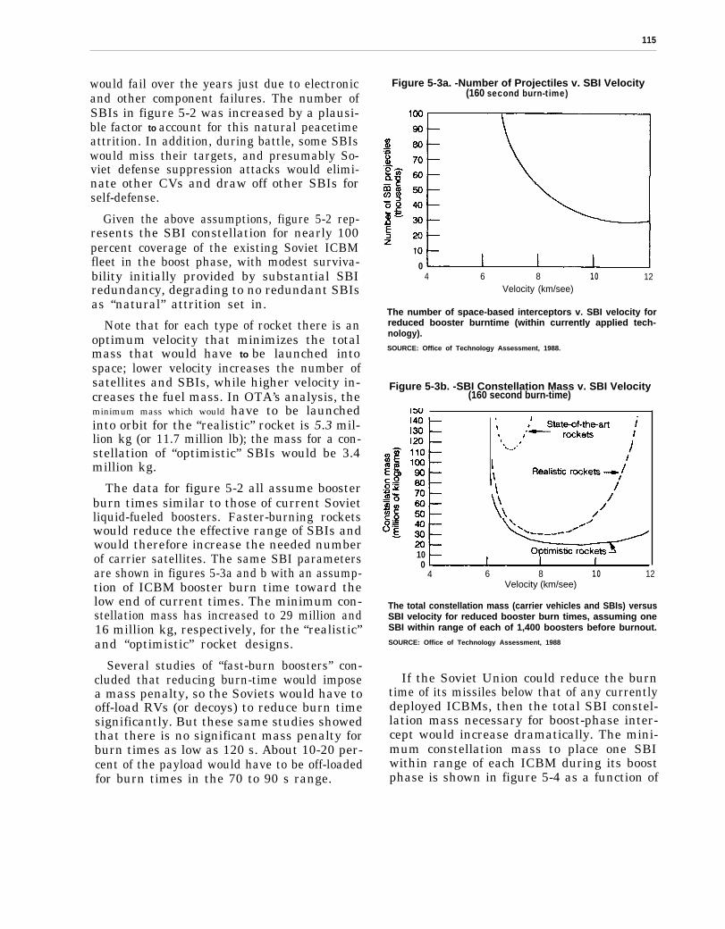
115
would fail over the years just due to electronicand other component failures. The number ofSBIs in figure 5-2 was increased by a plausi-ble factor to account for this natural peacetimeattrition. In addition, during battle, some SBIswould miss their targets, and presumably So-viet defense suppression attacks would elimi-nate other CVs and draw off other SBIs forself-defense.
Given the above assumptions, figure 5-2 rep-resents the SBI constellation for nearly 100percent coverage of the existing Soviet ICBMfleet in the boost phase, with modest surviva-bility initially provided by substantial SBIredundancy, degrading to no redundant SBIsas “natural” attrition set in.
Note that for each type of rocket there is anoptimum velocity that minimizes the totalmass that would have to be launched intospace; lower velocity increases the number ofsatellites and SBIs, while higher velocity in-creases the fuel mass. In OTA’s analysis, theminimum mass which would have to be launchedinto orbit for the “realistic” rocket is 5.3 mil-lion kg (or 11.7 million lb); the mass for a con-stellation of “optimistic” SBIs would be 3.4million kg.
The data for figure 5-2 all assume boosterburn times similar to those of current Sovietliquid-fueled boosters. Faster-burning rocketswould reduce the effective range of SBIs andwould therefore increase the needed numberof carrier satellites. The same SBI parametersare shown in figures 5-3a and b with an assump-tion of ICBM booster burn time toward thelow end of current times. The minimum con-stellation mass has increased to 29 million and16 million kg, respectively, for the “realistic”and “optimistic” rocket designs.
Several studies of “fast-burn boosters” con-cluded that reducing burn-time would imposea mass penalty, so the Soviets would have tooff-load RVs (or decoys) to reduce burn timesignificantly. But these same studies showedthat there is no significant mass penalty forburn times as low as 120 s. About 10-20 per-cent of the payload would have to be off-loadedfor burn times in the 70 to 90 s range.
Figure 5-3a. -Number of Projectiles v. SBI Velocity(160 second burn-time)
04 6 8 10 12
Velocity (km/see)
The number of space-based interceptors v. SBI velocity forreduced booster burntime (within currently applied tech-nology).SOURCE: Office of Technology Assessment, 1988.
Figure 5-3b. -SBI Constellation Mass v. SBI Velocity(160 second burn-time)
100
4 6 8 10 12Velocity (km/see)
The total constellation mass (carrier vehicles and SBIs) versusSBI velocity for reduced booster burn times, assuming oneSBI within range of each of 1,400 boosters before burnout.
SOURCE: Office of Technology Assessment, 1988
If the Soviet Union could reduce the burntime of its missiles below that of any currentlydeployed ICBMs, then the total SBI constel-lation mass necessary for boost-phase inter-cept would increase dramatically. The mini-mum constellation mass to place one SBIwithin range of each ICBM during its boostphase is shown in figure 5-4 as a function of
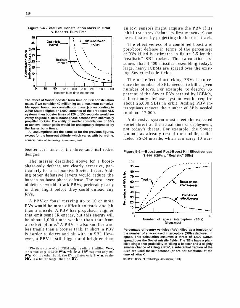
116
Figure 5-4.-Total SBI Constellation Mass in Orbitv. Booster Burn Time
Realisticrocket -
120 160 200 240 280 300Booster bum time (seconds)
The effect of Soviet booster burn time on SBI constellationmass. If we consider 40 million kg as a maximum conceiva-ble upper bound on constellation mass (corresponding to2,800 Shuttle flights or 1,000 launches of the proposed ALSsystem), then booster times of 120 to 150 seconds would se-verely degrade a 100%-boost-phase defense with chemicallypropelled rockets. The ability of smaller constellations of SBIsto achieve lesser goals would be analogously degraded bythe faster burn times.
All assumptions are the same as for the previous figures,except for the burn-out altitude, which varies with burn-time.
SOURCE: Office of Technology Assessment, 1988.
booster burn time for the three canonical rocketdesigns.
The masses described above for a boost-phase-only defense are clearly excessive, par-ticularly for a responsive Soviet threat. Add-ing other defensive layers would reduce theburden on boost-phase defense. The next layerof defense would attack PBVs, preferably earlyin their flight before they could unload anyRVs.
A PBV or “bus” carrying up to 10 or moreRVs would be more difficult to track and hitthan a missile. A PBV has propulsion enginesthat emit some IR energy, but this energy willbe about 1,000 times weaker than that froma rocket plume.14 A PBV is also smaller andless fragile than a booster tank. In short, a PBVis harder to detect and hit with an SBI. How-ever, a PBV is still bigger and brighter than
Whe first stage of an ICBM might radiate 1 million W/sr,the second stage 100,000 W/sr, while a PBV may emit only 100W/sr. On the other hand, the RV radiates only 5 W/sr, so thePBV is a better target than an RV.
an RV; sensors might acquire the PBV if itsinitial trajectory (before its first maneuver) canbe estimated by projecting the booster track.
The effectiveness of a combined boost andpost-boost defense in terms of the percentageof RVs killed is estimated in figure 5-5 for the“realistic” SBI rocket. The calculation as-sumes that 1,400 missiles resembling today’slarge, heavy ICBMs are spread over the exist-ing Soviet missile fields.
The net effect of attacking PBVs is to re-duce the number of SBIs needed to kill a givennumber of RVs. For example, to destroy 85percent of the Soviet RVs carried by ICBMs,a boost-only defense system would requireabout 26,000 SBIs in orbit. Adding PBV in-terceptions reduces the number of SBIs neededto about 17,000.
A defensive system must meet the expectedSoviet threat at the actual time of deployment,not today’s threat. For example, the SovietUnion has already tested the mobile, solid-fueled SS-24 missile, which can carry 10 war-
Figure 5-5.—Boost and Post-Boost Kill Effectiveness(1,400 ICBMs v. “Realistic" SBIs)
100
0o 40
Number of space interceptors (SBIs)(thousands)
Percentage of reentry vehicles (RVs) killed as a function ofthe number of space-based interceptors (SBIs) deployed inspace. This calculation assumes a threat of 1,400 ICBMsspread over the Soviet missile fields. The SBIs have a plau-sible single-shot probability of killing a booster and a slightlysmaller chance of killing a PBV; a substantial fraction of theSBIs are used for self-defense (or are not functional at thetime of attack).
SOURCE: Office of Technology Assessment, 1988,
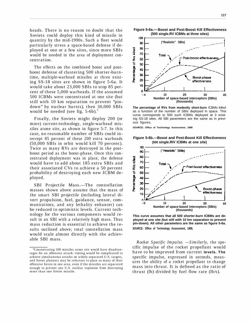
117
heads. There is no reason to doubt that theSoviets could deploy this kind of missile inquantity by the mid-1990s. Such a fleet wouldparticularly stress a space-based defense if de-ployed at one or a few sites, since more SBIswould be needed in the area of deployment con-centration.
The effects on the combined boost and post-boost defense of clustering 500 shorter-burn-time, multiple-warhead missiles at three exist-ing SS-18 sites are shown in figure 5-6a. Itwould take about 23,000 SBIs to stop 85 per-cent of these 5,000 warheads. If the assumed500 ICBMs were concentrated at one site (butstill with 10 km separation to prevent “pin-down” by nuclear bursts), then 30,000 SBIswould be needed (see fig. 5-6b).l5
Finally, the Soviets might deploy 200 (ormore) current-technology, single-warhead mis-siles atone site, as shown in figure 5-7. In thiscase, no reasonable number of SBIs could in-tercept 85 percent of these 200 extra warheads(50,000 SBIs in orbit would kill 70 percent).Twice as many RVs are destroyed in the post-boost period as the boost-phase. Once this con-centrated deployment was in place, the defensewould have to add about 185 extra SBIs andtheir associated CVs to achieve a 50 percentprobability of destroying each new ICBM de-ployed.
SBI Projectile Mass.—The constellationmasses shown above assume that the mass ofthe smart SBI projectile (including lateral di-vert propulsion, fuel, guidance, sensor, com-munications, and any lethality enhancer) canbe reduced to optimistic levels. Current tech-nology for the various components would re-sult in an SBI with a relatively high mass. Thusmass reduction is essential to achieve the re-sults outlined above; total constellation masswould scale almost directly with the achiev-able SBI mass.
“Concentrating 500 missiles atone site would have disadvan-tages for an offensive attack: timing would be complicated toachieve simultaneous attacks on widely separated U.S. targets,and Soviet planners may be reluctant to place so many of theiroffensive forces in one area, even if the missiles are separatedenough to prevent one U.S. nuclear explosion from destroyingmore than one Soviet missile.
Figure 5-6a.— Boost and Post-Boost Kill Effectiveness(500 single.RV ICBMs at three sites)
I(“Realistic” SBIs)
1
- o 10 20 30 40Number of space-based interceptors (SBIs)
(thousands)
The percentage of RVs from modestly short-burn ICBMs killedas a function of the number of SBIs deployed in space. Thiscurve corresponds to 500 such ICBMs deployed at 3 exist-ing SS-18 sites. All SBI parameters are the same as in previ-ous figures.
SOURCE: Office of Technology Assessment, 1988
Figure 5-6b.—Boost and Post-Boost Kill Effectiveness(500 singIe.RIV ICBMs at one site)
- 0 10 20 30 40Number of space-based interceptors (SBIs)
(thousands)
This curve assumes that all 500 shorter-burn ICBMs are de-ployed at one site (but still with 10 km separation to preventpin-down). All other parameters are the same as figure 5-6a.
SOURCE: Office of Technology Assessment, 1988,
Rocket Specific Impulse. —Similarly, the spe-cific impulse of the rocket propellant wouldhave to be improved from current levels. Thespecific impulse, expressed in seconds, meas-ures the ability of a rocket propellant to changemass into thrust. It is defined as the ratio ofthrust (lb) divided by fuel flow rate (lb/s).

118
Figure 5-7. - Boost and Peat-Boost Kill Effectiveness(200 “medium-burn-booster” ICBMs at one site)
100
90 — (“Realistic” SBIs)
I
00 10 20 30 40
Number of space-based interceptors (SBIs)(thousands)
Percentage of single-warhead ICBM RVs killed as a functionof number of SBIs in space. The 200 single-warhead ICBMsare deployed at one site with 10 km separation. All SBI pa-rameters are as in previous figures.SOURCE: Office of Technology Assessment, 1988.
The specific impulse of current propellantsvaries from 240 to 270 s for solid fuel and upto 390s at sea level for liquid oxygen and liq-uid hydrogen fuel. Assuming that BMD weap-ons would utilize solid fuels for stability andreliability, then the specific impulse for cur-rent technology would be limited to the 270-srange. 16 One common solid propellant, hy-droxyl-terminated polybutadiene (HTPB)loaded with aluminum, has an impulse in the260-to-265-s range. This can be increased to280s by substituting beryllium for the alumi-num. Manufacturers of solid propellant saythat further improvements are possible.
Rocket Mass Fraction. —Finally, the massfraction-the ratio of the fuel mass to the stagetotal mass (fuel plus structure but excludingpayload) –would have to be raised to meet SDIobjectives. Large mass fractions can beachieved for very big rockets having 95 per-cent of their mass in fuel. It would be moredifficult to reduce the percentage mass of struc-ture and propulsion motor components for verysmall SBI rockets.
—IThe SBI divert propulsion system in the final projectile stage
would probably use liquid fuel, and some have suggested thatthe second stage also use liquid fuel.
The mass fraction can be increased by re-ducing the mass of the rocket shell. New light-eight, strong materials such as carbon graph-ite fiber reinforced composite materials orjudicious use of titanium (for strength) and alu-minum (for minimum mass) may permit in-creased mass fractions for future rockets.
How Electromagnetic Launchers (EML) Work.–Electromagnetic launchers or “railguns” useelectromagnetic forces instead of direct chem-ical energy to accelerate projectiles along a pairof rails to very high velocities. The goal is toreach higher projectile velocities than practi-cal rockets can. This would extend the rangeof KEW, expanding their ability to attackfaster-burn boosters before burn-out. Whereasadvanced chemically propelled rockets of rea-sonable mass (say, less than 300 kg) couldaccelerate projectiles to at most 9 to 10 km/s,future EML launchers might accelerate smallprojectiles (1 to 2 kg) up to 15 to 25 km/s. SDIOhas set a goal of reaching about 15 km/s.
In principle, chemical rockets could reachthese velocities simply by adding more propel-lant. The efficiency of converting fuel energyinto kinetic energy of the moving projectile de-creases with increasing velocity, however: therocket must accelerate extra fuel mass that islater burned. A projectile on an ideal, stagedrocket could be accelerated to 15 km/s, but only17 percent of the fuel energy would be con-verted into kinetic energy of the projectile,down from 26 percent efficiency for a 12 km/sprojectile. Since a railgun accelerates only theprojectile, it could theoretically have higherenergy efficiency, which would translate intoless mass needed in orbit.
In practice, however, a railgun system wouldnot likely weigh less than its chemical rocketcounterpart at velocities below about 12 km/s,since railgun system efficiency would probablybe on the order of 25 percent at this velocity .17
17ms assumes 50 ~rmnt efficiency for converting fuel (ther-mal) energy into electricity, 90 percent efficiency in the pulseforming network, and 55 percent rail efficiency in convertingelectrical pulses into projectile kinetic energy. The SDIO hasa goal of reaching 40 percent overall EML system efficiency,but this would require the development of very high tempera-ture (2,000 to 2,500° K) nuclear reactor driven turbines. Thetotal system mass might still exceed that of a comparable chem-ical rocket system.

119
Therefore a railgun system would have to carryas much or more fuel than its chemical rocketequivalent-in addition to a massive rocket-engine generator system, an electrical pulse-forming network to produce the proper elec-trical current pulses, and the rail itself.
The conventional “railgun” (see figure 5-8)contains a moving projectile constrained bytwo conducting but electrically insulated rails.A large energy source drives electrical currentdown one rail, through the back end of the mov-ing projectile, and back through the other rail.This closed circuit of current forms a strongmagnetic field, and this field reacts with thecurrent flowing through the projectile to pro-duce a constant outward force. The projectiletherefore experiences constant acceleration asit passes down the rail.
The final velocity of the projectile is propor-tional to the current in the rail and the squareroot of the rail length; it is inversely propor-
Figure 5-8.-Schematic of an ElectromagneticLauncher (EML) or “Railgun”
Schematic of an electromagnetic launcher (EML) or “Rail-gun. ” In operation, a strong pulse of electrical current formsa circuit with the conducting rails and the projectile. This cur-rent loop generates a magnetic field. The interaction of thisfield with the current passing through the moving projectileproduces a constant outward force on the projectile, acceler-ating it to high velocities.
SOURCE’ Office of Technology Assessment, 1988.
tional to the square root of the projectile mass.High velocity calls for very high currents (mil-lions of amperes), long rails (hundreds of m),and very light projectiles (1 to 2 kg).
For the BMD mission, the projectile mustbe “smart”. That is, it must have all of the com-ponents of the chemically propelled SBIs: asensor, inertial guidance, communications, di-vert propulsion, a computer, and possibly alethality enhancement device. The EML pro-jectile must be lighter, and it must withstandaccelerations hundreds of thousands timesgreater than gravity, compared to 10 to 20“g’s” for chemically propelled SBIs.
Researchers at Sandia National Laboratoryhave proposed another type of EML launcherwhich would employ a series of coils to propelthe projectile. Their “reconnection gun” wouldavoid passing a large current through the pro-jectile, eliminating the “arcs and sparks” ofthe conventional railgun. The term “reconnec-tion” derives from the action of the movingprojectile: it interrupts the magnetic fields ofadjacent coils, and then these fields “recon-nect” behind the projectile, accelerating it inthe process.
Current Status of EMLs.—Several commer-cial and government laboratories have builtand tested experimental railguns over the lastfew decades. These railguns have fired verysmall plastic projectiles weighing from 1 to2,500 g, accelerating them to speeds from 2to 11 km/s. In general, only the very lightprojectiles reached the 10 km/s speeds.
One “figure of merit,” or index, for railgunperformance is the kinetic energy supplied tothe projectile. For BMD applications, SDIOoriginally set a goal of a 4 kg projectile acceler-ated to 25 km/s, which would have acquired1,250 MJ of energy. SDIO officials now statethat their goal is a 1 kg projectile at 15 km/s,which would acquire 113 MJ of kinetic energy.The highest kinetic energy achieved to datewas 2.8 MJ (317 g accelerated to 4.2 km/s), orabout 50 to 400 times less than BMD levels.
Finally, there have been no experiments withactual “smart” projectiles. All projectiles havebeen inert plastic solids. Some (non-operating)
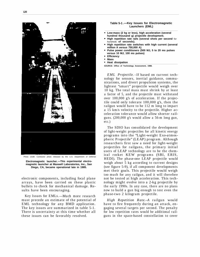
120
Photo credit: Contractor photo released by the U.S. Department of Defense
Electromagnetic launcher.—This experimental electro-magnetic launcher at Maxwell Laboratories, Inc., San
Diego, CA, became operational late in 1985.
electronic components, including focal planearrays, have been carried on these plasticbullets to check for mechanical damage. Re-sults have been encouraging.
Key Issues for EMLs.—Much more researchmust precede an estimate of the potential ofEML technology for any BMD application.The key issues are summarized in table 5-1.There is uncertainty at this time whether allthese issues can be favorably resolved.
Table 5-1 .—Key Issues for ElectromagneticLaunchers (EML)
Low-mass (2 kg or less), high acceleration (severalhundred thousand g) projectile development.High repetition rate rails (several shots per second forhundreds of seconds).High repetition rate switches with high current (severalmillion A versus 750,000 A)Pulse power conditioners (500 MJ, 5 to 20 ms pulsesversus 10 MJ, 100 ms pulses)EfficiencyMassHeat dissipation
SOURCE: Office of Technology Assessment, 1988.
EML Projectile. –If based on current tech-nology for sensors, inertial guidance, commu-nications, and divert propulsion systems, thelightest “smart” projectile would weigh over10 kg. The total mass must shrink by at leasta factor of 5, and the projectile must withstandover 100,000 g’s of acceleration. If the projec-tile could only tolerate 100,000 g’s, then therailgun would have to be 112 m long to imparta 15 km/s velocity to the projectile. Higher ac-celeration tolerance would allow shorter rail-guns. (200,000 g’s would allow a 56-m long gun,etc.)
The SDIO has consolidated the developmentof light-weight projectiles for all kinetic energyprograms into the “Light-weight Exo-atmos-pheric Projectile” (LEAP) program. Althoughresearchers first saw a need for light-weightprojectiles for railguns, the primary initialusers of LEAP technology are to be the chem-ical rocket KEW programs (SBI, ERIS,HEDI). The phase-one LEAP projectile wouldweigh about 5 kg according to current designs(see figure 5-9), if all component developmentsmet their goals. This projectile would weightoo much for any railgun, and it will thereforenot be tested at high acceleration. This tech-nology might evolve into a 2-kg projectile bythe early 1990s. In any case, there are no plansnow to build a gun big enough to test even thephase-two 2 kilogram projectile.
High Repetition Rate.–A railgun wouldhave to fire frequently during an attack, en-gaging several targets per second. The penaltyfor low repetition rates would be additional rail-guns in the space-based constellation to cover
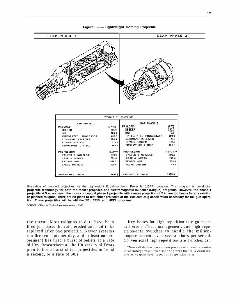
121
Figure 5-9.— Lightweight Homing Projectile
L E A P P H A S E 1
WEIGHT S’
LEAP PHASE 1PAYLOAD (1 600)
SEEKER 295.0IMU 285.0INTEGRATED PROCESSOR 400.0COMMAND RECEIVER 100.0
POWER SYSTEM 325.0STRUCTURE & MISC. 195.0
PROPULSION (3,059.0
VALVES & NOZZLES 570.0
CASE & INERTS 551.0
PROPELLANT 1818.0VALVE DRIVERS 120.0
PROJECTILE TOTAL 4659.(
L E A P P H A S E 2
STATEMENTS
LEAP PHASE 2PAYLOAD (670)
SEEKER 150.0IMU 70.0
INTEGRATED PROCESSOR 150.0COMMAND RECEIVER 25.0POWER SYSTEM 175.0STRUCTURE & MISC. 100.0
PROPULSION 0 ( 1 3 2 5 . 0VALVES & NOZZLES 375.0CASE & INERTS 215.0PROPELLANT 690.0
VALVE DRIVERS 45.0
PROJECTILE TOTAL 1995,0
Illustration of planned projectiles for the Lightweight Exoatmospheric Projectile (LEAP) program. This program is developingprojectile technology for both the rocket propelled and electromagnetic launcher (railgun) programs. However, the phase 1projectile at 5 kg and even the more conceptual phase 2 projectile with a mass projection of 2 kg are too heavy for any existingor planned railguns. There are no plans to test either projectile at the 100,000s of g acceleration necessary for rail gun opera-tion. These projectiles will benefit the SBI, ERIS, and HEDI programs.
SOURCE: Office of Technology Assessment, 1988.
the threat. Most railguns to date have beenfired just once: the rails eroded and had to bereplaced after one projectile. Newer systemscan fire ten shots per day, and at least one ex-periment has fired a burst of pellets at a rateof 10/s. Researchers at the University of Texasplan to fire a burst of ten projectiles in 1/6 ofa second, or a rate of 60/s.
Key issues for high repetition-rate guns arerail erosion,18 heat management, and high repe-tition-rate switches to handle the million-ampere current levels several times per second.Conventional high repetition-rate switches can
‘*New rail designs have shown promise of minimum erosionin laboratory tests; it remains to be proven that rails would sur-vive at weapons-level speeds and repetition rates.

122
handle up to 500 A today, although one spe-cial variable resistance switch tested by theArmy carried 750,000 A. An Air Force test suc-cessfully switched 800,000 A, limited only bythe power supply used. EML systems wouldhave to switch 1 to 5 million A.
EML Power. –An EML would consume highaverage electrical power and very high peakpower during each projectile shot. Considerfirst the average power requirements: a 1 kgprojectile would acquire 112 MJ of kineticenergy if accelerated to 15 km/s. Assuming 40percent efficiency and 5 shots per second, thenthe EML electrical system would have to de-liver 280 MJ of energy per shot or 1.4 GW ofaverage power during an attack which mightlast for several hundred seconds. For compar-ison, a modern nuclear fission power plant de-livers 1 to 2 GW of continuous power.
The SP-100 nuclear power system being dis-cussed for possible space application wouldproduce only 100 to 300 kW of power. The onlyapparent near-term potential solution to pro-viding 2.5 GW of power for hundreds of se-conds would be to use something like the SpaceShuttle Main Engine (SSME) coupled to a tur-bogenerator. Assuming 50 percent electricalconversion efficiency, then one could convertthe SSME 10 GW of flow energy into 5 GWof average electrical power while the engineswere burning.
High average power would not suffice. Theelectrical energy would have to be further con-centrated in time to supply very short burstsof current to the railgun. For example, a 112-m long railgun with 100,000-g accelerationwould propel a projectile down its length inabout 15 milliseconds (ins) to a final velocityof 15 km/s. The peak power during the shotwould be 50 GW.l9 And the EML system de-signer would like to shorten the 112-m railgunlength and increase acceleration, which wouldmean further shortening the pulse length andincreasing peak power.
Several techniques are under considerationto convert the average power from somethinglike the SSME into short pulses. One labora-tory approach is the homopolar generator: thisdevice stores current in a rotating machinemuch like an electrical generator and thenswitches it out in one large pulse. Existinghomopolar generators can supply up to 10 MJin about 100 ms; therefore, energy storage ca-pacity must increase by a factor of 50 and thepulse length shorten by a factor of 5 to 20.
EML Mass to Orbit.–The mass of an EMLsystem based on today’s technology would beexcessive. A homopolar generator to supply280 MJ per pulse would weigh 70 tonnesalone. 20 The rails would have to be long to limitacceleration on sensitive “smart projectiles,which would have to be very strong (massive)to resist the outward forces from the high railcurrents. The platform would have to includean SSME-type burst power generator, a ther-mal management system to dispose of theenergy deposited in the rails, divert propulsionto steer the railgun toward each target, andthe usual satellite communications and con-trol functions.
Given the early stage of EML research, esti-mates of total platform mass could be in errorby a factor of 10. At this time, a total massof about 100 tonnes would seem likely, mean-ing that each EML would have to be launchedin several parts, even if the United States de-veloped an Advanced Launch System (ALS)that could carry about 40 tonnes maximum perflight to high inclination orbits. It is conceiv-able that, in the farther term, superconductiveelectrical circuits could significantly reduce themass of an EML. Lighter compulsators (seebelow) might also reduce EML mass.
Nuclear-Driven Particles.–A nuclear explo-sion is a potent source of peak power andenergy. If even a small fraction of the energyin a nuclear explosion could be converted intokinetic energy of moving particles, then an ex-tremely powerful nuclear shotgun could be im-
lgFor a fi~e of referen~, consider that the total power av~-able from the U.S. power grid is several hundred gigawatts.
20Assuming today’s energy density for homopolar generatorsof 4 kJ/kg.
123
agined. These particles could be used for in-teractive discrimination as described above,since the particles would slow down light de-coys more than heavy RVs With more power,nuclear-driven particles could conceivably de-stroy targets. This concept is discussed in moredetail in the classified version of this report.
Directed-Energy Weapons
Directed-energy weapons (DEW) offer thepromise of nearly instantaneous destructionof targets hundreds or thousands of km away.While a KEW system would have to predicttarget positions several minutes in the futureand wait for a high speed projectile to reachthe intended target, the DEW could—in prin-ciple—fire, observe a kill, and even order a re-peat attack in less than a second.
DEW Systems
Although no DEW are planned for phase-one BMD deployment, both ground-based andspace-based DEW systems are possible in thenext century .21 Candidate DEW systemsinclude:
●
●
●
●
●
free electron lasers (FEL) (ground-basedor space-based),chemical lasers (space-based),excimer lasers (ground-based),x-ray laser (pop-up or space-based), orneutral particle beam (space-based).
The FEL is the primary SDIO candidate forground-based deployment (with the excimerlaser as a back-up). The hydrogen-fluoride (HF)laser and the neutral particle beam weapon arethe primary candidates for space-ased DEWS,although a space-based FEL or other chemi-cal laser concepts might also be possible.
Ground-Based Free Electron Laser (GBFEL).–A GBFEL system would include severalground-based lasers, “rubber mirror” beam di-rectors to correct for atmospheric distortionsand to direct the beams to several relay mir-rors in high-Earth orbit, and tens to hundreds
ZISDICI a9Wrt9 that some versions of DE W could be deployedlate in this century. It is examining designs for “entry level”systems with limited capabilities.
of “battle-mirrors’ in lower Earth orbit to fo-cus the beams on target. It would take sev-eral laser sites to assure clear weather at onesite all the time. Several lasers per site wouldprovide enough beams for the battle. Ideallythese lasers should beat high altitudes to avoidmost of the weather and atmospheric turbu-lence. But the FEL, as currently envisioned,requires very long ground path lengths forbeam expansion and large quantities of power.
The logical location for relay mirrors wouldbe geosynchronous orbit, so that the ground-based beam director would have a relativelyfixed aim point. The effects of thermalblooming 22 may best be avoided, however, byplacing the relay mirrors in lower orbit: the mo-tion of the laser beam through the upper atmos-phere as it follows the moving relay mirrorwould spread the thermal energy over a largearea.23
Adaptive optics would correct for atmos-pheric turbulence. The optical system wouldsense turbulence in real time and continuouslychange the shape of the beam-director mirrorto cancel wave-front errors introduced by theair. A beacon would be placed just far enoughin front of the relay satellite that the satellitewould move to the position occupied by thebeacon in the time it took for light to travelto the ground and back. A sensor on the groundwould detect the distortions in the test beamof light from the beacon, then feed the resultsto the “rubber mirror” actuators. With itswave front so adjusted, the laser beam wouldpass through the air relatively undistorted.
—‘zThermal blooming occurs when a high-power laser beam
passes through the atmosphere, heating the air which disturbsthe transmission of subsequent beam energy. See the sectionbelow on key DEW issues for details.
23 For exmple, a 1O-m dimekr laser beam which tracked arelay mirror at 1,000 km altitude would pass through a clean,unheated patch of air at 10 km altitude after 140 ms. If thermalblooming resulted from relatively long-term heating over a fewseconds, then scanning across the sky could ameliorate its ef-fects. While beam energy at altitudes below 10 km would takelonger than 140 ms to move to unheated patches of the atmos-phere, lower altitude blooming could be more readily correctedby the atmospheric turbulence compensation systems proposedfor ground based lasers: atmospheric compensation works bestfor “thin lens” aberrations close to the laser beam adaptive mir-ror on the ground.
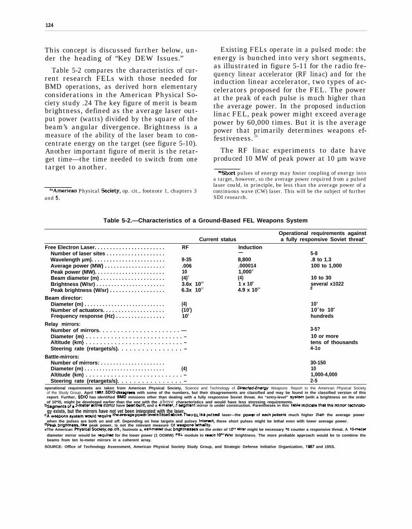
124
This concept is discussed further below, un-der the heading of “Key DEW Issues.”
Table 5-2 compares the characteristics of cur-rent research FELs with those needed forBMD operations, as derived horn elementaryconsiderations in the American Physical So-ciety study .24 The key figure of merit is beambrightness, defined as the average laser out-put power (watts) divided by the square of thebeam’s angular divergence. Brightness is ameasure of the ability of the laser beam to con-centrate energy on the target (see figure 5-10).Another important figure of merit is the retar-get time—the time needed to switch from onetarget to another.
~iAmerican Physical Society, op. cit., footnote 1, chapters 3and 5.
Existing FELs operate in a pulsed mode: theenergy is bunched into very short segments,as illustrated in figure 5-11 for the radio fre-quency linear accelerator (RF linac) and for theinduction linear accelerator, two types of ac-celerators proposed for the FEL. The powerat the peak of each pulse is much higher thanthe average power. In the proposed inductionlinac FEL, peak power might exceed averagepower by 60,000 times. But it is the averagepower that primarily determines weapons ef-festiveness. 26
The RF linac experiments to date haveproduced 10 MW of peak power at 10 µm wave
“Short pulses of energy may foster coupling of energy intoa target, however, so the average power required from a pulsedlaser could, in principle, be less than the average power of acontinuous wave (CW) laser. This will be the subject of furtherSDI research.
Table 5-2.—Characteristics of a Ground-Based FEL Weapons System
Operational requirements againstCurrent status a fully responsive Soviet threata
Free Electron Laser. . . . . . . . . . . . . . . . . . . . . . . RF InductionNumber of laser sites . . . . . . . . . . . . . . . . . . . — 5-8Wavelength µm). . . . . . . . . . . . . . . . . . . . . . . . 9-35 8,800 .8 to 1.3Average power (MW) . . . . . . . . . . . . . . . . . . . . .006 .000014 100 to 1,000Peak power (MW). . . . . . . . . . . . . . . . . . . . . . . 10 1,000 b
Beam diameter (m) . . . . . . . . . . . . . . . . . . . . . (4)C (4) 10 to 30Brightness (W/sr) . . . . . . . . . . . . . . . . . . . . . . . 3.6x 10¹⁴ 1 x 10⁶ several x1022Peak brightness (W/sr) . . . . . . . . . . . . . . . . . . 6.3x 10¹⁷ 4.9 x 10¹³ d
Beam director:Diameter (m) . . . . . . . . . . . . . . . . . . . . . . . . . . . (4) 10’Number of actuators. . . . . . . . . . . . . . . . . . . . (103) 103 to 104
Frequency response (Hz) . . . . . . . . . . . . . . . . 103 hundreds
Relay mirrors:Number of mirrors. . . . . . . . . . . . . . . . . . . . . . — 3-5?Diameter (m) . . . . . . . . . . . . . . . . . . . . . . . . . . . – 10 or moreAltitude (km) . . . . . . . . . . . . . . . . . . . . . . . . . . . – tens of thousandsSteering rate (retargets/s). . . . . . . . . . . . . . . . – 4-1o
BattIe-mirrors:Number of mirrors: . . . . . . . . . . . . . . . . . . . . . 30-150Diameter (m) . . . . . . . . . . . . . . . . . . . . . . . . . . . (4) 10Altitude (km) . . . . . . . . . . . . . . . . . . . . . . . . . . . – 1,000-4,000Steering rate (retargets/s). . . . . . . . . . . . . . . . – 2-5
operational requirements are taken from American Physical Society, Science and Technology of Dkected-Energy Weapons: Report to the American Physical Societyof the Study Group, April 19S7. SDIO dlsagreea with some of the numbers, but their disagreements are classified and may be found in the classified version of thisreport. Further, SDIO has identified BMD missions other than dealing with a fully responsive Soviet threat. An “entry-level” syatem (with a brightness on the orderof 10*0), might be developed earlier than the one with the above characteristics and would have less stressing requirements.
bSagment5 of ~ S.meter ~tive minor have baen built, and a A-meter, T.segmmt mirror is under construction. Parentheses in this table indicate that the mirror t=hnOlO-gy exists, but the mirrors have not yet been integrated with the laser.
CA weapons Systam would require the average ~wer levels listed above. The FEL is a pulsed laser—the powar of each pulsa iS much higher than the average power
when the pulses are both on and off. Depending on how targets and pulses Intaract, these short pulses might be lethal even with lower average power.dpeak brightness, like peak power, is not the relevant measure Of weapons lethatity.eThe American physl~ai s~lety, op. cit., footnote a, estimated that brightnesses on the order of 10” Wlsr might be necessary Io counter a responsive threat. A lo-meter
diameter mirror would be requirad for the lower power (1 OOMW) FEL module to raach 10’* WLsr brightness. The more probable approach would be to combine thebeams from ten lo-meter mirrors in a coherent array.
SOURCE: Office of Technology Assessment, American Physical Society Study Group, and Strategic Defense Initiative Organization, 19S7 and 19SS.
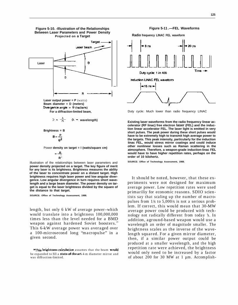
125
Figure 5-10. -Illustration of the RelationshipsBetween Laser Parameters and Power Density
Projected on a Target
Laser
D
Laser output power = P (watts)Beam diameter = D (meters)
For a diffraction-limited beam,
wavelength)
Brightness = B
Power density on target = I (watts/square cm)
R 2
Illustration of the relationships between laser parameters andpower density projected on a target. The key figure of meritfor any laser is its brightness. Brightness measures the abilityof the laser to concentrate power on a distant target. Highbrightness requires high laser power and low angular diver-gence. Low angular divergence in turn requires short wave-length and a large beam diameter. The power density on tar-get is equal to the laser brightness divided by the square ofthe distance to that target.
SOURCE: Office of Technology Assessment, 1988.
length, but only 6 kW of average power–whichwould translate into a brightness 100,000,000times less than the level needed for a BMDweapon against hardened Soviet boosters.26
This 6-kW average power was averaged overa 100-microsecond long “macropulse” in agiven second.
ZeThi9 brightne99 calculation assumes that the beam wouldbe expanded to fill a stateof-theart 4-m diameter mirror andwas diffraction-limited.
Figure 5-11 .—FEL Waveforms
Radio frequency LINAC FEL waveform
Duty cycle: Much lower than radio frequency LINAC
Existing laser waveforms from the radio frequency linear ac-celerator (RF Iinac) free electron laser (FEL) and the induc-tion linear accelerator FEL. The laser light is emitted in veryshort pulses. The peak power during these short pulses wouldhave to be extremely high to transmit high average power tothe targets. This peak intensity, particularly for the inductionIinac FEL, would stress mirror coatings and could induceother nonlinear losses such as Raman scattering in theatmosphere. Therefore, a weapon-grade induction-linac FELwould have to have higher repetition rates, perhaps on theorder of 10 kilohertz.
SOURCE: Office of Technology Assessment, 1988.
It should be noted, however, that these ex-periments were not designed for maximumaverage power. Low repetition rates were usedprimariliy for economic reasons. SDIO scien-tists say that scaling up the number of macro-pulses from 1/s to 5,000/s is not a serious prob-lem. If correct, this would mean that 30-MWaverage power could be produced with tech-nology not radically different from today ’s. Inaddition, aground-based weapon would use awavelength an order of magnitude smaller. Thebrightness scales as the inverse of the wave-length squared. For a given mirror diameter,then, if a similar power output could beproduced at a smaller wavelength, and the highrepetition rate were achieved, the brightnesswould only need to be increased by a factorof about 200 for 30 MW at 1 µm. Accomplish-

126
Photo credit: U.S. Department of Defense
Model of ALPHA experimental chemical laser.—Thisexperimental chemical laser and its large vacuumchamber have been constructed by TRW at a test sitenear San Juan Capistrano, CA. The cylindrical config-
uration of the laser design may be mostsuitable for basing in space.
ing both modifications would entail significantdevelopment work.
Space-based Chemical Lasers.—Placing high-power lasers directly on satellites would elim-inate the needs for atmospheric compensation,redundant lasers to avoid inclement weather,and relay mirrors in high orbits; it would alsoreduce beam brightness requirements by a fac-tor of 4 to 10 (depending on the wavelengthand atmospheric factors) since the atmospherewould not attenuate the beam.27 These advan-tages are offset by the engineering challengeof operating many tens or hundreds of lasersautonomously in space and by the possiblehigher vulnerability of lasers relative to battle-mirrors.
270ne defense contractor estimated that a space-based chem-ical laser system, including space transportation, would costabout 10 times less than the proposed ground-based free elec-tron laser weapon system.
The laser should operate at short wavelength(to keep the mirror sizes small) and should beenergy efficient (to reduce the weight of fuelneeded in orbit). Although its wavelength band(near 2.8 µm) is rather long, the hydrogen fluo-ride (HF) laser is the most mature and mostefficient laser available today. Table 5-3 com-pares the characteristics of a potential highperformance HF laser BMD system with thecurrent mid-infrared chemical laser (MIRACL)(using deuterium fluoride, or DF) operating atthe White Sands Missile Range in New Mex-ico.28
DEW Technology
How DEW Work.—Directed energy weaponswould change stationary, stored energy froma primary fuel source into a traveling beam ofenergy that could be directed and focused ona target. Several stages of energy conversionmay be necessary. The challenge is to build anaffordable, survivable, and reliable machinethat can generate the necessary beam ofenergy. Lasers can be driven by electricalenergy, chemical energy, or nuclear energy.
Free Electron Lasers.—Through 1987, theSDIO chose the FEL research program to re-ceive the most DEW emphasis (recently, SDIOhas returned to favoring research in space-based chemical lasers). The FEL uses a rela-tivistic29 electron beam from an accelerator toamplify a light beam in a vacuum. The keyadvantage of the FEL is the lack of a physicalgain medium: all other lasers amplify light ina solid, liquid, or gas. This gain medium mustbe stimulated with energy to produce an ex-cited population inversion of atoms or mole-cules. The fundamental limitation with theselasers is the need to remove waste heat beforeit affects the optical transparency of themedium. The FEL achieves its gain while pass-
28The SDIO is also considering lower-performance, “entrylevel, ” space-based chemical lasers for more limited BMDmissions.
29A beam of particles is deemed “relativistic” when it is ac-celerated to speeds comparable to a fraction of the speed of lightand acquires so much energy that its mass begins to increasemeasurably relative to its rest mass.

127
Table 5-3.—Characteristics of an HF Laser Weapons System
Estimated operationalCurrent status requirements a
Number of laser satellites . . . . . . . . . — 50-150Altitude (km) . . . . . . . . . . . . . . . . . . . . . 800-4,000Beam diameter (m) . . . . . . . . . . . . . . . 1.5b 10Power (MW) . . . . . . . . . . . . . . . . . . . . greater than 1 hundreds (single beam)Brightness (W/sr) . . . . . . . . . . . . . . . . . several x 1017C several x 1021
Phased array alternative:Number of beams . . . . . . . . . . . . . . 7Beam diameter (m) . . . . . . . . . . . . . 10Total power (MW): . . . . . . . . . . . . . . 100 (14 MW per beam)
aThese numbers derived from first principles, and from American Physical Society, SCienCe and Technology of Directed-EnergyWeapons. Report of ttre American Physical Society Study Group, April 1987, which contains estimates of booster hardnessfor a fully responsive threat The SDIO neither confirms nor denies these estimates. Current SDIO estimates may be foundIn the classified version of this report, In addition, SDIO has identified earlier entry-level systems with less stressing mls.sions and less stressing requirements with brightnesses on the order of 1010 WLsr.
bTh e LAMP mirror, not yet integrated with a high-power laser, has a diameter of 4 m.CAS~Unling perfect beam quality for a multi-megawatt system with the characteristics of the MIRACL laser
SOURCE Office of Technology Assessment, American Physical Society Study Group, and Strategic Defense Initiative Organ i-zat!on, 1987 and 19fM3
ing through an electron beam plasma, so muchof the “waste heat” exits the active regionalong with the electron beam at nearly thespeed of light.
Two types of electron beam accelerator arecurrently under investigation in the SDIO pro-gram: the radio frequency linear accelerator(RF linac) and the induction linac.30
In the RF linac, electrical energy from theprimary source is fed to radio-frequency gener-ators that produce an RF field inside the ac-celerator cavity. This field in turn accelerateslow energy electrons emitted by a specialsource in the front end of the accelerator. Theaccelerator raises this electron beam to higherand higher energy levels (and hence higher ve-locity) and they eventually reach speeds ap-proaching that of light. Simultaneously, theelectrons bunch into small packets in space,corresponding to the peaks of the RF wave.
This relativistic beam of electron packets isinserted into an optical cavity. There the beampasses through aperiodic magnetic field (calleda “wiggler” magnet) that causes the electrons
‘“Other types of accelerators are possible for a free electronlaser, such as the electrostatic accelerator FEL under investi-gation at the University of California at Santa Barbara, butthe RF linac and induction linac have been singled out as theprimary candidates for initial SDI experiments.
to oscillate in space perpendicular to the beamaxis. As a result of this transverse motion,weak light waves called synchrotrons radiationare generated. Some of this light travels alongwith the electron packets through the wigglermagnets. Under carefully controlled condi-tions, the electron beam gives up some of itsenergy to the light beam. The light beam isthen reflected by mirrors at the end of the op-tical cavity and returns to the wiggler mag-net synchronously with the next batch of elec-trons. The light beam picks up more energyfrom each pass, and eventually reaches highpower levels. This type of FEL is an optical“oscillator”: it produces its own coherent lightbeam starting from the spontaneous emissionfrom the synchrotrons radiation.
As more energy is extracted from the elec-tron beam, the electrons slow down. Theseslower electrons are then no longer syn-chronized with the light wave and the periodicmagnet, so the optical gain (amplification)saturates. To increase extraction efficiency, thewiggler magnet is “tapered”: the spacing ofthe magnets or the magnetic field strength isvaried so that the electrons continue in phasewith the light wave and continue to amplify
the beam as energy is extracted.
For high-power weapon applications, thepower from an oscillator might be too weak:

128
the limit for an RF linac FEL oscillator is near20 MW. In this case additional single-pass am-plifiers can boost the beam energy. This sys-tem is called a master oscillator power ampli-fier (MOPA) laser.
In the second type of FEL, the inductionlinac, large electrical coils accelerate narrowpulses of electrons. The high energy electronsinteract with an optical beam as in the RF linacFEL, but the optical beam as currently plannedwould be too intense to reflect off mirrors andrecirculate to pickup energy in multiple passesas in the RF oscillator. Rather, all of the energytransfer from the electron beam to the opticalbeam would occur on a single pass. This wouldentail very high gain, which demands very highdensity electron beams and very intense laserlight coming into the amplifier. The inductionlinac FEL therefore depends on an auxiliarylaser to initiate the optical gain process; thislimits the tunability of the induction linac FELto the wavelengths of existing conventionallasers of moderately high power.
The process of converting electron energyinto light energy can theoretically approach100 percent efficiency, although it may takevery expensive, heavy, and fragile equipment.3l
Nevertheless, the FEL could achieve very highpower levels, and, unlike other lasers, the RFlinac FEL can be tuned to different wavelengths by changing the physical spacing orfield strength of the wiggler magnets or theenergy of the electron beam.92 Tunability isdesirable for ground-based lasers, which mustavoid atmospheric absorption bands (wave-lengths of light absorbed by the air) if they areto reach into space.
Chemical (EIF) Lasers.–The HF laser de-rives its primary energy from a chemical re-action: deuterium and nitrogen trifluoride
~lTot~ sy9~m efficienW would probably be abOUt 20 Per@nt-
25 percent at best, assuming areasonably optimistic 50 percent-60 percent efficiency to convert chemical to electrical energyusing a rocket-driven turbine, and 40 percent efficiency to gen-erate RF power.
‘The wavelength of the FEL is proportional to the wigglermagnet spacing and inversely proportional to the square of theelectron beam energy. Higher beam energies are necessary forthe short wavelengths needed for BMD.
gases react in a device resembling a rocket en-gine. Hydrogen gas mixes with the combus-tion products. Chemical energy raises the re-sulting HF molecules to an excited state, from ,which they relax later by each emitting a pho-ton of light energy in one of several wavelengthlines near 2.8 µm in the MWIR. A pair of op-posing mirrors causes an intense beam of IRenergy to build up as each pass through theexcited HF gas causes more photons to radi-ate instep with the previously generated lightwave.33 Some additional electrical energy runspumps and control circuits.
Excimer Laser.— In an excimer34 laser, elec-trical energy, usually in the form of an elec-tron beam, excites a rare gas halide35 such askrypton fluoride or xenon chloride.36 Thesegases then emit in the ultraviolet (UV) regionof the spectrum, with wavelengths in the rangefrom.2 to .36pm. This very short wavelengthpermits smaller optical elements for a givenbrightness. However, the optical finish onthose UV optics would have to be of propor-tionately higher quality.
Ultraviolet light is also desirable for spaceapplications, since its high energy generallycauses more damage to the surfaces of targetsthan does that of longer-wavelength visible orIR light. One drawback is that internal mir-rors resistant to UV radiation damage are moredifficult to make. Another is that UV cannotreadily penetrate the atmosphere. These ob-stacles, combined with their relative immatu-rity and low efficiency, have relegated highpower excimers to a back-up role to the FELfor the ground-based BMD laser.
‘This process of repeat43d radiation in step is called “stimu-lated emission”: the traveling wave of light stimulates the ex-cited molecule to radiate with the same phase and direction asthe stimulating energy. The resulting beam of light is “coher-ent”: it can be focused to a very small spot. The term “laser”is derived from the phrase “Light Amplification by StimtiatsdElectromagnetic Radiation.”
~iEXCimer is sho~ for “exci~ state dimer”; the excitationof these rare gas halides produces molecules that only exist inthe excited state, unlike other lasing media which decay to aground state after emitting a photon of light.
S5A “h&de” is a compound of two elements, one of which iSa halogen: fluorine, chlorine, iodine, or bromine.
“Krypton fluoride produces a wavelength too short to pene-trate the atmosphere; for ground-based applications, xenon chlo-ride would be of interest.
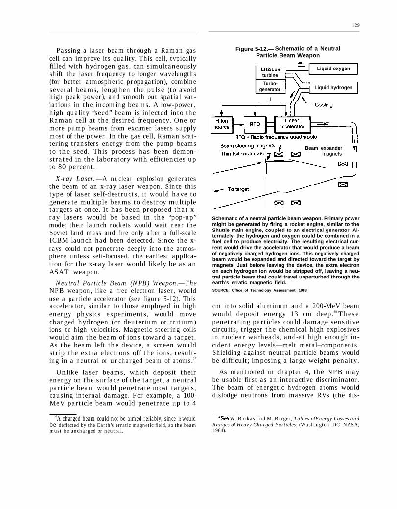
Passing a laser beam through a Raman gascell can improve its quality. This cell, typicallyfilled with hydrogen gas, can simultaneouslyshift the laser frequency to longer wavelengths(for better atmospheric propagation), combineseveral beams, lengthen the pulse (to avoidhigh peak power), and smooth out spatial var-iations in the incoming beams. A low-power,high quality “seed” beam is injected into theRaman cell at the desired frequency. One ormore pump beams from excimer lasers supplymost of the power. In the gas cell, Raman scat-tering transfers energy from the pump beamsto the seed. This process has been demon-strated in the laboratory with efficiencies upto 80 percent.
X-ray Laser. —A nuclear explosion generatesthe beam of an x-ray laser weapon. Since thistype of laser self-destructs, it would have togenerate multiple beams to destroy multipletargets at once. It has been proposed that x-ray lasers would be based in the “pop-up”mode; their launch rockets would wait near theSoviet land mass and fire only after a full-scaleICBM launch had been detected. Since the x-rays could not penetrate deeply into the atmos-phere unless self-focused, the earliest applica-tion for the x-ray laser would likely be as anASAT weapon.
Neutral Particle Beam (NPB) Weapon.—TheNPB weapon, like a free electron laser, woulduse a particle accelerator (see figure 5-12). Thisaccelerator, similar to those employed in highenergy physics experiments, would movecharged hydrogen (or deuterium or tritium)ions to high velocities. Magnetic steering coilswould aim the beam of ions toward a target.As the beam left the device, a screen wouldstrip the extra electrons off the ions, result-ing in a neutral or uncharged beam of atoms.37
Unlike laser beams, which deposit theirenergy on the surface of the target, a neutralparticle beam would penetrate most targets,causing internal damage. For example, a 100-MeV particle beam would penetrate up to 4
37A charged beam could not be aimed reliably, since it wouldbe deflected by the Earth’s erratic magnetic field, so the beammust be uncharged or neutral.
129
Figure 5-12.— Schematic of a NeutralParticle Beam Weapon
LH2/Lox- Liquid oxygenturbine
Turbo-generator Liquid hydrogen
I
Beam expandermagnets
Schematic of a neutral particle beam weapon. Primary powermight be generated by firing a rocket engine, similar to theShuttle main engine, coupled to an electrical generator. Al-ternately, the hydrogen and oxygen could be combined in afuel cell to produce electricity. The resulting electrical cur-rent would drive the accelerator that would produce a beamof negatively charged hydrogen ions. This negatively chargedbeam would be expanded and directed toward the target bymagnets. Just before leaving the device, the extra electronon each hydrogen ion would be stripped off, leaving a neu-tral particle beam that could travel unperturbed through theearth’s erratic magnetic field.SOURCE: Office of Technology Assessment, 1988
cm into solid aluminum and a 200-MeV beamwould deposit energy 13 cm deep.38 Thesepenetrating particles could damage sensitivecircuits, trigger the chemical high explosivesin nuclear warheads, and-at high enough in-cident energy levels—melt metal–components.Shielding against neutral particle beams wouldbe difficult; imposing a large weight penalty.
As mentioned in chapter 4, the NPB maybe usable first as an interactive discriminator.The beam of energetic hydrogen atoms woulddislodge neutrons from massive RVs (the dis-
Y3ee W. Barkas and M. Berger, Tables ofEnergy Losses andRanges of Heavy Charged Particles, (Washington, DC: NASA,1964).
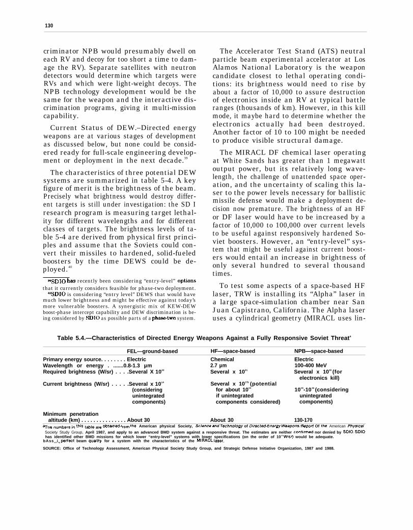
130
criminator NPB would presumably dwell oneach RV and decoy for too short a time to dam-age the RV). Separate satellites with neutrondetectors would determine which targets wereRVs and which were light-weight decoys. TheNPB technology development would be thesame for the weapon and the interactive dis-crimination programs, giving it multi-missioncapability.
Current Status of DEW.–Directed energyweapons are at various stages of developmentas discussed below, but none could be consid-ered ready for full-scale engineering develop-ment or deployment in the next decade.39
The characteristics of three potential DEWsystems are summarized in table 5-4. A keyfigure of merit is the brightness of the beam.Precisely what brightness would destroy differ-ent targets is still under investigation: the SD Iresearch program is measuring target lethal-ity for different wavelengths and for differentclasses of targets. The brightness levels of ta-ble 5-4 are derived from physical first princi-ples and assume that the Soviets could con-vert their missiles to hardened, solid-fueledboosters by the time DEWS could be de-ployed.40
WSDIO has recently been considering “entry-level” optionsthat it currently considers feasible for phase-two deployment.
40SD10 is considering “entry level” DEWS that would havemuch lower brightness and might be effective against today’smore vulnerable boosters. A synergistic mix of KEW-DEWboost-phase intercept capability and DEW discrimination is be-ing considered by SDIO as possible parts of a phastwo system.
The Accelerator Test Stand (ATS) neutralparticle beam experimental accelerator at LosAlamos National Laboratory is the weaponcandidate closest to lethal operating condi-tions: its brightness would need to rise byabout a factor of 10,000 to assure destructionof electronics inside an RV at typical battleranges (thousands of km). However, in this killmode, it maybe hard to determine whether theelectronics actually had been destroyed.Another factor of 10 to 100 might be neededto produce visible structural damage.
The MIRACL DF chemical laser operatingat White Sands has greater than 1 megawattoutput power, but its relatively long wave-length, the challenge of unattended space oper-ation, and the uncertainty of scaling this la-ser to the power levels necessary for ballisticmissile defense would make a deployment de-cision now premature. The brightness of an HFor DF laser would have to be increased by afactor of 10,000 to 100,000 over current levelsto be useful against responsively hardened So-viet boosters. However, an “entry-level” sys-tem that might be useful against current boost-ers would entail an increase in brightness ofonly several hundred to several thousandtimes.
To test some aspects of a space-based HFlaser, TRW is installing its “Alpha” laser ina large space-simulation chamber near SanJuan Capistrano, California. The Alpha laseruses a cylindrical geometry (MIRACL uses lin-
Table 5.4.—Characteristics of Directed Energy Weapons Against a Fully Responsive Soviet Threata
FEL—ground-based HF—space-based NPB—space-based
Primary energy source. . . . . . . . Electric Chemical ElectricWavelength or energy . .......0.8-1.3 µm 2.7 µm 100-400 MeVRequired brightness (W/sr) . . . .Several X 1022 Several x 1021 Several x 1019 (for
electronics kill)Current brightness (W/sr) . . . . .Several x 1014 Several x 1017b (potential
(considering for about 1010 1015-1016 (consideringunintegrated if unintegrated unintegratedcomponents) components considered) components)
Minimum penetrationaltitude (km) . . . . . . . . . . . . . . . About 30 About 30 130-170
aTh~ “u~ber~ in this table are ~btai”~d from the American physical Society, science and Technology of Difecfed-EnergY Weapons.’ f?8pOff Of the American ~hySkd
Society Study Group, April 1987, and apply to an advanced BMD system against a responsive threat. The estimates are neither confkmed nor denied by SDIO. SDIOhas identified other BMD missions for which lower “entry-level” systems with lower specifications (on the order of 1010 Wlsr) would be adequate.
bAss uming perfect beam quality for a system with the characteristics of the MIRACL laSer.
SOURCE: Office of Technology Assessment, American Physical Society Study Group, and Strategic Defense Initiative Organization, 1987 and 1988.
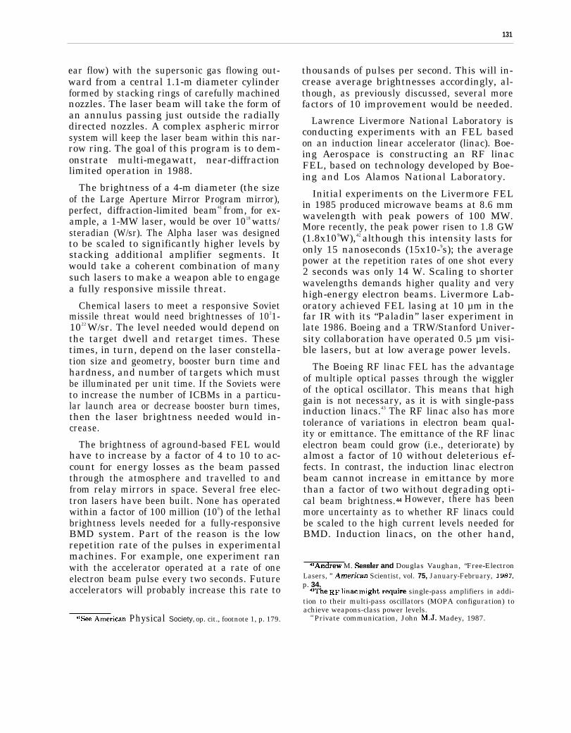
131
ear flow) with the supersonic gas flowing out-ward from a central 1.1-m diameter cylinderformed by stacking rings of carefully machinednozzles. The laser beam will take the form ofan annulus passing just outside the radiallydirected nozzles. A complex aspheric mirrorsystem will keep the laser beam within this nar-row ring. The goal of this program is to dem-onstrate multi-megawatt, near-diffractionlimited operation in 1988.
The brightness of a 4-m diameter (the sizeof the Large Aperture Mirror Program mirror),perfect, diffraction-limited beam41 from, for ex-ample, a 1-MW laser, would be over 1018 watts/steradian (W/sr). The Alpha laser was designedto be scaled to significantly higher levels bystacking additional amplifier segments. Itwould take a coherent combination of manysuch lasers to make a weapon able to engagea fully responsive missile threat.
Chemical lasers to meet a responsive Sovietmissile threat would need brightnesses of 1021-1022 W/sr. The level needed would depend onthe target dwell and retarget times. Thesetimes, in turn, depend on the laser constella-tion size and geometry, booster burn time andhardness, and number of targets which mustbe illuminated per unit time. If the Soviets wereto increase the number of ICBMs in a particu-lar launch area or decrease booster burn times,then the laser brightness needed would in-crease.
The brightness of aground-based FEL wouldhave to increase by a factor of 4 to 10 to ac-count for energy losses as the beam passedthrough the atmosphere and travelled to andfrom relay mirrors in space. Several free elec-tron lasers have been built. None has operatedwithin a factor of 100 million (108) of the lethalbrightness levels needed for a fully-responsiveBMD system. Part of the reason is the lowrepetition rate of the pulses in experimentalmachines. For example, one experiment ranwith the accelerator operated at a rate of oneelectron beam pulse every two seconds. Futureaccelerators will probably increase this rate to
“See American Physical Society, op. cit., footnote 1, p. 179.
thousands of pulses per second. This will in-crease average brightnesses accordingly, al-though, as previously discussed, several morefactors of 10 improvement would be needed.
Lawrence Livermore National Laboratory isconducting experiments with an FEL basedon an induction linear accelerator (linac). Boe-ing Aerospace is constructing an RF linacFEL, based on technology developed by Boe-ing and Los Alamos National Laboratory.
Initial experiments on the Livermore FELin 1985 produced microwave beams at 8.6 mmwavelength with peak powers of 100 MW.More recently, the peak power risen to 1.8 GW(1.8x10⁹W),42 although this intensity lasts foronly 15 nanoseconds (15x10-9s); the averagepower at the repetition rates of one shot every2 seconds was only 14 W. Scaling to shorterwavelengths demands higher quality and veryhigh-energy electron beams. Livermore Lab-oratory achieved FEL lasing at 10 µm in thefar IR with its “Paladin” laser experiment inlate 1986. Boeing and a TRW/Stanford Univer-sity collaboration have operated 0.5 µm visi-ble lasers, but at low average power levels.
The Boeing RF linac FEL has the advantageof multiple optical passes through the wigglerof the optical oscillator. This means that highgain is not necessary, as it is with single-passinduction linacs.43 The RF linac also has moretolerance of variations in electron beam qual-ity or emittance. The emittance of the RF linacelectron beam could grow (i.e., deteriorate) byalmost a factor of 10 without deleterious ef-fects. In contrast, the induction linac electronbeam cannot increase in emittance by morethan a factor of two without degrading opti-cal beam brightness.44 However, there has beenmore uncertainty as to whether RF linacs couldbe scaled to the high current levels needed forBMD. Induction linacs, on the other hand,
4ZAn&ew M. Sessler and Douglas Vaughan, ‘‘Free-ElectronLasers, ” Amen”can Scientist, vol. 75, January-February, 1987,p. 34.
4$The RF Iinac fight require single-pass amplifiers in addi-tion to their multi-pass oscillators (MOPA configuration) toachieve weapons-class power levels.
44 Private communication, John M.J. Madey, 1987.

132
have inherently high-current capability. Re-cently, the two FEL concepts have appearedon the whole to compete closely with oneanother.
Excimer lasers have been utilized for lowerpower research and some commercial applica-tions. The UV energy from an excimer laseris generally more damaging than visible or IRenergy. However, UV light can also damagemirrors and other optical components withinthe laser system, making high-power operationmuch more difficult. Scaling to higher poweris possible, but SDIO has judged the excimerprogram less likely to succeed, and has cut itback. The Air Force ASAT program is fund-ing continued excimer laser research jointlywith SDIO.
Los Alamos National Laboratory research-ers have conducted NPB-related experimentson their ATS. They have produced a currentlevel of 0.1 A at 5 MeV. Rocket-borne testsof parts of a NPB system were planned for thelate 1980s. The SDIO had planned a series offull space tests to begin in the early 1990s, in-cluding a NPB accelerator with a target satel-lite and a neutron detector satellite as part ofthe interactive discrimination experimentalprogram. Recently, scheduling of these testshas been delayed due to funding constraints.
Key DEW Issues.–With such a wide gap be-tween operational requirements and the cur-rent status of DEW, many key technical is-sues remain. DEW research over the next 10to 20 years could resolve some issues judgedcrucial today, but could also uncover other, un-foreseen, roadblocks. Some of the current is-sues of concern (large mirrors, pointing andtracking, and lethality measurements) aregeneric to all laser systems, while others arespecific to particular weapon systems.
Large Mirrors. –All laser systems (exceptthe x-ray laser) need very large mirrors to fo-cus the beam to a small spot at the target.45
‘bSpot size k inversely proportional to mirror diameter. La-ser brightness, the primary indicator of weapon lethality, in-creases as the square of mirror diameter. Thus doubling themirror size from 2 meters to 4 meters would increass laser bright-ness by a factor of 4.
This is true for both ground-based lasers withmultiple relay mirrors in space and for space-based lasers with the mirror adjacent to thelaser. In either case, the size of the last mirror(closest to the target) and its distance from thetarget determine the size of the laser spot fo-cused on that target. To achieve the bright-ness levels of 1021 to 1022 W/sr for BMD againsta fully responsive threat, laser mirrors wouldhave to be at least 4 m (assuming mirrors wereganged into coherent arrays), and preferably10 to 20 m, in diameter.
The largest monolithic telescope mirrorstoday are about 5 m in diameter (Mt. Palomar),and the largest mirror built for space applica-tion is the Hubble Space Telescope at 2.4 m.The Hubble or Palomar mirror technologieswould not simply be scaled up for SD I applica-tions. The current trend both in astronomy andin military applications is to divide large mir-rors into smaller segments. Electro-mechan-ical actuators within the mirror segments ad-just their optical surfaces so that they behaveas a single large mirror.
Even for these segments, direct scaling ofold mirror manufacturing techniques usinglarge blocks of glass for the substrate is notappropriate: these mirrors must weigh very lit-tle. They must be polished to their prescribedsurface figure within a small fraction of thewavelengths they are designed to reflect.Brightness and precision make opposite de-mands: usually, a thick and relatively heavysubstrate is necessary to keep good surface fig-ure. SDIO has developed new technologies toreduce substrate weight substantially.
Two segments of a 3-segment, 3-m mirror(HALO) have been built. The 7-segment, 4-mmirror (LAMP) is now assembled and currentlybeing tested. One segment of a l0-m mirroris to be built by 1991, but there are no currentplans to assemble a complete 10-m mirror. Re-cently, the SDIO has begun tests of the light-weight LAMP mirror, designed for space-based lasers.
Durable, high-reflectivity mirror coatings areessential to prevent high laser power fromdamaging the mirrors. The largest mirror that
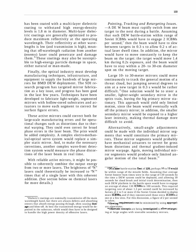
133
has been coated with a multi-layer dielectriccoating to withstand high energy-densitylevels is 1.8 m in diameter. Multi-layer dielec-tric coatings are generally optimized to pro-duce maximum reflectivity at the operatingwavelength. Their reflectivity at other wave-lengths is low (and transmission is high), mean-ing that off-wavelength radiation from another(enemy) laser could penetrate and damagethem.46 These coatings may also be suscepti-ble to high-energy particle damage in space,either natural or man-made.
Finally, the optical industry must developmanufacturing techniques, infrastructure, andequipment to supply the hundreds of large mir-rors for BMD DEW deployment. The SDI re-search program has targeted mirror fabrica-tion as a key issue, and progress has been goodin the last few years. Techniques have beendeveloped to fabricate light-weight, segmentedmirrors with hollow-cored substrates and ac-tuators to move each segment to correct forsurface figure errors.
These active mirrors could correct both forlarge-scale manufacturing errors and for opera-tional changes such as distortions due to ther-mal warping. They could even correct for broadphase errors in the laser beam. The price wouldbe added complexity. A complex electro-mechan-ical-optical servo system would replace a sim-pler static mirror. And, to make the necessarycorrections, another complex wave-front detec-tion system would measure the phase distor-tions of the laser beam in real time.
With reliable active mirrors, it might be pos-sible to coherently combine the output energyfrom two or more lasers. The brightness of “N”lasers could theoretically be increased to “N2”times that of a single laser with this coherentaddition. (See section below on chemical lasersfor more details.)
‘aDielectric coatings are nominally transmissive off the mainwavelength band, but there are always defects and absorbingcenters that absorb energy passing through, often causing dama-ge and blow-off. At best the transmitted energy would be de-posited in the substrate, which would then have to be designedto handle the high power density of offensive lasers.
Pointing, Tracking and Retargeting Issues.—A DE W beam must rapidly switch from onetarget to the next during a battle. Assumingthat each DEW battle-station within range ofSoviet ICBMs would have to engage 2 ICBMsper second,47 then the beam would have to slewbetween targets in 0.3 s to allow 0.2 s of ac-tual laser dwell time. In addition, the mirrorwould have to move constantly to keep thebeam on the target: the target would move 1.4km during 0.2s exposure, and the beam wouldhave to stay within a 20- to 30-cm diameterspot on the moving target.
Large 10- to 30-meter mirrors could movecontinuously to track the general motion of athreat cloud, but jumping several degrees toaim at a new target in 0.3 s would be ratherdifficult. 48 One solution would be to steer asmaller, lighter-weight secondary mirror in theoptics train, leaving the big primary mirror sta-tionary. This approach would yield only limitedmotion, since the beam would eventually walkoff the primary mirror; in addition, the smallersecondary mirror would be exposed to a higherlaser intensity, making thermal damage moredifficult to avoid.
Alternatively, small-angle adjustmentscould be made with the individual mirror seg-ments that would constitute the primary mir-rors. These mirror segments would probablyhave mechanical actuators to correct for grossbeam distortions and thermal gradient-inducedmirror warpage. Again, moving individual mir-ror segments would produce only limited an-gular motion of the total beam.49
4Tof a laser battle-station fleet of 120, perhaps 10 to 12 wouldbe within range of the missile fields. Assuming that averageSoviet booster bum times were in the range of 130 seconds bythe time a DEW system could be deployed, and allowing 30seconds for cloud break and initial track determination, theneach DEW platform in the battle space would have to engagean average of about 130 ICBMS in 100 seconds. This requiredtargeting rate of about 1.3 per second could be increased byfactors of 2 to 5 or more if the Soviet Union decided to deploymore ICBMS, and if they concentrated those extra ICBMS atone or a few sites. For this discussion, a figure of 2 per secondis taken.
4aSlewing requirements cm be minimized by using appropri-ate algorithms.
4BAl~rnate Concepts are being kveStigated to wow retmget-ing at large angles with steerable secondary mirrors.
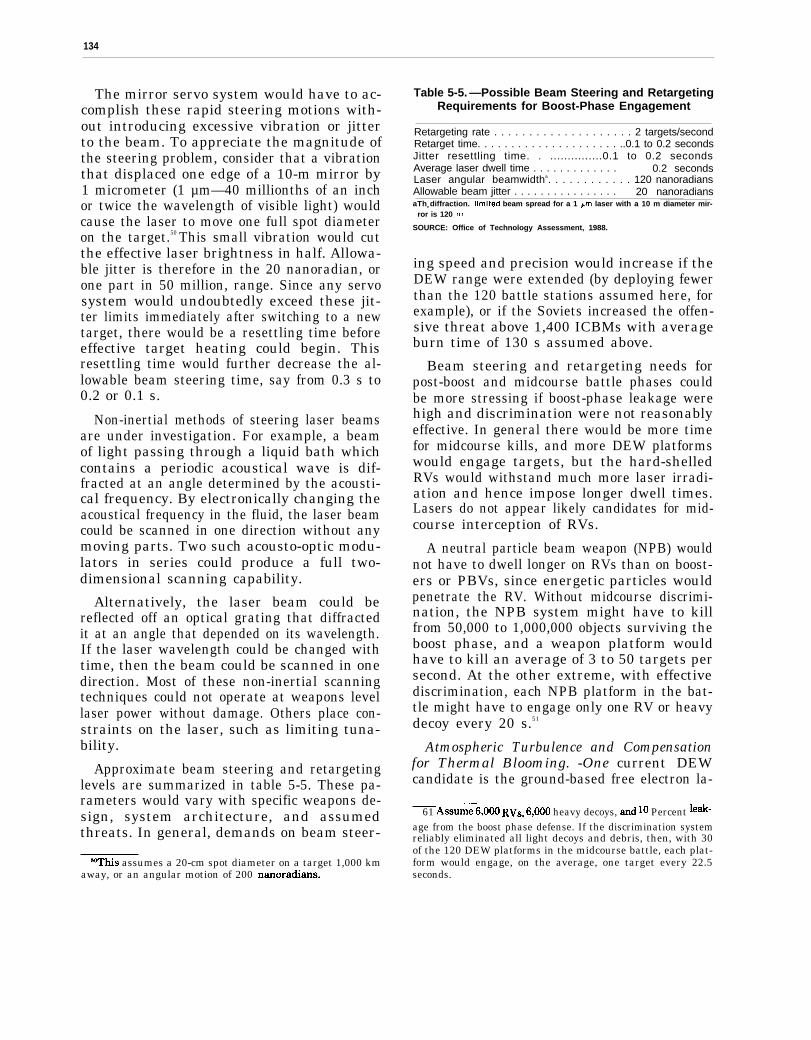
134
The mirror servo system would have to ac-complish these rapid steering motions with-out introducing excessive vibration or jitterto the beam. To appreciate the magnitude ofthe steering problem, consider that a vibrationthat displaced one edge of a 10-m mirror by1 micrometer (1 µm—40 millionths of an inchor twice the wavelength of visible light) wouldcause the laser to move one full spot diameteron the target.50 This small vibration would cutthe effective laser brightness in half. Allowa-ble jitter is therefore in the 20 nanoradian, orone part in 50 million, range. Since any servosystem would undoubtedly exceed these jit-ter limits immediately after switching to a newtarget, there would be a resettling time beforeeffective target heating could begin. Thisresettling time would further decrease the al-lowable beam steering time, say from 0.3 s to0.2 or 0.1 s.
Non-inertial methods of steering laser beamsare under investigation. For example, a beamof light passing through a liquid bath whichcontains a periodic acoustical wave is dif-fracted at an angle determined by the acousti-cal frequency. By electronically changing theacoustical frequency in the fluid, the laser beamcould be scanned in one direction without anymoving parts. Two such acousto-optic modu-lators in series could produce a full two-dimensional scanning capability.
Alternatively, the laser beam could bereflected off an optical grating that diffractedit at an angle that depended on its wavelength.If the laser wavelength could be changed withtime, then the beam could be scanned in onedirection. Most of these non-inertial scanningtechniques could not operate at weapons levellaser power without damage. Others place con-straints on the laser, such as limiting tuna-bility.
Approximate beam steering and retargetinglevels are summarized in table 5-5. These pa-rameters would vary with specific weapons de-sign, system architecture, and assumedthreats. In general, demands on beam steer-
‘Whis assumes a 20-cm spot diameter on a target 1,000 kmaway, or an angular motion of 200 nanoradians.
Table 5-5. —Possible Beam Steering and RetargetingRequirements for Boost-Phase Engagement
Retargeting rate . . . . . . . . . . . . . . . . . . . . 2 targets/secondRetarget time. . . . . . . . . . . . . . . . . . . . . ..0.1 to 0.2 secondsJitter resettling time. . ...............0.1 to 0.2 secondsAverage laser dwell time . . . . . . . . . . . . . 0.2 secondsLaser angular beamwidtha. . . . . . . . . . . . 120 nanoradiansAllowable beam jitter . . . . . . . . . . . . . . . . 20 nanoradiansaThe diffraction. [imited beam spread for a 1 ~m laser with a 10 m diameter mir-
ror is 120 nr,
SOURCE: Office of Technology Assessment, 1988.
ing speed and precision would increase if theDEW range were extended (by deploying fewerthan the 120 battle stations assumed here, forexample), or if the Soviets increased the offen-sive threat above 1,400 ICBMs with averageburn time of 130 s assumed above.
Beam steering and retargeting needs forpost-boost and midcourse battle phases couldbe more stressing if boost-phase leakage werehigh and discrimination were not reasonablyeffective. In general there would be more timefor midcourse kills, and more DEW platformswould engage targets, but the hard-shelledRVs would withstand much more laser irradi-ation and hence impose longer dwell times.Lasers do not appear likely candidates for mid-course interception of RVs.
A neutral particle beam weapon (NPB) wouldnot have to dwell longer on RVs than on boost-ers or PBVs, since energetic particles wouldpenetrate the RV. Without midcourse discrimi-nation, the NPB system might have to killfrom 50,000 to 1,000,000 objects surviving theboost phase, and a weapon platform wouldhave to kill an average of 3 to 50 targets persecond. At the other extreme, with effectivediscrimination, each NPB platform in the bat-tle might have to engage only one RV or heavydecoy every 20 s.51
Atmospheric Turbulence and Compensationfor Thermal Blooming. -One current DEWcandidate is the ground-based free electron la-
61 A55me–6,()()() RVS, 6,()()0 heavy decoys, and 10 Percent 1e*-age from the boost phase defense. If the discrimination systemreliably eliminated all light decoys and debris, then, with 30of the 120 DEW platforms in the midcourse battle, each plat-form would engage, on the average, one target every 22.5seconds.
135
ser. The beam from this laser would be directedto a mirror in space that would reflect the beamto “fighting mirrors” closer to the targets. Thelaser beam would be distorted in passingthrough the atmosphere, for the same reasonthat stars “twinkle.” If not corrected, atmos-pheric distortion would scramble the beam,making it impossible to focus with sufficientintensity to destroy ICBM boosters.
Techniques have been developed to measurethis distortion of the optical wave front andto modify the phase of low power laser beamsto nearly cancel the effects of the turbulentatmosphere. To correct distortion, the mirroris manufactured with a flexible outer skin orwith separate mirror segments. Mechanical ac-tuators behind the mirror surface move it toproduce phase distortions that complementphase errors introduced by the atmosphere.This “rubber mirror” must continuously ad-just to cancel the effects of atmospheric tur-bulence, which varies with time at frequenciesup to at least 140 hertz (cycles per second).
To measure atmospheric distortion, a testbeam of light must be transmitted through thesame patch of atmosphere as the high powerlaser beam. For the BMD application, this testbeam would be projected from a point near therelay mirror in space, or a reflector near thatrelay mirror would return a test beam from theground to the wave-front sensing system. Sig-nals derived from the wave-front sensor com-puter in response to the test beam would drivethe mirror actuators to correct the high-powerlaser beam.
The wave-front sensor must generate a co-herent reference beam to compare with the dis-torted beam, as in an interferometer. One tech-nique, called shearing interferometry, causestwo slightly displaced versions of the incom-ing distorted image to interfere. A computerthen deduces the character of the distortedwave front by interpreting the resulting inter-ference fringes,
Another wave-ront sensor system under in-vestigation filters part of the incoming refer-ence beam to produce a smooth, undistortedwave front. This clean wave front can then be
combined with the distorted wave front, pro-ducing interference fringes that more clearlyrepresent the atmospheric distortion. Unfor-tunately the energy levels in the filtered wavefront are too low, so an operational systemmight need image intensifiers.
Atmospheric compensation of low powerbeams has been demonstrated in the 1abora-tory and in tests during late 1985 at the AirForce Maui Optical Station (AMOS) in Hawaii.In this test, an argon laser beam was trans-mitted through the atmosphere to a soundingrocket in flight. A reflector on the soundingrocket returned the test signal. Wave-front er-rors generated on Maui drove a “rubber mir-ror” to compensate for the turbulence experi-enced by a second Argon laser beam aimed atthe rocket. A set of detectors spaced along thesounding rocket showed that this laser beamwas corrected to within a factor of two of thediffraction limit.
Successful atmospheric compensation willentail resolution of two key issues: thermalblooming and fabrication of large, multi-element mirrors. As a high-power laser beamheats the air in its path, it will create additionalturbulence, or “thermal blooming,” which willdistort the beam. At some level, this type ofdistributed distortion cannot be corrected. Forexample, if thermal blooming causes the laserbeam to diverge at a large distance from thelast mirror, then the test beam returning fromthe relay satellite would also spread over alarge area and would not all be collected bythe wave-front sensor. Under these conditions,complete compensation would not be possible.
Laboratory tests of thermal blooming wereplanned at MIT’s Lincoln Labs and field-testing was planned for early 1989 using thehigh-power MIRACL laser at the White SandsMissile Range. The latter series of tests is onhold due to lack of funding.
The mirror for a BMD FEL would need 1,000to 10,000 actuators for effective atmosphericcompensation. 52 Experiments to date haveused cooled mirrors with a relatively small
52American Physical Society, op. cit., footnote 1, p. 190.
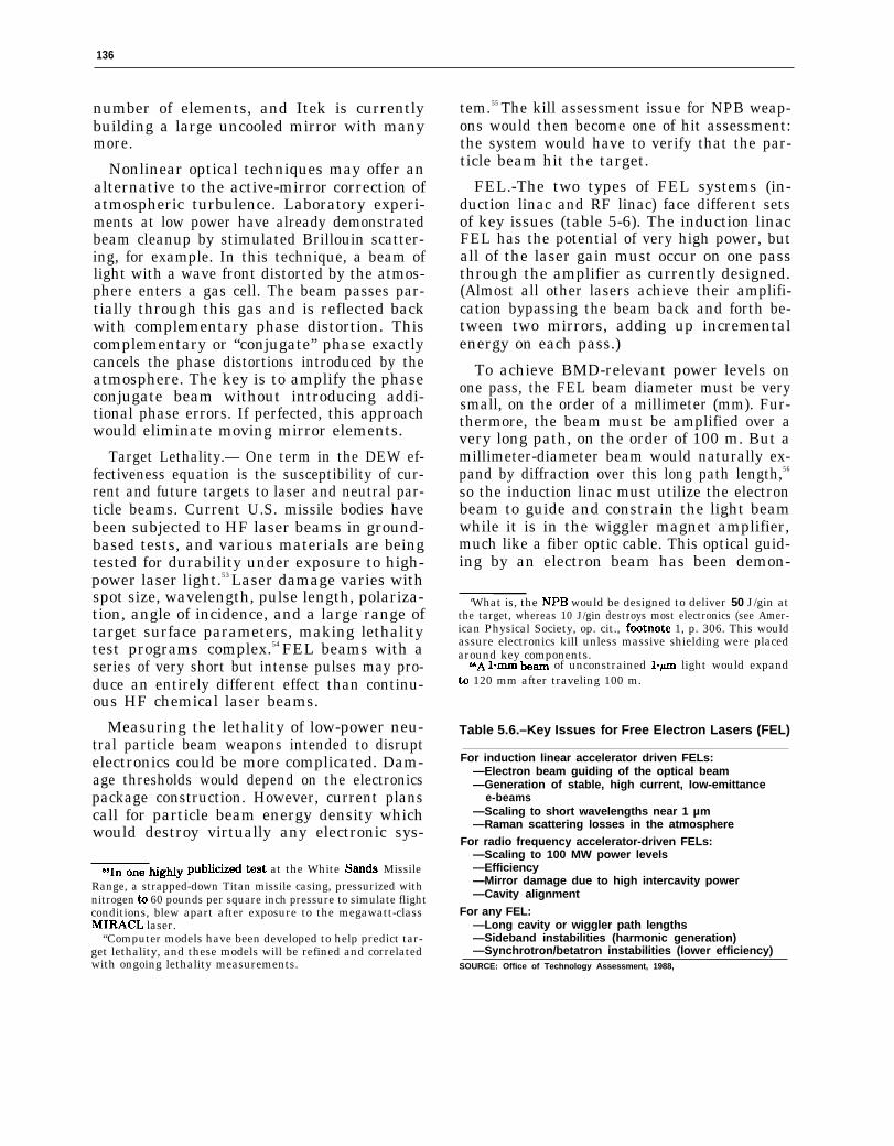
136
number of elements, and Itek is currentlybuilding a large uncooled mirror with manymore.
Nonlinear optical techniques may offer analternative to the active-mirror correction ofatmospheric turbulence. Laboratory experi-ments at low power have already demonstratedbeam cleanup by stimulated Brillouin scatter-ing, for example. In this technique, a beam oflight with a wave front distorted by the atmos-phere enters a gas cell. The beam passes par-tially through this gas and is reflected backwith complementary phase distortion. Thiscomplementary or “conjugate” phase exactlycancels the phase distortions introduced by theatmosphere. The key is to amplify the phaseconjugate beam without introducing addi-tional phase errors. If perfected, this approachwould eliminate moving mirror elements.
Target Lethality.— One term in the DEW ef-fectiveness equation is the susceptibility of cur-rent and future targets to laser and neutral par-ticle beams. Current U.S. missile bodies havebeen subjected to HF laser beams in ground-based tests, and various materials are beingtested for durability under exposure to high-power laser light.53 Laser damage varies withspot size, wavelength, pulse length, polariza-tion, angle of incidence, and a large range oftarget surface parameters, making lethalitytest programs complex.54 FEL beams with aseries of very short but intense pulses may pro-duce an entirely different effect than continu-ous HF chemical laser beams.
Measuring the lethality of low-power neu-tral particle beam weapons intended to disruptelectronics could be more complicated. Dam-age thresholds would depend on the electronicspackage construction. However, current planscall for particle beam energy density whichwould destroy virtually any electronic sys-
691~ ~~~ highly publicized test at the White S~ds MissileRange, a strapped-down Titan missile casing, pressurized withnitrogen to 60 pounds per square inch pressure to simulate flightconditions, blew apart after exposure to the megawatt-classMIRACL laser.
“Computer models have been developed to help predict tar-get lethality, and these models will be refined and correlatedwith ongoing lethality measurements.
tem.55 The kill assessment issue for NPB weap-ons would then become one of hit assessment:the system would have to verify that the par-ticle beam hit the target.
FEL.-The two types of FEL systems (in-duction linac and RF linac) face different setsof key issues (table 5-6). The induction linacFEL has the potential of very high power, butall of the laser gain must occur on one passthrough the amplifier as currently designed.(Almost all other lasers achieve their amplifi-cation bypassing the beam back and forth be-tween two mirrors, adding up incrementalenergy on each pass.)
To achieve BMD-relevant power levels onone pass, the FEL beam diameter must be verysmall, on the order of a millimeter (mm). Fur-thermore, the beam must be amplified over avery long path, on the order of 100 m. But amillimeter-diameter beam would naturally ex-pand by diffraction over this long path length,56
so the induction linac must utilize the electronbeam to guide and constrain the light beamwhile it is in the wiggler magnet amplifier,much like a fiber optic cable. This optical guid-ing by an electron beam has been demon-
‘What is, the NPB would be designed to deliver 50 J/gin atthe target, whereas 10 J/gin destroys most electronics (see Amer-ican Physical Society, op. cit., footnoti 1, p. 306. This wouldassure electronics kill unless massive shielding were placedaround key components.
66A l.m km of unconstrained l-pm light would expandto 120 mm after traveling 100 m.
Table 5.6.–Key Issues for Free Electron Lasers (FEL)
For induction linear accelerator driven FELs:—Electron beam guiding of the optical beam—Generation of stable, high current, Iow-emittance
e-beams—Scaling to short wavelengths near 1 µm—Raman scattering losses in the atmosphere
For radio frequency accelerator-driven FELs:—Scaling to 100 MW power levels—Efficiency—Mirror damage due to high intercavity power—Cavity alignment
For any FEL:—Long cavity or wiggler path lengths—Sideband instabilities (harmonic generation)—Synchrotron/betatron instabilities (lower efficiency)
SOURCE: Office of Technology Assessment, 1988,
strated, but not under weapon-like FEL con-ditions.
Two other disadvantages derive from thisnarrow, intense beam of light produced by theinduction linac FEL. First, the beam is so in-tense that it would damage any realizable mir-ror surface. The current plan is to allow thebeam to expand by diffraction after leavingthe FEL, traveling up to several km in anevacuated tunnel before striking the directormirror which would send the beam to the re-lay mirror in space.
A second disadvantage of such intensepulses of light is that they would react withthe nitrogen in the atmosphere by a processcalled “stimulated Raman scattering. ” Abovea threshold power density, the light would beconverted to a different frequency whichspreads out of the beam, missing the intendedtarget. 57 Again, this effect could be amelioratedby enclosing the beam in an evacuated tube,allowing it to expand until the power densitywere low enough for transmission through theatmosphere to the space relay. On the returnpath to the target, however, the beam wouldhave to be focused down to damage the target.
The experimental induction linac at Liver-more currently uses a (conventional, non-FEL)laser-initiated channel to guide the electronbeam before it is accelerated. This beam hasdrifted several millimeters laterally during theFEL pulse in initial experiments, severelylimiting FEL lasing performance because theelectron beam does not remain collinear withthe FEL laser beam.
The RF linac FEL, as currently configured,has shorter pulse lengths (20 picosecond v.15 nanoseconds for the induction linac FEL)but much higher pulse repetition rates (125MHz v. 0.5 MHz58), giving it higher duty cy-
S~The R~~ t~eshold for stimulated gain in nitrogen gasat one P light is about 1.8 MW/cm2. Above this power den-sity, the atmosphere becomes a singk+pass nitrogen laser: muchof the beam energy is converted to different (Stokes and anti-Stokes) wavelengths which diverge and cannot be focused onthe target.
‘aThe induction linac at Livermore could be operated up to1 kHz for up to 10 pulses. An o~rational linac FEL would havea repetition rate as high as tens of kilohertz.
137
cle and lower peak intensity for a given out-put average power level. It is uncertainwhether the RF linac can be scaled up to pro-duce power levels which seem probable for theinduction linac. By adding a set of power am-plifiers in series, it might be possible to reachthe power needed for a lethal laser weapon withan RF linac FEL.
The RF linac generates very high powerlevels inside the optical cavity. Mirror dam-age is therefore an issue, as is the problem ofextracting energy out of the cavity at thesehigh power levels. Cavity alignment is also crit-ical: the mirrors must be automatically alignedto maintain path-lengths within micrometersover many tens of meters during high-poweroperation.
The RF linac currently has low efficiency.In 1986, Los Alamos National Laboratory anda TRW-Stanford team demonstrated an energyrecovery technique whereby much of the un-used energy in an electron beam was recoveredafter the beam passed through a wiggler-ampli-fier. In principle, this energy could be coupledback to the RF generator to improve efficiencyin an operational system. At the higher opti-cal energy levels envisaged for the amplifiers,the RF linac amplifier should achieve 20 per-cent to 25 percent conversion efficiency, mak-ing energy recovery less advantageous.
An FEL would tend to be fragile. Accelera-tors are notorious for demanding careful align-ment and control, taking hours of manualalignment before operation. Major engineer-ing developments in automatic sensing andcontrol would be necessary before an FELcould become an operational weapon. LosAlamos is working to automate its ATS par-ticle beam accelerator; FEL systems wouldhave to incorporate similar automation, withthe added complexity of optical, as well as ac-celerator, alignment.
An FEL may suffer from electron beam (e-beam) instabilities. For example, unwanted lon-gitudinal e-beam excursions could create “side-band instabilities,” in which part of the opticalenergy would be diverted to sideband frequen-cies. Laser light at these extraneous frequen-
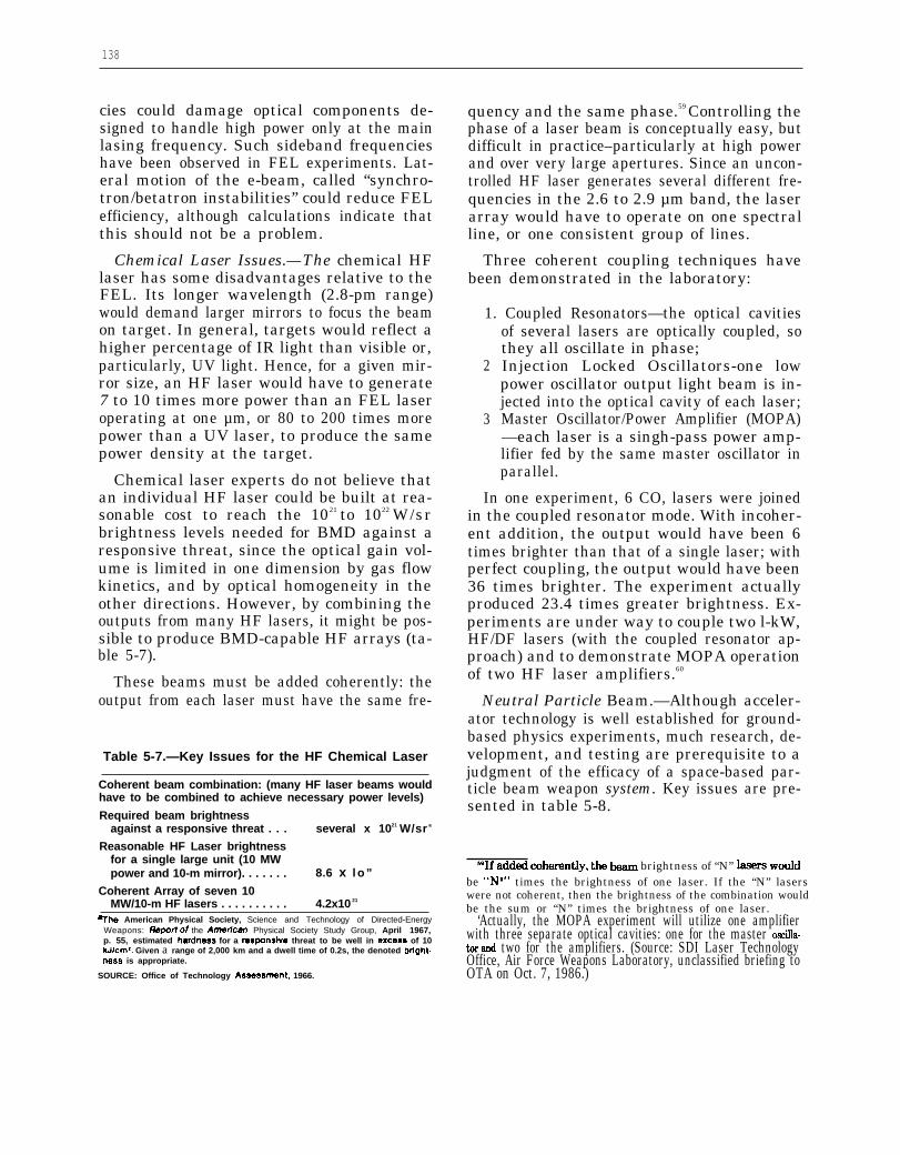
138
cies could damage optical components de-signed to handle high power only at the mainlasing frequency. Such sideband frequencieshave been observed in FEL experiments. Lat-eral motion of the e-beam, called “synchro-tron/betatron instabilities” could reduce FELefficiency, although calculations indicate thatthis should not be a problem.
Chemical Laser Issues.—The chemical HFlaser has some disadvantages relative to theFEL. Its longer wavelength (2.8-pm range)would demand larger mirrors to focus the beamon target. In general, targets would reflect ahigher percentage of IR light than visible or,particularly, UV light. Hence, for a given mir-ror size, an HF laser would have to generate7 to 10 times more power than an FEL laseroperating at one µm, or 80 to 200 times morepower than a UV laser, to produce the samepower density at the target.
Chemical laser experts do not believe thatan individual HF laser could be built at rea-sonable cost to reach the 1021 to 1022 W/srbrightness levels needed for BMD against aresponsive threat, since the optical gain vol-ume is limited in one dimension by gas flowkinetics, and by optical homogeneity in theother directions. However, by combining theoutputs from many HF lasers, it might be pos-sible to produce BMD-capable HF arrays (ta-ble 5-7).
These beams must be added coherently: theoutput from each laser must have the same fre-
Table 5-7.—Key Issues for the HF Chemical Laser
Coherent beam combination: (many HF laser beams wouldhave to be combined to achieve necessary power levels)
Required beam brightnessagainst a responsive threat . . . several x 1021 W/sr a
Reasonable HF Laser brightnessfor a single large unit (10 MWpower and 10-m mirror). . . . . . . 8.6 x l o ”
Coherent Array of seven 10MW/10-m HF lasers . . . . . . . . . . 4.2x10 21
~he American Physical Society, Science and Technology of Directed-EnergyWeapons: Repori of the Arnedcan Physical Society Study Group, April 1967,p. 55, estimated hardnees for a reaporwive threat to be well in excese of 10kJ/cm2. Given a range of 2,000 km and a dwell time of 0.2s, the denoted bright-ness is appropriate.
SOURCE: Office of Technology Asae~wnent, 1966.
quency and the same phase.59 Controlling thephase of a laser beam is conceptually easy, butdifficult in practice–particularly at high powerand over very large apertures. Since an uncon-trolled HF laser generates several different fre-quencies in the 2.6 to 2.9 µm band, the laserarray would have to operate on one spectralline, or one consistent group of lines.
Three coherent coupling techniques havebeen demonstrated in the laboratory:
1. Coupled Resonators—the optical cavities
2
3
of several lasers are optically coupled, sothey all oscillate in phase;Injection Locked Oscillators-one lowpower oscillator output light beam is in-jected into the optical cavity of each laser;Master Oscillator/Power Amplifier (MOPA)—each laser is a singh-pass power amp-lifier fed by the same master oscillator inparallel.
In one experiment, 6 CO, lasers were joinedin the coupled resonator mode. With incoher-ent addition, the output would have been 6times brighter than that of a single laser; withperfect coupling, the output would have been36 times brighter. The experiment actuallyproduced 23.4 times greater brightness. Ex-periments are under way to couple two l-kW,HF/DF lasers (with the coupled resonator ap-proach) and to demonstrate MOPA operationof two HF laser amplifiers.60
Neutral Particle Beam.—Although acceler-ator technology is well established for ground-based physics experiments, much research, de-velopment, and testing are prerequisite to ajudgment of the efficacy of a space-based par-ticle beam weapon system. Key issues are pre-sented in table 5-8.
~If ~d~ ~heren~y, & &am brightness of “N” ISSSrS wollldbe “Nz” times the brightness of one laser. If the “N” laserswere not coherent, then the brightness of the combination wouldbe the sum or “N” times the brightness of one laser.
‘Actually, the MOPA experiment will utilize one amplifierwith three separate optical cavities: one for the master oscilla-tor and two for the amplifiers. (Source: SDI Laser TechnologyOffice, Air Force Weapons Laboratory, unclassified briefing toOTA on Oct. 7, 1986.)

.
139
Photo Credit: U.S. Department of Defense,Strategic Defense Initiative Organization
Artist’s conception of a phased array of lasers.—Sinceit may be impractical to build a single module space-based chemical laser of a size useful for ballisticmissile defense, scientists and engineers are exploringthe possibility of using several smaller laser modulesthat would be phase-locked to provide a singlecoherent beam. This technique could increase the at-
tainable power density on a target by a factorof N* (instead of N for incoherent addition),
where N is the number of modules.
Table 5-8.—Neutral Particle Beam Issues
● Major issues:—Beam divergence: 50 times improvement required–Weight reduction (50 to 100 tonnes projected)—Kill assessment (or hit assessment)
. Other issues:—Beam sensing and pointing—Duty factor: 100 times improvement required—Ion beam neutralization (50°/0 efficient)—Space charge accumulation—ASAT potential
SOURCE Office of Technology Assessment, 1988
The NPB ATS now at Los Alamos gener-ates the necessary current (100 mA) for a NPBweapon, but at 20 to 40 times lower voltage,about 100 times lower duty cycle, and withabout 50 times more beam divergence than
would be needed for a space-based weapon. Acontinuous ion source with the necessary cur-rent levels has been operated at the CulhamLaboratory in the United Kingdom with 30-spulses, but not as yet coupled to an accelerator.
Researchers have planned a series of ground-based and space-based experiments to developbeams meeting NPB weapons specifications.It is possible that these experiments would en-counter unknown phenomena such as beam in-stabilities or unexpected sources of increasedbeam divergence, but there are no known phys-ics limitations that would preclude weaponsapplications.
High energy density at the accelerator wouldnot be sufficient for a weapon. The beam wouldhave to be parallel (or well-collimated, or have“low emittance” in accelerator parlance), tominimize beam spreading and maximize en-ergy transmitted to the target. In general,higher energy beams have lower emittance, butsome of the techniques used to increase beamcurrent might increase emittance, possibly tothe point where increased current would de-crease energy coupled to the distant target.With high emittance, the NPB would be ashort-range weapon, and more NPB weaponswould be necessary to cover the battle space.
The divergence of existing, centimeter-diam-eter particle beams is on the order of tens ofmicroradians; this divergence would have tobe reduced by expanding the particle beam di-ameter up to the meter range.6l This large beamwould have to be steered toward the targetwith meter-size magnets. Full-scale magneticoptics have not been built or tested. However,one-third scale optics have been built by LosAlamos National Laboratory and successfullytested at Argonne National Laboratory on a50 MeV beam line.
The weight of the NPB system would haveto be reduced substantially for space-basedoperation. The RF power supply alone for a
81 In theory, beam divergence decreases as the beam size isincreased. In practice, the magnets needed to increase the beamdiameter might add irregularities in transverse ion motion, whichcould contribute to increased beam divergence; not all of thetheoretical gain in beam divergence would be achieved.

140
weapon-class NPB would weigh 160,000 kg(160 tonnes) if based on existing RF radar tech-nology.62 Using solid-state transistors and re-ducing the weight of other components mightreduce RF weight about 22 tonnes.63 One studyconcluded that a total NPB platform weightof 100 tonnes is “probably achievable. ”64 LosAlamos scientists have estimated that theNPB platform weight for an “entry level,” 100-MeV, NPB system could be 50 tonnes. Someday, if high-temperature, high-current super-conductors became available, NPB weightsmight be reduced substantially.
Thermal management on a NPB satellitewould be challenging. A NPB weapon mightproduce 40 MW of waste heat.65 One proposalis to use liquid hydrogen to dispose of this heat.About 44 tonnes of hydrogen could cool theNPB for 500 s.66 The expulsion of hydrogengas would have to be controlled, since even aminute quantity of gas diffused in front of theweapon could ionize the beam, which wouldthen be diverted by the Earth’s magnetic field.Since the hydrogen gas would presumablyhave to be exhausted out opposing sides of thespacecraft to avoid net thrust, it might be dif-ficult to keep minute quantities of gas out ofthe beam.
A state-of-the-art ion accelerator (theRamped Gradient Drift Tube Linac) can raisebeam energy about 4 MeV per meter of acceler-— -.—. . . . .
‘The vacuum-tube (klystron) RF power supply for the PAVEPAWS radar system weighs approximately 2 g/W of power. ANPB weapon wo~d emit an average power of 20 MW (2x10⁷
watts), assuming 200 MeV beams at a current of 0.1 A. Assum-ing an overall efficiency of 25 percent (50 percent acceleratorefficiency and 50 percent beam neutralization efficiency), thepower supply would have to generate 80 MW average power,and would weigh 160 tonnes.
‘This assumes that the RF power is generatid with l-kW,commercial quality power transistors (80,000 transistors wouldbe required for the hypothetical 80 MW supply). These transis-tors can only be operated at 1 percent duty factor. New coolingtechnology wo~d have to be developed to operati at the 100percent duty factor required for a NPB weapon. (See AmericanPhysical Society, op. cit., footnote 1, pp. 149 and 361.) The over-all efficiency of these power supplies would be 40 percent.
“Ibid., p. 152.66Assuming a zoo.d, loo.Itiev” beam, 50 percent neutr~i-
zation efficiency, and 50 percent power generation efficiency.66Assuming heat of vaporization OIlly (450 J/g)* ~d no ‘te-
mperature rise in the hydrogen. If the gas temperature were al-lowed to rise by 100° K, then the hydrogen mass could be re-duced to about 14 tonnes.
ator length. At this gradient rate, a 200-MeVbeam would have to be over 50 m long. Thisaccelerator could be folded, but extra bendingmagnets would increase weight and could re-duce beam quality. The gradient could be in-creased, but if the ion beam energy were in-creased in a shorter length, then there wouldbe more heating in the accelerator walls. Thisimplies another system trade-off: reducinglength in an attempt to cut weight might even-tually reduce efficiency, which would dictateheavier RF power elements and more coolant.Again, future superconductors might amelio-rate this problem.
The beam would have to be steered to inter-cept the target. A NPB would have two ad-vantages over laser beams: the convenience ofelectronic steering and a lesser need for steer-ing accuracy. Magnetic coils could steer nega-tively charged hydrogen ions before the extraelectrons were stripped off. However, the an-gular motion of electronic steering would belimited: the entire accelerator would have tomaneuver mechanically to aim the beam in thegeneral direction of the target cluster. Like la-ser weapons, a NPB must have an agile opti-cal sensor system to track targets. However,the divergence of the NPB is larger than mostlaser beams (microradians versus 20 to 50nanoradians), so the beam steering need notbe as precise.
On the other hand, a hydrogen beam couldnot be observed directly. The particle beamdirection is detected in the laboratory by plac-ing two wires in the beam. The first wire castsa shadow on the second wire placed down-stream. By measuring the current induced inthis downstream wire as the upstream wire ismoved, the beam direction can be estimatedto something like 6 microradian accuracy.
New techniques would be needed to sensethe beam direction automatically with suffi-cient accuracy. One approach utilizes the factthat about 7 percent of the hydrogen atomspassing through a beam neutralization foilemerge in a “metastable” excited state: theelectrons of these atoms acquire and maintainextra energy. Passing a laser through the beamcan make these excited atoms emit light. The

141
magnitude of this fluorescence depends on theangle between the particle beam and the laserbeam. Thus the NPB direction can be deducedand the beam boresighted to an appropriateoptical tracking system. Laboratory tests havedemonstrated 250 microradian accuracy, com-pared to the l-microradian accuracy neces-sary.67 More recent tests at Argonne at 50 MeVhave yielded better results.
The current technique to neutralize thehydrogen ions is to pass them through a thinfoil or a gas cell. This process strips off, atmost, 50 percent of the electrons, cutting theefficiency of the system in half and thus in-creasing its weight. A gas cell is not practicalfor space applications. A stripping foil mustbe extraordinarily thin (about .03 to.1 µm, orten times less than the wavelength of visiblelight). In the proposed NPB weapon, a thin foil1 m in diameter would have to cover the out-put beam. Clearly such a foil could not be self-supporting, but Los Alamos scientists havetested foils up to 25 cm in diameter that aresupported on a fine wire grid. This grid ob-scures about 10 percent of the beam, but hassurvived initial tests in beams with averagepower close to operational levels.
Another beam neutralization concept is touse a powerful laser to remove the electrons-atechnique that some assert may yield 90 per-cent efficiency. However, the laser strippingprocess would call for a 25 MW Nd:YAG laser(near weapon-level power itself), and it wouldeliminate the excited state hydrogen atomsneeded for the laser beam sensing technique.68
Charged hydrogen ions that escaped neu-tralization might play havoc with an NPB sat-ellite. The accumulation of charge might se-verely degrade weapon system performance inunforeseen ways, although NPB scientists areconfident that this would not bean issue.69 TheBeam Experiment Aboard Rocket (BEAR) ex-periment with an ion source and the planned
67See American Physical Society, op. cit., footnote 1, p, 172.‘8 See American Physical Society, op. cit., footnote 1, p. 148.agone ~ugge9ted that the neutralizing foil be thicker so that
two electrons are stripped from some hydrogen ions, formingpositive hydrogen ions (protons) to help neutralize the chargein the vicinity of the spacecraft.
Integrated Space Experiment (ISE) should an-swer any remaaining doubts about space-chargeaccumulation.
Arcing or electrical breakdown that couldshort out highly charged components may alsobe a problem in space. Dust or metal particlesgenerated in ground-based accelerators fallharmlessly to the ground. In space, floatingparticles could cause arcing by forming a con-ducting path between charged components.
Existing accelerators demand many hoursof careful manual alignment before an experi-ment. Neutral particle beam weapons wouldhave to operate automatically in space. Cur-rent plans call for the ATS accelerator at LosAlamos to be automated soon.
Kill assessment might be difficult for weakparticle beam weapons. Damage deep insidethe target might completely negate its func-tion with no visible sign. The choices wouldbe either to forgo kill confirmation or to in-crease NPB energy levels until observabledamage were caused, possibly the triggeringof the high-energy explosive on the RV. Thecurrent plan is to forgo kill confirmation perse, but to increase the NPB power level to as-sure electronic destruction. Sensors would de-termine that the particle beam had hit eachtarget. Experiments are planned to assesswhether UV light emissions would indicatethat a particle beam had struck the surface ofa target.
The planned (and now indefinitely post-poned) ISE illustrates a point made in chap-ter 11 of this report: many BMD weaponswould have ASAT capabilities long before theycould destroy ballistic missiles or RVs. TheISE accelerator, if successful, would haveASAT lethality at close range, although fora limited duty cycle. Beam divergence mightlimit range, but it could probably destroy theelectronics in existing satellites within 500 to1,000 km.70 Even though not aiming a beam
‘This experiment could have nearly BMD-level lethality, pos-sibly raising issues with respect to the ABM Treaty. However,it would not have the necessary beam sensing and pointing orthe computer software and hardware for a BMD weapon; SDIOconsiders the experiment to be treaty compliant.

142
at other than a target satellite, this experimentconceivably might disrupt nearby satellite elec-tronics. Although this may not be serious (cal-culations indicate that it should not), there isenough uncertainty to cause ISE planners toask whether they should wait until the SpaceShuttle had landed before turning on the ISE.
X-ray Laser. —The nuclear bomb-driven x-ray laser is the least mature DE W technology.
To date this program has consisted of theo-retical and design work at Livermore NationalLaboratory and several feasibility demonstra-tion experiments at the underground Nevadanuclear weapons test site. Actual x-ray gener-ation technology may or may not reach suit-able levels in the years ahead; currently themethods to convert this technology into a via-ble weapons system remain paper concepts.
POWER AND POWER CONDITIONINGThe average electrical power consumed by
some proposed BMD spacecraft during bat-tle might be factors up to 100,000 over cur-rent satellite power levels. Most existing sat-ellites are powered by large solar arrays thatwould be vulnerable to defense suppression at-tack. To provide sufficient survivable powerfor space applications, most BMD satelliteswould require either nuclear reactors, rocketengines coupled to electrical generators, or ad-vanced fuel cells.
In addition to high average power, some pro-posed weapon satellites would demand highpeak power: energy from the prime source, ei-ther a nuclear reactor or a rocket-driven turbo-alternator, would have to be stored and com-pressed into a train of very high current pulses.For example, a railgun might expend 500 MJof energy in a 5-millisecond (ins) pulse, or 100GW of peak power. This is about 1,000 timesmore than current pulse power supplies candeliver.
The following sections outline satellite powerdemands and the technologies that mightsatisfy them. While space systems would callfor the primary advances, ground-based FELswould also depend on advances in pulsed-powersupply technology. Some of the technology de-veloped for space-borne neutral particle beamsystems, such as RF power sources, might beapplicable to FELs.
Space Power Requirements
Estimates of power needs of space-basedBMD systems are summarized in table 5-9.Since most of these systems have not been de-signed, these estimates could change signifi-cantly: the table only indicates a possible rangeof power levels. Power is estimated for threemodes of operation: base-level for general sat-ellite housekeeping and continuous surveil-lance operations lasting many years; alert-levelin response to a crisis, possibly leading to war;
Table 5-9.—Estimated Power Requirements for Space Assets(average power in kilowatts)
Mode of operation Base Alert Burst (battle)BSTS . . . . . . . . . . . . . . . . . . . . . . 4-1o 4-1o 4-1oSSTS (IR) . . . . . . . . . . . . . . . . . . 5-15 5-15 15-50
Ladar. . . . . . . . . . . . . . . . . . . . 15-20 15-20 50-100Ladar imager . . . . . . . . . . . . . 15-20 15-20 100-500Laser illumination . . . . . . . . . 5-1o 5-1o 50-100Doppler Iadar. . . . . . . . . . . . . 15-20 15-20 300-600
SBI carrier . . . . . . . . . . . . . . . . . 2-30 4-50 1o-1ooChemical laser . . . . . . . . . . . . . 50-100 100-150 100-200Fighting mirror . . . . . . . . . . . . . 10-50 10-50 20-100NPB/SBFEL . . . . . . . . . . . . . . . . 20-120 1,000-10,000 100,000-500,000EML (railgun) . . . . . . . . . . . . . . . 20-120 1,000-10,000 200,000-5,000,000
SOURCE: Space Defense Initiative Organization, 1988.

I143
and burst-mode for actual battle, which maylast hundreds of seconds.
In addition to average-power and surviva-bility perquisites, a space-based power systemwould have to be designed to avoid deleteri-ous effects of:
● thrust from power-generating rockets up-setting aiming,
● torque due to rotating components,● rocket effluent disrupting optics and beam
propagation,● vibration on sensors and beam steering,● thermal gradients, and● radiation from nuclear reactors.
Power systems would also have to operatereliably for long periods unattended in space.
Space Power Generation Technology
There are three generic sources of electricalpower in space: solar energy, chemical energy,and nuclear energy.
Solar EnergySolar panels have supplied power for most
satellites. The sun produces about 1.3 kW ofpower on every square meter of solar array sur-face. An array of crystalline silicon cells con-verts the sun’s energy into direct electrical cur-rent through the photovoltaic effect, with anefficiency of about 10 percent. Thus a l-m2
panel of cells would produce about 130 wattsof electricity, assuming that the panel were ori-ented perpendicular to the sun’s rays. A 20-kW array, typical for a BMD sensor, wouldthen have about 150 m2–roughly, a 12-m by12-m array. The Skylab solar array, the largestoperated to date, produced about 8 kW. NASAhas built, but not yet flown in space, a 25-kWexperimental solar array designed to supplyspace station power.
The major disadvantage of solar arrays isthat their large size makes them vulnerable toattack. Crystalline silicon photovoltaic cells arealso vulnerable to natural and man-made ra-diation. One approach to reduce both vulnera-bilities to some degree would be to concentratethe sun’s rays with a focusing optical collec-
tor. The collector would still be vulnerable, butif the system efficiency could be improved, thenthe area of the collector would be smaller thanequivalent ordinary solar cell arrays.
There are two other ways to convert theenergy from solar collectors into electricity.One is to use solar thermal energy to drive aconventional thermodynamic heat engine. Theother is to focus sunlight on more radiation-resistant and higher-efficiency photovoltaiccells such as gallium arsenide. Depending onthe temperature of the working fluid in a ther-modynamic heat engine cycle, efficiencies of20 percent to 30 percent might be achieved.Gallum arsenide cells have shown up to 24 per-cent efficiency in the laboratory, so 20 percentefficiency in space may be reasonable. Thus,either technology could cut the required col-lector area in half compared to conventionalsolar cells, or 75 m2 per 20-kW output. Neitherapproach has been tested in space, but NASAis pursuing both for future space applications.
Nuclear EnergyNuclear energy has also been used in space.
There are two types of nuclear energy sources:radioactive isotope generators that convertheat from radioactive decay to electricity, andnuclear fission reactors. Both have flown inspace, but the radioactive isotope generatoris more common.
Both radioactive decay and a controlled fis-sion reaction produce heat as the intermedi-ate energy form. This heat can be convertedinto electricity by static or dynamic means.A static power source produces electricitydirectly from heat without any moving parts,using either thermoelectric or thermionic con-verters. These converters generate direct cur-rent between two terminals as long as heat issupplied to the device. The efficiency and to-tal practical power levels are low, but for ap-plications of less than 500 W, the advantageof no moving parts makes a radioisotope ther-moelectric generator (RTG) a primary candi-date for small spacecraft.
To produce more than 500 W, a radioisotopesource could be coupled to a dynamic heat en-

144
gine. One dynamic isotope power system(DIPS) with 2 to 5 kW output has been ground-tested. This system weighs 215 kg. However,the U.S. production capacity for radioactiveisotopes would limit the number of satellitesthat could be powered by DIPS.
BMD satellites needing more than 5 to 10kW of power might carry a more powerful nu-clear fission reactor. Static thermoelectric con-verters would still convert the heat to electri-city. This is the approach proposed for theSP-100 space power program, the goal of whichis to develop elements of a system to providepower over the range of 10 to 1,000 kW. TheDepartments of Defense and Energy andNASA are producing a reference design incor-porating these elements to produce a 100-kWtest reactor.
71 This is the major focus for thenext generation of space power systems.
The SP-100 reactor, as currently designed,would use 360 kg of highly enriched uraniumnitride fuel with liquid lithium cooling operat-ing at 1,3500 K. This heat would be conductedto 200,000 to 300,000 individual thermoelec-tric elements which would produce 100 kW ofelectricity. The overall efficiency of the sys-tem would be about 4 percent, which wouldentail the disposal of 2.4 MW of waste heat.Large fins heated to 8000 K would radiate thisheat into space.
The SP-100 program faces numerous chal-lenges. In addition to being the hottest run-ning reactor ever built, the SP-100 would be
The estimated mass of the SP-100 is 3,000kg, or a specific mass of 30 kg/kW. Originalplans called for building a ground-test proto-type SP-100 based on the 100-kW design by1991, with a flight test several years later. Sub-sequently a 300-kW design was consideredwhich would have pushed initial hardwaretoward 1993, but current schedules are fluiddue to uncertain funding.
the first space system to: To produce power levels in excess of a few●
●
●
ž
●
●
use uranium nitride fuel,be cooled by liquid lithium,use strong refractory metals to contain theprimary coolant,have to start up with its coolant frozen,have two independent control mechanisms(for safety), anduse electronic semiconductors under suchintense heat and radiation stress.72
710riginal SDIO plans called for designing a 300 KW system,but as of this writing the goal has been reduced to 100 KW.
‘*See Eliot Marshall, “DOE’s Way-out Reactors,” Science,231:1359, March 21, 1986.
hundred kW, one would have to take the nextstep in the evolution of space nuclear powersystems: a nuclear reactor coupled through adynamic heat engine to an electrical genera-tor. In principle, large reactors in space couldgenerate hundreds of MW, satisfying the moststressing BMD average power demands.
A “multimegawatt,” or MMW, project hasbegun to study some of the fundamental is-sues raised by large reactors, including daunt-ing engineering challenges such as high tem-perature waste heat disposal in space, safetyin launch, operation, and decommissioning.These large nuclear systems might have to be

745
operated “open-cycle,” requiring much “fuel”in the form of cooling gas to dispose of excessheat. At this writing the MMW project is inthe conceptual phase with no well-defined re-search program. Multi-megawatt nuclear re-actors in space would have to be considereda 20-to-30 year project.
In summary, space nuclear power systemswould require extensive development toachieve reliable space operation at the 100-300kW level by the mid-to-late 1990s. Given cur-rent engineering and budget uncertainties, de-velopment of megawatt-class nuclear powersystems for space cannot be projected untilwell into the 21st century.
Chemical EnergySatellites frequently employ chemical energy
in the form of batteries, fuel cells, and tur-bogenerators. Batteries would be too heavy formost BMD applications, except possibly forpop-up systems with very short engagementtimes. Fuel cells, which derive their power bycombining, e.g., hydrogen and oxygen, are un-der active consideration for driving the acceler-ators of NPB weapons.
For the short bursts of MMW power neededby some BMD weapons, an electrical genera-tor driven by a rocket engine (e.g., burning liq-uid hydrogen and liquid oxygen) might be theonly available technology in the foreseeable fu-ture. The Space Shuttle main engine (SSME)develops about 10 GW of flow power, whichcould generate 5 GW of electrical energy if itcould be coupled to a turboalternator. Alter-natively, rocket exhaust could, in principle, beconverted to electricity by magnetohydro-dynamics (MHD).
The engineering challenges of using rocketengines to produce electrical power on boarda BMD satellite are posed not only by thegenerator itself, but by its effects on other com-ponents such as sensors, electronics, and weap-ons. Two counter-rotating and counter-thrust-ing rockets would probably be essential tocancel torque and thrust. Even then, sensorsand weapons-aiming devices would have to beisolated from vibration. Similarly, the effluent
from the rocket engines must not interfere withsensors or weapon beam propagation, and elec-trical noise must not interfere with communi-cation or data processing electronics.
It might be necessary to place rocket enginesand power generators on separate platformshundreds or a few thousands of meters awayto achieve the necessary isolation, transmit-ting power by cable or microwaves. Thismethod, however, would raise vulnerability is-sues, presenting to the adversary an additionaltarget and a vulnerable umbilical cord.
Power Conditioning
Power conditioning is matching the electri-cal characteristics of a power source with thoserequired by the load. A generator might pro-duce a continuous flow of electrical current,but a load, such as railgun firing, would requirea series of very high-current pulses. Power con-ditioning equipment would convert the contin-uous flow into pulses.
In some cases the projected power condition-ing device requirements exceed existing capa-bilities by two or three orders of magnitude,even for ground-based experiments. In manyareas, no space-qualified hardware exists atany power level. Pulsed power technology de-velopment efforts are underway in capacitiveand inductive energy storage, closing and open-ing switches, transformers, RF sources, AC-DC converters, and ultra high-voltage tech-niques and components.
Particle accelerators that drive the FEL andthe NPB use RF power. Railgun requirementswould present the greatest challenge: veryshort (millisecond) pulses of current severaltimes a second. Many electrical componentswould have to be developed to produce theproper current pulses for a railgun.
A homopolar generator combined with an in-ductor and opening switch is now the primarycandidate for the generation of very shortpulses. A homopolar generator is a rotatingmachine that stores kinetic energy in a rotat-ing armature. At the time of railgun firing,brushes would fall unto the armature, extract-
146
ing much of its energy in a fraction of a sec-ond. This would result in a sudden jerk in thetorque of the generator, which would disturba spacecraft unless compensated by a balancedhomopolar generator rotating in the oppositedirection.
The brushes would also wear out, whichraises questions about the durability of a rail-gun with high repetition rates. Very fastswitches would be essential. These switcheswould have to be light enough to move rap-idly, but heavy enough to handle the extraor-dinarily high currents.
Researchers at the University of Texas haveinvestigated one advanced modification to thehomopolar generator. They have replacedbrushes and switches with inductive switchesin a “compulsator,” a generator which pro-duces a string of pulses. By replacing non-current carrying iron with graphite-epoxy com-posites, these compulsators could be muchlighter than the homopolar generators.
While space applications drive power devel-opment requirements, emerging ground-baseddefensive systems would also stress existingpower sources. Ground-based BMD elementsmight require diesel and turbine driven elec-tric generators and MHD generators for mo-bile applications. A fixed-site system such asthe FEL might draw on the commercial util-ity grid, dedicated power plants, or supercon-ducting magnetic energy storage (SMES). Theelectrical utility grid could meet peacetimehousekeeping power needs and could keep astorage system charged, but, due to its extremevulnerability to precursor attack, could not be
relied on to supply power during a battle.Therefore, a site-secure MMW power systemwould probably be necessary.
Superconducting magnetic energy storageis a prime candidate for ground-based energystorage; an SMES system would be a large,underground superconducting coil with con-tinuous current flow. The science of SMES iswell established, but engineering developmentremains.
Recent discoveries of high-temperature su-perconductors could have an impact on futurepower supplies and pulse conditioning sys-tems. Given the likely initial cost of manufac-turing exotic superconducting materials andthe probable limits on total current, their firstapplications will probably be in smaller devicessuch as electronics, computers, and sensor sys-tems. But if:
●
●
scientists could synthesize high temper-ature superconducting materials able tocarry very large currents; andengineers could develop techniques tomanufacture those materials on a largescale suitable for large magnetic coils, RFpower generators, accelerator cavity walls,the rails of electromagnetic launchers, etc.;
then superconductors could substantially re-duce the power demand. Efficiency of thepower source and power conditioning networkscould also be improved. High temperature su-perconductors would be particularly attractivein space, where relatively cold temperaturescan be maintained by radiation cooling.
COMMUNICATION TECHNOLOGY
Communication would be the nervous sys- dreds to several thousands of weapons plat-tem of any BMD system. A phase-one defense forms in low-Earth orbits. “would include hundreds of space-based com-ponents, separated by thousands of kilometers, Three fundamental communication pathsfor boost and post-boost interception. A would link these space assets: ground to space,second-phase BMD system would include space to space, and space to ground. Groundmany tens of sensors in high orbits and hun- command centers would at least initiate the
147
battle; they would also receive updates onequipment status and sensor data in peacetimeand as the battle developed.
The attributes of an effective communica-tion system would include:
● adequate bandwidth and range,● reliability,● tolerance of component damage,● security from interception or take-over,● tolerance of nuclear effects, and● jam- or spoof-resistance.The bandwidths, or frequency space avail-
able, from links in the millimeter-wave bandswould be adequate for most near-term BMDfunctions. The most demanding element wouldbe the boost surveillance and tracking system(BSTS) satellite, with perhaps a l-million-bit-per-second data rate. Second-phase elementssuch as a space surveillance and tracking sys-tem (SSTS) sensor satellite might operate atmuch higher rates, up to 20 million bits persecond, while battle management might take50 or more million bits per second of informa-tion flow. Various additional data for syn-chronization signals would have to be commu-nicated. Transmission bandwidths might haveto be very large-perhaps 1-10 gigahertz (GHz)–to reduce the chances of jamming.
The communication system must be dura-ble and survivable even if some nodes fail dueto natural or enemy action. Redundant linksin a coupled network might assure that mes-sages and data got through even if some sat-ellites were destroyed. Tying together a vastBMD space network would be challenging,especially given that the satellites in low-Earthorbit would constantly change relative po-sitions.
One key issue for BMD communications isjamming by a determined adversary. Success-fully disrupting communications would com-pletely negate a BMD system that relied onsensors and command and control nodes sep-arated from weapons platforms by tens of thou-sands of km. Jammers could be developed, de-ployed, and even operated in peacetime withlittle risk of stimulating hostile counteraction.
Space-to-ground communication links wouldbe particularly vulnerable. Ground-based, ship-based or airborne high-power jammers mightblock the flow of information to satellites. Inwartime, nuclear explosions could disrupt thepropagation of RF waves. Ground-basedreceivers would also be susceptible to directattack. Even space-based communicationswould be susceptible to jamming.
Recently there have been two primary SDIcandidates for BMD communication links inspace: laser links and 60-GHz links. A 60-GHzsystem once seemed to promise a more jam-resistant channel for space-to-space commu-nications, since the atmosphere would absorbenough 60-GHz energy to reduce the threat ofground-based jammers. Recent analyses, how-ever, indicate that space and air-based jam-mers may limit the effectiveness of 60-GHzlinks.
60-GHz Communication Links
The operating frequencies of space commu-nication systems have been steadily increas-ing. For example, the Milstar communicationssatellite will use the extremely high frequency(EHF) band with a 44-GHz ground-to-space up-link and a 20-GHz downlink. These high fre-quencies allow very wide bandwidth (1 GHzin the case of Milstar) for high data transmis-sion rates, but also for more secure communi-cations through wide-band-modulation andfrequency-hopping anti-jamming techniques.
For space-to-space links, BMD designers areconsidering even higher frequencies-around60 GHz. This band includes many oxygen ab-sorption lines. It would be very difficult forground-based jammers to interfere with 60-GHz communications between, for example,a BSTS early warning satellite and SBI CVs:oxygen in the atmosphere would absorb thejamming energy.
Pre-positioned jammer satellites, or possi-bly rocket-borne jammers launched with an at-tack, might still interfere with 60-GHz chan-nels. The main beam of radiation from a60-GHz transmitter is relatively narrow, mak-

148
ing it difficult for an adversary to blind thesystem from the main lobe: the enemy jam-mer transmitter would have to be located veryclose to the BMD satellite broadcasting itsmessage. But a 60-GHz receiver would alsopick up some energy from the “sidelobes” andeven some from the opposite side of the receiver(the “backlobes”). While a receiver may be10,000 to 100,000 times less sensitive to energyfrom these sidelobes than from the main lobe,it must be extremely sensitive to pickup sig-nals from a low-Earth orbit satellite tens ofthousands of km away.
At high-Earth orbit, a near-by jammer withonly a few hundred watts of power could over-whelm a much more powerful 60-GHz systemon a sensor satellite. This neighbor mightmasquerade as an ordinary communicationssatellite in peacetime. In wartime, it could aimits antenna at the BSTS and jam the channel.The countermeasure would be to station theBSTS out of standard communications satel-lite orbits.
Laser Communication Links
The low-power diode laser offers the possi-bility of extremely wideband, highly direc-tional, and, therefore, very jam-proof commu-nications. The MIT Lincoln Laboratory hasdesigned a 220 megabit-per-second (Mbs) com-munication link that would need just 30 mil-liwatts of laser power from a gallium alumi-num arsenide (GaAIAs) light emitting diode(LED) to reach across the diameter of the ge-osynchronous orbit (about 84,000 km). The re-ceiver, using heterodyne detection,73 could pull
in a signal of just 10 picowatts (10-11 W)power. A 20-cm mirror on the transmitterwould direct the laser beam to an intended re-ceiver.
The high directionality of narrow laserbeams also complicates operation. A wide-angle antenna could flood the receiver area withsignal, even sending the same message to manyreceivers in the area at one time. A narrow la-ser beam must be carefully aimed at each sat-ellite. This would require mechanical mirrorsor other beam-steering optics, as well as soft-ware to keep track of all friendly satellites andto guide the optical beam to the right satel-lite. The lifetime of a laser source and an agileoptical system may be relatively short for thefirst few generations of laser communicationsystems.
A laser communication system, as presentlydesigned, would require up to eight minutesto establish a heterodyne link between a trans-mitter and a receiver. Plans call for reducingthis acquisition time to one minute. With avery narrow laser beam, even minute motionsof the transmitter platform could cause amomentary loss of coupling, forcing a delayto reacquire the signal.
While laser links might provide jam-proofcommunications between space-based assetsof a BMD system, laser communications to theground would have to overcome weather limi-tations. One approach would use multiplereceivers dispersed to assure one or more clearweather sites at all times. Alternatively, onecould envisage an airborne relay station, par-ticularly in time of crisis.
“The common “heterodyne” radio receiver includes a localoscillator which generates a frequency that is combined or“mixed” with the incoming radio signaL This process of “mix-ing” the local oscillator signal with the received signal improvesthe ability to detect a weak signal buried in noise, and reduces
interference. A laser heterodyne receiver would include its ownlaser source, which would be “mixed” at the surface of a lightdetector with the weak light signal from a distant laser trans-mitter.
SPACE TRANSPORTATION
Reasonable extensions of current U.S. space launch capabilities would be necessary to lifttransportation capability might launch the several hundred to over one thousand carriertens of sensor satellites envisaged by some vehicles and their cargoes of thousands to tensBMD architectures, but entirely new space of thousands of kinetic kill missiles into space
149
in a reasonable period of time. Therefore spacelaunch capability would have to evolve alongwith phase-one and phase-two weapon systemsto assure the United States—and to persuadethe Soviet Union-that a defense-dominatedworld would be feasible and enduring.
Space Transportation Requirements
Space-based interceptors and their carriersatellites would dominate initial space deploy-ment weights. Assuming that a phase-one de-ployment would include a few hundred CV\sSand a few thousand SBIs based on the "state-of-the-art” rockets described above, then to-tal launch weight requirements might be in therange of 1 million to 2 million kg.
The range of weights estimated by SD I sys-tem architects for a more advanced phase var-ied from 7.2 to 18.6 million kg. The large rangeof weight estimates reflects differences in ar-chitectures, and particularly differences in sur-vivability measures. Several contractors indi-cated that survivability measures—such asshielding, decoys, proliferation, and fuel formaneuvering-would increase weight by a fac-tor of about three. One could infer that theheavier designs might be more survivable.
Additional space transportation would be re-quired over time for servicing, refueling, orreplacement of failed components. One un-resolved issue is how best to maintain this fleetof orbiting battle stations: by originally includ-ing redundant components such as intercep-tor missiles on each satellite, by completereplacement of defective satellites, by on-orbitservicing, or by some combination of the above.One contractor estimated, for example, thatit would take 35 interceptor missiles on eachbattle station to assure 20 live missiles after10 years, with the attrition due entirely to nat-ural component failures.
Soviet countermeasures might drive upweight requirements substantially in lateryears. Increased Soviet ICBM deploymentsmight be countered with more SB I platforms.Defense suppression threats such as direct-ascent ASATs might be countered in part byproliferation of SBI battle stations or by other
heavy countermeasures. Advanced decoys dis-persed during the post-boost phase of missileflight might require some type of interactivediscrimination system in space. Reduced So-viet booster burn times would eventually im-pel a shift to DE W. Deploying these counter-measures would necessitate additional spacetransportation capability. Directed-energyweapon components in particular would prob-ably be very heavy. The range of SDI systemarchitects’ estimates for some far-term sys-tems was from 40 million to 80 million kg.
Space Transportation Alternatives
There seem to be two fundamental optionsfor lifting the postulated BMD hardware intospace: use derivatives of existing space trans-portation systems; or design, test, and buildanew generation space transportation system.The first option might be very costly; the sec-ond might postpone substantial space-basedBMD deployment into the 21st century.
Some BMD advocates outside the SDIOhave suggested that existing United Statesspace launch systems might be adequate foran initial spacebased BMD deployment in theearly 1990s. But the existing United Statesspace launch capability is limited in vehicle in-ventory, payload capacity per launch, cost,launch rate, and launching facilities. As shownin table 5-10, today’s total inventory of U.S.rockets could lift about 0.27 million kg intolow-Earth orbit (180 km) at the inclination an-gle of the launch site (28.50 for the KennedySpace Center in Florida) .74
The bulk of early SBI deployments wouldhave to be launched into near-polar orbits fromVandenberg AFB, which would now only bepossible for the 6 remaining Titan 34D vehi-cles with a combined lift capacity of 75,000 kg.
“Missile launch capacity is usually specified in terms of thepayload which can be lifted into direct East-West flight at analtitude of 180 km, which produces an orbit inclined at the lati-tude of the launch point. Extra propellant is required to lift thepayload to higher inclinations or to higher altitudes. ProposedBMD weapons systems would require higher inclinations (700to850, and higher altitudes (600 to 1,000 km), which translatesinto lower payload capacity.

150
This would correspond to about 6 percent ofthe initial phase-one BMD space deploymentrequirements. Some have suggested refurbish-ing Titan-IIs, which have been retired from theICBM fleet. If all 69 Titan-IIs were refur-bished, then the United States could liftanother 130,000 kg into polar orbit, or another11 percent of the near-term BMD needs.
The rate of missile launch might also belimited by the existing space transportationinfrastructure. Launching one Shuttle nowtakes a minimum of 580 hours at the KennedySpace Center (and might take about 800 hoursat Vandenberg AFB75), limiting potentiallaunches to one per month or less from eachcomplex. After the Shuttle accident, NASAestimated that 12 to 16 flights per year wouldbe reasonable. Clearly 16 launches per yearwould not be sufficient for BMD deployment.76
Several aerospace companies have proposedbuilding launch vehicles with increased lift ca-pacity to meet SDI, DoD, and civilian spacetransportation demands. Many of these vehi-cles would be derived from various Shuttle or
75Completion of the Vandenberg Shuttle launch site SLC-6has been postponed until 1992.
‘“Assuming 16 Shuttle launches per year with 9,000 kg pay-load to low polar orbit, it would take between 8 to 12 years todeploy a phase-one BMD system and 48 to 125 years to deploya phase-two system weighing 7 to 18 million kilograms.
Titan predecessors, such as the Titan-4, in-cluded in table 5-10. Twenty-three Titan-4s willbe built by 1988, but these have only margin-ally increased lift capacity. A major increasein lift capacity to the 40,000 to 50,000 kg rangewould be required for an effective space-basedBMD system. Even for a phase-one system,far more would be needed by the mid-1990s.Both SDIO and Air Force officials have calledfor anew space transportation system that isnot a derivative of existing technology.
Four aerospace companies analyzed variousspace transportation options under joint AirForce/NASA/SDIO direction. The Space Trans-portation Architecture Study (STAS) com-pared manned v. unmanned vehicles, horizon-tal v. vertical takeoff, single v. 2-stage rockets,and various combinations of reusable v. ex-pendable components.77 The &r Force, afterreviewing the initial STAS work, appears tobe leaning toward a decision that the BMD de-ployment should use an unmanned, expenda-ble, 2-stage heavy-lift launch vehicle (nowcalled the ALS or advanced launch system) .78
TTThe spice Trmsportation Architecture Study (S’I’AS) wasa joint Air Force/NASA/SDIO study on future space transpor-tation systems. The Air Force Systems Division contracted withRockwell and Boeing, while NASA employed General Dynamicsand Martin Marietta to analyze U.S. civilian and military spacerequirements and possible alternatives to satisfy them.
7sThe name HLLV (heavy lift launch vehicle) was changedto ALS in April 1987.
Table 5-10.—Current U.S. Space Launch Inventorya
Payload per vehicle (thousands of kg)
Inventory LEO Polarquantity (180 km) (180 km) Geo
Shuttle . . . . . . . . . . . . . . . 3 25 15 Centaur-G:4.5IUS: 2.3
Titan 34D . . . . . . . . . . . . . 15,3 12.5 IUS: 1.8Titan-4 b . . . . . . . . . . . . . . (23) 17.7 14.5 Centaur-G:4.6
IUS: 2.4Titan 11-SLV . . . . . . . . . . . (13)C 3.6 1.9Delta. . . . . . . . . . . . . . . . . 2.9Delta (MLV) . . . . . . . . . . . (7) 4 1.5Atlas. . . . . . . . . . . . . . . . . 13 6scout . . . . . . . . . . . . . . . . 21 .26(ALS) d . . . . . . . . . . . . . . . . ? (50-70) (40-55)aparentheses indicate future SyStemS.bThe Titan.4 or the complementary Expendable Launch Vehicle (CELV) iS the latest in the line Of Titan miSSile configurations;23 have been ordered.
CThe Titan 11.sLvs are Ming refurbished from the ICBM inventory. The first Titan-n may be available by 1989. An additional56 Titan II could be refurbished from the retired ICBM fleet.
dTh e Advanced Launch System is proposed to deploy the bulk of the BMCI SpaCe CO171pOIlWlk.
SOURCE: Office of Technology Assessment, 1988.

151
An interim STAS study suggested that sucha vehicle would have to evolve to a partiallyreusable system to meet SDIO cost reductiongoals. The STAS contractors projected thatdevelopment of a heavy-lift unmanned vehi-cle would require about 12 years, although atleast one aerospace company estimates thatan ALS could be developed in 6 years. If theoriginal 12-year estimate is correct, significantspace deployment of a BMD system could notbegin until the turn of the century even if theweapon systems were ready earlier. If the 6-year estimate were correct, then initial deploy-ment could begin by 1994.
To deploy space-based assets earlier, SDIOhas suggested a two-tier level program: buildpart of an ALS by the mid-1990s, but designthis system to evolve into the long-range sys-tem by the year 2000. The initial system wouldinclude some of the advanced features of theheavy-lift launch vehicle concepts outlined bySTAS, but would not have a fly-back boosterand would not meet the SDIO cost goals of$300 to $600 per kilogram. The interim goalwould be to reduce the current costs of $3,000-$6,000 per kilogram to $1,000-$2,000. Build-ing a space transportation system while try-ing to meet these two goals simultaneouslycould be risky. Compromises might be requiredeither to meet the early deployment date orto meet the long-term cost and launch rategoals.
The estimated launch rate for a fully devel-oped ALS vehicle is about once per month perlaunch complex.79 Assuming a 40,000-kg pay-load to useful BMD orbits, then between 30and 45 successful flights would be required fora phase-one BMD deployment and from 180to 460 flights for a much larger second phase.Allocating 5 years to deploy the latter system,the United States would need to build threeto eight new launch facilities.80
—. -—‘YFhe current maximum launch rate for Titans is three per
year from each pad, which might be increased to five per year.Further increases are unlikely because the Titans are assem-bled on-site. This is one of the reasons an entirely new spacelaunch system would be needed to meet the SDI launch rates.
*’The United States now has four launch pads for Titan-classboosters, two on the east coast and two on the west coast. Onewest coast pad is being modified to handle the CELV. Since
Photo credit: U.S. Department of Defense,Strategic Defense Initiative Organization
Advanced launch system (ALS).—Large-scale deploy-ment of space-based interceptors (SBI) or otherweapons in space will require a dramatic expansionof US. space-launch capabilities. Various proposals,including a Shuttle-derived, unmanned launch vehicle
such as this have been under consideration bythe Air Force, NASA, and the SDIO.
Figure 5-13 presents one very optimistic scenario which might lead to space launch facil-ities adequate for proposed second-phase BMD
SBIs would have to be launched from Vandenberg to reach near-polar orbits, all early deployments would have to be from onepad. The estimated time to build a new launch pad complexis 7 to 10 years,
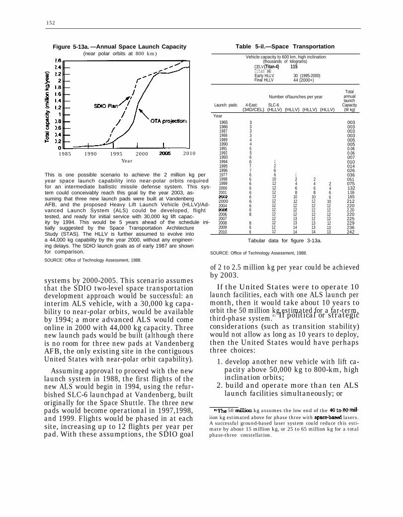
152
Figure 5-13a. —Annual Space Launch Capacity(near polar orbits at 800 km)
1985 1990 1995 2000 2010Year
This is one possible scenario to achieve the 2 million kg peryear space launch capability into near-polar orbits requiredfor an intermediate ballistic missile defense system. This sys-tem could conceivably reach this goal by the year 2003, as-suming that three new launch pads were built at VandenbergAFB, and the proposed Heavy Lift Launch Vehicle (HLLV)/Ad-vanced Launch System (ALS) could be developed, flighttested, and ready for initial service with 30,000 kg lift capac-ity by 1994. This would be 5 years ahead of the schedule ini-tially suggested by the Space Transportation ArchitectureStudy (STAS). The HLLV is further assumed to evolve intoa 44,000 kg capability by the year 2000, without any engineer-ing delays. The SDIO launch goals as of early 1987 are shownfor comparison.
SOURCE: Office of Technology Assessment, 1988.
systems by 2000-2005. This scenario assumesthat the SDIO two-level space transportationdevelopment approach would be successful: aninterim ALS vehicle, with a 30,000 kg capa-bility to near-polar orbits, would be availableby 1994; a more advanced ALS would comeonline in 2000 with 44,000 kg capacity. Threenew launch pads would be built (although thereis no room for three new pads at VandenbergAFB, the only existing site in the contiguousUnited States with near-polar orbit capability).
Assuming approval to proceed with the newlaunch system in 1988, the first flights of thenew ALS would begin in 1994, using the refur-bished SLC-6 launchpad at Vandenberg, builtoriginally for the Space Shuttle. The three newpads would become operational in 1997,1998,and 1999. Flights would be phased in at eachsite, increasing up to 12 flights per year perpad. With these assumptions, the SDIO goal
Table 5-il.—Space Transportation
Vehicle capacity to 600 km, high inclination:(thousands of kilograms)
CELV (Titan-4) 115Titan 34DEarty HLLV 30 (1995-2000)Final HLLV 44 (2000+)
TotalNumber of launches per year annual
launchLaunch pads: 4-East: SLC-6
(34D/CEL) (HLLV) (HLLV) (HLLV) (HLLV)Capacity(M kg)
Year1965 3 0031986 3 0031987 3 0031966 3 0031989 4 0051990 4 0051991 5 0.061992 5 0.061993 6 0071994 6 1 0101995 7 2 0141996 7 6 0261977 6 6 1 0361998 6 10 2 2 0511999 6 12 4 4 2 0752000 6 12 6 6 4 1322001 6 12 8 8 6 1.59
6 12 10 10 6 1652000 6 12 12 12 10 2122004 6 12 12 12 12 220
6 12 12 12 12 2.202006 8 12 12 12 12 2202007 12 13 12 12 225
82008 12 13 13 12 2292009 6 12 14 13 13 2362010 6 12 14 14 13 242
Tabular data for figure 3-13a.
SOURCE: Office of Technology Assessment, 1988.
of 2 to 2.5 million kg per year could be achievedby 2003.
If the United States were to operate 10launch facilities, each with one ALS launch permonth, then it would take about 10 years toorbit the 50 million kg estimated for a far-term,third-phase system.81 If political or strategicconsiderations (such as transition stability)would not allow as long as 10 years to deploy,then the United States would have perhapsthree choices:
1. develop another new vehicle with lift ca-pacity above 50,000 kg to 800-km, highinclination orbits;
2. build and operate more than ten ALSlaunch facilities simultaneously; or
ElThe 50 fion kg assumes the low end of the 40 to 80 ~-iion kg estimated above for phase three with spacebased lasers.A successful ground-based laser system could reduce this esti-mate by about 15 million kg, or 25 to 65 million kg for a totalphase-three constellation.
153
3. improve launch operations to reduce turn-around time below 30 days per pad.
The country would have to expand boostermanufacturing capacity to meet this demandfor up to 120 launches per year. Historically,Titan production lines completed up to 20 mis-siles per year, and Martin Marietta has esti-mated that it could easily produce 14 of theTitan class per year with existing facilities.82
Space Transportation Cost Reduction
Identifying 42 technologies related to spacetransportation, the STAS listed several whereresearch might lead to reduced operating costs(it emphasized the first three as offering espe-cially high leverage for cost reduction):
●
●
●
●
●
●
●
●
●
lightweight materials,expert systems and automated program-ming to cut software costs,better organization,reducing dry weights substantially,better ground facilities,higher performance engines,fault-tolerant avionics,reusability of major components, andbetter mating of spacecraft to launch ve-hicle for reduced ground costs.
— ..———sZThiS would inClu& 5 CELVS, 6 Titan 11s, and 3 Titan 34Ds.
The operating (as opposed to life-cycle) costsof space transportation are currently estimatedat $3,300 to $6,000 per kilogram of payloadto low-Earth orbit, and $22,000 to $60,000 perkilogram to geosynchronous orbit. At thatrate, it would cost $24 billion to $200 billionto launch a phase-two BMD system, and $140billion to $450 billion for a responsive phase-three deployment, based on the constellationweights estimated by various SDIO systemarchitects. The SDIO has set a goal of reduc-ing launch operating costs by a factor of 10.
Operating costs are estimated at about onethird of the total life-cycle costs of a spacetransportation system. Based on current oper-ating costs, total life-cycle costs for transport-ing a phase-two BMD system into space mightbe $72 billion to $600 billion; for phase three,the costs might range from $420 billion to$1.35 trillion. Reaching the goal of reducingoperating costs by a factor of 10 would reducelife-cycle costs for space transportation by only30 percent. Assuming that this percentagewould be valid for a new space transportationsystem, and assuming a 10 to 1 reduction inoperating costs only, then the total life-cyclecosts for space transportation might be $50billion to $420 billion for a phase-two deploy-ment and $290 billion to $900 billion for aphase-three deployment. Clearly the other kindsof costs for space transportation would have tobe reduced along with the operating costs.
CONCLUSIONS
Weapon Technology Conclusions
Phase One
Kinetic Energy Weapons.—KEWs (or else thekinds of nuclear-armed missiles developed forBMD in the 1960s) would most likely be the onlyBMD weapons available for deployment in thiscentury and possibly the first decade of the 21stcentury. Several varieties of non-nuclear, hit-to-kill KEW form the backbone of most near-and intermediate-term SDI architecture pro-posals. Considering the steady evolution ofrockets and “smart weapon” homing sensors
used in previous military systems, it seemslikely that these KEWs could have a high prob-ability of being able to destroy individual tar-gets typical of the current Soviet ICBM forceby the early to mid-1990s. The key unresolvedissue is whether a robust, survivable, in-tegrated system could be designed, built,tested, and deployed to intercept—in the faceof likely countermeasures—a sizeable fractionof evolving Soviet nuclear weapons.
Space-Based Interceptors.—SBIs deployed inthe mid to late 1990s could probably destroy
75-9220 - 88 - 6
154
some Soviet ICBMs in their boost phase. Thekey issue is whether the weight of the SBIprojectiles could be reduced before Sovietbooster burn times could be shortened, giventhat existing SS-24 and SS-25 boosters wouldalready stress projected SBI constellations.The probability of post-boost vehicle (PBV) killsis lower due to the smaller PBV size and IR sig-nal, but SBIs might still achieve some successagainst current PBVs by the mid to late 1990s.
Exe-atmospheric Reentry Interceptor Sys-tem.—The ERIS, which has evolved from pre-vious missiles, could probably be built by theearly to mid-1990s to attack objects in late mid-course. The key unknown is the method oftracking and discriminating RVs from decoys.Existing radar sensors are highly vulnerable,the SSTS space-based IR sensor probablywould not be available until the late 1990s toearly 2000s, and the AOS airborne sensorwould have limited endurance and range. Thiswould leave either new radars or some type ofpop-up, rocket-borne IR probe, which haveapparently received little development effortuntil recently. Given the uncertainty in sen-sors suitable for the ERIS system, its rolewould probably be confined to very late mid-course interceptions and it might have limitedBMD effectiveness until the late 1990s.
Phase TwoHigh Endo-atmospheric Defense Interceptor.
—The HEDI could probably be brought to oper-ational status as soon as the mid-1990s. To over-come the unique HEDI window heating prob-lem, the HEDI on-board homing IR sensorneeds more development than its ERIS cousin.But the HEDI system does not depend on long-range sensors to achieve its mission within theatmosphere. The HEDI could probably pro-vide some local area defense of hardened tar-gets by the mid-1990s against non-MaRVedRVS.83 HEDI performance against MaRVedRVs appears questionable.
‘S’’ MaRV” refers to maneuvering reentry vehicles, or RVswhich can change their course after reentering the atmosphereto improve accuracy or to avoid defensive interceptors.
SBIs against Reentry Vehicles.-The probabil-ity that SBIs would kill RVs in the mid-courseis low until the next century, given the difficultyin detecting and tracking many small, cool RVsin the presence of decoys, and given uncertain-ties in the SSTS sensor and battle managementprograms.
Phase Three
Directed-Energy Weapons. -It is unlikely thatany DEW system could be highly effective be-fore 2010 to 2015 at the earliest. No directedenergy weapon is within a factor of 10,000 ofthe brightness necessary to destroy respon-sively designed Soviet nuclear weapons. (OTAhas not had the opportunity to review recentSDIO suggestions for “entry level” DEWS ofmore modest capability. SDIO contends thateffective space-based lasers of one to twoorders of magnitude less than that needed fora responsive threat could be developed muchsooner.) At least another decade of researchwould likely be needed to support a decisionwhether any DEW could form the basis for anaffordable and highly effective ballistic mis-sile defense. Further, it is likely to take at leastanother decade to manufacture, test, andlaunch the large number of satellite battle sta-tions necessary for highly effective BMD.Thus, barring dramatic changes in weapon andspace launch development and procurementpractices, a highly effective DEW system isunlikely before 2010 to 2015 at the earliest.
Neutral Particle Beam.-The NPB, under de-velopment initially as an interactive discrimina-tor, is the most promising mid-course DEW.84
Shielding RVs against penetrating particlebeams, as opposed to lasers, appears prohibi-tive for energies above 200-MeV. Although lab-oratory neutral particle beams are still about10,000 times less bright than that needed forsure electronics kills of RVs in space, the nec-essary scaling in power and reduction in beamdivergence appears feasible, if challenging.
8iThe NPB would have virtually no boost phase capabilityagainst advanced “responsive” boosters since particle beamscannot penetrate below about 150 kilometers altitude.
155
However, as discussed in chapter 4 under thetopic of NPB interactive discrimination, it isunlikely that engineering issues could be re-solved before the late 1990s, which would mostlikely postpone deployment and effective sys-tem operation to at least 2010-2015.
Free Electron Laser.—The free electron laser(FEL) is one of the more promising BMD DEWweapon candidates. The FEL is in the researchphase, with several outstanding physics issuesand many engineering issues to be resolved.Even if powerful lasers could be built, the highpower optics to rapidly and accurately steerlaser beams from one target to the next couldlimit system performance. Although the basicsystem concept for an FEL weapon is well de-veloped, it is too early to predict BMD per-formance with any certainty.
Chemical Laser.—There are too many uncer-tainties to project BMD performance for thechemically pumped hydrogen fluoride (HF) la-ser. The HF laser has been demonstrated atrelatively high power levels on the ground, al-though still 100,000 times less bright than thatneeded for BMD against a responsive threat.Scaling to weapons-level brightness would re-quire coherent combination of large laserbeams, which remains a fundamental issue.This, coupled with the relatively long wave-length (2.8 micron region), make the HF laserless attractive for advanced BMD than theFEL.
Electromagnetic Launcher.—There are toomany uncertainties in the EML or railgun pro-gram to project any significant BMD capabil-ities at this time.
Space Power Conclusions
Phase OnePower Requirements.—Nuclear power would
be required for most BMD spacecraft, both toprovide the necessary power levels for station-keeping, and to avoid the vulnerability of largesolar panels or solar collectors.
Dynamic Isotope Power System.–The DIPS,which has been ground-tested in the 2 to 5 kW
range, should be adequate and available by themid to late 1990s, in time for early BSTS-typesensors.
Phase TwoNuclear Reactors.—Adequate space power
may not be available for SSTS or weapon plat-forms with ladars before the year 2000. ForBMD satellites that require much more than10 kW of power the SP-100 nuclear reactor/thermoelectric technology would have to be de-veloped. This is a high-risk technology, withspace-qualified hardware not expected beforethe late 1990s to early 2000s.
Phase ThreeChemical Power.—Chemically driven energy
sources (liquid oxygen and liquid hydrogen driv-ing turbogenerators or fuel cells) could proba-bly be available for burst powers of MW up toGW to drive weapons for hundreds of secondsby 2000-2005.
Power for Electromagnetic Launchers. -High-current pulse generators for electromagneticlaunchers (EML) would require extensive de-velopment and engineering, and would mostlikely delay any EML deployments well into the21st century.
High-Temperature Superconductors.–Re-search on high-temperature superconductorssuggests exciting possibilities in terms of reduc-ing the space power requirements and improv-ing power generation and conditioning efficien-cies. At this stage of laboratory discovery,however, it is too early to predict whether orwhen practical, high current superconductorscould affect BMD systems.
Space Communications Conclusion
Laser communications may be needed forspace-to-space and ground-to-space links toovercome the vulnerability of 60-GHz links tojamming from nearby satellites. Wide-bandlaser communications should be feasible by themid-1990s, but the engineering for an agilebeam steering system would be challenging.
156
Space Transportation Conclusions
Phase OneMid-1990s Deployments.—Extrapolating
reasonable extensions of existing space trans-portation facilities suggests that a limited-effectiveness, phase-one BMD system begunin the mid-1990s could not be fully deployedin fewer than 8 years.85 Assuming that thehardware could be built to start deploymentin 1994, the system would not be fully deployeduntil 2002. A more ambitious launcher-devel-opment program and a high degree of successin bringing payload weights down mightshorten that period.
Phase TwoNew Space Transportation System.—A fully
new space transportation system would be re-quired to lift the space assets of a “phase-two”BMD system. This system would have to in-clude a vehicle with heavier lift capability(40,000 to 50,000 kg v. 5,000 kg for the Tita.n-4), faster launch rates (12 per year v. 3 per yearper pad), and more launch pads (4 v. 1).
‘J6’l”& ~Sumes that two launch pads at Vandenberg AFB,4-East and the SLC-6 pad intended for the Shuttle, are modi-fied to handle the new Titam4 complementary expendable launchvehicle (CELV), and the launch rates are increased from threeTitans per year per pad up to six per year.
Optimistic Assumptions.—Even under veryoptimistic assumptions,86 the new space trans-portation system would be unlikely to reach thenecessary annual lift requirements for a large-scale, second-phase BMD until 2000-2005, withfull phase-two deployment completed in the 2008-2014 period.
Phase ThreeUltimate DEW Systems.–It might take 20 to
35 years of continuous launches to fully deployfar-term, phase-three BMD space assets designedto counter with very high effectiveness an ad-vanced, “responsive,” Soviet missile threat. Thisestimate assumes deployment of the proposedALS space transportation system and the kindof advanced space-based laser constellationsuggested by SD I system architects. A set ofground-based laser installations could reducethe space launch deployment time estimate to12-25 years.
~his assumes that the SDIO bifurcated goal is met: a revolu-tionary space transportation system with 10 times lower costis developed in 12 years, while a near-term component of thatsystem yields a working vehicle of reduced capability by 1994.

Chapter 6
System Development,Deployment, and Support
CONTENTS
Introduction. . . . ....... . . . . . . ....... . . . . . . . . .Architecture Definition . . . . . . . . . . . . . . . . . . . . . . . . . . .System Development . . . . . . . . . . . . . . . . . . . . . . . . . . . . .System Testing. . . . . . . . . . . . . . . . . . . . . . . . . . . . . . . . . .Fabrication. . . . . . . . . . . . . . . . . . . . . . . . . . . . . . . . . . . . . .
cost . . . . . . . . . . . . . . . . . . . . . . . . . . . . . . . . . . . . . . . . . .Time . . . . . . . . . . . . . . . . . . . . . . . . . . . . . . . . . . . . . . . . .Quality . . . . . . . . . . . . . . . . . . . . . . . . . . . . . . . . . . . . . . .
Deployment . . . . . . . . . . . . . . . . . . . . . . . . . . . . . . . . . . . . .Operation and Maintenance . . . . . . . . . . . . . . . . . . . . . . . .Example BMD Sub-System: SSTS. . . . . . . . . . . . . . . . . .Key System Issues . . . . . . . . . . . . . . . . . . . . . . . . . . . . . . .
System Testing . . . . . . . . . . . . . . . . . . . . . . . . . . . . . . . .Automatic Operation. . . . . . . . . . . . . . . . . . . . . . . . . . . .Scheduling and Deployment: An Illustrative Scenario
System Conclusions . . . . . . . . . . . . . . . . . . . . . . . . . . . . . .Testing . . . . . . . . . . . . . . . . . . . . . . . . . . . . . . . . . . . . . . .Automation . . . . . . . . . . . . . . . . . . . . . . . . . . . . . . . . . . .Scheduling and Deployment . . . . . . . . . . . . . . . . . . . . . .
Box6-A. SDIO
Figure No.
Demonstration
Box
Experiments . . . . . . . . . . . . .
Figures
Page. . . . . . . . . . . . . . . . 159. . . . . . . . . . . . . . . . 159... . . . . . . . . . . . 160. . . . . . . . . . . . . . . . 161. . . . . . . . . . . . . . . . 163. . . . . . . . . . . . . . . . 165. . . . . . . . . . . . . . . . 165. . . . . . . . . . . . . . . . 165.. . . . . . . . . . . . 166. . . . . . . . . . . . . . . . 166. . . . . . . . . . . . . . . . 167. . . . . . . . . . . . . . . . 167. . . . . . . . . . . . . . . . 167. . . . . . . . . . . . . . . . 168. . . . . . . . . . . . . . . . 169. . . . . . . . . . . . . . . . 174. . . . . . . . . . . . . . . . 174. . . . . . . . . . . . . . . . 174. . . . . . . . . . . . . . . . 174
Page. . . . . . . . . . . . . . . . 162
6-1. Number of Space-Based Interceptors Launched Into Space . ......1716-2. Number of Warheads Leaking Through Boost and
Defenses . . . . . . . . . . . . . . . . . . . . . . . . . . . . . . . . . . .6-3. Number of Warheads Leaking Through Boost and
Defenses . . . . . . . . . . . . . . . . . . . . . . . . . . . . . . . . . . .6-4a. Number of Warheads Leaking Through Boost and6-4b. Number of Warheads Leaking Through Boost and
Defenses . . . . . . . . . . . . . . . . . . . . . . . . . . . . . . . . . . .
TablesTable No,
Post-Boost..172
Post-Boost ””””..173
Post-Boost ..174Post-Boost. . . . . . . . . . . . . . . . 174
Page
6-1. Examples of Current v. Required Manufacturing Capacity forProposed BMD Systems . . . . . . . . . . . . . . . . . . . . . . . . . . . . . . . . . . . . . . .163
6-2. SSTS Sub-Systerms . . . . . . . . . . . . . . . . . . . . . . . . . . . . . . . ............1676-3. Three-Color LWIR Sensor Components . . . . . . ........ . ..........1676-4. Assumed Distribution of Soviet ICBMs for 1990-2010 . ............170
Chapter 6
System Development,Deployment, and Support
INTRODUCTION
The preceding chapters review the status ofkey ballistic missile defense (BMD) technol-ogies, describing the progress made and theadditional advances still needed to meet vari-ous BMD goals. These technologies wouldhave to work together in an integrated system.The United States would have to develop theinfrastructure to fabricate, test, deploy, oper-ate, and maintain that system, and modify itin response to Soviet countermeasures. In thecase of space-based elements, now consideredessential for a highly effective defense, theUnited States would have to design, test, andbuild anew space transportation system. Any-thing but the fastest development of this trans-portation system could delay all but the mostmodest space-based BMD deployment to wellinto the 21st century.
This chapter explores the steps involved inmoving from the current research and devel-
opment phase to operational status. Thesesteps include:
● architecture definition,● system development,● system testing,● fabrication,● deployment, and● operation and maintenance.Given the complexity of a global BMD sys-
tem and the immaturity of many technologies,this chapter can only outline and give someindication of the multitude of challenges thatwould face engineers and manufacturers if adecision were made to proceed to full-scale engi-neering development (FSED) and then to de-ployment. From the beginning, the develop-ment and deployment of dependable computersoftware would be a key issue; the subject ofsoftware is deferred until chapter 9.
ARCHITECTURE DEFINITIONThe first step toward deployment would be
to complete the detailed system design or ar-chitecture. As noted in chapter 3, five defensecontractors have competed with differentBMD system designs. The Strategic DefenseInitiative Organization (SDIO) has conductedadditional analyses outside the main architec-ture contracting framework. A single systemarchitect is to be chosen in 1988. This archi-tect is to define the actual BMD system in de-tail, providing information for a decision onwhether to proceed to the next step: full-scaleengineering development. The SDIO has pro-
Note: Complete definitions of acronyms and initialismsare listed in Append-x B of this report.
posed an early 1990s decision on FSED butits schedules are slipping as a result of fund-ing levels that are below its earlier expec-tations.
In the meantime, common elements in theexisting architecture studies can be used toguide the research program.’ All of the space-and ground-based architecture designs in-cluded space-based infrared (IR) sensors andspace-based interceptors (SBIs). All assumed
1Each architect defined three architectures: a combinationspace and ground-based system, a ground-only system, and atheater defense system. In addition, most architects have con-sidered various time-phased options. For this discussion we areconsidering primarily the combined space- and ground-basedarchitectures.
159

160
some type of ground-based exe-atmospheric The “concept validation” program approvedreentry interceptor system (E RI S). All saw a by the Secretary of Defense in September 1987,critical need for midcourse interactive discrimi- included work on SBIs, ERIS, and associatednation, although this task might be too diffi- sensors and battle management technology.cult for a near-term, phase-one deployment.
SYSTEM DEVELOPMENTThe system engineer must combine various
components and sub-systems defined by thearchitecture into a working system. A typicalBMD system as envisioned by system archi-tecture contractors for intermediate-term(“phase-two”) deployment might have included30,000 major sub-systems of nine differenttypes (for suggested major components of aphase-two system, see table 1-2 inch. 1). Thesub-systems would be tied together by a com-munications network. These sub-systemswould have to work together under the direc-tion of battle management computers.2
For each of these components, the systemengineer would have to consider the followingissues:
● Mass is particularly critical for SBIs: theywould have to be light to reduce spacetransportation costs and to achieve thenecessary velocity during battle.
● Total volume may be limited by the spacetransportation system. All space sub-sys-tems would have to conform to the launchvehicle internal dimensions, preferablywith minimum wasted payload space.
● For early deployment (late 1990s), thechoices for space base-load power wouldbe limited to solar (which is vulnerable),or nuclear, which would have to be devel-oped and space-qualified in the powerranges needed for BMD. Far-term di-rected-energy weapons could be driven byliquid oxygerd/liquid hydrogen turbogener-ators or fuel cells for a few hundred sec-onds. The weight of power supplies mightdominate future systems.
‘As discussed inch 7, this battle management function wouldlikely be distributed among many computers on different sat-ellites for survivability.
●
●
●
●
●
•
Heat rejected by the various deviceswould have to be minimized and properlymanaged, since cooling systems take upweight and power.Almost all sub-systems would have to beproduced in large quantities compared toprevious space systems. These compo-nents would have to be capable of massproduction, as compared to the one-of-a-kind laboratory fabrication used in manyof the SDIO technology demonstrationprojects. The United States has nevermass-produced any satellites.All components would have to withstandsevere radiation environments, includingnearby nuclear explosions. This would beparticularly stressing on electronic com-ponents such as IR detectors. The detec-tors and most electronics used for dem-onstration experiments would not besuitable for BMD deployment.These systems would have to endure andoperate on call after sitting dormant (ex-cept possibly for periodic tests) for years.The current goal is at least 5-year life forfirst-phase deployment, with 7 years desir-able. Limited lifetimes would further bur-den the space transportation system withreplacement or repair missions.Many systems might have to operatewithin seconds or minutes after warning,although there might be an alert statuslasting for days or weeks. Trade-offs be-tween long alert times and fuel consump-tion might be necessary.All space-based systems would have tooperate automatically, compared to thecareful “hand tweaking” common in ex-periments. In particular, there would belittle or no opportunity for the routine

161
maintenance common to all terrestrial mil-itary systems.
● Various sub-systems and componentswould have to work together. For exam-ple, radiation from a nuclear power sup-ply must not degrade the operation of sen-sitive IR sensors or electronics. Similarly,fumes from a propulsion system must notfog the optics of critical sensors, and vibra-tion from power sources must not degradeweapons pointing accuracy.
● If components are prone to failure, theyshould be easily replaceable or adjustable.For space-based systems, a key issuewould be whether to replace entire satel-lites when they failed, or to attempt peri-odic manual or robotic repair.
● All systems and components should sur-vive both natural and man-made environ-ments. Survivability measures such asdecoys, redundancy, shielding, maneuver-
SYSTEMTesting of both hardware and software is es-
sential to any engineering project. Componentsare tested and modified to overcome deficien-cies. Sub-systems are tested and modified. Fi-nally, prototypes of the complete system arebuilt and tested under full operating conditionswhenever possible. These system tests invari-ably reveal faults in the original design, faultswhich must be corrected before productionbegins.
A ballistic missile defense system could notbe tested in a full battle condition. Instead,the systems engineer would have to rely onsome combination of computer simulations andoperation under simulated conditions. Theanti-ballistic missile (ABM) treaty prohibitsspace-based tests in an ABM mode whichwould be necessary to establish even minimalconfidence in SBIs.
In place of complete system testing, theSDIO is developing the National Test Bed.This test bed (see ch. 8) is to tie together many
●
●
ability, electronic jamming, and shoot-back would add mass to space-based com-ponents. One system architect estimatedthat survivability measures would ac-count for 70 percent of on-orbit mass forSBI systems.The communications channels would haveto be secure against interception, manipu-lation, and jamming.The systems should be safe in manufac-ture, assembly, transport, and operation.
SDIO is funding research in all of theseareas. Optimists believe these characteristicsmay be achievable; pessimists question wheth-er the break necessary from past practice andexperience is possible; others say it is too earlyin the research program to judge whether theUnited States could achieve all of these attri-butes in a working system.
TESTING
communication nodes and computers via sat-ellite, simulating some of the complexity ofBMD. Some types of hardware (such as sen-sors) would also be coupled into this test sys-tem as they became available, “talking” to thecomputers as they would in a real battle. Thecost of simulation will be high, but this is theonly way to give leaders some degree of confi-dence in system operation. One of the key judg-ments the President and Congress will haveto make about the SDI program will be thelevel of confidence to be placed in a global sys-tem that has never been tested in a full opera-tional mode.
Testing so far under the SDIO program hasbeen limited to the component or sub-systemlevel, usually under simplified or artificial con-ditions. These experiments have yielded valu-able information necessary for the ongoing re-search and development effort; the UnitedStates should not, however, confuse a demon-stration test with operational readiness (seebox 6-A).

162
Box 6-A.—SDIO Demonstration ExperimentalHoming Overlay Experiment: The HOE demonstrated on the fourth test (June 10, 1984) that
an experimental IR homing vehicle can acquire and collide with a simulated reentry vehicle in flight.The RV was launched aboard a test ICBM from Vandenberg AFB in California. After detectionby radars on Kwajalein, a rocket carrying the experimental ground-launched interceptor was firedfrom a nearby island toward the oncoming RV. The IR sensor on the interceptor then acquired theRV and guided the interceptor to a direct hit high above the Pacific.
While this was an encouraging and successful experiment, it does not mean that the UnitedStates could deploy operational exoatmospheric interceptors tomorrow. The HOE experiment usedparts of an existing missile, too large and expensive for an affordable BMD system. The IR sensorwas cooled for many hours prior to the test; an operational system could not be maintained at suchcold temperatures. The detectors were not hardened against nuclear radiation; new types of detec-tors would be required for the operational system. The simulated RV fired from Vandenberg AFBin California radiated about 10 times more IR energy than that expected from today’s Soviet RV,and future RVs could have even lower IR signatures with thermal shrouds. There was only oneRV, and the experimenters knew when and where it would be fired; the real issue for exoatmosphericinterception is decoy discrimination-separating one RV out of a cloud of hundreds or thousandsof other objects, including tethered balloons. Opinions differ on how difficult this would be.
Delta 180: The Delta 180 mission (Sept. 5, 1986) launched a Delta missile into space; the twoupper stages of this missile were both placed in orbit. Each contained sensors later used to measureradiation from the other and from another missile launched from White Sands, New Mexico duringone orbit. One stage also contained a radar sensor used to guide the two stages into a collision courseat the end of the experiment.
The Delta 180 was a very successful measurement program, providing useful information aboutradiation from rocket exhaust plumes, both at close range in space and from the ground-launchedAries rocket. Some radiation patterns confirmed expectations, but there were some surprises whichcould improve our ability to detect and track future missile plumes. Tracking algorithms were alsotested in the final interception with the target stage accelerating, which is more difficult than fortargets with constant velocity. The entire Delta 180 mission took only 18 months from start tofinish, requiring extraordinary management and dedicated performance by defense contractors.
However, this measurements program should not be confused with a demonstration of the nearoperational readiness of space-based interceptors. This interception had little resemblance to theBMD problem–and could not have without violating the ABM treaty. The relative velocities andranges of the two stages were far less than those required for BMD. The target stage had a largeradar reflector (over 1 square meter). The size and mass of the interceptor stage (over 2,000 kg com-pared to a goal of less than 200 kg for SBIs) would eliminate any possibility of achieving the veloci-ties required of a SBI to kill an ICBM. All planned SBIs discussed to date would require an IRsensor for final homing, while Delta 180 used a Phoenix air-to-air missile radar. Finally, the nearhead-on aspect of the final kill would not be typical for a BMD mission, and did not stress the divertcapability of the interceptor.
FLAGE: Six of nine planned tests of the “flexible, light-weight agile guided experiment’ ’( FLAGE)short-range terminal interceptor missile have been completed. On the second test, the radar-guidedhoming interceptor passed very close to the target, again indicating that hit-to-kill interceptorsare feasible under appropriate conditions.
In the FLAGE tests, the target vehicle was flown into a highly instrumented volume of airabove the White Sands Missile Range. Although artificial, this controlled environment is appropri-ate for an experiment, which should collect as much data as possible. The successful interception
‘These comments on the SDI validation experiments should not be construed as criticism of SDIO management. These are all soundexperiments properly designed to collect bits of information necessary on the path to developing a working system. At this time we haveno major element of a non-nuclear ballistic missile defense system which has been tested in a system mode with equipment suitable for actualoperation.
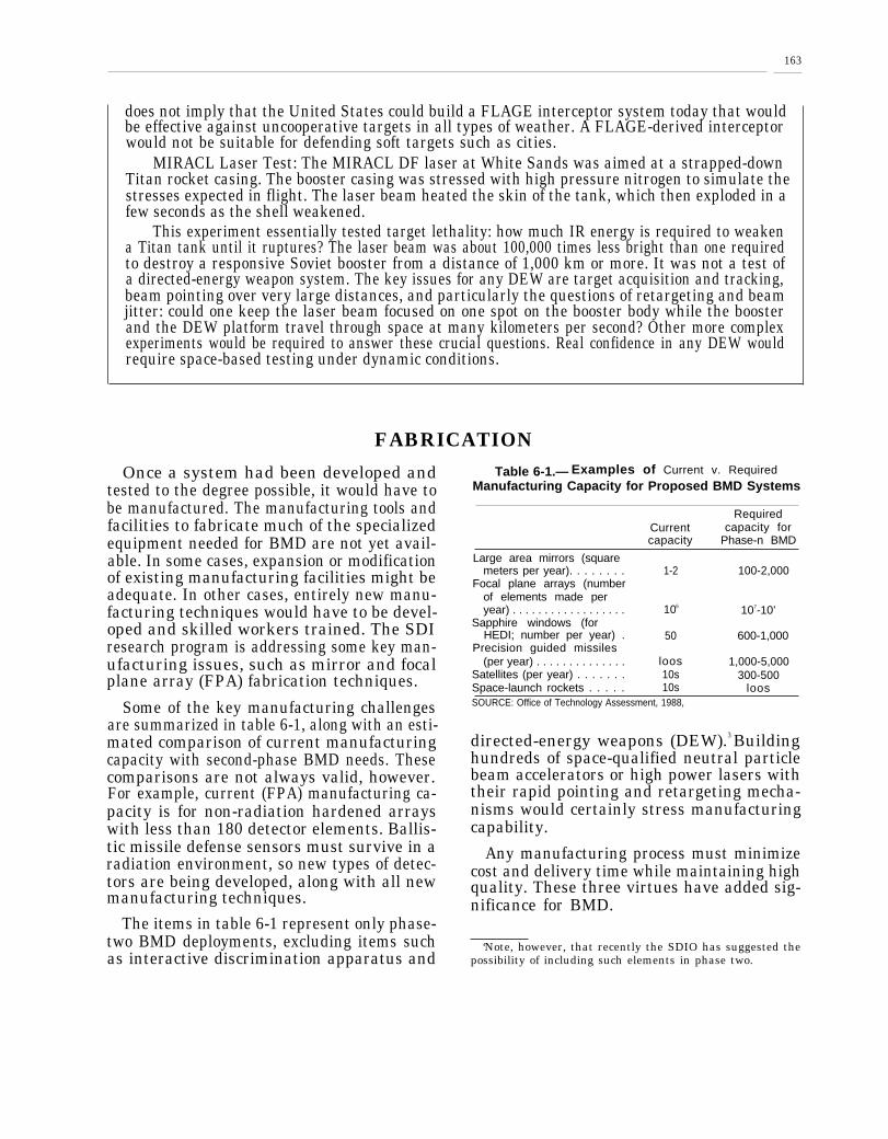
163
does not imply that the United States could build a FLAGE interceptor system today that wouldbe effective against uncooperative targets in all types of weather. A FLAGE-derived interceptorwould not be suitable for defending soft targets such as cities.
MIRACL Laser Test: The MIRACL DF laser at White Sands was aimed at a strapped-downTitan rocket casing. The booster casing was stressed with high pressure nitrogen to simulate thestresses expected in flight. The laser beam heated the skin of the tank, which then exploded in afew seconds as the shell weakened.
This experiment essentially tested target lethality: how much IR energy is required to weakena Titan tank until it ruptures? The laser beam was about 100,000 times less bright than one requiredto destroy a responsive Soviet booster from a distance of 1,000 km or more. It was not a test ofa directed-energy weapon system. The key issues for any DEW are target acquisition and tracking,beam pointing over very large distances, and particularly the questions of retargeting and beamjitter: could one keep the laser beam focused on one spot on the booster body while the boosterand the DEW platform travel through space at many kilometers per second? Other more complexexperiments would be required to answer these crucial questions. Real confidence in any DEW wouldrequire space-based testing under dynamic conditions.
FABRICATION
Once a system had been developed andtested to the degree possible, it would have tobe manufactured. The manufacturing tools andfacilities to fabricate much of the specializedequipment needed for BMD are not yet avail-able. In some cases, expansion or modificationof existing manufacturing facilities might beadequate. In other cases, entirely new manu-facturing techniques would have to be devel-oped and skilled workers trained. The SDIresearch program is addressing some key man-ufacturing issues, such as mirror and focalplane array (FPA) fabrication techniques.
Some of the key manufacturing challengesare summarized in table 6-1, along with an esti-mated comparison of current manufacturingcapacity with second-phase BMD needs. Thesecomparisons are not always valid, however.For example, current (FPA) manufacturing ca-pacity is for non-radiation hardened arrayswith less than 180 detector elements. Ballis-tic missile defense sensors must survive in aradiation environment, so new types of detec-tors are being developed, along with all newmanufacturing techniques.
The items in table 6-1 represent only phase-two BMD deployments, excluding items suchas interactive discrimination apparatus and
Table 6-1.— Examples of Current v. RequiredManufacturing Capacity for Proposed BMD Systems
RequiredCurrent capacity forcapacity Phase-n BMD
Large area mirrors (squaremeters per year). . . . . . . . 1-2 100-2,000
Focal plane arrays (numberof elements made peryear) . . . . . . . . . . . . . . . . . . 106 107-10’
Sapphire windows (forHEDI; number per year) . 50 600-1,000
Precision guided missiles(per year) . . . . . . . . . . . . . . loos 1,000-5,000
Satellites (per year) . . . . . . . 10s 300-500Space-launch rockets . . . . . 10s loosSOURCE: Office of Technology Assessment, 1988,
directed-energy weapons (DEW).3 Buildinghundreds of space-qualified neutral particlebeam accelerators or high power lasers withtheir rapid pointing and retargeting mecha-nisms would certainly stress manufacturingcapability.
Any manufacturing process must minimizecost and delivery time while maintaining highquality. These three virtues have added sig-nificance for BMD.
‘Note, however, that recently the SDIO has suggested thepossibility of including such elements in phase two.

164
Photo credit: U.S. Department of Defense
Delta 180 payload—The payload of the Delta 180experiment, atop a Delta booster, is shown duringshroud installation on Pad 17 at Cape Canaveral.Multiple boxes carrying optical sensors are mountedon the side of the rocket’s second-stage truss atbottom. The mast on top of the third stage is a Phoenixmissile sensor, which helped guide an interceptbetween the two vehicles to obtain rocket motor plume
data at short distances.
.
,
Photo credit: U.S. Department of Defense
Lethal test of high-velocity projectiles.—Electromag-netic launchers might hurl small homing projectilesat distant missile stages or warheads. In this test ofthe effects of high-velocity impact, a small (unguided)plastic projectile hit a cast aluminum block at 7 km/s.
This was a test of lethality, not of a weapon:the projectile was not launched from an
electromagnetic launcher.
Photo credit: U.S. Department of Defense
Laser lethality test.— In September 1986 this test atWhite Sands Missile Range, N. M., investigated thepossible effects of a laser beam on a rocket booster.The test vehicle was the second stage of a Titan Ibooster missile body. External loads were applied tothe booster to simulate flight conditions typical ofcurrent operational Soviet missile systems. The testvehicle contained no liquid propellant or explosives.It was irradiated with a high-energy laser beam forseveral seconds before being destroyed. The laserused, the Mid-Infrared Advanced Chemical Laser,generates a beam energy greater than 1 MW/sr. It isa test laser, not developed for deployment in space.
165
cost
The projected costs for a BMD system willstrongly affect a national decision on whetherto proceed with production or deployment. Inaddition to total costs, the incremental costsof BMD would have to be less (some think sub-stantially less) than the perceived incrementalcost of Soviet countermeasures. Thus the unitcosts of a deployed SBI might have to be lessthan l/370th to l/12th the cost of a Sovietbooster.’ On the other hand, the leverage pro-vided by a successful “adaptive preferentialdefense” might improve this cost-exchange ra-tio (see ch. 1).
The allowable costs for aground-based exo-atmospheric interceptor would depend on thesystem architecture. With low leakage fromthe boost phase and good discrimination, eachinterceptor would have to engage only a smallpercentage of the attacking Soviet reentry ve-hicles (RVs), and the interceptor could be rela-tively expensive. If discrimination were poor,which might be the case in a phase-one deploy-ment, then the interceptor might be compet-ing with cheap decoys. The defense would notbe cost-effective at the margin if every exo-atmospheric interceptor had to costless than10 light-weight decoys, or even less than 10heavy decoys.5
Time
The time to manufacture components forBMD might be crucial in several respects.
‘The 12-tOl cost ratio assumes that 8 percent of the SBISwould be within range of the Soviet missile fields and that oneSBI is fired at each booster or PBV. Them are no extra SBISfor redundancy or shoot-back against Soviet ASATS. In thiscase the United States would have to add about 12 SBIS (andanother carrier satellite) for each new Soviet booster. The 370-t~l cost ratio comes from a concentrated basing of new Sovietboosters in a relatively small area say 150 km by 150 km. Inthis case the United States would have to deploy 370 extra SBISand their associated satellites for each new Soviet booster toachieve an 85 percent probability of destroying that extra RV.
‘If the boost phase defense let through 10 percent of theboosters, and each booster carried 10 warheads, 10 heavy de-coys, and 100 light decoys, then the exe-atmospheric intercep-tor system would have to engage one warhead, one heavy de-coy, and 10 light decoys for each booster launched With perfectdiscrirnin ation one deployed interceptor would have to cost lessthan one loaded booster. Without any discrimination, one in-terceptor would have to cost l/12th of the booster.
Ideally the system should be deployed quicklyto avoid transition instabilities, although sys-tem architects differ on this point. Componentscould be produced and stockpiled until deploy-ment began.6 To the degree that space trans-portation would pace deployment, productiontimes would not be critical.
But the United States would also be lockedin a race with Soviet countermeasures. If theUnited States could not produce and deployenough SBIsbefore the Soviets had reduceda substantial number of their booster burntimes below 140 seconds, then BMD boost-phase system effectiveness would drop signif-icantly, perhaps to zero. The SBIs might forcethe Soviets to faster post-boost vehicle (PBV)dispersals, which could reduce the number ofRVs At some point, however, there would beno sense in deploying SBIs(and particularlySBIs Which did not have any midcourse capa-bility against RVs) until DEW were developed.(See also ch. 5 and the key-issues section atthe end of this chapter for more analysis of SBIeffectiveness against boosters with moderatelyfast burn times.)
On the other hand, if the United States couldproduce and deploy an SBI system in a fewyears, and if it could build and deploy a credi-ble DEW system as the Soviet Union con-verted to faster-burning boosters and fast-dis-persing PBVs, then BMD effectiveness mightcontinue. .
Production time involves not only the pro-duction rate, but the time to design, build, anddebug the manufacturing facilities, includingnecessary training of production workers.Since many new technologies are contem-plated, there might be relatively long periodsbefore routine production could begin.
Quality
Quality control would be essential, particu-larly for space-based deployment. Repair oreven replacement of failed assets in space
‘See U.S. Congress, Office of Technology Assessment, Bal-listic Missile Defense Technologies, OTA-ISC-254 (Washing-ton, D. C.: U.S. Government Printing Office), p. 119.
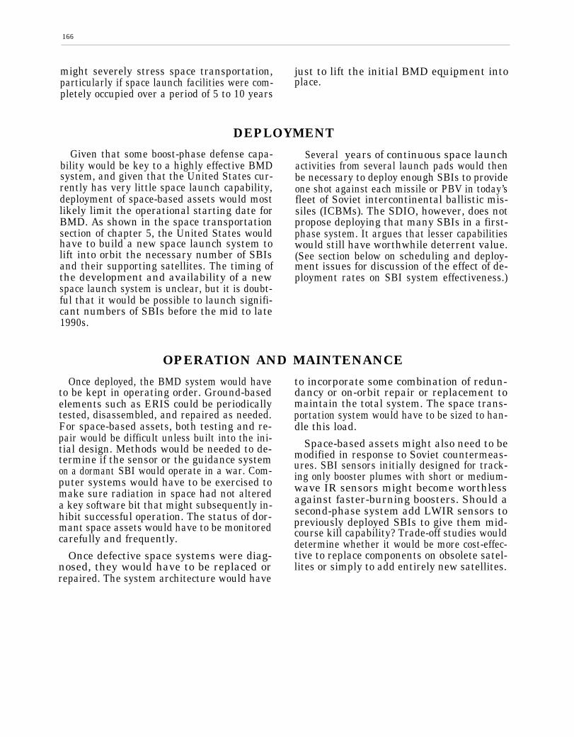
166
might severely stress space transportation, just to lift the initial BMD equipment intoparticularly if space launch facilities were com- place.pletely occupied over a period of 5 to 10 years
DEPLOYMENT
Given that some boost-phase defense capa-bility would be key to a highly effective BMDsystem, and given that the United States cur-rently has very little space launch capability,deployment of space-based assets would mostlikely limit the operational starting date forBMD. As shown in the space transportationsection of chapter 5, the United States wouldhave to build a new space launch system tolift into orbit the necessary number of SBIsand their supporting satellites. The timing ofthe development and availability of a newspace launch system is unclear, but it is doubt-ful that it would be possible to launch signifi-cant numbers of SBIs before the mid to late1990s.
Several years of continuous space launchactivities from several launch pads would thenbe necessary to deploy enough SBIs to provideone shot against each missile or PBV in today’sfleet of Soviet intercontinental ballistic mis-siles (ICBMs). The SDIO, however, does notpropose deploying that many SBIs in a first-phase system. It argues that lesser capabilitieswould still have worthwhile deterrent value.(See section below on scheduling and deploy-ment issues for discussion of the effect of de-ployment rates on SBI system effectiveness.)
OPERATION AND MAINTENANCE
Once deployed, the BMD system would haveto be kept in operating order. Ground-basedelements such as ERIS could be periodicallytested, disassembled, and repaired as needed.For space-based assets, both testing and re-pair would be difficult unless built into the ini-tial design. Methods would be needed to de-termine if the sensor or the guidance systemon a dormant SBI would operate in a war. Com-puter systems would have to be exercised tomake sure radiation in space had not altereda key software bit that might subsequently in-hibit successful operation. The status of dor-mant space assets would have to be monitoredcarefully and frequently.
Once defective space systems were diag-nosed, they would have to be replaced orrepaired. The system architecture would have
to incorporate some combination of redun-dancy or on-orbit repair or replacement tomaintain the total system. The space trans-portation system would have to be sized to han-dle this load.
Space-based assets might also need to bemodified in response to Soviet countermeas-ures. SBI sensors initially designed for track-ing only booster plumes with short or medium-wave IR sensors might become worthlessagainst faster-burning boosters. Should asecond-phase system add LWIR sensors topreviously deployed SBIs to give them mid-course kill capability? Trade-off studies woulddetermine whether it would be more cost-effec-tive to replace components on obsolete satel-lites or simply to add entirely new satellites.

167
EXAMPLE BMD SUB-SYSTEM: SSTSTo appreciate some of the complexity of a
BMD system, consider just one of the systemsin table 1-2: a moderately sophisticated SpaceSurveillance and Tracking System (SSTS). Thepotential sub-systems of an SSTS are shownin table 6-2. Almost every subsystem on thislist would require development to meet theprobable BMD specifications.
At the next level down, just one sub-systemfrom the SSTS, a three-color LWIR sensor,
Table 6-2.—SSTS Subsystems
Developmentrequired
Propulsion (for station-keeping) . . . . . . . . . . .Communications (space-to-space) . . . . . . . . .Communications (space-to-ground) . . . . . . . .Power source . . . . . . . . . . . . . . . . . . . . . . . . . . .Three-color LWIR sensor(s) . . . . . . . . . . . . . . .SWIR/MWIR sensor(s). . . . . . . . . . . . . . . . . . . .Laser ranger/designator . . . . . . . . . . . . . . . . . .Star tracker(s). , . . . . . . . . . . . . . . . . . . . . . . . . .Computer and memory. . . . . . . . . . . . . . . . . . .Waste heat rejection. . . . . . . . . . . . . . . . . . . . .Support structure . . . . . . . . . . . . . . . . . . . . . . .
LowHighHighHighHigh
MediumHigh
MediumMediumMedium
Low
would include the components listed in table6-3. Again, most of these components must bedeveloped to meet BMD specifications. Ananalysis of the other SSTS sub-systems andthe other major sub-systems in the threephases of SDI would reveal literally hundredsof sizeable development programs which wouldhave to come together to form the completesystem.
Table 6.3.—Three-Color LWIR Sensor Components
Developmentrequired
Primary mirror . . . . . . . . . . . . . . . . . . . . . . . . . .Secondary mirror. . . . . . . . . . . . . . . . . . . . . . . .Cryo-cooler. . . . . . . . . . . . . . . . . . . . . . . . . . . . .Three-color focal plane array (FPA) . . . . . . . .Signal processor . . . . . . . . . . . . . . . . . . . . . . . .Three-axis gimbal . . . . . . . . . . . . . . . . . . . . . . .Servo control system . . . . . . . . . . . . . . . . . . . .Thermal control system . . . . . . . . . . . . . . . . . .Sun shield . . . . . . . . . . . . . . . . . . . . . . . . . . . . .Support structures . . . . . . . . . . . . . . . . . . . . . .
HighHigh
MediumHighHigh
MediumMedium
LowLowLow
SOURCE: Office of Technology Assessment, 1988 SOURCE: Office of Technology Assessment, 1988.
KEY SYSTEM ISSUES
Building and deploying a system on the scaleof proposed BMD architectures would stressthe U.S. engineering and manufacturing infra-structure on many fronts. However, three crit-ical systems issues are unique to ballistic mis-sile defense with space-based components: thelack of realistic system testing, the necessityfor automated, computer-controlled operation,and the difficulties of scheduling and space de-ployment.
System TestingThe inability to test fully a global BMD sys-
tem (both hardware and software) would cast
doubt on its operational effectiveness. Theadministration and Congress will have to de-cide on the deployment of a system whose per-formance would have to be predicted largelyby computer simulations. The National TestBed and future component tests would im-prove the verisimilitude of those simulations,but they could not encompass all of the com-plexity of the real world. Some issues such assensor operation against a nuclear explosionbackground in space could not be tested evenat the component level without abandoning theLimited Test Ban Treaty. Except in computersimulations, the system could not be tested,short of war, with even 10 percent of the pos-sible wartime threat.

168
It is true that all military systems are sub-ject to uncertainty when they first go into bat-tle. A fighter aircraft, despite the best flighttest program, can never be tested with all thevariables that will arise in a real battle. Anaircraft-carrier battle group could never antici-pate all possible situations in some future bat-tle with a capable adversary, and might be sus-ceptible to unforeseen vulnerabilities. The U.S.carrier battle groups have never fought againstan enemy with modem “smart weapons. ”There is uncertainty in the performance predic-tions of these conventional military systems.
A global BMD system would have even morecomplex, untestable sub-system interactions.Even full interception tests, using SBIs firedagainst ICBMs launched from VandenbergAFB, could involve at best a salvo launch ofa few missiles. This would not substitute forthe launching of a thousand missiles by theSoviet Union at a time of their choosing,preceded by anti-satellite weapon (ASAT) at-tacks and nuclear precursor explosions. Indi-vidual components such as sensors, data proc-essors, and communication equipment couldbe tested by themselves to full operational ca-pacity in the laboratory or in simulated spacechambers, and some effects of nuclear explo-sions could be tested at the Nevada test site.In any case, the complete BMD system couldnot be tested as an integrated unit against areal threat. Neither, on the other hand, couldthe Soviet offensive ballistic missile force.
Automatic OperationAutomation has made dramatic changes in
factories and some military weapons systems.Robotics is firmly established in many manu-facturing situations, and will grow in the fu-ture. However, space-based BMD systemswould cross into new engineering domains ofautomatic operation on several counts:
● continuous unattended stand-by opera-tion for years,
a continuously changing constellation ofcomponents which would have to operatetogether as a unit, andoperation under adverse conditions againstan opponent determined to defeat thesystem.
None of these limitations is encountered inautomated factories.
Automatic fire control systems are commonin today’s weapons. Human intervention is al-ways possible, however, to repair and main-tain the system. The United States has neveroperated a weapon system in space. Both theUnited States and the Soviet Union have oper-ated sensor systems ins ace for surveillanceand early warning of ballistic missile attack.The challenge would be to integrate more so-phisticated early warning satellites with ac-tual weapon platforms thousands of kilome-ters away.
Sensor satellites currently in orbit operateautonomously, with directions from a fewground-based mission control nodes. Once thebattle began, BMD systems might require theautonomous operation of 30 to 40 sensorsworking in conjunction with hundreds or thou-sands of SBI carrier satellites. Sensors and car-rier satellites would be moving in different or-bits, so that the particular weapons platformsand sensors making up a “battle group” (inone possible battle management architecture)would be constantly changing with time. (Seech. 7 on wartime operation.) These battlegroups would have to be connected by securecommunication links. Higher system effective-ness would entail tighter coordination.
Automatic operation would be further chal-lenged by Soviet defense suppression tactics.The system would ideally adapt to lost or noisycommunication links and continue to managethe battle on the basis of degraded informa-tion. (See ch. 9 for a fuller discussion of BMDsoftware dependability.)
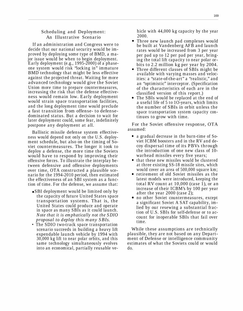
169
Scheduling and Deployment:An Illustrative Scenario
If an administration and Congress were todecide that our national security would be im-proved by deploying some type of BMD, a ma-jor issue would be when to begin deployment.Early deployment (e.g., 1995-2000) of a phase-one system would risk “locking in” immatureBMD technology that might be less effectiveagainst the projected threat. Waiting for moreadvanced technology would give the SovietUnion more time to prepare countermeasures,increasing the risk that the defense effective-ness would remain low. Early deploymentwould strain space transportation facilities,and the long deployment time would precludea fast transition from offense- to defense-dominated status. But a decision to wait forlater deployment could, some fear, indefinitelypostpone any deployment at all.
Ballistic missile defense system effective-ness would depend not only on the U.S. deploy-ment schedule, but also on the timing of So-viet countermeasures. The longer it took todeploy a defense, the more time the Sovietswould have to respond by improving theiroffensive forces. To illustrate the interplay be-tween defensive and offensive deploymentsover time, OTA constructed a plausible sce-nario for the 1994-2010 period, then estimatedthe effectiveness of an SBI system as a func-tion of time. For the defense, we assume that:
● SBI deployment would be limited only bythe capacity of future United States spacetransportation systems. That is, theUnited States could produce and operatein space as many SBIs as it could launch.Note that it is emphatically not the SDIOproposal to deploy this many SBIs.
• The SDIO two-track space transportationscenario succeeds in building a heavy liftexpendable launch vehicle by 1994 with30,000 kg lift to near polar orbits, and thissame technology simultaneously evolvesinto an economical, partially reusable ve-
hicle with 44,000 kg capacity by the year2000.Three new launch pad complexes wouldbe built at Vandenberg AFB and launchrates would be increased from 3 per yearper pad up to 12 per pad per year, bring-ing the total lift capacity to near polar or-bits to 2.2 million kg per year by 2004.Three different classes of SBIs might beavailable with varying masses and veloc-ities: a “state-of-the-art” a “realistic,” andan “optimistic” interceptor. (Specificationof the characteristics of each are in theclassified version of this report.)The SBIs would be replaced at the end ofa useful life of 5 to 1O-years, which limitsthe number of SBIs in orbit unless thespace transportation system capacity con-tinues to grow with time.
For the Soviet offensive response, OTAassumed:
●
●
●
●
a gradual decrease in the burn-time of So-viet ICBM boosters and in the RV and de-coy dispersal time of its PBVs throughthe introduction of one new class of 10-warhead missiles every five years;that these new missiles would be clusteredat three existing SS-18 missile sites, whichwould cover an area of 500,000 square km;retirement of old Soviet missiles as thelatest models were introduced, keeping thetotal RV count at 10,000 (case 1), or anincrease of their ICBM’s by 100 per yearafter the year 2000 (case 2);no other Soviet countermeasures, excepta significant Soviet A SAT capability, im-lied by our resewing a substantial frac-tion of U.S. SBIs for self-defense or to ac-count for inoperable SBIs that fail overtime.
While these assumptions are technicallyplausible, they are not based on any Depart-ment of Defense or intelligence communityestimates of what the Soviets could or woulddo.

170
Table 6-4.—Assumed Distribution ofSoviet ICBMs for 1990.2010
All ICBMs are assumed to carry 10 warheads. Please notethat the mix of forces here reflects neither Department ofDefense nor intelligence community estimates of what theSoviets actually may do. Instead, this table merely lays outa purely hypothetical sequence of a phasing-in of faster-burning ICBMs at 5-year internals beginning in 1990, Oldermissiles are retired as new ones are deployed, keeping thetotal RV count fixed at a hypothetical number of 10,000. Theslow-burn boosters are distributed over existing Soviet mis-sile fields, while the other four classes are assumed concen-trated at three existing sites.
Number of ICBMs
ICBM type SBB MBB-1 MBB-2 FBB-1 FBB-2
Year:1991 . . . . . .1992 . . . . . .1993 . . . . . .1994 . . . . . .1995 . . . . . .1996 . . . . . .1997 . . . . . .1998 . . . . . .1999 . . . . . .2000 . . . . . .2001 . . . . . .2002 . . . . . .2003 . . . . . .2004 . . . . . .2005 . . . . . .2006 . . . . . .2007 . . . . . .2008 . . . . . .2009 . . . . . .2010 . . . . . .
500500
500400300200100———————————
500 – – –500 – – –500 – – –500 – – –500 – – –500 100 — —500 200 – –500 300 – –500 400 – –500 500 – –400 500 100 –300 500 200 –200 500 300 –100 500 400 –— 500 500 –— 400 500 100— 300 500 200— 200 500 300
100 400— — 500 500
Legend:SBB: Slow-Burn BoosterMBB-1: Medium-Burn Booster—First GenerationMBB-2: Medium-Burn Booster—Second GenerationFBB-1: Fast-Burn Booster-First GenerationFBB-2: Fast-Burn Booster-Second Generation
SOURCE: Office of Technology Assessment, 1988
Space Transportation Limits on DeploymentAs indicated in chapter 5, a new space trans-
portation system would be needed to launchthe space-based assets of a highly effectiveBMD system. Even a more modest system,such as that proposed by SDIO for the firstphase, would call for considerable new spacetransportation capacity. The SDIO has iden-tified two potentially conflicting space trans-portation goals: reducing launch costs by a fac-tor of 10 and beginning some launches in themid-1990s. Derivatives of existing Shuttle/Titan launch systems are not likely to lead to
major cost reductions; an entirely new systemwould be needed. But a revolutionary newspace transportation system would not likelybe ready before the year 2000.
To achieve both the cost and schedule goals,SDIO has proposed a dual-track formula: a newspace transportation system would be devel-oped with a goal of a tenfold cost reductionby 2000 or so, but parts of this new systemwould be available by the mid-1990s for earlydeployments, probably with reduced lift capac-ity and higher cost. This approach might cre-ate design compromises. Either cost reductionsmight have to be postponed to meet the sched-ule, or the schedule might have to be slippedto meet the eventual cost goals: a space trans-portation system designed to meet just one ofthese goals might look quite different fromthe hybrid. In this scenario, however, we as-sume that both goals could be achieved simul-taneously.
The United States now has one pad capableof launching more than 10,000 kg to the highinclination orbits and altitudes of several hun-dreds of kilometers to be occupied by the SBIconstellation. 7 The Shuttle pad at VandenbergAir Force Base could be modified by 1992 tolaunch the Titan-4 (CELV) vehicle with a ca-pacity of about 14,500 kg to SBI orbits. In thepast, building new launch pads has taken from7 to 10 years and there is some questionwhether there is adequate space at Vanden-berg to add even a few more pads and theirnecessary assembly facilities. (The Air Forcehas been examining the possibility of launch-ing rockets from an off-shore oil rig.) Surviva-bility of launch facilities would also be ques-tionable if all U.S. polar-orbit pads were locatedat one coastal site. In this scenario, we assumethat these difficulties are overcome.
Launch rates have been in the range of threeto five per year from one pad. This rate is
‘The 4-East pad at Vandenberg Air Force Base in Californiais equipped to launch the Titan 34D and Titan-4 (CELV) vehi-cles mto polar or high inclination orbits. The 4-West pad at Van-denberg can handle tlw Titan-2 vehicle, which has less than 2,000kg capacity. Two pads at Kennedy Space Center (#40 and #41)can launch Titan 34Ds and Titan-4s, but not into near-polarorbits. There are no Delta launch facilities at Vandenberg.

171
limited by the necessity to assemble the launchvehicles at the site. Studies are underway todetermine if these launch rates could be in-creased to 6 per year, with some experts sug-gesting that rates up to 8 per year might be fea-sible in the future for the Titan class vehicles,and 12 per year per pad for the new vehicle.
SBI Characteristics
OTA analyzed three classes of SBIs, cor-responding to assumed improvements in SBItechnology as discussed in chapter 5. The“state-of-the-art” rocket would probably be thebest technology available for a first-phase de-ployment in the mid-1990s. For the most part,this SBI would use components that have beendemonstrated in the laboratory (as of 1988),but not as yet assembled into a working sys-tem. The “realistic” SBI represents a plausi-ble level of technology after more componentresearch and development, and might be avail-able by the mid to late 1990s; the overall rocketmass assumption of well under 100 kg wouldbe particularly challenging. The “optimistic”SBI assumes improvements in all areas of de-velopment, and would be much less likely, butpossible. Other assumptions about SBI redun-dancy factors and kill probabilities are thesame as those applied earlier in chapter 5 ofthis report.
Given the optimistic space launch projec-tions from chapter 5 and the different assump-tions for SBI masses, one can estimate the to-tal number of SBIs that might be placed inorbit as a function of time, as shown in figure6-1. The lifetimes of SBIs in space would becritical, since defunct interceptors would haveto be replaced, taking space transportation ca-pacity away from the tasks of increasing SBIdeployments or other BMD assets. It mightturn out, however, that on-orbit repair couldreduce the numbers of spares and replacementsneeded. As shown in figure 6-1, the numberof state-of-the-art rockets would reach a pla-teau by about 2006 if better SBIs could notbe developed: a space transportation systemsized to put the original constellation in placewould operate full-time just to replace these
.
20
0 I1990 1995 2005 2010
Year
Maximum number of SBIs that could be launched into orbitbased on the assumed space transportation revolution de-scribed in chapter 5. This chart assumes that all space launchcapability is devoted to SBIs and their associated carrier ve-hicles. The net mass per SBI, including the pro-rated shareof the carrier vehicle mass, would be 334, 179, and 129 kilo-grams for “state-of-the-art, “ “realistic,” and “optimistic” SBIs,with life-times of 5, 7, and 10 years.
SOURCE: Office of Technology Assessment, 1988.
SBIs and maintain the constellation in asteady-state constellation.
For the lighter and faster “optimistic” SBIs,the assumed transportation system could liftup to 160,000 SBIs into orbit by the year 2010.This assumes that no other space assets wouldbe launched into near polar orbits during theentire 1994-2010 period. Thus any later deploy-ments of interactive discrimination systemsor directed-energy weapons would reduce thepossible number of SBIs in orbit. In any case,it is obvious that the United States would nottry to manufacture, lift into space, and man-age a constellation of 160,000 SBIs.
The “optimistic” SBI effectiveness curveswhich follow are therefore unrealistic; they areshown only to indicate upper bounds on SBIboost and post-boost effectiveness. They sug-gest that while SBIs might be considered fora system intended to enhance deterrence, theywould not, by themselves, be suitable for a sys-tem intended to assure very RV low leakagerates. They also suggest that, barring substan-

172
tial offensive force reductions, the initial ef-fectiveness of an SBI system might be erodedby appropriate countermeasures. In that case,directed-energy weapons might have to bebrought on line just to maintain previous de-fense capability.
Assumed Soviet Offensive Countermeasures
As the U.S. space transportation system(and hence the number of possible SBIs inspace) grew, Soviet ICBM and submarine-launched ballistic missile SLBM forces wouldmost likely also change with time. One centralquestion for evaluating BMD effectiveness iswhether reasonable Soviet countermeasurescould keep ahead of possible U.S. BMD deploy-ments. Here, OTA analyzed the effects of justthree Soviet countermeasures: reduced boosterburn and PBV dispersal times and clusteringof new missiles at three existing missile sites.These analyses assumed that the Soviet Unionreduced its booster burn and PBV times grad-ually over the next two decades, introducinganew class of weapon each 5 years with moder-ately improved performance. Three cases wereassumed: optimistic (relatively long boosterbum times), base case, and pessimistic threats.Even the “pessimistic” threat case assumesa 90-second bum-time by 2006, still more thanthe 60- to 80-second burn-times deemed fea-sible for the next century by some rocket ex-perts. Thus these threat assumptions are allconservative compared to what may be tech-nically feasible.
SBI Boost and Post-Boost Effectiveness
We next calculated the maximum possiblenumber of RVs that could be destroyed eachyear by SBIs in either the boost or the post-boost phase, simply by calculating how manySBIs would be within range of the booster orthe post-boost vehicle at the time each RV wasdeployed.
We assumed uniform, serial RV deploymentover the PBV dispersal time. Each SBI at-
tacked the booster first if it was within range,then the PBV at the earliest possible time. Twoshots were taken if more than one SBI couldreach a booster or PBV. Perfect battle man-agement was assumed: the battle managerknew exactly where all boosters and SBIswould be at burnout, and assigned SBIs totheir highest value targets without error. Thesecalculations assumed that a substantial frac-tion of SBIs are used for self-defense (or areinoperable)—an on orbit repair system, how-ever, might reduce the extra numbers needed.Other assumptions were that each SBI had areasonably high single-shot kill probabilityagainst the boosters and and a slightly smallerone against the PBV.
The resulting system effectiveness (the num-ber of RVs leaking through the boost and post-boost SBI defense) is plotted as a function oftime in figure 6-2 for the three canonical SBIs
Figure 6-2.-Number of Warheads Leaking ThroughBoost and Peat-Booat Defenses
Year
BMD system effectiveness in terms of the number of RVs(out of a hypothetical attack of 1,000 missiles with 10,000 RVs)which would leak through a boost and post-boost defense,limited only by the ability of the U.S. space transportationsystem to lift space-based interceptors (SBIs) into orbit (fig-ure 6-1 indicates the number of SBIs available each year foreach type of SBI). The SBIs have a reasonable probability y ofdestroying a booster and a slightly smaller probability y of kill-ing a PBV; a substantial percentage of the SBIs are used forself-defense or are otherwise inoperative. The Soviet threathas a constant 10,000 warhead level, but with decreases inbooster burn-times and PBV dispersal times as described inthe text.
SOURCE: Office of Technology Assessment, 1988,
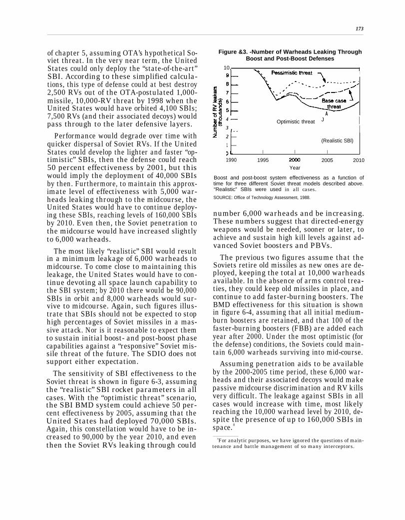
173
of chapter 5, assuming OTA’s hypothetical So-viet threat. In the very near term, the UnitedStates could only deploy the “state-of-the-art”SBI. According to these simplified calcula-tions, this type of defense could at best destroy2,500 RVs out of the OTA-postulated 1,000-missile, 10,000-RV threat by 1998 when theUnited States would have orbited 4,100 SBIs;7,500 RVs (and their associated decoys) wouldpass through to the later defensive layers.
Performance would degrade over time withquicker dispersal of Soviet RVs. If the UnitedStates could develop the lighter and faster “op-timistic” SBIs, then the defense could reach50 percent effectiveness by 2001, but thiswould imply the deployment of 40,000 SBIsby then. Furthermore, to maintain this approx-imate level of effectiveness with 5,000 war-heads leaking through to the midcourse, theUnited States would have to continue deploy-ing these SBIs, reaching levels of 160,000 SBIsby 2010. Even then, the Soviet penetration tothe midcourse would have increased slightlyto 6,000 warheads.
The most likely “realistic” SBI would resultin a minimum leakage of 6,000 warheads tomidcourse. To come close to maintaining thisleakage, the United States would have to con-tinue devoting all space launch capability tothe SBI system; by 2010 there would be 90,000SBIs in orbit and 8,000 warheads would sur-vive to midcourse. Again, such figures illus-trate that SBIs should not be expected to stophigh percentages of Soviet missiles in a mas-sive attack. Nor is it reasonable to expect themto sustain initial boost- and post-boost phasecapabilities against a “responsive” Soviet mis-sile threat of the future. The SDIO does notsupport either expectation.
The sensitivity of SBI effectiveness to theSoviet threat is shown in figure 6-3, assumingthe “realistic” SBI rocket parameters in allcases. With the “optimistic threat” scenario,the SBI BMD system could achieve 50 per-cent effectiveness by 2005, assuming that theUnited States had deployed 70,000 SBIs.Again, this constellation would have to be in-creased to 90,000 by the year 2010, and eventhen the Soviet RVs leaking through could
Figure &3. -Number of Warheads Leaking ThroughBoost and Post-Boost Defenses
10,
A4 Optimistic threat J I3
l - - I2 —
(Realistic SBl)1 —
I I I
1990 1995 2005 2010Year
Boost and post-boost system effectiveness as a function oftime for three different Soviet threat models described above.“Realistic” SBIs were used in all cases.SOURCE: Office of Technology Assessment, 1988.
number 6,000 warheads and be increasing.These numbers suggest that directed-energyweapons would be needed, sooner or later, toachieve and sustain high kill levels against ad-vanced Soviet boosters and PBVs.
The previous two figures assume that theSoviets retire old missiles as new ones are de-ployed, keeping the total at 10,000 warheadsavailable. In the absence of arms control trea-ties, they could keep old missiles in place, andcontinue to add faster-burning boosters. TheBMD effectiveness for this situation is shownin figure 6-4, assuming that all initial medium-burn boosters are retained, and that 100 of thefaster-burning boosters (FBB) are added eachyear after 2000. Under the most optimistic (forthe defense) conditions, the Soviets could main-tain 6,000 warheads surviving into mid-course.
Assuming penetration aids to be availableby the 2000-2005 time period, these 6,000 war-heads and their associated decoys would makepassive midcourse discrimination and RV killsvery difficult. The leakage against SBIs in allcases would increase with time, most likelyreaching the 10,000 warhead level by 2010, de-spite the presence of up to 160,000 SBIs inspace. 8
8For analytic purposes, we have ignored the questions of main-tenance and battle management of so many interceptors.
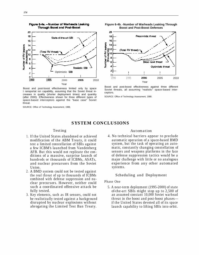
174
~ Optimistic SBI2 —
o~ I I I1990 1995 2000 2010
Year
Boost and post-boost effectiveness limited only by spacet ransportat ion capability, assuming that the Soviet threat in-creases in quality (shorter deployment times) and quantity(after 2000). Effectiveness shown for three different types ofspace-based interceptors against the “base case” Sovietthreat.
SOURCE: Office of Technology Assessment, 1988,
1.
2.
3.
Figure 6-4b. -Number of Warheads Leaking ThroughBoost and Post-Boost Defenses -
—
01 I I I
1990 1995 2005 2010
Year
Boost and post-boost effectiveness against three differentSoviet threats, all assuming “realistic” space-based inter-ceptors.
SOURCE: Office of Technology Assessment, 1988.
SYSTEM CONCLUSIONS
TestingIf the United States abandoned or achievedmodification of the ABM Treaty, it couldtest a limited constellation of SBIs againsta few ICBM’s launched from VandenbergAFB. But this would not replicate the con-ditions of a massive, surprise launch ofhundreds or thousands of ICBMs, ASATs,and nuclear precursors from the SovietUnion.A BMD system could not be tested againstthe real threat of up to thousands of ICBMscombined with defense suppression and nu-clear precursors. However, neither couldsuch a coordinated offensive attack befully tested.Key elements, such as IR sensors, could notbe realistically tested against a backgrounddisrupted by nuclear explosions withoutabrogating the Limited Test Ban Treaty.
Automation4. No technical barriers appear to preclude
automatic operation of a space-based BMDsystem, but the task of operating an auto-matic, constantly changing constellation ofsensors and weapons platforms in the faceof defense suppression tactics would be amajor challenge with little or no analogousexperience from any other automatedsystems.
Scheduling and Deployment
Phase One
5. A near-term deployment (1995-2000) of stateof-the-art SBIs might stop up to 2,500 ofan assumed constant 10,000 Soviet warheadthreat in the boost and post-boost phases—if the United States devoted all of its spacelaunch capability to lifting SBIs into orbit.
175
This assumes that the burn times andpost-boost vehicle dispersal times of fu-ture Soviet ICBM’s decrease over time ina reasonable manner. Of course, fewerSBIs could kill similar percentages ofboosters if a smaller attack were assumed.The SDIO argues that defenses that arefar from perfect still offer significant en-hancement of deterrence (see chs. 1,2, and
SBIs and into midcourse after 2005, reach-ing the pre-BMD levels of 10,000 leakingwarheads by 2010. Therefore, SBIs shouldnot be expected to achieve the strategicgoal of “assured survival” against nuclearattack by a Soviet missile force uncon-strained by arms reductions and limi-tations.
Phase 33 ) .
Phase 2 8.
6. An intermediate-term or “phase-two” de-ployment of more advanced SBIs might killup to 5,000 of the hypothesized fixed num-ber of 10,000 Soviet RVs in the boost andpost-boost phases, but only by orbiting from90,000 to 160,000 SBIs. Therefore, theUnited States would be unlikely to relyon SBIs for continued boost-phase inter-ception of advanced Soviet missiles. 9.
7. Given the assumptions of OTA analyses,under the most optimistic conditions the So-viet Union could maintain an RV leakageinto midcourse at or above the 6,000 war-head level by increasing the number ofICBMs deployed by 100 per year after theyear 2000. Under any of the assumed con-ditions, the Soviet Union could increasethe rate of warhead penetration against
A highly effective BMD system would re-quire either very effective midcourse dis-crimination or a very effective directed-energy weapon (DEW) system, and prefer-ably both, since an SBI system, as limitedby the most optimistic space transporta-tion system, could never assure that fewerthan 5,000 Soviet warheads and their asso-ciated decoys would leak through to themidcourse,As concluded in chapter 5, it is unlikelythat the United States could determinethe feasibility of DEW systems by the late1990s, and deployment probably could notbegin until 2005-2010 at the earliest. Ittherefore appears likely that the SovietUnion, unless constrained by offensive armscontrol agreements, would be able to main-tain leakage rates of a few thousand nuclearwarheads until at least the period 2005-2010.
Chapter 7
System Integrationand Battle Management
CONTENTS
Introduction . . . . . . . . . . . . . . . . . . . . . . . . . . . . . . . . . . . . . .Battle Management . . . . . . . . . . . . . . . . . . . . . . . . . . . . . . . .Conduct of the Battle. . . . . . . . . . . . . . . . . . . . . . . . . . . . . . .
Battle Management Functions . . . . . . . . . . . . . . . . . . . . .Interactions Among the Phases . . . . . . . . . . . . . . . . . . . .System Performance and Interaction . . . . . . . . . . . . . . . .Opportunities for Human Intervention . . . . . . . . . . . . . .
Supporting Functions. . . . . . . . . . . . . . . . . . . . . . . . . . . . . . .Communications . . . . . . . . . . . . . . . . . . . . . . . . . . . . . . . . .Recovery From Damage and Failures . . . . . . . . . . . . . . . .
Complexity of Battle Management . . . . . . . . . . . . . . . . . . . .Battle Management Architecture . . . . . . . . . . . . . . . . . . . . .Conclusions . . . . . . . . . . . . . . . . . . . . . . . . . . . . . . . . . . . . . . .
Box7-A.7-B.7-c.
Boxes
Algorithms. . . . . . . . . . . . . . . . . . . . . . . . . . . . . . . . . . . .Centralization, Distribution, and Coupling . . . . . . . . .Hierarchies and System Design .. ... . . . . . . . . .
Figure No.7-1. Analytic Chart
BMD System .
MissileTable No.7-1. Ballistic
of Battle. . . . . . . .
Figure
Management Functions in a. . . . . . . . . . . . . . . . . .
Table
Battle Management
. . . . . . .
.... . . . . . . . . . . . . 179
. . . . . . . . . . . . . . . . . . 179
. . . . . . . . . . . . . . . . . . 180
. . . . . . . . . . . . . . . . . . 180
. . . . . . . . . . . . . . . . . . 185
. . . . . . . . . . . . . . . . . . 186
. . . . . . . . . . . . . . . . . . 187
. . . . . . . . . . . . . . . . . . 190
. . . . . . . . . . . . . . . . . . 191
. . . . . . . . . . . . . . . . . . 191
. . . . . . . . . . . . . . . . . . 191
. . . . . . . . . . . . . . . . . . 192
. . . . . . . . . . . . . . . . . , 195
Page. . . . . . . . . . . . . . . . . . 188. . . . . . . . . . . . . . .. 192. . . . . . . . . . . . . . . . . . 193
Phase-One. . . . . . . . . . . . . . . .
Functions . . . . . . . . . . . . . .
Page
.196
Page.181
Chapter 7
System Integration and Battle Management
INTRODUCTION
Chapter 6 discusses developing, deploying,and maintaining a ballistic missile defense(BMD) system. Once deployed, BMD compo-nents would have to work together to form afighting system. Maintaining such integrationwould require regular, routine support. Thischapter looks at integrated operation of thesystem. Although some system capabilitiescould be used during peacetime, e.g., for sur-veillance, fully integrated use would only berequired during battle.1 Accordingly, most ofthis chapter is concerned with battle manage-ment, i.e., how the system would be managedto fight effectively.
‘Peacetime simulations of battles would also require consid-erable integration, but would probably omit operations suchas use of interactive discriminators and firing and controllingweapons.
A major assumption in the discussion thatfollows is that the system is sufficiently well-integrated during peacetime that it can bemoved promptly to a full fighting status. Asexamples, the communications network thatpermits battle managers to exchange informa-tion would have to be working and the battlemanagers would need timely data on the num-ber, kinds, and locations of resources availableto them. Peacetime activities needed to keepthe system integrated, such as sending updatesof resource-availability data and new versionsof software to battle managers, would have tobe performed routinely. Operational readiness,testing and evaluation, and repair or replace-ment off ailing system components would alsohave to be routine.
BATTLE MANAGEMENTThe battle management portion of a BMD
system would combine the data provided bysensors and the capabilities offered by weap-ons into a defensive system. The battle man-agement computers would provide computa-tional and decisionmaking capability. Thebattle management software would be the gluebonding the components together into a fight-ing system. Battle management includes strat-egy, tactics, resource allocation algorithms,and status reporting.
Battle management computing may be dis-tributed among many different platforms orconsolidated on just a few. In either case, thebattle management functions would remainthe same, although the capabilities needed insupporting functions, such as communications,
Note: Complete definitions of acronyms and intialismsare listed in Appendix B of this report.
might vary. This chapter describes the conductof a battle from the battle management view-point, from alert through the actual battle se-quence. The scenarios only meant to be illus-trative, not comprehensive. Its purpose is toconvey a sense of the complexity of the battlemanagement task, not to provide an actual bat-tle management system design.
In peacetime, the system might be in a quies-cent mode, conserving fuel and other resources,with some components shielded from space.As the probability of a battle increased, thesystem might move through a series of alertlevels, during which sensors such as the BoostSurveillance and ‘hacking System (BSTS) andSpace Surveillance and Tracking System(SSTS) would be fully opened to space andweapons would be prepared for battle, includ-ing warm-up and status checks. At the high-est alert level, the system would be fully pre-pared to fight a battle.
179
180
The battle may be partitioned into differentphases, each distinguished by a different setof offensive actions. The phases are boost, post-boost, mid-course, and terminal. For an indi-vidual reentry vehicle (RV) or decoy, the phasesoccur in the sequence given. Different RVs anddecoys may be in different phases concurrent-
ly, requiring the defense to fight in differentphases at the same time. In addition, the BMDsystem might have to defend itself against de-fense suppression attacks during any phase.For a description of the phases of ballistic mis-sile flight, see chapter 3, table 3-6.
CONDUCT OF THE BATTLE
Our battle scenario assumes, for simplicity,a system with a second-phase architecture asdescribed in chapter 3. We assume that it isin an alert stage from which it could be moveddirectly to fully automated battle manage-ment.2 The battle would commence with thelaunch of Soviet intercontinental ballistic mis-siles (ICBMs). We assume a mix of ICBMs,some of which would burnout above the atmos-phere, and some of which would bum out inthe atmosphere. The ICBMs release post-boostvehicles (PBVs) carrying both RVs and decoys.The PBVs would maneuver to dispense theirpayloads, inserting each RV and decoy into apreplanned trajectory. RVs and decoys wouldthen coast until they started to reenter theatmosphere. RVs would continue on to theirtargets, accompanied partway by those decoysdesigned to simulate reentry.
Besides launching ICBMs, the Soviets mightemploy a variety of defense-suppression meas-ures. For example, they might launch direct-ascent anti-satellite weapons (ASATs) at BMDsystem satellites. Such a weapon might carryone or more warheads and decoys. The defensesuppression attack might begin before anI C B M l a u n c h .
The following sections describe briefly thefunctions that a BMD system would have toperform during the battle. Requirements forrecovering from damage and failures occurring
‘Although the assumption that there would be sufficient priorwarning to an attack that a BMD system could be moved toan alert stage makes the scenario easier to describe, the sys-tem’s designers could not depend on such an assumption to betrue. There would have to be some provision to go from peacetime to battle in seconds in the event that no warning is re-ceived or that such warnings are ignored.
during battle are given simplified treatmentlater. Table 7-1 gives a more detailed descrip-tion, with examples, of the defensive functions,organized by function and by missile flightphase.
Battle Management Functions
In all phases of a battle the defensive sys-tem would have to track targets, assign weap-ons to destroy targets, aim, fire, and controlthose weapons, and assess the damage theydo. It would also continually report on systemstatus to human commanders, transmit infor-mation among computer battle managerswithin a battle phase, and from the battlemanagers in one phase (e.g., boost) to the bat-tle managers in another phase (e.g., terminal).Additional functions, unique to each phase, aredescribed in the following sections.
Each of these functions would involve mak-ing many decisions in short spaces of timeusing data obtained from a variety of sources.For example, aiming a weapon at a targetmight be based on tracking data obtained froma BSTS combined with data from a laser rangefinder located on satellite battle station, andwould require the prediction of an interceptpoint for the target and weapon.
Boost Phase
The task of detecting booster launches wouldbe unique to the boost phase as would be pre-dicting the approximate trajectories of PBVsfrom those boosters penetrating the boost-phase defense. Trajectory prediction wouldneeded so that space-based interceptors (SBIs)

181
Table 7-1 .—Ballistic Missile Defense Battle Management Functions
The components of any ballistic missile defense (BMD) system would have to be tied together in a battle managementnetwork. The table below lists the kinds of functions such a battle management system would have to perform, assuminga second- phase architecture of the type shown in Table 3-5. Computers would have to perform most of the functions. TheBMD system architecture would specify locations and interrelationships among the computers. The system might be moreor less centralized, more or less hierarchical. The elements of the system need to be tied together in a communications net-work. Chapter 8 of this report further discusses battle management communications and computation requirements.
Because different system components often perform the same functions in different ways, the table gives hypotheticalexamples of how the functions are accomplished in different battle phases. The “hypothetic/ examples’ are just that: thistable does not purport to outline a complete BMD architecture.
The table is organized into 6 sections. The first 5 sections correspond to the boost, post-boost, mid-course, terminal,and self-defense parts of a BMD battle. The sixth outlines a battle of BMD system self-defense against anti-satellite weapons.The functions and their descriptions are the same for each section of the table; what varies is the way the functions are ac-complished. Thus, to find out how objects might be tracked as part of the acquisition and discrimination function during theterminal phase, one reads the hypothetical example in the section of the table devoted to the terminal phase.
Boost Phase
Function Description Hypothetical Boost Phase Example
Acquire and discriminate objects Sense objects of interest
Distinguish between targets to attack anddecoys or debris
Track objects
Associate and Correlate objects sensed bydifferent means or from different platforms
Assess Situation
Decide Course of Action
Estimate whether enemy is attacking, and if sowith how many of what kinds of weapons withwhat battle tactics
Assess which of own BMD forces are availablefor battle
Authorize firing when ready, based on directionfrom higher authority if available, or as pre-authorized if not
Determine strategy and battle plan
Select Targets & Direct Weapons Choose which targets to strike
Employ Weapons
Assign weapons
Prepare engagement instructions
Assess kill: decide which targets have beendestroyed
Control weapon
Enable weapon
Prepare weapon
Short and mid-wavelength infrared telescopeson BSTS detect hot exhaust plumes fromlaunch of boosters
BSTS starts track files to distinguish movingICBMs from stationary background and cloudclutter
SSTS sensors start to observe and record pathsof identified objects
Battle management computers compareinformation gathered on two separate SSTSplatforms and give same identification numberto the same observed objects
BSTS detects ICBM launches, notes numbersand locations of launch sites, and determinestypes of missiles
Battle management computers determine whichspace based space-based interceptor (SBI)carrier vehicles (CVs) are in range of launchedICBM boosters, and will be in range of Post-Boost Vehicles (PBVs) when they are releasedfrom ICBMs.
If 3 or more ICBMs are launched within 1minute, space battle management computersare programmed to command launch of space-based SBIs when the 4th ICBM is detected
Determine plan for which kinds of ICBMs fromwhich locations and which PBVs to attackfirst based on trajectories. CV positions.predicted RV impact points, and predictedtimes of PBV separation from missile
Select the booster or PBV whose trajectory willplace it closest to the fly-out range of aparticular CV
Battle management computer decides that SBIsno. 7888 and 7930 should attack targetbooster no. 754, and commands CVs to flight-check SBIs.
Battle management computers send flight plansand target track information to CVs.
Remove a booster from the active target list
Feed target information to SBI guidancepackage
Conduct flight check of SBI
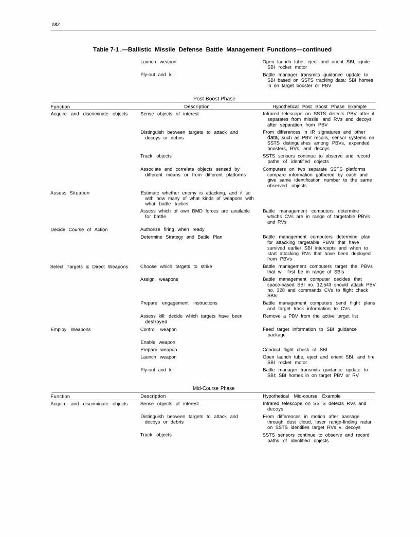
182
Table 7-1 .—Ballistic Missile Defense Battle Management Functions—continued
Launch weapon Open launch tube, eject and orient SBI, igniteSBI rocket motor
Fly-out and kill Battle manager transmits guidance update toSBI based on SSTS tracking data; SBI homesin on target booster or PBV
Post-Boost Phase
Function Description Hypothetical Post Boost Phase Example
Acquire and discriminate objects Sense objects of interest
Assess Situation
Decide Course of Action
Distinguish between targets to attack anddecoys or debris
Track objects
Associate and correlate objects sensed bydifferent means or from different platforms
Estimate whether enemy is attacking, and if sowith how many of what kinds of weapons withwhat battle tactics
Assess which of own BMD forces are availablefor battle
Authorize firing when ready
Determine Strategy and Battle Plan
Select Targets & Direct Weapons Choose which targets to strike
Assign weapons
Employ Weapons
Prepare engagement instructions
Assess kill: decide which targets have beendestroyed
Control weapon
Enable weapon
Prepare weapon
Launch weapon
Fly-out and kill
Mid-Course Phase
Infrared telescope on SSTS detects PBV after itseparates from missile, and RVs and decoysafter separation from PBV
From differences in IR signatures and otherdata, such as PBV recoils, sensor systems onSSTS distinguishes among PBVs, expendedboosters, RVs, and decoys
SSTS sensors continue to observe and recordpaths of identified objects
Computers on two separate SSTS platformscompare information gathered by each andgive same identification number to the sameobserved objects
Battle management computers determinewhichs CVs are in range of targetable PBVsand RVs
Battle management computers determine planfor attacking targetable PBVs that havesurvived earlier SBI intercepts and when tostart attacking RVs that have been deployedfrom PBVs
Battle management computers target the PBVsthat will first be in range of SBIs
Battle management computer decides thatspace-based SBI no. 12,543 should attack PBVno. 328 and commands CVs to flight checkSBIs
Battle management computers send flight plansand target track information to CVs
Remove a PBV from the active target list
Feed target information to SBI guidancepackage
Conduct flight check of SBI
Open launch tube, eject and orient SBI, and fireSBI rocket motor
Battle manager transmits guidance update toSBI; SBI homes in on target PBV or RV
Function Description Hypothetical Mid-course Example
Acquire and discriminate objects Sense objects of interest Infrared telescope on SSTS detects RVs anddecoys
Distinguish between targets to attack and From differences in motion after passagedecoys or debris through dust cloud, laser range-finding radar
on SSTS identifies target RVs v. decoys
Track objects SSTS sensors continue to observe and recordpaths of identified objects
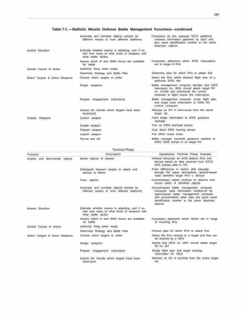
183
Table 7-1 .—Ballistic Missile Defense Battle Management Functions—continued
Assess Situation
Associate and correlate objects sensed bydifferent means or from different platforms
Estimate whether enemy is attacking, and if sowith how many of what kinds of weapons withwhat battle tactics
Assess which of own BMD forces are availablefor battle
Decide Course of Action Authorize firing when ready
Determine Strategy and Battle Plan
Select Targets & Direct Weapons Choose which targets to strike
Assign weapons
Employ Weapons
Prepare engagement instructions
Assess kill: Decide which targets have beendestroyed
Control weapon
Enable weapon
Prepare weapon
Launch weapon
Fly-out and kill
Terminal Phase
Computers on two separate SSTS platformscompare information gathered by each andgive same identification number to the sameobserved objects
Computers determine which ERIS interceptorsare in range of RVs
Determine plan for which RVs to attack first
Select the RVs within shortest flight time of aparticular ERIS site
Battle management computer decides that ERISinterceptor no. 3001 should attack target RVno. 10,005 and commands fire controlcomputer to flight check the interceptor
Battle management computer sends flight planand target track information to ERIS firecontrol computer
Remove an RV in mid-course from the activetarget list
Feed target information to ERIS guidancepackage
Turn on ERIS warhead sensor
Cool down ERIS homing sensor
Fire ERIS rocket motor
Battle manager transmits guidance updates toERIS; ERIS homes in on target RV
Function Description Hypothetical Terminal Phase Example
Acquire and discriminate objects Sense objects of interest Infrared telescope on AOS detects RVs anddecoys based on data received from SSTS;
Assess Situation
Decide Course of Action
Select Targets & Direct Weapons
Distinguish between targets to attack anddecoys or debris
Track objects
Associate and correlate objects sensed bydifferent means or from different platforms
Estimate whether enemy is attacking, and if sowith how many of what kinds of weapons withwhat battle tactics
Assess which of own BMD forces are availablefor battle
Authorize firing when ready
Determine Strategy and Battle Plan
Choose which targets to strike
Assign weapons
Prepare engagement instructions
Assess kill: Decide which targets have beendestroyed
AOS ‘passes data to TIR
From differences in motion after passagethrough the upper atmosphere, ground-basedradar identifies target RVs v. decoys
Ground-based radars continue to observe andrecord paths of identified objects
Ground-based battle management computercompares track information handed-off byspace-based battle management computerwith ground-based radar data and gives sameidentification number to the same observedobjects
Computers determine which HEDIs are in rangeof incoming RVs
Choose plan for which RVs to attack first
Select the RVs nearest to a target and that canbe reached by a HEDI
Decide that HEDI no. 1897 should attack targetRV no. 257
Ready flight plan and target trackinginformation for HEDI
Remove an RV in terminal from the active targetlist
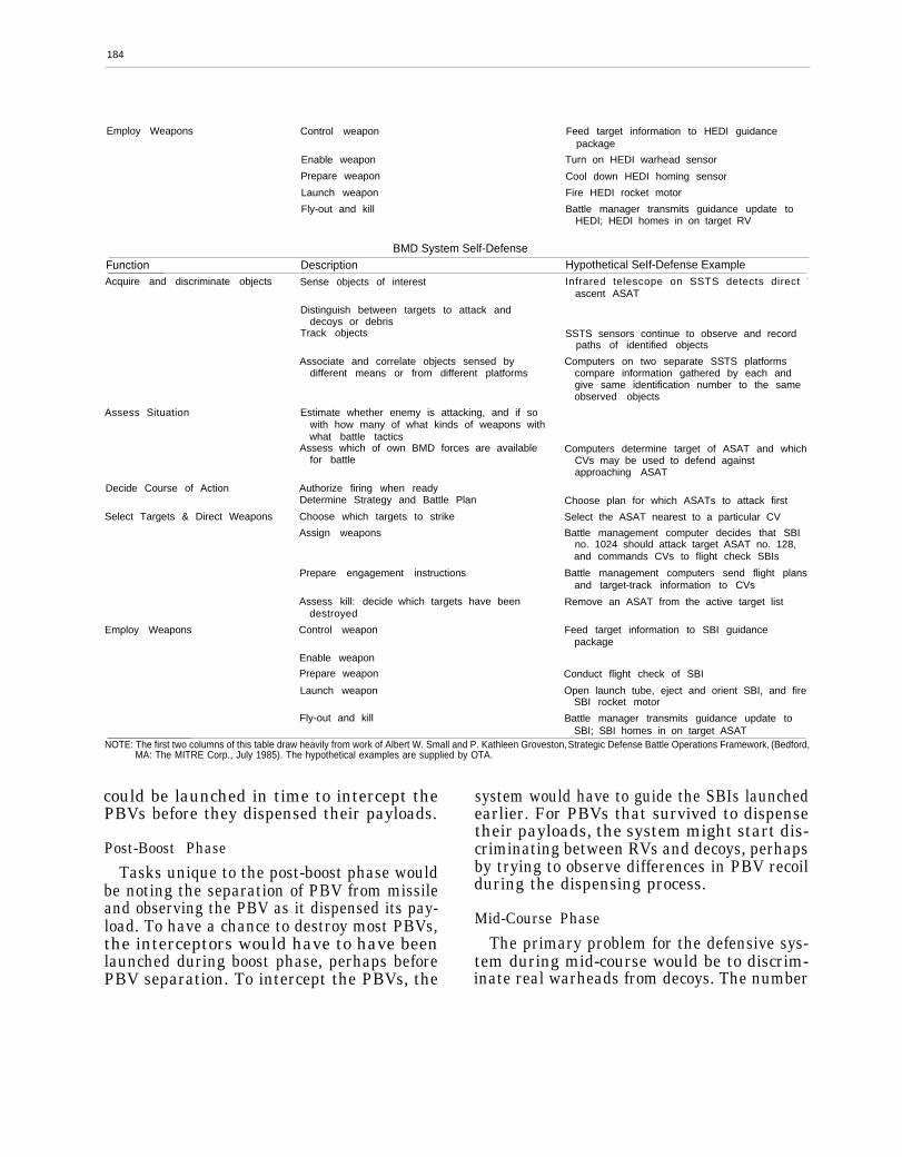
184
Employ Weapons Control weapon Feed target information to HEDI guidancepackage
Enable weapon Turn on HEDI warhead sensor
Prepare weapon Cool down HEDI homing sensor
Launch weapon Fire HEDI rocket motor
Fly-out and kill Battle manager transmits guidance update toHEDI; HEDI homes in on target RV
BMD System Self-DefenseFunction Description Hypothetical SeIf-Defense ExampleAcquire and discriminate objects
Assess Situation
Decide Course of Action
Select Targets & Direct Weapons
Employ Weapons
Sense objects of interest
Distinguish between targets to attack anddecoys or debris
Track objects
Associate and correlate objects sensed bydifferent means or from different platforms
Estimate whether enemy is attacking, and if sowith how many of what kinds of weapons withwhat battle tactics
Assess which of own BMD forces are availablefor battle
Authorize firing when readyDetermine Strategy and Battle Plan
Choose which targets to strike
Assign weapons
Prepare engagement instructions
Assess kill: decidedestroyed
Control weapon
Enable weapon
Prepare weapon
Launch weapon
Fly-out and kill
which targets have been
Infrared telescope on SSTS detects direct -
ascent ASAT
SSTS sensors continue to observe and recordpaths of identified objects
Computers on two separate SSTS platformscompare information gathered by each andgive same identification number to the sameobserved objects
Computers determine target of ASAT and whichCVs may be used to defend againstapproaching ASAT
Choose plan for which ASATs to attack first
Select the ASAT nearest to a particular CV
Battle management computer decides that SBIno. 1024 should attack target ASAT no. 128,and commands CVs to flight check SBIs
Battle management computers send flight plansand target-track information to CVs -
Remove an ASAT from the active target list
Feed target information to SBI guidancepackage
Conduct flight check of SBI
Open launch tube, eject and orient SBI, and fireSBI rocket motor
Battle manager transmits guidance update toSBI; SBI homes in on target ASAT
NOTE: The first two columns of this table draw heavily from work of Albert W. Small and P. Kathleen Groveston, Strategic Defense Battle Operations Framework, (Bedford,MA: The MITRE Corp., July 1985). The hypothetical examples are supplied by OTA.
could be launched in time to intercept thePBVs before they dispensed their payloads.
Post-Boost Phase
Tasks unique to the post-boost phase wouldbe noting the separation of PBV from missileand observing the PBV as it dispensed its pay-load. To have a chance to destroy most PBVs,the interceptors would have to have beenlaunched during boost phase, perhaps beforePBV separation. To intercept the PBVs, the
system would have to guide the SBIs launchedearlier. For PBVs that survived to dispensetheir payloads, the system might start dis-criminating between RVs and decoys, perhapsby trying to observe differences in PBV recoilduring the dispensing process.
Mid-Course Phase
The primary problem for the defensive sys-tem during mid-course would be to discrim-inate real warheads from decoys. The number

185
of decoys maybe in the hundreds of thousands,or even greater. Decoys and warheads may ap-pear very similar to optical, infrared, radar,and other sensors, both passive and active.3
Terminal Phase
During terminal phase, the defensive systemwould have to discriminate RVs from decoysusing data handed off from earlier phases andusing the atmosphere and radar signatures asdiscriminators.
Table 7-1 shows the different functions aBMD system would have to perform duringbattle, and how different components wouldparticipate in different phases of the battle.The table assumes a second-phase architecture,such as described in table 3-6. It also showsthe functions that would serve to defend thesystem against defense suppression threats.
Interactions Among the Phases
A BMD system would not be a single, mono-lithic entity. Instead, it would comprise manydifferent elements, some of which would par-ticipate in only one or two phases of the bat-tle. In most system architectures, battle man-agement would be conducted by differentbattle managers during the different phases.Furthermore, some battle managers might befighting one phase of the battle while othersare fighting a different phase. Boost, post-boost, and mid-course managers would be lo-cated in space, while terminal phase managerswould likely be on the ground. For the systemto function most effectively, information, suchas tracks and status of RVs and decoys, wouldhave to be communicated from battle manag-ers in earlier phases to battle managers in laterphases.
Interactions for Tracking Purposes
Establishing, distributing, and correlatingtrack information is a good example of a prob-lem involving interaction among different sys-tem elements and cooperation among battle
‘Chapters 4 and 10 discuss the issues of discrimination dur-ing mid-course in more detail.
managers. Detecting, identifying, and notingthe current position of a target would not besufficient for guiding a BMD weapon system.The target would move between the time thatthe sensor records its position and the timethe weapon is fired. An SBI traveling at, say,8 km/see, would take 250 seconds to reach anRV target if the SBI were fired at a range of2,000 km from the impact point. During those250 seconds, the RV would move 1750 km. Justas the hunter must lead the duck in flight ashe fires his shotgun, the BMD system wouldhave to aim its SBI well ahead of the speedingRV.4
The BMD system would therefore have tokeep track of each target’s motion and predictwhere the target would be at later times. Thesensors would have to generate a‘ ‘track file,i.e., a history of each target’s motion throughspace. Given the target’s past history in termsof position, velocity, and acceleration in threedimensions, a computer could then predict itsfuture position. This prediction could then beused to aim and fire the weapon system. Afterthe SBI was fired, the sensors would have tocontinue to track the target (and possibly theSBI), the track files would have to be updated,and mid-course guidance corrections sent tokeep the SBI on a collision course. Mid-coursecorrections would be mandatory if the targetacceleration changed after the SBI was fired,as would occur with multi-stage missiles.
For directed-energy weapons or interactivesensor systems, the delay from the time thatenergy is emitted by the target until it reachesthe sensor, and then from the firing of theweapon until the arrival of the kill energy trav-eling at the speed of light, would be very short,but not zero. At 2,000 km range, for example,13 milliseconds would elapse from the last sen-sor reading until the time a laser beam couldreach the target. The RV would move about91 meters in this time, so some predictive ca-
4However, the RV would be moving on a ballistic or free-fallflight with no external acceleration other than the force of grav-ity. Therefore, predicting its future path or trajectory wouldbe possible provided that the sensor generated two or more ac-curate three dimensional target positions. Predicting the futurepath of an accelerating, multi-stage missile would be much moredifficult. RVs that could maneuver would worsen the difficulties.
75-922 0 - 88 - 7

186
pability would be required.’ In addition, theobservable characteristics of the target wouldchange drastically during the tracking opera-tion. The sensor systems would begin track-ing the hot booster plume. For boost phasekills, the sensors would have to acquire andtrack the cold booster body, or rely on calcu-lations of the missile body position relativeto the booster plume for all booster/sensororientations. After the last booster stage hadburned out, the battle management computerswould have to continue the track file on thesurviving post-boost vehicles (PBV), eventhough tracking data might be derived fromother types of sensors. Finally, as individualRV’s and decoys were deployed, the track fileswould have to proliferate, taking the last PBVtrack projection as the recently deployed RVtrack file, until it could be verified and updatedby long wavelength infrared sensors.
The data handling problem would be com-pounded by RV’s that survived the boost andpost-boost defensive attacks. The survivingRV’s would usually pass out of the field of viewof the initial sensor. The track file obtainedfrom one sensor’s data would then have to becorrelated with the data from another sensor.6
Track data would be passed to the appropri-ate weapons platform at each stage of the bat-tle. Eventually the track files of surviving tar-gets should be passed on to the ground-basedterminal defensive systems to aid in the finalkill attempts. Information on decoys and otherrocket or killed target debris should also be
‘In general it would take additional time for the sensor signalprocessor to analyze the sensor data and for the track file tobe updated after the last signal was received; the actual elapsedtime between observation and the order to fire the weapon mightbe 5 to 10 seconds, so the target might move as much as 70km even for a directed-energy weapon.
6If battle managers, sensors, and weapons were organized intoautonomous battle groups, then each battle manager would haveto hand off and receive track data as targets passed throughthe field of view of sensors in its group, or it would have to per-form all of its own target acquisition and discrimination. If therewere a single battle manager to handle all tracking and correla-tion, it would have to maintain track files on all targets. Suchan organization would tie system survivability to survivabil-ity of the central battle manager. Finally, if battle groups wereto use fixed battle management platforms, but different sen-sors and weapons as the battle continued, then the battlemanagers would have to correlate tracks from different sensorsas the sensors moved in and out of its group.
transmitted, to avoid attacking too many falsetargets.
System Performance and Interaction
The ability to correlate data well from differ-ent sensors (required to get accurate three-dimensional track histories) could have astrong effect on system performance, as couldthe ability to correlate track files exchangedamong battle managers both within and be-tween phases. Poor performance in the earlyphases would mean many RVs leaking intolater phases, with possible overload of re-sources assigned to mid-course and terminalphases.
Distinctions Among the Phases
In all phases the defensive system wouldhave to perform many similar functions, suchas tracking; weapons assignment; aiming, fir-ing and controlling weapons; and reporting sta-tus. Sensors and weapons would vary consider-ably from one phase to another, however. Forexample, boost, post-boost, and mid-coursetracking would be done primarily by space-based infrared sensors such as those incorpo-rated in the BSTS and SSTS systems. Termi-nal phase tracking would be done by a com-bination of airborne infrared sensors andground-based radars. The software and hard-ware used to perform the sensing, discrimina-tion, and tracking functions indifferent phaseswould likely be quite different; aiming, firing,and controlling weapons might be similar.
Some phases would require unique functions.A good example is interactive discriminationof RVs from decoys for mid-course defense.Candidates for such discrimination, such asneutral particle beam systems, would likely becontrolled by unique computer software andhardware adapted to the task.
ReconfigurationIn addition to fighting the battle, the sys-
tem would also have to be able to reconfigureitself during and after the battle, to compen-sate for damage done to it, in preparation forfurther or continued engagements. In the post-
battle case, this might be done with humanassistance.
Opportunities for Human Intervention
Tracking and discriminating objects, aim-ing and firing weapons, and managing the bat-tle would require computers. During peace-time, humans could monitor surveillance dataafter it had been processed and displayed ina form suitable for human interpretation.Human decisionmakers could deduce from theevents monitored, among other things, wheth-er and when the defensive system should beplaced in alert status, ready to cope with a bat-tle. Once the battle started, however, the re-sponse time and data processing requirementswould severely limit the opportunities for hu-man intervention. There are four possible hu-
man intervention points under considerationin currently suggested BMD architectures:
●
●
●
●
the decision to move the system frompeacetime status to alert status,the decision to release weapons,the decision to switch to a back-up for oneor more of the algorithms (see box 7-A)used by the battle management comput-ers, andselection from a pre-specified set of tac-tics for terminal phase, made as a resultof observations of earlier phases of thebattle.
Transition to Alert Status
Humans could decide to move from one levelof alert to another in hours or minutes, as com-pared to fractions of seconds for computers
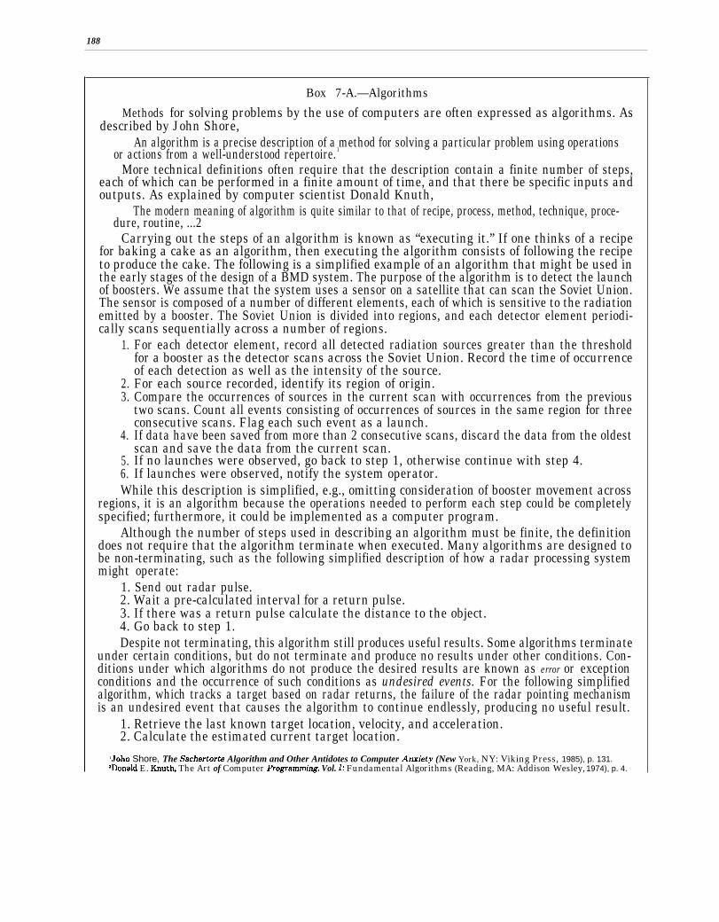
188
Box 7-A.—Algorithms
Methods for solving problems by the use of computers are often expressed as algorithms. Asdescribed by John Shore,
An algorithm is a precise description of a method for solving a particular problem using operationsor actions from a well-understood repertoire.1
More technical definitions often require that the description contain a finite number of steps,each of which can be performed in a finite amount of time, and that there be specific inputs andoutputs. As explained by computer scientist Donald Knuth,
The modern meaning of algorithm is quite similar to that of recipe, process, method, technique, proce-dure, routine, ...2
Carrying out the steps of an algorithm is known as “executing it.” If one thinks of a recipefor baking a cake as an algorithm, then executing the algorithm consists of following the recipeto produce the cake. The following is a simplified example of an algorithm that might be used inthe early stages of the design of a BMD system. The purpose of the algorithm is to detect the launchof boosters. We assume that the system uses a sensor on a satellite that can scan the Soviet Union.The sensor is composed of a number of different elements, each of which is sensitive to the radiationemitted by a booster. The Soviet Union is divided into regions, and each detector element periodi-cally scans sequentially across a number of regions.
1.
2.3.
4.
5.6.
For each detector element, record all detected radiation sources greater than the thresholdfor a booster as the detector scans across the Soviet Union. Record the time of occurrenceof each detection as well as the intensity of the source.For each source recorded, identify its region of origin.Compare the occurrences of sources in the current scan with occurrences from the previoustwo scans. Count all events consisting of occurrences of sources in the same region for threeconsecutive scans. Flag each such event as a launch.If data have been saved from more than 2 consecutive scans, discard the data from the oldestscan and save the data from the current scan.If no launches were observed, go back to step 1, otherwise continue with step 4.If launches were observed, notify the system operator.
While this description is simplified, e.g., omitting consideration of booster movement acrossregions, it is an algorithm because the operations needed to perform each step could be completelyspecified; furthermore, it could be implemented as a computer program.
Although the number of steps used in describing an algorithm must be finite, the definitiondoes not require that the algorithm terminate when executed. Many algorithms are designed tobe non-terminating, such as the following simplified description of how a radar processing systemmight operate:
1. Send out radar pulse.2. Wait a pre-calculated interval for a return pulse.3. If there was a return pulse calculate the distance to the object.4. Go back to step 1.Despite not terminating, this algorithm still produces useful results. Some algorithms terminate
under certain conditions, but do not terminate and produce no results under other conditions. Con-ditions under which algorithms do not produce the desired results are known as error or exceptionconditions and the occurrence of such conditions as undesired events. For the following simplifiedalgorithm, which tracks a target based on radar returns, the failure of the radar pointing mechanismis an undesired event that causes the algorithm to continue endlessly, producing no useful result.
1. Retrieve the last known target location, velocity, and acceleration.2. Calculate the estimated current target location.
‘John Shore, The Sachertorte Algorithm and Other Antidotes to Computer Ati”ety (New York, NY: Viking Press, 1985), p. 131.‘Donald E. Knuth, The Art of Computer Programrm”ng, Vol. 1: Fundamental Algorithms (Reading, MA: Addison Wesley, 1974), p. 4.

189
3.4.
5.
A
Point the radar at the estimated current target location and attempt object detection.If the radar locates no object at the estimated range to the target, revise the estimated targetlocation and return to step 3. Otherwise, continue with step 5.If the radar locates an object at the estimated range to the target, update the target location,velocity, and acceleration.real version of such a tracking algorithm would have to take into account the possibility that
the radar might fail in any of several different ways, or that earlier estimates of target positionmight be grossly wrong.
I
during battle. The humans’ decisions could bebased on data gathered from sources bothwithin and outside the BMD system. The com-puterized battle-time decisions would be basedon data acquired by the system’s sensors.
Weapons Release
Once a human had permitted the transitionto the highest level of alert, the system wouldfunction automatically, responding to threatsas it perceived them.7 It would be possible tobuild human intervention points for the releaseof weapons into the battle management proc-ess. In the first-phase and second-phase sys-tems described in chapter 3, the first weaponsto be released would be the SBIs. The periodfrom the time that a missile launch was firstperceived by BMD sensors until SBIs wouldhave to be launched to intercept a missile stillin its boost phase would be quite short—a fewminutes at most. Accordingly, if humans wereto control the release of weapons, they wouldhave to monitor the defense system’s opera-tion continuously once it had moved to thehighest alert status.
Since it may be necessary to release hun-dreds or thousands of SBIs within minutes,a human operator would not be able to author-ize release of individual SBIs. Because of therapid reaction times needed, continual humanintervention in the weapons release processwould likely degrade system effectiveness un-acceptably. It might be feasible to intervenewhen previously unused weapon systems were
‘The AEGIS ship defense system, often cited as performingmany of the same functions as a BMD system, reacts completelyautomatically to incoming threats when in the highest level ofalert mode. For some threats, AEGIS must react within 15 se-conds from the time a threat is detected.
brought into the battle. As an example, ifneutral particle beam (NPB) weapons had notbeen used before enemy missiles reached mid-course, then a human might be called onto au-thorize their use during the mid-course partof the battle. Even such occasional interven-tion might degrade performance somewhat.
Switching to Back-ups
During the course of the battle it might bepossible for a human observer to determinethat a BMD system was malfunctioning. Fora human to notice, the malfunction would prob-ably have to be gross, such as a failure to fireinterceptors or firing interceptors in obviouslywrong directions. If the problem lay in the al-gorithms used by the battle management com-puters, and if the system were designed in suchaway that back-up algorithms were availableto the computers, then the human might com-mand the battle management computers toswitch to a particular back-up algorithm.8
Human intervention of this type is rarelyused in existing systems because the humancannot interpret the situation correctly in theavailable time, and because it is difficult to de-sign the software to switch algorithms success-fully in mid-computation. Inmost systems, thegain is not worth the added software complex-ity. The potential gain for BMD from such in-tervention would be that in the cases where
‘Switching to a back-up algorithm should not be confused withsituations where a computer uses built-in diagnostics to deter-mine the occurrence of a hardware malfunction and then auto-matically switches operation to a redundant component. Suchdiagnostics and hardware redundancy for automatic switchingare now used in some critical applications, such as airline trans-action systems, telephone switching systems, and battle man-agement systems such as AEGIS.
190
the system had been badly spoofed by theenemy, and the human operator quickly rec-ognized the symptoms, cause, and needed cor-rective action, recovery might be possible intime to continue the battle. The risk would bethat the operator would misjudge the situa-tion, or that the complications involved in pro-vialing the appropriate interface to the opera-tor, both in additional software, hardware, andcommunications capability, would make thesystem less reliable.
Selection of TacticsBecause the boost, post-boost, and mid-
course phases of a BMD battle would last 20-30 minutes, a human commander might be ableto evaluate the results of those phases in timeto affect the tactics used during the terminalphase. To do so, he would have to be presentedwith status reports during the battle. Basedon his analysis of the battle, and on choicesof previously-determined tactics presented tohim by an automated battle manager, he couldchoose the terminal phase tactics to be used.Again, because of the time-scales and datavolumes involved, he would probably not beable to alter his choice once the terminal phasebegan.
Increasing degrees of human interventionwould require increasing complexity in the in-terface between humans and the battle man-agement system. A sophisticated interface be-tween human and computer would be needed,allowing the human to observe status and is-sue commands, and, when appropriate, receiveacknowledgements. Such an interface wouldadd complexity to the software. Furthermore,
SUPPORTING
Table 7-1 shows the primary battle manage-ment functions, but does not include severalsupporting functions. Most important of theseare communications and recovery from dam-age and from failures. Both of these functionsare needed in all phases, with communicationsplaying its traditionally crucial role in battlemanagement and with recovery invoked as
the human operator(s) would probably have tohave authority to release weapons, as theremight not be time to consult with higher au-thorities.
Common to all BMD system designs thatrequire human intervention at any stage is theneed to provide secure, rapid communicationsbetween the human and the battle manage-ment computers. If part of the system werein space, then most likely there would be a needfor space-to-ground communications.9
For all of the preceding reasons, it seemslikely that a BMD system would operatealmost completely automatically once movedto an alert status in preparation for battle.
The preceding analysis illustrates the diffi-cult trade-offs involved in designing a battlemanagement system. In considering the inter-face between humans and the system, the de-signer must trade off communications secu-rity against the need for human interventionagainst system structure against complicationof the computing tasks. He must also balancesystem performance against all other consider-ations, deciding whether the system could per-form better and more dependably with the aidof a human than without, and whether any ex-tra complication in the human-computer inter-faces would be worth whatever capability andtrustworthiness might be added by the human.
‘Even if a human operator were space-based, he might needto communicate with higher authority on the ground. Such com-munications would probably not require as rapid data commu-nication rates as battle-management-to-operator communi-cations.
FUNCTIONS
needed. Both communications and recoveryprocedures would be completely automatedduring a battle. Because of the short decisiontimes involved during boost, post-boost, andterminal phases, recovery would have to be ex-tremely rapid; delays would result in RVs mov-ing on to the next phase or reaching their tar-gets. Long delays in recovery could also reduce
191
the opportunities for a battle manager fight-ing in one phase to pass information along tobattle managers fighting in the next phase.
Communications
Automated communications links betweensensors and battle management computers, be-tween different battle management computers,between battle management computers andweapons, and between battle managementcomputers and humans, would all be neededfor effective battle management. Data wouldbe continually transmitted over a battle man-agement communications network during allbattle phases.
Recovery From Damage and Failures
Present in all phases would be the need torecognize and recover from system failures andfrom damage to system resources. Individual
system components would have to monitor andreport their own status continually. Theywould have to try to recover from local failures,whether internally generated—perhaps by asoftware error-or externally generated—per-haps by a detonation of a nearby nuclear anti-satellite weapon causing radiation damage ina computer chip.
Some instances of system damage and fail-ure, such as destruction of several adjacent bat-tle management platforms or communicationscontrollers, would require recovery based on“global information, “ i.e., information aboutthe status of the entire BMD system and theentire battle. Examples are knowing how toreroute communications around damagednodes in the communications network, orknowing which battle management computerswere in position, both physically and in termsof resources available, to take over the func-tions of a disabled battle manager.
COMPLEXITY OF BATTLE MANAGEMENT
Conduct of a successful BMD battle wouldbe similar to the conduct of a large conven-tional battle in that it would require the or-chestration of many different kinds of compo-nents under precise timing constraints. Theproblem may be ameliorated somewhat by pre-planning some of the orchestration. The differ-ence is that in a BMD battle the time con-straints would be tighter, the battle spacewould be larger, the fighting would largely beautomated, the components would be previ-ously untested in battle, and there would belittle chance to employ human ingenuity tocounter unanticipated threats or strategies.
The only kind of BMD system for which theU.S. has battle management software devel-opment experience and an understanding ofthe attendant problems is a terminal defensesystem, such as SAFEGUARD. Some con-sider even this experience as suspect, sinceSAFEGUARD and other systems like it werenever used in a real battle. Adding a boost-phase defense would add complexity to the sys-
tem and require the inclusion of technologieshitherto untried in battle. It would also be thefirst time that software was used to controlhighly automated space-based weapons.
Adding amid-course defense would probablyincrease the software complexity past that ofany existing systems. The burden of effectivelyintegrating information from different sensors,controlling different weapons, coordinating in-teractive discrimination to distinguish amonghundreds of thousands of potential targets,and selecting effective strategy and tactics—all while trying to defend against active coun-termeasures-would fall on the software. (Soft-ware issues are discussed in detail in ch. 9.)
Approaches to reducing complexity centeron “divide and conquer” strategies applied toarchitecture definition, aided by simulationsof the effectiveness of different battle manage-ment architectures. Those who favor such ap-proaches believe that the system could bedesigned and built in small, relatively inde-
192
pendent pieces that could each be adequatelytested, and that could be jointly subjected topeacetime tests. As an example, each intercep-tor carrier vehicle might contain a battle man-ager, designed to fight independently of otherbattle managers. They argue that the systemcould be easily expanded by adding morepieces, e.g., more CVs each with its own bat-tle manager. Since the pieces would tend tobe independent, the reliability of the systemwould be more strongly related to the reliabil-ity of an individual piece, rather than to thejoint reliability of all pieces, i.e., knowing thatindividual pieces were reliable would suggestthat the whole system was reliable. Also, thefailure of a single piece might not be as cata-
strophic as in an architecture where the pieceswere highly interdependent.
Those who doubt the effectiveness of sucha strategy in the face of the complexity inducedby BMD requirements argue that making thepieces independent would require making themvery complex. They further note that histori-cally no approach has led to the developmentof a weapon system whose software workedcorrectly the first time it was used in battle.The greater complexity of BMD software overexisting weapon systems leads them to believethat a BMD system would have little chanceof doing so.
BATTLE MANAGEMENT ARCHITECTURE
A battle management architecture is a speci-fication of the battle management functionsto be performed by different system compo-nents and the relationships among those com-ponents. Components may be software, suchas a set of computer programs that would al-locate weapons to targets, or hardware, suchas the computer(s) used to execute those pro-grams. (See also ch. 3.)
A significant architectural tradeoff concernsthe degree of coupling among battle managers(see box 7-B). Some proposed architectures usea very loosely coupled system with little com-munication among battle managers, similar tothe “almost perfect” architecture described inthe Fletcher Report.10 Such architectures tendto locate battle managers on board carrier ve-hicles. Others use a more tightly coupled sys-tem with track and other data exchangedamong battle managers for coordination pur-poses. They often locate battle managers onseparate platforms.
IOJ~es C. Fle~her, Study Chairman tmd B. IMcMill~, p~elChairman, Report of the Study on Mimi.mitingtbe Threat Posedby Nuclear Balh”stic Missiles: Volume V, Battle Management,Commum”cations, and Data Processing, (Washington, DC: Department of Defense, Defensive Technologies Study Team, Oct.1983), p. 19.
Box 7-B.—Centralization, Distribution,and Coupling
A centralized system concentrates comput-ing resources in one location and may consistof several processors that share the samememory and are housed together physically.Such a system is known as a multiprocessor.The processors are able to communicate witheach other at very high data rates, and aresaid to be ightly coupled. As the processorsare physically moved apart, acquire theirown, separate memories, and as the data com-munication rates among them decrease, theyacquire the characteristics of a distributedsystem, also called decentralized, and are saidto be loosely coupled.
An important factor in understanding thedegree of coupling is the criterion used to par-tition the battle space into segments so thateach battle management computer has respon-sibility for a segment. Indeed, criteria forsegmentation are one way of distinguishingamong architectures. Segments might be geo-graphically determined and of fixed location,or might be determined by the clustering oftargets as they move through space, or mightbe determined by the location of battle

193
managers, CVs sensors, and other system re-sources during a battle.
Although the Eastport Group” recommendedthat BMD battle managers be hierarchicallystructured, the Fletcher Report12 suggestedthat a logical battle management structurethat was almost perfect would not be hierar-chical, but would consist of a single battle man-ager replicated a number of different times,with each copy physically located on a differ-ent platform. The Fletcher report also notedthat such an architecture might be very costly,that there might be equally effective andcheaper alternatives, and that it was impor-tant to look at technical issues that distin-guished among those alternatives. An exam-ple given was the effectiveness of algorithmsthat allocated weapons to targets based only—...—-
1lEastport Study Group Report, “Report to the Director, Stra-tegic Defense Initiative Organization, 1985. ”
on local data. As yet, few detailed studies of suchtechnical issues appear to have been made.
The Eastport Group recommended the de-velopment of a decentralized, hierarchical bat-tle management architecture. ’3 Architecturescurrently under consideration for BMD sys-tems are consistent with that recommendation.In a typical such architecture, each battle man-ager would report as necessary to battlemanagers at higher levels, and would receivecommands from them. There might be 3 layersof battle managers; the lowest layer would belocal battle managers, which perform the fight-ing functions. The next layer would be regional
—.——13The EastPort Study Group is the name used to refer to the
SDIO Panel on Computing in Support of Battle Management.It was appointed “to devise an appropriate computational/com-munication response to the SDI battle management comput-ing problem and make recommendations for a research and tech-nology development program to implement the response. ” Its
‘zFletcher Report, op. cit~ footnote 10, pp. 9-21. report was issued in-De;ember 1985.
Box 7-C.—Hierarchies and System Design
Designers of systems find it useful to impose a structure on the design. For complex systems,several different structures may be used, each allowing the designer to concentrate on a differentconcern. In systems where many components are involved, such as complex software systems, largecommunications systems, and complex weapons systems, the structures used are often hierarchi-cal. Each hierarchy may be specified by identifying the participating components and a relationshipamong them. The military command structure is an example of a hierarchy. The components areindividuals of different rank, and the relationship is “obeys the commands of, ” e.g., a lieutenantobeys the commands of a captain.
Many proposed SDI battle management architectures use some variation of the relationship“resource contentions are resolved by. ” Thus, local battle managers’ resource contentions are re-solved by regional battle managers. However, another important battle management hierarchy is“communicates track data to. ” This latter hierarchy is important in determining communicationsneeds for the BMD system, and is sometimes confused with the former.
A tree is a special form of hierarchy in which a component at one level is only related to onecomponent at the next higher level. The military chain of command is an example. A lieutenantis only commanded by one captain, although a captain may have several lieutenants under his com-mand. The Eastport Group considered battle management architectures that were structured astrees to be the most promising for SDI.’
Structures may describe relationships among entities in a design, independent of physical rela-tionships among system components. Such structures are sometimes known as logical structures.2
‘The Eastport Study Group is the name used to refer to the SDIO Panel on Computing in Support of Battle Management. It was ap-pointed “to devise an appropriate computationallcommunication response to the SDI battle management computing problem and make rec-ommendations for a research and technology development program to implement the response. ” Its report was issued in December 1985.
‘!%, for example, Report of the Study on Eliminating the Threat Posed by Nucfear BaJlistic Missdes, James C. Fletcher, Study Chairman,Volume V, Battle Management, Communications, and Data Processing, (Washington, DC: Department of Defense, Defensive TechnologiesStudy Team, October 1983), p. 18.

194
battle managers, which would resolve conten-tions for resources among local battle manag-ers, as battle managers, sensors, and weaponsmoved, and which would assign responsibil-ity for targets passing between battle spaces.At the top would be a global battle managerthat would establish strategy for the regionaland local battle managers and that whichwould provide the interface between humansand the system. The battle space would be par-titioned into segments such that each battlemanager in the lowest layer of the hierarchyhad responsibility for a segment. As battlemanagers and targets moved through the bat-tle space, information concerning them, suchas type of target, location of target, and trajec-tory of target, would have to be moved fromone computer to another.
Some recent proposals have suggested fewerlayers in the battle management hierarchy. Insuch architectures, the hierarchy of automatedbattle managers is flat, i.e., there are no re-gional battle managers, and the top layer isa human commander. Such organizations havebeen designed so that battle managers mayact almost independently of each other.
The volume of data to be communicatedamong the battle management computerswould depend on the degree of coordinationamong the battle managers required by thebattle management architecture. (See chapter8 for estimates of communication require-ments.) The determining factor is the amountof target tracking information that would haveto be exchanged. Since there might be hun-dreds of thousands of objects to be tracked dur-ing mid-course, architectures that requiredtracks of all objects to be exchanged amongbattle managers would place a heavier load oncommunications than those that required noobject tracks to be exchanged. The price paidfor exchanging less information, however,would be the traditional one: the ability to co-ordinate the actions of different battlemanagers would be hampered and the overallefficiency of battle management might be de-creased.
The efficiency-volume trade-off may be seenby considering the transition from one phaseof the battle to the next. As an example, theterminal-phase battle managers would havethe best chance to destroy targets if they re-ceived target-tracking information from themid-course battle managers. Without such in-formation they would have to acquire, track,and discriminate among targets before point-ing and firing weapons. With such informationthey would only have to continue tracking tar-gets and point and fire weapons. In such a sit-uation, one might suggest combining the mid-course and terminal-phase battle managersinto one set of programs on one computer asopposed to a more distributed system within-formation transmitted among battle manag-ers. Unfortunately, this organization wouldprobably complicate the battle managementtask, since there would be somewhat differentfunctions to be performed in the differentphases, and since the way functions would beimplemented in different phases would bedifferent. 14
The Eastport Group believed that a hierar-chical battle management organization wouldsimplify the computing job of each battle man-ager and would allow the battle managers toact without frequent interchange of informa-tion.15 The concerns of each battle managercould then be simplified more than in a non-hierarchical organization, battle managerscould be added to the system as needed, andthe system would still survive if a few lowerlevel battle managers were lost.
14Since different weapons would be used in the terminal phaseas compared to the mid-course, pointing and controlling theweapons would be done differently. Similarly, different sensorsmay be used to discriminate between targets and decoys, re-quiring the allocation of resources with different characteris-tics and therefore a different resource allocation algorithm.
“Some earlier proposed architectures required the battlemanagers to be tightly coupled, exchanging considerable infor-mation with each other frequently. The Eastport Study Grouprejected such an architecture because of the computing and com-munications burden it would place on the battle managers, andbecause of the complexity it would induce in the battle man-agement software.

195
Decentralizing battle management meansthat the battle management task would bephysically distributed among different com-puters. Decentralization would permit otherbattle managers to continue fighting even ifa local battle manager were disabled. However,if the degree of coupling were high, the lossof data from the disabled battle manager mightresult in reduced effectiveness of the others.Without a specific design and a way of effec-tively testing architectures, it is difficult toverify claims about their merits and deficien-cies. Such tests would have to be based onsimulations and on whatever peacetime testscould be conducted.16 However, the apparentdisadvantages of a decentralized, hierarchicalsystem would be:
● contentions for resources would have tobe resolved at upper levels of the hierar-chy, possibly adding complexity to thecomputational problem as a whole,the actions of battle managers would bebased mainly on local data, perhaps result-ing in inefficiencies, e.g., adjacent battlemanagers might both shoot at some of thesame targets, thereby wasting shots, un-
—.— —‘The proposed National Test Bed, might provide some of the
simulation capabilities needed for architecture evaluation.
less sophisticated battle management al-gorithms to compensate for the informa-tion loss could be developed,
. if strategic and tactical decisionmakingwere concentrated at one level in the hier-archy, disabling some or all of that levelcould greatly reduce system performance.Such damage would be easier to accom-plish if there were relatively few battlemanagers at that level, as might be trueat the higher levels of the hierarchy.
The Eastport group believed that the advan-tages of a hierarchical, decentralized systemfar outweighed the disadvantages. Evaluationof advantages and disadvantages must awaita design specific enough to be tested, and aneffective test method.
No matter the choice of structure for battlemanagement, some technology would be strainedand software dependability would be a key is-sue. Centralization would appear particularlyto stress computational performance and sur-vivability. Decentralization would appear torequire more sophisticated software at the lo-cal battle manager level and would increasethe weapons supply needed. All architectureswould require secure communication, whetherto exchange track data, or to receive sensordata, or to communicate with the ground.
CONCLUSIONSBallistic missile defense battle management
would be an extremely complex process. Thenumber of objects, volume of space, and speedat which decisions would have to be made dur-ing a battle preclude most human participation.Aside from authorizing the system to moveto alert status, prepared to fight automatically,at best the human’s role would be to author-ize the initial release of weapons and to changeto back-up, previously-prepared, strategy ortactics. Decisions about which weapons to use,when to use them, and against which targetsto use them would all be automated. Inclusionof human intervention points would likely add
complexity to an already complex system andto compromise system performance in somesituations. On the other hand, if an attackerhad successfully foiled the primary defensivestrategy, human intervention might allow re-covery from defeat.
Battle management architectures as yet pro-posed are not specific enough for their claimedadvantages and disadvantages to be effec-tively evaluated. Such evaluation must awaitboth better architecture specifications and thedevelopment of an effective evaluation tech-nique, perhaps based on simulation.

. .
196
w

Chapter 8
Computing Technology
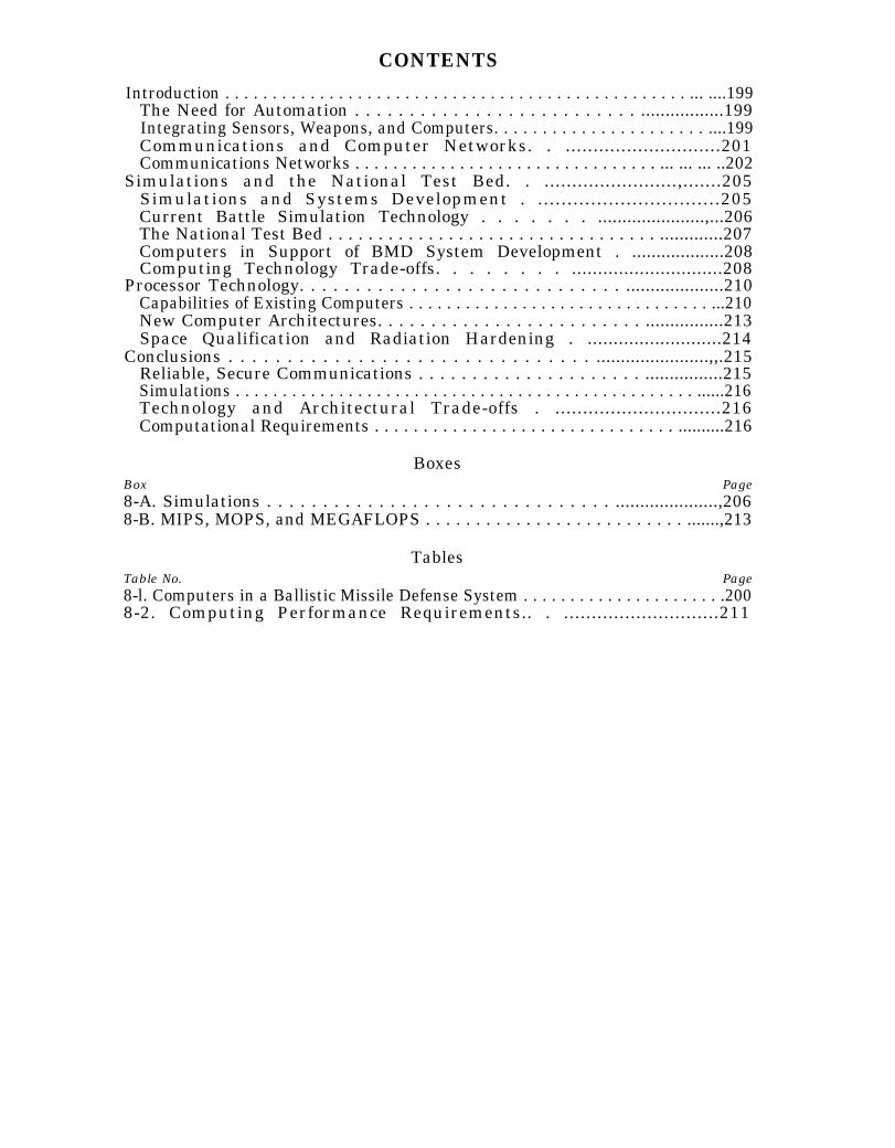
CONTENTS
Introduction . . . . . . . . . . . . . . . . . . . . . . . . . . . . . . . . . . . . . . . . . . . . . . . . . ... ....199The Need for Automation . . . . . . . . . . . . . . . . . . . . . . . . . . .................199Integrating Sensors, Weapons, and Computers. . . . . . . . . . . . . . . . . . . . . . ....199Communications and Computer Networks. . ............................201Communications Networks . . . . . . . . . . . . . . . . . . . . . . . . . . . . . . . . ... ... ... ..202
Simulations and the National Test Bed. . ........................,.......205Simulations and Systems Development . ...............................205Current Battle Simulation Technology . . . . . . . ......................,...206The National Test Bed . . . . . . . . . . . . . . . . . . . . . . . . . . . . . . . . . .............207Computers in Support of BMD System Development . ...................208Computing Technology Trade-offs. . . . . . . . .............................208
Processor Technology. . . . . . . . . . . . . . . . . . . . . . . . . . . . . ....................210Capabilities of Existing Computers . . . . . . . . . . . . . . . . . . . . . . . . . . . . . . . . ...210New Computer Architectures. . . . . . . . . . . . . . . . . . . . . . . . . ................213Space Qualification and Radiation Hardening . ..........................214
Conclusions . . . . . . . . . . . . . . . . . . . . . . . . . . . . . . . .......................,,.215Reliable, Secure Communications . . . . . . . . . . . . . . . . . . . . . ................215Simulations . . . . . . . . . . . . . . . . . . . . . . . . . . . . . . . . . . . . . . . . . . . . . . . . . ......216Technology and Architectural Trade-offs . ..............................216Computational Requirements . . . . . . . . . . . . . . . . . . . . . . . . . . . . . . . ..........216
BoxesBox Page8-A. Simulations . . . . . . . . . . . . . . . . . . . . . . . . . . . . . . . .....................,2068-B. MIPS, MOPS, and MEGAFLOPS . . . . . . . . . . . . . . . . . . . . . . . . . . .......,213
TablesTable No. Page8-l. Computers in a Ballistic Missile Defense System . . . . . . . . . . . . . . . . . . . . . .2008-2. Computing Performance Requirements.. . ............................211

Chapter 8
Computing Technology
INTRODUCTIONThis chapter discusses the demands that bal-
listic missile defense (BMD) systems wouldplace on computing technology, and the trade-offs that would have to be considered in satis-fying those demands. Initial sections discusswhy BMD would need computers and how itwould use them for battle management, weap-ons control, sensor data processing, commu-nications, and simulation. Later sections de-scribe the technology used to build computersand the requirements that the Strategic De-fense Initiative (SDI) imposes on that technol-ogy. The chapter concludes with key issuesposed by SDI computing needs. Any descrip-tion of computing technology must be accom-panied by a discussion of software and soft-ware technology issues; these can be found inchapter 9 and appendix A.
The Need for Automation
The rapid response times and volume of datato be processed would require the use of com-puters in every major BMD component andduring every phase of battle. Humans couldnot make decisions fast enough to direct thebattle. The launch of thousands of intercon-tinental ballistic missiles (ICBMs), some em-ploying fast-burn rocket boosters, might per-mit less than 60 seconds to detect, track, aim,and fire weapons at the first boosters to clearthe atmosphere. During mid-course it mightbe necessary to account for a million objectsand to discriminate among hundreds of thou-sands of decoys and thousands of reentry ve-hicles (RVs). In the terminal stage, RVs in theatmosphere would have to be quickly located,tracked, and destroyed by interceptor missiles.
Mutual occupation of space by two defen-sive systems of comparable capabilities mightrequire considerably faster reaction times than
Note: Complete definitions of acronyms and intialismsare listed in Appendix B of this report.
those needed to meet a ballistic missile attackalone. Countering an attack by space-bornedirected-energy weapons would require re-sponse times of seconds or less to avoid theloss of critical defensive capabilities. The crit-ical part of such a battle could well be over be-fore humans realized that it was taking place.
Although automated decision-making is a fo-cus of concern for the use of computers inBMD, computers would also serve many otherpurposes. Table 8-1 shows many of the placeswhere computers would be used.
Integrating Sensors, Weapons,and Computers
An automated BMD system would requiresome degree of coordination among differentcomputers, but there would be many placeswhere computers would act independently ofeach other. Table 8-1 shows many such cases,e.g., computers incorporated into sensor sys-tems, such as radars, to perform signal proc-essing on data perceived by the sensor. In eachcase the computer may be specially designedfor its job and is physically a part of the sys-tem of which it is a component.
As an example, an imaging radar would buildup an image of an object such as an RV byanalyzing the returns from the object over aperiod of seconds. The radar would processeach return individually and store the results.With sufficient individual returns, the radarcould analyze them to form an image of theobject. A single computer incorporated intothe radar would perform the processing, stor-age, and analysis. From the viewpoint of anexternal observer, such as a battle manage-ment computer residing on a different plat-form, the radar is a black box that producesan image of an RV. The external observer needknow nothing about the computer inside the
199
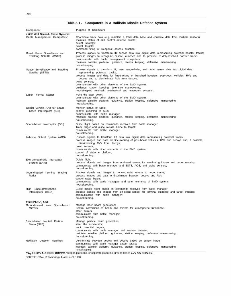
200
Table 8-1 .—Computers in a Ballistic Missile Defense System
Component Purpose of Computers
First. and Second. Phase Systems:Battle Management Computersa
Boost Phase Surveillance andTracking Satellite (BSTS)
Space Surveillance and TrackingSatellite (SSTS)
Laser Thermal Tagger
Carrier Vehicle (CV) for Space-based Interceptors (SBI)
Space-based Interceptor (SBI)
Airborne Optical System (AOS)
Exe-atmospheric InterceptorSystem (ERIS)
Ground-based Terminal ImagingRadar
High Endo-atmosphericInterceptors (HEDI)
Third Phase, Add:Ground-based Laser, Space-based
Mirrors
Space-based Neutral ParticleBeam (NPB)
Radiation Detector Satellites
Coordinate track data (e.g, maintain a track data base and correlate data from multiple sensors);maintain status of and control defense assets;select strategy;select targets;command firing of weapons; assess situation.
Process signals to transform IR sensor data into digital data representing potential booster tracks;process images to recognize missile launches and to produce crudely-resolved booster tracks;communicate with battle management computers;maintain satellite platform: guidance, station keeping, defensive maneuvering;housekeeping.
Process signals to transform IR, laser range-finder, and radar sensor data into digital datarepresenting potential tracks;
process images and data for fine-tracking of launched boosters, post-boost vehicles, RVs anddecoys and to discriminate RVs from decoys;
point sensors;communicate with other elements of the BMD system;guidance, station keeping, defensive maneuvering,housekeeping (maintain mechanical and electronic systems).
Point the laser beam;communicate with other elements of the BMD system;maintain satellite platform: guidance, station keeping, defensive maneuvering;housekeeping.
Monitor status of SBIs;control launching of SBIs;communicate with battle manager;maintain satellite platform: guidance, station keeping, defensive maneuvering;housekeeping.
Guide flight based on commands received from battle manager;Track target and guide missile home to target;communicate with battle manager;housekeeping.
Process signals to transform IR data into digital data representing potential tracks;process images and data for fine-tracking of post-boost vehicles, RVs and decoys and, if possible,
discriminating RVs from decoys;point sensors;communicate with other elements of the BMD system;control of airborne platform;housekeeping.
Guide flight;process signals and images from on-board sensor for terminal guidance and target tracking;communicate with battle manager and SSTS, AOS, and probe sensors;housekeeping.
Process signals and images to convert radar returns to target tracks;process images and data to discriminate between decoys and RVs;control radar beam;communicate with battle managers and other elements of BMD system;housekeeping.
Guide missile flight based on commands received from battle manager;process signals and images from on-board sensor for terminal guidance and target tracking;communicating with battle manager;housekeeping.
Manage laser beam generation;Control corrections to beam and mirrors for atmospheric turbulence;steer mirrors;communicate with battle manager;housekeeping.
Manage particle beam generation;steer the accelerator;track potential targets;communicate with battle manager and neutron detector;maintain satellite platform: guidance, station keeping, defensive maneuvering,housekeeping.
Discriminate between targets and decoys based on sensor inputs;communicate with battle manager and/or SSTS;maintain satellite platform: guidance, station keeping, defensive maneuvering;housekeeping.
aMaY be carried on sensor platforms, weapon platforms, or separate platforms; ground-based units maY be mobile.
SOURCE: Office of Technology Assessment, 1988,
201
radar, or how it operates, but only the formand content of its output.
Customizing the Computer for the Application
The above “black box” design strategy isbased on sound engineering principles andtends to simplify the battle management ar-chitecture, but it still involves some difficulttrade-offs. One such trade-off is that betweendeveloping special-purpose computers for dif-ferent sensors and weapons versus utilizingcommercially available hardware. Utilizingcommercially available computers may sim-plify the job of software development. Therewould be people available who have experiencewith existing hardware. In addition, supporttools for software development on availablecomputers already exist. As a result, softwaredeveloped for commercially available com-puters would probably be more reliable, moreefficient, and less expensive than software de-veloped for new computers built specificallyfor BMD. Furthermore, software developmentwould not have to wait for development of thehardware, reducing the risk of not meetingschedules.
On the other hand, hardware specially builtfor BMD is likely to be more efficient and bet-ter suited to the job, possibly offsetting effi-ciency losses in software. Moreover, maintaina-bility, reliability of the hardware, and life-cyclecost would have to be taken into account. Soft-ware experts at OTA’s SDI Software Work-shop suggested that hardware customizationv. software reliability and cost was an impor-tant trade-off that should be resolved in favorof simplifying software development. How-ever, some SDI computing might require theuse of novel hardware designs, even thoughthis might require designing new and complexsoftware from scratch.
Communications and ComputerNetworks
Battle management requires communica-tions among the battle managers, sensors, andweapons forming a BMD system and betweenthe battle managers and the human operators
of the system. Space-to-space, space-to-ground,and ground-to-space communications would berequired. As in traditional battle management,information must be sent in useful form, ontime, and securely to the place where it isneeded. Also as in traditional battle manage-ment, information transmitted among battlemanagers concerns the location of targets andweapons, the status of resources, and decisionsthat have been made. Distinct from traditionalbattle management, information transmittedin a BMD system would all be digitally en-coded and the transmissions controlled by com-puters. As noted in chapter 7, the rate and vol-ume of data to be transmitted depend on thebattle management architecture.
Estimates of Communications Requirements
The Fletcher Report estimated that the peakdata rate needed by any communications chan-nel in a BMD system would be about 107 bitsper second (bps).’ This estimate assumed thatan entire track file would have to be trans-mitted, that the file would contain 30,000tracks, and that each track could be repre-sented in 200 bits. Except for the number oftracks in a track file, the estimate is based onconservative assumptions. Furthermore, itscales linearly with the number of tracks, i.e.,a track file containing 300,000 tracks wouldrequire a peak rate of about 108 bps.
In more recent work, analysts have mademore specific assumptions about architecturesand have been able to produce more refined,but still rough, estimates. For example, onestudy of boost-phase communications uses ahighly distributed architecture consisting ofsensor satellites and satellite battle groupscomposed of battle management computers,sensors for booster tracking, and space-basedinterceptor (SBI) carrier satellites. Additionalassumptions were made about numbers of tar-gets tracked per sensor in the battle, number
‘James C. Fletcher, Study Chairman and B. McMi&n, PanelChairman, Report of the Study on E!inn”nating the Threat Posedby Nuclear Ballistic Missiles: Volume V, BattJe Management,Communications, and Data Processing, (Washington, DC: De-partment of Defense, Defensive Technologies Study Team, Oct.1983), p. 19.
202
of bits per target track, non-uniform messagetraffic density, number of relays per message,varying message types (examples are trackdata, status information, and engagementdata), and number of seconds per frame. Theresult was a peak link data rate for boost phasewithin the transmission rates of current tech-nology.2
The Fletcher Report noted, and OTA con-curs, that:
The technology exists today to transmit 107
to 108 bits/sec over data links of the length andkind needed for a BMD system. Therefore,even with 300,000 objects in the track file, ex-isting communication technology could han-dle the expected data rates. Cost and complex-ity will vary with the rate designed for, butthe Panel concludes that communication rates,per se, will not be a limiting factor in the de-sign of a BMD system.3
Communications Networks
Regardless of volume, communicationswould have to be secure and reliable. It wouldhave to survive attempts by an enemy to in-tercept, jam, or spoof communications, at bestrendering the system ineffective, at worst tak-ing control of it for his own purposes. It wouldalso have to survive physical damage incurredin a battle or defense suppression attack. Un-derstanding the threats requires understand-ing how communications would function in aBMD system.
Current communications technology, includ-ing that proposed for BMD systems, involvesestablishing a network of computers, each act-ing as a communications node, that transmitdata to each other. One example of an exist-ing network that is widely distributed geo-graphically is the ARPA network, initially de-veloped by the Defense Advanced ResearchProjects Agency (DARPA) as an experimentalnetwork. Another example is the AT&T longdistance telephone network. Both differ con-siderably from a space-based battle commu-nications network, which would have:
‘Personal communication, Ira Richer, The Mitre Corp.The Fletcher Report, op. a-t., footnote 1, p. 40.
1.
2.
3.4.
5.
more nodes and more available direct con-nections between nodes;different delays between nodes (perhaps5 milliseconds for the example distributedspace-based network described earlier ascompared to more than 25 milliseconds forthe ARPA network);more stringent security requirements;a need to re-establish links every few min-utes; and, probablylong repair times for individual nodes.
Nonetheless, the problems are sufficientlysimilar that the terrestrial networks are use-ful examples. Each node in the network com-municates with several other nodes. Users ofthe network communicate by submitting mes-sages to the network.4 The computers control-ling and comprising the network route the mes-sage from one node to another until it reachesits destination.
Some of the major issues that must be re-solved in designing a communications networkare:
●
●
●
●
●
●
the physical arrangement of the nodes andthe interconnections among the nodes;the unit of data transmission, which maybe a complete message or part of amessage;the algorithm used to decide what routethrough the network each unit of datatransmission will take;the algorithm used to encode units of datatransmission so that they may be relia-bly transmitted;the algorithm used by nodes for inter-changing data so that the start and endof each data transmission may be deter-mined; andthe methods used to ensure that data com-munications are secure and cannot bejammed, spoofed, or otherwise renderedunreliable.
4In the AT&T network, messages are sent across the networkto establish a circuit to be used for a long distance call whena subscriber dials a long distance number. Generally, once acircuit is established, it is dedicated to a call, and communica-tions on it may be sent in non-message form as analogue sig-nals or may be encoded digitally into messages.

204
Message Transmission
Information to be sent over a digital com-munications network, such as used in BMDsystems, is organized into messages. In somenetworks, known as “packet-switched” net-works, for transmission purposes the messagesare organized into blocks of data “packets.”7
In a packet-switched network the user submitshis message to the network unaware of howthe message will be organized for transmission.The software that controls the network mustincorporate a method for extracting messagesfrom packets when the packets reach their des-tinations.
Security of Communications
Secure network communications require thatthe routing algorithm be correct, that nodescannot be fooled into sending messages to thewrong recipient, and that the physical commu-nications links are secure from unauthorizedinterceptions. Since a network by its natureinvolves access to many computer systems, itaffords potential saboteurs a chance to accessmany different computers. Both the ARPAnetwork and the AT&T telephone networkhave been fooled on many occasions into per-mitting unauthorized access to the networkand, in the case of the ARPA network, to com-puters on the network. The managers of bothnetworks continually try to improve their pro-tection against such access, but no workablefoolproof protection techniques have beenfound. 8 As noted by Lawrence Castro, Chiefof the Office of Research and Development atthe National Computer Security Center,
(continued from previous page)
L?7EE Trans. on Corrmunications, vol. COM-26, No 12, Decem-ber 1978.
The reader should keep in mind that the ARPANET was de-signed as an experimental network, and not as a high reliabil-ity network intended for commercial use.
‘Depending on the situation, several messages maybe com-bined into one packet, or one message maybe split across sev-eral packets. In either case, the benefit of packet switching isthat network resources may be shared, leading to more efficientrouting of messages and more efficient use of the network, Thedisadvantage is that the job of the routing algorithm may becomplicated, and routing may become more difficult to debug.
“Access to a network is frequently separated from access tothe computers using the network. Entrance to the ARPA net-work is through computers dedicated to that job, known as ter-
Current computer networking technologyhas concentrated on providing services in a be-nign environment, and the security threats tothese networks have been largely ignored.While literature abounds with examples ofhackers wreaking havoc through access topublic networks and the computers connectedto them, hackers have exploited only a frac-tion of the vulnerabilities that exist. Tech-niques need to be developed that will preventboth passive exploitation (eavesdropping) andactive exploitation (alteration of messages ormessage routing.)9
Gaining unauthorized access to a BMD com-munications network would at least requirecommunications technology as sophisticatedas that used in the design and implementationof the network. Furthermore, an enemy wouldhave to penetrate the security of the data links,which would likely be encrypted. Since networkcommunications would be used for coordina-tion among battle managers, and would prob-ably involve transmission of target and healthdata,"10 the worst result of compromise of thenetwork would be that the enemy could con-trol the system for his own uses. Disruptionof communications could result in disuse ormisdirection of weapons and sensors, causingthe BMD system to fail completely in its mis-sion. To achieve such disruption, it would notbe necessary for a saboteur to gain control ofa battle management computer, but only tofeed it false data. Less subtle ways to achievethe same means might be to destroy sufficient
rninal access computers (TACS). Until recently, such access wasavailable to anyone who had the telephone number of a TAC.Several s~called hackers have made use of TAC facilities togain entrance to Department of Defense computer systems con-nected to the ARPA network, and they have been successfullyprosecuted for doing so, Partly as a result of such unauthorizeduse of TACS, password protection has been added to TAC ac-cess procedures. The telephone companies wage constant waragainst people who attempt to use their long distance networkswithout paying.
‘Lawrence Castro, “The National Computer Security Center’sR&D Program,” Journal of Electronic Defense, vol. 10, No. 1,January 1987.
‘The health of a resource, such as a sensor satellite or weaponsatellite, is how well the resource is able to perform its missionand what reserves are available to it. Example measures of sat-ellite health are battery power and efficiency of solar cells. Fora BMD satellite, such as a carrier vehicle for SBIS, additionaldata specific to the function of the satellite, such as numberof SBIS remaining, would be included.
203
Since most of these issues are resolved insoftware, the solutions chosen have a strongeffect on the complexity of the software andthe reliability of the battle management sys-tem as a whole. The more critical of these is-sues are discussed in the following sections.In almost every case, the trade-off is that add-ing sophistication to the algorithm(s) used tosolve the problem results in software that is morecomplicated and more difficult to debug.
Network TopologyThe arrangement of interconnections among
nodes is known as the “network topology.” Inattempts to improve the efficiency and relia-bility of networks, numerous topologies havebeen tried. As an example, until recently theAT&T long distance telephone switching sys-tem used a hierarchical topology to establisha circuit to be used for a long distance call.5
Nodes were organized into levels. Messagesrequesting the circuit were sent from a lowerlevel to a higher level, then across the higherlevel and back down to a lower level. If all mes-sages must pass through one or two nodes,then under heavy loads those nodes may formbottlenecks that decrease network perform-ance. If the nodes break down under the traf-fic load, the network cannot not function atall. As a result, most networks employ al-gorithms that decide what route each messagewill take through the network. The route mayvary according to the prevailing load condi-tions and the health of the nodes in thenetwork.
Routing in NetworksIn geographically distributed networks with
many nodes, the routing algorithm is a sophis-ticated computer program. Frequently, net-work performance degrades as a result of in-correct assumptions or errors in the design andimplementation of the routing algorithm. Find-
5T0 help alleviate bottlenecks in the system, AT&T is nowmoving toward anon-hierarchical system where nodes can com-municate directly with each other rather than going througha hierarchy. Note that decisions to change the structure of thelong distance system are made as the result of observing itsbehavior over extensive periods of use by millions of subscribers.
ing and correcting the reason for degraded per-formance requires knowledge of the networkstatus, including traffic loads at nodes andhealth of nodes. Since traffic load in particu-lar varies second-by-second, debugging net-work routing software is a difficult and time-consuming job.
One can only have confidence in relatively bug-free operation by permitting the network to func-tion under operational conditions long enoughto observe its performance under varying loads.Stress situations, e.g. especially heavy trafficconditions, tend to cause problems. In operationsuch conditions are relatively infrequent; theyare also hard to reproduce for debugging pur-poses. Nevertheless, for a dedicated networksuch as a BMD communications system, itmay be easier to simulate heavily loaded con-ditions than for a commercial network.
Either software failures, such as an error ina routing algorithm, or hardware failures maycause catastrophic network failure. In Decem-ber, 1986, the east coast portion of the ARPAnetwork was disconnected from the rest of thenetwork because a transmission cable was ac-cidentally cut. Although the ARPA networkhad evolved over more than 15 years, an op-portunity for a single-point catastrophic fail-ure remained in the design.
Sometimes the interaction of a hardware fail-ure and the characteristics of a particular rout-ing algorithm CM cause failure. In 1971 nor-mal operations of the ARPA network came toa halt because a single node in the networktransmitted faulty routing information toother nodes. Transmission of the faulty datawas the result of a computer memory failurein the bad node. Based on the erroneous data,the routing algorithm used by all nodes causedall messages to be routed through the faultynode. The routing algorithm was later revisedto prevent the situation from recurring, i.e.,the software was rewritten to compensate forcertain kinds of hardware failures.6
‘For a more complete description of this problem, see J.McQuillan, G. Falk, and I. Richer, “A Review of the Develop-ment and Performance of the ARPANET Routing Algorithm, ”
(continued on next page)
205
communications nodes that routing algorithmsbecome overstressed and fail, or to destroysufficient nodes that battle managers can nolonger communicate with each other. Theformer attack requires that the enemy havesome knowledge of the routing algorithmsused; the latter may require considerable ex-penditure of physical resources such as anti-satellite missiles.
Even passive observation of a BMD com-munications network could reveal enoughabout the battle management and communi-cations algorithms used by the network to per-mit an enemy to devise means of circumvent-ing those algorithms and thereby rendering thedefense partially or totally ineffective. To pre-vent an enemy gaining such knowledge by ob-servation of communications, encryption ofcommunication links and techniques for dis-guising potentially revealing changes in mes-
sage traffic would have to be incorporated anetwork design.
Although encryption and other technologycould make passive exploitation quite difficult,a saboteur could perhaps gain access to thecommunications software and hardware. Anal-ysis of the sabotage questions, however, be-yond the scope of this study.
Achieving secure, reliable, adequate commu-nications requires the conjunction of at leasttwo technologies. The technology for physicalcommunications, such as laser communica-tions, needs to provide a medium that is diffi-cult to interceptor j am and that can meet therequired transmission bandwidth. The networktechnology must provide adequate, secureservice for routing messages to their desti-nations.
SIMULATIONS AND THE NATIONAL TEST BED
Preceding sections have discussed the roleof computers during battle. Computing tech-nology would also play a key role in prepara- ●
tion for battle and in maintaining battle-readiness. Computer simulations (box 8-A)would be needed:
●
●
●
●
to anticipate threats against the system,to model different ways in which the sys-tem might work,to provide a realistic environment in whichsystem components may be tested duringtheir development, and
●
to test the functioning of the system asa whole, both before and after deployment.
Simulations and Systems Development
Simulators are useful during all stages of thedevelopment of complicated systems.
● During the early stages of the develop-ment of a system, simulators may predict ●
the behavior of different system designs.An example is simulators that predict
stresses on parts of a bridge for differentbridge designs.During the middle stages of development,simulators may test individual compo-nents of a system by simulating thoseparts not yet built or not yet connectedtogether. An example is a simulator thatreproduces the behavior of the differentparts of an aircraft before the aircraft’ssystems are integrated. A radar simulatorcan feed data to the radar data processorbefore the radar itself has been finished.During testing, a simulator can be usedto reproduce the environment in which thesystem will operate. Avionics computersand their software are tested before instal-lation by connecting them to an environ-mental simulator that reproduces theflight behavior of the aircraft’s systemsto which the computers will be connectedwhen installed in the airplane.After deployment, simulators test thereadiness of systems by mimicking theenvironment-including stress conditions
206
Box 8-A.—Simulations
A simulation is a system that mimics the behavior of another system. The difference betweenthe simulation and the system being mimicked (called the target), is that the simulation does notaccurately reproduce all of the behavior of the target. Behavior not accurately reproduced is eitherunimportant to the users of the simulation, unknown to the builders of the simulation, or too expen-sive to reproduce. Many simulators operate by solving a set of mathematical equations that predictthe behavior of the target system under the desired conditions. This process is known as modellingthe behavior of the target, and such a simulator is often called a model. Others may do no morethan supply a previously determined sequence of values on demand or at fixed time intervals.
Airplane flight simulators are good examples of simulators. Flight simulators used for pilottraining reproduce flight conditions well enough to help train pilots how to fly, but not to grantthem licenses. No one would trust a pilot all of whose flight time was logged on a simulator. Flightsimulators are just not sufficiently accurate reproductions of flight conditions to ensure that thepilot knows what it feels like to fly a real plane. However, a pilot who already has a license mayuse a simulator to qualify for another aircraft in the same class as his license, e.g., a pilot qualifiedfor a DC-10 could qualify to fly a Boeing 747 based only on simulated flights.
Constructing an accurate simulation requires that the target behavior be well understood andthat there be some method for comparing the behavior of the simulator with the behavior of thetarget. In cases where the physical target behavior is unavailable for comparison, simulator be-havior may be compared to other simulators modeled on the same target, or to predictions madeby mathematical models of the target. (In cases where the simulator itself is a model, a differentmodel may be used for comparison. If a different model is unknown another simulator already knownto be reliable, or hand calculations, maybe used.) A simulator that models the trajectory of a missilein flight can be checked against actual missiles and the equations of motion that are known to gov-ern such trajectories. A simulator that models the behavior of the Sun can only be compared toobserved solar behavior, and may be quite inaccurate when used to predict behavior under previ-ously unknown conditions.
–for which it is critical that the system attacking a single ship. Such simulations canoperate correctly. Such simulators areoften build into the system and containmeans of monitoring its behavior duringthe simulation. The design of the SAFE-GUARD anti-ballistic missile system ofthe early 1970s incorporated a simulatorcalled the system exerciser” to permitsimulated operation of SAFEGUARDduring development and after deployment.
now be run 30 times slower than real time, i.e.,30 seconds of processor time devoted to run-ning the simulation corresponds to 1 secondin an actual engagement. However, the de-mand is now to develop simulators that canmodel many missiles against many ships.
Work at the U.S. Army’s Strategic DefenseCommand (USASDC) Advanced ResearchCenter (ARC) is representative of current BMDsimulation technology. In late 1986, ARC re-
Current Battle Simulation Technology searchers completed a set of mid-course BMDbattle simulations. The simulations empoyed
As faster, deadlier, and more expensive 6 Digital Equipment Corporation VAX 11/780weapons, such as guided missiles, have been computers coupled by means of shared mem-added to arsenals, the demand on simulation ories. Four of the computers could simulatetechnology to analyze their effects has in- battle managers, one simulated surveillancecreased. For example, in the early 1970s, sin- sensors (all of the same type) and weaponsgle engagement simulations modeled such (ground-launched homing interceptors of theevents as defending against a single missile Exoatmospheric Reentry vehicle Interceptor

207
System), and one simulated 32 other engagedplatforms.”
The ARC researchers ran three battle man-agement design cases:
1.36 battle managers that communicatedamong each other, known as the distrib-uted case;
2. a single centralized battle manager; and3.36 autonomous battle managers that did
not communicate with each other, knownas the autonomous case.
The centralized and distributed cases as-sumed 236 and 237 interceptors respectively,and the autonomous case assumed 660. Themaximum threat simulated was 1,000 objects,which required 7 hours to run. The centralizedand distributed cases took 3 and 4 hours re-spectively to run against a threat of 216 RVs.The simulation took 15 months to develop, andincluded about 150,000 lines of code, much ofit in the Pascal programming language. (Codefor the battle managers was replicated for somesimulations; the replication is not included inthe 150,000 lines.)
Perhaps the largest stumbling block in run-ning larger scale and more realistic simulationsfor the ARC is the lack of computing power.SDIO expects the EV88 experiment sequence,running through fiscal year 1990, to conductlarger scale simulations involving the ARC,the Airborne Optical Adjunct, prototypespace-based BMD components, and the Na-tional Test Bed. This series of experiments willrequire considerably more computing powerthan is now in place at the ARC.
Simulation experts agree that computingpower is currently the major limitation in per-forming large scale simulations. However,other factors complicate the situation. Whereequipment or environments are not well-under-stood or include many random variables, theaccuracy of simulations is difficult to verify.This is the case, for example, in simulationsof sea conditions surrounding missile v. shipengagements.
11Depending on the architecture being simulated, the otherplatforms were either battle managers or sensors.
Some military simulation experts noted toOTA staff that every time they performedsimulated threat assessments without prior ac-cess to the real equipment being modeled, thebehavior of the real equipment surprised them.They strongly emphasized that it was onlywhen a simulation could be compared to an ac-tual experiment that the verisimilitude of thesimulation could be checked.12 The implicationfor BMD is that actual Soviet decoys and mis-siles would have to be examined and observedin operation to simulate their workings ac-curately. Similarly, the battle environment, in-cluding nuclear effects—where appropriate—and enemy tactics, would have to be well under-stood to conduct a battle simulation properly.
The National Test Bed
The SDIO is sponsoring the development ofa National Test Bed (NTB)—a network of com-puters and a set of simulations to execute onthose computers. A threat model is to simu-late the launch of Soviet missiles and displaytheir trajectories after launch. Another modelwould simulate a complete BMD battle to ex-ercise a deployed BMD system.
The NTB would be utilized in all phases ofthe development and deployment of a BMDsystem. It should permit experimentation withvarious system and battle management ar-chitectures, battle management strategies, andimplementations of architectures. It would bethe principal means of testing BMD systemcomponents and subsystems as well as the en-tire BMD system, thereby providing the ba-sis for their reliability.
Preliminary design work studies for the esti-mated $1 billion NTB were completed in De-cember 1986.13 Initially, the NTB is to be a net-work of computers, each simulating a differentaspect of a BMD engagement. The number ofcomputers linked for any particular engage-
lzExwrienCe cit~ here is drawn from discussions with Scien-tists from the Naval Research Laboratory’s Tactical ElectronicWarfare Division about simulations of Naval warfare.
‘3Major James Price, SDIO’S assistant NTB director, de-scribed the NTB as a $1 billion program through 1992 in aninterview reported in Defense Electronics in February, 1987.
208
ment would vary depending on the complete-ness and depth of detail required. Initial capa-bilities would not permit simulation of a fullbattle involving hundreds of thousands ofobjects.
A major use of the NTB would be to con-duct experiments with different BMD technol-ogies and strategies. The currently visualizedNTB would link sensors, weapons, or battlemanagers to simulations that reproduce thedata they would handle during a battle. Theobject could then be tested under varying con-ditions. The results of such experiments wouldbe quite sensitive to the verisimilitude of thesimulations. Accordingly, it is important thatthere be a way to verify the accuracy of thesimulations used in NTB tests and exper-iments.
Computers in Support ofBMD System Development
A BMD system to counter the Soviet bal-listic missile threat might be the most compli-cated system ever built. It would involve theuse of many different technologies, the auto-mated interplay of thousands of different com-puters, sensors, and weapons, and the devel-opment of more software than has been usedin any single previous project. Accordingly,managing the development of such a systemwould require considerable computer supportto track progress, to identify problems, andto maintain the status of components underdevelopment, in test, and deployed.
Computers would also be used to design, gen-erate, and test system hardware and software.Engineers and managers are likely to be geo-graphically dispersed and would need to trans-fer information from one computer to another.The interaction among people would only beeffective if there were a means for effective in-teraction among the computer systems thatthey use. Previous sections of this chapter haveconcentrated on the role of computers in theoperation and testing of a BMD system. Butit is clear that effective computing technologywould be needed not just in a strategic battle,but long before system deployment andthroughout the lifetime of the system.
Computing Technology Trade-offs
Chapter 7 and the preceding sections haveportrayed some of the trade-offs involved inusing computers for ballistic missile defense.The following list summarizes those trade-offs.
●
●
●
●
●
●
Processing power required v. volume ofdata communications among battle man-agers. Sharing information among battlemanagers relieves them of some of thetasks that they might otherwise have toperform, and decreases the processingload on each of the battle managers, butincreases the data communications raterequirements and also requires that com-munications be secure and reliable.Performance v. volume of data communi-cations. Sharing data among battle man-agers allows the system to operate moreefficiently, but, as in the previous trade-off, greater dependence on communica-tions requires greater communications ca-pacity, reliability, and security.Performance v. degree of automation. Per-mitting human intervention during a bat-tle degrades performance under some con-ditions, but may permit recovery fromfailures caused by the inability of an auto-mated system to recover from unantici-pated and undesired events.Processing power required v. battle man-agement organization. A distributed orga-nization would require less processingpower from each computer but more com-munications than centralized battle man-agement, which requires placing a consid-erable concentration of processing powerin one computer system.Software complexity v. battle manage-ment organization. A hierarchical battlemanagement architecture simplifies thesoftware design but may leave the systemless survivable because of the possibilityof command layers being disabled. A de-centralized battle management structurewould increase the complexity of the com-munications software and might requiremore weapon resources, but might resultin a more survivable system.Software expense and reliability v. hard-ware customization. Customizing hard-

209
Photo credit: Electronic Systems Division, US Air Force Systems Command
Computer simulations are to play a key role in the development and testing of SDI systems. The photographs here areof video displays screens generated by a ballistic missile defense battle simulation program developed at the MITRECorporation. The circles in the scene above depict areas of coverage for a system of space-based interceptors. The scene
below indicates the tracks of ICBM boosters a few minutes after launch.
ware to perform efficiently at specifictasks could improve hardware capabil-ities, but might result in longer softwaredevelopment schedules and decreasedsoftware reliability because of lack of ex-perience with and lack of developmenttools for the hardware.
These trade-offs represent important ar-chitectural issues that strongly affect the com-
puting technology needed for BMD. For mostof them, the SDI system architects have notyet explored the alternatives in sufficient de-tail to be able to quantify choices. As a result,there are still only crude estimates of thespeeds and sizes of the computers needed, andthe rates at which data would have to be com-municated among the elements of a BMDsystem.
PROCESSOR TECHNOLOGYTable 8-1 shows many of the places where
computers would be used in the fighting com-ponents of a BMD system and the jobs theywould perform. Rough estimates of the re-quired memory capacities and speeds are inincluded in the classified version of this re-port.14 Estimates of computer performance re-quirements for various BMD functions areshown in table 8-2.
Processing requirements are highly depen-dent on the system and battle managementarchitectures, and on the threat. Withoutdetailed architectural specifications and a pre-cise specification of the algorithms to be used,estimates of speed and memory requirementsaccurate to better than a factor of 10 probablycannot be made.
Because of the variety of jobs they wouldperform, BMD computers would vary con-siderably in speed and memory capacity. Spe-cial purpose computers would probably exe-cute some computing tasks, such as signalprocessing. General-purpose computers fasterthan any now existing would probably beneeded for computationally stressful taskssuch as discrimination of RVs and decoys inmid-course. All space-based computers wouldhave to be radiation-hardened beyond thelimits of existing computers.15
14 For many of the system elements shown in table 8-1, esti-mates for processing speed and size are not available. The mostcomputationally intensive tasks are probably signal process-ing for the IR and optical sensors incorporated into BSTS, SSTS,and AOS, especially for the mid-term and far-term architectures.
“Radiation hardening to within an order of magnitude of SDIrequirements for some critical components of computer systems
In addition to their use in the fighting com-ponents of the system, computers would alsobe used:
1. in simulators;2. to help design, test, exercise, and train
people in the use of the system; and3. to assist in supporting the system
throughout its lifetime.
Capabilities of Existing ComputersThe processing power of a computer is de-
termined by the operating speed of its compo-nents and the way they are interconnected (seebox 8-B). Processing and memory componentsare built from semiconductor chips, whosespeed is limited by the number and arrange-ment of circuits that can be placed on a chip.Developments in chip design and productiontechnology, including advances from largescale integrated circuits (LSI) to very largescale integrated circuits (VLSI), have increasedprocessor speeds for general purpose comput-ers by a factor of three to four approximatelyevery 2 years for about the past 10 years. Muchof this progress has been the result of refine-ments in chip design and production. As a re-sult, some existing supercomputers, such asthe Cray XMP series or Cray 2, may be closeto satisfying most SDI data processing needs,except that such machines are not packagedin a suitable form.
has been demonstrated. A complete computer system that isspace qualified and radiation-hardened to within an order of mag-nitude of SDI requirements for spaceborne computers has yetto be built.
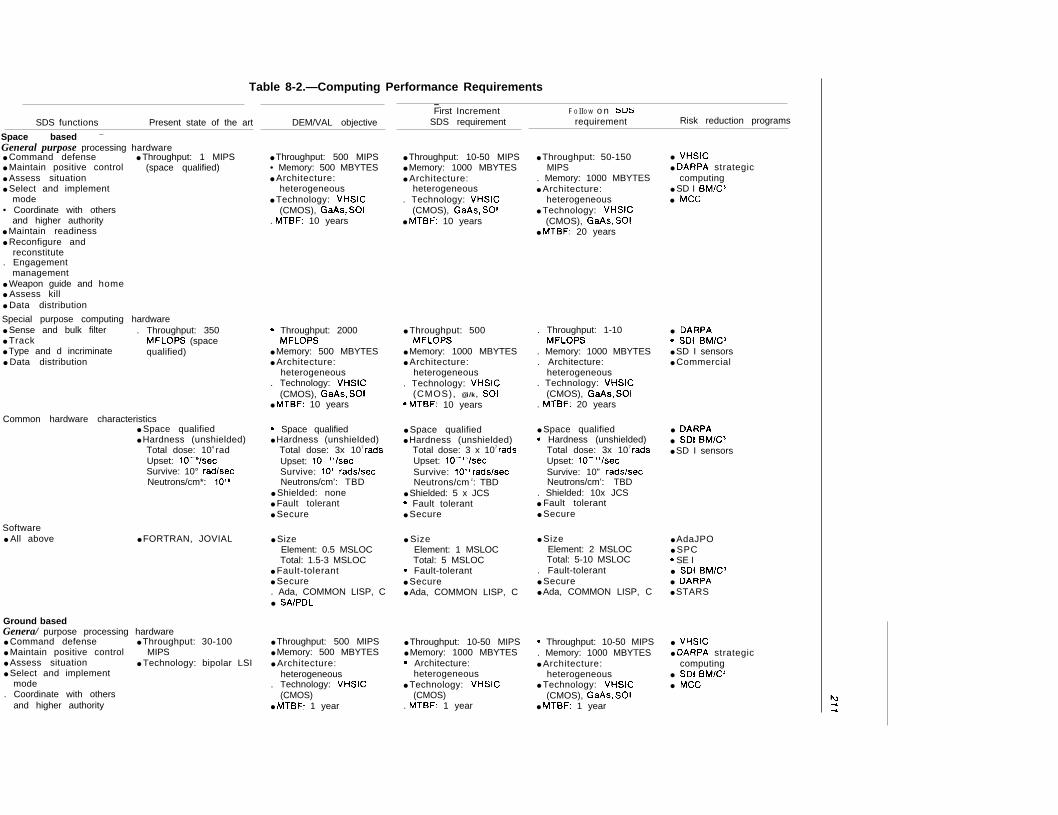
Table 8-2.—Computing Performance Requirements— —.
First IncrementSDS requirement
F O IIO W o n SDS
requirement Risk reduction programsSDS functions Present state of the art
Space based —
General purpose processing hardware● Command defense ● Throughput: 1 MIPS● Maintain positive control (space qualified)● Assess situation● Select and implement
mode• Coordinate with others
and higher authority● Maintain readiness● Reconfigure and
reconstitute. Engagement
management● Weapon guide and home● Assess kill● Data distribution
DEM/VAL objective
● Throughput: 500 MIPS• Memory: 500 MBYTES● Architecture:
heterogeneous● Technology: VHSIC
(CMOS), GaAs, SOI. MTBF: 10 years
● Throughput: 10-50 MIPS● Memory: 1000 MBYTES● Architecture:
heterogeneous. Technology: VHSIC
(CMOS), GaAs, SOI● MTBF: 10 years
● Throughput: 50-150MIPS
. Memory: 1000 MBYTES● Architecture:
heterogeneous● Technology: VHSIC
(CMOS), @/%i, SOI● MTBF: 20 years
● VHSIC● DARPA strategic
computing● SD I BM/C3● MCC
Special purpose computing hardware● Sense and bulk filter . Throughput: 350● Track MFLOPS (space● Type and d incriminate qualified)● Data distribution
c Throughput: 2000MFLOPS
● Memory: 500 MBYTES● Architecture:
heterogeneous. Technology: VHSIC
(CMOS), GaAs, SOI● MTBF: 10 years
● Throughput: 500MFLOPS
● Memory: 1000 MBYTES● Architecture:
heterogeneous. Technology: VHSIC
(CMOS), @i/k, SOIc MTBF: 10 years
. Throughput: 1-10MFLOPS
. Memory: 1000 MBYTES
. Architecture:heterogeneous
. Technology: VHSIC(CMOS), GaAs, SOI
. MTBF: 20 years
● DARPAc SDI BM/C3● SD I sensors● Commercial
Common hardware characteristics● Space qualified● Hardness (unshielded)
Total dose: 104 radUpset: 1O-e/secSurvive: 10° radlsecNeutrons/cm*: 10’0
c Space qualified● Hardness (unshielded)
Total dose: 3x 10⁷ radsUpset: 1O-’’/secSurvive: 10” rads/secNeutrons/cm’: TBD
● Shielded: none● Fault tolerant● Secure
● Space qualified● Hardness (unshielded)
Total dose: 3 x 10⁷ radsUpset: 1O-’’/secSurvive: 10” rads/secNeutrons/cm z: TBD
● Shielded: 5 x JCSc Fault tolerant● Secure
● Space qualifiedc Hardness (unshielded)
Total dose: 3x 10⁷ radsUpset: 1O-’’/secSurvive: 10” rads/secNeutrons/cm’: TBD
. Shielded: 10x JCS● Fault tolerant● Secure
● DARPA● SDI BM/C3● SD I sensors
Software● All above ● FORTRAN, JOVIAL ● Size
Element: 0.5 MSLOCTotal: 1.5-3 MSLOC
● Fault-tolerant● Secure. Ada, COMMON LISP, C● SAIPDL
● SizeElement: 1 MSLOCTotal: 5 MSLOC
c Fault-tolerant● Secure● Ada, COMMON LISP, C
● SizeElement: 2 MSLOCTotal: 5-10 MSLOC
. Fault-tolerant● Secure● Ada, COMMON LISP, C
● AdaJPO● SPCc SE I● SDI BM/C3● DARPA● STARS
Ground basedGenera/ purpose processing hardware● Command defense ● Throughput: 30-100● Maintain positive control MIPS● Assess situation ● Technology: bipolar LSI● Select and implement
mode. Coordinate with others
and higher authority
● Throughput: 500 MIPS● Memory: 500 MBYTES● Architecture:
heterogeneous. Technology: VHSIC
(CMOS)● MTBF: 1 year
● Throughput: 10-50 MIPS● Memory: 1000 MBYTESc Architecture:
heterogeneous● Technology: VHSIC
(CMOS). MTBF: 1 year
c Throughput: 10-50 MIPS. Memory: 1000 MBYTES● Architecture:
heterogeneous● Technology: VHSIC
(CMOS), GaAs, SOI● MTBF: 1 year
● VHSIC● DARPA strategic
computing● SDI BM/Cs● MCC
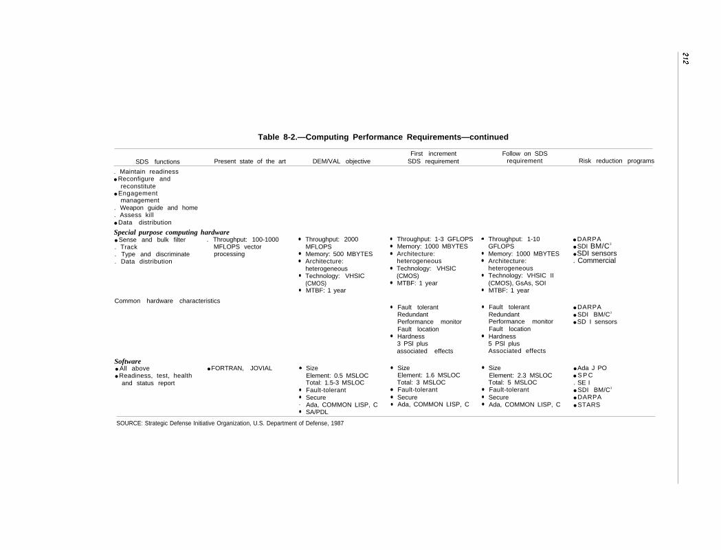
Table 8-2.—Computing Performance Requirements—continued
First increment Follow on SDSSDS functions Present state of the art DEM/VAL objective SDS requirement requirement Risk reduction programs
. Maintain readiness● Reconfigure and
reconstitute● Engagement
management. Weapon guide and home. Assess kill● Data distribution
Special purpose computing hardware● Sense and bulk filter . Throughput: 100-1000. Track MFLOPS vector. Type and discriminate processing. Data distribution
Common hardware characteristics
Software● All above ● FORTRAN, JOVIAL● Readiness, test, health
and status report
●
●
●
●
●
●
●
•
●
Throughput: 2000MFLOPSMemory: 500 MBYTESArchitecture:heterogeneousTechnology: VHSIC(CMOS)MTBF: 1 year
SizeElement: 0.5 MSLOCTotal: 1.5-3 MSLOCFault-tolerantSecureAda, COMMON LISP, CSA/PDL
●
●
●
●
●
●
●
●
●
●
●
SOURCE: Strategic Defense Initiative Organization, U.S. Department of Defense, 1987
Throughput: 1-3 GFLOPSMemory: 1000 MBYTESArchitecture:heterogeneousTechnology: VHSIC(CMOS)MTBF: 1 year
Fault tolerantRedundantPerformance monitorFault locationHardness3 PSl plusassociated effects
SizeElement: 1.6 MSLOCTotal: 3 MSLOCFault-tolerantSecureAda, COMMON LISP, C
●
●
●
●
●
●
●
●
●
●
Throughput: 1-10GFLOPSMemory: 1000 MBYTESArchitecture:heterogeneousTechnology: VHSIC II(CMOS), GsAs, SOIMTBF: 1 year
Fault tolerantRedundantPerformance monitorFault locationHardness5 PSl plusAssociated effects
SizeElement: 2.3 MSLOCTotal: 5 MSLOCFault-tolerantSecureAda, COMMON LISP, C
● DARPA● SDI BM/C3
● SDI sensors. Commercial
● DARPA● SDI BM/C3
● SD I sensors
● Ada J PO● S P C. SE I● SDI BM/C3
● DARPA● STARS
213
Box 8-B.–MIPS, MOPS, and MEGAFLOPS
The processing power of a computer is often expressed as the rate at which it can execute in-structions, measured in instructions per seconds, or ips. A computer that can execute a million in-structions per second is a 1 mips machine. Although mips give a crude measure of the speed ofa computer, there is too much variability in the time it takes to execute different instructions onthe same machine and in the instructions used by different machines for mips to be a true compara-tive measure of processing power.
Complex instructions may take four or five times longer to execute than simple instructionson the same machine. A complex instruction on one machine may have the same effect in two-thirdsthe time as three simple instructions on a different machine. To simulate operating conditions, amix of different instructions are often used in measuring computer performance. Such measure-ments are sometimes characterized as operations per second, or ops, rather than ips. A computerthat can execute a million operations per second is called a 1 mops machine. BMD signal processingneeds have been estimated to be as much as 50 billion ops (50 gigops).
One class of instructions, known as floating point instructions, are important in numerical cal-culations involving numbers that vary over a wide range, but are very costly in terms of executiontime. A common option on computers is an additional processor, sometimes known as a floatingpoint accelerator, specialized to perform floating point operations. The speed of computers designedto perform numerical floating point operations efficiently is usually measured in floating point oper-ations per second, or flops. A computer that can execute a million floating point instructions persecond is a 1 megaflops machine.
To compensate for differences in instruction sets and instruction effects on different computers,standard mixes of instructions are used to compare the performance of different computers. Forapplications involving widely-ranging numerical calculations, such as track correlation, floating pointinstructions are included in the mix. The variation in machine performance between machines maybe a factor of three or four, depending on the mix, the machines involved, and other factors.
For purposes of estimating processing power needs for SDI BMD, the requirements are notyet known to better than a factor of about 10, which dominates differences in performance on differ-ent instruction mixes. Accordingly, estimates in this report will generally be given in terms of mipsor mops.
If progress can be continued at the same rate the features used to construct circuits on theas in recent years, sufficiently powerful proc- chip. Increases in processor speeds may thenessors to meet the most stressing requirementsof SDI BMD should be available in about 10years. An obstacle to satisfying BMD proc-essing power requirements is that the proces-sors with the largest requirements are thosethat would have to be space-based and there-fore radiation hardened. Special developmentprograms would be needed to produce ade-quate space qualification and radiation harden-ing for the new processors.
New Computer ArchitecturesCurrent chip production technology may
soon reach physical limitations, such as thenumber of off-chip connectors and the size of
have to await new chip production technologyor new ways of building processors, e.g., opti-cal techniques. An alternative to increasingcomputer speeds without improving compo-nent speeds is to find better ways of intercon-necting components, i.e. better computer ar-chitectures, and better ways of partitioningcomputing tasks among computers. Comput-ers constructed by interconnecting many smallcomputers in ingenious ways, such as theHypercube computers developed at Cal Techand later produced by Intel as the iPSC ma-chine, are just now appearing on the market.16
“ C.L. Seitz, “The Cosmic Cube,” Communications of theACM, January 1985.
214
The iPSC is estimated to run at 100 mips and8 mflops, but is well-suited only for scientificcomputing tasks that can be organized to takeadvantage of the iPSC’s architecture. Whetheror not such architectures will be useful for themost computationally-intensive BMD taskswill depend on what algorithms are used.
Novel computer architectures, despite theirpotential processing power, have the drawbackthat the software technology base needed tocapitalize on their potential must be developed.New software is needed to run programs onnew computers, to help users decompose theirproblems to utilize the machine’s potential, andto convert existing software to execute on themachine. As an example, to meet Departmentof Defense (DoD) standards, a computer suchas the iPSC would need a compiler for AdaTM
(the DoD’s standard programming languagefor weapon systems) and an operating systemcompatible with AdaT M. Although advancesin computing hardware have come rapidly,software development is notoriously slow andcostly.
Space Qualification andRadiation Hardening
Space-qualified general purpose computerslag ground-based computers in processingpower by a factor of 20 or more. The fastestspace-qualified-but not radiation-hardened—processors today achieve processing rates ofabout 1 mips.17 Adequate radiation hardeningof the computers imposes a more significantpenalty in cost than in processing speed. Themost promising technology for meeting bothspeed and radiation hardening requirementscurrently uses gallium arsenide (GaAs) ratherthan silicon in the manufacture of chips. Al-though GaAs is more radiation resistant, highdefect densities reduce manufacturing yields,making chip production costlier. The higherdefect densities also impose smaller chip sizesand fewer electronic circuits per chip. The con-
17 The Sperry 1637 and Delco MAGIC V avionics processorsachieve a rate of about 1 mips, but neither are radiation-hardenednor have they been used in space applications. The RockwellIDF 224 and Delco MAGIC 362S space-qualified processorsachieve a rate of about 600 kops for instruction mixes that donot include floating point operations.
sequent lower overall level of integration mayrequire processors to have more componentsand be less reliable. Researchers in chip pro-duction say that current problems with man-ufacturing yields and circuit densities are tem-porary and will be solved. As Milutinovicstates,
. . . many problems related to materials areconsidered temporary in nature, and oneprediction states that the steady-state costwill be about one order of magnitude greaterfor GaAs than for silicon.18
Space-based computers must be able to with-stand long-term cumulative doses of radiationand neutron flux, short bursts of a few highly-energetic particles (known as transient events),and electromagnetic pulses (EMP) resultingfrom nuclear detonations. Although shieldingmay protect semiconductors against all threephenomena, it incurs a corresponding weightpenalty. Gallium arsenide is a promising ma-terial for semiconductors because it is moreresistant to cumulative radiation and neutronflux damage than silicon. Resistance of GaAsto transient events is dependent on the par-ticular chip design.
It may be possible to harden space-basedcomputers to survive the radiation of a nuclearweapons battle environment. But it is impor-tant to consider the effects of such an envi-ronment on software as well as on hardware.A transient radiation-caused upset might in-terrupt the current operation of computer hard-ware, leading either to a resetting of the proc-essor or to the changing of a bit in memoryor in the internal circuitry of the processor. Theprocessor may continue to function, but thestate of the computation maybe altered, caus-ing an error in software processing, i.e., a sys-tem failure.
Consider as an analogy the effects of a sin-gle digit error on the computation of an entryfor an income tax form. The error may be sosmall as to be hardly noticeable, and it mayeven make no difference because the tax scales
1’Veljko Milutinovic, “GaAs Microprocessor Technology, ”Computer, October 1986, pp. 10-13.
215
are incremental, not continuous. On the otherhand, a larger error in a single digit may havea considerable effect on the amount of tax paid.In either case, the error may propagatethrough later entries on the form until it is no-ticed and corrected. Unless the taxpayerchecks his entries for reasonableness, he maynot find the error. The IRS may find the errorby duplicating the taxpayer’s calculations, orby performing consistency and reasonablenesschecks.
The effects of transient events on comput-ing accuracy are difficult to predict. Design-
ing software to cope with such events is a for-midable problem, requiring one to forecast allpossible symptoms of upsets and provide error-recovery measures for them.19 It is also diffi-cult to simulate the occurrence of transientevents realistically enough to test the softwaredesign. There is little experience with software-intensive systems operating under conditionslikely to produce transient events.
19TWhe design problem maybe simplified somewhat by group-ing possible symptoms into classes so that all events in a par-ticular class may be handled in the same way. Grouping eventsinto classes and devising the appropriate response for each classis a very difficult design problem.
CONCLUSIONS
A BMD system to counter the Soviet bal-listic missile threat might be the most compli-cated artifact ever built. It would involve theapplication of many different technologies; theautomated interplay of thousands of differentcomputers, sensors, and weapons; and the de-velopment of more software than has been usedin any single previous project. An advancedBMD system would require computers in everyfighting element of the system and in manysupporting roles.
The degree of automation demanded entailsnot only advances in software technology (ad-dressed in chapter 9) but also advances in se-cure computer networking, processing power,and radiation hardening of electronics. The ex-tent and importance of simulations—in devel-oping, exercising, and otherwise maintainingthe system, as well as in training people in itsuse—would require an advance in simulationtechnology.
Because several difficult architectural trade-offs have not yet been sufficiently addressed,the scope of the advances needed cannot bewell predicted. Until an architectural descrip-tion is available that clearly specifies battlemanagement structure and allocates battlemanagement functions both physically andwithin that structure, better predictions willnot be possible.
Further discussion of the computing tech-nology issues involved in producing an auto-mated BMD system follows.
Reliable, Secure Communications
Common to all BMD systems that requirehuman intervention at any stage is the needto provide secure, rapid communications be-tween the human and the battle managementcomputers. If part of the system is in space,then most likely there would be a need forspace-to-ground communications. Battle man-agement requires communications among thebattle managers, the sensors, and the weap-ons forming a BMD system. The computersforming the communications network woulddigitally encode and control all the trans-missions.
Achieving secure, reliable, adequate commu-nications would call for simultaneous advancesin at least two technologies. First, hardwaretechnology, such as laser communications,needs to provide a medium that is difficult tointercept or jam and that can meet the requiredtransmission bandwidth. Second, networktechnology must provide adequate, secure, sur-vivable service for routing messages to theirdestinations. When damaged, the networkmust be able to reconfigure itself without sig-
216
nificantly disrupting communications. Suchperformance would take sophisticated networkcontrol software-probably beyond the currentstate of the art. Proposed solutions to theseproblems are either untried or have only beentried in ground-based laboratory situations.
Simulations
Simulations would play a key role in allphases of a BMD system’s life cycle. The SDIOis building a National Test Bed (NTB) to fa-cilitate the development and use of BMD simu-lation technology. A full-scale NTB should per-mit experimentation with different system andbattle management architectures, differentbattle management strategies, and differentimplementations of architectures. It would bethe principal means of testing and predictingcomponent, subsystem, and system reliability.Initially, the NTB would be a link among com-puters, each simulating a different aspect ofa BMD engagement. The number of computerslinked for any particular engagement wouldvary with the completeness and depth of de-tail required. Initial capabilities would not per-mit simulation of a full battle involving hun-dreds of thousands of objects. Battlesimulations on a scale needed to represent a fullbattle realistically have not been previously at-tempted. It would be crucial, but very difficult,to find a way of verifying the accuracy of suchsimulations, when and if they are developed.
Technology and ArchitecturalTrade-offs
Many difficult trade-offs have yet to be ade-quately addressed in the design of a BMD sys-tem to meet SDI requirements. Novel designideas or advances in computing technologymay decrease the importance of some of thesetrade-offs. However, no architecture has yetbeen specified sufficiently to permit clear trade-off studies. Issues that should be addressedinclude:
● simplifying software at the cost of add-ing computational burden to thehardware,
●
●
●
●
●
●
simplifying battle management softwareby structuring it hierarchically at the ex-pense of survivability,increasing survivability by decentralizingbattle management at the expense of in-creasing communications complexity,customizing hardware for specific appli-cations at the expense of increased soft-ware development cost and decreased soft-ware reliability,simplifying the problem of communica-tions security at the cost of decreasing thepossibilities for human intervention dur-ing battle,increasing the amount of human controlduring battle at the expense of fightingefficiency, andimproving fighting efficiency at the costof increasing the complexity and volumeof communications (and, thereby, the riskof catastrophic communications failure).
None of these trade-offs is easy to make andfew can be quantified. Compounding the diffi-culty is that many of the system elements—e.g., the Boost-phase Surveillance and Track-ing System and Space Surveillance and Track-ing System sensors, SBIs and associated CVs,high-powered lasers, and neutral particlebeams-are still in the research or developmentstages. Moreover, no previous system has everrequired the automated handling of manydifferent devices and different kinds of devicesas would an SD I missile defense. Nonetheless,tentative conclusions on some trade-offs havebeen reached. Most trade-offs could be prop-erly explored by use of an appropriate simula-tion, such as might be provided by a full-scaleNational Test Bed.
Computational Requirements
Processing requirements are highly depen-dent on the system design, the battle manage-ment architectures, and the threat. Becausedetailed architectural and algorithmic speci-fications for an SD I BMD system are not yetavailable, estimates of speed and memory re-quirements accurate to better than a factor of10 probably cannot be made. However, prog-

217
ress in processing speed has been rapid his-torically. If it continues at the same pace, itshould yield sufficiently powerful processorsto meet SDI needs within 10 years or less. Suchprocessors might still have to be space qual-ified and radiation hardened.
An additional problem in providing radia-tion-hardened computing hardware is the lack
of experience in building software tolerant ofradiation-induced faults. There is little experi-ence with complex, large-scale software sys-tems that must operate efficiently despite theoccurrence of radiation-induced transient ef-fects in the hardware.
75-9220- 88 - 8

Chapter 9
Software
CONTENTSPage
Introduction. . . . . . . . . . . . . . . . . . . . . . . . . . . . . . . . . . . . . . . . . . . . . . . . . . ...221The BMD Software Debate . . . . . . . . . . . . . . . . . . . . . . . . . . . . . . . . .. ....221Generic Software Issues . . . . . . . . . . . . . . . . . . . . . . . . . . . . . . . . . . . . . ....223The Software Crisis . . . . . . . . . . . . . . . . . . . . . . . . . . . . . . . . . . . ..........225The Nature of Software . . . . . . . . . . . . . . . . . . . . . . . . . . . . . . . . . ........225Failures and Errors in Computer Programs. . .......................226Tolerating Errors. . . . . . . . . . . . . . . . . . . . . . .........................226Tolerating Change . . . . . . . . . . . . . . . . . . . . . . . . . . . . . . . . . .............227Traditional Reliability Measures . . . . . . . . . . . . . . . . . . . . . .............227Traditional Reliability Measures Applied to Software . ...............227
Software Dependability . . . . . . . . . . . . . . . . . . . . . . . . . . . . . . . . .........228Figures of Merit . . . . . . . . . . . . . . . . . . . . . . . . . . . . . . . ...............229Correctness . . . . . . . . . . . . . . . . . . . . . . . . . . . . . . . . . .229Error Incidence . . . . . . . . . . . . . . . . . . . . . . . . . . . . . . . .................231Trustworthiness . . . . . . . . . . . . . . . . . . . . . . . . . . . . . . . ................231Fault Tolerance . . . . . . . . . . . . . . . . . . . . . . . . . . . . . . . .................232Availability . . . . . . . . . . . . . . . . . . . . . . . . . . . . . . . . . . . . . . ............233Security .. .. .. .. .. .. .. .. .. . $ . . . . . . . . . . . . .. .. .. .. .. .$ ...4....233Safety . . . . . . . . . . . . . . . . . . . . . . . . . . . . . . . . . .........234Appropriate Measures of Software Dependability. . ..................234
Characteristics of Dependable Systems . .............................234Observations of External Behavior . . . . . . . . . . . . . . . . . . . . . . . . . . . . . . ..235Observations of Internal Behavior .. .. .. .. .. .. .. .. .. .. .. ... ... ....23$Factors Distinguishing DoD Software Development . ................239Software Dependability and Computer Architecture . ................241Software Dependability and System Architecture . ..................241Software Dependability and System Dependability . .................242Software Dependability and the SDI . .............................242Development Approaches That Have Been Suggested. . ..............245
summary . . . . . . . . . . . . . . . . . . . . . . . . . . . . . . . . . . . . . . . . . . . . . . ... 245Estimating Dependability . . . . . . . . . . . . . . . . . . . . . . . . . . . . . . . . . . ....245Technology for Preventing Catastrophic Failure. . ...................246Confidence Based on Peacetime Testing. . ..........................246Establishing Goals and Requirements . .............................247
SDIO Investment in Battle Management, Computing Technology,and Software . . . . . . . . . . . . . . . . . . . . . . . . . . . . . . . . . . . . 247
Conclusions . . . . . . . . . . . . . . . ... ... .. 249
TablesTable No. Page
9-1. Characteristics of Dependable Systems Applied to SDI,SAFEGUARD, and the Telephone System . ......................243
9-2. SDIO Battle Management Investment . . . . . . .....................2489-3. Funding for OTA-Specified problems . ...........................248
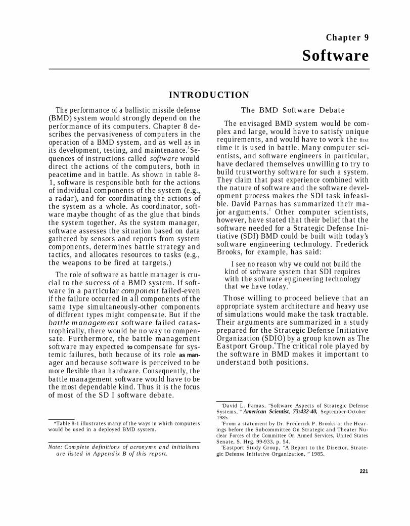
Chapter 9
Software
INTRODUCTION
The performance of a ballistic missile defense(BMD) system would strongly depend on theperformance of its computers. Chapter 8 de-scribes the pervasiveness of computers in theoperation of a BMD system, and as well as inits development, testing, and maintenance.1 Se-quences of instructions called software woulddirect the actions of the computers, both inpeacetime and in battle. As shown in table 8-1, software is responsible both for the actionsof individual components of the system (e.g.,a radar), and for coordinating the actions ofthe system as a whole. As coordinator, soft-ware maybe thought of as the glue that bindsthe system together. As the system manager,software assesses the situation based on datagathered by sensors and reports from systemcomponents, determines battle strategy andtactics, and allocates resources to tasks (e.g.,the weapons to be fired at targets.)
The role of software as battle manager is cru-cial to the success of a BMD system. If soft-ware in a particular component failed-evenif the failure occurred in all components of thesame type simultaneously-other componentsof different types might compensate. But if thebattle management software failed catas-trophically, there would be no way to compen-sate. Furthermore, the battle managementsoftware may expected to compensate for sys-temic failures, both because of its role as man-ager and because software is perceived to bemore flexible than hardware. Consequently, thebattle management software would have to bethe most dependable kind. Thus it is the focusof most of the SD I software debate.
The BMD Software Debate
The envisaged BMD system would be com-plex and large, would have to satisfy uniquerequirements, and would have to work the first
time it is used in battle. Many computer sci-entists, and software engineers in particular,have declared themselves unwilling to try tobuild trustworthy software for such a system.They claim that past experience combined withthe nature of software and the software devel-opment process makes the SDI task infeasi-ble. David Parnas has summarized their ma-jor arguments.2 Other computer scientists,however, have stated that their belief that thesoftware needed for a Strategic Defense Ini-tiative (SDI) BMD could be built with today’ssoftware engineering technology. FrederickBrooks, for example, has said:
I see no reason why we could not build thekind of software system that SDI requireswith the software engineering technologythat we have today.3
Those willing to proceed believe that anappropriate system architecture and heavy useof simulations would make the task tractable.Their arguments are summarized in a studyprepared for the Strategic Defense InitiativeOrganization (SDIO) by a group known as TheEastport Group.4 The critical role played bythe software in BMD makes it important tounderstand both positions.
*Table 8-1 illustrates many of the ways in which computerswould be used in a deployed BMD system.
Note: Complete definitions of acronyms and initialismsare listed in Appendix B of this report.
‘David L. Pamas, “Software Aspects of Strategic DefenseSystems, ” American Scientist, 73:432-40, September-October1985.
3From a statement by Dr. Frederick P. Brooks at the Hear-ings before the Subcommittee On Strategic and Theater Nu-clear Forces of the Committee On Armed Services, United StatesSenate, S. Hrg. 99-933, p. 54.
4Eastport Study Group, “A Report to the Director, Strate-gic Defense Initiative Organization, ” 1985.
221
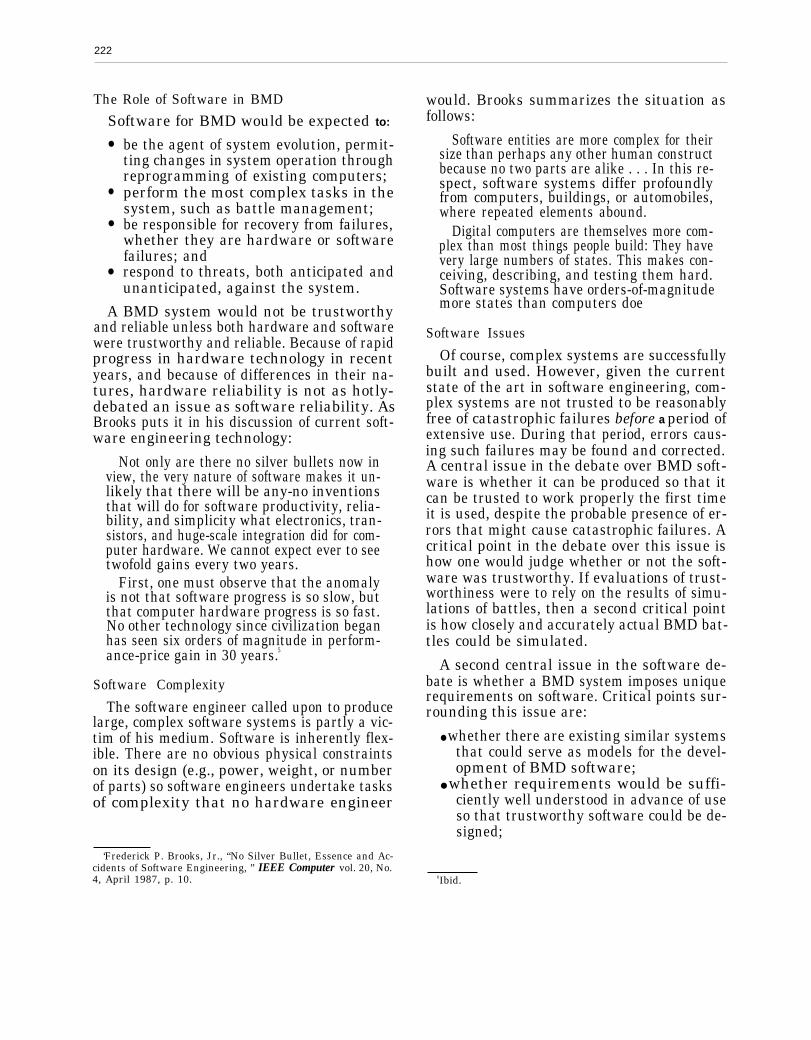
222
The Role of Software in BMD
Software for BMD would be expected to:
●
●
●
●
be the agent of system evolution, permit-ting changes in system operation throughreprogramming of existing computers;perform the most complex tasks in thesystem, such as battle management;be responsible for recovery from failures,whether they are hardware or softwarefailures; andrespond to threats, both anticipated andunanticipated, against the system.
A BMD system would not be trustworthyand reliable unless both hardware and softwarewere trustworthy and reliable. Because of rapidprogress in hardware technology in recentyears, and because of differences in their na-tures, hardware reliability is not as hotly-debated an issue as software reliability. AsBrooks puts it in his discussion of current soft-ware engineering technology:
Not only are there no silver bullets now inview, the very nature of software makes it un-likely that there will be any-no inventionsthat will do for software productivity, relia-bility, and simplicity what electronics, tran-sistors, and huge-scale integration did for com-puter hardware. We cannot expect ever to seetwofold gains every two years.
First, one must observe that the anomalyis not that software progress is so slow, butthat computer hardware progress is so fast.No other technology since civilization beganhas seen six orders of magnitude in perform-ance-price gain in 30 years.5
Software Complexity
The software engineer called upon to producelarge, complex software systems is partly a vic-tim of his medium. Software is inherently flex-ible. There are no obvious physical constraintson its design (e.g., power, weight, or numberof parts) so software engineers undertake tasksof complexity that no hardware engineer
would. Brooks summarizes the situation asfollows:
Software entities are more complex for theirsize than perhaps any other human constructbecause no two parts are alike . . . In this re-spect, software systems differ profoundlyfrom computers, buildings, or automobiles,where repeated elements abound.
Digital computers are themselves more com-plex than most things people build: They havevery large numbers of states. This makes con-ceiving, describing, and testing them hard.Software systems have orders-of-magnitudemore states than computers doe
Software Issues
Of course, complex systems are successfullybuilt and used. However, given the currentstate of the art in software engineering, com-plex systems are not trusted to be reasonablyfree of catastrophic failures before a period ofextensive use. During that period, errors caus-ing such failures may be found and corrected.A central issue in the debate over BMD soft-ware is whether it can be produced so that itcan be trusted to work properly the first timeit is used, despite the probable presence of er-rors that might cause catastrophic failures. Acritical point in the debate over this issue ishow one would judge whether or not the soft-ware was trustworthy. If evaluations of trust-worthiness were to rely on the results of simu-lations of battles, then a second critical pointis how closely and accurately actual BMD bat-tles could be simulated.
A second central issue in the software de-bate is whether a BMD system imposes uniquerequirements on software. Critical points sur-rounding this issue are:
● whether there are existing similar systemsthat could serve as models for the devel-opment of BMD software;
● whether requirements would be suffi-ciently well understood in advance of useso that trustworthy software could be de-signed;
‘Frederick P. Brooks, Jr., “No Silver Bullet, Essence and Ac-cidents of Software Engineering, ” IEEE Computer vol. 20, No.4, April 1987, p. 10. 6Ibid.
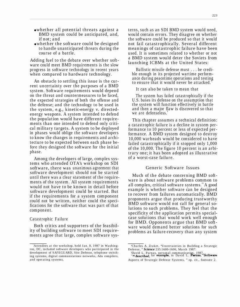
223
● whether all potential threats against aBMD system could be anticipated, and,if not; and
● whether the software could be designedto handle unanticipated threats during thecourse of a battle.
Adding fuel to the debate over whether soft-ware could meet BMD requirements is the slowprogress in software technology in recent yearswhen compared to hardware technology.
An obstacle to settling this issue is the cur-rent uncertainty over the purposes of a BMDsystem. Software requirements would dependon the threat and countermeasures to be faced,the expected strategies of both the offense andthe defense; and the technology to be used inthe system, e.g., kinetic-energy v. directed-energy weapons. A system intended to defendthe population would have different require-ments than one intended to defend only criti-cal military targets. A system to be deployedin phases would oblige the software developersto know the changes in requirements and archi-tecture to be expected between each phase be-fore they designed the software for the initialphase.
Among the developers of large, complex sys-tems who attended OTA’s workshop on SDIsoftware, there was unanimous agreement thatsoftware development should not be starteduntil there was a clear statement of the require-ments of the system.7 All system requirementswould not have to be known in detail beforesoftware development could be started. Butif the requirements for a system componentcould not be written, neither could the speci-fications for the software that was part of thatcomponent.
Catastrophic FailureBoth critics and supporters of the feasibil-
ity of building software to meet SDI require-ments agree that large, complex software sys-
7Attendees at the workshop, held Jan. 8, 1987 in Washing-ton, DC, included software developers who participated in thedevelopment of SAFEGUARD, Site Defense, telephone switch-ing systems, digital communications networks, Ada compilers,and operating systems.
terns, such as an SDI BMD system would need,would contain errors. They disagree on whetherthe software could be produced so that it wouldnot fail catastrophically. Several differentmeanings of catastrophic failure have beenused. It is sometimes related to whether or nota BMD system would deter the Soviets fromlaunching ICBMs at the United States:
Ballistic missile defense must . . . be credi-ble enough in its projected wartime perform-ance during peacetime operations and testingto ensure that it would never be attacked.8
It can also be taken to mean thatThe system has failed catastrophically if the
U.S. bases its defense on the assumption thatthe system will function effectively in battleand then a major flaw is discovered so thatwe are defenseless.9
This chapter assumes a technical definition:a catastrophic failure is a decline in system per-formance to 10 percent or less of expected per-formance. A BMD system designed to destroy10,000 warheads would be considered to havefailed catastrophically if it stopped only 1,000of the 10,000. The figure 10 percent is an arbi-trary one; it has been adopted as illustrativeof a worst-case failure.
Generic Software Issues
Much of the debate concerning BMD soft-ware is about software problems common toall complex, critical software systems.10 A goodexample is whether software can be designedto recover from failures automatically. BMDproponents argue that producing trustworthyBMD software would not call for general so-lutions to such problems. They feel that thespecificity of the application permits special-case solutions that would work well enoughfor BMD. Opponents argue that BMD soft-ware would demand better solutions for suchproblems as failure-recovery than any system
‘Charles A. Zraket, “Uncertainties in Building a StrategicDefense, ” Science 235:1600-1606, March 1987.
‘David L. Parnas, personal communication, 1987.10 AS descri~, for ex~ple, in David L. p~as, “Softw~e
Aspects of Strategic Defense Systems, ” op. cit., footnote 2.

224
previously built. They say that approaches pro-posed for SDI have been tried in the past andhave not been shown to be effective.
This chapter is primarily concerned witharguments over the generic issues. First, thereare as yet no clear statements of BMD soft-ware requirements, whether for battle manage-mentor particular BMD system components,let alone proposed software designs or pro-posed solutions for BMD for any of the genericproblems. Application-specific analysis mustawait those requirements, designs, and so-lutions.
Second, there seems to be agreement thatBMD software would be more complex thanany previously built. The first conclusion ofvolume V of the Fletcher report was:
Specifying, generating, testing, and main-taining the software for a battle management
system will be a task that far exceeds in com-plexity and difficulty any that has yet beenaccomplished in the production of civil or mil-itary software systems.11
Third, tasks for BMD software differ in im-portant ways from the tasks performed in to-day’s weapons systems and command, control,and communications systems. It is true thatmany BMD software tasks would resemblethose for current systems: e.g., target track-ing, weapons release and guidance, situationassessment, and communications control inreal time. The differences from current systemsare
●
●
●
●
●
●
that a BMD system would:
permit less opportunity for human inter-vention,have to handle more objects in its battlespace,have to manage a larger battle space,use different weapons and sensor tech-nology,contain vastly more elements,have more serious consequences of failure,
“James C. Fletcher, Study Chairman and Brockway McMil-lan, Panel Chairman, Report of the Study on Wm.hMting theThreat Posed by NucJear BaW”stic Missiles, Volume V: BattleManagement, Cornmuzu”cations, and Data Processing (Wash-ington, DC: Department of Defense, Defensive TechnologiesStudy Team, October 1983).
• have to operate in a nuclear environment,● be under active attack by the enemy, and● be useless if it failed catastrophically dur-
ing its first battle.
Accordingly, the debate over generic soft-ware issues is an appropriate one for BMDsoftware.
The purpose of this chapter is to examinethe key issues in the debate over the feasibil-ity of meeting BMD software requirements.This chapter:
1. discusses why there is such a debate and
2
3
4
includes a definition of key terms, suchas “catastrophic failure” and “trustwor-thiness”;analyzes properties often claimed to be im-portant for BMD software-e. g., trust-worthiness, reliability, correctness, low er-ror incidence, fault tolerance, security, andsafety, (including a discussion of the mean-ing of “reliability” as applied to softwareand why there is no single, simple meas-ure of software dependability);identifies the major factors that affectsoftware dependability; andcharacterize the demands placed on BMDsoftware and the BMD software develop-ment process in terms of the factors affect-ing dependability.
The remainder of this chapter begins witha brief discussion of Department of Defense(DoD) software experience, the nature of soft-ware, traditional reliability measures, and thepitfalls inherent in applying such measures tosoftware. Following sections deal with prop-erties such as trustworthiness, correctness,fault tolerance, security, and safety, and withthe factors that lead people to have confidencethat systems have such properties. (The avail-able technology for incorporating these prop-erties into software is analyzed in app. A.) Thechapter then presents an analysis of Strate-gic Defense Initiative BMD requirements fromthe viewpoint of those factors. The chapter con-cludes with: a discussion of why BMD soft-ware development is a difficult job—perhapsuniquely so; why we are unlikely to have morethan a subjective judgment of how trustwor-

225
thy the software is, once produced:mary of the key software issues.
The Software Crisis
and a sum-
Since the mid-1970s DoD officials have in-creasingly recognized the difficulties in pro-ducing command, control, and informationprocessing software for weapon systems.12 AsRonald Enfield says:
In the 1970s, the world’s largest customerfor computers–the U.S. Department of De-fense—changed its focus from hardware tosoftware as a major obstacle to progress in de-veloping advanced weapons. Reliable softwareis also a crucial component of complex systemssuch as nuclear power plants, automatic tell-ers, and many other technologies that touchour lives in critical ways. Yet, as the softwarefor these systems has grown increasingly com-plicated, it has become more prone to error.13
The complex of problems associated withtrying to produce software that operated prop-erly, on time, within budget, and maintaina-bly over its lifetime was dubbed “the softwarecrisis. ” DoD has found that the software crisisis sometimes forcing the military to wait forsoftware to be debugged before it can use newsystems. Progress in alleviating this crisis hasbeen slow, and the same problems would ap-ply to producing software for BMD. Both theFletcher and Eastport Group reports agreedthat software development for BMD would bea difficult, if not the most difficult, problemin BMD development. The Eastport Groupnoted that:
Software technology is developing againstinflexible limits in the complexity and relia-bility that can be achieved.14
To understand why DoD and other devel-opers of large, complex software systems havebeen experiencing a software crisis, it is first
l%An emly ~~y9i9 of the problem can be found in Don~dW. Kosy, “Air Force Command and Control Information Proc-essing Requirements in the 1980s: Trends in Software Tech-nology, ” Rand Report R-1012-PR, June 1974.
18Ron~d L. Enfield, “The Limits of Software Reliability, ”Technology Rew”ew, April 1987.
“Eastport Study Group Report, op. cit., footnote 4.
necessary to understand the nature of softwareand the demands made on it.
The Nature of Software
Digital computers are among our most flex-ible tools because the tasks they do can bechanged by changing the sequences of instruc-tions that direct them. Such instruction se-quences are called programs, or software andare stored in the computer’s memory. Flexi-bility is attained by loading different programsinto the memory at different times.15 Eachmake and model of computer has a unique setof instructions in which it must be pro-grammed, generically known as machine in-structions or machine language.
To simplify their job, programmers have de-veloped languages that are easier to use thanmachine language. These languages, such asFORTRAN, COBOL, and Ada, are known ashigh level languages, and require the program-mer to know less about how a particular com-puter works than do machine languages. Thelanguage in which a program is written isknown as the source language for the program,and the text of the program is called the sourceprogram or source code.16 A program whosesource language is a high level language mustbe translated into machine language before be-ing loaded into the computer’s memory for exe-cution. Some lines of text in a source programmay be translated into many machine instruc-tions, some into just a few.
There are several measures of program size.One measure is the number of lines in the textof the source program, also known as lines ofsource code (LOC), or number of machine lan-guage instructions. Size is greatly variable: asimple program to add a list of numbers mayrequire 10 or fewer instructions, while a word
ITo protect them horn change, and to enhance their perform-ance, some programs are loaded into memories that are eitherunchangeable or that must be removed from the computer tobe changed. However, most of the memory in nearly all com-puter systems is of a type that is reloadable while the computeris running.
leInstructions and data are encoded into a computer’s mem-
ory as numbers, and programs are sometimes known as codes.

processing program may take 10,000 LOC (10KLOC). The Navy’s AEGIS ship combat soft-ware consists of approximately 2 million in-structions.
Size alone is not a good measure of programdifficulty. Large programs can be simple, smallones very complex. The size of a program isinfluenced by the language, computer, pro-
grammer’s expertise, and other factors. A moreimportant question is, “How complex is theproblem to be solved by the program and thealgorithms used to solve it?’’17 Compoundingthe problem is the lack of a standard methodfor measuring complexity.
Failures and Errors inComputer Programs
Since a computer can only execute the in-structions that are stored in its memory, thoseinstructions must be adequate for all situationsthat may arise during their execution.18 Incor-rect performance by a computer program dur-ing its operation is known as a failure. Failuresin computer programs result from:
●
●
●
the occurrence of situations unforeseen bythe computer programmer(s) who wrotethe instructions,a misunderstanding by the programmer(s)of the problem to be solved (including mis-understandings among a group of pro-grammers), ora mistake in expressing the solution to theproblem as a computer program.
Each of these situations can cause errors inthe instructions making up computer pro-grams, errors manifested as failures when par-ticular inputs occur. 19 The effects of errors in
1~~ chap~r 8 for a discussion of algorithms.18some progr~s, kIMNVII as self-mdfying progr~st add ti
or modify their own instruction sequences and then execute theresulting instructions. Nonetheless, the response of the programto input data is completely determined by the instructions thatare initially stored in its memory.
leErrors in programs are often called bugs, although the termoriginally meant any cause of incorrect behavior. The origin ofthe term is described in John Shore, The Sachertorte A&on”thm,(New York, NY: Penguin Books, 1986).
programs range from minor inconveniences(e.g., misspelled words in the program’s out-put) to catastrophic failures-e. g., the cessa-tion of all processing by the computer, wronganswers to problems like computing missiletracks, or overdoses of radiation to devices con-trolled by the computer.20 21
Tolerating Errors
Errors in large computer programs are therule rather than the exception. Freedom fromerrors cannot be guaranteed and is extremelyrare. Since correcting an error requires chang-ing the list of instructions that make up theprogram, the process of removing an error may,and often does, introduce anew error. For largesoftware, the process of correcting errors is sotime consuming and expensive that modifica-tions to the software are distributed only a fewtimes a year. As a result, lists of known errorsare often published and distributed to users.22
Where there is a high degree of human inter-action with the program during its operation,the human user can usually circumvent situa-tions where the program is known to fail-oftenby restricting the data input to the programor by not using features of the program knownto be failure-prone.
The more critical the task(s) of the programand the smaller the degree of human interven-tion in the program’s operation, the smallerthe tolerance for errors. Accordingly, large,critical programs commonly include con-sistency checks whose goal is to try to detectfailures, prevent them when possible, and re-cover from them when not. This approach is
*°For a sample of the variety of problems involving computersand software, see ACM SIGSOFTSoftware Engineering Notes11(5):3-35, October 1986.
ZIThe Occumence of a failure condition is sometimes knownas anina”dent. The software may contain instructions that per-mit it to recover from such an incident. If the software success-fully corrects the condition, it remains no more than an inci-dent. Successful recovery from incidents requires goodunderstanding of their causes and corrections, and requires thatnot too many occur at once.
2~Mmu~ PWS describing programs used with the UNIX oper-ating system, developed and sold by AT&T Bell Laboratoriesand a currently popular operating system, contain as standardsections a description of the known bugs in the programs.

227
discussed in more detail in a later section onfault tolerance.
Tolerating Change
As previously noted, change is both theblessing and the curse of the software engineer.Software is expected to be flexible, and his de-signs must accommodate change. Without itsflexibility, software would be as useful. Al-though software does not wear out in the sensethat hardware does, complex software systemsapparently tolerate only a certain amount ofchange. The critical point occurs when changesintroduce more errors than they fix, i.e., eachchange, on the average, introduces more errorsthan it removes.23 It appears likely that increas-ing the rate of change decreases the time toreach the critical point. Brooks devotes a chap-ter to a discussion of the effects of changesin complex systems, concluding with:
Program maintenance is an entropy-increas-ing process, and even its most skillful execu-tion only delays the subsidence of the systeminto unfixable obsolescence.24
Although Brooks’s discussion is more than10 years old, it is still valid. Systems that tendto be very long-lived, e.g., 20 years old or more,undergo complete software redevelopmentevery few years. As an example, the Navy’sNaval Tactical Data System, first built in theearly 1960s, has undergone at least five majorrewrites.
Traditional Reliability Measures
Reliability is one measure of system be-havior. In engineering, reliability is often ex-pressed as the average time between failures.For inexpensive consumer items, such as lightbulbs, it is defined as the expected lifetime ofthe item, since such items are completelyreplaced when they fail. Complicated, expen-sive systems, such as automobiles, computer
“M. Lehman and L. Belady, “Programming System Dy-namics,” ACM SIGOPS Third Symposium on Operating Sys-tem Principles, October 1971.
ZiFrederick p. Brooks, Jr., The Mytlu”caJ Man-Month: Essayson Software En~”neering, (New York, NY: Addison-Wesley,1975).
systems, and weapon systems, are designedto outlive any particular component by allow-ing repair or replacement of components whenthey fail. Failure of a windshield wiper bladeonly requires the quick, inexpensive replace-ment of the blade by another that meets thesame specifications as the failed one.
Reliability of complicated systems is tradi-tionally measured in mean time between fail-ure (MTBF), or an equivalent measure such asfailure rate. MTBF is measured by countingfailures during operation and then dividing bythe length of the observation period. For sys-tems with no operational history, MTBF mustbe predicted on the basis of estimates of theMTBF of each of the system’s components.Usually such an estimate is made using theassumption that component failures are ran-dom, statistically independent events. With-out such an assumption, the analysis is muchmore difficult and often impractical for com-plex systems.
Reliability as measured by MTBF is usefulfor systems with the following characteristics:
●
●
●
the time to repair the system is unimpor-tant to the user, perhaps because a tem-porary replacement is available or the userhas no need of the system for a while; orthe time to repair the system is important,but can be kept very short compared tothe MTBF, perhaps by keeping a stockof replacement parts on hand; andthere are no failures so serious as to beunacceptable, e.g., failures that could re-sult in human deaths.
Traditional Reliability MeasuresApplied to Software
The concept of MTBF has historically beenof limited use for critical software. For appli-cations such as BMD, repair time is extremelyimportant. If the system, or parts of it, wereto fail, the user would have either no responseor a weakened response to an ICBM attack.Accordingly, the concept of MTBF alone is notsufficient to judge whether or not the systemwould behave as desired. Furthermore, the
228
models often used for predicting MTBF arebased on assumptions that are invalid for soft-ware. Many models assume that componentfailures are independent and that they are ran-dom, i.e., unrelated to system inputs andstates. Software components do not fail ran-domly: they contain errors that cause failuresin the event of particular inputs and particu-lar states. The failure of one component oftencauses others to fail because software compo-nents tend to be closely interrelated.
Replacing a software component by a copyof itself will cause exactly the same failure un-der the same conditions that caused the origi-nal to fail. Remedying a failure consists of mod-ifying a component to remove an error in itslist of instructions, not replacing a failed com-ponent with a copy. Once modified, the com-ponent can no longer be considered to be thesame as the original, and previous failure datado not apply to it. Finally, a failure in one com-
ponent is likely to lead to failures in others.Consequently, a stock of replacement compo-nents cannot be kept on hand in hopes of re-ducing repair time.
Regardless of whether MTBF were used toindicate software or hardware reliability fora BMD system, some failures would be clearlymore disastrous than others. To be useful,MTBF would have to be calculated for differ-ent classes of failures.
In recent work, researchers have shown thatif inputs are characterized in statisticallysound ways, it is possible in testing to deter-mine with high confidence a meaningful MTBFfor a program.25 Nonetheless, MTBF remainsinadequate as the sole means of characteriz-ing software dependability.
~5A~en Cumit, Michael Dyer, and Harlan D. M~s, “Certify-ing the Reliability of Software, ” L??EE Transactions On Soft-ware En&”neering, SE-12(1), January 1986, pp. 3-11.
SOFTWARE DEPENDABILITY
Computer scientists and software users havedevised a variety of ways to evaluate softwaredependability. As in deciding which automo-bile to buy, the buyer’s concerns should deter-mine which qualities are emphasized in theevaluation. Qualities commonly considered are:
●
●
●
●
●
●
correctness-whether or not the softwaresatisfies its specification;trustworthiness-probability that thereare no errors in the software that will causethe system to fail catastrophically;fault tolerance-either failure prevention,i.e., capability of the software to preventa failure despite the occurrence of an ab-normal or undesired event—or failure re-covery, i.e., capability of the software torecover from a failure when one occurs;availability-probability that the systemwill be available for use;security-resistance of the software to un-authorized use, theft of data, and modifi-cation of programs;error incidence—number of errors in the
software, normalized to some measure ofsize; and
● safety—preservation of human life andproperty under specified operating con-ditions.
For critical software, correctness and trust-worthiness are important indicators of depend-ability. Fault tolerance assumes importancewhen the system must continue to perform—as in the midst of a battle—even if perform-ance degrades. Security is important when val-uable data or services maybe stolen, damaged,or used in unauthorized ways. Safety is impor-tant in applications involving risk to humanlife or property. Error incidence is importantin assessing whether or not apiece of softwareshould stay in use.
OTA’s characterization of BMD software de-bendability will include all of the above-listedqualities because:
● national survival may depend on theproper operation of BMD software;
229
● such software would have to be trustedto operate well during the entire courseof a battle; and
● it would have a long lifetime.
Early versions of a BMD system may nothave goals as ambitious as later, more capa-ble versions. Nevertheless, we still would wantto be confident that the software would oper-ate well during the course of a battle, woulddo so without undue pause for failure recov-ery, would be secure, and would be safe to oper-ate. In addition, since it would surely undergocontinual modification during its lifetime, wewould need to be sure that it was being main-tained without repeated introduction of newerrors.
Dependability needs to be attended to fromthe beginning of software development, for itis not easily added on later. Software designsoften must be redone after system deliverywhen performance has been emphasized at thecost of such factors as correctness, fault toler-ance, or security. The cost of redoing softwaremay greatly exceed the original cost. Softwaredesigned for dependability may contain mech-anisms for later improving its correctness,trustworthiness, fault tolerance, security, andsafety later. For example, fault tolerance wasstrongly considered in the design of theSAFEGUARD software. During tests of theprototype system engineers realized that thewrong set of faults had been accommodated.Because the mechanism for detecting and re-sponding to faults had been incorporated intothe design, the set of faults tolerated by thesystem was changed in a matter of only a fewweeks. This change involved perhaps 10 per-cent of the lines of code in the operational soft-ware.26
Figures of Merit
No single figure of merit can indicate depend-ability. Single figures of merit generally focuson some single characteristic, such as the costto discover a password that would permit en-try to a computer system. Because software
“Victor Vyssotsky, personal communication, 1987.
engineering is a young discipline, softwareengineers do not yet know very well how toevaluate software quantitatively. And becauseinformation permitting numerical evaluationof software is usually considered proprietary,few data are available anyway for such analy-sis. Accordingly, we would not expect a use-ful quantitative evaluation of BMD softwaredependability to be available for many years.Therefore, only a brief analysis of each soft-ware property contributing to dependabilityfollows.
Trustworthiness is probably the most impor-tant quality for BMD software. The applica-tion is critical. Software engineers are unableto produce complex software that is correctand error-free at the current state of the art.Although BMD software should still be asnearly correct, highly available, error-free, se-cure, and safe to use as possible, we must aboveall know whether or not it could be trusted.
Correctness
Software developers work from specifica-tions, both written and verbal, that are in-tended to convey the desired system behavior.The specifications are frequently developed bypeople with little familiarity with software, e.g.,a Naval officer untrained in software develop-ment who writes specifications for a ship’scombat management system. “Correct” soft-ware exhibits exactly the behavior describedby its specifications. To convince himself andhis customer that he has done his job, the soft-ware developer must somehow demonstratethat his software is correct.
Mathematical Correctness
Because no single technique has proved com-pletely effective to demonstrate program cor-rectness, software developers use a variety oftechniques try to demonstrate that their soft-ware adequately approximates its specifica-tions. Computer scientists, in recognition ofthe problems involved, have devoted consid-erable research to such techniques. They haveinvestigated formal and informal, mathemati-cal and non-mathematical ideas. Much of the
230
research attention has been focused on devel-oping “program verification’ ’-mathematicaltechniques to verify that a computer programis correct with respect to properties requiredof it. Some progress has been made in mathe-matically proving that programs are correct.It is unlikely, though, that a sudden break-through will occur leading to order-of-magni-tude gains in productivity and greatly im-proved dependability. Brooks analyzed thispossibility:
Can both productivity and product reliabil-ity be radically enhanced by following the pro-foundly different strategy of proving designscorrect before the immense effort is pouredinto implementing and testing them?
I do not believe we will find productivitymagic here. Program verification is a verypowerful concept, and it will be very impor-tant for such things as secure operating sys-tem kernels. The technology does not prom-ise, however, to save labor. Verifications areso much work that only a few substantial pro-grams have ever been verified.
Program verification does not mean error-proof programs. There is no magic here, either.Mathematical proofs can also be faulty. Sowhereas verification might reduce the prog-ram-testing load, it cannot eliminate it.
More seriously, even perfect program veri-fication can only establish that a programmeets its specification. The hardest part of thesoftware task is arriving at a complete andconsistent specification, and much of the es-sence of building a program is in fact thedebugging of the specification.”Although mathematical techniques for dem-
onstrating correctness are not frequently ap-plied, other techniques-such as design re-views, code reviews, and building software insmall increments—are. The one technique al-ways used by software developers, however,is testing.
TestingProgram developers test a program by plac-
ing it in a simulated operating environment.28
27 Frederick p. Br~k9, Jr., “NO Silver Bullet, Essence ~d Ac-
cidents of Software Engineering, ” op. cit., footnote 5, p. 16.~sFor presentation pUrpOSSS, the discussion Of testing here
is simplified, omitting, e.g., component testing. Appendix Acontains a more complete discussion.
The simulation supplies inputs to the program,and the testers examine its output for fail-ures.29 They report any failures to the program-mers, who correct the relevant errors and re-submit the program for testing. The sequencecontinues until the developers agree that theprogram has passed the test. The final stageof testing developmental software for large andcritical systems, especially military software,is acceptance testing. A previously agreed-upon test is run to show that the softwaremeets criteria that make it acceptable to theuser.
It has been shown that testing of every pos-sible state of the program, known as exhaus-tive testing, is not practical even for simpleprograms. To illustrate this point, John Shorecalculated the amount of time required to testthe addition program used by 8 digit calcula-tors to add 2 numbers. He estimated that, atthe rate of one trial per second it, would takeabout 1.3 billion years to complete an exhaus-tive test.30
For large, complicated programs, the num-ber of tests that can be run practically is smallcompared to the number of possible tests.Therefore, developers apply a technique calledscenario testing. They observe the program’sbehavior in an operational scenario that theprogram would typically encounter. They mayestablish the scenario by simulating the oper-ational environment, such as an aircraft flightsimulator. Alternatively, they may place thesoftware in its actual environment under con-trolled conditions. For example, a test pilotmay put an aircraft with new avionics softwarethrough a series of pre-determined neuvers.In the former case, the simulator must firstbe shown to be correct before the results canbe considered valid. If the simulator itself re-lies on software, showing the validity of thesimulation may be as difficult or more diffi-cult than showing the correctness of the pro-gram to be tested.
z9G~ W9ter9 cue~ly determine the inputs to be used inadvance, often including some tests using random inputs, andsome using nonrandom, so as to get representative coverageof the expected operational inputs.
‘“John Shore, op. cit., footnote 19, pp. 171-172.

231
For systems like aircraft, such tests are soexpensive that only relatively few scenarioscan be flown. Flight tests of the avionics soft-ware for the Navy’s A-7 aircraft, includingland- and carrier-based tests, cost approxi-mately $300,000. Scenario tests for the SAFE-GUARD system consisted of installing a testversion of the system at Kwajalein missilerange and firing one or two missiles at a timeat it.
Since exhaustive testing is not practical,testing cannot be relied upon to show that acomputer program completely and exactly be-haves according to its specifications or eventhat it contains no errors. As stated by com-puter scientist Edsger Dijkstra:
Program testing can be used to show thepresence of bugs, but never to show their ab-sence!31
The deficiencies of testing as a means ofshowing correctness and freedom from errorshave moved software engineers to seek othermethods, such as mathematical. They havealso sought means of measuring error inci-dence. In addition, they are developing meth-ods for random testing that permit statisticalinferences about failure rates.32
Error Incidence
Some assert that error incidence-measured,for example, by the number of errors found perthousand lines of source code-measure pro-gram correctness. Those making this assertionassume that it is possible to count errors un-ambiguously and that the more errors a pro-gram has the less its behavior will conform toits specifications. They then portray the de-bate over BMD software dependability ashinging on the question of whether or not thesoftware would contain errors, and how manyit would contain.
Both critics and proponents of an attemptto build SDI software agree that any such soft-ware would contain errors. As put by the East-port Group:
Simply because of its inevitable large size,the software capable of performing the battlemanagement task for strategic defense willcontain errors. All systems of useful complex-ity contain software errors.33
Ware Myers notes:The whole history of large, complex software
development indicates that errors cannot becompletely eliminated.34
David Parnas asserts that:Error statistics make excellent diversions
but they do not matter. A low error rate doesnot mean that the system will be effective. Allthat does matter is whether software worksacceptably when first used by the customers;the sad answer is that, even in cases much sim-pler than SDI, it does not. What also mattersis whether we can find all the “serious’ errorsbefore we put the software into use. The sadanswer is that we cannot. What matters, too,is whether we could ever be confident that wehad found the last serious error. Again, thesad answer is that we cannot. Software sys-tems become trustworthy after real use, notbefore.35
Trustworthiness
Since correctness and error rates are not thereal issues in the software debate, trustwor-thiness has become the focus. The issue iswhether or not BMD software could be pro-duced so that it would be trustworthy despitethe presence of errors. In common usage, relia-bility and trustworthiness are often consideredto be the same. In engineering usage, reliabil-ity has become associated with specific meas-ures, such as MTBF. There have been few at-tempts to quantify trustworthiness, despite
~lJ, D~, E.W. Dijkstra, and C.A.R. Hoare, “Notes on Struc-
tured Programmingg,” structured Prognunmin g (London: Aca-demic Press, 1972), p. 6.
‘zSee the discussion on the cleanroom method in appendix Afor more details.
g3Eastport Study Group Report, Op. cit., footnote 4.“Ware Myers, “Can Software for the Strategic Defense Ini-
tiative Ever Be Error-Free?” IEEE Computer XX:61-67, No-vember 1986.
‘sDavid L. Parnas, “SDI Red Herrings Miss the Boat, ” (Let-ter to the Editor), 1lL!?lZ Computer 20(2):6-7, February 1987.
232
the desirability of trustworthy systems. Onepossible reason may be that trust is determinedqualitatively as much as quantitatively: peo-ple judge by past experience and knowledgeof internal mechanisms as much as by num-bers representing reliability. Another possiblereason is that most systems in critical appli-cations are safeguarded by human operators.Although the systems are trusted, the ultimatetrust resides in the human operator. Nuclearpower stations, subway systems, and autopi-lots are all examples.36
As noted in chapter 7, a BMD system wouldleave little time for human intervention: trustwould have to be placed in the system, not inthe human operator. Accordingly, it is impor-tant to be able to evaluate the trustworthinessof BMD software. One suggested definition isthat trustworthiness is the confidence one hasthat the probability of a catastrophic flaw isacceptably l0W.37 Trustworthiness might be de-scribed by a sentence such as “The probabil-ity of an unacceptable flaw remaining aftertesting is less than 1 in 1,000.”38 (This meas-ure of trustworthiness has only recently beensuggested, and no data have yet been pub-lished to support it.) Estimating trustworthi-ness consists of testing the software in a ran-domly selected subset of the set of internalstates with a randomly selected subset of thepossible inputs. The set of possible inputs andinternal states must be known. It must be pos-sible to recognize a catastrophic test result,i.e., the expected operating conditions mustbe well-understood. For BMD systems, thismeans understanding the expected threat andcountermeasures as well as testing under con-ditions closely simulating a nuclear envi-ronment.
SeEven when hum~ operators are aware of a problem theysometimes do not or cannot react quickly enough, or with theproper procedures, to prevent disaster.
s~Da~d L. prom, “when Can We Tlllst $Oftw- SYS~mS’?”
(Kewote Address), Comput=Assuranm, Software Systems In-tegrity: Software Safety and Rvcess secun”ty Conference, July1986.
~aDa~d L. Panas, person~ Communication, 1987.
Fault Tolerance
Realizing that errors in the code and un-foreseen and undesired situations are inevita-ble, software developers try to find ways ofcoping with the resulting failures. Software isconsidered fault-tolerant if it can either pre-vent or recover from such failures, whetherthey are derived from hardware or softwareerrors or from unanticipated input. Techniquesfor fault tolerance include:
● back-up algorithms,● voting by three or more different imple-
mentations of the same algorithm,● error-recovery programs, and● back-up hardware.Program verification techniques, discussed
above, attempt to prove correctness by math-ematical analysis of the code. In contrast, fault-tolerant techniques attempt to cope with fail-ures by analyzing how a program behaves dur-ing execution.
Since a BMD system would have to operateunder widely varying conditions for manyyears, its software would have to incorporatea high degree of fault tolerance. Unfortunately,there are no accepted measures of fault toler-ance, and design of fault-tolerant systems isnot well understood. As an example, spaceshuttle flight software is designed in a waythought to be highly fault-tolerant. Four iden-tical computers, executing identical software,vote on critical flight computations A fifth, ex-ecuting a different flight program, operates inparallel, providing a backup if the other fourfail. On an early attempted shuttle launch, thisflight system failed because the backup pro-gram could not synchronize itself with the fourprimary programs. The failure, occurring just20 minutes before the scheduled lift-off, causedthe flight to be postponed for a day. It wasa direct result of the attempt to make the soft-ware fault-tolerant.
The price for fault tolerance is generally paidin performance and complexity. A program in-corporating considerable code for the purposeof detecting, preventing, and recovering fromfailures will be larger and operate more slowly
233
than one that does not. A successful fault-toler-ant design will result in a system with higheravailability than a corresponding system builtwithout regard for fault tolerance. Producersof non-critical software may not care to paythe price. Those concerned with critical sys-tems that must operate continuously often feelthat they must.
Availability
Systems that are intended to maintain con-tinuous operation are often evaluated by cal-culating their availability, i.e., the percent oftime that they are available for use. Availabil-ity is easily measured by observing, for someinterval, the amount of time the system is un-available (the “down” time) and available (the“up” time) and then calculating (up time)/(uptime + down time). As with other figures ofmerit, availability figures are useful when theconditions under which they were measuredare well-known. Extrapolation outside of thoseconditions is risky. Since prediction of avail-ability is equivalent to prediction of MTBF andmean time to repair (MTTR)-measures of up-and down-times, respectively—availability isat least as difficult to predict as MTBF andMTTR are individually.
Security
Computer users concerned with preservingthe confidentiality of data and the effective-ness of weapon systems, such as banks or themilitary, consider security a necessary condi-tion for dependability. Breaches of securitythat concern such users include:
●
●
●
knowledge by an opponent of the al-gorithms implemented in a computer con-trolling a weapon system, allowing himto devise ways of circumventing the strat-egy and tactics embodied in those al-gorithms;access by unauthorized users to sensitiveor classified data stored in a computer;denial of access by authorized users totheir computers, thereby denying themthe capabilities of the computer and thedata stored in it; and
● substitution of an opponent software foroperational software-(changing even a fewinstructions may be potentially disas-trous), allowing the opponent to divert thecomputer to his own uses.
Many of the preceding concerns only applyif a computer must use a potentially corrupti-ble communications channel to receive data orinstructions from another computer or froma human.39 Any BMD system would containsuch links. (The possibility that a link couldbe corrupted and measures for preventing suchcorruption are discussed in ch. 8.) Over thesechannels one might:
●
●
●
●
load revised programs into the memoriesof the BMD computers;correct errors in existing programs;change the strategy incorporated into ex-isting programs; oraccommodate changes to software re-quirements, such as might be caused bythe introduction of new technology intothe BMD system.
In addition, any BMD architecture wouldcontain communications channels for the ex-change of data between battle managementcomputers and sensors and among battle man-agement computers.
Since the 1960s, when computers started tobe used on a large scale in weapon systems,the DoD has expended considerable effort tofind ways of making computer systems secure.As yet, no way has been found to meet all thesecurity requirements for computers used inthe design, development, and operation ofweapon systems. As Landwehr points out ina discussion of the state of the art in develop-ing secure software:
At present, no technology can assure bothadequate and trustworthy system perform-ance in advance. Those techniques that havebeen tried have met with varying degrees ofsuccess, but it is difficult to measure their suc-cess objectively, because no good measures ex-
SgPhY9ic~ secu~ty, i.e., control of physical access to comPut-ing equipment, is a problem as well, generally unsolvable bytechnical means and outside the scope of this report.
234
ist for ranking the security of various sys-tems.40
Although there is no quantifiable measureof the security of a computer system, the DoDhas developed a standard for evaluating thesecurity of computer systems.41 The evalua-tion consists of matching the features providedby a system against those known to be neces-sary, albeit not sufficient, to provide security.For example, the second highest rating is givento those systems that let users label their dataaccording to its security level, e.g., Confiden-tial or Secret, then protect the labels againstunauthorized modification. Furthermore, thedeveloper must show the security model usedin enforcing the protection and show that thesystem includes a program that checks everydata reference to ensure that it follows themodel. As with fault tolerance, incorporatingsecurity features into software exacts penal-ties in performance and complexity.
Safety
A software engineeringguished between safety and
Safety and reliability are
journal distin-reliability:
often equated,especially with respect to software, but thereis a growing trend to separate the two con-cepts. Reliability is usually defined as theprobability that a system will perform its in-tended function for a specified period of timeunder a set of specified environmental condi-tions. Safety is the probability that conditionswhich can lead to an accident (hazards) do notoccur whether the intended function is per-formed or not. Another way of saying this is
War] Landwehr, “The Best Available Technologies For ~om-puter Security,“ IEEE Computer, July 1983, p. 93.
“’’DoD Standard 5200.28, Department of Defense TrustedComputer System Evaluation Criteria,” (Washington, DC: De-partment of Defense, Aug. 15, 1983).
that software safety involves ensuring thatthe software will execute within a system con-text without resulting in unacceptable risk.42
Interest in software safety has increasedmarkedly in recent years. Formal publicationsspecifically addressing software safety issuesstarted appearing in the early 1980s.43 As yet,there are no standard measures or ways ofassessing software safety. Nonetheless, it isimportant that BMD software be safe so asto prevent accidents that are life threateningand costly. An unsafe BMD system might, forexample, accidentally destroy a satellite, spacestation, or shuttle.
Appropriate Measures of SoftwareDependability
As should be clear from the preceding discus-sion, software dependability cannot be cap-tured in any single measure. Correctness,trustworthiness, safety, security and fault tol-erance are all components of dependability. Allshould be considered in the development ofsoftware for a BMD system. Attempts toquantify them in a clear-cut way require speci-fying too many conditions on the measure toallow useful generalization. Estimates of thedependability of BMD software would alwaysbe suspect, since in large part they would al-ways be subjective. Until we can quantify soft-ware dependability we cannot know that wehave developed dependable BMD software.The following sections discuss the factors in-volved in developing dependable software.
“IEEE Transactions on Software Engineering: Special Is-sue On Reh”ability And Safety In Real-Time Process Control,SE-12(9):877, September 1986.
‘sNancy Leveson and Peter Harvey, “Analyzing SoftwareSafety,” IEEE Transactions on Softwaml?ngineering, SE-9(?),September 1983, pp. 569-579, was one of the first papers to dis-cuss software safety.
CHARACTERISTICS OF DEPENDABLE SYSTEMS
Despite the lack of ways of quantifying con- with confidence that they will be reliable whenfidence in software, people trust many com- finished. In this section we discuss why sys-puterized systems. Further, people are willing terns come to be trusted and give some exam-to undertake development of many systems pies of trusted systems. We divide methods
235
of gaining trust into two classes: those basedon observations of the external behavior of thesystem, and those based on understanding howthe system operates internally.
Observations of External Behavior
A system, whether containing software ornot, may be considered to be a black box withconnections to the outside world. One may ob-serve the inputs that are sent to the box andthe outputs it produces. The next few sectionsdiscuss methods of gaining confidence in soft-ware and systems based on black-box obser-vations of the software.
Extensive Use and Abuse
Perhaps the most important factor inspir-ing confidence in software is that the softwarehas been used extensively. A good analogy isthe automobile. Confidence comes fromfamiliarity with cars in general and frequentuse of one’s own car. Having seen that the en-gine will start when the key is turned hundredsof times gives one the feeling that it will startthe next time the key is turned. Automaticteller machines, electronic calculators, wordprocessors, and AT&T’s long distance tele-phone network are all examples of systems con-trolled by software that are trusted to workproperly. The trust is built on extensive ex-perience: one has high confidence that the tele-phone will work the next time it is tried be-cause it usually has in the past.
Confidence is considerably enhanced whena system continues to work even thoughabused. A car that starts on cold and rainydays inspires increased confidence that it willstart on mild and sunny days. Observing thatcalls still get through under heavy calling con-ditions (albeit not as quickly), that dialing anon-existent number produces a meaningfulresponse, and that calls can still be made whenmajor trunk circuits fail boosts one’s confi-dence that nearly all one’s calls will get throughunder normal conditions. Conversely, systemfailure detracts from confidence. Having ob-served that issuing a particular command toa word processor sometimes results in mean-
ingless text being inserted into a documentleads one to refrain from using that command.
It is important to note that extensive confi-dence comes from extensive use and not fromtesting that incompletely simulates use. Noone would consider granting a license to a pi-lot who had spent extensive time in a flightsimulator but had never actually flown an air-plane. Simulated use inspires confidence to thedegree that the simulation approximates oper-ational conditions. Real-world complicationsare often either too expensive or too poorlyunderstood to simulate. In testing systems,simulators are useful for convincing ourselvesthat the gain from putting the system into itsoperating environment is worth the attendantcost and risks. They allow the jump to actualuse with some confidence that disaster will notresult.
Predictable Environments
Confidence in software also comes from be-ing able to predict the behavior of the softwarein its operational environment. If the environ-ment itself is predictable, the job of designingand testing the software is considerably eased.For example, engineers can predict and math-ematically analyze the number of telephonecalls per hour that a particular switching cen-ter will receive at any time of day. The num-ber and type of signals that will be receivedon the telephone lines (e.g., the 7 digits in alocal telephone number) are known becausetheir specifications form part of the require-ments for the telephone system and are deter-mined by the designers. The software and hard-ware may then be designed to cope with thetelephone traffic and the signal types basedon the specifications.
Engineers can observe the system in opera-tion to verify predictions before new softwareis placed into operation. Finally, they can ob-serve the behavior of new software in termsof number of calls handled, number of callsrerouted, and other parameters for differenttraffic loads. Observing that behavior matchespredictions builds confidence in the operationof the system. Nonetheless, even when the de-velopers have extensive experience with a well-
236
controlled environment, they sometimes makemistakes in prediction and do not discoverthose mistakes until the system goes into use.
Low Cost of a FailureAlthough extensive use and environmental
predictability both strongly influence theamount of confidence placed in a system, theyare not sufficient to induce users to continueusing a system after significant failures. Large,complicated software systems inevitably ex-perience software failures. Therefore, usersdon’t have confidence in the software unlessthe risk associated with a failure is smaller thanthe gain from using the software. A word proc-essor that loses documents may go unused be-cause the cost of re-creating the document isgreater than the effort saved by using the wordprocessor.
If, however, an easy method of recoveringfrom such losses is available, perhaps by in-cluding a feature in the word processor thatautomatically saves back-up copies of docu-ments, then the cost to the user of the failurebecomes acceptably low: he can recover his doc-ument when it is lost. Similarly, the cost ofrecovering from a disconnected phone call issmall to the dialer and to the telephone com-pany. (Although a misdialed phone call is notreally a system failure, the same principle ap-plies: users can recover quickly and easily.) Theability to recover from a failure at low cost in-creases confidence in and willingness to usea system.
Systems With Stable RequirementsA desire for flexibility is a prime motive for
using computer systems. The behavior of acomputer can be radically altered by chang-ing its software. Radical changes may be madeto a computer program throughout its entirelifetime. Because there is no apparent physi-cal structure involved, the impact of changemay not be readily appreciated by those whodemand it without having to implement it. Noone would ask a bridge builder to change hisdesign from a suspension to an arch-supportedbridge after the bridge was half built withoutexpecting to pay a high price. The equivalent
is often demanded of software builders withthe expectation of little or no penalty in sched-ule, cost, or dependability.
An example is the combat system softwarefor the first of the Navy’s DD 963 class of des-troyers. During the development of the soft-ware, which cost less than 1 percent of the costof building the ship, the customers imposedmajor changes on the software developer. Theoriginal requirements specified that the com-bat system need only provide passive elec-tronic warfare functions. One year into devel-opment the buyers added a requirement foractive electronic warfare. A year later they re-moved the requirement for active electronicwarfare. On the ship’s maiden voyage its com-mander issued a casualty report on the soft-ware: the ship could not perform its functionbecause of deficiencies in the software. Al-though the major requirements changes wereprobably not the only reason for the deficien-cies, they were certainly a prime contributingfactor.
The B-lB bomber is another example of asystem where deficiencies have resulted fromtoo much change during development. Accord-ing to a report on the B-l B bomber,
Defense officials blame many of the pro-gram’s problems on the decision to begin pro-ducing the aircraft at the same time that re-search and development efforts were underway, forcing engineers to experiment withsome systems before they were completely de-veloped.44
Conversely, a system whose requirementschange little during the course of developmentis more likely to work properly. Developershave a chance of understanding the problemto be solved: they need not continually reana-lyze the problem and revise their solution. Sta-bility of requirements is particularly importantfor software because of the many decisions in-volved in software design. Each subdivisionof a program into subprograms involves deci-sions about the functions to be performed bythe subprograms and about the interfaces be-
44’’ New Weapon Suffers From Major Defects, ” WashingtonPost, Jan. 7, 1987, p. Al.

237
tween them. Writing each subprogram furtherinvolves decisions on the algorithm to be used,the way data are to be represented, the orderof the actions to be performed, and the instruc-tions to be used to represent those actions.
Decisions made early in the process are moredifficult to change than those made later in theprocess because later decisions are often de-pendent on earlier ones. Furthermore, the proc-ess of change is more expensive in later phasesof a project because there are more specifica-tions and other documentation. Using datafrom SAFEGUARD software and softwareprojects at IBM, GTE, and TRW, one experthas shown that, as a result of the precedingfactors, error correction costs (and costs tomake other software changes) increase expo-nentially with time. In Boehm’s words:
These factors combine to make the errortypically 100 times more expensive to correctin the maintenance phase than in the require-ments phase.45
Clearly then, for systems where require-ments change little during development, notonly can one have increased confidence in thesoftware, but one can also expect it to cost less.Among the developers of large, complex sys-tems who attended OTA’s workshop on SDIsoftware, there was unanimous agreement thatBMD software development could not beginuntil there were a clear statement of the re-quirements of the system.46
Systems Based on Well-UnderstoodPredecessors
As with other human engineering projects,successful software systems are generally theresult of slow, evolutionary change. Where rad-ical changes are attempted, failure rates arehigh and confidence in performance is low. This
“Barry W. Boehm, Software Engineering llconom”cs (Engle-wood Cliffs, NJ: Prentice-Hall, 1981), figure 4-2, p. 40.
attendees at the workshop included software developers whoparticipated in the development of SAFEGUARD, Hard Sitedefense, telephone switching systems, digital communicationnetworks, Ada compilers, and operating systems.
rule can be seen in endeavors such as bridgebuilding47 as well as software design.48
With the example and experience of a previ-ous solution to a problem, a software developercan have the confidence that a system to solvea small variation on the problem can be cor-rectly produced. The structure of the previoussolution and the associated algorithms maybe applied again with small variations. A goodexample is the software used by NASA to com-pute the orientation of unmanned spacecraft.The orientation, also known as attitude, is com-puted by ground-based computers while thespacecraft is in operation. Attitude is deter-mined from the readings of sensors on boardthe spacecraft. The sensor readings are teleme-tered to earth and supplied as input to an atti-tue determination program for the spacecraft.The algorithms for computing orientation arewell known and have been used many times.The design of the attitude determination soft-ware that incorporates the algorithms is alsodependable.
The design of an attitude determination pro-gram for a new spacecraft starts with the de-sign of an earlier program and consists of mod-ifying the design to take into account sensorand telemetry changes. Many of the subpro-grams from the earlier program are reused in-tact, some are modified, and some new sub-programs are written. A typical attitudedetermination program of this type is 50,000to 125,000 lines of code in size and takes about18 months to produce. It must be producedbefore the launch of the associated satellite,and must work when needed so that the satel-lite may be maneuvered as necessary. The de-
47As stated by Henry Petroski in To Engineer Is Human: TheRole of Failure in Successful Design, (New York, NY: St. Mar-tin’s Press, 1985), p. 219.
. . . departures from traditional designs are more likely than notto hold surprises.
‘Early compilers for the new Ada language have been so slow,unwieldy to use, and bug-ridden that they have been worthlessfor real software development. This situation has occurred de-spite the fact that compilers for older languages such as FOR-TRAN, for which there have been compilers since the mid-1950s,are considered routine development tasks. The main contribut-ing factors were the many features, especially the many newfeatures, incorporated into Ada.

238
veloper’s confidence in his ability to meet thesecriteria is based on the success of the previ-ous attitude determination programs.
The developers of the SAFEGUARD soft-ware believed they could solve the problem ofdefending a small area from a ballistic missileattack because similar, but somewhat simpler,problems had been solved in the past. The his-tory of missile defense systems can be tracedback to World War II anti-aircraft systems,starting with the T-10 gun director. Next came:the M-9 gun director, which ultimately at-tained a 90 percent success rate against theV-1 flying bombs; the Nike-Ajax missile inter-ceptor system; then, the Nike-Hercules, im-proved Hercules, Nike-Zeus, Nike-X, and Sen-tinel ABM systems.
49 Each system typicallyinvolved some mission changes and a changeof one or two components over the previousone. Although the last few of these were neverused in battle, constraining judgments of suc-cess in development, the evolutionary processis clear.
Note that the evolutionary approach re-quires the availability of experience gainedfrom the earlier systems. Experience may takethe form of personal memories or of documen-tation describing earlier programs. In otherwords, most of the problem must be well-understood and the solution clearly described.As Parnas put it, following a series of obser-vations on what makes software engineeringhard,
The common thread in all these observationsis that, even with sound software design prin-ciples, we need broad experience with similarsystems to design good, reliable software.50
Observations of Internal Behavior
The above approaches to gaining confidencein software are based on observing the exter-nal behavior of the software without trying todetermine how it behaves internally. That is,the software is tested by observing the effects
of executing computer programs rather thanthe mechanisms by which those effects areproduced. The next few sections discuss meth-ods based on observing the internal behaviorof programs-methods that may be called“clear box” to denote that the internal mech-anism used to produce behavior may now beobserved.
Simple DesignsIt is not practical to give mathematical
proofs that software performs correctly. Givena simple design and a clear specification of re-quirements, it is sometimes possible to givea convincing argument that each requirementis satisfied by some component of the design.Similarly, a convincing argument can be giventhat a simple design is properly implementedas a program. As with reliability measures,how convincing the argument is depends onsubjective judgment. Where only a weak argu-ment can be given that the design properly im-plements the requirements and that the codeproperly implements the design, there wouldbelittle reason to trust the software, especiallyin its initial period of operation. As one expertputs it,
. . . the main principle in dealing with complic-ated problems is to transform them into sim-ple ones.51
Put another way, each complication in a de-sign makes it less trustworthy. Simplicity, is,of course, relative to the problem. The inher-ent complexity of a problem it may requirecomplex solutions. The designer’s job is tomake the solution as simple as he can. As Ein-stein said:
Everything should be as simple as possi-ble, but no simpler.52
Disciplined DevelopmentThe software development process com-
prises a variety of activities. Describing soft-ware cost estimation techniques, Boehm iden-
4~he history of missile defense systems given here was sup-plied in a 1987 personal communication by Victor Vyssotsky,responsible for development of SAFEGUARD software.
‘“David L. Parnas, op. cit., footnote 1.
51T.C. Jones, Design Metlxxfs, Seeds Of Human Futures, (NewYork: John Wiley & Sons, 1980).
‘*Personal communication, P. Neumann.
239
tifies 8 different major activities occurringduring software development and 15 differentcost drivers.53 Other estimators use differentfactors. (One early study introduced more than90 factors influencing the cost of software de-velopment.) Fairley lists 17 different factorsthat affect the quality and productivity of soft-ware.54 There is general agreement that manyfactors affect software development. There isstill considerable doubt over how to identifythe factors that would most significantly affectanew project—particularly if there is little ex-perience with the development environment,the personnel involved, or the application. Ap-pendix A describes the typical software devel-opment process and some of the complicatingfactors.
Development of large, complicated softwaremust be a carefully controlled process. As thesize and complexity of the software increases,different factors may dominate the cost andquality of the resulting product. Based on per-sonal observations, Horning conjectured that:
. . . for every order of magnitude in softwaresize (measured by almost any interesting met-ric) a new set of problems seems to domi-nate.55
Although it is early to expect an accurateestimate of the size of BMD software, currentestimates of the size of SDI battle manage-ment software range from a factor of 2 to afactor of 30 larger than the largest existingsystems (and the the accuracy of some esti-mates is judged to be no better than a factorof 3).56 If Horning’s statement is correct, thenthere is reason to suspect that currently un-foreseen problems would dominate BMD soft-ware development. Solving these problems
“software EngixweringEcononu”cs, op. cit., footnote 45, p. 98.“Richard Fairley, Sofiwam Engineering Concepts, (New York,
NY: McGraw-Hill, 1985).“Jim Horning, “Computing in Support of Battle Manage-
merit, ’’ACM SIGSOFT Software En~”neering Notes 10(5):24-27, October 1985.
“Barry Boehm, author of Soft ware En~”neering Econonu”cs,and deviser of the most popular analytical software cost esti-mation model in use today, estimated, in a personal communi-cation, that estimates of the size of SDI battle managementsoftware with which he was familiar could easily be in error bya factor of 3.
would add to the time and expense involvedin producing the software, and may underminejudgments of its reliability.
The development process must be geared tocontrolling the effects of the dominating fac-tors. An example is the procedures by whichchanges are made. Most software developmentcan be viewed as a process of progressivechange. At every phase, ideas from the previ-ous phase are transformed into the productsof the current phase. For very small projects,the changes may be kept in the mind of oneperson. For moderately small projects, verbalcommunication among the project membersmay suffice to keep track of changes.
For larger projects, the number of people in-volved and the length of time of the projectrequire that changes be approved by smallcommittees and that written lists of revisionsbe distributed to all project personnel at regu-lar intervals. Revised products of earlier phasesare also distributed to those who need them.For very large projects, formal change controlboards are established and all changes to base-line designs must be approved before they areimplemented. A library of approved documentsand programs is maintained so that all person-nel have access to the same version of allproject products. The process of controllingchange becomes a source of considerable over-head, but is necessary so that all project mem-bers work from the same assumptions.
Factors Distinguishing DoDSoftware Development
There are some similarities between DoDand commercial software. The environmentswhere DoD uses software are also found out-side of DoD. Commercial and NASA avionicssystems perform many of the same functionsas military avionics, and must also work in life-threatening situations. Furthermore, the soft-ware must ultimately be produced in the sameform, i.e., as a computer program, often in thesame or a similar language for the same or asimilar computer. But the DoD developmentprocess, as described in appendix A, is often

240
quite different from commercial software de-velopment.
Several factors, in combination, distinguishDoD software from commercial software. Ele-ments of all of these factors are found in com-mercial software applications, but the combi-nation is usually not.
●
●
●
●
●
●
●
Long lifetime. Military command and con-trol software often has a lifetime of 20 ormore years. The Naval Tactical Data Sys-tem was developed in the early 1960s andis still in use.Embedded. New DoD systems must in-terface with other, existing DoD systems.The interfaces are not under the controlof the developer, and the need for the in-terface was often not foreseen when theexisting system was developed. Commer-cial software developers are generally freeto develop their own interfaces, or buildstand-alone systems.Operating in Real Time. Command andcontrol systems must generally respondto events in the outside world as they arehappening. A delayed response may resultinhuman deaths and damage to material.Life-critical. Command and Control andweapon systems are designed to inflictdeath or to prevent it from occurring.Large. DoD systems containing hundredsof thousands of lines of code are common.The larger systems contain as many as 3million lines of code.Complex. Command and control systemsperform many different functions andmust coordinate the actions of a varietyof equipment based on the occurrence ofexternal events.Machine-near. The programmers of com-mand and control systems must under-stand details of how the computer theyare using works, how the equipment thatit controls works, and what the interfacebetween the two is. Many such details aretransparent to commercial programmersbecause of the standardization of equip-ment, such as printers, for which alreadyexisting software handles the necessarydetails. The same is not true for new weap-
●
ens, sensors, and computer systems spe-cially tailored to particular DoD applica-tions. As an example, the computers usedon board the A-7 aircraft, in both the Navyand Air Force versions, were designed forthat aircraft and rarely used elsewhere.The use of non-standard equipment oftenmeans that standard programming lan-guages cannot be used because they protide no instructions that can be used tocontrol the equipment. The current DoDtrend is toward standardization of com-puters and languages, but programmersstill must deal with specialized equipment.Facing Intelligent Adversaries. DoD bat-tle management and command, control,and communications systems must dealwith intelligent adversaries who activelyseek ways to defeat them.
The DoD software development process isoften characterized as cumbersome and ineffi-cient, but is a significant improvement overthe situation of the early 1970s when there wasno standard development process. It providessome protection, in the form of requireddocumentation, against software that is eitherunmaintainable or unmaintainable by anyoneexcept the builders. Minimal requirements forthe conduct of acceptance tests also providessome protection against grossly inadequatesystems. Nonetheless, the process often stillproduces systems that contain serious errorsand are difficult to maintain.57 58 The complex-ity of BMD software development would prob-ably require significant changes in the proc-ess, both in management and technical areas.59
The Fletcher Study concluded that:Although a strong concern for the develop-
ment of software prevails throughout the civiland military data-processing community,
S7For exmpla of problems in such systems ss the SGT YORKDivision Air Defense Gun, see ACM SIGSOFl’Software Engz”-neering Notes, op. cit., footnote 20.
‘nUpgrade of the A-7E avionics software, which is small (nomore than 32,000 instructions), but quite complex (to accom-modate a new missile cost about $8 million).
‘eAppendix A contains a further discussion of the DoD soft-ware development process and recent technical developmentsthat might contribute to improving it.
241
more emphasis needs to be placed on the spe-cific problem of BMD:
● Expanded efforts to generate software de-velopment tools are needed.
● Further emphasis is needed on simulationas a means to assist the design of battlemanagement systems and software.
● Specific work is needed on algorithms re-lated to critical battle management func-tions.60
Improving the Process
Software development, a labor-intensiveprocess, depends for its success on many differ-ent factors. Improvements tend to come frombetter understanding of the process. Further-more, improvements tend to be made in smallincrements because of the many factors influ-encing the process. To produce a system suc-cessfully requires, among other things:
● availability y of appropriate languages andmachines,
● employment of properly trained people,• ood problem specification,● stable problem specification, and● an appropriate methodology.61
Current efforts in software engineering tech-nology development concentrate on providingautomated support for much of the process.Software engineering tools may contribute tosmall incremental improvements in the proc-ess and the product. Such tools may helpprogrammers produce prototypes, write andcheck the consistency of specifications, keeptrack of test results, and manage development
Software Dependability andComputer Architecture
Variations in computer design can have astrong effect on the software dependability.Some architectures are well-suited to certain
@OJ~es C. Fletcher, Study Chairman and Br@way McMil-lan, Panel Chairman, op. cit., footnote 11.
elIt is o~y k the l-t few years that the job tit]e ‘Jsoftwtireengineer” has been used. There is no qualification standard forsoftware engineers, and no standard curriculum. Few universi-ties or colleges yet offer an undergraduate major in softwareengineering, and there is only one educational institution in thecountry that offers a master’s degree in software engineering.
applications and make the job of developingand testing the software easier. As an exam-ple, some computer systems allow programsto act as if they each had their own copy ofthe computer’s memory. This feature permitsseveral programs to execute concurrently with-out risk that one will write over another’s mem-ory area. The computer detects attempts tocall on memory areas beyond a program’s ownand can terminate the program. The computerprovides the programmer with informationabout where in the program the failureoccurred, thus helping him find the error. Thismemory sharing technique makes the pro-grammer’s development job easier and allowsthe computer to be be used for several differ-ent purposes simultaneously.
Other systems permit the programmer to de-fine an area of the computer’s memory whosecontents are sent at regular intervals to an ex-ternal device. This feature could be used in con-junction with a display device to ensure thatthe display is properly maintained without theprogr ammer having to write a special programto do so. Such a feature simplifies the job ofdeveloping software for graphics applications.Also, at the cost of added hardware, it im-proves the performance of the computer sys-tem when used with graphic displays.
Features built into the computer may makethe software development job easier, the soft-ware more dependable, and the system per-formance better. The penalty for this approachmay be to make the computer designer’s jobharder and the hardware more expensive. Fur-ther, the gain in software dependability is, asin many other cases, not quantifiable. Chap-ter 8 contains a more detailed discussion ofvarious computer architectures and their po-tential for meeting the computational needsof BMD.
Software Dependability andSystem Architecture
Just as an appropriate computer architec-ture may lead to improved software dependa-bility, so may an appropriate system architec-ture. A BMD architecture that simplified
242
coordination and communication needs amongsystem components, such as different battlemanagers, would simplify the software designand might lead to improved software depend-ability. As with computer architecture, therewould be a penalty: decreased coordinationusually leads either to decreased efficiency orto more complex components. The increase incomplexity is caused by the need for each com-ponent to compensate for the loss of informa-tion otherwise obtained from other compo-nents. As an example, if battle managerscannot exchange track information with eachother, then they must maintain more tracksindividually to do their jobs as efficiently. Theymay also have to do their own RV/decoy dis-crimination. Note that an architecture that re-quires exchange of a small amount of track in-formation would be nearly as difficult to designand implement as one that required exchangeof a large amount. The reason is that the com-munications procedures for the reliable ex-change of small quantities of data are aboutthe same as those for large quantities.
The Eastport group estimated that for anSDI BMD system the penalty for not exchang-ing track information among battle managersduring boost phase would be about a 20 per-cent increase in the number of SBIs needed.62
The improvement in software dependabilitythat might be obtained by architectural vari-ations is not quantifiable.
Software Dependability andSystem Dependability
It is desirable to find some way of combin-ing software and hardware dependability meas-ures. As indicated earlier, MTBF, a traditionalhardware reliability measure, is not appropri-ate as a sole measure of dependability of BMDsoftware. Certainly it will still be desirable tomeasure hardware reliability in terms ofMTBF in order to schedule hardware mainte-nance and to estimate repair and replacement
62E&.port Study Group Report, op. cit., footnote 4. The m~Y-sis and assumptions behind this claim have not been madeavailable.
inventory needs. The only components of bothhardware and software dependability for whichthere may be some common ground for esti-mation are trustworthiness and availability.However, there have been few or no attemptsto estimate trustworthiness for systems thatare composites of hardware and software.
In summary, there are no established waysto produce a computer (hardware and software)system dependability measure. Furthermore,there are few good existing proposals for po-tential system dependability measures.
Software Dependability and the SDI
Although it is not possible to give a quan-titative estimate of achievable software de-pendability for SDI software, it is possible togain an idea of the difficulty of producing BMDsoftware known to be dependable. We can doso by comparing the characteristics of a BMDsystem with characteristics of large, complexsystems that are considered to be dependable.In an earlier section those characteristics weredescribed. We apply them here to potentialSDI BMD systems, using the architecture de-scribed in chapter 3 as a reference. Table 9-1is a summary of the following sections. Itshows whether or not each characteristic canbe applied to SDI software, and provides acomparison with SAFEGUARD and the AT&Ttelephone system software, both often men-tioned as comparable to SD I BMD software.63
SAFEGUARD and telephone system soft-ware represent different ends of the spectrumof large systems that could reasonably be com-pared to SDI BMD systems. The telephonesystem:
● is not a weapon system,● has evolved over a period of a hundred
years,egcf. Dr. Solomon Buchsbaum, Executive Vice President for
Customer Systems for AT&T Bell Laboratories and former chairof the Defense Science Board and the White House ScienceCouncil:
. . . most if not all of the essential attributes of the BM/CS sys-tem have, 1 believe, been demonstrated in comparable terres-trial systems.
S. Hrg. 99-933, op. cit., footnote 3, p. 275.The system most applicable to the issue at hand is the U.S.Public Telecommunications Network.
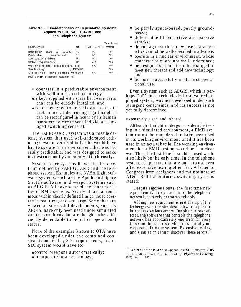
243
Table 9-1 .—Characteristics of Dependable SystemsApplied to SDI, SAFEGUARD, and
the Telephone System
TelephoneCharacteristic SDI SAFEGUARD system
Extensively used & abused No No YesPredictable environment. No No YesLow cost of a failure No No YesStable requirements. No Yes YesWell-understood predecessors No Yes YesSimple design ., Unknown 7 YesD isc ip l i ned deve lopmen t ’ Unknown Yes Yes
SOURCE Of ftce of Technology Assessment 1988
• operates in a predictable environmentwith well-understood technology,
● is kept supplied with spare hardware partsthat can be quickly installed, and
● is not designed to be resistant to an at-tack aimed at destroying it (although itcan be reconfigured in hours by its humanoperators to circumvent individual dam-aged switching centers).
The SAFEGUARD system was a missile de-fense system that used well-understood tech-nology, was never used in battle, would havehad to operate in an environment that was noteasily predictable, and was designed to makeits destruction by an enemy attack costly.
Several other systems lie within the spec-trum defined by SAFEGUARD and the tele-phone system. Examples are NASA flight soft-ware systems, such as the Apollo and SpaceShuttle software, and weapon systems suchas AEGIS. All have some of the characteris-tics of BMD systems. Nearly all are autono-mous within clearly defined limits, must oper-ate in real time, and are large. Some that areviewed as successful developments, such asAEGIS, have only been used under simulatedand test conditions, but are thought to be suffi-ciently dependable to be put on operationalstatus.
None of the examples known to OTA havebeen developed under the combined con-straints imposed by SD I requirements, i.e., anSDI system would have to:
● control weapons autonomatically;● incorporate new technology;
●
●
●
●
●
●
be partly space-based, partly ground-based;defend itself from active and passiveattacks;defend against threats whose character-istics cannot be well-specified in advance;operate in a nuclear environment, whosecharacteristics are not well-understood;be designed so that it can be changed tomeet new threats and add new technology;andperform successfully in its first opera-tional use.
Even a system such as AEGIS, which is per-haps DoD’s most technologically advanced de-ployed system, was not developed under suchstringent constraints, and its success is notyet fully determined.
Extensively Used and Abused
Although it might undergo considerable test-ing in a simulated environment, a BMD sys-tem cannot be considered to have been usedin its working environment until it has beenused in an actual battle. The working environ-ment for a BMD system would be a nuclearwar. Thus, the first time it would be used wouldalso likely be the only time. In the telephonesystem, components that are put into use evenafter extensive testing often fail. A letter toCongress from designers and maintainers ofAT&T Bell Laboratories switching systemsstated:
Despite rigorous tests, the first time newequipment is incorporated into the telephonenetwork, it rarely performs reliably.
Adding new equipment is just the tip of theiceberg; even the simplest software upgradeintroduces serious errors. Despite our best ef-forts, the software that controls the telephonenetwork has approximately one error for everythousand lines of code when it is initially in-corporated into the system. Extensive testingand simulation cannot discover these errors.64
134A copy of the lettir also appears as “SDI Software, p~tII: The Software Will Not Be Reliable,” Physics and Society,16(2), April 1987.
244
Predictable Environment
Two aspects of the BMD battle environmentwill remain unpredictable until the outbreakof war. The first is the effect of the nuclearbackground caused by the battle and the sec-ond is the type and extent of the countermeas-ures employed against the system. In contrast,the telephone system environment is well-known and predictable. Call traffic can bemeasured and compared to mathematical mod-els. Furthermore, much of the environment,such as the signals used in calling, is controlledby the designers of the system, so they are well-acquainted with its characteristics. Those whoseek to defeat telephone systems want to usethe environment for their own ends, and gen-erally do not try to disrupt it. Therefore, al-though countermeasures are not all known intype and extent, neither are they intended todestroy the operation of the system.
Low Cost of a FailureSoftware errors manifested as failures dur-
ing a battle would not be repairable until afterthe battle. Catastrophic failures could resultin unacceptably high numbers of warheadsreaching their targets; there is no way to guar-antee or predict that catastrophic failures willnot occur. Even minor failures may result infailure to intercept some enemy warheads,causing loss of human life. Telephone switch-ing centers experiencing catastrophic softwarefailures generally can be removed from serv-ice and the software repaired while calls arererouted. Minor failures are at most likely tocause difficulties for a few subscribers.
Stable RequirementsAs new threats arose, new strategies de-
vised, new countermeasures found, and newtechnology introduced, the requirements forBMD systems would change, and change con-tinually. Although some changes could beplanned and introduced gradually, changingthreats and, particularly, countermeasureswould impose changes beyond the control ofthe system developers and maintainers. BMDcountermeasures are not subject to close scru-tiny by the opposition, and new ones might
appear quickly, requiring rapid response. Be-cause changes in threat and the developmentof countermeasures would depend on Sovietdecisionmaking and technology, the rate atwhich the U.S. would have to make changesto its BMD software would partly depend onSoviet actions. Delays in responding to coun-termeasures might have serious consequences,including the temptation for the side that hadanew, effective countermeasure to strike firstbefore a counter-countermeasure could be de-vised and implemented.
Well-Understood PredecessorsEarlier BMD systems, such as SAFE-
GUARD, can be characterized as terminal orlate mid-course defense systems. The termi-nal and late mid-course defense part of an SD IBMD system could benefit from experiencewith these predecessors. There has been no ex-perience, however, with boost phase and post-boost phase, and little experience with earlymid-course defenses.65 They are new problemsthat will take new technologies to solve. Mostdemanding of all, a system to solve these prob-lems must be trusted to work properly the firsttime it is used. There have been approximately100 years of experience with telephone switch-ing systems. Each new system is a smallchange over its predecessor. If a newly-installed switching system does not work ac-ceptably, it can be replaced by its predecessoruntil it is repaired.
Simple Design and Disciplined DevelopmentSince the SDI BMD system has not yet pro-
ceeded to the point of a system design, muchless a design for battle management or othersoftware, one cannot judge whether or not the
eSThe Spatm fi99fle, US~ by SA F EG U A R D, cm be con-
sidered a late mid-course defense component. However, SAFE-GUARD was designed to discriminate reentry vehicles fromaircraft, satellites, aurora, and meteors, but not from decoysof the types expected to be available for use against BMD sys-tems within the next 10-20 years. The only discriminators avail-able to SAFEGUARD were phased-array radars. Potential coun-termeasures against modern BMD systems are discussed inchapters 10 and 11, and discriminators in chapter 4. Optionsconsidered for both include technologies considerably differentfrom anything available for or against SAFEGUARD.

245
design will be simple. Similarly, one cannotjudge whether or not the development proc-ess will be appropriately disciplined.
Development Approaches ThatHave Been Suggested
In the middle ground between those who be-lieve that an SDI BMD system could neverbe made trustworthy, and those who are surethat it could, are some software developers whoare unsure about the feasibility. The view someof them take is that it would be worthwhileto try to develop BMD software, given thatone were prepared to abandon the attempt ifthe system could not be shown to be trustwor-thy. The approaches they suggest have the fol-lowing characteristics:
● The purpose of the system would have tobe clearly stated so that the requirementswere known before development started.
●
●
●
●
The development would have to start withwhat was best known, i.e., should buildupon the knowledge and results of earlierU.S. efforts to build BMD systems.The development would have to bephased, so that each phase could buildupon the results of the previous one. Thesystem architecture would have to be con-sistent with such phasing.Simulation would be needed at everystage, and the simulations would have tobe extremely realistic.Realistic tests would have to be Performedat each stage of development:
Because failure is a clear possibility, thosewho advocate this approach recognize that op-tions to deal with the possibility must be leftopen. If this approach were adopted, and failed,the cost of the attempt, including maintain-ing other options, could be high.
SUMMARY
Estimating Dependability
Most of the indices of dependability for large,complex software systems would be missing inBMD software systems. In particular, the tele-phone switching system, often cited as an ex-ample of a large, complex system, is quite un-like BMD systems.
The characteristics associated with depend-ability in large, complex systems include:
●
●
●
●
●
●
●
a history of extensive use and abuse,operation in a predictable environment,a low cost of failures to the users,stable requirements,evolution from well-understood predeces-sor systems,a simple design, anda disciplined development effort.
The absence of many of these factors meansthat technology beyond the present state ofthe art in software engineering might have tobe developed if there is to be a chance of pro-ducing dependable BMD software. It might
be argued that such technology will be in-vented, but traditionally progress has beenslow in software engineering technology de-velopment. It appears that the nature of soft-ware causes progress to be slow, and that thereis no prospect for making a radical change inthat nature.
There is no highly reliable way to demonstratethat BMD software would operate properly whenused for the first time. One of the long-term pur-poses of the National Test Bed is to providea means of simulating operation of BMD soft-ware after deployment. Such tests could simu-late a variety of threats and countermeasures,as well as the conditions existing in a nuclearenvironment. On the other hand, actual envi-ronments often exhibit characteristics notreproduced in a simulator. Simulations of bat-tles involving BMD would have to reproduceenemy countermeasures—a particularly diffi-cult task. The usual technique for validatingsimulations—making predictions based on thesimulation and then verifying their accuracy—would be particularly difficult to use. This
246
would especially be true when one considersthe complexity of the atmospheric effects ofnuclear explosions and the speculation in-volved in determining countermeasures. Re-peated failures in simulation tests would dem-onstrate a lack of dependability. Successfulperformance in a simulation would give someconfidence in the dependability of the system,but neither the dependability nor the confi-dence could be measured. Subjective judg-ments based on simulations would probablybe highly controversial.
Traditional Reliability MeasuresTraditional measures of reliability, such as
mean time between failure, are insufficient tocharacterize dependability of software. Appro-priate software reliability measures have yetto be fully developed. Furthermore, in the de-bate over BMD software dependability thereis often confusion over the meaning of relia-bility. Error rate, e.g., number of errors perKLOC, is often misapplied as a definition ofsoftware reliability. There is no single figureof merit that would adequately quantify thedependability of BMD software. A potentiallyuseful view is that dependability can be con-sidered to be a combination of qualities suchas trustworthiness, correctness, availability,fault tolerance, security, and safety. Unfortu-nately, there are no good ways of quantifyingsome of these properties and dependabilitywould have to be a subjective judgment.
Technology for PreventingCatastrophic Failure
OTA found no evidence that the software engi-neering technology foreseeable in the near fu-ture would make large improvements in the de-pendability of software for BMD systems. Inparticular there would be no way to ensure thatBMD software would not fail catastrophicallywhen first used. It might be argued that themost important part of dependability is faulttolerance, and that there exist large, complexsystems that are fault-tolerant, such as thetelephone switching system. On the otherhand, the fault tolerance of such systems issmall compared to what would be needed for
BMD, since they are not under attack by anintelligent. adversary interested in destroyingtheir usefulness. A further complication of theargument over fault tolerance is that quantifi-cations of software fault tolerance are not eas-ily translated into measures of performance.At the same time, there is no generally ac-cepted subjective standard of fault tolerance.
Confidence Based on PeacetimeTesting
Confidence in the dependability of a BMDsystem would have to be derived from simu-lated battles and tests conducted during peace-time. Getting a BMD system to the point ofpassing realistic peacetime tests would mostlikely require a period of stability during whichthere were few changes made to the software.Unfortunately, the system developers andmaintainers would have to respond to changesin threats and countermeasures put into effectby the Soviets. That is, the Soviets wouldpartly control the rate at which changes wouldhave to be made to the system. As changeswere made, the system would again have topass tests in order for the United States tomaintain confidence in it.
Accommodating Changes During PeacetimeExperience with complex systems shows
that changes eventually start introducing er-rors at a rate faster than they can be removed.At such a point all changes must be stoppedand new software developed. The extent towhich changes could be made would dependon the foresight of the developers during thedesign of the software. The better the require-ments were understood at that time, and thebetter the potential changes were predicted,the more the chance that the software couldaccommodate changes as they occurred. Theappearance of an unforeseen threat or coun-termeasure, or simply the advent of new, un-expected technology, might require redevelop-ment of all or substantial parts of the software.In a sense, the useful lifetime of the softwarewould be determined by how well the softwaredevelopers understood the requirements ini-tially.
247
Establishing Goals and Requirements
Explicit performance and dependabilitygoals for BMD have not been established. Con-sequently, one cannot set explicit software de-pendability goals. Even when BMD goals havebeen set, it will be difficult to derive explicitsoftware dependability goals from them; thereis no clear mapping between system dependa-bility and software dependability. All agreethat perfect software dependability is unat-tainable. Only arguments by analogy, e.g., asdependable as an automobile or telephone,have been proposed. There is no common agree-ment on what the dependability needs to be,nor how to measure it, except that it must behigh.
There is common agreement that standardDoD procedures for developing software arenot adequate for producing dependable BMDsoftware in the face of rapidly changing re-quirements. There are few convincing pro-posals as yet on how to improve the proce-dures. The developers should not be expectedto produce an adequate system on the first try.As Brooks says in discussing large softwaresystems:
In most projects, the first system built isbarely usable. It maybe too slow, too big, too
awkward to use, or all three. There is no alter-native but to start again, smarting butsmarter, and build a redesigned version inwhich these problems are solved. . . . all large-system experience shows that it will be done.Where a new system concept or new technol-ogy is used, one has to build a system to throwaway, for even the best planning is not so om-niscient as to get it right the first time. . . .
Hence plan to throw one away: you will, any-how.66
BMD software may be an order of magni-tude larger than any software system yetproduced. Early estimates of software size forprojects are notoriously inaccurate, often bya factor of 3 or more. Some argue that the useof an appropriate systems architecture canmake SDI software comparable in size to thelargest existing systems. On the other hand,none of the intermediate or far-term architec-tures yet proposed would appear to have thiseffect, and previous experience with large soft-ware systems indicates that the size is likelyto be larger than current estimates. Such anincrease in scale could cause unforeseen prob-lems to dominate the development process.
‘Frederick P. Brooks, Jr., The Mythica/ Man-Month; l?ssayson Software Engin~ring (New1975), p. 116.
SDIO INVESTMENT IN BATTLE MANAGEMENT,TECHNOLOGY, AND SOFTWARE
Fork, NY: Addison-Wesl~y,
COMPUTING
SDIO’s battle management program servesas the focus for addressing many of the com-munications, computing, and software tech-nology problems discussed in chapters 7,8, and9. Based on funding and project descriptiondata supplied by SDIO, this section analyzeshow SDIO is spending its money to try to solvethese problems. The battle management pro-gram is organized into eight areas:
1. software technology program plan: devel-oping and implementing a software tech-nology program for the SDIO;
2. algorithms: development of algorithms forsolving battle management problems such
as resource allocation, track data hand-ing over, discrumination, and coordinationof actions within a distributed system;
3. communications: identifying the require-
4.
5.
ments and technology for establishing acommunications system to link SD I com-ponents together into a BMD system;experimental systems: proposing andevaluating system and battle manage-ment architectures and the technologiesfor implementing them;networks: the design and development ofdistributed systems and of communica-tions networks that could be used to sup-port BMD;
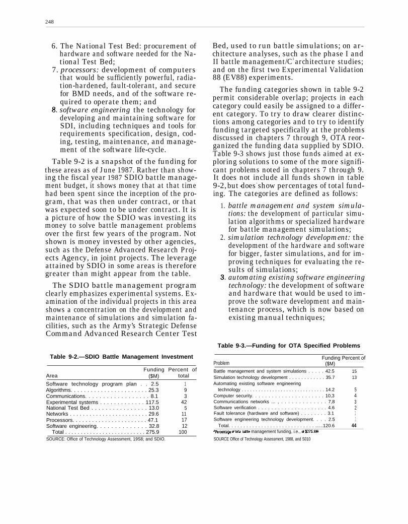
248
6. The National Test Bed: procurement ofhardware and software needed for the Na-tional Test Bed;
7. processors: development of computersthat would be sufficiently powerful, radia-tion-hardened, fault-tolerant, and securefor BMD needs, and of the software re-quired to operate them; andsoftware engineering the technology fordeveloping and maintaining software forSDI, including techniques and tools forrequirements specification, design, cod-ing, testing, maintenance, and manage-ment of the software life-cycle.
Table 9-2 is a snapshot of the funding forthese areas as of June 1987. Rather than show-ing the fiscal year 1987 SDIO battle manage-ment budget, it shows money that at that timehad been spent since the inception of the pro-gram, that was then under contract, or thatwas expected soon to be under contract. It isa picture of how the SDIO was investing itsmoney to solve battle management problemsover the first few years of the program. Notshown is money invested by other agencies,such as the Defense Advanced Research Proj-ects Agency, in joint projects. The leverageattained by SDIO in some areas is thereforegreater than might appear from the table.
The SDIO battle management programclearly emphasizes experimental systems. Ex-amination of the individual projects in this areashows a concentration on the development andmaintenance of simulations and simulation fa-cilities, such as the Army’s Strategic DefenseCommand Advanced Research Center Test
Table 9-2.—SDIO Battle Management Investment
Funding Percent ofArea ($M) total
Software technology program plan . . 2.5 1Algorithms. . . . . . . . . . . . . . . . . . . . . . . 25.3 9Communications. . . . . . . . . . . . . . . . . . 8.1 3Experimental systems . . . . . . . . . . . . . 117.5 42National Test Bed . . . . . . . . . . . . . . . . 13.0 5Networks . . . . . . . . . . . . . . . . . . . . . . . . 29.6 11Processors. . . . . . . . . . . . . . . . . . . . . . . 47.1 17Software engineering. . . . . . . . . . . . . . 32.8 12
Total . . . . . . . . . . . . . . . . . . . . . . . . . . 275.9 100
Bed, used to run battle simulations; on ar-chitecture analyses, such as the phase I andII battle management/C3 architecture studies;and on the first two Experimental Validation88 (EV88) experiments.
The funding categories shown in table 9-2permit considerable overlap; projects in eachcategory could easily be assigned to a differ-ent category. To try to draw clearer distinc-tions among categories and to try to identifyfunding targeted specifically at the problemsdiscussed in chapters 7 through 9, OTA reor-ganized the funding data supplied by SDIO.Table 9-3 shows just those funds aimed at ex-ploring solutions to some of the more signifi-cant problems noted in chapters 7 through 9.It does not include all funds shown in table9-2, - - -
ing.
1.
2.
but does show percentages of total fund-The categories are defined as follows:
battle management and system simula-tions: the development of particular simu-lation algorithms or specialized hardwarefor battle management simulations;simulation technology development: thedevelopment of the hardware and softwarefor bigger, faster simulations, and for im-proving techniques for evaluating the re-sults of simulations;automating existing software engineeringtechnology: the development of softwareand hardware that would be used to im-prove the software development and main-tenance process, which is now based onexisting manual techniques;
Table 9-3.—Funding for OTA Specified Problems
Funding Percent ofProblem ($M)Battle management and system simulations . . . . . 42.5Simulation technology development . . . . . . . . . . . . 35.7Automating existing software engineering
technology . . . . . . . . . . . . . . . . . . . . . . . . . . . . . . 14.2Computer security. . . . . . . . . . . . . . . . . . . . . . 10,3Communications networks ... , . . . . . . . . . . . . . 7,8Software verification . . . . . . . . . . . . . . . . . . . . . 4.6Fault tolerance (hardware and software) . . . . . . . . 3.1Software engineering technology development. . . . 2.5
Total. . . . . . . . . . . . . . . . . . . . . . . . . . . . . ......120.6
1513
543211
44a~rcentage of toul battle management funding, i.e., Of $275.9M
SOURCE Office of Technology Assessment, 1988, and S010SOURCE: Office of Technology Assessment, 19S8; and SDIO.
249
4.
5.
6.
7.
computer security: techniques for detect-ing and preventing unauthorized accessto computer systems;communications networks: the organiza-tion of computer-controlled communica-tions equipment into a network that couldmeet SDI communications requirements;software verification: the development ofpractical techniques for mathematicallyproving the correctness of computerprograms;fault tolerance (hardware and software):the development of hardware and softwarethat continues to work despite the occur-rence of failures; and
8. software engineering technology develop-
works, fault tolerance, and new software engi-neering technology development.
CONCLUSIONS
1.
2.
ment: the development of new techniquesfor improving the dependability of soft-ware and the rate at which dependablesoftware can be produced.
Table 9-3 shows that SDIO is investing con-siderably more in simulations and simulationtechnology than any of the other problem areasin battle management and computing identi-fied by OTA. Of some concern is the smallnessof the investment in especially challenging areassuch as computer security, communications net-
Based on both the preceding analysis, andthe further exposition in appendix A, OTA hasreached eight major conclusions.
The dependability of BMD software wouldhave to be estimated subjectively and with-out the benefit of data or experience from bat-tle use. The nature of software and our experi-ence with large, complex software systems,including weapon systems, together indicatethat there would always be irresolvable ques-tions about how dependable the BMD soft-ware was, and also about the confidence tobe placed in dependability estimates. Politi-cal decision-makers would have to keep inmind that there would be no good technicalanswers to questions about the dependabil-ity of the software, and no well-founded tech-nical definition of software dependability.
It is important to note that the Sovietswould have similar problems in trying toestimate the dependability of the software,and therefore the potential performance ofthe system. Technical judgments of depend-ability would rely on peacetime tests thatwould be unlikely to apply to battle condi-tions. Political judgments about the credi-bility of the defense provided would there-fore rest on very uncertain technical grounds.No matter how much peacetime testing weredone, there would be no guarantee that the
75-922 0 - 88 - 9
3.
4.
system would not fail catastrophically dur-ing battle as a result of a software error. Fur-thermore, experience with large, complex soft-ware systems that have unique requirementsand use technology untested in battle, suchas a BMD system, indicates that there is asignificant probability that a catastrophic fail-ure caused by a software error would occurin the system’s first battle.
It is possible that an administration and aCongress would reach the political decisionto “trust” software that passed all the teststhat could be devised in peacetime, despitethe irresolvable doubts about whether suchsoftware might fail catastrophically the firsttime it was used in an actual battle. Sucha decision could be based upon the argumentthat the purpose of strategic forces—evendefensive strategic forces—is primarily deter-rence, and that a defensive system passing allits peacetime tests would be adequate for de-terrence. If deterrence succeeded, we wouldnever know, and never need to know, whetherthe system would function in wartime.
The extent to which BMD software would dif-fer from complex software systems that haveproven to be dependable in the past raises thepossibility that software could not be createdthat ever passed its peacetime tests. This apossibility exacerbated by the prospect of

250
5.
6.
changing requirements caused by Soviet ac-tions. We might arrive at a situation inwhich fixing problems revealed by one testcreated new problems that caused the soft-ware to fail the next test.
No adequate models exist for the develop-ment, production, test, and maintenance ofsoftware for full-scale BMD systems. CurrentDoD models of the software life-cycle andmethods of software procurement appear in-adequate for the job of building software aslarge, complex, and dependable as BMDsoftware would have to be.
The system architecture, the technologies tobe used in the system, and a consistent setof performance requirements over the lifetimeof the system must be established before start-ing software development.67 Otherwise, thesystem is unlikely even to pass realisticpeacetime tests.
oTNotg that this does not preclude a phased system, with bothcapabilities and requirements growing over time, provided thatthe final architecture and final performance requirements areclear before initial software development begins. Even then, con-sidering the uniqueness of BMD defense, one would expect tospend considerable time finding a workable design.
7.
8.
As the strategic goals for a BMD system be-came more stringent, confidence in one’s abil-ity to produce software that would meet thosegoals would decrease as a result of the in-creased complication required in the softwaredesign. Even for modest goals, such as im-proved deterrence, the United States couldnot have high confidence that the softwarewould not fail catastrophically, whetherfaced with a modest threat or a severethreat. Put another way, there is no goodway of knowing that BMD software woulddegrade gracefully rather than fail catas-trophically when called on to face increas-ing levels of threat. Current techniques foridentifying problems and detecting errors,such as simulations, would not help, al-though they could help to reduce the fail-ure rate. Furthermore, foreseeable improve-ments in software engineering technologywould not change this situation.
The SDIO is investing relatively smallamounts of money in software technology re-search in general, and in software engineer-ing technology, computer security, communi-cations networks, and fault tolerance inparticular. This investment strategy is ofsome concern, since particularly challeng-ing BMD software development problemslie in these areas.
Chapter 10
Non-Destructive Countermeasuresto Ballistic Missile Defense
The classified version of this chapter is available in the classified version ofthis report. As of this writing, the unclassified version continues to be withheldfrom release by the Department of Defense.
CONTENTS
Introduction
Delivery Vehicles
Penetration Aids
Active Electronic and Electro-Optic CountermeasuresConclusion
Chapter 11
Defense Suppression andSystem Survivability
The classified version of this chapter is available in the classified version ofthis report. As of this writing, the unclassified version continues to be withheldfrom release by the Department of Defense.
CONTENTS
Introduction
Defense Suppression Threats
Survivability Measures To Counter Defense SuppressionConclusions on Defense Suppression Threats and Survivability Options

Chapter 12
Defense Suppression Scenarios
The classified version of this chapter is available in the classified version ofthis report. As of this writing, the unclassified version continues to be withheldfrom release by the Department of Defense.
CONTENTS
Introduction
Survivability Scenarios—Phase-One and Phase-Two ArchitecturesLonger-term ArchitecturesSurvivability Scenarios –
Mutual Occupancy of Space by Comparable Ballistic Missile Defense SystemsKey Survivability Scenario Issues and Conclusions

Appendixes

Appendix A
Technology for ProducingDependable Software
Introduction
Chapter 9 of this report often refers to the tech-nology of specific phases in the software life cycle.The application of such technology is known assoftware engineering. This appendix describes thestate of the art in software engineering andprospects for improvements in the state of thatart. It serves as a tutorial for those unfamiliar withDepartment of Defense (DoD) software develop-ment practices. It provides supporting detail forthe discussions in chapter 9 of the technology avail-able for producing dependable systems.
Origins of Software Engineering
The term “software engineering” originated in1968. Around that time, computer scientists be-gan to focus on the difficulties they encounteredin developing complicated software systems. A re-cent definition of software engineering is:
. . . the application of science and mathematics bywhich the capabilities of computer equipment aremade useful to man via computer programs, pro-cedures, and associated documentation.1
Another recent definition adds requirements forprecise management and adherence to scheduleand cost:
Software engineering is the technological andmanagerial discipline concerned with systematicproduction and maintenance of software productsthat are developed and modified on time and withincost estimates.2
The Institute of Electrical and Electronic Engi-neers (IEEE) defines software engineering as:
The systematic approach to the development,operation, maintenance, and retirement ofsoftware. 3
Before the late 1960s, managers paid little at-tention to the systematizing of software construc-tion building. Most software systems were notcomplicated enough to occupy large numbers ofpeople for long periods of time. Existing computers
‘Barry W. Boehm, Software Engineering Econom”cs (EnglewoodCliffs, NJ: Prentice-Hall, 1981), p. 16.
*Richard Fairley, Software Engineering Concepts, (New York:McGraw-Hill, 1985), p. 2.
‘IEEE Standard Glossay of Software Enp”neering Terminology,IEEE Standard 729-1983.
were not big or fast enough to solve very compli-cated problems:
As long as there were no machines, Program-ming was no problem at all; when we had a fewweak computers, Programming became a mildproblem, and now that we have gigantic com-puters, Programming has become an equally gigan-tic problem.4
Software engineering technology has improvedsince 1972, but not as quickly as the capabilitiesof computers. Studies in software engineering tech-nology transfer show that ideas typically take 18years to move from research environments, suchas universities and laboratories, to common usesDuring this time, considerable experimentationand repackaging occur.
Advances in software engineering technologyoften take the form of better techniques for pro-gram design and implementation. Some techniquesdemand no more than a pencil and paper and anunderstanding of their concepts. Most, however,become partially or fully automated. The form ofautomation is generally a computer program,known as a “software engineering tool. ” One ex-ample is the compiler-which helps to debug otherprograms; another is a program that checks theconsistency of software specifications. Becausesoftware engineering tools themselves take theform of complex computer programs, they are sub-ject to the typical problems involved in producingcomplex, trustworthy software. This fact helps ex-plain why software engineering technology lagshardware engineering technology.
The trend toward use of software engineeringtools seems to be growing, as evidenced by suchprojects as:
● DoD’s Software Technology for Adaptable,Reliable Systems (STARS), whose purpose hasbeen to produce an integrated set of tools forDoD software engineers;
4Edsger W. Dijkstra, “The Humble Programmer, ” Communicationsof the ACM, 15(10):859-866, 1972.
‘William E. Riddle, “The Magic Number 18 Plus or Minus Three: AStudy of Software Technology Maturation, ” ACM Software Engineer-ing Notes, vol. 9, No. 2, 1984, pp 21-37.
The figure of 18 years for technology transfer is consistent with otherengineering fields during periods of technological innovation, as ana-lyzed in Gerhard O. Mensch, Stalemate in Technolo&Cambridge, MA:Ballinger, 1979).
259
260
●
●
the Software Productivity Consortium,formed to produce software engineering toolsfor its client members, including many of thenation’s largest Aerospace companies; andthe Microcomputer and Electronics Consor-tium, one of whose purposes is to produce bet-ter software engineering technology for its cli-ent members.
State of the Art in SoftwareEngineering
This section discusses the current state of theart in software engineering technology. It consid-ers the application of that technology to system-atic approaches to software development. Finally,it reviews recent proposals for improvements insoftware engineering to aid in the development ofballistic missile defense (BMD) software.
The Software Development CycleThe process of developing and maintaining soft-
ware for military use is described in DoD militarystandards documents as the “software life cycle. ”The description here is simplified for the purposesof this report. The activities described are commonto nearly all DoD projects, though they vary in theamount of attention paid to each, the productsproduced by each, and the number and kind ofsubactivities in each.
Furthermore, the initial set of activities de-scribed encompasses only development, up to thepoint of acceptance of the system by DoD. Ourdescription lumps activities following developmentinto the category of “maintenance,” which is dis-cussed in a separate section. Finally, the activitiesdescribed here generally conform to the model ofdevelopment set forth in the DoD Standard (No.2167) for software development. Commercial de-velopment and advanced laboratory work may fol-low considerably different procedures (although alltend to produce documentation similr in intentto that described in the following sections).
Feasibility Analysis
The first phase of development is an analysis ofthe DoD’s operational needs for the proposed sys-tem. This phase may start with a series of studiesof the feasibility of meeting those needs. The re-ported results of the feasibility studies are oftenbased on computer simulations of the situationsthat the system would have to handle. The envi-ronment in which the system would operate may
be characterized in terms of quantifiable parame-ters. This process is analogous to telephone com-pany analyses of the traffic load–the number ofcalls per hour expected at different times of theday, week, and year-to be placed on a new switch-ing center. The feasibility analysis may be per-formed on a contract basis by systems analystswho are not software engineers. In the case of theStrategic Defense Initiative (SDI), systemsanalysts who are familiar with BMD have donemuch of the feasibility analysis as part of the com-petitive system architecture contracts (see ch. 3).
Feasibility analysis sometimes includes con-structing a software prototype designed to inves-tigate a few specific issues, for example, what themode of interaction between human and computershould be or which tracking algorithms would workbest under different circumstances. Most systemfunctions are not implemented in prototypes. Tosave time, the development of prototype softwaredoes not follow the standard cycle. Software in theprototype is not usually suitable for reuse in theactual system. The prototype is usually discardedat the end of the software development cycle.
The end-product of the feasibility analysis is adocument that describes what functions the newsystem needs to perform and how it will work. Thisreport is sometimes called a “concept of opera-tions” or an “operational requirements” document.The operational requirements document will formthe basis for a request for proposals to potentialdevelopment contractors. Once the contract hasbeen awarded, the document will underlie the state-ment of requirements to be met by the system—that is, the description of what the contractor mustbuild. The (SDI) battle management software de-velopment project is currently in the feasibilityanalysis stage.
Software Requirements Analysisand Specification
Software engineers enter the software develop-ment process at the software requirements analy-sis and specification phase. From their interpreta-tion of the operational requirements document,they write a requirements or performance “speci-fication” for the software (including how it is tointerface with other systems). Upon governmentapproval, this specification document supplies thecontractual criteria of acceptability of the softwareto the government. The specification differs fromthe operational requirements as follows:
● It is more detailed than the operational re-quirements statement. Where the latter may

261
vaguely describe the functions to be per-formed, such as “simultaneously track 10,000missiles, ” the requirements specification willdescribe a sequence of subfunctions needed toimplement the operational requirement. Thedescription of each subfunction will include adescription of the input supplied to the sub-function, the output produced by it, and a briefexplanation of the algorithm by which the in-puts are transformed into outputs.
For example, a subfunction of tracking maybe to update the track for a particular missile.The inputs of that subfunction are the currentfile of tracks and a new track report. Its out-put is an updated track file. The algorithmmight consist of the following steps:
—retrieve the existing track for the missilefrom the track database;
—update the position, velocity, acceleration,and time of last report components of themissile track; and
—store the updated track entry back intothe database.
● It describes the interfaces between the newsystem and all the other systems with whichit must interact. Sometimes these interfacesare described in a separate document.
● It describes the interfaces to the hardware de-vices that the software must control, such asweapons, or from which the software must ob-tain information, such as navigation deviceslike inertial guidance units.
When the requirements specification is complete,the government holds a “requirements review” atwhich it decides what, if any, changes must bemade. The specification becomes a contractuallybinding document and is passed on to the softwaredesigners. The review is the last time at which re-quirements errors can be corrected cheaply: fewassumptions have yet been made about the waythe requirements will be implemented as computerprograms. Procedures known as “configurationcontrol” are established. These ensure that thespecification is not arbitrarily changed. The speci-fication becomes the “baseline requirements speci-fication. ” All further changes go through a formalapproval cycle, requiring the concurrence of a com-mittee known as a “configuration control board. ”
DesignThe purpose of the design phase is to produce
a “program design specification” of how a c om-puter program can be written to satisfy the require-ments specification. The design specification usu-
ally describes the division of the software intocomponents. Each component may be subdividedagain, with the subdivision process eventually end-ing in subcomponents that can be implemented asindividual subprograms or collections of data. Thecomponents resulting from the first subdivision,sometimes called “configuration items, ” are usedto track the status of the system throughout itslifetime.
The organization that emerges from the designprocess is known as the structure of the software,and the criteria used are called “structuring cri-teria.” The relationship among components de-pends on the criteria used in the subdivision proc-ess. For example, if the criterion for subdivisionis function, at the first subdivision a componentcalled “tracking” might be formed. At the secondlevel one might find tracking subdivided into func-tions such as “obtain object track” and “updateobject track. ” Such a subdivision is called a “func-tional decomposition. ”
A very different criterion is type of change. Atthe first level one might then see components suchas all decisions that will change if the hardwarechanges and all decisions that will change if soft-ware requirements change. At the second level onemight find hardware decisions subdivided into de-cisions about sensor hardware, decisions aboutweapons hardware, and decisions about computerhardware. Such an organization is called an “in-formation hiding decomposition. ”
The structuring criteria are key to understand-ing the design and the trade-offs it embodies.6
Those who use functional decomposition arguethat it results in software that performs more effi-ciently. Those who use information hiding arguethat it results in software that is easier to main-tain because it is easier to demonstrate correct andeasier to understand. Other criteria optimize forother factors, for example, fault-tolerance, security,and ease of use. As might be expected, there is nosingle criterion that simultaneously optimizes alldesign goals.
An important purpose of the design specifica-tion is to describe the “interfaces” among compo-nents. The interfaces consist of the data to bepassed from one component to another, the se-
%ood designers find it useful to structure the design in several differ-ent ways to permit study of different trade-offs. For example, aninformation-hiding decomposition is useful in optimizing for changeslater in the life-cycle of the software. A functional decomposition helpsensure that all functions are performed and makes it easy to analyzethe efficiency of software. An important problem for the designer is tobe able to represent the different design structures so that they are con-sistent with each other.
262
quences of events to be used in coordinating theactions of the components, and the conditions un-der which the components interact. Once the in-terfaces are established, individual design teamsmay design each component. Since each componentmay interact with several others, agreement on theinterfaces is crucial for effective cooperation amongthe design teams.
Such agreement is equally important for thosewho must later implement the design as a com-puter program. A mistaken assumption about aninterface will result in an error in the software anda failure in the operation of the software. A changein an interface requires agreement among all thoseworking on the interfacing components, and mayresult in redoing weeks or months of work. Get-ting the interfaces right is generally agreed to bethe most difficult part of developing complexsoftware.
During the design process several reviews of thedesign are held. The purpose of the reviews is toensure that the design is feasible and correctly im-plements the requirements. Early reviews on willbe a “preliminary design review.” When the de-signers feel that the design specification is suffi-ciently complete to be turned into computer pro-grams, they hold a final, “critical design review. ”Errors found at this point can still be correctedrelatively cheaply. Once they become embedded inprograms they are very much more difficult to findand correct. Each design review results in changesto the design specification. Once the changes arecompleted, the design specification becomes thebasis for producing computer programs. It is thenplaced under configuration control, much as theapproved requirements specification is.
Code
The process of translating the program designspecification into computer programs is known as“coding.” By DoD policy, command and controlsystems, weapons, and other software develop-ment projects must use a DoD standard program-ming language.7 Individual programmers workfrom the design specification to implement thecomponents as computer programs. The more com-pletely and precisely the components and their in-terfaces are defined, the less communication is re-quired among the programmers. They can thenwork independently, in parallel. An incomplete or
‘Current DoD policy mandates the use of Ada as a standard program-ming language, unless the developer of a system obtains a waiver. Priorto the advent of Ada, each service had its own standard programminglanguage.
ambiguous specification requires the programmersto make design decisions, often with incompleteand unrecorded communication among each other.
Programming is writing instructions for a com-puter to perform a function described in the de-sign specification. The instructions are packagedtogether as a subprogram or a set of subprogramsthat cooperate to perform the function. Before itcan be executed, a subprogram must be translatedby a compiler from the programming language intomachine language. Part of the programming jobis to devise and perform tests on each subprogramto show that it works properly. A programmer usu-ally goes through several cycles of writing, test-ing, and revising a subprogram before he is readyto declare it finished. When a programmer is satis-fied that his subprograms perform correctly, hesubmits it to a test group.
Test
A separate group has the sole responsibility todevise, perform, and report on the results of tests.With no knowledge of the design, this group de-vises tests based on the requirements specification.It sends components that fail tests back to theirdevelopers with descriptions of failures and no at-tempts to diagnose the reasons for failures.
Test performance is the primary basis for confi-dence (or no confidence) that a system behaves asit is supposed to. A variety of techniques teststrustworthiness, fault-tolerance, correctness, secu-rity, and safety. It is during testing that compo-nents of the system first operate together and asa whole. The following sections describe the stepsin the integration and testing process. At eachstep, each of the reliability aspects maybe tested.
The test process resembles a reversal of the de-sign process. Subprograms are first tested in-dividually, then combined into components for in-tegration tests. Components are integrated againand tested as larger components, the process con-tinuing until all components have been combinedinto a complete system. To a large extent, integra-tion testing may be thought of as testing the in-terfaces between components. It is in integrationtesting that mistaken assumptions about howother programs behave first manifest themselvesas failures.
Early tests in the process often include supply-ing erroneous input data to components or plac-ing them under atypical operating conditions. Suchconditions might include heavy computationalloads or undesired events that, while abnormal,might occur. Such “stress” tests are designed tofind out how fault-tolerant the system will be.

263
As integration progresses, the total number ofpossible states of the formed component is theproduct of the number of states of its constituents.Combining component A with N states and com-ponent B with M states results in component Cwith M times N states. If R tests were performedon A, and T tests on B, combining each test of Awith each test of B would require performing Rtimes T tests on C. For large systems, it is imprac-tical to perform the number of tests needed: at eachintegration stage the number of tests performedrelative to the number of possible states becomesquite small. The tests performed on the entire in-tegrated system include only a few typical ex-pected scenarios.
The integration procedure described above iscalled “bottom-up,” since it starts on the lowestcomponent level and proceeds upward. A secondintegration technique that is becoming more com-mon starts with top-level components. It attemptsto test interfaces as early as possible. This tech-nique requires the writing of dummy subcompo-nents that simulate only some of the actions of theactual future subcomponents, but that use thesame interfaces. The dummies, called “stubs,” aregradually replaced with the actual subcomponentsas system “top-down” integration proceeds.
When the developer deems the system ready fordelivery, a contractually-specified formal test pro-cedure is performed to ensure that the system isacceptable to the government. This “acceptancetest” consists of running several scenarios, and itmay test endurance and handling of stress. Accept-ance tests are performed under government obser-vation under conditions as closely approximatingreal use as possible. If included, an endurance testconsists of continuous simulated use of the sys-tem for a minimum of 24 hours. Endurance testsare important for systems that are expected tooperate continuously once placed in service. Oncea system has passed its acceptance tests, it is de-livered to the government and enters the remain-ing phase of its life cycle, known as maintenance.
Despite elaborate test procedures, all complexsoftware systems contain errors when delivered.As previously noted, software tests cannot beexhaustive and cannot be relied upon to find allerrors. As an example, during the operationalevaluation of the AEGIS system on the U.S.S.Ticonderoga, 20 target missiles were fired whilethe ship was at sea under simulated battle condi-tions. Some of the target missiles were fired simul-taneously into the area scanned by the AEGIScombat system; thus, the 20 targets constitutedfewer than 20 scenario tests. The tests revealed
several software errors, costing approximately$450,000 to fix.8
Since errors do remain in software after accept-ance testing, the correction of errors continues asa major activity after a system has been deliveredand put into use.Maintenance
Unlike hardware, software contains no physicalcomponents and does not wear out as a result ofcontinuing use. Maintenance is really a misnomerwhen applied to software:
In the hardware world, maintenance means theprevention and detection of component failurecaused by aging and/or physical abuse. Since pro-grams do not age or wear out, maintenance in thesoftware world is often a euphemism for continuedtest and debug, and modification to meet chang-ing requirements.9
Errors emerging during system use must be cor-rected, and the system must be retested to ensurethat the corrections work properly and that no newerrors have been introduced. Correcting an errormay entail reanalyzing some requirements and do-ing some redesign; it almost certainly demands re-writing some code. Accordingly, all of the devel-opment activities also occur during maintenance.
Even when requirements appear to be completeand consistent, as users gain experience with a sys-tem they may change their minds about the per-formance they desire from it. The automobile is acase in point. Drivers’ behavior and expectationsabout the performance of their vehicles changedas new possibilities for travel emerged and as newtechnology became available. Behavior alsochanged as economic and political situationschanged. For example, wartime conditions affectedthe cost and availability of cars and auto parts,and oil production decisions affected the price offuel. Similarly, as writers have switched from type-writers to word processors, both their writinghabits and the features they expect in a word proc-essor have changed.
Maintenance costs are now becoming the majorcomponent of software life-cycle costs. Some datashow that by 1978, 48.8 percent of data process-ing costs were spent on maintenance activities.10
‘Discussion of the results of the Ticonderoga operational evaluationtestsmaybe found in U.C. Congress, Senate Committee on Armed Serv-icesthe record of the hearings before the Committee on Armed Serv-ices, United States Senate, 98th Congress, second session on S.2414part 8, Sea Power and Force Projection, Mar. 14, 18, 29, Apr. 5, II,May 1, 1984.
“D. David Weiss, U.S. Naval Research Laboratory, ‘‘The MUDD&port: A Case Study of Navy Software Development Practices, ” NRLReport 7909, May 1975.
IOBoehm, Softwsre Engineering Econo~”cs, op. cit., footnote 1, figure3-2, p. 18.

264
New technology, new strategies, and new computa-tional algorithms would cause envisioned BMDsystems to evolve over many years, Their long-lifetime, complexity, and evolutionary nature willmagnify the general trend towards relatively largersoftware maintenance costs.
Interaction Among the Phases
In the preceding sections the different phases ofthe software life cycle are described as if they oc-cur in a strict sequence. In fact, there is consider-able feedback among the phases. Changes in re-quirements, design, and code occur continually.Large systems may be subdivided into subsys-tems, for each of which there is a separate require-ments specification and a separate developmentcycle. These separate developments may proceedin parallel or sequentially.
The first planned delivery in a sequential devel-opment is called the initial operating capability(IOC). Sequencing the delivery of different versionsof the system over time permits faster delivery ofsome capabilities, but it introduces additional prob-lems into all of the development phases. The sys-tem must be designed so that added capabilitiesdo not require large changes to existing design orcode. In particular, interfaces must be designed totake into account potential future changes in ca-pabilities. This is another example of a problem inlarge, complex systems that does not occur in smallsystems, where the entire system is delivered atonce.
The requirements analysis and design phasesusually consume about 40 percent of the develop-ment effort, the coding phase about 20 percent, andthe testing phase about 40 percent. For long-livedsystems, the maintenance phase consumes 60-80percent of the total lifecycle cost. For this reason,the trend in large, long-lived systems is to try todevelop the software so as to make the mainte-nance job easier. Since the principal activity inmaintenance is change, an important developmentconsideration is how to make change easier.
Software Engineering Technology
Software engineering technology research anddevelopment tend to focus on particular phases ofthe software life cycle. For example, work on im-proving design techniques is often independent ofwork on improving techniques for translating high-level languages to machine code. One reason is thatthe different phases present very different prob-lems for the software engineer.
The next few sections briefly describe the stateof the art, the state of the practice, and the direc-tion in which software technology is currently mov-ing, particularly within DoD. Much of the work inthe last few years has concentrated on creatingautomated support for software development tech-niques. Such support usually consists of one ormore programs, called tools.ll
Constructing Prototypes
During the feasibility analysis and requirementsspecification stages, software engineers sometimesquickly produce prototypes to help feasibility anal-ysis and to explore different ways in which usersmight interact with the completed system. Suchrapid prototype are intended to allow explorationof only a few issues: they are not intended to bemodels of the final software. They are often exe-cuted in different languages, on different com-puters, and using a different development processthan the final software. Usually less than 10 per-cent of development effort is spent on such pro-totypes.
Sometimes software engineers do full prototyp-ing. Full prototyping means building a completeprototype system and then discarding it. This ap-proach has been advocated by Brooks:
Inmost projects, the first system built is barelyusable. It may be too slow, too big, too awkwardto use, or all three. There is no alternative but tostart again, smarting but smarter, and build a re-designed version in which these problems aresolved. . . . all large-system experience shows thatit will be done. Where a new system concept or newtechnology is used, one has to build a system tothrow away, for even the best planning is not soomniscient as to get it right the first time....
Hence plan to throw one away: you will, any-how.”
Specifying Requirements
Software requirements specifications constitutean agreement between the customer and the soft-ware developers. In stating what the softwaremust do, the specifications must be unambiguous,precise, internally consistent, complete, and cor-
tlRather th~ trying to describe even the few most notable example%this appendix just indicates general trends. For a more detailed surveyof software technology that maybe applicable to SDI, the reader shouldsee the following Institute for Defense Analysis report on the subjectprepared for the SDIO: Samuel T. RedWine, Jr., Sarah H. Nash, et al.,SDI Prelirnimuy Software Technology Integration Plan, IDA paper P-1926, July 1986.
1~Frederi& p. Br~ks, Jr., The Mythical lkf~-lfonth: ESSZ?YS On Soft-
ware En~”neering (New York, NY: Addison-Wesley, 1975).

265
rectly representive of the customer’s desires anddevelopers’ intent. By systematizing the process,methodologies for analyzing and expressing re-quirements are intended to help the analyst becomplete, consistent, and clear. Some tools partlyautomate the process—sometimes by providingmechanisms to support a particular methodology,sometimes just by providing storage and retrievalof documentation.
Before 1975, nearly all requirements were man-ually produced. Although they might containmathematical equations, they used no formalismsor notations tailored to the job of writing softwarespecifications. The underlying methodology fo-cused on describing functions the software had toperform and specified the input to and the outputfrom each function. By about 1980, two or threenew methodologies had appeared, incorporatingnovel methods of decomposition and correspond-ing notations and formalisms.
Also appearing were several tools representingsomewhat clumsy attempts to automate the proc-esses of storing and retrieving requirements speci-fications and of performing internal completenessand consistency checks. More advanced tools haveadded some simulation capability, enabling the re-quirements analyst to run a simulation of his sys-tem based on the description stored by the tool.The early tools enjoyed a brief popularity that hasnot been sustained.
Recent technology includes attempts to combineautomated support for methodologies with micro-computer systems, resulting in so-called “software-engineering workstations. ” Simpler workstationsmay use word processors to automate the textmaintenance and production process. More com-plex workstations use document control systemson minicomputers to manage the entry, mainte-nance, and production of requirements documen-tation; such systems may feature version controland graphics support. The more tedious jobs of pro-ducing and maintainingg text have been automated,but the more difficult jobs of assuring that require-ments are complete, consistent, and feasible to im-plement have not yet been much affected.
Design
Design technology is in a similar state to thatof requirements specification. There is still littleagreement on the appropriate techniques for rep-resenting and specifying designs. A few designmethodologies have become popular in the last 10years, and there are a few supporting tools thathelp the designer. There are a few serious attempts
to integrate requirements specification and designsupport technology, but they have not been verysuccessful. DoD has concentrated on finding de-sign techniques that are compatible with Ada (therecently adopted standard DoD programming lan-guage), then developing tools that support thosetechniques.
Recent software design technology is on a parwith requirements specification technology: the de-velopment of workstations and personal computertools aimed at supporting the designer’s job hasfollowed the development of similar tools on largercomputers.
Validating and VerifyingRequirements and Design
According to one estimate, errors in large projectsare 100 times more expensive to correct in themaintenance phase than in the requirementsphase.19 Supporting data suggest that the relation-ship between the relative cost to fix an error to thephase in which the error is detected and correctedis exponential. Accordingly, products of the soft-ware development phases undergo some kind ofvalidation and verification several times duringeach phase and at the end of each phase.
Although simulation is used to verify the resultsof feasibility and requirements analyses, much ofthe verification and validation of requirements anddesign is done by review. A review is a labor-intensive process. Users, designers, system engi-neers, and others scrutinize a specification for er-rors, usefulness, and other properties. Then, in aseries of meetings, they discuss comments and ob-jections to the specification. There is little auto-mated support for reviews, and there have beenfew advances in the past 10 years in the way theyhave been conducted. Although many of the cleri-cal aspects of such reviews are ripe for automation,the more difficult parts are likely to remain highlylabor-intensive.
Coding
Coding activities generally consume about 10-20 percent of the effort in large-scale software de-velopment, but they have been more highly auto-mated than any other part of the process. Perhapsthe largest advance was the development of com-pilers that translate high-level languages into se-quences of machine instructions. In addition, thereis a continuing stream of new tools that help thecoder to enter, edit, and debug his code.
ljB~hm, ~ftwue Enp”neering Economics, op. cit., footnote 1, P. 40.
266
Advanced coding tools include editors, com-pilers, and debuggers that:
● incorporate syntactic knowledge of the lan-guage being used,
• allow the programmer to move freely betweenediting and debugging programs, and
• provide him with powerful means of browsingthrough the text of a program and analyzingthe results of its execution.
Such tools generally reside either on a time-sharedcomputer or on a workstation that is at the soledisposal of the programmer.
Current practice varies widely, from compilersused on batch machines (i.e., noninteractively, withlittle or no editing or debugging tools and withprogrammers relying principally on printouts forinformation), to state-of-the-art systems.
Showing Correctness and Utility of Code
Because code is the means of directing a com-puter’s actions, it is the realization of the require-ments and the implementation of the design. Al-though earlier stages in the development processmight conceivably be reduced in scope and effort—or even eliminated-code to implement the systemmust still be written. To show that it is the accuraterealization of the desired system, the code mustbe demonstrated to execute correctly and usefully.Technology to support such demonstrations hasfollowed several different approaches.
The traditional approach is to test the softwareover a range of inputs that are deemed adequateto demonstrate correctness and usefulness. (Thecriteria for adequacy are generally determined bythose responsible for accepting the software as ade-quate.) Testing technology is discussed in the nextsection.
Code reviews, similar to design and requirementsreviews in structure, function, and labor-intensive-ness, are also generally used during the codingprocess to find errors. As with other reviews, thenonclerical aspects of the process are unlikely tobe automated.
Correctness proofs based on mathematical tech-niques are discussed in chapter 9 of this report.Although work in automating proofs of programcorrectness and finding and applying techniquesthat work for large programs started about 20years ago, the technology is still inadequate forlarge, complex programs. There are no currentsigns of ideas that may lead to rapid progress.
Testing
Although there are different types of testing fordifferent situations, the principles underlyingdifferent tests are the same: the program is exe-cuted using different sets of inputs and its be-havior, particularly its output, is observed. Test-ing technology has advanced to the point wheretest inputs can often be automatically generated,test output can be automatically compared withdesired output, and the parts of the program thathave been executed during the test can be auto-matically identified. As with coding, the currentpractice varies widely. For simple, noncritical sys-tems, none of the process maybe automated. Forcritical systems, considerable investment is oftenmade in automating tests. For such systems, it isoften important that test results be made visibleand understandable to nontechnical users. As anexample, elaborate computer-driven simulationsare used in pre-flight testing of aircraft flight soft-ware. A pilot can test the behavior of the flightsoftware without any knowledge of the code.
Integrated Support
Early tools designed to support software devel-opment or maintenance were aimed at solving spe-cific problems, such as translating high-level lan-guages to machine instructions, and were designedeither to work alone or in cooperation with one ortwo other tools. Requirements and, particularly,design support tools did not interface well with cod-ing and testing tools. More recent attempts at au-tomating the software development and mainte-nance processes are aimed at developing softwareengineering environments: tools that are compat-ible with each other, that make it easy for the soft-ware engineer to switch his attention among differ-ent tasks in different phases of the software lifecycle, and that support the entire software life cy-cle. Such environments are still in the developmentstage.
In recent years, efforts to provide automatedmanagement support have appeared. Such supportmight consist of providing an automated databasecontaining information about the progress of asoftware development or maintenance project. Ef-ficient tools for providing integrated managementsupport should be appearing on the market shortly.One area that has enjoyed automated support forsome time is change control, that is, keeping trackof changes that have been proposed and made to
267
a system during its lifetime, long recognized as animportant management need. Automated supportsystems designed just for change control have beenavailable for at least 10 years.
Incremental Development
To avoid the problems associated with attempt-ing to develop a large, complex system at one time,an incremental development technique is oftenused. Systematic approaches for incremental de-velopment have been described in the literature formore than 10 years; example variations are itera-tive enhancement, and program family develop-ment.14 More recently, incremental developmenthas been incorporated into a risk-based approachto development called the spiral approach.15 In thisapproach, each developmental increment is accom-panied by risk analyses. When deemed worth therisk, a complete development cycle, which maybesimilar to the one described in the preceding, isused. Incremental development has been used byDoD in a variety of forms for a number of years,and should not be expected to result in a majorimprovement in software dependability or produc-tivity.
Other Paradigms
The preceding discussion is oriented towards thestandard DoD software life cycle. Other paradigmsfor the software life cycle have been suggested.Some expand on the life cycle, such as a recentlyproposed model by Boehm that incorporates risk-assessment and incremental development. Othersattempt to eliminate or merge existing steps, suchas object-oriented programming using languageslike Smalltalk that lend themselves to rapidchange. Some introduce new or improved technol-ogy to change the nature of existing steps, suchas the Cleanroom method.
Object-Oriented Programming
Object-oriented programming is based on sev-eral different ideas that are used differently by ad-vocates of the technique.
“V.R. Basili and A.J. Turner, “Iterative Enhancement: A PracticalTechnique for Software Development, ” IEEE Transactions on SoftwareEngineering SE-1(4):390-396, December 1975. See also D. L. Parnas,“Designing Software for Ease of Extension and Contraction, ” IEEETransactions on Software Enp”neering 5(2), March 1979.
“B. Boehm, TRW Corp., A Spiral Model of Software Developmentand Enhancement, TRW technical report 21-371-85, 1985.
The term object-oriented programming h a s b e e nused to mean different things, but one thing theselanguages have in common is objects. Objects areentities that combine the properties of proceduresand data since they perform computations andsave local states.16
In many versions of the object-oriented model,the role of formal requirements and design speci-fication is reduced in favor of quickly producingdifferent versions of a program until one is attainedthat exhibits the desired behavior. Although thistechnique appears to work well on a small-scale,it has yet to be tried on large-scale programs thatrequire the cooperation of many programmers andthat are to be long-lived. Most likely, some of theideas and tools that facilitate change in languages,like Smalltalk, will be incorporated into the soft-ware engineering environments under developmentfor the standard DoD life cycle, where they willhelp make a modest improvement in productivity.
The Cleanroom Method
The Cleanroom method is an approach to soft-ware engineering recently developed at IBM.17 Themethod requires programmers to verify their pro-grams, using mathematically-based functional ver-ification methods developed at IBM. Programmersare not permitted to debug or test their own pro-grams; testing is done by a separate test group.Furthermore, the test process is based on statisti-cal methods that permit statistically valid esti-mates of mean time to failure to be calculated fromtest results.18 Reported Cleanroom experience in-cludes three projects, the largest containing 45,000lines of code. There is no reported accumulatedoperational experience with software developedusing this technique. Proponents believe the tech-nique will scale up to programs of the size and com-plexity needed for SDI.
Automatic Programming
In another suggested paradigm that would elim-inate much of the requirements and design phases,programs would be automatically generateddirectly from a requirements specification lan-guage that might read like a mathematized ver-sion of English. This idea is not new; the term auto-
1mM~k s~fik ~d Dtiel G. Bobrow, “Object-Oriented programming:Themes and Variations,” The AI Magszine 6(4):40-62, winter 1986.
ITH~l~ D. Mfi, “Cle~wm Software Engineering, ” to be publishedin IEEE Transactions on Software Engineering
‘*P. Allen, Michael Dyer, and D. Harlan, “Certifying the Reliabilityof So ftware, ” IEEE Transactions on Software Engineering, SE-12(l):3-11, January 1986.
268
matic programming was applied in discussions ofprogramming languages as early as 1948.19 As pro-gramming languages became more powerful, thelevel of expectation for automatic programmingrose. The technology to implement this paradigmin such a way that design specifications, as nowused, would be unneeded, is still well beyond thestate of the art.
Artificial Intelligence
Artificial intelligence (AI) is sometimes assertedto be a technology that would be needed to buildthe software for an SDI BMD system. In a critiqueof AI as applied to SDI, David Parnas points outtwo different definitions of AI that are currentlyused:
AI-1: The use of computers to solve problemsthat previously could only be solved by applyinghuman intelligence.
AI-2: The use of a specific set of programmingtechniques known as heuristic or rule-based pro-gramming. In this approach, human experts arestudied to determine what heuristics or rules ofthumb they use in solving problems. Usually theyare asked for their rules. These rules are then en-coded as input to a program that attempts to be-have in accordance with them. In other words theprogram is designed to solve a problem the waythat humans seem to solve it.20
Much of the investment in AI technology todayseems to be based on AI-2. The result is likely tobe several systems that work well in limited appli-cations where the rules for solving a problem arewell-known, relatively few in number, and consist-ent with each other. For battle management andother complex SDI computing problems, such anapproach is unlikely to apply: the rules for conduct-ing a battle in space against an opponent, who mayuse unforeseen strategy or tactics, are not wellknown.
Since AI-1 may be considered as a set of prob-lems, such as writing a computer program that cantranslate English to Russian, it cannot be trulycharacterized as having an underlying technology.Solutions to such problems may or may not useAI-2, or any other technology. Accordingly, thestate of the art in AI-1 can only be considered ona problem-by-problem basis, and a technologicalassessment cannot be made. Since it lacks a unify-
ISFOT a discussion of automatic progr amming, See David L. Parnas,“Can Automatic Progr amming Solve The SDI Software Problem, ” in“Software Aspects of Strategic Defense Systems,” American &“entist,September-Oct&er 1985, pp.432-40.
*“David L. Parnas, “Artificial Intelligence and the Strategic DefenseInitiative, ” ibid.
ing concept or technology, there is not much sensein talking about “applying’ AI-1 to SDI battlemanagement problems until a specific set of bat-tle management ’problems and their solutions isspecified.
Technology Summary
Much of the current software technology workmay be viewed as consolidation: the developmentof tools to support existing methodologies. Thisview is especially true for DoD, whose recent soft-ware technology investments are aimed at provid-ing automated support for software to be devel-oped in the Ada language. Both within and withoutDoD, particular emphasis is being given to soft-ware engineering environments: tools that are com-patible with each other, that make it easy for thesoftware engineer to switch his attention amongdifferent tasks in different phases of the softwarelife cycle, and that support the entire software lifecycle. This emphasis is likely a result of a growingrecognition by software engineers that althoughthey have spent considerable time helping to au-tomate other industries, they have been slow toautomate the software development and mainte-nance industry.
The difficult problems of how to go about creat-ing, analyzing, specifying, and validating require-ments and design, and validating that implemen-tations satisfy requirements, are still open researchproblems on which progress is slow.
Measuring Improvement
Because the quality of software depends sostrongly on the quality of the software develop-ment process, both the process and the productneed to be measured to understand where processimprovements are needed and what their effect is.As previously noted, increases in product scale re-sult in a shift in the factors determining success.Measurements made on small scale developmentscannot be generalized to large scale developments.As a result, laboratory-style measurements are oflittle help in trying to determine the factors affect-ing the development of BMD software. To be use-ful, measurements must be made of the actual pro-duction process, with the attendant risks ofaffecting the process. Since data from such meas-urements gives considerable insight into the prac-tices used by a company, it is considered by mostcompanies to be sensitive and is rarely availablefor study outside of the company. As a result, thereis little to chance to separate the effects of differ-

ent factors by comparing data from different de-velopment environments. Outside of internal com-pany studies, the few studies of software availablefrom measurements in production environmentscome either from NASA’s Software EngineeringLaboratory, or from the Data and Analysis Cen-ter for Software, supported by the Rome Air De-velopment Center.
Scaling up to the size estimated for the SDI bat-tle management software means that new devel-opmental problems will be encountered and thatexisting measurements will not apply well. Esti-
269
mates for the size of the SDI battle managementsoftware range from 7 million lines of code to 60million lines of code, depending on the estimatorand system architecture. The largest operationalsystems today that could be said to be similar toBMD systems contain about 3-4 million lines ofcode. 21
“The AEGIS software is in this category. The software for AT&T’s5ESS TM switching system, although not a good model for BMD soft-ware, is also in this size range. The SAFEGUARD system, not currentlyoperational, was slightly smaller.

Appendix B
Glossary
Glossary of Acronyms andAbbreviations
ABM —Anti-ballistic MissileALS –Advanced Launch SystemAOA –Airborne Optical AdjunctAOS —Airborne Optical SystemASAT –Anti-satellite WeaponATA –Advanced Test AcceleratorATH –Above The Horizon (Sensor)ATS –Advanced Test Stand (particle
beam accelerator)BM/C3 –Battle Management/Command,
Control, and CommunicationsBMD —Ballistic Missile DefenseBMEWS –Ballistic Missile Early Warning
SystemBSTS –Boost Surveillance and
Tracking SystemCCD –Charge-coupled DeviceCELV –Complementary Expendable
Launch Vehicle–Centimeter
CONUS –Continental United StatesCV –Carrier VehicleDANASAT –Direct Ascent Nuclear Anti-
satellite WeaponDANNASAT —Direct Ascent Non-nuclear Anti-
DARPA
DEWDFDIPSDoDDSATDSP
DSTEMLEMPERINTERIS
ETAeVFBBFELFLAGE
FLIR
270
satellite Weapon–Defense Advanced Research
Projects Agency–Directed-Energy Weapon–Deuterium Fluoride (Laser)–Dynamic Isotope Power System–Department of Defense—Defensive Satellite Weapon–Defense Support Program (U.S.
Military Satellite)–Defense Suppression Threat–Electromagnetic Launcher–Electromagnetic Pulse–Extended Range Interceptor–Exe-atmospheric Re-entry
Interceptor System–Experimental Test Accelerator–Electron Volt—Fast-burn Booster—Free Electron Laser–Flexible, Lightweight, Agile,
Guided Experiment–Forward Looking Infrared
(Sensor)
FLOPS
FOCFSED
FTV
gGBFEL
GOPS
GSTS
HALOHEDI
HFHLLVHOEIBCICBM
IOCISAR
JKEWkgkJKKVkmkWLAMP
LCCLEAP
LOCLWIRmMaRVMeVMHDMIPSMIRACL
MIRV
MOPSMOSFET
–Floating Point Operations perSecond
–Full Operating Capability–Full-scale Engineering
Development–Flight Test Vehicle; Functional
Technical Validation–Gram—Ground-based Free Electron
Laser–Billion (Giga-) Operations per
Second–Ground-based Surveillance and
Tracking System (Pop-up Probe)—High Altitude Large Optics—High Endo-atmospheric Defense
Interceptor–Hydrogen Fluoride (Laser)–Heavy Lift Launch Vehicle–Homing Overlay Experiment–Impurity Band Conductor–Intercontinental Ballistic
Missile–Initial Operating Capability—Inverse Synthetic Aperture
Radar–Joule—Kinetic Energy Weapon–Kilogram–Kilojoule–Kinetic Kill Vehicle–Kilometer–Kilowatt—Large Advanced Mirror
Program–Life Cycle Cost—Lightweight Exe-atmospheric
Advanced Projectiles–Lines of Code–Long-wave Infrared–Meter–Maneuverable Reentry Vehicle–Million Electron Volts–Magnetohydrodynamics–Million Instructions per Second–Mid-infrared Advanced
Chemical Laser–Multiple Independently-
targetable Reentry Vehicle–Million Operations per Second–Metallic Oxide Semiconductor
Field Effect Transistor
271
MTBFMTTRMWMW/srMWIRNd:YAG
NPBNTB
PARPBVRTG
RVSBHELSBISBKKVSDISDIO
SDSSGEMP
SLBM
—Mean Time Between Failures—Mean Time to Repair–Megawatt—Megawatts per Steradian–Medium-wave Infrared—Neodymium Yttrium-Aluminum-
Garnet (Laser)–Neutral Particle Beam–National Test Bed (for
computer simulations)–Phased-array Radar–Post-boost Vehicle–Radioisotope Thermal
Generator–Reentry Vehicle—Space-based High Energy Laser—Space-based Interceptor–Space-based Kinetic Kill Vehicle–Strategic Defense Initiative–Strategic Defense Initiative
Organization–Strategic Defense System–System-Generated
Electromagnetic Pulse–Submarine-launched Ballistic
MissileSS-18, SS-19,SS-24, SS-25 —U.S. designators for various
Soviet ICBMSSS-20 –U.S. designator for a Soviet
Medium Range Ballistic MissileSSME –Space Shuttle Main EngineSSTS –Space Surveillance and
Tracking SystemSTAS —Space Transportation
Architecture StudySWIR –Short-wave InfraredTDI –Time Delay and Integrate (data
processing technique forsensors)
TIR –Terminal Imaging RadarTREP –Thrusted Replica (decoy)UHF –U1tra-high FrequencyUV –Ultra-violetVHSIC –Very High Speed Integrated
CircuitryVLSI –Very Large-Scale Integrated
(Circuit)w –WattW/sr –Watts per Steradian
Glossary of Terms
Ablative Shield: A shield that evaporates whenheated, thereby absorbing energy and protect-ing the underlying structure from heat damage.Such shields are used to protect reentry vehiclesfrom damage during atmospheric reentry. Theycould also be used to shield boosters againstlasers.
Absentee Ratio: In a constellation of orbitingweapon platforms, the ratio of the number ofplatforms not in position to participate in a bat-tle to the number that are. Typical absentee ra-tios for kinetic energy weapons systems arearound 10 to 30, depending on details of the sat-ellite orbits and the assumed battle.
Absorption Bands: Frequency ranges in the elec-tromagnetic spectrum that are highly absorbedby the atmosphere, thus restricting transmissionbetween Earth and space. Absorption bands ofinterest to BMD are found in the ultraviolet, theinfrared, and at microwave frequencies.
Accelerator Test Stand (ATS): An accelerator atLos Alamos National Laboratory that is a pro-totype for a high intensity neutral particle beamaccelerator.
Acquisition: The search for, detection of, and main-tenance of contact with a potential target by thesensors of a weapon system.
Actitiv Discrimination: The electromagnetic irradi-ation of a potential target in order to determinefrom the characteristics of the reflected radia-tion whether it is a threatening object or a de-coy. Radar and laser radar (ladar) are examplesof active discrimination tools.
Adaptive Preferential Defense: A BMD tactic de-signed to increase the value of the defense. Thedefense determines in the early mid-course phaseof ballistic missile trajectories the intended tar-get of each RV that has survived the first de-fensive layers. Those targets that the defensewishes to protect are defended by preferentiallyattacking those warheads aimed at these targets.To optimize the number of surviving targets,those that have the fewest warheads aimed atthem are defended first.
Advanced Launch System (ALS): A rocket pro-posed for deployment in the mid-1990s thatwould have a large payload-to-orbit capacity (50tonnes or more) and that would be the primary

272
launch vehicle for deploying the thousands oftonnes required for an early deployment of theStrategic Defense System (q.v.).
Advanced Test Accelerator (ATA): A high-current50 MeV accelerator at Lawrence Livermore Na-tional Laboratory that is being used for free elec-tron laser experimentation and development.
AEGIS: The anti-missile system currently in useby the U.S. Navy, designed to defend carriergroups against attack by rockets, aircraft, or air-breathing missiles.
Agility: The ability of a pointing system for a sen-sor or a weapon to shift rapidly and accuratelyfrom one target to another.
Air Defense Initiative (ADI): A Department ofDefense research program that is designed tocounter air-breathing threats to the UnitedStates, such as aircraft and cruise missiles. De-signed to supplement the SDI.
Airborne Optical Adjunct (AOA): An experimentalaircraft with sensors being prepared for testingin the late 1980s as a part of the developmentprogram for the AOS.
Airborne Optical System (AOS): A set of opticalelements mounted on aircraft and intended toprovide tracking information on approachingwarheads and decoys and then to hand off thisinformation to the terminal phase of a missiledefense system.
Algorithm: A precise description of a method forsolving a particular problem, using operationsor actions from a well-understood repertoire.(Definition by J. Shore)
Alpha Laser: A megawatt-class chemical laser be-ing developed by TRW as a prototype for aspace-based anti-missile laser weapon.
Anti-ballistic Missile (ABM): A missile designedto destroy a ballistic missile.
Anti-satellite (ASAT) Weapon: A weapon designedto destroy satellites.
Anti-simulation: The tactic of trying to disguisea military asset as a decoy.
Architecture: The overall design of a system: itselements, their functions, and their interrela-tionships.
ARPA Network: The computer network set up bythe Department of Defense’s Advanced Re-search Projects Agency to facilitate data and in-formation exchange and thus to aid program-ming and research.
Artificial Intelligence: The ability of a computingsystem to learn from experience and to act inother ways indistinguishably from a sentientbeing.
Atmospheric Compensation: The physical distor-tion or modification of the components of an op-tical system for the purpose of compensating forthe distortion of light waves as they passthrough the atmosphere and the optical system.
Atmospheric Heave: Raising a large volume of theupper atmosphere to a substantially higher alti-tude (hundreds of kilometers) by means of a nu-clear detonation within the atmosphere. Thiscould have several different effects on the capa-bility of a missile defense system: for example,nuclear background radiation problems could besubstantially worsened for the defense and somedirected-energy weapons could be partially neu-tralized; on the other hand, offensive decoyscould become detectable and offensive targetingcould become more difficult.
Atmospheric Turbulence: Variations in atmos-pheric density that cause small changes in refrac-tivity of light that passes through the air. In thecontext of BMD sensors, turbulence causes dis-tortions of plane wavefronts that could, if notcompensated for, weaken the coherence and ef-fectiveness of a high power laser beam.
Ballistic Missile: A rocket-driven missile thatburns out relatively early in its trajectory andthen follows a ballistic path in the Earth’sgravitational field to its target.
Ballistic Missile Defense (BMD): A weapon sys-tem designed to destroy ballistic missiles or theirwarheads at any or all points in their trajecto-ries, from launch until just before target impact.
Battle Management: The analysis of data on thestate of a battle and decisions regarding weaponaiming and allocation. Subtasks include com-mand and communication, kill assessment, main-taining knowledge of the state and positions ofall elements of the defense system and calcula-tion of target track files.
Beam Control: The system that maintains thedesired pointing, tracking, and quality of a la-ser or particle beam.
Beam Director: A system that focuses and pointsa laser or particle beam in the desired direction.
Beam Neutralizer: Device located at the exit of aparticle accelerator that neutralizes the charged

273
ion beam in order to produce a neutral particlebeam, usually by stripping off extra electrons(charged beams can be accelerated and focusedby a particle accelerator while neutral beams can-not). The device may be a gas cell or foil or mayutilize an appropriate laser beam.
Bistatic Radar/Ladar: Radar or ladar using trans-mitters and receivers separated by substantialdistances. Reasons for separation may includeenhanced survivability or the ability to overcomethe countermeasure of retroreflectors.
Blinding: Destroying elements of an optical sen-sor by overloading them with radiation.
Boost Phase: The part of the trajectory of a ballis-tic missile during which the rocket booster fires.This phase lasts for about 3 to 5 minutes for cur-rent ICBMs.
Booster: The rocket that places a ballistic missilein its trajectory towards a target or thatlaunches a satellite or space vehicle into orbit.
Booster Clustering: Locating boosters relativelynear one another (within hundreds of kilometers)in order to force a space-based BMD to a higherabsentee ratio and therefore to increase the re-quired number of space-based interceptors.
Booster Decoys: Rockets that would imitate theearly phase of booster plume and trajectory inorder to draw fire from the defense, but thatwould not be armed intercontinental missiles andwould cost substantially less than ICBMs.
Bus: The rocket-propelled final stage of an ICBMthat, after booster burn-out, places warheadsand, possibly, decoys on ballistic paths towardstheir targets. Also known as “post-boost vehi-cle” (PBV).
Carrier Vehicle (CV): A vehicle in Earth orbit thatcarries the space-based interceptors of a BMD.It may also carry some sensors.
Chaff: Small, light bits of matter deployed in quan-tity to confuse radar or ladar by scattering radi-ation and concealing targets.
Charge-coupled Devices: Solid state devices thatconvert photons of incoming electromagnetic ra-diation to electric charge, usually in a propor-tional manner. The charge is then detected byattached electronic circuits and the resulting in-formation is analyzed to provide informationabout the original photons (direction of thesource, wavelength, time distribution, number).
Chemical Laser: A laser that uses chemical re-actions to pump energy into a lasing medium,thereby creating the inverted state populationneeded for lasing. An example of a high powerchemical laser is the hydrogen fluoride laser, in
which a hydrogen-fluorine reaction produces las-ing in a hydrogen fluoride medium.
Coherence: The maintenance of constant phaserelationships between adjacent rays of a beamof electromagnetic radiation. Coherent radiationis able to transfer energy much more efficientlyand in a more collimated beam than is incoher-ent radiation. Laser light is coherent.
Command Guidance: The technique of remotelycontrolling the trajectory of a rocket.
Complementary Expendable Launch Vehicle(CELV): The Titan IV; a new U.S. rocket forlaunch-to-orbit, to become operational in the late1980s and with a payload, to low-Earth orbits,of about 30,000 to 40,000 pounds.
Compulsator: A hollow-core generator able to pro-duce large amounts of electrical energy, but sub-stantially lighter than homopolar generators. Itmight be used to produce large currents suitablefor electromagnetic guns.
Computer Simulation: The representation on acomputer of a chain of physical events, usingphysical calculations. In the context of BMD,it will be attempted to reproduce, in computermemory and on screens, all aspects of a large en-gagement between a BMD system and the op-posing offensive force. The behavior of all ele-ments of both systems will presumably beincluded, as well as effects generated by nuclearexplosions in space and in the atmosphere. Theresults of many such simulations are supposedto show the effectiveness, robustness, and sur-vivability of the BMD system under various setsof assumptions.
Constellation: The number and orbital dispositionof a set of space-based weapons forming part ofa defensive system.
Cost-effective at the margin: In the context ofBMD effectiveness, the requirement that eachadditional increment of defensive capability costthe defense less than each corresponding offen-sive increment deployed by the offense. In thecontext of survivability, it corresponds to therequirement that the incremental cost of defend-ing one space asset be less expensive than theincremental cost of adding sufficient defensesuppression capability to destroy that asset.
Cost-exchange Ratio: In the BMD context, the ra-tio of the cost of an item to the defense to thecost of an equal and opposing item to the offense.For example, the cost-exchange ratio of a termi-nal defense system would be the cost to the de-fense of the number of rockets (plus the pro-ratedcost of support sensors) needed to kill one incom-
274
ing warhead to the cost to the offense of puttingthat warhead and associated decoys in the ter-minal phase of flight.
Countermeasure (Non-destructive and DefenseSuppression): A tactic used by the offense to op-pose defensive measures or by the defense to op-pose offensive measures. Non-destructive coun-termeasures are those that are intended tonullify the capability of the opposing system bymeans other than direct attack. Defense suppres-sion countermeasures include means of attack-ing defensive system elements.
Cryogenic cooler: The equipment used to cool sub-stances to very low temperatures.
Dazzling: The temporary blinding of a sensor byhostile incoming radiation (e.g., radiation fromlasers, generators, nuclear explosions).
Debris: In the BMD context, large quantities ofrelatively small particles. Debris could be usedas an intentional defense suppression measure;debris is also generated when objects in spaceare destroyed.
Decoy: An object intended to fool the adversary’ssensors into thinking it is a more expensive andmore threatening object. It could be a decoy re-entry vehicle, a decoy ASAT warhead, or a de-coy satellite belonging either to the offense ordefense.
Defense Suppression: Destroying the elements ofa defensive system.
Delta 160: An experiment in September 1986 thatsuccessfully took some radar and infrared meas-urements in space as well as the coordinationamong a large number of individual elements inspace and on the ground. See text for more detail.
Detector: A device that can sense and report onradiation originating from a remote object. De-tectors for BMD purposes are usually sensitiveto electromagnetic radiation, but some may beparticle detectors, able to sense, for example,electrons, neutral beams, or neutrons.
Deterrence: The prevention of war or other un-desired acts by a military posture threateningunacceptable consequences to an aggressor.
Dielectric Coating: On a mirror, a thin (usually frac-tions of a wavelength) coating of non-conductingmaterials designed to maximize reflectivity atthe operating wavelength.
Diffraction: The spreading out over distance ofeven a perfectly focused beam of electromagneticradiation. It provides an upper limit on the in-tensity that can be obtained. A perfectly focusedbeam will spread out at an angle (in radians)
equal to slightly more than the ratio of the wave-length to the diameter of the final focusingelement.
Direct Ascent Non-nuclear Anti-satellite Weapon(DANNASAT): A ground-based rocket with ahoming, non-nuclear warhead designed to de-stroy satellites.
Direct Ascent Nuclear Anti-satellite Weapon(DANASAT): A ground-based rocket with a nu-clear warhead designed to destroy satellites.
Discrimination: The process of determining whichof a set of targets in space (usually reentry vehi-cles) are real and which are decoys.
Distributed Architecture: A system design whoseprimary functions are dispersed and repeated innumerous nodes at diverse locations. Each nodehas a large amount of autonomy. This has theeffect of increasing the survivability of the sys-tem, since the loss of a few nodes will not causethe system to fail catastrophically. It may, how-ever, cause redundant actions, and thus requiremore system elements than a more efficient ar-chitecture.
Distributed Battle Management: A battle manage-ment system that relies on a distributed architec-ture with numerous, largely autonomous nodes.
Doppler Imaging: The use of radar or ladar to pro-duce reflected doppler-shifted electromagneticsignals from different parts of an object. Thistechnique can provide an image of the object ifit is spinning or tumbling. Since the doppler shiftdepends on the velocity of the object with respectto the observer, reflections from those parts ofthe object receding from the observer will havedifferent shifts from those moving towards theobserver.
Dynamic Isotope Power System (DIPS): A devicefor producing electric power for satellites thatutilizes the heat generated by a quantity of aradioactive isotope as a power source and thenconverts the heat energy to electricity by meansof a dynamic heat engine.
E-beam: An electron beam.Eastport Study Group: A group of computer soft-
ware and hardware experts convened by theSDIO in 1986 to provide independent advice onthe problems associated with designing and pro-ducing a battle management system for BMDand the associated software. The group reachedthe conclusion that insufficient attention hadbeen thus far paid to software problems and thatany BMD system should be designed aroundbattle management software, not vice-versa. It

275
also advocated the use of distributed systemsand concluded that a successful battle manage-ment system for BMD could be designed.
Electro-optic Countermeasures: Countermeasuresdesigned to confuse the sensors of one’s adver-sary by jamming, blinding, or dazzling, or by re-ducing the radiations and reflections producedby one’s own assets, or by using decoy targetsin conjunction with real targets.
Electromagnetic Launcher: A device that can accel-erate an object to high velocities using the elec-tromotive force produced by a large current ina transverse magnetic field.
Electromagnetic Pulse (EMP): A large pulse of elec-tromagnetic energy, effectively reaching out todistances of hundreds of kilometers or more; in-duced by the interactions of gamma rays thatare produced by a nuclear explosion with atomsin the upper atmosphere.
Endo-atmospheric Interceptor: An interceptorrocket that attacks incoming reentry vehicles intheir terminal phase within the atmosphere.
Ephemeris: The orbital parameters of a satelliteor planet.
Excimer Laser: A laser that produces the neces-sary population inversion of molecular energystates by an electric discharge in a lasant con-sisting of a noble gas and a halogen (e.g. argonand fluorine, xenon and chlorine). The two ele-ments of the lasant form a metastable excitedmolecular state, and, upon decaying to theground state and emitting a photon, separateonce more into their component atoms.
Exe-atmospheric Interceptor: An interceptorrocket that destroys incoming reentry vehiclesabove the atmosphere during the late midcoursephase.
Experimental Test Accelerator (ETA): A 5 MeVaccelerator at Livermore Laboratory thatproduced free electron lasing in the microwaveband in 1985.
Fast-burning Booster (FBB): A booster for a bal-listic missile that burns out more rapidly thanthe current minimum time of about three min-utes. Down to about 80 seconds, there are no an-ticipated serious technical difficulties in devel-oping such rockets. For shorter times, significantdevelopmental work may be necessary.
Fault-tolerance: The ability of hardware or soft-ware to continue to function despite the occur-ence of failures.
FLAGE Experiment: A set of experiments involv-ing a low altitude interceptor rocket for missiledefense.
Fletcher Report: The report of the Defensive Tech-nologies Study Team, headed by Dr. JamesFletcher. This report was requested by PresidentReagan in 1983 to investigate the technical fea-sibility of ballistic missile defenses. The reportunclassified conclusions were optimistic.
Fluorescence: Light or other electromagnetic ra-diation from excited atoms that have previouslybeen raised to excited states by radiation of ahigher frequency.
Focal Plane Array: A set of radiation-sensitive de-vices located at the focal plane of an optical train.The array then provides an image of objects lo-cated in front of the optics. The resolution of thearray depends on the number of elements in itand on the quality and size of the optics.
Free Electron Laser: A laser that takes energyfrom a transversely-oscillating electron beamand adds it to a coupled beam of electromagneticradiation. The wavelength of the radiation de-pends primarily on the distance of oscillation ofthe electron beam and on its energy.
Frond: A proposed countermeasure to doppler im-aging by radar or ladar: long, thin strips of metal,coated with a material that sublimates in space,are attached to a possible target. The randommotion of many of these objects on the same tar-get could confuse attempts to image the targetby doppler measurements over its surface.
Full-scale Engineering Development (FSED): Astage in the acquisition of a military system thatis intended to produce several working pro-totypes.
Geostationary Orbit: A circular orbit about 35,000kilometers above the Earth’s equator with aperiod of one day; a satellite in this orbit thusremains above one point on the equator.
“Hard” Kill: The destruction of an object in a wayeasily detectable from a distance, usually byfragmenting it or by changing its velocity radi-cally. Distinguished from “soft” kill (q.v.).
Hard Targets: Ground targets, such as missile silosor deeply buried command centers, that couldsurvive a nuclear blast unless it were to hitwithin a few hundred meters.
Heavy Lift Launch Vehicle (HLLV): Currently re-ferred to as the Advanced Launch System (q.v.);a projected vehicle capable of lifting tens oftonnes to orbit and ready for use by the mid1990s. A requirement for placing space-based ele-ments of the Phase One Strategic Defense Sys-tem into orbit within the timelines planned.
HF/DF Laser: A chemical laser, fueled by ahydrogen-(or deuterium-)fluoride reaction, that
276
produces lasing at 2.7 (3.8) microns. The mostpromising candidate for space-based chemicallasers.
Hierarchical Architecture: An architecture thathas several layers of a hierarchy; an element maytake direction from an element in a higher layerbut not from one in the same or a lower layer.
High Endo-atmospheric Interceptor (HEDI): Aproposed interceptor for ballistic missile defensethat could be available sometime in the 1990s.
Hit-to-kill Vehicle: A kinetic vehicle that destroysits target by hitting it directly and thereby trans-ferring a lethal amount of kinetic energy to it.
Homing: In the context of missile defense, the abil-ity of an interceptor to locate its target and tomodify its trajectory to insure that it approachesits target close enough to destroy it. May bebased on infra-red detectors, radar, or ladar.
Homing Overlay Experiment (HOE): An experi-ment carried out in summer 1984, in which amodified Minuteman I rocket, launched fromKwajelein Atoll in the Pacific, was able to homein on and destroy a simulated reentry vehiclelaunched from Vandenberg Air Force Base inCalifornia.
Homopolar Generator: An electric generator thatemploys a rotating cylinder to store largeamounts of electrical energy. Maybe used in con-junction with electromagnetic launchers.
Imaging Synthetic Aperture Radar (ISAR): A ra-dar technique that uses the motion of targetsto reconstruct an image with high resolution.Resolution is limited by the distance the targetmoves between successive radar pulses.
Impulse Tagging: A possible technique for inter-active discrimination. A high-powered laserstrikes an object, ablating a small amount of sur-face material. The object recoils, and the speedof the recoil is inversely proportional to its mass.
Impurity Band Conductor (IBC): Recently per-fected semiconductors that may be used forcharge-coupled devices and have a high degreeof radiation resistance.
Induction Linac: One of the candidate types of par-ticle accelerator for a free electron laser. TheETA and ATA at Lawrence Livermore Labora-tory are induction linacs. The electromagneticimpulse that accelerates the electron beamoriginates in a changing magnetic field producedby a series of loops that surrounds the beamrather than by a radiofrequency-generated elec-tric potential that is maintained along the beamjust ahead of the accelerated particles.
Inertial Guidance: Guidance provided from on-board a rocket. Inertial gyros sense accelerationand use that information to alter the rocket’spropulsion to maintain a predetermined course.
Interactive Discrimination: Techniques for dis-crimination that involve perturbing a target andobserving its reactions to the perturbation. Ex-amples are neutral particle beams (producingelectrons or neutrons in the target), impulse tag-ging with a laser (causing the object to recoil),and laser thermal tagging (heating an object andobserving the temperature rise).
Keep-out Zone: A volume of space around a satel-lite that is declared to be forbidden to entry byunauthorized intruders; enforcement of such azone is intended to protect space assets againstattack, particularly by space mines (q.v.).
Kill Assessment: Determiningg with remote sensorswhether an attacked target has been destroyed.
Kinetic Energy Weapons (KEW): Weapons that killby transferring a fraction of their kinetic energyto a target.
Kinetic Kill Vehicle (KKV): A rocket that homesin on its target and kills it by striking it or byhitting it with a fragmentation device.
Klystron: A high-powered vacuum tube used toproduce the radio frequency waves that acceler-ate particles in an rf accelerator.
Ladar: Laser radar; a form of radar that uses laserlight instead of microwave radiation as a radarsignal.
Lethal Radius: The maximum distance from an ex-ploding (nuclear or non-nuclear) warhead, withinwhich a target would be destroyed.
Lethality: The ability of a weapon to destroy atarget.
Lethality Enhancer: A device, used by a kinetickill vehicle, that explodes or expands at the pointof closest approach to the target, sending frag-ments of material into the target and destroy-ing it.
Life Cycle Costs (LCC): The total cost of a milit-ary system, including operation and mainte-nance over its anticipated lifetime.
Limited Test Ban Treaty: A treaty signed by theUS, the UK, and the USSR in 1963, restrictingnuclear tests to underground sites. Over one hun-dred nations have become signatories.
Lines of Source Code (LOC): The number of linesin a computer program in the highest (most re-moved from the computer) level language used.
Machine Language: The lowest level of computerlanguage that directly manipulates the bistable
277
states in a computer’s memory, effectively mov-ing around numbers and performing arithmeticoperations upon them.
Magnetohydrodynarnics (MHD): In the BMD con-text, a technique for converting a hot plasma toelectric energy bypassing it through a magneticfield. In space, it might be used to generate elec-trical energy from a large rocket exhaust.
Maneuvering Boosters: Boosters that can changecourse in a pre-programmed way; they might beused in an effort to avoid attack during the boostphase by space-based interceptors.
Maneuvering Reentry Vehicle (MaRV): A reentryvehicle that maneuvers in the late midcourse orterminal phase, either to enhance accuracy or toavoid anti-ballistic missiles. Maneuvers withinthe atmosphere are usually accomplished by aer-odynamic means; maneuvers in space could beaccomplished by small rockets.
Mass Fraction: The fraction of a rocket stage’smass that is taken up by fuel. The remainingmass is structure and payload.
Mean Time Between Failures (MTBF): The aver-age time between element failure in a system,usually composed of many elements.
Mean Time to Repair (MTTR): In a multi-elementsystem, the average time required to repair thesystem in the event of a failure.
Midcourse Phase: The phase in a ballistic missiletrajectory after the warheads are dispensed frompost-boost vehicles and before their reentry intothe atmosphere, in which the reentry vehicles(and decoys) coast in ballistic trajectories.
Milstar: A U.S. strategic communications satelliteunder development.
Mirror System: In the BMD context, a BMD sys-tem that one side builds in response to its ad-versary that contains similar elements and hassimilar missions.
Missile Silo: A usually hardened protective con-tainer, buried in the ground, in which land-basedlong-range ballistic missiles are placed forlaunching.
Monostatic Radar/Ladar: A radar/ladar in whichthe transmitter and receiver are located together.
Multiple Independently-targetable Reentry Vehi-cle (MIRV): One of several reentry vehicles car-ried on the same booster that are sent to diversetargets by a post-boost vehicle (q.v.).
Mutual Assured Destruction: The strategic situa-tion now existing in which either superpowercould inflict massive nuclear destruction on theother, no matter who struck first.
Mutual Assured Survival: The hypothetical stra-
tegic situation obtaining wherein each super-power would know that it would survive a nu-clear attack launched by the other with onlyminimal casualties because of the high effective-ness of its defensive systems.
National Test Bed (NTB): The nationwide comput-ing network, with a center in Colorado, to beorganized by SDIO to test and simulate softwareand, to a degree, the hardware that might be usedin a BMD system.
Network Topology: In computing, the elements,lines of communication between the elements,and the hierarchical structure of a computingnetwork.
Neutral Particle Beam (NPB): A beam of un-charged atomic particles, produced by a parti-cle accelerator and beam neutralizer, that couldbe used to strike and destroy an object or to “in-terrogate” it, ascertaining some informationabout it from the characteristics of the result-ing emitted radiation from the object.
Noctilucent Clouds: Naturally occurring clouds inthe upper atmosphere (about 60-80 km altitude)resulting from the accumulation of ice crystalsabout fine particles of meteoric dust. Such cloudsmay also be susceptible to artificial creation, andthus might be useful for possible countermeas-ures to ground-or air-based infrared sensors try-ing to look through the Earth’s atmosphere.
Nuclear Background: The background of infrared,visible, microwave and nuclear radiation causedby a nuclear explosion in space or in the atmos-phere. Such backgrounds could pose significantproblems for many proposed sensors of a BMDsystem.
Nuclear Precursor: A nuclear explosion detonatednear an adversary’s sensors or weapons shortlybefore the arrival of a number of nuclear war-heads on nearby targets. The aim would be toprevent the adversary from launching his ownweapons or from using his sensors because ofthe background or debris produced by the pre-cursor.
Outer Space Treaty: A treaty signed by the US,the UK, and the USSR in 1967, and acceded toby many other nations, that bans the station-ing of nuclear weapons in space.
Packet-switched Network: A computing networkin which information and data are distributedand retrieved in “packets”; the size and repeti-tion rate of the packets depend on the computa-tional and communication status of the systemat the time of data transfer.
Particle Accelerator: A device that accelerates

278
charged nuclear and sub-nuclear particles bymeans of changing electromagnetic fields. Par-ticles are accelerated to energies of millions ofelectron-volts and much higher. Accelerators forbasic research have reached over 1012 electronvolts of energy. Those useful for BMD missions,such as NPBs or FELs, need only reach between108 and 109 electron volts, but generally requirehigher currents.
Passive Discrimination: Discrimination of decoysfrom real targets by observing infrared, optical,or other emissions from the object. In BMD, pas-sive infrared observations may be used in earlyversions of a system to attempt to discriminatebetween reentry vehicles and simple decoys.
Passive Sensor: A sensor that passively observesradiation coming from an object at a distance.Usually refers to infrared or visible sensors.
Payload: On a rocket, the part of the total massthat is used to accomplish the rocket’s mission,apart from the rocket fuel and structure. Exam-ples are a satellite launched to orbit or a nuclearwarhead.
Penetration Aid: A device, such as a decoy or chaff,that would make it easier for a reentry vehicleto penetrate a BMD system by confusing thesystem’s sensors.
Phase One: In the context of missile defense, thefirst phase of a deployed Strategic Defense Sys-tem (q.v.), based on space- and ground-based in-terceptors, and planned for deployment by themid- to late-1990s.
Phase Three: A later phase of missile defense de-ployment, including directed-energy weaponsand interactive discrimination.
Phase Two: The phase of missile defense deploy-ment, following Phase One; would possibly in-clude more interceptors, some enhanced discrimi-nation capability and other innovations.
Phased Deployment: In the BMD context, the de-ployment of successively more effective systemsas they are developed.
Pixel: One unit of image information on a screen,corresponding to the smallest unit of the image;the more pixels, the higher the potential resolu-tion of the system.
Platform: In the BMD context, a satellite in spaceused for weapons, sensors, or both.
Platform Decoy: A relatively inexpensive objectintended to fool an adversary’s sensors intodeciding that the object is really a much morevaluable platform.
Plume: The hot, bright exhaust gases from arocket.
Pop-up: The use of rapidly reacting, ground-launched elements of a ballistic missile defense.These elements may be sensors (e.g. for mid-course tracking and discrimination) or weapons(e.g. X-ray lasers).
Post-boost Phase: The phase of a ballistic missiletrajectory in which reentry vehicles and associ-ated decoys are independently released on bal-listic trajectories towards various groundtargets.
Post-boost Vehicle (PBV): The rocket-propelled ve-hicle that dispenses reentry vehicles and associ-ated decoys on independent ballistic trajectoriestowards various ground targets.
Preferential Defense: The defensive tactic of pro-tecting some targets strongly while leavingothers less strongly, or not at all defended. Thisallocation of defense resources is to be hiddenfrom the offense, thus requiring it to waste re-sources and conferring a strategic advantage onthe defense.
Probe: In the context of SDS, a ground-based setof sensors that would be rapidly launched intospace on warning of attack and then function astracking and acquisition sensors to supportweapon allocation and firing by BMD weaponsagainst enemy ICBMs and RVs.
Radiation Hardness: The ability of electronics tofunction in high fields of nuclear radiation. Tech-niques for increasing hardness include semicon-ductors less susceptible to radiation upset,shielding, reduction in size, and redundancy.
Radio Frequency Linac: A particle accelerator thatuses a traveling electromagnetic wave at radiofrequencies to accelerate charged particles. Thewave is positioned at a relatively constant phaserelative to the particle position as both traveldown a tube, providing an electric field that fur-nishes the accelerating force.
Radioisotope Thermoelectric Generator (RTG): Anelectric generator that uses the heat producedby the decay of intense radioactive sources toproduce electricity by the intermediary of ther-moelectric devices.
Railgun: A device that uses the electromotive forceexperienced by a moving current in a transversemagnetic field to accelerate small objects rap-idly to high velocities. See electromagneticlauncher.
Range Gate: An electronic gate placed by a radarsystem with a timing intended to include ex-pected return signals. The radar would then onlylook at and analyze those return signals withinthe gate.
279
Reentry Vehicle (RV): The shielded nuclear war-head of a ballistic missile that reenters theEarth’s atmosphere to strike a target on theground.
Responsive Threat: The Soviet ballistic missileforce and the Soviet countermeasures to a U.S.ballistic missile defense that could be expectedto be deployed by the Soviet Union in an effortto oppose a U.S. missile defense.
Retargeting: Re-aiming a directed-energy weaponfrom one target to another.
Retroreflector: A mirror, usually a corner reflec-tor, that returns light or other electromagneticradiation in the direction from which it comes.
Robustness: The ability of a system to fulfill itsmission in the face of non-destructive counter-measures or a direct attack.
Rubber Mirror: An informal name for mirrors thatcan be distorted by electromechanical actuatorsin order to compensate for atmospheric distor-tions or changes in the geometry of the opticalsystem, and thereby restore a desired wave front.
SAFEGUARD: The anti-ballistic missile systemdeployed in North Dakota in 1975 and then dis-mantled in 1976 because of low cost-effectiveness.
Salvage-fused: In a warhead, a design includinga fuse that would detonate the warhead if it werestruck or attacked from a distance by anotherweapon.
Sensor: A device that detects electromagnetic ra-diation or particles emanating from a source ata distance.
Shoot-back: The defense tactic of shooting at at-tacking objects, trying to destroy them beforethey can destroy the targeted asset.
Shroud (RV, PBV): In the BMD context, a thinenvelope that would enclose a reentry vehicle,interfering with the infrared radiation that itwould emit; also, a loose conical device thatwould be positioned behind a PBV to conceal thedeployment of reentry vehicles and decoys fromoutside observers.
Sidelobe: In radar, a solid angle away from the aim-ing direction of an antenna, that contains a sig-nificant fraction of the energy radiated. The size,shape, and location of sidelobes depend on thewavelength and on the antenna geometry. En-ergy can also be inserted into the radar receiverthrough a sidelobe, providing an opportunity forjamming.
Signal Processing: The analysis (often rapid andin near-real time) of complex incoming data inorder to refine and simplify the information re-ceived to a form that is useful to the user. For
sensors, signal processing will be needed to sep-arate real signals (e.g. objects and their positions)from spurious and unwanted background infor-mation.
“Soft” Kill: A kill of an object, usually by a parti-cle beam, against electronics, such that an out-side observer cannot detect any physical changein the target from a distance, but in which thetarget is nevertheless unable to perform itsmission.
Soft Targets: In nuclear strategy, any target thatcannot be hardened in order to survive a nearbynuclear detonation (e.g. people, cities, airfields,factories).
Software Engineering: The technology for devel-oping and maintaining software.
Software Engineering Environment: Tools for de-veloping software that are mutually compatible,that enable the software engineer to deal in rapidsuccession with different phases of the softwarelife cycle and that support the entire softwarelife cycle. Such environments are in the devel-opment stage.
Software Security: The resistance of software tounauthorized use, theft of data, and modifica-tion of programs.
Software Trustworthiness: The probability thatthere are no errors in the software that will causethe system to fail catastrophically after it hasundergone testing.
Software Verification: The development of tech-niques for mathematically proving the correct-ness of computer programs.
Source Code: A computer program.Space Mine: A satellite with an explosive (either
nuclear or non-nuclear) charge that is designedto position itself within lethal range of a targetsatellite and detonate upon preprogrammedcommand, remote command or upon being itselfattacked.
Space Transportation Architecture Study: An in-teragency (SDIO, USAF, NASA) study under-taken in 1986 to investigate future US spacetransportation needs for military and civilianmissions and to propose methods to meet thoseneeds.
Space-based Interceptor (SBI): A kinetic kill rocketbased in space.
Spartan: Long-range nuclear-tipped missile usedas part of the SAFEGUARD missile defense sys-tem in 1975.
Specific Impulse: A measure of the efficiency ofa rocket fuel: the ratio of the thrust producedto the rate of fuel burning. It is measured in sec-

—
280
ends; good liquid fuels today range from 300 to400 seconds, and solid fuels from about 200 to300 seconds.
Sprint: High acceleration nuclear-tipped shortrange interceptors used as part of the SAFE-GUARD missile defense system in 1975.
Stability: Resistance to rapid and precipitouschange in an international situation. Crisis sta-bility refers to the ability of a situation to resistdeterioration to war in times of crisis. Arms racestability refers to the ability of the situation toresist deterioration into a spiraling arms racewithout apparent limits.
Stable Transition: In missile defense, refers to ahypothetical transition from today’s offense-dominated strategic relationship between the su-perpowers to a regime based on defense domi-nance, without passing through a period of cri-sis instability.
Stealth: Means of hiding one’s own asset from anadversary’s sensors, usually by reducing the ra-diation emitted or reflected by the asset.
Steradian: The solid angle subtending a unit areaon a unit sphere.
Stimulated Raman Scattering (SRS): A multi-photon interaction between a beam of photonsand the molecules of the medium through whichthe beam passes. If intense enough, the photonscan interact with rotational states of themolecules, producing coherent outgoing beamsof frequency equal to the sum (and difference)of the frequency initial beam and (from) theequivalent frequency of the rotational state. Inpractice, regarding BMD, a very intense laserbeam might interact with gas molecules in theatmosphere and produce SRS—the result couldbe a dispersal of the original beam, reducing itsweapons potential.
Strategic Defense: Defense against long range nu-clear weapons.
Strategic Defense Initiative: A Department of De-fense research program, initiated by PresidentReagan in 1983, with the purpose of investigat-ing methods of defending against the ballisticmissile threat to the United States.
Strategic Defense System: The proposed PhaseOne system for ballistic missile defense, plannedfor deployment in the mid- to late-1990s.
Surveillance: In space, the observation, tracking,and cataloging of objects in Earth orbit and ofobjects being launched from the Earth.
Survivability: The ability of a system to continueto fulfill its mission in the face of a direct attackupon it.
Survivability Enhancement Option: One of severalmethods to help a missile defense system sur-vive a direct attack (e.g., shootback, stealth, ma-neuver, shielding).
System-Generated Electromagnetic Pulse(SGEMP): An electromagnetic pulse in a satel-lite, generated by gamma rays and x-rays froma nuclear explosion. These rays strike metallicsurfaces of the satellite, causing electrons to flowalong conductors and inducing large currents inthe circuitry within the satellite.
Terminal Imaging Radar (TIR): A radar intendedfor missile defense use in the terminal phase byendo-atmospheric interceptors that need highresolution and discrimination information. Theradar may be ready for deployment in the 1990s.
Terminal Phase: The final phase of a ballistictrajectory in which the reentry vehicles passthrough the atmosphere to their targets. Thisphase lasts one minute or less.
Theater Defense: Defense against nuclear weap-ons on a regional level (i.e., Europe, Japan, Is-rael) rather than at the strategic level (globallyor the United States and the U.S.S.R.).
Thermal Blooming: The dispersion of a high-powered laser beam within the atmosphere,caused by heat transfer from the beam to theatmosphere. The center of the beam will be hot-ter, resulting in a less dense zone with a lowerindex of refraction. The beam is then refractedradially outward.
Thermal Tagging: A discrimination technique inwhich a high-powered laser heats up an object;a subsequent measure of its temperature couldhelp indicate whether the object were light(higher temperature) or massive (lower temper-ature). The higher temperatures could be de-tected and used as a discriminant by other sen-sors later in the trajectory.
Threat Tube: A narrow geometrical volume ofspace, usually over the arctic, from Soviet mis-sile fields to U.S. targets, within which therewould be a high density of RVs and decoys dur-ing a Soviet nuclear attack.
Thrusted Replica: A decoy reentry vehicle that hasa small rocket which is used upon reentry intothe atmosphere. The rocket thrust compensatesfor atmospheric drag, making it more difficultto discriminate the decoy from a real RV.
Time Delay and Integrate: The technique of in-tegrating (essentially, adding) signals from sev-eral sensors so that better photon statistics canbe obtained, helping the signal processor find asignal above background.

Tracking Denial: Denying an adversary’s sensorsthe ability to detect and keep track of a spaceasset.
Trajectory: The path followed by a moving object.Warhead: An explosive used by a missile to destroy
its target.X-band Radar: Radar operating in the frequency
band around 10 GHz.
281
X-ray Laser: A laser that produces radiation in theX-ray band (around a few angstroms). In theBMD context, such lasers would derive theirenergy from a nearby nuclear explosion, andwould function only for microseconds or less.
Z: The number of electrons (or protons) in the atomsof a given element.
Related OTA Reports
● Ballistic Missile Defense Technologies.OTA-ISC-254, 9/85; 336 pages, GPO stock #052-003-01008-9 $12.00NTIS order #PB 86-182 961/AS, Free summary available.
● Anti-Satellite Weapons, Countermeasures, and Arms Control.OTA-ISC-281, 9/85; 160 pages, GPO stock #052-003-01009-7 $6.00NTIS order #PB 86-182 953/AS.
● Directed Energy Missile Defense in Space—Background Paper.OTA-BP-ISC-26, 4/84; 100 pages, GPO stock #052-003-00948-0 $4.50NTIS order #PB 84-210 ill/AS.
. Space Launch and Mission Operations: New Technologies and Practices for Cost Reduction —forthcoming
● Space Transportation Options for the Future: A Buyer’s Guide—forthcoming
NOTE: Reports are available through the U.S. Government Printing Office, Superintendent of Documents, Washington, DC20401-9325, (202)783-3238; and the National Technical Information Service, 5285 port Royal Road, Springfield, VA22161-0001, (703)487-4650.