sdn and its role in automating & scaling in the data center · software defined networking...
TRANSCRIPT

Case study
Cisco public
© 2017 Cisco and/or its affiliates. All rights reserved. This document is Cisco Public Information. Page 1 of 62
Software Defined Networking (SDN) and its role in automating the
provision and scaling of cloud native architectures in the data
center through network programmability
About the Author: Nat Lawrence
Nat Lawrence is a Cisco IT network engineer working on the team responsible for managing, maintaining, and optimizing CAPNet, the Cisco
global backbone network. CAPNet supports all internal communications among our branch, campus, extranet, DeMilitarized Zone (DMZ)
and data center locations. His university studies were informed by experience in working at Cisco, with its use of the industry-leading
technologies, standards, and protocols that govern information and communication systems.
Nat’s interest in Cisco technologies began in 2006, when he found that Cisco’s literature and publication spoke to those who wanted a future
in the industry. Upon joining Cisco in 2014, Nat realized it was a time of transition from intelligent hardware to automation, network
programmability and Software-Defined Networking (SDN). He decided to use his research to assist those who also come from an
infrastructure-centric background in order to upskill for the future.
The result was a thesis written for Nat’s dual Bachelor of Science degree (Honors) in IT and Computing at The Open University in the UK:
“Software Defined Networking (SDN) and its role in automating the provision and scaling of cloud native architectures through network
programmability.” The aim of the thesis is to investigate the commercial, technical, and operational opportunities afforded to cloud and
enterprise providers considering investment in programmable networks. Nat’s goal for this thesis is to provide a forward-thinking body of
research that equips engineers, service managers, network providers, and C-suite executives with data they can use to remain relevant as
networks change in the future.

Case study
Cisco public
© 2017 Cisco and/or its affiliates. All rights reserved. This document is Cisco Public Information. Page 2 of 62
Contents
Glossary .................................................................................................................................................. 3
Section 1 Aims ......................................................................................................................................... 5
Section 2 Aims ........................................................................................................................................ 6
Tasks and subtasks .................................................................................................................................. 6
Section 1 ................................................................................................................................................................................ 6 Section 2 ............................................................................................................................................................................... 6
Executive Summary ................................................................................................................................. 7
Section 1 ................................................................................................................................................. 7
Introduction .......................................................................................................................................................................... 7
Network Architecture ............................................................................................................................. 10
Three-tier ............................................................................................................................................................................. 11 Limitations ........................................................................................................................................................................... 13 Oversubscription .................................................................................................................................................................. 13 Spine-Leaf architecture ....................................................................................................................................................... 16
Applications .......................................................................................................................................... 18
Monolithic applications ....................................................................................................................................................... 18 Orchestration in the cloud ................................................................................................................................................... 19 Cloud Native Applications ................................................................................................................................................... 20 OpenStack .......................................................................................................................................................................... 23 Network administration in the cloud .................................................................................................................................... 24 Virtualisation ....................................................................................................................................................................... 25 Layer 2 VLAN semantics ...................................................................................................................................................... 27 Network overlays ................................................................................................................................................................. 31 SDN ..................................................................................................................................................................................... 36 SDN Use-case ...................................................................................................................................................................... 40 Societal impact .................................................................................................................................................................... 46 Legal, social, ethical and professional issues ........................................................................................................................ 47 Conclusion ........................................................................................................................................................................... 49
References ............................................................................................................................................ 51
Bibliography .......................................................................................................................................... 58
Appendix I ........................................................................................................................................................................... 61 Appendix II .......................................................................................................................................................................... 61
For More Information ............................................................................................................................. 62

White paper
Cisco public
© 2017 Cisco and/or its affiliates. All rights reserved. This document is Cisco Public Information. Page 3 of 62
Glossary ACL = Access Control List
AIO SDN/NFV VM = All In One Software Defined Networking/Network Function Virtualization Virtual Machine
API = Application Programming Interface
ARP = Address Resolution Protocol
AS = Autonomous System
ASIC = Application Specific Integrated Circuit
BD = Broadcast Domain
BW = Bandwidth
CAM = Content Addressable Memory
CEF = Cisco Express Forwarding
CIA = Central Intelligence Agency
CNAs = Cloud Native Applications
CPU = Central Processing Unit
DB = Database
DC = Datacenter
DHCP = Dynamic Host Configuration Protocol
DNS = Domain Name System
DP = Designated Port (in STP)
ECMP = Equal Cost Multipath Routing
EIGRP = Enhanced Interior Gateway Routing Protocol
EoR = End of Row
EP = Endpoint/network host
ERP = Enterprise Resource Planning
FHRP = First Hop Redundancy Protocol
FTP = File Transfer Protocol
GUI = Graphical User Interface
HFT = High Frequency Trading
HPC = High Performance Computing
HSRP = Hot Standby Routing Protocol
HTTP = Hyper Text Transfer Protocol
IDC = International Data Corporation

White paper
Cisco public
© 2017 Cisco and/or its affiliates. All rights reserved. This document is Cisco Public Information. Page 4 of 62
IDF = Intermediate Distribution Frame
IDS/IPS = Intrusion Detection System/Intrusion Prevention System
IEEE = Institute of Electrical and Electronics Engineers
IETF = Internet Engineering Taskforce
IoT = Internet of Things
JSON = JavaScript Object Notation
KVM = Kernel-based Virtual Machine
LISP = Locator ID Separation Protocol
MDF = Main Distribution Frame
NAT = Network Address Translation
NFV = Network Function Virtualisation
NHS = National Health Service
NIC = Network Interface Card
NMS = Network Management System
NSA = National Security Agency
NSH = Network Service Header
ODL = Open Day Light
OS = Operating System
OSPF = Open Shortest Path First Protocol
PAT = Port Address Translation
QoS = Quality of Service
RAM = Random Access Memory
RB = Root Bridge (in STP)
REST = Representational State Transfer
RFC = Request for Comments
RP = Root Port (in STP)
RTE = Runtime Environment
R&D = Research and Development
SDN = Software Defined Networking
SLA = Service Level Agreement
SMTP = Simple Mail Transfer Protocol
SPB = Shortest Path Bridging

White paper
Cisco public
© 2017 Cisco and/or its affiliates. All rights reserved. This document is Cisco Public Information. Page 5 of 62
STP = Spanning Tree Protocol
ROI = Return on Investment
TCO = Total Cost of Ownership
TCP/IP = Transport Control Protocol/Internet Protocol
ToR = Top of Rack
TOSCA = Topology and Orchestration Specification for Cloud Applications
TRILL = Transparent Interconnection of Lots of Links
UDP = User Datagram Protocol
VLANs = Virtual Local Area Networks
VM = Virtual Machine
VTEP = VXLAN Tunnel Endpoint
VXLAN = Virtual eXtensible LAN
WSA = Web Service Architecture
WSNs = Wireless Sensor Networks
XML = Extensible Markup Language
Section 1 Aims i. Introduction
ii. Provide background on cloud computing
iii. Highlight the IoT and its impact on the computing industry
iv. Discuss network architecture, namely the three-tier hierarchical model, describing its limitations in large scale DCs
v. Discuss oversubscription in the DC and how it is managed
vi. Define spine-leaf network infrastructure design and explore its benefits over the three-tiered model in large scale DCs
vii. Compare and contrast monolithic vs cloud native applications
viii. Discuss the need for orchestration and automation in the cloud
ix. Describe the roles OpenStack and virtualisation play in cloud architecture
x. Introduce VLAN/Layer 2 semantics, flood and learn switching mechanics and Ethernet frame structure
xi. Introduce overlays and describe how VXLAN can mitigate key DC challenges
xii. Describe SDN and NFV and their role in accelerating and automating network services
xiii. Discuss open standards and their role in the integration of computing technologies
xiv. Provide a SDN cloud specific use-case
xv. Discuss societal factors concerning the use of SDN
xvi. What are the legal, social, ethical and professional considerations
xvii. References
xviii. Bibliography

White paper
Cisco public
© 2017 Cisco and/or its affiliates. All rights reserved. This document is Cisco Public Information. Page 6 of 62
Section 2 Aims xix. Review and reflection
xx. Risk Assessment
xxi. Scope of work and benefits of an SDN approach
xxii. Account of related literature
xxiii. Appendices
Tasks and subtasks Executive Summary
Section 1
Provide an introduction into cloud computing and the impact of IoT on the computing industry.
Provide network architecture concepts to set context. Compare the three tiered, hierarchical model with spine-leaf; highlighting the
challenges and differences in how they impact large scale data center (DC) operations. The purpose is to highlight the limitation of physical
networks within cloud provider environments; alluding to the requirement for sophistication in software to provide innovations that can scale
and optimize elastic cloud computing services.
Describe oversubscription in the DC and discuss the characteristics of cloud native applications and how their functions relate to the
underlying network infrastructure vs a monolithic application. This helps build the story as cloud providers take their journey towards a cloud
native environment to provide self-healing, highly available, fault tolerant computing services.
Describe current VLAN scaling limitations in large DC environments requiring tens of thousands of network segments. Explain how VXLAN
provides flexibility and scalability in cloud native environments. Discuss the role of virtualization and cloud orchestration platforms like
OpenStack in the DC.
Define SDN and contrast with NFV stating why standards based technologies are important for interoperability.
Provide a cloud orientated SDN use-case.
Explore the societal, legal, social and professional considerations for cloud providers developing and delivering SDN based computing
solutions.
Provide a conclusion and link it to the aims of the project.
Section 2
Provide a review and reflection on the project highlighting any challenges and planning methods.
Give a risk assessment on the scope of the topic and what considerations were made to complete the topic within the time constraints.
Provide an account of related literature describing how authoritative sources were chosen for literally sources.

White paper
Cisco public
© 2017 Cisco and/or its affiliates. All rights reserved. This document is Cisco Public Information. Page 7 of 62
Executive Summary The aim of this paper is to investigate the commercial, technical and operational opportunities afforded to cloud providers who invest in
programmable networks in the Data Center (DC). With the consistent growth seen within the cloud computing industry (Gartner, 2016),
cloud operators are constantly addressing ways to maximize Information Technology (IT) investment while accessing how to effectively
manage the mounting complexity seen within the DC. The IT organization represents a huge but essential cost canter for enterprise investors
and stakeholders.
The core of this investment (network infrastructure) must offer opportunities for innovations that provide continual operational efficiencies
that accelerate the delivery of new network services powered by the cloud. The concept of network programmability and Software Defined
Networking (SDN) enables public and private cloud operators to address mounting challenges concerning the implementation, scaling and
optimization of elastic cloud computing services. Such challenges have yet to be adequately mitigated by physical remediation measures. In
enterprise networks, current administration processes require a manual, device level approach where each infrastructure device is iteratively
configured to apply the latest configuration updates. These changes are time consuming and often present roadblocks to agile development
teams who constantly aim to turn out quick releases of new software features with ever shortening development cycles (Mueller, 2016).
Rather than rapidly enabling new features and services for a quicker time to market; when configured imperatively, the network often
represents an extensive cost to the enterprise that contributes to the sclerotic delivery of production services.
To keep up with the trajectory of innovation seen in leading public and private cloud deployments, network upgrades that once took IT
operation team’s months to complete, now needs to take minutes (Cisco, 2015a).
This thesis addresses the market transition away from imperatively administered networks to a declarative model. This declarative concept
provides a programmable network infrastructure through the exposure of Application Programming Interfaces (API’s) facilitated by open
standards to optimize and expedite the business outcomes of cloud operators. SDN provides rich and sophisticated options for cloud
providers to rapidly provision and scale their DC architecture. Some of the opportunities and trade-offs will be explored, with insight into the
technologies leading the way towards autonomic, networking. The objective is to give the reader an understanding of the foundations,
inherent technologies and concepts that power elastic cloud computing services. The limitations of human-to-machine provisioning has
opened the door for an alternative approach. This provides cloud operators with powerful ways to introduce value added computing features
and services to minimize operational costs while delivering services quicker to market. SDN offers a layer of abstraction where operators can
use declarative, policy driven models to rapidly align, integrate and execute enterprise requirements within the machinations of IT
operations. This paper will favor cloud providers on their journey towards automating their infrastructure. Secondly infrastructure engineers
embracing automation through programmable networks will also find interest in these pages. Software Defined Networking beacons as a
new paradigm shift designed to abstract complexity while facilitating agile options toward business transformation.
Section 1 Introduction
This paper forms investigative research into the evaluation of evolving infrastructure requirements for cloud providers in their journey
towards their adoption of SDN practices. In 1981 when the Internet Protocol (IP) became ratified by the Internet Engineering Task Force
(IETF) in Request for Comments (RFC) 791, Transmission Control Protocol/Internet Protocol (TCP/IP) networks were built and optimized for
north-to-south traffic patterns; forwarding IP packets between client-to-server and peer-to-peer architectures. Thirty years later, the diverse
richness of Internet traffic has transformed the landscape of how data is consumed. Causative factors include the digital revolution, multi-
megabit enterprise broadband speeds, the rise of 4G/5G networks and exploding mobile device density. These factors coupled with the need
for persistent access to pervasive Enterprise Resource Planning (ERP) applications serve to evidence the trajectory of Internet consumption
requirements since the wide adoption and subsequent diffusion of the Internet Protocol (IP) (Hamblen, 2014).
The unprecedented rate at which data consumption has increased within our hyper-connected world of smart devices, Wireless Sensor
Networks (WSNs) and Internet of Things (IoT) architectures has illuminated mounting challenges for cloud operators. Enterprise
architectures have witnessed user requirements transform from simple web browsing and email functionality to include instant messaging,

White paper
Cisco public
© 2017 Cisco and/or its affiliates. All rights reserved. This document is Cisco Public Information. Page 8 of 62
video conferencing, on-demand video and real-time streaming. The phasing out of paper based workflows replaced by electric business
processes has necessitated the recent wave in digitization seen within the enterprise (Weill and Woerner, 2014). The move towards electric,
automated business processes has precipitated accelerated consumption of network resources for users in aberrant ways (Cisco, 2016a).
Growth and profitability remains top of mind for enterprise CEOs, the need for increased efficiencies in business continuity, scalability and
cost savings holds great importance. These overarching objectives are amongst the primary drivers responsible for emergent cloud
consumption models (Rossi, 2015). The cloud represents an ecosystem of highly integrated computing platforms installed across both
hardware and software architectures. The physical and logical components of the cloud fulfil infrastructure, platform and application services
providing highly available web applications supporting multiple remote customers as a service (Fig 1a). With worldwide cloud service revenue
forecasted to reach $204 Billion in 2016 (Gartner, 2016), cloud operators are competing fervently to deliver their highest value proposition.
Fig 1b illustrates popular cloud providers with current managed services within the marketplace:
Figure 1. Cloud computing architecture - A layered approach Adapted from Yau and An (2011)

White paper
Cisco public
© 2017 Cisco and/or its affiliates. All rights reserved. This document is Cisco Public Information. Page 9 of 62
Figure 1a. Popular cloud providers and services - Adapted from: Dasgupta (2016)
The SaaS layer exposes cloud applications that customers interface with and consume through web protocols like Hypertext Transfer
Protocol over Transport Layer Security (HTTPS). PaaS offers a software platform for middleware, databases and development tools
providing open options for service integration testing and debugging application Runtime Environments (RTE). The infrastructure layer (IaaS)
provides the underlying compute, storage, memory and networking requirements; offering hardware resources for the entire stack. With the
global 2015 cloud infrastructure spend estimated at $32.6 billion (IDC, 2015); cloud computing has created economies of scale for providers
delivering managed services through public/private cloud strategies. Analysts have projected the annual revenue will rise to USD 241.13
Billion by 2022 (Cloud IT, 2016). Providers are constantly looking at ways to rapidly improve their bottom line and limit operational costs,
while accelerating go to market strategies. To succeed in these three crucial areas, providers are searching ways to leverage and optimize a
huge cost center - the Data Centre (DC) network.
The rise of cloud computing as a consumption model for enterprise applications has been partially driven by the popularity of virtualization
technologies. Virtualisation within the DC offers multitenancy, giving cloud operators scope and flexibility when scaling enterprise
infrastructure. This scalability introduces complexity by exponentially increasing End Point (EP) density; exacerbating server-to-server/east-
to-west traffic flows between distributed application tiers within and between DCs (Alizadeh and Edsall, 2013). According to (Gartner, 2016),
cloud service markets worldwide are projected to increase 16.5% from $175 billion in 2015 to $204 billion in 2016. This growth is seeing
enterprises considering the challenges around migrating their on-site ERP applications to the cloud (Fig 1b).
The Internet of Things (IoT) is a growing market vertical connecting people, processes and things. These ‘things’ are smart sensors/devices
with on-board compute and network connectivity (Eccleston, 2014). The data passing between IoT devices translate the analogue
measurements of the physical world, into discrete electronic data passing through the network. This data is captured through the use of
Wireless Sensor Networks (WSNs), electric devices, Radio-frequency identifications (RFIDs), actuators and embedded software. The
collective intelligence gained from the interpretation of data captured from these devices provides interesting use-cases and value
propositions for data mining, machine learning and predictive analysis. This information presents market trends that can build efficiencies
across industries such as retail, healthcare, manufacturing, transport and energy/utilities (Columbus, 2015).
The relationships and interactions within the IoT ecosystem (Fig 2) present a rich architecture of products services and technologies creating
new economies of scale. This offers lucrative analytics and integration opportunities for providers exposing software products and managed
services for IoT devices (Iyer, 2015). With an estimated 50 billion devices connected to the Internet by 2020 (DHL, 2015); IoT has already

White paper
Cisco public
© 2017 Cisco and/or its affiliates. All rights reserved. This document is Cisco Public Information. Page 10 of 62
facilitated innovations in smart cities/homes, supply chain, manufacturing and connected vehicles. Fig 2 depicts a heuristic model,
decoupling the layered IoT architecture presented by the IoT World Forum:
Figure 2. IoT Reference Architecture - Source: Cisco (2014a)
With the multitude of IoT devices, products and services passing data across the network, great administrative burden is introduced to
provision end-to-end data transportation reliably and securely. To adequately manage the growth of 50 billion projected IoT devices by 2020
from the 25 billion connected in 2015; (Cisco, 2014a) the automation of routine provisioning and administration tasks is imperative.
For the cloud to continue providing highly available and scalable computing services, the underlying infrastructure requires fundamental
changes in how it is provisioned, maintained and architected (Cisco, 2014a).
Large scale DC deployments still feature the legacy, three-tiered architecture model. Known for supporting a dizzying array of interlacing
protocols, these complex networks are difficult to troubleshoot and suffer debilitating administrative choke points related to static
provisioning, poor path determination and saturated link utilization. The ability to dynamically adapt to divergent business challenges while
rapidly integrating new features is paralyzed without automation and programmability. The litany of mission critical applications, micro-
services, translation of business process, access rules, and infrastructure requirements within the DC is a complex administrative quandary.
These challenges stifle innovation as network professionals are impeded by routine tasks, operations support and retroactive
troubleshooting. The handicap of the human-to-machine Command Line Interface (CLI) method is its inability to scale fast enough. If 500 DC
switches need an Internetwork Operating System (IOS) upgrade, a Network Engineer would have to Secure Shell (SSH) to each and every
solitary device to perform the administrative steps required to execute and verify the service upgrade. This imperative, device level approach
is too slow and cannot scale in large scale DC environments (Cisco, 2014b). Before delving into how the adoption of a SDN approach can
benefit cloud providers, some background in network architecture is given for context concerning the current DC landscape.
Network architecture This section provides background knowledge on network architecture and is required for insight into some of the past and present physical,
technological and infrastructural requirements deployed in the DC. This links back to the aims of the project presenting depth in perspective

White paper
Cisco public
© 2017 Cisco and/or its affiliates. All rights reserved. This document is Cisco Public Information. Page 11 of 62
on the underlying and emergent technologies that prove pivotal in the migration of business-critical applications to the cloud. These topics
are important for an appreciation of the complexity that SDN purports to abstract.
Three-tier
The classic infrastructure design model (Fig 3), prevalent in enterprise campus’, is also present within enterprise DCs. This hierarchal DC
architecture consists of three tiers (access, aggregation and core) each delineating the design characteristics of the physical network
infrastructure. Each layer has its own set of hardware and interface types supporting protocols and services that provide connectivity to
digitized enterprise resources. The logical constructs configured within the infrastructure devices are specific to each tier. This provides a
degree of modularity where identifiable fault characteristics are related to a particular tier of the network to ease troubleshooting. This
architectural model provides the foundation of the physical network infrastructure, presenting predictable upgrade paths for scalability,
when ever-increasing traffic will require more network switches and respective cabling to provide additional port density.
Access
The access layer is the network edge and serves as a demarcation between the infrastructure and End Point (EP) devices like, servers,
workstations and storage arrays. In enterprise and DC deployments such connections are typically through 100Mbp/s, 1Gigabit Ethernet
(GigE) or 10GE links (IEEE, 2015). Connections from the access layer link these endpoints to infrastructure devices. DC switches found at the
access layer are termed End of Row (EoR) and Top of Rack (ToR). EoR switches connect DC cabinet rows together (Fig 17). ToR switches
provide uplink ports for directly connected DC EPs.
Figure 3. Classic three tier hierarchical - Source: Banks (2014)
Aggregation
The aggregation layer sits between the core and access layers providing a collection point for all downstream connections. Aggregation
switches manage network policy boundaries and often run 10GigE and 40GigE connections in DC environments (Kozlowicz, 2013). In years
gone by, legacy layer two (L2) (Appendix I) switch loop prevention functions like Spanning Tree Protocol (STP) were used at the aggregation
layer to provide a logical, loop free forwarding path across the L2 domain (see Fig 7). STP has now long been replaced in modern DC
environments for more favored multipathing technologies that will be covered later in this paper.
IEEE 802.1q trunking is also provided at the aggregation tier to allow the communication of multiple Virtual Local Area Networks (VLANs)
between network segments (IEEE, 2012). A VLAN is a logical partition used to isolate broadcast traffic between separate computing
domains. For example, when a new engineer joins the IT department and connects to the network, their computer will request an Internet
Protocol (IP) address from a pool of IP addresses associated with a VLAN preconfigured for the IT department. Connecting to the

White paper
Cisco public
© 2017 Cisco and/or its affiliates. All rights reserved. This document is Cisco Public Information. Page 12 of 62
preconfigured IT VLAN grants connectivity to one specific and secured set of corporate IT resources. Similarly, any other department will
receive IP addresses designated for their departmental VLAN when they log into their respective corporate environments. This grants more
secure and specific connectivity to resources relevant for the function of that department. In enterprise networks, departments can be
segmented based on function or location. Segmenting computing domains using VLANs compartmentalizes broadcast traffic, so network
data is only processed by those inside the respective VLAN, creating a security boundary or broadcast domain. For example, if HR is assigned
VLAN 10, only HR devices will have visibility of data traversing within VLAN 10.
As seen in Fig 4, data for VLANs 10, 20 and 30 are transported across the trunk link connecting two network switches. This enables DC EPs
with similar resource requirements shared access to computing resources without having to occupy the same physical network segment. For
example, there may be two server rooms within a three storey DC, each containing a web server farm; one on the first floor and one on the
second floor. Although both server farms are connected to devices in different physical locations, as long as they are both configured and
connected to the same VLANs and those VLANs are trunked between floors; all connected users will have access to data within their
specified VLANs irrespective of what server farm they connect to. Another example is the Marketing department being spread across three
floors. As all Marketing staff require access to the same enterprise resources, they all reside within a VLAN pre-allocated to Marketing. If this
VLAN is trunked between the three floors connecting to each Marketing area, all connected staff will have access to Marketing resources.
This transit of VLANs between network segments is the purpose of 802.1q trunking at the aggregation layer.
Figure 4. IEEE 802.1q trunk connection - Adapted from Devannand (2016)
Quality of Service (QoS) is another functionality configured at the aggregation layer, allowing bandwidth (BW) capacity to be divided and
prioritized for different network traffic types according to company policy or application requirements. A call Centre would need voice traffic
prioritized over email traffic because telephone calls are their core business. A TV production company may need video traffic prioritized to
ensure enough available BW to support HD streaming between multicast endpoints at peak usage.
ACLs feature at the aggregation layer and specify network port numbers, protocols and digital resources in the form of IP address ranges.
These ‘network objects’ are referenced in an ACL to either permit or deny access to such resource groups on the network. ACLs filter network
traffic, defining who has access to what. For example, network administrators within IT Operations will have a VLAN assigned to them
mapping to a particular IP address range. Any useable IP address within this range has access to a server containing backup network
configurations. If someone with an IP address outside this permitted range (i.e. Engineering) tried to gain access, an ACL would be in place to
deny this. ACLs are important for enforcing trust access and security policies at the aggregation layer. Routing or Layer 3 (L3) switching
(Appendix I) is also important at this tier as it allows company data to traverse between VLANs. VLANs provide segmentation at L2, defining
the logical grouping of network hosts to an associated computing domain. Routers and L3 switches use routing protocols like Enhanced
Interior Gateway Routing Protocol (EIGRP) and Open Shortest Path First (OSPF) to map the network topology. This mapping populates
White paper
Cisco public
© 2017 Cisco and/or its affiliates. All rights reserved. This document is Cisco Public Information. Page 13 of 62
forwarding tables which are databases of ingress (inbound) and egress (outbound) interfaces on each infrastructure device. These tables
contain data used by the infrastructure devices to decide which interfaces send and receive data.
Core
The core is the backbone of the network facilitating L3 (App. I) routing services to the aggregation layer. The core not only provides a
collection point for aggregation layer devices, but also provides an interconnection for Local Area Networks (LAN) to reach other
campus/branch networks, through the Wide Area Network (WAN), enterprise DC or public Internet. High speed packet switching is required
at the core, to route IP traffic as quickly as possible throughout the network. In modern DC’s speeds of 40GigEt and 100GE are typically seen
today (Banks, 2014). Crucial design principles within the core require speed, simplicity, redundancy and high availability. To remain
competitive, enterprise and service provider networks need connections to be available 7x24x365 or 99.999% of the time. For this reason,
services like First Hop Redundancy Protocol (FHRP) and Hot Standby Routing Protocol (HSRP) are used in the core to provide sub-second
failover in the event of a network link or hardware/software failure. (Cisco, 2008)
Limitations
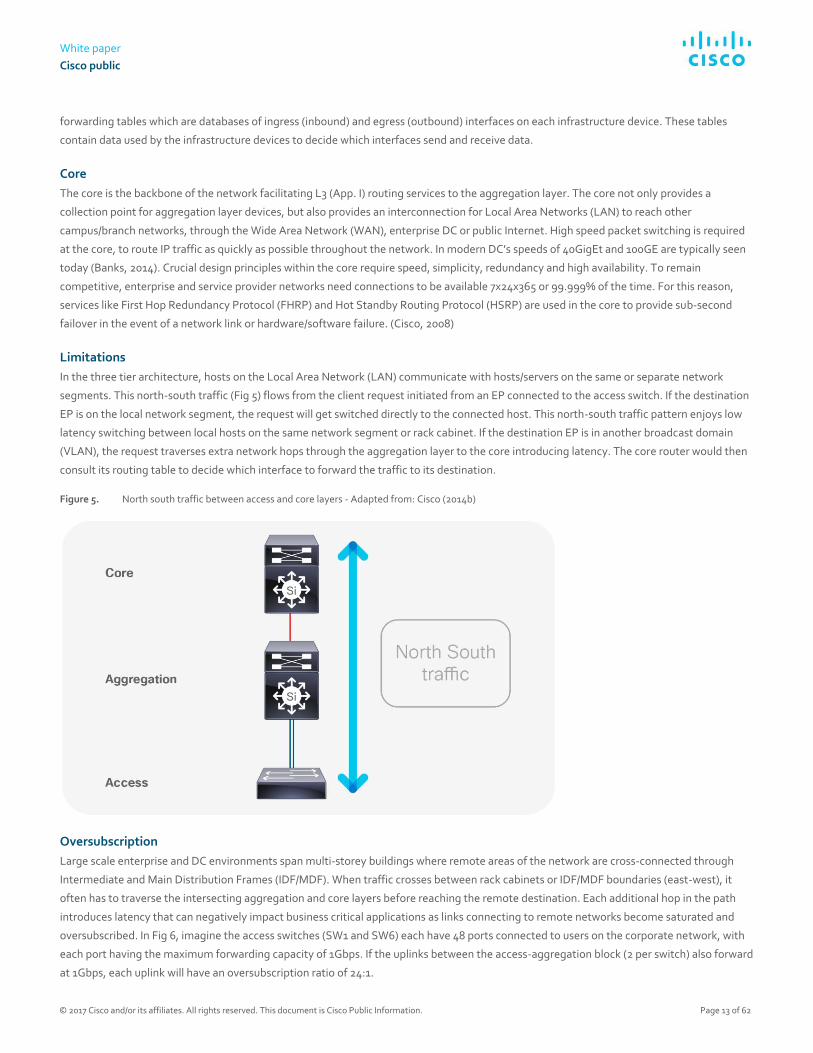
In the three tier architecture, hosts on the Local Area Network (LAN) communicate with hosts/servers on the same or separate network
segments. This north-south traffic (Fig 5) flows from the client request initiated from an EP connected to the access switch. If the destination
EP is on the local network segment, the request will get switched directly to the connected host. This north-south traffic pattern enjoys low
latency switching between local hosts on the same network segment or rack cabinet. If the destination EP is in another broadcast domain
(VLAN), the request traverses extra network hops through the aggregation layer to the core introducing latency. The core router would then
consult its routing table to decide which interface to forward the traffic to its destination.
Figure 5. North south traffic between access and core layers - Adapted from: Cisco (2014b)
Oversubscription
Large scale enterprise and DC environments span multi-storey buildings where remote areas of the network are cross-connected through
Intermediate and Main Distribution Frames (IDF/MDF). When traffic crosses between rack cabinets or IDF/MDF boundaries (east-west), it
often has to traverse the intersecting aggregation and core layers before reaching the remote destination. Each additional hop in the path
introduces latency that can negatively impact business critical applications as links connecting to remote networks become saturated and
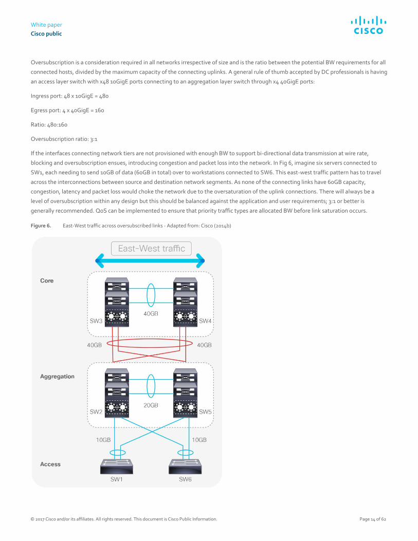
oversubscribed. In Fig 6, imagine the access switches (SW1 and SW6) each have 48 ports connected to users on the corporate network, with
each port having the maximum forwarding capacity of 1Gbps. If the uplinks between the access-aggregation block (2 per switch) also forward
at 1Gbps, each uplink will have an oversubscription ratio of 24:1.
White paper
Cisco public
© 2017 Cisco and/or its affiliates. All rights reserved. This document is Cisco Public Information. Page 14 of 62
Oversubscription is a consideration required in all networks irrespective of size and is the ratio between the potential BW requirements for all
connected hosts, divided by the maximum capacity of the connecting uplinks. A general rule of thumb accepted by DC professionals is having
an access layer switch with x48 10GigE ports connecting to an aggregation layer switch through x4 40GigE ports:
Ingress port: 48 x 10GigE = 480
Egress port: 4 x 40GigE = 160
Ratio: 480:160
Oversubscription ratio: 3:1
If the interfaces connecting network tiers are not provisioned with enough BW to support bi-directional data transmission at wire rate,
blocking and oversubscription ensues, introducing congestion and packet loss into the network. In Fig 6, imagine six servers connected to
SW1, each needing to send 10GB of data (60GB in total) over to workstations connected to SW6. This east-west traffic pattern has to travel
across the interconnections between source and destination network segments. As none of the connecting links have 60GB capacity,
congestion, latency and packet loss would choke the network due to the oversaturation of the uplink connections. There will always be a
level of oversubscription within any design but this should be balanced against the application and user requirements; 3:1 or better is
generally recommended. QoS can be implemented to ensure that priority traffic types are allocated BW before link saturation occurs.
Figure 6. East-West traffic across oversubscribed links - Adapted from: Cisco (2014b)
White paper
Cisco public
© 2017 Cisco and/or its affiliates. All rights reserved. This document is Cisco Public Information. Page 15 of 62
Although all hosts and applications can theoretically transmit data simultaneously, in practice this is not the case as request/response
messages are interleaved as they traverse the network. Network traffic is usually intermittent and bursty, as invocation of resource is
traditionally executed through request/response messages i.e. Dynamic Host Configuration Protocol (DHCP), File Transfer Protocol (FTP),
Simple Mail Transfer Protocol (SMTP), Domain Name System (DNS) etc. Network operators employ acceptable oversubscription ratios
pertaining to overall network design; striking a balance between performance and expense. Oversubscription is a vital consideration in
enterprise DCs where east-west traffic patterns constitute routine traffic patterns. This consideration is even more paramount in large scale
DCs where data is forwarded between hundreds or even thousands of physical and virtual EPs (Bloomberg, 2014).
Large scale DCs have to manage a tremendous amount of complexity across the network infrastructure as well as the applications sitting on
top. The deluge of resource requests and inter-server (server-to-server) traffic flows abound with BW intensive applications like High
Performance Computing (HPC), High Frequency Trading (HFT), distributed computing, IP storage and Virtual Machine (VM) clustering. These
are all examples of routine, east-west traffic flows within modern DCs that contribute to this complexity. Unlike campus deployments, the
east-to-west traffic created by server-to-server conversations is ubiquitous within DC environments (Alizadeh & Edsall, 2013).
Server-to-server communications across the classical hierarchical architecture introduces congestion and network choke points, not only due
to oversubscription but also because of the L2 path redundancy, introduced to fix outages if a switch port or circuit were to fail. This
redundancy introduces the possibility of switching loops, where traffic is sent on an infinite circular path within the three-tier architecture.
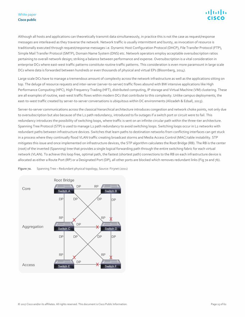
Spanning Tree Protocol (STP) is used to manage L2 path redundancy to avoid switching loops. Switching loops occur in L2 networks with
redundant paths between infrastructure devices. Switches that learn paths to destination networks from conflicting interfaces can get stuck
in a process where they continually flood VLAN traffic creating broadcast storms and Media Access Control (MAC) table instability. STP
mitigates this issue and once implemented on infrastructure devices, the STP algorithm calculates the Root Bridge (RB). The RB is the center
(root) of the inverted (Spanning) tree that provides a single logical forwarding path through the entire switching fabric for each virtual
network (VLAN). To achieve this loop free, optimal path, the fastest (shortest path) connections to the RB on each infrastructure device is
allocated as either a Route Port (RP) or a Designated Port (DP), all other ports are blocked which removes redundant links (Fig 7a and 7b).
Figure 7a. Spanning Tree – Redundant physical topology, Source: Fir3net (2011)

White paper
Cisco public
© 2017 Cisco and/or its affiliates. All rights reserved. This document is Cisco Public Information. Page 16 of 62
Figure 7b. STP - One logical forwarding path Source: Fir3net (2011)
As you can see in Fig 7a there are 11 links in the three-tier architecture. Once STP calculates the best loop free path, redundant links are
blocked and the resultant spanning tree is formed, ready to forward VLAN traffic. As seen in Fig. 7b the amount of useable links in the
topology is now reduced to 5 which is a 55% loss from the original eleven.
Such wastage is costly in both enterprise and cloud environments because congestion and network bottlenecks are introduced when all but
one forwarding path is blocked via STP. In this topology, redundant fiber links remain unused until a change in the STP topology re-calculates
an alternate path. Unused links provide no Return on Investment (ROI), heightening Total Cost of Ownership (TCO). Optical cables and
modules are expensive and have to be non-blocking in order to justify investment. In addition, the number of hops required for server-to-
server, east-west traffic flows add extra latency to transactions between hosts communicating over the network. As big data analytics (with
tremendous server-to-server communication requirements) increases in volume and importance in the data center, this latency becomes
even more of a concern. East-west traffic flows, network convergence, oversubscription and STP are some of the limitations that have
prompted the exploration of alternative architectures and technologies in DC environments.
Spine-Leaf architecture
With background given on the traditional hierarchical model and its limitations, the following section provides information on the preferred
architectural model used within modern DC environments. This provides an understanding of the physical infrastructure that powers DC
operations before looking at the software overlay technologies that sit on top.
In the DC, the successor to the three-tier model is spine-leaf. Spine-Leaf is the de facto reference architecture used in modern DCs (Wang
and Xu, 2014), and improves on the limitations presented by the hierarchical model and STP. Spine-Leaf is an adaptation of the (Clos)
network developed in 1952 (Hogg, 2014) and comprises a flat, non-blocking switching architecture where the core is divided across a number
of modular spine switches. Each spine switch up-links to every leaf. Leaf switches are located at the Top of the Rack cabinets (ToR) for direct
server/EP connectivity. As each leaf switch is connected to all spine switches, this creates a flat, densely connected topology where all leaf
switches are equidistant from anywhere in the architecture (Fig 8b). At any given moment, any DC EP is no more than three hops away from
an intended destination inside the DC. This gives each device access to the full BW of the fabric, building a simplified foundation of
predictable performance (Alizadeh and Edsall, 2013).

White paper
Cisco public
© 2017 Cisco and/or its affiliates. All rights reserved. This document is Cisco Public Information. Page 17 of 62
Applications, services and DC EPs can communicate to endpoints on opposite sides of the DC through the directly connected, local leaf
switch through the connecting spine switch; to the remote leaf switch connected to the destination host (Fig 8b). This brings consistent and
predictable latency and BW through the DC facilitating horizontal scaling for east-west traffic requirements. Fig 8a depicts an example Spine-
Leaf topology with two spines, each connecting to four leaf switches that in turn have 48 connected hosts. The 3:1 oversubscription ratio is
shown with each group of 48 connecting through 10Gbps connections with x4 40Gbps up-links from each spine to every leaf.
Figure 8a. Leaf-spine architecture - Adapted from: Banks (2014)
Figure 8b. Alternate depiction of leaf-spine architecture - Source: Wang (2013)
DC operators need to maximize utilization of invested resource. Although foundational to networking, the hierarchical model provides a
forwarding path confined to the cable or ether-channel permitted by STP. This introduces choke points between tiers creating a blocking
architecture that cannot scale beyond a certain point, wasting capital investment. In Spine-Leaf designs, the uniform, densely connected
switches place each EP no more than three hops away from the destination (Fig 8b). This equidistance allows simplified and predictable
scaling through the DC as low latency traffic is load balanced across multiple paths of equal cost.
Standards like Shortest Path Bridging (SPB), Transparent Interconnection of Lots of Links (TRILL) and Equal Cost Multi-Path (ECMP) are
options that provide a non-blocking, multiple path architecture maximizing cross-sectional BW.
This non-blocking architecture enables infrastructure devices to forward packets bi-directionally at line rate through the switching fabric with
the ability to scale to hundreds of thousands of ports. This non-blocking architecture is better suited for the intensive east-west traffic

White paper
Cisco public
© 2017 Cisco and/or its affiliates. All rights reserved. This document is Cisco Public Information. Page 18 of 62
patterns that are routine in today’s DC operations. Oversubscription and queue buffering can also be tailored to manage traffic bursting
when shifting large workloads across the DC (Alizadeh & Edsall, 2013).
Applications Now that we have introduced basic infrastructure concepts, we can delve into the application landscape and the changes seen in recent
years. This provides context on the evolution of applications from the monolithic architectures of the past to the cloud native applications of
the future. Forward thinking enterprises are now considering the challenges around migrating on premise applications to the cloud. The next
section will describe traditional, monolithic applications and how they differ from highly available cloud native applications. This section
describes the transition from owning and maintaining on-site application architectures, to consuming pay as you use cloud computing
services. This is important because the SDN approach is most powerful when it is used to provide cloud native applications with the speed
and agility required for highly available, self-healing, autonomic network services. This serves to convey that the health and resilience of a
cloud native architecture is dependent upon the capabilities afforded by an underlying, programmable infrastructure.
As we look at new cloud native application architectures and their capabilities, it’s also important to note that the process of developing and
supporting applications has changed dramatically in the past few years. The traditional waterfall development process has been disrupted by
agile development practices. Agile development has led to continuous integration, which led to continuous delivery, which led to Dev/Ops.
Each new phase enables application developers to iterate more development processes in parallel. Taking advantage of new automated
application code management, testing, and deployment tools. This dramatically increases application quality and significantly accelerates
the development and deployment of new business capabilities, which has driven their adoption in the IT world. However, these new
development processes require a much closer relationship among the traditionally-separated teams of customers (who define requirements),
coders (who develop the code), code testers (who provide quality and security and integration standards and testing), and code
maintenance/operations teams. As we’ll see soon, this parallels the closer relationships that are required by new cloud-native application
architectures.
Monolithic applications
Traditionally, when service providers build or buy applications to serve new business outcomes; the web, application and database
components are provisioned in silos connected by the underlying network infrastructure (Fig 9).
This methodology represents a complex workflow where continuous delivery application development is impeded by the
compartmentalization of each application tier. For a new application to be brought into production, the requirements of that application are
set by the application development, web and database teams depending on its particular features (Richardson, 2014). The network team is
expected to distil and translate these requirements into configurations the network can understand. Classically this configuration of
infrastructure involves a device level process where each infrastructure device is configured one by one through the CLI. Such configurations
include:
● Provisioning the correct VLANs and mapping them to the correct subnetworks so the right IP address ranges can reach the
application.
● Creating security policies and ACLs to ensure the correct level of access control is attributed to the clients within the permitted IP
address ranges, while limiting or excluding others to prevent unauthorized access.
● Providing load balancing to avoid choke points and bottlenecks by distributing application traffic across redundant paths through the
network.
● Configuring QoS so that delay or jitter sensitive traffic like voice, video or HFT data can be prioritized over more resilient/less critical
forms of traffic traversing the network.
● Configuring appropriate routing and switching configurations are also important to ensure the secure and reliable transportation of
data end-to-end. This is important whether the traffic remains within the originating administrative domain or has to cross
organizational boundaries to an external entity.

White paper
Cisco public
© 2017 Cisco and/or its affiliates. All rights reserved. This document is Cisco Public Information. Page 19 of 62
● Providing Network Address Translation (NAT) and IP prefix lists to make the best use of limited IPv4 address space and protect
private, internal IP address ranges from the public internet which can cause problems with the routing of application traffic outside of
the originating enterprise.
These are but a few examples of the complex configuration tasks required on each infrastructure device within a DC potentially housing
hundreds of network devices (Fig 15). For all this work to get approval from the business, scheduled maintenance windows have to be
arranged with advisory boards scrutinizing the intended procedures to minimize the potentiality of a negative impact on production services.
Depending on the size of the project or impact of the network change, this whole process can become convoluted and protracted, putting
pressure on project timelines and budget justifications. Such frustrations have contributed to the formation of DevOps to accelerate
application/feature delivery in agile environments. This is why innovative automated approaches to network provisioning are being explored,
as manual provisioning is not scalable in large scale cloud environments (ONF, 2016).
Figure 9. Three tier web, application and database architecture - Source: Cisco (2009)
Orchestration in the cloud
Once the new application is finally up and running in the DC (i.e. large DB application), it will typically live on purposefully built infrastructure
(bare metal or virtual machine installation) for its entire lifecycle. Classically, such applications have been proprietary, closed and monolithic
in nature, which suited IT silos with static delivery models that elicited infrequent change. This methodology represents a pre-DevOps, and
now antiquated approach to delivering the current trend in cloud native micro-services (Fig 11). The IT industry is a world of constant change,
with many companies wishing to take advantage of the operational cost efficiencies cloud computing delivers. Innovations in hyper-
convergence are now commonplace in the DC where compute, storage and network virtualization are all tightly integrated through software
centric architectures (Sverdlik, 2015). This highlights the application centric trend which affords tighter control on the management of
physical infrastructure through Graphical User Interfaces (GUIs) and software tools.
Interconnecting DCs must efficiently manage the connectivity requirements of geographically distributed computing services across
heterogeneous IT domains. To efficiently manage the scale and complexity of this conglomeration of network requests, services, functions
and processes, network programmability and automation is paramount (Mayoral et, al. 2015).
The proliferation of dynamic east-west traffic patterns between; multi-tier applications within and between DCs requires additional layers of
sophistication from the infrastructure. This will enable operators to remain competitive, keeping up with the pace of innovation seen in

White paper
Cisco public
© 2017 Cisco and/or its affiliates. All rights reserved. This document is Cisco Public Information. Page 20 of 62
forward thinking DC environments (Kleyman, 2016). Forward thinking cloud operators manage their infrastructure with an orchestration
layer, enabling them to accelerate continuous delivery through the automated provisioning and tearing down of computing services (Mayoral
et, al. 2015). The programmability afforded through the use of open APIs, drives down repetitive configuration tasks from months to hours
(Wibowo, 2013). The automation of administrative tasks derived through orchestration and programmability tools derives new found
operational efficiencies from the enterprise IT investment (sdxcentral, 2015).
Figure 10. Handling complexity in DC Operations - Source: Adapted from Balasubramanian (2015)
Cloud native applications
With the rise of cloud computing and the prevalence of distributed computing architectures, we are witnessing a trend within the DC similar
to Web Service Architectures (WSAs) where monolithic web applications are decomposed into discrete service components that constitute a
cloud ready/native architecture (Gracely, 2015). Applications that were once closed, inflexible islands of functionality are now deconstructed
into modular, reusable micro-service components that can be manipulated by developers via Application Programming Interfaces (APIs) that
run service calls for software functions. The loosely coupled, platform agnostic capabilities afforded by cloud micro-service components
afford reusability, control and runtime analytics providing administrative flexibility and the generation of new revenue streams (Cisco,
2014c).
Enterprises are looking towards cloud ready/native applications that are highly available, extensible, and reliable. This reality is not matched
by the static, error prone, device level network implementation methods currently used to provision infrastructure. The capabilities of the
network must facilitate the requirements of the services it supports with simplicity, ease, speed and flexibility. This flexibility is offered
through open APIs that support a programmable infrastructure. (Howard, 2016)

White paper
Cisco public
© 2017 Cisco and/or its affiliates. All rights reserved. This document is Cisco Public Information. Page 21 of 62
Table 1. Comparison between traditional and cloud native applications - Adapted from: Baecke (2015)
Traditional Cloud Native
Architecture Monolithic/Layered Micro services
State Steady Fluid/Ephemeral
Updates Infrequent (monthly/yearly) Frequent (days/weeks)
Availability Infrastructure Redundancy Highly available, resilient application architecture
Scalability Hard to scale and build out Distributed, easily scalable, service reuse
Enterprises are increasingly contemplating ways to lower operational costs while heightening productivity through the migration of business
applications to the cloud. Rather than being deployed on premise/dedicated hardware, cloud native applications are deployed within
containerized, logical instances housed on virtual servers within a providers DC. These applications take the form of micro services defining
discrete pieces of functionality that are easily updated, replicated and migrated across or between DCs without any down time
(Andrikopoulos, et al. 2012). Cloud native micro-services leverage multi-tenancy to supply multiple consumers with isolated, logical instances
of the applications they connect to. Like in any IT environment, hardware failures can occur at any given moment. Due to the amount of
cloud subscribers, operators have an extra burden of responsibility to their huge consumer base. For this reason, it is paramount the
implemented cloud architecture has imbedded resilience and fault tolerance built into its design principles (Balalaie, et. al, 2015).
Cloud Native applications differ from their monolithic counterparts in that they have a self-healing, fault tolerant capabilities derived from
the application having a cognizance and interaction with the health of the underlying infrastructure through southbound APIs. For
applications to truly be cloud native, the underlying infrastructure and application need to comprise a closed feedback loop communicating
real time analytics regarding an application contract between the two, to maintain optimal performance (West, 2015). This characteristic
enables the application to be resilient to network disruptions enabling the elastic, adaptive and proactive preservation of its uptime
irrespective of any underlying network disruption (Goodwell, 2016).
In recent years, we have witnessed a shift from proprietary hardware vendors supplying infrastructure devices to generic ‘white boxes’
(O’Reilly, 2015). Such white boxes are infrastructure devices with open Operating Systems that developers and network operators can
interface with using extensible languages like Extensible Markup Language (XML), JSON and Representational State Transfer (REST) APIs.
Such programmatic methodologies provide powerful options for developers to write scripts, tools and orchestration templates automating
routine administration processes. Not only can these innovations provide analytics on the status of the underlying infrastructure; they can
also be manipulated to provide taxonomy and telemetry regarding the applications health and Runtime Environment (RTE).
The application RTE is established once it has executed and able to send/receive instructions from the infrastructure (RAM, CPU etc.). In a
cloud native environment, the RTE of an application can be written to access real time analytics on infrastructure resources like compute,
storage, BW and latency. Cloud Native Applications (CNAs) contain an application contract which delimits the minimal runtime Service Level
Agreement (SLA) required by the infrastructure for optimal performance (West, 2015). If network resources fail to meet the terms of the
contract i.e. jitter and latency fall beneath a particular threshold; remediation options will be available pertaining to real-time availability of
computing resources within the administrative domain. Such options can include the resizing or provision of additional compute instances.
Another option could take the form of migrating any negatively affected VMs to a more stable network segment or even to another DC
central to the majority of the applications subscribers. In any case, through open APIs, the programmability of the infrastructure enables the
application to become intelligent enough to reach a new plateau in resilience, high availability and fault tolerance (West, 2015).

White paper
Cisco public
© 2017 Cisco and/or its affiliates. All rights reserved. This document is Cisco Public Information. Page 22 of 62
For an example of this mechanism we can look at MS Windows 10, which has the minimum hardware requirements of:
● ≥1GHz processor
● ≥ 2GB RAM
● ≥ 20 GB storage for 64-bit OS
● 1 NIC
These hardware attributes are required for the OS to function on a bare metal installation. Similarly, cloud native applications use a run-time
contract to inform the infrastructure of a SLA for optimal performance. If a monolithic HFT application has a run time contractual
requirement of <50ms jitter and 10Mb/s BW, then at any point where the network cannot deliver this, the user experience would suffer as
there is no ability for the application or infrastructure to remediate this issue without manual intervention.
In a cloud native environment, the application is sending periodic keep-alives, probing the infrastructure for status metrics on these
contractual requirements (Cane, 2014). If the available resources fall below these requirements, the IaaS layer will provision the required
resources to mitigate any potential degradation to the user experience. This intelligence occurs at the network infrastructure level, leaving
the end users completely agnostic of any degradation in service (Stine, 2015).
Figure 11. Achieving Cloud-Native Application Architecture - Source: Linthicum (2015)

White paper
Cisco public
© 2017 Cisco and/or its affiliates. All rights reserved. This document is Cisco Public Information. Page 23 of 62
The physical constraints of popular, vendor specific network appliances are limited by the tight coupling of closed software to proprietary
hardware platforms. The journey towards a cloud native architecture requires not only a re-imagining of how the application interacts with
the underlying hardware; but also the opening up of proprietary hardware to expose the API’s necessary to facilitate a truly resilient, self-
healing, programmable architecture. To meet this end, the industry is witnessing a prevalence of standards based efforts working towards
creating an ecosystem of open, interoperable technologies that enable tighter control and flexibility for engineers and cloud providers who
embrace innovation. A cloud native architecture gives providers the ability to raise ROI while lowering TCO as the investment in hardware
and DC capacity resourcing is insulated by the programmatic capabilities of the infrastructure. Cloud operators require the ability to
elastically scale and adapt their computing services to support dynamic market, technological and business transitions. Cloud native
architectures combined with a programmable infrastructure are steps in the direction towards achieving these business objectives.
OpenStack
OpenStack is a popular, open source IaaS solution that uses a set of configurable software tools for building and managing public and private
cloud computing platforms. Managed by the non-profit OpenStack Foundation, OpenStack enables the rapid deployment of on-demand
computing instances (i.e. VMs) that developers can interface with to test and run code. This code normally contributes to the functionality of
the micro-services users subscribe to. Developers interact with OpenStack service components via RESTful APIs. This enables the
automation of interrelated projects that manage processing, storage and networking resourcing utilised by the upper cloud computing
layers. OpenStack rapidly provisions logical computing instances that can be elastically spun up, scaled down and released on demand in
minutes. This gives the cloud operator tight control over elastic computing services while providing flexible and cost effective management
of cloud infrastructure (Denis, et, al. 2015).
OpenStack handles the scaling of reusable computing instances in two ways; vertical and horizontal. Vertical scaling, is essentially like a
hardware upgrade instantiated in software where a cloud provider may have a physical server running one computing instance hosting a new
service. This service may have less than desirable response times due to its resources being overrun with too many subscribers. To mitigate
this, the provider may resize the compute instance powering the service to provide more CPU cores, RAM etc. This may alleviate the issue for
a time but is capped by the amount of physical hardware resource available on the server.
Horizontal scaling is where the service is run on multiple servers that each run the required service within two or more computing instances. A
virtual load balancer can then be used to evenly distribute customer traffic between the computing instances spread across the multiple
servers. This allows enormous scaling potential over the vertical method as more servers can be added behind the load balancer with
additional hardware added as needed (Grinberg, 2015). OpenStack provides a critical set of tools that provide operators with the agility,
flexibility and scale required to manage complexity in the cloud. This in turn enhances and accelerates business objectives through the
orchestration of value added cloud based services.
Table 2. OpenStack cloud service components – Source: Lawrence (2016)
OpenStack Service Function
Identity Service (Keystone) Provisions users, groups, roles, projects, domains
Compute (Nova) Schedules VMs, manages their lifecycle
Image Service (Glance) Provides data assets (VM images, heat templates)
Networking Service (Neutron) Provides Software Defined Networking
Object Storage Service (Swift) Provides scalable, persistent object store
Block Storage Service (Cinder) Provides persistent block level storage

White paper
Cisco public
© 2017 Cisco and/or its affiliates. All rights reserved. This document is Cisco Public Information. Page 24 of 62
OpenStack Service Function
Orchestration Service (Heat) Orchestrator with auto-scaling functionally
Metering Service (Ceilometer) Collects metering probes from other services
Dashboard (Horizon) Provides web based interface for other services
Network administration in the cloud
The cloud computing industry is witnessing exponential growth with new customers and businesses subscribing to more services every day
(Gartner, 2016). This growth is underpinned by the explosion seen in agile development teams adopting DevOps approaches which
accelerate software feature releases used to maintain and develop cloud consumption models. Server and to a lesser extent storage
virtualization has revolutionized the amount of application services used throughout enterprise DCs, giving rise to large scale multi-tenancy
cloud computing architectures that introduce a tremendous amount of complexity into the network (Christy, 2012).
Networks are a critical component of any IT investment. Cloud computing environments are amongst the most complicated ecosystems of
technologies and services seen in the industry. Current network administration practices are clunky, complicated and time consuming. The
same manual, device level, CLI configuration process used 30 years ago is still heavily used by engineers today (Arellano, 2013). The CLI alone
as an administrative tool is not flexible enough to manage the increasing complexity witnessed in large scale DC environments.
In cloud environments, operators require application architectures that provide the rapid provisioning and scaling of computing services on
demand, providing business agility and continuity. This speed and flexibility requires the underlying infrastructure to also be open, flexible
and fault tolerant to support high performing cloud computing services. Server virtualization allows for the provision of multiple Virtual
Machines (VMs) in minutes, with each machine being capable of housing multiple applications where each subscriber has an isolated slice of
the applications/services they pay for. These VMs can easily be migrated, released and scaled up and down anywhere within or between DC
environments. The explosion of virtual endpoints introduces increasing demands and complexity on the DC network (Ziolo, 2015). Cloud
operators cannot remain competitive within the marketplace by solely engaging in traditional network administration practices because the
rigidity and limitations physical networks introduce works against the fluidity and extensibility of the services they support (ONS, 2014). The
amount of time required to make a new application secure and accessible through the most optimal paths across the network can take hours
at best compared to the minutes taken to spin up VMs hosting a new application. Agile development teams and server virtualization
capabilities are driving the demand for networks to become even faster and more sophisticated in their orchestration of cloud computing
services. This calls for a fresh approach that requires tighter control and extensibility in how network services are provisioned, maintained
and monitored.
As manual network configuration is an iterative process performed by humans, there is always an associated risk to the preservation of
existing production services should something be misconfigured. For this reason, network teams associated with the implementation of a
new project submit change management request tickets detailing each configuration step required to execute administrative tasks. Although
change management ensures governance over the protection of production services; this is provided at the expense of continuous delivery.
The many corporate processes required for change management approval impacts service execution timelines. The configuration of 100+
network devices typically seen in the DC carries associated risks. These risks include human error, and any negative impact on existing
production services which can amount in loss of revenue. This presents a choke point in service delivery as agile development teams have to
wait for the network before being able to rapidly test and release new service features.
Shadow IT is a descendent of this culture where frustrated development teams employ public cloud services to circumvent corporate IT. This
produces real concerns to the business as the enterprise is effectively financing for their private, Intellectual Property (IP) protected data to
be hosted in the public cloud. The potential security, compliance and regulatory ramifications present noteworthy concerns for the
enterprise. This necessitates the need for operators to find secure ways to mobilize and accelerate their infrastructure internally (Petty,
2016).

White paper
Cisco public
© 2017 Cisco and/or its affiliates. All rights reserved. This document is Cisco Public Information. Page 25 of 62
Virtualisation
Before virtualization, the classical client-server model consisted of a client request made to a physical server hosting web application
software that responds accordingly to each incoming request. The amount of simultaneous connections this server can handle is limited by
the maximum hardware capacity the server OS is running on. To scale further, server farms/clusters are employed to add more resources but
this raises TCO as additional hardware investment is required. This vertical scaling is not sustainable in DC environments due to finite floor
space, environmental considerations and power/cooling constraints. Duryee (2014) reported a leading cloud provider exposing services for
>244 million customers. It would be untenable to facilitate such a colossal user base using physical infrastructure alone. Virtualisation was
introduced within the DC to provide scale through multi-tenancy (Kajeepeta, 2010).
Virtualisation software is a specialised OS running on a physical server allowing the co-location of multiple operating system instances to run
inside a hypervisor which is a VM management system used to deploy and administer VMs. The hypervisor provides a layer of abstraction
that allows multiple guest OS’ to share a physical server. The physical hardware resources can then be divided in software and allocated
amongst multiple VM instances. Virtualisation is very popular in DCs due to multi-tenancy. All virtual machines are logically separated and
thus have exclusive resources and network connections that are isolated from each other. When subscribers connect to cloud services, they
are effectively connecting to a logical instance within a VM giving them their own slice of the service resources. This is depicted in Fig 12a/b
where all three VMs share the same physical hardware resources and host operating system. Each VM is containerized within its own logical
environment which can host a guest operating system housing multiple applications for cloud service subscribers to consume as web based
services.
Figure 12a. Loosely coupled hypervisor abstraction – Source: Lawrence (2016)

White paper
Cisco public
© 2017 Cisco and/or its affiliates. All rights reserved. This document is Cisco Public Information. Page 26 of 62
Although larger servers with more physical resources are required to support multi-tenancy, virtualization allows service providers to reduce
their physical server count while optimizing hardware. This is through the exploitation of the hypervisors’ efficient use of scaling hardware
resources. Maintenance costs, power/cooling, carbon footprint and DC floor space is also minimized through the use of virtualization
software providing operational cost efficiencies for providers, coupled with the fact that administrators can interface with the hypervisor
using built in tools to customize the virtual environment.
Resource isolation and multitenancy are advantageous in cloud environments as hardware resources are carved up and distributed between
multiple guest operating systems (i.e. Windows, Ubuntu etc.) which each can scale to run 100’s of VMs on one physical server. VMware’s EXSi
hypervisor for example can theoretically run up to 512 VM’s per server (VMware, 2013). Although VMware, Kernel-based Virtual Machine
(KVM) and Quick Emulation (QEMU) are popular industry hypervisor choices, there are many flavors of virtualization software employed
within the industry (Hess, 2016). An example is Amazon’s Elastic Compute Cloud which allows globally distributed clients to run applications
on a set of VMs which exist in the public cloud. Securely managing and scaling such a service would be untenable if limited to physical
hardware and manual network administration practices.
An issue with hosting multiple VMs on physical servers is if the server goes down it is a single point of failure for all hosted services. However,
the flexibility of provisioning, copying, and migrating VMs accordingly serves to justify its position within the DC. Providers can also mitigate
risk through providing redundant servers to mirror VM configuration through clustering. Virtualisation is not only limited to servers but also
extends to storage and network. The former is where multiple storage arrays are clustered and managed via one administrative interface.
The latter (Fig 12b) is where network components (like NIC cards, firewalls and switches) are replicated as logical, software components that
are decoupled from the physical hardware. The advantage is seamless integration of network functionality within divergent physical and
virtual computing domains. Such a scenario could see a VM with an integrated virtual switch passing data from a virtual network to the
physical network. The bottom line is that sophistication in software is necessary for DC operators to scale cloud services for their network,
compute and storage assets. Although network virtualization has extended the capabilities of physical network resources, SDN serves to
provide a further layer of abstraction where distributed network control is consolidated and centralized within a network controller serving as
the brains of the Network Management System (NMS) (ONF, 2014).
Figure 12b. Alternate depiction of server virtualisation - Source: Seetharaman (2014)

White paper
Cisco public
© 2017 Cisco and/or its affiliates. All rights reserved. This document is Cisco Public Information. Page 27 of 62
Layer 2 VLAN semantics
Before progressing into the more technical sections that follow, a primer on layer 2 (L2) semantics is given here to provide an understanding
into the layer 2 operations that occur within a TCP/IP network. This relates to section 1 aim xi to prepare the reader for the network overlay
topics.
At the physical layer in TCP/IP networks (App. I), electrical signals are encoded with data and sent onto the transmission medium for
transport across the network. When these signals reach the data link layer of the TCP/IP stack at the receiving device, they are encapsulated
within an IEE 803.3 Ethernet frame (Fig 15) delineating the logical link and Media Access Control (MAC) mechanisms required for procedural
and data integrity checking processes (Cisco, 2012). Ethernet frames contain source and destination MAC addresses. A MAC address is the
physical/hardware address burnt into the Network Interface Card (NIC) of any device connected to the network. The MAC address denotes a
static identifier signifying the physical address of a particular network host. Ethernet switches exist at L2 of the TCP/IP stack (App I.) which is
responsible for forwarding Ethernet frames from source to destination.
Figure 13. TCP/IP five-layer model - Source: Microchip Developer Help (2016)

White paper
Cisco public
© 2017 Cisco and/or its affiliates. All rights reserved. This document is Cisco Public Information. Page 28 of 62
In TCP/IP switching architecture, switches use MAC addresses to forward Ethernet frames (Fig 15) containing network data. This process is
termed flood and learn. In fig 14, when PC1 wants to send a message to PC4 for the first time, the message arrives at interface #1 on SW1. (1)
With no entries in SW1’s Content Addressable Memory (CAM) table, SW1 examines the source MAC address of the incoming frame and
associates it with interface #1. SW1 then floods an Address Resolution Protocol (ARP) request to resolve the destination MAC address; (2)
The ARP is a broadcast query sent to every switch within the broadcast domain (VLAN). As PC4 has the only matching MAC address, it
responds with a unicast frame to SW1 (3). Receiving the response on interface #2, SW3 records the source MAC address of PC4 on its #2
interface. Likewise, SW2 learns that PC4 can also be reached through its #2 interface and records this in its CAM table. SW1 follows suit by
associating PC4’s MAC address to its #3 interface. This has now built the L2 forwarding path between PC1 and PC4. Fig 14b shows the unicast
request (blue arrow) and response (green arrow) between PC1 and PC4 now that the L2 topology has converged:
Figure 14a. L2 MAC address flood and learn mechanism – Source: Lawrence (2016)

White paper
Cisco public
© 2017 Cisco and/or its affiliates. All rights reserved. This document is Cisco Public Information. Page 29 of 62
Figure 14b. L2 unicast request and response – Source: Lawrence (2016)
In enterprise networks, there are multiple departments needing exclusive access to company resources related to departmental tasks. This
includes applications, databases, servers and other corporate resources. In technical terms, the isolation required is termed segmentation.
Segmentation is provided by TCP/IP networks through VLANs. VLANs are logical separations assigned to network hosts that can be based on
location, department or organizational function. VLANs provide a security boundary to contain network traffic within a broadcast domain
(Cisco, 2015b). Typically, every Ethernet interface on a network switch connected to an end user specifies an access VLAN.
This defines the associated broadcast domain (BD) relating to an associated IP subnetwork. A broadcast domain denotes the extent to which
broadcast traffic is propagated to devices within the same administrative domain. To put this into context, if HR is allocated VLAN 10,
Marketing VLAN 20 and R&D VLAN 30 - only devices connected to the respective VLAN will be able to access and process data specific to
that VLAN. So, if a new employee started in R&D, their workstation would connect to the interface of an Ethernet switch configured for
access VLAN 30, making them a host within the R&D BD. This would enable the new hire to receive an IP address inside R&D VLAN 30;
providing connectivity to resources specific to the R&D department while isolating network traffic from any other VLAN. For data to cross
the broadcast domain (i.e. HR sending an email to Marketing) a Layer 3 (L3) device like a router is required.
Figure 15. ≥ 1536 byte long 802.3 Ethernet frame structure – Source: Lawrence (2016)
SOF = Start of Frame delimiter
FCS = Frame Check Sequence
Grey fields indicate Ethernet header
In production networks switch access ports connected to end user workstations are assigned to a single VLAN denoting the BD that the
connected device is a member of. When Ethernet frames travel between network switches, they traverse point to point connections called

White paper
Cisco public
© 2017 Cisco and/or its affiliates. All rights reserved. This document is Cisco Public Information. Page 30 of 62
trunk links (fig 4), allowing traffic from multiple VLANs to propagate throughout the network. For the network to accurately transport VLAN
specific data from source to destination, there needs to be a way of identifying VLANs within the Ethernet frame (Cisco, 2014d).
The IEEE 802.1Q standard provides this by VLAN aware network devices (switches) inserting a 4-byte header into the Ethernet frame called a
VLAN tag/802.1Q header (Fig 16) as the frames travel across trunk links. This tag defines the VLAN membership of each Ethernet frame.
Figure 16. 802.1Q tag inserted into 802.3 frame - Source: Lawrence (2016)
The important part of the 802.1Q tag in this context is the VLAN ID (VID). This field has a value of 12 bits which determines the maximum
amount of VLANs that can be used at any time across the network. As bits represent binary integers they only hold one of two values, either
on/1, or off/0. So theoretically the maximum number of VLANs as specified by the VID is 122 = 4096. Although ~4000 individual network
segments are sufficient for most enterprise environments, this is not adequate for DC/cloud environments. Modern DCs are structured with
physical servers stored in multiple rack cabinets that can run into the thousands (Fig 17). When servers share common network storage and
compute resources they are collectively termed a ‘pod’ which may exist within one cabinet or even extend multiple rack cabinets depending
upon the nature of the services they support (IETF, 2014). With the advent of virtualization, powerful servers have the ability to host
hundreds of VMs which each contain NICs that often communicate on multiple VLANs. Virtual networks also contain logical constructs that
require VLAN assignments to categories and isolate traffic traversing between physical and virtual network topologies. With some cloud
providers having upwards of 900,000 servers it quickly becomes apparent why more than ~4k VLANs are required to provide adequate scale
in the cloud (Miller, 2011).

White paper
Cisco public
© 2017 Cisco and/or its affiliates. All rights reserved. This document is Cisco Public Information. Page 31 of 62
Figure 17. Data Centre racks and rows - Source: Roig (2014)
Network overlays
Network operators have long investigated ways to optimize the management of their DC operations. In current enterprise networks VLAN
segmentation and STP enables the isolation of broadcast domains while providing a single L2 path for VLAN data to cross the network. This
provides network hosts with a secure, logical boundary where only traffic within the same broadcast domain is processed. Spanning Tree
attempts to remove switching loops caused by redundant paths through the STP algorithm. In the DC, the number of physical servers can
range into the thousands. Virtualisation multiplies this administrative domain considerably as VMs require communication between physical
and virtual hosts. Management and optimization now becomes challenging in large scale deployments as 1000’s of potential physical servers
can each house 100’s of virtual servers. For each network host to remain reachable across the entire DC fabric, end state information (IP and
MAC address mappings) needs to be accurately replicated, propagated and updated on spine-leaf device forwarding tables.
Although multiple tenants have their own virtual network domain, they are sharing the underlying physical infrastructure. This can cause the
duplication of end state information resulting in address conflicts and reachability issues between physical and virtual networks. In large
scale, multi-tenant environments computing workloads are often migrated from the private to the public cloud when a hardware failure
occurs or business imperatives change (Cisco, 2014e). This is termed the hybrid cloud where private cloud services need to burst into the
public cloud pertaining to business/functional requirements. The decoupling of location dependence of computing workloads from the
underlying network infrastructure is necessary for operators to provide elastic compute services on demand. Virtualized environments often
require the network to scale between DCs across the layer 2 domain to adequately allocate compute, network and storage resources. STP
fails to support this adequately as it disables redundant links which burns investment as operators end up paying for more links than what
they can use (Fig 6a/6b). In the context of scalability and operational efficiency, this is why network operators prefer multipathing techniques
across the spine-leaf architecture utilizing Equal Cost Multipathing (ECMP) and network overlays over L2 technologies like STP (IETF, 2014).
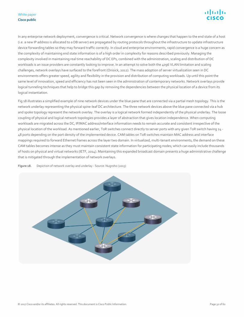
White paper
Cisco public
© 2017 Cisco and/or its affiliates. All rights reserved. This document is Cisco Public Information. Page 32 of 62
In any enterprise network deployment, convergence is critical. Network convergence is where changes that happen to the end state of a host
(i.e. a new IP address is allocated to a DB server) are propagated by routing protocols throughout the infrastructure to update infrastructure
device forwarding tables so they may forward traffic correctly. In cloud and enterprise environments, rapid convergence is a huge concern as
the complexity of maintaining end state information is of a high order in complexity for reasons described previously. Managing the
complexity involved in maintaining real time reachability of DC EPs, combined with the administration, scaling and distribution of DC
workloads is an issue providers are constantly looking to improve. In an attempt to solve both the 4096 VLAN limitation and scaling
challenges, network overlays have surfaced to the forefront (Onisick, 2012). The mass adoption of server virtualization seen in DC
environments offers greater speed, agility and flexibility in the provision and distribution of computing workloads. Up until this point the
same level of innovation, speed and efficiency has not been seen in the administration of contemporary networks. Network overlays provide
logical tunneling techniques that help to bridge this gap by removing the dependencies between the physical location of a device from its
logical instantiation.
Fig 18 illustrates a simplified example of nine network devices under the blue pane that are connected via a partial mesh topology. This is the
network underlay representing the physical spine-leaf DC architecture. The three network devices above the blue pane connected via a hub
and spoke topology represent the network overlay. The overlay is a logical network formed independently of the physical underlay. The loose
coupling of physical and logical network topologies provides a layer of abstraction that gives location independence. When computing
workloads are migrated across the DC, IP/MAC address/interface information needs to remain accurate and consistent irrespective of the
physical location of the workload. As mentioned earlier, ToR switches connect directly to server ports with any given ToR switch having 24 -
48 ports depending on the port density of the implemented device. CAM tables on ToR switches maintain MAC address and interface
mappings required to forward Ethernet frames across the layer two domain. In virtualized, multi-tenant environments, the demand on these
CAM tables becomes intense as they must maintain consistent state information for participating nodes; which can easily include thousands
of hosts on physical and virtual networks (IETF, 2014). Maintaining this expanded broadcast domain presents a huge administrative challenge
that is mitigated through the implementation of network overlays.
Figure 18. Depiction of network overlay and underlay - Source: Nugroho (2015)
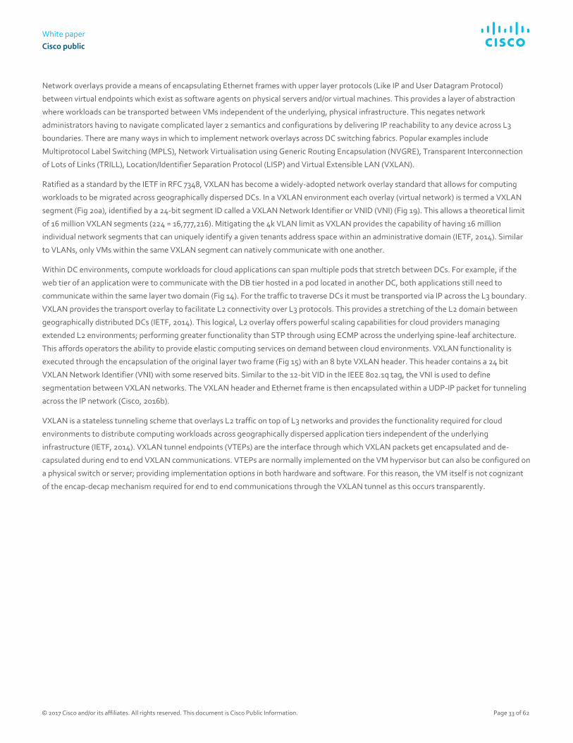
White paper
Cisco public
© 2017 Cisco and/or its affiliates. All rights reserved. This document is Cisco Public Information. Page 33 of 62
Network overlays provide a means of encapsulating Ethernet frames with upper layer protocols (Like IP and User Datagram Protocol)
between virtual endpoints which exist as software agents on physical servers and/or virtual machines. This provides a layer of abstraction
where workloads can be transported between VMs independent of the underlying, physical infrastructure. This negates network
administrators having to navigate complicated layer 2 semantics and configurations by delivering IP reachability to any device across L3
boundaries. There are many ways in which to implement network overlays across DC switching fabrics. Popular examples include
Multiprotocol Label Switching (MPLS), Network Virtualisation using Generic Routing Encapsulation (NVGRE), Transparent Interconnection
of Lots of Links (TRILL), Location/Identifier Separation Protocol (LISP) and Virtual Extensible LAN (VXLAN).
Ratified as a standard by the IETF in RFC 7348, VXLAN has become a widely-adopted network overlay standard that allows for computing
workloads to be migrated across geographically dispersed DCs. In a VXLAN environment each overlay (virtual network) is termed a VXLAN
segment (Fig 20a), identified by a 24-bit segment ID called a VXLAN Network Identifier or VNID (VNI) (Fig 19). This allows a theoretical limit
of 16 million VXLAN segments (224 = 16,777,216). Mitigating the 4k VLAN limit as VXLAN provides the capability of having 16 million
individual network segments that can uniquely identify a given tenants address space within an administrative domain (IETF, 2014). Similar
to VLANs, only VMs within the same VXLAN segment can natively communicate with one another.
Within DC environments, compute workloads for cloud applications can span multiple pods that stretch between DCs. For example, if the
web tier of an application were to communicate with the DB tier hosted in a pod located in another DC, both applications still need to
communicate within the same layer two domain (Fig 14). For the traffic to traverse DCs it must be transported via IP across the L3 boundary.
VXLAN provides the transport overlay to facilitate L2 connectivity over L3 protocols. This provides a stretching of the L2 domain between
geographically distributed DCs (IETF, 2014). This logical, L2 overlay offers powerful scaling capabilities for cloud providers managing
extended L2 environments; performing greater functionality than STP through using ECMP across the underlying spine-leaf architecture.
This affords operators the ability to provide elastic computing services on demand between cloud environments. VXLAN functionality is
executed through the encapsulation of the original layer two frame (Fig 15) with an 8 byte VXLAN header. This header contains a 24 bit
VXLAN Network Identifier (VNI) with some reserved bits. Similar to the 12-bit VID in the IEEE 802.1q tag, the VNI is used to define
segmentation between VXLAN networks. The VXLAN header and Ethernet frame is then encapsulated within a UDP-IP packet for tunneling
across the IP network (Cisco, 2016b).
VXLAN is a stateless tunneling scheme that overlays L2 traffic on top of L3 networks and provides the functionality required for cloud
environments to distribute computing workloads across geographically dispersed application tiers independent of the underlying
infrastructure (IETF, 2014). VXLAN tunnel endpoints (VTEPs) are the interface through which VXLAN packets get encapsulated and de-
capsulated during end to end VXLAN communications. VTEPs are normally implemented on the VM hypervisor but can also be configured on
a physical switch or server; providing implementation options in both hardware and software. For this reason, the VM itself is not cognizant
of the encap-decap mechanism required for end to end communications through the VXLAN tunnel as this occurs transparently.

White paper
Cisco public
© 2017 Cisco and/or its affiliates. All rights reserved. This document is Cisco Public Information. Page 34 of 62
Figure 19. VXLAN frame format - Source: Adapted from Cisco (2014f)
When a VM wants to exchange data with a VM on another pod, it encapsulates the application data within an Ethernet frame before the data
is forwarded to the destination VM (Fig 20b). After the data is encapsulated within the L2 frame, the VTEP on the local host performs a look
up to check what VNI is associated with the target VM (destination MAC address). This will determine if the destination MAC address is on
the same/local VXLAN segment or mapped to a remote VTEP (IETF, 2014). If there is a mapping to a remote VTEP, an outer MAC, IP and
VXLAN header are prepended to the original Ethernet frame (Fig 19). The encapsulated packet is then tunneled across the network. Once
received at the far end, the remote VTEP checks whether the VNI inside the VXLAN header is valid and if there is a local VM within that VNI
that has a MAC address matching the inner MAC address inside the VXLAN packet. If there is a match, the packet is stripped/de-
encapsulated of its headers and sent to the destination VM (IETF, 2014). This process allows the destination VTEP to learn the mapping of the
inner source MAC address to the outer source IP address. This is added to the forwarding table to provide a unicast response to the sender.
This end to end process is transparent to the VMs who function as though they are connected to the same network segment irrespective of
physical location.

White paper
Cisco public
© 2017 Cisco and/or its affiliates. All rights reserved. This document is Cisco Public Information. Page 35 of 62
Figure 20a. VTEP overlay topology - Source: Onisick (2012)
Figure 20b. VXLAN overlay Source: Cisco (2016b)
Overlays provide a loose coupling between infrastructure and policy where changes to physical topology are managed separately from
changes in policy (Cisco, 2013). This allows for an optimisation and specialisation in service functions where network configuration is not
constrained to a particular location within the network, adding flexibility while reducing complexity. This facilitates an elastic computing
architecture where complexity is handled at the edge (VTEPs). This releases the burden from spine devices mapping the topology of the
entire infrastructure, allowing the overlay and physical infrastructure to be handled independently. Without the use of network overlay
technologies like VXLAN, cloud operators would not be able to adequately manage DC assets. Physical servers, virtual machines and dense

White paper
Cisco public
© 2017 Cisco and/or its affiliates. All rights reserved. This document is Cisco Public Information. Page 36 of 62
spine-leaf infrastructure devices can collectively provide an almost innumerable amount of DC EPs that all require network reachability.
VXLAN allows for these network entities to communicate with one another over layer 3 networks as though they were attached to the same
cable. This level of functionality is powered by VXLANs ability to provide 16 Million network segments. This technology provides the
capability for cloud operators to effectively and reliably communicate data within or across large scale DCs.
SDN
In the world of distributed computing SDN provides an open and centralized approach to automating network administration. Traditionally
networks are administrated through a virtual terminal known as the Command Line Interface (CLI). Configuration changes through the CLI
are executed at the device level where each device is configured manually. A typical DC supporting a cloud environment can easily have
between 100 - 1000 spine switches (Morgan-Prickett, 2014). If they all require the latest image upgrade for example, the changes would be
executed through the CLI, on each device before testing. This method is not only time consuming but is also prone to human error and delay
especially if the complexity of the configuration change is of a high order; or the number of devices requiring the change is large. This static
methodology is proving too slow for both enterprise and cloud operators. Leading providers utilize some flavor of auto-scaling to provide
business agility. This shows the necessity for securely automating the routines that allow for business logic and compute workloads to be
distributed end to end (Orzell and Becker, 2012).
All networking devices have three main attributes which govern how they operate (Fig 21). The management plane is a software
environment that deals with how the network devices within the topology are managed. An example would be the Command Line Interface
(CLI) in Cisco networking devices which provides the interface through which administration changes are applied to an infrastructure device
(Fig 21). Whenever an engineer is configuring an infrastructure device, they are using the management plane to make and apply those
changes. The data plane governs how data packets flow through the network from source to destination. Application Specific Integrated
Circuits (ASICs) and Cisco Express Forwarding (CEF) are packet/frame forwarding engines instantiated in hardware that facilitate the
forwarding of data plane traffic across the network. The control plane is a software construct that maps the topology of the network
calculating reachability information to destinations across the network to discover the best paths for traffic to flow. Routing protocols like
Open Shortest Path First (OSPF), Border Gateway Protocol (BGP) and Enhanced Interior Gateway Routing Protocol (EIGRP) are examples
(Pepelnjak, 2013).
Traditional networks are replete with vendor specific hardware platforms that are proprietary in nature (Crago, et al. 2011). SDN moves away
from this closed environment through the embracement of open source internetwork operating systems and APIs (i.e. OpenFlow,
NETCONF). As seen in Fig 21, it is assumed an administrator has logged into the router and is connected to the management plane. This
represents the classical way of managing networks where each device is logged into individually for the application of administrative
changes. The control and data planes exist within each infrastructure device to map the network and forward data to its intended
destination.

White paper
Cisco public
© 2017 Cisco and/or its affiliates. All rights reserved. This document is Cisco Public Information. Page 37 of 62
Figure 21. Management plane, control plane, data plane - Source: Adapted from Salsano (2015)
In traditional networking, the management, control and data plane all exist on each infrastructure device. This distribution of functionality
explains why configuration changes are made at the device level. In SDN the management and control planes are abstracted from individual
devices into a centralized server accessed through a Graphical User Interface. This provides a virtualized, software orchestration layer
(network controller) where all network administration is viewed, managed and orchestrated.
The control plane is the brains of the network, the centralization of this functionality presents the network in a holistic fashion where a
configuration change made on the network controller (control plane) can be applied and pushed simultaneously to any number of devices in
the physical infrastructure. This is the type of scaling required by modern DC administrators to remain competitive (Fig 22).
Figure 22. SDN Controller – Management plane, forwarding plane – Source: Lawrence (2016)

White paper
Cisco public
© 2017 Cisco and/or its affiliates. All rights reserved. This document is Cisco Public Information. Page 38 of 62
In contrast to closed internetwork operating systems, open source internetwork operating systems can run on commodity hardware (termed
white boxes). These generic hardware appliances run ‘merchant silicon’ that can perform the necessary data forwarding functions required by
any standard infrastructure device. This creates an open architecture where enterprise development teams can create their own scripts and
scripting tools that can be used to automate network operations. This approach is not only more cost effective both in the capital and
operational sense; but also fosters customization and interoperability across an ecosystem of platform agnostic network orchestration
technologies like OpenStack and OpenDaylight (Baldwin, 2014). This integration of services is possible through open APIs. Northbound APIs
allow communication between the application or cloud service and the network controller/orchestrator. This provides a closed feedback loop
that presents specific application RTE data from the application to the network controller, enabling the controller to be cognizant of the
mission critical parameters within the application SLA and application profile. Southbound APIs (i.e. OpenFlow, NETCONF) enable
communication between the network controller/orchestrator and the physical infrastructure. This allows for any configuration change made
on the controller to be pushed across the network to any number of infrastructure devices. The SDN approach allows cloud operators to
automate business processes across their infrastructure which has the potential to cut project implementation times from months to minutes
(Cisco, 2016c).
As seen in Fig 23 the three network planes are depicted with a closed feedback loop between the application and control layers. As discussed
on pages 25-26, this feedback mechanism presents Service Level Agreement (SLA) information from the application profile through the
northbound API to the control layer. Similarly, the control plane uses a southbound API to probe and monitor physical infrastructure
conditions giving the system an awareness of the health of the network services powering the application in real time. This closed feedback
loop provides real time analytics and health monitoring of the cloud native application. If network conditions fall below the specifications
within the application profile SLA, the concept is that the cloud native application will be able to dynamically spin up virtual instances of
itself, pertaining to where within the DC fabric adequate network resources are available. In some cases, this migration can take place across
DCs. The real-time analytics afforded by this open architecture gives cloud operators new found capabilities to drive agile services that are
fault tolerant and self-healing (Pronschinske, 2015).

White paper
Cisco public
© 2017 Cisco and/or its affiliates. All rights reserved. This document is Cisco Public Information. Page 39 of 62
Figure 23. Northbound and Southbound APIs – Source: Lawrence (2016)
One of the main selling points of SDN is its ability to abstract the lower level complexity of the network infrastructure away from the control
plane. This allows enterprise and cloud operators to build a highly productive and scalable infrastructure through programmable, standards
based tools that support automation and business agility. Knowledge on how APIs work and how to manipulate and parse network status
information in programmatic ways has now taken precedence over specific product knowledge of hardware platforms. The Open Network
Foundation (ONF) is a non-profit organization dedicated to accelerating the adoption of SDN. ONF see SDN as a disruptive and revolutionary
approach to networking where network control is decoupled from data forwarding, providing a directly programmable architecture (ONF,
2016). The speed, flexibility and configuration options afforded by SDN enable administrators to provision networks through a policy driven
approach that directly aligns with business needs. This approach brings speed and agility to the instantiation of network services as the
technical and product/platform/vendor specific minutiae that was once required for configuration is no longer required to instantiate network
services.
Configuration templates can be created and inserted into the network controller that pushes configuration throughout the infrastructure as
seen in fig 22. This provides the automated provision of required network services that mobilize business objectives. This streamlines
operational efficiency moving network administration in line with the speed and agility seen in virtualization technologies within an
agile/DevOps environment.

White paper
Cisco public
© 2017 Cisco and/or its affiliates. All rights reserved. This document is Cisco Public Information. Page 40 of 62
This opens up the capabilities of the network as infrastructure devices are no longer constrained by vendor specific idiosyncrasies that have
hindered interoperability in the past. SDN extracts the repetitive tasks engineers must complete when updating services or adding new
applications to the network as the SDN controller is able to provision the routine tasks that engineers typically configure manually. This will
cause network professionals to update their skillset so as to understand open source technologies like Linux, Kernel based Virtual Machine
(KVM), OpenStack, overlays, Python, REST API’s containers etc. The rise of these open source technologies introduces a declarative model
where the end state of the business requirement is specified through a GUI (fig 30b) as oppose to the step by step imperative process
employed using the CLI. These skills will be essential to learn on top of existing TCP/IP knowledge for network professionals to be able to
cope with the changes occurring in the industry. For engineers this is paramount, as the emphasis on coveted, vendor specific certifications
are now eclipsed by the requirement to gain a more holistic view of open source standards, automation, APIs and programmatic
methodologies. The adoption of open source standards brings cloud and enterprise operators the speed, agility, control and visibility
required to automate their infrastructure (Sdxcentral, 2012).
Traditionally network services like switching, firewalling, load-balancing etc. are handled by proprietary hardware appliances purposefully
built to carry out the dedicated network service. In the same way that SDN decouples the management/control plane from infrastructure
devices, Network Function Virtualisation (NFV) decouples network service functions from proprietary hardware appliances so that these
functions can run in software on a range of industry standard servers. This consolidates network components as network services can be
instantiated on a VM purely in software. This represents a new way of designing, deploying and managing network services within a virtual
infrastructure (Garg, 2014). Cloud operators can leverage NFV by creating VMs that provide multiple network services in software. So, if a
new load-balancer, application accelerator, firewall and virtual switch are required for a particular enterprise deployment; these services can
all be implemented or ‘service chained’ in software to negate the complications related to each service having its own dedicated hardware
and syntactic requirements.
The European Telecommunications Standards Institute (ESTI) is an independent standardization organization that develops standards for
ICT within Europe. ESTI are responsible for the reference architecture for NFV for the purpose of handling the complexity involved in
integrating and deploying network services within a SDN environment (ESTI, 2012). The Open Platform for NFV Project (OPNFV) is a carrier
grade integrated platform founded by the Linux Foundation to accelerate the adoption of NFV products and services. OPNFV is dedicated to
working with the open standards, communities and commercial suppliers to build and deliver NFV Infrastructure (NFVI) and Virtualized
Infrastructure Management (VIM) as a de facto network virtualization platform in the industry (OPNFV, 2016). The existence of open source
efforts like Open Daylight, OPNFV, ETSI, and ONF are primary examples of the importance of open source efforts within the networking
industry. This illuminates the trend that interoperability and systems integration is only capable through the collaboration of open, standards
based technologies. This shift away from closed, proprietary technologies marks the importance of open community based efforts as they
are integral to the advancement of future networking technologies (Stallings, 2015).
SDN has an impact on varying layers within the landscape of the IT industry. Business continuity, operational effectiveness, speed and
flexibility in continuous delivery and customer satisfaction are all important factors but within the context of this paper ICT infrastructure
administration is the focus. From an IT professional standpoint, SDN encompasses the dynamic configuration and automation of a
programmable network infrastructure. The SDN market is gaining traction, although far from mature, strong growth is expected over the
next few years within the region of $12.5 billion by 2020 (IDC, 2016). To cope with this trend in cloud consumption, operators are looking for
ways to deliver high performing services to remain competitive.
SDN provides an alternate architectural approach that allows operators to respond quickly in a transient market. SDN brings the speed,
control and visibility required for businesses to remain agile and adaptable while delivering high performing computing services at scale.
SDN Use-case
Marist College is the New York state center for cloud computing and analytics and are the authority on academic cloud computing in New
York (DeCusatis, 2016). Their research has developed many innovative use-cases applicable to SDN and cloud automation; one of which is
explored below investigating the challenges that cloud exchanges have concerning efficient workload distribution, BW utilization and
predictive analytics through SDN and cloud orchestration.

White paper
Cisco public
© 2017 Cisco and/or its affiliates. All rights reserved. This document is Cisco Public Information. Page 41 of 62
A cloud exchange is a telecommunications interconnection facility where one or multiple carriers/service providers interconnect with one
another to provide on-demand cloud services to metropolitan areas. In the early 1990’s (DeCusatis, 2016) worked with IBM and other
stakeholders on a prototype cloud exchange in New York. The cloud infrastructure was set up at IBM’s HQ with three major customer DC’s
interconnected into IBMs enterprise HQ via a 125-kilometer dedicated optical network Dense Wavelength Division Multiplexing (DWDM) ring
as seen in fig 24. Services like remote desktop, IaaS, and video streaming at 10 Gigabits per optical wavelength were proposed as
deployment parameters. Although the operational model was viable and had interest from investors, the business case could not get
implemented as the network was too expensive; 90% of the cost for this solution was in the network (DeCusatis, 2016). Due to the issue of
excessive expense on the network, the project was terminated. Over the following 10 years’ work was done to determine a more efficient
means of provisioning optical wavelengths on demand, while providing a faster way to provision the private networks within the three
customer DCs (Fig 24).
Figure 24. Cloud exchange use-case - Source: DeCusatis (2016)
In fig 25, a graph is showing the BW utilization of a large bank in New York that had purchased an Optical Carrier 12 (OC-12)
telecommunications circuit with a transmission rate of 622.08 Mbps. The y axis shows BW utilization, the x axis shows time increments. This
customer’s BW requirements were running at ~50% of the OC-12 circuit (green line in fig 22). Although only half of the available BW was used
by most applications, performance still suffered due to the bursty traffic characteristics of enterprise workloads that exceeded the limit of the
circuit; this is punctuated by the spikes seen above the green line in fig 25.

White paper
Cisco public
© 2017 Cisco and/or its affiliates. All rights reserved. This document is Cisco Public Information. Page 42 of 62
To mitigate this bottleneck, the client opted to double the BW to Gigabit Ethernet (1000Mbps) as illustrated by the red line in fig 25.
Although the BW was doubled and performance did increase, network latency issues still continued. As highlighted by the blue arrow in fig
25, workload characteristics still found a way to spike above the Gigabit Ethernet limit (blue arrow in fig 25).
These spikes were experienced several times a day (DeCusatis, 2016). The outcome is that no matter how much static BW is provisioned; the
nature of the workloads moving across the network will always have intervals where they exceed the capacity of the circuit. This equates to
the expensive, over provisioning of BW resulting in wasted capacity as it is not utilized until the time intervals where network spikes occur. To
find an alternate solution, DeCusatis and his colleagues investigated the concept of predicting when a large network spike would occur, to
then dynamically provision BW by providing available optical wavelengths for a finite time period to efficiently absorb the traffic peaks.
These wavelengths would then be de-provisioned once workload traffic returns back to average utilization. This pool of optical wavelengths
would be advertised across the suite of enterprise applications for use whenever necessary.
Figure 25. Cloud exchange Use-case – Never Enough Static Bandwidth - Source: DeCusatis (2016)
This concept was prototyped at Marist College (Fig 26) with three Dense Wavelength Division Multiplexing (DWDM) systems connected to
the 125-kilometer core optical network with 10Gbps capacity per wavelength. Each of the three DWDM systems provides interconnection
points between each of the three DCs and the DWDM ring (Fig 26). Open Daylight was used as an open source network
controller/orchestrator providing centralized control plane management of the networks within and between all three DCs using the
OpenFlow protocol.
This system has the ability to actively monitor BW performance to allocate more or less BW when required to mitigate any associated
performance degradation during peak workload activity. As discussed earlier with cloud native applications, once the closed feedback control
loop is in place via SDN, predictive analytics can be used to monitor the health of the system. This enables the SDN system to be application
centric so the infrastructure can readily facilitate and honor the SLA requirements of the application profile. Predictive analytics also enables
cloud operators to proactively monitor BW utilization to allocate additional optical wavelengths to pre-empt periods of maximum BW usage
(DeCusatis, 2016).

White paper
Cisco public
© 2017 Cisco and/or its affiliates. All rights reserved. This document is Cisco Public Information. Page 43 of 62
Figure 26. Cloud exchange Use-case – Open Daylight SDN orchestration: Source: DeCusatis (2016)
Fig 27 is plotting VM migration times vs the page dirty rate, which is the rate at which copies of the memory pages are transferred from the
source VM to destination VM. Different vendors who specialize in virtualization technologies utilize different algorithms to determine the
page dirty rate, some of which are proprietary (DeCusatis, 2016). For this reason, cloud operators need to make educated, evidence based
assumptions on how these algorithms function to determine which changes yield the most desirable results. The curves depicted in Fig 27
represent three different algorithms used for VM migration. Such trends can provide useful telemetry analytics for cloud operators. This
telemetry data can be collated over time to create Big Data sets to make predictions on what the BW will do within a particular time interval
to mitigate the performance challenges illustrated in fig 25. Making such informed changes to the read/write rate around the knee of such a
curve as depicted in the chart could stand to produce significant changes to VM migration times (DeCusatis, 2016). For example, if a cloud
provider is migrating VMs from the private to public cloud; they could proactively model the curve of their given technology and use this data
to make appropriate decisions on how to provision their infrastructure (DeCusatis, 2016). SDN is what pushes down these changes to the
physical and virtual infrastructure elements, making the combination of SDN and predictive analytics very powerful.

White paper
Cisco public
© 2017 Cisco and/or its affiliates. All rights reserved. This document is Cisco Public Information. Page 44 of 62
Figure 27. Cloud exchange Use-case – Predictive Analytics Driving SDN, Source: DeCusatis (2016)
To understand how each element of the orchestration process comes together a closer look at the SDN architecture is required. Fig 28 shows
three tiers, the lower represents all physical and virtual network infrastructure devices including attached storage and any Virtual Network
Functions (VNFs) that have been service chained together to provide a suite of requisite network services for a particular set of business
outcomes. The top tier is all web and file serving services i.e. ERP applications, mobility and video. Similar to the access tier of the
hierarchical enterprise networking model, the application tier represents the interface through which users interact with the network. The
middle tier consists of a services platform that handles management and orchestration (DeCusatis, 2016). For example, if an application
requires specific security or BW requirements pertaining to its SLA/application profile, the system administrator will have access to a
catalogue of available services that delineate service options available at different points in the network. The orchestration engine then
collates these options into actionable services using a suite of software packages that can include but are not limited to applications like
Docker, Tail-f, Ansible, Puppet, Chef, Open Daylight and OpenShift. This management and orchestration tier receives information from the
physical and virtual infrastructure through Northbound APIs that feed infrastructure device metadata up to the orchestration engine
regarding configuration, end state and hardware/software platforms (i.e. routers, switches, firewalls, servers) which all have YANG (RFC
6020) and Topology and Orchestration Specification for Cloud Applications (TOSCA) models associated with them.
YANG and TOSCA are hierarchical data modelling languages constructed by a service template responsible for the structure and invocation
of management services within an IT infrastructure (fig 29). When combined with technologies like NETCONF, CONTIV and RESTCONF
(OASIS, 2013), these technologies provide structured data models that can be manipulated and utilized to push standardized configurations
into the SDN controller; which in turn can be used to push policy throughout the infrastructure through southbound APIs. The information
that gets pulled from the infrastructure layer to the management and orchestration tier sits within the service catalogue available for the
cloud administrator to correlate with incoming services requests to decide how these services are provisioned. For example, if an application
required multicast functionality for video streaming services, and the data pulled from the infrastructure layer showed that multicast was
only supported on 30% of the infrastructure devices; then the cloud administrator would know that this service can only be implemented over
certain transit paths across the network (DeCusatis, 2016).

White paper
Cisco public
© 2017 Cisco and/or its affiliates. All rights reserved. This document is Cisco Public Information. Page 45 of 62
Figure 28. Cloud Operator business transformation through orchestration - Adapted from: DeCusatis
Figure 29. Cloud automation: Example of YANG data model for automated/distributed configuration push - Source: Cisco (2015)

White paper
Cisco public
© 2017 Cisco and/or its affiliates. All rights reserved. This document is Cisco Public Information. Page 46 of 62
Fig 30a illustrates the CLI of an enterprise router which is the common way in which network administrators have interacted with
infrastructure devices. SDN steps away from this by administering networks via Graphical User Interfaces. Rather than using the CLI to
imperatively update the network with manual configuration updates line by line, device by device; SDN pushes configurations from the
controller using a GUI to push policy driven data models containing the configuration within a service template. This template can take the
form of a YANG model as seen in Fig 30b.
Figure 30a. Infrastructure device configuration using CLI - Source: Barker (2010)
Figure 30b. SDN Orchestration - OpenDaylight and YANG data model UI - Source: OpenDaylight (2014)
Societal impact
This project focuses on the transformative technologies that cloud and enterprise operators use to deliver value added computing services.
Although SDN facilitates the automation and business agility required to accelerate the digital business processes and outcomes of the
enterprise, there are also many societal aspects that come into play.
In the entertainment industry, global TV broadcasting companies normally subscribe to a telecommunications provider offering a baseline of
network services. Similar to the use case explored earlier, such a subscription for a private telecommunications circuit would typically be over
provisioned to attempt to facilitate times of peak activity (i.e. 1Gbps link with an average usage of 600Mbps). As peak network usage only
represents a fraction of the overall utilization of the circuit, the result is an over provisioned, underutilized service that amounts in expensive
network capacity that is wasted. SDN could make more efficient use of this wasted capacity if the service provider took advantage of a
programmable infrastructure. This would allow the TV broadcasting network to pre-emptively scale up network resource during peak events
like the Champions League, Wimbledon or the Olympics.
White paper
Cisco public
© 2017 Cisco and/or its affiliates. All rights reserved. This document is Cisco Public Information. Page 47 of 62
This would provide the dynamic auto scaling of BW requirements pertaining to the real-time load on the network. This brings a tailored
quality of service for customers and a more intelligent use of the available infrastructure. As TV sporting events make up a large part of our
social lives, the impact of value added services provided through SDN could provide greater efficiencies enabling TV broadcasting
corporations to provide even better value for money for their customers. This approach enables TV broadcasting companies to innovate
using the flexibility, speed and agility provided by the dynamic auto-scaling of differentiated services.
Programmable networks save time and money for businesses. Revising, updating and upgrading technology facilitates change and
innovation. Traditionally, upgrading or changing the network architecture of a company is something that takes meticulous planning with
serious ramifications for the business if something goes wrong. Upgrade projects can take months or even years of planning before
execution, based on the imperative, manual CLI configuration approach. SDN allows for a huge reduction in the timescales these upgrades
take through automated configuration pushes. Automation allows businesses to concentrate on innovating; allowing them to focus on
customer requirements rather than technology related limitations and reactive troubleshooting. With increasing regularity, the market is
seeing the emergence of start-up businesses disrupting widely accepted and long established methods of service delivery. SDN is such a
disruption which gives network operations the speed and business agility to adequately support an agile, DevOps environment that can run
enterprise level services at scale (François et, al. 2014). The societal impact SDN brings allows operators and providers to deliver cutting edge
services that broaden the previous boundaries and frontiers established in the industry. Automation and programmability removes the
routine, menial and laborious administrative processes required in configuring network services. This combined with functions like predictive
analytics provides a powerful tool for operators to concentrate on furthering their service offering portfolio because they will have more time
to innovate as oppose to administrating and firefighting routine tasks.
As SDN matures it will transform the landscape of skills required to implement manage and troubleshoot the full TCP/IP stack from the
physical to the application layer (App I). Current network engineers who know infrastructure will need to consider learning more about web
services, containers, Linux and the API driven interaction between the hardware and the software/orchestration layer (REST, XML JSON,
Tail-F and Python). Those who do not adapt their skills to learn more about scripting, programming and automation will find their salaries
decreasing while automated processes execute their current role responsibilities. The interesting social aspect is the amount of lives that can
be touched through the pace of innovation as project lead times will decrease rapidly allowing the next wave of future technologies to
approach quicker (Lopez et, al. 2016). Society would be one step closer to having machines automate the operation of the procedural
activities that stifle fast paced innovation (Pitt, 2015). Current IT professionals who do not opt to update their skills to meet this market
transition will find themselves being paid less to do less interesting work as SDN will find ways to automate the roles that humans are
currently being paid to carry out (Lawson, 2013). This has a great societal impact as those who fail to address and move in accordance with
this market transition, will be forced to consider new avenues of employment as automation will become the standard way of completing the
routine tasks currently performed manually by IT professionals.
Legal, social, ethical and professional issues
The far-reaching implications of a SDN approach presents interesting challenges for those leading public cloud service offerings. At mass
scale, cloud providers must architect comprehensive ways of providing governance to protect customer data and enterprise assets. Adhering
to global data protection standards and regulations are top of mind, using global legislation when data protection laws change across
international boundaries.
Any organization with a regional, national or global network stands to benefit from using SDN to automate their business processes. Many
companies store sensitive customer information and intellectual property protected enterprise assets, private account details, personal
records, government documents etc. How secure is this data? How different is the threat and vulnerability landscape of SDNs compared to
physical networks?
These are important questions that lead into legal, social, ethical and professional implications that both enterprise and cloud operators must
address. Imagine cyber criminals assuming control of a SDN controller responsible for the pentagon’s R&D assets, or Wall Street data storage
archives, such information disclosure has serious implications that concern national security. The security architecture of a chosen SDN
solution is paramount for any organization investing in automating network services. One way to deter cyber criminals is providing a
distributed controller for resiliency and redundancy to maintain administrative control of the network if one controller were compromised.

White paper
Cisco public
© 2017 Cisco and/or its affiliates. All rights reserved. This document is Cisco Public Information. Page 48 of 62
This provides a method of hardening the attack surface for potential intruders. Cybersecurity is always an important and pertinent topic for
enterprises because customer data is so valuable. In contrast to the classical way of building networks, security protocols within a SDN
solution is an embedded function that is natively inherent to the architecture in place. This provides a more robust security posture that is
integral to the design principles of the architecture as oppose to being bolted on as an afterthought. This method is important to prevent
security breaches similar to Sony Pictures who were compromised in 2014; the consequences of which are still felt today. (Lee, 2014).
In 2016, the security threats incumbents’ face concerning data integrity, repudiation, authentication and network security is higher than ever
(Gartner, 2016). These challenges have legal, social, ethical and professional ramifications that can carry severe legal penalties. Take for
example the NHS wanting to pilot an SDN solution across all medical centers in the UK. Imagine the sensitivity of personal patient
information records, addresses, medical status etc., which to the network is a distributed database of digital information sitting on physical
servers or VMs connected to a leaf-switch in the enterprise DC/private cloud. If a man in-the-middle attack intercepted the communication
channel between the SDN controller and physical network infrastructure (southbound API) communicating with these records; this would
compromise arguably the most important public health database we have in the UK. The main premise of an SDN solution is abstracting the
control plane (brain) from the data plane (muscle) and centralizing this point of control to govern and orchestrate the network from the top
down in a declarative fashion. If governmental bodies like the CIA, NSA, or Ofcom were to use an SDN solution; much thought would have to
go into building a comprehensive and robust SDN security framework with stringent procedures and policies for physical and logical access?
As SDNs evolve, built in security functions and tools will be developed to provide robust and trusted security functionality in software as
oppose to the hardware appliances that are now widely used. This aspect of SDN is still immature with efforts like ODL and ETSI working to
provide the level of security necessary to withstand protracted attacks from cyber criminals (Scott-Hayward et, al. 2016).
When provisioning networks using SDN, the control plane that was once the brain inside every infrastructure device, now resides as a single,
centralized point in the network that potentially represents a single point of failure if a redundant controller isn’t in place. Vendors and those
working on SDN controller solutions need to ensure security and policy remains top of mind for any commercial solution. Tightly controlled
access rights, and robust authentication/encryption approaches need careful consideration to protect the network from intrusion and any
potential code vulnerabilities. Service providers store petabytes of sensitive customer data. In recent years, some huge players have been
compromised which is an unnerving feeling for the consumer and service providers alike. (King, 2011).
At this irruption stage of SDN adoption across the industry, any large-scale implementation would be intimidating to many enterprises. SDN
is a methodology used to improve and accelerate the implementation, operation, and orchestration of enterprise application architectures
through a programmable network infrastructure. SDN is not a ‘one solution fits all”, but can be utilized to automate and scale IT projects with
minimal human interaction. This sophistication would prove beneficial to operations staff, development teams and customers as more
features will be available within a fraction of the time taken to implement manually. Concerns stem from issues surrounding security, data
integrity and customer confidentiality. As customer data traverses cloud provider boundaries, clear protocols and nomenclature should be
observed to govern the protection of private, customer data.
Enterprise workloads and network communication channels need to be secured with new levels of sophistication and threat detection. In the
market, we typically see hardware appliances that manage firewalling, load balancing and layer four services like Network Address
Translation (NAT), Port Address Translation (PAT) and access control. As SDN matures, such upper layer services will be instantiated in
software (NFV) where policy control and administrator access will be tightly secured through company policy and standards based regulation
(ONF, 2014).
SDN is still in its infancy with security measures being incrementally built into the architecture. So, if SDN were to be deployed at scale today,
there would be security concerns for enterprise and cloud operators around access control, repudiation, spoofing, information disclosure and
denial of service. If sensitive data was intercepted by a cyber attacker, it could be sold on the black market; destabilizing trust relationships
between customers and service providers. Although the inherent security issues regarding an unprotected SDN are glaring, a mature SDN
solution will stand to provide a suite of software defined security applications like intrusion detection and prevention (IDS/IPS), encryption
and distributed firewalling. The service chaining of such services combined with policy control, management and analytics serve as a dynamic
toolkit for utilization against data misuse and security breaches. The southbound API between the controller and infrastructure would be an

White paper
Cisco public
© 2017 Cisco and/or its affiliates. All rights reserved. This document is Cisco Public Information. Page 49 of 62
attractive attack vector for malicious intruders as this would compromise the integrity of the network architecture. Developments in
hardening such components provide interesting challenges in securing the potential of SDNs.
Issues concerning privacy present challenging considerations for operators as company data will need to be secured both physically and
logically. DCs already have very strong access control measures in place for visitors like iris/fingerprint scanners ID cards and PIN codes. Such
policies should be applied for access control to the physical and virtual components of SDN architecture. This combined with restricted
access to management approved administrator accounts can help to mitigate any potential identity theft or security breaches. SDN solutions
are being built with closed loop analytic engines providing system metrics that push business policy according to real-time requirements.
SDN solutions are envisioned to have built in security tools and processes that give administrators many options when securing enterprise
workloads (Wenjuan, et, al. 2016).
Software defined networks are controlled in software from a centralized server. The controller orchestrates network service relationships
throughout the architecture. This controller is instantiated in software which by nature is susceptible to code vulnerabilities, bugs and
weaknesses. These holes can be used as attack vectors for potential intruders however if rigorous security (physical or logical) measures are
in place and company policy is in line with standards based governance and legislation, data integrity and asset protection should be
adequately safeguarded. The security architecture of an SDN solution should be inherent within its design. Disastrous results would abound
for any business who released a SDN solution or controller with known security vulnerabilities. It is the responsibility of the vendor to patch
and mitigate any holes or defects in product software (Alsmadi et, al. 2015).
Conclusion
As enterprises race towards the cloud, providers are increasingly looking for ways of improving operational efficiencies to cope with the scale
and production timelines of their service delivery portfolio. Prior to the explosion of cloud computing, DC architects and operators were
accustomed to a fixed infrastructure that was manually configured to support static workloads. In such a traditional setting, there is no direct
correlation between the physical infrastructure and the applications running over the top. The incremental configuration changes made
within such an environment often lead into operational inefficiencies as new services are bolted on as opposed to being an integral element
of the architectural design principles. The industry is now in the midst of an inflection point where we see enterprises making strides towards
migrating business applications to the cloud. The drivers for this shift have been the emergence of new applications and service workloads
brought about by mobile computing, social networking, IoT, Big Data analytics and server-to-server traffic flows. With such varied workloads
crossing the DC fabric, cloud operators are intent on the need for agility, rapid application development, automation and cost/energy
effective scaling (DeCusatis, 2016).
This evolution of requirements has highlighted the fact that traditional networking was never intended to scale to large scale, hyper-
converged DCs. When scaling in this manner, irrespective of budgeting, there comes a point where the finite cooling resource and electricity
required for the infrastructure cannot scale to adequately support ever increasing DC workloads. This project took a look into the transition
from purely traditional, physical networking to the software defined cloud of the future. Cloud computing and IoT were introduced to give
background on the current market transitions happening to give an orientation into the challenges and opportunities faced by enterprises
and cloud operators alike.
The traditional networking architectural model and some of its rudimentary components were explored to provide the technologies that
preceded the ubiquitous spine-leaf architectures now prevalent within large scale DCs. These concepts provide details of the infrastructural
requirements for the applications running on top of the infrastructure. The transition towards cloud native applications was then explored to
highlight the target state for forward thinking operators who require more availability, resilience and reliability for their computing
architectures. The health of a cloud native application is dependent on how well it leverages the infrastructure to maintain its optimal RTE.
Orchestration and virtualization in the cloud helps to achieve this through the centralized management of distributed workloads through
open source tools that provide an interoperable ecosystem of technologies that abstract complexity using automation through
programmable APIs. Foundational layer 2 mechanics were explored as a primer to network overlays and the encap-decap mechanisms of
VXLAN. This is a popular standard by which operators surmount the 4k VLAN limitation for a 16M network segment domain that allows for
effective scaling within or even between DCs. These components serve as a necessary foundation that SDN uses to push policy based
configuration throughout the network in a declarative fashion. This simultaneous distribution of business policy can only be achieved through

White paper
Cisco public
© 2017 Cisco and/or its affiliates. All rights reserved. This document is Cisco Public Information. Page 50 of 62
an open, standards based architecture that allows access to APIs used to programmatically interface between the physical/virtual
infrastructure and upper orchestration/application layers. This architectural model separates application dependencies from the
infrastructure while abstracting the control plane into a centralized controller from where policy based configuration is pushed. This provides
operators with a powerful way in which they can rapidly translate business requirements into technological processes; which allows new
operational efficiencies in business agility, speed of provisioning, visibility and rapid scaling.
Forward thinking enterprises are constantly looking at ways to digitize and transform their business while improving their bottom line while
reducing operational costs. SDN serves this purpose by mobilizing the infrastructure, making it more efficient for the rapid delivery of new
value added services. As a result, there is an increasing race to the cloud to achieve the speed, scale and agility required to remain
competitive within the marketplace. Cloud operators have to adjust to this demand because traditional telecommunications operations
models cost more to deploy new services than they are making in reoccurring revenue (DeCusatis, 2016). SDN solves this problem by
lowering TCO through improving operational efficiencies while generating faster revenue through the rapid provisioning of elastic computing
services. The cloud is a vehicle for business agility and in the race towards a cloud native architecture, SDN proves to be a valuable tool that
when coupled with open standards, can be used to deliver, accelerate and scale the software defined DCs of the future.
As an engineer from a pure infrastructure background the current IT landscape represents an interesting opportunity to learn new skills to
remain relevant in years to come. The rise of IoT and the use of software within network administration will invariably impact traditional
engineering practices. It’s quite evident that 5-10 years from now, Network Engineers will require a totally different set of skills to remain
employable in an ever changing and competitive industry. For this reason, it is imperative for engineers to embrace this change to upskill
themselves in programmatic technologies as enterprises continue to strive towards automating their business workflows.

Case study
Cisco public
© 2017 Cisco and/or its affiliates. All rights reserved. This document is Cisco Public Information. Page 51 of 62
References Agarwal A, Saha, R. (2012) SDN Approach to Large Scale Global Data Centres, ONF [Online]. Available from: http://docs.huihoo.com/open-
networking-summit/2012/sdn-approach-to-large-scale-global-data-centers.pdf (Accessed: 4/7/2016)
Al-Fares, M, Loukissas, A, Vahdat, A. (2008) A Scalable, Commodity Data Center Network Architecture [Online]. Available from:
http://www.cs.kent.edu/~javed/class-CXNET09S/papers-CXNET-2009/FaLV08-DataCenter-interconnect-p63-alfares.pdf (Accessed 5/4/2016)
Alsmadi, I, Xu, D. (2015) Security of Software Defined Networks: A survey, Department of Computer Sciense, Boise State University [Online].
Available from: http://ac.els-cdn.com.libezproxy.open.ac.uk/S016740481500070X/1-s2.0-S016740481500070X-main.pdf?_tid=e927b43c-
fe95-11e5-b628-00000aacb35f&acdnat=1460235732_f5958e72035be82a3c8df0500c8ed1c1.
Andreyev, A, Farrington, N. (2013) Facebook’s Data Center Network Architecture [Online]. Available from:
http://citeseerx.ist.psu.edu/viewdoc/download?doi=10.1.1.309.5106&rep=rep1&type=pdf (Accessed 5/4/2016)
Andrikopoulos, V. Binz, T. Leyman, F, Strauch, S. (2012) How to adopt applications for the Cloud environment Challenges and solutions in
migrating applications to the Cloud, University of Stuttgart, Germany [Online]. Available from:
http://web.b.ebscohost.com.libezproxy.open.ac.uk/ehost/pdfviewer/pdfviewer?sid=d90fc426-cf25-4a2c-97f0-
ff1cdf2edc30%40sessionmgr106&vid=1&hid=118.
Arellano, E. N. (2013) Will SDN kill command-line interface? [Online]. Available from: http://www.itworldcanada.com/post/will-sdn-kill-
command-line-interface (Accessed: 28/6/2016)
Baker, K. (2010) BGP Configuration on Cisco IOS [Online]. Available from: https://www.youtube.com/watch?v=zqTFyuiq9bg (Accessed:
16/8/2016)
Balalaie, A. Heydarnoori, A. Jamshidi, P. (2015) Migrating to Cloud-Native Architectures Using Microservices: An Experience Report [Online].
Available from: http://arxiv.org.libezproxy.open.ac.uk/pdf/1507.08217v1.pdf (Accessed: 9/7/2016)
Balasubramanian, V. (2015) Why spend time on manual network configuration operations, when you could automate? [Online]. Available
from: https://blogs.manageengine.com/network/deviceexpert/2010/07/07/why-spend-time-on-manual-network-configuration-operations-
when-you-could-automate.html.
Baldwin, H. (2014) Making Heads or Tails of SDN Standards: From OpenFlow ro OpenDaylight and More [Online]. Available from:
http://www.infoworld.com/article/2842423/making-heads-or-tails-of-sdn-standards-from-openflow-to-opendaylight-and-more.html
(Accessed: 5/8/2016)
Banks, E. (2014a) The case for a leaf-spine data center topology [Online]. Available from:
http://searchdatacenter.techtarget.com/feature/The-case-for-a-leaf-spine-data-center-topology (Accessed 7/4/2016)
Banks, E. (2014b) The Ethernet Switching Landscape – Part 03 – Different Speeds For Different Needs [Online]. Available from:
http://ethancbanks.com/2014/03/24/the-ethernet-switching-landscape-part-03-different-speeds-for-different-needs/. (Accessed 7/4/2016)
Blakalov, V. (2015) Dealing with SDN Culture Shock, SDN success starts with addressing primary challenges, including the unavoidable
culture shift [Online]. Available from: http://www.networkworld.com/article/2983485/software-defined-networking/dealing-with-sdn-
culture-shock.html (Accessed: 4/7/2016)
Bloomberg (2014) 5 Numbers That Illustrate the Mind-Bending Size of Amazon’s Cloud [online]. Available from:
http://www.bloomberg.com/news/2014-11-14/5-numbers-that-illustrate-the-mind-bending-size-of-amazon-s-cloud.html (Accessed
24/3/2016)
Cain, B. (2014) Building Self-Healthing Applications with Saltstack [Online]. Available from: http://bencane.com/2014/12/30/building-self-
healing-applications-with-salt-api/ (Accessed: 6/7/2016)

White paper
Cisco public
© 2017 Cisco and/or its affiliates. All rights reserved. This document is Cisco Public Information. Page 52 of 62
Christy, P. (2012) Why Network Virtualization is Different from Server Virtualization (and the consequences) sdxcentral [Online]. Available
from: https://www.sdxcentral.com/articles/news/network-virtualization-different-from-server-virtualization/2012/08/ (Accessed 4/7/2016)
Chrysos, N, Neeser, Fredy, Gusat, M, Minkenberg, C, Denzel, W, Basso, C. (2014) All Routes To Efficient Datacenter Fabrics [Online].
Available from: http://delivery.acm.org.libezproxy.open.ac.uk/10.1145/2560000/2556861/a4-
chrysos.pdf?ip=137.108.145.45&id=2556861&acc=ACTIVE%20SERVICE&key=BF07A2EE685417C5%2E402DE054EF770E8A%2E4D4702B0C3
E38B35%2E4D4702B0C3E38B35&CFID=762245695&CFTOKEN=85986745&__acm__=1458733519_b677f0624664bcc1fe5bfd7f03d6bab2
(Accessed 5/4/2016)
Cisco (2009) Cloud Computing – A Primer – The Internet Protocol Journal, Volume 12, No.4 [Online]. Available from:
https://www.cisco.com/c/en/us/about/press/internet-protocol-journal/back-issues/table-contents-46/124-cloud2.html (Accessed: 14/6/2016)
Cisco (2012) LAN Switching and VLANs [Online]. Available from: https://docwiki.cisco.com/wiki/LAN_Switching_and_VLANs (Accessed:
20/6/2016)
Cisco (2014a) Building the Internet of Things [Online]. Available from:
http://cdn.iotwf.com/resources/72/IoT_Reference_Model_04_June_2014.pdf (Accessed: 15/7/2016)
Cisco (2014b) Cisco Enterprise Campus Infrastructure Best Practices Guide [Online] Available from:
https://www.cisco.com/c/en/us/products/collateral/switches/catalyst-6800-series-switches/guide-c07-733457.pdf (Accessed 24/03/2016)
Cisco (2014c) Software-Defined Networking: Discover How to Save Money and Generate New Revenue [online]. Available from:
https://www.cisco.com/c/en/us/solutions/collateral/service-provider/open-network-environment-service-providers/white-paper-c11-
732672.pdf (accessed 15 March 2016)
Cisco (2014d) Cisco Network Academy’s Introduction to VLANs, Cisco Networking Academy, Cisco Press [Online]. Available from:
http://www.ciscopress.com/articles/article.asp?p=2181837&seqNum=5 (Accessed 20/6/2016)
Cisco (2014e) Network Automation for Cloud – Practical Overview, White Paper [Online]. Available from:
https://www.cisco.com/c/dam/en/us/products/collateral/cloud-systems-management/prime-network-services-
controller/network_automation_cloud.pdf (Accessed: 13/7/2016)
Cisco (2014f) VXLAN Design with Cisco Nexus 9300 Platform Switches [Online]. Available from:
https://www.cisco.com/c/en/us/products/collateral/switches/nexus-9000-series-switches/white-paper-c11-732453.html (Accessed: 11/7/2016)
Cisco (2015a) Cisco to Champion SDN (Software Defined Networking) and Virtualisation Technologies at AfricaCom 2015 [Online]. Available
from: https://www.cisco.com/c/en_za/about/press-releases-south-africa/archive-2015/102815.html (Accessed: 2/8/2016)
Cisco (2015b) Internetwork Design – Designing Switched LAN Internetworks [Online]. Available from:
https://docwiki.cisco.com/wiki/Internetwork_Design_Guide_--_Designing_Switched_LAN_Internetworks (Accessed: 20/6/2016)
Cisco (2015c) TOSCA and YANG What is it? [Online]. Available from: https://www.ciscoknowledgenetwork.com/files/581_04-05-16-TOSKA-
CKN.pdf?utm_source=&utm_medium=&utm_campaign=&PRIORITY_CODE=194542_20 (Accessed: 16/8/2016)
Cisco (2016a) What Does It Take To Digitise A Country [Online]. Available from: https://gblogs.cisco.com/uki/what-does-it-take-to-digitise-a-
country/ (Accessed: 2/8/2016)
Cisco (2016b) Virtual Extensible LAN (VXLAN) Best Practices, White Paper [Online]. Available from:
https://www.cisco.com/c/en/us/products/collateral/switches/nexus-5000-series-switches/white-paper-c11-733618.pdf (Accessed/12/7/2016)
Cisco (2016) The Zettabyte Era-Trends and Analysis [Online]. Available from: https://www.cisco.com/c/en/us/solutions/collateral/service-
provider/visual-networking-index-vni/complete-white-paper-c11-481360.html (Accessed 14/6/2016)

White paper
Cisco public
© 2017 Cisco and/or its affiliates. All rights reserved. This document is Cisco Public Information. Page 53 of 62
Columbus, L. (2015) Roundup Of Internet of Things Forecasts And Market Estimate, 2015 [Online]. Available from:
http://www.forbes.com/sites/louiscolumbus/2015/12/27/roundup-of-internet-of-things-forecasts-and-market-estimates-
2015/#1b671b0048a0 (Accessed: 13/7/2016)
Crago, S., Dunn, K., Eads, P., Hochstein, L., Kang, D.I., Kang, M., Modium, D., Singh, K., Suh, J. and Walters, J.P., (2011) Heterogeneous cloud
computing. In 2011 IEEE International Conference on Cluster Computing (pp. 378-385). IEEE. Available from:
http://www.isi.edu/~mkkang/papers/PPAC2011.pdf (Accessed:5/8/2016)
Dabbagh, M, Hamdaoui, B, Guizani, M, Rayes, A (2015) Software-Defined Networking Security: Pros and Cons. IETF Communications
Magazine – Communications Standards Supplement June 2015 [Online]. Available from:
http://ieeexplore.ieee.org.libezproxy.open.ac.uk/stamp/stamp.jsp?tp=&arnumber=7120048 (Accessed 14/6/2016)
Dasgupta, R. (2016) A Definitive Guide to IaaS, Here is a guide that will help you know more about IaaS [Online]. Available from:
https://www.thirstt.com/droplets/A-Definitive-Guide-to-IaaS/56a06ef78a56216823b21e71 (Accessed: 5/7/2016)
DeCusatis, C. (2016) Cloudy with a chance of SDN Marist College [Online]. Available from:
https://www.ciscolive.com/online/connect/sessionDetail.ww?SESSION_ID=90737&tclass=popup (Accessed: 12/8/2016)
Denis, M. Jose, Leon, C, J. Ormancey, E. Tedesco, P. (2015) Identity federation in OpenStack – an Introduction to hybrid clouds, Journal of
Physics, Journal of Physics: Conference Series 664 (2015) 022015 [Online]. Avaliable from: http://iopscience.iop.org/article/10.1088/1742-
6596/664/2/022015/pdf (Accessed: 8/7/2016)
Devannand, D. (2016) VLAN Tagging [Online]. Available from: https://deepakdevanand.wordpress.com/2016/02/09/vlan-tagging/ (Accessed:
6/7/2016)
DHL (2015) Internet of Things in Logistics, A collaborative report by DHL and Cisco on implications and use cases for the logistics industry
[Online]. Available from: http://www.dpdhl.com/content/dam/dpdhl/presse/pdf/2015/DHLTrendReport_Internet_of_things.pdf Accessed:
15/7/2018
Duryee, T. (2014) Amazon adds 30 million customers in the past year, GeekWire [Online]. Available from:
http://www.geekwire.com/2014/amazon-adds-30-million-customers-past-year/ (Accessed: 18/6/2016)
Eccleston, S. (2014) Don’t Follow The Herd. Save it [Online]. Available from: https://gblogs.cisco.com/uki/dont-follow-the-herd-save-it/
(Accessed: 13/7/2016)
Ferro, G. (2011) Explaining L2 Multipath in terms of North/South, East West Bandwidth [Online]. Available from:
http://etherealmind.com/layer-2-multipath-east-west-bandwidth-switch-designs/ (Accessed 5/4/2016)
Fir3net (2011) Spanning Tree Protocol [Online]. Available from: https://www.fir3net.com/Networking/Protocols/spanning-tree-protocol.html
(Accessed 7/4/2016)
François, J. Dolberg, L. Festor, O. Engel, T. (2014) Network Security Through Software Defined Networking: a Survey [Online]. Available
from: http://delivery.acm.org.libezproxy.open.ac.uk/10.1145/2680000/2670390/a6-
francois.pdf?ip=137.108.145.45&id=2670390&acc=ACTIVE%20SERVICE&key=BF07A2EE685417C5%2E402DE054EF770E8A%2E4D4702B0C3
E38B35%2E4D4702B0C3E38B35&CFID=630610675&CFTOKEN=81292800&__acm__=1465907440_514fb004146765d2f7ca8795db6da939
DOI: http://dx.doi.org/10.1145/2670386.2670390. (Accessed 14/6/2016)
Galvin, P (2012) Traditional Infrastructure Model and Problems Associated with it [online]. Available from:
http://www.pluribusnetworks.com/blog/detail/traditional-network-infrastructure-model-and-problems-associated-with-it/ (Accessed
23/03/2016)
Garnter (2016) Gartner Says By 2020, 60 Percent of Digital Businesses Will Suffer Major Service Failures Due to the Inability of IT Security
Teams to Manage Digital Risk: Gartner Special Report Looks at Cybersecurity at the Speed of Digital Business [Online]. Available from:
http://www.gartner.com/newsroom/id/3337617 (Accessed: 22/8/2016)

White paper
Cisco public
© 2017 Cisco and/or its affiliates. All rights reserved. This document is Cisco Public Information. Page 54 of 62
Gartner (2016) Gartner Says Worldwide Public Cloud Services Market Is Forecast to Reach $204 Billion in 2016, Gartner [Online]. Available
from: http://www.gartner.com/newsroom/id/3188817 (Accessed: 28/6/2016)
Gartner (2015) Gartner Says 6.4 Billion Connected “Things” Will Be in Use in 2016, Up 30 Percent From 2015 [Online]. Available from:
http://www.gartner.com/newsroom/id/3165317 (Accessed: 15/07/2016)
Gebert, S. Schwartz, C. Zinner, T. Tran-Gia, P. (2015) Agile Management of Software Based Networks [Online]. Available from:
http://www.i3wue.de/TR/tr493.pdf (accessed 15 March 2016)
Gracely, B. (2015) Technical Dive into Cloud Native Application Platforms [Online]. Available from: http://wikibon.com/technical-dive-into-
cloud-native-application-platforms/ (Accessed: 17/6/2016)
Hamblen, M (2014) Mobile data traffic is expected to explode 11-fold by 2018 Computerworld [Online]. Available from:
http://www.computerworld.com/article/2487327/wireless-networking/mobile-data-traffic-is-expected-to-explode-11-fold-by-2018.html
(Accessed 15/6/2016)
Hess, K. (2016) Top 10 Virtualisation Technology Companies for 2016 [Online]. Available from: http://www.serverwatch.com/server-
trends/slideshows/top-10-virtualization-technology-companies-for-2016.html (Accessed: 18/6/2016)
Hogg, S. (2014) What goes around, comes around – Clos Networks are back Network World [Online. Available from:
http://www.networkworld.com/article/2226122/cisco-subnet/clos-networks--what-s-old-is-new-again.html (Accessed 15/6/2016)
Howard, J. (2016) Why the Network Industry has been stuck in the 1980s: Cisco’s Embrace of Complexity [Online]. Available from:
https://www.linkedin.com/pulse/why-network-industry-has-been-stuck-1980s-ciscos-embrace-joe-howard?trk=hp-feed-article-title-like
(Accessed: 15/6/2016)
Husseman, T. (2013) A Beginner’s Guide to Understanding the Leaf-Spine Network Topology [Online]. Available from:
https://blog.westmonroepartners.com/a-beginners-guide-to-understanding-the-leaf-spine-network-topology/ (Accessed 5/4/2016)
IDC (2015) IDC Forecasts Worldwide Cloud IT Infrastructure Market to Grow 24% Year Over Year in 2015, Driven by Public Cloud Datacenter
Expansion [Online]. Available from: http://www.idc.com/getdoc.jsp?containerId=prUS25946315 (Accessed: 15/7/2016)
IDC (2016) SDN Market to Experience Strong Growth Over Next Several Years, According to IDC, IDC Analyze the Future [Online]. Available
from: https://www.idc.com/getdoc.jsp?containerId=prUS41005016 (Accessed 28/6/2016)
IEEE (2012) IEEE Standard for Local and metropolitan area networks Virtual Bridged Local Area Networks-Bridge Port Extension, IEEE
Standards Association, IEEE Computer Society [Online]. Available from: file:///C:/Users/nalawren/Downloads/802.1BR-2012.pdf (Accessed:
15/6/2016)
IETF (2014) Virtual eXtensible Local Area Network (VXLAN): A Framework for Overlaying Virtualised Layer 2 Networks over Layer 3
Networks RFC 7348 [online]. Available from: https://tools.ietf.org/html/rfc7348 (Accessed 15 March 2016)
Kajeepeta, S. 2010 Multi-tenancy in the cloud: Why it matters [Online]. Available from:
http://www.computerworld.com/article/2517005/data-center/multi-tenancy-in-the-cloud--why-it-matters.html Accessed: 16/7/2016
King, M. (2011) What can I do about the PlayStation Network hack? Available from: http://www.theguardian.com/money/2011/apr/27/sony-
playstation-network-hack (Accessed 9/4/2016)
Kozloqicz, J. (2013) The 100GB Gorilla: New Connection Speeds Hit Data Centers [Online]. Available from:
https://www.greenhousedata.com/blog/the-100gbps-gorilla-new-connection-speeds-hit-data-centers (Accessed: 6/7/2016)
Kleyman, B. (2016) Top Five Data Centre and Cloud Considerations for 2016, Data Centre Knowledge [Online]. Available from:
http://www.datacenterknowledge.com/archives/2016/01/20/top-five-data-center-and-cloud-considerations-for-2016/ (Accessed 15/6/2016)

White paper
Cisco public
© 2017 Cisco and/or its affiliates. All rights reserved. This document is Cisco Public Information. Page 55 of 62
Kreutz, D, Ramos, V. M. F, Verissimo, P. (2013) Towards Secure and Dependable Software-Defined Networks [Online]. Available from:
https://www.ietf.org/proceedings/87/slides/slides-87-sdnrg-2.pdf (Accessed 10/4/2016)
Lawrence, N. (2016) Fig 12a: Loosely coupled hypervisor abstraction
Lawrence, N. (2016) Fig 14a: L2 MAC address flood and learn mechanism
Lawrence, N. (2016) Fig 14b: L2 unicast request and response
Lawrence, N. (2016) Fig 15: ≥ 1536 byte long 802.3 Ethernet frame structure
Lawrence, N. (2016) Fig 16: 802.1Q tag inserted into 802.3 frame
Lawrence, N. (2016) Fig 22: SDN Controller – Management plane, forwarding plane
Lawrence, N. (2016) Fig 23: Northbound and Southbound APIs
Lawrence, N. (2016) Table 2: OpenStack cloud service components
Lawson, S. Will software-defined networking kill network engineers’ beloved CLI? [Online]. Available from:
http://www.computerworld.com/article/2484358/it-careers/will-software-defined-networking-kill-network-engineers--beloved-cli-.html
(Accessed: 22/8/2016)
Linthicum, S. D. (2015) Migrating the Cloud, A Cookbook for the Enterprise [Online]. Available from:
http://www.slideshare.net/newrelic/cloud-migration-cookbook-webinar (Accessed: 17/6/2016)
Lopez, L. Reid, A. Manzalini, A. Odinin, M-P. (2016) Impact of SDN/NFV on Business Models. IEEE Software Defined Networks [Online].
Available from: http://sdn.ieee.org/newsletter/january-2016/impact-of-sdn-nfv-on-business-models (Accessed: 14/6/2016)
Mayoral, A. Vilalta, R. Muñoz, R. Casellas, R. Martin, R. (2015) SDN orchestration architectures and their integration with Cloud Computing
applications, Optical Switching and Networking, ScienceDirect [Online]. Available from: http://ac.els-
cdn.com.libezproxy.open.ac.uk/S1573427716000047/1-s2.0-S1573427716000047-main.pdf?_tid=0ccab156-442c-11e6-ba55-
00000aab0f27&acdnat=1467886846_d36cd2a5857947a1b3f747a0a18c3d79 (Accessed: 7/7/2016)
McKeown, N, Anderson, T, Balakrishnan, H, Parulkar, G, Shenker, S, Paterson, L, Turner, J, Rexford, J. (2008) OpenFlow: Enabling Innovation
in Campus Networks [Online]. Available from: http://archive.openflow.org/documents/openflow-wp-latest.pdf (Accessed: 10/4/2016)
Microchip Developer Help (2016) TCP/IP Five Layer Software Model Overview [Online]. Available from:
http://microchip.wikidot.com/tcpip:tcp-ip-five-layer-model (Accessed: 19/6/2016)
Miller, R. (2015) Inside Amazon’s Cloud Computing Infrastructure [Online]. Available from: http://datacenterfrontier.com/inside-amazon-
cloud-computing-infrastructure/ (Accessed, 5/4/2016)
Miller, R. (2011) Report: Google Uses About 900,000 Servers, Data Center Knowledge [Online]. Available from:
http://www.datacenterknowledge.com/archives/2011/08/01/report-google-uses-about-900000-servers/ (Accessed: 20/6/2016)
Morgan-Prickett, T. (2014) A Rare Peek Into The Massive Scale of AWS [Online]. Available from:
http://www.enterprisetech.com/2014/11/14/rare-peek-massive-scale-aws/ (Accessed, 5/4/2016)
Mueller, E. (2016) the agile admin, what is DevOps? [Online]. Available from: https://theagileadmin.com/what-is-devops/
(Accessed:2/8/2016)
Nugroho, N. (2015) How to Bring SDN/NFV into Reality [Online]. Available from: http://www.himawan.nu/2015/08/how-to-bring-sdnnfv-into-
reality.html (Accessed: 21/06/2016)
Onisick, J. (2012) Network Overlays: An Introduction [Online]. Available from: http://www.networkcomputing.com/networking/network-
overlays-introduction/1093920874 (Accessed: 18/7/2016)

White paper
Cisco public
© 2017 Cisco and/or its affiliates. All rights reserved. This document is Cisco Public Information. Page 56 of 62
ONS (2014) SDN: TRANSFORMING NETWORKING TO ACCELERATE BUSINESS AGILITY [Online]. Available from:
http://opennetsummit.org/archives/mar14/site/why-sdn.html (Accessed: 4/7/2016)
ONF (2014) Principles and Practices for Securing Software-Defined Networks ONF TR-511 [Online]. Available from:
https://www.opennetworking.org/images/stories/downloads/sdn-resources/technical-
reports/Principles_and_Practices_for_Securing_Software-Defined_Networks_applied_to_OFv1.3.4_V1.0.pdf (Accessed: 14/6/2016)
ONF (2016) Open networking foundation [online]. Available from: https://www.opennetworking.org/images/stories/downloads/about/onf-
what-why-2016.pdf (Accessed 17 March 2015)
OpenDaylight (2014) OpenDaylight User Guide, The Linux Foundation [Online]. Available from:
https://www.opendaylight.org/sites/opendaylight/files/bk-user-guide.pdf (Accessed: 16/8/2016)
OPNFV (2016) About. Linux Foundation Collaborative Projects [Online]. Available from: https://www.opnfv.org/about (Accessed: 10/8/2016)
O’Reilly, R. (2015) White Boxes Going Mainstream, NETWORK Computing [Online]. Available from:
http://www.networkcomputing.com/data-centers/white-boxes-going-mainstream/132192023 (Accessed: 9/7/2015)
Orzell, G. Becker, J. (2012) Autoscaling in the Amazon Cloud [Online]. Available from: http://techblog.netflix.com/2012/01/auto-scaling-in-
amazon-cloud.html (Accessed: 18/7/2016)
Petty, C (2016) Don’t Let Shadow IT Put Your Business at Risk, Gartner [Online]. Available from:
http://www.gartner.com/smarterwithgartner/dont-let-shadow-it-put-your-business-at-risk/ (Accessed 17/6/2016)
Pepelnjak, I. (2013) Management, Control and Data Planes In Network Devices And Systems [Online]. Available from:
http://blog.ipspace.net/2013/08/management-control-and-data-planes-in.html (Accessed: 29/6/2016)
Pitt, D (2015) What’s Ahead for SDN In 2016 [Online]. Available from: http://www.networkcomputing.com/networking/whats-ahead-sdn-
2016/778103327 (Accessed 14/6/2016)
Pronschinske, M. (2015) Real-Time Analytics In Service of Self-Healing Ecosystems @ Netflix. [Online]. Available from:
https://dzone.com/articles/real-time-analytics-in-service-of-self-healing-eco (Accessed: 5/8/2016)
Richardson, C (2014) Microservice architecture [Online]. Available from: http://microservices.io/patterns/monolithic.html (Accessed:
6/7/2016)
Roig, A (2014) Next Generation Data Centres Overview [Online]. Available from: http://blogs.salleurl.edu/nice-rack/2014/02/18/next-gen-
data-centers-overview/ (Accessed: 20/6/2016)
Rossi, B. (2015) 6 drivers for moving business to the cloud [Online]. Available from: http://www.information-age.com/technology/cloud-and-
virtualisation/123460482/6-drivers-moving-business-cloud (Accessed: 13/7/2016)
Scott-Hayward, S. Natarajan, S. Sezer, S (2016) A servey of Security in Software Defined Networks. IEEE Communication Surveys &
Tutorials, Vol. 18 No. 1, First Quarter [Online]. Available from:
http://ieeexplore.ieee.org.libezproxy.open.ac.uk/stamp/stamp.jsp?tp=&arnumber=7150550 (Accessed 14/6/2016)
Sdxcentral (2015) SDN Automation, Programmability and Programmable Networks [Online]. Available from:
https://www.sdxcentral.com/cloud/devops/definitions/programmability-network-automation-sdn-networks/ (Accessed: 9/7/2016)
Sdxcentral (2012) How Does ETSI NFV Operate [Online]. Available from: https://www.sdxcentral.com/nfv/definitions/who-is-etsi-network-
functions-virtualization-nfv/ (Accessed: 9/8/2016
Sdxcentral (2012) What is White Box Switching and White Box Switches? [Online]. Available from:
https://www.sdxcentral.com/cloud/converged-datacenter/whitebox/definitions/what-is-white-box-networking/ (Accessed: 4/7/2016)

White paper
Cisco public
© 2017 Cisco and/or its affiliates. All rights reserved. This document is Cisco Public Information. Page 57 of 62
Seetharaman, S. (2014) Understanding and Deploying Virtual Networks [Online]. Available from:
http://www.slideshare.net/sdnhub/understanding-and-deploying-network-virtualization (Accessed: 19/6/2016)
Shin, N. (2001) Strategies from competitive advantage in electronic commerce [Online]. Available from:
http://web.csulb.edu/journals/jecr/issues/20014/paper4.pdf (Accessed 5/4/2016)
Salsano, S. (2015) Software Defined Networking: tecnologia e prospettive [Online]. Available from: http://slideplayer.com/slide/8847752/
(Accessed: 19/7/2016)
Stallings, W. (2015) Foundations of Modern Networking: Background and Motivation of Software-Defined Networks (SDN) [Online].
Available from: http://www.informit.com/articles/article.aspx?p=2451956&seqNum=3 (Accessed: 10/8/2016)
Stine, S. (2015) Building self-healing distributed systems with Spring Cloud [Online]. Available from:
http://www.infoworld.com/article/2925047/application-development/build-self-healing-distributed-systems-with-spring-cloud.html
(Accessed: 6/7/2016)
Sverdlik, D. (2015) Why Hyperconverged Infrastructure is so Hot, Data Centre knowledge [Online]. Available from:
http://www.datacenterknowledge.com/archives/2015/12/10/why-hyperconverged-infrastructure-is-so-hot/ (Accessed: 17/6/2016)
Wang, W. (2013) Data Centre Network Flow Schedule [Online]. Available from: http://geekwei.com/2013/12/01/flow-schedule-1/ (Accessed
9/4/2016)
Weill, P. Woerner, L. S. (2014) 3 Ways to Manage Corporate Digitization [Online]. Available from:
http://www.cio.com/article/2376098/innovation/3-ways-to-manage-corporate-digitization.html (Accessed: 12/7/2016)
Wenjuan L, Weizhi, M Lam F, K. (2016) A survey on OpenFlow-based Software Defined Networks: Security challenges and countermeasures.
Journal of Network and Computer Applications [Online]. Available from: http://ac.els-cdn.com.libezproxy.open.ac.uk/S1084804516300613/1-
s2.0-S1084804516300613-main.pdf?_tid=b7f45fba-3229-11e6-b34a-
00000aab0f02&acdnat=1465906724_ba525d88f9487ea6dc6cf893ab5ca512 (Accessed 14/6/2016)
West, C. (2015) The cloud-native future Moving beyond ad-hoc automation to take advantage of patterns that deliver predictable capabilities
[Online]. Available from: https://www.oreilly.com/ideas/the-cloud-native-future (Accessed: 10/7/2016)
Wibowo, E. (2013) Cloud Management and Automation, IEEE [Online]. Available from:
http://ieeexplore.ieee.org.libezproxy.open.ac.uk/stamp/stamp.jsp?tp=&arnumber=6741550 (Accessed: 15/6/2015)
Yau and An, (2011) Software Engineering Meets Services and Cloud Computing, IEEE Computing Society [Online]. Available from:
http://ieeexplore.ieee.org.libezproxy.open.ac.uk/stamp/stamp.jsp?tp=&arnumber=6018959 (Accessed: 5/7/2016)
Yegulalp, S. (2013) Five SDN Benefits Enterprises Should Consider [Online]. Available from:
http://www.networkcomputing.com/networking/five-sdn-benefits-enterprises-should-consider/70381323 (Accessed: 14/6/2016)
Ziolo, B. (2015) Cloud & Virtualization Require SDN, Cloud and virtualization are transforming enterprise IT. But in order to truly benefit, the
network infrastructure must become just as dynamic and flexible. [Online]. Available from:
http://www.networkcomputing.com/networking/cloud-virtualization-require-sdn/1884956207 (Accessed: 28/6/2016)

Case study
Cisco public
© 2017 Cisco and/or its affiliates. All rights reserved. This document is Cisco Public Information. Page 58 of 62
Bibliography Al-Aqqad (2014) Learn Virtualization & VMware vSphere from Scratch [Online]. Available from:
http://www.virtualizationteam.com/certifications/learn-virtualization-vmware-vsphere-from-scratch.html (Accessed: 18/6/2016)
Alizadeh, M. Edsall, T. (2013) On the Path Performance of Leaf-Spine Datacentre Fabrics Annual Symposium on High-Performance
Interconnects [online]. Available from: http://ieeexplore.ieee.org/stamp/stamp.jsp?tp=&arnumber=6627738 (accessed 15 March 2016)
Baecke, M. (2015) Cloud Immigrant vs. Cloud Native Applications [Online]. Available from: http://thinkcloud.nl/2015/07/06/cloud-immigrant-
vs-cloud-native-applications/ (Accessed: 6/7/2016)
Bass, L. Weber, I. Zhu, L (2015) DevOps: A Software Architect’s Perspective, Pearson Education [online]. Available from:
https://books.google.co.uk/books?hl=en&lr=&id=fcwkCQAAQBAJ&oi=fnd&pg=PT13&dq=devops&ots=KQywo4JPPd&sig=R-
kTBiaJyMu_jCfUGto_r7zwSIg#v=onepage&q=devops&f=false (Accessed 16 March 2016)
Chowdhury, K. Mosharaf, M. N. Boutaba, R. (2009) Network Virtualization: State of the Art and Research Challenges. IEEE Communications
Magazine, July [online] available from: http://ieeexplore.ieee.org/stamp/stamp.jsp?tp=&arnumber=5183468 (accessed 15 March 2016)
Cisco (2014) Connecting Application Centric Infrastructure (ACI) to Outside Layer 2 and 3 Networks [Online]. Available from:
https://www.cisco.com/c/en/us/solutions/collateral/data-center-virtualization/application-centric-infrastructure/white-paper-c07-732033.pdf
(Accessed 23/3/2016)
Cloud IT (2016) Global Hybrid Cloud Computing Market Worth USD 241.13 Billion by 2022 – Analysis, Technologies & orecasts Report 2016-
2022 – Key Vendors: Amazon Web Services, Dell, Microsoft Corp – Research and Markets [Online]. Available from:
http://www.clouditweek.com/news/2016/07/01/8386899.htm (Accessed: 5/7/2016)
Cukier, D. (2013) DevOps patterns to scale web applications using cloud services, Department of Computer Science - University of Sao Paulo
[online] available from: http://delivery.acm.org.libezproxy.open.ac.uk/10.1145/2510000/2508432/p143-
cukier.pdf?ip=137.108.145.45&id=2508432&acc=ACTIVE%20SERVICE&key=BF07A2EE685417C5%2E402DE054EF770E8A%2E4D4702B0C3E3
8B35%2E4D4702B0C3E38B35&CFID=762245695&CFTOKEN=85986745&__acm__=1458118631_317189d5257bc83fafeddac26b9e1045
(Accessed 16 March 2016)
ETSI (2016) Terms and Definitions Database Interactive (TEDDI) [online]. Available from: http://webapp.etsi.org/Teddi/ (Accessed 17 March
2015)
Garg, A. (2014) Network Function Virtualization, Indian Institute of Technology Bombay [Online]. Available from:
http://s3.amazonaws.com/academia.edu.documents/35997093/anmol-garg-btp-stage-
1.pdf?AWSAccessKeyId=AKIAJ56TQJRTWSMTNPEA&Expires=1470757160&Signature=dWTLjOjZ0wKwbCqgLucAv5It4lE%3D&response-
content-disposition=inline%3B%20filename%3DAnalysis_of_open_source_IMS_implementati.pdf (Accessed: 9/8/2015)
Goodwell, M. (2016) Top Two Features of Self-Healing Microservices | @CloudExpo #Cloud #Microservices Microservices-based
environments that are more complex than their monolithic counterparts [Online]. Available from: http://cloudcomputing.sys-
con.com/node/3767375 (Accessed: 6/7/2016)
Grinberg, M. (2015) OpenStack Orchestration In Depth, Part IV: Scaling [Online]. Available from:
https://developer.rackspace.com/blog/openstack-orchestration-in-depth-part-4-scaling/ (Accessed: 9/7/2016)
IEEE (2015) IEEE Standard for Ethernet Amendment 3:Physical Layer Specifications and Management Parameters for 40 Gb/s and 100Gb/s
Operation over Fibre Optic Cables IEEE Standards Association, IEEE Computer Society [Online]. Available from:
file:///C:/Users/nalawren/Downloads/802.3bm-2015.pdf (Accessed: 15/6/2016)
IETF (2014) Problem Statement: Overlays for Network Virtualisation Internet Engineering Task Force (IETF) RFC 7364 [online]. Available
from: https://tools.ietf.org/html/rfc7364 (Accessed 15 March 2016)

White paper
Cisco public
© 2017 Cisco and/or its affiliates. All rights reserved. This document is Cisco Public Information. Page 59 of 62
IETF (2015) Software-Defined Networking (SDN): Layers and Architecture Terminology. Internet Research Task Force (IRTF) RFC 7426
[online]. Available from: https://tools.ietf.org/html/rfc7426 (Accessed 15 March 2016)
IETF (2014) Virtual eXtensible Local Area Network (VXLAN): A Framework for Overlaying Virtualised Layer 2 Networks over Layer 3
Networks RFC 7348 [online]. Available from: https://tools.ietf.org/html/rfc7348 (Accessed 15 March 2016)
JongWon, K. (2014) Preparing the End-to-end Virtualized Networking over Software-Defined Infrastructure. 12th International Conference
on Optical Internet Proceedings [online]. Available from: http://ieeexplore.ieee.org/stamp/stamp.jsp?tp=&arnumber=6950568 (Accessed 15
March 2016)
Juhoon, K. Meirosu, C. Papafili, I. Steinert, R. Sharma, S. Westphal, FJ. Kind, M. Shukla, A. N´emeth, F. Manzalini, A. (2015) Service Provider
DevOps for Large Scale Modern Network Services [online]. Available from:
http://ieeexplore.ieee.org/stamp/stamp.jsp?tp=&arnumber=7140502 (Accessed 15 March 2016)
Iyer, B. (2016) To Predict the Trajectory of the Internet of Things, Look to the Software Industry [Online]. Available from:
https://hbr.org/2016/02/to-predict-the-trajectory-of-the-internet-of-things-look-to-the-software-industry (Available from: 15/7/2016)
Kreutz, D. Ramos, M. V. F, Verı´ssimo, Esteves, P, Rothenberg, Esteve, C, Azodolmolky, S, Uhlig, S. (2015) Software-Defined Networking: A
Comprehensive Survey. Proceedings of the IEEE, vol. 103, No, 1. [Online]. Available from:
http://ieeexplore.ieee.org/stamp/stamp.jsp?tp=&arnumber=6994333 (Accessed 15 March 2016)
Lee, B, T. (2014) The Sony hack: how it happened, who is responsible, and what we’ve learned [Online]. Available from:
http://www.vox.com/2014/12/14/7387945/sony-hack-explained (Accessed 10/4/2016)
Mayoral, A. Vilalta, R. Muñoz, R. Casellas, R. Martinez, R. Vilchez, J. (n. d.) Integrated IT and Network Orchestration Using OpenStack,
OpenDaylight and Active Stateful PCE for Intra and Inter Data Center Connectivity. Centre Tecnològic de Telecomunicacions de Catalunya
(CTTC) [online] Available from:
https://www.researchgate.net/profile/Arturo_Mayoral/publication/278031633_Integrated_IT_and_Network_Orchestration_Using_OpenStac
k_OpenDaylight_and_Active_Stateful_PCE_for_Intra_and_Inter_Data_Center_Connectivity/links/557aa67c08aeb6d8c02082e8.pdf
(Accessed 15 March 2016)
OASIS (2013) Topology and Orchestration Specification for Cloud Applications Version 1.0 OASIS Standard 25 November 2013 [Online].
Available from: http://docs.oasis-open.org/tosca/TOSCA/v1.0/TOSCA-v1.0.html (Accessed: 16/8/2016)
ONF (2016) Software-Defined Networking (SDN) Definition[Online]. Available from: https://www.opennetworking.org/sdn-resources/sdn-
definition (Accessed: 6/7/2016)
ONF (2012) Software-Defined Networking: The New Norm for Networks. Open Networking Foundation [online]. Available from:
https://www.opennetworking.org/images/stories/downloads/sdn-resources/white-papers/wp-sdn-newnorm.pdf (Accessed 15 March 2016)
OpenConfig (2016) Data models and APIs [online]. Available from: http://www.openconfig.net/projects/data-models/ (Accessed 17 March
2016)
Opendaylight (2013) About the foundation [online]. Available from: https://www.opendaylight.org/about-foundation (Accessed 17 March
2016)
Opensource (n. d.) what is OpenStack [online]. Available from: https://opensource.com/resources/what-is-openstack (Accessed 17 March
2015)
SDx central (2012) Containers [online] Available from: https://www.sdxcentral.com/flow/containers/ (Accessed 15 March 2016)
SDx central (2012) What are Containers (like Docker Linux Containers)? [online]. Available from:
https://www.sdxcentral.com/resources/containers/what-are-containers-like-docker-linux-containers/ (Accessed 17 March 2015)

White paper
Cisco public
© 2017 Cisco and/or its affiliates. All rights reserved. This document is Cisco Public Information. Page 60 of 62
VMware (2013) Configuration Maximums VMware® vSphere 5.5 [Online]. Available from:
https://www.vmware.com/pdf/vsphere5/r55/vsphere-55-configuration-maximums.pdf (Accessed: 10/7/2016)
VMware (2007) VMware Virtual Networking Concepts [Online]. Available from:
https://www.vmware.com/files/pdf/virtual_networking_concepts.pdf (Accessed 17 March 2015)
Wang, P. Xu, Hong. (2014) Expeditus: Distributed Load Balancing with Global Congestion Information in Data Center Networks, University of
Hong Kong [Online]. Available from: http://delivery.acm.org/10.1145/2690000/2680825/p1-
wang.pdf?ip=173.38.209.6&id=2680825&acc=ACTIVE%20SERVICE&key=B646EAA0BF015DB2%2EB646EAA0BF015DB2%2E4D4702B0C3E3
8B35%2E4D4702B0C3E38B35&CFID=821134266&CFTOKEN=85580628&__acm__=1470168427_7916920dec57ba4e1b2ddb900fb092ae
(Accessed: 2/8/2016)
Zhang, Qi. Cheng, L. Boutaba, R. (2010) Cloud computing: state-of-the-art and research challenges [Online]. DOI: 10.1007/s13174-010-0007-6
(Accessed 15 March 2016)
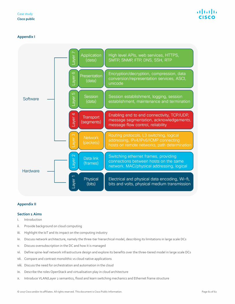
Case study
Cisco public
© 2017 Cisco and/or its affiliates. All rights reserved. This document is Cisco Public Information. Page 61 of 62
Appendix I
Appendix II
Section 1 Aims
i. Introduction
ii. Provide background on cloud computing
iii. Highlight the IoT and its impact on the computing industry
iv. Discuss network architecture, namely the three-tier hierarchical model, describing its limitations in large scale DCs
v. Discuss oversubscription in the DC and how it is managed
vi. Define spine-leaf network infrastructure design and explore its benefits over the three-tiered model in large scale DCs
vii. Compare and contrast monolithic vs cloud native applications
viii. Discuss the need for orchestration and automation in the cloud
ix. Describe the roles OpenStack and virtualisation play in cloud architecture
x. Introduce VLAN/Layer 2 semantics, flood and learn switching mechanics and Ethernet frame structure

White paper
Cisco public
© 2017 Cisco and/or its affiliates. All rights reserved. This document is Cisco Public Information. Page 62 of 62
xi. Introduce overlays and describe how VXLAN can mitigate key DC challenges
xii. Describe SDN and NFV and their role in accelerating and automating network services
xiii. Discuss open standards and their role in the integration of computing technologies
xiv. Provide a SDN cloud specific use-case
xv. Discuss societal factors concerning the use of SDN
xvi. What are the legal, social, ethical and professional considerations
xvii. References
xviii. Bibliography
For more information To read additional Cisco IT case studies on a variety of business solutions, visit Cisco on Cisco: Inside Cisco IT
https://www.cisco.com/go/ciscoit
Note:
This publication describes how Cisco has benefited from the deployment of its own products. Many factors may have contributed to the
results and benefits described; Cisco does not guarantee comparable results elsewhere.
CISCO PROVIDES THIS PUBLICATION AS IS WITHOUT WARRANTY OF ANY KIND, EITHER EXPRESS OR IMPLIED, INCLUDING THE
IMPLIED WARRANTIES OF MERCHANTABILITY OR FITNESS FOR A PARTICULAR PURPOSE.
Some jurisdictions do not allow disclaimer of express or implied warranties, therefore this disclaimer may not apply to you.
Printed in USAs C36-739302-00 07/17