sdn-based traffic engineering in data centers ... · preference for sdn to be interoperable...
TRANSCRIPT

SDN-based Traffic Engineering in Data Centers, Interconnects,and Carrier Networks
by
Tara Nath SUBEDI
MANUSCRIPT-BASED THESIS PRESENTED TO ÉCOLE DE
TECHNOLOGIE SUPÉRIEURE IN PARTIAL FULFILLMENT FOR THE
DEGREE OF DOCTOR OF PHILOSOPHY
Ph. D.
MONTREAL, FEBRUARY 01, 2018
ÉCOLE DE TECHNOLOGIE SUPÉRIEURE
UNIVERSITÉ DU QUÉBEC
Tara Nath Subedi, 2018

This Creative Commons license allows readers to download this work and share it with others as long as the
author is credited. The content of this work cannot be modified in any way or used commercially.

BOARD OF EXAMINERS
THIS THESIS HAS BEEN EVALUATED
BY THE FOLLOWING BOARD OF EXAMINERS
Mr. Mohamed Cheriet, Thesis Supervisor
Department of génie de la production automatisée, École de Technologie Supérieure
Mr. Jean-Marc Robert, President of the Board of Examiners
Department of génie logiciel et des technologies de l’information, École de Technologie
Supérieure
Mr. Michel Kadoch, Member of the jury
Department of génie électrique, École de Technologie Supérieure
Mrs. Halima Elbiaze, External Examiner
Department of d’informatique, Université du Québec à Montréal
THIS THESIS WAS PRESENTED AND DEFENDED
IN THE PRESENCE OF A BOARD OF EXAMINERS AND THE PUBLIC
ON JANUARY 19TH, 2018
AT ÉCOLE DE TECHNOLOGIE SUPÉRIEURE


ACKNOWLEDGEMENTS
I wish to express my deepest gratitude to Mohamed Cheriet, my thesis adviser, for his guidance,
support, encouragement to hard work and to help me to grow as a researcher. I will always be
indebted to him for believing in me and giving me the freedom in my research.
I would like to thank all involved in GreenStar Network, Green Sustainable Telco Cloud
(GSTC), V-WAN and Telus-Ciena projects. I would also like to thank CANARIE for sup-
porting GreenStar Network; Ericsson, the NSERC, and MITACS for supporting the GSTC
project; and Ciena, the NSERC, and MITACS for supporting the V-WAN project. It was a
highly rewarding and enriching experience for me where I got to learn and conduct research on
the cutting edge network technologies.
I thank the board of examiners, Halima Elbiaze, Jean-Marc Robert, and Michel Kadoch, for
their time and valuable comments and suggestions. I am grateful to my collaborator on all of
the articles presented in this thesis: Kim Khoa Nguyen.
I can not thank enough my friends and colleagues at the Synchromedia Lab for their great
support throughout the time.
A very special thanks to my family and friends for their encouragement and support that helped
me sustain thus far.


INGÉNIERIE DU TRAFIC BASÉE SUR SDN DANS LES CENTRES DE DONNÉES,LES INTERCONNEXIONS ET L’INFRASTRUCTURE RÉSEAU
Tara Nath SUBEDI
RÉSUMÉLa virtualisation des serveurs et le cloud computing ont augmenté les demandes en bande
passante et en performances des réseaux des centres de données (DCN). Les principaux dé-
fis des DCN sont la maximisation de l’utilisation du réseau et la garantie d’une tolérance aux
pannes pour résoudre les défaillances multiples de nœuds et de liaisons. Un environnement
multitenant virtualisé et hautement dynamique se compose d’un grand nombre de stations ter-
minales, entraînant un nombre important de flux qui remettent en cause l’évolutivité d’une so-
lution qui maximise le débit du réseau. Les défis sont l’évolutivité, en termes d’apprentissage
de l’adresse, de convergence des décisions de transmission et de taille de l’état de transfert,
ainsi que la flexibilité pour l’envoi des flux avec la migration des machines virtuelles.
Les centres de données géographiquement répartis sont interconnectés par l’intermédiaire de
l’infrastructure de réseau des fournisseurs de services. Les fournisseurs de services offrent une
connexion de réseau étendu (WAN) tels que des lignes privées et des circuits MPLS entre les
centres de données. Les centres de données des opérateurs de réseau essaient de maximiser
l’utilisation d’un tel réseau WAN déjà existant, c’est-à-dire l’interconnexion entre les centres
de données (DCI) appliquée du côté réseau des centres de données. Alors que les fournisseurs
de services des opérateurs de réseau tentent d’optimiser le cœur du réseau de l’opérateur. Par-
allèlement à l’adoption croissante des technologies ROADM, OTN et de la technologie de
commutation de paquets, le réseau IP/MPLS-over-WDM traditionnel à deux couches a évolué
pour devenir un réseau IP/MPLS-over-OTN sur DWDM à trois couches et la topologie de
superposition définie est en train de changer pour des topologies dynamiques basées sur les
demandes de trafic en temps réel.
Les opérations sur le réseau sont ainsi divisées en trois sous-réseaux physiques: DCN, DCI
overlay et l’infrastructure réseau multicouche de l’opérateur. La virtualisation de serveurs, le
cloud computing et l’infrastructure réseau multicouche évolutive de l’opérateur défient l’ingéni-
erie du trafic pour optimiser l’utilisation de tous ces sous-réseaux physiques. L’architecture
émergente de réseau défini par logiciel (SDN) déplace le calcul des chemins vers un contrôleur
centralisé, qui a une vue globale du réseau. Les opérateurs indiquent une forte préférence
pour que le SDN soit interopérable entre plusieurs fournisseurs dans des réseaux de transport
hétérogènes. SDN est un moyen naturel de créer une planification de contrôle unifié à travers
plusieurs divisions administratives. Cette thèse contribue avec des techniques d’ingénierie de
trafic basées sur SDN pour maximiser l’utilisation du réseau DCN, DCI et du réseau de trans-
port.
La première partie de la thèse porte sur l’ingénierie du trafic DCN. Les mécanismes d’achemin-
ement traditionnels utilisant un seul chemin ne peuvent pas tirer parti des multiples chemins
physiques disponibles. La solution MPTCP (Multipath Transmission Control Protocol) de

VIII
pointe utilise plusieurs chemins sélectionnés de manière aléatoire, mais ne peut pas fournir
une capacité totale agrégée. De plus, cela fonctionne comme un processus TCP et ne supporte
donc pas d’autres protocoles comme UDP. Pour résoudre ces problèmes, cette thèse présente
une solution utilisant le routage multivoie adaptatif dans un réseau de deux couches avec des
métriques statiques (capacité et latence), qui s’adapte aux ruptures de lien et de chemin. Cette
solution fournit une agrégation dans le réseau des capacités des chemins aux flux individuels,
ainsi que l’évolutivité et la Multi-Tenancy, en séparant les services de station terminale du
réseau du fournisseur. Les résultats démontrent une amélioration de 14% de la pire utilisation
de la bande passante de bissection, lorsque comparée au MPTCP avec 5 sous-flux.
La deuxième partie de la thèse porte sur l’ingénierie du trafic DCI. Les approches existantes
pour les services de réservation fournissent des capacités de réservation limitées, par ex. con-
nexions limitées sur les liens renvoyés par le traceroute par rapport aux réseaux IP tradition-
nels. De plus, la plupart des approches existantes n’abordent pas la tolérance aux erreurs en
cas de défaillance de nœuds ou de liaisons. Pour résoudre ces problèmes, cette thèse présente
ECMP-comme l’algorithme de routage multi-chemins et la technique d’assignation de routes
qui augmente le taux d’acceptation des réservations par rapport aux infrastructures de réser-
vation de pointe dans les liaisons WAN entre centres de données. Ces réservations peuvent
être configurées avec un nombre limité de règles de transfert statiques sur les commutateurs.
Notre prototype fournit l’interface de service Web RESTful pour la gestion des événements
de migration de liens et d’hôtes finaux et réachemine les chemins pour toutes les réservations
affectées.
Dans la dernière partie de la thèse, nous nous sommes concentrés sur l’ingénierie du trafic
du réseau de transport multicouche. Les nouvelles tendances de trafic dynamiques dans les
couches supérieures (par exemple le routage IP) nécessitent une configuration dynamique du
transport optique pour rediriger le trafic, ce qui nécessite à son tour l’intégration de plusieurs
couches de contrôle administratif. Lorsque plusieurs demandes de bande passante proviennent
de différents nœuds dans différentes couches, un calcul séquentiel distribué ne peut pas opti-
miser le réseau entier. La plupart des recherches antérieures se sont concentrées sur le problème
des deux couches, et les récentes études de recherche en trois couches se limitent au problème
de dimensionnement de la capacité. Nous présentons dans cette thèse un modèle d’optimisation
avec une formulation MILP pour le trafic dynamique dans un réseau à trois couches, ou nous
avons tenu compte des contraintes technologiques uniques de la couche OTN distincte. Nos
résultats expérimentaux montrent comment les valeurs de coût unitaire des différentes couches
affectent le coût du réseau et les paramètres par la présence de plusieurs ensembles de charges
de trafic. Nous démontrons également l’efficacité de notre approche heuristique proposée.
Mots-clés: multipath, capacité de chemin agrégé, OpenFlow, routage, transfert, à la demande,
à l’avance, réservation, SDN, inter-DC WAN, multicouche, paquet-optique, OTN, transport,
optimisation

SDN-BASED TRAFFIC ENGINEERING IN DATA CENTERS, INTERCONNECTS,AND CARRIER NETWORKS
Tara Nath SUBEDI
ABSTRACTServer virtualization and cloud computing have escalated the bandwidth and performance de-
mands on the DCN (data center network). The main challenges in DCN are maximizing net-
work utilization and ensuring fault tolerance to address multiple node-and-link failures. A
multitenant and highly dynamic virtualized environment consists of a large number of end-
stations, leading to a very large number of flows that challenge the scalability of a solution to
network throughput maximization. The challenges are scalability, in terms of address learning,
forwarding decision convergence, and forwarding state size, as well as flexibility for offloading
with VM migration.
Geographically distributed data centers are inter-connected through service providers’ carrier
network. Service providers offer wide-area network (WAN) connection such as private lines
and MPLS circuits between edges of data centers. DC sides of network operators try to max-
imize the utilization of such defined overlay WAN connection i.e. data center interconnection
(DCI), which applies to edges of DC networks. Service provider sides of network operators try
to optimize the core of carrier network. Along with the increasing adoption of ROADM, OTN,
and packet switching technologies, traditional two-layer IP/MPLS-over-WDM network has
evolved into three-layer IP/MPLS-over-OTN-over-DWDM network and once defined overlay
topology is now transitioning to dynamic topologies based on on-demand traffic demands.
Network operations are thus divided into three physical sub-networks: DCN, overlay DCI,
and multi-layer carrier network. Server virtualization, cloud computing and evolving multi-
layer carrier network challenge traffic engineering to maximize utilization on all physical sub-
networks. The emerging software-defined networking (SDN) architecture moves path compu-
tation towards a centralized controller, which has global visibility. Carriers indicate a strong
preference for SDN to be interoperable between multiple vendors in heterogeneous transport
networks. SDN is a natural way to create a unified control plane across multiple administrative
divisions. This thesis contributes SDN-based traffic engineering techniques for maximizing
network utilization of DCN, DCI, and carrier network.
The first part of the thesis focuses on DCN traffic engineering. Traditional forwarding mecha-
nisms using a single path are not able to take advantages of available multiple physical paths.
The state-of-the-art MPTCP (Multipath Transmission Control Protocol) solution uses multiple
randomly selected paths, but cannot give total aggregated capacity. Moreover, it works as a
TCP process, and so does not support other protocols like UDP. To address these issues, this
thesis presents a solution using adaptive multipath routing in a Layer-2 network with static
(capacity and latency) metrics, which adapts link and path failures. This solution provides in-
network aggregated path capacity to individual flows, as well as scalability and multitenancy,
by separating end-station services from the provider’s network. The results demonstrate an

X
improvement of 14% in the worst bisection bandwidth utilization, compared to the MPTCP
with 5 sub-flows.
The second part of the thesis focuses on DCI traffic engineering. The existing approaches
to reservation services provide limited reservation capabilities, e.g. limited connections over
links returned by the traceroute over traditional IP-based networks. Moreover, most existing
approaches do not address fault tolerance in the event of node or link failures. To address these
issues, this thesis presents ECMP-like multipath routing algorithm and forwarding assignment
scheme that increase reservation acceptance rate compared to state-of-art reservation frame-
works in the WAN-links between data centers, and such reservations can be configured with
a limited number of static forwarding rules on switches. Our prototype provides the RESTful
web service interface for link-fail event management and re-routes paths for all the affected
reservations.
In the final part of the thesis, we focused on multi-layer carrier network traffic engineering.
New dynamic traffic trends in upper layers (e.g. IP routing) require dynamic configuration of
the optical transport to re-direct the traffic, and this in turn requires an integration of multi-
ple administrative control layers. When multiple bandwidth path requests come from differ-
ent nodes in different layers, a distributed sequential computation cannot optimize the entire
network. Most prior research has focused on the two-layer problem, and recent three-layer
research studies are limited to the capacity dimensioning problem. In this thesis, we present an
optimization model with MILP formulation for dynamic traffic in a three-layer network, espe-
cially taking into account the unique technological constraints of the distinct OTN layer. Our
experimental results show how unit cost values of different layers affect network cost and pa-
rameters in the presence of multiple sets of traffic loads. We also demonstrate the effectiveness
of our proposed heuristic approach.
Keywords: multipath, aggregated path capacity, OpenFlow, routing, forwarding, on-demand,
in-advance, reservation, SDN, inter-DC WAN, multi-layer, packet-optical, OTN, transport, op-
timization

TABLE OF CONTENTS
Page
INTRODUCTION . . . . . . . . . . . . . . . . . . . . . . . . . . . . . . . . . . . . . . . . . . . . . . . . . . . . . . . . . . . . . . . . . . . . . . . . . . . . . . . . 1
0.1 Context . . . . . . . . . . . . . . . . . . . . . . . . . . . . . . . . . . . . . . . . . . . . . . . . . . . . . . . . . . . . . . . . . . . . . . . . . . . . . . . . . . . 8
0.2 Problem statement . . . . . . . . . . . . . . . . . . . . . . . . . . . . . . . . . . . . . . . . . . . . . . . . . . . . . . . . . . . . . . . . . . . . . . . . 8
0.2.1 Multipath bandwidth aggregation in DCN . . . . . . . . . . . . . . . . . . . . . . . . . . . . . . . . . . . . 9
0.2.2 Bandwidth reservation in DCI . . . . . . . . . . . . . . . . . . . . . . . . . . . . . . . . . . . . . . . . . . . . . . . . 11
0.2.3 Optimization in carrier network . . . . . . . . . . . . . . . . . . . . . . . . . . . . . . . . . . . . . . . . . . . . . . 12
0.3 Outline of the thesis . . . . . . . . . . . . . . . . . . . . . . . . . . . . . . . . . . . . . . . . . . . . . . . . . . . . . . . . . . . . . . . . . . . . . 14
CHAPTER 1 LITERATURE REVIEW .. . . . . . . . . . . . . . . . . . . . . . . . . . . . . . . . . . . . . . . . . . . . . . . . . . . 15
1.1 Data Center Federation . . . . . . . . . . . . . . . . . . . . . . . . . . . . . . . . . . . . . . . . . . . . . . . . . . . . . . . . . . . . . . . . . 15
1.2 Multipath in DCN . . . . . . . . . . . . . . . . . . . . . . . . . . . . . . . . . . . . . . . . . . . . . . . . . . . . . . . . . . . . . . . . . . . . . . . 17
1.3 Bandwidth reservation in DCI . . . . . . . . . . . . . . . . . . . . . . . . . . . . . . . . . . . . . . . . . . . . . . . . . . . . . . . . . . 20
1.4 Optimization in multi-layer carrier network . . . . . . . . . . . . . . . . . . . . . . . . . . . . . . . . . . . . . . . . . . . 23
CHAPTER 2 OBJECTIVES AND GENERAL METHODOLOGY . . . . . . . . . . . . . . . . . . . . . 25
2.1 Objectives of the research . . . . . . . . . . . . . . . . . . . . . . . . . . . . . . . . . . . . . . . . . . . . . . . . . . . . . . . . . . . . . . 25
2.2 General methodology . . . . . . . . . . . . . . . . . . . . . . . . . . . . . . . . . . . . . . . . . . . . . . . . . . . . . . . . . . . . . . . . . . . 27
2.2.1 Adaptive multipath routing architecture for DCN . . . . . . . . . . . . . . . . . . . . . . . . . . . 27
2.2.2 Bandwidth reservation framework for DCI . . . . . . . . . . . . . . . . . . . . . . . . . . . . . . . . . . 30
2.2.3 Optimization model for multi-layer carrier network . . . . . . . . . . . . . . . . . . . . . . . . 33
CHAPTER 3 OPENFLOW-BASED IN-NETWORK LAYER-2 ADAPTIVE
MULTIPATH AGGREGATION IN DATA CENTERS . . . . . . . . . . . . . . . . . . . . 37
3.1 Introduction . . . . . . . . . . . . . . . . . . . . . . . . . . . . . . . . . . . . . . . . . . . . . . . . . . . . . . . . . . . . . . . . . . . . . . . . . . . . . . 38
3.2 Related work . . . . . . . . . . . . . . . . . . . . . . . . . . . . . . . . . . . . . . . . . . . . . . . . . . . . . . . . . . . . . . . . . . . . . . . . . . . . 41
3.3 Adaptive Multipath Routing architecture . . . . . . . . . . . . . . . . . . . . . . . . . . . . . . . . . . . . . . . . . . . . . . 45
3.3.1 Adaptation to link failures . . . . . . . . . . . . . . . . . . . . . . . . . . . . . . . . . . . . . . . . . . . . . . . . . . . . 46
3.3.2 Multipath routing computation . . . . . . . . . . . . . . . . . . . . . . . . . . . . . . . . . . . . . . . . . . . . . . . 47
3.3.3 Path setup . . . . . . . . . . . . . . . . . . . . . . . . . . . . . . . . . . . . . . . . . . . . . . . . . . . . . . . . . . . . . . . . . . . . . . 50
3.4 Link selection . . . . . . . . . . . . . . . . . . . . . . . . . . . . . . . . . . . . . . . . . . . . . . . . . . . . . . . . . . . . . . . . . . . . . . . . . . . 53
3.5 Flow mapping to a multipath . . . . . . . . . . . . . . . . . . . . . . . . . . . . . . . . . . . . . . . . . . . . . . . . . . . . . . . . . . . 55
3.5.1 Address learning and PBB encapsulation . . . . . . . . . . . . . . . . . . . . . . . . . . . . . . . . . . . . 57
3.5.2 Multiple VNs and PBB decapsulation . . . . . . . . . . . . . . . . . . . . . . . . . . . . . . . . . . . . . . . 59
3.6 Scalability in a large topology . . . . . . . . . . . . . . . . . . . . . . . . . . . . . . . . . . . . . . . . . . . . . . . . . . . . . . . . . . 60
3.7 Evaluation . . . . . . . . . . . . . . . . . . . . . . . . . . . . . . . . . . . . . . . . . . . . . . . . . . . . . . . . . . . . . . . . . . . . . . . . . . . . . . . 63
3.7.1 Path aggregation for a single TCP session . . . . . . . . . . . . . . . . . . . . . . . . . . . . . . . . . . . 64
3.7.2 The TCP’s CWND and segment sequence number . . . . . . . . . . . . . . . . . . . . . . . . . 65
3.7.3 Dynamic adaptation to link and path failures . . . . . . . . . . . . . . . . . . . . . . . . . . . . . . . . 67
3.7.4 36 edge node topology . . . . . . . . . . . . . . . . . . . . . . . . . . . . . . . . . . . . . . . . . . . . . . . . . . . . . . . . 68
3.7.4.1 Bisection bandwidth . . . . . . . . . . . . . . . . . . . . . . . . . . . . . . . . . . . . . . . . . . . . . . 68
XII
3.7.4.2 Forwarding table size . . . . . . . . . . . . . . . . . . . . . . . . . . . . . . . . . . . . . . . . . . . . . 72
3.7.4.3 Convergence time . . . . . . . . . . . . . . . . . . . . . . . . . . . . . . . . . . . . . . . . . . . . . . . . . 72
3.8 Conclusion . . . . . . . . . . . . . . . . . . . . . . . . . . . . . . . . . . . . . . . . . . . . . . . . . . . . . . . . . . . . . . . . . . . . . . . . . . . . . . . 73
3.9 Acknowledgments . . . . . . . . . . . . . . . . . . . . . . . . . . . . . . . . . . . . . . . . . . . . . . . . . . . . . . . . . . . . . . . . . . . . . . . 74
CHAPTER 4 SDN-BASED FAULT-TOLERANT ON-DEMAND AND IN-
ADVANCE BANDWIDTH RESERVATION IN DATA CENTER
INTERCONNECTS . . . . . . . . . . . . . . . . . . . . . . . . . . . . . . . . . . . . . . . . . . . . . . . . . . . . . . . . . . 75
4.1 Introduction . . . . . . . . . . . . . . . . . . . . . . . . . . . . . . . . . . . . . . . . . . . . . . . . . . . . . . . . . . . . . . . . . . . . . . . . . . . . . . 76
4.2 Related work . . . . . . . . . . . . . . . . . . . . . . . . . . . . . . . . . . . . . . . . . . . . . . . . . . . . . . . . . . . . . . . . . . . . . . . . . . . . 79
4.2.1 Bandwidth reservation architectures . . . . . . . . . . . . . . . . . . . . . . . . . . . . . . . . . . . . . . . . . 80
4.2.2 Algorithms for bandwidth reservation . . . . . . . . . . . . . . . . . . . . . . . . . . . . . . . . . . . . . . . 81
4.3 Problem description . . . . . . . . . . . . . . . . . . . . . . . . . . . . . . . . . . . . . . . . . . . . . . . . . . . . . . . . . . . . . . . . . . . . . 83
4.4 Topology, time and reservation models . . . . . . . . . . . . . . . . . . . . . . . . . . . . . . . . . . . . . . . . . . . . . . . . 85
4.4.1 Topology model . . . . . . . . . . . . . . . . . . . . . . . . . . . . . . . . . . . . . . . . . . . . . . . . . . . . . . . . . . . . . . . 86
4.4.2 Time model . . . . . . . . . . . . . . . . . . . . . . . . . . . . . . . . . . . . . . . . . . . . . . . . . . . . . . . . . . . . . . . . . . . . 87
4.4.3 Reservation model . . . . . . . . . . . . . . . . . . . . . . . . . . . . . . . . . . . . . . . . . . . . . . . . . . . . . . . . . . . . 87
4.5 Proposed solutions . . . . . . . . . . . . . . . . . . . . . . . . . . . . . . . . . . . . . . . . . . . . . . . . . . . . . . . . . . . . . . . . . . . . . . 91
4.5.1 Determining the available bandwidth and path computation
(Solution for Problem P1) . . . . . . . . . . . . . . . . . . . . . . . . . . . . . . . . . . . . . . . . . . . . . . . . . . . . 91
4.5.1.1 Determining the available bandwidth of a link
(Solution for Problem P1-1) . . . . . . . . . . . . . . . . . . . . . . . . . . . . . . . . . . . . . . 91
4.5.1.2 Path compute: ECMP-like multiple paths consideration
(Solution for Problem P1-2) . . . . . . . . . . . . . . . . . . . . . . . . . . . . . . . . . . . . . . 92
4.5.2 Path setup and scalable forwarding (Solution for Problem P2) . . . . . . . . . . . . . 94
4.5.2.1 Co-existence of reservation and best-effort traffic . . . . . . . . . . . . . . . 95
4.5.2.2 Path setup . . . . . . . . . . . . . . . . . . . . . . . . . . . . . . . . . . . . . . . . . . . . . . . . . . . . . . . . . . 95
4.5.2.3 Tunnel assignments for scalable forwarding . . . . . . . . . . . . . . . . . . . . . 97
4.5.3 Fault tolerances to (ReRoute on) link/path failures and end-host
migrations (Solution for Problem P3) . . . . . . . . . . . . . . . . . . . . . . . . . . . . . . . . . . . . . . .100
4.5.4 SDN-based fault-tolerant bandwidth reservation (SFBR)
architecture . . . . . . . . . . . . . . . . . . . . . . . . . . . . . . . . . . . . . . . . . . . . . . . . . . . . . . . . . . . . . . . . . . .102
4.6 Approach evaluation . . . . . . . . . . . . . . . . . . . . . . . . . . . . . . . . . . . . . . . . . . . . . . . . . . . . . . . . . . . . . . . . . . .104
4.6.1 Acceptance rates . . . . . . . . . . . . . . . . . . . . . . . . . . . . . . . . . . . . . . . . . . . . . . . . . . . . . . . . . . . . .106
4.6.2 Forwarding rules scalability . . . . . . . . . . . . . . . . . . . . . . . . . . . . . . . . . . . . . . . . . . . . . . . . .108
4.6.3 Link failure and migration handling . . . . . . . . . . . . . . . . . . . . . . . . . . . . . . . . . . . . . . . .110
4.6.4 Affected reservation lookup efficiency . . . . . . . . . . . . . . . . . . . . . . . . . . . . . . . . . . . . . .111
4.6.5 Best-effort versus reservation flows . . . . . . . . . . . . . . . . . . . . . . . . . . . . . . . . . . . . . . . . .113
4.7 Conclusion . . . . . . . . . . . . . . . . . . . . . . . . . . . . . . . . . . . . . . . . . . . . . . . . . . . . . . . . . . . . . . . . . . . . . . . . . . . . . .114
4.8 Acknowledgments . . . . . . . . . . . . . . . . . . . . . . . . . . . . . . . . . . . . . . . . . . . . . . . . . . . . . . . . . . . . . . . . . . . . . .114
CHAPTER 5 SDN-BASED OPTIMIZATION MODEL OF MULTI-LAYER
TRANSPORT NETWORK DYNAMIC TRAFFIC ENGINEERING
. . . . . . . . . . . . . . . . . . . . . . . . . . . . . . . . . . . . . . . . . . . . . . . . . . . . . . . . . . . . . . . . . . . . . . . . . . . . . . . .115

XIII
5.1 Introduction . . . . . . . . . . . . . . . . . . . . . . . . . . . . . . . . . . . . . . . . . . . . . . . . . . . . . . . . . . . . . . . . . . . . . . . . . . . . .116
5.2 Related work . . . . . . . . . . . . . . . . . . . . . . . . . . . . . . . . . . . . . . . . . . . . . . . . . . . . . . . . . . . . . . . . . . . . . . . . . . .118
5.3 Traffic mapping in an OTN network . . . . . . . . . . . . . . . . . . . . . . . . . . . . . . . . . . . . . . . . . . . . . . . . . .120
5.4 Modeling of the three-layer network . . . . . . . . . . . . . . . . . . . . . . . . . . . . . . . . . . . . . . . . . . . . . . . . . .122
5.5 Optimization model . . . . . . . . . . . . . . . . . . . . . . . . . . . . . . . . . . . . . . . . . . . . . . . . . . . . . . . . . . . . . . . . . . . .124
5.6 MLO heuristics . . . . . . . . . . . . . . . . . . . . . . . . . . . . . . . . . . . . . . . . . . . . . . . . . . . . . . . . . . . . . . . . . . . . . . . . .133
5.7 Experimental results . . . . . . . . . . . . . . . . . . . . . . . . . . . . . . . . . . . . . . . . . . . . . . . . . . . . . . . . . . . . . . . . . . .138
5.7.1 Topology . . . . . . . . . . . . . . . . . . . . . . . . . . . . . . . . . . . . . . . . . . . . . . . . . . . . . . . . . . . . . . . . . . . . .139
5.7.2 Demand . . . . . . . . . . . . . . . . . . . . . . . . . . . . . . . . . . . . . . . . . . . . . . . . . . . . . . . . . . . . . . . . . . . . . . .139
5.7.3 Cost values . . . . . . . . . . . . . . . . . . . . . . . . . . . . . . . . . . . . . . . . . . . . . . . . . . . . . . . . . . . . . . . . . . .141
5.7.4 Numerical results . . . . . . . . . . . . . . . . . . . . . . . . . . . . . . . . . . . . . . . . . . . . . . . . . . . . . . . . . . . .142
5.7.4.1 Visualization of results . . . . . . . . . . . . . . . . . . . . . . . . . . . . . . . . . . . . . . . . . . .142
5.7.4.2 Three use cases . . . . . . . . . . . . . . . . . . . . . . . . . . . . . . . . . . . . . . . . . . . . . . . . . . .143
5.7.5 Heuristics results . . . . . . . . . . . . . . . . . . . . . . . . . . . . . . . . . . . . . . . . . . . . . . . . . . . . . . . . . . . . .146
5.8 Conclusion . . . . . . . . . . . . . . . . . . . . . . . . . . . . . . . . . . . . . . . . . . . . . . . . . . . . . . . . . . . . . . . . . . . . . . . . . . . . . .146
5.9 Acknowledgments . . . . . . . . . . . . . . . . . . . . . . . . . . . . . . . . . . . . . . . . . . . . . . . . . . . . . . . . . . . . . . . . . . . . . .147
CHAPTER 6 GENERAL DISCUSSIONS . . . . . . . . . . . . . . . . . . . . . . . . . . . . . . . . . . . . . . . . . . . . . . . .149
6.1 Multipath in DCN . . . . . . . . . . . . . . . . . . . . . . . . . . . . . . . . . . . . . . . . . . . . . . . . . . . . . . . . . . . . . . . . . . . . . .149
6.2 Bandwidth reservation in DCI . . . . . . . . . . . . . . . . . . . . . . . . . . . . . . . . . . . . . . . . . . . . . . . . . . . . . . . . .150
6.3 Optimization in multi-layer carrier network . . . . . . . . . . . . . . . . . . . . . . . . . . . . . . . . . . . . . . . . . .152
6.4 Combination in general framework . . . . . . . . . . . . . . . . . . . . . . . . . . . . . . . . . . . . . . . . . . . . . . . . . . .153
CONCLUSION AND RECOMMENDATIONS . . . . . . . . . . . . . . . . . . . . . . . . . . . . . . . . . . . . . . . . . . . . . .155
BIBLIOGRAPHY . . . . . . . . . . . . . . . . . . . . . . . . . . . . . . . . . . . . . . . . . . . . . . . . . . . . . . . . . . . . . . . . . . . . . . . . . . . . . .158


LIST OF TABLES
Page
Table 3.1 Ingress node’s uplink forwarding . . . . . . . . . . . . . . . . . . . . . . . . . . . . . . . . . . . . . . . . . . . . . . . 59
Table 3.2 Egress node’s downlink forwarding . . . . . . . . . . . . . . . . . . . . . . . . . . . . . . . . . . . . . . . . . . . . . 59
Table 3.3 Experiment scenarios and results. . . . . . . . . . . . . . . . . . . . . . . . . . . . . . . . . . . . . . . . . . . . . . . . 65
Table 4.1 Topology DB model . . . . . . . . . . . . . . . . . . . . . . . . . . . . . . . . . . . . . . . . . . . . . . . . . . . . . . . . . . . . . 86
Table 4.2 TB list mapping per outgoing link of switches . . . . . . . . . . . . . . . . . . . . . . . . . . . . . . . . . 87
Table 4.3 Reservation and tunnels mappings . . . . . . . . . . . . . . . . . . . . . . . . . . . . . . . . . . . . . . . . . . . . . . 88
Table 4.4 Node’s tunnel forwarding rules. . . . . . . . . . . . . . . . . . . . . . . . . . . . . . . . . . . . . . . . . . . . . . . . . . 99
Table 5.1 ODUk client mapping/multiplexing in OTUk server of 1.24G TSG:
number of TS required per ODUk times maximum number of ODUk
client supports . . . . . . . . . . . . . . . . . . . . . . . . . . . . . . . . . . . . . . . . . . . . . . . . . . . . . . . . . . . . . . . . . . .121
Table 5.2 tIP Traffic demands with 20, 50 and 90% fraction of 50G node
capacity (ai j = a ji) . . . . . . . . . . . . . . . . . . . . . . . . . . . . . . . . . . . . . . . . . . . . . . . . . . . . . . . . . . . . . .140
Table 5.3 tOP Traffic demands ( with 20, 50 and 90% of L1-CE boundary
point-pairs (ai j = a ji) . . . . . . . . . . . . . . . . . . . . . . . . . . . . . . . . . . . . . . . . . . . . . . . . . . . . . . . . . . .140
Table 5.4 Demand Scenario . . . . . . . . . . . . . . . . . . . . . . . . . . . . . . . . . . . . . . . . . . . . . . . . . . . . . . . . . . . . . . .141
Table 6.1 TE approach classification . . . . . . . . . . . . . . . . . . . . . . . . . . . . . . . . . . . . . . . . . . . . . . . . . . . . . .154


LIST OF FIGURES
Page
Figure 0.1 Traditional versus SDN . . . . . . . . . . . . . . . . . . . . . . . . . . . . . . . . . . . . . . . . . . . . . . . . . . . . . . . . . . 6
Figure 0.2 Unified control in network . . . . . . . . . . . . . . . . . . . . . . . . . . . . . . . . . . . . . . . . . . . . . . . . . . . . . . 7
Figure 0.3 Intra-DC, DCI and multi-layer carrier network . . . . . . . . . . . . . . . . . . . . . . . . . . . . . . . . 9
Figure 0.4 Multipath topology example . . . . . . . . . . . . . . . . . . . . . . . . . . . . . . . . . . . . . . . . . . . . . . . . . . . 10
Figure 0.5 DC level WAN topology and closer look at physical connectivity
for a pair of DC . . . . . . . . . . . . . . . . . . . . . . . . . . . . . . . . . . . . . . . . . . . . . . . . . . . . . . . . . . . . . . . . . 11
Figure 0.6 Multi-layered network and different routing mechanisms . . . . . . . . . . . . . . . . . . . . 13
Figure 2.1 Experimental testbed for DCN . . . . . . . . . . . . . . . . . . . . . . . . . . . . . . . . . . . . . . . . . . . . . . . . . 29
Figure 2.2 Experimental testbed for DCI . . . . . . . . . . . . . . . . . . . . . . . . . . . . . . . . . . . . . . . . . . . . . . . . . . 32
Figure 3.1 Multipath topology example . . . . . . . . . . . . . . . . . . . . . . . . . . . . . . . . . . . . . . . . . . . . . . . . . . . 39
Figure 3.2 AMR architecture . . . . . . . . . . . . . . . . . . . . . . . . . . . . . . . . . . . . . . . . . . . . . . . . . . . . . . . . . . . . . . . 46
Figure 3.3 Edmonds-Karp vs. AMR . . . . . . . . . . . . . . . . . . . . . . . . . . . . . . . . . . . . . . . . . . . . . . . . . . . . . . . 48
Figure 3.4 Flow and group entries for X-Y s-t-pair on the given topology
(Figure 3.1) . . . . . . . . . . . . . . . . . . . . . . . . . . . . . . . . . . . . . . . . . . . . . . . . . . . . . . . . . . . . . . . . . . . . . . 51
Figure 3.5 Fairness on multiple flows . . . . . . . . . . . . . . . . . . . . . . . . . . . . . . . . . . . . . . . . . . . . . . . . . . . . . . 52
Figure 3.6 Link selection example . . . . . . . . . . . . . . . . . . . . . . . . . . . . . . . . . . . . . . . . . . . . . . . . . . . . . . . . . 54
Figure 3.7 Internal components on a host. . . . . . . . . . . . . . . . . . . . . . . . . . . . . . . . . . . . . . . . . . . . . . . . . . 55
Figure 3.8 Experimental deployment of PBB . . . . . . . . . . . . . . . . . . . . . . . . . . . . . . . . . . . . . . . . . . . . . 56
Figure 3.9 PBB agent and directory system architecture . . . . . . . . . . . . . . . . . . . . . . . . . . . . . . . . . 57
Figure 3.10 PBB agents and directory system communication . . . . . . . . . . . . . . . . . . . . . . . . . . . . 58
Figure 3.11 Multiple OpenFlow domains (dotted rectangle), single Directory
System and MAC prefix concept . . . . . . . . . . . . . . . . . . . . . . . . . . . . . . . . . . . . . . . . . . . . . . . 60
Figure 3.12 Snapshot at 50th second during TCP Iperf session. . . . . . . . . . . . . . . . . . . . . . . . . . . . 64

XVIII
Figure 3.13 TCP response on 400MB transfer on different scenarios . . . . . . . . . . . . . . . . . . . . . 66
Figure 3.14 Egress node interfaces throughput variation on different link
failures during UDP session . . . . . . . . . . . . . . . . . . . . . . . . . . . . . . . . . . . . . . . . . . . . . . . . . . . . 68
Figure 3.15 Topology with 36 host nodes . . . . . . . . . . . . . . . . . . . . . . . . . . . . . . . . . . . . . . . . . . . . . . . . . . . 69
Figure 3.16 average distance (AD) vs. bisection throughput with the
probability density of AD . . . . . . . . . . . . . . . . . . . . . . . . . . . . . . . . . . . . . . . . . . . . . . . . . . . . . . 70
Figure 3.17 MPTCP vs. AMR . . . . . . . . . . . . . . . . . . . . . . . . . . . . . . . . . . . . . . . . . . . . . . . . . . . . . . . . . . . . . . . 71
Figure 4.1 DC level WAN topology and closer look at physical connectivity
for a pair of DC . . . . . . . . . . . . . . . . . . . . . . . . . . . . . . . . . . . . . . . . . . . . . . . . . . . . . . . . . . . . . . . . . 77
Figure 4.2 High-level framework . . . . . . . . . . . . . . . . . . . . . . . . . . . . . . . . . . . . . . . . . . . . . . . . . . . . . . . . . . 85
Figure 4.3 An illustration of topology DB Model . . . . . . . . . . . . . . . . . . . . . . . . . . . . . . . . . . . . . . . . . 86
Figure 4.4 An illustration of TB list of an outgoing link . . . . . . . . . . . . . . . . . . . . . . . . . . . . . . . . . . 88
Figure 4.5 Reservation mapping with tunnels and bandwidth . . . . . . . . . . . . . . . . . . . . . . . . . . . . 89
Figure 4.6 hwPathSetup/Tear Modeling (“internal” edge Controller maps
reservation flow to tunnel(s) on ingress internal edge node) . . . . . . . . . . . . . . . . . . 96
Figure 4.7 Tunnel assignments for scalable forwarding . . . . . . . . . . . . . . . . . . . . . . . . . . . . . . . . . . 98
Figure 4.8 SFBR Architecture . . . . . . . . . . . . . . . . . . . . . . . . . . . . . . . . . . . . . . . . . . . . . . . . . . . . . . . . . . . . .103
Figure 4.9 On-demand and In-advance Reservations workflow . . . . . . . . . . . . . . . . . . . . . . . . .103
Figure 4.10 Topology and reservation visualization . . . . . . . . . . . . . . . . . . . . . . . . . . . . . . . . . . . . . . .105
Figure 4.11 link’s time bandwidth visualization . . . . . . . . . . . . . . . . . . . . . . . . . . . . . . . . . . . . . . . . . . .106
Figure 4.12 Acceptance rates of PathCompute, Sahni and traceroute for the
fixed-bandwidth problem . . . . . . . . . . . . . . . . . . . . . . . . . . . . . . . . . . . . . . . . . . . . . . . . . . . . . .108
Figure 4.13 Our scalable forwarding needs fewer rules to fully exploit network
capacity . . . . . . . . . . . . . . . . . . . . . . . . . . . . . . . . . . . . . . . . . . . . . . . . . . . . . . . . . . . . . . . . . . . . . . . . .110
Figure 4.14 Failure handling . . . . . . . . . . . . . . . . . . . . . . . . . . . . . . . . . . . . . . . . . . . . . . . . . . . . . . . . . . . . . . . .111
Figure 4.15 Affected reservation lookup time versus reservation present . . . . . . . . . . . . . . . .112

XIX
Figure 4.16 Service differentiation and bandwidth guarantee on best-effort
versus reservation flow . . . . . . . . . . . . . . . . . . . . . . . . . . . . . . . . . . . . . . . . . . . . . . . . . . . . . . . .113
Figure 5.1 vlink’s capacity C is discrete variable. . . . . . . . . . . . . . . . . . . . . . . . . . . . . . . . . . . . . . . . .122
Figure 5.2 Multi-layered network and different routing mechanisms . . . . . . . . . . . . . . . . . . .123
Figure 5.3 Multi layer architecture and topology model . . . . . . . . . . . . . . . . . . . . . . . . . . . . . . . . .125
Figure 5.4 Formulation notation. . . . . . . . . . . . . . . . . . . . . . . . . . . . . . . . . . . . . . . . . . . . . . . . . . . . . . . . . . .126
Figure 5.5 extended NSFNET multi layer topology. . . . . . . . . . . . . . . . . . . . . . . . . . . . . . . . . . . . . .139
Figure 5.6 Extended NSFNET multi layer topology and states . . . . . . . . . . . . . . . . . . . . . . . . .143
Figure 5.7 Effect of varying COP and traffic loads . . . . . . . . . . . . . . . . . . . . . . . . . . . . . . . . . . . . . . .143
Figure 5.8 Effect of varying CLP_S and traffic loads . . . . . . . . . . . . . . . . . . . . . . . . . . . . . . . . . . . . . .144
Figure 5.9 Effect of individual/integrated approach and traffic loads . . . . . . . . . . . . . . . . . . .144
Figure 5.10 Heuristic versus optimization on individual/integrated approach
and traffic loads . . . . . . . . . . . . . . . . . . . . . . . . . . . . . . . . . . . . . . . . . . . . . . . . . . . . . . . . . . . . . . . .147


LIST OF ALGORITHMS
Algorithm 3.1 multiPathCompute(G,s,t) . . . . . . . . . . . . . . . . . . . . . . . . . . . . . . . . . 49
Algorithm 3.2 storePath(s,t,P,pC) . . . . . . . . . . . . . . . . . . . . . . . . . . . . . . . . . . . . . . 49
Algorithm 3.3 multiPathSetup(t,s) . . . . . . . . . . . . . . . . . . . . . . . . . . . . . . . . . . . . . 50
Algorithm 4.1 aTB(edge, ts, te) : available Time-Bandwidth . . . . . . . . . . . . . . . . . . . 91
Algorithm 4.2 PathCompute(G, s, d, ts, te, β ) . . . . . . . . . . . . . . . . . . . . . . . . . . . . . .93
Algorithm 4.3 ReRoute() . . . . . . . . . . . . . . . . . . . . . . . . . . . . . . . . . . . . . . . . . . . .101
Algorithm 4.4 linkFailAffect(u, v, nowTime) . . . . . . . . . . . . . . . . . . . . . . . . . . . . . .101
Algorithm 5.1 MLOHeuristic(MG, tLP, tOP, tIP, costs) . . . . . . . . . . . . . . . . . . . . . . . .135
Algorithm 5.2 single_bandwidth_path(G, d) . . . . . . . . . . . . . . . . . . . . . . . . . . . . . . 135
Algorithm 5.3 k-bandwidth-paths(G, d) . . . . . . . . . . . . . . . . . . . . . . . . . . . . . . . . . 136
Algorithm 5.4 reserveCapacity(G, hd , path, vlink_key ← None) . . . . . . . . . . . . . . . . 137
Algorithm 5.5 reroute_L2.5_vlinks(G, L2.5links, delta) . . . . . . . . . . . . . . . . . . . . . . 138


LIST OF ABBREVIATIONS
AMR Adaptive Multipath Routing
API Application Programming Interface
ASIC Application Specific Integrated Circuit
BA Backbone Address
CBC Coin-or Branch and Cut
CBR Constraint Based Routing
CE Customer Equipment
CTP Connection Termination Point
CTPP CTP Pool
CWND Congestion WiNDow
DC Data Center
DCN Data Center Network
DiffServ Differentiated Services
DPID DataPath ID
DWDM Dense Wavelength-Division Multiplexing
ECMP Equal-Cost Multi-Path
FDB Forwarding DataBase
FEC Forwarding Equivalent Class
GMPLS Generalized MPLS

XXIV
GRE Generic Routing Encapsulation
GSTC Green Sustainable Telco Cloud
IntServ Integrated Service
IP Internet Protocol
IS-IS Intermediate System-to-Intermediate System
L1 Layer-1
L2 Layer-2
L3 Layer-3
LLDP Link Layer Discovery Protocol
LSP Label Switched Path
MAC Media Access Control Address
MEC Multi-chassis EtherChannel
MPLS Multiple Protocol Label Switching
MPLS-TE MPLS with Traffic Engineering
MPTCP MultiPath Transmission Control Protocol
MRM Multipath Routing Module
MST Multiple Spanning Tree
NBI North-Bound Interface
NMS Network Management System
OCh Optical Channel

XXV
ODU Optical Data Unit
ONF Open Networking Foundation
OTN Optical Transport Network
OVS Open vSwitch
PBB Provider Backbone Bridge
PCE Path Computation Element
PCEP PCE communication Protocol
PE Provider Equipment
PMAC Pseudo MAC
PVST Per-VLAN Spanning Tree
QoS Quality of Service
REST REpresentational State Transfer
resvID reservation IDentifier
RSVP ReSource reserVation Protocol
RSVP-TE RSVP with TE extensions
RTT Round Trip Time
SBI South-Bound Interface
SDN Software Defined Networking
SID Service instance IDentifier
SPB Shortest Path Bridging

XXVI
SPBM SPB-MAC
SPBV SPB-VID
STP Service Termination Point
STP Spanning Tree Protocol
TB Time-Bandwidth
TCAM Ternary Content Addressable Memory
TDM Topology Discovery Module
TE Traffic Engineering
ToP Top of Pod
ToR Top of Rack
ToS Top of Super-pod
TRILL TRansparent Interconnection of Lots of Links
TS Time-Slot
TSG Time-Slot Granularity
TTL Time to Live
TTP Trail Termination Point
VC Virtual Circuit
VDC Virtual Data Center
vEth virtual Ethernet interface
VM Virtual Machine

XXVII
VN Virtual Network
vSwitch virtual Switch
VTD Virtual Topology Design
WAN Wide-Area Network
WPS Weighted Probabilistic Selection
WRR Weighted Round-Robin


INTRODUCTION
A network is typically configured by interconnecting physical devices such as routers and
switches. A major problem with the network is to adapt to the dynamic nature of the inter-
connection and traffic pattern. An important technique to address this problem is traffic en-
gineering, which optimizes the network and improves network robustness. As traffic demand
increases, traffic engineering can reduce the service degradation due to congestion and failure,
e.g. link failure.
The aim of this thesis is to provide SDN-based traffic engineering techniques for: A1) maxi-
mizing network utilization, A2) fault tolerance to address multiple node-and-link failures, and
A3) scalability in the forwarding table, of Data Centers, Interconnects and Carrier Networks.
We contribute in three approaches, dealing with each problem: P1) multipath bandwidth ag-
gregation P2) bandwidth reservation and P3) optimization.
Data Center Network
A Data Center Network (DCN) is a communication network interconnecting the entire pool
of resources (computational, storage, network) within a data center facility. A conventional
data center network comprises: servers that manage workloads; switches/routers that connect
devices together and perform forwarding functions; controllers that manage the workflow be-
tween network devices and gateways that serve as the junctions between DCNs and the carrier
network or the Internet.
In recent decades, data centers have benefited immensely from virtualization, that enables
server consolidation, application isolation, workload migration and faster deployment times,
which enables DC providers to pool their computing resources for multiple consumers. The
delivery of on-demand computing resources over the internet on a pay-for-use basis is called
cloud computing. Virtualization and cloud computing have promises for many organizations

2
to move in cloud environments without making sizable capital investments in computing hard-
ware.
DCN was designed under the safe assumption that each node was connected to the access port
of an end-of-row switch in the network and it corresponded to one server running the single
instance of an Operating System (OS). Another assumption was that it would not move to an-
other physical server. Server virtualization has invalidated these assumptions and has posed
some new challenges for the design of DCNs, that include scaling of the network for virtual-
ization, VM mobility, management complexity and support for convergence (Bari et al., 2013).
In this environment, the traditional tiered tree topology gives poor reliability and leads to over-
subscribed any-to-any network design, and forwarding along a tree constrains workload place-
ment (Greenberg et al., 2008, 2009). To support high bisection bandwidth and fault-tolerance,
in modern data center network, host servers are often built with multiple interfaces, and their
network topology consists of multiple redundant links, resulting in a multipath physical net-
work (Guo et al., 2008; Greenberg et al., 2009). Examples of multipath network topologies
include DCell (Guo et al., 2008), BCube (Guo et al., 2009), and Fat tree (Al-Fares et al., 2008),
as well as the flat-mesh architecture, an Ethernet fabric (Brocade), for example.
Data Center Interconnect
Data center interconnect (DCI) refers to the networking of two or more geographically dis-
tributed data centers. Such an inter data center network provides a dynamic and virtualized
environment when augmented with cloud infrastructure supporting end-host migration. Most
small to medium-sized enterprises purchase Carrier services from service providers instead
of building and maintaining their own network infrastructure to be more cost-effective to site
interconnection and data center interconnection. Many large-scale scientific and commercial
applications produce large amounts of data, in the order of terabytes to petabytes. Given the
need for low-latency and high-throughput data transfers, the DCI is often a dedicated network,

3
distinct from the WAN that connects with ISPs to reach end users (Hong et al., 2013). The most
effective transport for the DCI is through private lines and MPLS circuits, which is offered by
underlying packet-optical carrier network connected to the gateways of data centers. Here the
DCI topology is a static overlay topology, i.e. links between two end-ports are fixed.
DCI is an expensive resource, with the amortized annual cost of 100s millions of dollars, as it
provides 100s of Gbps to Tbps of capacity over long distances. Moreover, DCI is provisioned
for peak usage to avoid congestion. However, applications send as much traffic as they want
and whenever they want to, regardless of the current state of the network or other applications,
which leads to networks swinging between over and under subscription. The result of this is
poor efficiency in WAN-links as the average amount of traffic the WAN-link carries tends to
be low (30-40%) compared to capacity. Thus, over-provisioned DCI for worst case variability
does not fully leverage the investment in DCI.
The main aim in DCI is to maximize the utilization of DCI connection and to ensure fault tol-
erance to address multiple node-and-link failures. Deterministic traffic behavior of application
simplifies planning but coordination among the applications that use the network is a must.
Centralized TE allows specifying the intent to the applications and dynamically provisions
bandwidth resources in the network.
Carrier Networks
A carrier network refers to the wide-area network infrastructure belonging to a telecommuni-
cations service provider. It provides end-to-end connection and communications services over
long distances. A carrier network involves all packet-optical layers network devices (L0 to L3)
and interconnection. Transport network is more specific and applies to the transport layers (L0
and L1) of the carrier network. Large enterprises can also own such infrastructures by prefer-

4
ence or necessity for site interconnection and data center interconnection. Cloud computing is
forcing the once static WAN to transition from defined topologies to dynamic topologies.
Along with the increasing adoption of ROADM, OTN, and packet switching technologies,
the traditional two-layer IP/MPLS-over-WDM network has evolved into a much more agile
three-layer IP/MPLS-over-OTN-over-DWDM network with the addition of an OTN (Optical
Transport Network, G.709 (ITU-T G.709)) container (i.e., ODUj) switching as a middle layer
between the IP and DWDM layers. With the proliferation of Ethernet devices and a significant
shift in the type of traffic from voice to data, there has been a rapid growth in bandwidth
demand from 10 Mbps to 1, 2.5 or 10 Gbps in the transport network. Recent reports indicate
that traffic from data centers is now the largest volume driver for optical networks, surpassing
conventional telecommunication systems (DeCusatis, 2015).
OTN switching allows any transit traffic at intermediate nodes to bypass any intermediate core
IP routers and to be efficiently packed/groomed into higher speed wavelengths. In reality, an
IP interface is four to five times more expensive than an OTN interface (Tsirilakis et al., 2005;
Bhatta, 2008). As the OTN switching layer has helped distribute traffic for routers, service
providers do not need to expand the capacity of core routers as fast as the lower layer equip-
ments; thus the number of hops and IP interfaces is reduced, as well as the CAPEX for service
providers. One leading operator reduced 40% of its CAPEX with the IP/OTN synergy solu-
tion simply by bypassing the traffic from routers to the OTN switching layers (Bhatta, 2008).
Therefore, large service providers are recognizing that IP/MPLS-over-OTN-over-DWDM is
an emerged architecture (Bhatta, 2008). New dynamic traffic trends in upper layers (e.g. IP
routing), especially from data centers, require dynamic configuration of the optical transport to
re-direct the traffic, and which in turn requires an integration of multiple administrative control
layers. When multiple bandwidth path requests come from different nodes in different layers,
a distributed sequential computation cannot optimize the entire network. As there are contra-

5
dictory objective functions on individual layers, separate single-layer optimization also cannot
give global optimization, for which multi-layer joint-optimization is required.
Software-Defined Networking
The traditional network architecture is distributed, as shown in Figure 0.1, where each network-
ing device has both the control plane and the data plane. There are many traffic engineering
techniques for traditional network architectures. However, the traditional network architec-
ture is difficult to manage, and software-defined networking (SDN) promises to simplify it.
The Open Networking Foundation (ONF) (ONF, 2017a) defines software-defined network-
ing (SDN) as: “an emerging network architecture where network control is decoupled from
forwarding and is directly programmable.” The key component of SDN architecture is the
controller (Figure 0.1), which provides northbound application programming interfaces (APIs)
to applications and tracks all application requests; and southbound APIs to control data plane
of various devices, that works by injecting forwarding data-rules on flow tables explicitly via
different management interfaces (e.g. OpenFlow, TL-1, NETCONF, SNMP) or by initiating
distributed control plane signaling from the originating end of the connection (PCEP) to man-
age each forwarding segment (light-path, ODU path, MPLS-TE LSP) independently, as well
as possible manual provisioning (Y. Lee Ed., 2011; ONF, 2015; Rodrigues et al., 2014). The
controller maintains a model of the network topology and traffic loads and thus has global
visibility and uses this to compute paths. Thus SDN architecture moves path computation to-
wards a centralized controller. The SDN concept isolates the network function implementation
from the state-distribution mechanism and reduces the control plane complexity compared to
GMPLS. Carriers indicate a strong preference for SDN to be interoperable between multiple
vendors in heterogeneous transport networks.
To exploit the potential of SDN, new traffic engineering methods are required. Virtualiza-
tion, cloud computing, and dynamic traffic trends challenge traffic engineering to maximize

6
Figure 0.1 Traditional versus SDN (adapted from figure by
http://www.software-defined.net/networking.php)
utilization on all physical sub-networks: DCN, DCI, and multi-layer carrier network. The
SDN is a natural way to create a unified control plane across multiple administrative divisions:
DCN, DCI, and multi-layer carrier network, as shown in Figure 0.2. The software-defined DC
(SDDC) Controller uses the SDN concept in hosts and switches inside the DC. The software-
defined DCI/WAN (SD-DCI/SD-WAN) controller takes the SDN concept to the edge of the
DC network. The software-defined carrier (carrier SDN) controller takes the SDN concept to
the core of carrier network (service provider network). Transport SDN is more specific and
applies to the transport layers (L0/DWDM and L1/OTN) of the service provider network. An
orchestrator receives customer requests and involves coordinating software actions with the
SDN controllers to build an end to end network connection. For example, in case of traf-
fic between two end-hosts running on separate data centers, sub-networks traffic engineering
can coordinate to establish end-to-end path: source/destination DCN provides segment path
to/from edge nodes, multi-layer carrier network provides DCI, and DCI provides segment path
between edge nodes.

7
Figure 0.2 Unified control in network
Traffic Engineering approach and Network
As routing convergence and configuration time is very important in network, traffic engineering
approaches of maximizing network utilization depends upon scope (in terms of number/gran-
ularity of flow-demands, prior knowledge of required bandwidth) and size of the network. In
DCN, the number and duration of flows are very dynamic and applications do not have a pri-
ori knowledge of required bandwidth and/or do not tolerate additional latency of bandwidth
requests for short-lived traffic. In DCI, the fixed expense of a long-distance dedicated line is
justified with bandwidth reservation according to application’s intent, even though it incurs in
overhead for maintaining reservation states. Optimization gives best network utilization as it
considers all demand requests concurrently (instead of simple/sequential) but in the cost of
convergence and configuration time of routing paths. Because of aforementioned nature of in-
dividual approach and network, we scoped the three TE approaches: P1) multipath bandwidth
aggregation, P2) bandwidth reservation, and P3) optimization into Data Centers, Interconnects,
and Carrier Networks respectively.

8
Before developing further the theoretical aspect of this research, the context of the work is
presented first, and then, the research problems are stated and discussed more formally. Finally,
an outline of this thesis is presented.
0.1 Context
This thesis is within the scope of the Green Sustainable Telco Cloud (GSTC) and Telus-Ciena
projects inside Synchromedia laboratory. GSTC project goals are smart and sustainable pro-
visioning, profiling and assessment of Telco cloud services. The smart and sustainable pro-
visioning goals are achieved by defining a software-defined Telco cloud. This is achieved by
mechanisms: software-defined intra-DC and DCI forwarding, bandwidth-on-demand, multi-
tenant support, and isolation.
The Telus-Ciena project goal is to build multi-layer orchestration with functional requirement
of end-to-end bandwidth reservation across multi-layer and multi-domain controllers of carrier
network.
As shown in Figure 0.3, we partition the overall network as i) intra-DC; ii) DCI; and iii) multi-
layer carrier network, so that we can tackle the problems separately. This modular approach is
justifiable as these are the separate administrative domains with separate controllers for intra-
DC, DCI and multi-layer carrier network topology, and the coordination between them provides
end-to-end path crossing multiple domains.
0.2 Problem statement
We present the three problems in detail: P1) multipath bandwidth aggregation in DCN P2)
bandwidth reservation in DCI and P3) optimization in carrier network.

9
Figure 0.3 Intra-DC, DCI and multi-layer carrier network
0.2.1 Multipath bandwidth aggregation in DCN
Figure 0.4 depicts the DCN topology: circles and squares, representing switch nodes and host
nodes, are connected by links of various capacity weights (in Gbps). A multipath network is a
network in which there is more than one path between any pair of nodes. For example, in Fig-
ure 0.4, the route linking nodes X and Y consists of multiple paths. The use of multiple paths
simultaneously provides aggregated capacity, which is useful for applications that demand high
bandwidth, such as virtual machine (VM) migration, eScience, and video. Aggregated capac-
ity is the total capacity of all paths linking a pair of nodes. However, traditional forwarding
mechanisms using a single path are not able to take advantage of available multiple physical
paths. Moreover, a multitenant and highly dynamic virtualized environment consists of a large
number of end-stations, leading to a very large number of flows that challenge the scalability
in terms of address learning, forwarding state size, and forwarding decision convergence. For
example, Ethernet address learning by flooding and remembering the ingress port restricts the

10
topology to a cycle-free tree. In forwarding along a tree, switches near the root require more
forwarding entries (TCAM).
Figure 0.4 Multipath topology example
Main issues are:
• How to ensure per-flow aggregated capacity on multiple paths? How to allow a flow be-
tween nodes X and Y (Figure 0.4) to achieve the aggregated capacity of 2 Gbps along paths
X-a-b-Y and X-e-f-Y? In the case of a failed (a, b) link, how the flow still achieves the ag-
gregated capacity of 2 Gbps along the unequal paths X-e-f-Y and X-a-c-b-Y ? What is the
solution for out-of-order delivery ?
• How to achieve in-network multipath solution and network isolation for end-hosts in a
multitenant dynamic virtualized environment?

11
0.2.2 Bandwidth reservation in DCI
Geographically distributed data centers are inter-connected through data center interconnect
links. Figure 0.5 shows a DCI topology for 5 DCs, each of which has: i) two connected
WAN-facing core nodes (e.g. a, e); ii) end-hosts connected to the edge nodes through intra-
DC connection; and iii) 12 edge nodes (e.g. X1-X12) connected to both core nodes that
split traffic from the end-hosts over the core nodes. 5 DCs are inter-connected across their
10 WAN-facing core nodes. The WAN-links between the data centers (DC) carry aggre-
Figure 0.5 DC level WAN topology and closer look at physical
connectivity for a pair of DC
gated data traffic originating from within the co-located data producers. As stated in the Intro-
duction, bandwidth reservation capabilities that dynamically provision network resources are
recognized as extremely useful capabilities for many types of network services (Guok et al.,
2006; Nadeau and Gray, 2013). Bandwidth reservation allocates and/or deallocates a certain
amount of bandwidth that an activity is going to require either at a future time or immedi-

12
ately (Nadeau and Gray, 2013). The existing approaches to in-advance reservation services
provide limited reservation capabilities, e.g. limited connections over links returned by the
traceroute over traditional IP-based networks.
Main issues are:
• The current reservation approaches/frameworks have a low acceptance rate of reservation
requests even in the presence of available bandwidth, especially due to the limited number
of forwarding rule supports in switches. The number of per-flow paths is too large to be
handled by the switches.
• How the affected reservation lookup can be made efficient to support fault tolerance in the
event of node or link failures?
0.2.3 Optimization in carrier network
The carrier network, that inter-connects geographically distributed data centers, itself con-
sists of a multi-layered network. Figure 0.6 shows the IP/MPLS-over-OTN-over-DWDM
Network in a vertical top-down order of 4 Customer-Edge IP (L3) routers (CE1-4) and 6
Provider/Provider-Edge MPLS (2.5) nodes (PE1-6) as IP/MPLS traffic demand layer, and 13
and 12 network nodes in the OTN (L1) and DWDM (L0) layers respectively. L0 nodes are con-
nected by fiber links. Horizontal left-right order shows the network nodes’ placement as last
mile/customer premise, access, metro or core network, divided by vertical lines. Each L0, L1
and L2.5 network node consists of boundary ports, i.e. trail termination points (TTPs) (each
represented by a black circle: ), and multiplexing ports, i.e. connection termination point
(CTP) pools (CTPPs) (each represented by a white circle: ). The TTP port connects to the
CTPP port of the upper layer node. The link is called a boundary link (L0-L1, L1-L2.5 are not
shown in Figure 5.2 for clarity’s sake, but should be understood as - ). PE5 and PE6 connect

13
Figure 0.6 Multi-layered network and different routing
mechanisms
to content distribution network (CDN) and Internet through Internet Exchange points (IXP).
CEs are connected to the L2.5, L1 or L0 node, depending upon service demand. CEs’ inter-
faces with ≤1G are aggregated to 10G on the L2.5 node; and CEs’ interfaces with 10-40G are
aggregated to the L1 node to take advantage of traffic grooming. CEs’ interfaces with 40-100G
are directly connected to the L0 node. Service demands from the customer network elements
CE1, CE2, CE3 and CE4 to the other CEs or PEs are served with 4 routes: LSP-1, LSP-2,
LSP-3 and LSP-4, in which LSP-1 and LSP-2 go through MPLS/L2.5 switching as transit,
LSP-3 bypasses MPLS/L2.5 switching with ODU/L1 switching, and LSP-4 goes directly over
the OCh/L0 switching.
On the basis of physical topology, the optimization algorithm computes logical links and the
routing paths for all the service demands that can efficiently utilize the network’s resources.
The lightpath for the L0 TTP-pair and the ODUpath for the L1 TTP-pair provides logical links
in connected CTPP-pairs, and demand is then mapped onto a set of (logical) links. The result
may be different sets of logical links for different sets of demands.

14
Main issues are:
• How to design optimization model for IP/MPLS-over-OTN-over-DWDM network for traf-
fic engineering ? The optimization needs to solve different technological aspects such as:
three-layer traffic demands, non-uniform capacity types of Ethernet and OTUk ports, ODU-
flex’s flexible capacity and non-bifurcate capability of OTN and WDM switching layers.
0.3 Outline of the thesis
Chapter 1 presents a review of state-of-the-art methods that are relevant to the scope of the
research problems. Based on this literature review, the objectives of the research are defined,
and the general methodology is proposed in Chapter 2. The three following chapters present
the manuscripts written in response to specific research problematic. The manuscript defining
our intra-DC multi-path is presented in Chapter 3. DCI reservation is described in Chapter 4.
The multi-layer network optimization proposed is the subject of Chapter 5. Chapter 6 presents
a global discussion, and finally, the work accomplished in the thesis is summarized in a general
conclusion.

CHAPTER 1
LITERATURE REVIEW
This chapter presents a review of state-of-the-art methods related to the proposed traffic engi-
neering on different administrative domains: DCN, DCI and multi-layer carrier network. This
chapter is divided into four sections that are in line with the unified control and the three traf-
fic engineering domain problems exposed in the introduction. The first section presents data
center federation. The second section starts with a focus on multi-path in intra-DC networks.
The third section covers methods specific to the reservation in DCI networks. Finally, the last
section reviews optimization methods in a multi-layer carrier network.
1.1 Data Center Federation
Data center federation is the practice of interconnecting the DC computing environments of
two or more DC providers. It gives elasticity to VMs among DCs and thus, it is an enabler for
load balancing and high availability services between DC providers. Different DCs normally
consist of independent storage and network environments. If several DC environments can not
inter-work, then the inter-DC virtual network can not be achieved for VMs.
Any solution for inter-DC virtual network must maintain the insularity of the respective DCs
in support of each DC’s IT infrastructure autonomy, privacy, and security requirements (Nagin
et al., 2011). Autonomy refers to the ability of a DC to administer its IT infrastructure (for
eg: network, storage topology reorganization, changing IP addressing schemes, use of any
virtualization technology: VMWare, KVM or Xen) without consulting with other DCs. VM
placement should only be motivated by a DC’s own internal policy. Security refers to the extent
that an intruder can compromise a DC’s operations. A common security measure typically
applied by organizations is to forbid access from outside the organization to its servers, except
for those located in a specially designed “demilitarized zone (DMZ)”. Moreover, such servers
are sometimes configured with non-routable IP addresses, and/or are hidden behind a NAT
service. An example of possible security violation in the context of VM network is to require

16
that the individual hosts have IP addresses directly accessible from the Internet. Privacy refers
to the extent to which a DC must reveal the hardware and software used, DC topology and
activity.
Open source cloud platform like OpenStack (ope, 2017) is very promising for interoperability
among DCs. As load balancing case, some load balancing VMs can be migrated offline, using
export function of the cloud platform, to different DCs, while other online still serving the re-
quests from current DC. The target DC places the VM live anywhere in its switching fabric and
with tenant network identification of VM, provides a virtual network to those VMs running in
the DC. The virtual network is stretched across DC sites. DC uses network overlay technolo-
gies to provide such virtual network and to be scalable to a large number of VMs. There are
many network overlay technologies with different encapsulation frame formats including: Vir-
tual Extensible LAN (VxLAN), Network Virtualization Using Generic Routing Encapsulation
(NVGRE), Overlay Transport Virtualization (OTV), IEEE 802.1ad Provider Bridging, IEEE
802.1ah Provider Backbone Bridges, Transparent Interconnection of Lots of Links (TRILL),
Location/Identifier Separation Protocol (LISP) and MPLS (cis, 2013). Host server or edge
switch can support different tunneling functions. However, there is a non-trivial dependency
on the control plane for address learning and for forwarding of Layer 2 broadcast, multicast,
and unknown unicast traffic. For example, OTV (Cisco, 2012b) control plane (which uses IS-
IS) proactively advertises MAC reachability information, so that all OTV edge devices already
know what MAC addresses are reachable via the overlay. The single control plane of an overlay
technology across DCs violates DC isolation, as it exposes internal host servers for tunneling
to other DCs. Even in case of internal migration inside the DC, it needs to coordinate to other
DCs, obviously, it is an unnecessary burden. Moreover, there is no co-operation among the
control planes of different overlay technologies to create stretched virtual network.
Existing mobile IP solution (C. Perkins, 2002) for inter-domain VM mobility is not satisfactory,
all traffic destined to a mobile VM has to go through an anchoring point - the mobile’s home
agent. This triangular routing not only increases the packet delivery delay but also imposes
a burden on the networks as well as the home agent. VICTOR (Hao et al., 2010) logically

17
combine multiple geographically distributed physical devices with IP-in-IP tunnel and use a
centralized controller to control the forwarding, eliminating the triangular problem. But this
shares same controller among all DCs, updates about internal migration, and expose all internal
routers, thus does not respect DC isolation.
Recently control plane federation has favored the existence of multiple administrative network
domains, that are controlled by individual SDN control plane. To setup end-to-end network
with one user request, the control plane can follow any end-to-end setup coordination models:
“star”, “daisy chain”, and hybrid star/daisy chain (Bobyshev et al., 2010). To achieve control
plane federation with information exchange, the Internet engineering task force (IETF) devel-
oped a message exchange protocol, SDNi, as an interface between SDN controllers (Yin et al.,
2012). Lin et al. proposed a west-east bridge to facilitate inter-SDN communication (Lin et al.,
2015).
With DC isolation in mind, in this thesis, we favor SDN approach with separate DC controllers
and DCI controller, where data plane functions are simplified to tunneling and orchestrator co-
ordinates between controllers to obtain reachability information and to stitch multiple segment-
paths.
1.2 Multipath in DCN
The current Layer-3 (L3)-routed approach assigns IP addresses to hosts hierarchically, based
on their directly connected switch. For example, hosts connected to the same Top of Rack
(ToR) switch could be assigned the same /26 prefix, and hosts in the same row may have
a /22 prefix (Cisco, 2013a). With such an assignment, the forwarding tables across all data
center switches will be relatively small. So, using multiple L2-switched domains and an L3-
routed network for IP routing between them is a scalable addressing and forwarding solution.
However, configuration and operational complexity are increased in the case of VM migration
across L2 domains. VL2 (Greenberg et al., 2009) solves this problem and provides virtual L2
service in an L3-routed network by using IP-in-IP as the location separation mechanism and

18
agent/directory service that follows end-system-based address resolution and takes advantage
of a scalable L3 design. However, VL2 relies on ECMP, calculated by OSPF in L3 routers,
which cannot use multiple paths for a flow.
One of the challenges in L2-switched network deployments in current DCNs is that the span-
ning tree protocol (STP) will prune paths from the network to ensure a loop-free topology,
resulting in a single-tree topology (Perlman, 2009). Moreover, STP effectively wastes much of
the potential throughput between any pair of nodes (Perlman, 2009), and so a physical multi-
path design will not be fully exploited, which means that the DCN is not scalable. There is a
growing interest to eliminate STP in L2 networks and enable multipath use in switching net-
works. There have been several improvements giving multiple STP instances, that is, multiple
trees in a network. For example, Cisco’s Per-VLAN Spanning Tree (PVST) (Cisco, 2013b)
creates a separate spanning tree for each VLAN in a multi-VLAN network, and the IEEE
802.1s MST (Multiple Spanning Tree) (IEEE Standard 802.1s, 2002) links multiple VLANs
into a spanning tree, creating multiple trees in a network. The drawback of the multi-VLAN
approach is resource fragmentation and under-utilization (Greenberg et al., 2008), because VM
consolidation cannot be achieved between different VLANs.
Link aggregation (IEEE 802.3ad) (IEEE Std 802.3ad-2000, 2000) combines multiple links
to create a single logical connection between two directly connected endpoints and increases
bandwidth. However, this solution does not deal with links traversing multiple switches. There
are proprietary multi-chassis Etherchannel (MEC) solutions, VSS, vPC, and MLAG, for exam-
ple, which allow link aggregation towards different switches to form a single logical switch,
providing redundancy and resiliency (Cisco, 2013c; Arista). However, they are not yet sup-
ported by all the switches on the market.
TRILL (Perlman, 2009) and SPB (IEEE Standard 802.1aq-2012, 2012) are emerging tech-
nologies as STP replacements. VL2 (Greenberg et al., 2009), TRILL (IETF RFC 5556) (Perl-
man, 2009), and SPB (Shortest Path Bridging IEEE 802.1aq-2012 (IEEE Standard 802.1aq-
2012, 2012)) use the Equal-Cost Multi-Path (ECMP) to spread traffic across multiple paths.

19
ECMP (Hopps, 2000) balances the load across flow-based paths by calculating a hash of every
packet header, but uniquely mapping a flow to a single path to prevent out-of-order delivery at
the destination. For example, a flow between nodes X and Y (Figure 0.4) can be mapped to
either the X-a-b-Y or X-e-f-Y path. Thus, a single flow’s throughput is limited to single path
capacity, not to the aggregated path capacity. Although there are many flows in a network,
they are not always mapped to the right paths because of hashing collisions. The more links a
flow traverses, the more collisions will occur (Al-Fares et al., 2010). With ECMP, the overall
throughput is not optimal.
Multipath network needs routing and load balancing to enable the use of the full bisection
bandwidth. Techniques such as spanning trees, which are used in switched networks, are not
applicable to recently proposed architectures (DCell (Guo et al., 2008), BCube (Guo et al.,
2009), and Fat tree (Al-Fares et al., 2008)), because they do not exploit path diversity. Because
DCN topologies contain numerous end-to-end paths for each pair of endpoints, traffic engi-
neering can often improve the aggregate throughput by dynamically pinning flows to paths.
Al-Fares et al. proposed a system for dynamic DCN traffic engineering called Hedera (Al-
Fares et al., 2010) and showed that Hedera can improve network performance significantly.
Hedera (Al-Fares et al., 2010) is a reactive flow scheduling technique designed to dynamically
reroute flows on optimized paths. It performs load balancing by rescheduling flow on a single
optimal path, but does not provide aggregated bandwidth. This technique also poses scalability
issues on path convergence, and may result in path flapping in a congested network. Fat-tree-
like topologies can benefit from Valiant Load Balancing over ECMP (Greenberg et al., 2009)
but even there, prior work has shown a gap of 20% from the optimal throughput (Benson et al.,
2010).
Bcube (Guo et al., 2009) routing considers link disjoint multipaths up to the number of inter-
faces of a server, as it is a symmetric topology with identical link capacity. In this paper, we
consider asymmetric capacity links in the network and also compute intersecting paths.

20
In SPAIN (Mudigonda et al., 2010), end hosts perform adaptive routing over multiple VLANs.
For forwarding to be loop-free, a VLAN is mapped to an individual tree. However, the VLAN
configuration is static. Moreover, even if a single flow uses all the VLANs, not all the avail-
able aggregated throughput can be used with SPAIN, not does it consider different network
capacities.
The MPTCP (Multipath Transmission Control Protocol) (Raiciu et al., 2011) solution uses
multiple randomly selected paths, but cannot give total aggregated capacity. Moreover, it works
as a TCP process, and therefore does not support other protocols like UDP. The MPTCP with
OpenFlow (van der Pol et al., 2012) provides a Layer-2 (L2) multipath using multiple subflows
as end TCP processes and mapping subflows to VLANs, depending on ECMP hashing. For
example, when MPTCP uses 5 subflows to communicate between nodes X and Y (Figure 0.4),
ECMP hashing can choose both the X-a-b-Y (1 Gbps) and X-e-f-Y (1 Gbps) equal paths with
a certain probability (e.g. 95%). In the case of a failed (a, b) link, an unequal path X-a-c-b-Y
(1 Gbps) will not be used, which means that the ECMP only provides a single path bandwidth
of 1 Gbps instead of the available aggregated bandwidth of 2 Gbps.
1.3 Bandwidth reservation in DCI
Integrated Services (IntServ) / Resource Reservation Protocol (RSVP), Differentiated Services
(DiffServ), MPLS and Constraint-based routing (Pana and Put, 2013) are some of the fun-
damental Quality of Service (QoS) architectures. On the Internet, IntServ (Pana and Put,
2013) and DiffServ (Pana and Put, 2013) are designed, respectively, to provide bandwidth
guarantee and service differentiation along the existing route set up by an underlying routing
protocol. MPLS-TE (MPLS with traffic engineering (TE) extensions) is a Constraint Based
Routing (CBR) solution, which enables multiple paths between a specific source/destination
pair in a network. At the head end router, CBR calculates explicit paths as ordered set of
hops (next-hop IP addresses of routers) and associates labels to them, which are then propa-
gated to other routers in the explicit path by using signaling protocol RSVP-TE (RSVP with
TE extensions (Pana and Put, 2013; Awduche et al., 2001)). These fundamental architectures
21
(MPLS (Sharafat et al., 2011) at IP Layer 3 (L3) and Generalized MPLS (GMPLS) (Azodol-
molky et al., 2011b) at L0, L1 and L2) support only on-demand but not in-advance reservations.
Various in-advance reservation frameworks have been proposed, such as DRAC (Travostino
et al., 2005), DRAGON (Lehman et al., 2006), G-Lambda (Takefusa et al., 2006), OSCARS (Guok
et al., 2006) and AutoBHAN (Lukasik et al., 2008; Bouras et al., 2013), which provision
circuits and virtual circuits (VCs) at different network layers (data-planes). These frame-
works, except OSCARS, reserve and set-up L0 and L1 circuits over circuit-switched such as
wavelength-switched and OTN-switched networks. These provisioned L0/L1 circuits provide
WAN-link/topology to IP/MPLS routers, forming a packet-switched L3 overlay network. OS-
CARS provisions VCs i.e. MPLS label switched paths (LSPs) over the packet network, which
gives last-mile end-to-end reservation. Similar to OSCARS, SFBR addresses end-to-end reser-
vation on the packet network. While the advance reservation is supported by OSCARS, its
underlying path computation limits connections over links returned by traceroute; thus, it does
not explore all available bandwidths inside the network. In OSCARS, for each new reservation
request, the available bandwidth of each link is checked by querying all outstanding reserva-
tions on the link during the time slot of the reservation request from the database. Moreover,
in-advance reservation frameworks like DRAC (Travostino et al., 2005), DRAGON (Lehman
et al., 2006), G-Lambda (Takefusa et al., 2006), OSCARS (Guok et al., 2006) and AutoB-
HAN (Lukasik et al., 2008) are not fault tolerant to link failures of scheduled reservations.
Different algorithms for in-advance scheduling are described in (Lin and Wu, 2013; Dharam
et al., 2014; Sahni et al., 2007). In (Sahni et al., 2007), Sahni et al. described four basic
scheduling problems with different constraints on target bandwidth and time-slots, i.e., spec-
ified bandwidth in a specified time-slot, highest available bandwidth in a specified time-slot,
earliest available time with a specified bandwidth and duration, and all available time-slots
with a specified bandwidth and duration. For specified bandwidth in a fixed time-slot, Ex-
tended Breadth First Search (Sahni et al., 2007) path computation computes a single feasible
path with O(V + L) search complexity, where V is the number of vertices in the network and
L is the sum of the lengths of the TB lists. In (Jung et al., 2008), the authors evaluate dif-

22
ferent algorithms for in-advance scheduling and indicate that for the fixed-slot problem, the
minimum-hop feasible path algorithm proposed in (Sahni et al., 2007) maximizes network
utilization for large networks. In (Dharam et al., 2015), the authors compute a randomized
single feasible path (by employing random link weights) for fixed-slot problem to increase the
overall reservation success ratio, but in the context of link-state inaccuracy between multiple
controllers. In this thesis, we consider a specified bandwidth in a fixed time slot and propose
an ECMP-like equal-cost path algorithm that maximizes network utilization.
The key issue with these algorithms and architectures is that they do not consider the limited
number of forwarding rules support of packet switches, with which computed paths need to be
set up. SWAN (Hong et al., 2013) uses dynamic tunnels, in which forwarding rules are added
and deleted dynamically; thus fewer forwarding rules are required in comparison to static k-
paths. To not disrupt traffic, the make-and-break approach in SWAN adds new rules before
deleting existing rules, which requires extra rule capacity to be kept vacant to accommodate
the new rules. SWAN (Hong et al., 2013) sets aside 10% rule capacity and uses a multi-stage
approach to change the set of rules in the network. Our approach uses fewer forwarding entries
for tunnel paths with the help of a static tunnel identifier that maps per path; as a result, all
tunnels can be pre-configured. As a static tunnel never changes path, modifying a single rule
that labels a flow to a new tunnel just on the ingress edge is sufficient to direct the flow onto a
new path. The make-and-break of a tunnel path no longer required, nor is extra vacant space
on any of the switches on the network.
Different co-existing traffics are treated with priority queuing to provide bandwidth guarantees
and service differentiation (Ballani et al., 2011; Guo et al., 2010b). In (Ballani et al., 2011),
the authors propose a tenant allocation algorithm with bandwidth guarantees and service dif-
ferentiation by using two-level priorities. SecondNet (Guo et al., 2010b) focuses on the Virtual
Data Center (VDC) allocation algorithm (similar to virtual networking embedding) and opti-
mizes the number of VDCs according to the currently available link bandwidth. SFBR uses
such two-level priority queuing to support both reservation and best-effort flows.

23
1.4 Optimization in multi-layer carrier network
Most prior research has focused on the two-layer network design problem (Rožic et al., 2016;
Pavon-Marino and Izquierdo-Zaragoza, 2015). This problem involves two sub-problems (Assis
et al., 2005): the first is a virtual topology design (VTD) problem that decides which virtual
(e.g. lightpath) topology to embed in a given physical topology and routing (or grooming)
of traffic on the virtual topology that is seen from the client layer. The second sub-problem
is the routing and resource (e.g. wavelength) assignment (RWA) for these lightpaths at the
physical layer, which further involves a routing (path of virtual/lightpath link) problem and a
resource assignment problem. The goals of the research of the VTD include minimizing the
network cost, maximizing the throughput or maximizing the single-hop traffic, and minimizing
the number of wavelengths required or minimizing the maximum load in a lightpath for static
or dynamic traffic (Assis et al., 2005).
Network design problems are classified according to stages of network for resolution as stat-
ic/offline planning and dynamic/online provisioning. In the budgeting and implementation
stages, the offline network design problem includes the capacity planning (dimensioning) prob-
lem in the VTD sub-problem. The network capacity planning (or dimensioning) problem ob-
tains a capacity value (from a modular set of capacities) for each link that minimize the total
link cost (CAPEX) (e.g. cost related to number of transceivers, wavelengths, optical/ODU/IP
ports and kilometers of optical fiber) while satisfying the projected static or scheduled traffic
demands (Aparicio-Pardo et al., 2012). Afterwards, in the operational stage, traffic varies dy-
namically. This variance is not known in advance, as opposed to static or scheduled traffic,
and needs network redesign to better utilize bandwidths and garner the most benefits of capital
investment (CAPEX).
Recent research has addressed the three-layer IP/MPLS-over-OTN-over-DWDM optimization
model but only in relation to the network dimensioning problem (Katib and Medhi, 2012).
The model assumes a virtual topology with information about the virtual links, and the results
give dimensioning (capacity units to be installed) for the existing vlinks. (Katib and Medhi,

24
2012) also presents a heuristic for the network dimensioning problem, which, unlike its own
optimization model, begins with no information about the virtual links; the virtual links are
created gradually in the network while the heuristic is running. In (Alcatel-Lucent), significant
savings are shown in the total capital expense (CAPEX) (on link/interface cost) of the network
operator with a three-layer network design optimization compared to pure IP switching, pure
WDM tunneling optimization or pure OTN grooming optimizations; and it motivates for all-
layer optimization. These research studies focus on (offline) network design with the capacity
dimensioning problem and give the required network resources to be deployed for the three-
layer network.
In a network, configurations can be changed after deployment. In general, IP virtual topology
reconfiguration involves creating new IP links (lightpaths), deleting existing IP links (light-
paths), or both. As a result, a new virtual topology is created to replace the existing virtual
topology. As each virtual topology is subject to reconfiguration from one to another, the dy-
namic/iterative VTD is also called the reconfiguration problem of VTD (Ramamurthy and Ra-
makrishnan, 2000; Gençata and Mukherjee, 2003; Assis et al., 2005; Xin et al., 2016). In (Xin
et al., 2016), it is assumed that current and new virtual topologies are known, that shared pro-
tection backup capacity exists; and the objective is to optimize reconfiguration steps and pro-
cess. In (Ramamurthy and Ramakrishnan, 2000; Gençata and Mukherjee, 2003; Assis et al.,
2005), the reconfiguration problem is solved by considering the joint problems of VTD and LP
routing but not WA. In (Assis et al., 2005), Assis et al. presents a heuristic for VTD reconfig-
uration and then solve RWA. But these studies are based on the two-layer design and thus do
not include the ODU switching layer.

CHAPTER 2
OBJECTIVES AND GENERAL METHODOLOGY
In this chapter, first, the research objectives are defined, and then, the general methodology of
this thesis is explained. It is in line with the main purpose of this thesis, traffic engineering in
DCN, DCI and multi-layer carrier network.
2.1 Objectives of the research
The general objective of this thesis is to define traffic engineering in sub-networks: DCN, DCI
and carrier network aiming at maximizing network utilization.
The literature indicates that hashing maps a flow to a single path among ECMP paths. With
many flows, overall throughput is not optimal because of hashing collision and as hashing is
not based on flow bandwidth. State-of-art MPTCP (Raiciu et al., 2011) requires end-host mod-
ification to divide a TCP flow into sub-flows. Then, ECMP-enabled network chooses path per
sub-flow hashing (Raiciu et al., 2011) or OpenFlow-enabled network uses link disjoint equal
paths in a capacity-weighted round robin at source (van der Pol et al., 2013). However, these
solutions do not cover possible non-equal and intersecting paths due to out-of-order delivery
issue prevalent in the multi-path network and they do not provide the aggregated throughput
available and gives lower network utilization. A first specific objective of this thesis is thus:
Specific objective 1
To propose an adaptive multipath routing architecture that takes advantage of in-network
multipath mechanisms and provides transparent service to end-hosts.
The literature indicates limited bandwidth reservation capabilities in the packet network. OS-
CARS (Guok et al., 2006) limits connections over links returned by the traceroute over tradi-
tional IP-based networks and further does not address fault tolerance in the event of node or

26
link failures. Sahni (Sahni et al., 2007) gives a single bandwidth path for the specified time-slot
of the reservation request. However, switches along the path should have enough forwarding
rules capacity to set-up the computed path. SWAN (Hong et al., 2013) considers limited for-
warding rules capacity of switches for path computation and shows the dependency of network
utilization upon forwarding rules support. Therefore, a second specific objective of this thesis
is thus:
Specific objective 2
To propose bandwidth reservation framework for both on-demand and in-advance schedul-
ing that increases the acceptance rate of reservations while using a small number of for-
warding rules.
Most prior research has focused on the two-layer network design problem (Rožic et al., 2016;
Pavon-Marino and Izquierdo-Zaragoza, 2015). Recent research has addressed the three-layer
IP/MPLS-over-OTN-over-DWDM optimization model but only in relation to the network di-
mensioning problem (Katib and Medhi, 2012). The model assumes a virtual topology and the
results give dimensioning (capacity) for the existing vlinks. In dynamic traffic scenario, an
optimization model is required to obtain virtual topology, demand routing, and vlink routing
for the given physical multi-layer topology, and demand. OTN consists of unique technolog-
ical constraints, which are not covered in optimization study so far. Hence, the third specific
objective considered as:
Specific objective 3
To develop a multi-layer integrated optimization model and heuristic to achieve dynamic
traffic engineering

27
2.2 General methodology
The general methodology considered is directly tied to the specific objectives defined above,
and thus consists of three main parts: 1) adaptive multipath routing architecture for DCN, 2)
bandwidth reservation framework for DCI, and 3) optimization model for multi-layer carrier
network. Each part is briefly outlined here and is the subject of a complete chapter later.
2.2.1 Adaptive multipath routing architecture for DCN
The use of multiple paths simultaneously to provide aggregated capacity has been identified as
a particularly problematic case. It is an important problem due to out-of-order packet delivery
and asymmetric link capacity in network topology. Moreover links/paths can fail, so the routing
should be adaptive to provide available aggregated capacity. Hence, an adaptive multipath
routing (AMR) architecture is defined which dynamically adapts to network states and provides
aggregated capacity, a task that is directly linked to the realization of the first specific objective
of this thesis.
As stated in the first objective, our focus is on methods that could provide aggregated band-
width using multiple paths to end-hosts. The AMR consists of an OpenFlow centralized
controller-based application designed to “discover" topology, calculate multiple paths with
maximum flow capacity between nodes, and alter the forwarding table of switches dynami-
cally to set up loop-free multipath forwarding and routing.
For calculating throughput paths, the most straightforward algorithms are maximum flow al-
gorithms, Ford-Fulkerson and Edmonds-Karp (Cormen et al., 2009), for example. These algo-
rithms produce a set of links and capacities designed to maximize the aggregated capacity be-
tween nodes. In a packet network, however, packets that traverse different paths may reach the
receiver in a different order. In this case, the TCP retransmission mechanism, which is based
on the packet’s round trip time (RTT), is triggered to recover from the loss. In order to reduce
the possibility of out-of-order packet delivery, it is necessary to preserve the intended path of
the flow on multiple paths, for that, we have developed an algorithm, based on Edmonds-Karp,

28
to compute the outgoing interface rate for each incoming interface on every node on the paths,
instead of computing the outgoing interface rate of every node on the paths.
To set-up paths, various features of the OpenFlow switch: multiple tables, group entries, and
meter entries are used. Group entries represent different methods of forwarding, “select" is
used for multipath. With given group entry for an ingress flow, switches can opt for different
link selection algorithms to choose an outgoing link based on path weights, for example: rate-
limiting selection, weighted round-robin (WRR) or weighted probabilistic selection (WPS).
We have chosen the WPS approach with selection caching. With selection caching, instead
of choosing an outgoing link for every incoming packet of an ingress flow, a link selection
algorithm can use a selected outgoing interface for a fraction of a second, which provides the
same path for all the packets within the interval. This reduces the possibility of the packet
reordering of per packet alternate path selection.
To provide a scalable in-network multipath solution for end-hosts in a multitenant virtual-
ized environment, ingress flows from the downstream ports of an edge node are transparently
mapped to backbone-level paths with PBB (MAC-in-MAC) encapsulation. To scale the size
of the forwarding entries for all-to-all flows between VMs, we use PBB to encapsulate the
VM-level MAC addresses at the host level and support multiple virtual networks (VNs) with
I-SID. At this time, there is only a user-space implementation of a PBB-capable OpenFlow
switch, which is the CPqD switch (Fernandes, 2013). MAC-in-MAC forwarding throughput
within even a single such switch is very low, at 35 Mbps, and CPU consumption reaches 100%
measured on a Ubuntu machine powered by an Intel Xeon 2 GHz CPU. To improve the in-line
throughput rate, we write a kernel-space PBB module for tagging/untagging the PBB to/from
the packets.
In this thesis, we propose a scalable routing architecture for a large topology. The fact that
the central controller listens to every link discovery and failure, as well as computing L2 rout-
ing paths and updating the forwarding decision on nodes, poses scalability issues on a large
topology. Another scalability issue is related to forwarding entries, because each switch or

29
host has to maintain all the MAC addresses of its peers. We solve the controller scalability
issues by dividing a large-scale network into multiple OpenFlow domains. Hierarchical MAC
prefix is designed for edge nodes, such that OF domains compute paths between super-nodes
(a logical group of nodes), and forwarding nodes use flow entries with a MAC prefix to scale
in forwarding entries.
Figure 2.1 shows our experimental testbed of 36 host nodes and 8 switch nodes within a rack.
Those host and switches are made OpenFlow-enabled and controlled by an OpenFlow con-
troller. Virtual machines (VMs) are connected to host bridge, which is connected to host (edge
switch) through PBB interface.
Figure 2.1 Experimental testbed for DCN
An experimental validation study has been conducted to prove multiple path usage and aggre-
gated path throughput for a single TCP session between two VMs. Detailed results on dynamic
adaptation during multiple links failure and dynamic available aggregated bandwidth are pre-
sented in Chapter 3 of this thesis.
The main contributions of this work are:

30
• max-flow path computation algorithm and proactive provisioning of loop-free multiple
paths at network level,
• a solution for out-of-order packet delivery and ensuring per-flow aggregated capacity on
multiple paths by applying path capacity-based weighted probabilistic link selection with
caching in switches and admission control only at ingress switches,
• a scalable in-network multipath solution for end-stations by applying the reactive encapsu-
lation of end-station flows to edge switches.
2.2.2 Bandwidth reservation framework for DCI
On-demand and in-advance resource reservation capabilities that dynamically provisions net-
work resources are recognized as extremely useful capabilities in DCI topology. The main
challenge of the bandwidth reservation system is to maximize network utilization especially
within the limited number of forwarding rules supported in switches and to ensure fault tol-
erance to address multiple node-and-link failures. Hence, a bandwidth reservation system
(SFBR) is defined for both on-demand and in-advance scheduling, a task that is directly linked
to the realization of the second specific objective of this thesis.
As stated in the second objective, our focus is to design reservation framework to increase the
acceptance rate of reservations while using a small number of forwarding rules.
Topology, time and reservation models are defined. Topology information is retrieved from
the OpenFlow Controllers and the topology database is maintained. For each link, the time-
bandwidth list in ascending order of time is modeled in time model. Reservation request and
path mappings are modeled in reservation model. The reservation request is mapped to a path
or equal-cost paths; the selection of path(s) is not based on hashing but pre-configured on the
basis of path computation and reservation.
To compute path(s), for a given time-slot of a reservation request, available time-bandwidth on
all links are computed basing upon time model. If there is no single path with the requested

31
bandwidth capacity, we are using an Equal-Cost Multi-Path (ECMP) (Moy, 1998)-like algo-
rithm to compute paths. The main difference is that the proposed algorithm does not compute
only the shortest paths, but also takes into account all the paths that are equal-cost. We enumer-
ate all simple (loopless) paths that join s to d and group paths by equal path-cost in ascending
order to find the group whose multiple equal-cost paths fit the requested bandwidth. In this way,
the selected paths are not necessarily the shortest paths, as in ECMP, but they are equal-cost
paths.
Ingress switch maps reservation flow to corresponding path(s) by encapsulating the packets
within VxLAN (MAC-in-UDP) headers, in which an outer IP header is formed with a fixed
source IP address and a per-tunnel (path) destination IP address. The outer destination-IP
address is a tunnel identifier rather than an actual destination and uniquely identifies the path/-
tunnel.
Transit switches are provisioned with static tunnel/path forwarding rules, that read tunnel iden-
tifier of ingress flow and forward to the link along path/tunnel. Tunnel forwarding rules never
change to follow a different path. To change the path, the reservation flow is mapped to the
tunnel of a new path. With static tunnels, on-demand and in-advance reservation flows mapped
to a tunnel or group of tunnels (in case of ECMP-like paths) are always consistent in terms
of reserved path(s) on any timeline. With static tunnels, our tunnel assignment scheme gives
scalable prefix match forwarding rules on switches, as presented in Chapter 4 of this thesis.
To reroute traffic after link/path failure, it is important to discover which reservations are af-
fected on failed links. With reservations listed to the path/tunnel identifier(s) and those path/-
tunnel identifiers listed to the individual link along each path, the search is more efficient. With
this method, we can search affected reservations on a failed link just by seeking the tunnel
identifiers on the failed link and by tracing reservations to those tunnel identifiers.
We support both reservation and best-effort traffic, taking into account that applications do not
consume the entire reserved bandwidth. This is achieved by two priority queues, lower (default
Queue:0) and higher (Queue:1), which are configured in all ports of the edge and core switches

32
in the network for two classes of service: best-effort and reservation, respectively. The ingress
edge switch tags packets with differentiated service code point (DSCP) bits in the IP header
to indicate the flow’s priority class; and transit switches map DSCP bits to different priority
queues. Reservation flows are queued in the higher priority queue of output ports. Best-effort
flows use the default lower queue of output ports and will get best-effort bandwidth, depending
on the actual network usage of the reservation applications.
Figure 2.2 shows our experimental testbed of 5 DCs, each of DC has 2 WAN-facing switches
and 12 edge switches. Each edge switch is a combination of customer-facing (internal) and
WAN-facing (external) switches. Virtual machines (VMs) are connected to ‘internal’ edge
switches. Each ‘internal’ edge switch is connected to the ‘external’ edge switch through
VxLAN port and the ‘external’ edge switch is connected to both WAN-facing switches. All
switches are OpenFlow-enabled. All ‘internal’ edge switches are controlled by an OpenFlow
controller and rest of switches are controlled by a separate OpenFlow controller. Our SFBR
controller controls both controllers.
Figure 2.2 Experimental testbed for DCI
An experimental validation study has been conducted to prove bandwidth reservation on multiple-
paths between two VMs across DCs. Detailed results on acceptance rate, forwarding rules
scalability, reservation lookup efficiency, link failure handling and co-existence of best-effort
and reservation flows are presented in Chapter 4 of this thesis.

33
The main contribution of this work is a reservation framework that increases the acceptance
rate of reservations while using a small number of forwarding rules. This is achieved by:
• a new ECMP-like multiple paths computation,
• an efficient scheme of path forwarding rules,
• an efficient lookup and rerouting for link/path fault tolerance during the time slot of reser-
vations.
2.2.3 Optimization model for multi-layer carrier network
As there are contradictory objective functions on individual layers, separate single-layer op-
timization can not achieve global optimization, for which multi-layer joint-optimization is
required. However, most prior research has focused on the two-layer network design prob-
lem. Recent research addresses the three-layer IP/MPLS-over-OTN-over-DWDM optimization
model but for the network capacity planning (dimensioning) problem. We formulate an opti-
mization model and a heuristic algorithm for the three-layer IP/MPLS-over-OTN-over-DWDM
network and traffic engineering.
We present the background for different types of ports on different switching layers and a
unified multi-layer architecture in Chapter 5. On this basis, we present different assumptions
as follows:
• Capacities of ports are not uniform. Boundary ports between L1 and L2.5 switching layer
nodes can have different capacity Ethernet modules (e.g. 2.5, 5, 10) and boundary ports
between L0 and L1 switching layer nodes can have different capacity modules (e.g. OTUk
ports where k=1,2,3,4).
• Paths can be set-up only between same capacity type end-ports.

34
• One TTP port can pair with any available TTP port of the same capacity type; hence,
logical links to upper switching nodes provided by such a path (ODUpath and lightpath)
set-up between TTP ports are dynamic.
• Depending upon routing on L2.5 and traffic load on the TTP-pair of L1 nodes, the number
of TS (1...80) for ODUFlex adaptation can be configured. On the basis of such flexible
adaptation of traffic with varying ODU signals, the capacity of logical link can vary. Ether-
net interfaces of 10/40/100 GE can be rate-limited and the sub-rate Ethernet can be flexibly
mapped onto an ODUFlex container with a 1.24G bandwidth granularity.
• For any given data capacity of OTUk, there is a constraint on the maximum allowable
number of kilometers in a lightpath between nodes.
• For offered L1 traffic (Gbps), which traverses an existing lightpath through an OTUk port,
traffic routing is in the number of TSG (e.g. 1.24 G) slots.
• Demands are in all three layers: an offered aggregated IP traffic demand on the L2.5 node-
pair, an offered ODUpath traffic demand on the boundary point-pair of the L1 node-pair,
and an offered lightpath traffic demand (connection service) on the boundary point-pair of
the L0 node-pair.
• Traffic on the L2.5 nodes is allowed to ‘bifurcate’, with different fractions flowing through
different sets of ODUpaths. Traffic on TTP interfaces of L1 nodes cannot be ‘bifurcated’
through different sets of lightpaths (ODU signal: ODUk and ODUFlex cannot be ‘bifur-
cated’). Traffic on TTP interfaces of L0 nodes cannot be ‘bifurcated’ through different sets
of physical fiber links.
The problem is to minimize the total cost of vlinks (ODUpath and lightpath) and wavelengths
and the cost of switching (ODUpath-switched and lightpath-switched) traffic. We formulate
the optimization problem (P) using principles from multicommodity flow for traffic flow on
the virtual (ODUpaths and lightpaths) topology, and physical routing of lightpaths. The formu-

35
lation is a Mixed Integer Linear Program (MILP) because it uses both integers and continuous
variables.
The problem (P) has a large number of constraints and variables even for a small network and
the problem is NP-hard. We present a heuristic algorithm to solve the problem. The MLO-
Heuristic algorithm presented in Chapter 5 computes VTD and demand routing that minimizes
the cost along a number of runs. We represent a multi-layer topology as a multigraph. The
demand and capacity of L0, L1 and L2.5 layer links are represented in units of numbers of
wavelengths, a number of timeslots and Gbps respectively. The demand and capacity of L0-L1
and L1-L2 boundary links are represented in units of numbers of timeslots and Gbps respec-
tively. Two weight parameters (w1 and w2) are presented for each layer and boundary link.
w1 is 1, which counts as a single hop for every v/link; and w2 is the underlying path’s weight,
which is the sum of w2 of the underlying links along the path that realizes the vlink. We com-
pute the multi-layer shortest path using Dijkstra by considering w1 or w2 as link weights. A
multi-layer path consists of a mix of any layer of v/links (L0, L1 and L2.5) and/or boundary
links. w1 as a link weight favors the use of existing vlinks instead of creating new vlinks and
thus tries to minimize the total number of vlinks, but it switches more times. Conversely, w2 as
a link weight favors the opposite. The bandwidth-constrained shortest path for any demand d is
the (multi-layer) shortest path on the residual graph after removing the upper layer above d and
the links with the insufficient residual capacity. For the computed multi-layer path, capacity is
reserved, new virtual links are added, and related boundary links are removed. With this, once
a vlink is created, no paths through related boundary links are computed. As L2.5 vlinks have
flexible capacity (C and Cmax as in Figure 5.1), these vlinks are rerouted to increase capacity
whenever needed. The main intuition is to apply demands in the sequence of descending order
of demand volume but with slight reshuffling of higher demands and with random favoring of
vlink cost or switching cost with the w1 or w2 option.
An experimental validation study has been conducted to support the optimization model and
the heuristic algorithm. We first present the simulation topology, then the demand model, and
then we discuss our choice of cost values and finally show the numerical results of different

36
scenarios. In our experiments, we considered the NSFNET (Zhu et al., 2013) topology (with
14 nodes) as an L0 network and added 5 L1 nodes each with 4 OTU4 links; 5 L2.5 nodes
each with 5 10G links and 5 CE nodes connecting to L1 nodes with 5 10G links, as shown
in Figure 5.5. We assume that each L2.5 node is connected to an L1 node, and that each L1
node is connected to an L0 node. Three sets of traffic demands are considered with traffic
loads: 20, 50 and 90%. The extended NSFNET topology, demand matrix and cost parameter
are the inputs to the optimization model and the MLO heuristic. An experimental validation
study has been conducted to support the optimization model and heuristic algorithm. We first
present the simulation topology, then the demand model, and then we discuss our choice of
cost values and finally show the numerical results of different scenarios. In our experiments,
we considered the NSFNET (Zhu et al., 2013) topology (with 14 nodes) as an L0 network and
added 5 L1 nodes each with 4 OTU4 links; 5 L2.5 nodes each with 5 10G links and 5 CE nodes
connecting to L1 nodes with 5 10G links, as shown in Figure 5.5. We assume that each L2.5
node is connected to an L1 node, and that each L1 node is connected to an L0 node. Three sets
of traffic demands are considered with traffic loads: 20, 50 and 90%. The extended NSFNET
topology, demand matrix and cost parameter are the inputs to the optimization model and the
MLO heuristic. The goal of our study is to understand how a number of network parameters
are impacted by varying associated values such as the comparative unit cost values assigned at
different layers and traffic load. The objective cost of the heuristic solution is compared with
optimization model, to see the effectiveness of the solution.
The contributions of this work are:
• Modeling and integrated optimization of three layers: IP, OTN, and DWDM, for dynamic
traffic engineering;
• A heuristic to solve the optimization model and achieve dynamic traffic engineering.

CHAPTER 3
OPENFLOW-BASED IN-NETWORK LAYER-2 ADAPTIVE MULTIPATHAGGREGATION IN DATA CENTERS
Tara Nath Subedi1, Kim Khoa Nguyen1, Mohamed Cheriet1
1 Génie de la production automatisée, École de Technologie Supérieure,
1100 Notre-Dame Ouest, Montréal, Québec, Canada H3C 1K3
Article published at the journal « Elsevier Computer Communications », Volume 61, May
2015, Pages 58–69, DOI: 10.1016/j.comcom.2014.12.006.
Abstract
In order to satisfy the high bandwidth and performance demands of applications, host servers
are built with multiple network interfaces, and a data center network consists of multiple re-
dundant links. It is important to make efficient use of all the available network capacity, us-
ing multiple physical paths whenever possible, but traditional forwarding mechanisms using
a single path are not able to take advantages of available multiple physical paths. The state-
of-the-art MPTCP (Multipath Transmission Control Protocol) solution uses multiple randomly
selected paths, but cannot give total aggregated capacity. Moreover, it works as a TCP process,
and so does not support other protocols like UDP. This paper presents an alternative solution
using adaptive multipath routing in a Layer-2 network with static (capacity and latency) met-
rics, which adapts link and path failures. This solution provides in-network aggregated path
capacity to individual flows, as well as scalability and multitenancy, by separating end-station
services from the provider’s network. The results of deploying a proof-of-concept prototype
on a data center testbed, which show the aggregated path capacity per flow, demonstrate an
improvement of 14% in the worst bisection bandwidth utilization, compared to the MPTCP
with 5 subflows.

38
Keywords
multipath; aggregated path capacity; OpenFlow; routing; forwarding
3.1 Introduction
Server virtualization, consolidation, and cloud computing initiatives are enabling data center
providers to pool their computing resources for multiple consumers using a multitenant model.
The resources provided are location-independent, as they can be pooled from anywhere. This
is reshaping data center traffic flows, and escalating the bandwidth and performance demands
on the underlying physical network. In this environment, the traditional tiered tree topology
gives poor reliability and leads to oversubscribed any-to-any network design, and forwarding
along a tree constrains workload placement.
Rearchitecting the DCN topology to support high bisection bandwidth, as well as flexibility for
incremental expansion and fault-tolerance, is an active research area (Guo et al., 2008, 2009;
Al-Fares et al., 2008). In modern data centers, servers are often built with multiple interfaces,
and their network topology consists of multiple redundant links, resulting in a multipath phys-
ical network. Figure 3.1 depicts the DCN topology: circles and squares, representing switch
nodes and host nodes, are connected by links of various capacity weights (in Gbps). A link is
a direct connection between two adjacent nodes. A path is a set of continual links intercon-
necting two different nodes. A multipath network is a network in which there is more than one
path between any pair of nodes. For example, in Figure 3.1, the route linking nodes X and Y
consists of multiple paths. With more paths, nodes have more options for communicating with
one another, potentially increasing scalability, reliability, and link load balancing. Examples of
multipath network topologies include DCell (Guo et al., 2008), BCube (Guo et al., 2009), and
Fat tree (Al-Fares et al., 2008), as well as the flat-mesh architecture, an Ethernet fabric (Bro-
cade), for example. These topologies are an improvement over the traditional hierarchical tree
topology, in which there is only a single path between any pair of nodes in the network, and
so only basic connectivity is provided. The use of multiple paths simultaneously provides ag-

39
Figure 3.1 Multipath topology example
gregated capacity, which is useful for applications that demand high bandwidth, such as virtual
machine (VM) migration, eScience, and video. Aggregated capacity is the total capacity of
all paths linking a pair of nodes. In this paper, the term “flow” refers to a logical connection
between a pair of endpoints, and consists of packets sent from a source node to a destination
node.
The main challenges in DCN are maximizing network utilization and ensuring fault tolerance
to address multiple node and link failures. VL2 (Greenberg et al., 2009), TRILL (IETF RFC
5556) (Perlman, 2009), and SPB (Shortest Path Bridging IEEE 802.1aq-2012 (IEEE Standard
802.1aq-2012, 2012)) use the Equal-Cost Multi-Path (ECMP) to spread traffic across multiple
paths. ECMP (Hopps, 2000) balances the load across flow-based paths by calculating a hash
of every packet header, but uniquely mapping a flow to a single path to prevent out-of-order
delivery at the destination. For example, a flow between nodes X and Y (Figure 3.1) can be
mapped to either the X-a-b-Y or X-e-f-Y path. Thus, a single flow’s throughput is limited
to single path capacity, not to aggregated path capacity. Although there are many flows in a
network, they are not always mapped to the right paths because of hashing collisions. The

40
more links a flow traverses, the more collisions will occur (Al-Fares et al., 2010). With ECMP,
the overall throughput is not optimal.
The MPTCP with OpenFlow (van der Pol et al., 2012) provides a Layer-2 (L2) multipath
using multiple subflows as end TCP processes and mapping subflows to VLANs, depending
on ECMP hashing. For example, when MPTCP uses 5 subflows to communicate between
nodes X and Y (Figure 3.1), ECMP hashing can choose both the X-a-b-Y (1 Gbps) and X-e-
f-Y (1 Gbps) equal paths with a certain probability (e.g. 95%). In the case of a failed (a, b)
link, an unequal path X-a-c-b-Y (1 Gbps) will not be used, which means that the ECMP only
provides a single path bandwidth of 1 Gbps instead of available aggregated bandwidth of 2
Gbps.
A multitenant and highly dynamic virtualized environment consists of a large number of end-
stations, leading to a very large number of flows that challenge the scalability of a solution to
network throughput maximization. The challenges are scalability, in terms of address learning,
forwarding decision convergence, and forwarding state size, as well as flexibility for workload
migration with VM migration; for example, Ethernet address learning by flooding and remem-
bering the ingress port restricts the topology to a cycle-free tree. In forwarding along a tree,
switches near the root require more forwarding entries (TCAM).
In this paper, we propose an adaptive multipath routing architecture that takes advantage of in-
network multipath mechanisms and provides transparent service to end-stations. In addition,
our solution will address the asymmetric link bandwidth issue (as shown in Figure 3.1, links
may have different capacities), which has never been considered in recently proposed symmet-
ric topologies such as BCube (Guo et al., 2009) and DCell (Guo et al., 2008)), as they were
both designed with the same capacity in all their links. Our solution allows a flow between
nodes X and Y (Figure 3.1) to achieve the aggregated capacity of 2 Gbps along paths X-a-b-Y
and X-e-f-Y. In the case of a failed (a, b) link, the flow still achieves the aggregated capacity of
2 Gbps along the unequal paths X-e-f-Y and X-a-c-b-Y. The main contributions of this paper
are the following:

41
• an adaptive multipath routing (AMR) architecture, which dynamically adapts to network
states,
• a central application that proactively provisions loop-free multiple paths at network level,
• a solution for out-of-order packet delivery and ensuring per-flow aggregated capacity on
multiple paths by applying path capacity-based weighted probabilistic link selection with
caching in switches and admission control only at ingress switches,
• a scalable in-network multipath solution for end-stations in a multitenant dynamic virtu-
alized environment by applying the reactive encapsulation of end-station flows to edge
switches,
• scalable routing and forwarding solutions, by dividing a large topology into multiple ad-
ministrative domains and using the prefix MAC as the flow rule.
This paper is organized as follows. In section 3.2, we present related work on the multipath
concept in the DCN context. In section 3.3, the AMR architecture is defined and a controller ap-
plication is presented that proactively provisions multipath forwarding on OpenFlow switches,
based on the proposed multipath algorithm. In section 3.4, we describe a link selection algo-
rithm on switches. In section 3.5, we show how edge switches map an ingress flow to multiple
paths. In section 3.6, we describe the scalability of the solution in a large topology. In sec-
tion 3.7, we evaluate our proposed model, in terms of aggregated capacity, bisection bandwidth
utilization, forwarding table size, and convergence time. Finally, we conclude the paper and
present future work in section 3.8.
3.2 Related work
The current Layer-3 (L3)-routed approach assigns IP addresses to hosts hierarchically, based on
their directly connected switch. For example, hosts connected to the same Top of Rack (ToR)
could be assigned the same /26 prefix, and hosts in the same row may have a /22 prefix (Cisco,
2013a). With such an assignment, the forwarding tables across all data center switches will
42
be relatively small. So, using multiple L2-switched domains and an L3-routed network for IP
routing between them is a scalable addressing and forwarding solution. However, configuration
and operational complexity are increased in the case of VM migration across L2 domains.
VL2 (Greenberg et al., 2009) solves this problem and provides virtual L2 service in an L3-
routed network by using IP-in-IP as the location separation mechanism and agent/directory
service that follows end-system-based address resolution and takes advantage of a scalable L3
design. However, VL2 relies on ECMP, calculated by OSPF in L3 routers, which cannot use
multiple paths for a flow.
One of the challenges in L2-switched network deployment in current DCNs is that the spanning
tree protocol (STP) will prune paths from the network to ensure a loop-free topology, result-
ing in a single-tree topology (Perlman, 2009). Moreover, STP effectively wastes much of the
potential throughput between any pair of nodes (Perlman, 2009), and so a physical multipath
design will not be fully exploited, which means that DCN is not scalable. There is grow-
ing interest to eliminate STP in L2 networks and enable multipath use in switching networks.
There have been several improvements giving multiple STP instances, that is, multiple trees in
a network. For example, Cisco’s Per-VLAN Spanning Tree (PVST) (Cisco, 2013b) creates a
separate spanning tree for each VLAN in a multi-VLAN network, and the IEEE 802.1s MST
(Multiple Spanning Tree) (IEEE Standard 802.1s, 2002) links multiple VLANs into a spanning
tree, creating multiple trees in a network. The drawback of the multi-VLAN approach is re-
source fragmentation and under-utilization (Greenberg et al., 2008), because VM consolidation
cannot be achieved between different VLANs.
Link aggregation (IEEE 802.3ad) (IEEE Std 802.3ad-2000, 2000) combines multiple links
to create a single logical connection between two directly connected endpoints and increases
bandwidth. However, this solution does not deal with links traversing multiple switches. There
are proprietary multi-chassis Etherchannel (MEC) solutions, VSS, vPC, and MLAG, for exam-
ple, which allow link aggregation towards different switches to form a single logical switch,
providing redundancy and resiliency (Cisco, 2013c; Arista). However, they are not yet sup-
ported by all the switches on the market.

43
TRILL (Perlman, 2009) and SPB (IEEE Standard 802.1aq-2012, 2012) are emerging technolo-
gies as STP replacements. They both support multipaths at L2, using ECMP. TRILL uses TTL
(hop count), which is similar to the IP concept in the inner TRILL header to avoid loops and
allows redundant links, but it does not affect the forwarding table state. TRILL’s extra encap-
sulation requires new ASICs (Application Specific Integrated Circuits) to forward frames in
hardware, and using VLAN-ID is not sufficient for network isolation. There are two types of
SPB: SPB-VID (SPBV) and SPB-MAC (SPBM). SPBV uses VLAN stacking with 802.1ad
Q-in-Q. SPBM uses MAC containment for scalability in the core network using IEEE 802.1ah
(Provider Backbone Bridges (PBB)) MAC-in-MAC encapsulation. End-station frames are en-
capsulated in an Ethernet header - the PBB header - which is added at an ingress node and then
removed at an egress node. The PBB header contains the source MAC address of the ingress
node and the destination MAC address of the egress node. It also contains a 24-bit I-SID (Ser-
vice Instance IDentifier), and so 224 different virtual networks can be configured. In SPBM,
VM MAC addresses are learned by the control plane using an extension of the IS-IS (Interme-
diate System-to-Intermediate System) protocol (Banerjee and Ward, 2011). SPB calculates up
to 16 single source shortest path trees on each node, and frames are forwarded based on the
backbone destinations MAC and VLAN. ECMP, TRILL, and SPB all calculate the hash of the
packet header to define a flow, and then use only a single physical path per flow. Multiple flows
will be load-balanced on different paths, but a single flow cannot use multiple paths.
There have been many proposals for efficient network use in DCNs. A great deal of work has
been done in data centers with the Fat Tree and Clos topologies (Al-Fares et al., 2008; Niran-
jan Mysore et al., 2009). Fat Tree routing (Al-Fares et al., 2008) and Portland (Niranjan Mysore
et al., 2009) are equivalent to ECMP, as they distribute traffic across a set of intermediate nodes
in a Clos network. So they cannot use multiple paths for a flow. Portland (Niranjan Mysore
et al., 2009) is based on ARP spoofing on ingress with a hierarchical Pseudo MAC (PMAC)
and rewriting the original destination MAC on the egress switch, and scales on forwarding en-
tries with a location-based address prefix. However, when VMs are migrated, existing flows
destined for the migrated VMs will not reach them until ARP cache timeout, because of ARP

44
spoofing. With a single-fabric manager, failures of one or more switches would significantly
increase the convergence time. Portland assumes a standard technique, such as flow hashing in
ECMP for inter-Pod communication. The Portland PMAC defines the Pod level prefix and sup-
ports only a single-home host. Moreover, overlapped MAC and IP addresses are not supported.
Lookup is not efficient, as there is no address isolation for virtual networks.
MPTCP performs load balancing in nodes as part of TCP processes, but does not support other
protocols like UDP. Normally, MPTCP is used in a routed infrastructure, and routing tables at
a node determine which outgoing interface to use to reach a peer. The authors of (Raiciu et al.,
2011) present a simulation that results in throughput aggregation. They map MPTCP subflows
to random paths among multiple shortest paths, simulating ECMP hashing and showing that
throughput does not increase linearly with MPTCP subflows. They also show that eight sub-
flows are required for Fat Tree and BCube to achieve good throughput and fairness. In (van der
Pol et al., 2013), the end-host MPTCP uses link disjoint paths discovered by OpenFlow, in a
capacity-weighted round robin at source. However, link disjoint paths do not consider asym-
metric link capacity and do not cover possible intersecting paths. So, they do not provide the
aggregated throughput available. Moreover, in such an end host-based solution, end-stations
and VMs greedily maximize their resource usage. This is not suitable in the context of DCN,
as network resources will be used in an uncontrollable fashion, resulting in congestion and
failure.
Hedera (Al-Fares et al., 2010) is a reactive flow scheduling technique designed to dynamically
reroute flows on optimized paths. It performs load balancing by rescheduling flow on a single
optimal path, but does not provide aggregated bandwidth. This technique also poses scalability
issues on path convergence, and may result in path flapping in a congested network.
Bcube (Guo et al., 2009) routing considers link disjoint multipaths up to the number of inter-
faces of a server, as it is a symmetric topology with identical link capacity. In this paper, we
consider asymmetric capacity links in the network and also compute intersecting paths.

45
In SPAIN (Mudigonda et al., 2010), end hosts perform adaptive routing over multiple VLANs.
For forwarding to be loop-free, a VLAN is mapped to an individual tree. However, the VLAN
configuration is static. Moreover, even if a single flow uses all the VLANs, not all the avail-
able aggregated throughput can be used with SPAIN, not does it consider different network
capacities.
OpenFlow (McKeown et al., 2008) separates the network control plane from the data plane
and connects them by means of an open interface, the OpenFlow protocol. The control plane
is implemented in a software application in the form of a controller. An OpenFlow switch pro-
vides different features, such as multiple tables, group entries, and meter entries (ope, 2013).
OpenFlow introduces a flexible pipeline with multiple tables. Packets are processed through
the pipeline, they are matched with flow rules, and processed in the first table (table 0), and they
may also be processed in other tables. Group entries represent different methods of forwarding
(for example, “select" is used for multipath, and “all" is used for multicast or broadcast). Ver-
sion 1.3 of OpenFlow provides features like meter entries, which define per-flow meters, such
as rate-limiting. However, path selection at the start of flow; for example greedily routing a
flow along the path with least congestion, poses a scalability issue when the flows arrive rapidly
for processing.
3.3 Adaptive Multipath Routing architecture
Our proposed routing architecture, called AMR, consists of an OpenFlow centralized controller-
based application designed to “discover" topology, calculate multiple paths with maximum
flow capacity between nodes, and alter the forwarding table of switches dynamically to set up
loop-free multipath forwarding and routing. A high-level diagram of the AMR is shown in
Figure 3.2. A multipath routing module (MRM) is responsible for calculating multiple paths,
and sets up those paths using various features of the OpenFlow switch: multiple tables, group
entries, and meter entries. Ingress flows from the downstream ports of an edge node are trans-
parently mapped to backbone-level paths with PBB to provide in-network multipaths. So, any

46
higher layer, IP L4 TCP or UDP, for example, is transparently forwarded on multipaths by L2
multipath capabilities.
Figure 3.2 AMR architecture
In DCN, networks are expected to operate without interruption, even in the presence of node
or link failures. The AMR accomplishes three key tasks: adaptation to link failures, multipath
routing computation, and path setup, as follows.
3.3.1 Adaptation to link failures
The AMR adapts to network state changes, such as link up and link down, as follows.
In an OpenFlow-enabled network, a central controller controls all nodes via the OpenFlow
protocol. A topology discovery module (TDM) (Figure 3.2) running on top of the controller
connects to the OpenFlow switches and automatically discovers the topology by listening to

47
LLDP (IEEE 802.1AB-2009 Link Layer Discovery Protocol (IEEE Standard 802.1AB, 2009))
packets, and then triggers link-up events on link discovery, or link-down events on link failure.
Two threads, called Main and adaptiveRouting, are called at the controller’s multipath routing
module (MRM) startup. Three different data structures are used: edgeNodes, a list for storing
edge nodes; multiPDict, a five-dimensional (destination (t), source (s), node (u), in port, out
port) dictionary for storing outgoing bandwidth weights; and outPortDict, a two-dimensional
(node u, node v) dictionary for storing outgoing ports for u-v pairs. The Main thread listens
to link events and tracks changes by enqueuing link events in queue Q. The adaptiveRout-
ing thread initially waits for a link event in Q, at which point the procedure dequeues all link
events, updates the outPortDict and a topology graph G. It then calls the multiPathRouting(G)
procedure, which computes and sets up multipaths according to G by calling the multiPath-
Compute(G,s,t) and multiPathSetup(t,s) procedures for every s-t pair from the edge nodes dis-
covered. So, G represents a topology when a routing has been calculated. All network changes
made during a routing computation will be queued on Q and processed on the next iteration.
3.3.2 Multipath routing computation
The most straightforward algorithms for calculating throughput paths are maximum flow al-
gorithms, Ford-Fulkerson and Edmonds-Karp (Cormen et al., 2009), for example. These al-
gorithms produce a set of links and capacities designed to maximize the aggregated capacity
between nodes. In a packet network, however, packets that traverse different paths may reach
the receiver in a different order. In this case, the TCP retransmission mechanism, which is
based on the packet’s round trip time (RTT), is triggered to recover from the loss. In order to
reduce the possibility of out-of-order packet delivery, the length of multiple paths should be
considered and the intended path of the flow needs to be maintained. Multiple paths between
two nodes can be limited, such that the difference between each path length and the shortest
path does not exceed R hops (e.g. R=1). To preserve the intended path of the flow on multiple
paths, we have developed an algorithm, based on Edmonds-Karp, to compute the outgoing in-
terface rate for each incoming interface on every node on the paths, instead of computing the

48
outgoing interface rate of every node on the paths. The differences between the two algorithms
are illustrated in Figure 3.3, where 4 paths, each with a path capacity of 1 and pass through
Figure 3.3 Edmonds-Karp vs. AMR
a node, are computed. Edmonds-Karp simply results in sending rates of 2 Gbps and 2 Gbps at
ports 3 and 4 respectively. The AMR gives more granular results. For the ingress flow at port
1, the sending rate at port 3 is 1 Gbps. For the ingress flow at port 2, the sending rate at port 3
is 1 Gbps and the sending rate at port 4 is 2 Gbps.
In Algorithm 3.1, we present a path calculation algorithm, multiPathCompute(G,s,t), to maxi-
mize throughput by calculating and storing the lowest cost (latency) max flow paths with path
capacity. As we are considering static latency and link capacity metrics, the computed paths do
not depend on the network’s traffic matrices. Line 2 calculates a shortest path and line 3 stores
the path length (hop count) of the first path. Line 5 computes the capacity of the path, which
is the minimal capacity of all the links in the path. Line 6 subtracts the path capacity for each
link in the path. Line 7 calls the storePath algorithm to store the path and its capacity. This
path calculation algorithm is looped until all the paths that are no more than a length R from
the first path are processed. Finally, line 8 restores all the removed links and the link capacity
subtractions on G.

49
Algorithm 3.1 multiPathCompute(G,s,t)
1: while True do2: P ← dijkstra shortest path (G,s,t)
3: if (first path) : PL1 ← PL(P)
4: if (P=/0 or PL(P)-PL1 > R) : break
5: pC ← Capacity(P)
6: substract pC units of capacity along P in G
7: storePath (s,t,P,pC)
8: Restore all links and capacities
Algorithm 3.2 storePath(s,t,P,pC)
1: for u in {P - t} do2: in ← u=s ? -1 : outPortDict[u,u.prev]
3: out ← outPortDict[u,u.next]
4: if exists multiPDict[t,s,u,in,out] then5: multiPDict[t,s,u,in,out]+=pC
6: else7: multiPDict[t,s,u,in,out]=pC
The storePath algorithm (Algorithm 3.2) determines the bandwidth on the outgoing links for
a given incoming interface from multiple paths for each s-t pair. For each source node or
intermediate node along a path (line 1), an input interface (line 2) and an output interface
(line 3) are determined from the outPortDict dictionary. If the node is source node, the input
interface is -1. If the output interface has already been included for the input interface in
previous s-t paths (line 4), line 5 adds the current path capacity to the existing total capacity
of the output interface corresponding to the incoming interface. Otherwise, line 7 records the
path capacity for the output interface corresponding to the input interface.
When links change in the network, all the paths are recalculated, which makes our model
adaptive.

50
3.3.3 Path setup
One of main challenges in multipath routing is forwarding data on their intended paths while
avoiding loops, because of the many intersections that exist. The multiPathSetup(t,s) algorithm
returns all paths between s, t without a loop, as shown in Algorithm 3.3. The algorithm defines
Algorithm 3.3 multiPathSetup(t,s)
1: for u in multiPDict[t,s] do2: for inPort in multiPDict[t,s,u] do3: aggCapacity ← 0 ; Buckets ← /0
4: for outPort in multiPDict[t,s,u,inPort] do5: pC ← multiPDict[t,s,u,inPort,outPort]
6: Buckets.add(outPort,pC)
7: aggCapacity+=pC
8: gID ← getGID(u,s,t,inPort)
9: push on u: group=gID as select(Buckets)
10: if u=s then11: maxflow(s,t)← aggCapacity12: ccflow(s,t) ← exists(ccflow(s,t)) ? min(aggCapacity,
ccflow(s,t)) : aggCapacity13: push flow-entry on u’s table 1: Match {MAC(s),MAC(t)}
Instruction{meter: rate=ccflow(s,t)}{group=gID}
14: else push flow-entry on u’s table 0: Match
{MAC(s),MAC(t),inPort} Instruction{group=gID}
a list of outgoing interfaces with a weight for a given input interface (line 6). Line 7 calculates
the aggregated outgoing capacity corresponding to an input interface of a node on the path
from s to t. Line 9 pushes the list of outgoing interfaces with relative weight as a multipath
group entry represented by a group number, which is unique to s, t, and the input interface for
that node (line 8). If a node (u) is the source (s) (line 10), then line 11 stores the aggregated
capacity as maxflow(s, t). Line 12 initializes congestion-controlled (s, t)-flow (ccflow(s, t)) to
maxflow(s, t). If the ccflow(s, t) has already been initialized, a minimum value between the
aggregated capacity and ccflow(s, t) is stored as a new ccflow(s, t) capacity. The line 13 pushes
a flow entry in forwarding table 1 of the node. Packets going through this entry (matched

51
MAC (s) and MAC (t)) will be rate-limited to the ccflow(s, t). They will then be processed by
the multipath group entry to send to an interface on the list. Line 14 pushes a flow entry in
forwarding table 0 of nodes, if they are intermediate nodes. Packets going through this entry
(matched MAC (s), MAC (t) and input interface) will be processed by the multipath group
entry.
Figure 3.4 shows flow and group entries pushed by the controller along path nodes for the X-Y
pair on a given physical topology (Figure 3.1). There are two paths (X, a, b, Y) and (X,
Figure 3.4 Flow and group entries for X-Y s-t-pair on the given
topology (Figure 3.1)
e, f, Y) with an available aggregated path capacity of 2 Gbps. All the nodes along the paths
except for the destination node have at least one flow and one group entry. Source node X is
rate-limited to 2 Gbps, and forwards traffic to nodes a and e equally. Then, node a forwards the
incoming flow to node b, which forwards the flow to node Y. Similar forwarding schemes are
set on nodes e and f.
If we consider only the aggregated path bandwidth as the rate limit at source, the solution will
over-commit link bandwidth, as each source node commits (e.g. 2 Gbps) bandwidth to every
destination node. To overcome this issue, the sending rate at source nodes can be readjusted,
but only when there is congestion. A congestion control module (Figure 3.2) polls ports re-
ceiving statistics on all nodes, and considers an incoming link as a congested link when the
port exceeds a certain receive utilization, e.g. 90%, in two consecutive polls. If the incoming

52
link belongs to an edge node, then that edge node is declared to be a congested destination
node. Otherwise, the link itself is declared to be a congested incoming link. Then, the con-
gestion control module looks up traffic to the congested declared node or link in the traffic
matrix, which is the traffic demand for all (s, t) pairs maintained by polling flow’s statistics
only on edge nodes, and lowers the rate at the sending node. The new rate for the (s, t) pair
is maintained as ccflow(s, t). Moreover, the module also changes link selection weights for
multiple paths of the affected s-t pairs. For example, in Figure 3.5, There are two paths P1
(X-a-b-Y) and P2 (X-e-f-Y) each of 10 capacity for X-Y pair and single path P3 (X-e-f-g-Z) of
10 capacity for X-Z pair that gives maximum possible aggregated capacity to each pair. When
there are flow demands of 20 and 10 for X-Y and X-Z flows, there will be congestion on shared
links (X, e) and (e, f). The module divides the shared link resource equally on affected flows
i.e. 5 and 5 capacity to X-Y and X-Z pairs, giving link selection weights of 10:5 on paths
P1:P2 and sending rate of 15 for X-Y pair, and sending rate of 5 for X-Z pair. The module
may opt different allocation, giving link selection weights of 10:0 on paths P1:P2 and sending
rate of 10 for X-Y pair, and sending rate of 10 for X-Z pair. This provides fairness on multiple
flows sharing common congested links. When there is no congestion, ccflow(s, t) resets
Figure 3.5 Fairness on multiple flows
to maxflow(s, t). The details of the rate allocation are beyond the scope of this paper; they
are, however, available in other work, e.g. the Distributed Ethernet Traffic Shaping (DETS)
system (Bannazadeh and Leon-Garcia, 2010).

53
3.4 Link selection
For an ingress flow, nodes can opt for different link selection algorithms to choose an outgoing
link based on path weights, for example: rate-limiting selection, weighted round-robin (WRR)
or weighted probabilistic selection (WPS). In rate-limiting link selection, the node needs to
send an ingress flow to outgoing links at a specified rate. But flow-based rate-limiting selection
on every link is expensive, in terms of the node’s CPU resources.
We have chosen the WPS approach with selection caching. In this approach, a node probabilis-
tically chooses an outgoing link based on path weights. Although similar, it is unlike WRR in
that it does not impose a strict iteration. This reduces strict alternate link selection. Further-
more, instead of choosing an outgoing link for every incoming packet of an ingress flow, a link
selection algorithm can use a selected outgoing interface for a fraction of a second, e.g. 1/1000
sec (1 ms), which provides the same path for all the packets within the interval. This divides
a full-rate flow into smaller flows (e.g. 1/1000 of the full rate), but continuous ones and maps
to a path, instead of a per packet mapping to a path. This reduces the possibility of the packet
reordering of per packet alternate path selection. Since reordering is normally mistaken as a
packet drop indication, this results unnecessary retransmissions and spurious congestion win-
dow reduction(Leung et al., 2007). The performance of various reordering-tolerant algorithms
on TCP, which distinguishes between normal multipath reordering and loss, has been studied
extensively in (Leung et al., 2007). We may use lower layer solution on receiving end’s net-
work stack as presented in (Wu et al., 2009). To address reordering, on top of our solution, we
are considering Linux TCP’s adaptive TCP reordering threshold mechanism which is based on
the maximum observed reordering length(Hurtig and Brunstrom, 2011). As Linux TCP sup-
ports TCP reordering threshold as large as 127 and 2 Gbps flow can build 127 queues in 1 Gbps
link in 1.41 ms (1 Gbps link takes 1.41 ms to transfer 127 full size (1500 bytes) packets), the
selection caching value is taken as 1 ms (< 1.41 ms) to lower queue build up in port’s output
queue, to lower the reordering effect on congested network and to reduce nonproportional link
utilization in the presence of single or multiple flows. Figure 3.6 shows an example of flow
demands and the selection of available paths. For the ingress (X, Y) flow rate of 1.5 Gbps,

54
Figure 3.6 Link selection example
node f selects links (f, b), (f, Y), (f, Y), (f, b), (f, b), (f, Y), (f, b), (f, Y), (f, b), and (f, Y), and
sends 0.0015 Gb traffic on the output queue of the link for each 1 ms time interval. Similarly,
for the ingress (Z, Y) flow rate of 0.5 Gbps, node f selects links (f, b), (f, b), (f, Y), (f, b), (f,
Y), (f, b), (f, b), (f, Y), (f, Y), and (f, b), and sends 0.0005 Gb traffic on the output queue of the
link for each 1 ms time interval. For total ingress rate of 2 Gbps on output queue (0.002 Gb
per 1 ms); in 1 ms, 0.001 Gb get transferred and remaining 0.001 Gb get buffered on output
queue of link of 1 Gbps capacity; which get transferred in another 1 ms and reordering packets
are less than 127. It is like short bursts of data that comes almost alternatively on output ports
giving room to send in next turn.
Node’s link selection algorithm based on the interface weight as the relative weight for select-
ing an outgoing interface gives ratio diversion corresponding to input traffic. When a source
node applies a max-flow rate limiter on the flow, ratio diversion of the flow is limited to each
path capacity. So, only source nodes are rate-limiting on flows to the available aggregated path
capacity, as seen on line 13 of the multiPathSetup algorithm (Algorithm 3.3).

55
3.5 Flow mapping to a multipath
As a host server in the network can host multiple VMs, the aggregated paths between VMs
running on different hosts are the same as those at their host’s level. To scale the size of the
forwarding entries for all-to-all flows between VMs, we use PBB to encapsulate the VM-level
MAC addresses at the host level and support multiple virtual networks (VNs) with I-SID. By
running an OpenFlow software switch (vSwitch) on a host, the host itself is treated as an edge
node of the PBB backbone, and the multipath aggregation is set up only at backbone level.
It uses 6 of the 8 bytes of the DataPath ID (DPID) of the OpenFlow switch to identify the
MAC of each node. Figure 3.7 shows the internal components of a host, along with their
Figure 3.7 Internal components on a host
communications. Each virtual network (VN) consists of a single bridge and a PBB interface
attached to the bridge, and linked to a PBB edge node through a virtual link. VMs are attached
to bridges based on their VN attachment. The PBB interface has same source MAC (backbone
address, or BA) as the PBB edge node and a unique I-SID per VN. Figure 3.8 shows virtual
networks on top of a physical infrastructure. There are three VNs with I-SIDs of 100, 101, and
102. In the physical deployment, the edge nodes X, Y and Z are contained inside host servers,
which are represented as rectangles. A communication between VM A, which is connected to

56
Figure 3.8 Experimental deployment of PBB
the edge node X through a bridge, and VM B, which is connected to the edge node Y through a
bridge, is shown by arrows. A PBB interface attached to a bridge performs PBB encapsulation
of outgoing frames, using destination MAC Y, source MAC X, and I-SID 101. The ingress
edge node X maps the flow to the multipath, and then the frames are forwarded to node Y via
multiple paths. Egress edge node Y forwards the flow to an egress port associated with I-SID
101. A PBB interface of VN 101 decapsulates the frames and connected bridge on the PBB
interface finally forwards the frames to VM B.
At this time, there is only a user-space implementation of a PBB-capable OpenFlow switch,
which is the CPqD switch (Fernandes, 2013). MAC-in-MAC forwarding throughput within
even a single such switch is very low, at 35 Mbps, and CPU consumption reaches 100% mea-
sured on a Ubuntu machine powered by an Intel Xeon 2 GHz CPU. To improve the in-line
throughput rate, we write a kernel-space PBB module for tagging/untagging the PBB to/from
the packets.

57
3.5.1 Address learning and PBB encapsulation
For PBB encapsulation, the PBB interface needs to know the egress node (BDA) associated
with an end-station MAC address. For this purpose, the PBB interface snoops ARP packets
and communicates with the user-space agent, which then communicates with a distributed
directory system.
The PBB interface is instantiated by attaching an intercept module as netfilter pre-routing and
post-routing hooks onto a virtual Ethernet interface (vEth), as shown in Figure 3.9. There are a
communication kernel module and a FDB kernel module per host, which exported kernel func-
tions are called by all PBB interfaces’ intercept modules. Each intercept module is identified
by a BSA and an I-SID, and has its own forwarding database (FDB) table of limited size (e.g.
255 entries) in which to keep the CDA and BDA mappings. The intercept module’s post-
Figure 3.9 PBB agent and directory system architecture

58
routing hook checks the Ethernet source address (eth_src) and destination address (eth_dst),
and the protocol of outgoing frames. For ARP requests/responses, it generates an arp_update
netlink message consisting of eth_src and source IP of the outgoing frame, and BSA and I-SID
as intercept module’s own identity, and the user-space agent updates the directory system, as
shown in Figure 3.10, which builds the VN-based mapping for PBB encapsulation. The inter-
Figure 3.10 PBB agents and directory system communication
cept module generates an L2_miss netlink message for a missed FDB entry for the destination
MAC of the new flow and drops the frame. The L2_miss netlink message consists of eth_dst
of the outgoing frame, and BSA and I-SID as intercept module’s own identity. The user-space
agent pushes the eth_dst and BDA mapping with an update netlink message after querying the
directory system. The update netlink message also consists of BA and I-SID that helps FDB
module to identify VN-based FDB table to update the given mapping. When the intercept mod-
ule knows the BDA for the destination MAC, it encapsulates the frames with a PBB header.
FDB entries expire on inactive timeouts, which provides room for other forwarding entries.
In the case of VM migration, the directory system obtains new CDA and BDA mappings, and
updates old PBB encapsulation flows through the user-space agents.
ARP resolution can be achieved either with the control plane using the directory system or with
the data plane by providing per-VN multicast services.

59
3.5.2 Multiple VNs and PBB decapsulation
The PBB interface tags the I-SID on the outgoing frames. An ingress node processes incoming
frames from ingress ports through the node’s table 1, as shown in Table 3.1. The node’s table
1 already contains multipath forwarding entries, which, as explained in section 3.3.3, forward
Table 3.1 Ingress node’s uplink forwarding
table flow entries
0 match{in_port=ingress port} goto:1
frames to an egress node. The egress node then needs to forward the frames to a right egress
port, where a VN is connected. To support multiple VNs, the controller maintains a list of
ingress/egress ports of the edge nodes allocated to an I-SID, e.g. I-SID 100 on X:[3], Y:[3],
and Z:[3].
On the discovery of edge nodes, the controller pushes permanent flow entries to the nodes’
tables 0 and 2, as shown in Table 3.2. These flow entries check whether or not the nodes
themselves are the target of the incoming packets from uplink ports, and, if they are, the nodes
passes them on to their table 2 for further pipeline processing. For this purpose, the controller
maintains a list of the uplink ports of the edge nodes as edge-node:uplink-ports, e.g. X:[1,2],
Y:[1,2], and Z:[1,2]. A flow entry on a node’s table 2 finally forwards the frames to the egress
port of a VN. The PBB interface’s pre-routing hook decapsulates the PBB frames and passes
them to a bridge, which then forwards them to a VM.
Table 3.2 Egress node’s downlink forwarding
table flow entries
0 match{eth_dst=self,in_port=uplinks} goto:2
2 match{pbb_isid=101} apply:output=egress port

60
3.6 Scalability in a large topology
The fact that the central controller listens to every link discovery and failure, as well as comput-
ing L2 routing paths and updating the forwarding decision on nodes, poses scalability issues
on a large topology. Another scalability issue is related to forwarding entries, because each
switch or host has to maintain all the MAC addresses of its peers.
We solve the controller scalability issues by dividing a large-scale network into multiple Open-
Flow domains, as represented by the dotted rectangle in Figure 3.11, and by controlling each
OF domain by one or more centralized controllers. This raises issues on address learning and
end-to-end routing/forwarding decisions across OF domains. A single directory system is used
Figure 3.11 Multiple OpenFlow domains (dotted rectangle),
single Directory System and MAC prefix concept

61
for address learning and BA mapping for PBB encapsulation. As VM MAC is encapsulated
in the edge node’s MAC, the hierarchical MAC prefix is used for edge nodes, such that OF
domains compute paths between super-nodes (logical group of nodes), and forwarding nodes
use flow entries with a MAC prefix to scale in forwarding entries.
The topology in Figure 3.1 is treated as a Pod, which is a logical entity of multiple switches,
connected and managed as a single unit. It consists of two meshes, one on nodes a, b, c, and
d, and another on nodes e, f, g, and h. To be fault-tolerant, every node in a mesh is connected
to the other mesh nodes on one-to-one basis. A 1, 1 switch from each mesh provides 4 uplinks
in total for the Pod, and 3, 3 switches from each mesh provides 12x3x2 edge ports in total.
Every edge node is connected to every mesh in a Pod. Similarly, every Pod is connected to
every mesh in a super-Pod, through its uplinks. Finally, a core-Pod ties multiple super-Pods
together. Mesh switches allow intra-Pod and intra-super-Pod traffic to stay local within the Pod
and super-Pod entities, without following the core. Figure 3.11 shows a topology of 1 core-
Pod and 18 super-Pods, each with 18 Pods and 36 edge nodes per Pod, supporting 11,664 edge
nodes and 343 OF domains. More scalable topologies can be obtained using the same design
by considering different numbers of nodes and bandwidths (over-subscription ratio) at the Pod,
super-Pod, and core-Pod levels. Seventy-two edge nodes per Pod x 36 Pods per super-Pod x
36 super-Pods equals 93,312 edge nodes in total. As a large data center typically consists of
100,000 servers, this is a realistic number which can be used in a real-world scenario.
We define the hierarchical MAC prefix at two different levels, 00:SP and 00:SP:00:P for the
super-Pod and Pod respectively. Edge nodes are identified as 00:SP:00:P:00:xx, based on their
location on the super-Pod and Pod. Each Pod consists of Top of Pod (ToP) nodes, and each
super-Pod consists of Top of super-Pod (ToS) nodes, which act as border nodes for forwarding
inter-Pod and inter-super-Pod flows. ToS and ToP nodes are represented as 00:SP:ToS:00:00:00
and 00:SP:00:P:ToP:00 respectively, which means that they have the same prefix as the super-
Pod and Pod. Each ToS/ToP consists of two connected logical nodes: one is an internal node,
participating in the intra-super-Pod/Pod OpenFlow domain, and the other is an external node,
participating in the inter-super-Pod/Pod OpenFlow domain, as shown in Figure 3.11. As the

62
internal and external logical nodes of a ToS/ToP participate in different OpenFlow domains,
both can use the same identifier. The remaining nodes (other than the edge, ToP, and ToS
nodes) are represented as other than 00:xx:xx:xx:xx:xx, e.g. 02:xx:xx:xx:xx:xx. This MAC
scheme supports 255 edge nodes in a Pod, 255 ToP nodes in a Pod, 255 Pods in a super-Pod,
255 ToS nodes in a super-Pod, and 255 super-Pods. So, the MAC scheme alone can support
255 super-Pods x 255 Pods x 255 edge nodes = 16,581,375 edge nodes.
From the perspective of the core-Pod OpenFlow controller, ToS (external) nodes (00:SP:ToS:00:
00:00) are like edge nodes, the downlink ports of which are connected to super-Pod 00:SP:xx:xx
:xx:xx. The controller aggregates paths from each ToS (external) node of one super-Pod to all
the ToS (external) nodes of the other super-Pods, but pushes flow entries on node’s table with
the 2 bytes MAC prefix match. For e.g. the controller computes two paths for (ToS 1 i.e.
000101000000, ToS 3 i.e. 001201000000) s-t pair but sets-up multipath by using match{eth_-
src= 00:01:00:00:00:00/ff:ff:00:00:00:00, eth_dst=00:12:00:00:00:00/ff:ff:00:00:00:00}, where
wildcard mask following the slash matches only 2 bytes MAC prefix. Ingress flows on down-
link ports of ToS (external) nodes are mapped to the multipath. Connected super-Pod destined
ingress flows (eth_dst=00:SP:xx:xx:xx:xx) from uplink ports on the ToS (external) nodes are
forwarded to the downlink port.
Similarly, from the perspective of the super-Pod OpenFlow controller, ToP (external) nodes
(00:SP:00:P:ToP:00) are like edge nodes, the downlink ports of which are connected to Pod
00:SP:00:P:xx:xx, and the OpenFlow controller sets up multipath forwarding among Pods
and ToS internal nodes. For example, the controller computes two paths for (000100010100,
000100120100) s-t pair but sets-up multipath by using 4 bytes MAC prefix match{eth_src=
00:01:00:01:00:00/ff:ff:ff:ff:00:00, eth_dst=00:01:00:12:00:00/ff:ff:ff:ff:00:00}. It also sets up
a multipath that forwards inter-super-Pod (eth_dst!=00:01:00:00:00:00/ff:ff:00:00:00:00 as not
super-Pod 1) egress flows to ToS (internal) nodes. The ToS internal nodes then forward the
flow to an uplink, which is connected to a ToS external node.

63
A Pod OpenFlow controller controls the forwarding path within a Pod. Incoming flows from an
uplink port on the ToP internal nodes and other intra-Pod-destined flows are forwarded to the
final edge node. Inter-Pod (eth_dst!=00:01:00:01:00:00/ff:ff:ff:ff:00:00 as not Pod 1 of super-
Pod 1) egress flows are forwarded to the ToP (internal) nodes and then to an uplink, which
connects to a ToP external node.
Path setup at Pod level is transparent to any MAC structure of the edge nodes. But in case
of multiple Pods, path setup at super-Pod and core-Pod strictly requires hierarchical MAC
structure for edge nodes. Each core-Pod/super-Pod OpenFlow controller computes multipath
in its own domain, among its (border) nodes but sets-up multipath by using the 2 bytes/4 bytes
MAC prefix of the nodes. Only Pod OpenFlow controller uses complete MAC of the edge
nodes for intra-Pod path-setup. Flows are forwarded on multiple paths based on MAC prefix
matching with flow entries on forwarding nodes. With this method, neither single OpenFlow
controller is setting end-to-end path across OF domains nor OpenFlow controllers in different
domains are required to interact with each other to give a solution for multipath routing.
3.7 Evaluation
The research has been carried out in the context of pilot project. Given that legacy network
are not OF enabled, the transition to OF enabled DCN is done by installing Open vSwitch
(OVS) (ope, 2016b), which is an OF software (in-kernel datapath) switch, in all hosts and
switches on a data center testbed and by running AMR OF controller application. PBB inter-
faces and user-space agent modules are run as described in section3.5. Our data center testbed
is based on an Ericsson Blade System and hosts telecommunications applications. It consists
of two mesh topologies, each of 3 access switches with 12x3 edge ports in total, and 1 aggre-
gation switch, as shown in Figure 3.8. The 36 blade servers are connected to both meshes.
In our experiments, the dual-home host links are virtual (GRE) links, sharing single physical
interface of 1 Gbps, which is the only reason we are limiting the transfer rate of the host links
to 200 Mbps, and that of the core links to 2 Gbps. The network for the VMs of tenants A and
B are VNs 101 and 102 respectively and the network for host for VM migration is VN 100.

64
We present various experiments in the subsections below to evaluate our solution, as follows:
multiple link usage and aggregated path throughput for a single TCP session between two VMs
in subsection 3.7.1; the TCP’s aggregated throughput, in terms of congestion window (CWND)
and segment sequence number on three different scenarios of available paths between end-
stations, in subsection 3.7.2; and dynamic adaptation of the aggregated throughput in multiple
link failures during a UDP session, in subsection 3.7.3. In subsection 3.7.4, we extend our
topology to a 36 edge node topology and present our results with respect to the bisection
bandwidth utilization, forwarding table size, and convergence time.
3.7.1 Path aggregation for a single TCP session
We use the Iperf (ipe) tool to show the aggregated throughput between end-stations. The TCP
throughput from VM1 to VM2 of tenant A (A-VM1 to A-VM2) is 378 Mbps over 100 seconds.
A snapshot at the 50th second is shown in Figure 3.12. Square nodes X, Y and Z are edges
contained in host servers. Tenant A has three VMs: A-VM1, A-VM2, and A-VM3, one in
Figure 3.12 Snapshot at 50th second during TCP Iperf session
each edge node. Average link throughputs of 5 s are represented by different link colors and
weights (as shown in the legend). A solid blue link (A-VM1, X) shows high throughput, and

65
dashed blue (X, a) and (X, e) links have lower throughput, as traffic is distributed to them.
Ingress traffic to node a reaches node Y through node b. Similarly, ingress traffic to node e
reaches node Y through node f. Aggregated traffic on egress node Y is forwarded to A-VM2
with a higher throughput, as shown by the solid blue color. This shows that traffic is diverted
and aggregated properly along multiple paths, resulting in a TCP throughput of 378 Mbps,
which is close to an aggregated capacity in the network of 400 Mbps.
3.7.2 The TCP’s CWND and segment sequence number
We measure the TCP response in terms of the congestion window (CWND) and segment se-
quence number on a per packet basis for flows generated using Iperf. The CWND is used by
a source node to indicate how many bytes the TCP is willing to keep outstanding in the net-
work without acknowledgment, at any given time. The amount of TCP traffic transferred from
VM1 to VM2 of tenant A (A-VM1 to A-VM2) during an Iperf session is 400 MB, and their
CWND and sequence numbers are tracked. The experiments are carried out using three sce-
narios, as shown in Table 3.3. In the first scenario, all the links are up, and there are two equal
paths between A-VM1 and A-VM2, with an aggregated bandwidth of 400 Mbps (Figure 3.12).
Table 3.3 Experiment scenarios and results
Scenarios
First: Second: Third:
Category 2 equal 2 nonequal 1 path
paths paths
failed link none (a,b), (a,c), (a,b),(a,c),
(a,d) (a,d),(a,e)
paths used (X,a,b,Y), (X,a,e,f,b,Y), (X,e,f,Y)
(X,e,f,Y) (X,e,f,Y)
path BW 400 Mbps 400 Mbps 200 Mbps
tx time 8.4s 8.5s 17.4
throughput 398 Mbps 395 Mbps 193 Mbps
Retransmi- 0.276 MB 0.224 MB 1.615 MB
ssion (0.0006%) (0.0005%) (0.004%)

66
In the second scenario, links (a, b), (a, c), and (a, d) are down, and there are two remaining
nonequal paths between A-VM1 and A-VM2 with an aggregated bandwidth of 400 Mbps. In
the last scenario, links (a, b), (a, c), (a, d), and (a, e) are down, and there is a single remaining
path with a capacity of 200 Mbps. The measurements of each TCP session are presented in
Figure 3.13. Figure 3.13(A) shows a fluctuating CWND, and Figure 3.13(B) shows the next
Figure 3.13 TCP response on 400MB transfer on different
scenarios
send sequence segment, the increase in which is constant, except in cases where the CWND
decreases. This decrease in CWND size resulting from timeout is due to packet drops happen
in the rate limiter of the ingress edge node. The dropped packets have to be resent, as shown
by the horizontal lines in Figure 3.13(B).
In Figure 3.13(A), we can see many vertical spikes, which is justified by the default “cu-
bic” TCP congestion mechanism in Ubuntu VMs. In TCP CUBIC (Ha et al., 2008), when
the CWND is smaller than a slow-start threshold, the CWND increases very rapidly. Fig-

67
ure 3.13(A) clearly shows sparse vertical spikes, even in the case where R=2 hop difference
paths, which means that retransmission (caused by out-of-order delivery) is not occurring as
often. This favors the weighted probabilistic selection of links.
Figure 3.13(A) shows an increasing rate of CWND, when there are more paths between two
end-points. For example, in the case of 2 equal paths, the rate is highest, resulting in the
highest throughput slope in Figure 3.13(B). As seen in Figure 3.13, the 2-equal-path scenario
completes the 400 MB transfer in 8.4 s (the line finished at 8.4 s), the 2-nonequal-path scenario
completes in 8.5 s, and the 1-path scenario completes in 17.4 s, resulting in throughputs of
398, 395, and 193 Mbps respectively (Table 3.3). Retransmitted bytes are shown in Table 3.3
(bottom row), which are 0.0006%, 0.0005%, and 0.004% of the requested transfer (400 MB)
in the case of the 2-equal-path, 2-nonequal-path, and 1-path scenarios respectively. As a single
path takes the longest time to transfer, its retransmitted bytes is the highest.
3.7.3 Dynamic adaptation to link and path failures
A UDP test between VM1 to VM2 of tenant A (A-VM1 to A-VM2) is run for 100 seconds.
A-VM1 is hosted by node X and A-VM2 is hosted by node Y. We shut down links at different
times, as shown by vertical dotted lines in Figure 3.14, to show dynamic multipath aggregation.
Figure 3.14 shows a 5 s average throughput during the UDP session, on two incoming - (b, Y)
and (f, Y) - and one outgoing - (Y, A-VM2) - interfaces on egress edge node Y (Figure 3.12).
Initially, the throughput rate towards A-VM2 is nearly 400 Mbps, which is the available ag-
gregated path capacity in the network. The link (a, b) is down at the 20th second, but, at that
time, as shown in Figure 3.14, there is no decrease in throughput. Links - (a, c) and (a, d) - are
down at the 40th and 60th second respectively, but the throughput remains unaffected. Finally,
the (a, e) link fails at the 80th second, and, as a result, there is no traffic in the (b, Y) link, and
the (f, Y) link is the sole contributor to the overall throughput, the rate of which is close to 200
Mbps. Even though A-VM1 is constantly sending a high volume of UDP traffic, ingress edge
node X dynamically limits traffic to the available aggregated capacity, which is why there is
throughput variation on egress as a result of link and path failures.

68
Figure 3.14 Egress node interfaces throughput variation on
different link failures during UDP session
3.7.4 36 edge node topology
We now extend our initial 3 edge node topology (Figure 3.1) to a 36 edge node topology by
replacing three nodes - X, Y, and Z - with 36 nodes with the same link capacity of 1,1 Gbps
between host server and access switch, 10 Gbps between access switches, and 10 Gbps between
access switch and core switch, as shown in Figure 3.15. We present the results we achieved,
in terms of bisection bandwidth utilization, forwarding table size, and convergence time, when
our path aggregation algorithm is applied to the topology.
3.7.4.1 Bisection bandwidth
The bisection bandwidth is the bandwidth between two equal halves of the network (Hen-
nessy and Patterson, 2011). We are partitioning the 36 host nodes into two sets of equal size:
all the hosts in one set send data to a host in the other set, in such a way that each host has
exactly one communication partner.

69
Figure 3.15 Topology with 36 host nodes
We measure, by simulation, the utilization of bisection bandwidth of a unidirectional bisection
communication pattern with 18 randomly chosen s-t pairs from 36 hosts, to test our path ag-
gregation algorithm. The average hop distance (AD) on the selected s-t pairs is a measure of
the closeness of the pairs to an access switch. An AD of 3 means that none of the s-t pairs is
from the same access switch, and a lower AD means that the chosen s-t pairs are mostly from
the same access switch. The graph at the left of Figure 3.16 shows the AD versus the bisec-
tion bandwidth utilization for 1,000 different random sets of 18 s-t pair selections. The right
graph shows the probability density of the AD for all the bisection communication patterns
computed. The AD probability density shows bisection cut performed in almost all possible
ways. In all 1,000 different random bisection cuts, the bisection bandwidth utilization is 36,
which is a full bisection bandwidth in the case of 18 pairs with 2 links.

70
Figure 3.16 average distance (AD) vs. bisection throughput with
the probability density of AD
We compared our solution with MPTCP (Raiciu et al., 2011) in terms of bisection bandwidth
for the given topology (Figure 3.15) by simulation, and present the results in Figure 3.17.
MPTCP is network-agnostic, that is, it relies on the network for ECMP hashing to its subflows.
MPTCP works on intuition, by increasing the number of subflows; ECMP hashing chooses
many equal paths to its subflows. A single subflow (MPTCP 1 in Figure 3.17) is a normal TCP
and gives 50% of the optimal throughput, as s-t communications can use only a single interface
from a dual interface. With an increase in the number of subflows in MPTCP (MPTCP 2, 3,
4, and 5, as shown), there is an increase in both the worst and the average bisection bandwidth
utilization in 1,000 runs, but not a linear increase, because of collisions on randomly selected
paths. MPTCP needs 5 subflows to obtain the worst and average bisection bandwidth utilization
percentages of 86.11 and 96.85 of the optimal respectively. However, increasing the number of
subflows increases the number of collisions of randomly selected paths, which leads to network
congestion. This has an adverse affect on end applications, by reducing the throughput, and,

71
0
20
40
60
80
100
MPTCP1
MPTCP2
MPTCP3
MPTCP4
MPTCP5
AMR
Thro
ughp
ut (%
of o
ptim
al)
worstaverage
Figure 3.17 MPTCP vs. AMR
for practical purposes the bisection bandwidth utilization will be even lower in the case of
MPTCP.
As the full flow rate of 10 host servers of 1 Gbps can be applied to each access link (for a total
10 Gbps), and the access switches are meshed, 18 random pairs full-rate flow can utilize the
entire network bandwidth using our solution, and do so without the need for multiple subflows.
Moreover, our solution is network-based, and so does not depend on transport protocols. As a
result, it can be used in any provider’s network, transparently providing aggregated throughput
to end-station services.
If we apply SPB (IEEE Standard 802.1aq-2012, 2012) in this topology, equal cost multiple
trees give the two shortest paths for s-t edge node pairs. But, simple hashing method, for
example, an I-SID modulo, or other offline engineering path based on I-SID, maps the I-SID to
a single path. Moreover, the equal shortest path computation does not consider nonequal paths.
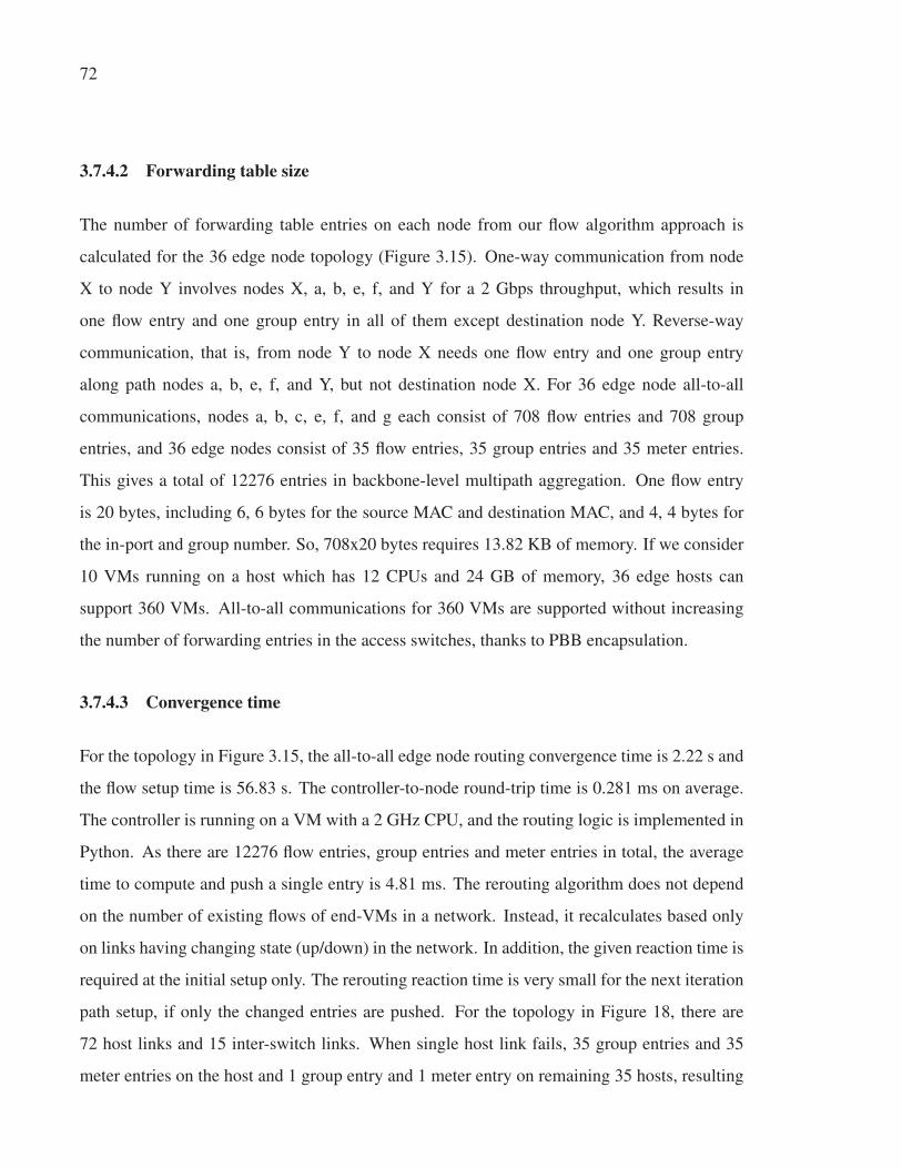
72
3.7.4.2 Forwarding table size
The number of forwarding table entries on each node from our flow algorithm approach is
calculated for the 36 edge node topology (Figure 3.15). One-way communication from node
X to node Y involves nodes X, a, b, e, f, and Y for a 2 Gbps throughput, which results in
one flow entry and one group entry in all of them except destination node Y. Reverse-way
communication, that is, from node Y to node X needs one flow entry and one group entry
along path nodes a, b, e, f, and Y, but not destination node X. For 36 edge node all-to-all
communications, nodes a, b, c, e, f, and g each consist of 708 flow entries and 708 group
entries, and 36 edge nodes consist of 35 flow entries, 35 group entries and 35 meter entries.
This gives a total of 12276 entries in backbone-level multipath aggregation. One flow entry
is 20 bytes, including 6, 6 bytes for the source MAC and destination MAC, and 4, 4 bytes for
the in-port and group number. So, 708x20 bytes requires 13.82 KB of memory. If we consider
10 VMs running on a host which has 12 CPUs and 24 GB of memory, 36 edge hosts can
support 360 VMs. All-to-all communications for 360 VMs are supported without increasing
the number of forwarding entries in the access switches, thanks to PBB encapsulation.
3.7.4.3 Convergence time
For the topology in Figure 3.15, the all-to-all edge node routing convergence time is 2.22 s and
the flow setup time is 56.83 s. The controller-to-node round-trip time is 0.281 ms on average.
The controller is running on a VM with a 2 GHz CPU, and the routing logic is implemented in
Python. As there are 12276 flow entries, group entries and meter entries in total, the average
time to compute and push a single entry is 4.81 ms. The rerouting algorithm does not depend
on the number of existing flows of end-VMs in a network. Instead, it recalculates based only
on links having changing state (up/down) in the network. In addition, the given reaction time is
required at the initial setup only. The rerouting reaction time is very small for the next iteration
path setup, if only the changed entries are pushed. For the topology in Figure 18, there are
72 host links and 15 inter-switch links. When single host link fails, 35 group entries and 35
meter entries on the host and 1 group entry and 1 meter entry on remaining 35 hosts, resulting

73
140 entries in total, are required to be modified. Routing convergence time 2.22 s and the
flow setup time for 140 entries, 0.64 s, constitutes only 2.86 s in total. For multiple host links
failure, the routing reaction time is approximately 2.22+ 0.64x f ailed_host_links. Similarly
when inter-switch link (e.g. (a, b)) fails, 12 host nodes (X) to 12 host nodes (Y) are affected
and required change of 10 entries per two-way communication gives 1440 affected entries.
Routing convergence time 2.22 s and the flow setup time for 1440 entries constitutes 8.88 s in
total.
3.8 Conclusion
In this paper, we have presented an adaptive multipath routing architecture which computes
and defines multiple paths (including intersecting and nonequal paths) in L2 networks. The
proposed solution is adaptive to link and path failures, and sets up all-to-all edge node for-
warding paths proactively, providing available aggregated throughput between all pairs of edge
nodes for any network state. Edge nodes reactively set up temporary PBB encapsulation flows
and enable in-network multipath mapping to a high number of flows. Aggregated bandwidth is
achieved per flow by using multiple paths simultaneously. To avoid the out-of-order delivery
issue in using multiple paths, weighted probabilistic selection with caching is used instead of
weighted round robin and per-packet link selection. We show full bisection bandwidth utiliza-
tion in bisection flows for a topology with 36 host nodes. With multiple OpenFlow domains
and location-based (MAC prefix) host node addressing, the solution can be scalable to a large
topology.
Our solution increases the network utilization of data centers, for example, the worst bisection
bandwidth utilization is 14% higher than with MPTCP with 5 subflows. In future, we would
like to integrate our work with OpenStack for virtual-to-physical network mapping and VM
address management on virtual machine migration. We would also like to expose northbound
functions, for example max-flow capacity, and integrate them with virtual network bandwidth
management solutions.

74
3.9 Acknowledgments
The authors thank Ericsson, the NSERC, and MITACS for supporting the Green Sustainable
Telco Cloud (GSTC) project.

CHAPTER 4
SDN-BASED FAULT-TOLERANT ON-DEMAND AND IN-ADVANCE BANDWIDTHRESERVATION IN DATA CENTER INTERCONNECTS
Tara Nath Subedi1, Kim Khoa Nguyen1, Mohamed Cheriet1
1 Génie de la production automatisée, École de Technologie Supérieure,
1100 Notre-Dame Ouest, Montréal, Québec, Canada H3C 1K3
Article published at the journal « International Journal of Communication Systems », Volume
31, Issue 4, 2018, DOI: 10.1002/dac.3479
Abstract
Geographically distributed data centers are inter-connected through provisioned dedicated WAN-
links, realized by circuit/wavelength-switching that support large-scale data transfer between
data centers. These dedicated WAN-links are typically shared by multiple services through
on-demand and in-advance resource reservations, resulting in varying bandwidth availability
in future time periods. Such an inter data center network provides a dynamic and virtual-
ized environment when augmented with cloud infrastructure supporting end-host migration. In
such an environment, dynamically provisioned network resources are recognized as extremely
useful capabilities for many types of network services. However, the existing approaches to
in-advance reservation services provide limited reservation capabilities, e.g. limited connec-
tions over links returned by the traceroute over traditional IP-based networks. Moreover, most
existing approaches do not address fault tolerance in the event of node or link failures and do
not handle end-host migrations; thus, they do not provide a reliability guarantee for in-advance
reservation frameworks. In this paper, we propose using multiple paths to increase bandwidth
utilization in the WAN-links between data centers when a single path does not provide the
requested bandwidth. Emulation-based evaluations of the proposed path computation show a
higher reservation acceptance rate compared to state-of-art reservation frameworks, and such
computed paths can be configured with a limited number of static forwarding rules on switches.

76
Our prototype provides the RESTful web service interface for link-fail and end-host migration
event management and re-routes paths for all the affected reservations.
Keywords
on-demand; in-advance; reservation; SDN; inter-DC WAN
4.1 Introduction
Many large-scale scientific and commercial applications produce large amounts of data, in the
order of terabytes to petabytes. When data providers and consumers are geographically dis-
tributed, the data must be transferred across wide-area network (WAN) links of high capacity.
The WAN-links between the data centers (DC) carry aggregated data traffic originating from
within the co-located data producers. Applications send as much traffic as they want and when-
ever they want to, regardless of the current state of the network or other applications, which
leads to networks swinging between over and under-subscription. The result of this is poor
efficiency in WAN-links as the amount of traffic the WAN-link carries tends to be low (30-
40%) compared to capacity. Figure 4.1 shows an inter-DC topology for 5 DCs, each of DC
has: i) two connected WAN-facing core nodes (e.g. a, e); ii) end-hosts connected to the edge
nodes through intra-DC connection; and iii) 12 edge nodes (e.g. X1-X12) connected to both
core nodes that split traffic from the end-hosts over the core nodes. 5 DCs are inter-connected
across their 10 WAN-facing core nodes. The connections between the WAN-facing core
nodes are Layer 2 (L2) logical links, which could be realized across multiple transit IP and
Multiple Protocol Label Switching (MPLS) routers or realized by underneath transport Layer
1 (L1)/Layer 0 (L0) (i.e. Optical Transport Network (OTN) / dense wavelength-division mul-
tiplexing (DWDM)); for example, the core nodes Ethernet ports are connected to OTN cards
and then transponder on DWDM transport. The end-hosts connected to the edge nodes can
be virtual machines (VM) in a cloud infrastructure, which allows seamless migration of VMs
and geographically distributed VMs to be part of the same cloud. The main challenge of the
bandwidth reservation system is to maximize network utilization in such a dynamic virtualized

77
Figure 4.1 DC level WAN topology and closer look at physical
connectivity for a pair of DC
environment and to ensure fault tolerance to address multiple node-and-link failures. In this
paper, the distributed DCs are considered to be a single provider’s domain. In this paper, the
distributed DCs are considered to be a single provider’s domain. The main type of fault con-
sidered in such network is node and/or link failure. It happens when a physical element (e.g.,
network device, card, port, or cable link) is down, or there is critical congestion in the physical
element. It is a common fault in all types of networks, and the most important cause of network
instability.
In the emerging software defined networking (SDN) architecture, the network control plane
is decoupled from the forwarding plane and is directly programmable (onf, 2016). The key
component of SDN architecture is the controller, which provides northbound application pro-
gramming interfaces (APIs) to applications and tracks all application requests. The controller
maintains a model of the network topology and traffic loads and uses this to compute paths.
SDN is a natural way to implement bandwidth reservations, and it makes paths available to the
application when needed.

78
The main motivations of this paper are as follows.
• The current reservation approaches/frameworks have a low acceptance rate of reservation
requests even in the presence of available bandwidth, especially due to the limited number
of forwarding rule supports in switches. The number of per-flow paths is too large to be
handled by the switches.
• The majority of reservation approaches/frameworks have not addressed service operation
concerns such as fault tolerance in the event of node or link failures and end-host migration.
Thus, they do not provide reliability guarantee. The reservation system has to persist in
reservation state information in such a way that the lookup would be efficient. Moreover,
cloud platforms (e.g. OpenStack) live migrate end-hosts; in this case, the migration needs
to be followed by path re-routing on the affected reservations.
• Moreover, many existing applications do not comply with the reservation system. They
do not have a priori knowledge of required bandwidth and/or they do not tolerate addi-
tional latency of bandwidth requests for short-lived traffic. Hence, the network needs to
operate with both types of applications: conforming and non-conforming to the bandwidth
request standards of the reservation system. This imposes a big challenge, since the reserva-
tion system cannot monitor all traffic demands accurately, and basing bandwidth decisions
on instantaneous link utilizations has proven to be unreliable (Khanna and Zinky, 1989).
Meanwhile, the bandwidth reservation system needs to confirm that the conforming appli-
cations’ needed bandwidth will not be taken away when a higher priority application starts
up in the middle of the application session. The system also needs to take into account that
applications may not consume all the requested bandwidth all the time.
This paper addresses the aforementioned issues by innovating bandwidth reservation system
(SFBR) for both on-demand and in-advance scheduling. The main contribution of this paper is
a new multipath reservation framework that increases the acceptance rate of reservations while
using a small number of forwarding rules. This is achieved by:

79
• a new ECMP-like multiple paths computation,
• an efficient scheme of path forwarding rules,
• an efficient lookup and rerouting for link/path fault tolerance during the time slot of reser-
vations,
• supporting both reservation and best-effort traffic.
This paper is organized as follows. In Section 4.2, we present related work on the bandwidth
reservation. Section 4.3 describes the problems. In Section 4.4, topology, time and reservation
models are presented. Section 4.5 proposes solutions for multipath computation, multipath
forwarding provisioning and link/path fault tolerance, and then defines SFBR architecture for
on-demand and in-advance reservations. In Section 4.6, we evaluate our proposed model, in
terms of acceptance rates, forwarding rules scalability, link failure and migration handling,
affected reservation lookup efficiency, and best-effort and reservation flow presence. Finally,
we conclude the paper and point to future work.
4.2 Related work
Bandwidth reservation refers to the ability to schedule the bandwidth that an activity is go-
ing to require. It gives software control to applications to add, remove or resize bandwidth
dynamically as demand changes. Applications use API to request a bandwidth controller to
allocate and/or deallocate a certain amount of bandwidth, either at a future time or immedi-
ately (Nadeau and Gray, 2013). The activation timing of bandwidth requests results in two
types of services: (a) in-advance (i.e. future) scheduling: bandwidth allocation and dealloca-
tion are scheduled in-advance for future time windows, i.e. requested start time to end time, as
asked by single in-advance request; and (b) on-demand, i.e. immediate, scheduling: bandwidth
allocation starts immediately upon receiving an (on-demand) allocation request by assuming
the deadline (end time) to deallocate bandwidth be infinity, and also bandwidth deallocation
starts immediately upon receiving a separate (on-demand) deallocation request at some future

80
time. In the presence of the in-advance scheduling requirement, even an on-demand sched-
uler needs a time-varying bandwidth representation of the link, but otherwise only the link’s
residue bandwidth at the present time. After receiving the request, the controller performs two
fundamental processes: (a) resource scheduling, which computes a multi-constrained path that
satisfies the requirements on the basis of resource availability and existing reservations and
reserves the path; and (b) path routing, which sets up the path to support (route) applications
traffic.
4.2.1 Bandwidth reservation architectures
Integrated Services (IntServ) / Resource Reservation Protocol (RSVP), Differentiated Services
(DiffServ), MPLS and Constraint-based routing (Pana and Put, 2013) are some of the fun-
damental Quality of Service (QoS) architectures. On the Internet, IntServ (Pana and Put,
2013) and DiffServ (Pana and Put, 2013) are designed, respectively, to provide bandwidth
guarantee and service differentiation along the existing route set up by an underlying rout-
ing protocol. MPLS-TE (MPLS with traffic engineering (TE) extensions) is Constraint Based
Routing (CBR), which enables multiple paths between a specific source/destination pair in
a network. At the head end router, CBR calculates explicit paths as ordered set of hops
(next-hop IP addresses of routers) and associates labels to them, which are then propagated
to other routers in the explicit path by using signaling protocol RSVP-TE (RSVP with TE
extensions (Pana and Put, 2013; Awduche et al., 2001)). These fundamental architectures
(MPLS (Sharafat et al., 2011) at IP Layer 3 (L3) and Generalized MPLS (GMPLS) (Azodol-
molky et al., 2011b) at L0, L1 and L2) support only on-demand but not in-advance reservations.
Various in-advance reservation frameworks have been proposed, such as DRAC (Travostino
et al., 2005), DRAGON (Lehman et al., 2006), G-Lambda (Takefusa et al., 2006), OSCARS (Guok
et al., 2006) and AutoBHAN (Lukasik et al., 2008; Bouras et al., 2013), which provision cir-
cuits and virtual circuits (VCs) at different network layers (data-planes). These frameworks ex-
cept OSCARS reserve and set-up L0 and L1 circuits over circuit-switched such as wavelength-
switched and OTN-switched networks. In (Zhao et al., 2016), Zhao et al. demonstrate in-

81
advance L1 circuits provisioning with support of extended OpenFlow (ope, 2016a) protocol.
These provisioned L0/L1 circuits provides WAN-link/topology to IP/MPLS routers, forming
packet-switched L3 overlay network. OSCARS provisions VCs i.e. MPLS label switched
paths (LSPs) over such packet network, which gives last-mile end-to-end reservation. Similar
as OSCARS, SFBR addresses end-to-end reservation on packet network. In (Xu et al., 2017),
Xu et al. present energy efficient flow scheduling for deadline-constrained flows on homoge-
neous DC networks but with exclusive routing i.e. reserving links for one flow exclusively by
assuming a flow can consume whole link bandwidth. While advance reservation is supported
by OSCARS, its underlying path computation limits connections over links returned by tracer-
oute; thus, it does not explore all available bandwidths inside the network. In OSCARS, for
each new reservation request, the available bandwidth of each link is checked by querying all
outstanding reservations on the link during the time slot of the reservation request from the
database.
Moreover, in-advance reservation frameworks like DRAC (Travostino et al., 2005), DRAGON
(Lehman et al., 2006), G-Lambda (Takefusa et al., 2006), OSCARS (Guok et al., 2006) and
AutoBHAN (Lukasik et al., 2008) are not fault tolerant to link failures of scheduled reserva-
tions. DynamicKL (Lim and Lee, 2013) reserves a backup VC in secondary links in addition
to a primary VC in primary links to support protection management of the primary VC to the
backup VC in the event of the primary link failure. However, bandwidth reservation in the
secondary links decreases the acceptance rate of new reservations since bandwidth has been
over-reserved.
4.2.2 Algorithms for bandwidth reservation
Different algorithms for in-advance scheduling are described in (Lin and Wu, 2013; Dharam
et al., 2014; Sahni et al., 2007). In (Lin and Wu, 2013), Lin et al. considered an exhaustive
combination of different path and bandwidth constraints and formulated four types of advance
bandwidth scheduling problems, with the objective to minimize the data transfer end time for
a given transfer request with a pre-specified data size. In (Dharam et al., 2014), Dharam et al.

82
considered deadline-constrained in-advance scheduling with the objective of finding a path to
transfer data of a given size before a specified deadline by accounting estimated in-progress
on-demand reservations in future time with a statistical scheme; such on-demand reservations
might otherwise be interrupted or preempted by newly activated in-advance reservation. In
our SFBR, in-advance scheduling does not neglect on-demand reservations in progress at all.
In (Sahni et al., 2007), Sahni et al. described four basic scheduling problems with different con-
straints on target bandwidth and time-slots, i.e., specified bandwidth in a specified time-slot,
highest available bandwidth in a specified time-slot, earliest available time with a specified
bandwidth and duration, and all available time-slots with a specified bandwidth and duration.
For specified bandwidth in a fixed time-slot, Extended Breadth First Search (Sahni et al., 2007)
path computation computes a single feasible path with O(V + L) search complexity, where V is
the number of vertices in the network and L is the sum of the lengths of the TB lists. In (Jung
et al., 2008), the authors evaluate different algorithms for in-advance scheduling and indicate
that for the fixed-slot problem, the minimum-hop feasible path algorithm proposed in (Sahni
et al., 2007) maximizes network utilization for large networks. In (Dharam et al., 2015), the
authors compute a randomized single feasible path (by employing random link weights) for
fixed-slot problem to increase the overall reservation success ratio, but in the context of link-
state inaccuracy between multiple controllers. In this paper, we consider a specified bandwidth
in a fixed time slot and propose an ECMP-like equal-cost path algorithm that maximizes net-
work utilization.
Key issue with these algorithms and architectures is that they do not consider the limited num-
ber of forwarding rules support of packet switches, with which computed paths need to be set
up. SWAN (Hong et al., 2013) uses dynamic tunnels, in which forwarding rules are added and
deleted dynamically; thus fewer forwarding rules are required in comparison to static k-paths.
Not to disrupt traffic, the make-and-break approach in SWAN adds new rules before deleting
existing rules, which requires extra rule capacity to be kept vacant to accommodate the new
rules. SWAN (Hong et al., 2013) sets aside 10% rule capacity and uses a multi-stage approach
to change the set of rules in the network. Our approach uses fewer forwarding entries for tunnel

83
paths with the help of a static tunnel identifier that maps per path; as a result, all tunnels can
be pre-configured. As a static tunnel never changes path, modifying a single rule that labels a
flow to a new tunnel just on the ingress edge is sufficient to direct the flow onto a new path.
The make-and-break of a tunnel path no longer required, nor is extra vacant space on any of
the switches on the network.
Different co-existing traffics are treated with priority queuing to provide bandwidth guarantees
and service differentiation (Ballani et al., 2011; Guo et al., 2010b). In (Ballani et al., 2011),
the authors propose a tenant allocation algorithm with bandwidth guarantees and service dif-
ferentiation by using two-level priorities. SecondNet (Guo et al., 2010b) focuses on the Virtual
Data Center (VDC) allocation algorithm (similar to virtual networking embedding) and opti-
mizes the number of VDCs according to the current available link bandwidth. SFBR uses such
two-level priority queuing to support both reservation and best-effort flows.
4.3 Problem description
We represent the network as a directed graph G = (V, E) with node set V and edge set E,
where each link l ∈ E maintains a list of residual bandwidths specified as a piecewise constant
function of time. In terms of data structure, a link is associated with a list consisting of time-
bandwidth (TB) pairs (t1, b1), ..., (tk, bk) in ascending order of time, i.e. t1 < .. < tk. The pair
(ti, bi) is interpreted as f (ti ≤ t < ti+1) = bi to mean that link l has bandwidth bi available from
time ti to time ti+1 (tk+1 = ∞). The actual scheduling or reservation of the found path requires
us to update the TB lists for the links on the path as well as to signal nodes on the path at the
reservation time.
The first problem (P1) is formulated as follows: given source s ∈ V and destination d ∈ V ,
compute paths for a reservation (resv) from s to d with specified bandwidth β in aggregation
in a specified time slot [ts, te), where ts < te. This has two sub-problems:

84
• The first sub-problem (P1-1) is to determine the available bandwidth ‘aTB’ of a link in
a specified time slot [ts, te). aT B = ∧te−εt=ts f (t), where ε → 0 and ∧ is the minimum of
piecewise constant function f (ti ≤ t < ti+1) = bi in the range of time [ts,te).
• The second sub-problem (P1-2) is to compute a set of paths {γ1, ..,γn} from s to d resulting
in a total path bandwidth β , i.e. ∑ni=1 βγi = β , where βγi is the path bandwidth of the ith
(where i = 1, .., n ) path. The path is a sequence of edges that connect a sequence of vertices
from s to d. We are considering reservations on multiple paths of equal costs. This will
increase the acceptance rate of reservation requests and increase network utilization.
The second problem (P2) is to compute such paths for P1 respecting rule space constraint. In
other words, it is to route reservation flows along computed paths with limited number of for-
warding rules on an individual switch. Forwarding rules set up computed paths of reservations.
Fully using network capacity requires many forwarding rules at switches to exploit many alter-
native paths through the network, but commodity switches can support only a limited number
of forwarding rules. Let Mu be the maximum number of forwarding rules that can be installed
at switch u ∈ V . Let rresvuv be the number of new rules added on switch u ∈ V to route a reser-
vation flow (resv) on the outgoing link (u,v) ∈ E along reserved paths. Ru is the total number
of rules that are installed at switch u ∈V and given by ∑v∈V rresvuv . The rule space constraint is
Ru ≤ Mu, where commodity switch has lower Mu.
The third problem (P3) is to enumerate the affected reservations on failed links in a minimal
lookup time. Any links along the reservation path can fail immediately on path setup time or
during any time slots of reservations. In the event of node or link failures, it is important to
discover which reservations are affected on failed links so that paths can be recalculated and
set up to those affected reservations to provide fault tolerance to link failures. Moreover, in
different circumstances a cloud platform (e.g. OpenStack) live migrates the end-host; in such
a case, migration needs to be followed by path re-routing on those reservations whose source
or destination endpoints contain the migrated endpoint.

85
Figure 4.2 shows the high-level framework with execution and data flows among modules.
The PathCompute module acts upon reservation requests and computes paths with data from
‘aTB’, and then the scheduler schedules for path setup and tear. The ‘ReRoute’ module acts
upon failed links and migration events. The database models are presented in Section 4.4, and
solutions of problems P1, P2 and P3 are presented in Sections 4.5.1, 4.5.2 and 4.5.3 respec-
tively. Section 4.5.4 binds all solutions in a SFBR architecture.
Figure 4.2 High-level framework
4.4 Topology, time and reservation models
Topology, time and reservation models are required for solutions to the problems described.

86
4.4.1 Topology model
Topology information is retrieved from the OpenFlow Controllers and Topology database is
maintained in a database as key-value pairs, as shown in Table 4.1. Figure 4.3 is a visual repre-
sentation of such a model. The ‘NEs’ key stores the set of vertices (forwarding nodes/switches)
that are represented by their datapath identifier as ‘dpid’. The edge forwarding node, which
Table 4.1 Topology DB model
key value
NEs {{dpid:A}, {dpid:B, local:{extPort:,
mac:, ip:, intPort:}} }
end-hosts {{end-host:{mac:.., ip:..}, attachedto:
{NE:B, ePort:3}}, .. }
edge:A:B:1 {cost:, mBW:100 }
edge:B:A:2 {cost:, mBW:100 }
Figure 4.3 An illustration of topology DB Model
is a combination of customer facing (internal) and WAN facing (external) nodes, stores more
properties: i) ‘intPort’: tunnel port on internal node; ii) ‘extPort’: port on external node that
links to ‘intPort’; and iii) IP and MAC addresses of the IP endpoint connected to ‘extPort’.
Internal and external edge nodes are controlled by separate OpenFlow Controllers but use the

87
same datapath-id (‘dpid’), which helps SFBR to map them into a single edge node. The ‘end-
hosts’ key stores the set of end-hosts that are represented by their MAC and IP addresses along
with the attachment port to the switch. The set of edges is represented as edge:v1:v2:ePort key
per edge. Each link between switch nodes is represented as two directed edges: outgoing and
incoming, each with the properties egress port (ePort), link capacity (mBW) and cost. The
‘cost’ is an abstract quantity attached to an edge that typically represents the edge’s latency.
4.4.2 Time model
We represent the time-bandwidth list (of time (ti) and residue (bi) tuple) in ascending order
of time as ‘TB’ property per edge key in the database, as shown in Table 4.2. As the TB list
is maintained for each outgoing link of switches, it represents a different residue for outgoing
and incoming on a bi-directional link. The table shows an outgoing link’s residue in different
time-slots as the result of multiple reservations. The TB list representation in Table 4.2 shows
100 (A switch’s ePort 1’s mBW), 40, 20 and 80 residual bandwidths for four time intervals
t < t1, t1 ≤ t < t2, t2 ≤ t < t3 and t3 ≤ t, respectively, as shown in the Figure 4.4.
Table 4.2 TB list mapping per outgoing link of
switches
key value
edge:A:B:1 {.., TB:[(t1,40), (t2,20), (t3,80)] }
edge:B:A:2 {.., TB:[(ti, bi),...] }
4.4.3 Reservation model
We represent the reservation request and mapping with path/tunnel(s) and bandwidth (βγ ) in a
database as key-value pairs as shown in Table 4.3. Figure 4.5 presents a visual representation
of such a model.

88
Figure 4.4 An illustration of TB list of an outgoing link
A reservation’s request parameters reservation-identifier (resvID), forwarding equivalent class
(FEC) as a list of service termination points (STPs), and provisioning parameters — requested
bandwidth (β ), start time (ts) and end time (te) — are represented as key-value pairs in the
database. Each STP is modeled as {source (sep): end-point , destination (dep): end-point}; and
each end-point is modeled as {‘mac’, ‘ip’, ‘proto’, ‘port’} as source or destination endpoint.
Thus, each STP is described by ‘n-tuple’ flow spaces (e.g. MAC address, IP address, protocol
IDs, TCP/UDP ports) that uniquely identify a flow and differentiate reservation traffic from
other traffic. With multiple STPs for a single reservation, multiple communication endpoints
attached to the same ingress and egress nodes can be treated as a forwarding equivalent class
(FEC).
Table 4.3 Reservation and tunnels mappings
key value
DC-Paths:DCPairID:X:Y [{p, path:[..]},..]
E2E-ECGroups:DCPairID:s:d [{eGi, path-cost, buckets:[{Ti,βγ},..]},..]
reservation: {FEC:[{sep:{}, dep:{}}], β :30 Mbps, ts, te,
resvID resType, tunnel:{DCPairID, Ti, βγ} or tunnels
:{DCPairID, eGi, [{Ti,βγ},..]}}
E2E-activeResvs:(intra-)DC-edge [resvID,...]
DC-activeResvs:DCPairID:p [resvID,...]
DC-activePaths:(inter-)DC-edge [DCPairID:p,...]

89
Figure 4.5 Reservation mapping with tunnels and bandwidth
A path computation module computes paths, and on it a path reservation module is called up
to reserve paths. Path setup cannot operate at the granularity of individual reservation flows.
Therefore, we label/color flows to tunnel(s) based on path(s) to be followed, and there is only
one fixed/static tunnel per path. SFBR implements tunnels by using VxLAN (MAC-in-UDP)
encapsulation. Tunnel forwarding rules never change to follow a different path. To change
path, the reservation flow is mapped to the tunnel of a new path. With static tunnels, on-
demand and in-advance reservation flows mapped to a tunnel or group of tunnels (in case of
ECMP-like paths) are always consistent in terms of reserved path(s) on any timeline. With

90
static tunnels, our tunnel assignment scheme gives scalable prefix match forwarding rules on
switches (Section 4.5.2.3).
As shown in Figure 4.5, DC-paths per DC-pair (with associated DCPairID identifier) list up
to 16 inter-DC paths (p=0...15). End-to-End paths for an s-d pair of edge nodes of the DC
pair are 4 times DC-paths and are indexed as tunnel-index (Ti: 0...63). E2E-ECGroups per
s-d pair of edge nodes of the DC pair are groups (equal-cost group index eGi) of equal-cost
paths/tunnels with associated bandwidth weights (βγ ) (of active reservations). A reservation
request is mapped to a tunnel (a path) (with DCPairID, Ti) or equal-cost tunnels (paths) (with
DCPairID, eGi and its individual constituents: Ti and βγ ). In this example (Figure 4.5), the path
computation module yields one path X1-a-b-Y1 for reservation request 1; and two paths, X1-a-
b-Y1 and X1-e-f-Y1 with βγ split 20 and 10 for reservation request 2. Path X1-a-b-Y1 belongs
to DCPairID:1 and has Ti:0. Two paths, X1-a-b-Y1 and X1-e-f-Y1, belong to DCPairID:1
and eGi:0, and have Ti:0 and Ti:35, respectively. Reservation flows are mapped onto a set of
tunnels; the selection of tunnel(s) is not based on hashing but preconfigured on the basis of
path-reservation.
When a reservation flow starts at ts, and ends at te, for the time duration, the reservation is
in the ‘active’ state. For edges along the intra-DC path, this active reservations (resvID) list
is maintained as the E2E-activeResvs:(intra-)DC-edge (undirected edge). For edges along the
inter-DC path, the active reservations (resvID) list is maintained by an associated inter-DC path
(p) as the DC-activeResvs:DCPairID:p key. The inter-DC path p (DCPairID : p) list is main-
tained by associated (undirected) edges along the inter-DC path as the DC-activePaths:(inter-
)DC-edge key. In Figure 4.5, the inter-DC paths 1:0 (DCPairID:p) and 1:8 are associated with
the (a, b) and (e, f) links along the X1-a-b-Y1 and X1-e-f-Y paths, respectively.

91
4.5 Proposed solutions
4.5.1 Determining the available bandwidth and path computation (Solution for ProblemP1)
This section presents solutions for sub-problems P1-1 and P1-2 of problem P1.
4.5.1.1 Determining the available bandwidth of a link (Solution for Problem P1-1)
The available time-bandwidth (‘aTB’) of a link on a given time-slot can be calculated as in
Algorithm 4.1. Line 1 assigns the edge’s ‘mBW’ and ‘TB’ list to ‘linkC’ and ‘TB_tuples’,
respectively. Line 2 returns linkC as ‘aTB’ if the TB list is empty or does not exist. Line 3
sequentially seeks the farthest tuple that has a time ≤ ts and assigns it to TBStart. This finds
the TBStart whose residue gives f(ts), i.e. f(ts) = TBStart.bi. Line 4 returns linkC as ‘aTB’ if
TBStart does not exist. Line 5 returns ‘aTB’ as the minimum bi of all tuples (tuple.bi) from
TBStart to the farthest tuple that has a time < te. The last tuple’s residue gives f(te − ε), i.e.
f(te − ε) = tuple.bi. Thus the returned ‘aTB’ is such that aT B = ∧te−εt=ts f (t). The complexity of
Algorithm 4.1 is O( l ), where l is length of the TB list on the link.
Algorithm 4.1 aTB(edge, ts, te) : available Time-Bandwidth
1: linkC ← edge.mBW; TB_tuples ← edge.TB
2: if (TB_tuples = /0) return aTB ← linkC
3: TBStart ← farthest tuple satisfying tuple.ti ≤ ts4: if (TBStart = /0) return aTB ← linkC
5: return aTB ← ∧te−εt=ts f (t) i.e. min tuple.bi along tuples(TBStart until
farthest tuple satisfying tuple.ti < te)

92
4.5.1.2 Path compute: ECMP-like multiple paths consideration (Solution for ProblemP1-2)
We are using an Equal-Cost Multi-Path (ECMP) (Moy, 1998)-like algorithm to compute paths.
The only difference is that the proposed algorithm does not compute only the shortest paths, but
also takes into account all the paths that are equal-cost. The cost of a path is the sum of costs
(latency) of its edges. In a packet network, packets that traverse different paths may reach the
receiver in a different order. In this case, the TCP retransmission mechanism, which is based
on the packet’s round-trip time (RTT), is triggered to recover from the loss. These packet
disordering or delay variation faults are important obstruction in multiple paths consideration.
In order to avoid a significant disparity in propagation delay between different paths and thus to
reduce the possibility of out-of-order packet delivery, multiple paths’ cost between two nodes is
limited in such a way that no path that is longer than the shortest path (among the selected paths)
by a fraction θ will be selected. In the case of ECMP, there are multiple (equal-cost) shortest
paths (θ = 0%) (Moy, 1998). There are other algorithms that relax the constraint of shortest
paths, e.g. k-paths that give the k paths of lowest cost, and θ = 25% is useful (Tam et al., 2011).
As we need to find equal-cost or closest-cost paths that fit the requested bandwidth requirement,
none of the ECMP and k-paths algorithms return the solution. For example, equal-cost shortest
paths may not have enough residual bandwidth, but there can be other (equal-cost but not
shortest) paths with sufficient residual bandwidth. We enumerate all simple (loopless) paths
that join s to d and group paths by equal path-cost (θ = 0%) in ascending order to find the
group whose multiple equal-cost paths fit the requested bandwidth. In this way, the selected
paths are not necessarily the shortest paths, as in ECMP, but they are equal-cost (θ = 0%) paths.
A number of algorithms are available to find multiple paths between two nodes, e.g. a modified
(do not search deeper than target node) depth-first search (Tam et al., 2011).
The PathCompute algorithm presented in Algorithm 4.2 computes multiple paths between edge
switches for a given time slot. The given input G is a directed graph of all core nodes and the
edges between them (excluding edge nodes), and s and d are ingress and egress edge switches
of the reservation request’s endhosts (seh.mac , deh.mac) that are sought as ‘attachedto.NE’ of

93
a matched ‘end-host’ set item of the ‘end-hosts’ key. This algorithm assumes the s and d are
on different DCs and β > 0. Line 1 adds s and d edge nodes and their edges to G, which forms
Algorithm 4.2 PathCompute(G, s, d, ts, te, β )
1: G.add(s, d edge nodes and their edges)
2: for each edge in G.E do3: G.edge.update(cost and aTB(edge, ts, te))
4: path γ1 ← bandwidth-constrained (aTB ≥ β ) shortest path first(CSPF)
(G, s, d, β )
5: if (path �= /0) return {path}, {β}
6: pathGroups ← all−simple−paths(G, s, d) grouped by path-cost in as-
cending order
7: for each pathGroup in pathGroups do8: aggBW ← 0; paths ← /0; weights ← /0
9: for each path γi in pathGroup do10: βγi ← min edge.aTB of each edge in path
11: βγi ← (aggBW + βγi > β ) ? β - aggBW
12: paths ∪ path ; weights ∪ βγi
13: edge.aTB ← edge.aTB - βγi ∀ edge ∈ path
14: aggBW ← aggBW + βγi
15: if( aggBW ≥ β ) return paths, weights
16: restore edge.aTB ∀ edge ∈ paths
17: return /0, /0
G of only s, d edge nodes and all core nodes. For each (directed) edge of G (Line 2), Line 3
computes the available time-bandwidth (aTB) and updates the edge of G with cost and aTB
properties. Line 4 calculates the bandwidth-constrained shortest path (γ1) from s to d through
edges that have aTB ≥ β . Line 5 returns the single path if it exists. If there is no single path
with the requested bandwidth capacity, Line 6 calculates all simple (loopless) paths from s
to d through edges that have aTB > 0, and it groups equal-cost paths in ascending order of
path-cost into pathGroups. Line 7 iterates over each equal-cost path group (pathGroup) in the
pathGroups to find those equal-cost paths and bandwidths whose aggregation would result in
the requested bandwidth β in following ways. Line 8 initializes aggBW, paths and weights
for multiple paths. Line 9 iterates over each path in the pathGroup. Then, Line 10 computes

94
the path capacity (βγi) of the available path. In Line 11, if the sum of the path capacity in
relation to aggregated bandwidth computed thus far gives more bandwidth than requested, the
path capacity is assigned as β - aggBW. Line 12 appends path and path-capacity on paths
and ‘weights’, respectively. Line 13 augments the edge’s aTB by subtracting path-capacity
along the path. Line 14 computes the aggregated bandwidth achieved so far. Line 15 returns
the paths and weights if the aggregated bandwidth is already equal to the requested bandwidth.
Otherwise, the algorithm continues until the next equal-cost path exists (Line 9). When no more
equal-cost paths exist in a pathGroup, Line 16 restores the previous edge.aTB augmentation,
and the algorithm continues to the next higher equal-cost paths (Line 7). Line 17 returns
an empty path if there is no solution up to this point. The complexity of the PathCompute
algorithm is O(L+V 2 +(V +E)), where L is the sum of the lengths of the TB lists, V is the
number of switches and E is total number of links. Using Dijkstra’s algorithm (Dijkstra, 1959)
to calculate CSPF on a modified graph by removing those links without enough bandwidth
(Line 4) contributes search complexity of O(V 2), and using a depth-first search to compute all
simple paths (Line 6) contributes to O(V+E).
End-hosts that are not present in the network at this moment may require future reservations,
and these end-hosts may show up at the reservation time. Such a provisioning feature will
allow a cloud platform, e.g. OpenStack, to request in-advance reservations on behalf of end-
hosts and to launch the end-hosts in ingress/egress nodes at a scheduled start time (ts). With
this, the end-hosts’ ports that are connected to ingress/egress nodes can be determined only
when they appear in the network. In such a scenario, a reservation request can include such
ingress and egress edge nodes along with the endhosts; then, the path computation module
computes paths for the ingress and egress edge nodes and paths are reserved and scheduled.
4.5.2 Path setup and scalable forwarding (Solution for Problem P2)
This section presents path setup of reservation and best-effort flows, and scalability on for-
warding rules.

95
4.5.2.1 Co-existence of reservation and best-effort traffic
We support both reservation and best-effort traffic, taking into account that applications do not
consume the entire reserved bandwidth. Improved mechanisms can utilize unused bandwidths
by taking into account the actual network usage with periodic measurements and allow a reser-
vation application to use other applications’ allocated bandwidths. Instead of measuring the
unused from the allocated bandwidths, we assign unused bandwidth only to best-effort appli-
cations. This is achieved by two priority queues, lower (default Queue:0) and higher (Queue:1),
which are configured in all ports of the edge and core switches in the network for two classes
of service: best-effort and reservation, respectively. The ingress edge switch tags packets with
differentiated service code point (DSCP) bits in the IP header to indicate the flow’s priority
class; and transit switches map DSCP bits to different priority queues. Reservation flows are
queued in the higher priority queue of output ports. Best-effort flows configured by the Open-
Flow Controller’s default algorithm use the default lower queue of output ports and will get
best-effort bandwidth, depending on the actual network usage of the reservation applications.
For example, we can set mBW ← 80 % of Cl (capacity of link l) as the maximum available
bandwidth for reservations to give at least 20% of Cl for best-effort flows; and the queuing
model can be strict priority (SP) on Q1 and Q0, in which packets on Q1 have a higher priority
than packets on Q0 whenever packets are on Q1. There is no starvation on Q1, as none of the
links (Q1 queue) will be reserved for more than 80% of Cl . Q0 will get 20 to 100% of Cl ,
depending on the actual network usage in Q1. This queuing mechanism helps the reservation
flow take back instantly its reserved but unused bandwidths. Different queuing models, such
as weighted fair queue (WFQ), for example, Q1: W ← 80 % of Cl; Q0: W ← 20 % of Cl , can
be applied, in which each queue gets a weighted amount of service in each cycle.
4.5.2.2 Path setup
Packet classification based on n-tuple (s, d, in-port, protocol (tcp/udp), port) per-flow state in
the network core never scales. To scale, a single label is assigned to multiple n-tuple flows at
the ingress node, as that label can be mapped to a path with a one flow entry in the core network

96
and those flows are also treated as the same forwarding equivalent class (FEC). The Controller
can create and delete label mappings of an FEC on edge nodes. Each FEC element identifies
a set of packets that may be mapped to a corresponding path by encapsulating the packets
with an outer IP header with a fixed source IP address and a per-tunnel (path) destination IP
address. The outer destination-IP address is a tunnel-ID (Tid) rather than an actual destination
and uniquely identifies the path/tunnel.
The path/tunnel(s) mapping data (as recorded in reservation:resvID key) is used to set up and
tear down the hardware paths at time ts and te, respectively. Procedures hwPathSetup and hw-
PathTear in the edge-network OpenFlow Controller set up and tear down action rules in the
following way. In the edge-network, each incoming packet maps to one of the tunnels
1: Meter rule: meterID, rate limiter of BW
2: eGi applicable: multi-path groupID(12×n×DCPairID+n×did +eGi): weight buck-
ets with actions:{capsule(Tid , DSCP), forward ( Queue:1, intPort)}
3: for each STP tuple do4: eGi applicable: Match:{ingress port of STP tuple, STP tuple} Actions:{meterID,
forward (groupID)}
5: eGi not applicable: Match:{ingress port of STP tuple, STP tuple} Ac-
tions:{meterID, capsule(Tid , DSCP), forward ( Queue:1, intPort) }
Figure 4.6 hwPathSetup/Tear Modeling (“internal” edge
Controller maps reservation flow to tunnel(s) on ingress internal
edge node)
or equal-cost groups of tunnels according to path-reservation, as depicted in Figure 4.6. The
packet classification, labeling/encapsulation and forwarding can be modeled as flow match ac-
tion entries on ingress “internal” edge nodes. The rate limiter is added to the switch (Line
1); in the case of multiple paths (equal-cost group of tunnels applicable), the multi-path group
table is added/updated with the set of tunnels and a weight assignment that reflects the ratio of
bandwidth split (Line 2). For each STP tuple of the reservation (Line 3), the packet classifica-
tion added uses the same rate limiter and is forwarded on the priority queue of the tunnel port

97
(intPort) of the switch (Line 4/5). The capsule (Tid , DSCP) pushes the label/tunnel-ID of a path
and priority onto the packets (Lines 2 and 5).
Egress “internal” edge nodes decapsulate and remove the label/Tunnel-ID from the ingress
packets (on intPort) and forward them to the priority queue of the egress port of the connected
endpoint destination.
4.5.2.3 Tunnel assignments for scalable forwarding
The core-network controller sets up tunnel paths forwarding on the ingress/egress “external”
edge nodes and core nodes. These switches on the core-network classify packets by ingress
port, SDC, and their label/tunnel-ID Tid and forward them to the priority queue (Queue:0 or
Queue:1 based on DSCP bits) of the egress port of the tunnel/path. Per-tunnel forwarding rules
are not scalable; and switch hardware supports a limited number of forwarding rules, which
makes it hard to use network capacity to the full. If we use k-paths between each pair of DCs,
fully using this network’s capacity requires k=16. If we use 8, 8 paths from each WAN-facing
core peer, it will result in 16 inter-DC paths. For example, core peer nodes a and e both have
8, 8 paths to remote DC Y. As the edge nodes have two uplinks to the core peers (e.g. (X1,
a) and (X1, e)), each core peer forwards the traffic either via another core peer or along the
WAN-facing path (a-e→DC Y or a→DC Y ). Remote DC’s core peers have two downlinks
to edge nodes ((b,Y1) and (b-f-Y1)), and each s-d pair of edge nodes gives 2×16×2 = 64
paths in total. Thus, 64 destination IPs as Tid are required per each destination edge node.
For 12 edge nodes per DC, 64×12 = 3×256 = 768 IP addresses are required as Tid per DC.
Each ingress edge node needs 768×4 = 3072 tunnel forwarding rules to communicate with 4
remote DCs, giving 3072×60 tunnels in total for 60 edge nodes. Assuming that one fourth of
the tunnels pass through each core node, 46K rules are needed at core nodes, which is beyond
the capabilities of recent SDN switches. The Broadcom Trident2 chipset supports only 16K
OpenFlow rules (tri).

98
To alleviate the above problem, we choose Tid in such a way that it gives scalability in the
forwarding rules as shown in Figure 4.7. Each destination DC is represented by its 22 bits IP
Figure 4.7 Tunnel assignments for scalable forwarding
prefix (dDC), and each destination edge node among its 12 edge nodes is represented by a did
(4 bits) number. Each of the two WAN-facing core nodes in a DC is identified by its peerID
number (a’s 0 and e’s 1). Each ingress edge node has two uplinks, each with a fixed ‘u’ label (0
or 1) denoting the peerID it connects to. We consider 16 possible inter-DC sub-paths, each of
which has a fixed label (p, 4 bits) per (sDC,dDC) pair. Each WAN-facing core node contributes
8 inter-DC sub-paths labeled as p=0xxx or p=1xxx based on its peerID (0 or 1). The destination
DC also has two downlinks for each egress edge node, with a fixed ‘d’ label (0 or 1) denoting
from which peerID it is connected. Arranging those labels of links and sub-paths along an
end-to-end path as dDC.p.ud.did , gives a final label (Tid) to the path. When e→f sub-path’s p is
assigned 1000 and Y1’s did is assigned 0001, a path/tunnel along X(1-12)-a-e→f-Y1 has Tid as
dDC.1000.01.0001. For DC pairs, Tid consists of the same p per inter-DC path, irrespective to
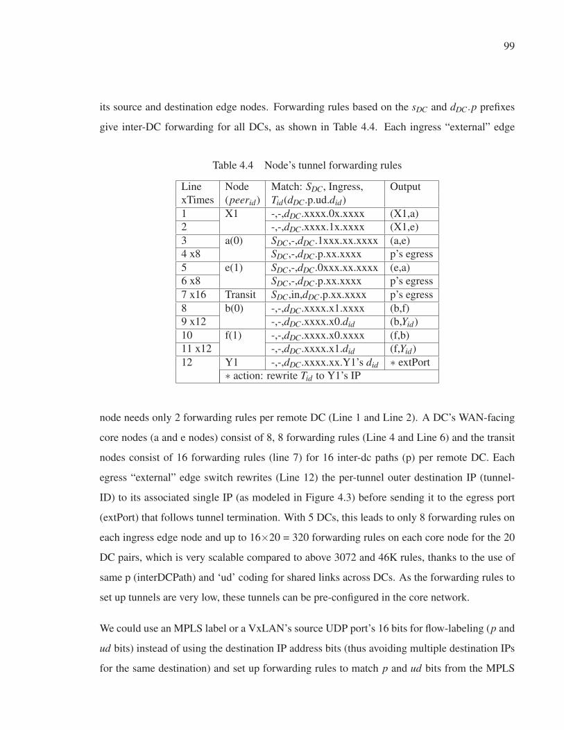
99
its source and destination edge nodes. Forwarding rules based on the sDC and dDC.p prefixes
give inter-DC forwarding for all DCs, as shown in Table 4.4. Each ingress “external” edge
Table 4.4 Node’s tunnel forwarding rules
Line Node Match: SDC, Ingress, Output
xTimes (peerid) Tid(dDC.p.ud.did)
1 X1 -,-,dDC.xxxx.0x.xxxx (X1,a)
2 -,-,dDC.xxxx.1x.xxxx (X1,e)
3 a(0) SDC,-,dDC.1xxx.xx.xxxx (a,e)
4 x8 SDC,-,dDC.p.xx.xxxx p’s egress
5 e(1) SDC,-,dDC.0xxx.xx.xxxx (e,a)
6 x8 SDC,-,dDC.p.xx.xxxx p’s egress
7 x16 Transit SDC,in,dDC.p.xx.xxxx p’s egress
8 b(0) -,-,dDC.xxxx.x1.xxxx (b,f)
9 x12 -,-,dDC.xxxx.x0.did (b,Yid)
10 f(1) -,-,dDC.xxxx.x0.xxxx (f,b)
11 x12 -,-,dDC.xxxx.x1.did (f,Yid)
12 Y1 -,-,dDC.xxxx.xx.Y1’s did ∗ extPort
∗ action: rewrite Tid to Y1’s IP
node needs only 2 forwarding rules per remote DC (Line 1 and Line 2). A DC’s WAN-facing
core nodes (a and e nodes) consist of 8, 8 forwarding rules (Line 4 and Line 6) and the transit
nodes consist of 16 forwarding rules (line 7) for 16 inter-dc paths (p) per remote DC. Each
egress “external” edge switch rewrites (Line 12) the per-tunnel outer destination IP (tunnel-
ID) to its associated single IP (as modeled in Figure 4.3) before sending it to the egress port
(extPort) that follows tunnel termination. With 5 DCs, this leads to only 8 forwarding rules on
each ingress edge node and up to 16×20 = 320 forwarding rules on each core node for the 20
DC pairs, which is very scalable compared to above 3072 and 46K rules, thanks to the use of
same p (interDCPath) and ‘ud’ coding for shared links across DCs. As the forwarding rules to
set up tunnels are very low, these tunnels can be pre-configured in the core network.
We could use an MPLS label or a VxLAN’s source UDP port’s 16 bits for flow-labeling (p and
ud bits) instead of using the destination IP address bits (thus avoiding multiple destination IPs
for the same destination) and set up forwarding rules to match p and ud bits from the MPLS

100
label or source UDP port. Forwarding rules based solely on an MPLS label lead to too many
pseudo-wires but combinations of Tid (dDC.did) and MPLS label (p.ud) scales.
4.5.3 Fault tolerances to (ReRoute on) link/path failures and end-host migrations (So-lution for Problem P3)
This section presents the solution for problem P3. To reroute traffic after link/path failure and
end-host migration, it is important to discover which reservations are affected on failed links
or migrated end-hosts. With path nodes mapping to every reservation, finding the affected
reservations on a failed link is less efficient, as every reservation needs to be checked as to
whether or not the failed link belongs to its path-nodes. With active reservations listed to the
inter-DC path label(s) (DCPairID:p, DC Pair ID: path index) and those inter-DC path labels
listed to the individual inter-DC link along each path, the search is more efficient. With this
method, we can search affected reservations on a failed inter-DC link just by seeking the inter-
dc path labels on the failed link (DC-activePaths:edge) and by tracing reservations to those path
labels (DC-activeResvs:DCPairID:p).
Topology link events can trigger on link up and link down. When link down events are trig-
gered, the downed links are queued in Q. In case of end-host migration, after successful mi-
gration, the SFBR system will be notified of a new edge node for the migrated end-host, which
will be queued as tuple (‘hMAC’,‘edgeNode’) in Q. The procedure ReRoute(Algorithm 4.3)
acts on Q as follows. Line 2 dequeues a failed link or migration mapping, if any, from Q. Line 3
assigns ‘nowTime’ as the current time, and Line 4 receives the affected reservations by calling
up the ‘linkFailAffect’ or ‘migrationAffect’ procedure, depending on the event. For each of
those reservations (Line 5), paths are re-computed (Line 6) and reserved (Line 7) for the entire
or remaining time period. In the case of an already started reservation (Line 8), Line 9 sets
up new paths on the physical infrastructure. Then, the ReRoute procedure acts upon the next
queued event.
The ‘linkFailAffect’ procedure (Algorithm 4.4) clears reservation states and returns affected
reservations for a given link. Line 1 assigns empty reservations, and Line 2 checks whether

101
Algorithm 4.3 ReRoute()
1: while True do2: (event, u, v) ← Q.dequeue
3: nowTime ← now
4: resvs ← (event is link-down) ? linkFailAffect(u, v, nowTime):
migrationAffect(hMAC←u, edgeNode←v, nowTime)
5: for resv in resvs do6: PathCompute(ingress of resv.FEC.sep, egress of resv.FEC.dep,
max(resv.ts, nowTime), resv.te, resv.β )
7: PathReserve(max(resv.ts, nowTime), resv.te) along path(s)
8: if resv.ts < nowTime then9: PathSetup(resv.resvID)
Algorithm 4.4 linkFailAffect(u, v, nowTime)
1: resvs ← [ ]
2: if � edge:u:v key then3: resvIDs ← E2E-activeResvs:u:v
4: interDCpaths ← DC-activePaths:u:v
5: for interDCpath in interDCpaths do6: DCPairID, p ← interDCpath.split(‘:’)
7: resvIDs ← resvIDs ∪ DC-activeResvs:DCPairID:p
8: for resvID in resvIDs do9: PathRelease(tu ← nowTime, tv ← resv.te) along path(s) of
resvID
10: resvs.append({resvID})
11: return resvs
the given (u, v) link is still down by searching database key edge:u:v. If the key does not
exist, i.e. the link is still down; the affected reservations are retrieved as follows. If the link
is an intra-DC edge, Line 3 finds affected reservations (resvID) by reading the database key
E2E-activeResvs:u:v. If the link belongs to inter-DC p paths, Line 4 finds affected (inter-DC)
paths by reading the database key DC-activePaths:u:v and Lines 5–7 find affected reservations
(resvID) in the database key DC-activeResvs:DCPairID:p. For each affected reservation (Line
8), Line 9 calls ‘PathRelease’ along the reservation’s path(s) to release the soft state path band-

102
width for the remaining time slot, and the reservation is appended to the list ‘resvs’ (Line 10),
which is returned by the algorithm (Line 11).
In the situation of migration, the ‘MigrationAffect’ procedure finds all reservations match-
ing its STP’s source or destination to the migrated end-host (resv.FEC.sep.mac=hMAC or
resv.FEC.dep.mac=hMAC) and for each reservation calls ‘PathRelease’ along the reservation’s
path(s) to release the soft state path bandwidth for the entire or remaining time slot [max(resv.ts,
nowTime), resv.te] and updates the end-host attachment by changing the ‘attachedto.NE’ (of
hosts key) in the database.
4.5.4 SDN-based fault-tolerant bandwidth reservation (SFBR) architecture
The SFBR architecture combines all the solutions given above and creates a service for dy-
namic bandwidth reservation. Figure 4.8 shows different modules of the SFBR architecture.
Client applications create (on-demand and in-advance), read, update and delete reservations
through Representational State Transfer (REST) web services provided by the SFBR Con-
troller. Read requests are executed directly. Create, update and delete requests are queued in
a message queue (MQ), from which a worker module dequeues and executes the request and
schedules the path setup and teardown. At a given scheduled time, the scheduler triggers the
path setup and teardown. A ReRoute module listens for link failure and migration events and
re-routes the traffic of active reservations on the failed links or migrated end-hosts.
Figure 4.9 depicts the workflow of on-demand and in-advance reservations. For on-demand
reservations, the time interval is modeled as ts ←now and te ←never for bandwidth allocations.
When a reservation is requested, the procedure Resv performs three actions. First, it com-
putes the available paths for the requested bandwidth (β ) within the given start time (ts) and
end time (te) by calling up the PathCompute procedure (Section 4.5.1.2). Secondly it calls up
the PathReserve procedure, which performs two actions. First, it reserves an individual path
bandwidth (βγi) for the given time interval on each link along the paths (decreases residue band-
width for the time slot [ts, te) and removes stale (past, t < now) tuples of ‘TB’ on the database

103
Figure 4.8 SFBR Architecture
Figure 4.9 On-demand and In-advance Reservations workflow
key edge:link, see Table 4.2). Secondly, it tracks the reservation along with tunnels and path
bandwidth in the database, as shown in Figure 4.5. Finally, Resv calls up the SetupTearSched-
ule procedure that i) in case of on-demand reservation, calls PathSetup to set up the intended

104
paths immediately; or ii) in case of in-advance reservation, schedules two jobs: resvID-setup at
ts time and resvID-tear at te time. Jobs resvID-setup and resvID-tear call up PathSetupFuture
and Tear, respectively, with only the resvID as the parameter.
For link/path fault tolerance, the procedure PathSetupFuture checks whether or not the reserva-
tion paths are still valid. If the reservation paths are valid, the procedure PathSetup is called up.
Otherwise, the path bandwidth reservation is released, the paths recomputed and re-reserved,
and PathSetup is called up. The procedure PathSetup retrieves flow parameters (FEC) and
path/tunnel(s) data for any given resvID (by reading the reservation:resvID key) and in case
of multiple tunnels, augments tunnels’ bandwidth on E2E-ECGroups (see Table 4.3). Then,
PathSetup associates the active reservation to the links by updating E2E-activeResvs and DC-
activeResvs (see Table 4.3). Finally, PathSetup sets up the intended paths on the physical
infrastructure (hwPathSetup Section 4.5.2).
When the application asks for deletion of a reservation before time te, then job resvID-tear’s
activation can be done immediately. Otherwise, at time te, the procedure Tear is called up.
The procedure Tear reads reservation:resvID and releases the path bandwidth on the respective
links (increases residue bandwidth of ‘TB’ on the database key edge:link, see Table 4.2) for the
time interval [max (resv.ts, nowTime), resv.te] and merges two consecutive duplicate TB states
by removing the latter. In the case of multiple tunnels, it also releases the tunnels’ bandwidth
on E2E-ECGroups (see Table 4.3). Then, Tear disassociates the reservation from the links by
updating E2E-activeResvs and DC-activeResvs (see Table 4.3). Finally, the Tear procedure
tears down the tunnel mapping of reservation flow on the physical infrastructure and updates
the split ratio of multi-paths as necessary (hwPathTear Section 4.5.2).
4.6 Approach evaluation
The testbed network is created using open vSwitch (ope, 2016b) and virtual machines. The
core and edge networks consist of Open vSwitch switches, and virtual machines are attached
to “internal” edge switches. In the testbed network, each “external” edge switch node has two

105
uplinks; and each switch interconnection link has 100 Mbps capacity, but the ingress/egress
links of the “internal” edge switches have 200 Mbps capacity. With this configuration, a single
path can give a maximum throughput of 100 Mbps; but with multiple paths, end-hosts can
receive a maximum throughput of 200 Mbps. Three controllers are hosted on three separate
VMs. Two Opendaylight (ODL) Controllers (odl, 2016) are used as the SDN Controllers, one
as “internal” edge network controller and another as core network controller. The SFBR Con-
troller works on top of ODLs and uses Redis as key-value pair NoSQL database. Figure 4.10
presents the user interface of SFBR, showing its database containing all the switches, end-
hosts, reservations and E2E-ECGroups on the topology in Figure 4.1. In the example, the s, d
endpoints request a reservation of 150 Mbps for 1 hour with start time (ts) 2017-08-17 11:00:00
and end time (te) 2017-08-17 12:00:00, and the SFBR Controller provides the multiple paths
X1-a-b-Y1 and X1-e-f-Y1 of 100 and 50 Mbps respectively.
Figure 4.10 Topology and reservation visualization

106
Figure 4.11 presents the user interface showing links’ time-bandwidth representation on the
topology in Figure 4.1. The orange line shows current time, which is around 2017-08-17
10:45. There is no record of residue bandwidth until 11:00 time as no reservation had been
made before 11:00. So, residue bandwidth before 11:00 is the link capacity. At time 11:00,
residue bandwidth is 0 on three links (X1, a), (a, b) and (b, Y1); and 50 on three links (X1, e),
(e, f) and (f, Y1). At time 12:00, residue bandwidth rises to 100 on all links. There is no record
of residue bandwidth after 12:00 as no reservation is made for later time. The final residue
bandwidth, i.e. 100, is therefore the residue bandwidth for future time.
Figure 4.11 link’s time bandwidth visualization
4.6.1 Acceptance rates
We performed emulation-based evaluations to conduct a performance comparison with the
traceroute-based method, Sahni (Sahni et al., 2007) and our multi-path algorithm. In the emu-
lation, a network topology with 60 edge nodes (each DC has 12 edge nodes) and 10 core nodes

107
is considered, as shown in Figure 4.1. The TB list of each link is randomly generated with
residual bandwidths ranging from 0.2 Gbps to a link’s capacity (edge link: 1 Gbps; core link:
10 Gbps) in each time slot for a total of 600 slots with an identical length of 1 second each.
The residual bandwidth distribution of each link (Rl) follows N (μ,σ2) a normal distribution
of μ = (0.2+C)/2 and σ = (μ −0.2)/3 as:
Rl[i] = quantile(N (μ,σ2),Pa +(Pb −Pa)∗ x) (4.1)
where the quantile is the inverse of CDF N (μ,σ2) distribution; Pa and Pb are CDF N (μ,σ2)
distribution at 0.2 and link l’s capacity (C), respectively; and x is a random variable within the
range of [0,1].
Fixed-bandwidth reservation is a decision problem and the satisfiability of a fixed-bandwidth
request is determined by the availability of network resources. This problem is dealt in OS-
CARS by traceroute to find the shortest path within the ESnet that the MPLS LSP traverses,
and then each link on the path is checked for available bandwidth. The Sahni algorithm is able
to find a feasible solution when a single path with a specified bandwidth exists.
We generated a series of fixed-bandwidth requests with requested bandwidth (β ) ranging from
0.2 Gbps to 2 Gbps at an interval of 0.2 Gbps. Each request consisted of random edge switch
endpoints as source and destination from different DCs, and the duration of a request te − ts
was constrained within the range of [1, 10] s. We ran different algorithms on these fixed-
bandwidth requests and repeated the fixed-bandwidth requests and feasibility for 200 runs and
plotted a series of acceptance rates in response to different β values, as shown in Figure 4.12.
The acceptance rate was defined as the ratio of successfully scheduled requests over the total
200 submitted requests. We observed that PathCompute exhibits performance superior to the
traceroute-based method and the single bandwidth path method. Since requests with larger
β values require more network resources, the acceptance rate decreases as β increases. In
traceroute and Sahni, the acceptance rate is 0 for a request of β > 1 Gbps, as a single path can
fit a maximum of 1 Gbps bandwidth on this experimental network. However, the PathCompute

108
algorithm accepts requests of β > 1 Gbps, for it explores multiple paths. It shows our algorithm
explores all available bandwidths, including multiple paths inside the network.
Figure 4.12 Acceptance rates of PathCompute, Sahni and
traceroute for the fixed-bandwidth problem
4.6.2 Forwarding rules scalability
We performed emulation-based evaluations on the network topology (as shown in Figure 4.1)
to conduct a throughput versus forwarding rules size comparison with static k-shortest paths
method, dynamic tunnel method and our forwarding method. For given 2 Gbps up-links capac-
ity of the edge node, 400 numbers of ingress traffic (each of 0.005 Gbps bandwidth) per edge
node are possible, resulting in 24000 numbers of ingress traffic on the given 60 edge node
network. Therefore, in the emulation, we generated a series of 24000 on-demand requests;
each request consisted of random edge switch endpoints from different DCs as source and
destination and of 0.005 Gbps fixed-bandwidth. We ran different forwarding methods on these
requests in two scenarios: i) no links fail and ii) 4 ((a,b), (c,d), (b,d), (d,i)) links fail. We plotted
the achieved throughput with respect to switch rule size (Figure 4.13). With k-shortest paths

109
fixed forwarding, all edge-to-edge nodes among DCs have pre-configured k-shortest paths for-
warding rules. For each request when there is a bandwidth path among supported fixed paths,
the throughput of network increased by 0.005. With the dynamic tunnel forwarding method (as
used by SWAN (Hong et al., 2013)), for each request, the forwarding rule for computed band-
width path is added if the path/tunnel does not already exist. With our forwarding scheme, all
DC-to-DC p-paths (p is inter-dc paths: 16 and 8 with 4 and 3 bits use, respectively) forwarding
rules are pre-configured by computing p2 -shortest inter-dc paths (none of the WAN-facing-
nodes of ingress and egress DCs in path transit) from each of WAN-facing-node of ingress
DC to all the WAN-facing-nodes on the egress DC. The rest of the forwarding rules within
the ingress and egress DC nodes (Table 4.4) are also added. For each request when there
was bandwidth path following among p inter-dc paths, the throughput of network increased by
0.005.
As shown in Figure 4.13, with k-shortest paths fixed forwarding, the maximum throughput is
obtained with 2-shortest paths forwarding in case of no link failure, but 64-shortest paths for-
warding is required in case of 4 link failures; and the rule size required per switch increases
from 1.44K to 84K. With the dynamic tunnel method, to achieve the same throughput, 1.44K
and 3.4K rule sizes per switch are required in case of no link failure and 4 link failures, re-
spectively. With our forwarding scheme, the same throughput is achieved with just 0.082K
(with p=8) (0.18K with p=16) in both the no link failure and 4 link failures cases. Indeed, the
acceptance rate is increasing along with throughput. Our forwarding scheme achieves 96%
throughput with just 0.18K rules, whereas dynamic tunnel method and static 64-shortest paths
method need 3.4K and 84K rules respectively. With 0.18K rules, the dynamic tunnel method
gives only 3% throughput, and 1-shortest path method is not even supported (it requires at
least 1.29K rules). With 1.44K rules, dynamic tunnel method and k-shortest paths method give
70% and 75% throughput respectively. Our forwarding scheme outperforms both methods.
Moreover, since the tunnel is static, we do not need to set up the tunnel across path nodes dy-
namically, thus lowering the path setup latency and transient congestion caused by the dynamic
tunnel method as used by SWAN (Hong et al., 2013).

110
Figure 4.13 Our scalable forwarding needs fewer rules to fully
exploit network capacity
4.6.3 Link failure and migration handling
Figure 4.14 shows an end-host’s TCP sending rate of 100 Mbps reservation flow. At time 50 s,
the link fails. When SFBR is notified, ‘linkFailAffect’ finds the affected reservations in 0.02 s,
and ‘Re-Route’ re-calculates and adjusts the path to a different route. The interruption time due
to link failure is within only one second, which includes the time for setting up two paths for
two-way communication. This shows how well failure is handled compared to SecondNet (Guo
et al., 2010b) which requires four seconds. In addition, SecondNet does not explain database
model to represent number of reservations and associated paths, and method to get affected
reservations on failed link. Both SecondNet and SFBR keep core-switches stateless, but only
SFBR can use multiple simultaneous paths. With an in-advance reservation, if the reservation
is not active — the start time is still in the future — the link failure will not trigger a re-
calculation of paths. At the start time, SFBR checks whether or not the paths are valid. If the
link is still down, SFBR will re-calculate and set up new paths.

111
Figure 4.14 Failure handling
For end-host migration, paths for all affected reservations, either active or scheduled, will be
re-calculated. The end-host migration effect is similar to that shown in Figure 4.14, but the
migration event is triggered instead of a link down event.
4.6.4 Affected reservation lookup efficiency
In Section 4.6.3, ‘linkFailAffect’ finds the affected reservations in 0.02 s. In this subsec-
tion, we measure such lookup efficiency in presence of upto 10,000 reservations. For this,
10,000 reservations (reservation:resvID) are added to database and associated to correspond-
ing inter-dc path (DC-activeResvs:DCPairID:p). There are 19 DC-activePaths:(inter-)DC-edge
records, through which each inter-dc link maintains list of inter-DC path p (DCPairID:p) pass-
ing through the link. We then measure time to find affected reservations upon a random inter-
dc link failure, with linkFailAffect and conventional approach. Conventional approach checks
presence of the given link in all reservations’ path-links. Figure 4.15 shows time versus the
number of reservations present in database. With our lookup method ‘linkFailAffect’, the
lookup time is constant (0.02s) whereas with the conventional method, lookup time tends to

112
Figure 4.15 Affected reservation lookup time versus reservation
present
increase linearly with the number of reservations in the database. Time response of link check
on path-links varies according to the order of links on the path, so it is not truly linear. This
behavior is explained as follows. When n′ (fraction of n = 16) inter-dc paths per DC-pair tra-
verse through an inter-dc edge, total paths traversing per inter-dc edge will be n′ ×DCpairs.
With the ‘linkFailAffect’ method, 1 for DC-activePaths:(inter-)DC-edge and n′ ×DCpairs for
DC-activeResvs:DCPairID:p database lookups contributes to O(1+n′ ×DCPairs) operations.
With the conventional method, for R reservations and L average number of inter-dc links per
reservation, the total number of operations is O(R×L). This also explains why the conventional
method but ‘linkFailAffect’ lookup response time starts with 0 in presence of no reservation. In
this experiment, the values of DCpairs, n′ and L are 10, 8 and 3 respectively. With the increase
of reservations, our lookup function is effective and scalable.

113
4.6.5 Best-effort versus reservation flows
For bandwidth regulation, a rate limiter is used at the ingress switch. All links use priority
queuing for service differentiation between reservation and best-effort flows. Best-effort traffic
always uses a link’s residual bandwidth. Figure 4.16 shows the result. At the beginning,
Figure 4.16 Service differentiation and bandwidth guarantee on
best-effort versus reservation flow
there is only best-effort traffic, and it achieves full capacity of 183 Mbps, which is around
200 Mbps total throughput. Reservation flow starts to generate reservation traffic at time 125
seconds. As requested bandwidth reservation, the reservation flow gets its throughput around
150 Mbps. In the presence of reservation flow traffic, best-effort decreases to 50 Mbps, which
is the remaining link capacity. At time 200 s, the reservation flow has no traffic to send, and
best-effort flow rebounds to a full residual bandwidth of 200 Mbps.

114
4.7 Conclusion
In this paper, we have presented a SDN-based fault-tolerant on-demand and in-advance band-
width reservations framework that increases the acceptance rate of reservations and increases
network utilization by using multiple paths even with a limited number of static forwarding
rules on switches. The proposed solution is adaptive to link and path failures and re-routes
the affected reservations on the failed links thanks to the SDN-based fault-tolerant framework.
End-host migration also follows path re-routing for the affected reservations. The proposed
reservation flow-to-path labels and path labels to link mapping functions efficiently for lookup
of affected reservations when the link fails.
Here, we have focused on a single data plane of L2/L3. End-to-end reservations in a hetero-
geneous data plane (L0, L1 and L2/L3) create new challenges that we would like to explore in
the future. We also plan to investigate how to co-ordinate reservations across multiple provider
domains to achieve end-to-end reservation.
4.8 Acknowledgments
This work is partly funded by the NSERC Canada Research Chair on Sustainable Smart Eco-
Cloud, MITACS and by NSERC/ERICSSON CRDPJ: ECOLOTIC Sustainable and Green
Telco-Cloud project.

CHAPTER 5
SDN-BASED OPTIMIZATION MODEL OF MULTI-LAYER TRANSPORTNETWORK DYNAMIC TRAFFIC ENGINEERING
Tara Nath Subedi1, Kim Khoa Nguyen1, Mohamed Cheriet1
1 Génie de la production automatisée, École de Technologie Supérieure,
1100 Notre-Dame Ouest, Montréal, Québec, Canada H3C 1K3
Article submitted at the journal « IEEE/OSA Journal of Optical Communications and
Networking » in December 12, 2017
Abstract
Traditional WAN networks are typically composed of two layers: a backbone router (IP/M-
PLS) layer and an optical transport (WDM) layer. Along with the increasing adoption of
integrated switching technologies into optical transport platforms, including ROADM, OTN,
and/or packet, the optical transport layer has evolved into a much more agile networking layer
leading to a three-layer IP/MPLS-over-OTN-over-DWDM transport network. New dynamic
traffic trends in upper layers (e.g. IP routing) require dynamic configuration of the optical
transport to re-direct the traffic, and this in turn requires an integration of multiple adminis-
trative control layers. When multiple bandwidth path requests come from different nodes in
different layers, a distributed sequential computation cannot optimize the entire network. Most
prior research has focused on the two-layer problem, and recent three-layer research studies
are limited to the capacity dimensioning problem. We here present an optimization model with
MILP formulation for dynamic traffic in a three-layer network, especially taking into account
the unique technological constraints of the distinct OTN layer. We also develop a heuristic for
this kind of three-layer network. Finally, our experimental results show how unit cost values
of different layers affect network cost and parameters in the presence of multiple sets of traffic
loads. We also demonstrate the effectiveness of the heuristic approach.

116
Keywords
multi-layer; packet-optical; OTN; transport; SDN, optimization
5.1 Introduction
With the proliferation of Ethernet devices and a significant shift in the type of traffic from voice
to data, there is rapid growth in bandwidth demand from 10 Mbps to 1, 2.5 or 10 Gbps in the
backbone transport network. Recent reports indicate that traffic from data centers is now the
largest driver for optical networks, surpassing conventional telecommunication systems (De-
Cusatis, 2015). Optical Transport Network (OTN) G.709 (ITU-T G.709) is a new transmission
technology that supports transparent transport of larger-bandwidth client signals. G.709 OTN
was originally defined as a point-to-point transport protocol (transponder role) designed to pro-
vide a digital wrapper/container (ODU1, ODU2 and ODU3 with rate of 2.5, 10.04 and 40.32
Gbps, respectively) of client data sent on a single wavelength. Later, it was extended not only
to include more containers (ODU0, ODU2e, ODU3e, ODUflex, ODU4) but also to wrap multi-
ple lower-speed sub-containers (muxponder role) with a mix of clients. The original definition
of an OTN enables a simple two-layer network architecture, IP/MPLS-over-WDM, that con-
sists of a packet layer over an underlying DWDM transport layer (Optelian). This is formed
by connecting integrated OTN interfaces (G.709-compliant interfaces, e.g. OTU2, long-reach
transponders) of IP routers and switches to WDM transport devices. Extended OTN enables
IP/MPLS-over-OTN-over-DWDM architecture with the addition of an OTN container (i.e.,
ODUj) switching as a middle layer between the IP and DWDM layers. OTN switching allows
any transit traffic at intermediate nodes to bypass any intermediate core IP routers and to be
efficiently packed/groomed into higher speed wavelengths. In reality, an IP interface is four
to five times more expensive than an OTN interface (Tsirilakis et al., 2005; Bhatta, 2008). As
the OTN switching layer has helped distribute traffic for routers, service providers do not need
to expand the capacity of core routers as fast as of lower layers, and thus the number of hops
and IP interfaces is reduced as well as the CAPEX for service providers. One leading operator
reduced 40% of its CAPEX with the IP/OTN synergy solution simply by bypassing the traffic

117
from routers to the OTN switching layers (Bhatta, 2008). Therefore, large service providers are
recognizing that IP/MPLS-over-OTN-over-DWDM is an emerging architecture (Bhatta, 2008).
From a control plane perspective, there has been an evolution of centralized control from dis-
tributed GMPLS to GMPLS/PCE to SDN to create a unified control plane for multi-layer op-
tical transport networks (Liu et al., 2012; Thyagaturu et al., 2016). Carriers indicate a strong
preference for a centralized solution compared to GMPLS (Das et al., 2012) to be interoper-
able between multiple vendors in heterogeneous transport networks. The Open Networking
Foundation (ONF) (ONF, 2017a) defines SDN as: “an emerging network architecture where
network control is decoupled from forwarding and is directly programmable.” The SDN con-
cept moves path computation towards a centralized controller that has global visibility and can
consider all requests concurrently (instead of simple/sequential) to compute a set of paths that
can efficiently utilize network resources. This is called GCO (Global Concurrent Optimization)
path computation.
On the basis of physical topology, optimization algorithm computes logical links and the rout-
ing paths for all the service demands that can efficiently utilize the network’s resources. The
underlying path (lightpath, ODUpath) provides logical links in the upper layer, and demand
is then mapped onto a set of (logical) links. The result may be different sets of logical links
for different sets of demands. As there are contradictory objective functions on individual lay-
ers, separate single-layer optimization cannot give global optimization, for which multi-layer
joint-optimization is required. However, most prior research has focused on the two-layer
network design problem. Recent research addresses the three-layer IP/MPLS-over-OTN-over-
DWDM optimization model but for the network capacity planning (dimensioning) problem.
We formulate a path optimization model (dynamic network design problem) for the three-
layer IP/MPLS-over-OTN-over-DWDM network. The model incorporates three-layer traffic
demands, non-uniform capacity types of the Ethernet and OTUk ports, ODUflex’s flexible ca-
pacity and non-bifurcate capability of OTN and WDM switching layers, as further discussed
in the following sections.

118
The contributions of this paper are:
• Modeling and integrated optimization of three layers: IP, OTN, and DWDM, for dynamic
traffic engineering
• A heuristic to solve the optimization model and achieve dynamic traffic engineering.
The rest of the paper is organized as follows. In Section 5.2, we present related work on the
multi-layer optimization. In Section 5.3 a brief technical overview of traffic mapping in the
OTN network is presented with the OTN signals’ bit rates and the multiplexing rules. Sec-
tion 5.4 presents modeling of the three-layer IP/MPLS-over-OTN-over-DWDM network. Sec-
tion 5.5, presents the optimization model, and Section 5.6 presents the heuristics of this kind
of network. In Section 5.7 we present detailed analysis with experimental results. Finally, we
conclude the paper.
5.2 Related work
Most prior research has focused on the two-layer network design problem (Rožic et al., 2016;
Pavon-Marino and Izquierdo-Zaragoza, 2015). This problem involves two sub-problems (Assis
et al., 2005): The first is a virtual topology design (VTD) problem that decides which virtual
(e.g. lightpath) topology to embed in a given physical topology and routing (or grooming)
of traffic on the virtual topology that is seen from the client layer. The second sub-problem
is the routing and resource (e.g. wavelength) assignment (RWA) for these lightpaths at the
physical layer, which further involves a routing (path of virtual/lightpath link) problem and a
resource assignment problem. The goals of the research of the VTD include minimizing the
network cost, maximizing the throughput or maximizing the single-hop traffic, and minimizing
the number of wavelengths required or minimizing the maximum load in a lightpath for static
or dynamic traffic (Assis et al., 2005).
Network design problems are classified according to stages of network for resolution as stat-
ic/offline planning and dynamic/online provisioning. In the budgeting and implementation

119
stages, the offline network design problem includes the capacity planning (dimensioning) prob-
lem in the VTD sub-problem. The network capacity planning (or dimensioning) problem ob-
tains a capacity value (from a modular set of capacities) for each link that minimize the total
link cost (CAPEX) (e.g. cost related to number of transceivers, wavelengths, optical/ODU/IP
ports and kilometers of optical fiber) while satisfying the projected static or scheduled traffic
demands (Aparicio-Pardo et al., 2012). Afterwards, in the operational stage, traffic varies dy-
namically. This variance is not known in advance, as opposed to static or scheduled traffic,
and needs network redesign to better utilize bandwidths and garner the most benefits of capital
investment (CAPEX).
Recent research has addressed the three-layer IP/MPLS-over-OTN-over-DWDM optimization
model but only in relation to the network dimensioning problem (Katib and Medhi, 2012).
The model assumes a virtual topology with information about the virtual links, and the results
give dimensioning (capacity units to be installed) for the existing vlinks. (Katib and Medhi,
2012) also presents a heuristic for the network dimensioning problem, which, unlike its own
optimization model, begins with no information about the virtual links; the virtual links are
created gradually in the network while the heuristic is running. In (Alcatel-Lucent), significant
savings are shown in the total capital expense (CAPEX) (on link/interface cost) of the network
operator with a three-layer network design optimization compared to pure IP switching, pure
WDM tunneling optimization or pure OTN grooming optimizations; and it is motivated for all-
layer optimization. These research studies focus on (offline) network design with the capacity
dimensioning problem and give the required network resources to be deployed for the three-
layer network.
In a network, configurations can be changed after deployment. In general, IP virtual topology
reconfiguration involves creating new IP links (lightpaths), deleting existing IP links (light-
paths), or both. As a result, a new virtual topology is created to replace the existing virtual
topology. As each virtual topology is subject to reconfiguration from one to another, the dy-
namic/iterative VTD is also called the reconfiguration problem of VTD (Ramamurthy and Ra-
makrishnan, 2000; Gençata and Mukherjee, 2003; Assis et al., 2005; Xin et al., 2016). In (Xin

120
et al., 2016), it is assumed that current and new virtual topologies are known, that shared protec-
tion backup capacity exists; and the objective is to optimize reconfiguration steps and process.
In (Ramamurthy and Ramakrishnan, 2000; Gençata and Mukherjee, 2003; Assis et al., 2005),
the reconfiguration problem is solved by considering the joint problems of VTD and LP routing
but not WA. In (Assis et al., 2005), Assis et al. presents a heuristic for VTD reconfiguration
and then solve RWA. But these studies are based on the two-layer design and thus do not in-
clude the ODU switching layer. In this paper, we solve the online network design problem for
given traffic and the IP/MPLS-over-OTN-over-DWDM network that result to virtual topologies
and demand routing. This study is first step in solving the reconfiguration problem. If we can
find current and new virtual topologies for two sets of traffic demands, then a reconfiguration
algorithm can be applied.
5.3 Traffic mapping in an OTN network
G.709 OTN (ITU-T G.709) defines 6 layers (OPU, ODU, OTU, OCh, OMS and OTS) and
switching occurs at two specific layers: at the ODU electrical layer (Layer 1, L1) and at the
OCh optical layer (Layer 0, L0).
The OTN supports different bit-rate client signals: 1.24, 2.50, 10.04, 10.40, 40.32, 104.79
and 1...80 × 1.24 Gbps, referred to as ODUk (k=0, 1, 2, 2e, 3, 4) and ODUflex respectively,
with 1.24G TSG on OTUk (k=1, 2, 3, 4) server signals. Table 5.1 shows the ODUk client
mapping/multiplexing capability of an OTUk server. Each column represents the number of
tributary slots (TS) required per ODUk times the maximum number of such ODUk supports.
The OTUk server interfaces OTU1, OTU2, OTU3 and OTU4 support 2, 8, 32 and 80 such slots
respectively. ODU0 signals are carried in 1 TS of OTU1, OTU2, OTU3 or OTU4 signals and
thus up to 2, 8, 32 and 80 ODU0s can be multiplexed respectively. ODUflex signals are carried
in variable numbers of TS (say ts) 1...8, 1...32 and 1...80 of OTU2, OTU3 and OTU4 signals
and supports up to 8/ts, 32/ts and 80/ts ODUflex respectively. ODUflex transport those traffic
that does not fit neatly into the ODU0/1/2/3/4 hierarchy. It is also possible to mix signals; for
example, 3 ODU0, a ODU1, and an ODUflex(ts=3) can be multiplexed onto an OTU2.

121
Table 5.1 ODUk client mapping/multiplexing in OTUk
server of 1.24G TSG: number of TS required per ODUk
times maximum number of ODUk client supports
server → OTU1 OTU2 OTU3 OTU4
client ↓ (2 TS) (8 TS) (32 TS) (80 TS)
ODU0 (1.24G) 1x2 1x8 1x32 1x80
ODU1 (2.50G) map 2x4 2x16 2x40
ODUFlex - (1..8) x (1..32) x (1..80) x
8/ts 32/ts 80/ts
ODU2 (10.04G) - map 8x4 8x10
ODU2e (10.40G) - - 9x3 8x10
ODU3 (40.32G) - - map 31x2
ODU4 (104.79G) - - - map
Client traffic Ethernet is wrapped (with adaptation function) to various ODUks (where k=0, 1,
2, 2e, 3, 4 or flex) client signals, which are then mapped or multiplexed onto OTUk (where
k=1, 2, 3 or 4) server signals. The OTUk is next mapped (adaptation function) onto a DWDM
lambda (OCh client layer) by transponder and then multiplexed onto a fiber OMS port (server
layer). The fiber link transports the multiplexed optical channels.
An OTN client card can support multiple configurable mappings (adaptation functions), such
as ODU0/1/2/2E/Flex, to a client (e.g. 10 G Ethernet) interface that enables multiple switching
granularity. Ethernet interfaces of 10/40/100 GE can be rate-limited, and the sub-rate Ethernet
can be mapped onto any supported granularity. Figure 5.1 shows notion of C_max, demand (D)
and C. For example, a vlink between two Ethernet 10G ports can support capacity up to Cmax
= 10 G. But depending upon the sub/full-rate demand volume of Ethernet data (aggregated
[labeled] traffic forwarded to the port as a result of traffic routing on the MPLS switching
layer), the underlying ODU mapping (adaptation function) can vary on the ODU switching
layer: ODU0, ODU1, ODU2 and ODUflex and C of vlink, varies 1G, 2.5, 10G and 1.24x.
ODUFlex flexibly maps the Ethernet onto containers with a 1.24G bandwidth granularity rather
than dedicating a full 10G (ODU2), 40G (ODU3) or 100G (ODU3) per service. As the decision
of one layer (e.g. traffic routing on the MPLS layer) affects the decision of the underlying layer

122
(e.g. capacity of ODUpath), multi-layers need to be considered in an integrated way for the
optimization of resources.
Figure 5.1 vlink’s capacity C is discrete variable.
To forward such configurable granular client traffic to server ports (with mapping/multiplex-
ing), ports’ attributes/capabilities should be known and the forwarding table should be config-
urable. Under the SDN approach, the data-plane switches are abstracted and presented to a
centralized controller. Open Networking Foundation (ONF) Optical Transport Working Group
(OTWG) has extended the OpenFlow protocol to support OTN, with OMS/OTS and OTU ports
attribute/capability extensions and match/action extensions to identify/determine the attributes
of the ingress/egress OCh (i.e. Grid, Channel Spacing, center frequency, channel mask) or
ODUj/k (i.e. ODU type, ODU Tributary Slot, ODU Tributary Port Number) signal (ONF,
2015).
5.4 Modeling of the three-layer network
Figure 5.2 shows the IP/MPLS-over-OTN-over-DWDM Network in a vertical top-down order
of 4 Customer-Edge IP (L3) routers (CE1-4) and 6 Provider/Provider-Edge MPLS (2.5) nodes
(PE1-6) as IP/MPLS traffic demand layer, and 13 and 12 network nodes in the OTN (L1)
and DWDM (L0) layers respectively. L0 nodes are connected by fiber links. Horizontal left-
right order shows the network nodes’ placement as last mile/customer premise, access, metro

123
Figure 5.2 Multi-layered network and different routing
mechanisms
or core network, divided by vertical lines. Each L0, L1 and L2.5 network node consists of
boundary ports, i.e. trail termination points (TTPs) (each represented by a black circle: ), and
multiplexing ports, i.e. connection termination point (CTP) pools (CTPPs) (each represented
by a white circle: ). The TTP port connects to the CTPP port of the upper layer node. The
link is called a boundary link (L0-L1, L1-L2.5 are not shown in Figure 5.2 for clarity’s sake,
but should be understood as - ). PE5 and PE6 connect to content distribution network (CDN)
and Internet through Internet Exchange points (IXP). CEs are connected to the L2.5, L1 or L0
node, depending upon service demand. CEs’ interfaces with ≤1G are aggregated to 10G on the
L2.5 node; and CEs’ interfaces with 10-40G are aggregated to the L1 node to take advantage of
traffic grooming. CEs’ interfaces with 40-100G are directly connected to the L0 node. On the
basis of topology and service demands from CEs, lightpaths and ODUpaths are provisioned
and demand is then mapped onto a set of (logical) links. Service demands from the customer
network elements CE1, CE2, CE3 and CE4 to the other CEs or PEs result in 4 routes: LSP-
1, LSP-2, LSP-3 and LSP-4, in which LSP-1 and LSP-2 go through MPLS/L2.5 switching
as transit, LSP-3 bypasses MPLS/L2.5 switching with ODU/L1 switching, and LSP-4 goes
directly over the OCh/L0 switching.

124
Figure 5.3 presents the high-level architecture of the multi-layer network. An individual net-
work management system (NMS) communicates with each node on a layer through a south-
bound interface (SBI) to collect nodes, ports and layer link attributes and to provision switch-
ing. The domain controller communicates with each layer’s NMS (L0, L1, L2.5 and L3 NMS)
through a northbound interface (NBI) to build a multi-layer topology that includes boundary
links. The domain controller can model the multi-layer network with layer nodes, layer ports
(TTP, CTPP for Ethernet, ODU/OTU and OCh/OMS), layer (v)links and boundary links. In
Figure 5.3, Ethernet ports of L3/L2.5 nodes are connected to ODU ports of L1 nodes, and OTU
ports of L1 nodes are connected to OCh ports of L0 nodes. This yields Ethernet TTP/CTPP
on L3/L2.5 nodes; ODU TTP and OTU CTPP on L1 node, and OCh TTP and OMS CTPP
on L0 node. The L2.5, L1 and L0 nodes perform MPLS, ODU and lambda switching respec-
tively. ODU switching along L1 nodes provides the ODUpath between two ODU TTPs; and
OCh switching along L0 nodes provides the lightpath between two OCh TTPs. These provide
logical links in connected CTPP-pairs.
5.5 Optimization model
We presented the background for different types of ports on different switching layers and a
unified multi-layer architecture in Sections 5.3 and 5.4. On this basis, we present different
assumptions as follows:
• Capacities of ports are not uniform. Boundary ports between L1 and L2.5 switching layer
nodes can have different capacity Ethernet modules (e.g. 2.5, 5, 10) and boundary ports
between L0 and L1 switching layer nodes can have different capacity modules (e.g. OTUk
ports where k=1,2,3,4).
• Paths can be setup only between same capacity type end-ports.
• One TTP port can pair with any available TTP port of the same capacity type; hence,
logical links to upper switching nodes provided by such a path (ODUpath and lightpath)
set-up between TTP ports are dynamic.

125
Figure 5.3 Multi layer architecture and topology model
• Depending upon routing on L2.5 and traffic load on the TTP-pair of L1 nodes, the number
of TS (1...80) for ODUFlex adaptation can be configured. On the basis of such flexible
adaptation of traffic with varying ODU signals, the capacity of logical link can vary. Ether-
net interfaces of 10/40/100 GE can be rate-limited and the sub-rate Ethernet can be flexibly
mapped onto an ODUFlex container with a 1.24G bandwidth granularity.
• For any given data capacity of OTUk, there is a constraint on the maximum allowable
number of kilometers in a lightpath between nodes.

126
• For offered L1 traffic (Gbps), which traverses an existing lightpath through an OTUk port,
traffic routing is in the number of TSG (e.g. 1.24 G) slots.
• Demands are in all three layers: an offered aggregated IP traffic demand on the L2.5 node-
pair, an offered ODUpath traffic demand on the boundary point-pair of the L1 node-pair,
and an offered lightpath traffic demand (connection service) on the boundary point-pair of
the L0 node-pair.
• Traffic on the L2.5 nodes is allowed to ‘bifurcate’, with different fractions flowing through
different sets of ODUpaths. Traffic on TTP interfaces of L1 nodes cannot be ‘bifurcated’
through different sets of lightpaths (ODU signal: ODUk and ODUFlex cannot be ‘bifur-
cated’). Traffic on TTP interfaces of L0 nodes cannot be ‘bifurcated’ through different sets
of physical fiber links.
Figure 5.4 Formulation notation
The problem is to minimize the total cost of vlinks (ODUpath and lightpath) and wavelengths
and the cost of switching (ODUpath-switched and lightpath-switched) traffic. We formulate
the optimization problem (P) using principles from multicommodity flow for traffic flow on
the virtual (ODUpaths and lightpaths) topology, and physical routing of lightpaths. The formu-
lation is a Mixed Integer Linear Program (MILP) because it uses both integers and continuous
variables. We employ the following notations and definitions:

127
• s,d = {1...N2.5} L2.5 layer source and destination nodes
• i{0,1}, j{0,1} = {1...N{0,1}} layer{0,1} nodes
• m = {1...M}
• x{0,1},y{0,1},b{0,1} = {1...B{0,1}}
• k = {1,2,3,4,5}, denotes OTU1,2,3,4, f lex resp.
Given:
L0 topology:
M Number of L0/OMS fiber links (directed)
lm Length of fiber link m in Kilometers
Wm Number of wavelengths support (C) of fiber link m
Boundary at L{0,1} layers:
B{0,1} Boundary (TTP) points (bidirectional) at L{0,1} layer
kb0k value of boundary point b0
Ck Capacity of a lightpath in Gbps which is realized by OTUk endpoints. (e.g: 2.5G, 10G
for k=1,2 resp.)
b{0,1}(i{0,1}) Boundary points (links) of node i{0,1}, which are connected to layer{1,2.5} (not
CE layer)
D{k,E}i{0,1} Degree of boundary points with k/E types on i{0,1}, which are connected to layer{1,2.5}
(not CE layer)
q ∈ {1,2, ...,Q(i0, j0),k} index of candidate shortest paths (with ≤ Lk, bounded lightpath
length in terms of kilometers) for OTUk of (i0, j0) node-pair at L0 layer (same index
on reversed path for ( j0, i0))
δ (i0, j0),kmq ∈ {0,1}, Link (m) in path (q of (i0, j0),k) indicator
Cb1Capacity of a boundary point b1
E ∈ {2.5,5,10, ...} Different capacity modules used throughout B1 points
costs and others:

128
COP_S Cost per ODUpath–switched Gbps
COP Cost per ODUpath
CLP_S Cost per lightpath–switched Gbps
CLP Cost per lightpath
Lk Maximum allowable number of kilometers in a lightpath between nodes, for data ca-
pacity of Ck
CV virtual cost per used wavelength channel in a fiber link
Demands:
ts,d �=sIP An offered IP traffic (directed, non-zero traffic) demand on s-d node-pair in Gbps (ag-
gregated demand)
tx{0,1},y{0,1}{LP,OP} An offered lightpath/ODUpath traffic (directed, non-zero traffic) demand (connec-
tion service ∈ {0,1} for LP, in Gbps for OP) on x{0,1}-y{0,1} boundary point-pair (of
i{0,1}- j{0,1} node-pair)
Decision Variables:
Xx{0,1}, j{0,1}{0,1} ∈ {0,1} ∀(x{0,1}, j{0,1}) : ({lightpath,ODUpath} topology) number
of {lightpaths, ODUpaths} realized through x{0,1} boundary point on (i{0,1} =
Node(x{0,1}), j{0,1}) L{0,1} node-pair. The current formulation considers directed {light-
pahts, ODUpaths} i.e. Xx{0,1}, j{0,1}{0,1} = 0 � X
y{0,1},i{0,1}{0,1} = 0.
f1s,dx1, j1 [0,1] (continuous) ∀ts,d
IP ,(x1, j1): (traffic routing) fraction of offered traffic
ts,dIP which traverse a existing ODUpath through x1 boundary point of (i1 = Node(x1), j1)
L1 node-pair (IP layer demand to ODUpaths mapping/routing). Note that traffic from
node s to node d (ts,dIP ) may be ‘bifurcated’, with different fractions flowing through
different sets of ODUpaths.
f0x1, j1x0, j0 ∈ {0,1,2...80} (Integer) ∀(x1, j1),(x0, j0) : (traffic routing) number of TSG
(of e.g. 1.24 G) allocation for offered traffic tx1, j1OP which traverse a existing lightpath
through x0 boundary point of (i0 = Node(x0), j0) L0 node-pair (L1 layer demand to
lightpaths mapping/routing).
′rx1,y1x0, j0 ∈ {0,1} ∀(tx1,y1
OP ),(x0, j0) :

129
rx1, j1x0, j0 ∈ {0,1} ∀(x1, j1),(x0, j0) : lightpath selection indicator: x1, j1 selects a
lightpath realized on (x0, j0). Note that traffic on (x1, j1) cannot be ‘bifurcated’ through
different sets of lightpaths.
With lightpath routing requirement:
′Px0,y0q ∈ {0,1} ∀(tx0,y0
LP ),q:
Px0, j0q ∈ {0,1} ∀(x0, j0),q: (lightpath routing) number of lightpaths realized
through x0 boundary point on (i0 = Node(x0), j0) L0 node-pair, which traverses through
path q. The current formulation considers directed lightpaths i.e. Px0, j0q = 0 � Py0,i0
q = 0
Replace all: Xx0, j00 as ∑q Px0, j0
q
where x ∈ b(i),y ∈ b( j �= i)
f1, f0, r and ′r gives Node-link formulation and the (x, j), (x1, j1), (x0,y0), and (x1,y1) links
must be directed. P and ′P gives link-path formulation. ′r and ′P gives traffic routing of direct
traffic demands tx1,y1OP and tx0,y0
LP respectively.
The Objective is to minimize cost:
min{TOP +TLP +TOP_S +TLP_S +TV} (5.1)
where,
TOP =COP × ( ∑(x1, j1)
X1x1, j1 + ∑
(tx1,y1OP )
1) (5.2)
TLP =CLP × ( ∑(x0, j0)
X0x0, j0 + ∑
(tx0,y0LP )
1) (5.3)
TOP_S =COP_S × ∑ts,dIP ,(x1, j1)
f1s,dx1, j1 × ts,d
IP (5.4)
TLP_S =CLP_S × ( ∑(x1, j1),(x0, j0)
f0x1, j1x0, j0 + ∑
(tx1,y1OP ),(x0, j0)
′rx1,y1x0, j0 ×�tx1,y1
OP /T SG�)×T SG) (5.5)

130
TV =CV × ( ∑(x0, j0),q,m
Px0, j0q ×δ
(Node(x0), j0),kx0mq + ∑
(tx0,y0LP ),q,m
′Px0,y0q ×δ
(Node(x0),Node(y0)),kx0mq )
(5.6)
Where (5.2) is to minimize number of ODUpath, (5.3) is to minimize number of lightpath,
(5.4) is to minimize ODUpath switching traffic, (5.5) is to minimize lightpath switching traffic
and (5.6) is to minimize spectrum use.
Constraints for ODUpath topology and traffic routing (IP–ODU demand–path mapping):
∑x1=b1(i1) and Cx1
=E
X1x1, j1 = ∑
y1=b1( j1) and Cy1=E
X1y1,i1 ∀(i1, j1 �= i1),E (5.7)
∑x1=b1(i1)
X1x1, j1 ≤ 1 ∀(i1, j1 �= i1) (5.8)
∑j1
X1x1, j1 ≤ 1 ∀x1 (5.9)
∑x1=b1(i1 �= j1)and Cx1
=E
X1x1, j1 ≤ DE
j1 ∀ j1,E (5.10)
f1s,dx1, j1 = 0 ∀ts,d
IP ,x1 j1in(LNode(s)) (5.11)
f1s,dx1, j1 = 0 ∀ts,d
IP ,x1 j1out(LNode(d)) (5.12)
∑x1 j1out(i1) f1s,dx1, j1 = 1;LNode(s) = i1
∑x1 j1in(i1) f1s,dx1, j1 = 1;LNode(d) = i1
∑x1 j1out(i1) f1s,dx1, j1 −∑x1 j1in(i1) f1
s,dx1, j1 = 0;else
⎫⎪⎪⎪⎬⎪⎪⎪⎭∀ts,d
IP , i1 (5.13)
∑ts,dIP
f1s,dx1, j1 × ts,d
IP ≤Cx1×X1
x1, j1 ∀(x1, j1) (5.14)
where x1 j1in(io1) = (x1 = b1(i1 �= io1), j1 = io1), x1 j1out(i
o1) = (x1 = b1(i1 = io1), j1 �= io1)
The (5.7) equation avoid a single interface having 2 links to different neighbors. This makes a
link bidirectional to the same neighbor. The (5.8), (5.9) and (5.10) equations serve as ODUpath
topology constraints. (5.8) ensures a single ODUpath between node pairs. To allow multiple

131
ODUpaths between node pairs, it is necessary to deactivate (5.8). (5.9) and (5.10) ensure that
the number of ODUpaths emerging (outdegree) from a boundary point is constrained by 1,
while the number of ODUpaths terminating (indegree) at a node is constrained by the degree
of the E capacity module at that node. This forbids the ODUpath on boundary points-pairs from
having a different Cb1. (5.11) and (5.12) are equations that avoid the self-loop for traffic routing.
(5.11) states not to map any traffic originating at node s (ts,dIP ) to any ODUpath terminating at a
lower node of s. (5.12) states not to map any traffic terminating at node d (ts,dIP ) to any ODUpath
originating at a lower node of d. (5.13) is a multi-commodity flow conservation equation
governing the flow of traffic through the ODUpath topology. (5.14) specifies the capacity
constraint of an individual ODUpath and also ensures that traffic can only flow through an
existing ODUpath.
Constraints for lightpath topology and traffic routing (ODU–LP demand–path mapping):
same as (5.7)–(5.12) but with 1 ←0,Cx1← kx0
,E ← k, ts,dIP ← (x1, j1) (5.15)
∑x0 j0out(i0) f0x1, j1x0, j0 ×T SG
≥ tx1, j1OP ; (5.16.1)
≤ tx1, j1OP +T SG− ε; (5.16.2)
⎫⎪⎪⎪⎬⎪⎪⎪⎭
LNode(Node(x1)) = i0
∑x0 j0in(i0) f0x1, j1x0, j0 ×T SG
≥ tx1, j1OP ; (5.16.1)
≤ tx1, j1OP +T SG− ε; (5.16.2)
⎫⎪⎪⎪⎬⎪⎪⎪⎭
LNode( j1) = i0
∑x0 j0out(i0) f0x1, j1x0, j0 ×T SG
−∑x0 j0in(i0) f0x1, j1x0, j0 ×T SG = 0
⎫⎬⎭else
⎫⎪⎪⎪⎪⎪⎪⎪⎪⎪⎪⎪⎪⎪⎪⎪⎪⎪⎪⎬⎪⎪⎪⎪⎪⎪⎪⎪⎪⎪⎪⎪⎪⎪⎪⎪⎪⎪⎭
∀(x1, j1), i0 (5.16)
where tx1, j1OP = ∑ts,d
IPf1
s,dx1, j1 × ts,d
IP
f0x1, j1x0, j0 ×T SG ≤Ckx0
× rx1, j1x0, j0 ∀(x1, j1),(x0, j0) (5.17)

132
∑x0 j0out(i0) rx1, j1x0, j0 ≤ 1;LNode(Node(x1)) = i0
∑x0 j0in(i0) rx1, j1x0, j0 ≤ 1;LNode( j1) = i0
∑x0 j0out(i0) rx1, j1x0, j0 −∑x0 j0in(i0) rx1, j1
x0, j0 = 0;else
⎫⎪⎪⎪⎬⎪⎪⎪⎭∀(x1, j1), i0 (5.18)
∑x0 j0out(i0)′rx1,y1
x0, j0 = 1;LNode(Node(x1)) = i0
∑x0 j0in(i0)′rx1,y1
x0, j0 = 1;LNode(Node(y1)) = i0
∑x0 j0out(i0)′rx1,y1
x0, j0 −∑x0 j0in(i0) rx1, j1x0, j0 = 0;else
⎫⎪⎪⎪⎬⎪⎪⎪⎭∀(tx1,y1
OP ), i0 (5.19)
( ∑x1, j1
f0x1, j1x0, j0 + ∑
tx1,y1OP
′rx1,y1x0, j0 ×�tx1,y1
OP /T SG�)×T SG ≤Ckx0×X0
x0, j0 ∀(x0, j0) (5.20)
where x0 j0in(io0) = (x0 = b0(i0 �= io0), j0 = io0), x0 j0out(i
o0) = (x0 = b0(i0 = io0), j0 �= io0)
The (5.15) equation serves same purposes as 5.7–5.12 but for lightpath. (5.16) is a multi-
commodity flow conservation equation governing the flow of traffic through the lightpath
topology. tOP is the derived ODU layer demand from the IP layer demand-flow mapping.
The number of TSGs required to fit the demand is �tx1, j1OP /T SG�, which is written as (5.16.1)
and (5.16.2). (5.17) and (5.18) restrict traffic on (x1, j1) from being ‘bifurcated’ through dif-
ferent sets of lightpaths. (5.19) gives the flow conservation equation governing the given direct
ODUpath demand (tOP) routing, and it restricts traffic from being ‘bifurcated’ through different
sets of lightpaths. (5.20) specifies the capacity constraint of an individual lightpath (OTUk) and
also ensures that traffic can only flow through an existing lightpath. The load contributions are
from derived ODU layer demand and direct ODU layer demand.
Constraints for lightpath routing:
∑q
Px0, j0q ≤ 1 ∀(x0, j0) (5.21)
∑q
′Px0,y0q = 1 ∀(tx0,y0
LP ) (5.22)
∑(x0, j0),q
Px0, j0q ×δ
(Node(x0), j0),kx0mq + ∑
(tx0,y0LP ),q
′Px0,y0q ×δ
(Node(x0),Node(y0)),kx0mq ≤Wm ∀m
(5.23)

133
(5.21) gives the derived demand constraints, (5.22) gives the direct demand constraints, and
(5.23) specifies the capacity (number of LPs (λ )) constraint in a fiber link, for both derived and
direct demands.
5.6 MLO heuristics
Problem (P) has a large number of constraints and variables even for a small network and the
problem is NP-hard. We present a heuristic algorithm to solve the problem. We represent
multi-layer topology as multigraph (MG). The demand (DL0, DL1, DL2.5) and capacity (CL0,
CL1, CL2.5) of L0, L1 and L2.5 layer links are represented in units of numbers of wavelengths,
number of timeslots and Gbps respectively. The demand and capacity of L0-L1 and L1-L2
boundary links are represented in units of numbers of timeslots and Gbps respectively. Two
weight parameters (w1 and w2) are presented for each layer and boundary link. w1 is 1, which
counts as single hop for every v/link; and w2 is the underlying path’s weight, which is sum
of w2 of the underlying links along the path that realizes the vlink. We compute the multi-
layer shortest path using Dijkstra by considering w1 or w2 as link weights. A multi-layer path
consists of a mix of any layer of v/links (L0, L1 and L2.5) and/or boundary links. w1 as a link
weight favors use of existing vlinks instead of creating new vlinks and thus tries to minimize
the total number of vlinks, but it switches more times. Conversely, w2 as a link weight favors
the opposite. The bandwidth-constrained shortest path for any demand d is the (multi-layer)
shortest path on the residual graph after removing the upper layer above d and the links with
the residual capacity Cl −Dl < f (hd). For the computed multi-layer path, capacity is reserved,
new virtual links are added, and related boundary links are removed. With this, once a vlink
is created, no paths through related boundary links are computed. As L2.5 vlinks have flexible
capacity (C and Cmax as in Figure 5.1), these vlinks are rerouted to increase capacity whenever
needed. The main intuition is to apply demands in the sequence of descending order of demand
volume but with slight reshuffling of higher demands and with random favoring of vlink cost
or switching cost with the w1 or w2 option.

134
The MLOHeuristic algorithm presented in Algorithm 5.1 computes VTD and demand routing
that minimizes cost along the number of runs. The given input MG is a multigraph of three
layers’ nodes, L0/OMS links and boundary links; tLP, tOP and tIP are traffic demands; and
costs include unit cost parameters. Line 1 initializes the best solution (Bestsol). In an attempt
to find the best solution, the algorithm solves the problem k×i times, where i is 1/2 of the total
number of demands (Line 2). In each run i, Line 3 initializes graph G as MG, demand routing
as /0 and rejection as 0. Line 4 sorts each layer demand in descending order of demand volume
(hd) and then shuffles first the i demands. For each demand in order of tLP, tOP and tIP (Line
5), Line 6 selects randomly the w1 or w2 option so that a single bandwidth path (Line 7) or
multiple paths (Line 8) satisfying the demand volume can be computed with option w1 or w2
as the link-weight and augmented on the graph (G). If the (layer) path/s are /0 (Line 9), Line 10
increases rejection; and in case more than one so-far-offered best solution is rejected, applies
the next run (Line 11). Otherwise (Line 12), Line 13 records the path/s as demand routing.
Once all the demands are satisfied, Line 14 records the solution (G and d_routing) and the cost
of the solution as the best solution, in case the cost is <Bestsol’s cost. Once all the runs have
been completed, Line 15 returns the best solution.
The single_bandwidth_path algorithm presented in Algorithm 5.2 computes a single bandwidth
path and reserves capacity for a given demand (d). Line 1 copies input G as g. Line 2 computes
the bandwidth-constrained shortest path. For the found path (Line 3), Line 4 reserves capacity
on g, and Line 5 returns the layer path and g. Otherwise, in case of an L2.5 demand (Line 6), the
algorithm computes the path by considering the flexible capacity (C and Cmax as in Figure 5.1)
of the L2.5 links. For this, Line 7 computes the bandwidth-constrained shortest path; but the
criterion to remove insufficient residual capacity from the L2.5 link is CmaxL2.5 −DL2.5 instead of
CL2.5 −DL2.5. For any path not found, Line 8 returns /0 and the original graph G. Otherwise,
Lines 9 and 10 reroute L2.5 links along a path whose current residual capacity does not support
a given demand. In case rerouting fails, Line 11 returns /0 and the original graph G. Line 12
reserves capacity on g, and Line 13 returns layer path and g.

135
Algorithm 5.1 MLOHeuristic(MG, tLP, tOP, tIP, costs)
1: Bestsol ← /0
2: for k × i (1/2 of total demands) runs do3: G ← MG.copy(), d_routing ← /0, rejection ← 0
4: sort each tLP, tOP, tIP in descending order of demand volume (hd)
and then resuffle first i demands
5: for each demand d in [tLP, tOP, tIP] do6: option = random(w1, w2)
7: layer_path, G ← single_bandwidth_path(G, d); weight ← hd8: If layer_path = /0 and d ∈ tIP: layer_paths, weights, G ← k-
bandwidth-paths(G, d)
9: if layer_path/s = /0 then10: rejection++
11: If rejection > bestsol’s rejection: repeat
12: else13: d_routing[d] ← layer_path/s, weight/s
14: If cost of soln (G and d_routing) < Bestsol’s cost: BestSol ←Record G, d_routing, rejection, cost
15: return Bestsol (G as VTD and d_routing)
Algorithm 5.2 single_bandwidth_path(G, d)
1: g ← G.copy()
2: path ← bandwidth-constrained shortest path (g, d, hd)
3: if path �= /0 then4: layer_path, g ← reserveCapacity(g, hd , path)
5: return layer_path, g
6: else if path = /0 and d ∈ tIP then7: path ← bandwidth-constrained shortest path (g, d, hd) // removing
L2.5 link of criteria: CmaxL2.5 −DL2.5 < hd
8: if path = /0 : return /0, G
9: links ← L2.5 links along path of CL2.5 −DL2.5 < hd10: success, g ← reroute_L2.5_vlinks(g, links, hd)
11: if success=False: return /0, G
12: layer_path, g ← reserveCapacity(g, hd , path)
13: return layer_path, g
The k-bandwidth-paths algorithm presented in Algorithm 5.3 computes multiple bandwidth
paths and reserves capacity for a given demand (d). Line 1 copies input G as g and initializes

136
aggBW, layer_paths and weights for multiple paths. Line 2 iterates until demand volume sat-
isfied. Line 3 computes the shortest path. Line 4 returns /0 when a path is not found. Line 5
computes the capacity of the path, considering Cmax −D for flexible capacity L2.5 links. In
Line 6, if the sum of the path capacity in relation to aggregated bandwidth computed thus far
gives more bandwidth than requested, the path capacity is assigned as hd - aggBW. Lines 7
and 8 reroute L2.5 links along a path whose current residual capacity does not support the path
capacity. In case rerouting fails, Line 9 returns /0 and original graph G. Line 10 reserves path
capacity on g, and Line 11 appends layer path and path-capacity on layer_paths and weights,
respectively. Line 12 computes the aggregated bandwidth achieved so far. When demand
volume is satisfied, Line 13 returns layer_paths and weights and g.
Algorithm 5.3 k-bandwidth-paths(G, d)
1: g ← G.copy(), aggBW ← 0 , layer_paths ← /0, weights ← /0
2: while aggBW < hd do3: path ← shortest path(g,d) //remove 0 residual links and compute
path
4: if path = /0: return /0, /0, G
5: pathC ← capacity of path (consider CmaxL2.5 −DL2.5 on L2.5 links if
underlying supports)
6: pathC ← (aggBW+pathC > hd) ? hd - aggBW
7: links ← L2.5 links along path whose CL2.5 −DL2.5 < pathC
8: success, g ← reroute_L2.5_vlinks(g, links, pathC)
9: if success=False: return /0, /0, G
10: layer_path, g ← reserveCapacity(g, pathC, path)
11: layer_paths U layer_path; weights U pathC
12: aggBW ← aggBW + pathC
13: return layer_paths, weights, g
The reserveCapacity algorithm presented in Algorithm 5.4 reserves capacity (hd) along a (multi-
layer) path on graph G and returns layer-path and augmented graph. Line 1 copies G as g. For
L0 segments in the path (Line 2), Line 3 augments links’ demand (number of wavelengths);
and if end links of segments are boundary links connecting to L1 nodes (Line 4), Line 5 adds
L1 vlinks, Line 6 removes those boundary links, and Line 7 replaces segments by vlinks in the

137
path. Similarly, for L1 segments in the path (Line 8), Line 9 augments links’ demand (times-
lots); and if the end links of segments are boundary links connecting to L2.5 nodes (Line 10),
Line 11 adds L2.5 vlinks, Line 12 removes boundary links, and Line 13 replaces segment by
vlinks in the path. For the L2.5 segment in the path (Line 14), Line 15 augments links’ demand.
As layer segments are replaced by vlinks, the path now becomes a layer path. Line 16 returns
layer path and g.
Algorithm 5.4 reserveCapacity(G, hd , path, vlink_key ← None)
1: g ← G.copy()
2: if one or more consecutive links of path are OMS/L0 links then3: g.DL0 ← g.DL0 +1
4: if end boundary links connects to L1 nodes then5: g.add OTU/L1 vlink on upper layer with CL1 ←CbL1 and DL1 ←
0, vlink_routing ← list of the L0 links, w1,w2
6: g. remove boundary links of the L1 vlink.
7: path.replace(list of the L0 links, L1 vlink)
8: if one or more consecutive links of path are OTU/L1 links then9: g.DL1 ← g.DL1 + �hd/tsg�)
10: if end boundary links connects to L2.5 nodes then11: g.add Ether/L2.5 vlink on upper layer with Cmax
L2.5=min(CbL1,
CbL2) , CL2.5 ← �hd/tsg�× tsg and DL2.5 ← 0, vlink_routing← list of
the L1 links, w1, w2 (if vlink_key �= None, use that key for (u,v,key))
12: g. remove boundary links of the L2.5 vlink.
13: path.replace(list of the L1 links, L2.5 vlink)
14: if one or more links of path are Ether/L2.5 link then15: g.DL2.5 ← g.DL2.5 +hd
16: return layer_path ← path, g
The reroute_L2.5_vlinks algorithm presented in Algorithm 5.5 releases the existing state of
given L2.5 links and establishes a new state with a new demand hd + DL2.5. Line 1 copies G
as g. For each L2.5 link in the given links (Line 2), Line 3 removes the L2.5 link and restores
related boundary links. For underlying routing links (Line 4), Line 5 releases demand; and
if there is no more demand (Line 6), Line 7-9 removes the link, restores the boundary links,
and releases demand from the underlying layer. For each L2.5 link in given links (Line 10),

138
Lines 11-14 compute the underlying paths for increased demand and reserve capacity. Line 15
returns the new state as g.
Algorithm 5.5 reroute_L2.5_vlinks(G, L2.5links, delta)
1: g ← G.copy()
2: for each L2.5 link in L2.5links do3: g.remove L2.5 vlink and restore related boundary links
4: for each L1 link (lightpath) realizing the L2.5 link (vlink_-
routingL2.5) do5: g.DL1 ← g.DL1 −�DL2.5/tsg�)
6: if g.DL1 = 0 then7: g.remove L1 vlink and restore related boundary links
8: for each L0 link realizing the L1 vlink (vlink_routingL1) do9: g.DL0 ← g.DL0 −1
10: for each L2.5 link in L2.5links do11: Path2 ← bandwidth-constrained shortest path (g, d ← [b1,b2],
DL2.5+delta, ld ← L1)
12: If path2= /0: return False, G
13: layer_path, g ← reserveCapacity(g, DL2.5+ delta, [b1, path2,b2],
vlink_key)
14: g.DL2.5 ← g.DL2.5 - delta
15: return True, g
The number of timeslots presented in Table 5.1 can be used instead of �demand/tsg� in Algo-
rithms 5.4 and 5.5.
5.7 Experimental results
We performed simulations to understand how network parameters are impacted by varying
associated values such as the comparative unit cost values assigned at different layers and
traffic loads. We then compared the total cost of the heuristic approach versus the optimization
model. We first present the simulation topology, then the demand model, and then we discuss
our choice of cost values and finally show the numerical results on different scenarios.

139
5.7.1 Topology
In our experiments, we considered the NSFNET (Zhu et al., 2013) topology (with 14 nodes)
as an L0 network and added 5 L1 nodes (O1, O2, O7, O12, O13) connecting to respective L0
nodes with 4 OTU4 links; 5 L2.5 nodes (P1, P2, P7, P12, P13) connecting to respective L1
nodes with 5 10G links; and 5 CE nodes connecting to L1 nodes with 5 10G links, as shown in
Figure 5.5. We assume that each L2.5 node is connected to an L1 node, and that each L1 node
is connected to an L0 node. Thus overall, a three-layer network has 14+5+5+5 nodes.
Figure 5.5 extended NSFNET multi layer topology
5.7.2 Demand
Within L2.5 nodes, IP traffic demand tIP can be realized. With CE nodes connected to L1
nodes, ODUpath traffic demand tOP can be realized. As there are no CE nodes connected to
L0 nodes, there is no lightpath traffic demand tLP. We generate a set of demands between L2.5
nodes and L1 nodes by using the demand model described in (Fortz and Thorup, 2000), which
implies relatively high demand between close pairs of nodes. We further scaled the volume

140
of demands in such a way that it would not exceed a given fraction of each node’s capacity.
For the given topology with 5 10G links per L2.5 node, the node capacity is 50 G. For traffic
demand on tOP, 2 random L1-CE boundary points from different nodes are selected until the
number of selected point-pairs equals a given fraction of the total L1-CE boundary points. We
use 20%, 50% and 90% fractions to generate different traffic loads on the network. Table 5.2
presents IP traffic demands (tIP) on L2.5 node-pairs, and Table 5.3 presents ODUpath traffic
demands (tOP) (in terms of number of boundary points) on L1 node-pairs. Empty cell (i row,
j column) values (ai j) above the diagonal of Tables 5.2 and 5.3 should be read as (a ji) values
(ai j = a ji). Traffic demand is considered to be bi-directional between all the L2.5 and L1 nodes.
Table 5.4 presents the total load, demands and average load per demand for tIP and tOP.
Table 5.2 tIP Traffic demands with 20, 50 and 90%
fraction of 50G node capacity (ai j = a ji)
P1 P2 P7 P12 P13
P1 –
P2 1.928, 7.361, 16.479 –
P7 3.651, 7.571, 2.158 0.509, 3.321, 11.628 –
P12 1.886, 7.604, 3.143 4.296, 6.293, 16.584 1.165, 3.51, 2.027 –
P13 1.229, 1.047, 20.238 2.776, 7.403, 0.309 3.675, 8.098, 0.125 0.644, 6.936, 20.262 –
Table 5.3 tOP Traffic demands ( with 20, 50 and 90%
of L1-CE boundary point-pairs (ai j = a ji)
O1 O2 O7 O12 O13
O1 –
O2 0, 1, 2 –
O7 0, 2, 2 1, 0, 0 –
O12 1, 0, 1 1, 1, 1 0, 1, 1 –
O13 0, 2, 0 0, 0, 1 0, 0, 2 0, 0, 2 –

141
Table 5.4 Demand Scenario
load Total load D Avg. Load/d
fraction tIP tOP tIP tOP tIP tOP20% 43.518 3x2x10 20 20 2.1759 3
50% 118.288 7x2x10 20 20 5.9144 7
90% 185.906 12x2x10 20 20 9.2953 12
5.7.3 Cost values
In the Problem (P), we have defined COP, CLP and CV . COP as the unit cost of the ODUpath,
which is defined as the sum of the both-ends cost of the boundary Ethernet/ODU interfaces of
L1 nodes. CLP is the cost of lightpath, which is defined as the sum of both-ends cost of the
OXC ports and the optical transponders of L0 nodes, plus the interface costs of line-cards along
paths on L0-nodes and a physical link distance cost. According to (Bigos et al., 2007), one of
the cost ratios of future network elements is 8, 0.5 and 1, representing the costs of a DWDM
transponder, IP/optical interface card, and a photonic OXC port respectively. The costs of the
router and OXC equipment are incorporated, respectively, into the IP/optical interface cost and
the OXC port cost. The COP cost becomes 2× (0.5) = 1, and the CLP cost considering only the
transponders and OXC port is 2× (8+1) = 18. Then we add other costs to the CLP to include
the interface cost for line-cards that connect between L0 nodes plus a physical distance cost;
we assume this is a fixed cost of 10. This means when COP is 1, then CLP is 28. We transform
this value so that when COP is 5, then CLP is 140.
We fixed the CLP at 140 throughout our study and adjusted the other units’ costs to understand
the impact due to the cost ratios’ changes at different layers. Specifically, for the COP we vary
the cost as 5, 10, 20, 30 and 40 to study the impact of different COP while the CLP is fixed. The
values of COP represent approximately 3.5, 7, 14, 21 and 28.5% of CLP respectively.
We are considering the cost of ODUpath switching per Gbps (COP_S) as CLP/50 = 2.8. The
intuition behind this is that each ODUpath is realized by a series of lightpaths and such light-
paths carry say 50 Gbps traffic. So COP_S would be the cost of the lightpaths divided by the

142
traffic. For this fixed COP_S, we vary the cost CLP_S as 0.7, 1.4, 2.8, 5.6, 11.2, which are 0.25,
0.5, 1, 2 and 4 times of COP_S respectively. Varying CLP_S, while other costs remain fixed helps
to understand the impact at different layers due to the cost ratio change.
5.7.4 Numerical results
The extended NSFNET topology and demand matrix are input to the optimization problem.
We ran problem (P) using the CBC (Coin-or branch and cut) 2.9 optimization package. The
experiments we conducted in this study with various cost values allowed us to investigate the
impact of each layer’s cost on other layers and ultimately the overall network cost. This also
allowed us to investigate how cost per Gbps and cost per logical link have an impact on the same
layer. Eventually, given a set of demands and the cost values of each layer, we can discover
the minimal network resources required at each layer to satisfy these demands. Note that we
would like to avoid establishing a new lightpath for every demand over expensive fiber links;
but at the same time, we do not want to route the tIP demands over many logical (ODUpath)
links.
5.7.4.1 Visualization of results
Figure 5.6 presents the user interface of multi-layer visualization, showing the results after
solving the problem (P) for the given topology and demand (20%). The user interface is based
on visjs library. The solid lines across nodes are links on same layer NEs. For clarity, we have
not shown the boundary links across layers in Figure 5.6. The colored dotted lines are vlinks,
which are VTD computed by solving the problem. When a vlink is selected, the user interface
displays the routing path on the layer underneath the vlink. Demand routing, i.e. a routing path
for each demand, is also visualized separately.

143
Figure 5.6 Extended NSFNET multi layer topology and states
Figure 5.7 Effect of varying COP and traffic loads
5.7.4.2 Three use cases
In this study, we show three use cases: I) varying COP and traffic loads, II) varying CLP_S and
traffic loads, and III) three optimization categories: L2.5 only, L1 only and L1+L2.5 com-

144
Figure 5.8 Effect of varying CLP_S and traffic loads
Figure 5.9 Effect of individual/integrated approach and traffic
loads
bined, and traffic loads. With these cases, we show how different values of COP, CLP_S and
categories on different traffic loads affect the solution. We consider five values of COP: 5,
10, 20, 30 and 40 in case I, five values of CLP_S: 0.7, 1.4, 2.8, 5.6 and 11.2 in case II, while
other costs remain fixed, thus giving five sets of cost parameters. In case III, we consider
COP_S = 2.8, COP = 5 and CLP_S = CLP = CV = 0 for ‘L2.5 only’; CLP_S = 1.4, CLP = 140
and COP_S =COP =CV = 0 for ‘L1 only’; and COP_S = 2.8, COP = 5, CLP_S = 1.4, CLP = 140
and CV = 0 for ‘L1+L2.5’ optimization. In all cases, three sets of traffic demands are con-
sidered with traffic load: 20%, 50% and 90%. With the cost parameter and traffic demand,
the individual problem is solved. The total (Equation 5.1) and break-down costs (Equations
5.2, 5.3, 5.4, 5.5) of solution, per COP and per load are shown in Figure 5.7(a) for case I, per
CLP_S and per load are shown in Figure 5.8(a) for case II, per category and per load are shown
in Figure 5.9(a) for case III. The number of ODUpaths (nOP), number of lightpaths (nLP), av-
erage hop for tIP traffic (avg_hop_t_IP) and average hop for tOP traffic (avg_hop_t_OP) are
computed from the solution of the problem. For this, equations 5.2, 5.3, 5.4 and 5.5 are con-

145
sidered as TOP =COP×nOP, TLP =CLP×nLP, TOP_S =COP_S×ODUpath-switched-traffic and
TLP_S = CLP_S × lightpath-switched-traffic. avg_hop_t_IP and avg_hop_t_OP are defined as
ODUpath-switched-traffic/∑ tIP and lightpath-switched-traffic/∑ tOP respectively. nOP, nLP,
avg_hop_t_IP and avg_hop_t_OP are plotted per COP and per load as shown in Figure 5.7(b)
for case I, per CLP_S and per load as shown in Figure 5.8(b) for case II, and per category and
per load as shown in Figure 5.9(b) for case III.
The Figure 5.7(a) shows that with increased COP, break-down costs TOP and TOP_S are both
increasing, and this is true even with increased traffic loads. With increased COP, nOP is de-
creasing, but avg_hop_t_IP is increasing, except with heavy loads as shown in Figure 5.7(b).
It is reasonable from TOP = COP × nOP, to minimize TOP with increased COP and nOP further
needs to be decreased. But decreasing nOP increases path-length and ODUpath-switched-traffic
and hence TOP_S and avg_hop_t_IP. This shows that TOP and TOP_S have an inverse relation due
to the inverse relation of nOP and path-length. With heavy loads, nOP does not decrease with
increased COP, because heavy loads cannot be aggregated with fewer links (nOP). Based on
the results, optimized solution attempts to obtain the smallest number of (v)links (ODUpath)
possible due to cost COP and, at the same time, the maximum number of (v)links to decrease
path-length due to cost COP_S.
The Figure 5.8(a) shows that with increased CLP_S, break-down costs TLP and TLP_S are both
increasing, and this is true even with increased traffic loads. With increased CLP_S, nLP is
increasing, but avg_hop_t_OP is decreasing, as shown in Figure 5.8(b). This is reasonable be-
cause from TLP_S =CLP_S× lightpath-switched-traffic, to minimize TLP_S with increased CLP_S,
lightpath-switched-traffic further needs to be decreased; that is made possible by decreas-
ing path-length and increasing nLP. As increasing nLP decreases path-length and lightpath-
switched-traffic, then also TLP_S and avg_hop_t_OP is decreased. This show TLP and TLP_S
have an inverse relation due to the inverse relation of nLP and path-length. Based on the results,
the optimized solution attempts to obtain the least number of (v)links (lightpath) possible due
to costs CLP and, at the same time, the maximum number of (v)links to decrease path-length
due to cost CLP_S.

146
Figure 5.9(b) shows ‘L2.5 only’ optimization results less the number of ODUpaths (nOP) and
the average hop for tIP traffic (avg_hop_t_IP) in comparison to the ‘L1 only’ optimization.
The ‘L1 only’ optimization results is fewer lightpaths (nLP) and less average hop for tOP traffic
(avg_hop_t_OP) as compared to the ‘L2.5 only’ optimization. In the case of ‘L1+L2.5’, all
network attribute values are exactly the same as or slightly higher than the minimum value of
the ‘L1 only’ and ‘L2.5 only’ results. This shows that ‘L2.5 only’ and ‘L1 only’ optimize their
own layer network attributes, whereas ‘L1+L2.5’ optimizes both layer network attributes.
5.7.5 Heuristics results
In this study, we compared the results of three optimization categories: L2.5 only, L1 only
and L1+L2.5 combined, on different traffic loads, as in Section 5.7.4.2 Case III but with the
heuristics approach.
The extended NSFNET topology, demand matrix and cost parameter are the inputs to the MLO
heuristic. Three set of traffic demands are considered with traffic loads: 20, 50 and 90%.
The total (Equation 5.1) cost of the heuristic solution per category and per load are shown in
Figure 5.10, along with the total cost (presented as *) of the optimization model (total cost of
Figure 5.9(a)). The optimization model was run with 6 parallel threads and with an elapsed
time limit of 4 hours, so the solution is not optimal but the best one for the time lapse. The
results show that for loads 20 and 50, the objective cost of heuristic is close to the optimized
solution. For load 90, the heuristic converges quickly for a better solution than the time lapse
of the optimization model.
5.8 Conclusion
In this paper we formulate the three-layer IP/MPLS-over-OTN-over-DWDM network problem
using MILP and propose a heuristic to solve it. We address the different technological aspects:
three-layer traffic demands, non-uniform capacity types of Ethernet and OTUk ports, the non-
bifurcate capability of OTN and WDM switching layers, and ODUflex’s flexible capacity.

147
Figure 5.10 Heuristic versus optimization on
individual/integrated approach and traffic loads
We present an analysis of the network parameters due to a number of cost factors. Our re-
sults show that integrated optimization gives better cost-effective results than individual layer
optimization does.
For future research, We plan to continue investigating the reconfiguration algorithm and traffic
restoration on a three-layer network.
5.9 Acknowledgments
The authors thank Ciena, NSERC, and MITACS for supporting the V-WAN project.


CHAPTER 6
GENERAL DISCUSSIONS
The general objective of this thesis was to define traffic engineering in sub-networks: DCN,
DCI and carrier network that maximizes network utilization. In this context, our proposed
general methodology covers three important aspects of the traffic engineering in sub-networks.
Chapter 3 presented our work on intra-DC multi-path. Chapter 4 presented DCI reservation.
Finally, multi-layer carrier network optimization was the subject of Chapter 5. First and second
work has been published and third work has been submitted as independent journal articles, in
order to disseminate them as widely as possible. However, it is interesting to note how well
those individual studies fit together in the proposed general framework. Below, we highlight
the strengths and weaknesses of the proposed techniques, and discuss the place occupied by
each one in the general framework.
6.1 Multipath in DCN
In Chapter 3, we defined multi-path aggregation in intra-DCN with AMR algorithm, based
on Edmonds-Karp max-flow algorithm and used weighted probabilistic selection (WPS) with
caching as link selection algorithm to choose an outgoing link based on path weights. The
AMR algorithm computes multiple paths (including intersecting and non-equal paths). To
minimize the out-of-order delivery issue, the intended path is preserved by considering ingress
port of flow and further by avoiding per packet round-robin link selection. This method has
been defined in an article published by Elsevier in the Computer Communications and is the
main contribution of this article. Our experiments show aggregated path throughput for a
single TCP session between two VMs, both in equal and non-equal paths. We compared our
solution with MPTCP (Raiciu et al., 2011) in terms of bisection bandwidth for the 36 edge
node topology (Figure 3.15) by simulation, and present the results in Figure 3.17. MPTCP is
network-agnostic, that is, it relies on the network for ECMP hashing to its sub-flows. MPTCP
works on intuition, by increasing the number of sub-flows; ECMP hashing chooses many equal

150
paths to its sub-flows. A single subflow (MPTCP 1 in Figure 3.17) is a normal TCP and gives
50% of the optimal throughput, as s-t communications can use only a single interface from
a dual interface. With an increase in the number of sub-flows in MPTCP (MPTCP 2, 3, 4,
and 5, as shown), there is an increase in the worst bisection bandwidth utilization in 1,000
runs, but not a linear increase, because of collisions on randomly selected paths. MPTCP
needs 5 sub-flows to obtain the worst bisection bandwidth utilization percentages of 86.11 of
the optimal respectively. However, increasing the number of sub-flows increases the number
of collisions of randomly selected paths, which leads to network congestion. This has an
adverse effect on end applications, by reducing the throughput, and, for practical purposes, the
bisection bandwidth utilization will be even lower in the case of MPTCP. Our AMR method
demonstrates an improvement of 14% in the worst bisection bandwidth utilization, compared
to the MPTCP with 5 subflows.
To be scalable with the higher number of flows, we use PBB encapsulation. Link events trigger
AMR to compute and set up all-to-all edge node forwarding paths for backbone (outer MAC)
level. Online flow setup is done only on edge nodes with temporary PBB encapsulation (push_-
pbb) and permanent last mile forwarding, that enable in-network multipath mapping to a high
number of flows. At this time, there is only a user-space implementation of a PBB-capable
OpenFlow switch. MAC-in-MAC forwarding throughput of such switch is very low, at 35
Mbps. To achieve the line-rate, we write in-kernel PBB datapath. This is another important
contribution of this article.
6.2 Bandwidth reservation in DCI
In Chapter 4, we defined ECMP-like equal-cost path algorithm between edge switches for a
given reservation request with a specified bandwidth and a given time slot. The proposed algo-
rithm computes equal-cost paths opposed to only the shortest paths in ECMP. Ingress switch
maps reservation flow to the corresponding path(s) by encapsulating the packets within VxLAN
(MAC-in-UDP) headers, in which an outer IP header is formed with a fixed source IP address
and a per-tunnel (path) destination IP address. The outer destination-IP address is a tunnel iden-

151
tifier rather than an actual destination and uniquely identifies the path/tunnel. Transit switches
are provisioned with static tunnel/path forwarding rules, that read tunnel identifier of ingress
flow and forward to the link along path/tunnel. Hence, selection of path per reservation flow
is based on the computed path(s) and not based on hashing as in ECMP. These methods have
been defined in an article published by Wiley in the International Journal of Communication
Systems and are the main contributions of this article.
With static tunnels, our tunnel assignment scheme gives scalable prefix match forwarding rules
on switches. Our method required only 0.18K rules on a single switch to achieve 96% through-
put utilization, whereas k-shortest paths method required 1.44K to 84K rules and dynamic
method used by SWAN required 1.44K to 3.4K rules. Evaluations of the proposed path com-
putation show a higher reservation acceptance rate, thus maximizes network utilization, com-
pared to state-of-art reservation frameworks, and such computed paths can be configured with
a limited number of static forwarding rules on switches. The system supports co-existence of
both reservation and best-effort traffic, taking into account that applications do not consume
the entire reserved bandwidth. These are another important contributions of this article.
With reservations listed to the path/tunnel identifier(s) and those path/tunnel identifiers listed
to the individual link along each path, the search of affected reservations on a failed link is
more efficient. With this method, the time is constant 0.02s. With conventional methods such
as used by OSCARS, time to find affected reservations upon a link failure increases linearly
with the number of reservations present in the system.
The SFBR architecture combines all the solutions and creates a service for dynamic bandwidth
reservation. Client applications create (on-demand and in-advance), read, update and delete
reservations through Representational State Transfer (REST) web services provided by the
SFBR Controller. The requests are executed and the path setup and teardown are scheduled.
At a given scheduled time, the scheduler triggers the path setup and teardown. A ReRoute
module listens for link failure and re-routes the traffic of active reservations on the failed links.

152
6.3 Optimization in multi-layer carrier network
In Chapter 5, we presented an optimization model with MILP formulation and a heuristic for
dynamic traffic in a three-layer network, especially taking into account the unique technolog-
ical constraints of the distinct OTN layer. This model and heuristic have been defined in an
article submitted for publication in IEEE/OSA Journal of Optical Communications and Net-
working. The model incorporates three-layer traffic demands, non-uniform capacity types of
the Ethernet and OTUk ports, ODUflex’s flexible capacity and non-bifurcate capability of OTN
and WDM switching layers.
For experimental setup, we considered the NSFNET (Zhu et al., 2013) topology (with 14
nodes) as an L0 network and added 5 L1 nodes connecting to L0 nodes with 4 OTU4 links;
5 L2.5 nodes connecting to L1 nodes with 5 10G links; and 5 CE nodes connecting to L1
nodes with 5 10G links. We represented such multi-layer topology as multigraph. We pre-
sented SDN-based high-level architecture of the multi-layer network to have such integrated
topology view. An individual network management system (NMS) communicates with each
node on a layer through a southbound interface (SBI) to collect attributes of nodes, ports, and
layer links. The domain controller communicates with each layer’s NMS (L0, L1, L2.5 and L3
NMS) through a northbound interface (NBI) and models such multi-layer topology with layer
nodes, layer ports (TTP and CTPP for Ethernet, ODU/OTU, and OCh/OMS), layer (v)links
and boundary links.
On the basis of physical multi-layer topology, optimization algorithm computes logical links
and the routing paths for all the service demands that can efficiently utilize the network’s re-
sources. The underlying path (lightpath, ODUpath) provides logical links in the upper layer,
and demand is then mapped onto a set of (logical) links. The result may be different sets of
logical links for different sets of demands. Our experimental results show how unit cost values
of different layers affect network cost and parameters in the presence of multiple sets of traf-
fic loads. Our results show that integrated optimization gives better cost-effective results than
individual layer optimization does.

153
For the heuristic approach, we represent multi-layer topology as multigraph, where a link is
either a layer or a boundary; demand (D) and capacity (C) of each link are represented with
proper units: number of wavelengths for L0 layer link, number of TS for L1 layer and L0-L1
boundary links; Gbps for L2.5 layer and L1-L2.5 boundary links. Two weight parameters (w1
and w2) are assigned to each layer and boundary link. w1 is 1, which counts as a single hop for
every v/link; and w2 is the underlying path’s weight, which is the sum of w2 of the underlying
links along the path that realizes the vlink. To solve the problem, demands are applied in
the sequence of descending order of demand bandwidth but with a slight reshuffling of higher
demands. For each demand, bandwidth-constrained (multi-layer) shortest path is computed
with the random favor of vlink or switching cost with the w1 or w2 option. The best solution
is achieved after a number of iterations. We demonstrated the effectiveness of the heuristic
approach.
6.4 Combination in general framework
Table 6.1 summarizes the classification of TE approaches based on our contributions. The
three TE approaches are: P1) multipath bandwidth aggregation, P2) bandwidth reservation,
and P3) optimization into Data Centers, Interconnects, and Carrier Networks respectively. As
routing convergence and configuration time is very important in network, traffic engineering
approaches of maximizing network utilization depends upon scope (in terms of number/gran-
ularity of flow-demands, prior knowledge of required bandwidth) and size of the network. In
DCN, the number and duration of flows are very dynamic and applications do not have a pri-
ori knowledge of required bandwidth and/or do not tolerate additional latency of bandwidth
requests for short-lived traffic. Our TE approach P1 does not require a priori knowledge of
required bandwidth from ingress flow/traffic and does not compute per-flow paths. This gives
lower flow setup latency. However, congestion may happen in network in case of one to many
and many to one traffic patterns, as multiple flows are not coordinated for use of bandwidth re-
sources. In DCI, the fixed expense of a long-distance dedicated line is justified with bandwidth
reservation according to application’s intent, even though it incurs in overhead for maintaining

154
reservation states. Our TE approach P2 requires a priori knowledge of required bandwidth from
ingress flow/traffic, and computes per-flow paths in sequential order of requests. This increases
flow setup latency but network is congestion-free. In Carrier network, our TE approach P3 re-
quires a priori knowledge of required bandwidth of all ingress flow demands and computes
per-flow paths by considering all demand requests concurrently (instead of simple/sequential).
This gives best network utilization, but at the cost of convergence and configuration time of
routing paths.
Table 6.1 TE approach classification
TE Approach Traffic Path Computation Properties
P1 non-deterministic no per-flow flow latency: low
congestion may happen
P2 deterministic sequential flow latency: medium
congestion free
P3 deterministic concurrent flow latency: high
congestion free
best utilization
Multiple DCs are connected through DCI overlay provided by the underlying carrier network.
By applying our contribution and solution on the individual domain, we can achieve end-to-
end communication between VMs running in two different data centers. For each data center,
a single directory system is used for address learning and BA mapping for PBB encapsulation.
For VMs running in two data centers, orchestrator coordinates between SDN controllers (intra-
DCNs and DCI) to have a global view of VM/address attachments through directory systems
of DCs. Based on that, intra-DCN can provide BA mapping for ingress flow to forward to an
edge node of DC, from where DCI take over for inter-DC forwarding (segment routing between
edge nodes of DCs) and again remote intra-DCN can provide BA mapping for egress flow to
forward to destination VM of remote DC. Edge nodes of DCs are client equipment for carrier
network. SDN controllers of DCI and carrier network communicates as client and provider, to
setup WAN-link connection between edges of data centers, that is considered as demand in the
carrier network.

CONCLUSION AND RECOMMENDATIONS
This thesis presented new methods for traffic engineering in communication networks. The
presented multipath algorithm computes and defines multiple paths (including intersecting
and nonequal paths) in L2 networks. Aggregated bandwidth is achieved per flow by using
those multiple paths simultaneously. To avoid the out-of-order delivery issue in using multiple
paths, weighted probabilistic selection with caching is used instead of weighted round robin
and per-packet link selection. Our solution increases the network utilization of data centers,
for example, the worst bisection bandwidth utilization is 14% higher than with MPTCP with 5
sub-flows.
The presented ECMP-like path computation and efficient forwarding scheme in on-demand
and in-advance bandwidth reservations framework, increases the acceptance rate of reserva-
tions and increases network utilization even with a limited number of static forwarding rules
on switches. The proposed reservation flow-to-path labels and path labels to link mapping
functions efficiently for lookup of affected reservations when the link fails.
For the three-layer IP/MPLS-over-OTN-over-DWDM network problem, we formulate MILP
and propose a heuristic to solve it. We address the different technological aspects: three-layer
traffic demands, non-uniform capacity types of Ethernet and OTUk ports, the nonbifurcate
capability of OTN and WDM switching layers, and ODUflex’s flexible capacity. Our results
demonstrate the effectiveness of the heuristic approach.
At the multiple administrative domain network level, the contributions of this thesis allow us to
envision many possibilities. A suitable method can be applied in an individual domain based
on the scope of the network. With the methods applied, individual domain network provides
scalability and maximizes network utilization. The SDN-based frameworks have the potential
to integrate multiple controllers to provide end-to-end path by stitching segment routing.

156
The highlight of the major contributions of this thesis are:
1. Adaptive multipath routing architecture has been defined to make efficient use of all the
available network capacity, using multiple physical paths whenever possible. AMR pro-
vides in-network aggregated path capacity to individual flows, as well as scalability and
multitenancy, by separating end-station services from the provider’s network.
2. Bandwidth reservation framework for both on-demand and in-advance scheduling has
been defined, that uses ECMP-like multiple paths in the DCI links when a single path
does not provide the requested bandwidth. Our tunnel/path assignment and forwarding
scheme configures computed paths with a limited number of static forwarding rules on
switches and hence scalable.
3. Multi-layer integrated optimization model and heuristic has been defined to achieve dy-
namic traffic engineering, especially taking into account the unique technological con-
straints of the distinct OTN layer.
Future work
In terms of multipath aggregation, our contribution is for greenfield deployment of OpenFlow-
enabled switch network. As future work, we would study multipath aggregation for brownfield
deployment of the network, i.e., with the existence of both OpenFlow-enabled and traditional
(non-OpenFlow) types of switches. We shall consider different topologies to explore benefits
in terms of utilization.
In terms of reservation, we shall consider contributed ECMP-like algorithm and forwarding
scheme in the context of other scheduling problems: highest available bandwidth in a specified
time-slot, earliest available time with a specified bandwidth and duration, all available time-

157
slots with a specified bandwidth and duration, and deadline-constrained in a specified data
size.
In terms of the carrier network, our contribution is VTD and routing computation for given
traffic demands. We shall consider reconfiguration algorithm to migrate traffic from one to
another computed VTD. Furthermore, multiple administrative domains in a carrier network
should be investigated.
Articles in peer-reviewed journals
1. T. N. Subedi, K. K. Nguyen and M. Cheriet, “OpenFlow-based in-network Layer-2 adap-
tive multipath aggregation in data centers”. In Computer Communications, Volume 61,
2015, Pages 58–69. DOI: 10.1016/j.comcom.2014.12.006
2. T. N. Subedi, K. K. Nguyen and M. Cheriet, “SDN-based Fault-tolerant on-Demand and
in-Advance Bandwidth Reservation in Data Center Interconnects”. In International Jour-
nal of Communication Systems, Volume 31, Issue 4, 2018. DOI: 10.1002/dac.3479
3. T. N. Subedi, K. K. Nguyen and M. Cheriet, “SDN-based Optimization Model of Multi-
layer Transport Network Dynamic Traffic Engineering”. (Submitted) IEEE/OSA Journal
of Optical Communications and Networking


BIBLIOGRAPHY
"GreenStar Network". @Online: http://www.greenstarnetwork.com/. [Last Accessed: August
06, 2017].
"Iperf". @Online: http://sourceforge.net/projects/iperf/. [Last Accessed: April 17, 2014].
"Broadcom Trident II series". @Online: http://www.broadcom.com/docs/features/StrataXGS_
Trident_II_presentation.pdf. [Last Accessed: October 17, 2016].
2013. "Data Center Overlay Technologies". @Online: https://www.cisco.com/c/en/us/
products/collateral/switches/nexus-9000-series-switches/white-paper-c11-730116.pdf.
[Last Accessed: July 26, 2017].
2013. "OpenFlow Switch Specification Version 1.3.0". @Online: https : / / www.
opennetworking.org/. [Last Accessed: November 11, 2013].
2016. "OpenDaylight". @Online: http://www.opendaylight.org/. [Last Accessed: October 17,
2016].
2016. "Open Network Foundation FAQs". @Online: https://www.opennetworking.org/about/
faqs. [Last Accessed: October 17, 2016].
2016a. "OpenFlow Switch Specification Version 1.4.0". @Online: https : / / www.
opennetworking.org/. [Last Accessed: October 17, 2016].
2016b. "Open vSwitch". @Online: http://openvswitch.org/. [Last Accessed: October 17,
2016].
2017. "Openstack cloud software". @Online: http://openstack.org/. [Last Accessed: July 26,
2017].
A. Farrel,J.-P. Vasseur, J. Ash. August 2006. "A Path Computation Element (PCE)-Based
Architecture". IETF RFC 4655 (Informational).
Al-Fares, Mohammad, Alexander Loukissas and Amin Vahdat. 2008. "A Scalable, Commodity
Data Center Network Architecture". SIGCOMM Comput. Commun. Rev., vol. 38, n◦ 4,
p. 63–74.
Al-Fares, Mohammad, Sivasankar Radhakrishnan, Barath Raghavan, Nelson Huang and Amin
Vahdat. 2010. "Hedera: dynamic flow scheduling for data center networks". In Proceed-ings of the 7th USENIX conference on Networked systems design and implementation.
(Berkeley, CA, USA, 2010), p. 19–19. USENIX Association.
Alcatel-Lucent. "Multi-Layer Network Optimization: A Pragmatic Approach for Delivering
Better Quality AT Lower Cost". @Online: http://www.tmcnet.com/tmc/whitepapers/
documents/whitepapers/2014/10741-multi-layer-network-optimization.pdf. [Last Ac-
cessed: February 17, 2017].

160
Alvizu, R. and G. Maier. June 2014. "Can open flow make transport networks smarter and
dynamic? An overview on transport SDN". In 2014 International Conference on SmartCommunications in Network Technologies (SaCoNeT). p. 1-6.
Ananthanarayanan, Ganesh, Srikanth Kandula, Albert Greenberg, Ion Stoica, Yi Lu, Bikas
Saha and Edward Harris. 2010. "Reining in the outliers in map-reduce clusters using
Mantri". In Proceedings of the 9th USENIX conference on Operating systems designand implementation. (Berkeley, CA, USA, 2010), p. 1–16. USENIX Association.
Aparicio-Pardo, R., N. Skorin-Kapov, P. Pavon-Marino and B. Garcia-Manrubia. Oct 2012.
"(Non-)Reconfigurable Virtual Topology Design Under Multihour Traffic in Optical
Networks". IEEE/ACM Transactions on Networking, vol. 20, n◦ 5, p. 1567-1580.
Arista. "Multi-Chassis Link Aggregation". @Online: http://www.aristanetworks.com/
products/eos/mlag. [Last Accessed: October 02, 2013].
Assis, K. D. R., W. Giozza, H. Waldman and M. Savasini. March 2005. "Iterative virtual topol-
ogy design to maximize the traffic scaling in WDM networks". In Second IFIP Inter-national Conference on Wireless and Optical Communications Networks, 2005. WOCN2005. p. 200-204.
Awduche, D., Lou Berger, D Gan, Tony Li, Vijay Srinivasan and George Swallow. December
2001. "RSVP-TE: extensions to RSVP for LSP tunnels". IETF RFC 3209 (Proposed
Standard).
Azodolmolky, S., R. Nejabati, E. Escalona, R. Jayakumar, N. Efstathiou and D. Simeonidou.
Sept 2011a. "Integrated OpenFlow-GMPLS control plane: An overlay model for soft-
ware defined packet over optical networks". In 2011 37th European Conference andExhibition on Optical Communication. p. 1-3.
Azodolmolky, Siamak, Reza Nejabati, Eduard Escalona, Ramanujam Jayakumar, Nikolaos
Efstathiou and Dimitra Simeonidou. 2011b. "Integrated OpenFlow–GMPLS control
plane: an overlay model for software defined packet over optical networks". Opticsexpress, vol. 19, n◦ 26, p. B421–B428.
Ballani, Hitesh, Paolo Costa, Thomas Karagiannis and Ant Rowstron. August 2011. "Towards
Predictable Datacenter Networks". SIGCOMM Comput. Commun. Rev., vol. 41, n◦ 4, p.
242–253.
Banerjee, Ayan and David Ward. April 2011. "Extensions to IS-IS for Layer-2 Systems". In
RFC 6165.
Bannazadeh, H and A Leon-Garcia. 2010. "A distributed ethernet traffic shaping system". In
Local and Metropolitan Area Networks, 2010 17th IEEE Workshop on. p. 1–7. IEEE.
Bari, M. F., R. Boutaba, R. Esteves, L. Z. Granville, M. Podlesny, M. G. Rabbani,
Q. Zhang and M. F. Zhani. Feb 2013. "Data Center Network Virtualization: A Sur-
vey". IEEE Communications Surveys Tutorials, vol. 15, n◦ 2, p. 909-928.

161
Benson, Theophilus, Ashok Anand, Aditya Akella and Ming Zhang. 2010. "The case for fine-
grained traffic engineering in data centers". In Proceedings of the 2010 internet networkmanagement conference on Research on enterprise networking. (Berkeley, CA, USA,
2010), p. 2–2. USENIX Association.
Bhatta, Madhav. November 2008. "Four challenges in backbone network". Huawei Commu-nicate, vol. 44, n◦ 3, p. 40–42.
Bigos, Wojtek, Bernard Cousin, Stéphane Gosselin, Morgane Le Foll and Hisao Nakajima.
2007. "Survivable MPLS over optical transport networks: Cost and resource usage
analysis". IEEE Journal on Selected Areas in Communications, vol. 25, n◦ 5.
Blake, S, D Black, M Carlson, E Davies, Z Wang and W Weiss. December 1998. "An Archi-
tecture for Differentiated Services". IETF RFC 2475.
Bobyshev, A, S Bradley, M Crawford, P DeMar, D Katramatos, K Shroff, M Swany and D Yu.
2010. "A collaborative network middleware project by Lambda Station, TeraPaths, and
Phoebus". In Journal of Physics: Conference Series. p. 062034. IOP Publishing.
Bouras, Christos, Ioannis Kalligeros and Kostas Stamos. 2013. "Handling Topology Updates
in a Dynamic Tool for Support of Bandwidth on Demand Service". In AICT 2013, TheNinth Advanced International Conference on Telecommunications. p. 161–165.
Braden, R, L Zhang, S Berson, S Herzog and S Jamin. September 1997. "Resource ReSerVa-
tion Protocol (RSVP)". IETF RFC 2205 (Proposed Standard).
Brocade. "What Is an ethernet Fabric?". @Online: http://www.brocade.com/downloads/
documents/white_papers/What_Are_Ethernet_Fabrics_WP.pdf. [Last Accessed: Octo-
ber 29, 2013].
C. Perkins, Ed. 2002. "IP Mobility Support for IPv4". @Online: http://tools.ietf.org/html/
rfc3344. [Last Accessed: October 29, 2015].
Channegowda, M., P. Kostecki, N. Efstathiou, S. Azodolmolky, R. Nejabati, P. Kaczmarek,
A. Autenrieth, J. P. Elbers and D. Simeonidou. Sept 2012. "Experimental evaluation of
Extended OpenFlow deployment for high-performance optical networks". In 2012 38thEuropean Conference and Exhibition on Optical Communications. p. 1-3.
Chen, Johnny. 2000. "New approaches to routing for large-scale data networks". PhD thesis,
Rice University.
Cisco. 2012a. "Locator/ID Separation Protocol (LISP)". @Online: http://lisp.cisco.com/.
[Last Accessed: July 26, 2012].
Cisco. 2012b. "Overlay Transport Virtualization (OTV)". @Online: http://www.cisco.com/
en/US/netsol/ns1153/index.html. [Last Accessed: October 29, 2012].

162
Cisco. 2013a. "Cisco Data Center Infrastructure 2.5 Design Guide". @Online: http:
//www.cisco.com/c/en/us/td/docs/solutions/Enterprise/Data_Center/DC_Infra2_5/DCI_
SRND_2_5a_book.pdf. [Last Accessed: October 29, 2013].
Cisco. 2013b. "Understanding Multiple Spanning Tree Protocol (802.1s)". @Online: http:
//www.cisco.com/image/gif/paws/24248/147.pdf. [Last Accessed: October 30, 2013].
Cisco. 2013c. "Cisco Catalyst 6500 VSS and Cisco Nexus 7000 vPC Interoperability and Best
Practices". @Online: http://www.cisco.com/en/US/prod/collateral/switches/ps5718/
ps708/white_paper_c11_589890.html. [Last Accessed: October 02, 2013].
Cormen, Thomas H., Charles E. Leiserson, Ronald L. Rivest and Clifford Stein. 2009. Intro-duction to Algorithms. MIT Press and McGraw-Hill.
Das, S., G. Parulkar and N. McKeown. Sept 2012. "Why OpenFlow/SDN can succeed where
GMPLS failed". In 2012 38th European Conference and Exhibition on Optical Commu-nications. p. 1-3.
Das, Saurav. June 2012. "PAC.C: A UNIFIED CONTROL ARCHITECTURE FOR PACKET
AND CIRCUIT NETWORK CONVERGENCE". PhD thesis, Dept. Electr. Eng, STAN-
FORD UNIVERSITY, Stanford, CA, USA.
de Dios, O. González, R. Casellas, R. Morro, F. Paolucci, V. López, R. Martínez, R. Muñoz,
R. Vilalta and P. Castoldi. March 2015. "First multi-partner demonstration of BGP-LS
enabled inter-domain EON control with H-PCE". In 2015 Optical Fiber Communica-tions Conference and Exhibition (OFC). p. 1-3.
de Miguel, M.A., J.F. Ruiz and M. Garcia. 2002. "QoS-aware component frameworks". In
Quality of Service, 2002. Tenth IEEE International Workshop on. p. 161-169.
Dean, Jeffrey and Sanjay Ghemawat. 2008. "MapReduce: simplified data processing on large
clusters". Commun. ACM, vol. 51, n◦ 1, p. 107–113.
DeCusatis, Casimer. 2015. "Reference architecture for multi-layer software defined optical
data center networks". Electronics, vol. 4, n◦ 3, p. 633–650.
Dharam, P., C.Q. Wu and Yongqiang Wang. Feb 2014. "Advance bandwidth reservation
with deadline constraint in high-performance networks". In Computing, Networkingand Communications (ICNC), 2014 International Conference on. p. 1041-1045.
Dharam, Poonam, Chase Q Wu and Nageswara SV Rao. 2015. "Advance Bandwidth Schedul-
ing in Software-Defined Networks". In 2015 IEEE Global Communications Conference(GLOBECOM). p. 1–6. IEEE.
Dharmalingam, Kalaiarul and Martin Collier. 2002. "Transparent QoS support of network
applications using netlets". In Mobile Agents for Telecommunication Applications, p.
206–215. Springer.

163
Dijkstra, E.W. 1959. "A note on two problems in connexion with graphs". NumerischeMathematik, vol. 1, n◦ 1, p. 269-271.
Doria, Avri, Jamal Salim, R. Haas, Hormuzd Khosravi, Weiming Wang, Ligang Dong, Ram
Gopal and J. Halpern. March 2010. "Forwarding and Control Element Separation
(ForCES) Protocol Specification". IETF RFC 5810 (Proposed Standard).
Enns, R, M Bjorklund, J Schoenwaelder and A Bierman. June 2011. "Network configuration
protocol (NETCONF)". IETF RFC 6241 (Proposed Standard).
Equation. "A Major Green ICT Initiative". @Online: http://equationtic.com/. [Last Accessed:
August 06, 2012].
Farrel, Adrian. "Status and Trends for Standardization of Architecture and Solutions for Multi-
Domain Optical Networks.".
Fernandes, Eder Leao. 2013. "CPqD OpenFlow 1.3 Software Switch". @Online: https:
//github.com/CPqD/ofsoftswitch13. [Last Accessed: August 10, 2013].
Fortz, Bernard and Mikkel Thorup. 2000. "Internet traffic engineering by optimizing OSPF
weights". In INFOCOM 2000. Nineteenth annual joint conference of the IEEE computerand communications societies. Proceedings. IEEE. p. 519–528. IEEE.
Gençata, Aysegül and Biswanath Mukherjee. 2003. "Virtual-topology Adaptation for WDM
Mesh Networks Under Dynamic Traffic". IEEE/ACM Trans. Netw., vol. 11, n◦ 2, p.
236–247.
Giorgetti, A., F. Cugini, F. Paolucci and P. Castoldi. April 2012. "OpenFlow and PCE archi-
tectures in Wavelength Switched Optical Networks". In 2012 16th International Con-ference on Optical Network Design and Modelling (ONDM). p. 1-6.
Giorgetti, A., F. Paolucci, F. Cugini and P. Castoldi. March 2015. "Proactive Hierarchical PCE
based on BGP-LS for Elastic Optical Networks". In 2015 Optical Fiber CommunicationsConference and Exhibition (OFC). p. 1-3.
Greenberg, Albert, James Hamilton, David A. Maltz and Parveen Patel. 2008. "The Cost of
a Cloud: Research Problems in Data Center Networks". SIGCOMM Comput. Commun.Rev., vol. 39, n◦ 1, p. 68–73.
Greenberg, Albert, James R. Hamilton, Navendu Jain, Srikanth Kandula, Changhoon Kim,
Parantap Lahiri, David A. Maltz, Parveen Patel and Sudipta Sengupta. 2009. "VL2: a
scalable and flexible data center network". SIGCOMM Comput. Commun. Rev., vol. 39,
n◦ 4, p. 51–62.
Gringeri, S., N. Bitar and T. J. Xia. March 2013. "Extending software defined network prin-
ciples to include optical transport". IEEE Communications Magazine, vol. 51, n◦ 3, p.
32-40.

164
Guo, Chuanxiong, Haitao Wu, Kun Tan, Lei Shi, Yongguang Zhang and Songwu Lu. 2008.
"Dcell: A Scalable and Fault-tolerant Network Structure for Data Centers". SIGCOMMComput. Commun. Rev., vol. 38, n◦ 4, p. 75–86.
Guo, Chuanxiong, Guohan Lu, Dan Li, Haitao Wu, Xuan Zhang, Yunfeng Shi, Chen Tian,
Yongguang Zhang and Songwu Lu. 2009. "BCube: A High Performance, Server-centric
Network Architecture for Modular Data Centers". SIGCOMM Comput. Commun. Rev.,vol. 39, n◦ 4, p. 63–74.
Guo, Chuanxiong, Guohan Lu, Helen J. Wang, Shuang Yang, Chao Kong, Peng Sun, Wenfei
Wu and Yongguang Zhang. 2010a. "SecondNet: a data center network virtualization
architecture with bandwidth guarantees". In Proceedings of the 6th International COn-ference. (New York, NY, USA, 2010), p. 15:1–15:12. ACM.
Guo, Chuanxiong, Guohan Lu, Helen J. Wang, Shuang Yang, Chao Kong, Peng Sun, Wenfei
Wu and Yongguang Zhang. 2010b. "SecondNet: A Data Center Network Virtualiza-
tion Architecture with Bandwidth Guarantees". In Proceedings of the 6th InternationalCOnference. (New York, NY, USA, 2010), p. 15:1–15:12. ACM.
Guok, C., D. Robertson, M. Thompson, J. Lee, B. Tierney and W. Johnston. October 2006.
"Intra and Interdomain Circuit Provisioning Using the OSCARS Reservation System".
In Broadband Communications, Networks and Systems, 2006. BROADNETS 2006. 3rdInternational Conference on. p. 1-8.
Ha, Sangtae, Injong Rhee and Lisong Xu. 2008. "CUBIC: a new TCP-friendly high-speed
TCP variant". SIGOPS Oper. Syst. Rev., vol. 42, n◦ 5, p. 64–74.
Hao, Fang, T. V. Lakshman, Sarit Mukherjee and Haoyu Song. 2010. "Enhancing dynamic
cloud-based services using network virtualization". SIGCOMM Comput. Commun. Rev.,vol. 40, n◦ 1, p. 67–74.
Hennessy, John L. and David A. Patterson. 2011. Computer Architecture, Fifth Edition: AQuantitative Approach, 5th ed. San Francisco, CA, USA: Morgan Kaufmann Publishers
Inc.
Hong, Chi-Yao, Srikanth Kandula, Ratul Mahajan, Ming Zhang, Vijay Gill, Mohan Nan-
duri and Roger Wattenhofer. 2013. "Achieving High Utilization with Software-driven
WAN". SIGCOMM Comput. Commun. Rev., vol. 43, n◦ 4, p. 15–26.
Hopps, C. 2000. "Analysis of an Equal-Cost Multi-Path Algorithm". In RFC 2992 (Informa-tional).
Humernbrum, Tim, Frank Glinka and Sergei Gorlatch. 2014. "A Northbound API for QoS
Management in Real-Time Interactive Applications on Software-Defined Networks.".
Journal of Communications, vol. 9, n◦ 8.
Hurtig, P. and A Brunstrom. Dec 2011. "Packet reordering in TCP". In GLOBECOM Work-shops (GC Wkshps), 2011 IEEE. p. 136-141.

165
IEEE Standard 802.1AB. 2009. "Station and Media Access Control Connectivity Discovery".
IEEE Standard 802.1aq-2012. 2012. "Shortest Path Bridging".
IEEE Standard 802.1s. 2002. "Virtual Bridged Local Area Networks - Amendment 3: Multiple
Spanning Trees".
IEEE Std 802.3ad-2000. 2000. "Amendment to Carrier Sense Multiple Access With Collision
Detection Access Method and Physical Layer Specifications-Aggregation of Multiple
Link Segments".
ITU-T G.709. "Recommendation G.709/Y.1331: Interfaces for the Optical Transport Network
(OTN)". @Online: https://www.itu.int/rec/T-REC-G.709-201202-I/en. [Last Accessed:
June 17, 2016].
Jain, Sushant, Alok Kumar, Subhasree Mandal, Joon Ong, Leon Poutievski, Arjun Singh, Sub-
baiah Venkata, Jim Wanderer, Junlan Zhou, Min Zhu, Jon Zolla, Urs Hölzle, Stephen
Stuart and Amin Vahdat. 2013. "B4: Experience with a Globally-deployed Software
Defined Wan". SIGCOMM Comput. Commun. Rev., vol. 43, n◦ 4, p. 3–14.
Jung, Eun-Sung, Yan Li, S. Ranka and S. Sahni. May 2008. "An Evaluation of In-Advance
Bandwidth Scheduling Algorithms for Connection-Oriented Networks". In Parallel Ar-chitectures, Algorithms, and Networks, 2008. I-SPAN 2008. International Symposiumon. p. 133-138.
Juniper. "Northstar Multi-Layer PCE Demonstration and Interoperability". @Online: https://
forums.juniper.net/t5/SDN-and-NFV-Era/Northstar-Multi-Layer-PCE-Demonstration-
and-Interoperability/ba-p/282738. [Last Accessed: February 03, 2017].
Katib, I. and D. Medhi. Oct 2011a. "A network protection design model and a study of three-
layer networks with IP/MPLS, OTN, and DWDM". In 2011 8th International Workshopon the Design of Reliable Communication Networks (DRCN). p. 17-24.
Katib, Iyad and Deep Medhi, 2009. A Network Optimization Model for Multi-layer IP/MPLSover OTN/DWDM Networks, p. 180–185. Springer Berlin Heidelberg, Berlin, Heidel-
berg. ISBN 978-3-642-04968-2.
Katib, Iyad and Deep Medhi. 2011b. "A Study on Layer Correlation Effects Through a Mul-
tilayer Network Optimization Problem". In Proceedings of the 23rd International Tele-traffic Congress. p. 31–38. International Teletraffic Congress.
Katib, Iyad and Deep Medhi. 2012. "IP/MPLS-over-OTN-over-DWDM multilayer networks:
an integrated three-layer capacity optimization model, a heuristic, and a study". IEEETransactions on Network and Service Management, vol. 9, n◦ 3, p. 240–253.
Khanna, Atul and John Zinky. 1989. "The revised ARPANET routing metric". ACM SIG-COMM Computer Communication Review, vol. 19, n◦ 4, p. 45–56.

166
KVM. "Kernel Based Virtual Machine". @Online: http://www.linux-kvm.org. [Last Accessed:
April 17, 2014].
Lantz, Bob, Brandon Heller and Nick McKeown. 2010. "A network in a laptop: rapid pro-
totyping for software-defined networks". In Proceedings of the 9th ACM SIGCOMMWorkshop on Hot Topics in Networks. p. 19. ACM.
Le Faucheur, F, J Manner, D Wing and A Guillou. October 2010. "Resource Reservation
Protocol (RSVP) Proxy Approaches". IETF RFC 5945.
Lehman, T., X. Yang, N. Ghani, F. Gu, C. Guok, I. Monga and B. Tierney. May 2011. "Multi-
layer networks: an architecture framework". IEEE Communications Magazine, vol. 49,
n◦ 5, p. 122-130.
Lehman, Tom, Jerry Sobieski and Bijan Jabbari. 2006. "DRAGON: a framework for ser-
vice provisioning in heterogeneous grid networks". Communications Magazine, IEEE,
vol. 44, n◦ 3, p. 84–90.
Leung, Ka-Cheong, Victor OK Li and Daiqin Yang. 2007. "An overview of packet reordering
in transmission control protocol (TCP): problems, solutions, and challenges". Paralleland Distributed Systems, IEEE Transactions on, vol. 18, n◦ 4, p. 522–535.
Lim, Huhnkuk and Youngho Lee. 2013. "Toward reliability guarantee vc services in an advance
reservation based network resource provisioning system". In ICSNC 2013, The EighthInternational Conference on Systems and Networks Communications. p. 112–120.
Lin, P., J. Bi, S. Wolff, Y. Wang, A. Xu, Z. Chen, H. Hu and Y. Lin. Feb 2015. "A west-east
bridge based SDN inter-domain testbed". IEEE Communications Magazine, vol. 53,
n◦ 2, p. 190-197.
Lin, Yunyue and Qishi Wu. February 2013. "Complexity Analysis and Algorithm Design
for Advance Bandwidth Scheduling in Dedicated Networks". Networking, IEEE/ACMTransactions on, vol. 21, n◦ 1, p. 14-27.
Liu, L., T. Tsuritani and I. Morita. July 2012. "From GMPLS to PCE/GMPLS to OpenFlow:
How much benefit can we get from the technical evolution of control plane in optical
networks?". In 2012 14th International Conference on Transparent Optical Networks(ICTON). p. 1-4.
López, V, B Huiszoon, J Fernández-Palacios, O González De Dios and J Aracil. 2010. "Path
computation element in telecom networks: Recent developments and standardization
activities". In Optical Network Design and Modeling (ONDM), 2010 14th Conferenceon. p. 1–6. IEEE.
López, V., O. González de Dios, L. M. Contreras, J. Foster, H. Silva, L. Blair, J. Marsella,
T. Szyrkowiec, A. Autenrieth, C. Liou, A. Sasdasivarao, S. Syed, J. Sun, B. Rao,

167
F. Zhang and J. P. Fernández-Palacios. March 2015. "Demonstration of SDN orchestra-
tion in optical multi-vendor scenarios". In 2015 Optical Fiber Communications Confer-ence and Exhibition (OFC). p. 1-3.
Lukasik, J, O Neofytou, A Sevasti, S Thomas and S Tyley. June 2008. Installation andDeployment Guide: AutoBAHN system Book. Published by DANTE.
Mannie, E. October 2004. "Generalized Multi-Protocol Label Switching (GMPLS) Architec-
ture". IETF RFC 3945 (Standards Track).
Mannie, E. et al. October 2004. "Generalized Multi-Protocol Label Switching (GMPLS)
Architecture". IETF RFC 3945 (Proposed Standard).
Martinez, A., M. Yannuzzi, V. López, D. López, W. Ramírez, R. Serral-Gracià, X. Masip-
Bruin, M. Maciejewski and J. Altmann. Fourthquarter 2014. "Network Management
Challenges and Trends in Multi-Layer and Multi-Vendor Settings for Carrier-Grade Net-
works". IEEE Communications Surveys Tutorials, vol. 16, n◦ 4, p. 2207-2230.
McKeown, Nick, Tom Anderson, Hari Balakrishnan, Guru Parulkar, Larry Peterson, Jennifer
Rexford, Scott Shenker and Jonathan Turner. 2008. "OpenFlow: Enabling Innovation
in Campus Networks". SIGCOMM Comput. Commun. Rev., vol. 38, n◦ 2, p. 69–74.
Mikoshi, Taiju, Toyofumi Takenaka, Ryuta Sugiyama, Akeo Masuda, Kohei Shiomoto and At-
sushi Hiramatsu. 2012. "High-speed calculation method for large-scale multi-layer
network design problem". In Telecommunications Network Strategy and Planning Sym-posium (NETWORKS), 2012 XVth International. p. 1–6. IEEE.
Mogul, Jeffrey C., Jean Tourrilhes, Praveen Yalagandula, Puneet Sharma, Andrew R. Cur-
tis and Sujata Banerjee. 2010. "DevoFlow: cost-effective flow management for high
performance enterprise networks". In Proceedings of the 9th ACM SIGCOMM Work-shop on Hot Topics in Networks. (New York, NY, USA, 2010), p. 1:1–1:6. ACM.
Moy, J. April 1998. "OSPF Version 2". STD 54, IETF RFC 2328.
Mudigonda, Jayaram, Praveen Yalagandula, Mohammad Al-Fares and Jeffrey C Mogul. 2010.
"SPAIN: COTS Data-Center Ethernet for Multipathing over Arbitrary Topologies.". In
NSDI. p. 265–280.
Nadeau, Thomas D and Ken Gray. 2013. SDN: Software Defined Networks. O’Reilly Media,
Inc.
Nagin, Kenneth, David Hadas, Zvi Dubitzky, Alex Glikson, Irit Loy, Benny Rochw-
erger and Liran Schour. 2011. "Inter-cloud mobility of virtual machines". In Pro-ceedings of the 4th Annual International Conference on Systems and Storage. (New
York, NY, USA, 2011), p. 3:1–3:12. ACM.

168
Niranjan Mysore, Radhika, Andreas Pamboris, Nathan Farrington, Nelson Huang, Pardis Miri,
Sivasankar Radhakrishnan, Vikram Subramanya and Amin Vahdat. 2009. "PortLand:
A Scalable Fault-tolerant Layer 2 Data Center Network Fabric". SIGCOMM Comput.Commun. Rev., vol. 39, n◦ 4, p. 39–50.
OIF/ONF. 2016. "Global Transport SDN Prototype Demonstration". @Online: https:
//www.opennetworking.org/images/stories/downloads/sdn-resources/technical-reports/
oif-p0105_031_18.pdf. [Last Accessed: May 18, 2016].
Oludele, Awodele, Emmanuel C. Ogu, Kuyoro Shade and Umezuruike Chinecherem. 2014.
"On the Evolution of Virtualization and Cloud Computing: A Review". Journal ofComputer Sciences and Applications, vol. 2, n◦ 3, p. 40–43.
ONF. 2015. "Optical Transport Protocol Extensions". @Online: https://www.opennetworking.
org / images / stories /downloads / sdn- resources /onf - specifications /openflow/Optical_
Transport_Protocol_Extensions_V1.0.pdf. [Last Accessed: May 18, 2015].
ONF. 2017a. "Open Networking Foundation". @Online: https://www.opennetworking.org/
about/faqs. [Last Accessed: February 07, 2017].
ONF. 2017b. "SDN architecture". @Online: https://www.opennetworking.org/images/stories/
downloads/sdn-resources/technical-reports/TR_SDN_ARCH_1.0_06062014.pdf. [Last
Accessed: February 17, 2017].
Optelian. "Vertical OTN: The Evolution of Optical Networks". @Online: http://www.optelian.
com/wp-content/uploads/2016/11/Optelian-VerticalOTN-WP.pdf. [Last Accessed: July
04, 2017].
Pana, Flavius and Ferdi Put. 2013. "A Survey on the Evolution of RSVP". CommunicationsSurveys & Tutorials, IEEE, vol. 15, n◦ 4, p. 1859–1887.
Pavon-Marino, P. and J. L. Izquierdo-Zaragoza. September 2015. "Net2plan: an open source
network planning tool for bridging the gap between academia and industry". IEEENetwork, vol. 29, n◦ 5, p. 90-96.
Perlman, R. May 2009. "Transparent interconnection of lots of links (TRILL): problem and
applicability statement". In RFC 5556 (Informational).
Presuhn, Randy. December 2002. "Version 2 of the Protocol Operations for the Simple Net-
work Management Protocol (SNMP)". STD 62, IETF RFC 3416.
R. Bradford,JP. Vasseur, A. Farrel. April 2009. "Preserving Topology Confidentiality in Inter-
Domain Path Computation Using a Path-Key-Based Mechanism". RFC 5520 (Standards
Track ).
Raiciu, Costin, Sebastien Barre, Christopher Pluntke, Adam Greenhalgh, Damon Wis-
chik and Mark Handley. 2011. "Improving Datacenter Performance and Robustness
with Multipath TCP". SIGCOMM Comput. Commun. Rev., vol. 41, n◦ 4, p. 266–277.

169
Ramamurthy, B. and A. Ramakrishnan. 2000. "Virtual topology reconfiguration of wavelength-
routed optical WDM networks". In Global Telecommunications Conference, 2000.GLOBECOM ’00. IEEE. p. 1269-1275 vol.2.
Rodrigues, H., I. Monga, A. Sadasivarao, S. Syed, C. Guok, E. Pouyoul, C. Liou and T. Rosing.
Aug 2014. "Traffic Optimization in Multi-layered WANs Using SDN". In 2014 IEEE22nd Annual Symposium on High-Performance Interconnects. p. 71-78.
Rosen, E., A. Viswanathan and R. Callon. January 2001. "Multiprotocol Label Switching
Architecture". IETF RFC 3031 (Proposed Standard).
Rothenberg, Christian Esteve. 2010. "Re-architected Cloud Data Center Networks and Their
Impact on the Future Internet". New Network Architectures, vol. 297/2010, n◦ Studies
in Computational Intelligence, p. 179-187.
Rožic, Ciril, Dimitrios Klonidis and Ioannis Tomkos. 2016. "A survey of multi-layer network
optimization". In Optical Network Design and Modeling (ONDM), 2016 InternationalConference on. p. 1–6. IEEE.
Sadasivarao, Abhinava, Sharfuddin Syed, Ping Pan, Chris Liou, Andrew Lake, Chin
Guok and Inder Monga. 2013. "Open Transport Switch: A Software Defined Net-
working Architecture for Transport Networks". In Proceedings of the Second ACMSIGCOMM Workshop on Hot Topics in Software Defined Networking. (New York, NY,
USA, 2013), p. 115–120. ACM.
Sahni, S., N. Rao, S. Ranka, Yan Li, Eun-Sung Jung and N. Kamath. April 2007. "Bandwidth
Scheduling and Path Computation Algorithms for Connection-Oriented Networks". In
Networking, 2007. ICN ’07. Sixth International Conference on. p. 47-47.
Schurman, Eric and Jake Brutlag. "The user and business impact of server delays, additional
bytes, and HTTP chunking in web search". Presentation at the O’Reilly Velocity Web
Performance and Operations Conference,2009.
Sharafat, Ali Reza, Saurav Das, Guru Parulkar and Nick McKeown. 2011. "MPLS-TE and
MPLS VPNS with OpenFlow". SIGCOMM Comput. Commun. Rev., vol. 41, n◦ 4, p.
452–453.
Shirazipour, M., W. John, J. Kempf, H. Green and M. Tatipamula. June 2012. "Realizing
packet-optical integration with SDN and OpenFlow 1.1 extensions". In 2012 IEEE In-ternational Conference on Communications (ICC). p. 6633-6637.
Takahashi, Koudai, Taiju Mikoshi and Toyofumi Takenaka. 2014. "High-Accuracy and High-
Speed Calculation Method for Large-Scale Multi-layer Network Designs by Integrated
Decomposition Method". Journal of Communication and Computer, vol. 11, p. 496–
507.

170
Takefusa, Atsuko, Michiaki Hayashi, Naohide Nagatsu, Hidemoto Nakada, Tomohiro Ku-
doh, Takahiro Miyamoto, Tomohiro Otani, Hideaki Tanaka, Masatoshi Suzuki, Yasunori
Sameshima et al. 2006. "G-lambda: Coordination of a grid scheduler and lambda path
service over GMPLS". Future Generation Computer Systems, vol. 22, n◦ 8, p. 868–875.
Tam, Adrian Sai-wah, Kang Xi and H Jonathan Chao. 2011. "Trimming the Multipath for
Efficient Dynamic Routing". arXiv preprint arXiv:1109.0792.
Thyagaturu, A. S., A. Mercian, M. P. McGarry, M. Reisslein and W. Kellerer. Fourthquarter
2016. "Software Defined Optical Networks (SDONs): A Comprehensive Survey". IEEECommunications Surveys Tutorials, vol. 18, n◦ 4, p. 2738-2786.
Tomkos, Ioannis, Siamak Azodolmolky, Josep Sole-Pareta, Davide Careglio and Eleni
Palkopoulou. 2014. "A tutorial on the flexible optical networking paradigm: State
of the art, trends, and research challenges". Proceedings of the IEEE, vol. 102, n◦ 9, p.
1317–1337.
Travostino, Franco, Rob Keates, Tal Lavian, Inder Monga and Bruce Schofield. 2005. "Project
DRAC: Creating an applications-aware network". Nortel Technical Journal, vol. 1, n◦ 1,
p. 23–26.
Tsirilakis, I., C. Mas and I. Tomkos. July 2005. "Cost comparison of IP/WDM vs. IP/OTN for
European backbone networks". In Proceedings of 2005 7th International ConferenceTransparent Optical Networks, 2005. p. 46-49 Vol. 2.
van der Pol, R., S. Boele, F. Dijkstra, A. Barczyk, G. van Malenstein, J.H. Chen and J. Mam-
bretti. Nov 2012. "Multipathing with MPTCP and OpenFlow". In High PerformanceComputing, Networking, Storage and Analysis (SCC), 2012 SC Companion:. p. 1617-
1624.
van der Pol, Ronald, Michael Bredel, Artur Barczyk, Benno Overeinder, Niels van
Adrichem and Fernando Kuipers. June 2013. "Experiences with MPTCP in an intercon-
tinental OpenFlow network". In Proceedings of the 29th TERENA Network Conference(TNC2013).
Van Heuven, Pim. 2002. "RSVP-TE daemon for DiffServ over MPLS under Linux.". In
Proceedings of the 9th International Linux System Technology Conference, September4-6, 2002, Cologne, Germany. p. 141–155.
Vasseur, JP and JL Roux. March 2009. "Path Computation Element (PCE) Communication
Protocol (PCEP)". IETF RFC 5440 (Proposed Standard).
White, P.P. May 1997. "RSVP and integrated services in the Internet: a tutorial". Communi-cations Magazine, IEEE, vol. 35, n◦ 5, p. 100-106.
Wu, Wenji, Phil Demar and Matt Crawford. 2009. "Sorting Reordered Packets with Interrupt
Coalescing". Computer Networks, vol. 53, n◦ 15, p. 2646 - 2662.

171
Xiao, Xipeng and L.M. Ni. Mar 1999. "Internet QoS: a big picture". Network, IEEE, vol. 13,
n◦ 2, p. 8-18.
Xin, Yufeng, Mark Shayman, Richard J. La and Steven I. Marcus. 2016. "Reconfiguration of
Survivable IP over WDM Networks". Opt. Switch. Netw., vol. 21, n◦ C, p. 93–100.
Xu, Guan, Bin Dai, Benxiong Huang, Jun Yang and Sheng Wen. 2017. "Bandwidth-aware
energy efficient flow scheduling with SDN in data center networks". Future GenerationComputer Systems, vol. 68, p. 163 - 174.
Y. Lee Ed.,G. Bernstein Ed., W. Imajuku. April 2011. "Framework for GMPLS and Path Com-
putation Element (PCE) Control of Wavelength Switched Optical Networks (WSONs)".
IETF RFC 6163 (Informational).
Yamada, Akiko, Keiichi Nakatsugawa, Shinji Yamashita and Toshio Soumiya. 2016. "New
value added to network services through software-defined optical core networking".
Yamashita, S., A. Yamada, K. Nakatsugawa, T. Soumiya, M. Miyabe and T. Katagiri. Oct
2015. "Extension of OpenFlow protocol to support optical transport network, and its im-
plementation". In Standards for Communications and Networking (CSCN), 2015 IEEEConference on. p. 263-268.
Yin, H., H. Xie, T. Tsou, D. Lopez, P. Aranda and R. Sidi. 2012. "A Message Exchange
Protocol for Software Defined Networks (SDNS) across Multiple Domains". @Online:
https://tools.ietf.org/html/draft-yin-sdn-sdni-00. [Last Accessed: July 26, 2017].
Zhao, Yongli, Yajie Li, Xinbo Wang, Bowen Chen and Jie Zhang. 2016. "Experimental
demonstration of bandwidth on demand (BoD) provisioning based on time scheduling
in software-defined multi-domain optical networks". Optical Fiber Technology, vol. 31,
p. 147 - 155.
Zhu, Zuqing, Wei Lu, Liang Zhang and Nirwan Ansari. Jan 2013. "Dynamic Service Provision-
ing in Elastic Optical Networks With Hybrid Single-/Multi-Path Routing". J. LightwaveTechnol., vol. 31, n◦ 1, p. 15–22.