se71-12 - product improvement items and general …
TRANSCRIPT

SERVICE LETTER"TAKE YOUR CESSNA HOME
FOR SERVICE AT THE SIGN MARKETING DIVISION . CESSNA AIRCRAFT COMPANY
OF THE CESSNA SHIELD" WICHITA, KANSAS 67201 . CABLE ADDRESS / CESSCO WICHITA
April 21, 1971
SE71-12
SUBJECT: PRODUCT IMPROVEMENT ITEMS ANDGENERAL SERVICING RECOMMENDATIONS
AIRCRAFT AFFECTED:
Cardinal RG .... serials 177RG0001 thru 177RG0134 (Reference attached InformationChart for exceptions).
REASON FOR LETTER:
Several production improvements have been made to the Cardinal RG since the first
deliveries began in December 1970.
Major areas of improvement are:
* Landing Gear ---- an improved method of attaching the gear strut support
assembly is being utilized and more detailed landing gear rigging instruc-
tions have been developed.
* Cabin Sealing ---- additional sealing has been incorporated in the cabin
floorboard area and baggage curtain retention has been improved to prevent
cold air from entering the cabin.
* Oil Cooler ---- the oil cooler air scoop in the lower cowl has been modified
to improve airflow through the oil cooler.
Complete details and instructions for in-service aircraft are contained in the attach-
ments to this Service Letter.
ACTION REQUIRED:
Refer to the attached information chart to determine aircraft serials affected by
each item and take the appropriate corrective action specified.
IMPORTANT NOTE
Because the secure attachment of the main gear strut support assemblies
is of primary importance in maintaining proper gear rigging and operation,bonding of the support assemblies is to be accomplished within the next
25 hours of operation or immediately if any operational problems have been
experienced.
PARTS INFORMATION:
All necessary parts called out in the Information Chart are available through the
Cessna Dealer Organization.
Continued .................
THERE ARE MORE CESSNAS FLYING THAN ANY OTHER MAKE

Page 2 of SE71-12 dated April 21, 1971
COST ALLOWANCE INFORMATION:
Parts credits and labor allowances will be paid for incorporating the improve-ment items noted in the information chart. To qualify for this allowanceprogram, work must be completed and a claim submitted by the following dates.
Domestic & Canada ..... September 1, 1971Export .......... November 1, 1971
(Owner Notification System - No. 1)
ALL PRICES SUBJECT TO CHANGE WITHOUT NOTICE
THE CESSNA AIRCRAFT COMPANY

INFORMATION CHARTParts Information
Aircraft Compliance SuggestedItem Serials Affected Action Required Time Part No. Description List Price
Landing Gear 177RG0001 to April (1) Bond main landing gear Within the next 25 Loctite 8721 Adhesive $4.20 (A)
19, 1971 deliver- support assemblies in posi- hours of operation
ies from Cessna, tion in accordance with the or immediately if EC2216B/A Adhesive $9.02 (S)
Wichita. procedures contained in the any landing gearattached rigging instructions problems have been Loctite 5381 Adhesive $9.99 (A)
NOTE: Delivery date (Ref. to Para. 5-37A thru experienced.
is the date of the 5-37K). While performing 2041016-6 Silencer Pad $1.42 (S)
Airworthiness Cer- this bonding operation, check NOTE: The silencer pad and Loctite
tificate in the entire landing gear system 5381 adhesive will only be
aircraft file. per the attached rigging and requi ed if inspection indi-maintenance "Quick Check" cates the need for r place-
procedures. ment.
All Cardinal RG (2) Insert the attached new As required. Reference Ca dinal RG Parts Cataloglanding gear rigging inst- as required.
ructions in Cardinal RGService Manuals and utilizethis expanded informationuntil such time that theService Manual is permanently
Cabin Sealing 177RG0001 thru Add sealant to cabin floor- At the next 100 hour S2092-1 Fabric Fastenen $1.80 (S)
177RG0049 (except board areas and install inspection. - Hook per yd.177RG0018, 0036 additional baggage curtain S2092-2 Fabric Fastene $2.25 (S)and 0039) retention strips per the - Pile per yd.
attached instructions. NOTE: The aluminum strips requiredare to be fabricated locallyper the material specificationsand d mensions shown in theattached instructions Floor-board sealing may be accom-plished with any locally avail-able non-hardening sealant andducting tape.
Oil Cooler Air 177RG0001 thru Modify the oil cooler air At the next engine N 0 N EScoop 177RG0093 (except scoop per the attached oil change or
177RG0075, 0078, instructions. immediately if high R E Q U I R E D0082, 0083, 0086, oil temperature has0087 and 0090 been observed.

CARDINAL RG LANDING GEAR
Rigging and Maintenance "Quick Check" Procedures
The Inspection Chart in Section 2 of the Service Manual specifies all items in thelanding gear system which are to be checked at each 100 hour inspection. The followinglist calls out some key points which will give a good indication of general landing
gear condition at intermediate or troubleshooting inspections. No disassembly is requiredfor this "Quick Check" inspection. Refer to the Service Manual for all required measure-ments and procedures for any necessary corrective action.
1. Jack the aircraft in accordance with normal jacking procedures.
2. (a) Operate the gear through one or two complete cycles and visually inspectnose gear doors for operation, proper fit, tire clearance and damage.
NOTE: If gear is to be cycled more than 3 or 4 times,an external power source should be used to avoidexcessive battery drain.
(b) Note cycling time. Approximate travel time of landing gear is 11-13
seconds (with fully charged battery or external power source) in each
direction. If travel time is slow, it may indicate lack of lubricationat pivot points, interference, misrigging, worn components or low hyd-raulic fluid level.
(c) Check for proper light indications and pump motor shut-off in extended
and retracted positions.
(d) Check for simultaneous and square contact of both main gear strut
support assemblies and simultaneous locking action of both main geardown locks.
3. (a) With nose gear extended, check overcenter measurement of drag links. (Ref.
Para. 5-68-a14)(b) Check unlocking force of lock assembly. (Ref. Para. 5-68-a16)
(c) Inspect for signs of interference and loose or damaged parts.
(d) Check security of attachment of wire bundles, switch brackets, etc.
4. (a) With the main gear in trail position, inspect strut support assemblies
for security of attachment.
(b) Check silencer pad for signs of looseness or uneven wear. Eithercondition may indicate the need for readjusting the strut support
assembly to obtain proper contact with the fuselage support forging.
NOTE: Silencer pads which are loose or worn excessivelyshould be replaced immediately. (Ref. Para. 5-26a)
(c) Manually actuate down locks to check for security of attachment &freedom of movement.
5. (a) Pump main gear down and locked. Check for proper down lock engagementand unlocking force. (Ref. Para. 5-37-K1 thru K9)
CAUTION
Use the procedure detailed in the ServiceManual rigging instructions for accomplishingthis check.

REPLACEMENT OF MAIN GEAR SILENCER PAD
e. Remove four nuts, washers, and bolts securing b. Wipe surface of adapter with solvent(MEK or alco-axle, brake torque plate, brake line bracket, and hol.wheel alignment shims. c. Roughen one side of the new silencer pad with
sandpaper and wipe with rag saturated with alcohol orNOTE MEK.
d. Apply Loctite 5381 adhesive, evenly to pad andWhen removing axle from strut fitting, note adapter.number and position of the wheel alignment e. Place pad on adapter and apply slight even pres-shims. Mark these shims or tape them to- sure with suitable block and clamp to hold in position.gether carefully so they can be reinstalledin exactly the same position to ensure that 5-27. MAIN GEAR STRUT AND WHEEL INSTALLA-wheel alignment is not disturbed. TION.
5-25. MAIN WHEEL AND AXLE INSTALLATION. NOTEa. Place axle, alignment shims, brake line bracket,
and brake torque plate in position. Make sure wheel Petrolatum (VV-P-236) or hydraulic fluidalignment shims and brake line bracket are in their (MIL-H-5606) shall be applied to O-ringsoriginal position. Insert bushings in brake torque and attach bolt before installation.plate and install bolts washers and nuts securingcomponents to strut fitting. a. If brake line plug was removed from gear strut,b. Connect hydraulic brake line to fitting at brake install new O-rings in plug and install plug in gear
line bracket. strut aligning gear strut attach bolt hole.c. Install wheel assembly in accordance with para- b. Install new O-ring in pivot assembly at inboard
graph 5-23. end of gear strut attach bolt hole.d. Connect hydraulic brake hose to brake cylinder. c. If strut support assembly was removed frome. Fill and bleed affected brake brake system. strut, install support assembly approximately 6-f. Lower aircraft and check main wheel alignment. inches from upper end of strut.
d. Apply general purpose grease (MIL-G-7711) to5-26. MAIN GEAR STRUT AND WHEEL REMOVAL. approximately 4 inches on upper end of strut.a. Jack aircraft in accordance with paragraph 2-4. e. Work strut into pivot assembly aligning strutb. Remove seats and carpet as required for access attach bolt holes.
to access plates above main landing gear and remove f. Install attach bolt and retainer ring.access plate. g. Fill cavity at end of attach bolt with general
c. Place master switch to ON and place landing purpose grease (MIL-G-7711) and install grommetgear control handle to UP position to unlock main over end of attach bolt.gear downlocks and return master switch to OFF. h. Refer to paragraph 5-37 for rigging of maind. Remove grommet at end of strut attach bolt. gear.e. Remove internal retainer ring from pivot assem-
bly around strut attach bolt. 5-28. MAIN GEAR ACTUATOR REMOVAL.f. Using main landing gear strut-attach bolt remo- a. Jack aircraft in accordance with paragraph 2-4.
ver tool, remove attach-bolt. The tool is illustrated b. Remove seats and carpet as required for accessin figure 5-5. Access to bolts is gained through ac- to access plate above main landing gear actuator andcess holes in the belly stringers adjacent to the main remove access plate.landing gear actuator. c. Disconnect the two hydraulic hose from actuator.
g. Work gear strut and wheel from pivot assembly. Cap or plug hose and open fittings to prevent loss ofh. Remove O-ring from pivot assembly. This is in fluid and entry of foreign material.
gear attach bolt hole. d. Remove three bolts, washers, and nuts to removeeither the right or left actuator support assembly.
5-26A. REPLACEMENT OF MAIN GEAR SILENCER Remove clamp attaching brake line to support.PAD. e. Remove bolt attaching actuator rod end to sectora. Remove existing pad and thoroughly clean surface arm.
of adapter, using #400 wet-or-dry sandpaper. f. Work actuator pin from support and work actu-ator from aircraft.
5-29. MAIN GEAR ACTUATOR DISASSEMBLY ANDREPAIR.
5-30. LEADING PARTICULARS.
Cylinder Bore Diameter (Below Gland) .. .... . 2.000 + 0.002, -0. 000 inPiston Rod Diameter ................ .0.624 + 0.000, -0.002 inPiston Diameter .............. ..... 1.997 + 0.000, -0.001 inStroke .................. ... 3.90 inLength Installation ................ . 8.00 inRod End Adjustment ................. 0.15 in
Change 1 5-17

MAIN GEAR RIGGING
d. Install gland on piston rod. Use care and pre- bly) toward the support forging acting simultaneouslyvent damage to O-ring and back-up rings, at the actuating arm to accomplish rotation of the
e. Install piston and gland into cylinder and install gears until full engagement is realized.retainer ring at end of gland. e. Pulling bevel gear subassembly forward and
f. Install rod end and lock nut on piston rod. pinions toward center of aircraft, adjust gear engage-g. Install actuator mounting pin in actuator. ment as required, that is teeth faces of the sector
and the pinion to be flush within 0. 015-inch T. I. R.,5-34. MAIN GEAR ACTUATOR INSTALLATION. and backlash of gears 0.004 to 0. 006 inch.a. Place actuator into position and insert mounting
pin in support. NOTEb. Install removed support and attaching bolts,
washers, and nuts. Install cotter pin. With gears engaged, measure resulting gapc. Adjust rod end and attach to sector gear arm. between pinion shoulder and spacer next tod. Connect hydraulic hose. the inboard bushing inner race, and betweene. With an external power source cycle landing gear bevel gear support and inboard support forg-
to bleed hydraulic system. Keep reservoir full of ing.fluid.
f. Install access plate, carpet and seats removed The following shims are used as required to shimfor access. the pinion shaft as required for correct gear engage-
g. Lower aircraft. ment.2041015-2 . . . . . . . . . . . . . . .0.025-in
5-35. MAIN GEAR PIVOT AND PINION GEAR 2041015-1 .............. .0.012-inASSEMBLY REMOVAL. 2041015-3 ....... . . . . .0.050-ina. Jack aircraft in accordance with paragraph 2-4.b. Remove main landing gear strut as outlined in The following shims are used as required between
paragraph 5-26. the bevel gear support forging and inboard supportc. Disconnect main gear actuator rod end from forging to shim bevel gear engagement.
sector gear arm. 2041018-1 ........... .0.050-ind. Remove four bolts and washers securing sector 2041018-2 ........... .0.025-in
gear and shaft assembly to the landing gear inboard 2041018-3 ........... .0.012-insupport forging.
e. Pull sector gear from pinion gears. Retain f. With shims as needed, slide pinion shaft throughshims, between support forgings, in their respective the inboard forging bushing, add spacer, key washer,positions. These shims are used to align sector gear and nut, and push pinion shaft into pivot assembly.with pinion gears. Use care and do not damage land- Tighten pinion shaft nut and safety by bending washering gear up switch. tang across nut flat.f. Disconnect brake line and remove swivel fitting g. Install bevel gear assembly as in step "d" with
at outboard end of pivot assembly. required shims. Install bolts and washers securingg. Form locking tang away from nut attaching assembly to inboard forging.
pinion shaft to forging and loosen nut. h. Install bolt securing pinion to pivot assembly.h. Remove nut, washer and bolt securing pinion i. Install landing gear strut and rig landing gear
shaft to pivot assembly. as outlined in paragraph 5-37.i. Remove four bolts and washers attaching pinion
and bushing to landing gear forging. 5-37. MAIN LANDING GEAR RIGGING. (Refer toj. Pull pinion from pivot assembly and forging figure 5-8.)
noting position, and number of shims and spacers.Retain shims, spacers, tang washer, and nut. NOTE
k. Remove pivot assembly. It may be necessaryto remove downlock mechanism to remove pivot Steps 5-37B thru 5-37K pertain to bondingassembly. of the main gear strut support assemblies
(Item 7, Sheet 1) to the main gear strut (1)
5-36. MAIN GEAR PIVOT AND PINION GEAR and positioning the support assemblies forASSEMBLY INSTALLATION. proper contact with support (2). Thesea. Paint mark the outboard faces of the two pinion steps need not be erformed unless:
teeth, located next to the centerline of symmetryand facing key groove on pinion shaft 1. New strut support assemblies are being in-and facing key groove on pinion shaft.
b. Slide greased pivot shaft end into the outboard stalled.support forging bushing. 2. Existing bonding has loosened and rebondingsupport forging bushing.
c. With plate, thick aluminum spacer (PIN 2041015- is required.4) on pinion slide pinion through bushing and into the 3. Landing gear rigging inspection or malfunc-pivot assembly. Do not fix pinion at this time. tion indicates the need to break existing bond and re-pivot assembly. Do not fix pinion at this time.
d. Place sector gear and shaft assembly to the position support assemblies.landing gear up position inboard support forging and 4. It is determined that strut support assem-engage first lower sector teeth between the markedengage first lower sector teeth between the marked blies were not bonded during a previous installation.teeth on both pinions with struts in up position; pushbevel gear subassembly (sector gear and shaft assem- Prior to performing any bonding operation on the
strut or strut support assemblies, all existing bond-
Change 1 5-21

ing must be completely removed. If the parts are collars (42) and remove adapters.new or have not been previously bonded, use #400 i. Tighten bolts (43) to 60-90 lb-in.wet or dry sandpaper to remove iridite finish from j. Apply adhesive (3MEC-2216 or equivalent) toinner surface of adapter (41) and mating surface of collar, as shown in detail "B" on sheet 2. Bondcollar (42). (Refer to detail "B" on Sheet 2). Using adapter to collar in the previously marked positionpaint remover, remove paint from main gear strut and tighten screws (40).(1) in the area covered by collar (Item 42, Sheet 1).
NOTEa. Jack aircraft in accordance with instructions
outlined in Section 2. ) It is important that cure time and tempera-b. With main landing gear rotating freely, adjust ture recommendation for adhesive be fol-
strut support assembly to a nominal distance of 1.8 lowed closely to assure maximum effective-inches from pivot assembly (3). Loosen 2 bolts at- ness of the bond.taching downlock support assembly (item 11, sheet2). k. To prevent rust, prime unpainted portion of
c. Mark area covered by strut support assembly strut (1) with Red Oxide Primer (Enmar Synthetic(item 7, sheet 1). Back off strut support assembly, Primer or equivalent). Apply top coat of aircraftand apply MIL-S-22473 Grade AV or Loctite Catalog exterior paint.No. 87 to area marked, and replace strut supportassembly. CAUTION
d. Using hand pump, bring landing gear to a nearlyfull-down position. As the landing gear approaches Mask off all surfaces and edges of silencerfull-down, check top surface of strut support assem- (item 39, sheet 2) prior to painting, asbly (7) for alignment with bottom surface of landing paint will craze material and loosen bond.gear support (item 2, sheet 1). (Additional pumpingwill be required to maintain sufficient pressure to 1. Adjust downlock assemblies (item 8, sheet 1)hold gear in position against landing gear support as follows: Manually trip locks to "locked" position.while making adjustments.) Right and left strut sup- Using tool No. SE997-3, check for overcenter linkageports (7) should make contact with landing gear sup- to be . 01 to .05 overcenter. (Refer to view C-C,ports (2) simultaneously and completely square. Ad- sheet 2.) Rotate eccentric spacer (item 31, sheet 2)just collars (item 42, sheet 2) in or out and position if required, to adjust. Check linkage and solenoidadapters (41) as required, to obtain simultaneous action for completely free motion.contact.
NOTENOTE
Tool No. SE997-3 may be fabricated locallyIf one support assembly makes contact before in accordance with instructions outlined inthe other, move support NOT making contact, figure 5-8, sheet 3, or may be acquired frominboard until the space between support assem- the Cessna Service Parts Center.bly (item 7, sheet 1) and support (2) is onehalf (1/2) what it was when the first support 2. Manually "unlock" downlocks.assembly made contact. Move opposite sup- 3. Using hand pump, lower landing gear to aport outboard exactly the same amount the nearly down position. Insert .025 inch shim or toolfirst was moved inboard. One support assem- No. SE997-1 (left-hand side) or SE997-2 (right-handbly should now be positioned outboard from side) between top face of strut support assemblythe 1.8 inch point (refer to step "b") exactly (item 7, sheet 1) and bottom face of support (2).the same amount the opposite support assem- Pump landing gear up hard against shims or tools.bly is positioned inboard of the 1.8 inch point). Suitable supports may be placed under tires to hold
gear hard against shims or tools without additionale. Recheck for simultaneous contact and square- use of hand pump while adjusting downlocks.
ness.NOTE
NOTETools No. SE997-1 and SE997-2 may be fab-
With gear in full-down position, light tapping ricated locally in accordance with instructionswith fiber or plastic mallet on bottom side of outlined in figure 5-8, sheet 3, or may be ac-support assembly (item 7, sheet 1) should po- quired from the Cessna Service Parts Center.sition support assembly to required squarenessof contact with main landing gear support (2). 4. Pins (item 38, sheet 2) in pivot assemblies
(3) should be engaged in downlock latches (14) andf. After final adjustment, tighten bolts (item 43, locks tripped to "locked" position.
sheet 2) snugly, taking care not to move collars (42) 5. Move downlocks (item 8, sheet 1) as requiredor adapters (41). to vertically center pin (item 38, sheet 2) in latchg. Pull relief valve to relieve pressure. Release (14). Using a suitable gage, check for . 02 to .06 dept
locks and allow landing gear to fall to "trail" position. of pin (38) in throat of latch (14). (Refer to view C-C,h. Mark position of adapters (item 41, sheet 2) on sheet 2.) Depth of engagement may be increased by
moving lock assembly (item 8, sheet 1) inboard or
5-22 Change 1

Refer to sheet 2 for detailsC A and B, and views C-C
and D-D.
1. Main Landing Gear Strut 22. Solenoid Mount Bracket2. Main Landing Gear Support 23. Spacer3. Pivot Assembly 24. Solenoid Attach Bracket4. Main Landing Gear Actuator 25. Solenoid5. Rubber Bumper 26. Switch Attach Bracket6. Main Landing Gear Wheel Well 27. Insulator7. Main Landing Gear Strut 28. Sequence Switch
Support Assembly 29. Plate8. Main Landing Gear Downlock 30. Link9. Switch Bracket 31. Eccentric Spacer
10. Up Indicator Switch 32. Plate11. Downlock Support Assembly 33. Grommet12. Switch Mount Plate 34. Retaining Ring13. Downlock Switch 35. Main Landing Gear Attach Bolt14. Downlock Latch 36. Packing15. Spring Bracket 37. Sleeve16. Solenoid Plunger Extension 38. Pin17. Swing Arm 39. Silencer18. Spring Bracket 40. Screw19. Retainer Ring 41. Adapter20. Overcenter Spring 42. Collar21. Solenoid Return Spring 43. Bolt
Figure 5-8. Main Gear Up and Downlock Rigging (Sheet 1 of 3)
Change 1 5-23

NOTE
SHOWN TO PROVIDE POSITIVECLEARANCE.
25
VIEW D-D
13
Apply adhesive
Figure 5-8. Main Gear Up and Downlock Rigging (Sheet 2 of 3)
5-24 Change 1
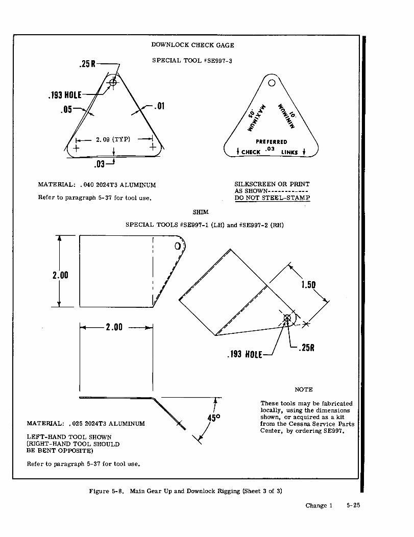
Figure 5-8. Main Gear Up and Downlock Rigging (Sheet 3 of 3)
Change 1 5-25

adding plate (item 32, sheet 2). Reverse procedure retracted and the rubber bumpers (item 5, sheet 1)to decrease engagement. Tighten attaching bolts. are half-way deflected.
6. Remove tire supports, pull relief valves to r. Adjust main gear actuator switch for .03 to .06relieve pressure, if required. inch overtravel when the gear is in the retracted
7. Remove . 025 inch shim. position and the main gear actuator piston is bottom-8. Check unlock force on downlocks as follows: ed out.
s. Check wheel and tire for positive clearance inWARNING wheel wells (items 6, sheet 1).
t. Attach external power source and cycle gearCheck unlock force on one gear and re-engage several times to assure proper operation, checkinglock before checking opposite side. light indications. Approximate travel time of land-
ing gear is 11-13 seconds in each direction.9. Manually unlock locks by pushing on over- u. Disconnect external power source and remove
center point on linkage. Unlock force should be ap- aircraft from jacks.proximately 3 to 4 pounds. After checking unlockforce on both sides with the aid of a helper manu- 5-38. MAIN WHEEL ALIGNMENT. Correct mainally support gear legs and trip locks to allow gear wheel alignment is obtained through the use of taper-to fall to "trail" position. ed shims between the gear strut fitting and the flange
1. Extend landing gear using aircraft battery of the axle. See figure 5-9 for procedure to use inpower. Check for simultaneous locking action and checking wheel alignment. Wheel shims, and theassure that no interference exists between locking correction imposed on the wheel by the various shims,mechanism and aircraft structure. are listed in the illustration.m. Adjust downlock limit switches (item 13, sheet2) to make contact when downlocks are locked. NOTE
n. Select normal gear retraction. Check for si-multaneous operation of both downlocks unlocking. Failure to obtain acceptable wheel alignment
o. Adjust sequence switches (item 28, sheet 2) to through the use of the shims indicates a de-be actuated when solenoid trips, then fasten attach- formed main gear strut or a bent axle.ing screws.
p. Check downlock assemblies (item 8, sheet 1) 5-39. NOSE GEAR.for drag-free operation of solenoid plunger. Tiltmounting bracket, if necessary, to correct solenoid 5-40. DESCRIPTION. The retractable nose gearadjustment. shock strut is pivoted at the lower front portion of
q. Adjust main gear actuating cylinder rod to bot- the engine mount, and retracts aft into the nosetom the piston out when the landing gear is fully- wheel well. Retraction and extension of the nose
Figure 5-9. Main Wheel Alignment (Sheet 1 of 2)
5-26 Change 1

NOSE GEAR RIGGING
b. Adjust piston rod in accordance with paragraph 5-65. RIGGING NOSE GEAR DOWNLOCK MECHAN-5-68 (a21) when nose gear is extended and locked. ISM. Refer to paragraph 5-68 for rigging of the nosec. Attach lower end of actuator to aft end of over- landing gear.
center lock assembly with bolt, safety bolt.d. Pull drag links down at center pivot points and 5-66. NOSE LANDING GEAR DOORS. Mechanically-
attach spring to clamp on actuator. actuated wheel well doors are provided for the nosee. Attach hydraulic hose to actuator according to landing gear. The doors are open when the nose gear
tags on hose. is down and closed when the nose gear is retracted.f. Clamp hose to actuator. The forward door is attached to the nose gear throughg. With external power source connected to aircraft, linkage and the door is hinged to the lower engine
cycle landing gear to bleed any air from system. cowling. The wheel well doors are hinged at lowerh. Check hydraulic fluid reservoir for proper amount side of the wheel well. Figure 5-15 shows the open-
of fluid. ing and closing mechanism for the doors and may bei. Check nose gear rigging as outlined in paragraph used as a guide during removal and installation.
5-68.5-67. RIGGING NOSE GEAR DOORS. Refer to para-
5-62. NOSE GEAR UPLOCK MECHANISM. Details graph 5-68 for rigging of the nose landing gear doors.of the nose gear uplock mechanism are shown in fig-ure 5-16, which may be used as a guide for removal 5-68. RIGGING NOSE LANDING GEAR. (Refer toand installation. figure 5-16.)
a. Jack aircraft in accordance with procedures5-63. RIGGING NOSE GEAR UPLOCK MECHANISM. outlined in Section 2 and rig nose gear as follows:Refer to paragraph 5-68 for rigging of the nose land- 1. Disconnect turnbuckle (item 32, sheet 2)ing gear. from strut, disconnect cowl flap linkage and remove
upper and lower engine cowling.5-64. NOSE GEAR DOWNLOCK MECHANISM. De- 2. Disconnect lock spring (item 10, sheet 2) attails of the nose gear downlock mechanism are upper end (clamp on nose gear actuator).shown in figure 5-16 which may be used as a guide 3. Remove bolt (2) attaching nose gear actuatorduring removal and installation. rod end (20) to lock assembly (1).
5
1. Nose Gear Strut Door 4. Actuator Arm 7. Door Open Stop2. Turnbuckle 5. Spring 8. Door Open Stop Adjustment3. Nose Wheel Door-Right 6. Hinge Half 9. Nose Wheel Door-Left
Figure 5-15. Nose Gear Doors
5-36 Change 1
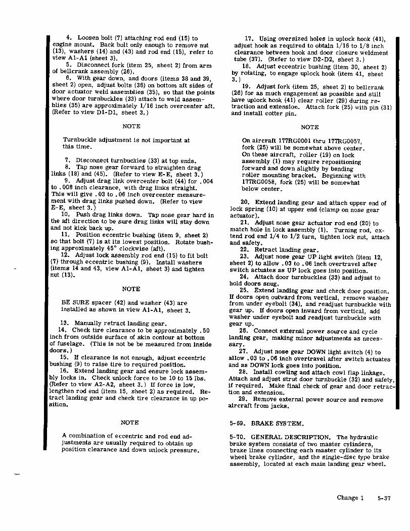
4. Loosen bolt (7) attaching rod end (15) to 17. Using oversized holes in uplock hook (41),engine mount. Back bolt only enough to remove nut adjust hook as required to obtain 1/16 to 1/8 inch(13), washers (14) and (43) and rod end (15), refer to clearance between hook and door closure weldmentview A1-A1 (sheet 3). tube (37). (Refer to view D2-D2, sheet 3.)
5. Disconnect fork (item 25, sheet 2) from arm 18. Adjust eccentric bushing (item 30, sheet 2)of bellcrank assembly (26). by rotating, to engage uplock hook (item 41, sheet
6. With gear down, and doors (items 38 and 39, 3.)sheet 2) open, adjust bolts (36) on bottom aft sides of 19. Adjust fork (item 25, sheet 2) to bellcrankdoor actuator weld assemblies (35), so that the points (26) for as much engagement as possible and stillwhere door turnbuckles (33) attach to weld assem- have uplock hook (41) clear roller (29) during re-blies (35) are approximately 1/16 inch overcenter aft. traction and extension. Attach fork (25) with pin (31)(Refer to view D1-D1, sheet 3.) and install cotter pin.
NOTE NOTE
Turnbuckle adjustment is not important at On aircraft 177RG0001 thru 177RG0057,this time. fork (25) will be somewhat above center.
On these aircraft, roller (19) on lock7. Disconnect turnbuckles (33) at top ends. assembly (1) may require repositioning8. Tap nose gear forward to straighten drag forward and down slightly by bending
links (18) and (45). (Refer to view E-E, sheet 3.) roller mounting bracket. Beginning with9. Adjust drag link overcenter bolt (44) for .004 177RG0058, fork (25) will be somewhat
to .008 inch clearance, with drag links straight. below center.This will give . 03 to .06 inch overcenter measure-ment with drag links pushed down. (Refer to view 20. Extend landing gear and attach upper end ofE-E, sheet 3.) lock spring (10) at upper end (clamp on nose gear
10. Push drag links down. Tap nose gear hard in actuator).the aft direction to be sure drag links will stay down 21. Adjust nose gear actuator rod end (20) toand not kick back up. match hole in lock assembly (1). Turning rod, ex-
11. Position eccentric bushing (item 9, sheet 2) tend rod end 1/4 to 1/2 turn, tighten lock nut, attachso that bolt (7) is at its lowest position. Rotate bush- and safety.ing approximately 45 ° clockwise (aft). 22. Retract landing gear.
12. Adjust lock assembly rod end (15) to fit bolt 23. Adjust nose gear UP light switch (item 12,(7) through eccentric bushing (9). Install washers sheet 2) to allow .03 to .06 inch overtravel after(items 14 and 43, view A1-A1, sheet 3) and tighten switch actuates as UP lock goes into position.nut (13). 24. Attach door turnbuckles (33) and adjust to
hold doors snug.NOTE 25. Extend landing gear and check door position.
If doors open outward from vertical, remove washerBE SURE spacer (42) and washer (43) are from under eyebolt (34), and readjust turnbuckle withinstalled as shown in view A1-A1, sheet 3. gear up. If doors open inward from vertical, add
washer under eyebolt and readjust turnbuckle with13. Manually retract landing gear. gear up.
14. Check tire clearance to be approximately .50 26. Connect external power source and cycleinch from outside surface of skin contour at bottom landing gear, making minor adjustments as neces-of fuselage. (This is not be be measured from inside sary.doors.) 27. Adjust nose gear DOWN light switch (4) to
15. If clearance is not enough, adjust eccentric allow .03 to .06 inch overtravel after switch actuatesbushing (9) to raise tire to required position. and as DOWN lock goes into position.
16. Extend landing gear and ensure lock assem- 28. Install cowling and attach cowl flap linkage.bly locks in. Check unlock force to be 10 to 15 lbs. Attach and adjust strut door turnbuckle (32) and safety,(Refer to view A2-A2, sheet 3.) If force is low, if required. Make final check of gear and door retrac-lengthen rod end (item 15, sheet 2) as required. Re- tion and extension.tract landing gear and check tire clearance in up po- 29. Remove external power source and removesition. aircraft from jacks.
NOTE 5-69. BRAKE SYSTEM.
A combination of eccentric and rod end ad- 5-70. GENERAL DESCRIPTION. The hydraulicjustments are usually required to obtain up brake system consists of two master cylinders,position clearance and down unlock pressure. brake lines connecting each master cylinder to its
wheel brake cylinder, and the single-disc type brakeassembly, located at each main landing gear wheel.
Change 1 5-37

C (SEE SHEET 2)
B
(SEE SHEET 2)
DOOR SHOWN IN UP Assembly 24. Rod(CLOSED) POSITION 2. Bolt 25. Fork
3. Nose Gear DOWN Light 26. Bellcrank AssemblySwitch Actuator 27. Spacer
(SEE SHEET 2) F 4. DOWN Light Switch 28. Bracket5. Nose Gear DOWN Light 29. Roller
Switch Bracket 30. Eccentric Bushing6. Engine Mount 31. Pin7. Bolt 32. Turnbuckle8. Nose Gear Actuator Rod 33. Turnbuckle9. Eccentric Bushing 34. Eyebolt
10. Lock Spring 35. Door Actuator Weld11. Nose Gear UP Light Assembly
Switch Bracket 36. Bolt12. UP Light Switch 37. Door Closer Weldment13. Nut Tube
NOTE 14. Washer 38. LH Aft Nose Gear Door15. Lock Link Stud Rod End 39. RH Aft Nose Gear Door
Refer to paragraph 5-68 for 16. Nose Gear UP Light 40. Strut Doornose gear rigging procedures. Switch Actuator 41. Uplock Hook
17. Bolt 42. Spacer18. Aft Drag Link 43. Washer19. Roller 44. Drag Link Over-20. Actuator Rod End Center Bolt21. Spring 45. Forward Drag Link22. Arm
Figure 5-16. Nose Gear Up and Downlock Rigging (Sheet 1 of 3)
5-38 Change 1

Change 1 5-39
15 DetailFhage1 -3

VIEW E-E (SEE SHEET 1)
Figure 5-16. Nose Gear Up and Downlock Rigging (Sheet 3 of 3)
5-40 Change 1

Figure 1. Baggage Curtain Retention

Fuselage (Cont)
43 8
41
38
Figure 14. Front & Center Cabin Section Assembly
42

Figure 1. Oil Cooler Airscoop

Title CABIN HEAT REDUCTION MODIFICATION
MODELS AFFECTED SERIALS AFFECTED
177 RG 177RG0001 thru 177RG0212F177RG F177RG0001 thru F177RG0042
PARTS LIST:
QUANTITY PART NUMBER NOMENCLATURE
2 1713138-2 Stiffener2 2013000-6 Seal2 2013000-7 Seal2 2013145-1 Retainer2 2013145-2 Retainer1 Installation Instructions
CHANGE IN WEIGHT AND BALANCE: NEGLIGIBLE
1. DESCRIPTION OF MODIFICATION.
a. Modification required by this Service Kit consist of:
(1) Rerigging cabin air heater valves to provide a positive seal.
(2) Seal all tooling holes, bend relief holes and any other openings in the area of the nose gearactuator housing at the top of the nose gear tunnel to prevent hot air from the engine compart-ment entering the cabin.
(3) Increase the full open position of the cabin fresh air doors to 1. 50".
(4) Install new cowl gap seals in front of the cabin fresh air doors to prevent hot engine compartmentair from entering the cabin through the fresh air doors.
(5) Plug the existing hole and drill a new hole in the bottom of the pitot tube head.
2. MODIFICATION INSTRUCTIONS.
a. (Refer to figure 1. ) Cabin Air Heater Valve Modification.
(1) Remove upper engine cowl to gain access to working area using standard procedures.
(2) Push cabin heat control knob (1) full forward and check each valve plate (3) to see that they aremaking a positive seal. This may be accomplished by tapping the inboard corners ofthe valve plates.
(3) If either valve plate is not closing completely, loosen the clamp securing the control wire tothe valve control arm (4), (both sides).
(4) Set the cabin heat control knob (1) 1/8" from the full in position and while holding the valveplate in the full closed position, secure the control wire to the control arm.
(5) Re-check valve plate for positive seal. If one corner of the plate is not seating open the valveand spring that corner of the plate so it will contact the seat first. An effective seal should beaccomplished after one or two adjustments using this method.
1 of 7

Figure 1. Cabin Air Heater Valve Modification.
b. (Refer to figure 2. ) Sealing of Nose Gear Actuator Housing Area.
(1) Disconnect lower end of defrost duct (Item 5, figure 1) to improve access to the working area.
(2) Use a bright light either in the tunnel or above the nose gear actuator housing area and checkfrom the opposite side to aid in locating any openings.
(3) Seal all openings with Proseal No. 700.
NOTE
Seal along all seams of actuator housing. Especiallylook for two .128" tooling holes on the inboard sideof the actuator housing and openings at the cornersresulting from bend relief cutouts.
(4) Reinstall lower end of defrost duct and any other items removed for access to the working area.
2

HOUSING AREA (REF)
FUSELAGE LOWER FORWARD SECTION
Figure 2. Sealing of Nose Gear Actuator Housing Area.
BRACKET (REF)
Figure 3. Rigging, Cabin Fresh Air Doors.

c. (Refer to figure 3.) Rigging, Cabin Fresh Air Doors.
(1) Pull each cabin air control knob (located at the outer edge of the left and right control panel) tothe full out position and check the opening of the door. If the opening of the door is less than1. 50 +. 10 -. 05 inch when measured from the front of the door to the edge of the skin cut out,continue with the next step and modify the rigging of the doors.
(2) Remove the forward interior trim panels.
(3) Disconnect control (3) from arm (4) and remove the clamp securing control (3) to supportbracket (2).
(4) Pull outboard on the forward edge of each door to determine maximum opening with controldisconnected and determine where the restriction is, if the door will not open to 1. 50".
NOTE
The restriction is most likely to be between the aftedge of the door and the fuselage skin. If this is thecase, proceed with the next step.
(5) Place a strip of tape along the aft edge of the door and the edge of the skin cutout to protectthe paint and pry the door open.
NOTE
Various approaches may be used to obtain the desiredopening. Analyze the point of interference to determineif a slight reforming of the skins will permit the doorsto open to the required dimension. Consider wedging apiece of .020 SS sheet metal between the skins whileprying out on the door to accomplish this. If notsuccessful, proceed with the next step.
(6) Remove the door by drilling out the rivets in the aft edge of the door and the forward flange ofthe hinge.
(7) Remove approximately 1/16" of material from the aft edge of the door. Maintain original radiusat the corner.
(8) Reinstall door and check opening.
(9) Clamp the control wire to arm (4) with the door in the open position (1. 50"). Adjust the lengthof the control wire housing to function as a stop for the full open position.
(10) Secure the control housing to support bracket (2) with the existing clamp.
NOTE
On the right side of the aircraft it may be necessaryto drill a new No. 10 hole between the two existingholes and locate the housing clamp outboard for im-proved cable alignment.
(11) Set the control knobs 1/8" from the full in position when the doors are fully closed.
NOTE
It may be necessary to make minor adjustments of thecontrol clamp at the control arm in order to meet therequirements for door opening and control knob posi-tion in the door closed position.
(12) Use silicone spray lubricant as required to improve operation.
(13) Reinstall side panels.
4

REF
1.7o
1.00
Figure 4. Installation of Cowl Gap Seals.
5

d. (Refer to Figure 4) Installation of Additional Cowl Gap Seals.
(1) Unfasten the lower cowl at the firewall and lower it just enough to gain access to the workingarea.
NOTE
It is not necessary to disconnect the nose geardoor or cowl flaps.
(2) Drill out the 5 rivets securing the stiffener (3) to the fuselage.
(3) Position seal (1), retainer (2) and new stiffener (3) as shown, drill through and secure withrivets (4).
(4) Using retainer (5) as a drill guide position on outside skin and drill five .098 holes through skinfor rivets (7).
(5) Position seal as shown and drill holes through the seal using the holes in the skin for a guide.
(6) Position the seal (6) between retainer (5) and the skin and secure with rivets (7).
NOTE
Repeat for opposite side.
e. (Refer to figure 5. ) Pitot Tube Hole Modification.
DRILL IN ACCORDANCEWITH TEXT
PLUG IN ACCORDANCE WITH TEXT
Figure 5. Pitot Tube Hole Modification.
6

(1) Locate hole (2) in bottom of the pitot tube head and plug with CCM-18 TYPE 1. Use either WhiteStreak, Plastic Division, Dynatron Corp., Atlanta, Georgia or Bondtite No. BTC-20, L.R. OateyCompany, Cleveland, Ohio.
(2) Smooth filler flush with bottom of pitot tube head and allow to dry.
(3) Drill new hole . 10" forward of the plugged hole. (Hole size #57, .0430 Diam).
NOTE
Use care not to drill into the threaded portion of thepitot tube. Leave the area around the new hole cleanand unpainted.
f. Touch up paint and reinstall all parts removed for access.
7

AUGUST 31, 1971
Title 177RG POWER PACK CONTROL VALVE MODIFICATION
MODELS AFFECTED SERIALS AFFECTED
177RG 177RG0001 thru 177RG0212F177RG F177RG0001 thru F177RG0042
PARTS LIST:
QUANTITY PART NUMBER NOMENCLATURE
1 2080020-1 Spring1 2080021-1 Retainer1 2080022-1 Washer1 Installation Instructions
CHANGE IN WEIGHT AND BALANCE: NEGLIGIBLE
1. DESCRIPTION OF INSTALLATION.
a. Installation of this kit consists of:
(1) Removing power pack assembly from aircraft.
(2) Disassembly of control valve and installation of kit parts.
(3) Assembly of control valve and installation of power pack in aircraft.
2. INSTALLATION INSTRUCTIONS.
a. Power Pack Assembly Removal.
(1) Remove aft baggage compartment panel to gain access to power pack.
NOTE
Refer to current Model 177RG Service Manual forremoval and service procedures.
(2) Disconnect ground strap from battery terminal. Disconnect and tag pump motor at solenoids,ground wire at fuselage and pressure switch wires.
(3) Spread drip cloth beneath power pack and disconnect four hydraulic lines.
NOTE
Cap or plug all hydraulic lines to prevent entry offoreign material.
(4) Remove four bolts, washers and nuts securing power pack and mounting bracket to aircraftstructure and remove power pack and bracket from aircraft.
b. (Refer to figure 1. ) Disassembly of Control Valve.
1 of 3


NOTE
On disassembly, if damaged or worn parts are found,all hydraulic system components should be disassembled,inspected and replacements made.
NOTE
Control valve need not be removed from power packunless further inspection is deemed necessary.
(1) Invert power pack assembly and secure to bench.
(2) Remove fitting (18) "O" ring (19) and washers (20 & 21) from control valve body (10). Discardwashers (20 & 21). Inspect "O" ring (19) and replace if damaged.
(3) Remove switch assembly (8) from tee (9). Remove tee (9) and fitting (4) as a unit from valvebody (10). Remove and inspect "O" ring (3) and replace if damaged. Remove washers (5 & 6)and discard washer (6).
Inspect washers (6 & 21), and if breakage or excessivewear is evident complete disassembly of control valve,power pack and other components will be required. Iffurther disassembly is required, care should be takenin removing spools (23 & 27) and sleeves (24 & 26) toavoid scoreing lapped surfaces. Keep spools andsleeves in pairs as removed and if replacement is re-quired they must be ordered and installed as sets.Damaged or worn parts should be replaced before kitparts are installed.
(4) Install spring (16) and retainer (17) in place of discarded washers (20 & 21). Install "O" ring(19) and fitting (18) as shown.
(5) Install washer (7) in place of discarded washer (6). Install washer (5), "O" ring (3), fitting (4)and tee (9) as shown. Install switch assembly (8) in tee (9).
NOTE
Fittings (13 & 15), "O" rings (11 & 14) and ball (12)need not be disturbed unless inspection is deemednecessary.
c. Power Pack Installation.
(1) Replace power pack assembly in aircraft by reversing removal procedure. Connect hydrauliclines and electrical wiring as tagged and noted to original fittings and connections.
(2) Fill and test system in accordance with Model 177RG Service Manual.
(3) Replace aft baggage panel.
3