sea keeping standard series for oblioue seas, (a …
TRANSCRIPT
rSEA KEEPING STANDARD SERIES FOR OBLIOUE SEAS, .
. o
(A SYNOPSIS) 8.
by Grigoropoulos, 0.3.', Loukakis,T.A) and Perakis, AN.2 w . .
National Techmcal University of Athens, 9 Heroon Polytechniou str., 15773 Zografos, Grc
Michigan University, Arm Arbor, Michigan, USA
L
Abstract - The seakeeping performance in oblique seas for a series of 72 cruiser-
stem hull forms has been evaluated analytically and is presented in a systematic
way. The hull form series have been created by Loukakis and Chryssostomidis
(1975) by extending the principal characteristics of the Series 60 to cover usual
shipbuilding, practice. In that work, howevet, only the seakeeping performance in
head seas was presented. Recently, the seakeeping performance Of the Extended
Series 60 was re-evaluated for both head seas and oblique' seas. The complete
results are presented in tabular and graphical form as a function of the principal
characteristics of the ship, the FroUde nuniber (including Fn=O, missing in the.
original series), the non-dimensional modal wave period and 'the heading angle in
a separate NTUA report (Grigoropoulos et al, 1994). In the present paper, the re-
sults for one case are gven in tabular form accompanied by graphical
representation. They include: heave, pitch, bending moment amidships, added
resistance, absolute vertical acceleration and relative vertical motion at the bow
and the stern regions and relative vertical velocity at stations 2 and 4 where
slamming is likely to occur.
Keywords: seakeeping responses, Seakeeping Standard Series, Series 60,
oblique seas, 'strip theory, vertical ship motions, added resistance in WaveS
NOMENCLATURE
= wave amplitude
:B =beam
= block coefficient
Fn =Froude number, .Fn=V/.IgL
g acceleration of gravity,.9.8.I ffi/sec2
H113 = significant wave height, in [m]
K,.1 = longitudinal radius of gyration about LCG
K,.'. = longitudinal radius of gyration of the forward part of the ship about LCO1
L, LBP = length between perpendiculars
Lwi. = length on. design waterline, for the Extended Series 60 L8p = 0.983 Lwi.
LCB = 1ongituinal position of centre of buoyancy
LCF longitudinal position of centre of flotation
LCG = longitudinal position of centre of gravity
LCGF distance of the centre'of gravity of the forebody from amidships
RAO = Response Amplitude Operator
RMS = Root-Mean-Square value
RM = amplitude of relative bow motion
SSS = Seakeeping Standard Series
t thrust deduction factor
T =draft .
Ip =modalperiod
Tp non-dimensional modal period,. T'= T/47
V ship speed

Lv
p
Gaw
weight of forward part Of ship
total weight of ship
= heading angle, 3= 180° corresponds to head seas
0 = pitch amplitude
wave number
wave length
RAO of bending mQmentBending Moment Amplitude
pgABL2
= specific density of sea water
=RAO of added resistance aMean AddedResistance
1W - pgA2(B2/L)
= circular frequency
1. INTRODUCTION
The seakeeping performance of a ship can. either be predicted using computer codes or
measuted in a seakeeping basin. However, during a feasibility Study or in the pre1iminay
ship design phase, the hull lines of the vessel are not yet available and hence, neither of the
aforementioned methods is applicable. In an attempt to assist the naval architect in
predicting the seakeeping behaviour in such cases, Loukakis and Chryssostomidis (1975)
presented the .Seakeeping Standard Seres (SSS) for cruiser-stern ships. In that Work tbc
authors extended the principal characteristics of the Series 60 to cover the usual
shipbuilding practice and they computed the seakeeping performance of the resulting
series analytically. Thus, they generated a set of tables containing the motion
characteristics in head seas of 72 Extended Series 60 hull .forfl. The information was
given for a systematic variation of the principal ship geometric parameters i.e. blOck
coefficient CB, length-to-beam ratio IiB and beam4o-draft ratio BIT. The results were
presented in tabular form for various fully developed seas, expressed in tetms of
significant wave height to length ratio H113/LBp and ship speed Vs. expressed as non
dimensional Froude number Fn = V / 4gL , where LWL is the length of the vessel at the
design waterline.
Since their presentation, the series have been extensively used in naval architecture
practice as well as a teaching tool. The usefulness of the series has been appreciated,
especially in studies on the effect of hull form parameters on the seakeeping behaviour of
ships. In this respect, the papers of Beukelman and Huijser (1977), Schmitke. and Murdey
(1980), Lee (1983), Pawlówski (1983), Loukakis et al (1983), Grigoropoulos and Loukakis
t1988. 1990) and Wilson (1985) should be mentioned. Furthermore, Bhattacharyya (1978)
included the series in his book on the dynamics of marine vehicles.
Recently, Townsin et al (1994) recOgnized the significance of the series and underlined
their two strong points, the wide range of hull forms and the number of the seakeeping
responses calculated. Ho'iiever, it was pointed out that, the seakeeping performance of the
72 hull forms from the Extended Series 60 has been evaluated analytically only for head
seas, while the HI,3II.Bp ratio range used, starting from H113/L8 = 0.015, corresponds to
only relatively high sea states for the longer ships of today.
The, afOrementiojed shortcomings of the series have also been noticed by the authors
of the original paper. The inconvenient selection of the HidLp ratios is closely connected
to the use of single-parameter modelling of the sea state (fully developed seas), while the
two-parameter spectral models are better representatiOns of the actual sea conditions. Since
the series refer to vertical motions only, which are linear with respect to the wave height,
or to added resistance, which is proportional to the square of the wave height, these
shortcomings could be remedied by appropriate scaling of the H1 for the same modal
4
5
period T. However, it would be :thóre convenient if the results Were presented for a range
of modal periods and .for unity significant wave height.
In addition, the absence of the zero-speed responses from the seakeeping tables,
prevented the use of the series in some applications e.g. the design of stationary ship-
factories or storage ships. Finally, scant usable information exists in the literature fo ship
responses in oblique seas, although such knowledge can be useful for ship routing and
seakeeping operability studies.
With the above in mind, it was decided to re-evaluate the seakeeping performance of
the Extended Series 60 for all headings, using the same seakeeping responses as the initial
paper and including a Wider range of non-dimensional sea states as well as zero-speed
responses. The strip theory of Salvesen, Tuck and Faitinsen (1970) has again been Used for
the estimation of the ship motions and bending moments. The energy method of Gerritsma
and euke1man (1972), as extended by Loukakis and Sclavounos (1978), has been used for
the prediction of added resistance in head to beam seas.
The usage of the same theories for analytical predictions after some twenty thrce years,
underlines the remarkable fact that the simple strip theory continues to give results useful
for practical purposes in an efficient computationally manner and it has not been
superseded by newer three-dimensional theories, except for the zero-speed case. In this
respect, it is interesting to note that in two recent International Conferences on Ship and
High Speed Craft Motions & Manoeuvrability, no less than 8 authors were using strip
theory for predictions in the absence of other tools, even at very high Fns! For a review of
seakeeping theories and their applicability one can refer to Odabasi and Heam (1977),
Heain and Donatl (1980) and to the reports of the Seakeeping Committee of 1TTC (1978,

1984, 1993), where the usefulness of strip theory is generally recognized, at least for
cruiser stern ships sailing at zero to moderate speeds.
In order to demonstrate the applicability of strip theoiy to oblique ship responses, the
analytical results in regular waves have been compared to the experimental results
conducted a long time ago at Wageningen (Vossers et al, 1960 and 1961). Figures 1, 2, 3
and 4 show that for a L8 =120 m, CB = 03, L'B = 7, B/T = 3.0 Series 60 hull form, the
predictions for pitching motion, relative bow motion, bending moment and added
resistance can be used in practice, with the bending moment and the added resistance
results being the weaker predictions (in the case of added resistance, the measured added
thrust is approximately converted to added resistance using the measured thrust deduction
factor in calm water, t = 0.184.). Furthermore, the analytically estimated bow acceleration
and added resistance responses in regular waves, fOr the s-I 75 containership proposed by
the I.T.T.C. for comparison studies, are shown in Figures 5 and 6. with the respective
experimental results conducted in the towing tank of the Laboratory for Ship and Marine
Hydrodynamics at NTUA (Grekoussis et al, 1986).
The SSS in oblique seas contain, in tabular form and as a function of the principal
characteristics of the ship, the Froude number, the non-dimensional modal wave period
and the heading angle, the results of the aforementioned computations, Table 1. Due to
obvious space limitations, the seakeeping responses for only one case could be
accommodated in the present paper in tabular form, accompanied by graphical
representation. The càmplete results, for all 72 cases, are ayailable in a separate technical
report accompanied by a PC floppy disk (Grigoropoulos. et al, 1994). The results of the
Seakeepirig Tables can be interpolated for the prediction of the seakeeping perfOrmance of
cruiserstem ships not necessarily with Series 60 hull forms.
'2
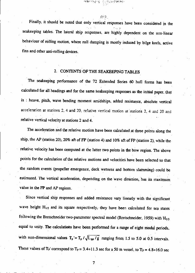
Finally; it should be noted that only vertical responses have been considered in the
seakeeping tables. The lateral ship responses, are highly dependent on the non-linear
behaviour of rolling motion, Where roll damping is mostly induced by bilge keels, active
fins and other anti-rolling devices.
2. CONTENTS OF THE SEAKEEPING TABLES
The seakeeping performance of the 72 Extended Series 60 hull forms has been
calculated for all headings and for the same seakeeping responses as the initial paper, that
is : heave, pitch, wave bending moment amidships, added resistance, absolute vertical
acceleration at stations 2, 4 and 20, relative vertical motion at tations 2, 4 and 20 and
relative vertical velocity at stations 2 and 4.
The acceleration and the relative motion have been calculated at three points along the
ship, the AP (station 20), 20% aft of F1' (station 4) and 10% aft of F1' (station 2), while the
relative velocity has been computed at the Jattet two points in the bow region. The above
points for the calculation of the relative motions and velocities have been selected so that
the random events (propeller emergence, deck wetness and bottom slamming) could be
estimated. The vertical acceleration, depending on the wave direction, has its maximum
value in the FP and AP regions.
Since vertical ship responses and added resistance vary linearly with the significant
wave height H113 and its square respectively, they have been calculated for sea states
following the Bretschneider tWo-parameter spectral model (Bretschneider, 1959) with H1,3
equal to unity. The calculations have been performed for a range ofeight modal periods,
with non-dimensional values T'= T /.JLBp /g ranging from 1.5 to 5.0 at 03 intervals.
These values of Tp' correspond to Tp= 3.411.3 sec fOra 50 m vessel, to T= 48l60 sec
7

for a 100 m vessel and to Tp = 6.822.6 sec for a 200 m vessel. Thus, they correspond to
sea states appropriate for the determination of the seakeeping responses of different size
ships, if the naturally observed relationship between wave height and wave period is taken
into account.
The results are in the form of integer values in the range 0 - 9999. In order to restrict
the results in this range, the following "non-dimensionalizations" have been used:
Heaving motion = (RMS heave at amidships) * 106 / (J H113)
Pitching motion = (RMS pitch in degrees) * / H113
Bending moment = RMS bending moment at amidships) * i09 / (pg LBP4 H113)
Added resistance = (mean added resistance) * 1010 / (pg LBP3 H113)
Relative motion = (RMS relative motion) * 106 / (TH113)
Relative velocity = (RMS relative velocity) * / (.JgL8 H1,3)
Acceleration = (RMS acceleration) * i05 / (g H113),
where all resUlts refer to unit significant wave height.
In this fashion, three pages are necessary for the tabular presentation of the results. for
each hull form anda sample page is shown in Table 1.
The seakeeping responses have been calculated for each of the 72 hull forms of the
Extended Series 60 with CB = 0.55 (0.05) 0.90, L/B 5.5, 7.0 and8.5 and B/T = 2.0, 3.0
and 4.0, at. four ship speeds corresponding to Froude numbers 0.0, 0.1, 0.2 and 0.3 and for
heading angles ranging from head seas (180°) to following seas (0°) at 15° intervals. It
should be noted that the radius of gyration K, has been assumed to be equal to 0.24 LBP,
while the weight of the forebody Wp and the distance of the centre of gravity of the
forebody LCGj from amidships are connected to CB by the following relations:
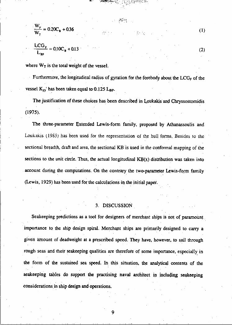
= O.2OCB +036I
LF=0.10C3+O.13
where WT is the total weight of the vessel.
Furthermore, the longitudinal radius of gyration fOr the forebody about the LCGF of the
vessel K' has been taken equal to 0.125 L8.
The jUstification of these choices has been described in Loukakis and Chryssostomidis
(1975).
The three-parameter Extended Lewis-form family, proposed by Athanassoulis and
Loukakis (1985) has been used for the representation of the hull forms. Besides to the
sectional breadth, thaft and area, the sectional KB is used in the conformal mapping of the
sections to the unit circle. Thus, the actual longitudinal KB(x) distribution was taken into
account during the computations. On the contrary the two-parameter L.ewis-fqrm family
(Lewis, 1929) has been used for the calculations in the initial paper
3. DISCUSSION
Seakeeping predictions as a tool for designers of merchant ships is not of paramount
importance to the ship design spiral; Merchant ships are primarily designed to carry a
given amount of deadweight at a prescribed speed. They have, however, to sil through
rough seas and their seakeeping qualities are therefore of some importance, especially in
the form of the sustained sea speed. In this situation, the analytcai contents of the
seakeeping tables do support the practising naval architect in c1ug seakeeping
considerations in ship design and operations,

This is true in particular for the case of oblique seas, since most of the reference
material pertains to head seas only. This is a void the present series can help to fill, as they
pertain to ship responses in all headings in realistic seaways and as strip theory is well
known to predict real life with adequate engineering approximation for the hull form and
the speeds of the series.
Using the tables, sufficient information can be obtained or a qualitative and
quantitative estimation of the seakeeping qualities of any hull form resembling the parent.
Furthermore, taking advantage of the quite wide ranges of the C3 coefficient and the IJB
and B/T ratios of the data base, conclusions can be drawn on the effect Of any variation of
these parameters on the seakeeping performance of the ship to be designed. Since.
according to usual practice, these parameters are always determined at the preliminary ship
design stage, when the hull form is only vaguely defined, the proposed series can support
the designer for the creation of a hull form with good seakeeping qualities.
Moreover, the existence of information about seakeeping responses in oblique seas can
help the naval architect broaden his understanding about what happens at sea. Using as
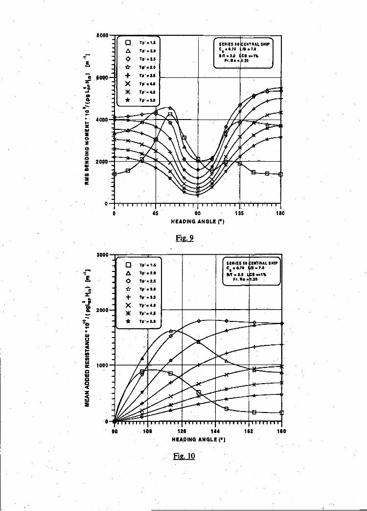
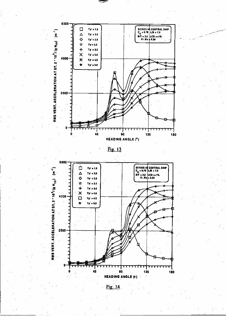
example the central ship of the series, the following responses are plotted: heave (Fig. 7),
pitch (Fig. 8), bending moment (Fig. 9), mean added resistance (Fig. 10), all at Froude
number Fn 0.20 and bow acceleration at Fn = 0.00, 0.10, 0.20 and 0.30 (Figs. 11, 12, 13
and l4)
Obviously, the non-dimensional resuitsare ported to real life, i.e. the ship in real sea
states, via the ship length and the wave height. But, nevertheless, the shape of the
corresponding curves is interesting per se. Thus, heave resonance occurs around 100°
heading angle (Fig. 7) and pitch resonance for the lower sea states (low values of Tp) is not
for head seas but for headings close to the 90° minimum, from both directions (Fig. 8).
10

Similar behavioUr pertains for the bending moment (Fig. 9) and even added resistance is
not largest for head seas, when in the lower sea states Fig. 10). For the case of bow
acceleration, the results (Figs. 11, 12, 13 and 14) are even more interesting as the
resonance is both pronounced and far away, (around beam seas), frOm head seas at zero
speed. Gradually, as speed increases, the situation moves toward the conventional wisdom
that head seas induce larger responses, although this is not true for the three lower sea
states even at Fn = 0.30.
4. CONCLUSION
The widely recoriized usefulness of the seakeeping standard series has been extended
by ipcluding the zero speed and the oblique seas cases.
The zero-speed and the oblique seas results can be of fUrther use to the designer n the
case of special ships, which operate at rest or when oblique seas operation is of
importance. Thus, for a given route of the vessel under investigation, the designer, using
the tables and the related, environmental data, can estimate the operational characteristics
of the proposed hull form and decide upon necessary modiflcations.
However, in addition to the hull form parameters considered in the initial series,
additional parameters referring to the.Waterplane. area (Cw and LCF) and the LCB position
affect the seakeeping behaviour of ships too. The same is true for the shape of the bow
region sections (U or V) as well as for above Water characteristics of' the hull form (flare
stem angle, and others). These parameters can not be examined within the scope of SSS,as
they Would increase dramatically the number of thç hull variants, which is 'inconsistent
with the stated intention of using the Tables 'during the feasibility study and the
preliminary design stage only.
11

Thus, the selection of main hull form parameters should be aécompanied by a
subsequent selection of the waterline form parameters Cw and LCF and thç longitudinal
distribution of KB. The statistical method of Bales (1980) or the direct technique proposed
by Grigoropoulos and Loukakis (1988, 1990) could assist the designed in this phase Both
techniques refer to head seas results.
5. REFERENCES
Athanassoulis, G.A. and Loukakis, T.A. (1985) An extended Lewis form family of ship
sections and its applications to seakeeping calculations, International Shipbuilding
Progress 32. No.366. 33-43. V
Beukelman, W and Huijser, A (1977) Variation of parameters determining seakeeping,
International Shipbuilding Progress 24, No. 275, 171-186.
Bhattacharyya, R. (1978) Dynamics of marine vehicles, edited by M.E. Mc Cormick, John
Wiley & Sons, New York.V
Bretschneider, C.L. (1959) Wave. variability and wave spectra for wind-generated gravity
waves, Beach Erosion Board Corps. of Engineers, Technical Memo 118.
Gerritsma, J. and Beukelman, W. (1972) Analysis of resistance increase in waves of a fast
cargo ship, International Shipbuilding Progress 19, No. 217, 285-293.
Grigoropoulos, J.G., Loukakis, l.A. and Perakis, A.N. (1994) Seakeeping standard series
for oblique seas, National Technical Univ. of Athens, Dept. of N.A. & M.E., Rept. NAL
1 14-F-i 994, Athens.
Hearn, G.E. and Donati, E. (1981) Sea-keeping theories: Applying some choice,
Transactions North-East Coast Institution of Engineers t2nd Shipbuilders 97, 53-72.V
12
International Conference on High Spee4 Craft Motions & Manoeuvrabily (1998) The
Royal Institution of Naval Architects, London.
International Conference on Ship Mofions 4 Manoeuvrabilty (1998) The Royal Institution
of Naval Architects, Lojidon.
15th I.T.T.0 Seakeeping Committee (198) Report of the Sealceeping Committee,
Proceedings of the 15th International Towirg Tank Conference 1, 55-114, The Hague, The
Netherlands.
17th IT.T.0 Seakeeping Committee (1984), RepOrt of the Seakeeping Conimittee1
PrOceedings of the iY' International Towng Tank Conference 1, 457-534, Goetenborg,
Sweden.
20th I.T.T.C. Seakeeping Committee (193), Report of the Seákeeping Committee,
Proceedings of the 2th International Tôwizg Tank Conference 1, 415-468, San Franzisco,
California.
Lee, CM. (1983) Preliminary studies leading to seakeeping hull design, 2 International
Symposium on Practical Design in Shipbuilding PRADS 83, 1-10, Tokyo and Seoul, Japan
and Korea.
Lewis1 F.M. (1929) The inertia of the water surrounding a vibrating ship1 Traflszctions
SNAME37, 1-20.
Loukakis T A and Chryssostomidis, C (1975) Seakeeping Standard Senes for Cruiser-
Stern Ships, Transactions SNAME 83,
Loukakis, LA. and Sciavounos, P. (1978) Some extensions of the classical approach to
strip theory of ship motion, including the calculation of mean added forces and moments,
Journal.of Ship Research 22, No. 1, 1-19.
13

Loukakis T.A., Perakis N. and Papouliás F.A. (1983) The effect of some hull form
parameters on the seakeeping behaviour of surface ships, Conference on Seagoing
Qualities of Ships and Marine Structures, Paper 57, 57.1-57.17, Vama, Bulgaria.
Odabasi, A.Y. and Hearn, G.E. (1978) Sea-keeping theories: What is the choice?,
Transactions North-East Coast Institution of Engineers and Shipbuilders 94,53-84.
Pawlowski, J.S. (1983) Form parameters for ship design, based upon hydrodynamic
theory, International Symposium on Ship Hydrodynamics and Energy Saving ISSHES'83,
Paper I-4,I-4.1-I-4..21, El Pardo.
Salvesen, N., Tuck, E.O. and Faltinsen, 0. (1970) Ship motions and sea loads,
Transactions SNAME 78. 250-287.
Schmitke, RT. and Murdey, D.C. (1980) Seakeeping and resistance trade-offs ir frigate
hull form design 13' Symposium on Naval Hydrodynamics, Office of Naval Research,
Tokyo.
Townsin, R.L., Kwon, Y.J., Baree, M.S. and Kim, D.Y. (1994) Estimating the influence of
weather on ship performance, Transactions RINA 134, Part B, 191-209.
Vossers, G., Swaan, W.A. and Rijken, B. (1960) Experiments with Series 60 models in
waves, Transactions SNAME 68, 364-450. -.
Vossers, G., Swam, W.A. and Rijken, H. (1961) Vertical and lateral bending moment
measurements on Series 60 models, International Shipbuilding Progress 8, No. 83, 302-
320.
Wilson, P.A. (1985) A review of the methods of calculation of added resistance for ships
in a seaway, Windtech '85 Symposium 4, Paper 31, 31.1-31.13, Southampton.
14
LABELS OF FIGURES
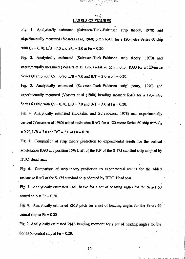
Fig. I. Analytically estimated (Salvesen-Tuck-Faltinsen strip theory, 1970) and
experimentally measured (Vossers et al, 1960) pitch RAO for a 120-metre Series 60 ship
with CB = 0.70, LJB = 7.0 and B/T = 3.0 at Fn = 0.20
Fig 2. Analytically estimated (Salvesen-Tuck-Faltinsen stnp theory, 1970) and
experimentally measured (Vossers et a!, 1960) relative bow motion RAO for a 120-metre
Series 60 ship with C = 0.70, LJB 7.0 and BI1' = 3.0 at Fn = 0.20.
Fig. 3. Analytically estimated (Salvesen-Tuck-Faltinsen strip theory, 1970) and
experimentally measured (Vossers et a] (1960) bending moment RAO for a 120-metre
Series 60 ship with CB = 0.70. LJB = 7.0 and Br!' = 3.0 at Fn = 0.20.
Fig. 4. Analytically estimated (Loukakis and Sclavounos, 1978) and experimentally
derived (Vossers et al 1960) added resistaflcé RAO for a 120-metre Series 60 ship With CB
= 0.70, [lB 7.0 and Br!' = 3.0 at Fn 0.20.
Fig. 5. Comparison of strip theory predictIon to experimental results for the vertical
acceleration .RAO a1 a position 15% L aft of the F.P of the S-17-5 stanthrd ship adopted by
ITFC. Head seas.
Fig. 6. Comparison of strip theory prediction to experimental Pesults for the addçd
resistance RAO of the S-175 standard ship adopted by flTC. Head seas.
Fig. 7. Analytically estimated RMS heave for a set of heacing angles for the Senes 60
central ship at Fn 020.
Fig. 8. Analytically estimated RMS pitch for a set of heading angles for the Series 60
central ship at Fn = 0.20.
Fig. 9. Analytically estimated RMS bending moment for a set of heading angles fOr the
Series 60 central ship at Fn 020.
15

Fig. 10. Analytically estimated RMS added resistance for a set of heading angles for the
Series 60 central ship at Fn = 0.20.
Fig 11. Analytically estimated RMS vertical acceleration at station 2 (10% aft of FP) for a
set of heading angles for the Series 60 central ship at Fn = 0.00.
Fig. 12. Analytically estimated RMS vertical acceleration at station 2 (10% aft of FP) for a.
set of heading angles for the Series 60 central ship at Fn 0.10.
Fig. 13. Analytically estimated RMS vertical acceleration at station 2 (10% aft of FP) for a
set of heading angles for the Series 60 central ship at Fn = 0.20.
Fig. 14. Analytically estimated RMS vertical acceleration at station 2 (10% aft of FP) for a
set of heading angles for the Series 60 central ship at Fn = 0.30.
16

0a
I
:
!I
:
H
w a n c
a .n 0.1 tit tnr.
U Ill
-4O.fl 0 u 0 0
U U
Ifl0a
aflO
Il? 0 Il 0U
U Il?
OIfl0U
ON
fl in U U
IllN0
w
u 0 U C
' fl 0 iflON
N'
UIf
00
.1! 0 in ouo Il? 0I'
U In
I,
0 in 0 mO
ml 0
.-4 N N
inin Um
l?
0
UD
U)0U
iOS
fl0.4 N
N inin U
U In
-Iu ca
0 in o.4 N
inin U U
U0I
M
U
UM
U
In 0 Il? 0 In 0 IA 0
N m
m ' U
InNa
0mb
00000000
0. .
00000000
In o mo In 0 In 0
-4 C4r4:rn in U
U In
N0
0000000000000000

1.00-
6 0.80-
C.)
0.60-a.
1.40
1.20 -
0.40 -
0.0 -
0.00
0.0
5.00
4.00 -
3.00 -
2.00 -
1.00 -
I'I
1790
A -7 100
ODD
I 0 2.0A/L
Fig. 1
Fig. 2
0K 50
900
3.0
Fr , 0.20
+ -I0° Exper.
o _5O0 Exper
o Exper.
o .13O°Exper.
=170°Exper.
4.0
Fr 0.20
5.0
'
+ooo
.10e
90°
0'1300'17O
Exper.
Exper.
Exper
0.00
0.0 1.0. 2.0 3.0 4.0 5.0AlL

0.03
0.02.I-zUI
o
C,z0.01
UI.
0.00
12
I I?O0
0'f. I
;I.
0..J1o' A./Ifli'S
:1A14\ 5' 0.
'Di' \. ° Or;
I -I
00 1.0 2,0 3.0A/L
Fig.3
4.0
Fr.*.20
O .13O°xper.
.17P°Ee.
0.0 1.0 2.0
AlL
Fig;A
3.0 4.0
5.0
5.0
4.
.Fr.O.20
á1ø Eer.
I. ooo
5O Eer.ao° Eer.13O°E,er
a .ilO E&.I Do

60
-a
z0
I-0I,dz0I-
Iii-' 20'UUU
I-0UI
000 10 2.0
= iao I(L,Ig)
Fig. 5
Fig. 6
30 40
-I
-
ITTC S.17S CONC.O.SS.IJB.7.O
BIT.S.O.LCB..1%Fr.No.O.27S
TAINERSHIP
flRT.ACC.
- STRIPTNEORYVERT.ACC.
EXPERUIENTAL1-¼
---
-
4
7
4
Aaa
a Aa!
-
4
-i ii t iii , , r1u i u,,ui liii I I I I I I 14 II I
Lv
:---
-15-
7
I
7
7
' ITTC S-1Th CONTAINO.U,UB.7.O
BI?.3.O.LCB',1SFr. No èO.275
ERSHIP
ADD. RES. RAO- STRIP THEORY* EXPERUIENTALADD.RES.RAO, 77
. 7
-
10 7
4 .7-.-
**
5---'-
a
*
LIII III
7.
7.
III1IIIIL
7
*
iii-iiiit10 2.0 40
44 w0 w0i(L8Ig)°

4000
3500
3000E
2500a.
-T
. 2000a
w1500
'U
U)
1000
500
0
6000
4000
2000
0
ViaL_
0 T=1iTp.2.0
Tp.2.S
Tp.3.0
+ Tp .3.5
)( Tp.4.0
* Tp.4.S
jurilti, iii-iuuuu -uiii,iii Ill-ui
FigS
Yp. 1.5
Tp a 2.0
Tp 2.3
Tp 3.0
Tp
Tp 4.0
Yp
Tp
SERIES 50 CENTRAL SNIPC.0.70 .7.0OIl. 3.0 CO .+1%
Fr.No 0.20
1111111 11111111 1-1111111 111111110 45 90 135 180
HEADING ANGLE (°)
SERIES S(C1 a OTo
- fl
CENTRAL SHIPL 17.04P _.1. - -
Ff We 0.20 /
45 90 135 180
HEADING ANGLE (°)
Figs 7
8000
6000I.
-J
0.
a-0
4000zw
06,
2000
E
0."3o.2
a-eU
waz03
Ui
aUia.02
Tp.1.S
Tp.2.0Tp.2.3
* .v,..3.0
+X Tp.&)IE Tp.&S
* Tp.S.0
SERIES 60 ENTRAL SNIPcs.0.10011.3.0
Fr. No 20
HEADING ANGLE(°)
Fig. 10
0
uUU
-
000
000
- - -i $
2.0
SERIES 60C SOlOBIT .3.0 LCD
Fr.No.O.20
ENTRAL SNIPJB.7J
.iI%
Tp
Tp
Tps2.5
A Tp.3.O
Tp.4.O
)IE Tp.4.5* To-S.D
slIhuuir18162
0
90
11111!108
huh126
11111111
144
11111111 1111.1.1 ! 11111 II III! II I I
45 90
HEADING ANGLE (°)
Fig. 9
1801350

6000
e
4000Cl
I.-(I,I-
z0I-.
'U2000
UU
Ui
0
6000
E
4000Cl
U,I-
z0
2000'UUU
I-Ui
0
0
oTp.2.0
,Tp .2.5
* Tp.3.0
Tp 3.5
X Tp.4.0
)E p.o.s* Tp.5.0
¼
SERIES Sb cENTRAL SHIPC .0.70; LI 7.0
SIT. 3D LCO ..1%F,. No 0.00
11111111 11111111 111111(1 JI 111111145 90
HEADING ANGLE (0)
Fig. 11
0
-
.0 Tp.1.S
IpILOO Tp.2.5
* Tp.3.0
+ Tp.8.S
X Tp.4JTp' 4.5
Tp
- _,
S.
SERIES 61 CENTRAL SHPC0.0.70 L19.71Bll.3.0 LCB.,i%
F,. Ho. 0.10¼
Fig. 12
180
I I I I I I 1 I I I I I-IIl I- l- I-I 1 II Il I 11 I I I- I I
0 45 90 135
HEADING ANGLE (°)
135 180
4000
I-4z0I-4
2000UiU
6000
TO 1.5
Tp 2.0
Tp 2.5
Tp. 3.0
Ip 3.5
Tp 4.0
Tp 4.5
Tp 1.0
SERIES S CENTRAL SNIPC1 .0.70 LiD 7.0
e/f 3.3 LCB ..l%Fr.PIo 0.20 -
Tp 1.5
Tp 2.0
Tp 2.5
Tp' 3.0
Tp 3.5
Tp 4.0
4_s
Tp 5.0
SERIES S CENTRAL SHC1.0.T0 UD.7.o8/1.3.0 LCB.+1%
Fr No 0.30
*
45 90 135
HEADING ANGLEo)
Fig. 14.
180
0 45 90
HEADING ANGLE (°)
Fig. 13
135 180