sea trial results of a chaotic direct-sequence spread...
TRANSCRIPT

������������ ����������������������������������������
Sea trial results of a chaotic direct-sequence spread spectrum underwatercommunication system
S. Azou1 and G. Burel 1
1 Laboratoire d’Electronique et Systèmes deTélécommunications (UMR CNRS 6165)
6, Avenue Le Gorgeu, BP 80929285 BREST Cedex, France
e-mail : {Stephane.Azou, Gilles.Burel}@univ-brest.fr
L. Le Duff 2 , C. Pistre 2
2 Groupe d’Etudes Sous-Marines de l’Atlantique(GESMA), BP 42
29240 BREST Armées, Francee-mail : {leduff, pistre}@gesma.fr
Abstract- Recent theoretical results show that use of chaoticdynamics can significantly increase privacy of digitalcommunication signals. The purpose of this paper is to reportsea trial results of a chaotic spread spectrum system. Due toits ability to simultaneously sharing the same frequency bandfor various users (through Code Division Multiple Access)and its robustness against channel imperfections, it is theDirect-Sequence scheme that we use in our system. This isdone by using a chaotic dynamic for the spreading codegenerator.Two receiver structures are discussed ; one is similar to thematched filter struture usually encountered in standard DS-SS systems ; the other, more original, is based on a state-space formulation to recover various parameters of theincoming chaotic signal.Through these first sea trials, we aim to prove the feasabilityof a chaos-based transmission for a single user that operateswithout any covertness constraint. Other tests will beconducted soon to evaluate the performances for a Signal-to-Noise Ratio below 0 dB.
I. INTRODUCTION
In the last few years, a great research effort has beendevoted towards the development of efficient chaos-basedmodulation techniques [1][2]. This motivation originatesfrom theoretical results of Pecora and Caroll about thesynchronizing capability of two identical chaotic systemsthat start from different initial conditions [3]. Due to itsrandom-like deterministic behavior, chaos not only spreadsthe spectrum of the information signal but also acts as anencryption key. Hence, covertness of transmissions can beensured and due to intricate dynamics of the receivedsignals, it will be extremely difficult for the unauthorizeduser aware of the transmission to access the information.Many approaches exist to take advantage of these features,among others Direct-Sequence or Frequency-HoppedSpread Spectrum Systems, Chaotic Masking or ChaosShift Keying. To date, most of the results available in thelitterature have been derived through numericalsimulations and few practical investigations are detailed.
Due to their non periodic nature and their extremesensitivity, it is not so easy to exploit chaotic signals for aninformation transmission.As Direct-Sequence Code Division Multiple Accessscheme becomes a popular choice in shallow waterapplications, such as Underwater Acoustic Network [4],we will focus on such a scheme. By this time, DS-SStransmitters make intensive use of pseudo-noise (PN)codes such as maximal-length, Gold or Kasami and are nolonger robust against interception, as pointed out recently[5][6], because of the periodic nature of the codes and theirwell known construction process. Chaotic codes aim tocorrect this deficiency while maintaining comparable Bit-Error-Rate and data rate performances. A recent paper [7]attempted to show the feasability of Chaotic DS-SS(CD3S) transmissions through numerical simulations. Thepresent paper now puts into practice the receiver schemesthat was introduced in the previous study.The first receiver, operating at the symbol rate, employs aconventional matched filter structure [8], with acquisitionand tracking through delay-lock loop for synchronizationand a coherent correlator based demodulation (use of aphase-locked loop), together with power control. Thesecond solution, more original, relies on a state spaceformulation of the demodulation process, thanks to theUnscented Kalman (UK) estimator developped by Julier etal. in the robotics field [9]. In presence of nonlineardynamics, the UK estimator is known to be more accuratethat the standard Extended Kalman Filter with the samecomputational complexity and an easier implementation. Adual estimation structure is proposed here to find thesymbol and residual phase of the incoming basebandCD3S signal, together with a power control feedback.Such a receiver scheme is more suited for nonstationnarychannels, as it can operates at the chip-rate. In a blindapproach, the despreading code has to be reconstructedfrom the noisy received signal ; this general approachbased on chaotic synchronization was proposed in [7].Although this method works on multipath channels forhigh SNRs (> 15 dB), it is not yet finalized and additionnal
Vol. 3, pp. 1539-1546
©2003 IEEE. Personal use of this material is permitted. However, permission to reprint/republish this material for advertising or promotional purposes or for creating new collective works for resale or redistribution to servers or lists, or to reuse any copyrighted component of this work in other works must be obtained from the IEEE.

������������ ����������������������������������������
investigations are needed to improve the denoising processfor the code at lower SNRs. In this paper, knowledge ofthe despreading code will then be assumed and a codedelay estimation will be used to track the received CD3Ssymbols. For the two receivers, the signal is first acquiredthrough search and verification stages with an adaptivethreshold to reduce false alarm probability [10].An experiment was performed at the bay of Brest (France)in december 2002, to confirm the viability of the previousreceivers. Several data blocks containing up to 200 bitswas transmitted with a SNR about 7-8 dB. No error wasnoticed for the received symbols, using various spreadinggains between 63 and 127. Other experiments will beconducted soon to evaluate the performances in a coverttransmission scenario (low SNR).The paper is organized as follows. In section II we presentprinciples of a CD3S transmitter. Then, in third section, wepresent the acquisition process and the two receiversschemes. Experimental results will be illustrated anddiscussed in section IV and finally we will draw someconcluding remarks.
II. CHAOTIC DIRECT-SEQUENCE SPREAD SPECTRUM(CD3S) SIGNALS
Figure 1 illustrates the principles of a CD3S transmitter.At the moment, data have been modulated through BPSK.A differential encoding may be performed to eliminate thephase ambiguity at the reception. The spreading operationis done by multiplication of the data symbols with thechaotic signal, evolving at a rate dc FF >> , dF being thedata rate. The choice of the processing gain
FdFcW /= results from a tradeoff between the availablebandwidth of the channel, the desired data rate and biterror rate together with the existence of any covertnessconstraint.
In order to facilitate the receiver synchronization, theinformation to transmit is structured in frames ; In thisway, chaotic markers, whose length is identical to theprocessing gain, are regularly inserted after the spreadingoperation. This means that the receiver can reconstruct themarkers in an autonomous way. A basic solution is torepeat the same marker for each new frame and to store themarker signal at the receiver side.
Then, an upsampling process by zeros inserting isaccomplished and a square-root raised cosine shaping filteris applied, with a rolloff factor α of 0.3, before a carriermodulation at central frequency 0F . To avoid aliasing, thesignal has to be sampled at a minimum value of
cFF )1(2 0 α++ .
Figure 1 – Block diagram of a CD3S transmitter
As in [7], the logistic map is suggested as the spreadingsequence generator, due to its favorable correlationproperties. Hence, the wideband signal resulting from thespreading operation (before markers insertion) is given by
)21( 21−−= kkk xdx (1)
where kx denotes the state of the dynamical system and
where the parameter kd is the data symbol (e.g. 1± for aBPSK encoding).
III. RECEIVER STRUCTURES FOR CD3S SIGNALS
The receivers that we describe in this paper both have togenerate a perfect replica of the original spreading code, ina synchronous manner. This will require two steps : Therole of the code acquisition will be to achieve a coarse timealignment between the received chaotic code and thelocally generated code, whereas the tracking loop will haveto maintain the receiver code offset below a fraction ofchip duration and to track carrier phase (the Doppler willnot be considered here) before any demodulation.
Although a chaotic generator exhibits an extremesensitivity to its initial conditions and a stochastic-likebehavior, the construction of a perfect replica of theoriginal spreading code at the receiver side is not aproblem, thanks to the deterministic nature of chaoticsystems and the discrete-time implementation we choosed.
A. Code Acquisition
As mentioned before, the objective of initial codeacquisition is to achieve a coarse synchronization betweenthe receiver despreading code and the transmitted signal. Apopular approach to solve this problem is the serial search[8], which relies on a correlation between the receivedsignal and the receiver code ; the tracking is then startedwhen a predefined treshold is crossed or for the maximumcorrelation value. In order to reduce the false alarm
Vol. 3, pp. 1539-1546
©2003 IEEE. Personal use of this material is permitted. However, permission to reprint/republish this material for advertising or promotional purposes or for creating new collective works for resale or redistribution to servers or lists, or to reuse any copyrighted component of this work in other works must be obtained from the IEEE.

������������ ����������������������������������������
probability, it is desirable to use search techniques inconjunction with a verification step (double-dwell system).To improve the performances, it is even possible to run thesearch and verification simultaneously, as it is proposed in[10]. Such an approach has been implemented in ourCD3S system; It is summarized in the rest of thissubsection.A number M of preamble symbols will be devoted toacquisition. The same chaotic code (chaotic marker) can bechosen for each preamble symbols ; if a a low probabilityof interception is needed, the marker will change for eachnew frame. If W denotes the spreading gain, that is thelength of the chaotic code ][kc for one symbol, and ][kr isthe received baseband signal, we compute the matched-filter output in the search block :
][][][1
0
lWclkrkgW
l
−−= ∑−∆
=
(2)
where ∆ is the number of samples per chip.Then, we proceed to the comparison
(3)where ][kη denotes an adaptive treshold, whose valuestarts from 0η at 0=k or at time instants where a failureis declared by the verification process. Then, the tresholdevolves in time as
{ }20 ]1[],1[,max][ −−= kgkk ηηη (4)
A verification will be started as soon as
][][ 2 kkg η> (5)and then search and verification processes operatessimultaneously. The task of the verification is to verify thatcorrelation peaks occur at time instants
MmWmkkm ,...,2,1 ,11 =∆+=+ (6)where 1k denotes the instant where the verification havebeen started.The verification will be considered successful, and then thetracking initiated, if
( )∑=
=+>M
mm kkgM
11
2 ]1[)(/1 0.8 , ρρη (7)
otherwise the acquisition continues in the search modeonly, until initial treshold 0η is crossed again. During theverification process, if a crossing is observed at a timeinstant mkk ≠ , then the verification is stopped to save oncomputational time.The number M of preamble symbols required to proceedthe acquisition have to be carefully chosen in practice. Agreater M is needed as the SNR decreases in order to keepfalse alarm probability as low as possible.
B. Conventional Matched-filter approach
Figure 2 shows the block diagram of a typical DS-SSreceiver structure (single user), which consists of a DelayLock Loop (DLL) for code tracking and a Costas Loop forcarrier tracking [8]. The acquired signal is firstdownconverted to the baseband using a locally generatedIn-phase and Quadrature-phase of the carrier. Then, after alow-pass filtering (I & Q arms), the signal is correlatedwith the prompt, early and late versions of the locallygenerated code (figure 2). The Early and Late I/Q-components are used to detect a code phase error; the codediscriminator output is then used to control the codegenerator. The carrier discriminator, working at thesymbol-rate, relies on the I/Q Prompt correlations values,the purpose being to keep the angle between the I-component and Q-component as small as possible. Afterthe phase error has been filtered, it is fed back to the localoscillator of the receiver. Finally, transmitted symbols arerecovered as the sign of the In-phase prompt correlationvalues (for a Binary Phase Shift Keying modulation).Such DS-SS receivers have been studied for application tothe underwater acoustic channel for many years now;experimental results are discussed in recent papers such as[11][12]. As reported in [11], the PLL performance isdependent upon the signal amplitude. Hence, a powercontrol has to be implemented to reach good phasetracking performances.
Figure 2 – Conventional Matched-Filter CD3SReceiver
We made use of the structure illustrated by figure 2 toreceive chaotic DS-SS signals. The only difference of thisreceiver with respect to PN codes based DS-SS receivers isthe way the code generator is controlled. This generator isa discrete-time chaotic system (logistic system); After theacquisition process, the receiver code starts from the samevalue as that used by the transmitter, hence ensuring aperfect replica of the original spreading code.To implement the power control, we follow the methodproposed by Freitag et al. in [11] : the input signal isnormalized according to
][/][][' nPnrnr = (8)
Vol. 3, pp. 1539-1546
©2003 IEEE. Personal use of this material is permitted. However, permission to reprint/republish this material for advertising or promotional purposes or for creating new collective works for resale or redistribution to servers or lists, or to reuse any copyrighted component of this work in other works must be obtained from the IEEE.

������������ ����������������������������������������
where the power P is estimated at the symbol-rate as thefollowing recursion :
][)1(]1[][ 2 nynPnP αα −+−= (9)
1≤α being an exponential weigting factor, and ][nydenoting the prompt correlation value.In order to get satisfying performances with this receiver,the processing gain W should be chosen so that WTcexceeds the multipath spread of the channel; If thisrequirement is not met, Inter Symbol Interference (ISI)will severely degrade the transmission. For covertnesspurpose it is also important to choose a large W. On theother hand, as the PLL and the power control both operateat symbol rate, it is desirable to avoid large processinggains to track efficiently time varying channels. Theselimitations motivated the development of moresophisticated DS-SS receivers, operating at a higher rate(e.g. chip-rate), to take into account the nonstationnarynature of underwater channels. By this time, the DS-SSreceiver proposed in [13], based on hypothesis feedbackequalization, seems to be a very promizing approach. Inthe next subsection, we suggest another approach toreceive CD3S signals, using a dual state space formulationof the chip-rate estimation problem.
C. Dual Unscented Kalman Estimation (DUKE)approach
The idea of using state space adaptive filtering toperform chaotic synchronization is not new [14]. To date,most of the results rely on a Kalman filtering scheme.Given a stochastic linear discrete-time model in state-space, the task of a Kalman filter [15] is to produce anestimate ][ˆ kx of the true state ][kx , given a sequence ofnoisy observations up to time k . In the linear case, theKalman filter yields the optimal estimate in the minimummean-squared error (MMSE) sense. For application tononlinear models, the so-called Extended Kalman Filter(EKF) is often used in practice. In the EKF, the statedistribution is approximated by a Gaussian randomvariable, which is propagated analytically through a first-order linearization of the nonlinear system. As aconsequence of these successive approximations, largeerrors in the true posterior mean and covariance of thetransformed random variable can occur, which may lead tosub-optimal performance and sometimes divergence of thefilter.Due to the above drawbacks of EKF, we will make use ofthe Unscented Kalman (UK) filter, a particularlyinnovative solution to the problem of nonlinear state-spaceestimation (see [9][16] for a detailed explanation). Thestate distribution is again represented by a Gaussianrandom variable, but is now specified using a minimal setof carefully chosen sample points. At each step of the
recursion, these sample points are propagated through thetrue nonlinear functions of the model. Hence, posteriormean and covariance are captured accurately to the secondorder (Taylor series expansion), whatever the nonlinearityis. To the knowledge of the authors, such a tool has notbeen yet employed for synchronization of chaotic signals;also, it is the purpose of this paper to verify the reliabilityof the UK estimator on in-water data.A Dual UK Estimation (DUKE) scheme will be applied toestimate phase, symbol and power of the receivedbaseband CD3S signal.After the acquired signal has been converted to baseband(using the nominal carrier), the code delay has first to befound for each new symbol to initiate the DUKE-basedprocessing (figure 3). For comparison purposes withrespect to the previous conventional CD3S receiver, wewill employ a DLL again. A state space solution to thisproblem is currently under investigation.Then, we get at the input of the DUKE block the chip-ratesampled signal
][].[].[][ ][ knekckdkz kj += φ (10)where 1][ ±=kd denotes the transmitted symbol, ][kc isthe chaotic code, ][kφ is the phase error and ][kn standsfor a zero mean, complex White Gaussian Noise (WGN)sequence with variance R modelling channelimperfections.
Figure 3 – Dual Unscented Kalman Estimation based CD3SReceiver
The block diagram of the proposed estimation scheme isshown at figure 4. Three UK filters operatesimultaneously: two of these filters compute the symbol
][ˆ kd and the phase ][ˆ kφ thanks to the exact spreading code][kc , the noisy observations ][kz and past outputs
]1[ˆ −kφ / ]1[ˆ −kd (for the UK symbol estimator/UK phaseestimator respectively), while the third filter aims toreconstruct the original code owing to the estimatedsymbol and phase. This last filter is used for power controlpurpose only, by comparing the statistics (e.g. standarddeviation) of the incoming code with respect to that of theestimated code ][ˆ kc .The power adjustement rate will depend upon thespreading gain W; for a low W, this method is limited to atracking at symbol rate, while higher spreading gains
Vol. 3, pp. 1539-1546
©2003 IEEE. Personal use of this material is permitted. However, permission to reprint/republish this material for advertising or promotional purposes or for creating new collective works for resale or redistribution to servers or lists, or to reuse any copyrighted component of this work in other works must be obtained from the IEEE.
������������ ����������������������������������������
enable a better tracking capability. The reason is that manychips are required to derive the statistics of ][ˆ kc .Each UK estimator relies on a dynamic model that dependsupon the underlying state that is searched. The models weused was as follows, for the code, symbol and phaserespectively :
+−=+−=
+−−=
][]1[][ ][]1[][
][]1[21][ 2
kvkkkvkdkd
kvkckcd
c
φφφ(11)
where ][kvc , ][kv d and ][kvφ denote zero mean WGN
processes with variance cQ , dQ and φQ respectively ;these uncertainties about various dynamics act upon theadaptation rate of the receiver. The lower the varianceswill be, the less the receiver will be capable of trackingrapid varying channels. Also, it should be noted that amore sophisticated model for the phase can significantlyincrease the performances.
Figure 4 – Structure of the Dual Unscented KalmanEstimator
An interesting characteristic of this DUKE based receiveris its ability to cope with multipath propagation althoughthe state space model implemented does not explicitly takeinto account the delayed versions of the transmitted signal.The reason is that in the observation model, the noise ][knreflects the uncertainty due to all channel imperfections :noise, interference, multipath… In practice, variance R ofthis noise has to be carrefully tuned to get goodperformances; This can be achieved thanks to preamblesymbols.
IV. EXPERIMENTAL RESULTS
A. Description of the Experiment
The two previously described CD3S receivers was testedon in-water data at the bay of Brest (France) in lastdecember. This first experiment is intended to verify thatchaos based transmissions can work in shallow water formoderate SNRs.
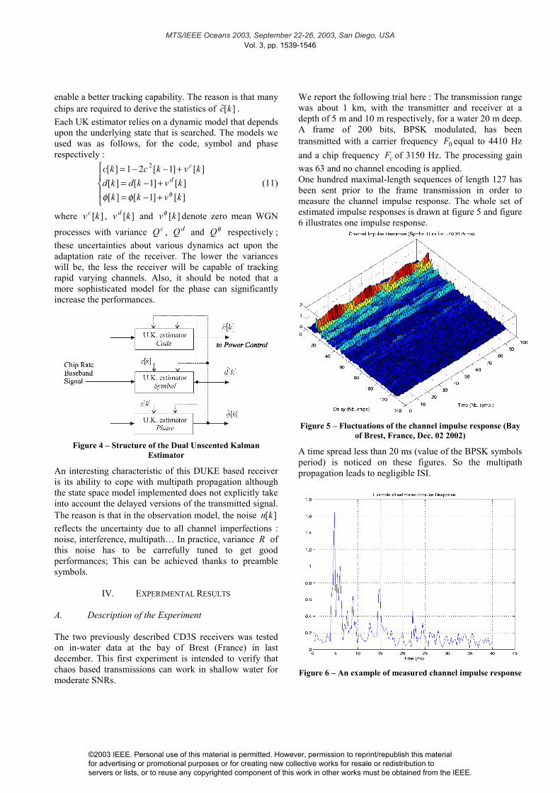
We report the following trial here : The transmission rangewas about 1 km, with the transmitter and receiver at adepth of 5 m and 10 m respectively, for a water 20 m deep.A frame of 200 bits, BPSK modulated, has beentransmitted with a carrier frequency 0F equal to 4410 Hzand a chip frequency cF of 3150 Hz. The processing gainwas 63 and no channel encoding is applied.One hundred maximal-length sequences of length 127 hasbeen sent prior to the frame transmission in order tomeasure the channel impulse response. The whole set ofestimated impulse responses is drawn at figure 5 and figure6 illustrates one impulse response.
Figure 5 – Fluctuations of the channel impulse response (Bayof Brest, France, Dec. 02 2002)
A time spread less than 20 ms (value of the BPSK symbolsperiod) is noticed on these figures. So the multipathpropagation leads to negligible ISI.
Figure 6 – An example of measured channel impulse response
Vol. 3, pp. 1539-1546
©2003 IEEE. Personal use of this material is permitted. However, permission to reprint/republish this material for advertising or promotional purposes or for creating new collective works for resale or redistribution to servers or lists, or to reuse any copyrighted component of this work in other works must be obtained from the IEEE.

������������ ����������������������������������������
The SNR value at the receiver input (in the Nyquist band)was about 7.5 dB. The Power Spectral Density (PSD) ofthe received signal, sampled at 22050 Hz, is illustrated atfigure 7.
Figure 7 – Power Spectral Density of the received signal
B. Performance Comparison of two receivers
- Conventional Matched Filter receiver –The results for the matched filter CD3S receiver arereported below. Due to the values of the processing gainand the data rate, this receiver does not significantly sufferfrom ISI and no additionnal RAKE processing is requiredto combat multipath propagation.The DLL performance is illustrated by figure 8. As long asthe E/L discriminator output stays in the interval [0.8, 1.2],the receiver code was considered on-time. Hence, we canobserve that the code delay is correctly tracked for thewhole frame.
Figure 8 - Evolution of the Early/Late discriminator
Figure 9 shows the estimated phase. As a limited spreadinggain and a sufficient value for the chip rate has been usedin this test, a rather good phase tracking is noticed.Additionnal experiments with higher processing gains onthe same channel did not yield better results. Thedependance of phase tracking upon the symbol rate is adrawback of this receiver ; It will not particularly suitedfor more difficult channels.
Figure 9 - Symbol rate estimated phase (Costas loop)
The gain control for a weighting factor α of 0.5 isillustrated by figure 10. This choice enables the receiver tocorrectly follow changes of signal power. However, as theestimation is performed at symbol rate only, more rapidchanges would be difficult to track.
Figure 10 - Power control in the conventional CD3S receiver
Vol. 3, pp. 1539-1546
©2003 IEEE. Personal use of this material is permitted. However, permission to reprint/republish this material for advertising or promotional purposes or for creating new collective works for resale or redistribution to servers or lists, or to reuse any copyrighted component of this work in other works must be obtained from the IEEE.
������������ ����������������������������������������
Figure 11 – Symbol scatter plot for the conventional CD3Sreceiver
Finally, figure 11 gives the symbol scatter plot for thetransmitted frame. No error was noticed here, but we canobserve the dregradation due to low rate phase tracking.
- DUKE receiver –
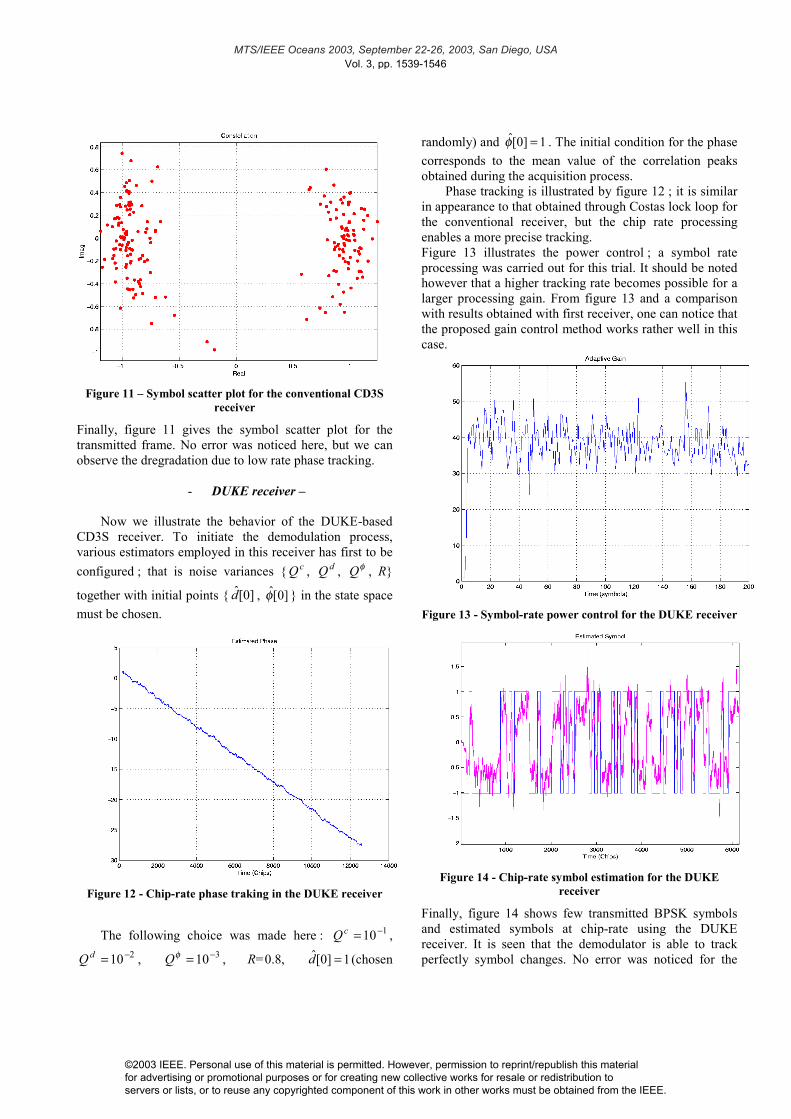
Now we illustrate the behavior of the DUKE-basedCD3S receiver. To initiate the demodulation process,various estimators employed in this receiver has first to beconfigured ; that is noise variances { cQ , dQ , φQ , R}
together with initial points { ]0[d̂ , ]0[φ̂ } in the state spacemust be chosen.
Figure 12 - Chip-rate phase traking in the DUKE receiver
The following choice was made here : 110−=cQ ,210−=dQ , 310−=φQ , R=0.8, 1]0[ˆ =d (chosen
randomly) and 1]0[ˆ =φ . The initial condition for the phasecorresponds to the mean value of the correlation peaksobtained during the acquisition process.
Phase tracking is illustrated by figure 12 ; it is similarin appearance to that obtained through Costas lock loop forthe conventional receiver, but the chip rate processingenables a more precise tracking.Figure 13 illustrates the power control ; a symbol rateprocessing was carried out for this trial. It should be notedhowever that a higher tracking rate becomes possible for alarger processing gain. From figure 13 and a comparisonwith results obtained with first receiver, one can notice thatthe proposed gain control method works rather well in thiscase.
Figure 13 - Symbol-rate power control for the DUKE receiver
Figure 14 - Chip-rate symbol estimation for the DUKEreceiver
Finally, figure 14 shows few transmitted BPSK symbolsand estimated symbols at chip-rate using the DUKEreceiver. It is seen that the demodulator is able to trackperfectly symbol changes. No error was noticed for the
Vol. 3, pp. 1539-1546
©2003 IEEE. Personal use of this material is permitted. However, permission to reprint/republish this material for advertising or promotional purposes or for creating new collective works for resale or redistribution to servers or lists, or to reuse any copyrighted component of this work in other works must be obtained from the IEEE.

������������ ����������������������������������������
whole frame. Due to process and observation noisespresent in DUKE models and the symbol estimation atchip-rate, the receiver implicitly combats multipath fading.
V. CONCLUSIONS & FUTURE WORK
Many recent papers claimed that use of chaotic codes cansignificantly decrease probabilities of interception anddetection of digital communication signals. At themoment, few practical investigations permitted to verifythis benefit. The problem of receiver design in a ChaoticDirect-Sequence Spread Spectrum System (CD3S) hasbeen considered in this paper. The aim is to report sea trialresults of such a system in standard shallow waterpropagation conditions (single user, moderate SNR, lowdoppler…). This first step will be followed by other testson in water data with more constraints such as covertnessand/or multiple access.Two receiver schemes has been described : the firstreceiver follows the conventional receiver structurefrequently encountered in DS-SS systems based on PNperiodic codes. There is just a change at the spreading codegenerator level (use of a chaotic dynamic instead of linearfeedback shift registers). Good performances was obtainedfor this receiver, although it is not capable of trackingrapid varying channels. Its main advantage is itscomputational/implementation simplicity. An additionnalRAKE processing can be performed to increase theperformances. The second receiver is more innovative ; itis based on a state-space formulation of the symbol/phaseestimation in baseband (no carrier PLL) thanks toUnscented Kalman filters. A dual estimation approach hasbeen proposed to solve the demodulation process (DUKEstructure). An additionnal UK filter is used for powercontrol purpose. From sea trial results, one can concludethat this approach is viable for difficult channels, as thesymbol and phase are tracked at chip-rate. Although thisapproach requires more complexity, the implementationremains simple.Additionnal investigations is now necessary to succeed inusing chaos for covertness transmission and/or in multipleaccess systems. The code delay synchronization will beexamined in a different way of Early/Late DLL, togetherwith effect of Doppler on the DUKE receiver.
REFERENCES
[1] M. Hasler « Synchronization of chaotic systems andtransmission of information », Int. J. Bifurcation and Chaos,Vol. 8, No 4, pp 647-659, 1998.
[2] G. Kolumban, M. P. Kennedy, L. O. Chua, « The role ofsynchronization in digital communication using chaos – PartII : Chaotic modulation and chaotic synchronization », IEEETrans. Circuits Syst., Vol. 45, No 11, 1998.
[3] L. Pecora, T. Caroll, « Synchronization in chaotic systems »,Phys. Rev. Lett., Vol. 64, pp. 821-823, 1990.
[4] E. M. Sozer, M. Stojanovic, J. G. Proakis, « UnderwaterAcoustic Networks », IEEE J. Oceanic Eng., Vol. 25, No 1,2000.
[5] G. Burel, C. Bouder, « Blind estimation of the pseudo-randomsequence of a direct-sequence spread spectrum signal », IEEE21st Century Military Communications Conference (IEEE-MILCOM’2000), October 22-25, 2000, Los Angeles, USA.
[6] M. K. Tsatsanis, G. B. Proakis, « Blind estimation of directsequence spread spectrum signals in multipath », IEEETrans. Signal Processing, Vol. 45, No. 5, pp. 1241-1252,1997.
[7] S. Azou, C. Pistre, G. Burel, "A chaotic direct sequencespread-spectrum system for underwater communication",IEEE-Oceans'02, Biloxi, Mississippi, Oct. 2002.
[8] J. G. Proakis, Digital communications, 3rd ed., Mac-Graw-HillInt. Ed., 1995.
[9] S. Julier, J. Uhlmann, H. F. Durrant-Whyte, « A new methodfor the nonlinear transformation of means and covariances infilters and estimators », IEEE Trans. Automat. Contr., Vol.45, No. 3, pp. 477-482, 2000.
[10] H. S. Chang, Y. W. Park, Y. H. Lee, « DS-SS CodeAcquisition Based on Simultaneous Search andVerification », IEEE Trans. On Communications, Vol.48, No. 6, June 2000.
[11] L. Freitag, M. Stojanovic, S. Singh, M. Johnson, « Analysisof Channel Effects on Direct-Sequence and Frequency-Hopped Spread-Spectrum Acoustic Communication », IEEEJ. Oceanic Eng., Vol. 26, No. 4, Oct. 2001.
[12] E. M. Sozer et al., “Direct Sequence Spread Spectrum BasedModem for Underwater Acoustic Communication andChannel Measuremenst”, Proc. IEEE OCEANS Conf.,Seattle, USA, Sept. 1999.
[13] M. Stojanovic, L. Freitag, “Hypothesis-FeedbackEqualization for Direct-Sequence Spread-SpectrumUnderwater Communications”, Proc. IEEE OCEANS Conf.,2000.
[14] H. Leung, J. Lam, “Design of demodulator for the chaoticmodulation communication”, IEEE Trans. Circuits Syst. I,Vol. 44, 1997.
[15] Y. Bar-Shalom, X.-R. Li, « Estimation and Tracking –Principles, Techniques ans Software », Artech House, 1993.
[16] E. A. Wan and R. van der Merwe, "Kalman Filtering andNeural Networks", chap. 7 : The Unscented Kalman Filter,Wiley Publishing, Eds. S. Haykin, 2001.
Vol. 3, pp. 1539-1546
©2003 IEEE. Personal use of this material is permitted. However, permission to reprint/republish this material for advertising or promotional purposes or for creating new collective works for resale or redistribution to servers or lists, or to reuse any copyrighted component of this work in other works must be obtained from the IEEE.