seagate crystal reports - trcsy
TRANSCRIPT

System ChecksumsBy ae
AHU-1 (Atrium & North Offices) Variable Volume Reheat (30% Min Flow Default)
HEATING COIL PEAKCLG SPACE PEAKCOOLING COIL PEAK TEMPERATURES13 / 1Mo/Hr:7 / 9Mo/Hr:7 / 15Mo/Hr:Peaked at Time: Cooling Heating
SADBOADB: 1378OADB:91 / 77 / 118OADB/WB/HR:Outside Air: 55.0 83.5Plenum 76.6 67.6ReturnPercentCoil PeakSpace PeakSpace PercentPercentNetPlenumSpace 77.4 67.6Ret/OASens. + Lat. Of TotalTot SensSpace SensOf TotalSensibleOf TotalTotalSens. + Lat 48.881.6
0.00.3Fn MtrTDBtu/h (%)Btu/hBtu/h(%)Btu/h(%)Btu/hBtu/h0.00.7Fn BldTDEnvelope Loads0.02.2Fn Frict0Skylite Solar 0.00000.0000.0000
0Skylite Cond 0.00000.0000.00000Roof Cond 7.91-45,32100.0002.1019,90019,900
0.00137,789Glass Solar 0045.53217,96914.52137,789022,830Glass Cond -83,305 14.54-83,3050.924,4092.4122,8300 AIRFLOWS
HeatingCooling1,346Wall Cond 1.84-10,569-3,2520.381,7980.434,1242,778
3,1736,851Vent0Partition 0.00000.0000.000
00Infil0Exposed Floor 0.00000.0000.000
7,93821,581Supply0.000Infiltration -7-70.0000.000
7,938 7,938MinStop/Rh24.29161,965Sub Total ==> -139,202-86,56446.83224,17619.46184,64322,679
21,581Return 7,938Internal Loads3,1736,851Exhaust126,658Lights 0.000026.46126,65816.69158,32331,665
0 0Rm Exh169,412People 0.000020.4898,03117.86169,41200Auxiliary14,456Misc 0.00003.0214,4561.5214,4560
310,526Sub Total ==> 0.000049.96239,14536.07342,19131,665
20,579Ceiling Load 0.000-31,4973.1214,9470.000-20,5790Ventilation Load 30.12-172,59000.00037.20352,9710
Sup. Fan Heat 7.1367,614
ENGINEERING CKSHeatingCooling
Ret. Fan Heat 1.7816,90416,904
% OA 40.031.7
Duct Heat Pkup 0.0000
0.190.51cfm/ft²
117Ov/Undr Sizing 0.00000.094310.01117
272.97cfm/ton
Exhaust Heat -1.277,277-1.66-15,715
530.49ft²/ton-13.6722.62Btu/hr·ft²
396No. People493,187Grand Total ==> 100.00-573,094-118,061100.00478,698100.00948,72434,953
AREAS HEATING COIL SELECTIONCOOLING COIL SELECTIONTotal Capacity Sens Cap. Coil Airflow Enter DB/WB/HR Leave DB/WB/HR Gross Total Glass Coil Airflow Ent LvgCapacity
ton MBh MBh cfm °F °F gr/lb °F °F gr/lb ft² (%) °F°FcfmMBh
Floor 41,941 Main Htg -278.6 7,938 51.8 83.579.1 948.7 629.7 19,016 81.6 67.1 77.1 51.8 50.6 53.3Main ClgPart 0 Aux Htg 0.0 0.00.000.0 0.0 0.0 0 0.0 0.0 0.0 0.0 0.0 0.0Aux ClgExFlr 0 -294.8Preheat 13.0 51.86,8510.0 0.0 0.0 0 0.0 0.0 0.0 0.0 0.0 0.0Opt VentRoof 21,873 0 0Wall 7,824 5,010 64 Humidif 0.0 0 0.0 0.079.1 948.7Total
Opt Vent 0.0 0.00.00-573.4Total
Envelope LoadsSkylite SolarSkylite CondRoof CondGlass SolarGlass CondWall CondPartitionExposed FloorInfiltrationSub Total ==>
LightsPeopleMiscSub Total ==>
Ceiling LoadVentilation Load
Additional Reheat
OA Preheat Diff.
Ov/Undr SizingExhaust Heat
RA Preheat Diff.
Grand Total ==>
Internal Loads
0
-177,315-91,264
30.9415.92
0.00
-15,715
Reheat at Design 0 0.00
TRACE® 700 v4.1 calculated at 10:27 AM on 04/03/2006Project Name: SSBDataset Name: Alternative - 1 System Checksums report Page 1 of 6C:\Documents and Settings\jpf161\THESIS\TRACE\HCC_SSB0403061657BAK.TRC

System ChecksumsBy ae
AHU-2 (South Offices) Variable Volume Reheat (30% Min Flow Default)
HEATING COIL PEAKCLG SPACE PEAKCOOLING COIL PEAK TEMPERATURES13 / 1Mo/Hr:9 / 10Mo/Hr:7 / 15Mo/Hr:Peaked at Time: Cooling Heating
SADBOADB: 1372OADB:91 / 77 / 118OADB/WB/HR:Outside Air: 55.0 77.7Plenum 76.3 69.0ReturnPercentCoil PeakSpace PeakSpace PercentPercentNetPlenumSpace 77.1 69.0Ret/OASens. + Lat. Of TotalTot SensSpace SensOf TotalSensibleOf TotalTotalSens. + Lat 26.684.6
0.00.3Fn MtrTDBtu/h (%)Btu/hBtu/h(%)Btu/h(%)Btu/hBtu/h0.00.7Fn BldTDEnvelope Loads0.02.2Fn Frict0Skylite Solar 0.00000.0000.0000
0Skylite Cond 0.00000.0000.00000Roof Cond 2.60-12,53300.0000.615,4295,429
0.0054,619Glass Solar 0029.0997,0216.1954,61909,763Glass Cond -35,640 7.40-35,640-0.59-1,9531.119,7630 AIRFLOWS
HeatingCooling336Wall Cond 1.37-6,585-1,3320.062060.191,6651,329
4,2677,432Vent0Partition 0.00000.0000.000
00Infil0Exposed Floor 0.00000.0000.000
5,63315,036Supply0.000Infiltration -5-50.0000.000
5,633 5,633MinStop/Rh11.3764,718Sub Total ==> -54,763-36,97728.5795,2758.0971,4766,758
15,036Return 5,633Internal Loads4,2677,432Exhaust111,044Lights 0.000033.30111,04415.72138,80527,761
0 0Rm Exh186,000People 0.000031.39104,70021.06186,00000Auxiliary10,312Misc 0.00003.0910,3121.1710,3120
307,356Sub Total ==> 0.000067.78226,05637.95335,11727,761
14,526Ceiling Load 0.000-11,3713.3111,0410.000-14,5260Ventilation Load 55.98-269,71300.00049.00432,7400
Sup. Fan Heat 5.5448,939
ENGINEERING CKSHeatingCooling
Ret. Fan Heat 1.3912,23512,235
% OA 75.749.4
Duct Heat Pkup 0.0000
0.160.43cfm/ft²
0Ov/Undr Sizing 0.00000.341,1430.000
204.32cfm/ton
Exhaust Heat -1.014,859-1.97-17,418
474.88ft²/ton-13.7925.27Btu/hr·ft²
422No. People386,600Grand Total ==> 100.00-481,824-48,348100.00333,516100.00883,08914,810
AREAS HEATING COIL SELECTIONCOOLING COIL SELECTIONTotal Capacity Sens Cap. Coil Airflow Enter DB/WB/HR Leave DB/WB/HR Gross Total Glass Coil Airflow Ent LvgCapacity
ton MBh MBh cfm °F °F gr/lb °F °F gr/lb ft² (%) °F°FcfmMBh
Floor 34,947 Main Htg -162.1 5,633 51.8 77.773.6 883.1 500.9 13,764 84.6 70.7 91.6 51.8 50.4 52.4Main ClgPart 0 Aux Htg 0.0 0.00.000.0 0.0 0.0 0 0.0 0.0 0.0 0.0 0.0 0.0Aux ClgExFlr 0 -319.7Preheat 13.0 51.87,4320.0 0.0 0.0 0 0.0 0.0 0.0 0.0 0.0 0.0Opt VentRoof 5,900 0 0Wall 3,956 2,104 53 Humidif 0.0 0 0.0 0.073.6 883.1Total
Opt Vent 0.0 0.00.00-481.8Total
Envelope LoadsSkylite SolarSkylite CondRoof CondGlass SolarGlass CondWall CondPartitionExposed FloorInfiltrationSub Total ==>
LightsPeopleMiscSub Total ==>
Ceiling LoadVentilation Load
Additional Reheat
OA Preheat Diff.
Ov/Undr SizingExhaust Heat
RA Preheat Diff.
Grand Total ==>
Internal Loads
0
-136,175-26,032
28.265.400.00
-17,418
Reheat at Design 0 0.00
TRACE® 700 v4.1 calculated at 10:27 AM on 04/03/2006Project Name: SSBDataset Name: Alternative - 1 System Checksums report Page 2 of 6C:\Documents and Settings\jpf161\THESIS\TRACE\HCC_SSB0403061657BAK.TRC

System ChecksumsBy ae
AHU-3 (Private Dining & Catering) Variable Volume Reheat (30% Min Flow Default)
HEATING COIL PEAKCLG SPACE PEAKCOOLING COIL PEAK TEMPERATURES13 / 1Mo/Hr:9 / 10Mo/Hr:7 / 11Mo/Hr:Peaked at Time: Cooling Heating
SADBOADB: 1372OADB:84 / 74 / 111OADB/WB/HR:Outside Air: 55.0 89.9Plenum 76.0 66.6ReturnPercentCoil PeakSpace PeakSpace PercentPercentNetPlenumSpace 76.8 66.6Ret/OASens. + Lat. Of TotalTot SensSpace SensOf TotalSensibleOf TotalTotalSens. + Lat 46.379.3
0.00.2Fn MtrTDBtu/h (%)Btu/hBtu/h(%)Btu/h(%)Btu/hBtu/h0.00.5Fn BldTDEnvelope Loads0.01.4Fn Frict0Skylite Solar 0.00000.0000.0000
0Skylite Cond 0.00000.0000.00000Roof Cond 5.71-10,24900.0000.641,7671,767
0.0075,980Glass Solar 0067.65101,68327.3375,98005,534Glass Cond -36,316 20.25-36,316-1.32-1,9901.995,5340 AIRFLOWS
HeatingCooling3,361Wall Cond 4.63-8,302-5,2302.013,0161.975,4852,125
8082,080Vent0Partition 0.00000.0000.000
00Infil0Exposed Floor 0.00000.0000.000
2,1296,777Supply0.000Infiltration -1-10.0000.000
2,129 2,129MinStop/Rh30.5984,875Sub Total ==> -54,867-41,54768.33102,70931.9388,7663,892
6,777Return 2,129Internal Loads8082,080Exhaust18,146Lights 0.000012.0718,1468.1622,6834,537
0 0Rm Exh56,800People 0.000018.9628,50020.4356,80000Auxiliary0Misc 0.00000.0000.0000
74,946Sub Total ==> 0.000031.0346,64628.5979,4834,537
1,655Ceiling Load 0.000-5,3700.649590.000-1,6550Ventilation Load 28.46-51,04800.00033.9794,4490
Sup. Fan Heat 5.1214,232
ENGINEERING CKSHeatingCooling
Ret. Fan Heat 1.925,3375,337
% OA 37.930.7
Duct Heat Pkup 0.0000
0.421.35cfm/ft²
0Ov/Undr Sizing 0.00000.0000.000
292.49cfm/ton
Exhaust Heat -1.683,015-1.53-4,241
217.32ft²/ton-35.6255.22Btu/hr·ft²
104No. People161,475Grand Total ==> 100.00-179,345-46,917100.00150,313100.00278,0257,869
AREAS HEATING COIL SELECTIONCOOLING COIL SELECTIONTotal Capacity Sens Cap. Coil Airflow Enter DB/WB/HR Leave DB/WB/HR Gross Total Glass Coil Airflow Ent LvgCapacity
ton MBh MBh cfm °F °F gr/lb °F °F gr/lb ft² (%) °F°FcfmMBh
Floor 5,035 Main Htg -87.4 2,129 52.9 89.923.2 278.0 175.8 6,004 79.3 66.4 77.3 52.9 51.1 53.2Main ClgPart 0 Aux Htg 0.0 0.00.000.0 0.0 0.0 0 0.0 0.0 0.0 0.0 0.0 0.0Aux ClgExFlr 0 -92.0Preheat 13.0 52.92,0800.0 0.0 0.0 0 0.0 0.0 0.0 0.0 0.0 0.0Opt VentRoof 5,035 0 0Wall 3,786 2,144 57 Humidif 0.0 0 0.0 0.023.2 278.0Total
Opt Vent 0.0 0.00.00-179.4Total
Envelope LoadsSkylite SolarSkylite CondRoof CondGlass SolarGlass CondWall CondPartitionExposed FloorInfiltrationSub Total ==>
LightsPeopleMiscSub Total ==>
Ceiling LoadVentilation Load
Additional Reheat
OA Preheat Diff.
Ov/Undr SizingExhaust Heat
RA Preheat Diff.
Grand Total ==>
Internal Loads
0
-56,256-20,189
31.3711.26
0.00
-4,241
Reheat at Design 0 0.00
TRACE® 700 v4.1 calculated at 10:27 AM on 04/03/2006Project Name: SSBDataset Name: Alternative - 1 System Checksums report Page 3 of 6C:\Documents and Settings\jpf161\THESIS\TRACE\HCC_SSB0403061657BAK.TRC

System ChecksumsBy ae
AHU-4 (Bookstore) Variable Volume Reheat (30% Min Flow Default)
HEATING COIL PEAKCLG SPACE PEAKCOOLING COIL PEAK TEMPERATURES13 / 1Mo/Hr:7 / 9Mo/Hr:7 / 8Mo/Hr:Peaked at Time: Cooling Heating
SADBOADB: 1378OADB:76 / 72 / 111OADB/WB/HR:Outside Air: 55.0 86.6Plenum 75.5 69.5ReturnPercentCoil PeakSpace PeakSpace PercentPercentNetPlenumSpace 76.3 69.5Ret/OASens. + Lat. Of TotalTot SensSpace SensOf TotalSensibleOf TotalTotalSens. + Lat 16.676.1
0.00.2Fn MtrTDBtu/h (%)Btu/hBtu/h(%)Btu/h(%)Btu/hBtu/h0.00.5Fn BldTDEnvelope Loads0.01.5Fn Frict0Skylite Solar 0.00000.0000.0000
0Skylite Cond 0.00000.0000.00000Roof Cond 0.00000.0000.0000
0.00121,697Glass Solar 0066.27121,25736.26121,6970291Glass Cond -24,649 11.98-24,6490.711,3040.092910 AIRFLOWS
HeatingCooling303Wall Cond 1.90-3,910-1,8410.152700.20671368
2,3462,540Vent0Partition 0.00000.0000.000
00Infil1,878Exposed Floor 9.04-18,603-18,6030.921,6860.561,878
2,5048,249Supply0.000Infiltration -1-10.0000.000
2,504 2,504MinStop/Rh22.92124,170Sub Total ==> -47,163-45,09368.05124,51737.10124,538368
8,249Return 2,504Internal Loads2,3462,540Exhaust21,166Lights 0.000011.5721,1667.8826,4585,292
0 0Rm Exh69,440People 0.000019.2535,21720.6969,44000Auxiliary924Misc 0.00000.519240.289240
91,530Sub Total ==> 0.000031.3257,30728.8596,8225,292
1,164Ceiling Load 0.000-8360.631,1550.000-1,1640Ventilation Load 72.08-148,30900.00026.8290,0360
Sup. Fan Heat 6.1320,591
ENGINEERING CKSHeatingCooling
Ret. Fan Heat 2.187,3197,319
% OA 93.730.8
Duct Heat Pkup 0.0000
0.341.11cfm/ft²
0Ov/Undr Sizing 0.00000.0000.000
294.92cfm/ton
Exhaust Heat -0.591,207-1.09-3,647
266.38ft²/ton-27.6445.05Btu/hr·ft²
130No. People216,865Grand Total ==> 100.00-205,757-45,929100.00182,979100.00335,6608,167
AREAS HEATING COIL SELECTIONCOOLING COIL SELECTIONTotal Capacity Sens Cap. Coil Airflow Enter DB/WB/HR Leave DB/WB/HR Gross Total Glass Coil Airflow Ent LvgCapacity
ton MBh MBh cfm °F °F gr/lb °F °F gr/lb ft² (%) °F°FcfmMBh
Floor 7,451 Main Htg -94.0 2,504 52.8 86.628.0 335.7 213.3 8,234 76.1 65.3 76.9 52.8 51.7 55.8Main ClgPart 0 Aux Htg 0.0 0.00.000.0 0.0 0.0 0 0.0 0.0 0.0 0.0 0.0 0.0Aux ClgExFlr 3,596 -112.0Preheat 13.0 52.82,5400.0 0.0 0.0 0 0.0 0.0 0.0 0.0 0.0 0.0Opt VentRoof 0 0 0Wall 2,250 1,455 65 Humidif 0.0 0 0.0 0.028.0 335.7Total
Opt Vent 0.0 0.00.00-206.0Total
Envelope LoadsSkylite SolarSkylite CondRoof CondGlass SolarGlass CondWall CondPartitionExposed FloorInfiltrationSub Total ==>
LightsPeopleMiscSub Total ==>
Ceiling LoadVentilation Load
Additional Reheat
OA Preheat Diff.
Ov/Undr SizingExhaust Heat
RA Preheat Diff.
Grand Total ==>
Internal Loads
0
-8,548-2,944
4.151.430.00
-3,647
Reheat at Design 0 0.00
TRACE® 700 v4.1 calculated at 10:27 AM on 04/03/2006Project Name: SSBDataset Name: Alternative - 1 System Checksums report Page 4 of 6C:\Documents and Settings\jpf161\THESIS\TRACE\HCC_SSB0403061657BAK.TRC

System ChecksumsBy ae
AHU-5 (Dining Hall Seating & Service) Variable Volume Reheat (30% Min Flow Default)
HEATING COIL PEAKCLG SPACE PEAKCOOLING COIL PEAK TEMPERATURES13 / 1Mo/Hr:6 / 18Mo/Hr:7 / 15Mo/Hr:Peaked at Time: Cooling Heating
SADBOADB: 1384OADB:91 / 77 / 118OADB/WB/HR:Outside Air: 55.0 78.8Plenum 75.5 69.8ReturnPercentCoil PeakSpace PeakSpace PercentPercentNetPlenumSpace 76.5 69.8Ret/OASens. + Lat. Of TotalTot SensSpace SensOf TotalSensibleOf TotalTotalSens. + Lat 13.991.0
0.00.2Fn MtrTDBtu/h (%)Btu/hBtu/h(%)Btu/h(%)Btu/hBtu/h0.00.5Fn BldTDEnvelope Loads0.01.5Fn Frict0Skylite Solar 0.00000.0000.0000
0Skylite Cond 0.00000.0000.00000Roof Cond 0.00000.0000.0000
0.0029,543Glass Solar 0016.1836,9763.4629,54309,116Glass Cond -33,277 5.98-33,2772.195,0141.079,1160 AIRFLOWS
HeatingCooling180Wall Cond 0.35-1,925-9060.061270.04374194
3,52210,300Vent0Partition 0.00000.0000.000
00Infil0Exposed Floor 0.00000.0000.000
3,58010,300Supply0.000Infiltration -1-10.0000.000
3,580 3,580MinStop/Rh6.3338,838Sub Total ==> -35,202-34,18318.4342,1174.5739,032194
10,300Return 3,580Internal Loads3,52210,300Exhaust24,183Lights 0.000010.5824,1833.5430,2296,046
0 0Rm Exh322,850People 0.000070.65161,42537.82322,85000Auxiliary0Misc 0.00000.0000.0000
347,033Sub Total ==> 0.000081.23185,60841.36353,0796,046
531Ceiling Load 0.000-1860.224990.000-5310Ventilation Load 40.02-222,64600.00051.82442,3230
Sup. Fan Heat 2.8924,669
ENGINEERING CKSHeatingCooling
Ret. Fan Heat 1.2510,65010,650
% OA 98.4100.0
Duct Heat Pkup 0.0000
0.361.04cfm/ft²
268Ov/Undr Sizing 0.00000.122690.03268
144.79cfm/ton
Exhaust Heat -0.15820-1.92-16,395
139.86ft²/ton-56.0785.80Btu/hr·ft²
587No. People386,671Grand Total ==> 100.00-556,278-34,369100.00228,493100.00853,626-36
AREAS HEATING COIL SELECTIONCOOLING COIL SELECTIONTotal Capacity Sens Cap. Coil Airflow Enter DB/WB/HR Leave DB/WB/HR Gross Total Glass Coil Airflow Ent LvgCapacity
ton MBh MBh cfm °F °F gr/lb °F °F gr/lb ft² (%) °F°FcfmMBh
Floor 9,949 Main Htg -103.1 3,580 52.8 78.871.1 853.6 430.1 10,153 91.0 76.9 118.3 52.8 52.8 59.7Main ClgPart 0 Aux Htg 0.0 0.00.000.0 0.0 0.0 0 0.0 0.0 0.0 0.0 0.0 0.0Aux ClgExFlr 0 -454.8Preheat 13.0 52.810,3000.0 0.0 0.0 0 0.0 0.0 0.0 0.0 0.0 0.0Opt VentRoof 0 0 0Wall 2,865 1,965 69 Humidif 0.0 0 0.0 0.071.1 853.6Total
Opt Vent 0.0 0.00.00-557.8Total
Envelope LoadsSkylite SolarSkylite CondRoof CondGlass SolarGlass CondWall CondPartitionExposed FloorInfiltrationSub Total ==>
LightsPeopleMiscSub Total ==>
Ceiling LoadVentilation Load
Additional Reheat
OA Preheat Diff.
Ov/Undr SizingExhaust Heat
RA Preheat Diff.
Grand Total ==>
Internal Loads
0
-299,2490
53.790.000.00
-16,395
Reheat at Design 0 0.00
TRACE® 700 v4.1 calculated at 10:27 AM on 04/03/2006Project Name: SSBDataset Name: Alternative - 1 System Checksums report Page 5 of 6C:\Documents and Settings\jpf161\THESIS\TRACE\HCC_SSB0403061657BAK.TRC

System ChecksumsBy ae
AHU-6 (Kitchen) Incremental Heat Pump
HEATING COIL PEAKCLG SPACE PEAKCOOLING COIL PEAK TEMPERATURES13 / 1Mo/Hr:3 / 12Mo/Hr:7 / 15Mo/Hr:Peaked at Time: Cooling Heating
SADBOADB: 1355OADB:91 / 77 / 118OADB/WB/HR:Outside Air: 55.0 70.0Plenum 84.9 70.0ReturnPercentCoil PeakSpace PeakSpace PercentPercentNetPlenumSpace 84.9 70.0Ret/OASens. + Lat. Of TotalTot SensSpace SensOf TotalSensibleOf TotalTotalSens. + Lat 69.984.9
0.00.2Fn MtrTDBtu/h (%)Btu/hBtu/h(%)Btu/h(%)Btu/hBtu/h0.00.4Fn BldTDEnvelope Loads0.01.2Fn Frict0Skylite Solar 0.00000.0000.0000
0Skylite Cond 0.00000.0000.00000Roof Cond 0.00000.0000.0000
0.000Glass Solar 000.0000.00000Glass Cond 0 0.0000.0000.0000 AIRFLOWS
HeatingCooling0Wall Cond 0.00000.0000.0000
4040Vent0Partition 0.00000.0000.000
00Infil0Exposed Floor 0.00000.0000.000
41,04041,040Supply0.010Infiltration 000.0000.000
0 0MinStop/Rh0.010Sub Total ==> 000.0000.0000
41,040Return 41,040Internal Loads4040Exhaust5,242Lights 0.00000.385,2420.456,5521,310
0 0Rm Exh3,650People 0.00000.141,8750.253,65000Auxiliary1,353,868Misc 0.000099.331,353,86893.541,353,8680
1,362,759Sub Total ==> 0.000099.851,360,98494.241,364,0701,310
2,038Ceiling Load 0.00000.152,0480.000-2,0380Ventilation Load 100.00-2,52900.0000.142,0900
Sup. Fan Heat 5.6581,716
ENGINEERING CKSHeatingCooling
Ret. Fan Heat 0.0000
% OA 0.10.1
Duct Heat Pkup 0.0000
24.1424.14cfm/ft²
0Ov/Undr Sizing -0.02000.0000.000
340.25cfm/ton
Exhaust Heat 0.000-0.03-441
14.09ft²/ton-1.49851.43Btu/hr·ft²
7No. People1,364,797Grand Total ==> 100.00-2,5290100.001,363,033100.001,447,436-1,168
AREAS HEATING COIL SELECTIONCOOLING COIL SELECTIONTotal Capacity Sens Cap. Coil Airflow Enter DB/WB/HR Leave DB/WB/HR Gross Total Glass Coil Airflow Ent LvgCapacity
ton MBh MBh cfm °F °F gr/lb °F °F gr/lb ft² (%) °F°FcfmMBh
Floor 1,700 Main Htg -2.5 41,040 69.9 70.0120.6 1,447.4 1,444.3 41,040 85.5 59.5 34.9 53.8 46.1 34.3Main ClgPart 0 Aux Htg 0.0 0.00.000.0 0.0 0.0 0 0.0 0.0 0.0 0.0 0.0 0.0Aux ClgExFlr 0 0.0Preheat 0.0 0.000.0 0.0 0.0 0 0.0 0.0 0.0 0.0 0.0 0.0Opt VentRoof 0 0 0Wall 0 0 0 Humidif 0.0 0 0.0 0.0120.6 1,447.4Total
Opt Vent 0.0 0.00.00-2.5Total
Envelope LoadsSkylite SolarSkylite CondRoof CondGlass SolarGlass CondWall CondPartitionExposed FloorInfiltrationSub Total ==>
LightsPeopleMiscSub Total ==>
Ceiling LoadVentilation Load
Additional Reheat
OA Preheat Diff.
Ov/Undr SizingExhaust Heat
RA Preheat Diff.
Grand Total ==>
Internal Loads
0
00
0.000.010.00
-441
Reheat at Design 0 0.00
TRACE® 700 v4.1 calculated at 10:27 AM on 04/03/2006Project Name: SSBDataset Name: Alternative - 1 System Checksums report Page 6 of 6C:\Documents and Settings\jpf161\THESIS\TRACE\HCC_SSB0403061657BAK.TRC

System ChecksumsBy ae
WSHPs (AHU-1,4 N-WING) Water Source Heat Pump
HEATING COIL PEAKCLG SPACE PEAKCOOLING COIL PEAK TEMPERATURES13 / 1Mo/Hr:7 / 9Mo/Hr:7 / 9Mo/Hr:Peaked at Time: Cooling Heating
SADBOADB: 1378OADB:78 / 72 / 107OADB/WB/HR:Outside Air: 58.4 70.3Plenum 76.3 69.1ReturnPercentCoil PeakSpace PeakSpace PercentPercentNetPlenumSpace 76.3 69.1Ret/OASens. + Lat. Of TotalTot SensSpace SensOf TotalSensibleOf TotalTotalSens. + Lat 66.576.0
0.00.0Fn MtrTDBtu/h (%)Btu/hBtu/h(%)Btu/h(%)Btu/hBtu/h0.00.1Fn BldTDEnvelope Loads0.00.2Fn Frict0Skylite Solar 0.00000.0000.0000
0Skylite Cond 0.00000.0000.00000Roof Cond 6.01-46,54800.0002.5228,17528,175
0.00376,935Glass Solar 0051.61391,82733.69376,935010,085Glass Cond -107,954 13.94-107,9540.866,5130.9010,0850 AIRFLOWS
HeatingCooling2,139Wall Cond 1.89-14,660-5,0920.261,9930.495,4873,348
8,5289,429Vent0Partition 0.00000.0000.000
00Infil1,878Exposed Floor 2.40-18,603-18,6030.221,6860.171,878
41,27641,276Supply0.002Infiltration -8-80.0020.002
0 0MinStop/Rh24.24391,039Sub Total ==> -187,773-131,65752.95402,02137.77422,56231,523
41,276Return 41,276Internal Loads8,5289,429Exhaust149,485Lights 0.000019.69149,48516.70186,85637,371
0 0Rm Exh238,852People 0.000017.55133,24821.35238,85200Auxiliary51,267Misc 0.00006.7551,2674.5851,2670
439,603Sub Total ==> 0.000043.99333,99942.63476,97537,371
20,337Ceiling Load 0.000-14,0203.0623,2100.000-20,3370Ventilation Load 16.48-127,66800.00019.73220,7010
Sup. Fan Heat 1.0912,230
ENGINEERING CKSHeatingCooling
Ret. Fan Heat 0.0000
% OA 20.722.8
Duct Heat Pkup 0.0000
0.820.82cfm/ft²
0Ov/Undr Sizing 0.05-357-3570.0000.000
367.98cfm/ton
Exhaust Heat -1.027,873-1.22-13,694
447.87ft²/ton-12.8026.79Btu/hr·ft²
525No. People850,979Grand Total ==> 100.00-774,531-146,034100.00759,231100.001,118,77334,863
AREAS HEATING COIL SELECTIONCOOLING COIL SELECTIONTotal Capacity Sens Cap. Coil Airflow Enter DB/WB/HR Leave DB/WB/HR Gross Total Glass Coil Airflow Ent LvgCapacity
ton MBh MBh cfm °F °F gr/lb °F °F gr/lb ft² (%) °F°FcfmMBh
Floor 50,237 Main Htg -203.8 41,276 65.9 70.393.2 1,118.8 768.4 41,276 76.1 64.8 74.2 58.2 56.0 63.9Main ClgPart 0 Aux Htg -145.7 0.00.000.0 0.0 0.0 0 0.0 0.0 0.0 0.0 0.0 0.0Aux ClgExFlr 3,596 0.0Preheat 0.0 0.0018.9 227.2 175.7 9,429 91.3 77.1 118.7 74.5 71.2 110.9Opt VentRoof 21,873 0 0Wall 10,074 6,465 64 Humidif 0.0 0 0.0 0.0112.2 1,346.0Total
Opt Vent -439.2 55.013.09,429-788.7Total
Envelope LoadsSkylite SolarSkylite CondRoof CondGlass SolarGlass CondWall CondPartitionExposed FloorInfiltrationSub Total ==>
LightsPeopleMiscSub Total ==>
Ceiling LoadVentilation Load
Additional Reheat
OA Preheat Diff.
Ov/Undr SizingExhaust Heat
RA Preheat Diff.
Grand Total ==>
Internal Loads
0
-445,333-21,273
57.502.750.00
-13,694
Reheat at Design 0 0.00
TRACE® 700 v4.1 calculated at 10:27 AM on 04/03/2006Project Name: SSBDataset Name: Alternative - 3 System Checksums report Page 1 of 2C:\Documents and Settings\jpf161\THESIS\TRACE\HCC_SSB0403061657BAK.TRC

System ChecksumsBy ae
WSHPs (AHU-2,3,5,6 S-WING) Water Source Heat Pump
HEATING COIL PEAKCLG SPACE PEAKCOOLING COIL PEAK TEMPERATURES13 / 1Mo/Hr:9 / 10Mo/Hr:7 / 15Mo/Hr:Peaked at Time: Cooling Heating
SADBOADB: 1372OADB:91 / 77 / 118OADB/WB/HR:Outside Air: 56.9 71.2Plenum 79.5 69.7ReturnPercentCoil PeakSpace PeakSpace PercentPercentNetPlenumSpace 79.5 69.7Ret/OASens. + Lat. Of TotalTot SensSpace SensOf TotalSensibleOf TotalTotalSens. + Lat 66.178.4
0.00.0Fn MtrTDBtu/h (%)Btu/hBtu/h(%)Btu/h(%)Btu/hBtu/h0.00.1Fn BldTDEnvelope Loads0.00.2Fn Frict0Skylite Solar 0.00000.0000.0000
0Skylite Cond 0.00000.0000.00000Roof Cond 1.59-23,53100.0000.349,5999,599
0.00241,552Glass Solar 0013.14290,1928.52241,552016,783Glass Cond -105,232 7.09-105,2320.092,0700.5916,7830 AIRFLOWS
HeatingCooling4,587Wall Cond 1.15-17,055-7,4680.235,0770.308,4483,861
21,26621,266Vent0Partition 0.00000.0000.000
00Infil0Exposed Floor 0.00000.0000.000
87,25587,255Supply0.002Infiltration -7-70.0010.002
0 0MinStop/Rh9.83262,924Sub Total ==> -145,825-112,70713.46297,3409.75276,38513,461
87,255Return 87,255Internal Loads21,26621,266Exhaust156,955Lights 0.00007.11156,9556.92196,19339,239
0 0Rm Exh569,300People 0.000013.43296,50020.08569,30000Auxiliary1,388,242Misc 0.000062.861,388,24248.971,388,2420
2,114,496Sub Total ==> 0.000083.391,841,69675.972,153,73539,239
68,289Ceiling Load 0.000-4,3143.1469,4450.000-68,2890Ventilation Load 23.85-353,77300.00017.12485,4020
Sup. Fan Heat 0.9125,853
ENGINEERING CKSHeatingCooling
Ret. Fan Heat 0.0000
% OA 24.424.4
Duct Heat Pkup 0.0000
1.721.72cfm/ft²
0Ov/Undr Sizing 0.03-466-4660.0000.000
312.80cfm/ton
Exhaust Heat -0.477,020-3.76-106,519
182.06ft²/ton-29.2165.91Btu/hr·ft²
1,120No. People2,445,709Grand Total ==> 100.00-1,483,607-117,487100.002,208,481100.002,834,856-122,108
AREAS HEATING COIL SELECTIONCOOLING COIL SELECTIONTotal Capacity Sens Cap. Coil Airflow Enter DB/WB/HR Leave DB/WB/HR Gross Total Glass Coil Airflow Ent LvgCapacity
ton MBh MBh cfm °F °F gr/lb °F °F gr/lb ft² (%) °F°FcfmMBh
Floor 50,786 Main Htg -493.1 87,255 66.1 71.2236.2 2,834.9 2,088.1 87,255 78.5 64.6 69.6 56.7 53.9 57.8Main ClgPart 0 Aux Htg 0.0 0.00.000.0 0.0 0.0 0 0.0 0.0 0.0 0.0 0.0 0.0Aux ClgExFlr 0 0.0Preheat 0.0 0.0042.7 512.5 396.3 21,266 91.3 77.1 118.7 74.5 71.2 110.9Opt VentRoof 10,935 0 0Wall 10,607 6,213 59 Humidif 0.0 0 0.0 0.0279.0 3,347.4Total
Opt Vent -990.6 55.013.021,266-1,483.6Total
Envelope LoadsSkylite SolarSkylite CondRoof CondGlass SolarGlass CondWall CondPartitionExposed FloorInfiltrationSub Total ==>
LightsPeopleMiscSub Total ==>
Ceiling LoadVentilation Load
Additional Reheat
OA Preheat Diff.
Ov/Undr SizingExhaust Heat
RA Preheat Diff.
Grand Total ==>
Internal Loads
0
-990,5640
66.770.000.00
-106,519
Reheat at Design 0 0.00
TRACE® 700 v4.1 calculated at 10:27 AM on 04/03/2006Project Name: SSBDataset Name: Alternative - 3 System Checksums report Page 2 of 2C:\Documents and Settings\jpf161\THESIS\TRACE\HCC_SSB0403061657BAK.TRC

SYSTEM SUMMARYDESIGN CAPACITY QUANTITIES
By ae
HEATINGCOOLINGMain Auxiliary Optional Main Auxiliary Optional
System System Vent Cooling System System Preheat Reheat Vent HeatingHumidificationCapacity Capacity Capacity Totals Capacity Capacity Capacity Capacity Capacity TotalsCapacity
tonSystem Description System Type ton ton ton Btu/h Btu/h Btu/h Btu/h Btu/h Btu/hBtu/h
AHU-1 (Atrium & NorthOffices)
Variable Volume Reheat (30% M 79 0 0 79 -278,640 0 -294,780 -160,253 0 -573,4200
AHU-2 (South Offices) Variable Volume Reheat (30% M 74 0 0 74 -162,089 0 -319,741 -113,735 0 -481,8300AHU-3 (Private Dining &Catering)
Variable Volume Reheat (30% M 23 0 0 23 -87,389 0 -91,956 -40,471 0 -179,3460
AHU-4 (Bookstore) Variable Volume Reheat (30% M 28 0 0 28 -93,995 0 -111,962 -47,866 0 -205,9560AHU-5 (Dining HallSeating & Service)
Variable Volume Reheat (30% M 71 0 0 71 -103,085 0 -454,747 -68,246 0 -557,8320
AHU-6 (Kitchen) Incremental Heat Pump 121 0 0 121 -2,533 0 0 0 0 -2,5330
Totals 396 0 0 396 -727,731 0 -1,273,186 -430,571 0 -2,000,9170
* The building peaked at hour 15 month 7 with a capacity of 396 tons.
Project Name: SSB TRACE® 700 v4.1 calculated at 10:27 AM on 04/03/2006Dataset Name: C:\Documents and Settings\jpf161\THESIS\TRACE\HCC_SSB0403061657BAK.TRC Alternative - 1 Design Capacity Quantities report page 1

SYSTEM SUMMARYDESIGN CAPACITY QUANTITIES
By ae
HEATINGCOOLINGMain Auxiliary Optional Main Auxiliary Optional
System System Vent Cooling System System Preheat Reheat Vent HeatingHumidificationCapacity Capacity Capacity Totals Capacity Capacity Capacity Capacity Capacity TotalsCapacity
tonSystem Description System Type ton ton ton Btu/h Btu/h Btu/h Btu/h Btu/h Btu/hBtu/h
WSHPs (AHU-1,4N-WING)
Water Source Heat Pump 93 0 19 112 -203,842 -145,683 0 0 -439,212 -788,7370
WSHPs (AHU-2,3,5,6S-WING)
Water Source Heat Pump 236 0 43 279 -493,048 0 0 0 -990,564 -1,483,6120
Totals 329 0 62 391 -696,890 -145,683 0 0 -1,429,776 -2,272,3490
* The building peaked at hour 8 month 7 with a capacity of 382 tons.
Project Name: SSB TRACE® 700 v4.1 calculated at 10:27 AM on 04/03/2006Dataset Name: C:\Documents and Settings\jpf161\THESIS\TRACE\HCC_SSB0403061657BAK.TRC Alternative - 3 Design Capacity Quantities report page 1

VENTILATION ASHRAE STD 90.1 Lighting
ASHRAE STD 90.1
Compliant
W/ft2 yes/no cfm/ person cfm/ft2 Total cfm
1st 100 ATRIUM / LOWER LOBBY 2,000 15 5500 0.6 NO 5.0 0.06 195 1 195 01st 101 FAMILY TOILET 48 0 --- 0.9 NO 1 0 01st 102 ELEV MACHINE ROOM 100 0 200 1.5 YES 5.0 0.06 6 1 6 01st 103 HOUSE KEEPING 100 0 --- 0.6 NO 5.0 0.06 6 1 6 01st 104 HOUSE KEEPING OFFICE 142 0 100 1.1 YES 5.0 0.06 9 1 9 01st 105 MECHANICAL 410 0 --- 1.5 YES 5.0 0.06 25 1 25 01st 106 STORAGE 1,440 0 300 0.6 NO 0.0 0.12 173 1 173 01st 107 OFFICE SUPPORT WORK AREA 1,125 6 450 1.1 NO 5.0 0.06 98 1 98 01st 108 RECEPTON 200 1 175 1.1 NO 5.0 0.06 17 1 17 01st 109 ASSISTANT OFFICE 140 2 550 1.1 NO 5.0 0.06 18 1 18 01st 110 MANAGER OFFICE 140 2 550 1.1 NO 5.0 0.06 18 1 18 01st 111 DIRECTOR OFFICE 150 2 660 1.1 NO 5.0 0.06 19 1 19 01st 112 CASH HANDLING WORK ROOM 250 4 260 1.5 YES 5.0 0.06 35 1 35 01st 112A CLOSET 20 0 --- 0.3 YES 5.0 0.06 1 1 1 01st 113 BOOKSTORE MERCHANDISING AREA 3,596 110 6360 1.7 YES 7.5 0.12 1257 1 1257 01st 114 WELCOME CENTER RECEPTION 230 6 428 1.3 NO 5.0 0.06 44 1 44 01st 115 CALL CENTER 100 1 75 1.1 NO 5.0 0.06 11 1 11 01st 116 SHARED OFFICE 595 6 400 1.1 NO 5.0 0.06 66 1 66 01st 116A OFFICE STORAGE 100 0 50 0.8 NO 0.0 0.12 12 1 12 01st 117 SECURITY RECEPTION 150 2 125 1.1 NO 5.0 0.06 19 1 19 01st 118 ID OFFICE 170 2 140 1.1 NO 5.0 0.06 20 1 20 01st 119 DIRECTOR OFFICE 150 2 135 1.1 YES 5.0 0.06 19 1 19 01st 119A STORAGE 100 0 105 0.8 NO 5.0 0.12 12 1 12 01st R11 WOMEN TOILET ROOM 350 0 300 0.9 NO 5.0 0.06 21 1 21 01st R12 MEN TOILET ROOM 350 0 300 0.9 NO 5.0 0.06 21 1 21 01st E11 ELECTRICAL CLOSET 40 0 285 1.5 NO 5.0 0.06 2 1 2 01st T11 TELECOM & AV 40 0 --- 1.5 NO 5.0 0.06 2 1 2 01st V11 VESTIBULE 190 0 --- 0.6 NO 5.0 0.06 11 1 11 01st C11 CORRIDOR 55 0 --- 0.5 NO 5.0 0.06 3 1 3 01st C12 CORRIDOR 1,025 0 440 0.5 NO 5.0 0.06 62 1 62 01st C13 CORRIDOR 500 0 315 0.5 NO 5.0 0.06 30 1 30 01st C14 CORRIDOR 545 0 --- 0.5 NO 5.0 0.06 33 2 0 331st C15 CORRIDOR 500 0 400 0.5 NO 5.0 0.06 30 2 0 301st C16 CORRIDOR 175 0 --- 0.5 NO 5.0 0.06 11 2 0 111st 120 MAIN DINING HALL 5730 250 11400 0.9 YES 7.5 0.18 2906 2 0 29061st 120A HOUSE KEEPING CLOSET 37 0 --- 0.6 NO 5.0 0.06 2 2 0 21st 121 FOOD SERVING AREA 2395 60 3600 1.2 YES 7.5 0.18 881 2 0 8811st 122 KITCHEN 1045 5 5700 1.2 YES 7.5 0.18 226 2 0 2261st 123 FOOD SERVICE OFFICE 135 2 150 1.1 NO 5.0 0.06 18 2 0 181st 124 DRY STORAGE 520 0 --- 0.8 NO 5.0 0.06 31 2 0 311st 125 PRIVATE RESTROOM 42 0 --- 0.9 NO 5.0 0.06 3 2 0 31st 126 HOUSEKEEPING STORAGE 35 0 --- 0.8 NO 5.0 0.12 4 2 0 41st 127 CATERING STORAGE 250 0 --- 0.8 NO 5.0 0.12 30 2 0 301st 128 CENTRAL TRASH 140 0 --- 0.8 NO 5.0 0.06 8 2 0 81st L11 LOADING DOCK 525 0 --- 0.5 YES 2 0 01st T12 TELECOM & AV 50 0 --- 1.5 YES 5.0 0.06 3 2 0 31st E12 ELECTRICAL CLOSET 50 0 285 1.5 YES 5.0 0.06 3 2 0 3
26,180 6421 LR TOTA 2232 418914"/12X12 18"/16X16
2nd 200 VENDING ALCOVE 100 0 ---- 0.5 NO 5.0 0.06 6 1 6 02nd 200A JANITORS CLOSET 60 0 ---- 0.6 NO 5.0 0.06 4 1 4 02nd 201 FINANCE RECEPTION 300 5 350 1.1 NO 5.0 0.06 43 1 43 02nd C201 CORRIDOR 1450 0 1950 0.5 YES 5.0 0.06 87 1 87 02nd 202 OFFICE SUPPORT WORK AREA 495 5 700 1.1 NO 5.0 0.06 55 1 55 02nd C202N CORRIDOR 110 0 ---- 0.5 NO 5.0 0.06 7 1 7 02nd 203 AR/CR OFFICE 2 135 1 620 1.1 YES 5.0 0.06 13 1 13 02nd C203 CORRIDOR 480 0 ---- 0.5 YES 5.0 0.06 29 1 29 02nd 204 AR/CR OFFICE 1 135 1 470 1.1 YES 5.0 0.06 13 1 13 02nd C204 CORRIDOR 545 0 200 0.5 NO 5.0 0.06 33 1 33 02nd 205 ASSOCIATE DIRECTOR 1 135 2 620 1.1 YES 5.0 0.06 18 1 18 02nd C205 CORRIDOR 210 0 ---- 0.5 NO 5.0 0.06 13 1 13 02nd 206 ADMINISTRATIVE 135 1 620 1.1 YES 5.0 0.06 13 1 13 02nd C206 CORRIDOR 140 0 360 0.5 NO 5.0 0.06 8 1 8 02nd 207 SHARED OFFICE ACCOUNTS PAYABLE 415 4 680 1.1 YES 5.0 0.06 45 1 45 02nd 208 ASSOCIATE DIRECTOR 2 135 2 150 1.1 YES 5.0 0.06 18 1 18 02nd 209 ASSOCIATE DIRECTOR 3 135 2 150 1.1 YES 5.0 0.06 18 1 18 02nd 210 ADMIN OFFICE 2 135 2 140 1.1 YES 5.0 0.06 18 1 18 02nd 211 SHARED OFFICE PAYROLL 420 4 470 1.1 YES 5.0 0.06 45 1 45 02nd 212 CASHIERS 485 4 550 1.5 YES 5.0 0.06 49 1 49 02nd 213 SUPERVISOR OFFICE 135 1 135 1.1 YES 5.0 0.06 13 1 13 02nd 214 AR/CR SHARED OFFICE 290 2 300 1.1 NO 5.0 0.06 27 1 27 02nd 215 STORAGE/ FILE ROOM 400 0 110 0.8 NO 5.0 0.06 24 1 24 02nd 216 CASH HANDLING WORK ROOM 250 2 250 1.5 NO 5.0 0.06 25 1 25 02nd 217 ASSOCIATE DIRECTOR 4 135 1 150 1.1 YES 5.0 0.06 13 1 13 02nd 218 STORAGE ROOM 485 0 330 0.8 NO 5.0 0.12 58 1 58 02nd 219 DIRECTOR OFFICE 150 1 150 1..1 YES 5.0 0.06 14 1 14 02nd 220 AUDITOR'S CONFERENCE ROOM 275 18 360 1.3 YES 5.0 0.06 107 1 107 02nd 221 CONFERENCE ROOM 280 19 370 1.3 NO 5.0 0.06 112 1 112 02nd 222 FINANCIAL AND RECEPTION 810 10 170 1.1 NO 5.0 0.06 99 1 99 02nd 223 SUPERVISOR OFFICE 105 2 100 1.1 NO 5.0 0.06 16 1 16 0
FLOOR SPACE DESCRIPTION AREA (sqft)ROOM # OCCU-
PANCYDESIGNED SA (cfm)
ASHRAE 62.1 2004 Required OA Ventilation
1=N WING 2=S
WING
NORTH WING OA
SOUTH WING OA

VENTILATION ASHRAE STD 90.1 Lighting
ASHRAE STD 90.1
Compliant
W/ft2 yes/no cfm/ person cfm/ft2 Total cfm
FLOOR SPACE DESCRIPTION AREA (sqft)ROOM # OCCU-
PANCYDESIGNED SA (cfm)
ASHRAE 62.1 2004 Required OA Ventilation
1=N WING 2=S
WING
NORTH WING OA
SOUTH WING OA
2nd 224 COUNSELING OFFICE 4 105 2 135 1.1 NO 5.0 0.06 16 1 16 02nd 225 COUNSELING OFFICE 3 135 2 300 1.1 YES 5.0 0.06 18 1 18 02nd 226 COUNSELING OFFICE 2 135 2 300 1.1 YES 5.0 0.06 18 1 18 02nd 227 COUNSELING OFFICE 1 135 2 300 1.1 YES 5.0 0.06 18 1 18 02nd 228 OFFICE SUPPORT WORK AREA 300 3 300 1.1 YES 5.0 0.06 33 1 33 02nd 228A STORAGE / FILE AREA 160 0 100 0.8 NO 5.0 0.12 19 1 19 02nd 229 ASSOCIATE DIRECTOR 135 1 300 1.1 YES 5.0 0.06 13 1 13 02nd 230 DIRECTOR OFFICE 150 1 470 1.1 YES 5.0 0.06 14 1 14 02nd 231 ASSISTANT DIRECTOR 135 1 150 1.1 YES 5.0 0.06 13 1 13 02nd T21 TELECOM & AV ROOM 75 0 ---- 1.5 NO 5.0 0.06 5 1 5 02nd E21 ELECTRICAL CLOSET 53 0 285 1.5 YES 5.0 0.06 3 1 3 02nd R21 WOMEN TOILET ROOM 235 0 200 0.9 NO 5.0 0.06 14 1 14 02nd R22 MEN TOILET ROOM 225 0 200 0.9 NO 5.0 0.06 14 1 14 02nd V21 VESTIBULE 110 0 ---- 0.6 YES 5.0 0.06 7 2 0 72nd 232 CONFERENCE ROOM 2 630 30 700 1.3 NO 5.0 0.06 188 2 0 1882nd 233 RECORDS & REGISTRATION RECEPTION 880 8 700 1.1 NO 5.0 0.06 93 2 0 932nd 234 OFFICE SUPPORT WORK AREA 240 8 245 1.1 YES 5.0 0.06 54 2 0 542nd 235 RECORD ROOM & STORAGE 400 2 300 0.8 NO 5.0 0.12 58 2 0 582nd 236 REC SPECALIST 2 135 2 140 1.1 YES 5.0 0.06 18 2 0 182nd 237 REC SPECALIST 1 135 1 140 1.1 YES 5.0 0.06 13 2 0 132nd 238 ASSISTANT DIRECTOR 3 135 2 140 1.1 YES 5.0 0.06 18 2 0 182nd 239 ASSISTANT DIRECTOR 2 135 2 140 1.1 YES 5.0 0.06 18 2 0 182nd 240 ASSISTANT DIRECTOR 1 135 1 140 1.1 YES 5.0 0.06 13 2 0 132nd 241 DIRECTOR OFFICE 150 2 680 1.1 NO 5.0 0.06 19 2 0 192nd 242 ADMISSIONS & ADVISING RECEPT 550 5 200 1.1 NO 5.0 0.06 58 2 0 582nd 243 TRANSFER CENTER LAB 1590 50 4250 1.4 YES 5.0 0.06 345 2 0 3452nd 243A VISITING TRANSFER REP 130 1 130 1.1 YES 5.0 0.06 13 2 0 132nd 243B TRANSFER ASSISTANT 130 1 130 1.1 YES 5.0 0.06 13 2 0 132nd 244 OFFICE SUPPORT WORK AREA 300 3 560 1.1 NO 5.0 0.06 33 2 0 332nd 245 WAITING & STUDENT WORK AREA 840 42 840 1.1 YES 5.0 0.06 260 2 0 2602nd 246 INFORMATION SPECIALIST 515 8 1380 1.1 NO 5.0 0.06 71 2 0 712nd 247 OFFICE SUPERVISOR 135 1 340 1.1 YES 5.0 0.06 13 2 0 132nd 248 DIRECTOR OFFICE 150 1 340 1.1 YES 5.0 0.06 14 2 0 142nd 249 ADVISING OFFICE 12 135 1 340 1.1 YES 5.0 0.06 13 2 0 132nd 250 ADVISING OFFICE 11 135 1 340 1.1 YES 5.0 0.06 13 2 0 132nd 251 ADVISING OFFICE 10 135 1 340 1.1 YES 5.0 0.06 13 2 0 132nd 252 ADVISING OFFICE 9 135 1 340 1.1 YES 5.0 0.06 13 2 0 132nd 253 ADVISING OFFICE 8 135 1 340 1.1 YES 5.0 0.06 13 2 0 132nd 254 ADVISING OFFICE 7 135 1 340 1.1 YES 5.0 0.06 13 2 0 132nd 255 ADVISING OFFICE 6 135 1 340 1.1 YES 5.0 0.06 13 2 0 132nd 256 ADVISING OFFICE 5 135 1 340 1.1 YES 5.0 0.06 13 2 0 132nd 257 OFFICE SUPPORT STORAGE 205 0 150 0.8 NO 5.0 0.12 25 2 0 252nd 258 RECORD ROOM 210 0 165 0.8 NO 5.0 0.06 13 2 0 132nd 259 ADVISING OFFICE 4 135 1 340 1.1 YES 5.0 0.06 13 2 0 132nd 260 ADVISING OFFICE 3 135 1 340 1.1 YES 5.0 0.06 13 2 0 132nd 261 ASSOCIATE DIRECTOR 5 135 1 340 1.1 YES 5.0 0.06 13 2 0 132nd 262 ASSOCIATE DIRECTOR 4 135 1 340 1.1 YES 5.0 0.06 13 2 0 132nd 263 ASSOCIATE DIRECTOR 3 135 1 410 1.1 YES 5.0 0.06 13 2 0 132nd 264 ADVISING OFFICE 2 125 2 310 1.1 YES 5.0 0.06 18 2 0 182nd 265 TRANSCRIPT EVALUATOR 2 135 1 130 1.1 YES 5.0 0.06 13 2 0 132nd 266 ASSOCIATE DIRECTOR 2 135 2 310 1.1 YES 5.0 0.06 18 2 0 182nd 267 TRANSCRIPT EVALUATOR 1 135 1 130 1.1 YES 5.0 0.06 13 2 0 132nd 268 ASSOCIATE DIRECTOR 1 135 1 310 1.1 YES 5.0 0.06 13 2 0 132nd 269 ADVISING OFFICE 1 125 2 310 1.1 YES 5.0 0.06 18 2 0 182nd C202S CORRIDOR 815 0 500 0.5 NO 5.0 0.06 49 2 0 492nd C207 CORRIDOR 0 0 ---- 0.5 YES 5.0 0.06 0 2 0 02nd C208 CORRIDOR 360 0 ---- 0.5 NO 5.0 0.06 22 2 0 222nd C209 CORRIDOR 1140 0 100 0.5 NO 5.0 0.06 68 2 0 682nd C210 CORRIDOR 170 0 ---- 0.5 NO 5.0 0.06 10 2 0 102nd E22 ELECTRICAL CLOSET 50 0 285 1.5 NO 5.0 0.06 3 2 0 32nd T22 TELECOM & AV ROOM 50 0 ---- 1.5 YES 5.0 0.06 3 2 0 3
24418 3015 LR TOTA 1241 177510"/8X10 12"/10X12
3rd 300 VENDING ALCOVE 100 0 ---- 0.5 NO 5.0 0.06 6 1 6 03rd 300A JANITORS CLOSET 20 0 ---- 0.6 NO 5.0 0.06 1 1 1 03rd 301 FAMILY TOILET 63 0 ---- 0.9 NO 5.0 0.06 4 1 4 03rd 302 ACADEMIC SUPPORT, CAREER &COUNCIL 400 10 310 1.1 NO 5.0 0.06 74 1 74 03rd 302A WAITING 230 0 310 1.1 NO 5.0 0.06 14 1 14 03rd 303 OFFICE SUPPORT WORK AREA 378 4 440 1.1 NO 5.0 0.06 43 1 43 03rd 304 CAREER SERVICE LIBRARY COMPUTERS 1120 25 495 1.4 YES 5.0 0.06 192 1 192 03rd 304A LAB RECEPTION 128 2 100 1.1 YES 5.0 0.06 18 1 18 03rd 304B CAREER SERVICE LIBRARY COMPUTERS 682 15 165 1.4 YES 5.0 0.06 116 1 116 03rd 305 CAREER SERVICE COMPUTER LAB 990 20 1800 1.4 YES 5.0 0.06 159 1 159 03rd 305A RECORDS ROOM / STORAGE 105 0 265 0.8 NO 5.0 0.06 6 1 6 03rd 306 ASSISTANT DIRECTOR 1 135 1 375 1.1 YES 5.0 0.06 13 1 13 03rd 307 ASSISTANT DIRECTOR 2 135 2 150 1.1 YES 5.0 0.06 18 1 18 03rd 308 ADMIN 1 135 1 150 1.1 YES 5.0 0.06 13 1 13 03rd 309 ADMIN 2 135 1 150 1.1 YES 5.0 0.06 13 1 13 03rd 310 ADMIN 3 135 1 150 1.1 YES 5.0 0.06 13 1 13 03rd 311 ADMIN 4 135 1 150 1.1 YES 5.0 0.06 13 1 13 0

VENTILATION ASHRAE STD 90.1 Lighting
ASHRAE STD 90.1
Compliant
W/ft2 yes/no cfm/ person cfm/ft2 Total cfm
FLOOR SPACE DESCRIPTION AREA (sqft)ROOM # OCCU-
PANCYDESIGNED SA (cfm)
ASHRAE 62.1 2004 Required OA Ventilation
1=N WING 2=S
WING
NORTH WING OA
SOUTH WING OA
3rd 312 ADMIN 5 135 1 150 1.1 YES 5.0 0.06 13 1 13 03rd 313 ADMIN 6 135 1 150 1.1 YES 5.0 0.06 13 1 13 03rd 314 ADMIN 7 135 1 150 1.1 YES 5.0 0.06 13 1 13 03rd 315 ASSISTANT DIRECTOR 3 135 2 150 1.1 YES 5.0 0.06 18 1 18 03rd 316 RECORDS ROOM / STORAGE 132 0 --- 0.8 NO 5.0 0.06 8 1 8 03rd 317 ADMIN 8 135 1 150 1.1 YES 5.0 0.06 13 1 13 03rd 318 ADMIN 9 135 1 150 1.1 YES 5.0 0.06 13 1 13 03rd 319 ASSISTANT DIRECTOR 4 135 2 150 1.1 YES 5.0 0.06 18 1 18 03rd 320 ASSISTANT DIRECTOR 5 135 2 350 1.1 YES 5.0 0.06 18 1 18 03rd 321 ADMIN 10 135 1 140 1.1 YES 5.0 0.06 13 1 13 03rd 322 ADMIN 11 135 1 140 1.1 YES 5.0 0.06 13 1 13 03rd 323 ADMIN 12 135 1 140 1.1 YES 5.0 0.06 13 1 13 03rd 324 ADMIN 13 135 1 140 1.1 YES 5.0 0.06 13 1 13 03rd 325 ADMIN 14 135 1 140 1.1 YES 5.0 0.06 13 1 13 03rd 326 ADMIN 15 135 1 140 1.1 YES 5.0 0.06 13 1 13 03rd 327 ADMIN 16 135 1 140 1.1 YES 5.0 0.06 13 1 13 03rd 328 ADMIN 17 135 1 140 1.1 YES 5.0 0.06 13 1 13 03rd 329 ADMIN 21 135 1 140 1.1 YES 5.0 0.06 13 1 13 03rd 330 ASSISTANT DIRECTOR 6 135 2 420 1.1 YES 5.0 0.06 18 1 18 03rd 331 ASSISTANT DIRECTOR 7 135 2 500 1.1 YES 5.0 0.06 18 1 18 03rd 332 ASSISTANT DIRECTOR 8 135 2 500 1.1 YES 5.0 0.06 18 1 18 03rd 333 DIRECTOR OFFICE 150 1 500 1.1 YES 5.0 0.06 14 1 14 03rd 334 CONFERENCE ROOM 3 390 20 1840 1.3 NO 5.0 0.06 123 1 123 03rd 335 ADMIN 20 135 1 280 1.1 YES 5.0 0.06 13 1 13 03rd 336 ADMIN 19 135 1 280 1.1 YES 5.0 0.06 13 1 13 03rd 337 ADMIN 18 135 1 280 1.1 YES 5.0 0.06 13 1 13 03rd 338 RECORDS ROOM STORAGE 135 0 280 0.8 NO 5.0 0.12 16 1 16 03rd T31 TELECOM & AV 60 0 ---- 1.5 NO 5.0 0.06 4 1 4 03rd E31 ELECTRICAL CLOSET 45 0 285 1.5 YES 5.0 0.06 3 1 3 03rd C301 CORRIDOR 800 0 400 0.5 NO 5.0 0.06 48 1 48 03rd C301A CORRIDOR 560 0 1000 0.5 YES 5.0 0.06 34 1 34 03rd C302 CORRIDOR 800 0 500 0.5 NO 5.0 0.06 48 2 0 483rd C303 CORRIDOR 850 0 200 0.5 NO 5.0 0.06 51 1 51 03rd C304 CORRIDOR 220 0 --- 0.5 NO 5.0 0.06 13 1 13 03rd C305 CORRIDOR 220 0 --- 0.5 NO 5.0 0.06 13 1 13 03rd C306 CORRIDOR 220 0 100 0.5 NO 5.0 0.06 13 1 13 03rd C307 CORRIDOR 360 0 --- 0.5 NO 5.0 0.06 22 1 22 03rd R31 WOMEN TOILET ROOM 230 0 175 0.9 NO 1 0 03rd R32 MEN TOILET ROOM 225 0 175 0.9 NO 1 0 03rd 339 CONFERENCE ROOM 4 625 30 800 1.3 NO 5.0 0.06 188 2 0 1883rd 340 RECEPTION 540 4 360 1.1 NO 5.0 0.06 52 2 0 523rd 341 OFFICE SUPPORT WORK AREA 255 2 235 1.1 YES 5.0 0.06 25 2 0 253rd 342 STORAGE 225 0 1000 0.8 NO 5.0 0.12 27 2 0 273rd 343 ADAPTIVE LAB 283 5 290 1.4 YES 5.0 0.06 42 2 0 423rd 344 ADMIN 22 135 1 150 1.1 YES 5.0 0.06 13 2 0 133rd 345 LAB RECEPTION 150 4 150 1.1 YES 5.0 0.06 29 2 0 293rd 346 LAC COMPUTER LAB 925 19 1590 1.4 YES 10.0 0.12 301 2 0 3013rd 347 LARGE TUTORING LAB 1980 50 1320 1.4 YES 5.0 0.06 369 2 0 3693rd 348 ADMIN 23 125 1 310 1.1 YES 5.0 0.06 13 2 0 133rd 349 ADMIN 24 135 1 310 1.1 YES 5.0 0.06 13 2 0 133rd 350 ADMIN 25 135 1 310 1.1 YES 5.0 0.06 13 2 0 133rd 351 ASSISTANT DIRECTOR 9 135 2 310 1.1 YES 5.0 0.06 18 2 0 183rd 352 LAC WRITE LAB 330 17 590 1.4 YES 10.0 0.12 210 2 0 2103rd 353 ASSISTANT DIRECTOR 10 135 2 350 1.1 YES 5.0 0.06 18 2 0 183rd 354 SMALL TUTORING 1 140 4 350 1.4 YES 5.0 0.06 28 2 0 283rd 355 SMALL TUTORING 2 140 4 350 1.4 YES 5.0 0.06 28 2 0 283rd 356 SMALL TUTORING 3 140 4 350 1.4 YES 5.0 0.06 28 2 0 283rd 357 SMALL TUTORING 4 140 4 350 1.4 YES 5.0 0.06 28 2 0 283rd 358 ASSISTANT DIRECTOR 11 140 2 350 1.1 YES 5.0 0.06 18 2 0 183rd 359 TEST CENTER RECEPTION 335 4 340 1.1 NO 5.0 0.06 40 2 0 403rd 360 LARGE TESTING ROOM 1580 32 3920 1.4 YES 7.5 0.06 335 2 0 3353rd 361 TEST CENTER COORDINATOR 140 2 135 1.1 YES 5.0 0.06 18 2 0 183rd 362 STORAGE 370 0 100 0.8 NO 5.0 0.12 44 2 0 443rd 363 TOILET 42 0 --- 0.9 NO 2 0 03rd 364 TOILET 42 0 --- 0.9 NO 2 0 03rd 365 OFFICE SUPPORT WORK AREA 125 2 135 1.1 YES 5.0 0.06 18 2 0 183rd 366 TEST CENTER RECEPTION 330 4 690 1.1 NO 5.0 0.06 40 2 0 403rd 367 COMPUTER PLACEMENT TESTING ROOM 900 16 2040 1.4 YES 7.5 0.06 174 2 0 1743rd 368 PROMETRIC TESTING ROOM 415 8 1095 1.4 NO 5.0 0.06 65 2 0 653rd 369 READER/ WRITER TESTING ROOM 135 3 350 1.4 YES 5.0 0.06 23 2 0 233rd 370 READER/ WRITER TESTING ROOM 135 3 350 1.4 YES 5.0 0.06 23 2 0 233rd E32 ELECTRICAL CLOSET 50 0 285 1.5 YES 5.0 0.06 3 2 0 33rd T32 TELECOM & AV 50 0 --- 1.5 YES 5.0 0.06 3 2 0 33rd C309 CORRIDOR 400 0 100 0.5 NO 5.0 0.06 24 2 0 243rd C310 CORRIDOR 380 0 200 0.5 NO 5.0 0.06 23 2 0 23
25770 3753 LR TOTA 1409 234312"/10X10 14"/12X12
4th 400 PRIVATE DINING ROOM 1 2988 200 6660 0.9 NO 7.5 0.18 2038 2 0 20384th 400A TERRACE 1385 92 --- 0.9 YES 2 0 04th 401 PRIVATE DINING ROOM 2 1360 90 2700 0.9 YES 7.5 0.18 920 2 0 920

VENTILATION ASHRAE STD 90.1 Lighting
ASHRAE STD 90.1
Compliant
W/ft2 yes/no cfm/ person cfm/ft2 Total cfm
FLOOR SPACE DESCRIPTION AREA (sqft)ROOM # OCCU-
PANCYDESIGNED SA (cfm)
ASHRAE 62.1 2004 Required OA Ventilation
1=N WING 2=S
WING
NORTH WING OA
SOUTH WING OA
4th 402 PANTRY 340 4 600 0.8 NO 5.0 0.06 40 2 0 404th 403 STORAGE 320 0 340 0.8 NO 5.0 0.12 38 2 0 384th C402A JANITORS CLOSET 40 0 --- 0.6 NO 5.0 0.06 2 2 0 24th C400 CORRIDOR 809 0 1600 0.5 NO 5.0 0.06 49 2 0 494th C401 CORRIDOR 1350 0 900 0.5 NO 5.0 0.06 81 2 0 814th C402 CORRIDOR 185 0 100 0.5 NO 5.0 0.06 11 2 0 114th R41 WOMEN TOILET ROOM 245 0 150 0.9 NO 5.0 0.06 15 2 0 154th R42 MEN TOILET ROOM 198 0 150 0.9 NO 5.0 0.06 12 2 0 124th E41 ELECTRICAL CLOSET 40 0 285 1.5 NO 5.0 0.06 2 2 0 2
9260 3208 LR TOTA 0 320816"/14X14
90,280 16,397 4882 1151520"/18X18 30"/26X26
TOTAL (sqft)
TOTAL (people)
TOTAL (cfm) AVG
TOTAL (cfm)
TOTAL (cfm) N-WING
TOTAL (cfm) S-WING
TOTALS 90,280 1,542 120,353 1.2 YES 16,397 4882 11515
Clean Energy Project Analysis Software
Ground-Source Heat Pump Project Model
Click Here to StartDescription & Flow ChartColour CodingOnline Manual
WorksheetsEnergy ModelHeating & Cooling LoadCost AnalysisGreenhouse Gas AnalysisFinancial Summary
FeaturesProduct DataWeather DataCost DataCurrency OptionsSensitivity Analysis
Version 3.1 © Minister of Natural Resources Canada 1997-2005.
Partners
NRCan/CETC - Varennes
MarketplaceCase Studies
e-Textbook
Clean EnergyDecision Support Centre
www.retscreen.net
Training & SupportInternet Forums

RETScreen® Energy Model - Ground-Source Heat Pump Project Training & Support
Site Conditions Estimate Notes/RangeProject name HCC SSB See Online ManualProject location Howard Co, MdAvailable land area m² 10,000Soil type - Light rockDesign heating load kW 666.0 Complete H&CLC sheetDesign cooling load kW 1,343.4
System Characteristics Estimate Notes/Range Base Case HVAC System
Building has air-conditioning? yes/no YesHeating fuel type - Natural gasHeating system seasonal efficiency % 65% 55% to 350%Air-conditioner seasonal COP - 3.0 2.4 to 5.0
Ground Heat Exchanger SystemSystem type - Vertical closed-loopDesign criteria - CoolingTypical land area required m² 3,648Ground heat exchanger layout - StandardTotal borehole length m 12,548
Heat Pump SystemAverage heat pump efficiency - High See Product DatabaseStandard cooling COP - 5.50Standard heating COP - 4.00Total standard heating capacity kW 922.1
million Btu/h 3.146Total standard cooling capacity kW 1,334.0
ton (cooling) 379.4 Supplemental Heating and Heat Rejection System
Suggested supplemental heating capacity kW 0.0million Btu/h 0.000
Suggested supplemental heat rejection kW 0.0ton (cooling) 0.0
Annual Energy Production Estimate Notes/Range Heating
Electricity used MWh 8.4Supplemental energy delivered MWh 0.0GSHP heating energy delivered MWh 21.3
million Btu 72.6Seasonal heating COP - 2.5 2.0 to 5.0
CoolingElectricity used MWh 65.1GSHP cooling energy delivered MWh 298.7
million Btu 1,019.3Seasonal cooling COP - 4.6 2.0 to 5.5Seasonal cooling EER (Btu/h)/W 15.7 7.0 to 19.0
Version 3.1 © Minister of Natural Resources Canada 1997 - 2005. NRCan/CETC - Varennes
Complete Cost Analysis sheet
4/10/2006; Hcc ssb hybrid.xls

RETScreen® Energy Model - Ground-Source Heat Pump Project Training & Support
Site Conditions Estimate Notes/RangeProject name HCC SSB See Online ManualProject location Howard Co, MdAvailable land area m² 10,000Soil type - Light rockDesign heating load kW 666.0 Complete H&CLC sheetDesign cooling load kW 1,343.4
System Characteristics Estimate Notes/Range Base Case HVAC System
Building has air-conditioning? yes/no YesHeating fuel type - Natural gasHeating system seasonal efficiency % 65% 55% to 350%Air-conditioner seasonal COP - 3.0 2.4 to 5.0
Ground Heat Exchanger SystemSystem type - Vertical closed-loopDesign criteria - HeatingTypical land area required m² 1,051Ground heat exchanger layout - StandardTotal borehole length m 3,649
Heat Pump SystemAverage heat pump efficiency - High See Product DatabaseStandard cooling COP - 5.50Standard heating COP - 4.00Total standard heating capacity kW 922.1
million Btu/h 3.146Total standard cooling capacity kW 1,334.0
ton (cooling) 379.4 Supplemental Heating and Heat Rejection System
Suggested supplemental heating capacity kW 0.0million Btu/h 0.000
Suggested supplemental heat rejection kW 952.7ton (cooling) 271.0
Annual Energy Production Estimate Notes/Range Heating
Electricity used MWh 7.5Supplemental energy delivered MWh 0.0GSHP heating energy delivered MWh 21.3
million Btu 72.6Seasonal heating COP - 2.8 2.0 to 5.0
CoolingElectricity used MWh 62.1GSHP cooling energy delivered MWh 298.7
million Btu 1,019.3Seasonal cooling COP - 4.8 2.0 to 5.5Seasonal cooling EER (Btu/h)/W 16.4 7.0 to 19.0
Version 3.1 © Minister of Natural Resources Canada 1997 - 2005. NRCan/CETC - Varennes
Complete Cost Analysis sheet
4/10/2006; Hcc ssb hybrid.xls

RETScreen® Heating and Cooling Load Calculation - Ground-Source Heat Pump Project
Site Conditions Estimate Notes/RangeNearest location for weather data Baltimore, MDHeating design temperature °C -10.6 -40.0 to 15.0Cooling design temperature °C 32.8 10.0 to 40.0Average summer daily temperature range °C 8.1 5.0 to 15.0Cooling humidity level - MediumLatitude of project location °N 39.2 -90.0 to 90.0Mean earth temperature °C 12.8Annual earth temperature amplitude °C 19.8 5.0 to 20.0Depth of measurement of earth temperature m 0.0 0.0 to 3.0
Building Heating and Cooling Load Estimate Notes/Range
Type of building - CommercialAvailable information - Energy use dataDesign heating load kW 666.0
million Btu/h 2.272Annual heating energy demand MWh 4.3
million Btu 14.7Design cooling load kW 1,343.4
ton (cooling) 382.1Annual cooling energy demand MWh 23.8
million Btu 81.2
Version 3.1 © Minister of Natural Resources Canada 1997-2005. NRCan/CETC - Varennes
Return to Energy Model sheet
See Weather Database
Visit NASA satellite data site
4/10/2006; Hcc ssb hybrid.xls

RETScreen® Cost Analysis - Ground-Source Heat Pump Project
Type of analysis: Feasibility Currency: $ $ Cost references: NoneSecond currency: USA USD Rate: $/USD 1.47700
Initial Costs (Credits) Unit Quantity Unit Cost Amount Relative Costs Quantity Range Unit Cost RangeFeasibility Study
Site investigation p-h 10 65$ 650$ - -Soil/hydrology assessment p-h 25 65$ 1,625$ - -Preliminary design p-h 14 75$ 1,050$ - -Detailed cost estimate p-h 13 75$ 975$ - -Report preparation p-h 16 75$ 1,200$ - -Travel and accommodation p-trip 0 -$ -$ - -Other - Feasibility Study Cost 0 -$ -$ - -Credit - Feasibility Study Credit 1 3,000$ (3,000)$ - -
Sub-total: 2,500$ 0.4% - 0Development
Permits and approvals p-h 10 65$ 650$ - -Land survey p-h 10 65$ 650$ - -Project financing p-h 14 90$ 1,260$ - -Project management p-h 25 75$ 1,875$ - -Travel and accommodation p-trip 0 -$ -$ - -Other - Development Cost 0 -$ -$ - -Credit - Development Credit 1 2,500$ (2,500)$ - -
Sub-total: 1,935$ 0.3% - 0Engineering
GSHP system design p-h 35 75$ 2,625$ - -Tenders and contracting p-h 25 65$ 1,625$ - -Construction supervision p-h 25 75$ 1,875$ - -Other - Engineering Cost 0 -$ -$ - -Credit - Engineering Credit 1 4,500$ (4,500)$ - -
Sub-total: 1,625$ 0.2% 0Energy Equipment
Heat pumps kW cooling 1,334.0 248$ 331,174$ - -Well pumps kW 0.0 -$ -$ - -Circulating pumps kW 22.7 850$ 19,277$ - -Circulating fluid m³ 0.64 2,600$ 1,677$ - -Plate heat exchangers kW 0.0 -$ -$ - -Trenching and backfilling m 0 -$ -$ - -Drilling and grouting m 3,649 39.37$ 143,665$ - -Ground HX loop pipes m 7,298 3.41$ 24,887$ - -Fittings and valves kW cooling 1,334.0 12.00$ 16,008$ - -Other - Energy Equipment Cost 300 4$ 1,200$ - -Electric central heating system Credit 1 20,000$ (20,000)$ - -
Sub-total: 517,888$ 72.5% 3475.68331Balance of System
Supplemental heating system kW 0.0 -$ -$ - -Supplemental heat rejection kW 952.7 18$ 17,067$ - -Internal piping and insulation kW cooling 1,334.0 60$ 80,042$ - -Other - Plate Heat Exchanger Cost 0 -$ -$ - -Credit - Balance of System Credit 1 1,000$ (1,000)$ - -
Sub-total: 96,109$ 13.5% 0Miscellaneous
Training p-h 14 70$ 980$ - -Contingencies % 15% 621,037$ 93,156$ - -
Sub-total: 94,136$ 13.2% 1243.912795Initial Costs - Total 714,193$ 100.0%
Annual Costs (Credits) Unit Quantity Unit Cost Amount Relative Costs Quantity Range Unit Cost RangeO&M
Property taxes/Insurance project 0 -$ -$ - -O&M labour m² 1,000 2.50$ 2,500$ - -Travel and accommodation p-trip 0 -$ -$ - -Other - O&M Cost 0 -$ -$ - -Credit - O&M Credit 1 3,500$ (3,500)$ - -Contingencies % 5% 620,057$ 31,003$ - -
Sub-total: 30,003$ 226.7% 0Fuel/Electricity
Electricity kWh 69,563 0.060$ 4,174$ - -Incremental electricity load kW -174.5 120$ (20,944)$ - -
Sub-total: (16,770)$ -126.7% 0Annual Costs - Total 13,233$ 100.0%
Periodic Costs (Credits) Period Unit Cost Amount Interval Range Unit Cost RangeHeat pump compressor Cost 10 yr 5,000$ 5,000$ - -Air-conditioner replacement Credit 12 yr 6,000$ (6,000)$ - -
-$ - -End of project life Credit - 2,000$ (2,000)$
Version 3.1 © Minister of Natural Resources Canada 1997 - 2005. NRCan/CETC - Varennes
Go to GHG Analysis sheet
4/10/2006; Hcc ssb hybrid.xls

Certified Drawing for 5 tons Project: Jason WSHps 04/03/2006 Prepared By: 03:38PM
Water Source Heat Pumps Builder 4.12 Page 1 of 1
Front
K M
BlowerOutlet
J
L
CAP=Control Access PanelCSP=Compressor Service PanelBSP=Blower Service PanelASP=Alternate Service Panel
Right Return
Front
LeftDischarge 3
CSP
BackDischarge
Condensate3 / 4" FPT
3.25
F
Front-View
D
H G
I
2 1
1.6
E
A
CAP
BSP
Air Coil
C
S R
B
ASP Q
P
Front
K
M
BlowerOutlet
J
L
Front
BSP
LEFT RETURN RIGHT RETURN
Air Coil
CSP
Front
1.1
C
S
Q
P R
B
Unit Hanger Detail
X
Y
Fron
t
Z Model X Y Z 006-024 43.1 24.375 20.375030-036 53.1 24.375 20.375042-048 62.1 24.375 20.375060 71.1 27.375 23.375
B Configuration - Right Return Back Discharge
A
Air
Coi
l Sid
e
C
O M
BlowerOutlet
N
L
ASP CSP
BSP
'
Front
Left Return
F
3.25
CSP
Condensate3 / 4" FPT
ASP
3' ServiceAccess
3 Right Discharge
BackDischarge
Air
Coi
l Sid
e
L
A
C
E Configuration - Left Return Back Discharge
M
BlowerOutlet
N
O
BSP
Power Supply3 / 4" Knockout
1 / 2"Knockout
Low Voltage 1 / 2" Knockout
Water Connection
Water Connection
3 Service Access
3'SERVICE ACCESS
3'SERVICE ACCESS
S Configuration - Left Return Right Discharge - Air Coil Opening
3'SERVICE ACCESS
Right View
LeftView
S Configuration - Left Return Right Discharge - Air Coil Opening
Z Configuration - Right Return Left Discharge - Air Coil Opening
LeftView
Right View
Z Configuration - Right Return Left Discharge - Air Coil Opening
NOTES:1. Condensate is 3 / 4 -in. FPT copper.2. Horizontal unit shipped with filter bracket only. This bracket should be removed for return duct connection.3. Hanger kit is factory installed. Isolation grommets are provided. 4. Right and left orientation is determined by looking at water connection side.
50RHR UNITS
OVERALL CABINET
WATER CONNECTIONS ELECTRICAL KNOCKOUTS (in.)
DISCHARGE CONNECTIONDuct Flange Installed (±0.10 in.)
RETURN CONNECTION Using Return Air Opening
1 2 3 LoopWater FPT
G 1 / 2 conduit
H 1 / 2 conduit
I 3 / 4 conduit
A Width
B Depth
C Height
D In
E Out
F Cond- ensate
Low Voltage
Ext Pump
Power Supply J K
L SupplyHeight
M SupplyDepth
N O P
ReturnDepth
Q ReturnHeight
R S
006-012 in. 22.4 43.1 11.3 2.4 5.4 0.6 1 / 2 3.5 5.5 8.2 5.8 4.0 5.8 8.0 5.8 1.5 17.1 9.3 2.2 1.0
cm 56.8 109.5 28.7 6.1 13.7 1.5 8.9 14.0 20.8 14.7 10.2 14.7 20.3 14.7 3.8 43.4 23.6 5.6 2.5
015-024 in. 22.4 43.1 17.3 2.4 4.9 0.6 3 / 4 3.5 7.5 10.2 5.0 5.6 10.4 9.3 5.0 1.5 17.1 15.3 2.2 1.0
cm 56.8 109.5 43.9 6.1 12.4 1.5 8.9 19.1 25.9 12.7 14.2 26.4 23.6 12.7 3.8 43.4 38.9 5.6 2.5
030 in. 22.4 53.2 19.3 2.4 5.4 0.6 3 / 4 5.7 9.7 12.2 5.0 6.8 10.4 9.3 5.0 2.1 23.1 17.3 2.2 1.0
cm 56.8 135.1 49.0 6.1 13.7 1.5 14.5 24.6 31.0 12.7 17.3 26.4 23.6 12.7 5.3 58.7 43.9 5.6 2.5
036 in. 22.4 53.2 19.3 2.4 5.4 0.6 3 / 4 5.7 9.7 12.2 2.9 3.8 13.5 13.1 2.9 1.9 23.1 17.3 2.2 1.0
cm 56.8 135.1 49.0 6.1 13.7 1.5 14.5 24.6 31.0 7.4 9.7 34.3 33.3 7.4 4.8 58.7 43.9 5.6 2.5
042-048 in. 22.4 62.2 19.3 2.4 5.4 0.6 1 5.7 9.7 12.2 2.9 3.8 13.5 13.1 2.9 1.9 32.1 17.3 2.2 1.0 cm 56.8 158.0 49.0 6.1 13.7 1.5 14.5 24.6 31.0 7.4 9.7 34.3 33.3 7.4 4.8 81.5 43.9 5.6 2.5
060 in. 25.4 71.2 21.3 2.4 5.4 0.6 1 8.1 11.7 14.2 5.8 5.0 13.6 13.3 5.8 2.9 36.1 19.3 2.2 1.0 cm 64.5 180.8 54.1 6.1 13.7 1.5 20.6 29.7 36.1 14.7 12.7 34.5 33.8 14.7 7.4 91.7 49.0 5.6 2.5
AIRFLOW CONFIGURATION Code Return Discharge
S Left Right E Left BackZ Right LeftB Right Back
50RHR006-060 UNITS

Performance Summary For 0.5 tons Project: Jason WSHps 04/03/2006 Prepared By: 03:42PM
Water Source Heat Pumps Builder 4.12 Page 1 of 11
Unit Parameters Tag Name:..............................................0.5 tons Quantity: ............................................................ 1 Part Number: ......................50RHR006SCC3--20 Unit Size: .............................. 0.5 Tons, 200 CFM Fluid Type:................................................. Water Fluid Concentration: .......................................... 0 % Fluid Flow Rate: ............................................. 1.1 gpm Fluid Pressure Drop:....................................... 2.0 ft wg Airflow:........................................................ 210.0 CFM Altitude: ............................................................. 0 ft External Static Pressure: ................................ .05 in wg Fan Speed:..................................................LOW Electrical Voltage: ..........................................208/230-1-60 V-Ph-Hz Compressor LRA:......................................... 17.7 Amps Compressor RLA:........................................... 2.9 Amps Fan FLA:......................................................... 0.3 Amps Total FLA:....................................................... 3.2 Amps Max fuse amps: ............................................... 15 Amps Min Circuit Amps: ........................................... 3.9 Amps Min/Max Voltage:.................................... 197/254 Volts Design Requirements Cooling Loop Temp Cooling: ..................................... 85.0 F Cooling Ent. Air DB Temp.: .......................... 80.6 F Cooling Ent. Air WB Temp.:.......................... 70.0 F Total Cooling: ................................................. 6.3 MBH Sensible Cooling: ........................................... 3.8 MBH EER:............................................................. 11.1 Cooling kW: .................................................... 0.6 kW Heat of Rejection: ........................................... 8.2 MBH Leaving Air DB Temp.: ................................. 63.9 F Leaving Air WB Temp.:................................. 61.0 F Cooling LWT:................................................ 99.9 F Heating Loop Temp Heating: ..................................... 75.0 F Heating Ent. air DB Temp.:........................... 68.0 F Heating Leaving air Temp.: ........................ 102.7 F Total Heating: ................................................. 7.9 MBH COP:............................................................... 4.0 Heating kW:.................................................... 0.6 kW Heat of Absorbtion:......................................... 5.9 MBH Heating LWT: ............................................... 64.3 F

Performance Summary For 0.75 tons Project: Jason WSHps 04/03/2006 Prepared By: 03:42PM
Water Source Heat Pumps Builder 4.12 Page 2 of 11
Unit Parameters Tag Name:............................................0.75 tons Quantity: ............................................................ 1 Part Number: ......................50RHR009SCC3--20 Unit Size: ............................ 0.75 Tons, 300 CFM Fluid Type:................................................. Water Fluid Concentration: .......................................... 0 % Fluid Flow Rate: ............................................. 1.6 gpm Fluid Pressure Drop:....................................... 4.7 ft wg Airflow:........................................................ 360.0 CFM Altitude: ............................................................. 0 ft External Static Pressure: ................................ .05 in wg Fan Speed:..................................................LOW Electrical Voltage: ..........................................208/230-1-60 V-Ph-Hz Compressor LRA:......................................... 22.2 Amps Compressor RLA:........................................... 3.9 Amps Fan FLA:......................................................... 0.8 Amps Total FLA:....................................................... 4.7 Amps Max fuse amps: ............................................... 15 Amps Min Circuit Amps: ........................................... 5.7 Amps Min/Max Voltage:.................................... 197/254 Volts Design Requirements Cooling Loop Temp Cooling: ..................................... 85.0 F Cooling Ent. Air DB Temp.: .......................... 80.6 F Cooling Ent. Air WB Temp.:.......................... 70.0 F Total Cooling: ................................................. 8.1 MBH Sensible Cooling: ........................................... 5.7 MBH EER:............................................................. 10.6 Cooling kW: .................................................... 0.8 kW Heat of Rejection: ......................................... 10.7 MBH Leaving Air DB Temp.: ................................. 66.0 F Leaving Air WB Temp.:................................. 63.4 F Cooling LWT:................................................ 97.9 F Heating Loop Temp Heating: ..................................... 75.0 F Heating Ent. air DB Temp.:........................... 68.0 F Heating Leaving air Temp.: .......................... 95.6 F Total Heating: ............................................... 10.7 MBH COP:............................................................... 4.2 Heating kW:.................................................... 0.8 kW Heat of Absorbtion:......................................... 8.2 MBH Heating LWT: ............................................... 65.1 F

Performance Summary For 1 tons Project: Jason WSHps 04/03/2006 Prepared By: 03:42PM
Water Source Heat Pumps Builder 4.12 Page 3 of 11
Unit Parameters Tag Name:.................................................1 tons Quantity: ............................................................ 1 Part Number: ......................50RHR012SCC3--20 Unit Size: .................................1 Tons, 375 CFM Fluid Type:................................................. Water Fluid Concentration: .......................................... 0 % Fluid Flow Rate: ............................................. 2.2 gpm Fluid Pressure Drop:....................................... 9.1 ft wg Airflow:........................................................ 330.0 CFM Altitude: ............................................................. 0 ft External Static Pressure: ................................ .05 in wg Fan Speed:..................................................LOW Electrical Voltage: ..........................................208/230-1-60 V-Ph-Hz Compressor LRA:......................................... 27.9 Amps Compressor RLA:........................................... 5.3 Amps Fan FLA:......................................................... 0.8 Amps Total FLA:....................................................... 6.1 Amps Max fuse amps: ............................................... 15 Amps Min Circuit Amps: ........................................... 7.4 Amps Min/Max Voltage:.................................... 197/254 Volts Design Requirements Cooling Loop Temp Cooling: ..................................... 85.0 F Cooling Ent. Air DB Temp.: .......................... 80.6 F Cooling Ent. Air WB Temp.:.......................... 70.0 F Total Cooling: ............................................... 11.9 MBH Sensible Cooling: ........................................... 7.5 MBH EER:............................................................. 12.1 Cooling kW: .................................................... 1.0 kW Heat of Rejection: ......................................... 15.2 MBH Leaving Air DB Temp.: ................................. 59.7 F Leaving Air WB Temp.:................................. 59.0 F Cooling LWT:................................................ 98.8 F Heating Loop Temp Heating: ..................................... 75.0 F Heating Ent. air DB Temp.:........................... 68.0 F Heating Leaving air Temp.: ........................ 110.0 F Total Heating: ............................................... 15.0 MBH COP:............................................................... 4.0 Heating kW:.................................................... 1.1 kW Heat of Absorbtion:....................................... 11.3 MBH Heating LWT: ............................................... 64.8 F

Performance Summary For 1.25 tons Project: Jason WSHps 04/03/2006 Prepared By: 03:42PM
Water Source Heat Pumps Builder 4.12 Page 4 of 11
Unit Parameters Tag Name:............................................1.25 tons Quantity: ............................................................ 1 Part Number: ......................50RHR015SCC3--20 Unit Size: ............................ 1.25 Tons, 500 CFM Fluid Type:................................................. Water Fluid Concentration: .......................................... 0 % Fluid Flow Rate: ............................................. 2.8 gpm Fluid Pressure Drop:....................................... 3.7 ft wg Airflow:........................................................ 565.0 CFM Altitude: ............................................................. 0 ft External Static Pressure: ................................ .05 in wg Fan Speed:..................................................LOW Electrical Voltage: ..........................................208/230-1-60 V-Ph-Hz Compressor LRA:............................................ 29 Amps Compressor RLA:........................................... 6.1 Amps Fan FLA:............................................................ 1 Amps Total FLA:....................................................... 7.1 Amps Max fuse amps: ............................................... 15 Amps Min Circuit Amps: ........................................... 8.6 Amps Min/Max Voltage:.................................... 197/254 Volts Design Requirements Cooling Loop Temp Cooling: ..................................... 85.0 F Cooling Ent. Air DB Temp.: .......................... 80.6 F Cooling Ent. Air WB Temp.:.......................... 70.0 F Total Cooling: ............................................... 14.4 MBH Sensible Cooling: ......................................... 10.1 MBH EER:............................................................. 14.0 Cooling kW: .................................................... 1.0 kW Heat of Rejection: ......................................... 17.9 MBH Leaving Air DB Temp.: ................................. 64.0 F Leaving Air WB Temp.:................................. 62.5 F Cooling LWT:................................................ 98.0 F Heating Loop Temp Heating: ..................................... 75.0 F Heating Ent. air DB Temp.:........................... 68.0 F Heating Leaving air Temp.: .......................... 96.5 F Total Heating: ............................................... 17.4 MBH COP:............................................................... 5.4 Heating kW:.................................................... 1.0 kW Heat of Absorbtion:....................................... 14.2 MBH Heating LWT: ............................................... 64.7 F

Performance Summary For 1.5 tons Project: Jason WSHps 04/03/2006 Prepared By: 03:42PM
Water Source Heat Pumps Builder 4.12 Page 5 of 11
Unit Parameters Tag Name:..............................................1.5 tons Quantity: ............................................................ 1 Part Number: ......................50RHR019SCC3--20 Unit Size: .............................. 1.5 Tons, 600 CFM Fluid Type:................................................. Water Fluid Concentration: .......................................... 0 % Fluid Flow Rate: ............................................. 3.3 gpm Fluid Pressure Drop:....................................... 6.3 ft wg Airflow:........................................................ 580.0 CFM Altitude: ............................................................. 0 ft External Static Pressure: ................................ .05 in wg Fan Speed:..................................................LOW Electrical Voltage: ..........................................208/230-1-60 V-Ph-Hz Compressor LRA:............................................ 49 Amps Compressor RLA:........................................... 8.6 Amps Fan FLA:......................................................... 1.1 Amps Total FLA:....................................................... 9.7 Amps Max fuse amps: ............................................... 20 Amps Min Circuit Amps: ......................................... 11.8 Amps Min/Max Voltage:.................................... 197/254 Volts Design Requirements Cooling Loop Temp Cooling: ..................................... 85.0 F Cooling Ent. Air DB Temp.: .......................... 80.6 F Cooling Ent. Air WB Temp.:.......................... 70.0 F Total Cooling: ............................................... 19.3 MBH Sensible Cooling: ......................................... 11.9 MBH EER:............................................................. 11.8 Cooling kW: .................................................... 1.6 kW Heat of Rejection: ......................................... 24.8 MBH Leaving Air DB Temp.: ................................. 61.6 F Leaving Air WB Temp.:................................. 59.9 F Cooling LWT:.............................................. 100.1 F Heating Loop Temp Heating: ..................................... 75.0 F Heating Ent. air DB Temp.:........................... 68.0 F Heating Leaving air Temp.: ........................ 108.5 F Total Heating: ............................................... 25.4 MBH COP:............................................................... 4.4 Heating kW:.................................................... 1.7 kW Heat of Absorbtion:....................................... 19.5 MBH Heating LWT: ............................................... 63.1 F

Performance Summary For 2 tons Project: Jason WSHps 04/03/2006 Prepared By: 03:42PM
Water Source Heat Pumps Builder 4.12 Page 6 of 11
Unit Parameters Tag Name:.................................................2 tons Quantity: ............................................................ 1 Part Number: ......................50RHR024SCC5--20 Unit Size: .................................2 Tons, 800 CFM Fluid Type:................................................. Water Fluid Concentration: .......................................... 0 % Fluid Flow Rate: ............................................. 4.4 gpm Fluid Pressure Drop:..................................... 10.4 ft wg Airflow:........................................................ 680.0 CFM Altitude: ............................................................. 0 ft External Static Pressure: ................................ .05 in wg Fan Speed:..................................................LOW Electrical Voltage: ..........................................208/230-3-60 V-Ph-Hz Compressor LRA:............................................ 51 Amps Compressor RLA:........................................... 6.7 Amps Fan FLA:......................................................... 1.3 Amps Total FLA:.......................................................... 8 Amps Max fuse amps: ............................................... 15 Amps Min Circuit Amps: ........................................... 9.7 Amps Min/Max Voltage:.................................... 197/254 Volts Design Requirements Cooling Loop Temp Cooling: ..................................... 85.0 F Cooling Ent. Air DB Temp.: .......................... 80.6 F Cooling Ent. Air WB Temp.:.......................... 70.0 F Total Cooling: ............................................... 22.8 MBH Sensible Cooling: ......................................... 14.0 MBH EER:............................................................. 11.8 Cooling kW: .................................................... 1.9 kW Heat of Rejection: ......................................... 29.4 MBH Leaving Air DB Temp.: ................................. 61.6 F Leaving Air WB Temp.:................................. 59.8 F Cooling LWT:................................................ 98.4 F Heating Loop Temp Heating: ..................................... 75.0 F Heating Ent. air DB Temp.:........................... 68.0 F Heating Leaving air Temp.: ........................ 105.5 F Total Heating: ............................................... 27.6 MBH COP:............................................................... 3.9 Heating kW:.................................................... 2.1 kW Heat of Absorbtion:....................................... 20.5 MBH Heating LWT: ............................................... 65.7 F

Performance Summary For 3 tons Project: Jason WSHps 04/03/2006 Prepared By: 03:42PM
Water Source Heat Pumps Builder 4.12 Page 7 of 11
Unit Parameters Tag Name:.................................................3 tons Quantity: ............................................................ 1 Part Number: ......................50RHR036SCC5--20 Unit Size: ............................... 3 Tons, 1200 CFM Fluid Type:................................................. Water Fluid Concentration: .......................................... 0 % Fluid Flow Rate: ............................................. 6.6 gpm Fluid Pressure Drop:....................................... 4.0 ft wg Airflow:..................................................... 1,080.0 CFM Altitude: ............................................................. 0 ft External Static Pressure: ................................ .05 in wg Fan Speed:..................................................LOW Electrical Voltage: ..........................................208/230-3-60 V-Ph-Hz Compressor LRA:......................................... 65.5 Amps Compressor RLA:........................................... 9.4 Amps Fan FLA:............................................................ 3 Amps Total FLA:..................................................... 12.4 Amps Max fuse amps: ............................................... 20 Amps Min Circuit Amps: ......................................... 14.7 Amps Min/Max Voltage:.................................... 197/254 Volts Design Requirements Cooling Loop Temp Cooling: ..................................... 85.0 F Cooling Ent. Air DB Temp.: .......................... 80.6 F Cooling Ent. Air WB Temp.:.......................... 70.0 F Total Cooling: ............................................... 34.2 MBH Sensible Cooling: ......................................... 21.6 MBH EER:............................................................. 12.4 Cooling kW: .................................................... 2.8 kW Heat of Rejection: ......................................... 43.6 MBH Leaving Air DB Temp.: ................................. 62.1 F Leaving Air WB Temp.:................................. 60.4 F Cooling LWT:................................................ 98.2 F Heating Loop Temp Heating: ..................................... 75.0 F Heating Ent. air DB Temp.:........................... 68.0 F Heating Leaving air Temp.: ........................ 104.8 F Total Heating: ............................................... 42.9 MBH COP:............................................................... 4.0 Heating kW:.................................................... 3.2 kW Heat of Absorbtion:....................................... 32.2 MBH Heating LWT: ............................................... 65.2 F

Performance Summary For 2.5 tons Project: Jason WSHps 04/03/2006 Prepared By: 03:42PM
Water Source Heat Pumps Builder 4.12 Page 8 of 11
Unit Parameters Tag Name:..............................................2.5 tons Quantity: ............................................................ 1 Part Number: ......................50RHR030SCC5--20 Unit Size: ............................ 2.5 Tons, 1000 CFM Fluid Type:................................................. Water Fluid Concentration: .......................................... 0 % Fluid Flow Rate: ............................................. 5.5 gpm Fluid Pressure Drop:....................................... 5.0 ft wg Airflow:..................................................... 1,030.0 CFM Altitude: ............................................................. 0 ft External Static Pressure: ................................ .05 in wg Fan Speed:..................................................LOW Electrical Voltage: ..........................................208/230-3-60 V-Ph-Hz Compressor LRA:............................................ 55 Amps Compressor RLA:........................................... 6.9 Amps Fan FLA:......................................................... 1.9 Amps Total FLA:....................................................... 8.8 Amps Max fuse amps: ............................................... 15 Amps Min Circuit Amps: ......................................... 10.6 Amps Min/Max Voltage:.................................... 197/254 Volts Design Requirements Cooling Loop Temp Cooling: ..................................... 85.0 F Cooling Ent. Air DB Temp.: .......................... 80.6 F Cooling Ent. Air WB Temp.:.......................... 70.0 F Total Cooling: ............................................... 28.9 MBH Sensible Cooling: ......................................... 20.0 MBH EER:............................................................. 12.4 Cooling kW: .................................................... 2.3 kW Heat of Rejection: ......................................... 36.9 MBH Leaving Air DB Temp.: ................................. 62.6 F Leaving Air WB Temp.:................................. 61.6 F Cooling LWT:................................................ 98.4 F Heating Loop Temp Heating: ..................................... 75.0 F Heating Ent. air DB Temp.:........................... 68.0 F Heating Leaving air Temp.: .......................... 99.4 F Total Heating: ............................................... 35.0 MBH COP:............................................................... 4.4 Heating kW:.................................................... 2.3 kW Heat of Absorbtion:....................................... 27.0 MBH Heating LWT: ............................................... 65.2 F

Performance Summary For 3.5 tons Project: Jason WSHps 04/03/2006 Prepared By: 03:42PM
Water Source Heat Pumps Builder 4.12 Page 9 of 11
Unit Parameters Tag Name:..............................................3.5 tons Quantity: ............................................................ 1 Part Number: ......................50RHR042SCC5--20 Unit Size: ............................ 3.5 Tons, 1400 CFM Fluid Type:................................................. Water Fluid Concentration: .......................................... 0 % Fluid Flow Rate: ............................................. 7.7 gpm Fluid Pressure Drop:....................................... 5.5 ft wg Airflow:..................................................... 1,100.0 CFM Altitude: ............................................................. 0 ft External Static Pressure: ................................ .05 in wg Fan Speed:..................................................LOW Electrical Voltage: ..........................................208/230-3-60 V-Ph-Hz Compressor LRA:............................................ 75 Amps Compressor RLA:......................................... 10.3 Amps Fan FLA:............................................................ 3 Amps Total FLA:..................................................... 13.3 Amps Max fuse amps: ............................................... 25 Amps Min Circuit Amps: ......................................... 15.9 Amps Min/Max Voltage:.................................... 197/254 Volts Design Requirements Cooling Loop Temp Cooling: ..................................... 85.0 F Cooling Ent. Air DB Temp.: .......................... 80.6 F Cooling Ent. Air WB Temp.:.......................... 70.0 F Total Cooling: ............................................... 39.9 MBH Sensible Cooling: ......................................... 24.0 MBH EER:............................................................. 12.5 Cooling kW: .................................................... 3.2 kW Heat of Rejection: ......................................... 50.8 MBH Leaving Air DB Temp.: ................................. 60.4 F Leaving Air WB Temp.:................................. 58.9 F Cooling LWT:................................................ 98.2 F Heating Loop Temp Heating: ..................................... 75.0 F Heating Ent. air DB Temp.:........................... 68.0 F Heating Leaving air Temp.: ........................ 108.3 F Total Heating: ............................................... 47.8 MBH COP:............................................................... 4.0 Heating kW:.................................................... 3.5 kW Heat of Absorbtion:....................................... 35.9 MBH Heating LWT: ............................................... 65.7 F

Performance Summary For 4 tons Project: Jason WSHps 04/03/2006 Prepared By: 03:42PM
Water Source Heat Pumps Builder 4.12 Page 10 of 11
Unit Parameters Tag Name:.................................................4 tons Quantity: ............................................................ 1 Part Number: ......................50RHR048SCC5--20 Unit Size: ............................... 4 Tons, 1600 CFM Fluid Type:................................................. Water Fluid Concentration: .......................................... 0 % Fluid Flow Rate: ............................................. 8.8 gpm Fluid Pressure Drop:....................................... 9.2 ft wg Airflow:..................................................... 1,670.0 CFM Altitude: ............................................................. 0 ft External Static Pressure: ................................ .05 in wg Fan Speed:..................................................LOW Electrical Voltage: ..........................................208/230-3-60 V-Ph-Hz Compressor LRA:............................................ 91 Amps Compressor RLA:......................................... 12.6 Amps Fan FLA:......................................................... 3.4 Amps Total FLA:........................................................ 16 Amps Max fuse amps: ............................................... 30 Amps Min Circuit Amps: ......................................... 19.2 Amps Min/Max Voltage:.................................... 197/254 Volts Design Requirements Cooling Loop Temp Cooling: ..................................... 85.0 F Cooling Ent. Air DB Temp.: .......................... 80.6 F Cooling Ent. Air WB Temp.:.......................... 70.0 F Total Cooling: ............................................... 48.8 MBH Sensible Cooling: ......................................... 32.0 MBH EER:............................................................. 12.6 Cooling kW: .................................................... 3.9 kW Heat of Rejection: ......................................... 62.1 MBH Leaving Air DB Temp.: ................................. 62.9 F Leaving Air WB Temp.:................................. 61.2 F Cooling LWT:................................................ 99.1 F Heating Loop Temp Heating: ..................................... 75.0 F Heating Ent. air DB Temp.:........................... 68.0 F Heating Leaving air Temp.: ........................ 103.0 F Total Heating: ............................................... 63.1 MBH COP:............................................................... 4.4 Heating kW:.................................................... 4.2 kW Heat of Absorbtion:....................................... 48.7 MBH Heating LWT: ............................................... 63.9 F

Performance Summary For 5 tons Project: Jason WSHps 04/03/2006 Prepared By: 03:42PM
Water Source Heat Pumps Builder 4.12 Page 11 of 11
Unit Parameters Tag Name:.................................................5 tons Quantity: ............................................................ 1 Part Number: ......................50RHR060SCC5--20 Unit Size: ............................... 5 Tons, 2000 CFM Fluid Type:................................................. Water Fluid Concentration: .......................................... 0 % Fluid Flow Rate: ............................................. 11. gpm Fluid Pressure Drop:..................................... 12.9 ft wg Airflow:..................................................... 1,825.0 CFM Altitude: ............................................................. 0 ft External Static Pressure: ................................ .05 in wg Fan Speed:..................................................LOW Electrical Voltage: ..........................................208/230-3-60 V-Ph-Hz Compressor LRA:.......................................... 124 Amps Compressor RLA:......................................... 14.7 Amps Fan FLA:......................................................... 4.3 Amps Total FLA:........................................................ 19 Amps Max fuse amps: ............................................... 35 Amps Min Circuit Amps: ......................................... 22.7 Amps Min/Max Voltage:.................................... 197/254 Volts Design Requirements Cooling Loop Temp Cooling: ..................................... 85.0 F Cooling Ent. Air DB Temp.: .......................... 80.6 F Cooling Ent. Air WB Temp.:.......................... 70.0 F Total Cooling: ............................................... 60.9 MBH Sensible Cooling: ......................................... 38.6 MBH EER:............................................................. 12.6 Cooling kW: .................................................... 4.8 kW Heat of Rejection: ......................................... 77.4 MBH Leaving Air DB Temp.: ................................. 61.0 F Leaving Air WB Temp.:................................. 59.8 F Cooling LWT:................................................ 99.1 F Heating Loop Temp Heating: ..................................... 75.0 F Heating Ent. air DB Temp.:........................... 68.0 F Heating Leaving air Temp.: ........................ 104.1 F Total Heating: ............................................... 71.2 MBH COP:............................................................... 4.4 Heating kW:.................................................... 4.8 kW Heat of Absorbtion:....................................... 55.0 MBH Heating LWT: ............................................... 65.0 F

Description Size Units Price Quantity TotalWater source heat pump 0.5 tons $1,155.00 49 $56,595.00Water source heat pump 0.75 tons $1,200.00 18 $21,600.00Water source heat pump 1 tons $1,250.00 21 $26,250.00Water source heat pump 1.25 tons $1,400.00 9 $12,600.00Water source heat pump 1.5 tons $1,500.00 5 $7,500.00Water source heat pump 2 tons $1,600.00 5 $8,000.00Water source heat pump 2.5 tons $1,700.00 2 $3,400.00Water source heat pump 3 tons $1,800.00 6 $10,800.00Water source heat pump 3.5 tons $2,000.00 5 $10,000.00Water source heat pump 4 tons $2,200.00 5 $11,000.00Water source heat pump 5 tons $2,400.00 36 $86,400.00WSHP (Kitchen) 50 tons $38,500.00 2 $77,000.00
TOTAL 163 $331,145.00
Description Geo Thermal As Designedcost cost
Heat Exchange Fluid 1,677.00$ -$ Circulation Pumps 19,227.00$ 25,462.00$ Air Handling Units 110,000.00$ 738,167.00$ VAV boxes -$ 41,000.00$ Water Source Heat Pumps 331,145.00$ -$ Drilling & Grout 203,524.00$ -$ Ground loop piping 24,887.00$ -$ Fittings and Valves 16,008.00$ -$ Building HVAC Piping 901,500.00$ 655,500.00$ Chiller -$ 250,000.00$ Cooling tower 29,200.00$ 44,700.00$ Plate heat exchanger 47,300.00$ -$ Sheet metal 132,755.00$ 879,400.00$
Totals 1,817,223.00$ 2,634,229.00$
Equipment & Material Initial Costs
WSHP Pricing


Analysis Details Project: Student Services Building 4/10/2006 Prepared By: The Pennsylvania State University 9:03:13 PM
Engineering Economic Analysis v 3.0 Page 1 of 1
Geothermal Economics
Type of Analysis ...............................................................................Public Sector Lifecycle Analysis Type of Design Alternatives ................................................................................... Mutually Exclusive Length of Analysis.............................................................................................................20 yrs Discount Rate.................................................................................................................4.50 % 1A. Summary of Results Base Case [Winner] Geothermal [Geothermal] Challenger Original Design Base Case [Base Case] [Geothermal] Total Present Worth ($) $4,275,799 [Base Case] Total Present Worth ($) $5,116,437 Net Present Worth Savings ($) $-840,638 Savings-To-Investment Ratio (SIR) -0.029 Payback Period (yrs) n/a 1B. Comparative Analysis Details
Cash Flow (Present Worth $)
SIR and Payback Calculation (Present Worth $)
Year Date [Geothermal]
Cash Flow ($)
[Base Case]
Cash Flow ($)
Net Present Worth
Savings ($)
OperatingCost
Savings ($)
CumulativeOperating
Cost Savings
($)
Additional Investment
Cost ($)
CumulativeAdditionalInvestment
Cost ($)
Year-End SIR
0 Initial 1,817,223 2,634,229 -817,006 0 0 817,006 817,006 0.0001 1 135,677 136,981 -1,304 -1,304 -1,304 0 817,006 -0.0022 2 134,248 135,539 -1,290 -1,290 -2,595 0 817,006 -0.0033 3 132,835 134,112 -1,277 -1,277 -3,871 0 817,006 -0.0054 4 131,437 132,700 -1,263 -1,263 -5,135 0 817,006 -0.0065 5 130,054 131,304 -1,250 -1,250 -6,385 0 817,006 -0.0086 6 128,685 129,921 -1,237 -1,237 -7,622 0 817,006 -0.0097 7 127,330 128,554 -1,224 -1,224 -8,846 0 817,006 -0.0118 8 125,990 127,201 -1,211 -1,211 -10,057 0 817,006 -0.0129 9 124,663 125,862 -1,198 -1,198 -11,255 0 817,006 -0.01410 10 123,351 124,537 -1,186 -1,186 -12,441 0 817,006 -0.01511 11 122,053 123,226 -1,173 -1,173 -13,614 0 817,006 -0.01712 12 120,768 121,929 -1,161 -1,161 -14,775 0 817,006 -0.01813 13 119,497 120,645 -1,149 -1,149 -15,923 0 817,006 -0.01914 14 118,239 119,375 -1,137 -1,137 -17,060 0 817,006 -0.02115 15 116,994 118,119 -1,125 -1,125 -18,184 0 817,006 -0.02216 16 115,763 116,875 -1,113 -1,113 -19,297 0 817,006 -0.02417 17 114,544 115,645 -1,101 -1,101 -20,398 0 817,006 -0.02518 18 113,338 114,428 -1,089 -1,089 -21,487 0 817,006 -0.02619 19 112,145 113,223 -1,078 -1,078 -22,565 0 817,006 -0.02820 20 110,965 112,032 -1,067 -1,067 -23,632 0 817,006 -0.029
Totals 4,275,799 5,116,437 -840,638 -23,632 817,006

Lifecycle Summary Project: Student Services Building 4/10/2006 Prepared By: The Pennsylvania State University 9:03:13 PM
Engineering Economic Analysis v 3.0 Page 1 of 1
Geothermal Economics
Type of Analysis ...............................................................................Public Sector Lifecycle Analysis Type of Design Alternatives ................................................................................... Mutually Exclusive Length of Analysis.............................................................................................................20 yrs Discount Rate.................................................................................................................4.50 %
Table 1. Executive Summary Economic Criteria Best Design Case for Each Criteria Value ($)Incremental SIR Analysis Geothermal -Lowest Total Present Worth Geothermal $4,275,799Lowest Annual Operating Cost Geothermal $137,120Lowest First Cost Geothermal $1,817,223 Table 2. Design Cases Ranked by First Cost Design Case Name Design Case
Short Name Total Present
Worth ($)Annual Operating
Cost ($/yr) First Cost ($)
Geothermal Geothermal $4,275,799 $137,120 $1,817,223Original Design Base Case Base Case $5,116,437 $138,438 $2,634,229 Table 3. Incremental Analysis Data Challenger Base Case Additional
First Cost ($)NPW Savings
($) SIR Payback
Period (yrs)Base Case Geothermal [Winner] $817,006 $-840,638 -0.029 n/a

Total Present Worth Profiles Project: Student Services Building 4/10/2006 Prepared By: The Pennsylvania State University 9:03:13 PM
Engineering Economic Analysis v 3.0 Page 1 of 1
Geothermal Economics
Type of Analysis ...............................................................................Public Sector Lifecycle Analysis Type of Design Alternatives ................................................................................... Mutually Exclusive Length of Analysis.............................................................................................................20 yrs Discount Rate.................................................................................................................4.50 %
Design Cases Ranked by First Cost Design Case Name Design Case Short
Name Total Present
Worth ($)Annual Operating
Cost ($/yr) First Cost ($)
Geothermal Geothermal $4,275,799 $137,120 $1,817,223Original Design Base Case Base Case $5,116,437 $138,438 $2,634,229

VENTILATION
1st 100 ATRIUM / LOWER LOBBY 2,000 VARIES VARIES VARIES 1250 0.6251st 101 FAMILY TOILET 48 32 2 1 64 1.3331st 102 ELEV MACHINE ROOM 100 32 2 2 128 1.2801st 103 HOUSE KEEPING 100 32 2 2 128 1.2801st 104 HOUSE KEEPING OFFICE 142 32 2 2 128 0.9011st 105 MECHANICAL 410 32 2 6 384 0.9371st 106 STORAGE 1,440 32 3 11 1056 0.7331st 107 OFFICE SUPPORT WORK AREA 1,125 32 3 14 1344 1.1951st 108 RECEPTON 200 32 2 4 256 1.2801st 109 ASSISTANT OFFICE 140 32 2 3 192 1.3711st 110 MANAGER OFFICE 140 32 2 3 192 1.3711st 111 DIRECTOR OFFICE 150 32 2 3 192 1.2801st 112 CASH HANDLING WORK ROOM 250 32 2 4 256 1.0241st 112A CLOSET 20 0 0 0 0 0.0001st 113 BOOKSTORE MERCHANDISING AREA 3,596 VARIES VARIES VARIES 3880 1.0791st 114 WELCOME CENTER RECEPTION 230 VARIES VARIES VARIES 840 3.6521st 115 CALL CENTER 100 32 2 2 128 1.2801st 116 SHARED OFFICE 595 32 2 11 704 1.1831st 116A OFFICE STORAGE 100 32 3 2 192 1.9201st 117 SECURITY RECEPTION 150 32 2 3 192 1.2801st 118 ID OFFICE 170 32 2 3 192 1.1291st 119 DIRECTOR OFFICE 150 32 2 2 128 0.8531st 119A STORAGE 100 32 3 2 192 1.9201st R11 WOMEN TOILET ROOM 350 32 2 12 768 2.1941st R12 MEN TOILET ROOM 350 32 2 12 768 2.1941st E11 ELECTRICAL CLOSET 40 32 2 1 64 1.6001st T11 TELECOM & AV 40 32 2 1 64 1.6001st V11 VESTIBULE 190 32 1 4 128 0.6741st C11 CORRIDOR 55 32 3 1 96 1.7451st C12 CORRIDOR 1,025 32 3 8 768 0.7491st C13 CORRIDOR 500 32 3 4 384 0.7681st C14 CORRIDOR 545 32 3 5 480 0.8811st C15 CORRIDOR 500 32 3 3 288 0.5761st C16 CORRIDOR 175 32 3 2 192 1.0971st 120 MAIN DINING HALL 5730 VARIES VARIES VARIES 4250 0.7421st 120A HOUSE KEEPING CLOSET 37 32 2 1 64 1.7301st 121 FOOD SERVING AREA 2395 VARIES VARIES VARIES 2845 1.1881st 122 KITCHEN 1045 32 3 12 1152 1.1021st 123 FOOD SERVICE OFFICE 135 32 3 2 192 1.4221st 124 DRY STORAGE 520 32 3 6 576 1.1081st 125 PRIVATE RESTROOM 42 32 2 1 64 1.5241st 126 HOUSEKEEPING STORAGE 35 32 2 1 64 1.8291st 127 CATERING STORAGE 250 32 3 3 288 1.1521st 128 CENTRAL TRASH 140 32 3 2 192 1.3711st L11 LOADING DOCK 525 17 2 6 204 0.3891st T12 TELECOM & AV 50 32 2 1 64 1.2801st E12 ELECTRICAL CLOSET 50 32 2 1 64 1.280
26,180
2nd 200 VENDING ALCOVE 100 32 2 1 64 0.6402nd 200A JANITORS CLOSET 60 32 2 1 64 1.0672nd 201 FINANCE RECEPTION 300 32 2 7 448 1.4932nd C201 CORRIDOR 1450 32 1 18 576 0.3972nd 202 OFFICE SUPPORT WORK AREA 495 VARIES VARIES VARIES 816 1.6482nd C202N CORRIDOR 110 40 2 2 160 1.4552nd 203 AR/CR OFFICE 2 135 32 2 2 128 0.9482nd C203 CORRIDOR 480 40 2 3 240 0.5002nd 204 AR/CR OFFICE 1 135 32 2 2 128 0.9482nd C204 CORRIDOR 545 40 2 8 640 1.1742nd 205 ASSOCIATE DIRECTOR 1 135 32 2 2 128 0.9482nd C205 CORRIDOR 210 40 2 3 240 1.1432nd 206 ADMINISTRATIVE 135 32 2 2 128 0.9482nd C206 CORRIDOR 140 40 2 3 240 1.7142nd 207 SHARED OFFICE ACCOUNTS PAYABLE 415 32 2 6 384 0.9252nd 208 ASSOCIATE DIRECTOR 2 135 32 2 2 128 0.9482nd 209 ASSOCIATE DIRECTOR 3 135 32 2 2 128 0.948
FLOOR SPACE DESCRIPTION AREA (sqft)ROOM #
POWER DENSITY W/SQFT
NO OF LAMPS
PER FIXTURE
WATTSWATTAGE PER LAMP
NO OF FIXTURES

VENTILATION
FLOOR SPACE DESCRIPTION AREA (sqft)ROOM #
POWER DENSITY W/SQFT
NO OF LAMPS
PER FIXTURE
WATTSWATTAGE PER LAMP
NO OF FIXTURES
2nd 210 ADMIN OFFICE 2 135 32 2 2 128 0.9482nd 211 SHARED OFFICE PAYROLL 420 32 2 6 384 0.9142nd 212 CASHIERS 485 VARIES VARIES VARIES 560 1.1552nd 213 SUPERVISOR OFFICE 135 32 2 2 128 0.9482nd 214 AR/CR SHARED OFFICE 290 32 2 8 512 1.7662nd 215 STORAGE/ FILE ROOM 400 32 3 5 480 1.2002nd 216 CASH HANDLING WORK ROOM 250 32 2 6 384 1.5362nd 217 ASSOCIATE DIRECTOR 4 135 32 2 2 128 0.9482nd 218 STORAGE ROOM 485 32 3 5 480 0.9902nd 219 DIRECTOR OFFICE 150 32 2 2 128 0.8532nd 220 AUDITOR'S CONFERENCE ROOM 275 32 2 4 256 0.9312nd 221 CONFERENCE ROOM 280 VARIES VARIES VARIES 534 1.9072nd 222 FINANCIAL AND RECEPTION 810 VARIES VARIES VARIES 1496 1.8472nd 223 SUPERVISOR OFFICE 105 32 2 2 128 1.2192nd 224 COUNSELING OFFICE 4 105 32 2 2 128 1.2192nd 225 COUNSELING OFFICE 3 135 32 2 2 128 0.9482nd 226 COUNSELING OFFICE 2 135 32 2 2 128 0.9482nd 227 COUNSELING OFFICE 1 135 32 2 2 128 0.9482nd 228 OFFICE SUPPORT WORK AREA 300 32 3 3 288 0.9602nd 228A STORAGE / FILE AREA 160 32 3 2 192 1.2002nd 229 ASSOCIATE DIRECTOR 135 32 2 2 128 0.9482nd 230 DIRECTOR OFFICE 150 32 2 2 128 0.8532nd 231 ASSISTANT DIRECTOR 135 32 2 2 128 0.9482nd T21 TELECOM & AV ROOM 75 32 2 2 128 1.7072nd E21 ELECTRICAL CLOSET 53 32 2 1 64 1.2082nd R21 WOMEN TOILET ROOM 235 32 2 12 768 3.2682nd R22 MEN TOILET ROOM 225 32 2 12 768 3.4132nd V21 VESTIBULE 110 32 1 2 64 0.5822nd 232 CONFERENCE ROOM 2 630 VARIES VARIES VARIES 1524 2.4192nd 233 RECORDS & REGISTRATION RECEPTION 880 32 2 20 1280 1.4552nd 234 OFFICE SUPPORT WORK AREA 240 32 2 4 256 1.0672nd 235 RECORD ROOM & STORAGE 400 32 3 5 480 1.2002nd 236 REC SPECALIST 2 135 32 2 2 128 0.9482nd 237 REC SPECALIST 1 135 32 2 2 128 0.9482nd 238 ASSISTANT DIRECTOR 3 135 32 2 2 128 0.9482nd 239 ASSISTANT DIRECTOR 2 135 32 2 2 128 0.9482nd 240 ASSISTANT DIRECTOR 1 135 32 2 2 128 0.9482nd 241 DIRECTOR OFFICE 150 VARIES VARIES VARIES 192 1.2802nd 242 ADMISSIONS & ADVISING RECEPT 550 32 2 15 960 1.7452nd 243 TRANSFER CENTER LAB 1590 32 2 25 1600 1.0062nd 243A VISITING TRANSFER REP 130 32 2 2 128 0.9852nd 243B TRANSFER ASSISTANT 130 32 2 2 128 0.9852nd 244 OFFICE SUPPORT WORK AREA 300 VARIES VARIES VARIES 736 2.4532nd 245 WAITING & STUDENT WORK AREA 840 32 2 12 768 0.9142nd 246 INFORMATION SPECIALIST 515 32 2 9 576 1.1182nd 247 OFFICE SUPERVISOR 135 32 2 2 128 0.9482nd 248 DIRECTOR OFFICE 150 32 2 2 128 0.8532nd 249 ADVISING OFFICE 12 135 32 2 2 128 0.9482nd 250 ADVISING OFFICE 11 135 32 2 2 128 0.9482nd 251 ADVISING OFFICE 10 135 32 2 2 128 0.9482nd 252 ADVISING OFFICE 9 135 32 2 2 128 0.9482nd 253 ADVISING OFFICE 8 135 32 2 2 128 0.9482nd 254 ADVISING OFFICE 7 135 32 2 2 128 0.9482nd 255 ADVISING OFFICE 6 135 32 2 2 128 0.9482nd 256 ADVISING OFFICE 5 135 32 2 2 128 0.9482nd 257 OFFICE SUPPORT STORAGE 205 32 3 2 192 0.9372nd 258 RECORD ROOM 210 32 3 2 192 0.9142nd 259 ADVISING OFFICE 4 135 32 2 2 128 0.9482nd 260 ADVISING OFFICE 3 135 32 2 2 128 0.9482nd 261 ASSOCIATE DIRECTOR 5 135 32 2 2 128 0.9482nd 262 ASSOCIATE DIRECTOR 4 135 32 2 2 128 0.9482nd 263 ASSOCIATE DIRECTOR 3 135 32 2 2 128 0.9482nd 264 ADVISING OFFICE 2 125 32 2 2 128 1.0242nd 265 TRANSCRIPT EVALUATOR 2 135 32 2 2 128 0.9482nd 266 ASSOCIATE DIRECTOR 2 135 32 2 2 128 0.9482nd 267 TRANSCRIPT EVALUATOR 1 135 32 2 2 128 0.948

VENTILATION
FLOOR SPACE DESCRIPTION AREA (sqft)ROOM #
POWER DENSITY W/SQFT
NO OF LAMPS
PER FIXTURE
WATTSWATTAGE PER LAMP
NO OF FIXTURES
2nd 268 ASSOCIATE DIRECTOR 1 135 32 2 2 128 0.9482nd 269 ADVISING OFFICE 1 125 32 2 2 128 1.0242nd C202S CORRIDOR 815 32 1 17 544 0.6672nd C207 CORRIDOR 0 0 0 0 0 0.0002nd C208 CORRIDOR 360 40 2 6 480 1.3332nd C209 CORRIDOR 1140 40 2 19 1520 1.3332nd C210 CORRIDOR 170 40 2 3 240 1.4122nd E22 ELECTRICAL CLOSET 50 32 2 2 128 2.5602nd T22 TELECOM & AV ROOM 50 32 2 1 64 1.280
24418
3rd 300 VENDING ALCOVE 100 32 2 3 192 1.9203rd 300A JANITORS CLOSET 20 32 2 1 64 3.2003rd 301 FAMILY TOILET 63 32 2 1 64 1.0163rd 302 ACADEMIC SUPPORT, CAREER &COUNCIL 400 32 2 9 576 1.4403rd 302A WAITING 230 32 2 6 384 1.6703rd 303 OFFICE SUPPORT WORK AREA 378 VARIES VARIES VARIES 576 1.5243rd 304 CAREER SERVICE LIBRARY COMPUTERS 1120 32 2 16 1024 0.9143rd 304A LAB RECEPTION 128 32 2 1 64 0.5003rd 304B CAREER SERVICE LIBRARY COMPUTERS 682 32 2 6 384 0.5633rd 305 CAREER SERVICE COMPUTER LAB 990 32 2 18 1152 1.1643rd 305A RECORDS ROOM / STORAGE 105 32 3 1 96 0.9143rd 306 ASSISTANT DIRECTOR 1 135 32 2 2 128 0.9483rd 307 ASSISTANT DIRECTOR 2 135 32 2 2 128 0.9483rd 308 ADMIN 1 135 32 2 2 128 0.9483rd 309 ADMIN 2 135 32 2 2 128 0.9483rd 310 ADMIN 3 135 32 2 2 128 0.9483rd 311 ADMIN 4 135 32 2 2 128 0.9483rd 312 ADMIN 5 135 32 2 2 128 0.9483rd 313 ADMIN 6 135 32 2 2 128 0.9483rd 314 ADMIN 7 135 32 2 2 128 0.9483rd 315 ASSISTANT DIRECTOR 3 135 32 2 2 128 0.9483rd 316 RECORDS ROOM / STORAGE 132 32 3 2 192 1.4553rd 317 ADMIN 8 135 32 2 2 128 0.9483rd 318 ADMIN 9 135 32 2 2 128 0.9483rd 319 ASSISTANT DIRECTOR 4 135 32 2 2 128 0.9483rd 320 ASSISTANT DIRECTOR 5 135 32 2 2 128 0.9483rd 321 ADMIN 10 135 32 2 2 128 0.9483rd 322 ADMIN 11 135 32 2 2 128 0.9483rd 323 ADMIN 12 135 32 2 2 128 0.9483rd 324 ADMIN 13 135 32 2 2 128 0.9483rd 325 ADMIN 14 135 32 2 2 128 0.9483rd 326 ADMIN 15 135 32 2 2 128 0.9483rd 327 ADMIN 16 135 32 2 2 128 0.9483rd 328 ADMIN 17 135 32 2 2 128 0.9483rd 329 ADMIN 21 135 32 2 2 128 0.9483rd 330 ASSISTANT DIRECTOR 6 135 32 2 2 128 0.9483rd 331 ASSISTANT DIRECTOR 7 135 32 2 2 128 0.9483rd 332 ASSISTANT DIRECTOR 8 135 32 2 2 128 0.9483rd 333 DIRECTOR OFFICE 150 32 2 2 128 0.8533rd 334 CONFERENCE ROOM 3 390 VARIES VARIES VARIES 534 1.3693rd 335 ADMIN 20 135 32 2 2 128 0.9483rd 336 ADMIN 19 135 32 2 2 128 0.9483rd 337 ADMIN 18 135 32 2 2 128 0.9483rd 338 RECORDS ROOM STORAGE 135 32 2 2 128 0.9483rd T31 TELECOM & AV 60 32 2 2 128 2.1333rd E31 ELECTRICAL CLOSET 45 32 2 1 64 1.4223rd C301 CORRIDOR 800 VARIES VARIES VARIES 992 1.2403rd C301A CORRIDOR 560 32 1 6 192 0.3433rd C302 CORRIDOR 800 32 1 16 512 0.6403rd C303 CORRIDOR 850 40 2 16 1280 1.5063rd C304 CORRIDOR 220 40 2 4 320 1.4553rd C305 CORRIDOR 220 40 2 4 320 1.4553rd C306 CORRIDOR 220 40 2 4 320 1.4553rd C307 CORRIDOR 360 40 2 6 480 1.3333rd R31 WOMEN TOILET ROOM 230 32 2 12 768 3.339

VENTILATION
FLOOR SPACE DESCRIPTION AREA (sqft)ROOM #
POWER DENSITY W/SQFT
NO OF LAMPS
PER FIXTURE
WATTSWATTAGE PER LAMP
NO OF FIXTURES
3rd R32 MEN TOILET ROOM 225 32 2 12 768 3.4133rd 339 CONFERENCE ROOM 4 625 VARIES VARIES VARIES 1524 2.4383rd 340 RECEPTION 540 32 2 12 768 1.4223rd 341 OFFICE SUPPORT WORK AREA 255 32 2 3 192 0.7533rd 342 STORAGE 225 32 3 2 192 0.8533rd 343 ADAPTIVE LAB 283 32 2 6 384 1.3573rd 344 ADMIN 22 135 32 2 2 128 0.9483rd 345 LAB RECEPTION 150 32 2 2 128 0.8533rd 346 LAC COMPUTER LAB 925 32 2 20 1280 1.3843rd 347 LARGE TUTORING LAB 1980 32 2 32 2048 1.0343rd 348 ADMIN 23 125 32 2 2 128 1.0243rd 349 ADMIN 24 135 32 2 2 128 0.9483rd 350 ADMIN 25 135 32 2 2 128 0.9483rd 351 ASSISTANT DIRECTOR 9 135 32 2 2 128 0.9483rd 352 LAC WRITE LAB 330 32 2 5 320 0.9703rd 353 ASSISTANT DIRECTOR 10 135 32 2 2 128 0.9483rd 354 SMALL TUTORING 1 140 32 2 2 128 0.9143rd 355 SMALL TUTORING 2 140 32 2 2 128 0.9143rd 356 SMALL TUTORING 3 140 32 2 2 128 0.9143rd 357 SMALL TUTORING 4 140 32 2 2 128 0.9143rd 358 ASSISTANT DIRECTOR 11 140 32 2 2 128 0.9143rd 359 TEST CENTER RECEPTION 335 32 2 9 576 1.7193rd 360 LARGE TESTING ROOM 1580 VARIES VARIES VARIES 1976 1.2513rd 361 TEST CENTER COORDINATOR 140 32 2 2 128 0.9143rd 362 STORAGE 370 32 3 4 384 1.0383rd 363 TOILET 42 32 2 1 64 1.5243rd 364 TOILET 42 32 2 1 64 1.5243rd 365 OFFICE SUPPORT WORK AREA 125 32 2 2 128 1.0243rd 366 TEST CENTER RECEPTION 330 32 2 9 576 1.7453rd 367 COMPUTER PLACEMENT TESTING ROOM 900 32 2 18 1152 1.2803rd 368 PROMETRIC TESTING ROOM 415 32 2 10 640 1.5423rd 369 READER/ WRITER TESTING ROOM 135 32 2 2 128 0.9483rd 370 READER/ WRITER TESTING ROOM 135 32 2 2 128 0.9483rd E32 ELECTRICAL CLOSET 50 32 2 1 64 1.2803rd T32 TELECOM & AV 50 32 2 1 64 1.2803rd C309 CORRIDOR 400 40 2 4 320 0.8003rd C310 CORRIDOR 380 40 2 7 560 1.474
25770
4th 400 PRIVATE DINING ROOM 1 2988 50 1 63 3150 1.0544th 400A TERRACE 1385 VARIES VARIES VARIES 936 0.6764th 401 PRIVATE DINING ROOM 2 1360 50 1 24 1200 0.8824th 402 PANTRY 340 32 3 4 384 1.1294th 403 STORAGE 320 32 3 3 288 0.9004th C402A JANITORS CLOSET 40 32 2 1 64 1.6004th C400 CORRIDOR 809 32 2 10 640 0.7914th C401 CORRIDOR 1350 VARIES VARIES VARIES 2052 1.5204th C402 CORRIDOR 185 32 1 4 128 0.6924th R41 WOMEN TOILET ROOM 245 32 2 8 512 2.0904th R42 MEN TOILET ROOM 198 32 2 9 576 2.9094th E41 ELECTRICAL CLOSET 40 32 2 1 64 1.600
9260
90,280
TOTAL (sqft)
TOTAL (Watts)
OVERALL (W/sqft)
TOTALS 90,280 98243 1.088


Return to: TRU-AIM IR® MR16 Print Page
Product Number:
54173
Order Abbreviation:
50MR16/IR/FL40/C 12V
General Description:
Tungsten Halogen Tru-Aim MR16 IR UV-Stop Capsule With Axial Filament, Hard Dichroic Reflector GU5.3 Bi-Pin Base 50Watt 12Volt Flood Beam
Product Information
Abbrev. With Packaging Info. 50MR16IRFL40C 12V 20/CS 1/SKU
Average Rated Life (hr) 4000
Base GU5.3 Bipin
Beam Angle (deg) 40
Beam Type FL
Bulb MR16
Centerbeam Candlepower (cp) 2850
Class C (gas)
Color Rendering Index (CRI) 100
Color Temperature/CCT (K) 3000
Diameter (in) 2
Diameter (mm) 50.8
Ecologic YES
Family Brand Name TRU-AIM® IR
Filament AXIAL
Horizontal Beam Angle (deg) 40
Maximum Overall Length - MOL (in) 1.75
Maximum Overall Length - MOL (mm) 44.45
Nominal Voltage (V) 12.00
Nominal Wattage (W) 50.00
Vertical Beam Angle (deg) 40
Additional Product Information
Product Documents, Graphs, and Images
Packaging Information
Footnotes
Page 1 of 2Product Details
4/7/2006http://ecom.mysylvania.com/sylvaniab2c/catalog/updateItems.do

UV Filter capsule with axial filament in constant color, hard coated Dichroic reflector and infrared reflective coating on the lamp capsule. Infrared lamp technology Max. seal temperature 350 C (662F) Max pin temperature 250 C. Max temperature at lens reflector joint 240 C.
Print Page
Page 2 of 2Product Details
4/7/2006http://ecom.mysylvania.com/sylvaniab2c/catalog/updateItems.do

Type Catalog number
............................. .......................................................................................................
............................. .......................................................................................................
Aperture: 6-1/4 (15.9)Ceiling opening: 6-3/4 (17.1)Overlap trim: 7-1/2 (19.1)
Series
AFV
Example: AFV 1/26DTT 6AR 120 GEB10 WLP
Ballast6
EMB Electromagneticballast.
GEB10 Electronic ballast.DMHL Lutron Hi-lume�
electronic dimmingballast, 120V or277V, 18DTT, 26DTT,26TRT and 32TRTonly.
ADEZ Advance Mark Xelectronic dimmingballast. (120V or277V; 26DTT, 26TRTand 32TRT only.)
ORDERING INFORMATIONChoose the boldface catalog nomenclature that best suits your needs and write it on theappropriate line. Order accessories as separate catalog numbers (shipped separately).
AFV
Wattage/lamp
9TT1 One 9W twin-tube13TT1 One 13W twin-
tube13DTT One 13W double
twin-tube18DTT One 18W double
twin-tube26DTT One 26W double
twin-tube18TRT2 One 18W tri-tube26TRT2 One 26W tri-tube32TRT2 One 32W tri-tube
Reflector Type
6AR Clear6PR Pewter
6UBR Umber6WTR Wheat6CR3 Champagne
Gold6GR3 Gold6MB4 Black Baffle6WR4 Clear6WB4 Pewter
Voltage
120
277
347
Finish
(blank) Specular lowiridescent
LD Semi-diffuselow iridescent
Accessories
Order as separate catalog numbers.SC6 Sloped ceiling adaptor. Degree of slope must be
specified (10D, 15D, 20D, 25D, 30D). Example: SC6 10D.CTA6 Ceiling thickness adaptor. (Extends mounting
frame to accommodate ceiling thickness up to 2".)
Options
WLP With 35°K lamp (shippedseparately).
TRW White painted flange(standard on 6MB). 6WRand 6WB.
LRC6 Provides compatibilitywith Lithonia Reloc Sys-tem.
GMF Single slow-blow fuse.RIF Radio interference filter.ELR Emergency battery
pack. Access above ceil-ing required. Remote testswitch provided. (Consultfactory for dimensionalchanges.)
GSKT 1/8" x 3/8" foam gasketing.QDS7 Quick-disconnect for
easy ballast replace-ment.
CSA Listed and labeled tocomply with CanadianStandards.
NOTES:1 Available with magnetic ballast only.2 Available with electronic ballast only.3 Not recommended for use with compact fluores-
cent lamp; consult factory.4 Not available with finishes.5 Refer to options and accessories tab for additional
ballast types.6 For compatible Reloc systems, refer to options and
accessories tab.7 Not available wtih ELR option.
FEATURES
OPTICAL• Reflector – Self-flanged, specular clear or semi-diffuse reflector.
Bounding Ray Optical Principle design provides lamp before lampimage and smooth transition from top of reflector to bottom.Minimum flange matches reflector finish. White painted flangeoptional. (Vertisys optical system patented – US Patent #5,800,050)
• Baffle– Specular clear upper reflector. Microgroove baffle withwhite painted flange.
MECHANICAL• 16-gauge galvanized steel mounting/plaster frame with friction
support springs to retain optical system. Accommodates up to 7/8”thick ceiling standard. See Accessories for increased ceilingthickness capability.
• Mounting bars are 16-gauge galvanized steel with continuous 4”vertical adjustment, held in place with tool-less, cam-action lockingsystem. Post installation adjustment possible without the use of toolsfrom above or below the ceiling. Shipped pre-installed.
• Galvanized steel junction box with bottom-hinged access coversand spring latches. Two combination ½”-3/4” and three ½”knockouts for straight-through conduit runs. Capacity: 8 (4 in, 4 out)No. 12 AWG conductors rated for 90°C.
ELECTRICAL SYSTEM• Rugged aluminum lampholder housing designed for positive lamp
positioning.• Vertically mounted, positive-latch thermoplastic socket.• Class P, thermally-protected, high power factor ballast mounted to
the junction box.LISTING• Fixtures are UL Listed for thru-branch wiring, recessed mounting
and damp locations. Listed and labeled to comply with CanadianStandards (see Options).
*Maximum height depends on lamp wattage/type, dimensions range from 9-1/16 to to 10-7/8
ENERGY
LER.DOH Annual Lamps Lamp Ballast InputEnergy Cost Lumens Factor Watts
40 $6.02 (1)26TRT 1800 .98 27Calculated in accordance with NEMA standard LE-5.
Compact Fluorescent Downlights
6" AFVOpen Reflector
Vertical LampTwin-Tube, Double Twin-Tube or Tri-Tube
*10-7/8 (27.6)
All dimensions areinches (centimeters).
15-13/16 (40.2)
12-15/16(32.9)
���� AFV 6 OPEN DCF-370
Lens Type
(blank) no lensCGL Safety glass (w/lamp-
holder for enclosedmetal halide lamp).
CAL Clear acrylic lensPCL Clear polycarbonate lensT73 Tempered prismatic lensA12 Prismatic acrylic lensPPC Prismatic polycarbonate
lens
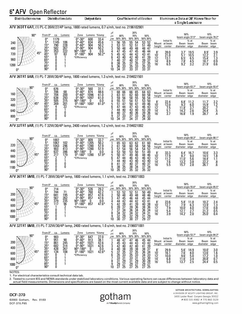
6" AFV Open Reflector
DCF-370
©2003 Gotham, Rev. 01/03DCF-370.P65
From 0° cp. Lumens
0° 11795° 1145 106
15° 790 22825° 582 26735° 353 22245° 97 8355° 0 165° 0 175° 0 185° 0 190° 0
AFV 26DTT 6AR, (1) PL-C 26W/27/4P lamp, 1800 rated lumens, 0.7 s/mh, test no. 2196102901�f 20%�c 80% 70% 50%�w 50% 30% 50% 30% 50% 30%1 56 55 55 54 53 522 53 51 52 51 51 493 50 48 49 48 48 474 47 45 47 45 46 445 45 42 44 42 43 416 43 40 42 40 41 397 40 37 40 37 39 378 38 35 37 35 37 359 36 33 35 33 35 33
10 34 31 33 31 33 31
Zone Lumens %lamp
0°-30° 600 33.40°-40° 834 45.60°-60° 904 50.20°-90° 904 50.2
90°-180° 0 0.00°-180° 904 50.2*
*Efficiency
50% 10%beam angle 37.5° beam angle 78.2°
Initial fc fc at fc atMount at beam Beam beam Beam beamheight center diameter edge diameter edge
8' 39.0 3.7' 19.5 8.9' 3.910' 21.0 5.1' 10.5 12.2' 2.112' 13.1 6.5' 6.5 15.4' 1.314' 8.9 7.8' 4.5 18.7' 0.916' 6.5 9.2' 3.2 21.9' 0.6
240480
720
9601200
0°
90°
45°
From 0° cp. Lumens
0° 6765° 706 68
15° 704 20025° 638 29335° 505 31545° 269 20155° 4 2265° 0 175° 0 085° 0 090° 0
AFV 26TRT 6AR, (1) PL-T 26W/30/4P lamp, 1800 rated lumens, 1.3 s/mh, test no. 2194021501�f 20%�c 80% 70% 50%�w 50% 30% 50% 30% 50% 30%1 68 66 66 65 64 632 63 61 62 60 60 583 59 56 58 55 56 544 55 51 54 51 53 505 51 47 50 47 49 466 47 44 47 43 46 437 44 40 43 40 43 398 40 37 40 36 39 369 37 33 37 33 36 33
10 34 31 34 31 34 30
Zone Lumens %lamp
0°-30° 560 31.10°-40° 874 48.60°-60° 1096 61.00°-90° 1097 61.0
90°-180° 0 0.00°-180° 1097 61.0*
*Efficiency
50% 10%beam angle 63.7° beam angle 93.4°
Initial fc fc at fc atMount at beam Beam beam Beam beamheight center diameter edge diameter edge
8' 22.4 6.8' 11.2 11.7' 2.210' 12.0 9.3' 6.0 15.9' 1.212' 7.5 11.8' 3.7 20.2' .714' 5.1 14.3' 2.6 24.4' .516' 3.7 16.8' 1.9 28.7' .4
45°
90°
0°
From 0° cp. Lumens
0° 10075° 1067 102
15° 1043 29625° 903 41335° 637 39645° 217 17955° 2 765° 0 175° 0 085° 0 090° 0
AFV 32TRT 6AR, (1) PL-T 32W/30/4P lamp, 2400 rated lumens, 1.2 s/mh, test no. 2194021002
�f 20%�c 80% 70% 50%�w 50% 30% 50% 30% 50% 30%1 65 63 63 62 61 602 61 58 60 58 58 563 57 54 56 54 54 524 53 50 53 50 51 495 50 47 49 46 48 466 47 44 46 43 46 437 44 40 43 40 43 408 41 37 40 37 40 379 38 35 38 34 37 34
10 35 32 35 32 35 32
Zone Lumens %lamp
0°-30° 809 33.70°-40° 1205 50.20°-60° 1390 57.90°-90° 1390 57.9
90°-180° 0 0.00°-180° 1390 57.9*
*Efficiency
50% 10%beam angle 60.3° beam angle 88.1°
Initial fc fc at fc atMount at beam Beam beam Beam beamheight center diameter edge diameter edge
8' 33.3 6.4' 16.7 10.6' 3.310' 17.9 8.7' 9.0 14.5' 1.812' 11.2 11.0' 5.6 18.4' 1.114' 7.6 13.3' 3.8 22.2' .816' 5.5 15.7' 2.8 26.1' .6
45°
90°
0°
220
440660
880
1100
160
320480
640
800
From 0° cp. Lumens
0° 7145° 744 71
15° 681 19525° 567 26235° 379 23545° 117 9655° 1 265° 0 175° 0 185° 0 190° 0
AFV 26TRT 6MB, (1) PL-T 26W/30/4P lamp, 1800 rated lumens, 1.1 s/mh, test no. 2196071003�f 20%�c 80% 70% 50%�w 50% 30% 50% 30% 50% 30%1 53 52 52 51 50 492 50 48 49 48 48 463 47 45 46 44 45 444 44 42 44 42 43 415 42 39 41 39 40 386 39 37 39 36 38 367 37 34 36 34 36 348 34 32 34 32 34 319 32 29 32 29 31 29
10 30 27 30 27 29 27
Zone Lumens %lamp
0°-30° 526 29.20°-40° 760 42.20°-60° 857 47.60°-90° 857 47.6
90°-180° 0 0.00°-180° 857 47.6*
*Efficiency
50% 10%beam angle 55.6° beam angle 85.5°
Initial fc fc at fc atMount at beam Beam beam Beam beamheight center diameter edge diameter edge
8' 23.6 5.8' 11.8 10.2' 2.410' 12.7 7.9' 6.3 13.9' 1.312' 7.9 10.0' 4.0 17.6' 0.814' 5.4 12.1' 2.7 21.3' 0.516' 3.9 14.2' 2.0 25.0' 0.4
45°
90°
0°
200
400
600800
1000
NOTES:1. For electrical characteristics consult technical data tab.2. Tested to current IES and NEMA standards under stabilized laboratory conditions. Various operating factors can cause differences between laboratory data and
actual field measurements. Dimensions and specifications are based on the most current available data and are subject to change without notice.
From 0° cp. Lumens
0° 9035° 951 90
15° 861 24525° 682 31435° 428 26745° 134 10855° 0 165° 0 175° 0 185° 0 190° 0
AFV 32TRT 6MB, (1) PL-T 32W/30/4P lamp, 2400 rated lumens, 1.0 s/mh, test no. 2196071001�f 20%�c 80% 70% 50%�w 50% 30% 50% 30% 50% 30%1 48 47 47 46 45 442 45 43 44 43 43 423 42 40 42 40 41 394 40 38 39 38 38 375 37 35 37 35 36 346 35 33 35 33 34 337 33 31 33 31 32 308 31 29 31 29 30 289 29 27 29 27 29 27
10 27 25 27 25 27 25
Zone Lumens %lamp
0°-30° 647 27.00°-40° 913 38.10°-60° 1021 42.60°-90° 1021 42.6
90°-180° 0 0.00°-180° 1021 42.6*
*Efficiency
50% 10%beam angle 53.7° beam angle 84.3°
Initial fc fc at fc atMount at beam Beam beam Beam beamheight center diameter edge diameter edge
8' 29.9 5.6' 14.9 10.0' 3.010' 16.1 7.6' 8.0 13.6' 1.612' 10.0 9.6' 5.0 17.2' 1.014' 6.8 11.6' 3.4 20.8' 0.716' 5.0 13.7' 2.5 24.4' 0.5
45°
90°
0°
200
400
600800
1000
Distribution curve Distribution data Output data Coefficient of utilization Illuminance Data at 30" Above Floor fora Single Luminaire

Return to: DULUX T/E/IN (amalgam, triple, 4-Pin) Print Page
Product Number:
20879
Order Abbreviation:
CF26DT/E/IN/827
General Description:
DULUX 26W triple compact fluorescent amalgam lamp with 4-pin base, integral EOL, 2700K color temperature, 82 CRI, for use with electronic and dimming ballasts
Product Information
Abbrev. With Packaging Info. CF26DTEIN827 50/CS 1/SKU
Average Rated Life (hr) 12000
Base GX24Q-3
Bulb T4
Color Rendering Index (CRI) 82
Color Temperature/CCT (K) 2700
Family Brand Name Dulux® T/E
Industry Standards IEC 60901- 3426
Initial Lumens at 25C 1800
Mean Lumens at 25C 1548
Maximum Overall Length - MOL (in) 5.0
Maximum Overall Length - MOL (mm) 126
NEMA Generic Designation (current) CFTR26W/GX24Q/827
NEMA Generic Designation (old) CFM26W/GX24Q/827
Nominal Wattage (W) 26.00
Additional Product Information
Product Documents, Graphs, and Images
Compatible Ballast
Packaging Information
Footnotes
Approximate initial lumens after 100 hours operation. The life ratings of fluorescent lamps are based on 3 hr. burning cycles under specified
Page 1 of 2Product Details
4/7/2006http://ecom.mysylvania.com/sylvaniab2c/catalog/updateItems.do

conditions and with ballast meeting ANSI specifications. If burning cycle is increased, there will be a corresponding increase in the average hours life. Rule of Thumb for Compact Fluorescent Lamps: Divide wattage of incandescent lamp by 4 to determine approximate wattage of compact fluorescent lamp that will provide similar light output. Amalgam compact fluorescent lamps provide at least 90% light output from 40-140 degrees F. Non-amalgam compact fluorescent lamps provide atleast 90% light output from 60-100 degrees F in the base up position, the temperature range is narrower for horizontal or base down. Minimum starting temperature is a function of the ballast; consult the ballast manufacturer. There is a NEMA supported, industry issue where T2, T4, and T5 fluorescent and compact fluorescent lamps operated on high frequency ballasts may experience an abnormal end-of-life phenomenon. This end-of-life phenomenon can resultin one or both of the following: 1. Bulb wall cracking near the lamp base. 2. The lamp can overheat in the base area and possibly melt the base and socket. NEMA recommends that high frequency compact fluorescent ballasts have an end-of-life shutdown circuit which will safely and reliably shut down the system in the rare event of an abnormal end-of-life failure mode described above. The final requirements of this system are yet to be defined by ANSI. For additional information refer to NEMA papers on their WEBSITE at www.NEMA.org. SYLVANIA ECOLOGIC fluorescent lamps are designed to pass the Federal Toxic Characteristic Leaching Procedure (TCLP) criteria for classification as non-hazardous waste in most states. TCLP test results are available upon request. Lamp disposal regulations may vary, check your local & state regulations. For more information, please visit www.lamprecycle.org This 4-pin DULUX lamp has an internal end-of-life mechanism (EOL) that shuts down the lamp preventing abnormal end-of life failure modes. This lamp was designed for use with high frequency ballasts that do not have their own end-of-life (lamp)sensing circuits, but it is also compatible with high frequency ballasts that have their own end-of-life (lamp) sensing circuits.
Print Page
Page 2 of 2Product Details
4/7/2006http://ecom.mysylvania.com/sylvaniab2c/catalog/updateItems.do

Return to search Print Page
Product Number:
51738
Order Abbreviation:
QTP 1/2XCF UNV B M
General Description:
1/2-lamp universal 120-277V programmed rapid start normal ballast factor electronic ballast in a metal enclosure bottom mount without leads for 26W 4-pin compact fluorescent lamp
Product Information
Abbrev. With Packaging Info. QTP12XCFUNVBM
Ballast Factor 1.00
Ballast Height H (in) 1.3500
Ballast Length L (in) 4.9500
Ballast Width W (in) 2.9300
Circuit Type Series
Family Brand Name QUICKTRONIC Professional
Input Wattage (W) 32.00
Nominal Voltage (V) UNIVERSAL 120-277
Number of Lamps 1
Power Factor >98%
Sound Rating A
Starting Method Programmed Rapid Start
Starting Temperature - Fahrenheit -5
Starting Temperature - Celsius -20
Total Harmonic Distortion (THD) <10%
Wiring Method Plug-in Connectors
Additional Product Information
Product Documents, Graphs, and Images
Compatible Lamps
Packaging Information
Footnotes
70C Max Case Temperature UL Listed Class P, Type 1 Outdoor Ground ballast case Install in accordance with National Electric Codes
Page 1 of 2Product Details
4/7/2006http://ecom.mysylvania.com/sylvaniab2c/catalog/Z_bigSearch.do

Complies with FCC 47 CFR Part 18, Non-Consumer Input Frequency: 50/60Hz. Remote Mounting up to 19 feet (keep red wires short for 1&2 lamp). Remote Mounting up to 19 feet (keep red wires short for 1&2 lamp models). ANSI C62.41 cat. B3 Transient Protection. Remote mounting - Typically 6ft with suitable ground plane, but varies by model and application. Contact ECS Application Engineering for information on longer applications.
Print Page
Page 2 of 2Product Details
4/7/2006http://ecom.mysylvania.com/sylvaniab2c/catalog/Z_bigSearch.do