sear ii application 9v871-a01f prepared for …
TRANSCRIPT

PRINTED IN U.S.A.
CONFIGURATION SUMMARY SEAR II APPLICATION 9V871-A01F PREPARED FOR BURLINGTON NORTHERN SANTE FE MARCH 2008, REVISED JUNE 2014
DOCUMENT NO. SIG-00-05-11-001 VERSION F.1
Siemens Industry, Inc., Rail Automation 9568 Archibald Ave., Suite 100, Rancho Cucamonga, California 91730
1-800-793-7233 Copyright © 2014 Siemens Industry, Inc., Rail Automation All rights reserved

9V871-A01CONFIGURATION SUMMARY CONFIGURATION
ii SIG-00-05-11-001 March 2008, Revised June 2014 Version No.: F.1
PROPRIETARY INFORMATION Siemens Industry, Inc., Rail Automation (Siemens) has a proprietary interest in the information contained herein and, in some instances, has patent rights in the systems and components described. It is requested that you distribute this information only to those responsible people within your organization who have an official interest. This document, or the information disclosed herein, shall not be reproduced or transferred to other documents or used or disclosed for manufacturing or for any other purpose except as specifically authorized in writing by Siemens.
TRANSLATIONS
The manuals and product information of Siemens are intended to be produced and read in English. Any translation of the manuals and product information are unofficial and can be imprecise and inaccurate in whole or in part. Siemens does not warrant the accuracy, reliability, or timeliness of any information contained in any translation of manual or product information from its original official released version in English and shall not be liable for any losses caused by such reliance on the accuracy, reliability, or timeliness of such information. Any person or entity who relies on translated information does so at his or her own risk.
WARRANTY INFORMATION
Siemens Industry, Inc., Rail Automation warranty policy is as stated in the current Terms and Conditions of Sale document. Warranty adjustments will not be allowed for products or components which have been subjected to abuse, alteration, improper handling or installation, or which have not been operated in accordance with Seller's instructions. Alteration or removal of any serial number or identification mark voids the warranty.
SALES AND SERVICE LOCATIONS
Technical assistance and sales information on Siemens Industry, Inc., Rail Automation products may be obtained at the following locations:
Siemens Industry, Inc., Rail Automation Siemens Industry, Inc., Rail Automation 2400 NELSON MILLER PARKWAY 939 S. MAIN STREET LOUISVILLE, KENTUCKY 40223 MARION, KENTUCKY 42064 TELEPHONE: (502) 618-8800 TELEPHONE: (270) 918-7800 FAX: (502) 618-8810 CUSTOMER SERVICE: (800) 626-2710 SALES & SERVICE: (800) 626-2710 TECHNICAL SUPPORT: (800) 793-7233 WEB SITE: http://www.rail-automation.com/ FAX: (270) 918-7830

9V871-A01CONFIGURATION SUMMARY CONFIGURATION
iii SIG-00-05-11-001 March 2008, Revised June 2014 Version No.: F.1
DOCUMENT HISTORY
Version Release Date Details of Change
A 4-25-05 Initial release of 9V871-A01A.
B 7-19-07
Bumped version per software update. Updated logo and added change notice. Also added following notes at end of section 3:
Note: MTSS inputs cannot be changed and are automatically assigned by the application program. Non-MTSS inputs can be assigned to any remaining input.
Note: Inputs used for alarm logic must be assigned using the pre-defined input list. These pre-defined inputs automatically assign the correct name/state names to the input which will be used in alarm logic. Inputs should only be named manually if they are used for recording purposes and not for alarming.
Note: If there is not sufficient space for inputs onboard the SEAR II, some inputs may be monitored from the SSCC instead. In that case, those inputs must be wired to the assigned SSCC inputs shown in the table above.
C 8-22-07
Not released.
• \Bumped document revision number from B to C (reflects software change).
• Section 7.1 Application Alarms:
o Added note indicating when alarms are recorded they will be preceded by double asterisks in the Event Log for easier search capability.
o Changed description of Gate Break alarm.
o Changed Preemption fail to Preemption Alarm.
o Changed Alarm #’s 5, 6 & 7 now mapped to RTU Alarm #2.
o Changed Alarm #’s 3, 10, 11, 12, 14, 15, & 17 now mapped to RTU Alarm #3.
• Section 7.2 Application Messages:
o Added note indicating when messages are recorded they will be preceded by an asterisk in the Event Log for easier search capability.
D 8-22-07
Not released.
• Bumped document revision number from C to D (reflects software change).
• Incorporated changes from version C (as above).
• Section 7.1 Application Alarms:
o Changed descriptions for Preemption Alarm, Lamp Out, Flash Rate Too Slow, Flash Rate Too Fast and Gate Break.
E Oct 2007 • Bumped document version number from D to E (reflects software
change).

9V871-A01CONFIGURATION SUMMARY CONFIGURATION
iv SIG-00-05-11-001 March 2008, Revised June 2014 Version No.: F.1
• Incorporated changes from versions C & D (as above).
• Section 6.0 Indicator LED Configuration:
o Removed Short Warning Time (I01).
• Section 7.1 Application Alarms:
o Removed Short Warning Time alarm.
o Modified descriptions for Flash Rate Too Slow, Flash Rate Too Fast and Preemption Alarm.
F March 2008
• Bumped document version from E to F (reflects software changes).
• Section 2.0 - User Menu Items – Site Setup Table:
o Page 2: Changed Calculate WARNING Time to Calculate ACTIVATION Time for Island 1, 2, 3, 4, 5 and 6.
o Page 5: Added LOW BATTERY PERCENTAGE and HIGH BATTERY PERCENTAGE questions and parameters.
• Section 6.0 - Indicator LED Configuration Table:
o Added LED I01 for clarity – NOT USED.
o LED I02 changed Designator description to XING ACTIVE TOO LONG.
o LED I03 changed Designator description to CONTROLLER TLITE.
o LED I16 - Added alarm number 18 and changed Designator description to ANALYZER FAILURE.
• Section 7.1 - Application Alarms Table:
o LED I03 Description – added note to refer to Section 7 – Troubleshooting in the SSCC IV I & I manual for additional information on Maintenance Call problems.
o LED I04 Description – deleted “after XRK drops”. o Updated Descriptions for LEDs I10, I11, and I14. o Added second LED I16 and parameters for Alarm # 18.
• Section 7.2 - Application Messages Table:
o Changed WARNING Time: xx Seconds to ACTIVATION Time: xx Seconds.
F.1 June 2014 Rebrand for Siemens
9V871-A01CONFIGURATION SUMMARY CONFIGURATION
v SIG-00-05-11-001 March 2008, Revised June 2014 Version No.: F.1
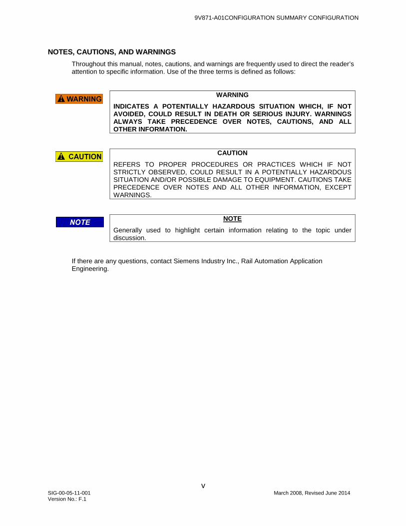
NOTES, CAUTIONS, AND WARNINGS Throughout this manual, notes, cautions, and warnings are frequently used to direct the reader’s attention to specific information. Use of the three terms is defined as follows:
WARNING
INDICATES A POTENTIALLY HAZARDOUS SITUATION WHICH, IF NOT AVOIDED, COULD RESULT IN DEATH OR SERIOUS INJURY. WARNINGS ALWAYS TAKE PRECEDENCE OVER NOTES, CAUTIONS, AND ALL OTHER INFORMATION.
CAUTION
REFERS TO PROPER PROCEDURES OR PRACTICES WHICH IF NOT STRICTLY OBSERVED, COULD RESULT IN A POTENTIALLY HAZARDOUS SITUATION AND/OR POSSIBLE DAMAGE TO EQUIPMENT. CAUTIONS TAKE PRECEDENCE OVER NOTES AND ALL OTHER INFORMATION, EXCEPT WARNINGS.
NOTE
Generally used to highlight certain information relating to the topic under discussion.
If there are any questions, contact Siemens Industry Inc., Rail Automation Application Engineering.

9V871-A01CONFIGURATION SUMMARY CONFIGURATION
vi SIG-00-05-11-001 March 2008, Revised June 2014 Version No.: F.1
This page intentionally left blank

9V871-A01CONFIGURATION SUMMARY CONFIGURATION
vii SIG-00-05-11-001 March 2008, Revised June 2014 Version No.: F.1
TABLE OF CONTENTS
Section Title Page PROPRIETARY INFORMATION ......................................................................... ii TRANSLATIONS ................................................................................................. ii WARRANTY INFORMATION............................................................................... ii SALES AND SERVICE LOCATIONS ................................................................... ii DOCUMENT HISTORY ...................................................................................... iii NOTES, CAUTIONS, AND WARNINGS .............................................................. v
1.0 Introduction ......................................................................................................... 1
2.0 User Menu Items – Site Setup ............................................................................ 2
3.0 Digital Input Configuration ................................................................................... 6
4.0 Battery Input Configuration ................................................................................10
5.0 A80258 Output Configuration .............................................................................10
6.0 Indicator LED Configuration ...............................................................................11
6.1 Standard LED Conventions ................................................................................11
7.0 Messages ..........................................................................................................12
7.1 Application Alarms .............................................................................................12
7.2 Application Messages ........................................................................................14

9V871-A01CONFIGURATION SUMMARY CONFIGURATION
viii SIG-00-05-11-001 March 2008, Revised June 2014 Version No.: F.1
This page intentionally left blank

9V871-A01CONFIGURATION SUMMARY CONFIGURATION
1 SIG-00-05-11-001 March 2008, Revised June 2014 Version No.: F.1
1.0 INTRODUCTION
This document supports installation and maintenance of SEAR II units configured with the 9V871-A01F user program stored in flash memory. This document:
• Explains LED indications
• Lists setup steps unique to 9V871-A01F
• Lists all messages generated by 9V871-A01F
• Lists connector / wire tag assignments
For further information on SEAR II, including configuration of executive software, refer to the SAFETRAN EVENT ANALYZER RECORDER II (SEAR II) − Installation & Operation manual (Siemens document no. SIG-00-02-07).

9V871-A01CONFIGURATION SUMMARY CONFIGURATION
2 SIG-00-05-11-001 March 2008, Revised June 2014 Version No.: F.1
2.0 USER MENU ITEMS – SITE SETUP
The following table lists configuration settings that are unique to 9V871-A01F. Each row presents an entry in the site setup sequence. The first column shows the text that appears on the SEAR II screen or in the terminal display. The three middle columns give the options or define the range of values that may be entered. The rightmost column summarizes conditions that determine if that row’s step will appear, for example: the ‘CALCULATE WARNING TIME FOR ISLAND 2’ entry will appear only if the entry for ‘NUMBER OF ISL INPUTS’ is greater than one.
QUESTION MINIMUM / SELECTION 1
MAXIMUM / SELECTION 2
SELECTION 3 CONDITION FOR
MENU TO BE DISPLAYED
LAMP / GATE OPERATION NORMAL EXIT GATE SPLIT GATE NUMBER OF TRACKS? 1 8
NUMBER OF MD INPUTS? 0 6
NUMBER OF ISL INPUTS 1 8
CALCULATE ACTIVATION TIME FOR ISLAND 1
YES NO
CALCULATE ACTIVATION TIME FOR ISLAND 2
YES NO ISLANDS>1
CALCULATE ACTIVATION TIME FOR ISLAND 3
YES NO ISLANDS>2
CALCULATE ACTIVATION TIME FOR ISLAND 4
YES NO ISLANDS>3
CALCULATE ACTIVATION TIME FOR ISLAND 5
YES NO ISLANDS>4
CALCULATE ACTIVATION TIME FOR ISLAND 6
YES NO ISLANDS>5
GATE 1 INPUT NO YES MTSS LAMP/GATE
OPERATION <> EXIT GATE
GATE 2 INPUT NO YES MTSS LAMP/GATE
OPERATION <> EXIT GATE
GATE 3 INPUT NO YES MTSS LAMP/GATE
OPERATION <> EXIT GATE
GATE 4 INPUT NO YES MTSS LAMP/GATE
OPERATION <> EXIT GATE
GATE 5 INPUT NO YES MTSS LAMP/GATE
OPERATION <> EXIT GATE

9V871-A01CONFIGURATION SUMMARY CONFIGURATION
3 SIG-00-05-11-001 March 2008, Revised June 2014 Version No.: F.1
QUESTION MINIMUM / SELECTION 1
MAXIMUM / SELECTION 2
SELECTION 3 CONDITION FOR
MENU TO BE DISPLAYED
GATE 6 INPUT NO YES MTSS LAMP/GATE
OPERATION <> EXIT GATE
GATE 1 CONTROLLED BY XRK 1XRK 2XRK GATE 1 INPUT <>
NO
GATE 2 CONTROLLED BY XRK 1XRK 2XRK GATE 2 INPUT <>
NO
GATE 3 CONTROLLED BY XRK 1XRK 2XRK GATE 3 INPUT <>
NO
GATE 4 CONTROLLED BY XRK 1XRK 2XRK GATE 4 INPUT <>
NO
GATE 5 CONTROLLED BY XRK 1XRK 2XRK GATE 5 INPUT <>
NO
GATE 6 CONTROLLED BY XRK 1XRK 2XRK GATE 6 INPUT <>
NO
GATE 1A INPUT NO YES MTSS LAMP/GATE
OPERATION =EXIT GATE
GATE 2A INPUT NO YES MTSS LAMP/GATE
OPERATION =EXIT GATE
GATE 1B INPUT NO YES MTSS LAMP/GATE
OPERATION = EXIT GATE
GATE 2B INPUT NO YES MTSS LAMP/GATE
OPERATION = EXIT GATE
GATE 1C INPUT NO YES MTSS LAMP/GATE
OPERATION = EXIT GATE
GATE 2C INPUT NO YES MTSS LAMP/GATE
OPERATION = EXIT GATE
EXIT GATE 3A INPUT NO YES MTSS LAMP/GATE
OPERATION = EXIT GATE
EXIT GATE 4A INPUT NO YES MTSS LAMP/GATE
OPERATION = EXIT GATE
EXIT GATE 3B INPUT NO YES MTSS LAMP/GATE
OPERATION = EXIT GATE

9V871-A01CONFIGURATION SUMMARY CONFIGURATION
4 SIG-00-05-11-001 March 2008, Revised June 2014 Version No.: F.1
QUESTION MINIMUM / SELECTION 1
MAXIMUM / SELECTION 2
SELECTION 3 CONDITION FOR
MENU TO BE DISPLAYED
EXIT GATE 4B INPUT NO YES MTSS LAMP/GATE
OPERATION = EXIT GATE
GATE 1 BELL SENSOR YES NO GATE 1 INPUT =
MTSS
GATE 2 BELL SENSOR YES NO GATE 2 INPUT =
MTSS
GATE 3 BELL SENSOR YES NO GATE 3 INPUT =
MTSS
GATE 4 BELL SENSOR YES NO GATE 4 INPUT =
MTSS
GATE 5 BELL SENSOR YES NO GATE 5 INPUT =
MTSS
GATE 6 BELL SENSOR YES NO GATE 6 INPUT =
MTSS
GATE 1A BELL SENSOR YES NO GATE 1A INPUT =
MTSS
GATE 2A BELL SENSOR YES NO GATE 2A INPUT =
MTSS
GATE 1B BELL SENSOR YES NO GATE 1B INPUT =
MTSS
GATE 2B BELL SENSOR YES NO GATE 2B INPUT =
MTSS
GATE 1C BELL SENSOR YES NO GATE 1C INPUT =
MTSS
GATE 2C BELL SENSOR YES NO GATE 2C INPUT =
MTSS
EXIT GATE 3A BELL SENSOR YES NO EXIT GATE 3A INPUT = MTSS
EXIT GATE 4A BELL SENSOR YES NO EXIT GATE 4A INPUT = MTSS
EXIT GATE 3B BELL SENSOR YES NO EXIT GATE 3B INPUT = MTSS
EXIT GATE 4B BELL SENSOR YES NO EXIT GATE 4B INPUT = MTSS
VEHICLE DETECTION YES NO LAMP/GATE
OPERATION = EXIT GATE
ILOD’S 0 8
DO ILOD’S HAVE WIRE WRAPS?
NO YES ILOD’S>0
DOES ILOD1 HAVE WIRE WRAPS?
NO YES WIRE
WRAPS=”YES”

9V871-A01CONFIGURATION SUMMARY CONFIGURATION
5 SIG-00-05-11-001 March 2008, Revised June 2014 Version No.: F.1
QUESTION MINIMUM / SELECTION 1
MAXIMUM / SELECTION 2
SELECTION 3 CONDITION FOR
MENU TO BE DISPLAYED
DOES ILOD2 HAVE WIRE WRAPS?
NO YES WIRE
WRAPS=”YES” DOES ILOD3 HAVE WIRE
WRAPS? NO YES
WIRE WRAPS=”YES”
DOES ILOD4 HAVE WIRE WRAPS?
NO YES WIRE
WRAPS=”YES” DOES ILOD5 HAVE WIRE
WRAPS? NO YES
WIRE WRAPS=”YES”
DOES ILOD6 HAVE WIRE WRAPS?
NO YES WIRE
WRAPS=”YES” DOES ILOD7 HAVE WIRE
WRAPS? NO YES
WIRE WRAPS=”YES”
DOES ILOD8 HAVE WIRE WRAPS?
NO YES WIRE
WRAPS=”YES”
ILOD 1 OPERATES WITH XRK 1XRK 2XRK ILODs > 0
ILOD 2 OPERATES WITH XRK 1XRK 2XRK ILODs > 1
ILOD 3 OPERATES WITH XRK 1XRK 2XRK ILODs > 2
ILOD 4 OPERATES WITH XRK 1XRK 2XRK ILODs > 3
ILOD 5 OPERATES WITH XRK 1XRK 2XRK ILODs > 4
ILOD 6 OPERATES WITH XRK 1XRK 2XRK ILODs > 5
ILOD 7 OPERATES WITH XRK 1XRK 2XRK ILODs > 6
ILOD 8 OPERATES WITH XRK 1XRK 2XRK ILODs > 7
SSCC IIIa, IIIplus, IV 0 4
BATTERY BANKS 1 8
LOW BATTERY PERCENTAGE
1 99
HIGH BATTERY PERCENTAGE
101 199
PREEMPTION NO YES
OUTPUTS CONNECTED TO RTU
NO YES
AUXILARY DIGITAL I/O NO YES
AUXILARY ANALOG I/O NO YES

9V871-A01CONFIGURATION SUMMARY CONFIGURATION
6 SIG-00-05-11-001 March 2008, Revised June 2014 Version No.: F.1
3.0 DIGITAL INPUT CONFIGURATION
The SEAR II provides 18 digital inputs. Additional digital I/O can be added using external expansion modules or other Echelon-capable devices as nodes on a common LAN . These devices and the assigned nodes are as follows:
EXTERNAL DEVICE PART NUMBER
DEVICE DESIGNATION LAN NODE
ASSIGNMENT(S) 80271 Module iLOD 1-8 Nodes 3-10 91210 Module SSCC III plus / SSCC IV Entrance Node 11 91210 Module SSCC IV Exit Node 12 91210 Module SSCC IV Auxiliary Entrance Node 13 91210 Module SSCC IV Auxiliary Exit Node 14 80258 Module 24 input module Node 15 80258 Module 4 analog input module Node 16
The left column of the following table shows the suggested input assignments. The second column from the left indicates the normal state for each input followed by the input logic states in the third and fourth columns. The recommended SEAR II inputs are listed in the fifth column followed by specific Solid-State Crossing Controller (SSCC) inputs in the sixth column. The column on the far right shows the conditions that must exist for that input to be used.
NOTE
Inputs from the SSCC on Exit Gate Applications can NOT be changed.
NOTE
XRK is normally de-energized when using an SSCC and energized for all other controllers or relays.
NAME NORM ‘1’ ‘0’ INPUT SSCC INPUT MENU CONDITION 1ISLK UP UP DOWN N/A 2 ISLANDS>0 2ISLK UP UP DOWN N/A 3 ISLANDS>1 3ISLK UP UP DOWN N/A 4 ISLANDS>2 4ISLK UP UP DOWN N/A N/A ISLANDS>3 5ISLK UP UP DOWN N/A N/A ISLANDS>4 6ISLK UP UP DOWN N/A N/A ISLANDS>5 7ISLK UP UP DOWN N/A N/A ISLANDS>6 8ISLK UP UP DOWN N/A N/A ISLANDS>7 1MDK UP UP DOWN N/A 1 MDCOUNT>0 2MDK UP UP DOWN N/A N/A MDCOUNT>1 3MDK UP UP DOWN N/A N/A MDCOUNT>2 4MDK UP UP DOWN N/A N/A MDCOUNT>3

9V871-A01CONFIGURATION SUMMARY CONFIGURATION
7 SIG-00-05-11-001 March 2008, Revised June 2014 Version No.: F.1
NAME NORM ‘1’ ‘0’ INPUT SSCC INPUT MENU CONDITION 5MDK UP UP DOWN N/A N/A MDCOUNT>4 5MDK UP UP DOWN N/A N/A MDCOUNT>5 XRK UP UP DOWN N/A N/A CONROLLERS=0 XRK UP DOWN UP N/A N/A CONTROLLERS>0 1XRK UP UP DOWN N/A N/A CONROLLERS=0 1XRK UP DOWN UP N/A N/A CONTROLLERS>0 2XRK UP UP DOWN N/A N/A CONROLLERS=0 2XRK UP DOWN UP N/A N/A CONTROLLERS>0 1GUK UP UP NOT UP N/A N/A GATE 1=YES
1GDK NOT
DOWN DOWN
NOT DOWN
N/A N/A GATE1=YES
2GUK UP UP NOT UP N/A N/A GATE 2=YES
2GDK NOT
DOWN DOWN
NOT DOWN
N/A N/A GATE2=YES
3GUK UP UP NOT UP N/A N/A GATE 3=YES
3GDK NOT
DOWN DOWN
NOT DOWN
N/A N/A GATE3=YES
4GUK UP UP NOT UP N/A N/A GATE 4=YES
4GDK NOT
DOWN DOWN
NOT DOWN
N/A N/A GATE4=YES
5GUK UP UP NOT UP N/A N/A GATE 5=YES
5GDK NOT
DOWN DOWN
NOT DOWN
N/A N/A GATE5=YES
6GUK UP UP NOT UP N/A N/A GATE 6=YES
6GDK NOT
DOWN DOWN
NOT DOWN
N/A N/A GATE6=YES
1AGUK UP UP NOT UP N/A N/A GATE 1A=YES
1AGDK NOT
DOWN DOWN
NOT DOWN
N/A N/A GATE1A=YES
2AGUK UP UP NOT UP N/A N/A GATE 2A=YES
2AGDK NOT
DOWN DOWN
NOT DOWN
N/A N/A GATE2A=YES
1BGUK UP UP NOT UP N/A N/A GATE 1B=YES
1BGDK NOT
DOWN DOWN
NOT DOWN
N/A N/A GATE1B=YES
2BGUK UP UP NOT UP N/A N/A GATE 2B=YES
2BGDK NOT
DOWN DOWN
NOT DOWN
N/A N/A GATE2B=YES
1CGUK UP UP NOT UP N/A N/A GATE 1C=YES
1CGDK NOT
DOWN DOWN
NOT DOWN
N/A N/A GATE1C=YES
2CGUK UP UP NOT UP N/A N/A GATE 2C=YES
2CGDK NOT
DOWN DOWN
NOT DOWN
N/A N/A GATE2C=YES
3AGUK UP UP NOT UP N/A N/A GATE 3A=YES

9V871-A01CONFIGURATION SUMMARY CONFIGURATION
8 SIG-00-05-11-001 March 2008, Revised June 2014 Version No.: F.1
NAME NORM ‘1’ ‘0’ INPUT SSCC INPUT MENU CONDITION
3AGDK NOT
DOWN DOWN
NOT DOWN
N/A N/A GATE3A=YES
3BGUK UP UP NOT UP N/A N/A GATE 3B=YES
3BGDK NOT
DOWN DOWN
NOT DOWN
N/A N/A GATE3B=YES
4AGUK UP UP NOT UP N/A N/A GATE 4A=YES
4AGDK NOT
DOWN DOWN
NOT DOWN
N/A N/A GATE4A=YES
4BGUK UP UP NOT UP N/A N/A GATE 4B=YES
4BGDK NOT
DOWN DOWN
NOT DOWN
N/A N/A GATE4B=YES
GATE 1 (MTSS)
N/A N/A N/A 2 N/A GATE 1=MTSS
GATE 2 (MTSS)
N/A N/A N/A 3 N/A GATE 2=MTSS
GATE 3 (MTSS)
N/A N/A N/A 4 N/A GATE 3=MTSS
GATE 4 (MTSS)
N/A N/A N/A 5 N/A GATE 4=MTSS
GATE 5 (MTSS)
N/A N/A N/A 6 N/A GATE 5=MTSS
GATE 6 (MTSS)
N/A N/A N/A 7 N/A GATE 6=MTSS
GATE 1A (MTSS)
N/A N/A N/A 2 N/A GATE 1A=MTSS
GATE 2A (MTSS)
N/A N/A N/A 3 N/A GATE 2A=MTSS
GATE 1B (MTSS)
N/A N/A N/A 4 N/A GATE 1B=MTSS
GATE 2B (MTSS)
N/A N/A N/A 5 N/A GATE 2B=MTSS
GATE 1C (MTSS)
N/A N/A N/A 16 N/A GATE 1C=MTSS
GATE 2C (MTSS)
N/A N/A N/A 17 N/A GATE 2C=MTSS
GATE 3A (MTSS)
N/A N/A N/A 7 N/A GATE 3A=MTSS
GATE 4A (MTSS)
N/A N/A N/A 10 N/A GATE 4A=MTSS
GATE 3B (MTSS)
N/A N/A N/A 8 N/A GATE 3B=MTSS
GATE 4B (MTSS)
N/A N/A N/A 11 N/A GATE 4B=MTSS
PREEMPT UP UP DOWN N/A 8 PREEMPTION=YES 1MAINT ON ON OFF N/A N/A CONTROLLERS>0

9V871-A01CONFIGURATION SUMMARY CONFIGURATION
9 SIG-00-05-11-001 March 2008, Revised June 2014 Version No.: F.1
NAME NORM ‘1’ ‘0’ INPUT SSCC INPUT MENU CONDITION 2MAINT ON ON OFF N/A N/A CONTROLLERS>1 3MAINT ON ON OFF N/A N/A CONTROLLERS>2 4MAINT ON ON OFF N/A N/A CONTROLLERS>3
NVDK UP UP DOWN N/A 5 VEHICLE
DETECTION=”YES”
SVDK UP UP DOWN N/A 6 VEHICLE
DETECTION=”YES”
VDHK UP UP DOWN N/A 7 VEHICLE
DETECTION=”YES” POK ON ON OFF N/A N/A N/A
BELLOUT OFF ON OFF N/A N/A N/A 3XGRK DOWN UP DOWN N/A N/A GATE 3A OR 3B <> NO 4XGRK DOWN UP DOWN N/A N/A GATE 4A OR 4B <> NO
NOTE
MTSS inputs cannot be changed and are automatically assigned by the application program. Non-MTSS inputs can be assigned to any remaining input.
NOTE
Inputs used for alarm logic must be assigned using the pre-defined input list. These pre-defined inputs automatically assign the correct name/state names to the input which will be used in alarm logic. Inputs should only be named manually if they are used for recording purposes and not for alarming.
NOTE
If there is not sufficient space for inputs onboard the SEAR II, some inputs may be monitored from the SSCC instead. In that case, those inputs must be wired to the assigned SSCC inputs shown in the table above.

9V871-A01CONFIGURATION SUMMARY CONFIGURATION
10 SIG-00-05-11-001 March 2008, Revised June 2014 Version No.: F.1
4.0 BATTERY INPUT CONFIGURATION
The following table shows the 9V871-A01F default names, node assignments, and resolutions for the possible battery inputs to the SEAR II.
NAME NODE-INPUT RESOLUTION MB Not assigned 1 VDC 1MB Not assigned 1 VDC 2MB Not assigned 1 VDC 3MB Not assigned 1 VDC 4MB Not assigned 1 VDC XB Not assigned 1 VDC 1XB Not assigned 1 VDC 2XB Not assigned 1 VDC 3XB Not assigned 1 VDC 4XB Not assigned 1 VDC B Not assigned 1 VDC
B12 Not assigned 1 VDC
5.0 A80258 OUTPUT CONFIGURATION
The following table shows the 9V871-A01F default names and node assignments for the four digital outputs when using the A80258 Analog and Digital I/O Unit.
NAME NODE-OUTPUT RTU1 15-01 RTU2 15-02 RTU3 15-03 RTU4 15-04

9V871-A01CONFIGURATION SUMMARY CONFIGURATION
11 SIG-00-05-11-001 March 2008, Revised June 2014 Version No.: F.1
6.0 INDICATOR LED CONFIGURATION
This table and the following material on LED conventions define operation of the red Indicator LEDs for 9V871-A01F.
LED ALARM
NUMBERS DESIGNATOR CHECKED
I01 N/A NOT USED ---------- I02 2 XING ACTIVE TOO LONG ALWAYS I03 3 CONTROLLER TLITE ALWAYS I04 4 VEHICLE LOOP HEALTH TRAIN MOVE I05 5 GATE BREAK ALWAYS I06 6 GATE NOT UP ALWAYS I07 7 EXIT GATE NOT UP ALWAYS I08 8 GATE NOT DOWN TRAIN MOVE I09 9 EXIT GATE NOT DOWN TRAIN MOVE I10 10 LAMP OUT TRAIN MOVE I11 11, 12 FLASH RATE ALARM TRAIN MOVE I12 N/A NOT USED ---------- I13 13 POWER OFF ALWAYS I14 14, 15 LOW OR HIGH BATTERY ALWAYS I15 16 PREEMPTION FAIL TRAIN MOVE I16 17, 18 ANALYZER FAILURE ALWAYS
6.1 STANDARD LED CONVENTIONS
1. LEDs are ON (RED) steady when in Normal Mode. 2. LEDs FLASH FAST when an alarm condition exists. 3. LEDs FLASH SLOW if an alarm has occurred since the last time the CLEAR ALARM key was
pressed, but has been cleared. 4. The CLEAR ALARM key will clear out alarms if the conditions that caused them no longer
exist. 5. Any alarm associated with a train move can be cleared by the CLEAR ALARM key even if
there has not been a train move without an alarm since the alarm occurred. 6. Preemption fail will activate if a PREEMPT input is defined and it does not activate within 1
second after XRK drops.

9V871-A01CONFIGURATION SUMMARY CONFIGURATION
12 SIG-00-05-11-001 March 2008, Revised June 2014 Version No.: F.1
7.0 MESSAGES
The tables in the following subsections list all of the messages generated by the 9V871-A01F application. Messages generated by the SEAR II executive are not presented here.
Messages fall into categories defined by message numbers:
0 Internal SEAR II Messages 1-100 Application Alarms 101-200 Application Alarm Clears 231-240 Application Information Messages 1000-1099 Office Software Alarms 1100 –1199 Office Software Alarm Clears
7.1 APPLICATION ALARMS
The 9V871-A01F application generates these alarms. Note: When these alarms are recorded they will be preceded by double asterisks (**) in the Event Log, for easier search capability.
LED NAME DESCRIPTION RTU
ALARM TESTED
ALARM #
I02 Crossing Active
Too Long XRK down for 30+ minutes 1 Always 2
I03 Controller
Trouble Light
1MAINT, 2MAINT, 3MAINT or 4MAINT OFF for 20+ seconds. NOTE: Refer to section 7 – Troubleshooting in the SSCC IV I & I manual (Doc# SIG-00-03-02) for additional information on Maintenance Call problems.
3 Always 3
I04 Vehicle Loop
Health VDHK off for 8+ seconds 4
Non-train move
4
I05 Gate Break
Any gate DOWN and tip sensor NOT LEVEL within 10 seconds. Will not generate after gate has been declared horizontal
2 Always 5
I06 Gate Not Up XRK up and GUK, 1GUK or 2GUK NOT UP 40+ seconds
2 Non-train
move 6
I07 Exit Gate Not
Up
3XGRK OFF and EXIT GATES 3A or 3B NOT UP 40+ seconds or 4XGRK OFF and EXIT GATES 4A or 4B NOT UP 40+ seconds
2 Always 7
I08 Gate Not Down XRK down for 20+ seconds and IslandOccupied and ANY GATE NOT DOWN
2 Train Move
8

9V871-A01CONFIGURATION SUMMARY CONFIGURATION
13 SIG-00-05-11-001 March 2008, Revised June 2014 Version No.: F.1
LED NAME DESCRIPTION RTU
ALARM TESTED
ALARM #
I09 Exit Gate Not
Down
3XGRK ON 20+ seconds and EXIT GATES 3A OR 3B not down or 4XGRK ON 20+ seconds and EXIT GATES 4A or 4B NOT DOWN
2 Always 9
I10 Lamp Out
Any iLOD reports that the lamps are OFF for 1 minute during a train move and remain OFF through the end of the move.
3 Train Move
10
I11 Flash Rate Too
Slow
Flash rate is less than 35 FPM and greater than 0 FPM and XRK has been down for 12 seconds. Flash rate must remain low for 1 minute and not recover prior to the end of the train move – alarm stays valid until cleared on next train move.
3 Train Move
11
I11 Flash Rate Too
Fast
Flash rate is greater than 65 FPM and XRK has been down for 12 seconds. Flash rate must remain high for 1 minute and not recover prior to the end of the train move - alarm stays valid until cleared on next train move.
3 Train Move
12
I13 Power Off Power is off for 30 minutes N/A Always 13
I14 Low Battery Any battery voltage drops below the user defined percentage of calibrated capacity for 30 seconds
3 Always 14
I14 High Battery Any battery voltage rises above the user defined percentage of calibrated capacity for 30 seconds
3 Always 15
I15 Preemption
Alarm
If no preemption activation within 30 seconds prior to, or 5 seconds after the XRK drop, the preemption alarm will be recorded.
N/A Train Move
16
I16 Echelon Health Any comm. lost for any node for 30 seconds.
3 Always 17
I16 MTSS Comm
Bad Communication is lost with any MTSS unit for 30 seconds
3 Always 18
9V871-A01CONFIGURATION SUMMARY CONFIGURATION
14 SIG-00-05-11-001 March 2008, Revised June 2014 Version No.: F.1
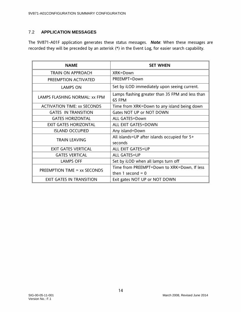
7.2 APPLICATION MESSAGES
The 9V871-A01F application generates these status messages. Note: When these messages are recorded they will be preceded by an asterisk (*) in the Event Log, for easier search capability.
NAME SET WHEN
TRAIN ON APPROACH XRK=Down PREEMPTION ACTIVATED PREEMPT=Down
LAMPS ON Set by iLOD immediately upon seeing current.
LAMPS FLASHING NORMAL: xx FPM Lamps flashing greater than 35 FPM and less than 65 FPM
ACTIVATION TIME: xx SECONDS Time from XRK=Down to any island being down GATES IN TRANSITION Gates NOT UP or NOT DOWN GATES HORIZONTAL ALL GATES=Down
EXIT GATES HORIZONTAL ALL EXIT GATES=DOWN ISLAND OCCUPIED Any island=Down
TRAIN LEAVING All islands=UP after islands occupied for 5+ seconds
EXIT GATES VERTICAL ALL EXIT GATES=UP GATES VERTICAL ALL GATES=UP
LAMPS OFF Set by iLOD when all lamps turn off
PREEMPTION TIME = xx SECONDS Time from PREEMPT=Down to XRK=Down, If less then 1 second = 0
EXIT GATES IN TRANSITION Exit gates NOT UP or NOT DOWN

9V871-A01CONFIGURATION SUMMARY CONFIGURATION
15 SIG-00-05-11-001 March 2008, Revised June 2014 Version No.: F.1
NOTES
9V871-A01CONFIGURATION SUMMARY CONFIGURATION
16 SIG-00-05-11-001 March 2008, Revised June 2014 Version No.: F.1
NOTES

9V871-A01CONFIGURATION SUMMARY CONFIGURATION
17 SIG-00-05-11-001 March 2008, Revised June 2014 Version No.: F.1
NOTES

Siemens Industry, Inc., Rail Automation 2400 Nelson Miller Parkway Louisville, Kentucky 40223
(502) 618-8800
Siemens Industry, Inc., Rail Automation California R&D Division
9568 Archibald Ave., Suite 100 Rancho Cucamonga, California 91730
(909) 532-5300