seat belt assembly tensile test procedure development
TRANSCRIPT

DOT HS 812 925 June 2021
Seat Belt Assembly Tensile Test Procedure Development

DISCLAIMER This publication is distributed by the U.S. Department of Transportation, National Highway Traffic Safety Administration, in the interest of information exchange. The opinions, findings, and conclusions expressed in this publication are those of the authors and not necessarily those of the Department of Transportation or the National Highway Traffic Safety Administration. The United States Government assumes no liability for its content or use thereof. If trade or manufacturers’ names or products are mentioned, it is because they are considered essential to the object of the publication and should not be construed as an endorsement. The United States Government does not endorse products or manufacturers. NOTE: This report is published in the interest of advancing motor vehicle safety research. While the report provides results from research or tests using specifically identified motor vehicle models, it is not intended to make conclusions about the safety performance or safety compliance of those motor vehicles, and no such conclusions should be drawn.
Suggested APA Format Reference: Wietholter, K., & Wetli, A. (2021, June). Seat belt assembly tensile test procedure development.
(Report No. DOT HS 812 925). National Highway Traffic Safety Administration.

i
Techincal Report Documentation Page
1. Report No. DOT HS 812 925
2. Government Accession No. 3. Recipient's Catalog No.
4. Title and Subtitle Seat Belt Assembly Tensile Test Procedure Development
5. Report Date June 2021 6. Performing Organization Code NHTSA/NSR-130
7. Authors Kedryn Wietholter, NHTSA; Alaine Wetli, TRC Inc.
8. Performing Organization Report No.
9. Performing Organization Name and Address National Highway Traffic Safety Administration Vehicle Research and Test Center P.O. Box 37 East Liberty, OH 43319
10. Work Unit No. (TRAIS)
11. Contract or Grant No.
12. Sponsoring Agency Name and Address National Highway Traffic Safety Administration 1200 New Jersey Avenue SE Washington, DC 20590
13.Type of Report and Period Covered Final Report 14. Sponsoring Agency Code NHTSA/NSR-130
15. Supplementary Notes The authors would like to thank Mike Van Voorhis and Josh Smith of TRC Inc. for their testing support.
16. Abstract Federal Motor Vehicle Safety Standard (FMVSS) No. 209, Seat Belt Assemblies, specifies requirements, including performance requirements, for seat belt assemblies used in motor vehicles. The standard includes an assembly performance tensile test where seat belt assemblies must withstand a minimum tensile force and not exceed an elongation limit. NHTSA is evaluating potential changes to the test procedures, to better represent in-vehicle restraint angles. To support the tensile test procedure development, NHTSA’s Vehicle Research and Test Center collected in-vehicle measurements of seat belt assemblies with different occupant sizes and conducted tensile tests at the resulting representative angles. The seat belts were tested on fabricated fixtures using the original equipment manufacturer seat belt assemblies, including hardware and bolts. Out of 10 seat belt assemblies tested using the in-vehicle seat belt angles, four did not meet the performance criteria when tested using the procedure under evaluation. Additional testing was completed aiming to further develop the test procedure to determine if seat belt assemblies with load limiters can meet the force criterion in one test when using stroke-limited machines. All assemblies tested under the conditions of no webbing on the spool or minimal webbing on the spool reached the force criterion, although more steps were required to test with minimal webbing on the spool and the load limiters were not fully engaged. Overall, the updated test procedure was feasible and converted the in-vehicle geometry of the seat belt assembly into a more representative tensile test. The developed test procedures include a detailed method for collecting the in-vehicle angle measurements, incorporating all in-vehicle hardware, and fabricating unique fixtures to complete tensile tests with representative in-use angles.
17. Key Words FMVSS No. 209, seat belt assembly, tensile test
18. Distribution Statement Document is available to the public from the National Technical Information Service, www.ntis.gov.
19. Security Classif. (of this report) Unclassified
20. Security Classif. (of this page) Unclassified
21. No. of Pages 60
22. Price
Form DOT F 1700.7 (8-72) Reproduction of completed page authorized

ii
Table of Contents
Executive Summary ..................................................................................................................... vi Introduction ........................................................................................................................... 1
In-Vehicle Angles Description ............................................................................................. 2
Outboard and Inboard Hardware Angles ......................................................................... 2
Retractor Angle ................................................................................................................ 3
Guide Loop Angles .......................................................................................................... 4
In-Vehicle Measurements ..................................................................................................... 5
Tensile Testing ....................................................................................................................... 6
Tensile Testing Matrix ..................................................................................................... 6
Test Set-Up ....................................................................................................................... 7
Tensile Test Procedure ..................................................................................................... 9
Tensile Test Results ......................................................................................................... 9
Tensile Test Discussion .................................................................................................. 14
4.5.1 2014 Volkswagen Tiguan ....................................................................................... 14
4.5.2 2011 Ford Explorer Inflatable Belt ......................................................................... 15
4.5.3 2012 Mercedes S400 ............................................................................................... 16
4.5.4 2017 Mercedes E300............................................................................................... 17
4.5.5 Seat Belt Assemblies With Load Limiters .............................................................. 17
Tensile Test Comparisons .............................................................................................. 17
4.6.1 Test Head Rotation ................................................................................................. 17
4.6.2 Guide Loop Rotation............................................................................................... 19
4.6.3 Buckle Stalk Movement .......................................................................................... 21
4.6.4 Multiple Guide Loops ............................................................................................. 22
4.6.5 Updated and FMVSS No. 209 Test Procedure Comparisons ................................. 27
Load Limiter Evaluation .................................................................................................... 31
No Webbing on the Spool .............................................................................................. 32
Minimal Webbing on the Spool ..................................................................................... 33
Actuated Retractor Pretensioner..................................................................................... 34
Load Limiter Evaluation Testing Observations ............................................................. 35
Summary .............................................................................................................................. 36
In-Vehicle Measurement Procedure ............................................................. A-1
In-Vehicle Measurements .............................................................................. B-1

iii
Tensile Test Procedure .................................................................................. C-1
Tensile Test Results ........................................................................................ D-1
Minimal Webbing on the Spool Procedure .................................................. E-1
Tables
Table 1. Vehicle Test Matrix .......................................................................................................... 6
Table 2. 2014 Hyundai Tucson In-Vehicle Angles ........................................................................ 6
Table 3. Tensile Testing Matrix ...................................................................................................... 7
Table 4. Pelvis Loop (Lap Belt) Tensile Test Results .................................................................. 11
Table 5. Upper Torso Loop (Shoulder Belt) Tensile Test Results ............................................... 12
Table 6. Pelvis Loop Test Head Rotation Comparison................................................................. 19
Table 7. Upper Torso Loop Test Head Rotation Comparison ...................................................... 19
Table 8. 2011 Honda Odyssey Guide Loop Rotation Comparison .............................................. 21
Table 9. 2011 Hyundai Tucson Guide Loop Rotation Comparison ............................................. 21
Table 10. 2012 Mercedes S400 Multiple Guide Loops Results ................................................... 27
Table 11. 2011 Chevrolet Traverse Multiple Guide Loops Results ............................................. 27
Table 12. 2014 Fiat 500L Procedure Results Comparison ........................................................... 30
Table 13. 2014 Volkswagen Tiguan Procedure Results Comparison ........................................... 30
Table 14. Load Limiter Evaluation Test Matrix ........................................................................... 32
Table 15. Load Limiter Evaluation—No Webbing Condition Results......................................... 33
Table 16. Minimal Amount of Webbing....................................................................................... 33
Table 17. Load Limiter Evaluation—Minimal Webbing Condition Results ................................ 34
Table 18. Load Limiter Evaluation—Actuated Retractor Pretensioner Condition Results .......... 35
Table B1. 2011 Honda Odyssey In-Vehicle Angles ................................................................... B-1
Table B2. 2011 Ford Explorer In-Vehicle Angles ...................................................................... B-1
Table B3. 2014 Hyundai Tucson In-Vehicle Angles .................................................................. B-1
Table B4. 2011 Chevrolet Traverse In-Vehicle Angles .............................................................. B-1
Table B5. 2014 Fiat 500L In-Vehicle Angles ............................................................................. B-2
Table B6. 2017 Mercedes E300 In-Vehicle Angles ................................................................... B-2
Table B7. 2012 Mercedes S400 In-Vehicle Angles.................................................................... B-2
Table B8. 2014 Volkswagen Tiguan In-Vehicle Angles ............................................................ B-2

iv
Table D1. Pelvic Tensile Test Results ........................................................................................ D-1
Table D2. Upper Torso Tensile Test Results .............................................................................. D-2
Figures
Figure 1. FMVSS No. 209 Tensile Test Set-Up. ............................................................................ 1
Figure 2. Updated Tensile Test Set-Up—Upper Torso Loop (Shoulder Belt). .............................. 2
Figure 3. Outboard and Inboard Hardware Angles. ........................................................................ 3
Figure 4. Retractor Angle. .............................................................................................................. 4
Figure 5. Guide Loop Angles.......................................................................................................... 5
Figure 6. 2014 Hyundai Tucson 95th Male Shoulder Belt Fabrication Drawing. .......................... 8
Figure 7. 2014 Hyundai Tucson 95th Shoulder Belt Fixtures. ....................................................... 8
Figure 8. 2014 Hyundai Tucson 95th Lap Belt Fixtures. ............................................................... 9
Figure 9. 2014 Volkswagen Tiguan Buckle Pre-Test. .................................................................. 14
Figure 10. 2014 Volkswagen Tiguan Buckle Fracture ................................................................. 14
Figure 11. 2011 Ford Explorer Inflatable Belt Lap Belt Retractor Pre-Test. ............................... 15
Figure 12. 2011 Ford Explorer Inflatable Belt Lap Belt Retractor Fracture. ............................... 15
Figure 13. 2012 Mercedes S400 (Guide Bar Only) Pre-Test........................................................ 16
Figure 14. 2012 Mercedes S400 Guide Bar Fracture. .................................................................. 16
Figure 15. Test Head Rotation (top) and Test Head Fixed (bottom). ........................................... 18
Figure 16. Guide Loop Rotation. .................................................................................................. 20
Figure 17. Fixed Guide Loop. ....................................................................................................... 20
Figure 18. Buckle Stalk Movement Example. .............................................................................. 22
Figure 19. 2012 Mercedes S400 Guide Bar. ................................................................................. 23
Figure 20. 2011 Chevrolet Traverse Second Guide Loop. ........................................................... 23
Figure 21. 2012 Mercedes S400 Multiple Guide Loops Comparison. ......................................... 25
Figure 22. 2011 Chevrolet Traverse Multiple Guide Loops Comparison. ................................... 26
Figure 23. FMVSS No. 209 Test Set-Up for Pelvis Loop (left) and Upper Torso Loop (right) of 2014 Fiat 500L Seat Belt Assembly. ............................................................................................ 28
Figure 24. Updated Test Set-Up for Pelvis Loop (left) and Upper Torso Loop (right) of 2014 Fiat 500L Seat Belt Assembly.............................................................................................................. 28
Figure 25. FMVSS No. 209 Test Set-Up for Pelvis Loop (left) and Upper Torso Loop (right) of 2014 Volkswagen Tiguan Seat Belt Assembly. ............................................................................ 29

v
Figure 26. Updated Test Set-Up for Pelvis Loop (left) and Upper Torso Loop (right) of 2014 Volkswagen Tiguan Seat Belt Assembly. ..................................................................................... 29
Figure 27. Chevrolet Traverse Guide Loop Bending. ................................................................... 35
Figure 28. Hyundai Tucson D-ring Rotation. ............................................................................... 36
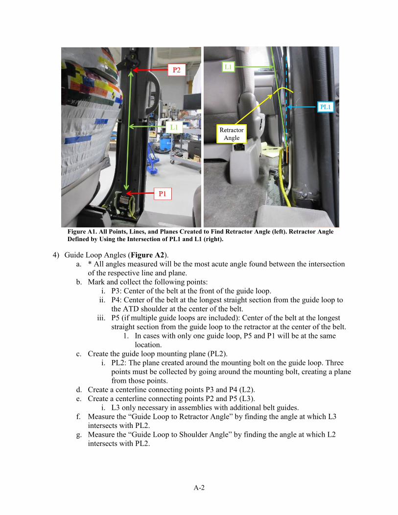
Figure A1. All Points, Lines, and Planes Created to Find Retractor Angle (left). Retractor Angle Defined by Using the Intersection of PL1 and L1 (right). .......................................................... A-2
Figure A2. All Points, Lines, and Planes Created to Find Guide Loop Angle (left). Guide Loop Angles Defined by Using the Intersection of PL2 and L2 (right)............................................... A-3
Figure A3. All Points, Lines, and Planes Created to Find Inboard Angles (left and right). ....... A-4
Figure A4. All Points, Lines, and Planes Created to Find Outboard Hardware Angle (left). Outboard Hardware Angle Defined by Using the Intersection of PL5 and L7 (right). .............. A-5
Figure E1. Crosshead of the Tensile Test Machine at Starting Position (left) Compared to Top of Stroke (right). ............................................................................................................................... E-1
Figure E2. All Webbing Removed With Locking Clip. .............................................................. E-1
Figure E3. All Excess Webbing Pulled Through to the Buckle Side of the Assembly. .............. E-2
Figure E4. (a) Measured Loop Length That Matches Previous Testing; (b) Bebbing Spooled Back on the Retractor................................................................................................................... E-2

vi
Executive Summary Federal Motor Vehicle Safety Standard (FMVSS) No. 209, Seat Belt Assemblies, (44 FR 72139, 1979) specifies requirements, including performance requirements, for seat belt assemblies used in motor vehicles. The standard includes an assembly performance tensile test where seat belt assemblies must withstand a minimum tensile force and not exceed an elongation limit. The National Highway Traffic Safety Administration is evaluating potential changes to the test procedures, to better represent in-vehicle restraint angles. To support the tensile test procedure development, NHTSA’s Vehicle Research and Test Center (VRTC) collected in-vehicle measurements of seat belt assemblies with different occupant sizes and conducted tensile tests at the representative angles measured. In-vehicle geometry of the seat belt assembly is 3-dimensional (3D) while the tensile test set-up is 2-dimensional (2D). The developed procedures include a method for translating the angles into a 2D set-up using a coordinate measuring machine. To encompass the largest range of representative in-vehicle measurements, the Hybrid III 6-year-old (6YO) and 95th percentile male anthropomorphic test devices (ATDs) were seated in-vehicle and the seat belt assembly angles measured. For front row seating positions, the Hybrid III 5th percentile female was used rather than the 6YO.
The in-vehicle angles were used to fabricate fixtures that held the hardware at the representative angles for tensile testing. Four sets of fixtures (small occupant lap belt, small occupant shoulder belt, large occupant lap belt, large occupant shoulder belt) were created per seat belt assembly. Each seat belt was installed to the appropriate fixtures using the original equipment manufacturer (OEM) seat belt assembly’s vehicle attachment hardware and bolts.
Out of 10 seat belt assemblies tested using the in-vehicle seat belt angles, 4 did not meet the FMVSS No. 209 performance criteria when tested using the procedure under evaluation, due to hardware fracture or surpassing the elongation limit. Throughout testing, several additional key observations were noted, including test head rotation, guide loop rotation, buckle stalk movement, multiple guide loops set-up, and updated test procedure comparisons.
Additional testing was completed aiming to further develop the test procedure to determine if seat belt assemblies with load limiters can meet the force criterion in one test when using stroke-limited machines. The assemblies with load limiters were tested in three conditions: no webbing on the spool, minimal webbing on the spool, and retractor pretensioner actuated. All assemblies tested in the conditions of no webbing on the spool or minimal webbing on the spool reached the force criterion, although more steps were required to test with minimal webbing on the spool and the load limiters were not fully engaged. Testing with the retractor pretensioner actuated did not achieve the required load.
Overall, the updated test procedures were feasible and converted the in-vehicle geometry of the seat belt assembly into a more representative tensile test. The developed test procedures include a detailed method for collecting as-used in-vehicle angle measurements, incorporating all vehicle attachment hardware, and fabricating unique fixtures to complete tensile tests at representative in-use angles.

1
Introduction FMVSS No. 2091 specifies requirements, including performance requirements, for seat belt assemblies used in motor vehicles. The standard includes an assembly performance tensile test where seat belt assemblies must withstand a minimum tensile force and not exceed an elongation limit. NHTSA’s Enforcement Laboratory Test Procedure for FMVSS No. 2092 details the assembly test procedure and set-up. Figure 1, from the Code of Federal Regulations, illustrates the tensile test set-up where the attachment hardware of the seat belt assembly can be secured at discrete angles either parallel, perpendicular, or 45 degrees relative to the seat belt webbing.
Figure 1. FMVSS No. 209 Tensile Test Set-Up.
NHTSA is evaluating clarifications to the test procedures to better represent in-vehicle restraint angles. To support the tensile test procedure development, the VRTC collected in-vehicle measurements of seat belt assemblies with different occupant sizes and conducted tensile tests for both the pelvis loop (lap belt) and upper torso loop (shoulder belt) at the representative angles with seat belt equipment used in-vehicle. Figure 2 shows an example of the updated tensile test set-up for the upper torso loop tests.
1 44 FR 72139, Dec. 13, 1979; Title 49, Subtitle B, Chapter V, Part 571, mSubpart B, §571.209. 2 National Highway Traffic Safety Administration. (2007, December 7). Laboratory test procedure for FMVSS 209, seat belt assemblies (Report No. TP-209-08). Author. Retrieved from https://one.nhtsa.gov/DOT/NHTSA/Vehicle %20Safety/Test%20Procedures/Associated%20Files/TP-209-08.pdf.

2
Figure 2. Updated Tensile Test Set-Up—Upper Torso Loop (Shoulder Belt).
In-Vehicle Angles Description In-vehicle geometry of the seat belt assembly is 3D while the tensile test set-up is 2D. The developed procedures include a method for translating measured angles into a 2D set-up using a coordinate measuring machine (a FaroArm3). It is anticipated that the angle tolerance would be plus or minus one degree. A detailed procedure for collecting the in-vehicle angles can be found in Appendix A. Four types of in-vehicles angles were identified to be measured for the updated tensile test: retractor, guide loop, outboard hardware, and inboard hardware.
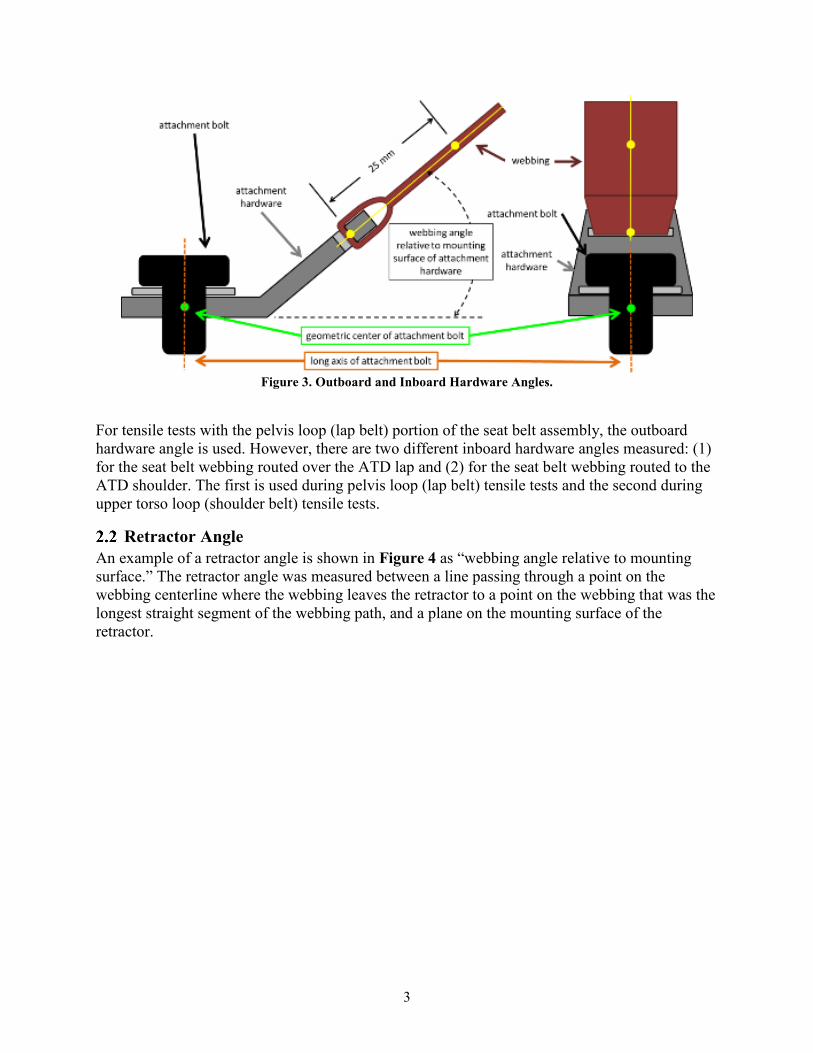
Outboard and Inboard Hardware Angles An example of a hardware angle is shown in Figure 3 as the “webbing angle relative to mounting surface of the attachment hardware.” The hardware angles were measured between a line passing through a point on the webbing centerline from the attachment hardware connection to the webbing (yellow dot) to a point on the webbing that was the longest straight segment of the webbing path (yellow dot), and a plane on the mounting surface of the attachment hardware (dashed line).
3 FARO Technologies, Inc., Lake Mary, FL.
3
Figure 3. Outboard and Inboard Hardware Angles.
For tensile tests with the pelvis loop (lap belt) portion of the seat belt assembly, the outboard hardware angle is used. However, there are two different inboard hardware angles measured: (1) for the seat belt webbing routed over the ATD lap and (2) for the seat belt webbing routed to the ATD shoulder. The first is used during pelvis loop (lap belt) tensile tests and the second during upper torso loop (shoulder belt) tensile tests.
Retractor Angle An example of a retractor angle is shown in Figure 4 as “webbing angle relative to mounting surface.” The retractor angle was measured between a line passing through a point on the webbing centerline where the webbing leaves the retractor to a point on the webbing that was the longest straight segment of the webbing path, and a plane on the mounting surface of the retractor.

4
Figure 4. Retractor Angle.
Guide Loop Angles An example of a guide loop angle is shown in Figure 5 as “angles ϴ1 and ϴ2 are webbing angles of interest relative to the mounting surface.” The guide loop, most often a D-ring, has two angles to incorporate into the set-up: one line of webbing extends from the retractor, and the other is generally directed toward the occupant’s shoulder. In some cases, there are seat belt assemblies which have multiple guide loops. In that case, all angles created by the guide loops were measured. The guide loop angles were measured between (1) a line passing through a point on the centerline of the webbing on the bottom side of the guide loop to the centerline of webbing outside of the retractor, or (2) a line passing through a point on the centerline of the webbing on the top portion of the guide loop (yellow dot) and a point at the end of the straightest segment near the occupant’s shoulder, and a plane on the mounting surface of the attachment hardware (dashed line).

5
Figure 5. Guide Loop Angles.
In-Vehicle Measurements To encompass the largest range of representative in-vehicle measurements, the Hybrid III 6YO and 95th percentile ATDs were seated in-vehicle and the seat belt assembly angles measured. For front row driver seating positions, the Hybrid III 5th percentile female ATD was used rather than the 6YO. Details regarding the seat configurations and measurement procedure can be found in Appendix A.
The representative amount of webbing on the retractor spool for a given ATD was also measured as a part of the measurement procedure. With the belt positioned normally on the given ATD, the webbing was marked where it leaves the retractor spool; then all the webbing was pulled off the spool and a new mark was made where it leaves the retractor. The distance between these two marks was recorded as the representative length of webbing on the retractor spool, with a tolerance of plus or minus 2.5 millimeters.

6
In-vehicle angles were collected for eight test vehicles, selected to include various seat belt technologies including load limiters, inflatable belts, and multiple guide loops. Table 1 shows the test matrix of vehicles. An example of the resulting in-vehicle angles is shown in Table 2 for the 2014 Hyundai Tucson. All the in-vehicle angle results can be found in Appendix B.
Table 1. Vehicle Test Matrix Model Year Make/Model Seating Position ATDs
1 2011 Honda Odyssey Front Row, Passenger 6YO 95th Male
2 2011 Ford Explorer (inflatable belt option) 2nd Row, Passenger 6YO 95th Male
3 2011 Hyundai Tucson Front Row, Driver 5th Female 95th Male
4 2011 Chevrolet Traverse Front Row, Driver 5th Female 95th Male
5 2014 Fiat 500L 2nd Row, Passenger 6YO 95th Male
6 2017 Mercedes E300 2nd Row, Passenger 6YO 95th Male
7 2012 Mercedes S400 2nd Row, Passenger 6YO 95th Male
8 2014 Volkswagen Tiguan 2nd Row, Passenger 6YO 95th Male
Table 2. 2014 Hyundai Tucson In-Vehicle Angles In-Vehicle Measurements 5th
Female 95th Male
Retractor Angle 6° 7° Inboard Hardware Lap Angle 70° 21° Inboard Hardware Shoulder Angle 42° 18° Outboard Hardware Angle 15° 37° Guide Loop to Shoulder Angle 27° 53° Guide Loop to Retractor Angle 11° 13° Webbing on Spool 1,232 mm 1,100 mm
Tensile Testing
Tensile Testing Matrix Ten seat belt assemblies were a part of the tensile test matrix. Eight were the vehicle-specific belts described previously, and two universal seat belt assemblies were selected because the provided instructions indicated the belts met FMVSS No. 209 standards. Table 3 lists the 10 seat belt assemblies used in tensile testing.

7
Table 3. Tensile Testing Matrix Model Year Make/Model Seating Position ATDs
1 2011 Honda Odyssey Front Row, Passenger 6YO 95th Male
2 2011 Ford Explorer (inflatable belt option) 2nd Row, Passenger 6YO 95th Male
3 2011 Hyundai Tucson Front Row, Driver 5th Female 95th Male
4 2011 Chevrolet Traverse Front Row, Driver 5th Female 95th Male
5 2014 Fiat 500L 2nd Row, Passenger 6YO 95th Male
6 2012 Mercedes S400 2nd Row, Passenger 6YO 95th Male
7 2017 Mercedes E300 2nd Row, Passenger 6YO 95th Male
8 2014 Volkswagen Tiguan 2nd Row, Passenger 6YO 95th Male
9 Universal SeatBeltsPlus4 N/A N/A N/A
10 Universal Dorman5 N/A N/A N/A
Test Set-Up The in-vehicle angles were used to fabricate fixtures that held the hardware at the representative angles for tensile testing. Four sets of fixtures (small occupant lap belt, small occupant shoulder belt, large occupant lap belt, large occupant shoulder belt) were created per seat belt assembly. In the case of multiple guide loop tests, additional fixtures were required. To simplify fabrication, drawings were created that translated the in-vehicles angles to be relative to horizontal. An example of the 95th male angles for a shoulder belt fixture is shown in Figure 6 on the following page.
4 Oceanside, CA. 5 Dorman Products, Inc., Colmar, PA.

8
Figure 6. 2014 Hyundai Tucson 95th Male Shoulder Belt Fabrication Drawing.
Care was taken during fabrication to ensure the appropriate loop length required (1,220 to 1,270 millimeters) was achievable during the tensile test. Examples of the shoulder and lap belt test fixtures, for the 2014 Hyundai Tucson, are shown in Figures 7 and 8.
\ Figure 7. 2014 Hyundai Tucson 95th Shoulder Belt Fixtures.
Test machine head
Fixture cross bar

9
Figure 8. 2014 Hyundai Tucson 95th Lap Belt Fixtures.
Tensile Test Procedure The seat belts were installed on the fixtures using the OEM seat belt assembly’s attachment hardware and bolts. The tensile force was applied at a rate of 51 millimeters6 per minute until the required force was met; the force criterion for the pelvis loop (lap belt) was 22,241 newtons (N), and the criterion for the upper torso loop (shoulder belt) was 13,345 N. Elongation was recorded as movement of the tensile test machine and multiplied by two, representing each segment of seat belt webbing in contact with the test head. The elongation limit criterion for these tests was 508 millimeters (254 mm per segment).7 The detailed tensile test procedure is included in Appendix C.
Along with the representative amount of webbing on the spool, the required loop length was set for each loop test while installed on the fixtures on the tensile test machine. The loop length is defined as the distance between furthest attachment bolts of the seat belt assembly hardware; the required loop length is 1,220 to 1,270 millimeters. As an example, for the upper torso loop, the furthest attachment bolts would be from the retractor bolt to the inboard buckle stalk anchor bolt. When both the loop length and the representative amount of webbing on the spool could not be set in combination, the test was completed with the representative amount on the spool and the resulting loop length was recorded.
Tensile Test Results To analyze the results from tensile testing, the maximum force and elongation measurements for each test were tabulated and color coded. Dark red indicates a tensile test where the hardware
6 FMVSS No. 209 specifies the heads of the testing machine shall be separated at a rate between 51 and 102 mm per minute. The test equipment used for this test project was capable of only 51 mm per minute. 7 Elongation limits do not apply to the front seat configurations where seat assemblies include a load limiter because the seating position is covered by FMVSS No. 208 dynamic testing.

10
fractured, and red indicates the elongation limit was surpassed. Yellow-orange indicates tests where the tensile test machine was not able to complete the test to the required force due to limitation on the stroke of the machine. Results shown in Tables 4 and Table 5 tabulate the force and elongation results for pelvis loop tests and upper torso loop tests, respectively. Data, photos, and videos of each test can be found in NHTSA’s Component Data Base (CDB) using the test numbers included (C01376-C01426, C01698-C01714). Cells marked with asterisks indicate front row seating position assemblies with load limiters where the elongation limits do not apply.

11
Table 4. Pelvis Loop (Lap Belt) Tensile Test Results Model Year Make Model Seating
Position ATD CDB Number Force (N)
Elongation (mm)
2011 Honda Odyssey 1st Row, Passenger 6YO C01377 22,241 146
2011 Honda Odyssey 1st Row, Passenger 6YO C01378 22,322 164
2011 Honda Odyssey 1st Row, Passenger 95th C01379 22,292 88
2011 Honda Odyssey 1st Row, Passenger 6YO C01380 22,309 173
2011 Honda Odyssey 1st Row, Passenger 95th C01381 22,293 128
2011 Ford Explorer (inflatable)
2nd Row, Passenger 95th C01385 22,276 242
2011 Ford Explorer (inflatable)
2nd Row, Passenger 95th C01386 22,287 224
2011 Ford Explorer (inflatable)
2nd Row, Passenger 6YO C01387 22,219 379
2011 Hyundai Tucson 1st Row, Driver 5th C01388 22,328 179
2011 Hyundai Tucson 1st Row, Driver 95th C01389 22,359 81
2011 Chevrolet Traverse 1st Row, Driver 5th C01390 22,314 156
2011 Chevrolet Traverse 1st Row, Driver 95th C01391 22,310 130
2014 Fiat 500L 2nd Row, Passenger 95th C01392 22,324 136
2014 Fiat 500L 2nd Row, Passenger 6YO C01393 22,300 146
2017 Mercedes E300 2nd Row, Passenger 95th C01394 22,285 194
2017 Mercedes E300 2nd Row, Passenger 6YO C01395 22,296 261
2012 Mercedes S400 2nd Row, Passenger 95th C01396 22,293 88
2014 Volkswagen Tiguan 2nd Row, Passenger 6YO C01397 13,523 162
2014 Volkswagen Tiguan 2nd Row, Passenger 6YO C01398 17,456 114
2014 Volkswagen Tiguan 2nd Row, Passenger 95th C01399 22,303 186
Universal Seat Belts Plus N/A N/A N/A C01382 22,276 159
Universal Seat Belts Plus N/A N/A N/A C01383 22,280 142
Universal Dorman tensilN/A N/A N/A C01384 22,273 203

12
Table 5. Upper Torso Loop (Shoulder Belt) Tensile Test Results Model Year Make Model Seating
Position ATD CDB Number Force (N)
Elongation (mm)
2011 Honda Odyssey 1st Row, Passenger 6YO C01400 11,431 580*
2011 Honda Odyssey 1st Row, Passenger 95th C01376 13,382 524*
2011 Honda Odyssey 1st Row, Passenger 95th C01401 13,369 534*
2011 Honda Odyssey 1st Row, Passenger 6YO C01402 13,380 532*
2011 Honda Odyssey 1st Row, Passenger 95th C01403 13,380 536*
2011 Ford Explorer (inflatable)
2nd Row, Passenger 95th C01406 13,400 500
2011 Ford Explorer (inflatable)
2nd Row, Passenger 6YO C01407 13,356 688
2011 Hyundai Tucson 1st Row, Driver 5th C01408 7,477 768*
2011 Hyundai Tucson 1st Row, Driver 5th C01409 5,411 546*
2011 Hyundai Tucson 1st Row, Driver 95th C01410 7,230 492*
2011 Hyundai Tucson 1st Row, Driver 95th C01411 5,903 592*
2011 Chevrolet Traverse 1st Row, Driver 5th C01412 6,941 498*
2011 Chevrolet Traverse 1st Row, Driver 5th C01413 6,298 480*
2011 Chevrolet Traverse 1st Row, Driver 5th C01414 6,924 514*
2011 Chevrolet Traverse 1st Row, Driver 95th C01415 6,473 508*
2011 Chevrolet Traverse 1st Row, Driver 95th C01416 5,951 456*
2014 Fiat 500L 2nd Row, Passenger 95th C01417 13,397 208
2014 Fiat 500L 2nd Row, Passenger 6YO C01418 13,371 444
2017 Mercedes E300 2nd Row, Passenger 95th C01419 13,360 324
2017 Mercedes E300 2nd Row, Passenger 6YO C01420 13,398 514
2012 Mercedes S400 2nd Row, Passenger 95th C01421 10,431 227
2012 Mercedes S400 2nd Row, Passenger 95th C01422 10,012 172

13
Model Year Make Model Seating
Position ATD CDB Number Force (N)
Elongation (mm)
2012 Mercedes S400 2nd Row, Passenger 95th C01423 13,372 164
2012 Mercedes S400 2nd Row, Passenger 95th C01424 13,377 186
2014 Volkswagen Tiguan 2nd Row, Passenger 6YO C01425 9,036 380
2014 Volkswagen Tiguan 2nd Row, Passenger 95th C01426 12,384 366
Universal Seat Belts Plus N/A N/A N/A C01404 13,402 275 Universal Seat Belts Plus N/A N/A N/A C01405 13,385 343
2014 Volkswagen Tiguan 2nd Row, Passenger 6YO C01698 13,379 136
2014 Volkswagen Tiguan 2nd Row, Passenger 95th C01699 13,378 122
2014 Volkswagen Tiguan 2nd Row, Passenger 6YO C01704 13,373 310
2014 Volkswagen Tiguan 2nd Row, Passenger 95th C01705 13,413 308
2011 Hyundai Tucson 1st Row, Driver 5th C01700 13,483 89*
2011 Hyundai Tucson 1st Row, Driver 95th C01701 13,474 76*
2011 Hyundai Tucson 1st Row, Driver 5th C01706 13,390 739*
2011 Hyundai Tucson 1st Row, Driver 95th C01707 13,386 605*
2011 Hyundai Tucson 1st Row, Driver 5th C01711 7,098 740*
2011 Hyundai Tucson 1st Row, Driver 95th C01712 7,210 710*
2011 Chevrolet Traverse 1st Row, Driver 5th C01702 13,371 131*
2011 Chevrolet Traverse 1st Row, Driver 95th C01703 13,382 118*
2011 Chevrolet Traverse 1st Row, Driver 5th C01708 13,373 675*
2011 Chevrolet Traverse 1st Row, Driver 95th C01709 11,056 737*
2011 Chevrolet Traverse 1st Row, Driver 95th C01710 13,372 711*
2011 Chevrolet Traverse 1st Row, Driver 5th C01713 9,924 737*
2011 Chevrolet Traverse 1st Row, Driver 95th C01714 9,801 704*

14
Tensile Test Discussion Additional analysis was completed on tensile tests that did not meet the FMVSS No. 209 performance criteria. Out of 10 seat belt assemblies tensile tested, 4 did not meet the performance criteria via hardware fracture or surpassing the elongation limit.
4.5.1 2014 Volkswagen Tiguan The 2014 Volkswagen Tiguan had a complete fracture on the pelvic loop during tensile testing at the 6YO representative in-vehicle angles (C01397). The Tiguan buckle consisted of a steel cable welded to a steel loop around the attachment bolt. The fracture occurred due to a broken weld before the required force was met. Figure 9 shows the pre-test set-up of the 2014 Volkswagen Tiguan buckle; Figure 10 is post-test, highlighting the fracture. The test was repeated with a new seat belt assembly and the fracture occurred in the repeat test (C01398).
Figure 9. 2014 Volkswagen Tiguan Buckle Pre-Test.
.
Figure 10. 2014 Volkswagen Tiguan Buckle Fracture.

15
4.5.2 2011 Ford Explorer Inflatable Belt The 2011 Ford Explorer inflatable belt included a retractor in the pelvic loop assembly due to an inflator attached to the buckle. The lap belt retractor was measured in-vehicle and installed at the representative angles. Figure 11 shows the pre-test set-up of the 2011 Ford Explorer pelvis loop test at the 6YO angles (C01387). During the tensile test, the retractor bracket tore resulting in the fracture shown in Figure 12. Additionally, the 2011 Ford Explorer upper torso loop test at the 6YO representative angles exceeded the elongation limit at 688 millimeters with the representative amount of webbing on the retractor spool.
Figure 11. 2011 Ford Explorer Inflatable Belt Lap Belt Retractor Pre-Test.
Figure 12. 2011 Ford Explorer Inflatable Belt Lap Belt Retractor Fracture.

16
4.5.3 2012 Mercedes S400 The 2012 Mercedes S400 was selected for this study because it had multiple guide loops (described as a guide bar and D-ring) in the shoulder belt assembly. Tests were completed to compare the effect of multiple guide loops (see 4.6.4 for more discussion of these tests). Tests at the 95th percentile in-vehicles angles used 1) both the D-ring and guide bar assembly, 2) guide bar only, and 3) D-ring only. Figure 13 shows the guide bar only test set-up (C01422). A guide bar bolt sheared off before the required force was met as shown in Figure 14. Guide bar fracture occurred on the test with the guide bar only (C01422) and the test with both the D-ring and guide bar (C01421).
Figure 13. 2012 Mercedes S400 (Guide Bar Only) Pre-Test.
Figure 14. 2012 Mercedes S400 Guide Bar Fracture.

17
4.5.4 2017 Mercedes E300 The 2017 Mercedes E300 upper torso loop (shoulder belt) test (C01420) at the 6YO representative angles exceeded the elongation limit at 514 millimeters with the representative amount of webbing on the retractor spool.
4.5.5 Seat Belt Assemblies With Load Limiters As previously described, the representative amount of webbing on the spool for each ATD was measured during in-vehicle measurements. This length was then implemented in tensile testing with the seat belt assembly. The front row 2011 Hyundai Tucson and 2011 Chevrolet Traverse, and second row 2014 Volkswagen Tiguan seat belt assemblies had load limiters. During tensile testing with these seat belt assemblies, the test machine at VRTC reached its maximum stroke before the force criterion was met because the webbing slowly released from the retractor spool. Per the compliance testing laboratory’s test procedure, the webbing that has been pulled off the spool would be pulled tight from the loop, the test machine reset, and then the tensile test continued. Section 5 details a study aiming to further develop the test procedure to determine if seat belt assemblies with load limiters can meet the force criterion in one test when using stroke-limited machines.
Tensile Test Comparisons Throughout testing, several additional comparisons were made based on observations during testing including test head rotation, guide loop rotation, buckle stalk movement, multiple guide loops set-up, and updated test procedure comparisons.
4.6.1 Test Head Rotation Initially, the fabricated test machine head (triangle shaped fixture) could rotate during the testing. This caused the webbing and hardware to be loaded unevenly and changed the angles at which the fixture was pulling on the hardware. The 2011 Honda Odyssey seat belt assembly was initially tested with the rotating test head (marked in grey). However, the seat belt assembly was re-tested, with new belts, with the test head fixed. Figure 15 shows the differences between when the test head could rotate (top) and when the test head was fixed (the following page).

18
Figure 15. Test Head Rotation (top) and Test Head Fixed (bottom).
Elongation results showed some variation between the rotating and fixed test head conditions, while the force results did not show any significant differences. Direct comparisons are found in Table 6 and 7 below, for the pelvic loop and upper torso loop respectively, with the rotating test head tests shown in grey. The cell marked in yellow-orange did not reach the required force due to a software error but was included for comparison purposes.

19
Table 6. Pelvis Loop Test Head Rotation Comparison Model Year Make Model Seating
Position ATD CDB Number Force (N)
Elongation (mm)
2011 Honda Odyssey 1st Row, Passenger 6YO C01378 22,322 164
2011 Honda Odyssey 1st Row, Passenger 6YO C01380 22,309 173
2011 Honda Odyssey 1st Row, Passenger 95th C01379 22,292 88
2011 Honda Odyssey 1st Row, Passenger 95th C01381 22,293 128
Table 7. Upper Torso Loop Test Head Rotation Comparison
Model Year Make Model Seating
Position ATD CDB Number Force (N)
Elongation (mm)
2011 Honda Odyssey 1st Row, Passenger 6YO C01400 11,431 580*
2011 Honda Odyssey 1st Row, Passenger 6YO C01402 13,380 532*
2011 Honda Odyssey 1st Row, Passenger 95th C01376 13,382 524*
2011 Honda Odyssey 1st Row, Passenger 95th C01403 13,380 536*
4.6.2 Guide Loop Rotation During tensile testing, it was observed that the guide loop (D-ring) tended to rotate in certain seat belt assemblies during upper torso loop tests. For two vehicle specific assemblies, the 2011 Hyundai Tucson and 2011 Honda Odyssey, the guide loop slowly rotated during the entirety of the test until the rotation caused the webbing to bunch up in the guide loop. A photo of the bunched webbing in the guide loop is shown in Figure 16. The bunched-up webbing caused an increase in force results for most tests. Repeat tests were completed with the guide loops fixed by fabricating additional wings on the fixtures (Figure 17). A direct comparison of results can be found in Table 8 and Table 9. The comparisons for the 2011 Honda Odyssey were inconclusive. The 2011 Hyundai Tucson saw decreased force results when the guide loop was fixed, while the elongation results were inconclusive due to high variability when the guide loop rotated.

20
Figure 16. Guide Loop Rotation.
Figure 17. Fixed Guide Loop.

21
Table 8. 2011 Honda Odyssey Guide Loop Rotation Comparison
Model Year Make Model Seating
Position ATD CDB Number
Upper Torso Loop Test
Force (N)
Elongation (mm)
Guide Loop
Rotation
2011 Honda Odyssey 1st Row, Passenger 6YO C01400 11,431 580*
2011 Honda Odyssey 1st Row, Passenger 95th C01376 13,382 524*
Fixed Guide Loop
2011 Honda Odyssey 1st Row, Passenger 6YO C01402 13,380 532*
2011 Honda Odyssey 1st Row, Passenger 95th C01403 13,380 536*
Table 9. 2011 Hyundai Tucson Guide Loop Rotation Comparison
Model Year Make Model Seating
Position ATD CDB Number
Upper Torso Loop Test
Force (N)
Elongation (mm)
Guide Loop
Rotation
2011 Hyundai Tucson 1st Row, Driver 5th C01408 7,477 768*
2011 Hyundai Tucson 1st Row, Driver 95th C01410 7,230 492*
Fixed Guide Loop
2011 Hyundai Tucson 1st Row, Driver 5th C01409 5,411 546*
2011 Hyundai Tucson 1st Row, Driver 95th C01411 5,903 592*
4.6.3 Buckle Stalk Movement When incorporating the representative in-vehicles angles into the tensile test set-up, the initial orientation of the buckle and connected buckle stalk was observed to start in a location that allowed the stalk to move during the test. A target was placed on the top edge of the buckle for better visibility. As shown in Figure 18, the buckle stalk started at a shallow angle behind the tensile test machine uprights, then as the tensile test occurs, the buckle and connected buckle stalk move upward, rotating about the attachment bolt. This motion occurred for every test, and the magnitude of movement varied depending on in-vehicle angle measurements and buckle

22
stalk design. Per the test procedure, the elongation is zeroed at the 98 newtons pre-load, so in some cases the approximate buckle stalk movement value is greater than the elongation value because of this difference in reporting. Because the buckle stalk movement is included in the maximum elongation value, the approximate buckle stalk movement was quantified using desktop caliper software (Iconico Screen Calipers) for every test. All tensile test force and elongation results, along with the approximate buckle stalk movement in the Z-direction (component of elongation) can be found in Appendix D. The buckle stalk movement values ranged from a minimum of 7 millimeters to a maximum of 133 millimeters. The 2017 Mercedes E300 buckle stalk moved approximately 133 millimeters which is 51 percent of the total elongation recorded. Overall, many seat belt assemblies had more than 100 millimeters in buckle stalk movement, accounting for 10 to 20 percent of their total elongation results. Although the buckle stalk movement adds to the total elongation of the system in this procedure, because the test, including the buckle stalk, replicates the in-vehicle angles, the elongation measurement is more representative of in-use conditions than the current FMVSS No. 209 procedure.
Figure 18. Buckle Stalk Movement Example.
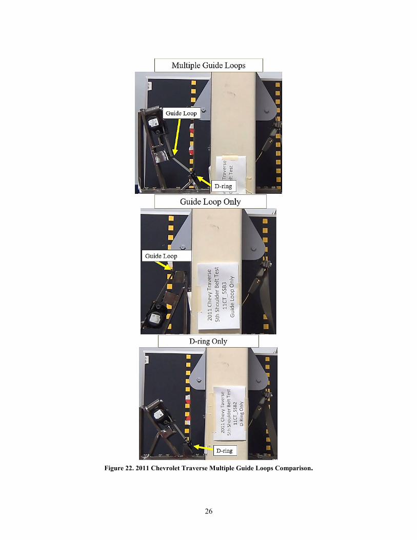
4.6.4 Multiple Guide Loops At least one seat belt assembly with multiple guide loops was selected to be a part of the test matrix as described previously. In the end, two vehicles (2012 Mercedes S400 and 2011 Chevrolet Traverse) were tested that had multiple guide loops. The 2012 Mercedes S400 had a

23
guide bar in the seat belt assembly, as shown in Figure 19. The guide bar was a curved metal bar that was attached by two bolts on either end.
Figure 19. 2012 Mercedes S400 Guide Bar.
The 2011 Chevrolet Traverse seat belt assembly included a second guide loop. The guide loop was held in by a plastic pin in the B-pillar of the vehicle, as shown in Figure 20. Another angle was created because of this guide loop, so it was measured and included in the tensile tests.
Figure 20. 2011 Chevrolet Traverse Second Guide Loop.
These assemblies were tested in multiple configurations: both D-ring and guide bar/loop, guide bar/loop only, and D-ring only. Additional angles were measured in these vehicles to orient the hardware at representative in-vehicle angles. The different guide bar/loop set-ups for the 2012 Mercedes S400 and 2011 Chevrolet Traverse are shown in Figures 21 and 22, respectively.

24
Comparisons of results can be found in Tables 10 and 11, for the Mercedes S400 and Chevrolet Traverse, respectively.
Results of testing with multiple guide loop configurations for the 2012 Mercedes S400 showed that the use of a guide bar produced failure at a lower force level because the guide bar fractured during the multiple guide loop and guide bar only tests, yet also produced higher elongation results. Results from the 2011 Chevrolet Traverse were inconclusive because the tensile test machine reached is maximum movement before the required force was met. However, because the Chevrolet Traverse is a front row seat belt assembly and has a load limiter, elongation is not a criterion, indicated by the asterisks.

25
Figure 21. 2012 Mercedes S400 Multiple Guide Loops Comparison.
26
Figure 22. 2011 Chevrolet Traverse Multiple Guide Loops Comparison.

27
Table 10. 2012 Mercedes S400 Multiple Guide Loops Results
Model Year Make Model Seating
Position ATD Test Description CDB Number
Upper Torso Loop Test
Force (N)
Elongation (mm)
2012 Mercedes S400 2nd Row, Passenger 95th
Multiple Guide Loops
C01421 10,431 227
2012 Mercedes S400 2nd Row, Passenger 95th D-ring Only C01423 13,372 164
2012 Mercedes S400 2nd Row, Passenger 95th D-ring Only C01424 13,377 186
2012 Mercedes S400 2nd Row, Passenger 95th Guide Bar
Only C01422 10,012 172
Table 11. 2011 Chevrolet Traverse Multiple Guide Loops Results
Model Year Make Model Seating
Position ATD Test Description CDB Number
Upper Torso Loop Test
Force (N)
Elongation (mm)
2011 Chevrolet Traverse 1st Row, Driver 5th
Multiple Guide Loops
C01412 6,941 498*
2011 Chevrolet Traverse 1st Row, Driver 5th D-ring
Only C01413 6,298 480*
2011 Chevrolet Traverse 1st Row, Driver 5th Guide Loop
Only C01414 6,924 514*
4.6.5 Updated and FMVSS No. 209 Test Procedure Comparisons Two of the seat belt assemblies (2014 Fiat 500L and 2014 Volkswagen Tiguan) tested with the updated test procedure incorporating representative angles had been previously tested by NHTSA’s Office of Rulemaking. Therefore, comparisons could be made between the current FMVSS No. 209 test procedure and the updated test procedure. Examples of the differences in test set-up are shown in Figures 23 and 24 for the Fiat 500L and Figures 25 and 26 for the Volkswagen Tiguan seat belt assemblies.

28
Figure 23. FMVSS No. 209 Test Set-Up for Pelvis Loop (left) and Upper Torso Loop (right) of 2014 Fiat 500L Seat Belt Assembly.
Figure 24. Updated Test Set-Up for Pelvis Loop (left) and Upper Torso Loop (right) of 2014 Fiat 500L Seat Belt Assembly.

29
Figure 25. FMVSS No. 209 Test Set-Up for Pelvis Loop (left) and Upper Torso Loop (right) of 2014 Volkswagen Tiguan Seat Belt Assembly.
Figure 26. Updated Test Set-Up for Pelvis Loop (left) and Upper Torso Loop (right) of 2014 Volkswagen Tiguan Seat Belt Assembly.
A direct comparison of results can be found in Tables 12 and 13, for the 2014 Fiat 500L and 2014 Volkswagen Tiguan seat belt assemblies, respectively. Results from the current FMVSS No. 209 test procedure are shown in grey. For the Fiat 500L, the current and upgraded test procedures produced similar results for the pelvic loop tests. For the upper torso loop tests, the current procedure produced results similar to those for the updated procedure when the 6YO angles were used, while the use of the 95th angles resulted in less than half the elongation. The

30
cell marked in red indicates that the anchor plate fractured during NRM testing. For the Volkswagen Tiguan, the FMVSS No. 209 test procedure generally produced less elongation than the upgraded procedure in the pelvis loop tests, and those tests with the 6YO angles had hardware fractures that were not seen in the NRM testing. The rear seat belt assembly with load limiter did not meet the elongation limit during one of the NRM upper torso loop tests. However, with the updated procedure, the seat belt assembly was not tested to the required force due to the spool out of the shoulder belt webbing during the test because of the stroke limitation of the tensile test machine.
Table 12. 2014 Fiat 500L Procedure Results Comparison
Model Year Make Model Seating Position ATD
Pelvic Loop Tests Upper Torso Loop Tests
Force (N)
Elongation (mm)
Force (N)
Elongation (mm)
2014 Fiat 500L 2nd Row, Passenger
N/A
22,241 142 13,345 457
2014 Fiat 500L 2nd Row, Passenger 20,020 N/A 13,345 432
2014 Fiat 500L 2nd Row, Passenger 22,241 135 13,345 442
2014 Fiat 500L 2nd Row, Passenger 95th 22,324 136 13,397 208
2014 Fiat 500L 2nd Row, Passenger 6YO 22,300 146 13,371 444
Table 13. 2014 Volkswagen Tiguan Procedure Results Comparison
Model Year Make Model Seating
Position ATD
Pelvic Loop Tests Upper Torso Loop Tests
Force (N)
Elongation (mm)
Force (N)
Elongation (mm)
2014 Volkswagen Tiguan 2nd Row, Passenger
N/A
22,241 130 13,345 472
2014 Volkswagen Tiguan 2nd Row, Passenger 22,241 130 13,345 > 853 mm
2014 Volkswagen Tiguan 2nd Row, Passenger 22,241 148 Not Tested Not Tested
2014 Volkswagen Tiguan 2nd Row, Passenger 95th 22,303 186 12,384 366
2014 Volkswagen Tiguan 2nd Row, Passenger 6YO 13,523 162 9,036 380

31
Model Year Make Model Seating
Position ATD
Pelvic Loop Tests Upper Torso Loop Tests
Force (N)
Elongation (mm)
Force (N)
Elongation (mm)
2014 Volkswagen Tiguan 2nd Row, Passenger 6YO 17,456 114 Not Tested Not Tested
Load Limiter Evaluation Four of the 10 seat belt assemblies in the tensile test matrix included load limiters. Three assemblies (2011 Chevrolet Traverse, 2011 Hyundai Tucson, and 2014 Volkswagen Tiguan) were selected for continued testing, and each included a torsion bar load limiter design. As described in Section 4, the tensile test machine reached its maximum stroke before the force criterion was met for these seat belt assemblies. Further testing was conducted aiming to develop a test procedure to determine if seat belt assemblies with load limiters can meet the force criterion in one test when using stroke-limited machines.
For the load limiter evaluation test matrix, the same loop length and in-vehicle angles were used as in Section 4 tensile testing, per respective vehicle. In the initial tensile test matrix, the 2011 Chevrolet Traverse was tested in three different configurations due to the multiple guide loops included in the shoulder belt assembly. In the load limiter evaluation test matrix, the Chevrolet Traverse was tested using the D-ring and guide loop configuration for the 95th percentile male and the guide loop only configuration for the 5th percentile female in-vehicle angles because they recorded the highest elongation.
Three test conditions were developed which were anticipated to allow the shoulder belt assemblies with load limiters to reach the required force in one test:
• The first test condition was to remove all the webbing from the spool before testing. • The second test condition was to determine and use the minimal amount of webbing
possible on the spool which allowed webbing to be fully off the spool before the tensile test machine reached its maximum stroke. A procedure was developed to determine the minimal amount of webbing required for each shoulder belt assembly and is detailed in Appendix E.
• The third test condition was to actuate the seat belt retractor pretensioners before tensile testing. Only the Chevrolet Traverse and Hyundai Tucson seat belt assemblies included retractor pretensioners, so only they were tested in this condition.
The test matrix for the load limiter evaluation testing is shown in Table 14.

32
Table 14. Load Limiter Evaluation Test Matrix Model
Year Make/Model Seating Position ATDs Webbing
Condition Retractor
Pretensioner
1 2014 Volkswagen Tiguan
2nd Row, Passenger 6YO 95th
Male No Webbing on
Spool Not Actuated
2 2011 Hyundai Tucson
Front Row, Driver
5th Female
95th Male
No Webbing on Spool Not Actuated
3 2011 Chevrolet Traverse
Front Row, Driver
5th Female
95th Male
No Webbing on Spool Not Actuated
4 2014 Volkswagen Tiguan
2nd Row, Passenger 6YO 95th
Male Minimal Webbing
on Spool Not Actuated
5 2011 Hyundai Tucson
Front Row, Driver
5th Female
95th Male
Minimal Webbing on Spool Not Actuated
6 2011 Chevrolet Traverse
Front Row, Driver
5th Female
95th Male
Minimal Webbing on Spool Not Actuated
7 2011 Hyundai Tucson
Front Row, Driver
5th Female
95th Male
Measured Amount Actuated
8 2011 Chevrolet Traverse
Front Row, Driver
5th Female
95th Male
Measured Amount Actuated
Yellow-orange in the subsequent tables indicates tests where the tensile test machine was not able to complete the test to the required force due to limitation on the stroke of the machine. Cells marked with an asterisk indicate front row seating position assemblies with load limiters where the elongation limits do not apply.
No Webbing on the Spool All three shoulder belt assemblies with load limiters were tested with no webbing on the spool. Before testing, all the webbing was removed from the spool and the shoulder belt assembly was set-up with the same loop length and representative in-vehicle angles as the Section 4 tensile test series. The load limiters do not engage in this configuration. The results from the no webbing condition tests are reported in Table 15, and all tests reached the required force.

33
Table 15. Load Limiter Evaluation—No Webbing Condition Results
Model Year Make Model Seating
Position ATD CDB Number
Force (N)
Elongation (mm)
2014 Volkswagen Tiguan 2nd Row, Passenger 6YO C01698 13,379 136
2014 Volkswagen Tiguan 2nd Row, Passenger 95th C01699 13,378 122
2011 Hyundai Tucson 1st Row, Driver 5th C01700 13,483 89*
2011 Hyundai Tucson 1st Row, Driver 95th C01701 13,474 76*
2011 Chevrolet Traverse 1st Row, Driver 5th C01702 13,371 131*
2011 Chevrolet Traverse 1st Row, Driver 95th C01703 13,382 118*
Minimal Webbing on the Spool All three shoulder belt assemblies were tested with a minimal amount of webbing on the spool which allowed webbing to be fully off the spool before the tensile test machine reached its maximum stroke. This allowed the load limiter to engage at least partially during testing and ensured the force criterion could be met during the tensile test.
Due to the different loop lengths, each shoulder belt assembly required a different amount of webbing on the spool to ensure that the webbing would run out before the tensile test machine reached its maximum stroke. A procedure to determine the required amount of webbing was developed and is detailed in Appendix E. Table 16 reports the amount of webbing on the spool for each belt assembly tested with the minimal webbing.
Table 16. Minimal Amount of Webbing
In-Vehicle Measurements 5th
Female or 6YO
95th Male
Volkswagen Tiguan 390 mm 440 mm Hyundai Tucson 625 mm 530 mm Chevrolet Traverse 540 mm 585 mm
The results from the minimal webbing condition tests are shown in Table 17. The force criterion was met for all shoulder belt assemblies tested with the determined minimal amount of webbing on the spool. However, this condition does not necessarily fully engage the load limiter. Test C01709 did not reach the force criterion because 50 millimeters was originally used for the initial clearance between the crosshead and the top of the tensile test machine stroke (see steps 2 and 3 in Appendix E). Subsequently, it was determined that 100 millimeters was needed to

34
provide adequate clearance, so the procedure was modified. When re-tested (C01710), that shoulder belt assembly met the required force. So, the remaining tests (C01704-01708) were tested with 100-millimeter clearance.
Table 17. Load Limiter Evaluation—Minimal Webbing Condition Results
Model Year Make Model Seating
Position ATD CDB Number
Force (N)
Elongation (mm)
2014 Volkswagen Tiguan 2nd Row, Passenger 6YO C01704 13,373 310
2014 Volkswagen Tiguan 2nd Row, Passenger 95th C01705 13,413 308
2011 Hyundai Tucson 1st Row, Driver 5th C01706 13,390 739*
2011 Hyundai Tucson 1st Row, Driver 95th C01707 13,386 605*
2011 Chevrolet Traverse 1st Row, Driver 5th C01708 13,373 675*
2011 Chevrolet Traverse 1st Row, Driver 95th C01709 11,056 737*
2011 Chevrolet Traverse 1st Row, Driver 95th C01710 13,372 711*
Actuated Retractor Pretensioner Two shoulder belt assemblies were tested with the retractor pretensioner actuated before testing. The loop lengths and representative amounts of webbing used in the Section 4 tensile test series were matched. For each test, the shoulder belt assembly was set-up and then the retractor pretensioner was actuated with the belt in this position on the tensile test machine. The actuation of the pretensioner resulted in the removal of all extra slack in the webbing and a resulting average force of approximately 1,000 newtons was observed for both pretensioners. After actuating the pretensioner, the force was zeroed on the tensile test machine to measure the change in force, and the shoulder belt assembly was tested using the tensile test procedure outlined in Appendix C. Despite actuating the pretensioner, the maximum stroke of the tensile test machine was reached before the required force for both seat belt assemblies. The results of the actuated retractor pretension test series are shown in Table 18.

35
Table 18. Load Limiter Evaluation—Actuated Retractor Pretensioner Condition Results
Model Year Make Model Seating
Position ATD CDB Number
Force (N)
Elongation (mm)
2011 Hyundai Tucson 1st Row, Driver 5th C01711 7,098 740*
2011 Hyundai Tucson 1st Row, Driver 95th C01712 7,210 710*
2011 Chevrolet Traverse 1st Row, Driver 5th C01713 9,924 737*
2011 Chevrolet Traverse 1st Row, Driver 95th C01714 9,801 704*
Load Limiter Evaluation Testing Observations During the load limiter evaluation test series, it was observed that both the Chevrolet Traverse guide loop and Hyundai Tucson D-ring reacted differently than in the Section 4 test series. During the initial testing, the guide loop did not bend, likely a difference because the force criterion was not met in the initial series.
For each condition tested on the 2011 Chevrolet Traverse shoulder belt in the load limiter evaluation test series, the guide loop bent outwards towards the retractor but did not fracture for any test. Figure 27 illustrates the bending of the guide loop in each condition.
Figure 27. Chevrolet Traverse Guide Loop Bending.
The D-ring of the Hyundai Tucson shoulder belt assembly rotated during the load limiter evaluation test series. The Hyundai Tucson was in the fixed D-ring orientation, but during testing, the D-ring was pushed slightly past the fixed D-ring fixture, allowing slight rotational

36
movement. The maximum D-ring rotation was observed in the actuated retractor pretensioner condition. Minor rotation was observed in the minimal webbing condition, and no rotation was observed in the no webbing condition. Figure 28 shows post-test photos of the slightly rotated D-ring in the actuated retractor pretensioner condition.
Figure 28. Hyundai Tucson D-ring Rotation.
Summary FMVSS No. 209 specifies performance requirements for seat belt assemblies used in motor vehicles. The standard includes an assembly performance tensile test where seat belt assemblies must withstand a minimum tensile force and not exceed an elongation limit. NHTSA is evaluating potential changes to the test procedures, to better represent in-vehicle restraint angles. To support the tensile test procedure development, VRTC collected in-vehicle measurements of seat belt assemblies with different occupant sizes and conducted tensile tests at the resulting representative angles. Out of 10 seat belt assemblies tested using the in-vehicle seat belt angles, four did not meet the performance criteria when tested using the procedure under evaluation. Throughout testing, several additional comparisons were made based on observations including test head rotation, guide loop rotation, buckle stalk movement, multiple guide loops set-up, and updated test procedure comparisons. Additional testing was completed aiming to further develop the test procedure to determine if seat belt assemblies with load limiters can meet the force criterion in one test when using stroke-limited machines. All assemblies tested under the conditions of no webbing on the spool or minimal webbing on the spool reached the required force, although more steps were required to test with minimal webbing on the spool and the load limiters were not fully engaged. Overall, the updated test procedure was feasible and converted the in-vehicle geometry of the seat belt assembly into a more representative tensile test. The developed test procedures include a detailed method for collecting the in-vehicle angle measurements, incorporating all in-vehicle hardware, and fabricating unique fixtures to complete tensile tests at representative in-use angles.

A-1
In-Vehicle Measurement Procedure 1) Remove any trim pieces to gain access to all seat belt mounting bolts and hardware. 2) Seat the ATD following the below seating procedure:
a. Hybrid III 6-year-old child ATD. i. The 6YO should be seated with the head restraint in the full down position,
the seat track full forward, the guide loop at its lowest achievable height, and the seat back at 25 degrees per SAE J826.
b. Hybrid III 5th percentile female per FMVSS No. 208 (TP208-13 G1) seating procedure.
i. The 5th percentile female should be seated with the head restraint in the full down position, the seat track full forward, the guide loop at mid-height, and the seat back fully upright.
c. Hybrid III 95th male ATD. i. The 95th percentile male should be seated with the head restraint in the full
up position, the seat track full rearward, the guide loop at its highest achievable height, and the seat back at 25 degrees per SAE J826.
3) Retractor Angle (Figure A1). a. * All angles measured will be the most acute angle found between the intersection
of the respective line and plane. b. Mark and collect the following points:
i. P1: Center of the belt at retractor (this point should be as close as possible to the center of the belt where the webbing leaves the retractor).
ii. P2: Center of the belt at the back of the guide loop (or longest straight line from P1).
c. Create the retractor mounting plane (PL1). i. PL1: The plane created around the mounting bolt on the retractor surface.
Three points must be collected by going around the retractor bolt, creating a plane from those points.
d. Create a centerline connecting points P1 and P2 (L1). e. Record the “Retractor Angle” by finding the angle at which PL1 and L1 intersect.
A-2
Figure A1. All Points, Lines, and Planes Created to Find Retractor Angle (left). Retractor Angle Defined by Using the Intersection of PL1 and L1 (right).
4) Guide Loop Angles (Figure A2). a. * All angles measured will be the most acute angle found between the intersection
of the respective line and plane. b. Mark and collect the following points:
i. P3: Center of the belt at the front of the guide loop. ii. P4: Center of the belt at the longest straight section from the guide loop to
the ATD shoulder at the center of the belt. iii. P5 (if multiple guide loops are included): Center of the belt at the longest
straight section from the guide loop to the retractor at the center of the belt. 1. In cases with only one guide loop, P5 and P1 will be at the same
location. c. Create the guide loop mounting plane (PL2).
i. PL2: The plane created around the mounting bolt on the guide loop. Three points must be collected by going around the mounting bolt, creating a plane from those points.
d. Create a centerline connecting points P3 and P4 (L2). e. Create a centerline connecting points P2 and P5 (L3).
i. L3 only necessary in assemblies with additional belt guides. f. Measure the “Guide Loop to Retractor Angle” by finding the angle at which L3
intersects with PL2. g. Measure the “Guide Loop to Shoulder Angle” by finding the angle at which L2
intersects with PL2.

A-3
Figure A2. All Points, Lines, and Planes Created to Find Guide Loop Angle (left). Guide Loop Angles Defined by Using the Intersection of PL2 and L2 (right).
5) Inboard Hardware Angle (Figure A3).
a. * All angles measured will be the most acute angle found between the intersection of the respective line and plane.
b. Mark and collect the following points: i. P6: Inboard top center of buckle.
ii. P7: Inboard anchor buckle attachment. iii. P8: Center of shoulder belt, 76 mm (3 inches) from tongue belt loop. iv. P9: Center of shoulder belt at tongue belt loop. v. P10: Center of lap belt at tongue belt loop.
vi. P11: Center of lap belt, 76 mm (3 inches) from tongue belt loop. c. Create the mounting planes and center lines.
i. PL3: The plane created around the anchor attachment of the inboard hardware. Three points must be collected by going around the mounting bolt, creating a plane from those points.
ii. PL4: The plane created on the tongue latch plate. Three points must be collected by going around the latch plate, creating a plane from those points.
iii. Use P6 and P7 to create a centerline of the inboard buckle (L4). iv. Use P8 and P9 to create a centerline for tongue shoulder belt (L5). v. Use P10 and P11 to create a centerline for tongue lap belt (L6).
d. Measure the “Inboard Buckle Angle” by finding the angle at which L4 intersects with PL3.
e. Measure the ‘Latch Shoulder Belt Angle’ by finding the angle at which L5 intersects with PL4.
f. Measure the ‘Latch Lap Belt Angle’ by finding the angle at which L6 intersects with PL4.
g. Determine the Inboard Hardware Angles by adding the “Latch Lap Belt Angle” and “Inboard Buckle Angle” for the Inboard Hardware Lap Angle and adding the

A-4
“Latch Shoulder Belt Angle” and “Inboard Buckle Angle” for the Inboard Hardware Shoulder Angle.
Figure A3. All Points, Lines, and Planes Created to Find Inboard Angles (left and right).
6) Outboard Hardware Angle (Figure A4). a. * All angles measured will be the most acute angle found between the intersection
of the respective line and plane. b. Mark and collect the following points:
i. P12: Outboard seat belt anchor attachment. 1. Remove plastic covering if necessary.
ii. P13: Outboard anchor center of the seat belt, past cover or longest straight segment.
c. Create the mounting plane. i. PL5: The plane created around the anchor attachment of the outboard
hardware. Three points must be defined by going around the mounting bolt, creating a plane from those points.
d. Create a centerline of the outboard seat belt using P12 and P13 to (L7). e. Measure the “Outboard Hardware Angle” by finding the angle at which L7 and PL5
intersect.

A-5
Figure A4. All Points, Lines, and Planes Created to Find Outboard Hardware Angle (left). Outboard Hardware Angle Defined by Using the Intersection of PL5 and L7 (right).
7) With the ATD is seated and the seat belt buckled, mark the webbing where it leaves the
retractor spool. 8) After completing all the measurements with the ATD seated, pull all the webbing off the
spool and mark where it leaves the retractor. a. Record the distance between the two marks on the webbing as the representative
length of webbing on the retractor spool.

B-1
In-Vehicle Measurements Table B1. 2011 Honda Odyssey In-Vehicle Angles
In-Vehicle Measurements 6YO 95th Male Retractor Angle 5° 7° Inboard Hardware Lap Angle 78° 15° Inboard Hardware Shoulder Angle 39° 18° Outboard Hardware Angle 29° 23° Guide Loop to Shoulder Angle 6° 3° Guide Loop to Retractor Angle 47° 57° Webbing on Spool 1,283 mm 989 mm
Table B2. 2011 Ford Explorer In-Vehicle Angles
In-Vehicle Measurements 6YO 95th Male Retractor Angle 16° 15° Inboard Hardware Lap Angle 76° 16° Inboard Hardware Shoulder Angle 41° 25° Outboard Hardware Angle 31° 47° Guide Loop to Shoulder Angle 40° 33° Guide Loop to Retractor Angle 3° 3° Webbing on Spool 1,240 mm 535 mm
Table B3. 2014 Hyundai Tucson In-Vehicle Angles
In-Vehicle Measurements 5th Female
95th Male
Retractor Angle 6° 7° Inboard Hardware Lap Angle 70° 21° Inboard Hardware Shoulder Angle 42° 18° Outboard Hardware Angle 15° 37° Guide Loop to Shoulder Angle 27° 53° Guide Loop to Retractor Angle 11° 13° Webbing on Spool 1,232 mm 1,100 mm
Table B4. 2011 Chevrolet Traverse In-Vehicle Angles
In-Vehicle Measurements 5th Female
95th Male
Retractor Angle 3° 0° Inboard Hardware Lap Angle 51° 20° Inboard Hardware Shoulder Angle 36° 20° Outboard Hardware Angle 55° 32° Guide Loop to Shoulder Angle 31° 61° Guide Loop to Second Guide Loop 7° 8° Guide Loop to Retractor Angle 28° 28° Webbing on Spool 595 mm 570 mm

B-2
Table B5. 2014 Fiat 500L In-Vehicle Angles
In-Vehicle Measurements 6YO 95th Male Retractor Angle 2° 3° Inboard Hardware Lap Angle 35° 32° Inboard Hardware Shoulder Angle 28° 35° Outboard Hardware Angle 36° 30° Guide Loop to Shoulder Angle 40° 35° Guide Loop to Retractor Angle 2° 2° Webbing on Spool 1,250 mm 652 mm
Table B6. 2017 Mercedes E300 In-Vehicle Angles
In-Vehicle Measurements 6YO 95th Male Retractor Angle 31° 8° Inboard Hardware Lap Angle 104° 63° Inboard Hardware Shoulder Angle 85° 71° Outboard Hardware Angle 77° 77° Guide Loop to Shoulder Angle N/A N/A Guide Loop to Retractor Angle N/A N/A Webbing on Spool 1,035 mm 790 mm
Table B7. 2012 Mercedes S400 In-Vehicle Angles
In-Vehicle Measurements 6YO 95th Male Retractor Angle 10° 9° Inboard Hardware Lap Angle 59° 18° Inboard Hardware Shoulder Angle 36° 23° Outboard Hardware Angle 84° 76° Guide Loop to Shoulder Angle 47° 39° Guide Loop to Guide Bar 0° 2° Guide Loop to Retractor Angle 1° 1° Webbing on Spool NA 795 mm
Table B8. 2014 Volkswagen Tiguan In-Vehicle Angles
In-Vehicle Measurements 6YO 95th Male Retractor Angle 4° 2° Inboard Hardware Lap Angle 112° 28° Inboard Hardware Shoulder Angle 92° 32° Outboard Hardware Angle 58° 61° Guide Loop to Shoulder Angle N/A N/A Guide Loop to Retractor Angle N/A N/A Webbing on Spool 1,530 mm 785 mm

C-1
Tensile Test Procedure • If testing a belt with a retractor, mark one-inch increments across the webbing starting
from the mark which represents the representative length of webbing on the retractor spool.
• Set-up the seat belt on the double roller block assembly on the tensile test machine. – Use the webbing length on the spool for the representative ATD. – Record webbing length on spool.
• Position the attachments on the adapter fixtures at the representative ATD angles targeting a 1,245 mm loop length.
– Measure loop length from furthest attachment bolts (record loop length). – Verify the belt is aligned:
• Make sure webbing is in the middle of the guide loop slot. • Measure offset of belt on the rollers (record offset).
– Mark webbing clamp to make sure there’s no slippage. – Measure vertical webbing angles.
• Add signboard and targets for video (i.e. Model Year/Make/Model, Test Description, Test Number).
• Add a target on edge of buckle for video analysis and paint/marker on buckle stalk. • Be sure the force pre-test is zeroed. • Run Preload tensile test machine program:
– Apply 245 N load. – Reduce the load to 0 N.
• Verify the loop length between attaching bolts is between 1,220 and 1,270 mm (record webbing length).
• Take pre-test photos: – Whole set up (from all angles). – Each hardware/fixture. – Webbing and hardware. – The triangle apparatus. – Each hardware with inclinometer. – Each vertical webbing with inclinometer. – Marked line at clamp.
• Start video recording (set video recorder back so the rotation of the test head can be observed, and as much of the tensile test machine uprights as possible can be seen).
• Verify the ALR/ELR is locked. • Run shoulder belt or lap belt tensile test machine program:
– Preload to 98 N. • Do not zero this preload. • Zero position at 98 N.
– Pull at a minimum rate of 51 mm/min until 22,241 or 13,345 N, measured at the test machine head, is reached.
• Release load from test equipment. • Report displacement at 22,241 N or 13,345 N (record max. force and max. displacement).
– Criteria: Withstand force of 22,241 N for lap belt (11,120 N per segment). or 13,345 N (6,672 N per segment) for shoulder belt without fracture.
– Elongation: No more than 254 mm movement of machine head.

C-2
• Not required for front outboard designated seating position seat belts with load limiters.
• Stop video recording. • Take post-test photos:
– Whole set up (from all angles). – Each hardware set up. – Webbing and hardware. – The triangle apparatus. – Marked line at clamp. – Any fractured metal or visibly broken components.
• Record test details in notebook. • Write test number on seat belt assembly parts.

D-1
Tensile Test Results Table D1. Pelvic Tensile Test Results
Model Year Make Model Seating
Position ATD CDB Number Force (N)
Elongation (mm)
Buckle Stalk
Movement (mm)
2011 Honda Odyssey 1st Row, Passenger 6YO C01377 22,241 146 120
2011 Honda Odyssey 1st Row, Passenger 6YO C01378 22,322 164 102
2011 Honda Odyssey 1st Row, Passenger 95th C01379 22,292 88 19
2011 Honda Odyssey 1st Row, Passenger 6YO C01380 22,309 173 76
2011 Honda Odyssey 1st Row, Passenger 95th C01381 22,293 128 16
2011 Ford Explorer (inflatable)
2nd Row, Passenger 95th C01385 22,276 242 9
2011 Ford Explorer (inflatable)
2nd Row, Passenger 95th C01386 22,287 224 7
2011 Ford Explorer (inflatable)
2nd Row, Passenger 6YO C01387 22,219 379 81
2011 Hyundai Tucson 1st Row, Driver 5th C01388 22,328 179 114
2011 Hyundai Tucson 1st Row, Driver 95th C01389 22,359 81 14
2011 Chevrolet Traverse 1st Row, Driver 5th C01390 22,314 156 69
2011 Chevrolet Traverse 1st Row, Driver 95th C01391 22,310 130 22
2014 Fiat 500L 2nd Row, Passenger 95th C01392 22,324 136 15
2014 Fiat 500L 2nd Row, Passenger 6YO C01393 22,300 146 34
2017 Mercedes E300 2nd Row, Passenger 95th C01394 22,285 194 55
2017 Mercedes E300 2nd Row, Passenger 6YO C01395 22,296 261 133
2012 Mercedes S400 2nd Row, Passenger 95th C01396 22,293 88 29
2014 Volkswagen Tiguan 2nd Row, Passenger 6YO C01397 13,523 162 184
2014 Volkswagen Tiguan 2nd Row, Passenger 6YO C01398 17,456 114 186
2014 Volkswagen Tiguan 2nd Row, Passenger 95th C01399 22,303 186 44
Universal Seatbelt Plus N/A N/A N/A C01382 22,276 159 95
Universal Seatbelt Plus N/A N/A N/A C01383 22,280 142 48
Universal Dorman N/A N/A N/A C01384 22,273 203 69

D-2
Table D2. Upper Torso Tensile Test Results
Model Year Make Model Seating
Position ATD CDB Number Force (N)
Elongation (mm)
Buckle Stalk
Movement (mm)
2011 Honda Odyssey 1st Row, Passenger 6YO C01400 11,431 580* 33
2011 Honda Odyssey 1st Row, Passenger 95th C01376 13,382 524* 37
2011 Honda Odyssey 1st Row, Passenger 95th C01401 13,369 534* 14
2011 Honda Odyssey 1st Row, Passenger 6YO C01402 13,380 532* 25
2011 Honda Odyssey 1st Row, Passenger 95th C01403 13,380 536* 13
2011 Ford Explorer 2nd Row, Passenger 95th C01406 13,400 500 10
2011 Ford Explorer 2nd Row, Passenger 6YO C01407 13,356 688 60
2011 Hyundai Tucson 1st Row, Driver 5th C01408 7,477 768* 60
2011 Hyundai Tucson 1st Row, Driver 5th C01409 5,411 546* 47
2011 Hyundai Tucson 1st Row, Driver 95th C01410 7,230 492* 12
2011 Hyundai Tucson 1st Row, Driver 95th C01411 5,903 592* 10
2011 Chevrolet Traverse 1st Row, Driver 5th C01412 6,941 498* 41
2011 Chevrolet Traverse 1st Row, Driver 5th C01413 6,298 480* 31
2011 Chevrolet Traverse 1st Row, Driver 5th C01414 6,924 514* 40
2011 Chevrolet Traverse 1st Row, Driver 95th C01415 6,473 508* 15
2011 Chevrolet Traverse 1st Row, Driver 95th C01416 5,951 456* 14
2014 Fiat 500L 2nd Row, Passenger 95th C01417 13,397 208 38
2014 Fiat 500L 2nd Row, Passenger 6YO C01418 13,371 444 26
2017 Mercedes E300 2nd Row, Passenger 95th C01419 13,360 324 41
2017 Mercedes E300 2nd Row, Passenger 6YO C01420 13,398 514 24
2012 Mercedes S400 2nd Row, Passenger 95th C01421 10,431 227 30
2012 Mercedes S400 2nd Row, Passenger 95th C01422 10,012 172 22
2012 Mercedes S400 2nd Row, Passenger 95th C01423 13,372 164 14
2012 Mercedes S400 2nd Row, Passenger 95th C01424 13,377 186 2
2014 Volkswagen Tiguan 2nd Row, Passenger 6YO C01425 9,036 380 115

D-3
Model Year Make Model Seating
Position ATD CDB Number Force (N)
Elongation (mm)
Buckle Stalk
Movement (mm)
2014 Volkswagen Tiguan 2nd Row, Passenger 95th C01426 12,384 366 36
Universal Seatbelt Plus N/A N/A N/A C01404 13,402 275 NA
Universal Seatbelt Plus N/A N/A N/A C01405 13,385 343 NA
2014 Volkswagen Tiguan 2nd Row, Passenger 6YO C01698 13,379 136 53
2014 Volkswagen Tiguan 2nd Row, Passenger 95th C01699 13,378 122 13
2014 Volkswagen Tiguan 2nd Row, Passenger 6YO C01704 13,373 310 77
2014 Volkswagen Tiguan 2nd Row, Passenger 95th C01705 13,413 308 29
2011 Hyundai Tucson 1st Row, Driver 5th C01700 13,483 89* 44
2011 Hyundai Tucson 1st Row, Driver 95th C01701 13,474 76* 9
2011 Hyundai Tucson 1st Row, Driver 5th C01706 13,390 739* 13
2011 Hyundai Tucson 1st Row, Driver 95th C01707 13,386 605* 62
2011 Hyundai Tucson 1st Row, Driver 5th C01711 7,098 740* 51
2011 Hyundai Tucson 1st Row, Driver 95th C01712 7,210 710* 7
2011 Chevrolet Traverse 1st Row, Driver 5th C01702 13,371 131* 36
2011 Chevrolet Traverse 1st Row, Driver 95th C01703 13,382 118* 16
2011 Chevrolet Traverse 1st Row, Driver 5th C01708 13,373 675* 42
2011 Chevrolet Traverse 1st Row, Driver 95th C01709 11,056 737* 23
2011 Chevrolet Traverse 1st Row, Driver 95th C01710 13,372 711* 22
2011 Chevrolet Traverse 1st Row, Driver 5th C01713 9,924 737* 27
2011 Chevrolet Traverse 1st Row, Driver 95th C01714 9,801 704* 17

E-1
Minimal Webbing on the Spool Procedure 1) Install the respective hardware and fixtures on the tensile test machine. 2) Move the double roller block assembly/crosshead of the tensile test machine to the top of
the machine’s stroke and zero the position (Figure E1).
Figure E1. Crosshead of the Tensile Test Machine at Starting Position (left) Compared to Top of Stroke (right).
3) Move the crosshead down 100 mm and then zero the position. 4) Remove all webbing from the retractor spool and secure a locking clip to ensure no
webbing retracts back on the spool (Figure E2).
Figure E2. All Webbing Removed With Locking Clip.
5) Insert buckle and pull through any additional slack. Lock 3-bar locking clip above buckle
to ensure no slipping of the webbing (Figure E3).

E-2
Figure E3. All Excess Webbing Pulled Through to the Buckle Side of the Assembly.
6) Jog the crosshead down and remove the locking clip to allow the webbing to spool back
onto the retractor until the loop length matches the measured amount of webbing on the spool in the vehicle (Figure E4).
Figure E4. (a) Measured Loop Length That Matches Previous Testing; (b) Bebbing Spooled Back on the Retractor.
7) Verify the webbing is locked in the retractor. 8) Holding onto the retractor webbing to keep any webbing from spooling back onto
retractor, unbuckle the buckle. Next, zero the force and elongation. 9) Load in the program and re-insert the buckle. 10) Run the test and record data per the Appendix C procedures.

DOT HS 812 925 June 2021
14747-061021-v7