sebu8172-02
DESCRIPTION
Perkins Service ManualTRANSCRIPT

SEBU8172-02 July 20 12
Operation andMaintenanceManual1104D Industrial EngineNH (Engine)NJ (Engine)

Important Safety InformationMost accidents that involve product operation, maintenance and repair are caused by failure toobserve basic safety rules or precautions. An accident can often be avoided by recognizing potentiallyhazardous situations before an accident occurs. A person must be alert to potential hazards. Thisperson should also have the necessary training, skills and tools to perform these functions properly.
Improper operation, lubrication, maintenance or repair of this product can be dangerous andcould result in injury or death.
Do not operate or perform any lubrication, maintenance or repair on this product, until you haveread and understood the operation, lubrication, maintenance and repair information.
Safety precautions and warnings are provided in this manual and on the product. If these hazardwarnings are not heeded, bodily injury or death could occur to you or to other persons.
The hazards are identified by the “Safety Alert Symbol” and followed by a “Signal Word” such as“DANGER”, “WARNING” or “CAUTION”. The Safety Alert “WARNING” label is shown below.
The meaning of this safety alert symbol is as follows:
Attention! Become Alert! Your Safety is Involved.
The message that appears under the warning explains the hazard and can be either written orpictorially presented.
Operations that may cause product damage are identified by “NOTICE” labels on the product and inthis publication.
Perkins cannot anticipate every possible circumstance that might involve a potential hazard. Thewarnings in this publication and on the product are, therefore, not all inclusive. If a tool, procedure,work method or operating technique that is not specifically recommended by Perkins is used,you must satisfy yourself that it is safe for you and for others. You should also ensure that theproduct will not be damaged or be made unsafe by the operation, lubrication, maintenance orrepair procedures that you choose.
The information, specifications, and illustrations in this publication are on the basis of information thatwas available at the time that the publication was written. The specifications, torques, pressures,measurements, adjustments, illustrations, and other items can change at any time. These changes canaffect the service that is given to the product. Obtain the complete and most current information beforeyou start any job. Perkins dealers or Perkins distributors have the most current information available.
When replacement parts are required for thisproduct Perkins recommends using Perkins replacement parts.Failure to heed this warning can lead to prema-ture failures, product damage, personal injury ordeath.

SEBU8172-02 3Table of Contents
Table of Contents
Foreword ................................................................. 4
Safety Section
Safety Messages .................................................... 6
General Hazard Information ................................... 9
Burn Prevention .................................................... 10
Fire Prevention and Explosion Prevention ............. 11
Crushing Prevention and Cutting Prevention ........ 13
Mounting and Dismounting ................................... 13
High Pressure Fuel Lines ..................................... 13
Before Starting Engine .......................................... 15
Engine Starting ..................................................... 15
Engine Stopping ................................................... 16
Electrical System .................................................. 16
Engine Electronics ................................................ 17
Product Information Section
Model Views ......................................................... 18
Product Identification Information ........................ 23
Operation Section
Lifting and Storage ................................................ 25
Gauges and Indicators .......................................... 27
Features and Controls .......................................... 29
Engine Diagnostics ............................................... 36
Engine Starting ..................................................... 40
Engine Operation .................................................. 43
Engine Stopping ................................................... 44
Cold Weather Operation ....................................... 46
Maintenance Section
Refill Capacities .................................................... 50
Maintenance Recommendations .......................... 67
Maintenance Interval Schedule ............................ 69
Warranty Section
Warranty Information .......................................... 105
Index Section
Index ................................................................... 106
4 SEBU8172-02Foreword
ForewordLiterature InformationThis manual contains safety, operation instructions,lubrication and maintenance information. Thismanual should be stored in or near the engine areain a literature holder or literature storage area. Read,study and keep it with the literature and engineinformation.
English is the primary language for all Perkinspublications. The English used facilitates translationand consistency in electronic media delivery.
Some photographs or illustrations in this manualshow details or attachments that may be differentfrom your engine. Guards and covers may havebeen removed for illustrative purposes. Continuingimprovement and advancement of product designmay have caused changes to your engine which arenot included in this manual. Whenever a questionarises regarding your engine, or this manual, pleaseconsult with your Perkins dealer for the latestavailable information.
SafetyThis safety section lists basic safety precautions.In addition, this section identifies hazardous,warning situations. Read and understand the basicprecautions listed in the safety section beforeoperating or performing lubrication, maintenance andrepair on this product.
OperationOperating techniques outlined in this manual arebasic. They assist with developing the skills andtechniques required to operate the engine moreefficiently and economically. Skill and techniquesdevelop as the operator gains knowledge of theengine and its capabilities.
The operation section is a reference for operators.Photographs and illustrations guide the operatorthrough procedures of inspecting, starting, operatingand stopping the engine. This section also includes adiscussion of electronic diagnostic information.
MaintenanceThe maintenance section is a guide to engine care.The illustrated, step-by-step instructions are groupedby fuel consumption, service hours and/or calendartime maintenance intervals. Items in the maintenanceschedule are referenced to detailed instructions thatfollow.
Use fuel consumption or service hours to determineintervals. Calendar intervals shown (daily, annually,etc.) may be used instead of service meter intervalsif they provide more convenient schedules andapproximate the indicated service meter reading.
Recommended service should be performed at theappropriate intervals as indicated in the MaintenanceInterval Schedule. The actual operating environmentof the engine also governs the Maintenance IntervalSchedule. Therefore, under extremely severe,dusty, wet or freezing cold operating conditions,more frequent lubrication and maintenance than isspecified in the Maintenance Interval Schedule maybe necessary.
The maintenance schedule items are organized fora preventive maintenance management program. Ifthe preventive maintenance program is followed, aperiodic tune-up is not required. The implementationof a preventive maintenance management programshould minimize operating costs through costavoidances resulting from reductions in unscheduleddowntime and failures.
Maintenance IntervalsPerform maintenance on items at multiples of theoriginal requirement. Each level and/or individualitems in each level should be shifted ahead or backdepending upon your specific maintenance practices,operation and application. We recommend thatthe maintenance schedules be reproduced anddisplayed near the engine as a convenient reminder.We also recommend that a maintenance record bemaintained as part of the engine's permanent record.
See the section in the Operation and MaintenanceManual, “Maintenance Records” for informationregarding documents that are generally acceptedas proof of maintenance or repair. Your authorizedPerkins dealer can assist you in adjusting yourmaintenance schedule to meet the needs of youroperating environment.
OverhaulMajor engine overhaul details are not covered in theOperation and Maintenance Manual except for theinterval and the maintenance items in that interval.Major repairs are best left to trained personnel oran authorized Perkins dealer. Your Perkinsdealer offers a variety of options regarding overhaulprograms. If you experience a major engine failure,there are also numerous after failure overhaul optionsavailable from your Perkins dealer. Consult withyour dealer for information regarding these options.

SEBU8172-02 5Foreword
California Proposition 65 WarningDiesel engine exhaust and some of its constituentsare known to the State of California to cause cancer,birth defects, and other reproductive harm.
Battery posts, terminals and related accessoriescontain lead and lead compounds. Wash handsafter handling.

6 SEBU8172-02Safety SectionSafety Messages
Safety Sectioni02864025
Safety Messages
There may be several specific warning signs on yourengine. The exact location and a description of thewarning signs are reviewed in this section. Pleasebecome familiar with all warning signs.
Ensure that all of the warning signs are legible. Cleanthe warning signs or replace the warning signs ifthe words cannot be read or if the illustrations arenot visible. Use a cloth, water, and soap to cleanthe warning signs. Do not use solvents, gasoline, orother harsh chemicals. Solvents, gasoline, or harshchemicals could loosen the adhesive that secures thewarning signs. The warning signs that are loosenedcould drop off of the engine.
Replace any warning sign that is damaged ormissing. If a warning sign is attached to a part of theengine that is replaced, install a new warning sign onthe replacement part. Your Perkins dealer or yourdistributor can provide new warning signs.
(1) Universal Warning
Do not operate or work on this equipment unlessyou have read and understand the instructionsand warnings in the Operation and MaintenanceManuals. Failure to follow the instructions orheed the warnings could result in serious injuryor death.
g01154807Illustration 1
Typical example
The Universal Warning label (1) is located on bothsides of the valve mechanism cover base. Refer toillustration 1.

SEBU8172-02 7Safety Section
Safety Messages
g01268960Illustration 2
(1) Universal warning
(2) Hand (High Pressure)
Contact with high pressure fuel may cause fluidpenetration and burn hazards. High pressure fu-el spray may cause a fire hazard. Failure to fol-low these inspection, maintenance and service in-structions may cause personal injury or death.
8 SEBU8172-02Safety SectionSafety Messages
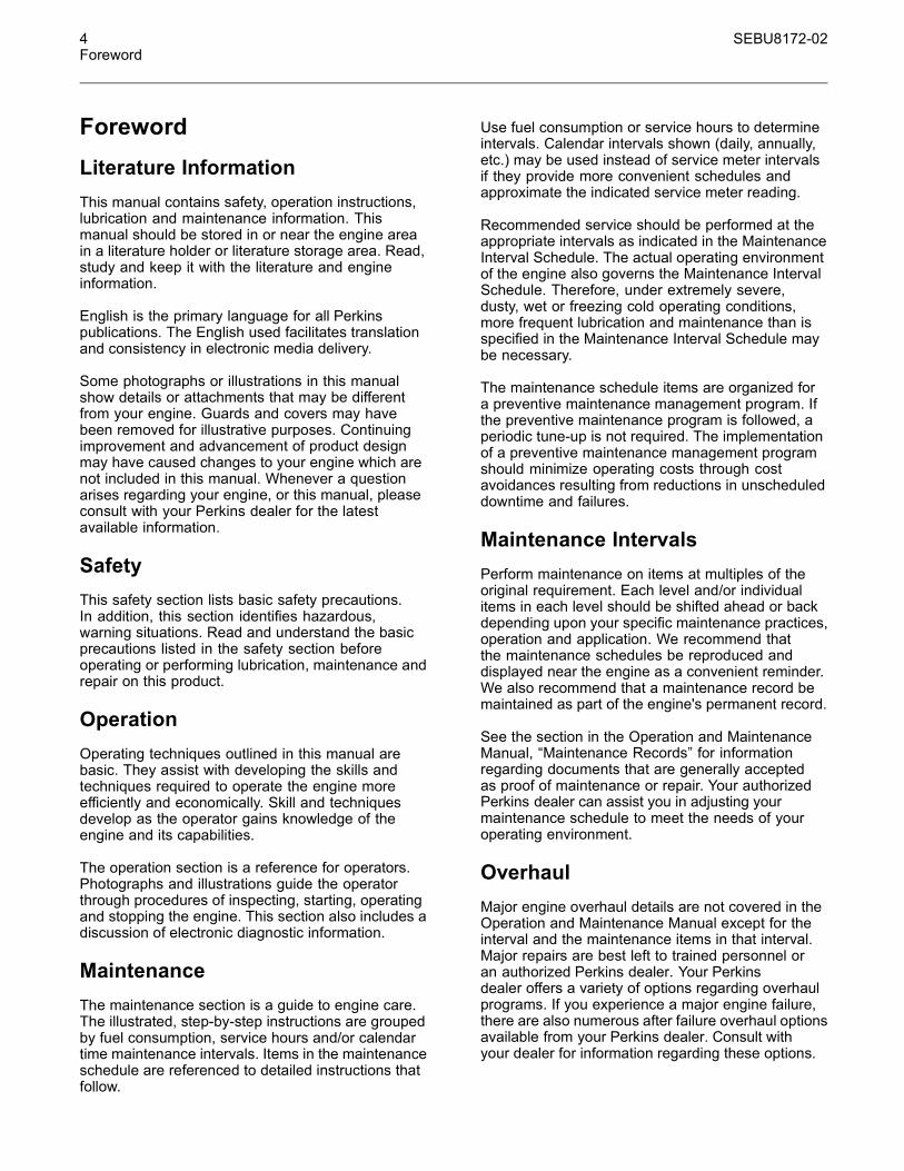
g01426636Illustration 3
(2) Hand (High Pressure) (3) Ether
g01154858Illustration 4Typical example
The warning label for the Hand (High Pressure) (2)is located on the top of the fuel manifold. Refer toillustration 4.
(3) Ether
Do not use aerosol types of starting aids such asether. Such use could result in an explosion andpersonal injury.
g01154809Illustration 5Typical example
The ether warning label (3) is located on the cover ofthe inlet manifold. Refer to illustration 4.
Note: The location of this label will depend on theapplication of the engine.
SEBU8172-02 9Safety Section
General Hazard Information
i02328435
General Hazard Information
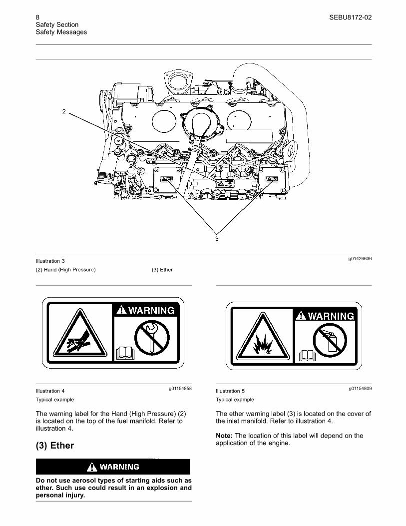
g00104545Illustration 6
Attach a “Do Not Operate” warning tag or a similarwarning tag to the start switch or to the controlsbefore you service the equipment or before yourepair the equipment.
g00702020Illustration 7
Wear a hard hat, protective glasses, and otherprotective equipment, as required.
Do not wear loose clothing or jewelry that can snagon controls or on other parts of the engine.
Make sure that all protective guards and all coversare secured in place on the engine.
Keep the engine free from foreign material. Removedebris, oil, tools, and other items from the deck, fromwalkways, and from steps.
Never put maintenance fluids into glass containers.Drain all liquids into a suitable container.
Obey all local regulations for the disposal of liquids.
Use all cleaning solutions with care.
Report all necessary repairs.
Do not allow unauthorized personnel on theequipment.
Ensure that the power supply is disconnected beforeyou work on the bus bar or the glow plugs.
Perform maintenance on the engine with theequipment in the servicing position. Refer to theOEM information for the procedure for placing theequipment in the servicing position.
Pressure Air and WaterPressurized air and/or water can cause debrisand/or hot water to be blown out. This could result inpersonal injury.
The direct application of pressurized air orpressurized water to the body could result in personalinjury.
When pressurized air and/or water is used forcleaning, wear protective clothing, protective shoes,and eye protection. Eye protection includes gogglesor a protective face shield.
The maximum air pressure for cleaning purposesmust be below 205 kPa (30 psi). The maximumwater pressure for cleaning purposes must be below275 kPa (40 psi).
Fluid PenetrationPressure can be trapped in the hydraulic circuit longafter the engine has been stopped. The pressure cancause hydraulic fluid or items such as pipe plugs toescape rapidly if the pressure is not relieved correctly.
Do not remove any hydraulic components or partsuntil pressure has been relieved or personal injurymay occur. Do not disassemble any hydrauliccomponents or parts until pressure has been relievedor personal injury may occur. Refer to the OEMinformation for any procedures that are required torelieve the hydraulic pressure.
10 SEBU8172-02Safety SectionBurn Prevention
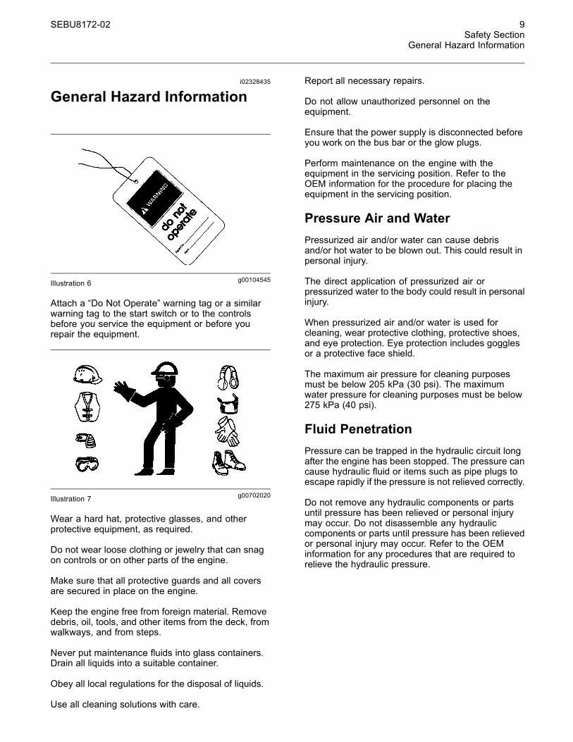
g00687600Illustration 8
Always use a board or cardboard when you checkfor a leak. Leaking fluid that is under pressure canpenetrate body tissue. Fluid penetration can causeserious injury and possible death. A pin hole leak cancause severe injury. If fluid is injected into your skin,you must get treatment immediately. Seek treatmentfrom a doctor that is familiar with this type of injury.
Containing Fluid SpillageCare must be taken in order to ensure that fluidsare contained during performance of inspection,maintenance, testing, adjusting and repair of theengine. Make provision to collect the fluid with asuitable container before any compartment is openedor before any component is disassembled.
• Only use the tools that are suitable for collectingfluids and equipment that is suitable for collectingfluids.
• Only use the tools that are suitable for containingfluids and equipment that is suitable for containingfluids.
Obey all local regulations for the disposal of liquids.
i02334785
Burn Prevention
Do not touch any part of an operating engine.Allow the engine to cool before any maintenance isperformed on the engine.
Contact with high pressure fuel may cause fluidpenetration and burn hazards. High pressure fu-el spray may cause a fire hazard. Failure to fol-low these inspection, maintenance and service in-structions may cause personal injury or death.
After the engine has stopped, you must wait for 60seconds in order to allow the fuel pressure to bepurged from the high pressure fuel lines before anyservice or repair is performed on the engine fuel lines.
Allow the pressure to be purged in the air system, inthe hydraulic system, in the lubrication system, or inthe cooling system before any lines, fittings or relateditems are disconnected.
CoolantWhen the engine is at operating temperature, theengine coolant is hot. The coolant is also underpressure. The radiator and all lines to the heaters orto the engine contain hot coolant.
Any contact with hot coolant or with steam can causesevere burns. Allow cooling system components tocool before the cooling system is drained.
Check the coolant level after the engine has stoppedand the engine has been allowed to cool.
Ensure that the filler cap is cool before removing thefiller cap. The filler cap must be cool enough to touchwith a bare hand. Remove the filler cap slowly inorder to relieve pressure.
Cooling system conditioner contains alkali. Alkali cancause personal injury. Do not allow alkali to contactthe skin, the eyes, or the mouth.
OilsHot oil and hot lubricating components can causepersonal injury. Do not allow hot oil to contact theskin. Also, do not allow hot components to contactthe skin.
BatteriesElectrolyte is an acid. Electrolyte can cause personalinjury. Do not allow electrolyte to contact the skin orthe eyes. Always wear protective glasses for servicingbatteries. Wash hands after touching the batteriesand connectors. Use of gloves is recommended.

SEBU8172-02 11Safety Section
Fire Prevention and Explosion Prevention
i04823662
Fire Prevention and ExplosionPrevention
g00704000Illustration 9
All fuels, most lubricants, and some coolant mixturesare flammable.
Flammable fluids that are leaking or spilled onto hotsurfaces or onto electrical components can causea fire. Fire may cause personal injury and propertydamage.
After the emergency stop button is operated, ensurethat you allow 15 minutes, before the engine coversare removed.
Determine whether the engine will be operated in anenvironment that allows combustible gases to bedrawn into the air inlet system. These gases couldcause the engine to overspeed. Personal injury,property damage, or engine damage could result.
If the application involves the presence of combustiblegases, consult your Perkins dealer and/or yourPerkins distributor for additional information aboutsuitable protection devices.
Remove all flammable combustible materials orconductive materials such as fuel, oil, and debris fromthe engine. Do not allow any flammable combustiblematerials or conductive materials to accumulate onthe engine.
Store fuels and lubricants in correctly markedcontainers away from unauthorized persons. Storeoily rags and any flammable materials in protectivecontainers. Do not smoke in areas that are used forstoring flammable materials.
Do not expose the engine to any flame.
Exhaust shields (if equipped) protect hot exhaustcomponents from oil or fuel spray in a line, a tube,or a seal failure. Exhaust shields must be installedcorrectly.
Do not weld on lines or tanks that contain flammablefluids. Do not flame cut lines or tanks that containflammable fluid. Clean any such lines or tanksthoroughly with a nonflammable solvent prior towelding or flame cutting.
Wiring must be kept in good condition. Ensure thatall electrical wires are correctly routed and securelyattached. Check all electrical wires daily. Repair anywires that are loose or frayed before you operate theengine. Clean all electrical connections and tightenall electrical connections.
Eliminate all wiring that is unattached or unnecessary.Do not use any wires or cables that are smaller thanthe recommended gauge. Do not bypass any fusesand/or circuit breakers.
Arcing or sparking could cause a fire. Secureconnections, recommended wiring, and correctlymaintained battery cables will help to prevent arcingor sparking.
Contact with high pressure fuel may cause fluidpenetration and burn hazards. High pressure fu-el spray may cause a fire hazard. Failure to fol-low these inspection, maintenance and service in-structions may cause personal injury or death.
After the engine has stopped, wait for 60 seconds inorder to allow the fuel pressure to be purged from thehigh-pressure fuel lines before any service or repairis performed on the engine fuel lines.
Ensure that the engine is stopped. Inspect all linesand hoses for wear or for deterioration. Properlyroute all hoses. The lines and hoses must haveadequate support and secure clamps.
Properly install oil filters and fuel filters. The filterhousings must be tightened to the correct torque.Refer to the Disassembly and Assembly manual formore information.
12 SEBU8172-02Safety SectionFire Prevention and Explosion Prevention
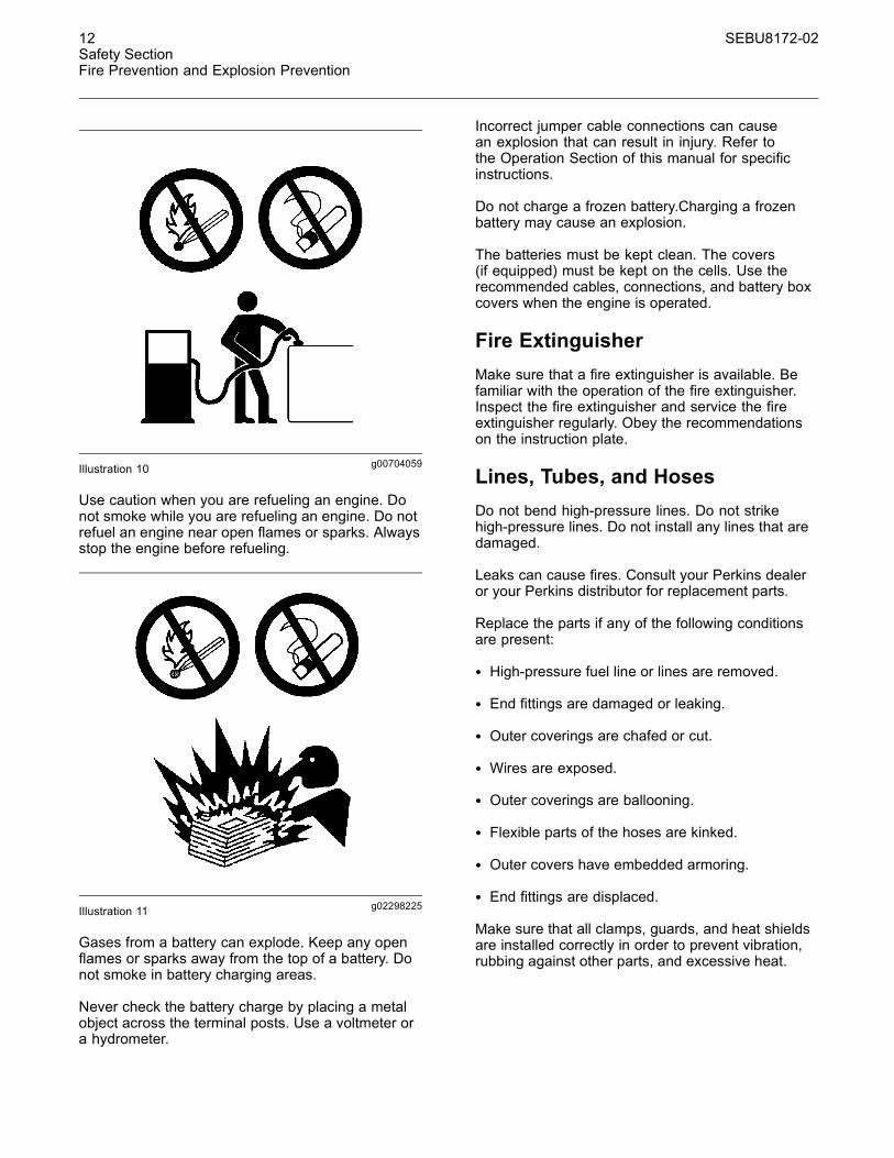
g00704059Illustration 10
Use caution when you are refueling an engine. Donot smoke while you are refueling an engine. Do notrefuel an engine near open flames or sparks. Alwaysstop the engine before refueling.
g02298225Illustration 11
Gases from a battery can explode. Keep any openflames or sparks away from the top of a battery. Donot smoke in battery charging areas.
Never check the battery charge by placing a metalobject across the terminal posts. Use a voltmeter ora hydrometer.
Incorrect jumper cable connections can causean explosion that can result in injury. Refer tothe Operation Section of this manual for specificinstructions.
Do not charge a frozen battery.Charging a frozenbattery may cause an explosion.
The batteries must be kept clean. The covers(if equipped) must be kept on the cells. Use therecommended cables, connections, and battery boxcovers when the engine is operated.
Fire ExtinguisherMake sure that a fire extinguisher is available. Befamiliar with the operation of the fire extinguisher.Inspect the fire extinguisher and service the fireextinguisher regularly. Obey the recommendationson the instruction plate.
Lines, Tubes, and HosesDo not bend high-pressure lines. Do not strikehigh-pressure lines. Do not install any lines that aredamaged.
Leaks can cause fires. Consult your Perkins dealeror your Perkins distributor for replacement parts.
Replace the parts if any of the following conditionsare present:
• High-pressure fuel line or lines are removed.
• End fittings are damaged or leaking.
• Outer coverings are chafed or cut.
• Wires are exposed.
• Outer coverings are ballooning.
• Flexible parts of the hoses are kinked.
• Outer covers have embedded armoring.
• End fittings are displaced.
Make sure that all clamps, guards, and heat shieldsare installed correctly in order to prevent vibration,rubbing against other parts, and excessive heat.

SEBU8172-02 13Safety Section
Crushing Prevention and Cutting Prevention
i02143194
Crushing Prevention andCutting Prevention
Support the component correctly when work beneaththe component is performed.
Unless other maintenance instructions are provided,never attempt adjustments while the engine isrunning.
Stay clear of all rotating parts and of all movingparts. Leave the guards in place until maintenanceis performed. After the maintenance is performed,reinstall the guards.
Keep objects away from moving fan blades. The fanblades will throw objects or cut objects.
When objects are struck, wear protective glasses inorder to avoid injury to the eyes.
Chips or other debris may fly off objects when objectsare struck. Before objects are struck, ensure that noone will be injured by flying debris.
i02235492
Mounting and Dismounting
Inspect the steps, the handholds, and the work areabefore mounting the engine. Keep these items cleanand keep these items in good repair.
Mount the engine and dismount the engine only atlocations that have steps and/or handholds. Do notclimb on the engine, and do not jump off the engine.
Face the engine in order to mount the engine ordismount the engine. Maintain a three-point contactwith the steps and handholds. Use two feet and onehand or use one foot and two hands. Do not use anycontrols as handholds.
Do not stand on components which cannot supportyour weight. Use an adequate ladder or use a workplatform. Secure the climbing equipment so that theequipment will not move.
Do not carry tools or supplies when you mount theengine or when you dismount the engine. Use a handline to raise and lower tools or supplies.
i02861106
High Pressure Fuel Lines
Contact with high pressure fuel may cause fluidpenetration and burn hazards. High pressure fu-el spray may cause a fire hazard. Failure to fol-low these inspection, maintenance and service in-structions may cause personal injury or death.

14 SEBU8172-02Safety SectionHigh Pressure Fuel Lines
g01425090Illustration 12
(1) High pressure line(2) High pressure line
(3) High pressure line(4) High pressure line
(5) High pressure fuel manifold (rail)(6) High pressure line
The high pressure fuel lines are the fuel lines thatare between the high pressure fuel pump and thehigh pressure fuel manifold and the fuel lines that arebetween the fuel manifold and cylinder head. Thesefuel lines are different from fuel lines on other fuelsystems.
This is because of the following differences:
• The high pressure fuel lines are constantly chargedwith high pressure.
• The internal pressures of the high pressure fuellines are higher than other types of fuel system.
• The high pressure fuel lines are formed to shapeand then strengthened by a special process.
Do not step on the high pressure fuel lines. Do notdeflect the high pressure fuel lines. Do not bend orstrike the high pressure fuel lines. Deformation ordamage of the high pressure fuel lines may cause apoint of weakness and potential failure.
Do not check the high pressure fuel lines with theengine or the starting motor in operation. After theengine has stopped allow 60 seconds to pass in orderto allow the pressure to be purged before any serviceor repair is performed on the engine fuel lines.
Do not loosen the high pressure fuel lines in orderto remove air from the fuel system. This procedureis not required.
Visually inspect the high pressure fuel lines beforethe engine is started. This inspection should be eachday.
If you inspect the engine in operation, always usethe proper inspection procedure in order to avoida fluid penetration hazard. Refer to Operation andMaintenance Manual, “General Hazard Information”.
• Inspect the high pressure for the following:damage, deformation, a nick, a cut, a crease, ora dent

SEBU8172-02 15Safety Section
Before Starting Engine
• Do not operate the engine with a fuel leak. If thereis a leak do not tighten the connection in orderto stop the leak. The connection must only betightened to the recommended torque. Refer toDisassembly and Assembly Manual, “Fuel InjectionLines - Remove and Fuel Injection Lines - Install”.
• If the high pressure fuel lines are torqued correctlyand the high pressure fuel lines are leaking thehigh pressure fuel lines must be replaced.
• Ensure that all clips on the high pressure fuel linesare in place. Do not operate the engine with clipsthat are damaged, missing or clips that are loose.
• Do not attach any other item to the high pressurefuel lines.
• Loosened high pressure fuel lines must bereplaced. Also removed high pressure fuel linesmust be replaced. Refer to Disassembly andAssembly Manual, “ Fuel Injection Lines - Install”.
i02813489
Before Starting Engine
Before the initial start-up of an engine that is new,serviced or repaired, make provision to shut theengine off, in order to stop an overspeed. This maybe accomplished by shutting off the air and/or fuelsupply to the engine.
Overspeed shutdown should occur automatically forengines that are controlled electronically. If automaticshutdown does not occur, press the emergency stopbutton in order to cut the fuel and/or air to the engine.
Inspect the engine for potential hazards.
Before starting the engine, ensure that no one is on,underneath, or close to the engine. Ensure that thearea is free of personnel.
If equipped, ensure that the lighting system for theengine is suitable for the conditions. Ensure that alllights work correctly, if equipped.
All protective guards and all protective covers mustbe installed if the engine must be started in orderto perform service procedures. To help prevent anaccident that is caused by parts in rotation, workaround the parts carefully.
Do not bypass the automatic shutoff circuits. Do notdisable the automatic shutoff circuits. The circuits areprovided in order to help prevent personal injury. Thecircuits are also provided in order to help preventengine damage.
See the Service Manual for repairs and foradjustments.
i02251260
Engine Starting
Do not use aerosol types of starting aids such asether. Such use could result in an explosion andpersonal injury.
If a warning tag is attached to the engine start switchor to the controls DO NOT start the engine or movethe controls. Consult with the person that attachedthe warning tag before the engine is started.
All protective guards and all protective covers mustbe installed if the engine must be started in orderto perform service procedures. To help prevent anaccident that is caused by parts in rotation, workaround the parts carefully.
Start the engine from the operator's compartment orfrom the engine start switch.
Always start the engine according to the procedurethat is described in the Operation and MaintenanceManual, “Engine Starting” topic in the OperationSection. Knowing the correct procedure will help toprevent major damage to the engine components.Knowing the procedure will also help to preventpersonal injury.
To ensure that the jacket water heater (if equipped)and/or the lube oil heater (if equipped) is workingcorrectly, check the water temperature gaugeand/or the oil temperature gauge during the heateroperation.
Engine exhaust contains products of combustionwhich can be harmful to your health. Always start theengine and operate the engine in a well ventilatedarea. If the engine is started in an enclosed area,vent the engine exhaust to the outside.
Note: The engine is equipped with a device for coldstarting. If the engine will be operated in very coldconditions, then an extra cold starting aid may berequired. Normally, the engine will be equipped withthe correct type of starting aid for your region ofoperation.
These engines are equipped with a glow plug startingaid in each individual cylinder that heats the intakeair in order to improve starting.

16 SEBU8172-02Safety SectionEngine Stopping
i02234873
Engine Stopping
Stop the engine according to the procedure inthe Operation and Maintenance Manual, “EngineStopping (Operation Section)” in order to avoidoverheating of the engine and accelerated wear ofthe engine components.
Use the Emergency Stop Button (if equipped) ONLYin an emergency situation. Do not use the EmergencyStop Button for normal engine stopping. After anemergency stop, DO NOT start the engine until theproblem that caused the emergency stop has beencorrected.
Stop the engine if an overspeed condition occursduring the initial start-up of a new engine or an enginethat has been overhauled.
To stop an electronically controlled engine, cut thepower to the engine and/or shutting off the air supplyto the engine.
i02234878
Electrical System
Never disconnect any charging unit circuit or batterycircuit cable from the battery when the charging unitis operating. A spark can cause the combustiblegases that are produced by some batteries to ignite.
To help prevent sparks from igniting combustiblegases that are produced by some batteries, thenegative “−” cable should be connected last from theexternal power source to the negative “−” terminalof the starting motor. If the starting motor is notequipped with a negative “−” terminal, connect thecable to the engine block.
Check the electrical wires daily for wires thatare loose or frayed. Tighten all loose electricalconnections before the engine is started. Repair allfrayed electrical wires before the engine is started.See the Operation and Maintenance Manual forspecific starting instructions.
Grounding Practices
g01162916Illustration 13Typical example
(1) Starting motor to engine block(2) Ground to starting motor(3) Ground to battery
g01162918Illustration 14Typical example
(4) Ground to engine(5) Ground to battery
Correct grounding for the engine electrical systemis necessary for optimum engine performanceand reliability. Incorrect grounding will result inuncontrolled electrical circuit paths and in unreliableelectrical circuit paths.
SEBU8172-02 17Safety Section
Engine Electronics
Uncontrolled electrical circuit paths can result indamage to the crankshaft bearing journal surfacesand to aluminum components.
Engines that are installed without engine-to-frameground straps can be damaged by electricaldischarge.
To ensure that the engine and the engine electricalsystems function correctly, an engine-to-frameground strap with a direct path to the battery must beused. This path may be provided by way of a directengine ground to the frame.
The connections for the grounds should be tight andfree of corrosion. The engine alternator must begrounded to the negative “-” battery terminal witha wire that is adequate to handle the full chargingcurrent of the alternator.
The power supply connections and the groundconnections for the engine electronics should alwaysbe from the isolator to the battery.
i02650954
Engine Electronics
Tampering with the electronic system installationor the OEM wiring installation can be dangerousand could result in personal injury or death and/orengine damage.
Electrical Shock Hazard. The electronic unit injec-tors use DC voltage. The ECM sends this voltageto the electronic unit injectors. Do not come incontact with the harness connector for the elec-tronic unit injectors while the engine is operating.Failure to follow this instruction could result inpersonal injury or death.
This engine has a comprehensive, programmableEngine Monitoring System. The Electronic ControlModule (ECM) has the ability to monitor the engineoperating conditions. If any of the engine parametersextend outside an allowable range, the ECM willinitiate an immediate action.
The following actions are available for enginemonitoring control:
• Warning
• Derate
• Shutdown
The following monitored engine operating conditionshave the ability to limit engine speed and/or theengine power:
• Engine Coolant Temperature
• Engine Oil Pressure
• Engine Speed/Timing
• Intake Manifold Air Temperature
The Engine Monitoring package can vary for differentengine models and different engine applications.However, the monitoring system and the enginemonitoring control will be similar for all engines.
Note:Many of the engine control systems and displaymodules that are available for Perkins Engines willwork in unison with the Engine Monitoring System.Together, the two controls will provide the enginemonitoring function for the specific engine application.Refer to Troubleshooting for more information on theEngine Monitoring System.
18 SEBU8172-02Product Information SectionModel Views
Product InformationSection
Model Viewsi02861104
Model View Illustrations
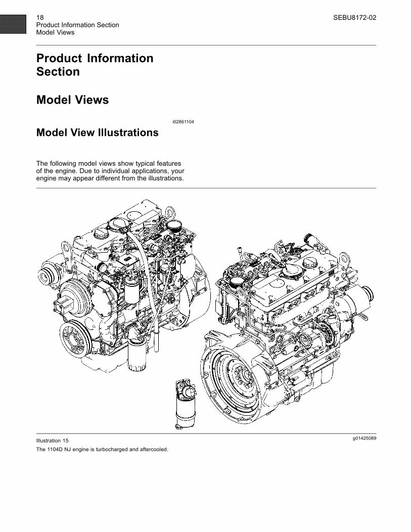
The following model views show typical featuresof the engine. Due to individual applications, yourengine may appear different from the illustrations.
g01425089Illustration 15The 1104D NJ engine is turbocharged and aftercooled.
SEBU8172-02 19Product Information Section
Model Views
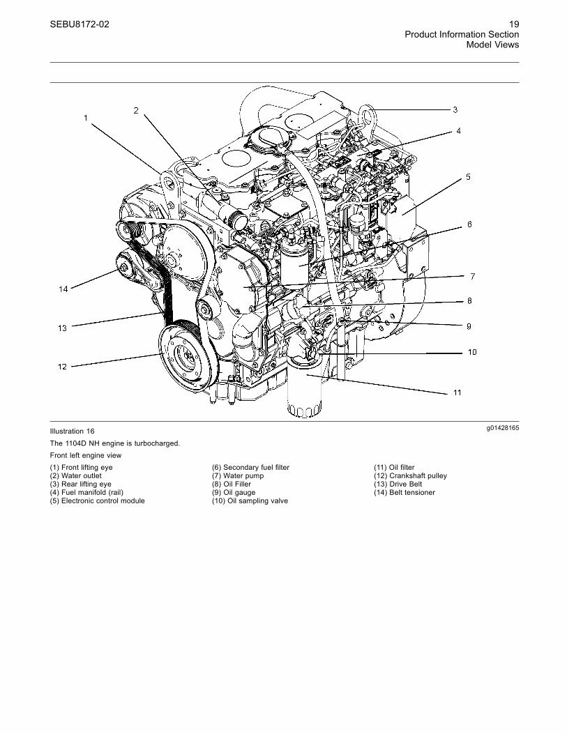
g01428165Illustration 16
The 1104D NH engine is turbocharged.Front left engine view(1) Front lifting eye(2) Water outlet(3) Rear lifting eye(4) Fuel manifold (rail)(5) Electronic control module
(6) Secondary fuel filter(7) Water pump(8) Oil Filler(9) Oil gauge(10) Oil sampling valve
(11) Oil filter(12) Crankshaft pulley(13) Drive Belt(14) Belt tensioner
20 SEBU8172-02Product Information SectionModel Views
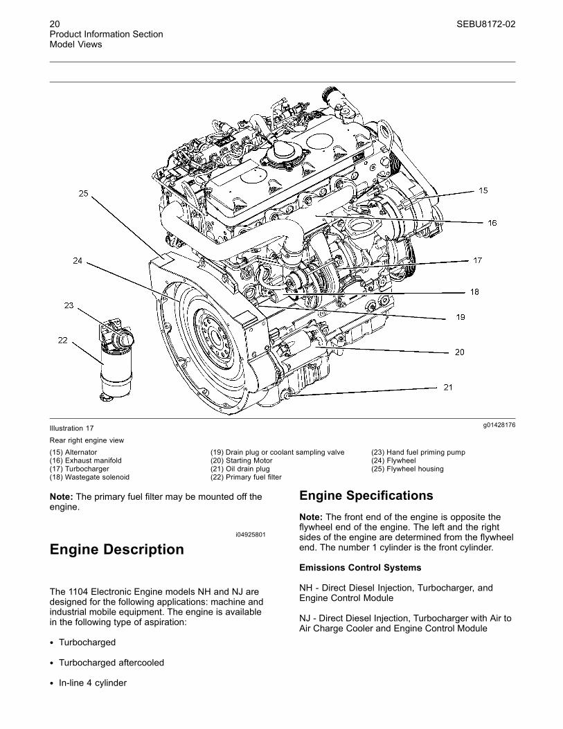
g01428176Illustration 17
Rear right engine view(15) Alternator(16) Exhaust manifold(17) Turbocharger(18) Wastegate solenoid
(19) Drain plug or coolant sampling valve(20) Starting Motor(21) Oil drain plug(22) Primary fuel filter
(23) Hand fuel priming pump(24) Flywheel(25) Flywheel housing
Note: The primary fuel filter may be mounted off theengine.
i04925801
Engine Description
The 1104 Electronic Engine models NH and NJ aredesigned for the following applications: machine andindustrial mobile equipment. The engine is availablein the following type of aspiration:
• Turbocharged
• Turbocharged aftercooled
• In-line 4 cylinder
Engine SpecificationsNote: The front end of the engine is opposite theflywheel end of the engine. The left and the rightsides of the engine are determined from the flywheelend. The number 1 cylinder is the front cylinder.
Emissions Control Systems
NH - Direct Diesel Injection, Turbocharger, andEngine Control Module
NJ - Direct Diesel Injection, Turbocharger with Air toAir Charge Cooler and Engine Control Module
SEBU8172-02 21Product Information Section
Model Views
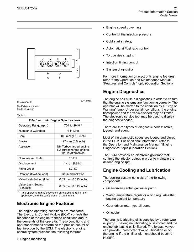
g01187485Illustration 18(A) Exhaust valves(B) Inlet valves
Table 1
1104 Electronic Engine Specifications
Operating Range (rpm) 750 to 2640(1)
Number of Cylinders 4 In-Line
Bore 105 mm (4.13 inch)
Stroke 127 mm (5.0 inch)
Aspiration NH Turbocharged engineNJ Turbocharged engine
that is aftercooled
Compression Ratio 16.2:1
Displacement 4.4 L (269 in3)
Firing Order 1,3,4,2
Rotation (flywheel end) Counterclockwise
Valve Lash Setting (Inlet) 0.35 mm (0.013 inch)
Valve Lash Setting(Exhaust) 0.35 mm (0.013 inch)
(1) The operating rpm is dependent on the engine rating, theapplication, and the configuration of the throttle.
Electronic Engine FeaturesThe engine operating conditions are monitored.The Electronic Control Module (ECM) controls theresponse of the engine to these conditions and tothe demands of the operator. These conditions andoperator demands determine the precise control offuel injection by the ECM. The electronic enginecontrol system provides the following features:
• Engine monitoring
• Engine speed governing
• Control of the injection pressure
• Cold start strategy
• Automatic air/fuel ratio control
• Torque rise shaping
• Injection timing control
• System diagnostics
For more information on electronic engine features,refer to the Operation and Maintenance Manual,“Features and Controls” topic (Operation Section).
Engine DiagnosticsThe engine has built-in diagnostics in order to ensurethat the engine systems are functioning correctly. Theoperator will be alerted to the condition by a “Stop orWarning” lamp. Under certain conditions, the enginehorsepower and the vehicle speed may be limited.The electronic service tool may be used to displaythe diagnostic codes.
There are three types of diagnostic codes: active,logged, and event.
Most of the diagnostic codes are logged and storedin the ECM. For additional information, refer tothe Operation and Maintenance Manual, “EngineDiagnostics” topic (Operation Section).
The ECM provides an electronic governor thatcontrols the injector output in order to maintain thedesired engine rpm.
Engine Cooling and LubricationThe cooling system consists of the followingcomponents:
• Gear-driven centrifugal water pump
• Water temperature regulator which regulates theengine coolant temperature
• Gear-driven rotor type oil pump
• Oil cooler
The engine lubricating oil is supplied by a rotor typeoil pump. The engine lubricating oil is cooled and theengine lubricating oil is filtered. The bypass valvescan provide unrestricted flow of lubrication oil tothe engine if the oil filter element should becomeplugged.

22 SEBU8172-02Product Information SectionModel Views
Engine efficiency, efficiency of emission controls, andengine performance depend on adherence to properoperation and maintenance recommendations.Engine performance and efficiency also depend onthe use of recommended fuels, lubrication oils, andcoolants. Refer to this Operation and MaintenanceManual, “Maintenance Interval Schedule” for moreinformation on maintenance items.

SEBU8172-02 23Product Information Section
Product Identification Information
Product IdentificationInformation
i02378644
Plate Locations and FilmLocations
g01248563Illustration 19Location of the serial number plate
Perkins engines are identified by an engine serialnumber.
An example of an engine number isNH*****U000001J.
***** ____________________The list number for the engine
NH _________________________________________Type of engine
U ____________________________Built in the United Kingdom
000001 ___________________________Engine Serial Number
J _____________________________________Year of Manufacture
Perkins dealers or Perkins distributors need all ofthese numbers in order to determine the componentsthat were included with the engine. This permitsaccurate identification of replacement part numbers.
The numbers for fuel setting information for electronicengines are stored within the personality module.These numbers can be read by using the ElectronicService Tool.
Serial Number Plate (1)The engine serial number plate is located on the leftside of the cylinder block to the rear of the engine.
g01094203Illustration 20
Serial number plate
i02164876
Reference Numbers
Information for the following items may be needed toorder parts. Locate the information for your engine.Record the information in the appropriate space.Make a copy of this list for a record. Keep theinformation for future reference.
Record for ReferenceEngine Model _______________________________________________
Engine Serial number _____________________________________
Engine Low Idle rpm ______________________________________
Engine Full Load rpm _____________________________________
Primary Fuel Filter _________________________________________
Water Separator Element ________________________________
Secondary Fuel Filter Element __________________________
24 SEBU8172-02Product Information SectionProduct Identification Information
Lubrication Oil Filter Element ___________________________
Auxiliary Oil Filter Element _______________________________
Total Lubrication System Capacity _____________________
Total Cooling System Capacity _________________________
Air Cleaner Element _______________________________________
Fan Drive Belt ______________________________________________
Alternator Belt ______________________________________________
i02861254
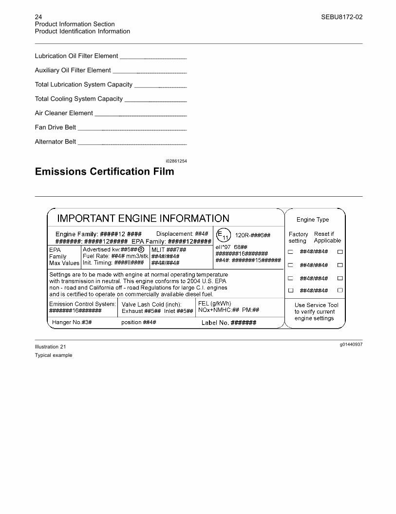
Emissions Certification Film
g01440937Illustration 21Typical example

SEBU8172-02 25Operation SectionLifting and Storage
Operation Section
Lifting and Storagei02164186
Engine Lifting
g01097527Illustration 22
NOTICENever bend the eyebolts and the brackets. Only loadthe eyebolts and the brackets under tension. Remem-ber that the capacity of an eyebolt is less as the anglebetween the supporting members and the object be-comes less than 90 degrees.
When it is necessary to remove a component at anangle, only use a link bracket that is properly rated forthe weight.
Use a hoist to remove heavy components. Usean adjustable lifting beam to lift the engine. Allsupporting members (chains and cables) should beparallel to each other. The chains and cables shouldbe perpendicular to the top of the object that is beinglifted.
Some removals require lifting the fixtures in order toobtain correct balance and safety.
To remove the engine ONLY, use the lifting eyes thatare on the engine.
Lifting eyes are designed and installed for specificengine arrangements. Alterations to the lifting eyesand/or the engine make the lifting eyes and the liftingfixtures obsolete. If alterations are made, ensurethat correct lifting devices are provided. Consultyour Perkins dealer or your Perkins distributor forinformation regarding fixtures for correct enginelifting.
i02308881
Engine Storage
If the engine is not started for a month or longer thelubricating oil will drain from the cylinder walls andfrom the piston rings. Rust can form on the cylinderwalls. Rust on the cylinder walls will cause increasedengine wear and a reduction in engine service life.
Perkins are not responsible for damage which mayoccur when an engine is in storage after a period inservice.
Your Perkins dealer or your Perkins distributor canassist in preparing the engine for extended storageperiods.
If an engine is out of operation and if use of theengine is not planned for more than one month, acomplete protection procedure is recommended.
To help prevent excessive engine wear and corrosionto the engine, use the following guidelines:
1. Completely clean the outside of the engine.
2. Ensure that the vehicle is on level ground.
3. Drain the fuel system completely and refillthe system with preservative fuel. 1772204POWERPART Lay-Up 1 can be mixed withthe normal fuel in order to change the fuel intopreservative fuel.
If preservative fuel is not available, the fuel systemcan be filled with normal fuel. This fuel must bediscarded at the end of the storage period togetherwith the fuel filter elements.

26 SEBU8172-02Operation SectionLifting and Storage
Personal injury can result from hot coolant. Anycontact with hot coolant or with steam can causesevere burns. Allow cooling system componentsto cool before the cooling system is drained.
4. Drain and refill the cooling system. Refer to thisOperation and Maintenance Manual, “CoolingSystem coolant (Commercial Heavy Duty -Change or Cooling System coolant (ELC) -Change” for information on draining, flushing andrefilling the cooling system.
Contact with high pressure fuel may cause fluidpenetration and burn hazards. High pressure fu-el spray may cause a fire hazard. Failure to fol-low these inspection, maintenance and service in-structions may cause personal injury or death.
5. Operate the engine until the engine reachesnormal operating temperature. Stop the engine.After the engine has stopped, you must wait for 60seconds in order to allow the fuel pressure to bepurged from the high pressure fuel lines before anyservice or repair is performed on the engine fuellines. If necessary, perform minor adjustments.Repair any leaks from the low pressure fuelsystem and from the cooling, lubrication or airsystems. Replace any high pressure fuel line thathas leaked. Refer to Disassembly and assemblyManual, “Fuel Injection Lines - Install”.
6. Drain the lubricating oil from the oil pan.
Renew the canister(s) of the lubricating oil filter.
Fill the oil pan to the Full Mark on the engine oillevel gauge with new, clean lubricating oil. Add1762811 POWERPART Lay-Up 2 to the oil inorder to protect the engine against corrosion. If1762811 POWERPART Lay-Up 2 is not available,use a preservative of the correct specificationinstead of the lubricating oil. If a preservative isused, this must be drained completely at the endof the storage period and the oil pan must berefilled to the correct level with normal lubricatingoil.
7. Operate the engine in order to circulate engine oil.
8. Disconnect the battery. Ensure that the battery isin a fully charged condition. Protect the terminalsagainst corrosion. 1734115 POWERPARTLay-Up 3 can be used on the terminals. Put thebattery into safe storage.
9. If equipped, replace the crankcase breatherelement. Seal the end of the breather pipe.
10.Remove the valve mechanism cover. Spray1762811 POWERPART Lay-Up 2 around therocker shaft assembly.
11.Remove the glow plugs. Slowly rotate thecrankshaft. By checking the valves, position thepiston at BDC. Spray 1762811 POWERPARTLay-Up 2 for two seconds into the cylinder bore.This procedure must be carried out on eachcylinder.
12. Install the glow plugs. Install the valve mechanismcover.
13.Remove the pipes that are installed betweenthe air filter assembly and the turbocharger.Spray 1762811 POWERPART Lay-Up 2 intothe turbocharger. The duration of the spray isprinted on the container. Seal the turbochargerwith waterproof tape.
14.Remove the exhaust pipe from the output side ofthe turbocharger. Spray 1762811 POWERPARTLay-Up 2 into the turbocharger. The duration ofthe spray is printed on the container. Seal theturbocharger with waterproof tape.
15.Seal the vent of the fuel tank or the fuel filler capwith waterproof tape.
16.Remove the alternator drive belt and put the drivebelt into storage.
17. In order to prevent corrosion to the outsideof the engine, spray the engine with 1734115POWERPART Lay-Up 3. Do not spray the areainside the alternator.

SEBU8172-02 27Operation Section
Gauges and Indicators
Gauges and Indicatorsi02861754
Gauges and Indicators
Your engine may not have the same gauges or all ofthe gauges that are described. For more informationabout the gauge package, see the OEM information.
Gauges provide indications of engine performance.Ensure that the gauges are in good working order.Determine the normal operating range by observingthe gauges over a period of time.
Noticeable changes in gauge readings indicatepotential gauge or engine problems. Problems mayalso be indicated by gauge readings that changeeven if the readings are within specifications.Determine and correct the cause of any significantchange in the readings. Consult your Perkins dealeror your Perkins distributor for assistance.
Some engine applications are equipped with IndicatorLamps. Indicator lamps can be used as a diagnosticaid. There are two lamps. One lamp has an orangelens and the other lamp has a red lens.
These indicator lamps can be used in two ways:
• The indicator lamps can be used to identify thecurrent operational status of the engine. Theindicator lamps can also indicate that the enginehas a fault. This system is automatically operatedvia the ignition switch.
• The indicator lamps can be used to identify activediagnostic codes. This system is activated bypressing the Flash Code button.
Refer to the Troubleshooting Guide, “IndicatorLamps” for further information.
NOTICEIf no oil pressure is indicated, STOP the engine. Ifmaximum coolant temperature is exceeded, STOPthe engine. Engine damage can result.
Engine Oil Pressure – The oil pressureshould be greatest after a cold engine isstarted. The typical engine oil pressure with
SAE10W40 is 350 to 450 kPa ( 50 to 65 psi) at ratedrpm.
A lower oil pressure is normal at low idle. If the loadis stable and the gauge reading changes, performthe following procedure:
1. Remove the load.
2. Stop the engine.
3. Check and maintain the oil level.
Jacket Water Coolant Temperature –Typical temperature range is 83° to 95°C(181.4° to 171°F). The maximum allowable
temperature at sea level with the pressurized coolingsystem at 48 kPa (7 psi) is 103 °C (217.4 °F). Highertemperatures may occur under certain conditions.The water temperature reading may vary accordingto load. The temperature reading should neverexceed 7 °C (44.6 °F) below the boiling point for thepressurized system that is being used.
A 100 kPa (14.5 psi) radiator cap may be installed onthe cooling system. The temperature of this coolingsystem must not exceed 112 °C (233.6 °F).
If the engine is operating above the normal rangeand steam becomes apparent, perform the followingprocedure:
1. Reduce the load and the engine rpm.
2. Determine if the engine must be shut downimmediately or if the engine can be cooled byreducing the load.
3. Inspect the cooling system for leaks.
Tachometer – This gauge indicates enginespeed (rpm). When the throttle control leveris moved to the full throttle position without
load, the engine is running at high idle. The engine isrunning at the full load rpm when the throttle controllever is at the full throttle position with maximumrated load.
NOTICETo help prevent engine damage, never exceed thehigh idle rpm. Overspeeding can result in seriousdamage to the engine. Operation at speeds exceed-ing high idle rpm should be kept to a minimum.
Ammeter – This gauge indicates theamount of charge or discharge in thebattery charging circuit. Operation of the
indicator should be to the “+” side of “0” (zero).
Fuel Level – This gauge indicates the fuellevel in the fuel tank. The fuel level gaugeoperates when the “START/STOP” switch
is in the “on” position.

28 SEBU8172-02Operation SectionGauges and Indicators
Service Hour Meter – The gauge indicatestotal operating hours of the engine.

SEBU8172-02 29Operation Section
Features and Controls
Features and Controlsi02651062
Monitoring System
If the Shutdown mode has been selected and thewarning indicator activates, engine shutdownmaytake as little as 20 seconds from the time the warn-ing indicator is activated. Depending on the ap-plication, special precautions should be taken toavoid personal injury. The engine can be restartedfollowing shutdown for emergency maneuvers, ifnecessary.
NOTICEThe Engine Monitoring System is not a guaranteeagainst catastrophic failures. Programmed delaysand derate schedules are designed to minimize falsealarms and provide time for the operator to stop theengine.
The following parameters are monitored:
• Coolant temperature
• Intake air temperature
• Engine intake manifold pressure
• Engine Oil pressure
• Pressure in the fuel rail
• Engine speed/timing
Programmable Options andSystems Operation
If the Warning/Derate/Shutdown mode has beenselected and the warning indicator activates,bring the engine to a stop whenever possible. De-pending on the application, special precautionsshould be taken to avoid personal injury.
The engine can be programmed to the followingmodes:
“Warning”
The “Warning” lamp and the warning signal (orangelamp) turn “ON” and the warning signal is activatedcontinuously in order to alert the operator that one ormore of the engine parameters is not within normaloperating range.
“Warning/Derate”
The “Diagnostic” lamp turns “ON” and the warningsignal (red lamp) is activated. After the warning, theengine power will be derated. The warning lamp willbegin to flash when the derating occurs.
The engine will be derated if the engine exceedspreset operational limits. The engine derate isachieved by restricting the amount of fuel that isavailable for each injection. The amount of thisreduction of fuel is dependent on the severity of thefault that has caused the engine derate, typically upto a limit of 50%. This reduction in fuel results in apredetermined reduction in engine power.
“Warning/Derate/Shutdown”
The “Diagnostic” lamp turns “ON” and the warningsignal (red lamp) is activated. After the warning,the engine power will be derated. The engine willcontinue at the rpm of the set derate until a shutdownof the engine occurs. The engine can be restartedafter a shutdown for use in an emergency.
A shutdown of the engine may occur in as littleas 20 seconds. The engine can be restarted aftera shutdown for use in an emergency. However,the cause of the initial shutdown may still exist.The engine may shut down again in as little as 20seconds.
If there is a signal for low oil pressure or for coolanttemperature, there will be a two second delay inorder to verify the condition.
For each of the programmed modes, refer toTroubleshooting , “Indicator Lamps” for moreinformation on Indicator Lamps.
For more information or assistance for repairs, consultyour Perkins dealer or your Perkins distributor.

30 SEBU8172-02Operation SectionFeatures and Controls
i02296746
Monitoring System
Table 2
WarningLamp
ShutdownLamp Lamp Status Description of lamp status Engine Status
ON ONLamp check When the engine start switch is turned to the
“ON” position both lamps will illuminate for 2seconds only.
The engine has not beenstarted.
OFF OFF No faults There are no active diagnostic faults. The engine is runningnormally.
ON OFFActivediagnosticfault
An active diagnostic fault has been detected. The engine is runningnormally.
ON FLASHINGActivediagnosticfault
A serious active diagnostic fault has beendetected and an engine derate has beeninvoked.
The engine is runningbut the engine has beenderated.
FLASHING OFF Warning One or more of the engine protection valueshas been exceeded.
The engine is runningnormally.
FLASHING FLASHINGDerate andwarning
One or more of the engine protection valueshas been exceeded.
The engine is runningbut the engine has beenderated.
ON ONEngineshutdown
One or more of the engine protection values hasbeen exceeded or a serious active diagnosticfault has been detected.
The engine is shutdown orshutdown is imminent.
i02861773
Sensors and ElectricalComponents
Sensor LocationsIllustration 23 shows the typical locations of thesensors and the ECM on the engine. Specific enginesmay appear different from the illustration due todifferences in applications.

SEBU8172-02 31Operation Section
Features and Controls
g01425443Illustration 23(1) Coolant temperature sensor(2) Intake manifold pressure sensor(3) Inlet air temperature sensor
(4) Fuel pressure sensor(5) Electronic control module(6) Primary position sensor
(7) Secondary position sensor(8) Engine oil pressure sensor
Illustration 24 shows the sensors and the ECM inposition on the engine.

32 SEBU8172-02Operation SectionFeatures and Controls
g01425468Illustration 24
Failure of Sensors
All Sensors
A failure of any of the sensors may be caused by oneof the following malfunctions:
• Sensor output is open.
• Sensor output is shorted to “- battery” or “+ battery”.
• Measured reading of the sensor is out of thespecification.
Programmable Monitoring System(PMS)The Programmable Monitoring System determinesthe level of action that is taken by the ElectronicControl Module (ECM) in response to a conditionthat can damage the engine. These conditions areidentified by the ECM from the signals that areproduced from the following sensors.
• Coolant Temperature Sensor
• Intake manifold Air Temperature Sensor
• Intake manifold Pressure Sensor
• Fuel Pressure Sensor

SEBU8172-02 33Operation Section
Features and Controls
• Engine Oil Pressure Sensor
• Primary Speed/Timing Sensor
• Secondary Speed/Timing Sensor
Coolant Temperature Sensor 1The coolant temperature sensor monitors enginecoolant temperature. The output of the ECM (5) canindicate a high coolant temperature through a relayor a lamp. The coolant temperature sensor is usedby the ECM to determine initiation of the Cold StartCondition.
Failure of the Coolant TemperatureSensor
The ECM (5) will detect a failure of the coolanttemperature sensor. The diagnostic lamp will warn theoperator about the status of the coolant temperaturesensor. A failure of the coolant temperature sensorwill not cause a shutdown of the engine or anyhorsepower change. In order to check the correctoperation of the sensor, refer to Troubleshooting,“Engine Temperature Sensor Circuit - Test”.
Intake Manifold Air TemperatureSensor 2Note: This sensor can have two different locations.The location will depend on the type of engine.
The intake manifold air temperature sensor measuresthe intake air temperature. A signal is sent to theECM (5). The intake manifold air temperature sensoris also used by the ECM to determine initiation of theCold Start Strategy.
In order to check the correct operation of the sensor,refer to Troubleshooting, “EngineTemperature SensorCircuit - Test”.
Intake Manifold Pressure Sensor 3The intake manifold pressure sensor measurespressure in the manifold. A signal is sent to the ECM(5).
Fuel Pressure Sensor 4The fuel pressure sensor measures the fuel pressurein the fuel manifold. A signal is sent to the ECM (5).
Electronic Control Module 5The ECM is the control computer of the engine. TheECM provides power to the electronics. The ECMmonitors data that is input from the sensors of theengine. The ECM acts as a governor in order tocontrol the speed and the power of the engine.
The ECM adjusts injection timing and fuel pressurefor the best engine performance, the best fueleconomy and the best control of exhaust emissions.
Primary Speed/Timing Sensor 6If the ECM (5) does not receive a signal from theprimary speed/timing sensor , the “DIAGNOSTIC”lamp will indicate a diagnostic fault code which will belogged in the ECM memory.
If the ECM does not receive a signal from the primaryspeed/timing sensor (7), the ECM will read the signalfrom the secondary speed/timing sensor (8). TheECM continually checks in order to determine if thereis a signal from both sensors.
Intermittent failure of the sensors will cause erraticengine control.
Failure of the Primary Speed/TimingSensor
Correct operation of the primary speed/timingsensor is essential. Software in the ECM protectsagainst reverse running of the engine. If the primaryspeed/timing sensor fails there is no automaticprotection against reverse running. In someapplications, it is possible for the transmission torun the engine in reverse. In this event, Stop theengine immediately. Turn the keyswitch to the “OFF”position.
In order to check the correct operation of the sensor,refer to Troubleshooting, “Engine speed/Timingsensor - Test”.
Secondary Speed/Timing Sensor 7The signal from the secondary speed/timing sensoris used by the ECM (5) on engine start-up in orderto check the stroke of the pistons. The secondaryspeed/timing sensor may be used by the ECMin order to operate the engine if the primaryspeed/timing sensor is faulty.
In order to check the correct operation of the sensor,refer to Troubleshooting, “Engine speed/Timingsensor-Test”.

34 SEBU8172-02Operation SectionFeatures and Controls
Engine Oil Pressure Sensor 8Note: This sensor can have two different locations.The location will depend on the type of engine.
The engine oil pressure sensor is an absolutepressure sensor that measures the engine oilpressure in the main oil gallery. The engine oilpressure sensor detects engine oil pressure fordiagnostic purposes. The engine oil pressure sensorsends a signal to the ECM (5).
Low Oil Pressure Warning
The setpoint for the low pressure warning isdependent upon the engine speed. The fault will beactive and logged only if the engine has been runningfor more than 8 seconds.
Very Low Oil Pressure Warning
The very low oil pressure setpoint is dependentupon the engine speed. If the DERATE mode of theengine monitoring system is selected, the ECM (5)will derate the engine power. The engine horsepowerwill be limited.
Failure of the Engine Oil Pressure Sensor
The ECM (5) will detect failure of the engine oilpressure sensor. The diagnostic lamp warns the userabout the status of the engine oil pressure sensor.The engine oil pressure related strategies will bedisabled in the event of a failure of the engine oilpressure sensor. A failure of the engine oil pressuresensor will not cause a shutdown of the engine orany horsepower change. In order to check the correctoperation of the sensor, refer to Troubleshooting, “5Volt Sensor Supply Circuit - Test”.
i02858345
Engine Shutoffs and EngineAlarms
ShutoffsThe shutoffs are electrically operated or mechanicallyoperated. The electrically operated shutoffs arecontrolled by the ECM.
Shutoffs are set at critical levels for the followingitems:
• Operating temperature
• Operating pressure
• Operating level
• Operating rpm
The particular shutoff may need to be reset beforethe engine will start.
NOTICEAlways determine the cause of the engine shutdown.Make necessary repairs before attempting to restartthe engine.
Be familiar with the following items:
• Types and locations of shutoff
• Conditions which cause each shutoff to function
• The resetting procedure that is required to restartthe engine
AlarmsThe alarms are electrically operated. The operationof the alarms are controlled by the ECM.
The alarm is operated by a sensor or by a switch.When the sensor or the switch is activated a signalis sent to the ECM. An event code is created bythe ECM. The ECM will send a signal in order toilluminate the lamp.
Your engine may be equipped with the followingsensors or switches:
Coolant level – The low coolant level switchindicates when the coolant level is low.
Coolant temperature – The coolant temperaturesensor indicates high jacket water coolanttemperature.
Intake manifold air temperature – The intakemanifold air temperature sensor indicates high intakeair temperature.
Intake manifold pressure – The intake manifoldpressure sensor checks the rated pressure in theengine manifold.
Fuel rail pressure – The fuel rail pressure sensorchecks for high pressure or low pressure in the fuelrail.
Engine oil pressure – The engine oil pressuresensor indicates when oil pressure drops below ratedsystem pressure, at a set engine speed.
SEBU8172-02 35Operation Section
Features and Controls
Engine overspeed – The primary speed/timingsensor checks the engine speed. The alarm isactivated at 3000 RPM.
Air filter restriction – The switch checks the airfilter when the engine is operating.
User defined switch – This switch can shut downthe engine remotely.
Water in fuel switch – This switch checks for waterin the primary fuel filter when the engine is operating.
Note: The sensing element of the coolanttemperature switch must be submerged in coolantin order to operate.
Engines may be equipped with alarms in orderto alert the operator when undesirable operatingconditions occur.
NOTICEWhen an alarm is activated, corrective measuresmustbe taken before the situation becomes an emergencyin order to avoid possible engine damage.
If corrective measures are not taken within areasonable time, engine damage could result. Thealarm will continue until the condition is corrected.The alarm may need to be reset.
TestingTurning the keyswitch to the ON position will checkthe indicator lights on the control panel. All theindicator lights will be illuminated for two secondsafter the keyswitch is operated. Replace suspectbulbs immediately.
Refer to Troubleshooting for more information.
i02237393
Overspeed
An overspeed condition is detected by the ElectronicControl Module (ECM). The event code will belogged if the engine speed exceeds 3000 rpm. The“DIAGNOSTIC” lamp will indicate a diagnostic activecode. The diagnostic active code will remain activeuntil the engine speed drops to 2800 rpm.

36 SEBU8172-02Operation SectionEngine Diagnostics
Engine Diagnosticsi02651093
Self-Diagnostics
Perkins electronic engines have the capability toperform a self-diagnostics test. When the systemdetects an active problem, a diagnostic lampis activated. Diagnostic codes will be stored inpermanent memory in the Electronic Control Module(ECM). The diagnostic codes can be retrievedby using the electronic service tool. Refer toTroubleshooting , “Electronic Service Tools” forfurther information.
Some installations have electronic displays thatprovide direct readouts of the engine diagnosticcodes. Refer to the manual that is providedby the OEM for more information on retrievingengine diagnostic codes. Alternatively refer toTroubleshooting , “Indicator Lamps” for furtherinformation.
Active codes represent problems that currently exist.These problems should be investigated first.
Logged codes represent the following items:
• Intermittent problems
• Recorded events
• Performance history
The problems may have been repaired since thelogging of the code. These codes do not indicate thata repair is needed. The codes are guides or signalswhen a situation exists. Codes may be helpful totroubleshoot problems.
When the problems have been corrected, thecorresponding logged fault codes should be cleared.
i02651107
Diagnostic Lamp
A diagnostic lamp is used to indicate the existence ofan active fault. Refer to Troubleshooting , “IndicatorLamps” for more information. A fault diagnosticcode will remain active until the problem is repaired.The diagnostic code may be retrieved by using theelectronic service tool. Refer to Troubleshooting ,“Electronic Service Tools” for more information.
i02855276
Diagnostic Flash CodeRetrieval
“Diagnostic” LampUse the “DIAGNOSTIC” Lamp or an electronicservice tool to determine the diagnostic flash code.
Use the following procedure to retrieve the flashcodes if the engine is equipped with a “DIAGNOSTIC”lamp:
1. Turn the keyswitch “ON/OFF” two times within 3seconds.
A flashing“YELLOW” lamp indicates a 3 digit code forthe engine. The sequence of flashes represents thesystem diagnostic message. Count the first sequenceof flashes in order to determine the first digit of theflash code. After a two second pause, the secondsequence of flashes will identify the second digit ofthe flash code. After the second pause, the thirdsequence of flashes will identify the flash code.
Any additional flash codes will follow after a pause.These codes will be displayed in the same manner.Flash Code 551 indicates that No Detected Faultshave occurred since the ignition keyswitch has beenturned to the ON position.
For further information, assistance for repairs, ortroubleshooting, refer to the Service Manual orconsult an authorized Perkins dealer.
Table 3 lists the flash codes and the table also givesa brief description of the flash codes.
Note: Table 3indicates the potential effect on engineperformance with “ACTIVE” flash codes.
Some codes record events. Also, some codesmay also indicate that a mechanical system needsattention. Troubleshooting is not required for code“551”. Code 001 will not display a flash code. Somecodes will limit the operation or the performance ofthe engine.
Table 3 indicates the potential effect on the engineperformance with active flash codes. Table 3 alsoforms a list of Electronic diagnostic codes anddescriptions.

SEBU8172-02 37Operation SectionEngine Diagnostics
Table 3
Flash Codes for the Industrial Engine
Effect On Engine Performance (1) Suggested Operator Action
Diagnostic Flash Code EngineMisfire
LowPower
ReducedEngineSpeed
EngineShutdown
ShutDown theEngine (2)
Service (3) Schedule aService. (4)
111 Cylinder 1 Fault X X X
112 Cylinder 2 Fault X X X
113 Cylinder 3 Fault X X X
114 Cylinder 4 Fault X X X
133Intake ManifoldTemperature sensorfault (5)
X X
141 Primary Speed/Timing Sensor Fault X X
142SecondarySpeed/TimingSensor Fault
X
143 Timing CalibrationFault X X
144Engine OperationMode SelectorSwitch Fault
X X
151 High Air FilterRestriction X X
154 Throttle Positionsensor Fault X X
155Secondary ThrottlePosition sensorFault
X X
157 Oil Pressure SensorFault(5) X X X X X
159 Fuel Rail PressureSensor Fault X X
162 High Pressure FuelPump Fault X X X
168Coolant
Temperature SensorFault
X X X
169 Low Engine Coolant X X
177 Wastegate SolenoidFault X
185 High ExhaustTemperature X X
197Intake ManifoldPressure SensorFault
X X
199 Glow Plug StartRelay Fault X
(continued)

38 SEBU8172-02Operation SectionEngine Diagnostics
(Table 3, contd)
Flash Codes for the Industrial Engine
Effect On Engine Performance (1) Suggested Operator Action
Diagnostic Flash Code EngineMisfire
LowPower
ReducedEngineSpeed
EngineShutdown
ShutDown theEngine (2)
Service (3) Schedule aService. (4)
415 Incorrect EngineSoftware X X X
426Machine SecuritySystem ModuleFault (6)
X
429 Keyswitch Fault X
511 Intermittent BatteryPower to ECM X X X X
514 SAE J1939 DataLink Fault X X
5165 Volt Sensor DCPower SupplyFault(5)
X X
517 8 Volt Sensor DCPower Supply Fault X X
527Check CustomerParameters orSystem Parameters(5)
X X X
(1) An “X” indicates that the effect on engine performance may occur if the code is active.(2) Shut Down the Engine: Operate the engine cautiously. Get immediate service. Severe engine damage may result.(3) The operator should go to the nearest location that has a qualified service program.(4) Schedule Service: The problem should be investigated when the operator has access to a qualified service program.(5) These Flash Codes may affect the system under specific environmental conditions such as engine start-up at cold temperature andcold weather operation at high altitudes.
(6) The engine will not start.
i01902949
Fault Logging
The system provides the capability of Fault Logging.When the Electronic Control Module (ECM)generates an active diagnostic code, the code willbe logged in the memory of the ECM. The codesthat have been logged by the ECM can be identifiedby the electronic service tool. The active codes thathave been logged will be cleared when the faulthas been rectified or the fault is no longer active.The following logged faults can not be cleared fromthe memory of the ECM without using a factorypassword: Overspeed, low engine oil pressure, andhigh engine coolant temperature.
SEBU8172-02 39Operation SectionEngine Diagnostics
i02651197
Engine Operation with ActiveDiagnostic Codes
If a diagnostic lamp illuminates during normal engineoperation, the system has identified a situation that isnot within the specification. Use the electronic servicetool to check the active diagnostic codes.
The active diagnostic code should be investigated.The cause of the problem should be corrected assoon as possible. If the cause of the active diagnosticcode is repaired and there is only one activediagnostic code, the diagnostic lamp will turn off.
Operation of the engine and performance of theengine can be limited as a result of the activediagnostic code that is generated. Acceleration ratesmay be significantly slower and power outputs maybe automatically reduced. Refer to Troubleshooting, “Troubleshooting with a Diagnostic Code” for moreinformation on the relationship between each activediagnostic code and the possible effect on engineperformance.
i01902995
Engine Operation withIntermittent Diagnostic Codes
If a diagnostic lamp illuminates during normal engineoperation and the diagnostic lamp shuts off, anintermittent fault may have occurred. If a fault hasoccurred, the fault will be logged into the memory ofthe Electronic Control Module (ECM).
In most cases, it is not necessary to stop the enginebecause of an intermittent code. However, theoperator should retrieve the logged fault codesand the operator should reference the appropriateinformation in order to identify the nature of the event.The operator should log any observation that couldhave caused the lamp to light.
• Low power
• Limits of the engine speed
• Excessive smoke, etc
This information can be useful to help troubleshootthe situation. The information can also be used forfuture reference. For more information on diagnosticcodes, refer to the Troubleshooting Guide for thisengine.

40 SEBU8172-02Operation SectionEngine Starting
Engine Startingi02322201
Before Starting Engine
Before the engine is started, perform the requireddaily maintenance and any other periodicmaintenance that is due. Refer to the Operationand Maintenance Manual, “Maintenance IntervalSchedule” for more information.
• Open the fuel supply valve (if equipped).
NOTICEAll valves in the fuel return line must be open beforeand during engine operation to help prevent high fuelpressure. High fuel pressure may cause filter housingfailure or other damage.
If the engine has not been started for several weeks,fuel may have drained from the fuel system. Airmay have entered the filter housing. Also, when fuelfilters have been changed, some air pockets will betrapped in the engine. In these instances, prime thefuel system. Refer to the Operation and MaintenanceManual, “Fuel System - Prime” for more informationon priming the fuel system.
Engine exhaust contains products of combustionwhich may be harmful to your health. Always startand operate the engine in a well ventilated areaand, if in an enclosed area, vent the exhaust to theoutside.
• Do not start the engine or move any of the controlsif there is a “DO NOT OPERATE” warning tag orsimilar warning tag attached to the start switch orto the controls.
• Reset all of the shutoffs or alarm components (ifequipped).
• Ensure that any equipment that is driven by theengine has been disengaged from the engine.Minimize electrical loads or remove any electricalloads.
i02322203
Starting the Engine
Note: Do not adjust the engine speed control duringstart-up. The electronic control module (ECM) willcontrol the engine speed during start-up.
Starting the Engine1. Disengage any equipment that is driven by theengine.
2. Turn the keyswitch to the RUN position. Leave thekeyswitch in the RUN position until the warninglight for the glow plugs is extinguished.
3. When the warning light for the glow plugs isextinguished turn the keyswitch to the STARTposition in order to engage the electric startingmotor and crank the engine.
Note: The operating period of the warning light forthe glow plugs will change due to the temperatureof the engine.
NOTICEDo not engage the starting motor when flywheel isturning. Do not start the engine under load.
If the engine fails to start within 30 seconds, releasethe starter switch or button and wait two minutes toallow the starting motor to cool before attempting tostart the engine again.
4. Allow the keyswitch to return to the RUN positionafter the engine starts.
5. Repeat step 2 through step 4 if the engine failsto start.
i02325155
Cold Weather Starting
Do not use aerosol types of starting aids such asether. Such use could result in an explosion andpersonal injury.
Startability will be improved at temperatures below−18 °C (0 °F) from the use of a jacket water heateror extra battery capacity.

SEBU8172-02 41Operation SectionEngine Starting
When Group 2 diesel fuel is used, the following itemsprovide a means of minimizing starting problemsand fuel problems in cold weather: Engine oil panheaters, jacket water heaters, fuel heaters, and fuelline insulation.
Use the procedure that follows for cold weatherstarting.
Note: Do not adjust the engine speed control duringstart-up. The electronic control module (ECM) willcontrol the engine speed during start-up.
1. Disengage any driven equipment.
2. Turn the keyswitch to the RUN position. Leave thekeyswitch in the RUN position until the warninglight for the glow plugs is extinguished.
NOTICEDo not engage the starting motor when flywheel isturning. Do not start the engine under load.
If the engine fails to start within 30 seconds, releasethe starter switch or button and wait two minutes toallow the starting motor to cool before attempting tostart the engine again.
3. When the warning light for the glow plugs isextinguished turn the keyswitch to the STARTposition in order to engage the electric startingmotor and crank the engine.
Note: The operating period of the warning light forthe glow plugs will change due to the temperatureof the engine.
4. Allow the keyswitch to return to the RUN positionafter the engine starts.
5. Repeat step 2 through step 4 if the engine failsto start.
Note: The engine should not be “raced” in order tospeed up the warm up process.
6. Allow the engine to idle for three to five minutes, orallow the engine to idle until the water temperatureindicator begins to rise. When idling after theengine has started in cold weather, increase theengine rpm from 1000 to 1200 rpm. This willwarm up the engine more quickly. Maintainingan elevated low idle speed for extended periodswill be easier with the installation of a handthrottle. Allow the white smoke to disperse beforeproceeding with normal operation.
7. Operate the engine at low load until all systemsreach operating temperature. Check the gaugesduring the warm-up period.
i02322204
Starting with Jump StartCables
Improper jump start cable connections can causean explosion resulting in personal injury.
Prevent sparks near the batteries. Sparks couldcause vapors to explode. Do not allow jump startcable ends to contact each other or the engine.
Note: If it is possible, first diagnose the reason forthe starting failure. Refer to Troubleshooting, “EngineWill Not Crank and Engine Cranks But Will Not Start”for further information. Make any necessary repairs.If the engine will not start only due to the conditionof the battery, either charge the battery, or start theengine by using another battery with jump startcables.The condition of the battery can be rechecked afterthe engine has been switched OFF.
NOTICEUsing a battery source with the same voltage as theelectric starting motor. Use ONLY equal voltage forjump starting. The use of higher voltage will damagethe electrical system.
Do not reverse the battery cables. The alternator canbe damaged. Attach ground cable last and removefirst.
Turn all electrical accessories OFF before attachingthe jump start cables.
Ensure that the main power switch is in the OFF posi-tion before attaching the jump start cables to the en-gine being started.
1. Turn the start switch on the stalled engine to theOFF position. Turn off all the engine's accessories.
2. Connect one positive end of the jump start cableto the positive cable terminal of the dischargedbattery. Connect the other positive end of the jumpstart cable to the positive cable terminal of theelectrical source.

42 SEBU8172-02Operation SectionEngine Starting
3. Connect one negative end of the jump start cableto the negative cable terminal of the electricalsource. Connect the other negative end of thejump start cable to the engine block or to thechassis ground. This procedure helps to preventpotential sparks from igniting the combustiblegases that are produced by some batteries.
4. Start the engine.
5. Immediately after the engine is started, disconnectthe jump start cables in reverse order.
After jump starting, the alternator may not be able tofully recharge batteries that are severely discharged.The batteries must be replaced or charged to theproper voltage with a battery charger after the engineis stopped. Many batteries which are consideredunusable are still rechargeable. Refer to Operationand Maintenance Manual, “Battery - Replace” andTesting and Adjusting Manual, “Battery - Test”.
i02330138
After Starting Engine
Note: In ambient temperatures from 0 to 60°C(32 to 140°F), the warm-up time is approximatelythree minutes. In temperatures below 0°C (32°F),additional warm-up time may be required.
When the engine idles during warm-up, observe thefollowing conditions:
Do not check the high pressure fuel lines with theengine or the starting motor in operation. If youinspect the engine in operation, always use theproper inspection procedure in order to avoid afluid penetration hazard. Refer to Operation andMaintenance Manual, “General hazard Information”.
• Check for any fluid or for any air leaks at idle rpmand at one-half full rpm (no load on the engine)before operating the engine under load. This is notpossible in some applications.
• Allow the engine to idle for three to five minutes, orallow the engine to idle until the water temperatureindicator begins to rise. Check all gauges duringthe warm-up period.
Note: Gauge readings should be observed andthe data should be recorded frequently while theengine is operating. Comparing the data over timewill help to determine normal readings for eachgauge. Comparing data over time will also helpdetect abnormal operating developments. Significantchanges in the readings should be investigated.

SEBU8172-02 43Operation SectionEngine Operation
Engine Operationi02330143
Engine Operation
Correct operation and maintenance are key factorsin obtaining the maximum life and economy ofthe engine. If the directions in the Operation andMaintenance Manual are followed, costs can beminimized and engine service life can be maximized.
The engine can be operated at the rated rpm after theengine reaches operating temperature. The enginewill reach normal operating temperature if the engineis operated at low idle speed and operated with alight load. This procedure is more effective than idlingthe engine at no load. The engine should reachoperating temperature in a few minutes.
Gauge readings should be observed and the datashould be recorded frequently while the engineis operating. Comparing the data over time willhelp to determine normal readings for each gauge.Comparing data over time will also help detectabnormal operating developments. Significantchanges in the readings should be investigated.
i02330149
Fuel Conservation Practices
The efficiency of the engine can affect the fueleconomy. Perkins design and technology inmanufacturing provides maximum fuel efficiency inall applications. Follow the recommended proceduresin order to attain optimum performance for the lifeof the engine.
• Avoid spilling fuel.
Fuel expands when the fuel is warmed up. The fuelmay overflow from the fuel tank. Inspect fuel lines forleaks. Repair the fuel lines, as needed.
• Be aware of the properties of the different fuels.Use only the recommended fuels.
• Avoid unnecessary idling.
Shut off the engine rather than idle for long periods oftime.
• Observe the air cleaner service indicator frequently.Keep the air cleaner elements clean.
• Maintain the electrical systems.
One damaged battery cell will overwork the alternator.This will consume excess power and excess fuel.
• Ensure that the drive belts are correctly adjusted.The drive belts should be in good condition.
• Ensure that all of the connections of the hoses aretight. The connections should not leak.
• Ensure that the driven equipment is in goodworking order.
• Cold engines consume excess fuel. Utilize heatfrom the jacket water system and the exhaustsystem, when possible. Keep cooling systemcomponents clean and keep cooling systemcomponents in good repair. Never operate theengine without water temperature regulators.All of these items will help maintain operatingtemperatures.

44 SEBU8172-02Operation SectionEngine Stopping
Engine Stoppingi02334873
Stopping the Engine
NOTICEStopping the engine immediately after it has beenworking under load, can result in overheating and ac-celerated wear of the engine components.
Avoid accelerating the engine prior to shutting it down.
Avoiding hot engine shutdowns will maximize tur-bocharger shaft and bearing life.
Note: Individual applications will have differentcontrol systems. Ensure that the shutoff proceduresare understood. Use the following general guidelinesin order to stop the engine.
1. Remove the load from the engine. Reduce theengine speed (rpm) to low idle. Allow the engineto idle for five minutes in order to cool the engine.
2. Stop the engine after the cool down periodaccording to the shutoff system on the engine andturn the ignition key switch to the OFF position.If necessary, refer to the instructions that areprovided by the OEM.
i01903586
Emergency Stopping
NOTICEEmergency shutoff controls are for EMERGENCY useONLY. DO NOT use emergency shutoff devices orcontrols for normal stopping procedure.
The OEM may have equipped the application withan emergency stop button. For more informationabout the emergency stop button, refer to the OEMinformation.
Ensure that any components for the external systemthat support the engine operation are secured afterthe engine is stopped.
i02330274
After Stopping Engine
Note: Before you check the engine oil, do not operatethe engine for at least 10 minutes in order to allowthe engine oil to return to the oil pan.
Contact with high pressure fuel may cause fluidpenetration and burn hazards. High pressure fu-el spray may cause a fire hazard. Failure to fol-low these inspection, maintenance and service in-structions may cause personal injury or death.
• After the engine has stopped, you must wait for60 seconds in order to allow the fuel pressure tobe purged from the high pressure fuel lines beforeany service or repair is performed on the enginefuel lines. If necessary, perform minor adjustments.Repair any leaks from the low pressure fuelsystem and from the cooling, lubrication or airsystems. Replace any high pressure fuel line thathas leaked. Refer to Disassembly and assemblyManual, “Fuel Injection Lines - Install”.
• Check the crankcase oil level. Maintain the oil levelbetween the “MIN” mark and the “MAX” mark onthe engine oil level gauge.
• If the engine is equipped with a service hour meter,note the reading. Perform the maintenance thatis in the Operation and Maintenance Manual,“Maintenance Interval Schedule”.
• Fill the fuel tank in order to help preventaccumulation of moisture in the fuel. Do not overfillthe fuel tank.
NOTICEOnly use antifreeze/coolant mixtures recommended inthe Coolant Specifications that are in the Operationand Maintenance Manual. Failure to do so can causeengine damage.
Pressurized System: Hot coolant can cause seri-ous burns. To open the cooling system filler cap,stop the engine and wait until the cooling systemcomponents are cool. Loosen the cooling systempressure cap slowly in order to relieve the pres-sure.
• Allow the engine to cool. Check the coolant level.

SEBU8172-02 45Operation SectionEngine Stopping
• Check the coolant for correct antifreeze protectionand the correct corrosion protection. Add thecorrect coolant/water mixture, if necessary.
• Perform all required periodic maintenance on alldriven equipment. This maintenance is outlined inthe instructions from the OEM.

46 SEBU8172-02Operation SectionCold Weather Operation
Cold Weather Operationi02717265
Cold Weather Operation
Perkins Diesel Engines can operate effectively incold weather. During cold weather, the starting andthe operation of the diesel engine is dependent onthe following items:
• The type of fuel that is used
• The viscosity of the engine oil
• The operation of the glow plugs
• Optional Cold starting aid
• Battery condition
This section will cover the following information:
• Potential problems that are caused by cold weatheroperation
• Suggest steps which can be taken in order tominimize starting problems and operating problemswhen the ambient air temperature is between0° to−40 °C (32° to 40 °F).
The operation and maintenance of an engine infreezing temperatures is complex . This is becauseof the following conditions:
• Weather conditions
• Engine applications
Recommendations from your Perkins dealer oryour Perkins distributor are based on past provenpractices. The information that is contained inthis section provides guidelines for cold weatheroperation.
Hints for Cold Weather Operation• If the engine will start, operate the engine until aminimum operating temperature of 81 °C (177.8 °F)is achieved. Achieving operating temperature willhelp prevent the intake valves and exhaust valvesfrom sticking.
• The cooling system and the lubrication systemfor the engine do not lose heat immediately uponshutdown. This means that an engine can be shutdown for a period of time and the engine can stillhave the ability to start readily.
• Install the correct specification of engine lubricantbefore the beginning of cold weather.
• Check all rubber parts (hoses, fan drive belts, etc)weekly.
• Check all electrical wiring and connections for anyfraying or damaged insulation.
• Keep all batteries fully charged and warm.
• Fill the fuel tank at the end of each shift.
• Check the air cleaners and the air intake daily.Check the air intake more often when you operatein snow.
• Ensure that the glow plugs are in working order.Refer to Testing and Adjusting Manual, “Glow Plug- Test”.
Personal injury or property damage can resultfrom alcohol or starting fluids.
Alcohol or startingfluids are highly flammable andtoxic and if improperly stored could result in injuryor property damage.
Do not use aerosol types of starting aids such asether. Such use could result in an explosion andpersonal injury.
• For jump starting with cables in cold weather,refer to the Operation and Maintenance Manual,“Starting with Jump Start Cables.” for instructions.
Viscosity of the Engine LubricationOilCorrect engine oil viscosity is essential. Oil viscosityaffects the amount of torque that is needed tocrank the engine. Refer to this Operation andMaintenance Manual, “Fluid Recommendations” forthe recommended viscosity of oil.
Recommendations for the CoolantProvide cooling system protection for the lowestexpected outside temperature. Refer to this Operationand Maintenance Manual, “Fluid Recommendations”for the recommended coolant mixture.

SEBU8172-02 47Operation Section
Cold Weather Operation
In cold weather, check the coolant often for thecorrect glycol concentration in order to ensureadequate freeze protection.
Engine Block Heaters
Engine block heaters (if equipped) heat theengine jacket water that surrounds the combustionchambers. This provides the following functions:
• Startability is improved.
• Warm up time is reduced.
An electric block heater can be activated oncethe engine is stopped. An effective block heateris typically a 1250/1500 W unit. Consult yourPerkins dealer or your Perkins distributor for moreinformation.
Idling the EngineWhen idling after the engine is started in coldweather, increase the engine rpm from 1000 to 1200rpm. This will warm up the engine more quickly.Maintaining an elevated low idle speed for extendedperiods will be easier with the installation of a handthrottle. The engine should not be “raced” in order tospeed up the warm up process.
While the engine is idling, the application of a lightload (parasitic load) will assist in achieving theminimum operating temperature. The minimumoperating temperature is 82 °C (179.6 °F).
Recommendations for CoolantWarm UpWarm up an engine that has cooled below normaloperating temperatures due to inactivity. This shouldbe performed before the engine is returned to fulloperation. During operation in very cold temperatureconditions, damage to engine valve mechanisms canresult from engine operation for short intervals. Thiscan happen if the engine is started and the engine isstopped many times without being operated in orderto warm up completely.
When the engine is operated below normal operatingtemperatures, fuel and oil are not completely burnedin the combustion chamber. This fuel and oil causessoft carbon deposits to form on the valve stems.Generally, the deposits do not cause problems andthe deposits are burned off during operation atnormal engine operating temperatures.
When the engine is started and the engine is stoppedmany times without being operated in order to warmup completely, the carbon deposits become thicker.This can cause the following problems:
• Free operation of the valves is prevented.
• Valves become stuck.
• Pushrods may become bent.
• Other damage to valve train components canresult.
For this reason, when the engine is started,the engine must be operated until the coolanttemperature is 71 °C (160 °F) minimum. Carbondeposits on the valve stems will be kept at a minimumand the free operation of the valves and the valvecomponents will be maintained.
In addition, the engine must be thoroughly warmed inorder to keep other engine parts in better conditionand the service life of the engine will be generallyextended. Lubrication will be improved. There will beless acid and less sludge in the oil. This will providelonger service life for the engine bearings, the pistonrings, and other parts. However, limit unnecessaryidle time to ten minutes in order to reduce wear andunnecessary fuel consumption.
The Water Temperature Regulator andInsulated Heater Lines
The engine is equipped with a water temperatureregulator. When the engine coolant is below thecorrect operating temperature jacket water circulatesthrough the engine cylinder block and into theengine cylinder head. The coolant then returns to thecylinder block via an internal passage that bypassesthe valve of the coolant temperature regulator. Thisensures that coolant flows around the engine undercold operating conditions. The water temperatureregulator begins to open when the engine jacketwater has reached the correct minimum operatingtemperature. As the jacket water coolant temperaturerises above the minimum operating temperature thewater temperature regulator opens further allowingmore coolant through the radiator to dissipate excessheat.
The progressive opening of the water temperatureregulator operates the progressive closing of thebypass passage between the cylinder block andhead. This ensures maximum coolant flow tothe radiator in order to achieve maximum heatdissipation.
Note: Perkins discourages the use of all air flowrestriction devices such as radiator shutters.Restriction of the air flow can result in the following:high exhaust temperatures, power loss, excessivefan usage, and reduction in fuel economy.

48 SEBU8172-02Operation SectionCold Weather Operation
A cab heater is beneficial in very cold weather. Thefeed from the engine and the return lines from thecab should be insulated in order to reduce heat lossto the outside air.
Insulating the Air Inlet and EngineCompartment
When temperatures below −18 °C (−0 °F) will befrequently encountered, an air cleaner inlet thatis located in the engine compartment may bespecified. An air cleaner that is located in the enginecompartment may also minimize the entry of snowinto the air cleaner. Also, heat that is rejected by theengine helps to warm the intake air.
Additional heat can be retained around the engine byinsulating the engine compartment.
i02685960
Fuel and the Effect from ColdWeather
Note: Only use grades of fuel that are recommendedby Perkins. Refer to this Operation and MaintenanceManual, “Fluid Recommendations”.
The following components provide a means ofminimizing problems in cold weather:
• Glow plugs (if equipped)
• Engine coolant heaters, which may be an OEMoption
• Fuel heaters, which may be an OEM option
• Fuel line insulation, which may be an OEM option
The cloud point is a temperature that allows waxcrystals to form in the fuel. These crystals can causethe fuel filters to plug.
The pour point is the temperature when diesel fuelwill thicken. The diesel fuel becomes more resistantto flow through fuel lines, fuel filters,and fuel pumps.
Be aware of these facts when diesel fuel ispurchased. Consider the average ambient airtemperature for the engine's application. Engines thatare fueled in one climate may not operate well if theengines are moved to another climate. Problems canresult due to changes in temperature.
Before troubleshooting for low power or for poorperformance in the winter, check the fuel for waxing.
Low temperature fuels may be available for engineoperation at temperatures below 0 °C (32 °F). Thesefuels limit the formation of wax in the fuel at lowtemperatures.
For more information on cold weather operation, referto the Operation and Maintenance Manual, “ColdWeather Operation and Fuel Related Components inCold Weather”.

SEBU8172-02 49Operation Section
Cold Weather Operation
i02323237
Fuel Related Components inCold Weather
Fuel TanksCondensation can form in partially filled fuel tanks.Top off the fuel tanks after you operate the engine.
Fuel tanks should contain some provision for drainingwater and sediment from the bottom of the tanks.
Some fuel tanks use supply pipes that allow waterand sediment to settle below the end of the fuelsupply pipe.
Some fuel tanks use supply lines that take fueldirectly from the bottom of the tank. If the engine isequipped with this system, regular maintenance ofthe fuel system filter is important.
Drain the water and sediment from any fuel storagetank at the following intervals: weekly, serviceintervals, and refueling of the fuel tank. This will helpprevent water and/or sediment from being pumpedfrom the fuel storage tank and into the engine fueltank.
Fuel FiltersA primary fuel filter is installed between the fueltank and the engine fuel inlet. After you changethe fuel filter, always prime the fuel system in orderto remove air bubbles from the fuel system. Referto the Operation and Maintenance Manual in theMaintenance Section for more information on primingthe fuel system.
The location of a primary fuel filter is important in coldweather operation. The primary fuel filter and the fuelsupply line are the most common components thatare affected by cold fuel.
Fuel HeatersNote: The OEM may equip the application with fuelheaters. If this is the case, the temperature of the fuelmust not exceed 73 °C (163 °F) at the fuel transferpump.
For more information about fuel heaters (if equipped),refer to the OEM information.

50 SEBU8172-02Maintenance SectionRefill Capacities
Maintenance Section
Refill Capacitiesi04262329
Refill Capacities
Lubrication SystemThe refill capacities for the engine crankcasereflect the approximate capacity of the crankcaseor sump plus standard oil filters. Auxiliary oil filtersystems will require additional oil. Refer to the OEMspecifications for the capacity of the auxiliary oil filter.Refer to the Operation and Maintenance Manual,“Maintenance Section” for more information onLubricant Specifications.
Table 4
EngineRefill Capacities
Compartment or System Minimum(1)
Maximum(2)
Crankcase Oil Sump 6 L (1.32Imp gal)
14 L (3.1Imp gal)
(1) The minimum value is the approximate capacity for thecrankcase oil sump (aluminum) which includes the standardfactory installed oil filters. Engines with auxiliary oil filters willrequire additional oil. Refer to the OEM specifications for thecapacity of the auxiliary oil filter. The design of the oil pan canchange the oil capacity of the oil pan.
(2) Approximate capacity of the largest crankcase oil sump. Referto OEM for more information.
Cooling SystemRefer to the OEM specifications for the ExternalSystem capacity. This capacity information willbe needed in order to determine the amount ofcoolant/antifreeze that is required for the TotalCooling System.
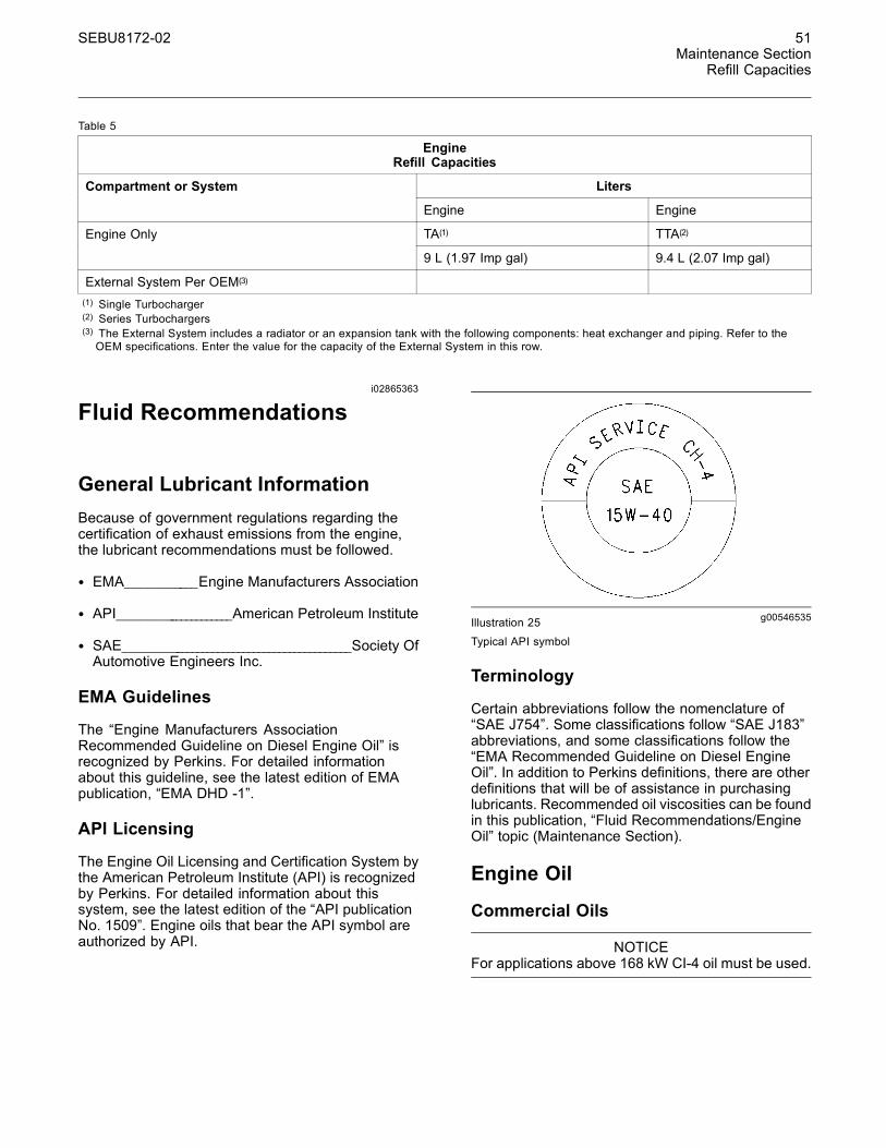
SEBU8172-02 51Maintenance Section
Refill Capacities
Table 5
EngineRefill Capacities
LitersCompartment or System
Engine Engine
TA(1) TTA(2)Engine Only
9 L (1.97 Imp gal) 9.4 L (2.07 Imp gal)
External System Per OEM(3)
(1) Single Turbocharger(2) Series Turbochargers(3) The External System includes a radiator or an expansion tank with the following components: heat exchanger and piping. Refer to theOEM specifications. Enter the value for the capacity of the External System in this row.
i02865363
Fluid Recommendations
General Lubricant InformationBecause of government regulations regarding thecertification of exhaust emissions from the engine,the lubricant recommendations must be followed.
• EMA____________Engine Manufacturers Association
• API_____________________American Petroleum Institute
• SAE___________________________________________Society OfAutomotive Engineers Inc.
EMA Guidelines
The “Engine Manufacturers AssociationRecommended Guideline on Diesel Engine Oil” isrecognized by Perkins. For detailed informationabout this guideline, see the latest edition of EMApublication, “EMA DHD -1”.
API Licensing
The Engine Oil Licensing and Certification System bythe American Petroleum Institute (API) is recognizedby Perkins. For detailed information about thissystem, see the latest edition of the “API publicationNo. 1509”. Engine oils that bear the API symbol areauthorized by API.
g00546535Illustration 25
Typical API symbol
Terminology
Certain abbreviations follow the nomenclature of“SAE J754”. Some classifications follow “SAE J183”abbreviations, and some classifications follow the“EMA Recommended Guideline on Diesel EngineOil”. In addition to Perkins definitions, there are otherdefinitions that will be of assistance in purchasinglubricants. Recommended oil viscosities can be foundin this publication, “Fluid Recommendations/EngineOil” topic (Maintenance Section).
Engine Oil
Commercial Oils
NOTICEFor applications above 168 kW CI-4 oil must be used.
52 SEBU8172-02Maintenance SectionRefill Capacities
Table 6
API Classifications for the 1104D Industrial Engine
Oil Specification MaintenanceInterval
CH-4/CI-4 500 Hours
CI-4 500 Hours
CG-4 250 Hours
Maintenance intervals for engines that usebiodiesel – The oil change interval can be adverselyaffected by the use of biodiesel. Use oil analysis inorder to monitor the condition of the engine oil. Useoil analysis also in order to determine the oil changeinterval that is optimum.
Note: These engine oils are not approved byperkins and these engine oils must not beused:CC, CD, CD-2, and CF-4.
The performance of commercial diesel engineoils is based on API classifications. These APIclassifications are developed in order to providecommercial lubricants for a broad range of dieselengines that operate at various conditions.
Only use commercial oils that meet the followingclassifications:
• API____________________________________________ CH-4 CI-4
In order to make the correct choice of a commercialoil, refer to the following explanations:
EMA DHD-1 – The EMA has developed lubricantrecommendations as an alternative to the API oilclassification system. DHD-1 is a RecommendedGuideline that defines a level of oil performance forthese types of diesel engines: high speed, four strokecycle, heavy-duty, and light duty. DHD-1 oils maybe used in Perkins engines when the following oilsare recommended: API CH-4 and API CG-4. DHD-1oils are intended to provide superior performance incomparison to API CG-4.
DHD-1 oils will meet the needs of high performancePerkins diesel engines that are operating in manyapplications. The tests and the test limits that areused to define DHD-1 are similar to the new APICH-4 classification. Therefore, these oils will alsomeet the requirements for diesel engines that requirelow emissions. DHD-1 oils are designed to control theharmful effects of soot with improved wear resistanceand improved resistance to plugging of the oil filter.These oils will also provide superior piston depositcontrol for engines with either two-piece steel pistonsor aluminum pistons.
All DHD-1 oils must complete a full test programwith the base stock and with the viscosity grade ofthe finished commercial oil. The use of “API BaseOil Interchange Guidelines” are not appropriate forDHD-1 oils. This feature reduces the variation inperformance that can occur when base stocks arechanged in commercial oil formulations.
DHD-1 oils are recommended for use in extended oilchange interval programs that optimize the life of theoil. These oil change interval programs are basedon oil analysis. DHD-1 oils are recommended forconditions that demand a premium oil. Your Perkinsdistributor has the specific guidelines for optimizingoil change intervals.
API CH-4 – API CH-4 oils were developed in order tomeet the requirements of the new high performancediesel engines. Also, the oil was designed tomeet the requirements of the low emissions dieselengines. API CH-4 oils are also acceptable for usein older diesel engines and in diesel engines thatuse high sulfur diesel fuel. API CH-4 oils may beused in Perkins engines that use API CG-4 and APICF-4 oils. API CH-4 oils will generally exceed theperformance of API CG-4 oils in the following criteria:deposits on pistons, control of oil consumption, wearof piston rings, valve train wear, viscosity control,and corrosion.
Three new engine tests were developed for the APICH-4 oil. The first test specifically evaluates depositson pistons for engines with the two-piece steel piston.This test (piston deposit) also measures the controlof oil consumption. A second test is conductedwith moderate oil soot. The second test measuresthe following criteria: wear of piston rings, wear ofcylinder liners, and resistance to corrosion. A thirdnew test measures the following characteristics withhigh levels of soot in the oil: wear of the valve train,resistance of the oil in plugging the oil filter, andcontrol of sludge.
In addition to the new tests, API CH-4 oils havetougher limits for viscosity control in applications thatgenerate high soot. The oils also have improvedoxidation resistance. API CH-4 oils must pass anadditional test (piston deposit) for engines that usealuminum pistons (single piece). Oil performance isalso established for engines that operate in areaswith high sulfur diesel fuel.
All of these improvements allow the API CH-4 oil toachieve optimum oil change intervals. API CH-4 oilsare recommended for use in extended oil changeintervals. API CH-4 oils are recommended forconditions that demand a premium oil. Your Perkinsdistributor has specific guidelines for optimizing oilchange intervals.
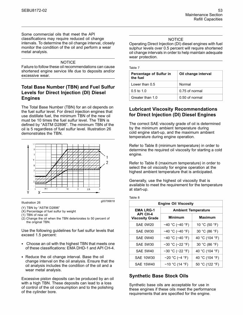
SEBU8172-02 53Maintenance Section
Refill Capacities
Some commercial oils that meet the APIclassifications may require reduced oil changeintervals. To determine the oil change interval, closelymonitor the condition of the oil and perform a wearmetal analysis.
NOTICEFailure to follow these oil recommendations can causeshortened engine service life due to deposits and/orexcessive wear.
Total Base Number (TBN) and Fuel SulfurLevels for Direct Injection (DI) DieselEngines
The Total Base Number (TBN) for an oil depends onthe fuel sulfur level. For direct injection engines thatuse distillate fuel, the minimum TBN of the new oilmust be 10 times the fuel sulfur level. The TBN isdefined by “ASTM D2896”. The minimum TBN of theoil is 5 regardless of fuel sulfur level. Illustration 26demonstrates the TBN.
g00799818Illustration 26(Y) TBN by “ASTM D2896”(X) Percentage of fuel sulfur by weight(1) TBN of new oil(2) Change the oil when the TBN deteriorates to 50 percent of
the original TBN.
Use the following guidelines for fuel sulfur levels thatexceed 1.5 percent:
• Choose an oil with the highest TBN that meets oneof these classifications: EMA DHD-1 and API CH-4.
• Reduce the oil change interval. Base the oilchange interval on the oil analysis. Ensure that theoil analysis includes the condition of the oil and awear metal analysis.
Excessive piston deposits can be produced by an oilwith a high TBN. These deposits can lead to a lossof control of the oil consumption and to the polishingof the cylinder bore.
NOTICEOperating Direct Injection (DI) diesel engines with fuelsulphur levels over 0.5 percent will require shortenedoil change intervals in order to help maintain adequatewear protection.
Table 7
Percentage of Sulfur inthe fuel
Oil change interval
Lower than 0.5 Normal
0.5 to 1.0 0.75 of normal
Greater than 1.0 0.50 of normal
Lubricant Viscosity Recommendationsfor Direct Injection (DI) Diesel Engines
The correct SAE viscosity grade of oil is determinedby the minimum ambient temperature duringcold engine start-up, and the maximum ambienttemperature during engine operation.
Refer to Table 8 (minimum temperature) in order todetermine the required oil viscosity for starting a coldengine.
Refer to Table 8 (maximum temperature) in order toselect the oil viscosity for engine operation at thehighest ambient temperature that is anticipated.
Generally, use the highest oil viscosity that isavailable to meet the requirement for the temperatureat start-up.
Table 8
Engine Oil Viscosity
Ambient TemperatureEMA LRG-1API CH-4
Viscosity Grade Minimum Maximum
SAE 0W20 −40 °C (−40 °F) 10 °C (50 °F)
SAE 0W30 −40 °C (−40 °F) 30 °C (86 °F)
SAE 0W40 −40 °C (−40 °F) 40 °C (104 °F)
SAE 5W30 −30 °C (−22 °F) 30 °C (86 °F)
SAE 5W40 −30 °C (−22 °F) 40 °C (104 °F)
SAE 10W30 −20 °C (−4 °F) 40 °C (104 °F)
SAE 15W40 −10 °C (14 °F) 50 °C (122 °F)
Synthetic Base Stock Oils
Synthetic base oils are acceptable for use inthese engines if these oils meet the performancerequirements that are specified for the engine.
54 SEBU8172-02Maintenance SectionRefill Capacities
Synthetic base oils generally perform better thanconventional oils in the following two areas:
• Synthetic base oils have improved flow at lowtemperatures especially in arctic conditions.
• Synthetic base oils have improved oxidationstability especially at high operating temperatures.
Some synthetic base oils have performancecharacteristics that enhance the service life of theoil. Perkins does not recommend the automaticextending of the oil change intervals for any type ofoil.
Re-refined Base Stock Oils
Re-refined base stock oils are acceptable foruse in Perkins engines if these oils meet theperformance requirements that are specified byPerkins. Re-refined base stock oils can be usedexclusively in finished oil or in a combination with newbase stock oils. The specification for the US militaryand the specifications of other heavy equipmentmanufacturers also allow the use of re-refined basestock oils that meet the same criteria.
The process that is used to make re-refined basestock oil should adequately remove all wear metalsthat are in the used oil and all the additives thatare in the used oil. The process that is used tomake re-refined base stock oil generally involves theprocess of vacuum distillation and hydrotreating theused oil. Filtering is adequate for the production ofhigh quality, re-refined base stock oil.
Lubricants for Cold Weather
When an engine is started and an engine is operatedin ambient temperatures below −20 °C (−4 °F), usemultigrade oils that are capable of flowing in lowtemperatures.
These oils have lubricant viscosity grades of SAE0W or SAE 5W.
When an engine is started and operated in ambienttemperatures below −30 °C (−22 °F), use a syntheticbase stock multigrade oil with an 0W viscosity gradeor with a 5W viscosity grade. Use an oil with a pourpoint that is lower than −50 °C (−58 °F).
Perkins recommends the following lubricants for usein cold weather conditions:
Use a commercial oil that is API:CI-4, CI-4 PLUS,CH-4, and CG-4. The oil must have one of thefollowing lubricant viscosity grades: SAE 0W-20, SAE0W-30, SAE 0W-40, SAE 5W-30, and SAE 5W-40
Aftermarket Oil Additives
Perkins does not recommend the use of aftermarketadditives in oil. It is not necessary to use aftermarketadditives in order to achieve the engine's maximumservice life or rated performance. Fully formulated,finished oils consist of base oils and of commercialadditive packages. These additive packages areblended into the base oils at precise percentages inorder to help provide finished oils with performancecharacteristics that meet industry standards.
There are no industry standard tests that evaluatethe performance or the compatibility of aftermarketadditives in finished oil. Aftermarket additives maynot be compatible with the finished oil's additivepackage, which could lower the performance of thefinished oil. The aftermarket additive could fail tomix with the finished oil. This could produce sludgein the crankcase. Perkins discourages the use ofaftermarket additives in finished oils.
To achieve the best performance from a Perkinsengine, conform to the following guidelines:
• Select the correct oil, or a commercial oil that meetsthe “EMA Recommended Guideline on DieselEngine Oil” or the recommended API classification.
• See the appropriate “Lubricant Viscosities” table inorder to find the correct oil viscosity grade for yourengine.
• At the specified interval, service the engine. Usenew oil and install a new oil filter.
• Perform maintenance at the intervals that arespecified in the Operation and MaintenanceManual, “Maintenance Interval Schedule”.
Oil analysis
Some engines may be equipped with an oil samplingvalve. If oil analysis is required the oil sampling valveis used to obtain samples of the engine oil. The oilanalysis will complement the preventive maintenanceprogram.
The oil analysis is a diagnostic tool that is used todetermine oil performance and component wearrates. Contamination can be identified and measuredthrough the use of the oil analysis. The oil analysisincludes the following tests:
• The Wear Rate Analysis monitors the wear of theengine's metals. The amount of wear metal andtype of wear metal that is in the oil is analyzed. Theincrease in the rate of engine wear metal in theoil is as important as the quantity of engine wearmetal in the oil.
SEBU8172-02 55Maintenance Section
Refill Capacities
• Tests are conducted in order to detectcontamination of the oil by water, glycol or fuel.
• The Oil Condition Analysis determines the loss ofthe oil's lubricating properties. An infrared analysisis used to compare the properties of new oil to theproperties of the used oil sample. This analysisallows technicians to determine the amount ofdeterioration of the oil during use. This analysisalso allows technicians to verify the performanceof the oil according to the specification during theentire oil change interval.
i02788820
Fluid Recommendations(Fuel Specification)
• Glossary
• ISO International Standards Organization
• ASTM American Society for Testing and Materials
• HFRR High Frequency Reciprocating Rig forLubricity testing of diesel fuels
• FAME Fatty Acid Methyl Esters
• CFR Co-ordinating Fuel Research
• LSD Low Sulfur Diesel
• ULSD Ultra Low Sulfur Diesel
• RME Rape Methyl Ester
• SME Soy Methyl Ester
• EPA Environmental Protection Agency of theUnited States
General Information
NOTICEEvery attempt is made to provide accurate, up to dateinformation. By use of this document you agree thatPerkins Engines Company Limited is not responsiblefor errors or omissions.
NOTICEThese recommendations are subject to change with-out notice. Contact your local Perkins distributor forthe most up to date recommendations.
Diesel Fuel RequirementsSatisfactory engine performance is dependent onthe use of a good quality fuel. The use of a goodquality fuel will give the following results: long enginelife and acceptable exhaust emissions levels. Thefuel must meet the minimum requirements that arestated in table 9.
NOTICEThe footnotes are a key part of the Perkins Specifica-tion for Distillate Diesel Fuel Table. Read ALL of thefootnotes.

56 SEBU8172-02Maintenance SectionRefill Capacities
Table 9
Perkins Specification for Distillate Diesel Fuel (1)
Property UNITS Requirements “ASTM”Test “ISO”Test
Aromatics %Volume 35% maximum D1319 “ISO”3837
Ash %Weight 0.01% maximum D482 “ISO”6245
Carbon Residue on10% Bottoms
%Weight 0.35% maximum D524 “ISO”4262
Cetane Number (2) - 40 minimum D613/D6890 “ISO”5165
Cloud Point °C The cloud point mustnot exceed the lowestexpected ambienttemperature.
D2500 “ISO”3015
Copper StripCorrosion
- No. 3 maximum D130 “ISO”2160
Density at 15 °C(59 °F) (3)
Kg / M 3 801 minimum and 876maximum
No equivalent test “ISO 3675 ”“ISO 12185”
Distillation °C 10% at 282 °C(539.6 °F) maximum90% at 360 °C (680 °F)maximum
D86 “ISO”3405
Flash Point °C legal limit D93 “ISO”2719
Thermal Stability - Minimum of 80%reflectance after agingfor 180 minutes at150 °C (302 °F)
D6468 No equivalent test
Pour Point °C 6 °C (42.8 °F) minimumbelow ambienttemperature
D97 “ISO”3016
Sulfur (1)(4) %mass 1% maximum D5453/D26222 “ISO 20846 ”“ISO 20884”
Kinematic Viscosity (5) “MM”2“/S (cSt)” The viscosity of thefuel that is delivered tothe fuel injection pump.“1.4 minimum/4.5maximum”
D445 “ISO”3405
Water and sediment % weight 0.1% maximum D1796 “ISO”3734
Water % weight 0.1% maximum D1744 No equivalent test
Sediment % weight 0.05% maximum D473 “ISO”3735
Gums and Resins (6) mg/100mL 10 mg per 100 mLmaximum
D381 “ISO”6246
(continued)

SEBU8172-02 57Maintenance Section
Refill Capacities
(Table 9, contd)
Lubricity correctedwear scar diameter at60 °C (140 °F). (7)
mm 0.52 maximum D6079 “ISO”12156-1
(1) This specification includes the requirements for Ultra Low Sulfur Diesel (ULSD). ULSD fuel will have ≤ 15 ppm (0.0015%) sulfur. Refer to“ASTM D5453”, “ASTM D2622”, or “ISO 20846, ISO 20884” test methods. This specification includes the requirements for Low SulfurDiesel (LSD). LSD fuel will have ≤500 ppm (0.05%) sulfur. Refer to following:“ASTM 5453, ASTM D2622”, “ISO 20846”, and “ISO 20884test methods”.
(2) A fuel with a higher cetane number is recommended in order to operate at a higher altitude or in cold weather.(3) “Via standards tables, the equivalent API gravity for the minimum density of 801 kg / m3 (kilograms per cubic meter) is 45 and for themaximum density of 876 kg / m3 is 30”.
(4) Regional regulations, national regulations or international regulations can require a fuel with a specific sulfur limit. Consult all applicableregulations before selecting a fuel for a given engine application. Perkins fuel systems and engine components can operate on high sulfurfuels. Fuel sulfur levels affect exhaust emissions. High sulfur fuels also increase the potential for corrosion of internal components.Fuel sulfur levels above 0.5% may significantly shorten the oil change interval. For additional information, refer to this manual, “Fluidrecommendations (General lubricant Information)”.
(5) The values of the fuel viscosity are the values as the fuel is delivered to the fuel injection pumps. Fuel should also meet the minimumviscosity requirement and the fuel should meet the maximum viscosity requirements at 40 °C (104 °F) of either the “ASTM D445” testmethod or the “ISO 3104” test method. If a fuel with a low viscosity is used, cooling of the fuel may be required to maintain 1.4 cSt orgreater viscosity at the fuel injection pump. Fuels with a high viscosity might require fuel heaters in order to lower the viscosity to 4.5cSt at the fuel injection pump.
(6) Follow the test conditions and procedures for gasoline (motor).(7) The lubricity of a fuel is a concern with low sulfur and ultra low sulfur fuel. To determine the lubricity of the fuel, use the “ISO 12156-1or ASTM D6079 High Frequency Reciprocating Rig (HFRR)” test. If the lubricity of a fuel does not meet the minimum requirements,consult your fuel supplier. Do not treat the fuel without consulting the fuel supplier. Some additives are not compatible. These additivescan cause problems in the fuel system.
NOTICEOperating with fuels that do not meet the Perkins rec-ommendations can cause the following effects: Start-ing difficulty, poor combustion, deposits in the fuel in-jectors, reduced service life of the fuel system, de-posits in the combustion chamber, and reduced ser-vice life of the engine.
Diesel Fuel CharacteristicsPerkins Recommendation
Cetane Number
Fuel that has a high cetane number will give a shorterignition delay. This will produce a better ignitionquality. Cetane numbers are derived for fuels againstproportions of cetane and heptamethylnonane in thestandard CFR engine. Refer to “ISO 5165” for thetest method.
Cetane numbers in excess of 45 are normallyexpected from current diesel fuel. However, a cetanenumber of 40 may be experienced in some territories.The United States of America is one of the territoriesthat can have a low cetane value. A minimum cetanevalue of 40 is required during average startingconditions. A higher cetane value may be requiredfor operations at high altitudes or in cold weatheroperations.
Fuel with a low cetane number can be the root causeof problems during cold start.
Viscosity
Viscosity is the property of a liquid of offeringresistance to shear or flow. Viscosity decreases withincreasing temperature. This decrease in viscosityfollows a logarithmic relationship for normal fossilfuel. The common reference is to kinematic viscosity.This is the quotient of the dynamic viscosity that isdivided by the density. The determination of kinematicviscosity is normally by readings from gravity flowviscometers at standard temperatures. Refer to “ISO3104” for the test method.
The viscosity of the fuel is significant because fuelserves as a lubricant for the fuel system components.Fuel must have sufficient viscosity in order to lubricatethe fuel system in both extremely cold temperaturesand extremely hot temperatures. If the kinematicviscosity of the fuel is lower than 1.4 cSt at the fuelinjection pump damage to the fuel injection pumpcan occur. This damage can be excessive scuffingand seizure. Low viscosity may lead to difficult hotrestarting, stalling and loss of performance. Highviscosity may result in seizure of the pump.
Perkins recommends kinematic viscosities of 1.4 and4.5 mm2/sec that is delivered to the fuel injectionpump.

58 SEBU8172-02Maintenance SectionRefill Capacities
Density
Density is the mass of the fuel per unit volumeat a specific temperature. This parameter has adirect influence on engine performance and a directinfluence on emissions. This determines the heatoutput from a given injected volume of fuel. Thisis generally quoted in the following kg/m at 15 °C(59 °F).
Perkins recommends a value of density of 841 kg/min order to obtain the correct power output. Lighterfuels are acceptable but these fuels will not producethe rated power.
Sulfur
The level of sulfur is governed by emissionslegislations. Regional regulation, national regulationsor international regulations can require a fuel witha specific sulfur limit. The sulfur content of the fueland the fuel quality must comply with all existing localregulations for emissions.
By using the test methods “ASTM D5453, ASTMD2622, or ISO 20846 ISO 20884”, the content ofsulfur in low sulfur diesel (LSD) fuel must be below500 PPM 0.05%. By using the test methods “ASTMD5453, ASTM D2622, or ISO 20846 ISO 20884”, thecontent of sulfur in ultra low sulfur (ULSD) fuel mustbe below 15 PPM 0.0015%. The use of LSD fuel andthe use of ULSD fuel are acceptable provided thatthe fuels meet the minimum requirements that arestated in table 9. The lubricity of these fuels must notexceed wear scar diameter of 0.52 mm (0.0205 inch).The fuel lubricity test must be performed on a HFRR,operated at 60 °C (140 °F). Refer to “ISO 12156-1 ”.
In some parts of the world and for some applications,high sulfur fuels above 0.5% by mass might onlybe available. Fuel with very high sulfur contentcan cause engine wear. High sulfur fuel will havea negative impact on emissions of particulates.High sulfur fuel can be used provided that the localemissions legislation will allow the use. High sulfurfuel can be used in countries that do not regulateemissions.
When only high sulfur fuels are available, it willbe necessary that high alkaline lubricating oil isused in the engine or that the lubricating oil changeinterval is reduced. Refer to this Operation andMaintenance Manual, “Fliud Recommendations(Genernal Lubrication Information)” for informationon sulfur in fuel.
Lubricity
This is the capability of the fuel to prevent pumpwear. The fluid's lubricity describes the ability of thefluid to reduce the friction between surfaces that areunder load. This ability reduces the damage that iscaused by friction. Fuel injection systems rely on thelubricating properties of the fuel. Until fuel sulfur limitswere mandated, the fuel's lubricity was generallybelieved to be a function of fuel viscosity.
The lubricity has particular significance to the currentlow viscosity fuel, low sulfur fuel and low aromaticfossil fuel. These fuels are made in order to meetstringent exhaust emissions. A test method formeasuring the lubricity of diesel fuels has beendeveloped and the test is based on the HFRRmethod that is operated at 60 °C (140 °F). Refer to“ISO 12156 part 1 and CEC document F06-A-96” forthe test method.
Lubricity wear scar diameter of 0.52 mm (0.0205 inch)MUST NOT be exceeded. The fuel lubricity test mustbe performed on a HFRR, operated at 60 °C (140 °F).Refer to “ISO 12156-1 ”.
Fuel additives can enhance the lubricity of a fuel.Contact your fuel supplier for those circumstanceswhen fuel additives are required. Your fuel suppliercan make recommendations for additives to use andfor the proper level of treatment.
Distillation
This is an indication of the mixture of differenthydrocarbons in the fuel. A high ratio of light weighthydrocarbons can affect the characteristics ofcombustion.
Classification of the Fuels
Diesel engines have the ability to burn a wide varietyof fuels. These fuels are divided into four generalgroups: Ref to table 10

SEBU8172-02 59Maintenance Section
Refill Capacities
Table 10
Fuel Groups Classification
Group 1 Preferred fuels Full life of theProduct
Group 2 Permissiblefuels with anappropriate fueladditive
These fuelsMAY causereducedengine life andperformance
Group 3 Permissiblefuels with anappropriate fueladditive
These fuelsWILL causereducedengine life andperformance
Group 4 Biodiesel
Group 1 Specifications (Preferred Fuels)
This group of fuel specifications is consideredacceptable:
• EN590 DERV Grade A, B, C, E, F, Class, 0, 1, 2,3, and 4
• “BS2869 Class A2” Off-Highway Gas Oil RedDiesel
• “ASTM D975”, Class 1D , and Class 2D
• “JIS K2204 Grades 1,2,3 and Special Grade 3”This grade of fuel must meet the minimum lubricityrequirements that are stated in table 9.
• 5% FAME to “EN14214” can be mixed with the fuelthat meets the requirements that are stated in table9. This blend is commonly known as B5.
Note: The use of LSD fuel and the use of ULSDfuel is acceptable provided that the fuels meet theminimum requirements that are stated in table 9. Thelubricity of these fuels must not exceed wear scardiameter of 0.52 mm (0.0205 inch). The lubricity testmust be performed on a HFRR, operated at 60 °C(140 °F). Refer to “ISO 12156-1 ”. By using the testmethods “ASTM D5453, ASTM D2622, or ISO 20846ISO 20884”, the content of sulfur in LSD fuel must bebelow 500 PPM 0.05%. By using the test methods“ASTM D5453, ASTM D2622, or ISO 20846 ISO20884”, the content of sulfur in ULSD fuel must bebelow 15 PPM 0.0015%.
Group 2 Specifications (PermissibleFuels)
This group of fuel specifications is consideredacceptable, but only with an appropriate fuel additive,but these fuels MAY reduce the engine life andperformance.
• “JP7 (MIL-T-38219)”
• “NATO F63”
• JP8
• JP5
• “Jet A1 (ASTM D1655)”
• “Jet A (ASTM D1655)”
• “NATO F34 ”
Note: These fuels are only acceptable provided thatthese fuels are used with an appropriate fuel additive.These fuels must meet the requirements that arestated in table 9. Fuel samples should be analyzedfor the compliance. These fuels MUST NOT exceedlubricity wear scar diameter of 0.52 mm (0.0205 inch).The fuel lubricity test must be performed on aHFRR, operated at 60 °C (140 °F). Refer to “ISO12156-1 ”. Fuels must have minimum viscosity of1.4 centistokes that is delivered to the fuel injectionpump. Fuel cooling may be required in order tomaintain minimum viscosity of 1.4 centistokes that isdelivered to the fuel injection pump.
Group 3 Specifications (PermissibleFuels)
This group of fuel specification must be used onlywith the appropriate fuel additive. This fuel WILLreduce engine life and performance.
“JIS 2203#1 and #2 Toyu”
Note: These fuels are only acceptable provided thatthese fuels are used with an appropriate fuel additive.These fuels must meet the requirements that arestated in table 9. Fuel samples should be analyzedfor the compliance. These fuels MUST NOT exceedlubricity wear scar diameter of 0.52 mm (0.0205 inch).The fuel lubricity test must be performed on aHFRR, operated at 60 °C (140 °F). Refer to “ISO12156-1 ”. Fuels must have minimum viscosity of1.4 centistokes that is delivered to the fuel injectionpump. Fuel cooling may be required in order tomaintain minimum viscosity of 1.4 centistokes that isdelivered to the fuel injection pump.

60 SEBU8172-02Maintenance SectionRefill Capacities
Group 4 Biodiesel
Biodiesel is a fuel that can be defined as mono-alkylesters of fatty acids. Biodiesel is a fuel that canbe made from a variety of feedstock. The mostcommonly available biodiesel in europe is RapeMethyl Ester (REM). This biodiesel is derived fromrapeseed oil. Soy Methyl Ester (SME) is the mostcommon biodiesel in the United States. This biodieselis derived from soybean oil. Soybean oil or rapeseedoil are the primary feedstocks. These fuels aretogether known as Fatty Acid Methyl Esters (FAME).
Raw pressed vegetable oils are NOT acceptable foruse as a fuel in any concentration in compressionengines. Without esterification, these oils gel in thecrankcase and the fuel tank. These fuels may not becompatible with many of the elastomers that are usedin engines that are manufactured today. In originalforms, these oils are not suitable for use as a fuelin compression engines. Alternate base stocks forbiodiesel may include animal tallow, waste cookingoils, or a variety of other feedstocks. In order to useany of the products that are listed as fuel, the oilmust be esterified.
Note: Engines that are manufactured by Perkinsare certified by use of the prescribed EnvironmentalProtection Agency (EPA) and European Certificationfuels. Perkins does not certify engines on any otherfuel. The user of the engine has the responsibilityof using the correct fuel that is recommended bythe manufacturer and allowed by the EPA and otherappropriate regulatory agencies.
Recommendation for the use of biodiesel
Use of FAME fuels is permissible. However, thefollowing conditions apply:
• The FAME fuel must comply with “EN14214”.
• A maximum of 5% mixture of FAME can be usedin mineral oil diesel fuel, provided that the fuelcomplies with the fuel specification that is listed intable 9. This blend is commonly known as B5. Nomixture above 5% is acceptable. Concentrationsabove 5% will lead to reduced product service lifeand potential failure of the fuel injection equipment.
Note: When biodiesel, or any blend of biodiesel isused, the user has the responsibility for obtaining theproper local exemptions, regional exemptions, and/ornational exemptions that are required for the useof biodiesel in any Perkins engine that is regulatedby emissions standards. Biodiesel that meets EN14214 is acceptable. The biodiesel must be blendedwith an acceptable distillate diesel fuel at themaximum stated percentages. However, the followingoperational recommendations must be followed:
• The oil change interval can be affected by the useof biodiesel. Use Services Oil Analysis in orderto monitor the condition of the engine oil. UseServices Oil Analysis also in order to determine theoil change interval that is optimum.
• Confirm that biodiesel is acceptable for use withthe manufacturer of the fuel filters.
• In a comparison of distillate fuels to biodiesel,biodiesel provides less energy per gallon by 5% to7%. Do NOT change the engine rating in order tocompensate for the power loss. This will help avoidengine problems when the engine is convertedback to 100 percent distillate diesel fuel.
• The compatibility of the elastomers with biodieselis being monitored. The condition of seals andhoses should be monitored regularly.
• Biodiesel may pose low ambient temperatureproblems for both storage and operation. At lowambient temperatures, fuel may need to be storedin a heated building or a heated storage tank. Thefuel system may require heated fuel lines, filters,and tanks. Filters may plug and fuel in the tank maysolidify at low ambient temperatures if precautionsare not taken. Consult your biodiesel supplier forassistance in the blending and attainment of theproper cloud point for the fuel.
• Biodiesel has poor oxidation stability, whichcan result in long term problems in the storageof biodiesel. The poor oxidation stability mayaccelerate fuel oxidation in the fuel system.This is especially true in engines with electronicfuel systems because these engines operate athigher temperatures. Consult the fuel supplier foroxidation stability additives.
• Biodiesel is a fuel that can be made from a varietyof feedstock. The feedstock that is used canaffect the performance of the product. Two of thecharacteristics of the fuel that are affected arecold flow and oxidation stability. Contact your fuelsupplier for guidance.
• Biodiesel or biodiesel blends are not recommendedfor engines that will operate occasionally. Thisis due to poor oxidation stability. If the user isprepared to accept some risk, then limit biodieselto a maximum of B5. Examples of applications thatshould limit the use of biodiesel are the following:Standby Generator sets and certain emergencyvehicles
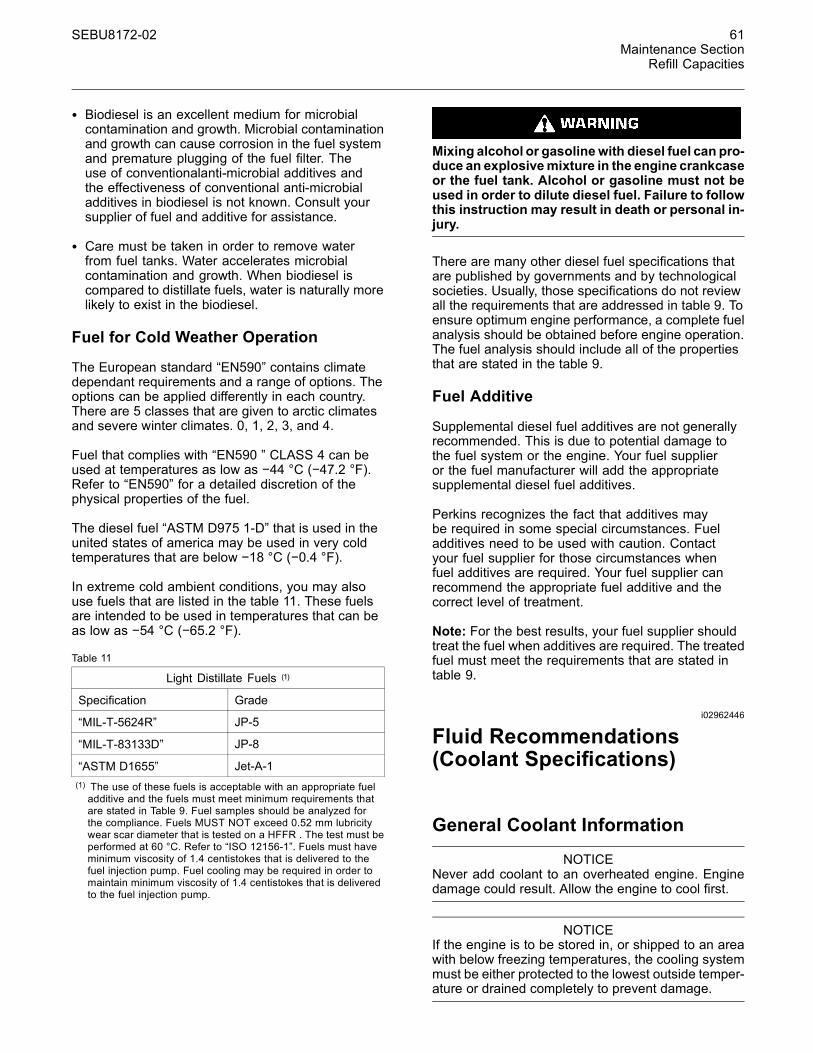
SEBU8172-02 61Maintenance Section
Refill Capacities
• Biodiesel is an excellent medium for microbialcontamination and growth. Microbial contaminationand growth can cause corrosion in the fuel systemand premature plugging of the fuel filter. Theuse of conventionalanti-microbial additives andthe effectiveness of conventional anti-microbialadditives in biodiesel is not known. Consult yoursupplier of fuel and additive for assistance.
• Care must be taken in order to remove waterfrom fuel tanks. Water accelerates microbialcontamination and growth. When biodiesel iscompared to distillate fuels, water is naturally morelikely to exist in the biodiesel.
Fuel for Cold Weather Operation
The European standard “EN590” contains climatedependant requirements and a range of options. Theoptions can be applied differently in each country.There are 5 classes that are given to arctic climatesand severe winter climates. 0, 1, 2, 3, and 4.
Fuel that complies with “EN590 ” CLASS 4 can beused at temperatures as low as −44 °C (−47.2 °F).Refer to “EN590” for a detailed discretion of thephysical properties of the fuel.
The diesel fuel “ASTM D975 1-D” that is used in theunited states of america may be used in very coldtemperatures that are below −18 °C (−0.4 °F).
In extreme cold ambient conditions, you may alsouse fuels that are listed in the table 11. These fuelsare intended to be used in temperatures that can beas low as −54 °C (−65.2 °F).
Table 11
Light Distillate Fuels (1)
Specification Grade
“MIL-T-5624R” JP-5
“MIL-T-83133D” JP-8
“ASTM D1655” Jet-A-1(1) The use of these fuels is acceptable with an appropriate fueladditive and the fuels must meet minimum requirements thatare stated in Table 9. Fuel samples should be analyzed forthe compliance. Fuels MUST NOT exceed 0.52 mm lubricitywear scar diameter that is tested on a HFFR . The test must beperformed at 60 °C. Refer to “ISO 12156-1”. Fuels must haveminimum viscosity of 1.4 centistokes that is delivered to thefuel injection pump. Fuel cooling may be required in order tomaintain minimum viscosity of 1.4 centistokes that is deliveredto the fuel injection pump.
Mixing alcohol or gasolinewith diesel fuel can pro-duce an explosivemixture in the engine crankcaseor the fuel tank. Alcohol or gasoline must not beused in order to dilute diesel fuel. Failure to followthis instruction may result in death or personal in-jury.
There are many other diesel fuel specifications thatare published by governments and by technologicalsocieties. Usually, those specifications do not reviewall the requirements that are addressed in table 9. Toensure optimum engine performance, a complete fuelanalysis should be obtained before engine operation.The fuel analysis should include all of the propertiesthat are stated in the table 9.
Fuel Additive
Supplemental diesel fuel additives are not generallyrecommended. This is due to potential damage tothe fuel system or the engine. Your fuel supplieror the fuel manufacturer will add the appropriatesupplemental diesel fuel additives.
Perkins recognizes the fact that additives maybe required in some special circumstances. Fueladditives need to be used with caution. Contactyour fuel supplier for those circumstances whenfuel additives are required. Your fuel supplier canrecommend the appropriate fuel additive and thecorrect level of treatment.
Note: For the best results, your fuel supplier shouldtreat the fuel when additives are required. The treatedfuel must meet the requirements that are stated intable 9.
i02962446
Fluid Recommendations(Coolant Specifications)
General Coolant Information
NOTICENever add coolant to an overheated engine. Enginedamage could result. Allow the engine to cool first.
NOTICEIf the engine is to be stored in, or shipped to an areawith below freezing temperatures, the cooling systemmust be either protected to the lowest outside temper-ature or drained completely to prevent damage.

62 SEBU8172-02Maintenance SectionRefill Capacities
NOTICEFrequently check the specific gravity of the coolant forproper freeze protection or for anti-boil protection.
Clean the cooling system for the following reasons:
• Contamination of the cooling system
• Overheating of the engine
• Foaming of the coolant
NOTICENever operate an engine without water temperatureregulators in the cooling system. Water temperatureregulators help to maintain the engine coolant at theproper operating temperature. Cooling system prob-lems can develop without water temperature regula-tors.
Many engine failures are related to the coolingsystem. The following problems are related to coolingsystem failures: Overheating, leakage of the waterpump, and plugged radiators or heat exchangers.
These failures can be avoided with correct coolingsystem maintenance. Cooling system maintenance isas important as maintenance of the fuel system andthe lubrication system. Quality of the coolant is asimportant as the quality of the fuel and the lubricatingoil.
Coolant is normally composed of three elements:Water, additives, and glycol.
Water
Water is used in the cooling system in order totransfer heat.
Distilled water or deionized water isrecommended for use in engine cooling systems.
DO NOT use the following types of water in coolingsystems: Hard water, softened water that has beenconditioned with salt, and sea water.
If distilled water or deionized water is not available,use water with the properties that are listed in Table12.
Table 12
Acceptable Water
Property Maximum Limit
Chloride (Cl) 40 mg/L
Sulfate (SO4) 100 mg/L
Total Hardness 170 mg/L
Total Solids 340 mg/L
Acidity pH of 5.5 to 9.0
For a water analysis, consult one of the followingsources:
• Local water utility company
• Agricultural agent
• Independent laboratory
Additives
Additives help to protect the metal surfaces ofthe cooling system. A lack of coolant additives orinsufficient amounts of additives enable the followingconditions to occur:
• Corrosion
• Formation of mineral deposits
• Rust
• Scale
• Foaming of the coolant
Many additives are depleted during engine operation.These additives must be replaced periodically.
Additives must be added at the correct concentration.Overconcentration of additives can cause theinhibitors to drop out-of-solution. The deposits canenable the following problems to occur:
• Formation of gel compounds
• Reduction of heat transfer
• Leakage of the water pump seal
• Plugging of radiators, coolers, and small passages
Glycol
Glycol in the coolant helps to provide protectionagainst the following conditions:
• Boiling

SEBU8172-02 63Maintenance Section
Refill Capacities
• Freezing
• Cavitation of the water pump
For optimum performance, Perkins recommends a1:1 mixture of a water/glycol solution.
Note: Use a mixture that will provide protectionagainst the lowest ambient temperature.
Note: 100 percent pure glycol will freeze at atemperature of −23 °C (−9 °F).
Most conventional antifreezes use ethylene glycol.Propylene glycol may also be used. In a 1:1 mixturewith water, ethylene and propylene glycol providesimilar protection against freezing and boiling. SeeTables 13 and 14.
Table 13
Ethylene Glycol
Concentration Freeze Protection
50 Percent −36 °C (−33 °F)
60 Percent −51 °C (−60 °F)
NOTICEDo not use propylene glycol in concentrations that ex-ceed 50 percent glycol because of propylene glycol'sreduced heat transfer capability. Use ethylene glycolin conditions that require additional protection againstboiling or freezing.
Table 14
Propylene Glycol
Concentration Freeze Protection
50 Percent −29 °C (−20 °F)
To check the concentration of glycol in the coolant,measure the specific gravity of the coolant.
Coolant Recommendations
• ELC____________________________Extended Life Coolant
• SCA___________________Supplement Coolant Additive
• ASTM__________________________________________AmericanSociety for Testing and Materials
The following two coolants are used in Perkins dieselengines:
Preferred – Perkins ELC
Acceptable – A commercial heavy-duty antifreezethat meets “ASTM D4985” specifications
NOTICEDo not use a commercial coolant/antifreeze that on-ly meets the ASTM D3306 specification. This type ofcoolant/antifreeze is made for light automotive appli-cations.
Perkins recommends a 1:1 mixture of water andglycol. This mixture of water and glycol will provideoptimum heavy-duty performance as a antifreeze.This ratio may be increased to 1:2 water to glycol ifextra freezing protection is required.
Note: A commercial heavy-duty antifreeze thatmeets “ASTM D4985” specifications MAY require atreatment with an SCA at the initial fill. Read the labelor the instructions that are provided by the OEM ofthe product.
In stationary engine applications and marine engineapplications that do not require anti-boil protectionor freeze protection, a mixture of SCA and wateris acceptable. Perkins recommends a six percentto eight percent concentration of SCA in thosecooling systems. Distilled water or deionized wateris preferred. Water which has the recommendedproperties may be used.
Table 15
Coolant Service Life
Coolant Type Service Life
Perkins ELC 6,000 Service Hours orThree Years
Commercial Heavy-DutyAntifreeze that meets“ASTM D4985”
3000 Service Hours orTwo Years
Perkins POWERPARTSCA
3000 Service Hours orTwo Years
Commercial SCA andWater
3000 Service Hours orTwo Years
ELC
Perkins provides ELC for use in the followingapplications:
• Heavy-duty spark ignited gas engines
• Heavy-duty diesel engines
• Automotive applications
64 SEBU8172-02Maintenance SectionRefill Capacities
The anti-corrosion package for ELC is different fromthe anti-corrosion package for other coolants. ELCis an ethylene glycol base coolant. However, ELCcontains organic corrosion inhibitors and antifoamagents with low amounts of nitrite. Perkins ELChas been formulated with the correct amount ofthese additives in order to provide superior corrosionprotection for all metals in engine cooling systems.
ELC is available in a premixed cooling solution withdistilled water. ELC is a 1:1 mixture. The PremixedELC provides freeze protection to −36 °C (−33 °F).The Premixed ELC is recommended for the initialfill of the cooling system. The Premixed ELC is alsorecommended for topping off the cooling system.
Containers of several sizes are available. Consultyour Perkins distributor for the part numbers.
ELC Cooling System Maintenance
Correct additions to the Extended LifeCoolant
NOTICEUse only Perkins products for pre-mixed or concen-trated coolants.
Mixing Extended Life Coolant with other products re-duces the Extended Life Coolant service life. Failure tofollow the recommendations can reduce cooling sys-tem components life unless appropriate corrective ac-tion is performed.
In order to maintain the correct balance betweenthe antifreeze and the additives, you must maintainthe recommended concentration of ELC. Loweringthe proportion of antifreeze lowers the proportion ofadditive. This will lower the ability of the coolant toprotect the system from pitting, from cavitation, fromerosion, and from deposits.
NOTICEDo not use a conventional coolant to top-off a coolingsystem that is filled with Extended Life Coolant (ELC).
Do not use standard supplemental coolant additive(SCA).
When using Perkins ELC, do not use standard SCA'sor SCA filters.
ELC Cooling System Cleaning
Note: If the cooling system is already using ELC,cleaning agents are not required to be used atthe specified coolant change interval. Cleaningagents are only required if the system has beencontaminated by the addition of some other type ofcoolant or by cooling system damage.
Clean water is the only cleaning agent that is requiredwhen ELC is drained from the cooling system.
Before the cooling system is filled, the heater control(if equipped) must be set to the hot position. Referto the OEM in order to set the heater control. Afterthe cooling system is drained and the cooling systemis refilled, operate the engine until the coolant levelreaches the normal operating temperature anduntil the coolant level stabilizes. As needed, addthe coolant mixture in order to fill the system to thespecified level.
Changing to Perkins ELC
To change from heavy-duty antifreeze to the PerkinsELC, perform the following steps:
NOTICECare must be taken to ensure that all fluids arecontained during performance of inspection, main-tenance, testing, adjusting and the repair of theproduct. Be prepared to collect the fluid with suitablecontainers before opening any compartment or dis-assembling any component containing fluids.
Dispose of all fluids according to local regulations andmandates.
1. Drain the coolant into a suitable container.
2. Dispose of the coolant according to localregulations.
3. Flush the system with clean water in order toremove any debris.
4. Use Perkins cleaner to clean the system. Followthe instruction on the label.
5. Drain the cleaner into a suitable container. Flushthe cooling system with clean water.
6. Fill the cooling system with clean water andoperate the engine until the engine is warmed to49° to 66°C (120° to 150°F).

SEBU8172-02 65Maintenance Section
Refill Capacities
NOTICEIncorrect or incomplete flushing of the cooling systemcan result in damage to copper and other metal com-ponents.
To avoid damage to the cooling system, make sure tocompletely flush the cooling system with clear water.Continue to flush the system until all the signs of thecleaning agent are gone.
7. Drain the cooling system into a suitable containerand flush the cooling system with clean water.
Note: The cooling system cleaner must be thoroughlyflushed from the cooling system. Cooling systemcleaner that is left in the system will contaminate thecoolant. The cleaner may also corrode the coolingsystem.
8. Repeat Steps 6 and 7 until the system iscompletely clean.
9. Fill the cooling system with the Perkins PremixedELC.
ELC Cooling System Contamination
NOTICEMixing ELC with other products reduces the effective-ness of the ELC and shortens the ELC service life.Use only Perkins Products for premixed or concen-trate coolants. Failure to follow these recommenda-tions can result in shortened cooling system compo-nent life.
ELC cooling systems can withstand contamination toa maximum of ten percent of conventional heavy-dutyantifreeze or SCA. If the contamination exceeds tenpercent of the total system capacity, perform ONE ofthe following procedures:
• Drain the cooling system into a suitable container.Dispose of the coolant according to localregulations. Flush the system with clean water. Fillthe system with the Perkins ELC.
• Drain a portion of the cooling system into a suitablecontainer according to local regulations. Then, fillthe cooling system with premixed ELC. This shouldlower the contamination to less than 10 percent.
• Maintain the system as a conventional Heavy-DutyCoolant. Treat the system with an SCA. Changethe coolant at the interval that is recommended forthe conventional Heavy-Duty Coolant.
Commercial Heavy-Duty Antifreeze andSCA
NOTICECommercial Heavy-Duty Coolant which containsAmine as part of the corrision protection system mustnot be used.
NOTICENever operate an engine without water temperatureregulators in the cooling system. Water temperatureregulators help to maintain the engine coolant at thecorrect operating temperature. Cooling system prob-lems can develop without water temperature regula-tors.
Check the antifreeze (glycol concentration) inorder to ensure adequate protection against boilingor freezing. Perkins recommends the use of arefractometer for checking the glycol concentration.
Perkins engine cooling systems should be tested at500 hour intervals for the concentration of SCA.
Additions of SCA are based on the results of the test.An SCA that is liquid may be needed at 500 hourintervals.
Refer to Table 16 for part numbers and for quantitiesof SCA.
Table 16
Perkins Liquid SCA
Part Number Quantity
21825735 10
Adding the SCA to Heavy-Duty Coolantat the Initial Fill
Commercial heavy-duty antifreeze that meets “ASTMD4985” specifications MAY require an addition ofSCA at the initial fill. Read the label or the instructionsthat are provided by the OEM of the product.
Use the equation that is in Table 17 to determine theamount of Perkins SCA that is required when thecooling system is initially filled.
Table 17
Equation For Adding The SCA To The Heavy-DutyCoolant At The Initial Fill
V × 0.045 = X
V is the total volume of the cooling system.
X is the amount of SCA that is required.
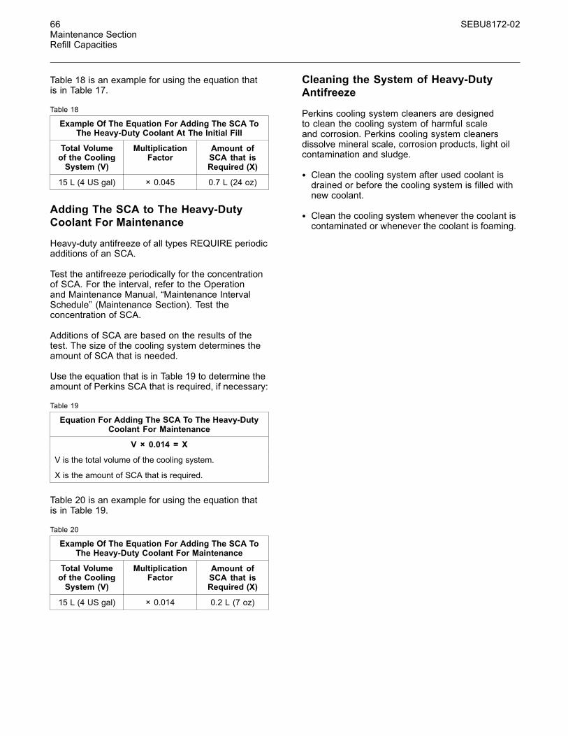
66 SEBU8172-02Maintenance SectionRefill Capacities
Table 18 is an example for using the equation thatis in Table 17.
Table 18
Example Of The Equation For Adding The SCA ToThe Heavy-Duty Coolant At The Initial Fill
Total Volumeof the CoolingSystem (V)
MultiplicationFactor
Amount ofSCA that isRequired (X)
15 L (4 US gal) × 0.045 0.7 L (24 oz)
Adding The SCA to The Heavy-DutyCoolant For Maintenance
Heavy-duty antifreeze of all types REQUIRE periodicadditions of an SCA.
Test the antifreeze periodically for the concentrationof SCA. For the interval, refer to the Operationand Maintenance Manual, “Maintenance IntervalSchedule” (Maintenance Section). Test theconcentration of SCA.
Additions of SCA are based on the results of thetest. The size of the cooling system determines theamount of SCA that is needed.
Use the equation that is in Table 19 to determine theamount of Perkins SCA that is required, if necessary:
Table 19
Equation For Adding The SCA To The Heavy-DutyCoolant For Maintenance
V × 0.014 = X
V is the total volume of the cooling system.
X is the amount of SCA that is required.
Table 20 is an example for using the equation thatis in Table 19.
Table 20
Example Of The Equation For Adding The SCA ToThe Heavy-Duty Coolant For Maintenance
Total Volumeof the CoolingSystem (V)
MultiplicationFactor
Amount ofSCA that isRequired (X)
15 L (4 US gal) × 0.014 0.2 L (7 oz)
Cleaning the System of Heavy-DutyAntifreeze
Perkins cooling system cleaners are designedto clean the cooling system of harmful scaleand corrosion. Perkins cooling system cleanersdissolve mineral scale, corrosion products, light oilcontamination and sludge.
• Clean the cooling system after used coolant isdrained or before the cooling system is filled withnew coolant.
• Clean the cooling system whenever the coolant iscontaminated or whenever the coolant is foaming.

SEBU8172-02 67Maintenance Section
Maintenance Recommendations
MaintenanceRecommendations
i04103075
Welding on Engines withElectronic Controls
NOTICEBecause the strength of the frame may decrease,some manufacturers do not recommend welding ontoa chassis frame or rail. Consult the OEM of the equip-ment or your Perkins dealer regarding welding ona chassis frame or rail.
Proper welding procedures are necessary in orderto avoid damage to the engines ECM, sensors, andassociated components. When possible, removethe component from the unit and then weld thecomponent. If removal of the component is notpossible, the following procedure must be followedwhen you weld on a unit equipped with an ElectronicEngine. The following procedure is considered to bethe safest procedure to weld on a component. Thisprocedure should provide a minimum risk of damageto electronic components.
NOTICEDo not ground the welder to electrical componentssuch as the ECM or sensors. Improper grounding cancause damage to the drive train bearings, hydrauliccomponents, electrical components, and other com-ponents.
Clamp the ground cable from the welder to the com-ponent that will be welded. Place the clamp as closeas possible to the weld. This will help reduce the pos-sibility of damage.
Note: Perform the welding in areas that are free fromexplosive hazards.
1. Stop the engine. Turn the switched power to theOFF position.
2. Ensure that the fuel supply to the engine is turnedoff.
3. Disconnect the negative battery cable from thebattery. If a battery disconnect switch is provided,open the switch.
4. Disconnect all electronic components fromthe wiring harnesses. Include the followingcomponents:
• Electronic components for the driven equipment
• ECM
• Sensors
• Electronically controlled valves
• Relays
• Aftertreatment ID module
NOTICEDo not use electrical components (ECM or ECM sen-sors) or electronic component grounding points forgrounding the welder.
g01075639Illustration 27Use the example above. The current flow from the welder tothe ground clamp of the welder will not damage any associatedcomponents.(1) Engine(2) Welding electrode(3) Keyswitch in the OFF position(4) Battery disconnect switch in the open position(5) Disconnected battery cables(6) Battery(7) Electrical/Electronic component(8) Minimum distance between the component that is being welded
and any electrical/electronic component(9) The component that is being welded(10) Current path of the welder(11) Ground clamp for the welder

68 SEBU8172-02Maintenance SectionMaintenance Recommendations
5. Connect the welding ground cable directly tothe part that will be welded. Place the groundcable as close as possible to the weld in order toreduce the possibility of welding current damageto the following components. Bearings, hydrauliccomponents, electrical components, and groundstraps.
Note: If electrical/electronic components are usedas a ground for the welder, or electrical/electroniccomponents are located between the welder groundand the weld, current flow from the welder couldseverely damage the component.
6. Protect the wiring harness from welding debrisand spatter.
7. Use standard welding practices to weld thematerials.

SEBU8172-02 69Maintenance Section
Maintenance Interval Schedule
i04949917
Maintenance Interval Schedule
When Required
Battery - Replace .................................................. 71Battery or Battery Cable - Disconnect .................. 72Engine - Clean ...................................................... 79Engine Air Cleaner Element (Dual Element) -Clean/Replace .................................................... 80Engine Oil Sample - Obtain .................................. 84Fuel System - Prime ............................................. 89Severe Service Application - Check ..................... 99
Daily
Alternator Belt - Inspect/Adjust/Replace ............... 71Cooling System Coolant Level - Check ................ 77Driven Equipment - Check .................................... 79Engine Air Cleaner Service Indicator - Inspect ..... 82Engine Air Precleaner - Check/Clean ................... 83Engine Oil Level - Check ...................................... 83Fuel System Primary Filter/Water Separator -Drain ................................................................... 93V-Belts - Inspect/Adjust/Replace ........................ 101Walk-Around Inspection ...................................... 102
Every 50 Service Hours or Weekly
Fuel Tank Water and Sediment - Drain ................. 97
Every 250 Service Hours
Engine Oil and Filter - Change ............................. 87
Initial 500 Service Hours
Engine Valve Lash - Inspect/Adjust ...................... 87
Every 500 Service Hours
Fan Clearance - Check ......................................... 88V-Belts - Inspect/Adjust/Replace ........................ 101
Every 500 Service Hours or 1 Year
Battery Electrolyte Level - Check .......................... 72Cooling System Supplemental Coolant Additive(SCA) - Test/Add ................................................. 78Crankcase Breather (Canister) - Replace ............. 79Engine Air Cleaner Element (Dual Element) -Clean/Replace .................................................... 80Engine Oil and Filter - Change ............................. 84Fuel System Primary Filter (Water Separator)Element - Replace .............................................. 90Fuel System Secondary Filter - Replace .............. 94Hoses and Clamps - Inspect/Replace .................. 97Radiator - Clean .................................................... 98
Every 1000 Service Hours
Engine Valve Lash - Inspect/Adjust ...................... 87
Every 2000 Service Hours
Aftercooler Core - Inspect ..................................... 70Alternator - Inspect ............................................... 71Belt Tensioner - Inspect ........................................ 73Engine Mounts - Inspect ....................................... 83Exhaust Manifold - Inspect ................................... 87Starting Motor - Inspect ...................................... 100Turbocharger - Inspect ........................................ 100Water Pump - Inspect ......................................... 104
Every 3000 Service Hours
Alternator Belt - Inspect/Adjust/Replace ............... 71
Every 3000 Service Hours or 2 Years
Cooling System Coolant (Commercial Heavy-Duty) -Change ............................................................... 73
Every 4000 Service Hours
Aftercooler Core - Clean/Test ............................... 70
Every 12 000 Service Hours or 6 Years
Cooling System Coolant (ELC) - Change ............. 75
Commissioning
Fan Clearance - Check ......................................... 88

70 SEBU8172-02Maintenance SectionAftercooler Core - Clean/Test
i02322260
Aftercooler Core - Clean/Test
1. Remove the core. Refer to the OEM informationfor the correct procedure.
2. Turn the aftercooler core upside-down in order toremove debris.
Personal injury can result from air pressure.
Personal injury can result without following prop-er procedure.When using pressure air, wear a pro-tective face shield and protective clothing.
Maximum air pressure at the nozzle must be lessthan 205 kPa (30 psi) for cleaning purposes.
3. Pressurized air is the preferred method forremoving loose debris. Direct the air in theopposite direction of the fan's air flow. Hold thenozzle approximately 6 mm (.25 inch) away fromthe fins. Slowly move the air nozzle in a directionthat is parallel with the tubes. This will removedebris that is between the tubes.
4. Pressurized water may also be used for cleaning.The maximum water pressure for cleaningpurposes must be less than 275 kPa (40 psi). Usepressurized water in order to soften mud. Cleanthe core from both sides.
NOTICEDo not use a high concentration of caustic cleaner toclean the core. A high concentration of caustic cleanercan attack the internal metals of the core and causeleakage. Only use the recommended concentration ofcleaner.
5. Back flush the core with a suitable cleaner.
6. Steam clean the core in order to remove anyresidue. Flush the fins of the aftercooler core.Remove any other trapped debris.
7. Wash the core with hot, soapy water. Rinse thecore thoroughly with clean water.
Personal injury can result from air pressure.
Personal injury can result without following prop-er procedure.When using pressure air, wear a pro-tective face shield and protective clothing.
Maximum air pressure at the nozzle must be lessthan 205 kPa (30 psi) for cleaning purposes.
8. Dry the core with compressed air. Direct the air inthe reverse direction of the normal flow.
9. Inspect the core in order to ensure cleanliness.Pressure test the core. If necessary, repair thecore.
10. Install the core. Refer to the OEM information forthe correct procedure.
11.After cleaning, start the engine and acceleratethe engine to high idle rpm. This will help in theremoval of debris and drying of the core. Stop theengine. Use a light bulb behind the core in orderto inspect the core for cleanliness. Repeat thecleaning, if necessary.
i02322295
Aftercooler Core - Inspect
Note: Adjust the frequency of cleaning according tothe effects of the operating environment.
Inspect the aftercooler for these items: damaged fins,corrosion, dirt, grease, insects, leaves, oil, and otherdebris. Clean the aftercooler, if necessary.
For air-to-air aftercoolers, use the same methods thatare used for cleaning radiators.
Personal injury can result from air pressure.
Personal injury can result without following prop-er procedure.When using pressure air, wear a pro-tective face shield and protective clothing.
Maximum air pressure at the nozzle must be lessthan 205 kPa (30 psi) for cleaning purposes.
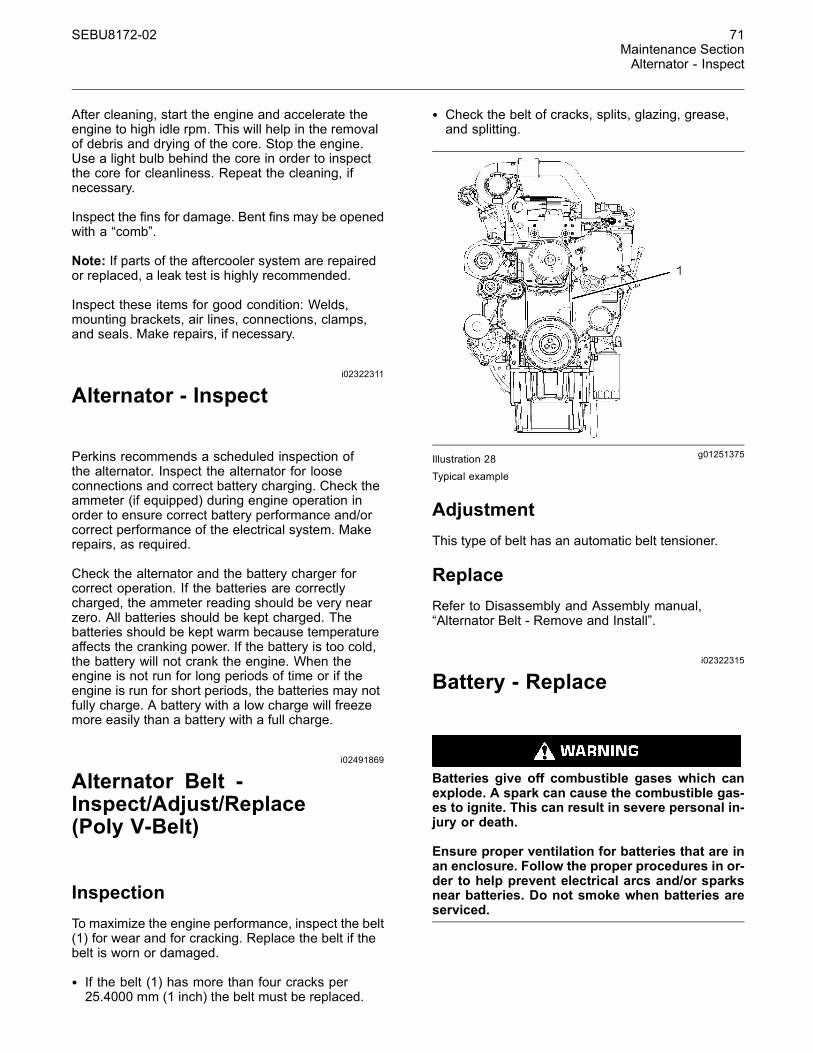
SEBU8172-02 71Maintenance SectionAlternator - Inspect
After cleaning, start the engine and accelerate theengine to high idle rpm. This will help in the removalof debris and drying of the core. Stop the engine.Use a light bulb behind the core in order to inspectthe core for cleanliness. Repeat the cleaning, ifnecessary.
Inspect the fins for damage. Bent fins may be openedwith a “comb”.
Note: If parts of the aftercooler system are repairedor replaced, a leak test is highly recommended.
Inspect these items for good condition: Welds,mounting brackets, air lines, connections, clamps,and seals. Make repairs, if necessary.
i02322311
Alternator - Inspect
Perkins recommends a scheduled inspection ofthe alternator. Inspect the alternator for looseconnections and correct battery charging. Check theammeter (if equipped) during engine operation inorder to ensure correct battery performance and/orcorrect performance of the electrical system. Makerepairs, as required.
Check the alternator and the battery charger forcorrect operation. If the batteries are correctlycharged, the ammeter reading should be very nearzero. All batteries should be kept charged. Thebatteries should be kept warm because temperatureaffects the cranking power. If the battery is too cold,the battery will not crank the engine. When theengine is not run for long periods of time or if theengine is run for short periods, the batteries may notfully charge. A battery with a low charge will freezemore easily than a battery with a full charge.
i02491869
Alternator Belt -Inspect/Adjust/Replace(Poly V-Belt)
InspectionTo maximize the engine performance, inspect the belt(1) for wear and for cracking. Replace the belt if thebelt is worn or damaged.
• If the belt (1) has more than four cracks per25.4000 mm (1 inch) the belt must be replaced.
• Check the belt of cracks, splits, glazing, grease,and splitting.
g01251375Illustration 28Typical example
AdjustmentThis type of belt has an automatic belt tensioner.
ReplaceRefer to Disassembly and Assembly manual,“Alternator Belt - Remove and Install”.
i02322315
Battery - Replace
Batteries give off combustible gases which canexplode. A spark can cause the combustible gas-es to ignite. This can result in severe personal in-jury or death.
Ensure proper ventilation for batteries that are inan enclosure. Follow the proper procedures in or-der to help prevent electrical arcs and/or sparksnear batteries. Do not smoke when batteries areserviced.
72 SEBU8172-02Maintenance SectionBattery Electrolyte Level - Check
The battery cables or the batteries should not beremoved with the battery cover in place. The bat-tery cover should be removed before any servic-ing is attempted.
Removing the battery cables or the batteries withthe cover in place may cause a battery explosionresulting in personal injury.
1. Switch the engine to the OFF position. Removeall electrical loads.
2. Turn off any battery chargers. Disconnect anybattery chargers.
3. The NEGATIVE “-” cable connects the NEGATIVE“-” battery terminal to the NEGATIVE “-” terminalon the starting motor. Disconnect the cable fromthe NEGATIVE “-” battery terminal.
4. The POSITIVE “+” cable connects the POSITIVE“+” battery terminal to the POSITIVE “+” terminalon the starting motor. Disconnect the cable fromthe POSITIVE “+” battery terminal.
Note: Always recycle a battery. Never discard abattery. Dispose of used batteries to an appropriaterecycling facility.
5. Remove the used battery.
6. Install the new battery.
Note: Before the cables are connected, ensure thatthe engine start switch is OFF.
7. Connect the cable from the starting motor to thePOSITIVE “+” battery terminal.
8. Connect the NEGATIVE “-” cable to the NEGATIVE“-” battery terminal.
i02747977
Battery Electrolyte Level -Check
When the engine is not run for long periods of time orwhen the engine is run for short periods, the batteriesmay not fully recharge. Ensure a full charge in orderto help prevent the battery from freezing. If batteriesare correctly charged, the ammeter reading shouldbe very near zero, when the engine is in operation.
All lead-acid batteries contain sulfuric acid whichcan burn the skin and clothing. Always wear a faceshield and protective clothing when working on ornear batteries.
1. Remove the filler caps. Maintain the electrolytelevel to the “FULL” mark on the battery.
If the addition of water is necessary, use distilledwater. If distilled water is not available use cleanwater that is low in minerals. Do not use artificiallysoftened water.
2. Check the condition of the electrolyte with asuitable battery tester.
3. Install the caps.
4. Keep the batteries clean.
Clean the battery case with one of the followingcleaning solutions:
• Use a solution of 0.1 kg (0.2 lb) baking sodaand 1 L (1 qt) of clean water.
• Use a solution of ammonium hydroxide.
Thoroughly rinse the battery case with clean water.
i02323088
Battery or Battery Cable -Disconnect
The battery cables or the batteries should not beremoved with the battery cover in place. The bat-tery cover should be removed before any servic-ing is attempted.
Removing the battery cables or the batteries withthe cover in place may cause a battery explosionresulting in personal injury.
1. Turn the start switch to the OFF position. Turn theignition switch (if equipped) to the OFF positionand remove the key and all electrical loads.
2. Disconnect the negative battery terminal. Ensurethat the cable cannot contact the terminal. Whenfour 12 volt batteries are involved, two negativeconnection must be disconnected.
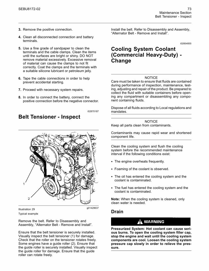
SEBU8172-02 73Maintenance Section
Belt Tensioner - Inspect
3. Remove the positive connection.
4. Clean all disconnected connection and batteryterminals.
5. Use a fine grade of sandpaper to clean theterminals and the cable clamps. Clean the itemsuntil the surfaces are bright or shiny. DO NOTremove material excessively. Excessive removalof material can cause the clamps to not fitcorrectly. Coat the clamps and the terminals witha suitable silicone lubricant or petroleum jelly.
6. Tape the cable connections in order to helpprevent accidental starting.
7. Proceed with necessary system repairs.
8. In order to connect the battery, connect thepositive connection before the negative connector.
i02870187
Belt Tensioner - Inspect
g01429637Illustration 29Typical example
Remove the belt. Refer to Disassembly andAssembly, “Alternator Belt - Remove and Install”.
Ensure that the belt tensioner is securely installed.Visually inspect the belt tensioner (1) for damage.Check that the roller on the tensioner rotates freely.Some engines have a guide roller (2). Ensure thatthe guide roller is securely installed. Visually inspectthe guide roller for damage. Ensure that the guideroller can rotate freely.
Install the belt. Refer to Disassembly and Assembly,“Alternator Belt - Remove and Install”.
i02854855
Cooling System Coolant(Commercial Heavy-Duty) -Change
NOTICECare must be taken to ensure that fluids are containedduring performance of inspection, maintenance, test-ing, adjusting and repair of the product. Be prepared tocollect the fluid with suitable containers before open-ing any compartment or disassembling any compo-nent containing fluids.
Dispose of all fluids according to Local regulations andmandates.
NOTICEKeep all parts clean from contaminants.
Contaminants may cause rapid wear and shortenedcomponent life.
Clean the cooling system and flush the coolingsystem before the recommended maintenanceinterval if the following conditions exist:
• The engine overheats frequently.
• Foaming of the coolant is observed.
• The oil has entered the cooling system and thecoolant is contaminated.
• The fuel has entered the cooling system and thecoolant is contaminated.
Note: When the cooling system is cleaned, onlyclean water is needed.
Drain
Pressurized System: Hot coolant can cause seri-ous burns. To open the cooling system filler cap,stop the engine and wait until the cooling systemcomponents are cool. Loosen the cooling systempressure cap slowly in order to relieve the pres-sure.
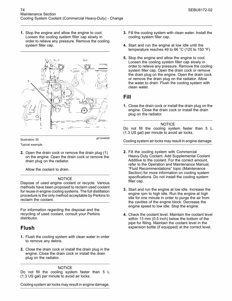
74 SEBU8172-02Maintenance SectionCooling System Coolant (Commercial Heavy-Duty) - Change
1. Stop the engine and allow the engine to cool.Loosen the cooling system filler cap slowly inorder to relieve any pressure. Remove the coolingsystem filler cap.
g01244659Illustration 30
Typical example
2. Open the drain cock or remove the drain plug (1)on the engine. Open the drain cock or remove thedrain plug on the radiator.
Allow the coolant to drain.
NOTICEDispose of used engine coolant or recycle. Variousmethods have been proposed to reclaim used coolantfor reuse in engine cooling systems. The full distillationprocedure is the only method acceptable by Perkins toreclaim the coolant.
For information regarding the disposal and therecycling of used coolant, consult your Perkinsdistributor.
Flush1. Flush the cooling system with clean water in orderto remove any debris.
2. Close the drain cock or install the drain plug in theengine. Close the drain cock or install the drainplug on the radiator.
NOTICEDo not fill the cooling system faster than 5 L(1.3 US gal) per minute to avoid air locks.
Cooling system air locksmay result in engine damage.
3. Fill the cooling system with clean water. Install thecooling system filler cap.
4. Start and run the engine at low idle until thetemperature reaches 49 to 66 °C (120 to 150 °F).
5. Stop the engine and allow the engine to cool.Loosen the cooling system filler cap slowly inorder to relieve any pressure. Remove the coolingsystem filler cap. Open the drain cock or removethe drain plug on the engine. Open the drain cockor remove the drain plug on the radiator. Allowthe water to drain. Flush the cooling system withclean water.
Fill1. Close the drain cock or install the drain plug on theengine. Close the drain cock or install the drainplug on the radiator.
NOTICEDo not fill the cooling system faster than 5 L(1.3 US gal) per minute to avoid air locks.
Cooling system air locksmay result in engine damage.
2. Fill the cooling system with CommercialHeavy-Duty Coolant. Add Supplemental CoolantAdditive to the coolant. For the correct amount,refer to the Operation and Maintenance Manual,“Fluid Recommendations” topic (MaintenanceSection) for more information on cooling systemspecifications. Do not install the cooling systemfiller cap.
3. Start and run the engine at low idle. Increase theengine rpm to high idle. Run the engine at highidle for one minute in order to purge the air fromthe cavities of the engine block. Decrease theengine speed to low idle. Stop the engine.
4. Check the coolant level. Maintain the coolant levelwithin 13 mm (0.5 inch) below the bottom of thepipe for filling. Maintain the coolant level in theexpansion bottle (if equipped) at the correct level.

SEBU8172-02 75Maintenance Section
Cooling System Coolant (ELC) - Change
g00103639Illustration 31Filler cap
5. Clean the cooling system filler cap and inspect thegasket. If the gasket is damaged, discard the oldfiller cap and install a new filler cap. If the gasketis not damaged, use a suitable pressurizing pumpin order to pressure test the filler cap. The correctpressure is stamped on the face of the filler cap. Ifthe filler cap does not retain the correct pressure,install a new filler cap.
6. Start the engine. Inspect the cooling system forleaks and for correct operating temperature.
i02490917
Cooling System Coolant (ELC)- Change
NOTICECare must be taken to ensure that fluids are containedduring performance of inspection, maintenance, test-ing, adjusting and repair of the product. Be prepared tocollect the fluid with suitable containers before open-ing any compartment or disassembling any compo-nent containing fluids.
Dispose of all fluids according to Local regulations andmandates.
NOTICEKeep all parts clean from contaminants.
Contaminants may cause rapid wear and shortenedcomponent life.
Clean the cooling system and flush the coolingsystem before the recommended maintenanceinterval if the following conditions exist:
• The engine overheats frequently.
• Foaming of the coolant is observed.
• The oil has entered the cooling system and thecoolant is contaminated.
• The fuel has entered the cooling system and thecoolant is contaminated.
Note: When the cooling system is cleaned, onlyclean water is needed when the ELC is drained andreplaced.
Note: Inspect the water pump and the watertemperature regulator after the cooling system hasbeen drained. This is a good opportunity to replacethe water pump, the water temperature regulator andthe hoses, if necessary.
Drain
Pressurized System: Hot coolant can cause seri-ous burns. To open the cooling system filler cap,stop the engine and wait until the cooling systemcomponents are cool. Loosen the cooling systempressure cap slowly in order to relieve the pres-sure.
1. Stop the engine and allow the engine to cool.Loosen the cooling system filler cap slowly inorder to relieve any pressure. Remove the coolingsystem filler cap.
g01244659Illustration 32Typical example
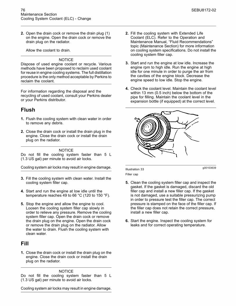
76 SEBU8172-02Maintenance SectionCooling System Coolant (ELC) - Change
2. Open the drain cock or remove the drain plug (1)on the engine. Open the drain cock or remove thedrain plug on the radiator.
Allow the coolant to drain.
NOTICEDispose of used engine coolant or recycle. Variousmethods have been proposed to reclaim used coolantfor reuse in engine cooling systems. The full distillationprocedure is the only method acceptable by Perkins toreclaim the coolant.
For information regarding the disposal and therecycling of used coolant, consult your Perkins dealeror your Perkins distributor.
Flush1. Flush the cooling system with clean water in orderto remove any debris.
2. Close the drain cock or install the drain plug in theengine. Close the drain cock or install the drainplug on the radiator.
NOTICEDo not fill the cooling system faster than 5 L(1.3 US gal) per minute to avoid air locks.
Cooling system air locksmay result in engine damage.
3. Fill the cooling system with clean water. Install thecooling system filler cap.
4. Start and run the engine at low idle until thetemperature reaches 49 to 66 °C (120 to 150 °F).
5. Stop the engine and allow the engine to cool.Loosen the cooling system filler cap slowly inorder to relieve any pressure. Remove the coolingsystem filler cap. Open the drain cock or removethe drain plug on the engine. Open the drain cockor remove the drain plug on the radiator. Allowthe water to drain. Flush the cooling system withclean water.
Fill1. Close the drain cock or install the drain plug on theengine. Close the drain cock or install the drainplug on the radiator.
NOTICEDo not fill the cooling system faster than 5 L(1.3 US gal) per minute to avoid air locks.
Cooling system air locksmay result in engine damage.
2. Fill the cooling system with Extended LifeCoolant (ELC). Refer to the Operation andMaintenance Manual, “Fluid Recommendations”topic (Maintenance Section) for more informationon cooling system specifications. Do not install thecooling system filler cap.
3. Start and run the engine at low idle. Increase theengine rpm to high idle. Run the engine at highidle for one minute in order to purge the air fromthe cavities of the engine block. Decrease theengine speed to low idle. Stop the engine.
4. Check the coolant level. Maintain the coolant levelwithin 13 mm (0.5 inch) below the bottom of thepipe for filling. Maintain the coolant level in theexpansion bottle (if equipped) at the correct level.
g00103639Illustration 33Filler cap
5. Clean the cooling system filler cap and inspect thegasket. If the gasket is damaged, discard the oldfiller cap and install a new filler cap. If the gasketis not damaged, use a suitable pressurizing pumpin order to pressure test the filler cap. The correctpressure is stamped on the face of the filler cap. Ifthe filler cap does not retain the correct pressure,install a new filler cap.
6. Start the engine. Inspect the cooling system forleaks and for correct operating temperature.

SEBU8172-02 77Maintenance Section
Cooling System Coolant Level - Check
i04408743
Cooling System Coolant Level- Check
Engines With a Coolant RecoveryTankNote: The cooling system may not have beenprovided by Perkins. The procedure that followsis for typical cooling systems. Refer to the OEMinformation for the correct procedures.
Check the coolant level when the engine is stoppedand cool.
NOTICEWhen any servicing or repair of the engine coolingsystem is performed, the procedure must be per-formed with the engine on level ground. This will allowyou to accurately check the coolant level. This willalso help in avoiding the risk of introducing an air lockinto the coolant system.
1. Observe the coolant level in the coolant recoverytank. Maintain the coolant level to “COLD FULL”mark on the coolant recovery tank.
Pressurized System: Hot coolant can cause seri-ous burns. To open the cooling system filler cap,stop the engine and wait until the cooling systemcomponents are cool. Loosen the cooling systempressure cap slowly in order to relieve the pres-sure.
2. Loosen filler cap slowly in order to relieve anypressure. Remove the filler cap.
3. Pour the correct coolant mixture into the tank.Refer to the Operation and Maintenance Manual,“Refill Capacities and Recommendations” forinformation on the correct mixture and type ofcoolant. Refer to the Operation and MaintenanceManual, “Refill Capacities and Recommendations”for the cooling system capacity. Do not fill thecoolant recovery tank above “COLD FULL” mark.
g02590196Illustration 34Filler cap
4. Clean filler cap and the receptacle. Reinstall thefiller cap and inspect the cooling system for leaks.
Note: The coolant will expand as the coolant heatsup during normal engine operation. The additionalvolume will be forced into the coolant recovery tankduring engine operation. When the engine is stoppedand cool, the coolant will return to the engine.
Engines Without a CoolantRecovery TankCheck the coolant level when the engine is stoppedand cool.
g00285520Illustration 35
Cooling system filler cap

78 SEBU8172-02Maintenance SectionCooling System Supplemental Coolant Additive (SCA) - Test/Add
Pressurized System: Hot coolant can cause seri-ous burns. To open the cooling system filler cap,stop the engine and wait until the cooling systemcomponents are cool. Loosen the cooling systempressure cap slowly in order to relieve the pres-sure.
1. Remove the cooling system filler cap slowly inorder to relieve pressure.
2. Maintain the coolant level at the maximum markthat is correct for your application. If the engine isequipped with a sight glass, maintain the coolantlevel to the correct level in the sight glass.
3. Clean the cooling system filler cap and inspect thegasket. If the gasket is damaged, discard the oldfiller cap and install a new filler cap. If the gasketis not damaged, use a suitable pressurizing pumpin order to pressure test the filler cap. The correctpressure is stamped on the face of the filler cap. Ifthe filler cap does not retain the correct pressure,install a new filler cap.
4. Inspect the cooling system for leaks.
i03644948
Cooling System SupplementalCoolant Additive (SCA) -Test/Add
Cooling system coolant additive contains alkali.To help prevent personal injury, avoid contact withthe skin and the eyes. Do not drink cooling systemcoolant additive.
Test for SCA Concentration
Heavy-Duty Coolant/Antifreeze and SCA
NOTICEDo not exceed the recommended six percent supple-mental coolant additive concentration.
Use a Coolant Conditioner Test Kit in order to checkthe concentration of the SCA.
Add the SCA, If Necessary
NOTICEDo not exceed the recommended amount of sup-plemental coolant additive concentration. Excessivesupplemental coolant additive concentration can formdeposits on the higher temperature surfaces of thecooling system, reducing the engine's heat transfercharacteristics. Reduced heat transfer could causecracking of the cylinder head and other high temper-ature components. Excessive supplemental coolantadditive concentration could also result in radiatortube blockage, overheating, and/or accelerated waterpump seal wear. Never use both liquid supplementalcoolant additive and the spin-on element (if equipped)at the same time. The use of those additives togethercould result in supplemental coolant additive concen-tration exceeding the recommended maximum.
Pressurized System: Hot coolant can cause seri-ous burns. To open the cooling system filler cap,stop the engine and wait until the cooling systemcomponents are cool. Loosen the cooling systempressure cap slowly in order to relieve the pres-sure.
NOTICEWhen any servicing or repair of the engine coolingsystem is performed the proceduremust be performedwith the engine on level ground. This will allow you toaccurately check the coolant level. This will also helpin avoiding the risk of introducing an air lock into thecoolant system.
1. Slowly loosen the cooling system filler cap inorder to relieve the pressure. Remove the coolingsystem filler cap.
Note: Always discard drained fluids according tolocal regulations.
2. If necessary, drain some coolant from the coolingsystem into a suitable container in order to allowspace for the extra SCA.
3. Add the correct amount of SCA. Refer to theOperation and Maintenance Manual, “RefillCapacities and Recommendations” for moreinformation on SCA requirements.

SEBU8172-02 79Maintenance Section
Crankcase Breather (Canister) - Replace
4. Clean the cooling system filler cap and inspect thegasket. If the gasket is damaged, discard the oldfiller cap and install a new filler cap. If the gasketis not damaged, use a suitable pressurizing pumpin order to pressure test the filler cap. The correctpressure is stamped on the face of the filler cap. Ifthe filler cap does not retain the correct pressure,install a new filler cap.
i02866782
Crankcase Breather (Canister)- Replace
NOTICEEnsure that the engine is stopped before any servicingor repair is performed.
Note: The breather assembly is not installed on allengines.
1. Place a container under the canister (1).
2. Clean the outside of the canister. Use a suitabletool in order to remove the canister.
g01428096Illustration 36Typical example
3. Lubricate the O ring seal (2) on the new canister(3) with clean engine lubricating oil. Install the newcanister. Tighten the canister to 12 N·m (8 lb ft).Do not overtighten the canister.
4. Remove the container. Dispose of the old canisterand any split oil in a safe place.
i02151646
Driven Equipment - Check
Refer to the OEM specifications for more informationon the following maintenance recommendations forthe driven equipment:
• Inspection
• Adjustment
• Lubrication
• Other maintenance recommendations
Perform any maintenance for the driven equipmentwhich is recommended by the OEM.
i01909392
Engine - Clean
Personal injury or death can result from high volt-age.
Moisture can create paths of electrical conductiv-ity.
Make sure that the electrical system is OFF. Lockout the starting controls and tag the controls “DONOT OPERATE”.
NOTICEAccumulated grease and oil on an engine is a fire haz-ard. Keep the engine clean. Remove debris and fluidspills whenever a significant quantity accumulates onthe engine.
NOTICEFailure to protect some engine components fromwashing may make your engine warranty invalid.Allow the engine to cool for one hour before washingthe engine.

80 SEBU8172-02Maintenance SectionEngine Air Cleaner Element (Dual Element) - Clean/Replace
Periodic cleaning of the engine is recommended.Steam cleaning the engine will remove accumulatedoil and grease. A clean engine provides the followingbenefits:
• Easy detection of fluid leaks
• Maximum heat transfer characteristics
• Ease of maintenance
Note: Caution must be used in order to preventelectrical components from being damaged byexcessive water when the engine is cleaned.Pressure washers and steam cleaners should not bedirected at any electrical connectors or the junction ofcables into the rear of the connectors. Avoid electricalcomponents such as the alternator, the starter, andthe ECM. Protect the fuel injection pump from fluidsin order to wash the engine.
i02334355
Engine Air Cleaner Element(Dual Element) - Clean/Replace
NOTICENever run the engine without an air cleaner elementinstalled. Never run the engine with a damaged aircleaner element. Do not use air cleaner elements withdamaged pleats, gaskets or seals. Dirt entering theengine causes premature wear and damage to enginecomponents. Air cleaner elements help to prevent air-borne debris from entering the air inlet.
NOTICENever service the air cleaner element with the enginerunning since this will allow dirt to enter the engine.
Servicing the Air Cleaner ElementsNote: The air filter system may not have beenprovided by Perkins. The procedure that followsis for a typical air filter system. Refer to the OEMinformation for the correct procedure.
If the air cleaner element becomes plugged, the aircan split the material of the air cleaner element.Unfiltered air will drastically accelerate internalengine wear. Refer to the OEM information for thecorrect air cleaner elements for your application.
• Check the precleaner (if equipped) and the dustbowl daily for accumulation of dirt and debris.Remove any dirt and debris, as needed.
• Operating in dirty conditions may require morefrequent service of the air cleaner element.
• The air cleaner element should be replaced at leastone time per year. This replacement should beperformed regardless of the number of cleanings.
Replace the dirty air cleaner elements with clean aircleaner elements. Before installation, the air cleanerelements should be thoroughly checked for tearsand/or holes in the filter material. Inspect the gasketor the seal of the air cleaner element for damage.Maintain a supply of suitable air cleaner elementsfor replacement purposes.
Dual Element Air Cleaners
The dual element air cleaner contains a primary aircleaner element and a secondary air cleaner element.
The primary air cleaner element can be used upto six times if the element is properly cleaned andproperly inspected. The primary air cleaner elementshould be replaced at least one time per year. Thisreplacement should be performed regardless of thenumber of cleanings.
The secondary air cleaner element is not serviceable.Refer to the OEM information for instructions in orderto replace the secondary air cleaner element.
When the engine is operating in environments thatare dusty or dirty, air cleaner elements may requiremore frequent replacement.
g00736431Illustration 37
(1) Cover(2) Primary air cleaner element(3) Secondary air cleaner element(4) Air inlet
1. Remove the cover. Remove the primary aircleaner element.
2. The secondary air cleaner element should beremoved and discarded for every three cleaningsof the primary air cleaner element.
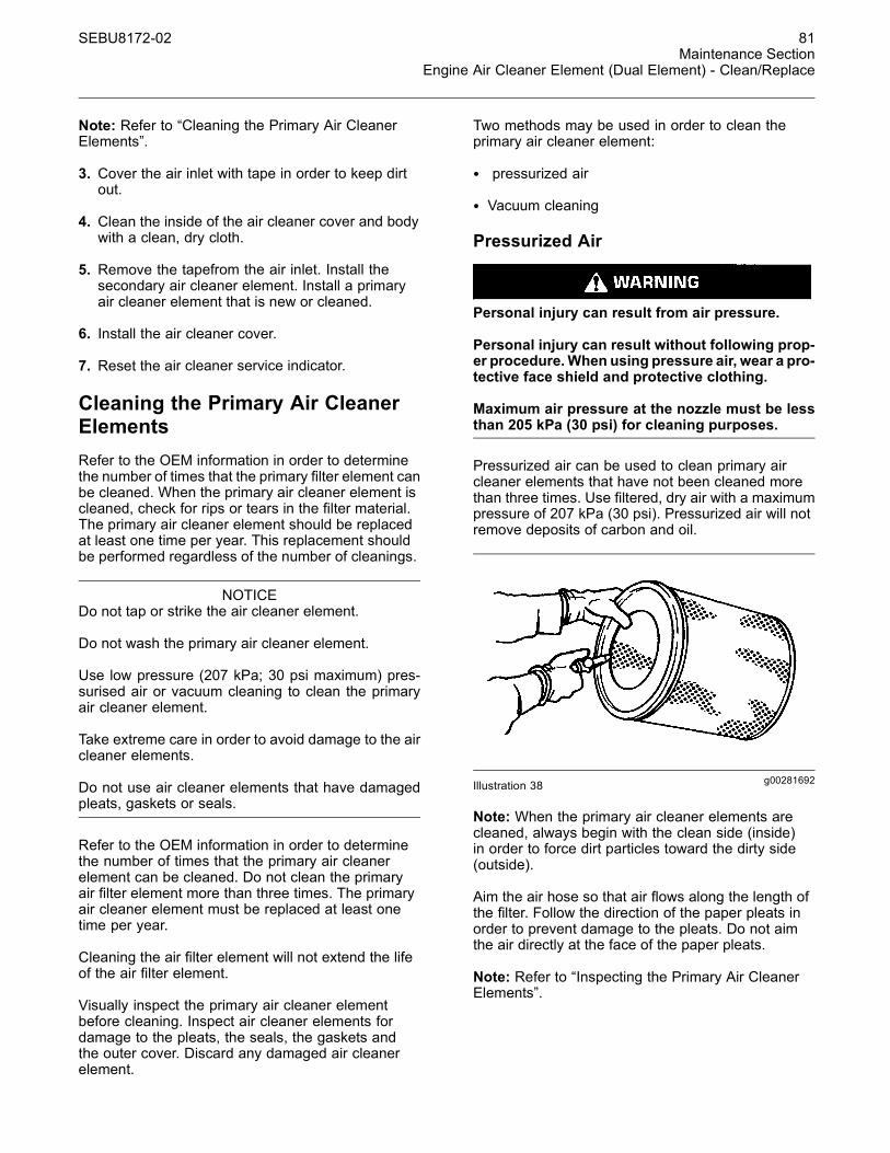
SEBU8172-02 81Maintenance Section
Engine Air Cleaner Element (Dual Element) - Clean/Replace
Note: Refer to “Cleaning the Primary Air CleanerElements”.
3. Cover the air inlet with tape in order to keep dirtout.
4. Clean the inside of the air cleaner cover and bodywith a clean, dry cloth.
5. Remove the tapefrom the air inlet. Install thesecondary air cleaner element. Install a primaryair cleaner element that is new or cleaned.
6. Install the air cleaner cover.
7. Reset the air cleaner service indicator.
Cleaning the Primary Air CleanerElementsRefer to the OEM information in order to determinethe number of times that the primary filter element canbe cleaned. When the primary air cleaner element iscleaned, check for rips or tears in the filter material.The primary air cleaner element should be replacedat least one time per year. This replacement shouldbe performed regardless of the number of cleanings.
NOTICEDo not tap or strike the air cleaner element.
Do not wash the primary air cleaner element.
Use low pressure (207 kPa; 30 psi maximum) pres-surised air or vacuum cleaning to clean the primaryair cleaner element.
Take extreme care in order to avoid damage to the aircleaner elements.
Do not use air cleaner elements that have damagedpleats, gaskets or seals.
Refer to the OEM information in order to determinethe number of times that the primary air cleanerelement can be cleaned. Do not clean the primaryair filter element more than three times. The primaryair cleaner element must be replaced at least onetime per year.
Cleaning the air filter element will not extend the lifeof the air filter element.
Visually inspect the primary air cleaner elementbefore cleaning. Inspect air cleaner elements fordamage to the pleats, the seals, the gaskets andthe outer cover. Discard any damaged air cleanerelement.
Two methods may be used in order to clean theprimary air cleaner element:
• pressurized air
• Vacuum cleaning
Pressurized Air
Personal injury can result from air pressure.
Personal injury can result without following prop-er procedure.When using pressure air, wear a pro-tective face shield and protective clothing.
Maximum air pressure at the nozzle must be lessthan 205 kPa (30 psi) for cleaning purposes.
Pressurized air can be used to clean primary aircleaner elements that have not been cleaned morethan three times. Use filtered, dry air with a maximumpressure of 207 kPa (30 psi). Pressurized air will notremove deposits of carbon and oil.
g00281692Illustration 38
Note: When the primary air cleaner elements arecleaned, always begin with the clean side (inside)in order to force dirt particles toward the dirty side(outside).
Aim the air hose so that air flows along the length ofthe filter. Follow the direction of the paper pleats inorder to prevent damage to the pleats. Do not aimthe air directly at the face of the paper pleats.
Note: Refer to “Inspecting the Primary Air CleanerElements”.
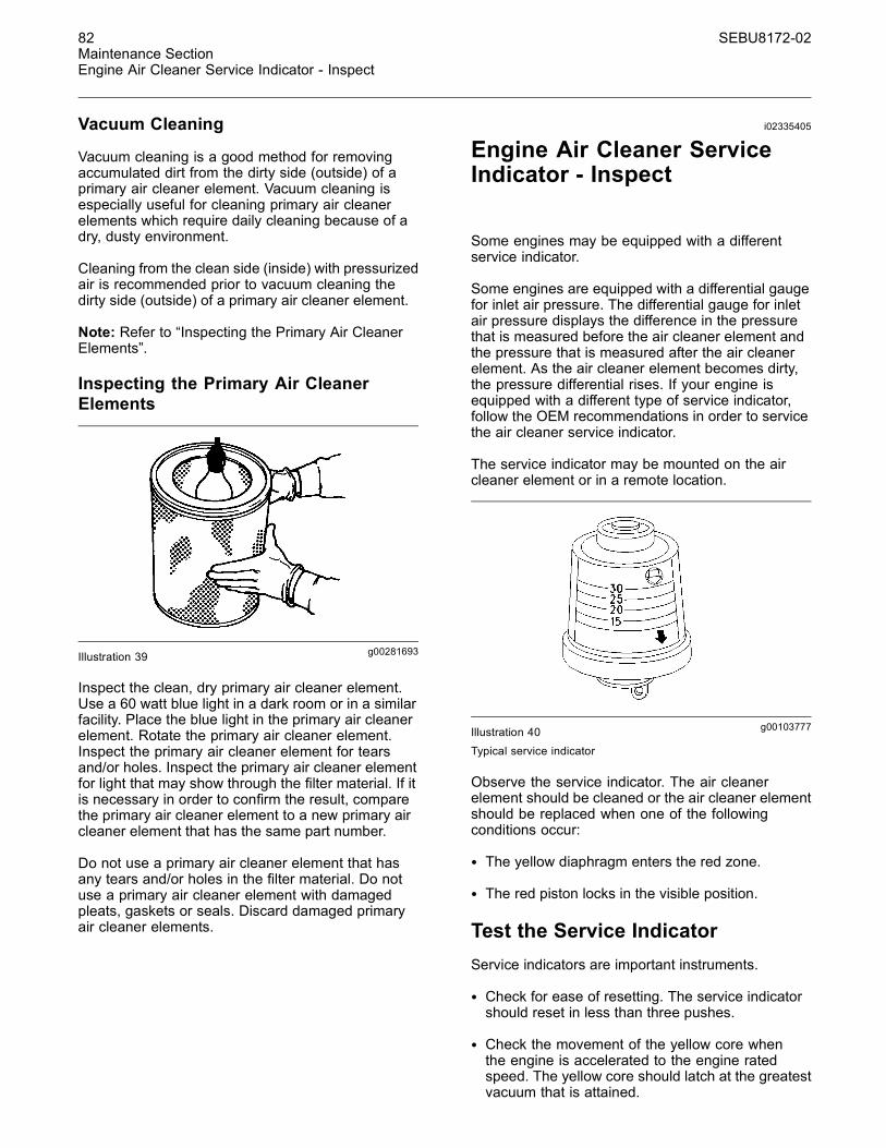
82 SEBU8172-02Maintenance SectionEngine Air Cleaner Service Indicator - Inspect
Vacuum Cleaning
Vacuum cleaning is a good method for removingaccumulated dirt from the dirty side (outside) of aprimary air cleaner element. Vacuum cleaning isespecially useful for cleaning primary air cleanerelements which require daily cleaning because of adry, dusty environment.
Cleaning from the clean side (inside) with pressurizedair is recommended prior to vacuum cleaning thedirty side (outside) of a primary air cleaner element.
Note: Refer to “Inspecting the Primary Air CleanerElements”.
Inspecting the Primary Air CleanerElements
g00281693Illustration 39
Inspect the clean, dry primary air cleaner element.Use a 60 watt blue light in a dark room or in a similarfacility. Place the blue light in the primary air cleanerelement. Rotate the primary air cleaner element.Inspect the primary air cleaner element for tearsand/or holes. Inspect the primary air cleaner elementfor light that may show through the filter material. If itis necessary in order to confirm the result, comparethe primary air cleaner element to a new primary aircleaner element that has the same part number.
Do not use a primary air cleaner element that hasany tears and/or holes in the filter material. Do notuse a primary air cleaner element with damagedpleats, gaskets or seals. Discard damaged primaryair cleaner elements.
i02335405
Engine Air Cleaner ServiceIndicator - Inspect
Some engines may be equipped with a differentservice indicator.
Some engines are equipped with a differential gaugefor inlet air pressure. The differential gauge for inletair pressure displays the difference in the pressurethat is measured before the air cleaner element andthe pressure that is measured after the air cleanerelement. As the air cleaner element becomes dirty,the pressure differential rises. If your engine isequipped with a different type of service indicator,follow the OEM recommendations in order to servicethe air cleaner service indicator.
The service indicator may be mounted on the aircleaner element or in a remote location.
g00103777Illustration 40Typical service indicator
Observe the service indicator. The air cleanerelement should be cleaned or the air cleaner elementshould be replaced when one of the followingconditions occur:
• The yellow diaphragm enters the red zone.
• The red piston locks in the visible position.
Test the Service IndicatorService indicators are important instruments.
• Check for ease of resetting. The service indicatorshould reset in less than three pushes.
• Check the movement of the yellow core whenthe engine is accelerated to the engine ratedspeed. The yellow core should latch at the greatestvacuum that is attained.

SEBU8172-02 83Maintenance Section
Engine Air Precleaner - Check/Clean
If the service indicator does not reset easily, or if theyellow core does not latch at the greatest vacuum,the service indicator should be replaced. If the newservice indicator will not reset, the hole for the serviceindicator may be restricted.
The service indicator may need to be replacedfrequently in environments that are severely dusty.
i02343354
Engine Air Precleaner -Check/Clean
g00287039Illustration 41Typical example
(1) Wing nut(2) Cover(3) Body
Remove wing nut (1) and cover (2). Check for anaccumulation of dirt and debris in body (3). Clean thebody, if necessary.
After cleaning the precleaner, install cover (2) andwing nut (1).
Note: When the engine is operated in dustyapplications, more frequent cleaning is required.
i02323089
Engine Mounts - Inspect
Note: The engine mounts may not have beensupplied by Perkins. Refer to the OEM informationfor further information on the engine mounts and thecorrect bolt torque.
Inspect the engine mounts for deterioration and forcorrect bolt torque. Engine vibration can be causedby the following conditions:
• Incorrect mounting of the engine
• Deterioration of the engine mounts
• Loose engine mounts
Any engine mount that shows deterioration shouldbe replaced. Refer to the OEM information for therecommended torques.
i02335785
Engine Oil Level - Check
Hot oil and hot components can cause personalinjury. Do not allow hot oil or hot components tocontact the skin.
g01165836Illustration 42(Y) “Min” mark. (X) “Max” mark.
NOTICEPerform this maintenance with the engine stopped.
Note: Ensure that the engine is either level or thatthe engine is in the normal operating position in orderto obtain a true level indication.
Note: After the engine has been switched OFF, waitfor ten minutes in order to allow the engine oil to drainto the oil pan before checking the oil level.
1. Maintain the oil level between the “ADD” mark (Y)and the “FULL” mark (X) on the engine oil dipstick.Do not fill the crankcase above the “FULL” mark(X).

84 SEBU8172-02Maintenance SectionEngine Oil Sample - Obtain
NOTICEOperating your engine when the oil level is above the“FULL” mark could cause your crankshaft to dip intothe oil. The air bubbles created from the crankshaftdipping into the oil reduces the oil's lubricating char-acteristics and could result in the loss of power.
2. Remove the oil filler cap and add oil, if necessary.Clean the oil filler cap. Install the oil filler cap.
i01907674
Engine Oil Sample - Obtain
The condition of the engine lubricating oil may bechecked at regular intervals as part of a preventivemaintenance program. Perkins include an oilsampling valve as an option. The oil sampling valve(if equipped) is included in order to regularly samplethe engine lubricating oil. The oil sampling valve ispositioned on the oil filter head or the oil samplingvalve is positioned on the cylinder block.
Perkins recommends using a sampling valve in orderto obtain oil samples. The quality and the consistencyof the samples are better when a sampling valve isused. The location of the sampling valve allows oilthat is flowing under pressure to be obtained duringnormal engine operation.
Obtain the Sample and the Analysis
Hot oil and hot components can cause personalinjury. Do not allow hot oil or hot components tocontact the skin.
In order to help obtain the most accurate analysis,record the following information before an oil sampleis taken:
• The date of the sample
• Engine model
• Engine number
• Service hours on the engine
• The number of hours that have accumulated sincethe last oil change
• The amount of oil that has been added since thelast oil change
Ensure that the container for the sample is clean anddry. Also ensure that the container for the sample isclearly labelled.
To ensure that the sample is representative of theoil in the crankcase, obtain a warm, well mixed oilsample.
To avoid contamination of the oil samples, the toolsand the supplies that are used for obtaining oilsamples must be clean.
The sample can be checked for the following: thequality of the oil, the existence of any coolant in theoil, the existence of any ferrous metal particles inthe oil, and the existence of any nonferrous metalparticles in the oil.
i02867741
Engine Oil and Filter - Change
Hot oil and hot components can cause personalinjury. Do not allow hot oil or hot components tocontact the skin.
NOTICECare must be taken to ensure that fluids are containedduring performance of inspection, maintenance, test-ing, adjusting and repair of the product. Be prepared tocollect the fluid with suitable containers before open-ing any compartment or disassembling any compo-nent containing fluids.
Dispose of all fluids according to local regulations andmandates.
NOTICEKeep all parts clean from contaminants.
Contaminants may cause rapid wear and shortenedcomponent life.
Do not drain the engine lubricating oil when theengine is cold. As the engine lubricating oil cools,suspended waste particles settle on the bottom ofthe oil pan. The waste particles are not removed withdraining cold oil. Drain the oil pan with the enginestopped. Drain the oil pan with the oil warm. Thisdraining method allows the waste particles that aresuspended in the oil to be drained properly.
Failure to follow this recommended procedure willcause the waste particles to be recirculated throughthe engine lubrication system with the new oil.

SEBU8172-02 85Maintenance Section
Engine Oil and Filter - Change
Drain the Engine Lubricating OilNote: Ensure that the vessel that will be used is largeenough to collect the waste oil.
After the engine has been run at the normal operatingtemperature, stop the engine. Use one of thefollowing methods to drain the engine oil pan:
g01428532Illustration 43Typical example
• If the engine is equipped with a drain valve, turn thedrain valve knob counterclockwise in order to drainthe oil. After the oil has drained, turn the drain valveknob clockwise in order to close the drain valve.
• If the engine is not equipped with a drain valve,remove the oil drain plug (1) in order to allow the oilto drain. If the engine is equipped with a shallow oilpan, remove the bottom oil drain plugs from bothends of the oil pan.
After the oil has drained, the oil drain plugs should becleaned and installed. If necessary, replace the Oring seal. Tighten the drain plug to 34 N·m (25 lb ft).
Replace the Oil Filter
NOTICEPerkins oil filters are manufactured to Perkins speci-fications. Use of an oil filter that is not recommendedby Perkins could result in severe damage to the en-gine bearings, crankshaft, etc., as a result of the largerwaste particles from unfiltered oil entering the enginelubricating system. Only use oil filters recommendedby Perkins.
1. Remove the oil filter with a suitable tool. Ahorizontally installed oil filter can be drainedbefore removal.
Note: The following actions can be carried out aspart of the preventive maintenance program.
2. Cut the oil filter open with a suitable tool. Breakapart the pleats and inspect the oil filter for metaldebris. An excessive amount of metal debris inthe oil filter may indicate early wear or a pendingfailure.
Use a magnet to differentiate between the ferrousmetals and the nonferrous metals that are found inthe oil filter element. Ferrous metals may indicatewear on the steel and cast iron parts of the engine.
Nonferrous metals may indicate wear on thealuminum parts, brass parts or bronze parts of theengine. Parts that may be affected include thefollowing items: main bearings, rod bearings, andturbocharger bearings.
Due to normal wear and friction, it is notuncommon to find small amounts of debris in theoil filter.

86 SEBU8172-02Maintenance SectionEngine Oil and Filter - Change
g01187802Illustration 44Typical example
3. Clean the sealing surface of the oil filter head (2).Ensure that the union is secure in the filter head.
4. Apply clean engine oil to the O ring seal (3) forthe new oil filter.
NOTICEDo not fill the oil filters with oil before installing them.This oil would not be filtered and could be contaminat-ed. Contaminated oil can cause accelerated wear toengine components.
5. Install the oil filter. Tighten the oil filter to 12 N·m(8.8 lb ft). Do not overtighten the oil filter.
Horizontal Oil Filter
g01428535Illustration 45Typical example
Note: Some oil filters may be installed horizontally.Refer to illustration 45. This type of oil filter assemblycan be drained before the filter is removed. Start atstep 1 in order to remove the oil filter and install theoil filter.
Fill the Oil Pan1. Remove the oil filler cap. Refer to thisOperation and Maintenance Manual, “FluidRecommendations” for more information onsuitable oils. Fill the oil pan with the correctamount of new engine lubricating oil. Referto this Operation and Maintenance Manual,“Refill Capacities” for more information on refillcapacities.
NOTICEIf equipped with an auxilliary oil filter system or a re-mote filter system, follow the OEM or the filter manu-facture's remonmendations. Under filling or over fillingthe crankcase with oil can cause engine damage.
2. Start the engine and run the engine at “LOWIDLE” for two minutes. Perform this procedure inorder to ensure that the lubrication system hasoil and that the oil filters are filled. Inspect the oilfilter for oil leaks.
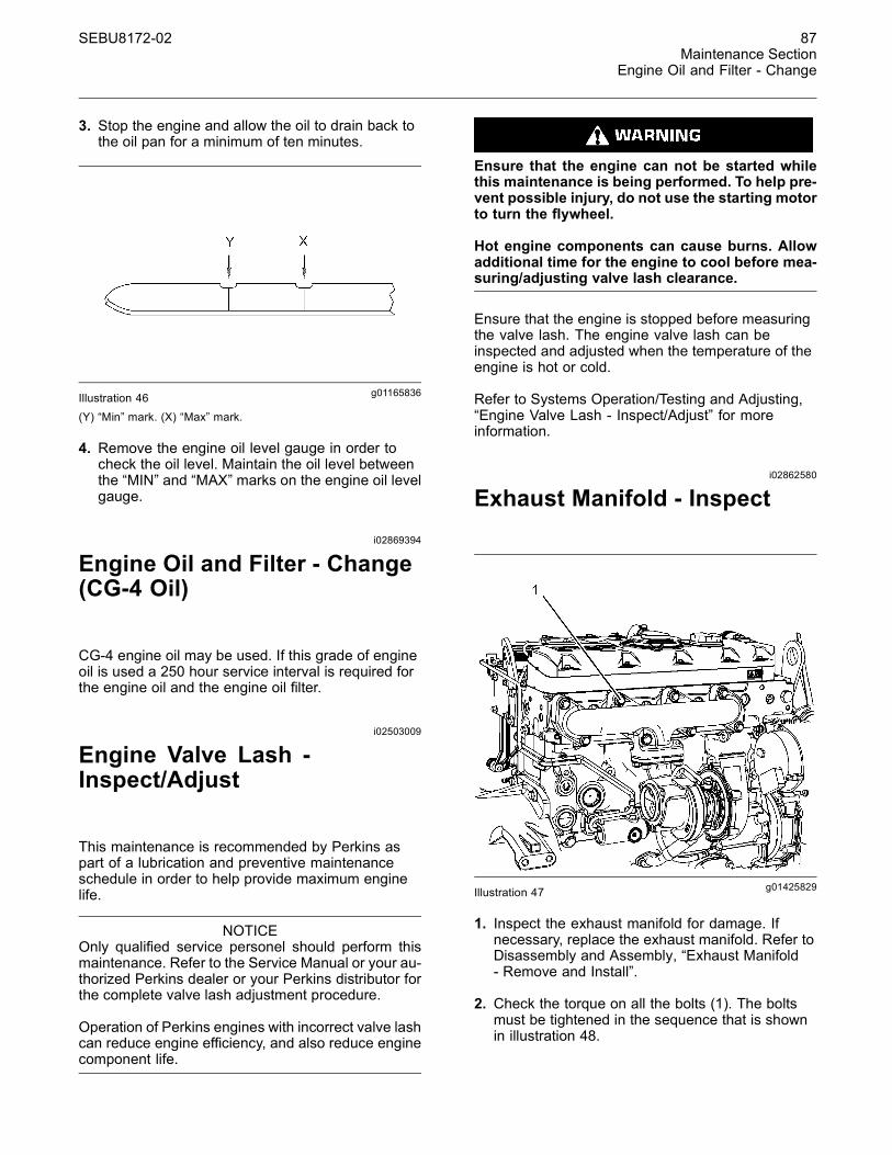
SEBU8172-02 87Maintenance Section
Engine Oil and Filter - Change
3. Stop the engine and allow the oil to drain back tothe oil pan for a minimum of ten minutes.
g01165836Illustration 46(Y) “Min” mark. (X) “Max” mark.
4. Remove the engine oil level gauge in order tocheck the oil level. Maintain the oil level betweenthe “MIN” and “MAX” marks on the engine oil levelgauge.
i02869394
Engine Oil and Filter - Change(CG-4 Oil)
CG-4 engine oil may be used. If this grade of engineoil is used a 250 hour service interval is required forthe engine oil and the engine oil filter.
i02503009
Engine Valve Lash -Inspect/Adjust
This maintenance is recommended by Perkins aspart of a lubrication and preventive maintenanceschedule in order to help provide maximum enginelife.
NOTICEOnly qualified service personel should perform thismaintenance. Refer to the Service Manual or your au-thorized Perkins dealer or your Perkins distributor forthe complete valve lash adjustment procedure.
Operation of Perkins engines with incorrect valve lashcan reduce engine efficiency, and also reduce enginecomponent life.
Ensure that the engine can not be started whilethis maintenance is being performed. To help pre-vent possible injury, do not use the starting motorto turn the flywheel.
Hot engine components can cause burns. Allowadditional time for the engine to cool before mea-suring/adjusting valve lash clearance.
Ensure that the engine is stopped before measuringthe valve lash. The engine valve lash can beinspected and adjusted when the temperature of theengine is hot or cold.
Refer to Systems Operation/Testing and Adjusting,“Engine Valve Lash - Inspect/Adjust” for moreinformation.
i02862580
Exhaust Manifold - Inspect
g01425829Illustration 47
1. Inspect the exhaust manifold for damage. Ifnecessary, replace the exhaust manifold. Refer toDisassembly and Assembly, “Exhaust Manifold- Remove and Install”.
2. Check the torque on all the bolts (1). The boltsmust be tightened in the sequence that is shownin illustration 48.
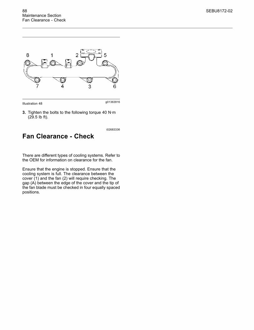
88 SEBU8172-02Maintenance SectionFan Clearance - Check
g01363916Illustration 48
3. Tighten the bolts to the following torque 40 N·m(29.5 lb ft).
i02683336
Fan Clearance - Check
There are different types of cooling systems. Refer tothe OEM for information on clearance for the fan.
Ensure that the engine is stopped. Ensure that thecooling system is full. The clearance between thecover (1) and the fan (2) will require checking. Thegap (A) between the edge of the cover and the tip ofthe fan blade must be checked in four equally spacedpositions.

SEBU8172-02 89Maintenance SectionFuel System - Prime
g01348394Illustration 49
Adjustment of the cover will change the clearance(gap) between the edge of the cover and the tip ofthe fan blade. Ensure that the cover is centralized tothe fan.
The maximum clearance is 12.5 mm (0.4921 inch).The minimum clearance is 6 mm (0.2362 inch).
i02871014
Fuel System - Prime
Contact with high pressure fuel may cause fluidpenetration and burn hazards. High pressure fu-el spray may cause a fire hazard. Failure to fol-low these inspection, maintenance and service in-structions may cause personal injury or death.
Refer to the Operation and Maintenance Manual ,“General Hazard Information and High Pressure FuelLines” before adjustments and repairs are performed.
Note: Refer to Systems Operation, Testingand Adjusting, “Cleanliness of Fuel SystemComponents” for detailed information on thestandards of cleanliness that must be observedduring ALL work on the fuel system.
Ensure that all adjustments and repairs are performedby authorized personnel that have had the correcttraining.
NOTICEDo not crank the engine continuously for more than30 seconds. Allow the starting motor to cool for twominutes before cranking the engine again.
If air enters the fuel system, the air must be purgedfrom the fuel system before the engine can bestarted. Air can enter the fuel system when thefollowing events occur:

90 SEBU8172-02Maintenance SectionFuel System Primary Filter (Water Separator) Element - Replace
• The fuel tank is empty or the fuel tank has beenpartially drained.
• The low pressure fuel lines are disconnected.
• A leak exists in the low pressure fuel system.
• The fuel filter has been replaced.
Hand Fuel Priming PumpUse the following procedures in order to remove airfrom the fuel system:
1. Ensure that the fuel system is in working order.Check that the fuel supply valve (if equipped) is inthe “ON” position.
g01476592Illustration 50Typical example
2. Operate the fuel priming pump (1). Count thenumber of operations of the fuel priming pump.After 100 depressions of the fuel priming pumpstop.
3. The engine fuel system should now be primed andthe engine should now be able to start.
4. Operate the engine starter and crank the engine.After the engine has started, operate the engine atlow idle for a minimum of five minutes, immediatelyafter air has been removed from the fuel system.
Note: Operating the engine for this period of time willhelp ensure that the fuel system is free of air.
Note: Do not loosen the high pressure fuel linein order to purge air from the fuel system. Thisprocedure is not required.
Contact with high pressure fuel may cause fluidpenetration and burn hazards. High pressure fu-el spray may cause a fire hazard. Failure to fol-low these inspection, maintenance and service in-structions may cause personal injury or death.
After the engine has stopped, you must wait for60 seconds in order to allow the fuel pressure tobe purged from the high pressure fuel lines beforeany service or repair is performed on the enginefuel lines. If necessary, perform minor adjustments.Repair any leaks from the low pressure fuel systemand from the cooling, lubrication or air systems.Replace any high pressure fuel line that has leaked.Refer to Disassembly and Assembly Manual, “FuelInjection Lines - Install”.
If you inspect the engine in operation, always usethe proper inspection procedure in order to avoida fluid penetration hazard. Refer to Operation andMaintenance Manual, “General hazard Information”.
i02869425
Fuel System Primary Filter(Water Separator) Element -Replace
Type One Filter
Fuel leaked or spilled onto hot surfaces or elec-trical components can cause a fire. To help pre-vent possible injury, turn the start switch off whenchanging fuel filters or water separator elements.Clean up fuel spills immediately.
Note: Refer to Testing and Adjusting Manual, “Cleanliness of Fuel System Components”for detailed information on the standards ofcleanliness that must be observed during ALLwork on the fuel system.
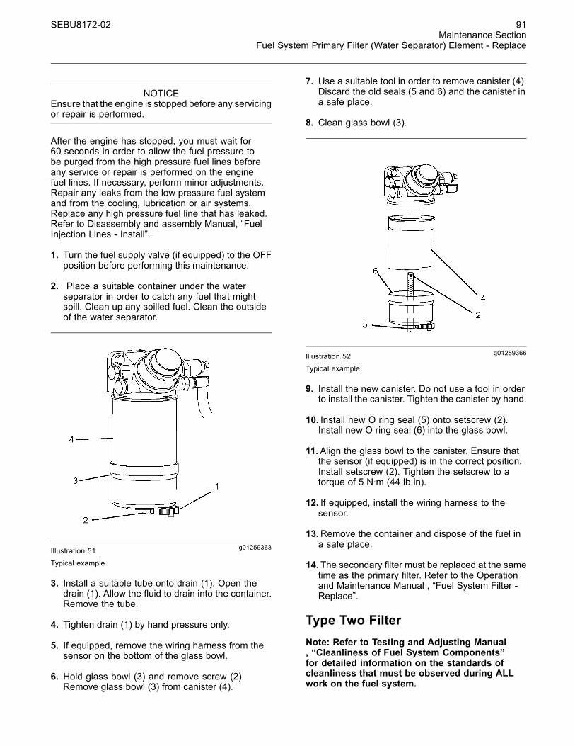
SEBU8172-02 91Maintenance Section
Fuel System Primary Filter (Water Separator) Element - Replace
NOTICEEnsure that the engine is stopped before any servicingor repair is performed.
After the engine has stopped, you must wait for60 seconds in order to allow the fuel pressure tobe purged from the high pressure fuel lines beforeany service or repair is performed on the enginefuel lines. If necessary, perform minor adjustments.Repair any leaks from the low pressure fuel systemand from the cooling, lubrication or air systems.Replace any high pressure fuel line that has leaked.Refer to Disassembly and assembly Manual, “FuelInjection Lines - Install”.
1. Turn the fuel supply valve (if equipped) to the OFFposition before performing this maintenance.
2. Place a suitable container under the waterseparator in order to catch any fuel that mightspill. Clean up any spilled fuel. Clean the outsideof the water separator.
g01259363Illustration 51Typical example
3. Install a suitable tube onto drain (1). Open thedrain (1). Allow the fluid to drain into the container.Remove the tube.
4. Tighten drain (1) by hand pressure only.
5. If equipped, remove the wiring harness from thesensor on the bottom of the glass bowl.
6. Hold glass bowl (3) and remove screw (2).Remove glass bowl (3) from canister (4).
7. Use a suitable tool in order to remove canister (4).Discard the old seals (5 and 6) and the canister ina safe place.
8. Clean glass bowl (3).
g01259366Illustration 52Typical example
9. Install the new canister. Do not use a tool in orderto install the canister. Tighten the canister by hand.
10. Install new O ring seal (5) onto setscrew (2).Install new O ring seal (6) into the glass bowl.
11.Align the glass bowl to the canister. Ensure thatthe sensor (if equipped) is in the correct position.Install setscrew (2). Tighten the setscrew to atorque of 5 N·m (44 lb in).
12. If equipped, install the wiring harness to thesensor.
13.Remove the container and dispose of the fuel ina safe place.
14. The secondary filter must be replaced at the sametime as the primary filter. Refer to the Operationand Maintenance Manual , “Fuel System Filter -Replace”.
Type Two FilterNote: Refer to Testing and Adjusting Manual, “Cleanliness of Fuel System Components”for detailed information on the standards ofcleanliness that must be observed during ALLwork on the fuel system.

92 SEBU8172-02Maintenance SectionFuel System Primary Filter (Water Separator) Element - Replace
After the engine has stopped, you must wait for60 seconds in order to allow the fuel pressure tobe purged from the high pressure fuel lines beforeany service or repair is performed on the enginefuel lines. If necessary, perform minor adjustments.Repair any leaks from the low pressure fuel systemand from the cooling, lubrication or air systems.Replace any high pressure fuel line that has leaked.Refer to Disassembly and assembly Manual, “FuelInjection Lines - Install”.
NOTICEEnsure that the engine is stopped before any servicingor repair is performed.
1. Turn the fuel supply valve (if equipped) to the OFFposition before performing this maintenance.
2. Place a suitable container under the waterseparator in order to catch any fuel that mightspill. Clean up any spilled fuel. Clean the outsideof the water separator.
g01429124Illustration 53
3. Install a suitable tube onto drain (1). Open drain(1). Allow the fluid to drain into the container.Remove the tube.
4. Tighten drain (1) by hand pressure only.
5. If equipped, remove the wiring harness from thesensor on the bottom of the bowl .
g01429125Illustration 54
6. Rotate bowl (3) counterclockwise in order toremove the bowl. Remove O ring seal (2). Cleanthe bowl.
g01429126Illustration 55

SEBU8172-02 93Maintenance Section
Fuel System Primary Filter/Water Separator - Drain
7. Use a suitable tool in order to remove old canister(4).
g01429127Illustration 56
8. Lubricate O ring seal (5 ) with clean engine oil onthe new canister. Install new canister (6). Spinon the canister until the O ring seal contacts thesealing surface. Then rotate the canister 360degree in order to tighten the canister correctly.
9. Remove cap (8) from the threaded end of the newcanister and remove new O ring seal (7). Installthe new O ring seal into bowl (3).
10. Lubricate O ring seal (7) with clean engine oil.Install the bowl onto the new canister. Tighten thebowl to 15 N·m (11 lb ft).
11. If equipped, install the wiring harness to thesensor. Open the fuel supply valve.
12.Remove the container and dispose of the fluid ina safe place.
13. The secondary filter must be replaced at the sametime as the primary filter. Refer to the Operationand Maintenance Manual , “Fuel System Filter -Replace”.
i02869410
Fuel System PrimaryFilter/Water Separator - Drain
Fuel leaked or spilled onto hot surfaces or elec-trical components can cause a fire. To help pre-vent possible injury, turn the start switch off whenchanging fuel filters or water separator elements.Clean up fuel spills immediately.
NOTICEEnsure that the engine is stopped before any servicingor repair is performed.
After the engine has stopped, you must wait for60 seconds in order to allow the fuel pressure tobe purged from the high pressure fuel lines beforeany service or repair is performed on the enginefuel lines. If necessary, perform minor adjustments.Repair any leaks from the low pressure fuel systemand from the cooling, lubrication or air systems.Replace any high pressure fuel line that has leaked.Refer to Disassembly and Assembly Manual, “FuelInjection Lines - Install”.
NOTICEThe water separator can be under suction during nor-mal engine operation. Ensure that the drain valve istightened securely to help prevent air from enteringthe fuel system.
1. Place a suitable container under the waterseparator in order to catch any fuel that might spill.Clean up any spilled fuel.

94 SEBU8172-02Maintenance SectionFuel System Secondary Filter - Replace
g01476633Illustration 57Typical example
2. Install a suitable tube onto the drain (1). Open thedrain (1). Allow the fluid to drain into the container.
3. Tighten the drain (1) by hand pressure only.Remove the tube and dispose of the drained fluidin a safe place.
Primary Filter with a Vent Screw
g01371846Illustration 58Typical example
Note: Not all primary filters require vent screw (2).This primary fuel filter that has a vent screw may beinstalled on a fuel system that has a low fuel tank.
1. Install a suitable tube onto drain (1). Loosen ventscrew (2).
2. Open drain (1). Allow the fluid to drain into thecontainer.
3. Tighten drain (1) by hand pressure only. Removethe tube and dispose of the drained fluid in a safeplace.
4. Tighten vent screw to 6 N·m (53 lb in).
i02869989
Fuel System Secondary Filter -Replace
Type One
Fuel leaked or spilled onto hot surfaces or elec-trical components can cause a fire. To help pre-vent possible injury, turn the start switch off whenchanging fuel filters or water separator elements.Clean up fuel spills immediately.
Note: Refer to Testing and Adjusting Manual, “Cleanliness of Fuel System Components”for detailed information on the standards ofcleanliness that must be observed during ALLwork on the fuel system.
NOTICEEnsure that the engine is stopped before any servicingor repair is performed.
This fuel filter can be identified by the six drain holesin the filter. Refer to illustration 59.

SEBU8172-02 95Maintenance Section
Fuel System Secondary Filter - Replace
g01429525Illustration 59Typical example
After the engine has stopped, you must wait for60 seconds in order to allow the fuel pressure tobe purged from the high pressure fuel lines beforeany service or repair is performed on the enginefuel lines. If necessary, perform minor adjustments.Repair any leaks from the low pressure fuel systemand from the cooling, lubrication or air systems.Replace any high pressure fuel line that has leaked.Refer to Disassembly and Assembly Manual, “FuelInjection Lines - Install”.
1. Ensure that the fuel supply valve (if equipped) is inthe OFF position. Place a suitable container underthe fuel filter in order to catch any fuel that mightspill. Clean up any spilled fuel.
g01429517Illustration 60Typical example
2. Clean the outside of the fuel filter. Use a suitabletool in order to remove the canister (2) from theengine and dispose of the canister in a safe place.
3. Ensure that dirt can not enter the new canister. Donot fill the canister with fuel before the canister isinstalled. Lubricate the O ring seal (1) with cleanengine oil on the new canister.
4. Install the new canister. Do not use a tool in orderto install the canister. Tighten the canister by hand.
5. Spin on the canister until the O ring seal contactsthe sealing surface. The canister will require a ¾ ofa full turn in order to tighten the canister correctly.
6. Prime the fuel system. Refer to the Operation andMaintenance Manual, “Fuel System - Prime” formore information.
Type Two
Fuel leaked or spilled onto hot surfaces or elec-trical components can cause a fire. To help pre-vent possible injury, turn the start switch off whenchanging fuel filters or water separator elements.Clean up fuel spills immediately.
Note: Refer to Testing and Adjusting Manual, “Cleanliness of Fuel System Components”for detailed information on the standards ofcleanliness that must be observed during ALLwork on the fuel system.

96 SEBU8172-02Maintenance SectionFuel System Secondary Filter - Replace
NOTICEEnsure that the engine is stopped before any servicingor repair is performed.
g01429532Illustration 61
This fuel filter can be identified by the 12 drain holesin the filter. Refer to illustration 61.
After the engine has stopped, you must wait for60 seconds in order to allow the fuel pressure tobe purged from the high pressure fuel lines beforeany service or repair is performed on the enginefuel lines. If necessary, perform minor adjustments.Repair any leaks from the low pressure fuel systemand from the cooling, lubrication or air systems.Replace any high pressure fuel line that has leaked.Refer to Disassembly and Assembly Manual, “FuelInjection Lines - Install”.
1. Ensure that the fuel supply valve (if equipped) is inthe OFF position. Place a suitable container underthe fuel filter in order to catch any fuel that mightspill. Clean up any spilled fuel.
g01429516Illustration 62Typical example
2. Clean the outside of the fuel filter. Use a suitabletool in order to remove the canister (2) from theengine and dispose of the canister in a safe place.
3. Ensure that dirt can not enter the new canister. Donot fill the canister with fuel before the canister isinstalled. Lubricate the O ring seal (1) with cleanengine oil on the new canister.
4. Install the new canister. Do not use a tool in orderto install the canister. Tighten the canister by hand.
5. Spin on the canister until the O ring seal contactsthe sealing surface. Then rotate the canister 360degree in order to tighten the canister correctly.
6. Remove the container and dispose of the fuel in asafe place. If equipped, open the fuel supply valve.
7. Prime the fuel system. Refer to the Operation andMaintenance Manual, “Fuel System - Prime” formore information.

SEBU8172-02 97Maintenance Section
Fuel Tank Water and Sediment - Drain
i02335436
Fuel Tank Water and Sediment- Drain
NOTICECare must be taken to ensure that fluids are containedduring performance of inspection, maintenance, test-ing, adjusting, and repair of the product. Be preparedto collect the fluid with suitable containers beforeopening any compartment or disassembling any com-ponent containing fluids.
Dispose of all fluids according to local regulations andmandates.
Fuel TankFuel quality is critical to the performance and to theservice life of the engine. Water in the fuel can causeexcessive wear to the fuel system.
Water can be introduced into the fuel tank when thefuel tank is being filled.
Condensation occurs during the heating and coolingof fuel. The condensation occurs as the fuel passesthrough the fuel system and the fuel returns to thefuel tank. This causes water to accumulate in fueltanks. Draining the fuel tank regularly and obtainingfuel from reliable sources can help to eliminate waterin the fuel.
Drain the Water and the SedimentFuel tanks should contain some provision for drainingwater and draining sediment from the bottom of thefuel tanks.
Open the drain valve on the bottom of the fuel tankin order to drain the water and the sediment. Closethe drain valve.
Check the fuel daily. Allow five minutes after thefuel tank has been filled before draining water andsediment from the fuel tank.
Fill the fuel tank after operating the engine inorder to drive out moist air. This will help preventcondensation. Do not fill the tank to the top. Thefuel expands as the fuel gets warm. The tank mayoverflow.
Some fuel tanks use supply pipes that allow waterand sediment to settle below the end of the fuelsupply pipe. Some fuel tanks use supply lines thattake fuel directly from the bottom of the tank. Ifthe engine is equipped with this system, regularmaintenance of the fuel system filter is important.
Fuel Storage TanksDrain the water and the sediment from the fuelstorage tank at the following intervals:
• Weekly
• Service intervals
• Refill of the tank
This will help prevent water or sediment from beingpumped from the storage tank into the engine fueltank.
If a bulk storage tank has been refilled or movedrecently, allow adequate time for the sediment tosettle before filling the engine fuel tank. Internalbaffles in the bulk storage tank will also help trapsediment. Filtering fuel that is pumped from thestorage tank helps to ensure the quality of the fuel.When possible, water separators should be used.
i02349879
Hoses and Clamps -Inspect/Replace
Contact with high pressure fuel may cause fluidpenetration and burn hazards. High pressure fu-el spray may cause a fire hazard. Failure to fol-low these inspection, maintenance and service in-structions may cause personal injury or death.
If you inspect the engine in operation, always usethe proper inspection procedure in order to avoida fluid penetration hazard. Refer to Operation andMaintenance Manual, “General hazard Information”.
Inspect all hoses for leaks that are caused by thefollowing conditions:
• Cracking
• Softness
• Loose clamps

98 SEBU8172-02Maintenance SectionRadiator - Clean
Replace hoses that are cracked or soft. Tighten anyloose clamps.
Check for the following conditions:
• End fittings that are damaged or leaking
• Outer covering that is chafed or cut
• Exposed wire that is used for reinforcement
• Outer covering that is ballooning locally
• Flexible part of the hose that is kinked or crushed
• Armoring that is embedded in the outer covering
A constant torque hose clamp can be used in placeof any standard hose clamp. Ensure that the constanttorque hose clamp is the same size as the standardclamp.
Due to extreme temperature changes, the hose willharden. Hardening of the hoses will cause hoseclamps to loosen. This can result in leaks. A constanttorque hose clamp will help to prevent loose hoseclamps.
Each installation application can be different. Thedifferences depend on the following factors:
• Type of hose
• Type of fitting material
• Anticipated expansion and contraction of the hose
• Anticipated expansion and contraction of thefittings
Replace the Hoses and the ClampsRefer to the OEM information for further informationon removing and replacing fuel hoses (if equipped).
The coolant system and the hoses for the coolantsystem are not usually supplied by Perkins. Thefollowing text describes a typical method of replacingcoolant hoses. Refer to the OEM information forfurther information on the coolant system and thehoses for the coolant system.
Pressurized System: Hot coolant can cause seri-ous burns. To open the cooling system filler cap,stop the engine and wait until the cooling systemcomponents are cool. Loosen the cooling systempressure cap slowly in order to relieve the pres-sure.
1. Stop the engine. Allow the engine to cool.
2. Loosen the cooling system filler cap slowly inorder to relieve any pressure. Remove the coolingsystem filler cap.
Note: Drain the coolant into a suitable, cleancontainer. The coolant can be reused.
3. Drain the coolant from the cooling system to alevel that is below the hose that is being replaced.
4. Remove the hose clamps.
5. Disconnect the old hose.
6. Replace the old hose with a new hose.
7. Install the hose clamps with a torque wrench.
Note: For the correct coolant, see this Operation andMaintenance Manual, “Fluid Recommendations”.
8. Refill the cooling system. Refer to the OEMinformation for further information on refilling thecooling system.
9. Clean the cooling system filler cap. Inspect thecooling system filler cap's seals. Replace thecooling system filler cap if the seals are damaged.Install the cooling system filler cap.
10.Start the engine. Inspect the cooling system forleaks.
i02335774
Radiator - Clean
The radiator is not usually supplied by Perkins. Thefollowing text describes a typical cleaning procedurefor the radiator. Refer to the OEM information forfurther information on cleaning the radiator.
Note: Adjust the frequency of cleaning according tothe effects of the operating environment.
Inspect the radiator for these items: Damaged fins,corrosion, dirt, grease, insects, leaves, oil, and otherdebris. Clean the radiator, if necessary.
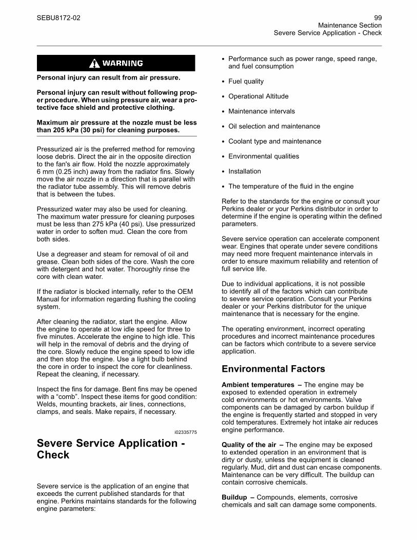
SEBU8172-02 99Maintenance Section
Severe Service Application - Check
Personal injury can result from air pressure.
Personal injury can result without following prop-er procedure.When using pressure air, wear a pro-tective face shield and protective clothing.
Maximum air pressure at the nozzle must be lessthan 205 kPa (30 psi) for cleaning purposes.
Pressurized air is the preferred method for removingloose debris. Direct the air in the opposite directionto the fan's air flow. Hold the nozzle approximately6 mm (0.25 inch) away from the radiator fins. Slowlymove the air nozzle in a direction that is parallel withthe radiator tube assembly. This will remove debristhat is between the tubes.
Pressurized water may also be used for cleaning.The maximum water pressure for cleaning purposesmust be less than 275 kPa (40 psi). Use pressurizedwater in order to soften mud. Clean the core fromboth sides.
Use a degreaser and steam for removal of oil andgrease. Clean both sides of the core. Wash the corewith detergent and hot water. Thoroughly rinse thecore with clean water.
If the radiator is blocked internally, refer to the OEMManual for information regarding flushing the coolingsystem.
After cleaning the radiator, start the engine. Allowthe engine to operate at low idle speed for three tofive minutes. Accelerate the engine to high idle. Thiswill help in the removal of debris and the drying ofthe core. Slowly reduce the engine speed to low idleand then stop the engine. Use a light bulb behindthe core in order to inspect the core for cleanliness.Repeat the cleaning, if necessary.
Inspect the fins for damage. Bent fins may be openedwith a “comb”. Inspect these items for good condition:Welds, mounting brackets, air lines, connections,clamps, and seals. Make repairs, if necessary.
i02335775
Severe Service Application -Check
Severe service is the application of an engine thatexceeds the current published standards for thatengine. Perkins maintains standards for the followingengine parameters:
• Performance such as power range, speed range,and fuel consumption
• Fuel quality
• Operational Altitude
• Maintenance intervals
• Oil selection and maintenance
• Coolant type and maintenance
• Environmental qualities
• Installation
• The temperature of the fluid in the engine
Refer to the standards for the engine or consult yourPerkins dealer or your Perkins distributor in order todetermine if the engine is operating within the definedparameters.
Severe service operation can accelerate componentwear. Engines that operate under severe conditionsmay need more frequent maintenance intervals inorder to ensure maximum reliability and retention offull service life.
Due to individual applications, it is not possibleto identify all of the factors which can contributeto severe service operation. Consult your Perkinsdealer or your Perkins distributor for the uniquemaintenance that is necessary for the engine.
The operating environment, incorrect operatingprocedures and incorrect maintenance procedurescan be factors which contribute to a severe serviceapplication.
Environmental FactorsAmbient temperatures – The engine may beexposed to extended operation in extremelycold environments or hot environments. Valvecomponents can be damaged by carbon buildup ifthe engine is frequently started and stopped in verycold temperatures. Extremely hot intake air reducesengine performance.
Quality of the air – The engine may be exposedto extended operation in an environment that isdirty or dusty, unless the equipment is cleanedregularly. Mud, dirt and dust can encase components.Maintenance can be very difficult. The buildup cancontain corrosive chemicals.
Buildup – Compounds, elements, corrosivechemicals and salt can damage some components.

100 SEBU8172-02Maintenance SectionStarting Motor - Inspect
Altitude – Problems can arise when the engine isoperated at altitudes that are higher than the intendedsettings for that application. Necessary adjustmentsshould be made.
Incorrect Operating Procedures• Extended operation at low idle
• Frequent hot shutdowns
• Operating at excessive loads
• Operating at excessive speeds
• Operating outside the intended application
Incorrect Maintenance Procedures• Extending the maintenance intervals
• Failure to use recommended fuel, lubricants andcoolant/antifreeze
i02177969
Starting Motor - Inspect
Perkins recommends a scheduled inspection of thestarting motor. If the starting motor fails, the enginemay not start in an emergency situation.
Check the starting motor for correct operation. Checkthe electrical connections and clean the electricalconnections. Refer to the Systems Operation, Testingand Adjusting Manual, “Electric Starting System -Test” for more information on the checking procedureand for specifications or consult your Perkins dealeror your Perkins distributor for assistance.
i04149590
Turbocharger - Inspect
A regular visual inspection of the turbocharger isrecommended. If the turbocharger fails during engineoperation, damage to the turbocharger compressorwheel and/or to the engine may occur. Damage to theturbocharger compressor wheel can cause additionaldamage to the pistons, the valves, and the cylinderhead.
NOTICETurbocharger bearing failures can cause large quanti-ties of oil to enter the air intake and exhaust systems.Loss of engine lubricant can result in serious enginedamage.
Minor leakage of oil into a turbocharger under extend-ed low idle operation should not cause problems aslong as a turbocharger bearing failure has not oc-cured.
When a turbocharger bearing failure is accompaniedby a significant engine performance loss (exhaustsmoke or engine rpm up at no load), do not continueengine operation until the turbocharger is renewed.
A visual inspection of the turbocharger can minimizeunscheduled downtime. A visual inspection of theturbocharger can also reduce the chance for potentialdamage to other engine parts.
Removal and InstallationFor options regarding the removal, installation,and replacement, consult your Perkins dealer oryour Perkins distributor. Refer to the Disassemblyand Assembly, “Turbocharger - Remove andTurbocharger - Install” and Systems Operation,Testing and Adjusting, “Turbocharger - Inspect” forfurther information.
Inspecting
NOTICEThe compressor housing for the turbocharger mustnot be removed from the turbocharger for inspectionor removed for the cleaning of the compressor.
1. Remove the pipe from the turbocharger exhaustoutlet and remove the air intake pipe to theturbocharger. Visually inspect the piping for thepresence of oil. Clean the interior of the pipesin order to prevent dirt from entering duringreassembly.
2. Check for obvious heat discoloration of theturbocharger. Check for any loose bolts or anymissing bolts. Check for damage to the oil supplyline and the oil drain line. Check for cracks inthe housing of the turbocharger. Ensure that thecompressor wheel can rotate freely.
3. Check for the presence of oil. If oil is leaking fromthe back side of the compressor wheel, there is apossibility of a failed turbocharger oil seal.

SEBU8172-02 101Maintenance Section
V-Belts - Inspect/Adjust/Replace
The presence of oil may be the result of extendedengine operation at low idle. The presence of oilmay also be the result of a restriction of the linefor the intake air (clogged air filters), which causesthe turbocharger to slobber.
4. Inspect the bore of the housing of the turbineoutlet for corrosion.
5. Fasten the air intake pipe and the exhaust outletpipe to the turbocharger housing. Ensure that allclamps are installed correctly and that all clampsare tightened securely.
i02866087
V-Belts - Inspect/Adjust/Replace
Inspection
g01249073Illustration 63
Arrangement for the V-belts
To maximize the engine performance, inspect thebelts for wear and for cracking. Replace belts that areworn or damaged.
For applications that require multiple drive belts,replace the belts in matched sets. Replacing onlyone belt of a matched set will cause the new belt tocarry more load because the older belt is stretched.The additional load on the new belt could cause thenew belt to break.
If the belts are too loose, vibration causesunnecessary wear on the belts and pulleys. Loosebelts may slip enough to cause overheating.
To accurately check the belt tension, a suitable gaugeshould be used.
g01003936Illustration 64Typical example(1) Belt tension gauge
Fit the gauge (1) at the center of the longest freelength and check the tension. The correct tension fora used belt is 355 N (79.8 lb). If the tension of thebelt is below 250 N (56 lb) adjust the belt to 355 N(79.8 lb).
Note: The correct tension for a new belt or new beltsis 535 N (120 lb). A higher tension is required inorder to compensate for the stretch that is in a newbelt. Only use the higher tension on a belt that hasnot been used. A used belt is a belt that has been inoperation for 30 minutes or a longer period of time.
If twin belts are installed, check and adjust thetension on both belts.

102 SEBU8172-02Maintenance SectionWalk-Around Inspection
Adjustment
g01427780Illustration 65Typical example
1. Loosen nut (2) and the bolt (3).
2. Move the alternator in order to increase ordecrease the belt tension. Tighten the nut (2) andthe bolt (3) to 22 N·m (16 lb ft).(1).
ReplaceRefer to Disassembly and Assembly manual, “V-Belts - Remove and Install” for more information.
i03577563
Walk-Around Inspection
Inspect the Tube of the CrankcaseBreather
g01905095Illustration 66
Inspect the breather tube (1) for damage. Ensure thatthe outlet (2) is clean and free from any obstructions.Ice can cause obstructions in adverse weatherconditions.
Inspect the Engine for Leaks andfor Loose ConnectionsA walk-around inspection should only take a fewminutes. When the time is taken to perform thesechecks, costly repairs and accidents can be avoided.
For maximum engine service life, make a thoroughinspection of the engine compartment before startingthe engine. Look for items such as oil leaks or coolantleaks, loose bolts, worn belts, loose connections andtrash buildup. Make repairs, as needed:
• The guards must be in the correct place. Repairdamaged guards or replace missing guards.
• Wipe all caps and plugs before the engine isserviced in order to reduce the chance of systemcontamination.

SEBU8172-02 103Maintenance Section
Walk-Around Inspection
NOTICEFor any type of leak (coolant, lube, or fuel) clean up thefluid. If leaking is observed, find the source and correctthe leak. If leaking is suspected, check the fluid levelsmore often than recommended until the leak is foundor fixed, or until the suspicion of a leak is proved to beunwarranted.
NOTICEAccumulated grease and/or oil on an engine is a firehazard. Remove the accumulated grease and oil. Re-fer to this Operation and Maintenance Manual, “En-gine - Clean” for more information.
• Ensure that the cooling system hoses are correctlyclamped and that the cooling system hoses aretight. Check for leaks. Check the condition of allpipes.
• Inspect the water pump for coolant leaks.
Note: The water pump seal is lubricated by thecoolant in the cooling system. It is normal for a smallamount of leakage to occur as the engine cools downand the parts contract.
Excessive coolant leakage may indicate the need toreplace the water pump. Remove the water pump.Refer to Disassembly and Assembly , “Water Pump -Remove and Install”. For more information, consultyour Perkins dealer or your Perkins distributor.
• Inspect the lubrication system for leaks at the frontcrankshaft seal, the rear crankshaft seal, the oilpan, the oil filters and the rocker cover.
• Inspect the piping for the air intake system and theelbows for cracks and for loose clamps. Ensurethat hoses and tubes are not contacting otherhoses, tubes, wiring harnesses, etc.
• Ensure that the areas around the rotating parts areclear.
• Inspect the alternator belts and any accessorydrive belts for cracks, breaks or other damage.
• Inspect the wiring harness for damage.
Belts for multiple groove pulleys must be replaced asmatched sets. If only one belt is replaced, the belt willcarry more load than the belts that are not replaced.The older belts are stretched. The additional load onthe new belt could cause the belt to break.
High Pressure Fuel Lines
Contact with high pressure fuel may cause fluidpenetration and burn hazards. High pressure fu-el spray may cause a fire hazard. Failure to fol-low these inspection, maintenance and service in-structions may cause personal injury or death.
After the engine has stopped, you must wait for10 minutes in order to allow the fuel pressure tobe purged from the high pressure fuel lines beforeany service or repair is performed on the enginefuel lines. If necessary, perform minor adjustments.Repair any leaks from the low pressure fuel systemand from the cooling, lubrication or air systems.Replace any high pressure fuel line that has leaked.Refer to Disassembly and assembly Manual, “FuelInjection Lines - Install”.
If you inspect the engine in operation, always usethe proper inspection procedure in order to avoida fluid penetration hazard. Refer to Operation andMaintenance Manual, “General hazard Information”.
Visually inspect the high pressure fuel lines fordamage or signs of fuel leakage. Replace anydamaged high pressure fuel lines or high pressurefuel lines that have leaked.
Ensure that all clips on the high pressure fuel linesare in place and that the clips are not loose.
• Inspect the rest of the fuel system for leaks. Lookfor loose fuel line clamps.
• Drain the water and the sediment from the fueltank on a daily basis in order to ensure that onlyclean fuel enters the fuel system.
• Inspect the wiring and the wiring harnesses forloose connections and for worn wires or frayedwires. Check for any loose tie-wraps or missingtie-wraps.
• Inspect the ground strap for a good connection andfor good condition.
• Disconnect any battery chargers that are notprotected against the current drain of the startingmotor. Check the condition and the electrolyte levelof the batteries, unless the engine is equipped witha maintenance free battery.
• Check the condition of the gauges. Replace anygauges that are cracked. Replace any gauge thatcan not be calibrated.
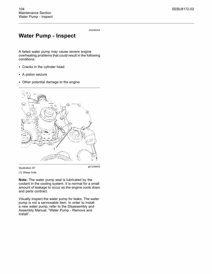
104 SEBU8172-02Maintenance SectionWater Pump - Inspect
i02499304
Water Pump - Inspect
A failed water pump may cause severe engineoverheating problems that could result in the followingconditions:
• Cracks in the cylinder head
• A piston seizure
• Other potential damage to the engine
g01249453Illustration 67(1) Weep hole
Note: The water pump seal is lubricated by thecoolant in the cooling system. It is normal for a smallamount of leakage to occur as the engine cools downand parts contract.
Visually inspect the water pump for leaks. The waterpump is not a serviceable item. In order to installa new water pump, refer to the Disassembly andAssembly Manual, “Water Pump - Remove andInstall”.

SEBU8172-02 105Warranty Section
Warranty Information
Warranty Section
Warranty Informationi01903596
Emissions WarrantyInformation
This engine may be certified to comply with exhaustemission standards and gaseous emission standardsthat are prescribed by the law at the time ofmanufacture, and this engine may be covered by anEmissions Warranty. Consult your authorized Perkinsdealer or your authorized Perkins distributor in orderto determine if your engine is emissions certified andif your engine is subject to an Emissions Warranty.

106 SEBU8172-02Index Section
Index
A
After Starting Engine ............................................. 42After Stopping Engine............................................ 44Aftercooler Core - Clean/Test ................................ 70Aftercooler Core - Inspect...................................... 70Alternator - Inspect ................................................ 71Alternator Belt - Inspect/Adjust/Replace (PolyV-Belt).................................................................. 71Adjustment ......................................................... 71Inspection........................................................... 71Replace.............................................................. 71
B
Battery - Replace................................................... 71Battery Electrolyte Level - Check .......................... 72Battery or Battery Cable - Disconnect ................... 72Before Starting Engine .................................... 15, 40Belt Tensioner - Inspect ......................................... 73Burn Prevention..................................................... 10Batteries............................................................. 10Coolant............................................................... 10Oils..................................................................... 10
C
Cold Weather Operation........................................ 46Hints for Cold Weather Operation...................... 46Idling the Engine ................................................ 47Recommendations for Coolant Warm Up .......... 47Recommendations for the Coolant .................... 46Viscosity of the Engine Lubrication Oil............... 46
Cold Weather Starting ........................................... 40Cooling System Coolant (Commercial Heavy-Duty) -Change ................................................................ 73Drain .................................................................. 73Fill ...................................................................... 74Flush .................................................................. 74
Cooling System Coolant (ELC) - Change.............. 75Drain .................................................................. 75Fill ...................................................................... 76Flush .................................................................. 76
Cooling System Coolant Level - Check ................. 77Engines With a Coolant Recovery Tank............. 77Engines Without a Coolant Recovery Tank........ 77
Cooling System Supplemental Coolant Additive(SCA) - Test/Add.................................................. 78Add the SCA, If Necessary ................................ 78Test for SCA Concentration ............................... 78
Crankcase Breather (Canister) - Replace ............. 79Crushing Prevention and Cutting Prevention ........ 13
D
Diagnostic Flash Code Retrieval ........................... 36“Diagnostic” Lamp.............................................. 36
Diagnostic Lamp.................................................... 36Driven Equipment - Check..................................... 79
E
Electrical System................................................... 16Grounding Practices .......................................... 16
Emergency Stopping ............................................. 44Emissions Certification Film .................................. 24Emissions Warranty Information.......................... 105Engine - Clean....................................................... 79Engine Air Cleaner Element (Dual Element) -Clean/Replace ..................................................... 80Cleaning the Primary Air Cleaner Elements ...... 81Servicing the Air Cleaner Elements ................... 80
Engine Air Cleaner Service Indicator - Inspect...... 82Test the Service Indicator................................... 82
Engine Air Precleaner - Check/Clean.................... 83Engine Description ................................................ 20Electronic Engine Features................................ 21Engine Cooling and Lubrication ......................... 21Engine Diagnostics ............................................ 21Engine Specifications......................................... 20
Engine Diagnostics................................................ 36Engine Electronics................................................. 17Engine Lifting......................................................... 25Engine Mounts - Inspect........................................ 83Engine Oil and Filter - Change .............................. 84Drain the Engine Lubricating Oil ........................ 85Fill the Oil Pan.................................................... 86Horizontal Oil Filter ............................................ 86Replace the Oil Filter ......................................... 85
Engine Oil and Filter - Change (CG-4 Oil)............. 87Engine Oil Level - Check....................................... 83Engine Oil Sample - Obtain ................................... 84Obtain the Sample and the Analysis.................. 84
Engine Operation................................................... 43Engine Operation with Active Diagnostic Codes ... 39Engine Operation with Intermittent DiagnosticCodes .................................................................. 39Engine Shutoffs and Engine Alarms...................... 34Alarms................................................................ 34Shutoffs.............................................................. 34Testing................................................................ 35
Engine Starting ................................................ 15, 40Engine Stopping .............................................. 16, 44Engine Storage...................................................... 25Engine Valve Lash - Inspect/Adjust ....................... 87Exhaust Manifold - Inspect .................................... 87

SEBU8172-02 107Index Section
F
Fan Clearance - Check.......................................... 88Fault Logging......................................................... 38Features and Controls ........................................... 29Fire Prevention and Explosion Prevention ............. 11Fire Extinguisher ................................................ 12Lines, Tubes, and Hoses ................................... 12
Fluid Recommendations........................................ 51Engine Oil .......................................................... 51General Lubricant Information ........................... 51
Fluid Recommendations (Coolant Specifications).. 61ELC Cooling System Maintenance .................... 64General Coolant Information.............................. 61
Fluid Recommendations (Fuel Specification) ........ 55Diesel Fuel Characteristics ................................ 57Diesel Fuel Requirements.................................. 55General Information ........................................... 55
Foreword ................................................................. 5California Proposition 65 Warning ....................... 5Literature Information........................................... 4Maintenance ........................................................ 4Maintenance Intervals.......................................... 4Operation ............................................................. 4Overhaul .............................................................. 4Safety................................................................... 4
Fuel and the Effect from Cold Weather ................. 48Fuel Conservation Practices.................................. 43Fuel Related Components in Cold Weather .......... 49Fuel Filters ......................................................... 49Fuel Heaters ...................................................... 49Fuel Tanks.......................................................... 49
Fuel System - Prime.............................................. 89Hand Fuel Priming Pump................................... 90
Fuel System Primary Filter (Water Separator)Element - Replace ............................................... 90Type One Filter .................................................. 90Type Two Filter................................................... 91
Fuel System Primary Filter/Water Separator -Drain .................................................................... 93Primary Filter with a Vent Screw ........................ 94
Fuel System Secondary Filter - Replace............... 94Type One ........................................................... 94Type Two ........................................................... 95
Fuel Tank Water and Sediment - Drain ................. 97Drain the Water and the Sediment..................... 97Fuel Storage Tanks............................................ 97Fuel Tank ........................................................... 97
G
Gauges and Indicators .......................................... 27General Hazard Information .................................... 9Containing Fluid Spillage ................................... 10Fluid Penetration.................................................. 9Pressure Air and Water........................................ 9
H
High Pressure Fuel Lines ...................................... 13Hoses and Clamps - Inspect/Replace ................... 97Replace the Hoses and the Clamps .................. 98
I
Important Safety Information ................................... 2
L
Lifting and Storage ................................................ 25
M
Maintenance Interval Schedule ............................. 69Maintenance Recommendations........................... 67Maintenance Section............................................. 50Model View Illustrations......................................... 18Model Views .......................................................... 18Monitoring System........................................... 29–30Programmable Options and SystemsOperation ......................................................... 29
Mounting and Dismounting.................................... 13
O
Operation Section.................................................. 25Overspeed............................................................. 35
P
Plate Locations and Film Locations....................... 23Serial Number Plate (1) ..................................... 23
Product Identification Information .......................... 23Product Information Section .................................. 18
R
Radiator - Clean .................................................... 98Reference Numbers .............................................. 23Record for Reference......................................... 23
Refill Capacities..................................................... 50Cooling System.................................................. 50Lubrication System ............................................ 50
S
Safety Messages..................................................... 6(1) Universal Warning .......................................... 6(2) Hand (High Pressure)..................................... 7(3) Ether ............................................................... 8
Safety Section ......................................................... 6
108 SEBU8172-02Index Section
Self-Diagnostics..................................................... 36Sensors and Electrical Components ..................... 30Coolant Temperature Sensor 1 .......................... 33Electronic Control Module 5............................... 33Engine Oil Pressure Sensor 8............................ 34Failure of Sensors.............................................. 32Fuel Pressure Sensor 4 ..................................... 33Intake Manifold Air Temperature Sensor 2......... 33Intake Manifold Pressure Sensor 3.................... 33Primary Speed/Timing Sensor 6 ........................ 33Programmable Monitoring System (PMS) ......... 32Secondary Speed/Timing Sensor 7 ................... 33Sensor Locations ............................................... 30
Severe Service Application - Check ...................... 99Environmental Factors ....................................... 99Incorrect Maintenance Procedures.................. 100Incorrect Operating Procedures....................... 100
Starting Motor - Inspect ....................................... 100Starting the Engine................................................ 40Starting the Engine ............................................ 40
Starting with Jump Start Cables ............................ 41Stopping the Engine .............................................. 44
T
Table of Contents..................................................... 3Turbocharger - Inspect ........................................ 100Inspecting......................................................... 100Removal and Installation.................................. 100
V
V-Belts - Inspect/Adjust/Replace......................... 101Adjustment ....................................................... 102Inspection......................................................... 101Replace............................................................ 102
W
Walk-Around Inspection ...................................... 102High Pressure Fuel Lines................................. 103Inspect the Engine for Leaks and for LooseConnections ................................................... 102Inspect the Tube of the Crankcase Breather ... 102
Warranty Information ........................................... 105Warranty Section ................................................. 105Water Pump - Inspect.......................................... 104Welding on Engines with Electronic Controls ........ 67

Product and Dealer InformationNote: For product identification plate locations, see the section “Product Identification Information” in the Operationand Maintenance Manual.
Delivery Date:
Product InformationModel:
Product Identification Number:
Engine Serial Number:
Transmission Serial Number:
Generator Serial Number:
Attachment Serial Numbers:
Attachment Information:
Customer Equipment Number:
Dealer Equipment Number:
Dealer InformationName: Branch:
Address:
Dealer Contact Phone Number Hours
Sales:
Parts:
Service:

©2012 Perkins Engines Company LimitedAll Rights Reserved