sec 2 chap 1
TRANSCRIPT

CHAPTER 1
DESCRIPTIONCHAPTER 1
DESCRIPTION
SIGMA TANDEM SYSTEM OWNER’S MANUAL
Page 2:X Section 2: Equipment • Chapter 1 - Description 11301 - 00.00.0000
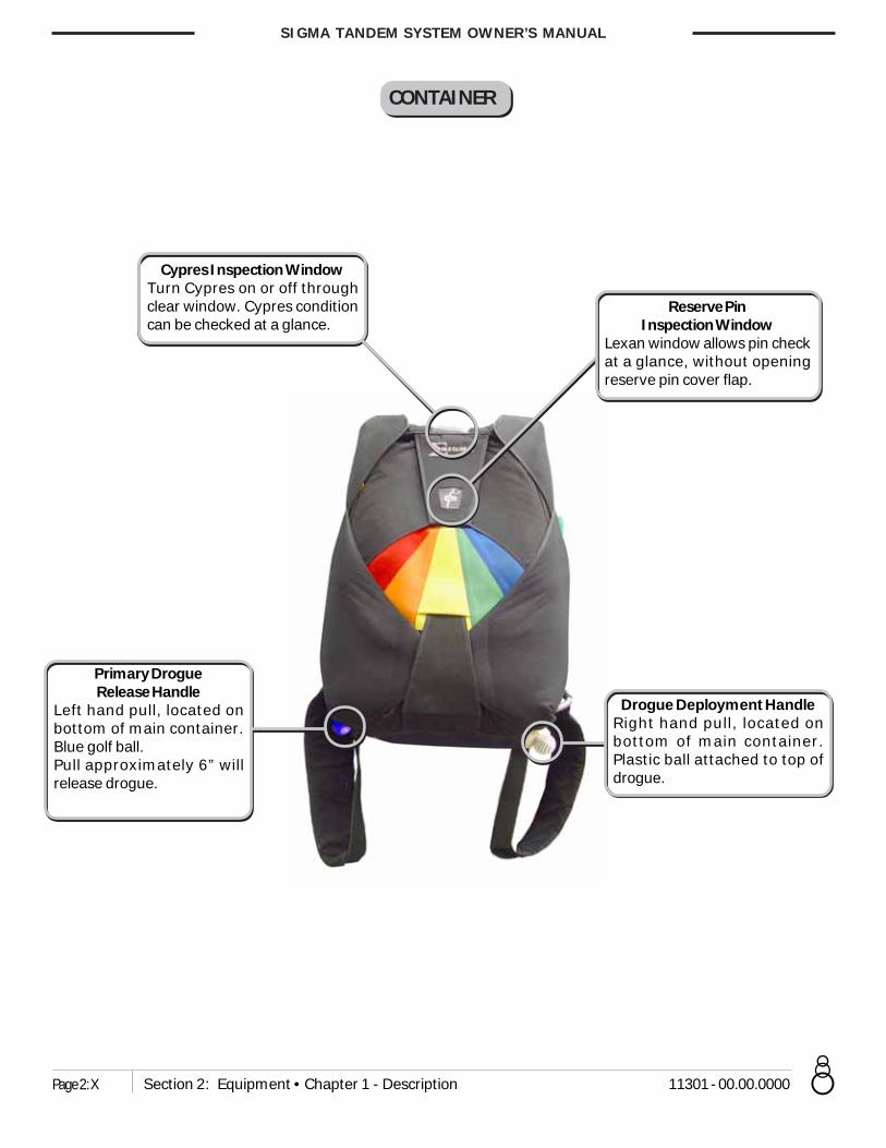
CONTAINER
Reserve PinInspection Window
Lexan window allows pin checkat a glance, without openingreserve pin cover flap.
Cypres Inspection WindowTurn Cypres on or off throughclear window. Cypres conditioncan be checked at a glance.
Drogue Deployment HandleRight hand pull, located onbottom of main container.Plastic ball attached to top ofdrogue.
Primary DrogueRelease Handle
Left hand pull, located onbottom of main container.Blue golf ball.Pull approximately 6” willrelease drogue.

Page 3:X
SIGMA TANDEM SYSTEM OWNER’S MANUAL
11301 - 00.00.0000 Section 2: Equipment • Chapter 1 - Description
Main Lift Web Adjustment PointsWebbing is adjusted through apair of three bar adapters.
Bottom StudentAttachment Point
Consists of two RW-8 ringsmounted sideways, threadedthrough each diagonal on theleft and right sides.
Reserve RipcordLeft hand pull. Either awebbing loop handle (or softpillow handle) attached firmlyto the left main lift web in anoutboard position. Handlecolor is red.
Top StudentAttachment Point
Two D-rings mountedinverted under the largeharness ring on both sides ofthe main lift web.
Cutaway HandleRight hand pull. Soft pillowhandle (or loop-style handle)attached firmly in anoutboard position on rightmain lift web. Handle color isgreen.
Auxiliary Reserve Ripcord/Integrated Lanyard(Dual Purpose)
A. Auxiliary Reserve Ripcord: Right hand pull. Ball handle on reserve staticline next to 3-Ring on right hand side of rig. To be used if left hand isincapacitated in any way, and unable to pull reserve ripcord. Ball must bepulled straight up to release RSL connectoin and initiate reserve activation.
B. Integrated Lanyard: RSL can be used prior to landing in the event of highground winds.
Secondary Right HandDrogue Release Handle
Right hand pull. Orange golfball.
HARNESS
No Crytal BallIf the system has a Skyhookinstalled there will be no CrystalBall.

SIGMA TANDEM SYSTEM OWNER’S MANUAL
Page 4:X Section 2: Equipment • Chapter 1 - Description 11301 - 00.00.0000
THE STUDENT HARNESS
The Sigma / Vector Student Harness is quite a departure from previous tandem student harnesses. It was designed,with the help of a cardiologist, to safely contain the human body without cutting off normal blood flow. Disruptedblood flow is why almost all students on older student harnesses were uncomfortable, and why some got sick or evenpassed out.
A hip-hugging horizontal back and belt strap combination allows the main lift webs to be positioned, and held, moretoward the front of the upper body than on other designs. This prevents the “squeezing” of the upper body and theinside of the upper legs which can cut off blood flow. It also automatically lifts the legs up and forward after opening,putting them in a safer position for landing.
The Student Harness was designed to comfortably and safely fit a wide range of body sizes and types. To accomplishthis, it has thirteen (13) points of adjustment. This wide range of adjustment means that it is possible to give atandem student a truly comfortable experience on their tandem skydive. However, the harness must still be adjustedsecurely to fit the student’s body to prevent them from falling out in extreme situations and unusual body positions.
While fitting this harness on a tandem student is not difficult, it is different from other harnesses you may have usedin the past. The most important point to consider is the security of the student. You must insure that all straps arecomfortably snug against the student’s body.

Page 5:X
SIGMA TANDEM SYSTEM OWNER’S MANUAL
11301 - 00.00.0000 Section 2: Equipment • Chapter 1 - Description
Top Attachment Points(Snap Hooks)
Side Attachment Points(Quick Ejectors)
Chest Strap
Belly Strap
Diagonal Back Strap
Horizontal Back Strap
Adjustable Leg Straps
THE STUDENT HARNESS

SIGMA TANDEM SYSTEM OWNER’S MANUAL
Page 6:X Section 2: Equipment • Chapter 1 - Description 11301 - 00.00.0000
THE MAIN CANOPY
Canopy Nose
A-Line
B-Line
C-LineD-Line
Canopy Tail
Standard Control Lines
Long Gold Toggles Short BlackToggles
Tandem Instructor Toggle
Student Toggle
Diagram shows loaded ribs only

Page 7:X
SIGMA TANDEM SYSTEM OWNER’S MANUAL
11301 - 00.00.0000 Section 2: Equipment • Chapter 1 - Description
SUMMARIZING THE ADVANTAGES OF THE SIGMA TANDEM
1. It takes fewer steps, with fewer potential errors, to close the main container.
2. Accidentally snagging the drogue bridle will not open the container.
3. Out-of-sequence deployments are eliminated.
4. Its center-of-main-container drogue connection gives a more “natural” and comfortable drogue-fall position thanother Tandem systems.
5. The drogue release ripcords are automatically retracted after use, or accidental snagging, so that they are alwayswhere they should be, cannot be lost, and don’t have to be stowed after pulling.
6. It has two redundant, fail-safe drogue release ripcords, one on the right, and one on the left.
7. The drogue release/container opening pin is “locked” until you throw the drogue, preventing accidental highopenings.
8. No more time consuming untwisting of drogue kill line during packing. Kill lines can be easily replaced in the field.
9. You still get a more or less normal deployment if the kill line breaks, and you don’t lose your drogue.
10. It’s improved deployment bag means less canopy damage.
11. It has an improved student harness, which means safer and more comfortable students, and their positive word-of-mouth advertising will increase your tandem business.
12. Skyhook RSL with intergrated Collin’s Lanyard.
13. It has tuck-tab main, reserve, and riser covers.
14. Clear plastic windows make reserve pin checks and Cypres operation easier.
15. It has “Wonderfoam” padding throughout.
THE SIGMA IS MADE TO THE HIGHEST QUALITY STANDARDS IN THE INDUSTRY BY
UNINSURED UNITED PARACHUTE TECHNOLOGIES

SIGMA TANDEM SYSTEM OWNER’S MANUAL
Page 8:X Section 2: Equipment • Chapter 1 - Description 11301 - 00.00.0000
DROGUE DEFINITIONS
Exterior – Top Down
1. Handle – The 1-5/8in ball, connected to the apex of the drogue envelope, used to deploy the drogue.
2. Envelope – The fabric and mesh portion of the drogue. Its top is called the apex, its bottom the base.
3. Bridle – The doubled, 1¾ ”, 4,000 lb. Kevlar section that leads from the envelope to the deployment bagconnection loop.
4. Safety Pin – A compound-curved pin connected to the bridle, designed to prevent accidentalmain container openings.
5. Disk – A 5” aluminum disk, with a 1” flanged chimney.
5.5 Disk Cover – Designed to protect disk..
6. Disk Attachment Loop - A loop on the Kevlar drogue bridle to which the disk is attached with a stainless steel pin,held in place with two flat head screws. A 3/32” hex drive is required to tighten or loosen screws. (inclosed)
7. Drogue Bridle Loop – The loop at the end of the Kevlar drogue bridle, to which the deployment bag is attached.
8. Bag Attachment Loop – A loop of tubular Nylon at the top of the main deployment bag where both the bridle andkill line are attached by means of a #5 stainless rapid link.
Interior – Top Down
9. Kill Line Attachment Bridle – A 9” length of 1” Nylon tape that serves as an attachment point for the kill line, andlimits the degree of collapse if a kill line is accidentally made too short.
10. Kill Line – A length of 1,000 lb. Vectran/Spectra line, with a 1” loop at each end, that runs inside the Kevlar droguebridle from the kill line attachment bridle to the rapid link at the bag attachment loop.
11. Drogue Set Limiter Tapes –Two pieces of 1” Nylon tape that run from the drogue apex to the drogue skirt. Thissaves wear and tear on the drogue bridle and kill line by limiting the distance they slide on each other duringdrogue collapse.
12. Kill Line Guide Grommet – A “0” stainless steel grommet at the base of the drogue envelope which directs the killline into the Kevlar drogue bridle preventing wear. It also serves as an emergency stop for the kill line attachmentbridle if the kill line is accidentally made too short.
13. Disk Attachment Pin – A threaded stainless steel rod, used to attach the disk to the bridle, using 2, 3/32” hex drivescrews.

Page 9:X
SIGMA TANDEM SYSTEM OWNER’S MANUAL
11301 - 00.00.0000 Section 2: Equipment • Chapter 1 - Description
THE DROGUE

SIGMA TANDEM SYSTEM OWNER’S MANUAL
Page 10:X Section 2: Equipment • Chapter 1 - Description 11301 - 00.00.0000
THE SIGMA DROGUE COLLAPSE SEQUENCE
The collapse sequence on the Sigma drogue is the same as on previous Vector drogues. The drogue partially collapses,at a controlled rate during bag lift-off, yielding just the right amount of force for an orderly deployment. However, themethod of collapse is slightly different.
The drogue bridle and kill line now both end at the same place, a rapid link connected to the top of the deploymentbag. When the drogue is set (or cocked) during the packing sequence, the Kevlar drogue bridle below the disk is“scrunched up”, effectively making the bridle shorter than the kill line. When the drogue is deployed, it can inflatebecause the kill line is longer than the bridle. When a ripcord is pulled to end droguefall, the container opens and thedisk is released, allowing the “scrunched up” section of the bridle below the disk to extend to its full length, thusmaking the bridle longer than the kill line. This inverts the drogue apex, collapsing the drogue.
Because both the drogue bridle and kill line are made of non-stretch materials, the drogue collapse sequence is“stopped” automatically, at just the right point. No ring, slamming into a “stop ring” at high speed is needed, and thebridle moves over the kill line for a much shorter distance than on the previous design. This means less friction isgenerated, so everything lasts longer. And with no stop ring, the kill line is much less complicated and easier toreplace. Also, because both the drogue bridle and kill line end at the same place, it is impossible to twist one independentof the other. This means no more time consuming untwisting of the kill line at pack time.
HOW TO CHECK IF YOUR DROGUE KILL LINE IS THE CORRECTLENGTH
For this system to work correctly, a precise relationship between the length of the drogue bridle and the length of thekill line must be maintained. To check this relationship:
Anchor the rapid link at the deployment bag end of the drogue bridle. Both the drogue bridle and kill line should beconnected to this link.
Extend the drogue bridle fully.
Put a finger on either side of the kill line guide grommet at the base of the drogue, and apply about 10 lbs. of tensionagainst the Kevlar bridle.
With the other hand apply the same tension on the kill line by pulling on the kill line attachment bridle or the droguehandle. The larks head knot at the bottom of the kill line attachment bridle should be 1½ ” above the kill line guidegrommet.
You can notice this relationship less formally each time you pick up your drogue after landing.
If this distance is more than 2” greater, the drogue may not fully collapse, yielding a higher snatch force, increasedchance of malfunction due to line dump, and increased chance of canopy damage. If you notice a kill line that is over2” too long, a simple overhand knot, tied within the finger-locked section of the kill line, at the deployment bag end, willeffectively shorten it almost 2”, and bring your drogue collapse system back into trim.
If this distance is more than 1” less, the larks head knot will impact the guide grommet at high speed, quickly causingdamage to both. However, in this instance, deployment, while slightly slower, will still happen more or less normally.
Drouge collapse is calibrated for average weight and fall rates, if you feel the drouge is collapsing to far with longerthan normal “trap door” you may Larkshead a PD Slink onto the bottom of the kill line to reduce the amount ofcollapse.

Page 11:X
SIGMA TANDEM SYSTEM OWNER’S MANUAL
11301 - 00.00.0000 Section 2: Equipment • Chapter 1 - Description
UNDERSTANDING THE MAIN RECOIL RIPCORD SYSTEM
The Recoil Ripcord System for the Tandem Sigma drogue consists of:
1. A single length of 1,000 lb. Spectra line with finger locked loops at each end, and near the center.2. A single length of 1/8” bungee cord, finger locked between the loops at each end of the Spectra line.3. Two, specially prepared, solid core ball handles.4. One stainless steel, eyeleted, ripcord pin.5. Two stainless steel ripcord housings.
One ripcord handle is located at the bottom left corner of the main container, and the other on the right leg pad,allowing the tandem instructor to release the drogue with either hand. The right handle is positioned on the tandem
instructor’s harness so as to simulatea Bottom of Container (BOC) positionfor the student. You don’t have tohook it up to the student harnessbefore each jump. It is automaticallyin the right position.There are no “ripcord pockets” per say.Each ripcord handle “plugs into” theend of the housing, and is held inposition by a combination of friction,and the pull of the bungee cord retractsystem.
Pulling either handle about 5” pulls the singleripcord pin, opening the container andreleasing the drogue. Notice that each ripcordis set up as a 2-1 pulley, so that a pull of 5pounds at the handle translates into a pull of10 lbs at the pin, resulting in easy pulls everytime.
Once the drogue is released, as evidenced bythe “trap door effect,” you can simply let goof the handle. It will automatically return toits position on the end of the ripcord housing.Although the housings are double clampedinto position under the drogue pouch formaximum security and long life, excessivepulling on the ripcord handles after droguerelease might eventually damage thesehousing connections. You don’t have to babythe system, but pull only as far as necessaryto release the drogue, and then let go of thehandle.
FIGURE 1RELEASE HANDLE SYSTEM
(Cross section view of spandex for clarity)
FIGURE 2RIPCORD DETAIL
(Housings, et., removed for detail)
Bungee
SpectraRipcord

SIGMA TANDEM SYSTEM OWNER’S MANUAL
Page 12:X Section 2: Equipment • Chapter 1 - Description 11301 - 00.00.0000
The advantages of this system are obvious. The spherical shape of the ripcord handles, and theirmethod of attachment, makes snagging highly unlikely. If dislodged, they automatically return toposition, so no more searching for “floating” ripcords. And the unique “Safety Pin,” connected tothe drogue bridle, makes it virtually impossible for a snagged ripcord handle to cause an accidentalcontainer opening. And let’s not forget, you no longer have to waste time and effort stowing thehandles after opening, or searching for them at packing time.
Because this system is new (The first production rigs went into service Summer 2000), we don’t yet know how long therecoil ripcord system will last under actual field conditions. Although bench tests show that the ripcord system canlast for over 1,000 jumps, you should inspect the whole system often for signs of wear.
Look for wear at the junction of the Spectra ripcords and the handles, and around the pin area. The Spectra is 1,000lbs. strong, and the force required to pull the pin is less than 10 lbs. That’s over a 100 to 1 safety margin, so a smallamount of fraying should not be cause for alarm. Besides, the ripcord system is designed to be redundant. If one sidewere to break or jam for any reason, the other side is still fully functional.
Also notice if the recoil system is doing its job properly. With the rig packed, each ripcord should snap back into placewhen pulled a few inches and released. But please realize, if you pull and release each ripcord handle several timesbefore each jump, you will shorten the life of the system by a factor of three. Inspect, but don’t play with the systemincessantly if you want maximum life from your ripcords.
UNDERSTANDING THE SIGMA SKYHOOK RSL COLLINS’ LANYARD
The Collins’ lanyard was designed to prevent a main-reserve entanglement, by releasing the left (non-RSL side) mainriser, in the event that the right (RSL side) main riser breaks or prematurely releases by itself, for any reason. On theSigma, it is integrated into the RSL with no external lanyard. This is accomplished by threading the left riser 3-ringrelease cable through a loop in the reserve static line (RSL). As the right riser leaves, the RSL automatically pulls theleft cutaway cable as it pulls the reserve pin, yielding an almost simultanious breakaway and clean reserve deployment.
A standard RSL does one thing. It pulls the reserve ripcord pin automatically after a breakaway. The Skyhook RSL doesthis, and then goes two steps further.
A. It automatically releases the Left (non-RSL) riser, if the right (RSL) riser releases prematurely for any reason (Collins.Lanyard). (You wouldn.t want your reserve container opened with one riser still attached, would you?)
B. It then uses your departing main canopy as a super .pilot chute. to get your reserve to line stretch fasterthan ever before. Breakaway, to canopy-out-of-bag times are between ½ and ¾ of a second, depending on thesize of your reserve canopy. This is up to three times faster than a pilot chute can do it alone.
If you have a main total malfunction, or your AAD fires, the Skyhook Lanyard automatically releases, andtherefore does nothing to hinder normal reserve deployment.
