secogear cat final2
TRANSCRIPT

GE Consumer & IndustrialPower Protection
SecoGear ™
GE imagination at work
12-24kV Metal-clad Switchgear
@
Power Protection (formerly GE Power Controls), a division of GE Consumer & Industrial, is a fi rst class European supplier of low-voltage products including wiring devices, residential and industrial electrical distribution components, automation products, enclosures and switchboards. Demand for the company’s products comes from wholesalers, installers, panel-board builders, contractors, OEMsand utilities worldwide.
www.ge.com/eu/powerprotection www.ge.com/ex/powerprotection
GE Consumer & IndustrialPower Protection
680878Ref. I/3256/E/EX 3.0 Ed.01/09
© Copyright GE Power Controls 2009
4600
4
GE imagination at work
NewGE CONSUMER & INDUSTRIAL HUNGARYVáci út 77H-1340 BudapestHungary
Customer ServiceTel. + 361 447 6046Fax + 361 447 5060e-mail: mea.export [email protected]
GE POWER CONTROLS129-135 Camp RoadSt AlbansHerts AL1 5HLUnited Kingdom
Customer ServiceTel. 0800 587 1251Fax 0800 587 1239e-mail: [email protected]
GE POWER CONTROLS IBERICAP.I. Clot del Tufau, s/nE-08295 Sant Vicenç de CastelletSpain
GE POWER CONTROLS ITALIAViale Brianza 181I-20092 Cinisello Balsamo (MI)Italia
GE POWER CONTROLS FRANCEParis Nord 213, rue de la PerdrixF-95958 Roissy CDG CédexFrance
GE CONSUMER & INDUSTRIAL GmbHVor den Siebenburgen 2D-50676 KölnGermany
GE INDUSTRIAL BELGIUMNieuwevaart 51B-9000 GentBelgium
GE CONSUMER & INDUSTRIALPOWER PROTECTIONKuortaneenkatu 200510 HelsinkiFinland

SecoGear™
1
Metal-clad Sw
itchgear
1
GeneralSecoGear metal-clad switchgear is designed and manufactured with advance technology and has been comprehensively and successfully type-tested.
SecoGear switchgear is typically used in power plant, substation of public utilities and suitable to provide control and protection for transformers, capacitors and motors.
The rated voltage of SecoGear is 12-24kV and rated current ranges from 630A to 4000A. All SecoGear with switching device are equipped with SecoVac vacuum circuit breaker with corresponding specifi cations.
SecoGear switchgear is designed for indoor applications.
SecoGear is particularly suitable for application in industrial i.e. iron and steel mill, mining, oil and gasand infrastructure projects i.e. hi-rise building, airport, water treatment, etc.
SecoGear is designed, assembled and tested tomeet or exceed applicable lEC, DIN VDE, andGB/DL standards.
SecoGear is designed for power protection applications in all major industries, including Power Generation, T&D, Oil&Gas, Automotives, Processing Plants, and Commercial Buildings
12-24kV Metal-clad Switchgear• SecoGear is an air insulated switchgear with a
compact design
• SecoGear is a safe and reliable switchgear for universal indoor applications
• SecoGear is designed with full segregation of its breaker compartment and equipped with embedded pole SecoVac vacuum circuit breaker
• SecoGear has cable compartments with ample space for ease of power cable connection
• SecoGear is equipped with comprehensive safety interlock systems allowing mistakeproof operation
• Features on front panel ensures the easy and safe operation
IndexIntroduction . . . . . . . . . . . . . . . . . . . . . . . . . . . . . . . . . . . . . . . 1
Performance features. . . . . . . . . . . . . . . . . . . . . . . . . . . . . . 4
SecoVac. . . . . . . . . . . . . . . . . . . . . . . . . . . . . . . . . . . . . . . . . . . 7
VT Module . . . . . . . . . . . . . . . . . . . . . . . . . . . . . . . . . . . . . . . . . 9
Instrument transformers . . . . . . . . . . . . . . . . . . . . . . . . . . 10
Primary schemes . . . . . . . . . . . . . . . . . . . . . . . . . . . . . . . . . 11
Internal wiring diagrams . . . . . . . . . . . . . . . . . . . . . . . . . . 16
Installation . . . . . . . . . . . . . . . . . . . . . . . . . . . . . . . . . . . . . . . 18
SecoGear™
2
Met
al-c
lad
Swit
chge
ar
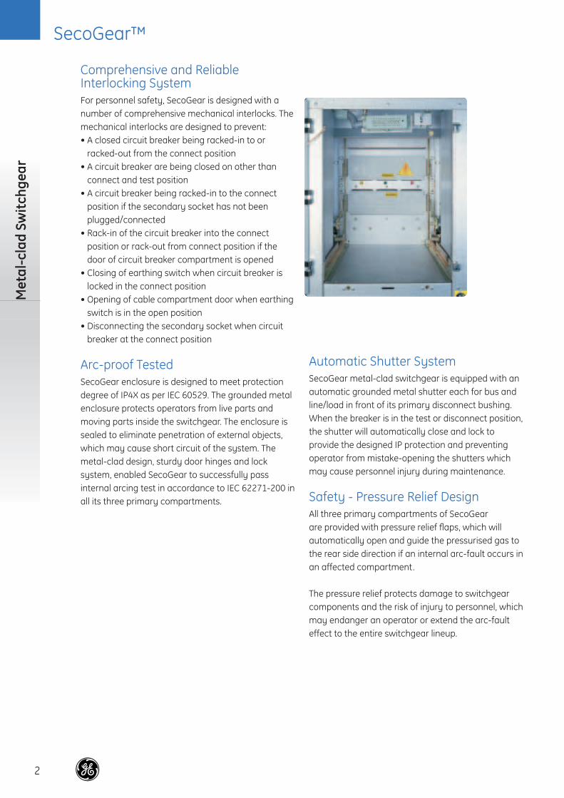
Automatic Shutter SystemSecoGear metal-clad switchgear is equipped with an automatic grounded metal shutter each for bus and line/load in front of its primary disconnect bushing. When the breaker is in the test or disconnect position, the shutter will automatically close and lock to provide the designed IP protection and preventing operator from mistake-opening the shutters which may cause personnel injury during maintenance.
Safety - Pressure Relief DesignAll three primary compartments of SecoGear are provided with pressure relief fl aps, which will automatically open and guide the pressurised gas to the rear side direction if an internal arc-fault occurs in an affected compartment.
The pressure relief protects damage to switchgear components and the risk of injury to personnel, which may endanger an operator or extend the arc-fault effect to the entire switchgear lineup.
Comprehensive and Reliable Interlocking SystemFor personnel safety, SecoGear is designed with a number of comprehensive mechanical interlocks. The mechanical interlocks are designed to prevent:• A closed circuit breaker being racked-in to or
racked-out from the connect position• A circuit breaker are being closed on other than
connect and test position• A circuit breaker being racked-in to the connect
position if the secondary socket has not been plugged/connected
• Rack-in of the circuit breaker into the connect position or rack-out from connect position if the door of circuit breaker compartment is opened
• Closing of earthing switch when circuit breaker is locked in the connect position
• Opening of cable compartment door when earthing switch is in the open position
• Disconnecting the secondary socket when circuit breaker at the connect position
Arc-proof TestedSecoGear enclosure is designed to meet protection degree of IP4X as per IEC 60529. The grounded metal enclosure protects operators from live parts and moving parts inside the switchgear. The enclosure is sealed to eliminate penetration of external objects, which may cause short circuit of the system. The metal-clad design, sturdy door hinges and lock system, enabled SecoGear to successfully pass internal arcing test in accordance to IEC 62271-200 in all its three primary compartments.

SecoGear™
3
Metal-clad Sw
itchgearRemote Control Solution• Only for special order• For remote control from a central control room
for intelligent switchgear systems, the following functions of SecoGear are provided:
• Motorized drawout mechanism for remote connect and test position
• Remote opening and closing the switchgear device• Motorised earthing switch
High Reliable ComponentsSecoGear reliability is based on the usage of proven components. All components including the advanced SecoVac embedded pole vacuum circuit breaker, insulating materials, disconnect bushings, inter-unit bushing and instrument transformers have been strictly selected and have been qualifi ed for 40 years lifetime through accelerated thermal aging tests.
Robust Drawout MechanismSecoGear drawout mechanism is designed to avoid misalignment during racking, therefore overheating of the primary disconnect is prevented. All drawout mechanism is bolted to the enclosure frame with a double bended support.
Space HeatersSecoGear offers space heaters at the cable compartment as a standard feature to avoid condensation inside the switchgear due to high humidity. Space heaters should be permanently energized during installation and commissioning period and can be controlled thru humidistat or thermostat after switchgear is in normal operation.
Environmental ConditionsSecoGear is equipped with the following components which guarantee successful operations under adverse climatic and environment:• Epoxy resin embedded pole vacuum circuit breaker• Corrugated design of insulators and bushings• Totally enclosed under all operation conditionsSecoGear had successfully passed the high altitude application tests up to 2000m above sea level, grade II pollution test, condensation test and salt spray test.

SecoGear™
4
Met
al-c
lad
Swit
chge
ar
Reliability• The 3 primary compartments and 1 secondary
compartment are completely self contained and segregated from each other which limits the infl uence between compartments and prevents spreading of an arc-fault between compartments.
• SecoGear is equipped with a Quick-action earthing switch type JN(ESW) with short circuit making capability.
• A heat-shrinkable material with high dielectric and strength properties insulates the busbar.
• The main busbar is provided with inter-unit bushing to prevent travel of arcing to the entire main busbar of the line-up.
• SecoGear is equipped with a highly reliable SecoVac vacuum circuit breaker with excellent electrical and mechanical performance.
• Circuit breaker in the SecoGear switchgear has three positions: connected, test and disconnected positions.
SafetySecoGear is designed with a number of interlocking systems to prevent maloperation:
• The circuit breaker can only be moved from test to connect position and vice versa when circuit breaker is opened.
• The earthing switch cannot be closed when the circuit breaker is in the connect position and in the traveling position between test and connect.
• The cable compartment door can be opened only when the earthing switch is closed and at the same time the earthing switch can be opened only when the cable compartment door is closed.
• The secondary plug can only be inserted or removed only when the circuit breaker is in the test position.
• The circuit breaker can only be closed when the circuit breaker is precisely in the defi nite test or connection position.
• When the circuit breaker is removed from connect position, the metal shutters will close automatically.
• The switchgear is internally arc-proof.• All high primary compartments are provided with
a pressure relief fl aps located on the topside of the switchgear.
• Any overpressure inside the compartment by an internal arcing will be released thru the pressure relief fl aps.
Performance Features

SecoGear™
5
Performance Features
Adaptability• SecoGear cable compartment provides ample
space for easy power cable connection.• Standard current transformers, zero sequence
current transformer, voltage transformers, surge arresters, protection relays and other instruments can be easily installed to the switchgear.
• SecoVac vacuum breakers with the same rating are interchangeable without any adjustment.
• CNC punching and bending machines ensure high quality and consistent dimensions and weight of the cubicle.
Technical Data of SecoGear Switchgear
Description Unit Data
Rated voltage kV 12 24Rated frequency Hz 50/60 50/60
Rated power frequency stand voltage/1 minute kV 42 65Lightning impulse with stand voltage (peak value) kV 75 125
Rated current of busbar A 630/1250/1600/2000/2500/3150/4000(1) 630/1250/1600/2000/2500Rated current of T-off Busbar A 630/1250/1600/2000/2500/3150/4000(1) 630/1250/1600/2000/2500Rated short time withstand current (3s) kA 20/25/31.5/40/50 20/25/31.5
≤ 150+CT(2)(≤ 630A) ≤ 150+CT(2)(≤ 630A)Rated peak withstand current (peak value) kA 50/63/80/100/125 50/63/80Resistance of main circuit μΩ ≤ 100+CT(2)(≤ 1250A) ≤ 100+CT(2)(≤ 1250A)
≤ 70+CT(2)(≤ 2000A) ≤ 70+CT(2)(≤ 2000A)≤ 50+CT(2)(≤ 2500A) ≤ 50+CT(2)(≤ 2500A)
Ingress protection Panel IP4X, Compartment IP2X Panel IP4X, Compartment IP2X
(1) Forced cooling ventilation is required(2) Direct current resistance of current transformer
Normal Service Conditions
Description
Minimum ambient temperature -15°CMaximum ambient temperature +40°CDaily average temperature ≤+35°CMaximum relative humidity 95%Monthly average relative humidity ≤90%Maximum altitude 2000m a.s.l.

SecoGear™
6
Met
al-c
lad
Swit
chge
ar
Dimensions and Weight
12kV Height (h) (mm) Width (w) (mm) Depth (d) (mm) Mass (kg)
T-off busbar rated current ≤ 1250A
2250
650/800
1400 800-1200
Short time withstand current ≤ 31.5kA
T-off busbar rated 1250A 800/1000Short time withstand current = 40kA/50kAT-off busbar rated current = 1600A/2000A 800/1000T-off busbar rated current ≥ 2500A 1000
24kV
T-off busbar rated current ≤ 1250A
2250
800 or 1000
1680 800-1200Short time withstand current ≤ 25kA (Choice or better optional)
1250A < T-off busbar rated current ≤ 2500A 100025kA < Short time withstand current ≤ 31.5kA
A = Busbar compartment B = Circuit breaker compartment C = Cable compartmentD = Low Voltage compartment
Front view Side view
SecoGear front and cross section view

SecoGear™
7
SecoVac
Description Unit Data Data
Rated voltage kV 12 24Rated frequency Hz 50/60 50/60Rated power frequency withstand voltage (1 minute) kV 42 65Rated impulse withstand voltage (peak value) kV 75 125Rated current A 630/1250/1600/2000/2500/3150/4000 (fan cooled) 630/1250/1600/2000/2500Rated short circuit breaking current kA 20/25/31.5/40/50 20/25/31.5Rated short time withstand current (3 seconds) kA 20/2/31.5/40/50 20/25/31.5
Medium voltage embedded pole vacuum circuit breaker 12-24kV, up to 4000A and 50kA• SecoVac satisfi es diverse application requirements:
its simple but reliable operating mechanism is a key factor to make switchgear compact.
• SecoVac is manufactured using specially customized materials and specialized techniques. The process ensures quality and reliability of product. It is suitable for application in different operating conditions.
• The modularized operating mechanism design of SecoVac allows for standardized mass production, shorter lead-time, and a fast module replacement to minimize downtime.
• SecoVac fully complies with IEC, DIN VDE and GB/DL standards.
SecoVac
SecoGear™
8
Met
al-c
lad
Swit
chge
ar
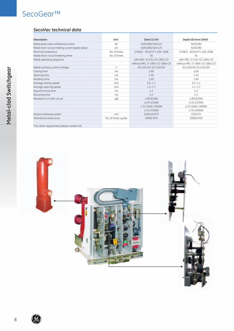
SecoVac technical data
Description Unit Data (12 kV) Depth (d) (mm) (24kV)
Rated peak value withstand current kA 50/63/80/100/125 50/63/80Rated short circuit making current (peak value) kA 50/63/80/100/125 50/63/80
Electrical endurance No. of times 274(E2) - IEC62271-100: 2006 274(E2) - IEC62271-100: 2006Rated short circuit breaking times No. of times 50 50Rated operating sequence with ARC: O-0.3s-CO-180s-CO with ARC: O-0.3s-CO-180s-CO
without ARC: O-180s-CO-180s-CO without ARC: O-180s-CO-180s-CORated auxiliary control voltage V AC110/220; DC110/220 AC110/220; DC110/220Closing time ms ≤ 60 ≤ 60Opening time ms ≤ 45 ≤ 45Breaking time ms ≤ 60 ≤ 60Average closing speed m/s 0.5~1.1 0.5~1.1Average opening speed m/s 1.1~1.7 1.1~1.7Asynchronous time ms ≤ 2 ≤ 2Bouncing time ms ≤ 2 ≤ 2Resistance of main circuit μΩ ≤ 80 (630A) ≤ 80 (630A)
≤ 45 (1250A) ≤ 45 (1250A)≤ 35 (1600~2000A) ≤ 35 (1600~2000A)
≤ 35 (2500A) ≤ 35 (2500A)Distance between poles mm 150/210/275 210/275Mechanical endurance No. of times cycles 30000 (M2) 20000 (M2)
*For other requirement please contact GE

SecoGear™
9
VT Module
There are 2 types of VT modules available on our SecoGear:• Withdrawable VT module with primary fuses for
line voltage sensing at the cable compartment of breaker panel
• Withdrawable VT module with primary fuses for bus voltage sensing at metering panel
A special fi xed type VT module without primary fuses for bus voltage sensing (mounted on the top of breaker panel) is available. This option is intended to eliminate number of vertical sections for dedicated metering panel.
Number of the voltage transformer on the VT module can be 2 or 3 VT depending on the application and requirement.
The withdrawable VT module allows replacement of the fuses with the switchgear in service. Truck racking-out with the door closed operates closure of an automatic shutter between the live parts of the switchgear and the VT metering panel compartment.
Surge arresters on a drawn-out VT module and blown fuse indicator switch are as an option.
VT Module
Voltage TransformerThe voltage transformers can be one or two poles type, with performances and accuracy classes suited to the functional requirements of the connected devices.
When they are installed on a withdrawable truck they are fi tted with primary fuses.
The current and voltage transformers are designed to meet or exceed requirement of IEC60044-1 and IEC60044-2 standards respectively.
SecoGear™
10
Met
al-c
lad
Swit
chge
ar
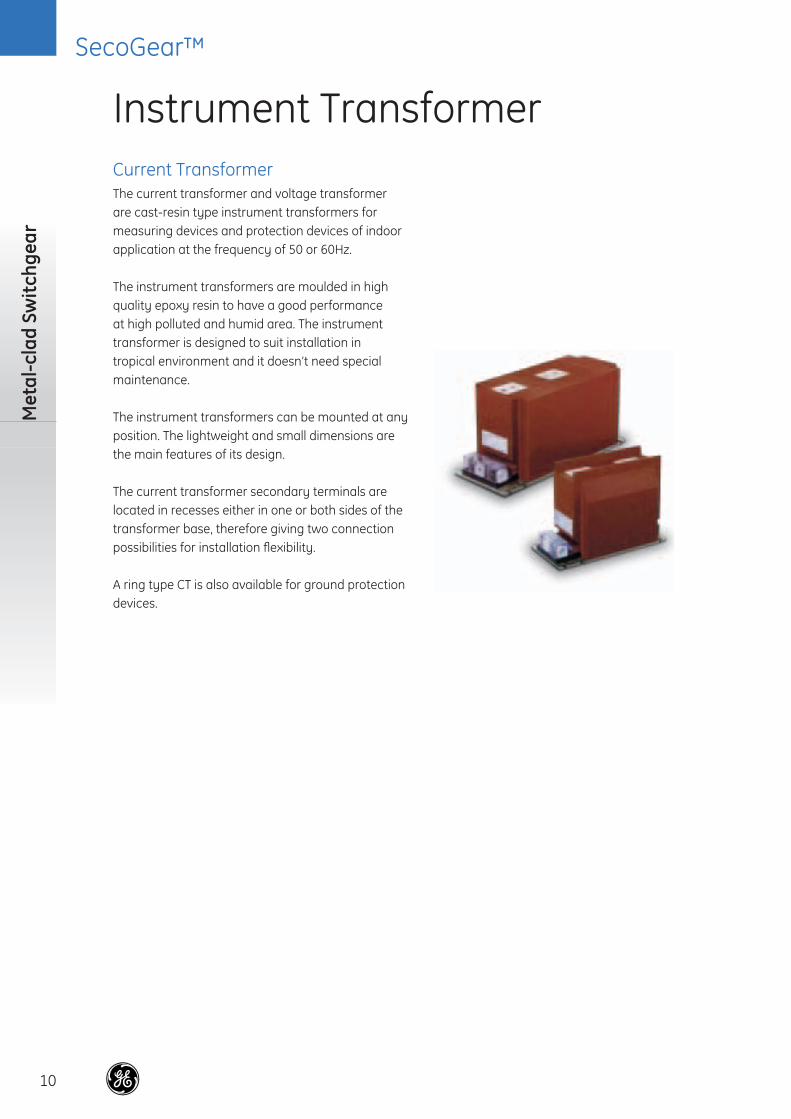
Current TransformerThe current transformer and voltage transformer are cast-resin type instrument transformers for measuring devices and protection devices of indoor application at the frequency of 50 or 60Hz.
The instrument transformers are moulded in high quality epoxy resin to have a good performance at high polluted and humid area. The instrument transformer is designed to suit installation in tropical environment and it doesn’t need special maintenance.
The instrument transformers can be mounted at any position. The lightweight and small dimensions are the main features of its design.
The current transformer secondary terminals are located in recesses either in one or both sides of the transformer base, therefore giving two connection possibilities for installation fl exibility.
A ring type CT is also available for ground protection devices.
Instrument Transformer
SecoGear™
11
Primary schem
es
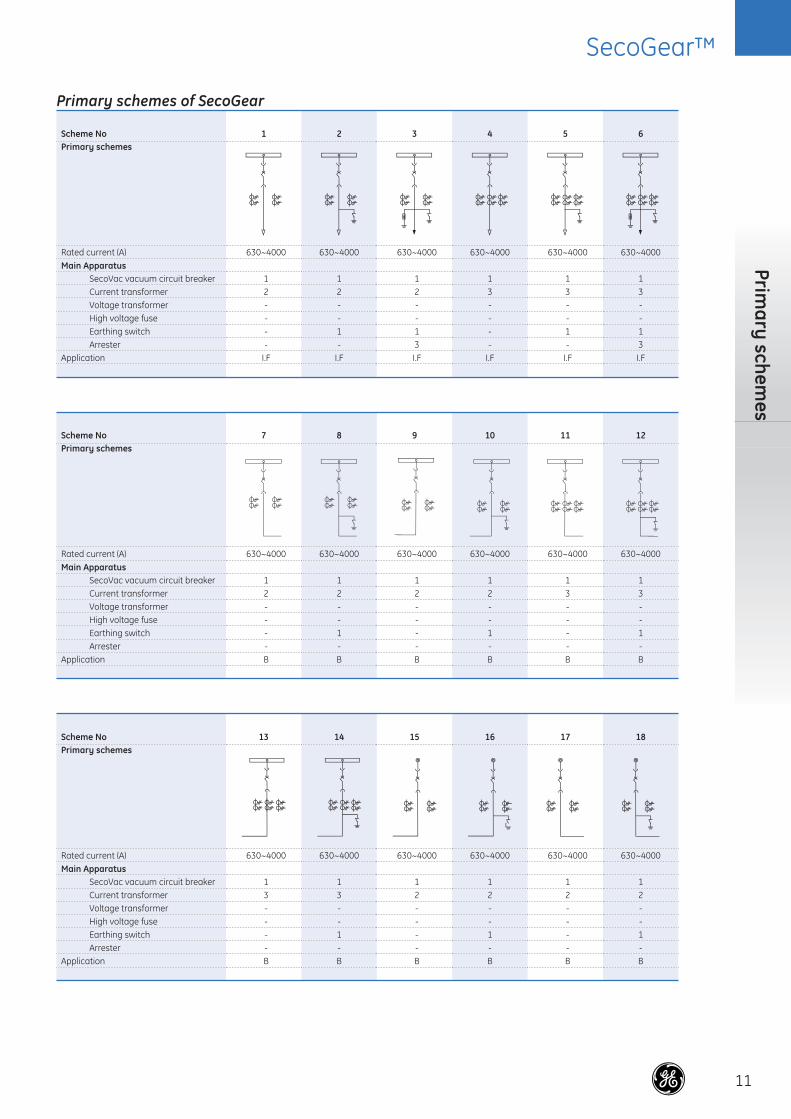
Primary schemes of SecoGear
Scheme No 1 2 3 4 5 6Primary schemes
Rated current (A) 630~4000 630~4000 630~4000 630~4000 630~4000 630~4000Main Apparatus SecoVac vacuum circuit breaker 1 1 1 1 1 1 Current transformer 2 2 2 3 3 3 Voltage transformer - - - - - - High voltage fuse - - - - - - Earthing switch - 1 1 - 1 1 Arrester - - 3 - - 3Application I.F I.F I.F I.F I.F I.F
Scheme No 7 8 9 10 11 12Primary schemes
Rated current (A) 630~4000 630~4000 630~4000 630~4000 630~4000 630~4000Main Apparatus SecoVac vacuum circuit breaker 1 1 1 1 1 1 Current transformer 2 2 2 2 3 3 Voltage transformer - - - - - - High voltage fuse - - - - - - Earthing switch - 1 - 1 - 1 Arrester - - - - - -Application B B B B B B
Scheme No 13 14 15 16 17 18Primary schemes
Rated current (A) 630~4000 630~4000 630~4000 630~4000 630~4000 630~4000Main Apparatus SecoVac vacuum circuit breaker 1 1 1 1 1 1 Current transformer 3 3 2 2 2 2 Voltage transformer - - - - - - High voltage fuse - - - - - - Earthing switch - 1 - 1 - 1 Arrester - - - - - -Application B B B B B B

SecoGear™
12
Met
al-c
lad
Swit
chge
ar
Primary schemes of SecoGear (continued)
Scheme No 19 20 21 22 23 24Primary schemes
Rated current (A) 630~4000 630~4000 630~4000 630~4000 630~4000 630~4000Main Apparatus SecoVac vacuum circuit breaker 1 1 1 1 1 1 Current transformer 3 3 3 3 2 2 Voltage transformer - - - - - - High voltage fuse - - - - - - Earthing switch - 1 - 1 - 1 Arrester - - - - - -Application B B B B I.F I.F
Scheme No 25 26 27 28 29 30Primary schemes
Rated current (A) 630~4000 630~4000 630~4000 630~4000 630~4000 630~4000Main Apparatus SecoVac vacuum circuit breaker 1 1 1 1 1 1 Current transformer 2 3 3 3 2 2 Voltage transformer - - - - 2 2 High voltage fuse - - - - 3 3 Earthing switch 1 - 1 1 - 1 Arrester 3 - - 3 - -Application I.F I.F I.F I.F I+P I+P
Scheme No 31 32 33 34 35 36Primary schemes
Rated current (A) 630~4000 630~4000 630~4000 630~4000 630~4000 630~4000Main Apparatus SecoVac vacuum circuit breaker 1 1 1 1 1 1 Current transformer 2 3 3 3 2 2 Voltage transformer 2 2 2 2 3 3 High voltage fuse 3 3 3 3 3 3 Earthing switch - - 1 - - 1 Arrester 3 - - 3 - -Application I+P I+P I+P I+P I+P I+P

SecoGear™
13
Primary schem
es
Primary schemes of SecoGear (continued)
Scheme No 37 38 39 40 41 42Primary schemes
Rated current (A) 630~4000 630~4000 630~4000 630~4000 630~4000 630~4000Main Apparatus SecoVac vacuum circuit breaker 1 - - - - - Current transformer 2 - - - - - Voltage transformer 3 2 3 2 3 2 High voltage fuse 3 3 3 3 3 3 Earthing switch - - - - - - Arrester 3 - - 3 3 3Application I+P P P P+Arrester P+Arrester P+Arrester
Scheme No 43 44 45 46 47 48Primary schemes
Rated current (A) 630~4000 630~4000 630~4000 630~4000 630~4000 630~4000Main Apparatus SecoVac vacuum circuit breaker - - - - - - Current transformer - - - - - - Voltage Transformer 3 2 2 3 3 2 High voltage fuse 3 3 3 3 3 3 Earthing switch - - - - - - Arrester 3 - - - - 3Application P+Arrester P+R P+R P+R P+R P+R +Arrester
Scheme No 49 50 51 52 53 54Primary schemes
Rated current (A) 630~4000 630~4000 630~4000 630~4000 630~4000 630~4000Main Apparatus SecoVac vacuum circuit breaker - - - - - - Current transformer - - - - - - Voltage transformer 2 3 3 - - - High voltage fuse 3 3 3 - - - Earthing switch - - - - - - Arrester 3 3 3 - - -Application R+P+Arrester R+P+Arrester R+P+Arrester R R D
SecoGear™
14
Met
al-c
lad
Swit
chge
ar
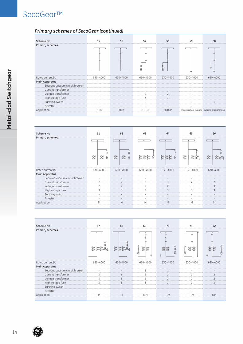
Primary schemes of SecoGear (continued)
Scheme No 55 56 57 58 59 60Primary schemes
Rated current (A) 630~4000 630~4000 630~4000 630~4000 630~4000 630~4000Main Apparatus SecoVac vacuum circuit breaker - - - - - - Current transformer - - - - - - Voltage transformer - - 2 2 - - High voltage fuse - - 3 3 - - Earthing switch - - - - - 1 Arrester - - - - - -Application D+B D+B D+B+P D+B+P Outgoing phase changing Outgoing phase changing
Scheme No 61 62 63 64 65 66Primary schemes
Rated current (A) 630~4000 630~4000 630~4000 630~4000 630~4000 630~4000Main Apparatus SecoVac vacuum circuit breaker - - - - - - Current transformer 2 2 3 3 2 2 Voltage transformer 2 2 2 2 3 3 High voltage fuse 3 3 3 3 3 3 Earthing switch - - - - - - Arrester - - - - - -Application M M M M M M
Scheme No 67 68 69 70 71 72Primary schemes
Rated current (A) 630~4000 630~4000 630~4000 630~4000 630~4000 630~4000Main Apparatus SecoVac vacuum circuit breaker - - 1 1 - - Current transformer 3 3 2 2 2 2 Voltage transformer 3 3 2 2 2 2 High voltage fuse 3 3 3 3 3 3 Earthing switch - - - - - - Arrester - - - - - -Application M M I+M I+M I+M I+M
SecoGear™
15
Primary schem
es
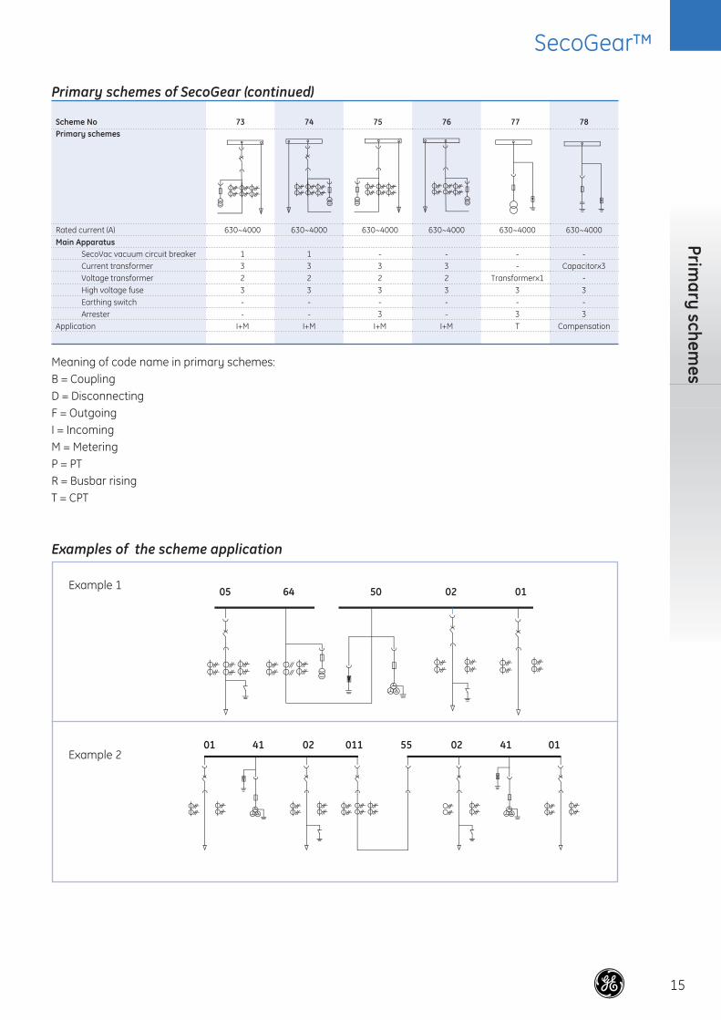
Primary schemes of SecoGear (continued)
Scheme No 73 74 75 76 77 78Primary schemes
Rated current (A) 630~4000 630~4000 630~4000 630~4000 630~4000 630~4000Main Apparatus SecoVac vacuum circuit breaker 1 1 - - - - Current transformer 3 3 3 3 - Capacitorx3 Voltage transformer 2 2 2 2 Transformerx1 - High voltage fuse 3 3 3 3 3 3 Earthing switch - - - - - - Arrester - - 3 - 3 3Application I+M I+M I+M I+M T Compensation
Meaning of code name in primary schemes:B = CouplingD = DisconnectingF = OutgoingI = IncomingM = MeteringP = PTR = Busbar risingT = CPT
Examples of the scheme application
Example 1
Example 2
05
01 41 02 011 55 02 41 01
64 50 02 01

SecoGear™
16
Met
al-c
lad
Swit
chge
ar
Internal Wiring Diagrams
Withdrawable Type – AC Control
Withdrawable Type – DC Control
Y0 Blocking Magnet for withdrawable unit-- V0Y1 Closing block magnetY2 First opening releaseY3 Closing releaseY4 Undervoltage releaseY7-Y9 Indirect overcurrent release (optional)Y10 Second opening release (optional)P Manual chargingM Charging motorV0-V5 Rectifier (V0&V5 optional)
Notes:1. Auxiliary switch-S1 shown for VCB-mechanism is discharged.2. VCB in opening and service status.3. The optional components are not included in basic version if not specified.
Service position
Opening circuit 2nd opening circuit Close blocking circuit Closing circuit Charging circuit
Overcurrentrelease(A phase)
Overcurrentrelease(B phase)
Overcurrentrelease(C phase)
Under currentrelease
Truck RackBlock magnet
Closing monitor circuit
Test position
S1 Auxiliary switch of charging MotorS2 Auxiliary switch of block magnet-Y1S3 Auxiliary switch of VCBS8 Auxiliary switch for test positionS9 Auxiliary switch for service positionK0 Anti-pumping relayR0 ResistanceJP1 Bypass of R0JS1 Connector of K0 (the internal anti- pumping function will be dismissed if it is cut)
Opening circuit 2nd opening circuit Close blocking circuit Closing circuit Charging circuit
Overcurrentrelease(A phase)
Overcurrentrelease(B phase)
Overcurrentrelease(C phase)
Under currentrelease
Truck RackBlock magnet
Closing monitor circuit
Service position
Test position
Y0 Blocking Magnet for withdrawable unit-- V0Y1 Closing block magnetY2 First opening releaseY3 Closing releaseY4 Undervoltage releaseY7-Y9 Indirect overcurrent release (optional)Y10 Second opening release (optional)P Manual chargingM Charging motor
Notes:1. Auxiliary switch-S1 shown for c.b.-mechanism discharged.2. VCB in opening and service status.3. The optional components are not included in basic version if not specified.
S1 Auxiliary switch of charging MotorS2 Auxiliary switch of block magnet-Y1S3 Auxiliary switch of VCBS8 Auxiliary switch for test positionS9 Auxiliary switch for service positionK0 Anti-pumping relayR0 ResistanceJP1 Bypass of R0JS1 Connector of K0 (the internal anti- pumping function will be dismissed if it is cut)
SecoGear™
17
Internal Wiring D
iagrams
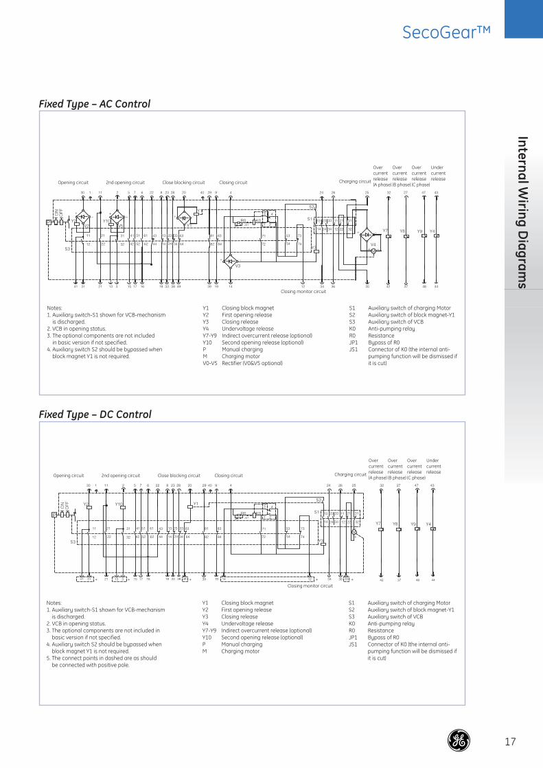
Fixed Type – AC Control
Fixed Type – DC Control
Opening circuit 2nd opening circuit Close blocking circuit Closing circuit Charging circuit
Overcurrentrelease(A phase)
Overcurrentrelease(B phase)
Overcurrentrelease(C phase)
Under currentrelease
Notes:1. Auxiliary switch-S1 shown for VCB-mechanism is discharged.2. VCB in opening status.3. The optional components are not included in basic version if not specified.4. Auxiliary switch S2 should be bypassed when block magnet Y1 is not required.
Y1 Closing block magnetY2 First opening releaseY3 Closing releaseY4 Undervoltage releaseY7-Y9 Indirect overcurrent release (optional)Y10 Second opening release (optional)P Manual chargingM Charging motorV0-V5 Rectifier (V0&V5 optional)
S1 Auxiliary switch of charging MotorS2 Auxiliary switch of block magnet-Y1S3 Auxiliary switch of VCBK0 Anti-pumping relayR0 ResistanceJP1 Bypass of R0JS1 Connector of K0 (the internal anti- pumping function will be dismissed if it is cut)
Closing monitor circuit
Opening circuit 2nd opening circuit Close blocking circuit Closing circuit Charging circuit
Overcurrentrelease(A phase)
Overcurrentrelease(B phase)
Overcurrentrelease(C phase)
Under currentrelease
Closing monitor circuit
Notes:1. Auxiliary switch-S1 shown for VCB-mechanism is discharged.2. VCB in opening status.3. The optional components are not included in basic version if not specified.4. Auxiliary switch S2 should be bypassed when block magnet Y1 is not required.5. The connect points in dashed are as should be connected with positive pole.
Y1 Closing block magnetY2 First opening releaseY3 Closing releaseY4 Undervoltage releaseY7-Y9 Indirect overcurrent release (optional)Y10 Second opening release (optional)P Manual chargingM Charging motor
S1 Auxiliary switch of charging MotorS2 Auxiliary switch of block magnet-Y1S3 Auxiliary switch of VCBK0 Anti-pumping relayR0 ResistanceJP1 Bypass of R0JS1 Connector of K0 (the internal anti- pumping function will be dismissed if it is cut)

SecoGear™
18
Met
al-c
lad
Swit
chge
ar
In order to obtain an optimum installation sequence and ensure high quality standards, site installation of the switchgear should only be carried out by specially trained, or at least by personnel supervised and monitored by responsible persons.
On commencement of installation on site, the switch-room must be fundamentally fi nished, provided with lighting and the electricity supply, lockable, dry and with facilities for ventilation. It is also required that
the basic frame and indoor ground of switch should be checked and accepted before the construction. It must be ensured that the ceiling height is suffi cient for the opening travel of the pressure relief plates.
Tolerances for laying the fl oor frame are: Evenness tolerance: ± 1mm within a measuring length of 1m.Straightness tolerance: 1mm per 1m, but not more than 3mm over entire length of frame.
Installation of switchgear
Figure 2: plane layout for switchgear arrangement (section A-A)
Figure 1: plane layout for switchgear arrangement

SecoGear™
19
Installation
Figure 4: Typical basic frame foundation (for 1000 mm/800 mm width dimension model)
Figure 3: Switch-room cable duct arrangement

SecoGear™
20
Met
al-c
lad
Swit
chge
ar
Notes
. . . . . . . . . . . . . . . . . . . . . . . . . . . . . . . . . . . . . . . . . .
. . . . . . . . . . . . . . . . . . . . . . . . . . . . . . . . . . . . . . . . . .
. . . . . . . . . . . . . . . . . . . . . . . . . . . . . . . . . . . . . . . . . .
. . . . . . . . . . . . . . . . . . . . . . . . . . . . . . . . . . . . . . . . . .
. . . . . . . . . . . . . . . . . . . . . . . . . . . . . . . . . . . . . . . . . .
. . . . . . . . . . . . . . . . . . . . . . . . . . . . . . . . . . . . . . . . . .
. . . . . . . . . . . . . . . . . . . . . . . . . . . . . . . . . . . . . . . . . .
. . . . . . . . . . . . . . . . . . . . . . . . . . . . . . . . . . . . . . . . . .
. . . . . . . . . . . . . . . . . . . . . . . . . . . . . . . . . . . . . . . . . .
. . . . . . . . . . . . . . . . . . . . . . . . . . . . . . . . . . . . . . . . . .
. . . . . . . . . . . . . . . . . . . . . . . . . . . . . . . . . . . . . . . . . .
. . . . . . . . . . . . . . . . . . . . . . . . . . . . . . . . . . . . . . . . . .
. . . . . . . . . . . . . . . . . . . . . . . . . . . . . . . . . . . . . . . . . .
. . . . . . . . . . . . . . . . . . . . . . . . . . . . . . . . . . . . . . . . . .
. . . . . . . . . . . . . . . . . . . . . . . . . . . . . . . . . . . . . . . . . .
. . . . . . . . . . . . . . . . . . . . . . . . . . . . . . . . . . . . . . . . . .
. . . . . . . . . . . . . . . . . . . . . . . . . . . . . . . . . . . . . . . . . .
. . . . . . . . . . . . . . . . . . . . . . . . . . . . . . . . . . . . . . . . . .
. . . . . . . . . . . . . . . . . . . . . . . . . . . . . . . . . . . . . . . . . .
. . . . . . . . . . . . . . . . . . . . . . . . . . . . . . . . . . . . . . . . . .
. . . . . . . . . . . . . . . . . . . . . . . . . . . . . . . . . . . . . . . . . .
. . . . . . . . . . . . . . . . . . . . . . . . . . . . . . . . . . . . . . . . . .
. . . . . . . . . . . . . . . . . . . . . . . . . . . . . . . . . . . . . . . . . .
. . . . . . . . . . . . . . . . . . . . . . . . . . . . . . . . . . . . . . . . . .
. . . . . . . . . . . . . . . . . . . . . . . . . . . . . . . . . . . . . . . . . .
. . . . . . . . . . . . . . . . . . . . . . . . . . . . . . . . . . . . . . . . . .
. . . . . . . . . . . . . . . . . . . . . . . . . . . . . . . . . . . . . . . . . .
. . . . . . . . . . . . . . . . . . . . . . . . . . . . . . . . . . . . . . . . . .
. . . . . . . . . . . . . . . . . . . . . . . . . . . . . . . . . . . . . . . . . .
. . . . . . . . . . . . . . . . . . . . . . . . . . . . . . . . . . . . . . . . . .
. . . . . . . . . . . . . . . . . . . . . . . . . . . . . . . . . . . . . . . . . .
. . . . . . . . . . . . . . . . . . . . . . . . . . . . . . . . . . . . . . . . . .
. . . . . . . . . . . . . . . . . . . . . . . . . . . . . . . . . . . . . . . . . .
. . . . . . . . . . . . . . . . . . . . . . . . . . . . . . . . . . . . . . . . . .
. . . . . . . . . . . . . . . . . . . . . . . . . . . . . . . . . . . . . . . . . .
. . . . . . . . . . . . . . . . . . . . . . . . . . . . . . . . . . . . . . . . . .
. . . . . . . . . . . . . . . . . . . . . . . . . . . . . . . . . . . . . . . . . .
. . . . . . . . . . . . . . . . . . . . . . . . . . . . . . . . . . . . . . . . . .
. . . . . . . . . . . . . . . . . . . . . . . . . . . . . . . . . . . . . . . . . .
. . . . . . . . . . . . . . . . . . . . . . . . . . . . . . . . . . . . . . . . . .
. . . . . . . . . . . . . . . . . . . . . . . . . . . . . . . . . . . . . . . . . .
. . . . . . . . . . . . . . . . . . . . . . . . . . . . . . . . . . . . . . . . . .
. . . . . . . . . . . . . . . . . . . . . . . . . . . . . . . . . . . . . . . . . .
. . . . . . . . . . . . . . . . . . . . . . . . . . . . . . . . . . . . . . . . . .
. . . . . . . . . . . . . . . . . . . . . . . . . . . . . . . . . . . . . . . . . .
. . . . . . . . . . . . . . . . . . . . . . . . . . . . . . . . . . . . . . . . . .
. . . . . . . . . . . . . . . . . . . . . . . . . . . . . . . . . . . . . . . . . .

GE Consumer & IndustrialPower Protection
SecoGear ™
GE imagination at work
12-24kV Metal-clad Switchgear
@
Power Protection (formerly GE Power Controls), a division of GE Consumer & Industrial, is a fi rst class European supplier of low-voltage products including wiring devices, residential and industrial electrical distribution components, automation products, enclosures and switchboards. Demand for the company’s products comes from wholesalers, installers, panel-board builders, contractors, OEMsand utilities worldwide.
www.ge.com/ex/powerprotection www.ge.com/eu/powerprotection
GE Consumer & IndustrialPower Protection
680878Ref. I/3256/E/EX 3.0 Ed.01/09
© Copyright GE Power Controls 2009
4600
4
GE imagination at work
NewGE CONSUMER & INDUSTRIAL HUNGARYVáci út 77H-1340 BudapestHungary
Customer ServiceTel. + 361 447 6046Fax + 361 447 5060e-mail: mea.export [email protected]
GE POWER CONTROLS129-135 Camp RoadSt AlbansHerts AL1 5HLUnited Kingdom
Customer ServiceTel. 0800 587 1251Fax 0800 587 1239e-mail: [email protected]
GE CONSUMER & INDUSTRIAL 1101, City Tower 2, Sheikh Zayed Road P.O. Box 11549, Dubai United Arab Emirates Tel. +97143131202
GE CONSUMER & INDUSTRIALNaberezhnaya Tower,Krasnopresnenskaya nab., 18, 11 floorMoscow 123317RussiaTel. +74957396856
GE CONSUMER & INDUSTRIAL Unit 4, 130 Gazelle Avenue Corporate Park Midrand 1685 PO Box 76672 Wendywood 2144 South Africa Tel. +2711 238 3000
GE POWER CONTROLS IBERICAP.I. Clot del Tufau, s/nE-08295 Sant Vicenç de CastelletSpain
GE POWER CONTROLS ITALIAViale Brianza 181I-20092 Cinisello Balsamo (MI)Italia
GE POWER CONTROLS FRANCEParis Nord 213, rue de la PerdrixF-95958 Roissy CDG CédexFrance
GE CONSUMER & INDUSTRIALVor den Siebenburgen 2D-50676 KölnGermany
GE INDUSTRIAL BELGIUMNieuwevaart 51B-9000 GentBelgium
GE CONSUMER & INDUSTRIALKuortaneenkatu 200510 HelsinkiFinland