secondary disinfection systems (sds) - cmahc disinfection systems (sds) doug sackett, mahc director...
TRANSCRIPT

Secondary Disinfection Systems (SDS)
Doug Sackett, MAHC Director
Tom Schaefer, atg UV Technology, CA
Beth Hamill, Dell Ozone, CA
NEHA, Las Vegas, NV July 7, 2014

Why Secondary Disinfection Systems (SDS)?
• Needed to address the increased risk of patrons in certain venues acquiring Recreational Water Illness, and specifically Cryptosporidium.
– Aquatic venues design for young children
• Wading pools
• Interactive water play aquatic venues
– Therapy pools

Outbreaks of Acute Gastrointestinal Illness Associated
with Recreational Water, United States, 1978–2010*
0
10
20
30
40
50
60
No
. of
ou
tbre
aks
* n=393; Hlavsa MC et al. 2014. MMWR 63(1):6–10.
Year

Outbreaks of Acute Gastrointestinal Illness Associated
with Treated Recreational Water, United States, 2001–
2010*
Extremely
chlorine
tolerant
Chlorine sensitive:
Poor pool operation
& maintenance
Cryptosporidium
spp. (“Crypto”)
76.2%
Unidentified 7.0%
Norovirus 4.7%
Shigella spp. 4.1% Other* 2.3%
Giardia 3.5%
E. coli 2.3%
* n=172; Other includes Salmonella, Campylobacter,
Plesiomonas, and multiple pathogens; Hlavsa MC et al. 2014.
MMWR 63(1):6–10.
Game
Changer

Cryptosporidiosis, Non-Outbreak Case Reports:
United States, 1994-2010
Yoder JS et al. MMWR 2012;61:1-12.
0
1000
2000
3000
4000
5000
6000
7000
8000
9000
1994 1996 1998 2000 2002 2004 2006 2008 2010
Nu
mb
er
of
Case R
ep
ort
s
Report Year
Est. 748,000 cases/year
What Does SDS Do?
• No in situ treatment available for Cryptosporidium
• With each pass SDS reduces the number of infective Cryptosporidium parvum oocysts
• By way of dilution, over time the number of infective Cryptosporidium parvum oocysts in the pool are reduced to below 1 infectious dose

How Does SDS Do This?
• By definition, SDS must achieve 3-log inactivation of Cryptosporidium parvum oocysts with each pass
• Flow rate through SDS is determined based upon aquatic venue volume and prescribed dilution time for reducing an assumed initial dose of 100 million (108) oocysts to a concentration of 1 oocyst/100mL
How Does SDS Do This?
• By definition, SDS must achieve 3-log inactivation of Cryptosporidium parvum oocyst with each pass
• Flow rate through SDS is determined based upon aquatic venue volume and prescribed dilution time for reducing an assumed initial dose of 100 million (108) oocysts to a concentration of 1 oocyst/100mL
SDS Sizing Criteria
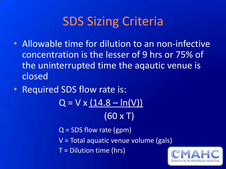
• Allowable time for dilution to an non-infective concentration is the lesser of 9 hrs or 75% of the uninterrupted time the aqautic venue is closed
• Required SDS flow rate is:
Q = V x (14.8 – ln(V))
(60 x T)
Q = SDS flow rate (gpm)
V = Total aquatic venue volume (gals)
T = Dilution time (hrs)
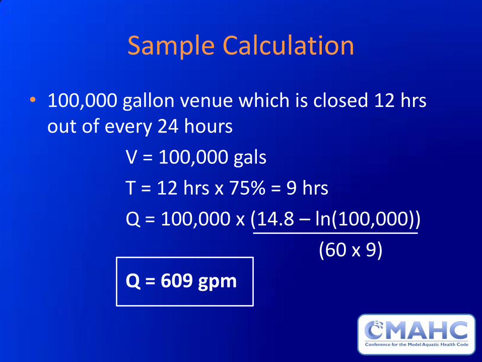
Sample Calculation
• 100,000 gallon venue which is closed 12 hrs out of every 24 hours
V = 100,000 gals
T = 12 hrs x 75% = 9 hrs
Q = 100,000 x (14.8 – ln(100,000))
(60 x 9)
Q = 609 gpm
Additional Considerations
• Minimum SDS size (flow rate) is determined independent of the filtration flow rate
• SDS can be sized for 100% of the filtration flow rate, so long as the flow through the SDS unit is equal to or greater than the minimum required flow rate as determined by the sizing formula

General SDS Design Requirements
• SDS may be installed on any type of aquatic venue
• If installation is required, they must be labeled as a SDS and conform to all SDS requirements
• SDS must achieve 3-log reduction in the number of infective Cryptosporidium parvum oocysts per pass through the SDS
• SDS must be located post-filtration • MAHC currently recognizes UV and Ozone as
acceptable SDS processes

Ozone
Secondary Disinfection
for
Public Swimming Venues
Under MAHC Compliance

Definition of Ozone
• Ozone is a gas that is dissolved in water to kill microorganisms, destroy organics, and break down chloramines by oxidation. This occurs immediately at the ozone gas injection point, and continues as the side-stream remixes with the main return. A small residual (~0.1 PPM) of dissolved ozone will enter the pool, providing further oxidation of contaminants.
Properties of Ozone
• Ozone (O3) is a gas derived from oxygen which can be readily dissolved in water
• Ozone has a fresh scent at low concentrations and smells pungent at higher concentrations
• Gaseous Ozone dissolved in water is referred to as Aqueous Ozone (which has no odor)
• Ozone is a powerful antimicrobial oxidizer and sanitizer • Aqueous Ozone is an effective micro-flocculant • Aqueous Ozone is an effective anti-foaming agent • Aqueous Ozone is an effective antimicrobial agent • The disinfecting capability of 1 PPM Aqueous Ozone is equivalent to
many times (10 to 4,000 times) the concentration of free available chlorine (Morris, 1975 – Disinfection: Water & Wastewater), depending on pH, temperature, and on the specific microorganisms to be destroyed
• Ozone is compatible with Chlorine in Swimming Pools

How is Ozone Measured?
• Dissolved ozone is measured by an Oxidation Reduction Potential (ORP) monitor/controller in a swimming pool
• The ORP reading can range between 600 mV to 900 mV at the point of introduction into the main return line before entering the pool
• An ORP of 800 mV is ~ 0.2 PPM dissolved ozone which is estimated to equate to ~40 PPM Cl in terms of oxidation and antimicrobial efficacy

Ozone Regulatory
• 1976 EPA Approves Ozone as an Antimicrobial Oxidizer Device • 1982 IBWA Bottled Water Association Approve Ozone as an
Antimicrobial for Product, and Disinfectant for Filler Lines • 1999 EPA Lists Ozone as Safe for Surface and Ground Water • 2001 FDA/USDA Approve Ozone as an Antimicrobial Food
Additive • 2001 FDA/USDA Approve Ozone as a Food Contact Surface
Disinfectant • 2001 USDA National Organic Program Allows Ozone as an
Antimicrobial Food Additive and Food Surface Disinfectant • 2010 Ozone is added to the FDA Model Food Code as an
approved antimicrobial surface sanitizer • 2012 Ozone is recognized as a Secondary Disinfection
System in the Model Aquatic Health Code

Ozone Safety • EPA approved
• As a pesticide, ozone equipment must be registered by the EPA under the Federal Insecticide, Fungicide, and Rodenticide Act (FIFRA). DEL Ozone is an EPA registered establishment (EPA Estab. No. 071472-CA-001).
• OSHA Regulations for Ozone (Gaseous Only)
• Health Hazard Data
– Inhalation /Respiratory System, Eyes, Blood
• PEL (Permissible Exposure Limit)
– 8 hour Time Weighted Average 0.1 PPM Vol.
• STEL (Short Term Exposure Limit)
– 15 Minute 0.3 PPM Vol.
• IDLH (Immediately Dangerous to Life and Health)
– 5 PPM
• No OSHA Regulations apply to Aqueous Ozone; it is not harmful to humans

Ozone Biocidal Behavior
Before ozone treatment After ozone treatment
Electron micrographs of E. coli
E. coli dried as a biofilm on a porous surface
Sequential
Electron
Beam Power
Magnification Scale of Measure
One Micrometer
(micron)
Working Distance
1. Ozone oxidizes cell membranes, causing osmotic bursting (instantaneously)
2. Ozone continues to oxidize enzymes and DNA

Public Bath Tubs • Ozone Anti-Microbial Validation under ANSI/NSF Protocol P308
• Pass compliance requires a 3-log (99.9%) reduction of E. coli, Staphylococcus aureus, Pseudomonas aeruginosa, Trichophyton mentagrophytes and Candida albicans in 30 minutes
• Actual Microbial Reductions in 30 Minutes
E. coli 4.7 log (>99.99%)
Staphylococcus aureus 4.7 log (>99.99%)
Pseudomonas aeruginosa 3.2 log (>99.9%)
Trichophyton mentagrophytes 4.0 log (99.99%)
Candida albicans 4.7 log (>99.99%)
Test Parameters
Water temperature @ 93° F, 20 PPM oil insult, 1.1 PPM side-stream applied single pass ozone dose, microorganism destruction was measured in the tub

Public Swimming Venues • Ozone Anti-Microbial Validation under ANSI/NSF Standard 50, Annex H
• Pass compliance requires a 3-log (99.9%) reduction of Pseudomonas aeruginosa and Enterococcus faecium in 30 minutes
• Actual Microbial Reductions in 6 Minutes
Pseudomonas aeruginosa 6.6 log (>99.9999%)
Enterococcus faecium 6.7 log (>99.9999%)
Test Parameters
Water temperature @70° F
20 PPM oil insult
9 PPM Urea insult
1.6 PPM side-stream applied single pass ozone dose
Microorganism destruction was measured in the pool

Public Swimming Venues
• Ozone Antimicrobial Validation for Cryptosporidium parvum Reduction tested by NSF International
• Pass compliance requires a 3 Log (99.9%) reduction of Cryptosporidium parvum
• Actual Microbial Reductions in 30 Seconds
Cryptosporidium parvum 3.0 log (>99.9%)
Test Parameters
Water temperature @76° F
1.6 PPM side-stream applied ozone dose
Crypto measurements were taken on a single pass [measured after side-stream is diluted in full flow] defined as a side-stream-applied single-pass or full-flow system

Side-Stream Applied Single Pass
Determining Ozone’s Proper Operation
• Ozone’s ORP reading is 750 mV or greater
• Ozone generator’s control system indicates that zone is being produced
• Ozone generator’s operational indicators are in the proper operational ranges

CT Values for Cryptosporidium parvum Inactivation
CT Value Concentration times Time
(PPM * Minutes Exposure = CT Value)
Chlorine CT is 15,300 [20 PPM for 13 hours (780 minutes)]
Aqueous Ozone Total CT (@ 100%) 0.76
NSF Rated CT Value (0.76*2) 1.52
Donofrio, R. (2013) Laboratory Validation of an Ozone Device for Recreational Water Treatment. Journal of Water and Health; Published by IWA Publishing in collaboration with the World Health Organization (WHO). Peer-reviewed and accepted for publication 10 Mar 2013

MAHC Ozone System Requirements
An ozone system shall be a complete system, consisting of the following (either skid-mounted or components):
1) Ozone generator
2) Injector / injector manifold
3) Reaction tank (contact tank) / mixing tank / degas tower
4) Degas valve (if applicable, to vent undissolved gaseous ozone)
5) Ozone destruct (to destroy undissolved gaseous ozone)
6) ORP monitor / controller
7) Ambient ozone monitor / controller (for indoor systems)

Basic Ozone System System Components: A) Ozone Generator B) Injector Manifold C) Reaction Tank D) Degas Valve &
Destruct E) ORP
Monitor/Controller F) Ambient Ozone
Monitor/Controller
A
E
B
D
C
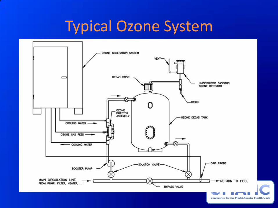
Typical Ozone System

Basic Ozone System Components Shown: A) Ozone Generator B) Injector Manifold C) Reaction Tank D) Degas Valve E) Ozone Destruct F) ORP Controllers
(not shown)
A A
C C
E
B B
D D

Ozone System & ORP Controller
Components Shown: A) Ozone Generator B) ORP Controller
A
B

Injector Assembly
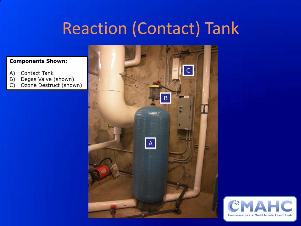
Reaction (Contact) Tank
Components Shown: A) Contact Tank B) Degas Valve (shown) C) Ozone Destruct (shown)
A
B
C

Degas Valve

Ozone Destruct

Ambient & Controller/Alarm
Components Shown: A) Monitor B) Sensor
A
B
Ozone Compatibility with Cl and Br
• Ozone’s reaction with chlorine is minimal
• Ozone will break down chloramines
• Ozone provides the main oxidation and disinfection in the pool while the chlorine provides a chemical residual
• It is not recommended that ozone be used in conjunction with bromine. When used with bromine, ozone oxidizes “spent” bromine (bromide) back to useful bromine. This depletes the ozone before it can oxidize the organic contaminants in the water, and significantly reduces ozone’s efficacy.

References and Credentials
• INTERNATIONAL OZONE ASSOCIATION PROCEEDINGS OF THE INTERNATIONAL OZONE ASSOCIATION - PAN AMERICAN GROUP ANNUAL CONFERENCE, September 19-22, 2010, Bellevue, Washington – Peer reviewed and Copyrighted © 2010
• DISINFECTION AND WATER QUALITY TECHNICAL COMMITTEE - MODEL AQUATIC HEALTH CODE – Peer reviewed 2010
• RIP G. RICE, PH.D., R.I.C.E. INTERNATIONAL GLOBAL OZONE CONSULTANT – Peer reviewed 2010 • HAAG, W. R. AND HOIGNE, J. (1984) 'Kinetics and products of the Reactions of Ozone with Various forms of
Chlorine and Bromine in Water', Ozone: Science & Engineering, 6: 2, 103 - 114 • AIR LIQUIDE AMERICA CORP, Chicago Research Center, James T.C. YUAN, Ph.D., ca 2000 • NSF INTERNATIONAL ANSI/NSF Protocol P308 - Validation • NSF INTERNATIONAL ANSI/NSF Standard 50 - Validation • NSF INTERNATIONAL ANSI/NSF Standard 50 – Annex H (Microbial Efficacy and Ozone Safety) – Validation • NSF INTERNATIONAL Report J-00047649 (Cryptosporidium parvum) – Validation • Donofrio, R. (2013) Laboratory Validation of an Ozone Device for Recreational Water Treatment. Journal of
Water and Health; Published by IWA Publishing in collaboration with the World Health Organization (WHO). Peer-reviewed and accepted for publication 10 Mar 2013
• NSF INTERNATIONAL TOXICOLOGY GROUP safety testing based on Hazard Communications Standard as promulgated through the Occupational Safety and Health Act (OSHA) of 1970 and documented in the Code of Federal Regulations, Title 29 – Compliant
• USEPA registered establishment under the Federal Insecticide, Fungicide, and Rodenticide Act (FIFRA) - Compliant
• USEPA/FIFRA Office of Pesticide Programs (OPP) Disinfectant Technical Science Section (DIS/TSS) - Compliant
Applying
UV Treatment
Secondary Disinfection
for
Public Swimming Venues
Under MAHC Compliance

The Main Functions of UV Pool Water Treatment
1. To provide secondary disinfection, particularly against chlorine-resistant pathogens such as Cryptosporidium and Giardia.
2. To reduce the chloramine components of combined chlorine.

Key Parameters for a Secondary Disinfection System (SDS)
• Water quality (For UV it is the UV Transmittance)
• Turnover rate through the SDS
• Rate of reduction in the number of ineffective Cryptosporidium parvum oocysts per pass
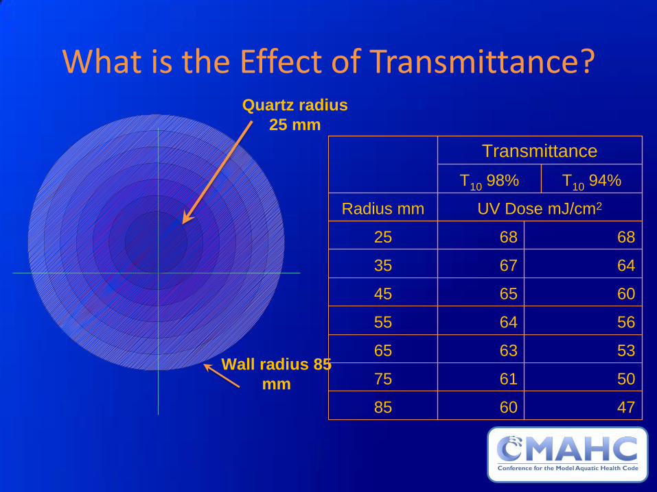
What is the Effect of Transmittance? Quartz radius
25 mm
Wall radius 85
mm
47 60 85
50 61 75
53 63 65
56 64 55
60 65 45
64 67 35
68 68 25
UV Dose mJ/cm2 Radius mm
T10 94% T10 98%
Transmittance
Defining a Standard for UV Transmittance
• UV performance / dose is highly dependent on the water’s
transmittance to UV light . • Manufacturers quoted doses where calculated from
assumed UVT’s ranging between 94% to 98% • Some pool operators believed 98% represented a ‘better
basis’ • UVT data was obtained from 20 aquatic facilities which had
a UVT range of 93.5% to 95% • USA’s Model Aquatic Health Code annex: “Design
transmissions over 94% are not recommended, and exceptionally heavily loaded facilities may consider using a lower number as a design basis.”

Figure 1: Steady State Velocities on Inlet Plane

Figure 2: Steady State Flow Pattern (Streamlines)
Note: deep-end jets carry further (all inlets identical with same flow rate)

Figure 3: Contaminant after First Time Step
100e6 organisms
introduced over the first time step
Note that contaminant is introduced
immediately in front of an inlet,
leading to rapid initial spread
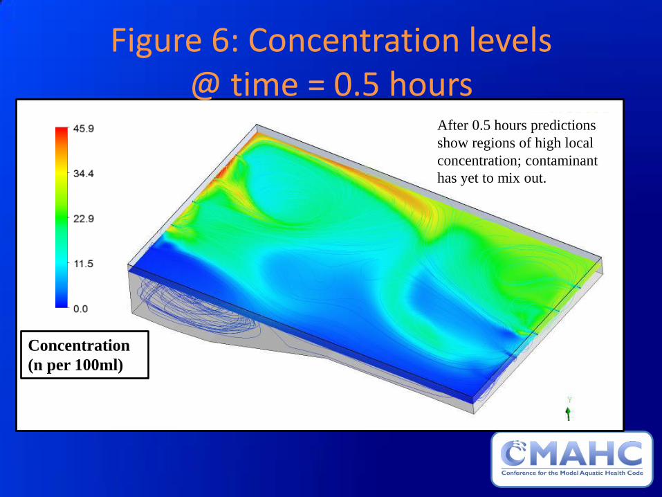
Figure 6: Concentration levels @ time = 0.5 hours
Concentration
(n per 100ml)
After 0.5 hours predictions
show regions of high local
concentration; contaminant
has yet to mix out.
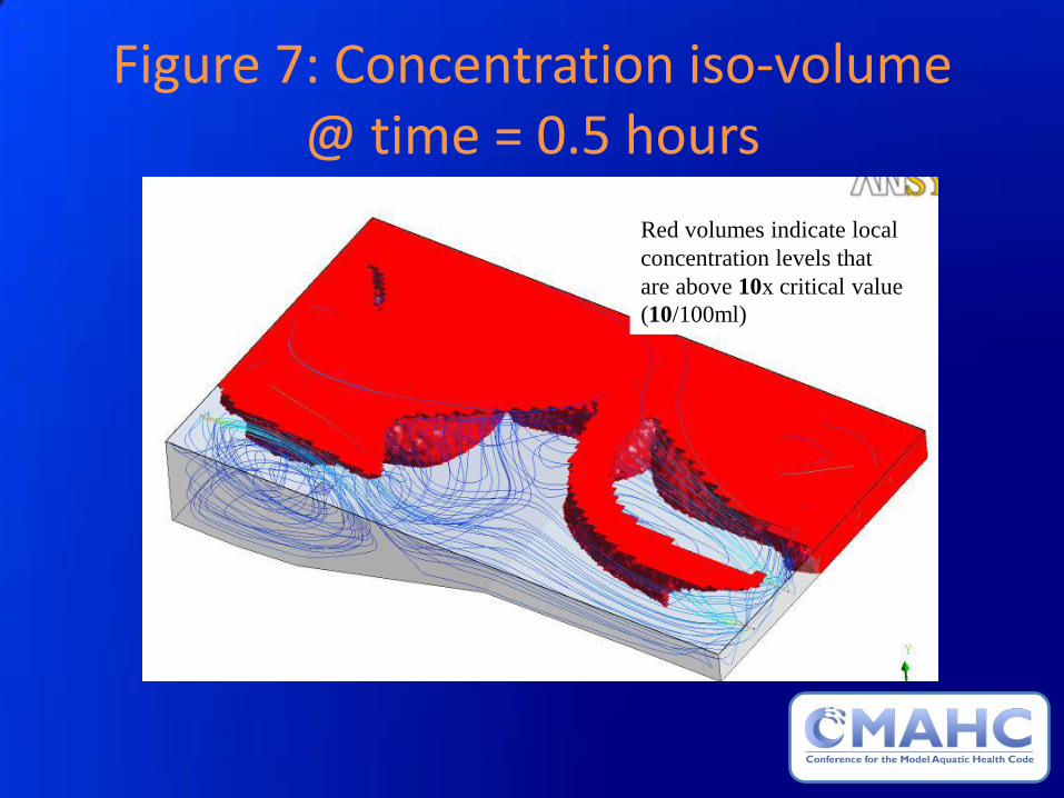
Figure 7: Concentration iso-volume @ time = 0.5 hours
Red volumes indicate local
concentration levels that
are above 10x critical value
(10/100ml)

Figure 13: Concentration iso-volume @ time = 12 hours
Red volumes indicate local
concentration levels that are
above 1.0x critical value
(1.0/100ml)
Turnover Rate Calculation
• Full flow treatment is the most effective route and the simplest to check and manage.
• For a well designed filtration system full flow will meet the requirements of the MAHC code formula

Disinfection Rate
• The disinfection rate was established based on exponential decay calculations as 99.9% reduction per pass (3 log reduction)
• For a UV system this is in effect the dose. • ‘Dose’ is the most contentious aspect of UV
design. • The term dose is meaningless without
understanding the calculation basis. • UV Monitoring is incorrectly assumed to precisely
measure this process
Calculating a Dose for Combined Chlorine Reduction
• Historically a dose of 60mJ/cm2 based on an average calculation using wavelengths from 200 to around 315nm was the standard.
• Manufacturers could use a band of 200 nm – 400 nm (almost twice the normal UV band)
• No change to system power or effective performance, yet capacities almost double in some cases

Wavelengths Used to Calculate UV Intensity
Alternative
Range
Usual Range

Calculating a Dose for Disinfection
• This is more complex as it requires not just adequate amounts of UV but hydraulically efficient application.
• This aspect of UV has resulted in most modern UV applications making use of RED (reduction equivalent dose) which is usually still expressed in mJ/cm2
• RED doses are normally ‘validated’ by third parties to approved national standards and include significant standard error factors (validation factors and RED bias)

Average Dose is Sometimes a Poor Measure of Disinfection Performance
• Disinfection performance is dependent on dose distribution.
• Assumes perfect laminar flow through the length and cross-section of the chamber.
• Does not allow for false inclusion of high or cumulative dose values (a micro-organism can be de-activated only once).

Dose Distribution
Avg. Dose = 50mj/cm2
RED = 24 mj/cm2
>3 Log reduction
(After VF and RED Bias)
Avg. Dose = 60mj/cm2
RED = 12 mj/cm2
<2 Log reduction
(After VF and RED bias)
0
6
12
18
24
30
36
42
48
54
60
66
72
78
84
90
96
20
0
50
0 0
50
100
150
200
250
300
350
0 6 12 18 24 30 36 42 48 54 60 66 72 78 84 90 96 200 500
0
50
100
150
200
250
300
350

CFD Velocity Gradients – Axial Flow Chamber Design
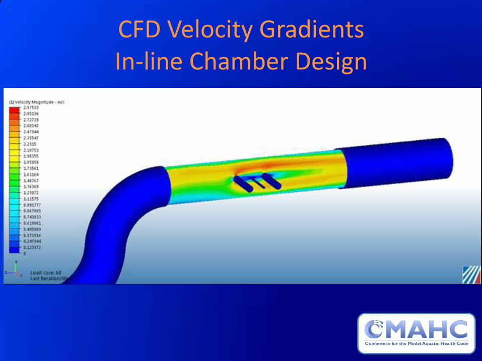
CFD Velocity Gradients In-line Chamber Design

Model Aquatic Health Code (MAHC)
• “Secondary Disinfection Systems shall be designed to achieve a minimum 3-log (99.9%) reduction in the number of infective Cryptosporidium parvum oocysts per pass through the Secondary Disinfection System….. UV equipment shall be third party validated in accordance with the practices outlined in the US EPA Ultraviolet Disinfectant Guidance Manual dated November, 2006, publication number EPA 815-R-06-007.”

Required Disinfection Performance
• Performance of equipment should be equivalent to drinking water standards.
• Proof of performance should be independently assessed.
• 3rd party validation (e.g. against USEPA guidelines) is the only certain method.
• CFD modelling is no substitute; it can be used for design, but is not independently evaluated.

Recommendations
• UV systems should be sized on a realistic transmittance value, e.g. 94%.
• An average UV dose for combined chlorine of 60 mJ/cm2 reduction should be calculated only on the UV output from germicidal UVC wavelengths, i.e. 200 nm – 315 nm.
• UV systems should be 3rd party validated to demonstrate 99.9% reduction of Cryptosporidium oocysts.
• The dose for 3 log reduction shall be at end of lamp life and include the tested validation factor including RED bias taken at 90% UVT as per the USEPA tables for Cryptosporidium inactivation.
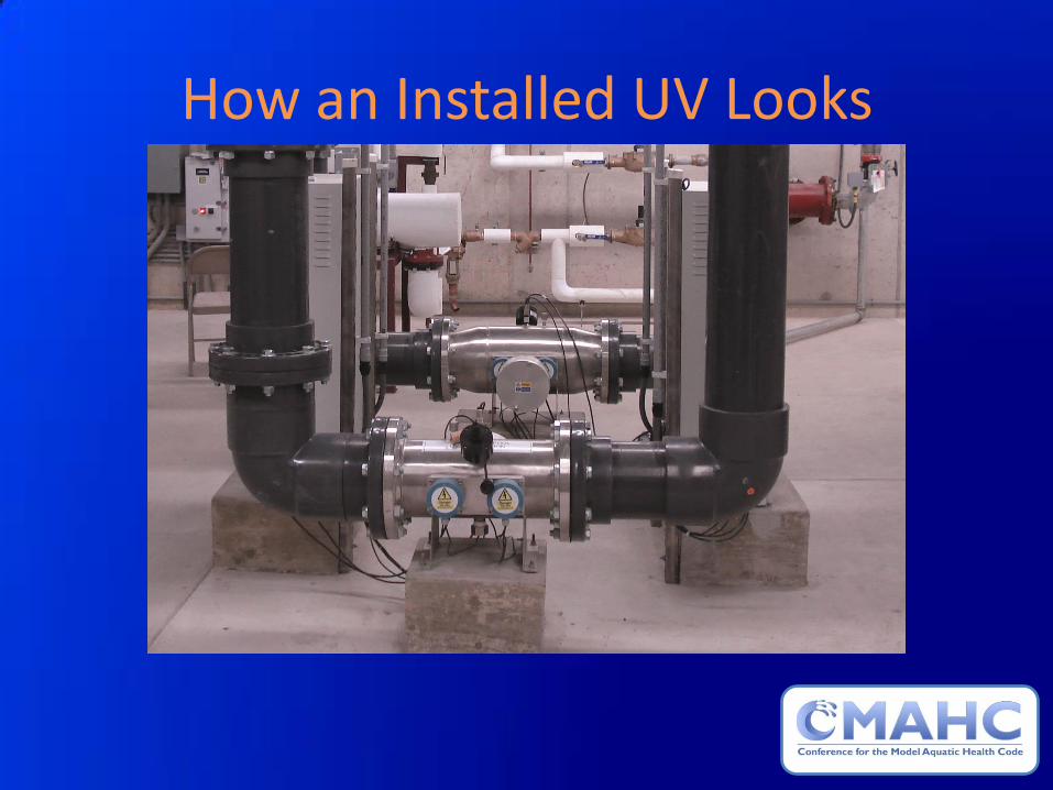
How an Installed UV Looks

Typical UV Controller

Typical Validation Letter

Checking the Controller to ensure UV is Operating within Parameters
• Equipment must be labeled with design specifications
Flow less than max Transmissivity greater than min Intensity greater than min Dosage greater than min

CMAHC Information: Search on “CMAHC” or visit the CMAHC
Website: www.cmahc.org
Email: [email protected]
MAHC Information: Search on “CDC MAHC” or visit the Healthy Swimming
MAHC Website: www.cdc.gov/mahc
Email: [email protected]