secondary-side-only simultaneous power and efficiency...
TRANSCRIPT

Copyright © 2016 Society of Automotive Engineers of Japan, Inc. All rights reserved
Secondary-side-only Simultaneous Power and Efficiency Control
in Dynamic Wireless Power Transfer System
Giorgio Lovison 1) Daita Kobayashi 1) Takehiro Imura 2) Yoichi Hori 1)
1) The University of Tokyo, Graduate School of Frontier Sciences
5-1-5 Kashiwanoha, Kashiwa, Chiba, 277-8561, Japan
2) The University of Tokyo, Graduate School of Engineering,
7-3-1 Hongo, Bunkyo-ku, Tokyo, 113-8656, Japan
Presented at the EVTeC and APE Japan on May 26, 2016
ABSTRACT: Electric vehicles and wireless power transfer are a convenient combination. Past research considered either
power control or efficiency control in wireless secondary side, but a more advanced control is desirable. Therefore, the
authors propose a control for power and efficiency with two converters entirely performed on the secondary side of the
wireless system, independently from the primary side. In this paper, a dynamic charging scenario is considered: the control
must provide the required power at maximum efficiency conditions while the mutual inductance is changing. The
experimental results verify that the proposed control effectively works during dynamic charging.
KEY WORDS: dynamic wireless charging, power control, efficiency control
1. INTRODUCTION
In the last few years, electric vehicles (EVs) have become a key
point in saving energy, achieving high controllability by use of
electric motors and reducing pollution. However, currently most
of EVs must be charged via plug-in method: this process is time
consuming as well as carrying some safety issues for the
consumer such as the high voltage used during charging.
Wireless power transfer (WPT) technology recently is becoming
suitable for automotive applications. WPT by magnetic resonant
coupling1) can achieve high power and high efficiency when the
transmission distance is lower than one meter because it allows
robustness against misalignment, increased air gap and higher
transmission efficiency when compared to conventional
induction method. There are different types of WPT by magnetic
resonant coupling, depending on the compensation carried by the
capacitances: one of the types used in automotive application is
the series-series (SS) compensation because it allows high power
to flow on the receiver side. Currently, static WPT is available on
the market; however, developing in-motion wireless power
transfer is necessary because it would mean extreme reduction of
battery weight and range anxiety; recently, some trial units are
been experimented upon and achieved promising results. A good
converter control is necessary to send the necessary power to the
vehicle with high efficiency2). In WPT, converter control is
generally divided into power control and efficiency control; they
can be performed on primary side3) 4), on secondary side5) 6) or on
both sides at the same time7) 8). However, most of the times, in
past research power and efficiency control have been performed
in different sides of the systems (e.g. efficiency control on
16mm
④
20169060
Fig. 1: Equivalent circuit of SS compensated WPT system.

Copyright © 2016 Society of Automotive Engineers of Japan, Inc. All rights reserved
primary side and power control on secondary side). A novel
control able on the secondary side to transfer at the same time the
desired power with high efficiency without any kind of
communication with the primary side is desirable. In a WPT
system for EV battery charging, the secondary side usually
include a rectifier and a DC/DC converter connected to the
battery. Therefore, it is possible to control the efficiency and the
power flow only by secondary side. The motivation to control
only the secondary side consists in keeping the primary side
simple, thus allowing a standardization for future commercial
WPT installations. A paper dealing with this concept in a static
charging scenario has been recently published 9). Therefore, in
this paper, the authors propose a simultaneous power and
efficiency control for the secondary side of a WPT system with
SS compensation for dynamic charging.
2. CASE OF STUDY
This paper deals with the secondary side control of a WPT
system with SS compensation: it includes a half active rectifier
(HAR), a DC/DC converter and a battery as load. The frequency
in the WPT system is the resonant frequency extracted from the
coil parameters and is independent from the load and the distance
between the coils. The resonant angular frequency is given as
follows:
2211
11
CLCL (1)
with 1L and 1C as the primary coil inductance and capacitance,
respectively; similarly, 2L and 2C are the secondary coil
inductance and capacitance. The coil internal resistance has no
effect on the resonant frequency but affects the losses and the
dynamic response of the system. The mutual inductance between
the primary and secondary coil depends on factors such as the
distance between coils, their geometry, the media between them,
the presence of metallic parts in the coils vicinity, etc.. The
reference circuit is shown in Fig.1. Using a HAR and a DC/DC
converter to control the efficiency and the power flow in the
secondary side is proposed with respect to this circuit.
3. PROPOSED CONTROL
3.1. Control concept
In WPT theory, the formulae of the load power LP and
transmitting efficiency , presented in previous papers 10) 11) 12),
are given respectively by:
2
0,12221
2
VLRZR
ZLP
mL
Lm
L
(2)
2212
2
mLL
Lm
LRZRZR
ZL
(3)
where LZ is the load impedance seen from the secondary coil,
2R is the secondary coil resistance, 1R is the primary coil
resistance, mL is the mutual inductance between the coils and
0,1V is the rms value of the fundamental wave of primary side
voltage. In this paper, the power factor of the primary side
voltage is assumed to be unity, therefore the power factor of the
fundamental wave of the secondary side voltage 2V is
considered to be unity, too. The HAR is a full wave diode bridge
whose low side diodes are replaced by active devices like
Fig. 2: Reference circuit of WPT using SS compensation and equivalent coil configuration.
Fig. 3: HAR modes.

Copyright © 2016 Society of Automotive Engineers of Japan, Inc. All rights reserved
MOSFETs or IGBTs: by turning on the both the devices on the
low side, the coil terminals are shorted (short mode) and no
power is transmitted to the load. Since the SS compensation of
magnetic resonant coupling makes the secondary side coil behave
like an equivalent current source, short-circuiting the coil
terminals is allowed. On the other hand, if both the low side
devices are off, the converter works like a single-phase rectifier
composed by diodes (rectification mode), as shown in Fig. 3, and
power is sent to the load.
The influence of load impedance has been examined in 10) 11) 13).
In particular, the load impedance associated with maximum
transmission efficiency and the one related to maximum
deliverable power are different. The former one is equal to:
22
2
1
2max, RL
R
RZ mL (4)
The secondary coil voltage that maximizes the transmission
efficiency can be expressed by:
0,1
22121
1
2max V
LRRRR
L
R
RV
m
m
(5)
On the other hand, the load impedance and the secondary coil
voltage related to the maximum available power are given by:
2
1
2
max, RR
LZ m
PL
(6)
0,11
max2
VR
LV m
P
(7)
Voltages in (5) and (7) are rms values of the fundamental wave
component. Finally, the total input impedance seen from the
secondary coil must be max,LZ during rectification mode. On
the other hand, when short mode happens the secondary input
impedance is only a few ohms. The control of the input
impedance allows to use the HAR to send the power desired by
the load to the DC/DC converter, which in turn is used to
guarantee maximum transmitting efficiency. Fig. 4 shows the
relationship between power and efficiency with respect to the
load impedance. The power corresponding to maximum
transmitting efficiency is fixed. However, by the proposed
secondary side control, it is possible to send a different power
value while retaining the same transmitting efficiency. This is
because of the switching between short mode and rectification
mode by HAR. The length of the short mode during the HAR
switching period determines the amount of power received by the
load. Fig. 5 shows how the control works and how the secondary
side input parameters are shaped. In rectification mode, the rms
value of secondary side voltage is unchanged, therefore the rms
value of the secondary side input power is unchanged. The
secondary side coil behaves like an equivalent current source so
the current does not change as well. The power is calculated by
averaging, as well as the efficiency; consequently, the averaged
efficiency computed from the ratio between secondary power and
primary power will be lower because of the resistive losses
happening during short mode. In fact, during rectification mode
the efficiency is maximum while in short mode it is zero since
the load is not supplied.
Fig. 4: Transmission efficiency and load power with respect to
load impedance for V201 V and μH2.39mL .
Fig. 5: Control concept with parameters waveforms (top to
bottom: HAR input voltage 2V , HAR input current 2I ,
HAR input power 2P , total efficiency ).

Copyright © 2016 Society of Automotive Engineers of Japan, Inc. All rights reserved
3.2. Control operation
In Fig. 6 and Fig. 7 are represented the control blocks for the
HAR and DC/DC converter, respectively. The feedback part of
both the controllers is designed with the pole placement method.
1)(
s
sk
s
kksC di
pPID
(8)
The HAR can be thought as a non-linear resistance; however, in
this paper dynamic charging is considered, therefore transient
must be included. Then, its plant includes only one pole due to
secondary DC smoothing capacitor DCC :
sCR
P
sd
sPsP
DCL
DCHAR
1)(
)()( 2 (9)
with 2P as the HAR input power and LR as the equivalent
circuit load resistance. However, instead of a PID controller, a PI
one is considered sufficient. In the proposed control, the
following requirements must be met:
1) Primary side voltage source and system frequency are given
and fixed. The duty cycle of the primary converter is fixed,
consequently the primary coil voltage is fixed, too.
2) The HAR switching frequency is at least one order of
magnitude lower than the DC/DC converter one to avoid
operation conflict and potential instability.
3.2.1 HAR control
The HAR modulates the power by adjusting the duty cycle to
switch between rectification mode and short mode. Therefore, a
voltage formula related to the desired power *
LP and the
maximum power is necessary. From (7), the above mentioned
voltage is computed as follows 14):
1
*2212
maxmax*R
PLRRVVV Lm
PPPL
(10)
By rearranging (10), the value of the desired power as a function
of the voltage is obtained as follows:
221
2max
2max1*
*
m
PPP
LLRR
VVVRP L
(11)
Since the aim is to achieve high transmission efficiency, the
upper limit of the desired power is reached when *LP
V is equal to
maxV ; therefore, (11) is adjusted and becomes:
221
2maxmax
2max1
max,
m
PP
LLRR
VVVRP
(12)
The feedforward part of the control in Fig. 6 is decided by the
ratio between the HAR input power 2P and (12).
3.2.2 DC/DC converter control
In this paper, a buck converter is considered. The control makes
the DC link voltage equal to the maximum efficiency voltage, but
the mutual inductance must be known. Since this paper deals
with a dynamic charging scenario, the coils are moving and
therefore the mutual inductance changes. Therefore, a method to
estimate the mutual inductance is necessary. In 15), a real-time
estimation of the coupling coefficient by using secondary side
DC link information and recursive least square (RLS) filter has
been proposed. In this paper, the DC/DC converter control
concept is the same. The estimation is important to the control
because it affects also the HAR control: in fact, in (12) there are
many factors related to it. Poor estimation leads to noisy,
unstable references that severely reduce the efficiency. In
particular, the operation of HAR is the main cause of noisy
estimation. This is because during short mode the DC link
current is equal to zero: since the secondary DC current
information is used as input in the RLS filter, when its value
becomes zero so does the estimated mutual inductance and the
voltage reference for high efficiency control. The RLS filter
output ][iy and input ][i are expressed as follows 15):
])[][(4][ 212
11 iIRiVIRVViy DCDCDC (13)
][2][ iIi DC (14)
with i as the sampling counter. From (13) and (14), the updating
parameters are computed in discrete time as:
])1[][(][][ iiiyi (15)
Fig. 6: HAR power control block.
Fig. 7: DC/DC converter DC link efficiency control block.

Copyright © 2016 Society of Automotive Engineers of Japan, Inc. All rights reserved
][]1[][
][]1[]1[][
2i
iTi
iiTii
(16)
]1[][
][]1[][1
]1[][
2 iTi
iiTi
iTiT
(17)
However, in this paper ,the application of conditional updating to
the RLS filter is considered: when short mode happens, the
values are held at their last value; when rectification mode
happens, the filter coefficients updating restarts. These
parameters are employed in the PID feedback and in the
feedforward equilibrium point as described in 15). Finally, the
transient of the current 2I must end much earlier than the vehicle
speed one because the filter can be applied only in steady state.
4. SIMULATION AND EXPERIMENTAL RESULT
In order to verify the effectiveness of the proposed method,
experiments have been performed. The aim is to prove that even
if mutual inductance changes, the control is stable and the desired
power is effectively sent to the load. The circuit parameters are
reported in table 1. The DC/DC converter resistance convR and
its inductance convL are 0.2 Ω and 1000 µH, respectively; as for
the DC/DC converter filter capacitance convC , its value is 1000
µF. The HAR switching frequency is 500 Hz, while the DC/DC
converter one is 10 kHz. In order to verify the proposed system, a
mini model is being used. The primary voltage source is 18 V.
The experimental setup is shown in Fig. 8. In the experiment, the
Table 1: Circuit parameters.
Parameter Value
Load battery voltage [V] 6.34
Primary coil capacitance C1 [nF] 6.03
Secondary coil capacitance C2 [nF] 12.15
DC link capacitor CDC [µF] 1000
Primary coil inductance L1 [µH] 417.8
Secondary coil inductance L2 [µH] 208.5
Mutual inductance Lm [µH] (best alignment) 39.2
Coil gap [mm] (best alignment) 100
Resonant frequency [kHz] 100
Primary coil resistance R1 [Ω] 1.83
Secondary coil resistance R2 [Ω] 1.281
(a) Mutual inductance (b) DC link voltage (c) Power (d) DC to DC efficiency
Fig. 9: Simulation result with the DC/DC converter control proposed in 15) for a speed of 10 km/h.
(a) Mutual inductance (b) DC link voltage (c) Secondary side power (d) DC to DC efficiency
Fig. 10: Simulation result with the proposed control: reference power is 5 W and the speed is 10 km/h.
Fig. 8: Experimental setup.
Copyright © 2016 Society of Automotive Engineers of Japan, Inc. All rights reserved
receiver coil is moved by a linear actuator. The position of the
coil is recorded by an encoder, which transmits the data to the
controller. The speed by which the receiver coil moves is 10
km/h. The experimental results on DC to DC efficiency are
compared with the experimental results obtained by using the
control and the converters presented in 15). The experiments for a
desired power of 3 W and 5 W have been performed.
In Fig. 9, the simulation results using the method and the
converters proposed in 15) are shown. In these simulation, the full
bridge diode rectifier is considered instead of the HAR in order
to to provide a reference for the transmitted power and efficiency.
In fact, if using a diode rectifier, the power is not controlled. The
efficiency in Fig. 9(d) is assumed to be the maximum DC to DC
efficiency the system can reach in ideal conditions.
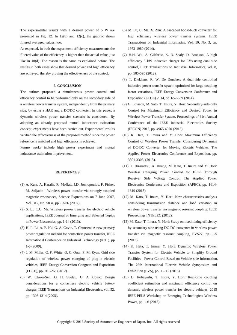
In Fig. 10, the simulation result of the proposed control are
presented. The influence of short mode is very noticeable. The
desired power is sent to the load and high efficiency is achieved.
However, in 12(c), the filtered average value is higher than the
actual value. This is due to the filter delay and the HAR low
switching frequency. Unfortunately, the mutual inductance
estimation results in the experiment are not as good as the ones
described in 15). Nevertheless, with those results the control can
still achieve the expected desired power and high efficiency, as it
can be seen in Fig. 11 and Fig. 12.
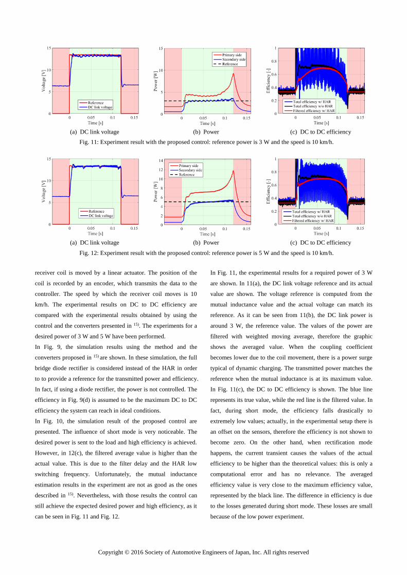
In Fig. 11, the experimental results for a required power of 3 W
are shown. In 11(a), the DC link voltage reference and its actual
value are shown. The voltage reference is computed from the
mutual inductance value and the actual voltage can match its
reference. As it can be seen from 11(b), the DC link power is
around 3 W, the reference value. The values of the power are
filtered with weighted moving average, therefore the graphic
shows the averaged value. When the coupling coefficient
becomes lower due to the coil movement, there is a power surge
typical of dynamic charging. The transmitted power matches the
reference when the mutual inductance is at its maximum value.
In Fig. 11(c), the DC to DC efficiency is shown. The blue line
represents its true value, while the red line is the filtered value. In
fact, during short mode, the efficiency falls drastically to
extremely low values; actually, in the experimental setup there is
an offset on the sensors, therefore the efficiency is not shown to
become zero. On the other hand, when rectification mode
happens, the current transient causes the values of the actual
efficiency to be higher than the theoretical values: this is only a
computational error and has no relevance. The averaged
efficiency value is very close to the maximum efficiency value,
represented by the black line. The difference in efficiency is due
to the losses generated during short mode. These losses are small
because of the low power experiment.
(a) DC link voltage (b) Power (c) DC to DC efficiency
Fig. 11: Experiment result with the proposed control: reference power is 3 W and the speed is 10 km/h.
(a) DC link voltage (b) Power (c) DC to DC efficiency
Fig. 12: Experiment result with the proposed control: reference power is 5 W and the speed is 10 km/h.
Copyright © 2016 Society of Automotive Engineers of Japan, Inc. All rights reserved
The experimental results with a desired power of 5 W are
presented in Fig. 12. In 12(b) and 12(c), the graphic shows
filtered averaged values, too.
As expected, in both the experiment efficiency measurements the
filtered value of the efficiency is higher than the actual value, just
like in 10(d). The reason is the same as explained before. The
results in both cases show that desired power and high efficiency
are achieved, thereby proving the effectiveness of the control.
5. CONCLUSION
The authors proposed a simultaneous power control and
efficiency control to be performed only on the secondary side of
a wireless power transfer system, independently from the primary
side, by using a HAR and a DC/DC converter. In this paper, a
dynamic wireless power transfer scenario is considered. By
adopting an already proposed mutual inductance estimation
concept, experiments have been carried out. Experimental results
verified the effectiveness of the proposed method since the power
reference is matched and high efficiency is achieved.
Future works include high power experiment and mutual
inductance estimation improvement.
REFERENCES
(1) A. Kurs, A. Karalis, R. Moffatt, J.D. Jonnopoulos, P. Fisher,
M. Soljacic : Wireless power transfer via strongly coupled
magnetic resonances, Science Expressions on 7 June 2007,
Vol. 317, No. 5834, pp. 83-86 (2007).
(2) S. Li, C.C. Mi: Wireless power transfer for electric vehicle
applications, IEEE Journal of Emerging and Selected Topics
in Power Electronics, pp. 1-14 (2013).
(3) H. L. Li, A. P. Hu, G. A. Covic, T. Chunsen: A new primary
power regulation method for contactless power transfer, IEEE
International Conference on Industrial Technology (ICIT), pp.
1-5 (2009).
(4) J. M. Miller, C. P. White, O. C. Onar, P. M. Ryan: Grid side
regulation of wireless power charging of plug-in electric
vehicles, IEEE Energy Conversion Congress and Exposition
(ECCE), pp. 261-268 (2012).
(5) W. Chwei-Sen, O. H. Stielau, G. A. Covic: Design
considerations for a contactless electric vehicle battery
charger, IEEE Transactions on Industrial Electronics, vol. 52,
pp. 1308-1314 (2005).
(6) M. Fu, C. Ma, X. Zhu: A cascaded boost-buck converter for
high efficiency wireless power transfer systems, IEEE
Transactions on Industrial Informatics, Vol. 10, No. 3, pp.
1972-1980 (2014).
(7) H.H. Wu, A. Gilchrist, K. D. Sealy, D. Bronson: A high
efficiency 5 kW inductive charger for EVs using dual side
control, IEEE Transactions on Industrial Informatics, vol. 8,
pp. 585-595 (2012).
(8) T. Diekhans, R. W. De Doncker: A dual-side controlled
inductive power transfer system optimized for large coupling
factor variations, IEEE Energy Conversion Conference and
Exposition (ECCE) 2014, pp. 652-659 (2014).
(9) G. Lovison, M. Sato, T. Imura, Y. Hori: Secondary-side-only
Control for Maximum Efficiency and Desired Power in
Wireless Power Transfer System, Proceedings of 41st Annual
Conference of the IEEE Industrial Electronics Society
(IECON) 2015, pp. 4965-4970 (2015).
(10) K. Hata, T. Imura and Y. Hori: Maximum Efficiency
Control of Wireless Power Transfer Considering Dynamics
of DC-DC Converter for Moving Electric Vehicles, The
Applied Power Electronics Conference and Exposition, pp.
3301-3306, (2015).
(11) T. Hiramatsu, X. Huang, M. Kato, T. Imura and Y. Hori:
Wireless Charging Power Control for HESS Through
Receiver Side Voltage Control, The Applied Power
Electronics Conference and Exposition (APEC), pp. 1614-
1619 (2015).
(12) M. Kato, T. Imura, Y. Hori: New characteristics analysis
considering transmission distance and load variation in
wireless power transfer via magnetic resosnat coupling, IEEE
Proceedings INTELEC (2012).
(13) M. Kato, T. Imura, Y. Hori: Study on maximizing efficiency
by secondary side using DC-DC converter in wireless power
transfer via magnetic resosnat coupling, EVS27, pp. 1-5
(2013).
(14) K. Hata, T. Imura, Y. Hori: Dynamic Wireless Power
Transfer System for Electric Vehicle to Simplify Ground
Facilities - Power Control Based on Vehicle-side Information,
The 28th International Electric Vehicle Symposium and
Exhibition (EVS), pp. 1 – 12 (2015)
(15) D. Kobayashi, T. Imura, Y. Hori: Real-time coupling
coefficient estimation and maximum efficiency control on
dynamic wireless power transfer for electric vehicles, 2015
IEEE PELS Workshop on Emerging Technologies: Wireless
Power, pp. 1-6 (2015).