secondnet: a data center network virtualization ...€¦ · secondnet: a data center network...
TRANSCRIPT
SecondNet: A Data Center Network VirtualizationArchitecture with Bandwidth Guarantees∗
Chuanxiong Guo1, Guohan Lu1, Helen J. Wang2, Shuang Yang3
Chao Kong4, Peng Sun5, Wenfei Wu6, Yongguang Zhang1
1Microsoft Research Asia, 2Microsoft Research Redmond, 3Stanford University4Huawei Technologies, 5Princeton University, 6University of Wisconsin-Madison
{chguo,lguohan,helenw,ygz}@microsoft.com, [email protected], [email protected]@cs.princeton.edu, [email protected]
ABSTRACTIn this paper, we propose virtual data center (VDC) asthe unit of resource allocation for multiple tenants in thecloud. VDCs are more desirable than physical data cen-ters because the resources allocated to VDCs can be rapidlyadjusted as tenants’ needs change. To enable the VDC ab-straction, we design a data center network virtualization ar-chitecture called SecondNet. SecondNet achieves scalabilityby distributing all the virtual-to-physical mapping, routing,and bandwidth reservation state in server hypervisors. Itsport-switching based source routing (PSSR) further makesSecondNet applicable to arbitrary network topologies usingcommodity servers and switches. SecondNet introduces acentralized VDC allocation algorithm for bandwidth guaran-teed virtual to physical mapping. Simulations demonstratethat our VDC allocation achieves high network utilizationand low time complexity. Our implementation and exper-iments show that we can build SecondNet on top of vari-ous network topologies, and SecondNet provides bandwidthguarantee and elasticity, as designed.
Categories and Subject DescriptorsC.2.1 [Network Architecture and Design]: Packet-switching networks
General TermsAlgorithms, Design
KeywordsVirtual data center, DCN, Bandwidth guarantee∗This work was performed when Shuang, Kong, Peng, andWenfei were interns at Microsoft Research Asia.
Permission to make digital or hard copies of all or part of this work forpersonal or classroom use is granted without fee provided that copies arenot made or distributed for profit or commercial advantage and that copiesbear this notice and the full citation on the first page. To copy otherwise, torepublish, to post on servers or to redistribute to lists, requires prior specificpermission and/or a fee.ACM CoNEXT 2010, November 30 – December 3 2010, Philadelphia,USA.Copyright 2010 ACM 1-4503-0448-1/10/11 ...$
1. INTRODUCTIONWith the advent of Amazon EC2, Google AppEngine,
and Microsoft Azure, the dream of computing-as-a-utilityis becoming a reality [3, 13, 25]. By outsourcing com-puting to the cloud, businesses and consumers are freedfrom the cost and burden of planning, purchasing, oper-ating, and maintaining physical hardware and software,and at the mean time, it offers elasticity to meet dy-namic demands in resources and good economy with apay-as-you-go billing model [13].The Service Level Agreement (SLA) of today’s util-
ity computing [3, 25] are centered around computation(dollars per hour per virtual machine or VM), stor-age (dollars per GB per month), Internet traffic (dollarper GB transferred), and the availability of these re-sources. Nevertheless, no abstraction or mechanismsand hence no SLAs are available to capture the require-ments on the interactions among the allocated VMs,such as bandwidth guarantees among the VMs.In this paper, we propose virtual data center (VDC)
as the abstraction for resource allocation. A VDC is de-fined as a set of VMs with a customer-supplied IP ad-dress range and an associated service level agreement(SLA). The SLA specifies not only computation andstorage requirements, but also bandwidth requirementsfor the VMs. The bandwidth requirement is a key ad-dition and offers the significant benefit of performancepredictability. A VDC gives the illusion of a dedicatedphysical data center. This requires VDCs to be isolatedfrom one another in all resource access and usage. AVDC is in fact more desirable than a physical data cen-ter because it offers elasticity which allows its SLA to beadjusted according to the customer’s dynamic demands.To support VDC, we have designed a data center net-
work virtualization architecture called SecondNet. Thegoals of SecondNet are as follows. The design mustbe scalable. For example, bandwidth reservation statemaintenance must scale up to hundreds of thousandsof servers and millions of VMs in a data center. Itmust achieve high utilization of the infrastructure net-
work and support elasticity when tenants’ needs change.Finally, the architecture must be practically deployablewith commodity servers and switches. Providing band-width guarantees while achieving these goals is a keychallenge and is the focus of this paper.Maintaining bandwidth allocation state at switches
is prohibitively expensive even if only a small subsetof the VMs are communicating with one another (Sec-tion 3.2). We address the scalability issue by distribut-ing those state at the hypervisors of servers (which needonly handle state for their hosted VMs) and use sourcerouting to encode the route into each packet. Conse-quently, switches in SecondNet are stateless. The hy-pervisors are responsible for bandwidth policing sincethey are part of the trusted computing base.For providing bandwidth guarantees, we leverage a
special characteristic of data center networks. That is,a data center network is administered by a single entity,and thereby its network topology and failures withincan be obtained. This global view of the network al-lows a centralized bandwidth allocation together withfailure handling, which greatly simplifies the problem.In contrast, significant complexity arises for achievingIntegrated Services for the Internet due to the numerousISPs involved [14].Nevertheless, even centralized bandwidth allocation
poses significant challenges. It is an NP-hard problem.We then designed a low time-complexity heuristic algo-rithm. In this algorithm, we group neighboring serversinto clusters of different sizes. When allocating a VDC,we only search the appropriate clusters instead of theentire physical network, greatly reducing the allocationtime. This also leads to bandwidth-efficient VDCs be-cause the servers allocated are close in distance. Wethen use the efficient min-cost flow algorithm to mapVMs onto physical servers and leverage the rich connec-tivity of the physical networks in path allocation. Ourallocation algorithm handles incremental expansion andrelease of resource usage to support elasticity.For a practical implementation of source routing in
the data center environment, we introduce a Port-Switchingbased Source Routing (PSSR). Since the network topol-ogy of a data center network is known, PSSR repre-sents a routing path as a sequence of output ports ofswitches. PSSR can be readily implemented using theMPLS (multi-protocol label switching) [28] capabilityin existing commodity switches. SecondNet thereforecan be ready deployed on top of any of the recentlyproposed data center network structure, such as fat-tree [2], VL2[9], DCell [10], and BCube [11].The simulation results of our VDC algorithm show
that we can allocate a 5000-VM VDC in 493 secondson average in a 100,000-server data center. Moreover,our allocation algorithm achieves high resource utiliza-tion. We achieve more than 90% server bandwidth
for BCube, fat-tree, and VL2. We have implementedSecondNet with commodity servers and switches. Wehave constructed a 64-server testbed that supports bothBCube and fat-tree. Our experiments show that Sec-ondNet provides service differentiation and bandwidthguarantee, and SecondNet can perform path realloca-tion in seconds and VM migration in tens of secondsfor failure handling and dynamic VDC expansion.The rest of the paper is organized as follows. We de-
scribe our VDC service model in Section 2 and overviewour SecondNet architecture in Section 3. We presentPSSR and the VDC allocation algorithm in Section 4and Section 5. We use simulation to study VDC alloca-tion in Section 6 and show implementation and exper-iment results in Section 7. Section 8 presents relatedwork and Section 9 concludes.
2. SERVICE MODELAddressing. For address isolation, every VDC has
its own IP address space (possibly supplied by tenants),which may overlap with other VDCs’ IP address spaces.VMs within the same VDC can communicate with eachother just as they are in the same layer-2 Ethernet.VMs in different VDCs cannot talk with each other bydefault due to security concern. But if needed, theycan communicate through layer-3 gateways. Similarly,VMs in VDCs can communicate with computers in theInternet or other private networks.Service Types. We enumerate the possible scenar-
ios needed by different tenants and make the case fordifferent VDC service types.Firstly, some applications desire performance predictabil-
ity and can benefit from having bandwidth guaranteesbetween VM-pairs. For example, many web servicescan be divided into three tiers: a frontend Web servertier, a middle application tier for business logic, and abackend database/storage tier. It is desirable to havebandwidth guarantees for the frontend-to-middle andmiddle-to-backend communications so that such webservices can serve their tenants with predictable perfor-mance. Also, distributed computing applications, suchas those that use MapReduce for data-intensive oper-ations, need to shuffle data among many servers. Theexecution of such a MapReduce job may be severely de-layed by a small number of straggling tasks due to con-tentions for network bandwidth [8]. Bandwidth guar-antees make it possible to predict the execution timeof such distributed computing applications and henceknow how long a VDC needs to be rented.Secondly, there are applications, such as background
file backup, that do not require bandwidth guarantee.A best effort network service is sufficient for them.Lastly, there are applications whose detailed traffic
patterns cannot be predetermined, but still prefer bet-ter than best-effort service. For example, when en-
terprises move their IT infrastructures into the cloud,they can reserve egress/ingress bandwidths for theirWeb/email/file servers and assign better than best-effortpriority to these services for service differentiation.Based on these observations, we support a service
model of three VDC types. Type-0 service providesguaranteed bandwidth between two VMs, which is anal-ogous to Integrated Service [14]. We also provide thetraditional best-effort service without any bandwidthguarantee. Between type-0 and best-effort, we offer atype-1 service that provides local egress/ingress band-width reservation for a virtual machine. Our VDCmodel focuses on bandwidth since network bandwidthis a scarce resource [8]. How to include metrics such aslatency into the VDC model is our future work.From a service differentiation point of view, type-0
provides hard end-to-end bandwidth guarantee. Type-1 provides only last and/or first hop guarantee, but itsperformance is better than best-effort. We therefore as-sign type-0 traffic the highest priority followed by type-1 traffic, and best-effort traffic has the lowest priority.We monitor and shape the type-0 and type-1 traffic andensure that they do not violate their reservations. Lowpriority traffic can use the network bandwidth reservedby high priority traffic if the reservation is not fully uti-lized. Hence the hybrid of different service types natu-rally results in efficient network bandwidth usage.A VDC’s bandwidth requirements can be specified
using a set of rules of the format [VDCId, srcVM, dstVM,srcPort, dstPort, protocol]→ servType (bandwidth). Forexample, [vdc0,vm0,vm1,80,*,TCP]→ type-0 (100Mb/s)specifies that TCP packets from vm0 to vm1 with sourceport 80 in vdc0 requires a type-0 service with an end-to-end bandwidth guarantee of 100Mb/s. SecondNetneeds to reserve the sum of the bandwidth required forall type-0 flows from vm0 to vm1. In another example,[vdc1, vm2, *, 139, *, TCP] →type-1 (50Mb/s) speci-fies that all TCP packets from source port 139 of vm2
requires a type-1 service with a local egress bandwidthguarantee of 50Mb/s at vm2.
3. SECONDNET OVERVIEWTo support the above service model, we have de-
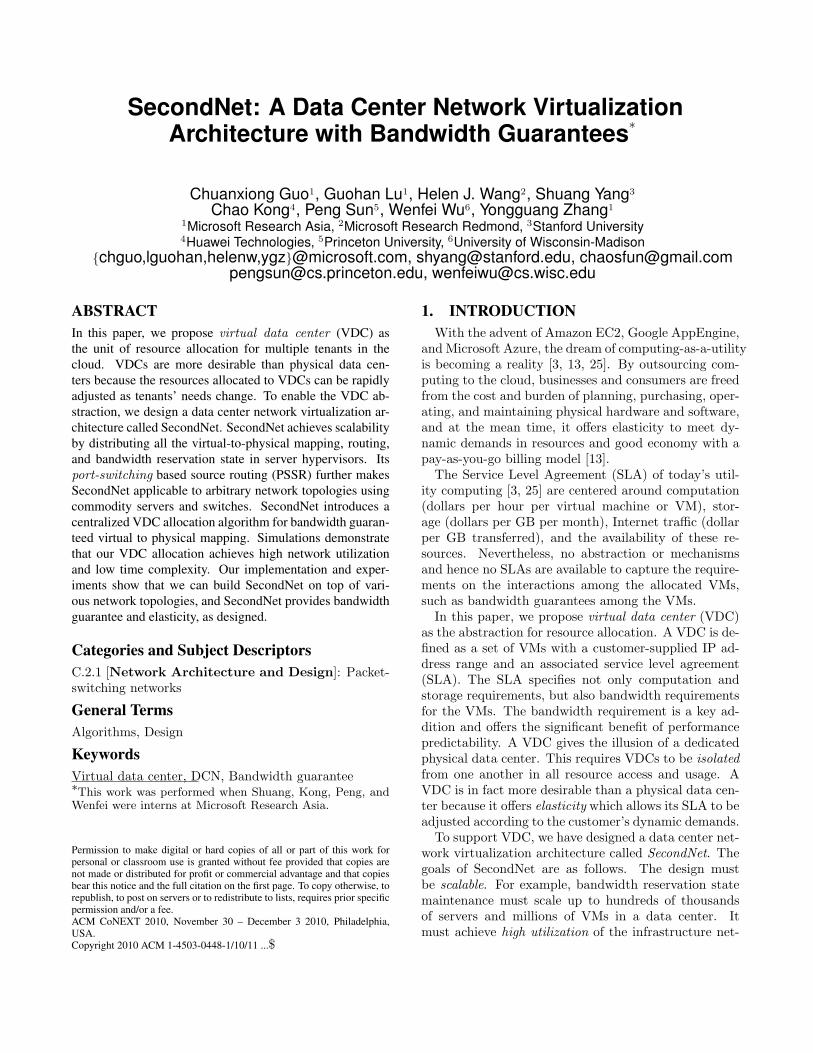
signed a data center virtualization architecture calledSecondNet as illustrated in Fig. 1. SecondNet focuseson bandwidth allocation and leverages server hypervisortechnology for CPU, memory, and storage isolation andsharing. It introduces a VDC manager for VDC cre-ation, adjustment, and deletion. VDC manager decideshow a VDC is mapped to the physical infrastructure.VDC manager, server hypervisors, and switches formthe trusted computing base because they are managedby data center operator. VDC manager manages theservers and switches using a spanning tree (SPT) basedsignaling channel.
Figure 1: The SecondNet architecture. The reddashed lines form a signaling spanning tree. Theblack broad lines show a port-switching sourcerouting (PSSR) path.
3.1 VDC ManagerA physical data center is administered by a single
entity. This led us to introduce a logically centralizedVDC manager. VDC manager controls all resources. Itperforms admission control for VDC requests based onthe request SLA and the available physical resources,using a VDC allocation algorithm (Section 5). The al-location algorithm decides how the VMs and virtualedges of a VDC are mapped onto physical servers androuting paths. The algorithm also supports elasticitywhen tenants expand or shrink the resources of theirVDCs, or when various failures happen.VDC manager assigns every VDC a unique VDC ID
and uniquely identifies a VM by its VDC ID and IP ad-dress. When VDC manager creates a VM for a VDC,it configures the host server hypervisor with the VDCID and IP address of the VM, the reserved bandwidthsfor type-0 and type-1 services, the routing paths fortype-0 VM-pairs, and the rule set for mapping trafficto different service types. VMs in a VDC form a con-ceptual level broadcast domain. Since VDC managermaps VMs to physical servers, it is the natural placefor VM-to-physical-server resolution.VDC manager needs to be scalable and highly fault
tolerant. It needs to be up all the time and scale with alarge number of VDC requests both in computation andin bandwidth. As we will show in Section 6, one sin-gle server can carry out our VDC allocation for VDCswith thousands of VMs at most hundreds of seconds.The traffic between VDC manager and the servers in-cludes VDC creation, adjustment, release requests andthe associated configuration messages. The traffic vol-ume is low. For example, the traffic volume for creatinga VDC with 1000 VMs is about 30MB, which can beeasily handled using the SPT signaling channel.VDC manager needs to maintain two types of state
for its operations. To perform VDC allocation, VDC
manager needs to store the whole physical network topol-ogy tagged with residual link capacities. For each al-located VDC, VDC manager needs to store all the re-source allocation state (i.e., the VM-to-physical-servermapping, egress/ingress bandwidth reservation for type-1 services, and bandwidth reservation and routing pathsfor type-0 services). Our simulation shows that we need5GB memory to store all the state for a VL2 [9] networkthat contains 100k servers. For fault tolerant, consis-tent, and high available state maintenance, we adopta similar approach to that of the directory service ofVL2 [9] for VDC manager, using replicated state ma-chines and Paxos consensus protocol [23].
3.2 Data PlaneStateless switches. To provide bandwidth guaran-
tee, we need to pin the routing paths for type-0 VM-pairs. One traditional way for bandwidth reservation isto setup the bandwidth reservation state in not only thephysical servers, but also the switches along the routingpath. However, this approach incurs severe scalabilityproblem in switch state maintenance. We use VL2 [9]as an example to illustrate the problem. In VL2, a top-of-rack (ToR) switch connects 20 servers, and an Aggre-gation switch connects 72 ToR switches. Suppose eachserver hosts 32 VMs and each VM talks to 1000 otherVMs. Then the bandwidth reservation state in an Ag-gregation switch will be 46 million (32×1000×20×72)entries. The entries in a server and a ToR switch are32k (32×1000) and 640k (32×1000×20), respectively.The state-of-the-art, high-end switches (e.g., Aristanet-works 7100 [4] and Cisco Nexus 7000 [7]) can only have16k-128k forwarding entries.To make state maintenance scalable at switches, we
use source routing. With source routing, switches be-come stateless and are unaware of any VDC and band-width reservation state at all. They just perform prior-ity queueing and forward packets based on the sourcerouting information carried in the packet headers.Hypervisors. Source hypervisors store virtual-to-
physical mappings, routing paths and bandwidth reser-vation state. The number of bandwidth reservation en-tries in a server is around 32k in the above example.This number can be trivially managed by servers.Hypervisors classify VM packets to different service
types and assign priority to those packets according toSLA. They then monitor and shape the type-0 and type-1 traffic before the traffic enters switches. Best-efforttraffic does not need shaping due to its lowest priority.Best-effort traffic therefore can use network bandwidthwhen type-0 and type-1 services do not fully use theirreservations. Hypervisors encode the priority and rout-ing path into packet headers. We note that traffic mon-itoring, shaping and prioritization must be placed inhypervisors instead of VMs since VMs are not trusted.
Practical deployment. Commodity servers andswitches provide the best performance-price tradeoff [5].We therefore want to implement both priority queueingand source routing on commodity servers and switches.Priority queueing is widely available in both servers andswitches. Source routing can be efficiently implementedin current server operating systems as kernel drivers.However, source routing generally is not available in
commodity switches. Furthermore, commodity switchesuse MAC or IP address for packet forwarding. Somedata center network structures may even not use MACor IP address [10, 11, 15].To this end, we introduce port-switching based source
routing (PSSR). Instead of carrying a sequence of next-hop addresses in source routing path, we directly carrythe sequence of next-hop output port numbers. WithPSSR, SecondNet can be implemented with any ad-dressing schemes and network topologies. PSSR canbe implemented readily with MPLS (multi-protocol la-bel switching) [28], which is a commodity technology.Fig. 1 shows one PSSR path {0,2,2,1} from vm0 to vm1
in VDC0. Suppose vm0 in VDC0 needs to send a packetto its peer vm1, it first generates a packet that containsvm1 as the destination address and vm0 as the sourceaddress and delivers the packet to the host hypervisors0. The host s0 then inserts the routing path, {0,2,2,1},priority, and related information into the packet headerand sends the packet to the neighboring switch. Theswitches then route the packet using PSSR. After thedestination server s1 receives the packet, it removes thePSSR header, and delivers the packet to vm1.
3.3 Signaling and Failure HandlingVDC manager needs a signaling channel to manage
all the server hypervisors network devices. Various serverand switch and link failures are inevitable in large datacenters. Failures cause network topology changes whichthen impact both signaling and bandwidth reservation.VDC manager must be notified when failures occur, androuting paths of the affected VDCs must be adjusted.Timely signaling delivery is challenging since the sig-naling channel itself may fail. In SecondNet, we builda robust, in-band spanning tree (SPT) rooted at theVDC manager as our signaling channel.In the spanning tree protocol, every device exchanges
an SPT message with all its physical neighbors. Themessage contains the parent and the level of the de-vice. When a device does not know its level, its level isset to NULL. The level of VDC manager is 0. Directneighbors of VDC manager then get level 1, and so on.A device always chooses the neighbor with the lowestlevel as its parent. When a device finds that its parentbecomes unavailable or the level of its parent becomesNULL, it tries to get a new level from its available neigh-bors other than its children. As long as the network is
connected, the spanning tree can be maintained. Sincethe spanning tree maintenance message contains parentinformation, a parent node knows all its children.VDC manager uses the spanning tree for all VDC
management tasks. Devices use the spanning tree todeliver failure messages to VDC manager. VDC man-ager then adjusts routing paths or reallocate VMs forthe affected VDCs if needed. VDC manager also broad-casts the topology changing information to all devicesvia the spanning tree. Certainly when a link in thespanning tree breaks, the link failure message can onlybe delivered after the spanning tree has been restored.We note that the spanning tree is only for signaling
purpose hence the traffic volume in the spanning tree issmall. We set the priority of the signaling traffic to bethe highest. And we can reserve a small amount of thelink bandwidth for the spanning tree. Section 6 furthershows that the spanning tree converges very quicklyeven when the link failure rate is 5%.
4. PORT-SWITCHING BASED SOURCEROUTING
4.1 Source RoutingSince servers know network topology and various fail-
ures via the spanning tree, we can remove switches frommaking routing decisions. This leads us to use sourcerouting for a scalable data plane.For type-0 traffic, source routing paths are decided by
VDC manager. Server hypervisors directly use thosepaths for routing. For type-1 and best-effort traffic,all the existing DCN routing designs can be easily im-plemented using source routing at source hypervisors.Both VL2 [9] and BCube [11] use source routing at theserver side, hence they can be directly incorporated intothe SecondNet framework. In PortLand [15], switchesuse destination physical MAC (PMAC) hashing to de-cide the next hop. The source servers can easily calcu-late the routing path on behalf of the switches in thiscase. Similarly, the source servers can calculate routingpaths for DCell [10], since DCell routing path is derivedfrom DCell IDs.The overhead of source routing is the routing path
carried in the header of every packet. We pay the over-head willingly for a scalable data plane and a flexiblerouting framework, since the maximum path length of atypical data center network is small (typically 6-8 hops).
4.2 Port-switchingWe introduce port-switching to simplify switch func-
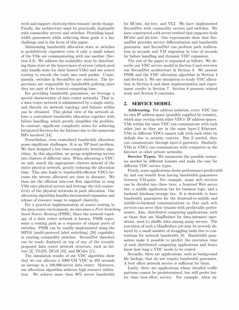
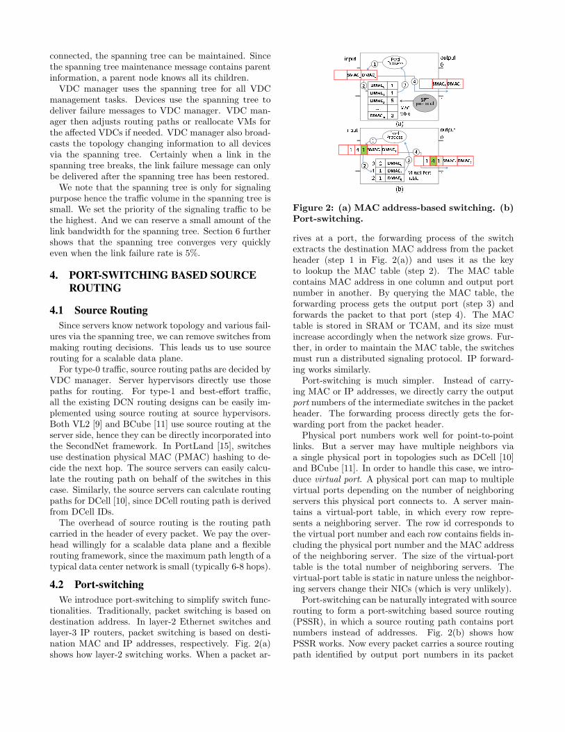
tionalities. Traditionally, packet switching is based ondestination address. In layer-2 Ethernet switches andlayer-3 IP routers, packet switching is based on desti-nation MAC and IP addresses, respectively. Fig. 2(a)shows how layer-2 switching works. When a packet ar-
Figure 2: (a) MAC address-based switching. (b)Port-switching.
rives at a port, the forwarding process of the switchextracts the destination MAC address from the packetheader (step 1 in Fig. 2(a)) and uses it as the keyto lookup the MAC table (step 2). The MAC tablecontains MAC address in one column and output portnumber in another. By querying the MAC table, theforwarding process gets the output port (step 3) andforwards the packet to that port (step 4). The MACtable is stored in SRAM or TCAM, and its size mustincrease accordingly when the network size grows. Fur-ther, in order to maintain the MAC table, the switchesmust run a distributed signaling protocol. IP forward-ing works similarly.Port-switching is much simpler. Instead of carry-
ing MAC or IP addresses, we directly carry the outputport numbers of the intermediate switches in the packetheader. The forwarding process directly gets the for-warding port from the packet header.Physical port numbers work well for point-to-point
links. But a server may have multiple neighbors viaa single physical port in topologies such as DCell [10]and BCube [11]. In order to handle this case, we intro-duce virtual port. A physical port can map to multiplevirtual ports depending on the number of neighboringservers this physical port connects to. A server main-tains a virtual-port table, in which every row repre-sents a neighboring server. The row id corresponds tothe virtual port number and each row contains fields in-cluding the physical port number and the MAC addressof the neighboring server. The size of the virtual-porttable is the total number of neighboring servers. Thevirtual-port table is static in nature unless the neighbor-ing servers change their NICs (which is very unlikely).Port-switching can be naturally integrated with source
routing to form a port-switching based source routing(PSSR), in which a source routing path contains portnumbers instead of addresses. Fig. 2(b) shows howPSSR works. Now every packet carries a source routingpath identified by output port numbers in its packet
header. There is a pointer in the header that points tothe next output port number (step 1). The forward-ing process uses the next port number to lookup thevirtual-port table (step 2), gets the physical port num-ber (step 3), and updates the pointer and forwards thepacket through that port (step 4).PSSR significantly simplifies switch functionalities.
Switches are not involved in routing. The virtual-porttable is static. The size of virtual-port table is small,since a node typically has at most tens of neighbors.As a comparison, the MAC table (or IP-lookup table)needs at least several thousands entries and its size in-creases as the network expands.
4.3 MPLS for PSSRPSSR is easy to implement conceptually - servers en-
code path and priority information into packet head-ers, and switches simply perform priority queueing andforward packets based on port-switching. Commodityswitches, which are increasingly popular in data centersdue to technology advances and the rule of economicsof scale [5], can support PSSR as long as it has MPLS,a commonly available switching technology.In MPLS, switches perform forwarding based on la-
bels carried in packet headers. Labels only have lo-cal meaning between two adjacent switches. Switchesrewrite the label of a packet hop-by-hop. Labels canalso be stacked together to form label stack for MPLStunneling. In MPLS, labels are established using anLDP (label distribution protocol) signaling protocol.In SecondNet, we re-interpret MPLS label as port.
Consequently, the MPLS label table is interpreted asour virtual-port table. We further implement sourcerouting with MPLS label stack. Since the virtual-porttable is static and is pre-configured, signaling proto-col like LDP is eliminated. An MPLS label is 20-bits,which is more than enough to describe the number ofneighbors a switch or server has (typically less than onehundred). MPLS label also has 3 Exp bits for packetpriority. We therefore can implement both PSSR andpriority queueing using commodity MPLS switches.As we have mentioned, VMs in the same VDC form
a layer-2 broadcast domain. To support broadcast, weassign a special MPLS tag for each VDC, and use thistag to setup broadcast spanning tree for the VDC inthe infrastructure network.
5. VDC ALLOCATION
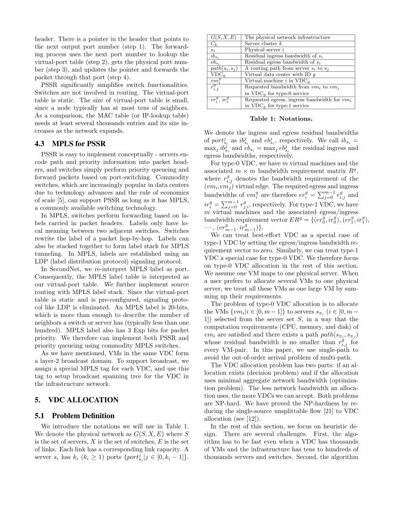
5.1 Problem DefinitionWe introduce the notations we will use in Table 1.
We denote the physical network as G(S,X,E) where Sis the set of servers, X is the set of switches, E is the setof links. Each link has a corresponding link capacity. Aserver si has ki (ki ≥ 1) ports {portjsi |j ∈ [0, ki − 1]}.
G(S,X,E) The physical network infrastructureCk Server cluster ksi Physical server iibsi Residual ingress bandwidth of siebsi Residual egress bandwidth of sipath(si, sj) A routing path from server si to sjVDCg Virtual data center with ID gvmg
i Virtual machine i in VDCg
rgi,j Requested bandwidth from vmi to vmj
in VDCg for type-0 serviceergi , ir
gi Requested egress, ingress bandwidth for vmi
in VDCg for type-1 service
Table 1: Notations.
We denote the ingress and egress residual bandwidthsof portjsi as ibjsi and ebjsi , respectively. We call ibsi =maxj ib
jsi and ebsi = maxj eb
jsi the residual ingress and
egress bandwidths, respectively.For type-0 VDC, we have m virtual machines and the
associated m × m bandwidth requirement matrix Rg,where rgi,j denotes the bandwidth requirement of the(vmi,vmj) virtual edge. The required egress and ingress
bandwidths of vmgi are therefore ergi =
∑m−1j=0 rgi,j and
irgi =∑m−1
j=0 rgj,i, respectively. For type-1 VDC, we havem virtual machines and the associated egress/ingressbandwidth requirement vectorERg = {(erg0 , ir
g0), (er
g1 , ir
g1),
· · · , (ergm−1, irgm−1)}.
We can treat best-effort VDC as a special case oftype-1 VDC by setting the egress/ingress bandwidth re-quirement vector to zero. Similarly, we can treat type-1VDC a special case for type-0 VDC. We therefore focuson type-0 VDC allocation in the rest of this section.We assume one VM maps to one physical server. Whena user prefers to allocate several VMs to one physicalserver, we treat all these VMs as one large VM by sum-ming up their requirements.The problem of type-0 VDC allocation is to allocate
the VMs {vmi|i ∈ [0,m− 1]} to servers sπi (i ∈ [0,m−1]) selected from the server set S, in a way that thecomputation requirements (CPU, memory, and disk) ofvmi are satisfied and there exists a path path(sπi , sπj )whose residual bandwidth is no smaller than rgi,j forevery VM-pair. In this paper, we use single-path toavoid the out-of-order arrival problem of multi-path.The VDC allocation problem has two parts: if an al-
location exists (decision problem) and if the allocationuses minimal aggregate network bandwidth (optimiza-tion problem). The less network bandwidth an alloca-tion uses, the more VDCs we can accept. Both problemsare NP-hard. We have proved the NP-hardness by re-ducing the single-source unsplittable flow [21] to VDCallocation (see [12]).In the rest of this section, we focus on heuristic de-
sign. There are several challenges. First, the algo-rithm has to be fast even when a VDC has thousandsof VMs and the infrastructure has tens to hundreds ofthousands servers and switches. Second, the algorithm
should well utilize the network bandwidth, and accom-modate as many VDCs as possible. Third, the algo-rithm needs to offer elasticity when tenants’ require-ments change and timely performs resource reallocationwhen various failures happen.Related problems have been studied in virtual net-
work embedding and testbed mapping [6, 30, 27]. Theprevious solutions cannot be applied to VDC allocationdue to the scale of our problem and the VDC elasticityrequirement. See Section 8 for detailed discussion.To our best knowledge, our VDC allocation algorithm
is the first attempt that addresses VDC allocation andexpansion with thousands of VMs in data centers withhundreds of thousands servers and switches. Further-more, by taking advantage of VM migration, our al-gorithm is able to perform bandwidth defragmentationwhen the total residual bandwidth becomes fragmented.
5.2 The Allocation AlgorithmWe pre-configure servers into clusters before any VDC
allocation takes place. This is to reduce the problemsize and to take server locality into account. Thereare clusters of different diameters (and hence differentsizes). Intuitively, servers within the same ToR switchform a ToR cluster, servers within the same aggregateswitch form a Pod cluster, etc. Formally, we use serverhop-count, which is the number of hops from one serverto another, as the metric to group servers into clus-ters. A server can belong to multiple clusters, e.g., a2-hop cluster, a 4-hop cluster, and certainly the wholeserver set.When the size of a cluster is much larger thanthat of its belonging small clusters, we combine severalsmaller ones to form middle size clusters. We denotethe clusters as C0, C1, · · · , Ct−1. A cluster Ck has |Ck|servers. The clusters are sorted in ascending order suchthat |Ci| ≤ |Cj | for i < j.In certain scenarios, users may prefer to allocate VMs
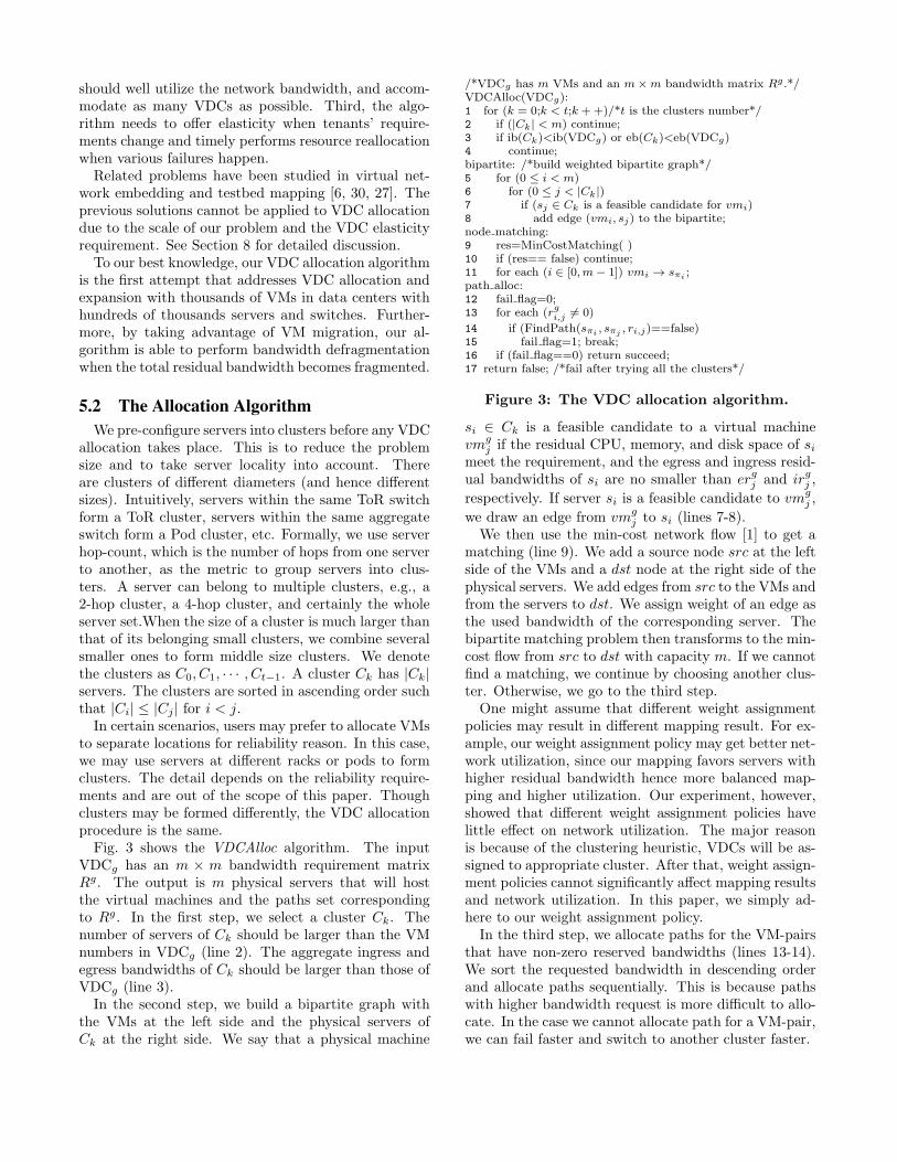
to separate locations for reliability reason. In this case,we may use servers at different racks or pods to formclusters. The detail depends on the reliability require-ments and are out of the scope of this paper. Thoughclusters may be formed differently, the VDC allocationprocedure is the same.Fig. 3 shows the VDCAlloc algorithm. The input
VDCg has an m × m bandwidth requirement matrixRg. The output is m physical servers that will hostthe virtual machines and the paths set correspondingto Rg. In the first step, we select a cluster Ck. Thenumber of servers of Ck should be larger than the VMnumbers in VDCg (line 2). The aggregate ingress andegress bandwidths of Ck should be larger than those ofVDCg (line 3).In the second step, we build a bipartite graph with
the VMs at the left side and the physical servers ofCk at the right side. We say that a physical machine
/*VDCg has m VMs and an m×m bandwidth matrix Rg .*/VDCAlloc(VDCg):1 for (k = 0;k < t;k ++)/*t is the clusters number*/2 if (|Ck| < m) continue;3 if ib(Ck)<ib(VDCg) or eb(Ck)<eb(VDCg)4 continue;bipartite: /*build weighted bipartite graph*/5 for (0 ≤ i < m)6 for (0 ≤ j < |Ck|)7 if (sj ∈ Ck is a feasible candidate for vmi)8 add edge (vmi, sj) to the bipartite;node matching:9 res=MinCostMatching( )10 if (res== false) continue;11 for each (i ∈ [0,m− 1]) vmi → sπi ;path alloc:12 fail flag=0;13 for each (rgi,j ̸= 0)
14 if (FindPath(sπi , sπj , ri,j)==false)15 fail flag=1; break;16 if (fail flag==0) return succeed;17 return false; /*fail after trying all the clusters*/
Figure 3: The VDC allocation algorithm.
si ∈ Ck is a feasible candidate to a virtual machinevmg
j if the residual CPU, memory, and disk space of simeet the requirement, and the egress and ingress resid-ual bandwidths of si are no smaller than ergj and irgj ,
respectively. If server si is a feasible candidate to vmgj ,
we draw an edge from vmgj to si (lines 7-8).
We then use the min-cost network flow [1] to get amatching (line 9). We add a source node src at the leftside of the VMs and a dst node at the right side of thephysical servers. We add edges from src to the VMs andfrom the servers to dst. We assign weight of an edge asthe used bandwidth of the corresponding server. Thebipartite matching problem then transforms to the min-cost flow from src to dst with capacity m. If we cannotfind a matching, we continue by choosing another clus-ter. Otherwise, we go to the third step.One might assume that different weight assignment
policies may result in different mapping result. For ex-ample, our weight assignment policy may get better net-work utilization, since our mapping favors servers withhigher residual bandwidth hence more balanced map-ping and higher utilization. Our experiment, however,showed that different weight assignment policies havelittle effect on network utilization. The major reasonis because of the clustering heuristic, VDCs will be as-signed to appropriate cluster. After that, weight assign-ment policies cannot significantly affect mapping resultsand network utilization. In this paper, we simply ad-here to our weight assignment policy.In the third step, we allocate paths for the VM-pairs
that have non-zero reserved bandwidths (lines 13-14).We sort the requested bandwidth in descending orderand allocate paths sequentially. This is because pathswith higher bandwidth request is more difficult to allo-cate. In the case we cannot allocate path for a VM-pair,we can fail faster and switch to another cluster faster.
We use FindPath to allocate path from sπi and sπj
with bandwidth requirement rgi,j . In G(S,X,E), we re-move the links whose residual bandwidth is smaller thanrgi,j , and use shortest-path to get a path from sπi to sπj .Since all the links have unit length, we use Breadth FirstSearch (BFS) as the shortest-path algorithm. After weassign a path for a VM-pair, we update the residualbandwidths of the links along the path. If we fail to al-locate a path for a VM-pair, we go back to get anothercluster and start again. If we do allocate paths for allrgi,j ̸= 0, we succeed and return the assigned physicalservers and paths. If we cannot find an allocation aftersearching all the clusters, we fail and reject the VDCallocation request.VDCAlloc naturally supports VDCs that have mul-
tiple service types. For example, when a VM has bothtype-0 and type-1 requests, a bipartite edge betweenthis VM and a server is feasible only when the egress andingress residual bandwidths of the server meet the sumof the two requests. After the bipartite is constructed,the rest allocation procedure is the same. VDCAlloccan be executed in parallel for different VDC requestas long as they use different clusters. Therefore, a largeVDC request will not block a small VDC request. Alsoduring a VDCAlloc, the physical topology may changedue to various failures, as long as the related cluster isnot affected, VDCAlloc is not affected. Otherwise, wemay need to redo the allocation.The major components, min-cost flow and path allo-
cation, are of low time-complexity. Since all the edges inthe bipartite graph have unit weight, MinCostMatchingcan be solved inO(n3 log(n+m)), where n is the numberof VMs and m is the number of servers in the currentcluster. The worst-case time-complexity for path allo-cation is O(n2|E|), where |E| is the number of edgesof the physical network. The complexity of VDCAlloccertainly depends on how many clusters we need to trybefore a matching is found. Our simulation (Section 6)shows that even for VDCs with 5000 VMs in data cen-ters with 100k servers, VDCAlloc needs only hundredsof seconds even when network utilization is high.
5.3 VDC AdjustmentVDC has the advantage of dynamic expansion and
shrinking as tenants’ needs change. VDC shrinkingcan be trivially performed by releasing the unneededVMs and bandwidths. VDC expansion, however, is notthat easy. There are two expansion cases: increasingbandwidth reservations for existing VM-pairs, or addingnew VMs. Also we need to perform VDC reallocationwhen failures happen. When server failures happen,the hosted VMs disappear. Hence server failures needto be handled by user applications using for examplereplica which is out of the scope of this paper. But forlink or switch failures, SecondNet can perform path re-
allocation or VM migration for the affected VDCs. Itis possible that VDC reallocation may fail. But as wedemonstrate in Section 6, VDC reallocation can alwayssucceed when the network utilization is not high.In this work, we handle incremental expansion and
failures with the same algorithm based on VDCAlloc.Our goal is to minimize reallocations of existing VMs.Moreover, we try to reuse existing routing paths. Whenwe increase bandwidth reservation of a VM-pair, wetry to increase bandwidth reservation along its exist-ing path. When the existing path cannot meet the re-quirement (due to link or switch failure, or insufficientbandwidth along that path), we try to allocate a newpath for that VM-pair. When path reallocation is notpossible, VM migration needs to be performed.We then maintain a to-be-allocated VM set, which
includes the newly added VMs and the VMs that needreallocation. We try to allocate these VMs within thesame cluster of the existing VMs using the bipartitematching of Fig. 3. If we find a matching, we allocatepaths (step 3 of Fig. 3, with existing paths unchanged).Once we cannot allocate a path between an existing VMand a to-be-allocated VM, we add that existing VM intothe to-be-allocated VM set and iterate. If a matchingcannot be found, VDC expansion or reallocation withinthis cluster is not possible. We choose a larger clusterwhich contains this existing cluster and iterate.
5.4 Bandwidth DefragmentationAn advantage of server virtualization is that VMs can
be migrated from one server to another. VM migrationcan be used for not only server upgrade and mainte-nance, but also for better network utilization. We usean example to illustrate the idea. Suppose a small num-ber of VMs of VDC0 are mapped to servers in a clusterC0 and most of the other VMs are mapped to a clusterC1. When VMs of some other VDCs in C1 are released,it is possible to migrate VMs of VDC0 in C0 to C1. Themigration not only increases the residual capacity of thephysical infrastructure (due to the fact that the interC0-C1 bandwidth of VDC0 is released), but also im-proves the performance of VDC0 by reducing the pathlengths among its VMs.Based on the above observation, we design a VDC
defragmentation algorithm as follows. When a VDC isreleased from a cluster, we check if we get chance tomigrate VMs of some VDCs to this cluster. To accel-erate VDC selection, we mark VDCs that have VMsscattered in different clusters as defragmentation can-didates. A defragmentation is carried out only whenthe following two conditions are met: 1) the bandwidthreservation of the reallocated VDCs can still be met;2) the total residual bandwidth of the physical infras-tructure is increased. VDC defragmentation is a back-ground process and can be performed when the activity
of the to-be-migrated VM is low. Simulation results [12]show that bandwidth defragmentation can significantlyimprove network utilization.
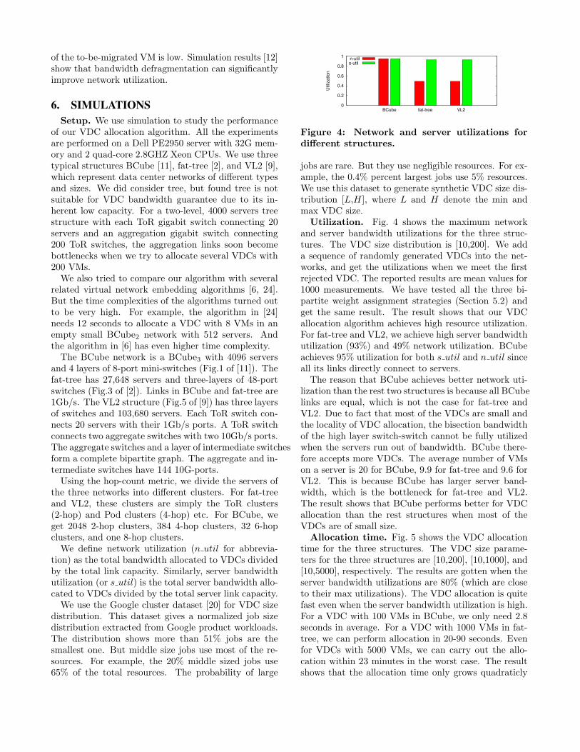
6. SIMULATIONSSetup. We use simulation to study the performance
of our VDC allocation algorithm. All the experimentsare performed on a Dell PE2950 server with 32G mem-ory and 2 quad-core 2.8GHZ Xeon CPUs. We use threetypical structures BCube [11], fat-tree [2], and VL2 [9],which represent data center networks of different typesand sizes. We did consider tree, but found tree is notsuitable for VDC bandwidth guarantee due to its in-herent low capacity. For a two-level, 4000 servers treestructure with each ToR gigabit switch connecting 20servers and an aggregation gigabit switch connecting200 ToR switches, the aggregation links soon becomebottlenecks when we try to allocate several VDCs with200 VMs.We also tried to compare our algorithm with several
related virtual network embedding algorithms [6, 24].But the time complexities of the algorithms turned outto be very high. For example, the algorithm in [24]needs 12 seconds to allocate a VDC with 8 VMs in anempty small BCube2 network with 512 servers. Andthe algorithm in [6] has even higher time complexity.The BCube network is a BCube3 with 4096 servers
and 4 layers of 8-port mini-switches (Fig.1 of [11]). Thefat-tree has 27,648 servers and three-layers of 48-portswitches (Fig.3 of [2]). Links in BCube and fat-tree are1Gb/s. The VL2 structure (Fig.5 of [9]) has three layersof switches and 103,680 servers. Each ToR switch con-nects 20 servers with their 1Gb/s ports. A ToR switchconnects two aggregate switches with two 10Gb/s ports.The aggregate switches and a layer of intermediate switchesform a complete bipartite graph. The aggregate and in-termediate switches have 144 10G-ports.Using the hop-count metric, we divide the servers of
the three networks into different clusters. For fat-treeand VL2, these clusters are simply the ToR clusters(2-hop) and Pod clusters (4-hop) etc. For BCube, weget 2048 2-hop clusters, 384 4-hop clusters, 32 6-hopclusters, and one 8-hop clusters.We define network utilization (n util for abbrevia-
tion) as the total bandwidth allocated to VDCs dividedby the total link capacity. Similarly, server bandwidthutilization (or s util) is the total server bandwidth allo-cated to VDCs divided by the total server link capacity.We use the Google cluster dataset [20] for VDC size
distribution. This dataset gives a normalized job sizedistribution extracted from Google product workloads.The distribution shows more than 51% jobs are thesmallest one. But middle size jobs use most of the re-sources. For example, the 20% middle sized jobs use65% of the total resources. The probability of large
0
0.2
0.4
0.6
0.8
1
BCube fat-tree VL2
Utilization
n-util
s-util
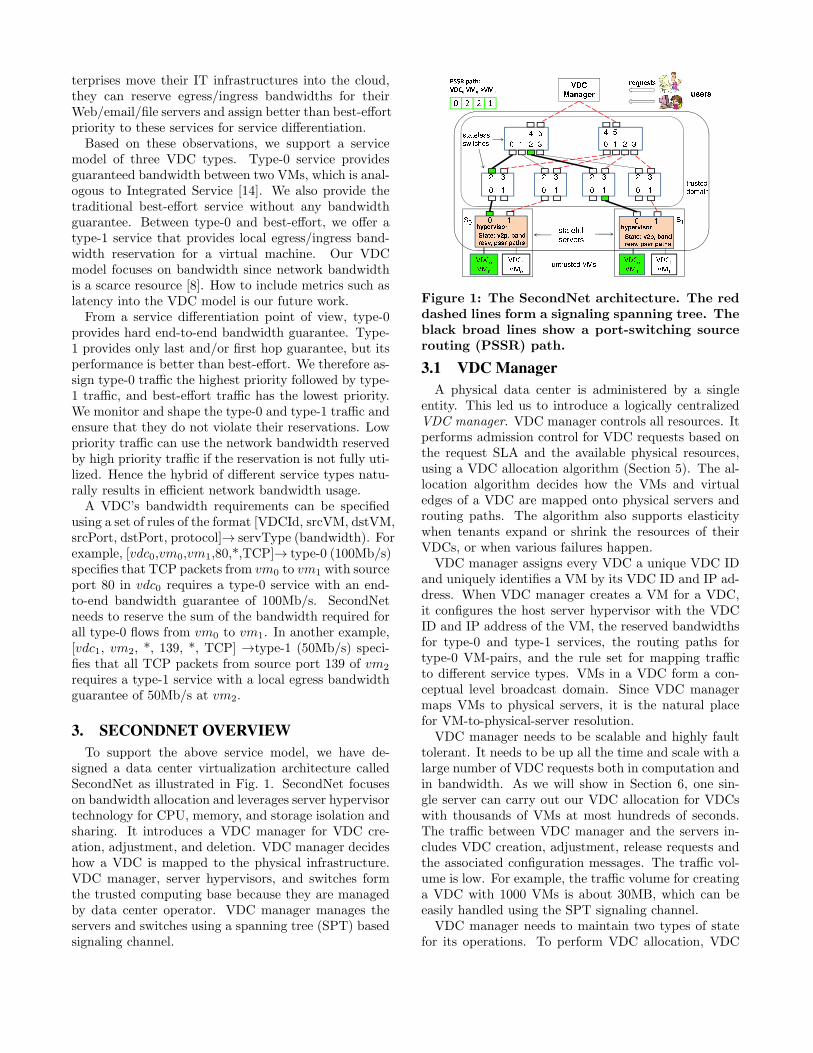
Figure 4: Network and server utilizations fordifferent structures.
jobs are rare. But they use negligible resources. For ex-ample, the 0.4% percent largest jobs use 5% resources.We use this dataset to generate synthetic VDC size dis-tribution [L,H], where L and H denote the min andmax VDC size.Utilization. Fig. 4 shows the maximum network
and server bandwidth utilizations for the three struc-tures. The VDC size distribution is [10,200]. We adda sequence of randomly generated VDCs into the net-works, and get the utilizations when we meet the firstrejected VDC. The reported results are mean values for1000 measurements. We have tested all the three bi-partite weight assignment strategies (Section 5.2) andget the same result. The result shows that our VDCallocation algorithm achieves high resource utilization.For fat-tree and VL2, we achieve high server bandwidthutilization (93%) and 49% network utilization. BCubeachieves 95% utilization for both s util and n util sinceall its links directly connect to servers.The reason that BCube achieves better network uti-
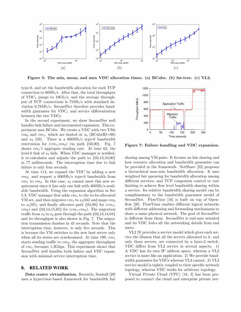
lization than the rest two structures is because all BCubelinks are equal, which is not the case for fat-tree andVL2. Due to fact that most of the VDCs are small andthe locality of VDC allocation, the bisection bandwidthof the high layer switch-switch cannot be fully utilizedwhen the servers run out of bandwidth. BCube there-fore accepts more VDCs. The average number of VMson a server is 20 for BCube, 9.9 for fat-tree and 9.6 forVL2. This is because BCube has larger server band-width, which is the bottleneck for fat-tree and VL2.The result shows that BCube performs better for VDCallocation than the rest structures when most of theVDCs are of small size.Allocation time. Fig. 5 shows the VDC allocation
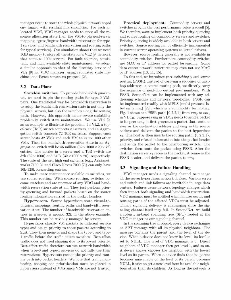
time for the three structures. The VDC size parame-ters for the three structures are [10,200], [10,1000], and[10,5000], respectively. The results are gotten when theserver bandwidth utilizations are 80% (which are closeto their max utilizations). The VDC allocation is quitefast even when the server bandwidth utilization is high.For a VDC with 100 VMs in BCube, we only need 2.8seconds in average. For a VDC with 1000 VMs in fat-tree, we can perform allocation in 20-90 seconds. Evenfor VDCs with 5000 VMs, we can carry out the allo-cation within 23 minutes in the worst case. The resultshows that the allocation time only grows quadraticly
Link failure Time slot PDF (%)rate (%) 0 1 2 3 4 5
1 62.02 34.14 3.62 0.13 0.09 02 61.72 34.74 3.18 0.17 0.12 0.053 61.78 34.58 3.38 0.14 0.06 0.044 60.38 35.93 3.39 0.17 0.08 0.035 59.96 36.22 3.34 0.26 0.18 0.03
Table 2: The distribution of the spanning treeconvergence time under different link failurerate for the BCube network.
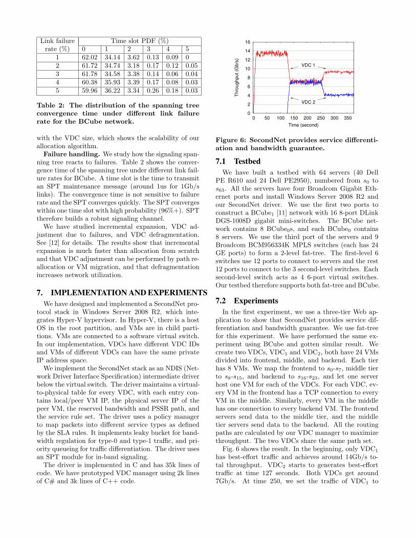
with the VDC size, which shows the scalability of ourallocation algorithm.Failure handling. We study how the signaling span-
ning tree reacts to failures. Table 2 shows the conver-gence time of the spanning tree under different link fail-ure rates for BCube. A time slot is the time to transmitan SPT maintenance message (around 1us for 1Gb/slinks). The convergence time is not sensitive to failurerate and the SPT converges quickly. The SPT convergeswithin one time slot with high probability (96%+). SPTtherefore builds a robust signaling channel.We have studied incremental expansion, VDC ad-
justment due to failures, and VDC defragmentation.See [12] for details. The results show that incrementalexpansion is much faster than allocation from scratchand that VDC adjustment can be performed by path re-allocation or VM migration, and that defragmentationincreases network utilization.
7. IMPLEMENTATION AND EXPERIMENTSWe have designed and implemented a SecondNet pro-
tocol stack in Windows Server 2008 R2, which inte-grates Hyper-V hypervisor. In Hyper-V, there is a hostOS in the root partition, and VMs are in child parti-tions. VMs are connected to a software virtual switch.In our implementation, VDCs have different VDC IDsand VMs of different VDCs can have the same privateIP address space.We implement the SecondNet stack as an NDIS (Net-
work Driver Interface Specification) intermediate driverbelow the virtual switch. The driver maintains a virtual-to-physical table for every VDC, with each entry con-tains local/peer VM IP, the physical server IP of thepeer VM, the reserved bandwidth and PSSR path, andthe service rule set. The driver uses a policy managerto map packets into different service types as definedby the SLA rules. It implements leaky bucket for band-width regulation for type-0 and type-1 traffic, and pri-ority queueing for traffic differentiation. The driver usesan SPT module for in-band signaling.The driver is implemented in C and has 35k lines of
code. We have prototyped VDC manager using 2k linesof C# and 3k lines of C++ code.
0
2
4
6
8
10
12
14
16
0 50 100 150 200 250 300 350
Thro
ughput (G
b/s
)
Time (second)
VDC 1
VDC 2
Figure 6: SecondNet provides service differenti-ation and bandwidth guarantee.
7.1 TestbedWe have built a testbed with 64 servers (40 Dell
PE R610 and 24 Dell PE2950), numbered from s0 tos63. All the servers have four Broadcom Gigabit Eth-ernet ports and install Windows Server 2008 R2 andour SecondNet driver. We use the first two ports toconstruct a BCube1 [11] network with 16 8-port DLinkDGS-1008D gigabit mini-switches. The BCube net-work contains 8 BCube0s, and each BCube0 contains8 servers. We use the third port of the servers and 9Broadcom BCM956334K MPLS switches (each has 24GE ports) to form a 2-level fat-tree. The first-level 6switches use 12 ports to connect to servers and the rest12 ports to connect to the 3 second-level switches. Eachsecond-level switch acts as 4 6-port virtual switches.Our testbed therefore supports both fat-tree and BCube.
7.2 ExperimentsIn the first experiment, we use a three-tier Web ap-
plication to show that SecondNet provides service dif-ferentiation and bandwidth guarantee. We use fat-treefor this experiment. We have performed the same ex-periment using BCube and gotten similar result. Wecreate two VDCs, VDC1 and VDC2, both have 24 VMsdivided into frontend, middle, and backend. Each tierhas 8 VMs. We map the frontend to s0-s7, middle tierto s8-s15, and backend to s16-s23, and let one serverhost one VM for each of the VDCs. For each VDC, ev-ery VM in the frontend has a TCP connection to everyVM in the middle. Similarly, every VM in the middlehas one connection to every backend VM. The frontendservers send data to the middle tier, and the middletier servers send data to the backend. All the routingpaths are calculated by our VDC manager to maximizethroughput. The two VDCs share the same path set.Fig. 6 shows the result. In the beginning, only VDC1
has best-effort traffic and achieves around 14Gb/s to-tal throughput. VDC2 starts to generates best-efforttraffic at time 127 seconds. Both VDCs get around7Gb/s. At time 250, we set the traffic of VDC1 to
101
102
10−3
10−2
10−1
100
101
102
VDC size (#VM)
Tim
e (
second)
BCube
(a)
101
102
103
10−2
10−1
100
101
102
VDC size (#VM)
Tim
e (
second)
Fat−tree
(b)
101
102
103
10−2
100
102
104
VDC size (#VM)
Tim
e (
second)
VL2
(c)
Figure 5: The min, mean, and max VDC allocation times. (a) BCube. (b) fat-tree. (c) VL2.
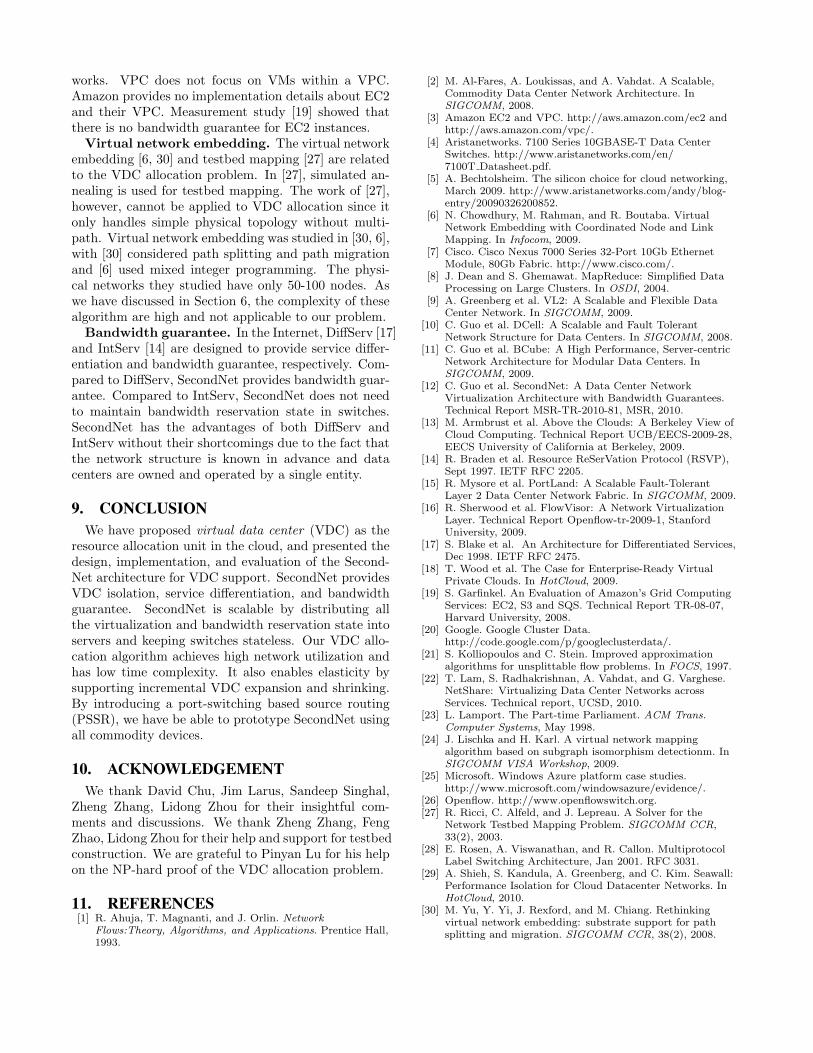
type-0, and set the bandwidth allocation for each TCPconnection to 80Mb/s. After that, the total throughputof VDC1 jumps to 10Gb/s, and the average through-put of TCP connections is 75Mb/s with standard de-viation 0.78Mb/s. SecondNet therefore provides band-width guarantee for VDC1 and service differentiationbetween the two VDCs.In the second experiment, we show SecondNet well
handles link failure and incremental expansion. This ex-periment uses BCube. We create a VDC with two VMsvm0 and vm1, which are hosted at s0 (BCubeID=00)and s3 (03). There is a 600Mb/s type-0 bandwidthreservation for (vm1,vm0) via path {03,00}. Fig. 7shows vm1’s aggregate sending rate. At time 62, thelevel-0 link of s3 fails. When VDC manager is notified,it re-calculates and adjusts the path to {03,13,10,00}in 77 milliseconds. The interruption time due to linkfailure is only four seconds.At time 114, we expand the VDC by adding a new
vm2, and request a 600Mb/s type-0 bandwidth fromvm1 to vm2. In this case, s3 cannot meet this new re-quirement since it has only one link with 400Mb/s avail-able bandwidth. Using the expansion algorithm in Sec5.3, VDC manager first adds vm1 to the to-be-allocatedVM set, and then migrates vm1 to s4(04) and maps vm2
to s5(05), and finally allocates path {04,00} for (vm1,vm0) and {04,14,15,05} for (vm1,vm2). The migrationtraffic from s3 to s4 goes through the path {03,13,14,04}and its throughput is also shown in Fig. 7. The migra-tion transmission finishes in 45 seconds. Note that theinterruption time, however, is only five seconds. Thisis because the VM switches to the new host server onlywhen all its states are synchronized. At time 199, vm1
starts sending traffic to vm2, the aggregate throughputof vm1 becomes 1.2Gbps. This experiment shows thatSecondNet well handles both failure and VDC expan-sion with minimal service interruption time.
8. RELATED WORKData center virtualization. Recently, Seawall [29]
uses a hypervisor-based framework for bandwidth fair
0
200
400
600
800
1000
1200
0 50 100 150 200 250
Thro
ughput (M
b/s
)Time (second)
Application Traffic
MigrationTraffic
Figure 7: Failure handling and VDC expansion.
sharing among VM-pairs. It focuses on fair sharing andhow resource allocation and bandwidth guarantee canbe provided in the framework. NetShare [22] proposesa hierarchical max-min bandwidth allocation. It usesweighted fair queueing for bandwidth allocation amongdifferent services, and TCP congestion control or ratelimiting to achieve flow level bandwidth sharing withina service. Its relative bandwidth sharing model can becomplimentary to the bandwidth guarantee model ofSecondNet. FlowVisor [16] is built on top of Open-flow [26]. FlowVisor enables different logical networkswith different addressing and forwarding mechanisms toshare a same physical network. The goal of SecondNetis different from them. SecondNet is end-user orientedand its VDC hides all the networking details from endusers.VL2 [9] provides a service model which gives each ser-
vice the illusion that all the servers allocated to it, andonly those servers, are connected by a layer-2 switch.VDC differs from VL2 service in several aspects. 1)A VDC has its own IP address space, whereas a VL2service is more like an application. 2) We provide band-width guarantee for VDCs whereas VL2 cannot. 3) VL2service model is tightly coupled to their specific networktopology, whereas VDC works for arbitrary topology.Virtual Private Cloud (VPC) [18, 3] has been pro-
posed to connect the cloud and enterprise private net-
works. VPC does not focus on VMs within a VPC.Amazon provides no implementation details about EC2and their VPC. Measurement study [19] showed thatthere is no bandwidth guarantee for EC2 instances.Virtual network embedding. The virtual network
embedding [6, 30] and testbed mapping [27] are relatedto the VDC allocation problem. In [27], simulated an-nealing is used for testbed mapping. The work of [27],however, cannot be applied to VDC allocation since itonly handles simple physical topology without multi-path. Virtual network embedding was studied in [30, 6],with [30] considered path splitting and path migrationand [6] used mixed integer programming. The physi-cal networks they studied have only 50-100 nodes. Aswe have discussed in Section 6, the complexity of thesealgorithm are high and not applicable to our problem.Bandwidth guarantee. In the Internet, DiffServ [17]
and IntServ [14] are designed to provide service differ-entiation and bandwidth guarantee, respectively. Com-pared to DiffServ, SecondNet provides bandwidth guar-antee. Compared to IntServ, SecondNet does not needto maintain bandwidth reservation state in switches.SecondNet has the advantages of both DiffServ andIntServ without their shortcomings due to the fact thatthe network structure is known in advance and datacenters are owned and operated by a single entity.
9. CONCLUSIONWe have proposed virtual data center (VDC) as the
resource allocation unit in the cloud, and presented thedesign, implementation, and evaluation of the Second-Net architecture for VDC support. SecondNet providesVDC isolation, service differentiation, and bandwidthguarantee. SecondNet is scalable by distributing allthe virtualization and bandwidth reservation state intoservers and keeping switches stateless. Our VDC allo-cation algorithm achieves high network utilization andhas low time complexity. It also enables elasticity bysupporting incremental VDC expansion and shrinking.By introducing a port-switching based source routing(PSSR), we have be able to prototype SecondNet usingall commodity devices.
10. ACKNOWLEDGEMENTWe thank David Chu, Jim Larus, Sandeep Singhal,
Zheng Zhang, Lidong Zhou for their insightful com-ments and discussions. We thank Zheng Zhang, FengZhao, Lidong Zhou for their help and support for testbedconstruction. We are grateful to Pinyan Lu for his helpon the NP-hard proof of the VDC allocation problem.
11. REFERENCES[1] R. Ahuja, T. Magnanti, and J. Orlin. Network
Flows:Theory, Algorithms, and Applications. Prentice Hall,1993.
[2] M. Al-Fares, A. Loukissas, and A. Vahdat. A Scalable,Commodity Data Center Network Architecture. InSIGCOMM, 2008.
[3] Amazon EC2 and VPC. http://aws.amazon.com/ec2 andhttp://aws.amazon.com/vpc/.
[4] Aristanetworks. 7100 Series 10GBASE-T Data CenterSwitches. http://www.aristanetworks.com/en/7100T Datasheet.pdf.
[5] A. Bechtolsheim. The silicon choice for cloud networking,March 2009. http://www.aristanetworks.com/andy/blog-entry/20090326200852.
[6] N. Chowdhury, M. Rahman, and R. Boutaba. VirtualNetwork Embedding with Coordinated Node and LinkMapping. In Infocom, 2009.
[7] Cisco. Cisco Nexus 7000 Series 32-Port 10Gb EthernetModule, 80Gb Fabric. http://www.cisco.com/.
[8] J. Dean and S. Ghemawat. MapReduce: Simplified DataProcessing on Large Clusters. In OSDI, 2004.
[9] A. Greenberg et al. VL2: A Scalable and Flexible DataCenter Network. In SIGCOMM, 2009.
[10] C. Guo et al. DCell: A Scalable and Fault TolerantNetwork Structure for Data Centers. In SIGCOMM, 2008.
[11] C. Guo et al. BCube: A High Performance, Server-centricNetwork Architecture for Modular Data Centers. InSIGCOMM, 2009.
[12] C. Guo et al. SecondNet: A Data Center NetworkVirtualization Architecture with Bandwidth Guarantees.Technical Report MSR-TR-2010-81, MSR, 2010.
[13] M. Armbrust et al. Above the Clouds: A Berkeley View ofCloud Computing. Technical Report UCB/EECS-2009-28,EECS University of California at Berkeley, 2009.
[14] R. Braden et al. Resource ReSerVation Protocol (RSVP),Sept 1997. IETF RFC 2205.
[15] R. Mysore et al. PortLand: A Scalable Fault-TolerantLayer 2 Data Center Network Fabric. In SIGCOMM, 2009.
[16] R. Sherwood et al. FlowVisor: A Network VirtualizationLayer. Technical Report Openflow-tr-2009-1, StanfordUniversity, 2009.
[17] S. Blake et al. An Architecture for Differentiated Services,Dec 1998. IETF RFC 2475.
[18] T. Wood et al. The Case for Enterprise-Ready VirtualPrivate Clouds. In HotCloud, 2009.
[19] S. Garfinkel. An Evaluation of Amazon’s Grid ComputingServices: EC2, S3 and SQS. Technical Report TR-08-07,Harvard University, 2008.
[20] Google. Google Cluster Data.http://code.google.com/p/googleclusterdata/.
[21] S. Kolliopoulos and C. Stein. Improved approximationalgorithms for unsplittable flow problems. In FOCS, 1997.
[22] T. Lam, S. Radhakrishnan, A. Vahdat, and G. Varghese.NetShare: Virtualizing Data Center Networks acrossServices. Technical report, UCSD, 2010.
[23] L. Lamport. The Part-time Parliament. ACM Trans.Computer Systems, May 1998.
[24] J. Lischka and H. Karl. A virtual network mappingalgorithm based on subgraph isomorphism detectionm. InSIGCOMM VISA Workshop, 2009.
[25] Microsoft. Windows Azure platform case studies.http://www.microsoft.com/windowsazure/evidence/.
[26] Openflow. http://www.openflowswitch.org.[27] R. Ricci, C. Alfeld, and J. Lepreau. A Solver for the
Network Testbed Mapping Problem. SIGCOMM CCR,33(2), 2003.
[28] E. Rosen, A. Viswanathan, and R. Callon. MultiprotocolLabel Switching Architecture, Jan 2001. RFC 3031.
[29] A. Shieh, S. Kandula, A. Greenberg, and C. Kim. Seawall:Performance Isolation for Cloud Datacenter Networks. InHotCloud, 2010.
[30] M. Yu, Y. Yi, J. Rexford, and M. Chiang. Rethinkingvirtual network embedding: substrate support for pathsplitting and migration. SIGCOMM CCR, 38(2), 2008.