secret doors drawers compartments
TRANSCRIPT

http://www.instructables.com/id/Secret-Doors-Drawers-Compartments/
IntroductionBruce Wayne hid the entrance to the Batcave behind a bookcase, operated by a button hidden in a bust of Shakespeare. Ever wanted to make your own? Here atinstructables.com, we got you covered with secret doors, drawers & compartments!
This guide features 16 projects built by our users made to keep your stuff safe and hidden from view. From hidden rooms behind bookshelves to secret compartments infurniture, hiding your stuff has never been more fun! You could dig a hole and bury your stuff, or build an Arduino-powered secret knock detecting lock to stash your stuff.Why not try a few of these projects the next time you've got some secret stuff you want to stash? Batcave plans not included.
Instructables is the most popular project-sharing community on the Internet. Since August 2005, Instructables has provided easy publishing tools to enable passionate,creative people to share their most innovative projects, recipes, skills, and ideas. Instructables has projects covering all subjects, including crafts, art, electronics, kids,home improvement, pets, outdoors, reuse, bikes, cars, robotics, food, decorating, woodworking, costuming, games, and life in general.

http://www.instructables.com/id/Secret-Doors-Drawers-Compartments/
Table of Contents
Introduction . . . . . . . . . . . . . . . . . . . . . . . . . . . . . . . . . . . . . . . . . . . . . . . . . . . . . . . . . . . . . . . . . . . . . . . . . . . . . . . . . . . . . . . . . . . . . . . . . . . . . . . . . . . . . . . . . . 1
Author and Copyright Notices . . . . . . . . . . . . . . . . . . . . . . . . . . . . . . . . . . . . . . . . . . . . . . . . . . . . . . . . . . . . . . . . . . . . . . . . . . . . . . . . . . . . . . . . . . . . . . . . . . 7
Disclaimer . . . . . . . . . . . . . . . . . . . . . . . . . . . . . . . . . . . . . . . . . . . . . . . . . . . . . . . . . . . . . . . . . . . . . . . . . . . . . . . . . . . . . . . . . . . . . . . . . . . . . . . . . . . . . . . . . 8
Wireless light switch or bust . . . . . . . . . . . . . . . . . . . . . . . . . . . . . . . . . . . . . . . . . . . . . . . . . . . . . . . . . . . . . . . . . . . . . . . . . . . . . . . . . . . . . . . . . . . . . . . . . . . . . . 9
Intro: Wireless light switch or bust . . . . . . . . . . . . . . . . . . . . . . . . . . . . . . . . . . . . . . . . . . . . . . . . . . . . . . . . . . . . . . . . . . . . . . . . . . . . . . . . . . . . . . . . . . . . . . 9
Step 1: Make one Beethoven two. . . . . . . . . . . . . . . . . . . . . . . . . . . . . . . . . . . . . . . . . . . . . . . . . . . . . . . . . . . . . . . . . . . . . . . . . . . . . . . . . . . . . . . . . . . . . . . 9
Step 2: Fun with soldering irons . . . . . . . . . . . . . . . . . . . . . . . . . . . . . . . . . . . . . . . . . . . . . . . . . . . . . . . . . . . . . . . . . . . . . . . . . . . . . . . . . . . . . . . . . . . . . . . . 11
Step 3: Putting it all together . . . . . . . . . . . . . . . . . . . . . . . . . . . . . . . . . . . . . . . . . . . . . . . . . . . . . . . . . . . . . . . . . . . . . . . . . . . . . . . . . . . . . . . . . . . . . . . . . . 13
Step 4: Overview and completed video . . . . . . . . . . . . . . . . . . . . . . . . . . . . . . . . . . . . . . . . . . . . . . . . . . . . . . . . . . . . . . . . . . . . . . . . . . . . . . . . . . . . . . . . . . 14
Related Instructables . . . . . . . . . . . . . . . . . . . . . . . . . . . . . . . . . . . . . . . . . . . . . . . . . . . . . . . . . . . . . . . . . . . . . . . . . . . . . . . . . . . . . . . . . . . . . . . . . . . . . . . . 14
How to Build a Simple Security Camera Safe . . . . . . . . . . . . . . . . . . . . . . . . . . . . . . . . . . . . . . . . . . . . . . . . . . . . . . . . . . . . . . . . . . . . . . . . . . . . . . . . . . . . . . . . . 15
Intro: How to Build a Simple Security Camera Safe . . . . . . . . . . . . . . . . . . . . . . . . . . . . . . . . . . . . . . . . . . . . . . . . . . . . . . . . . . . . . . . . . . . . . . . . . . . . . . . . . 15
Step 1: Materials. . . . . . . . . . . . . . . . . . . . . . . . . . . . . . . . . . . . . . . . . . . . . . . . . . . . . . . . . . . . . . . . . . . . . . . . . . . . . . . . . . . . . . . . . . . . . . . . . . . . . . . . . . . 15
Step 2: Attaching the Baseplate. . . . . . . . . . . . . . . . . . . . . . . . . . . . . . . . . . . . . . . . . . . . . . . . . . . . . . . . . . . . . . . . . . . . . . . . . . . . . . . . . . . . . . . . . . . . . . . . 17
Step 3: Moving the Mount. . . . . . . . . . . . . . . . . . . . . . . . . . . . . . . . . . . . . . . . . . . . . . . . . . . . . . . . . . . . . . . . . . . . . . . . . . . . . . . . . . . . . . . . . . . . . . . . . . . . . 18
Step 4: Finishing up. . . . . . . . . . . . . . . . . . . . . . . . . . . . . . . . . . . . . . . . . . . . . . . . . . . . . . . . . . . . . . . . . . . . . . . . . . . . . . . . . . . . . . . . . . . . . . . . . . . . . . . . . 19
Step 5: Optional, Geocache! . . . . . . . . . . . . . . . . . . . . . . . . . . . . . . . . . . . . . . . . . . . . . . . . . . . . . . . . . . . . . . . . . . . . . . . . . . . . . . . . . . . . . . . . . . . . . . . . . . 20
Related Instructables . . . . . . . . . . . . . . . . . . . . . . . . . . . . . . . . . . . . . . . . . . . . . . . . . . . . . . . . . . . . . . . . . . . . . . . . . . . . . . . . . . . . . . . . . . . . . . . . . . . . . . . . 21
Bookcase / Han in Carbonite Hidden Door . . . . . . . . . . . . . . . . . . . . . . . . . . . . . . . . . . . . . . . . . . . . . . . . . . . . . . . . . . . . . . . . . . . . . . . . . . . . . . . . . . . . . . . . . . . 22
Intro: Bookcase / Han in Carbonite Hidden Door . . . . . . . . . . . . . . . . . . . . . . . . . . . . . . . . . . . . . . . . . . . . . . . . . . . . . . . . . . . . . . . . . . . . . . . . . . . . . . . . . . . 22
Step 1: Determine the size of the opening . . . . . . . . . . . . . . . . . . . . . . . . . . . . . . . . . . . . . . . . . . . . . . . . . . . . . . . . . . . . . . . . . . . . . . . . . . . . . . . . . . . . . . . . 23
Step 2: Minding the Gap . . . . . . . . . . . . . . . . . . . . . . . . . . . . . . . . . . . . . . . . . . . . . . . . . . . . . . . . . . . . . . . . . . . . . . . . . . . . . . . . . . . . . . . . . . . . . . . . . . . . . 24
Step 3: How to make the door "swing" . . . . . . . . . . . . . . . . . . . . . . . . . . . . . . . . . . . . . . . . . . . . . . . . . . . . . . . . . . . . . . . . . . . . . . . . . . . . . . . . . . . . . . . . . . . 24
Step 4: Make it look pretty . . . . . . . . . . . . . . . . . . . . . . . . . . . . . . . . . . . . . . . . . . . . . . . . . . . . . . . . . . . . . . . . . . . . . . . . . . . . . . . . . . . . . . . . . . . . . . . . . . . . 27
Step 5: Drop it like it's Han . . . . . . . . . . . . . . . . . . . . . . . . . . . . . . . . . . . . . . . . . . . . . . . . . . . . . . . . . . . . . . . . . . . . . . . . . . . . . . . . . . . . . . . . . . . . . . . . . . . 28
Step 6: Get it all together and see how it works! . . . . . . . . . . . . . . . . . . . . . . . . . . . . . . . . . . . . . . . . . . . . . . . . . . . . . . . . . . . . . . . . . . . . . . . . . . . . . . . . . . . . 29
Related Instructables . . . . . . . . . . . . . . . . . . . . . . . . . . . . . . . . . . . . . . . . . . . . . . . . . . . . . . . . . . . . . . . . . . . . . . . . . . . . . . . . . . . . . . . . . . . . . . . . . . . . . . . . 30
Making a Motorized Secret Entrance . . . . . . . . . . . . . . . . . . . . . . . . . . . . . . . . . . . . . . . . . . . . . . . . . . . . . . . . . . . . . . . . . . . . . . . . . . . . . . . . . . . . . . . . . . . . . . . 31
Intro: Making a Motorized Secret Entrance . . . . . . . . . . . . . . . . . . . . . . . . . . . . . . . . . . . . . . . . . . . . . . . . . . . . . . . . . . . . . . . . . . . . . . . . . . . . . . . . . . . . . . . . 31
Step 1: Planning the Layout . . . . . . . . . . . . . . . . . . . . . . . . . . . . . . . . . . . . . . . . . . . . . . . . . . . . . . . . . . . . . . . . . . . . . . . . . . . . . . . . . . . . . . . . . . . . . . . . . . . 31
Step 2: Framing and Safety . . . . . . . . . . . . . . . . . . . . . . . . . . . . . . . . . . . . . . . . . . . . . . . . . . . . . . . . . . . . . . . . . . . . . . . . . . . . . . . . . . . . . . . . . . . . . . . . . . . 32
Step 3: Walling it in . . . . . . . . . . . . . . . . . . . . . . . . . . . . . . . . . . . . . . . . . . . . . . . . . . . . . . . . . . . . . . . . . . . . . . . . . . . . . . . . . . . . . . . . . . . . . . . . . . . . . . . . . 32
Step 4: Adding the Wheel and Motor . . . . . . . . . . . . . . . . . . . . . . . . . . . . . . . . . . . . . . . . . . . . . . . . . . . . . . . . . . . . . . . . . . . . . . . . . . . . . . . . . . . . . . . . . . . . 34
Step 5: Electrical Work . . . . . . . . . . . . . . . . . . . . . . . . . . . . . . . . . . . . . . . . . . . . . . . . . . . . . . . . . . . . . . . . . . . . . . . . . . . . . . . . . . . . . . . . . . . . . . . . . . . . . . 34
Step 6: Finishing Touches . . . . . . . . . . . . . . . . . . . . . . . . . . . . . . . . . . . . . . . . . . . . . . . . . . . . . . . . . . . . . . . . . . . . . . . . . . . . . . . . . . . . . . . . . . . . . . . . . . . . 36
Related Instructables . . . . . . . . . . . . . . . . . . . . . . . . . . . . . . . . . . . . . . . . . . . . . . . . . . . . . . . . . . . . . . . . . . . . . . . . . . . . . . . . . . . . . . . . . . . . . . . . . . . . . . . . 36
bookcase door . . . . . . . . . . . . . . . . . . . . . . . . . . . . . . . . . . . . . . . . . . . . . . . . . . . . . . . . . . . . . . . . . . . . . . . . . . . . . . . . . . . . . . . . . . . . . . . . . . . . . . . . . . . . . . . . 37
Intro: Bookcase door . . . . . . . . . . . . . . . . . . . . . . . . . . . . . . . . . . . . . . . . . . . . . . . . . . . . . . . . . . . . . . . . . . . . . . . . . . . . . . . . . . . . . . . . . . . . . . . . . . . . . . . . 37
Step 1: Location . . . . . . . . . . . . . . . . . . . . . . . . . . . . . . . . . . . . . . . . . . . . . . . . . . . . . . . . . . . . . . . . . . . . . . . . . . . . . . . . . . . . . . . . . . . . . . . . . . . . . . . . . . . 39
Step 2: Build the bookcases . . . . . . . . . . . . . . . . . . . . . . . . . . . . . . . . . . . . . . . . . . . . . . . . . . . . . . . . . . . . . . . . . . . . . . . . . . . . . . . . . . . . . . . . . . . . . . . . . . 40
Step 3: The Door . . . . . . . . . . . . . . . . . . . . . . . . . . . . . . . . . . . . . . . . . . . . . . . . . . . . . . . . . . . . . . . . . . . . . . . . . . . . . . . . . . . . . . . . . . . . . . . . . . . . . . . . . . . 40
http://www.instructables.com/id/Secret-Doors-Drawers-Compartments/
Step 4: Rest of the shelves . . . . . . . . . . . . . . . . . . . . . . . . . . . . . . . . . . . . . . . . . . . . . . . . . . . . . . . . . . . . . . . . . . . . . . . . . . . . . . . . . . . . . . . . . . . . . . . . . . . 42
Step 5: Getting in . . . . . . . . . . . . . . . . . . . . . . . . . . . . . . . . . . . . . . . . . . . . . . . . . . . . . . . . . . . . . . . . . . . . . . . . . . . . . . . . . . . . . . . . . . . . . . . . . . . . . . . . . . 43
Step 6: The latch . . . . . . . . . . . . . . . . . . . . . . . . . . . . . . . . . . . . . . . . . . . . . . . . . . . . . . . . . . . . . . . . . . . . . . . . . . . . . . . . . . . . . . . . . . . . . . . . . . . . . . . . . . . 44
Step 7: . . . . . . . . . . . . . . . . . . . . . . . . . . . . . . . . . . . . . . . . . . . . . . . . . . . . . . . . . . . . . . . . . . . . . . . . . . . . . . . . . . . . . . . . . . . . . . . . . . . . . . . . . . . . . . . . . . 46
Related Instructables . . . . . . . . . . . . . . . . . . . . . . . . . . . . . . . . . . . . . . . . . . . . . . . . . . . . . . . . . . . . . . . . . . . . . . . . . . . . . . . . . . . . . . . . . . . . . . . . . . . . . . . . 47
Hidden Door Bookshelf . . . . . . . . . . . . . . . . . . . . . . . . . . . . . . . . . . . . . . . . . . . . . . . . . . . . . . . . . . . . . . . . . . . . . . . . . . . . . . . . . . . . . . . . . . . . . . . . . . . . . . . . . 48
Intro: Hidden Door Bookshelf . . . . . . . . . . . . . . . . . . . . . . . . . . . . . . . . . . . . . . . . . . . . . . . . . . . . . . . . . . . . . . . . . . . . . . . . . . . . . . . . . . . . . . . . . . . . . . . . . . 48
Step 1: Calculate dimensions . . . . . . . . . . . . . . . . . . . . . . . . . . . . . . . . . . . . . . . . . . . . . . . . . . . . . . . . . . . . . . . . . . . . . . . . . . . . . . . . . . . . . . . . . . . . . . . . . 48
File Downloads . . . . . . . . . . . . . . . . . . . . . . . . . . . . . . . . . . . . . . . . . . . . . . . . . . . . . . . . . . . . . . . . . . . . . . . . . . . . . . . . . . . . . . . . . . . . . . . . . . . . . . . . . . . 49
Step 2: Door Frame - moving steel frame . . . . . . . . . . . . . . . . . . . . . . . . . . . . . . . . . . . . . . . . . . . . . . . . . . . . . . . . . . . . . . . . . . . . . . . . . . . . . . . . . . . . . . . . . 49
Step 3: Installing frame . . . . . . . . . . . . . . . . . . . . . . . . . . . . . . . . . . . . . . . . . . . . . . . . . . . . . . . . . . . . . . . . . . . . . . . . . . . . . . . . . . . . . . . . . . . . . . . . . . . . . . 51
Step 4: Add the wood . . . . . . . . . . . . . . . . . . . . . . . . . . . . . . . . . . . . . . . . . . . . . . . . . . . . . . . . . . . . . . . . . . . . . . . . . . . . . . . . . . . . . . . . . . . . . . . . . . . . . . . 52
Step 5: Videos . . . . . . . . . . . . . . . . . . . . . . . . . . . . . . . . . . . . . . . . . . . . . . . . . . . . . . . . . . . . . . . . . . . . . . . . . . . . . . . . . . . . . . . . . . . . . . . . . . . . . . . . . . . . 54
Related Instructables . . . . . . . . . . . . . . . . . . . . . . . . . . . . . . . . . . . . . . . . . . . . . . . . . . . . . . . . . . . . . . . . . . . . . . . . . . . . . . . . . . . . . . . . . . . . . . . . . . . . . . . . 55
Secret Knock Detecting Door Lock . . . . . . . . . . . . . . . . . . . . . . . . . . . . . . . . . . . . . . . . . . . . . . . . . . . . . . . . . . . . . . . . . . . . . . . . . . . . . . . . . . . . . . . . . . . . . . . . . 56
Intro: Secret Knock Detecting Door Lock . . . . . . . . . . . . . . . . . . . . . . . . . . . . . . . . . . . . . . . . . . . . . . . . . . . . . . . . . . . . . . . . . . . . . . . . . . . . . . . . . . . . . . . . . 56
File Downloads . . . . . . . . . . . . . . . . . . . . . . . . . . . . . . . . . . . . . . . . . . . . . . . . . . . . . . . . . . . . . . . . . . . . . . . . . . . . . . . . . . . . . . . . . . . . . . . . . . . . . . . . . . . 56
Related Instructables . . . . . . . . . . . . . . . . . . . . . . . . . . . . . . . . . . . . . . . . . . . . . . . . . . . . . . . . . . . . . . . . . . . . . . . . . . . . . . . . . . . . . . . . . . . . . . . . . . . . . . . . 57
Secret Knock Detecting Door Lock . . . . . . . . . . . . . . . . . . . . . . . . . . . . . . . . . . . . . . . . . . . . . . . . . . . . . . . . . . . . . . . . . . . . . . . . . . . . . . . . . . . . . . . . . . . . . . . . . 58
Intro: Secret Knock Detecting Door Lock . . . . . . . . . . . . . . . . . . . . . . . . . . . . . . . . . . . . . . . . . . . . . . . . . . . . . . . . . . . . . . . . . . . . . . . . . . . . . . . . . . . . . . . . . 58
Step 1: Tools, Supplies, And Skills . . . . . . . . . . . . . . . . . . . . . . . . . . . . . . . . . . . . . . . . . . . . . . . . . . . . . . . . . . . . . . . . . . . . . . . . . . . . . . . . . . . . . . . . . . . . . . 59
(If this all looks too challenging, you might consider signing kit mailing list which, when available, will be much easier and a lot more simple.) Time : . . . . . . . 59
Skills : . . . . . . . . . . . . . . . . . . . . . . . . . . . . . . . . . . . . . . . . . . . . . . . . . . . . . . . . . . . . . . . . . . . . . . . . . . . . . . . . . . . . . . . . . . . . . . . . . . . . . . . . . . . . . . . . . 59
Tools: . . . . . . . . . . . . . . . . . . . . . . . . . . . . . . . . . . . . . . . . . . . . . . . . . . . . . . . . . . . . . . . . . . . . . . . . . . . . . . . . . . . . . . . . . . . . . . . . . . . . . . . . . . . . . . . . . . 59
Materials : . . . . . . . . . . . . . . . . . . . . . . . . . . . . . . . . . . . . . . . . . . . . . . . . . . . . . . . . . . . . . . . . . . . . . . . . . . . . . . . . . . . . . . . . . . . . . . . . . . . . . . . . . . . . . . 59
Electronics: . . . . . . . . . . . . . . . . . . . . . . . . . . . . . . . . . . . . . . . . . . . . . . . . . . . . . . . . . . . . . . . . . . . . . . . . . . . . . . . . . . . . . . . . . . . . . . . . . . . . . . . . . . . 59
Case: . . . . . . . . . . . . . . . . . . . . . . . . . . . . . . . . . . . . . . . . . . . . . . . . . . . . . . . . . . . . . . . . . . . . . . . . . . . . . . . . . . . . . . . . . . . . . . . . . . . . . . . . . . . . . . . . 59
Step 2: Program The Arduino . . . . . . . . . . . . . . . . . . . . . . . . . . . . . . . . . . . . . . . . . . . . . . . . . . . . . . . . . . . . . . . . . . . . . . . . . . . . . . . . . . . . . . . . . . . . . . . . . 60
File Downloads . . . . . . . . . . . . . . . . . . . . . . . . . . . . . . . . . . . . . . . . . . . . . . . . . . . . . . . . . . . . . . . . . . . . . . . . . . . . . . . . . . . . . . . . . . . . . . . . . . . . . . . . . . . 61
Step 3: Lay Out And Test The Circuit . . . . . . . . . . . . . . . . . . . . . . . . . . . . . . . . . . . . . . . . . . . . . . . . . . . . . . . . . . . . . . . . . . . . . . . . . . . . . . . . . . . . . . . . . . . . 61
Step 4: Prepare The Case . . . . . . . . . . . . . . . . . . . . . . . . . . . . . . . . . . . . . . . . . . . . . . . . . . . . . . . . . . . . . . . . . . . . . . . . . . . . . . . . . . . . . . . . . . . . . . . . . . . . 62
Step 5: Make The Lock Turning Clamp . . . . . . . . . . . . . . . . . . . . . . . . . . . . . . . . . . . . . . . . . . . . . . . . . . . . . . . . . . . . . . . . . . . . . . . . . . . . . . . . . . . . . . . . . . 64
Step 6: Make The Knock Detector Spring . . . . . . . . . . . . . . . . . . . . . . . . . . . . . . . . . . . . . . . . . . . . . . . . . . . . . . . . . . . . . . . . . . . . . . . . . . . . . . . . . . . . . . . . 65
Step 7: Soldering The Circuits . . . . . . . . . . . . . . . . . . . . . . . . . . . . . . . . . . . . . . . . . . . . . . . . . . . . . . . . . . . . . . . . . . . . . . . . . . . . . . . . . . . . . . . . . . . . . . . . . 66
Step 8: Assembling The Case . . . . . . . . . . . . . . . . . . . . . . . . . . . . . . . . . . . . . . . . . . . . . . . . . . . . . . . . . . . . . . . . . . . . . . . . . . . . . . . . . . . . . . . . . . . . . . . . . 71
Step 9: Mounting, Testing, and Use . . . . . . . . . . . . . . . . . . . . . . . . . . . . . . . . . . . . . . . . . . . . . . . . . . . . . . . . . . . . . . . . . . . . . . . . . . . . . . . . . . . . . . . . . . . . . 74
Step 10: Epilog: Changes And Improvements . . . . . . . . . . . . . . . . . . . . . . . . . . . . . . . . . . . . . . . . . . . . . . . . . . . . . . . . . . . . . . . . . . . . . . . . . . . . . . . . . . . . . 74
Did you build this? . . . . . . . . . . . . . . . . . . . . . . . . . . . . . . . . . . . . . . . . . . . . . . . . . . . . . . . . . . . . . . . . . . . . . . . . . . . . . . . . . . . . . . . . . . . . . . . . . . . . . . 74
Masters of Secret Knocks: . . . . . . . . . . . . . . . . . . . . . . . . . . . . . . . . . . . . . . . . . . . . . . . . . . . . . . . . . . . . . . . . . . . . . . . . . . . . . . . . . . . . . . . . . . . . . . . . . . 74
Related Instructables . . . . . . . . . . . . . . . . . . . . . . . . . . . . . . . . . . . . . . . . . . . . . . . . . . . . . . . . . . . . . . . . . . . . . . . . . . . . . . . . . . . . . . . . . . . . . . . . . . . . . . . . 75
Hidden Cabinet . . . . . . . . . . . . . . . . . . . . . . . . . . . . . . . . . . . . . . . . . . . . . . . . . . . . . . . . . . . . . . . . . . . . . . . . . . . . . . . . . . . . . . . . . . . . . . . . . . . . . . . . . . . . . . . 76

http://www.instructables.com/id/Secret-Doors-Drawers-Compartments/
Intro: Hidden Cabinet . . . . . . . . . . . . . . . . . . . . . . . . . . . . . . . . . . . . . . . . . . . . . . . . . . . . . . . . . . . . . . . . . . . . . . . . . . . . . . . . . . . . . . . . . . . . . . . . . . . . . . . 76
Step 1: Materials and Tools . . . . . . . . . . . . . . . . . . . . . . . . . . . . . . . . . . . . . . . . . . . . . . . . . . . . . . . . . . . . . . . . . . . . . . . . . . . . . . . . . . . . . . . . . . . . . . . . . . . 76
Step 2: Glue 'em Together . . . . . . . . . . . . . . . . . . . . . . . . . . . . . . . . . . . . . . . . . . . . . . . . . . . . . . . . . . . . . . . . . . . . . . . . . . . . . . . . . . . . . . . . . . . . . . . . . . . . 77
Step 3: Saw off the Spine . . . . . . . . . . . . . . . . . . . . . . . . . . . . . . . . . . . . . . . . . . . . . . . . . . . . . . . . . . . . . . . . . . . . . . . . . . . . . . . . . . . . . . . . . . . . . . . . . . . . 77
Step 4: Backing the Cases . . . . . . . . . . . . . . . . . . . . . . . . . . . . . . . . . . . . . . . . . . . . . . . . . . . . . . . . . . . . . . . . . . . . . . . . . . . . . . . . . . . . . . . . . . . . . . . . . . . 78
Step 5: Drill Time . . . . . . . . . . . . . . . . . . . . . . . . . . . . . . . . . . . . . . . . . . . . . . . . . . . . . . . . . . . . . . . . . . . . . . . . . . . . . . . . . . . . . . . . . . . . . . . . . . . . . . . . . . 80
Step 6: Spring Loading . . . . . . . . . . . . . . . . . . . . . . . . . . . . . . . . . . . . . . . . . . . . . . . . . . . . . . . . . . . . . . . . . . . . . . . . . . . . . . . . . . . . . . . . . . . . . . . . . . . . . . 81
Step 7: Prepare the Cabinet . . . . . . . . . . . . . . . . . . . . . . . . . . . . . . . . . . . . . . . . . . . . . . . . . . . . . . . . . . . . . . . . . . . . . . . . . . . . . . . . . . . . . . . . . . . . . . . . . . 83
Step 8: Adding the Clutch . . . . . . . . . . . . . . . . . . . . . . . . . . . . . . . . . . . . . . . . . . . . . . . . . . . . . . . . . . . . . . . . . . . . . . . . . . . . . . . . . . . . . . . . . . . . . . . . . . . . 85
Step 9: Cleaning Up . . . . . . . . . . . . . . . . . . . . . . . . . . . . . . . . . . . . . . . . . . . . . . . . . . . . . . . . . . . . . . . . . . . . . . . . . . . . . . . . . . . . . . . . . . . . . . . . . . . . . . . . 86
Step 10: The Finished Cabinet . . . . . . . . . . . . . . . . . . . . . . . . . . . . . . . . . . . . . . . . . . . . . . . . . . . . . . . . . . . . . . . . . . . . . . . . . . . . . . . . . . . . . . . . . . . . . . . . 86
Related Instructables . . . . . . . . . . . . . . . . . . . . . . . . . . . . . . . . . . . . . . . . . . . . . . . . . . . . . . . . . . . . . . . . . . . . . . . . . . . . . . . . . . . . . . . . . . . . . . . . . . . . . . . . 88
Cheap secret compartment! . . . . . . . . . . . . . . . . . . . . . . . . . . . . . . . . . . . . . . . . . . . . . . . . . . . . . . . . . . . . . . . . . . . . . . . . . . . . . . . . . . . . . . . . . . . . . . . . . . . . . . 89
Intro: Cheap secret compartment! . . . . . . . . . . . . . . . . . . . . . . . . . . . . . . . . . . . . . . . . . . . . . . . . . . . . . . . . . . . . . . . . . . . . . . . . . . . . . . . . . . . . . . . . . . . . . . 89
Step 1: Cut out the hatch... . . . . . . . . . . . . . . . . . . . . . . . . . . . . . . . . . . . . . . . . . . . . . . . . . . . . . . . . . . . . . . . . . . . . . . . . . . . . . . . . . . . . . . . . . . . . . . . . . . . 90
Step 2: Install the hinges... . . . . . . . . . . . . . . . . . . . . . . . . . . . . . . . . . . . . . . . . . . . . . . . . . . . . . . . . . . . . . . . . . . . . . . . . . . . . . . . . . . . . . . . . . . . . . . . . . . . 90
Step 3: The fun part... . . . . . . . . . . . . . . . . . . . . . . . . . . . . . . . . . . . . . . . . . . . . . . . . . . . . . . . . . . . . . . . . . . . . . . . . . . . . . . . . . . . . . . . . . . . . . . . . . . . . . . . 91
Step 4: Build a box below and complete... . . . . . . . . . . . . . . . . . . . . . . . . . . . . . . . . . . . . . . . . . . . . . . . . . . . . . . . . . . . . . . . . . . . . . . . . . . . . . . . . . . . . . . . . 91
Related Instructables . . . . . . . . . . . . . . . . . . . . . . . . . . . . . . . . . . . . . . . . . . . . . . . . . . . . . . . . . . . . . . . . . . . . . . . . . . . . . . . . . . . . . . . . . . . . . . . . . . . . . . . . 93
Hidden Drawer Safe . . . . . . . . . . . . . . . . . . . . . . . . . . . . . . . . . . . . . . . . . . . . . . . . . . . . . . . . . . . . . . . . . . . . . . . . . . . . . . . . . . . . . . . . . . . . . . . . . . . . . . . . . . . 94
Intro: Hidden Drawer Safe . . . . . . . . . . . . . . . . . . . . . . . . . . . . . . . . . . . . . . . . . . . . . . . . . . . . . . . . . . . . . . . . . . . . . . . . . . . . . . . . . . . . . . . . . . . . . . . . . . . . 94
Step 1: Drawer and hindges . . . . . . . . . . . . . . . . . . . . . . . . . . . . . . . . . . . . . . . . . . . . . . . . . . . . . . . . . . . . . . . . . . . . . . . . . . . . . . . . . . . . . . . . . . . . . . . . . . 95
Step 2: Gas Spring . . . . . . . . . . . . . . . . . . . . . . . . . . . . . . . . . . . . . . . . . . . . . . . . . . . . . . . . . . . . . . . . . . . . . . . . . . . . . . . . . . . . . . . . . . . . . . . . . . . . . . . . . 96
Step 3: Electronic Strike and Latch . . . . . . . . . . . . . . . . . . . . . . . . . . . . . . . . . . . . . . . . . . . . . . . . . . . . . . . . . . . . . . . . . . . . . . . . . . . . . . . . . . . . . . . . . . . . . 97
Step 4: Keypad and Power . . . . . . . . . . . . . . . . . . . . . . . . . . . . . . . . . . . . . . . . . . . . . . . . . . . . . . . . . . . . . . . . . . . . . . . . . . . . . . . . . . . . . . . . . . . . . . . . . . . 97
Step 5: Foam . . . . . . . . . . . . . . . . . . . . . . . . . . . . . . . . . . . . . . . . . . . . . . . . . . . . . . . . . . . . . . . . . . . . . . . . . . . . . . . . . . . . . . . . . . . . . . . . . . . . . . . . . . . . . 99
Step 6: Backups . . . . . . . . . . . . . . . . . . . . . . . . . . . . . . . . . . . . . . . . . . . . . . . . . . . . . . . . . . . . . . . . . . . . . . . . . . . . . . . . . . . . . . . . . . . . . . . . . . . . . . . . . . . 99
Related Instructables . . . . . . . . . . . . . . . . . . . . . . . . . . . . . . . . . . . . . . . . . . . . . . . . . . . . . . . . . . . . . . . . . . . . . . . . . . . . . . . . . . . . . . . . . . . . . . . . . . . . . . . . 100
Super-Secret Hiding Place: The Toe-Kick . . . . . . . . . . . . . . . . . . . . . . . . . . . . . . . . . . . . . . . . . . . . . . . . . . . . . . . . . . . . . . . . . . . . . . . . . . . . . . . . . . . . . . . . . . . . 101
Intro: Super-Secret Hiding Place: The Toe-Kick . . . . . . . . . . . . . . . . . . . . . . . . . . . . . . . . . . . . . . . . . . . . . . . . . . . . . . . . . . . . . . . . . . . . . . . . . . . . . . . . . . . . 101
Step 1: Identify the spot . . . . . . . . . . . . . . . . . . . . . . . . . . . . . . . . . . . . . . . . . . . . . . . . . . . . . . . . . . . . . . . . . . . . . . . . . . . . . . . . . . . . . . . . . . . . . . . . . . . . . . 102
Step 2: Carefully, carefully pry off the board . . . . . . . . . . . . . . . . . . . . . . . . . . . . . . . . . . . . . . . . . . . . . . . . . . . . . . . . . . . . . . . . . . . . . . . . . . . . . . . . . . . . . . . 104
Step 3: Clean and inspect the space . . . . . . . . . . . . . . . . . . . . . . . . . . . . . . . . . . . . . . . . . . . . . . . . . . . . . . . . . . . . . . . . . . . . . . . . . . . . . . . . . . . . . . . . . . . . 105
Step 4: Prepare the board . . . . . . . . . . . . . . . . . . . . . . . . . . . . . . . . . . . . . . . . . . . . . . . . . . . . . . . . . . . . . . . . . . . . . . . . . . . . . . . . . . . . . . . . . . . . . . . . . . . . 105
Step 5: Put the screws in . . . . . . . . . . . . . . . . . . . . . . . . . . . . . . . . . . . . . . . . . . . . . . . . . . . . . . . . . . . . . . . . . . . . . . . . . . . . . . . . . . . . . . . . . . . . . . . . . . . . . 106
Step 6: Stash your stuff! . . . . . . . . . . . . . . . . . . . . . . . . . . . . . . . . . . . . . . . . . . . . . . . . . . . . . . . . . . . . . . . . . . . . . . . . . . . . . . . . . . . . . . . . . . . . . . . . . . . . . 107
Step 7: Final notes . . . . . . . . . . . . . . . . . . . . . . . . . . . . . . . . . . . . . . . . . . . . . . . . . . . . . . . . . . . . . . . . . . . . . . . . . . . . . . . . . . . . . . . . . . . . . . . . . . . . . . . . . 107
Related Instructables . . . . . . . . . . . . . . . . . . . . . . . . . . . . . . . . . . . . . . . . . . . . . . . . . . . . . . . . . . . . . . . . . . . . . . . . . . . . . . . . . . . . . . . . . . . . . . . . . . . . . . . . 107
BOOKCASE DOOR THAT REPLACES YOUR DOOR. . . . . . . . . . . . . . . . . . . . . . . . . . . . . . . . . . . . . . . . . . . . . . . . . . . . . . . . . . . . . . . . . . . . . . . . . . . . . . . . . . . 108
Intro: BOOKCASE DOOR THAT REPLACES YOUR DOOR. . . . . . . . . . . . . . . . . . . . . . . . . . . . . . . . . . . . . . . . . . . . . . . . . . . . . . . . . . . . . . . . . . . . . . . . . . . 108
Step 1: Cutting your wood. . . . . . . . . . . . . . . . . . . . . . . . . . . . . . . . . . . . . . . . . . . . . . . . . . . . . . . . . . . . . . . . . . . . . . . . . . . . . . . . . . . . . . . . . . . . . . . . . . . . 108
Step 2: Cutting the books . . . . . . . . . . . . . . . . . . . . . . . . . . . . . . . . . . . . . . . . . . . . . . . . . . . . . . . . . . . . . . . . . . . . . . . . . . . . . . . . . . . . . . . . . . . . . . . . . . . . 109

http://www.instructables.com/id/Secret-Doors-Drawers-Compartments/
Step 3: Stain your wood . . . . . . . . . . . . . . . . . . . . . . . . . . . . . . . . . . . . . . . . . . . . . . . . . . . . . . . . . . . . . . . . . . . . . . . . . . . . . . . . . . . . . . . . . . . . . . . . . . . . . 110
Step 4: Glue the books on the door. . . . . . . . . . . . . . . . . . . . . . . . . . . . . . . . . . . . . . . . . . . . . . . . . . . . . . . . . . . . . . . . . . . . . . . . . . . . . . . . . . . . . . . . . . . . . . 110
Step 5: Hanging the door . . . . . . . . . . . . . . . . . . . . . . . . . . . . . . . . . . . . . . . . . . . . . . . . . . . . . . . . . . . . . . . . . . . . . . . . . . . . . . . . . . . . . . . . . . . . . . . . . . . . . 111
Step 6: HANDLE IN THE WALL . . . . . . . . . . . . . . . . . . . . . . . . . . . . . . . . . . . . . . . . . . . . . . . . . . . . . . . . . . . . . . . . . . . . . . . . . . . . . . . . . . . . . . . . . . . . . . . . 113
Step 7: MORE PHOTOS . . . . . . . . . . . . . . . . . . . . . . . . . . . . . . . . . . . . . . . . . . . . . . . . . . . . . . . . . . . . . . . . . . . . . . . . . . . . . . . . . . . . . . . . . . . . . . . . . . . . . 115
Related Instructables . . . . . . . . . . . . . . . . . . . . . . . . . . . . . . . . . . . . . . . . . . . . . . . . . . . . . . . . . . . . . . . . . . . . . . . . . . . . . . . . . . . . . . . . . . . . . . . . . . . . . . . . 115
The Mysterious Bookcase . . . . . . . . . . . . . . . . . . . . . . . . . . . . . . . . . . . . . . . . . . . . . . . . . . . . . . . . . . . . . . . . . . . . . . . . . . . . . . . . . . . . . . . . . . . . . . . . . . . . . . . 116
Intro: The Mysterious Bookcase . . . . . . . . . . . . . . . . . . . . . . . . . . . . . . . . . . . . . . . . . . . . . . . . . . . . . . . . . . . . . . . . . . . . . . . . . . . . . . . . . . . . . . . . . . . . . . . . 116
Step 1: The build . . . . . . . . . . . . . . . . . . . . . . . . . . . . . . . . . . . . . . . . . . . . . . . . . . . . . . . . . . . . . . . . . . . . . . . . . . . . . . . . . . . . . . . . . . . . . . . . . . . . . . . . . . . 116
Step 2: Installation and tweaking . . . . . . . . . . . . . . . . . . . . . . . . . . . . . . . . . . . . . . . . . . . . . . . . . . . . . . . . . . . . . . . . . . . . . . . . . . . . . . . . . . . . . . . . . . . . . . . 118
Step 3: Finish . . . . . . . . . . . . . . . . . . . . . . . . . . . . . . . . . . . . . . . . . . . . . . . . . . . . . . . . . . . . . . . . . . . . . . . . . . . . . . . . . . . . . . . . . . . . . . . . . . . . . . . . . . . . . 120
Related Instructables . . . . . . . . . . . . . . . . . . . . . . . . . . . . . . . . . . . . . . . . . . . . . . . . . . . . . . . . . . . . . . . . . . . . . . . . . . . . . . . . . . . . . . . . . . . . . . . . . . . . . . . . 120
How to Make a TV Lift cabinet . . . . . . . . . . . . . . . . . . . . . . . . . . . . . . . . . . . . . . . . . . . . . . . . . . . . . . . . . . . . . . . . . . . . . . . . . . . . . . . . . . . . . . . . . . . . . . . . . . . . 121
Intro: How to Make a TV Lift cabinet . . . . . . . . . . . . . . . . . . . . . . . . . . . . . . . . . . . . . . . . . . . . . . . . . . . . . . . . . . . . . . . . . . . . . . . . . . . . . . . . . . . . . . . . . . . . 121
Step 1: Video of TV Cabinet operation . . . . . . . . . . . . . . . . . . . . . . . . . . . . . . . . . . . . . . . . . . . . . . . . . . . . . . . . . . . . . . . . . . . . . . . . . . . . . . . . . . . . . . . . . . . 129
Step 2: Required materials, tools and cost . . . . . . . . . . . . . . . . . . . . . . . . . . . . . . . . . . . . . . . . . . . . . . . . . . . . . . . . . . . . . . . . . . . . . . . . . . . . . . . . . . . . . . . . 129
Step 3: Plywood and Glue . . . . . . . . . . . . . . . . . . . . . . . . . . . . . . . . . . . . . . . . . . . . . . . . . . . . . . . . . . . . . . . . . . . . . . . . . . . . . . . . . . . . . . . . . . . . . . . . . . . . 130
Step 4: Wood Parts Detailed Plans, Cut List and Cut Drawings . . . . . . . . . . . . . . . . . . . . . . . . . . . . . . . . . . . . . . . . . . . . . . . . . . . . . . . . . . . . . . . . . . . . . . . . 131
File Downloads . . . . . . . . . . . . . . . . . . . . . . . . . . . . . . . . . . . . . . . . . . . . . . . . . . . . . . . . . . . . . . . . . . . . . . . . . . . . . . . . . . . . . . . . . . . . . . . . . . . . . . . . . . . 131
Step 5: How to Video for TV Lift Cabinet . . . . . . . . . . . . . . . . . . . . . . . . . . . . . . . . . . . . . . . . . . . . . . . . . . . . . . . . . . . . . . . . . . . . . . . . . . . . . . . . . . . . . . . . . 132
Step 6: Assembly of the Carcass . . . . . . . . . . . . . . . . . . . . . . . . . . . . . . . . . . . . . . . . . . . . . . . . . . . . . . . . . . . . . . . . . . . . . . . . . . . . . . . . . . . . . . . . . . . . . . . 132
Step 7: Continue Carcass Construction . . . . . . . . . . . . . . . . . . . . . . . . . . . . . . . . . . . . . . . . . . . . . . . . . . . . . . . . . . . . . . . . . . . . . . . . . . . . . . . . . . . . . . . . . . 132
Step 8: Drill Holes for Firgelli Lift . . . . . . . . . . . . . . . . . . . . . . . . . . . . . . . . . . . . . . . . . . . . . . . . . . . . . . . . . . . . . . . . . . . . . . . . . . . . . . . . . . . . . . . . . . . . . . . 134
Step 9: Add Door Carcass Bottoms . . . . . . . . . . . . . . . . . . . . . . . . . . . . . . . . . . . . . . . . . . . . . . . . . . . . . . . . . . . . . . . . . . . . . . . . . . . . . . . . . . . . . . . . . . . . . 135
Step 10: Cut holes for Speaker Wires and AC outlets . . . . . . . . . . . . . . . . . . . . . . . . . . . . . . . . . . . . . . . . . . . . . . . . . . . . . . . . . . . . . . . . . . . . . . . . . . . . . . . . 136
Step 11: Cut Top Flap Door Hole and Install Flap Door with Hinge . . . . . . . . . . . . . . . . . . . . . . . . . . . . . . . . . . . . . . . . . . . . . . . . . . . . . . . . . . . . . . . . . . . . . . 136
Step 12: Build Door Panels and Front Panel Assembly . . . . . . . . . . . . . . . . . . . . . . . . . . . . . . . . . . . . . . . . . . . . . . . . . . . . . . . . . . . . . . . . . . . . . . . . . . . . . . 137
Step 13: Install Door Hinges . . . . . . . . . . . . . . . . . . . . . . . . . . . . . . . . . . . . . . . . . . . . . . . . . . . . . . . . . . . . . . . . . . . . . . . . . . . . . . . . . . . . . . . . . . . . . . . . . . 139
Step 14: Apply Edge Tape to the Doors and Front Panel Assembly . . . . . . . . . . . . . . . . . . . . . . . . . . . . . . . . . . . . . . . . . . . . . . . . . . . . . . . . . . . . . . . . . . . . . 140
Step 15: Attach Interior Door and Front Panel Assembly Molding . . . . . . . . . . . . . . . . . . . . . . . . . . . . . . . . . . . . . . . . . . . . . . . . . . . . . . . . . . . . . . . . . . . . . . . 140
Step 16: Install the Front Panel Assembly . . . . . . . . . . . . . . . . . . . . . . . . . . . . . . . . . . . . . . . . . . . . . . . . . . . . . . . . . . . . . . . . . . . . . . . . . . . . . . . . . . . . . . . . 141
Step 17: Drawer Glide Installation . . . . . . . . . . . . . . . . . . . . . . . . . . . . . . . . . . . . . . . . . . . . . . . . . . . . . . . . . . . . . . . . . . . . . . . . . . . . . . . . . . . . . . . . . . . . . . 142
Step 18: Drawer Construction . . . . . . . . . . . . . . . . . . . . . . . . . . . . . . . . . . . . . . . . . . . . . . . . . . . . . . . . . . . . . . . . . . . . . . . . . . . . . . . . . . . . . . . . . . . . . . . . . 144
Step 19: Add Dummy Fillers . . . . . . . . . . . . . . . . . . . . . . . . . . . . . . . . . . . . . . . . . . . . . . . . . . . . . . . . . . . . . . . . . . . . . . . . . . . . . . . . . . . . . . . . . . . . . . . . . . 145
Step 20: Remove all Pieces and Setup to Sand and Paint . . . . . . . . . . . . . . . . . . . . . . . . . . . . . . . . . . . . . . . . . . . . . . . . . . . . . . . . . . . . . . . . . . . . . . . . . . . . 146
Step 21: Painting . . . . . . . . . . . . . . . . . . . . . . . . . . . . . . . . . . . . . . . . . . . . . . . . . . . . . . . . . . . . . . . . . . . . . . . . . . . . . . . . . . . . . . . . . . . . . . . . . . . . . . . . . . . 146
Step 22: Mave To the Final Location and Final Assembly . . . . . . . . . . . . . . . . . . . . . . . . . . . . . . . . . . . . . . . . . . . . . . . . . . . . . . . . . . . . . . . . . . . . . . . . . . . . . 146
Step 23: Add the Final Trim Pieces . . . . . . . . . . . . . . . . . . . . . . . . . . . . . . . . . . . . . . . . . . . . . . . . . . . . . . . . . . . . . . . . . . . . . . . . . . . . . . . . . . . . . . . . . . . . . 147
Step 24: Final Thoughts . . . . . . . . . . . . . . . . . . . . . . . . . . . . . . . . . . . . . . . . . . . . . . . . . . . . . . . . . . . . . . . . . . . . . . . . . . . . . . . . . . . . . . . . . . . . . . . . . . . . . 148
Related Instructables . . . . . . . . . . . . . . . . . . . . . . . . . . . . . . . . . . . . . . . . . . . . . . . . . . . . . . . . . . . . . . . . . . . . . . . . . . . . . . . . . . . . . . . . . . . . . . . . . . . . . . . . 149
Bookcase with Hidden Drawer . . . . . . . . . . . . . . . . . . . . . . . . . . . . . . . . . . . . . . . . . . . . . . . . . . . . . . . . . . . . . . . . . . . . . . . . . . . . . . . . . . . . . . . . . . . . . . . . . . . . 150
Intro: Bookcase with Hidden Drawer . . . . . . . . . . . . . . . . . . . . . . . . . . . . . . . . . . . . . . . . . . . . . . . . . . . . . . . . . . . . . . . . . . . . . . . . . . . . . . . . . . . . . . . . . . . . 150

http://www.instructables.com/id/Secret-Doors-Drawers-Compartments/
Related Instructables . . . . . . . . . . . . . . . . . . . . . . . . . . . . . . . . . . . . . . . . . . . . . . . . . . . . . . . . . . . . . . . . . . . . . . . . . . . . . . . . . . . . . . . . . . . . . . . . . . . . . . . . 154

http://www.instructables.com/id/Secret-Doors-Drawers-Compartments/
Author and Copyright NoticesInstructable: Wireless light switch or bustAuthor: TheNewHobbyistLicense: Attribution-NonCommercial-ShareAlike (by-nc-sa)
Instructable: How to Build a Simple Security Camera SafeAuthor: Spl1nt3rC3llLicense: Attribution-NonCommercial-ShareAlike (by-nc-sa)
Instructable: Bookcase / Han in Carbonite Hidden DoorAuthor: nylananLicense: Attribution-NonCommercial-ShareAlike (by-nc-sa)
Instructable: Making a Motorized Secret EntranceAuthor: flaming_pele!License: Attribution-NonCommercial-ShareAlike (by-nc-sa)
Instructable: Bookcase doorAuthor: cross_eyedLicense: Attribution-NonCommercial-ShareAlike (by-nc-sa)
Instructable: Hidden Door BookshelfAuthor: kenbobLicense: Attribution-NonCommercial-ShareAlike (by-nc-sa)
Instructable: Secret Knock Detecting Door LockAuthor: vinny03License: Attribution-NonCommercial-ShareAlike (by-nc-sa)
Instructable: Secret Knock Detecting Door LockAuthor: GrathioLicense: Attribution-NonCommercial-ShareAlike (by-nc-sa)
Instructable: Hidden CabinetAuthor: Romado12187License: Attribution-NonCommercial-ShareAlike (by-nc-sa)
Instructable: Cheap secret compartment!Author: fortnejaLicense: Attribution-NonCommercial-ShareAlike (by-nc-sa)
Instructable: Hidden Drawer SafeAuthor: pagan209License: Attribution-NonCommercial-ShareAlike (by-nc-sa)
Instructable: Super-Secret Hiding Place: The Toe-KickAuthor: brandegorLicense: Attribution-NonCommercial-ShareAlike (by-nc-sa)
Instructable: BOOKCASE DOOR THAT REPLACES YOUR DOOR.Author: THE GOOSELicense: Attribution-NonCommercial-ShareAlike (by-nc-sa)
Instructable: The Mysterious BookcaseAuthor: StrykerLicense: Attribution-NonCommercial-ShareAlike (by-nc-sa)
Instructable: How to Make a TV Lift cabinetAuthor: ihartLicense: Attribution-NonCommercial-ShareAlike (by-nc-sa)
Instructable: Bookcase with Hidden DrawerAuthor: briangrabskiLicense: Public Domain (pd)

http://www.instructables.com/id/Secret-Doors-Drawers-Compartments/
DisclaimerAll do-it-yourself activities involve risk, and your safety is your own responsibility, including proper use of equipment and safety gear, and determining whether you haveadequate skill and experience. Some of the resources used for these projects are dangerous unless used properly and with adequate precautions, including safety gear.Some illustrative photos do not depict safety precautions or equipment, in order to show the project steps more clearly. The projects are not intended for use by children.
Many projects on Instructables are user-submitted, and appearance of a project in this format does not indicate it has been checked for safety or functionality. Use of theinstructions and suggestions is at your own risk. Instructables, Inc. disclaims all responsibility for any resulting damage, injury, or expense. It is your responsibility to makesure that your activities comply with all applicable laws.

http://www.instructables.com/id/Secret-Doors-Drawers-Compartments/
Wireless light switch or bustby TheNewHobbyist on February 14, 2011
Intro: Wireless light switch or bustI stumbled upon the website lightobject.com while looking for an affordable thermocouple for the immersion circulator I’m planning on building. I found the part I waslooking for and I also came across a “ Mult-function 1CH RF Remote Control Tx/Rx Set ” which is a small remote controlled relay switch that runs on a 12v power supplyand will switch 120v 10A. This is one of those things that I knew I had to have but had no idea for what reason, it just seemed handy to have around. Then inspirationstruck.
Batman, a constant source of inspiration.
In the original Batman TV show Bruce Wayne used a switch hidden within a bust of Shakespeare to open a hidden entrance to the Batcave. While I don’t have a hiddendoor to open I honestly can’t think of a cooler way to turn on and off the lights to my “Mancave”. So now that I had a goal in mind it was time to gather the requiredparts.
Parts list:
* Momentary push button* Multi-function 1CH RF Remote Control Tx/Rx Set* Various hinges/bits of metal* An impressive bust (I went with Beethoven)* 6 outlet plug strip* 12v power supply* Various lengths of wire* Small piece for wood for switch mount* Glue* Wood stain
Image Notes1. Batman, a constant source of inspiration.
Step 1: Make one Beethoven two.Like all good projects this one started with cutting off someone’s head with a band saw. In this case Ludwig van Beethoven was the unfortunate soul to have his headseparated from his body. From what I can tell, the hard outer shell was a fiberglass like material while the inside was a poured porous plaster. The plaster created aterrific mess but was pretty easy to chisel out to make room for electronics. After chiseling, I gave the plaster a nice coat of Elmer’s glue to reduce the amount of plasterdust leaking from Ludwig’s orifices. I also cut and stained a piece of plywood to act as a mount for the push button and hide the plaster.

http://www.instructables.com/id/Secret-Doors-Drawers-Compartments/
Image Notes1. One bust, slightly modified.

http://www.instructables.com/id/Secret-Doors-Drawers-Compartments/
Image Notes1. Bust meet bandsaw
Image Notes1. One head
Image Notes1. One body, good shot of the plaster here.
Image Notes1. Help from my Dad, master woodworker.
Image Notes1. Wood base for push button
Image Notes1. Body with a little stain and glue
Step 2: Fun with soldering ironsThe next step was finding a cheap 12v power supply to drive the relay. I used an old power supply I had lying around, I also picked up a cheap 6 plug power strip andremoved enough of the outer shield to cut into the positive (120v) line. This was extended and plugged into the relay board. Additionally I removed the wireless remotefrom it’s plastic casing and soldered the push button to the PCB. After mounting the push button on the plywood insert I added an extra bead of hot glue around all theconnections for added support, including the battery on the remote.

http://www.instructables.com/id/Secret-Doors-Drawers-Compartments/
Image Notes1. 12v lines2. 120v lines3. relay
Image Notes1. Remote in it's original form
Image Notes1. Remote "guts"
Image Notes1. Blobby (but functional) solder connecting the new push button.
Image Notes1. Push button connected to wooden base.2. Remote guts
Image Notes1. Hot glue for added stability. This battery loved to jump off the board.

http://www.instructables.com/id/Secret-Doors-Drawers-Compartments/
Image Notes1. 6 plug power strip2. 12v power supply3. This box comes with the wireless relay. Neatly packaged and taped closed.4. This is where I cut into the power strip. This was later taped and made prettier.
Step 3: Putting it all togetherThe last step was mounting the electronics inside the body and attaching the head on a hinge. There wasn’t too much to this part, I just drilled some holes and used oldbrackets, hinges, nuts and bolts to hold everything in place.
Image Notes1. Bust and electronics ready to become one.
Image Notes1. Drilling pilot holes for the nuts and bolts

http://www.instructables.com/id/Secret-Doors-Drawers-Compartments/
Image Notes1. Testing the fit of the switch
Image Notes1. Head mounted on hinge and button installed.
Image Notes1. Close up on the hinge
Image Notes1. Head open, you can see the extra bracket that use used to keep the head fromflipping all the way back.
Step 4: Overview and completed videoThis project was a lot of fun and required minimal effort. Since very little modification was required this is a great project for a beginner (like me). The relay board canswitch up to 10 Amps so it can handle switching a lot more than the couple lights I’ve got it attached too. It’s also worth mentioning that you can buy additional relayboards that operate on the same frequency (allowing you to switch even more lights). The range on this remote is really impressive so in theory it could be used to turn onand off lights all over the house with the press of one button. This is one of those projects that is only limited by your creativity and imagination.
Related Instructables
Clickety-ClacketySunlight WaveMachine(Photos) by Elap
Mod a Bye ByeStandby Switchby millmore
How to make anH-bridge byrandofo
Expo-markerFlashlight! bymossimo3
Simplesoldering irontimer bybowlerhatman
How ElectronicSwitches WorkFor Noobs:Relays andTransistors byjpoopdog
SingingPumpkins/Arduino bywirenut1980
Iron Man styleArc Reactor -usb powered(Photos) byjasonbdesign

http://www.instructables.com/id/Secret-Doors-Drawers-Compartments/
How to Build a Simple Security Camera Safeby Spl1nt3rC3ll on March 15, 2009
Author:Spl1nt3rC3ll author's websiteI enjoy videography and art in general. My specialty is directing and editing, and I have multiple films under my belt. As you can tell, I prefer to be behind thecamera rather than in its sight. I am a dedicated Geocacher with many finds and several hides. My passion is Airsofting and paintballing, I hope to own acourse someday. Hate to toot my own horn, but I am the last thing you'll see on the battlefield, if you see me at all.
Intro: How to Build a Simple Security Camera SafeCameras, they seem to be everywhere these days. They are so ubiquitous that the eye sometimes simply fails to notice them. I pass by at least one or two camerasevery time I walk the hallways from one class to another. Big Brother is always watching. Some people chose to become invisible or fail to do so , but why not takeadvantage of these ever present cameras? In this Instructable, I will show you how to modify a Dummy Security Camera with Blinking LED into a secret safe for yourvaluables. Not only will this deter crime on your property, but what criminal will search a security camera for valuables? As an additional bonus, simply add a logbook andyou'll have geocachers scratching their heads in no time!
Step 1: Materials.First thing's first, you are going to need ThinkGeeks's Dummy Security Camera with Blinking LED . It's only slightly essential to this project.
While you are waiting for the camera to arrive, drive down to the local hardware store and pick up these supplies:
A few 5mm and 4mm screws; it never hurts to have some extra just in case. You will need two 4mm and one 5mm screw for this project.Two 4mm nuts.One 5mm nut.Two 4mm washers.A metal baseplate.5 and 4mm taps.A #30 and #19 drill bit.Optional- Velcro.Optional- additional screws.
There you are, sitting on the couch, eyes glazed over, half watching an all day Dirty Jobs marathon. Suddenly, just as Mike Rowe obtains a mouth full sewage, your doglets out a startled Woof! Ears perked, head tilted, she listens intently. Slowly, she gets up, then bolts to the door. Her initial woof escalated to rapid barks. Could it be? Itis! The delivery truck! You accept the package and open it with mounting excitement. After what seemed like months, years even, it's here. Now we can proceed.

http://www.instructables.com/id/Secret-Doors-Drawers-Compartments/
Image Notes1. Taps.2. Screws, thumbscrews, washers, and nuts (not pictured).3. The Camera.4. Drill bit.5. Baseplate.6. (Not pictured) Velcro.
Image Notes1. Could it be?
Image Notes1. It has arrived!
Image Notes1. W00t!

http://www.instructables.com/id/Secret-Doors-Drawers-Compartments/
Step 2: Attaching the Baseplate.Using a pen or a pencil, trace the two holes on the bottom of the mount where you want to attach it to the baseplate. Using your #19 drill bit, drill a 4mm hole througheach marking. Thread the newly drilled holes with the 4mm tap. Be sure to thread on the way in and out. Firmly screw the mount onto the baseplate using the 4mmscrews.
Image Notes1. Mark where you want the hole to be.
Image Notes1. Drill here.2. And here.
Image Notes1. The hole now needs to be threaded.
Image Notes1. Be sure to thread on the way out.
Image Notes1. Nice and secure.

http://www.instructables.com/id/Secret-Doors-Drawers-Compartments/
Step 3: Moving the Mount.You will need to move the mount from underneath the camera to the back, freeing up the pre-existing threaded hole. This allows the thumbscrew to secure both the innerand outer casing of the camera. To move the mount, remove the original screw and trace the hole where you want the mount to be attached. Drill through this mark usingthe #30 drill bit, taking care when you are close to punching through. Thread the newly formed hole with the 5mm tap, again remembering to thread as you pull out.Replace the original screw and firmly screw the mount onto the back of the camera.
Image Notes1. Mark where the mount will be attached.
Image Notes1. Drill here.
Image Notes1. Now you need to thread the hole.
Image Notes1. Threading the hole.

http://www.instructables.com/id/Secret-Doors-Drawers-Compartments/
Image Notes1. Firmly attached.
Step 4: Finishing up.Secure the 5mm screw on the inside of the camera with a 5mm nut, along with the two 4mm screws on the baseplate, using 4mm nuts. Flip the baseplate over and trimoff any excess length of screw using the router tool, taking extra care with the thumbscrew. Only trim off small amounts at a time, you can always reduce more length, butyou can never regain what you cut off. Lastly, screw in that final thumbscrew, step back, admire your handiwork, and think of all the criminals you just fooled. Someonedeserves a cookie.
*A note on placement: As a safe, this security camera is best kept indoors facing a corridor or doorway. This avoids the possibility of someone glancing your way andspotting that $25,000 diamond as you place it into the safe.
Image Notes1. Make sure it's firmly secured before you trim off any excess.
Image Notes1. Trimming off the excess length. Why oh why didn't I film this in high speed?

http://www.instructables.com/id/Secret-Doors-Drawers-Compartments/
Image Notes1. Nuts secured with excess length trimmed.
Image Notes1. Trimming the thumbscrew.
Image Notes1. If you make the camera a geocache, be sure to paint the thumbscrew to matchthe camera. Otherwise, the cachers will think it is a magnetic nano andimmediately discover the ploy.
Step 5: Optional, Geocache!If you plan to turn this into a geocache, you will more than likely want to make the camera easy to attach and remove without damaging the building. This is where thevelcro comes in. Snip the heads off of four screws and glue them into the four corner holes of the baseplate. This creates the illusion that the camera is firmly screwedinto the surface it is mounted on. Finally, place the velcro along the inside of the baseplate and along the surface you wish to attach it to. Congratulations, you've justbecome a devious cache hider!
Another note on placement: As a geocache, feel free to place this cache outside. However, it would be best if the camera is sheltered from direct rainfall, etc.
Please, remember to vote! Recall that President Nixon's Head won by a single vote!

http://www.instructables.com/id/Secret-Doors-Drawers-Compartments/
Image Notes1. Cutting off the screw heads.
Image Notes1. Using toothpicks to apply glue.
Related Instructables
SecurityCamera SafeCommercial(video) bySpl1nt3rC3ll
Secret MarkerCompartment.by Salsa766 DXG 305V
Digital CameraBattery Mod -No More WornOut Batteries!by MarxNutz
$20 NauticalCameraBag/Tote(Photos) by ErenS.
MagneticCombinationLock PictureSafe bypastprimitive
The TravelingGeocache! byRevolt Lab
cool penstandwith secretcompartment bysumanta1999
Your OwnSecret HiddenSafe! For Under$2 by jpvideo

http://www.instructables.com/id/Secret-Doors-Drawers-Compartments/
Bookcase / Han in Carbonite Hidden Doorby nylanan on December 9, 2009
Intro: Bookcase / Han in Carbonite Hidden DoorThis is a bit of strange one. I got a lot of the concepts from other hidden bookcase door tutorials, but added some twists of my own.
the concept is a bookcase built-in that can swivel to reveal an entrance to a room.
When my home was constructed I saved some money on interior doors by having archways installed. this is pretty cool for open rooms like my dining room and gameroom, but for my theater not so much. you really need it dark in there to enjoy a movie. In my head I have pondered adding a regular door, but then I saw an instructablefor using IKEA bookcases as a hidden door partition and it clicked what I wanted to do.
Objective was to achieve a hidden door look, mix in my love of Star Wars and close off the theater.
Aprroximate total cost was about $150
(little quick edit here, just to be clear it's $150 not including Han, which if it's a DIY sculpt could be a few bucks or for a custom made or even licensed product could be$$$$$. I will hopefully be adding in some info on how to get at least the face casts, like you see on my wall outside the theater)
update: added a vid of the finished product, it also shows the bookcase out of the archway.

http://www.instructables.com/id/Secret-Doors-Drawers-Compartments/
Step 1: Determine the size of the openingThe size of the opening has a lot of do with the look and operation of the door.
I wanted a built in look, with 3 sections. this allowed me to have the certain bookcase be my "door"
My approach was to find a way to have the bookcases appear to be static, yet roll open when needed.
As you can see in the photo, I have an arch to deal with as well as an opening of about 59"
I decided to get 2 CD towers from IKEA (Billy model) and one 30" bookcase from Walmart.

http://www.instructables.com/id/Secret-Doors-Drawers-Compartments/
Step 2: Minding the GapNow that you have your bookcases you have to start making some aesthetic choices. In order to have decent clearances I opted to space out th bookcases and use 5.5"boards as trim.
In this pic you can see the bookshelfs are fairly spaced apart, but the boards help to make them look like one piece.
I used angle brackets and put in a board across the top. this helps to stabilize the shelves as well as provide a top pivot point for the center bookcase (which I'll go intolater)
Image Notes1. you can kind of make out the pipe that is the hinge the bookcase rotatesaround
Image Notes1. These wheels are on the bottom of the bookcase and allow the door to rollopen
Image Notes1. This is pipe at the top of the bookcase. At the bottom there are 2 flanges, oneattached to the bookcase and one that sits on the floor like a table leg
Image Notes1. There are 2 brackets on either side of the top board. This is the only pointsthat the shelf is mounted to the wall.
Step 3: How to make the door "swing"Okay, here's where it gets kinda tricky. the keys to a hidden door are the hinges have to be hidden. there are a couple ways to handle this, if you door will swing in, youcan simply put the hinges on the back. I however wanted my door to swing out so the carbonite block can be seen as you open the door.
What I did was put the whole center bookshelf on wheels. I then mounted thread pipe floor flanges with threaded pipe inserted in them. I drilled a hole in the board Imounted accross the doorway and this allows the bookcase to swing in a fixed arc.

http://www.instructables.com/id/Secret-Doors-Drawers-Compartments/
Image Notes1. you can see the wheels the bookcaase rolls on
Image Notes1. These wheels are on the bottom of the bookcase and allow the door to roll open
Image Notes1. This is pipe at the top of the bookcase. At the bottom there are 2 flanges, oneattached to the bookcase and one that sits on the floor like a table leg

http://www.instructables.com/id/Secret-Doors-Drawers-Compartments/
Image Notes1. There is a pipe at the top and bottom that allow the bookcase to open in afixed arc

http://www.instructables.com/id/Secret-Doors-Drawers-Compartments/
Step 4: Make it look prettyI added some trim here and there. Take note of where the door opens and that your trim doesn't hamper the doors movement. This was a bit of trial an error for me.
Also in my case I mounted the trim to the center bookcase on one side and mounted it to the fixed bookcases on the other. this really helps to conceal the shelf as well asproviding the handle to open the door.

http://www.instructables.com/id/Secret-Doors-Drawers-Compartments/
Image Notes1. this piece of trim is mounted to the right shelf and not attached to the centerbookcase at all.2. this piece of trim is mounted to the center bookcase and moves with the door
Image Notes1. you can see the wheels the bookcaase rolls on
Step 5: Drop it like it's HanYou can just leave the back plain I guess. I was going to put a movie poster frame on the back and make it look like a marquee from the inside, but I happened to have aHan in Carbonite sculpt laying around.
Alright, this piece isn't something you can just come accross. Best I can tell ya is search the net. There is a yahoogroup
http://movies.groups.yahoo.com/group/HICBuilders/
I happened to find someone with a custom sculpt of just the body parts which was perfect for this project. He does not sell em anymore, but on Ebay you can sometimesfind the face. the body I think would be an easy sculpt.
I mounted the casting on a thin board and then used bondo and bondo resin jelly to smooth it in and give a "carbonite" look.

http://www.instructables.com/id/Secret-Doors-Drawers-Compartments/
Step 6: Get it all together and see how it works!Once it's all together I have to make some adjustments to the trim to make the door swing right.
I also used a black satin finish. The satin hides a lot of imperfections and gaps.
Here's a video of the bookcase during construction so you can see how it works

http://www.instructables.com/id/Secret-Doors-Drawers-Compartments/
Related Instructables
Star Wars FlashDrive bydudeguy1234 Han Solo in
CarboniteCostume bybserinese
Han Solo incarbonitechocolate bar!by FreakCitySF
DIY R2D2 Lampfrom $10 IKEAlamp by nylanan
Han Solo 'En-Queso'd InCarbonite'Queso Dish byGregDDC
bookcase doorby cross_eyed
build aalternative hansolo blaster byslimguy379
Star Wars HanSolo Belt GunHolster byMVMann

http://www.instructables.com/id/Secret-Doors-Drawers-Compartments/
Making a Motorized Secret Entranceby flaming_pele! on November 1, 2010
Author:flaming_pele!Web developer by day. Gamer by night. DIYer, all the time! My projects tend to combine technology and craftsmanship to produce something that's fun touse and cool to look at.
Intro: Making a Motorized Secret EntranceIf you're decorating along the lines of a haunted house or a superhero lair, a secret entrance is just the thing to get Halloween guests into your home. In our case, wethrew a Superhero costume party and wanted to build a motorized, moving wall activated by statue - a nod to the Batman series of the 60s.
Goals:- Surprise guests with an apparently closed room as they walk in- Give them a riddle to figure out how to open the hidden door/wall- Keep the area this occupies to a functional minimum so it doesn't take up too much actual entertaining space
Step 1: Planning the LayoutWe have a tiled area at our front door which defined a natural boundary for our fake room. The area is large enough for 2-3 guests to comfortably walk in and movearound, and small enough that it doesn't occupy too much of the (real) room.
We decided that walking in from the front door, into a tiny room with only walls wouldn't seem very plausible. To help sell the illusion we hung a door in front of you as youwalk in, but boarded it up, so the room appeared as a small vestibule which was no longer passable. We left the knob off this door, just to keep guests from trying to gothrough it (despite the boards). Which leads me to a point about safety...
Image Notes

http://www.instructables.com/id/Secret-Doors-Drawers-Compartments/
1. front (exterior) door2. fake door
Step 2: Framing and SafetyIt's important to realize that guests may push on any wall, looking for a way in, and you don't want anything collapsing. Sometimes Halloween props can be flimsy andjust for looks; this isn't one of those times. So I took care to build a sturdy structure framed mostly with 2x4s. Given our particular geometry, and materials used, we gotaway with only anchoring one top corner to the actual wall with a single screw.
For the section of the wall that makes up the secret door, we used lighter materials so the job of moving it would be easier on the motor. It consists of just one 2x4 on theedge where it hinges, a 1x3 across the top, a 1x4 across the bottom, and a lightweight 2x3 steel stud on the side that moves. Since this section was light, just two hingeswere used to connect it to the other framing.
There's about an inch gap at the top and bottom of the framing of this section, so there's plenty of clearance to move. The gaps would be covered once the "walls" wereadded.
Image Notes1. anchored to wall here2. typical door hinge3. typical door hinge4. small gap along here for carpet clearance5. small gap along here
Step 3: Walling it inThe walls and a false ceiling were added with panels of pink insulation foamboard. It's lightweight, easy to cut, hang, and paint, plus easy to re-use for a different projectlater. Two inch masking tape works great to cover seams and screws - in spooky lighting it disappears nicely.
You could do any faux paint finish inside - we just painted everything white to blend with our existing doors and (real) walls.

http://www.instructables.com/id/Secret-Doors-Drawers-Compartments/
http://www.instructables.com/id/Secret-Doors-Drawers-Compartments/
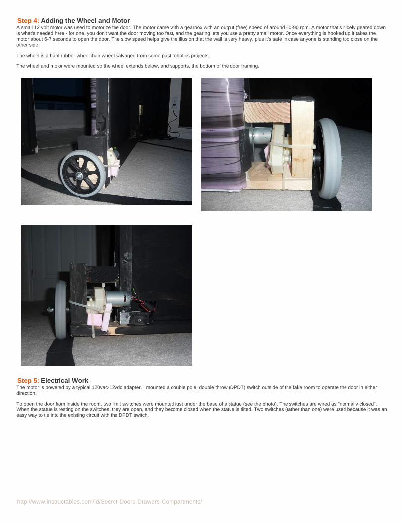
Step 4: Adding the Wheel and MotorA small 12 volt motor was used to motorize the door. The motor came with a gearbox with an output (free) speed of around 60-90 rpm. A motor that's nicely geared downis what's needed here - for one, you don't want the door moving too fast, and the gearing lets you use a pretty small motor. Once everything is hooked up it takes themotor about 6-7 seconds to open the door. The slow speed helps give the illusion that the wall is very heavy, plus it's safe in case anyone is standing too close on theother side.
The wheel is a hard rubber wheelchair wheel salvaged from some past robotics projects.
The wheel and motor were mounted so the wheel extends below, and supports, the bottom of the door framing.
Step 5: Electrical WorkThe motor is powered by a typical 120vac-12vdc adapter. I mounted a double pole, double throw (DPDT) switch outside of the fake room to operate the door in eitherdirection.
To open the door from inside the room, two limit switches were mounted just under the base of a statue (see the photo). The switches are wired as "normally closed".When the statue is resting on the switches, they are open, and they become closed when the statue is tilted. Two switches (rather than one) were used because it was aneasy way to tie into the existing circuit with the DPDT switch.

http://www.instructables.com/id/Secret-Doors-Drawers-Compartments/
Image Notes1. limit switch2. limit switch

http://www.instructables.com/id/Secret-Doors-Drawers-Compartments/
Step 6: Finishing TouchesSome final details really help to pull everything together. Also, the surprise of the wall opening is heightened if the lighting/decor is different on either side of the room.Inside, we added some webbing and LED candles inside for a run-down, creepy atmosphere. Outside we had different colored lighting and decorations.
We marked the swing of the door with an arc of gaffers tape on the floor. This would keep our guests aware of not standing too close as more people come in.
The final touch was a small riddle inside to give guests a clue of how to enter.
Related Instructables
SimpleDecoration ForHalloween(Photos) bylogannebell
The MysteriousBookcase byStryker
simple elegantHalloweenfeather wreath(Photos) byeaolsen
Creating anIndoorHalloweenAtmosphere bywoofboy111
Halloween DoorHang/Wall Vaseby LAWNMUSIC
How to Build aBatcave byMercat
Flight of theBats (Photos) byLarry.0
Spooky FrontStoop " TheBirds " (Photos)by lancmaltby

http://www.instructables.com/id/Secret-Doors-Drawers-Compartments/
bookcase doorby cross_eyed on April 26, 2011
Intro: Bookcase doorOk this is my first Instructable and it's a bit on the large side so here goes.Who doesn't love secret passages? I bought my first house last summer and over the cold winter ideas started forming in my mad scientist brain. As soon as it was warmenough to spend extended periods of time in the garage I got to work.
Image Notes1. this section of wall gets removed
Image Notes1. bottom of shelf

http://www.instructables.com/id/Secret-Doors-Drawers-Compartments/
Image Notes1. floor fitting and pipe2. arced lines to mark path
Image Notes1. casters mounted on arc2. bolts for strength

http://www.instructables.com/id/Secret-Doors-Drawers-Compartments/
Step 1: LocationFirst up is the where. There is a closet under my stairs and about a one foot indentation along a nine foot wall. Seems like a pretty good spot! I pulled the door off andwidened the opening to accommodate the bookshelf.
Image Notes1. this section of wall gets removed

http://www.instructables.com/id/Secret-Doors-Drawers-Compartments/
Step 2: Build the bookcasesThe first bookcase I made was a stationary one. I should have taken more pics of the process, especially the steps that apply to each section. The sides and shelves are3/4 inch plywood. there are 2x4 braces on the bottom and 2x2 braces on the top. 1/4 plywood on the backs and tops. 1x6 pine to trim around the cases. 1 inch pipe andfloor fittings for the hinge and casters for the door. When you figure out where you want the bookshelves, you need to leave a gap at the top and bottom. The top so thedoor won't scrape the ceiling, and the bottom for the casters. I routed a 3/4 inch channel 1/4 inch deep into each side for each shelf. Drill holes for 3 inch wood screws sothat you don't split the wood and keep your square handy to make your shelves level. if you're sure they are level, nail the 1/4 plywood to the back for strength. I alsoscrewed the stationary cases to the wall and each other.
Image Notes1. bottom of shelf
Image Notes1. top of shelf
Step 3: The DoorMost of the door bookcase construction is the same as the stationary ones. The big differences are 1) the door wont be resting directly on the floor and 2) it will be movingso i put an additional piece of 3/4 inch plywood on the back, bottom and top. For the bottom, attach a floor fitting to the corner that will pivot. Attach a string or wire to itand use as a compass to mark the curves that the casters will lay on. I attached the casters and fitting to the second piece of plywood with bolts and attached it to theother piece plywood, hiding the evidence. attach the pipe and another floor fitting and move the bookcase into place. Once in place, unscrew the pipe until the secondfitting reaches the floor. Mark the holes position on the floor. Move the bookcase out of the way. Drill at the marked points and insert concrete anchors. Put the bookcaseback in place and use lag bolts to anchor it to the floor. It will now hinge by screwing or unscrewing in the threads. Since it's only a quarter turn, there isn't a significantchange in height. I repeated the pipe flange setup at the top to keep the case from wobbling. Just take careful measurements to put it in the same spot, or it will bind.
Image Notes1. floor fitting and pipe2. arced lines to mark path
Image Notes1. casters mounted on arc2. bolts for strength
http://www.instructables.com/id/Secret-Doors-Drawers-Compartments/
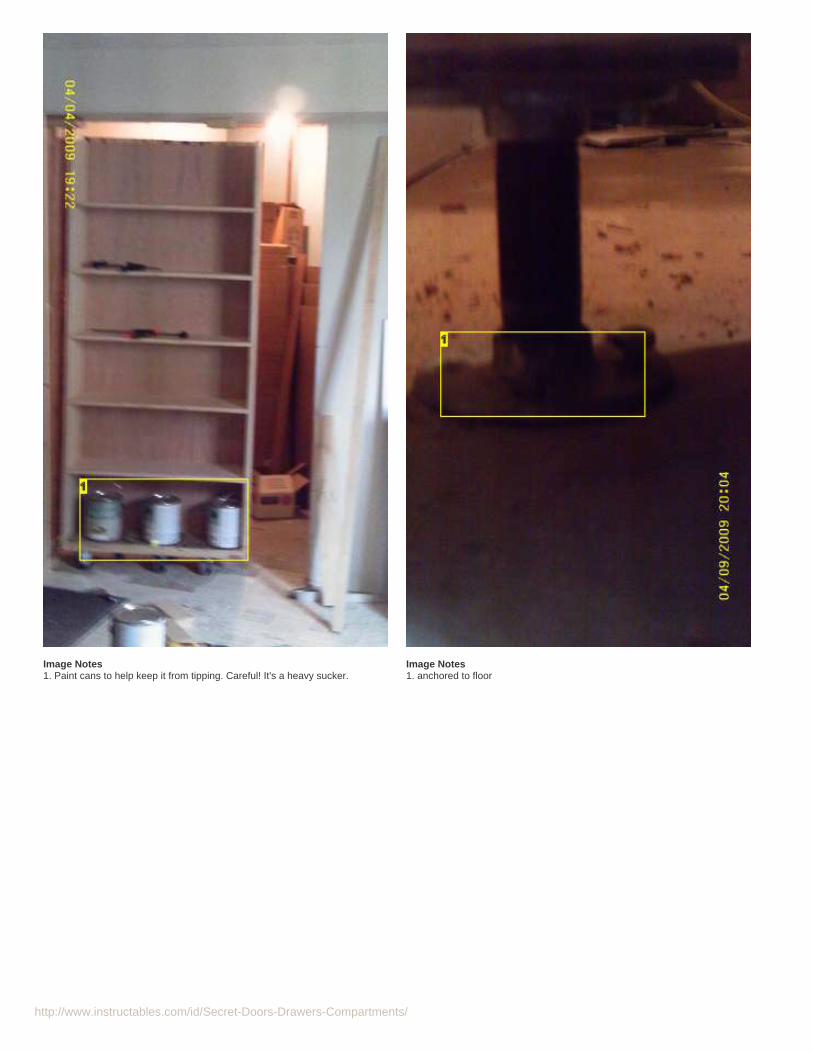
Image Notes1. Paint cans to help keep it from tipping. Careful! It's a heavy sucker.
Image Notes1. anchored to floor

http://www.instructables.com/id/Secret-Doors-Drawers-Compartments/
Image Notes1. attach with bolts at the top too2. through the old ceiling to the studs
Step 4: Rest of the shelvesDepending on your wall and shelf lengths, you may need more bookcases. I needed one more to bridge the gap between the two. Triple check your measurements. Mylast shelf ended up being a bit more narrow than the other two.

http://www.instructables.com/id/Secret-Doors-Drawers-Compartments/
Step 5: Getting inThis room is the best space in case of storms, so I wanted a mechanical locking mechanism in case of power outages. To get in one one needs to have a magnetic item.When placed correctly, the magnet will stick. The panel warped slightly when cut and ended up keeping the latch tight until a little pressure is applied. Release bothlatches and voila hidden space. Springs in the back keep the panel from falling but still allow it to open. With the panel open, we see two cables. Pull one to lock and theother to unlock. This works really well right now, and if I want to go with a classic "book" opener it should be a pretty simple mod.
Image Notes1. Magnets are the "key"
Image Notes1. magnetic baby latches hold the panel until released2. shorter books to allow clearance
Image Notes1. cable 22. cable1
Image Notes1. open a crack

http://www.instructables.com/id/Secret-Doors-Drawers-Compartments/
Step 6: The latchThe latch is made of scrap plywood about 4" wide. I've got 2 bars that pivot on screws and are kept tight by rails. Another scrap of ply was used to sync the two barstogether. I installed carabiners in line with the cables in case I want to lock any one out while I'm on the inside. The door is pretty secure when locked and takes a goodshove to get it to move at all.
Image Notes1. carabiner
Image Notes1. "open" cable2. bottom bar
Image Notes1. bottom latch and rail2. beam connects bars so they both open/close3. pivot screw

http://www.instructables.com/id/Secret-Doors-Drawers-Compartments/
Image Notes1. "close" cable2. top latch and rail3. pivot screw4. pivot screw5. another brace when locked
4. pivot screw5. "open" cable

http://www.instructables.com/id/Secret-Doors-Drawers-Compartments/
Step 7: Stain to match existing wood and seal. Load with books and try to keep the secret. Or just show it off to all your friends. No one has figured it out yet without major clues.Now I just need to put together the mad science lab!
http://www.instructables.com/id/Secret-Doors-Drawers-Compartments/
Related Instructables
Bookcase / Hanin CarboniteHidden Door bynylanan
Hidden DoorBookshelf bykenbob Bookcase with
Hidden Drawer(Photos) bybriangrabski
The MysteriousBookcase byStryker
How totransform abookcase to acupboard /comotransformar unlibrero en unarmario byGirbska
BOOKCASEDOOR THATREPLACESYOUR DOOR. byTHE GOOSE
TARDISbookcasecupboard -Goodhart MakerDen of UnequityStorage Cabinetby caitlinsdad
Sliding Doorsfor largeshelving unitsby marcgr

http://www.instructables.com/id/Secret-Doors-Drawers-Compartments/
Hidden Door Bookshelfby kenbob on May 6, 2007
Author:kenbobI am an engineer in high tech. I like to make things.
Intro: Hidden Door BookshelfWall to wall bookshelves that conceal a hidden door. Made without casters. Some people call this a bookcase.
My home office was messy. After I am done it will still be messy but now it is finished AND it has the secret feature. Well it was secret, till I wrote this.
In one wall of my home office is a 5 feet tall 2 feet wide door to access the storage area and crawl space under the garage. This is where we put holiday decorations, oldstuff, and junk.
This wall was the perfect spot for floor to ceiling bookshelves, which I have done lots of, but it had this door in the middle of the wall. The perfect answer was a bookshelfthat opened.
One day my father in law visited and we started drawing pictures of how book shelf hidden door could work, how to hinge, where to hinge, how to hide opening, etc.Following are the highlights from the journey that followed.
Image Notes1. finished product - now they are full of books, and computer parts, and nifty stuff imust save...
Image Notes1. before shot - note door to storage area and disaster like piles of stuff...
Step 1: Calculate dimensionsFirst thing I did was figure out how big and where a bookshelf would need to pivot in order to clear walls and neighboring shelves with minimum gaps. I positioned thehinge point 7" in from the right and 2" in from the front of the cabinet. For sanity I made a scale drawing of shelves and cut out the rotating shelf shape.
With a pin I tried different pivot ideas, validating my measurements. The goal was to have the vertical gap between moving shelf box and fixed shelves be covered with asingle 4.5" trim piece.
I added a better drawing of the key part of the unit, the moving center. The left and right side shelves are not to scale. This was made with visio, which lets you adjust therotation point, so i could simulate the shelves opening to show clearance.The visio file is attached if can read it. the close up is where i notched the vertical trim to allowthe horizontal trim to pivot "through" it.
---Ken

http://www.instructables.com/id/Secret-Doors-Drawers-Compartments/
Image Notes1. when i knew the size of the shelf/door i made scale drawing and cutout to testpivot points and clearances2. plan was to have a 4.5 " vertical trim cover the door workings3. dimensions of steel frame,,, next step4. subtracting out vertical components for door frame size
File Downloads
shelf.vsd (160 KB)[NOTE: When saving, if you see .tmp as the file ext, rename it to 'shelf.vsd']
shelf.pdf ((613x793) 10 KB)[NOTE: When saving, if you see .tmp as the file ext, rename it to 'shelf.pdf']
Step 2: Door Frame - moving steel frameThe next key insight, thanks Jim, was to build a steel frame rather than trying to hinge the wood shelves directly. This would allow the door to swing easily and support500-1000lbs without a problem ( full bookshelf). I calculated the size for the frame allowing minimum clearance from the floor for trim and base board (2" ) and enoughclearance from the ceiling for the metal frame barely below crown. ( 5") and the width was set to just cover the access door and be centered ( 42"). The steel 2x2 box was$90 cut to length with miters. I bought a couple of 3/4" bolts to act as the pivot pins. These were welded 7" in at center of bolt, from ends of the frame , and cut off to fitinto 2x2 box anchors. My welding is not super, so I do a lot of welds.
The steel frame would pivot on a upper and lower anchor point, mounted to ceiling and floor respectively.

http://www.instructables.com/id/Secret-Doors-Drawers-Compartments/
Image Notes1. purchased 2x2 1/8 thick box, cut in picture frame miters
Image Notes1. had to go get more gas
Image Notes1. welded a piece of scrap quarter inch plate to pivot points, then welded 3/4 inchbolts to the plate for extra strength. bolts get cut off to ~ 2 inch long

http://www.instructables.com/id/Secret-Doors-Drawers-Compartments/
Step 3: Installing frameThe ceiling anchor was sized to span 3 floor joist and had a short arm out to avoid rocking (scrap steel). The pivot point on both ends was a 3/4 inch brass flange bearinginserted into a 1 inch hole in the 2x2 box. The floor anchor was much smaller as bolting to the concrete floor made it pretty damn solid. Good luck to the person that hasto remove this someday.
This let me position and place the top anchor, base anchor, and frame. I attached top anchor loosely letting it rock, slipped in frame and bottom anchor on pin (with 2washers on pin above bearing), then slid the whole set into place. A plum bob hanging along the edge of the frame made it quick to tell if it was vertical in both directions.When true, I secured bolts on both ends. I tested the swing of the door frame with ~500 lbs of people standing in it. Dead smooth action.
Image Notes1. extra hole....2. 1 inch holes in bottom and 3/8 holes in top for lag bolts into floor joist3. pivot point with brass 3/4 bearing in 1 inch hole4. this little arm prevents any tendency to rock when lagged to the joist5. third joist hole
Image Notes1. floor anchor, carpet cut away and angle iron bolted to slab2. pivot point under here, one washer tween brass bushing and bolt. bolt cut to 2inch long3. plumb bob for constant check of level in both directions
Image Notes

http://www.instructables.com/id/Secret-Doors-Drawers-Compartments/
Image Notes1. plum bob string.2. doorbell, i removed and moved this.
1. screwed into three joist and twice in center joist2. pivot point. i split a tiny piece - about 3/8 inch - of nylon tubing and slipped it onexposed bolt. this keeps the bearing from slipping down3. pretty level...
Step 4: Add the woodInto the installed frame I built the first shelf box for the swinging shelf and verified clearance. In my design I made the swinging shelf 2 inch shallower than the othershelves to allow clearance behind it for the arc when it swung. ( If I did this again I would bring all the shelves out from the wall, making all full depth. Then I built the twoside shelves and installed trim all around. I used a credit card for gaps between trim and crown to allow clearance.
The 4.5 inch trim left and right of the shelf-door, the right side is fixed to the fixed shelf, the left side moves with the door.I had to bevel notches in the trim on the rightbecause the horizontal trim dives under it as the door opens. I also had to slightly round the horizontal pieces to slip underneath smoothly.
I am not the best woodworker, and the materials ( mdf and particle board ) are less than optimum, and the walls are crooked, but the results were great. Nobody wouldever see the finished wall and think "Hey I wonder if that is a door?"
all in all i have about $350 in the project.

http://www.instructables.com/id/Secret-Doors-Drawers-Compartments/
Image Notes1. lots of sharpies2. 7/16 plywood on center moving shelf. side shelf boxes were built tight to wall.3. save everything.... a bunch of kvm cables... soon to live on the new shelf4. this outlet is going to be in the middle of a shelf box. I cut a hole for it. it nowpowers my printer.
Image Notes1. hits steel to keep door from closing too far
Image Notes1. had to cut out for outlet2. 4.5 inch trim hides clearance gap between shelf boxes3. 3.5 inch mdf across top - 1 credit card thickness below crown molding. crownwas placed slightly inset from outside edge of top trim.4. special gap on following picture5. 2.5 inch mdf across bottom. this clears the floor by about 3 inches, i put 2.2inch trim board 2 inch back so from viewing angle looks like trim in toe kick area.
Image Notes1. 4.5 inch trim on this side attached to door. on other side attached toneighboring shelf box2. 3.5 inch trim - one credit card distance below crown molding crown moldingset 1/8 inch in from outside edge of trim
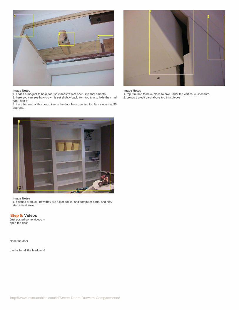
http://www.instructables.com/id/Secret-Doors-Drawers-Compartments/
Image Notes1. added a magnet to hold door so it doesn't float open, it is that smooth2. here you can see how crown is set slightly back from top trim to hide the smallgap - sort of3. the other end of this board keeps the door from opening too far - stops it at 90degrees.
Image Notes1. top trim had to have place to dive under the vertical 4.5inch trim.2. crown 1 credit card above top trim pieces
Image Notes1. finished product - now they are full of books, and computer parts, and niftystuff i must save...
Step 5: VideosJust posted some videos --open the door
close the door
thanks for all the feedback!
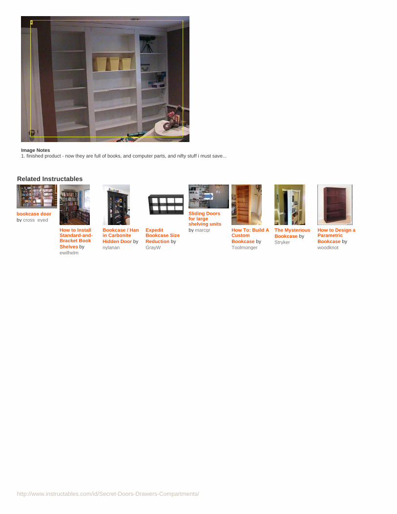
http://www.instructables.com/id/Secret-Doors-Drawers-Compartments/
Image Notes1. finished product - now they are full of books, and computer parts, and nifty stuff i must save...
Related Instructables
bookcase doorby cross_eyed
How to InstallStandard-and-Bracket BookShelves byewilhelm
Bookcase / Hanin CarboniteHidden Door bynylanan
ExpeditBookcase SizeReduction byGrayW
Sliding Doorsfor largeshelving unitsby marcgr How To: Build A
CustomBookcase byToolmonger
The MysteriousBookcase byStryker
How to Design aParametricBookcase bywoodknot

http://www.instructables.com/id/Secret-Doors-Drawers-Compartments/
Secret Knock Detecting Door Lockby vinny03 on May 23, 2011
Intro: Secret Knock Detecting Door LockThis project was inspired from Grathio. I saw his video on Koreus and thought about doing the same thing for my final project in College. I added some functions to theprogram. It works very well.
File Downloads
Detection_frappe_secrete_V04.pde (11 KB)[NOTE: When saving, if you see .tmp as the file ext, rename it to 'Detection_frappe_secrete_V04.pde']
Detection_frappe_secrete_V04.pde (11 KB)[NOTE: When saving, if you see .tmp as the file ext, rename it to 'Detection_frappe_secrete_V04.pde']

http://www.instructables.com/id/Secret-Doors-Drawers-Compartments/
Related Instructables
Secret KnockDetecting DoorLock by Grathio
Intrusion (andattempt)detection(Photos) byslopjong
Knock Block byjkestner
RFID cat doorby landmanr
Very SimpleArduino ElectricLock by RKlenka
Tweet'n'knock -Tweeting theknock (Photos)byfabrizio.granelli
Arduino Basics:PIR Sensors byfrenzy Bathroom
Status IndicatorLights andAutomaticSwitch byMr.Nelson

http://www.instructables.com/id/Secret-Doors-Drawers-Compartments/
Secret Knock Detecting Door Lockby Grathio on October 12, 2009
Author:Grathio Grathio LabsCreative swashbuckler. Writer for MAKE Magazine, presenter of inventions on TV, radio, magazines and newspapers. Professional problem solver.Annoyingly curious. Hacker of all things from computers to clothes to cuisine.
Intro: Secret Knock Detecting Door LockProtect your secret hideout from intruders with a lock that will only open when it hears the secret knock.
This started out as a bit of a joke project, but turned out to be surprisingly accurate at judging knocks. If the precision is turned all the way up it can even detect peopleapart, even if they give the same knock! (Though this does trigger a lot of false negatives, which is no fun if you're in a hurry.)
It's also programmable. Press the programming button and knock a new knock and it will now only open with your new knock. By default the knock is "Shave and aHaircut " but you can program it with anything, up to 20 knocks long. Use your favorite song, Morse code, whatever.
Maybe a video will explain it better:
Important Notes:(I hate to even have to say this, but since someone's going to say it, I'll say it first:)1) This is for entertainment purposes only. Really. This decreases the security of your door by adding another way to unlock it, and it makes your unlock code known toanyone who can hear. If you put this on your door, be sure to carry your key too. The batteries might die, the suction cups might fail or you might forget your knock. Don'tcomplain to me if someone imitates your knock and steals all your stuff, you've been warned.
For obvious improvements to safety, security and whatever, see the final page of the Instructable.
2) This is not a project for a beginner! Read through it carefully and be sure you understand it before you start! I will not take time to answer questions that are alreadyin the instructions or from people who have gotten in over their head.
(If you think this project is too complex you might go here and sign up for the kit mailing list. The kits will be much more simple than this.)
Sorry about that. Now that that's out of the way, lets get to work.

http://www.instructables.com/id/Secret-Doors-Drawers-Compartments/
Step 1: Tools, Supplies, And Skills(If this all looks too challenging, you might consider signing up to the kit mailing list which, when available, will be much easier and alot more simple.)
Time:
This project will take several hours to complete.
Skills:
To complete this project you should be able to do the following:These are important! If you're not sure if you have these skills, read through the entire Instructable and make sure you understand it before starting anything!
Basic soldering.Read a basic schematic.Basic knowledge of microcontrollers (I'll be using the Arduino.) This means you know what one is, how to upload data to it, and how to make minor changes tocode.Improvisation. There are many ways to do this project, and you will have to make changes based on how your door and lock works.
Tools:
Drill (ideally a drill press) and an assortment of drill bits.Saw capable of cutting PVC pipe. (ie: Pretty mcuh any saw.)Soldering iron and solder.Pliers.Screw drivers.Heat-shrink tubing and/or electrical tape.Wire stripper.Vice.Safety glasses.Gloves.
Other things you might find handy: a ruler/tape measure, a multimeter, a breadboard, some tape, a magic marker, sand paper, files, hot glue. And if you're like me a wellstocked first aid kit.
Materials:
(The links are for example only, I don't necessarily recommend or have experience with any of these vendors. Feel free to suggest other sources in the comments.)
Electronics:1 Arduino Duemilanove (Or compatible. Or really any microcontroller with at least 1 analog input and 3 digital outputs.) Buy from here, here, or here. And otherplaces.1 5v Gear reduction motor. The higher torque the better. Here's a good one. (14-16mm diameter is ideal because it fits inside of 1/2" PVC pipe.) I recommend onewith at least 15oz/in (11 N-cm) of torque at 5v to turn a basic lock. 1
1 Piezo speaker. (30mm) similar to this. You can use larger or smaller ones, smaller will be less sensitive.1 SPST momentary pushbutton. (normally "off")1 Red LED1 Green LED1 NPN Transistor P2N2222A like these or these (or similar).1 Rectifier Diode (1N4001 or similar) this or this will do.1 2.2k ohm resistor (1/4 watt)1 10k ohm resistor (1/4 watt)1 1M ohm resistor (1/4 watt)2 560 ohm resistor (Or whatever will run your red and green LED's at 5v. How to tell.)1 small piece of perf board. 5x15 holes or longer. (example)1 9 volt battery clip and 9v battery. (Or any other way you can think of to get 7-12v to the Arduino. A wall adapter like this is a great option so you don't have toworry about batteries running out. 6 AA's would be another option for longer lasting power, but it will bring down the suction cups.)Connector wire. 20 gauge or narrower flexible wire in a number of colors for connecting the electronics together.
It's also a good idea to have a breadboard for setting up and testing the circuit before you solder it. We'll be doing this in step 3.
Case:(These items are to make the project as pictured. Feel free to build a completely different and more functional case.)
20" PVC Pipe 1/2".3 right angle 1/2" PVC connectors.1 5-way 1/2" PVC connector. (example)2 1/2" PVC end plug.3 1 1/2" suction cups. (Available at hardware stores and craft centers.) NOTE: If your door is unsuitable for suction cups then replace these with three end capsand you can use adhesive strips or screws to mount the lock.6" of 1/2" wide by 1/64" thick metal strip (steel, tin, copper, etc.) (available at hardware, craft, and art supply stores.)4.5" of 1" wide metal sheet, 1/32" thick (steel, tin, copper, etc.) (available at hardware, craft, and art supply stores.)2 3/32" x 3/8" screws with nuts. (1/8" will work too if you can't find the smaller ones.)2 1.6M (metric) 16mm screws. Ideally with countersunk heads if you can find them. (For securing the motor. Check your motor specs to see what screws it needs.One motor I tried used 1.6M, the other 2M. You'll probably have to buy long ones and cut them to length.)
1 If you have a torque meter or a torque wrench, apply it to your door lock to get an idea of what torque it will take to open your lock. Use a online conversion tool toconvert between foot/pounds, N/m, etc.

http://www.instructables.com/id/Secret-Doors-Drawers-Compartments/
Image Notes1. Arduino microcontroller.2. Momentary pushbutton3. 10K ohm resistor (brown, black, orange)4. Green LED5. Red LED6. 560 ohm resistors. (Green Blue Brown)7. Gear motor8. 2.2K ohm resistor (red red red)9. 2n2222 Transistor (NPN type)10. Rectifier diode (1N4001)11. Perf board 5x15 holes.12. 1M ohm resistor (brown, black, green)13. Piezo speaker14. Some wire, 20-22 gauge. The more colors the better.15. 9v battery connector16. 9v battery. You can also run this project from the appropriate wall plug.
Image Notes1. 20 inches of PVC, 1/2"2. 1 1/2" diameter suction cups.3. 5-way PVC connector. (Can be a little tricky to find.)4. PVC end plugs5. PVC right angle (90 degree) connectors6. 1/2" wide metal strip used for a spring to press the detector to the door.7. This metal strip will be made into the widget that connects our motor to the lock.8. Screws and matching nuts. (Turns out you only need 2 pairs, not 4.)
Step 2: Program The ArduinoThis section assumes that you know how to connect your Arduino microcontroller to you computer, compile and upload a sketch. If you don't know how to do that youprobably shouldn't be doing this Instructable. But spending some time on this page and doing some of the examples and tutorials there might bring you up to speed.
We're going to upload our sketch before doing any of the electronics so we can test the electronics as we go.
#1: DownloadDownload the file secret_knock_detector.pde at the bottom of this section and copy it to your sketchbook. (Or view the text and cut and paste it into a new sketch.)
(Tip: If the name of the downloaded file is something like "BARS5HS13H8SW.tmp" simply rename it to secret_knock_detector.pde. and you're good to go.)
#2:Open the sketch and compile it. It should compile properly the first go, but it's good to be sure.
#3:Connect your Arduino and upload the sketch.
If you have any trouble, check the troubleshooting section at the Arduino site.
Code overview:For the curious, here's a look at a few bits of code if you're interested in tinkering:(If you're not curious, go to the next section)
about Line 28:const int threshold = 4;
This is the sensitivity of the knock detector. If you get a lot of noise, raise this (up to 1023), if you're having a hard time hearing knocks you can lower it (as low as 1).
about Line 29:const int rejectValue = 25; about Line 30:const int averageRejectValue = 15;
Both of these are used to determine how accurately someone has to knock. They are percentages and should be in the range of 0-100. Lowering these means someonemust have more precise timing, higher is more forgiving. averageRejectValue should always be lower than rejectValue.
Settings of about 10 and 7 make it hard for two people to knock the same knock even if they know the rhythm. But it also increases the number of false negatives. (ie:You knock correctly and it still doesn't open.)
about Line 31:const int knockFadeTime = 150;
This is a crude debounce timer for the knock sensor. After it hears a knock it stops listening for this many milliseconds so it doesn't count the same knock more thanonce. If you get a single knock counted as two then increase this timer. If it doesn't register two rapid knocks then decrease it.
about Line 32:const int lockTurnTime = 650;
This is now many milliseconds we run the motor to unlock the door. How long this should be depends on the design of your motor and your lock. It's okay if it runs a little
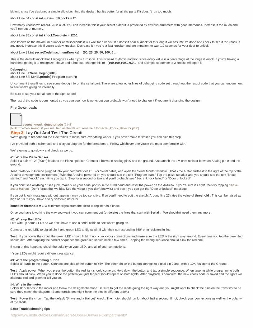
http://www.instructables.com/id/Secret-Doors-Drawers-Compartments/
bit long since I've designed a simple slip clutch into the design, but it's better for all the parts if it doesn't run too much.
about Line 34:const int maximumKnocks = 20;
How many knocks we record. 20 is a lot. You can increase this if your secret hideout is protected by devious drummers with good memories. Increase it too much andyou'll run out of memory.
about Line 35:const int knockComplete = 1200;
Also known as the maximum number of milliseconds it will wait for a knock. If it doesn't hear a knock for this long it will assume it's done and check to see if the knock isany good. Increase this if you're a slow knocker. Decrease it if you're a fast knocker and are impatient to wait 1.2 seconds for your door to unlock.
about Line 39:int secretCode[maximumKnocks] = {50, 25, 25, 50, 100, 5 .....
This is the default knock that it recognizes when you turn it on. This is weird rhythmic notation since every value is a percentage of the longest knock. If you're having ahard time getting it to recognize "shave and a hair cut" change this to {100,100,100,0,0,0... and a simple sequence of 3 knocks will open it.
Debugging:about Line 51:Serial.begin(9600); about Line 52: Serial.println("Program start.");
Uncomment these lines to see some debug info on the serial port. There are a few other lines of debugging code set throughout the rest of code that you can uncommentto see what's going on internally.
Be sure to set your serial port to the right speed.
The rest of the code is commented so you can see how it works but you probably won't need to change it if you aren't changing the design.
File Downloads
secret_knock_detector.pde (9 KB)[NOTE: When saving, if you see .tmp as the file ext, rename it to 'secret_knock_detector.pde']
Step 3: Lay Out And Test The CircuitWe're going to breadboard the electronics to make sure everything works. If you never make mistakes you can skip this step.
I've provided both a schematic and a layout diagram for the breadboard. Follow whichever one you're the most comfortable with.
We're going to go slowly and check as we go.
#1: Wire the Piezo SensorSolder a pair of 12" (30cm) leads to the Piezo speaker. Connect it between Analog pin 0 and the ground. Also attach the 1M ohm resistor between Analog pin 0 and theground.
Test : With your Arduino plugged into your computer (via USB or Serial cable) and open the Serial Montor window. (That's the button furthest to the right at the top of theArduino development environment.) With the Arduino powered on you should see the text "Program start." Tap the piezo speaker and you should see the text "knockstarting" and "knock" each time you tap it. Stop for a second or two and you'll probably see "Secret knock failed" or "Door unlocked!"
If you don't see anything or see junk, make sure your serial port is set to 9600 baud and reset the power on the Arduino. If you're sure it's right, then try tapping Shaveand a Haircut (Don't forget the two bits. See the video if you don't know it.) and see if you can get the "Door unlocked!" message.
If you get knock messages without tapping it may be too sensitive. If so you'll need to edit the sketch. Around line 27 raise the value of threshold . This can be raised ashigh as 1032 if you have a very sensitive detector.
const int threshold = 3; // Minimum signal from the piezo to register as a knock
Once you have it working the way you want it you can comment out (or delete) the lines that start with Serial ... We shouldn't need them any more.
#2: Wire up the LEDsLets wire up some LEDs so we don't have to use a serial cable to see what's going on.
Connect the red LED to digital pin 4 and green LED to digital pin 5 with their corresponding 560* ohm resistors in line.
Test : If you power the circuit the green LED should light. If not, check your connections and make sure the LED is the right way around. Every time you tap the green ledshould dim. After tapping the correct sequence the green led should blink a few times. Tapping the wrong sequence should blink the red one.
If none of this happens, check the polarity on your LEDs and all of your connections.
* Your LEDs might require different resistance.
#3: Wire the programming buttonSolder 8" leads to the button. Connect one side of the button to +5v. The other pin on the button connect to digital pin 2 and, with a 10K resistor to the Ground.
Test : Apply power. When you press the button the red light should come on. Hold down the button and tap a simple sequence. When tapping while programming bothLEDs should blink. When you're done the pattern you just tapped should repeat on both lights. After playback is complete, the new knock code is saved and the lights wilalternate red and green to tell you so.
#4: Wire in the motorSolder 8" of leads to the motor and follow the design/schematic. Be sure to get the diode going the right way and you might want to check the pins on the transistor to besure they match the diagram. (Some transistors might have the pins in different order.)
Test : Power the circuit. Tap the default "Shave and a Haircut" knock. The motor should run for about half a second. If not, check your connections as well as the polarityof the diode.
Extra Troubleshooting tips :

http://www.instructables.com/id/Secret-Doors-Drawers-Compartments/
1) If the motor turns very weakly the diode might be reversed.
2) If you need more power on your motor make the following circuit change: Move the wire that goes from the motor to +5v to the Vin pin on the Arduino. This will supplythe motor with 9v (or whatever voltage you're supplying to it.)
Tip : Check which way the motor turns. It should turn the same way as you turn your deadbolt lock to unlock it. If not, switch the motor's leads which should reverse themotor.
Congratulations! You have a working secret knock detector!
Now we have to put it into something more permanent that we can stick on our door.
Step 4: Prepare The CaseIf you're making your own case you can skip this step. Otherwise grab your PVC and saw and lets get cracking.
Important!We're just testing for fit here. Don't glue or fasten anything yet!
#1: The Button mountTake one of the PVC end caps and drill a hole through the center appropriate for your push button. For my button that was 3/8". Secure the button in the hole.
Plug this into one of the 4 radial holes in the 5-way connector. (ie: not the one that points down.)
#2: The Motor mountTake the other PVC end cap and drill a hole big enough for the shaft of your motor to pass through. You might also need to make it even bigger if your motor has abearing that sticks out.
Depending on the design of your motor you may want to sand down the thickness of the plug so that you have more of the motor shaft to work with. Test the fit by placingthe motor through the back of the plug. If it's too tight you might have to sand/file/grind the inside of the plug so it will fit.

http://www.instructables.com/id/Secret-Doors-Drawers-Compartments/
Use a paper template to place the holes for the fastening screws, drill the holes and attach the motor to the plug. (In my case using the two 2M screws.) Countersink thescrews if possible.
Plug this into the "down" facing hole on the 5-way connector.
#3: The 'arms'Cut one piece of PVC pipe 5 inches long. We're going to call this the "long arm". Put a right angle connector on one end. Plug the other end into the 5-way connectoropposite the button.
Cut two pieces of PVC pipe two inches long. We'll call these the "short arms". Half way along their length drill a 1/4" hole through one side. Put right angle connectors onone end of each arm. Plug these into the two remaining holes on the 5-way connector. You should really start to see it take shape.
#3b: A Few Extra Holeswith a pencil or marker draw a line down the center of the top and the bottom of the long arm. On the top side, make marks for two holes, one 3/4" from the 5-way, andanother 1 1/2" from the 5-way. Drill a 3/16 (5mm) hole at each of these places. This is where our LEDs are going.
Also make a line along the bottom where the long arm connects to the 5-way. Using a saw, cut a short way through the pipe, from the bottom up, until there is about a1/2" hole into the pipe. (this is where the spring for our detector will attach. Also on the bottom, drill a 1/8" hole 1/4" further along the pipe (Away from the 5-way). We willthread the sensor's wires through here.
#4: The 'legs'These are the parts that attach to the door. You may not want to cut these yet, The length depends on the design of your door lock, the length of the shaft on your motorand the final design of the Lock Turning Clamp in the next step. All three of mine were 2 5/16" long, but you're better off cutting them long and trimming them down to sizelater
If they're too long the motor won't reach the lock to turn it. If they're too short the suction cups won't reach the door.
When you do cut these, hot glue the suction cups in one end and stick the other ends in the right angle connectors on the ends of our legs.
Image Notes1. Button mount. End plug with hole drilled for the panel mount button.2. 5-way connector. The motor goes in the center of this.3. This is an exploded view with all of the parts laid out how they attach(though the angles are wrong on some parts.4. Top arm. Hole drilled to let wires through.5. The "Board Arm" This is the arm we're putting the circuit board into. Holedrilled to allow wires through.6. Motor mount. Will go in the bottom hole on the 5-way.7. Ignore this hole. Not sure what I was thinking.8. holes for LEDs.9. The "Long Arm". (It's longer because it provides more holding power againstthe torque of the turning lock.)
Image Notes1. Two sample motor mounts for two different motors. The one on the left issmaller but actually more powerful. The one on the right has a larger hole to allowclearance for the bearing. The facing surface on both of these have been grounddown so more of the shaft can stick out.

http://www.instructables.com/id/Secret-Doors-Drawers-Compartments/
Step 5: Make The Lock Turning ClampIn this section we make the all important part that connects the motor to the lock.
(This is a reasonably clunky way to do this, but it's simple and cheap. If you think of a better way, please mention it in comments.)
What we're making is a clamp that attaches to the D-shaft of our motor and fits easily over the lock latch so that it can turn the lock. It attaches securely to the motor, butthere is some give in it so that it can slip if it finds its self between a rock and a hard place. (Which we prefer to wrenching the project to pieces.)
Drilling the holes:First take the piece of metal that's 4 1/2" long and 1 1/4" tall. and cut it in half so you get two 2 1/4" pieces.
Tape them together, mark each side so you know which side is "out", and mark one of the long edges as "up". This will all help you keep everything lined up as you go.
Measure and mark the center line from top to bottom. 1/2" each side of this center line and 1/4" from the top mark holes for drilling.
Drill 1/8" holes at these marks. Marking the points with a punch, or giving it a whack with a hammer and nail will make your drilling more accurate.
The edge with the holes is the side that attaches to the motor.
Bending the metalMeasure the width of your lock latch (the narrow way) and divide by 2. This distance is how much zig we're going to bend into each piece of metal. Mark this zig distancealong each strip. Bend one piece so it zigs to the left, the other so it zigs to the right. Make sure that the screw holes at the top of the pieces stay lined up and the bendsdon't keep the pieces from meeting at the top.
Finishing and sizingFor this part you'll need your motor, the two 1/8" screws and a couple matching nuts.
Put the screws through the holes in the top of the plates so it makes an upside down "Y" (sort of) and place the motor shaft in the top between the screws. Screw nuts oneach side and tighten until it's firmly (but not really firmly) attached. The small amount of give between the metal and the shaft will let the motor spin if it meets too muchresistance. (Rather than breaking something important.)
Check the other end for fit over the lock. It should fit a little loosely over the lock latch. Not so firmly that it's clamped tight, but not so loose that it can turn without turningthe lock. Adjust the bend of the flanges if you need to.
After you've got the adjustments right, tighten another nut onto the end of the screws and tighten them up against the first ones. This will help lock them in place.
Image Notes1. It's not a bad idea to file down the sharp corners.
Image Notes1. A few markings will help keep them straight when you put them back together.2. Two pieces taped together so we get the holes lined up.

http://www.instructables.com/id/Secret-Doors-Drawers-Compartments/
Image Notes1. Edge view. Your lock will slot in here.
Image Notes1. In position over the lock.2. 1/2 of the thickness of the lock handle. This is how much we "zig" each flange.3. Tighten the screws so they clamp down on the D-shaft.4. Having a little bit of space is fine and will make it easier to put on.
Step 6: Make The Knock Detector SpringIn this section we're going to put our knock detector on the end of a little springy bit so it presses securely up against the door. You could just use a piece of tape or evenglue or screw it straight to your door, but doing it this way keeps it portable.
#1: The parts:You'll need
Your strip of thin metal (which is 6" of thin 1/2").The piezo sensor (which should have about a foot of leads soldered on.The piece of PVC I've been calling the "long arm".
The PVC pipe segment, on the bottom side, should have a slot cut 3/4" from the end and a 1/8" hole just inside of it.
#2: Attach the sensor to the metal strip.Using glue, hot glue, tape, etc and fasten the piezo sensor to one end of the metal strip. Wrap some of the remaining wire around the strip so that it stays out of the way.
(If your piezo sensor has its leads on the back then drill a hole through the strip. be sure to cover the leads with insulating tape or heat-shrink.#3: Attach the metal strip to the PVC.Thread the free end of the wire through the bottom hole on the PVC and then insert the free end of the metal strip in the slot. Bend the strip as shown so that the sensorfaces out and down and will lay flat on the door.
The strip should stick in the slot with friction, but if not, take some pliers and bend over the end of ths strip that's inside the pipe.
Image Notes1. Hot glue (or otherwise attach) the sensor to the end of the metal strip. Make

http://www.instructables.com/id/Secret-Doors-Drawers-Compartments/
Image Notes1. The bottom side of the Long Arm with the 1/2" slot for the metal strip and ahole for the wire.2. 4-6" flexible metal strip.3. Piezo sensor with about a foot of wire attached.
sure the "open" end is facing out.2. Wrap some of the remaining wire around the strap to keep it out of the way.
Image Notes1. Thread the wire through the round hole and slide the free end of the metalstrip into the slot.2. The free end of our wires.3. Bend the strip more or less like this.4. This area is where the door will be, Try to bend it so the sensor lies more orless flat against the door.
Step 7: Soldering The CircuitsDue to the needlessly complex nature of my case, soldering and case mounting are somewhat intertwined, but I'll try to break it down so it makes sense.
I recommend that after each step you plug in and test the circuit to make sure you didn't make a mistake, moving each bit from the breadboard one at a time. Having todesolder components is no fun.
Tip : Use wires in as many colors as you can get so you can keep things straight. I also usually put labeled bits of tape on the ends of the wires to help me remember.
Tip : If you're using stranded core wire, be sure to tin the ends . It will help with your joints and make it easier to stick them into the breadboard for testing.
#1 Solder leads to the LEDs. (Hey, that almost rhymes!)About 10" or so should work.
Okay, so much for the easy steps. After this it gets more complex because most of the components need to be threaded through various holes in our case before they'resoldered. Of course if you made a different case then you don't need to worry about most of the tedium and can get right to soldering the components to the perfboard.
Tip : Mount the components as closely as possible to the perfboard. There isn't much clearance inside the pipe.
#2 Prepare the perfboard.We're using a perfboard with 0.10" spacing where each hole has an individual copper pad. Cut the perf board to size (5x15 holes) and then sand/file/grind off some of theedges so it fits easily into the 1/2" PCV pipe.
For future reference we're calling the side with the copper "back" and the side with the components the "front".
#3: The ground lineSince the ground is the most common terminal in the project we're going to run a ground line across the back for the components to connect to. To make this I too a 9inch piece of solid core wire that I'm using as my ground wire and stripped about an inch off one end. The soldered between hole 1 and hole 10 (see the attacheddiagram). Then I'll tack the other gronded components to it as the come through the board. (You can also just bridge the connections with solder, but I hate doing thatbecause it can get messy. My soldering is messy enough.)
The other end of this wire will go to a Ground pin on the Arduino. (This is a good time to label the other end with a piece of tape.)
#4: The +5v line.There are also a couple points where we want to supply +5v. This is the same idea as the ground line but we only need about half an inch stripped.
The other end of this will connect to the +5v pin on the Arduino.
#5: The LEDs.Solder the LED's resistors (560 ohm by default) in place as shown.
You have two choices of how to deal with the LED's. You can mount them on top (the easy way) or you can mount them from the bottom, which looks better, but is a painbecause 1/2" PVC doesn't give you much room to work. If you mount them from the top, be sure to thread the leads through the holes before soldering.
Thread all 4 leads from the leds out through the near end of the 'long arm' through the 5-way and through the 'board arm".
Solder the cathode (-) lead (the short one) from each LED as indicated. The anode will connect to digital pin 4 (red) and 5 (green) on the Arduino. (Thread the Ardunioleads through the "short arm" of the 5-way.)

http://www.instructables.com/id/Secret-Doors-Drawers-Compartments/
#7: The knock sensor.Solder the speaker's 1M ohm resistor in place on the board.
Make sure you have the speaker mounted firmly at the end of the spring and the wire is wound a few times around it to keep it out of the way. Thread the wire through thelong leg, through the 5-way and into the short arm that we're keeping the circuit board.
Solder one end of these leads to each side of the 1M resistor. Then solder a 8" lead from the ungrounded end of the resistor. This will go to Analog pin 0.
#6: The button.Solder the 10K ohm resistor in place as shown.
Fasten the button through the hole on the end plug, then put the plug on the 5-way connector and thread both wires through to the 'board arm' hole.
Solder one lead from the switch to the resistor. The other end to the +5v wire.
Solder a length of wire from the resistor according to the diagram and label it "Digital 2".
#8: The motor.Nearly done.
Solder the diode, transistor and resistor in place. (Make sure you get the direction right on the diode. And the transistor for that matter.)
To the free end of the 2.2k ohm resistor solder a 8" lead that will go to digital pin 3.
Put the motor in place in the bottom hole of the 5-way connector, thread the leads trough and solder them in place on either side of the diode, making sure you've got themotor wires in the right order so when it runs it will turn to unlock.
#9: The Arduino pinsConnect the labeled wires to their appropriate places on the Arduino.
Test :Wait, you don't need to do this, right? You've been testing as we go, haven't you?
Plug some power into the Arduino and make everything works. Especially make sure that the motor spins in the right direction to unlock your lock.
Image Notes1. Check the pin order on your transistor. Some times they're reversed.
Image Notes1. Tape labels are a good idea for this project if you're making the PVC pipecase. Misrouting wires is a real possibility.2. The ground wire. We'll tack other components to this as we add them to theboard.3. The +5v wire. We'll tack other wires to this as we add them to the board.4. In the soldering diagram this hole is hole #1,15. On the soldering diagram this hole is #5,15.6. This is the bottom of the board, compared to the soldering diagram.

http://www.instructables.com/id/Secret-Doors-Drawers-Compartments/
Image Notes1. #5: The solder the resistors in place to the ground line, and the short leads ofthe LEDs to the resistors. Pass the leads through the Board Arm hole of the 5-way.2. While we're threading wires we have threaded both the Piezo sensor wiresthrough for the next step.3. The + leads for the LEDs come out up here. And we mark them with tape sowe don't confuse them later.
Image Notes1. The1M resistor soldered in with the piezo sensor attached either side.2. A lead attached that will go to Analog 0. (We don't need to thread thisanywhere for right now.
Image Notes1. Closer look at the resistors and their connections. This is what it should looklike after #7, above.

http://www.instructables.com/id/Secret-Doors-Drawers-Compartments/
Image Notes1. The button in place with the wires fed through the 5-way.2. The resistor and button connections.

http://www.instructables.com/id/Secret-Doors-Drawers-Compartments/
Image Notes1. The motor in place.2. The final circuit with the wires fed through.3. All the connections that will go to the Digital side of the Arduino we threadthrough to the Short Arm side.
Image Notes1. Close up of the completed board.2. Embarrassing note: the motor connection (the green connection on the left) isnot in the same hole as the diagram. It's connected the same, just in the wronghole.

http://www.instructables.com/id/Secret-Doors-Drawers-Compartments/
Image Notes1. Here's the back of the board so you can see the bridged connections. And alot of messy soldering.
Step 8: Assembling The CaseAll of your components should be in place and the circuit should be working. We're almost there, all we have to do is cram all that wire and the circuits into the pipe.
#1 Getting the wires to the correct side .If you had the wires connected to the Arduino, unplug them.
The wire to Analog 0 and to Ground and +5v will come out of the Board Arm, so we don't do anything with those yet.
The other wires to Digital 2,3,4 and 5 thread through the 5-way to where the Short Arm will go.
#2: The Short ArmSpeaking of the short arm... Pull the wires for Digital 2,3,4 and 5 through the hole in the middle of the Short Arm pipe.
#3: The Long Arm.The long arm has the LEDs and the sensor in it. Using needle nose pliers, (or a bit of coat hanger with a small hook on the end, or a crochet hook) pull up the slack onthese wires as you plug it into the 5-way.
#4 The circuit board. The circuit board should be the first part put in place inside the pipe for the Board Arm. Thread the wires for Ground, +5v and, Analog 0 through the small hole on top ofthe arm.
Now make a tight bundle of the wires around the circuit board putting even pressure on it, being careful not to bend, break or spindle the thing. Gently slide it into theBoard Arm. If you have a lot of extra wire lengths you might want to push it out the far side about half an inch so there's more room for wire on the inside.
When it's in place, plug this short arm into the 5-way.
#5 The Motor .The motor should already be in place in the bottom of the 5-way. But if it's not nows the time to put it there.
#6: The Button .The button should also be in place, but if not, put it in. If you have a bunch of extra wire getting jammed up inside the 5-way, you can try pulling some of it (gently!) to thebutton side of the 5-way since it doesn't take up much space.
#7: The legs and suction cups.The arms should all be plugged in. Attach 90" turns to the ends of the 3 arms, and plug the legs in to the other end.
Suction cups should fit snug into the bottom of the legs. If not, some hot glue will get them into shape.
(If you're not using suction cups then this is where you use your alternate solution.)

http://www.instructables.com/id/Secret-Doors-Drawers-Compartments/
#8: The Arduino and batteryYes, this is ugly as sin. I works, but... yeah. If you come up with anything better, you're welcome to it.
Stick the Arduino onto the top of the frame. I used lengths of insulated wire. It worked...
Attach the battery in a similar way somewhere where it can power the Arduino. Again, I used insulated solid core wires. At one point I used rubber bands which alsoworked just fine.
Tape? Yes, that would work too.
Plug in the wires in where they labels say they should go. Might as well test again it since it's all hooked up.
Whew! Now we're ready to attach it to the door!
Image Notes1. The digital pin wires threaded through the Short Arm
Image Notes1. Circuit board getting ready to be crammed into the Board Arm.2. The wires for Analog 0, Ground and +5v threaded through the hole in theBoard Arm.
Image Notes1. The circuit board has been pushed into the Board Arm. Having a little stickingout the far side is fine, it'll be hidden in the right angle adapter.
Image Notes1. Short Arm plugged in.2. Board Arm plugged in.3. Button plugged in.4. Once again, ignore this hole.

http://www.instructables.com/id/Secret-Doors-Drawers-Compartments/
Image Notes1. Legs and suction cups in place. at the end of the arms.
Image Notes1. Side view. We haven't attached the lock clamp yet.
Image Notes1. The knock sensor is arranged so it will press flatly against the door.2. Battery attached.3. Arduino attached and wires plugged.4. Here is where a neat person would shorten the leads.
Image Notes1. Side view. We've attached the lock clamp. Now we're ready to test it on thedoor!2. Shortening the wires and removing the labels would make it look nicer, butyou'll have to do that on your own time. I have an Instructable to finish!
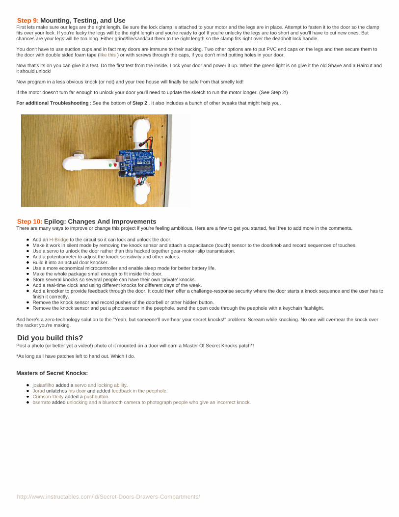
http://www.instructables.com/id/Secret-Doors-Drawers-Compartments/
Step 9: Mounting, Testing, and UseFirst lets make sure our legs are the right length. Be sure the lock clamp is attached to your motor and the legs are in place. Attempt to fasten it to the door so the clampfits over your lock. If you're lucky the legs will be the right length and you're ready to go! If you're unlucky the legs are too short and you'll have to cut new ones. Butchances are your legs will be too long. Either grind/file/sand/cut them to the right length so the clamp fits right over the deadbolt lock handle.
You don't have to use suction cups and in fact may doors are immune to their sucking. Two other options are to put PVC end caps on the legs and then secure them tothe door with double sided foam tape (like this ) or with screws through the caps, if you don't mind putting holes in your door.
Now that's its on you can give it a test. Do the first test from the inside. Lock your door and power it up. When the green light is on give it the old Shave and a Haircut andit should unlock!
Now program in a less obvious knock (or not) and your tree house will finally be safe from that smelly kid!
If the motor doesn't turn far enough to unlock your door you'll need to update the sketch to run the motor longer. (See Step 2!)
For additional Troubleshooting : See the bottom of Step 2 . It also includes a bunch of other tweaks that might help you.
Step 10: Epilog: Changes And ImprovementsThere are many ways to improve or change this project if you're feeling ambitious. Here are a few to get you started, feel free to add more in the comments.
Add an H-Bridge to the circuit so it can lock and unlock the door.Make it work in silent mode by removing the knock sensor and attach a capacitance (touch) sensor to the doorknob and record sequences of touches.Use a servo to unlock the door rather than this hacked together gear-motor+slip transmission.Add a potentiometer to adjust the knock sensitivity and other values.Build it into an actual door knocker.Use a more economical microcontroller and enable sleep mode for better battery life.Make the whole package small enough to fit inside the door.Store several knocks so several people can have their own 'private' knocks.Add a real-time clock and using different knocks for different days of the week.Add a knocker to provide feedback through the door. It could then offer a challenge-response security where the door starts a knock sequence and the user has tofinish it correctly.Remove the knock sensor and record pushes of the doorbell or other hidden button.Remove the knock sensor and put a photosensor in the peephole, send the open code through the peephole with a keychain flashlight.
And here's a zero-technology solution to the "Yeah, but someone'll overhear your secret knocks!" problem: Scream while knocking. No one will overhear the knock overthe racket you're making.
Did you build this?Post a photo (or better yet a video!) photo of it mounted on a door will earn a Master Of Secret Knocks patch*!
*As long as I have patches left to hand out. Which I do.
Masters of Secret Knocks:
josiasfilho added a servo and locking ability.Jorad unlatches his door and added feedback in the peephole.Crimson-Deity added a pushbutton.bserrato added unlocking and a bluetooth camera to photograph people who give an incorrect knock.

http://www.instructables.com/id/Secret-Doors-Drawers-Compartments/
Image Notes1. Post a picture (or video!) of your secret knock detector in comments and get this fancy Master of Secret Knocks patch
Related Instructables
Secret KnockDetecting DoorLock (Photos) byvinny03
How to BreakDown a Door bydrums787 Magnetic
CombinationLock PictureSafe bypastprimitive
Very SimpleArduino ElectricLock by RKlenka
NintendoKeyless EntrySystem byaction_owl
A bit of safecracking... bykillerjackalope
Knock Block byjkestner
Arduino RFIDDoor Lock bypcmofo

http://www.instructables.com/id/Secret-Doors-Drawers-Compartments/
Hidden Cabinetby Romado12187 on August 10, 2009
Intro: Hidden CabinetThis is a hidden cabinet large enough to fit two remote controls, a wallet, a watch, and a bunch of other small items. Using this guide to direct you through this project willfacilitate the process. The cabinet is hidden by a faux DVD collection that flips upward when pressed inward.
WHY: My TV was mounted onto the wall using a bulky bracket. From the left and right sides of the TV, the brackets would show. I covered them up by making twosmaller sized boxes to fit and block the bracket area. I just recently remodeled my room, so I thought it would be nice to do something a little more creative than astandard shelf. The hidden shelf looks like a stack of dvds, but is in fact a hidden door.
This secret door is also a fairly nice way to conceal electronics.
Cost: Roughly $25
Every part seen in this guide can easily be purchased at your local hardware store.
This project should probably be done before the assembly of the outer cabinet, it will make measurements easier. Otherwise be ready to be asphyxiated by bondo fumes.
Step 1: Materials and ToolsYou will need:
Materials:
1x metal rod (needs to be able to slip through the spring of a mouse trap)1x mouse trap2x Bottle of 5 minute epoxy1x magnetic cabinet clutch (push in/out)1x 2'x4' laminated 1/8 MDF board1x Tube of PL glueTapeBondo (too cover up mistakes)Tin Foil
Tools:
ClampsDrill and drill bitHack sawTable sawMiter SawLevel
As many DVD cases needed to fill in the empty space
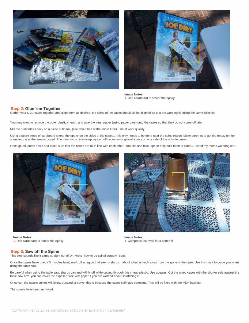
http://www.instructables.com/id/Secret-Doors-Drawers-Compartments/
Image Notes1. Use cardboard to smear the epoxy
Step 2: Glue 'em TogetherGather your DVD cases together and align them as desired, the spine of the cases should all be alligned so that the wording is facing the same direction.
You may want to remove the outer plastic sheath, and glue the inner paper (using paper glue) onto the cases so that they do not come off later.
Mix the 5 minutes epoxy on a piece of tin foil, (use about half of the entire tube)... must work quickly
Using a spare piece of cardboard smear the epoxy on the sides of the cases... this only needs to be done near the spine region. Make sure not to get the epoxy on thespine for this is the area exposed. The inner dvds receive epoxy on both sides, only spread epoxy on one side of the outside cases.
Once glued, press down and make sure that the cases are all in line with each other. You can use blue tape to help hold them in place... I used my moms watering can.
Image Notes1. Use cardboard to smear the epoxy
Image Notes1. Compress the dvds for a better fit
Step 3: Saw off the SpineThis step sounds like it came straight out of Dr. Nicks "how to do spinal surgery" book.
Once the cases have dried ( 5 minutes later) mark off a region that seems sturdy... about a half an inch away from the spine of the case. Use this mark to guide you whenusing the table saw.
Be careful when using the table saw, shards can and will fly off while cutting through this cheap plastic. Use goggles. Cut the glued cases with the shorter side against thetable saw arm. you can cover the exposed side with paper if you are worried about scratching it.
Once cut, the case's spines will billow outward or curve, this is because the cases still have openings. This will be fixed with the MDF backing.
The spines have been removed.

http://www.instructables.com/id/Secret-Doors-Drawers-Compartments/
Image Notes1. Mark it
Image Notes1. Saw it
Image Notes1. The spines have been removed
Step 4: Backing the CasesThis is probably the second most difficult step.
The MDF serves two purposes: 1, to keep the cases perfectly aligned, and 2, to hold the mounted spring in place.
Place the cases on top of the laminated MDF and trace its shape. I used a miter saw to cut out the shape I wanted, a razor should work too. Now you should have thebacking and the cases. The backing should fit perfectly on the the back of the DVD.
Using tin foil as a mixing plate, stir together the remaining epoxy. Using a new piece of cardboard smear the epoxy onto the NON laminated side of the MDF. Make sure itis completely covered, you may want to put excess epoxy along the edges.
You will then want to take some PL glue, and put it along the caverns of the spine's backsides. This will assure a solid and sturdy structure.
Now you will need to use the clamps to make sure that the backing sticks on the spines. I used four different ones, but it shouldn't matter as long as it all lines up.

http://www.instructables.com/id/Secret-Doors-Drawers-Compartments/
Image Notes1. MDF
Image Notes1. Trace the cases
Image Notes1. NON laminated
Image Notes1. It fits
Image Notes1. PL

http://www.instructables.com/id/Secret-Doors-Drawers-Compartments/
Image Notes1. place the MDF on the spines
Step 5: Drill TimeI waited 24 hours for the assembled unit to settle. You may want to wait this long, just because the drilling needs to be very precise and can not be subjected to flimsyareas.
This step can be pretty tricky because the drill hole really needs to be perfect if you want the spines (we can now call it the door) to flip up straight. I recommend using adrill press. Depending on how you set your cabinet up, will change where you orient your door's hole. I wanted my door to pivot upward so that the hinge would be prettyconcealed.
Once the hole is drilled, you need to pass the metal rod through the door and make sure that it goes straight through. If it looks straight, take it out.
The hole that was just drilled is a pre-drill guideline. You will use this as a guideline for the wider drill bit.You can use a hand drill to make the wider hole, which only needs to be on one side of the door. This second hole is designed to harness the mouse trap spring.
Image Notes1. Looks like a pretty solid structure, the PL really works well
Image Notes1. Starting to look like a door cover

http://www.instructables.com/id/Secret-Doors-Drawers-Compartments/
Image Notes1. This is where the spring will be situated, the springs force is against the MDFbacking
Step 6: Spring LoadingNow you will load the spring into the door.
First take apart the mouse trap and extract the spring. Slip the spring down the metal rod to see if it fits. If it does not, use pliers to loosen up the pitch. You are going towant to wedge the spring into the second larger hole that one of the springs legs is fastened against the MDF.
The spring should stay pretty fastened, but if it does not use some bondo to harness it in place. Bondo rarely fails.
Now you should have a spring loaded door... no metal rod should be inserted yet.
Image Notes1. Slip the spring through the rod to make sure that it fits

http://www.instructables.com/id/Secret-Doors-Drawers-Compartments/
Image Notes1. Take this out

http://www.instructables.com/id/Secret-Doors-Drawers-Compartments/
Image Notes1. This is where the spring will be situated, the springs force is against the MDFbacking
Image Notes1. Before the backing
Step 7: Prepare the CabinetThe ease of this step will depend on how well you measure. The external cabinet must have three holes drilled in it. Two for the pivot axis (metal rod) and one to wedgeone of the springs arms into.
The third drill hole will vary depending on how springy you want the door to be. If the hole is parallel with the horizontal door, then it will be less springy. The moreperpendicular the third hole is to the horizontal door the springier the action will be. I wanted springy... so I put the hold directly below the axis hole. You could also usetwo springs for heavier doors and apply this same method.
The first two holes drilled coincide with the holes in the door. Use a ruler to assure perfect alignment.
Once the holes are properly bored out, the door should be place inside the cabinet and lined up with the holes.
This part is tricky.
Wedge the spring arm into the third hole, and push it upward so that the door holes, and the cabinet holes align.
Now you can wedge the metal rod through, completing the axis of rotation. Since no clutches have been used yet, the door should swing open horizontal to the floor.
I cut an area out so that you can see the hidden spring... I later covered it with bondo.

http://www.instructables.com/id/Secret-Doors-Drawers-Compartments/
Image Notes1. Hole 1
Image Notes1. Hole 2
Image Notes1. Horziontal door.2. second hole3. Third hole
Image Notes1. Metal rod is the last step
Image Notes1. Spring

http://www.instructables.com/id/Secret-Doors-Drawers-Compartments/
Step 8: Adding the ClutchPlace a magnet on the bottom surface of the laminated MDF. I used epoxy to hold it in place.
To mark off where the clutch should go, I taped a pen onto the back of the door and pushed back. This allowed me to see the farthest point back that the clutch shouldgo.
Using the mark as a guideline I used epoxy to harness the clutch.
Once the epoxy dries, you can press the door down. It should fit in perfectly.
The hinge is virtually invisible, and makes for a great hidden door.
Image Notes1. before backing went on
Image Notes1. Epoxy
Image Notes1. open position

http://www.instructables.com/id/Secret-Doors-Drawers-Compartments/
Step 9: Cleaning UpIf you made countless errors like I did with the drilling, you will need to cover up the areas with bondo.
I also got some glue on the dvd covers. At first I thought I ruined everything, but i just got another dvd, took the paper out, cut it to size, and glued it on the dirtied spinewith paper glue. It worked pretty well.
I also made a little overhang for the cabinet to add some style. The little thing seen, was made using MDF as well.
Image Notes1. Nicely cleaned up2. Overhang
Step 10: The Finished CabinetI hope you enjoy using your new hidden cabinet, it makes for a great storing place.
Image Notes1. Nicely cleaned up2. Overhang

http://www.instructables.com/id/Secret-Doors-Drawers-Compartments/
Image Notes1. finished cabinet... one more to go :(
Image Notes1. open position
Image Notes1. Colbert

http://www.instructables.com/id/Secret-Doors-Drawers-Compartments/
Related Instructables
How to install acabinet door byWoodooz
How to install aglass door forcabinets byWoodooz
Tardis Cabinetbyflammablesquid
Installing IKEAUpper KitchenCabinets byjskingry
Projectorhidden cabinet(Photos) bynewtonn2
Episode 13: TheHiddenBookshelfArcade (video)byStupidInventions
Woodworking:Making woodprojects withoutusing nails,screws, or glue.by mikey77
FishAquarium Stand(40 breeder tankwith hiddensump door) byd00dy

http://www.instructables.com/id/Secret-Doors-Drawers-Compartments/
Cheap secret compartment!by fortneja on December 21, 2007
Author:fortneja author's websiteI enjoy quick and easy projects that are useful and cheap. I enjoy building and creating new things!
Intro: Cheap secret compartment!This will show you how to make a secret compartment that can be built into a bookcase, or some other piece of furniture. It uses a sneaky lock that doesn't expose anyhardware to the surface. If you can keep from showing all your friends (I couldn't), this would actually be a useful place to store valuables. This design is very flexible toall sorts of shapes and sizes. It can also be installed vertically.
You will need:
A bookcase. I built my own, but virtually any sort of furniture will work: bookcases, china cabinets, dressers, whatever. Just be sure there is a clear amount ofspace underneath, and the surface for the hatch is at least half an inch thick.Magnetic Child LockConcealed Hinges
I know these pieces can be found at most hardware or home improvement stores as well.
UPDATE 1/9/08:
WOW! Thank you so much to everyone who has commented and checked out my instructable! I had no idea people would find it this interesting! Keep experimenting andsending me your thoughts and variations on my design!
Also, Cousin Eddie wanted to see if neodymium magnets could open the lock, instead of the key, here are his findings:
"Anyway I checked to see if I could open a latch with simple neodymium magnets & found that it took at least 3 small (watch battery size) neod. magnets to open it. BUTyou have to have the polarities of all the magnets (including the one inside the latch) lighted up.... otherwise it wont work. Simple to do though. Think I will mount themagnets in my own "key". "
Thanks for the findings!
UPDATE 1/27/08:
I received a request for some pictures of what my bookcase looked like as a whole. I put it them in at the end.
Image Notes1. Your own secret compartment!

http://www.instructables.com/id/Secret-Doors-Drawers-Compartments/
Step 1: Cut out the hatch...Use a hand-held jig saw to cut out your hatch. I was able to remove the shelf during this step, which makes this much easier. For best concealment, cut along a joint, (ex:in the corner) so the cut looks as natural as possible. For this example, I didn't, but the outline is still faint. Use as narrow a blade as you can, as any gap would lookreally obvious. This is where you are free to adapt the size and shape of the your hatch.
Image Notes1. Outline of the hatch
Step 2: Install the hinges...This is pretty simple, although drilling holes for the hinges into the surrounding shelf can be tricky with smaller hatches unless you have a right-angle drill. With thesehinges, I had to chisel the hatch and counter-sink the hole, in order for the the hatch to fit flush with the shelf. For the fitting the hinge to the hatch, I used my trusty jig sawand a chisel until the hinge fit flush with the rest of the wood.
Check the movement of the hinges, and adjust them if need be. Ideally, the hatch should still be flush with the shelf.
Install a small block opposite the hinges, to keep the hatch from falling into the compartment below.
Image Notes1. Cut the hatch as necessary to make the hinge flush to the hatch. This willkeep gaps from showing around the hatch.
Image Notes1. The box below.2. I installed a small stop block to keep the hatch from falling into thecompartment. This way, it sits flush with the rest of the shelf.

http://www.instructables.com/id/Secret-Doors-Drawers-Compartments/
Step 3: The fun part...Install the magnet lock per the manufacturers directions. Ensure the lock creates a tight latch. For my hatch, I had to shim the other side of lock to make a tight fit. Thepictures below describe how this lock works.
Image Notes1. Here's what the lock looks like in its normal latched state.
Image Notes1. The catch opens when the magnet is placed above it. You will hear a click.
Step 4: Build a box below and complete...Next build a box underneath your hatch. Again, the dimensions of this are up to you. Don't make the box too much bigger than the hatch though, as this will make it hardto reach around in.
Here is a photo review of the entire method of opening the compartment:
Image Notes1. Place the key above the lock and pull...

http://www.instructables.com/id/Secret-Doors-Drawers-Compartments/
Image Notes1. Your own secret compartment!
Image Notes1. The secret cavity is under here.
Image Notes1. The shelf before I started cutting. Note also I hadn't put backing behind thecupboard yet, either.
http://www.instructables.com/id/Secret-Doors-Drawers-Compartments/
Related Instructables
Bookcase withHidden Drawer(Photos) bybriangrabski
Bookcase withdog parts(Photos) byknife141
Loft beds withbookshelfladders bymakendo
bookcase doorby cross_eyed
TARDISbookcasecupboard -Goodhart MakerDen of UnequityStorage Cabinetby caitlinsdad
Bookcase (orbasic shelf) forlittle to nothing!by TMonkDesign
How To: Build ACustomBookcase byToolmonger
The MysteriousBookcase byStryker

http://www.instructables.com/id/Secret-Doors-Drawers-Compartments/
Hidden Drawer Safeby pagan209 on March 19, 2011
Intro: Hidden Drawer Safe
While building my entertainment center I decided to one up my standard design by combining a hidden gun safe drawer. The project worked rather well with my originaldesign but did require a few modifications and quite a bit of research on my part. Seeing as this project is so closely connected to my entertainment center, I'll try to put alittle more detail into the research and information portion of this instructable.
When building a hidden drawer there are a few important decissions that need to be made. Location is one of the primary decisions you will be faced with. Luckily, I wasin the middle of designing a piece of furniture where the safe was easy to integrate but the overall design of this slide motion/latch/trigger mechanisms can be moved intoany "draw" type project. Next is reigning in the slide motion/latch/trigger design. I'm going to cover this in a little more detail before I venture into my project just to give anunderstanding of why I made some of the choices that I made.
When building a drawer, the slide motion begins with a drawer slide. In this case roller drawer slides are pretty much only going to vary by length and strength. I used 24"TopSlide® Series Heavy Duty Slides that I purchased online from Rockler.com.
Next, and a bit more complicated is the motion. Options for motion include Springs, Electric motors, or Hydrolics. I'm going to stay away from the Hydrolic options andfocus on the motors and springs. Electric motors or linear actuators, give you the ability to open and close a drawer with the push of a button and can be smooth, quietand strong. If you prefer motors great but, I ran into a few negatives when trying to rationalize a motor for my design. The first issue that came with the motor was thelatch. A motor eliminates the need for a latch because you can establish its limits electronically. As long as the motor is reasonably strong you should be ok. however, Iran into issues when it came to the failsafe I wanted. What I mean by this is that the drawer, using a motor would require a complicated disengage so that you could stillopen the drawer in the event of powerloss or motor failure. This is by no means impossible but I found it to be more complicated. A motors motion control options arequite tempting though... just not where I felt I should go. This brings me to the Gas piston spring. The 24"easy lift from www.bansbach.de/com ended up being what Idecided upon. This gas piston cost a little over $100 but offered a controlled slow release and an adjustable pressure level. Using a gas spring required a latch assemblybut gave me all the features I wanted.
So Materials break down toA spaceDrawer (steel in my case) $120Drawer Slides $50Gate Latch $10Electronic door strike $25Keypad $45Gas Spring $120Wire $5Misc nuts bolts and screws $5Foam $40Electric knife $25
Oh and I have plans for some polished concrete medallions to decorate the entertainment center with. A laser cutter would go a long way in helping with the moldingdesign process. Sounds like another instructable to me.

http://www.instructables.com/id/Secret-Doors-Drawers-Compartments/
Step 1: Drawer and hindgesThe drawer itself was fabricated at a local machine shop out of 16 guage steel. However I prefer to measure once and cut twice so I had to cut the thing in half and re-weld it. I neglected to account for the 1/2 inch thick drawer slides in my original dimensions. I never learn!!!
The hindges are attached to the inside right and left portions of the drawer passage using several wood screws and connected to the drawer using pand head machinescrews, washers and nylon lock nuts. I suggest investin in a "step bit" or "Unicorn bit" so you can drill out the necessary holes in the steel drawer. These bits are typicallyused in electrical work and will eliminate the burs left by a standard bit.
The facade of the drawer is made out of a solid piece of Birch attached with half inch pan head wood screws. I deliberatly made the screws smaller in order to allow thefacade to be sacraficial, pending any forceful attempt to pry the drawer open.
SuggestionsIf i did it again, which I may, I would have lined the drawer hole with a steel sleave and moved the drawer thickness up to 1/8 inch stainless steel. Cost was a factor hereand considering the hidden nature of the project it seemed unnecessary.

http://www.instructables.com/id/Secret-Doors-Drawers-Compartments/
Step 2: Gas SpringThe gas spring will vary based on specific drawer dimensions and design but the instillation will be similar. The use of a ball socket joint end and bracket will allow for asmooth rotation as the drawer opens and closes. This will also give some wiggle room when it comes to installing the spring. Meaning you will not need to mount itexactly perpendicular and or level to the drawers face or range of motion. The gas springs are available with fast normal and slow extension speed. I went with andadjustable force slow release. The adjustable force allows me to get the push in force dialed into what is most comfortable. Be careful with the adjustable force optionbecause if you release too much then you have to ship it back to Germany to have the cylinder recharged. I don't know if it is necessary but I have mine set a littlestronger to allow for a breaking in period. I did this just as a precaution.
http://www.bansbach.de/com/gasfedern/gasdruckfeder-ausfuhrungen-2.html
is a great source for figuring all of this out. They also have a variety of other motion controllers motors and actuators.

http://www.instructables.com/id/Secret-Doors-Drawers-Compartments/
Step 3: Electronic Strike and LatchThe electronic strike is mortised into a block of oak and bolted to the center rear portion of the drawer passage. The gate latch is mortised into a matching block of oakand attached to the rear of the drawer using 1/2 inch threaded rods. The treaded rod may seem a little strange but it really allows me to make the necessary adjustmentsto get the two matching perfectly. All the nuts used are nylon lock nuts paired with fender washers. Again, use a unicorn bit to debur the holes drilled in the rear of thedrawer.
Quick point on the electronic strike. You can use either a electronic strike like the one I use here or an electro magnetic strike. The magnetic strikes are quieter butrequire a continuous draw of power in order to stay engaged. This not only seemed wasteful but would open the drawer in case of failure. due to obvious safety concernsI did not like this. The standard electronic strike makes a slight buzzing sound and cannot disengage if there is force applied to the strike. The gas spring keeps acontinuous force on the strike. This may seem like a disadvantage but it requires that you give a light push to the front of the drawer in order to disengage the strike. I seethis as a pretty nice safety feature. not only do you need to know where the keypad is but you need to know the combo then know the location of the drawer and finallythat you have to give it a little push in a specific time frame. If you do not like this then you could use the magnetic version.
Components were purchased from http://www.smarthome.com .
Powering can be done using a power supply available from Smarthome, or read on for what I did.
Step 4: Keypad and PowerThe keypad is an Enforcer Digital Keypad which was also purchased from Smarthome.com. This is the real heart of your setup so it is important to be aware of theoptions this poses. This keypad allows you to set up multiple users, master passwords, temporary passwords and just about anything else that you would want. This alsohas some nice tamper resistant features.
Powering can be done by purchasing a plug in AC power supply orrrr... you can connect the keypad into a household alarm system. The tie into the alarm system givesyou the ability to use some of the strongest security features of the keypad. False codes can trigger your alarm system. Tampering with the keypad(attempting to remove)will trigger the alarm system. Specific code entries can trigger the alarm system. More importantly the keypad is powered by your alarm systems backup power supply inthe event of a power outage and or power loss.
I used some stiff exterior sprinkler wiring to wire the power and alarm system together. Yes this is overkill seeing as Rj-45 would work perfectly but the rigid nature of thesprinkler wire allowed me to feed the wiring throughout my house a little easier, and I had plenty left over from a sprinkler project.
Once the keypad is wired you attach it to the electronic stike using the same wiring.
Hiding the keypad is as important as hiding the drawer so you need to think about what inconspicuous place you want to put it. I made a false facade to the right of the

http://www.instructables.com/id/Secret-Doors-Drawers-Compartments/
drawer that blends in perfectly and folds down to reveal the keypad.
The faux door is installed using two hinges and some mortised rare earth magnets. To install the magnets all you need to do is use a Forstner bit to drill out the hole andscrew it in using a sleeve that comes with the magnets. The magnets were purchased at Rockler.com.
Just an FYI, you can use almost anything to trigger this style of strike. Some of the options available out there are; keypads, Bluetooth switches, keys, knock sensors,push buttons, timers, IR swithces, motion sensors. You can also create a series of switches or actions that need done. Imagination is you limit. You could even tie it intothat clapping bra ible if you'd like.

http://www.instructables.com/id/Secret-Doors-Drawers-Compartments/
Step 5: FoamThe foam I purchased was High density firm foam from http://foamforyou.com . Say that three times fast.
The easiest way to get a clean cut out of foam is to use an electric knife. The knifes are like $25 from target and work really well. If you prefer, you can even mount theknife on a router table to get a true 90 degree cut. There is a video I remember seeing online somewhere that illustrates how to do this. I found that the knife worked outperfectly by hand.
First, I worked everything upside down so that any markings were on the underside of the foam. Lay out what you want. In my case they were guns but it could beanything. Trace the items with a sharpie and remember that it is upside down. Once everything is how you prefer then lay the sheet out on a flat open surface and plungethe knife in following as closely and as perpendicular to the line as possible. Be careful!!! you are working with a carving knife after all. I'd like to keep my fingersas should you.
Once I had the cutouts I took the scrap and cut it in half to act as a cushion in the drawer. This is not necessary but I think it looks nice. This cutting in half was a littledifficult and I think I'd make some form of jig if I did it again.
Step 6: BackupsOne thing that I did that I'm not going to detail is work in backups. You should always have a way to get into your draw in the event that you have the unforeseen occur.Redundancy is always a plus.
I find that a mechanical way of disengaging the lock is imperative.
I hope you enjoyed the project.

http://www.instructables.com/id/Secret-Doors-Drawers-Compartments/
Related Instructables
make BedroomNightstandDrawer tosecure firearms. by Diabloscope
Bookcase withHidden Drawer(Photos) bybriangrabski
FloatingComputer DeskWorkstation(with hiddenprinter area andfloatingkeyboardpullout) bybrassmnkys
Desk Shelf byNatalina
Cool CedarWood JewelryBox bytriumphman
Hidden Blade -Assassin'sCreed inspired(Photos) bythe_burrito_master
great looking,inexpensivecomputer deskby nickfarnell
The Makin' of aCase Safe/PSUcombo byMrJentis

http://www.instructables.com/id/Secret-Doors-Drawers-Compartments/
Super-Secret Hiding Place: The Toe-Kickby brandegor on September 2, 2009
Intro: Super-Secret Hiding Place: The Toe-KickI've been obsessed with hiding things since I was a kid, and over the years have developed what I like to think are some pretty sophisticated, yet easily made, spots thatmost people will never find.
Kitchen (and bathroom) cabinets usually have what is called a "toe-kick" - the area between the floor and the bottom of the cabinet. The toe-kick is most often recessed -and guess what? There's nothing there but space waiting to be used.
You can do this in a rented apartment as long as you are careful - take your time, and you'll end up with an awesome stash spot.
Best of all, this doesn't cost more than a buck!
Here's what you need to get started:
Tools:
Razor knifePutty knife with a thin bladeSome sort of pry tool, putty knife with thicker blade or flat piece of metalA trim tool - used to pry molding from base boardsDiagonal cutters or tin snipsHammer or malletSafety glassesFile and sandpaperBlock of wood to protect the surface you're going to hammerVacuum cleaner or broom (optional)
Materials:
4 rare earth magnetsFour screws or nails with heads - make sure they're attracted to magnetsEpoxySmall piece of thin plywood (optional)Box or other container to fit the spot (optional)
Image Notes1. Trim tool2. Thin blade putty knife3. larger pry-bar

http://www.instructables.com/id/Secret-Doors-Drawers-Compartments/
Image Notes1. This is a toe-kick
Step 1: Identify the spotLook around your kitchen or bathroom to find a corner or end floor cabinet with just a foot or so of recessed baseboard. In my case, I had a corner cabinet in the kitchenthat was perfect for this.
The baseboard needs to be a separate piece of wood, i.e., not attached to the cabinet itself. Most floor cabinets are set up this way.

http://www.instructables.com/id/Secret-Doors-Drawers-Compartments/
Image Notes1. This is a toe-kick

http://www.instructables.com/id/Secret-Doors-Drawers-Compartments/
Step 2: Carefully, carefully pry off the boardThe complete success of this project rests on how delicately and carefully you remove this board. You don't want any obvious marks, or heaven forbid cracks or paintchips to piss of your landlord and give away where you've hidden your fortune.
Begin by scoring between the adjoining boards to separate the paint (if it's painted), so that nothing peels or chips. Then take the putty knife, and gently work it betweenthe boards from top to bottom. Try not to pry, but to loosen. Keep working your way from top to bottom, wiggling the tool as you go. As soon as you've got a clean line,pry gently until you can fit in the thicker tool. Do this on both sides if you have access - mine was next to the stove, so I had to work from one side. I strongly adviseagainst using a screwdriver, as they are prone to putting big dents in the wood.
Once you get the board moved about 1/4", you can put one end of the tool against the inside of the board and give it a couple of taps with your hammer. Keep workinglike this until you can fit your fingers in the space.
Then start pushing the board back and forth with your hand, being careful not to break or crack it. This can take awhile if the space is tight, so be patient. It's okay to bendthe nails, and once you get it far enough out, you can bang on it with the hammer.
Eventually you'll be able to pull the board completely off. Yay! Look at all that room!

http://www.instructables.com/id/Secret-Doors-Drawers-Compartments/
Step 3: Clean and inspect the spaceThe space you have just revealed may be a bit grimy or dusty. It's nice to have it clean, especially if you're going to be using it a lot.
I also like to put something on the floor - usually cardboard or a scrap of carpet. Underneath my cabinet, the vinyl flooring had been cut and tucked in, so I tacked thatdown just to make everything smooth.
If your cabinet is one with a drawer on the bottom, chances are it will have a dust barrier, which is a piece of wood underneath the drawer. If it doesn't, the space is stillsecure - but you can add a piece of wood if you want.
Image Notes1. Look at all that room!
Step 4: Prepare the boardNow you have the board in your hot little hands. Most likely it will have been tacked on by four or more nails. Do NOT, I repeat, DO NOT, pound the nails through the frontor back!
Take your diagonal cutters, rotary tool or hacksaw and cut the nails close to the board, and file them so they don't bite you later.
Now, poke starter holes below or above the nail stubs, and slowly drill a little recess to insert the magnets. Be extremely careful not to drill through the board.
A neat little woodworkers trick is to wrap a small piece of tape around the bit at the right depth. That way all of the holes will be the same depth.
Test fit the magnets until they are perfectly flush with the board. If you drill too deep, just put a piece of cardboard or scrap of something in the hole to shore it up. Whenthey are flush, glue them in with epoxy, and double check that they're still flush.
Now you're ready to work on the cabinet itself.
That's it, the board is ready!

http://www.instructables.com/id/Secret-Doors-Drawers-Compartments/
Image Notes1. Wrap a little piece of tape around the bit to mark your depth.
Image Notes1. Glue them in!
Step 5: Put the screws inIn this step you will be putting the screws (or nails) on the cabinet frame, which will grab the magnets and hold the board.
To mark the spot, I put the screws on the magnet and pressed it against the cabinet frame.
Drill pilot holes - slightly smaller than the diameter of the screws, then put those puppies in. You want them as flush as possible and still able to grab the magnets. Asyou're driving them, watch weather or not the wood is starting to split. If it is, back out the screws and drill a larger hole. If the hole is too big, just glue the screws in.Keepchecking your work until you get it right and everything from the outside looks nice and tight.

http://www.instructables.com/id/Secret-Doors-Drawers-Compartments/
Step 6: Stash your stuff!That's it! You now have a very secure and oh-so-cool spot to hide whatever you want. If you like, find a box or other container that slides in and out, so you don't have toreach way in there.
Happy hiding!
Step 7: Final notesIf you want to get super-fancy, you can rig up something that pulls out of the spot with wheels or drawer slides. I just put a handle on the box, so I can reach right in andpull it out.
Finally, the toe-kick board may be pretty darn tight. Mine was way too tight, so I filed and sanded the top of it off until it fit just right.
Image Notes1. After - looks good, right?
Related Instructables
Secret HoodieStash by TheMollusk
Secret JeansStash by TheMollusk
Jeans Stash byRye2121
Secret DresserStash by TheMollusk
Secret GumStash by TheMollusk
Hide things inyour oldDeoderantcontainer! byGunk on Floor
Lynx (deodorant ) CanStash / Safe byn1cod3mus
How to Make aDecorative Boxor Tin withPolymer Clay(video) bythickneckarts

http://www.instructables.com/id/Secret-Doors-Drawers-Compartments/
BOOKCASE DOOR THAT REPLACES YOUR DOOR.by THE GOOSE on November 29, 2009
Intro: BOOKCASE DOOR THAT REPLACES YOUR DOOR.90 PERCENT OF THESE BOOKS WERE WATER DAMAGED!!!!!!!I DONT CONDONE DESTROYING BOOKS!!!!!!!!!!
IV WANTED TO BUILD THIS DOOR FOR YEARS BUT DIDNT WANT TO RUIN A BUNCH OF BOOKS. SO I FINALY FOUND SOME WATER DAMAGED BOOKSTHAT NO ONE WOULD WANT TO READ. THATS THE HARDEST PART OF THIS PROJECT. I CUT ALL THE BOOKS THEN SUN BATHED THEM FOR A FORDAYS TO DRY THEM AND TAKE ANY SMELL OUT. YOU COULD JUST GO TO A LIBRARY BOOK SALE AND GET BAGS OF BOOKS FOR ABOUT $2 A BAG, BUTPEOPLE FROWN UPON DESTROING BOOKS SO TRY TO FIND DAMAGED ONES IF YOU CAN.
YOU CAN REUSE YOUR DOOR OR BUILD A NEW ONE LIKE I DID. IF YOU REUSE YOUR DOOR ITS A MATER OF ADDING MORE WOOD AND BOOKS TO IT.
Step 1: Cutting your wood.cut 1 1/2" x 3/4 pieces to make a frame around your door. [make sure you leave enough space on the latch side, that the door will shut and not hit on the jam.] measurethe books you get to determin where you put the next piece of wood.

http://www.instructables.com/id/Secret-Doors-Drawers-Compartments/
Step 2: Cutting the bookscutting the books is not fun! but if you have a-table sawshopvacdust maskyou can do this fairly easy. set your fence on the saw to 1 1/4" hook up your shop vac to the saw, put on you dust mask. and start cutting the books with the bind of thebook to the fence, you will have to empty the shopvac about 5 times depending on the size of the vac. IF YOU TRY TO CUT THESE IN A CLOSED AREA WITHOUT ASHOPVAC AND MASK YOU WILL NOT BE ABLE TO BREATH!!! I KNOW CAUSE I DID IT.

http://www.instructables.com/id/Secret-Doors-Drawers-Compartments/
Step 3: Stain your woodstain or paint all your wood pieces and attach them with glue and nails. if your building a new door stain everything. MAKE SURE YOU MATCH THE STAIN OR PAINTOF YOUR DOOR JAM. then clear your wood with a varnish or polyurathane.
Step 4: Glue the books on the door.glue the books on the door making sure to dry fit them first useing pl400 or some other very good glue.i used a lever handle so i could hollow out the book i wanted to use as the handle. i then drilled the handle and attached with screws. if you dont have a lever handle youcould get creative with 2 books or somthing.

http://www.instructables.com/id/Secret-Doors-Drawers-Compartments/
Step 5: Hanging the doornow you can rehang the door but keep in mind your door will be much heavier and you may need to add a heavier duty hinge.now it should look somthing like mine or better! and the inside of your door will look just like a door.

http://www.instructables.com/id/Secret-Doors-Drawers-Compartments/

http://www.instructables.com/id/Secret-Doors-Drawers-Compartments/
Step 6: HANDLE IN THE WALL
My bedroom is very small, and after hanging the door i hit my arm on the book handle a few times. so i came up with this idea to make the handle go into the wall, andgain about 3" of walk space.
i just marked the wall were the handle hit the wall, and built a box that fit around the handle. cut out the wall and slid in the box with a little glue on it. then mounted a wallbumper on the wall down low.
this could be added to about any door that you needed more walk space.
THANKS FOR CHECKING OUT MY INSTRUCTABLE!THANKS: THE GOOSE

http://www.instructables.com/id/Secret-Doors-Drawers-Compartments/

http://www.instructables.com/id/Secret-Doors-Drawers-Compartments/
Step 7: MORE PHOTOSmore photos.
Related Instructables
Hidden DoorBookshelf bykenbob Bookcase / Han
in CarboniteHidden Door bynylanan
bookcase doorby cross_eyed Episode 13: The
HiddenBookshelfArcade (video)byStupidInventions
InvertedBookshelf byfungus amungus
Sliding Doorsfor largeshelving unitsby marcgr Stylish and easy
to make cornerbookshelf bySimonF
Howto(Successfully)Hide a Gift! byshadowfeet

http://www.instructables.com/id/Secret-Doors-Drawers-Compartments/
The Mysterious Bookcaseby Stryker on February 15, 2012
Intro: The Mysterious BookcaseAll my brother wanted for Christmas was a secret door. Since every self respecting man should have one . I began by taking some measurements, doing some internetresearch and this is what I came up with. The hard part was that he lives an hour away from me. So I had to build a mock door frame, transport it and hope thingsmatched up.
Step 1: The buildUnfortunately I don't have many pictures of the build so I'll explain it the best I can.
Materials:Sheet of 3/4" smooth plywoodSheet of 1/2 plywoodLazy susanLong bolt and washers for top pivot pointMisc. trim /spacer woodBed frame caster wheelScrewsWood glueTrim to match houseGate latch with fishing string and special book for secret opener.
The BuildI begin by making a door frame to the exact measurements of my brothers closet. The dimensions of the finished door came out to be 34" wide, 77" tall and 8" deep. Iassume if you are building this project you have enough wood working skills to make a bookshelf and your sizing will vary so I won't go into detail about that.
The door is a solid bookcase made from 3/4 smooth plywood and 1/2" regular plywood for the back. Glued and screwed on all sides. There are five attached shelves andadjustable shelf holes drilled at the top. I made a template to help drill the holes all the correct width and height.
One of the hardest parts was the hinge point. I used a lazy suzan on some 2x4 blocks for the bottom and a long bolt for the top. It took a lot of measuring and testing toget it centered right. Adequate spacing was needed on the hinge side to just barely clear the door frame and still be covered by trim.Most commercial doors have steel frames and don't need caster wheels. Due to the weight of the shelves and contents we added a bed caster. Which needs to bechanged because it's marking my brothers soft wood floors.

http://www.instructables.com/id/Secret-Doors-Drawers-Compartments/
Image Notes1. Just enough gap to clear the frame and still be hidden by molding.2. Long bolt with multiple washers.3. Make a template to save yourself time and effort on these holes.

http://www.instructables.com/id/Secret-Doors-Drawers-Compartments/
Image Notes1. Double or triple knot this so it doesn't come loose.
Step 2: Installation and tweakingInstallation involved removing the closet door and trim. Screwing in some wood blocks to the inside wall that would accept the top hinge bolt.
Once the door was in place, I tested the opening many times and then secured the base with 4" screws.
The latch bolt was installed to the interior door frame matching the latch height. A fishing line was secured and run through the back of the door and connected to thesecret book opener.Hindsight note: Double or triple knot that fishing line or it might come off and your door is stuck closed.
The secret door opening book was a really nice touch supplied by my brother. I glued the pages together to make a solid area for attaching a small brass hinge andfishing line to pull open the latch.

http://www.instructables.com/id/Secret-Doors-Drawers-Compartments/
Image Notes1. I always bring my corded drill. Just in case the cordless runs out. Which it did.
Image Notes1. Small hole for fishing line.2. Small hole for fishing line.3. Hinge point for book/handle

http://www.instructables.com/id/Secret-Doors-Drawers-Compartments/
Step 3: FinishMy brother finished painting and loading with books and decorations. I think it turned out really nice and I'm told it's a great conversation piece when company comes overand he puts their coats away.
Related Instructables
bookcase doorby cross_eyed Overhead
Bookcase bynikolardo
BookCASE:Travel bookcasein a suitcase! bymoseph
Ipod Book Case(Photos) bylukethebook333 Loft beds with
bookshelfladders bymakendo
Wood KindleCase by ChrysN
How to InstallStandard-and-Bracket BookShelves byewilhelm
Make table legsout of books! byjessyratfink

http://www.instructables.com/id/Secret-Doors-Drawers-Compartments/
How to Make a TV Lift cabinetby ihart on February 7, 2012
Intro: How to Make a TV Lift cabinetDo you hate walking into your living room or family room and seeing a huge black TV flat screen dominating your view? Do you wish that you could just make it disappearwhen you're not watching? If so, read on. We will show you how to build a TV lift cabinet that hides your flat screen TV in a nice looking piece of furniture when you're notwatching it. When you're ready to watch, hit a button on a universal remote and it will rise up out of the cabinet like magic.
This Instructable uses birch plywood and a lift by Firgelli Automation to implement the design. The TV shown here is a 60" Samsung but could be any modern flat screen.It includes shelving for your components and drawers to store Wii remotes and DVDs/CDs.
The step by step pictures show key parts and there are over 40 minutes of video with tips and tricks as well. The total cost is around $1000... not including your TV.

http://www.instructables.com/id/Secret-Doors-Drawers-Compartments/

http://www.instructables.com/id/Secret-Doors-Drawers-Compartments/

http://www.instructables.com/id/Secret-Doors-Drawers-Compartments/

http://www.instructables.com/id/Secret-Doors-Drawers-Compartments/

http://www.instructables.com/id/Secret-Doors-Drawers-Compartments/
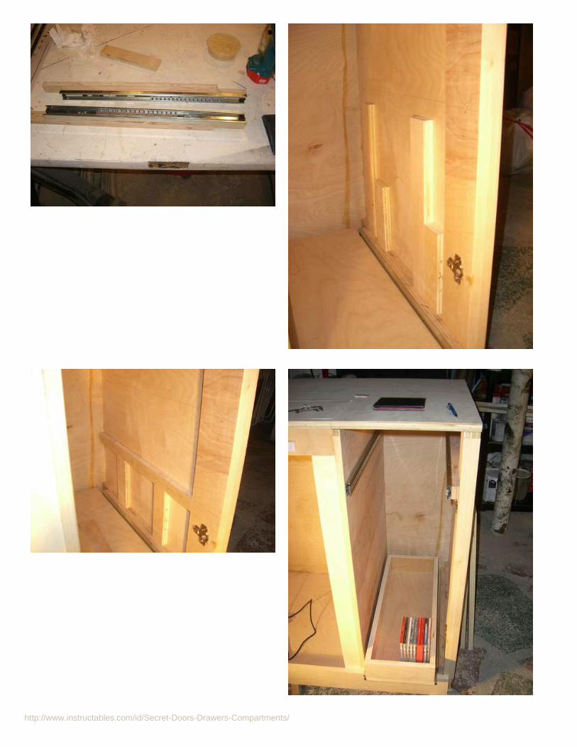
http://www.instructables.com/id/Secret-Doors-Drawers-Compartments/

http://www.instructables.com/id/Secret-Doors-Drawers-Compartments/

http://www.instructables.com/id/Secret-Doors-Drawers-Compartments/
Step 1: Video of TV Cabinet operation
This is a video showing the TV Lift cabinet in action.
This video shows how to remove the front panel for access to the inside of the TV Lift Cabinet.
Step 2: Required materials, tools and costThe TV lift cabinet will require the following materials. Associated costs are also shown:
1 - Firgelli Lift (http://www.firgelliauto.com/default.php?cPath=108 ) FA-TVL-170-24-36 (includes IR detect and remote) $4905 - Sheets of 3/4" Birch Plywood (HW or lumber store) $2251 - Sheet of 1/4" Birch Plywood (HW or lumber store) $304 - Hinges, soft close (http://www.amazon.com/gp/product/B003OE9W7G/ref=oh_o00_s00_i00_details ) $224 - Rolls of birch edge tape (HW/lumber store or (http://www.amazon.com/Cloverdale-28050-Band--Veneer-Edging/dp/B001B1CIKC/ref=sr_1_3?s=hi&ie=UTF8&qid=1328900588&sr=1-3 )) $281 - bottle wood glue (HW or lumber store or (http://www.amazon.com/Franklin-International-5004-Titebond-16-Ounces/dp/B0000223UR/ref=pd_cp_hi_2 )) Tightbond isgreat stuff. $820 - feet of 1.25" x 3/4" Wood Panel molding (I got mine at Home depot) $3030 - feet of 1" x 1/4" Wood Panel molding (I got mine at local lumber store) $455 - drawer glide pairs (http://www.ebay.com/itm/2235-1-Pair-22-Full-Extension-Side-Mount-Ball-Bearing-Drawer-Slides?item=160669477926&cmd=ViewItem ) You mightuse lighter duty glides for the drawers.. $381 - Piano Hinge (http://www.amazon.com/gp/product/B005J0ITT0/ref=oh_o00_s01_i00_details) (you may want to use 2 hinges and cut them to fit the whole ~60" pop updoor) $131 - IR repeater to hide components and IR receivers (http://www.amazon.com/gp/product/B001BLTDZA/ref=oh_o00_s00_i00_details ) $454 - Drawer pulls (Home Depot) $62 - Door pull knobs (Home Depot) $34 - bolts, nuts and washers for the Firgelli lift. $51 - pack of strong velcro. $5
Total = $993.00

http://www.instructables.com/id/Secret-Doors-Drawers-Compartments/
The TV lift cabinet construction will need the following tools:
- Table saw- Jig saw (a band-saw may come in handy)- Compound Miter Saw (a Miter box would work also)- Drill press- Hand held corded drill.- Clamps (assorted)- Tape measure and small steel ruler- Right angle square.- Orbital sander with 60 and 100 grit sand paper.- Sanding block and loose 60 and 100 grit sand paper.- Old iron for applying edge tape.- Sharp box cutter for edge tape trimming.- Drill bits and Forstner drill bits- Countersink drill bit for drywall screws.- Dowel points like this and a few 1/4" dowls- Nail gun and compressor (a finish nailer is fine with 2" and smaller finish nails) It is used to hold wood while the glue dries.- Putty knife for spackling- Socket set, screwdriver, hammer
Step 3: Plywood and GlueI wanted to start out by showing you that wood glue is very strong. The wood will fail before the glue bond fails. This picture I took shows that you can trust your preciousbig screen TV to the glue.. ;-)

http://www.instructables.com/id/Secret-Doors-Drawers-Compartments/
Step 4: Wood Parts Detailed Plans, Cut List and Cut DrawingsThe following Word document contains top, front and side views of the TV Lift cabinet. It also contains a list of wood parts that should be cut. Some of the parts are 3/4"plywood. Some are 1/4" plywood and some are trim molding cuts.
There is also a plywood cut sheet with recommended cuts from each sheet of plywood to allow maximal efficiency of your plywood panels. The sheets can be pre-rippedin your lumber yard or home center for easier carrying in your car. Of course all measurements should be double checked for your application and may be converted tometric.
The documents are in Word so that you can easily modify them for your needs if your application or installation is different.
When choosing your plywood sheets, be sure that they are not warped or bent. Line each one up and sight it with your eye. Reject the warped pieces.
Cutting large sheets of plywood can be tricky. If you have access to a panel saw with a good plywood blade, you are golden. If not, there are some tricks.
- The first is somewhat dangerous and you need a helper. Set up your table saw outside with the fence and guards removed. Mark your lines on the wood and pass thelarge sheet of plywood through the table saw blade with you pushing and your helper catching. Go slowly and accurately.
- The second method is to lay some 2 x 6 pieces on a smooth floor. Lay your marked plywood on the floor and slowly cut your lines with a skill saw with a plywood bladeinstalled.
- Please double check ALL the measurements and dry fit your parts before drilling, nailing or gluing.
- You may find it useful to cut parts from the larger plywood sheets as the project progresses. It gives you a better ability to check for errors. The downside is that youhave to setup the table saw each time.
File Downloads
tv_lift_cabinet_drawings.doc (2 MB)[NOTE: When saving, if you see .tmp as the file ext, rename it to 'tv_lift_cabinet_drawings.doc']

http://www.instructables.com/id/Secret-Doors-Drawers-Compartments/
Step 5: How to Video for TV Lift Cabinet
This video playlist is over 40 minutes long and will show you some of the details that I think are important to getting this cabinet right. PLEASE be extremely careful withall power tools. Watch your fingers and wear eye protection.
Click the link below to watch the video. When it opens, click "Play All" or watch the individual videos that you're interested in.
Click here for the Youtube video playlist.
Step 6: Assembly of the CarcassYou'll need a helper for this first assembly step. Most of the other ones can be done solo. Reference the top view drawing.
Before you start assembling the carcass , make sure that you will have enough room and a plan to get it to it's final location. It is 26" wide which should fit through anydoors BUT it is 87" long so it may be tough to get around corners.
Assembly:
- Lay the Bottom piece "G" on a flat work surface. I use an old door on adjustable saw horses. Set it up so the back and right side are hanging over the edge of the worktable. You will be shooting nails up into this area.
- Put Glue on the bottom of the back piece "Back" and get your helper to hold it in place.
- Put Glue on the right side of the "Back" where piece "E" will connect to it..
- Put Glue on the bottom of the right side piece "E" and get your helper to hold it in place against the back piece.
- Shoot 3" framer nails to secure the right piece "E" to the "Back" piece. Shoot nails from underneath into the bottom to secure the Back and piece "E" to the bottom. Yourhelper is done!
- On the Back of the carcass, mark 42.75" from the right edge and draw a vertical nailing line on the back. Drill a few small holes through this line to carry through yourvertical nailing line to the inside.
- Put glue on the back and bottom of "C2" and center it on these nailing holes you just drilled. Check with a square that "C2" is 90 degrees square to the back and to thebottom. Nail through the back to secure "C2".
- Put Glue on the front of "C2" and on the bottom of "C1". Center "C1" on the front of "C2" and nail through "C1" into C2".
Step 7: Continue Carcass ConstructionWe will continue adding the vertical members to the carcass here. Reference the top view drawing.
- Mark the inside back and bottom of the carcass with a line that is 11.5" away from the right edge. Drill a few small holes 3/8" to the left of this line on the inside back. Goto the back of the carcass and connect the holes with a straight edge to make a nailing line..
- Add glue to the top back and bottom of piece "D". Install it with the right most edge on the line you just marked so the inside dimension is exactly 11.5". Go to the backand nail piece "D" in place.
- Go to the left side of the carcass and mark a line on the back that is 25" in from the left back edge. drill holes 3/8" over to the right of this line. Mark this line on the back.Mark another line 25 3/4" over from the left side bottom edge.
- Put glue on the bottom and back of piece "B" and nail in from the back on the 25" line.
- As shown in the drawing, draw a line 18.5" parallel to the back.
- Put glue on the back and bottom of the "H" piece. As viewed from the left side of the carcass, it should attach to the right side of "B" and be on the right side of the 18.5"line you drew. Nail from "B" into "H".
- Put glue on the back and bottom of "A3". Attach "A3" as shown in the diagram. Nail from the left side of "A3" into "H".
- Put glue on the back and bottom of "A4". Attach "A4" as shown in the diagram 10 7/8" from "A3". Nail from the middle of "H" into "A4".
- Add top panel support piece "FS". It goes between piece "B" and "D" as shown in the drawings.. Apply glue to both ends of "FS". Carefully nail into place from each end.

http://www.instructables.com/id/Secret-Doors-Drawers-Compartments/
Use clamps or a helper to get this right.
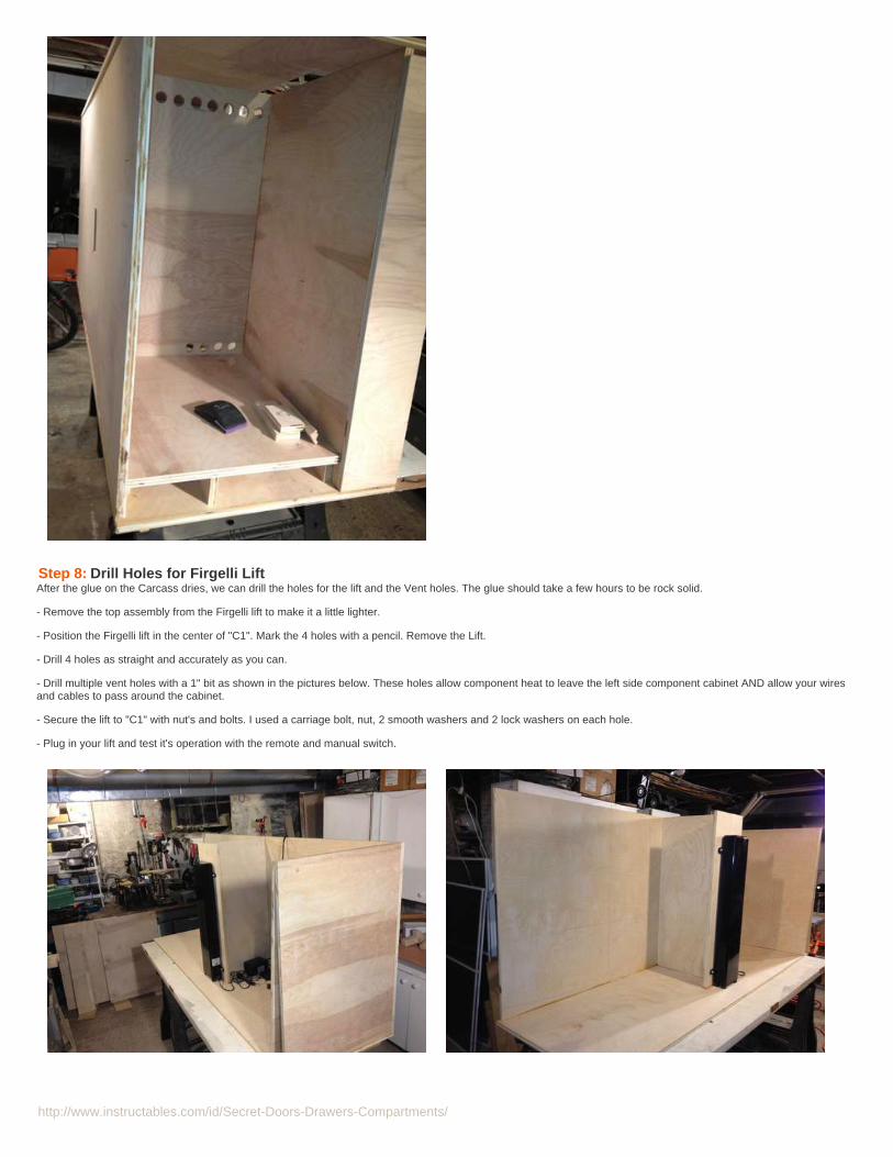
http://www.instructables.com/id/Secret-Doors-Drawers-Compartments/
Step 8: Drill Holes for Firgelli LiftAfter the glue on the Carcass dries, we can drill the holes for the lift and the Vent holes. The glue should take a few hours to be rock solid.
- Remove the top assembly from the Firgelli lift to make it a little lighter.
- Position the Firgelli lift in the center of "C1". Mark the 4 holes with a pencil. Remove the Lift.
- Drill 4 holes as straight and accurately as you can.
- Drill multiple vent holes with a 1" bit as shown in the pictures below. These holes allow component heat to leave the left side component cabinet AND allow your wiresand cables to pass around the cabinet.
- Secure the lift to "C1" with nut's and bolts. I used a carriage bolt, nut, 2 smooth washers and 2 lock washers on each hole.
- Plug in your lift and test it's operation with the remote and manual switch.

http://www.instructables.com/id/Secret-Doors-Drawers-Compartments/
Step 9: Add Door Carcass BottomsIn this step, we will add the door carcass bottoms. In my application, I routed HVAC air out the left door bottom but I will assume that you don't have to do this.
- Make 2 scrap piece templates that are 2 1/2" wide by about 20" long. These will be used to support the door bottoms while you glue and nail them. The idea is that thetops of these shelves will be at the top of "BB1" and "BB3" as shown in the drawing front and side views.
- Insert the two template pieces on the left door cavity. One next to the back and one next to piece "H"
- Put glue on the sides of piece "A6". Insert and nail in from the sides. Remove templates.
- Insert the two template pieces on the right door cavity. One next to the right side piece "E" and one next to piece "D"
- Put glue on the sides of piece "E1". Insert and nail in from the sides.

http://www.instructables.com/id/Secret-Doors-Drawers-Compartments/
Step 10: Cut holes for Speaker Wires and AC outlets- Carefully measure where your AC outlet is on the wall. Cut a rectangle hole in the back of the cabinet with a skill saw to allow plug access to the AC outlet. If you don'thave a wall outlet, you will need to bring power up through the bottom.
- Cut a hole in the bottom to bring your speaker wires up from the floor. If your speakers will go up through the top of the cabinet, you can drill holes in the top for thatlater.
Step 11: Cut Top Flap Door Hole and Install Flap Door with HingeWe are ready to cut the top flap door in the top and install the piano hinges. Dry fit this and convince yourself that everything lines up and is flat here by laying the top onthe carcass. Note how wide your TV is and where it will hit the bottom of the top when mounted on the lift. The measurements here are for my 60" Samsung TV which is60" wide and 1.5" thick.
- Transfer the rectangle to the top panel "F" as shown in the Top Panel View drawing. Drill a hole that is wide enough to insert your skill saw blade in the 4 top panelcorners of your marked lines.
- Stick the skill saw blade in the holes and CAREFULLY cut your lines to remove the flap door rectangle. This is scrap wood.
- Get a helper to help you move the carcass of of your work table now. Put it on a floor or another set of saw horses nearby. You will need the flat work surface to get thepiano hinge and "FD" on the top.
- Make sure that the Flap Door "FD" piece you cut will fit nicely in the top hole with at least 1/8" clearance on each side.
- Line up the Piano Hinge with the back of the "FD" top and you will see that the "FD" top needs to be trimmed to cut a slot as shown in the Top Panel View drawing. Markthis slot and carefully use your skill saw to cut this. Use 60 grit sandpaper to make sure everything lines up nicely and has clearance.
- Install the edge tape to all 4 inside areas on the top "F". Install the edge tape on the 4 sides of the flap door "FD". Do not put it in the hinge slot. Make sure there is stillgood clearance in the hole.
- See the videos for edge tape installation tips. When the iron is hot, carefully apply the edge tape as you did on your test pieces. Cut the edges carefully with a sharp boxcutter. Using 100 grit paper ONLY, remove the excess edge tape as you did in your test pieces.
- Install the hinge screws per the video tips. The idea is to align the bottom of the hinge to be flush with your work table top. Mark the holes and install the hinge to the flapdoor first. Next take the Flap door with dangling hinge and attach this to the Top.
- Make sure it lifts up and down smoothly. Carefully bring it over to your carcass and lay it on top. Verify that it is where you want it to be and swings up and down nicely.
- Put in small pieces of scrap as stop block on the right side of the carcass where needed to support the door when it descends. glue and clamp these stops.
-DO NOT attach the top yet. We will do this with L brackets in the Final Assembly.

http://www.instructables.com/id/Secret-Doors-Drawers-Compartments/
Step 12: Build Door Panels and Front Panel AssemblyBuilding the doors and front panel can be a very rewarding part of this project. In my opinion, they quickly become beautiful pieces for relatively low effort. Definitely watchthe video clips on the door and panel sections. The rails are the top and bottom pieces. The stiles are the left and right vertical members. The rails and stiles all need tohave groves cut in them on the table saw. The center panels edges will fit in the grooves.
- Set the table saw blade height for just over 1/4". Set the fence to be 1/8" from the blade. Make two passes through at this setting to guarantee that the slot is clear ofmaterial.
- Since the 1/4" plywood panels are 3/16" thick, you need to move the fence 1/16" to the right. Make 2 passes through again. Test this process out a few times on somescrap to get your technique down.
- Dry fit your door together with the 2 rails, 2 stiles and the panel in the center. Note that the front right door is shown in the front view drawing. The front right door hasdifferent size stiles for the right and left. The left side door is shown in the Side view drawing. Bring your dry fit door over to the carcass and convince yourself that it willwork. You should see a 3/8" overlap on the 3/4" wood edge where the hinge side will be. Note that on the right front door, the left edge of the door ends to the left of the"D" part as shown in the drawings.
- Slip in your panel and with each door, put some glue on the top and bottom of the stiles. The panel can float on the inside. Put a clamp on each side of the rails andpress the glue gently until you see some squeeze out. Let is dry for a few hours.
- Build the front panel assembly up in the same manner as the doors. Carefully verify that the test fit will fit in place with the right side door leaving about an 1/8" gap onthe right side of the front panel assembly. The left side of the front panel assembly should be centered on the 3/4" wide edge of piece "A3". You will need long clamps forthis part. I have long clamps that are made with a piece of 8' iron pipe with these inexpensive clamp attachments Home depot has them as well or at harbor freight for $9

http://www.instructables.com/id/Secret-Doors-Drawers-Compartments/

http://www.instructables.com/id/Secret-Doors-Drawers-Compartments/
Step 13: Install Door HingesThe 1/2 overlay hinges are forgiving for left/right alignment. The can be adjusted if you are slightly off in your measurements. Definitely use 2 pieces of scrap plywood totest your hinges before drilling into the real parts.
- Install one hinge centered 4" away from the top. Install the other hinge 4" away from the bottom. Mark a line in each 4" position on the doors. If your hinge has atemplate then use that, otherwise, hold your hinge and carefully trace the outline of the bottom of the hinge on the door. Referencing the picture below, the hinge shouldbe about 1/4" away from the door edge.
- On a drill press, carefully hold the door or build up a platform near the drill press to hold the door stable on the drill press. Using a Forstner drill bit, drill into the outlineyou made. Test the hinge to see if it will fit in your hole. You may need to use a smaller Forstner bit to remove additional material. You should set the stop on the drillpress so you dont drill too far into the door panel. When you have removed enough material and the hinge fits in the hole, mark, drill and screw it in.
- Referencing the picture and the test piece you made, mark the cabinet side of the hinge. You can remove the cabinet side of the hing plate with the quick release. Installboth the plates and then click the doors into place.

http://www.instructables.com/id/Secret-Doors-Drawers-Compartments/
Step 14: Apply Edge Tape to the Doors and Front Panel AssemblyHere's where we apply the edge tape to the doors and front panel assembly. Since you already have some experience at this, it should go quickly.
- Iron on the edge tape to both door edges and the panel edge.
- Remove excess tape by laying flat and sanding with the 100 grit sand paper. DO NOT use 60 grit sand paper. It will scratch the doors/panels.
- While you are edge taping, apply edge tape to the carcass at all points that will be exposed in the final cabinet. This should be obvious at this point. Sand edges with thesander or a sanding block with 100 grit sand paper.
Step 15: Attach Interior Door and Front Panel Assembly MoldingThis is the step that allows the beauty to really come out in the doors and panel.
- Watch the video clip on the molding installation. Look at the picture below.
- Take the T5 molding pieces. Practice with a few small pieces on your compound miter saw cutting the inside angles. You should make accurate and fine cuts to "walkin" on your measurement. All 4 pieces in each panel should dry fit tightly together.
- Apply a little glue at the mitered joints and a dab in the center of each piece and let it dry.
- Do this for each panel. You will end up with 9 panels x 4 sides = 36 pieces as you work.
- Referencing the picture, drill and attach the door pulls to the doors.

http://www.instructables.com/id/Secret-Doors-Drawers-Compartments/
Step 16: Install the Front Panel AssemblyWe need to install the Front Panel Assembly so it can be easily removed from the cabinet so you can get to the inside for service, get access to cables and show off yourcabinet to your drooling buddies.. ;-) We will use our dowel points to align 2 holes so that a pair of small dowels can hold the bottom.
- Rest the the Front Panel assembly on the carcass piece "BB1". Mark a small vertical line with a straight edge 2 feet in from each edge of the assembly.
- Practice with the dowel points first on a test piece. Drill a 1/4" hole in the edge of the Front Panel Assembly along the line you just drew. Repeat at the other location.Insert the 1/4" dowel point into the holes. Put the Front panel assembly into place exactly where you want it. Press down hard and 2 impressions will be made in the topof "BB1".
- Drill 1/4" holes in these 2 impressions. Insert 1/4" dowels into the 2 holes. Fit Front Panel Assembly and ensure that it mounts into "BB1" securely.
- Apply 3 pieces of good quality stick on Velcro onto the top inside of the front Panel Assembly and the "FS" bar.

http://www.instructables.com/id/Secret-Doors-Drawers-Compartments/
Step 17: Drawer Glide InstallationI chose to use extra heavy duty drawer glides. You could probably find lighter duty drawer glides that would work for your DVD/CDs. For the components, you shouldstick with the heavy duty stuff. Because the hinge and open door will be in the way when the drawers pull out, we need to pad out the glides on that side. We do this with3/4" wood cut to the width of the glides.
Two guide support pieces are needed on the right side because I have a piece of wall molding on the right side of my application that I needed to clear. You may have adifferent application and can modify your glides mounts.
4 RGS1 Right guide support 20 ½ x 1 ½4 RGS2 Right guide support 24 ¼ x 1 ½1 LGS Left guide support 24 x 1 ½
- Starting on the left side component opening, cut 2 template blocks at the height that you want the bottom of your component shelf to be, as shown in the picture below.Starting on the left side, rest the "LGS" piece on the template blocks and mark a line along the top of the "LGS" piece to hold your position. With a raw glide, do the sameon the right of the component opening to mark a line at the top of the glide. The 2 glide heights should be at the same height now with respect to the component openingbottom.
- On the drill press or workbench, drill counter sunk holes through the "LGS" piece to attach to the left side component space. Attach the drawer guide to the "LGS".Remove the drawer glide. Attach the "LGS" to the inside left cabinet below your line. Attach drawer glide again.
- Attach the drawer glide to the inside right edge below your line. Slide in inside parts of both drawer glides. Measure inside width to check that drawer bottommeasurement is good.
- For the right door drawers, the right side will use the "RGS1" and "RGS2" pieces. Set up those two pieces as shown in the top drawing. Mark the pieces where theymeet so they will line up together. The idea is that the 2 pieces are needed to get around the "HSB" piece. We will build up an assembly with the "RGS1" and "RGS2"pieces and the drawer glide. We will attach the assembly tot he cabinet from the right most OUTSIDE cabinet. This makes it easier to get the piece on without having towork in the narrow 11" space...
- On the drill press or workbench:a) drill holes to attach the drawer glide to "RGS2".b) remove drawer glide from "RGS2" and drill counter sunk holes through the "RGS2" piece to attach to the "RGS1" piece.
- repeat a) through b) for the other 3 pieces.
- Make 2 template piece for each height as shown in the picture below. With the right drawer glide assembly all together, rest each one on top of the template pieces atthe exact height you want. Mark a line inside the cabinet. Drill a few small holes through the right cabinet wall below the lines. Go to the OUTSIDE right cabinet and drillcountersunk holes.
- Rest drawer glide assembly on the template guides. Secure them with screws from the OUTSIDE.
- repeat for all 3 remaining drawer glide assemblies.
- When this looks good, remove all 4 drawer glide assemblies.

http://www.instructables.com/id/Secret-Doors-Drawers-Compartments/
- Set up the templates on the left side and mark the top of the glides. Attach the drawer glide to the inside right edge below your line.
- reattach right drawer glide assemblies. Slide in inside parts of both drawer glides to all 8 glides. Measure inside width to check that drawer measurements are good.

http://www.instructables.com/id/Secret-Doors-Drawers-Compartments/
Step 18: Drawer Construction- Start by making sure that the "A5" and each "D1" piece fits between the drawer glides. Mount the pieces in the drawer glides with screws and verify they glide well.
- Attach the drawer pull to the front piece "D4".
- Build up the drawers as shown in the picture below with pieces "D2, D3 and D4". Glue and nail.
- Apply glue to the bottom of the drawer sides and attach to the "D1" pieces. Make sure to offset the drawer side assembly back from the drawers bottoms "D1" to allowclearance of the drawer pull. If you don't do this, the drawer pull will interfere with the door closing.
- Apply edge tape to all exposed edges and sand.

http://www.instructables.com/id/Secret-Doors-Drawers-Compartments/
Step 19: Add Dummy FillersOptional step: I added dummy filler plates of 1/4" wood in 2 places. They can be cut quickly on the band-saw.
- Add a filler plate to the left of "D' so you cant see the cabinet insides when you open the right side door. Glue in lace and add some painters tape to hold while it dries.See picture below.
- Add a filler plate at the roof of the component cavity so you cant see the component cavity inside when the flap lid is open. Screw from underneath. See picture below.

http://www.instructables.com/id/Secret-Doors-Drawers-Compartments/
Step 20: Remove all Pieces and Setup to Sand and PaintOur goal here is to remove all the pieces from the cabinet now to do final spackling, sanding and painting.
- Remove all pieces from the cabinet that are not glued.
- Lay them out on surfaces or tables.
- Spackle all nail holes, gouges and scratches with a putty knife. Wait for it to dry.
- Sand everything with 100 grit paper that feels rough to your hand. Use a combination of random orbital sander, sanding block and sand paper in your hand.
- Wipe off all sanding sawdust. Clean your shop area to prepare for painting.
Step 21: PaintingThe best way to paint a cabinet like this is with an HVLP sprayer system. They are expensive, require a spray booth and... I dont have one. So, I used a brush, paint anda finish coat of polyurethane to cover this cabinet.
Experiment with multiple coats of paint and urethane to get the finish you want before painting the cabinet.
I used Home Depot, "Decorator White" Behr Premium Plus Ultra which is primer and paint together and is water based. It still takes 3 coats of this paint to cover thewood.
I put a few finish coats of Minwax satin water based poly. The poly keeps things like books and picture frames from sticking to the paint when you put them on it.
- Paint all parts of the cabinet that will be visible. Paint the remaining trim pieces and bottom pieces to be used in the final assembly.
Step 22: Mave To the Final Location and Final AssemblyThis Cabinet is heavy. I built mine in my basement and needed a strong friend to help me carry it upstairs (thanks Troy!). I wanted as few things attached as possiblewhile I moved it to reduce weight so I did the final assembly upstairs. I recommend the same for you.
After the paint has dried, you are ready to move it. Before you move it. Make sure you have prepared any wiring or cables that will need to go into the cabinet.
- Move the cabinet carefully. When it is in place, get all your wiring into the cabinet. Mount the doors and place the top on the cabinet.
- Make sure that you dont have more than 1/8 " from the cabinet top edge to your walls. If you do, the caulk may nut hold and you'll need to insert filler pieces.
- Mount the Firgelli lift in the cabinet. Make sure the roller wheels are mounted properly on top. Test the operation of the lift going up and opening the flap door smoothly.Test that the lift goes down nicely and the flap door shuts. Watch carefully and keep your finger near the controls in case you see a potential problem.
- Attach the top to the cabinet carcass with L brackets as shown in the picture below. This will make for easy removal.. just in case. Put the L brackets in any area that thetop may try to rise up a little. I used 4 L brackets.

http://www.instructables.com/id/Secret-Doors-Drawers-Compartments/
Install the TV per the Firgelli manual:
- Lay the TV down on a flat rug and install the 4 brackets to the TV. Slide in the 2 black "wing" pieces.
- Attach the Lift top housing to these "wing" pieces.
- Carefully , Add the TV with lift top to the top of the lift secure it with the 4 bolts.
- Connect all your cables to the Power, cable box, receiver, IR sensors etc.
- Test that your TV lift works!!
Step 23: Add the Final Trim PiecesNow it's time to add the following pieces:
1 BB2 Bottom Block 86 ¾ x 2 ¾1 BB4 Bottom Block 26 ½ x 2 ¾
Trim molding:--------------------1 T1 Big Molding 861 T2 Big Molding 26 1/41 T3 Big Molding 86 1/21 T4 Big Molding 26 3/4
- The lengths of these pieces should be long. You will need to measure, trim and install them.
- Install "BB2" and "BB4" per the drawings. Make sure to cut mitered joints where they meet.
- Install "T2" and "T1" moldings on the top per the drawings. Make sure to cut mitered joints where they meet.
- Install "T3" and "T4" moldings on the bottom per the drawings. Make sure to cut mitered joints where they meet.
- spackle, sand with 220 grit paper and touch-up paint all mitered joints and holes.

http://www.instructables.com/id/Secret-Doors-Drawers-Compartments/
Step 24: Final ThoughtsThis is a big project but it is very rewarding. I plan to build shelves that will sit on top of my cabinet where I have the picture frames now. The IR sensor and Wii sensorswill go up there as well. A rough drawing is shown below.
I hope you enjoyed building this project!

http://www.instructables.com/id/Secret-Doors-Drawers-Compartments/
Related Instructables
How to modifyanentertainmentcenter to fit aHDTV bythatdecad Home
automation POPUP TV LIFTcabinetinstallationinstructions byrdickson
DisappearingTV with Pop UpTV Lift MountedBehindFurniture byhiddentvguy
Vintage TVCabinet Reduxby CementTruck
UPDATED:QUADscreens(4,200 x 1,680) --fka:triplescreens41-inchuberHDTV(3,150 x 1,680) -3 x 20" monitorsin portrait byacfou
HDTv Antennaon a Direct TVmount. byarte.sano
Stylish HDTVAntenna bydragosurf
Low-costBattery-poweredportablewidescreen DTVby Last_Liberal

http://www.instructables.com/id/Secret-Doors-Drawers-Compartments/
Bookcase with Hidden Drawerby briangrabski on January 30, 2012
Author:briangrabski Designed & MADEPrinciple of designed & MADE Custom Woodworking, an innovator and problem solver who works with you through the design phase to the post-completionparty. twitter.com/briangrabski
Intro: Bookcase with Hidden Drawer
If you like this project, don't forget to vote for it in the Furniture Challenge!
The look and feel of the painted bookcase surface replicates that found on antique furniture. Like older traditional finishes, the milk paint used on this bookcase consistsof milk protein, clay, earth pigments and lime. Where conventional paint can chip and scratch, milk paint penetrates into the grain; polishing as it wears. For this piece Iused three layers of color: lexington green, barn red, and pitch black in that order. The subtle complexities will improve as the furniture wears, creating a tortoiseshellappearance. In addition, I added small tear-outs and other “hand tool marks” to create the authentic look of a genuine antique piece of furniture, along with custom wooddrawer slides and full mortise solid brass hardware.
To create the rich tones on the walnut and Carpathian elm burl book matched veneer top I used Kusmi #1 button shellac imported directly from India. The shellac isapplied over a preliminary coat of boiled linseed oil. The oil penetrates the wood giving a maximum illumination to the fibers. Because there’s no purity standard forethanol labeled “Denatured Alcohol” for dissolving the shellac, I use high-test, 190 proof Everclear (95% pure ethanol) as my preferred shellac solvent. No other finishcan compare when it comes to the illumination of the natural beauty inherent in the wood.
It’s not only what’s visible that makes this piece unique, but rather what goes unseen. Built into the bookcase is a hidden drawer . To access the drawer, you have topull each of the visible drawers open to a certain point before the latches they control slide out of the way, similar to how the pins in a regular lock work. That allows alength of wooden dowel to slide out – hidden as a knot in the wood itself – to trigger the opening of the secret compartment built into what looks like a normal molding.

http://www.instructables.com/id/Secret-Doors-Drawers-Compartments/

http://www.instructables.com/id/Secret-Doors-Drawers-Compartments/

http://www.instructables.com/id/Secret-Doors-Drawers-Compartments/

http://www.instructables.com/id/Secret-Doors-Drawers-Compartments/
Related Instructables
ClassroomBookcase byknife141
bookcase doorby cross_eyed
How totransform abookcase to acupboard /comotransformar unlibrero en unarmario byGirbska
Bookcase withdog parts(Photos) byknife141
Bookcase / Hanin CarboniteHidden Door bynylanan
great looking,inexpensivecomputer deskby nickfarnell
make BedroomNightstandDrawer tosecure firearms. by Diabloscope
Hidden DrawerSafe bypagan209

http://www.instructables.com/id/Secret-Doors-Drawers-Compartments/