section 1-1 page 1 dummy features 78051-218x … · © 2005 first technology safety systems, inc....
TRANSCRIPT

© 2005 First Technology Safety Systems, Inc. Rev. A, April, 2005
Section 1-1 Page 1
Hybrid III 50th Male Dummy78051-218XFMVSS208, 49CFR Part 572, Subpart E
The FTSS Hybrid III 50th Percentile Male Crash TestDummy is the most widely used crash test dummyin the world for the evaluation of automotive safetyrestraint systems in frontal crash testing. Originallydeveloped by General Motors, the Hybrid III 50thdesign is now maintained and developed by FTSS inconjunction with the Society of Automotive Engineers’(SAE) Biomechanics Committees and the NationalHighway Transport and Safety Administration(NHTSA). The dummy is a regulated test device inthe USA Code of Federal Regulations (Part 572,Subpart E) and also in the European ECERegulations. It is considered to have excellentbiofidelity and instrumentation capability. Recentrevisions have improved the biofidelity in the femurrange of motion, the ankle and foot. The dummy canalso be used in many non-automotive applicationssuch as wheelchairs, medical and sports equipment.
Simulation Models
FTSS offers highly detailed and fully validated FiniteElement Models of its dummies, plus crashsimulation services. The FT-Arup FE Model Seriessupports the LS-Dyna™ format. Pamcrash™ formatis also supported. Please contact FTSS for latestavailability.
Dummy Features
Head and Neck
The skull and skull cap are one piece cast aluminumparts with removable vinyl skins. The neck is a segmentedrubber and aluminum construction with a center cable. Itaccurately simulates the human dynamic moment/rotation, flexion and extension response.
Upper Torso
The rib cage is represented by six high strength steelribs with polymer based damping material to simulatehuman chest force-deflection characteristics. Each ribunit comprises left and right anatomical ribs in onecontinuous part open at the sternum and anchored to theback of the thoracic spine. A sternum assembly connectsto the front of the ribs and includes a slider for the chestdeflection rotary potentiometer. The angle between theneck and upper torso is determined by the constructionof the neck bracket which can incorporate a six-axis necktransducer. A two-piece aluminum clavicle and claviclelink assembly have cast integral scapulae to interfacewith shoulder belts.
Lower Torso
A curved cylindrical rubber lumbar spine mount providesthe humanlike slouch of a seated person and mounts tothe pelvis through an optional three axis lumbar load cell.The pelvis is a vinyl skin/urethane foam molded over analuminum casting in the seated position. The ball-jointedfemur attachments carry bump stops to reproduce thehuman leg to hip moment/rotation characteristics. Thefemur, tibia and ankle can be instrumented to predict bonefracture and the knee can evaluate tibia to femur ligamentinjury. The foot and ankle simulate heel compressionand ankle range of motion.
Hyb
rid II
I 50t
h M
ale
Dum
my
7805
1-21
8X

© 2005 First Technology Safety Systems, Inc. Rev. A, April, 2005
Section 1-1 Page 2
*Special four channel configurations are available in the upper and lower tibia load cells.
InstrumentationLocations Description ChannelsHead: 3 Accelerometers in a triaxial array Ax, Ay, Az(HIC)
Up to 15 Accelerometers 5X Ax, Ay, Az Head RotationNeck: Six-Axis Upper Neck Load Cell Fx, Fy, Fz, Mx, My, Mz
Six-Axis Lower Neck Load Cell Fx, Fy, Fz, Mx, My, MzClavicle: Biaxial Load Cell (Left and Right) Fx, FzHumerus:Four-Axis Load Cell (Left and Right) Fx, Fy, Mx, My
Thorax: 3 Accelerometers in a triaxial array Ax, Ay, Az (Chest Accel)Chest Displacement Transducer Dx (standard equipment)Four-Axis Rib/Spine Load Cells Fx, Fy, Fz, MyFive-Axis Thoracic Spine Load Cell Fx, Fy, Fz, Mx, My
Lumbar Spine: Three-Axis Lumbar Spine Load Cell Fx, Fz, MyPelvis: 3 Accelerometers (or triax pack) Ax, Ay, Az
Submarining Load bolts Fx (3 per side)Femur: Uniaxial Femur Load Cell Fx (per leg)
or Six-Axis Upper Femur Load Cell Fx, Fy, Fz, Mx, My, Mz (per leg)Knee: Knee Displacement Dx (per knee)Lower Legs*: Biaxial Knee Clevis Load Cell Fz (per leg)
Biaxial Upper Tibia Load Cell Mx, My (per leg)Three-Axis Lower Tibia Load Cell Fy, Fz, Mx (per leg)
Or Biaxial Knee Clevis Load Cell Fz (per leg)Four-Axis Upper Tibia Load Cell Fx, Fz, Mx, My (per leg)Four -Axis Lower Tibia Load Cell Fx, Fy, Mx, My (per leg)
Ankle: Five-Axis Load Cell Fx, Fy, Fz, Mx, My, Mz (per leg)Toe: Toe Load Cell Fz (per foot)
External Dimensions
Dimension In. Tol. +/- mm Tol. +/-Total Sitting Height 34.8 0.2 883.9 5.1Shoulder Pivot Height 20.2 0.3 513.1 7.6H-Point Height 3.4 0.1 86.4 2.5H-Point from Seat Back 5.4 0.1 137.2 2.5Shoulder Pivot from Backline 3.5 0.2 88.9 5.1Thigh Clearance 5.8 0.3 147.3 7.6Elbow to Wrist Pivot 11.0 0.3 297.2 7.6Skull Cap to Backline 1.7 0.1 43.2 2.5Shoulder to Elbow 13.3 0.3 337.8 7.6Elbow Rest Height 7.9 0.4 200.7 10.2Buttock to Knee 23.3 0.5 591.8 12.7Popliteal Height 17.4 0.5 442.0 12.7Knee Pivot to Floor 19.4 0.3 492.8 7.6Buttock Popliteal Lgth. 18.3 0.5 464.8 12.7Chest Depth 8.7 0.3 221.0 7.6Foot Length 10.2 0.3 259.1 7.6Foot Width 3.9 0.3 99.1 7.6Shoulder Width 16.9 0.3 429.3 7.6Hip Width at H-Point 14.3 0.3 363.2 7.6Chest Circumference 38.8 0.6 985.5 15.2Waist Circumference 33.5 0.6 850.9 15.2Ref. Location forChest Circumference 17.0 0.1 431.8 2.5Ref. Location forWaist Circumference 9.0 0.1 228.6 2.5
Test EquipmentThe following FTSS fixtures are required to calibrate and setup the Hybrid III 50th Percentile Dummy.Head TE-100 Head DropNeck TE-207 Neck Pendulum
185-0000 Neck CompressionToolThorax TE-325 Thorax Pendulum
83-5006-007 Chest Depth Gage AssemblyKnee TE-550 Knee Impact/Knee Sheer Test
TE-512-109 Bracket to test Ball Bearing KneePelvis 270-0000 Femur Range of Motion
187-0000 Lumbar Bracket ToolTE-2505 H-Point Locator78051-532 Pelvis Angle Gage
Foot 320-0000 Foot Compression FixtureTE-5000 Eurofoot Fixture
Ex. DimTE-1000 External Dimensions Seat
Assembly Weights Part Lbs. Tol. +/- Kgs. Tol. +/-Head Assembly 10.0 0.1 4.54 0.05Neck Assembly 3.4 0.1 1.54 0.05Upper Torso 37.9 0.3 17.19 0.36Lower Torso 50.8 0.3 23.04 0.36Upper Arm, Left or Right 4.4 0.1 2.0 0.05Lower Arm/Hand, L or R 5.0 0.2 2.27 0.09Upper Leg, Left or Right 13.2 0.2 5.99 0.09Lower Legs/Feet, L or R 12.0 0.3 5.44 0.14Total Dummy Weight 171.3 2.6 77.70 1.18

© 2005 First Technology Safety Systems, Inc. Rev. A, April, 2005
Section 1-1 Page 3
Hybrid III 50th Male Dummy Description78051-218X
FMVSS208, 49CFR Part 572, Subpart E
Hybrid III 50th Male Dummy (78051-218X)FMVSS208 Instrumentation
78051-218X Fiftieth Percentile Male, Hybrid III Non-Instrumented/TestedDesigned to accept Six-Axis Neck Transducer
Anthropomorphic (Non-Instrumented) Test Dummy thatmeets FMVSS 208 option, specified in 49CFR Part 572,Subpart E.
Includes the following:
* Structural Replacement Member for Six-Axis Neck Transducer* Chest Displacement Transducer (Rotary Potentiometer 78051-342)* Tibia-Femur Displacement Transducer without Potentiometers (Sliding Knee Assemblies)* Pelvis tested for the Range of Motion* Forty-Five Degree Feet Assemblies
* Accelerometer Mounts for the Head, Chest and Pelvis Please specify type of accelerometers to be used when placing your order* Attached Matrix references available Accelerometer Mounts
Part Number Description Qty. Req'dPer Dummy
IE-101 Uniaxial 7231C-750 Accelerometers in the followng locations: 6* Three (3) in the Head* Three (3) in the Chest
IF-205 Six-Axis Upper Neck Load Cell, 350 ohm 1orIF-206 Six-Axis Upper Neck Load Cell, 120 ohm 1
78051-342 Rotary Potentiometer (Included in dummy) 1
IF-604 Uniaxial Femur Force Load Cell, 350 ohm (one per leg) 2orIF-602 Uniaxial Femur Force Load Cell, 120 ohm (one per leg) 2

© 2005 First Technology Safety Systems, Inc. Rev. A, April, 2005
Section 1-1 Page 4
Hybrid III 50th Male Dummy Description(78051-218X-BKS)
EuroNCAP
Hybrid III 50th Male Dummy (78051-218X-BKS)EuroNCAP Instrumentation
Part Number Description Qty. Req'dPer Dummy
IE-116 Uniaxial 7264C-2000 Accelerometers in the following locations: 6* Three (3) in the Head* Three (3) in the Chest (T4)
78051-342 Chest Deflection Transducer Assembly - Included in the Dummy 1
IF-205 Six-Axis Upper Neck Load Cell, 350 ohm 1orIF-206 Six-Axis Upper Neck Load Cell, 120 ohm 1
IF-604 Uniaxial Femur Force Load Cell, 350 ohm (one per leg) 2orIF-602 Uniaxial Femur Force Load Cell, 120 ohm (one per leg) 2
IF-820 Four-Axis Upper Tibia Load Cell, 350 ohm (Fx,Fz,Mx,My) 2orIF-830 Four-Axis Upper Tibia Load Cell, 120 ohm (Fx,Fz,Mx,My) 2
IF-853 Five-Axis Lower Tibia Load Cell, 350 ohm (Fx,Fy,Fz,Mx,My,Mz) 2orIF-854 Five-Axis Lower Tibia Load Cell, 120 ohm (Fx,Fy,Fz,Mx,My,Mz) 2
Part Number Description Qty. Req'dPer Dummy
78051-218X-BKS Fiftieth Percentile Male, Hybrid III Non-Instrumented/Testedwith Ball Bearing Knee Slider Assemblies
Includes the following:
* Structural Replacement Member for Six-Axis Neck Transducer* Chest Displacement Transducer (Rotary Potentiometer 78051-342)* Ball Bearing Knee Slider Assemblies (includes potentiometer)* Pelvis tested for the Range of Motion* Forty-Five Degree Feet Assemblies
* Accelerometer Mounts for the Head, Chest and Pelvis Please specify type of accelerometers to be used when placing your order* Attached Matrix references available Accelerometer Mounts

© 2005 First Technology Safety Systems, Inc. Rev. A, April, 2005
Section 1-1 Page 5
Hybrid III 50th Male DummyOptional Instrumentation
Part Number Description Qty. Req'dPer Dummy
IF-151 Six-Axis Head Modified for 15 Accel Array, 7264-2000 1
IF-156 Six-Axis Head Modified for 15 Accel Array, 7264A/B-2000 1
IF-157 Free Motion Headform Modified for 12 Accel (7264C and 7267A) 1
IF-205J Six-Axis Upper Neck Load Cell, Wired to SAE J211 Sign Convention, 350 ohm 1orIF-206J Six-Axis Upper Neck Load Cell, Wired to SAE J211 Sign Convention, 120 ohm 1
IF-207 Six-Axis Upper Neck Load Cell, Low Capacity, 350 ohm 1orIF-208 Six-Axis Upper Neck Load Cell, Low Capacity, 120 ohm 1 IF-210 Six-Axis Lower Neck Load Cell, 350 ohm 1orIF-204 Six-Axis Lower Neck Load Cell, 120 ohm 1
IF-219 Six-Axis Adjustable Neck Load Cell, 350 ohm 1orIF-220 Six-Axis Adjustable Neck Load Cell, 120 ohm 1
IF-223 Three-Axis Adjustable Neck Load Cell, 350 ohm 1orIF-232 Three-Axis Adjustable Neck Load Cell, 120 ohm 1
IF-256 Four-Axis Upper Neck Load Cell, Low Capacity, 350 ohm 1orIF-257 Four-Axis Upper Neck Load Cell, Low Capacity, 120 ohm 1
IF-2564 Three-Axis Upper Neck Load Cell, 350 ohm 1orIF-2565 Three-Axis Upper Neck Load Cell, 120 ohm 1
IF-310 Five-Axis Modified Thoracic Spine Load Cell, 350 ohm 1Includes spine box and thoracic insert
orIF-318 Five-Axis Modified Thoracic Spine Load Cell, 120 ohm 1
Includes spine box and thoracic insert
IF-320 Two-Axis Clavicle Load Cell, Set L&R, 350 ohm 1or IF-321 Two-Axis Clavicle Load Cell, Set L&R, 120 ohm 1
IF-402 Three-Axis Lumbar Load Cell, 350 ohm 1orIF-403 Three-Axis Lumbar Load Cell, 120 ohm 1
© 2005 First Technology Safety Systems, Inc. Rev. A, April, 2005
Section 1-1 Page 6
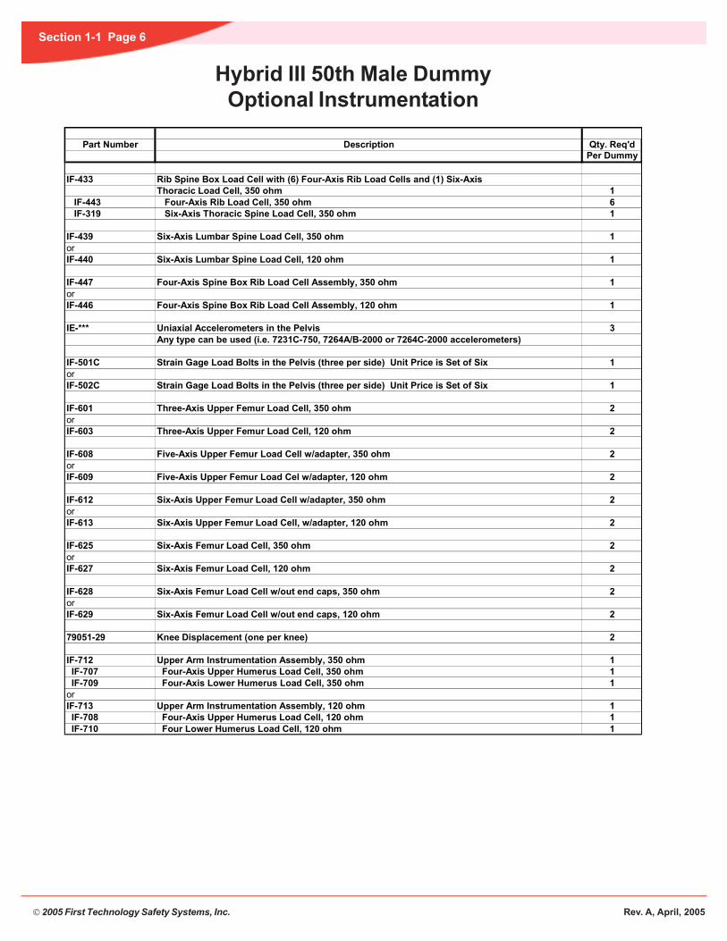
Hybrid III 50th Male DummyOptional Instrumentation
Part Number Description Qty. Req'dPer Dummy
IF-433 Rib Spine Box Load Cell with (6) Four-Axis Rib Load Cells and (1) Six-Axis Thoracic Load Cell, 350 ohm 1
IF-443 Four-Axis Rib Load Cell, 350 ohm 6 IF-319 Six-Axis Thoracic Spine Load Cell, 350 ohm 1
IF-439 Six-Axis Lumbar Spine Load Cell, 350 ohm 1orIF-440 Six-Axis Lumbar Spine Load Cell, 120 ohm 1
IF-447 Four-Axis Spine Box Rib Load Cell Assembly, 350 ohm 1orIF-446 Four-Axis Spine Box Rib Load Cell Assembly, 120 ohm 1
IE-*** Uniaxial Accelerometers in the Pelvis 3 Any type can be used (i.e. 7231C-750, 7264A/B-2000 or 7264C-2000 accelerometers)
IF-501C Strain Gage Load Bolts in the Pelvis (three per side) Unit Price is Set of Six 1orIF-502C Strain Gage Load Bolts in the Pelvis (three per side) Unit Price is Set of Six 1
IF-601 Three-Axis Upper Femur Load Cell, 350 ohm 2orIF-603 Three-Axis Upper Femur Load Cell, 120 ohm 2
IF-608 Five-Axis Upper Femur Load Cell w/adapter, 350 ohm 2orIF-609 Five-Axis Upper Femur Load Cel w/adapter, 120 ohm 2
IF-612 Six-Axis Upper Femur Load Cell w/adapter, 350 ohm 2orIF-613 Six-Axis Upper Femur Load Cell, w/adapter, 120 ohm 2
IF-625 Six-Axis Femur Load Cell, 350 ohm 2orIF-627 Six-Axis Femur Load Cell, 120 ohm 2
IF-628 Six-Axis Femur Load Cell w/out end caps, 350 ohm 2orIF-629 Six-Axis Femur Load Cell w/out end caps, 120 ohm 2
79051-29 Knee Displacement (one per knee) 2
IF-712 Upper Arm Instrumentation Assembly, 350 ohm 1 IF-707 Four-Axis Upper Humerus Load Cell, 350 ohm 1 IF-709 Four-Axis Lower Humerus Load Cell, 350 ohm 1orIF-713 Upper Arm Instrumentation Assembly, 120 ohm 1 IF-708 Four-Axis Upper Humerus Load Cell, 120 ohm 1 IF-710 Four Lower Humerus Load Cell, 120 ohm 1

© 2005 First Technology Safety Systems, Inc. Rev. A, April, 2005
Section 1-1 Page 7
Hybrid III 50th Male DummyOptional Instrumentation
Part Number Description Qty. Req'dPer Dummy
IF-807 Instrumented Lower Leg Assemblies (pair), 350 ohm 1 IF-803 Two-Axis Knee Clevis Load Cell, 350 ohm (Fz x 2) 2 IF-820 Four-Axis Upper Tibia Load Cell, 350 ohm (Fx,Fz,Mx,My) 2 IF-819 Four-Axis Lower Tibia Load Cell, 350 ohm (Fx,Fy,Mx,My) 2orIF-808 Instrumented Lower Leg Assemblies (pair), 120 ohm 1 IF-802 Two-Axis Knee Clevis Load Cell, 120 ohm (Fz x 2) 2 IF-830 Four-Axis Upper Tibia Load Cell, 120 ohm (Fx,Fz,Mx,My) 2 IF-838 Four-Axis Lower Tibia Load Cell, 120 ohm (Fx,Fy,Mx,My) 2
IF-801 Instrumented Lower Leg Assemblies (pair), 350 ohm 1 IF-803 Two-Axis Knee Clevis Load Cell, 350 ohm (Fz x 2) 2 IF-820 Four-Axis Upper Tibia Load Cell, 350 ohm (Fx,Fz,Mx,My) 2 IF-825 Four-Axis Lower Tibia Load Cell, 350 ohm (Fx,Fz,Mx,My) 2orIF-806 Instrumented Lower Leg Assemblies (pair), 120 ohm 1 IF-802 Two-Axis Knee Clevis Load Cell, 120 ohm (Fz x 2) 2 IF-830 Four-Axis Upper Tibia Load Cell, 120 ohm (Fx,Fz,Mx,My) 2 IF-834 Four-Axis Lower Tibia Load Cell, 120 ohm (Fx,Fz,Mx,My) 2
IF-855 Instrumented Lower Leg Assemblies (pair), 350 ohm 1 IF-803 Two-Axis Knee Clevis Load Cell, 350 ohm (Fz x 2) 2 IF-851 Five-Axis Upper Tibia Load Cell, 350 ohm (Fx,Fy,Fz,Mx,My,Mz) 2 IF-853 Five-Axis Lower Tibia Load Cell, 350 ohm (Fx,Fy,Fz,Mx,My,Mz) 2orIF-856 Instrumented Lower Leg Assemblies (pair), 120 ohm 1 IF-802 Two-Axis Knee Clevis Load Cell, 120 ohm (Fz x 2) 2 IF-852 Five-Axis Upper Tibia Load Cell, 120 ohm (Fx,Fy,Fz,Mx,My,Mz) 2 IF-854 Five-Axis Lower Tibia Load Cell, 120 ohm (Fx,Fy,Fz,Mx,My,Mz) 2
IF-871 Five-Axis Ankle-Toe Load Cell, 350 ohm (per foot) 2orIF-870 Five-Axis Ankle-Toe Load Cell, 120 ohm (per foot) 2

© 2005 First Technology Safety Systems, Inc. Rev. A, April, 2005
Section 1-1 Page 8
Hybrid III 50th Male DummyTest Equipment
Part Number Description Qty. Req'd
HEAD DROP TEST EQUIPMENT
TE-100 Head Drop Test Fixture - 110 volt 1orTE-100-E Head Drop Test Fixture - 220 volt 1
- Includes: Nickel plated steel base plate with support stand, hardware suspension structure, electromagnet release mechanism and the Hybrid III 50th head suspension cables and head positioning gage. - Four Channels are required to record the certification data. - Fixture Dimensions: 25 in. L x 29 in. W x 70 in. H
TE-2000-64 Junction Box, 4 Signal Lines 1
IE-101-33L Three (3) 7231C-750 Uniaxial Accelerometers, Full Bridge, 33' 34-Conductor Cable required, but not included
NECK PENDULUM TEST EQUIPMENT
TE-207 Neck Pendulum Test Fixture - 110 volt 1orTE-207-E Neck Pendulum Test Fixture - 220 volt 1
- Includes: support for pendulum, hoist for lifting pendulum, impact plate for mounting honeycomb blocks and the Head/neck rotation measurement unit for the Hybrid III 50th & 95th - Six Channels are required to record the certification data. - Fixture dimensions: 96 in. L x 28 in. W x 150 in. H
TE-2000-65 Junction Box, 9 Signal Lines 1
IE-101-33L One (1) 7231C-750 Uniaxial Accelerometers, Full Bridge, 33' 14-Conductor Cable required for all pendulums, but not included
IF-205 Six-Axis Upper Neck Load Cell, 350 ohm 1orIF-206 Six-Axis Upper Neck Load Cell, 120 ohm 1
Required for Hybrid III 5th, 50th, 95th and 6 year old, SID-IIs and BioSID testing, but not included
TE-342 Rotary Potentiometer Calibration Unit 1Used to calibrate the potentioimeters on the Neck Pendulum Fixture
185-0000 Neck Compression Tool 1Assists in the assembly/disassembly of the Hybrid III 50th and 95th head and neck bycompressing the nodding blocks to allow for alignment of the nodding joint.

© 2005 First Technology Safety Systems, Inc. Rev. A, April, 2005
Section 1-1 Page 9
Hybrid III 50th Male DummyTest Equipment
Part Number Description Qty. Req'd
THORAX IMPACT TEST EQUIPMENT
TE-325 Thorax Impact Test Fixture - 110 volt 1orTE-325-E Thorax Impact Test Fixture - 220 volt 1
- Includes: structural framework, 51.5 lbs. (23.36 kgs.) Probe, hoist for lifting test probe, hydraulic lift table (with stainless steel surface), release mechanism, velocity pick up and chest deflection calibration unit for the Hybrid III 50th dummy. - Three Channels are required to record the certification data. - Fixture dimensions: 218 in. L x 74 in. W x 180 in. H
TE-2000-66 Junction Box, 12 Signal Lines 1
IE-101-33L One (1) 7231C-750 Uniaxial Accelerometers, Full Bridge, 33' 14-Conductor Cable required for all probes, but not included
83-5006-007 Thorax Depth Gage for the Hybrid III-50th 1Gage for checking geometry (deformation) of Hybrid III 50th rib cage at rib #1 and rib #6.
TE-2505 H-Point Locator, Hybrid III 50th 1Assists in the positioning of dummy for external dimensions. Uses lumbar adapter squarehole to locate H-Point.
78051-532 Pelvic Angle Gage for the Hybrid III-50th 1Assists in the measurement of the Hybrid III 50th pelvic angle by offering an accessiblesurface to mount an inclinometer.
187-0000 Lumbar Bracket Tool 1A tool used to set the lumbar block onto the pelvis
TE-852 Angle Star Protractor System (electronic) 1
KNEE IMPACT TEST EQUIPMENT
TE-550 Hybrid III Knee Impact/Shear Test Fixture - 110 volt 1orTE-550-E Hybrid III Knee Impact/Shear Test Fixture - 220 volt 1
- Includes: structural framework for mounting multiple impact probes, impact structure for mounting knee and knee slider assemblies. - Three Channels are required to record the certification data. - Fixture dimensions: 87 in. L x 47 in. W x 123 in. H
TE-2000-67 Junction Box, 5 Signal Lines 1
IE-101-33L One (1) 7231C-750 Uniaxial Accelerometers, Full Bridge, 33' 14-Conductor Cable required for all probes, but not included
79051-29 Requires one (1) linear potentiometer for knee slider testing on the Hybrid III Adult dummies 1
TE-512-109 Load Distribution Bracket for the Hybrid III 50th 1Ball Bearing Knee Slider Assemblies

© 2005 First Technology Safety Systems, Inc. Rev. A, April, 2005
Section 1-1 Page 10
Hybrid III 50th Male DummyTest Equipment
Part Number Description Qty. Req'd
FOOT COMPRESSION TEST FIXTURE
320-0000 Foot Compression Test Fixture - 110 volt 1or320-0000-E Foot Compression Test Fixture - 220 volt 1
- Includes: load cell, linear actuator and controller. - Two Channels are required to record the certification data. - Fixture Dimensions: 16W 26L 54H (with stand)
320-0000-DAS Foot Compression Test Fixture with DAS - 110 volt 1or320-0000-DAS-E Foot Compression Test Fixture with DAS - 220 volt 1
- Includes: load cell, linear actuator and controller. Also included is an 8-channel DTS lab data acquisition system (DAS), pc and software. - Fixture Dimensions: 16W 26L 54H (with stand)
HIP RANGE OF MOTION TEST FIXTURE
270-0000 Hip Range of Motion Test Fixture - 110 volt 1or270-0000-E Hip Range of Motion Test Fixture - 220 volt 1
Includes: stepper motor, actuator, control indexer, frame, load cell, two (2) tilt sensors and mounting hardware for the H3-50th dummy. - Four Channels are required to record the certification data. - Fixture dimensions: 42 in. L x 28 in W x 62 in H
270-0000-DAS Hip Range of Motion Test Fixture with DAS - 110 volt 1or270-0000-DAS-E Hip Range of Motion Test Fixture with DAS - 220 volt 1
- Includes: stepper motor, actuator, control indexer, frame, load cell, two (2) tilt sensors and mounting hardware for the H3-50th dummy. Also includes an 8-channel DTS lab data acquisition system (DAS), pc and software. - Fixture dimensions: 42 in. L x 28 in W x 62 in H
TE-2000-64 Junction Box, 4 Signal Lines 1
EUROFOOT TEST FIXTURE
TE-5000 Eurofoot Test Fixture - 110 volt 1orTE-5000-E Eurofoot Test Fixture - 220 volt 1
- The Eurofoot Test Fixture is designed to meet EC Directive 1999/98/EC. - This certification procedure is for the Hybrid III 50th dummy and can perform the following tests: * Heel Impact without Shoe * Heel Impact with Shoe * Upper Foot Impact - Includes: Impactor and pendulum support with quick-release mechanism, potentiometer, digital angle read-out and controller box. - Four Channels are required to record the certification data. - Fixture dimensions: 72 in. L x 36 in W x 72 in H
TE-2000-64 Junction Box, 4 Signal Lines 1
IE-116-33 One (1) Uniaxial 7264C-2000 Accelerometer , Full Bridge, 33' Cable 1required, but not included

© 2005 First Technology Safety Systems, Inc. Rev. A, April, 2005
Section 1-1 Page 11
Hybrid III 50th Male DummyTest Equipment
Part Number Description Qty. Req'd
EXTERNAL DIMENSIONS MEASURING EQUIPMENT
TE-1000 External Dimensions Seat 1 - For measuring and recording external dimensions of the Hybrid II 50th, SID, BioSID and Hybrid III Adult dummies and BioSID. Also includes belts to secure dummy, spacers, and H-Point locating tools for obtaining proper measurements. - Fixture dimensions: 18 in L x 24 in. W x60 in. H
TE-7100 Data Acquisition and Analysis Controlling Software - V2.0 1
TE-7104 Data Acquisition and Analysis Windows Software for the Hybrid III Fiftieth Male - V2.0 1

© 2005 First Technology Safety Systems, Inc. Rev. A, April, 2005
Section 1-1 Page 12
Hybrid III 50th Male DummyOptional Equipment
Part Number Description Qty. Req'dPer Dummy
OPTION #1 This option includes the complete inboard and outboard assemblies rightand left, rotary potentiometers and new knee caps.
79051-000-1 Ball Bearing Knee Slider Assembly, Left Tested/Certified 1 79051-30 Screw SHSS 3/8 X 3/8 Machined 1 79051-32 Washer, Sliding Knee 1 79051-33 Compression Washer No. 157-0059-01 1 79051-101 Shoulder Screw, Modified 1 79051-105 Machined Knee Cap Assembly 1 79051-81-1 Slider Assembly, Left 1 IH-150-2 String Potentiometer 1or79051-81-3 Slider Assembly, Left without String Potentiometer 1
79051-000-2 Ball Bearing Knee Slider Assembly, Right Tested/Certified 179051-30 Screw SHSS 3/8 X 3/8 Machined 179051-32 Washer, Sliding Knee 179051-33 Compression Washer No. 157-0059-01 179051-101 Shoulder Screw, Modified 179051-105 Machined Knee Cap Assembly 179051-81-2 Slider Assembly, Right 1 IH-150-1 String Potentiometer 1or79051-81-4 Slider Assembly, Right without String Potentiometer 1
OPTION #279051-KIT-1 Ball Bearing Knee Slider Assemblies 1 pair79051-KIT-2 Right and Left, less Knee Caps
This options includes the complete inboard and outboard assembliesright and left and the rotary potentiometers. FTSS will supply a drawingfor the knee cap (79051-22) for customer to modify.Customer will have the responsibility to modify the knee caps and test the complete Ball Bearing Knee Slider Assembly.
corridors as the standard knee slider assemblies. To calibrate the Ball Bearing Knee Sliders, a NewLoad Distribution Bracket (Part Number TE-512-109) is required.
Listed below are the purchasing options for the Ball Bearing Knee Slider Assemblies:
knee assemblies, rotary potentiometers, modified knee caps. The sliders are made out of hardened,high strength steel and natural rubber with chrome steel ball bearings.
The Ball Bearing Knee Slider Assemblies are tested and certified to the same performance
due the ground ball bearing, which allows for smoother operation.
The Ball Bearing Knee Slider Assemblies are direct replacements for the standard knee slidersthat are supplied with the complete dummy. They are sold as complete assemblies, which include
FTSS is now offering Ball Bearing Knee Slider Assemblies for the Hybrid III Fiftieth PercentileCrash Test Dummy. They come in sets (inboard and outboard sliders) for both right and leftknees. The Ball Bearing Knee Sliders provide consistent performance over the current knee sliders

© 2005 First Technology Safety Systems, Inc. Rev. A, April, 2005
Section 1-1 Page 13
Hybrid III 50th Male DummyOptional Equipment
Part Number Description Qty. Req'dPer Dummy
78051-84 Bib Simulator (for weight & CG checking) 1
78051-351-79 Nodding Block, Black 79 +/- 2 Shore A 2
78051-351-80 Nodding Block, Blue 80 +/- 3 Shore A 2
78051-351-86 Nodding Block, Green 86 +/- 3 Shore A 2
78051-351-90 Nodding Block, Black 89 +/- 1 Shore A 2
78051-351S Nodding Block, Red 70-75 Shore A 2
1039006 Neck Shield (for Airbag Testing, Optional) Low Density Foam Construction 1
ATD-7799 Neck Shield (for Airbag Testing, Optional) High Density Foam Construction 1with outer skin surface
78051-169UZ Chest Flesh Assembly (zipper starts from the bottom) 1
78051-73-LC Lower Leg Flesh with Zipper, Left 1
78051-74-LC Lower Leg Flesh with Zipper, Right 1
78051-622 Hybrid III 50th 45 Degree Foot Assembly, Left modified for 17264A/B-2000 Accelerometers
78051-623 Hybrid III 50th 45 Degree Foot Assembly, Right modified for 17264A/B-2000 Accelerometers
78051-622-EU Hybrid III 50th 45 Degree Foot Assembly, Left modified for 1 7264A/B-2000 Accelerometers - Tested to European Specs
78051-623-EU Hybrid III 50th 45 Degree Foot Assembly, Right modified for 1 7264A/B-2000 Accelerometers - Tested to European Specs
78051-624 Hybrid III 50th 45 Degree Foot Assembly, Left modified for 1Kyowa ASM-200BA/1KBBV Accelerometers
78051-625 Hybrid III 50th 45 Degree Foot Assembly, Right modified for 1Kyowa ASM-200BA/1KBBV Accelerometers
78051-624-EU Hybrid III 50th 45 Degree Foot Assembly, Left modified for 1 Kyowa ASM-200BA/1KBBV Accelerometers - tested to European Specs
78051-625-EU Hybrid III 50th 45 Degree Foot Assembly, Right modified for 1 Kyowa ASM-200BA/1KBBV Accelerometers - tested to European Specs

© 2005 First Technology Safety Systems, Inc. Rev. A, April, 2005
Section 1-1 Page 14
Hybrid III 50th Male DummyOptional Equipment
Part Number Description Qty. Req'dPer Dummy
78051-630 Hybrid III 50th 45 Degree Foot Assembly, Left modified for 17264-2000 Accelerometers
78051-631 Hybrid III 50th 45 Degree Foot Assembly, Right modified for 17264-2000 Accelerometers
78051-630-EU Hybrid III 50th 45 Degree Foot Assembly, Left modified for 1 7264-2000 Accelerometers - Tested to European Specs
78051-631-EU Hybrid III 50th 45 Degree Foot Assembly, Right modified for 1 7264-2000 Accelerometers - Tested to European Specs
78051-632 Hybrid III 50th 45 Degree Foot Assembly, Left modified for 17264A/B-2000 Accelerometers
78051-63 Hybrid III 50th 45 Degree Foot Assembly, Right modified for 17264A/B-2000 Accelerometers
78051-632-EU Hybrid III 50th 45 Degree Foot Assembly, Left modified for 1 7264A/B-2000 Accelerometers - Tested to European Specs
78051-633-EU Hybrid III 50th 45 Degree Foot Assembly, Right modified for 1 7264A/B-2000 Accelerometers - Tested to European Specs
912-0000 Mobile Dummy Storage Cart for Adult Dummies 1
TE-650 Support Fixture for ATD's and OCATD's 1
TE-650-430 ATD Support Bracket to be used on the TE-650 (Specifically for the ATD's) 1
78051-292 Shirt, 100% Cotton Short-Sleeve Medium (Pink) 1
78051-293 Pant, Above the Knee, 100% Cotton Large (Pink) 1
6000156 Shoes, Men's Oxford 11XW MIL-S-13192P (Pair) 1
78051-BPA Complete NHTSA Drawing Package 1
78051-231 Lifting Ring 1
83-5006-007 Chest Depth Gage 1
78051-532 Pelvic Angle Gage 1
187-0000 Lumbar Bracket Tool 1
9000630 Small Parts Cabinet 18-Drawer Metal 1
© 2005 First Technology Safety Systems, Inc. Rev. A, April, 2005
Section 1-1 Page 15
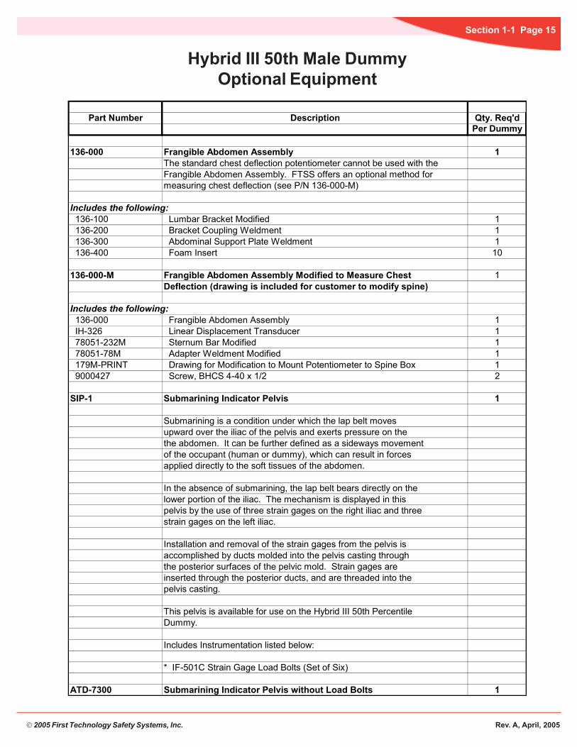
Hybrid III 50th Male DummyOptional Equipment
Part Number Description Qty. Req'dPer Dummy
136-000 Frangible Abdomen Assembly 1The standard chest deflection potentiometer cannot be used with the Frangible Abdomen Assembly. FTSS offers an optional method for measuring chest deflection (see P/N 136-000-M)
Includes the following: 136-100 Lumbar Bracket Modified 1 136-200 Bracket Coupling Weldment 1 136-300 Abdominal Support Plate Weldment 1 136-400 Foam Insert 10
136-000-M Frangible Abdomen Assembly Modified to Measure Chest 1Deflection (drawing is included for customer to modify spine)
Includes the following: 136-000 Frangible Abdomen Assembly 1 IH-326 Linear Displacement Transducer 1 78051-232M Sternum Bar Modified 1 78051-78M Adapter Weldment Modified 1 179M-PRINT Drawing for Modification to Mount Potentiometer to Spine Box 1 9000427 Screw, BHCS 4-40 x 1/2 2
SIP-1 Submarining Indicator Pelvis 1
Submarining is a condition under which the lap belt moves upward over the iliac of the pelvis and exerts pressure on thethe abdomen. It can be further defined as a sideways movementof the occupant (human or dummy), which can result in forcesapplied directly to the soft tissues of the abdomen. In the absence of submarining, the lap belt bears directly on thelower portion of the iliac. The mechanism is displayed in thispelvis by the use of three strain gages on the right iliac and threestrain gages on the left iliac. Installation and removal of the strain gages from the pelvis isaccomplished by ducts molded into the pelvis casting throughthe posterior surfaces of the pelvic mold. Strain gages are inserted through the posterior ducts, and are threaded into thepelvis casting.
This pelvis is available for use on the Hybrid III 50th PercentileDummy.
Includes Instrumentation listed below:
* IF-501C Strain Gage Load Bolts (Set of Six)
ATD-7300 Submarining Indicator Pelvis without Load Bolts 1

© 2005 First Technology Safety Systems, Inc. Rev. A, April, 2005
Section 1-1 Page 16
Hybrid III 50th Male DummyAccelerometer Mount Kits
AccelerometerType (78051-61) (78051-61X) (78051-89) (78051-59) (78051-600/601)
3-Axis 6-Axis 3-Axis Head 6-Axis Head Chest Pelvis 45o FootEndevco7231C-750 1032010 1032014 1032046 1032058 1032050 1032054 Endevco7264-2000 1032011 1032015 1032047 1032059 1032051 1032055 10323137264C-2000Endevco7264A-2000 7264B-2000 1032108 1032109 1032119 1032120 1032121 1032122 1032314Endevco7267A 1032012 1032016 1032048 1032060 1032052 1032056Endevco7265AM3KyowaAS-A 1032013 1032017 1032049 1032061 1032053 1032057KyowaAS-HA 1032013 1032017 1032049 1032061 1032053 1032057KyowaAS-HAM 1032013 1032017 1032049 1032061 1032053 1032057KyowaAS-TAKyowaASM-200BA 1032038 1032039 1032239 1032240 1032241 1032242 1032315KyowaASM-1KBBV 1032287 1032288 1032268 1032269 1032316EntranEGE-73C-50-750 1032010 1032014 1032046 1032058 1032050 1032054 EntranEGE-73BE0-50-2000 1032011 1032015 1032047 1032059 1032051 1032055 EntranEGE-73C-750 EntranEGE-73BM-50-2000 EntranEGE-73B4-50-2000H 1032108 1032109 1032119 1032120 1032121 1032122 EntranEGE3-73E0-50-1500 1032012 1032016 1032048 1032060 1032052 1032056
(78051-218 /218X)ComponentsComplete Dummy

© 2005 First Technology Safety Systems, Inc. Rev. A, April, 2005
Section 1-1 Page 17
(4) 78051-94Screw, SHCS1/4-20x5/8,Nylok
78051-229Cap Skin
78051-220Skull Cap, Machined
78051-77XBSkull, 6 Axis Machined Assembly
78051-228Head Skin
(4) 9000264Screw, SHCS 1/4-28 x 7/8
(4) 90006771/4 x 3/8 x 1/16 Stripper Bolt Shim
(2) 9000452Screw, SSCP 8-32 x 1/478051-339
Neck Transducer Pivot Pin
(2) 78051-253Nodding Joint Washers
78051-383XStructural Replacement6 Axis Neck Transducer
Hybrid III 50th Male DummyHead Assembly
*Accelerometer MountRefer to AccelerometerMount Matrix
Part Number Description Qty. Req'dPer Dummy
78051-61X Head Assembly Complete, Tested/Certified* 1Head machined to accept six-axis neck transducer
78051-228 Head Skin, Tested/Certified 1 78051-77XB Skull, machined assembly, 6-axis Neck with ballast 1 78051-220 Skull Cap, machined 1 78051-229 Cap Skin 1 78051-94 Screw, SHCS 1/4-20 x 5/8, Nylok 4 78051-383X Structural Replacement, 6-axis Neck Transducer 1 78051-339 Pivot Pin, Neck Transducer 1 78051-253 Washer, Nodding Joint 2 9000452 Screw, SSCP 8-32 x 1/4 2 9000677 Stripper Bolt Shim, 1/4 x 3/8 x 1/16 4 9000264 Screw, SHCS 1/4 - 28 x 7/8 4
*The Complete Head Assembly is supplied with an accelerometer mount kit free of charge. Please specifythe type required when placing order.

© 2005 First Technology Safety Systems, Inc. Rev. A, April, 2005
Section 1-1 Page 18
(4) 78051-337Screw, FHCS 1/4-20 x 3/4, Nylok
(2) 78051-351Nodding Block
78051-297Nodding Joint Assembly
78051-301Neck Cable
78051-336Neck Molded,Tested/Certified
78051-307Upper Neck Bracket
9001260Washer
(4) 78051-252Flat Washer, Neck Bracket
78051-64Nut, Hex Jam 1/2-20
(4) 78051-94Screw, SHCS 1/4-20 x 5/8, Nylok
78051-322Nodding Joint Neck Bushing
Hybrid III 50th Male DummyNeck Assembly
Part Number Description Qty. Req'dPer Dummy
78051-90 Neck Assembly Complete, Tested/Certified 1 78051-337 Screw, FHCS 1/4-20 x 3/4, Nylok 4 78051-297 Nodding Joint Assembly 1 78051-322 Bushing, Nodding Joint, Neck 1 78051-301 Neck Cable 1 78051-336 Neck Molded, Tested/Certified 1 78051-351 Nodding Block, 85+/- 5, Shore A 2 78051-64 Nut, Hex Jam 1/2-20 1 78051-252 Washer, Flat, Neck Bracket 4 78051-94 Screw, SHCS 1/4-20 x 5/8, Nylok 4
9001260 Washer, 1.06 OD x .53 ID x .06 CAD Plate 178051-307 Neck Bracket, Upper 1

© 2005 First Technology Safety Systems, Inc. Rev. A, April, 2005
Section 1-1 Page 19
Hybrid III 50th Male DummyUpper Torso Assembly
78051-303Lower Neck Bracket
78051-26Thorax CG Weight
78051-98Screw, 3/8-16 x 1, Nylok
78051-305Clamping Washer
(4) 9000433Screw, SHCS 5/16-24 x 7/8, Nylok
(4) 78051-306Flat Washers
78051-355Transducer Arm Connector
78051-179Thoracic Spine
78051-78Adaptor Weldment
(2) 78051-85Torso Flexion Stop
(4) 78051-95Screw, SHCS 1/4-20 x 3/4,Nylok 78051-387
Transducer Arm
78051-366Transducer Arm Ball
9000407Screw, BHCS1/4-20 x 1/2
(2) 78051-225Screw, FHCS 10-32 x .290 (Spec.)(2) 78051-93
Screw, SHCS 1/4-20 x 3/8, Nylok (4) 78051-94Screw, SHCS 1/4-20 x 5/8, Nylok
(3) 9000643Screw, FHCS 1/4-20 x 5/8, Nylok
78051-333Screw, SSCP 4-40 x 3/8
78051-354Potentiometer Bracket
(3) 78051-334Screw, SSCP 4-40 x 3/16(used to attach the trans-ducer arm to the connector)

© 2005 First Technology Safety Systems, Inc. Rev. A, April, 2005
Section 1-1 Page 20
Hybrid III 50th Male DummyUpper Torso Assembly
Part Number Description Qty. Req'dPer Dummy
78051-89 Upper Torso Assembly Complete, Tested/Certified* 1 9000433 Screw, SHCS 5/16-24 x 7/8, Nylok 4 78051-306 Washer, Flat 4 78051-98 Screw, SHCS 3/8-16 x 1, Nylok 1 78051-305 Washer, Clamping 1 78051-303 Neck Bracket, Lower 1 78051-179 Thoracic Spine 1 78051-225 Screw, FHCS 10-32 x .290 (Spec) 2 78051-93 Screw, SHCS 1/4-20 x 3/8, Nylok 2
78051-116 Adapter Assembly, Instrument 1 78051-95 Screw, SHCS 1/4-20 3/4, Nylok 4 78051-88 Adapter Assembly 1 78051-78 Adaptor Weldment 1 78051-94 Screw, SHCS 1/4-20 x 5/8, Nylok 4 78051-26 Thorax CG Weight 1 78051-85 Torso Flexion Stop, Molded 2 9000643 Screw, FHCS 1/4-20 x 5/8, Nylok 3
78051-317 Chest Deflection Transducer Assembly 1 9000407 Screw, BHCS 1/4-20 x 1/2 1 78051-353 Transducer Arm Assembly 1 78051-387 Transducer Arm 1 78051-366 Transducer Arm Ball 1 78051-333 Screw, SSCP 4-40 x 3/8 1 78051-355 Transducer Arm Connector 1 78051-334 Screw, SSCP 4-40 x 3/16 3 78051-430 Potentiometer Bracket Assembly 1 78051-377 Pin, Slotted Spring Modified 1 9001196 Bearing 2 78051-354 Potentiometer Bracket without Bearing 1 78051-342 Potentiometer, (Rotary Chest Deflection) 1
Please specify the type required when placing order.*The Complete Upper Torso Assembly is supplied with an accelerometer mount kit free of charge.

© 2005 First Technology Safety Systems, Inc. Rev. A, April, 2005
Section 1-1 Page 21
Hybrid III 50th Male DummyUpper Torso Assembly
78051-169Chest Flesh
78051-316Transducer Arm Slider
(2) 78051-233Front End Stiffener Plate
78051-215Bib Assembly
78051-RSRib Set Complete
(6) 78051-304Rib Rear Support
(12) 78051-118Screw, BHCS10-32 x 1/2
(2) 78051-234Front Rib EndStrip Threaded
(24) 78051-117Screw, BHCS 10-32 x 5/8
78051-232Sternum
(2) 78051-356Sternum Stop
78051-9Sternum Stop
Part Number Description Qty. Req'dPer Dummy
78051-89 Upper Torso Assembly Complete, Tested/Certified* (cont'd) 78051-304 Support, Rib Rear 6 78051-118 Screw, BHCS 10-32 x 1/2 12
78051-RS Rib Set Complete, Tested/Certified 1 78051-35 Individual Rib, Rib # 1, untested 1 78051-36 Individual Rib, Rib # 2, untested 1 78051-37 Individual Rib, Rib # 3, untested 1 78051-38 Individual Rib, Rib # 4, untested 1 78051-39 Individual Rib, Rib # 5, untested 1 78051-40 Individual Rib, Rib # 6, untested 1
78051-234 Strip, Front Rib End Threaded 2
78051-357 Sternum Assembly 1 78051-232 Sternum 1 78051-356 Stop, Sternum 2 78051-9 Stop, Sternum 1
78051-215 Bib Assembly, Sternum to Ribs 1 78051-117 Screw, BHCS 10-32 x 5/8 24 78051-233 Plate, Front End Stiffener 2 78051-316 Transducer Arm Slider 1 78051-169 Chest Flesh and Skin Assembly (Zipper Starts from the Top) 1
*The Complete Upper Torso Assembly is supplied with an accelerometer mount kit free of charge. Please specify the type required when placing order.

© 2005 First Technology Safety Systems, Inc. Rev. A, April, 2005
Section 1-1 Page 22
Hybrid III 50th Male DummyUpper Torso
78051-360Shoulder Yoke
78051-199Bushing,Upper Arm/Elbow Pivot
78051-200Washer, UpperArm/Elbow Pivot
78051-249SpringWasher
78051-250ShoulderYoke Retain-ing Washer
78051-251Hex JamNut 3/8-16
78051-188Left Clavicle Link
(2) 78051-241Clavicle Spacer
78051-240ClavicleSpringStop
78051-255Nut, UpperArm Pivot
78051-246Bushing,Shoulder YokePivot
9001339Washer, Flat
78051-128Screw, SHSS 1/2 x 1-1/4
78051-141Left Clavicle
78051-236ClavicularLink PivotWasher
78051-238ClavicularLinkPivot Nut
78051-235ShoulderBumper
78051-237ClavicularLinkPivot Nut/Washer
78051-239Clavicular LinkPivot Screw
78051-127Screw, SHSS 1/2 x 1
78051-243Flat Washer
78051-242Stop, ShoulderYoke Pivot
78051-93Screw,SHCS1/4-20 x 3/8
78051-244Stop,ShoulderYoke PivotSteel
78051-248ShoulderYokeWasher
(2) 9000487Screw, SHCS 10-24 x 3/8
78051-247Washer,ShoulderYoke Pivot
78051-245Stop,ShoulderYoke
78051-236Clavicular Link PivotWasher
78051-249Spring Washer

© 2005 First Technology Safety Systems, Inc. Rev. A, April, 2005
Section 1-1 Page 23
Hybrid III 50th Male DummyUpper Torso
Part Number Description Qty. Req'dPer Dummy
78051-89 Upper Torso Assembly Complete, Tested/Certified* (cont'd) 78051-235 Bumper Shoulder 1 78051-238 Nut, Clavicular Link Pivot 1 78051-236 Washer, Clavicular Link Pivot 2 78051-237 Washer/Nut, Clavicular Link Pivot 1 78051-239 Clavicular Link Pivot Screw 1
78051-410 Shoulder Assembly Complete, Left 1 78051-188 Clavicle Link, Left 1 78051-240 Spring, Clavicle Stop 1 78051-241 Spacers, Clavicle 2 78051-243 Washer, fFlat, Stainless Steel 1 78051-127 Screw, SHSS 1/2 x 1 1 78051-141 Clavicle, Left 1 78051-242 Stop, Shoulder Yoke Pivot (Rubber) 1 78051-251 Nut, Hex Jam 3/8-16 1 78051-93 Screw, SHCS 1/4-20 x 3/8, Nylok 1 78051-250 Washer, Shoulder Yoke Retaining 1 78051-249 Washer, Spring 2 78051-248 Washer, Shoulder Yoke (Steel) 1 78051-247 Washer, Shoulder Yoke Pivot 1 78051-246 Bushing, Shoulder Yoke Pivot 1 78051-360 Shoulder Yoke 1 78051-245 Stop, Shoulder Yoke 1 78051-244 Stop, Shoulder Yoke Pivot (Steel) 1 9000487 Screw, SHCS 10-24 x 3/8 2 78051-128 Screw, SHSS 1/2 x 1-1/4 1 9001339 Washer, Flat, Stainless Steel 1 78051-200 Washer, Upper Arm/Elbow Pivot 1 78051-199 Bushing, Upper Arm/Elbow Pivot 1 78051-255 Nut, Upper Arm Pivot 1
*The Complete Upper Torso Assembly is supplied with an accelerometer mount kit free of charge. Please specify the type required when placing order.

© 2005 First Technology Safety Systems, Inc. Rev. A, April, 2005
Section 1-1 Page 24
Hybrid III 50th Male DummyUpper Torso
78051-250ShoulderYokeRetainingWasher
78051-249SpringWasher
78051-248Shoulder YokeWasher
78051-247Shoulder YokePivot Washer
78051-255Upper ArmPivot Nut
78051-199Upper Arm PivotBushing
78051-200Upper Arm PivotWasher
01339asher
78051-128Screw,SHSS1/2 x 1-1/4
78051-360ShoulderYoke
78051-251Hex Jam Nut3/8-16
78051-142Right Clavicle
78051-243Flat Washer
78051-127Screw, SHSS1/2 x 1
78051-189RightClavicle Link
78051-240Clavicle SpringStop
78051-238Clavicular LinkPivot Nut
78051-237Clavicular LinkPivot Nut/Washer
(2) 78051-236Clavicular LinkPivot Washer
78051-239ClavicularLinkPivot Screw
78051-235ShoulderBumper
78051-246Shoulder YokePivot Bushing
78051-93Screw, SHCS1/4-20 x 3/8
78051-242Stop, ShoulderYoke Pivot
78051-245Stop,ShoulderYoke
(2) 9000487Screw, SHCS10-24 x 3/8
78051-244Stop, Shoulder YokePivot Steel
(2) 78051-241Clavicle Spacer78051-249
Spring Washer
© 2005 First Technology Safety Systems, Inc. Rev. A, April, 2005
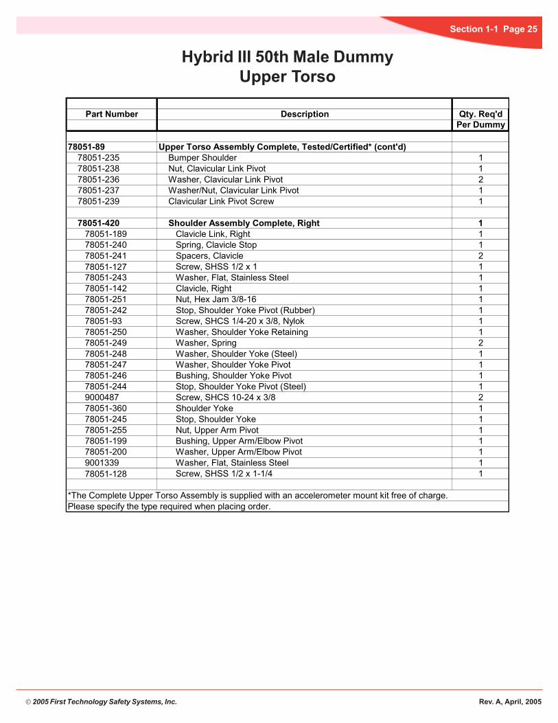
Section 1-1 Page 25
Hybrid III 50th Male DummyUpper Torso
Part Number Description Qty. Req'dPer Dummy
78051-89 Upper Torso Assembly Complete, Tested/Certified* (cont'd) 78051-235 Bumper Shoulder 1 78051-238 Nut, Clavicular Link Pivot 1 78051-236 Washer, Clavicular Link Pivot 2 78051-237 Washer/Nut, Clavicular Link Pivot 1 78051-239 Clavicular Link Pivot Screw 1
78051-420 Shoulder Assembly Complete, Right 1 78051-189 Clavicle Link, Right 1 78051-240 Spring, Clavicle Stop 1 78051-241 Spacers, Clavicle 2 78051-127 Screw, SHSS 1/2 x 1 1 78051-243 Washer, Flat, Stainless Steel 1 78051-142 Clavicle, Right 1 78051-251 Nut, Hex Jam 3/8-16 1 78051-242 Stop, Shoulder Yoke Pivot (Rubber) 1 78051-93 Screw, SHCS 1/4-20 x 3/8, Nylok 1 78051-250 Washer, Shoulder Yoke Retaining 1 78051-249 Washer, Spring 2 78051-248 Washer, Shoulder Yoke (Steel) 1 78051-247 Washer, Shoulder Yoke Pivot 1 78051-246 Bushing, Shoulder Yoke Pivot 1 78051-244 Stop, Shoulder Yoke Pivot (Steel) 1 9000487 Screw, SHCS 10-24 x 3/8 2 78051-360 Shoulder Yoke 1 78051-245 Stop, Shoulder Yoke 1 78051-255 Nut, Upper Arm Pivot 1 78051-199 Bushing, Upper Arm/Elbow Pivot 1 78051-200 Washer, Upper Arm/Elbow Pivot 1 9001339 Washer, Flat, Stainless Steel 1 78051-128 Screw, SHSS 1/2 x 1-1/4 1
*The Complete Upper Torso Assembly is supplied with an accelerometer mount kit free of charge. Please specify the type required when placing order.

© 2005 First Technology Safety Systems, Inc. Rev. A, April, 2005
Section 1-1 Page 26
Hybrid III 50th Male DummyArm Assembly, Left
78051-174Upper Arm Assembly Flesh
78051-191Upper Arm LowerPart Weldment
78051-194Lower Arm Assembly Flesh
78051-255Nut, Upper Arm Pivot
78051-200Upper Arm ElbowPivot Washer
78051-199Upper Arm ElbowPivot Bushing
78051-243Washer, Flat
78051-204Lower Arm Lower Part Weldment
78051-125Screw, SHSS 3/8 x 178051-214Wrist Pivot Screw
78051-208Left Hand Assembly
78051-128Screw, SHSS 1/2 x 1-1/4
78051-249Washer, Spring
78051-126Screw, SHSS 3/8 x 1-1/2
(2) 78051-198Lower Arm Stop
Part Number Description Qty. Req'dPer Dummy
78051-123 Arm Assembly Complete, Left 1 78051-174 Upper Arm Assembly, Molded, with Flesh 1 78051-126 Screw, SHSS 3/8 x 1-1/2 1 78051-243 Washer, Flat, (Stainless Steel) 1 78051-191 Upper Arm, Lower Part Weldment 1 78051-128 Screw, SHSS 1/2 x 1-1/4 1 78051-249 Washer, Spring 1 78051-199 Bushing, Upper Arm/Elbow Pivot 1 78051-200 Washer, Upper Arm/Elbow Pivot 1 78051-255 Nut, Upper Arm Pivot 1 78051-194 Lower Arm Assembly, Molded, with Flesh 1 78051-198 Stop, Lower Arm, Molded 2 78051-125 Screw, SHSS 3/8 x 1 1 78051-204 Lower Arm, Lower Part Weldment 1 78051-214 Pivot Screw, Wrist 1 78051-208 Hand Assembly, Left 1

© 2005 First Technology Safety Systems, Inc. Rev. A, April, 2005
Section 1-1 Page 27
Hybrid III 50th Male DummyArm Assembly, Right
78051-209Right Hand Assembly
78051-174Upper Arm Assembly Flesh
78051-191Upper Arm Lower Part Weldment
78051-194Lower Arm Assembly Flesh
78051-255Nut, Upper Arm Pivot
78051-200Upper Arm Elbow Pivot Washer
78051-199Upper Arm ElbowPivot Bushing
78051-243Washer, Flat
78051-204Lower Arm Lower Part Weldment
78051-125Screw, SHSS 3/8 x 1
78051-214Wrist Pivot Screw
78051-128Screw, SHSS 1/2 x 1-1/4
78051-249Washer, Spring
78051-126Screw, SHSS 3/8 x 1-1/2
(2) 78051-198Lower Arm Stop
Part Number Description Qty. Req'dPer Dummy
78051-124 Arm Assembly Complete, Right 1 78051-174 Upper Arm Assembly, Molded, with Flesh 1 78051-126 Screw, SHSS 3/8 x 1-1/2 1 78051-243 Washer, Flat, (Stainless Steel) 1 78051-191 Upper Arm, Lower Part Weldment 1 78051-128 Screw, SHSS 1/2 x 1-1/4 1 78051-249 Washer, Spring 1 78051-199 Bushing, Upper Arm/Elbow Pivot 1 78051-200 Washer, Upper Arm/Elbow Pivot 1 78051-255 Nut, Upper Arm Pivot 1 78051-194 Lower Arm Assembly, Molded, with Flesh 1 78051-198 Stop, Lower Arm, Molded 2 78051-125 Screw, SHSS 3/8 x 1 1 78051-204 Lower Arm, Lower Part Weldment 1 78051-214 Pivot Screw, Wrist 1 78051-209 Hand Assembly, Right 1

© 2005 First Technology Safety Systems, Inc. Rev. A, April, 2005
Section 1-1 Page 28
Hybrid III 50th Male DummyLower Torso Assembly
(2) 78051-641/2-20 Hex Jam Nut(2) 78051-65
1/2-20 Hex Nut78051-66Lumbar Spine(2) 78051-69
Lumbar Cable
78051-52Abdominal Insert
78051-60Pelvis
78051-13Pelvic Instrument Cavity Cover
78051-111Femur & FlangeAssembly, Right
78051-110Femur & Flange Assembly, Left
78051-53Lumbar Spine Bracket
(2) 78051-259Femur Friction PlungerAssembly
(4) 9000624Screw, SHCS 10-24 x 1/2
(2) 9000063Screw, SHSS 5/8 x 1-3/4
(6) 78051-95Screw, SHCS 1/4-20 x 3/4, Nylok
(2) 78051-102Screw, SHCS 3/8-16 x 1-1/4 Nylok
(2) 78051-97Screw SHCS 3/8-16 x 3/4 Nylok
*Accelerometer MountRefer to AccelerometerMount Matrix
78051-498-1Femur Bumper, Left78051-498-2
Femur Bumper,Right
(3) 78051-94Screw SHCS 1/4-20 x 5/8, Nylok
(2) 9000345Screw, BHCS 8-32 x 3/8
(2) 9000345Screw, BHCS 8-32 x 3/8

© 2005 First Technology Safety Systems, Inc. Rev. A, April, 2005
Section 1-1 Page 29
Hybrid III 50th Male DummyLower Torso Assembly
Part Number Description Qty. Req'dPer Dummy
78051-70 Lower Torso Assembly Complete, Tested/Certified* 1 78051-64 Nut, Hex Jam 1/2-20 2 78051-65 Nut, Hex 1/2-20 2 78051-66 Lumbar Spine, Molded 1 78051-69 Lumber Cable 2 78051-53 Lumbar Spine Bracket, Molded 1 78051-94 Screw, SHCS 1/4-20 x 5/8, Nylok 3 78051-97 Screw, SHCS 3/8-16 x 3/4, Nylok 2 78051-102 Screw, SHCS 3/8-16 x 1-1/4 Nylok 2 78051-52 Abdominal Insert 1
78051-59 Pelvic Assembly Complete, Tested/Certified ROM* 1 78051-259 Femur Friction Plunger Assembly (Set Screw Assy.) 2 9000624 Screw, SHCS 10 - 24 x 1/2 4 78051-13 Pelvic Instrument Cavity Cover 1 78051-60 Pelvis, Molded, Tested/Certified ROM 1 9000063 Screw, SHSS 5/8 x 1-3/4 2 78051-95 Screw, SHCS 1/4-20 x 3/4, Nylok 6 78051-97 Screw, SHCS 3/8-16 x 3/4, Nylok 1 ATD-7148 Shim, Femur Retainer 2 78051-114 Femur Flange Assembly, Left with Bumper 1 78051-110 Femur & Flange Assembly, Left 1 78051-498-1 Femur Bumper, Left 1 9000345 Screw, BHCS 8-32 x 3/8 2 78051-115 Femur Flange Assembly, Right with Bumper 1 78051-111 Femur & Flange Assembly, Right 1 78051-498-2 Femur Bumper, Right 1 9000345 Screw, BHCS 8-32 x 3/8 2
*The Complete Lower Torso and Complete Pelvis Assembly is supplied with an accelerometer mount kit free of charge. Please specify the type required when placing order.

© 2005 First Technology Safety Systems, Inc. Rev. A, April, 2005
Section 1-1 Page 30
Hybrid III 50th Male DummyLeg Assembly, Left
78051-41Thigh Flesh, Left
78051-43Upper Leg Bone Weldment, Left
79051-66Knee Slider Assembly, Left
78051-27Knee Insert
78051-5Knee Flesh, Left
87051-110-CLeft Knee Clevis
78051-100Screw, SHCS 3/8-16 x 2, Nylok
(4) 9000115Screw, SHCS 1/4-28 x 1/2
78051-73SLower Leg Flesh, Left
C-1877-1Non-instrumentedTibia, Left
B-1889Ankle Rotation Assembly
78051-60045 Degree Foot, Left
A-1887Ankle to Leg AttachmentBolt
78051-99Screw, SHCS 3/8-16 x 1-3/4, Nylok
78051-319Load Cell Simulator
79051-22Knee Cap
A-1886Screw, SHSS 1/4 x 3/4Modified(7) 9000076
Screw, BHCS 8-32 x 1/2
(8) 9000313Screw, FHCS 1/4-28 x 3/8
78051-610Ankle Bumper (Rubber)
78051-608Heel Pad Foam
(4) 79051-17AScrew, SHCS 8-32 x 1/2 (two on each side)

© 2005 First Technology Safety Systems, Inc. Rev. A, April, 2005
Section 1-1 Page 31
Hybrid III 50th Male DummyLeg Assembly, Left
Part Number Description Qty. Req'dPer Dummy
86-5001-001 Leg Assembly, Complete, Left (without Potentiometer) 1 78051-46 Upper Leg (Thigh) Assembly Complete, Left 1 78051-41 Thigh Flesh/Skin, Molded, Left 1 78051-43 Upper Leg (Thigh) Bone Weldment, Left 1 78051-319 Load Cell Simulator 1 78051-99 Screw, SHCS 3/8-16 x 1-3/4, Nylok 1
78051-100 Screw, SHCS 3/8-16 x 2, Nylok 1
86-5001-003 Knee & Lower Leg Assembly, Left 1 79051-16-1 Sliding Knee Assembly, (w/o Pot), Tested/Cert., Left 1 79051-22 Knee Cap, Machined Assembly 1 78051-5 Knee Flesh/Skin, Molded, Left 1 78051-27 Knee Insert, Tested/Certified (Rubber) 1 79051-66 Knee Slider Assembly, Tested/Certified, Left 1 79051-23-1 Potentiometer Shaft Support, Left 1 79051-34 Rotation Stop Cover 1 79051-30 Screw, SHSS 3/8 x 3/8 Machined (used to hold stop cover in place) 2 79051-19 Pin, Potentiometer Shaft 1 79051-17A Screw, SHCS 8-32 x 1/2 4 9000313 Screw, FHCS 1/4-28 x 3/8 8 79051-33 Compression Washer 1 79051-32 Washer, Sliding Knee 1 79051-35 Rotation Stop Arm 1 78051-73 Lower Leg Assembly, Left 1 78051-73S Lower Leg Flesh/Skin, Molded, Left 1 C-1877-1 Non-instrumented Tibia, left 1 9000115 Screw, SHCS 1/4-28 x 1/2 4 87051-110-C Knee Clevis Weldment, left 1 C-1895 Lower Leg Structural Replacement 1
79051-29 Linear Potentiometer (Optional) 1
B-1889 Ankle Rotation Assembly 1 C-1884 Ankle, Upper Shell 1 C-1885 Ankle, Lower Shell 1 A-1590 Ankle Shaft 1 9000072 Pin, Dowel 3/16 x 1/2 1 A-1672 Stop Pin Retainer 1 A-1888 Ankle Friction Pad 1 9000073 Screw, SSCP 5/16-18 x 3/8 1 9000011 Screw, SSCP 10-32 x 1/4 2 9000076 Screw, BHCS 8-32 x 1/2 7 A-1887 Ankle to Leg Attachment Bolt 1 78051-610 Ankle Bumper (Rubber) 1 A-1886 Screw, SHSS 1/4 x 3/4 Modified 1 78051-600 Foot Molded 45 Degree, Tested/Certified, Left 1 78051-608 Heel Pad Foam 1

© 2005 First Technology Safety Systems, Inc. Rev. A, April, 2005
Section 1-1 Page 32
Hybrid III 50th Male DummyLeg Assembly, Right
78051-42Right Thigh Flesh
78051-44Upper Leg Bone Weldment Right
78051-319Load Cell Simulator
79051-16-2Right Knee Slider Assembly
79051-22Knee Cap
78051-6Knee Flesh Right
87051-111-CRight Knee Clevis
78051-99Screw, SHCS 3/8-16 x 1-3/4,Nylok
78051-74sLower Leg Flesh Right
A-1887Ankle to Leg Attachment Bolt
C-1877-2Non-instrumented Tibia,Right
78051-60145 Degree Foot Right
A-1886Screw, SHSS 1/4 x 3/4Modified
B-1889Ankle Rotation Assembly
78051-100Screw, SHCS 3/8-16 x 2, Nylok
(4) 9000115Screw, SHCS 1/4-28 x 1/2
(7) 9000076Screw, BHCS 8-32 x 1/2
(8) 9000313Screw, FHCS 1/4 - 28 x 3/8
78051-610Ankle Bumper (Rubber)
78051-608Heel Pad Foam
(4) 79051-17AScrew, SHCS 8-32 x 1/2(two on each side)
79051-27Knee Insert

© 2005 First Technology Safety Systems, Inc. Rev. A, April, 2005
Section 1-1 Page 33
Hybrid III 50th Male DummyLeg Assembly, Right
Part Number Description Qty. Req'dPer Dummy
86-5001-002 Leg Assembly Complete, Right (without Potentiometer) 1 78051-47 Upper Leg (Thigh) Assembly Complete, Right 1 78051-42 Thigh Flesh/Skin, Molded, Right 1 78051-44 Upper Leg (Thigh) Bone Weldment, Right 1 78051-319 Load Cell Simulator 1 78051-99 Screw, SHCS 3/8-16 x 1-3/4, Nylok 1
78051-100 Screw, SHCS 3/8-16 x 2, Nylok 1
86-5001-004 Knee & Lower Leg Assembly, Right 1 79051-16-2 Sliding Knee Assembly, (w/o Pot), Tested/Cert., Right 1 79051-22 Knee Cap, Machined Assembly 1 78051-6 Knee Flesh/Skin, Molded, Right 1 78051-27 Knee Insert, Tested/Certified (Rubber) 1 79051-67 Knee Slider Assembly, Tested/Certified, Right 1 79051-23-2 Potentiometer Shaft Support, Right 1 79051-34 Rotation Stop Cover 1 79051-30 Screw, SHSS 3/8 x 3/8 Machined (used to hold stop cover in place) 2 79051-19 Pin, Potentiometer Shaft 1 79051-17A Screw, SHCS 8-32 x 1/2 4 9000313 Screw, FHCS 1/4-28 x 3/8 8 79051-33 Compression Washer 1 79051-32 Washer, Sliding Knee 1 79051-35 Rotation Stop Arm 1
78051-74 Lower Leg Assembly, Right 1 78051-74s Lower Leg Flesh/Skin, Molded, Right 1 C-1877-2 Non-instrumented Tibia, Right 1 9000115 Screw, SHCS 1/4-28 x 1/2 4 87051-111-C Knee Clevis Weldment, Right 1 C-1895 Lower Leg Structural Replacement 1
79051-29 Linear Potentiometer (Optional) 1
B-1889 Ankle Rotation Assembly 1 C-1884 Ankle, Upper Shell 1 C-1885 Ankle, Lower Shell 1 A-1590 Ankle Shaft 1 9000072 Pin, Dowel 3/16 x 1/2 1 A-1672 Stop Pin Retainer 1 A-1888 Ankle Friction Pad 1 9000073 Screw, SSCP 5/16-18 x 3/8 1 9000011 Screw, SSCP 10-32 x 1/4 2 9000076 Screw, BHCS 8-32 x 1/2 7 A-1887 Ankle to Leg Attachment Bolt 1 78051-610 Ankle Bumper (Rubber) 1 A-1886 Screw, SHSS 1/4 x 3/4 Modified 1 78051-601 Foot Molded 45 Degree, Tested/Certified, Right 1 78051-608 Heel Pad Foam 1

© 2005 First Technology Safety Systems, Inc. Rev. A, April, 2005
Section 1-1 Page 34
Hybrid III 50th Male DummyConsumables Kit
Hybrid III 50th Male DummyTools and Accessories
Part Number Description Qty. Req'dPer Dummy
78051-CK Consumables Kit Frequently used replacement parts, includes the following items:
78051-228 Head Skin, Tested/Certified 1 78051-229 Cap Skin 1 78051-336 Neck, Molded, Tested/Certified 1 70851-307 Neck Bracket, Upper 1 78051-303 Neck Bracket, Lower 1 78051-RS Rib Set Complete, Tested/Certified 1 78051-188 Clavicle Link, Left 1 78051-189 Clavicle Link, Right 1 78051-66 Lumbar Spine 1 1200071 Skin Patch Material (Vinyl) 1
Part Number Description Qty. Req'dPer Dummy
TOOLS and MISCELLANEOUSAll items may be purchased individually.TOOL KIT Tool Accessory Kit for Dummy Shipments 1 1200071 Skin Patch Material (Vinyl) 1 9000465 Soldering Iron, Welder 1 9000765 Soldering Iron Tip 2 9000577 Hex Key Wrench, Ball End Set 1 6000476 Hex Key Wrench, Allen Set 1
Included with the Purchase of a Dummy:
103**** Mount Kit (Accelerometer Type to be Referenced by Customer) 1TOOL KIT Tool Accessory Kit for Dummy 178051-292 Shirt, 100% Cotton Short-Sleeve Medium (Pink) 178051-293 Pant, Above the Knee, 100% Cotton Large (Pink) 178051-231 Lifting Ring 1H3-50 Certification Booklet 1H3-50TH PRINT Assembly Drawings (Reference 78051-218) 178051-MANUAL User's and Calibration Manual 1

© 2005 First Technology Safety Systems, Inc. Rev. A, April, 2005
Section 1-1 Page 35
Hybrid III 50th Male DummySmall Parts Kit
Part Number Description Qty. Req'dPer Dummy
78051-SPK Small Parts Kit 1 Unless otherwise indicated, the Small Parts Kit contains all the small parts and hardware, listed below, required for one complete dummy. The Small Parts Kit comes in an 18 compartment metal cabinet.
9001260 Washer, 1.06 OD x .53 ID x .06 CAD Plate 19000043 Screw, SHSS 1/2 x 1 16000476 Hex Key Wrench, Allen Set 19000066 Screw, SHCS 3/8-16 x 2, Nylok 29000060 Screw, SHCS 3/8-16 x 1-1/4 Nylok 29000025 Screw, BHCS 10-32 x 5/8 249000026 Screw, BHCS 10-32 x 1/2 129000519 Screw, SHSS 3/8 x 1 29000082 Screw, SHSS 3/8 x 1-1/2 29000043 Screw, SHSS 1/2 x 1 19000055 Screw, SHSS 1/2 x 1-1/4 478051-198 Stop, Lower Arm, Molded 478051-199 Bushing, Upper Arm/Elbow Pivot 478051-200 Washer, Upper Arm/Elbow Pivot 478051-214 Pivot Screw, Wrist 278051-225 Screw, FHCS 10-32 x .290 (Spec) 278051-233 Plate, Front End Stiffener 278051-234 Strip, Front Rib End Threaded 278051-235 Bumper Shoulder 278051-236 Washer, Clavicular Link Pivot 478051-237 Washer/Nut, Clavicular Link Pivot 278051-238 Nut, Clavicular Link Pivoting 278051-239 Clavicular Link Pivot Screw 278051-240 Spring, Clavicle Stop 278051-241 Spacers, Clavicle 478051-242 Stop, Shoulder Yoke Pivot (Rubber) 29001339 Washer, Flat, Stainless Steel 478051-244 Stop, Shoulder Yoke Pivot (Steel) 278051-245 Stop, Shoulder Yoke 278051-246 Bushing, Shoulder Yoke Pivot 278051-247 Washer, Shoulder Yoke Pivot 278051-248 Washer, Shoulder Yoke (Steel) 278051-249 Washer, Spring 678051-250 Washer, Shoulder Yoke Retaining 29000052 Nut, Hex Jam 3/8-16 278051-252 Washer, Flat, Neck Bracket 478051-253 Washer, Nodding Joint 278051-202 Nut, Elbow Pivot 478051-259 Femur Friction Plunger Assembly (Set Screw Assy.) 278051-297 Nodding Joint Assembly 178051-301 Neck Cable 178051-304 Support, Rib Rear 678051-305 Washer, Clamping 1

© 2005 First Technology Safety Systems, Inc. Rev. A, April, 2005
Section 1-1 Page 36
Hybrid III 50th Male DummySmall Parts Kit
Part Number Description Qty. Req'dPer Dummy
78051-SPK Small Parts Kit (continued) 1
9000022 Washer 478051-322 Bushing, Nodding Joint, Neck 19000032 Screw, SSCP 4-40 x 3/8 19000034 Screw, SSCP 4-40 x 3/16 39000017 Screw, FHCS 1/4-20 x 3/4, Nylok 478051-339 Pivot Pin, Neck Transducer 178051-356 Stop, Sternum 278051-366 Transducer Arm Ball 178051-377 Pin, Slotted Spring Modified 178051-387 Transducer Arm 178051-498-1 Femur Bumper, Left 178051-498-2 Femur Bumper, Right 178051-608 Heel Pad Foam 278051-610 Ankle Bumper (Rubber) 29000018 Nut, Hex Jam 1/2-20 39000057 Nut, Hex 1/2-20 278051-85 Torso Flexion Stop, molded 278051-9 Stop, Sternum 19000041 Screw, SHCS 1/4-20 x 3/8, Nylok 29000005 Screw, SHCS 1/4-20 x 5/8, Nylok 159000009 Screw, SHCS 1/4-20 x 3/4, Nylok 109000059 Screw, SHCS 3/8-16 x 3/4, Nylok 39000021 Screw, SHCS 3/8-16 x 1, Nylok 19000083 Screw, SHCS 3/8-16 x 1-3/4, Nylok 29000516 Screw, SHCS 8-32 x 1/2 1279051-19 Pin, Potentiometer Shaft 279051-30 Screw, SHSS 3/8 x 3/8 Machined 479051-32 Washer, Sliding Knee 279051-33 Compression Washer 279051-34 Rotation Stop Cover 279051-35 Rotation Stop Arm 29000011 Screw, SSCP 10-32 x 1/4 49000041 Screw, SHCS 1/4-20 x 3/8, Nylok 29000063 Screw, SHSS 5/8 x 1-3/4 29000072 Pin, Dowel 3/16 x 1/2 29000073 Screw, SSCP 5/16-18 x 3/8 29000076 Screw, BHCS 8-32 x 1/2 149000115 Screw, SHCS 1/4-28 x 1/2 89000264 Screw, SHCS 1/4 - 28 x 7/8 49000313 Screw, FHCS 1/4-28 x 3/8 169000345 Screw, BHCS 8-32 x 3/8 49000407 Screw, BHCS 1/4-20 x 1/2 19000433 Screw, SHCS 5/16-24 x 7/8, Nylok 49000452 Screw, SSCP 8-32 x 1/4 29000487 Screw, SHCS 10-24 x 3/8 49000577 Hex Key Wrench, Ball End Set 19000624 Screw, SHCS 10-24 x 1/2 49000630 Small Parts Cabinet 18-Drawer Metal 19000643 Screw, FHCS 1/4-20 x 5/8, Nylok 39000677 Stripper Bolt Shim, 1/4 x 3/8 x 1/16 49000765 Soldering Iron Tip 29001260 Washer, 1.06 OD x .53 ID x .06 Cad Plate 2A-1672 Stop Pin Retainer 2A-1886 Screw, SHSS 1/4 x 3/4 Modified 2A-1887 Ankle to Leg Attachment Bolt 2A-1888 Ankle Friction Pad 2