section 11026 safe part 1 - general fcps master... · section 11026 . safe. part 1 - general. ......
TRANSCRIPT

11026-1 11/15
SECTION 11026
SAFE
PART 1 - GENERAL 1.01 RELATED DOCUMENTS
A. Drawings and general provisions of the Contract, including General Conditions and Division 1 Specifications Section, apply to work of the Section.
1.02 RELATED WORK
A. Cast-In-Place Concrete: Section 03300. 1.03 DESCRIPTION OF WORK
A. The location of the safe is indicated on the Drawings. 1.04 INSERTS AND ANCHORAGES
A. Furnish inserts and anchorage devices that must be set into a concrete base for installation of the unit.
1.05 SUBMITTALS
A. Product Data: Submit manufacturer's product data and installation instructions for safe unit.
B. Shop Drawing: Provide shop drawing indicating anchorage to concrete.
PART 2 - PRODUCTS 2.01 ACCEPTABLE MANUFACTURERS
A. Provide unit by the following manufacturers:
1. American Security Products (AMSEC, www.amsecusa.com) which shall be the basis of the specification.
2. Diebold, Incorporated, Owings Mills, MD. 3. Pre-bid approved manufacturer (See Section 01630).
2.02 SAFE
A. Product Description: AMSEC "Wide Body" B-Rated Model BWB3020, 29 3/4" H. x 19 3/4" W. x 17" D., with the following features:

SAFE SECTION 11026
11026-2 11/15
1. 1/8" thick solid steel body, continuously welded 2. 1/2" thick steel door, recessed, with continuous, welded hinge 3. U. L. listed, Group II, key changeable combination lock 4. Automatic 3-way, 5-bolt locking mechanism 5. Adjustable shelves (2) 6. Mounting holes for anchoring to concrete base
PART 3 - EXECUTION 3.01 INSTALLATION
A. Install safe by anchoring to base in accordance with requirements indicated in Product Data and approved Shop Drawings.
B. Upon completion of installation, including work of other adjoining trades, clean,
test and adjust to proper operation, free from any warp or distortion.
END OF SECTION

11/15
INSTRUCTIONS FOR EDITING
SECTION 11040
WALL DEPOSITORY SAFE
INSTRUCTIONS FOR EDITING: 1. PAGE 11040-2, 2.02 Through The Wall Depository With PEDESTAL
A. Product Description: Insert the wall thickness after the model # PRO-GN489- ___________.
11040-1 11/15
SECTION 11040
WALL DEPOSITORY SAFE
PART 1 - GENERAL 1.01 RELATED DOCUMENTS
A. Drawings and general provisions of the Contract, including General Conditions and Division 1 Specifications Section, apply to work of the Section.
1.02 RELATED WORK
A. Gypsum Wallboard: Section 09250 B. Structural Steel: Section 05120 C. Unit Masonry: Section 04200
1.03 DESCRIPTION OF WORK
A. Through wall depository with Pedestal. Drop Box Safe is indicated on the Drawings.
1.04 SUBMITTALS
A. Product Data: Submit manufacturer's product data and installation instructions per design intent
B. Shop Drawing: Provide shop drawing indicating anchorage and support through
Concrete masonry wall or Gypsum board wall and Chest anchor to the floor as indicated on the drawings. Shop drawing shall indicate finished wall thickness.
PART 2 - PRODUCTS 2.01 ACCEPTABLE MANUFACTURERS
A. Provide unit by the following manufacturers:
1. Perma-Vault Safe Co, www.perma-vault.com), which shall be the basis of the specification. (1-215-293-9951)
2. American Security Cabinets, (www.paymentdrops.com), 1-800-538-7898 3. Pre-bid approved manufacturer (See Section 01630).

WALL DEPOSITORY SAFE SECTION 11040
11040-2 11/15
2.02 Through The Wall Depository with PEDESTAL SAFE
A. Product Description: Perma-Vault "Through the door/wall Depository/Dual Custody” Model PRO-GN48P-(insert wall thickness), 25” high/Black, with the following features:
1. Heavy 12 gauge steel construction. Chute is part of the safe and
measures 5 ½: x 10” at opening with a throat dimension of 2 ½” x 10” (chute capacity)
2. Provide 3/8” door hinged right equipped with Group II Combination Lock
with (4) 3/8” mounting holes in the back. 3. 4” x 12” exterior Mail flap with finishing flange to allow for 2 ½” drop
capacity. 4. Dimension to Interior center door to be between the range 28” to 30” to
allow ease of operation 5. Dimension to Exterior center of handle to be between the range of 46” to
48” max. 6. Provide (2) signs “DROP BOX” label on Access door. 7. Black enamel finish.
PART 3 - EXECUTION 3.01 INSTALLATION
A. Install safe by anchoring to base in accordance with requirements indicated in Product Data and approved Shop Drawings.
B. Upon completion of installation, including work of other adjoining trades, clean,
test and adjust to proper operation, free from any warp or distortion.
END OF SECTION

11050-1 11/15
SECTION 11050
LIBRARY MATERIALS SECURITY SYSTEM (MIDDLE AND HIGH SCHOOLS ONLY)
PART 1 - GENERAL 1.01 RELATED DOCUMENTS
A. Drawings and General Provisions of Contract, including General Conditions and Division 1 Specification Sections, apply to the Work of this Section.
1.02 DESCRIPTION
A. Provide and install a complete, functioning radio frequency (RF) security system, capable of detecting unauthorized removal of Media Center materials, which shall be equipped with detection and deactivation elements. Refer to the drawings for location and quantity required
1. Power to operate the system shall be provided under the work of
Division 16 - Electrical. 1.03 SUBMITTALS
A. Comply with provisions of Section 01340: Shop Drawings, Product Data and Samples.
B. Submit manufacturers’ product literature describing type of system, system
components and detection/deactivation elements. Include installation and maintenance instructions and warranty information.
C. Furnish samples of Detection Labels and Detuner Elements for Selection.
D. Submit a layout based on Drawings and field verified conditions. Show
dimensions indicating clearances and extent of detection coverage. 1.04 DELIVERY AND STORAGE
A. Deliver security system components and accessories in the Manufacturers’ original packaging with identifying labels intact.
1.05 QUALITY ASSURANCE
A. Installation shall be performed by Manufacturers’ designated personnel. B. Store in a secure location, protected from the elements, unauthorized access
and damage by work of other trades.

LIBRARY MATERIALS SECURITY SYSTEM (MIDDLE AND HIGH SCHOOLS ONLY) SECTION 11050
11050-2 11/15
1.06 WARRANTY
A. Provide a minimum one (1) year warranty covering equipment and components. B. Service contract: Make a service contract available to the Owner. Terms of the
proposed contract shall indicate service response time and shall identify the service provider.
PART 2 - PRODUCTS 2.01 SECURITY SYSTEM EQUIPMENT
A. General Description: The system shall consist of sensing antennas secured to the floor and forming access aisle(s) with widths as indicated on the drawings, a control module, detection labels and deactivation elements.
1. Attachment of detection labels and deactivation elements shall be the
responsibility of the School staff.
B. Basis of Specification: RF Detection systems as manufactured by Checkpoint Systems, Inc., and supported by 3M Corporation, 1-800-328-0067, www.3m.com/library.
C. RF Systems by other manufacturers, pre-bid approved in accordance with
Section 01630, shall be acceptable. 2.02 DETECTION EQUIPMENT
A. “Liberty PX” model
1. Dimensions: 68" high, 19 3/4" X 4 1/2" base.
2. Power requirements: 110VAC, 50-60 Hz.
3. Configuration: 2 modules spaced 72" apart with 36" of detection coverage on each side (total detection coverage of 144").
4. Finish: Solid oak with “natural oak” factory finish. B. Power Supply Unit (Control Module) - Features
1. Key controlled “on/off” switch.
2. “Power On” indicator light.
3. Power requirements: 110VAC, 50/60 Hz; operates at less than 100 watts

LIBRARY MATERIALS SECURITY SYSTEM (MIDDLE AND HIGH SCHOOLS ONLY) SECTION 11050
11050-3 11/15
4. Power Supply (Control Module) dimensions: 9" L. X 5 3/8" W. X 3 1/2" H.
C. Detection Labels
1. General
a. Labels shall be flexible, programmed tags laminated with paper stock on one side, pressure sensitive adhesive on the other side, and produced on a siliconized release paper.
b. Labels shall not discolor or lose adhesive strength with age.
c. Labels shall be of a size to easily slip on to or under a book jacket or a book pocket. Labels shall have the option for custom printing to identify place of origin.
2. RF320 Series Detection Labels: 2" X 2" “Date Due” labels (#648270)
3. Quantity of labels: Provide 10 rolls (2000 labels per roll) for middle
schools and 20 rolls for high schools.
D. Detuner (Deactivation) Elements.
1. General
a. These elements are designed to provide a “date due” notice for the student who checks out media material, and to “detune” the detection label at the time of check out, so that the media material can pass through the sensor area without activating an alarm.
b. “Date Due” Tabs shall have a non-permanent adhesive backing for easy removal.
2. “Date Due” Tabs: 1.5" X 1" (#820787), provide five (5) rolls of 1,000 tabs
each roll to Owner for all projects. Designed to be used in conjunction with custom printed detection labels or labels placed onto or under a book jacket.
PART 3 - EXECUTION 3.01 INSPECTION
A. Prior to beginning work of this Section, inspect the premises and verify that the RF system can be satisfactorily installed in accordance with approved submittals. Verify that the required power is available in a suitable location. Notify Owner’s Representative and Architect if any conditions are identified that would be

LIBRARY MATERIALS SECURITY SYSTEM (MIDDLE AND HIGH SCHOOLS ONLY) SECTION 11050
11050-4 11/15
detrimental to proper installation and operation of the security system. Do not proceed until unsatisfactory conditions have been corrected.
1. AC outlet provided by Division 16 shall be located within 5' of low voltage
Power Supply Unit (Control Module) location 2. Power Supply Unit (Control Module) location shall be within 12' of
detection sensor gate. 3. Refer to contractor’s package provided by manufacturer: Thomas Wetzelberger, 443-286-2323, [email protected].
3.02 INSTALLATION
A. Install system in accordance with approved submittals, using personnel meeting the requirements of 1.05 of this Section.
B. Make final electrical connections and place system in operation. Test system to
verify proper performance. 3.03 MAINTENANCE AND TRAINING A. Provide maintenance and operation manuals to Media Center staff.
B. Schedule an on-site demonstration to instruct Media Center staff in proper equipment operation, care of components, and correct use of detection/deactivation elements.
3.04 PROTECTION AND CLEANING A. Protect security system from damage until acceptance by Owner.
B. Remove all debris and excess materials associated with the work of this Section from the project site and dispose of legally.
END OF SECTION

11/15
INSTRUCTIONS FOR EDITING
SECTION 11060
MUSICAL INSTRUMENT STORAGE EQUIPMENT (ELEMENTARY SCHOOLS)
1. 1.03 Description of Work: Edit specification to comply with the following conditions:
A. Where instrument storage units are located in a separate lockable storage room, units shall be fabricated without doors. Where units are located in a classroom, provide lockable doors.

11060-1 11/15
SECTION 11060
MUSICAL INSTRUMENT STORAGE EQUIPMENT (ELEMENTARY SCHOOLS)
PART 1 - GENERAL 1.01 RELATED DOCUMENTS
A. Drawings and General Provisions of Contract, including General Conditions and Division 1 Specification Sections, apply to the Work of this Section.
1.02 RELATED WORK
A. General Casework: Section 12302
B. Plastic Laminate Faced Casework: Section 12304 1.03 DESCRIPTION OF WORK
A. Provide musical instrument storage cabinets in quantities, types and locations indicated on the Drawings.
B. Where instrument storage units are located in a separate lockable storage room,
units shall be fabricated without doors 1.04 QUALITY ASSURANCE
A. Provide single-source responsibility for all storage equipment.
B. Submit evidence of at least five (5) years successful experience in the fabrication and installation of storage equipment.
C. Manufacturer shall meet or exceed the level of design, quality of materials, level
of workmanship and standards of detailing of the manufacturer established as the basis of Specification in Part 2.
1.05 SUBMITTALS
A. Product Data: Submit manufacturer's fabrication and product data, along with recommended installation instructions for each type of storage unit specified. Include manufacturer’s recommended maintenance procedures.
B. Samples: Provide color and finish samples for each type of finish surface
required. Selections shall be made from manufacturer's standard list of colors and finishes. Provide physical sample of PVC edging for door and body edging.

MUSICAL INSTRUMENT STORAGE EQUIPMENT (ELEMENTARY SCHOOLS) SECTION 11060
11060-2 11/15
C. Shop Drawings: Submit dimensioned drawings for storage units showing plans, elevations, cross sections and joinery details. Indicate relationship of equipment to surrounding and adjacent walls, doors and windows, based on field verified dimensions of areas to receive equipment. Show type and location of anchorage.
D. Numbering Sequence: Submit door numbering identification where units with
doors are indicated. 1.06 WARRANTY
A. All storage equipment shall be warranted for a period of not less than one (1) year. Refer to Section 01740.
1.07 DELIVERY, STORAGE, AND HANDLING
A. Deliver and store equipment in undamaged condition, in original labeled and sealed protective packaging. Protect from weather, temperature extremes, construction hazards and unauthorized access. Packaging shall remain intact until equipment is ready for installation.
B. Remove equipment from temporary storage only when "wet" trades have
completed their work in the area of installation. PART 2 - PRODUCTS 2.01 APPROVED MANUFACTURERS
A. LSI Composer Series. LSI Corporation of America, Inc., Minneapolis, MN, 1-763-559-4664 (www.lsi-casework.com).
B. TMI Music Storage Systems (TMI Systems Design Corp.), Dickinson, ND, 1-800-
456-6716 (www.tmisystems.com).
C. “Caseright” Instrument Storage Cabinets, Acoustic Systems, Inc., Austin, TX., 1-800-749-1460 (www.acousticsystems.com).
D. Paragon Casework, Chantilly, VA, 1-703-802-1517.
E. Stevens Industries, Teutopolis, IL, as represented by Nycom, Inc., Richmond,
VA, 1-804-794-3044.
F. Cabinets By Design Inc, Duluth, GA; 814-619-6232 or 770-418-1200
G. Other manufacturers, pre-bid approved in accordance with Section 01630. As part of approval process, Manufacturer shall submit a fabricated sample of equipment casework for Owner's inspection.

MUSICAL INSTRUMENT STORAGE EQUIPMENT (ELEMENTARY SCHOOLS) SECTION 11060
11060-3 11/15
2.02 MATERIALS
A. Cabinet Body Panels:
1. Core Material: Minimum 50 PCF density industrial grade particle board, 3/4" thick, balanced construction. Comply with ANSI A208.1 - 1993, type M-3 Industrial Grade.
2. Toe Base: Separate, continuous platform of water resistant plywood.
3. Body Surfacing (for both open units and units with doors): Selected from
manufacturer's standards choice of colors.
B. Door and Cabinet Body Edging: Minimum 3mm solid PVC edge-banding, with homogeneous color throughout, beveled and corner radiused.
C. Doors: Solid doors, of same construction as wall panels. Provide
manufacturer's standard choice of finishes.
1. Exposed door face: High pressure decorative laminate, GP-28, .030" thick.
2. Interior door face: Backing sheet color matched to interior surfaces of
cabinet body.
D. Cabinet Back Panel: Same construction as wall panels, 3/8" thick minimum. Panel shall be recessed and structurally grooved all four sides of cabinet body, set with hot melt adhesive and stiffeners.
E. Cabinet Shelves: Hardboard both sides, laminated to particleboard core with
front edge protected by a 3/4" x 3/4" extruded aluminum angle. Top leg of angle shall be flush with top surface of shelf. Minimum shelf thickness: 3/4".
F. End Panels: Same core material as body panels; exposed face shall be high
pressure decorative laminate, GP-28, 030" thick. Interior face shall be pressure-fused melamine, color matched to interior cabinet body.
G. Hardware
1. Hinges: Five (5) knuckle safety tip hinges, 2-3/4" barrel .095" steel with 9
screw attachment. Hinges shall have full 180º swing.
2. Door latch: one piece finger pull/padlock hasp with integral door stop. 3. Provide number plates and label holder attached to door for identification
insert. Provide door numbering identification for each compartment, sequentially numbered around entire room.

MUSICAL INSTRUMENT STORAGE EQUIPMENT (ELEMENTARY SCHOOLS) SECTION 11060
11060-4 11/15
4. Cabinet levelers: Each cabinet shall be equipped with four leveling glides threaded through four (4) steel corner brackets. Provide six (6) glides for cabinets with divider panels.
2.03 FABRICATION:
A. General: Fabricate and package all components in the factory, and ship fully assembled where practical for size of units.
B. Door attachment: Door shall be inset, flush between cabinet/compartment end
panels.
C. PVC edging shall be machine applied with hot melt adhesives. Edging shall be uniformly buffed and beveled.
D. Joinery Hardware: Two (2) inch panel connectors with threaded steel insert;
finish with powder paint coating to match panel finish. PART 3 - EXECUTION 3.01 INSTALLATION
A. Inspect areas where instrument storage equipment is to be permanently placed. Notify contractor and Owner's Field Representative if any conditions exist which would adversely affect installation. Do not proceed until such conditions have been corrected.
B. Install equipment in strict accordance with manufacturer's instructions.
1. Check all cabinets for proper level. Adjust as necessary.
2. Test and adjust all hardware for proper and free movement.
3. Install approved door-numbering identification for each compartment.
C. Any defective or damaged cabinet units, hardware, or other accessories shall be
repaired or replaced, depending upon the severity of condition. 3.02 CLEANING
A. Clean all surfaces to remove soil, smudges, fingerprints, or other similar blemishes.
B. Remove all excess materials, tools, packaging or other debris from the Work
area and dispose of legally.
END OF SECTION

11061-1 11/15
SECTION 11061
MUSICAL INSTRUMENT STORAGE EQUIPMENT (MIDDLE AND HIGH SCHOOLS)
PART 1 - GENERAL 1.01 RELATED DOCUMENTS
A. Drawings and General Provisions of Contract, including General Conditions and Division 1 Specification Sections, apply to the Work of this Section.
1.02 RELATED WORK
A. Substitutions: Section 01630
B. Warranties: Section 01740 1.03 DESCRIPTION OF WORK
A. Provide and install musical instrument storage cabinets in quantities, types, and locations indicated on the Drawings.
B. Provide and install music library storage units in quantities and in location
indicated on the Drawings. 1.04 QUALITY ASSURANCE
A. Provide single-source responsibility for all storage equipment. 1.05 SUBMITTALS
A. Product Data: Submit manufacturer's fabrication and product data, along with recommended installation instructions for each type of storage unit specified. Include manufacturer’s recommended maintenance procedures.
B. Samples: Provide color and finish samples for each type of finish surface
required. Selections shall be made from manufacturer's standard list of colors and finishes. Provide physical sample of PVC edging for door and body edging.
C. Shop Drawings: Submit dimensioned drawings for storage units showing plans,
elevations, cross sections and joinery details. Indicate relationship of equipment to surrounding and adjacent walls, doors and windows, based on field verified dimensions of areas to receive equipment. Show type and location of anchorage.
D. Numbering Sequence: Submit door numbering identification for instrument
storage equipment.

MUSICAL INSTRUMENT STORAGE EQUIPMENT (MIDDLE AND HIGH SCHOOLS) SECTION 11061
11061-2 11/15
1.06 WARRANTY
A. Provide manufacturer's written warranty that products not in accordance with requirements of Contract Documents within five years after commencement of warranties shall be corrected promptly after receipt of written notice from Owner. Cabinet shelf shall be warranted for ten years. Refer to Section 01740.
1.07 DELIVERY, STORAGE AND HANDLING
A. Deliver and store equipment in undamaged condition, in original labeled and sealed protective packaging. Protect from weather, temperature extremes, construction hazards and unauthorized access. Packaging shall remain intact until equipment is ready for installation.
B. Remove equipment from temporary storage only when "wet" trades have
completed their work in the area of installation. PART 2 - PRODUCTS 2.01 APPROVED MANUFACTURERS
A. Wenger Corporation, Owatonna, Minnesota, 1-800-4WENGER (www.wengercorp.com).
B. Pre-bid approved manufacturer in accordance with Section 01630.
Manufacturers requesting approval shall submit a full-size sample cabinet, along with specifications indicating compliance with the requirements of this section.
2.02 MATERIALS
A. Instrument Storage Equipment:
1. Cabinet Wall Panels:
a. Core Material: Minimum 45 PCF density industrial grade particle board, 3/4" thick.
b. Face Material: Thermoset polyester laminate, selected from
manufacturer's standards choice of colors.
2. Door and Cabinet Body Edging: Minimum .078" solid PVC edge-banding, with homogeneous color throughout.
3. Doors: Welded steel grille construction as follows:

MUSICAL INSTRUMENT STORAGE EQUIPMENT (MIDDLE AND HIGH SCHOOLS) SECTION 11061
11061-3 11/15
a. Wire for perimeter and center keel(s): minimum 5/16" diameter rod.
b. Wire for vertical grilles: 3/16" diameter minimum. c. Finish: Epoxy powder paint coating, color selected from
manufacturer's standard choice of colors. d. Provide INSET STYLE DOOR PANELS. Reveal or full overlay
style solid or wire grille doors will not be permitted. All hinges shall be structurally attached to vertical panels using engineered and tested through-bolt hardware, and either welded to wire grille doors or through-bolted to solid door leaf. Screw mounted hinges will not be permitted.
4. Cabinet Back Panel: Same construction as wall panels, 1/2" thick
minimum.
5. Shelving:
a. One piece, blow molded polyethylene with 1 3/8” radius front edge. Cabinets over 27” wide shall have ribbed shelving.
6. Hardware:
a. Hinges shall be a 5-knuckle institutional type hinge. Hinge will
support 315 lbs. dynamic vertical load placed at the outer edge of the door. Hinge pin shall be 2-3/4" long. Fastened to cabinet and door with through-bolt construction using steel threaded inserts. Inserts shall have angled teeth that bite into the wood as the bolt is tightened; attachment by wood screws not acceptable. Finish: oyster powder paint. Two hinges on compartment doors, four on full height doors. Architect may request test data or require a demonstration showing evidence that the door will support the required dynamic vertical loads as listed above.
b. Door Latch: Minimum 14 gauge steel slide bolt with padlock eye
and matching strike. All edges shall be smoothly ground and radiussed prior to application of factory paint.
c. Provide number plates and label holder welded to door grille for
identification insert. Provide door-numbering identification for each compartment, sequentially numbered around entire room.
d. Cabinet Levelers: Each cabinet shall be equipped with four
leveling glides threaded through four (4) steel corner brackets or

MUSICAL INSTRUMENT STORAGE EQUIPMENT (MIDDLE AND HIGH SCHOOLS) SECTION 11061
11061-4 11/15
other means to enable installation of cabinets in plumb and level position.
7. Accessories:
a. Provide vertical, horizontal or top back closure kits to provide visual closure between ends of cabinets and adjoining walls or soffits.
b. Closure panels shall be constructed of same materials as cabinet
wall panels, with matching exposed finish.
B. Music Library Storage Equipment:
1. Description: High density, modular storage units. 6-shelf unit, with 2 fixed shelves and 4 adjustable shelves. Units shall accommodate music filing boxes and shall be capable of storing music up to 9” x 12” in size.
2. Construction: 1” tubular steel frame; plywood core shelves with polyester
laminate finish (“Oyster” color). 3. Dimensions (each modular unit): 44” D. x 16” W. x 81½” H.
4. Accessories:
a. Provide manufacturer’s standard end covers, color matched to
unit, for exposed sides. See Drawings for locations of modular units.
b. Provide handle and label holder on door face of each storage unit. 5. Storage unit: Model #173C601
6. End cover: Model #173A010
2.03 FABRICATION:
A. General: Fabricate and package all components in the factory, and ship fully assembled where practical for size of units.
B. Hinge attachment: Fasten to cabinet body and door using through bolt
construction.
C. PVC edging shall be machine applied with hot melt adhesives. Edging shall be uniformly buffed and beveled.

MUSICAL INSTRUMENT STORAGE EQUIPMENT (MIDDLE AND HIGH SCHOOLS) SECTION 11061
11061-5 11/15
D. Joinery Hardware: Two (2) inch panel connectors with threaded steel insert; finish with powder paint coating to match panel finish.
PART 3 - EXECUTION 3.01 INSTALLATION
A. Inspect areas where instrument storage equipment is to be permanently placed. Notify contractor and Owner's Field Representative if any conditions exist which would adversely affect installation. Do not proceed until such conditions have been corrected.
B. Install equipment in strict accordance with manufacturer's instructions.
1. Check all cabinets for proper level. Adjust as necessary.
2. Test and adjust all hardware for proper and free movement.
3. Install approved door numbering identification for each instrument
storage compartment.
C. Any defective or damaged cabinet units, hardware, or other accessories shall be repaired or replaced, depending upon the severity of condition.
3.02 CLEANING
A. Clean all surfaces to remove soil, smudges, fingerprints, or other similar blemishes.
B. Remove all excess materials, tools, packaging or other debris from the Work
area and dispose of legally.
END OF SECTION

11062-1 11/15
SECTION 11062
STAGE CURTAINS (MIDDLE AND HIGH SCHOOLS)
PART 1 - GENERAL 1.01 RELATED DOCUMENTS
A. Drawings and general provisions of the Contract, including General and Supplementary Conditions and Division 01 Specification Sections, apply to this Section.
1.02 SUMMARY
A. Section includes stage curtains, draw-curtain tracks, and rigging accessories.
B. Related Sections:
1. Section 05500 "Metal Fabrications" for steel framing and supports for stage-curtain systems.
1.03 PERFORMANCE REQUIREMENTS
A. Delegated Design: Design rigging using performance requirements and design criteria indicated.
B. Structural Performance: Rigging shall withstand the effects of gravity loads and
the following loads and stresses within limits and under conditions indicated.
1. Design Loads: Weight of curtains 1.04 ACTION SUBMITTALS
A. Product Data: For each type of product indicated. For draw-curtain machines, include rated capacities, operating characteristics, and electrical characteristics.
B. Shop Drawings: Show fabrication and installation details for stage curtains.
Include plans, elevations, sections, details, attachments to other work, and the following:
1. Operating clearances.
2. Requirements for supporting curtains, track, and equipment. Verify
capacity of each track and rigging component to support loads.
3. Locations of equipment components, switches, and controls. Differentiate between manufacturer-installed and field-installed wiring.

STAGE CURTAINS (MIDDLE AND HIGH SCHOOLS) SECTION 11062
11062-2 11/15
4. Wiring Diagrams: For power, signal, and control wiring.
C. Samples for Initial Selection: For each type of stage curtain indicated. Include
color charts showing the full range of colors, textures, and patterns available, together with a 12 square-inch Sample (any color) of each type of fabric.
1.05 INFORMATIONAL SUBMITTALS
A. Qualification Data: For qualified installer.
B. Product Certificates: For the following, from manufacturer:
1. Fabric: Provide name of flame-retardant chemical used, identification of applicator, treatment method, application date, allowable life span for treatment, and details of any restrictions and limitations.
2. Rigging: Compliance of suspended battens and tracks with requirements.
C. Warranty: Sample of special warranty.
1.06 CLOSEOUT SUBMITTALS
A. Operation and Maintenance Data: For stage curtains and rigging to include in operation and maintenance manuals.
1.07 QUALITY ASSURANCE
A. Installer Qualifications: Fabricator of stage curtains.
B. Fire-Test-Response Characteristics: Provide stage curtains with the fire-test-response characteristics indicated, as determined by testing identical products per test method indicated below by UL or a testing and inspecting agency acceptable to authorities having jurisdiction.
1. Flame-Resistance Ratings: Passes NFPA 701.
a. Permanently attach label to each fabric of curtain assembly in a
location accessible from the floor, indicating whether fabric is inherently and permanently flame resistant or treated with flame-retardant chemicals, and whether it requires retreatment after designated time period or cleaning.
b. Permanently attach a 1-square foot piece of fabric from the same
dye lot to the back of the curtain to be used as an FR test strip.

STAGE CURTAINS (MIDDLE AND HIGH SCHOOLS) SECTION 11062
11062-3 11/15
C. Electrical Components, Devices, and Accessories: Listed and labeled as defined in NFPA 70, by a qualified testing agency, and marked for intended location and application.
D. Preinstallation Conference: Conduct conference at project site to coordinate
curtain and stage lighting location. 1.08 PROJECT CONDITIONS
A. Field Measurements: Verify actual dimensions of openings and construction contiguous with stage curtains and rigging by field measurements before fabrication.
1.09 WARRANTY
A. Special Warranty: Manufacturer's standard form in which manufacturer agrees to repair or replace components of rigging equipment that fail in materials or workmanship within specified warranty period.
1. Failures include, but are not limited to, faulty operation of rigging
equipment.
2. Warranty Period one year from date of Substantial Completion. PART 2 - PRODUCTS 2.01 CURTAIN FABRICS
A. General: Provide fabrics inherently and permanently flame resistant to comply with requirements indicated. Provide fabrics of each type and color from same dye lot.
B. Heavyweight Polyester Velour (Valance and Main Drape): Napped fabric of 100
percent polyester weighing not less than 25 oz./linear yd., with pile height approximately 75 mils; inherently and permanently flame resistant; 54-inch minimum width.
1. Products: Subject to compliance with requirements, available products
that may be incorporated into the Work include, but are not limited to, the following:
a. JB Martin Company; Dante. (matte finish)
b. KM Fabrics, Inc.; Charisma (matte finish)
2. Color: As selected by Architect from manufacturer’s full range.

STAGE CURTAINS (MIDDLE AND HIGH SCHOOLS) SECTION 11062
11062-4 11/15
C. Lightweight Polyester Velour (Borders, Travelers, Legs, Rear): Napped fabric of 100 percent polyester weighing not less than 13 oz./linear yd., with pile height approximately 75 mils; inherently and permanently flame resistant; 54-inch minimum width.
1. Products: Subject to compliance with requirements, available products
that may be incorporated into the Work include, but are not limited to, the following:
a. JB Martin Company; Volcano 13.5 oz.
b. KM Fabrics, Inc.; Plateau 13 oz.
2. Color: Black
D. Muslin (Cyclorama) Sheer, plain-woven fabric.
1. Fabric: 100 percent FR cotton weighing not less than 16 oz./linear yd.;
seamless.
2. Color: Natural 2.02 CURTAIN FABRICATION
A. General: Affix permanent label, stating compliance with requirements of authorities having jurisdiction, in accessible location on curtain not visible to audience. Provide vertical seams unless otherwise indicated. Arrange vertical seams so they do not fall on faces of pleats. Do not use fabric cuts less than one-half width.
1. Vertical Hems: Provide vertical hems not less than 2 inches wide, with
not less than a 1-inch tuck, and machine sew, trim all selvage, serge and overcast all seams. Sew open ends of hems closed.
2. Leading and Trailing Edge Turnbacks: Provide turnbacks formed by
folding back not less than 12 inches of face fabric, with not less than a 1-inch tuck.
3. Top Hems: Reinforce top hems by triple-stitching 3-1/2-inch- wide,
inherently flame retardant synthetic webbing to top edge on back side of curtain with not less than 2 inches of face fabric turned under.
4. Pleats: Provide 50 percent fullness in curtains, exclusive of turnbacks
and hems, by grommetting, not sewed. Six inches of material shall be gathered into a pleat every 12 inches and secured with a 2 1/8” S-hook or a tie line, whichever is appropriate, to make a round pleat.

STAGE CURTAINS (MIDDLE AND HIGH SCHOOLS) SECTION 11062
11062-5 11/15
a. Black Curtains: Provide brass or aluminum grommets with black finish.
b. Flat Curtains: Place 12 inches o.c. and 1 inch from corner of
curtain; for ties, snap hooks, or S-hooks.
c. Pleated Curtains: with two grommets spaced 6” apart every 12” and 1 inch from corner of curtain; for snap hooks or S-hooks.
5. Bottom Hems: For flat curtains without fullness.
a. Provide a 4-inch lined hem with a pocket that allows the sliding of
a pipe or conduit stiffener into the bottom of the curtain, and provide a concealing flap of same fabric in front of pocket and made 2 inches longer than the bottom edge of the pocket.
6. Bottom Hems: For curtains with fullness.
a. For curtains that do not hang to the floor, provide hems not less
than 3 inches deep. Sew open ends of hems closed.
b. For floor-length curtains, provide hems not less than 6 inches deep with manufacturer's standard series of individual weights in individual closed pockets sewn above the finished bottom edge of curtain. Sew open ends of hems closed.
7. Velour Curtains: Fabricate with the fabric nap down.
B. Cyclorama: Fabricate from FR cotton muslin fabric, sewn flat, seamless.
Provide 6-inch pipe pocket at bottom with a 6-inch flap of same fabric in front of pocket. Provide double-stitched, 3-1/2-inch inherently flame retardant synthetic webbing at top with not less than No. 2 brass grommets spaced at 12 inches o.c. and 1 inch from corner of curtain. Provide not less than a 2-inch side hem and a 4-inch bottom hem.
1. S-Hooks: Manufacturer's standard heavy-duty plated-wire hooks, not less
than 2 inches long. 2. Tie Lines: No. 4 or No. 4-1/2 cord or braided soft cotton tape, black or
white to best match curtain; not less that 5/8 inch wide by 36 inches long. 3. Snap Hooks: Track manufacturer's standard heavy-duty hooks
2.03 STEEL-CURTAIN TRACK
A. Steel Track: Fabricate of roll-formed, galvanized, commercial-quality, zinc-coated steel sheet; complying with ASTM A 653/A 653M; G60 coating

STAGE CURTAINS (MIDDLE AND HIGH SCHOOLS) SECTION 11062
11062-6 11/15
designation with continuous bottom slot and with each half of track in one continuous piece.
1. Products: Subject to compliance with requirements, available products
that may be incorporated into the Work include, but are not limited to, the following:
a. Automatic Devices Company; (As indicated below)
b. H & H Specialties Inc.; (As indicated below)
2. Thickness: 0.079 inch.
B. Clamp and Bracket Hangers: Manufacturer's steel clamps and brackets of
sufficient strength required to support loads for attaching track to overhead support.
C. Track Lap Clamp: Metal to match track channel for attaching double-sectioned
track at center overlap.
D. Heavy-Duty Track System: (Any track system over 40’ wide). Equip track with heavy-duty components. Provide end stops for track.
1. Curtain Carriers: Standard carriers of plated steel with a pair of nylon
tired ball-bearing wheels riveted parallel to body. Equip carriers with rubber or neoprene bumpers to reduce noise, and heavy-duty, plated-steel swivel eye and manufacturer's standard trim chain for attaching curtain snap or S-hook. Provide quantity of curtain carriers sufficient for track length, to suit curtain fabrication.
a. Master Curtain Carriers: One master carrier, for each leading
curtain edge, of plated steel with two pairs of nylon tired ball-bearing wheels and with two line guides per carrier.
2. End Pulleys and Floor Pulley: One dead-end, single-wheel pulley; one
live-end, double-wheel pulley; and one tensioned floor pulley; each with not less than 3.5” molded-nylon- or glass-filled-nylon-tired ball-bearing sheaves enclosed in steel housings. Provide pulleys with steel housing finished to match track and with bracket for securing off-stage curtain end. Provide a floor pulley to maintain proper tension on operating line with steel housing.
E. Medium-Duty Track System: (Legs) Walk along operation. Provide end stops for
track.
1. Curtain Carriers: Standard carriers of plated steel with a pair of nylon wheels riveted parallel to body. Equip carriers with plated-steel swivel

STAGE CURTAINS (MIDDLE AND HIGH SCHOOLS) SECTION 11062
11062-7 11/15
eye for attaching curtain snap or S-hook. Provide quantity of curtain carriers sufficient for track length, to suit curtain fabrication.
2.04 DRAW-CURTAIN MACHINE (Main Drape)
A. General: Provide track mounted operating machine of size and capacity recommended and provided by track manufacturer for curtain specified, with electric motor and factory-prewired motor controls, starter, gear-reduction unit, and remote controls. Coordinate wiring requirements and electrical characteristics with building electrical system.
1. Products: Subject to compliance with requirements, provide the following:
a. Automatic Devices Company; Silver Service Model No. 2928
B. Operator Type: Double Machined N-Grooves in conjunction with an adjustable
tension idler.
C. Operator Type: Traction drive.
D. Motor Characteristics: Sufficient to start, accelerate, and operate connected loads at designated speeds within installed environment and with indicated operating sequence, and without exceeding nameplate rating or considering service factor. Comply with NEMA MG 1 and the following:
1. Voltage: 120 VAC.
2. Horsepower: 1/2.
3. Duty: Continuous duty at ambient temperature of 105 deg F and at
altitude of 3300 feet above sea level.
E. Remote-Control Station: Provide momentary-contact, three-button control station with push-button controls labeled "Open," "Close," and "Stop."
F. Limit Switches: Fully closed and fully opened preset stops.
2.05 CURTAIN RIGGING
A. Curtain Battens: Fabricate battens from steel pipe with a minimum number of joints. As necessary for required lengths, connect pipe with a drive-fit pipe sleeve not less than 18 inches long, and secure with four flush rivets, plug welds, or another equally secure method. Shop-paint completed pipe battens with black paint and with a 1-inch- wide yellow stripe at the center of each. Threaded pipe couplings are not acceptable.
1. Steel Pipe: ASTM A 53/A 53M, Grade A, standard weight (Schedule 40),
black, NPS 1-1/2 nominal diameter unless otherwise indicated.

STAGE CURTAINS (MIDDLE AND HIGH SCHOOLS) SECTION 11062
11062-8 11/15
B. Supports, Clamps, and Anchors: Sheet steel in manufacturer's standard
thicknesses, galvanized after fabrication according to ASTM A 153/A 153M, Class B.
C. Trim and Support Chain: Grade 30 Proof coil chain
D. Inserts, Bolts, Rivets, and Fasteners: Manufacturer's standard corrosion-
resistant units. PART 3 - EXECUTION 3.01 EXAMINATION
A. Examine areas and conditions, with installer present, for compliance with requirements for supporting members, blocking, installation tolerances, clearances, and other conditions affecting performance of stage-curtain work. Examine inserts, clips, blocking, or other supports required to be installed by others to support tracks and battens.
B. Proceed with installation only after unsatisfactory conditions have been
corrected. 3.02 INSTALLATION, GENERAL
A. Install stage-curtain system according to track manufacturer's and curtain fabricator's written instructions.
3.03 BATTEN INSTALLATION
A. Install battens by suspending at heights indicated with trim and support spaced to support load, but do not exceed 10’ o.c.
1. Secure chains either directly to structures or to inserts, eye screws, or
other devices that are secure and appropriate to substrate and that are not subject to deterioration or failure with age or elevated temperatures.
2. Chain Trim and Support: Secure chain with load-rated terminations
3.04 TRACK INSTALLATION
A. Suspended: Install track by suspending from structural beams with manufacturer’s track clamp hangers at spacing according to manufacturer’s written instructions.
B. Spacing: Do not exceed the following dimensions between supports:

STAGE CURTAINS (MIDDLE AND HIGH SCHOOLS) SECTION 11062
11062-9 11/15
1. Heavy-Duty Track: 84 inches.
2. Medium-Duty Track: 72 inches.
C. Install track for center-parting curtains with not less than 24-inch overlap of track
sections at center, supported by special lap clamps.
3.05 CURTAIN INSTALLATION
A. Track Hung: Secure curtains to track carriers with S-hooks.
B. Batten Hung: Secure curtains to pipe battens with ties.
3.06 DRAW-CURTAIN-MACHINE INSTALLATION
A. Install draw-curtain machines by securely mounting to track, according to manu-facturer's written instructions.
3.07 DEMONSTRATION
A. Engage a factory-authorized service representative to train. Owner's maintenance personnel to adjust, operate, and maintain stage curtains and tracks.
END OF SECTION

11063-1 11/15
SECTION 11063
CURTAINS AND TRACKS (BLACK BOX AND TV STUDIO)
PART 1 - GENERAL 1.01 RELATED DOCUMENTS
A. Drawings and general provisions of the Contract, including General and
Supplementary Conditions and Division 01 Specification Sections, apply to this Section.
1.02 SUMMARY
A. Section includes stage curtains, draw-curtain tracks, and rigging accessories.
B. Related Sections:
1. Section 05500 "Metal Fabrications" for steel framing and supports for
stage-curtain systems.
1.03 PERFORMANCE REQUIREMENTS A. Delegated Design: Design rigging using performance requirements and design
criteria indicated.
B. Structural Performance: Rigging shall withstand the effects of gravity loads and the following loads and stresses within limits and under conditions indicated.
1.04 ACTION SUBMITTALS
A. Product Data: For each type of product indicated. For draw-curtain machines,
include rated capacities, operating characteristics, and electrical characteristics.
B. Shop Drawings: Show fabrication and installation details for stage curtains. Include plans, elevations, sections, details, attachments to other work, and the following:
1. Operating clearances. 2. Requirements for supporting curtains, track, and equipment. Verify
capacity of each track and rigging component to support loads.
3. Locations of equipment components, switches, and controls. Differentiate between manufacturer-installed and field-installed wiring.
4. Wiring Diagrams: For power, signal, and control wiring.

CURTAINS AND TRACKS (BLACK BOX AND TV STUDIO) SECTION 11063
11063-2 11/15
C. Samples for Initial Selection: For each type of stage curtain indicated. Include
color charts showing the full range of colors, textures, and patterns available, together with a 12 square-inch Sample (any color) of each type of fabric.
1.05 INFORMATIONAL SUBMITTALS
A. Qualification Data: For qualified installer.
B. Product Certificates: For the following, from manufacturer:
1. Fabric: Provide name of flame-retardant chemical used, identification of
applicator, treatment method, application date, allowable life span for treatment, and details of any restrictions and limitations.
2. Rigging: Compliance of suspended battens and tracks with requirements.
C. Warranty: Sample of special warranty.
1.06 CLOSEOUT SUBMITTALS
A. Operation and Maintenance Data: For stage curtains and rigging to include in
operation and maintenance manuals.
1.07 QUALITY ASSURANCE A. Installer Qualifications: Fabricator of stage curtains.
B. Fire-Test-Response Characteristics: Provide stage curtains with the fire-test-
response characteristics indicated, as determined by testing identical products per test method indicated below by UL or a testing and inspecting agency acceptable to authorities having jurisdiction.
1. Flame-Resistance Ratings: Passes NFPA 701.
a. Permanently attach label to each fabric of curtain assembly in a location accessible from the floor, indicating whether fabric is inherently and permanently flame resistant or treated with flame-retardant chemicals, and whether it requires retreatment after designated time period or cleaning.
b. Permanently attach a 1-square foot piece of fabric from the same
dye lot to the back of the curtain to be used as an FR test strip.
C. Electrical Components, Devices, and Accessories: Listed and labeled as defined in NFPA 70, by a qualified testing agency, and marked for intended location and application.

CURTAINS AND TRACKS (BLACK BOX AND TV STUDIO) SECTION 11063
11063-3 11/15
D. Preinstallation Conference: Conduct conference at project site to coordinate curtain and stage lighting location.
1.08 PROJECT CONDITIONS
A. Field Measurements: Verify actual dimensions of openings and construction
contiguous with stage curtains and rigging by field measurements before fabrication.
1.09 WARRANTY
A. Special Warranty: Manufacturer's standard form in which manufacturer agrees to
repair or replace components of rigging equipment that fail in materials or workmanship within specified warranty period.
1. Failures include, but are not limited to, faulty operation of rigging
equipment.
2. Warranty Period one year from date of Substantial Completion.
PART 2 - PRODUCTS 2.01 CURTAIN FABRICS
A. General: Provide fabrics inherently and permanently flame resistant to comply with requirements indicated. Provide fabrics of each type and color from same dye lot.
B. Lightweight Polyester Velour: Napped fabric of 100 percent polyester weighing
not less than 13oz./linear yd., with pile height approximately 75 mils; inherently and permanently flame resistant; 54-inch minimum width.
1. Products: Subject to compliance with requirements, available products
that may be incorporated into the Work include, but are not limited to, the following:
a. JB Martin Company; Volcano 13.5 oz.
b. KM Fabrics, Inc.; Plateau 13 oz.
2. Color: Black
2.02 CURTAIN FABRICATION
A. General: Affix permanent label, stating compliance with requirements of authorities having jurisdiction, in accessible location on curtain not visible to audience. Provide vertical seams unless otherwise indicated. Arrange vertical

CURTAINS AND TRACKS (BLACK BOX AND TV STUDIO) SECTION 11063
11063-4 11/15
seams so they do not fall on faces of pleats. Do not use fabric cuts less than one-half width. 1. Vertical Hems: Provide vertical hems not less than 2 inches wide, with
not less than a 1-inch tuck, and machine sew, trim all selvage, serge and overcast all seams. Sew open ends of hems closed.
2. Top Hems: Reinforce top hems by triple-stitching 3-1/2-inch- wide,
inherently flame retardant synthetic webbing to top edge on back side of curtain with not less than 2 inches of face fabric turned under.
3. Pleats: Provide 50 percent fullness in curtains, exclusive of turnbacks
and hems, by grommetting, not sewed. Six inches of material shall be gathered into a pleat every 12 inches and secured with a 2 1/8” S-hook or a tie line, whichever is appropriate, to make a round pleat.
a. Black Curtains: Provide brass or aluminum grommets with black
finish.
b. Pleated Curtains: with two grommets spaced 6” apart every 12” and 1 inch from corner of curtain; for snap hooks or S-hooks.
4. Bottom Hems: For curtains with fullness.
a. For curtains that do not hang to the floor, provide hems not less
than 3 inches deep. Sew open ends of hems closed.
b. For floor-length curtains, provide hems not less than 6 inches deep with manufacturer's standard series of individual weights in individual closed pockets sewn above the finished bottom edge of curtain. Sew open ends of hems closed.
5. Velour Curtains: Fabricate with the fabric nap down.
B. S-Hooks: Manufacturer's standard heavy-duty plated-wire hooks, not less than 2 inches long.
C. Snap Hooks: Track manufacturer's standard heavy-duty hooks
2.03 CURTAIN TRACK, SUSPENSION SYSTEM AND ACCESSORIES
A. General: Automatic Devices Company, Allentown, PA (www.automaticdevices.com), is the basis of specification for all products listed below. Comparable products of H & H Specialties, South El Monte, CA (www.hhspecialties.com) and other manufacturers, meeting the requirements of this Section and the Drawings, shall be acceptable. All products listed below shall be provided by a single manufacturer (except for shackles and bolts).

CURTAINS AND TRACKS (BLACK BOX AND TV STUDIO) SECTION 11063
11063-5 11/15
B. Curtain Track: ADC “Rig-I-Flex” Model 142 (Walk-Along Track System): 1. 11 gauge, extruded aluminum I-beam construction, with center rib and
top, intermediate and bottom flanges.
C. Curtain Carrier: Model 4201, spaced 12” on center; steel construction, with 2 ny-lon tired, ball-bearing wheels. Carrier shall be equipped with 2 rubber bumpers for noise reduction, snap-on spacers, and a plated swivel to accept a curtain spring clip.
D. Hanging Clamps: Model 4208.
E. Suspension Straps
1. For attachment of track to overhead parallel pipe batten: No. 1478-A. 2. For attachment of track to overhead perpendicular pipe batten:
No. 1481-A.
F. Pipe battens:
1. No. PB-1 (Curved), 1 ¼” I.D. Schedule 40 pipe. 2. No. PB-3 (Straight), 1 ¼” I.D. Schedule 40 pipe.
G. Chain: 3/16” grade 30 proof coil chain. H. Wall brackets: No. 1483.
I. Shackles: Load-rated, bolt-type chain shackle.
J. Bolts: 3/8” diameter, grade 5, with washers and “nylock” nuts.
PART 3 - EXECUTION
3.01 PREPARATION
A. Examine work area where curtains and track assemblies shall be installed. Veri-fy that structural framing is sufficient for proper installation of track suspension. Notify Architect and Owner’s Representative in writing of any observed deficien-cies. Do not begin work of this Section until all deficiencies have been corrected.
B. Coordinate work of this Section with work of other trades in order to minimize
scheduling conflicts, and to avoid damage to curtains and track assemblies.

CURTAINS AND TRACKS (BLACK BOX AND TV STUDIO) SECTION 11063
11063-6 11/15
3.02 INSTALLATION
A. General: Install curtains in location indicated on the drawings and in accordance with approved final shop drawings and manufacturer’s recommended installation details.
B. Support curtain tracks from pipe battens at 4’-0” on center maximum. C. Support pipe battens from structural framing at 10’ on center maximum using
miscellaneous structural steel provided and installed under Division 5.
1. Wrap chain around batten one and one half (1 ½) times and secure with chain shackle utilizing one grade 5 bolt, washer and nylock nut as a safe-ty bolt. Secure chain to structural framing in the same manner.
D. Stabilize curtain track using wall brackets where applicable.
3.03 ADJUSTMENTS AND CLEAN UP. A. Test all curtain and track assemblies for proper operation. Make adjustments to
eliminate binding or other conditions that hamper smooth operation. B. Bottom clearance: Make leveling adjustments to establish a uniform one-inch (1”)
clearance of curtains to floor surface. C. Thoroughly vacuum curtains and track after installation in order to remove dust,
loose threads, fabric lint, or other loose debris. D. Remove all excess materials, tools, packaging, hardware, and other debris asso-
ciated with the work of this Section and dispose of legally.
END OF SECTION

11065-1 11/15
SECTION 11065
THEATRE AND STAGE EQUIPMENT - RIGGING SYSTEM (HIGH SCHOOL)
PART 1 - GENERAL 1.01 REQUIREMENTS
A. The general provisions of the Contract, including General and Supplementary Conditions and General Requirements, apply to the work specified in this Section.
1.02 SCOPE
A. The work covered under this Section shall include the materials and equipment necessary to furnish and install a theatrical rigging hoist system(s), and turn over all wiring devices to the Division 16 Contractor for installation. It shall also include the services of qualified field engineer/technicians regularly employed by the manufacturer of the system(s) who shall review the installation(s) to ensure its proper operation and provide Owner training.
B. The rigging hoists shall be furnished by a factory authorized Installer (Rigging
Contractor) certified to install, program and service the systems. One ETCP Certified Theatrical Rigging Installer shall be on staff. The Rigging Contractor shall be responsible for coordination between the Electrical Contractor and other trades installing theatrical equipment and for control terminations, system startup, system training, and warranty repair. The Rigging Contractor must show evidence of successfully furnishing theatrical systems specified for at least five (5) years.
C. The Rigging Contractor shall furnish and install all necessary equipment as
hereinafter detailed for a complete and functional theatrical rigging hoist system(s). Although not every component is called out in every detail, it shall be the responsibility of the manufacturer providing the system to assure that the intended function is furnished.
D. The system specified herein shall consist of UL Listed Hoist system, fully tested
to 100% rated load in the field after installation.
E. The Rigging Contractor shall furnish and install in accordance with the theatrical rigging manufacturer’s instructions.
F. Related Work
1. Division 1, General Conditions
2. Division 5, Structural
3. Section 11062, Stage Curtains

THEATRE AND STAGE EQUIPMENT - RIGGING SYSTEM (HIGH SCHOOL) SECTION 11065
11065-2 11/15
4. Division 15, Mechanical
5. Division 16, Electrical
1.03 QUALITY ASSURANCE
A. The Rigging contractor shall furnish submittals for all components of the theatrical rigging hoist system(s) in accordance with SECTION 11065 of these Specifications. All submittals shall be submitted in a timely manner, allowing sufficient time for adequate review and possible resubmittal without jeopardizing the project schedule. The submittals should include the manufacturers working drawings and shall include, but not be limited to the following: 1. Manufacturer's catalog data for all equipment and components that shall
include all technical data to demonstrate conformance with these Specifications.
2. Complete physical drawings of all items of equipment showing
dimensions, metal gauges, etc.
3. Load schedules shall clearly indicate loads and all other scheduled information which shall relate the equipment to the project requirements.
B. All materials used shall be new and of good quality conforming to these
specifications and the successfully reviewed submittals. Any material not successfully reviewed by the Architect/Engineer that is incorporated in the work, used or delivered to the site, shall be immediately removed upon the order of the Owner or Architect/Engineer and replaced to the satisfaction of the Owner and Architect/Engineer at this Contractor's expense.
1. It shall be the Rigging Contractor’s responsibility to include costs incurred
in other trades for any work disarranged by such replacements described above. This will include replacement of work and damaged equipment during the progress of construction.
C. The theatrical rigging hoist system equipment specified herein shall be the sole
responsibility of a single manufacturer. .
D. All work shall be in accordance with good engineering practices. All equipment for this system shall be listed by Underwriter's Laboratories, Inc. (UL), bear the UL label, and shall be installed in accordance with all requirements of the National Electrical Code (NEC), state and local codes, and these Specifications.
E. The entire theatrical rigging hoist system shall be completely factory assembled
and tested under load conditions prior to shipment of the system.

THEATRE AND STAGE EQUIPMENT - RIGGING SYSTEM (HIGH SCHOOL) SECTION 11065
11065-3 11/15
F. Prior to any work being performed on the existing system, the entire theatrical rigging hoist system shall be completely tested under load conditions. The test shall include each device on the existing system. The Contractor shall certify the operating condition and report any abnormal conditions to the Owner.
G. Startup and Training
1. The manufacturer’s representative must perform start-up services,
including setting of limits and performance adjustments. The representative shall provide up to eight (8) hours of training for the equipment provided.
1.04 QUALIFICATIONS
A. The Rigging Contractor shall be required to furnish satisfactory proof of their competence as evidenced by successfully completed previous contracts where rigging equipment of this nature has been specified.
B. The Rigging Contractor is encouraged to visit the site, shall become familiar with
the Drawings outlining this work, and shall become completely familiar with the various items of equipment being furnished under other Divisions of these Specifications related to this work. The Contractor shall make all necessary investigations relative to the conditions that may be encountered on this project.
PART 2 - PRODUCTS 2.01 MANUFACTURERS
A. The Rigging control system as shown on the Drawings and herein specified shall be as manufactured by ELECTRONIC THEATRE CONTROLS, INC. (ETC) [Prodigy System] as listed or the equivalent as manufactured by JR CLANCY [Powerlift] which must meet all of the requirements of these Specifications. The system shall utilize the manufacturer’s standard products and components with modifications as required meeting the construction and performance requirements of this section.
2.02 HOISTS
A. General Standards
1. Each hoist shall be fully tested under full rated load throughout its full travel distance with all its liftlines terminated to the hoist before the hoist is shipped from the manufacturer. Testing shall include:
a. Hoist operation b. Hoist/motor speed c. Liftline terminations under load

THEATRE AND STAGE EQUIPMENT - RIGGING SYSTEM (HIGH SCHOOL) SECTION 11065
11065-4 11/15
d. Braking and stopping under load e. Load cell functions f. Slack line detection g. Position sensing h. Hoist noise
2. Only hoists that successfully pass pre-shipment testing shall be sent to
any jobsite. A record of testing and its results shall be available for review at the manufacturer’s facility for at least one year after testing.
3. Paint as required under this section shall be the manufacturer's standard
finish and color except as noted.
4. All equipment items shall be new and conform to applicable provisions of Underwriters' Laboratories (UL), American Standards Association (ASA), American National Standards Institute (ANSI), National Fire Protection Association (NFPA) Life Safety Code 01, National Electric Code (NEC) and PLASA.
B. Where acceptable equipment items are specified by catalog number only, device
shall meet all published manufacturer's specifications. Where quantities or sizes are not given, refer to drawings. Where two or more products are listed, contractor may use either, at his discretion. Equipment shall not be substituted without specific written approval by the Architect under the substitution paragraphs of these specifications.
1. All pipe battens shall be fabricated from 1.5" Schedule 40 pipe.
2. All turnbuckles and cable clips shall be drop forged.
3. All turnbuckles and clips, tracks, chains and other items of incidental
hardware shall be furnished plated or painted. Wire rope shall be galvanized. Fasteners, chain, and other miscellaneous hardware shall be either cadmium or zinc plated.
4. All materials used in this project shall be new, unused and of the latest
design. Refurbished materials are not permitted.
5. In order to establish minimum standards of safety, a minimum factor of 8 shall be required for all equipment and hardware used on this project. In addition, the following factors shall be used:
Cables and fittings 10 Design Factor Cable bending ratio 26 times diameter Max. Fleet angle 2 degrees Steel 1/5 of yield Bearings Two times required load at full for 2000 hours
THEATRE AND STAGE EQUIPMENT - RIGGING SYSTEM (HIGH SCHOOL) SECTION 11065
11065-5 11/15
C. Hoists
1. Hoists shall be purpose-designed and fabricated for overhead lifting of
theatre lights, equipment, curtains and scenic elements, whether used on stage, in the auditorium or other places of public assembly where people shall move beneath the suspended or moving load. The systems shall incorporate mechanical, electrical and safety features that shall be inherent to this equipment; they shall provide an engineered, efficient device for overhead lifting. The mechanical, electrical and safety features of this hoisting and control system shall establish the standard of quality, performance and safety by which hoisting systems of other manufacture shall be evaluated.
2. Each wire rope liftline shall adhere to a design factor of 10:1 with an
ultimate strength of 4200 pounds. All load path components between the building structure and the batten shall exceed the breaking strength of the wire rope. The motor brake shall be rated at least at 125% of the motor torque.
3. Standard configured hoists shall be capable of supporting a live load
suspended from the batten as follows
a. General purpose Variable Speed 0-180 fpm, 1000 pound capacity in standard configuration. Powerhead shall measure no more than 16” high x 16” w x 55 1/4” long and weigh 495 pounds
b. General purpose 30 fpm 1900 pound capacity in standard
configuration. Powerhead shall measure 16” high x 18” w x 53 1/2” long and weigh 580 pounds
c. Stage Electric 30 fpm 1500 pound capacity in standard
configuration. Powerhead shall measure 16” high x 18” w x 53 1/2” long and weigh 580 pounds
4. The general purpose hoist(s) shall consist of the following major
components: 1) Powerhead, 2) compression tube with beam clamps, loft blocks, liftline and liftline terminations, Right Angle Cable Adjuster (RACA) and 3) pipe batten.
5. The stage electric hoist shall consist of the following major components:
1) Powerhead, 2) Compression Tube with beam clamps, cable management system, loft blocks, liftline and liftline terminations Right Angle Cable Adjuster (RACA), 3) pipe batten and power/control distribution strip

THEATRE AND STAGE EQUIPMENT - RIGGING SYSTEM (HIGH SCHOOL) SECTION 11065
11065-6 11/15
6. The hoist shall include the following features:
a. A Powerhead containing the following elements: the gearmotor, motor brake, load brake, limit switches operating electronics, load sensor, slack line detector, absolute position sensors, cable drum assembly, and wire rope.
b. A Compression Tube that prevents hoist system lateral forces
from transferring to the building. Hoists or hoisting systems that impose a lateral load on the building shall not be acceptable.
c. The hoist shall incorporate a built-in load cell.
d. The hoist shall incorporate a built-in slack line sensor.
e. The hoist shall include the emergency contactor built into the
hoist.
7. The hoist shall be manufactured from UL Listed components and shall be UL Listed and tested as a complete system (not just UL listed parts).
D. Powerhead
1. The Powerhead shall be a fully enclosed, powder coated sheet metal
housing that shall prevent contact with moving and electrical parts and shall provide protection against dirt, dust and debris.
2. For setup and maintenance, the following functions shall be available
from the Powerhead: power and operating switches, address setting knobs, limit switch setting knobs, limit switch override button, indicators for power, status and communication. Each of these functions shall be clearly labeled.
E. Gearmotor and Motor Brake
1. The gearmotor and motor brake shall be an integral unit from a single
manufacturer. It shall operate on 480 Volt 60 Hz, 3 phase current for fixed speed units and for variable speed hoists.
a. Variable Speed Hoist #V1000S/480 shall have 7.50 HP motor
b. Fixed Speed P1900G/480 or Electric P1500E shall have 2.0 HP
motor
2. The motor brake shall be integral to the gearmotor and shall be capable of holding 125% of the motor full load torque.

THEATRE AND STAGE EQUIPMENT - RIGGING SYSTEM (HIGH SCHOOL) SECTION 11065
11065-7 11/15
3. The motor brake shall be spring actuated to apply and hold braking force.
4. The motor brake shall be magnetically released and held open upon actuation.
F. Load Brake
1. Fixed Speed Hoists
a. The rotary disk load brake shall bring the moving load to a
complete stop and shall hold the load in position in the event of a mechanical failure of the motor, motor brake or gearbox.
b. Noise from the load brake shall be minimally audible at any time in
the operational cycle.
c. Normal hoist operation shall not be limited by heat or noise caused by the load brake.
d. The load brake shall be mechanically released when the load is
moving in the up direction. The load brake shall be close when the hoist has stopped. The load brake shall always be engaged when the load has stopped moving either up or down. When lowering the load the load brake shall partially disengage to allow and control descent of the batten. The load brake shall remain closed in the absence of rotational torque on the gearbox.
G. Wire Rope Drum
1. Shall wrap up to eight 3/16” diameter 7 x 19 galvanized aircraft (utility)
wire rope liftlines up to 50’ long in a compact manner on the cable drum. They shall be managed by a wire rope (cable) keeper integral to the Powerhead. The drum design shall prevent wire rope from tangling or crossing over itself.
H. Limit Switch
1. A limit switch assembly shall be mounted within the Powerhead for hard
“normal” and “ultimate” end of travel limits. Hard end of travel limits shall be set/adjusted at the time of installation aided by an indicator light visible on the bottom panel of the Powerhead cover. Any system that indicates that the limit has been set by audible or tactile means only shall not be acceptable.

THEATRE AND STAGE EQUIPMENT - RIGGING SYSTEM (HIGH SCHOOL) SECTION 11065
11065-8 11/15
I. Load Sensor / Load Profiling
1. A load sensor shall be built into the Powerhead to create a profile of the actual load on the hoist as it travels through its normal cycle. The profile may be changed by “re-training” the profiling system whenever the suspended load is changed on the batten by activating a key-switch operated training cycle on the motor controller. The load sensor shall continuously monitor the load when load sensing is turned on.
J. Position Sensor
1. A position sensing system shall be built into the Powerhead to provide
accurate position information. The system shall consist of two absolute sensor types that provide accurate position information for each batten at power-up of the system. Hoisting systems that require re-homing shall not be acceptable. Incremental encoders shall not be acceptable for position readout purposes.
K. Slack Line Detector
1. The slack line detector shall be built into the Powerhead. When a slack
line condition in excess of 15” develops in a liftline, the slack line detector shall remove power from the hoist. The batten shall be allowed to move only in the upward direction to allow removal of the cause of the slack line fault.
L. Local User Interface at Powerhead
1. User interface at the Powerhead control panel at the rear of the hoist shall
include:
a. Hoist Up/Down Control b. Limit Switch override buttons (tool accessible) c. Address switches d. Status LED’s
M. Information Storage Within Powerhead
1. Record of severe fault conditions with date and time stamp
2. Record of E-stops, overloads, moves and power cycles
3. Record of travel distance and peak loads since installation/inspection

THEATRE AND STAGE EQUIPMENT - RIGGING SYSTEM (HIGH SCHOOL) SECTION 11065
11065-9 11/15
N. Compression Tube and Beam Clamps
1. The Compression Tube shall be a continuous channel of extruded aluminum engineered in conjunction with the beam clamps to neutralize rigging-generated lateral forces on the building. Systems that do not offer a compression system shall not be accepted.
2. The Compression Tube shall support the system loft blocks.
3. Compression Tube sections shall be joined into a continuous assembly
by a pair of dedicated splicing plates at each tube joint.
4. The Compression Tube shall be installed only by means of dedicated beam clamps that allow the Compression Tube to snap into place and to fractionally move horizontally under load.
5. Beam clamps shall be capable of attaching to horizontal beams, joists,
truss flanges or flat steel plates measuring from 1/4” thick up to 1” thick and from 4” wide up to 14” wide placed no more than 14’-0” apart. P1500E, P1900G and V1000S hoists must be mounted on 3/8” x 6” wide or larger steel if deemed sufficient by a structural engineer. Support structures must be deemed sufficient by a structural engineer to support any forces imposed by the hoisting systems. Beam clamps shall accommodate up to 1/2” vertical misalignment.
6. Hoist systems that do not neutralize hoist generated lateral forces on the
building shall not be accepted for this project.
O. Loft Blocks
1. Each loft block shall be an assembly of steel side plates, a wire rope idler, sheave, bearings, shaft locked against rotation and support hardware. Each loft block shall be inserted into the slot on the bottom of the Compression Tube. The blocks shall be positioned no closer than 4’-0” from each other, unless muled.
2. Loft block sheaves shall measure 5” in diameter and contain a pair of
press fit sealed ball bearings. Liftlines shall travel in a groove shaped and sized for 3/16” diameter wire rope per the latest edition of the Wire Rope Users’ Manual as published by the Wire Rope Technical Board. The loft block sheave shall be concentric about the hub and shall be evenly balanced for ease of rotation.
3. An idler shall be incorporated into the top assembly of the loft block to
guide and support liftlines as they pass the block.

THEATRE AND STAGE EQUIPMENT - RIGGING SYSTEM (HIGH SCHOOL) SECTION 11065
11065-10 11/15
4. Hoisting systems requiring the loft blocks to be mounted directly to the facility structure shall not be accepted for this project.
P. Liftline Terminations
1. Each liftline shall be terminated in the Powerhead via a standard copper
oval compression sleeve installed/crimped at the factory.
2. Liftlines shall be terminated at the load hanger with a low profile Right Angle Cable Adjuster (RACA)™, thimble and copper oval compression sleeve. The RACA and cable terminations at the batten shall be installed at the time of hoist installation.
3. Batten trim shall be adjustable up to 6” via the RACA.
4. Systems utilizing turnbuckles or chain to trim the batten shall not be
accepted for this installation.
Q. Hangers
1. Raceway hangers shall be specially shaped flat bar that shall support the wire rope termination hardware and secure the raceway and the pipe batten.
R. Connector Strip—Distro Trough (Refer to Section 16580)
1. The system may incorporate an internal barrier to permit emergency
circuit wiring in the same trough.
2. The trough shall be powder coated.
3. Circuit wiring shall be supplied to the trough via an ETC Pantograph cable management system.
4. Cable management shall utilize an ETC Prodigy pantograph that allows
up to sixteen line-voltage circuits or a combination of line–voltage and up to two emergency circuits. Knockouts located 6” on-center are built into the raceway. The knockouts permit installation of houselights with canopy or stem mounts to attach directly to the raceway. Up to 50 pounds may be suspended between raceway supports.
5. Pantograph cable management and distribution is UL LISTED for use
with flat cable circuit distribution and fixture mounting as described above.

THEATRE AND STAGE EQUIPMENT - RIGGING SYSTEM (HIGH SCHOOL) SECTION 11065
11065-11 11/15
S. Pipe Batten
1. The pipe batten shall be 1½” schedule 40 grade A, seamless pipe fabricated in the largest possible lengths without splices. Battens of greater length shall be spliced by means of .120 x 1 9/16 dia. DOM tube 18” long with 9” of tube inserted into each half of the splice. The tight fitting splice tube shall be held in place by a pair of 3/8 x 2 ½” grade 5 hex bolts on each side of the joint. The bolts shall pass through the pipe at an angle of 90° to each other. There shall be two bolts on each side of the joint spaced 1” and 8” from the joint. Alternatively, one pair of bolts on one side of the joint may be replaced with either plug welds or tight fitting steel rivets. Pipes shall be straight and painted flat black.
2. A safety-yellow batten cap shall be installed at each end of each pipe
batten.
3. The manufacturer shall provide up to four self-adhesive labels for each batten on which the rated batten load shall be written by the installer.
T. Power and Control Distribution (PCD)
1. Each hoist shall receive power and control via a pair of 8’-0” long jumper
cables extending from the Powerhead to the source outlets. Receptacles shall be installed in a sheet metal junction box or trough with outlets. Each outlet shall be located no more than 6’-0” away from the rear face of each hoist.
2. Each Powerhead shall include a power cord hardwired to the hoist with
an appropriately sized twistlock connector at the PCD end and a removable control cable with a circular 9 pin connector at each end. The wiring and connectors shall be barriered between high and low voltage.
3. The power/distribution channel shall be UL LISTED for this application.
U. Provide the following rigging equipment:
1. Four (4) Prodigy Hoists P1500E/480 with beam clamps, compression
tubes, Pantograph/Prodigy cable management, and all additional parts needed for a complete and working system.
2. One (1) Prodigy Hoist V1000S/480 with beam clamps, compression
tubes, pipe, and all additional parts needed for a complete and working system.
THEATRE AND STAGE EQUIPMENT - RIGGING SYSTEM (HIGH SCHOOL) SECTION 11065
11065-12 11/15
2.03 QUICKTOUCH+ FIXED AND VARIABLE SPEED CONTROL SYSTEM
A. GENERAL
1. The entire motor system shall be operated by a QuickTouch+ fixed and variable speed controller. It shall be purpose-designed and fabricated to manage and operate motors specifically designed for overhead lifting. Each system shall incorporate mechanical, electrical and safety features that shall be inherent to this equipment and shall provide an engineered, efficient device to control the equipment. The mechanical, electrical and safety features of this control system shall establish the standard of quality, performance and safety by which motor systems of other manufacture shall be evaluated.
2. The QuickTouch+ Control System shall consist of a surface mounted
primary control panel and one remote E-stop stations.
3. The controller shall include the following features:
a. Key operated power switch
b. LCD display for feedback/operating information
c. Key operated motor load profile training/enable switch
d. Latching motor selection buttons with rear illuminated naming tabs
e. Rear illuminated hold-to-operate (dead-man) up and down operation buttons
f. Recessed speed adjustment slide-pot
g. Rotary data entry encoder
h. Dedicated E-stop button
i. Outlet for wired remote
j. Door
3. The control system shall only employ the QuickTouch+ controller, a
power and control distribution infrastructure and the motors. A System that requires separate drive cabinets or motor-starters shall not be acceptable.
4. The controller shall be UL LISTED and shall be fabricated from UL
LISTED components.

THEATRE AND STAGE EQUIPMENT - RIGGING SYSTEM (HIGH SCHOOL) SECTION 11065
11065-13 11/15
B. ENCLOSURE
1. The back box and face panel shall be fabricated from 16ga powder
coated sheet steel specially formed to provide support for installation as well as support for all components installed within the housing.
2. The QuickTouch+ face panel shall be printed with complete labeling
information to identify the function of each of the buttons in the control station.
3. The face panel shall identify the system as a QuickTouch+ controller for
stage rigging.
4. The face panel shall be shades of grey. The ring surrounding the E-stop button shall be safety yellow and shall be rear illuminated
5. The steel panel to which all switches are mounted shall be removable via
screws in the surface located underneath the face panel film.
C. LCD SCREEN
1. The liquid crystal display shall be purpose designed to communicate all information in human readable text.
2. The screen shall be rear illuminated and shall be dimmable.
3. During system start up the screen shall show the progress of the motor
diagnostics self-tests. Upon completion of the startup sequence the screen shall indicate that the system is “OK” or shall provide specific information should a fault be detected. Fault conditions shall be reported in human readable text. Systems that report fault conditions in a series of blinking lights shall not be acceptable for this installation.
4. When a motor is selected the LCD screen shall readout the motor name
and number, the current batten position above the floor, the amount of weight suspended from the batten, the trim position that is recorded, as well as two bar graph scales that show the current position of the batten, top and bottom limits and the current weight suspended from the batten.
D. MOTOR SELECTION/OPERATION BUTTONS
1. There shall be rear illuminated motor selection buttons. Buttons shall
remain illuminated until de-selected.
2. Up to four motors may be selected to move at one time. When the up or down button is pushed and held, each motor shall move to its next stop

THEATRE AND STAGE EQUIPMENT - RIGGING SYSTEM (HIGH SCHOOL) SECTION 11065
11065-14 11/15
location. If the stop location is the adjustable trim position, the motor can be made to continue to travel in the selected direction by releasing and re-pressing the up or down hold-to-operate button until the next stop for the motor(s) is reached.
3. A maximum of four motors may move at one time and only in one
direction at a time.
4. Although four motors moving at one time is the factory default, it shall be possible to increase the quantity of simultaneously moving motors to eight or reduce it to one.
5. The system software will limit the number of simultaneous moving motors.
As a backup, there shall be dedicated hardware to detect and disable the system if the system attempts to move more than the configured maximum quantity of motors.
6. All buttons shall fit neatly within each of the cover panel cutouts on the
controller.
E. KEY SWITCHES
1. A key switch shall control power to the control system. The key must be in the lock and the key turned to the on position for the motor system to operate.
2. A separate key is required to turn on the load profiling system. That key
must be in the lock and turned to the “ON” position for load profiling to function.
3. When load profiling is turned on the motor shall know the amount of
weight that is supposed to be supported by the batten at any location in the path of travel. Should the weight exceed or be reduced below the profiled weight by a preset value, the motor shall stop operation until the fault is cleared.
F. SLACK LINE DETECTOR
1. The slack line detector is located in the Powerhead. When a slack line
condition occurs, it shall cease motor movement and result in a fault message on the LCD screen on the controller. Movement in the upward direction shall be possible to clear the fault.
G. E-STOP
1. The E-stop button on the QuickTouch controller shall be a mushroom
button with a rear illuminated ring surrounding the button. During normal

THEATRE AND STAGE EQUIPMENT - RIGGING SYSTEM (HIGH SCHOOL) SECTION 11065
11065-15 11/15
operation the E-stop button shall be in the out position. An E-stop can be activated via this button by firmly pressing the button in. The button shall latch and immediately cause a class zero stop of all fixed speed motors and a class one stop of all variable speed motors in the system. The LCD screen shall report this as an E-stop condition. To continue system operation the E-stop button must be cleared by twisting the button to release the latch. Power to the control station must be cycled off/on to re-initiate the system. This action shall also initiate a self-test of the entire control system and contactors.
2. The illuminated ring around each E-stop button shall be dimmable. The
status of the lighted ring shall provide additional information about the state of the system as follows:
a. Ring at low intensity: no motor moving
b. Ring at high intensity: motor(s) moving
c. Ring blinking: system in E-stop condition
3. Up to three remote E-stop stations may be connected to the system.
Each additional E-stop station shall operate in the same way as the primary E-stop at the QuickTouch control panel.
H. SYSTEM DIAGNOSTICS
1. Upon energization the control system shall perform an automatic series of
diagnostic tests that assure that all system safety functions are working. Should an error in the safety functions be determined, the controller shall report back a fault condition in the LCD display window and shall identify the nature of the fault.
2. Monthly, the system automatically shall perform an additional series of
diagnostic tests to determine if there are any problems with any portion of the motor control system safety features. In the event of a problem, the controller shall report back a fault condition in the LCD display window and shall identify the nature of the fault.
3. Eleven months after a system inspection has been performed, the system
shall remind the user to schedule a full system maintenance/inspection. The reminder shall remain in the system with a count-down calendar until it is turned off by the factory authorized and trained inspector.
4. The installing contractor shall be able to leave contact information within
the system. This information shall be displayed at power up and in the event of severe fault conditions.

THEATRE AND STAGE EQUIPMENT - RIGGING SYSTEM (HIGH SCHOOL) SECTION 11065
11065-16 11/15
I. TRIM POSITIONS
1. It shall be possible easily to store (and delete) up to five (5) Trim positions per motor
2. The user shall be able to utilize three of these positions as general
purpose trim positions, one as user programmable upper limit and one as user programmable lower limit
3. During normal operation, the hoist shall stop at every trim position, but it
shall also be possible to select a specific trim position as the target position for the next move.
J. SPEED CONTROL
1. The motor controller shall provide a recessed speed adjustment slider
2. It shall be possible to adjust the speed of a running variable speed motor
via this slider. During movement the LCD screen shall show the actual speed of the selected motor
3. It shall be possible to pre-set the speed for the next move for the selected
motors. The LCD screen shall display the pre-set speed for the selected motors.
K. Provide the following equipment:
1. One (1) QuickTouch Plus Control System.
2. Two (2) E-Stop Stations
PART 3 - EXECUTION 3.01 INSTALLATION
A. The Rigging Contractor shall be responsible for the complete mechanical installation of the system; to include: motors, support structures, cables, and blocks.
B. All electrical installation shall be performed by the Division 16 Contractor. The
Rigging Contractor shall be responsible for all coordination and final layouts, and shall be fiscally responsible for any rigging system wiring that deviates from the electrical drawings.
C. All work shall be under the supervision of a field engineering technician,
accredited by the system manufacturer. It shall be the responsibility of this technician to check and inspect the installation to the Owner's and

THEATRE AND STAGE EQUIPMENT - RIGGING SYSTEM (HIGH SCHOOL) SECTION 11065
11065-17 11/15
Architect/Engineer's satisfaction. This technician shall also provide up to eight (8) hours of training for the Owner's operating personnel on the proper operation and maintenance of the lighting control system equipment.
3.02 OPERATING AND MAINTENANCE INSTRUCTIONS
A. At the completion of the installation, the Rigging Contractor shall furnish four (4) final sets of "as-built" drawings as well as manuals of instruction as to the proper operation and maintenance of the lighting control system. “As built” drawings shall include all field modifications. Formal turn-on and instruction shall be provided to the Owner's officially designated representative within fourteen (14) days of a written request by the Owner.
B. The Rigging Contractor shall furnish the Owner's officially designated
representative(s) with a minimum of three (3) hours of “on-the-job” instructions in the operation, maintenance, and diagnostic testing of the system. (This shall not be part of the system turn-on specified above.)
3.03 SYSTEM TEST (COMMISSIONING)
A. The Rigging Contractor shall conduct an operating test of the complete system. The system shall test free from grounds, shorts, and other faults. All connections shall be thoroughly checked for mechanical and electrical connections. All control system equipment shall be demonstrated to operate in accordance with the requirements set forth in these Specifications and as shown on the Drawings.
B. The Rigging Contractor shall field test the system to 100% of the rated load prior
to final commission.
C. The Rigging Contractor shall perform all tests in the presence of the Architect/Engineer. This Contractor shall furnish all personnel and test instruments for use in the test.
3.04 WARRANTY
A. The Rigging Contractor shall deliver the work in a first-class operating condition in every respect.
B. The Manufacturer shall warrant that the material, equipment, and workmanship
furnished shall be entirely free from defects for a period of two years from commissioning. Equipment found to be defective during this period shall be repaired or replaced within thirty (30) days of notice. Any material, equipment, or workmanship in which defects may develop before or during the warranty period shall be repaired or replaced at the Contractor's own expense. Refer to SECTION 01740 for the start of the warranty period. The Contractor shall further warrant that all material, equipment, and workmanship used in the installation, but not specifically mentioned in the Drawings and Specifications, is the best of

THEATRE AND STAGE EQUIPMENT - RIGGING SYSTEM (HIGH SCHOOL) SECTION 11065
11065-18 11/15
their respective kinds and that the construction and installation was performed in accordance with the best accepted standard practices in all details.
C. Contractor shall provide safety inspections for one calendar year from the date of
Commission as part of the contract and shall offer a price for subsequent Inspections as part of the "As-Builts".
D. .All materials used shall be new and of good quality conforming to these
specifications and the successfully reviewed submittals. Any material not successfully reviewed by the Architect/Engineer that is incorporated in the work, used or delivered to the site, shall be immediately removed upon the order of the Owner or Architect/Engineer and replaced to the satisfaction of the Architect/Engineer at this Contractor's expense.
E. It shall be the Rigging Contractor’s responsibility to include costs incurred in
other trades for any work disarranged by such replacements described above. This will include replacement of work and damaged equipment during the progress of construction.
F. Ordinary wear and damage due to the improper use of equipment is not covered
by this warranty.
END OF SECTION

11132-1 11/15
SECTION 11132
PROJECTION SCREENS
PART 1 - GENERAL 1.01 RELATED DOCUMENTS
A. Drawings and General Provisions of Contract, including General Conditions and other Division 1 Specification Sections, apply to the Work of this Section.
1.02 RELATED WORK
A. Division 16 Electrical Specification Sections (Motorized Projection Screens). 1.03 DESCRIPTION OF WORK
A. Quantities, types and locations of projection screens are indicated on the Drawings.
B. Subject to scope of work indicated, types of projection screens include the
following:
1. Front projection screens, manually operated.
2. Front projection screens, electrically operated. 1.04 QUALITY ASSURANCE
A. Single source responsibility: Each type of projection screen shall be obtained from a single manufacturer as a complete unit, including mounting hardware and accessories.
B. Screen fabric: Shall meet requirements from flame resistance in accordance
with NFPA 701, and mildew resistance in accordance with Federal Standard 191A/5760.
C. Motorized units shall be tested and listed by Underwriters Laboratories, Inc. as
an entire unit. 1.05 SUBMITTALS
A. Shop Drawings: Submit shop drawings indicating assembly and erection details, fasteners and supports required, and connections to adjacent construction.
B. Catalog Data: Submit manufacturer's catalog data for each type of projection
screen required.

PROJECTION SCREENS SECTION 11132
11132-2 11/15
1.06 DELIVERY, STORAGE, AND HANDLING
A. Do not deliver and install projection screens until other work within the areas where screens shall be installed is substantially complete.
B. Store projection screens in a secure, weather tight area, in original packaging
and protected from damage, until ready for installation. PART 2 - PRODUCTS 2.01 MANUALLY OPERATED, FRONT PROJECTION SCREENS
A. Heavy duty, spring roller operated projection screen: "Luma 2", Draper Shade and Screen Co., Inc. www.draperinc.com (basis of Specification). Other products complying with the product description and all other requirements of this Section shall be acceptable.
B. Product Description:
1. Case: Minimum 22 gauge steel, one-piece construction, with no welds or
splices. End caps shall be of minimum 12 gauge steel, chrome plated, with integral roller brackets. Provide manufacturer's standard finish for steel case.
2. Viewing surface: matt white fabric, mounted on rigid steel roller by
means of clip/groove system for permanent attachment. Bottom of viewing surface shall have a pocket containing a 1 1/2" tubular steel slat with shatterproof vinyl end caps. Slat hem shall be double stitched and reinforced at corners.
2.02 ELECTRICALLY OPERATED, FRONT PROJECTION SCREENS
A. Heavy duty, motorized projection screens: "Rolleramic", Draper Shade and Screen Co., Inc. (basis of Specification). Other products complying with the product description and all other requirements of this Section shall be acceptable.
B. Product Description:
1. Motor: 110-120 Volt AC, 3-wire, instantly reversible, with lifetime
lubrication. Control switch: three (3) position, "up-off-down", key operated. Motor shall be mounted on vibration isolators. Provide thermal overload protection.
a. Provide three (3) keys for each motorized projection screen
scheduled to be provided.
2. Roller: 5" O. D., with double row, radial ball bearing roller brackets.

PROJECTION SCREENS SECTION 11132
11132-3 11/15
3. Viewing Surface: Matt white.
4. Case: Wood, prime coated, with wall, ceiling, or recessed mounting as indicated on the Drawings. Provide hinged panel for motor access. Motor compartment shall be metal lined. Bottom of case shall be enclosed except for screen slot. Provide manufacturer's standard mounting brackets for the type of installation shown on Drawings.
C. Locations and sizes: (Coordinate with drawings)
1. Elementary School: a. 9’ (H) x 12’ (W) at the cafeteria or/and Gym b. 8’ (H) x 8’ (W) in the Library
2. Middle School:
a. 9’ (H) x 12’ (W) at the cafeteria or Gym b. 8’ (H) x 8’ (W) in the Library
3. High School:
a. 9’ (H) x 12’(W) at the cafeteria b. 8’ (H) x 8’ (W) in the Library (Instructional areas) c. 8’ (H) x 8’ (W) in the Electronic Resource Room d. 8’ (H) x 8’ (W) in the Computer Alcove e. 10’(H) x 10’ (W) in the Lecture Hall f. 16’ (H) x 16’ (W) at the Stage
PART 3 - EXECUTION 3.01 INSTALLATION
A. Install projection screens at locations indicated on Drawings in accordance with Manufacturer's written instructions. Securely anchor cases to supporting substrate, plumb and level, in order to provide smooth function and properly aligned viewing surface.
B. Replace any parts, accessories or entire assemblies, which are defective or are
damaged during installation.
C. Protect projection screens after installation to avoid damage and soiling. Repair or replace accessories, parts, or entire assemblies if damaged by work of other trades.
3.02 CLEANING
A. After completion of the installation, remove all trash, debris, tools and other materials related to the Work of this Section and dispose of legally.
END OF SECTION

11160-1 11/15
SECTION 11160
LOADING DOCK EQUIPMENT PART 1 - GENERAL 1.01 RELATED DOCUMENTS
A. Drawings and general provisions of the Contract, including General Conditions and Division 1 Specification Sections, apply to this Section.
1.02 SUMMARY
A. This Section includes the following: 1. Dock bumpers at the Loading Dock.
1.03 RELATED WORK
A. Division 3 Section "Cast-in-Place Concrete" for concrete work at loading dock areas.
B. Division 5 Section "Metal Fabrications" for curb angles at edge of loading dock
and for platform edge channels. 1.04 SUBMITTALS
A. Product Data: Include rated capacities, furnished specialties, accessories, details of construction relative to materials, dimensions of individual components, profiles, and finishes.
B. Shop Drawings: Show details of fabrication and installation. Include plans,
elevations, sections, details, and attachments to other work.
C. Provide templates for anchors and bolts anchored to permanent construction. PART 2 - PRODUCTS 2.01 MANUFACTURERS
A. Manufacturers: Subject to compliance with requirements, provide products by one of the following:
B. Dock Bumpers:
1. American Floor Products Co., Inc. 2. Durable Corporation. 3. Pawling Corporation; Standard Products Division.

LOADING DOCK EQUIPMENT SECTION 11160
11160-2 11/15
4. Pre-bid approved manufacturer in accordance with requirements of Section 01630.
2.02 DOCK BUMPERS
A. Molded-Rubber Bumpers: Provide units of size and configuration indicated, fabricated from heavy molded-rubber compound reinforced with nylon, rayon, or polyester cord.
B. Configuration: Rectangle, 6” t X 8” W X Length as required by plan. Extruded-
Rubber Bumpers: Provide units of size and configuration indicated, fabricated from extruded synthetic rubber, not less than 3/4 inch (19 mm) thick. Furnish units with predrilled anchor holes and concealed, flat, steel mounting bar.
PART 3 - EXECUTION 3.01 EXAMINATION
A. Examine areas and conditions, with Installer present, for compliance with requirements for installation tolerances and other conditions affecting performance of loading dock equipment.
3.02 PREPARATION
A. General: Coordinate installation of loading dock equipment indicated to be attached to or recessed into concrete or masonry, and furnish anchoring devices with templates, diagrams, and instructions for their installation.
3.03 INSTALLATION, GENERAL
A. General: Comply with manufacturer's detailed written instructions for installing loading dock equipment.
3.04 DOCK-BUMPER INSTALLATION
A. Attach dock bumpers to structure in a manner that complies with requirements indicated for spacing, arrangement, and position relative to top of platform and anchorage.
B. Bolted Attachment: Attach dock bumpers to preset anchor bolts embedded in
concrete or to cast-in-place inserts or threaded studs welded to embedded steel plates or angles. If preset anchor bolts, cast-in-place inserts, or threaded studs welded to embedded plates or angles are not provided, attach dock bumpers by drilling and anchoring with expansion anchors and bolts.
3.05 CLEANING AND PROTECTING
A. Restore marred, abraded surfaces to their original condition.

LOADING DOCK EQUIPMENT SECTION 11160
11160-3 11/15
B. Provide final protection and maintain conditions, in a manner acceptable to the
manufacturer and the installer, that ensure loading dock equipment is without damage or deterioration at the time of Substantial Completion.
END OF SECTION

11/15
INSTRUCTIONS FOR EDITING
SECTION 11400
FOOD SERVICE EQUIPMENT
INSTRUCTIONS FOR EDITING: 1. PAGE 11400-7, 2.04 Food Service Equipment List:
Insert Items of equipment applicable to the scope of the project. (DO NOT ALTER THE NUMBERING SEQUENCE. If an item is not used denote, “N/A”). Include the following:
A. Manufacturer and Catalog number.
B. Description of item to include:
1. Materials and Construction 2. Capacity and/or size 3. Utility characteristics 4. Accessories and options 5. Special warranty requirements 6. Approvals and labels required
C. Where sink heaters are retrofitted to existing three-compartment sinks, the scope of work shall be as follows:
1. The Food Service Equipment contractor shall furnish and install the
heater. 2. Final plumbing and electric connections shall be performed as part of the
work of Division 15 and 16, respectively

11400-1 11/15
SECTION 11400
FOOD SERVICE EQUIPMENT
PART 1 - GENERAL 1.01 RELATED DOCUMENTS
A. Drawings and General Provisions of Contract, including General Conditions and other Division 1 Specification Sections, apply to the Work of this Section.
1.02 DESCRIPTION OF WORK
A. The extent of food service equipment provided is indicated on the Drawings and in the equipment schedule of this Section.
B. All food service equipment shall be set in place, ready for final connection to all
required plumbing, electrical and ventilating rough-ins. 1.03 RELATED WORK
A. Refer to applicable Sections of Divisions 15 and 16, covering rough-in work necessary for final connections and proper function of equipment provided under this Section.
B. All plumbing fittings and accessories, unless specifically called for in the
equipment list, shall be provided under Division 15 specifications. All final plumbing connections shall be performed under Division 15 specifications.
C. All fans and ductwork, including final connections of equipment to such items,
shall be provided under the provisions of Division 15 specifications, unless specifically called for in this Section.
D. All electrical devices shall be provided under Division 16 specifications, unless
specifically called for in the equipment list, and unless such devices are integral to the equipment item. All final electrical connections shall be performed under Division 16 specifications.
1.04 QUALITY ASSURANCE
A. Food service equipment suppliers shall demonstrate satisfactory evidence of compliance with the following qualifications and conditions:
1. Successful completion of projects of comparable scope for a period of not
less than three (3) years. 2. Possess manufacturer's authorization to distribute specified factory
produced equipment items.

FOOD SERVICE EQUIPMENT SECTION 11400
11400-2 11/15
3. Maintain or have access to readily available stock of repair and
replacement parts for factory produced equipment items.
4. Maintain or have access to factory authorized personnel in the metropolitan Washington, D.C. area for repair and maintenance of factory produced equipment.
5. Maintain or have access to fabrication shop complying with National
Sanitation Foundation (NSF) requirements for custom fabricated items specified in the equipment list.
B. Standards for Food Service Equipment:
1. NSF Standards: Comply with applicable NSF standards and
recommended criteria. All food service equipment shall bear the NSF Seal of Approval.
2. U. L. Labels: Provide U.L. labels on those equipment items possessing
prime electrical components. Provide U.L. Recognized Marking on other items with electrical components, signifying U.L. listing.
3. ANSI Standards: Comply with applicable ANSI standards (ANSI Z21;
B57.1, A40.6 and A40.4).
4. Comply with the National Electrical Code, latest adopted edition, and with NFPA No. 96 for exhaust system equipment.
5. ASME Boiler Code: For steam generating and steam heated equipment,
comply with applicable ASME requirements, including inspections, stamps and equipment registration with the National Board.
6. American Gas Association Laboratories: Comply with applicable AGA
standards and recommendations for gas-fired equipment. 1.05 SUBMITTALS
A. Product Data: Submit manufacturer's product specifications and installation instructions for each item. Include the following:
1. Elevations of equipment showing rough-in dimensions, equipment size,
and locations of service connections.
2. Types of service connections and utility requirements. 3. Performance characteristics.
B. Shop Drawing Submittals: Submit plans, elevations, sections and details of custom fabricated items and of assembled units made up of manufactured

FOOD SERVICE EQUIPMENT SECTION 11400
11400-3 11/15
equipment. Submit rough-in plan showing required services and connections by size and locations.
C. Samples: Submit samples of exposed finishes for both manufactured and
custom fabricated equipment. 1.06 DELIVERY, STORAGE, AND HANDLING
A. Deliver and store food service equipment in undamaged condition, in original packaging, protected from weather, construction hazards, and unauthorized access.
B. Wrapping and protective coverings shall remain on all items until ready for final
placement. Stainless steel equipment shall remain covered until installation is complete.
1.07 EQUIPMENT DEMONSTRATION
A. Subsequent to final connection, provide demonstration of operable equipment to Owner’s food service personnel. Demonstration shall be conducted by equipment manufacturer’s authorized representative in order to ensure proper and safe function and operation.
1.08 OPERATION AND MAINTENANCE DATA
A. Comply with the requirements of Section 01730. 1.09 WARRANTIES
A. All manufactured and custom fabricated food service equipment shall be warranted against defects in workmanship for a period of one (1) year. Parts shall be warranted for a period of two (2) years. List each item of equipment along with the authorized service agency. Refer to food service equipment list for additional warranties.
PART 2 - PRODUCTS 2.01 ACCEPTABLE MANUFACTURERS: (NO SUBSTITUTION IS ALLOWED; UNLESS
THE EQUIPMENT SAYS APPROVED EQUAL). All approved equal items shall be considered as pre-bid approved manufacturer(s); see Section 01630
MATERIALS
A. Metals:
1. Stainless Steel: AISI type 302/304, hardest workable temper; No. 4 directional polish.

FOOD SERVICE EQUIPMENT SECTION 11400
11400-4 11/15
2. Galvanized Steel Sheet: ASTM A 526, except ASTM A 527 for extensive forming; ASTM A 525, G90 zinc coating, chemical treatment.
a. Where painted finish is indicated, provide mill phosphatized
treatment in lieu of chemical treatment.
3. Steel Sheet: ASTM A 569 hot-rolled carbon steel.
4. Galvanized Steel Pipe: ASTM A 53 or ASTM A 120, welded or seamless, Schedule 40, galvanized.
5. Steel Structural Members: Hot-rolled or cold formed, carbon steel
(unless stainless steel is indicated).
a. Galvanized Finish: ASTM A 123, apply after fabrication.
6. Aluminum: ASTM B 209/B221 sheet, plate and extrusions as indicated. Alloy, temper and finish: 0.40 mill natural anodized finish unless indicated otherwise.
B. Plastic Laminate:
1. NEMA LD3 general purpose, high-pressure type, minimum 0.05" thick,
except 0.042" for post-forming, non textured. Color: As selected by Architect. Comply with NSF No. 35 where applicable.
C. Insulation:
1. Cooling component type: Rigid, closed cell polyurethane foam; slab
stock for adhesive lamination with face sheets, or foamed in place. K-value = 0.15 maximum.
2. Heating component type: Rigid board, semi-rigid blanket of glass fiber or
mineral fiber insulation, certified for long term heat exposure without deterioration; K-value = 0.30 maximum.
D. Joint Materials:
1. Sealants: One-part polyurethane or silicone based liquid elastomeric
sealant complying with FS TT-S-00277 or FS-TT-S-00230; non-solvent release type, mildew-resistant, Shore A hardness of 45 minimum.
2. Backer Rod: Polyethylene rod stock, diameter larger than width of joint.
3. Gaskets: Solid or hollow (not cellular) neoprene or PVC; shore A
hardness of 40 minimum, self-adhesive or designed for adhesive application or mechanical anchoring.

FOOD SERVICE EQUIPMENT SECTION 11400
11400-5 11/15
E. Paints and coatings:
1. Painting and coating materials shall be suitable and approved for use in conjunction with food service operations; durable, non-toxic, non-dusting and non-flaking, mildew-resistant, complying with USDA and NSF recommendations for food service.
2. Colors: As selected by Architect from manufacturers full range of
standard colors. 2.02 FABRICATED EQUIPMENT
A. General: Provide manufacturers' standard equipment, except as modified; in no case shall compliance be less than the standards of ANSI A156.9 (BHMA Standard 201), Type 2 Institutional; satin finish stainless steel or dull chrome finish.
B. Plumbing Fittings, Trim and Accessories: Where exposed or semi-exposed to
view, provide bright chrome-plated brass or polished stainless steel units. Where not exposed to view, provide copper or brass.
1. Vacuum Breakers: Provide with food service equipment, including
locations where water outlets are outfitted with hose attachment.
2. Water outlets: Include manual shut-off valves and connecting stem pipes to permit outlet servicing without shutdown of water piping supply systems.
C. Electrical Materials:
1. Controls and Signals: Provided commercial grade signals, "on-off" push
buttons or switches, speed and temperature controls, pilot lights, graphics, etc., for items as indicated, complete with steel cover plates.
2. Connections: Equip electrically operated items with either a terminal box
for permanent connection, or standard gray grounded cord and plug for interruptible connection, based upon equipment specification. Coordinate with Division 16 for correct electrical rough-ins and matching receptacles.
3. Motors: Enclosed type, except drip-proof type where not exposed to dust
or moisture. Windings shall be impregnated to resist moisture. Provide proper horsepower and duty-cycle ratings for the service required.
4. Nameplates: Locate nameplates and labels in accessible location, out of
customer view where possible. Custom fabricated items require only those labels required to indicate compliance with regulations or performance.

FOOD SERVICE EQUIPMENT SECTION 11400
11400-6 11/15
2.03 METALWORK FABRICATION
A. General Requirements: Remove burrs from cut edges of metal, ease corners and make smooth to eliminate cutting hazard. Bend metal sheets at not less than minimum radius required to avoid grain separation. Maintain flat, smooth surfaces.
B. Reinforce metal at locations of hardware, anchorages, and accessory
attachment, where metal is of less than 14 gauge, or mortised condition exists. Conceal reinforcement.
C. Fastenings: Machine screws capped with acorn nuts unless fully concealed.
Provide nuts and lockwashers unless metal to be fastened is at least 12 gauge. Fastener heads and nuts shall be of the same alloy as the metal to be fastened.
D. Welding: Arc-weld fabricated items using stainless steel electrodes. Welds to
be free of pits and flaws, peened to remove flux, and ground smooth.
1. Where components of metal work are to be galvanized, and involve welding or machining of minimum 16 gauge metal, hot-dip galvanize such components subsequent to fabrication to the greatest extent possible. Comply with applicable requirements of ASTM A 123.
E. Provide removable panels for access to concealed mechanical and electrical
service connections, where such connections are not otherwise accessible.
F. Minimum metal gauges: Except as otherwise specified, fabricate exposed metal work of stainless steel, and of the following gauges; in no case shall metal be less than 20 gauge:
1. Table tops: 14 gauge 2. Table frames: 1 5/8" O. D. tubing 3. Counter tops: 14 gauge 4. Shelves: 16 gauge, except 18 gauge if less than 12 wide 5. Front Drawer/Door Panels: 18 gauge, double pan type 6. Single pan Doors and Drawer Fronts: 16 gauge 7. Enclosed base cabinets: 18 gauge 8. Enclosed wall cabinets: 18 gauge 9. Sinks and drainboards: 14 gauge 10. Sink compartment covers: 16 gauge 11. Exhaust Hoods: 18 gauge 12. Pan type Insets and Trays: 16 gauge 13. Removable covers and panels: 18 gauge 14. Skirts/Enclosure panels: 18 gauge 15. Closures and trim strips: 18 gauge 16. Hardware reinforcement: 12 gauge 17. Gusset plates: 10 gauge 18. Tray Slide: 14 gauge

FOOD SERVICE EQUIPMENT SECTION 11400
11400-7 11/15
G. Work Surfaces: Fabricate to provide seamless construction, ground and
polished. Reinforce work surfaces 30" o. c. both ways. Reinforce edges not self-reinforced by forming. Sound-deaden the underside of work surfaces, including sinks.
H. Structural Framing: Except as otherwise specified, provide framing of minimum
1" round pipe or tube, with mitered and welded joints and gusset plates, ground smooth. Use stainless steel tube for exposed framing and galvanized steel tube for concealed areas.
I. Shop Painting: Clean and prepare metal surfaces to be painted; remove rust
and dirt. Apply treatment to zinc-coated surfaces that have not been mill-phosphatized. Coat welded and abraded areas of zinc-coated surfaces with galvanized touch-up paint.
2.04 FOOD SERVICE EQUIPMENT LIST
(Insert Project Food Service Equipment List) PART 3 - EXECUTION 3.01 INSPECTION AND PREPARATION
A. Rough-in Work: Food Service Equipment Drawings are diagrammatic. Coordinate with General Contractor for the following field conditions:
1. Types and locations of roughed-in utilities and direct utility connections
designed to serve specified equipment.
2. Conditions of floor, wall, column and ceiling installations that may affect placement of specified equipment.
3. Dimensions and clearances affecting correct placement of specified
equipment.
B. Notify Architect and Owner’s Representative in writing of any deficiencies and discrepancies that would affect final placement, utility connection, and proper operation of specified equipment. Do not proceed with fabrication and placement until such conditions have been corrected, or until request for corrective changes have been submitted, reviewed and approved by the Architect and Owner’s Representative.
3.02 INSTALLATION
A. Set each item of equipment securely in place, ready for final utility connection, leveled and adjusted to correct height. Anchor where indicated and required for sustained operation and use without shifting. Conceal anchorages. Adjust

FOOD SERVICE EQUIPMENT SECTION 11400
11400-8 11/15
counter tops and other work surfaces to a level tolerance of 1/16" maximum offset, and maximum variation from level or specified slope of 1/16" per foot.
B. Complete field assembly of those joints that cannot be shop fabricated.
C. Where conditions require submerged water inlets, equip plumbing fixtures with a
vacuum breaker and check valve (See Division 15).
D. Treat enclosed spaces that are inaccessible after installation with powdered borax at a rate of 4 ounces per square foot on horizontal spaces.
E. Install closure plates and trim strips where required.
F. Install sealants and gaskets all around each unit to make joints airtight,
waterproof, vermin-proof, and sanitary for cleaning purposes. Provide sealant filled (rod backed) or gasketed joints where joints are 3/4" or less; provide metal closures for wider joints, with sealant each side of strip. At internal corner joints, apply sealant or gaskets to form a sanitary cove, of not less than 3/8" radius.
3.03 CLEANING AND REPAIR OF FINISHES
A. After completion of installation, and completion of other major work in food service area, remove protective coverings and thoroughly clean equipment inside and out. Restore exposed and semi-exposed finished where abraided or otherwise damaged; polish exposed metal surfaces and touch-up painted surfaces. Any work that cannot be restored to a smooth, even finish shall be replaced.
3.04 START-UP, TESTING, INSTRUCTION AND DEMONSTRATION
A. Do not start-up or test food service equipment until utility service lines have been tested, balanced and adjusted for pressure, voltage and similar performance characteristics. Water and steam lines shall be clean and sanitation treated prior to start-up and testing.
B. Test each item of operational equipment in the presence of the Owners
Representative, to demonstrate proper performance and to show that controls and safety devices are functioning correctly. Provide burn-in time for all equipment as required by equipment manufacturer. Repair or replace equipment that is found to be defective, including items, which are below capacity or operating with excessive noise or vibration. Start-up and re-test or test repaired or replaced equipment.
C. Instruct Owners' operating personnel in proper operating and maintenance procedures for each item of operational equipment.
3.05 FINAL CLEANING
FOOD SERVICE EQUIPMENT SECTION 11400
11400-9 11/15
A. After testing and start-up, and prior to Owner acceptance, clean and sanitize all food service equipment, and leave in condition ready for operation by Owners' food service personnel.
END OF SECTION

Quantity
1. MILK COOLER SEE INDEX
STANDARD: Beverage Air Model SMF-58S, or equal.
DESCRIPTION: Single access drop-lid milk cooler with exterior mounted thermometer.
EXTERIOR: Stainless steel. INTERIOR: Stainless steel. Rack in bottom of box to have vinyl coating. Lid and door stainless steel. INSULATION: Moisture free, foamed-in-place polyurethane.
LEGS: 6” Casters with locking breaks.
CAPACITY/SIZE: 58" wide x 33-½" deep x 47" high.
COLOR: Stainless steel.
ELECTRICAL: 115 volts/60/1; single phase; 1/2 hp.; 15 amps dedicated outlet. Twist-type plug 8’ long cord. REFRIGERANT: R134a, CFC + HCFC free.
APPROVAL AND LABELS REQUIRED: NSF and UL and Energy Star
ACCESSORIES/OPTIONS: 1. Lid locks and two keys. 2. Four (4) swivel casters with two braked casters. Field verify. 3. Stainless steel interior. 4. Exterior mounted thermometer. 5. Twist locks electrical cord.
WARRANTY: One year on labor and two years on parts.
SERVICE: Must be service representative in Metropolitan Washington area.

Quantity 2. PORTABLE HOT FOOD TABLE SEE INDEX
STANDARD: Delfield SH6NU at MS and HS. Provide SH5NU at ES with accessories listed below.
DESCRIPTION: Six 12" x 20" wells; dry-moist electric heat, with 1,000 watt heating elements, individual thermostat controls.
Top: 14 gauge stainless steel, #3 satin finish.
Body: Stainless steel, 18 gauge minimum. 74"(SH5NU), 96” (SH6NU) long with open under storage lined with 18 gauge stainless steel.
Interior: 18 gauge stainless steel with cover corners.
ELECTRICAL: Hot Wells (Heater Section): 208/230 volts; 24/27 amps, single phase; 6-50P NEMA plug type. Accessories 4, 6, and 7 (shown below): 120/208 volts, 17.2 amps, single phase; 14-30P NEMA plug type. 3 phases is preferred. ELECTRICAL REQUIREMENTS: To be evaluated on a job basis depending on electrical on site.
APPROVAL AND LABELS REQUIRED: NSF and UL.
ACCESSORIES: 1. Tray slide, solid stainless steel. 2. Cutting board (10" wide) of solid stainless steel (fold down type). 3. Model G Food Protector, sloped front, with adjustable, removable glass with 3" gap above serving area for
MS and HS and full glass front with.82" gap for ES. 4. Fluorescent lights for Food Protector. 5. Line-up interlock device. 6. Convenience outlet: 120 volt. 7. Vertical Trim strip: stainless steel, applied to front and rear of counter units. 8. Open understorage. 9. Casters: 5” polyurethane swivel casters with locking brakes.
WARRANTY: One year on labor, two years on parts.
SERVICE: Must be a service representative in the Metropolitan Washington, D.C. area

Quantity 3. FROST TOP TABLE SEE INDEX
STANDARD: Delfield, SCFT-60-NU, with accessories listed below.
DESCRIPTION: Mechanically cooled. Fully insulated. Provide (4) four 5” casters with locking brakes. EXTERIOR: Top shall be constructed of 14 gauges, with a No. 3 finish, welded, ground, and polished into one integral unit. Top shall have square exterior corners and include a frost top with removable framed black plastic grid to cover frost top.
BODY: Stainless steel, 18 gauge minimum. FROST TOP: The frost top shall be constructed of 18 gauge, recessed 1/4" below counter top. Copper refrigeration tubing shall be attached to the underside of the frost top and be fully insulated. The perimeter of the frost top shall have a drain. Drain shall empty through a faucet at the bottom of the unit.
CAPACITY/SIZE: 60" long x 30" wide x 36" high on server's side. Tray slide to be mounted 34" above finished floor.
ELECTRICAL: 120 volts; single phase; 5.2 amps; 5-15P NEMA Plug Type; plus accessory 3 below.
REFRIGERATION: Unit shall be refrigerated by a self-contained, 120V/60C/1 Phase, hermetically sealed condensing unit with adjustable frost-top temperature control using environmentally friendly refrigeration. Unit shall be wired with a 3-wire, grounded, 10-foot cord and plug (NEMA 5-15P).
APPROVAL AND LABELS REQUIRED: NSF and UL.
ACCESSORIES: 1. 12" wide tray slide, solid stainless steel. 2. Model H Two-tier display case. Display case shall be constructed of 1.25” (3.2cm) square stainless steel
tubing. Shelves shall be 0.25” (0.6 cm) thick laminated safety glass. Front shall have bonded safety glass with adjustable brackets.
3. Fluorescent lights for display stands. 4. Line-up interlock device. 5. Vertical trim strip: Stainless steel, applied to front and rear of counters. 6. Removable plastic grid in stainless steel frame to cover frost top. 7. 10" wide stainless steel cutting board (fold down type). 8. Refrigerated under storage compartment. 9. Casters: 5” Polyurethane swivel casters with locking brakes.
WARRANTY: One year on labor, two years on parts.
SERVICE: Must be a service representative in the Metropolitan Washington, D.C. area.

Quantity 4. PORTABLE CASHIER’S STAND SEE INDEX
STANDARD: Delfield SCS -30 DESCRIPTION: A stainless steel base to hold the cash registers.
CAPACITY/SIZE: 30" long x 30" deep (not including tray rail).
EXTERIOR BODY: Stainless steel, 18 gauge minimum.
EXTERIOR TOP: Shall be of 14 gauges, stainless steel with a No. 3 finish, welded ground and polished into one integral unit and shall have squire exterior corners.
EXTERIOR BODY: Interior lining at the cashier's end shall be 18 gauges stainless steel, with a stainless steel bottom shelf. Unit includes a 16.5"x 16.5" x 5" deep stainless steel cash drawer with lock and key.
ELECTRICAL: 110/120 volt; 15 amp; single phase dedicated line for electronic cash registers. NEMA 5-15R with circuit breaker. Outlet is to be located on the interior lining. Counter top shall have a 3" diameter hole for passing the register cord. A 6 foot cord with a NEMA 5-15P cap shall be supplied.
APPROVAL AND LABELS REQUIRED: NSF and UL.
PLUMBING: None
ACCESSORIES: 1. 12" wide tray slide, solid stainless steel. 2. Line-up interlock device. 3. Casters: 5” polyurethane swivel casters with locking brakes.
WARRANTY: One year on labor, two years on parts. SERVICE: Must be a service representative in the Metropolitan Washington, D.C. area.

Quantity 5. PORTABLE SOLID TOP TABLE SEE INDEX
STANDARD: Delfield SC - 28 with accessories listed below.
DESCRIPTION: To be placed on end of hot food table. To have under counter storage space.
EXTERIOR BODY: Stainless steel, 18 gauge minimum.
EXTERIOR TOP: Shall be of 14 gauges, welded, ground and polished into one integral unit. Top shall be reinforced and have square exterior corners.
INTERIOR BODY: Shall contain a compartment equipped with a fixed stainless steel shelf.
CAPACITY/SIZE: 28" long x 30" deep x 36" high on server's side.
ELECTRICAL: None
ACCESSORIES: 1. 12" wide tray slide, solid stainless steel. 2. Line-up interlock device. 3. Casters: 5” polyurethane swivel casters with brakes.
WARRANTY: One year on labor, two years on parts.
SERVICE: Must be a service representative in the Metropolitan Washington, D.C. area.

Quantity 6. FALSE FRONT PANEL W/TRAY SLIDE SEE INDEX
STANDARD: Delfield SSPC 31” with accessories listed below.
DESCRIPTION: Stainless steel panel, mounted with tray slide into Delfield serving line providing space for ice cream cabinet. Exterior body shall include venting for ice cream cabinet.
EXTERIOR BODY: Shall be of 16 gauges, grade 18-8 stainless steel with a No. 3 finish, welded, ground, and polished into one integral unit. Top shall be reinforced and have square exterior corners.
LEGS: Stainless steel, flanged feet, adjustable to 6" (replaces casters). False front must be bolted to floor at installation.
ELECTRICAL: None.
PLUMBING: None.
ACCESSORIES: 1. 12" wide tray slide, solid stainless steel. 2. Vertical trim strip: Stainless steel, applied to front and rear of counter. 3. Line-up interlock device. 4. See Spec. Section 01092 for mounting heights.
WARRANTY: One year on labor, two years on parts. SERVICE: Service representative must be in the Metropolitan Washington D.C. area.

Quantity 7. TRAY SLIDE SEE INDEX
STANDARD: Delfield
DESCRIPTION: 12" wide, stainless steel tray slide. See Spec Section 01092 for mounting height for items 2, 3, 4, 5, and 6.

Quantity 8. ICE CREAM CABINET SEE INDEX
STANDARD: Nelson model BD4 or equal.
DESCRIPTION: 8 cubic foot all metal constructed cabinet with a self-contained refrigeration system.
EXTERIOR BODY: Exterior cabinet is to be finished in baked-on white enamel. Basic cabinet is all metal, with foamed-in-place polyurethane insulation inside shell.
EXTERIOR TOP: Cabinet top is one piece stainless steel with rounded edges and a 3 3/4" flange front and back.
INTERIOR BODY: Cabinet interior shell has a baked aluminum finish and is to be rust resistant.
LIDS: Heavy gauge stainless steel top and bottom in molded rubber frame and with foamed-in-place urethane insulation. Hinges are all metal with self-leveling lid action.
CAPACITY/SIZE: 30 ½" wide x 30 ½" long x 32 ½" high; 8 cubic feet storage capacity.
COLOR: White.
ELECTRICAL: 115 volts; with twist lock plug.
PLUMBING: None
APPROVAL AND LABELS REQUIRED: NSF and UL ACCESSORIES/OPTIONS: 1. Casters 5” with 2 locking brakes with two metal channels and four caters. 2. Lid-locking devices and locks with two keys. 3. Tray slide is not to be fastened to the ice cream cabinet.
WARRANTY: One year, to include labor and parts.
SERVICE: Must be a service representative in the Metropolitan Washington D.C. area.

Quantity 9. A. ICE MACHINE, CUBER SEE INDEX
STANDARD: Hoshizaki;KM 201 BAH for elementary schools. DESCRIPTION: Cuber ice machine with built-in storage bin. 80 pound capacity, energy star qualified. MATERIAL: Vinyl clad galvanized steel cabinet with stainless steel top. Stainless steel evaporator; removable air filter. REFRIGERANT: R-404A refrigerant. ELECTRICAL: 115v/60/1-ph, 6.1 amps WARRANTY: 3 years parts & labor, 5 years parts & labor evaporator, 5 years compressor
B) ICE MACHINE - CUBER SEE INDEX
STANDARD: Hoshizaki;KM 260 BAH for middle schools. DESCRIPTION: Cuber ice machine with built-in storage bin. 100 pound capacity, energy star qualified. MATERIAL: Vinyl clad galvanized steel cabinet with stainless steel top. Stainless steel evaporator; removable air filter. REFRIGERANT: R-404A refrigerant. ELECTRICAL: 115v/60/1-ph, 7.6 amps WARRANTY: 3 years parts & labor, 5 years parts & labor evaporator, 5 years compressor
C) ICE MACHINE - CUBER SEE INDEX
STANDARD: Hoshizaki;KM 901 MAH, B-900PF Ice Bin for high schools. DESCRIPTION: Cuber ice machine with built-in storage bin. 660 pound capacity, energy star qualified. MATERIAL: Vinyl clad galvanized steel cabinet with stainless steel top. Stainless steel evaporator; removable air filter. REFRIGERANT: R-404A refrigerant. ELECTRICAL: 208-230v/60/1-ph, 11.4 amps WARRANTY: 3 years parts & labor, 5 years parts & labor evaporator, 5 years compressor

Quantity
10. THREE COMPARTMENT SINK SEE INDEX
STANDARD: Eagle Spec-Master, FFN2490-3-24-14/3 MOD stainless steel three compartment sink with T&S brass Model B-0231 faucets with B-0199-01 aerators,1/2” copper pipe.
DESCRIPTION: Stainless steel three-compartment sink with 10” high back splash and drain boards on each end. Two swivel faucets in enter to accommodate three compartments. Lever handled waste.
MATERIAL: Stainless Steel. EXTERIOR: 14 gauge stainless steel sink; with built-in temperature monitor. LEGS: 1 5/8” 16 gauge stainless steel tubing with stainless steel gussets. Front and back legs shall have flange type adjustable stainless feet bolted to floor. REINFORCEMENT: Flat bars ¼” x 2” x 12” will be welded to back splash to reinforce faucet mountings. CAPACITY/SIZE: Compartments of sink 24” wide x 24” depth x 12” from top to bottom of sink. Height 36” from floor to lip of sink wells. Drain boards 24” wide with ¾” rolled edges as specified by Design and Construction after site visit. *On site visit required before fabrication to be sure new sink fits properly and to measure for appropriate size drain board. ELECTRICAL: None. PLUMBING: Hot and cold water. The intake/supply line to the sink is to be copper piping. Third compartment sink should be plumbed separately from the first and second sink with a designated drain line that feeds to a floor drain with a 3” air gap. INSPECTION OF COMPLETED WORK: Sink to be inspected by county inspector to review sink after install, specifically plumbing, to insure install was performed to spec APPROVAL ANDL ABELS REQUIRED: NSF and UL. ACCESSORIES: 1. Sink shall be piped to nearest drain for emptying. 2. Legs to be lengthened 4” to allow for 4” floor recess. WARRANTY: One year on labor, two years on parts. SERVICE: Must be service representative in Metropolitan Washing area.

Quantity
11. TURBO WASH POT SINK SEE INDEX
STANDARD: Hobart Turbo Wash II. Stainless steel three compartments sink with T&S brass Model B-0231 faucets with B-0199-01 aerators for middle and high schools only. DESCRIPTION: Stainless steel three compartment sink with 11” high back splash and drain boards on each end; two swivel faucets in center to accommodate three compartments. Lever handled waste. MATERIAL: Stainless steel. EXTERIOR: 14 gauge stainless steel sink; with built=in temperature monitor. LEGS: 15/8” IPS iron-pipe legs finished in Duco or stainless steel Front and back legs shall have flange type adjustable stainless feet bolted to floor. REINFORCEMENT: Flat bars ¼” x 2” x 12” will be welded to back splash to reinforce faucet mountings. Removable, welded H frame leg sets. CAPACITY/SIZE: Compartments of sink 30” wide x 24” depth x 12” from top to bottom of sink. Drain boards 30” wide with ¾” rolled edges. Height 36” to top of rim on front of sink to working surface. ELECTRICAL: 208 volts; 9 kw, 3 phase, or 480v 3 phase for heater and pump motor. Field verify. PUMP: 2 HP totally enclosed wash motor w/permanently sealed bearing. Self draining, stainless steel pump and impeller. Centrifugal pump w/4” diameter intake and 3” diameter outlet. Low water protection for wash pump motor. Inherent motor overload protection manual reset. PLUMBING: Hot and cold water. APPROVAL AND LABELS REQUIRED: NSF and UL. ACCESSORIES: 1. Sink shall be piped to nearest drain. Legs to be lengthened 4” to allow for 4” floor recess 2. Pump shut down timer. WARRANTY: One year on labor, two years on parts. SERVICE: Must be service representative in Metropolitan Washington area.

Quantity
12. WALK-IN REFRIGERATION (-10ºFREEZER) (35º COOLER) SEE INDEX
STANDARD: Walk-in cooler and/or freezer shall be prefabricated modular construction, all panels shall consist of metal pans formed to precise dimensions as manufactured by Thermo-Kool, Master Bilt, or approved equal in accordance with Spec Section 01630 DESCRIPTION: Zero temperature, air cooled, with evaporators and condensing units and all controls for remote hook-up. Delivered and erected. Semi-hermetic compressor, required. Price to include all necessary refrigeration piping from condensing units to coil inside box, start up, and adjustment to maintain -10ºF -0ºF freezer and 36º for refrigerator. External digital thermometer with probe installed on wall of box. STRUCTURAL: Self supporting ceilings. Provide channels to transmit weight of ceiling to wall panels. Unit shall not be hung from structure. METAL FINISHES: All metal finishes for panel skins shall be as follows: 1. Exterior floor, walls and ceiling shall be .040 colored embossed aluminum. 2. Interior walls and ceiling shall be .040 fine pebble grained embossed aluminum 3. Tread plate Treadbrite, interior floor shall be 16 ga. Type 304 # 2B finish stainless steel with non-skid
floor. Must withstand minimum of 1000 lbs per sq. ft. for High School applications.
4. Metal Finishes: Tread plate Treadbrite, interior floor must be adhered to sub floor to prevent lifting. INSULATION: All panels shall be 4” thick, foamed-in-place urethane insulation without use of CFCs. 95% closed cell, having a K factor of not more than .12, a U factor of not more than .31, R factor of 32 and shall meet ASTM E-84 and UL723. DOORS: Flush self-closing door, PVC extrusion door frame and perimeter; replaceable perimeter gasket w/o use of tools adjustable sill sweep gasket. View port window, kick plate 36” high of diamond tread plate on door interior only. Door heater, sill heater, heated air vent, 3rd hinge. Door must accommodate pallets. LIGHTING: Vapor-proof lamps that operate by toggle-switch with light-on indicator and lamps located for even lighting of unit. Number to be determined by the size of the box. Fixture on door needs to be centered over door frame. SHELVES: See separate specification. SIZE: See each school plan and field verify ELECTRICAL: To be installed by the successful bidder per electrical drawings and to comply with all applicable codes. Condenser units must be 208V/3 phase. PLUMBING: Required, see each school plan for details. APPROVAL AND LABELS REQUIRED: NSF and UL. ACCEPTABLE REFRIGERANTS: HFC-134a, HCFC-22, AZ-20, AZ-50, R-404a. ACCESSORIES/OPTIONS: 1. External stainless steel handle w/hasp locking device to accommodate padlock. 2. Door, 48” x 78” High/Middle Schools; 36” x 76” for Elementary Schools 3. Recessed slab at High/Middle schools. Provide Ramp at ES to be determined by existing conditions. 4. Remote compressor located on roof w/winter controls. 5. Separate electrical connection point for door / window heaters.

6. Curtain vinyl strips for door. 7. Non-skid floor strips as needed. WARRANTY: Panels shall be covered by ten-year factory warranty, five years on compressor and one year on labor. SERVICE: Must be service representative in Metropolitan Washington area.
Quantity
12A. WALK-IN DRAIN LINE HEAT TAPE 1 ea.
DESCRIPTION: Drain line heat tape for evaporator coil condensate drain line ELECTRICAL: 115 volts, 15.0 amps APPROVAL AND LABELS REQUIRED: UL. ACCESSORIES/OPTIONS: 1. Install on evaporator coil drain line and wrap with Armaflex insulation. 2. Extend insulated drain line 4” beyond limits of walk-in panels 3. Heat tape shall be sized to wrap freezer drain line, having a full wrap every inch 4. Provide an electrical receptacle mounted behind evaporator coil for heat tape.
WARRANTY: Two year parts, One year labor
SERVICE: Must be service representative in Metropolitan Washington area.
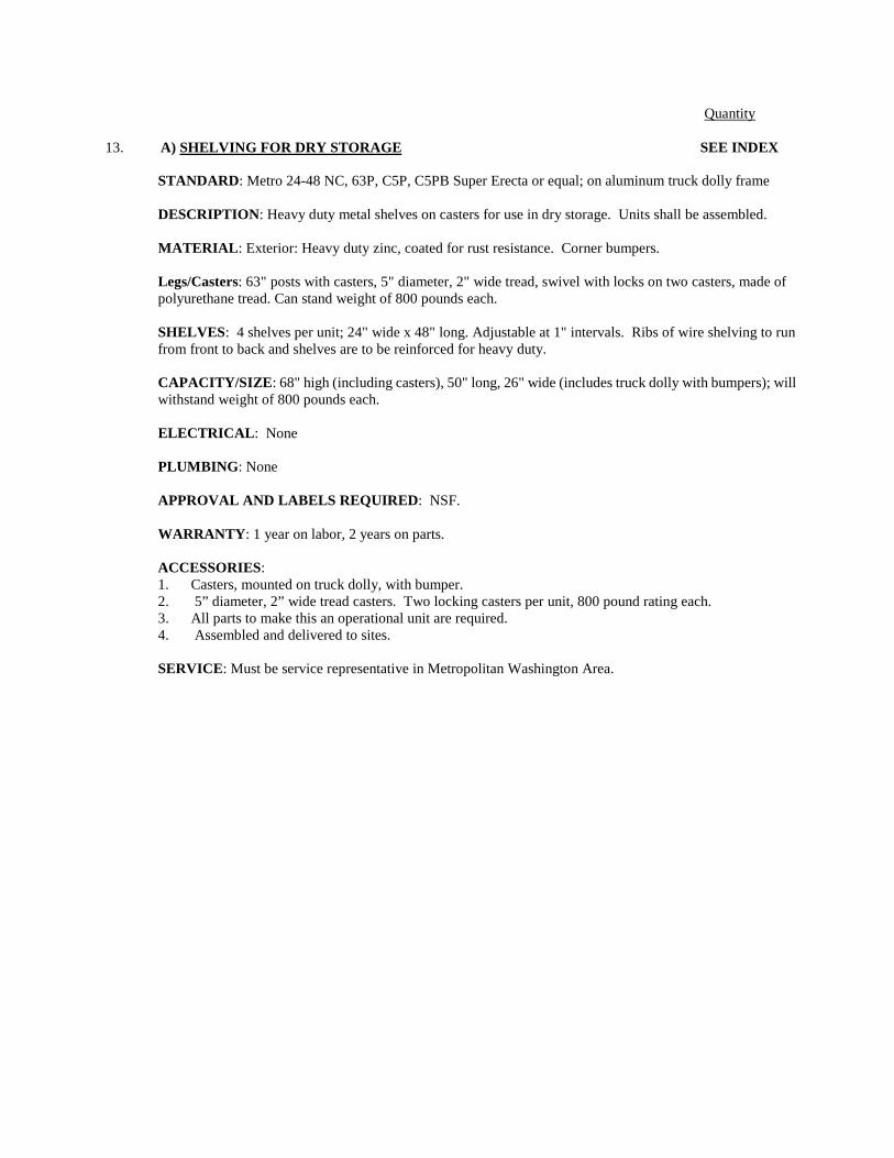
Quantity
13. A) SHELVING FOR DRY STORAGE SEE INDEX
STANDARD: Metro 24-48 NC, 63P, C5P, C5PB Super Erecta or equal; on aluminum truck dolly frame
DESCRIPTION: Heavy duty metal shelves on casters for use in dry storage. Units shall be assembled. MATERIAL: Exterior: Heavy duty zinc, coated for rust resistance. Corner bumpers. Legs/Casters: 63" posts with casters, 5" diameter, 2" wide tread, swivel with locks on two casters, made of polyurethane tread. Can stand weight of 800 pounds each. SHELVES: 4 shelves per unit; 24" wide x 48" long. Adjustable at 1" intervals. Ribs of wire shelving to run from front to back and shelves are to be reinforced for heavy duty. CAPACITY/SIZE: 68" high (including casters), 50" long, 26" wide (includes truck dolly with bumpers); will withstand weight of 800 pounds each. ELECTRICAL: None PLUMBING: None APPROVAL AND LABELS REQUIRED: NSF. WARRANTY: 1 year on labor, 2 years on parts. ACCESSORIES: 1. Casters, mounted on truck dolly, with bumper. 2. 5” diameter, 2” wide tread casters. Two locking casters per unit, 800 pound rating each. 3. All parts to make this an operational unit are required. 4. Assembled and delivered to sites. SERVICE: Must be service representative in Metropolitan Washington Area.
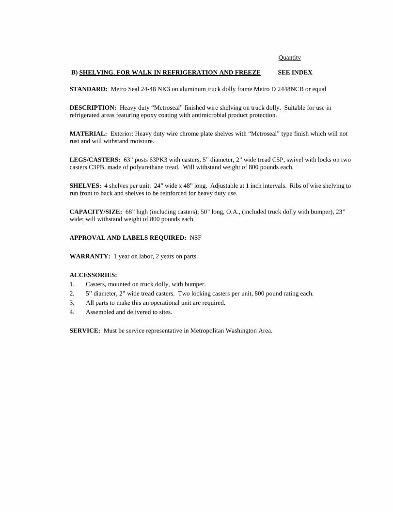
Quantity
B) SHELVING, FOR WALK IN REFRIGERATION AND FREEZE SEE INDEX
STANDARD: Metro Seal 24-48 NK3 on aluminum truck dolly frame Metro D 2448NCB or equal DESCRIPTION: Heavy duty “Metroseal” finished wire shelving on truck dolly. Suitable for use in refrigerated areas featuring epoxy coating with antimicrobial product protection. MATERIAL: Exterior: Heavy duty wire chrome plate shelves with “Metroseal” type finish which will not rust and will withstand moisture. LEGS/CASTERS: 63” posts 63PK3 with casters, 5” diameter, 2” wide tread C5P, swivel with locks on two casters C3PB, made of polyurethane tread. Will withstand weight of 800 pounds each. SHELVES: 4 shelves per unit: 24” wide x 48” long. Adjustable at 1 inch intervals. Ribs of wire shelving to run front to back and shelves to be reinforced for heavy duty use. CAPACITY/SIZE: 68” high (including casters); 50” long, O.A., (included truck dolly with bumper), 23” wide; will withstand weight of 800 pounds each. APPROVAL AND LABELS REQUIRED: NSF WARRANTY: 1 year on labor, 2 years on parts. ACCESSORIES: 1. Casters, mounted on truck dolly, with bumper. 2. 5” diameter, 2” wide tread casters. Two locking casters per unit, 800 pound rating each. 3. All parts to make this an operational unit are required. 4. Assembled and delivered to sites. SERVICE: Must be service representative in Metropolitan Washington Area.

Quantity
14. DOUBLE CONVECTION OVEN, NATURAL GAS SEE INDEX
STANDARD: Blodgett DFG-200 Double electric or equal. DESCRIPTION: Double-deck gas all-purpose convection oven, to have two independent porcelainized steel oven cavities, with one halogen light in each cavity. EXTERIOR: Full angle iron frame. Top, front, and sides to be heavy gauge stainless steel, heat resistant. Oven front to be polished stainless steel. INTERIOR: Double sided porcelanized enamel on steel liner baking compartment. LEGS: Adjustable 6” stainless steel legs. DOORS: Depended stainless steel doors with simultaneous door operation. Dual pane thermal glass windows. Safety switch that turns off fan when doors are opened. Seal must be stainless steel. INSULATION: High density K-Fac insulation.
SHELVES: Five (5) removable chrome-plated steel racks per oven chamber, eleven positions on guide in each oven chamber with minimum of 1-5/8” spacing. FANS: To be powered by 1/3 HP motor that is serviceable from the front and has two-speed fan. CAPACITY/SIZE: Oven shall accept five 18” x 26” pans in right to left or front to back position. FLOOR SPACE: 38 ¼” wide, 36-7/8” deep, 65” high. COLOR: Top, sides and door stainless steel. ELECTRICAL: 2 wire with Ground, 6 amp, 115 VAC, 1 phase, 60Hz, ½ HP, 2 speed motor, 1120 and 1710 RPM, 120,000 BTU=s/hr (60,000 each section). ACCESSORIES: 1. Two speed motor 60 Hz. 2. Solid state time & controls. Electric timer & buzzer. 3. Calibration of temperature gauge on location. 4. 2 user manuals. 5. 1 oven light per cavity. APPROVAL AND LABELS REQUIRED: NSF and AGA
WARRANTY: 1 year on parts & labor, 5 year limited oven doors.
SERVICE: Must be a service representative in the Metropolitan Washington D.C. Area.

Quantity
15. COMBINATION-OVEN/STEAMER, ELECTRIC SEE INDEX
STANDARD: Blodgett Model BCX 14E single oven, with boiler and 25” legs. (NO SUBSTITUTION). DESCRIPTION: Steam/oven combination that cooks with pressureless steam, hot air, or combination of steam and hot air and cool down. Generator shall be separated from the cooking compartment. Steam generator shall drain and flush automatically. Capacity: 14 steam table pans; or 7 full sheet pans; 5 stainless steel wire racks per section. Start up inspection service. MATERIAL: Constructed entirely of stainless steel. Fully welded stainless steel frame. Dual pane tempered viewing window with hinged inner glass for easy cleaning. Large doors, right hand glass door with condensate drip pan and door interlock switch that automatically shuts off fan with door is opened. SHELVES: Five stainless steel wire shelves per station. Unit can accept full size sheet pans. ELECTRICAL: 480/18.4 –3phase. WATER: 40 PSI/minimum and 50/PSI maximum. ¾” hose cold water. 2” drain connection. CAPACITY/SIZE: 33”H x 40 ½ ” W x 34 5/8”D (Excluding stand). APPROVAL LABELS REQUIRED: UL listed, USDA accepted; CUL listed, NSF Certified. ACCESSORIES:
1. Leg 25” (635mm) adjustable legs 2. Hose: retractable hose reel and spray assembly; pump. 3. Side shield. 4. Halogen lights for supervisor cavity illumination. WARRANTY: 2 years on labor and parts.
SERVICE: Must be a service representative in the Metropolitan Washington Area.

Quantity
16. OVEN/STEAMER, COMBINATION – GAS, SINGLE, SEE INDEX
STANDARD: Blodgett Model BCX-14G, Gas, with boiler an 25” legs. (NO SBUSTITUTION) DESCRIPTION: Oven/steamer that cooks with pressure less steam, hot air, or combination of steam and hot air and cool down. Generator shall be separated from the cooking compartment. Steam generator shall drain and flush automatically. Capacity: 14 steam table pans; or 7 full sheet pans; 5 stainless steel wire racks per section. Start up inspection service. MATERIAL: Constructed entirely of stainless steel. Fully welded stainless steel frame. Dual pane tempered viewing window with hinged inner glass for easy cleaning. Large doors, right hand glass door with condensate drip pan and door interlock switch that automatically shuts off fan with door is opened. SHELVES: Five stainless steel wire shelves per station. Unit can accept full size sheet pans on stainless steel
wire racks
GAS: Max BTU input 90,000, ½” NPT Gas Inlet, Nat-7” WC static to unit. NEMA 5-15, 115v/15 Amp.
ELECTRICAL: 115/120 VAC; 1 phase, 60 Hz 15-20 amp circuit required.
WATER SUPPLY: 40 PSI/minimum and 50/PSI maximum. ¾” hose cold water. 2” drain connection.
CAPACITY/SIZE: 33”H x 40 ½ ” W x 34 5/8”D (Excluding stand).
APPROVAL LABELS REQUIRED: UL; USDA accepted; CUL; NSF; ANSI
ACCESSORIES: 1. Floor stand with rack supports. 2. Stand mount casters. 3. Two additional stainless steel wire shelves. 4. Extended warranty. 5. Hose: retractable hose reel and spray assembly. 6. Side shield 7. Halogen lights for supervisor cavity illumination. SERVICE: Must be a service representative in the Metropolitan Washington D. C. area.

Quantity 17. REFRIGERATOR, ROLL-THROUGH SEE INDEX
STANDARD: Delfield SSRRTI-S or equal. DESCRIPTION: Self-contained, two full door switch locks, dial thermometer indicator on exterior of unit, power "on" indicator on unit. MATERIAL: Exterior: Stainless Steel. INTERIOR: Aluminum INSULATION: Minimum of 2 inches polyurethane frothed cellular insulation poured into place, bonded to shell and liner. SHELVES: None CAPACITY/SIZE: 38 cu. ft. storage. ELECTRICAL: 115/60/ single phase, 1/3 HP, 2,200-2,500 BTU's, 90º ambient temperature, 25º F evaporated temperature. Interior incandescent light, automatically controlled through a switch mounted in the door. APPROVAL AND LABELS REQUIRED: NSF. WARRANTY: 5 year compressor and two year parts and labor. Warranty on all components and the cabinet. ACCESSORIES: 1. Provide door lock and two sets of keys. 2. Item 18 must fit. Each section can accommodate 22" x 27" x 65" storage rack. 3. Two operation manuals. 4. Each door has two edges mount, self closing cam lift style hinges. Door can be removed without tools. 5. R404A or R134A refrigerant used, and maintains temperature between 33°F + 40°F during heavy use.

Quantity 18. STORAGE RACK FOR ROLL IN REFRIGERATOR AND HEATED CABINET SEE INDEX
STANDARD: Metro Mobile Model RF13N DESCRIPTION: Mobile storage rack for 18” x 26” pans that will fit into Delfield SSRT1-S refrigerator. MATERIAL: Rack to be high strength extruded aluminum with 5” swivel type casters. Load capacity of 200 pounds each caster. SHELVES: 64” high x 21 ¼” wide x 26” deep. Holds 18” x 26” pans. Shelf space 1 ½ inches.

Quantity
19. ROLL THROUGH HEATED CABINET SEE INDEX
STANDARD: Delfield SSHRT1-S DESCRIPTION: Self-contained. Two full door switch locks, electric heated. Full heat of 200ºF. Humidity control dial thermometer on exterior of cabinet. Power “on” indicator on unit. EXTERIOR: Stainless steel. INTERIOR: Stainless steel interior, ends, door drum, housing trim, entrance ramp and floors. Magnetic gasket and stainless steel breaker strips around door opening. Interior incandescent light, automatically controlled through a switch mounted on the door. INSULATION: Minimum of 2 inches polyurethane rigid foam, expanded and bonded in place. ELECTRICAL: 208/115/60/1, 7.8 amps APPROVAL AND LABELS REQUIRED: NSF and UL WARRANTY: Two year on parts and labor. ACCESSORIES: 1. Provide door lock and two sets of keys. 2. Item 9 (Roll in Rack) must fit each section to accommodate 22” x 27” x 65” storage rack. 3. Tow operation manuals. 4. Each door has two edges mount, self-closing cam lift style hinges. Doors can be removed without
tools.

Quantity 20. REFRIGERATOR, REACH-IN SEE INDEX
STANDARD: Delfield SSR2-S Stainless exterior and interior full door.
DESCRIPTION: Self-contained, two full doors, front opening unit. Fan circulated air. Automatic defrosting and evaporation system. Refrigeration system located on top of cabinet.
MATERIAL:
EXTERIOR: Stainless steel.
INTERIOR: Cabinet liner is stainless steel, interior incandescent light, automatically controlled through a switch mounted in the door.
INSULATION: Minimum of 2-inch polyurethane foam insulation, poured into place, bonded to shell and liner.
SHELVES: To be adjustable at one-inch intervals.
CAPACITY/SIZE: 51-52 cubic feet of storage space. 56" wide, 32"-36" deep; and 81"-84 1/2" high (including legs).
COLOR: Stainless steel.
ELECTRICAL: 115 volts; 60 cycles; starting 9.5 amps; single phase; ½-¾ hp; ambient temperature; 20°F evaporated temperature; 5-15P Nema plug
Transformer to be factory installed.
APPROVAL AND LABELS REQUIRED: NSF and UL.
PLUMBING: None.
ACCESSORIES:
1. LED digital display thermometer on exterior of unit, very visible and permanently adhered to unit. 2. Heavy-duty wire shelves that are rust resistant and will withstand heavy use. Quantity: 10 shelves. 3. Full solid stainless steel doors. 4. Heavy duty, chromium-plated handles, with positive action hinge mechanism, magnetic gaskets and
cylinder locks on all doors. 5. Casters: 6-inch heavy duty, swivel with locking brakes. 6. Each door has two edge mount, self closing can lift style hinges. Doors can be removed without tools.
WARRANTY: Five year in compressor, two on parts and labor.

Quantity 21. FREEZER (2-DOOR) SEE INDEX
STANDARD: Delfield SSF2-S or equal.
DESCRIPTION: Self-contained, two full doors, front opening unit. Fan circulated air. Automatic defrosting and evaporation system. Refrigeration system located on top of cabinet.
EXTERIOR: Stainless steel.
INTERIOR: Stainless steel. LEGS: Heavy duty, 6” casters. Cabinet liner is stainless steel, interior incandescent light, automatically controlled through a switch mounted in the door.
INSULATION: Minimum of 2-inch polyurethane foam insulation, bonded to shell and liner.
SHELVES: To be adjustable at one-inch intervals.
CAPACITY/SIZE: 50-52 cubic feet of storage space. 52" wide, 30"deep; and 80"-82" high (including legs).
COLOR: Stainless steel.
ELECTRICAL: 115 volts; 60 cycles; 14.3 amps; single phase; 1hp; transformer to be factory installed.
Transformer to be factory installed. PLUMBING: None.
APPROVAL AND LABELS REQUIRED: NSF and UL.
ACCESSORIES:
1. LED digital display thermometer on exterior of unit, very visible. Calibrated adjustment. Power or indicator
2. Heavy-duty wire shelves that are rust resistant and will withstand heavy use. Quantity: 10 shelves with clips.
3. Full solid stainless steel doors. 4. Heavy duty, chromium-plated handles, with positive action hinge mechanism, magnetic gaskets and
cylinder locks on all doors and two sets of keys.
WARRANTY: Two years on labors and parts.

Quantity
22. WORK TABLE SEE INDEX
STANDARD: Advance Tabco SS-306 MOD or equal. DESCRIPTION: Basic Stainless steel work table with one-drawer and under shelf, on casters. All corners should be smooth and all edges ground and polished. EXTERIOR: 14 gauge 18-8 stainless steel with 1 ½” roll front and back and square side edges . CASTERS: Four 5” polyurethane, locking brakes on two casters at opposite corners.
SHELVES: Stainless steel solid under shelf, 10” above the floor. DRAWER: 20” x 20” x 5” deep, stainless steel drawer (front and bowl) on ball bearing shelves with limit stops. CAPACITY/SIZE: 72” long x 30” wide, x working height 34” high. COLOR: Stainless steel. APPROVAL AND LABELS REQUIRED: NSF WARRANTY: 1 year parts and labor. ACCESSORIES: 1. Stainless steel drawer with durable runners. 2. Four 5” casters with two brakes. 3. Stainless steel solid under shelf. 4. Unit to be fully assembled. 5. HD Caster set. 6. All welded set up. 7. All welded drawer runner. SERVICE: Must be a service representative in the Metropolitan Washington D.C. Area.

Quantity 23. MOBILE FOOD TRANSPORT CABINET SEE INDEX
STANDARD: Metro C599-SDC-U DESCRIPTION: Rapid head up and recovery times, and precise humidity control, are achieved with a digitally controlled dual element ducted heating and humidity system. Intelligent power distribution maximizes efficiency and assures food is held at the desired temperature. Low water sensor and low temperature alarm assure cabinet is performing safely. CONSTRUCTION: Stainless steel and aluminum. Doors are lift off and field reversible. DOORS AND LATCHES: Glass doors are fully insulated double panel construction (Dutch clear door). Clear doors are double pane tempered glass, Argon filled with low-E coating. Chrome plated, high strength magnetic pull latch with lever-action release. CASTERS: 5" donut neoprene wheels, double ball bearing swivel, ball bearing axle, nickel plated, two with brake. 3" rubber caster on Under Counter models. TRAY SLIDES: 1½" x ½" x 0.63" extruded aluminum channel slides on 0.63" aluminum vertical standards. Universal slides hold 18"x26"sheets pans or 12"x20 steam table pans on adjustable 1½ increments. CONTROLLED HUMIDITY HEATED HOLDING/PROOFING CABINET: Measures and display actual cabinet temperature; easy to use controls that anyone can understand; measures and displays actual cabinet relative humidity; 9 series controller generates heat before humidity for food safety; feature that indicates when water is needed; assures cabinet is operating at desired temperature, view setting at the touch of a button.
ELECTRICAL: NEMA 5-20P, 120 volts; 2,000 watts; 60 cycles; 16 amps, 60Hz single phase 71/2 foot extension power cord and plug. PLUMBING: None. APPROVAL AND LABELS REQUIRED: NSF, UL and Energy Star ACCESSORIES/OPTIONS: 1. Brakes, locking (set of two). 2. Heavy duty full perimeter bumper, push handles. WARRANTY: Limited one year parts, 90 days labor. SERVICE: Must be service representative in Metropolitan Washington area.

Quantity 24. PAN RACK SEE INDEX
STANDARD: Kelmax 4J0075 DESCRIPTION: Medium duty pan racks with rounded tops and reinforced gussets for greater strength; opening holds 18’ x 26” sheet pans. Provide 5” polyurethane swivel casters with two locking devices on two wheels. 304 pound capacity. 16 gauge stainless steel construction. CAPACITY SIZE: 21” x 26” x 69” APPROVAL AND LABELS REQUIRED: NSF WARRANTY: One year labor, two years parts.

Quantity
25. UTILTY CART SEE INDEX STANDARD: Lakeside 492, or equal
DESCRIPTION: Assembled stainless steel tubular utility cart w/2 stainless steel solid shelves and one handle, 500 lb capacity. MATERIAL: Stainless steel posts and shelves. Donut bumpers on wheels. SHELVES: Two shelves, stainless steel, flat, solid. CAPACITY/SIZE: 21” x 33” x 21 ½” COLOR: Stainless steel. APPROVAL AND LABELS REQUIRED: NSF. WARRANTY: One year on labor and parts.
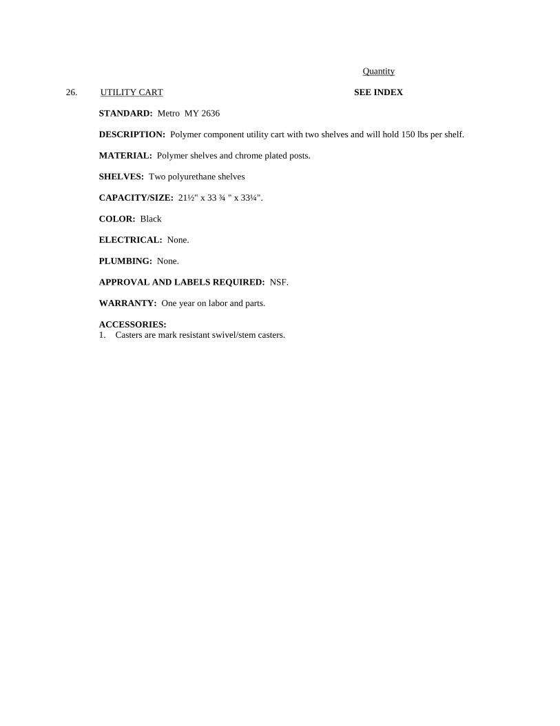
Quantity 26. UTILITY CART SEE INDEX
STANDARD: Metro MY 2636 DESCRIPTION: Polymer component utility cart with two shelves and will hold 150 lbs per shelf. MATERIAL: Polymer shelves and chrome plated posts. SHELVES: Two polyurethane shelves CAPACITY/SIZE: 21½" x 33 ¾ " x 33¼". COLOR: Black ELECTRICAL: None. PLUMBING: None. APPROVAL AND LABELS REQUIRED: NSF. WARRANTY: One year on labor and parts. ACCESSORIES: 1. Casters are mark resistant swivel/stem casters.

Quantity 27. BOW TIE DUNNAGE RACK SEE INDEX
STANDARD: Metro HP 2230PD, HP2236PD, HP2248PD, and HP2260 PD
DESCRIPTION: Bow Tie Dunnage rack join together end to end or back to back Molded grey poly ethylene construction, 22” x 36” long; 12” high; slotted top for air circulation; slots run front to back for easy loading and unloading. Each rack provided with separate polymer tie for joining racks in “end to end” and “back to back” configurations. No assembly required.
MATERIAL: Molded grey polyethylene construction INSULATION: N/A SHELVES: Single shelf
CAPACITY: minimum 1500 pounds SIZE: 36” OR 48” length x 22” wide x 12” height
APPROVAL AND LABELS REQUIRED: NSF.

Quantity 28. WASHER SEE INDEX
See Spec Section 11452 for Washer specifications.

Quantity
29. DRYER SEE INDEX See Spec Section 11452 for Dryer specifications.

Quantity 30. LOCKERS AND BENCH SEE INDEX
See Spec Section 10505 for Lockers and Benches specifications.

Quantity
31. COMPUTERIZED POINT OF SALE SEE INDEX
WITH HP COMPATIBLE COMPUTER WITH MODEM IN MANAGER'S OFFICE (N.I.C) STANDARD: SNAP
DESCRIPTION: A new school is going to need a computer in the manager's office and SNAP cash register terminals on all the serving lines.
COMPUTER EQUIPMENT ITEM: Computer, HP Vectra Model VLI 8 Mid Size Desktop
(8.4 GB Hard Drive Memory, 128MB) 1 Monitor, 17" SVGA Color Display 1 W/ 10T/100T Network Card 1 Printer, Epson, FX-880 1
SNAP EQUIPMENT: SNAP Terminal for each serving line, Model 4.0. 5 total SNAP Bar Code Reader for each serving line. 5 total SOFTWARE: System Master Program. 1 Point of Sale. 1 Free & Reduced Meals. 1 Communications. 1 Purchasing and Inventory. 1 ELECTRICAL: 110 volts, 60 cycles, 4 amps. Required dedicated electrical line.
11452-1 11/15
SECTION 11452
RESIDENTIAL APPLIANCES PART 1 – GENERAL 1.01 RELATED DOCUMENTS
A. Drawings and general provisions of the Contract, including General Conditions and Division One Specifications Sections, apply to the Work of this Section.
1.02 DESCRIPTION OF WORK
A. Extent of required residential appliances is indicated on the equipment plans and equipment schedules shown on the Drawings. Equipment includes, but is not limited to, the following:
1. Ranges 2. Cooktops 3. Overhead Microwave Ovens with light and false exhaust hoods 4. Refrigerator/Freezers 5. Dishwashers 6. Clothes Washers 7. Clothes Dryers 8. Garbage Disposers
B. Plumbing requirements (water service, drainage and venting) and connections
are covered under the Work of Division 15. C. Electrical Service and connections are covered under the Work of Division 16. D. Hood system: All hoods above the range shall have underside light with false
exhaust system. Location for the exhaust and light switches at Handicapped stations MUST be accessible. Coordinate with Division 15 for ducted exhaust system.
1.03 QUALITY ASSURANCE
A. Certification Labels: Provide appliances which comply with the standards listed below, and which bear certification labels as follows:
1. Energy ratings: Appliances shall have “Energy Guide” labels with energy
cost analysis (annual operating costs), and efficiency information in accordance with Federal Trade Commission (FTC) requirements.
2. The following equipment shall have “Energy Star” labels indicating
compliance with the Department of Energy (DOE) and the Environmental Protection Agency (EPA) “Energy Star” Program:

RESIDENTIAL APPLIANCES SECTION 11452
11452-2 11/15
a. Clothes Washers b. Dishwashers c. Refrigerator/Freezers d. UL and NEMA compliance: Appliances shall have electrical
components listed and labeled by UL and complying with applicable NEMA standards.
B. Single Source: Provide products by the same manufacturer for each type of
appliance indicated on the Drawings. 1.04 SUBMITTALS
A. Product Data: Submit manufacturer’s written specifications and product data for each appliance indicated on the Drawings.
B. Installation Instructions: Submit manufacturer’s written installation instructions.
C. Provide manufacturer’s written recommended operating and maintenance
instructions.
D. Submit data indicating compliance with certifications and labeling as required by 1.03.
E. Provide copies of manufacturer’s standard warranty for each appliance.
1.05 DELIVERY, STORAGE AND HANDLING
A. Deliver appliances only after utility rough-ins are complete, and the spaces designated to receive the appliances are fully enclosed and substantially complete.
B. Deliver and store appliances in manufacturer’s original, undamaged protective
containers, with all labeling intact and legible, until time of installation. 1.06 WARRANTIES
A. Manufacturer’s standard form, for repair or replacement due to defects in materials and workmanship, within the specified warranty period.
PART 2 – PRODUCTS 2.01 ACCEPTABLE MANUFACTURERS
A. Products by the following manufacturers shall be acceptable, subject to the requirements of the Drawings and this Section.
1. General Electric Company (www.geappliances.com) 2. Frigidaire (www.fridgidaire.com)

RESIDENTIAL APPLIANCES SECTION 11452
11452-3 11/15
3. Kenmore (www.contractsales.sears.com) 4. Maytag (www.maytag.com) 5. Whirlpool (www.whirlpool.com) 6. Other manufacturer(s), pre-bid approved in accordance with Section
01630. 2.02 MATERIALS
A. Colors: Provide manufacturer’s standard colors for selection by the Architect. Where appliances by more than one manufacturer shall be provided for the same space, units shall be color matched as closely as possible.
2.03 EQUIPMENT SCHEDULES
A. Manufacturers and exact catalog numbers are indicated in the equipment schedules shown on the Drawings, and are the basis of design and standard of quality for the required appliances and accessories.
PART 3 – EXECUTION 3.01 INSPECTION
A. Prior to installation, inspect the spaces designated to receive the appliances. Verify that the correct service connections are available for proper function of the appliances that dimensional clearances are within acceptable manufacturer tolerances for proper fit and operation of the appliances, and that rough openings will be completely concealed. Notify Owner’s Representative and Architect if any such deficiencies are encountered. Do not begin until such deficiencies are corrected.
3.02. INSTALLATION
A. General: Comply with manufacturer’s written installation instructions. B. Built-in Appliances: Securely anchor units to supporting cabinetry or countertops
with concealed fasteners.
C. Free-standing Appliances: Place units in final locations only after room finishes have been completed.
D. Utilities: Coordinate with Divisions 15 and 16 for plumbing and electrical
requirements, respectively. Provide all pigtails, cords, plugs and outlets necessary to provide proper connection and operation of appliances.
3.03 TESTING, ADJUSTMENT AND CLEANING
A. Test each appliance in accordance with the manufacturer’s written instructions, in order to verify proper operation. Make adjustments if required.

RESIDENTIAL APPLIANCES SECTION 11452
11452-4 11/15
B. Accessories: Verify that each appliance has been furnished with accessories consistent with specified catalog number of each unit.
C. Cleaning: Clean all installed appliances. Remove all packaging from the
premises, and dispose of legally. 3.04 DEMONSTRATION
A. Demonstrate proper operation of appliances in the presence of the Owner’s operating personnel.
END OF SECTION

11454-1 11/15
SECTION 11454
ATHLETIC LAUNDRY EQUIPMENT
PART 1 - GENERAL 1.01 RELATED DOCUMENTS
A. Drawings and General Provisions of Contract including General Conditions and Division 1 Specification Sections apply to the Work of this Section.
1.02 DESCRIPTION OF WORK
A. The extent of commercial laundry equipment is indicated on the drawings. 1.03 QUALITY ASSURANCE
A. Manufacturer’s Qualifications: 10 years minimum experience manufacturing athletic laundry equipment with a history of successful production, delivery and low maintenance acceptable to the Architect and the Owner.
1.04 SUBMITTALS
A. Manufacturer’s Data: Submit the manufacturer's data and installation instruction for each piece of equipment. Include rough-in details.
B. Samples: Submit full range of manufacturer’s standard color chips for color
selection by the Architect. 1.05 PRODUCT HANDLING
A. Coordinate delivery of equipment with construction schedule in order to ensure timely installation.
B. Store laundry equipment in secure, dry interior environment, in original factory
cartons, and with original packaging intact, until ready to set in final location. Once installed, cover or otherwise protect as necessary until time of final acceptance by Owner’s Representative.
1.06 WARRANTY
A. Washer – Extractor:
1. Five (5) years on frame, back gable and wash cylinder. 2. Two (2) years on main drive motor and other parts.
B. Dryer: Two (2) years on all parts.

ATHLETIC LAUNDRY EQUIPMENT SECTION 11454
11454-2 11/15
PART 2 - PRODUCTS 2.01 ACCEPTABLE MANUFACTURERS
A. Belco Athletic Laundry Equipment Company, P.O. Box 241655, Charlotte, NC 28224-1655, (1-704-525-2077) shall be the basis of this specification.
B. Other manufacturers, pre-bid approved in accordance with Section 01630, shall
be acceptable. 2.02 EQUIPMENT
A. Washer – Extractor:
1. Belco “60:, 60 pound capacity (Middle Schools) 2. Belco “80”, 80 pound capacity (High Schools)
(This model requires a clear door opening of 39” minimum)
B. Dryer (Gas or Electric)
1. Belco “50”, 50 pound capacity (Middle Schools).
2. Belco “75”, 75 pound capacity (High Schools). (This model requires a clear door opening of 39” minimum)
C. Washer – Extractor Features:
1. Galvanized steel frame. 2. Stainless steel tubs, back gable and front panels. 3. All-automatic controls.
4. Automatic soap dispenser.
5. “Soak” period incorporated into wash cycle.
6. Extractor force shall be less than 90 G’s.
7. “Normally closed” drain valve.
8. Drive and motor bearings shall be permanently lubricated.
9. Motor drive belt: tensioning shall be self-adjusting. 10. Water inlet valves shall be self-cleaning.

ATHLETIC LAUNDRY EQUIPMENT SECTION 11454
11454-3 11/15
11. Electrical Characteristics: 208/240V, 3-phase (standard voltage). UL
listed.
12. Accessories: Belco 6” high steel mounting base with predrilled holes.
D. Dryer Features
1. AGA approved (gas model) 2. All automatic controls
3. Temperature controls for 100°F, 140°F, and 180°F settings.
4. Fully enclosed insulated cabinet with preheating chamber.
5. Fully enclosed fan cooled motor: (3/4 HP, 800 CFM for
“50” model; 1 HP, 1000 CFM for “75” model).
6. Dryer cabinet: Baked-on paint coating on all surfaces (interior and exterior).
7. Aluminized steel ovens and bases.
8. Lint compartment shall not be lockable.
9. Electric Heat: Electrical characteristics: 480V, 3 phase (40 Amps for “50”
model; 40 Amps for “75” model). UL listed
10. Gas Model: 130,000 BTU per hr (“50” model) or 175,000 BTU per hour (“75” model)
PART 3 - EXECUTION 3.01 INSPECTION
A. Inspect the work premises prior to beginning work. Notify Architect and Owner’s Representative of any conditions that would adversely affect proper work performance and equipment installation. Do not begin work until such conditions have been corrected.
3.02 INSTALLATION
A. General: Install appliances and equipment plumb, level, rigid and securely anchored to concrete foundation in accordance with manufacturer’s written installation instructions.
B. Moving Parts: Check carefully to ensure smooth and accurate operation.
ATHLETIC LAUNDRY EQUIPMENT SECTION 11454
11454-4 11/15
C. Clean all surfaces including both sides of view glass. D. Damaged Work: Repair equal to new undamaged work, or replace with new
units or components acceptable to the Owner’s Representative (Note: repairs shall be in accordance with manufacturer’s requirements, and shall not void warranties).
E. Rough-in and connections shall be provided under Division 15 and 16. See
Mechanical, Plumbing and Electrical Drawings and details. 3.03 CLEANING
A. Remove all excess materials and debris associated with the work of this Section, and dispose of legally off-site.
END OF SECTION

11470-1 11/15
SECTION 11470
PHOTO LAB EQUIPMENT
PART 1 - GENERAL 1.01 RELATED DOCUMENTS
A. Drawings and General Provisions of Contract, including General Conditions and other Division 1 Specification Sections, apply to the Work of this Section.
1.02 DESCRIPTION OF WORK
A. Work of this Section includes all labor, materials, equipment and services necessary to complete the Photo Lab equipment installation as shown on the drawings and specified herein, including but not limited to, the following:
1. Installation of equipment, casework (enlarger stations & print drying
cabinets), sinks, accessories and mechanical and electrical service fixtures in association with casework installed by others.
2. Service fixtures are supplied as part of this work. Field connections of
service fixtures are included under mechanical work of Division 15 and electrical work of Division 16.
1.03 RELATED WORK
A. Section 12304: Plastic Laminate Faced Casework and Fixtures. B. Division 15: Mechanical roughing and connections. C. Division 16: Electrical service and connections.
1.04 SUBMITTALS
A. Product Data: Submit manufacturer's product specifications and installation instructions for each item. Include elevations of equipment showing rough-in dimensions, equipment size, types and locations of service connections and utility requirements.
B. Shop Drawing Submittals: Submit plans, elevations, ends, cross-sections and
details of items and of assembled units made up of manufactured equipment; show all associated casework. Include rough-in plan showing required services and connections by size and locations.
C. Samples: Submit actual material samples of exposed finishes for both
manufactured and custom fabricated equipment.

PHOTO LAB EQUIPMENT SECTION 11470
11470-2 11/15
1. Submit full-size samples of units and accessories when requested by Architect.
D. Color Selection: Submit full line of manufacturer’s actual material samples
where finish choices are available. 1.05 QUALITY ASSURANCE A. Single Source Responsibility: Provide Photo Lab equipment manufactured or
furnished by same company for single responsibility. Darkroom equipment manufacturer must have at least (10) years experience in the fabrication and installation of similar projects.
B. The use of catalog numbers, and specific requirements set forth in drawings and
specifications are not intended to preclude the use of any other acceptable manufacturer’s product which may be equivalent, but are given for purpose of establishing standard of design and qualify for materials, construction and workmanship.
1.06 DELIVERY, STORAGE, AND HANDLING
A. Deliver Photo Lab equipment only after wet operations in building are completed. B. Store Photo Lab equipment and accessories in a ventilated place, protected from
the weather, with relative humidity therein of 50% or less at 70 deg .F C. Protect finished surfaces from soiling and damage during handling and
installation. Keep covered with protective covering. 1.07 WARRANTIES
A. Equipment Warranty: Provide a written warranty indicating all work of this Section will be free from defects in material and workmanship for a period of one year after Substantial Completion, and that repairs or replacements of said defects shall be performed in a timely manner at no expense to the owner.
B. Sink Unit Warranty: Fiber laminated products shall be free of defects in
workmanship and material for two years from date of Substantial Completion. PART 2 - PRODUCTS 2.01 ACCEPTABLE MANUFACTURERS
A. Manufacturers offering products to comply with requirements for laboratory equipment and casework (enlarger stations) include but are not limited to the following:

PHOTO LAB EQUIPMENT SECTION 11470
11470-3 11/15
1. Need to find a new company (Try to confirm DarkRoom USA,) (Basis of Design), .
2. Other pre-bid approved manufacturers will be considered in accordance
with Section 01630. 2.02 CASEWORK
A. See Section 12304: Plastic Laminated Faced Casework and Fixtures for cabinets, countertops and splashes.
2.03 SINK UNIT (GLASS FIBER LAMINATED) FABRICATION
A. General:
1. Factory finished units manufactured of blend of resins developed especially to resist the corrosive effects of rapid fixers, color bleaches, iron chlorides, and other chemicals required in photographic and graphic arts processing.
2. Hand lay-up each unit for molded one-piece fabrication using highly
polished molds to produce smooth homogeneous surface with radius outside and inside corners.
3. Construct sink bottom to ensure positive drainage while supporting
processing trays and tanks in level position.
4. Remove traces of materials, which may be toxic or incompatible with other building materials.
5. Prepare each unit for installation on cabinet/stand to facilitate quick
assembly and disassembly for installation.
B. Mold each sink unit to develop maximum strength and rigidity in each integral unit with min. 0.25 mm (10 mil) gel coat thickness and min 1525.76g per sq. m (5 oz. per sq. ft.) of glass fiber mat.
C. Apply gel coat in two coats and catalyze with max 2 ½ percent keystone
peroxides, with first coat fully cured before application of second coat.
D. Apply back-up resins and reinforcing in layers, working out bells or voids between gel coat and mat, using extra layers of mat at points of stress.
E. Use minimum 40 percent by weight fiberglass mat content.
F. After completion of required mat layers, bag down sinks under vacuum and roll
out to ensure proper and even distribution of resin.

PHOTO LAB EQUIPMENT SECTION 11470
11470-4 11/15
G. Set and thoroughly cure sink units under min. 5858.92kgh per sq. m (1,200 psf)
pressure and aged to obtain min. 95 percent polymerization of polyester resins.
H. Colors: Select each sink unit color from standard manufacturer’s finishes and cabinet/stand finishes from manufacturer’s standard offerings.
I. Factory Plumbing
1. Plumbing: Each sink unit shall be factory plumbed as shown on the
drawings or specified herein.
a. All faucets, valves, spouts, vacuum breakers, circulation systems, temperature blenders, chilled water systems, compressed air systems, nitrogen systems, etc., shall be factory installed and connected as shown on the drawings or specified herein.
b. Each sink unit shall be factory plumbed for field connection of
required services at the back or end of the unit; see plans for specific locations.
c. All faucets and control bodies shall be heavy-duty brass except
those dedicated to deionized water and/or chemicals, which shall be polyvinyl chloride.
d. All connecting piping shall be heavy-duty copper.
e. All plumbing shall be factory tested at 100 psi hydrostatic
pressure 2.04 ELECTRICAL SERVICE FIXTURES
A. Service Fixtures: Provide factory wired and connected units complete with metal housing or box: necessary receptacles, terminals, switches, pilot lights, device plates: and fitting and gaskets required for mounting on casework. All fixtures UL tested.
PART 3 – EXECUTION 3.01 INSPECTION
A. Examine the areas and conditions where Photo Lab Equipment is to be installed and notify the Architect and the Owner’s Representative of conditions detrimental to the proper and timely completion of the work. Do not proceed with the work until unsatisfactory conditions are corrected to permit proper installation of the work.

PHOTO LAB EQUIPMENT SECTION 11470
11470-5 11/15
3.02 SERVICE FIXTURES AND ACCESSORIES INSTALLALTION
A. Service fixtures and accessories supplied and/or installed as a portion of this work shall be installed in a precise manner in accordance with manufacturer’s directions. Where connections are required to mechanical and electrical lines, the manufacturer is to provide items required for connection, and coordinate the final installation made by the other Contractors.
3.03 CASEWORK INSTALLATION
A. See Section 12304: Plastic Laminated Faced Casework and Fixtures for cabinets, countertops and splashes installation
3.04 CLEANING AND PROTECTION
A Repair or remove and replace defective work as directed upon completion of installation.
B. Clean shop finished surfaces, touch-up required, and remove or refinish
damaged or soiled areas, as acceptable to Architect.
C. Protection: Advise Contractor of procedures and precautions of protection of materials and installed Photo Lab equipment from damage by work of other trades.
3.05 PHOTO LAB EQUIPMENT SCHEDULE
MARK ITEM DESCRIPTION MANUFACTURER / MODEL #
C56 STUDENT ENLARGER STATION KREOLAB / EWS36KDD
w/ SAFELIGHT, DRAWERS & BAFFLE
C57 STUDENT ENLARGER STATION (HC) KREOLAB / EWS36KDH w/ SAFELIGHT, DRAWERS & BAFFLE
C67 PRINT DRYING CABINET KREOLAB / BDO/RCFS-3623 w/ SET OF 8 SCREENS
7 PRINT SQUEEGEE BOARD KREOLAB / 2024SB
8 ILLUMINATED SIGN KREOLAB / KAPA -1 9 SILVER RECOVERY SYSTEM X-RITE / 643
10 SAFE LIGHT (CHAIN HUNG) THOMAS / DUPLEX-DUB
(See Marshall HS Spe)

PHOTO LAB EQUIPMENT SECTION 11470
11470-6 11/15
16 FILM PROCESSOR WING-LYNCH / MODEL 5
17 FILTER UNIT USI / X-RITE 643
18 TANK TEMPERATURE MONITOR WING-LYNCH / MODEL 5
20 ROLL FILM DRYER KREOLAB / RFD20-36
22 DARK ROOM CURTAIN FULLER & D’ALBERT / DCT-02
24 PRINT DRYING ARKAY / RC-2100
25 TRAY SINK w/ HC STAND KREOLAB / 1775E2SH
w/ TWO (2) ADDITIONAL TRAY SINK WATER FAUCETS – SINGLE VALVE TEMPERATURE CONTROL KFC110VB
26 ISLAND SINK w/ HC STAND KREOLAB / 3475ESE1SH
27 ROUND WASHER KREOLAB / 30PWRSH 28 FUME VENTING SYSTEM KREOLAB / WASV-72
END OF SECTION

11480-1 11/15
SECTION 11480
ATHLETIC SCOREBOARDS
(HIGH SCHOOL ONLY) PART 1 — GENERAL 1.01 RELATED DOCUMENTS
A. Drawings and General Provisions of Contract including General Conditions and
Division 1 Specification Sections apply to the Work of this Section. 1.02 DESCRIPTION OF WORK (See drawings for scope or work as it relates to the following
scoreboard and accessories) A. Single-sided LED baseball scoreboard (Baseball) B. Single-sided LED baseball scoreboard (Softball) C. Single-sided LED basketball scoreboard (Main Gym) D. Six-sided LED statistics display (Main Gym) E. Single-sided LED basketball scoreboard (Auxiliary Gym) F. Single-sided LED multisport scoreboard (Stadium)
1.03 REFERENCES
A. Standard for Electric Signs, UL 48 B. Standard for CSA C22.2 #207 C. Federal Communications Commission Regulation Part 15 D. National Electric Code
1.04 SUBMITTALS
A. Product data: Submit manufacturer’s product illustrations, data and literature that fully describe the scoreboards and accessories proposed for installation.
B. Shop drawings: Submit mechanical and electrical drawings. C. Maintenance data: Submit manufacturer’s installation, operation, and
maintenance manuals.
1.05 DELIVERY, STORAGE AND HANDLING A. Product delivered on site
B. Scoreboard and equipment to be housed in a clean, dry environment
1.06 PROJECT CONDITIONS A. Environmental Limitations: Do not install scoring equipment until spaces are
enclosed and weatherproof, wet work in spaces is complete and dry, and
ATHLETIC SCOREBOARDS SECTION 11480
11480-2 11/15
ambient temperature and humidity conditions are maintained at the levels indicated for project when occupied for its intended use.
B. Field Measurements: Coordinate scoreboard location and height with the customer. Verify dimensions by field measurements.
C. Supply weight and mounting method for owner to verify that building structure is capable of supporting the scoreboard’s weight in addition to the auxiliary equipment.
1.07 QUALITY ASSURANCE
A. For indoor use only B. Source Limitations: Obtain each type of scoring equipment and electronic
displays through one source from a single manufacturer. C. ETL listed to UL 48 D. NEC complaint E. FCC complaint F. ETLC listed to CSA 22.2 #207
1.08 WARRANTY
A. Provide 5 years of no cost parts exchange including standard shipping on electronics parts and radios due to manufacturing defects
B. Provide toll-free service coordination
C. Provide technical online and phone support during Daktronics business hours
PART 2 — PRODUCTS 2.01 MANUFACTURER
A. Daktronics, Inc., 201 Daktronics Drive, P.O. Box 5128, Brookings, SD 57006-5128
B. Subject to compliance with requirements and properties of the product listed,
products from other manufacturers will be considered if submitted prior to bid in accordance with the stipulations in the Instructions to Bidders.
2.02 PRODUCT

ATHLETIC SCOREBOARDS SECTION 11480
11480-3 11/15
A. Baseball-Daktronics BA-2125 single-sided baseball scoreboard displays HOME and GUEST team scores for up to 10 innings, total RUNS and HITS to 99 and ERR (errors) to nine for each team, AT BAT to 99, BALL to three, STRIKE to two, OUT to two, and H/E (hit or error) with field position number for the error. Scoreboard can show TIME or PITCH COUNT instead of AT BAT, as well as AT BAT or PITCH COUNT in place of H/E.
B. Softball-Daktronics BA-2019 single-sided baseball scoreboard displays HOME and GUEST team scores for up to 10 innings, total RUNS and HITS to 99 and ERR (errors) to nine for each team, AT BAT to 99, BALL to three, STRIKE to two, OUT to two, and H/E (hit or error) with field position number for the error. Scoreboard can show TIME or PITCH COUNT instead of AT BAT, as well as AT BAT or PITCH COUNT in place of H/E.
C. Main Gym-Daktronics BB-2155 single-sided basketball scoreboard displays period time to 99:59, HOME and GUEST scores to 199, PERIOD to nine, team FLS (fouls) to 19, PLYR (player) number to 99, player FOUL to nine, T.O.L. (time outs left) to nine and indicates possession and bonus. During the last minute of the period, scoreboard displays time to 1/10 of a second. Electronic captions automatically change when volleyball and wrestling modes are selected. Scoreboard can also score any sport requiring a clock, score and period function.
D. Statistic Display for Main Gym-Daktronics SD-2102 statistics display shows
player (PLYR) number to 99, player fouls (FLS) to 9 and player points (PTS) to 99 for five players. Display can also show ACES and KILLS for six players in volleyball mode with included reversible caption panel. Displays sold in pairs for tracking statistics of both teams. Dimensions, weight and power listed below are for a single display.
E. Auxiliary Gym-Daktronics BB-2101 single sided basketball scoreboard displays
period time to 99:59, HOME and GUEST scores to 199, PERIOD to nine and indicates possession and bonus. During the last minute of the period, scoreboard displays time to 1/10 of a second. Scoreboard can also score volleyball, wrestling and any sport requiring a clock, score and period function.
F. Stadium-Daktronics MS-2009 single-sided multisport scoreboard displays period
time to 99:59, HOME and GUEST scores to 99, PERIOD to nine, PLAYER number to 99 and PENALTY time to 9:59 for two players on both teams, and indicates team penalty. During the last minute of the period, the clock displays time to 1/10 of a second.
2.03 BASEBALL/SOFTBALL SCOREBOARD (PROVIDE 1)
A. General Information
1. Dimensions: 7’-0” (2.13 m) high, 25’-0” (7.62 m) wide, 0’-8” (203 mm)
deep 2. Base weight: 875 lb (397 kg) with vinyl captions-options may increase
weight

ATHLETIC SCOREBOARDS SECTION 11480
11480-4 11/15
3. Base power requirement: 900 W with vinyl captions-options may increase wattage
4. Color: provide over 150 colors to choose from B. Construction
1. Alcoa aluminum alloy 5052 for excellent corrosion resistance 2. Scoreboard back, face, and perimeter: 0.063” (1.60 mm) thick 3. Scoreboard top and bottom: 0.125” (3.18 mm) thick
C. Digits
1. LED color: Amber 2. AT BAT, BALL, STRIKE, OUT, and H/E digits: 18” (457 mm) high 3. Inning scores, RUNS, HITS, and ERR digits: 15” (381 mm) high 4. Seven bar segments per digit 5. PanaView® LED digital technology 6. All digits are sealed front and back with weather-tight silicone gel
D. Captions
1. Vinyl applied directly to scoreboard face 2. HOME and GUEST captions: 12” (305 mm) high 3. AT BAT, BALL, STRIKE, OUT, and H/E captions: 10” (254 mm) high 4. Inning numbers, RUNS, HITS, and ERR captions: 8” (203 mm) high 5. Color: standard white or others available upon request
E. Additional Equipment 1. Vinyl striping applied around the scoreboard face 2. Custom team name caption in place of HOME
2.04 BASEBALL/SOFTBALL SCOREBOARD (PROVIDE 1)
A. General Information: 1. Dimensions: 6’-0” (1.83 m) high, 20’-0” (6.10 m) wide, 0’-8” (203 mm)
deep 2. Base weight: 500 lb (227 kg) with vinyl captions-options may increase
weight 3. Base power requirement: 900 W with vinyl captions-options may increase
wattage 4. Color: provide over 150 colors to choose from
B. Construction 1. Alcoa aluminum alloy 5052 for excellent corrosion resistance 2. Scoreboard back, face, and perimeter: 0.063” (1.60 mm) thick 3. Scoreboard top and bottom: 0.125” (3.18 mm) thick

ATHLETIC SCOREBOARDS SECTION 11480
11480-5 11/15
C. Digits: 1. LED color: Amber 2. AT BAT, BALL, STRIKE, OUT, and H/E digits: 15” (381 mm) high 3. Inning scores, RUNS, HITS, and ERR digits: 10” (254 mm) high 4. Seven bar segments per digit 5. PanaView® LED digital technology 6. All digits are sealed front and back with weather-tight silicone gel
D. Captions
1. Vinyl applied directly to scoreboard face 2. HOME and GUEST captions: 12” (305mm) high 3. AT BAT, BALL, STRIKE, OUT, and H/E captions: 8” (203 mm) high 4. Inning numbers, RUNS, HITS, and ERR captions: 6” (152 mm) high 5. Color: standard white or others available upon request
E. Additional Equipment: 1. Vinyl striping applied around the scoreboard face 2. Custom team name caption in place of HOME
2.05 BASKETBALL SCOREBOARD (PROVIDE 2)
A. General Information: 1. Dimensions: 6’-0” (1.83 m) high, 10’-0” (3.05 m) wide, 0’-6” (152 mm)
deep 2. Base weight: 275 lb (125 kg) –options may increase weight 3. Base power requirement: 350 W -options may increase wattage 4. Color: provide over 150 colors to choose from
B. Construction
1. All-aluminum construction 2. Scoreboard back, face, and perimeter: 0.063” (1.60 mm) thick 3. Cabinet withstands high-velocity impact from air-filled sports balls without
the need for protective screens
C. Digits & Indicators:
1. LED digit technology: PanaView® (PV)-discrete LEDs protrude through the scoreboard face
2. Clock and score digits: 13” (330 mm) high 3. PERIOD, FLS, PLYR/FOUL and T.O.L. digits: 10” (254 mm) high 4. Bonus indicators: 4” (102 mm) high 5. Possession arrows: 3” (76 mm) high 6. Clock/colon, PERIOD, PLYR/FOUL and T.O.L. digits and bonus
indicators: amber LEDs

ATHLETIC SCOREBOARDS SECTION 11480
11480-6 11/15
7. Score and FLS digits and possession indicators: red LEDs 8. Seven bar segments per digit
D. Vinyl Captions
1. Vinyl applied directly to scoreboard face 2. HOME and GUEST captions: 6” ( 152 mm) high 3. PERIOD and T.O.L. captions: 4” (102 mm) high 4. Color: standard white or others available upon request
E. Electronic Captions
1. FLS and PLYR/FOUL captions: 6” (152 mm) high 2. Color: amber LEDs
F. Horn
1. Vibrating horn mounted inside the scoreboard cabinet behind the face 2. Sounds automatically when period clock counts down to zero 3. Sounds manually as directed by operator
G. Power Cord
1. Cord is 11’ (3.35 m) long 2. Cord plugs into a standard grounded outlet
H. Additional Equipment
1. Vinyl striping applied around the clock and scoreboard face 2. Custom team name caption in place of HOME 3. Double bonus indicators in place of single bonus indicators
2.06 STATS DISPLAYS (TWO DISPLAYS)
A. General Information: 1. Dimensions: 6’-0” (1.83 m) high, 3’-6” (1.07 m) wide, 0’-6” (152 mm) deep 2. Base weight: 90 lb (41 kg) –options may increase weight 3. Base power requirement: 400 W -options may increase wattage 4. Color: provide over 150 colors to choose from
B. Construction 1. All-aluminum construction 2. Scoreboard back, face, and perimeter: 0.063” (1.60 mm) thick 3. Cabinet withstands high-velocity impact from air-filled sports balls without
the need for protective screens
C. Digits:

ATHLETIC SCOREBOARDS SECTION 11480
11480-7 11/15
1. LED digit technology: PanaView® (PV)-discrete LEDs protrude through the scoreboard face
2. All digits: 7” (178 mm) high 3. PLYR digits: amber LEDs 4. FLS and PTS digits: red LEDs 5. Seven bar segments per digit
D. Captions 1. Vinyl applied to a reversible caption panel 2. All captions: 4” (102 mm) high 3. Color: standard white or others available upon request
E. Power Cord 1. Cord is 11’ (3.35 m) long 2. Cord plugs into a standard grounded outlet
F. Additional Equipment 1. Vinyl striping applied around the scoreboard face 2. One 6” (152 mm) high electronic caption in place of vinyl captions-add 7
lb (3kg) and 50 W
2.07 BASKETBALL SCOREBOARD (PROVIDE 1)
A. General Information: 1. Dimensions: 4’-0” (1.22 m) high, 8’-0” (2.44 m) wide, 0’-6” (152 mm) deep 2. Base weight: 120 lb (54 kg) –options may increase weight 3. Base power requirement: 200 W -options may increase wattage 4. Color: provide over 150 colors to choose from
B. Construction 1. All-aluminum construction 2. Scoreboard back, face, and perimeter: 0.063” (1.60 mm) thick 3. Cabinet withstands high-velocity impact from air-filled sports balls without
the need for protective screens
C. Digits & Indicators: 1. LED digit technology: PanaView® (PV)-discrete LEDs protrude through
the scoreboard face 2. Clock and score digits: 13” (330 mm) high 3. PERIOD digit: 10” (254 mm) high 4. Bonus indicators: 4” (102 mm) high 5. Possession arrows: 3” (76 mm) high 6. Clock/colon and PERIOD digits and bonus indicators: amber LEDs
ATHLETIC SCOREBOARDS SECTION 11480
11480-8 11/15
7. Score digits and possession indicators: red LEDs 8. Seven bar segments per digit
D. Captions 1. Vinyl applied directly to scoreboard face 2. HOME and GUEST captions: 6” (152 mm) high 3. PERIOD caption: 4” (102 mm) high 4. Color: standard white or other colors available upon request
E. Horn 1. Vibrating horn mounted inside the scoreboard cabinet behind the face 2. Sounds automatically when period clock counts down to zero 3. Sounds manually as directed by operator
F. ‘Power Cord 1. Cord is 11’ (3.35 m) long 2. Cord plugs into a standard grounded outlet
G. Additional Equipment 1. Vinyl striping applied around the clock and scoreboard face 2. Custom team name caption in place of HOME
2.08 MULTISPORT SCOREBOARD
A. General Information: 1. Dimensions: 10’-0” (3.05 m) high, 25-0” (7.62 m) wide, 0’-8” (203 mm)
deep 2. Base weight: 950 lb (431 kg) with vinyl captions –options may increase
weight 3. Base power requirement: 600 W with vinyl captions-options may increase
wattage 4. Color: provide over 150 colors to choose from
B. Construction 1. Alcoa aluminum alloy 5052 for excellent corrosion resistance 2. Scoreboard back, face, and perimeter: 0.063” (1.60 mm) thick 3. Scoreboard top and bottom 0.125” (3.18 mm) thick
C. Digits: 1. LED color: Amber 2. HOME, GUEST and clock digits: 24” (610 mm) high 3. PERIOD, PLAYER, and PENALTY digits: 18” (457 mm) high 4. Seven bar segments per digit

ATHLETIC SCOREBOARDS SECTION 11480
11480-9 11/15
5. PanaView® LED digit technology 6. All digits are sealed front and back with weather-tight silicone gel
D. Captions 1. Vinyl applied directly to scoreboard face 2. HOME and GUEST captions: 15” (381 mm) high 3. PERIOD, 1, and 2 captions: 10” (254 mm) high 4. PLAYER and PENALTY captions: 9” (229 mm) high 5. Color: standard white or other colors available upon request
E. Additional Equipment 1. Vinyl striping applied around the scoreboard face 2. Custom team name caption in place of HOME 3. Electronic captions-add 160 lbs (73 kg) and 540 W] [Backlit captions-add
80 lb (36 kg) and 260 W
2.09 SCORING CONSOLE
A. Console is an All Sport® 5000 controller
B. Scores multiple sports using changeable keyboard inserts
C. Controls multiple scoreboards, stats displays and shot clocks, including other All Sport 5000 controlled displays currently owned by customer
D. Recalls clock, score, and period information if power is lost
E. Runs Time of Day and Segment Timer modes F. Console includes:
1. Rugged aluminum enclosure to house electronics 2. Sealed membrane water-resistant keyboard 3. 32-character backlit LCD to verify entries and recall information currently
displayed 4. Power cord that plugs into a standard grounded outlet; 6 watts max 5. Control cable to connect to the control receptacle junction box (wired
system only) 6. Hand-held switch for main clock start/stop and horn 7. Soft-sided carrying case
F. Additional Equipment 1. 2.4 GHz spread spectrum radio system with frequency hopping
technology and 64 non-interfering channels; system includes a transmitter installed inside the console and a receiver installed inside the scoreboard(s)
2. Hard carrying case

ATHLETIC SCOREBOARDS SECTION 11480
11480-10 11/15
3. Battery pack
2.10 NON-ILLUMINATED SPONSOR/IDENTIFICATION PANELS
A. Provide Daktronics outdoor non-backlit Sponsor & ID panel displays to recognize team mascot or sponsors.
B. General Information
1. Sponsor/Identification display (provide 1)
a. Dimensions: 2’-0” high, 25’-0” wide b. Color: over 150 colors to choose from, plus unlimited digital image
selection
2. Sponsor/Identification display (provide 1)
a. Dimensions: 2’- 0” high, 20’-0” wide b. Color: over 150 colors to choose from, plus unlimited digital image
selection
3. Sponsor/Identification display (provide 1)
a. Dimensions: 2’ -0” high, 17’-0” wide b. Color: over 150 colors to choose from, plus unlimited digital image
selection
4. Sponsor/Identification displays (provide 2)
a. Dimensions: 3’-0” high, 25’-0” wide b. Color: over 150 colors to choose from, plus unlimited digital image
selection
C. Construction
1. Signage cabinetry and metal parts shall be made of durable, lightweight aluminum.
2. All sheet metal parts shall be constructed of 0.050” aluminum with an alloy content of 5052-H34 minimum.
3. All painted surfaces shall be primed and painted using automotive industrial finish or better.
D. Sign decoration
1. Sign decoration shall be constructed using self-adhesive vinyl materials
with a minimum of a 3-year outdoor warranty. 2. Digitally produced graphics shall be 3M Scotchprint® or equivalent.

ATHLETIC SCOREBOARDS SECTION 11480
11480-11 11/15
PART 3 — EXECUTION 3.01 EXAMINATION
A. Verify that mounting surface is ready to receive scoreboard. Verify that
placement of conduit and junction boxes are as specified and indicated in plans and shop drawings.
3.02 INSTALLATION
A. Power conduit, cables and outlet boxes to be provided and installed by the electrical contractor. Signal raceways, conduit and boxes to be provided by the electrical contractor. Electrical contractor is also responsible for any required wire and terminators between each scoreboard and control location.
B. Mount scoreboards and interior displays to wall in location detailed and in
accordance with manufacturer’s instructions. Unit to be plumb and level.
3.03 INSTALLATION-CONTROL CENTER
A. Provide boxes, cover plates and jacks as required to meet control specification requirements. Control cables to control panels shall be concealed.
B. Test the operation of the scoreboard, controller and all control jacks; leave control unit in carrying case and other loose items with owner’s designated representative.
C. Conduct operator training on the scoreboard/controller operation.
END OF SECTION

11486-1 11/15
SECTION 11486
GYMNASIUM DIVIDER CURTAIN
PART 1 - GENERAL 1.01 RELATED DOCUMENTS
A. Drawings and General Provisions of Contract including General Conditions and Division 1 Specification Sections apply to the Work of this Section.
1.02 DESCRIPTION OF WORK
A. Locations of "Roll-Fold" type Gymnasium Divider Curtains are indicated on the Drawings. Provide and install curtain, electric operator and all mounting accessories (clamps, turn buckles, chains etc.) necessary for a complete, properly functional assembly, in each location indicated.
1.03 WORK EXCLUDED
A. Structural steel for continuous support of curtain assembly is provided under Division 5.
B. Power supply for electric operator is provided under Division 16.
1.04 QUALITY ASSURANCE
A. Use only personnel who are skilled in the work required by this Section, and who are completely familiar with the manufacturer's recommended methods of installation.
1.05 SUBMITTALS
A. Shop Drawings: Submit in accordance with the provisions of Section 01340. Indicate all dimensions, materials, components, motor characteristics and accessories. Indicate attachment method to structural supports provided by others.
B. Installation Methods: Submit the manufacturer's recommended written
installation methods, showing all required blocking & bracing.
C. Product Data: Submit manufacturer’s product data for all major components. Include evidence of flame resistance for curtain fabric and mesh.
D. Samples: Submit manufacturer’s standard color samples of the curtain fabric for
selection.

GYMNASIUM DIVIDER CURTAIN SECTION 11486
11486-2 11/15
1.06 DELIVERY, STORAGE AND HANDLING
A. Deliver divider curtain components to job site in original, unopened packaging, with all manufacturers’ labeling intact.
B. Store divider curtain components in a secure area, safe from weather exposure
and damage by work of other trades until ready for installation. C. Protection: Protect Divider Curtain during and after installation and protect
adjacent installed work and materials of other trades from damage during installation.
D. Replacements: In the event of damage, make all repairs and replacements
necessary until accepted by Owner’s Representative. PART 2 - PRODUCTS 2.01 APPROVED MANUFACTURERS
A. Porter Equipment Co., Broadview, Il, 1-800-947-6783 (www.porter-ath.com) shall be the basis of specification and standard of quality.
B. Aalco Manufacturing Company, St. Louis, MO, 1-800-537-1259
(www.aalcomfg.com), Model VSC-M
C. Performance Sports Systems, Noblesville, IN, 1-800-848-8034, (www.perfsports.com), Model 4020.
D. Jaypro Sports, LLC, Waterford, CT, 1-800-243-1533 (www.japro.com), Model
FC-680
E. ADP Lemco, West Jordan, UT, 1-800-575-3626 (www.adplemco.com)
F. Spalding Equipment, Jefferson, IA, 1-800-435-3865 (www.spaldingequipment.com)
G. Pre-bid Approved manufacturer in accordance with Section 01630.
2.02 DIVIDER CURTAIN
A. Basis of Specification: Porter Equipment Co., Schiller Park, Illinois. Roll Fold Curtain #90670-100 (solid and mesh). Provide all equipment and accessories necessary for a complete, functioning divider curtain assembly.

GYMNASIUM DIVIDER CURTAIN SECTION 11486
11486-3 11/15
B. Curtain
1. Lower Section: 8'-0" high "Flexivide" solid vinyl, polyester reinforced fabric with antibacterial, fungi-resistant and flame-retardant treatment (Fed. Std. 191, 5903-T). Weight: 18 oz. per square yard.
2. Upper Section: "Fleximesh" open polyester interlocking grid weave, PVC
coated. Mesh shall be flame-resistant. Weight: 6 oz. per square yard.
3. Top of curtain shall be fabricated with a pocket to conceal a continuous 15/16” O.D. steel tube.
4. Colors:
a. Lower Section: Selected from Manufacturer's standard range of
colors. b. Upper Section: White
5. Maintain 3’-0” clearance from wall (both ends)
C. Equipment
1. Electric operator: #10670-100, 3/4 HP, 115V, double output shaft, C-faced gear motor with the following features:
a. Automatic overload protection. b. Oil filled gear reducer. c. Integral rotary counting limit switches. d. Remote control key switch. (Provide 3 keys).
2. Hoist cables: Minimum 1/8" diameter galvanized cable, 2100 pound breaking strength per cable, 12’-0” O/C maximum spacing.
3. Bottom support tube: 1 5/8" O. D. pipe, weighted at ends of curtain, and
concealed in curtain pocket. Tube shall be encased in closed cell foam rubber padding.
4. Upper ends of hoist cable shall terminate into individual hoist drums
positioned on continuous 1 5/8” O.D. steel tube, line shaft arrangement.
5. Roller Assembly: Roller assembly supports shall support the top curtain tube by means of 3/16” proof coil chain at 12”-0” on center maximum. Note: in lieu of “5” hooks, utilize load rated safety snap hooks, or other form of load rated closed fastener.

GYMNASIUM DIVIDER CURTAIN SECTION 11486
11486-4 11/15
2.03 CURTAIN OPERATION
A. Hoisting of cables along cable guides on top line shaft shall fold curtain in a accordion fold arrangement. Curtain shall lie across bottom tube as hoisting progresses.
PART 3 - EXECUTION 3.01 INSPECTION AND INSTALLATION
A. Prior to installation, inspect the premises to determine if any adverse conditions exist which would interfere with proper installation and performance. Verify that supporting structure is correct and adequate. Notify Architect and Owner’s Representative of any adverse conditions encountered during inspection. Do not proceed until adverse conditions are corrected.
B. Install per manufacturer's written recommendations and final approved shop
drawings. 3.02 CLEANING
A. Remove all excess materials, packaging, and other debris from the work area and dispose of legally.
3.03 DEMONSTRATION
A. Conduct on-site demonstration of divider curtain in the presence of the Owner’s operating personnel. Instruct Owner’s personnel in the proper operation and maintenance of the curtain.
END OF SECTION

11488-1 11/15
SECTION 11488
ATHLETIC EQUIPMENT
PART 1 - GENERAL 1.01 RELATED DOCUMENTS
A. Drawings and general provisions of Contract, including General Conditions and Division 1 Specification sections, apply to the Work of this Section.
1.02 RELATED WORK A. Gymnasium Control System 11484 B. Gymnasium Divider Curtain: Section 11486 1.03 DESCRIPTION OF WORK
A. Field Measurements: Take field measurements prior to preparation of shop drawings and fabrication where possible to ensure proper fitting of work. However, allow for adjustments within manufacturer’s recommended tolerances.
B. Coordination: Furnish inserts and anchors which must be built into other work.
Coordinate delivery with other work to avoid delay.
C. Manufacturers: Provide athletic equipment produced by the following manufacturers or pre-bid approved manufacturer (except as noted herein).
1. Porter Athletic Equipment Company, Broadview, IL, 1-800-947-6783
www.porterathletic.com shall be the basis of specification except as noted)
2. Performance Sports Systems, Noblesville, IN, 1-800-848-8034
(www.perfsports.com) 3. Draper, Inc., Spiceland, IN, 1-800-238-7999 (www.draperinc.com) 4. Jaypro Sports, LLC, Waterford, CT, 1-800-243-0533 www.jaypro.com
(where noted) 5. Architectural Design Products (ADP), ADP Lemco, Inc., West Jordan,
UT, 1-800-575-3626 (www.adplemco.com) 6. Spalding Equipment, Jefferson, IA, 1-800-435-3865 (www.spaldingequipment.com)

ATHLETIC EQUIPMENT SECTION 11488
11488-2 11/15
7. AALCO Manufacturing Company, St. Louis, MO, 314-544-4300, (www.aalcomfg.com)
8. Pre-bid approved manufacturer in accordance with provisions of Section
01630
1.04 SUBMITTALS
A. Product Data: Submit manufacturer's details, technical data for materials, finish, fabrication and installation, including catalog cuts of anchors, hardware, fastenings and accessories.
B. Shop Drawings: Submit shop drawings for fabrication and erection of
assemblies not fully described by product drawings, templates, and instructions for installation of anchorage devices as related to other work.
1.05 DELIVERY, STORAGE, AND HANDLING
A. Deliver and store all equipment in manufacturer’s original packaging with labels intact in a dry, secure area.
PART 2 - PRODUCTS 2.01 MATERIALS
A. Gymnasium Equipment (Refer to drawings for quantity required. All catalog numbers shown are Porter unless noted otherwise). 1. Backstops: a. Wall mounted, Center Strut, with height adjuster (4) 1) 90918000-Stationary Backstop 2) Manual Height Adjuster: #00900211 3) Face of backboard to wall-48” min 4) 2 Nets at 8’-0” AFF & at 10’-0” AFF b. Ceiling suspended, forward fold, rear braced with height adjuster (2) 1) 90917000 Center Strut 2) Manual Height Adjuster: #00900211 3) Nets at 10’-0” AFF
2. Safety Catches (all folding backstops): Aut-O-Loc 2 Safety Belt (LynRus
Corporation); or pre-bid approved substitution. Catch shall have automatic reset.
3. Banks for Backstops:

ATHLETIC EQUIPMENT SECTION 11488
11488-3 11/15
a. Elementary Schools: 00234-300
1) Fan-shaped, cast aluminum; high tensile #319, with structural reinforcing ribs and 1 1/2” deep perimeter flange. Finish: while powder coat finish with perimeter and target area markings. Mounting holes shall be integrated with reinforcing ribs.
2) Acceptable alternate: Fan shaped steel, minimum 13
gauge, reinforced with steel channel sections; exterior grade enamel finish with perimeter and target area markings.
b. High Schools and Middle Schools (official game courts): Porter
00224-300 "Superboard" Rectangular Glass Backboard with 00223-000 "Powerflex" Goal and companion net, and 00227-000 safety padding.
4. Manual winch: (Elementary Schools): 00700-000
a. Worm gear type, designed to hold backstop at any position when
raised or lowered; forged bronze alloy with a 30:1 ratio. b. Input Shaft: 3 /4” square for use with portable electric operator. c. Electric Operator: Double insulated, 00269-000, 115V, 8 AMP,
failure protected. “D” type handle with built-in trigger and reversing switch. 50’ power cord with 2-prong plug.
d. Provide 10” x 30” x 2” chamfered wood pad for mounting to wall.
5. Remote Control Electric Winch (Middle and High Schools): 00706-000.
a. 1/2 H.P., 9 AMP, 60 cycle, 115V, single phase electric motor with
thermal overload protection and adjustable limit switch. b. Worm gear type, designed to hold backstop at any position when
raised or lowered.
c. Worm and gear shall be factory sealed in an oil bath in the main shaft housing.
d. Key Switch: Flush mounted, hesitation type, with stainless steel
cover plate. Provide 3 keys.
6. Combination Game Standards:
ATHLETIC EQUIPMENT SECTION 11488
11488-4 11/15
a. Elementary: Jaypro MP-500R, 145 pound base.
b. Middle and High School: Jaypro MP 521OR, 220 lb. base.
c. Features: Base shall be secured with a nut and bolt. Uprights shall be equipped with sliding eyebolt collars for adjustable net heights.
7. Game Accessories
a. Net Tensioning Chords: 00435-00 (Set of 4)
1) Elementary: 2 sets 2) Middle: 2 sets (Main gym) 3) High School: 5 sets (Main gym)
b. Badminton Nets: 02236-000
1) Elementary: Provide 2 2) Middle: Provide 2 (Main gym) 3) High School: Provide 6 (Main gym)
c. Volleyball Nets: 02253-000
1) Elementary: Provide 2 2) Middle: Provide 2 (Main gym) 3) High School: Provide 4 (main gym)
8. Wall Padding: 00560-0XX; 3.7 lb. density, 2" urethane filler, vinyl-covered
panels.
B. Outdoor Equipment
1. Basketball Goals:
a. Backstop: Sportsplay Products #541-637; double post with 7' extension (no substitution).
b. Goal: Double Strength "Super Goal", Sportsplay products; except
delete steel chain net and provide nylon net (no substitution).
2. Combination Football/Soccer Goal: 00274-000 with #00291-000 Backstays; provide complete with 00294-000 net, sleeves, ground anchors and anchor pins. Sleeves shall be set into concrete in accordance with manufacturer’s recommendations (high Schools only).

ATHLETIC EQUIPMENT SECTION 11488
11488-5 11/15
PART 3 - EXECUTION 3.01 INSPECTION
A. Examine areas and conditions under which equipment and related items are to
be installed, and notify the Architect and Owner’s Representative in writing of any conditions encountered that would be detrimental to proper and timely completion of the work. Do not proceed with work until unsatisfactory conditions have been corrected.
3.02 INSTALLATION
A. General: Comply with manufacturer's written recommended procedures and installation sequences. Install equipment rigid, straight, plumb and level. Secure all equipment with manufacturer's recommended anchoring devices.
3.03 ADJUSTMENTS AND CLEAN UP
A. General: All equipment shall be cleaned and given a final adjustment including lubrication, if recommended by manufacturer, prior to acceptance by Owner.
B. Remove all excess materials, tools, packaging, and other debris from the work
area, and dispose of legally.
END OF SECTION