section 11101ct - valves - the city of canton, ohio
TRANSCRIPT

VOLUME 3
TECHNICAL SPECIFICATIONS
FOR
WATER RECLAMATION FACILITY
PHOSPHORUS/TOTAL NITROGEN PROJECT
CONTRACT NO. 26
CITY OF CANTON, OHIO

DIVISION 11
EQUIPMENT
10182 REV. 11/07/13 11101CT - 1
SECTION 11101CT - VALVES
PART 1 - GENERAL
1.1 RELATED DOCUMENTS
A. Drawings and general provisions of Contract, including General and Supplementary
Conditions and Division 1 Specification Sections, apply to this Section.
B. Requirements of the following Divisions apply to this section:
1. Division 2 - Site Work.
2. Division 11 - Equipment.
3. Division 13 - Special Construction.
1.2 SUMMARY
A. Extent of each type of size of valve required is indicated on drawings and/or schedule.
B. All valves used for a particular service are to be of the same manufacturer, make and style
for each valve type.
C. Each valve unit shall be of the proper size and type to suit the intended service with
appropriate; body style, operator, joint accessories, coatings, guides, supports, pertinent
accessories to be complete, in placed, tested and ready for service in conformance with
project conditions.
1.3 SUBMITTALS
A. General: Submit the following in accordance with conditions of Contract and Division 1
Specification Sections.
B. Product Data: Provide manufacturer's illustrated catalog data depicting general
construction, materials list, coatings and necessary appurtenances in sufficient detail to
verify product compliance.
C. Shop Drawings: Provide manufacturer's drawings showing; principal dimensions, operator
detail and arrangements, project schedule tag reference or location of intended usage as
required to suit project conditions.
1.4 QUALITY ASSURANCE
A. Each valve shall be subjected to operation and hydrostatic tests at the manufacturer's plant
as specified within applicable AWWA Standards.

10182 REV. 11/07/13 11101CT - 2
B. All coated surfaces shall receive manufacturer's production and holiday testing as specified
in applicable AWWA Standards.
1.5 DELIVERY, STORAGE AND HANDLING
A. Preparation for Transport: Prepare valves for shipping as follows:
1. Ensure valves are dry and internally protected against rust and corrosion.
2. Protect valve ends against damage and entry of dirt, etc. by use of appropriate end
protectors.
3. Set valves in best position for handling. Set gate valves closed to prevent rattling; set
ball and plug valves open to minimize exposure of functional surfaces; set butterfly
valves closed or slightly open; and block swing check valves in either closed or open
position.
B. Storage: Use the following precautions during storage:
1. Do not remove valve end protectors unless necessary for inspection; then reinstall for
storage.
2. Protect valves from weather. Store valves indoors. Maintain valve temperature
higher than the ambient dew point temperature. If outdoor storage is necessary,
support valves off the ground or pavement in watertight enclosures.
C. Handling: Use a sling to handle valve whose size requires handling by crane or lift. Rig
valves to avoid damage to exposed or internal valve parts. Do not use handwheels and
stems as lifting or rigging points.
PART 2 - PRODUCTS
2.1 GENERAL
A. Valves bodies shall be of either gray or ductile cast iron and shall have the name,
monogram, or initials of the manufacturer cast thereon.
B. Valves shall have nonrising stems, open by turning left or counter-clockwise and be
provided with either a 2-inch square nut for buried valves or handwheel for exposed valves
unless otherwise noted. The direction of opening shall be indicated by an arrow cast on the
body and/or the actuator.
C. All body bolts and nuts shall be bronze or stainless steel for buried, submerged or
nonprotected applications and cadmium plated for exposed or interior applications that will
receive protective finish coatings.

10182 REV. 11/07/13 11101CT - 3
2.2 GATE OR TAPPING VALVES
A. The valves, described in this section shall be resilient seated gate valves manufactured to
meet or exceed AWWA C509. Valves shall be of compression type seal design, providing
bubble tight shut-off with bi-directional seating ability for pressures up to 200 psi.
B. The valve shall have a smooth, unobstructed waterway free from any sedimentation
pockets. Valve shall provide a 100% port of nominal pipe size when fully open. Tapping
valve port shall be sized to permit a full pipe port tap.
C. Body style shall be mechanical joint type for buried service, flange joint type for exposed
service and when required, to include special end connections for tapping requirements or
otherwise if indicated on the contract drawings.
D. Stuffing boxes shall be O-ring seal type with two (2) rings located in steam above thrust
collar.
E. Thrust bearings shall be of the low friction torque reduction type, located both above and
below the steam collar.
F. Valves shall be as manufactured by; American-Darling, Clow, M & H, Stockham, U.S.
Pipe or an approved equal.
2.3 BUTTERFLY VALVES - WATER
A. Butterfly valves shall comply with the latest revision of AWWA Specification C504, Class
150B. Valve discs shall be ductile iron, one (1) piece cast design for constant drip tight
closure with flow in either direction for pressure up to 150 psi.
B. Body style shall be full bodied, mechanical joint for buried service and flange joint type for
exposed service unless otherwise indicated on the contract drawings.
C. Wafer or lug body styles, when called for, shall have body applied seats that totally
encapsulate the inside surface of the valve and also serve as the flange gaskets.
D. All valve seat mating surfaces shall be against a 304 stainless steel or nickel-chromium disc
edge surface for body applied seats or a 304 stainless steel surface with an O-ring seal
against the body for disc applied seats as applied by means of manufacturers specified
herein.
E. Full body style valve seats shall be of Buna-N (Nitrile) rubber applied to either the body or
the disc:
1. Body applied seats shall be retained by a bonding process meeting ASTM-D-429,
Test Method "B" or may be mechanically retained.
2. Disc applied seats to be mechanically secured by a 304 stainless steel retention ring
and fasteners to allow for field adjustability or replacement.

10182 REV. 11/07/13 11101CT - 4
F. Shafts shall be 316 or 304 stainless steel construction. Shaft bearings shall be
self-lubricated sleeve type. Shaft seals may be of V-type packing or standard O-ring seals
allowing replacement without removing the valve shaft.
G. Valves shall be as manufactured by; American-Darling, Mueller, Pratt, DeZurik, Keystone
or an approved equal.
2.4 BUTTERFLY VALVES - AIR
A. Valves utilized shall be specifically designed for air service and 25 psi air pressure.
B. Butterfly valves shall meet the intent of the latest AWWA Specification C504, Class 25.
These valves shall be a fully lugged wafer type or a flanged type design as indicated on the
contract drawings; with cast iron body, ASTM A126, Class B.
C. Disc to be ductile iron, ASTM A536, Grade 65-45-12 with electroless nickel plating or
solid welded on nickel disc edge.
D. Elastomer seats shall be in the body. Seat on disc edge is not acceptable in air systems.
Seats shall be of EPDM, and be field replaceable without special tools. Elastomer
thickness, not inclusive of backing rings or stiffeners, shall be a minimum of 3/8-inch for
valves 6 inches and smaller; and 1/2-inch for valves 8 inches and larger.
E. Shafts shall be of 304 or 316 stainless steel construction. Shaft seals shall be adjustable
chevron packing or O-ring.
F. Discharge butterfly valves shall have locking lever operators.
G. The valves shall be the product of Keystone, DeZurik or an approved equal.
2.5 CHECK VALVES - WATER
A. Swing Check: Valves shall be quiet closing and constructed for a minimum of 150 pounds
working pressure. They shall be iron body, bronze seats, with outside lever and adjustable
weights and have hinge pins of stainless steel or bronze. Valves shall be a product of
American-Darling, Clow, Empire-GA, Mueller, U.S. Pipe or an approved equal.
B. Swing Flex Check: Valves shall be quiet closing, low headloss and constructed for a
minimum of 150 pounds working pressure. Valves shall be Val-Matic Series 500, Cla-Val
Model 540, American-Darling or approved equal.
C. Air Cushioned Swing Check: Valves shall be GA Industries Model 250-D cushioned
swing check valves with outside lever and weight; APCO; or an approved equal. Cushioned
check valves shall be installed in the locations noted.
D. Valves shall be in full compliance with the latest revision of AWWA Specification C508.

10182 REV. 11/07/13 11101CT - 5
2.6 CHECK VALVES - AIR
A. The body of wafer type construction shall be designed for 25 psi air pressure.
B. Valves shall have a EPDM sealing member suitable for continuous duty operation.
C. Bodies shall be cast iron, ASTM A126, Class B with aluminum bronze plates. The valve
shall be drilled to match standard ANSI 125 flanges.
D. Valves shall be Mission "Duo-Check II"; Techno Check Valve, Apco, Val-Matic; an
approved equal.
2.7 KNIFE GATE VALVES
A. Knife gate valves shall be wafer style with tapped bolt holes, one (1) piece body design, and
suitable for 0 to 150 psig drip-tight shut-off service. Valves over 20 inches in diameter
shall be suitable for 50 psig rating.
B. Valve, bodies, blade, stem, and all other wetted parts shall be 304 stainless steel. The gate
shall have a rounded bottom with beveled knife edge and all sides of gate should be finish
ground.
C. Valves shall have handwheel with rising stem and rated for service pressures. Valves over
20 inches in diameter shall be bevel gear operated.
D. Flanges shall be drilled to ANSI B 16.1, CL 125, 150 psi standard.
E. Valve packing shall be suitable material, multiple V-ring, compression type with a definite
packing gland coated with plastic or epoxy to prevent corrosion.
F. The yoke sleeve shall be acid resisting bronze.
G. Provide neoprene elastomer seat ring.
H. Valves shall be the product of DeZurik Series L825, Ecolaine Series 7L, Red Valve Series
G or an approved equal.
2.8 PLUG VALVES
A. Valves shall be the nonlubricated, eccentric type with resilient, soft faced Buna-N rubber
plugs providing bi-directional dead-tight shut-off to the full valve rating. Valve pressure
ratings shall be 175 psi through 12 inches and 150 psi for valves over 12 inches.
B. Bodies of valves shall be furnished with a welded overlay seat of not less than 90% pure
nickel. Seat area shall be completely covered with raised surface weld to insure that the
plug face contacts only nickel. Screwed-in seats shall not be acceptable.

10182 REV. 11/07/13 11101CT - 6
C. Plugs shall be of ASTM A126 Class B cast iron. The plug shall have a cylindrical seating
surface eccentrically offset from the center of the plug shaft. The interference between the
plug face and body seat shall be externally adjustable in the field with valve in line under
pressure.
D. Valve bearings shall be sleeve type, oil impregnated, permanently lubricated, stainless steel.
Nonmetallic bearings shall not be acceptable.
E. Shaft seals may be of the multiple V-ring or O-ring type conforming with ASTM C504 and
shall be externally adjustable and replaceable without removing the valve while under
pressure.
F. Valves shall be capable of passing a sphere equivalent to the nominal pipe diameter.
G. Valves shall be as manufactured by; DeZurik, Keystone, Milliken or an approved equal.
2.9 PRESSURE RELIEF VALVES - AIR
A. The pressure relief valves shall be compatible with the operating conditions of the blowers
as defined elsewhere in these specifications. Each of the blowers shall be furnished with a
weighted pressure relief valve on the discharge as shown on the drawings.
B. The weight loaded pressure relief valve shall be cast iron body with cast iron weights. The
cast iron weights shall be easily added or subtracted so that an adjustment can be made to
accommodate the blower's pressure capabilities.
C. The weighted pressure relief valves shall be as manufactured by Fuller Company; Roots
Type PW; or an approved equal.
2.10 PRESSURE RELIEF VALVES - WATER; TANK TYPE
A. Valves to be of floor and wall type as required to suit project conditions. All such valves
are to be of same manufacturer throughout project and installed per published
recommendations of such.
B. Valves shall be of flanged body style and be complete with body, or wall, pipe in length of
concrete thickness being placed, removable strainer and soft composition rubber seats on
both the body and cover.
C. Floor types have integral locking lugs to retain cover, but allow for removable if necessary.
D. Wall types shall be hinged with bronze pin and may permit use of an independent wall
casting if strainer is mounted within the valve unit.
E. Valves shall be as manufactured by; American-Darling, Clow, Trumbull Industries or an
approved equal.

10182 REV. 11/07/13 11101CT - 7
2.11 MUD VALVES
A. Valves shall be of the rising stem type unless otherwise noted.
B. The valve body shall be flanged and drilled to ANSI B 16.1, CL 125, 150 psi standard.
C. The stem, stem nut, disc ring, and seat ring shall be bronze.
D. Extension stems, operator, stem supports, floor box, etc. shall be provided as required by
specifications, Valve Schedule and/or shown on the drawings.
E. Valve shall be as manufactured by; Clow, M & H, Troy Valve or an approved equal.
2.12 TELESCOPING VALVES
A. Valves shall be capable of giving an infinitely variable discharge rate to suit travel range as
indicated on the drawings.
B. Valves shall be of the rising stem type, unless otherwise noted.
C. General Contractor shall provide normal bolted, cast iron flange at elevation shown on the
drawing and shall be responsible to provide sufficient straight pipe below the valve to allow
for full travel of the tube inside.
D. Each valve shall consist of an offset cast iron floor stand with suitable stem guide, cut tooth
pinion bar rack assembly, spur gear with ductile iron locking panel, clear plastic stem cover
with cap and travel scale indicator. Pinion shaft is operated by a 12-inch diameter offset
handwheel with a rotating crank handle, or an 18-inch diameter top mounted handwheel
with anti-rotation plate as required by valve schedule and/or plan illustration.
E. The decant tube is to be of PVC pipe, smooth, stiff, concentric, connected on upper end
with stainless steel bail and threaded adjustable rod connected to the bar rack assembly.
F. Special flange having a neoprene O-ring insert and a flange transition seal gasket shall be
provided by the equipment manufacturer to bolt to pipe flange by Contractor. Foundation
bolts for operating stand will be stainless steel furnished with the equipment.
G. Valves shall be as manufactured by; FMC Corporation, Waterman Industries or an
approved equal.
2.13 SURGE RELIEF VALVE
A. Valves shall open rapidly when system pressure exceeds the intensity for which the pilot is
set and close upon pressure subsidence below pilot setting. Provision shall be incorporated
to regulate the closing speed of the valve. Initial relief pressure to be factory set.
B. The main valve shall operate on the differential piston principle such that the area on the
underside of the piston is no less than the pipe area, and the area on the upper surface of the
piston is of a greater area than the underside of the piston.
10182 REV. 11/07/13 11101CT - 8
C. The valve piston shall be guided on its outside diameter by long stroke stationary Vee ports
which shall be downstream of the seating surface to minimize the consequences of
throttling.
D. The valve shall be capable of operating in any position and shall incorporate only one
flanged cover at the valve top from which all internal parts shall be accessible. The valve
may be furnished either in a globe or angle design to suit project conditions.
E. The valve interior trim shall be bronze conforming to ASTM B62.
F. All controls and piping shall be noncorrosive construction materials.
G. A visual valve position indicator shall be provided for observing the valve piston position
at any time.
H. Valves shall be as manufactured by GA Industries Figure 6600-DL or an approved equal.
2.14 FLAP GATES/TIDE GATES
A. Unless otherwise indicated, flap gates/tide gates shall be as follows:
1. Flap valves shall have a flanged cast iron frame and flap with bronze seats having
heavy duty cast iron double hinge arms with stainless steel hinge pins.
2. All gates shall be fully automatic, operating solely by differences in pressure on both
sides of the valve. Each valve shall be adjustable so as to provide the optimum
opening and yet close providing a virtually watertight seal when no seating head is
present.
3. The flap gate shall be secured to a flanged wall casting or thimble connection unless
otherwise indicated. Wall thimbles, when needed, shall be a one-piece design
supplied by the flap gate manufacturer.
4. Valves shall be as manufactured by Hydro-Gate, Rodney Hunt, Troy Valve or an
approved equal.
2.15 DIGESTER GAS VALVES
A. The gas service valves for the digesters shall be nonlubricated eccentric plug valves with
resilient plug seal which shall be Type RS Buna-N and shall be UL listed for gas service.
B. The plug valves shall provide complete shut-off of the flow stream and the O-ring seal shall
be completely gas-tight, permitting no leakage whatsoever of the sewage gas to the
atmosphere.
C. Corrosion-resistant bushings of the permanently lubricated type shall be provided in the
upper and lower plug journals to support the rotating element true unions. Bearings shall
be stainless steel or bronze suitable for sewage gas service. Tape sprayed, or roll-on
bushing or sleeves are not acceptable.
D. Valves shall be as manufactured by DeZurik Series 425 or an approved equal.

10182 REV. 11/07/13 11101CT - 9
2.16 OPERATORS
A. All valves 6 inches and larger, and all buried, submerged, or chain operated valves shall be
gear operated. Gears for valve operation shall be sized for the working pressure and
installed in such a manner that the stuffing box will be accessible for packing.
B. Manual Operation
1. Valves shall be equipped with nut, handwheel, crank, chain, gears, floor stand, and
other appurtenances as required for manual operation as specified or scheduled.
2. Operation shall be designed so that the effort required to operate the handwheel,
lever, or chain shall not exceed 25 lbs. applied at the extremity of the wheel or lever.
3. Handwheels on valves 4 in. and larger shall not be less than 12 in. in diameter.
4. Chainwheels shall be provided when installed centerline of valve is over 5 ft.-6 in.
above the floor. Chains shall be cadmium plated and loop 3 ft.-6 in. from the floor.
Orient chainwheel and provide intermediate pulley mounting, if necessary, to permit
unobstructed chain operation.
5. Wrench nuts shall be cast iron or bronze, 1-15/16 in. at top, 2 in. square at base and
1-3/4 in. high with a flanged base.
a. Provide one (1) tee wrench for each valve type used and of each significant
length differential required. All wrenches supplied shall be a length so that the
bar handle extends approximately 3 feet above finished grade in addition to the
required bury depth length(s).
C. Hydraulic Operation
1. Valves for hydraulic operation shall be equipped with cylinders in accordance with
AWWA C540, mounted on the valve bonnet. The size of the cylinder shall be
determined by the valve manufacturer to be adequate for specified pressure and
operating conditions in each instance where a hydraulically operated valve is
specified in the definitive specifications of this section. Unless otherwise specified,
cylinders above 12 inches in size, or where the cylinder pressure exceeds 100 lbs.,
shall be cast iron bronze-lined type.
D. Electric valve operations
1. The operator shall be the helical and worm gear type driven by an electric motor. All
power gearing shall be grease lubricated. The actuator shall be in conformance with
AWWA C540. The valve manufacturer shall furnish the value of the maximum
operating torque required to operate the valve as defined in the Appendix to AWWA
C540. The operator manufacturer shall furnish evidence that the operator is designed
to equal or exceed the torque requirements.
2. Unless otherwise noted, the operator shall be geared to operate the valve from the
fully open position to the fully closed position or vice-versa in approximately 60
seconds. It shall be possible to change this cycle time by substituting suitable gear
trains. The operator shall be equipped with a declutchable handwheel for manual
10182 REV. 11/07/13 11101CT - 10
operation. The operator shall be designed to hold the valve in any intermediate
position between fully open and fully closed without creeping or fluttering.
3. Suitable reduction gearing shall be provided off the main shaft of the gearing, turning
approximately 270 degrees while the valve performs full travel. The reduction
gearing shall be equipped with the following position indicating devices for each
operator:
a. A mechanical position indicator dial;
b. The output signal shall be 4-20 ma; a standard potentiometer, 1000 ohms with
linearity of +/- 3% for indication in the remote controller;
4. Each operator shall be equipped with adjustable torque switches for overload
protection in both opening and closing directions with torque switch bypass for
unseating.
5. Each operator shall be equipped with four adjustable train gear limit switches. Each
limit switch shall include a switch and counter gear. The setting accuracy shall be
less than 1/10 turn of the operator output shaft. Two (2) gear limit switches are for
remote indication of end positions.
6. Each motor shall be 480 volts, 60 Hz, three phase, induction type as recommended by
the operator manufacturer.
7. Three (3) thermostats in series placed in the winding shall provide the motor with
thermal protection. They shall interrupt the control circuit as soon as the temperature
goes beyond the permissible winding temperature.
8. Each operator shall be equipped with a reversing magnetic starter. The starter shall
be capable of receiving contact closures from remote sources to actuate the operator
in either direction. Control voltage shall be 120 volts supplied by a transformer
included in the control enclosure. Each operator shall include a local
OPEN-STOP-CLOSE control, push button station, and a pad lockable
LOCAL-OFF-REMOTE selector switch.
9. All electrical components shall be integral with the operator, housed in a watertight
NEMA 4X enclosure and completely wired.
10. A circuit-breaker disconnect shall be provided with the operator.
11. Easily identifiable terminal blocks shall be provided for all external power, control,
and signal connections.
12. Operators, located outdoors, shall include thermostats and space heaters in the motor
and control compartments.
13. The operator shall be as manufactured by Rotork, Limitorque, EIM, or equal.
2.17 PROTECTIVE COATINGS
A. All iron parts of valve assemblies shall be painted before leaving the shop.
B. All exterior and internal waterway ferrous surfaces of each valve, except finished or bearing
surfaces shall be shop painted with a liquid or powder epoxy coating of approximately 10
mils dry film thickness conforming to AWWA C-550.
C. Glass lined valves lining material shall consist of vitreous and inorganic material applied to
the internal surfaces that have been prepared by blasting. The lining shall be applied in a
minimum of two (2) coats, separately applied and fired at an approximate temperature of

10182 REV. 11/07/13 11101CT - 11
1400 degrees F. The entire finished coat shall be a minimum of 10 mils (0.01”) and a
maximum of 25 mils (0.025”). The glass lining shall be tested by “low voltage, wet
sponge, non-destructive holiday detection unit” per applicable ASTM D-5162-01, NACE
RP 0188-99 and SSPC Coating Manual Volume 1 Section XIV standards and
documentation submitted to the Engineer to review. The standard for quality shall be
VITCO SG-14, Fast Fabricators/ Waterworks Manufacturing MEH-32, or approved equal.
2.18 EXTENSION STEMS AND STEM GUIDES
A. When required by drawings, schedule or project details, provide an extension stem made of
cold-rolled steel material and the same size as the stem of the valve it operates. If the
extension is more than 8 ft. long, intermediate stem guides shall be installed and supported
from the wall by suitable brackets at a maximum spacing of 8 ft.
B. Brackets and stem guides shall be made of cast iron and fully adjustable. The guide block
shall be bronze bushed where it contacts the extension stem. Stem guides shall be as
manufactured by the Eddy Valve Co., Rodney Hunt, or equal. Secure stem guides to walls
with stainless steel bolts. In the event of off-set of misalignment, provide off-set extension
road with universal end fittings at valve actuator and stem drop connection.
C. Extension stem shall have connecting socket for 2-inch square nut and pinsocket to lock on
valve operating nut.
2.19 VALVE BOXES
A. Valve boxes shall be cast iron, 5-1/4" shaft, three-piece screw type, adjustable boxes. The
top section to have a drop lid of which to be marked for service which it is used cast
thereon. Cover and boxes shall be round pattern.
B. Provide proper base size and shape to straddle the valve bonnet without touching or being
supported by the valve mechanism. Use No. 6 base size for 6-inch and 8-inch gate valves
or typical butterfly valve operators, No. 160 oval base size for 12-inch and larger gate
valves or other size necessary to suit a particular valve manufacturer's requirements.
C. Extension sections shall be provided where the depth of trench is such that they are needed
to bring the top of the box to finished grade. The valve box shall be installed so that it is
perfectly vertical and centered on the valve operating nut.
2.20 FLOOR BOXES AND STANDS
A. Each valve operator projecting through a floor shall be equipped with a floor box or floor
stand and extension stem.
B. Floor boxes for access to operating nuts of valves, sluice or slide gates shall be cast iron
cover and body with bronze or brass bushings. Casting length to equal the thickness of the
concrete slab in as much as possible. Floor boxes shall be as manufactured by Clow,
Trumbull Industries or an approved equal.

10182 REV. 11/07/13 11101CT - 12
C. Floor stands shall be made of cast iron and shall extend to a level where handwheel or other
operator is easily operated. Stands shall be fitted with bronze bushings to maintain proper
stem alignment, brass or stainless steel nameplates shall be provided to identify related
valve manufacturer, valve type and size or in the case of stand being of valve manufacturer,
cast in name would suffice. Provide plastic stem covers with open-close scale for all rising
stem applications. Stands shall be anchored to the concrete slab with stainless steel bolts.
PART 3 - EXECUTION
3.1 INSTALLATION
A. Valves shall be carefully handled and placed so as not to permit any damage to the interior
coatings, disc or seat. Internal type lifting devices shall not be permitted. Do not use
handwheels or stems as lifting of rigging points.
B. All valves shall be carefully installed in their respective positions free from distortion and
stress. Connecting joints shall conform to applicable requirements of the specifications.
C. Stem guides shall be accurately aligned.
D. If the valve box is tipped or otherwise not centered on the valve operating nut or not
installed at the proper elevation, the Contractor shall, at his own expense, make whatever
correction is required to remedy the defect promptly, upon notice to do so by the Engineer.
3.2 TESTING
A. All valves shall be tested in place by the Contractor as far as practicable under conditions
for the pipelines in which they are placed, and defects revealed in valves or connections
under test shall be corrected at the expense of the Contractor to the satisfaction of the
Engineer.
3.3 OPERATION AND MAINTENANCE MANUALS
A. Prior to or with the delivery of equipment, the manufacturer shall provide copies of an
operation and maintenance manual including storage, installation, start-up, operating and
maintaining instructions, and a complete parts and recommended spare parts list. The O &
M Manuals shall be in compliance with the General Requirements of these specifications.
END OF SECTION 11101CT 11/93

10182 REV. 10/28/13 11124CT - 1
SECTION 11124CT - FACTORY MODIFICATIONS TO CENTRIFUGAL BLOWERS
PART 1 - GENERAL
1.01 RELATED DOCUMENTS:
A. P & ID Drawings and general provisions of Contract, including General and
Supplementary Conditions and Division-1 Specification sections, apply to work of
this section.
B. Division 11 - Process Equipment.
C. Section 13500 - Process Instrumentation and Control Systems
D. Division 16 - Electrical
1.02 DESCRIPTION OF WORK:
A. There are (4) four existing 800 HP Hoffman blowers and (1) one existing 500 HP
Hoffman blower in the Compressor Building. The Contractor, under this section,
shall remove the motors from the four (4) existing 800 HP Hoffman blowers and
from the 500 HP Hoffman blower, install new blower motors on all five blowers,
rebuild the inlet valve drive on all five (5) blowers, install (5) new local blower
control panels and (1) master blower control panel, and start up all five (5) blowers.
Upon completion the blowers will supply scour air to the Membrane Bioreactor
(MBR).
B. AS AN ADD ALTERNATE, the shafts and impellers are to be replaced on all five
(5) blowers.
C. Only one (1) blower at a time shall be out of service. All work on the blowers shall
be completed in a timeframe of no more than three (3) months.
D. Incidentals such as couplings, gaskets, hardware, and painting as required to
complete the work shall be included under this section.
E. Equipment manufactured by Gardner Denver, Inc. (formerly Hoffman) has been
identified by the Owner as the Standard for the base bid for the equipment and
incidental labor to perform motor replacements, inlet valve rebuilding, and check
valve replacement, and to supply and install the control panels for the scour air
system, based on technical capability and compatibility with the existing treatment
plant layout, existing treatment plant processes, and proposed treatment plant
improvements
A copy of the quotation from Gardner Denver Nash Hoffman & Lamson Products,
titled “Proposal No. 23201R3 Canton Ohio WWTP Equipment
Repair…Centrifugal Products”, prepared by Todd Lilly, Product Specialist, dated
October 15, 2013, consisting of 8 pages is included in the Appendix to the Technical
Specifications.

10182 REV. 10/28/13 11124CT - 2
Equipment manufactured by Gardner Denver, Inc. (formerly Hoffman) has been
identified by the Owner as the Standard for the alternate bid (Bid Alternate A-2)
consisting of replacing the shafts and impellers on all five blowers.
A copy of the quotation from Gardner Denver Nash Hoffman & Lamson Products,
which includes information pertaining to Bid Alternate A-2, and titled “Proposal
No. 23201R3 Canton Ohio WWTP Equipment Repair…Centrifugal Products”,
prepared by Todd Lilly, Product Specialist, dated October 15, 2013, consisting of 8
pages is included in the Appendix to the Technical Specifications.
F. It is the intent of this Contract that the final installation be complete in all respects
and the Contractor shall be responsible for minor or specific details and all
necessary appurtenances; coordination with trades; equipment manufacturing;
installation, equipment commissioning and manufacturer’s start-up services; and
any necessary special construction not specifically included in the Drawings or
Specifications. The Contractor shall include in the lump sum price bid all
associated cost for the Work.
1.03 QUALITY ASSURANCE:
A. Refurbished blowers shall be guaranteed for one (1) year after acceptance date.
1.04 SUBMITTALS:
A. The Contractor shall submit detailed shop drawings of all new and upgraded
equipment in connection with the blower upgrade described herein.
B. The shop drawings shall consist of the following:
1. Detailed drawings of the new motors.
2. Drawings and details of any components upgraded or changed to keep the
blowers in satisfactory operation.
3. Schedule of periods when the blowers will be under modification, including
periods of down time for each blower.
4. Dynamic balancing test results for each unit.
PART 2 - PRODUCTS
2.01 PERFORMANCE REQUIREMENTS:
A. The existing 800 HP blowers are Hoffman Model 79104B. The refurbished 800 HP
blowers shall meet the following conditions when driven by the new motors:
1. Blower inlet conditions: (800 HP blower):
i. Elevation: 1000 ft.

10182 REV. 10/28/13 11124CT - 3
ii. Barometric pressure: 14.16 PSIA
iii. Inlet pressure: 13.89 PSIA
iv. Inlet temperature: 0 F - 100 F
v. Relative humidity: 36%
2. Existing 800 HP Motor Characteristics:
i. 800 hp @ 3580 rpm
ii. 4160 V, 60 cycle, 3 ph
iii. Rated load amps: 108
iv. Locked rotor amps: 700
v. 3/4 load amps: 85
vi. 1/2 load amps: 65
3. 800 HP Blower performance requirements:
i. Design point: 13,000 ICFM @ 6.1 PSIG
ii. Required blower HP
@ design point: 420 BHP
iii. Motor/blower RPM: 3570
iv. Minimum pressure rise
to surge @ design point: 0.5 psi
v. Vibration tolerance: 0.28"/sec velocity
B. The existing 500 HP blower is a Hoffman Model 67105A. The refurbished 500 HP
blowers shall meet the following conditions when driven by the new motor:
1. Blower inlet conditions: (500 HP blower):
i. Elevation: 1000 ft.
ii. Barometric pressure: 14.16 PSIA
iii. Inlet pressure: 13.89 PSIA
iv. Inlet temperature: 0 F - 100 F
v. Relative humidity: 36%
2. Design Point No. 1 (500 HP blower):
i. Inlet air volume: 12,300 ICFM
ii. Inlet air pressure at blower: 13.89 psia
iii. Inlet air temperature: 68 F
iv. Relative humidity: 36%
v. Discharge pressure: 6.0 psig
3. Design Point No. 2: (500 HP blower):
i. Inlet air volume: 12,000 ICFM
ii. Inlet air pressure at blower: 13.89 psia
iii. Inlet air temperature: 100 F
iv. Relative humidity: 36%

10182 REV. 10/28/13 11124CT - 4
v. Discharge pressure: 6.0 psig
vi. Minimum pressure rise to
surge at Design Point No. 2: 0.50 psi
4. Design Point No. 3: (500 HP blower):
i. Inlet air volume: 12,800 ICFM
ii. Inlet air pressure at blower: 13.89 psia
iii. Inlet air temperature: 0 F
iv. Relative humidity: 36%
v. Discharge pressure: 6.0 psig
vi. Blower and motor to be non-overloading when operating at Design Point
No. 3.
5. Technical Data: (500 HP blower):
i. Number of stages: 5
ii. Inlet connection: 20" flange, 125# ASA
iii. Discharge connection: 18" flange, 125# ASA
iv. Bearings: Ball, 10 year minimum life
(B-10) per ANSI/AFBMA
9-1990
v. Lubrication: Oil
vi. Impeller diameter: 28.75"
vii. Nominal speed: 3550 rpm
viii. Seals: 2 carbon rings at each end
ix. Shaft end: 2-7/8" diameter
x. Vibration tolerance: 0.28"/sec velocity
xi. Noise level: In compliance with OSHA
xii. Drive location: Inlet end
xiii. Inlet connection orientation: Horizontal
xiv. Outlet connection orientation: Horizontal
2.02 ITEMS TO BE PROVIDED OR REPLACED:
A. The existing 800 HP blowers are Hoffman Model 79104B. The blowers house a
four-stage impeller assembly and a 4160 volt 800 HP motor. All four (4) 800 HP motors
are to be replaced with Premium Efficiency 800 HP, Weather Protected Type II (WPII)
Medium Voltage (4160 volt), 3-phase Motors. Service factor shall be 1.15.
B. The existing 500 HP blower is a Hoffman Model 67105A. The blower houses a five-stage
impeller assembly and a 4160 volt 500 HP motor. The 500 HP motor is to be replaced
with a Premium Efficiency 500 HP, Weather Protected Type II (WPII) Medium Voltage
(4160 volt), 3-phase Motor. Service factor shall be 1.15.
C. The upgraded blowers must have the same external dimensions as the existing blower.
D. AS AN ADD ALTERNATE, replace the shafts and impellers on all five (5) blowers.

10182 REV. 10/28/13 11124CT - 5
E. All bearings, seals and gaskets and other appurtenances in the blower motor housings shall
be replaced. The motor housings shall be inspected and all worn or damaged parts shall
be replaced in the motor housing so that the blower motors and housings are “like new”
after the motor change out.
F. Furnish and install new meter relays equal to existing in kind and recalibrated to the
existing blowers and the upgraded motors.
G. Replace the outlet check valve on all five (5) blowers.
H. The outlet dampers on all five (5) blowers shall be modified as necessary to allow the
blower control system to automatically startup and shutdown each blower.
I. Inlet valve drives on all five (5) blowers shall be replaced. The inlet valves shall be
capable of being positioned as necessary for automatic startup by the blower control
system. The inlet valve drives shall be capable of being controlled by the blower control
system such that inlet valve throttling could be used to control blower output.
J. As an Alternate to Item G above, Contractor shall rebuild all inlet drives and valves. The
refurbished drives, valves and associated appurtenances shall be restored to a “like new”
condition and shall be in good working order.
K. Six blower control panels shall be provided. There shall be one (1) master control panel
and five (5) individual blower control panels. Additional requirements for the controls
and control panels are identified below in the Materials Section of this specification.
2.03 MATERIALS:
A. Bearings: 10 year minimum life per ANSI/AFBMA 9-1990.
B. Motors: Premium Efficiency 4-800 HP WPII Medium Voltage (4160 volt) Motors and
1-500 HP WPII Medium Voltage (4160 volt) Motor.
C. Blower Control Panels
1. One (1) Blower Master Control Panel and five (5) Blower Local Control Panels shall
be provided.
2. The plant SCADA system shall send a signal, via ethernet protocol, to the Blower
Master Control Panel, that corresponds to the total required scour air flow demand
needed by the MBR’s. In addition, the plant SCADA shall send a signal, via ethernet,
that corresponds to the total air flow being delivered to the MBR’s by totalizing the air
flow meters at all MBR basins. The Blower Master Control Panel and the five (5)
individual Blower Control Panels shall be connected to the MBR SCADA System
Fiber Optic Network Ring as shown on the Instrumentation SCADA One Line
Diagram.

10182 REV. 10/28/13 11124CT - 6
3. The Blower Master Control Panel shall determine the air flow to be provided by each
of the blowers and shall control all five (5) blowers such that the total scour air flow
demand is continually satisfied. Blower control shall utilize any or all of the five (5)
blowers as necessary to satisfy the total scour air demand while maintaining sufficient
pressure to avoid surge. The blowers shall be controlled in the most energy efficient
manner that can be reasonably achieved. Data shall be formatted as required to
communicate with the plant SCADA system. Blower Manufacturer shall
coordinate with the plant integrator to map data for SCADA interface. Blower
Manufacturer shall coordinate and be responsible for all communication between the
Blower Master Control Panel and the individual Blower Local Control Panels.
a. Scour Air Flow Demand Levels – The Scour Air Blower System shall be capable
of providing scour air flow levels that satisfy the demands of the MBR basins
over the entire range of operation. There are twelve (12) MBR basins and the
number of basins operating at any one time will vary from five (5) to twelve (12).
Each basin could operate at minimum air demand (2,014 SCFM), design air
demand (4,028 SCFM), or maximum air demand (6,042 SCFM). The minimum
total scour air demand would occur with five (5) basins operating at minimum
flow for a total scour air demand of 10,070 SCFM. As additional basins are
brought on line, total scour air demand will increase. The incremental increase
could be as low as 2,014 SCFM or as high as 6,042 SCFM. The maximum total
scour air demand occurs with twelve (12) basins operating at maximum air for a
total scour air demand of 72,504 SCFM. The following table lists many, but not
all, of the possible total scour air demand levels. The Scour Air Blower System
shall be capable of meeting all possible MBR scour air demand levels whether or
not they are listed in the following table. The Scour Air Blower System shall be
capable of meeting all possible MBR scour air demand levels at 7.1 psi discharge
pressure and at 100˚F inlet air temperature and inlet air relative humidity of 95%.
POSSIBLE TOTAL SCOUR AIR DEMAND LEVELS (SCFM)
Not All Possible Demand Levels Are Shown
Number of MBR Basins
On Line
All Basins at Minimum
All Basins at Standard
All Basins at Maximum
5 10070 20140 30210
6 12084 24168 36252
7 14098 28196 42294
8 16112 32224 48336
9 18126 36252 54378
10 20140 40280 60420
11 22154 44308 66462
12 24168 48336 72504

10182 REV. 10/28/13 11124CT - 7
PART 3 - EXECUTION
3.01 STAGING OF WORK:
A. All four (4) of the existing 800 HP scour air blowers and the 500 HP scour air
blower shall have the motors replaced.
B. Only one (1) unit shall be out of service at a time. Subsequent blowers shall not be
removed until the preceding one has been re-installed, placed into trouble-free
operation by the Contractor and accepted by the Owner.
3.02 ITEMS OF WORK:
A. Removal
1. Disconnect motor from drive coupling and base plate.
2. Disconnect all power conductors and control wiring.
3. Contractor shall assume full responsibility for loss or damage to Owner's
property.
B. Installation
1. Replace motor, bearings, etc., as described in subsection 2.02.
2. Align and connect motor to blower, make any required piping connections,
make medium voltage electrical connections, and connect instrument
wiring.
3. Install five (5) new blower local control panels.
4. Install one (1) new blower master control panel.
C. Motor Testing:
Tests shall be performed in accordance with American National Standards
Institute, Institute of Electrical and Electronic Engineers (ANSI/IEEE) Standard
112 and ANSI C52.1. Parts 12 and 20 (National Electrical Manufacturers
Association (NEMA) No. MG 1). Motor shall be subjected to a full test including
full load heat, percent slip, running light current, locked rotor current, starting
torque, efficiencies and power factor at 100, 75 and 50 percent full load, winding
resistance and high potential (winding insulation) tests. Detailed test reports shall
be provided for all completed tests.
D. Painting: Touch-up all pre-existing and newly damaged painted surfaces including
blower, motor, base, and piping.

10182 REV. 10/28/13 11124CT - 8
E. Startup
After the installation of the equipment has been completed, a field service
mechanic from the blower manufacturer shall inspect and approve the installation,
check alignment and rotation, be present at start-up, and instruct the Owner's
personnel in the operation and maintenance of the equipment. Start up service
shall include a minimum of one (1) 8-hour visit by a factory trained mechanic for
each blower. The equipment manufacturer shall also submit a written report
stating that the equipment:
1. Has been properly installed.
2. Is in accurate alignment.
3. Instrumentation and controls have been tested and operate satisfactorily.
END OF SECTION 11124CT

10182 REV. 11/08/13 11216CT-1
SECTION 11216 - METERING PUMPS
PART 1 – GENERAL
1.1 DESCRIPTION OF WORK
A. The work covered by this Section shall include the furnishing of all labor and
materials to complete the equipment fabrication, installation and initiate
satisfactory operation of metering pumps along with all support brackets,
fasteners, anchors and other incidental work, including chemical solution to start-
up and calibrate the completed installation.
B. It is the intent of this Contract that the final installation is complete in all respects
and the Contractor shall be responsible for minor or specific details; coordination
with trades, equipment manufacturing, installation and manufacturers start-up
representatives; and any necessary special construction not specifically included
in the Drawings or Specifications.
C. The Contractor shall pay particular attention to the following elements of the
installation.
1. Electrical Coordination. The Contractor shall coordinate all electrical
components including wiring, conduit, equipment and installation based
on the shop drawings for the equipment being supplied by providing the
Contractor/trade with the appropriate drawings and information.
2. Instrumentation/central control interface.
1.2 SCOPE
A. Contractor shall provide all labor, materials , equipment and incidentals, as shown,
specified and required to furnish and install chemical metering pumps.
1.3 RELATED SECTIONS
A. Section 09801 – Special Coatings
B. Section 11830 – Process Pipe Hangers and Supports
C. Section 11381 – Process Pipe and Fittings
D. Section 11503 – Heated and Insulated Bulk Chemical Storage Tanks
E. Section 13500 – Process Instrumentation and Control Systems
F. Division 16 – Electrical Work

10182 REV. 11/08/13 11216CT-2
1.4 QUALITY ASSURANCE
A. The named equipment in addition to the detailed specifications, establishes the
minimum acceptable standards of material and workmanship.
In addition to requirements of these Specifications, all work performed shall be in
accordance with approved trade practices and manufacturers recommendations.
All equipment shall perform as specified and accessories shall be provided as
required for satisfactory operation.
B. Responsibility and Coordination:
1. Under this Contract, the Contractor shall be responsible for the purchase,
storage, and installation of the metering pumps complete, and any
accessories required. The devices shall be completely wired, tested, and
be suitable for operation.
2. The Drawings and Specifications are intended to illustrate and define the
equipment installation but do not propose to cover all details entering into
its design and construction, however the Contractor shall properly install,
adjust, and place in operation the complete installation. The Contractor
shall assume full responsibility for additional costs which may result from
unauthorized deviations from the Specifications.
C. The Contractor shall coordinate and verify that the equipment furnished meets the
Specification, system intentions and design criteria prior to equipment submittals
and shipment from the manufacturers to the project site.
1.5 SUBMITTALS
A. Product Data: Submit manufacturer's technical data and application instructions
in accordance with Division 1. Product data shall include data for each size and
type of pump, motor, and accessories, including manufacturer’s brochure,
specifications, weight, performance data, turndown, and capacity.
B. Shop Drawings: The Contractor shall submit complete shop drawings of all
equipment furnished for this project as covered by these Specifications. The
Contractor's submittal must include a certification that the submitted material
describes exactly the equipment to be provided. Substitutions of equipment
subsequent to those equipment names provided with the bid or to previously
approve will not be accepted. All shop drawings shall clearly identify the specific
equipment and material being supplied, the quantity being supplied, and all
accessories, dimensions, descriptions, mounting and connection details, electrical
control diagrams, wiring schematics and any other information necessary to
determine compliance with the plans and Specifications. The submittal as a
minimum shall include the following data drawings and other related materials.
C. Testing Plans: The Contractor shall submit source quality control testing plan and
the field quality control testing plan for review and approval

10182 REV. 11/08/13 11216CT-3
D. Operation and Maintenance Manuals: Six (6) copies of Operation and
Maintenance (O&M) Manuals shall be submitted when requested to the Owner's
Representative prior to delivery of the equipment.
E. Warranty: The Equipment Manufacturer shall warrant that all equipment
furnished by him shall be free of defects in the material and workmanship for a
period of two (2) years from the date of acceptance. Warranties shall comply
with the General Requirements.
1.6 REFERENCES
A. ASTM – American Society for Testing and Materials
B. NEC – National Electrical Code
C. NEMA – National Electrical Manufacturers Association
PART 2 - PRODUCTS
2.1 GENERAL
A. The chemical metering pumps shall be provided to supply the following systems:
1. BNR/MBR Alum Feed
2. BNR/MBR Refined Glycerin Feed
3. Emergency Disinfection Feed
B. The metering pumps shall be suitable r pumping the chemicals listed below with
the following characteristics:
1. MBR Alum Feed = 48.5% Alum by Weight
2. MBR Refined Glycerin Feed = 100% Refined Glycerin by Weight
3. Emergency Disinfection Feed = 12.5% Sodium Hypochlorite
C. Pumps shall be manufactured by Wallace & Tiernan, Watson Marlow, Master
Flex or Approved Equal.
3.2 MATERIALS/EQUIPMENT
A. Chemical Feed Pumps – dimensions and capacities
1. MBR Alum Feed Pumps (To RAS Recycle Well and Preaeration)
a. Quantity 9 (6 duty, 3 standby)
b. Maximum Capacity, each 14.6 gph
c. Minimum Capacity, each 4.2 gph
d. Maximum Discharge Pressure 25 psi
e. Inlet/Outlet Connections 1” NPT
f. Power 120V, 1 Ph., 60 Hz
g. Motor 0.5 Hp, SCR Drive

10182 REV. 11/08/13 11216CT-4
2. MBR Nitrogen Reduction Feed Pumps (To MBR Main Influent Channel)
a. Quantity 2 (1 duty, 1 standby)
b. Maximum Capacity, each 100 gph
c. Maximum Discharge Pressure 25 psi
d. Inlet/Outlet Connections 2” NPT
f. Power 120V, 1 Ph., 60 Hz
g. Motor 0.5 Hp, SCR Drive
3. MBR Nitrogen Reduction Feed Pumps (To RAS Recycle Wells)
a. Quantity 8 (6 duty, 2 standby)
b. Maximum Capacity, each 16.67 gph
c. Maximum Discharge Pressure 25 psi
c. Inlet/Outlet Connections 1” NPT
f. Power 120V, 1 Ph., 60 Hz
g. Motor 0.5 Hp, SCR Drive
4. Emergency Disinfection Feed Pumps
a. Feed Point 48” North Permeate Pipe and
36” South Permeate Pipe
b. Chemical 12.5% Sodium Hypochlorite
c. Quantity 2
d. Maximum Feed Rate, each 180 gph
e. Maximum Discharge Pressure 20 psi
f. Inlet/Outlet Connections 1” NPT
g. Power 480V, 3 Ph., 60 Hz
h. Motor 1 Hp
4.2 PERISTALTIC METERING PUMPS
A. General
1. Chemical metering pumps shall be peristaltic, complete with pump head,
flexible extruded tube, and integral variable speed drive. Equipment shall
be compatible with the intended chemical service. All wetted surfaces of
the feed pump and all sealing gaskets shall be suitable for continuous
exposure to chemicals listed.
B. Pump Head
1. The pumps assembly shall be three components consisting of a standard
pump head close-coupled to a commercial gearbox that is directly
connected to a NEMA C-Face motor.
2. Tubing shall be completely contained within the pump head. Pump cover
shall be provided with a viewing window positioned to allow viewing
direction of rotation. When close, pump door shall seal against the pump
track for leak containment in the event of a tube failure.
10182 REV. 11/08/13 11216CT-5
3. Pump shall not require used of check valves or dynamic seals in contact
with pumped fluid. One roller shall at all times be fully engaged with the
tubing providing complete compression to prevent backflow or siphoning.
4. All pump cover bolts and fasteners shall be of Type 316 stainless steel.
5. Tubing shall be replaceable with no disassembly of pump head and
without using tools.
6. Capable of delivering continuous discharge pressure specified.
7. The pump head must be capable of accepting difference diameter tubing.
8. Rotor shall be capable of self-priming with suction lift capability of 25
feet of water.
9. Pump must be able to run dry without damaging pump or tubing.
10. Each pump shall be furnished and installed with factory mounted switch
for indication of “Tubing/Hose Failure”.
11. Leak detector shall be mounted at the lowest point of the pump cover.
Leak detection outside of pump housing is not acceptable. Each switch
shall be compatible with the pumped fluid and shall be SPDT rated for 5A,
240 VAC, single phase.
12. Speed adjustment:
a. Two modes: manual scale with zero to 100 percent scale
indication, and automatic via remote 4-20 mA DC flow
proportional signal.
b. Adjustment shall be possible while pump is operating.
c. Infinitely- variable to meet or exceed minimum-to-maximum flow
range specified.
13. Pump drive shall be completely contained within integral enclosure,
complete with brackets, supports, fasteners, and appurtenance suitable for
mounting as shown or indicated in the Drawings. Enclosure finish shall
provide long-term protection form environmental conditions. Unpainted
enclosures are not acceptable. Each pump shall have stainless steel
nameplate with manufacture name, model, serial number, rating, range,
speed, and other pertinent data.
14. Pumpheads shall be rated for 24 hour continuous service, 40 degrees C
ambient temperature. .
C. Tubing/Hose
1. During normal operation, tubing’s inner wall shall be the only surface in
contact with pumped fluid.
2. Tubing/Hose shall be extruded from material compatible with pumped
fluid.
3. Tubing/Hose shall be compatible with the pumped fluid and pressures
specified.
4. Supply two (2) one-meter long flexible reinforced hoses for connection to
the pump suction and discharge process lines. The flexible hose shall
have built-in shut-off valves for ease of maintenance and connection to the
process lines.

10182 REV. 11/08/13 11216CT-6
D. Drive
1. Drive motor shall be variable speed, brushless DC with integral gearbox.
2. Circuitry shall be microprocessor-controlled with pulse width modulation,
and with temperature- and load-compensation and protection.
3. Drive Speed: Infinitely variable to meet or exceed associated pump speed
range specified.
4. Rating: Continuous 24-hour per day operating, 40 degrees C ambient
temperature.
5. Power supply 110/120 volt, single phase, 50/60 Hertz, field switchable
and fused. Supply ten-foot length main power cord with standard 120-volt
three prong plug.
6. Controls shall have manual override. Provide interface for the following
signals.
a. Analog Input: 4-20 mA DC (250 ohms) speed reference signal.
Provisions for alternative remote accessory potentiometer (if
supplied by others) for primary speed control or secondary speed
scaling.
b. Analog Output:
c. Digital Input (drive contact closure): start/stop signal
d. Digital Output (dry contact closure, rated two amps at 120 volts
AC): in auto status, running status, hose break alarm status, faults
status, and high differential pressure status signals.
e. Interface shall accept RS485 or RS232 data protocol.
7. Minimum requirements for operator interface functionality:
a. Blacklit graphical liquid crystal display (LCD) capable of up to
four lines of text with 16 characters per line to display pump speed,
running status, flow rate, and programming instructions.
b. Keypad for start, stop, speed increment, speed decrement,
forward/reverse direction, rapid prime, and programming.
c. Menu-driven, on-screen programming of manual or auto control,
flow, and remote signal calibration, and general programming.
d. Programmable “Auto Restart” features to resume pump status after
power outage.
e. Programmable “Keypad Lock” to allow operator lockout of all
keys expect emergency start/stop.
f. Programmable “Maximum Speed” to allow operator to set
maximum speed of pump.
g. As an alternate to the graphical LCD and keypad, provide the
following hardwired control devices:
1. Pump Running: Greet Pilot light
2. Pump Fault – Amber Pilot light
3. Manual speed potentiometer
4. Start pushbutton
5. Stop pushbutton
6. Two position Local/Remote switch

10182 REV. 11/08/13 11216CT-7
h. Control Logic:
1. When the Local mode, pump speed shall be regulated via
keypad or speed potentiometer and shall be started or
stopped via the keypad or Start/Stop pushbuttons. When in
the Remote position, pump shall be started or stopped via a
remote closed contact signal and pump speed shall be
controlled via remote 4-20 mA signal. When in Remote,
pump will not stop until remote contact start is disengaged.
2. When running, run status the Pump Running pilot light
shall be illuminated or run status shall be indicated on the
LCD screen.
3. In the event of a hose failure, motor over temperature or
drive failure the Faults light shall be illuminated or the fault
shall be indicated on the LCD screen. Provide a rest
pushbutton or restore the pump to functional mode once the
failure has been corrected.
2.3 FLOW PROPORTIONAL CONTROL
A. Stroke frequency shall be capable of being controlled automatically, via a Flow
Proportional Controller and a SCR Control Unit for speed variations of a DC
pump motor. The Flow Proportional Controller shall be microprocessor-based
with a NEMA 4X enclosure. It shall accept a 4-20 mA process variable input
signal.
B. The user interface shall include a membrane touch keypad and backlit LCD
display. This display shall be scrollable to five (5) operating menus as follows:
(1) Main Menu shall display values (2) Setup menu (3) Input and Output options
(4) Diagnostic Menu for troubleshooting (5) Calibration menu. Dosage can be set
from 10 to 400% of output.
C. The SCR Control Unit shall consist of an electronic switching amplifier, SCR full
wave rectifier and associated circuitry. The Control Unit for both pumps shall be
housed in one (1) NEMA 4 enclosure and operate with a 115/230 VAC supply.
The pump stroking speed shall be continuously adjustable over a 20:1 range.
Closed loop speed regulation shall provide feed rate control accurate to + 1% of
full scale.
D. Provide speed readout meter for each pump calibrated 0-100%.
2.4 SHOP PAINTING/FINISHES
A. Surface preparation and painting shall conform to Section 09801, Special
Coatings. All surfaces shall be cleaned of dirt, grease, oil, rust, scale or other
injurious substances. Unless otherwise noted, all ungalvanized metal surfaces
shall receive a shop cleaned surface preparation equivalent to SSPC-SP-10
immediately prior to shop priming by the manufacturer.

10182 REV. 11/08/13 11216CT-8
B. All ungalvanized metal surfaces shall receive manufacturer's standard primer and
finish coatings.
2.5 ACCESSORIES:
A. Provide one (1) pressure relief valve (PRV) for each pump provided. Valve
construction shall be PVC with same nominal size as pump discharge. Valves
shall be field-adjustable without removing from piping, and shall initially be set
ten psi higher than design discharge pressure of the associated pumps. Pressure
relief valves shall be adjustable from 0 – 60 psi.
B. Provide one (1) pressure gauge and switch combination with a diaphragm seal on
the discharge of the pump. Gauge to have a 3.5” dial with liquid filled case, ½”
NPT connection, stainless steel tube and socket with pressure range of 0 – 60 psi.
C. Provide one (1) pulsation dampener for each pump provided. Construction shall
be PVC with same nominal size as pump discharge.
D. Provide one (1) backpressure valve for each pump provided. Construction shall
be PVC with same nominal size as pump discharge.
E. Provide one (1) calibration column as shown on the drawings.
1. Calibration column shall be a transparent, clear tube. Graduations
markings have both ml calibrations and direct reading flow in gallons per
milliliter in proportion to the size of the column..
2. Calibration column shall be sized to provide at least 30 seconds of storage
at maximum rated pump flow.
3. Calibration column must have an inlet port and outlet port that can be
connected to piping via threaded or solvent welded joints.
2.6 SPARE PARTS
The intent of this Specification is to provide uninterrupted operation for a minimum
period of three (3) years. To meet this objective, the equipment manufacturer shall
supply any spare parts that are required to meet this time frame. As a minimum, the
following spare parts will be furnished:
A. Furnish the following for each type and size of pump furnished:
1. One spare pump head assembly.
2. For each chemical application, one 50-foot roll of tubing.
3. One quart of touch-up paint.
4. Two complete sets of special tools required for normal maintenance and
operation.

10182 REV. 11/08/13 11216CT-9
B. These parts shall be identified, prepared and packed for long term storage.
The manufacturer shall provide, as a minimum, a complete inventory of all manufacturer
recommended spare parts. Spare parts shall be protected and packaged as recommended
by the manufacturer. Each package shall be tagged for positive identification noting:
part name, part number, associated equipment name and number, manufacturer name and
address.
PART 3 - EXECUTION
3.1 FIELD CONSTRUCTION QUALITY CONTROL
A. Procedure
The Contractor shall submit to the Owner for review and comment a construction
procedure and quality control procedure prior to commencing work. Construction
procedure and all required testing shall comply with these specifications and all
applicable codes and standards.
1. Inspection: Prior to all work of this Section, carefully inspect the
fabricated and installed work of all other trades and verify that all such
work is completed to the point where this installation may properly
commence.
2. Inspect all parts of the furnished equipment and verify that the system may
be installed in strict accordance with all pertinent codes and regulations,
the original drawings, the referenced standards, and the manufacturers'
recommendations.
3. Discrepancies: Notify the Owner's Representative immediately of all
unsatisfactory conditions or discrepancies. Do not proceed with
installation in areas of discrepancy until all such discrepancies have been
fully resolved. Beginning with the installation means, the installer accepts
the existing surfaces and conditions.
4. Coordination: It is the Contractor's responsibility to notify and coordinate
with the equipment manufacturer and other trades in a timely manner in
order for them to conduct their required work, inspection, servicing,
testing, and instruction.
5. Anchorage. The Contractor shall be responsible for furnishing and
placing all anchorage systems (bolts, nuts, washers, gaskets and any other
items necessary) for the installation of the equipment. The Contractor
shall coordinate with the manufacturer in identifying proper size and
locations of all anchorage.
6. Protection: Protect adjacent equipment, materials, piping, structures,
and/or valving against damage from the installation procedure.
7. Manufacturer's Instructions: Preparatory work in accordance with
manufacturer's instructions shall be completed prior to equipment
installation.

10182 REV. 11/08/13 11216CT-10
3.2 MANUFACTURER'S FIELD SERVICE
A qualified representative of the manufacturer shall inspect the completed installation,
service the equipment, adjust, field test, operate the equipment under all design
conditions, instruct the Owner's personnel in proper operating and maintenance
procedures, and provide the Owner with a written certificate of approval. This
representative shall spend at least one (1) - eight (8) hour visits performing the required
services and submit a manufacturer’s representative report for each site visit. The
training shall be scheduled with specified service time spent on site.
3.3 LUBRICATION
A. Storage Lubrication. Any equipment delivered and stored shall be checked at
delivery for storage practices and lubricated for long term storage as
recommended by the equipment manufacturer as outlined in the O & M Manual.
B. Continuous Service Lubrication - As part of the equipment start-up and testing
procedures, the Contractor shall service and lubricate the equipment for
continuous duty in accordance with the manufacturer's recommendations.
3.4 FIELD ADJUSTMENT/START-UP FIELD TESTING
A. The source quality control testing plan and that field quality control testing plan
shall be submitted to the Engineer for review and approval.
B. Prior to acceptance, conduct an operational test of the equipment herein specified
and controls systems in accordance with start-up and testing, under the
observation of the Engineer, to determine if the installed equipment meets the
purpose and intent of the specification.
C. A factory trained engineer from the equipment manufacturer shall conduct the
tests in the presence of the Owner. The equipment manufacturer shall provide all
materials, instruments and equipment required for the tests and shall provide a
written report of test results to the Contractor and Owner.
D. Field calibrate each pump and present calibration curves to the Owner. Perform
capacity/head tests, including pump’s rated design point, at shutoff, and at
maximum flow.
E. Contractor shall be responsible for furnishing sufficient chemicals as noted in
Item 2.1.C at his expense for startup, calibration, and demonstration purposes of
the metering pumps for each system. Coordinate delivery with Owner.
F. Certification - The manufacturer shall submit to the Engineer and the Owner a
written notarized report of the results of the tests which includes certifying that
the equipment has been checked and is suitable for operation.

10182 REV. 11/08/13 11216CT-11
3.5 OPERATION AND MAINTENANCE (O&M) MANUALS
Operation and Maintenance (O&M) Manuals will be provided by the equipment
manufacturer at least two (2) weeks prior to shipment of all major equipment
components. The O & M Manuals shall include instructions on storage, installation,
start-up, and operation and maintenance, together with a complete parts list and a
recommended spare parts list. Each O&M Manual shall be a bound, indexed binder with
drawings and parts lists prepared specifically for this project rather than general
instructions that are not designed for this project. As a minimum the manual shall
contain:
A. General arrangement and detail equipment drawings.
B. Detail erection drawings.
C. A complete bill of materials for the equipment including the weights of all
components.
D. Installation, operation and maintenance instructions for the specific equipment
including the erection sequence, maintenance, and trouble-shooting checkpoints
and complete lubrication procedures with recommended grades of lubricants.
E. Cut sheets for all items of equipment purchased from other manufacturers.
F. A list of the manufacturer's recommended spare parts specifically denoting wear
items, long delivery items, and all items convenient for stocking as optional
replacement items.
G. An address, phone number and contact person for servicing equipment and
ordering parts.
3.6 TRAINING
The equipment manufacturer shall each provide up to four (4) hours of training session
on the operation and maintenance and control of the equipment after installation is
complete and before the start-up and testing of the first unit.
END OF SECTION 11216

10182 REV. 10/31/13 11290CT - 1
SECTION 11290CT - SLIDE GATES
PART 1 - GENERAL
1.1 RELATED DOCUMENTS
A. Drawings and general provisions of Contract, including General and Supplementary
conditions and Division-1 Specification sections, apply to work of this section.
1.2 DESCRIPTION OF WORK
A. This section includes the furnishing and installation of wall thimbles, gate frames, slide
gates, floor stands, extension stems, stem guides, operating devices, position indicators,
wall brackets, floor boxes, anchors, and all appurtenances.
B. Motors and electrical work incidental to installation and operation of slide gates shall be
included herewith unless otherwise directed under other Contract Items.
C. Slide gates labeled for refurbishment shall be removed and shipped to a certified factory
repair shop.
1.3 QUALITY
A. Slide gates and their appurtenances shall conform to applicable portions of AWWA
Standard.
1. Fabricated Stainless Steel Slide Gates shall comply with AWWA C561-04
2. Fabricated Composite Slide Gates shall comply with AWWA C563-04
3. Cast-Iron Slide Gates shall comply with AWWA C560-07
4. Open Channel, Fabricated-Metal, Slide Gates and Open-Channel, Fabricated-
Metal Weir Gates shall comply with AWWA C513-05
5. Power-Actuating Devices for Valves and Slide Gates shall comply with AWWA
C542-09
1.4 PROTECTION
A. All gates shall be shipped, stored, and installed in such a way as to avoid warping the
frame and to maintain tolerances between seating faces.
1.5 SUBMITTALS
A. Product Data: Submit manufacturer's technical data and application instructions.
B. Slide Gate Refurbishment: Submit name, address, and evidence of certification of the
factory certified repair shop.

10182 REV. 10/31/13 11290CT - 2
C. Slide gates, operators, and appurtenances shall be as shown on the Drawings, schedule,
as specified, or as ordered.
PART 2 - PRODUCTS
2.1 CAST-IRON SLIDE GATES
A. Slide gates shall consist of an iron-bodied and bronze-mounted gate with bronze faced
wedges and wedge blocks. Side wedges shall be adjustable. Top and bottom wedges
shall withstand seating and unseating heads shown in the Schedule included in the
Drawings.
B. Frames shall be circular or rectangular flanged frames to connect with wall thimbles
and provide for openings of the shape and dimensions specified unless otherwise
indicated.
C. Guides shall be of cast iron and of sufficient length so that at least one-half of the disc is
within them at full opening.
D. Operating stems and extensions shall be ASTM A 276 stainless steel with high finish
corrosion-resistant restraint threads and shall operate without binding or jamming in the
lift nut. Adjustable stem guides shall have bronze bushings.
E. Wall thimbles shall be of cast iron and similar to Type "F" as manufactured by Rodney
Hunt Mfg. Co., Hydro-Gate; or equal, unless otherwise noted.
F. Each extension stem shall be the same material and the same size as the stem of the gate
it operates. If the extension is more than 8 ft. long, intermediate stem guides shall be
installed and supported from the wall by suitable brackets at 8-ft. intervals. Brackets
and stem guides shall be made of cast iron and fully adjustable. The guide block shall
be bushed where it contacts the extension stem.
G. All gates which are to be operated by T-wrench shall have 2-in. square operating nut at
the top of the extension stem. A T-wrench shall be supplied for each gate with
operating nut.
H. Slide gates shall be manufactured by Rodney Hunt Mfg. Co., Hydro-Gate; or equal.
2.2 ALUMINUM SLIDE GATES
A. The guides shall be of extruded aluminum incorporating a dual slot design. The
primary slot shall accept the plate of the disc and the secondary slot shall be sufficiently
wide to accept the reinforcing ribs of the disc. The guides shall be designed for
maximum rigidity, shall have a weight of not less than 3 lbs. per foot and will be
provided with keyways to lock it into the concrete. The invert of the frame shall be an
angle welded to the lower ends of the guides to form a seating surface for the resilient
seal mounted on the disc.

10182 REV. 10/31/13 11290CT - 3
B. Where the guides extend above the operating floor, they shall be sufficiently strong so
that no further reinforcing will be required. The yoke to support the operating bench-
stand will be formed by two angles welded at the top of the guides to provide a one
piece rigid frame. The arrangement of the yoke shall be such that the disc and stem can
be removed without disconnecting the yoke.
C. The disc or sliding member shall be of aluminum plate reinforced with "A" shaped
aluminum extrusions welded to the plate not more than 16 inches apart. Reinforcing
ribs shall extend into the guides so that they overlap the seating surface of the guide. A
specially molded resilient seal shall be mounted on both vertical sides and the bottom of
the disc to provide flush bottom closure or as noted on the slide gate schedule. The
shape of the seal shall produce a seating surface having a minimum width of 3/4" and
the seal shall extend into the secondary slot of the guide. The vertical face of the seal
shall be in contact with the seating surface of the guide to provide a proper seal at the
corners.
D. All parts of the gate shall have a minimum thickness of 1/4".
E. Operation of the gate shall be by means of a handwheel or crank operated benchstand
mounted on the yoke of the gate. The benchstand will be fully enclosed, equipped with
roller bearings above and below the operating nut and with a mechanical seal around the
operating nut. On a crank operated benchstand, the pinion shaft will be cadmium plated
and supported on roller bearings. A mechanical seal will be provided around the pinion
shaft where it extends from the hoist enclosure. The operating stem shall be of Type 304
stainless steel designed to have an L/r of less than 200, to withstand at least twice the
rated output of the benchstand and to have a minimum diameter of 1-1/2". The stem
shall be connected to the disc by means of a cast aluminum stem connector threaded
and bolted to the stem and welded to the disc.
F. All necessary attaching bolts and anchor bolts shall be stainless steel and will be
furnished by the slide gate manufacturer.
G. Slide gates shall be manufactured by Rodney Hunt Mfg., Hydro-Gate, North Coast
Valve and Gate, Whipps; or equal.
2.3 STAINLESS STEEL SLIDE GATES
A. Gate seat and angle frame shall be an integral unit of steel structural shapes, assembled
by welding or bolting, to form the waterway opening. Side angles, filler bars, and cover
bars shall form guides for the slide and holes shall be provided for mounting on anchor
bolts.
B. Slide gate shall be fabricated from plate having 1/4- in. minimum thickness and shall be
reinforced with structural shapes sized to withstand the specified seating and unseating
heads with a maximum deflection of 1/360 of the gate span. The slide shall be provided
with a pocket for attaching the stem. This pocket shall be attached to the slide by
welding and shall be capable of taking the full thrust developed during normal gate
operation.

10182 REV. 10/31/13 11290CT - 4
C. Gates so designated in the Gate Schedule shall be provided with a flush bottom seal.
All parts shall be as specified above except a solid rubber seal shall be securely fastened
to the bottom cross member of the frame with a retainer and threaded fasteners. The top
surface of the seal shall be flush with the invert of the gate opening. The seal shall be
replaceable without disassembly of the gate.
D. The gates, frames, stems and extensions shall be fabricated entirely of Type 316
stainless steel.
E. Slide gates shall be manufactured by Rodney Hunt Mfg., Hydro-Gate, North Coast
Valve and Gate, Whipps; or equal.
2.4 COMPOSITE SLIDE GATES
A. Slide gates shall be designed for the unseating heads. Slide gates shall conform to the
AWWA C563. Conformance to AWWA applies to discs and frames with a safety factor
of five (5) with regard to tensile, compressive and shear strength and with the requirement
that all gates will yield no more leakage than shown in Section 3.2 of this specification.
Calculations shall be submitted to show conformance. Materials of construction shall be
suitable for the environment in which the sluice gates shall be installed and operated.
1. Reinforced Plastic Sluice Gates – General: (Carbon Steel, Flame Zinc Sprayed [4
to 6 mils] & Epoxy Coated [min. 14 mils DFT] frames), reinforced plastic slide
(disc) as specified herein. FRP, GRP, plastic coated steel or externally reinforced
slide (disc) shall not be acceptable.
B. Slide (Disc): Shall be constructed from a reinforced rigid composite plastic material,
having a minimum thickness of 1/8 inch. Slide (disc) shall have an internal matrix of
carbon steel of suitable strength for the specified service. The slide (disc) outer surface
skins shall be a homogeneous plastic material having extremely high tensile and impact
strength, be nontoxic and shall be stabilized against ultraviolet light. The plastic material
shall be an Aramid fiber from the KEVLAR family of fibers, and shall have the following
minimum properties and shall be designed to limit the deflection to a maximum of 1/1000
of the span under design head conditions based upon horizontal support members only.
Manufacturer shall submit drawings and comprehensive design criteria to substantiate that
the required deflection figure for each disc has been achieved. Safety factors shall be
calculated for the disc under maximum head, and shear at the disc/seal interface. No
substitute of fiber type will be acceptable.

10182 REV. 10/31/13 11290CT - 5
Properties Table
Tensile Strength 12,500
Young's Modulus 1,200,000 psi
Flexural Strength 18,000 psi
Flexural Modulus 1,400,000 psi
Compressive Strength 11,000 psi
Impact Strength 2.97 ft-lb/in
Water Absorption 0.38%
Specific Gravity 1.72
Coefficient of Thermal
Expansion
1.6 x 10⁻⁵ per C
Heat Distortion Point 80 degrees C ASTM D648
Low Temperature Impact
Strength
93% @ -20C
Notch Sensitivity Not notch sensitive
Weathering Properties Excellent
Fire Resistance Class 1 Spread of Flame,
Rating BS476: Part 1:
1953 self-extinguishing,
ASTM D635-56R
Chemical Resistance Organics, Alkaline, Ozone
(2 to 3 PPM)
Rigid Polyurethane foam shall be used as filler between the steel grid reinforcing
system and shall be a min. of 7 LB density/cu. ft.
C. Seals: The sealing arrangement for the reinforced plastic sluice gates shall comprise of
sealing faces and side guides constructed of ultra high molecular weight polyolefin having
an extremely low coefficient of friction and backing constructed of highly resilient
expanded neoprene. Guides and seating of the gate shall be easily adjustable (min. 5/8
inch). All moving contact surfaces shall be compatible to each other thereby minimizing
sticking / jamming and making the operation easy. Leakage rates shall be one-half (1/2)
that allowed by AWWA C563.

10182 REV. 10/31/13 11290CT - 6
D. Fasteners: Shall be 316 stainless steel. All anchor bolts, assembly bolts, screws, nuts, etc.
shall be of ample section to safely withstand the forces created by operation of the gate
while subjected to the heads specified.
E. Stems: All stems shall be the rising types. The entire stem, including extension stem, shall
be Type 316 Stainless Steel. The sections of extension stems shall be joined together by
solid couplings, threaded and keyed to the stems. All couplings of the same size shall be
interchangeable. Stems shall be furnished with adjustable, stem guides, spaced as
necessary to maintain a slenderness ration L/R of less than 200. Stems shall be of ample
cross section to prevent distortion and shall have stub acme threads. Stems shall be
designed to withstand tensile and compressive loads that occur under maximum operating
conditions. Design for compressive loading shall meet AISC code where K=1 with a
minimum safety Factor of 2 to 1.
These requirements exceed AWWA standards. Stems shall be cold rolled with a double
start stub acme thread and a finish of 32 microns or less. Stems shall be fixed to the disc
by a threaded and keyed assembly into a lifting nut attached to the disc in a lifting bracket,
which is bolted to the disc.
2.5 REQUIREMENTS FOR REFURBISHING SLIDE GATES
A. Clean gate stem, stem guides, slide, and gate frame to make gate function as originally
intended over its full range of operation.
2.6 LIFT ASSEMBLIES
A. Floor stands shall be of the enclosed gear pedestal lift type with single or double gears
as required, and with thrust bearings above and below the flange on the bronze lifting
nut. Bevel and pinion gears shall be steel with cut teeth, and spur gear shall be cast iron
with cut teeth. Bearings for the gear and pinion shaft shall be bronze bushed. The lift
shall operate on a 25-lb. pull on the crank. A clear butyrate plastic pipe stem cover
shall be provided with Mylar open and close indication.
B. The guides on self-contained gates shall extend above the operating floor. They shall
be sufficiently strong so that an additional reinforcing is not necessary. The yoke to
support the operating benchstand will be formed by welding two angles across the top
of the guides.
C. Where the head frame extends higher than 4 ft. above the operating floor, the gate
operator shall include a bevel gear assembly.
D. Electric Gate Operator (Open-Close)
1. The operator shall be the helical and worm gear type driven by electric motor. All
power gearing shall be grease lubricated. The gate manufacturer shall furnish the
value of the maximum operating torque required to operate the gate as defined in
the Appendix to AWWA C560, C561, and C563. The operator manufacturer
shall furnish evidence that the operator is designed to equal or exceed the torque
requirements.

10182 REV. 10/31/13 11290CT - 7
2. Unless otherwise noted, the operator shall be geared to operate the gate at a rate of
approximately 12 in. in 60 seconds under the full specified operating head. It
shall be possible to change this cycle time by substituting suitable gear trains.
The operator shall be equipped with a declutchable handwheel for manual
operation. The operator shall be designed to hold the valve in any intermediate
position between fully open and fully closed without creeping or fluttering.
3. Suitable reduction gearing shall be provided off the main shaft of the gearing,
turning approximately 270 degrees while the valve performs full travel. The
reduction gearing shall be equipped with a mechanical position indicator dial.
Other indicating devices shall be provided as indicated.
4. Each operator shall be equipped with adjustable torque switches for overload
protection in both opening and closing directions with torque switch bypass for
unseating.
5. Each operator shall be equipped with four adjustable train gear limit switches.
Each limit switch shall include a switch and counter gear. The setting accuracy
shall be less than 1/10 turn of the operator output shaft. Two (2) gear limit
switches are for switching off when reaching end positions.
6. Each motor shall be 480 volts, 60 Hz, three phase, squirrel cage, totally enclosed
type suitable for modulating service. The motor shall be capable of starting and
stopping with a frequency of 10 cycles per minute and of reversing service after a
minimum delay of 50 msec.
7. Three (3) thermostats in series placed in the winding shall provide the motor with
thermal protection. They shall interrupt the control circuit as soon as the
temperature goes beyond the permissible winding temperature.
8. Each operator shall be equipped with a reversing magnetic starter. The starter
shall be capable of receiving contact closures from remote sources to actuate the
operator in either direction. Control voltage shall be 120 volts supplied by a
transformer included in the control enclosure. Each operator shall include a local
OPEN-STOP- CLOSE control switch and a pad lockable LOCAL-OFF-
REMOTE selector switch.
9. All electrical components shall be integral with the operator, housed in a
watertight NEMA 4X enclosure and completely wired.
10. A circuit-breaker disconnect shall be provided with the operator.
11. Easily identifiable terminal blocks shall be provided for all external power,
control, and signal connections.
12. Operator, located outdoors, shall include thermostats and space heaters in the
motor and control compartments and heavy duty PVC stern covers.
13. The operator shall be as manufactured by Limitorque; EIM; or equal.
2.7 PAINTING AND FINISHING
A. All unmachined surfaces of the cast iron slide gates shall be shop cleaned by shot or
sandblasting and painted with one coat of a polyester resin primer.

10182 REV. 10/31/13 11290CT - 8
PART 3 - EXECUTION
3.1 INSTALLATION
A. Installation shall be as shown on the Drawings and in conformance with AWWA
Standard C560, C561, C562 and C563 for slide gates.
3.2 TESTING
A. After installation the Contractor shall test each gate for satisfactory operation and
watertightness against maximum operating pressure insofar as practicable.
B. Leakage limits shall be as follows:
1. Without resilient seal
a. Seating head up to 20 ft. - 0.3 gpm/lin. ft. of perimeter
b. Unseating head up to 20 ft. - 0.6 gpm/lin. ft. of perimeter
2. With resilient seal
a. Seating head up to 20 ft. - 0.2 gpm/lin. ft. of perimeter
b. Unseating head up to 20 ft. - 0.4 gpm/lin. ft. of perimeter
3.3 OPERATION AND MAINTENANCE MANUALS
A. Prior to or with the delivery of equipment, the manufacturer shall provide copies of an
operation and maintenance manual including storage, installation, start-up, operating
and maintenance instructions and a complete parts list and recommended spare parts
list. The O & M manuals shall be in compliance with the General Requirements.
END OF SECTION 11290CT 1/89

10182 REV. 11/5/13 11310CT - 1
SECTION 11310CT - PUMPING EQUIPMENT
PART 1 - GENERAL
1.1 DESCRIPTION
A. The Contractor shall provide all labor, materials, tools and equipment required to
furnish and install all pumps under this section, complete as shown on the
Contract Drawings and as specified herein.
B. The pumps shall include all drives, drive shafts, couplings, coupling guards, belts,
belt guards, drive bases, pump bases, anchor bolts, and other appurtenances as
specified or required for a complete installation.
C. All work performed under this section shall be in accordance with all approved
trade practices and manufacturer's recommendations.
1.2 RELATED DOCUMENTS
A. Drawings and general provisions of Contract, including General and
Supplementary Conditions and Division-1 Specification sections, apply to work
of this section.
B. The following equipment and related work is specified and furnished under other
items:
1. Piping and Fittings
2. Special Coatings
3. Electrical - As specified on the drawings
1.3 QUALITY ASSURANCE
A. In addition to requirements of these specifications, comply with manufacturer's
instructions and recommendations for work.
1.4 SUBMITTALS
A. Submittals shall be in accordance with the General Requirements.
B. Product Data: Submit the manufacturer’s technical data and installation instructions
including certified pump curves with efficiency, capacity, head, speed, brake
horsepower required and operating point required for each pump. Submit all
wiring diagrams.

10182 REV. 11/5/13 11310CT - 2
C. Manufacturer’s Data:
1. The Contractor shall submit, as a minimum, the following information:
a. Motor data, including starting Kva, starting torque, full load current, full
load torque efficiency curves, and power factor curves (computer model
printouts not acceptable).
b. Where required, verification that the variable speed drive is capable of
delivering the required torque and power over the entire speed range of the
pump.
c. Materials of construction for all components.
d. Details of the new pump installation.
2. Manufacturer's Certificates, including certified test curves with the design points
clearly marked (computer model printouts are not acceptable). Performance
curves shall be submitted for each pump to be supplied to both the Engineer and
City.
D. Warranty: The Equipment Manufacturer shall submit a warranty certificate for
review for all pump equipment. The date of the warranty begins after commissioning
and operational demonstration and will be determined in the field by the Owner’s
Engineer. Warranties beginning sooner will not be accepted.
PART 2 - PRODUCTS
2.1 HORIZONTAL CENTRIFUGAL PUMPS
A. Horizontal centrifugal pumps shall be in accordance with the requirements described
in the following paragraphs and in the Equipment Schedule of this section.
B. All pumps used for one application shall be produced by the same manufacturer.
C. Pumps shall be of the manufacturer and model noted in Equipment Schedule or
Equal.
D. Each pump shall be shop tested for capacity, head, speed, power, and efficiency in
accordance with Standards of the Hydraulic Institute. Six (6) certified copies of each
test curve shall be furnished to the Engineer for approval. The pumps shall not leave
the manufacturer's plant until receipt of the Engineer's approval.
E. Each pump shall also be hydrostatically tested in accordance with the Hydraulic
Institute Standard Test Code.
F. The pump casing shall be of one piece volute type with integral horizontal suction
nozzle and vertical discharge nozzle. It shall be made of the material specified in the
Equipment Schedule of sufficient strength, weight, and thickness to provide accurate
alignment and prevent excessive deflection.

10182 REV. 11/5/13 11310CT - 3
The casing shall be designed to permit the removal of the rotating assembly without
disturbing the motor or the suction and discharge connections. Suction and discharge
nozzles shall be tapped for gauge connections and shall have ANSI 125 lb. flanges.
The casing shall also have vent and drain connections provided.
G. The impellers shall be made of the material specified in the Equipment Schedule
accurately machined and dynamically balanced. The impellers shall be secured to the
shaft with a key and locknut which prevent loosening by torque from either forward
or reverse rotation.
H. Means for maintaining pump efficiency shall be provided as indicated in the
Equipment Schedule.
I. Pump shafts shall be of heat treated alloy steel of sufficient size to transmit the full
driver horsepower and shall be accurately machined over the entire length. Shafts
shall be protected in the stuffing box area by removable hardened chrome steel shaft
sleeves which are sealed to prevent leakage between the sleeve and shaft.
J. Stuffing boxes shall be designed for packing and suitable for clean water sealing.
The packing gland shall be of the material specified in the Equipment Schedule.
K. Bearings shall be anti-friction type mounted in removable cast iron frame and
arranged to eliminate all radial play. The bearings shall be grease lubricated or oil
lubricated as indicated in the Equipment Schedule. Suitable seals shall be provided in
the bearing covers to prevent the entrance of contaminants. The bearings shall be
designed for a minimum AFBMA B-10 life of 40,000 hours.
L. Each pump shall have a flexible type coupling and a cast iron or steel frame with
anchor bolts. The pump and driver shall be mounted on this common frame.
M. There shall be a 3/4 inch vent line connected to the high point of the pumps which
discharges into a floor drain. The vent line shall be valved with a 3/4 inch brass cock.
N. One set of special tools required for service and maintenance shall be provided with
each set of pumps.
O. Each pump shall be provided with a safety guard around each pump drive shaft and
flexible coupling conforming to OSHA requirements.
P. Removable wearing rings of unlike, hardened chrome steel shall be furnished on the
impeller and casing and arranged with the wearing surface normal to the axis of
rotation. They shall be designed to compensate for a minimum of 1/8 inch wear.
Q. Motors
1. Unless otherwise specified in the Equipment Schedule, each pump shall be
provided with a horizontal squirrel cage induction type motor of sufficient power
such that no point on the pump curve requires more than the nameplate
horsepower of the motor furnished.

10182 REV. 11/5/13 11310CT - 4
2. The motors shall be NEMA Design B, with Class F insulation for a 60 degree C
maximum temperature rise above 40 degree C ambient, and a 1.15 service factor.
The motor enclosure shall be of the open drip-proof type.
3. The motors shall be in conformance with the latest recommendations of IEEE and
NEMA, including noise requirements.
2.2 PROGRESSING CAVITY PUMPS
A. Progressing cavity pumps shall be in accordance with the requirements described in
the following paragraphs and in the Equipment Schedule of this section.
B. The pumping units shall be self-priming, positive displacement, and progressing
cavity type specifically designed for pumping wastewater sludge.
C. The pumps shall include all motors, gear reducers, drive shafts, couplings, coupling
guards, drive bases, pump bases, anchor bolts, flow sensor, pressure sensor, controls,
and other appurtenances as specified or required for a complete installation.
D. The pumps shall be of the compact, close-coupled design. The gear reducer shall be
sized for a minimum service factor of 1.5 and designed with a thrust load capability
of 150 percent of the actual thrust load.
E. The pumps, along with associated drive appurtenances, shall be mounted on common
fabricated steel baseplates.
F. The pumps shall be provided with a “no” suction flow alarm sensor and shutdown
switch, high discharge pressure and shutdown switch.
G. Pressure Gauges and Connections
1. The sludge transfer pumps shall be supplied with a 2.5 inch diameter glycerin
filled discharge pressure gauge and sensing spool. Indicating range shall be 2x to
4x the specified discharge pressure. Gauges shall be a product of H.O Trerice,
Ashcroft or equal.
2. Annual pressure sensing spool shall be equal to Red Valve Co. Series 40 Pressure
sensor; carbon steel body, ANSI B16.5 Class 150 flanges, neoprene sleeve,
ethylene glycol fluid. Spool shall be the same nominal pipe size as the pump’s
discharge check valve.
H. Expansion Joints
1. The sludge transfer pumps shall be installed with flexible rubber expansion joints
in the suction and discharge piping.
2. Expansion joint shall be equal to Red Valve Company J-1 Series, General Rubber
Corporation Style 1025, 1050, or 2000; Garlock Style 204.
3. At minimum, expansion joints shall be rated for 65 psi or 3x the highest specified
pump operating pressure, whichever is greater.

10182 REV. 11/5/13 11310CT - 5
I. Pressure Relief Valve
1. Furnish and install a safety pressure relief valve in the sludge transfer pump
discharge piping.
2. Pressure relief valve shall be Apco Model 6502, cast iron construction.
J. Due to the viscosities and long suction line at this installation, the pumps shall run in
reverse rotation to improve NPSH requirements and intake efficiencies.
K. Mounting
1. The pump shall be cradle mounted to allow the vertical port to be rotated in 90-
degree increments perpendicular to the centerline to facilitate pumping
connections.
2. Mount pump, gearbox, and motor on a common fabricated channel steel base
plate with a minimum of 0.25 inches thickness.
L. Casing
1. The stuffing box, drive adapter, and suction housings of the pump shall be thick-
walled cast iron.
2. All cast parts shall be free of sand holes, blow holes, and other defects.
3. The suction housing shall incorporate two rectangular inspection ports, 180º apart,
to permit access to the suction housing interior without disconnecting the piping.
4. The suction and discharge connection shall be raised face flanges with bolt hole
dimensions and spacing to ANSI standards. The suction and discharge flanges
shall mate to ANSI standard, 125 lbs raised face flanges.
M. Rotors
1. The rotor shall be of one-piece construction with integrally machined rotor head.
Rotors made in long lengths and cut to size, with welded rotor heads, will not be
accepted.
2. The rotor shall be machined from alloy steel, AISI D6. The rotor shall be of the
single helix design with a chromium nitride coating (Duktil process) with a
minimum thickness of .0108 inches for maximum abrasion resistance.
3. The rotor shall be replaceable without dismantling the pump flanges or associated
piping. The rotor head shall not be a component of a universal joint. The rotor
design shall include provisions so that a rotor replacement does not require the
disassembly of either universal joint. No special tools or adherence to any fastener
torque setting shall be required for the replacement of the rotor.
N. Stator
1. A two piece stator shall be provided. The two stator pieces shall be identical. The
Shore A durometer of the Nitrite stator shall be 71 ± 4.
2. Stator shall be provided with “Smart Conveying Technology”
3. The stator shall be replaceable without dismantling the pump suction or discharge
piping, disconnection of pump flanges, or removal of the rotor.

10182 REV. 11/5/13 11310CT - 6
Stator designs that, for replacement, require dismantling of pipe work,
disconnection of any pump flange or removal of the rotor shall not be allowed.
4. The stator shall additionally incorporate the newest style re-tensioning feature that
allows external adjustment of the compression fit between the stator and rotor to
compensate for normal stator wear.
5. Stators for the progressing cavity pumps shall be manufactured to size. Stators
made in long lengths and cut to size will not be accepted.
6. No special tools or adherence to any fastener torque setting shall be required for
either the replacement or re-tensioning of the stator.
7. Multilobe rotors and stator elements will not be acceptable.
O. Universal Joints
1. Each pump rotor shall be driven through a positively sealed and lubricated pin
joint. The pin joint shall have replaceable bushings, constructed of air-hardened
tool steel of 57-60 HRc, in the rotor head and coupling rod. The pin shall be
constructed of high speed steel, air hardened to 60-65 HRc. The joint shall be
grease lubricated with a high temperature (450 F), PTFE filled synthetic grease,
covered with Buna N sleeve and positively sealed with hose clamps constructed
of 304 stainless steel.
2. Stainless steel shells shall cover both universal joint assemblies to protect the
elastomer sleeve from being damaged by tramp metals or glass and mechanical
components of the gear joints shall be guaranteed to operator for 10,000 hours at
the manufacturer's published maximum speeds and pressures. This guarantee
shall be unconditional in regards to damage or wear. Gear joints are not
acceptable.
P. Connecting Rod and Shaft
1. A rigid, connecting rod shall connect the universal joints of the drive shaft, and
eccentrically moving rotor. The drive shaft shall pass through the stuffing box
and be attached to the adjacent gear drive.
2. The connecting rod shall be machined of stainless alloy steel, AISI 316 TI.
Q. Drive Shaft
1. They shall also consist of a drive shaft of one-piece construction through the shaft
sealing area. The drive shaft shall be made of AISI 316 TI SS.
R. Electrical / Motor
1. Unless otherwise specified in the Equipment Schedule, each pump shall be
provided with a horizontal squirrel cage induction motor of sufficient power such
that no point on the pump requires more than the nameplate horsepower of the
motor furnished.
2. The motors shall be Premium Efficiency, NEMA Design B, with Class F
insulation for a 60˚C maximum temperature rise about 40˚C ambient and a 1.15
service factor. The motor enclosure shall be explosion proof.
3. The motors shall be in conformance with the latest recommendations of IEEE and
NEMA, including noise requirements.

10182 REV. 11/5/13 11310CT - 7
S. Stuffing Box
1. The stuffing box shall be equipped with a split-packing gland with stainless steel
adjustment studs, stainless steel nuts and split Teflon lantern ring to permit pump
re-packing without removing the bearings or drive shaft components. Fittings
will be provided for grease lubrication of the packing.
T. Run Dry Protection System
1. The stator shall be fitted with a sensor sleeve and thermistor sensor. A controller
shall also be provided and shall be installed by the contractor in the motor control
center. The controller shall monitor the stator temperature and activate a
shutdown and alarm sequence if the stator temperature reaches the adjustable
limit on the controller. The controller shall include a manual local and remote
reset function. Input to the controller shall be 1x115VAC/60 Hz.
U. Control Panels
1. A local control panel with starter, VFD control and other flow related signals for a
flow meter shall be provided. The panels shall be NEMA 4X stainless steel.
2.3 ROTARY LOBE PUMPS
A. Rotary lobe pumps shall be in accordance with the requirements described in the
following paragraphs and in the Equipment Schedule of this section.
B. The pumping units shall be positive displacement, rotary lobe type, specifically
designed for pumping wastewater sludge.
C. The pumping units required under this section shall be complete. All parts shall be so
designed and proportioned as to have liberal strength, stability, and stiffness and to be
especially adapted for the service to be performed. Ample room for inspection,
repairs and adjustment shall be provided.
D. The pumps shall include all motors, motor controls, solid steel rotors, elastomer
inserts, drive shafts, pump bases, seals, bearings, timing belts, anchor bolts, flow
sensor, pressure sensor, controls, and other appurtenances as specified or required for
a complete installation.
E. Each pump shall be provided with a “no” suction flow alarm sensor and shutdown,
high discharge pressure and shutdown switch.
F. All equipment shall be designed and built for 24-hour continuous service at any and
all points within the specified range of operation, without overheating, and without
excessive vibration or strain. Pumps shall operate at variable speed and shall be
capable of running dry, for a short period of time, without damage to the pump and or
drive unit. Pumps must have design option to integrate a dry running protection in
the rotor case in terms of unlikely very long period of dry running.

10182 REV. 11/5/13 11310CT - 8
G. Mechanical equipment, including drives and electric motors shall be supplied and
installed in accordance with applicable OSHA regulations. The noise level of the
pumps shall not exceed 85 dBA measured 3 meters from the unit under free field
conditions.
H. Pumps shall be designed with a Bearing Security System, an open gap between pump
head and pump bearing housing in order to allow sludge to leak on to the floor and
not into the bearing housing in the event of shaft seal failure. Pumps must be
designed with an ease of maintenance internal applied cartridge mechanical seal with
flushing connections. Mechanical seal must be front loading without need of rotor
case removal.
I. Stainless steel nameplates giving the name of the manufacturer, the pump serial
number and material code and all other pertinent data shall be attached to each pump
and motor.
J. Mechanical equipment, including drives and electric motors shall be supplied and
installed in accordance with applicable OSHA regulations.
K. All fluid-wetted parts including the mechanical seal shall be replaceable through the
quick release front cover without disassembly of coupling, drive unit or pipe system.
L. Pump Housing
1. The pump housing shall be constructed of aluminum and be manufactured from a
single casting. Pumps with replaceable housing halves shall not be acceptable.
2. The pump head flanges shall be integral to the pump housing. Pumps that have a
rectangular port and require additional flanges are not acceptable.
3. The front cover shall incorporate a compression fit seal for sealing between front
cover and rotor case. All fasteners shall be stainless steel.
M. Housing Inserts
1. Pumps must have a replaceable rubber inner made from Buna-N. Inserts must
include a pulsation reduction system to produce an almost pulsation free flow.
Pumps without a replaceable rubber liner are not acceptable.
N. Front Cover
1. The pumps shall be provided with an aluminum quick release cover.
O. Rotors
1. The pumps should be provided with the ability to adjust rotors in the field.
2. The pump shall be fitted with flat front and back faced bi-lobe rotors to eliminate
dead areas and the possibility of fibrous material to become entrapped. Rotors
must be constructed of hardened steel with Buna-N pads on the sides of each
rotor. Rotors with cast iron cores and coated with a layer of elastomer are not
acceptable.

10182 REV. 11/5/13 11310CT - 9
3. Rotors shall be fixed to the shaft using non-wetted taper lock assemblies located
outside of the pump head. Rotors that are bolted or keyed to the shaft inside the
pump head are not acceptable.
4. Rotors must be able to be removed without the use of any special tools. Pump
that require lobe pullers are not acceptable.
P. Shafts
1. The shafts shall be constructed of carbon steel and be appropriately sized and heat
treated to ensure a smooth operation and concentric positioning on the rotors.
Total length of shafts must be as short as possible in order to avoid any shaft
deflection. Long shaft overhang at pump head is not acceptable.
2. The motor driven shaft shall be either the upper shaft of lower shaft as determined
by the centerline height of the driver.
3. The shaft shall be non-wetted at all points and sealed from the pumped liquid.
4. Shafts with sludge contact below shaft seal sleeve are not acceptable due to risk of
corrosion.
Q. Bearing and Timing Belt
1. Each shaft shall be supported by heady-duty angular contact roller bearings.
2. Bearings shall be housed in a separate bearing housing. Bearing shall be
permanently greased and shall not require oil lubrication. Pumps that have an oil
gearbox are not acceptable.
3. Pump shall transmit power via a double sided tooth belt which drives and
synchronizes the pump shafts.
R. Mechanical Seals
1. Each pump shall be supplied with cartridge mechanical shaft seals. Shaft seals
must be heavy duty simple and robust design in order to allow high operation
safety and easy servicing. The rotating and static seal faces must be abrasive
resistant Duronit or silicon carbide to tungsten carbide seal surfaces, elastomer in
NBR quality. Each shaft seal must have flushing connections for grease, oil or
water lubrication. Shaft seals must be front loading seals and fixed to the shaft of
the rotor. Designs requiring the removal of the rotor case for seal replacement
will not be acceptable.
S. Couplings
1. Furnish a flexible, forged steel coupling of an approved type for connecting the
pump, reducer and motor. Coupling shall be integral to the pump. Provide
couplings of all the proper size to transmit the power required to drive the pump
under all conditions of operation.
2. OSHA approved guards shall be furnished over all couplings.
T. Control Panels
1. The pumps will be powered from the MCC and no local panels are needed. All
control will be via the SCADA system sending signals to the MCC.
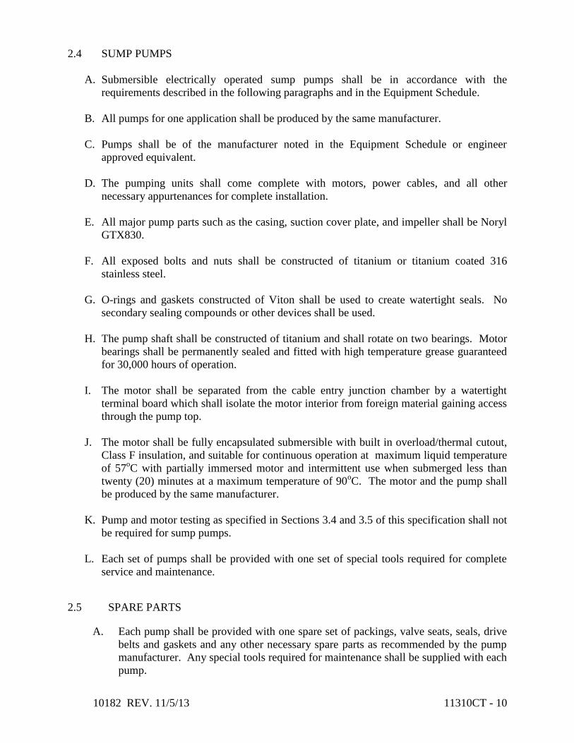
10182 REV. 11/5/13 11310CT - 10
2.4 SUMP PUMPS
A. Submersible electrically operated sump pumps shall be in accordance with the
requirements described in the following paragraphs and in the Equipment Schedule.
B. All pumps for one application shall be produced by the same manufacturer.
C. Pumps shall be of the manufacturer noted in the Equipment Schedule or engineer
approved equivalent.
D. The pumping units shall come complete with motors, power cables, and all other
necessary appurtenances for complete installation.
E. All major pump parts such as the casing, suction cover plate, and impeller shall be Noryl
GTX830.
F. All exposed bolts and nuts shall be constructed of titanium or titanium coated 316
stainless steel.
G. O-rings and gaskets constructed of Viton shall be used to create watertight seals. No
secondary sealing compounds or other devices shall be used.
H. The pump shaft shall be constructed of titanium and shall rotate on two bearings. Motor
bearings shall be permanently sealed and fitted with high temperature grease guaranteed
for 30,000 hours of operation.
I. The motor shall be separated from the cable entry junction chamber by a watertight
terminal board which shall isolate the motor interior from foreign material gaining access
through the pump top.
J. The motor shall be fully encapsulated submersible with built in overload/thermal cutout,
Class F insulation, and suitable for continuous operation at maximum liquid temperature
of 57oC with partially immersed motor and intermittent use when submerged less than
twenty (20) minutes at a maximum temperature of 90oC. The motor and the pump shall
be produced by the same manufacturer.
K. Pump and motor testing as specified in Sections 3.4 and 3.5 of this specification shall not
be required for sump pumps.
L. Each set of pumps shall be provided with one set of special tools required for complete
service and maintenance.
2.5 SPARE PARTS
A. Each pump shall be provided with one spare set of packings, valve seats, seals, drive
belts and gaskets and any other necessary spare parts as recommended by the pump
manufacturer. Any special tools required for maintenance shall be supplied with each
pump.

10182 REV. 11/5/13 11310CT - 11
B. Dewatering Pumps
1. One (1) shelf spare pump.
C. Waste Activated Sludge Pumps
1. One (1) shelf spare for the Waste Activated Sludge (WAS) pumps.
D. Progressive Cavity Pumps Additional Spare Parts
1. Per manufacturer’s recommendation.
E. Rotary Lobe Pumps Additional Spare Parts
1. One elastomer housing insert.
2. One set of rotors for each pump.
3. One set of mechanical seals for each pump.
4. One front cover o-ring or gasket for each pump.
F. Sump Pumps Additional Spare Parts
1. Per manufacturer’s recommendation.
PART 3 - EXECUTION
3.1 INSTALLATION
A. The equipment shall be installed in accordance with the manufacturer's
recommendations.
3.2 INITIAL LUBRICATION
A. Initial lubrication required for startup and field test operation shall be furnished and
applied in accordance with the manufacturer's recommendations.
3.3 INSPECTION, STARTUP, AND TESTING
A. The manufacturer of the pumps with drive motors of 25 Hp or larger shall provide a
representative to check the installation, make final adjustments, supervise initial
startup of each pump, and prepare a written test report thereof for the Owner.
B. The representative shall instruct the Owner's personnel in the operation and
maintenance of the equipment.
C. For smaller pumps with drive motors of less than 25 Hp, the manufacturer shall make
final adjustments, provide initial startup, and instruct the Owner's personnel in the
operation and maintenance of the equipment.
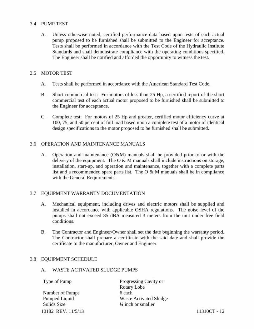
10182 REV. 11/5/13 11310CT - 12
3.4 PUMP TEST
A. Unless otherwise noted, certified performance data based upon tests of each actual
pump proposed to be furnished shall be submitted to the Engineer for acceptance.
Tests shall be performed in accordance with the Test Code of the Hydraulic Institute
Standards and shall demonstrate compliance with the operating conditions specified.
The Engineer shall be notified and afforded the opportunity to witness the test.
3.5 MOTOR TEST
A. Tests shall be performed in accordance with the American Standard Test Code.
B. Short commercial test: For motors of less than 25 Hp, a certified report of the short
commercial test of each actual motor proposed to be furnished shall be submitted to
the Engineer for acceptance.
C. Complete test: For motors of 25 Hp and greater, certified motor efficiency curve at
100, 75, and 50 percent of full load based upon a complete test of a motor of identical
design specifications to the motor proposed to be furnished shall be submitted.
3.6 OPERATION AND MAINTENANCE MANUALS
A. Operation and maintenance (O&M) manuals shall be provided prior to or with the
delivery of the equipment. The O & M manuals shall include instructions on storage,
installation, start-up, and operation and maintenance, together with a complete parts
list and a recommended spare parts list. The O & M manuals shall be in compliance
with the General Requirements.
3.7 EQUIPMENT WARRANTY DOCUMENTATION
A. Mechanical equipment, including drives and electric motors shall be supplied and
installed in accordance with applicable OSHA regulations. The noise level of the
pumps shall not exceed 85 dBA measured 3 meters from the unit under free field
conditions.
B. The Contractor and Engineer/Owner shall set the date beginning the warranty period.
The Contractor shall prepare a certificate with the said date and shall provide the
certificate to the manufacturer, Owner and Engineer.
3.8 EQUIPMENT SCHEDULE
A. WASTE ACTIVATED SLUDGE PUMPS
Type of Pump Progressing Cavity or
Rotary Lobe
Number of Pumps 6 each
Pumped Liquid Waste Activated Sludge
Solids Size ¼ inch or smaller

10182 REV. 11/5/13 11310CT - 13
Percent Solids 0.75 to 2.0 percent, average is 1.2 percent
Liquid Temperature 40 to 75 degree F
Static Head Between 13.9 and 25 ft
Low Flow Condition, Each 35 gpm @ 25.6 ft TDH
Max Flow Condition, Each 145 gpm @ 33.3 ft TDH
Normal Range, Today 45 gpm @ 20.9 ft TDH to 90 gpm @ 23.4 ft TDH
Normal Range, Future 55 gpm @ 21.3 ft TDH to 120 gpm @ 25.8 ft TDH
Maximum Horsepower 7.5
Motor Service Factor 115%
Motor Drive VFD
Power Requirements 460 volts, 3 phase, 60 hz
Discharge Pipe Size 6” (Reducer per Pump Manufacturer)
Suction Pipe Size 6” (Reducer per Pump Manufacturer)
Bearing Lubrication Grease
Progressive Cavity Manufacturer Seepex, or approved equal
Rotary Lobe Manufacturer Boerger, Netzsch, or approved equal
Special Conditions: The Waste Activated Sludge Pumps and Belt Filter Press Feed Pumps
can be either progressive cavity or rotary lobe type. The same type of pump and only one
manufacturer shall be used for both locations.
B. BELT FILTER PRESS FEED PUMPS
Type of Pump Progressing Cavity or
Rotary Lobe
Number of Pumps 6
Pumped Liquid WAS - Belt Filter Press Feed Pumps
Solids Size ¼ inch or smaller
Percent Solids 0.75 to 2.0 percent, average is 1.2 percent
Liquid Temperature 40 to 75 degree F
Static Head Between 1.83 and 21.2 ft
Low Flow, Each 75 gpm @ 22 feet TDH
Max Flow, Each 450 gpm @ 44 feet TDH
Normal Range 200 gpm @ 12.3 feet TDH to
350 gpm @ 22 ft. TDH
Minimum Horsepower 30 HP
Motor Service Factor 115%
Motor Drive VFD
Power Requirements 460 volts, 3 phase, 60 hz
Discharge Size 6” (Reducer per Pump Manufacturer)
Suction Size 6” (Reducer per Pump Manufacturer)
Bearing Lubrication Grease
Progressive Cavity Manufacturer Seepex or approved equal
Rotary Lobe Manufacturer Boerger, Netzsch or approved equal

10182 REV. 11/5/13 11310CT - 14
C. STAGE 1 EQUALIZATION DEWATERING PUMPS
Type of Pump Horizontal Centrifugal
Number Required 4
Solids Size Pass 1-inch solids
Liquid Temperature 40 to 75 degree F
Static Head 14.25 ft
Design Point 1 2,731 gpm @ 37 ft
Maximum NPSHR 18 ft
Minimum Horsepower 40 HP
Motor Speed 1200 rpm
Motor Service Factor 115%
Motor Drive VFD
Power Requirements 460 volts, 3 phase, 60 hz
Discharge Piping Size 12” (Reducer per Pump Manufacturer)
Suction Piping Size 12” (Reducer per Pump Manufacturer)
Bearing Lubrication Grease
Manufacturer Deming, Flowserve, Peerless, Pentair or approved
equal
D. SUMP PUMPS
Type of Pump Submersible
Number Required 3
Solids Size Pass ¼-inch solids
Liquid Temperature 40 to 75 degree F
Design Point 35 gpm @ 10 ft
Minimum Horsepower 0.4 HP
Motor Speed 3450 rpm
Motor Service Factor 110%
Power Requirements 115 volts, 1 phase, 60 hz
Discharge Piping Size 2”
Suction Piping Size Not Applicable
Bearing Lubrication Grease
Manufacturer BJM Pumps, LLC or approved equal
END OF SECTION 11310CT 1/89

10182 REV. 10/31/13 11325CT - 1
SECTION 11325CT – FINE SCREEN EQUIPMENT
PART 1 - GENERAL
1.1 DESCRIPTION
A. The Contractor shall provide all labor, materials, tools, transportation and equipment
required to fabricate, furnish, install, test and initiate satisfactory operation of the fine
screening system complete with mechanically cleaned continuous band type fine screens,
transfer sluicing system and screenings washing compactor unit, main and local control
systems and associated equipment as shown on the drawings and specified herein.
B. The fine screening systems are being bid as alternative systems. The base bid is a two (2)
stage screening system with 6mm screens in the first stage and 2 mm screens for the second
stage. The alternate bid is the 2 mm screens without the 6 mm first stage screens. Sluice
system, washer compactors and other appurtenances will be bid with the base bid and
alternate bid.
Equipment manufactured by Hydro-Dyne Engineering, Inc. has been identified by the Owner
as the Standard for the base bid screening system based on technical capability and
compatibility with the existing treatment plant layout, existing treatment plant processes, and
proposed treatment plant improvements. Hydro-Dyne Engineering, Inc. has provided a
proposal to provide base bid equipment, services, warrantees and appurtenances, titled
Canton WRF Nutrient Removal and Miscellaneous Improvements Fine Screening Facility
Scope of Work #11272-13-14 for (Dual Stage) Hydro-Flo Screens and Washing
Compactors”, prepared by Steve D. Frank, Regional Sales Manager, dated August 30, 2013,
consisting of 8 pages.
With respect to the alternate, Hydro-Dyne Engineering, Inc. has provided a proposal to
provide equipment, services, warrantees and appurtenances, titled Canton WRF Nutrient
Removal and Miscellaneous Improvements Fine Screening Facility Scope of Work #11272-
12 for (Single Stage) Hydro-Flo Screens and Washing Compactors”, prepared by Steve D.
Frank, Regional Sales Manager, dated August 30, 2013, consisting of 7 pages.
C. It is the intent of this Contract that the final installation be complete in all respects and the
Contractor shall be responsible for all aspects of system installation including minor or
specific details and all necessary appurtenances; coordination with trades; equipment
manufacturing; installation, equipment commissioning and manufacturer‟s start-up services;
and any necessary special construction not specifically included in the Drawings or
Specifications. The Contractor shall include in the lump sum price all associated cost for the
Work.
D. The specifications direct attention to certain required features of the equipment but do not
propose to cover all details entering into its design and construction. The Manufacturer shall
furnish the equipment complete in all details, ready for installation and operation. The
Contractor shall properly install, adjust and place in operation the complete installation.

10182 REV. 10/31/13 11325CT - 2
E. The Contractor shall pay particular attention to elements of work requiring coordination with
other trades and/or contractors. In particular, the Contractor shall coordinate all general
trades work separately installed however related to the equipment; electrical, control and
instrumentation components including verification of wiring, conduit, associated equipment
and all shop drawings supplied by all Contractors for the actual installation.
F. Fine screen equipment, screenings transfer system and washing compactors furnished
hereunder shall be provided by Hydro-Dyne Engineering, Inc., Oldsmar, Florida, except as
such equipment is modified by the requirements of these specification. Any other equipment
shall be considered a substitution and is subject to the requirements of Specification Section
01024CT – Substitutions.
1.2 RELATED SECTIONS
A. Drawings and general provisions of this Contract, including General and Supplementary
Conditions and Division-1 Specification sections, apply to work of this section.
B. The following equipment and related work is specified and furnished under other items:
1. Section 03310CT – Concrete Work
2. Section 05500CT – Metal Fabrications
3. Section 09801CT – Special Coatings
4. Section T13500 – Process Instrumentation and Control Systems
5. Division 16 – Electrical
1.3 QUALITY ASSURANCE
A. The named equipment in addition to the detailed specifications, establishes the minimum
acceptable standards of material and workmanship. In addition to requirements of these
specifications, comply with manufacturer‟s instructions and recommendations for work. All
equipment shall perform as specified and accessories shall be provided as required for
satisfactory operation.
B. It is the intent of these Specifications that all equipment specified under this section; and in
order to assure uniform quality, ease of maintenance and minimal parts storage; shall be
supplied by a single manufacturer. This does not require that all components of the assembly
be manufactured by a single manufacturer, but it does require that the specified manufacturer
be responsible for the complete assembly of the equipment, delivery, commissioning and
satisfactory operation of the equipment provided and appurtenances specified herein. The
equipment manufacturer shall, in addition to the Contractor, assume the responsibility for
proper installation and functioning of the equipment.
C. The Contractor shall provided confirmation from the manufacturer that the equipment being
supplied meets the design conditions, conditions of service and overall system installation.
The Manufacturer shall be the company specializing in the manufacturing of the products
specified in this section and shall have a minimum five years of installed, operating and
documented experience.

10182 REV. 10/31/13 11325CT - 3
D. All equipment and components shall be furnished as complete standard type assemblies in
accordance with the standards of the industry. All internal wiring, piping, valving and
control devices integrated into the equipment shall be delivered as part of the assembly.
Equipment with motors shall be delivered on common base plates or equipment stands as
recommended by the manufacturer. Control panels including all electrical components shall
be completely assembled and ready for installation on stands provided by the equipment
supplier. Items delivered partially disassembled when required by transportation regulations,
for protection of components or when field assembly is required shall be shipped in the
largest possible assembly to minimize field assembly in accordance with industrial standards
and the manufacturer‟s recommendation.
E. All work performed under this section shall be in accordance with all approved trade
practices and manufacturer‟s recommendations. The Contractor shall coordinate and verify
the actual field conditions with that of the equipment being furnished prior to submittal of
shop drawings. Any conditions of concern shall be noted on the shop drawings for the
Engineers/Owners review.
F. The equipment shall be constructed in accordance with the following industrial
specifications:
1. American Iron and Steel Institute (AISI),
2. American Society for Testing and Materials (ASTM),
3. American Bearing Manufacturers Association (ABMA),
4. American Gear Manufacturers Association ( AGMA),
5. National Electrical Manufacturers Association (NEMA),
6. National Fire Protection Association (NFPA),
7. Underwriters Laboratory (UL).
8. National Electrical Code (NEC)
9. Occupational Safety and Health Act (OSHA)
10. American Welding Society (AWS)
11. American Institute of Steel Construction (AISC)
12. Anti-Friction Bearing Manufacturers Association (AFBMA)
13. American National Standards Institute (ANSI)
G. Warranty: All equipment furnished shall be free of defects in the material and workmanship
for a period of two (2) years from the date of acceptance by the Owner. Acceptance by the
Owner is to be after commissioning and operational demonstration. After these tasks by the
Contractor are completed and accepted by the Owner, the Owner is responsible for the
operation of equipment and the warranty period begins. The full warranty period shall be
covered by the equipment manufacturer‟s warranty certificate. The warranty shall
guarantee, at no cost to the Owner, prompt repair or replacement of any of the components
which fail to function properly, under normal operation and maintenance, due to
deficiencies in product design, workmanship, or materials. The warranty shall include the
cost of all materials and labor required.

10182 REV. 10/31/13 11325CT - 4
H. Factory Testing: All components of the screening system shall be factory assembled and
tested for a minimum of 24 hours prior to shipment. The equipment shall be shipped in the
largest assemblies possible permitted for transporting to minimize field assembly by the
Contractor. During the factory testing the screening system shall be adjusted as required
assuring proper operation on completion of the field installation. The manufacturer shall
provide a certificate of completion of the factory testing to certify that the equipment was
successfully assembled and satisfactorily operated prior to shipment. The Contractor shall
notify the Owner/Engineer at least 45 days in advance of the factory testing so the
Owner/Engineer can arrange to be at the factory testing if chosen. The Owner/Engineer will
be responsible for travel and lodging expenses. The manufacturer shall be responsible for
local travel and meals.
1.4 SUBMITTALS
A. Product Data: The Contractor shall submit manufacturer‟s technical data and application
instruction in accordance with the General and Supplementary Conditions and Division 1
Specifications and any additional information listed herein.
B. Shop Drawings: The Contractor shall submit complete shop drawings of all equipment
furnished for this project as covered by these specifications. All shop drawings shall clearly
identify the specific equipment and material being supplied, the quantity being supplied, and
all accessories, dimensions, descriptions, dimensional/orientation layout drawings,
mounting and connection details, electrical control diagrams, wiring schematics and any
other information required of the Engineer/Owner to determine compliance with the plans
and specifications. The submittal as a minimum shall included the above data drawings and
other related materials. The shop drawings shall be reviewed by the Contractor for
completeness and compliance with the project and so acknowledge prior to the review by
the Engineer.
C. Operation and Maintenance Manuals: Submit O&M Manual in accordance with Part 3 of
this specification.
D. Warranty: The Equipment Manufacturer shall submit a warranty certificate for review.
The date of the warranty begins after commissioning and operational demonstration and
will be determined in the field by the Owner‟s Engineer. Warranties beginning sooner will
not be accepted.
E. Certifications and Calculations: The Equipment Manufacturer shall submit worksheets
and pertinent calculations that support the sizing of the fine screens, sluice(s) and washer
compactors. The Equipment Manufacturer shall also submit a certification stating that the
screen capture ratios of all of that fine screens meets or exceeds the performance
requirements listed in this specification.
1. Screen Capture Ratio (SCR) is defined as: The mass of all screenings captured by the
screen (Y) divided by the sum of the mass of all screenings captured by the screen (Y) plus
the mass of all screenings passed through the screen (Z). (SCR = Y/(Y + Z)

10182 REV. 10/31/13 11325CT - 5
PART 2 - PRODUCTS
2.1 MANUFACTURER
A. Approved Manufacturer
1. Hydro-Dyne Engineering Inc., Oldsmar, Florida.
2.2 DESCRIPTION
A. General. Provide the fine screens to be installed at the City of Canton Water Reclamation
Facility (WRF) new Fine Screen Building. The Fine Screen building is to be constructed
within the existing Pre-aeration Tank Nos. 3 and 4 and upstream of the proposed MBR
activated sludge secondary treatment process. Fine screening will be positioned in the plant
after coarse screening, influent pumping, flow monitoring and longitudinal aerated
grit/grease removal.
B. Workmanship and Design. All components of the assembly shall be engineered for long,
continuous, and uninterrupted service. Provisions shall be made for easy lubrication,
adjustment or replacement of all parts. Corresponding parts of multiple units shall be
interchangeable.
2.3 WRF DESIGN PARAMETERS
Existing Low Flow 14 MGD
Existing Annual Average Day Flow 29 MGD
Design Annual Average Day Flow 39 MGD
Maximum Month Flow 42 MGD
Peak Day Flow (sustained for 24 hours) 88 MGD
Peak Instantaneous Flow 110 MGD
Channel Bottom Elevation 69.0
Top of Channel Wall (Building Floor) Elevation 81.0
Static Water Elevation 70.0
Normal Downstream of Fine Screen Water Surface Elevation 74.0
Maximum Downstream of Fine Screen Water Surface Elevation 75.11
Maximum Upstream of Stage 1 Screens Water Surface Elevation 77.0
2.4 SCREENS SYSTEM PERFORMANCE AND DESIGN REQUIREMENTS
A. Base Bid –Two Stage Fine Screening. The two stage system will be designed to meet the
following minimum design parameters:

10182 REV. 10/31/13 11325CT - 6
Fine Screening Stage 1 – 6 mm Screens
1. Number of Screens 3 each
2. Hydro Flo Model No HF-50-67-206-6-P
3. Peak flow per screen 44 MGD
4. Average flow to screen 30 MGD
5. Screen grid opening 6 mm
6. Screen grid material 9 mm thick UHMWPE
7. Screen Capture Ratio (SCR) Minimum 80%; Average 84%
8. Normal downstream water depth @ max Q 90.0 inches @ 44 MGD
9. Normal upstream water depth @ max Q 93.71 inches @ 44 MGD
10. Maximum velocity through screen throat 3.0 feet/sec @ 44 MGD
11. Maximum velocity through screen grid 2.91 feet/sec @ 44 MGD
12. Maximum head loss at peak flow 4.0 inches @ 50 % blinding
13. Approach channel width 48 inches
14. Screen channel width 84 inches
15. Channel depth 144 inches
16. Screen height above top of channel 61.5 inches
17. Screen discharge height above top channel 48 inches
18. Electric motor 1 HP, VFD controlled, rated for use
as shown on the electrical drawings
NFPA 820 area classification
19. Power Requirements 3 Ph., 460 V, 60 Hz
20. Wash water per screen 64 gpm @ 60 psi
Fine Screen Stage 2 – 2mm Screens
1. Number of screens 6 each (1 is a standby)
2. Hydro-Flo Model No. HF-38-72-207-2-P
3. Peak flow per screen 21.6 MGD
4. Average flow to screen 15.0 MGD
5. Screen grid opening 2 mm
6. Screen grid material 12 gauge Type 316 SS
7. Screen Capture Ratio (SCR) Minimum 90%, Average 93%
8. Normal downstream water depth @ max Q 73.3inches @ 21.6 MGD
9. Normal upstream water depth @ max Q 84.28 inches @ 21.6 MGD
10. Maximum velocity through screen throat 2.36 feet/sec @ 21.6 MGD
11. Maximum velocity through screen grid 2.83 feet/sec @ 21.6 MGD
12. Maximum head loss at peak flow 11.0 inches @ 60 % blinding
13. Approach Channel width 36 inches
14. Screen channel width 72 inches
15. Channel depth 144 inches
16. Screen height above top of channel 62.9 inches
17. Screen discharge height above top channel 48 inches
18. Electric motor 1 HP, VFD controlled, rated for
use as shown on the electrical
drawings NFPA 820 area
classification

10182 REV. 10/31/13 11325CT - 7
19. Power Requirements 3 Ph., 460 V, 60 Hz
20. Wash water per screen 69 gpm @ 60 psi
B. Alternate Bid –Single Stage Fine Screening. The single stage system will be designed to
meet the following minimum design parameters:
Single Stage Fine Screening – 2mm Screens
1. Number of screens 6 each (1 is a standby)
2. Hyrdo-Flo Model No. HF-38-90-207-2-P
3. Peak flow per screen 21.6 MGD
4. Average flow to screen 15 MGD
5. Screen grid opening 2 mm
6. Screen grid material 12 gauge Type 316 SS
7. Screen Capture Ratio (SCR) Minimum 90%; Average 93%
8. Normal downstream water depth @ max Q 73.3inches @ 21.6 MGD
9. Normal upstream water depth@ max Q 84.6 inches @ 21.6 MGD
10. Maximum velocity through screen throat 2.34 feet/sec @ 21.6 MGD
11. Maximum velocity through screen grid 2.93 feet/sec @ 21.6 MGD
12. Maximum head loss at peak flow 12.0 inches @ 70 % blinding
13. Approach channel width 36 inches
14. Screen channel width 72 inches
15. Channel depth 144 inches
16. Screen height above top of channel 62.9 inches
17. Screen discharge height above top channel 48 inches
18. Electric motor 1 HP, VFD controlled, rated for
use as shown on the electrical
drawings NFPA 820 area
classification
19. Power Requirements 3 Ph., 460 V, 60 Hz.
20. Wash water per screen 87 gpm @ 60 psi
C. Base Bid and Alternate Bid. The screenings washer/compactors shall be the same system
for the Base Bid and Alternate Bid system and shall be designed to meet the following
minimum design parameters:
Screenings Washer/Compactor
1. Number of washer compactors 3 each
2. Diameter of screw 12 inches
3. Diameter of shaft 3.5 inches
4. Flights ¼ inch thick and full pitch
5. Electric motor 3 HP, rated for use as shown on the
electrical drawings NFPA 820 area
classification
6. Power Requirements 3 Ph., 460 V, 60 Hz.
7. Compactor discharge height above grade 84 inches
8. Wash water per compactor 8 GPM @ 60 PSI

10182 REV. 10/31/13 11325CT - 8
9. Wash water for launder sluice 50 gpm @ 60 psi – Pulsed
Note: The screenings washing and compaction unit will be sized to handle the peak
washings from the fine screen. The screenings washing and compacting unit shall discharge
screenings with a minimum 45 percent solids concentration and less than 5 percent free
organic content. The maximum BOD5 of each unit‟s washed screening product is 10 mg/g
of dry solids. The Contractor will be responsible for providing and paying for the services
of an independent laboratory to perform all testing.
D. Sluicing System
The sluicing system shall be designed for the Base Bid – Two Stage Fine Screening. The
sluicing system shall be designed and provided by the screen manufacturer and shall convey
the screenings discharged from all screens to the screenings washer/compactor. Shop
drawings shall be provided based on the Base Bid - Two Stage Fine Screening design.
The sluicing system will be providing for the actual number of screens being installed. In
the event the Owner selects the Alternate Screening option, a transition piece to the Fine
Screenings Stage 1 - 6mm screens shall be provided with a stop plate at the main lateral and
to provide for future extension to a Fine Screenings Stage 1 - 6 mm screens if ever
implemented by the Owner. The Contractor shall include in the cost of the Alternate Bid
the sluicing system from the Fine Screenings Stage 2 - 2mm screens to the
washer/compactors with the transition pieces and stop plate for a future extension; however
no extension from the main sluicing lateral to, the Fine Screenings Stage 1 – 6 mm Screens
will be provided.
2.5 MATERIALS OF CONSTRUCTION
A. Center Flow Band Screen
General: The screens shall be sized as indicated in Section 2.3 WRF Design Parameter.
The fine screen shall have a continuous stainless steel belt that automatically rotates within
the internal guide system of the static frame. The screen shall be a center flow type with
flow entering the inside of the continuous belt and exiting through both sides and the bottom
of the belt. The captured solids will be elevated, as either a mat on the screen band, by
stainless steel lifting forks equally spaced across the entire width of the screening panel and
located every 8” vertically on the screen band or lifting trays spanning the entire width of
the screening panel located every 48” vertically on the screen band. During normal
operation, with variable frequency drives motors, the screen shall operate at 30 Hz, 5 feet
per minute. As the water surface differential increases across the screen during peak hours
the screens rotational operation shall increase to up to 60Hz, 10 feet per minute. Screenings
shall be
removed from the screening plates and lifting forks and/or lifting trays by way of two (2)
stainless steel spray bars, outside of the belt at the apex of travel and deposited into an
integral screenings collection hopper. The continuous belt shall be directly driven by drive
sprockets that shall support and rotate the grid assembly. The screen with be totally
enclosed and have access covers that will be lightweight and easily removable for
maintenance.

10182 REV. 10/31/13 11325CT - 9
Screen Frame: The continuous band will rotate within a heavy duty stainless steel static
support frame that shall be rectangular in shape. The support frame shall be fabricated from
a minimum of ¼ inch thick, 316L stainless steel. The guide link system will travel around a
stainless steel guide wear track that is integral to the support frame. The track shall be a
minimum of ¼” thick at the top and down the sides and shall be a minimum of 3/8” thick at
the bottom section of the track. Top and bottom wear tracks shall be bolt in and field
replaceable. The back plate of the screen shall be a solid 12 gauge minimum, 316L stainless
steel panel rigidly fixed to the screen frame. Easily removable, 12 gauge, 316L stainless
steel inspection hatches (not less than 12 inches wide by 8 inches high) shall be provided to
ensure all adjustable or replaceable items are accessible including but not limited to the
spray bar and screening plates. Two (2) 316L stainless steel inlet diverter plates with
neoprene seals shall be supplied with all necessary anchor bolts to ensure a waterproof seal
at the wall in the approach channel directly in front of the screen. All hardware shall be
T316 stainless steel.
Screening Band: The two (2) mm screening band shall be a continuous assembly comprised
of a multiplicity of minimum 12 gauge T316 stainless steel panels with 2 mm perforations.
The six (6) mm screening band shall be a continuous assembly comprised of a multiplicity
of minimum 9mm thick UHMWPE screening panels punched with 6 mm perforations. The
screening panels will be supported by 12 gauge stainless steel vertical mounted lifting hooks
horizontally spaced a maximum of 3 inches apart preventing deflection. The lifting hooks
shall support the screening panels and bear tension loads across the entire length and width
of the screen band. The hooks on elements shall form horizontal lifting trays or shelves for
removing large solids and rags every 8 inches around the entire screen grid. The screening
panels will be connected by heavy duty stainless steel axles every 8 inches to form a
continuous band that will rotate within the frame‟s guide system. The axle design will
allow the plates to pivot and create a seal between the screen panels to prevent the passage
of solids. The axles will include Delrin spacers that will maintain the 3 inch space between
the vertical support elements. Delrin spacers will also form a seal between each perforated
panel with clearance not to exceed 0.5mm. The axles will be extended to fix a UHMWPE
guide link to the side of each screen panel. These guides will interlock to create a
continuous guide link system that will slide within the frame. The heavy duty guide links
will be minimum 2 inches thick to protect against undue wear from grit and will be specially
machined to form a closure seal between the rotating belt and the static frame.
Screening Sealing: The screening band chain and UHMWPE guide links installed on the
frame of the screen shall form a three sided positive seal. The seal shall be continuous from
grade level through the water flow forming an uninterrupted closure between the traveling
screen grid and the stationary frame. The seal shall be heavy gauge stainless steel, fixed to
the screen frame and be adjustable so it will remain in contact with the rotating screen belt
at all times. There shall be no gap in the grid to frame seal larger than 0.5mm. The heavy
duty guide links will be minimum 2 inches thick to protect against undue wear from grit.
The contractor will be responsible to grout the base of the screen and diverter plates to
prevent leaking of solids under the screen. The design will ensure that the support frame
meshes with the closure seal on each guide link to prevent passage of screening material and
grit particles.

10182 REV. 10/31/13 11325CT - 10
Screening Drive Mechanism: The screen drive mechanism shall be a direct drive system
which will drive the screening band by a minimum of two wheels of the sprocket type and
are integral to the head space of the unit. Pins that are affixed to the sprockets that will
transmit torque directly from the gear reducer to notches on the underside of the UHMWPE
guide links to drive the screen band around on the internal track.
Screen Cleaning: Screened solids retained from the flow will be carried out on the
screening band, out of the liquid level and to the screenings hopper located in the head space
of the screen. Screenings shall be washed from the inside face of the band by externally
applied wash water. It shall be distributed over the screen bands entire width by two (2)
spray bars at the flow rate and pressure noted in Section 2.4 – Screen Performance and
Design Requirements. Cleaning brushes are not acceptable. The spray bars will incorporate
brass nozzles at two (2) inch spacing that can easily be removed or replaced for cleaning.
All materials not collected in the collection hopper shall be maintained upstream of the
screen.
B. Screening Washing and Compacting
General: The main body will be the washing trough and shall receive screenings and wash
water directly from the end of the screenings transfer sluice. The washing trough will house
a screw auger and provide a dedicated section to reduce organic content. It will comprise of
angled side walls manufactured from 10 gauge stainless steel that will direct the screenings
onto the screw auger, and a drainage section in which the screw auger will ride. The
compactor shall be sized to handle maximum 380 cubic feet per hour. The drainage trough
section shall be stainless steel wedge wire section with maximum 2mm slots. The wedge
wire section shall be removable and easily replaceable in the field with no special tools.
The flights of the screw will be fitted with a stiff nylon brush that will maintain contact with
the wedge wire, preventing blockages. The brushes will be supplied in pre-coiled lengths
with suitable clamps. The brushes must be replaceable without removing the screw from
the washing trough.
The underside of the washing trough will be a T316SS catch pan that will collect the
contaminated water that passes through the drainage section. The catch pan will feed a 6
inch diameter outlet connection. The outlet pipe connection will be fitted with a quick
release coupling. The General Contractor will connect the pipe to take the water back to
plant drain line.
The catch pan will include a separate wash supply to periodically purge the area of
accumulated solids. The manufacturer will supply a single spray nozzle that will direct
water across the length of the pan toward the outlet. The frequency of cleansing cycles will
be manually controlled.
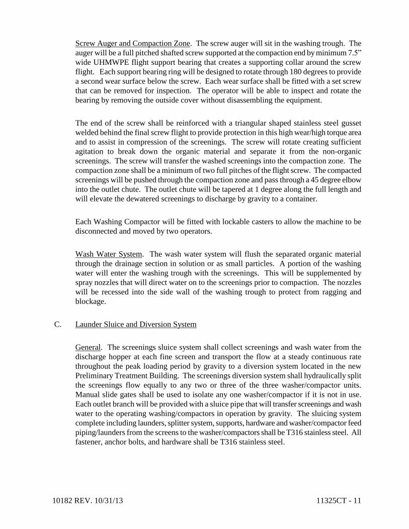
10182 REV. 10/31/13 11325CT - 11
Screw Auger and Compaction Zone. The screw auger will sit in the washing trough. The
auger will be a full pitched shafted screw supported at the compaction end by minimum 7.5”
wide UHMWPE flight support bearing that creates a supporting collar around the screw
flight. Each support bearing ring will be designed to rotate through 180 degrees to provide
a second wear surface below the screw. Each wear surface shall be fitted with a set screw
that can be removed for inspection. The operator will be able to inspect and rotate the
bearing by removing the outside cover without disassembling the equipment.
The end of the screw shall be reinforced with a triangular shaped stainless steel gusset
welded behind the final screw flight to provide protection in this high wear/high torque area
and to assist in compression of the screenings. The screw will rotate creating sufficient
agitation to break down the organic material and separate it from the non-organic
screenings. The screw will transfer the washed screenings into the compaction zone. The
compaction zone shall be a minimum of two full pitches of the flight screw. The compacted
screenings will be pushed through the compaction zone and pass through a 45 degree elbow
into the outlet chute. The outlet chute will be tapered at 1 degree along the full length and
will elevate the dewatered screenings to discharge by gravity to a container.
Each Washing Compactor will be fitted with lockable casters to allow the machine to be
disconnected and moved by two operators.
Wash Water System. The wash water system will flush the separated organic material
through the drainage section in solution or as small particles. A portion of the washing
water will enter the washing trough with the screenings. This will be supplemented by
spray nozzles that will direct water on to the screenings prior to compaction. The nozzles
will be recessed into the side wall of the washing trough to protect from ragging and
blockage.
C. Launder Sluice and Diversion System
General. The screenings sluice system shall collect screenings and wash water from the
discharge hopper at each fine screen and transport the flow at a steady continuous rate
throughout the peak loading period by gravity to a diversion system located in the new
Preliminary Treatment Building. The screenings diversion system shall hydraulically split
the screenings flow equally to any two or three of the three washer/compactor units.
Manual slide gates shall be used to isolate any one washer/compactor if it is not in use.
Each outlet branch will be provided with a sluice pipe that will transfer screenings and wash
water to the operating washing/compactors in operation by gravity. The sluicing system
complete including launders, splitter system, supports, hardware and washer/compactor feed
piping/launders from the screens to the washer/compactors shall be T316 stainless steel. All
fastener, anchor bolts, and hardware shall be T316 stainless steel.

10182 REV. 10/31/13 11325CT - 12
The screenings sluice will collect screenings and wash water from the discharge hopper of
the 6mm and 2mm screens. The branches from each screen shall enter a common “W”
sluice with an overflow diversion plate between. The solids and wash water from the
screens will transfer by gravity into a sluice divider system.
The sluice divider system will be designed to include symmetrical wye-branches that
provide an even split between any two selected on-line washer compactors. The off-line
washer compactor will be isolated with a manual slide gate.
The sluice divider will transfer solids by gravity directly into the Washing Compactor
washing through via vertical PVC hose down chutes that will be flange connected to the
sluice and to the cover of the Washing Compactor. A blanking plate with a drain will be
supplied to cover the sluice outlet when the Washing Compactor is removed.
The sluice shall comprise of U-shaped, and W-shaped lengths of trough that will be welded
to the desired overall length. The sluice will fall at a 1% slope from the screens to the
washing compactors. The system will include the support leg structure suitable for fixing to
a concrete floor. The height of the legs will be adjustable to allow for fine-tuning during
installation. Covers shall be lightweight and easily removable by a single operator.
Level sensors shall be placed throughout the sluice system and divider sluice that signal a
high level alarm should blocking occur.
Each screen sluice branch shall have maintenance points that consist of a washing nozzle
and ¾” manual ball valve. The manufacturer shall supply a ¾” explosion proof solenoid
valve and manual ball valve shall be fitted to the back plate of the sluice. The contractor
will connect to a local plant water supply. The water supply will provide supplementary
transport water.
2.6 ELECTRICAL/MOTORS
A. Screen Drive Motors
The motor shall be premium efficiency, inverter duty, totally enclosed fan cooled (TEFC), for
continuous duty operation. The motors shall meet the requirement Section 2.4 Screen
System Performance and Design Requirements. All motors shall be suitable for use as
shown on the electrical drawings NFPA 820 area classifications. The motors shall not been
overloaded under any normal operating conditions. The screen motor shall be “C” faced
mounted directly to gearbox. Gearbox shall be hollow shafted output direct driving screen
drive shaft. Each gearbox of the screen drive geared motor shall have a service factor of
1.15.

10182 REV. 10/31/13 11325CT - 13
B. Washing Compactor Drive Motors
The motor shall be premium efficiency, TEFC, continuous duty electric geared type and shall
meet the requirement Section 2.4 Screen System Performance and Design Requirements. All
motors shall be suitable for use as shown on the electrical drawings NFPA 820 area
classifications. The screw motor shall be “C” faced mounted directly to gearbox. Gearbox
shall be hollow shafted output direct driving screw drive shaft. Each gearbox of the washing
compactor drive geared motor shall have a service factor of 1.15.
2.7 CONTROL SYSTEM
A. General: All equipment shall be suitable for use as shown on the electrical drawings NFPA
820 area classifications. The manufacturer shall supply the following to automatically
control the equipment specified in this section:
1. One (1) main control panel for the 2 mm fine screens.
2. One (1) main control panel for the 6 mm fine screens.
3. One (1) main control panel for the washer/compactors.
4. One (1) local panel for each screen and compactor.
B. Main Control Panels for Screens: The following controls shall be supplied with the
screening and screening handling equipment: a totally enclosed, front access type, 460 volt
control panel with a single 316 stainless steel enclosure. All controls shall be manufactured
by a UL508A certified company. The control panel wiring shall be neatly cabled and
supported in non-flammable wiring raceways. All control devices and switches required for
good quality operation shall be supplied in the control panel.
1. The main control panel for the 6mm screens shall include the following items:
Enclosure, NEMA 1, Painted Steel Enclosure, wall mount type
1 – Main Circuit Breaker, w/door handle
3 – Motor Branch circuit protection
3 – VFDs, Sq.D Altivar 312 [Screens, 1HP]
1 – Control power transformer, 480-120VAC
1 – PLC, Allen-Bradley MicroLogix w/ Ethernet
1 – OIU, Allen-Bradley Panelview Plus 600
1 – Ethernet switch [Unmanaged]
1 – Power supply, 24 VDC
1 – Lot, controls for the solenoid valves
3 – HydroRanger 200 Differential Level assembly [w/ 2 transducers/hand held
Programmer and digital display]
3 – Hour Meter
1 – Alarm horn
3 – Push buttons, NEMA 1 [E-Stop, Reset, Silence]
7 – Pilot lights, NEMA 1, Transformer type [(1) Power, (3) Run, (3) Fault]
1 – Lot, Control relays, socket type
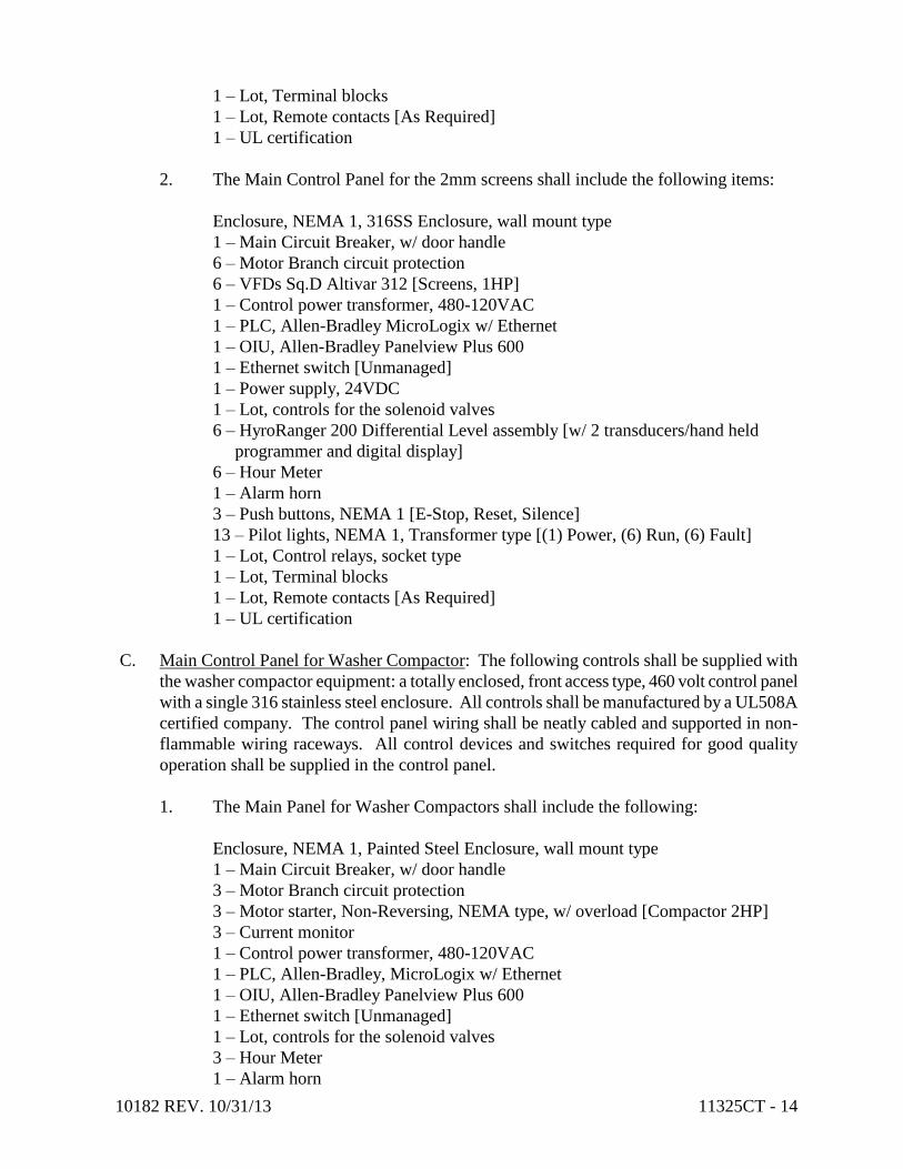
10182 REV. 10/31/13 11325CT - 14
1 – Lot, Terminal blocks
1 – Lot, Remote contacts [As Required]
1 – UL certification
2. The Main Control Panel for the 2mm screens shall include the following items:
Enclosure, NEMA 1, 316SS Enclosure, wall mount type
1 – Main Circuit Breaker, w/ door handle
6 – Motor Branch circuit protection
6 – VFDs Sq.D Altivar 312 [Screens, 1HP]
1 – Control power transformer, 480-120VAC
1 – PLC, Allen-Bradley MicroLogix w/ Ethernet
1 – OIU, Allen-Bradley Panelview Plus 600
1 – Ethernet switch [Unmanaged]
1 – Power supply, 24VDC
1 – Lot, controls for the solenoid valves
6 – HyroRanger 200 Differential Level assembly [w/ 2 transducers/hand held
programmer and digital display]
6 – Hour Meter
1 – Alarm horn
3 – Push buttons, NEMA 1 [E-Stop, Reset, Silence]
13 – Pilot lights, NEMA 1, Transformer type [(1) Power, (6) Run, (6) Fault]
1 – Lot, Control relays, socket type
1 – Lot, Terminal blocks
1 – Lot, Remote contacts [As Required]
1 – UL certification
C. Main Control Panel for Washer Compactor: The following controls shall be supplied with
the washer compactor equipment: a totally enclosed, front access type, 460 volt control panel
with a single 316 stainless steel enclosure. All controls shall be manufactured by a UL508A
certified company. The control panel wiring shall be neatly cabled and supported in non-
flammable wiring raceways. All control devices and switches required for good quality
operation shall be supplied in the control panel.
1. The Main Panel for Washer Compactors shall include the following:
Enclosure, NEMA 1, Painted Steel Enclosure, wall mount type
1 – Main Circuit Breaker, w/ door handle
3 – Motor Branch circuit protection
3 – Motor starter, Non-Reversing, NEMA type, w/ overload [Compactor 2HP]
3 – Current monitor
1 – Control power transformer, 480-120VAC
1 – PLC, Allen-Bradley, MicroLogix w/ Ethernet
1 – OIU, Allen-Bradley Panelview Plus 600
1 – Ethernet switch [Unmanaged]
1 – Lot, controls for the solenoid valves
3 – Hour Meter
1 – Alarm horn

10182 REV. 10/31/13 11325CT - 15
3 – Push buttons, NEMA 1 [E-Stop, Reset, Silence]
7 – Pilot lights, NEMA 1, Transformer type [(1) Power, (3) Run, (3) Fault]
1 – Lot, Control relays, socket type
1 – Lot, Terminal blocks
1 – Lot, Remote contacts [As Required]
1 – UL certification
D. Local Control Panels for the Fine Screens and Washer Compactors: The following local
controls shall be supplied for each fine screen and washer compactor: a totally enclosed,
rated for use in areas as shown on the electrical drawings NFPA 820 area classifications. All
controls shall be manufactured by a UL508A certified company. All control devices and
switches required for good quality operation shall be supplied in the control panel.
6mm and 2mm screens (Base Bid) shall have the following local controls:
Nine (9) Local Control Panels for Screens
Enclosure, NEMA 7, 2-Hole
HOA & E-Stop
2mm screens (Alternate Bid) shall have the following local controls:
Six (6) Local Control Panels for Screens
Enclosure, NEMA 7, 2-Hole
HOA & E-Stop
Washing Compactors shall have the following local controls:
Three (3) Local Control Panels for Washer Compactors
Enclosure, NEMA 4X, 2-Hole
HOA & E-Stop
E. Accessories – 6mm and 2mm (Base Bid) The following accessories shall be supplied by the
manufacturer with the equipment:
1. Necessary anchor bolts for mounting.
2 Nine (9) 2.5” PVC female slip wash water strainers [1 per screen].
3. Three (3) 1.5” PVC female slip wash water strainers [1 per washing compactor].
4. Nine (9) 2.5” Manual ball valves [1 per screen].
5. Eighteen (18) 1.5” Manual union style ball valves [2 per screen].
6. Six (6) 1” Manual ball valves [2 per washing compactor].
7. Nineteen (19) ¾” Manual ball valves [1 per screen, 10 at sluice system].
8. Nine (9) 1.5” Explosion proof solenoid valves [1 per screen].
9. Three (3) 1” Non explosion proof solenoid valves [1 per washing compactor].
10. One (1) ¾” Explosion proof solenoid valve [1 at sluice system].
11. Thirteen (13) Flow switches [1 per screen, 1 per washing compactor, 1 at sluice
system].
12. Twelve (12) Pressure switches [1 per screen, 1 per washing compactor].
13. Six (6) Sluice high level sensors.
14. Two (2) wash water pressure gauges per Screen.
15. Compactors disconnect power and control cables with wall mounted receptacles to
pig tail plug to compactor motors.
16. Three (3) Bagging Assemblies for Washing Compactors

10182 REV. 10/31/13 11325CT - 16
17. One (1) Screen Test Kit
F. Accessories – 2mm (Alternate Bid) The following accessories shall be supplied by the
manufacturer with the equipment:
1. Necessary anchor bolts for mounting.
2 Six (6) 2.5” PVC female slip wash water strainers [1 per screen].
3. Three (3) 1.5” PVC female slip wash water strainers [1 per washing compactor].
4. Six (6) 2.5” Manual ball valves [1 per screen].
5. Twelve (12) 1.5” Manual union style ball valves [2 per screen].
6. Six (6) 1” Manual ball valves [2 per washing compactor].
7. Thirteen (13) ¾” Manual ball valves [1 per screen, 10 at sluice system].
8. Six (6) 1.5” Explosion proof solenoid valves [1 per screen].
9. Three (3) 1” Non explosion proof solenoid valves [1 per washing compactor].
10. One (1) ¾” Explosion proof solenoid valve [1 at sluice system].
11. Ten (10) Flow switches [1 per screen, 1 per washing compactor, 1 at sluice
system].
12. Nine (9) Pressure switches [1 per screen, 1 per washing compactor].
13. Five (5) Sluice high level sensors.
14. Two (2) wash water pressure gauges per Screen.
15. Compactors disconnect power and control cables with wall mounted receptacles to
pig tail plug to compactor motors.
16. Three (3) Bagging Assemblies for Washing Compactors
17. One (1) Screen Test Kit
G. Sequence(s) of Operation
1. Fine Screen:
a. The following shall be the sequence of operation.
1) Signal received to start (from level control or duty selection)
2) Screen drive starts and water supply solenoid valve opens.
3) Signal received to stop
4) Screen drive water supply run on for 0-5 minutes.
5) End of cycle.
b. The following conditions shall be sensed by the control panel.
1) Screen drive tripped (stop screen).
2) Water supply fail (stop screen).
2. Washing Compactor:
a. The following shall be the sequence of operation.
1) When the screen operates, a volt free (N/O contact) signal will be
supplied to the Washing Compactor control panel to start it
“OPERATING”.
2) At the loss of this signal the Washing Compactor shall enter its
"SWITCHING OFF" mode. Any specified remote equipment may
require control signals at these times.

10182 REV. 10/31/13 11325CT - 17
3) On entering the "SWITCHING OFF" mode, (i.e. when the screen stops)
the Washing Compactor shall "overrun" for a period determined by a 0-5
min timer. When this timer times out, the Washing Compactor Solenoid
Valve shall overrun for a further period of 0 - 5 minutes.
4) The screw auger shall be allowed to stop and start periodically within its
"OPERATING" mode. The stop and start shall be controlled by an
adjustable 0-5 min "screw auger run" timer and an adjustable 0-60 sec
"screw auger dwell" timer. Only the screw auger is to be controlled by
these timers. The screen operation shall not be influenced by these
timers.
b. The following conditions shall be sensed by the control panel for a general
alarming.
1) Low level in washing tank (Stop Washing Compactor).
H. Screenings discharge baggers
The Manufacturer shall provide to the City of Canton a bagger system on the discharge end
of the washer compactors.
Each Washing Compactor outlet chute will be tapered at 1 degree along the full length and
will elevate the dewatered screenings to discharge into a bagging system.
The tapered outlet chute will terminate in a flange that will connect directly to a stainless
steel discharge box that will direct the compacted screenings downward into the cassette
bagger. The box will be designed to prevent bridging of solids and will have a bolted down
maintenance access hatch.
The outlet of the discharge box will be a stainless steel mounting assembly that will allow a
24” diameter circular cassette of bags to slide horizontally into position.
The plastic cassette will house one 230 feet long continuous bag that will be released under
the weight of compacted screenings dropping from the outlet chute.
I. Test Kit
Screen Manufacturer shall provide the City of Canton with a test kit consisting of a pump,
suction and discharge piping and screen disc to be inserted into the discharge piping system.
The purpose of the test kit is for the City to be able to periodically test the influent and
effluent flows at the screens to determine the effectiveness of the installed screens. The
manufacturer shall demonstrate the use of the test kit during commissioning and will assist
the City in establishing baseline data for comparison with future tests. An additional purpose
of the test kit will be to monitor the effectiveness of the screen over time so maintenance
can be appropriately scheduled.

10182 REV. 10/31/13 11325CT - 18
1. Test Apparatus
The testing kit consists of intake piping, a flow meter, electric motor pump, two
pressure sensors, the Screen Sample Assembly (SSA), discharge piping and a PLC.
The flow is pumped up through adjustable level intake piping, the flow meter and
SSA before being piped back to the channel. The SSA will include perforated panels
matching all the screens on site. Prior to each simulation, the parameters pertaining
to each test (grid type, opening size, test duration, etc.) are programmed into the PLC
via the touch screen panel. Data collected by the SSA and flow meter is then stored
by the onboard PLC for interpretation by the testing party.
2. Test Procedure
Testing should be conducted when flows are typically highest during the day and
consist of a series of 10 individual tests upstream and 10 individual tests downstream
of each screen to measure how quickly the screen grid completely blinds. Trials were
run at the top, the middle and the bottom of the channel to account for variations in
solids quantities at different channel elevations. Findings were recorded via the
onboard PLC.
3. Analysis of Test Data
Each test provides the testing party with an accurate time taken to blind each
perforated panel in the SSA. There shall be 10 results upstream and 10 results
downstream of the tested screen. They can quickly be compared and averaged to
provide a ratio between the efficiency upstream and downstream of the screen.
J. Anchor Bolts
1. Furnish all anchor bolts of ample size and strength required to securely anchor each
item of equipment. Anchor bolts, hex nuts, and washers shall be AISI Type 316
stainless steel unless noted otherwise. Anchor bolts shall be wedge or epoxy type.
2. Anchor bolts shall be set by the Contractor. Equipment shall be placed on the
foundations, leveled, shimmed, bolted down, and grouted with a non-shrinking
grout.
K. Shop Paintings
1. All non-stainless metal surfaces which shall be partially or wholly submerged shall
receive a shop coat of polyester resin primer. All non-galvanized metal surfaces
which will be above water surfaces shall receive a shop coat of a universally
compatible primer.
2. All shop paint primers are to be compatible with finished coating system specified in
Section 09801 – Special Coatings.

10182 REV. 10/31/13 11325CT - 19
3. All surfaces shall be thoroughly cleaned of dirt, grease, oil, rust, scale, or other
injurious substances. All non-stainless metal surfaces shall be sandblasted in
accordance with SSPC-SP10, Near-White Blast Cleaning.
4. All stainless steel materials, including hardware shall be acid passivated for quality
control, removal of heat affected discoloration, surface treatment for corrosive
environment and to provide a uniform finish to stainless surfaces.
L. Spare Parts
1. The intent of this Specification is to provide uninterrupted operation for minimum
period of three (3) years. To meet this objective the equipment manufacturer is shall
supply any spare parts that are required to meet this time frame. Spare parts shall be
packaged for long term storage in containers bearing labels clearly designating the
contents and the pieces of equipment for which they are intended.
2. As a minimum, the following spare parts shall be furnished for the Base and
Alternate Bids:
a. (2) UHMWPE or stainless steel screening plate for each screen furnished.
b. Two (2) grid axles for each screen furnished.
c. Two (2) UHMWPE guide links for each screen furnished.
d. Twenty (20) hook links and elements spacers for each screen furnished.
e. One (1) lot of necessary anchor bolts.
f. Two (2) center support links for each screen furnished.
g. A total of six (6) solenoid valves.
h. A total of six (6) strainers.
i. Two (2) wash water spray bars and fifty (50) nozzles.
k. Two (2) set of brushes for the screw with fixing clamps for each unit
furnished.
2.8 WASHER/COMPACTER QUICK CONNECTS
A. The washer/compactor shall be supplied with electrical wiring, control wiring, plumbing and
sluice connections that will permit the unit to be easily disconnected and moved when
required.
B. Disconnected ends of electrical and control wiring shall be provided with protective caps for
each connector.
C. The control wiring shall be pre-wired by the manufacturer using a multi-wire wiring harness
with waterproof twistlock connectors. All solenoid valves, limit switches, instruments, etc.
shall be pre-wired to the wiring harness in the factory. Any equipment that needs to be
shipped loose and field wired shall have a terminal block that will connect that device to the
wiring harness. The manufacturer shall also provide a wall mounted control station with
keyed multi-pin receptacle to plug into that is field installed by the EC. The control station
and all other equipment shall be suitable for use as shown on the electrical drawings NFPA
820 area classification.

10182 REV. 10/31/13 11325CT - 20
D. A high voltage power cable with multi-pin plug receptacle on each end will connect to the
Washer/Compactor motor and a wall mounted station with keyed multi-pin receptacle.
E. The wash water supply pipe work shall be disconnected by means of a union fitting located
downstream of the solenoid valve leaving it (and the strainer and manual ball valves) in place
when the Washing Compactor is removed.
F. The launder sluice shall unbolt at a flange. The outlet pipe shall be provided with a quick
release coupling.
G. The power cord shall be type „SJ‟ or equal, the plug and receptacle shall be a Leviton
watertight, keyed, pin and sleeve type device, with strain relief, or approved equal. The cord
and plug shall be properly sized for the connected load. The cord and plug shall be installed
in the factory and the receptacle shipped loose for field installation by the EC.
H. The manufacturer shall submit a wiring diagram indicating all field wiring requirements.
I. The fixed end of the sluice box shall be equipped with shut-off gate and drain. The
compactor drain line shall be equipped with a quick disconnect coupling with flexible hose.
PART 3 - EXECUTION
3.1 FIELD CONSTRUCTION QUALITY CONTROL
A. General: The Contractor shall submit to the Owner and Engineer for review and comment a
construction procedure and quality control procedure prior to commencing work.
Construction procedure and all required testing shall comply with these specifications and all
applicable codes and standards.
B. Inspection: Prior to all work of this Section, carefully inspect the fabricated and installed
work of all other trades and verify that all such work is completed to the point where this
installation may properly commence.
C. Inspect all parts of the furnished equipment and verify that the system may be installed in
strict accordance with all pertinent codes and regulations, the original drawings, the
referenced standards, and the manufacturer‟s recommendations.
D. Notify the Owner‟s representative immediately of all unsatisfactory conditions or
discrepancies. Do not proceed with installation in areas of discrepancy until all such
discrepancies have been fully resolved. Beginning with the installation means, the installer
accepts the existing surfaces and conditions.
E. It is the Contractor‟s responsibility to notify and coordinate with the equipment manufacturer
and other trades in a timely manner in order for them to conduct their required work,
inspection, servicing, testing and instruction.

10182 REV. 10/31/13 11325CT - 21
F. The Contractor shall be responsible for furnishing and placing all anchorage systems for the
installation of the equipment. The Contractor shall coordinate with the manufacturer in
identifying proper size and locations of all anchorage. The Contractor shall furnish and
install Type 316 stainless steel anchor bolts unless indicated otherwise in the specifications
and per manufacturer‟s recommendation.
G. Protect adjacent equipment, materials, piping, structures and/or valving against damage from
the installation procedure.
H. Preparatory work in accordance with manufacturer‟s instructions shall be completed prior to
equipment installation.
3.2 PRODUCT DELIVERY, STORAGE AND HANDLING
A. Delivery and storage shall be per specification Section 01043CT.
3.3 O&M MANUALS
A. Submit three (3) copies of the manufacturer's O&M instruction manuals with/or prior to the
equipment delivery. These copies will be used for review by the Engineer for completeness
and by the Owner/Engineer (2 field copies) during construction, equipment installation, start-
up and demonstration.
B. Any revisions noted during equipment installation, start-up, training or initial operation
shall be made by the manufacturer. One (1) final draft hard bond copy of the O&M
Instruction Manual shall be submitted to the Engineer for final acceptance. When the final
draft is found acceptable to the Engineer, the Contractor will be notified by the Engineer, and
the Contractor shall submit an additional two (2) hard bound copies and six (6) electrical disc
copies of the O&M instructions manual for final distribution to the Owner.
C. The Contractor shall disclose to the Engineer/Owner the purchase price of the equipment
once the Contractor has secured an agreement with the equipment manufacturer. The O&M
Instruction Manuals shall be assigned a value of 10% of the total equipment purchase price.
The Contractor shall be provided 70% of the 10% once the O&M instruction manual
submitted and the equipment delivery have been found to be acceptable. The remaining 30%
of the 10% will be released upon receipt of the final two (2) hard bound copies and six (6)
electronic disc copies.
3.4 INSTALLATION
A. The equipment shall be installed and tested in accordance with the manufacturer's
recommendations and as indicated on the Contract Documents.

10182 REV. 10/31/13 11325CT - 22
3.5 ELECTRICAL
A. Unless noted otherwise all indicating lights, controls, conduit, wiring, remote sensors and all
other devices to form a complete operating electrical system will be supplied, mounted and
wired in this section. All electrical equipment supplied in this Section will conform to
Division 16 – Electrical and shall be suitable for use as shown on the electrical drawings
NFPA 820 area classification.
B. All electrical equipment, conduit and wiring not indicated on the Drawings, but necessary to
provide a complete operating system shall be provided at no additional cost to the Owner in
this section.
C. Electrical Wiring: The external conduit and wiring required for power supply and control to
electrical equipment supplied in this Section will be furnished and installed in Division - 16,
Electrical and shall be suitable for the electrical drawings NFPA 820 area classification.
D. Motor Size: Any deviation in motor size must be approved by the Engineer. Any electrical
equipment or wiring that must change to accommodate a different size motor will be at no
additional cost to the Owner.
3.6 INITIAL LUBRICATION
A. Storage Lubrication – Any equipment delivered and stored shall be checked at delivery for
storage practices and lubrication for long term storage as recommended by the equipment
manufacturer in the O & M Manual.
B. Continuous Service Lubrication – As part of the equipment startup and field testing
procedures, the Contractor shall service and lubricate the equipment for continuous duty in
accordance with the manufacturer's recommendations.
3.7 FIELD PREPARATION AND PAINTING
A. Finish field preparation and painting shall be performed as specified in Section 09801CT.
B. The Contractor shall touch-up all minor shipping damage to painted surfaces as soon as the
equipment arrives on the job site.
C. Prior to assembly, all stainless steel bolts and nut threads shall be coated with a non-seizing
compound by the Contractor.
3.8 EQUIPMENT COMMISSIONING
A. Equipment commissioning shall be in accordance with Specification Section 01650 Starting
of Systems.

10182 REV. 10/31/13 11325CT - 23
B. A qualified and authorized employee of the manufacturer shall be present during the
commissioning of the equipment to inspect the completed installation, service the equipment,
adjust, field test, operate the equipment under all design conditions, instruct the Owner‟s
personnel in proper operating and maintenance procedures, and provide the Owner with a
written certificate of approval.
1. A start-up or service technician employed by the manufacturer shall schedule a total of
three trips, one (1) trip to the project site for equipment commissioning assistance for
the Contractor, one (1) trip for operator training for Owner personnel and one (1) trip
after 3 months of operation to make any necessary field adjustments and/or follow up
training. All other trips requested by the Contractor to assist with the equipment and
make the installation operational shall be at the Contractor‟s cost.
C. Equipment Commissioning. The equipment manufacturer‟s employee shall make Trip 1 to
commission the equipment shall include a minimum of five (5) man days (40 hours) to
inspect the equipment and to supervise field testing and start-up for the Contractor. The
manufacturer‟s employee shall conduct all operational test of the equipment herein specified
and control systems in accordance with start-up and testing recommended by the
manufacturer and described herein these specifications, under the observation of the
Construction manager/Engineer/Owner, to determine if the installed equipment meets the
purpose and intent of the specification and that the installation is ready for commissioning.
The equipment manufacturer shall provide all materials, instruments and equipment required
for the tests and shall provide a written report of test results to the Contractor and Owner.
D. Operator Training. The manufacturer‟s employee shall provide training for the plant staff
that shall consist of two (2) 12 hour days. The equipment manufacturer‟s employee shall
provide a total of six (6) 4-hour training sessions on the operation and maintenance and
control of the equipment after installation is complete and during commissioning of the
system. The number of personnel required to attend the training sessions shall be requested
by the Owner at least 45 working days before the scheduled training date. Operator Training
shall be in accordance with Specification Section 01820 –Demonstration and Training
E. Adjustment Trip. The adjustment trip, Trip 3, shall occur after a minimum of two months
of operation and not more than three months of operation. The manufacturer‟s employee
shall spend two (2) consecutive days (16 hours) on site observing the equipment operation
and working with plant operators to answer questions and expand the plant
personnel‟s knowledge regarding the operation and maintenance of the equipment.
3.9 OPERATION DEMONSTRATION
A. The Contractor shall demonstrate the operation of equipment for a period of fourteen (14)
days of continuous uninterrupted operation in accordance with Specification Section
01650CT – Starting of Systems prior to final acceptance and initiation of the warranty period
by the Owner.

10182 REV. 10/31/13 11325CT - 24
3.10 EQUIPMENT WARRANTY DOCUMENTATION
A. All equipment furnished shall be free of defects in the material and workmanship for a period
of stipulated in Section 1.3 Quality Assurance, paragraph G. Warranty.
B. The Contractor and Engineer/Owner shall set the date beginning the warranty period. The
Contractor shall prepare a certificate with the said date and shall provide the certificate to the
manufacturer, Owner and Engineer.
END OF SECTION 11325CT

10182 REV. 11/05/13 11328CT - 1
SECTION 11328CT - LONGITUDINAL GRIT AND GREASE REMOVAL SYSTEM
PART 1 - GENERAL
1.1 DESCRIPTION
A. The Contractor shall provide all labor, materials, tools, transportation and equipment
required to fabricate, furnish, install, test and initiate satisfactory operation of a
longitudinal aerated grit and grease removal system complete with baffle separated grit
and grease channels, two (2) dual compartment traveling bridges, air diffuser assemblies,
grit pumps and removal system including grit classifiers, grease removal system
including grease augers, control equipment, main and local control panels and all other
associated equipment as shown on the drawings and specified herein.
B. It is the intent of this Contract that the final installation be complete in all respects and
the Contractor shall be responsible for all aspects of system installation including minor
or specific details and all necessary appurtenances; coordination with trades; equipment
manufacturing; installation, equipment commissioning and manufacturer's start-up
services; and any necessary special construction not specifically included in the Drawings
or Specifications.
C. The specifications direct attention to certain required features of the equipment but do not
propose to cover all details entering into its design and construction. The Manufacturer
shall furnish the equipment complete in all details, ready for installation and operation.
The Contractor shall properly install, adjust and place in operation the complete
installation.
D. The Contractor shall pay particular attention to elements of work requiring coordination
with other trades and/or contractors. In particular, the Contractor shall coordinate all
general trades work separately installed however related to the equipment; electrical,
control and instrumentation components including verification of wiring, conduit,
associated equipment and all shop drawings supplied by all contractors for the actual
installation.
E. The Contractor shall include in the lump sum price all associated cost for the Work. The
Contractor shall assume full responsibility for additional costs which may result from
unauthorized deviations from the Specifications.
F. Equipment manufactured by Schreiber LLC of Trussville, Alabama has been identified
by the Owner to as the Standard for the aerated grit and grease removal system based on
technical capability and compatibility with the existing treatment plant layout, existing
treatment plant processes, and proposed treatment plant improvements. Schreiber LLC
has provided a proposal to provide equipment, services, warranties and appurtenances.
Schreiber LLC’s proposal is titled Schreiber Proposal No.: 10-13-1984 and is dated
November 1, 2013. A copy of the Schreiber LLC proposal is included in the Appendix to
the Technical Specifications.

10182 REV. 11/05/13 11328CT - 2
1.2 RELATED SECTIONS
A. Drawings and general provisions of this Contract, including General and Supplementary
Conditions and Division-1 Specification sections, apply to work of this section.
B. The following equipment and related work is specified and furnished under other items:
1 Section 05500 - Metal Fabrication
2 Section 03310 - Concrete Work
3 Section 09801 - Special Coatings
4 Section 13500 - Process Instrumentation and Control Systems
5 Division 16 - Electrical Work
1.3 QUALITY ASSURANCE
A. The named equipment in addition to the detailed specifications, establishes the minimum
acceptable standards of material and workmanship. In addition to requirements of these
specifications, comply with manufacturer's instructions and recommendations for work.
All equipment shall perform as specified and accessories shall be provided as required for
satisfactory operation.
B. It is the intent of these Specifications that all equipment specified under this section; and
in order to assure uniform quality, ease of maintenance and minimal parts storage; shall
be supplied by a single manufacturer. This does not require that all components of the
assembly be manufactured by a single manufacturer, but it does require that the specified
manufacturer be responsible for the complete assembly of the equipment, delivery,
commissioning and satisfactory operation of the equipment provided and appurtenances
specified herein. The equipment manufacturer shall, in addition to the Contractor, assume
the responsibility for proper installation and functioning of the equipment.
C. The Contractor shall provided confirmation from the manufacturer that the equipment
being supplied meets the design conditions, conditions of service and overall system
installation. The Manufacturer shall be the company specializing in the manufacturing of
the products specified in this section and shall have a minimum five years of installed,
operating and documented experience.
D. All equipment and components shall be furnished as complete standard type assemblies
in accordance with the standards of the industry. All internal wiring, piping, valving and
control devices integrated into the equipment shall be delivered as part of the assembly.
Equipment with motors shall be delivered on common base plates or equipment stands as
recommended by the manufacturer.
Electrical/control panels shall be completely assembled and ready for installation on
stands provided by the equipment supplier. Items delivered partially disassembly when
required by transportation regulations, for protection of components or when field
assembly is required shall be shipped in the largest possible assembly to minimize field
assembly in accordance with industrial standards and the manufacturer’s
recommendation.

10182 REV. 11/05/13 11328CT - 3
E. All work performed under this section shall be in accordance with all approved trade
practices and manufacturer's recommendations. The Contractor shall coordinate and
verify the actual field conditions with that of the equipment being furnished prior to
submittal of shop drawings. Any conditions of concern shall be noted on the shop
drawings for the Engineers/Owners review.
F. The equipment shall be constructed in accordance with the following industrial
specifications:
1. American Iron and Steel Institute (AISI)
2. American Society for Testing and Materials (ASTM)
3. American Bearing Manufacturers Association (ABMA)
4. American Gear Manufacturers Association ( AGMA)
5. National Electrical Manufacturers Association (NEMA)
6. National Fire Protection Association (NFPA)
7. Underwriters Laboratory (UL)
8. National Electrical Code (NEC)
9. Occupational Safety and Health Act (OSHA)
10. American Society of Testing and Materials (ASTM)
11. American Welding Society (AWS)
12. American Institute of Steel Construction (AISC)
13. Anti-Friction Bearing Manufacturers Association (AFBMA)
14. American National Standards Institute (ANSI)
G. Warranty: All equipment furnished shall be free of defects in the material and
workmanship for a period of two (2) years from the date of acceptance by the Owner.
Acceptance by the Owner is to be after commissioning and operational demonstration.
After these tasks by the Contractor are completed and accepted by the Owner, the Owner
is responsible for the equipment and the warranty period begins. The full warranty
period shall be covered by the equipment manufacturer’s warranty certificate. The
warranty shall guarantee, at no cost to the Owner, prompt repair or replacement of any of
the components which fail to function properly, under normal operation and maintenance,
due to deficiencies in product design, workmanship, or materials. The warranty shall
include the cost of all materials and labor required.
1.4 SUBMITTALS
A. Product Data: The Contractor shall submit manufacturer’s technical data and application
instruction in accordance with the General and Supplementary Conditions and Division 1
specifications and any additional information listed herein.
B. Shop Drawings: The Contractor shall submit complete shop drawings of all equipment
furnished for this project as covered by these specifications. All shop drawings shall
clearly identify the specific equipment and material being supplied, the quantity being
supplied, and all accessories, dimensions, descriptions, dimensional/orientation layout
drawings, mounting and connection details, electrical control diagrams, wiring
schematics and any other information required of the Engineer/Owner to determine
compliance with the plans and specifications. The submittal as a minimum shall included

10182 REV. 11/05/13 11328CT - 4
the above data drawings and other related materials. The shop drawings shall be
reviewed by the Contractor for completeness and compliance with the project and so
acknowledge prior to the review by the Engineer.
C. Operation and Maintenance Manuals: Submit O&M Manual in accordance with Part 3 of
this specification.
D. Warranty: The Equipment Manufacturer shall submit a warranty certificate for review.
The date the warranty begins is after commissioning and operational demonstration and
will be determined in the field by the Owner’s Engineer. Warranties beginning sooner
will not be accepted.
E. Certifications and Calculations.
PART 2 - PRODUCTS
2.1 COMPONENTS
A. General: Provide two (2) combination dual longitudinal aerated grit and grease removal
unit(s), Model SFB 440. Each unit shall include one (1) traveling bridge system equipped
with two (2) submersible grit pumps; two (2) air distribution pipes with multiple air
diffuser drop assemblies, two (2) grease collection (skimmer, beaching plate and hopper)
and discharge (grease augers) systems, divider baffles; controls/instruments/electrical
components and appurtenances. Also provide two grit classifiers, complete to be used
with the two (2) dual longitudinal aerated grit and grease systems.
B. Design Criteria:
1. Type: Combination Dual Longitudinal Aerated Grit and Grease Removal
2. Number of Units: Two (2) Dual Units
3. Total Units Process Flow Rates
4. Low Flow: 14 MGD
5. Present Average Day Flow 29 MGD
6. Average Day Flow: 39 MGD
7. Peak Day Flow (sustained for 24 hours): 88 MGD
8. Peak Instantaneous Flow: 110 MGD
9. Width of Grease Channel: 6’ - 6” [two (2) per unit]
10. Length of Grease Channel: 89’-6”
11. Side Water Depth of Grit Channel: 12’ - 0”
12. Width of Grit Channel: 7’ - 2” [two (2) per unit]
13. Length of Grit Channel: 95’-6
14. Grit Channel Hydraulic Detention Time at Peak Instantaneous Flow: 3.25 min.
15. Grease Channel Surface Loading Rate: 870 gal/ft2/hr
16. Air Requirements: 210 scfm - each (840 scfm – total)
17. Air Supply Pressure at the top of the drop pipe shall be: 5.5 psig

10182 REV. 11/05/13 11328CT - 5
C. Air Distribution Pipes Air Diffuser Drop Assemblies:
1 . Distribution Pipe
a. Furnish a 4-inch diameter 316 stainless steel air header along the entire
length of each grit channel wall parallel to and above the maximum water
elevation equipped with removable drop legs and aeration diffuser
assemblies as shown on the Drawings. Each 4-inch header to have a 4-inch
wafer style butterfly valve for regulating air flow in the header. Each drop
leg shall be equipped with an air throttling/isolation valve and threaded
coupler. Valve shall be positioned so it can be operated with a wrench from
the bridge or walkways without modifications to the bridge. Threaded
couplings for disconnection of the air drop leg from the header pipe shall be
conveniently positioned to simplify disconnection of the drop leg when the
tank is empty.
2 . Air Supply Drop Legs
a. Furnish sixteen (16) 1-inch diameter 316 stainless steel air supply drop leg
assemblies to connect to the air distribution header pipe along each grit
channel. (Total of 64 drop pipes)
b. The upper end of each drop leg shall be provided with 1-inch brass full port
ball valve rated and capable of high temperature operation on compressed
air systems. This valve shall be used for isolation and throttling the air
flow to the drop leg. A 1-inch standard threaded union, located above the
maximum water surface level will be used for disconnection of the drop leg
from the air header pipe.
c. Furnish 316 stainless steel wall mounting brackets and Type 316 stainless
steel anchor bolts for air supply drop pipes.
3. Aeration Assemblies
a. Each aeration assembly shall consist of a PVC tee connected to a drop leg
and two (2) PVC diffuser assemblies (one (1) assembly on each side of the
tee). The last drop leg has one (1) diffuser assembly and shall be located at
the outlet end of the grit tank to prevent excessive accumulation of grit
immediately below the outlet weir.
b. Diffusers shall be 1-inch diameter PVC by 30 inches in length and be
provided with a minimum of 15 air discharge points, each 1/8 inch in
diameter.
4. Diffuser Supports
a. Two (2) adjustable fabricated 316 stainless steel supports with V-shaped
guides to be furnished to support each drop leg and enable leveling of
diffuser headers for even air distribution shall be furnished.
b. Attach supports to wall with Type 316 stainless steel anchor bolts.
c. Supports shall be adjustable, plus or minus 1-inch, vertically.
d. Supports shall be designed to bear the entire weight of the drop leg and
aeration assembly so that the union between the drop leg and the air supply
10182 REV. 11/05/13 11328CT - 6
header can be easily connected or disconnected.
D. Traveling Bridge System:
1. Bridge
a. The traveling bridge shall contain and support the two (2) grit removal pump
systems, bridge drive mechanism, grease skimmer system, handrail, electrical
equipment and other appurtenant equipment. Each traveling bridge frame shall
be a minimum of 4 feet wide fabricated of welded Type 304 stainless steel
construction and shall span two (2) longitudinal grit and grease process trains
driven by a drive gear rotating alloy steel axles rigidly supported to the side
plates and bridge frame. Each traveling bridge shall be fabricated structural
steel of welded construction and shall span the grit compartment with wheels
running on top of standard 25-lb. ASCE steel rails that are attached to the
exterior walls. The bridge drive unit shall be dual axles, one with two idler
wheels and the other with two drive wheels. Wheels shall be of steel
construction, with two being of flanged construction to assure proper tracking
on steel rails.
b. The bridge frame shall be of heavy Type 304 stainless steel sections with
maximum deflection of 1/720 of the span with a dead load plus 100-1b./ft2
live load. Main member shall be braced to assure rigidity.
c. The traveling bridge walkway shall be 48" wide, shall have skid resistant
aluminum grating deck, and shall have handrails on each side of the walkway.
Handrails shall be constructed of Type 304 stainless steel 1-1/2" round tubing,
and stand 42" in height.
d. Normal Bridge Speed: 9 – 9.5 ft/min.
e. Maximum Bridge Speed: 10ft./min.
f. Bridge stops shall be furnished on steel rails to limit run
of bridge to length of channel and maintain clearance between bridge and
adjacent equipment.
g. Integrally mounted steps are to be are to be supplied for access onto the bridge
deck. Handrailing shall extend to the bottom tread.
2. Bridge Drive
a. Gears
1 ) Type Precision-cut helical gears
2 ) Material SAE 8620 drop forgings
3 ) Finish AGMA Class 12
4 ) Hardness 58-62 RC
b. Gearbox
1 ) Material: Cast Iron
2 ) Designed for maximum rigidity, absorbance of high torsional or linear
stresses and noise absorption.
3 ) Gearbox shall be painted on the inside with a corrosion-resistant paint.
c. Bearings
1) B-10 Bearing Life: 40,000 hours minimum.
2) Lubrication: Packed with bearing grease.
3) Quality: ABEC 1.

10182 REV. 11/05/13 11328CT - 7
d. Seals
1) Provide double lip seals on all input and output shafts.
2) Material: Nitrile (Buna N).
3) Temperature Range: -40°F to 250°F.
e. Rotation: Capable of clockwise or counter-clockwise rotation without
restriction.
f. Service Factor: Conform to AGMA standards with a minimum service
factor of 1.5 based on nameplate motor horsepower.
g. Operation: Design for continuous duty
1 ) Type: Reversible.
2 ) Motor size: 1/2 HP.
3 ) 460 volt AC, 60 hertz, 3-phase brushless. Wound Class F with a B
temperature rise, sealed anti-friction type ball or roller or tapered
bearings with a minimum B-10 life red bearings with a minimum B-10
life of 40,000 hours.
4 ) Gear motor shall have premium helical gearing with AGMA Class 12
finish.
5 ) Provide motor stator housing and conduit box with weep holes,
positioned for drainage, based on the mounting position of the motor.
Coat the motor stator bore, rotor surface, and conduit box interior with a
polyurethane insulator paint.
h. Maintenance: Removal of the gear cover shall expose the load brake and all
gearing, making it possible to remove them without dismantling any other
part.
3. Rail Heating System
a. A system specifically designed for de-icing and snow melting on steel (crane)
rails shall be provided.
b. The system shall include 480 VAC - 25 watt/foot constant wattage heating
cable, primary insulating jacket, heater brackets, high temperature fiberglass
channels, crane rail channel brackets, low power connection detection, end
seals for hazardous locations, Junction boxes with sealed fittings and NEMA
4X control panel.
c. All mounting hardware shall be 18-8 stainless steel.
c. The control panel shall include: lockable handle, door switch and enclosure
light, main breaker, contactor, lightning arrestor, control transformer, remote
local selector switch, On and Fault light, GFI protected (50-100 MA) with
door mounted RTD temperature controller.
d. The Heat Trace Control panel shall be installed by the Contractor in the
electrical room at the Preliminary Treatment Building.
c. The crane rail heating system shall be as manufactured by Thermal-Flex
Systems, Inc, Northford, CT or approved equal.

10182 REV. 11/05/13 11328CT - 8
E. Grease Collection/Removal:
1. The grease collection/removal equipment shall include a mechanical grease skimmer
blade, fabricated of Type 316 stainless steel, in the grease channel supported on a
cantilevered arm extending off the end of the traveling bridge. Flexible squeegees
shall be provided on each end of the blade to prevent floating grease and scum from
escaping at the sidewalls.
2. The skimming blade pushes grease and scum along channel to a grease auger. The
diverter box is followed by a trough tapering from the outer wall to the low point
in the center whereby the grease auger removes the grease. The diverter box and
tapered trough shall be fabricated of 316 stainless steel. Skimming blade arms shall
rise above the water surface after completion of a skimming pass and remain raised as
bridge travels back to the park position.
3. The grease scraper shall be lowered by a ¼ HP motor before the bridge starts
traveling from the parked position to the beaching ramp, and the grease skimmer
blade shall be held in the raised position as the bridge returns to the park position.
4. Grease removal shall consist of a shafted screw conveyor lifting the floatables from
the collection area at the head end of the tank for discharge to containers.
Shafted screw conveyor consists of screw, conveying pipe or U trough, bearing, and
drive assembly.
a. The screw shall be nominally 12-inches in diameter, 304 stainless steel shafted,
continuous and non-segmented.
b. Conveying pipe or U-shaped trough of 10 ga. stainless steel, shall be provided for
the screw to rotate in to transport the grease from the grease trough to the
containers discharge. The conveying pipe or U-shaped trough shall be provided
with a flange for bolting to the carrier pipe. The conveying pipe or U-shaped
trough shall be placed within a 24-inch diameter AP15L, Grade B galvanized
steel carrier pipe (Min. Thickness of 0.375 inches) to facilitate installation and
maintenance. The carrier pipe shall be tapered on the lower end so as to fit flush
with the inside face of the concrete tank wall. A rectangular one quarter (1/4”)
steel plate shall be welded to carrier pipe six (6”) inches from and parallel to the
face of the lower end of the tapered carrier pipe. The upper end of the carrier pipe
shall have a one-quarter (1/4”) circular steel plate flange with a bolt circle that
matches the template for the conveying pipe or U-shaped trough flange. The
flange shall completely cover the annular open space between the conveying pipe
or U-shaped trough and the carrier pipe such that the seal is air tight. A one
quarter (1/4”) rubber gasket shall be placed between the flanges. All mounting
hardware shall be 316 stainless steel.
c. Upper end of the conveying pipe or U-shaped trough shall be equipped with a
flanged bearing, shaft extension, and shaft mounted drive assembly. The
discharge end of the conveying pipe or U-shaped trough shall be fitted with a
flange to securely attach the conveyance system to the carrier pipe. The U-shaped
trough shall have a stainless steel flat cover plate that extends from the discharge
chute to the inside face of the grit channel. Non metallic spacers shall be provide
every three feet minimum on center and at the conveyance system inlet end to

10182 REV. 11/05/13 11328CT - 9
firmly hold and align the conveyance system in the carrier pipe.
d. Motor shall be 1-1/2 HP, reversing starter, 230/460 volt, 3-phase, 60 Hz
e. Furnish extended flexible grease lines to permit easy access for bearing and motor
lubrication without the need for a ladder.
f. Provide a bagging system on the discharge of each grease removal system to
improve housekeeping and reduce odors.
F. Grit Removal Pump:
1. Service Conditions
a. Provide submersible grit removal pump with Vortex impeller for handling a grit
slurry, supported from and moving with the traveling bridge. Pump shall
discharge to grit trough which feeds grit classifier.
1) Design Capacity: 120 gpm at 10 ft. T.D.H.
2) Type: ITT Flygt, Model DF3068 submersible pump.
3) Size: 3.0 HP Maximum.
4) Speed: 1,750 rpm.
2. Materials of Construction
a. Pump casing, impeller, and motor housing: Class 30 gray cast iron.
b. Hardware: 316 type stainless steel.
3. Manual hoist with pump attachment, stainless steel cable and hand cable winch for
removal. Supply one (1) hoist for each pump.
4. Arrange discharge piping for automatic draining.
5. Furnish 3” schedule 80 galvanized steel piping and flexible hose from the grit pump
to the discharge at the grit sluice.
G. Baffles:
1. Provide divider baffles between the grit and grease channels as shown on the
drawings.
a. Material: HDP
b. Size
1 ) Width: 4 inch.
2 ) Length: As shown on Drawings to maintain 12" clear opening between bottom
of baffle and bottom of wall opening.
c. Spacing: 2" clear opening.
d. Attach baffle to center wall in conjunction with stainless steel angles with 304
stainless steel or 18-8 stainless steel bolts.
H. Grit Trough:
1. To be furnished by others.
I. Grit Classifier:
1. Provide two (2) stainless steel Grit Classifier Unit(s), each capable of handling a
maximum flow of 300 gpm of grit slurry.
a. Each grit classifier unit shall consist of an inlet/decant housing, support frames,
screw conveyor, and drive assembly.
b. Inlet/decant housing shall be fabricated of Type 304 stainless steel. It shall be of
a triangular hopper configuration mounted on top of the screw conveyor housing
inclined at 25 degree above horizontal. A flanged 8” pipe stub shall be provided

10182 REV. 11/05/13 11328CT - 10
on the end for the grit slurry inlet. A flanged 6” stub shall be provided in the end
for the liquid decant overflow.
The entire hopper shall be covered by stainless steel plate with bolted on access
hatch.
c. Two support frames shall be provided, fabricated of 3/16” stainless steel plate and
structural members. Upper support frame shall be an “A” profile located beneath
the inclined screw housing and near enough to the grit discharge end to ensure
stability. Both lower and upper support frames shall have base plates with holes
for anchoring into foundation. (Where required for elevated dumping heights,
support frame extensions shall be included to raise the entire classifier assembly.)
d. The inclined screw conveyor shall be comprised of a 20-inch diameter schedule
10 stainless steel pipe forming a trough. The trough shall accommodate a
fabricated hardened steel shaftless screw of nominal 20-inch diameter. The round
trough shall be notched at the lower end for fabrication with inlet/decant housing.
The upper end shall be totally enclosed with a flanged cap adjacent to the drive
unit. The trough shall include a formed fit removable stainless steel liner with
wear bars.
e. Adjacent to the upper end of the trough and in the bottom of the circular section
there shall be a gravity grit outlet consisting of a welded pipe stub of 12”
diameter.
f. Each spiral screw shall consist of an AR400 hardened steel shaftless flight,
extending end to end. Flight thickness shall be ¾” thick minimum. The upper
end shall be welded to a flanged pipe with a bolted-on drive shaft extension.
g. The shaft mounted drive assembly shall be mounted to a framework on the upper
end of the inclined trough and keyed to the drive shaft extension. The drive
assembly shall contain case-hardened gearing of AGMA Class 12 finish in a
rugged, corrosion-proof cast iron housing. Double lip seals shall be provided on
both input and output shafts, together with additional gasketing to assure oil
leakage protection. Motor shall be 3 HP, TEFC, brushless.
J. Electrical Controls:
a. The manufacturer shall refer to the electrical plans for area classification per NFPA
820. Panels, all electrical devices and wiring shall be rated for use in that
classification.
b. A remote off-bridge mounted control panel shall be provided for automatic and
manual operation of each traveling bridge; as a minimum the control panel shall
contain the following items and provide the following required features: Main circuit
breaker, motor starters for traveling bridge, two grit pumps, and two grease skimmer
hoists, and control power transformer.
1) Condensation heater.
2)
3) Allen Bradley, Compact Logix L23E PLC, Ethernet module, I/O as required.
4) Beijer Electrinics QTERM-A7 7” color touch OIT, with sun shield. Display
shall have a temperature operating range from -30 to 70 degrees C.
5) 24VDC power supply.
6) Ethernet switch, unmanaged.
7) External limit switches and relays for forward and reverse travel.
8) Front panel mounted Hand-Off-Automatic selector switch to simultaneously

10182 REV. 11/05/13 11328CT - 11
control bridge movement, two grease skimmer hoists and two grit pumps.
9) In addition to the H-O-A provide local start stop controls per the following:
a. Forward-Off-Reverse selector to control bridge travel.
b. Two Raise-Off-Lower selectors, one for each skimmer hoist.
c. Two Start-Stop selectors, one for each grit pump.
10) Provide emergency start-stop station – a local bridge mounted NEMA 7 control
panel shall be provided to provide the following:
a. E-stop push button to stop all five motor driven devices
b. Cycle Start push button
c. Bridge Forward Off Reverse
d. Skimmer 1, Raise Off Lower
e. Skimmer 2, Raise Off lower
f. Grit Pump 1, Start/Stop
g. Grit Pump 2, Start/Stop
11) Front panel mounted Power On, Alarm, Bridge Running and Grit Pump
Running lights.
c. Contractor shall provide power and control for Screw Conveyors and Grit Classifiers
in accordance with the requirements shown on the plans and specifications.
d. Data shall be formatted as required to communicate with SCADA. The system shall
communicate via TCP/IP and the manufacturer shall coordinate with the plant system
integrator to map data for SCADA interface.
K. Electrification:
1. Power and Signal Cable System:
a. Provide a festoon cable system to deliver power from the junction box to the
control panel or control panels on the traveling bridge and signals from the bridge.
b. System shall be designed for outdoor applications.
c. System shall have adequate cable capacity to provide for continuous travel of full
length of tank.
d. Cable shall be looped with a 5 ft. maximum loop depth with each end of the loop
being attached to a separate carrier.
e. Upon traveling to the end of the tank the loops shall be extended to form a draped
cable supported by each carrier. As the cable returns, the loop shall be retracted
by the action of the outrigger fastened to the moving bridge to tow the lead
carrier.
2. Cable Description:
a. Provide outdoor duty, flat cable with weatherproof neoprene jacket, resistant to
UV.
b. Use No. 12 AWG cable for power. Electrical Contractor responsible for de-rating
wire sizes to allow for long runs.
c. Provide cable connectors on each end of cable to connect to the junction box and
the control panel.
3. Festoon Mast:
a. Furnish eleven (11) 4” x 4” square tubing support column fabricated with carbon
steel and galvanized. Provide cross arms of sufficient size to support festooning
system. Furnish column plates with four (4) anchor bolts per plate. Mast System

10182 REV. 11/05/13 11328CT - 12
to be structurally capable of supporting the Festoon System without support
supplied by the grit sluice grout.
4. Festoon System:
a. C-Track System:
1 ) Provide a C-Rail track attached to hanger brackets approximately every 5
feet.
2 ) Hanger brackets shall be mounted to the columns “T” section fabricated on
top of each column.
3 ) Provide an adequate number of track couplers to connect the track together.
4 ) Provide an end clamp and end stop on the junction box side of the track.
5 ) Provide end caps on each end of the track.
6 ) Provide a cable towing trolley and towing arm.
(7) Provide an adequate number of cable trolleys such that the load per trolley
does not exceed 15 pounds.
5. Electrical Conduit:
a. Traveling bridge shall be pre-wired with galvanized rigid conduit.
6. Other Requirements:
a. Provide an adequate number of cable carriers such that the load per carrier does
not exceed 15 pounds.
b. Provide all necessary hangers, supports, carriers, clamps, end straps, fixtures, and
couplers necessary for a complete system.
2.3 ANCHOR BOLTS
A. Furnish all anchor bolts of ample size and strength required to securely anchor each item
of equipment. Anchor bolts, hex nuts, and washers shall be AISI Type 316 stainless steel
unless noted otherwise. Anchor bolts shall be wedge or epoxy type.
B. Anchor bolts shall be set by the Contractor. Equipment shall be placed on the
foundations, leveled, shimmed, bolted down, and grouted with a non-shrinking grout.
2.4 SHOP SURFACE PREPARATION AND PAINTING
A. Electric motors, speed reducers, and other self-contained or enclosed components shall
have manufacturer's standard enamel finish.
B. After the manufacture of individual stainless steel components, they shall be pickled by
immersion in a tank containing an ambient nitric-hydrofluoric acid solution made up
from Oakite Deoxidizer SS, or equal, and monitored to generally maintain a 25% or
higher solution by volume of water. The duration of immersion shall be 15 to 20 minutes
and may be supplemented by manually scrubbing or brushing with non metallic pads or
stainless steel wire brushes. The acid treatment shall be followed by immersion in a rinse
water tank, followed, if necessary, by a spray rinse. The stainless steel components shall
then be allowed to air dry to achieve passivation.

10182 REV. 11/05/13 11328CT - 13
C. Structural steel bridge components, skimmer arm, diverter box and grease trough shall be
prepared and field coated as specified in Section 09801 Special Coatings for ferrous
metal submerged non potable
2.5 SPARE PARTS
A. The Contractor shall provide the following spare parts to the Owner. The spare parts
shall be delivered to the site at the time the equipment is delivered. Spare parts shall be
crated separately and marked “SPARE PARTS” with the project name, equipment
manufacturer, contractors name and process unit. A listing or each part with part number
and quantity shall be provided in a clear envelope adhered to the crate with the spare
parts. Spare parts shall be provided to the Owner within one week of receipt. The Owner
and Contractor will open and check the contents together at the time the spare parts are
provided to the Owner. Spare parts will not be used by the Contractor to replace
defective or broken parts identified or found during equipment installation.
B. Spare parts list.
1. Two (2) bridge wheels (flanged)
2. Two (2) bridge wheels (non-flanged)
3. Four (4) shaft bearings
4. Four (4) shaft couplings
5. One (1) grit pump
6. Four (4) diffusers
7. Two crane rail keepers
8. One festooning system tow trolley
9. Two (2) festooning system standard trolleys
10. Two (2) sets of grease auger drive belts
PART 3 - EXECUTION
3.1 FIELD CONSTRUCTION QUALITY CONTROL
A. General: The Contractor shall submit to the Owner for review and comment a
construction procedure and quality control procedure prior to commencing work.
Construction procedure and all required testing shall comply with these specifications
and all applicable codes and standards.
B. Inspection: Prior to all work of this Section, carefully inspect the fabricated and installed
work of all other trades and verify that all such work is completed to the point where this
installation may properly commence.
C. Inspect all parts of the furnished equipment and verify that the system may be installed in
strict accordance with all pertinent codes and regulations, the original drawings, the
referenced standards, and the manufacturer’s recommendations.
D. Notify the Owner’s representative immediately of all unsatisfactory conditions or
discrepancies. Do not proceed with installation in areas of discrepancy until all such

10182 REV. 11/05/13 11328CT - 14
discrepancies have been fully resolved. Beginning with the installation means, the
installer accepts the existing surfaces and conditions.
E. It is the Contractor’s responsibility to notify and coordinate with the equipment
manufacturer and other trades in a timely manner in order for them to conduct their
required work, inspection, servicing, testing and instruction.
F. The Contractor shall be responsible for furnishing and placing all anchorage systems for
the installation of the equipment. The Contractor shall coordinate with the manufacturer
in identifying proper size and locations of all anchorage. The Contractor shall furnish
and install Type 316 stainless steel anchor bolts unless indicated otherwise in the
specifications and per manufacturer’s recommendation.
G. Protect adjacent equipment, materials, piping, structures and/or valving against damage
from the installation procedure.
H. Preparatory work in accordance with manufacturer’s instructions shall be completed prior
to equipment installation.
3.2 PRODUCT DELIVERY, STORAGE AND HANDLING:
A. Delivery and storage shall be per Section 01043CT.
3.3 O&M MANUALS
A. Submit three (3) copies of the manufacturer's O&M instruction manuals with/or prior to
the equipment delivery.
These copies will be used for review by the Engineer for completeness and by the
Owner/Engineer (2 field copies) during construction, equipment installation, start-up and
demonstration.
B. Any revisions noted during equipment installation, start-up, training or initial operation
shall be made by the manufacturer. One (1) final draft hard bond copy of the O&M
Instruction Manual shall be submitted to the Engineer for final acceptance. When the
final draft is found acceptable to the Engineer, the Contractor will be notified by the
Engineer, and the Contractor shall submit an additional two (2) hard bound copies and six
(6) electrical disc copies of the O&M instructions manual for final distribution to the
Owner.
3.4 INSTALLATION
A. The equipment shall be installed and tested in accordance with the manufacturer's
recommendations and as indicated on the Contract Documents.
3.5 ELECTRICAL
A. Unless noted otherwise all indicating lights, controls, conduit, wiring, remote sensors and
all other devices to form a complete operating electrical system will be supplied, mounted

10182 REV. 11/05/13 11328CT - 15
and wired in this section. All electrical equipment supplied in this Section will conform
to Division 16 - Electrical.
B. All electrical equipment, conduit and wiring not indicated on the Drawings, but necessary
to provide a complete operating system shall be provided at no additional cost to the
Owner in this section.
C. Electrical Wiring: The external conduit and wiring required for power supply and control
to electrical equipment supplied in this Section will be furnished and installed in Division
- 16, Electrical.
D. Motor Size: Any deviation in motor size must be approved by the Engineer. Any
electrical equipment or wiring that must change to accommodate a different size motor
will be at no additional cost to the Owner.
3.6 INITIAL LUBRICATION
A. Storage Lubrication – Any equipment delivered and stored shall be checked at delivery
for storage practices and lubrication for long term storage as recommended by the
equipment manufacturer in the O & M Manual.
B. Continuous Service Lubrication – As part of the equipment startup and field testing
procedures, the Contractor shall service and lubricate the equipment for continuous duty
in accordance with the manufacturer's recommendations.
3.7 FIELD PREPARATION AND PAINTING
A. Finish field preparation and painting shall be performed as specified in Section 09801CT.
B. The Contractor shall touch-up all shipping damage to the paint and stainless steel as soon
as the equipment arrives on the job site.
C. Prior to assembly, all stainless steel bolts and nut threads shall be coated with a non-
seizing compound by the Contractor.
3.8 EQUIPMENT COMISSIONING
A. Equipment commissioning shall be in accordance with Specification Section 01650
Starting of Systems.
B. A qualified and authorized employee of the manufacturer shall be present during the
commissioning of the equipment to inspect the completed installation, service the
equipment, adjust, field test, operate the equipment under all design conditions, instruct
the Owner’s personnel in proper operating and maintenance procedures, and provide the
Owner with a written certificate of approval.
1. A start-up or service technician employed by the manufacturer shall schedule a total

10182 REV. 11/05/13 11328CT - 16
of three trips, one (1) trip to the project site for equipment commissioning assistance
for the Contractor, one (1) trip for operator training for Owner personnel and one (1)
trip after 3 months of operation to make any necessary field adjustments and/or
follow up training. All other trips requested by the Contractor to assist with the
equipment and make the installation operational shall be at the Contractors cost.
C. Equipment Commissioning. The equipment manufacturer’s employee shall make Trip 1
to commission the equipment shall include a minimum of five (5) man days (40 hours) to
inspect the equipment and to supervise field testing and start-up for the Contractor.
The manufacturer’s employee shall conduct all operational test of the equipment herein
specified and control systems in accordance with start-up and testing recommended by
the manufacturer and described herein these specifications, under the observation of the
Construction manager/Engineer/Owner, to determine if the installed equipment meets the
purpose and intent of the specification and that the installation is ready for
commissioning. The equipment manufacturer shall provide all materials, instruments and
equipment required for the tests and shall provide a written report of test results to the
Contractor and Owner.
D. Operator Training. The manufacturer’s employee shall provide training for the plant staff
that shall consist of two (2) 12 hour days. The equipment manufacturer’s employee shall
provide a total of six (6) 4-hour training sessions on the operation and maintenance and
control of the equipment after installation is complete and during commissioning of the
system. The number of personnel required to attend the training sessions shall be
requested by the Owner at least 45 working days before the scheduled training date.
Operator Training shall be in accordance with Specification Section 01820 –
Demonstration and Training.
E. Adjustment Trip. The adjustment trip, Trip 3, shall occur after a minimum of two months
of operation and not more than three month of operation. The manufacturer’s employee
shall spend two (2) consecutive days (16 hours) on site observing the equipment
operation and working with plant operators to answer questions and expand the plant
personnel’s knowledge regarding the operation and maintenance of the equipment.
3.10 OPERATION DEMONSTRATION
A. The Contractor shall demonstrate the operation of equipment for a period of fourteen (14)
days of continuous uninterrupted operation in accordance with Specification Section
01650CT – Starting of Systems prior to final acceptance and initiation of the warranty
period by the Owner.

10182 REV. 11/05/13 11328CT - 17
3.11 EQUIPMENT WARRANTY DOCUMENTATION
A. All equipment furnished shall be free of defects in the material and workmanship for a
period of stipulated in Section 1.3 Quality Assurance, paragraph G. Warranty.
B. The Contractor and Engineer/Owner shall set the date beginning the warranty period.
The Contractor shall prepare a certificate with the said date and shall provide the
certificate to the manufacturer, Owner and Engineer.
END OF SECTION 11328CT

10182 REV. 11/08/13 11361CT - 1
SECTION 11361CT - DESIGN, CONSTRUCTION AND OPERATIONAL CONDITIONS FOR THE MBR ACTIVATED SLUDGE TREATMENT PROCESS SYSTEM
PART 1 - GENERAL
1.1 DESCRIPTION
A. The MBR Activated Sludge Treatment Process System goods and services have been pre-purchased by the Owner from OVIVO USA. Equipment systems and requirements are
described in the Procurement Agreement included in the Appendix to the contract documents. All subsequent referenced to MBR System Supplier shall mean OVIVO.
B. Contractor shall be responsible for the proper handling, storage, installation, start-up
and commissioning of OVIVO furnished systems in accordance with OVIVO’s
requirements.
C. All other MBR System equipment that is not specifically included in the above pre-
purchase agreement but required for the process shall be purchased, furnished, installed, started and commissioned by the Contractor as part of the bid price of the selected
Bidder(s). Refer to Specification 01010 – Summary of Work.
D. This specification directs attention to certain required features of the equipment but does
not propose to cover all details entering into its design, construction and commissioning. OVIVO shall furnish the equipment complete in all details per the pre-purchase agreement between the Supplier and the Owner, ready for installation by
the Contractor.
1.2 RELATED SECTIONS
A. Drawings and general provisions of this Contract, including General and Supplementary
Conditions and Division-1 Specification sections, apply to work of this section.
B. The pre-purchase agreement between the Owner and MBR System Supplier applies to work of this section.
C. The following equipment and related work is specified and furnished under other items:
1. Section 03255 - Expansion and Construction Joints 2. Section 03310 - Concrete Work 3. Section 05014 - Aluminum Floor Grating
4. Section 05016 - Aluminum Handrails 5. Section 05500 - Metal Fabrications
6. Section 11070 - Chemical Feed Piping 7. Section 11101 - Valves
8. Section 11124 - Factory Modifications to Centrifugal Blowers 9. Section 11830 - Process Pipe Hangers and Supports 10. Section 11818 - Blowers and Accessories
11. Section 11831 - Process Piping and Fittings

10182 REV. 11/08/13 11361CT - 2
12. Section 11839 - Stainless Steel Low Pressure Air Piping 13. Section 13500 - Process Instrumentation and Control Systems
14. Section 14621 - Hoist, Cranes and Monorails 15. Division 16 – Electrical
1.3 QUALITY ASSURANCE
A. The named equipment in addition to the detailed specifications, establishes the minimum
acceptable standards of material and workmanship. In addition to requirements of these specifications, comply with manufacturer's instructions and recommendations for work.
All equipment shall perform as specified and accessories shall be provided as required for satisfactory operation.
B. All equipment specified for a common function under this section shall be by a single
supplier in order to assure uniform quality, eases of maintenance and minimal parts storage. This does not require that all components of the assembly be manufactured by a
single manufacturer, but it does require that the specified supplier be responsible for the complete assembly, delivery, commissioning and satisfactory operation of the equipment
provided and appurtenances specified herein. The equipment manufacturer shall, in addition to the Contractor, assume the responsibility for the proper installation and
functioning of the equipment.
C. All equipment and components shall be furnished as complete standard type assemblies in
accordance with the standards of the industry. All internal wiring, piping, valving and control devices integrated into the equipment shall be delivered as part of the assembly.
Equipment with motors shall be delivered on common base plates or equipment stands as recommended by the manufacturer. Electrical/control panels shall be completely
assembled and ready for installation on stands provided by the equipment supplier. Items delivered partially disassembled (when required by transportation regulations, for protection of components or when field assembly is required) shall be shipped in the
largest possible assembly to minimize field assembly in accordance with industrial standards and the manufacturer’s recommendation.
D. All work performed under this section shall be in accordance with all approved trade
practices and manufacturer's recommendations.
E. The equipment shall be constructed in accordance with the following industrial specifications.
1. American Iron and Steel Institute (AISI) 2. American Society for Testing and Materials (ASTM) 3. American Bearing Manufacturers Association (ABMA)
4. American Gear Manufacturers Association (AGMA) 5. American National Standards Institute (ANSI)
6. National Electrical Code (NEC) 7. National Electrical Manufacturers Association (NEMA)
8. National Fire Protection Association (NFPA) 9. Occupational Safety and Health Act (OSHA)Underwriters Laboratory (UL)
10182 REV. 11/08/13 11361CT - 3
1.4 SUBMITTALS
A. Operation and Maintenance Manuals: Submit O&M Manual in accordance with Part 3
of this specification.
B. Warranty: The Supplier shall submit individual Warranty Certificates (6 total) for each
process unit following a successful operational demonstration (Refer to paragraph 3.9 B). The date of each warranty certificate shall be determined in the field by the
Owner’s Engineer upon Substantial Completion.
C. Certifications and Calculations. Submit the performance data of the membranes; all
pump curves, bearing data and all necessary motor data.
PART 2 - PRODUCTS
2.1 SUPPLIER
A. Refer to the OVIVO Contract for the equipment being provided by the MBR System
Supplier.
2.2 DESCRIPTION
A. General - The project consists of converting six (6) existing activated sludge process
tanks to six (6) Membrane Bioreactor activated sludge process units as describe herein and shown on the drawings.
B. Workmanship and Design - All components of the assembly shall be engineered for
long, continuous, and uninterrupted service. Provisions shall be made for easy
lubrication, adjustment or replacement of all parts. Corresponding parts of multiple units shall be interchangeable.
2.3 CANTON WRF DESIGN PARAMETERS
Existing Low Flow 14 MGD
Existing Annual Average Day Flow 29 MGD Design Annual Average Day Flow 39 MGD Peak
Day Flow (Sustained for 24 hours) 88 MGD Peak Instantaneous Flow (Equalized) 108 MGD

10182 REV. 11/08/13 11361CT - 4
2.4 MBR SYSTEM DESIGN PARAMETERS
A. MBR system design flows
Low Flow 14.0 MGD
Average Annual Flow 39.0 MGD Maximum Monthly Flow 42.0 MGD
Peak Week Flow 57.6 MGD Peak Day Flow (Sustained for 24 hours) 88.0 MGD
B. Design Influent and Permit Limits
Item Influent
Pollutants
Case I
Influent
Pollutants
Case II
Permitted
Effluent Limits
COD 324 mg/l
BOD5 160 mg/l <10 mg/l
TSS 170 mg/l 161 mg/l <12 mg/l
TKN 26 mg/l 29 mg/l <3.0 mg/l
NH3 (Summer) <1.85 mg/l
NH3 (Winter) 3.85 mg/l
Min. Water Temp. 11 Deg. F 11 Deg. F
P 5 mg/l 4 mg/l <1.0 mg/l
TN <8.0 mg/l
Turbidity 1 NTU
C. Preliminary Treatment Facilities ahead of the MBR System follow:
1. Influent Screening - 1.0 inch coarse screening (existing) 2. Influent Pumping - 4 pumps each @ 29.5 MGD (existing) 3. Influent Flow Meter - Parshall Flume - 110 MGD (new)
4. Longitudinal Aerated Grit and Grease System - 110 MGD (new) 5. Single Stage or Two Stage Fine Screening - 110 MGD with one screen out of
service, minimum screen opening is 2mm perforated (new) 6. Stage 1 Equalization Control Chamber - Allows upward of 88 MGD to be conveyed
to the MBR activated. 7. Flows in Excess of the 88 MGD will be diverted to Stage 1 or Stage 2 Equalization.
8. Total Equalization Volume is 6.25 MG Stage 1 and 6.45 MG Stage 2 for a total of 12.7 MG of equalization.
9. Flows in excess of 88 MGD shall be equalized for treatment after peak flows subside.
In the event all equalization is full, flows up to 108 MGD could be passed through the MBR System provided operational parameters conform to Supplier
recommendations and TMP is not more than double the Normal Range (3.0 psig).

10182 REV. 11/08/13 11361CT - 5
D. BNR/ MBR Activated Sludge Process
1. Overall Process
Number of Process Train 6 Overall Dimensions, Ea. 225 ft long x 68 ft wide x 17.0 ft wall height
Bottom Elevation 55.0 Top of Wall 72.0
Total Volume all Basins 7.157 MG
2. Anaerobic Zone
No. of Basins
Total Volume Dimensions, Ea., L x W Down Stream Control Weir EL
SWD (Static)/ WL SWD @ Low Flow/ WL
SWD @ Peak Flow/ WL HWL
6 1.042 MG
27.5 ft x 68 ft El 68.5
13.5 ft/ El 68.5 13.9/ El 68.9
14.1/ El 69.1 El 69.1
3.
Anoxic Zone
No. of Basins
6
Total Volume Dimensions, Ea., L x W Weir Elevation
SWD (Static)/ WL SWD @ Low Flow/ WL
SWD @ Peak Flow/ WL HWL
2.30 MG 55.08 ft x 68 ft El 68.5 13.5 ft
13.87/ El 68.87 14.0/ El 69.0
El 69.0
4.
Swing Zone Volume
No. of Basins
12
Volume Dimensions, Ea., L x W
Weir Elevation SWD (Static)/ WL
SWD @ Low Flow/ WL SWD @ Peak Flow/ WL
HWL Process Air Results OTR/SOTR/Temp
Process Air Results OTR/SOTR/Temp
0.288 MG 9.0 ft x 25.75 ft
El 68.5 13.5 ft
13.87/ El 68.87 14.0/ El 69.0 El 69.0
301#per hr/762# per hr/11degree C
349#per hr/912# per hr/20degree C

10182 REV. 11/08/13 11361CT - 6
5.
Pre-Aeration No. of Basins
12
Volume Dimensions, Ea., L x W
Weir Elevation SWD (Static)/WL SWD @ Low Flow/ WL
SWD @ Peak Flow/ WL
HWL Process Air Results OTR/SOTR/Temp
Process Air Results OTR/SOTR/Temp
1.019 MG 33.0 ft x 25.75 ft
68.0 13.0 ft/ El 68.0 13.37/ El 68.37
13.54/ El 68.54 13.54/ El 68.54
832#per hr/2102# per hr/11degree C 1038#per hr/2717# per hr/20degree C
6. MBR No. of Basins 12 Volume
Dimensions, Ea., L x W
2.796 MG
88.5 ft x 27.5 ft Weir Elevation 67.5
SWD (Static)/WL 12.5 ft SWD @ Low Flow/ WL 12.80/El 67.80
SWD @ Peak Flow/ WL 12.86/El 67.86 HWL 67.86 No. of Membrane Rows per Basin 8
No. of SMU’s per Row 7 No. of Membrane Units per Basin 53
Membrane Type SP-400 No. of Modules per Unit
Surface Area Per Unit Flux @ 39 MGD
Flux @ 42 MGD Flux @ 88 MGD
Scour Air Results OTR/SOTR/Temp Scour Air Results OTR/SOTR/Temp Scour Air – Air flow Rate
MBR Basin MLSS Range Target MLSS Range
Normal TMP Range
40 400 square meters/4,305.6sf
14.2 gal/sf/day 15.3 gal/sf/day
32.1 gal/sf/day 1,717#per hr/6,001# per hr/11degree C
1,724#per hr/6,001# per hr/20degree C 48,336 cf/ min 11,000 mg/l to 14,000 mg/l
12,000 mg/l to 13,000 mg/l 0.25 psi to 1.5 psi

10182 REV. 11/08/13 11361CT - 7
7. WAS System
SRT 11 days minimum
Waste Sludge Volume @ 30 MGD 300,000 gal/day to 400,000 gal/day Waste Sludge Volume @ 39 MGD 400,000 gal/day to 500,000 gal/day
Total Solids Weight @ 30 MGD 31,300 # per day to 40,850 # per day Total Solids Weight @ 39 MGD 40,700 # per day to 53,100 # per day
2.5 EQUIPMENT AND MATERIALS BY MBR SYSTEM SUPPLIER
A. Submerged Membrane Unit (SMU)
1. Total 636 submerged membrane Units (SMU). SMUs shall be type [SP-400] as
manufactured by Kubota. 2. SMUs shall be comprised of a diffuser module and 40 membrane modules, with a
total of 400 square meters of effective membrane area. 3. Membrane modules shall use plate membranes manufactured by Kubota assembled
within a polypropylene block that includes two integral permeate plenums. Each membrane plate shall be heat welded within the membrane block.
4. Membranes shall be chlorinated polyethylene with an average pore size of 0.2 microns and a maximum pore size of 0.4 microns.
5. SMUs shall have integral medium-bubble diffuser assemblies and permeate manifolds.
6. The diffuser shall be constructed using an ABS inside pipe with an EPDM
membrane. 7. The integral permeate manifolds shall be constructed using ABS plastic.
8. Membrane diffuser and module frames shall be constructed of type 304 stainless steel components and shall be designed to support the membranes inside the bioreactor. SMUs are to be installed directly into the activated sludge basin.
9. SMUs shall be furnished with 304 stainless steel guide bars to allow easy installation and removal of the SMUs.
10. SMUs shall be furnished with all support bases, guide plates, and anchors for securing SMUs to the basin floor.
11. The membrane module shall be approved by the California Department of Health Services (DHS) under the California Recycled Water Criteria (Title 22 of the
California Code of Regulations). Supplier shall provide a copy of the DHS acceptance letter and test report.
12. The Contractor shall install the SMU in accordance with the contract drawings, in accordance with Kubota protocols, recommendations and installation instruction.
10182 REV. 11/08/13 11361CT - 8
B. Pump Assisted Gravity Flow Permeate System: The MBR System Supplier shall furnish
the Pumps for the Pump Assisted Gravity flow permeate system. Pumps shall be supplied on a common base plate complete with motor for installation by the Contractor. The
Contractor shall furnish and install the permeate pipe system on the suction and discharge of the pumps as describe herein. The pumps shall be installed at the location and at the
elevation shown on the drawings.
Pumps to Assist Gravity Flow 12 pumps installed Pumps to Assist Gravity Flow Spare 1 Shelf Spare Pump Peak Flow Rate 5,658 gpm
Peak Flow Rate TDH 25 Feet Low Flow Rate 1600 gpm
Low Flow Rate TDH 5 Feet Motor Size 60 HP Motor type and drive Premium efficiency, inverter duty, with
1.15 design capacity before motor
overload Pump Type Inline Axial Flow Pump Pump Manufacturer Goulds
C. Process Air Blower Equipment: The Contractor shall furnish and install the process air
system blower equipment and piping in accordance with the Contract drawings and as
specified in the Contract Documents. The MBR System Supplier shall provide equipment to be installed in the process air piping system as specified within this specification and in
accordance with the pre-purchase agreement between Supplier and Owner.
D. Scour Air Blower Equipment Modifications: The Contractor shall remove, rehabilitate
and re-install the scour air blower equipment, piping, appurtenance and control modifications in accordance with the Contract Drawings and as specified in the
Contract Documents. The MBR System Supplier shall provide equipment to be installed in the scour air piping system as specified within this specification and in accordance
with the pre-purchase agreement between Supplier and Owner.
E. Fine Bubble Aeration System: The MBR System Supplier shall furnish the pre-aeration
basin and swing zone fine bubble diffuser systems including diffuser assemblies, PVC manifolds, purge systems, 304SS supports and anchors and PVC drop legs up to the SS to PVC Clamp Coupling. The Contractor shall provide the SS to PVC Clamp Coupling. The
Contractor shall install the pre-aeration basin and swing zone fine bubble diffuser systems and process air piping systems complete.
1. Swing Zone Air Diffuser System Twelve (12) Systems
a. Design Temperature 20 degree C
b. SOTR 912 #/Hr
c. SOTR Efficiency 27.4% d. Number of Diffusers 24
e. Air Flow per Diffuser 11.06 scfm f. Total Tank Airflow 266 scfm
g. Drop Pipe Diameter 10” OVIVO
h. Manufacturer/Model Sanitaire Gold Series or Equal
10182 REV. 11/08/13 11361CT - 9
2. Pre-Aeration Air Diffuser System Twelve (12) Systems
a. Design Temperature 20 degree C
b. SOTR 2717#/Hr
c. SOTR Efficiency 28% d. Number of Diffusers 93
e. Air Flow per Diffuser 8.33 scfm f. Total Tank Airflow 775 scfm
g. Drop Pipe Diameter 12” h. Manufacturer/Model Sanitaire Gold Series or Equal
F. Internal Recycle Pump Systems. The MBR System Supplier shall furnish the internal
recycle pumps and motors complete with thermal and moisture sensors/relays with cables,
power cables with 480 Volt twist lock quick disconnect couplings (both mates), stainless steel discharge flanges, stainless steel guide rails and supports for
installation by the Contractor.
Internal Recycled Pumps Six (6) pumps installed Internal Recycle Pump(s) Shelf Spare 1 Internal Recycle Flow Rate 2,900 gpm to 4,550 gpm
Internal Recycle Well Water Surface Min E1 68.5 Internal Recycle Well Water Surface Max EL 69.1
Internal Recycle Well Bottom Elevation EL 55.0 Internal Recycle Discharge Pipe Diameter 20 inches
Anaerobic Basin Water Surface Min E1 68.5 Anaerobic Basin Water Surface Max E1 69.5
Internal Recycle Pump Discharge TDH [email protected]; 0.77 ft@ 6.50 MGD Motor Size 7.0 HP
Motor type and drive Premium efficiency, inverter duty, Class F Insulation with 1.15 design capacity
before motor overload Pump Type Submersible Axial Flow Pump Pump Manufacturer Wilo or Equal
G. Traditional RAS Recycle Pump Systems: The MBR System Supplier shall furnish the
Traditional RAS recycle pumps and motors complete with temperature and moisture sensors/relays with cables, power cables with 480 Volt twist lock quick disconnect couplings (both mates), stainless steel adaptor rings and stainless steel lift chains for installation by the
Contractor.
RAS Pumps installed Twelve (12) RAS Pump(s) shelf spare One (1)
RAS Pump Flow Rate 5,800 gpm to 9,100 gpm RAS Well Water Surface Min. EL 60.0 RAS Well Water Surface Max. EL 66.0
Anoxic Basin Water Surface Min 68.5 Anoxic Basin Water Surface Max 69.0
RAS Recycle Pump TDH 9.54 [email protected] MGD; 10.24 [email protected] MGD

10182 REV. 11/08/13 11361CT - 10
Motor Size 34 HP Motor type and drive Premium efficiency, inverter duty, Class
F insulation with 1.15 design capacity
before motor overload Pump Type Vertical Turbine Propeller Pump Pump Manufacturer Wilo or Equal
H. Anaerobic and Anoxic Mixers: The MBR System Supplier shall furnish the anaerobic and
anoxic basin mixers with motors complete with power cables, and mounting bases for
installation by the Contractor. The mixer bridges are excluded from MBR System Supplier’s Scope of Supply and shall be provided by Contractor.
1. Anaerobic Mixer
a. Quantity 6
b. Quantity of Shelf Spares 1
c. Manufacturer/Model Invent / HCM2500-26-7.5HP d. Drive Unit Cast Iron with High Quality Coating
e. Propeller High Quality FRP, 98.4 inch Diameter f. Mounting Base Carbon Steel with Powder Coating and
Rubber Buffers g. Propeller speed 27.1 RPM
h. Mixing Capacity 130,000 Gallons i. Rated Power 7.5 HP
2. Anoxic Mixer a. Quantity 12
b. Quantity of Shelf Spares 1
c. Manufacturer/Model Invent / HCM2500-26-7.5HP d. Drive Unit Cast Iron with High Quality Coating
e. Propeller High Quality FRP, 98.4 inch Diameter. f. Mounting Base Carbon Steel with Powder Coating and
Rubber Buffers g. Propeller speed 27.1 RPM
h. Mixing Capacity 287,000 Gallons i. Rated Power 7.5 HP
I. In-Place Cleaning System:
1. MBR System Supplier shall furnish two (2) chemical pumps for acid cleaning and two
(2) chemical pumps for the hypochlorite cleaning and associated appurtenances herein to be installed by the Contractor. One set of pumps shall feed MBR basins in trains 1, 2 and 3
and the second set of pumps shall feed MBR basins in trains 4, 5 and 6. The performance requirements of the pumps are specified herein.

10182 REV. 11/08/13 11361CT - 11
2. CIP feed system components to be provided by the MBR System Supplier shall include
the following:
a. Two (2) Sodium Hypochlorite chemical feed pumps
Pump Type Centrifugal
Pump Manufacturer Magnatex Pump Model Mer-50 Sodium Hypochlorite Concentration 12.5%
Pump Feed Rate, Ea 70 gpm @ 30 PSI Pump HP, Ea 3.0 HP
Power Requirements 480 volts, 3 phase, 60 hertz Drive Type Magnetic Controls MBR PLC
b. Two (2) Acid Chemical Feed Pumps
Pump Type Centrifugal Pump Manufacturer Magnatex
Pump Model Mer-50 Acid Type and Concentration 32% Hydrochloric Acid
Pump Feed Rate, Ea 55 gpm @ 30PSI Pump HP, Ea 3.0 HP
Power Requirements 480 volts, 3 phase, 60 hertz Drive Type Magnetic Controls MBR PLC
c. Two (2) Pressure regulating valves. Valve shall be Cla-Val Model 690-01 pilot-
operated regulator capable of holding downstream pressure to a pre-determined limit.
d. Two (2) In-Line CIP Mixers. Mixer shall be Koflo Model 10-80-4-2-9IF(2.0) 10”
diameter, schedule 80, PVC static mixer containing two (2) fixed mixing elements with 150 lb. raised face flanged ends complete with a 2" 150 lb. flanged chemical
injection port.
e. Four (4) Chemical pump check valves. Valve shall be Asahi PVC Ball Style Check
Valve.
f. Eight (8) Chemical pump isolation valves. Valve shall be Asahi Type 21 PVC Tru
Union style ball valve.
g. Eight (8) Chemical pump pressure gauges. Pressure gauge shall be McDaniel Model MPB/S Glycerin filled pressure gauge with 4½” case and ½” NPT bottom
connection.
h. Eight (8) pressure gauges isolation valves. Valve shall be Asahi Type 21 PVC Tru
Union style ball valve

10182 REV. 11/08/13 11361CT - 12
i. Two (2) flow meters for CIP chemical. Flow meter shall be Endress+Hauser
electromagnetic flow meter Model ProMag10P with PTFE lined measuring tube, 1.4435/316L stainless steel electrodes and integrally mounted signal converter for 4 to 20 mA output.
j. Two (2) flow meters for plant water used for CIP. Flow meter shall be
Endress+Hauser electromagnetic flow meter Model ProMag10W with polyurethane lined measuring tube, 316L stainless steel electrodes and integrally mounted signal
converter for 4 to 20 mA output.
k. Two (2) electrically operated, modulating Flow Control Valves for CIP chemicals.
Valve shall be Asahi Type 21 Tru Union ball valve with Rotork IQTM electric
actuator complete with integral local controls and a separate remote panel mounted at the operator’s level. The remote panel shall be NEMA 4X and powered by
460V/3~/60HZ and capable of output to MBR PLC.
l. Two (2) electrically operated, modulating and motorized Flow Control Valves
for plant water used for CIP. Valve shall be Keystone Figure AR2 lug style butterfly valve with Rotork IQTM electric actuator complete with integral local
controls on the valve and a separate remote panel mounted at the operator’s level. The remote panel shall be NEMA 4X and powered by 460V/3~/60HZ and
capable of output to MBR PLC
3. The Contractor shall be responsible for providing electrically actuated CIP overpressure
preventing CIP vent valves, the sodium hypochlorite and acid storage tanks, the fill
station equipment and the piping for the CIP chemical systems. The Contractor shall be responsible for the installation of the CIP chemical systems complete including the
equipment provided by the MBR System Supplier in accordance with the project plans and specifications.
J. Piping, Valves, Instruments and Appurtenances
1. Flexible piping for submerged membrane units shall be Tigerflex TSD™ Series EPDM fabric reinforced suction & discharge hose manufactured by Kuriyama Of America, Inc.
2. Piping assemblies shall be designed to withstand expansion and contraction from
the specified field operating conditions.
3. Manual shutoff /isolation valves, and unions, or similar easily disassembled
connections shall be provided for all pipe connections of each membrane cassette
unit.
10182 REV. 11/08/13 11361CT - 13
4. MBR System Supplier. The MBR System Supplier shall furnish the materials
specifically included in the Scope of Supply in the pre-purchase agreement for installation by the Contractor. These materials include the following items:
a. All air and permeate piping within the twelve (12) MBR basins including all valves,
fittings, couplings, flexible piping from the SMU to the branch flange of the permeate header in MBR basins and to the branch flange of the air header
above the center galley. The permeate pipe and air pipe in the MBR basin shall be Schedule 80 PVC and 304 Stainless Steel respectively. The MBR System Supplier shall provide one hundred and ninety-two (192) permeate
header isolation valves for the permeate header branch and ninety six (96) isolation valves for the air header branch. Valves shall be gear operated,
Figure AR2 lug style butterfly valves by Keystone.
b. Twelve (12) membrane scour air flow meters and transmitters. Airflow meters
shall be Endress+Hauser Model T-MASS 65I insertion type of flow
sensors with transmitter for 4 to 20 mA output.
c. Twelve (12) electrically operated, modulating and motorized membrane scour
air flow control valves. Valves shall be Keystone Figure AR2 lug style butterfly
valves with Rotork IQM electric actuators with integral controls. Valves shall operate by modulating to control air flow to the scour air diffusers.
d. Twenty four (24) process air flow meters and transmitters for pre-aeration
and swing basins. Air flow meters shall be Endress+Hauser Model T-MASS 65I insertion type of flow sensors with transmitters for 4 to 20 mA output.
e. Twenty-four (24) transmembrane pressure transmitters. Pressure transmitters
shall be Endress+Hauser Model Cerabar T PMC131 with capacitive ceramic
sensor, 4 to 20 mA output, and 11 to 30 VDC input power. These pressure transmitters shall be installed at the MBR System Supplier recommended
locations.
f. Twenty four (24) permeate flow meters. Flow meters shall be
Endress+Hauser electromagnetic flow meter Model ProMag10W with
polyurethane lined measuring tube, 316L stainless steel electrodes and integrally mounted signal converter for 4 to 20 mA output.
g. Twenty four (24) electrically operated, modulating and motorized Permeate flow control valves. Valves shall be Keystone Figure AR2 lug style butterfly
valves with Rotork IQM electric actuators with integral controls. Valves shall operate by modulating to control permeate flow based on process control
functions for the entire designed flow range.
h. Twenty four (24) electrically operated solenoid valves for permeate air vent pipes.
Solenoid valves shall be normally closed, full port with 120V/60HZ
encapsulated Class H coil.

10182 REV. 11/08/13 11361CT - 14
i. Twelve (12) electrically operated motorized permeate to waste drain valves. Valves shall be Keystone Figure AR2 lug style butterfly valves with Rotork
IQT electric actuators with integral controls. Valves shall operate to open or
close position with field adjustable open/closing time. Contacts shall be provided for position indication.
j. Twelve (12) electrically operated motorized CIP isolation valves. Valves shall
be Keystone Figure AR2 lug style butterfly valves with Rotork IQT electric actuators with integral controls. Valves shall operate to open or close position with field adjustable open/closing time. Contacts shall be provided for position
indication.
k. Twelve (12) turbidity measurement systems. Each system shall include HACH
1720E Low Range Turbidimeter, SC200 transmitter, installation cable and
and Formazin calibration kit. The system shall be capable of measuring and reporting 0.001 to 100 NTU with an accuracy of plus or minus 2% of reading
or 0.015 NTU (whichever is greater) from 0 to 40 NTU; plus or minus 5% of reading from 40 to 100 NTU.
l. Six (6) internal recycle flow meters. Flow meter shall be Endress+Hauser
electromagnetic flow meter Model ProMag 10W rated for continuous submergence with polyurethane lined measuring tube, 316L stainless steel
electrodes and remote mounted signal converter for 4 to 20 mA output.
m. Twelve (12) traditional RAS recycle flow meters. Flow meter shall be
Endress+Hauser electromagnetic flow meter Model ProMag 10W rated for continuous submergence with polyurethane lined measuring tube, 316L
stainless steel electrodes and remote mounted signal converter for 4 to 20 mA output.
n. Twenty four (24) DO/Temperature monitoring systems, twelve (12) for anoxic
basins and twelve (12) for pre-aeration basins. Each system shall include Hach LDO sensor, SC200 transmitter and pole mount hardware. Installation
locations shall be determined by MBR System Supplier.
o. Twelve (12) MLSS measurement systems for MBR basins. The MLSS
measurement system shall be HACH SOLITAX sc Suspended Solids and
Turbidity Analyzer, including SC200 controller and stainless steel ts-line sc Solids and Turbidity Sensor with wiper. Installation location shall be
determined by MBR System Supplier.
p. Six (6) ORP measurement systems for anaerobic basins. Each ORP measurement
system shall include HACH differential RD1P5 ORP sensor, SC200 transmitter and CPVC mounting hardware. Installation location shall be determined by MBR
System Supplier.

10182 REV. 11/08/13 11361CT - 15
q. Twelve (12) low level and twelve (12) high level float switches for MBR basins.
Level switch shall be Conery 2900 Mechanical Series Narrow Angle Single Pole Double Throw (SPDT) float switch complete with power cable, cord weight and 304SS mounting brackets. Installation location shall be determined by MBR
System Supplier.
r. Six (6) level transmitters for RAS recycle wells. Level transmitter shall be Blue
Ribbon model Birdcage hydrostatic sensor complete with 40’ cable. Installation
location shall be determined by MBR System Supplier.
s. Thirteen (13) pressure transmitters; twelve (12) for MBR scour air headers, and one
(1) for process air main header. Pressure transmitters shall be Endress+Hauser
Model Cerabar T PMC131 with capacitive ceramic sensor, 4 to 20 mA output, and 11 to 30 VDC input power. These pressure transmitters shall be installed at MBR System Supplier recommended locations.
t. One (1) process air flow meters and transmitters for process air main header.
Airflow meter shall be Endress+Hauser Model T-MASS 65I insertion type of flow sensors with transmitters for 4 to 20 mA output.
2.6 GENERAL
A. All pumps, mixers and other equipment for the same service shall be of the same size and
type and shall be identical and interchangeable. Each pump or mixer and its respective
motor shall be mounted together on one frame.
B. Each piece of equipment, its motor(s) and drive unit(s) shall be designed and constructed
to operate at any point between no-load and full load without overloading the motor or drive or decreasing any service factor; causing noise or vibration that exceeds the specified limits or government regulations, whichever is less. Pumps and drives shall not
exceed the vibration limits of the Hydraulic Institute, when measured at the top of the motor.
C. Motors larger than 25 HP shall require a certified report of the short commercial test of
each actual motor proposed to be furnished and shall be submitted to the Engineer for acceptance. Motors shall be Baldor, Reliance or equal
D. All necessary anchor bolts, plates, nuts, washers and other hardware shall be Type 304
Stainless Steel unless otherwise noted.
E. Nameplates shall be securely attached to all equipment and motors.
F. The motors shall be premium efficiency, cooled for the duty, for continuous duty
operation of 3 phase, 60 hertz, and 460 volt current. Motors for variable frequency drives shall be inverter duty and meet the performance standards of NEMA MG 1-31. Motor
insulation system shall be rated Class F unless noted differently and the service factor shall be 1.15. Temperature rise shall be limited to Class B insulation systems when the motor is operated continuously at the rated horsepower with ambient temperature not
exceeding 40 degrees C, unless noted otherwise. Motors shall be TEFC unless noted otherwise.

10182 REV. 11/08/13 11361CT - 16
G. Motors weighting more than 50 pounds shall have a minimum of one lifting eye or lug
which is capable of bearing the full motor weight.
H. Motors below the liquid level shall be capable of submergence with no bolts protruding
through the motor housing for fastening the stator onto the housing. The motor housing shall be provided with means to prevent overheating while running in a partially
submerged condition for a minimum period of 30 minutes. Motor windings shall be Class F insulated. Motors shall be equipped with moisture sensors and thermal switches. All
cables shall be rated for submerged duty, extra hard service. A ground wire shall be included in each cable and sized per NEC250. Minimum size wire shall be 16 AWG for control wire and 14 AWG for power conductors. Power conductors shall be sized at 125%
of the motor full load current and NEC 400-5. Length of cable shall be as required with an additional minimum length of two (2) feet.
2.7 MBR SYSTEM CONTROL SYSTEM
A. General
The MBR System Supplier shall furnish all equipment and custom software programming as
required for a fully automatic and operational system, and shall provide the necessary hardware/software to allow for remote monitoring of the MBR System via the plant SCADA
system. The MBR System shall be designed for intermittent stopping and starting (relax mode) as well as for continuous operation.
The control panel shall be a floor mounted stainless steel NEMA 4X unless indicated otherwise and shall house the programmable logic controller(s), input and output racks, and
power supply. Specifically, the control panel shall receive input from the plant influent flow meter and provide for control of the process trains influent flow, anaerobic basins, anoxic
basin, swing zone and pre-aeration basins, membrane basins, traditional RAS recycle system, internal recycle system, in-place cleaning system, gravity pump assisted permeate system
and all instruments, valves, meters, mixers and equipment provided by the MBR System Supplier or in the process areas mention above to fully control the MBR process.
All equipment mounted at an elevation 7 feet above the operators walking surface
shall be provided with a remote control panel to be installed at operator level for the operators to use to control the equipment.
Power to the control panel shall be 120 volts. All wires inside the panel shall be routed in
conduits. The power, control and signal wires shall be routed in separate conduits within the panel. Wires to the control panel shall be terminated on terminal blocks. Arrangements
of circuits on terminal blocks shall be such that all connections for one circuit, plus any spare conductors, shall be on adjacent terminals. Leads for external circuit wiring shall be connected to grouped terminal blocks located for convenient connection of
external circuits entering from below. Splices will not be permitted in cabinet wiring. Terminal blocks shall be marked in accordance with the Equipment Supplier’s connection
diagrams. Each end of each conductor shall be identified with the opposite and destination marked on plastic wire sleeves. All materials and equipment within the panels shall be
by the MBR System Supplier. The Contractor shall install the panels and the Contractor shall land external wire and cables, etc.
10182 REV. 11/08/13 11361CT - 17
The MBR shall be controlled by using a PLC as manufactured by Allen Bradley utilizing Control Logics. The software shall be Intellution and shall be compatible with the existing SCADA system. The existing SCADA system is currently using PLC 5 but will be updated
to Control Logics. The control systems shall include 10 percent spare I/O built into the panel and 10 percent additional room on the racks. The PLC and associated mounting rack, CPU, power supply, input/output cards, and interface devices shall all be installed in the control
cabinet.
Generally, any piece of equipment associated with the MBR process will be controlled by MBR System Supplier supplied PLC/Panel. There will be an internal control loop as shown
on the control architecture for the membrane system control. Input and Output communications will be via Ethernet or fiber cable. The Membrane System display screens
shall be developed so they are able to be used by Others for the plant SCADA system. The City will decide which display screens will be used for viewing and what can be controlled.
The Membrane System control system shall have a separate HMI for the MBR process, but it will be set up where they can share screens. Screen shall be IFIX screens utilizing an IGS
driver, and 1280x1024 screen resolution.
After commissioning of all the MBR trains the MBR screens shall be provided as a package to Others for use in the development of the plant wide SCADA system. The Contractor will
be responsible for incorporating or “marrying” the MBR control system provided screens into the plant SCADA system. Changes to the SCADA set points will be able to be made
remotely (from the SCADA system) as determined by the Owner and agreed to by the MBR System Supplier. The ability to change set points versus view only shall be based on the
user login permissions.
B. MBR System Supplier Control System Scope of Supply
1. One (1) Desktop PC with one (1) server key 2. One (1) master control cabinet with two (2) redundant PLC processors. The marrying
of the two systems will serve as the redundancy needed. A second desktop PC for the plant wide SCADA system shall be provided by the Contractor in the MBR Control Room to achieve a redundant server.
3. The MBR System Supplier shall include Excel in MBR HMI PC to assist the data link for accesses and trending remotely.
4. The MBR System Supplier shall use electrical drawings tagging system. Other wire numbers shall be based on the drawing page that the wire is to be referenced.
5. Six (6) NEMA 4X stainless steel panels one per train for mounting in the east end
of each pipe galley for I/O. The size of each cabinet is approximately 4’x6’.
There will be no switches. There will be fiber from one point to the next
dedicated to I/O with a ring architecture.
6. One (1) NEMA 4X stainless steel panel for the CIP system located at the feed
pumps and included in the ring architecture.
7. One (1) NEMA 12 remote I/O panel with one rack for the control of motor
starters in the aeration building MCC.
8. One (1) NEMA 12 panel with two I/O racks for MCC control in MBR Control.

10182 REV. 11/08/13 11361CT - 18
C. Coordination items by the plant wide SCADA system provider:
1. The City has a laptop key, one client with control, four view only clients,
and one SCADA server.
2. MCC will not be smart or have I/O rack incorporated. The VFD’s will be ordered
with Ethernet connectivity. Control of the VFDs will be via this Ethernet
connection.
3. Contractor will install panels.
4. 120 volt will be supplied by via lighting panels by the Contractor to all control panels
and all 120 volt powered field devices. 120 volt to 24 volt power transformers shall be supplied as part of I/O panel.
2.8 Process Control and System Operation. Refer to Specification 13700 for the plant
function description.
2.9 MBR Crane System and Rapid Recovery Unit
A. The Contractor shall furnish for use during and after construction by the MBR System
Supplier, Contractor and Owner a gantry crane system on the crane rails shown on the
drawings and explained in Specification Section 14621.
B. The MBR System Suppler will furnish a cleaning system known as a Rapid Recovery
Unit (RRU) for future use by the Owner. The Contractor shall coordinate with OVIVO
to furnish all utilities, drains and appurtenances required for the RRU.
1. The water requirement for the RRU is 500gpm @ 39 PSI. A pressure gauge is
installed on the RRU to measure the pressure delivered. The Contractor shall
provide a flow meter and a manual flow control valve need to be installed at the
inlet water line (not provided with RRU).
2. The interconnecting hoses on the RRU are 3” and will be provided by the MBR
System Supplier. The Contractor shall supply the 6” hoses to connect the yard
hydrant to the RRU Unit. Approximately 50 feet of 6” hose shall be supplied
by the Contractor to be stored at a location determined by the Owner.
3. The wash water will be drained from the collecting pan either by using a pump
or by gravity. The Contractor shall provide an additional 50 feet of 6” hose to
drain the water into the manhole that ties into the existing drain system as
shown on the drawings.
4. The Electrical requirement for RRU is 480V/60/3.
2.10 ASSEMBLY
A. Membrane Blocks (636) and Diffuser Blocks (636) shall be delivered separately for field
assembly per instructions.

10182 REV. 11/08/13 11361CT - 19
B. The control panel, including those controls required for automatic operation, shall be
assembled, wired, and tested prior to shipment. The MBR System Supplier shall
notify the Owner at the appropriate time and prior to testing to allow the Owner and
Owner’s representative to witness the panel control system development at critical
milestones and testing.
C. The pumps, mixers, pump rails systems, supports, instruments, valves, meters, instruments
external to the control enclosure and other non-skid mounted process equipment shall be
furnished loose in packages and tag for field installation by the Contractor.
2.11 SHOP PAINTING
A. All surfaces shall be thoroughly cleaned of dirt, grease, oil, rust, scale, or other
injurious substances. All painted metal surfaces shall be sandblasted in accordance
with SSPC-SP10, Near-White Blast Cleaning.
B. All metal surfaces except for stainless steel surfaces which shall be partially or wholly
submerged shall receive a shop coat of polyester resin primer. All non-galvanized
metal surfaces except for stainless steel surfaces which will be above water
surfaces shall receive a shop coat of a universally compatible primer
2.12 SPARE PARTS
A. MBR System Supplier shall provide spare parts in accordance with Pre-purchase
Agreement.
B. One (1) set of special tools required for normal operations and maintenance, and
parts, shall be provided for each piece of equipment. Spare parts shall be effectively
protected from moisture and corrosion with appropriate wrappings or coatings or a
combination thereof. Miscellaneous spare parts shall be furnished in sturdy labeled
boxes.
C. Spare parts not requiring maintenance during storage shall be packaged for long term
storage by the Contractor in containers bearing labels clearly designating the
contents and the pieces of equipment for which they are intended.
2.13 WARRANTY
A. The MBR System Supplier shall warranty the performance of the MBR System
based on the Warranty Section of the Pre-Purchase Agreement to meet the effluent
requirements at the influent parameters listed in Section 2.4.A/B and as further
clarified in each Warranty Certificate.
10182 REV. 11/08/13 11361CT - 20
B. MBR System Supplier shall guarantee the MBR system and appurtenances against
defects in materials or workmanship. Any significant defects in material or
workmanship shall be repaired or replaced at no cost to the OWNER. The System
Supplier is not responsible for labor or incidental costs associated with repair or
replacement of minor items (for tasks requiring less than 16hrs to complete). Labor is
included for major warranty items requiring greater than 16hrs to complete. All
components, excluding membrane cassettes, shall be warranted for a period of 24
months from the date of Substantial Completion. Submerged membrane units shall be
warranted based on the Warranty Section of the Pre-purchase Agreement.
PART 3 - EXECUTION
3.1 FIELD CONSTRUCTION QUALITY CONTROL
A. General: The Contractor shall submit to the Owner for review and comment a
construction procedure and quality control procedure prior to commencing work.
Construction procedure and all required testing shall comply with these specifications
and all applicable codes and standards.
B. Inspection: Prior to all work of this Section, carefully inspect the fabricated and installed
work of all other trades and verify that all such work is completed to the point where this
installation may properly commence.
C. Inspect all parts of the furnished equipment and verify that the system may be installed
in strict accordance with all pertinent codes and regulations, the Contract
Documents, the referenced standards, and the MBR System Supplier or
manufacturer’s recommendations.
D. Notify the Owner’s representative immediately of all unsatisfactory conditions or discrepancies. Do not proceed with installation in areas of discrepancy until all such
discrepancies have been fully resolved. Beginning with the installation means the installer accepts the existing surfaces and conditions.
E. It is the Contractor’s responsibility to notify and coordinate with the equipment
manufacturer and other trades in a timely manner in order for them to conduct their
required work, inspection, servicing, testing and instruction.
F. The Contractor shall be responsible for furnishing and placing all anchorage systems for
the installation of the equipment. The Contractor shall coordinate with the manufacturer in identifying proper size and locations of all anchorage. The Contractor shall furnish and
install Type 316 stainless steel anchor bolts unless indicated otherwise in the specifications and per manufacturer’s recommendation.
G. Protect adjacent equipment, materials, piping, structures and/or valves against damage
from the installation procedure.

10182 REV. 11/08/13 11361CT - 21
H. Preparatory work in accordance with manufacturer’s instructions shall be completed prior
to equipment installation.
I. Furnish and install any temporary provision necessary for the isolation, construction,
and testing of MBR basins in a sequenced manner as outlined in Specification 01010 Sequence of Construction.
3.2 PRODUCT DELIVERY, STORAGE AND HANDLING
A. Unloading and storing of pre-purchased equipment shall be by the Contractor in
accordance with the instructions of the MBR System Supplier.
B. The parts and assemblies that are required to be shipped unassembled shall be packaged and tagged in a manner that will protect the equipment from damage and facilitate the final
assembly in the field. Generally, machined and unpainted parts shall be protected from damage by the elements with the application of a strippable protective coating.
C. Membrane equipment shall be shipped separately from the rest of the equipment, on pallets
and individually shrink wrapped. Membranes shall be stored per manufacturer’s instruction manual. Under no circumstances shall the membranes be exposed to
moisture/direct sunlight/corrosive gas /source of heat/freeze or become dry after wetting. Proper project coordination will be required for timely shipping and to ensure membrane
arrival just prior to wet testing of the tanks.
D. The instruments and electrical actuators shall be kept indoors in a warm, dry and secure
area, inside their packing cases and crates until ready to be installed. 3.3 O&M MANUALS
A. Submit three (3) hard copies of the Supplier’s O&M instruction manuals with/or prior to
the equipment delivery. These copies will be used for review by the Engineer for completeness and by the Owner/Engineer (2 field copies) during construction, equipment
installation, start-up and demonstration.
B. MBR System Supplier shall make all revisions to the O&M instruction manuals noted
during equipment installation, start-up, training or initial operation. One (1) hard copy of the final draft of the manual shall be submitted to the Engineer for approval. When the
final draft is accepted by the Engineer, the Supplier shall submit additional two (2) hard copies and six (6) electrical disc copies of the manuals for final distribution to the
Owner.
C. The Contractor shall disclose to the Engineer/Owner the purchase price of the equipment
once the Contractor has secured an agreement with the MBR System Supplier. 3.4 INSTALLATION
A. The equipment shall be installed and tested in accordance with the manufacturer's
recommendations and as indicated in the Contract Documents.

10182 REV. 11/08/13 11361CT - 22
3.5 ELECTRICAL
A. Unless noted otherwise all indicating lights, controls, conduit, wiring, remote sensors and all other devices to form a complete operating electrical system in this Section shall be
supplied, mounted and wired by the Contractor. All electrical equipment supplied shall conform to Division 16 – Electrical and shall be suitable for use as shown on the
electrical drawings NFPA 820 area classification.
B. Contractor shall provide all electrical equipment, conduit and wiring on the Drawings necessary to form a complete operating system.
C. Electrical Wiring: The external conduits and wiring required for power supplies and
controls to electrical equipment supplied in this Section shall be furnished and installed in accordance with Division 16 - Electrical and shall be suitable for the electrical
drawings NFPA 820 area classification. 3.6 INITIAL LUBRICATION
A. Storage Lubrication – Any equipment delivered and stored shall be checked at delivery for
storage practices and lubrication for long term storage as recommended by the equipment manufacturer in the O & M Manual.
B. Continuous Service Lubrication – As part of the equipment startup and field testing
procedures, the Contractor shall service and lubricate the equipment for continuous duty in accordance with the manufacturer's recommendations.
3.7 FIELD PREPARATION AND PAINTING
A. Finish field preparation and painting shall be performed by the Contractor as specified in
Section 09801CT.
B. The Contractor shall touch-up all shipping damage to the paint and stainless steel as soon as the equipment arrives on the job site.
C. Prior to assembly, Contractor shall coat all stainless steel bolts and nut threads with a non- seizing compound.
3.8 MBR SYSTEM COMISSIONING
A. MBR system commissioning shall be in accordance with Supplier’s startup and
commissioning procedures.
B. A qualified and authorized personnel of the MBR System Supplier or equipment
manufacturer’s representative shall be present during the commissioning of the equipment to inspect the completed installation, service/adjust the equipment, field test the equipment
under all design conditions, train the Owner’s personnel, and provide the Owner with a written certificate of approval.

10182 REV. 11/08/13 11361CT - 23
C. A start-up or service technician approved by the MBR System Supplier shall provide the
following onsite installation, commissioning, operation and training assistances to the Contractor and Owner in accordance with the OVIVO Contract.
D. Prior to plant start-up, OVIVO technicians and/or other equipment manufacturer’s
representatives shall inspect all equipment for proper installation, alignment/level, proper connections, and satisfactory performance. All pumps and blowers shall be
checked for proper installation and rotation and response to SCADA controls prior to operation. When pumps and blowers are put into service, amperage drawn on each
phase of motor windings shall be checked and recorded. Actuated values, gates, transmittals, etc., shall be tested for proper operation and response to SCADA controls.
E. The Contractor shall check all piping systems and test them in accordance with
appropriate ASTM specifications. Permeate piping integrity tests shall be performed
by the Contractor under the direction of OVIVO’s technicians. Contractor shall repair any leaks or piping deficiencies.
F. The Contractor shall check and lubricate equipment during storage, during initial
lubrication and prior to start up per respective manufacturer’s requirements.
G. Prior to the installation of the SMU’s the MBR System Supplier shall complete the following as a minimum; with the assistance of the Contractor:
1. Inspect all basins for acceptance for commissioning and installation of
membranes.
2. Properly calibrate all OVIVO furnished instruments. 3. Check equipment for rotation and operation when applicable. 4. Confirm and check for signals for all wire runs.
5. Confirm the Control System is operational and ready to accept the MBR train being commissioned.
6. Clean water test the air diffuser system in the process air tanks 7. Clean water test the permeate piping for piping losses.
8. Provide a written report to the Contractor of items not acceptable and/or that the MBR process basin and control system is acceptable for commissioning.
H. Contractor shall provide the following assistance as may be required to achieve proper installation, startup and commissioning of the MBR systems:
1. Provide sufficient support personnel to assist OVIVO’s technicians in resolving issues as they arise.
2. Participate in the development and acceptance of a site specific commissioning plan to suit OVIVO’s unique requirements. See OVIVO Contract in the
Appendix. 3. Schedule construction and startup activities to occur in a manner that performance
testing and warranty requirements are not exceeded. 4. Coordinate and accommodate SMU shipping, on-site inspections, offloading,
storage and installation procedures to suit OVIVO’s requirements. 5. One month prior to startup, accompany OVIVO’s technician on a mechanical
inspection to confirm system component readiness and complete any punchlist items that result.

10182 REV. 11/08/13 11361CT - 24
6. Provide written notice that punchlist items have been completed and system is ready for startup.
7. Correct any unacceptable leaks or other deficiencies resulting from the integrity testing of basins, permeate piping, diffusers or other system components.
8. Coordinate with OVIVO and other electrical system manufacturers regarding OVIVO’s performance of functional testing of control and power wiring and
remediate any deficiencies. 9. Calibrate non-OVIVO furnished devices and assist OVIVO’s technicians in their
calibration of OVIVO furnished devices. 10. Assist OVIVO technicians with the proper seeding and maturation of the
biological process to suit startup requirements. 11. Assist OVIVO technicians as required during the operational demonstration,
performance testing and one year correction periods and remediate any issues that arise.
12. Contractor shall make sure that SMU installation is level and at the same depth of submergence. Contractor shall make any adjustments that may be necessary.
3.9 OPERATION DEMONSTRATION
A. The Contractor shall demonstrate continuous uninterrupted operation of equipment for a
period of fourteen (14) days prior to final acceptance and initiation of the warranty period
by the Owner. The ability of each MBR Process Unit to operate per Paragraph 2.4 A herein shall be demonstrated within 60 days of commissioning of the unit. A total of
seven (7) successful tests shall be conducted in accordance with paragraphs 3.9 B, C and D to accommodate the construction schedule. The final MBR System test shall be
performed with all process units online or in service.
B. The MBR System Supplier shall be responsible for supervising each Test and shall
coordinate as necessary with the Owner.
1. An approved representative of the Supplier shall be on site for each Test unless
otherwise agreed to in writing. 2. Testing shall not commence until the Process Unit is operational and the biological
process fully stabilized as indicated by the following: a. Mixed liquor suspended solids concentrations in the reactor shall be between
12,000 mg/l and 13,000 mg/l. b. No excessive foaming indicative of upset conditions
c. Filterability in excess of 10 ml in 5 minutes d. A baseline permeability has been established as the average over a 14-day period
at average net flux production greater at ±25% of AAF. 3. Testing shall not commence until the clean-in-place system and chemical feed
systems are fully functional.
10182 REV. 11/08/13 11361CT - 25
C. Each Process Unit shall be tested individually in two phases. Conditions shall simulate
rated MMF (Phase 1) and PDF (Phase 2) for the plant. In preparation for, or during, testing:
1. Configure the plant to allow one Process Unit to treat MMF for at least 2 consecutive
days and PDF flow for at least 8 consecutive hours. 2. Operate the Process Unit being tested, and all integral equipment, per Specifications
including but not limited to air scouring, recycle and relax set points.
3. Conduct membrane cleaning, in accordance with Supplier recommendations before or in between test phases.
4. Record instantaneous flux, trans-membrane pressure, permeability, temperature and airflow at one minute intervals.
D. The following are the Pass/Fail criteria for each Test:
1. The net (average) output, or permeate production, shall be within 5% of target flow
for each Phase. 2. For Phase 2, the permeability shall recover to a value of 90% or greater as compared
to the established baseline value for MMF.
3. If necessary, conduct a Maintenance Cleaning and compare recovery to baseline MMF.
4. Failure to pass the Performance Test shall result in a second Test. A second failure shall require a remedy at the expense of the Supplier and at no additional cost to the
Owner. 5. A final system test with all six Process Units online shall be performed to
demonstrate proper functioning and conformance to Specifications. The System shall operate for 60 days without a major upset (defined as a decrease in capacity by
10% for more than 24 hrs) and fully compliant effluent according to paragraph 2.4 B. 3.10 EQUIPMENT WARRANTY DOCUMENTATION
A. All equipment furnished shall be free of defects in the material and workmanship as
stipulated in the Pre-purchase Agreement between MBR System Supplier and Owner.
B. The Contractor, MBR System Supplier and Engineer/Owner shall set the date beginning
each warranty certificate (period). The Contractor shall prepare a certificate with the said date and shall provide the certificate to the Supplier, Owner and Engineer.
END OF SECTION
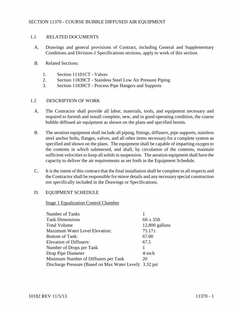
10182 REV 11/5/13 11370 - 1
SECTION 11370 - COURSE BUBBLE DIFFUSED AIR EQUIPMENT
1.1 RELATED DOCUMENTS
A. Drawings and general provisions of Contract, including General and Supplementary
Conditions and Division-1 Specifications sections, apply to work of this section.
B. Related Sections:
1. Section 11101CT - Valves
2. Section 11839CT - Stainless Steel Low Air Pressure Piping
3. Section 11830CT - Process Pipe Hangers and Supports
1.2 DESCRIPTION OF WORK
A. The Contractor shall provide all labor, materials, tools, and equipment necessary and
required to furnish and install complete, new, and in good operating condition, the coarse
bubble diffused air equipment as shown on the plans and specified herein.
B. The aeration equipment shall include all piping, fittings, diffusers, pipe supports, stainless
steel anchor bolts, flanges, valves, and all other items necessary for a complete system as
specified and shown on the plans. The equipment shall be capable of imparting oxygen to
the contents in which submersed, and shall, by circulation of the contents, maintain
sufficient velocities to keep all solids in suspension. The aeration equipment shall have the
capacity to deliver the air requirements as set forth in the Equipment Schedule.
C. It is the intent of this contract that the final installation shall be complete in all respects and
the Contractor shall be responsible for minor details and any necessary special construction
not specifically included in the Drawings or Specifications.
D. EQUIPMENT SCHEDULE
Stage 1 Equalization Control Chamber
Number of Tanks 1
Tank Dimensions 6ft x 35ft
Total Volume 12,800 gallons
Maximum Water Level Elevation: 75.17±
Bottom of Tank: 67.00
Elevation of Diffusers: 67.5
Number of Drops per Tank 1
Drop Pipe Diameter 4-inch
Minimum Number of Diffusers per Tank 20
Discharge Pressure (Based on Max Water Level): 3.32 psi

10182 REV 11/5/13 11370 - 2
Aerated Sludge Holding
Number of Aerated Sludge Holding Tanks 4
Tank Diameter, Each 65 ft
Total Volume 992,300 gallons
Maximum Water Level Elevation: 79
Bottom of Tank (Tapered Bottom): 62.67 - 69
Elevation of Diffusers: 68
Number of Drops per Tank 1
Drop Pipe Diameter 8-inch
Minimum Number of Diffusers per Tank 120
Discharge Pressure (Based on Max Water Level): 4.77 psi
1.3 QUALITY ASSURANCE
A. In addition to requirements of these specifications, comply with manufacturer's instructions
and recommendations for work.
1.4 SUBMITTALS
A. Shop Drawings: The Contractor shall submit complete shop drawings of all equipment
furnished for the project covered by these specifications. All shop drawings shall clearly
identify the specific equipment and material being supplied, the quantity being supplied,
and all accessories, dimensions, descriptions, dimensional/orientation layout drawings,
mounting and connection details, electrical control diagrams, wiring schematics and any
other information required by the Engineer/Owner to determine compliance with the plans
and specifications. The shop drawings shall be reviewed by the Contractor for
completeness and compliance with the project and so acknowledged prior to the review by
the Engineer. Fabrication and installation shall be in accordance with such approved
drawings.
B. Diffuser rating curves.
C. Submit manufacturer's technical data and application instructions
1.5 APPROVED MANUFACTURERS
A. Sanitaire - Water Pollution Control Corp., Milwaukee, WI
B. EDI – Environmental Dynamics, Inc., Columbia, MO
C. Siemens Water Technologies, Alpharetta, GA
D. Aquarius Technologies, Inc., Port Washington, WI
E. Approved Equal

10182 REV 11/5/13 11370 - 3
PART 2 - PRODUCTS
2.1 AIR CHECK DIAPHRAGM DIFFUSERS
A. Provide air check diaphragm type coarse bubble diffusers complete with gate valves,
supports, header, and drop piping as specified herein and listed in the Equipment
Schedule.
B. Design. Each air check diaphragm diffuser shall be of the nonclog type which during
aeration causes the diaphragm to distend and allows air to exit through the diffuser
orifices. When air flow stops, the diaphragm seats by pressure head of liquid and thus
prevents backflow. The maximum recommended air volume per diffuser shall not
exceed 5 standard cubic feet per minute (scfm). Each diffuser body shall be
manufactured of a corrosion resistant plastic.
C. Arrangement. The diffusers shall be spaced evenly along the header at a spacing not to
exceed 18 inches.
2.2 HEADER AND AIR SUPPLY DROP PIPING
A. Provide the header and air supply drop piping for diffusers as specified herein.
B. Diffuser Header Pipe. Each header pipe shall be Schedule 40, 304L stainless steel pipe
with threaded adapters welded to the pipe for installation of the diffusers. Each header
shall be complete with fittings and end caps for the installation shown on the plans.
C. Supports. Each header pipe shall be removable and shall be supported as detailed on the
plans.
D. Air Drop Pipe. Each header assembly shall be provided with a vertical air drop pipe. Each
air drop pipe shall be Schedule 40, 304L stainless steel pipe and shall have a union to
facilitate removal.
2.3 AIR CONTROL VALVE
A. Each air drop pipe for diffusers shall be provided with a gate valve to control the flow of
air. Each gate valve shall be Class 125, all bronze, and equipped with a handwheel
operator.
2.4 SHOP PAINTING
A. All fabricated steel surfaces requiring painting shall be thoroughly cleaned per SSPC SP 5
and shop primed as specified in Section 09801 Special Coatings.
PART 3 - EXECUTION

10182 REV 11/5/13 11370 - 4
3.1 INSTALLATION
A. Prior to connecting the diffusers to the headers, the Contractor shall carefully clean all
piping, headers, and accessories through which air is delivered, so that all dust, dirt, oil,
grease, or other foreign material will be effectively removed from contact with the air being
blown through the diffusers. This cleaning shall be done with clean water at a velocity of 2
to 3 feet per second. All diffusers in a tank shall be level and shall be installed at the same
elevation.
3.2 TESTING
A. After the piping, headers, and diffusers for any tank have been installed, clear water shall be
introduced into the tank until the diffusers have been covered about 2 inches. Compressed
air shall then be released through the tubes and any leaks through joints, piping, and the like
shall be repaired. This test shall be repeated until the entire system is tight, to the
satisfaction of the Engineer. Testing will be done by the Contractor under the direction of
the Engineer.
3.3 OPERATION AND MAINTENANCE MANUALS
A. Prior to or with the delivery of equipment, the manufacturer shall provide copies of an
operation and maintenance manual including storage, installation, start-up, operating and
maintenance instructions, and a complete parts list and recommended spare parts list. The
O & M Manuals shall be in compliance with the General Requirements.
3.4 MANUFACTURER’S REPRESENTATIVE
A. A qualified representative of the equipment manufacturer shall inspect the completed
installation, service the equipment, and operate the equipment under all design conditions,
assist with adjusting of air flow to each diffuser bank, instruct the Owner’s personnel in
proper operating and maintenance procedures, and provide the Owner with a written
certificate of approval.
END OF SECTION 11370CT

10182 REV. 10/31/13 11371CT - 1
SECTION 11371CT - LIQUID POLYMER FEED SYSTEM
PART 1 - GENERAL
1.1 SCOPE
A. This section includes the furnishing and installation of equipment for transferring, mixing,
and feeding polymer to the belt filter press and for the purpose of and improving the
dewatering characteristics of the waste activated sludge.
B. The polymer dilution/feed system shall include: an integrated equipment package which
shall automatically meter, dilute, completely activate and feed liquid polymer and water;
backflow preventer, pressure reducers, priming accessories, interconnecting piping and
valving, all necessary level controls, all necessary starters, and all other accessories
necessary to provide a complete and operable system.
1.2 GENERAL
A. The polymer dilution/feed system shall be: Dynablend system Fluid Dynamics, Inc. of
Boulder CO, Polyblend-UGSI, VeloDyne, or Approved Equal.
PART 2 - PRODUCTS
2.1 POLYMER DILUTION/FEED SYSTEM
A. Concentrated polymer and water shall be blended in a complete back-mixed high energy,
low shear environment.
B. Mixing chamber shall be constructed of materials which allow the operator to view the
mixing action within. Mixer motor shall be ball bearing type, permanently lubricated,
TEFC.
C. System shall include a diaphragm-type metering or progressive cavity type pump capable of
pumping solution or emulsion-type polymers of anionic, non-anionic, or cationic types with
apparent viscosities of 75,000 cps. The metering pump shall capable of a neat polymer
output of 0.75 to 15.0 gph.
D. System shall have a solenoid valve for on/off control of dilution water supply. System shall
have a rotometer-type flow indicator equipped with integral rate adjusting valve. Water
flow rate shall be adjustable from 60 to 600 gph.
E. System electrical requirement shall be 120 VAC, average input power less than 11 amps.
F. System shall include all component parts necessary in a single compact package that may
be easily transported and floor mounted adjacent to a storage tank of concentrated liquid
polymer.

10182 REV. 10/31/13 11371CT - 2
G. Controls: 1. A control panel integral to the systems frame shall be provided. The enclosure shall be
rated NEMA 4X and constructed of FRP. The control panel shall consist of all
controllers, digital displays, potentiometers, switches, lights, relays, and other control
devices required for a complete operable system. The control panel and all components
shall be industrial duty. All skid mounted electrical components interconnected to the
control panel shall terminate at numbered and labeled terminal blocks. The terminal
blocks shall be sized for 14 ga. wire. Wires shall be neatly run through wire race-way
and numbered with shrink tubing type labels. Adhesive labels shall not be used. The
control panel shall be positioned such that there are no obstructions in front of the
control panel per related NFPA requirements. Control.
2. Power: 120 VAC, 1Ph, 60/50 Hz..
3. A circuit breaker on the main control circuit and on each motor shall be provided as
manufactured by Allen Bradley or equal. Fuses shall not be used for circuit protection.
3. Operator Interface – Discrete Selector Switch:
a. System ON / OFF(reset) / Remote
b. Ten-Turn Potentiometer – Progressive Cavity Metering Pump Control
4. Status / Alarm Indicators:
a. Main Power ON
b. Display of Metering Pump Rate (diaphragm pump only: located on diaphragm
metering pump face)
5. Inputs (signals by others):
a. Remote Start / Stop (discrete dry contact)
b. Pacing Signal Based on Process Flow (4-20mA)
6. Outputs:
a. System Running (discrete dry contact)
b. Remote Mode (discrete dry contact)
c. Common Alarm (discrete dry contact)
PART 3 - EXECUTION
3.1 INSTALLATION
A. The liquid polymer feed system shall be installed and connected in accordance with the
manufacturer's instructions.
3.2 Field Services
A. Provide the services of a qualified field service technician to inspect and certify the
installation, start up the equipment, troubleshoot any problems that may arise and
provide complete and thorough training of operator personnel.
B. Field services shall consist of one (1) eight (8) hour day, exclusive of travel time.
END OF SECTION 11371CT 1/89

10182 REV. 11/5/13 11376 - 1
SECTION 11376 - MEMBRANE AERATION SYSTEM
PART 1 - GENERAL
1.1 RELATED DOCUMENTS
A. Drawings and general provisions of Contract, including General and
Supplementary Conditions and Division-1 Specifications sections, apply to work
of this section.
B. Related Sections:
1. Section 11101CT – Valves
2. Section 11839CT - Stainless Steel Low Air Pressure Piping
3. Section 11830CT - Process Pipe Hangers and Supports
1.2 DESCRIPTION OF WORK
A. The work under this section includes furnishing and installing fine bubble
membrane air diffusion equipment assemblies in the two (2) existing 151 ft x 75 ft
ID x 10.5 ft SWD chlorine contact tanks for their conversion to post aeration
tanks, as shown on the Drawings, as described in this section, or as directed by the
Engineer.
B. Each of the fine bubble membrane air diffusion assemblies shall consist of a drop
leg, submerged manifold and supports; air distribution header system with
diffuser element holders, gaskets, moisture blowoff assemblies, distributor
supports, anchor bolts, expansion couplings, dropleg and manifold joints, fittings
for laterals, fine bubble membrane diffuser elements, airlift purge system and all
other accessories required for satisfactory operation.
C. All of the membrane air diffusion assemblies shall be a product of the same
manufacturer. The manufacturer shall provide necessary data proving that the air
assemblies will perform in accordance with the Specifications when operated at
the specified design conditions.
1.3 QUALITY ASSURANCE
A. The manufacturer shall provide the required number of diffusers and adequately
sized air piping to meet the specified oxygen transfer and headloss requirements.
If more diffusers are required than specified elsewhere or shown on the drawings,
then such diffusers shall be provided. Similarly, if larger diameter manifold or
dropleg piping must be furnished to meet the total system pressure drop, then
there shall be no adjustments in price for the cost of extra diffusers or larger pipe.

10182 REV. 11/5/13 11376 - 2
B. Equipment shall be provided by a company experienced and qualified in the
design, manufacture and operation of similar fine bubble aeration systems.
C. Provide evidence of previous experience by submitting a list of at least ten similar
fine bubble aeration systems in continuous satisfactory operation for a period of
not less than three years. Submit list of installations, including names and phone
numbers of key contacts with the shop drawing submittal package.
D. Provide evidence of experience and description of adequate facilities to perform
factory oxygen transfer tests. Submit copies of previous oxygen transfer test
reports conducted in accordance with the ASCE subcommittee on Oxygen
Transfer and details of the factory oxygen transfer test facility, if required by the
Engineer.
1.4 SUBMITTALS
A. Submit shop drawings and technical information to show compliance with the
specifications. The information shall include the following:
1. Drawings showing plan views and cross sections of the equipment as
installed in the post aeration tanks.
2. Detailed layouts of anchor bolt locations and anchor bolt technical
information.
3. Fabrication drawings showing details of distribution laterals, droplegs and
manifolds.
4. Complete and detailed Bill of Materials listing all required quantities of
equipment and spare parts.
5. Detail drawings of standard system components.
6. Certified oxygen transfer test report from previous factory oxygen transfer
tests or procedures for performance testing, if required.
7. Procedures for product quality control testing, as required herein.
8. Installation, operation and maintenance manual.
9. A list of operating systems complying with this specification.
1.5 APPROVED MANUFACTURERS
A. Sanitaire - Water Pollution Control Corp., Milwaukee, WI.
B. EDI – Environmental Dynamics, Inc., Columbia, MO
C. Siemens Water Technologies, Alpharetta, GA
D. Aquarius Technologies, Inc., Port Washington, WI
E. Approved Equal

10182 REV. 11/5/13 11376 - 3
1.6 PACKAGING, PROTECTION, AND STORAGE
A. All fittings shall be carefully packaged in triple wall corrugated fiberboard
containers to protect the components from dirt and dust and from the effects of
ultraviolet light. Containers shall have a water-resistant copolymer coating.
B. Diffusers shall be stored in their shipping cartons until they are ready for
installation.
C. Stainless steel pipe shall be carefully stored so that the interior of the pipe remains
clean. Contact with non-stainless steel ferrous materials shall be avoided.
D. The Contractor shall inspect all shipping cartons for damage and shall promptly
report any damage to the manufacturer. The Contractor shall also confirm ship
quantities with the approved Bill of Materials.
PART 2 - PRODUCTS
2.1 POST AERATION SYSTEM DESIGN CRITERIA
A. The diffuser system is intended to aerate BNR MBR effluent.
B. Equipment Schedule
Number of Post Aeration Tanks 2
Tank Dimensions, (Each) 151ft x 75ft
Tank Volume, (Each) 1.3 MG
Maximum Water Level Elevation: 51.59
Elevation of Diffusers: 44.0±
Number of Drops per Tank 2
Minimum Number of Diffusers per Tank 130
DO 3.0 mg/l
Drop Pipe Diameter 6-inch
Discharge Pressure (Based on Max Water Level): 3.29 psi
C. Diffuser numbers and arrangement as shown on the plans are based on one
acceptable layout. Other layouts are acceptable so long as they meet the
requirements of this specification and are grid layouts. Arrangements that provide
diffusers only along the wall of the tank so that a roll pattern results in the tank
shall not be permitted.
2.2 EQUIPMENT, MATERIALS, AND WORKMANSHIP
A. Disc Diffuser Assembly
1. Diffuser assemblies shall consist of singular or dual unit diffusers.
Diffusers shall be composed of EPDM elastomer with a PVC body and
shall be resistant to attack by common municipal wastewater.
10182 REV. 11/5/13 11376 - 4
2. Diffusers shall be free of voids, tears, bubbles, creases or other structural
defects.
3. The diffuser unit with membrane media shall be fully capable of operating
under continuous or intermittent conditions and shall be designed with
check valve capabilities to prevent entry of liquid into the diffuser unit or
air piping on air shutdown or interruption of air supply.
4. Membrane shall allow openings to close when the air supply is
interrupted, and shall contract and seat on backer plate. 5. The maximum recommended air volume per diffuser shall not exceed 3
standard cubic feet per minute (scfm).
B. Disc Diffuser Baseplates
1. Each diffuser baseplate shall be factory solvent welded or mechanically
attached to the PVC diffuser lateral and shall be manufactured of PVC
with 1-1/2% Ti02 added for ultraviolet protection. The welding contact
area between the baseplate and the distribution lateral shall be sized to
provide a structurally sound connection.
2. The baseplate shall be centered on the crown of the pipe and the angular
variation of all the baseplates on a distribution lateral shall not exceed +/-
1.0 degree.
3. Each baseplate shall incorporate an air flow control orifice sized to give
minimum headloss while assuring uniform air distribution.
C. Panel Diffusers and Assembly
1. Each diffuser assembly shall be factory assembled and include support
tube and membrane retainer clamps.
2. The diffuser membrane shall be fully supported over full length and
circumference with a PVC membrane support frame.
3. Each diffuser membrane shall be held in place by two (2) 304 SS or GFPP
crimp type retainer clamps.
4. Installation of the diffuser membrane shall be accomplished with the
removal and installation of the membrane clamps.
5. The diffuser unit shall be fully capable of operating under continuous or
intermittent conditions and shall be designed with check valve capabilities
to prevent entry of liquid into the diffuser unit or air piping on air
shutdown or interruption of air supply.
6. Membrane shall allow openings to close when the air supply is
interrupted, and shall contract and close around and seal against the full
diameter support frame.
7. Diffuser units shall be completely factory assembled with diffuser support
frame, membranes, and retainer clamps.

10182 REV. 11/5/13 11376 - 5
D. Piping, headers, and supports shall be 304L stainless steel with a 2D finish
conforming to ASTM A240 or a full immersion passivation conforming to ASTM
380. Bolts, anchor bolts washers and follower flanges shall be made from 304
stainless steel. The pipe, drop-legs and headers shall have a minimum wall
thickness of 0.109 inches.
E. Flanges above liquid level shall consist of a 304L stainless steel angle ring and a
galvanized ductile iron follower flange per ASTM A-536 with 125 lb bolt pattern.
Submerged flanges shall have a stainless steel follower flange. Hardware shall be
stainless steel.
F. Piping, drop-legs and header dimensions shall be as shown on the drawings with
dimensional tolerances conforming to ASTM A554 and ASTM A530.
G. All welding on this equipment shall be completed in the factory. Field welding
shall not be permitted unless specifically noted. All welding shall be by the
shielded arc, inert gas, MIG or TIG method. Filler wire shall be added to all
welds to provide for a cross-section of weld metal equal to or greater than the
parent metal. Butt welds shall have full penetration to the interior surface and gas
shielding shall be provided to the interior and exterior of the joint. Welding
procedures, welders and welding equipment shall meet the requirements of
ASME Code Section IX.
H. Expansion joint gaskets shall be composed of solid neoprene rubber and shall
conform to ASTM D-2000. Gaskets shall be suitable for withstanding the effects
of wastewater and for temperatures up to 250 °F.
I. Supports
1. Header and lateral supports shall be spaced at a maximum distance
of eight (8) feet. Supports shall include a vertically adjustable
header hold down locking mechanism mounted on a stainless steel
supporting structure. All supports shall have a minimum plus or
minus two (2) inch vertical adjustment and plus or minus one half
(1/2) inch lateral adjustment.
2. Supports shall be secured to tank floors with expansion bolts.
Anchor bolts shall be designed with a minimum strength safety
factor of ten (10) to resist the calculated buoyant forces.
3. A support assembly shall be provided at or near the mid-point of
every distribution lateral. A support shall also be provided for
every expansion coupling. Two (2) supports shall be provided on
the corner tees of all grids.
4. The support system shall provide adequate resistance to any thrust
generated by water hammer at the end of each distribution lateral.
Supports at the ends of grids or ends of distribution laterals shall
not deflect more than 0.05 inches under a horizontal load of 300
lbs.

10182 REV. 11/5/13 11376 - 6
J. Stainless Steel Droplegs
1. The stainless steel droplegs shall convey process air from the start of the
aeration system supplier's scope (generally the downstream flange of the
butterfly valve) to the connection point to the manifold riser or the lower
dropleg.
2. Dropleg piping shall be welded Schedule 5S 304L stainless steel
conforming to ASTM A-240 with a maximum length of 20' nominal.
3. Non-welded components shall be Type 304 stainless steel and shall
include follower flanges, bolts, nuts and washers.
4. The dropleg shall connect to the air main or valve with a loose follower
flange with ANSI B16.1 Class 125 flange pattern. The dropleg shall
connect to the lower dropleg or diffuser manifold with a sleeve joint for
ease of installation, alignment and adjustability. Support of the dropleg
shall be from its upper connection. Additional stabilizing brackets shall be
provided as required, depending on the length of the dropleg.
5. Welding procedures, welders and welding operators shall meet the
requirements of ASME Code Section IX. Procedures shall be tested to
insure full penetration welding.
6. The longitudinal welds in pipes and fittings shall be made either by the
automatic GTAW (gas tungsten arc welding) with or without filler metal,
the automatic GMAW (gas metal arc welding) or the automatic plasma arc
welding process. Gas backup protection shall be provided in all cases.
Interior weld beads shall be smooth and even and shall not have an interior
projection more than 1/16" beyond the I.D. of the pipe or fitting.
7. Pipe and fittings shall be manufactured in accordance with ASTM A-778
and A-774 respectively.
8. Pickling, passivation and other corrosion protection techniques shall be in
accordance with ASTM A-380.
9. Pipes shall be straight within a maximum of 1/8" deviation over 10 feet.
Surface finish of welds shall be “as-welded”.
K. Moisture Blowoff Assemblies
1. Provide at least one (1) moisture blowoff assembly for each aeration grid.
2. The vertical moisture blowoff piping shall be Schedule 80 1/2" diameter
PVC in accordance with ASTM D-2467. Fittings shall be solvent welded
socket type Schedule 80. Field solvent welding shall be permitted for this
item. The vertical piping shall be secured to the tank wall with stainless
steel anchors and nylon or stainless steel cable fasteners. Support spacing
shall not exceed 5 feet. The vertical piping shall extend to the top of the
post aeration tank or baffle wall but not more than 5' above the water
surface.

10182 REV. 11/5/13 11376 - 7
3. Provide a 1/2" Schedule 80 PVC tee at the top of the vertical blowoff
piping. One (1) outlet of the tee shall have a threaded cap to allow clean
out of the blowoff piping.
The other outlet of the tee shall have a 1/2" PVC threaded gate valve or
ball valve.
4. The bottom of the vertical purge piping shall connect to a moisture
blowoff tee. The moisture blowoff tee shall be integral with the aeration
grid piping and shall be provided with a factory-welded 1/2" PVC dip tube
which shall remove moisture from the invert of the grid piping.
2.3 SPARE PARTS
A. One set of special tools needed for installation of maintenance shall be provided.
B. Provide the following spare parts for the Owner's inventory.
1. Ten percent of the number of installed diffusers, including retainer rings
and diffuser support plates, as applicable
2. One percent of the total number of installed pipe supports, including
anchor bolts
3. One percent of each type of diffuser lateral (disc system only).
4. Two percent of the total number of expansion fittings (tees and couplings).
C. The above spares shall be provided strictly for the Owner’s inventory. In addition,
furnish and identify separately in the Bill of Materials a nominal quantity of spare
parts for the Contractor’s use to cover loss, breakage, etc.
PART 3 - EXECUTION
3.1 MANUFACTURER'S SUPERVISION
A. A qualified representative of the equipment manufacturer shall inspect the
completed installation, service the equipment, and operate the equipment under all
design conditions, assist with adjusting of air flow to each diffuser bank, instruct
the Owner’s personnel in proper operating and maintenance procedures, and
provide the Owner with a written certificate of approval.
3.2 INSTALLATION PROCEDURES
A. Contractor shall furnish, inspect, store, and install aeration system in accordance
with manufacturer’s written instructions and approved submittals.
B. Diffuser assemblies on a common grid shall be installed within an elevation
tolerance of ±1/2 inches.

10182 REV. 11/5/13 11376 - 8
C. Contractor shall provide all valves, air header piping, wall sleeves with seals, wall
pipes, and concrete pedestals as necessary to complete the system as shown on the
plans.
D. Air piping including blower manifold, header, and in-basin piping must be clean
prior to delivering air up the diffusers.
E. Contractor shall be responsible for cleanliness of piping and may be required to
manually clean pipe, or air or water flush piping as required.
3.2 START-UP AND FIELD TESTING
A. After installation is completed, the Contractor shall perform the following field tests
in the presence of the Engineer and the Owner.
1. Fill the reactor to the bottom of the diffuser assemblies.
2. Adjust the pipe supports and diffuser assemblies such that all diffuser
units are installed within ±1/2 inches of the design diffuser elevation.
3. Fill the reactor to a level of 2 feet above the top of the diffusers.
4. Release air to the system and inspect the system for air leaks at all piping
or diffuser connections.
5. Check all membrane for cuts or tears that may have occurred during the
installation.
6. Adjust any piping or diffusers that show leaks or disproportionate amount
of airflow.
7. Operate the blowers at the design air rate and observe air release and air
distribution patterns.
8. All water, air, power and labor associated with testing and adjustment of
diffuser assemblies are to be supplied by Contractor.
B. The Contractor shall furnish the Engineer a written report certifying that the
connecting piping and supports are free from any stress, that the equipment is
properly installed and operable, and that the system has been satisfactorily
operated at full capacity.
3.3 OPERATION AND MAINTENANCE MANUALS
A. Operation and Maintenance (O & M) Manuals shall be provided prior to or with
delivery of the equipment. The O & M Manuals shall include instructions on
storage, installation, start-up and operation and maintenance, together with a
complete parts list and a recommended spare parts list, and shall be in compliance
with Section 01097.
END OF SECTION 11376

10182 REV. 11/1/13 11377CT - 1
SECTION 11377CT - POSITIVE DISPLACEMENT BLOWERS AND ACCESSORIES
PART 1 - GENERAL
1.1 RELATED DOCUMENTS
A. Drawings and general provisions of Contract, including General and Supplementary
Conditions and Division-1 Specifications sections, apply to work of this section.
1.2 DESCRIPTION OF WORK
A. This section includes the furnishing and installation of positive displacement (straight
and hybrid lobe) blowers and all pertinent accessories, complete and in place, ready for
service as shown on the Drawings and described in this section.
B. Each of the blowers shall be furnished complete with positive displacement blower,
electric motor, inlet and discharge expansion joints, discharge check valve, discharge
butterfly valve with operator, inlet and discharge silencers, filter, pressure relief valve,
anchor bolts, and all other accessories required for satisfactory operation.
C. Aerzen Hybrid blowers are approved for these applications and may be provided with
their standard offerings where this specification for standard rotary lobe blowers differs.
1.3 QUALITY ASSURANCE
A. In addition to requirements of these specifications, comply with manufacturer's
instructions and recommendations for work.
1.4 SUBMITTALS
A. Certified general arrangement drawings showing materials, details of construction, dimensions
and connections.
B. Complete Performance Data at the Design Point and all specified operating points including:
C. Actual Operating Speed (RPM) and % of maximum rated speed,Capacity – scfm and icfm,
Design inlet conditions, pressure, temperature and RH%, Discharge pressure, dB(A) noise
pressure level
D Blower Shaft HP, Motor HP and Package HP
E. List of recommended spare parts broken down into on hand parts and long term for 2 years
operation and 3 to 5 years operation.
F. Descriptive Brochures

10182 REV. 11/1/13 11377CT - 2
G. Performance Curves (for vfd applications)
H. Motor Data
I. Instrumentation and Wiring Diagram
L. Complete blower package operating and maintenance instructions.
PART 2 - PRODUCTS
2.1 EQUIPMENT
A. The positive displacement blowers shall be in accordance with the requirements
described in this section.
B. The blowers shall be of the two (2) impeller, rotary positive displacement design, with
the drive units and couplings able to transmit the noted horsepower of the drive motor to
the blower without excessive wear or strain on any component part of the blower or
motor.
C. The cylinder casing shall be one-piece with separate headplates, gear cover, and end
cover and shall be close grained cast iron.
D. The impellers shall be of the straight lobe involute type made from a ductile iron casting
and shall operate without rubbing or liquid seals or lubrication, and shall be positively
timed by a pair of accurately machined steel spur tooth, timing gears. Each impeller
shall be mounted on a carbon steel shaft having a press fit in the impeller and supported
by two (2) double row antifriction bearings.
E. There will be provided a positive oil seal at each bearing, designed to prevent lubricant
from leaking into the air stream. Further provisions shall be made to vent the impeller
side of the oil seal to the atmosphere, eliminating any possible carryover of lubricant
into the air stream.
F. Units shall have splash oil lubrication at the gear end and may be oil or grease lubricated
at the drive end. The oil level on the timing gears shall be regulated to the optimum by
means of a metering orifice. A sufficient amount of lubricants for each blower should
be supplied for normal recommended operation. The type of lubricants shall be as per
the manufacturer's recommendations.
G. Motors:
1. Each blower shall be provided with a horizontal squirrel cage induction motor of
sufficient power such that the above specified operating points can be safely
attained without exceeding the motor nameplate horsepower.
2. The motors shall be NEMA Design B, with Class F insulation for a 60 C
maximum temperature rise above a 40 C ambient, and a 1.15 service factor. The
motor enclosure shall be Nema Class B. Nameplate horsepower shall, at
minimum, be as specified above.

10182 REV. 11/1/13 11377CT - 3
3. The motors shall be in conformance with the latest recommendations of IEEE and
NEMA, including noise requirements.
H. Baseplate:
1. The blowers shall be furnished with a fabricated steel base of sufficient size and
rigidity to support and maintain alignment of the blower and motor. Blowers shall
be installed on adjustable motor bases.
2. Baseplates shall be grouted in place as required by conditions of installation with
a nonshrink grout equal to Five Star Grout, Master Builders Embeco 636 Grout,
or equal. Minimum grout thickness shall be 1-1/2 in. or as recommended by the
manufacturer. Provide structural steel framework and supports as required.
3. Belt guards shall be provided which completely enclose the V-belts and sheaves.
The guards shall be easily removable so that belts may be conveniently serviced.
Guards are to be painted OSHA orange.
4. All required anchor bolts and sleeves shall be ASTM A 36 steel and shall be
furnished by the equipment manufacturer.
5. The V-belt drive shall be approved by the blower manufacturer.
2.2 ACCESSORIES
A. Inlet Air Filter:
1. Each blower shall be furnished and installed with an inlet filter compatible with
the operating conditions of the blowers.
2. The filters shall consist of a dry type radial fin felted element contained in an
enameled carbon steel all-weather housing. Outlet shall be same nominal piping
size as its respective blower.
3. Nominal retention shall be 98% of particles 10 microns in diameter or larger.
Initial headloss thru the filter will be 1/2 in. of water column or less. The filter
design will utilize a molded end element to prevent leakage of unfiltered air past
the element.
4. The inlet filters shall be manufactured by Dollinger Corporation, Model
AI-104-SB-330-080 for the septage tank, Model AI-104-SB-110-040 for the grid
tanks, and Model AI-104-SB-58-030 for the phosphorus tanks; Universal; or
equal.
B. Inlet and Discharge Silencers
1. Each blower shall be fitted with an inlet and discharge silencer as shown on the
Drawings and as compatible with the operating conditions of the blowers.
2. The silencers shall be the absorption type with annular perforated metal air
passages surrounded by sound absorbing material. Silencers shall be all-welded
hot-rolled steel construction, with piping connections of the same nominal size
and type as the blower inlet and outlet connections. Exterior surfaces are to prime
coated.
10182 REV. 11/1/13 11377CT - 4
3. The inlet and discharge silencers shall be the product of Burgess-Manning,
Universal or equal. Overall length of silencers used may not exceed that shown in
the Drawings.
C. Additional Accessories:
1. Each blower shall be equipped with a discharge pressure dial gauge which
included Bourbon tube gearless movement, 2-1/2 in. dial with 0-15 psig range,
bottom 1/4 in. male pipe thread connection, and a black finish brass case. The
pressure gauge shall be provided with a gauge cock.
2. One (1) set of special tools shall be provided for complete service and
maintenance of the blowers.
3. Inlet and outlet flexible connections: 25 psig @ 250oF continuous duty, Red
Valve Co. Series J-1, Class II.
4. Discharge pressure relief valves: Each blower shall be supplied with a pressure
relief valve for mounting in the discharge piping. Relief pressure shall be capable
of passing sufficient air volume to prevent overloading the blower or motor.
D. Sound-Proof Enclosures:
1. The sound enclosure shall encase the entire package and have inlet and discharge
openings to allow for proper ventilation.
2. The sound enclosure shall have easy open/lock maintenance door(s) located for
access to maintenance areas, a minimum of two (2) lifting handles and an integral
ventilation fan to insure proper cooling. The ventilation motor shall provide
approximately 10 CFM/motor HP.
3. Enclosure shall reduce the sound levels by 15-20 dBa and shall be sufficient to
meet the 75 dBa attenuation requirement at one (1) meter from any exterior
surface of the enclosure.
4. The enclosure shall be free standing and not attached or mounted onto the blower
package frame in any way. The enclosure shall be supplied with installation
instructions as well as all fasteners required for assembly.
5. Any pipe penetration holes in the enclosure shall be sized to allow for passage of
pipe flanges. All penetration holes shall have flash rings installed to seal around
the pipe.
6. Where blowers are to be located outside, enclosures shall also be weather-proof
E. Blower Piping:
1. Unless otherwise shown or indicated, blower inlet and discharge piping including
filters, silencers, valves, and accessories shall be the same nominal size and pipe
connection style as the blower inlet and discharge connections. Unless otherwise
shown or indicated, pipe and fittings 3" and smaller shall be SCH 40 galvanized
steel with threaded connections; pipe and fittings 4" and larger shall be ductile
iron with 125 lb. ANSI flanges.
2. All inlet and discharge pipe inside the buildings shall have neoprene bushings
installed in all flange holes. The neoprene bushings shall comply with ASTM D
2000-SC-725-BF latest specification.

10182 REV. 11/1/13 11377CT - 5
F. Spare Parts
1. Complete set of matched V-belts
2. One inlet air filter element
3. Spare parts shall be properly bound and labeled for easy identification without opening the
packaging.
2.3 Design Parameters
A. General
1. Sludge Holding / Conditioning Blowers
Type of Blower: Positive Displacement (PD) or Aerzen Hybrid
a. Number of Blowers: 3 (2 Duty, 1 Standby)
b. VFD’s Required: Yes
c. Maximum Elevation: 79
d. Minimum Water Level: 73
e. Bottom of Tank (Tapered Bottom): 62.67 – 69
f. Elevation of Diffusers: 68
g. Inlet Pressure: 14.29 psi
h. Discharge Pressure (Based on Max Water Level): 5.75 psi
i. Inlet Air Temperature: From 30˚F to 90˚F
j. Relative Humidity: From 60% to 70%
k. Maximum Flow per Blower: 2000 scfm
l. Minimum Flow per Blower: 500 scfm
m. Maximum energy to unit at 2000 scfm (PD) 59.2 KW
n. Maximum energy to unit at 2000 scfm (Hybrid) 56 KW
o. Operating Conditions: Based on DO and Water Depth
p. Turndown: 4 : 1
q. Power Supply: 480V, 3 Phase, 60Hz
r. Maximum HP per Blower (if PD Blower): 100
s. Maximum HP per Blower (if Hybrid Blower): 75
t. Motor Service Factor: 1.15
u. Recommended Manufacturers/Models for Sludge Holding Blowers
1) Aerzen Hybrid or PD)
2) Kaeser
3) Universal Blower PAC
4) Tuthill
5) Roots Dresser
6) Approved Equal
2. Post-Aeration Blowers
a. Type of Blower: Positive Displacement (PD or Aerzen Hybrid)
b. Number of Blowers: 2 (1 Duty, 1 Standby)
c. VFD’s Required: Yes
d. Maximum Water Elevation: 50.86
e. Minimum Water Level: 50.42
f. Bottom of Tank (Stepped Bottom): 38.16 – 42.83

10182 REV. 11/1/13 11377CT - 6
g. Elevation of Diffusers: 43.83
h. Inlet Pressure: 14.29 psi
i. Discharge Pressure (Based on Max Water Level): 4.5 psi
j. Inlet Air Temperature: From 30˚F to 90˚F
k. Relative Humidity: From 60% to 70%
l. Air Flow per Blower (constant): 650 scfm
m. Operating Conditions: Add 3 mg/l DO
n. Power Supply: 480V, 3 Phase, 60Hz
o. Maximum HP per Blower: 40
p. Motor Service Factor: 1.15
q. Recommended Manufacturers/Models for Post-Aeration Blowers
1) Aerzen Hybrid or PD
2) Kaeser
3) Universal Blower PAC
4) Tuthill
5) Roots Dresser
6) Approved Equal
PART 3 - EXECUTION
3.1 DELIVERY, STORAGE AND HANDLING
A. All equipment shall be completely factory assembled, skid mounted, crated and delivered to
protect against damage during shipment.
B. All exposed flanges shall be covered and sealed with shrink-wrap to prevent the entrance of
moisture. Finished iron or steel surfaces not painted shall be properly protected to prevent rust
and corrosion.
C. All equipment delivered to the site shall be stored as specified in accordance with the
manufacturer’s instructions.
3.2 INITIAL LUBRICATION
A. Initial lubrication required for startup and field test operation shall be furnished and
applied in accordance with the manufacturer's recommendations.
3.3 INSPECTION, STARTUP AND TESTING
A. The manufacturer of the blowers shall provide a representative for a minimum period of
five (5) days to check the installation, make final adjustments, supervise initial startup
of each blower, and prepare a written test report for the Owner.
B. The representative shall instruct the Owner's personnel in the operation and maintenance
of the equipment for a minimum period of one (1) eight (8) hour day.

10182 REV. 11/1/13 11377CT - 7
3.4 LUBRICATION
A. The equipment shall be lubricated by the Contractor when erected and he shall furnish
the necessary oil and or grease for one (1) year of operation. The grades of oil and
grease shall be in accordance with the recommendations of the manufacturer.
3.5 OPERATION AND MAINTENANCE MANUALS
A. Prior to or with the delivery of equipment, the manufacturer shall provide copies of an
operation and maintenance manual including storage, installation, start-up, operating
and maintenance instructions, and a complete parts list and recommended spare parts
list. The O & M Manuals shall be in compliance with the General Requirements.
END OF SECTION 11377CT 1/89

10182 REV. 11/08/13 11503CT-1
SECTION 11503CT - HEATED AND INSULATED BULK CHEMICAL STORAGE TANKS
PART 1 - GENERAL
1.1 DESCRIPTION
A. Scope:
1. CONTRACTOR shall provide all labor, materials, equipment and incidentals as
shown, specified and required to furnish and install fiberglass tanks.
2. The following vertical cylindrical tanks shall be provided as shown and as specified
herein:
a. Two (2) tanks for storage of alum.
b. Two (2) tanks for storage of refined glycerin.
B. Related Sections:
1. Section 05500, Metal Fabrication.
2. Section 05016, Aluminum Handrails.
3. Section 09801, Special Coatings (Surface preparation and shop painting are included
in this Section).
4. Section 13400, Field Mounted Instrumentation Equipment.
5. Section T11830, Process Pipe Hangers and Supports.
6. Section 15122, Chemical Feed System Appurtenances.
C. Coordination:
1. Review installation procedures under other Sections and coordinate the installation of
items that must be installed with fiberglass tanks.
2. Size and location of manways, pipe connections, etc. shall be coordinated with the
requirements of applicable chemical feed systems per the schedule and details shown
on the Drawings.
1.2 REFERENCES
A. Reference Standards: Comply with the latest edition of the applicable provisions and
recommendations of the following, except as otherwise shown or specified:
1. ASTM D3299, Standard Specification for Filament –Wound Glass-Fiber-Reinforced
Thermoset Resin Corrosion-Resistant Tanks.
2. ARM (Association of Rotational Molders), Low Temperature Impact Resistance
(Falling Dart Test Procedure).
3. ANSI B-16.5, Pipe Flanges and Flanged Fittings.
4. 29 CFR 1910.106 Occupational Safety and Health Administration, Flammable and
Combustible Liquids.
5. ASTM D-5421 Standard Specification for Contact Molded “Fiberglass” (Glass-
Fiber-Reinforced Thermosetting Resin) Flanges.

10182 REV. 11/08/13 11503CT-2
6. ASTM D-4398 Standard Test Method for Determining the Chemical resistance of
Fiberglass-Reinforced Thermosetting Resins by One-Side Panel Exposure.
1.3 QUALITY ASSURANCE
A. Manufacturer’s Qualifications:
1. CONTRACTOR shall furnish and install fiberglass storage tanks from a manufacturer
who has experience in the design and manufacturing of fiberglass storage tanks of the
same or larger size to those specified. For a manufacturer to be determined
acceptable for providing fiberglass storage tanks and appurtenances on this project,
CONTRACTOR shall show evidence of five separate, substantially similar
installations that have been in satisfactory operation for at least five years.
B. All equipment provided under this Section shall be obtained from a single supplier or
manufacturer. The manufacturer shall assume full responsibility for the engineering,
design and completeness of the system. The manufacturer shall be the source of
information on all equipment furnished regardless of the manufacturing source of that
equipment.
C. Independent Inspection and Testing:
1. CONTRACTOR shall retain the services of an independent inspection and testing
firm specially qualified in the design and inspection of fiberglass systems and tanks.
Within this Section, the representative of the inspection and testing firm is hereafter
known as "Inspector".
a. The Inspector shall send all inspection reports directly to the ENGINEER and
CONTRACTOR.
2. Inspection and testing firm shall have no affiliations with a specific fiberglass storage
tank manufacturer.
3. Provide Independent Inspection and Testing services of one of the following:
a. FSE Inc., 316 E. McLeod, Suite 1, Bellingham, WA 98226, (800) 800-7040.
b. Or equal.
4. Contractor shall submit the summary of qualifications for an “or equal” inspection
and testing firm for approval by ENGINEER prior to their selection. The statement
of qualifications shall include the following:
a. A summary of key staff members and their specific roles in inspection.
b. Resumes for the key staff members.
c. A sample format for the inspection reports.
D. Source Quality Control:
1. All dimensions will be taken with the tank in the vertical position, unfilled. Tank
dimensions will represent the exterior measurements.
a. The tolerance for the outside diameter, including out of roundness, shall be per
ASTM D 1998.

10182 REV. 11/08/13 11503CT-3
b. The tolerance for fitting placements shall be +/- 0.5 in. in elevation and 2 degrees
radial at ambient temperature.
2. Test specimens shall be taken form fitting location areas or piggy-back test molds.
3. Low Temperature Impact Test - ARM Standard:
a. Test specimens shall be conditioned at -40 degrees Fahrenheit for a minimum of
2 hours.
b. The test specimens shall be impacted in accordance with ARM Standard Test
Method. Test specimens <2" thickness shall be tested at 100 ft.-lb. Test
specimens > 2" thickness shall be tested at 200 ft.-lb.
4. Ultrasonic Tank Thickness Test
a. All tanks 2000 gallons or larger shall be measured for tank wall thickness at 6 in.,
1ft., 2ft. and 3ft. on the tank sidewall height at 0° and 180° around the tank
circumference with 0° being the tank manway and going counter-clockwise per
ANSI standard drafting specifications. A copy of this test report can be ordered
when placing the original tank order. All tanks shall meet design thickness
requirements and tolerances.
b. For tanks smaller than 2000 gallons a copy of the test report for the appropriate
manufactured lot verifying conformance with the design criteria specified will be
provided if ordered.
5. Hydrostatic Water Test: The hydrostatic water test shall consist of filling the tank to
brim full capacity for a minimum of four hours and conducting a visual inspection for
leaks. A hydrostatic water test will be conducted for all tanks.
E. Each tank shall be inspected for defects such as foreign inclusions, air bubbles, pinholes,
pimples, crazing, cracking and delaminations that will impair the serviceability of the
vessel. All cut edges where openings are cut into the tanks shall be trimmed smooth.
F. Contractor shall be responsible for obtaining any necessary storage tank permits.
1.4 SUBMITTALS
A. Shop Drawings: Comply with Section 01061, Shop Drawing and Submittals, and the
additional requirements below: Submit for approval the following:
1. Layout and all critical dimensions, including thickness of tank wall.
2. Materials of construction.
3. Fitting locations and details.
4. Accessories.
5. Anchor and hold-down details.
6. Manufacturer's literature, illustrations, chemical compatibility data, calibration charts,
specifications, engineering data and installation instructions.

10182 REV. 11/08/13 11503CT-4
B. Submit for the Record:
1. Three copies of structural design calculations sealed and signed by a registered
professional engineer.
C. Test Reports: Submit copies of test reports required.
D. Operation and Maintenance Manuals: Submit in accordance with requirements of Section
01097, Maintenance Manuals. The Operation and Maintenance Manuals shall include,
but not be limited to, the following:
1. Manufacturer’s written instructions for unloading, handling, and storing Fiberglass
tanks and appurtenances.
2. Installation instructions for installing tank on a concrete slab.
3. Tank manufacturer’s recommended compression ratio of the gasket for flanges.
E. Local Service Representative: Provide name, address and telephone number of
manufacturer and local, factory-trained service representative.
F. Documentation that the manufacturer meets the qualifications specified in paragraph
1.3.A above.
1.5 PRODUCT DELIVERY, STORAGE, AND HANDLING
A. Deliver materials to the Site to ensure uninterrupted progress of the Work. Deliver anchor
bolts and anchorage devices that are to be embedded in cast-in-place concrete in ample
time to prevent delay of the Work.
B. CONTRACTOR shall be responsible for the safe transportation to the Site, including any
freight cost and necessary permits, handling and open air storage of the tanks and other
materials purchased as specified in this Section. Refer to Section 01043, Product Handling
and Protection, and supplementary requirements below.
C. Handle all fiberglass storage tanks and appurtenances as recommended by the
manufacturer to avoid damage. Tanks that are damaged will not be acceptable. Protect all
tank appurtenances or sub-assemblies from damage and contamination. Refer to Section
01043, Product Handling and Protection, and supplementary requirements below.
1. Whenever feasible, shipments shall be made by truck.
2. Tanks that are shipped in horizontal position shall be mounted on padded cradles. All
tank end blocking used to prevent shifting of tanks shall be padded and bear only
upon the knuckle radius of the tank bottom.
3. Tanks shall be secured to the cradles or skids to prevent rotation or other movement.
In turn, the cradles or skids shall be fastened securely to the truck bed.
4. All tie-down straps shall provide provision for thermal expansion and shall be padded
where in contact with the equipment.
5. Flange faces shall be protected from damage by securely fastening suitable plywood
or hardboard to cover. The tanks shall be positively vented at all times.

10182 REV. 11/08/13 11503CT-5
6. Pipe, fittings and other miscellaneous small parts shall be crated or boxed. Additional
protection, such as end wrapping, cross bearing, or other interior fastening may be
required to assure such individual equipment pieces are not damaged in transit.
7. CONTRACTOR and ENGINEER shall inspect the equipment before it is unloaded at
the Site and any damage found shall be the carrier’s and/or fabricator’s responsibility
to repair at no additional cost to the OWNER.
8. The tanks and appurtenances shall be unloaded and stored in accordance with the
manufacturer’s written instructions.
1.6 WARRANTY
A. The equipment supplier shall furnish a manufacturer’s 5 year warranty on all components
of the fiberglass tanks, as described, furnished and installed under this item. Acceptance
by the OWNER is defined to be after start up, operation demonstration, and required field
testing. After these tasks by the Contractor are completed and accepted by the OWNER,
the OWNER is responsible for the equipment and the warranty period begins.
B. The warranty shall guarantee, at no cost to the OWNER, prompt repair or replacement of
any of the components which fail to function properly, under normal operation and
maintenance, due to deficiencies in product design, workmanship, or materials. The
warranty shall include the cost of all materials and labor required.
PART 2 - PRODUCTS
2.1 SERVICE CONDITIONS
A. CONTRACTOR shall furnish and install fiberglass storage tanks and appurtenances as
shown and specified herein.
B. General Design Conditions:
1. Normal Temperature. Storage tanks are intended to be installed outdoors and be
suitable for chemical delivery and storage temperatures from 0 º F. to 129 º F.
Chemicals may be delivered at higher or lower temperatures, depending on season.
2. Normal Internal Loads: Hydrostatic based on the specific gravity of the stored liquid.
3. External Loads:
a. Concentrated topload: 250 pounds distributed over a 4-inch by 4-inch area at the
top of the tank.
b. Tanks and tank hold down system shall be designed for 70 MPH wind load and
Seismic Zone 1 for Canton, Ohio, in accordance with the International Building
Code.
4. Storage Tank Configuration:
a. Bulk storage tanks and day tanks shall be flat-bottom, vertical, cylindrical,
vented tanks with domed tops.
5. All storage tank volumes as shown shall include only that volume in the straight shell
below the overflow pipe invert elevation. Nominal capacity or the inclusion of dished
tops, domed tops or freeboard as additional capacity is not acceptable.

10182 REV. 11/08/13 11503CT-6
C. Tanks shall be suitable for:
Chemical Concentration Specific
Gravity
Nominal
Diameter
(ft)
Straight
Shell
Length
(ft)
Capacity
(gallons)1
Accessories
Alum 48.5% 1.34 8’-0” 17’-0” 6,000 L,
HR,TLI,ULD
Refined
Glycerin 97% 1.25 8’-6” 16’-6” 7,000
L,
HR,TLI,ULD
1Capacity shall be based on the nominal diameter of the tank filled to within 3 inches of the
invert of the overflow.
D. Abbreviations: Abbreviations used in the Schedule:
Accessories:
a. Access Ladder L
b. Handrail & Grating HR
c. Tube Level Indicator TLI
d. Ultrasonic Level Detector ULD
2.2 MATERIALS OF CONSTRUCTION
A. Tank shall be constructed of filament-wound glass fiber reinforced thermoset resin in
accordance with ASTM D 3299. Surface portions of the tanks, inside and outside, shall
be suitable for the specified environment and chemical stored within the vessel.
B. Inner corrosion barrier fabricated with Atlac 382 polyester resin reinforced with 10 mil
"C" glass surface veil and backed with 100 mil chopped strand fiberglass laminate;
balance of laminate fabricated to full wall thickness with isophthalic polyester resin and
exterior surface finished with translucent exterior protective coating.
C. Tank top, side wall, and bottom shall be 1/4" minimum thickness. Tank top shall be
capable of supporting a 250 lb. load on 16 sq. in. area plus 20 lb./sq. ft snow load.
D. Fittings shall be neatly and accurately bonded in place and shall appear as an integral
part of the tank. The corrosion barrier of fittings shall be equivalent to that of the tank.
All fittings to be factory installed 150 Lb. flanged. All gaskets are to be compatible with
the chemical stored.
E. Flanged manway shall be 24" minimum diameter, lockable with turn-down cover,
gasket, and stainless steel fasteners.
F. Tank legs shall be furnished with hold down lugs or plates. Hold down system shall be
designed for 70 mph wind load and Zone 1 seismic load.
G. Manufacturer:

10182 REV. 11/08/13 11503CT-7
1. Plas-Tanks Industries.
2. Protecto Plas Co.
3. Warner Fiberglass Products
4. Justin Tanks
5. Or Approved Equal.
2.3 DETAILS OF CONSTRUCTION
A. Design:
1. The minimum required wall thickness of the cylindrical shell at any fluid level shall
be determined by the following equation, but shall not be less than 0.187 in. thick.
T = P x O.D./2 SD = 0.433 x S.G. x O.D./2 SD
T = wall thickness
SD = hydrostatic design stress, PSI
P = pressure (.433 x S.G. x H), PSI
H = fluid head, ft.
S.G. = specific gravity, g/cm^3
O.D. = outside diameter, in.
a. The hydrostatic design stress shall be determined by multiplying the hydrostatic
design basis, determined by ASTM D 2837 using rotationally molded samples,
with a service factor selected for the application. The hydrostatic design stress is
600 PSI at 73 degrees Fahrenheit. The tank shall have a stratiform (tapered wall
thickness) wall.
b. The hydrostatic design stress shall be derated for service above 100 degrees
Fahrenheit and for mechanical loading of the tank.
c. The design specific gravity shall be 1.9.
2. The minimum required wall thickness for the cylinder straight shell must be sufficient
to support its own weight in an upright position without any external support. Flat
areas shall be provided to allow locating large fittings on the cylinder straight shell.
The bottom knuckle radius of flat bottom tanks shall be a minimum of 2 inches.
3. The top head must be integrally molded with the cylinder shell. The minimum
thickness of the top head shall be equal to the top of the straight wall. The top head
of tanks with 2000 or more gallons of capacity shall be designed to provide a
minimum of 1300 square inches of flat area for fitting locations.
4. Tanks with 2000 or more gallons of capacity shall have a minimum of 3 lifting lugs
integrally molded into the top head. The lifting lugs shall be designed to allow
erection of an empty tank.
5. Bulk storage and day tanks shall be designed to provide a minimum of 4 tie-down
lugs integrally molded into the top head. The tie-down lugs shall be designed to
allow tank retention in wind and seismic loading situations without tank damage.
6. The storage tank design shall allow for an appropriate combination of conditions
which may include any or all of the following:
a. Internal or external pressure.
b. Static head of contents (working and test conditions).

10182 REV. 11/08/13 11503CT-8
c. Mass of structure and contents.
d. Design temperature including upset conditions.
e. Superimposed loads, such as seismic.
f. Live loads.
g. Bending moments due to eccentric loads.
h. Localized loads acting at supports, lugs, nozzles and other attachments.
i. Loads due to heating or cooling and thermal gradients.
j. Loads applied during transport or erection.
k. Loads imposed by personnel during erection and operations.
7. As a minimum, the following specific items shall be analyzed:
a. Shell overturning due to wind/seismic:
1) Wind and seismic not considered to act simultaneously.
2) For flat-bottomed tanks, resistance to overturning shall not include the
weight of the liquid contained in the tank.
3) All other normal operating loads to be combined with seismic or wind.
4) Critical buckling of the shell.
b. Anchoring, due to overturning and/or internal pressure:
1) Lug design.
2) Analysis of attachment to shell.
3) Effect on shell knuckle.
4) Maximum pullout forces and moments reported for the foundation design.
c. Attachments:
1) Ability of secondary overlays to support beams, clips, lugs, etc.
2) Effect of point loads on shell due to attachment of lugs, clips, etc.
3) Lifting lugs - ability to lift from horizontal (shipping) position to vertical.
d. Internal pressure or vacuum:
1) Main shell and head, hoop and axial.
2) Deflection of flat bottoms for empty tanks.
e. Thermal: Differential expansion of piping, duct and tank at temperature
extremes.
f. Special loads:
1) Transportation and handling loads.
2) Effect of piping on nozzles.
3) Dead or live loads on domes, as point loads or evenly distributed.
4) Dynamic loads due to fluid agitation.
B. Construction:
1. Bulk storage tanks shall be upright, cylindrical, flat-bottomed, one-piece seamless
construction by rotational molded.
2. The tanks shall be designed for above ground, vertical installation and shall be
capable of containing chemicals at atmospheric pressure.
3. Tanks shall be of sizes shown on the Drawings and specified herein.
4. Lifting Lugs: As required for installation. Capable of withstanding weight of tank
with a safety factor of 3 to 1.
5. Hardware for mounting and connections of accessories use: Hastelloy hardware for
alum and tanks shall utilize Schedule 10 Stainless Steel for Refined Glycerin.

10182 REV. 11/08/13 11503CT-9
6. All gaskets and accessories shall be compatible with the chemical in storage.
C. Fittings:
1. Bolted Double 150 lb. Flange Fittings:
a. The bolted double flange fitting shall be constructed with 2 ea/ 150 lb. flanges, 2
ea. 150 lb. flange gaskets, and the correct number and size of all-thread bolts for
the flange specified by the flange manufacturer. The flanges shall be constructed
of PVC Type 1, Grade 1. Gaskets shall be a minimum of 1/4" thickness and
constructed of 60-70 durometer viton. There shall be a minimum of 4 ea. all-
thread bolts. The bolts may have gasketed flanged metal heads or bolt heads
encapsulated in fiberglass material. The encapsulated bolt shall be designed to
prevent metal exposure to the liquid in the tank and prevent bolt rotation during
installation. The fiberglass encapsulation shall fully cover the bolt head and a
minimum of 1/4" of the threads closest to the bolt head. The fiberglass shall be a
minimum of 1/4" of the threads closest to the bolt head. Each encapsulated bolt
shall have a gasket to provide a bolt sealing surface against the inner flange.
b. Provide all sidewall fittings with a flexible expansion joint suitable for the
chemical being stored. Flexible expansion joints shall compensate for expansion
and contraction of the storage tank during filling and draining of the tank.
c. Provide 6-inch pipe flanged connections on top heads of storage tanks for level
instrumentation. Exact location shall be as recommended by the level instrument
manufacturer.
2. Bottom Side Drain Outlet Fitting:
a. The fitting shall be an integral part of the tank and provide complete drainage of
liquid through the sidewall of a flat bottom container without the use of a special
support structure or concrete pad. The outlet shall be constructed from a PVC
compatible schedule 80 male adapter.
2.4 ACCESSORIES
A. Extent: Provide accessories if shown on Drawings or in the Schedule.
B. Tube Level Indicators:
1. General:
a. Components, including any valves exposed to tank content and any components
located on the exterior of the tank below the elevation of the containment walls
shall be resistant to corrosion by tank contents.
b. Include a scale adjacent to the indicator graduated in gallons with graduations
spaced as appropriate for the tank size.
c. Connect indicator to the tank shell using flanged connections. Provide an
isolating globe valve, an automatic excess flow shutoff valve and a housing or
tube drain valve at the bottom connection. Connect the top of the housing or tube

10182 REV. 11/08/13 11503CT-10
to the tank shell, without an isolating valve, at a location which is at least one
inch above the crown of the tank overflow.
d. Connections for indicators shall be installed by the tank manufacturer and subject
to the same factory hydrostatic test as the tank.
e. The sight level gage shall be constructed of flexible PE tubing to allow for tank
contraction and expansion due to loading and temperature changes.
2. Clear Tube Type Indicator:
a. Clear tube type indicators shall be constructed of transparent plastic.
C. Manways:
1. Bolted Sealed Top Manway:
a. Provide the size and location as shown on the Drawings.
b. The sealed manway shall be constructed of fiberglass material. The bolts shall
be polypropylene, fiberglass or PVC. The manway gaskets shall be viton cross-
link fiberglass foam.
D. Exterior Access Ladder:
1. Construction: Heavy-duty OSHA fiberglass reinforced vinylester capable of a 300-lb
load. Ladder shall be 18-inches wide between side rails, and rungs shall be spaced
12-inches on center. Rungs shall be non-slip and square.
2. Ladder shall be equipped with safety cages in accordance with OSHA requirements.
3. Ladders shall meet OSHA requirements and be fully resistant to the liquids stored in
the corresponding fiberglass tanks.
4. Ladders shall be assembled at the factory.
5. Ladders shall meet ASTM requirements for UV resistance and flame spread.
6. Stainless steel angle clips shall be furnished for mounting the bottom of the ladders to
the concrete pad.
7. Tank tops shall be equipped with ladder clips to bolt ladder handrails to the tanks
8. Ladder hardware shall be 3/8-inch bolts, nuts, and washers unless otherwise specified
by FRP storage tank manufacturer.
9. Manufacturer:
a. Morrison Molded Fiberglass Co.
b. Daniel Mechanical.
c. Or equal.
E. Vents:
1. Required as shown.
2. Provide the size and location as shown on the Drawings.
3. Vents shall be constructed of Schedule 80 PVC.
4. Each tank vent line shall be equipped with an insect screen constructed from
materials that are compatible with the chemical stored in the tank.
F. Tank Pipe Support Brackets:

10182 REV. 11/08/13 11503CT-11
1. Pipe supports shall be furnished in accordance with Section 1T11830, Process Pipe
Hangers and Supports, and the additional requirements listed below.
2. Provide support braces from tanks' outside wall for support of the tanks' overflow
lines.
3. Maximum spacing between pipe supports shall be 5-feet.
G. FRP Handrail Grating on Top of Tanks:
1. Handrail, grating and appurtenances shall be manufactured of FRP and shall be
furnished and installed by the tank manufacturer. Handrail and grating shall meet
OSHA requirements and be fully resistant to the liquid being stored.
2. Handrail and grating shall be assembled at the factory.
3. Handrail and grating shall meet ASTM requirements for UV resistance and flame
spread.
4. All rails, posts, kick plates, base plates, fasteners, and necessary appurtenances for a
complete and rigid installation shall be provided and installed in accordance with the
manufacturer's recommendations.
5. Product and Manufacturer: Provide one of the following:
a. Morrison Molded Fiberglass Co.
b. GEF, Inc.
c. Or equal.
H. Tie Down Systems:
1. Tie down systems must meet seismic zone 1 requirements.
2. The tie down system shall be other than stainless steel and shall be resistant to the
chemicals stored.
I. Ultrasonic Level Detector
1. Ultrasonic Level Detectors are specified in Section 13500.
2.5 SPARE PARTS
A. Furnish and deliver the following spare parts as specified below:
1. Tanks: Two sets of each size of all gaskets, washers, and o-rings for each type of tank
furnished and installed.
B. Spare parts shall be packed in sturdy containers with clear indelible identification
markings and shall be stored in a dry, warm location until transferred to the OWNER at
the conclusion of the project.
2.6 TANK LABELS
A. Nameplates: Permanently attach either Type 316 stainless steel or fiberglass label to each
tank with the following minimum information.

10182 REV. 11/08/13 11503CT-12
1. Chemical to be stored including:
a. Concentration.
b. Specific gravity.
c. Maximum temperature.
2. Name, address, and telephone number of manufacturer.
3. Date of manufacture.
4. Tank serial number.
5. Tank material.
6. Tank capacity.
B. Tanks shall be furnished with OSHA approved 20-inch by 24-inch Chemical Warning
signs with NFPA 704 hazard numbers for the chemical services intended. Chemical signs
shall include, as a minimum, the name of the product stored in the tank, precautionary
measures, signal word (danger, warning, caution), statement of hazard, precautionary
measures, instructions in case of contact, exposure, etc. and NFPA 704 hazard numbers.
C. Labels: Provide right-to-know polyester labels for each hazardous chemical container.
Provide 7-inch by 10-inch labels with information pre-printed by manufacturer. Provide
labels with 2-mil polyester overlaminate and with a complete line of all standard and
custom pictograms.
2.7 HEATING SYSTEM
A. Freeze protection of tank contents shall be afforded by electric resistance heating
consisting of either low-watt density heat panels attached to the tank outer wall; or braided
- wire resistance elements encapsulated directly into the tank bottom.
B. The heating system shall be designed to maintain tank contents at a minimum delta T of
50F above outside ambient temperature, but in any event shall be one thousand (1000)
watt minimum heating capacity.
C. Heat panels shall have a minimum watt density of 125 watts/sq. ft. and shall be Factory
Mutual approved for hazardous area service. Each heat panel system shall use a product
temperature control thermostat and a panel overheat thermostat to protect tank and
contents from possible damage.
D. The tank bottom encapsulated heating system shall be 2" wide elements of nickel-clad
resistance wire braided into a structure of "E" grade fiberglass. The tape shall be installed
directly behind the inner corrosion barrier and shall become an integral part of the tank
bottom or straight shell. Current demands will be determined by a thermocouple in tank
bottom which directly reflects temperature of tank contents. System shall be able to
maintain a temperature deviation of plus or minus 3 °F of specified temperature.
E. All heating system control components shall be mounted in a high impact plastic or
fiberglass NEMA 4 enclosure. Thermostats shall have a minimum setting range of 35°F
to 100F. All controls shall be 120 VAC. Pilot lights shall include one (l) green "power
on" light and an amber "heater on" light for each heating circuit.

10182 REV. 11/08/13 11503CT-13
2.8 INSULATION
A. The insulation shall consist of two (2) inch minimum thickness of 2 lb. density
polyurethane foam board and shall have a minimum "R" factor of 13. All "R" factors are
to be calculated exclusive of the tank wall values.
B. The insulation utilized shall be of uniform density and thickness in order to avoid areas of
incalculable heat loss.
C. All nozzles and fittings shall have insulation replaced around lay-up areas.
D. The insulation shall be protected by a 0.125" thick fiberglass skin, consisting of chopped
continuous roving and filament winding. The insulation casing resin shall be pigmented
for UV protection.
E. Insulated tanks shall have external expansion joints, as required, to prevent damage to
outer protective layer due to temperature cycling. Expansion joint must be designed to
prevent seepage from rain and other forms of precipitation.
PART 3 - EXECUTION
3.1 INSPECTION
A. CONTRACTOR shall examine the conditions under which the Work is to be installed and
notify the ENGINEER in writing of conditions detrimental to the proper and timely
completion of the Work. Do not proceed with the Work until unsatisfactory conditions
have been corrected.
B. Inspect tanks prior to installation. If damaged, notify ENGINEER and manufacturer at
once.
C. Do not install damaged tanks until repairs are made in accordance with manufacturers
written instructions and approval by ENGINEER.
D. Inspect concrete pads for proper elevation, dimensions, evenness and anchor bolt
locations. Correct if required.
3.2 INSTALLATION
A. Install tanks in complete conformance with manufacturer's instructions.
B. CONTRACTOR will examine the areas and conditions under which tunneling is to For
bulk storage and day tanks, install lining material between the tank bottom and the
concrete pad according to the manufacturer’s recommendations. Lining material must be
compatible with chemical stored in tank.
3.3 FIELD QUALITY CONTROL
A. Refer to Section 01650, Starting of Systems.

10182 REV. 11/08/13 11503CT-14
B. Required Manufacturer Services: Retain a qualified representative of the manufacturer for
a minimum period of 8 hours to perform the following services:
1. Equipment Installation:
a. Oversee installation of the equipment and accessories specified herein.
b. Inspect the completed installation and note deficiencies.
2. Furnish test forms and procedures for field testing.
C. Field Testing:
1. Provide all test apparatus required at no extra cost to OWNER.
2. Follow testing procedures recommended by the manufacturer and approved by the
ENGINEER.
3. After installation is complete but before piping connections are made, block all
outlets and fill each tank with water to the overflow elevation.
4. Each tank must maintain the overflow elevation level with zero-leakage for a 24-hour
period.
5. Repair all leaks in accordance with manufacturer's instructions.
D. Manufacturer's Installation Report:
1. Prepare manufacturer's installation reports and submit within 30 days after
completion of field testing and operation instruction. The reports shall be prepared in
accordance with the requirements of Section 01440, Field Testing Requirements, and
shall include the following:
a. Field testing reports.
b. Description of installation deficiencies not resolved to the OWNER's satisfaction.
c. Description of problems or potential problems.
3.4 CLEANING AND REPAIRING
A. After installation is complete and connections made, clean tank and nozzles with detergent
and rinse with 180o F water.
END OF SECTION 11503CT

10182 REV. 11/08/13 11504-1
SECTION 11504CT - HEATED AND INSULATED ACID AND BLEACH TANKS
PART 1 - GENERAL
1.1 DESCRIPTION
A. Scope:
1. CONTRACTOR shall provide all labor, materials, equipment and incidentals as
shown, specified and required to furnish and install polyethylene tanks.
2. The following vertical cylindrical tanks shall be provided as shown and as specified
herein:
a. One (1) bleach tank for storage of Sodium Hypochlorite
b. One (1) acid tank for storage of Hydrochloric Acid, Oxalic Acid or Citric Acid
B. Related Sections:
1. Section 05016, Aluminum Handrails.
2. Section 09801, Special Coatings (Surface preparation and shop painting are included
in this Section)
3. Section 13400, Field Mounted Instrumentation Equipment
4. Section T11830, Process Pipe Hangers and Supports
5. Section 15122, Chemical Feed System Appurtenances
C. Coordination:
1. Review installation procedures under other Sections and coordinate the installation of
items that must be installed with polyethylene tanks.
2. Size and location of manways, pipe connections, etc. shall be coordinated with the
requirements of applicable chemical feed systems per the schedule and details shown
on the Drawings.
1.2 REFERENCES
A. Reference Standards: Comply with the latest edition of the applicable provisions and
recommendations of the following, except as otherwise shown or specified:
1. ASTM D618, Conditioning Plastics and Electrical Insulating Materials for Testing.
2. ASTM D638, Tensile Properties of Plastics.
3. ASTM D790, Flexural Properties of Unreinforced and Reinforced Plastics and
Electrical Insulating Materials.
4. ASTM D883, Definitions of Terms Relating to Plastics.
5. ASTM D1505, Density of Plastics by the Density-Gradient Technique.
6. ASTM D1525, Test Method for Vicat Softening Temperature of Plastics.
7. ASTM D1693, Test Method for Environmental Stress-Cracking of Ethylene Plastics.
8. ASTM D1998, Standard Specification for Polyethylene Upright Storage Tanks.
9. ASTM D2837, Method for Obtaining Hydrostatic Design Basis for Thermoplastic
Pipe Materials.
10. ASTM D3892, Practice for Packaging/Packing of Plastics.

10182 REV. 11/08/13 11504-2
11. ASTM F412, Definitions of Terms Relating to Plastic Piping Systems.
12. ARM (Association of Rotational Molders), Low Temperature Impact Resistance
(Falling Dart Test Procedure).
13. ANSI B-16.5, Pipe Flanges and Flanged Fittings.
14. 29 CFR 1910.106 Occupational Safety and Health Administration, Flammable and
Combustible Liquids.
1.3 QUALITY ASSURANCE
A. Manufacturer’s Qualifications:
1. CONTRACTOR shall furnish and install high density cross-link (HDXLPE) or high
density linear (HDLPE) polyethylene storage tanks from a manufacturer who has
experience in the design and manufacturing of polyethylene storage tanks of the same
or larger size to those specified. For a manufacturer to be determined acceptable for
providing polyethylene storage tanks and appurtenances on this project,
CONTRACTOR shall show evidence of five separate, substantially similar
installations that have been in satisfactory operation for at least five years.
B. All equipment provided under this Section shall be obtained from a single supplier or
manufacturer. The manufacturer shall assume full responsibility for the engineering,
design and completeness of the system. The manufacturer shall be the source of
information on all equipment furnished regardless of the manufacturing source of that
equipment.
C. Independent Inspection and Testing:
1. CONTRACTOR shall retain the services of an independent inspection and testing
firm specially qualified in the design and inspection of polyethylene systems and
tanks. Within this Section, the representative of the inspection and testing firm is
hereafter known as "Inspector".
a. The Inspector shall send all inspection reports directly to the ENGINEER and
CONTRACTOR.
2. Inspection and testing firm shall have no affiliations with a specific polyethylene
storage tank manufacturer.
3. Provide Independent Inspection and Testing services of one of the following:
a. FSE Inc., 316 E. McLeod, Suite 1, Bellingham, WA 98226, (800) 800-7040.
b. Or equal.
4. Contractor shall submit the summary of qualifications for an “or equal” inspection
and testing firm for approval by ENGINEER prior to their selection. The statement
of qualifications shall include the following:
a. A summary of key staff members and their specific roles in inspection.
b. Resumes for the key staff members.
c. A sample format for the inspection reports.

10182 REV. 11/08/13 11504-3
D. Source Quality Control:
1. All dimensions will be taken with the tank in the vertical position, unfilled. Tank
dimensions will represent the exterior measurements.
a. The tolerance for the outside diameter, including out of roundness, shall be per
ASTM D 1998.
b. The tolerance for fitting placements shall be +/- 0.5 in. in elevation and 2 degrees
radial at ambient temperature.
2. Test specimens shall be taken form fitting location areas or piggy-back test molds.
3. Low Temperature Impact Test - ARM Standard:
a. Test specimens shall be conditioned at -40 degrees Fahrenheit for a minimum of
2 hours.
b. The test specimens shall be impacted in accordance with ARM Standard Test
Method. Test specimens <2" thickness shall be tested at 100 ft.-lb. Test
specimens > 2" thickness shall be tested at 200 ft.-lb.
4. Ultrasonic Tank Thickness Test
a. All tanks 2000 gallons or larger shall be measured for tank wall thickness at 6 in.,
1ft., 2ft. and 3ft. on the tank sidewall height at 0° and 180° around the tank
circumference with 0° being the tank manway and going counter-clockwise per
ANSI standard drafting specifications. A copy of this test report can be ordered
when placing the original tank order. All tanks shall meet design thickness
requirements and tolerances.
b. For tanks smaller than 2000 gallons a copy of the test report for the appropriate
manufactured lot verifying conformance with the design criteria specified will be
provided if ordered.
5. Hydrostatic Water Test: The hydrostatic water test shall consist of filling the tank to
brim full capacity for a minimum of four hours and conducting a visual inspection for
leaks. A hydrostatic water test will be conducted for all tanks.
E. Each tank shall be inspected for defects such as foreign inclusions, air bubbles, pinholes,
pimples, crazing, cracking and delaminations that will impair the serviceability of the
vessel. All cut edges where openings are cut into the tanks shall be trimmed smooth.
F. Contractor shall be responsible for obtaining any necessary storage tank permits.
1.4 SUBMITTALS
A. Shop Drawings: Comply with Section 01061, Shop Drawing and Submittals, and the
additional requirements below: Submit for approval the following:
1. Layout and all critical dimensions, including thickness of tank wall.
2. Materials of construction.
3. Fitting locations and details.
4. Accessories.
5. Anchor and hold-down details.
6. Manufacturer's literature, illustrations, chemical compatibility data, calibration charts,
specifications, engineering data and installation instructions.

10182 REV. 11/08/13 11504-4
B. Submit for the Record:
1. Three copies of structural design calculations sealed and signed by a registered
professional engineer.
C. Test Reports: Submit copies of test reports required.
D. Operation and Maintenance Manuals: Submit in accordance with requirements of Section
01097, Maintenance Manuals. The Operation and Maintenance Manuals shall include,
but not be limited to, the following:
1. Manufacturer’s written instructions for unloading, handling, and storing Polyethylene
tanks and appurtenances.
2. Installation instructions for installing tank on a concrete slab.
3. Tank manufacturer’s recommended compression ratio of the gasket for flanges.
E. Local Service Representative: Provide name, address and telephone number of
manufacturer and local, factory-trained service representative.
F. Documentation that the manufacturer meets the qualifications specified in paragraph
1.3.A above.
1.5 PRODUCT DELIVERY, STORAGE, AND HANDLING
A. Deliver materials to the Site to ensure uninterrupted progress of the Work. Deliver anchor
bolts and anchorage devices that are to be embedded in cast-in-place concrete in ample
time to prevent delay of the Work.
B. CONTRACTOR shall be responsible for the safe transportation to the Site, including any
freight cost and necessary permits, handling and open air storage of the tanks and other
materials purchased as specified in this Section. Refer to Section 01043, Product Handling
and Protection, and supplementary requirements below.
C. Handle all polyethylene storage tanks and appurtenances as recommended by the
manufacturer to avoid damage. Tanks that are damaged will not be acceptable. Protect all
tank appurtenances or sub-assemblies from damage and contamination. Refer to Section
01043, Product Handling and Protection, and supplementary requirements below.
1. Whenever feasible, shipments shall be made by truck.
2. Tanks that are shipped in horizontal position shall be mounted on padded cradles. All
tank end blocking used to prevent shifting of tanks shall be padded and bear only
upon the knuckle radius of the tank bottom.
3. Tanks shall be secured to the cradles or skids to prevent rotation or other movement.
In turn, the cradles or skids shall be fastened securely to the truck bed.
4. All tie-down straps shall provide provision for thermal expansion and shall be padded
where in contact with the equipment.
5. Flange faces shall be protected from damage by securely fastening suitable plywood
or hardboard to cover. The tanks shall be positively vented at all times.
6. Pipe, fittings and other miscellaneous small parts shall be crated or boxed. Additional
protection, such as end wrapping, cross bearing, or other interior fastening may be
required to assure such individual equipment pieces are not damaged in transit.

10182 REV. 11/08/13 11504-5
7. CONTRACTOR and ENGINEER shall inspect the equipment before it is unloaded at
the Site and any damage found shall be the carrier’s and/or fabricator’s responsibility
to repair at no additional cost to the OWNER.
8. The tanks and appurtenances shall be unloaded and stored in accordance with the
manufacturer’s written instructions.
1.6 WARRANTY
A. The equipment supplier shall furnish a manufacturer’s 5 year warranty on all components
of the polyethylene tanks, as described, furnished and installed under this item.
Acceptance by the OWNER is defined to be after start up, operation demonstration, and
required field testing. After these tasks by the Contractor are completed and accepted by
the OWNER, the OWNER is responsible for the equipment and the warranty period
begins.
B. The warranty shall guarantee, at no cost to the OWNER, prompt repair or replacement of
any of the components which fail to function properly, under normal operation and
maintenance, due to deficiencies in product design, workmanship, or materials. The
warranty shall include the cost of all materials and labor required.
PART 2 - PRODUCTS
2.1 SERVICE CONDITIONS
A. CONTRACTOR shall furnish and install polyethylene storage tanks and appurtenances as
shown and specified herein.
B. General Design Conditions:
1. Normal Temperature. Storage tanks are intended to be installed outdoors and be
suitable for chemical delivery and storage temperatures from 0 º F. to 129 º F.
Chemicals may be delivered at higher or lower temperatures, depending on season.
2. Normal Internal Loads: Hydrostatic based on the specific gravity of the stored liquid.
3. External Loads:
a. Concentrated topload: 250 pounds distributed over a 4-inch by 4-inch area at the
top of the tank.
b. Tanks and tank hold down system shall be designed for 70 MPH wind load and
Seismic Zone 1 for Canton, Ohio, in accordance with the International Building
Code.
4. Storage Tank Configuration:
a. Bulk storage tanks and day tanks shall be flat-bottom, vertical, cylindrical,
vented tanks with domed tops.
5. All storage tank volumes as shown shall include only that volume in the straight shell
below the overflow pipe invert elevation. Nominal capacity, or the inclusion of
dished tops, domed tops or freeboard as additional capacity is not acceptable.

10182 REV. 11/08/13 11504-6
C. Tanks shall be suitable for:
Chemical Concentration Specific
Gravity
Nominal
Diameter
(ft)
Straight
Shell
Length
(ft)
Capacity
(gallons)1
Accessories
Sodium
Hypochlorite 12.5% 1.18 7’-0” 19’-0” 5,500
L,
HR,TLI,ULD
Citric
Acid 50% 1.24
7’-0” 19’-0” 5,500 L,
HR,TLI,ULD
Hydrochloric
Acid 32% 1.19
Oxalic
Acid 10% 1.7
1Capacity shall be based on the nominal diameter of the tank filled to within 3 inches of the
invert of the overflow.
D. Abbreviations: Abbreviations used in the Schedule:
Accessories:
a. Access Ladder L
b. Handrail & Grating HR
c. Tube Level Indicator TLI
d. Ultrasonic Level Detector ULD
2.2 MATERIALS OF CONSTRUCTION
A. General:
1. The plastic shall not contain any fillers.
2. Surface portions of the tanks, inside and outside, shall be suitable for the specified
environment and chemical stored within the vessel.
B. Polyethylene:
1. The tanks shall be rotationally molded from Type I Cross-linked (XLPE) or Type II
Linear High-Density Polyethylene (LHDPE). The resin used shall be Exxon
8660/8661 HDLPE or Series 7000 cross-link polyethylene as manufactured by
Exxon/Mobil Chemical. The material used shall be virgin polyethylene resin as
compounded and certified by the manufacturer.
2. All polyethylene resin material shall contain a UV stabilizer as compounded by the
resin manufacturer. Pigments may be added, but shall not exceed 0.25% (dry
blended) of the total weight.
3. Mechanical Properties of Tank Material:

10182 REV. 11/08/13 11504-7
C. Manufacturer:
1. Snyder Industries, Inc.
2. Assmann Corporation.
3. Or equal.
2.3 DETAILS OF CONSTRUCTION
A. Design:
1. The minimum required wall thickness of the cylindrical shell at any fluid level shall
be determined by the following equation, but shall not be less than 0.187 in. thick.
T = P x O.D./2 SD = 0.433 x S.G. x O.D./2 SD
T = wall thickness
SD = hydrostatic design stress, PSI
P = pressure (.433 x S.G. x H), PSI
H = fluid head, ft.
S.G. = specific gravity, g/cm^3
O.D. = outside diameter, in.
a. The hydrostatic design stress shall be determined by multiplying the hydrostatic
design basis, determined by ASTM D 2837 using rotationally molded samples,
with a service factor selected for the application. The hydrostatic design stress is
600 PSI at 73 degrees Fahrenheit. The tank shall have a stratiform (tapered wall
thickness) wall.
Mechanical Properties of Type I tank material:
PROPERTY ASTM VALUE Density (Resin) D1505 0.938-0.946 g/cc
Tensile (Yield Stress 2"/min) D638 2830 PSI
Elongation at Break (2"/min.) D638 700%
ESCR (100% Igepal, Cond. A, F50) D1693 >1000 hours
ESCR (10% Igepal, Cond. A, F50) D1693 >1000 hours
Vicat Softening Degrees F. Temperature D1525 250
Flexural Modulus D790 100,000 PSI
Mechanical Properties of Type II tank material:
PROPERTY ASTM VALUE
VALUE Density (Resin) D1505 0.940-0.947 g/cc
Tensile (Yield Stress 2"/min) D638 2950 PSI
Elongation at Break (2"/min.) D638 100%
ESCR (100% Igepal, Cond. A, F50) D1693 550 hours
ESCR (10% Igepal, Cond. A, F50) D1693 48 hours
Vicat Softening Degrees F. Temperature D1525 235
Flexural Modulus D790 129,000 PSI

10182 REV. 11/08/13 11504-8
b. The hydrostatic design stress shall be derated for service above 100 degrees
Fahrenheit and for mechanical loading of the tank.
c. The design specific gravity shall be 1.9.
2. The minimum required wall thickness for the cylinder straight shell must be sufficient
to support its own weight in an upright position without any external support. Flat
areas shall be provided to allow locating large fittings on the cylinder straight shell.
The bottom knuckle radius of flat bottom tanks shall be a minimum of 2 inches.
3. The top head must be integrally molded with the cylinder shell. The minimum
thickness of the top head shall be equal to the top of the straight wall. The top head
of tanks with 2000 or more gallons of capacity shall be designed to provide a
minimum of 1300 square inches of flat area for fitting locations.
4. Tanks with 2000 or more gallons of capacity shall have a minimum of 3 lifting lugs
integrally molded into the top head. The lifting lugs shall be designed to allow
erection of an empty tank.
5. Bulk storage and day tanks shall be designed to provide a minimum of 4 tie-down
lugs integrally molded into the top head. The tie-down lugs shall be designed to
allow tank retention in wind and seismic loading situations without tank damage.
6. The storage tank design shall allow for an appropriate combination of conditions
which may include any or all of the following:
a. Internal or external pressure.
b. Static head of contents (working and test conditions).
c. Mass of structure and contents.
d. Design temperature including upset conditions.
e. Superimposed loads, such as seismic.
f. Live loads.
g. Bending moments due to eccentric loads.
h. Localized loads acting at supports, lugs, nozzles and other attachments.
i. Loads due to heating or cooling and thermal gradients.
j. Loads applied during transport or erection.
k. Loads imposed by personnel during erection and operations.
7. As a minimum, the following specific items shall be analyzed:
a. Shell overturning due to wind/seismic:
1) Wind and seismic not considered to act simultaneously.
2) For flat-bottomed tanks, resistance to overturning shall not include the
weight of the liquid contained in the tank.
3) All other normal operating loads to be combined with seismic or wind.
4) Critical buckling of the shell.
b. Anchoring, due to overturning and/or internal pressure:
1) Lug design.
2) Analysis of attachment to shell.
3) Effect on shell knuckle.
4) Maximum pullout forces and moments reported for the foundation design.
c. Attachments:
1) Ability of secondary overlays to support beams, clips, lugs, etc.
2) Effect of point loads on shell due to attachment of lugs, clips, etc.
3) Lifting lugs - ability to lift from horizontal (shipping) position to vertical.

10182 REV. 11/08/13 11504-9
d. Internal pressure or vacuum:
1) Main shell and head, hoop and axial.
2) Deflection of flat bottoms for empty tanks.
e. Thermal: Differential expansion of piping, duct and tank at temperature
extremes.
f. Special loads:
1) Transportation and handling loads.
2) Effect of piping on nozzles.
3) Dead or live loads on domes, as point loads or evenly distributed.
4) Dynamic loads due to fluid agitation.
B. Construction:
1. Bulk storage tanks shall be upright, cylindrical, flat-bottomed, one-piece seamless
construction by rotational molded.
2. The tanks shall be designed for above ground, vertical installation and shall be
capable of containing chemicals at atmospheric pressure.
3. Tanks shall be of sizes shown on the Drawings and specified herein.
4. Lifting Lugs: As required for installation. Capable of withstanding weight of tank
with a safety factor of 3 to 1.
5. Hardware for mounting and connections of accessories use: Hastelloy hardware for
hydrochloric, citric or oxalic acid and tanks shall utilize titanium or hastelloy for
Sodium hypochlorite.
6. All gaskets and accessories shall be compatible with the chemical in storage.
C. Fittings:
1. Bolted Double 150 lb. Flange Fittings:
a. The bolted double flange fitting shall be constructed with 2 ea/ 150 lb. flanges, 2
ea. 150 lb. flange gaskets, and the correct number and size of all-thread bolts for
the flange specified by the flange manufacturer. The flanges shall be constructed
of PVC Type 1, Grade 1. Gaskets shall be a minimum of 1/4" thickness and
constructed of 60-70 durometer viton. There shall be a minimum of 4 ea. all-
thread bolts. The bolts may have gasketed flanged metal heads or bolt heads
encapsulated in polyethylene material. The encapsulated bolt shall be designed
to prevent metal exposure to the liquid in the tank and prevent bolt rotation
during installation. The polyethylene encapsulation shall fully cover the bolt
head and a minimum of 1/4" of the threads closest to the bolt head. The
polyethylene shall be a minimum of 1/4" of the threads closest to the bolt head.
Each encapsulated bolt shall have a gasket to provide a bolt sealing surface
against the inner flange.
b. Provide all sidewall fittings with a flexible expansion joint suitable for the
chemical being stored. Flexible expansion joints shall compensate for expansion
and contraction of the storage tank during filling and draining of the tank.
c. Provide 6-inch pipe flanged connections on top heads of storage tanks for level
instrumentation. Exact location shall be as recommended by the level instrument
manufacturer.
2. Bottom Side Drain Outlet Fitting:

10182 REV. 11/08/13 11504-10
a. The fitting shall be an integral part of the tank and provide complete drainage of
liquid through the sidewall of a flat bottom container without the use of a special
support structure or concrete pad. The outlet shall be constructed from a PVC
compatible schedule 80 male adapter.
2.4 ACCESSORIES
A. Extent: Provide accessories if shown on Drawings or in the Schedule.
B. Level Indicators:
1. General:
a. Components, including any valves exposed to tank content and any components
located on the exterior of the tank below the elevation of the containment walls
shall be resistant to corrosion by tank contents.
b. Include a scale adjacent to the indicator graduated in gallons with graduations
spaced as appropriate for the tank size.
c. Connect indicator to the tank shell using flanged connections. Provide an
isolating globe valve, an automatic excess flow shutoff valve and a housing or
tube drain valve at the bottom connection. Connect the top of the housing or tube
to the tank shell, without an isolating valve, at a location which is at least one
inch above the crown of the tank overflow.
d. Connections for indicators shall be installed by the tank manufacturer and subject
to the same factory hydrostatic test as the tank.
e. The sight level gage shall be constructed of flexible PE tubing to allow for tank
contraction and expansion due to loading and temperature changes.
2. Clear Tube Type Indicator:
a. Clear tube type indicators shall be constructed of transparent plastic.
C. Manways:
1. Bolted Sealed Top Manway:
a. Provide the size and location as shown on the Drawings.
b. The sealed manway shall be constructed of polyethylene material. The bolts
shall be polypropylene, polyethylene or PVC. The manway gaskets shall be
viton cross-link polyethylene foam.
D. Exterior Access Ladder:
1. Construction: Heavy-duty OSHA fiberglass reinforced vinylester capable of a 300-lb
load. Ladder shall be 18-inches wide between side rails, and rungs shall be spaced
12-inches on center. Rungs shall be non-slip and square.
2. Ladder shall be equipped with safety cages in accordance with OSHA requirements.
3. Ladders shall meet OSHA requirements and be fully resistant to the liquids stored in
the corresponding polyethylene tanks.
4. Ladders shall be assembled at the factory.
5. Ladders shall meet ASTM requirements for UV resistance and flame spread.

10182 REV. 11/08/13 11504-11
6. Stainless steel angle clips shall be furnished for mounting the bottom of the ladders to
the concrete pad.
7. Tank tops shall be equipped with ladder clips to bolt ladder handrails to the tanks
8. Ladder hardware shall be 3/8-inch bolts, nuts, and washers unless otherwise specified
by FRP storage tank manufacturer.
9. Manufacturer:
a. Morrison Molded Fiberglass Co.
b. Daniel Mechanical.
c. Or equal.
E. Vents:
1. Required as shown.
2. Provide the size and location as shown on the Drawings.
3. Vents shall be constructed of Schedule 80 PVC.
4. Each tank vent line shall be equipped with an insect screen constructed from
materials that are compatible with the chemical stored in the tank.
F. Tank Pipe Support Brackets:
1. Pipe supports shall be furnished in accordance with Section 1T11830, Process Pipe
Hangers and Supports, and the additional requirements listed below.
2. Provide support braces from tanks' outside wall for support of the tanks' overflow
lines.
3. Maximum spacing between pipe supports shall be 5-feet.
G. FRP Handrail Grating on Top of Tanks:
1. Handrail, grating and appurtenances shall be manufactured of FRP and shall be
furnished and installed by the tank manufacturer. Handrail and grating shall meet
OSHA requirements and be fully resistant to the liquid being stored.
2. Handrail and grating shall be assembled at the factory.
3. Handrail and grating shall meet ASTM requirements for UV resistance and flame
spread.
4. All rails, posts, kick plates, base plates, fasteners, and necessary appurtenances for a
complete and rigid installation shall be provided and installed in accordance with the
manufacturer's recommendations.
5. Product and Manufacturer: Provide one of the following:
a. Morrison Molded Fiberglass Co.
b. GEF, Inc.
c. Or equal.
H. Tie Down Systems:
1. Tie down systems must meet seismic zone 1 requirements.
2. The tie down system shall be other than stainless steel and shall be resistant to the
chemicals stored.
I. Ultrasonic Level Detector

10182 REV. 11/08/13 11504-12
1. Ultrasonic Level Detectors are specified in Section 13500.
2.5 SPARE PARTS
A. Furnish and deliver the following spare parts as specified below:
1. Tanks: Two sets of each size of all gaskets, washers, and o-rings for each type of tank
furnished and installed.
B. Spare parts shall be packed in sturdy containers with clear indelible identification
markings and shall be stored in a dry, warm location until transferred to the OWNER at
the conclusion of the project.
2.6 TANK LABELS
A. Nameplates: Permanently attach either Type 316 stainless steel or fiberglass label to each
tank with the following minimum information.
1. Chemical to be stored including:
a. Concentration.
b. Specific gravity.
c. Maximum temperature.
2. Name, address, and telephone number of manufacturer.
3. Date of manufacture.
4. Tank serial number.
5. Tank material.
6. Tank capacity.
B. Tanks shall be furnished with OSHA approved 20-inch by 24-inch Chemical Warning
signs with NFPA 704 hazard numbers for the chemical services intended. Chemical signs
shall include, as a minimum, the name of the product stored in the tank, precautionary
measures, signal word (danger, warning, caution), statement of hazard, precautionary
measures, instructions in case of contact, exposure, etc. and NFPA 704 hazard numbers.
C. Labels: Provide right-to-know polyester labels for each hazardous chemical container.
Provide 7-inch by 10-inch labels with information pre-printed by manufacturer. Provide
labels with 2-mil polyester overlaminate and with a complete line of all standard and
custom pictograms.
2.7 HEATING SYSTEM
A. Freeze protection of tank contents shall be afforded by electric resistance heating
consisting of either low watt density heat panels attached to the tank outer wall; or braided
- wire resistance elements encapsulated directly into the tank bottom.
B. The heating system shall be designed to maintain tank contents at a minimum delta T of
50F above outside ambient temperature, but in any event shall be one thousand (1000)
watt minimum heating capacity.
10182 REV. 11/08/13 11504-13
C. Heat panels shall have a minimum watt density of 125 watts/sq. ft. and shall be Factory
Mutual approved for hazardous area service. Each heat panel system shall use a product
temperature control thermostat and a panel overheat thermostat to protect tank and
contents from possible damage.
D. The tank bottom encapsulated heating system shall be 2" wide elements of nickel-clad
resistance wire braided into a structure of "E" grade fiberglass. The tape shall be installed
directly behind the inner corrosion barrier and shall become an integral part of the tank
bottom or straight shell. Current demands will be determined by a thermocouple in tank
bottom which directly reflects temperature of tank contents. System shall be able to
maintain a temperature deviation of plus or minus 3 °F of specified temperature.
E. All heating system control components shall be mounted in a high impact plastic or
fiberglass NEMA 4 enclosure. Thermostats shall have a minimum setting range of 35°F
to 100F. All controls shall be 120 VAC. Pilot lights shall include one (l) green "power
on" light and an amber "heater on" light for each heating circuit.
2.8 INSULATION
A. The insulation shall consist of two (2) inch minimum thickness of 2 lb. density
polyurethane foam board and shall have a minimum "R" factor of 13. All "R" factors are
to be calculated exclusive of the tank wall values.
B. The insulation utilized shall be of uniform density and thickness in order to avoid areas of
incalculable heat loss.
C. All nozzles and fittings shall have insulation replaced around lay-up areas.
D. The insulation shall be protected by a 0.125" thick fiberglass skin, consisting of chopped
continuous roving and filament winding. The insulation casing resin shall be pigmented
for UV protection.
E. Insulated tanks shall have external expansion joints, as required, to prevent damage to
outer protective layer due to temperature cycling. Expansion joint must be designed to
prevent seepage from rain and other forms of precipitation.
PART 3 - EXECUTION
3.1 INSPECTION
A. CONTRACTOR shall examine the conditions under which the Work is to be installed and
notify the ENGINEER in writing of conditions detrimental to the proper and timely
completion of the Work. Do not proceed with the Work until unsatisfactory conditions
have been corrected.
B. Inspect tanks prior to installation. If damaged, notify ENGINEER and manufacturer at
once.
C. Do not install damaged tanks until repairs are made in accordance with manufacturers
written instructions and approval by ENGINEER.

10182 REV. 11/08/13 11504-14
D. Inspect concrete pads for proper elevation, dimensions, evenness and anchor bolt
locations. Correct if required.
3.2 INSTALLATION
A. Install tanks in complete conformance with manufacturer's instructions.
B. CONTRACTOR will examine the areas and conditions under which tunneling is to For
bulk storage and day tanks, install lining material between the tank bottom and the
concrete pad according to the manufacturer’s recommendations. Lining material must be
compatible with chemical stored in tank.
3.3 FIELD QUALITY CONTROL
A. Refer to Section 01650, Starting of Systems.
B. Required Manufacturer Services: Retain a qualified representative of the manufacturer for
a minimum period of 8 hours to perform the following services:
1. Equipment Installation:
a. Oversee installation of the equipment and accessories specified herein.
b. Inspect the completed installation and note deficiencies.
2. Furnish test forms and procedures for field testing.
C. Field Testing:
1. Provide all test apparatus required at no extra cost to OWNER.
2. Follow testing procedures recommended by the manufacturer and approved by the
ENGINEER.
3. After installation is complete but before piping connections are made, block all
outlets and fill each tank with water to the overflow elevation.
4. Each tank must maintain the overflow elevation level with zero-leakage for a 24-hour
period.
5. Repair all leaks in accordance with manufacturer's instructions.
D. Manufacturer's Installation Report:
1. Prepare manufacturer's installation reports and submit within 30 days after
completion of field testing and operation instruction. The reports shall be prepared in
accordance with the requirements of Section 01440, Field Testing Requirements, and
shall include the following:
a. Field testing reports.
b. Description of installation deficiencies not resolved to the OWNER's satisfaction.
c. Description of problems or potential problems.
3.4 CLEANING AND REPAIRING
A. After installation is complete and connections made, clean tank and nozzles with detergent
and rinse with 180o F water.
END OF SECTION 11504CT
10182 REV. 05/10/13 11602CT - 1
SECTION 11602CT - INCUBATOR ENVIRONMENTAL CHAMBER/REFRIGERATOR
ENVIRONMENTAL CHAMBER EQUIPMENT
PART 1 - GENERAL
1.1 RELATED DOCUMENTS
A. Drawings and general provisions of Contract, including General and Supplementary
Conditions and Division-1 Specification sections, apply to work of this section.
1.2 DESCRIPTION OF WORK
A. The Contractor shall provide all labor, materials, tools and equipment required to upgrade
the incubator-refrigerator equipment, complete as shown on the Contract Drawings and as
specified herein. The existing incubator-refrigerator system is located on the second floor
of the Administration Building in the vicinity of the laboratories that the system supports.
B. Contractor shall replace the whole of the mechanical system, all controls and all cabinet
doors and door gasketing. Existing cabinets shall be re-used in their current location. The
existing humidity controls are no longer needed. Humidity controls shall be removed and
are not to be replaced. The incubator-refrigerator system equipment shall include all new
coils, compressors, refrigerant tubing, roof mounted condensing units, refrigerant piping,
thermocouples, sensors and other appurtenances as specified or required for a complete
fully functioning installation.
C. The incubator-refrigerator work shall include all appurtenances as specified or required for
removal as specified, and for complete rebuilding and refurbishment of each unit as
specified and installation of new equipment as specified. The project intention is to replace
all equipment except the cabinets and to refurbish the cabinets such that the
rebuilt/refurbished incubator-refrigerator systems are in a “like new” condition with an
expected life of twenty years or more. All performance specifications of the
rebuilt/refurbished systems shall meet or exceed the specifications of the existing systems.
The completed refurbishment shall include all associated work to complete the removal,
refurbishment and installation and all other appurtenances necessary to provide a complete
working installation that is fully ready for satisfactory operation.
D. Contractor shall dispose of all removed materials in accordance with approved methods.
E. Equipment available from Farrar Scientific of Marietta, Ohio has been identified by the
Owner as the Standard for the rehabilitation of the incubator/refrigerator, including
incidental labor, based on technical capability and compatibility with the existing treatment
plant equipment. Farrar Scientific has provided a proposal to perform the work to start and
complete the rehabilitation of these units.

10182 REV. 05/10/13 11602CT - 2
A copy of Farrar Scientific’s proposal is included in the Appendix to the Technical
Specifications and is titled “Quote: FS080512 Rev 1 for Refrigerator Environmental
Chamber/Incubator Environmental Chamber System”, prepared by Craig A. Wood,
Director of Engineering, dated May 10, 2013, consisting of 2 pages.
F. It is the intent of this Contract that the final installation be complete in all respects and the
Contractor shall be responsible for all aspects of system removal, system rehabilitation and
system installation including minor or specific details and all necessary appurtenances;
coordination with trades; equipment manufacturing; installation, equipment commissioning
and manufacturer’s start-up services; and any necessary special construction not
specifically included in the Drawings or Specifications. The Contractor shall include in the
lump sum price all associated cost for the Work.
G. Specifically the work to replace and refurbish shall be as follows.
1. The Contractor shall remove existing equipment, replace equipment and refurbish
equipment in accordance with Farrar Scientific Proposal, Quote FS080512 Rev 1,
dated May 10, 2013.
2. The installation of the equipment shall be in accordance with Farrar Scientific Quote
FS080512 Rev 1 and shall be complete with all appurtenances fully tested and fully
ready for operation.
3. Temperature range control for both chambers shall be 0˚C to 20˚C and accuracy shall
be within ±1˚C when chamber is empty.
H. All work performed under this section shall be in accordance with all approved trade
practices, performed by workers in this type of work and performed in accordance with the
manufacturer's recommendations.
I. The following specifications pertain to the existing incubator-refrigerator systems:
INCUBATOR (Existing)
Construction: Exterior - .044 embossed aluminum
Interior - .044 embossed aluminum
Interior floor - galvanized steel with 3/16”
aluminum tread plate
Insulation: 4” foamed in place insulation
Finish: Exterior Natural
Interior: White
Dimensions: Interior: 3’-41/2”W x 19’-81/2”D x 7’-4”H
Electrical: Main – 240V, 1-phase, 3 wire, 32 FLA, 60 Hz
Compressor - 460V, 3-phase, 3 wire, 4 FLA, 60 Hz
Temperature Controller: Digital thumbwheel
Range: +20˚C
Control: ±0.2˚C

10182 REV. 05/10/13 11602CT - 3
Humidity Control: Direct dial
Type Humidification: Boilers
Range: 65% to 95% RH at 20˚C
Control: ±5% RH
Refrigeration: (1) 1-1/2 HP, air cooled, remote mounted
compressor with 440V crankcase heater
Heaters: 4 at 600 Watts each
Lights: 2 fluorescent lamps
REFRIGERATOR (Existing)
Construction: Exterior - .044 embossed aluminum
Interior - .044 embossed aluminum
Interior floor - galvanized steel with 3/16”
aluminum tread plate
Insulation: 4” foamed in place insulation
Finish: Exterior Natural
Interior: White
Dimensions: Interior: 3’-41/2”W x 19’-81/2”D x 7’-4”H
Electrical: Main - 240V, 1-phase, 3 wire, 7 FLA, 60 Hz
Compressor - 460V, 3-phase, 3 wire, 5 FLA, 60 Hz
Temperature Controller: On/Off
Range: +4˚C
Control: ±0.2˚C
Refrigeration: (1) 2 HP, air cooled, remote mounted compressor
with hot gas defrost
Lights: 2 fluorescent lamps
1.3 QUALITY ASSURANCE
A. In addition to requirements of these specifications, comply with manufacturer's instructions
and recommendations for work.
B. Warranty. The Contractor shall provide a manufacturer’s warranty for all equipment
supplied for not less than one year for parts and labor.
PART 2 - PRODUCTS
2.1 INCUBATOR ENVIRONMENTAL CHAMBER / REFRIGERATOR
ENVIRONMENTAL CHAMBER EQUIPMENT

10182 REV. 05/10/13 11602CT - 4
A. All equipment shall be in accordance with the requirements described in the following
paragraphs and in the Equipment Schedule of this section.
B. Nominal Cabinet Interior Size: (Existing) 88"H x 40.5" D x 19' 8.5" W
C. Interior Material: (Existing) .044 embossed aluminum, natural finish
D. Nominal Capacity: (Existing) 488 internal cubic feet
E. Shelving: (Existing) Fixed spacing
F. Nominal Exterior Size: (Existing) 102" H x 46.5" D x 21' -2” W
G. Exterior Material: (Existing) .044 Stucco aluminum, natural finish
H. Floor Material: (Existing) 14 Gauge galvanized
I. Construction: Double wall
J. Frame Material: Integral
K. Paint: N/A
L. Insulation: (Existing) 4” thick urethane walls and ceiling, 4" thick urethane floor
M. A general summary of the new equipment and scope of work included in Farrar Scientific
FS080512 Rev 1 includes but is not necessarily limited to the eight items listed below:
1. Replacement evaporator coils, refrigerant piping and associated components.
2. Replacement roof mounted machine sections utilizing existing equipment rails.
3. Replacement control panel with up to date electronic control panels and new sensors.
4. Replacement sliding glass doors with new hinged doors that are equipped with
perimeter heat (Quantity of 8). All hinged doors shall have a hold open feature.
5. Stainless panels to block all glass for the incubator chamber. Can optionally be used
temporarily on the refrigerator chamber to provide temporary incubator storage space
during construction.
6. Operation and maintenance manuals.
7. Recommended spare parts list.
8. Temperature mapping report.
N. Doors: (New) 48" x 67", Quantity: 4 per chamber (8 total); to be 2-pane, heated hinged
glass doors. Each door shall have a 24" x 67" window and polished aluminum frame. All
doors shall be equipped with hold open feature. Incubator chamber doors shall be
equipped with stainless steel panels to prevent light penetration.
O. Air Flow: (New) Motorized Impeller.
P. Refrigeration: (New) Single stage, air cooled, non-CFC R134 refrigerant, remote mounted
on roof of building utilizing existing equipment rails; quantity of two (2). The refrigeration
systems for both the incubator chamber and the refrigeration chamber shall be Copeland

10182 REV. 05/10/13 11602CT - 5
FTAH-A201-TFD-020. Each refrigeration unit shall be capable of operating as either an
incubator system or as a refrigerator system.
Q. Defrost: (New) Automatic.
R. Temperature Range: 0C to +20C, +/- 1.0C control in empty chamber
S. Temperature Controller: (New) Dual LED PID microprocessor based. The temperature
controller shall be a Watlow Series 96 Temperature Controller.
T. Electrical: Chamber, 240VAC Single phase/ Condensing unit, 460V 3 phase, 60HZ.
U. Alarms: (New) Local “Over Temp” & “Under Temp” audible and visual alarms with
remote contact connections.
V. Drain: 1/2” NPT, located on bottom rear
PART 3 - EXECUTION
3.1 GENERAL
A. The laboratories supported by the incubator-refrigerator will remain in operation during the
construction period. As such the total construction duration must be kept to the minimum
practical length. Contractor shall submit a detailed construction schedule that identifies the
construction duration for the incubator system and construction duration for the refrigerator
system.
B. The City may desire to keep either the incubator system or the refrigerator system in
operation during the construction period. The Contractor shall complete all work on one
system while the existing other system remains in service. The Contractor shall complete
the second system after the first system has been fully upgraded and while the first system
is in full operation. To accommodate continued laboratory testing services during
construction, the refrigeration unit may need to be temporarily converted to and operated as
an incubator unit, or the incubator unit may need to be temporarily converted to and
operated as a refrigeration unit. Conversion of the refrigerator unit to incubator unit shall
include installation of light blocking panels on the glass doors.
C. Contractor shall include services and materials for conversion of refrigerator unit to
temporary incubator unit for temporary operation, and shall convert the temporary
incubator unit back to refrigerator unit for permanent operation. Alternatively, the Owner
may elect to convert the new incubator unit for temporary operation as a refrigerator unit in
lieu of the other conversion. In either case, the Contractor shall be responsible for one
conversion for temporary use, and one conversion back to permanent use.
3.2 ALTERNATES
A. As an add alternate, Contractor shall include the cost to rent a temporary refrigerated
storage unit for thirty (30) days.

10182 REV. 05/10/13 11602CT - 6
Temporary storage units shall be similar to Farrar Scientific PharmaPort Model 7628.
Approximate dimensions of rental unit are 80” x 52.5” x 58.5”H.
3.3 INSPECTION, START-UP, AND TESTING
A. The Contractor shall provide a representative to check the installation, make final
adjustments, supervise initial startup of all equipment, and prepare a written test report
thereof for the Owner.
B. Initial testing of each chamber shall be conducted over a minimum of 24 hours. A 12 point
temperature mapping shall be completed. Test results shall be documented and a written
copy of the test reports shall be provided to the City of Canton. Any interruption of the
continuous operation caused by the incubator-refrigerator equipment shall result in
restarting of the testing period.
END OF SECTION 11602CT

10182 REV 4/11/13 11830CT - 1
SECTION 11830 - PROCESS PIPE HANGERS AND SUPPORTS
PART 1 - GENERAL
1.1 RELATED DOCUMENTS
A. Drawing and general provisions of the Contract, including the General and Supplementary
Conditions and Division 1 Specification Sections, apply to this Section.
1.2 SUMMARY
A. This Section includes hangers and supports for process piping systems and equipment.
B. Related Sections: The following Sections contain requirements that relate to this Section:
1. Division 5 Section "Metal Fabrications" for materials for attaching hangers and
supports to building structure.
1.3 DEFINITIONS
A. Terminology used in this Section is defined in MSS SP-90.
1.4 SUBMITTALS
A. General: Submit the following according to the Conditions of the Contract and Division 1
Specification Sections.
B. Product data for each type of hanger and support.
C. Submit pipe hanger and support schedule showing manufacturer's Figure No., size,
location, and features for each required pipe hanger and support.
D. Welder certificates signed by Contractor certifying that welders comply with requirements
specified under the "Quality Assurance" Article.
E. Shop Drawings shall be signed and sealed by a qualified professional engineer for multiple
piping supports and trapeze hangers. Include design calculations and indicate size and
characteristics of components and fabrication details. Shop drawings for each type of
hanger and support, indicating dimensions, weights, required clearances, and methods of
component assembly.
10182 REV 4/11/13 11830CT - 2
1.5 QUALITY ASSURANCE
A. Qualify welding processes and welding operators according to AWS D1.1 "Structural
Welding Code--Steel."
1. Certify that each welder has satisfactorily passed AWS qualification tests for welding
processes involved and, if pertinent, has undergone recertification.
B. Qualify welding processes and welding operators according to ASME "Boiler and Pressure
Vessel Code," Section IX, "Welding and Brazing Qualifications."
C. NFPA Compliance: Comply with NFPA 13 for hangers and supports used as components
of fire protection systems.
D. Listing and Labeling: Provide hangers and supports that are listed and labeled as defined in
NFPA 70, Article 100.
1. UL and FM Compliance: Hangers, supports, and components include listing and
labeling by UL and FM where used for fire protection piping systems.
2. Listing and Labeling Agency Qualifications: A "Nationally Recognized Testing
Laboratory" (NRTL) as defined in OSHA Regulation 1910.7.
E. Licensed Operators: Use operators that are licensed by powder-operated tool manufacturers
to operate their tools and fasteners.
1.6 PERFORMANCE REQUIREMENTS
A. Design channel support systems for piping to support multiple pipes capable of supporting
combined weight of supported systems, system contents, and test water.
B. Design heavy-duty steel trapezes for piping to support multiple pipes capable of supporting
combined weight of supported systems, system contents, and test water.
PART 2 - PRODUCTS
2.1 MANUFACTURED UNITS
A. Hangers, Supports, and Components: Factory-fabricated according to MSS SP-58.
1. Components include galvanized coatings where installed for piping and equipment
that will not have a field-applied finish.
2. Pipe attachments include nonmetallic coating for electrolytic protection where
attachments are in direct contact with copper tubing.

10182 REV 4/11/13 11830CT - 3
B. Thermal-Hanger Shield Inserts: 100-psi (690-kPa) average compressive strength,
waterproofed calcium silicate, encased with sheet metal shield. Insert and shield cover
entire circumference of pipe and are of length indicated by manufacturer for pipe size and
thickness of insulation.
C. Powder-Actuated Drive-Pin Fasteners: Powder-actuated-type, drive-pin attachments with
pull-out and shear capacities appropriate for supported loads and building materials where
used. Fasteners for fire protection systems include UL listing and FM approval.
D. Mechanical-Anchor Fasteners: Insert-type attachments with pull-out and shear capacities
appropriate for supported loads and building materials where used. Fasteners for fire
protection systems include UL listing and FM approval.
2.2 MISCELLANEOUS MATERIALS
A. Structural Steel: ASTM A 36 (ASTM A 36M), steel plates, shapes, and bars, black and
galvanized.
B. Bolts and Nuts: ASME B18.10 or ASTM A 183, steel, hex-head, track bolts and nuts.
C. Washers: ASTM F 844, steel, plain, flat washers.
D. Grout: ASTM C 1107, Grade B, nonshrink, nonmetallic.
1. Characteristics include post-hardening, volume-adjusting, dry, hydraulic-cement-type
grout that is nonstaining, noncorrosive, nongaseous and is recommended for both
interior and exterior applications.
2. Design Mix: 5000-psi (34.5-MPa), 28-day compressive strength.
3. Water: Potable.
4. Packaging: Premixed and factory-packaged.
PART 3 - EXECUTION
3.1 HANGER AND SUPPORT APPLICATION
A. Specific hanger requirements are specified in the Section specifying the equipment and
systems.
B. Comply with MSS SP-69 for pipe hanger selections and applications that are not specified
in piping specification Sections.

10182 REV 4/11/13 11830CT - 4
3.2 HANGER AND SUPPORT INSTALLATION
A. General: Comply with MSS SP-69 and SP-89. Install hangers, supports, clamps, and
attachments as required to properly support piping from building structure.
B. Arrange for grouping of parallel runs of horizontal piping supported together on field-
fabricated, heavy-duty trapeze hangers where possible.
C. Install supports with maximum spacings complying with MSS SP-69.
D. Where pipes of various sizes are supported together by trapeze hangers, space hangers for
smallest pipe size or install intermediate supports for smaller diameter pipes as specified
above for individual pipe hangers.
E. Install building attachments within concrete or to structural steel. Space attachments within
maximum piping span length indicated in MSS SP-69. Install additional attachments at
concentrated loads, including valves, flanges, guides, strainers, expansion joints, and at
changes in direction of piping. Install concrete inserts before concrete is placed; fasten
insert to forms. Install reinforcing bars through openings at top of inserts.
F. Install concrete inserts in new construction prior to placing concrete.
G. Install powder-actuated drive-pin fasteners in concrete after concrete is placed and
completely cured. Use operators that are licensed by powder-actuated tool manufacturer.
Install fasteners according to powder-actuated tool manufacturer's operating manual. Do
not use in lightweight concrete slabs or in concrete slabs less than 4 inches (100 mm) thick.
H. Install mechanical-anchor fasteners in concrete after concrete is placed and completely
cured. Install according to fastener manufacturer's written instructions. Do not use in
lightweight concrete slabs or in concrete slabs less than 4 inches (100 mm) thick.
I. Install hangers and supports complete with necessary inserts, bolts, rods, nuts, washers, and
other accessories.
J. Heavy-Duty Steel Trapezes: Field-fabricate from ASTM A 36 steel shapes selected for
loads being supported. Weld steel according to AWS D-1.1.
K. Support fire protection systems piping independent of other piping.
L. Install hangers and supports to allow controlled movement of piping systems, permit
freedom of movement between pipe anchors, and facilitate action of expansion joints,
expansion loops, expansion bends, and similar units.
M. Load Distribution: Install hangers and supports so that piping live and dead loading and
stresses from movement will not be transmitted to connected equipment.

10182 REV 4/11/13 11830CT - 5
N. Pipe Slopes: Install hangers and supports to provide indicated pipe slopes and so that
maximum pipe deflections allowed by ASME B31.9 "Building Services Piping" is not
exceeded.
O. Insulated Piping: Comply with the following installation requirements.
1. Clamps: Attach clamps, including spacers (if any), to piping with clamps projecting
through insulation; do not exceed pipe stresses allowed by ASME B31.9.
2. Saddles: Install protection saddles MSS Type 39 where insulation without vapor
barrier is indicated. Fill interior voids with segments of insulation that match
adjoining pipe insulation.
3. Shields: Install MSS Type 40, protective shields on cold piping with vapor barrier.
Shields span an arc of 180 degrees (3.1 rad) and have dimensions in inches (mm) not
less than the following:
LENGTH THICKNESS
NPS (Inches) (Inches) (Inches)
1/4 to 3-1/2 12 0.048
4 12 0.060
5 and 6 18 0.060
8 to 14 24 0.075
16 to 24 24 0.105
4. Pipes 8 Inches (DN 200) and Larger: Include wood inserts.
5. Insert Material: Length at least as long as the protective shield.
6. Thermal-Hanger Shields: Install with insulation of same thickness as piping.
3.3 EQUIPMENT SUPPORTS
A. Fabricate structural steel stands to suspend equipment from structure above or support
equipment above floor.
B. Grouting: Place grout under supports for equipment, and make a smooth bearing surface.

10182 REV 4/11/13 11830CT - 6
3.4 METAL FABRICATION
A. Cut, drill, and fit miscellaneous metal fabrications for pipe and equipment supports.
B. Fit exposed connections together to form hairline joints. Field-weld connections that
cannot be shop-welded because of shipping size limitations.
C. Field Welding: Comply with AWS D1.1 procedures for manual shielded metal-arc
welding, appearance and quality of welds, methods used in correcting welding work, and
the following:
1. Use materials and methods that minimize distortion and develop strength and
corrosion resistance of base metals.
2. Obtain fusion without undercut or overlap.
3. Remove welding flux immediately.
4. Finish welds at exposed connections so that no roughness shows after finishing, and
so that contours of welded surfaces match adjacent contours.
3.5 ADJUSTING
A. Hanger Adjustment: Adjust hangers to distribute loads equally on attachments and to
achieve indicated slope of pipe.
3.6 PAINTING
A. Touching Up: Cleaning and touch-up painting of field welds, bolted connections, and
abraded areas of shop paint on miscellaneous metal is specified in Division 9, Section
09801 - Special Coatings.
B. Galvanized Surfaces: Clean welds, bolted connections, and abraded areas and apply
galvanizing-repair paint to comply with ASTM A 780.
3.7 WARRANTY
A. The equipment supplier shall warrant for a period of 12 months that its equipment shall be
free from defects in material and workmanship; and that it will replace or repair, F.O.B. its
factory, any part or parts returned to it which examination shall show to have failed under
normal use and service by the user. Warrantee period will commence upon completion of
all project improvements.
END OF SECTION 11830CT

10182 REV. 10/25/13 11831 - 1
SECTION 11831CT - PROCESS PIPE AND FITTINGS
PART 1 - GENERAL
1.1 RELATED DOCUMENTS
A. Drawings and general provisions of Contract, including General and Supplementary Conditions
and Division-1 Specification sections, apply to work of this section.
1. Section 02616CT - Pipe Joints and Fittings
1.2 DESCRIPTION OF WORK
A. Extent of pipe, tube, and fittings required by this section is indicated on drawings and/or
specified in other sections.
B. Types of pipe, tube, and fittings specified in this section include the following:
1. Steel Pipes
2. Copper Tube
3. Ductile Iron Pipe
4. Plastic Pipe
5. Plastic Tubing
6. Drainage Tile
7. Miscellaneous Piping Materials/Products
C. Pipes and pipe fittings furnished as part of factory- fabricated equipment are specified as part
of equipment assembly in other sections.
1.3 QUALITY ASSURANCE
A. Manufacturer's Qualifications: Firms regularly engaged in manufacturer of pipes and pipe
fittings of types and sizes required, whose products have been in satisfactory use in similar
service for not less than 5 years.
B. Codes and Standards:
1. Welding: Quality welding procedures, welders and operators in accordance with
ASME B31.1, or ASME B31.9, as applicable, for shop and project site welding of
piping work. Certify welding of piping work using Standard Procedure Specifications
by, and welders tested under supervision of, the National Certified Pipe Welding
Bureau (NCPWB).
2. Brazing: Certify brazing procedures, brazers, and operators in accordance with ASME
Boiler and Pressure Vessel Code, Section IX, for shop and job-site brazing of piping
work.
3. NSF Labels: Where plastic piping is indicated to transport potable water, provide pipe
and fittings bearing approval label by National Sanitation Foundation (NSF).

10182 REV. 10/25/13 11831 - 2
1.4 SUBMITTALS
A. Product Data: Submit manufacturer's technical product data, installation instructions, and
dimensioned drawings for each type of pipe and pipe fitting. Submit piping schedule showing
Manufacturer, pipe or tube weight, fitting type, and joint type for each piping system.
B. Welding Certifications: Submit reports as required for piping work.
C. Brazing Certifications: Submit reports as required for piping work.
D. Maintenance Data: Submit maintenance data and parts lists for each type of mechanical
fitting. Include this data, product data, and certifications in maintenance manual; in
accordance with requirements of Division 1.
1.5 DELIVERY, STORAGE, AND HANDLING
A. Except for concrete, corrugated metal, hub-and-spigot, clay, and similar units of pipe, provide
factory-applied plastic end-caps on each length of pipe and tube. Maintain end-caps through
shipping, storage and handling as required to prevent pipe-end damage and eliminate dirt and
moisture from inside of pipe and tube.
B. Where possible, store pipe and tube inside and protected from weather. Where necessary to
store outside, elevate above grade and enclose with durable, waterproof wrapping.
C. Protect flanges and fittings from moisture and dirt by inside storage and enclosure, or by
packing with durable, waterproof wrapping.
PART 2 - PRODUCTS
2.1 GENERAL
A. Piping Materials: Provide pipe and tube of type, joint type, grade, size and weight (wall
thickness or Class) indicated for each service. Where type, grade or class is not indicated,
provide proper selection as determined by Installer for installation requirements, and comply
with governing regulations and industry standards.
B. Pipe/Tube Fittings: Provide factory-fabricated fittings of type, materials, grade, class and
pressure rating indicated for each service and pipe size. Provide sizes and types matching
pipe, tube, valve or equipment connection in each case. Where not otherwise indicated,
comply with governing regulations and industry standards for selections, and with pipe
manufacturer's recommendations where applicable.
2.2 STEEL PIPES AND PIPE FITTINGS
A. Black Steel Pipe: ASTM A 53, A 106 or A 120; except comply with ASTM A 53 or A 106
where close coiling or bending is required.

10182 REV. 10/25/13 11831 - 3
B. Galvanized Steel Pipe: ASTM A 53 or A 120; except comply with ASTM A 53 where close
coiling or bending is required.
C. Malleable-Iron Threaded Fittings: ANSI B16.3; plain or galvanized as indicated.
D. Malleable-Iron Threaded Unions: ANSI B16.39; selected by Installer for proper piping
fabrication and service requirements, including style, end connections, and metal-to-metal
seats (iron, bronze or brass); plain or galvanized as indicated.
E. Threaded Pipe Plugs: ANSI B16.14.
F. Steel Flanges/Fittings: ANSI B16.5, including bolting and gasketing of the following material
group, end connection and facing, except as otherwise indicated.
1. Material Group: Group 1.1.
2. End Connections: Buttwelding.
3. Facings: Raised-face.
G. Ductile Iron Couplings/Fittings/Flanges:
1. Refer to Section 02617 Ductile Iron Fittings.
2.3 COPPER TUBE AND FITTINGS
A. Copper Tube: ASTM B 88; Type L (above grade), Type K (below grade) as indicated for
each service; hard-drawn temper, except as otherwise indicated.
1. Grooved-end joint couplings for copper tubing shall consist of copper colored alkyd
enamel coated ductile iron housings, conforming to ASTM A395 and A536, cast with
offsetting angle-pattern bolt pads, complete with pressure responsive synthetic rubber
gasket of a FlushSeal® design. (Grade to suit the intended service.) Victaulic Style
606.
2. Grooved-end joint fittings for copper tubing shall be wrought copper, conforming to
ASTM B75 and B152 and ANSI B16.22, or bronze sand castings, conforming to
ASTM B584-87 and ANSI B16.18. (Fittings manufactured to copper tubing sizes.
Flaring of tube and fitting ends to IPS dimensions is not allowed.)
B. DWV Copper Tube: ASTM B 306.
C. ACR Copper Tube: ASTM B 280.
2.4 DUCTILE IRON PRESSURE PIPES AND PIPE FITTINGS
A. Ductile Iron Pipe: ANSI A21.51; AWWA C151.
B. Cement Mortar Lining for Ductile Iron and Gray Iron Pipe and Fittings for Water: ANSI
A21.4; AWWA C104.

10182 REV. 10/25/13 11831 - 4
C. Polyethylene Encasement for Ductile Cast-iron Piping: ANSI A21.5; AWWA C105.
D. Ductile Iron-Fittings: AWWA C110. All fittings shall be full body. Compact fittings are not
permitted.
E. Rubber Gasket Joints: AWWA C111.
H. Flanged Joints for Ductile Iron Pipe and Fittings:
1. All flanged joints shall conform to ANSI/AWWA C115/A21.15. Full face type rubber
gaskets of an approved quality equal in all respects to "Rainbow" gaskets one sixteenth
(1/8) inch thick as manufactured by the U.S. Rubber Company shall be used in all flanged
joints.
2. All bolt heads and nuts shall conform in dimensions to the American Standard heavy
series and nuts shall be hexagonal cold pressed with well fitting threads. Bolts and nuts
shall be cadmium plated by an approved process with a plate thickness of 0.0003 to
0.0005 inches. In lieu of cadmium plating, galvanizing will be acceptable. All studs shall
be made from silicon bronze ASTM B 124 with bronze nuts where used in contact with
any liquid or buried underground or Type 316 stainless steel using an anti-seize lubricant
during assembly or as called for on the contract drawings.
I. MECHANICAL JOINTS
1. All mechanical joints and accessories shall be in accordance with AWWA
C111/A21.11.
2. Gaskets shall be in compliance with ANSI A21.11and made of SBR rubber unless a
material or tip style change is deemed appropriate to suit the needs of the service being
conveyed in accordance with pipe manufacture’s recommendations.
3. Mechanical joint connections using a smaller diameter PVC or other iron pipe size pipe,
an approved duck-tipped transition gasket shall be provided in accordance with the
manufacturer's standards and recommendations.
4. M.J. bolt assemblies shall be in accordance with the manufacturer's recommendations
using a Tee-head bolt per ANSI/AWWA C-111, thread pitch -ANSI/ASME B1.1
(UNC), thread class 2A and a Hex nut thread pitch -ANSI/ASME B1.1 (UNC), thread
class 2B.
5. Bolt assemblies used on inside applications shall be corrosion resistant, high strength,
low carbon alloy steel having minimum yield strength of 45,000 psi.
6. All bolt heads and nuts shall conform in dimensions to the American Standard heavy
series and nuts shall be hexagonal cold pressed with well fitting threads. Bolts and nuts
shall be cadmium plated by an approved process with a plate thickness of 0.0003 to
0.0005 inches. In lieu of cadmium plating, galvanizing will be acceptable. All studs shall
be made from silicon bronze ASTM B 124 with bronze nuts where used in contact with

10182 REV. 10/25/13 11831 - 5
any liquid or buried underground or Type 316 stainless steel using an anti-seize
lubricant during assembly or as called for on the contract drawings.
7. All "job" cut pipe ends shall be ground, filed or otherwise properly worked on so as to
be beveled and square to the pipe barrel similar to "factory" finished pipe ends. There
shall be no "burrs" on any part of the cut pipe end.
8. Joint deflection shall be limited to no more than eighty percent (80%) of the
manufacturer’s maximum recommendation. Joints shall not be deflected after being
secured on pipe.
9. Where shown on the drawings, or ordered, mechanical joints shall be provided with
approved harnesses to affect tied joints.
10. No special payment will be made for glands, bolts, nuts, gaskets, harnesses to effect
tied joint or lock type joints used for mechanical joint connections. The cost thereof shall
be included in the unit price bid for mechanical joint cast/ductile iron pipe and
mechanical joint cast/ductile iron fittings. Payment, when specified, on a tonnage basis
will be based on the body weight of the pipe or fittings only and shall not include
additional weight of accessories.
2.5 PLASTIC PIPES AND PIPE FITTINGS
A. Polyvinyl Chloride Pipe (PVC): ASTM D 1785.
B. Polyvinyl Chloride Water Pipe (PVC): AWWA C900, and C905.
C. Polyvinyl Chloride Sewer Pipe (PVC): ASTM D 2729.
D. PVC Fittings:
1. Schedule 80 Socket: ASTM D 2467.
2. Schedule 80 Threaded: ASTM D 2464.
3. Sewer Socket: ASTM D 2729.
5. Fusion ASTM D638
6. Solvent Cement: ASTM D 2564.
7. Solvent Cement (To Join PVC to ABS): ASTM D 3138.
8. Appurtenances used to make flanged joints shall include: 1/8 in. thick red rubber
gaskets, bolts having American Standard Heavy Unfinished Hexagonal Head and Nut
dimensions in conformance with ANSI B18.1, and material for bolts and nuts shall
conform to ASTM A 575 or A 576.
E. Polyethylene Tubing (PE): ASTM D 2737.
F. Polyvinyl Chloride Tubing (PVC): ASTM D 2740.
G. PE Fittings: ASTM D 2609.
10182 REV. 10/25/13 11831 - 6
H. PVC Fittings: ASTM D 2609.
J. Materials of construction, including joints and gaskets, shall be suitable for exposure to raw
sewage, and shall also be UV stabilized with either 2% carbon black or titanium dioxide.
K. Threaded connections will be used and changes in same class as the pipe. It is the intent of
these specifications and be put together in such a way that it can be easily rodded and
disassembled in short lengths for cleaning.
L. Push on Joints for PVC Pipe and Fittings:
1. Push on type joints shall be in accordance with applicable ANSI/AWWA or ASTM
standards as well as the requirements of the manufacturer’s pipe and fittings being used
for intended service use of either gravity or pressure pipe application as called for on
the contract drawings.
2. Rubber gaskets shall be of type shaped to fit the particular configuration of the bells of
the pipe being installed and shall produce a leak free pipe system.
3. Immediately prior to assembly, thoroughly clean all pipe surfaces which the rubber
gasket contacts, insert the gasket properly and lubricate the joint surfaces.
4. Schedule 40, 80, and 120 sizes and pressure-rated for water is often belled for use as
line pipe. For details of the solvent cement bell, see ASTM Specification D 2672 and
for details of belled elastomeric joints, see ASTM Specifications D 3139 and D 3212.
5. All ends shall be beveled and square to the pipe barrel and shall be kept in a straight
and square alignment to the receiving bell during assembly.
6. All "job" cut pipe ends shall be ground, filed or otherwise properly worked on so as to
be beveled and square to the pipe barrel similar to "factory" finished pipe ends. There
shall be no "burrs" on any part of the cut pipe end.
2.6 MISCELLANEOUS PIPING MATERIALS/PRODUCTS
A. Welding Materials: Except as otherwise indicated, provide welding materials as determined
by Installer to comply with installation requirements. Comply with Section II, Part C, ASME
Boiler and Pressure Vessel Code for welding materials.
B. Soldering Materials: Except as otherwise indicated, provide soldering materials as determined
by Installer to comply with installation requirements. Solder shall be lead free.
C. Brazing Materials: Except as otherwise indicated, provide brazing materials as determined by
Installer to comply with installation requirements. Comply with SFA-5.8, Section II, ASME
Boiler and Pressure Vessel Code for brazing filler metal materials.
D. Gaskets for Flanged Joints: ANSI B16.21; full-faced for cast- iron flanges; raised-face for
steel flanges, unless otherwise indicated.

10182 REV. 10/25/13 11831 - 7
E. Piping Connectors for Dissimilar Non-Pressure Pipe: Elastomeric annular ring insert,
grooved-end waterway, or elastomeric flexible coupling secured at each end with stainless
steel clamps, sized for exact fit to pipe ends and subject to approval by plumbing code.
Manufacturer: Subject to compliance with requirements, provide piping connectors of the
following:
1. Fernco, Inc.
2. Victaulic Co. of America
PART 3 - EXECUTION
3.1 INSTALLATION
A. General:
1. Install drainage piping (perforated, porous or tile) from lowest end of slope to highest,
solidly bedded in filtering or drainage fill. Shape bed for bells of piping (if any). Place
bells/hubbs and grooved-ends of units up-stream. Lay perforated pipe with perforations
down.
2. All trenches, when pipe laying is in progress, shall be kept dry and all pipes and specials
shall be laid accurately to the required lines and grades and shall be uniformly supported
along their entire lengths. The bottom of the excavation shall be properly trimmed, with
holes at each joint to receive the bell and to permit the properly cementing the joints.
3. Pipe shall be fully entered and shall abut against adjacent pipe and in such a manner
that there will be no unevenness along the inverts.
4. When pipes enter or pass through concrete walls, manholes, sewers or other structures,
holes shall be provided and the pipes properly cemented in place so as to form a
watertight joint.
5. Install gray and ductile cast-iron water mains and appurtenances in accordance with
AWWA C600.
6. Install pipes and pipe fittings in accordance with recognized industry practices which
will achieve permanently- leakproof piping systems, capable of performing each
indicated service without piping failure.
7. Install each run with minimum joints and couplings, but with adequate and accessible
unions for disassembly and maintenance/replacement of valves and equipment. Reduce
sizes (where indicated) by use of reducing fittings.
8. Align piping accurately at connections, within 1/16" misalignment tolerance.
9. Comply with ANSI B31 Code for Pressure Piping.

10182 REV. 10/25/13 11831 - 8
F. Locate piping runs, except as otherwise indicated, vertically and horizontally (pitched to drain)
and avoid diagonal runs wherever possible. Orient horizontal runs parallel with walls and
column lines.
Locate runs as shown or described by diagrams, details and notations or, if not otherwise
indicated, run piping in shortest route which does not obstruct usable space or block access for
servicing building and its equipment. Hold piping close to walls, overhead construction,
columns and other structural and permanent-enclosure elements of building; limit clearance to
1/2" where furring is shown for enclosure or concealment of piping, but allow for insulation
thickness, if any. Where possible, locate insulated piping for 1" clearance outside insulation.
Wherever possible in finished and occupied spaces, conceal piping from view, by locating in
column enclosures, in hollow wall construction or above suspended ceilings; do not encase
horizontal runs in solid partitions, except as indicated.
G. Electrical Equipment Spaces: Do not run piping through transformer vaults and other
electrical or electronic equipment spaces and enclosures unless unavoidable. Install drip pan
under piping that must be run through electrical spaces.
3.2 PIPING SYSTEM JOINTS
A. General: Provide joints of type indicated in each piping system.
B. Thread pipe in accordance with ANSI B2.1; cut threads full and clean using sharp dies.
Ream threaded ends to remove burrs and restore full inside diameter. Apply pipe joint
compound, or pipe joint tape (Teflon) where recommended by pipe/fitting manufacturer, on
male threads at each joint and tighten joint to leave not more than 3 threads exposed.
C. Braze copper tube-and-fitting joints where indicated, in accordance with ANSI B31.
D. Solder copper tube-and-fitting joints where indicated, in accordance with recognized industry
practice. Cut tube ends squarely, ream to full inside diameter, and clean outside of tube ends
and inside of fittings. Apply solder flux to joint areas of both tubes and fittings. Insert tube
full depth into fitting, and solder in manner which will draw solder full depth and
circumference of joint. Wipe excess solder from joint before it hardens.
E. Mechanically Formed Tee Connections: In lieu of providing tee fittings in copper tubing,
Installer may, as option, provide mechanically formed tee connections, providing they are in
accordance with the following:
1. Size and wall thickness of both run tube and branch tube are listed by Manufacturer of
forming equipment as "Acceptable Application".
2. Height of drawn collar is not less than 3 times wall thickness of run tubing.
3. End of branch tube is notched to conform to inner curve of run tube, and dimpled to set
exact penetration depth into collar.
4. Resulting joint is minimum of 3 times as long as thickness of thinner joint member, and
brazed using B-CuP series filler metal.

10182 REV. 10/25/13 11831 - 9
F. Mechanically Formed Couplings: In lieu of providing couplings in copper tubing, Installer may,
as option, provide mechanically formed couplings, provided they are in accordance with the
following:
1. Form couplings by first annealing area at end of tube where expansion will occur.
Insert tube expander to die size required and expand tube end to accept tubing of same
size.
2. Resulting joint is a minimum of 3 times as long as thickness of tube, and brazed using
B-CuP series filler metal.
G. Weld pipe joints in accordance with ASME Code for Pressure Piping, B31.
H. Weld pipe joints in accordance with recognized industry practice and as follows:
1. Weld pipe joints only when ambient temperature is above 0 deg F (-18 deg C) where
possible.
2. Bevel pipe ends at a 37.5 deg angle where possible, smooth rough cuts, and clean to
remove slag, metal particles and dirt.
3. Use pipe clamps or tack-weld joints with 1" long welds; 4 welds for pipe sizes to 10", 8
welds for pipe sizes 12" to 20".
4. Build up welds with stringer-bead pass, followed by hot pass, followed by cover or filler
pass. Eliminate valleys at center and edges of each weld. Weld by procedures which
will ensure elimination of unsound or unfused metal, cracks, oxidation, blow-holes and
non-metallic inclusions.
5. Do not weld-out piping system imperfections by tack- welding procedures; refabricate
to comply with requirements.
6. At Installer's option, install forged branch-connection fittings wherever branch pipe is
indicated; or install regular "T" fitting.
7. At Installer's option, install forged branch-connection fittings wherever branch pipe of
size smaller than main pipe is indicated; or install regular "T" fitting.
I. Weld pipe joints of steel water pipe in accordance with AWWA C206.
J. Flanged Joints: Match flanges within piping system, and at connections with valves and
equipment. Clean flange faces and install gaskets. Tighten bolts to provide uniform
compression of gaskets.
K. Concrete Pipe Joints: Except as otherwise indicated, comply with applicable provisions of
"Concrete Pipe Field Manual" by the American Concrete Pipe Assn.
L. Plastic Pipe/Tube Joints: Comply with manufacturer's instructions and recommendations, and
with applicable industry standards:
1. Heat Joining of Thermoplastic Pipe: ASTM D 2657.
2. Making Solvent-Cemented Joints: ASTM D 2235, and ASTM F 402.
M. Open Drain-Tile Joints: Except as otherwise indicated, provide 1/4" open joint, with top 2/3 of
annular space covered by joint accessory material.

10182 REV. 10/25/13 11831 - 10
N. Joint Lubricant: Lubricant shall be nontoxic, not support the growth of bacteria, have no
deteriorating effects on the gasket, pipe, or fitting, and shall not impart a taste or odor to the
liquid being carried in the pipe.
3.3 CLEANING, FLUSHING, INSPECTING
A. General:
1. Clean exterior surfaces of installed piping systems of superfluous materials, and prepare
for application of specified coatings (if any). Flush out piping systems with clean water
before proceeding with required tests. Inspect each run of each system for completion
of joints, supports and accessory items.
2. Inspect pressure piping in accordance with procedures of ASME B31.
B. Disinfect water mains and water service piping in accordance with AWWA C601.
3.4 PIPING TESTS
A. Test pressure piping in accordance with ASME B31.
B. General: Provide temporary equipment for testing, including pump and gages. Test piping
system before insulation is installed wherever feasible, and remove control devices before
testing. Test each natural section of each piping system independently but do not use piping
system valves to isolate sections where test pressure exceeds valve pressure rating. Fill each
section with water and pressurize for indicated pressure and time.
Testing shall be in accordance with Section 01410CT.
C. Repair piping systems sections which fail required piping test, by disassembly and
re-installation, using new materials to extent required to overcome leakage. Do not use
chemicals, stop-leak compounds, mastics, or other temporary repair methods.
D. Drain test water from piping systems after testing and repair work has been completed.
3.5 COATINGS AND LININGS
A. Paint: The outside of all interior ferrous pipe and fittings, except plastic coated pipe and
fittings, shall be shop primed as specified under Section 09801, "Special Coatings".
B. Bituminous and Coat Tar: The inside of ferrous pipe and fittings shall be coated with an
asphaltic material in accordance with ANSI/AWWA C104/A21.4 for ductile iron pipe and
fittings, and with a coal tar in accordance with AWWA C203 for steel pipe and fittings. If
this coating material is found to be damaged prior to the pipe trench being backfilled, the
Contractor shall provide and apply additional material of that required to repair the damages.
The Contractor shall have sufficient coating material available at the job site prior to laying the
pipe.

10182 REV. 10/25/13 11831 - 11
C. Polyethylene Wrap: All underground, buried ductile iron pipe, fittings and appurtenances shall
be encased with 8 mil polyethylene film conforming to ANSI/AWWA C105/A21.5, unless
noted otherwise. Installation shall include wrapping overlapping terminations at pipe joints.
D. Glass: A glass lining, where called for, shall be a minimum of two (2) coats, fired separately,
for a total thickness of not less than 0.008 inch, have a hardness of 5 to 6 on the MOHS scale
with a density of 2.5 to 3.0 grams per cubic centimeter. Glass lining shall be capable of
withstanding a thermal shock of 350 deg F., solutions with a pH range of 3 to 10 and no
visible loss of surface gloss after immersion in an 8% sulfuric acid solution at 148 deg F. for
10 minutes. In addition, the lining, when tested according to ASTM C283, shall show a
weight loss of not more than 3 milligrams per square inch. Lining shall be Ervite Type SG-14
by the Ervite Corporation, the Glass Lined Pipe Company, or equal.
E. Plastic: A plastic coating and/or lining, when called for, shall not be less than 60 mils thick, be
corrosion and abrasion resistant, and be a vinyl polymer conforming to ASTM F491 or a
polyethylene copolymer conforming to ASTM F546.
F. Cement: When called for, pipe and fittings shall be lined with cement mortar and seal coated
in accordance with ANSI/AWWA C104/A21.4.
END OF SECTION 11831CT

10182 REV. 10/22/13 11839 - 1
SECTION 11839 - STAINLESS STEEL LOW PRESSURE AIR PIPING
PART 1 - GENERAL
1.1 DESCRIPTION OF WORK
A. The Contractor shall furnish all materials, tools, equipment, transportation, labor,
supervision, and incidentals required to supply, store, install, clean, and test the shop
fabricated stainless steel pipe and fittings as shown on the drawings and as specified herein.
B. Shop fabricated stainless steel piping shall be used for the following applications:
1. Low pressure process air
1.2 RELATED DOCUMENTS
A. Drawings and general provisions of Contract, including General and Supplementary
Conditions and Division-1 Specification sections, apply to work of this section.
B. The following equipment and related work is specified and furnished under other items:
1. Valves - Section 11101CT
2. Process Pipe Hangers and Supports - Section T11830
3. Process Pipe and Fittings - Section T11831
1.3 QUALITY ASSURANCE
A. All shop fabricated stainless steel pipe and fittings shall be furnished by a single
manufacturer who is experienced, reputable and qualified in the manufacture and
fabrication of the items to be furnished. The pipe and fittings shall be shop fabricated and
field installed in accordance with common industry wide practices and methods and shall
comply with these specifications. Pipe and fittings shall be as manufactured and fabricated
by Douglas Brothers, Portland, Maine; Felker Brothers Corporation, Marshfeld, WI; or
approved equal.
1.4 SUBMITTALS
A. The Contractor shall submit for review and approval piping layouts, schedules, shop
fabrication drawings, specifications, catalog cuts, and other data necessary to show
conformance of the complete piping systems to these specifications. The Contractor's
submittal shall include dimensions, fittings, locations of equipment, valves, and
appurtenances, joint locations and details, types and locations of supports, coordination
with all other work and existing conditions, and all other pertinent technical specifications
for the piping systems to be furnished. Submittals shall be in accordance with Items 60
& 61.
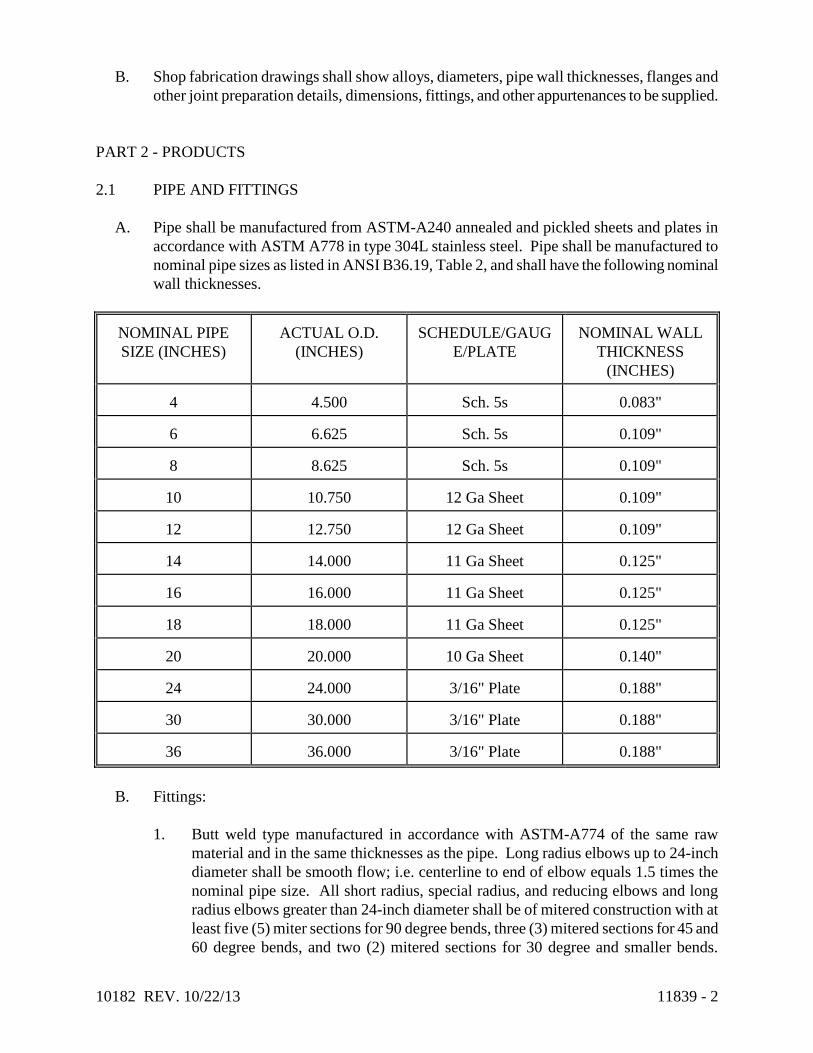
10182 REV. 10/22/13 11839 - 2
B. Shop fabrication drawings shall show alloys, diameters, pipe wall thicknesses, flanges and
other joint preparation details, dimensions, fittings, and other appurtenances to be supplied.
PART 2 - PRODUCTS
2.1 PIPE AND FITTINGS
A. Pipe shall be manufactured from ASTM-A240 annealed and pickled sheets and plates in
accordance with ASTM A778 in type 304L stainless steel. Pipe shall be manufactured to
nominal pipe sizes as listed in ANSI B36.19, Table 2, and shall have the following nominal
wall thicknesses.
NOMINAL PIPE
SIZE (INCHES)
ACTUAL O.D.
(INCHES)
SCHEDULE/GAUG
E/PLATE
NOMINAL WALL
THICKNESS
(INCHES)
4
4.500
Sch. 5s
0.083"
6
6.625
Sch. 5s
0.109"
8
8.625
Sch. 5s
0.109"
10
10.750
12 Ga Sheet
0.109"
12
12.750
12 Ga Sheet
0.109"
14
14.000
11 Ga Sheet
0.125"
16
16.000
11 Ga Sheet
0.125"
18
18.000
11 Ga Sheet
0.125"
20
20.000
10 Ga Sheet
0.140"
24
24.000
3/16" Plate
0.188"
30
30.000
3/16" Plate
0.188"
36
36.000
3/16" Plate
0.188"
B. Fittings:
1. Butt weld type manufactured in accordance with ASTM-A774 of the same raw
material and in the same thicknesses as the pipe. Long radius elbows up to 24-inch
diameter shall be smooth flow; i.e. centerline to end of elbow equals 1.5 times the
nominal pipe size. All short radius, special radius, and reducing elbows and long
radius elbows greater than 24-inch diameter shall be of mitered construction with at
least five (5) miter sections for 90 degree bends, three (3) mitered sections for 45 and
60 degree bends, and two (2) mitered sections for 30 degree and smaller bends.

10182 REV. 10/22/13 11839 - 3
Reducers shall be straight tapered, cone type. Tees, crosses, laterals and wyes shall
be shop fabricated from pipe.
2. Grooved end type manufactured in accordance with ASTM A403. Long radius
elbows up to 12-inch diameter shall be smooth flow; i.e., centerline to end of elbow
equals 1.5 times the nominal pipe size. Reducing tee fittings shall be shop fabricated
from stainless steel pipe conforming to ASTM A312.
C. The finish on the raw material, manufactured to ASTM A240 will be No. 1, HRAP (hot
rolled annealed and pickled) or better. The finish on the completed pipe and fittings shall
be as specified in ASTM A778 and A774, respectively.
2.2 FLANGES
Flanged pipe ends shall be made up of type 304L stainless steel slip-on type rolled angle face
rings and hot dipped galvanized ductile iron back-up flanges drilled to ANSI 16.1 Class 125
standard. The angle face ring thickness shall be equal to or greater than the wall of the pipe or
fitting to which it is welded and it shall be continuously welded on both sides to the pipe or
fitting. The angle leg shall not interfere with the flange bolt holes. The back-up flanges shall be
supplied with the following nominal thicknesses.
Nominal Pipe Flange
Size (Inches) Thickness (Inches)
2-1/2 - 3 1/2
4 9/16
6 - 10 5/8
12 - 16 3/4
18 - 20 7/8
24 - 30 1
36 1-1/8
2.3 COUPLINGS
A. The piping will be shop prepared for pipe couplings where shown on the drawings or
specified herein.
1. Sleeve type couplings shall be Dresser style 38 or equal, of standard steel
construction with rubber gaskets suitable for 250 deg F air service. Pipe shall be
plain end with external weld beads ground smooth to insure proper gasket seating.
For pressure pipe lines, sleeve coupling joints will be restrained by the use of harness
rods connecting across the joint to flange lugs on adjacent flange joints. Where no
adjacent flange joints exist, stainless steel harness lugs shall be welded to the pipe to
receive the harness rods. All sleeve couplings, flange lugs, harness rods and
hardware will be provided by the Contractor.

10182 REV. 10/22/13 11839 - 4
2. Arched band (split-sleeve) type couplings shall be stainless steel of equal or superior
alloy and wall thickness as the pipe and will be Depend-O-Lok type as manufactured
by Victaulic Depend-O Lok. Couplings will be Fixed - FxF, Expansion - ExE, or
Fixed by Expansion - FxE as noted on the drawings or as required. The pipe shall be
plain end with external weld beads ground smooth and with S.S. restraining rings
shop welded to the piping for fixed type couplings.
3. Grooved-End Joint Couplings:
a. Flexible grooved-end joint couplings shall have Type 316 stainless steel
housings, conforming to ASTM A351, A743 and A744, complete with
synthetic rubber gasket. (Grade to suit the intended service.) Use in locations
where vibration attenuation and stress relief are required. Flexible couplings
may be used in lieu of flexible connectors at equipment connections.
(Couplings shall be placed in close proximity to the vibration source.)
Victaulic Style 77S.
b. For exterior applications, stainless steel grooved-end joint rigid couplings shall
be Type 316 stainless steel housings, conforming to ASTM A351, A743,
A744, key designed to clamp the bottom of the groove to provide rigidity,
complete with synthetic rubber gasket. (Grade to suit the intended service.)
Victaulic Style 489.
c. For interior applications, ductile iron grooved-end rigid joint couplings for
stainless steel pipe shall have ductile iron housings, conforming to ASTM
A395 and A536, key designed to clamp the bottom of the groove to provide
rigidity, complete with synthetic rubber gasket. (Grade to suit the intended
service). Victaulic Style 89.
Style 77S
Flexible
Style 489
Rigid
Style 89
Rigid
2 - 2-1/2 500 300 300
3 400 300 300
4 350 300 300
6 200 300 300
8 125 300 300
10 75 300 300
12 125 300 300
2.4 THREADED CONNECTIONS
A. Threaded pipe, gauge or instrument connections shall be made using stainless steel, 150-
pound threaded half-couplings conforming to ASTM A182 or ASTM A276, shop welded to
the pipe at the locations shown on the drawings.

10182 REV. 10/22/13 11839 - 5
2.5 JOINTS
A. Flanges shall be provided as a minimum at all flanged valves, meters, couplings, and other
equipment. Couplings will be provided as shown on the drawings.
B. Pipe and fitting spools shall be shop fabricated to the fullest extent possible in 40'-0"
maximum lengths with 7'-6" maximum widths for efficient commercial transport to the
project site. Spools with fittings may exceed 40'-0" so long as length allows commercial
transport. Smaller pipe spools shall be provided with joints as shown on the drawings for
special handling, installation, and/or disassembly requirements.
C. All other joints required for shipping, handling and installation of the piping spools shall be
flange joints, grooved-end joint couplings, sleeve couplings, or split-sleeve band couplings.
2.6 BOLTING
A. Bolts, washers, nuts, and other hardware for flange bolting shall be Type 316 SS. Number
and size of bolts shall conform to ANSI B16.1 requirements for each size of flange.
2.7 GASKETS
A. EPDM, 1/8 inch thick, 230 deg F rated for air service.
PART 3 - EXECUTION
3.1 SHOP FABRICATION
A. After the manufacture of individual stainless steel fittings and pipe lengths, they shall be
pickled by immersion in a tank containing an ambient nitric-hydrofluoric acid solution
made up from Oakite Deoxidizer SS, or equal, and monitored to generally maintain a 25%
or higher solution by volume of water. The duration of immersion shall be 15 to 20
minutes and may be supplemented by manually scrubbing or brushing with non metallic
pads or stainless steel wire brushes. The acid treatment shall be followed by immersion in a
rinse water tank, followed, if necessary, by a spray rinse. The stainless steel products shall
then be allowed to air dry to achieve passivation.
B. Welding of pipe spools shall be performed using welders and procedures qualified in
accordance with ASME Section IX. Piping with wall thicknesses up to and including 11
gauge (0.125") shall be welded with the TIG (GTAW) process. Heavier walls shall be
beveled according to procedure, roof pass welded with the TIG (GTAW), and have
subsequent weld passes performed using the TIG (GTAW), MIG (GMAW), or Metallic Arc
(SMAW) process. Filler metal of equal or superior ELC grades only shall be added to all
welds to provide a cross section at the weld equal to or greater than the parent metal. Weld
deposit shall be smooth and evenly distributed; weld reinforcement shall be as follows:

10182 REV. 10/22/13 11839 - 6
Wall Thickness Weld Reinforcement (Max.)
I.D. O.D.
Up to 12 Ga. (0.109") 1/16" 3/32"
11 Ga. (0.125") to 3/16" Pl. 3/32" 1/8"
1/4" Plate & Larger 1/8" 3/16"
Concavity, undercut, cracks or crevices shall not be allowed. Butt welds shall have full
penetration to the interior surface, and inert argon gas shielding shall be provided to the
interior and exterior of the joint. Angle face rings shall be continuously welded on both
sides to pipe or fitting. Exterior welds, such as the back side of face rings or flanges and
structural attachments, may be welded by the MIG (GMAW) or Metallic Arc (SMAW)
process; however, care must be taken to avoid melting through to the interior surface on
very light walls. Excessive weld deposits, slag, spatter and projections shall be removed by
grinding. Welds on gasket surfaces shall be ground smooth.
C. Spools shall be fabricated to the "Pipe Fabrication Institute" fabricating tolerances ES-3
(1981).
D. After shop fabrication into pipe spools, exterior welds shall be manually scrubbed or
brushed with non metallic pads or stainless steel wire brushes to remove weld
discoloration, rinsed with clean water and allowed to air dry.
E. All fabricated piping shall have openings plugged and flanges secured for storage and/or
transport after fabrication. All fabricated piping shall be piece marked with identifying
numbers or codes which correspond to the Contractor's layout and installation drawings.
The marks will be located on the spools at opposite ends and 180 degrees apart.
F. The piping supplier during manufacturing, fabrication and handling stages, and the
Contractor during handling and installation stages, shall use extreme care to avoid the
contact of any ferrous materials with the stainless steel piping. All saws, drills, files, wire
brushes, etc., shall be used for stainless steel piping only. Pipe storage and fabrication
racks shall be non ferrous or stainless steel or rubber lined. Nylon slings or straps or alloy
chains or cable shall be used for handling stainless steel piping. After installation, the
Contractor shall wash and rinse all foreign matter from the piping surface. If rusting of
embedded iron occurs, the Contractor shall pickle the affected surface with Oakite
Deoxidizer SS or equal, scrub with stainless steel brushes and rinse clean.
G. Grooved-End Joint Installation:
1. All grooved couplings, fittings, valves and specialties shall be the products of a single
manufacturer. Grooving tools shall be of the same manufacturer as the grooved
components.
2. Grooved ends shall be clean and free from indentations, projections, and roll marks
in the area from pipe end to groove.

10182 REV. 10/22/13 11839 - 7
3.2 FIELD WELDING
A. No field welding will be permitted.
3.3 PAINTING
A. After installation, the Contractor shall paint all steel or iron flanges, couplings, and
appurtenances in accordance with Section 09801. Painting of the stainless steel pipe is not
required. However, the Contractor shall be responsible for supplying and installing the
stainless steel piping with a consistently clean surface. Identifying spool piece marks shall
be removed with pain thinner or solvents and the entire stainless steel surface shall be
washed with detergent and hot water and rinsed clean.
3.4 TESTING
A. After installation, the piping system shall be tested at 12 psig by the Contractor according to
Specification Section T11831.
END OF SECTION T11839 (05/96)

10182 REV. 10/31/13 11848 - 1
SECTION 11848 – TURBO BLOWERS AND ACCESSORIES
PART 1 - GENERAL
1.1 SCOPE
A. The Contractor shall provide all labor, materials, tools, transportation and equipment
required to fabricate, furnish, test, install and initiate satisfactory operation of eleven (11)
high efficiency blowers and all pertinent accessories for four (4) separate processes as
specified in PART 2 PRODUCTS sub-section of this specification, complete and in place,
ready for service as shown on the Drawings and described in this section. The four
processes are:
Grit and Grease Process 3 Blowers
Pre-Aeration Process Air System 3 Blowers
B. The complete installation of the system would include: enclosure with inlet and outlet
flanges, blower with high efficiency high speed motor, drive controls (VFD) where
stipulated, discharge cone/diffuser, pilot operated pressure relief valve, DC choke and inlet
air filters. Also included with each blower but exterior to the blower enclosure: discharge
silencer, expansion joint, check valve, and enclosure with harmonic filters for mounting in
blower enclosure or near blower. The complete installation will include all associated work
to complete the installation and all other appurtenances necessary to provide a complete
installation for satisfactory operation.
C. It is the intent of this Contract that the final installation be complete in all respects and the
Contractor shall be responsible for minor or specific details; coordination with trades;
equipment manufacturing; installation and manufacturer’s start-up services; and any
necessary special construction not specifically included in the Drawings or Specifications.
D. The specifications direct attention to certain required features of the equipment but do not
propose to cover all details entering into its design and construction. The Manufacturer
shall furnish the equipment complete in all details, ready for installation and operation. The
Contractor shall properly install, adjust and place in operation the complete installation.
E. The Contractor shall pay particular attention to elements of work requiring coordination
with other trades and/or contractors. In particular the Contractor shall coordinate all
general trades work separately installed however related to the equipment; electrical,
control and instrumentation components including verification of wiring, conduit,
associated equipment and all shop drawings supplied by all Contractors for the actual
installation.
F. The allowed manufacturers of the blower equipment furnished hereunder are listed in
PART 2 – PRODUCTS sub-section of this specification.

10182 REV. 10/31/13 11848 - 2
Blower submittals will be evaluated on the basis of a guaranteed “wire-to-air” efficiency
and “lowest and best” evaluation. Equipment selection will be based on the total evaluated
price, i.e. initial cost plus operating cost, over a period of twenty years.
G. The Contractor shall include in the lump sum price bid for all associated cost for the Work.
The Contractor shall assume full responsibility for additional costs which may result from
unauthorized deviations from the Specifications.
1.2 RELATED SECTIONS
A. Drawings and general provisions of this Contract, including General and Supplementary
Conditions and Division-1 Specification sections, apply to work of this section.
1. Division 13 – Special Construction
2. Division 16 - Electrical
B. The following equipment and related work is specified and furnished under other items:
1. American Society for Testing and Materials, (ASTM).
2. National Electric Code, (NEC).
3. National Electrical Manufacturers Association, (NEMA).
4. Institute of Electrical and Electronic Engineers, (IEEE).
5. American National Standards Institute, (ANSI).
6. ASME PTC 10–1997-2003 – Test Configuration and Calculations.
7. ASME PTC-19.5-2004 – Flow Measurement.
8. ASME PTC-19.2 – Pressure Measurement.
9. ASME PTC-19.3 – Temperature Measurement.
10. ISO 5389-2005, Turbo compressors – Performance test code.
11. ISO 3746-1995, Determination of sound power levels of noise sources using sound
pressure – Survey method using an enveloping measurement surface over a reflecting
plane
12. ISO 3744-1994, Determination of sound power levels of noise sources using sound
pressure – Engineering method in an essentially free field over a reflecting plane
13. ISO 4871-1996. Declaration and verification of noise emission values of machinery
and equipment
1.3 QUALITY ASSURANCE
A. The named equipment in addition to the detailed specifications, establishes the minimum
acceptable standards of material and workmanship. In addition to requirements of these
specifications, comply with manufacturer's instructions and recommendations for work.
All equipment shall perform as specified and accessories shall be provided as required for
satisfactory operation.
B. All equipment specified in this section for any one of the three process areas shall be
furnished by one manufacturer.

10182 REV. 10/31/13 11848 - 3
This does not require that all components of the assembly be manufactured by a single
manufacturer, but does require that, within any one process area, the specified manufacturer
be responsible for the complete assembly of the equipment, delivery, start-up services and
satisfactory operation of the blowers specified herein.
C. All equipment and components shall be furnished as complete standard type assemblies in
accordance with the standards of the industry. All internal wiring, piping, valves and
control devices integrated into the equipment shall be delivered as part of the assembly.
Equipment with motors shall be delivered on common base plates or equipment stands as
recommended by the manufacturer. Electrical/control panels shall be completely assembled
and ready for installation on stands provided by the equipment supplier. Items delivered
partially disassembled when required by transportation regulations, for protection of
components or when field assembly is required shall be shipped in the largest possible
assembly to minimize field assembly in accordance with industrial standards and the
manufacturer’s recommendation.
D. All work performed under this section shall be in accordance with all approved trade
practices and manufacturer's recommendations.
E. The Contractor shall coordinate and verify the actual field conditions with that of the
equipment being furnished prior to submittal of shop drawings. Any conditions of concern
shall be noted on the shop drawings for the Engineers/Owners review.
F. The Contractor shall provide confirmation from the manufacturer that the equipment being
supplied meets the design conditions, conditions of service and overall system installation.
G. The blower manufacturer shall submit with the bid documents the guaranteed wire-to-air
(“wire”) kW for the blower unit.
1. The wire kW shall include all losses associated with the blower unit at all specified
operating points. The guaranteed wire kW’s of the blower unit shall not exceed the
following. Wire KW consists of blower, motor, VFD and any cooling or other
auxilliary systems if used.
2. The guaranteed wire power KW numbers at the specified operating points shall be
“guaranteed” per flow rates calculated by ASME PTC-10 testing with zero plus
tolerance.
3. The blower manufacturer shall supply, coordinate, start up and calibrate all items
specified in this Section.
4. After reaching operational speed, noise emission from the blower package shall not
exceed 85 dBa (± 2) at the machine location, at the air intake and at the discharge
piping system, without any special sound attenuation installed in the blower room.
H. Certified Performance Testing
1. Upon completion of assembly, the blower shall be performance tested at the place of
manufacture, witnessed by representatives of the Owner and a licensed Professional
Engineer experienced in testing requirements of ASTM PTC-10. The Witnessing
Professional Engineer shall sign, stamp and date the test procedure and results,
certifying that the assembled systems were tested together, as a system, in the blower
manufacturer’s facility and that they meet the guaranteed performance as specified in
(G) above. Owner travel expenses shall be paid for by the Contractor.

10182 REV. 10/31/13 11848 - 4
2. Performance testing shall utilize PTC-10-1997 “Type 2” test or as modified for high
speed turbo blowers. An open loop configuration shall be used as defined in PTC-10
Figure 4.5. Where impractical, inlet piping shall be omitted and calibrated
equipment shall be used to determine inlet conditions to the equipment. Flow
measurement shall be made at the discharge per PTC-10 Section 4.8.
3. Test shall be for all components within this blower cabinet.
4. All test equipment shall be calibrated and certified by an independent test agency no
more than 12 months prior to the test date. Certificates shall show the stability of the
calibration over a period of at least one year per ISO 9001, Paragraph 4.11.
5. The discharge conditions are defined as the conditions that exist at the discharge
flange of the blower at typical point of connection to the Owner’s equipment.
6. At a minimum, the blower system shall be factory tested for duration of not less than
4 hours at maximum load and maximum temperature.
7. A power meter calibrated to NIST standards instantaneously monitoring all electrical
legs for voltage and amperage to calculate instantaneous power usage shall measure
the electrical power input to the system as described, including all auxiliary systems.
Measured power shall include wire-to-air and include all losses associated with
electrical power, including, but not limited to the motor, inverter, VFD and cooling
systems, if used.
8. The Witnessing Professional Engineer shall sign a copy of the test data log sheet
certifying that the required tests were performed in strict accordance with these
specifications and the ASME PTC-10.
9. Velocity vibrations versus frequency levels shall be recorded within 10-1,000 and 10-
10,000 Hz frequency ranges. Vibration shall be reported velocity (in/sec) versus
frequency.
10. The blower test report shall present the computations in exact accordance with the
appropriate section or testing codes with performance curves showing flow, pressure
and power inputs.
11. Test results, certified calibration records for all equipment used and signed/stamped
test logs shall be submitted for approval prior to blower shipment.
I. Warranty. All equipment furnished shall be free of defects in the material and workmanship
as stipulated in the equipment schedule for a period of two (2) years from the date of
acceptance, not to exceed thirty (30) months from the date of shipment. Acceptance by the
Owner is defined to be after start up, operation demonstration and required field testing.
After these tasks are completed by the Contractor and accepted by the Owner, the Owner is
responsible for the equipment and the warranty period begins.
1.4 SUBMITTALS
A. Product Data: The Contractor shall submit manufacturer’s technical data and application
instruction in accordance with the General and Supplementary Conditions and Division 1
Specifications and any additional information listed herein.
1. Proposed surface preparation and factory paint
2. Blower operating characteristics and specifications
3. Motor characteristics and specifications

10182 REV. 10/31/13 11848 - 5
4. Datasheet on materials of Constructions for major blower components and
accessories associated with the blower unit at all specific operating points.
5. Total system weight
B. Shop Drawings: The Contractor shall submit complete shop drawings of all equipment
furnished for this project as covered by these specifications. All shop drawings shall clearly
identify the specific equipment and material being supplied, the quantity being supplied,
and all accessories, dimensions, descriptions, dimensional/orientation layout drawings,
mounting and connection details, electrical control diagrams, wiring schematics and any
other information required of the Engineer/Owner to determine compliance with the plans
and specifications. The submittal as a minimum shall include the above data drawings and
other related materials. The shop drawings shall be reviewed by the Contractor for
completeness and compliance with the project and so acknowledged prior to the review by
the Engineer.
C. Operation and Maintenance Manuals: Submit six (6) copies for review prior to or with the
delivery of the equipment. The O & M manuals shall include instructions on storage,
installation, start-up, and operation and maintenance, together with a complete parts list,
distributor and a recommended spare parts list.
D. Warranty: The Equipment Manufacturer shall submit a warranty for review.
E. Certifications and Calculations: The Shop Drawings should include dimensional sketches
of all units, the weight of each unit mounted on its base and the weights of all components.
The performance test report of each blower signed by the manufacturer’s test engineer
using standard or equivalent test procedure. All necessary motor data shall be included.
F. Manufacturer’s Qualifications
1. Installation List – include a comprehensive list of all installed units, with North
American installations clearly identified. List shall include equipment model and
service application.
2. Service Network – Manufacturer shall describe their current service network by
listing the nearest factory authorized service center and/or qualified service
representative. Identify service technicians and include pertinent certifications to
substantiate their knowledge and expertise.
3. Start-up Services – Manufacturer shall describe and demonstrate their approach to
field start-up and training.
G. Additional Submittal Data
1. Installation manual including manufacturing information, assembly information,
storage, transportation, leveling, alignment, wiring, pre-start, check list, and initial
start up procedures.
2. Operating manual including LCD setup, local/remote operating method, and error
code.
3. Maintenance manual including daily, weekly, monthly, and annual inspection
procedures
4. Performance data at the design point and all specified operating points including:
a. Actual Operating Speed (RPM) and % of maximum rated speed

10182 REV. 10/31/13 11848 - 6
b. Capacity – scfm and icfm
c. Design inlet conditions, pressure, temperature and RH%
d. Discharge pressure
e. dB(A) noise pressure levels
f. Blower Shaft HP, Motor HP and Package HP
PART 2 - PRODUCTS
2.1 DESCRIPTION
A. Four (4) Blower systems are to be installed in four separate buildings. Grit and Grease
Blowers will be installed in the Primary Treatment Building. Pre-Aeration Process Air
Blowers will be installed in the Secondary Treatment Building. Sludge Holding /
Conditioning Blowers will be installed in the Sludge Treatment Building. Post-aeration
blowers will be installed in a standalone prefabricated building. Refer to the drawings for
specific conditions associated with the installations.
2.2 DESIGN PARAMETERS
A. General
1. Grit and Grease Blowers
a. Type of Blower: Turbo
b. Number of Blowers: 3
c. VFD’s Required: Yes
d. HWL Elevation: 77.941
e. Weir Elevation: 77
f. Elevation of Diffusers: 66
g. Bottom of Tank Elevation 65
h. Inlet Pressure: 14.29 psi
i. Discharge Pressure: 7.3 psi
j. Inlet Air Temperature: From 30˚F to 90˚F
k. Relative Humidity: From 60% to 70%
l. Total Design Air Flow Rate: 840 scfm
m. Maximum Flow per Blower: 420 scfm
n. Minimum Flow per Blower: 300 scfm
o. Nominal efficiency at 400 scfm 63%
p. Maximum energy to unit at 400 scfm 14.5 KW
q. Operating Conditions: Based on DO and water depth
r. Power Supply: 480V, 3 Phase, 60Hz
s. Maximum HP per Blower: 25
t. Motor Service Factor: 1.15
u. Recommended Manufacturers/Models for Grit and Grease Process Blowers
1) APG - Neuros
2) Aerzen

10182 REV. 10/31/13 11848 - 7
3) Approved Equal
2. Pre-Aeration Process Air Blowers
a. Type of Blower: Turbo
b. Number of Blowers: 3
c. VFD’s Required: Yes
d. HWL Elevation: 69.026
e. Minimum Water Level 68
f. Elevation of Diffusers: 56
g. Bottom of Tank Elevation 55
h. Inlet Pressure: 14.29 psi
i. Maximum Discharge Pressure at Blower Discharge: 7.0 psi
j. Inlet Air Temperature: From 30˚F to 90˚F
k. Relative Humidity: From 60% to 70%
l. Maximum Flow per Blower: 7200 scfm
m. Minimum Flow per Blower: 4320 scfm
n. Nominal efficiency at 7200 scfm 70.3%
o. Maximum energy to unit at 7200 scfm 224.2 KW
p. Turndown: 1.66 : 1
q. Operating Conditions: Based on DO and
water depth
r. Power Supply: 480V, 3 Phase, 60Hz
s. Maximum HP per Blower: 300
t. Motor Service Factor: 1.15
u. Recommended Manufacturers/Models for Pre-Aeration Process Air Blowers
1) APG - Neuros
2) Aerzen
3) Approved Equal
B. Workmanship and Design. All components of the assembly shall be engineered for long,
continuous, and uninterrupted service. Provisions shall be made for easy lubrication,
adjustment or replacement of all parts. Corresponding parts of multiple units shall be
interchangeable.
2.3 MATERIALS OF CONSTRUCTION
A. Materials shall be as follows:

10182 REV. 10/31/13 11848 - 8
Component Material
Blower discharge spool and elbow Steel, ASTM A 36
Flexible Joint Stainless steel or EPDM rubber
Blow Off Discharge silencer Steel, ASTM A 36
Blow off valve Aluminum Casting Alloy
Check Valve, Wafer Style Wafer-Style Cast Iron Body,
Aluminum disc, Viton or EPDM seat
2.4 ELECTRICAL/MOTORS
A. The motors shall be rated for inverter duty, 3 phase, 60 hertz, and 460 volt with the
following characteristics:
1. High efficiency induction type synchronous motor or permanent magnet (PM) motor.
2. The motor shall have a 1.15 service factor above maximum design conditions.
3. The motor shall be capable of continuous operation at full load and rated frequency
with a voltage variance of ±10% of the nameplate voltage.
4. The motor shall be able to start under 5% of electric current at design condition.
5. Insulation of motor shall be either Epoxy coated Class H or Class F non-hygroscopic
epoxy vacuum/pressure impregnated insulation system, limited to the temperature
rise specified herein. All connections shall be brazed, with no crimp connections
used except for terminals.
6. Rotor shall be sustained by non-contact bearings like air-foil or magnetic and shall
not require oils or lubricants for adequate operation.
7. Electric Standards shall conform to latest issue of IEE, ANSI, and NEMA.
8. There shall be no physical frequency sensor on rotor system to prevent unexpected
crash by the defect of these sensors. Frequency sensing shall be sensorless.
9. Provide motor with either thermistor switches or two (2) internal RTDs embedded in
the motor windings and one (1) internal RTD embedded in the motor core with a
motor protection relay that provides a high motor temperature alarm and shutdown
contact. RTDs shall be 100 ohm, platinum, of the 3-wire type with transmitters for
interfacing with the PLC.
2.5 BLOWERS
A. All blower systems shall be provided by one manufacturer with the following
characteristics:
1. All blowers shall be capable of variable speed operation.
2. Heated air from the motor and inverter shall not be mixed with intake fresh air.
3. Noise emission for the blower package shall not exceed 85 dBA at the machine
location inside the Blower Room.
4. The blower package vibration levels shall be low enough that it shall not require any
floor anchoring for adequate operation.
5. No special foundations shall be required for installation.

10182 REV. 10/31/13 11848 - 9
6. The blowers shall be certificated by National Recognized Testing Laboratory (NRTL)
with appropriate UL standards.
7. Each blower shall be factory tested per Section 1.3(I). The acceptance criteria are
2% tolerances on power, and flow.
8. Each blower shall have a flow measurement system based upon the theory of the
fundamental fluid mechanics, and not be the independent component.
9. Blower casing shall have a maximum continuous duty design temperature of 400 °F,
and a design pressure of 50 psig.
10. Blower impellors for turbo blowers shall be of the backswept three dimensional high
efficiency configuration, designed using computational fluid dynamics with two
stages in one (axial and centrifugal), milled from forged or cast aluminum alloy or
cast stainless steel, and with first lateral critical speed at least 120% of the maximum
allowable operating speed. The impellor shall be directly mounted to the motor shaft
and shall be statically and dynamically balanced.
11. Blowers shall be designed to maintain a minimum rise to surge margin of 3.0 psig
away from surge at any point on its capacity range.
12. The bearings shall be sized for a minimum of ten (10) years between major
overhauls.
13. All elastomeric materials for couplings, valves, etc. shall be rated for a minimum of
250 °F.
2.6 CONTROL/VFD
A. Each blower shall be equipped with an integral touch screen CPU or PLC based control
system and integral inverter for motor speed control. Control panel shall be preassembled
and pretested. All information shall be in English units of measure.
B. Blower controls shall be built-in with required temperature and pressure sensors.
C. PLC shall be accessible through a touch screen control panel.
1. Ethernet Inputs/Outputs
a. Data shall be formatted as required to communicate with the Plant SCADA
system. The VFD's shall communicate via ethernet TCP/IP. The manufacturer
shall coordinate with the Plant System Integrator to map data for SCADA
system interface. As a minimum, the following control and status signals will
be communicated to and/or from the VFD.
1) Remote Command from SCADA: For remote control of blower speed by
DO probes.
2) Present Status: motor speed, airflow, discharge pressure
3) Remote start/stop: input
4) Blower run: output
5) Blower alarm: output
6) Blower error: output
7) Blower power off: output
D. Blower shall detect surge at real time and control this.

10182 REV. 10/31/13 11848 - 10
E. VFD control shall be based upon constant motor current, not constant rpm.
F. VFD shall be provided by a blower manufacturer which can make the best match with the
motor.
G. Local Control Panel (LCP) Design and Testing
1. The blower LCP shall be a PLC based control panel with processor I/O cards,
communications interfaces, operator display, power supply and other components
required for a complete, functioning blower control system.
2. PLC manufacturers:
a. Allen-Bradley ControlLogix 1756 or pre-approved equal.
3. The LCP will be fed with one 480 VAC, 3 phase power connection. LCP shall
contain distribution components, power supplies and transformers, as required to
derive power for all instruments and equipment provided as part of the blower
package.
4. The LCP design, construction and testing shall be completed by the blower
manufacturer.
5. Provide wire tags on every conductor. Provide slip on or heat shrink sleeve markers.
Tags using adhesives are unacceptable.
2.7 ACCESSORIES
A. Inlet Filter – NOT APPLICABLE
1. The filter media shall have an efficiency of 90% by weight per ASHRAE 52-76 with
synthetic dust equivalent to separation >95% at 10 microns.
2. Maximum clean pressure loss across the filter shall be less than 0.12 microns.
3. The inlet filter shall be suitable for indoor or outdoor installations and shall be
integrally mounted directly to the blower enclosure.
4. Filter element shall be washable.
5. Inlet filter shall be flanged; air will be drawn through an 8” ANSI 150 Flange. Air
will pass through the intake flange through the panel filter of the enclosure.
6. Provide pressure differential indicating transmitter to monitor pressure drop across
the inlet filter.
B. Sound Enclosures
1. Each blower shall be supplied with a NRTL or UL/ULC certified standard sound
enclosure covering the blower package.
2. The sound enclosure must be designed for easy inspection and maintenance of all
blower package components. Control panels shall have hinged doors to provide easy
and quick access for routine maintenance of the blower and the package components.
Doors shall use a frame, reinforcements and supporting elements as required.
3. The enclosure housing the blower and blower appurtenances shall be NEMA 1,
painted carbon steel.
4. Field evaluation for certification shall not be permitted.

10182 REV. 10/31/13 11848 - 11
C. Operator shall not be required to reach over any components of the blower package to
perform maintenance.
D. Each blower shall have a set of inlet silencers or baffles. Filter and silencer performance
losses shall be included by the blower vendor in the blower performance calculation.
E. Each blower package shall have a set of EPDM flexible connector or stainless steel bellows
type expansion joint located at the discharge of the package capable of withstanding the
vacuum, pressure and temperature under all operating conditions.
The flexible connectors shall be sized for a standard pipe diameter with galvanized
retaining rings drilled for ASME/ANSI B16.5, Class 150 bolt pattern with stainless steel
hardware and shall prevent the transmission of noise and vibrations from the blower
package into the piping.
The expansion joint shall be suitable for the maximum operating temperature and pressure
ratings of the equipment in the air stream. Provide stainless restraining bolts and hardware.
F. Blow-off valve which is actuated by the discharge air pressure, shall be located inside the
blower package, and supplied by the blower manufacturer.
G. Blower manufacturer shall be responsible for attenuating noise and vibration in the blower
package such that no special installation base shall be required nor shall any vibration from
the blower package be transmitted to the base of the piping.
H. Each blower shall be supplied with one check valve that shall be installed on the discharge
line.
1. Provide each blower with a wafer type discharge check valve of the dual flat plate
type with center hinge, spring closure, cast iron body, EPDM seal and 316 aluminum
plates, stainless steel springs and trims, and rated for temperatures up to 250 °F. The
valves shall have flat surfaces with resilient seat facing on the body. Check valves
should be suitable for installation in the horizontal or vertical position as indicated on
the drawings. Valves shall be manufactured by Technocheck or equal.
2. Check valves shall be especially designed and suitable for use with the type of blower
provided, and shall retain positive sealing capacity at 300° F.
I. Isolation Butterfly Valve
1. Provide each blower with a wafer-type discharge isolation valve. The valve shall be
provided with a manual operator.
SPARE PARTS
J. The following spare parts shall be provided:
1. One (1) set of Manufacturer’s recommended spare parts for each type and size of
blower specified.
2. One (1) inlet filter per each blower specified.

10182 REV. 10/31/13 11848 - 12
K. Spare parts shall be packaged for long term storage in containers bearing labels clearly
designating the contents and the pieces of equipment for which they are intended.
PART 3 - EXECUTION
3.1 FIELD CONSTRUCTION QUALITY CONTROL
A. General: The Contractor shall submit to the Owner for review and comment a construction
procedure and quality control procedure prior to commencing work.
Construction procedure and all required testing shall comply with these specifications and
all applicable codes and standards.
B. Inspection: Prior to all work of this Section, carefully inspect the fabricated and installed
work of all other trades and verify that all such work is completed to the point where this
installation may properly commence.
C. Inspect all parts of the furnished equipment and verify that the system may be installed in
strict accordance with all pertinent codes and regulations, the original drawings, the
referenced standards, and the manufacturer’s recommendations.
D. Notify the Owner’s representative immediately of all unsatisfactory conditions or
discrepancies. Do not proceed with installation in areas of discrepancy until all such
discrepancies have been fully resolved. Beginning with the installation means, the installer
accepts the existing surfaces and conditions.
E. It is the Contractor’s responsibility to notify and coordinate with the equipment
manufacturer and other trades in a timely manner in order for them to conduct their required
work, inspection, servicing, testing and instruction.
F. The Contractor shall be responsible for furnishing and placing all anchorage systems for the
installation of the equipment. The Contractor shall coordinate with the manufacturer in
identifying proper size and locations of all anchorage. The Contractor shall furnish and
install Type 304 stainless steel anchor bolts per manufacturer’s recommendation.
G. Protect adjacent equipment, materials, piping, structures and/or valves against damage from
the installation procedure.
H. Preparatory work in accordance with manufacturer’s instructions shall be completed prior to
equipment installation.
3.2 MANUFACTURER’S FIELD SERVICE
A. A qualified representative of the manufacturer shall inspect the completed installation,
service the equipment, adjust, field test, operate the equipment under all design conditions,
instruct the Owner’s personnel in proper operating and maintenance procedures, and provide
the Owner with a written certificate of approval.

10182 REV. 10/31/13 11848 - 13
The representative shall be on site a total of 2 trips for each type of breaker provided for
start-up and instruction services. Each site trip shall include performing the required
services and submission of a manufacturer’s representative report. The two (2) days required
for each type of breaker provided for training shall be held during the first trip(s) and is
separate from the specified service time spent on site.
3.3 DELIVERY AND STORAGE
A. All equipment shall be completely factory assembled, properly crated, and delivered to
jobsite to protect against damage during shipment.
Factory assembled parts and components shall not be dismantled for shipment. Contractor
shall not be required to do any jobsite assembly of the blower package and shall not
disassemble any factory assembled component without blower manufacturer’s written
approval.
B. All exposed flanges shall be protected by wooden blank flanges, strongly built and securely
bolted thereto. Finished iron or steel surface not painted shall be properly protected to
prevent rust and corrosion. No shipment shall be made until approved by the Contractor in
writing.
C. All equipment delivered to the site shall be stored in accordance with manufacturer’s
instructions.
D. All blowers shall not, under any conditions, be allowed to sit out-of-doors unprotected.
During actual installation of each unit, blower package shall be covered with a waterproof
material in the event of any precipitation and also at all times that construction does not
require exposure of the equipment. Covering shall be securely anchored.
3.4 INSTALLATION
A. The equipment shall be furnished, installed, placed in service, and tested in accordance with
the manufacturer's recommendations.
B. The blower supplier shall supply blower packages shipped completely pre-assembled. Only
the electrical connections and pipe connections shall be performed onsite by the contractor.
C. Contractor shall, where required, install anchor bolts per the Manufacturer’s instructions
and calculations.
D. Contractor shall be fully responsible for installing all equipment in this section and
conducting startup and testing in accordance with the equipment manufacturer’s written
recommendations and/or requirements. The Contractor shall include in his costs all
assistance required of the Manufacturer to ensure proper installation, provide startup and
testing assistance and train the Owner’s personnel.

10182 REV. 10/31/13 11848 - 14
E. Following installation but prior to startup or testing, the Manufacturer shall send a
representative to the jobsite to inspect the installation. Any deficiencies noted during the
Manufacturer’s inspection must be corrected prior to startup or testing. The manufacturer
shall note his findings in a written Installation Deficiency Report to the Contractor, with a
copy provided to the Engineer.
F. The Contractor shall remedy the deficiencies noted by the Manufacturer in the Installation
Deficiency Report. The Manufacturer shall re-inspect the installation and this process shall
be repeated until the Manufacturer finds the equipment to be installed in accordance with
its recommendations and requirements.
G. Upon finding of satisfactory installation, and prior to startup or testing, the Manufacturer
shall issue a Certificate of Proper Installation and provide a copy to the Engineer.
Startup and testing may begin once the Engineer has received the Certificate of Proper
Installation from the Manufacturer.
3.5 INITIAL LUBRICATION (If Required)
A. Storage Lubrication – Any equipment delivered and stored shall be checked at delivery for
storage practices and lubrication for long term storage as recommended by the equipment
manufacturer in the O & M Manual.
B. Continuous Service Lubrication – As part of the equipment startup and field testing
procedures, the Contractor shall service and lubricate the equipment for continuous duty in
accordance with the manufacturer's recommendations.
3.6 FIELD ADJUSTMENT/START-UP FIELD TESTING
A. After the installation of the units and all appurtenances, each unit shall be subjected to a
field running test under actual operating conditions.
The field test shall be made by the Contractor in the presence of and as directed by the
Manufacturer’s Representative. The field tests shall demonstrate that under all conditions of
operation each unit:
1. Has not been damaged by transportation or installation.
2. Has been properly installed.
3. Has no mechanical defects.
4. Is in proper alignment.
5. Has been properly connected.
6. Is free of overheating of any parts.
7. Is free of all objectionable vibration.
8. Is free of all excessive noise.
9. Is free of overloading of any parts.
10. Shall operate as specified with the control system.
10182 REV. 10/31/13 11848 - 15
B. A factory trained technician from the equipment manufacturer shall conduct the tests in the
presence of the Owner. The equipment manufacturer shall provide all materials,
instruments and equipment required for the tests and shall provide a written report of test
results to the Contractor and Owner. Any defects in the equipment or failure to meet the
requirements of the Specifications shall be promptly corrected by the Manufacturer.
C. Certification - The manufacturer shall submit to the Engineer and the Owner a written
certified report of the results of the tests which includes certifying that the equipment has
been checked and is suitable for operation.
3.7 OPERATION DEMONSTRATION
A. The Contractor shall demonstrate the operation of all of the provided blowers on-line
together, that could be expected to operate simultaneously when in service, for a period of
two (2) weeks prior to final acceptance and initiation of the warranty period by the Owner.
3.8 TRAINING
A. The equipment manufacturer shall provide a minimum two (2) 8-hour training sessions, for
each type of breaker provided, on the operation and maintenance and control of the
equipment after installation is complete and before start-up and testing of the first unit.
3.9 OPERATION AND MAINTENANCE MANUALS
A. Operation and maintenance (O&M) manuals shall be provided prior to or with the delivery
of the equipment. The O & M manuals shall include instructions on storage, installation,
start-up, and operation and maintenance, together with a complete parts list and a
recommended spare parts list. The O & M manuals shall be in compliance with the
General Requirements.
3.10 EQUIPMENT WARRANTY
A. The manufacturer shall furnish a 2-year warranty on all components of the blowers, as
described, furnished and installed under this item. The warranty shall be for a 2-year period
commencing with the formal acceptance of the blowers.
B. The warranty shall guarantee, at no cost to the Owner, prompt repair or replacement of any
of the components which fail to function properly, under normal operation and
maintenance, due to deficiencies in product design, workmanship, or materials. The
warranty shall include the cost of all materials and labor required.
C. Warranty shall also make all parts associated with the blower package available for
shipment within 24 hours from USA location.
END OF SPECIFICATION SECTION 11848

DIVISION 13
SPECIAL CONSTRUCTION

10182 REV. 11/08/13 13400 - 1
SECTION 13400 - FIELD-MOUNTED INSTRUMENTATION EQUIPMENT
PART 1 - GENERAL
1.01 SECTION INCLUDES
A. The general requirements of the instrumentation equipment.
1.02 RELATED SECTIONS
A. P & ID Drawings and general provisions of Contract, including General and
Supplementary Conditions and Division 1 Specification sections, apply to work of
this section.
B. Section 13500
C. Division 11 - Process Equipment
D. Division 16 - Electrical
1.03 REFERENCES
A. ANSI/NFPA 70 - National Electrical Code.
B. Instrument Society of America (ISA).
C. Underwriters Laboratories (UL): Applicable listings.
1.04 SUBMITTALS
A. Submit under provisions of Division 1 - General Requirements.
B. Complete and detailed system schematic drawings showing all
components and the pneumatic/hydraulic and electrical point connections of each
system together with a description of the operation of the system and equipment.
C. Instrumentation equipment specifications, outlined dimension drawings,
and wiring and piping diagrams for each item of equipment. Duplicate equipment
may be covered by one set of literature.
D. The submittal shall be organized in a logical manner and have a schematic
(ladder) diagram for each system.
1.05 QUALIFICATIONS
A. Manufacturer: Company specializing in manufacturing Products specified
in this Section with minimum five years documented experience.

10182 REV. 11/08/13 13400 - 2
1.06 REGULATORY REQUIREMENTS
A. Conform to requirements of ANSI/NFPA 70.
B. Furnish products listed and classified by Underwriters Laboratories, Inc.
as suitable for purpose specified and shown.
1.07 RESPONSIBILITY
A. Under this contract, the General Contractor shall be responsible for the purchase,
storage, and proper installation of all field mounted instrumentation equipment
and all accessories required.
1.08 OPERATION AND MAINTENANCE DATA
A. Submit under provisions of Division 1 - General Requirements.
B. Complete descriptive literature for each piece of equipment, including a
list and description of all parts of each piece of equipment.
C. Data sheets containing information relative to metering range, indicator or
chart range, electrical requirements, system function, and shop drawing
data.
D. Process flow diagrams showing location of instrumentation equipment,
function of each piece, and description of use of equipment as applied to
this project.
E. Equipment settings required at various flow.
1.09 DELIVERY, STORAGE, AND HANDLING
A. Deliver, store, protect and handle products to site under provisions of
Division 1 - General Requirements.
B. Accept unit on site on skids. Inspect for damage (do not accept damaged
equipment).
C. Protect equipment from dirt and moisture by securely wrapping in heavy
plastic.
1.10 TRAINING
A. Prior to the on-site demonstrations, provide training in the operation and
maintenance of the System for two (2) of the Owner's personnel.

10182 REV. 11/08/13 13400 - 3
B. Training shall be provided by Contractor's employees involved in the installation,
design, implementation and start-up of this project. The exception will be training
provided by Equipment Manufacturers or authorized Factory trainers.
C. Provide a single, in-house Training Administrator that has experience in on-site
industrial O & M training. All facility (in house) training shall be recorded and
shall reside on the SCADA System for future use.
PART 2 - PRODUCTS
2.01 GENERAL
A. Furnish and install the instrumentation and appurtenances required for
this project.
B. Electronic instruments shall be solid state and the manufacturer's latest
design. Equipment shall use a 4-20 mA DC standard process signal unless
otherwise specified. Signals from measuring systems and analyzers with millivolt
outputs shall be immediately raised and converted to 4-20 mA DC signals for
transmission.
C. All field instruments shall be of the same manufacturer and general model
type.
D. Equipment to be installed in hazardous locations shall be listed for the location.
Refer to electrical drawings for area classifications.
2.02 ULTRASONIC TYPE LEVEL DETECTOR
A. Acceptable Manufacturers:
1. Endress & Hauser.
2. Bristol Babcock.
3. or approved equal.
B. Level Sensor:
1. Range: 0-40 feet (or as shown).
2. Operating Frequency: 30 KHZ.
3. Sample Rate: Sample Rate 2 KHZ.
4. Mounting: Direct bracket mounting (or as shown).
5. Electronic Housing: Enameled aluminum.
6. Operating Pressure: 7 PSIG Max.
7. Standard Operating Temperature: -4oF to 140
oF.
8. Temperature Compensation: Silicon temperature sensor located behind
acoustic membrane.
9. Power Supply: Transmitter provides power input to sensor.
10. Cable: As recommended by vendor.

10182 REV. 11/08/13 13400 - 4
C. Level Indicating Transmitter:
1. Enclosure: NEMA 4X as minimum.
2. Power Requirements: 115 VAC, 60 HZ, 6 VA.
3. Operating Temperature: -5o to 160
oF.
4. Accuracy: 1% of span typical.
5. Display: 4-digit LCS meter, scaleable to user's engineering units.
6. Output: 4-20 mA, DC, direct acting into 0-500 Ohms.
7. Linearity: 1% of span.
8. Repeatability: .1% of span.
2.03 FLOAT SWITCHES
A. The level detecting devices shall be at least 5-1/2 inch in diameter or better, PVC
or polypropylene float that does not use a mercury switch inside and flexibly
supported by a PVC jacketed heavy-duty cable.
B. The float switch shall have a 20 amp rating at 120 VAC. The float switch shall
close on rising level. Each float switch shall have a normally open and normally
closed contact.
C. Cable shall be long enough to terminate in a field-mounted junction box with
terminal strips provided for power and float switch connections.
D. The floats shall be mounted on two (2) inch stainless steel pipe using 316 stainless
steel clamps or plastic zip ties. The pipe shall be clamped to the wall using 316
stainless steel clamps. The length of the pipe and float cable shall be sized by the
contractor.
E. The floats shall be manufactured by Anchor Scientific Company, Dryden Aqua,
Pepperl + Fuchs, or approved equal.
2.04 GAGE PRESSURE TRANSMITTER
A. Acceptable Manufacturers:
1. Honeywell.
2. Rosemount Inc.
3. Bristol Babcock, Inc.
4. Endress & Hauser.
5. or approved equal.
B. Description: Gage pressure.
C. Mounting: Provide bracket for wall mounting.
D. Enclosure: NEMA 4X minimum.

10182 REV. 11/08/13 13400 - 5
E. External Power Supply: 4-20 mA DC.
F. Transmitter Panel: 12-45 V DC.
G. Output: 4-20 mA DC.
H. Accuracy: +0.25 percent of calibrated span.
I. Stability: +0.25 percent of upper range limit for six months.
J. Temperature Effect:
1. Zero Effect: +0.5 percent of span per 100 degrees F.
2. Total Effect: +1.0 percent of span per 100 degrees F.
K. Power Supply Effect: Less than 0.005 percent of output span per volt.
L. Range: 0-100 inches of water.
M. Humidity Limits: 0-100 percent RH.
N. Span and Zero: Continuously adjustable externally.
O. Sensing Element: Diaphragm type.
P. Isolating Diaphragm: 316L SS, Hastelloy C, Monel or Tantalum.
Q. Drain/Vent Valves: 316L SS, Hastelloy C, Monel or Tantalum.
R. Process Flange and Adapter: Cadmium-plated carbon steel, 316 SS, Hastelloy
C or Monel.
S. Wetted O-Rings: Viton.
T. Bolting Flange and Bolts: Cadmium plated carbon steel.
U. When indicated on the drawings, provide local pressure indicators. These
indicators must meet the following requirements:
1. Mounting: Integrally mounted on the pressure transmitter enclosure
or on an enclosure next to the transmitter.
2. Enclosure: Weatherproof NEMA 4X (minimum).
3. Accuracy: +2.0 percent of span.
4. Scale: 0 to 100 percent linear with process variable except differential
pressure flow which shall be 0 to 100 percent square root proportional to
flow.
5. Manufacturer: Same as transmitter.

10182 REV. 11/08/13 13400 - 6
2.05 TRANSDUCERS
A. Voltage-To-Current (V/I) Transducers
1. Acceptable Manufacturers:
a. Moore Industries.
b. AGM.
c. or approved equal.
2. Voltage-to-current transducers or isolators shall change a voltage input
signal to a proportional current output signal.
3. The device shall be completely solid state.
4. The device shall accept an input voltage signal and shall provide an
output signal of 4-20 mA DC.
5. Accuracy: +0.5 percent of full scale.
6. Ambient Temperature Range: 4 to 52 degrees C.
7. Prepare unit for surface mounting or for mounting in equipment
enclosures as specified.
B. Current-to-Current (I/I) Transducers (Isolators)
1. Acceptable Manufacturers:
a. Moore Industries.
b. AGM.
c. or approved equal.
2. Current-to-current transducers shall be an electronic type and shall
convert current inputs to proportional current outputs.
3. Span: Adjustable over full scale.
4. Zero: Adjustable over full scale.
5. Accuracy: +0.1 percent of span.
6. Isolation: 1 kV peak to peak.
2.06 DISSOLVED OXYGEN PROBE
A. Measuring unlimited from 0.00 to 20.00 ppm / 0.00 – 20.00 mg/L/ 0
to Range 200% saturation
B. Resolution 0.01 ppm / 0.01 mg/L/0.01% saturation
C. Repeatability .05 ppm
D. Accuracy <1 ppm: + 0.1 ppm;
>1 ppm: + 0.2 ppm
E. Sensitivity + 0.05% of span
F. Response Time to 90%: <30 seconds; to 95%: <90 seconds
(20° C)
G. Interferences No interference from the following: H2S, pH, K+1
, Na+1
, Mg+2
,
Ca+2
, NH4+1
, AI+3
, Pb+2
, Cd+2
, Zn+2
, Cr(tot,) Fe+2
, Fe+3
, Mn+2
, Cu+2
, Mi+2
, Co+2
,
CN-1
, NO3-1
, SO4-2
, S-2
, PO4+3
, CI-1
, Anion Active Tensides, Crude Oils, CI2-1
H. Sensor Cable Provide with integral cable with a quick disconnect type plug,
length as required. Maximum distance from analyzer to sensor of 300 m (985 ft).
I. Probe Material - Foamed Noryl and 316 SS
J. Sensor Material - Polybutyl Methacrolate

10182 REV. 11/08/13 13400 - 7
K. Probe Warranty - 3 years minimum
L. Sensor Warranty - 1 year minimum
DO Controller Specifications
M. DO: 0.00 – 20.00 ppm / 0.00 – 20.00 mg/L/ 0-999.9% saturation
N. Accuracy + 0.1% of span
O. Repeatability + 0.05% of span
P. Temperature + 0.02% of span per C
Drift
Q. Zero and Span
R. Response Time - 60 seconds to 90% of value on step change
S. Relay Types/Outputs – Three SPDT (Form C), 5A @ 114/230 Vac, 5A @ 30 Vdc
resistive
T. Alarms – Settings for low alarm point, low alarm point deadband, high alarm
point, high alarm point deadband, off delay, on delay.
U. Analog Outputs – Two isolated 0/4-20 mA, 0.004 mA resolution, up to 600 ohm
load.
2.07 INSTRUMENT POWER
A. Provide instruments to operate on 105-135 V RMS at 60-Hz power supplies.
Provide regulators and power supplies with the instrument required for
compliance. Electrical isolation shall be provided between power supplies and
connected instrument systems. Equipment which requires voltage regulation of
less than +10 percent variation shall be provided with constant voltage
transformers.
B. All panels containing solid state electronic equipment shall be equipped with line
voltage surge suppressors to protect the equipment from damage due to electrical
transients induced in the interconnecting lines from lightning discharges or near
by electrical devices.
C. The surge suppressors shall be of the plugtrab sleeves as manufactured by
Phoenix Contact, or approved equal, and mounted on a DIN rail.
2.08 SIGNAL LINE TRANSIENT PROTECTION
A. All signal lines for solid-state electronic equipment shall be equipped with line
voltage surge suppressors to protect the equipment from damage due to electrical
transients induced in the interconnecting lines from lightning discharges or nearby
equipment.
B. This shall include, but not be limited to digital inputs, analog inputs, analog
outputs, flow transmitters and level transmitters. The signal line transient
protection shall be provided on any signal lines which are outside of the building
structure housing the area control panel and RTU electronic equipment.
C. The signal line transient protection shall include gas discharge tubes, varistors,
and suppressor diodes.

10182 REV. 11/08/13 13400 - 8
D. The unit shall be Phoenix terminal block type Plugtrab Model UFBK 2/2, UFBK
2-PE, UFBK2-PE/1, or approved equal.
E. Provide lightning protection termination for all digital and analog signal plus a
minimum of 10 percent spares per panels.
F. Terminal block shall be DIN rail type, mounted in the vertical position.
2.09 MAGNETIC FLOW METERS (LIQUID/SOLIDS FLOW)
A. Acceptable Manufacturer:
1. Sparling Instruments Company, Inc.
2. Ficher & Porter Company.
3. Krohne America Inc.
4. Danfoss.
5. or approved equal.
B. Magnetic Flowmeters: Electro-magnetic induction pulsed D.C. type and
producing a signal directly proportional to the liquid rate of flow with zero
point stability.
C. Provide magnetic flowmeters such that the ratio of flow velocity to
reference signal generated is identical for all sizes so that all meters are
compatible with secondary readout instruments without circuit
modifications.
D. Meter Housing: Splash proof and weather resistant, and capable of
withstanding 30 feet of submergence.
E. Grounding Rings: Provide corrosion resistant metallic grounding gaskets
or rings on the upstream and on the downstream ends of the meter.
F. End Connections: Flanged type, unless otherwise specified or shown.
G. Electrodes: Zirconium, tantalum, or 316 S.S.
H. Connections: Provide connections for signal and external power supply.
I. Magmeter Liners: PTFE type Teflon, polyurethane or neoprene. Use for
appropriate fluid as indicated below:
Fluid PTFE Polyurethane Neoprene
raw sewage x x x
activated sludge x x x
thickened sludge x x
primary sludge x

10182 REV. 11/08/13 13400 - 9
J. Liner Protectors: Provide liner protectors on meters with Teflon liners.
K. Transmitters: Furnish meters with integral transmitters, unless otherwise
stated.
L. Rangeability: 100:1, or greater.
M. Metering System Accuracy: Within +1 percent of rate for a flow velocity
of 3 to 31 fps including the signal converter and readout instrumentation.
N. Calibration: Hydraulically calibrate meters at the manufacturer's facility
against a master meter traceable to the National Institute of Science and
Technology (NIST). Furnish a computer printout of the calibration data
with each meter. Include a calibration curve.
O. Signal Converter Cable: Include signal cable for connecting the meters
for indicating signal converters for magmeters where mounted remotely
to the meters.
P. Signal Converter
1. Input Impedance: 10 to the 10th ohms, or greater.
2. Electronics: Microprocessor controlled.
3. Provide magmeters with bi-directional flow capabilities.
4. Include empty pipe detection and low flow cut-off.
5. Output: 4-20 mA DC into 0 to 900 ohms.
6. Power Supply: 120 volts, single phase.
7. Calibration: Capable of operation throughout its expected life under
normal use without calibration.
8. Display: Indication of instantaneous and totalized flow.
2.10 PRESENCE/ABSENCE DETECTOR
A. Acceptable Manufacturers:
1. Princo L3545.
2. or approved equal.
B. Sensor/Transmitter:
1. Mounting: Flange – coordinate size with associated piping
2. Standard Operating Temperature: -4oF to 140
oF.
3. Temperature Drift: less than 0.1 pF per 20F
4. Construction: 316SS
5. Adjustable time delay
6. Power Supply: Transmitter provides power input to sensor. Transmitter
shall be 120V, 60 Hz.
7. Cable: As recommended by vendor.
8. Housing: NEMA 4X minimum

10182 REV. 11/08/13 13400 - 10
9. Cannot affect flow
2.11 THERMAL DISPERSION MASS FLOW METER (AIR FLOW)
A. Acceptable Manufacturers:
1. Fluid Components International.
2. or approved equal.
B. Flow Sensor:
1. Material: 316SS
2. Technology: Thermal Dispersion utilizing a varying differential
temperature signal created by a fixed current through two RTD's.
3. Accuracy: ±2% reading, 0.5% full scale
C. FlowTransmitter:
1. Enclosure: NEMA 4X minimum.
2. Power Requirements: 115 VAC, 60 HZ.
3. Operating Temperature: -0o to 140
oF.
4. Display: 4-digit LCD meter, scaleable to user's engineering units.
5. Output: 4-20 mA, DC, direct acting into 0-500 Ohms.
2.12 GAS SENSING EQUIPMENT
A. Provide a gas detection and alarming system. Sensor types and enclosure ratings
shall be as shown on plans.
B. Sensor/Transmitter Requirements
1. Infrared Combustible Sensor/Transmitter
a. The infrared (IR) combustible sensor must be capable of
calibration without gas. The sensor/transmitter must be capable of
performing a full calibration by zero adjustment only.
b. The IR sensor/transmitter shall detect for an above 100% LEL
condition (over-range).
c. The IR sensor/transmitter shall not contain a flashback arrestor/frit.
d. The IR sensor/transmitter must allow for a gas check without
alternate calibration / gas check fittings or cap.
2. Sensor/Transmitter Operating Requirements
a. Operating Voltage - The sensor/transmitter can operate between 8-
30 VDC.
b. Sensor/transmitter electronics shall consist of one PCB. This PCB
shall offer expandability to allow for optional LED’s and relays.
c. The single PCB shall not require tools for installation or removal.
d. The single PCB must be self-aligning in the enclosure.

10182 REV. 11/08/13 13400 - 11
e. Sensor/transmitter shall require the following wiring
configurations:
1) 3-wire cable for all combustible units (configured with or
without LED or relay options).
f. Sensor/transmitter shall allow for optional reset connector for
resetting latched alarms.
g. Set-up and start-up of the sensor/transmitter will be so that the
enclosure need not be opened during this process.
h. Sensor/transmitter shall be factory calibrated, ready for use out of
the box. A gas check is all that is required to ensure proper
operation.
i. Sensor/transmitter shall contain no pots, jumpers or switches.
j. 3.4.10 Sensor/transmitter output signal shall be 4 to 20mA or
HART.
The combustible sensor/transmitter will be a sourcing type
of signal capable of operating into a 600-ohm load.
3. Sensor/Transmitter Display
a. There will be a local display indicating the gas type being
monitored and the concentration of gas present. The display will
alternate between the gas type (1 second) and gas concentration (5
seconds). The display will be an integral part of the
sensor/transmitter enclosure. The display will be visible from a
minimum of 5 feet and will be present always, and will not require
being turned on or off. This readout will be three, one half-inch (3
1/2") digit Liquid Crystal Displays (LCD).
b. Sensor/transmitter display shall indicate all diagnostic check/fault
conditions with a scrolling message detailing the condition. Error
codes shall not be used.
c. Sensor/transmitter will display 3 levels of alarm. Alarm levels will
be adjustable by means of a hand held infrared controller or a
HART hand held communicator.
4. Smart Sensor Technology
a. Sensors shall be contained in sensor modules mounted external to
the main enclosure. All sensor modules shall have the capability of
replacement while the unit is under power (hazardous areas)
without the need for tools.
b. Sensor modules shall contain all relevant sensor information within
the module. This information shall include sensor manufacturer
date, gas type, gas range, calibration data, and default relay
parameters.
c. Sensor module shall store all calibration data so that the module
may be calibrated off site and installed in the field without the
necessity of recalibration. The sensor module shall not require a
battery or power source to store this data.
5. LED / Relay Options
a. Sensor/transmitter shall have optional LED’s, viewable from 50
feet, 3.7.2 Sensor/transmitter shall have optional relays. Relays
shall be rated at 5 amps @ 30VDC, 5 amps @ 220VAC, single-
pole, double-throw and consist of three for alarm levels and one for

10182 REV. 11/08/13 13400 - 12
fault. All relay contact activation will be monitored. If the relay
cannot activate for any reason, the trouble relay will change state.
All relays shall be field selectable through a non-intrusive hand-
held wireless remote control unit (Controller) or a HART hand
held communicator. Selectable features include:
1) Alarm level
2) Latching / Non-latching
3) Upscale / Downscale
4) Normally-opened / Normally-closed
5) Energized / De-energized
6. Other Features
a. Sensor/transmitter shall allow for full range scaling of the 4-
20mA-output signal.
b. Sensor/transmitter will be capable of storing and displaying
average, minimum and maximum gas concentrations over selected
periods of time.
c. The sensor/transmitter will give an indication of when sensor is
nearing the end of its useful life by means of the front panel LCD.
This indication that the sensor is nearing its useful life will be
based on the sensor output. It shall not be based on the time the
sensor was in service.
7. Sensing Element Warranty
a. All electrochemical and catalytic bead sensing elements (sensors)
will have a minimum useful life of one year. The supplier will
provide replacement sensors at no charge for any sensor that does
not meet the minimum requirement.
b. The IR source in the infrared sensor will have a minimum useful
life of ten (10) years. The supplier will provide replacement
sensors at no charge for any sensor that does not meet the
minimum requirement.
C. Sensor Enclosure Parameters
1. General-purpose Sensor/Transmitter
a. Sensor/transmitter will be a plastic enclosure designed to meet
NEMA 4X requirements.
2. Explosion-proof Sensor/Transmitter
a. The sensor/transmitter will be in a 316 stainless steel enclosure
suitable for location in Class I, Division 1 & 2, Groups A, B, C &
D classified areas.
b. The enclosure shall have a minimum of four entries, allowing for
flexible mounting options for sensor, power, signal, and optional
relay wiring.
c. The enclosure shall offer a means to mount without using an
entryway.
D. Sensor/Transmitter Single Condulet Mounting
1. General-purpose Sensor/Transmitter

10182 REV. 11/08/13 13400 - 13
a. Sensor/transmitter will be mounted in a single condulet. The back
portion of the enclosure shall be separate from the electronics,
allowing for mounting and wiring of the unit without the
electronics present.
2. Explosion-proof Sensor/Transmitter
a. Sensor/transmitter will be mounted in a single condulet. The back
portion of the enclosure shall be separate from the electronics,
allowing for mounting and wiring of the unit without the
electronics present.
E. Sensor/Transmitter Remote Sensor Mounting
1. The sensor portion of the sensor/transmitter unit will be capable of being
able to be remotely mounted from the electronics and display. The
separate sensor enclosure will be able to be mounted up to one hundred
(100) feet from the main enclosure.
2. The sensor housing for the explosion-proof Gas Monitor will be in an
enclosure suitable for location in Class I, Division 1, Groups A, B, C & D,
Class II, Division 1, Groups E & F, Class III classified areas.
3. A two twisted pair cable will connect the sensor housing and the
calibration electronics.
4. The readout portion of the sensor/transmitter shall have a display of the
concentration of gas present. The display will be visible from a minimum
of 5 feet and will be present at all times. It will not be required to be
turned on or off. This readout will be three, one half inch (3 1/2") digit
Liquid Crystal Displays (LCD).
F. Installation and Mounting Hardware
1. A mounting strap shall be used which mounts the sensor/transmitter to a
wall or similar structure.
2. The mounting strap shall attach to the sensor/transmitter via two tapped
and threaded holes on the rear of the sensor/transmitter. There shall be no
brackets or clamps to secure this strap to the sensor/transmitter.
G. Approvals
1. The general-purpose monitor shall have CE approval.
2. The explosion-proof monitor shall have Class I, Division 1 & 2, Groups
A, B, C, and D; Class II, Division 1, Groups F & G; Class III approval.
3. The explosion-proof Remote Sensor shall have Class I, Division 1 & 2,
Groups A, B, C, and D, Class II, Division 1, Groups F & G; Class III
approval.
4. The explosion-proof infrared monitor shall have Class I, Division 1 & 2,
Groups A, B, C, and D; Class II, Division 1, Groups F, and G, Class III
approval.
H. Non-intrusive Calibration Capability
1. All sensor/transmitters can be calibrated without opening any enclosures.
2. By means of a non-intrusive hand held wireless remote control unit or a
HART hand held communicator, the sensor/transmitter will enter the
calibration mode.

10182 REV. 11/08/13 13400 - 14
The display of the sensor/transmitter will instruct the
user on when to apply zero and span gas. The sensor/transmitter will
automatically adjust its internal settings to the proper calibration values
without further intervention by the user. Upon completion of a successful
calibration, the sensor transmitter will exit the calibration mode. Date
stamp of last successful calibration will be retained in the
sensor/transmitter internal memory, with capability to be displayed on
LCD. If calibration is unsuccessful for any reason, the display must show
an unsuccessful calibration attempt and revert to its previous calibration
settings. Use of flashlight type devices, magnets or clamp-on devices to
achieve calibration is not acceptable.
The acceptable methods are to use a transmitter, which employs a digitally
encoded infrared light beam, or a HART hand held communicator
3. Provide a non-intrusive hand held wireless remote control:
a. A small non-intrusive hand held wireless remote control which
will let the user only perform sensor zeroing, calibration and
setting the multiplex address.
b. The sensor/transmitter will not be affected by low level
ambient light either natural or man-made.
I. Manufacturer Capability Requirements - As a minimum, the Gas Monitoring
Equipment manufacturer must meet the following requirements.
1. The manufacturer must be capable of supplying all equipment used to
check or calibrate the sensor/transmitter units.
2. The manufacturer must be capable of providing on-site service with
factory trained personnel.
3. The manufacturer must be capable of providing on-site training for
owner/operator.
J. The sensor/transmitter shall be a MSA Ultima X Series Gas Monitor
Sensor/Transmitter or approved equal.
2.13 PID CONTROLLERS
A. The PID controller shall conform to the following minimum specifications unless
otherwise directed by the Engineer:
1. Enclosure: NEMA 1, panel mounted. Provide stand-alone enclosure
(NEMX 4X minimum) if mounted at equipment.
2. Power Requirements: 120 VAC, 60 HZ.
3. Operating Temperature: 40° F to 120° F.
4. Operating Humidity: 10% to 90%.
5. Input Signal: 4-20 mADC. Process Variable.
4-20 mADC Remote Set Point

10182 REV. 11/08/13 13400 - 15
6. Control Output Signal: 4-20 mADC Control Variable
7. Accuracy at Display:
Local Set Point + .1% of Span
Analog Input + .1% of Span
Analog Output + .1% of Span
Control Modes:
Prop. Band + 5% of Setting
Integral + 5% of Setting ≥ .1 min.
Derivative + .5 sec for < .1 min.
Calculations + .1%
8. Ambient temperature effect max error:
Local Set Point ± .1% of Span
Analog Input ± .5% of Span
Analog Output ± .5% of Span
9. Output Noise: .25% peak to peak
10. Execution Rate: 10 times per second.
11. Display
a. Numeric-Process Variable - 15 mm
b. Alpha Numeric - user configured - 6mm
c. Alpha Numeric - user configured - 6mm
d. All displays are vacuum fluorescent.
12. Manufacturer: Moore Industries, Honeywell or approved equivalent.
2.14 PAN/TILT/ZOOM IP CAMERA
A. The indoor/outdoor network positioning system shall consist of a receiver,
enclosure, variable speed/high speed pan and tilt drive unit with continuous 360º
rotation; 1/4-inch high resolution color/black-white camera (540 TVL) with an
infrared cut filter, 36X optical zoom, 12X digital zoom, electronic image
stabilization, and wide dynamic range.
B. The indoor/outdoor network positioning system shall support standard IT
protocols.
C. The indoor/outdoor network positioning system shall provide a 100Base-TX
network interface.

10182 REV. 11/08/13 13400 - 16
D. The indoor/outdoor network positioning system shall support two simultaneous,
configurable video streams. MJPEG, MPEG-4, and H.264 compression formats
shall be available across several resolution configurations. The streams shall be
configurable n a variety of frame rates, bit rates, and group of pictures (GOP)
structures.
E. The indoor/outdoor network positioning system shall use a standard Web browser
interface for remote administration and configuration of camera parameters. The
browser interface shall provide PTZ control including preset and pattern and on-
screen display (OSD) for access to camera programming.
F. The indoor/outdoor network positioning system shall provide a window blanking
feature with eight, four-sided, user-defined shapes.
G. The indoor/outdoor network positioning system shall include a built-in heater,
window defroster/defogger, sun shroud, and insulation blanket.
H. The indoor/outdoor network positioning system shall include an optional
programmable window wiper with washer/wipe sequence under a single
command.
I. The indoor/outdoor network positioning system shall offer an Integrated Optics
Package (IOP) or a pressurized Integrated Optics Cartridge (IOC).
J. The indoor/outdoor network positioning system shall include pedestal, and/or wall
mount options.
K. The indoor/outdoor network positioning system shall provide AutoTracking to
detect and track movement of a single target entering the camera’s field of view.
When the AutoTracking behavior is configured, the system will automatically pan
and tilt to follow the moving object until object stops or disappears from the
monitored area.
L. The indoor/outdoor network positioning camera shall feature open architecture
connectivity for third-party software recording solutions allowing integration into
virtually any IP-based system. It is also compatible with Endura, Digital Sentry,
and DX4700/DX4800 video management systems.
M. The indoor/outdoor network positioning system shall meet or exceed the
following design and performance specifications.
1. General Specifications
a. Construction Die-cast, extruded and sheet aluminum;
stainless steel hardware, NEMA 4x
b. Finish Gray polyester power coat

10182 REV. 11/08/13 13400 - 17
c. Viewing Window 5.84 mm (0.23-inch) thick, optically clear,
polycarbonate with proprietary impact-
resistant UV rated coating
d. Limit Stops Nonmechanical, programmable for manual
panning, auto/random scanning, and frame
scanning
e. Wiring Internally prewired with no exposed wiring
from the mount to the camera enclosure
f. Programming Built-in, user friendly menu system for on-
screen setup; programming stored on non-
volatile memory chip
g. Azimuth Zero Programmable to 0° point to correspond to
true or magnetic north compass readings
h. Pan Movement 360º continuous pan rotation
i. Azimuth/Elevation Programmable on-screen readout of azimuth
from 0 to 359 and elevation 0 to –90
j. Direction Display Programmable on-screen readout of compass
directions (N, NE, NW, E, SE, S, SW, and
W)
k. Mode of Operation Selectable at power-up
l. Zones Eight, programmable in size with 20-
character label for each and with the ability
to blank the video in the zone
m. Auxiliary Output One, which shall be an open collector at 32
VDC maximum at an output of 40 mA and
which shall deactivate automatically after
two seconds of activation
n. Pattern 8 user-defined configurable patterns
including pan/tilt/zoom and preset functions,
and pattern configuration through control
keyboard or through dome system on-screen
menu
o. Receiver Integral with automatic sensing for selection
of protocol
p. Addressing Selectable DIP Switches
q. Variable Pan/Tilt Speed
1. Pan 0.1° to 40°/sec variable-speed
operation, 100°/sec turbo
2. Tilt 0.1° to 30°/sec variable-speed
operation
r. Preset Speeds
1. Pan 100°/sec in 50 mph winds and 50°/sec
in 90 mph winds
2. Tilt 30°/sec
s. Vertical Tilt +36° to –85° unobstructed
t. Configurable Presets 256 with Labels

10182 REV. 11/08/13 13400 - 18
u. Preset Accuracy ±0.1°
v. Park Programmable to go to a preset location after
a user-programmed time
w. Safety Features Built-in safety to keep from being overdriven
and move in wind speeds up to 130 mph
while power is applied; damage-free motor
assemblies if unit is back-driven while under
power or no power applied
x. Pressurized IOC 10 psig, Nominal (Sea Level, 21°C [70°F])
1. Internal Sensors Temperature, dew point, and pressure
2. On-Screen Alert High and low temperature and
pressure; high humidity
3. Alert On-Screen Display 4 modes
4. Acknowledge 4 modes
5. Relief Valve Pressurized
6. Certification Meets IP67 standards
y. Vertical Tilt Unobstructed tilt of +36º to –85º
2. Video Specifications
a. Video Encoding H.264 Base profile, MPEG-4, and MJPEG
b. Video Streams Up to 2 simultaneous streams, the second
stream is variable based on the setup of the
primary stream
c. Frame Rate Up to 30, 25, 24, 15, 12.5, 12, 10, 8, 7.5, 6, 5,
4, 3, 2, 1 (depending upon coding, resolution,
and stream configuration)
d. Available Resolutions
1. 704 (W) x 480 (H),
NTSC
30.0 ips max., 5.4 Mbps bit rate for MJPEG;
30.0 ips max., 1.9 Mbps bit rate for H.264;
30.0 ips max., 2.0 Mbps for MPEG-4
2. 352 (W) x 240 (H),
NTSC
30.0 ips max., 1.3 Mbps bit rate for MJPEG;
30.0 ips max., 0.5 Mbps bit rate for H.264;
30.0 ips max., 0.6 Mbps bit rate for MPEG-4
3. 704 (W) x 576 (H),
PAL
25.0 ips max., 5.4 Mbps bit rate for MJPEG;
25.0 ips max., 1.9 Mbps bit rate for H.264;
25.0 ips max., 2.0 Mbps bit rate for MPEG-4
4. Supported Protocols TCP/IP, UDP/IP (Unicast, Multicast IGMP),
UPnP, DNS, DHCP, RTP, RTSP, NTP, IPv4,
SNMP, QoS, HTTP, HTTPS, LDAP (client),
SSH, SSL, SMTP, FTP, and 802.1x (EAP)
e. Users
1. Unicast Up to 20 simultaneous users
2. Multicast Unlimited H.264 or MPEG-4
f. Security Access Password protected
g. Software Interface Web browser view and setup

10182 REV. 11/08/13 13400 - 19
h. Pelco System
Integration
Endura 1.5 (or later) MPEG-4 or Endura 2.0 (or
later) H.264; Digital Sentry 7.3 (or later)
DX4700/DX4800 Series 1.1 (or later)
i. Open API Pelco API or ONVIF v1.02
j. Minimum PC Requirements
1. Processor Intel® Premium
® 4 microprocessor, 1.6 GHz
2. Operating System Microsoft® Windows
® XP, Windows
Vista®, Windows 7, or Mac
® OS X 10.4 (or
later)
3. Web User Interface Internet Explorer® 7.0 (or later) or
Mozilla®
Firefox® 3.0 (or later)
4. Memory 512 MB RAM
5. Network Interface Card 100 Mbps
6. Monitor Minimum of 1024 x 768 resolution, 16- or
32-bit
7. Media Player Pelco Media Player or QuickTime® 7.6.5 for
Microsoft Windows XP, Windows Vista, or
QuickTime 7.6.4 for Mac OS X 10.4 (or
later)
3. Camera Specifications
a. Signal Format NTSC, PAL
b. Scanning System Interlace/progressive selectable
c, Image Sensor 1/4-inch EXview HAD™
1. Effective Pixels
i. NTSC 768 (H) x 494 (V)
ii. PAL 752 (H) x 582 (V)
d. Horizontal Resolution >540 TVL
e. Lens f1.4 (focal length, 3.3 ~ 119 mm optical)
f. Zoom 36X optical, 12X digital
g. Zoom Speed 3.2/4.6/6.6 seconds
h. Horizontal
1. Angle of View 57.2° at 3.3 mm wide zoom; 1.7° at 119 mm
telephoto zoom
2. Focus Automatic with manual override
i. Sensitivity at 35 IRE
1. NTSC 0.02 lux at 1/2 sec shutter;
0.55 lux at 1/60 sec shutter (color)
0.018 lux at 1/2 sec shutter (color)
0.000018 lux at 1/2 sec shutter (B-W)
2. PAL 0.02 lux at 1/1.5 sec shutter;
0.45 lux at 1/50 sec shutter (color)
0.015 lux at 1/1.5 sec shutter (color)
0.000015 lux at 1/1.5 sec shutter (B-W)
j. Sync System Internal/AC line lock, phase adjustable using
remote control, V-Sync
k. White Balance Automatic with manual override
l. Shutter Speed Automatic (electronic iris)/Manual
1. NTSC 1/2 ~ 1/30,000 of a second

10182 REV. 11/08/13 13400 - 20
2. PAL 1/1.5 ~ 1/30,000 of a second
m. Iris Control Automatic with manual override
n. Gain Control Automatic/OFF
o. Electronic Image Stabilization Integrated
4. Integral Enclosure Specifications
a. Integral Enclosure Assembly Part of pan tilt unit assembled at
factory
b. Access Forward-opening lid with spring
assist
c. Latch One line-lock, No. 3 stainless-steel
capable of being padlocked
d. Temperature Protection Standard with factory-installed
defroster/defoggers, microprocessor-
controlled heaters, thermal
insulation, and sun shroud
e. Camera Mounting Integrated camera sled assembly
f. Camera and Lens Assembly Installed in the enclosure at the
factory
g. Camera and Lens Connectors Plug-in type for easy removal
h. Integral Windshield Wiper Programmable with a washer/wipe
sequence
5. Electrical Specifications
a. Input Voltage 24, 120, or 230 VAC, 50/60 Hz,
switch selectable for 120/230 VAC
inputs
b. Input Voltage Range ±10%
c. Power Consumption Maximum 75 VA
d. Heater and Defroster Thermostatically controlled
e. Connections 2 power source connections made at
mount location with wire splices and
1 ground wire splice
f. Aux 2 Open collector output with 2-second
activation; connected relay must
require no more than 32 VDC and 40
mA to energize relay coil
g. Operating Temperatures –45° to 50°C (–50° to 122°F)
sustained; 60°C (140°F) maximum
h. Operating Environment Will remain operational in 145 kph
(90 mph) wind conditions;
withstands 209 kph (130 mph)
6. Dimensions 13.3” (L) x 18.7” (H) x 7.7” (W)
7. Warranty
a. 24 months, parts and labor

10182 REV. 11/08/13 13400 - 21
N. Certifications and Ratings
1. CE, Class A
2. FCC, Class A
3. UL/cUL Listed
4. C-Tick
5. NEMA 4X and IP66 standards
6. Meet IP67 standards (pressurized IOC)
7. IP67 standards (IOC Models)
O. Basis of Design
1. ES41E36-xW-x Series Wall Mount, Esprit IP, with wiper
and IOP
2. Approved Equal
P. Provide with power supply required for 120 volt power connection.
2.15 MISCELLANEOUS
A. After a power interruption, equipment shall resume normal operation without
manual resetting when power is restored.
B. Local manual operation shall be provided for emergency situations or to
facilitate maintenance and repair.
C. Signals transmitted to remote equipment and pacing signals for feeders,
samplers, pumps, and similar equipment shall be provided with isolators and
boosters.
D. Special cables required to connect system components shall be supplied by the
meter manufacturer.
E. Pressure piping, including drains, air supply, and signal, shall be copper with
soldered or compression fittings sized as recommended by the meter
manufacturer. Piping shall be neatly and accurately run in straight lines and
concealed where possible. Piping shall slope per ISA standards where applicable.
F. Each recording instrument shall be furnished with a 1-year supply of charts,
felt tip pens, and accessories from date of acceptance. Indicator scales shall be
direct reading unless stated otherwise. Counters and totalizers shall include
legend plates showing the multiplier.
G. Transmitters shall be indicating type or have local indicators with direct reading,
unless stated otherwise, and shall output a 4-20 mA DC signal into a minimum
500 ohm load.
H. Differential pressure transmitters shall have 5-valve, equalizing manifolds.

10182 REV. 11/08/13 13400 - 22
I. Differential pressure transmitters shall be connected to high and low pressure
taps on the primary device by two 1/2-inch valved copper lines.
J. Provide square root extractors on differential pressure transmitters.
K. Control trip alarms shall be fully adjustable by means of knobs with calibrated
dials and shall have isolated contacts.
L. Free standing instrument panels, cubicles, and consoles, unless specifically
stated otherwise, shall be installed on a 4-inch thick concrete pad.
M. Panels, cubicles, consoles, and enclosures shall be in conformance with the
detailed equipment specifications. Color and finish will be selected by Engineer.
N. Isolators shall be used for sampler, chemical pacing, and remote
instrumentation signals to increase loop security and to facilitate field wiring.
O. Desiccant used to protect equipment during shipment shall be non-corrosive.
P. End connections for Venturi tubes, valves, and metering devices shall be as
shown.
Q. Signal wire shall confirm to the equipment and manufacturer's recommendations
if it exceeds the minimum requirements specified in Division 16 and shall be
shielded with twisted pairs and installed in rigid galvanized steel conduit
containing signal wiring only. Wiring and conduit shall be provided in
accordance with Division 16.
R. All components provided, both field and panel mounted, shall be provided with
permanently mounted nametags. Panel mounted tags shall be plastic; field
mounted tags shall be stamped stainless steel.
PART 3 - EXECUTION
3.01 EXAMINATION
A. Verify location of cabinets as shown on Plans.
3.02 INSTALLATION
A. Install in accordance with manufacturers requirements.
B. Install Work in accordance with standards required by authority having
jurisdiction.

10182 REV. 11/08/13 13400 - 23
C. Provide flexible conduit drip legs in power and signal connections to
instruments.
D. Touch-up minor damaged surfaces caused during installation. Replace
damaged components as directed by Engineer.
3.03 MANUFACTURER'S FIELD SERVICES
A. Prepare and start systems under provisions of Division 1 - General
Requirements.
B. Furnish a service representative of the system manufacturer to check the
installation before operation and to supervise field testing.
C. Service representative to submit 3 copies of a signed statement addressed
to Owner stating that the system has been properly installed, satisfactorily
tested, and is in satisfactory operating condition.
D. Include one man-day for every eight instruments installed.
3.04 ADJUSTING
A. Adjust work under provisions of Division 1 - General Requirements.
3.05 DEMONSTRATION
A. Provide systems demonstration under provisions of Division 1 - General
Requirements.
B. Demonstrate and instruct Owner on unit operation. Describe unit
limitations.
END OF SECTION 13400

10182 REV. 11/05/13 13500CT - 1
SECTION 13500 - PROCESS INSTRUMENTATION AND CONTROL SYSTEMS
PART 1 - GENERAL
1.1 RELATED DOCUMENTS
A. P & ID Drawings and general provisions of Contract, including General and
Supplementary Conditions and Division-1 Specification sections, apply to work of
this section.
B. Division 11 - Process Equipment
C. Section 13400 - Field Instruments
D. Division 16 - Electrical
E. Division 1 - General Requirements
1.2 SUMMARY
A. All work included in this section is to be part of the Contractor’s contract. This work
will be performed by a sub-contractor of the Contractor. This sub-contractor will be
referred to as the “Plant System Integrator” or “PSI” throughout the drawings and
specifications.
B. Refer to Division 1 for the description of an alternate bid to use Status, Control &
Integration as the Plant System Integrator on this project.
C. The work to be included by the Plant System Integrator includes the following:
1. All work shown on the “I” drawings and necessary for engineering, furnishing,
adjusting, testing, documenting, and start-up the Process Instrumentation and
Control (I and C) System, as a complete fully functioning computer-based
supervisory control and data acquisition (SCADA) system.
2. Furnish design, construction, delivery, start up and programming of all plant
SCADA system panels referred to as RTU’s (Remote Terminal Units) and
MTU’s (Main Terminal Units) except those specifically stated as being
furnished by the MBR manufacturer. Refer to drawings for division of
responsibilities between MBR manufacturer and Plant System Integrator in
regards to these panels. Panels shall be complete with I/O cards, PLC’s,
network interface cards, power supplies, terminal blocks, wire management,
ventilation, heating, lighting, screens, panel mounted instrumentation, surge
protection, UPS, etc. as shown on the drawings and as necessary for a complete
and fully functioning SCADA system.
3. Provide all new client CPU’s with software as shown on the drawings except
those specifically stated as being furnished by the MBR manufacturer.
4. Provide software licensing, software updating and additional software packages
as specified.

10182 REV. 11/05/13 13500CT - 2
5. Provide all SCADA system programming, start-up, adjustment and training.
SCADA system programming to be performed in order to meet the functional
description of all processes as outlined in this specification section.
6. Provide coordination and direction to the Contractor for termination of
structured cable wiring (category 6 and fiber optic cables).
7. Provide all flat screen monitors and televisions as specified. Program displays
as specified.
8. Provide all miscellaneous network switches and media converters as shown on
the drawings and specifications.
9. Provide modifications and necessary equipment to all existing control panels to
be interfaced to the SCADA.
10. Provide all work and coordination necessary to facilitate the upgrade of the
existing SCADA system in a phased manner during which multiple processes
may require stepped changeovers to ensure continuous operation. Provide any
temporary programming or SCADA equipment as required.
11. Provide programming work required to interface to MBR manufacturer’s
SCADA system so that MBR SCADA information is available through the
Plant’s SCADA system.
12. Furnish design, construction, delivery, start up and programming of all
control panels shown on the drawings except those specifically stated as being
furnished by the equipment manufacturer. Refer to drawings for division of
responsibilities between Contractor and Plant System Integrator in regards to
these panels. Panels shall be complete with I/O cards, PLC’s, network interface
cards, power supplies, terminal blocks, wire management, ventilation, heating,
lighting, screens, panel mounted instrumentation, surge protection, UPS, etc.
as shown on the drawings and as necessary for a complete and fully functioning
system.
D. The following is a list of associated work that is to be performed by the Contractor.
1. Provide incoming power conduit and wiring between the SCADA equipment
and the source of power.
2. Provide control signal conduit and wiring between the SCADA equipment,
motor control centers, area control panels, analog panels, process interface
units, control devices and instruments.
3. Provide tagging of power and signal wires and structured cabling. Provide
termination of power and signal wires and structured cabling system punch
downs and connections. Structured cabling termination types will be as directed
by the Plant System Integrator.

10182 REV. 11/05/13 13500CT - 3
4. Provide category 6 and fiber optic cable (structured cabling) and associated
conduit.
5. Provide point-to-point testing of power and signal wiring from SCADA
terminations to the field device or power source.
6. Install all control panels and SCADA RTU’s and MTU’s.
E. Drawings and Specifications are to be considered as supplementing each other.
Work specified but not shown, or shown but not specified, shall be performed or
furnished as though mentioned in both Specifications and Drawings. All systems
shall be complete and fully operational upon completion of the project.
F. Contractors shall not construe any correspondence or verbal communications with or
by the engineer or his representative as authorization or “extra” construction
payment. All requests for additions to this contract shall be submitted in writing by
the contractor to the Engineer for consideration by the Owner’s representative. Work
performed without written approval of the Owner and engineer will be the
contractor’s sole responsibility without additional compensation.
G. Contractor shall comply with and schedule work according to the schedule of
construction specified in Division 1. All work shall be completed within these time
constraints and the contractors for the work of this section shall provide all required
temporary utilities and connections necessary to maintain the existing systems in full
operation during the progress of this work. Sections of any systems may be taken out
of service only when approved in writing by the Owner.
1.3 DEFINITION OF TERMS
A. Plant System Integrator:
1. A single supplier, which shall assume complete responsibility for engineering
and furnishing, technically advising on and certifying and correctness of
installation, adjusting, documenting, testing, and starting-up the complete I and
C system.
2. Plant System Integrator must utilize full-time, permanent employees to provide
the following services:
a. Program/Project Management
b. Training
c. Quality Assurance
d. SCADA/PLC Programming
e. High Level Systems and Applications Programming
f. Network Design, Installation, Testing and Validation

10182 REV. 11/05/13 13500CT - 4
B. Responsibility for Complete Systems:
1. The Plant System Integrator shall be ultimately responsible and shall
provide for the supply, installation certification, adjustment, and start-up of a
complete coordinated system which shall reliably perform the specified
functions.
2. The Plant System Integrator shall obtain from the Contractor the required
information on those primary elements, valves, valve actuators, Variable
Frequency Drives, Motor Starters, Vendor Control Panels, and other control
equipment or devices that are required to be interfaced with, but that are not
provided under this section. In particular, any major equipment items furnished
by other Contracts but installed under this Contract.
C. Coordination Meetings:
1. In order to ensure timely performance of the Contract and the system's
conformance with these Specifications, coordination meetings shall be held at
the Engineer's Mentor, Ohio office periodically during the course of the project.
The Contractor and Plant System Integrator shall provide for their attendance at
a minimum of 5 such meetings in his quotation.
1.4 HARDWARE SUBMITTAL
A. Before any components are fabricated, and/or integrated into assemblies, or shipped
to the site, furnish to the Engineer, in accordance with the approved
Submittal/Payment Schedule, and receive his review of five copies of full details,
shop drawings, catalog cuts, and such other descriptive matter and documentation as
may be required to fully describe the equipment and to demonstrate its conformity to
these Specifications. The decision of the Engineer upon the acceptability of any
submittal shall be final. Catalog information shall be submitted for all equipment.
B. Specifically, the following materials, where applicable shall be submitted:
1. Catalog information, descriptive literature, wiring diagrams and shop drawings
on all controllers, panel instruments, SCADA Panels, Desktop PC’s, printers
and all other components of the System.
2. Panel elementary ladder logic diagrams of prewired panels. Diagrams shall be
similar to those diagrams shown on the drawings, but with the addition of all
switched analog signals and all ancillary devices such as additional relays,
alarms, fuses, lights, fans, heaters, etc.
3. Interconnecting wring diagrams, showing all component and panel terminal
board identification numbers. This diagram shall be coordinated with the
Contractor and shall bear his mark showing that this has been done. Diagrams,
device designations, and symbols shall be in accordance with NEMA ICS 1-
101.
10182 REV. 11/05/13 13500CT - 5
4. Symbology for software logic functions should utilize the following methods.
a. Ladder diagram format: This method may be used for programmable
controllers only. The use of the ladder diagrams to show logic in
computer or microprocessor that cannot be programmed in ladder logic is
not acceptable.
b. Structured logic format (scripts): This method shall utilize structured
logic statements: If-and, and-or, etc.
5. Color schedule with color samples for the control panels.
6. Power requirement and heat dissipation summary for all control panels. Power
requirements shall state required voltages, currents, and phases (s). Heat
dissipations shall be maximums and shall be given in Btu/hr. Summary shall be
supplemented with calculations.
1.5 SYSTEM SOFTWARE SUBMITTAL
A. The Software Functional Design submittal shall provide a complete description of the
system on a functional level. The software shall be organized into functional
subsystems. The intent of the Software Functional Design submittals shall be to
describe, in detail, what functions are to be performed by each subsystem. It is not
the intent of this documentation to describe the individual programs that support these
functions.
1.6 QUALITY ASSURANCE
A. Maintain quality in both design and workmanship as well as materials used in the
manufacture of the equipment. Use new equipment and materials.
1.7 SPARES AND EXPENDABLES RECOMMENDATIONS
A. A list of recommended spares and expendable items in sufficient quantities to sustain
the Process Instrumentation and Control System for a period of 1 year after
acceptance shall be provided. A total purchase cost for the recommended list shall be
provided in addition to the unit cost for each item.
1.8 DOCUMENTATION
A. Documentation for the complete Process Instrumentation and Control System shall be
provided. This documentation shall include Record Drawings.
B. The Plant System Integrator shall furnish clear, typewritten, easy-to-understand,
tightly bound, hard cover instruction manuals for daily operation and maintenance of
system. Specifically, the manuals shall contain explicit instructions and well-
diagrammed procedures for process operations, loop tuning, and systems
maintenance. The instruction manuals shall include as a minimum the following
information.

10182 REV. 11/05/13 13500CT - 6
1. Photographs and data sheets of major system components.
2. Input/Output terminal diagrams.
3. Logic and block diagrams.
4. Manufacturer published operation and maintenance instructions on all
equipment.
5. Description of systems operation.
6. Configuration language description.
7. Names, addresses, and telephone numbers of local equipment manufacturer
representatives for each device in the system.
8. Listing of expendable materials by form, stock, or model number (e.g. paper,
magnetic discs, ribbons, etc.).
1.9 TESTS
A. All elements of the Instrumentation and Control System shall be tested to demonstrate
that the total system satisfies all of the requirements of this Specification.
B. All special testing materials and equipment shall be provided. Where it is not
practical to test with real process variables, other suitable means of simulation shall
be provided. These simulation techniques shall be subject to the approval of the
Engineer.
1.10 TEST PROCEDURE DEVELOPMENT AND TEST DOCUMENTATION
A. Within 12 months after award of the Contract, a detailed description of the proposed
test procedures to be performed to demonstrate conformance of the complete system
of instrumentation and controls to this Specification shall be prepared and submitted
to the Engineer for review. The decision of the Engineer upon the acceptability of the
test procedures shall be final.
B. It is recommended that test procedures be in two steps by first submitting general
descriptions and outlines of the tests and then, upon receipt of approval, submit the
required detailed procedures and forms.
C. It is required that this be a two-step submittal, outlines first followed by specific test
descriptions. Test descriptions shall be in sufficient detail to fully describe the
specific tests to be conducted to demonstrate conformance with this specification.
1.11 OPERATIONAL ACCEPTANCE TESTS
A. Prepare check-off sheet (s) for each loop and an instrument calibration sheet for each
active I and C element (except simple hand switches, lights, etc.) These check-off
and data sheets shall form the basis for these operational tests and this documentation.
The engineer shall be present when tests are performed.
1.12 ON-SITE SUPERVISION
A. Provide an on-site resident engineer to supervise and coordinate installation,
adjustment, testing, and start-up of the Process Instrumentation and Control System.

10182 REV. 11/05/13 13500CT - 7
The resident engineer shall be present during the total period required to affect a
complete and operating system.
B. Provide a minimum of 2-weeks system start-up assistance by engineering personnel.
One (1) week of start-up assistance shall constitute 40 hours of on-site work. During
this start-up period, the Plant System Integrator's personnel are to thoroughly check
all of the equipment and perform the on-site tests specified above.
1.13 TRAINING
A. Prior to the on-site demonstrations, provide training in the operation and maintenance
of the System for two (2) of the Owner's personnel.
B. Training shall be provided by Plant System Integrator's employees involved in the
installation, design, implementation and start-up of this project. The exception will
be training provided by Equipment Manufacturers or authorized Factory trainers.
C. Provide a single, in-house Training Administrator that has experience in on-site
industrial O & M training. All facility (in house) training shall be recorded and shall
reside on the SCADA System for future use.
1.14 DEFINITION OF ACCEPTANCE
A. System acceptance shall be defined as that point in time when the following
requirements have been fulfilled:
1. All submittals and documentation have been submitted, reviewed and marked
by the Engineer to the effect that re-submittal is not required.
2. The complete system of instrumentation and controls has successfully
completed all testing requirements cited herein.
3. All Owner's staff personnel training programs have been completed.
1.15 QUALITY ASSURANCE
A. Codes and Standards. Perform all work in compliance with applicable requirements
of governing agencies having jurisdiction and in accordance with the plans and as
specified herein.
1. National Electrical Manufacturers Association (NEMA) Compliance.
2. National Electric Code (NEC) Compliance.
3. Instrument Society of America (ISA).
4. Institute of Electrical and Electronic Engineers (IEEE).
5. Underwriters’ Laboratories, Inc. (UL) Compliance and Labeling. Comply with
provisions of UL safety standards pertaining to process controller equipment.
Provide products and components which have been UL listed and labeled.

10182 REV. 11/05/13 13500CT - 8
1.16 EXPANDABILITY
A. The system proposed shall be configurable to provide for minor changes and
additions during manufacturing, installation, and commissioning phases, and on-site
by the Owner’s operating personnel.
1.17 FUNCTIONAL DESCRIPTION
The following set of control descriptions shall be incorporated in the Plant SCADA
System designed and provided by the Plant System Integrator. The following
descriptions have been prepared based on specified equipment and existing
conditions. The Plant System Integrator shall modify this document as required to
accommodate actual approved equipment shop drawings.
GENERAL REQUIREMENT FOR AUTOMATIC / REMOTE / LOCAL CONTROL
SWITCHES, INDICATING LIGHTS AND TRENDING
The requirements listed here shall be adhered to for all motor operated devices
controlled by the SCADA System unless specifically stated otherwise elsewhere in
this specification. Motor operated devices shall be equipped with locally mounted
switches that provide “HAND-OFF- AUTO” capability.
The “AUTO” position shall allow operation through SCADA. The “HAND” position
shall allow local operation of the device. The “OFF” position shall disable all
operation of the device. In addition, “START-STOP” controls shall be mounted
locally on all motor operated devices. Additional local controls such as
“FORWARD-REVERSE”, if required, will be identified with the control
requirements of the specific device.
All devices controlled by SCADA shall have locally mounted indicating lights that
identify the status of the device such as open-closed or on-off.
All devices controlled by SCADA shall have their status recorded, and total run time
or total elapsed time shall be trended. The SCADA shall allow totalizing of trended
data.
A. EXISTING INFLUENT SCREENING AND PUMP BUILDING
Controls Overview
This section presents an overview of the control requirements of the equipment in the
Screening and Pump Building. This equipment includes the mechanically-raked bar
screens, isolation gates, screening conveyor, collection containers as well as the four
raw wastewater pumps themselves.
The scope of work in this building primarily involves installing a new SCADA
remote terminal panel named RTU-SP. This panel will include I/O cards for
terminating all existing I/O points. The existing I/O is currently all hardwired back to
the Solids Handling Building where it is tied to the Plant SCADA system. The new

10182 REV. 11/05/13 13500CT - 9
arrangement will involve a fiber optic connection from RTU-SP to the Plant SCADA
system. RTU-SP will also have a PLC capable of running the Screen & Pump
Building autonomously if the SCADA network goes down. The existing SCADA
programming and screens must be transferred to the new RTU-SP without any
complete downtimes of the Screen & Pump building. The following is a description
of the existing system in this building runs and how it should continue to run
following the SCADA system upgrade. Coordinate all changeover work closely with
the Contractor.
The mechanical rake arms are automatically activated by timers at regular intervals.
If bubbler level probes in the screen influent well detect an excessive water level
differential, they will override the timer control. In addition, each screen is equipped
with timers, limit and level switches and safety devices to protect the mechanism in
the event of flooding or jamming. Local control operation is provided through
switches with “HAND-OFF-AUTO” and “REVERSE-OFF- FORWARD” capability.
Screens not in service will be gated off upstream and downstream.
The conveyor is interlocked to operate continuously whenever a bar screen has been
powered. Local control provides “HAND-OFF-AUTO” and “EMERGENCY STOP”
capability. Safety kill switches are mounted around the perimeter of the conveyor.
Screenings bin is checked periodically and replaced with an empty unit whenever it is
full.
There are four (4) 500 HP raw sewage pumps. There are two individual suction wells
(Wet Wells #1 and 2) and two individual bubbler systems located in the Screening
and Pump Building. The bubbler level control system maintains the suction wells at a
predetermined level by controlling the speed of the raw sewage pumps.
A new set point controller shall be provided for each of the raw sewage pumps. Each
new set point controller will be mounted on the cover of new RTU-SP. The
controllers will serve to replace the existing set point controllers for the pumps which
are currently located at the Solids Handling Building. In normal operation, the set
point controllers shall operate based on a remote set point signal received from the
SCADA system. An operator shall be able to change this set point through the
SCADA system. An operator shall also be able to override the remote set point
locally at the controller. In the event of a SCADA system outage, the set point
controller shall still operate continuously without dropping the pumps to minimum
speed. They shall operate based on the last remote set point signal they received from
SCADA or a local override by an operator. Pump selection and operating times shall
continue to be manual as selected by operators. This process shall not be automated.
The operators shall decide how many and which pumps to run at a time and will
monitor the influent flow and adjust accordingly.
The system integrator shall provide a system to measure, indicate, totalize, display,
log and continuously trend record influent pump station wet well level, influent flow,
and raw sewage pump operation.

10182 REV. 11/05/13 13500CT - 10
The system integrator shall provide a system to measure, indicate, totalize,
display, log and continuously trend record incoming sewage flow and to provide an
alarm at a preset high-flow limit.
Upon reaching a high-flow condition with all influent pumps running at
maximum speed, the SCADA System shall provide console alarm, and an alarm
message shall be printed.
The SCADA System shall indicate and trend the following:
• INFLUENT WELL OVERFLOW
• BAR SCREEN #1 RUNNING
• BAR SCREEN #2 RUNNING
• BAR SCREEN #3 RUNNING
• BAR SCREEN #4 RUNNING
• CONVEYOR RUNNING
• AIR FLOW
• SMOKE ALARM
• GAS ALARM
• SMOKE DETECTOR TROUBLE ALARM
• INFLUENT WELL LEVEL
• WET WELL #1 LEVEL
• WET WELL #2 LEVEL
• DISCHARGE HEADER PRESSURE
• DISCHARGE FLOW
• RAW SEWAGE PUMP #1 SPEED
• RAW SEWAGE PUMP #1 TEMPERATURE ALARMS (9) – Annunciated on
Bubbler Control Panel
• RAW SEWAGE PUMP #1 DISCHARGE PRESSURE
• RAW SEWAGE PUMP #1 CONE VALVE OPEN
• RAW SEWAGE PUMP #1 CONE VALVE CLOSED
• RAW SEWAGE PUMP #1 ON
• RAW SEWAGE PUMP #1 AUTO MODE
• RAW SEWAGE PUMP #1 HAND MODE
• RAW SEWAGE PUMP #1 OFF MODE
• RAW SEWAGE PUMP #1 FAIL ALARM
• RAW SEWAGE PUMP #1 LUBE PUMP FAIL ALARM
• RAW SEWAGE PUMP #1 ECC FAIL ALARM
• RAW SEWAGE PUMP #1 VALVE OPEN SEQUENCE
• RAW SEWAGE PUMP #1 LUBE PUMP START
• RAW SEWAGE PUMP #1 COUPLING START
• RAW SEWAGE PUMP #1 PUMP STOP
• RAW SEWAGE PUMP #1 SPEED COMMAND
• RAW SEWAGE PUMP #1 LEVEL REMOTE SET POINT
• RAW SEWAGE PUMP #2 SPEED
• RAW SEWAGE PUMP #2 TEMPERATURE ALARMS (9) – Annunciated on
Bubbler Control Panel
• RAW SEWAGE PUMP #2 DISCHARGE PRESSURE
• RAW SEWAGE PUMP #2 CONE VALVE OPEN

10182 REV. 11/05/13 13500CT - 11
• RAW SEWAGE PUMP #2 CONE VALVE CLOSED
• RAW SEWAGE PUMP #2 ON
• RAW SEWAGE PUMP #2 AUTO MODE
• RAW SEWAGE PUMP #2 HAND MODE
• RAW SEWAGE PUMP #2 OFF MODE
• RAW SEWAGE PUMP #2 FAIL ALARM
• RAW SEWAGE PUMP #2 LUBE PUMP FAIL ALARM
• RAW SEWAGE PUMP #2 ECC FAIL ALARM
• RAW SEWAGE PUMP #2 VALVE OPEN SEQUENCE
• RAW SEWAGE PUMP #2 LUBE PUMP START
• RAW SEWAGE PUMP #2 COUPLING START
• RAW SEWAGE PUMP #2 PUMP STOP
• RAW SEWAGE PUMP #2 SPEED COMMAND
• RAW SEWAGE PUMP #2 LEVEL REMOTE SETPOINT
• RAW SEWAGE PUMP #3 SPEED
• RAW SEWAGE PUMP #3 TEMPERATURE ALARMS (9) – Annunciated on
Bubbler Control Panel
• RAW SEWAGE PUMP #3 DISCHARGE PRESSURE
• RAW SEWAGE PUMP #3 CONE VALVE OPEN
• RAW SEWAGE PUMP #3 CONE VALVE CLOSED
• RAW SEWAGE PUMP #3 ON
• RAW SEWAGE PUMP #3 AUTO MODE
• RAW SEWAGE PUMP #3 HAND MODE
• RAW SEWAGE PUMP #3 OFF MODE
• RAW SEWAGE PUMP #3 FAIL ALARM
• RAW SEWAGE PUMP #3 LUBE PUMP FAIL ALARM
• RAW SEWAGE PUMP #3 ECC FAIL ALARM
• RAW SEWAGE PUMP #3 VALVE OPEN SEQUENCE
• RAW SEWAGE PUMP #3 LUBE PUMP START
• RAW SEWAGE PUMP #3 COUPLING START
• RAW SEWAGE PUMP #3 PUMP STOP
• RAW SEWAGE PUMP #3 SPEED COMMAND
• RAW SEWAGE PUMP #3 LEVEL REMOTE SETPOINT
• RAW SEWAGE PUMP #4 SPEED
• RAW SEWAGE PUMP #4 TEMPERATURE ALARMS (9) – Annunciated on
Bubbler Control Panel
• RAW SEWAGE PUMP #4 DISCHARGE PRESSURE
• RAW SEWAGE PUMP #4 CONE VALVE OPEN
• RAW SEWAGE PUMP #4 CONE VALVE CLOSED
• RAW SEWAGE PUMP #4 ON
• RAW SEWAGE PUMP #4 AUTO MODE
• RAW SEWAGE PUMP #4 HAND MODE
• RAW SEWAGE PUMP #4 OFF MODE
• RAW SEWAGE PUMP #4 FAIL ALARM
• RAW SEWAGE PUMP #4 LUBE PUMP FAIL ALARM
• RAW SEWAGE PUMP #4 ECC FAIL ALARM
• RAW SEWAGE PUMP #4 VALVE OPEN SEQUENCE
• RAW SEWAGE PUMP #4 LUBE PUMP START
• RAW SEWAGE PUMP #4 COUPLING START

10182 REV. 11/05/13 13500CT - 12
• RAW SEWAGE PUMP #4 PUMP STOP
• RAW SEWAGE PUMP #4 SPEED COMMAND
• RAW SEWAGE PUMP #4 LEVEL REMOTE SETPOINT
• SAMPLE TEMPERATURE
• SAMPLE PH LEVEL
• SAMPLE DIP COMMAND
• RING FLUSHING PUMP #1 RUNNING
• RING FLUSHING PUMP #2 RUNNING
• PUMP AND SCREEN BUILDING GENERAL ALARM
• INFLUENT WELL BUBBLER ALARM
• WET WELL #1 BUBBLER ALARM
• WET WELL #2 BUBBLER ALARM
• INFLUENT WELL HEAT LEVEL ALARM
• WET WELL #1 HEAT LEVEL ALARM
• WET WELL #2 HEAT LEVEL ALARM
• INFLUENT WELL LOW LEVEL ALARM
• SCREEN AND PUMP BUILDING AMBIENT TEMPERATURE
• HIGH FLOW ALARM
B. PRELIMINARY TREATMENT
PARSHALL FLUME
The plant influent flow shall be measured by means of a parshall flume and an
ultrasonic level indicating transmitter. The transmitter shall transmit a linear 4-20mA
dc signal proportional to the flow rate to both the Plant and MBR SCADA Systems
where it shall be totalized, displayed, logged, and continuously trend recorded.
The SCADA System shall indicate and trend the following:
• Plant Influent Flow
GRIT/GREASE REMOVAL INFLUENT CONTROL
A system will be provided to control the incoming sewage to the grit/grease removal
system, using four automatically controlled motor operated slide gates on the four grit
channels.
There will be four grit and grease removal units with one traveling bridge for two
units. The two northerly grit and grease removal units shall operate together. The
two southerly grit and grease units shall operate together. There will be four motor
operated influent gates to control flows of raw sewage into the four grit channels.
Two influent gates will be dedicated to the northern two grit channels, and two gates
will be dedicated to the southern two channels.
The four influent slide gates shall be controlled based on total system flow. Control
of the four influent gates shall provide for the lead-lag operation of the grit and grease
removal systems. The control shall cause the two northerly influent gates to operate
together and shall cause the two southerly influent gates to operate together.

10182 REV. 11/05/13 13500CT - 13
Each influent gate shall be equipped with a “HAND-OFF-AUTO” selector and with
an “OPEN- CLOSE” control. Gate position shall be locally indicated with “OPEN-
CLOSE” lights.
The SCADA System shall indicate and trend the following:
• Grit and Grease Removal Influent Gate #1 "OPEN"
• Grit and Grease Removal Influent Gate #1 "CLOSED"
• Grit and Grease Removal Influent Gate #2 "OPEN"
• Grit and Grease Removal Influent Gate #2 "CLOSED"
• Grit and Grease Removal Influent Gate #3 "OPEN"
• Grit and Grease Removal Influent Gate #3 "CLOSED"
• Grit and Grease Removal Influent Gate #4 "OPEN"
• Grit and Grease Removal Influent Gate #4 "CLOSED"
GRIT AND GREASE BLOWER CONTROL
A system will be provided to aerate the grit and grease basins. There will be three
VFD equipped blowers, with KW meters, that provide air, through a common header,
to the grit channels. From the common header the air supply splits into two branch
headers. One of these branch headers supplies air to the two northerly grit and grease
removal units and one branch header supplies air to the two southerly grit and grease
removal units. In normal operation one blower will be required when the two
northerly units operate and a second blower will be required when both northerly and
southerly units operate simultaneously. The third blower will act as backup to either
of the other two blowers. Air must be supplied whenever a grit and grease removal
unit is in operation.
The system integrator shall provide controls to regulate the air supply to the grit and
grease channels by varying the speed of the VFD equipped air blowers. The control
shall implement a lead-lag scheme to equalize running time on all three blowers. The
branch air headers to the two northerly grit and grease channels and to the two
southerly grit and grease channels will each be equipped with a modulating valve,
flow meter and pressure transmitter.
The control shall allow the operator to select a fixed air flow rate. When both the two
northerly units and two southerly units are operating, the control shall provide equal
air flow to each unit. The system integrator shall use the air flow signals from the two
branch header flow meters to maintain equal air flow in each branch header by
sending a positioning signal to the valve controller. If branch header flow rates vary
by a preselected amount, the control shall partially open or partially close the
modulating valve in that branch header incrementally until flow rate variance is met.
Each grit and grease air system blower shall be equipped with a locally mounted
“HAND-OFF- AUTO” selector. Blower status shall be locally indicated with “ON-
OFF” lights.

10182 REV. 11/05/13 13500CT - 14
The SCADA System shall indicate and trend the following:
• Grit and Grease Air System Blower #1 - Ready
• Grit and Grease Air System Blower #2 - Ready
• Grit and Grease Air System Blower #3 - Ready
• Grit and Grease Air System Blower #1 - Running
• Grit and Grease Air System Blower #2 - Running
• Grit and Grease Air System Blower #3 - Running
• Grit and Grease Air System Blower #1 - Loaded
• Grit and Grease Air System Blower #2 - Loaded
• Grit and Grease Air System Blower #3 - Loaded
• Grit and Grease Air System Blower #1 - Power On
• Grit and Grease Air System Blower #2 - Power On
• Grit and Grease Air System Blower #3 - Power On
• Grit and Grease Air System Blower #1 - Error
• Grit and Grease Air System Blower #2 - Error
• Grit and Grease Air System Blower #3 - Error
• Grit and Grease Air System Blower #1 - Start
• Grit and Grease Air System Blower #2 - Start
• Grit and Grease Air System Blower #3 - Start
• Grit and Grease Air System Blower #1 - Stop
• Grit and Grease Air System Blower #2 - Stop
• Grit and Grease Air System Blower #3 - Stop
• Grit and Grease Air System Blower #1 - Speed Control
• Grit and Grease Air System Blower #2 - Speed Control
• Grit and Grease Air System Blower #3 - Speed Control
• Grit and Grease Air System Blower #1 - Flow
• Grit and Grease Air System Blower #2 - Flow
• Grit and Grease Air System Blower #3 - Flow
• Grit and Grease Northern Train #1 Air Flow
• Grit and Grease Southern Train #2 Air Flow
• Grit and Grease Northern Train #1 Air Pressure
• Grit and Grease Southern Train #2 Air Pressure
• Train #1 High Pressure Alarm
• Train #2 High Pressure Alarm
• Grit and Grease Northern Two Units Aeration “OFF”
• Grit and Grease Northern Two Units Aeration “ON”
• Grit and Grease Southern Two Units Aeration “OFF”
• Grit and Grease Southern Two Units Aeration “ON”
• Grit and Grease Train #1 Air ROF valve % open
• Grit and Grease Train #2 Air ROF valve % open
GRIT AND GREASE REMOVAL CONTROL
A system will be provided to remove the grit and grease from the incoming raw
sewage. The system will use grit channels and grease channels, traveling bridges, air
diffuser assemblies, grit pumps, grease scrapers, grease augers, and grit classifiers.
There will be four grit and grease channel units. There will be two traveling bridges.
One traveling bridge will serve two units.

10182 REV. 11/05/13 13500CT - 15
Control shall be provided for two grit and grease systems which shall operate with a
grit classifier that will have a motor driven inclined grease screw. All bridge mounted
controls and selectors shall be in rated enclosures suitable for use in the area as
classified on the electrical plans. Each traveling bridge shall be controlled to operate
on a pre-set timed basis or on a pre-set total system flow. The operator will be able to
override the timed operation whenever an unscheduled operation is necessary. The
controls shall cause the traveling bridge, two grease scrapers and two grease screws to
operate whenever the traveling bridge is moving forward, and shall cause the two grit
pumps and grit classifiers to operate whenever the traveling bridge is moving in either
direction. The controls shall automatically lower the two grease scrapers whenever
the bridge is traveling forward and raise the two skimming arms when the bridge
reaches the end of travel and before reversing direction to return to the parked
position.
There will be two submersible grit pumps on each bridge. Control shall be provided
to automatically operate the two bridge-mounted submersible grit pumps whenever
the bridge is traveling in either direction. The grit pumps will discharge to a grit
trough which feeds the grit classifiers.
For each bridge a local bridge mounted control panel will be provided for automatic
and manual operation of each traveling bridge, two grease skimmer hoists and two
grit pumps. External limit switches and relays will be provided for forward and
reverse travel. A panel mounted Hand-Off- Automatic (H-O-A) selector switch will
be provided to simultaneously control bridge movement, two grease skimmer hoists
and two grit pumps. In addition to the H-O-A, a Forward-Stop-Reverse selector will
be provided to control bridge travel; two Raise-Stop-Lower selectors, one for each
skimmer hoist, will be provided; and two Start-Stop selectors, one for each grit pump,
will be provided. An emergency start-stop station will also be provided on the bridge.
The E-stop push button shall stop all five motor driven devices, and the Cycle Start
push button will also be provided. Front panel mounted Power On, Alarm, Bridge
Running and Grit Pump Running lights will be provided.
Local control will be provided in the east electrical room of the Preliminary
Treatment Building for automatic and manual operation of four grease screws. The
SCADA System shall automatically operate the associated grease screws whenever
the bridge is traveling forward. Hand-Off-Auto selectors will be provided for the
grease screws on their starters.
In addition, ON/OFF selectors will be provided for each grease screw. For each
grease screw, one ON/OFF switch will be located near the grease screw on the outside
of the Preliminary Treatment Building and one ON/OFF switch will be located near
the grease screw on the inside of the Preliminary Treatment Building.
Local control will be provided in the east electrical room of the Preliminary
Treatment Building for automatic and manual operation of two Grit Classifiers. The
SCADA System shall operate the grit classifiers in a lead-lag manner. One grit
classifier shall run whenever one bridge is traveling in either direction.

10182 REV. 11/05/13 13500CT - 16
Both classifiers shall run when both bridges are traveling in either direction. Hand-
Off-Auto selectors will be provided for two Grit Classifiers located on the starters.
The system integrator shall coordinate with the traveling bridge manufacturer to
ensure proper communications between the Grit and Grease Removal system
equipment and the Plant SCADA.
The SCADA System shall indicate and trend the following:
• Bridge #1 is “RUNNING”
• Bridge #1 in “AUTO”
• Bridge #1 “ALARM”
• Bridge #2 is “RUNNING”
• Bridge #2 in “AUTO”
• Bridge #2 “ALARM”
• Bridge #1 Grease Scraper Arm #1 is “LOWERED”
• Bridge #1 Grease Scraper Arm #1 is “RAISED”
• Bridge #1 Grease Scraper Arm #2 is “LOWERED”
• Bridge #1 Grease Scraper Arm #2 is “RAISED”
• Bridge #2 Grease Scraper Arm #1 is “LOWERED”
• Bridge #2 Grease Scraper Arm #1 is “RAISED”
• Bridge #2 Grease Scraper Arm #2 is “LOWERED”
• Bridge #2 Grease Scraper Arm #2 is “RAISED”
• Bridge #1 Grit Pump #1 is “RUNNING”
• Bridge #1 Grit Pump #2 is “RUNNING”
• Bridge #2 Grit Pump #1 is “RUNNING”
• Bridge #2 Grit Pump #2 is “RUNNING”
• Grit Classifier #1 is “RUNNING”
• Grit Classifier #1 “ALARM”
• Grit Classifier #1 in “AUTO”
• Grit Classifier #2 is “RUNNING”
• Grit Classifier #2 “ALARM”
• Grit Classifier #2 in “AUTO”
• Grease Screw #1 is in “AUTO”
• Grease Screw #1 is “”RUNNING”
• Grease Screw #1 “ALARM”
• Grease Screw #2 is in “AUTO”
• Grease Screw #2 is “”RUNNING”
• Grease Screw #2 “ALARM”
• Grease Screw #3 is in “AUTO”
• Grease Screw #3 is “”RUNNING”
• Grease Screw #3 “ALARM”
• Grease Screw #4 is in “AUTO”
• Grease Screw #4 is “”RUNNING”
• Grease Screw #4 “ALARM”

10182 REV. 11/05/13 13500CT - 17
FINE SCREEN INFLUENT CONTROL AND FINE SCREEN EFFLUENT
CONTROL
A system will be provided to control the incoming sewage to the three Stage 1 fine
screens, using three automatically-controlled, motor-operated slide gates. A system
will be provided to control effluent from the Stage 2 fine screens, using six
automatically-controlled, motor-operated slide gates. Since the fine screen influent
gates and fine screen effluent gates must operate together, the controls requirements
have been combined into this one section.
There will be three Stage 1 fine screens and six Stage 2 fine screens. The screens
will be operated as Trains. A Fine Screen Train consists of one Stage 1 Fine Screen
and two Stage 2 Fine Screens. Stage 1 Fine Screens effluent share a common
channel. However, there are two normally closed, manually operated slide gates in
this channel that separate the channel into three sections, thus separating the Trains
from one another. There is one influent gate on the upstream side of each Stage 1
Fine Screen.
There is one effluent gate on the downstream side of each of the Stage 2 Fine Screens.
The influent gate on any one Train and the two effluent gates on that Train shall
operate together. The control shall cause the influent gate and the effluent gates to
open at the same time and to close at the same time.
The influent and effluent slide gates shall be controlled based on total system flow.
Control of the gates shall provide for the cascading lead-lag operation of the three fine
screen trains. The control shall allow the operator to select a fine screen Train for
minimal load (base Train). The control shall open the influent gate and the two
effluent gates to the operator-selected Train. If flow increases to a higher pre-set
value the controls shall open the influent and effluent gates on the second Train and
allow the second Train to operate. If flow further increases to an even higher pre-set
value, the controls shall open the influent and effluent gates on the third Train and
allow the third Train to operate. When flows decrease the third Train shall be taken
off line first by closing the influent and effluent gates. As flows continue to decrease,
the first Train shall be taken off line, which will cause the second Train to be the only
Train on line (Train #2 becomes base Train). The cascading lead-lag progression
shall equalize the number of operating cycles seen by each Train. The Train lead-lag
progression through three cycles from minimum flow to maximum flow shall be as
follows: 1-2-3; 2-3-1; 3-1-2. The control shall allow the operator to disable
automatic lead-lag control and to manually control which Stage 1 Fine Screen(s) and
which Stage 2 Fine Screens are in service. The operator may choose to close the
manually operated channel separating gate(s) and to operate, for example, Train #1
Stage 1 Fine Screen with Train #2 Stage 2 Fine Screens.
Each Fine Screen influent gate will be equipped with a “HAND-OFF-AUTO” selector
and with an “OPEN-CLOSE” control. Gate position shall be locally indicated with
“OPEN-CLOSE” lights.

10182 REV. 11/05/13 13500CT - 18
Each Fine Screen effluent gate will be equipped with a “HAND-OFF-AUTO” selector
and with an “OPEN-CLOSE” control. Gate position shall be locally indicated with
“OPEN-CLOSE” lights. The SCADA System shall indicate and trend the following:
• Fine Screen Influent Gate #1 "OPEN"
• Fine Screen Influent Gate #1 "CLOSED"
• Fine Screen Influent Gate #2 "OPEN"
• Fine Screen Influent Gate #2 "CLOSED"
• Fine Screen Influent Gate #3 "OPEN"
• Fine Screen Influent Gate #3 "CLOSED"
• Fine Screen Effluent Gate #1 "OPEN"
• Fine Screen Effluent Gate #1 "CLOSED"
• Fine Screen Effluent Gate #2 "OPEN"
• Fine Screen Effluent Gate #2 "CLOSED"
• Fine Screen Effluent Gate #3 "OPEN"
• Fine Screen Effluent Gate #3 "CLOSED"
• Fine Screen Effluent Gate #4 "OPEN"
• Fine Screen Effluent Gate #4 "CLOSED"
• Fine Screen Effluent Gate #5 "OPEN"
• Fine Screen Effluent Gate #5 "CLOSED"
• Fine Screen Effluent Gate #6 "OPEN"
• Fine Screen Effluent Gate #6 "CLOSED" FINE SCREENS
A system of fine screens will be provided in the Fine Screens Building to receive the
flow of incoming sewage and screen solids and discharge them to the screenings
processing equipment. There will be three Stage 1 Fine Screens and six Stage 2 Fine
Screens. In normal operation, the Fine Screens shall be operated as Trains. A Train
consists of one Stage 1 Fine Screen and two Stage 2 Fine Screens. Flow discharging
from a Stage 1 Fine Screen is separated from flows from the other two Stage 1 Fine
Screens by slide gates.
The level in the fine screen channel will be monitored on both sides of the screen by
ultrasonic level transmitters. The screen’s operation shall be controlled by signals
from the upstream and downstream ultrasonic level sensors to automatically maintain
a constant water height differential. The control shall have the additional capability to
operate the screens based on a preset time.
All Fine screens, both Stage 1 and Stage 2, will be equipped with a “HAND-OFF-
AUTO” selector and with a “START-STOP” control.
The SCADA System shall indicate and trend the following:
• Stage 1 Fine Screen #1 Running
• Stage 1 Fine Screen #2 Running
• Stage 1 Fine Screen #3 Running
• Stage 2 Fine Screen #1 Running
• Stage 2 Fine Screen #2 Running
• Stage 2 Fine Screen #3 Running
• Stage 2 Fine Screen #4 Running
10182 REV. 11/05/13 13500CT - 19
• Stage 2 Fine Screen #5 Running
• Stage 2 Fine Screen #6 Running
• Stage 1 Fine Screen #1 Effluent Low-Level Alarm
• Stage 1 Fine Screen #2 Effluent Low-Level Alarm
• Stage 1 Fine Screen #3 Effluent Low-Level Alarm
• Stage 2 Fine Screen #1 Effluent Low-Level Alarm
• Stage 2 Fine Screen #2 Effluent Low-Level Alarm
• Stage 2 Fine Screen #3 Effluent Low-Level Alarm
• Stage 2 Fine Screen #4 Effluent Low-Level Alarm
• Stage 2 Fine Screen #5 Effluent Low-Level Alarm
• Stage 2 Fine Screen #6 Effluent Low-Level Alarm
• Stage 1 Fine Screen #1 Wash Water Failure Alarm
• Stage 1 Fine Screen #2 Wash Water Failure Alarm
• Stage 1 Fine Screen #3 Wash Water Failure Alarm
• Stage 2 Fine Screen #1 Wash Water Failure Alarm
• Stage 2 Fine Screen #2 Wash Water Failure Alarm
• Stage 2 Fine Screen #3 Wash Water Failure Alarm
• Stage 2 Fine Screen #4 Wash Water Failure Alarm
• Stage 2 Fine Screen #5 Wash Water Failure Alarm
• Stage 2 Fine Screen #6 Wash Water Failure Alarm
• Stage 1 Fine Screen #1 Overload Alarm
• Stage 1 Fine Screen #2 Overload Alarm
• Stage 1 Fine Screen #3 Overload Alarm
• Stage 2 Fine Screen #1 Overload Alarm
• Stage 2 Fine Screen #2 Overload Alarm
• Stage 2 Fine Screen #3 Overload Alarm
• Stage 2 Fine Screen #4 Overload Alarm
• Stage 2 Fine Screen #5 Overload Alarm
• Stage 2 Fine Screen #6 Overload Alarm
FINE SCREENS WASHER COMPACTORS
A system will be provided, with the fine screen system, to receive sewage screenings
from the six Stage 2 fine screens and will wash, separate organic material, water rinse,
compact, dewater and convey the collected screenings to the point of collection.
There will be three washing compactors on the system.
The SCADA System shall indicate and trend the following:
• Washer Compactor #1 Running
• Washer Compactor #1 Low Level Alarm
• Washer Compactor #1 High Level Alarm
• Washer Compactor #1 Overload Alarm
• Washer Compactor #2 Running
• Washer Compactor #2 Low Level Alarm
• Washer Compactor #2 High Level Alarm
• Washer Compactor #2 Overload Alarm
• Washer Compactor #3 Running
• Washer Compactor #3 Low Level Alarm

10182 REV. 11/05/13 13500CT - 20
• Washer Compactor #3 High Level Alarm
• Washer Compactor #3 Overload Alarm
• Exhaust Fan EF-1 Fan Failure Alarm
• Exhaust Fan EF-2 Fan Failure Alarm
• Exhaust Fan EF-3 Fan Failure Alarm
• Exhaust Fan EF-4 Fan Failure Alarm
• Makeup Air Unit MAU-1 Fan Failure Alarm
• Makeup Air Unit MAU-2 Fan Failure Alarm
COMBUSTIBLE GAS DETECTION
A system of combustible gas detection will be provided that monitor combustible gas
levels in the Preliminary Treatment Fine Screens building. The system will shall
transmit a linear 4-20mA dc signal proportional to the combustible gas level to the
Plant SCADA System where it shall be displayed, logged, and continuously trend
recorded.
The SCADA System shall indicate and trend the following:
• Fine Screen Building - Combustible Gas – Percent of Explosive Level
• Fine Screen Building - Combustible Gas – 20% LEL Alarm
• Fine Screen Building – Combustible Gas Detection Fault Alarm
C. STAGE 1 AND STAGE 2 EQUALIZATION CONTROL
A system will be provided to control equalization, using computer-controlled, motor-
operated sluice gates for Stage 1 and computer-controlled, motor-operated rate-of-
flow valves for Stage 2. The system integrator shall provide a system to measure,
indicate, control, log and trend Stage 1 and Stage 2 equalization.
An ultrasonic level indicating transmitter will be provided in the Stage 1 Equalization
Control Chamber. The transmitter will transmit a linear 4-20mA dc signal
proportional of the level in the chamber to the SCADA System where it shall be
totalized, displayed, logged, and continuously trend recorded. This level shall be the
primary measurement used to control Stage 1 equalization. The control system shall
allow the operator to select a Stage 1 Equalization Control Chamber level setpoint.
The control system shall maintain the operator selected set point level by controlling
the eight Stage 1 equalization tank sluice gates.
Stage 1 Equalization: There will be eight Stage 1 equalization tanks and eight sluice
gates. Two sluice gates shall open at one time to fill two equalization tanks. The
sluice gates will be capable of being partially operated. That is, the gates can be
partially opened. The control system shall utilize the sluice gates’ partial operating
capabilities, as necessary, to avoid causing surges in the level of the Stage 1
Equalization Control Chamber.
Equalization tank level transmitters shall transmit a “Tank-Full” status to the control
system which shall cause the two sluice gates to the filled tanks to close and shall
cause the next two equalization tank sluice gates to open. This sequence shall
10182 REV. 11/05/13 13500CT - 21
continue as long as equalization is needed or until all eight tanks are filled. If
additional equalization is required after filling all available tanks in Stage 1, the
control system shall allow Stage 2 equalization to proceed.
Each Stage 1 sluice gate will be equipped with a “HAND-OFF-AUTO” selector and
with an “OPEN- CLOSE” control. Gate position will be locally indicated with a
percent-open indicator.
Stage 2 Equalization: An ultrasonic level indicating transmitter will be provided in
the MBR influent channel. The transmitter will transmit a linear 4-20mA dc signal
proportional to the level in the MBR influent channel to the SCADA System where it
shall be totalized, displayed, logged, and continuously trend recorded. This level shall
be the primary measurement used to control Stage 2 equalization.
Before allowing Stage 2 equalization to proceed, the control system shall require that
one of the following two conditions is met: Stage 1 Equalization Control Chamber
Level is high and all available Stage 1 tanks are full, or Stage 1 Equalization Control
Chamber Level is high and the Stage 1 tanks are off-line.
The level in the MBR influent channel shall be controlled by opening the Stage 2
Equalization Bypass Gate and allowing flow into the Stage 2 Equalization tanks.
There will be eight Stage 2 Equalization Tanks, each with its own rate-of-flow
influent valve. The control system shall allow the operator to select an MBR influent
channel level setpoint. The control system shall maintain the operator selected set
point level in the MBR channel by controlling the Stage 2 Equalization Bypass Gate
and eight Stage 2 equalization tank influent rate-of-flow valves. The level in the
MBR influent channel affects flow to the MBR. The control system shall operate the
Stage 2 Equalization Bypass Gate slowly so that there are no surges in the level of the
MBR influent channel or in flows to the MBR. Two rate-of-flow valves shall open at
one time to fill two Stage 2 equalization tanks. The rate-of-flow valves will be
capable of being partially operated. That is, the valves can be partially opened. The
control system shall utilize the rate-of-flow valves’ partial operating capabilities, as
necessary, in addition to the Stage 2 Equalization Gate position control to avoid
causing surges in the level of the MBR influent channel. Stage 2 Equalization tank
level transmitters shall transmit a “Tank-Full” status to the control system which shall
cause the two rate- of-flow valves to the filled tanks to close and shall cause the next
two equalization tank rate-of-flow valves to open. This sequence shall continue as
long as Stage 2 equalization is needed or until all available tanks are filled.
The Stage 2 Equalization Bypass Gate will be equipped with a “HAND-OFF-AUTO”
selector and with an “OPEN-CLOSE” control. Gate position will be locally indicated
with a percent-open indicator. Each existing Stage 2 rate-of-flow valve is equipped
with a “HAND-OFF-AUTO” selector and with an “OPEN-CLOSE” control. Valve
position is locally indicated with “OPEN-CLOSE” lights.
The control system shall allow the operator to select whether Stage 1 or Stage 2 tanks
are to be utilized first. When the operator selects Stage 1 tanks to be utilized first,
control shall be as described above. When the operator selects Stage 2 tanks to be
utilized first, the filling of Stage 2 equalization tanks is also described above.

10182 REV. 11/05/13 13500CT - 22
However, the above does not describe filling of the Stage 1 tanks when Stage 2 has
been selected to be utilized first and the Stage 2 tanks are full. If Stage 2 tanks have
been operator selected to be utilized first, and if all available Stage 2 tanks are full,
and if additional equalization is needed, then the control system shall allow Stage 1
equalization to proceed.
That is, the control system shall use the level transmitter in the Stage 1 Equalization
Control Chamber to control the Stage 1 equalization sluice gates to fill Stage 1
equalization tanks in the same manner as described above.
Dewatering of Stage 1 equalization tanks is performed by manually operating the
dewatering pumps on the equalization tanks. For Stage 1 EQ there will be four
dewatering pumps; one dewatering pump for every two (2) tanks. Each pair of Stage
1 EQ dewatering pumps will be equipped with a flow meter (2 flow meters total).
The dewatering piping for each pair of Stage 1 tanks will be hard piped direct from
the tanks.
Each pump inlet pipe will be equipped with an absence/presence sensor to stop pump
operation on empty tank condition. Dewatering pumps will be VFD driven and can
be set to operate to maintain a setpoint flow.
Locally mounted "HAND-OFF-AUTO" and “START-STOP” control will be
provided for each equalization dewatering pump. Stage 1 dewatering flow will return
to the Stage 1 Equalization Control Chamber.
Dewatering of Stage 2 equalization tanks is performed by manually opening the drain
valves on the existing drain lines. The tanks will then drain by gravity.
High-level alarm float switches will be installed in all Stage 1 and 2 equalization
tanks and control chambers.
The SCADA System shall indicate, control and trend the following:
• Stage 1 Equalization Enabled
• Stage 2 Equalization Enabled
• Stage 1 Equalization Control Chamber Level
• Stage 1 Equalization Control Chamber High Level Alarm
• Stage 1 Equalization Tank #1 Level
• Stage 1 Equalization Tank #1 High Level Alarm
• Stage 1 Equalization Tank #1 Sluice Gate (0 - 100% OPEN)
• Stage 1 Equalization Tank #2 Level
• Stage 1 Equalization Tank #2 High Level Alarm
• Stage 1 Equalization Tank #2 Sluice Gate (0 - 100% OPEN)
• Stage 1 Equalization Tank #3 Level
• Stage 1 Equalization Tank #3 High Level Alarm
• Stage 1 Equalization Tank #3 Sluice Gate (0 - 100% OPEN)
• Stage 1 Equalization Tank #4 Level
• Stage 1 Equalization Tank #4 High Level Alarm
• Stage 1 Equalization Tank #4 Sluice Gate (0 - 100% OPEN)

10182 REV. 11/05/13 13500CT - 23
• Stage 1 Equalization Tank #5 Level
• Stage 1 Equalization Tank #5 High Level Alarm
• Stage 1 Equalization Tank #5 Sluice Gate (0 - 100% OPEN)
• Stage 1 Equalization Tank #6 Level
• Stage 1 Equalization Tank #6 High Level Alarm
• Stage 1 Equalization Tank #6 Sluice Gate (0 - 100% OPEN)
• Stage 1 Equalization Tank #7 Level
• Stage 1 Equalization Tank #7 High Level Alarm
• Stage 1 Equalization Tank #7 Sluice Gate (0 - 100% OPEN)
• Stage 1 Equalization Tank #8 Level
• Stage 1 Equalization Tank #8 High Level Alarm
• Stage 1 Equalization Tank #8 Sluice Gate (0 - 100% OPEN)
• Stage 1 EQ Dewatering Pumps #1 and 2 Flow
• Stage 1 EQ Dewatering Pump #3 and 4 Flow
• Stage 1 EQ Dewatering Pump #1 Running
• Stage 1 EQ Dewatering Pump #1 Fail
• Stage 1 EG Dewatering Pump #1 Start/Stop
• Stage 1 EQ Dewatering Pump #2 Running
• Stage 1 EQ Dewatering Pump #2 Fail
• Stage 1 EG Dewatering Pump #2 Start/Stop
• Stage 1 EQ Dewatering Pump #3 Running
• Stage 1 EQ Dewatering Pump #3 Fail
• Stage 1 EG Dewatering Pump #3 Start/Stop
• Stage 1 EQ Dewatering Pump #4 Running
• Stage 1 EQ Dewatering Pump #4 Fail
• Stage 1 EG Dewatering Pump #4 Start/Stop
Stage 2 Related SCADA indication, control and trending
• Stage 2 Equalization Control Chamber Level
• Stage 2 Equalization Control Chamber High Level Alarm
• Stage 2 Equalization Tank #1 Level
• Stage 2 Equalization Tank #1 High Level Alarm
• Stage 2 Equalization Tank #1 Influent Valve Position Set Point
• Stage 2 Equalization Tank #1 Influent Valve Position
• Stage 2 Equalization Tank #2 Level
• Stage 2 Equalization Tank #2 High Level Alarm
• Stage 2 Equalization Tank #2 Influent Valve Position Set Point
• Stage 2 Equalization Tank #2 Influent Valve Position
• Stage 2 Equalization Tank #3 Level
• Stage 2 Equalization Tank #3 High Level Alarm
• Stage 2 Equalization Tank #3 Influent Valve Position Set Point
• Stage 2 Equalization Tank #3 Influent Valve Position
• Stage 2 Equalization Tank #4 Level
• Stage 2 Equalization Tank #4 High Level Alarm
• Stage 2 Equalization Tank #4 Influent Valve Position Set Point
• Stage 2 Equalization Tank #4 Influent Valve Position
• Stage 2 Equalization Tank #5 Level
• Stage 2 Equalization Tank #5 High Level Alarm

10182 REV. 11/05/13 13500CT - 24
• Stage 2 Equalization Tank #5 Influent Valve Position Set Point
• Stage 2 Equalization Tank #5 Influent Valve Position
• Stage 2 Equalization Tank #6 Level
• Stage 2 Equalization Tank #6 High Level Alarm
• Stage 2 Equalization Tank #6 Influent Valve Position Set Point
• Stage 2 Equalization Tank #6 Influent Valve Position
• Stage 2 Equalization Tank #7 Level
• Stage 2 Equalization Tank #7 High Level Alarm
• Stage 2 Equalization Tank #7 Influent Valve Position Set Point
• Stage 2 Equalization Tank #7 Influent Valve Position
• Stage 2 Equalization Tank #8 Level
• Stage 2 Equalization Tank #8 High Level Alarm
• Stage 2 Equalization Tank #8 Influent Valve Position Set Point
• Stage 2 Equalization Tank #8 Influent Valve Position
• Stage 2 EQ Bypass Gate Position Set Point
• Stage 2 EQ Bypass Gate Position
D. MBR SYSTEM CONTROL
An MBR system will be provided by OVIVO. The MBR system control is achieved
through a SCADA based system provided by OVIVO. OVIVO will make available to
the plant system integrator all screens for display and control by the plant SCADA.
The plant SCADA must allow operation of the MBR from the plant SCADA. The
plant system integrator shall incorporate the data and alarm information as shown in
the MBR approved shop drawing P&IDs into the plant SCADA System. The plant
SCADA System shall access the MBR SCADA information. For bidding purposes the
integrator shall assume that 75 screens will have to be accessed to accommodate the
new MBR system on the plant SCADA System. The Plant System Integrator shall
provide a SCADA based control system to measure, indicate, control, log and trend
the MBR and its associated components. The plant operators will continue to have
control of all plant functions from one centralized location in the Solids Handling
Building. The extent to which a plant operator can use the plant SCADA to exercise
control over MBR functions shall be based on operator login hierarchy. Refer to the
P & ID drawings for delineation between MBR and Plant SCADA input/output.
A Parshall Flume has been installed to measure total plant influent flow. The signal
from the Parshall Flume shall be wired to both the plant SCADA system and to the
MBR SCADA. The MBR contains six trains. The control shall use total plant influent
flow, from the Parshall Flume, to cause the number of trains to be in operation per the
following table:
Influent MGD Number of Trains
14 – 20 4
20 – 25 5
25 – 30 6
> 30 All trains ramp up together
The SCADA System will utilize total plant influent flow to determine the flow
through each train that is on line. The total flow through each train shall be equalized.

10182 REV. 11/05/13 13500CT - 25
Each train has been equipped with an influent valve and influent flow meter. Each
membrane basin has also been equipped with a permeate valve, VFD controlled
permeate pump, permeate flow meter and level indicating transmitter. The control
system shall regulate the influent valve and permeate valves on each train to control
flow to the SCADA determined rate. When permeate flow, due to gravity, is
insufficient. The control shall operate the permeate pumps as necessary to maintain
required flow. A level indicating transmitter has been provided in the RAS well.
Permeate pump flow shall be trimmed by the RAS well level such that the RAS well
level will operate within a dead band. In each train, there is one mixer in the
anaerobic zone and two mixers in the anoxic zone. The mixers in the anaerobic basin
and in the anoxic basin shall run continuously, even when the train is off-line. The
RAS recycle pump and the internal recycle pump shall run continuously, even when
the train is off- line. Flow meters have been provided for the RAS recycle and
internal recycle flows.
The control system shall automatically select which four trains are to be on-line at
minimum flow. As flow increases and decreases, the control system shall cause
additional trains to be put on-line and taken off line in a manner that equalizes total
hours on all trains. The control system shall allow the operator to override automatic
control and to select which four trains are to be on-line at minimum flow.
The SCADA System shall indicate, control and trend the following:
• Total Plant Influent Flow (from Parshall Flume)
• MBR Influent Channel Level
• MBR Influent Channel High Level Alarm
• Average DO of all Anoxic Basins On-Line
• Average Process Air Valve Position (0 – 100% OPEN) of All Process Air Supply
Drops for All Anoxic Basins On-Line
• Average DO of all Pre-Aeration Basins On-Line
• Average Process Air Valve Position (0 – 100% OPEN) of All Process Air Supply
Drops for All Pre-Aeration Basins On-Line
The SCADA System shall indicate, control and trend the following for each of six (6)
trains. Only Train #1 SCADA items are shown below. Trains #2 through #6 are
identical to Train #1.
• Train #1 Influent Valve Position (0 - 100% OPEN)
• Train #1 Influent Valve Position Signal to the Valve
• Train #1 Influent Valve In Auto
• Train #1 Influent Flow
• Train #1 Anaerobic Basin ORP Level
• Train #1 Anaerobic Basin Mixer #1 Running
• Train #1 Anaerobic Basin Mixer #1 Remote
• Train #1 Anaerobic Basin Mixer #1 Motor High Temperature
• Train #1 Anaerobic Basin Mixer #1 Tripped
• Train #1 Anaerobic Basin Mixer #1 Start/Stop
• Train #1 Anoxic Basin Trans-Membrane Pressure
• Train #1 Anoxic Basin Mixer “1a” Running

10182 REV. 11/05/13 13500CT - 26
• Train #1 Anoxic Basin Mixer “1a” Remote
• Train #1 Anoxic Basin Mixer “1a” Motor High Temperature
• Train #1 Anoxic Basin Mixer #1a Tripped
• Train #1 Anoxic Basin Mixer #1a Start/Stop
• Train #1 Anoxic Basin Mixer “1b” Running
• Train #1 Anoxic Basin Mixer “1b” Remote
• Train #1 Anoxic Basin Mixer “1b” Motor High Temperature
• Train #1 Anoxic Basin Mixer #1a Tripped
• Train #1 Anoxic Basin Mixer #1a Start/Stop
• Train #1 Anoxic Basin DO Level #1a
• Train #1 Anoxic Basin DO Level #1b
• Train #1 Anoxic Basin Low DO Level #1a Alarm
• Train #1 Anoxic Basin Low DO Level #1b Alarm
• Train #1 Anoxic Basin Temperature #1a
• Train #1 Anoxic Basin Temperature #1b
• Train #1 RAS Recycle Well
• Train #1 Pre-Aeration Basin DO Level #1a
• Train #1 Pre-Aeration Basin DO Level #1b
• Train #1 Pre-Aeration Basin Low DO Level #1a Alarm
• Train #1 Pre-Aeration Basin Low DO Level #1b Alarm
• Train #1 Pre-Aeration Basin Temperature #1a
• Train #1 Pre-Aeration Basin Temperature #1b
• Train #1 Internal Recycle Pump Running
• Train #1 Internal Recycle Pump Remote
• Train #1 Internal Recycle Pump Motor High Temperature
• Train #1 Internal Recycle Pump Motor High Moisture
• Train #1 Internal Recycle Pump Run
• Train #1 Internal Recycle Speed Signal
• Train #1 Internal Recycle Fail
• Train #1 Internal Recycle Flow
• Train #1 RAS Recycle Pump #1 Motor Running
• Train #1 RAS Recycle Pump #1 Motor Remote
• Train #1 RAS Recycle Pump #1 Motor High Temperature
• Train #1 RAS Recycle Pump #1 Motor High Moisture
• Train #1 RAS Recycle Pump Run
• Train #1 RAS Recycle Speed Signal
• Train #1 RAS Recycle Fail
• Train #1 RAS Recycle #1 Flow
• Train #1 RAS Recycle Pump #2 Motor Running
• Train #1 RAS Recycle Pump #2 Motor Remote
• Train #1 RAS Recycle Pump #2 Motor High Temperature
• Train #1 RAS Recycle Pump #2 Motor High Moisture
• Train #1 RAS Recycle Pump Run
• Train #1 RAS Recycle Speed Signal
• Train #1 RAS Recycle Fail
• Train #1 RAS Recycle #2 Flow
• Train #1 Membrane Basin #1a Low Level Alarm
• Train #1 Membrane Basin #1a High Level Alarm
• Train #1 Membrane Basin #1a MLSS Level

10182 REV. 11/05/13 13500CT - 27
• Train #1 Membrane Basin #1a High MLSS Alarm
• Train #1 Membrane Basin #1a Upper Permeate Flow
• Train #1 Membrane Basin #1a Upper Permeate Pressure
• Train #1 Membrane Basin #1a Upper Permeate High Pressure
• Train #1 Membrane Basin #1a Upper Permeate Valve CLOSED
• Train #1 Membrane Basin #1a Upper Permeate Valve Position Signal to the Valve
• Train #1 Membrane Basin #1a Upper Permeate Valve Position Signal to the Valve
Fail
• Train #1 Membrane Basin #1a Upper Permeate Valve Position Signal to the Valve
Auto
• Train #1 Membrane Basin #1a Lower Permeate Flow
• Train #1 Membrane Basin #1a Lower Permeate Pressure
• Train #1 Membrane Basin #1a Lower Permeate High Pressure
• Train #1 Membrane Basin #1a Lower Permeate Valve CLOSED
• Train #1 Membrane Basin #1a Lower Permeate Valve Position Signal to the Valve
• Train #1 Membrane Basin #1a Upper Permeate Valve Position Signal to the Valve
Fail
• Train #1 Membrane Basin #1a Upper Permeate Valve Position Signal to the Valve
Auto
• Train #1 Membrane Basin #1a Permeate Pump 1a “RUNNING”
• Train #1 Membrane Basin #1a Permeate Pump 1a “FAIL”
• Train #1 Membrane Basin #1a Permeate Pump 1a Speed
• Train #1 Membrane Basin #1a Permeate Pump 1a Auto
• Train #1 Membrane Basin #1a Permeate Pump 1a Start/Stop
• Train #1 Membrane Basin #1a Permeate Turbidity Level
• Train #1 Membrane Basin #1a Permeate High Turbidity Alarm
• Train #1 Membrane Basin #1a Lower Permeate Vent Solenoid
• Train #1 Membrane Basin #1a Pressure Relief Valve Position Signal to Valve
• Train #1 Membrane Basin #1a Pressure Relief Valve Fail
• Train #1 Membrane Basin #1a Pressure Relief Valve Open
• Train #1 Membrane Basin #1a Pressure Relief Valve Closed
• Train #1 Membrane Basin #1a Pressure Relief Valve Auto
• Train #1 Membrane Basin #1a CIP to MBR Valve Position Signal to Valve
• Train #1 Membrane Basin #1a CIP to MBR Valve Fail
• Train #1 Membrane Basin #1a CIP to MBR Valve Open
• Train #1 Membrane Basin #1a CIP to MBR Valve Closed
• Train #1 Membrane Basin #1a CIP to MBR Valve Auto
• Train #1 Membrane Basin #1a CIP to MBR Drain Valve Position Signal to Valve
• Train #1 Membrane Basin #1a CIP to MBR Drain Valve Fail
• Train #1 Membrane Basin #1a CIP to MBR Drain Valve Open
• Train #1 Membrane Basin #1a CIP to MBR Drain Valve Closed
• Train #1 Membrane Basin #1a CIP to MBR Drain Valve Auto
• Train #1 Membrane Basin #1b Low Level Alarm
• Train #1 Membrane Basin #1b High Level Alarm
• Train #1 Membrane Basin #1b MLSS Level
• Train #1 Membrane Basin #1b High MLSS Alarm
• Train #1 Membrane Basin #1b Upper Permeate Flow
• Train #1 Membrane Basin #1b Upper Permeate Pressure
• Train #1 Membrane Basin #1b Upper Permeate High Pressure

10182 REV. 11/05/13 13500CT - 28
• Train #1 Membrane Basin #1b Upper Permeate Valve Closed
• Train #1 Membrane Basin #1b Upper Permeate Valve Position Signal to the Valve
• Train #1 Membrane Basin #1b MLSS Level
• Train #1 Membrane Basin #1b High MLSS Alarm
• Train #1 Membrane Basin #1b Lower Permeate Flow
• Train #1 Membrane Basin #1b Lower Permeate Pressure
• Train #1 Membrane Basin #1b Lower Permeate High Pressure
• Train #1 Membrane Basin #1b Lower Permeate Valve Closed
• Train #1 Membrane Basin #1b Lower Permeate Valve Position Signal to the Valve
• Train #1 Membrane Basin #1b MLSS Level
• Train #1 Membrane Basin #1b High MLSS Alarm
• Train #1 Membrane Basin #1b Permeate Pump 1b “RUNNING”
• Train #1 Membrane Basin #1b Permeate Pump 1b “FAIL”
• Train #1 Membrane Basin #1b Permeate Pump 1b Speed
• Train #1 Membrane Basin #1b Permeate Pump 1b Auto
• Train #1 Membrane Basin #1b Permeate Pump 1b Start/Stop
• Train #1 Membrane Basin #1b Permeate Turbidity Level
• Train #1 Membrane Basin #1b High Turbidity Alarm
• Train #1 Membrane Basin #1b Lower Permeate Vent Solenoid
• Train #1 Membrane Basin #1b Pressure Relief Valve Position Signal to Valve
• Train #1 Membrane Basin #1b Pressure Relief Valve Fail
• Train #1 Membrane Basin #1b Pressure Relief Valve Open
• Train #1 Membrane Basin #1b Pressure Relief Valve Closed
• Train #1 Membrane Basin #1b Pressure Relief Valve Auto
• Train #1 Membrane Basin #1b CIP to MBR Valve Position Signal to Valve
• Train #1 Membrane Basin #1b CIP to MBR Valve Fail
• Train #1 Membrane Basin #1b CIP to MBR Valve Open
• Train #1 Membrane Basin #1b CIP to MBR Valve Closed
• Train #1 Membrane Basin #1b CIP to MBR Valve Auto
• Train #1 Membrane Basin #1b CIP to MBR Drain Valve Position Signal to Valve
• Train #1 Membrane Basin #1b CIP to MBR Drain Valve Fail
• Train #1 Membrane Basin #1b CIP to MBR Drain Valve Open
• Train #1 Membrane Basin #1b CIP to MBR Drain Valve Closed
• Train #1 Membrane Basin #1b CIP to MBR Drain Valve Auto
• Train #1 Anoxic Basin #1a Process Air Supply Valve “CLOSED”
• Train #1 Anoxic Basin #1a Process Air Supply Valve “AUTO"
• Train #1 Anoxic Basin #1a Process Air Supply Valve "FAIL:
• Train #1 Anoxic Basin #1a Process Air Supply Valve Position Signal
• Train #1 Anoxic Basin #1a Process Air Supply Air Flow
• Train #1 Anoxic Basin #1a Process Air Supply High Air Flow Alarm
• Train #1 Anoxic Basin #1a Process Air Supply Low Air Flow Alarm
• Train #1 Anoxic Basin #1b Process Air Supply Valve “CLOSED”
• Train #1 Anoxic Basin #1b Process Air Supply Valve “AUTO"
• Train #1 Anoxic Basin #1b Process Air Supply Valve "FAIL:
• Train #1 Anoxic Basin #1b Process Air Supply Valve Position Signal
• Train #1 Anoxic Basin #1b Process Air Supply Air Flow
• Train #1 Anoxic Basin #1b Process Air Supply High Air Flow Alarm
• Train #1 Anoxic Basin #1b Process Air Supply Low Air Flow Alarm
• Train #1 Preparation Basin #1a Process Air Supply Valve “CLOSED”

10182 REV. 11/05/13 13500CT - 29
• Train #1 Preparation Basin #1a Process Air Supply Valve “AUTO"
• Train #1 Preparation Basin #1a Process Air Supply Valve "FAIL:
• Train #1 Preparation Basin #1a Process Air Supply Valve Position Signal
• Train #1 Preparation Basin #1a Process Air Supply Air Flow
• Train #1 Preparation Basin #1a Process Air Supply High Air Flow Alarm
• Train #1 Preparation Basin #1a Process Air Supply Low Air Flow Alarm
• Train #1 Preparation Basin #1b Process Air Supply Valve “CLOSED”
• Train #1 Preparation Basin #1b Process Air Supply Valve “AUTO"
• Train #1 Preparation Basin #1b Process Air Supply Valve "FAIL:
• Train #1 Preparation Basin #1b Process Air Supply Valve Position Signal
• Train #1 Preparation Basin #1b Process Air Supply Air Flow
• Train #1 Preparation Basin #1b Process Air Supply High Air Flow Alarm
• Train #1 Preparation Basin #1b Process Air Supply Low Air Flow Alarm
• Train #1 Membrane Basin #1a Scour Air Supply Valve “CLOSED”
• Train #1 Membrane Basin #1a Scour Air Supply Valve “AUTO"
• Train #1 Membrane Basin #1a Scour Air Supply Valve "FAIL:
• Train #1 Membrane Basin #1a Scour Air Supply Valve Position Signal
• Train #1 Membrane Basin #1a Scour Air Supply Air Flow
• Train #1 Membrane Basin #1a Scour Air Supply High Air Flow Alarm
• Train #1 Membrane Basin #1a Scour Air Supply Low Air Flow Alarm
• Train #1 Membrane Basin #1a Scour Air Pressure
• Train #1 Membrane Basin #1a Scour Air High Pressure Alarm
• Train #1 Membrane Basin #1b Scour Air Supply Valve “CLOSED”
• Train #1 Membrane Basin #1b Scour Air Supply Valve “AUTO"
• Train #1 Membrane Basin #1b Scour Air Supply Valve "FAIL:
• Train #1 Membrane Basin #1b Scour Air Supply Valve Position Signal
• Train #1 Membrane Basin #1b Scour Air Supply Air Flow
• Train #1 Membrane Basin #1b Scour Air Supply High Air Flow Alarm
• Train #1 Membrane Basin #1b Scour Air Supply Low Air Flow Alarm
• Train #1 Membrane Basin #1b Scour Air Pressure
• Train #1 Membrane Basin #1b Scour Air High Pressure Alarm
E. BLOWER CONTROL
A system will be provided to automatically provide aeration to MBR membrane
basins (scour air) and to the anoxic and pre-aeration basins (process air). There will
be two blower systems; they are the Scour Air System and the Process Air System.
SCOUR AIR SYSTEM BLOWER CONTROL
Membrane basins require air flow whenever they are in-service (permeating) and may
also require Scour Air when they are idle. Air flow rate required to any one basin
could range from low to design (normal) or to high. The MBR manufacturer’s
SCADA will determine the required flow to each basin and send this total air flow
demand signal to the Scour Air blower master controller.
Air to the membrane basins will be supplied by four existing 800 HP 4160 volt
centrifugal blowers and one existing 500 HP 4160 volt centrifugal blower. All five of
the blowers will be constant speed. All five blowers will be equipped with a

10182 REV. 11/05/13 13500CT - 30
modulating inlet valve to allow individual air flow control of each blower. All five
membrane scour air blowers will connect to a common scour air supply header. The
header is equipped with an existing pressure transmitter and an existing air flow
meter. The air supply lines from the header to each membrane basin will be equipped
with flow meters, modulating valves and valve position indicators.
The blowers will be retrofitted by the manufacturer with new controllers that will act
as slaves to a master controller which will have redundant PLC’s. These controllers
will be Ethernet compatible and will be connected to the MBR SCADA network ring.
The MBR SCADA will send an air requirement signal to the Scour Air blower master
controller. The blower manufacturer’s new master controller will optimize the Scour
Air system so that it provides the required air flow and pressure in the most energy
efficient manner while at the same time ensuring equal run times on all blowers. The
optimization will involve modulating inlet valve positions efficiently. The MBR
SCADA will totalize the actual air delivered to each membrane basin, via meters
located at the MBR basin air flow valves, and will send a totalized air signal to the
Scour Air blower master controller. This totalized air flow signal shall be used as
feedback in the Scour Air blower control. This control will be provided by the blower
manufacturer and the MBR manufacture’s integrator will only be responsible for
sending the air requirement signal and the totalized air signal and annunciating the
status of the Scour Air blower system per the points list below.
PROCESS AIR SYSTEM BLOWER CONTROL
The process air system will supply air flow to the anoxic basins and to the pre-
aeration basins. The process air will be supplied by new turbo blowers with VFD’s,
KW monitors and Ethernet connectivity.
There will be 3 new turbo blowers for process air. Air flow from the turbo blowers
will pass through a header that has flow metering and pressure indication. Whenever a
train is on line, the control system shall provide air flow to the pre-aeration basins and
shall make air flow available to the anoxic basins. The anoxic basins are considered
“swing zones” and shall be operator selectable as “ON” or “OFF”. There will be two
air supply drops into each pre-aeration basin and two air supply drops into each
anoxic basin. Each air supply drop is equipped with an air flow meter, modulating
air supply valve and air supply valve position indicator. Control of air flow to pre-
aeration and anoxic basins shall initially be based on total plant influent flow, but
shall be trimmed by dissolved oxygen (DO) readings. The DO set point will be set by
the operator. The initial influent based air flow shall be controlled by modulating the
speed of the blowers. The DO based flow shall be trimmed by operation of the air
supply valves on the drops into the pre-aeration and anoxic basins.
The SCADA System shall calculate the average DO from all probes of on-line pre-
aeration basins. The SCADA shall then open or close the air supply valve at each drop
to cause the DO at each location to match the calculated average of all pre-aeration
basin DO readings. Whenever an anoxic basin has been operator selected as “ON’,
the SCADA shall calculate the average DO from all “ON” anoxic basins. The
SCADA shall then open or close the air supply valve at each drop to cause the DO at
each location to match the calculated average of all anoxic basin DO readings. The

10182 REV. 11/05/13 13500CT - 31
SCADA shall continuously calculate the average supply air valve position for all
drops into the pre-aeration basins and anoxic basins. The SCADA System shall use
this calculated average valve position as the initial position to be used when a pre-
aeration basin is put in service or when an anoxic basin (swing zone) is initially
placed in “ON”. After initially setting the valve to the calculated average position, the
SCADA shall then trim the valve position based on DO readings. The minimum time
interval between air valve position trim adjustments shall be operator adjustable.
The MBR SCADA System shall modulate the speed of the three VFD equipped turbo
blowers to provide the required process air flow in the most energy efficient manner
while maintaining sufficient pressure to avoid operating the blower below surge
pressure. The control shall operate the process blowers in a lead-lag manner to
equalize running hours on all three blowers. The control shall allow the operator to
select which blowers are to be used when less than three are required.
The SCADA System shall indicate and trend the following:
• Scour Air System Header Pressure
• Scour Air System Header Pressure High
• Scour Air System Header Air Flow
• Totalized Scour Air Flow from All 12 MBR Air Flow Meters
• Scour Air System Flow and Pressure Signal to System Controller
• Scour Air System Header Pressure
• Scour Air System Header Pressure High
• Scour Air System Header Air Flow
• Scour Air System Blower #1 in Ready
• Scour Air System Blower #1 in Running
• Scour Air System Blower #1 in Loaded
• Scour Air System Blower #1 in Power
• Scour Air System Blower #1 in Error
• Scour Air System Blower #2 in Ready
• Scour Air System Blower #2 in Running
• Scour Air System Blower #2 in Loaded
• Scour Air System Blower #2 in Power
• Scour Air System Blower #2 in Error
• Scour Air System Blower #3 in Ready
• Scour Air System Blower #3 in Running
• Scour Air System Blower #3 in Loaded
• Scour Air System Blower #3 in Power
• Scour Air System Blower #3 in Error
• Scour Air System Blower #4 in Ready
• Scour Air System Blower #4 in Running
• Scour Air System Blower #4 in Loaded
• Scour Air System Blower #4 in Power
• Scour Air System Blower #4 in Error
• Scour Air System Blower #5 in Ready
• Scour Air System Blower #5 in Running
• Scour Air System Blower #5 in Loaded
• Scour Air System Blower #5 in Power
• Scour Air System Blower #5 in Error

10182 REV. 11/05/13 13500CT - 32
• Process Air System Header Pressure
• Process Air System Header Pressure High
• Process Air System Header Air Flow
• Process Air System Blower #1 in Ready
• Process Air System Blower #1 in Running
• Process Air System Blower #1 in Loaded
• Process Air System Blower #1 in Power
• Process Air System Blower #1 in Error
• Process Air System Blower #1 in Start
• Process Air System Blower #1 in Stop
• Process Air System Blower #1 in Load (Speed Control)
• Process Air System Blower #1 in Flow
• Process Air System Header Pressure
• Process Air System Header Pressure High
• Process Air System Header Air Flow
• Process Air System Blower #2 in Ready
• Process Air System Blower #2 in Running
• Process Air System Blower #2 in Loaded
• Process Air System Blower #2 in Power
• Process Air System Blower #2 in Error
• Process Air System Blower #2 in Start
• Process Air System Blower #2 in Stop
• Process Air System Blower #2 in Load (Speed Control)
• Process Air System Blower #12in Flow
• Process Air System Header Pressure
• Process Air System Header Pressure High
• Process Air System Header Air Flow
• Process Air System Blower #3 in Ready
• Process Air System Blower #3 in Running
• Process Air System Blower #3 in Loaded
• Process Air System Blower #3 in Power
• Process Air System Blower #3 in Error
• Process Air System Blower #3 in Start
• Process Air System Blower #3 in Stop
• Process Air System Blower #3 in Load (Speed Control)
• Process Air System Blower #3 in Flow
F. POST AERATION BLOWERS
The post aeration air system will supply air flow to the process effluent in the existing
chlorine contact tanks. The process air will be supplied by new turbo blowers with
VFD’s, KW monitors and Ethernet connectivity.
There will be 2 new turbo blowers for process air. Air flow from the turbo blowers
will pass through a header to diffusers in located near the end of the chlorine contact
tanks. Control of air flow shall be based on dissolved oxygen (DO) readings. The
DO set point will be set by the operator. The blower VFD’s will modulate their speed
to meet the DO setpoint.

10182 REV. 11/05/13 13500CT - 33
The SCADA System shall indicate, control and trend the following:
• Post Aeration Air System Blower #1 in Ready
• Post Aeration Air System Blower #1 in Running
• Post Aeration Air System Blower #1 in Loaded
• Post Aeration Air System Blower #1 in Power
• Post Aeration Air System Blower #1 in Error
• Post Aeration Air System Blower #1 in Error
• Post Aeration Air System Blower #1 start/stop
• Post Aeration Air System Blower #1 speed signal
• Post Aeration Air System Blower #1 air flow
• Post Aeration Air System Blower #2 in Ready
• Post Aeration Air System Blower #2 in Running
• Post Aeration Air System Blower #2 in Loaded
• Post Aeration Air System Blower #2 in Power
• Post Aeration Air System Blower #2 in Error
• Post Aeration Air System Blower #2 start/stop
• Post Aeration Air System Blower #2 speed signal
• Post Aeration Air System Blower #2 air flow
G. WASTE ACTIVATED SLUDGE (WAS) STORAGE AND SLUDGE HOLDING
CONTROL
A system will be provided to collect waste activated sludge (WAS) from the MBR
system. Each of the six (6) MBR trains will be equipped with a VFD controlled pump
and flow meter. In normal operation the system will waste continuously. Each of the
WAS pumps shall be equipped with a local set point controller. The flow meters shall
send a signal to both SCADA and to the local set point controller. The SCADA shall
totalize flow from all six meters. The SCADA shall allow the operator to override
continuous operation and to waste on manual control. The SCADA shall also allow
the operator to select a waste rate; that is to select “X” flow in “Y” hours, where “X”
and “Y” are operator selectable. The WAS pumps shall be equipped with local flow
control via the set point controller and a local control station.
The sludge will be pumped from the MBR’s into a diverter chamber located near the
sludge holding tanks. The operator will select which of four sludge holding tanks
(SHT’s) is to receive sludge by opening or closing the manually operated sluice gate
to each of the four SHT’s. There will be three blowers for the four SHT’s. One
blower will be dedicated to the two northerly tanks and a second blower will be
dedicated to the two southerly tanks. The third blower will be a standby that can
supply air to either pair of tanks. All three blowers will be equipped with VFD’s. An
air flow meter and a pressure transmitter will be supplied on each of the two air lines
feeding Tanks #1 and #2 (grouped) together and Tanks #3 and #4 (grouped together).
Air header blower isolation valves will be equipped with “Open-Close” position
indicators. Motor operated modulating air valves will be provided for each sludge
holding tank. The control shall use the “Open-Close” position indication on the air
header blower isolation valves to provide a permissive for starting the duty blowers or
alternately the standby blower. The control shall use DO to control air flow to the
sludge holding tanks by modulating the air flow valves and VFD controlled blowers.

10182 REV. 11/05/13 13500CT - 34
A system will be provided to dewater the sludge and to convey the sludge to solids
handling. The system will include six VFD controlled sludge transfer pumps, three
dewatering Belt Filter Presses, polymer feed system, belt spray wash system and a
conveyor system. The scope of work for all subsystems is as follows:
A. Sludge Grinders
1. Grinders will be removed. All panel instrumentation and programming
associated with them will be removed.
B. Sludge Transfer Pumps
1. The existing 3 pumps will be removed. They will be replaced with 6 new
VFD driven pumps. All existing panel instrumentation associated with these
pumps will be removed and replaced with a new control panel section. The
programming associated with these pumps is to remain and to be modified
per this specification.
C. Belt Filter Presses
1. Presses are existing to remain. The panel instrumentation and programming
associated with them are to remain.
D. Washwater Pumps
1. The existing 3 pumps will remain. The door mounted panel instrumentation
for these is to be removed and replaced with a new control panel section.
The programming associated with these pumps is to remain.
E. Polymer Feed Pumps
1. The existing 2 pumps will remain. A third pump will be added. All existing
panel instrumentation associated with these pumps will be removed and
replaced with a new control panel section. The programming associated
with these pumps is to remain and to be modified per this specification.
F. Sludge Flow Meters
1. The existing 2 meters will be removed. Three new meters will be added.
All existing panel instrumentation associated with these meters will be
removed and replaced with a new control panel section. The programming
associated with these meters is to remain and to be modified per this
specification.
G. Conveyors
1. The existing conveyor system will be completely removed and replaced.
There is currently one control panel that controls all three belt filter presses and
associated equipment including the washwater pumps, sludge grinders, sludge transfer
pumps, polymer feed pumps and sludge flow meters. The control panel and all
associated equipment are currently designed for running a maximum of 2 presses at
one time. The modifications to the system under this project will allow running 3
presses at one time. This will be accomplished by adding a new factory assembled

10182 REV. 11/05/13 13500CT - 35
section to the existing control panel. The right most door of the existing control panel
will be removed and replaced with a new blank cover. The new section door to be
added will serve to replace and modify the door instrumentation which is to be
removed.
Sludge Transfer Pumps
The sludge transfer pumps will be arranged in two sets of three. Pumps #1, #3 & #5
will comprise the northerly set; pumps #2, #4 & #6 will comprise the southerly set.
The selector valves in the piping that connects the sludge holding tanks to the pumps
can be manually configured to allow any of the four SHT’s to be connected to any of
the six pumps.
Each of the six pumps will be equipped with a pressure switch and a presence/absence
switch for safety shutoff purposes.
New piping and valving will be installed to allow maximum flexibility for matching
pumps to the presses. For example, any sludge transfer pump will be capable of
feeding any press. There are limitations, however, to combinations of pumps and
presses that can be used simultaneously. All selector valves will be manually
controlled and not supervised by the control panel. The operators will be responsible
for correct valve positioning and verification when changing pump selections.
Belt Filter Presses, Polymer Feed Pumps & Washwater Pumps
Normal operation of the belt filter presses will be as follows: The operator will
manually select a sludge transfer pump, polymer feed pump and washwater pump for
the specific press. The operator will then start the press and each associated pump
manually in the order which is currently used as the standard operating procedure.
This must be verified and explained in the O & M manual. Once all equipment is
running, the operator will manually set the speed of the press using the manual speed
controller. This controller will vary the speed of associated sludge transfer pump.
The new sludge transfer pumps will be located a significant distance from the presses
and sludge flow meters. This will result in a time delay between changing the speed
of the transfer pump and the resultant flow change at the press. The press control
panel will wait until the flow change is verified with the flow meter and then it will
automatically change the speed of the press and polymer feed pump accordingly.
Each belt filter press will have a dedicated sludge flow meter located on the inlet to
the press. Flows will be indicated on the face of the new control panel section.
When sludge pumping to a press is stopped, the polymer feed system shall be stopped,
but the Belt Filter Press shall continue to run and the spray wash shall continue to run
for a fixed amount of time.
Sludge Load Out Conveyor System
A sludge load out conveyor system will be provided to transfer sludge from three (3)
belt filter presses to two (2) load-out truck bays. This system will consist of a total of

10182 REV. 11/05/13 13500CT - 36
eight (8) shaftless screw conveyors, three (3) diverter gates, ten (10) drop chutes &
ten (10) ultrasonic level sensors configured to provide two (2) fully redundant paths.
The following is a description of the load out conveyor system components:
A. Diverter Gates DG-1A, 1B & 1C
a. Each belt filter press discharges to a dedicated diverter gate
b. Each gate is 3 position to choose between discharging to press conveyor
PC-1, PC-2 or both
B. Diverter Gate DG-2
a. 3 position gate to choose between discharging to load out conveyor LO-1,
LO-2 or both
C. Press Conveyors PC-1 & 2
a. Transfer sludge from diverter gates to discharge conveyors
b. Conveyors will normally only operate in one direction and can be
manually reversed in order to clear jams
D. Discharge Conveyors DC-1 & 2
a. Transfer sludge from press conveyors to load out conveyors
b. Conveyors will normally only operate in one direction and can be
manually reversed in order to clear jams
E. Load Out Conveyors LO-1 & 2
a. Transfer sludge from discharge conveyors to shuttle conveyors
b. Conveyors will normally operate in both directions depending on the
load out truck bay selected
F. Shuttle Conveyors SC-1 & 2
a. Transfer sludge from load out conveyors to drop chutes
b. Conveyors will normally operate in both directions depending on the
automated load out sequence
G. Slide Gates SG-1A through 1E and SG-2A through 2E
a. Drops sludge from the shuttle conveyors to the truck bays below
b. Gates SG-1A, 1E and SG-2A, 2E or normally open without electric
operators. The rest can be opened and closed with electric operators.
H. Ultrasonic levels dedicated one (1) per slide gate
a. Located on the bottom of shuttle conveyors adjacent to each slide gate to
measure sludge level in the truck bed below.
Under normal operation, there will be two (2) load out trains and (2) load out bays to
choose from for the load out process. The selection of trains and bays will affect
components in the following manner:
A. Load Out Train Selection
a. Diverter Gate positions
b. Press Conveyor selection
c. Discharge Conveyor selection
d. Load Out Conveyor selection
B. Load Out Bay Selection
a. Load Out Conveyor direction
b. Shuttle Conveyor selection
c. Slide Gate group selection

10182 REV. 11/05/13 13500CT - 37
If Train #1 is selected and Bay #2 is selected, the system will operate as follows:
1. The operator sets the selector switches as noted above and presses the start
button.
2. All four (4) diverter gates change to position 1
3. Press Conveyor PC-1 runs
4. Discharge Conveyor DC-1 runs
5. Load Out Conveyor LO-1 runs in the direction of Load Out Bay #2
6. Shuttle Conveyor SC-2 and Slide Gates SG-2A through SG-2E begin their
loading sequence. The sequence is automatic and will run as follows:
a. Shuttle Conveyor will run in the direction slide gate SG-2A.
b. Gates SG-2B, 2C and 2D are closed
c. When the level sensor at gate SG-2A is satisfied, gate SG-2B will open.
d. When the level sensor at SG-2B is satisfied, gate SG-2C will open,
shuttle conveyor SC-2 will reverse direction and gate SG-2B will close.
e. When the level sensor at SG-2C is satisfied, gate SG-2D will open and
gate SG-2C will close.
f. When the level sensor at SG-2D is satisfied, gate SG-2D will close.
g. At a preset time before the level sensor at SG-2E is satisfied, an alarm
indication will sound indicating that the loading of Bay #2 is near
complete. At this time, an operator will choose what will happen once
the sequence is complete. The sequence on Bay #1 could start or the
shutdown sequence outlined below will be initiated.
h. When the level sensor at SG-2E is satisfied, the step the operator
selected above will commence.
IP cameras with pan/tilt/zoom capability will be installed at each end of the load out
bay area. These cameras will be wired directly to the SCADA system and will each
be assigned display screens at the SCADA terminal. The SCADA interface will also
allow full control of pan, tilt and zoom functions. The cameras will be used by
operators to confirm the load out sequence completion prior to proceeding to the next
load out process.
The shutdown sequence, other than emergency shutdown, shall allow the conveyors
to empty before being stopped. When the Belt Filter Press is stopped, the conveyors
shall continue to run for an operator selectable amount of time. The press conveyors
shall be stopped first and then the other conveyors each separated by a selectable time
interval to allow for clearing of each conveyor.
Conveyors will be equipped with locally mounted “E-STOP” switches along their
length as well as zero speed sensing switches. When any emergency shutdown switch
is pushed, the control system shall immediately stop all conveyors, all dewatering
processes and all sludge pumping from the SHT’s.
Belt Filter Press Control Panel – New Section
The new section to be added to the belt filter press control panel will provide the
following selection capability:

10182 REV. 11/05/13 13500CT - 38
• Washwater Pumps:
A. Each pump will have a selector switch for assigning it to a press. Switches
will be configured as follows:
• Washwater Pump #1: Press #1 / Press #2
• Washwater Pump #2: Press #1 / Press #2 / Press #3
• Washwater Pump #3: Press #2 / Press #3
• Sludge Transfer Pumps:
A. Each press will have a selector switch for choosing a pump. Each switch
will be 6 position, allowing for selection of any of the pumps.
• Polymer Feed Pumps:
A. Each pump will have a selector switch for assigning it to a press. Switches
will be configured as follows:
• Polymer Feed Pump #1: Press #1 / Press #2
• Polymer Feed Pump #2: Press #1 / Press #2 / Press #3
• Polymer Feed Pump #3: Press #2 / Press #3
• Load Out Trains:
A. A 3-way selector switch will be configured as follows:
• Train #1 / Train #2 / Both Trains
• Load Out Bays:
A. A 2-way selector switch will be configured as follows:
• Load Out Bay #1 / Load Out Bay #2
The control panel will momentarily sound an alarm horn and turn on an error
indicator light if a selection conflict occurs when an operator attempts to start the
equipment in question. For instance, if Sludge Pump #1 is set to operate with Press
#1 and it is already running, an operator cannot set Press #2 to use Sludge Pump #1.
Upon trying to start that pump, the alarm will activate.
The SCADA System shall indicate, control and trend the following:
• Totalized Sludge Flow of All MBR’s
• MBR Train #1 Sludge Flow
• MBR Train #2 Sludge Flow
• MBR Train #3 Sludge Flow
• MBR Train #4 Sludge Flow
• MBR Train #5 Sludge Flow
• MBR Train #6 Sludge Flow
• WAS Pump #1 Auto
• WAS Pump #1 Run Signal
• WAS Pump #1 Running
• WAS Pump #1 Fault
• WAS Pump #1 Remote Set Point
• WAS Pump #1 Flow Signal
• WAS Pump #1 Local Alarm

10182 REV. 11/05/13 13500CT - 39
• WAS Pump #2 Auto
• WAS Pump #2 Run Signal
• WAS Pump #2 Running
• WAS Pump #2 Fault
• WAS Pump #2 Remote Set Point
• WAS Pump #2 Flow Signal
• WAS Pump #2 Local Alarm
• WAS Pump #3 Auto
• WAS Pump #3 Run Signal
• WAS Pump #3 Running
• WAS Pump #3 Fault
• WAS Pump #3 Remote Set Point
• WAS Pump #3 Flow Signal
• WAS Pump #3 Local Alarm
• WAS Pump #4 Auto
• WAS Pump #4 Run Signal
• WAS Pump #4 Running
• WAS Pump #4 Fault
• WAS Pump #4 Remote Set Point
• WAS Pump #4 Flow Signal
• WAS Pump #4 Local Alarm
• WAS Pump #5 Auto
• WAS Pump #5 Run Signal
• WAS Pump #5 Running
• WAS Pump #5 Fault
• WAS Pump #5 Remote Set Point
• WAS Pump #5 Flow Signal
• WAS Pump #5 Local Alarm
• WAS Pump #6 Auto
• WAS Pump #6 Run Signal
• WAS Pump #6 Running
• WAS Pump #6 Fault
• WAS Pump #6 Remote Set Point
• WAS Pump #6 Flow Signal
• WAS Pump #6 Local Alarm
• Sludge Holding Tank #1 Level
• Sludge Holding Tank #1 “High Level” Alarm
• Sludge Holding Tank #1 “DO”
• Sludge Holding Tank #1 Air Inlet Valve “0 – 100% OPEN”
• Sludge Holding Tank #1 Air Inlet Valve Control Signal
• Sludge Holding Tank #2 Level
• Sludge Holding Tank #2 “High Level” Alarm
• Sludge Holding Tank #2 “DO”
• Sludge Holding Tank #2 Air Inlet Valve “0 – 100% OPEN”
• Sludge Holding Tank #2 Air Inlet Valve Control Signal
• Sludge Holding Tank #3 Level
• Sludge Holding Tank #3 “High Level” Alarm
• Sludge Holding Tank #3 “DO”
• Sludge Holding Tank #3 Air Inlet Valve “0 – 100% OPEN”

10182 REV. 11/05/13 13500CT - 40
• Sludge Holding Tank #3 Air Inlet Valve Control Signal
• Sludge Holding Tank #4 Level
• Sludge Holding Tank #4 “High Level” Alarm
• Sludge Holding Tank #4 “DO”
• Sludge Holding Tank #4 Air Inlet Valve “0 – 100% OPEN”
• Sludge Holding Tank #4 Air Inlet Valve Control Signal
• Sludge Holding Tanks #1 and 2 Pressure
• Sludge Holding Tanks #3 and 4 Pressure
• Sludge Holding Tanks #1 and 2 Flow
• Sludge Holding Tanks #3 and 4 Flow
• Sludge Holding Tank Blower Isolation Valve #1 “OPEN”
• Sludge Holding Tank Blower Isolation Valve #1 “CLOSED”
• Sludge Holding Tank Blower Isolation Valve #2 “OPEN”
• Sludge Holding Tank Blower Isolation Valve #2 “CLOSED”
• Sludge Holding Tank Blower #1 Ready
• Sludge Holding Tank Blower #1 Planning
• Sludge Holding Tank Blower #1 Loaded
• Sludge Holding Tank Blower #1 Power
• Sludge Holding Tank Blower #1 Error
• Sludge Holding Tank Blower #1 Start
• Sludge Holding Tank Blower #1 Stop
• Sludge Holding Tank Blower #1 Load (Speed Control)
• Sludge Holding Tank Blower #1 Flow
• Sludge Holding Tank Blower #2 Ready
• Sludge Holding Tank Blower #2 Planning
• Sludge Holding Tank Blower #2 Loaded
• Sludge Holding Tank Blower #2 Power
• Sludge Holding Tank Blower #2 Error
• Sludge Holding Tank Blower #2 Start
• Sludge Holding Tank Blower #2 Stop
• Sludge Holding Tank Blower #2 Load (Speed Control)
• Sludge Holding Tank Blower #2 Flow
• Sludge Holding Tank Blower #3 Ready
• Sludge Holding Tank Blower #3 Planning
• Sludge Holding Tank Blower #3 Loaded
• Sludge Holding Tank Blower #3 Power
• Sludge Holding Tank Blower #3 Error
• Sludge Holding Tank Blower #3 Start
• Sludge Holding Tank Blower #3 Stop
• Sludge Holding Tank Blower #3 Load (Speed Control)
• Sludge Holding Tank Blower #3 Flow
The SCADA System shall indicate, control and trend the following:
• Thickened Sludge Pump #1 "RUNNING"
• Thickened Sludge Pump #1 "AUTO"
• Thickened Sludge Pump #1 "SPEED"
• Thickened Sludge Pump #1 "FAULT"
• Thickened Sludge Pump #2 "RUNNING"

10182 REV. 11/05/13 13500CT - 41
• Thickened Sludge Pump #2 "AUTO"
• Thickened Sludge Pump #2 "SPEED"
• Thickened Sludge Pump #2" FAULT"
• Thickened Sludge Pump #3 "RUNNING"
• Thickened Sludge Pump #3 "AUTO"
• Thickened Sludge Pump #3 "SPEED"
• Thickened Sludge Pump #3 "FAULT"
• Thickened Sludge Pump #4 "RUNNING"
• Thickened Sludge Pump #4 "AUTO"
• Thickened Sludge Pump #4 "SPEED"
• Thickened Sludge Pump #4 "FAULT"
• Thickened Sludge Pump #5 "RUNNING"
• Thickened Sludge Pump #5 "AUTO"
• Thickened Sludge Pump #5 "SPEED"
• Thickened Sludge Pump #5 "FAULT"
• Thickened Sludge Pump #6 "RUNNING"
• Thickened Sludge Pump #6 "AUTO"
• Thickened Sludge Pump #6 "SPEED"
• Thickened Sludge Pump #6 "FAULT"
• Belt Filter Press #1 Sludge Flow
• Belt Filter Press #1 Run
• Belt Filter Press #1 Alarm
• Polymer Pump #1 Run
• Polymer Pump #1 Alarm
• Waste Water Pump #1 Run
• Waste Water Pump #1 Alarm
• Belt Filter Press #2 Sludge Flow
• Belt Filter Press #2 Run
• Belt Filter Press #2 Alarm
• Polymer Pump #2 Run
• Polymer Pump #2 Alarm
• Waste Water Pump #2 Run
• Waste Water Pump #2 Alarm
• Belt Filter Press #3 Sludge Flow
• Belt Filter Press #3 Run
• Belt Filter Press #3 Alarm
• Polymer Pump #3 Run
• Polymer Pump #3 Alarm
• Waste Water Pump #3 Run
• Waste Water Pump #3 Alarm
• Thickened Sludge Pump #1 Run Control Signal
• Thickened Sludge Pump #1 Speed Control Signal
• Thickened Sludge Pump #1 Run Feedback
• Thickened Sludge Pump #1 Speed Feedback
• Thickened Sludge Pump #2 Run Control Signal
• Thickened Sludge Pump #2 Speed Control Signal
• Thickened Sludge Pump #2 Run Feedback
• Thickened Sludge Pump #2 Speed Feedback
• Thickened Sludge Pump #3 Run Control Signal

10182 REV. 11/05/13 13500CT - 42
• Thickened Sludge Pump #3 Speed Control Signal
• Thickened Sludge Pump #3 Run Feedback
• Thickened Sludge Pump #3 Speed Feedback
• Thickened Sludge Pump #4 Run Control Signal
• Thickened Sludge Pump #4 Speed Control Signal
• Thickened Sludge Pump #4 Run Feedback
• Thickened Sludge Pump #4 Speed Feedback
• Thickened Sludge Pump #5 Run Control Signal
• Thickened Sludge Pump #5 Speed Control Signal
• Thickened Sludge Pump #5 Run Feedback
• Thickened Sludge Pump #5 Speed Feedback
• Thickened Sludge Pump #6 Run Control Signal
• Thickened Sludge Pump #6 Speed Control Signal
• Thickened Sludge Pump #6 Run Feedback
• Thickened Sludge Pump #6 Speed Feedback
Include 100 other points for supervision and control of Belt Filter Press Control Panel
as directed by the Owner.
• Diverter Gate #DG-1A Position Indication
• Diverter Gate #DG-1A Position Control
• Diverter Gate #DG-1B Position Indication
• Diverter Gate #DG-1B Position Control
• Diverter Gate #DG-1C Position Indication
• Diverter Gate #DG-1C Position Control
• Press Conveyor #PC-1 in “Auto”
• Press Conveyor #PC-1 Running Forward
• Press Conveyor #PC-1 Running Reverse
• Press Conveyor #PC-1 Alarm
• Press Conveyor #PC-1 Control Output
• Press Conveyor #PC-2 in “Auto”
• Press Conveyor #PC-2 Running Forward
• Press Conveyor #PC-2 Running Reverse
• Press Conveyor #PC-2 Alarm
• Press Conveyor #PC-2 Control Output
• Discharge Conveyor #DC-1 in “Auto”
• Discharge Conveyor #DC-1 Running Forward
• Discharge Conveyor #DC-1 Running Reverse
• Discharge Conveyor #DC-1 Alarm
• Discharge Conveyor #DC-1 Control Output
• Discharge Conveyor #DC-2 in “Auto”
• Discharge Conveyor #DC-2 Running Forward
• Discharge Conveyor #DC-2 Running Reverse
• Discharge Conveyor #DC-2 Alarm
• Discharge Conveyor #DC-2 Control Output
• Load Out Conveyor #LO-1 in “Auto”
• Load Out Conveyor #LO-1 Running Forward
• Load Out Conveyor #LO-1 Running Reverse
• Load Out Conveyor #LO-1 Alarm

10182 REV. 11/05/13 13500CT - 43
• Load Out Conveyor #LO-1 Control Output
• Load Out Conveyor #LO-2 in “Auto”
• Load Out Conveyor #LO-2 Running Forward
• Load Out Conveyor #LO-2 Running Reverse
• Load Out Conveyor #LO-2 Alarm
• Load Out Conveyor #LO-2 Control Output
• Shuttle Conveyor #SC-1 in “Auto”
• Shuttle Conveyor #SC-1 Running Forward
• Shuttle Conveyor #SC-1 Running Reverse
• Shuttle Conveyor #SC-1 Alarm
• Shuttle Conveyor #SC-1 Control Output
• Shuttle Conveyor #SC-2 in “Auto”
• Shuttle Conveyor #SC-2 Running Forward
• Shuttle Conveyor #SC-2 Running Reverse
• Shuttle Conveyor #SC-2 Alarm
• Shuttle Conveyor #SC-2 Control Output
• Drop Chute #CH-1A Position Indication
• Drop Chute #CH -1A Position Control
• Drop Chute #CH-1B Position Indication
• Drop Chute #CH -1B Position Control
• Drop Chute #CH-1C Position Indication
• Drop Chute #CH -1C Position Control
• Drop Chute #CH-1D Position Indication
• Drop Chute #CH -1D Position Control
• Drop Chute #CH-1E Position Indication
• Drop Chute #CH -1E Position Control
• Drop Chute #CH-2A Position Indication
• Drop Chute #CH -2A Position Control
• Drop Chute #CH-2B Position Indication
• Drop Chute #CH -2B Position Control
• Drop Chute #CH-2C Position Indication
• Drop Chute #CH -2C Position Control
• Drop Chute #CH-2D Position Indication
• Drop Chute #CH -2D Position Control
• Drop Chute #CH-2E Position Indication
• Drop Chute #CH -2E Position Control
• Drop Chute #CH -1A Sludge Level
• Drop Chute #CH -1B Sludge Level
• Drop Chute #CH -1C Sludge Level
• Drop Chute #CH -1D Sludge Level
• Drop Chute #CH -1E Sludge Level
• Drop Chute #CH -2A Sludge Level
• Drop Chute #CH -2B Sludge Level
• Drop Chute #CH -2C Sludge Level
• Drop Chute #CH -2D Sludge Level
• Drop Chute #CH -2E Sludge Level
• IP Camera #1 Video Input
10182 REV. 11/05/13 13500CT - 44
• IP Camera #1 Control Output
• IP Camera #2 Video Input
• IP Camera #2 Control Output
CHEMICAL SYSTEMS
There will be three chemical systems: alum system, nitrogen reduction system, and
Clean-In-Place (CIP) System.
ALUM SYSTEM CONTROL
A system will be provided to add alum to the Pre-aeration zone, anoxic zone and RAS
Recycle Well at the MBR. The system will pump alum from two double-walled
storage tanks using nine VFD controlled pumps. The alum storage tanks will be
equipped with a level indicating transmitter, a high level switch, a temperature sensor
and a moisture sensor between the inner tank walls and the outer tank walls to detect
leaks. The nine pumps are arranged into three groups of three pumps each. The
piping and manually operated valves connecting the two tanks to the pump groups are
configured so that either tank can feed any of the three pump groups by manually
operating the valves. Each pump group has two duty pumps and one standby pump.
Pump group #1 supplies MBR Train #1 and #2. Pump group #2 supplies MBR Train
#3 and #4. Pump group #3 supplies MBR Train #5 and #6. The manually operated
valves on the discharge side of the pumps allow the standby pump to supply either of
the MBR Trains associated with that pump group. In normal operation one pump will
supply one MBR Train.
The alum chemical pump speeds shall be controlled automatically using a 4-20mA dc
signal from the SCADA System based on an operator-selected speed. The control
shall allow the operator to select which pumps are available and what feed points are
to be used. A local alum pump control panel shall be supplied to provide control
upon loss of SCADA. A local fill station alarm panel shall also be provided. Should
an alum tank go into high level, an alarm shall sound and a flashing light shall
activate at the alarm panel, an alarm message shall be printed, and the SCADA
System shall alert the operator. Subsequent action must be initiated by the operator.
The SCADA System shall indicate control and trend the following:
• Alum Tank #1 Level
• Alum Tank #1 High-Level Alarm
• Alum Tank Area General Alarm
• Alum Tank #1 Temperature
• Tank #1 low Temp Alarm
• Alum Tank #2 Level
• Alum Tank #2 High-Level Alarm
• Alum Tank #2 Temperature
• Tank #2 Low Temp Alarm
• Alum Tank #1 Leak Alarm
• Alum Tank #2 Leak Alarm

10182 REV. 11/05/13 13500CT - 45
For each of the nine (9) alum pumps, the SCADA System shall indicate, control and
trend the following:
• Pump “Start/Stop”
• Pump Speed Control Signal
• Pump in Auto
• Pump Fault
• Pump Running
NITROGEN REDUCTION SYSTEM
A new nitrogen reduction system will be provided for the addition of a carbon source
supplement to the BNR process for Total Nitrogen removal. The additional carbon
source that will be used is refined glycerin.
A system will be been provided to add refined glycerin to the treatment system at
seven different locations. The system will pump refined glycerin from two storage
tanks. The tanks have been heated and insulated to maintain a user defined
temperature. There are ten (10) metering pumps. The new feed pumps will connect
to the feed piping which will extend to the locations of chemical application.
Chemical will be applied to the BNR/MBR influent channel and to all six RAS
recycle wells for a total of seven (7) feed points. The feed points used and the feed
rates will be controlled based on the biology.
The metering pumps will be suitable to pump refined glycerin and have pressure
gauges and back pressure valves on the discharge side. The refined glycerin tanks
will be equipped with a level indicating transmitter and a high level switch. An
emergency eyewash and shower station will be provided at the fill station. The
emergency eyewash and shower station shall be equipped with a flow switch to detect
when it is operated.
The refined glycerin chemical pumps are flow pace controlled automatically using a
4-20mA dc signal from the SCADA System based on either an operator-selected set
point or on total plant influent flow. The control shall allow the operator to select
which pump is available and whether operator selected set point or automatic mode is
to be used. A local control panel shall be provided to control the refined glycerin
feed upon loss of SCADA. A local fill station alarm panel shall also be provided.
Should a refined glycerin tank go into high level, an alarm shall sound and a flashing
light shall activate at the alarm panel, an alarm message shall be printed, and the
SCADA System shall alert the operator. Subsequent action must be initiated by the
operator.
The SCADA System shall indicate, control and trend the following:
• Provide 4-20 mA dc Flow Pace Signal
• For each of ten (10) pumps trend identically to Pump #1 shown below
• Pump #1 Start/Stop
• Pump #1 Speed
• Pump #1 in Auto

10182 REV. 11/05/13 13500CT - 46
• Pump #1 Fault
• Pump #1 Running
• Refined glycerin Tank #1 Level
• Refined glycerin Tank #1 High-Level Alarm
• Refined glycerin Tank #2 Level
• Refined glycerin Tank #2 High-Level Alarm
• Refined glycerin Tank area General Alarm
• Refined glycerin Tank Emergency Eyewash/Shower Activated
CLEAN-IN-PLACE (CIP) SYSTEM CONTROL
A system will be provided to clean the membranes in the MBR. The CIP system will
deliver stock chemical solutions from a storage tank to a dilution water supply line.
The plant water and the stock solutions will then be mixed by an in-line mixer before
the dilute solution reaches the basin to be cleaned. Typically, one MBR basin will be
taken off-line at a time for cleaning. The CIP system will consist of two storage
tanks, four constant speed pumps, actuated valves, two plant water supply lines and
two in-line mixers.
The piping and associated manually operated valves from the CIP tanks to the pumps
will be connected in such a way that one tank supplies two pumps (one pump pair).
In normal operation one tank and one pump from pump pair #1 will supply bleach to
MBR Trains 1, 2 & 3; the second tank and one pump from pump pair #2 will supply
bleach to MBR Trains 4, 5 & 6. The piping and associated manually operated valves
on the discharge side of the pumps will be connected in such a way that a pump from
pump pair #1 can supply bleach to MBR Trains 4, 5 & 6. This piping and valve
arrangement will also allow a pump from pump pair #2 to supply bleach to MBR
Trains 1, 2 & 3. Chemical flow from the pumps will be metered and flow will be
controlled by motor operated valves just ahead of the two tees where plant water and
chemicals are combined.
Plant water flow will be metered and water flow is controlled by motor operated
valves just ahead of the two tees where plant water and chemicals are combined. The
combined flows of chemical and water will then flow through mixers before flowing
to the MBR Trains.
The four motor operated modulating valves (two for chemical and two for water) shall
be equipped with a “HAND-OFF-AUTO” selector and with an "OPEN/CLOSE"
partial control. Valve position “CLOSED” shall be locally indicated.
At the membrane basin, the automated valves will be positioned to accept chemical
into the lower permeate header. The upper permeate will remain in operation until a
flow meter totalizes one-half of the required chemical volume, after which, permeate
shuts down and the remaining volume will be delivered and allowed to soak for the
required time. Cleaning will be enhanced with basin aeration every thirty minutes for
a five-minute duration. To protect against over pressuring the membranes during
chemical cleaning, each permeate line will be equipped with vent. For additional
over pressure protection a solenoid operated pressure relief valve will be added. The
SCADA shall open the relief valve when the permeate line pressure exceeds a

10182 REV. 11/05/13 13500CT - 47
predetermined threshold. Upon completion of the cleaning cycle the control shall
open the motor operated drain valve to drain the chemicals from the permeate line.
The MBR SCADA control system will allow the operator to manually schedule a CIP
operation. The plant SCADA System shall mimic the MBR operator selectable
control and incorporate the data and alarm information shown on the MBR screens.
Controls shall be provided that include transfer “START-STOP-PAUSE”,
“TRANSFER TOTAL RESET”, and soak timer “START-STOP- PAUSE”. The plant
SCADA shall allow the operator to select total soak time. The plant SCADA shall be
interfaced to the MBR blower control to allow the operator to schedule basin aeration
on an adjustable schedule and for an operator selectable duration.
A local fill station alarm panel shall also be provided. Should a CIP tank go into high
level, an alarm shall sound and a flashing light shall activate at the alarm panel, an
alarm message shall be printed, and the SCADA System shall alert the operator.
Subsequent action must be initiated by the operator.
The SCADA System shall indicate control and trend the following:
• CIP Bleach Tank Level
• CIP Bleach Tank High-Level Alarm
• CIP Chemical Area General Alarm
• CIP Chemical Emergency Eyewash/Shower Activated
• CIP Acid Tank Level
• CIP Acid Tank High-Level Alarm
• CIP Membrane Clean “In Operation”
• CIP Chemical Feed Valve #1 Position Control
• CIP Chemical Feed Valve #1 "Closed"
• CIP Chemical Feed Valve #1 "Fail"
• CIP Chemical Feed Valve #1 "Auto"
• CIP Chemical Feed Valve #1 Flow
• CIP Chemical Feed Valve #2 Position Control
• CIP Chemical Feed Valve #2 "Closed"
• CIP Chemical Feed Valve #2 "Fail"
• CIP Chemical Feed Valve #2 "Auto"
• CIP Chemical Feed Valve #2 Flow
• CIP Plant Water Valve #1 Position Control
• CIP Plant Water Valve #1 "Closed"
• CIP Plant Water Valve #1 "Fail"
• CIP Plant Water Valve #1 "Auto"
• CIP Plant Water Valve #1 Flow
• CIP Plant Water Valve #2 Position Control
• CIP Plant Water Valve #2 "Closed"
• CIP Plant Water Valve #2 "Fail"
• CIP Plant Water Valve #2 "Auto"
• CIP Plant Water Valve #2 Flow
For each of the two (2) constant speed CIP bleach pumps, and two (2) constant speed
CIP acid pumps, the SCADA System shall indicate, control and trend the following:

10182 REV. 11/05/13 13500CT - 48
• Pump Start/Stop
• Pump in Auto
• Pump Fault
• Pump Running
• Pump Tripped
PART 2 - PRODUCTS
2.1 MATERIAL FUNCTIONAL REQUIREMENTS
A. General:
1. The system shall provide all of the functions described hereinafter and as
indicated in specifications and drawings, furnish all items of equipment,
whether indicated or not, that are necessary to effect the required performance.
2.2 SIGNAL CHARACTERISTICS
A. All process variable (Analog) signals shall be 4-20 mAdc. Transmitters shall have a
load resistance capability conforming to Class L. Transmitters and receivers shall be
fully isolated.
B. Discrete signals are two-state logic signals (on/off) signals shall utilize 120V ac
sources and interposing relays to provide dry contacts to the I/O system.
2.3 ENVIRONMENTAL CONDITIONS
A. Unless otherwise noted, equipment shall be suitable for the following environmental
conditions:
1. Conditioned Air Environment (Electrical Room / Office):
a. Temperature: 40 to 105 degrees Fahrenheit
b. Relative Humidity 10 to 80 percent
c. Enclosure Rating: NEMA Type 12
d. Classification: Nonhazardous
2. Corrosive Air Environment (Process Area):
a. Temperature: 40 to 105 degrees Fahrenheit
b. Relative Humidity 10 to 100 percent
c. Enclosure Rating: NEMA Type 4X
d. Atmosphere: Corrosive (H2S and salt spray)
e. Classification Nonhazardous
3. Rated Area Environment:
a. Temperature: 40 to 105 degrees Fahrenheit
b. Relative Humidity 10 to 100 percent

10182 REV. 11/05/13 13500CT - 49
c. Enclosure Rating: NEMA 7
d. Classification Class 1, Division 1 or 2
2.4 SCADA SYSTEM
A. This section details the functional attributes of the waste water treatment plant
control/SCADA System including all remote terminal units and necessary peripheral
equipment for the monitoring and automatic operation of specified equipment. The
Plant System Integrator shall provide all equipment, functions and services detailed in
this specification. Minimal functional requirements are:
1. Automatic collection of operating data from remote and local sensors in a
continuous polling mode of communications.
2. Execution of manual and automatic control commands, Alarm/Event
detection, annunciation and recording, operating on a network utilizing
distributed system and database concepts using an operator P.C. based system.
3. Provide intelligent operation interface with multi-user security levels,
performing multi-tasking functions in a real-time environment.
4. Display system information via a color graphic display.
5. Trending and logging of requested data for historical records.
6. Download on-line control functions and database configuration.
B. The primary task of this system shall be to gather data, and to control equipment
responsible for liquid levels, pressures and flows. It shall be the means by which
operators monitor the remote and local facilities and are alerted to equipment
failures, power outages, and other emergencies. The computer system shall be able
to monitor the operation and provide capability to control the entire system. It shall
provide color graphic displays of operational status and printed logs and reports of all
digital information of varying types from different sites, both remote and local, and
supply control output signals when required. It shall provide the ability to record
data and provide access to that data in real-time as well as historical fashion.
C. The computer system shall also be able to support a remote operator station with
communications to the central system over an Ethernet - TCP/IP plant wide local
work area. This allows an operator to have the same interface and functions (such as
alarming, eventing, trending, historical searches and supervisory control) at a remote
location.
The remote operator station shall obtain display and trend data from the central
system database in a transparent mode without affecting the operating programs or
devices running on the central system.
Security, in the form of usernames and passwords, shall be in the same format as the
central system. The remote operator station will have central system files, disk,
programs and devices at the local location.
Diagnostics shall be incorporated in the design to support data link statistics via an
on-line display or utility program to flag any communication errors.

10182 REV. 11/05/13 13500CT - 50
D. The system shall utilize standard, modular, software to be fully debugged and
provided with certified operational status. Software shall be the "off-the-shelf"
variety with no special programming necessary. All software shall be stored on the
included hard drives provided for the highest level of performance and security. All
data base modifications, additional and control set points shall be easily modified in
the field by the operator and downloaded on-line to the system when revisions or
expansions are required with minimum interruption to data acquisition. User level
commands shall be available to provide necessary system backup and archiving of
data files.
E. Operator Stations (HMI)
The following chart explains the scope of work regarding operator stations or
nodes. Provide new and upgraded software license keys as required:
Node Function
Node
Type
Physical Location
Scope
Responsibility
(Furnish & Install)
Plant SCADA Control
client
Desktop
PC
Solids Handling Control Room
Existing
to
be
replaced
Plant System
Integrator
Plant SCADA View
Only
Client
Desktop
PC
Solids Handling Control Room
Existing
to
be
replaced
Plant System
Integrator
Plant SCADA
Server/Historian
Desktop
PC
Admin - Data Acquisition Room
Existing
to
be
replaced
Plant System
Integrator
Plant SCADA View
Only
Client
Desktop
PC
Admin - Superintendent's Office
Existing
to
be
replaced
Plant System
Integrator
Plant SCADA View
Only
Client
Desktop
PC
Admin - Asst. Superintendent's
Office
Existing
to
be
replaced
Plant System
Integrator
Plant SCADA View
Only
Client
Desktop
PC
Admin - Maintenance Chief's
Office
New
Plant System
Integrator
Plant SCADA View
Only
Client
Desktop
PC
Electrical Shop
Existing
to
be
replaced
Plant System
Integrator
F. Software
1. The iFIX operating system is existing to remain. Upgrade shall include Excel
add-on package for data polling in a useful format.
G. HMI Screen Programming
1. The following screens shall be configured at the HMI operator stations:
a. Main menu.
b. One screen for each process. Described in the "Functional Description"
portion of this specification. The screens shall include information
specified in the Functional Description.
10182 REV. 11/05/13 13500CT - 51
c. Screens for all process set points.
d. Screens for last 24-hour alarms.
e. Help screen.
H. Desktop Personal Computers
1. Desktop PC’s to be provided with client licenses listed above shall include the
following:
a. 20” minimum flat screen monitor
b. CD/DVD R/RW drive
c. 4 GB minimum RAM
d. 160 GB minimum hard drive
e. RAID 1 mirrored drive
f. Windows 7, 32 bit operating system
g. XP Virtual mode
h. Current version of Microsoft Office
i. Video card with dual HDMI outputs
I. Flat Screen Monitors/TV’s
1. All displays shall be sized per the drawings and meet the following performance
requirements:
a. 1080p resolution
b. 120Hz refresh rate
c. 2 HDMI inputs minimum
d. Backlight type: LED
2.5 PROGRAMMABLE LOGIC CONTROLLER
A. Acceptable Manufacturers:
1. Rockwell Automation - 1756 Control Logix.
B. Description: Provide programmable controllers that are compatible to the existing
operating system with input/output modules, power supplies, cable connectors,
mounting racks, and appurtenant equipment.
C. Service Conditions:
1. Temperature: (Operating) 32 to 140 degrees F, 0 to 60 degrees C.
2. Humidity: 5 to 95% without condensation.
D. Configuration:
1. Processor Unit: Include processor, power supply, random access erasable-
programmable read only memory, input/output modules and all required
hardware and software for a complete and functioning system. Memory size
and operating speeds shall be best available at shop drawing submittal.

10182 REV. 11/05/13 13500CT - 52
2. Remote Input/Output Unit: Include input/output modules, interface module and
power supply for system inputs and outputs.
E. Power Supply:
1. Input Voltage: 120 volts, 60-Hz.
2. Surge Protection: Provide a transient voltage surge suppression system (TVSS)
as sized by equipment manufacturer.
F. Application Software:
1. The Plant System Integrator shall be responsible for all application
logic development and programming.
2. PLC software shall be RSLogix G. Communication
1. The PLC's shall be configured to communicate (via Cat 6 and fiber optic
cables) with all other PLC's, RTU's and OS's, printers and other peripheral
equipment on the system's Ethernet. Communication shall be Ethernet
(TCP/IP) (1000 Base-T).
3. I/O status, alarm status and register data may be exchanged between PLC's and
outputs of one PLC may be controlled by another PLC.
H. Input/Output Units
1. Digital Input Characteristics: 24-120 volts, dry contact from interposing relay.
2. Analog Input Characteristics: 4-20 milliamperes DC.
3. Digital Output Characteristics: 24-120 volts, dry contact from interposing relay.
4. Analog Output Characteristics: 4-20 millamperes DC.
5. Remote Input Output Communications Unit: Ethernet (TCP/IP) (1000 Base-T)
6. I/O point quantity:
a. Digital Inputs: As required, plus 20 percent spare.
b. Analog Inputs: As required, plus 20 percent spare.
c. Digital Outputs: As required, plus 20 percent spare.
d. Analog Outputs: As required, plus 20 percent spare.
7. Rack Assemblies
a. Racks shall be sized such that at each different location, there is 20% spare
register and I/O slots.
2.6 STRUCTURED CABLING SYSTEM
A. The Contractor is responsible for the structured cabling system cable and
terminations.
B. The Plant System Integrator shall coordinate the installation and termination types
with the Contractor.

10182 REV. 11/05/13 13500CT - 53
2.7 PANEL-MOUNTED INSTRUMENTATION
A. Type:
1. All instrumentation supplied shall be of the manufacturer's latest design
and shall produce or be activated by signals which are established standards
from the water and wastewater industries.
2. All electronic instrumentation shall be of the solid-state type and shall utilize
linear transmission signals of 4 to 20 mAdc (milliampere direct current).
3. Outputs of equipment that are not of the standard signals as outlined, shall have
the output immediately raised and/or converted to compatible standard signals
for remote transmission. No zero based signals will be allowed.
4. Equipment installed in a hazardous area shall meet class, group and division as
shown on the contract electrical drawings, to comply with the National Electric
Code.
5. All indicators and recorder readouts shall be linear in process units, unless
otherwise noted.
6. Electronic equipment shall be of the manufacturer's latest design, utilizing
printed circuitry and suitably coated to prevent contamination by dust, moisture
and fungus. Solid state components shall be conservatively rated for their
purpose, to assure optimum long term performance and dependability over
ambient atmosphere fluctuations and 0 to 100 percent relative humidity.
The field mounted equipment and system components shall be designed for
installation in dusty, humid and slightly corrosive service conditions.
7. All equipment, cabinets and devices furnished hereunder shall be heavy-duty
type, designed for continuous industrial service. The system shall contain
products of a single manufacturer, insofar as possible, and shall consist of
equipment models which are currently in production. All equipment provided
shall be of modular construction and shall be capable of field expansion.
8. The field mounted equipment and system components shall be designed for
installation in dusty, humid and slightly corrosive service conditions. Field
cabinets and enclosures shall be suitable for environment or as a
minimum, a NEMA 4x gasketed with multi-purpose latching doors and shall
be provided with thermostatically controlled strip heaters to prevent
condensation.
B. Electrical:
1. All equipment shall be designed to operate on a 60 Hertz alternating current
power source at a nominal 120 volts, plus or minus 10%, except where
specifically noted. All regulators and power supplies required for compliance
with the above shall be provided between power supply and interconnected
instrument. All power supplies shall have TVSS protection.

10182 REV. 11/05/13 13500CT - 54
2. All analog transmitter and controller outputs shall be 4-20 milliamps.
3. All switches shall have double-pole double-throw contacts rated at a minimum
of 600 VA, unless specifically noted otherwise.
4. Materials and equipment used shall be U.L. approved wherever such approved
equipment and materials are available.
5. All equipment shall be designed and constructed so that in the event of a power
interruption, the equipment specified hereunder shall resume normal operation
without manual resetting when power is restored.
2.8 PANEL CONSTRUCTION (APPLIES TO SCADA RTU'S, RTU'S, MTU'S AND
CONTROL PANELS SHOWN ON THE DRAWINGS)
A. Control Panels:
1. Panels shall be completely fabricated, instruments installed, and wired in the
manufacturer's factory. All wiring shall be completed and tested prior to
shipment. All external connections shall be by way of numbered terminal
blocks.
B. Freestanding Panel Construction:
1. Freestanding panels shall be provided with switched fluorescent back-of-panel
lights. One light shall be provided for every 4 feet of panel width and shall be
mounted inside and in the top of the back-of-panel area.
2. Freestanding panels shall be provided with a 20-amp, 120-volt, duplex
receptacle within the back-of-panel area. One duplex receptacle shall be
provided for every three feet of panel width and spaced evenly along the back-
of-panel area.
3. All panels shall be designed to permit continuous operation of all components
mounted therein with panel ambient temperatures of up to 105 degrees
Fahrenheit. Panels shall be provided with louvers and/or forced ventilation as
required to prevent temperature build-up due to electrical devices mounted in or
on the panel. Except for panels mounted with their back directly adjacent to a
wall, louvers shall be in the rear of the panels, top and bottom and shall be
stamped sheet metal construction. For panels mounted with their backs directly
adjacent to a wall, louvers shall be on the sides. Forced ventilation fans, where
used, shall be provided with washable or replaceable filters. Fan motors shall
operate on 120-volt, 60-Hz power.
4. In addition to all NEMA standards, the smaller panels shall conform to the
following requirements:
a. Minimum metal thickness shall be 14-gauge.

10182 REV. 11/05/13 13500CT - 55
b. All doors shall be rubber-gasketed with continuous hinge.
c. Wherever practical, enclosures shall be a manufactured item, Hoffman, or
approved equal.
d. All panels manufactured or fabricated shall be summarized, and the
summary together with catalog cuts and/or shop drawings shall be
submitted to the Engineer for review and marked by the Engineer to the
effect that resubmittal is not required prior to purchase or fabrication.
e. Smaller panels shall be so sized as to adequately dissipate heat generated
by equipment mounted in or on the panel.
f. Where panels are mounted outside or in unheated areas, they shall be
provided with thermostatically controlled heaters that will maintain their
inside temperature above 40 F.
g. Provide a door switch controlled, fluorescent light and a breaker protected,
120 V 15A amp duplex receptacle within each panel.
C. Control Panel Electrical:
1. Power Distribution Within Panels:
a. Each panel will be provided with a 120V ac, 60-Hz feeder circuit
from the associated circuit breaker distribution panel provided under
Electrical. On each panel, make provisions for feeder circuit conduit entry
and provide a terminal board for termination of the wires. Panel shall
have TVSS protection.
b. Provide master circuit breaker and a circuit breaker on each individual
circuit distributed from the panel as shown. The circuit breakers shall be
grouped on a single subpanel. Provide subpanel placement so that there is
a clear view of and access to the breakers when the door is open. Opening
the main breaker will interrupt all 120 VAC circuits (there shall be no 120
VAC on terminal blocks from remote devices).
D. Wiring:
1. All electrical wiring shall be in accordance with the applicable requirements of
the NEC.
a. Wires shall be 600-volt class, PVC insulated stranded copper and shall be
of the sizes required for the current to be carried, but not below 12 AWG
enclosed in either sheet metal raceway or plastic wiring duct. Wiring for 4
to 20 mA signal circuits shall be twisted shielded pairs not smaller than
No. 16 AWG, and be separated at least 6 inches from any power wiring.

10182 REV. 11/05/13 13500CT - 56
2. All interconnecting wires between panel mounted equipment and external
equipment shall be terminated at numbered terminal blocks.
3. All wires shall be identified per the requirements of Electrical section. E.
E. Terminal Blocks:
1. Terminal blocks shall be one-piece molded plastic blocks with screw type
terminals and barriers rated for 300 volts. Terminals shall be double sided and
supplied with removable covers to prevent accidental contact with live circuits.
Terminals shall have permanent, legible identification, clearly visible with the
protective cover removed.
2. Wires shall be terminated at the terminal blocks with crimp type,
preinsulated, ring-tongue lugs. Lugs shall be of the appropriate size for the
terminal block screws and for the number and size of the wires terminated.
3. Terminal blocks shall be Allen-Bradley Bulletin 1492, Style CD-3 or approved
equal.
F. Relays:
1. Signal circuit switching shall be accomplished with analog signal switching
relays shall be provided to switch either 4 to 20 mA dc signals. Units shall have
double-throw dry circuit contacts in a break-before-make configuration rated for
10 amps at 120 volts minimum. The number of poles and coil energization
voltage shall be as required. Signal switching relays shall be sealed to prevent
entry of contamination in the form of dust, dirt or moisture.
2. Control circuit switching shall be accomplished with relays. These relays, for
interfacing and control applications, shall be the compact general-purpose plug-
in type having low coil inrush and holding current characteristics. Contact
arrangements shall be as shown, and shall be rated for not less than 10 amperes
at 120 Vac. Coil voltage shall be as shown. Nonlatching relays shall have a
single coil. Latching relays shall have two coils, unlatching being accomplished
by energizing one coil, and latching being accomplished by energizing the other
coil. Relays shall have plain plastic dust covers, test buttons, and mounting
sockets with screw terminals and hold-down springs. Relays shall be Allen-
Bradley Bulletin 700, Square "D" Class 8501, Cutler-Hammer General Purpose
or approved equivalent.
3. Time delay functions shall be accomplished with time delay relays. Units shall
be adjustable time delay relays with the number of contacts and contact
arrangements as shown. Contacts shall be rated for 10 amperes at 120V Ac.
Integral knob with calibrated scale shall be provided for adjustment of time
delay. Initial setting shall be as shown with time delay range approximately
three items the initial setting. Time delay responsibility shall be at least ten to
one. Operating voltage shall be 120V ac, plus 10 percent, minus 15 percent at
60 Hz. Operating temperature shall be minus 20 F to 165 F. Repeat timing

10182 REV. 11/05/13 13500CT - 57
accuracy shall be plus or minus 10 percent over the operating range. Units
shall be Allen-Bradley Bulletin 700, Square "D" Class 9050 or Cutler-Hammer;
Eagle Signal controls; or equivalent.
4. All relays shall have a screw terminal interface with the wiring. Terminals shall
have a permanent, legible identification Relays shall be mounted such that the
terminal identifications are clearly visible and the terminals are readily
accessible.
G. Panel Touch Screens:
1. Touch screens to be Rockwell Automation Panel View Plus.
2. Screens shall be 12" color.
3. Screens shall have Ethernet communication compatibility.
4. Screens shall be 120V AC.
2.9 NAMEPLATES, NAME TAGS, AND SERVICE LEGENDS
A. All components provided under this section shall be provided with permanently
mounted name tags bearing the entire ISA tag number of the component. Panel
mounted tags shall be plastic.
B. The panel drawings refer to nameplates and service legends; nameplates are
defined as inscribed laminated plastic plates mounted under or near a panel face
mounted instrument. Service legends are defined as inscribed laminated plastic
integrally mounted on a panel face mounted instrument.
C. Service legends and nameplates shall be engraved, rigid, laminated plastic type with
adhesive back. Unless otherwise noted, color shall be black with white letters and
letter height shall be 3/16-inch.
D. Each panel shall be provided with a face mounted laminated nameplate as specified
above. Unless otherwise noted, color shall be black with white letters 1/2-inch high.
E. Standard Light Colors and Inscriptions.
1. Unless otherwise noted in the individual Loop Specifications, the
following color code and inscriptions shall be followed for the lenses of all
indicating lights:
TAG
INSCRIPTIONS
COLOR
ON ON RED
OFF OFF GREEN
CLOSED CLOSED RED
OPEN OPEN RED
LOW LOW RED
FAIL FAIL RED
HIGH HIGH AMBER

10182 REV. 11/05/13 13500CT - 58
TAG
INSCRIPTIONS
COLOR
AUTOMATIC AUTO WHITE
MANUAL MAN BLUE
LOCAL LOCAL WHITE
REMOTE REMOTE AMBER
2. Lettering shall be black on white, yellow and amber lenses. Lettering shall be
white on red and green lenses.
3. Unless otherwise noted in the individual Loop Specifications, the following
color code and inscriptions shall be followed for all pushbuttons:
TAG
INSCRIPTIONS
COLOR
OO ON RED
OFF GREEN
OC
OPEN
CLOSE
RED
GREEN
OCA
OPEN
CLOSE
AUTO
RED
GREEN
WHITE
HOA
HAND
OFF
AUTO
RED
GREEN
WHITE
MA
MANUAL
AUTO
YELLOW
WHITE
SS
START
STOP
RED
GREEN
RESET RESET BLACK
4. All unused or non-inscribed buttons shall be black. Lettering shall be black on
white for yellow buttons. Lettering shall be white on black for red and green
buttons.
5. All push buttons, pilot lights, selector switches shall be 30.5 mm,
watertight/oil tight, or as indicated, as manufactured by Allen-Bradley Bulletin
800T or approved equal.
10182 REV. 11/05/13 13500CT - 59
F. Electrical Transient Protection:
1. All control equipment mounted outside of protective structures (field mounted
equipment) shall be equipped with suitable surge-arresting devices to protect
the equipment from damage due to electrical transients induced in the
interconnecting lines from lighting discharges or nearby electrical devices.
Protective devices used on 120 Vac inputs to field mounted equipment shall be
secondary valve surge protectors conforming to the requirements of IEEE
Standard 28-1972 (ANSI C62.-1-1971).
2.10 UNINTERRUPTIBLE POWER SYSTEM (UPS)
A. All desktop PC's, RTU's and MTU's shall be protected electrically by an on-line UPS.
The UPS shall have (as a minimum) the following features:
1. During normal operation the UPS shall convert line power into clean, regulated,
on-line, computer grade power. When line power is unacceptable or gone
completely, the UPS shall create pure sine wave power with no interruptions to
the computer. UPS shall be provided by Liebert or approved equal.
2. The UPS shall conform to the following specifications:
a. Lightning and surge protection: shall meet ANSI/IEEE C62.41 Cat A & B
b. Input: 0-138 Vac
c. Output: 120 Vac
d. Output waveform less than 5% THD
e. UL listed
f. Warranty: one full year.
2.11 DC LOOP POWER SUPPLIES
A. Each power supply shall be enclosed in a NEMA Type 1 enclosure, vertical
surface mounting type, with surface barrier screw terminals for load connection.
Each power supply shall be equipped with a power on/off circuit breaker.
B. Power supplies shall meet the following specifications:
1. Input Power: 115 V AC +10 percent, 60 Hz.
2. Output Voltage: 24 V DC.
3. Output Voltage Adjustment: 5 percent.
4. Line Regulation: 0.05 percent for 10 percent line change.
5. Load Regulation: 0.15 percent to no load to full load.
6. Ripple: less than 3 millivolt RMS.
7. Operating Temperature: 32-140 degrees F.
C. Size power supplies to accommodate present load plus 25
percent spare capacity.
D. Provide a relay contact to indicate the on/off status of the power supply.
E. Provide power supply output overvoltage and overcurrent protective
devices to protect the instruments from damage due to power supply

10182 REV. 11/05/13 13500CT - 60
failure and to protect the power supply from damage due to external
failures.
F. Mount power supplies such that dissipated heat does not adversely affect other
components.
2.12 PANEL INSTRUMENTS
A. Indicators
1. Acceptable Manufacturers:
a. Dixson, Inc.
b. or approved equal.
2. Indicator, Electronic, Bar Graph
a. Function: Receive a process variable signal and display the value
in engineering units, both digitally and in a vertical bar graph.
b. Type: Single-station, panel-mounted, liquid crystal display (LCD)
digital/bar-graph indicator.
3. Performance
a. Scale Range: As noted.
b. Accuracy: 0.1 percent +1 count on digital indicator.
c. Resolution:
1) Bar-Graph (101 Segments): 1.0 per full scale.
2) Digital (Three Digits, 0.2 Inch High): 0.1 percent of full
scale.
d. Linearity: 0.1 percent of full scale.
e. Operating Temperature: 0-60 degrees C.
4. Features
a. LCD bar-graph and three-digit display.
b. Electroluminescent backlighting.
c. End-zero bar graph.
d. Vertical orientation.
e. Under and over range indication.
5. Signal Interface
a. Hardwired Analog Input Signal: 4-20 mA, isolated input.
b. Detachable screw terminal connector.
6. Enclosure
a. Type: Integral metallic DIN-sized housing.
b. Mounting: Front panel.
c. Dimensions: 1.5 inch by 6 inch face by 6 inches deep.
7. Power
a. Voltage: 120V AC, 60-Hz.

10182 REV. 11/05/13 13500CT - 61
2.13 DIGITAL PAPERLESS RECORDING STATION
A. The recorder shall be microprocessor based providing continuous trending for up
to four inputs. The unit shall contain an integrally mounted alphanumeric
display for sequential or continuous indication of recorder values. The unit
shall be field configurable via an integral multi-function keypad. Configuration
and calibration information shall be password protected and stored in
nonvolatile memory.
B. Recording shall be continuous. Speed shall be configurable from 1 to 4096
hours per revolution.
C. The recorder shall accept a 4-20 mA dc input signal with field configurable
ranges. Input and display resolution shall be 0.01% of full scale. Display and
recording accuracy shall be +/-0.1% and +/-0.25% full scale, respectively.
Repeatability shall be 0.02% of span. Output accuracy shall +/-0.1% of
engineering unit span.
D. The unit shall be provided with the capability to totalize up to four (4)
configured channels. The totalizer shall be configurable as a nonresettable or
resettable totalizer, with continuous, preset up, of preset down capabilities.
Contact outputs shall be available for remote totalization of the selected
channels.
E. The recorder shall be powered by 120 V ac, 60 Hz. Unit shall provide isolated
28 V dc, 22mA power for up to four remote-mounted, 2-wire transmitters.
F. The recorder shall be suitable for surface mounting as required. The enclosure
shall be of stainless steel, NEMA 4X, with locking door, tamper evident feature
and shatterproof glass window.
G. The Digital Recorder shall be as manufactured by Eurotherm, Honeywell, the
Foxboro Company, or approved equal.
2.14 ALARM INDICATION LIGHTS
A. The alarm indication light shall be a red, LED, 100,000 hour, strobe light
capable of providing 80 high-intensity flashes per minute. The housing shall be
UL listed, NEMA 4X, watertight and corrosion resistant, suitable for outdoor
use and IP65 rated.
B. The alarm indicating light shall operate on 120 VAC and shall incorporate a
voltage in-rush limiting printed circuit board.
C. The alarm indicating light shall use a 1/2 inch pipe mount and bracket as
required to mount indicating light 3 feet above building.
D. The alarm lights shall be manufactured by Federal Signal Corporation, Edwards-
Signals, Square D, or approved equal.

10182 REV. 11/05/13 13500CT - 62
2.15 ALARM INDICATION HORNS
A. The alarm horn shall be a heavy-duty, high volume, 30 watt, 110 db minimum,
industrial signaling device capable of producing volume controlled, high-
decibel tones. The horn shall use a microprocessor circuit to create 20 different
tones. A single tone shall be selectable using an integral selector switch.
Provide a list of tones to the plant operator for selection and set tones in field.
B. The alarm horn shall operate from a field-wired, normally open contact on a 120
VAC external voltage source.
C. The alarm horn shall be UL listed for outdoor use and as a minimum be NEMA
3R and IP44 rated. Mount speaker to bracket system 3 feet above building,
rotate speaker in direction as directed in field.
D. The alarm horn shall be manufactured by Federal Signal Corporation, Edwards-
Signals, Square D, or approved equal.
2.16 ANNUNCIATOR
A. Power Supply: 120 V.
B. Internal Supply Voltage: 24-48 V DC.
C. Illuminated Indicators and nameplates for 18 alarm points.
D. Module for power on and pushbuttons for alarm
acknowledge, test, and reset.
E. Panel mount modular configuration with 2 high by five wide. Modules shall
accommodate two lenses each.
F. Integral alarm horn with on/off selector switch.
G. Integral reflash relay.
H. Annunciator shall include all necessary equipment to interface with the PLC
and transmit area alarm conditions to the main OS.
2.17 ACCESSORIES
A. Plastic Raceway
1. Carlon, Hoffman Engineering Co., or approved equal.
2. Description: Open slot wiring duct.
a. Rigid vinyl (PVC) bodies.
b. Smooth edges with side holes opposite each other.
c. Hi-impact rigid vinyl snap-on covers.

10182 REV. 11/05/13 13500CT - 63
PART 3 - EXECUTION
3.1 WORKMANSHIP
A. General:
1. Install materials and equipment in a workmanlike manner utilizing craftsmen
skilled in the particular trade. Provide work which has a neat and finished
appearance.
2. Coordinate I and C work with the Owner, the General Contractor and work of
other trades to avoid conflicts, errors, delays, and unnecessary interference
with operation of the plant during construction.
3. Provide a qualified Field Service Engineer (FSE) to guide and assist in the
handling, placement, installation and checkout and to be on-site whenever any
equipment is being installed.
4. Cooperate with the Contractor to provide a complete exchange of information
as necessary to install equipment provided.
5. Forward copies of correspondence between you and the Contractor to the
engineer.
B. Protection during Construction:
1. Throughout this Contract, provide protection for materials and equipment
against loss or damage and the effects of weather. Prior to installation, store
items in indoor, dry locations. Provide heating in storage areas for items
subject to corrosion under damp conditions. Specific storage requirements
shall be in accordance with the Engineer-reviewed I and C Subcontractor's
recommendations.
C. Material and Equipment Installation:
1. Follow manufacturer's installation instructions explicitly. Wherever any conflict
arises between manufacturer's instructions, and these Contract Documents, verify
with manufacturer the proper way to install the equipment. Shop drawings shall
be considered as means and methods of installation. Keep copy of
manufacturer's installation instructions on the jobsite available for review at all
times.
D. Removal or Relocation of Materials and Equipment:
1. Where existing materials and equipment are removed or relocated, remove and
deliver to the Owner all materials no longer used unless otherwise directed by
the engineer. Repair affected surfaces to conform to the type, quality, and
finish of the surrounding surface in a neat and workmanlike manner. Follow
any specific instructions given by the engineer.

10182 REV. 11/05/13 13500CT - 64
E. Equipment Finish:
1. Provide materials and equipment with manufacturer's standard finish system
in accordance with Painting Specifications. Provide manufacturer's standard
finish color, except where specific color is indicated. If manufacturer has no
standard color, finish equipment with light gray color.
F. Cleaning and Touch-up Painting:
1. Keep the premises free from accumulation of waste material or rubbish.
Upon completion of work, remove materials, scraps, and debris form premises
and from interior and exterior of all devices and equipment. Touch-up
scratches, scrapes, or chips in interior and exterior surfaces of devices and
equipment with finishes matching as nearly as possible the type, color,
consistency, and type of surface of the original finish.
G. Panels and Panel-Mounted Equipment:
1. Panels and panel-mounted equipment shall be assembled as far as possible at
the Plant System Integrator's plant. No work, other than correction of minor
defects of minor transit damage, shall be done on the panels at the jobsite.
H. Equipment Furnished by Plant System Integrator and Installed by Contractor:
1. I and C Supplier shall observe and advise on the installation, to the extent
required to certify in writing that the equipment will perform as required.
3.2 CONTROL VALVES
A. Verify correctness of installation. Calibrate and adjust all positioners and I/P
transducers and verify correct control action. Adjust limit switch settings. Adjust
opening and closing speeds and travel stops.
3.3 ELECTRICAL POWER AND SIGNAL WIRING
A. Control and signal wiring external to the control panels and all power wiring shall be
by the Contractor. Parallel runs of Power (120 Vac) and signal (4-20 mA) shall be
separated by 2 feet.
B. Control and signal wiring in control panels shall be restrained by plastic ties or ducts.
Hinge wiring shall be secured at each end so that any bending or twisting will be
around the longitudinal axis of the wire and the bend area shall be protected with a
sleeve.
C. Arrange wiring neatly, cut to proper length, and remove surplus wire. Provide
abrasion protection for any wire bundles which pass through holes or across edges of
sheet metal.

10182 REV. 11/05/13 13500CT - 65
D. Use manufacturer's recommended tool with the proper sized anvil, for all crimp
terminations. No more than one wire may be terminated in a single crimp lug and no
more than two lugs may be installed on a single screw terminal. Wiring shall not be
spliced or tapped except at device terminals or terminal blocks.
E. All signal wiring shields shall be grounded at control panel only.
3.4 INSPECTIONS
A. All materials, equipment, and workmanship shall be subject to inspection at any time
by the Engineer or his representatives. Correct any work, materials, or equipment
not in accordance with these Contract Documents or found to be deficient or
defective in a matter satisfactory to the Engineer at no additional cost to the Owner.
B. Perform the following inspections of the installed equipment:
1. Certify in writing that the equipment has been installed per drawings and
recommended installation procedures. Report any discrepancies.
2. Certify in writing that the equipment power and grounding requirements
have been satisfied. Report any discrepancies.
3. Certify in writing that terminations to the equipment are property installed.
Report any discrepancies.
4. Certify that the system is ready for field testing.
C. In addition to installation assistance required by the Contractor, provide other on-site
services for:
1. Process meetings
2. Pre-shipment site visits
3. Field testing
4. Training
5. Operational availability demonstration
6. Time to repair or correct shipping defects and additional trips as a result of
shipping problems.
END OF SECTION 13500CT

10182 REV. 11/6/13 13804 - 1
SECTION 13804 - REMOVAL OF WASTE MATERIALS AT THE TERTIARY FILTER FACILITY
PART 1 - GENERAL
1.1 RELATED DOCUMENTS
A. Drawings and general provisions of Contract, including General and Supplementary Conditions and Division-1 Specifications sections, apply to work of
this section. 1.2 DESCRIPTION OF WORK
A. The Contractor shall furnish all the labor, equipment, and materials necessary to properly remove the following:
1. The solids accumulated in the mudwell tanks complete. Contractor shall
clean any which may remain on the interior floor, walls, and other exposed interior surfaces of the tertiary filter mudwell tanks.
2. The Filter Media Complete including gravel, anthracite and solids in the
tertiary filter cells.
B. This work shall include the pumping, handling, storage, transport, and disposal of any solids or filter media and any rinse water or other incidental wastes generated
during interior tank cleaning. 1.3 SUBMITTALS
A. Submit a plan and schedule detailing starting and completion dates, cleaning methods and equipment to be used, disposal method, and ultimate repository of the wastes. No work shall commence without approval of the Owner and Engineer.
PART 2 - PRODUCTS A. Mudwell Solids and samples of the solids were obtained and analyzed during
design. Refer to results in Site Specific Conditions. Total Mudwell dimensions: 106’Long
156’Wide 2’Depth of Solids (assumed)

10182 REV. 11/6/13 13804 - 2
B. Filter Media - Following is a description of the filter media when originally
installed. Filter Media (gravel and anthracite) Twelve (12) filter cells, 802 s.f. each Total Filter Area: 9,624 s.f. 9,912 cubic feet Gravel - 12-inch depth plus 3% extra
1/8-inch x No. 12 3 inches 1/4-inch x 1/8-inch 3 inches 1/2-inch x 1/4-inch 3 inches 3/4-inch x 1/2-inch 3 inches (bottom layer)
496 tons 26,466 cubic feet Filter Anthracite - 32-inch depth plus 1-inch skimming allowance
Effective Size: 1.20mm to 1.30mm Uniformity Co-Efficient: 1.60 662 tons
PART 3 - EXECUTION 3.1 COORDINATION, SCHEDULING AND RESPONSIBILITY
A. Once the new MBR activated sludge process is operational and accepted for
continuous operation, the Owner will make available the Tertiary Facility for demolition.
B. Mudwells shall be cleaned of all solids and the filter cells cleaned of all filter media
and/or solids before the building and/or structures can be demolished.
C. Equipment removal may occur as waste materials are being removed.
D. Prior to receiving permission to commence work, the Contractor shall submit his plan and schedule for the work for approval by the Engineer and Owner.
3.2 CLEANING OF THE MUDWELLS
A. The following procedures are suggested for cleaning of the mudwells:
1. The Contractor will close off and securely lock the isolation valve to the
mudwell being cleaned. Bulkhead all other openings.
2. Draw off as much clear supernatant as possible and dispose to plant drain. Coordinate with plant operations personnel and the Engineer.

10182 REV. 11/6/13 13804 - 3
3. Continue pumping solids for offsite disposal with Owner's approval. A
fire hose may be used for flushing and washdown so as to remove as much
of the material through the draw-off piping or drain system as possible.
B. The following are suggested for cleaning of the filter cells:
1. Remove equipment prohibiting access to the filter media. 2. Remove filter media and solids by mechanical means or manually as
approved by the Owner and Engineer.
3. Continue removing media for offsite disposal with Owner's approval. A
fire hose may be used for flushing and washdown so as to remove as much of the material through the draw-off piping or drain system as possible.
4. Any unpumpable waste material shall be removed by manual or mechanical
means as approved by the Owner and Engineer.
3.3 CONTAINMENT, HANDLING, AND DISPOSAL OF WASTE MATERIALS
A. The Contractor shall be responsible for handling, containing, storing, and disposing of all solids, filter media, liquid and solid waste materials generated during interior
cleaning of the tanks. Any materials which may be deemed "hazardous wastes" by regulatory definition must be handled, transported from the site, treated and/or disposed in accordance with OEPA, USEPA and USDOT regulations. Any solid wastes and other non-hazardous waste materials must be handled, transported from
the site, treated and/or disposed in accordance with applicable local regulations, and/or OEPA, USEPA, and USDOT regulations.
3.4 INSPECTION
A. All work and materials supplied under this section shall be subject to inspection by
the owner or the Engineer. The Contractor shall correct, at his own expense, such work or replace such material as is found defective under this specification.
B. The Owner or the Engineer will perform a visual inspection of all tanks following
final cleaning by the Contractor.
3.5 SAFETY
A. The Contractor shall provide adequate and proper lighting, scaffolding, ventilation, power generation, respiratory protection, and personnel monitoring, including such
equipment such as lamps, blowers, exhaust fans, respirators or supplied air systems, non-sparking tools and equipment, proper electrical grounding, and any other appurtenances and procedures necessary for the provision of a safe working environment under Occupational Safety and Health Administration regulations.
END OF SECTION

DIVISION 14
CONVEYING SYSTEMS

10182 REV. 11/01/13 14550 - 1
SECTION 14550CT - CONVEYOR SYSTEMS
PART 1 - GENERAL
1.1 DESCRIPTION OF WORK
A. The work covered by this Section shall include the furnishing of all labor and materials to
complete the equipment fabrication, installation and initiate satisfactory operation of all
conveyor equipment.
B. Each shaftless screw conveyor shall consist essentially of spiral flighting, trough, trough
ends, trough liners, inlet and discharge ports, electrically operated discharge gates, drive,
gearbox and supporting systems and all other appurtenances necessary to provide a
complete installation for satisfactory operation.
C. It is the intent of this specification that the final installation is complete in all respects and
the Contractor shall be responsible for minor or specific details; coordination with trades,
equipment manufacturing, installation and manufacturers start-up representatives; and
any incidentals not specifically included in the Drawings or Specifications.
1.2 RELATED DOCUMENTS
A. Drawings and general provisions of Contract, including General Supplementary
Conditions and Division-1 Specifications sections apply to work of this section.
B. The following equipment and related work is specified and furnished under other items:
1. Concrete Work - Section 03300
2. Metal Fabrications – Section 05500CT
3. Special Coatings – Section 09801
4. Process Instrumentation And Control Systems – Section 13500CT
5. Electrical - Division 16000
1.1 QUALITY ASSURANCE
A. The named equipment in addition to the detailed specifications, establishes the minimum
acceptable standards of material and workmanship. In addition to requirements of these
Specifications, all work performed shall be in accordance with approved trade practices
and manufacturers recommendations. All equipment shall perform as specified and
accessories shall be provided as required for satisfactory operation.
B. Responsibility and Coordination
1. Under this Contract, the Contractor shall be responsible for the purchase, storage,
and installation of the conveyor system complete, and any accessories required.
The devices shall be completely wired, tested, and be suitable for operation.

10182 REV. 11/01/13 14550 - 2
2. The Drawings and Specifications are intended to illustrate and define the
equipment installation but do not propose to cover all details entering into its
design and construction, however the Contractor shall properly install, adjust, and
place in operation the complete installation. The Contractor shall assume full
responsibility for additional costs which may result from unauthorized deviations
from the Specifications.
C. The Contractor shall coordinate and verify that the equipment furnished meets the
Specification, system intentions and design criteria prior to equipment submittals and
shipment from the manufacturers to the project site.
D. The conveyors shall be manufactured of the best quality material and workmanship. All
materials shall be new.
E. All construction and equipment shall conform to Conveyor Equipment Manufacturer’s
Association (CEMA) Standards.
F. All work performed under this section shall be in accordance with approved trade
practices and manufacturer's recommendations.
G. All work/equipment shall be of a standard type unit.
H. Supplier shall have 15 installations in operation for 5 years.
1.2 SUBMITTALS
A. Product Data: Submit manufacturer's technical data and application instructions in
accordance with Division 1.
B. Shop Drawings: The Contractor shall submit complete shop drawings of all equipment
furnished for this project as covered by these Specifications. The Contractor's submittal
must include a certification that the submitted material describes exactly the equipment to
be provided and meets project requirements. All shop drawings shall clearly identify the
specific equipment and material being supplied, the quantity being supplied, and all
accessories, dimensions, dimensional/orientation layout drawings, torque calculations,
horsepower calculations, descriptions, mounting and connection details, electrical
control diagrams, wiring schematics and any other information necessary to determine
compliance with the plans and Specifications. The submittal as a minimum shall include
the above data drawings and other related materials.
C. Certificate of design stamped by a Registered Professional Engineer stating that the
equipment to be provided for this project meets or exceeds all design requirements of
these Specifications. The certificate shall state the respective loads and design criteria.
10182 REV. 11/01/13 14550 - 3
PART 2 - PRODUCTS
2.1 DESIGN CRITERIA
A. The conveyor system was designed around equipment manufactured by Keystone
Conveyor Corporation, Elk River, MN. The conveyor manufacturer shall be Keystone,
Spirac Inc., Imperial Technologies, Atara Equipment LTD or approved equal.
B. The conveyor system shall be designed to handle partially dewatered sewage sludge at
approximately 17% to 22% solids.
C. The shaftless screw conveyors shall be 12-inch diameter shaftless spiral flight, U-trough
design.
D. The screw conveyor shall operate at a maximum speed to not exceed 25% trough loading
and be capable of conveying up to 270 cubic feet per hour of sludge.
E. The screw conveyors shall include electrically operated diverter gates and slide gates at
locations shown for transfer path redundancy and for discharge to the trailers in the
Sludge Load-Out Building.
2.2 SHAFTLESS SCREW CONVEYOR
A. Shaftless Flighting
The screw conveyors shall incorporate 12-inch minimum diameter, full pitch shaftless
flighting formed from 1" thick x 3” wide, ±220 Brinnell hardness alloy steel. The
flighting shall be capable of conveying the product capacity and all horsepower and
torque loadings without exceeding 1 mm in 100 mm flight distortion or movement in the
trough. The flighting sections shall have full penetration welds. The flighting shall
include a bolted connection to the end shaft. A grease lubricated labyrinth seal shall be
shaft mounted between the back plate and coupling.
B. Drive
1. The constant speed gear reducer conveyor drive shall be a 460 volt, 3 phase, 3 HP
minimum, 1800 RPM, severe duty motor with 1.15 SF and class F insulation.
2. An AGMA Class II single or double reduction helical gear reducer shall be
provided at the conveyor trough end.
3. The drive package shall provide final screw speed to meet capacity without
exceeding 40% trough loading.
C. Trough and Wear Liner
1. The conveyor flight shall be housed in a minimum #10 gage, 304 stainless steel,
U-trough with formed top flanges and integral end flanges.

10182 REV. 11/01/13 14550 - 4
2. The trough shall include 3/8” thickness, replaceable, UHMW polyethylene wear
liners from roll line to roll line in the trough interior. Liners shall be held in place
with fastener clips as required that do not penetrate the conveyor trough or interfere
with the spiral or product conveyed. Liners shall be segmented in short lengths to
facilitate replacement. Liner material shall as manufactured by Durawear, Solidur,
or approved equal.
3. Trough ends shall be 1/4" minimum thickness, type 304 stainless steel and will
include top flange and support foot.
4. Minimum 13" x 13" discharge ports shall be provided at the locations shown on the
drawings for conveyor-to-conveyor transfer and discharge to the loadout container.
5. Troughs shall include internal stiffeners if required for cover seam support and
shall also include hold-down devices to prevent the spiral from raising and
contacting the covers or internal stiffeners.
6. The tail-end of the conveyor shall include a 3-inch dia. threaded drain connection.
D. Slide Gates
1. Discharge Slide Gates shall be provided at the locations shown on the drawings.
The gates shall each be 13" x 13" minimum and shall match trough port sizes and
be actuated by electromechanical linear actuators furnished with the gates.
2. The slide blades shall be guided and supported by pins, guide bars or UHMW lined
grooves to prevent binding.
3. The gate actuator shall have a 110 volt, 1 ph. TENV permanent split capacitor, high
starting torque motor with a rod travel velocity of approximately 2-inches per
second. The actuator shall include all metal gearing, two, 115V independently
adjustable, gear driven position indication and limit switches, anti-friction drive
bearings, manual override chain wheel, nickel-plated drive rod and cast aluminum
NEMA 4 enclosure.
4. The gate frame body shall be constructed of type 304 stainless steel.
5. The gate blade shall be 3/8" thick type 304 stainless steel, suitably stiffened as
required.
E. Diverter Gates
1. Two-way flop-type diverter gates shall be provided at the locations shown on the
drawings.

10182 REV. 11/01/13 14550 - 5
2. The diverter gate flop blade shall be minimum #10 gage. stainless steel. The blade
shall attach to the pivot shaft by bolting. The pivot shaft shall be 1-1/4" dia.
minimum stainless steel supported at the gate housing by anti-friction flange-block
bearings.
3. The diverter gate actuator shall have a 110 volt, 1 ph. TENV permanent split
capacitor, high starting torque motor with a rod travel velocity of approximately
2-inches per second. The actuator shall include all metal gearing, two, 115V
independently adjustable, gear driven position indication switches, anti-friction
drive bearings, manual override chain wheel, nickel-plated drive rod and cast
aluminum NEMA 4 enclosure.
4. The slide gate and diverter gate chutes shall be #10ga. type 304 stainless steel with
flanged connections. Slide gate chutes shall not be smaller than 13-inches square
with diverter gate chute to meet the dimensions of the conveyors and belt filter
press discharge dimensions.
F. Flexible Chutes
1. Flexible connections and chute extensions shall be provided as required at each
screw conveyor discharge. The flexible chute extensions shall extend to the
elevation shown on the plans and shall be fabricated from rubberized canvas or
similar material resistant to the sludge being handled. Inlet extensions shall be
provided to accept loading from the belt filter press discharge as required to prevent
cake spillage.
F. Covers
1. The screw conveyor trough shall include a gasketed, minimum 14 gage 304
stainless steel cover. Covers shall be held in place with stainless steel bolts or screw
clamps on 24" maximum centers. Covers shall be segmented not to exceed five(5)
feet in length.
G. Supports
1. The screw conveyor shall be supported at locations shown on the drawings, spaced no
more than 12'-0" on center. The supports shall be type 304 stainless steel.
2. All fasteners used shall be 304 stainless steel.
H. Safety Stop Switch
1. The conveyor is to be provided with a Explosion proof Class 1, Group D, Division
1 NEMA-7, 115 V., safety pull cord stop switch. A continuous orange vinyl coated
galvanized cable shall fully surround the conveyor. The cable shall be supported
from the conveyor frame on 10-foot maximum centers.

10182 REV. 11/01/13 14550 - 6
I. Zero Speed Switch
1. The distribution screw conveyor is to be provided with a Explosion proof Class 1,
Group D, Division 1 NEMA-7, 115V, zero speed switch. The speed switch shall
be of the non-contacting sensor type with stainless steel mounting bracket.
2.3 SPARE PARTS
A. The following spare parts shall be furnished:
1. A minimum of 50 lf of screw conveyor trough liners, formed and banded for
storage or replacement.
2. One(1) packing gland set per conveyor.
3. The manufacturer shall provide, as a minimum, a complete inventory of all
manufacturer recommended spare parts. This shall be in addition to any spare
parts or equipment specified in this section. Spare parts shall be protected and
packaged as recommended by the manufacturer. Each package shall be tagged for
positive identification noting: part name, part number, associated equipment
name and number, manufacturer name and address.
2.4 TESTS
A. Motor Test
1. Tests shall be performed in accordance with American Standard Test Code.
2. A certified test report shall be submitted to the Owners representative prior to
shipment of the motor to the project site for acceptance of results.
3. A short commercial test shall be performed.
PART 3 - EXECUTION
3.1 EQUIPMENT SCHEDULE
A. DG-1A (Diverter Gate with Chutes)
Type of Equipment Diverter Gate with Chutes
Horizontal Length 8 feet
Vertical Length To be field determined
Power Requirements 115 volt, 1 phase electric actuator.
Remarks Receives sludge from Belt Filter Press 1 and discharges to
PC-1 or PC-2
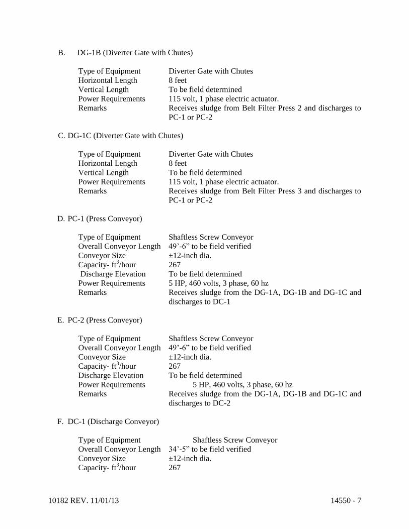
10182 REV. 11/01/13 14550 - 7
B. DG-1B (Diverter Gate with Chutes)
Type of Equipment Diverter Gate with Chutes
Horizontal Length 8 feet
Vertical Length To be field determined
Power Requirements 115 volt, 1 phase electric actuator.
Remarks Receives sludge from Belt Filter Press 2 and discharges to
PC-1 or PC-2
C. DG-1C (Diverter Gate with Chutes)
Type of Equipment Diverter Gate with Chutes
Horizontal Length 8 feet
Vertical Length To be field determined
Power Requirements 115 volt, 1 phase electric actuator.
Remarks Receives sludge from Belt Filter Press 3 and discharges to
PC-1 or PC-2
D. PC-1 (Press Conveyor)
Type of Equipment Shaftless Screw Conveyor
Overall Conveyor Length 49’-6” to be field verified
Conveyor Size ±12-inch dia.
Capacity- ft3/hour 267
Discharge Elevation To be field determined
Power Requirements 5 HP, 460 volts, 3 phase, 60 hz
Remarks Receives sludge from the DG-1A, DG-1B and DG-1C and
discharges to DC-1
E. PC-2 (Press Conveyor)
Type of Equipment Shaftless Screw Conveyor
Overall Conveyor Length 49’-6” to be field verified
Conveyor Size ±12-inch dia.
Capacity- ft3/hour 267
Discharge Elevation To be field determined
Power Requirements 5 HP, 460 volts, 3 phase, 60 hz
Remarks Receives sludge from the DG-1A, DG-1B and DG-1C and
discharges to DC-2
F. DC-1 (Discharge Conveyor)
Type of Equipment Shaftless Screw Conveyor
Overall Conveyor Length 34’-5” to be field verified
Conveyor Size ±12-inch dia.
Capacity- ft3/hour 267

10182 REV. 11/01/13 14550 - 8
Power Requirements 5 HP, 460 volts, 3 phase, 60 hz
Remarks Receives sludge from PC-1 and discharges to DG-2
G. DC-2 (Discharge Conveyor)
Type of Equipment Shaftless Screw Conveyor
Overall Conveyor Length 34’-5” to be field verified
Conveyor Size ±12-inch dia.
Capacity- ft3/hour 267
Power Requirements 5 HP, 460 volts, 3 phase, 60 hz
Remarks Receives sludge from PC-1 and discharges to DG-2
H. DG-2 (Diverter Gate with Chutes)
Type of Equipment Diverter Gate with Chutes
Vertical Length To be field measured
Power Requirements 115 volt, 1 phase electric actuator.
Remarks Receives sludge from DC-1 and DC-2 and discharges to
LO-1 or LO-2
I. LO-1 (Load-Out Conveyor)
Type of Equipment Shaftless Screw Conveyor
Overall Conveyor Length 19’-0”
Conveyor Size ±12-inch dia.
Capacity- ft3/hour 267
Power Requirements 3 HP, 460 volts, 3 phase, 60 hz
Remarks Receives sludge from DG2 and discharges SC-1 or SC-2 by
means of its reversing operation
J. LO-2 (Load-Out Conveyor)
Type of Equipment Shaftless Screw Conveyor
Overall Conveyor Length 19’-0”
Conveyor Size ±12-inch dia.
Capacity- ft3/hour 267
Power Requirements 3 HP, 460 volts, 3 phase, 60 hz
Remarks Receives sludge from DG2 and discharges SC-1 or SC-2 by
means of its reversing operation
K. SC-1 (Shuttle Conveyor)
Type of Equipment Shaftless Screw Conveyor with Discharge Gates
Overall Conveyor Length 29’-0”
Conveyor Size ±12-inch dia.
Capacity- ft3/hour 267
Power Requirements 3 HP, 460 volts, 3 phase, 60 hz

10182 REV. 11/01/13 14550 - 9
Remarks Receives sludge from LO-1 and LO-2 and discharges to
trailer at any one of five discharge ports
L. SC-2 (Shuttle Conveyor)
Type of Equipment Shaftless Screw Conveyor with Discharge Gates
Overall Conveyor Length 29’-0”
Conveyor Size ±12-inch dia.
Capacity- ft3/hour 267
Power Requirements 3 HP, 460 volts, 3 phase, 60 hz
Remarks Receives sludge from LO-1 and LO-2 and discharges to
trailer at any one of five discharge ports
M. SG-1A,1B,1C and SG-2A,2B and 2C (Slide Gates)
Type of Equipment Slide Gates
Size ±13-inch dia.
Capacity- ft3/hour 267
Power Requirements 115 volts, 1 phase, 60 hz
Remarks (SG-1A, SG-1B, SG-1C) receive sludge from SC-1 and
(SG-2A,SG-2B, SG-2C) receives sludge from SC-2.
3.2 FIELD CONSTRUCTION QUALITY CONTROL
A. Procedure
The Contractor shall submit to the Owner for review and comment a construction
procedure and quality control procedure prior to commencing work. Construction
procedure and all required testing shall comply with these specifications and all
applicable codes and standards.
1. Pre-inspection: Prior to all work of this Section, carefully inspect the fabricated
and installed work of all other trades and verify that all such work is completed to
the point where this installation may properly commence.
2. Inspection: Inspect all parts of the furnished equipment and verify that the system
may be installed in strict accordance with all pertinent codes and regulations, the
original drawings, the referenced standards, and the manufacturers'
recommendations.
3. Discrepancies: Notify the Owner's Representative immediately of all
unsatisfactory conditions or discrepancies. Do not proceed with installation in
areas of discrepancy until all such discrepancies have been fully resolved.
Beginning with the installation means, the installer accepts the existing surfaces
and conditions.

10182 REV. 11/01/13 14550 - 10
4. Coordination: It is the Contractor's responsibility to notify and coordinate with
the equipment manufacturer and other trades in a timely manner in order for the
equipment manufacturer to conduct its required work, inspection, servicing,
testing, and instruction.
5. Anchorage. The Contractor shall be responsible for furnishing and placing all
anchorage systems for the installation of the equipment. The Contractor shall
coordinate with the manufacturer in identifying proper size and locations of all
anchorage.
6. Protection: Protect adjacent equipment, materials, piping, structures, and/or
valving against damage from the installation procedure.
7. Manufacturer's Instructions: Preparatory work in accordance with manufacturer's
instructions shall be completed prior to equipment installation.
8. Field Assembly: The belt conveyor system will be delivered by the manufacturer
in fully assembled head, tail and intermediate sections approximately 10 feet in
length with match-marked splice plates, and complete with splicing hardware and
instructions. Other than spiral flight lengths that cannot be shipped/handled in full
length sections, no field welding shall be required. Assembly will consist only of
joining the sections anchoring the supports, installing belts, and electrical hookup.
3.3 MANUFACTURER'S FIELD SERVICE
A. A qualified representative of the manufacturer shall inspect the completed installation,
service the equipment, adjust, field test, operate the equipment under all design conditions,
instruct the Owner's personnel in proper operation and maintenance procedures, and provide
the Owner with a written certificate of approval dated the same day as the beginning of the
warranty period. Each representative shall spend at least two (2) 8-hour days performing
the required services and submit a manufacturer's representative report for each site visit.
The training shall be separate from the specified service time spent on site.
3.4 DELIVERY AND STORAGE
A. Delivery: The manufacturer will provide for the staggered shipment of assembled sections
to the construction site accordance with the sequence of construction in the Summary of
Work. The Contractor will provide all labor and equipment to unload assemblies at the site.
B. Storage fabricated assemblies shall be field checked prior to and during unloading by the
engineer to check for defects or inconsistencies with contract specifications and drawings.
Assemblies will be stored in strict conformance with storage recommendations provided by
the clarifier manufacturer in the Operation and Maintenance Manual. Any assembly found
to be defective or not in conformance with contract drawings or specifications upon receipt
will be shipped back to the manufacturer for correction at the manufacturer's expense at the
discretion of the Engineer.

10182 REV. 11/01/13 14550 - 11
C. Fabricated assemblies shall be factory assembled and properly match marked for ease of
field erection and then shipped in the largest sections permitted by carrier regulations.
3.5 INSTALLATION
A. During time of installation, a minimum of one belt press must be maintained in continuous
operation.
3.6 LUBRICATION
A. Storage Lubrication. Any equipment delivered and stored shall be checked at delivery for
storage practices and lubricated for long term storage as recommended by the equipment
manufacturer as outlined in the O & M Manual.
B. Continuous Service Lubrication - As part of the equipment start-up and testing procedures,
the Contractor shall service and lubricate the equipment for continuous duty in accordance
with the manufacturer's recommendations.
3.7 FIELD ADJUSTMENT/START-UP FIELD TESTING
A. Prior to acceptance, conduct an operational test of the equipment herein specified and
controls systems in accordance with start-up and testing, under the observation of the
Construction Manager, to determine if the installed equipment meets the purpose and intent
of the specification.
B. A factory trained Engineer from the equipment manufacturer shall conduct the tests in the
presence of the Owner. The equipment manufacturer shall provide all materials, instruments
and equipment required for the tests and shall provide a written report of test results to the
Contractor and Owner.
Tests shall demonstrate design conditions.
C. Certification - The manufacturer shall submit to the Engineer and the Owner a written
notarized report of the results of the tests which includes certifying that the equipment has
been checked and is suitable for operation.
3.8 OPERATION DEMONSTRATION
A. The intent of this specification is to provide equipment for long non-interrupted continuous
operation. The Contractor shall demonstrate the operation of equipment for a period of one
(1) week in accordance with Specification Section 01650 prior to final acceptance and
initiation of the warranty period by the Owner
3.9 OPERATION AND MAINTENANCE (O&M) MANUALS

10182 REV. 11/01/13 14550 - 12
A. Operation and Maintenance (O&M) Manuals will be provided by the equipment
manufacturer at least two (2) weeks prior to shipment of all major equipment components.
The O & M Manuals shall include instructions on storage, installation, start-up, and
operation and maintenance, together with a complete parts list and a recommended spare
parts list. Each O&M Manual shall be a bound, indexed binder with drawings and parts lists
prepared specifically for this project rather than general instructions that are not designed for
this project.
The manual shall be in accordance with the General Requirements. As a minimum the
manual shall contain:
1. General arrangement and detail equipment drawings.
2. Detail erection drawings.
3. A complete bill of materials for the equipment including the weights of all components.
4. Installation, operation and maintenance instructions for the specific equipment
including the erection sequence, maintenance, and trouble-shooting check points and
complete lubrication procedures with recommended grades of lubricants.
5. Cut sheets for all items of equipment purchased from other manufacturers.
6. A list of the manufacturer's recommended spare parts specifically denoting wear items,
long delivery items, and all items convenient for stocking as optional replacement
items.
7. An address, phone number and contact person for servicing equipment and ordering
parts.
3.10 EQUIPMENT WARRANTY DOCUMENTATION
A. All equipment furnished shall be free of defects in the material and workmanship for a
period of two (2) years from the date of acceptance. Warranties shall comply with the
General Requirements.
B. The Contractor and Engineer/Owner shall set the date beginning the warranty period. The
Contractor shall prepare a certificate with the said date and shall provide the certificate to the
manufacturer, Owner and Engineer.
3.11 TRAINING
A. The equipment manufacturer shall each provide one (1) 8-hour day training session on the
operation and maintenance and control of the equipment after installation is complete and
before the start-up and testing of the first unit. The number of personnel required to attend
the training sessions shall be requested of the Owner by the Contractor at least five (5)
working days before the scheduled training date.
END OF SECTION 14550

10182 REV. 10/25/13 14621CT - 1
SECTION 14621CT - HOISTS, CRANES AND MONORAILS
PART 1 - GENERAL
1.1 RELATED DOCUMENTS
A. Drawings and general provisions of Contract, including General and Supplementary
Conditions and Division-1 Specifications sections, apply to work of this section.
1.2 DESCRIPTION OF WORK
A. This section includes furnishing and installing, unless otherwise noted herein, the hoisting
equipment, controls, trolleys and supporting tracks, for the type of operation shown on the
Drawings and specified herein.
B. All work performed under this section shall comply and be in accordance with all approved
trade practices and manufacturer's recommendations, including ANSI MH 27.1 - 1981
"Specifications for Underhung Cranes and Monorail Systems".
C. All cranes and hoisting equipment shall comply with applicable OSHA CMAA and ANSI
requirements.
D. It is the intent of this Contract that the final installation shall be complete in all respects, and
the Contractor will be responsible for all minor details, whether or not shown on the Drawings
or specifically included in these Specifications.
1.3 QUALITY ASSURANCE
A. In addition to requirements of these specifications, comply with manufacturer's instructions
and recommendations for work.
B. The crane manufacturer shall have at least 5-years of successfully designed and built
installations of a similar scope and shall be and active member of the Crane Manufacturers
Association of America (CMAA).
1.4 SUBMITTALS
A. Submittals shall be in accordance with the General Requirements.
B. At the time of bidding, the Contractor shall submit, as a minimum, the following information:
1. Descriptive literature, bulletins, or other data describing the crane or hoist equipment
and verification that the equipment is capable of fulfilling the requirements of this
specification.
2. Complete list of equipment and appurtenances included with the equipment, complete
with manufacturer's name and model number

10182 REV. 10/25/13 14621CT - 2
3. General arrangement and dimension drawings
4. Assembly drawings
5. Materials of construction
6. Schematic wiring diagrams
C. The bid submittal package shall be enclosed in a separate envelope with the section number
marked clearly on the outside and shall be submitted with the Contractor's bid.
PART 2 - PRODUCTS
2.1 SUPPORTING TRACK
A. The supporting track shall consist of standard sections supported from precast beams or steel
beams, as and where noted, complete with all necessary stops, guides, bolts, clips, plates,
support connections, switches, and incidentals for a complete system. All steel, unless
otherwise noted, shall meet the requirements for structural steel as specified under American
Institute of Steel Construction capable of supporting the loads listed in the Equipment
Schedule, in addition to its own weight, load impact, hoist, trolley, and appurtenances.
1. Standard Rail - The non-electrified rail to be used with manual trolley and hoist
systems and cord and reel feed trolley and hoist systems specified herein shall be
standard I-beam sections of the size indicated on the plans or as per the hoist and
trolley manufacturer's requirements.
2. Electrified Rail - The electrified rail shall be a rolled high carbon-manganese steel
section as manufactured by Louden (Super Track), American Monorail (Railmaster
Track), Twin City Monorail (Wide Flange Rail), or equal.
3. Conductors - The electrified rail manufacturer shall furnish the rail with electric
conductors for 460 volt, 60 Hertz, 3 phase power. Electric conductors shall be
mounted the length of the rail and be so designed to protect against the possibility of
accidental physical contact by an insulation system.
B. Track Suspensions:
1. All necessary clamps, hanger rods, bolts and other fittings from which the track system
is suspended, shall be provided as part of the overhead track system. Track hanger
supports shall be spaced as per the drawings attached, as specified, or as per
manufacturer's recommendations.
2. Means shall be provided, on flexible type rod suspensions, to allow for minimum 1"
vertical adjustment of the track, both before and after the system has been put in
operation so that the track can be erected and maintained level.
3. Where flexible type rod suspensions are used, the hanger rod shall be made from high
strength alloy steel with rolled threads and furnished with a spherical nut at each end.
Each spherical nut shall be equipped with a brass-tipped set screw having a nylon
patch on the thread for locking purposes. In addition, a cotter pin shall be provided at
each end of the rod to prevent the spherical nut from backing off the rod.
4. Where flexible type rod suspensions are used, the top and bottom hanger fittings shall
be provided with a spherical seat to match the spherical nuts on the hanger rod.

10182 REV. 10/25/13 14621CT - 3
5. Where track system is suspended from flexible type rod suspensions, the system shall
be braced laterally and longitudinally to prevent excessive sway. All bracing is to be
provided by the monorail erector.
6. Rigid suspensions can be obtained by flush clamping or bolting the monorail track
direct to the supporting steel.
7. All suspension fittings shall be furnished with S.A.E. Grade 5 or ASTM A 325
mounting bolts.
2.2 TROLLEYS
A. Trolleys shall have the capacities as listed in the Equipment Schedule and shall be installed in
the proper location, complete.
1. Hand Push Trolleys - Hand push trolleys shall be four-wheel type with a load eye for a
hand operated hoist. The trolley shall have forged steel wheels. The trolley shall be
manufactured by the same manufacturer as the attached hoist.
2. Gear Driven Trolleys - Gear driven trolleys shall be equipped with a chain wheel and
endless chain. Chain shall be of sufficient length to extend within three (3) feet of the
floor.
The trolley shall be equipped with a clevis, link, or eye bolt of minimum 3/4 inch
diameter steel and with minimum 3 inch diameter "eye" for attachment of hand hoists.
Trolley shall be equal to Budget "Hi-Cap" Trolleys as manufactured by Dresser Crane,
Hoist and Tower Division, Dresser Industries, Inc., or equal.
3. Electrified Trolley Drives - Electrified trolley drives shall be electric travel, single
speed soft start, with speed not to exceed 35 fpm. Trolley drive shall operate on 460
volt, 60 hertz, 3 phase current, complete with overload protection and motor starter.
Drive controls shall be incorporated with the hoist controls in a suspended push button
station. The trolleys shall be driven by means of an electric motor coupled to spur or
helical reducer and under rail tire drive. Motoveyor and hoist trolley to be equipped
with side guide rollers for smooth operation around curves. All gears shall operate in
an oil bath in sealed enclosures providing positive splash lubrication for gears and
bearings. All bearings will be anti-friction, radial thrust type. Trolley wheel axles will
be pre-lubricated and sealed for life with bearings mounted in cartridges in bored seats.
Trolley wheels shall be in pairs and trolley drives shall be as manufactured by David
Round and Son, Inc., Crane and Monorail Systems, Cleveland Tramrail by Gorbel Inc.,
or equal.
2.3 HOISTS
A. Hand Operated Hoists - All hand operated hoists shall be as indicated on the Drawings or as
specified herein so as to deliver maximum efficiency and require minimum maintenance.
They shall be equipped with a corrosion-resistant aluminum housing; a load brake; forged
steel, free swivel, safety latch hooks, and a cadmium or zinc plated pull chain extending to
within 3 feet of the floor below. The hoist shall also have a load limiter which will not permit
overloading of the hoist. The hoist shall be as manufactured by Acco-Wright, Dresser, P & H
or equal.

10182 REV. 10/25/13 14621CT - 4
B. Electric Hoists - All electric hoists shall be as indicated on the Drawings or as specified herein.
They shall have a 3 phase, 460 volt, 60 Hz motor with single speed lift. The lifting speed shall
be a min. of 5 FPM. The hoist shall be controlled from a pendant pushbutton station.
1. The hoist shall be equipped with alloy steel load chain sized for the listed load; steel,
safety latch hook; an overload protection device; and load chain reel.
2. The hoist shall be as manufactured by David Round and Sons, Inc., Yale, P & H,
Acco-Wright; Demag or equal.
C. All hoist gearing shall be helical or spur made from forged, rolled, or cast steel and shall have
machine cut teeth. All pinions shall be made from alloy steel and shall be heat treated.
D. All bearings shall be heavy duty, antifriction, radial type. All gears shall operate in an oil bath
in sealed housings providing positive splash lubrication for gears and bearings. Sheave
bearings shall be packed with grease and shall be lubricated through pressure type fittings.
E. A mechanical load brake or suitable method of electric braking shall be provided in addition to
the hoist motor brake. Mechanical load brake of electric braking system shall automatically
regulate the speed during lowering and prevent undue acceleration. Mechanical load brake
shall be capable of holding full load independent of hoist motor brake.
F. Hoist motor brake shall be magnetically operated disc type or shoe type, mounted on the
extended pinion shaft. Brake shall be spring set and equally effective in both directions of
motor rotation and of sufficient size to stop motor and hold rated capacity load. Brake shall be
set automatically when current is not flowing to the motor.
2.4 JIB CRANES
A. Jib cranes shall be constructed of standard ASTM-A36 structural steel members. Jib cranes
shall be standard production models as manufactured by Demag, David Round and Son, Inc.,
Americrane & Hoist Corp., Gorbel, or equal. Jib cranes shall have the reach, clear height and
load capacities, including appropriate impact and safety factors, indicated in the Equipment
Schedule, unless otherwise specified. Each jib crane shall be capable of pivoting at least 200o
or as indicated on the Drawings with load at outer most reach. Jib cranes equipped with
electric hoists and/or pivoting shall be controlled from a pendant suspended from the mast.
B. Jib crane shall be base plate mounted and suitable for service as required for the location
shown on the Drawings.
2.5 TRAVEING GANTRY CRANE
A. The traveling gantry crane and accessories shall be supplied by
1. Demag
2. Tri State Tool and Hoist
3. Approved Equal
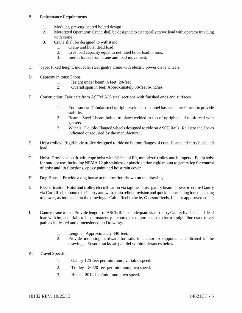
10182 REV. 10/25/13 14621CT - 5
B. Performance Requirements
1. Modular, pre-engineered bolted design.
2. Motorized Operation: Crane shall be designed to electrically move load with operator traveling
with crane.
3. Crane shall be designed to withstand:
1. Crane and hoist dead load.
2. Live load capacity equal to net rated hook load: 5 tons.
3. Inertia forces from crane and load movement.
C. Type: Fixed height, movable, steel gantry crane with electric power drive wheels.
D. Capacity in tons: 5 tons.
1. Height under beam in feet: 20-feet
2. Overall span in feet: Approximately 88-feet 6-inches
E. Construction: Fabricate from ASTM A36 steel sections with finished ends and surfaces.
1. End frames: Tubular steel uprights welded to channel base and knee braces to provide
stability.
2. Beam: Steel I-beam bolted to plates welded to top of uprights and reinforced with
gussets.
3. Wheels: Double-Flanged wheels designed to ride on ASCE Rails. Rail size shall be as
indicated or required by the manufacturer.
F. Hoist trolley: Rigid-body trolley designed to ride on bottom flanges of crane beam and carry hoist and
load.
G. Hoist: Provide electric wire rope hoist with 32-feet of lift, motorized trolley and bumpers. Equip hoist
for outdoor use, including NEMA 12 pb stainless or plastic station rigid mount to gantry leg for control
of hoist and jib functions, epoxy paint and hoist rain cover.
H. Dog House: Provide a dog house at the location shown on the drawings.
I. Electrification: Hoist and trolley electrification via tagline across gantry beam. Power to entire Gantry
via Cord Reel, mounted to Gantry and with strain relief provision and quick-connect plug for connecting
to power, as indicated on the drawings. Cable Reel to be by Gleeson Reels, Inc., or apporoved equal.
J. Gantry crane track: Provide lengths of ASCE Rails of adequate size to carry Gantry live load and dead
load with impact. Rails to be permanently anchored to support beams to form straight line crane travel
path as indicated and dimensioned on Drawings.
1. Lengths: Approximately 440-feet.
2. Provide mounting hardware for rails to anchor to supports, as indicated in the
drawings. Ensure tracks are parallel within tolerances below.
K. Travel Speeds:
1. Gantry-125-feet per minimum, variable speed.
2. Trolley – 80/20-feet per minimum, two speed.
3. Hoist – 2014-feet/minimum, two speed.

10182 REV. 10/25/13 14621CT - 6
L. Straightness of Crane Runway
1. Tolerances shall meet the requirements of CMAA Specification 70.
M. Shop Finishing:
1. Paint system as required for outdoor exposure in accordance with Specification
09801CT - Special Coatings.
2. Provide extra primer and paint for field touch-up.
3. Hoist - 2014-feet/minimum, two speed.
2.6 ELECTRICAL EQUIPMENT
A. Motors shall be NEMA standard designed for crane service. Motors will be ball bearing, with
Class "B" insulation and rated on the basis of 40 degrees C ambient temperature and a
30-minute rating.
B. Controls for all electrified portions of a hoisting system shall be mounted in one common push
button pendant. Push button switches shall be arranged for not less than two accelerating
points in each direction for hoist motion and one for trolley motion, if required. Control
circuits shall be 115 volt AC. Control enclosures shall be NEMA 12. Unless otherwise
specified, pendants shall extend to a height of three (3) feet above the operating floor.
C. A manual mainline fused disconnect switch shall be provided and installed by the Contractor
with wiring and conduit to runway power conductors. All wire sizes shall be suitable for crane
rated motors in accordance with Article 610 of the NEC. All insulation, conduit and fittings
shall conform to the requirements of the latest addition of the NEC.
D. Monorail Conductors:
1. Power shall be transmitted to the hoist and motoveyor motors through a system of
insulated conductor bars supported on the monorail and collectors supported on the
hoist.
2. The shoes shall be a brass alloy set in molded insulators and attached to collector arms,
suitably mounted on brackets from the hoists.
E. Hoist is to have an upper limit switch. When hook reaches upward limit of travel, an electric
circuit shall be opened to stop flow of current to hoist.
F. The manufacturer shall refer to the electrical plans for area classification. All enclosures,
devices and wiring methods shall be rated for use in that classification.

10182 REV. 10/25/13 14621CT - 7
PART 3 - EXECUTION
3.1 ERECTION
A. The monorails gantry crane, hoisting equipment and controls shall be erected and tested by
manufacturer or manufacturer's representative in accordance with the manufacturer's
recommendations.
3.2 INITIAL LUBRICATION
A. Initial lubrication required for startup and field test operation shall be furnished and applied in
accordance with the manufacturer's recommendations.
3.3 PAINTING
A. All materials shall be cleaned of loose rust, mill scale and foreign matter.
B. Trolleys, track, track switches, and suspension fittings shall be painted one shop coat of
manufacturer's standard finish, which shall be compatible with the finish paint. Gantry crane
rails need not be painted.
C. Bolts or hanger rods will not be painted but must be adequately protected against damage and
rust in shipment.
1. Bolts and hanger rods shall be painted with the ceiling.
3.4 INSPECTION, START-UP, AND TESTING
A. The manufacturer of the mechanism shall provide a representative to check the installation,
make final adjustments, supervise initial start-up of the equipment, and prepare a written test
report thereof for the Owner.
B. The representative shall instruct the Owner's personnel in the operation and maintenance of the
equipment.
C. The manufacturer shall furnish two (2) complete sets of replacement parts for each monorail
and jib crane.

10182 REV. 10/25/13 14621CT - 8
3.5 OPERATION AND MAINTENANCE MANUALS
A. Prior to or with the delivery of equipment, the manufacturer shall provide copies of an
operation and maintenance manual including storage, installation, start-up, operating and
maintenance instructions, and a complete parts list and recommended spare parts list. The O
& M manuals shall be in compliance with the General Requirements.
3.6 EQUIPMENT SCHEDULE
A. Monorail
Location Capacity Minimum Lift Type of Hoist Type of Trolley
Preliminary
Treatment Solids
Building, Qty. 4
1-1/2 Ton
16’-0”
Manual
Hand Operated
Secondary
Treatment North
& South Access,
Qty. 2
1 Ton
12’-0”
Electrical
Hand Operated
Secondary
Treatment RAS
Pumps, Qty. 3
1 Ton
20’-0
Electrical
Electrical
B. Traveling Gantry Crane
Location Capacity Minimum Lift Type of Hoist Type of Trolley
Secondary
Treatment MBR
Units, Qty. 1
5 Ton 32’-0 Electrical Electrical
C. Jib Crane
Location Capacity Minimum Lift Type of Hoist Type of Trolley
West of
Screening
Building, Qty. 2
1 Ton 10’-0” Electrical Hand Operated
END OF SECTION 14621CT 1/88

DIVISION 15
MECHANICAL
10182 REV. 10/22/13 15050CT-1
SECTION 15050CT - BASIC MECHANICAL MATERIALS AND METHODS
PART 1 - GENERAL
1.1 RELATED DOCUMENTS
A. Drawings and general provisions of the Contract, including General and Supplementary
Conditions and Division 1 Specification Sections, apply to this Section.
1.2 SUMMARY
A. This Section includes the following:
1. Piping materials and installation instructions common to most piping systems.
2. Transition fittings.
3. Dielectric fittings.
4. Mechanical sleeve seals.
5. Sleeves.
6. Escutcheons.
7. Grout.
8. Equipment installation requirements common to equipment sections.
9. Painting and finishing.
10. Concrete bases.
11. Supports and anchorages.
12. Mechanical demolition.
1.3 DEFINITIONS
A. Finished Spaces: Spaces other than mechanical and electrical equipment rooms, furred
spaces, pipe and duct shafts, unheated spaces immediately below roof, spaces above
ceilings, unexcavated spaces, crawlspaces, and tunnels.
B. Exposed, Interior Installations: Exposed to view indoors. Examples include finished
occupied spaces and mechanical equipment rooms.
C. Exposed, Exterior Installations: Exposed to view outdoors or subject to outdoor
ambient temperatures and weather conditions. Examples include rooftop locations.
D. Concealed, Interior Installations: Concealed from view and protected from physical
contact by building occupants. Examples include above ceilings and in duct shafts.
E. Concealed, Exterior Installations: Concealed from view and protected from weather
conditions and physical contact by building occupants but subject to outdoor ambient
temperatures. Examples include installations within unheated shelters.
10182 REV. 10/22/13 15050CT-2
F. The following are industry abbreviations for plastic materials:
1. ABS: Acrylonitrile-butadiene-styrene plastic.
2. CPVC: Chlorinated polyvinyl chloride plastic.
3. PE: Polyethylene plastic.
4. PVC: Polyvinyl chloride plastic.
G. The following are industry abbreviations for rubber materials:
1. EPDM: Ethylene-propylene-diene terpolymer rubber.
2. NBR: Acrylonitrile-butadiene rubber.
1.4 SUBMITTALS
A. Product Data: For the following:
1. Transition fittings.
2. Dielectric fittings.
3. Mechanical sleeve seals.
4. Escutcheons.
B. Welding certificates.
1.5 QUALITY ASSURANCE
A. Steel Support Welding: Qualify processes and operators according to AWS D1.1,
"Structural Welding Code--Steel."
B. Steel Pipe Welding: Qualify processes and operators according to ASME Boiler and
Pressure Vessel Code: Section IX, "Welding and Brazing Qualifications."
1. Comply with provisions in ASME B31 Series, "Code for Pressure Piping."
2. Certify that each welder has passed AWS qualification tests for welding processes
involved and that certification is current.
C. Electrical Characteristics for Mechanical Equipment: Equipment of higher electrical
characteristics may be furnished provided such proposed equipment is approved in
writing and connecting electrical services, circuit breakers, and conduit sizes are
appropriately modified. If minimum energy ratings or efficiencies are specified,
equipment shall comply with requirements.
1.6 DELIVERY, STORAGE, AND HANDLING
A. Deliver pipes and tubes with factory-applied end caps. Maintain end caps through
shipping, storage, and handling to prevent pipe end damage and to prevent entrance of
dirt, debris, and moisture.
B. Store plastic pipes protected from direct sunlight. Support to prevent sagging and
bending.

10182 REV. 10/22/13 15050CT-3
1.7 COORDINATION
A. Arrange for pipe spaces, chases, slots, and openings in building structure during
progress of construction, to allow for mechanical installations.
B. Coordinate installation of required supporting devices and set sleeves in poured-in-place
concrete and other structural components as they are constructed.
C. Coordinate requirements for access panels and doors for mechanical items requiring
access that are concealed behind finished surfaces.
PART 2 - PRODUCTS
2.1 MANUFACTURERS
A. In other Part 2 articles where subparagraph titles below introduce lists, the following
requirements apply for product selection:
1. Manufacturers: Subject to compliance with requirements, provide products by the
manufacturers specified.
2.2 PIPE, TUBE, AND FITTINGS
A. Refer to individual Division 15 piping Sections for pipe, tube, and fitting materials and
joining methods.
B. Pipe Threads: ASME B1.20.1 for factory-threaded pipe and pipe fittings.
2.3 JOINING MATERIALS
A. Refer to individual Division 15 piping Sections for special joining materials not listed
below.
B. Pipe-Flange Gasket Materials: Suitable for chemical and thermal conditions of piping
system contents.
1. ASME B16.21, nonmetallic, flat, asbestos-free, 1/8-inch maximum thickness
unless thickness or specific material is indicated.
a. Full-Face Type: For flat-face, Class 125, cast-iron and cast-bronze flanges.
b. Narrow-Face Type: For raised-face, Class 250, cast-iron and steel flanges.
2. AWWA C110, rubber, flat face, 1/8 inch thick, unless otherwise indicated; and
full-face or ring type, unless otherwise indicated.
C. Flange Bolts and Nuts: ASME B18.2.1, carbon steel, unless otherwise indicated.
D. Plastic, Pipe-Flange Gasket, Bolts, and Nuts: Type and material recommended by
piping system manufacturer, unless otherwise indicated.
10182 REV. 10/22/13 15050CT-4
E. Solder Filler Metals: ASTM B 32, lead-free alloys. Include water-flushable flux
according to ASTM B 813.
F. Brazing Filler Metals: AWS A5.8, BCuP Series, copper-phosphorus alloys for general-
duty brazing, unless otherwise indicated; and AWS A5.8, BAg1, silver alloy for
refrigerant piping, unless otherwise indicated.
G. Welding Filler Metals: Comply with AWS D10.12 for welding materials appropriate
for wall thickness and chemical analysis of steel pipe being welded.
H. Solvent Cements for Joining Plastic Piping:
1. ABS Piping: ASTM D 2235.
2. CPVC Piping: ASTM F 493.
3. PVC Piping: ASTM D 2564. Include primer according to ASTM F 656.
4. PVC to ABS Piping Transition: ASTM D 3138.
I. Fiberglass Pipe Adhesive: As furnished or recommended by pipe manufacturer.
2.4 TRANSITION FITTINGS
A. AWWA Transition Couplings: Same size as, and with pressure rating at least equal to
and with ends compatible with, piping to be joined.
1. Manufacturers:
a. Cascade Waterworks Mfg. Co.
b. Dresser Industries, Inc.; DMD Div.
c. Ford Meter Box Company, Incorporated (The); Pipe Products Div.
d. JCM Industries.
e. Smith-Blair, Inc.
f. Viking Johnson.
2. Underground Piping NPS 1-1/2 and Smaller: Manufactured fitting or coupling.
3. Underground Piping NPS 2 and Larger: AWWA C219, metal sleeve-type
coupling.
4. Aboveground Pressure Piping: Pipe fitting.
B. Plastic-to-Metal Transition Fittings: PVC one-piece fitting with manufacturer's
Schedule 80 equivalent dimensions; one end with threaded brass insert, and one
solvent-cement-joint end.
1. Manufacturers:
a. Eslon Thermoplastics.
10182 REV. 10/22/13 15050CT-5
C. Plastic-to-Metal Transition Adaptors: One-piece fitting with manufacturer's SDR 11
equivalent dimensions; one end with threaded brass insert, and one solvent-cement-joint
end.
1. Manufacturers:
a. Thompson Plastics, Inc.
D. Plastic-to-Metal Transition Unions: MSS SP-107, PVC four-part union. Include brass
end, solvent-cement-joint end, rubber O-ring, and union nut.
1. Manufacturers:
a. NIBCO INC.
b. NIBCO, Inc.; Chemtrol Div.
E. Flexible Transition Couplings for Underground Nonpressure Drainage Piping:
ASTM C 1173 with elastomeric sleeve, ends same size as piping to be joined, and
corrosion-resistant metal band on each end.
1. Manufacturers:
a. Cascade Waterworks Mfg. Co.
b. Fernco, Inc.
c. Mission Rubber Company.
d. Plastic Oddities, Inc.
2.5 DIELECTRIC FITTINGS
A. Description: Combination fitting of copper alloy and ferrous materials with threaded,
solder-joint, plain, or weld-neck end connections that match piping system materials.
B. Insulating Material: Suitable for system fluid, pressure, and temperature.
C. Dielectric Unions: Factory-fabricated, union assembly, for 250-psig minimum working
pressure at 180 deg F.
1. Manufacturers:
a. Capitol Manufacturing Co.
b. Central Plastics Company.
c. Eclipse, Inc.
d. Epco Sales, Inc.
e. Hart Industries, International, Inc.
f. Watts Industries, Inc.; Water Products Div.
g. Zurn Industries, Inc.; Wilkins Div.

10182 REV. 10/22/13 15050CT-6
D. Dielectric Flanges: Factory-fabricated, companion-flange assembly, for 150- or 300-
psig minimum working pressure as required to suit system pressures.
1. Manufacturers:
a. Capitol Manufacturing Co.
b. Central Plastics Company.
c. Epco Sales, Inc.
d. Watts Industries, Inc.; Water Products Div.
E. Dielectric-Flange Kits: Companion-flange assembly for field assembly. Include
flanges, full-face- or ring-type neoprene or phenolic gasket, phenolic or polyethylene
bolt sleeves, phenolic washers, and steel backing washers.
1. Manufacturers:
a. Advance Products & Systems, Inc.
b. Calpico, Inc.
c. Central Plastics Company.
d. Pipeline Seal and Insulator, Inc.
2. Separate companion flanges and steel bolts and nuts shall have 150- or 300-psig
minimum working pressure where required to suit system pressures.
F. Dielectric Couplings: Galvanized-steel coupling with inert and noncorrosive,
thermoplastic lining; threaded ends; and 300-psig minimum working pressure at 225
deg F.
1. Manufacturers:
a. Calpico, Inc.
G. Dielectric Nipples: Electroplated steel nipple with inert and noncorrosive,
thermoplastic lining; plain, threaded, or grooved ends; and 300-psig minimum working
pressure at 225 deg F.
1. Manufacturers:
a. Perfection Corp.
b. Precision Plumbing Products, Inc.
c. Sioux Chief Manufacturing Co., Inc.
d. Victaulic Co. of America.
2.6 MECHANICAL SLEEVE SEALS
A. Description: Modular sealing element unit, designed for field assembly, to fill annular
space between pipe and sleeve.

10182 REV. 10/22/13 15050CT-7
1. Manufacturers:
a. Advance Products & Systems, Inc.
b. Calpico, Inc.
c. Metraflex Co.
d. Pipeline Seal and Insulator, Inc.
2. Sealing Elements: EPDM interlocking links shaped to fit surface of pipe. Include
type and number required for pipe material and size of pipe.
3. Pressure Plates: Carbon steel. Include two for each sealing element.
4. Connecting Bolts and Nuts: Stainless steel of length required to secure pressure
plates to sealing elements. Include one for each sealing element.
2.7 SLEEVES
A. Galvanized-Steel Sheet: 0.0239-inch minimum thickness; round tube closed with
welded longitudinal joint.
B. Steel Pipe: ASTM A 53, Type E, Grade B, Schedule 40, galvanized, plain ends.
C. Cast Iron: Cast or fabricated "wall pipe" equivalent to ductile-iron pressure pipe, with
plain ends and integral waterstop, unless otherwise indicated.
D. Stack Sleeve Fittings: Manufactured, cast-iron sleeve with integral clamping flange.
Include clamping ring and bolts and nuts for membrane flashing.
1. Underdeck Clamp: Clamping ring with set screws.
E. Molded PVC: Permanent, with nailing flange for attaching to wooden forms.
F. PVC Pipe: ASTM D 1785, Schedule 40.
G. Molded PE: Reusable, PE, tapered-cup shaped, and smooth-outer surface with nailing
flange for attaching to wooden forms.
2.8 ESCUTCHEONS
A. Description: Manufactured wall and ceiling escutcheons and floor plates, with an ID to
closely fit around pipe, tube, and insulation of insulated piping and an OD that
completely covers opening.
B. One-Piece, Deep-Pattern Type: Deep-drawn, box-shaped brass with polished chrome-
plated finish.
C. One-Piece, Cast-Brass Type: With set screw.
1. Finish: Polished chrome-plated.
D. One-Piece, Floor-Plate Type: Cast-iron floor plate.

10182 REV. 10/22/13 15050CT-8
2.9 GROUT
A. Description: ASTM C 1107, Grade B, nonshrink and nonmetallic, dry hydraulic-
cement grout.
1. Characteristics: Post-hardening, volume-adjusting, nonstaining, noncorrosive,
nongaseous, and recommended for interior and exterior applications.
2. Design Mix: 5000-psi, 28-day compressive strength.
3. Packaging: Premixed and factory packaged.
PART 3 - EXECUTION
3.1 PIPING SYSTEMS - COMMON REQUIREMENTS
A. Install piping according to the following requirements and Division 15 Sections
specifying piping systems.
B. Drawing plans, schematics, and diagrams indicate general location and arrangement of
piping systems. Indicated locations and arrangements were used to size pipe and
calculate friction loss, expansion, pump sizing, and other design considerations. Install
piping as indicated unless deviations to layout are approved on Coordination Drawings.
C. Install piping in concealed locations, unless otherwise indicated and except in
equipment rooms and service areas.
D. Install piping indicated to be exposed and piping in equipment rooms and service areas
at right angles or parallel to building walls. Diagonal runs are prohibited unless
specifically indicated otherwise.
E. Install piping above accessible ceilings to allow sufficient space for ceiling panel
removal.
F. Install piping to permit valve servicing.
G. Install piping at indicated slopes.
H. Install piping free of sags and bends.
I. Install fittings for changes in direction and branch connections.
J. Install piping to allow application of insulation.
K. Select system components with pressure rating equal to or greater than system operating
pressure.
10182 REV. 10/22/13 15050CT-9
L. Install escutcheons for penetrations of walls, ceilings, and floors according to the
following:
1. New Piping:
a. Piping with Fitting or Sleeve Protruding from Wall: One-piece, deep-
pattern type.
b. Chrome-Plated Piping: One-piece, cast-brass type with polished chrome-
plated finish.
c. Insulated Piping: One-piece, stamped-steel type with spring clips.
d. Bare Piping at Wall and Floor Penetrations in Finished Spaces: One-piece,
cast-brass type with polished chrome-plated finish.
e. Bare Piping at Ceiling Penetrations in Finished Spaces: One-piece, cast-
brass type with polished chrome-plated finish.
f. Bare Piping in Unfinished Service Spaces: One-piece, cast-brass type with
polished chrome-plated finish.
g. Bare Piping in Equipment Rooms: One-piece, cast-brass type.
h. Bare Piping at Floor Penetrations in Equipment Rooms: One-piece, floor-
plate type.
M. Sleeves are not required for core-drilled holes.
N. Permanent sleeves are not required for holes formed by removable PE sleeves.
O. Install sleeves for pipes passing through concrete and masonry walls and concrete floor
and roof slabs.
1. Cut sleeves to length for mounting flush with both surfaces.
a. Exception: Extend sleeves installed in floors of mechanical equipment
areas or other wet areas 2 inches above finished floor level. Extend cast-
iron sleeve fittings below floor slab as required to secure clamping ring if
ring is specified.
2. Install sleeves in new walls and slabs as new walls and slabs are constructed.
3. Install sleeves that are large enough to provide 1/4-inch annular clear space
between sleeve and pipe or pipe insulation. Use the following sleeve materials:
a. Steel Pipe Sleeves: For pipes smaller than NPS 6.
b. Steel Sheet Sleeves: For pipes NPS 6 and larger, penetrating gypsum-board
partitions.
c. Stack Sleeve Fittings: For pipes penetrating floors with membrane
waterproofing. Secure flashing between clamping flanges. Install section
of cast-iron soil pipe to extend sleeve to 2 inches above finished floor level.
Refer to Division 7 Sections for flashing materials and installation.
1) Seal space outside of sleeve fittings with grout.
4. Except for underground wall penetrations, seal annular space between sleeve and
pipe or pipe insulation, using joint sealants appropriate for size, depth, and
location of joint. Refer to Division 7 Section "Joint Sealants" for materials and
installation.

10182 REV. 10/22/13 15050CT-10
P. Aboveground, Exterior-Wall Pipe Penetrations: Seal penetrations using sleeves and
mechanical sleeve seals. Select sleeve size to allow for 1-inch annular clear space
between pipe and sleeve for installing mechanical sleeve seals.
1. Install steel pipe for sleeves smaller than 6 inches in diameter.
2. Install cast-iron "wall pipes" for sleeves 6 inches and larger in diameter.
3. Mechanical Sleeve Seal Installation: Select type and number of sealing elements
required for pipe material and size. Position pipe in center of sleeve. Assemble
mechanical sleeve seals and install in annular space between pipe and sleeve.
Tighten bolts against pressure plates that cause sealing elements to expand and
make watertight seal.
Q. Underground, Exterior-Wall Pipe Penetrations: Install cast-iron "wall pipes" for
sleeves. Seal pipe penetrations using mechanical sleeve seals. Select sleeve size to
allow for 1-inch annular clear space between pipe and sleeve for installing mechanical
sleeve seals.
1. Mechanical Sleeve Seal Installation: Select type and number of sealing elements
required for pipe material and size. Position pipe in center of sleeve. Assemble
mechanical sleeve seals and install in annular space between pipe and sleeve.
Tighten bolts against pressure plates that cause sealing elements to expand and
make watertight seal.
R. Fire-Barrier Penetrations: Maintain indicated fire rating of walls, partitions, ceilings,
and floors at pipe penetrations. Seal pipe penetrations with firestop materials. Refer to
Division 7 Sections for materials and installation.
S. Verify final equipment locations for roughing-in.
T. Refer to equipment specifications in other Sections of these Specifications for roughing-
in requirements.
3.2 PIPING JOINT CONSTRUCTION
A. Join pipe and fittings according to the following requirements and Division 15 Sections
specifying piping systems.
B. Ream ends of pipes and tubes and remove burrs. Bevel plain ends of steel pipe.
C. Remove scale, slag, dirt, and debris from inside and outside of pipe and fittings before
assembly.
D. Soldered Joints: Apply ASTM B 813, water-flushable flux, unless otherwise indicated,
to tube end. Construct joints according to ASTM B 828 or CDA's "Copper Tube
Handbook," using lead-free solder alloy complying with ASTM B 32.
E. Brazed Joints: Construct joints according to AWS's "Brazing Handbook," "Pipe and
Tube" Chapter, using copper-phosphorus brazing filler metal complying with
AWS A5.8.

10182 REV. 10/22/13 15050CT-11
F. Threaded Joints: Thread pipe with tapered pipe threads according to ASME B1.20.1.
Cut threads full and clean using sharp dies. Ream threaded pipe ends to remove burrs
and restore full ID. Join pipe fittings and valves as follows:
1. Apply appropriate tape or thread compound to external pipe threads unless dry
seal threading is specified.
2. Damaged Threads: Do not use pipe or pipe fittings with threads that are corroded
or damaged. Do not use pipe sections that have cracked or open welds.
G. Welded Joints: Construct joints according to AWS D10.12, using qualified processes
and welding operators according to Part 1 "Quality Assurance" Article.
H. Flanged Joints: Select appropriate gasket material, size, type, and thickness for service
application. Install gasket concentrically positioned. Use suitable lubricants on bolt
threads.
I. Plastic Piping Solvent-Cement Joints: Clean and dry joining surfaces. Join pipe and
fittings according to the following:
1. Comply with ASTM F 402 for safe-handling practice of cleaners, primers, and
solvent cements.
2. ABS Piping: Join according to ASTM D 2235 and ASTM D 2661 Appendixes.
3. CPVC Piping: Join according to ASTM D 2846/D 2846M Appendix.
4. PVC Pressure Piping: Join schedule number ASTM D 1785, PVC pipe and PVC
socket fittings according to ASTM D 2672. Join other-than-schedule-number
PVC pipe and socket fittings according to ASTM D 2855.
5. PVC Nonpressure Piping: Join according to ASTM D 2855.
6. PVC to ABS Nonpressure Transition Fittings: Join according to ASTM D 3138
Appendix.
J. Plastic Pressure Piping Gasketed Joints: Join according to ASTM D 3139.
K. Plastic Nonpressure Piping Gasketed Joints: Join according to ASTM D 3212.
L. PE Piping Heat-Fusion Joints: Clean and dry joining surfaces by wiping with clean
cloth or paper towels. Join according to ASTM D 2657.
1. Plain-End Pipe and Fittings: Use butt fusion.
2. Plain-End Pipe and Socket Fittings: Use socket fusion.
M. Fiberglass Bonded Joints: Prepare pipe ends and fittings, apply adhesive, and join
according to pipe manufacturer's written instructions.
3.3 PIPING CONNECTIONS
A. Make connections according to the following, unless otherwise indicated:
1. Install unions, in piping NPS 2 and smaller, adjacent to each valve and at final
connection to each piece of equipment.
2. Install flanges, in piping NPS 2-1/2 and larger, adjacent to flanged valves and at
final connection to each piece of equipment.

10182 REV. 10/22/13 15050CT-12
3. Dry Piping Systems: Install dielectric unions and flanges to connect piping
materials of dissimilar metals.
4. Wet Piping Systems: Install dielectric coupling and nipple fittings to connect
piping materials of dissimilar metals.
3.4 EQUIPMENT INSTALLATION - COMMON REQUIREMENTS
A. Install equipment to allow maximum possible headroom unless specific mounting
heights are not indicated.
B. Install equipment level and plumb, parallel and perpendicular to other building systems
and components in exposed interior spaces, unless otherwise indicated.
C. Install mechanical equipment to facilitate service, maintenance, and repair or
replacement of components. Connect equipment for ease of disconnecting, with
minimum interference to other installations. Extend grease fittings to accessible
locations.
D. Install equipment to allow right of way for piping installed at required slope.
3.5 PAINTING
A. Painting of mechanical systems, equipment, and components is specified in Division 9
Section "Painting”.
B. Damage and Touchup: Repair marred and damaged factory-painted finishes with
materials and procedures to match original factory finish.
3.6 CONCRETE BASES
A. Concrete Bases: Anchor equipment to concrete base according to equipment
manufacturer's written instructions and according to seismic codes at Project.
1. Construct concrete bases of dimensions indicated, but not less than 4 inches larger
in both directions than supported unit.
2. Install dowel rods to connect concrete base to concrete floor. Unless otherwise
indicated, install dowel rods on 18-inch centers around the full perimeter of the
base.
3. Install epoxy-coated anchor bolts for supported equipment that extend through
concrete base, and anchor into structural concrete floor.
4. Place and secure anchorage devices. Use supported equipment manufacturer's
setting drawings, templates, diagrams, instructions, and directions furnished with
items to be embedded.
5. Install anchor bolts to elevations required for proper attachment to supported
equipment.
6. Install anchor bolts according to anchor-bolt manufacturer's written instructions.
7. Use 3000-psi, 28-day compressive-strength concrete and reinforcement as
specified in Division 3 Section "Cast-in-Place Concrete".

10182 REV. 10/22/13 15050CT-13
3.7 ERECTION OF METAL SUPPORTS AND ANCHORAGES
A. Refer to Division 5 Section "Metal Fabrications" for structural steel.
B. Cut, fit, and place miscellaneous metal supports accurately in location, alignment, and
elevation to support and anchor mechanical materials and equipment.
C. Field Welding: Comply with AWS D1.1.
3.8 ERECTION OF WOOD SUPPORTS AND ANCHORAGES
A. Cut, fit, and place wood grounds, nailers, blocking, and anchorages to support, and
anchor mechanical materials and equipment.
B. Select fastener sizes that will not penetrate members if opposite side will be exposed to
view or will receive finish materials. Tighten connections between members. Install
fasteners without splitting wood members.
C. Attach to substrates as required to support applied loads.
3.9 GROUTING
A. Mix and install grout for mechanical equipment base bearing surfaces, pump and other
equipment base plates, and anchors.
B. Clean surfaces that will come into contact with grout.
C. Provide forms as required for placement of grout.
D. Avoid air entrapment during placement of grout.
E. Place grout, completely filling equipment bases.
F. Place grout on concrete bases and provide smooth bearing surface for equipment.
G. Place grout around anchors.
H. Cure placed grout.
3.10 MECHANICAL DEMOLITION
A. Refer to Division 1 Sections "Cutting and Patching" and "Selective Demolition" for
general demolition requirements and procedures.
B. Disconnect, demolish, and remove mechanical systems, equipment, and components
indicated to be removed.
1. Piping to Be Removed: Remove portion of piping indicated to be removed and
cap or plug remaining piping with same or compatible piping material.

10182 REV. 10/22/13 15050CT-14
2. Piping to Be Abandoned in Place: Drain piping and cap or plug piping with same
or compatible piping material.
3. Ducts to Be Removed: Remove portion of ducts indicated to be removed and
plug remaining ducts with same or compatible ductwork material.
4. Ducts to Be Abandoned in Place: Cap or plug ducts with same or compatible
ductwork material.
5. Equipment to Be Removed: Disconnect and cap services and remove equipment.
6. Equipment to Be Removed and Reinstalled: Disconnect and cap services and
remove, clean, and store equipment; when appropriate, reinstall, reconnect, and
make equipment operational.
7. Equipment to Be Removed and Salvaged: Disconnect and cap services and
remove equipment and deliver to Owner.
C. If pipe, insulation, or equipment to remain is damaged in appearance or is
unserviceable, remove damaged or unserviceable portions and replace with new
products of equal capacity and quality.
END OF SECTION 15050CT 5/02

10182 REV. 10/22/13 15060CT - 1
SECTION 15060CT - HANGERS AND SUPPORTS
PART 1 - GENERAL
1.1 RELATED DOCUMENTS
A. Drawings and general provisions of the Contract, including General and Supplementary
Conditions and Division 1 Specification Sections, apply to this Section.
1.2 SUMMARY
A. This Section includes hangers and supports for mechanical system piping and
equipment.
B. Related Sections include the following:
1. Division 5 Section "Metal Fabrications" for materials for attaching hangers and
supports to building structure.
1.3 DEFINITIONS
A. MSS: Manufacturers Standardization Society for the Valve and Fittings Industry.
B. Terminology: As defined in MSS SP-90, "Guidelines on Terminology for Pipe Hangers
and Supports."
1.4 PERFORMANCE REQUIREMENTS
A. Design channel support systems for piping to support multiple pipes capable of
supporting combined weight of supported systems, system contents, and test water.
B. Design heavy-duty steel trapezes for piping to support multiple pipes capable of
supporting combined weight of supported systems, system contents, and test water.
1.5 SUBMITTALS
A. Product Data: For each type of pipe hanger, channel support system component, and
thermal-hanger shield insert indicated.
B. Shop Drawings: Signed and sealed by a qualified professional engineer for multiple
piping supports and trapeze hangers. Include design calculations and indicate size and
characteristics of components and fabrication details.
C. Welding Certificates: Copies of certificates for welding procedures and operators.

10182 REV. 10/22/13 15060CT - 2
1.6 QUALITY ASSURANCE
A. Welding: Qualify processes and operators according to ASME Boiler and Pressure
Vessel Code: Section IX, "Welding and Brazing Qualifications."
B. Engineering Responsibility: Design and preparation of Shop Drawings and calculations
for each multiple pipe support and trapeze by a qualified professional engineer.
PART 2 - PRODUCTS
2.1 MANUFACTURERS
A. Manufacturers: Subject to compliance with requirements, provide products by one of
the following:
1. Pipe Hangers:
a. AAA Technology and Specialties Co., Inc.
b. B-Line Systems, Inc.
c. Carpenter & Patterson, Inc.
d. Empire Tool & Manufacturing Co., Inc.
e. Globe Pipe Hanger Products, Inc.
f. Grinnell Corp.
g. GS Metals Corp.
h. Michigan Hanger Co., Inc.
i. National Pipe Hanger Corp.
j. PHD Manufacturing, Inc.
k. PHS Industries, Inc.
l. Piping Technology & Products, Inc.
2. Channel Support Systems:
a. B-Line Systems, Inc.
b. Grinnell Corp.; Power-Strut Unit.
c. GS Metals Corp.
d. Michigan Hanger Co., Inc.; O-Strut Div.
e. National Pipe Hanger Corp.
f. Thomas & Betts Corp.
g. Unistrut Corp.
h. Wesanco, Inc.
3. Thermal-Hanger Shield Inserts:
a. Carpenter & Patterson, Inc.
b. Michigan Hanger Co., Inc.
c. PHS Industries, Inc.
d. Pipe Shields, Inc.
e. Rilco Manufacturing Co., Inc.
f. Value Engineered Products, Inc.

10182 REV. 10/22/13 15060CT - 3
4. Powder-Actuated Fastener Systems:
a. Gunnebo Fastening Corp.
b. Hilti, Inc.
c. ITW Ramset/Red Head.
d. Masterset Fastening Systems, Inc.
2.2 MANUFACTURED UNITS
A. Pipe Hangers, Supports, and Components: MSS SP-58, factory-fabricated components.
Refer to "Hanger and Support Applications" Article in Part 3 for where to use specific
hanger and support types.
B. General: Hangers, rods, supports, etc. for this project to be corrosion resistant,
galvanized steel; pre-galvanized or hot dipped.
1. Exception: Hangers, rods, supports, etc. in the following areas to be type 304 or
316 stainless steel:
a. All exterior locations.
b. All components in the Fine Screen Building.
2. Nonmetallic Coatings: On attachments for electrolytic protection where
attachments are in direct contact with copper tubing.
C. Channel Support Systems: MFMA-2, factory-fabricated components for field
assembly.
1. Coatings: Manufacturer's standard finish, unless bare metal surfaces are
indicated.
2. Nonmetallic Coatings: On attachments for electrolytic protection where
attachments are in direct contact with copper tubing.
D. Thermal-Hanger Shield Inserts: 100-psi minimum compressive-strength insulation,
encased in sheet metal shield.
1. Material for Cold Piping: ASTM C 552, Type I cellular glass or water-repellent-
treated, ASTM C 533, Type I calcium silicate with vapor barrier.
2. Material for Cold Piping: ASTM C 552, Type I cellular glass with vapor barrier.
3. Material for Cold Piping: Water-repellent-treated, ASTM C 533, Type I calcium
silicate with vapor barrier.
4. Material for Hot Piping: ASTM C 552, Type I cellular glass or water-repellent-
treated, ASTM C 533, Type I calcium silicate.
5. Material for Hot Piping: ASTM C 552, Type I cellular glass.
6. Material for Hot Piping: Water-repellent-treated, ASTM C 533, Type I calcium
silicate.
7. For Trapeze or Clamped System: Insert and shield cover entire circumference of
pipe.
8. For Clevis or Band Hanger: Insert and shield cover lower 180 degrees of pipe.
9. Insert Length: Extend 2 inches beyond sheet metal shield for piping operating
below ambient air temperature.

10182 REV. 10/22/13 15060CT - 4
2.3 MISCELLANEOUS MATERIALS
A. Powder-Actuated Drive-Pin Fasteners: Powder-actuated-type, drive-pin attachments
with pull-out and shear capacities appropriate for supported loads and building
materials where used.
B. Mechanical-Anchor Fasteners: Insert-type attachments with pull-out and shear
capacities appropriate for supported loads and building materials where used.
C. Structural Steel: ASTM A 36/A 36M, steel plates, shapes, and bars, black and
galvanized.
D. Grout: ASTM C 1107, Grade B, factory-mixed and -packaged, nonshrink and
nonmetallic, dry, hydraulic-cement grout.
1. Characteristics: Post hardening and volume adjusting; recommended for both
interior and exterior applications.
2. Properties: Nonstaining, noncorrosive, and nongaseous.
3. Design Mix: 5000-psi, 28-day compressive strength.
PART 3 - EXECUTION
3.1 HANGER AND SUPPORT APPLICATIONS
A. General: Hangers, rods, supports, etc. for this project to be corrosion resistant,
galvanized steel; pre-galvanized or hot dipped.
1. Exception: Hangers, rods, supports, etc. in the following areas to be type 304 or
316 stainless steel:
a. All exterior locations.
b. All components in the Fine Screen Building.
B. Specific hanger requirements are specified in Sections specifying equipment and
systems.
C. Comply with MSS SP-69 for pipe hanger selections and applications that are not
specified in piping system Specification Sections.
D. Horizontal-Piping Hangers and Supports: Unless otherwise indicated and except as
specified in piping system Specification Sections, install the following types:
1. Adjustable Steel Clevis Hangers (MSS Type 1): For suspension of noninsulated
or insulated stationary pipes, NPS 1/2 to NPS 30.
2. Yoke-Type Pipe Clamps (MSS Type 2): For suspension of 120 to 450 deg F
pipes, NPS 4 to NPS 16, requiring up to 4 inches of insulation.
3. Carbon- or Alloy-Steel, Double-Bolt Pipe Clamps (MSS Type 3): For suspension
of pipes, NPS 3/4 to NPS 24, requiring clamp flexibility and up to 4 inches of
insulation.

10182 REV. 10/22/13 15060CT - 5
4. Steel Pipe Clamps (MSS Type 4): For suspension of cold and hot pipes, NPS 1/2
to NPS 24, if little or no insulation is required.
5. Pipe Hangers (MSS Type 5): For suspension of pipes, NPS 1/2 to NPS 4, to
allow off-center closure for hanger installation before pipe erection.
6. Adjustable Swivel Split- or Solid-Ring Hangers (MSS Type 6): For suspension of
noninsulated stationary pipes, NPS 3/4 to NPS 8.
7. Adjustable Steel Band Hangers (MSS Type 7): For suspension of noninsulated
stationary pipes, NPS 1/2 to NPS 8.
8. Adjustable Band Hangers (MSS Type 9): For suspension of noninsulated
stationary pipes, NPS 1/2 to NPS 8.
9. Adjustable Swivel-Ring Band Hangers (MSS Type 10): For suspension of
noninsulated stationary pipes, NPS 1/2 to NPS 2.
10. Split Pipe-Ring with or without Turnbuckle-Adjustment Hangers (MSS Type 11):
For suspension of noninsulated stationary pipes, NPS 3/8 to NPS 8.
11. Extension Hinged or Two-Bolt Split Pipe Clamps (MSS Type 12): For
suspension of noninsulated stationary pipes, NPS 3/8 to NPS 3.
12. U-Bolts (MSS Type 24): For support of heavy pipe, NPS 1/2 to NPS 30.
13. Clips (MSS Type 26): For support of insulated pipes not subject to expansion or
contraction.
14. Pipe Saddle Supports (MSS Type 36): For support of pipes, NPS 4 to NPS 36,
with steel pipe base stanchion support and cast-iron floor flange.
15. Pipe Stanchion Saddles (MSS Type 37): For support of pipes, NPS 4 to NPS 36,
with steel pipe base stanchion support and cast-iron floor flange and with U-bolt
to retain pipe.
16. Adjustable Pipe Saddle Supports (MSS Type 38): For stanchion-type support for
pipes, NPS 2-1/2 to NPS 36, if vertical adjustment is required, with steel pipe
base stanchion support and cast-iron floor flange.
17. Single Pipe Rolls (MSS Type 41): For suspension of pipes, NPS 1 to NPS 30,
from two rods if longitudinal movement caused by expansion and contraction
might occur.
18. Adjustable Roller Hangers (MSS Type 43): For suspension of pipes, NPS 2-1/2
to NPS 20, from single rod if horizontal movement caused by expansion and
contraction might occur.
19. Complete Pipe Rolls (MSS Type 44): For support of pipes, NPS 2 to NPS 42, if
longitudinal movement caused by expansion and contraction might occur but
vertical adjustment is not necessary.
20. Pipe Roll and Plate Units (MSS Type 45): For support of pipes, NPS 2 to
NPS 24, if small horizontal movement caused by expansion and contraction might
occur and vertical adjustment is not necessary.
21. Adjustable Pipe Roll and Base Units (MSS Type 46): For support of pipes,
NPS 2 to NPS 30, if vertical and lateral adjustment during installation might be
required in addition to expansion and contraction.
E. Vertical-Piping Clamps: Unless otherwise indicated and except as specified in piping
system Specification Sections, install the following types:
1. Extension Pipe or Riser Clamps (MSS Type 8): For support of pipe risers,
NPS 3/4 to NPS 20.
2. Carbon- or Alloy-Steel Riser Clamps (MSS Type 42): For support of pipe risers,
NPS 3/4 to NPS 20, if longer ends are required for riser clamps.

10182 REV. 10/22/13 15060CT - 6
F. Hanger-Rod Attachments: Unless otherwise indicated and except as specified in piping
system Specification Sections, install the following types:
1. Steel Turnbuckles (MSS Type 13): For adjustment up to 6 inches for heavy
loads.
2. Steel Clevises (MSS Type 14): For 120 to 450 deg F piping installations.
3. Swivel Turnbuckles (MSS Type 15): For use with MSS Type 11, split pipe rings.
4. Malleable-Iron Sockets (MSS Type 16): For attaching hanger rods to various
types of building attachments.
5. Steel Weldless Eye Nuts (MSS Type 17): For 120 to 450 deg F piping
installations.
G. Building Attachments: Unless otherwise indicated and except as specified in piping
system Specification Sections, install the following types:
1. Steel or Malleable Concrete Inserts (MSS Type 18): For upper attachment to
suspend pipe hangers from concrete ceiling.
2. Top-Beam C-Clamps (MSS Type 19): For use under roof installations with bar-
joist construction to attach to top flange of structural shape.
3. Side-Beam or Channel Clamps (MSS Type 20): For attaching to bottom flange of
beams, channels, or angles.
4. Center-Beam Clamps (MSS Type 21): For attaching to center of bottom flange of
beams.
5. Welded Beam Attachments (MSS Type 22): For attaching to bottom of beams if
loads are considerable and rod sizes are large.
6. C-Clamps (MSS Type 23): For structural shapes.
7. Top-Beam Clamps (MSS Type 25): For top of beams if hanger rod is required
tangent to flange edge.
8. Side-Beam Clamps (MSS Type 27): For bottom of steel I-beams.
9. Steel-Beam Clamps with Eye Nuts (MSS Type 28): For attaching to bottom of
steel I-beams for heavy loads.
10. Linked-Steel Clamps with Eye Nuts (MSS Type 29): For attaching to bottom of
steel I-beams for heavy loads, with link extensions.
11. Malleable Beam Clamps with Extension Pieces (MSS Type 30): For attaching to
structural steel.
12. Welded-Steel Brackets: For support of pipes from below or for suspending from
above by using clip and rod. Use one of the following for indicated loads:
a. Light (MSS Type 31): 750 lb.
b. Medium (MSS Type 32): 1500 lb.
c. Heavy (MSS Type 33): 3000 lb.
13. Side-Beam Brackets (MSS Type 34): For sides of steel or wooden beams.
14. Plate Lugs (MSS Type 57): For attaching to steel beams if flexibility at beam is
required.
15. Horizontal Travelers (MSS Type 58): For supporting piping systems subject to
linear horizontal movement where head room is limited.
H. Saddles and Shields: Unless otherwise indicated and except as specified in piping
system Specification Sections, install the following types:

10182 REV. 10/22/13 15060CT - 7
1. Steel Pipe-Covering Protection Saddles (MSS Type 39): To fill interior voids
with insulation that matches adjoining insulation.
2. Protection Shields (MSS Type 40): Of length recommended by manufacturer to
prevent crushing insulation.
3. Thermal-Hanger Shield Inserts: For supporting insulated pipe, 360-degree insert
of high-density, 100-psi minimum compressive-strength, water-repellent-treated
calcium silicate or cellular-glass pipe insulation, same thickness as adjoining
insulation with vapor barrier and encased in 360-degree sheet metal shield.
I. Spring Hangers and Supports: Unless otherwise indicated and except as specified in
piping system Specification Sections, install the following types:
1. Restraint-Control Devices (MSS Type 47): Where indicated to control piping
movement.
2. Spring Cushions (MSS Type 48): For light loads if vertical movement does not
exceed 1-1/4 inches.
3. Spring-Cushion Roll Hangers (MSS Type 49): For equipping Type 41 roll hanger
with springs.
4. Spring Sway Braces (MSS Type 50): To retard sway, shock, vibration, or thermal
expansion in piping systems.
5. Variable-Spring Hangers (MSS Type 51): Preset to indicated load and limit
variability factor to 25 percent to absorb expansion and contraction of piping
system from hanger.
6. Variable-Spring Base Supports (MSS Type 52): Preset to indicated load and limit
variability factor to 25 percent to absorb expansion and contraction of piping
system from base support.
7. Variable-Spring Trapeze Hangers (MSS Type 53): Preset to indicated load and
limit variability factor to 25 percent to absorb expansion and contraction of piping
system from trapeze support.
8. Constant Supports: For critical piping stress and if necessary to avoid transfer of
stress from one support to another support, critical terminal, or connected
equipment. Include auxiliary stops for erection, hydrostatic test, and load-
adjustment capability. These supports include the following types:
a. Horizontal (MSS Type 54): Mounted horizontally.
b. Vertical (MSS Type 55): Mounted vertically.
c. Trapeze (MSS Type 56): Two vertical-type supports and one trapeze
member.
3.2 HANGER AND SUPPORT INSTALLATION
A. Pipe Hanger and Support Installation: Comply with MSS SP-69 and MSS SP-89.
Install hangers, supports, clamps, and attachments as required to properly support
piping from building structure.
B. Channel Support System Installation: Arrange for grouping of parallel runs of piping
and support together on field-assembled channel systems.

10182 REV. 10/22/13 15060CT - 8
1. Field assemble and install according to manufacturer's written instructions.
C. Heavy-Duty Steel Trapeze Installation: Arrange for grouping of parallel runs of
horizontal piping and support together on field-fabricated, heavy-duty trapezes.
1. Pipes of Various Sizes: Support together and space trapezes for smallest pipe size
or install intermediate supports for smaller diameter pipes as specified above for
individual pipe hangers.
2. Field fabricate from ASTM A 36/A 36M, steel shapes selected for loads being
supported. Weld steel according to AWS D-1.1.
D. Install building attachments within concrete slabs or attach to structural steel. Space
attachments within maximum piping span length indicated in MSS SP-69. Install
additional attachments at concentrated loads, including valves, flanges, guides,
strainers, and expansion joints, and at changes in direction of piping. Install concrete
inserts before concrete is placed; fasten inserts to forms and install reinforcing bars
through openings at top of inserts.
E. Install powder-actuated drive-pin fasteners in concrete after concrete is placed and
completely cured. Use operators that are licensed by powder-actuated tool
manufacturer. Install fasteners according to powder-actuated tool manufacturer's
operating manual.
F. Install mechanical-anchor fasteners in concrete after concrete is placed and completely
cured. Install fasteners according to manufacturer's written instructions.
G. Install hangers and supports complete with necessary inserts, bolts, rods, nuts, washers,
and other accessories.
H. Install hangers and supports to allow controlled thermal and seismic movement of
piping systems, to permit freedom of movement between pipe anchors, and to facilitate
action of expansion joints, expansion loops, expansion bends, and similar units.
I. Load Distribution: Install hangers and supports so that piping live and dead loads and
stresses from movement will not be transmitted to connected equipment.
J. Pipe Slopes: Install hangers and supports to provide indicated pipe slopes and so
maximum pipe deflections allowed by ASME B31.9, "Building Services Piping," is not
exceeded.
K. Insulated Piping: Comply with the following:
1. Attach clamps and spacers to piping.
a. Piping Operating above Ambient Air Temperature: Clamp may project
through insulation.
b. Piping Operating below Ambient Air Temperature: Use thermal-hanger
shield insert with clamp sized to match OD of insert.
c. Do not exceed pipe stress limits according to ASME B31.9.

10182 REV. 10/22/13 15060CT - 9
2. Install MSS SP-58, Type 39 protection saddles, if insulation without vapor barrier
is indicated. Fill interior voids with insulation that matches adjoining insulation.
a. Option: Thermal-hanger shield inserts may be used. Include steel weight-
distribution plate for pipe NPS 4 and larger if pipe is installed on rollers.
3. Install MSS SP-58, Type 40 protective shields on cold piping with vapor barrier.
Shields shall span arc of 180 degrees.
a. Option: Thermal-hanger shield inserts may be used. Include steel weight-
distribution plate for pipe NPS 4 and larger if pipe is installed on rollers.
4. Shield Dimensions for Pipe: Not less than the following:
a. NPS 1/4 to NPS 3-1/2: 12 inches long and 0.048 inch thick.
b. NPS 4: 12 inches long and 0.06 inch thick.
c. NPS 5 and NPS 6: 18 inches long and 0.06 inch thick.
d. NPS 8 to NPS 14: 24 inches long and 0.075 inch thick.
5. Insert Material: Length at least as long as protective shield.
6. Thermal-Hanger Shields: Install with insulation same thickness as piping
insulation.
3.3 EQUIPMENT SUPPORTS
A. Fabricate structural-steel stands to suspend equipment from structure above or to
support equipment above floor.
B. Grouting: Place grout under supports for equipment and make smooth bearing surface.
3.4 METAL FABRICATION
A. Cut, drill, and fit miscellaneous metal fabrications for heavy-duty steel trapezes and
equipment supports.
B. Fit exposed connections together to form hairline joints. Field-weld connections that
cannot be shop-welded because of shipping size limitations.
C. Field Welding: Comply with AWS D1.1 procedures for shielded metal arc welding,
appearance and quality of welds, and methods used in correcting welding work, and
with the following:
1. Use materials and methods that minimize distortion and develop strength and
corrosion resistance of base metals.
2. Obtain fusion without undercut or overlap.
3. Remove welding flux immediately.

10182 REV. 10/22/13 15060CT - 10
4. Finish welds at exposed connections so no roughness shows after finishing and
contours of welded surfaces match adjacent contours.
3.5 ADJUSTING
A. Hanger Adjustment: Adjust hangers to distribute loads equally on attachments and to
achieve indicated slope of pipe.
3.6 PAINTING
A. Touching Up: Clean field welds and abraded areas of shop paint. Paint exposed areas
immediately after erecting hangers and supports. Use same materials as used for shop
painting. Comply with SSPC-PA 1 requirements for touching up field-painted surfaces.
1. Apply paint by brush or spray to provide a minimum dry film thickness of 2.0
mils.
B. Galvanized Surfaces: Clean welds, bolted connections, and abraded areas and apply
galvanizing-repair paint to comply with ASTM A 780.
END OF SECTION 15060CT 5/02

10182 REV. 7/18/11 15075CT - 1
SECTION 15075CT - MECHANICAL IDENTIFICATION
PART 1 - GENERAL
1.1 RELATED DOCUMENTS
A. Drawings and general provisions of the Contract, including General and Supplementary
Conditions and Division 1 Specification Sections, apply to this Section.
1.2 SUMMARY
A. This Section includes the following mechanical identification materials and their
installation:
1. Equipment nameplates.
2. Equipment markers.
3. Access panel and door markers.
4. Pipe markers.
1.3 SUBMITTALS
A. Product Data: For each type of product indicated.
B. Samples: For color, letter style, and graphic representation required for each
identification material and device.
1.4 QUALITY ASSURANCE
A. ASME Compliance: Comply with ASME A13.1, "Scheme for the Identification of
Piping Systems," for letter size, length of color field, colors, and viewing angles of
identification devices for piping.
1.5 COORDINATION
A. Coordinate installation of identifying devices with completion of covering and painting
of surfaces where devices are to be applied.
B. Coordinate installation of identifying devices with location of access panels and doors.
C. Install identifying devices before installing acoustical ceilings and similar concealment.

10182 REV. 7/18/11 15075CT - 2
PART 2 - PRODUCTS
2.1 EQUIPMENT IDENTIFICATION DEVICES
A. Equipment Nameplates: Metal, with data engraved or stamped, for permanent
attachment on equipment.
1. Data:
a. Manufacturer, product name, model number, and serial number.
b. Capacity, operating and power characteristics, and essential data.
c. Labels of tested compliances.
2. Location: Accessible and visible.
3. Fasteners: As required to mount on equipment.
B. Equipment Markers: Engraved, color-coded laminated plastic. Include contact-type,
permanent adhesive.
1. Terminology: Match schedules as closely as possible.
2. Data:
a. Name and plan number.
b. Equipment service.
c. Design capacity.
d. Other design parameters such as pressure drop, entering and leaving
conditions, and speed.
3. Size: 2-1/2 by 4 inches for control devices, dampers, and valves; 4-1/2 by 6
inches for equipment.
C. Access Panel and Door Markers: 1/16-inch- thick, engraved laminated plastic, with
abbreviated terms and numbers corresponding to identification. Provide 1/8-inch center
hole for attachment.
1. Fasteners: Self-tapping, stainless-steel screws or contact-type, permanent
adhesive.
2.2 PIPING IDENTIFICATION DEVICES
A. Manufactured Pipe Markers, General: Preprinted, color-coded, with lettering indicating
service, and showing direction of flow.
1. Colors: Comply with ASME A13.1, unless otherwise indicated.
2. Lettering: Use piping system terms indicated and abbreviate only as necessary for
each application length.
3. Pipes with OD, Including Insulation, Less Than 6 Inches: Full-band pipe markers
extending 360 degrees around pipe at each location.

10182 REV. 7/18/11 15075CT - 3
4. Pipes with OD, Including Insulation, 6 Inches and Larger: Either full-band or
strip-type pipe markers at least three times letter height and of length required for
label.
5. Arrows: Integral with piping system service lettering to accommodate both
directions; or as separate unit on each pipe marker to indicate direction of flow.
B. Self-Adhesive Pipe Markers: Plastic with pressure-sensitive, permanent-type, self-
adhesive back.
C. Plastic Tape: Continuously printed, vinyl tape at least 3 mils thick with pressure-
sensitive, permanent-type, self-adhesive back.
1. Width for Markers on Pipes with OD, Including Insulation, Less Than 6 Inches:
3/4 inch minimum.
2. Width for Markers on Pipes with OD, Including Insulation, 6 Inches or Larger: 1-
1/2 inches minimum.
PART 3 - EXECUTION
3.1 APPLICATIONS, GENERAL
A. Products specified are for applications referenced in other Division 15 Sections. If
more than single-type material, device, or label is specified for listed applications,
selection is Installer's option.
3.2 EQUIPMENT IDENTIFICATION
A. Install and permanently fasten equipment nameplates on each major item of mechanical
equipment that does not have nameplate or has nameplate that is damaged or located
where not easily visible. Locate nameplates where accessible and visible. Include
nameplates for the following general categories of equipment:
1. Fuel-burning units, including furnaces, unit heaters, and water heaters.
2. Compressors, condensers, and similar motor-driven units.
3. Fans, blowers, primary balancing dampers, and mixing boxes.
4. Packaged HVAC central-station and zone-type units.
B. Install equipment markers with permanent adhesive on or near each major item of
mechanical equipment. Data required for markers may be included on signs, and
markers may be omitted if both are indicated.
1. Letter Size: Minimum 1/4 inch for name of units if viewing distance is less than
24 inches, 1/2 inch for viewing distances up to 72 inches, and proportionately
larger lettering for greater viewing distances. Include secondary lettering two-
thirds to three-fourths the size of principal lettering.

10182 REV. 7/18/11 15075CT - 4
2. Data: Distinguish among multiple units, indicate operational requirements,
indicate safety and emergency precautions, warn of hazards and improper
operations, and identify units.
3. Locate markers where accessible and visible. Include markers for the following
general categories of equipment:
a. Fuel-burning units, including furnaces, unit heaters, and water heaters.
b. Compressors, condensers, and similar motor-driven units.
c. Fans, blowers, primary balancing dampers, and mixing boxes.
d. Packaged HVAC central-station and zone-type units.
C. Install access panel markers with screws on equipment access panels.
D. Install permanent sign of corrosion resistant materials hung above hose bibb “non-
potable water, not for human consumption.
3.3 PIPING IDENTIFICATION
A. Install manufactured pipe markers indicating service on each piping system. Install
with flow indication arrows showing direction of flow.
1. Pipes with OD, Including Insulation, Less Than 6 Inches: Self-adhesive pipe
markers. Use color-coded, self-adhesive plastic tape, 1-1/2 inches wide, lapped at
least 1-1/2 inches at both ends of pipe marker, and covering full circumference of
pipe.
2. Pipes with OD, Including Insulation, 6 Inches and Larger: Self-adhesive pipe
markers. Use color-coded, self-adhesive plastic tape, at least 1-1/2 inches wide,
lapped at least 3 inches at both ends of pipe marker, and covering full
circumference of pipe.
B. Locate pipe markers and color bands where piping is exposed in finished spaces;
machine rooms; accessible maintenance spaces such as shafts, tunnels, and plenums;
and exterior nonconcealed locations as follows:
1. Near each valve and control device.
2. Near each branch connection, excluding short takeoffs for fixtures and terminal
units. Where flow pattern is not obvious, mark each pipe at branch.
3. Near penetrations through walls, floors, ceilings, and nonaccessible enclosures.
4. At access doors, manholes, and similar access points that permit view of
concealed piping.
5. Near major equipment items and other points of origination and termination.
6. Spaced at maximum intervals of 50 feet along each run. Reduce intervals to 25
feet in areas of congested piping and equipment.
7. On piping above removable acoustical ceilings. Omit intermediately spaced
markers.

10182 REV. 7/18/11 15075CT - 5
3.4 ADJUSTING
A. Relocate mechanical identification materials and devices that have become visually
blocked by other work.
3.5 CLEANING
A. Clean faces of mechanical identification devices.
END OF SECTION 15075CT 5/02

10182 REV. 7/12/13 15081CT-1
SECTION 15081CT - DUCT INSULATION
PART 1 - GENERAL
1.1 RELATED DOCUMENTS
A. Drawings and general provisions of the Contract, including General and Supplementary
Conditions and Division 1 Specification Sections, apply to this Section.
1.2 SUMMARY
A. This Section includes semirigid and flexible duct, plenum, and breeching insulation;
insulating cements; field-applied jackets; accessories and attachments; and sealing
compounds.
B. Related Sections include the following:
1. Division 15 Section "Pipe Insulation" for insulation for piping systems.
2. Division 15 Section "Metal Ducts" for duct liner.
1.3 SUBMITTALS
A. Product Data: Identify thermal conductivity, thickness, and jackets (both factory and
field applied, if any), for each type of product indicated.
B. Installer Certificates: Signed by the Contractor certifying that installers comply with
requirements.
1.4 QUALITY ASSURANCE
A. Installer Qualifications: Skilled mechanics who have successfully completed an
apprenticeship program or another craft training program certified by the U.S.
Department of Labor, Bureau of Apprenticeship and Training.
B. Fire-Test-Response Characteristics: As determined by testing materials identical to
those specified in this Section according to ASTM E 84, by a testing and inspecting
agency acceptable to authorities having jurisdiction. Factory label insulation and jacket
materials and sealer and cement material containers with appropriate markings of
applicable testing and inspecting agency.
1. Insulation Installed Indoors: Flame-spread rating of 25 or less, and smoke-
developed rating of 50 or less.
2. Insulation Installed Outdoors: Flame-spread rating of 75 or less, and smoke-
developed rating of 150 or less.

10182 REV. 7/12/13 15081CT-2
1.5 DELIVERY, STORAGE, AND HANDLING
A. Packaging: Ship insulation materials in containers marked by manufacturer with
appropriate ASTM specification designation, type and grade, and maximum use
temperature.
1.6 COORDINATION
A. Coordinate clearance requirements with duct Installer for insulation application.
1.7 SCHEDULING
A. Schedule insulation application after testing duct systems. Insulation application may
begin on segments of ducts that have satisfactory test results.
PART 2 - PRODUCTS
2.1 MANUFACTURERS
A. Manufacturers: Subject to compliance with requirements, provide products by one of
the following:
1. Mineral-Fiber Insulation:
a. Johns Manville Corp.
b. Knauf FiberGlass GmbH.
c. Owens-Corning Fiberglas Corp.
2.2 INSULATION MATERIALS
A. Mineral-Fiber Blanket Thermal Insulation: Glass fibers bonded with a thermosetting
resin. Comply with ASTM C 553, Density 1.0 PCF, and with FSK jacket manufactured
from kraft paper, reinforcing scrim, aluminum foil.
B. Mineral-Fiber Board Insulation: Glass fibers bonded with resin. ASTM C612, density
3.0 PCF, with factory applied all service jacket.
2.3 VAPOR RETARDERS
A. Mastics: Materials recommended by insulation material manufacturer that are
compatible with insulation materials, jackets, and substrates.
2.4 FIELD APPLIED JACKETS
A. Aluminum Jacket: Comply with ASTM B209, Alloy 3003, 3105. Thickness to be
0.024 inches, finish to be painted corrugated (cross-crimped).

10182 REV. 7/12/13 15081CT-3
PART 3 - EXECUTION
3.1 EXAMINATION
A. Examine substrates and conditions for compliance with requirements for installation
and other conditions affecting performance of insulation application.
B. Proceed with installation only after unsatisfactory conditions have been corrected.
3.2 PREPARATION
A. Surface Preparation: Clean and dry surfaces to receive insulation. Remove materials
that will adversely affect insulation application.
3.3 GENERAL APPLICATION REQUIREMENTS
A. Apply insulation materials, accessories, and finishes according to the manufacturer's
written instructions; with smooth, straight, and even surfaces; and free of voids
throughout the length of ducts and fittings.
B. Refer to schedules at the end of this Section for materials, forms, jackets, and
thicknesses required for each duct system.
C. Use accessories compatible with insulation materials and suitable for the service. Use
accessories that do not corrode, soften, or otherwise attack insulation or jacket in either
wet or dry state.
D. Roof Penetrations: Apply insulation for interior applications to a point even with top of
roof flashing.
1. Seal penetrations with vapor-retarder mastic.
2. Apply insulation for exterior applications tightly joined to interior insulation ends.
3. Seal insulation to roof flashing with vapor-retarder mastic.
E. Interior Wall and Partition Penetrations: Apply insulation continuously through walls
and partitions, except fire-rated walls and partitions.
F. Fire-Rated Wall and Partition Penetrations: Terminate insulation at fire/smoke damper
sleeves for fire-rated wall and partition penetrations.
G. Floor Penetrations: Terminate insulation at underside of floor assembly and at floor
support at top of floor.
1. For insulation indicated to have vapor retarders, taper termination and seal
insulation ends with vapor-retarder mastic.

10182 REV. 7/12/13 15081CT-4
3.4 DUCT SYSTEM APPLICATIONS
A. Materials and thicknesses for systems listed below are specified in schedules at the end
of this Section.
B. Insulate the following plenums and duct systems:
1. Indoor supply-air, return-air, and outside-air ductwork. (Administration Building)
2. Outdoor supply-air and return-air ducts. (Administration Building)
C. Items Not Insulated: Unless otherwise indicated, do not apply insulation to the
following systems, materials, and equipment:
1. Metal ducts with duct liner.
2. Supply-air ductwork serving Make-up Air Units (MAU-11, 12, 13, 14, 15):
Heating ducts are in the conditioned space.
3. Factory-insulated flexible ducts.
4. Factory-insulated plenums, casings, terminal boxes, and filter boxes and sections.
5. Testing agency labels, equipment nameplates, or access panels/doors.
3.5 DUCT AND PLENUM APPLICATION SCHEDULE
A. Service: Administration Building; Indoor supply-air, return-air and outside-air ducts.
1. Material: Mineral-fiber blanket, 1-1/2-inches thick.
B. Service: Administration Building: Outdoor supply-air and return-air ducts.
1. Material: Mineral-fiber board, 2-inches thick.
2. Field Applied Jacket: Painted aluminum, corrugated, 0.024-inches thick.
END OF SECTION 15081CT 05/02

10182 REV. 10/15/13 15083CT - 1
SECTION 15083CT - PIPE INSULATION
PART 1 - GENERAL
1.1 RELATED DOCUMENTS
A. Drawings and general provisions of the Contract, including General and Supplementary
Conditions and Division 1 Specification Sections, apply to this Section.
1.2 SUMMARY
A. This Section includes preformed, rigid and flexible pipe insulation; insulating cements;
field-applied jackets; accessories and attachments; and sealing compounds.
B. Related Sections include the following:
1. Division 7 Section "Firestopping" for firestopping materials and requirements for
penetrations through fire and smoke barriers.
2. Division 15 Section "Duct Insulation" for insulation for ducts and plenums.
3. Division 15 Section "Hangers and Supports" for pipe insulation shields and
protection saddles.
1.3 SUBMITTALS
A. Product Data: Identify thermal conductivity, thickness, and jackets (both factory and
field applied, if any), for each type of product indicated.
B. Installer Certificates: Signed by the Contractor certifying that installers comply with
requirements.
1.4 QUALITY ASSURANCE
A. Installer Qualifications: Skilled mechanics who have successfully completed an
apprenticeship program or another craft training program certified by the U.S.
Department of Labor, Bureau of Apprenticeship and Training.
B. Fire-Test-Response Characteristics: As determined by testing materials identical to
those specified in this Section according to ASTM E 84, by a testing and inspecting
agency acceptable to authorities having jurisdiction. Factory label insulation and jacket
materials and sealer and cement material containers with appropriate markings of
applicable testing and inspecting agency.

10182 REV. 10/15/13 15083CT - 2
1. Insulation Installed Indoors: Flame-spread rating of 25 or less, and smoke-
developed rating of 50 or less.
2. Insulation Installed Outdoors: Flame-spread rating of 75 or less, and smoke-
developed rating of 150 or less.
1.5 DELIVERY, STORAGE, AND HANDLING
A. Packaging: Ship insulation materials in containers marked by manufacturer with
appropriate ASTM specification designation, type and grade, and maximum use
temperature.
1.6 COORDINATION
A. Coordinate size and location of supports, hangers, and insulation shields specified in
Division 15 Section "Hangers and Supports."
B. Coordinate clearance requirements with piping Installer for insulation application.
1.7 SCHEDULING
A. Schedule insulation application after testing piping systems. Insulation application may
begin on segments of piping that have satisfactory test results.
PART 2 - PRODUCTS
2.1 MANUFACTURERS
A. Manufacturers: Subject to compliance with requirements, provide products by one of
the following:
1. Mineral-Fiber Insulation:
a. Johns Manville Corp.
b. Knauf FiberGlass GmbH.
c. Owens-Corning Fiberglas Corp.
2. Flexible Elastomeric Thermal Insulation:
a. Armstrong World Industries, Inc.
b. Rubatex Corp.
2.2 INSULATION MATERIALS
A. Mineral-Fiber Insulation: Glass fibers bonded with a thermosetting resin complying
with the following:

10182 REV. 10/15/13 15083CT - 3
1. Preformed Pipe Insulation: Comply with ASTM C 547, Type 1, with factory-
applied, all-purpose, vapor-retarder jacket.
2. Fire-Resistant Adhesive: Comply with MIL-A-3316C in the following classes
and grades:
a. Class 1, Grade A for bonding glass cloth and tape to unfaced glass-fiber
insulation, for sealing edges of glass-fiber insulation, and for bonding
lagging cloth to unfaced glass-fiber insulation.
b. Class 2, Grade A for bonding glass-fiber insulation to metal surfaces.
3. Vapor-Retarder Mastics: Fire- and water-resistant, vapor-retarder mastic for
indoor applications. Comply with MIL-C-19565C, Type II.
4. Mineral-Fiber Insulating Cements: Comply with ASTM C 195.
5. Expanded or Exfoliated Vermiculite Insulating Cements: Comply with
ASTM C 196.
6. Mineral-Fiber, Hydraulic-Setting Insulating and Finishing Cement: Comply with
ASTM C 449/C 449M.
B. Flexible Elastomeric Thermal Insulation: Closed-cell, sponge- or expanded-rubber
materials. Comply with ASTM C 534, Type I for unslit tubular materials and Type II
for sheet materials.
1. Adhesive: As recommended by insulation material manufacturer.
2. Ultraviolet-Protective Coating: As recommended by insulation manufacturer.
2.3 FIELD-APPLIED JACKETS
A. General: ASTM C 921, Type 1, unless otherwise indicated.
B. Standard PVC Fitting Covers: Factory-fabricated fitting covers manufactured from 20-
mil- thick, high-impact, ultraviolet-resistant PVC.
1. Shapes: 45- and 90-degree, short- and long-radius elbows, tees, valves, flanges,
reducers, end caps, soil-pipe hubs, traps, mechanical joints, and P-trap and supply
covers for lavatories for the disabled.
2. Adhesive: As recommended by insulation material manufacturer.
C. Aluminum Jacket: Comply with ASTM B209, alloy 3003 or 3105. Thickness to be
0.024 inches, finish to be painted corrugated (cross-crimped).
2.4 VAPOR RETARDERS
A. Mastics: Materials recommended by insulation material manufacturer that are
compatible with insulation materials, jackets, and substrates.

10182 REV. 10/15/13 15083CT - 4
PART 3 - EXECUTION
3.1 EXAMINATION
A. Examine substrates and conditions for compliance with requirements for installation
and other conditions affecting performance of insulation application.
B. Proceed with installation only after unsatisfactory conditions have been corrected.
3.2 PREPARATION
A. Surface Preparation: Clean and dry pipe and fitting surfaces. Remove materials that
will adversely affect insulation application.
3.3 GENERAL APPLICATION REQUIREMENTS
A. Apply insulation materials, accessories, and finishes according to the manufacturer's
written instructions; with smooth, straight, and even surfaces; free of voids throughout
the length of piping, including fittings, valves, and specialties.
B. Refer to schedules at the end of this Section for materials, forms, jackets, and
thicknesses required for each piping system.
C. Use accessories compatible with insulation materials and suitable for the service. Use
accessories that do not corrode, soften, or otherwise attack insulation or jacket in either
wet or dry state.
D. Apply insulation with longitudinal seams at top and bottom of horizontal pipe runs.
E. Seal joints and seams with vapor-retarder mastic on insulation indicated to receive a
vapor retarder.
F. Apply insulation over fittings, valves, and specialties, with continuous thermal and
vapor-retarder integrity, unless otherwise indicated. Refer to special instructions for
applying insulation over fittings, valves, and specialties.
G. Apply insulation with integral jackets as follows:
1. Pull jacket tight and smooth.
2. Circumferential Joints: Cover with 3-inch- wide strips, of same material as
insulation jacket. Secure strips with adhesive and outward clinching staples along
both edges of strip and spaced 4 inches o.c.
3. Longitudinal Seams: Overlap jacket seams at least 1-1/2 inches. Apply
insulation with longitudinal seams at bottom of pipe. Clean and dry surface to
receive self-sealing lap.
4. Vapor-Retarder Mastics: Where vapor retarders are indicated, apply mastic on
seams and joints and at ends adjacent to flanges, unions, valves, and fittings.
5. At penetrations in jackets for thermometers and pressure gages, fill and seal voids
with vapor-retarder mastic.

10182 REV. 10/15/13 15083CT - 5
H. Roof Penetrations: Apply insulation for interior applications to a point even with top of
roof flashing.
1. Seal penetrations with vapor-retarder mastic.
2. Apply insulation for exterior applications tightly joined to interior insulation ends.
3. Extend metal jacket of exterior insulation outside roof flashing at least 2 inches
below top of roof flashing.
4. Seal metal jacket to roof flashing with vapor-retarder mastic.
I. Exterior Wall Penetrations: For penetrations of below-grade exterior walls, terminate
insulation flush with mechanical sleeve seal. Seal terminations with vapor-retarder
mastic.
J. Interior Wall and Partition Penetrations: Apply insulation continuously through walls
and floors.
K. Fire-Rated Wall and Partition Penetrations: Apply insulation continuously through
penetrations of fire-rated walls and partitions.
1. Firestopping and fire-resistive joint sealers are specified in Division 7 Section
"Firestopping."
L. Floor Penetrations: Apply insulation continuously through floor assembly.
1. For insulation with vapor retarders, seal insulation with vapor-retarder mastic
where floor supports penetrate vapor retarder.
3.4 MINERAL-FIBER INSULATION APPLICATION
A. Apply insulation to straight pipes and tubes as follows:
1. Secure each layer of preformed pipe insulation to pipe with wire, tape, or bands
without deforming insulation materials.
2. Where vapor retarders are indicated, seal longitudinal seams and end joints with
vapor-retarder mastic. Apply vapor retarder to ends of insulation at intervals of
15 to 20 feet to form a vapor retarder between pipe insulation segments.
3. For insulation with factory-applied jackets, secure laps with outward clinched
staples at 6 inches o.c.
4. For insulation with factory-applied jackets with vapor retarders, do not staple
longitudinal tabs but secure tabs with additional adhesive as recommended by the
insulation material manufacturer and seal with vapor-retarder mastic.
B. Apply insulation to fittings and elbows as follows:
1. Apply premolded insulation sections of the same material as straight segments of
pipe insulation when available. Secure according to manufacturer's written
instructions.
2. When premolded insulation elbows and fittings are not available, apply mitered
sections of pipe insulation, or glass-fiber blanket insulation, to a thickness equal
to adjoining pipe insulation. Secure insulation materials with wire, tape, or bands.

10182 REV. 10/15/13 15083CT - 6
3. Cover fittings with standard PVC fitting covers.
C. Apply insulation to valves and specialties as follows:
1. Apply premolded insulation sections of the same material as straight segments of
pipe insulation when available. Secure according to manufacturer's written
instructions.
2. When premolded insulation sections are not available, apply glass-fiber blanket
insulation to valve body. Arrange insulation to permit access to packing and to
allow valve operation without disturbing insulation. For check valves, arrange
insulation for access to stainer basket without disturbing insulation.
3. Apply insulation to flanges as specified for flange insulation application.
4. Use preformed standard PVC fitting covers for valve sizes where available.
Secure fitting covers with manufacturer's attachments and accessories. Seal
seams with tape and vapor-retarder mastic.
5. Use preformed heavy PVC fitting covers for valve sizes where available. Secure
fitting covers with manufacturer's attachments and accessories. Seal seams with
tape and vapor-retarder mastic.
6. For larger sizes where PVC fitting covers are not available, seal insulation with
canvas jacket and sealing compound recommended by the insulation material
manufacturer.
3.5 FLEXIBLE ELASTOMERIC THERMAL INSULATION APPLICATION
A. Apply insulation to straight pipes and tubes as follows:
1. Follow manufacturer's written instructions for applying insulation.
2. Seal end joints with manufacturer's recommended adhesive cement to avoid
openings in insulation that will allow passage of air to the pipe surface.
B. Apply insulation to fittings and elbows as follows:
1. Apply mitered sections of pipe insulation.
2. Secure insulation materials and seal seams with manufacturer's recommended
adhesive. Cement to avoid openings in insulation that will allow passage of air to
the pipe surface.
3.6 FINISHES
A. Flexible elastomeric Insulation: After adhesive has fully cured, apply two coats of the
insulation manufacturer's recommended protective coating.
3.7 PIPING SYSTEM APPLICATIONS
A. Insulation materials and thicknesses are specified in schedules at the end of this Section.

10182 REV. 10/15/13 15083CT - 7
B. Items Not Insulated: Unless otherwise indicated, do not apply insulation to the
following systems, materials, and equipment:
1. Flexible connectors.
2. Vibration-control devices.
3. Fire-suppression piping.
4. Drainage piping located in crawl spaces, unless otherwise indicated.
5. Below-grade piping, unless otherwise indicated.
6. Chrome-plated pipes and fittings, unless potential for personnel injury.
7. Air chambers, unions, strainers, check valves, plug valves, and flow regulators.
3.8 INSULATION APPLICATION SCHEDULE, GENERAL
A. Application schedules identify piping system and indicate pipe size ranges and material,
thickness, and jacket requirements.
3.9 INSULATION APPLICATION SCHEDULE
A. Service: Administration Building; Chilled water, heating hot water, domestic cold, hot,
recirculated hot water.
1. Operating Temperature: 40 to 200 deg F.
2. Insulation Material: Mineral fiber.
3. Insulation Thickness: 1 inch.
4. Jacket (Interior and concealed piping): All service.
5. Jacket (Exposed exterior piping): Field applied, painted aluminum, corrugated,
0.024 inches thick.
6. Vapor Retarder Required: Yes.
B. Service: All Buildings other than the Administration Building; Potable and non-potable
hot, tempered, and recirculated water.
1. Operating Temperature: 40 to 120 deg F.
2. Insulation Material: Mineral fiber.
3. Insulation Thickness: ½ inch for piping up to 1.25-inch diameter. 1-inch for
piping 1.5-inch diameter and larger.
4. Jacket: All service.
5. Vapor Retarder Required: None.
C. Service: Sludge Loadout Building; non-potable cold water.
1. Operating Temperature: 40 to 70 deg F.
2. Insulation Material: Mineral fiber.
3. Insulation Thickness: 1 inch.
4. Jacket: Field applied, painted aluminum, corrugated, 0.024 inches thick.
5. Vapor Retarder Required: Yes.

10182 REV. 10/15/13 15083CT - 8
D. Service: Refrigerant Suction Piping.
1. Operating Temperature: 35 to 50 deg F.
2. Insulation Material: Flexible Elastomeric.
3. Insulation Thickness: ½ inch.
4. Jacket: None.
5. Vapor Retarder Required: None.
6. Finish: Painted.
E. Service: Interior condensate drain piping.
1. Operating Temperature: 35 to 75 deg F.
2. Insulation Material: Mineral fiber.
3. Insulation Thickness: ½ inch.
4. Jacket: All service.
5. Vapor Retarder Required: Yes.
F. Service: Stormwater Piping and Roof Drain Bodies, in MBR Access Stair Buildings
and all Electrical/MCC Rooms.
1. Operating Temperature: 32 to 140 deg F.
2. Insulation Material: Mineral fiber.
3. Insulation Thickness: ½ inch.
4. Jacket: All service.
5. Vapor Retarder Required: Yes.
6. Finish: None.
END OF SECTION 15083CT 08/02
10182 REV. 10/22/13 15110CT - 1
SECTION 15110CT -VALVES
PART 1 - GENERAL
1.1 RELATED DOCUMENTS
A. Drawings and general provisions of the Contract, including General and Supplementary
Conditions and Division 1 Specification Sections, apply to this Section.
1.2 SUMMARY
A. This Section includes general-duty valves.
B. Related Sections include the following:
1. Division 15 piping Sections for specialty valves applicable to those Sections only.
1.3 SUBMITTALS
A. Product Data: For each type of valve indicated. Include body, seating, and trim
materials; valve design; pressure and temperature classifications; end connections;
arrangement; dimensions; and required clearances. Include list indicating valve and its
application. Include rated capacities; shipping, installed, and operating weights;
furnished specialties; and accessories.
1.4 QUALITY ASSURANCE
A. ASME Compliance: ASME B31.1 for power piping valves and ASME B31.9 for
building services piping valves.
B. ASME Compliance for Ferrous Valves: ASME B16.10 and ASME B16.34 for
dimension and design criteria.
C. NSF Compliance: NSF 61 for valve materials for potable-water service.
1.5 DELIVERY, STORAGE, AND HANDLING
A. Prepare valves for shipping as follows:
1. Protect internal parts against rust and corrosion.
2. Protect threads, flange faces, grooves, and weld ends.
3. Set angle, gate, and globe valves closed to prevent rattling.
4. Set ball and plug valves open to minimize exposure of functional surfaces.
5. Block check valves in either closed or open position.

10182 REV. 10/22/13 15110CT - 2
B. Use the following precautions during storage:
1. Maintain valve end protection.
2. Store valves indoors and maintain at higher than ambient dew-point temperature.
If outdoor storage is necessary, store valves off the ground in watertight
enclosures.
PART 2 - PRODUCTS
2.1 MANUFACTURERS
A. In other Part 2 articles where subparagraph titles below introduce lists, the following
requirements apply for product selection:
1. Manufacturers: Subject to compliance with requirements, provide products by the
manufacturers specified.
2.2 VALVES, GENERAL
A. Refer to Part 3 "Valve Applications" Article for applications of valves.
B. Bronze Valves: NPS 2 and smaller with threaded ends, unless otherwise indicated.
C. Ferrous Valves: NPS 2-1/2 and larger with flanged ends, unless otherwise indicated.
D. Valve Pressure and Temperature Ratings: Not less than indicated and as required for
system pressures and temperatures.
E. Valve Sizes: Same as upstream pipe, unless otherwise indicated.
F. Valve Actuators:
1. Chainwheel: For attachment to valves, of size and mounting height, as indicated
in the "Valve Installation" Article in Part 3.
2. Handwheel: For valves other than quarter-turn types.
3. Lever Handle: For quarter-turn valves NPS 6 and smaller, except plug valves.
G. Extended Valve Stems: On insulated valves.
H. Valve Flanges: ASME B16.1 for cast-iron valves, ASME B16.5 for steel valves, and
ASME B16.24 for bronze valves.
I. Valve Grooved Ends: AWWA C606.
1. Solder Joint: With sockets according to ASME B16.18.
a. Caution: Use solder with melting point below 840 deg F for angle, check,
gate, and globe valves; below 421 deg F for ball valves.
2. Threaded: With threads according to ASME B1.20.1.

10182 REV. 10/22/13 15110CT - 3
2.3 COPPER-ALLOY BALL VALVES
A. Manufacturers:
1. Two-Piece, Copper-Alloy Ball Valves:
a. Conbraco Industries, Inc.; Apollo Div.
b. Crane Co.; Crane Valve Group; Crane Valves.
c. Crane Co.; Crane Valve Group; Jenkins Valves.
d. Crane Co.; Crane Valve Group; Stockham Div.
e. DynaQuip Controls.
f. Flow-Tek, Inc.
g. Grinnell Corporation.
h. Hammond Valve.
i. Honeywell Braukmann.
j. Jamesbury, Inc.
k. Jomar International, LTD.
l. Kitz Corporation of America.
m. Legend Valve & Fitting, Inc.
n. Milwaukee Valve Company.
o. Nexus Valve Specialties.
p. NIBCO INC.
q. R & M Energy Systems (Borger, TX).
r. Red-White Valve Corp.
s. Richards Industries; Marwin Ball Valves.
t. Watts Industries, Inc.; Water Products Div.
B. Copper-Alloy Ball Valves, General: MSS SP-110.
C. Two-Piece, Copper-Alloy Ball Valves: Brass or bronze body with regular port,
chrome-plated bronze ball; PTFE or TFE seats; and 600-psig minimum CWP rating and
blowout-proof stem.
2.4 BRONZE CHECK VALVES
A. Manufacturers:
1. Type 2, Bronze, Lift Check Valves with Nonmetallic Disc:
a. Cincinnati Valve Co.
b. Crane Co.; Crane Valve Group; Crane Valves.
c. Crane Co.; Crane Valve Group; Stockham Div.
d. Red-White Valve Corp.
e. Walworth Co.
2. Type 4, Bronze, Swing Check Valves with Nonmetallic Disc:
a. American Valve, Inc.
b. Cincinnati Valve Co.
c. Crane Co.; Crane Valve Group; Crane Valves.

10182 REV. 10/22/13 15110CT - 4
d. Crane Co.; Crane Valve Group; Jenkins Valves.
e. Crane Co.; Crane Valve Group; Stockham Div.
f. Grinnell Corporation.
g. Hammond Valve.
h. Kitz Corporation of America.
i. Legend Valve & Fitting, Inc.
j. Milwaukee Valve Company.
k. NIBCO INC.
l. Powell, Wm. Co.
m. Red-White Valve Corp.
n. Walworth Co.
o. Watts Industries, Inc.; Water Products Div.
B. Bronze Check Valves, General: MSS SP-80.
C. Type 2, Class 125, Bronze, Lift Check Valves: Bronze body and seat, with nonmetallic
disc.
D. Type 4, Class 125, Bronze, Swing Check Valves: Bronze body and seat, with
nonmetallic disc.
2.5 CAST-IRON GATE VALVES
A. Manufacturers:
1. Type I, Cast-Iron, Rising-Stem Gate Valves:
a. Cincinnati Valve Co.
b. Crane Co.; Crane Valve Group; Crane Valves.
c. Crane Co.; Crane Valve Group; Jenkins Valves.
d. Crane Co.; Crane Valve Group; Stockham Div.
e. Grinnell Corporation.
f. Hammond Valve.
g. Kitz Corporation of America.
h. Legend Valve & Fitting, Inc.
i. Milwaukee Valve Company.
j. NIBCO INC.
k. Powell, Wm. Co.
l. Red-White Valve Corp.
m. Walworth Co.
n. Watts Industries, Inc.; Water Products Div.
B. Cast-Iron Gate Valves, General: MSS SP-70, Type I.
C. Class 125, OS&Y, Bronze-Mounted, Cast-Iron Gate Valves: Cast-iron body with
bronze trim, rising stem, and solid-wedge disc.

10182 REV. 10/22/13 15110CT - 5
2.6 CHAINWHEEL ACTUATORS
A. Available Manufacturers:
B. Manufacturers:
1. Babbitt Steam Specialty Co.
2. Roto Hammer Industries, Inc.
C. Description: Valve actuation assembly with sprocket rim, brackets, and chain.
1. Sprocket Rim with Chain Guides: Cast iron of type and size required for valve.
2. Brackets: Type, number, size, and fasteners required to mount actuator on valve.
3. Chain: Hot-dip, galvanized steel, of size required to fit sprocket rim.
PART 3 - EXECUTION
3.1 EXAMINATION
A. Examine piping system for compliance with requirements for installation tolerances and
other conditions affecting performance.
1. Proceed with installation only after unsatisfactory conditions have been corrected.
B. Examine valve interior for cleanliness, freedom from foreign matter, and corrosion.
Remove special packing materials, such as blocks, used to prevent disc movement
during shipping and handling.
3.2 VALVE APPLICATIONS
A. Refer to piping Sections for specific valve applications. If valve applications are not
indicated, use the following:
1. Shutoff Service: Ball or gate valves.
2. Pump Discharge: Spring-loaded, lift-disc check valves.
B. Domestic Water Piping: Use the following types of valves:
1. Ball Valves, NPS 2 and Smaller: Two-piece, 600-psig CWP rating, copper alloy.
2. Swing Check Valves, NPS 2 and Smaller: Type 4, Class 125 bronze.
3. Swing Check Valves, NPS 2-1/2 and Larger: Type II, Class 125, gray iron.
4. Gate Valves, NPS 2-1/2 and Larger: Type I, Class 125 OS&Y, bronze-mounted
cast iron.
3.3 VALVE INSTALLATION
A. Piping installation requirements are specified in other Division 15 Sections. Drawings
indicate general arrangement of piping, fittings, and specialties.
10182 REV. 10/22/13 15110CT - 6
B. Install valves with unions or flanges at each piece of equipment arranged to allow
service, maintenance, and equipment removal without system shutdown.
C. Locate valves for easy access and provide separate support where necessary.
D. Install valves in horizontal piping with stem at or above center of pipe.
E. Install valves in position to allow full stem movement.
F. Install chainwheel operators on valves NPS 4 and larger and more than 96 inches above
floor. Extend chains to 60 inches above finished floor elevation.
G. Install check valves for proper direction of flow and as follows:
1. Swing Check Valves: IN horizontal position with hinge pin level.
2. Dual-Plate Check Valves: In horizontal or vertical position, between flanges.
3. Lift Check Valves: With stem upright and plumb.
3.4 JOINT CONSTRUCTION
A. Refer to Division 15 Section "Basic Mechanical Materials and Methods" for basic
piping joint construction.
B. Grooved Joints: Assemble joints with keyed coupling housing, gasket, lubricant, and
bolts according to coupling and fitting manufacturer's written instructions.
C. Soldered Joints: Use ASTM B 813, water-flushable, lead-free flux; ASTM B 32, lead-
free-alloy solder; and ASTM B 828 procedure, unless otherwise indicated.
3.5 ADJUSTING
A. Adjust or replace valve packing after piping systems have been tested and put into
service but before final adjusting and balancing. Replace valves if persistent leaking
occurs.
END OF SECTION 15110CT 05/02

10182 REV. 10/9/12 15122CT - 1
SECTION 15122CT - METERS AND GAGES
PART 1 - GENERAL
1.1 RELATED DOCUMENTS
A. Drawings and general provisions of the Contract, including General and Supplementary
Conditions and Division 1 Specification Sections, apply to this Section.
1.2 SUMMARY
A. This Section includes the following meters and gages for mechanical systems:
1. Thermometers.
2. Gages.
3. Test plugs.
1.3 SUBMITTALS
A. Product Data: For each type of product indicated; include performance curves.
PART 2 - PRODUCTS
2.1 MANUFACTURERS
A. In other Part 2 articles where titles below introduce lists, the following requirements
apply to product selection:
1. Manufacturers: Subject to compliance with requirements, provide products by
one of the manufacturers specified.
2.2 LIQUID-IN-GLASS THERMOMETERS
A. Manufacturers:
1. Palmer - Wahl Instruments Inc.
2. Trerice, H. O. Co.
3. Weiss Instruments, Inc.
4. Weksler Instruments Operating Unit; Dresser Industries; Instrument Div.
B. Case: Interior Locations: die-cast aluminum, brass, or molded polyester, 7 inches long.
Exterior Locations: die-cast coated aluminum, weatherproof, 7 inches long.
C. Tube: Red or blue reading, organic-liquid filled, with magnifying lens.

10182 REV. 10/9/12 15122CT - 2
D. Tube Background: Satin-faced, nonreflective aluminum with permanently etched scale
markings.
E. Window: Glass.
F. Connector: Adjustable type, 180 degrees in vertical plane, 360 degrees in horizontal
plane, with locking device.
G. Stem: Copper-plated steel, aluminum, or brass for thermowell installation and of length
to suit installation.
H. Accuracy: Plus or minus 1 percent of range or plus or minus 1 scale division to
maximum of 1.5 percent of range.
I. Thermowells: Pressure-tight, socket-type metal fitting made for insertion into piping
and of type, diameter, and length required to hold thermometer.
2.2 PRESSURE GAGES
A. Manufacturers:
1. AMETEK, Inc.; U.S. Gauge Div.
2. Ashcroft Commercial Instrument Operations; Dresser Industries; Instrument Div.
3. Ernst Gage Co.
4. Eugene Ernst Products Co.
5. KOBOLD Instruments, Inc.
6. Marsh Bellofram.
7. Miljoco Corp.
8. Noshok, Inc.
9. Palmer - Wahl Instruments Inc.
10. REO TEMP Instrument Corporation.
11. Trerice, H. O. Co.
12. Weiss Instruments, Inc.
13. Weksler Instruments Operating Unit; Dresser Industries; Instrument Div.
14. WIKA Instrument Corporation.
15. Winters Instruments.
B. Direct-Mounting, Dial-Type Pressure Gages: Indicating-dial type complying with
ASME B40.100.
1. Case: Dry type. Interior locations: drawn steel or cast aluminum, 4-1/2-inch
diameter. Exterior locations: stainless steel, weatherproof, 2-1/2-inch diameter.
2. Pressure-Element Assembly: Bourdon tube, unless otherwise indicated.
3. Pressure Connection: Brass, NPS 1/4, bottom-outlet type unless back-outlet type
is indicated.
4. Movement: Mechanical, with link to pressure element and connection to pointer.
5. Dial: Satin-faced, nonreflective aluminum with permanently etched scale
markings.
6. Pointer: Red or other dark-color metal.
7. Window: Glass.
8. Ring: Metal.

10182 REV. 10/9/12 15122CT - 3
9. Accuracy: Grade B, plus or minus 2 percent of middle half scale.
10. Vacuum-Pressure Range: 30-in. Hg of vacuum to 15 psig of pressure.
11. Range for Fluids under Pressure: Two times operating pressure.
C. Pressure-Gage Fittings:
1. Valves: NPS 1/4 brass or stainless-steel needle type.
2. Syphons: NPS 1/4 coil of brass tubing with threaded ends.
3. Snubbers: ASME B40.5, NPS 1/4 brass bushing with corrosion-resistant, porous-
metal disc of material suitable for system fluid and working pressure.
2.3 TEST PLUGS
A. Manufacturers:
1. Flow Design, Inc.
2. MG Piping Products Co.
3. National Meter, Inc.
4. Peterson Equipment Co., Inc.
5. Sisco Manufacturing Co.
6. Trerice, H. O. Co.
7. Watts Industries, Inc.; Water Products Div.
B. Description: Corrosion-resistant brass or stainless-steel body with core inserts and
gasketed and threaded cap, with extended stem for units to be installed in insulated
piping.
C. Minimum Pressure and Temperature Rating: 500 psig at 200 deg F.
D. Core Inserts: One or two self-sealing rubber valves.
1. Insert material for air, water, oil, or gas service at 20 to 200 deg F shall be CR.
2. Insert material for air or water service at minus 30 to plus 275 deg F shall be
EPDM.
PART 3 - EXECUTION
3.1 APPLICATIONS
A. Install thermometers, gages, and test plugs as indicated on the plans and other
specification sections.
B. Provide the following temperature ranges for thermometers:
1. Domestic Hot Water: 30 to 180 deg F, with 2-degree scale divisions.
2. Domestic Cold Water: 0 to 100 deg F, with 2-degree scale divisions.
3. Heating Hot Water: 30 to 240 deg F, with 2-degree scale divisions.

10182 REV. 10/9/12 15122CT - 4
3.2 INSTALLATIONS
A. Install direct-mounting thermometers and adjust vertical and tilted positions.
B. Install thermowells with socket extending to center of pipe and in vertical position in
piping tees where thermometers are indicated.
C. Install direct-mounting pressure gages in piping tees with pressure gage located on pipe
at most readable position.
D. Install needle valve and snubber fitting for each pressure gauge.
3.3 CONNECTIONS
A. Install meters and gages adjacent to machines and equipment to allow service and
maintenance for meters, gages, machines, and equipment.
3.4 ADJUSTING
A. Adjust faces of meters and gages to proper angle for best visibility.
END OF SECTION 15122CT 05/02

10182 REV. 10/2/12 15140CT - 1
SECTION 15140CT - DOMESTIC WATER PIPING
PART 1 - GENERAL
1.1 RELATED DOCUMENTS
A. Drawings and general provisions of the Contract, including General and Supplementary
Conditions and Division 1 Specification Sections, apply to this Section.
1.2 SUMMARY
A. This Section includes potable domestic and non-potable water piping from locations
indicated to fixtures and equipment inside the building.
B. Related Sections include the following:
1. Division 15 Section "Meters and Gages" for thermometers, pressure gages, and
fittings.
2. Division 15 Section "Plumbing Specialties" for water distribution piping
specialties.
1.3 PERFORMANCE REQUIREMENTS
A. Provide components and installation capable of producing domestic water piping
systems with the following minimum working-pressure ratings, unless otherwise
indicated:
1. Potable Domestic Water Service Piping: 160 psig.
2. Potable Domestic Water Distribution Piping: 125 psig.
3. Non-Potable Water Piping: 125 psig.
1.4 SUBMITTALS
A. Product Data: For pipe, tube, fittings, and couplings.
B. Water Samples: Specified in "Cleaning" Article in Part 3.
C. Field Test Reports: Indicate and interpret test results for compliance with performance
requirements.
1.5 QUALITY ASSURANCE
A. Piping materials shall bear label, stamp, or other markings of specified testing agency.
B. Comply with NSF 61, "Drinking Water System Components-Health Effects; Sections 1
through 9," for potable domestic water piping and components.
10182 REV. 10/2/12 15140CT - 2
PART 2 - PRODUCTS
2.1 PIPING MATERIALS
A. Refer to Part 3 "Piping Applications" Article for applications of pipe, tube, fitting, and
joining materials.
B. Transition Couplings for Aboveground Pressure Piping: Coupling or other
manufactured fitting the same size as, with pressure rating at least equal to and ends
compatible with, piping to be joined.
C. Transition Couplings for Underground Pressure Piping: AWWA C219, metal, sleeve-
type coupling or other manufactured fitting the same size as, with pressure rating at
least equal to and ends compatible with, piping to be joined.
2.2 DUCTILE-IRON PIPING
A. Push-on-Joint, Ductile-Iron Pipe: AWWA C151, with push-on-joint, bell- and plain-
spigot end, unless grooved or flanged ends are indicated.
1. Push-on-Joint, Ductile-Iron Fittings: AWWA C110, ductile- or gray-iron,
standard pattern.
a. Gaskets: AWWA C111, rubber.
2. Ductile-Iron, Flexible Expansion Joints: Compound, ductile-iron fitting with
combination of flanged and mechanical-joint ends complying with AWWA C110
or AWWA C153. Include two gasketed, ball-joint sections and one or more
gasketed, sleeve section. Assemble components for offset and expansion
indicated. Include AWWA C111 ductile-iron glands, rubber gaskets, and steel
bolts.
3. Ductile-Iron, Deflection Fittings: Compound, ductile-iron coupling fitting with
sleeve and flexing sections for up to 20-degree deflection, gaskets, and restrained-
joint ends complying with AWWA C110 or AWWA C153. Include
AWWA C111 ductile-iron glands, rubber gaskets, and steel bolts.
4. Ductile-Iron, Expansion Joints: Three-piece, ductile-iron assembly consisting of
telescoping sleeve with gaskets and restrained-type, ductile-iron, bell-and-spigot
end sections complying with AWWA C110 or AWWA C153. Select and
assemble components for expansion indicated. Include AWWA C111 ductile-
iron glands, rubber gaskets, and steel bolts.
2.3 COPPER TUBING
A. Soft Copper Tube: ASTM B 88, Types K, water tube, annealed temper.
1. Copper Pressure Fittings: ASME B16.18, cast-copper-alloy or ASME B16.22,
wrought-copper, flared fittings. Furnish wrought-copper fittings if indicated.

10182 REV. 10/2/12 15140CT - 3
B. Hard Copper Tube: ASTM B 88, Types L, water tube, drawn temper.
1. Copper Pressure Fittings: ASME B16.18, cast-copper-alloy or ASME B16.22,
wrought- copper, solder-joint or crimped fittings. Furnish wrought-copper fittings
if indicated.
2. Bronze Flanges: ASME B16.24, Class 150, with solder-joint or crimped ends.
Furnish Class 300 flanges if required to match piping.
3. Copper Unions: MSS SP-123, cast-copper-alloy, hexagonal-stock body, with
ball-and-socket, metal-to-metal seating surfaces and solder-joint, crimped, or
threaded ends.
4. Copper, Grooved-End Fittings: ASTM B 75 copper tube or ASTM B 584 bronze
castings.
2.4 PVC PIPE
A. PVC Schedule 40 Pipe: ASTM D 1785.
1. PVC Schedule 40 Fittings: ASTM D 2467, socket type.
2.5 CPVC PIPE
A. CPVC schedule 40 pipe: ASTM D 2846, ASTM F 441.
1. CPVC Schedule 40 fittings: ASTM F 439, socket type.
2.6 VALVES
A. Refer to Division 15 Section "Valves" for bronze and cast-iron, general-duty valves.
B. Refer to Division 15 Section "Plumbing Specialties" for balancing and drain valves.
PART 3 - EXECUTION
3.1 EXCAVATION
A. Refer to Division 2 Section "Earthwork" for excavating, trenching, and backfilling.
3.2 PIPING APPLICATIONS
A. Transition and special fittings with pressure ratings at least equal to piping rating may
be used in applications below, unless otherwise indicated.
B. Flanges may be used on aboveground piping, unless otherwise indicated.
C. Fitting Option: Crimped joints may be used on aboveground copper tubing.

10182 REV. 10/2/12 15140CT - 4
D. Underground Potable Domestic Water and Water Service Piping: Use the following
piping materials for each size range:
1. NPS 2 and Smaller: Soft copper tube, Type K, with flared fittings.
2. NPS 3 to NPS 8: Push-on-joint, ductile-iron pipe; mechanical-joint, ductile-iron
fittings; and restrained, gasketed joints.
E. Aboveground Potable Domestic Water Piping: Use the following piping materials for
all sizes:
1. Hard copper tube, Type L; copper pressure fittings; and soldered or crimped
joints.
F. Aboveground Non-Potable Cold Water Piping:
1. PVC, schedule 40 pipe; PVC, schedule 40 socket fittings and solvent-cement
joints.
G. Aboveground Non-potable Hot and Tempered Water Piping.
1. Hard copper tube, Type L; copper pressure fittings, and soldered or crimped
joints.
2. CPVC, Schedule 40 pipe, CPVC schedule 40 socket fittings.
3.3 VALVE APPLICATIONS
A. Drawings indicate valve types to be used. Where specific valve types are not indicated,
the following requirements apply:
1. Shutoff Duty: Use bronze ball for piping NPS 2 and smaller. Use cast-iron gate
valves with flanged ends for piping NPS 2-1/2 and larger.
2. Hot-Water-Piping, Balancing Duty: Calibrated balancing valves.
3. Drain Duty: Hose-end drain valves.
3.4 PIPING INSTALLATION
A. Refer to Division 2 Section "Water Distribution" for site water distribution and service
piping.
B. Refer to Division 15 Section "Basic Mechanical Materials and Methods" for basic
piping installation.
C. Extend domestic water service piping to exterior water distribution piping in sizes and
locations indicated.
D. Install underground ductile-iron piping according to AWWA C600. Install buried
piping inside building between wall and floor penetrations and connection to water

10182 REV. 10/2/12 15140CT - 5
service piping outside building with restrained joints. Anchor pipe to wall or floor.
Install thrust-block supports at vertical and horizontal offsets.
E. Install underground copper tubing according to CDA's "Copper Tube Handbook."
F. Install cast-iron sleeve with water stop and mechanical sleeve seal at each service pipe
penetration through foundation wall. Select number of interlocking rubber links
required to make installation watertight. Refer to Division 15 Section "Basic
Mechanical Materials and Methods" for sleeves and mechanical sleeve seals.
G. Install shutoff valve, hose-end drain valve, strainer, pressure gage, and test tee with
valve, inside building at each domestic water service. Refer to Division 15
Section "Meters and Gages" for pressure gages, and to Division 15 Section "Plumbing
Specialties" for drain valves and strainers.
H. Install aboveground potable and non-potable domestic water piping level.
I. Fill water piping. Check components to determine that they are not air bound and that
piping is full of water.
J. Perform the following steps before operation:
1. Close drain valves, hydrants, and hose bibbs.
2. Open shutoff valves to fully open position.
3. Open throttling valves to proper setting.
4. Remove plugs used during testing of piping and plugs used for temporary sealing
of piping during installation.
5. Remove and clean strainer screens. Close drain valves and replace drain plugs.
6. Remove filter cartridges from housings, and verify that cartridges are as specified
for application where used and that cartridges are clean and ready for use.
K. Check plumbing equipment and verify proper settings, adjustments, and operation. Do
not operate water heaters before filling with water.
L. Check plumbing specialties and verify proper settings, adjustments, and operation.
1. Water-Pressure Regulators: Set outlet pressure at 80 psig maximum, unless
otherwise indicated.
M. Energize pumps (where applicable) and verify proper operation.
3.5 JOINT CONSTRUCTION
A. Refer to Division 15 Section "Basic Mechanical Materials and Methods" for basic
piping joint construction.
B. Soldered Joints: Use ASTM B 813, water-flushable, lead-free flux; ASTM B 32, lead-
free-alloy solder; and ASTM B 828 procedure, unless otherwise indicated.

10182 REV. 10/2/12 15140CT - 6
3.6 VALVE INSTALLATION
A. Install sectional valve close to water main on each branch and riser serving plumbing
fixtures or equipment.
B. Install shutoff valve on each water supply to equipment and on each water supply to
plumbing fixtures without supply stops.
C. Install drain valves for equipment, at base of each water riser, at low points in
horizontal piping, and where required to drain water piping.
1. Install hose-end drain valves at low points in water mains, risers, and branches.
2. Install stop-and-waste drain valves where indicated.
D. Install calibrated balancing valves in each hot-water circulation return branch and
discharge side of each pump and circulator. Set calibrated balancing valves partly open
to restrict but not stop flow. Refer to Division 15 Section "Plumbing Specialties" for
calibrated balancing valves.
3.7 HANGER AND SUPPORT INSTALLATION
A. Refer to Division 15 Section "Hangers and Supports" for pipe hanger and support
devices. Install the following:
1. Vertical Piping: MSS Type 8 or Type 42, clamps.
2. Individual, Straight, Horizontal Piping Runs: According to the following:
a. 100 Feet and Less: MSS Type 1, adjustable, steel clevis hangers.
b. Longer Than 100 Feet: MSS Type 43, adjustable roller hangers.
c. Longer Than 100 Feet, if Indicated: MSS Type 49, spring cushion rolls.
3. Multiple, Straight, Horizontal Piping Runs 100 Feet or Longer: MSS Type 44,
pipe rolls. Support pipe rolls on trapeze.
4. Base of Vertical Piping: MSS Type 52, spring hangers.
B. Install supports according to Division 15 Section "Hangers and Supports."
C. Support vertical piping and tubing at base and at each floor.
D. Rod diameter may be reduced 1 size for double-rod hangers, to a minimum of 3/8 inch.
E. Install hangers for copper tubing with the following maximum horizontal spacing and
minimum rod diameters:
1. NPS 3/4 and Smaller: 60 inches with 3/8-inch rod.
2. NPS 1 and NPS 1-1/4: 72 inches with 3/8-inch rod.
3. NPS 1-1/2 and NPS 2: 96 inches with 3/8-inch rod.

10182 REV. 10/2/12 15140CT - 7
F. Install supports for vertical copper tubing every 10 feet.
G. Support piping and tubing not listed above according to MSS SP-69 and manufacturer's
written instructions.
H. Install hangers for PVC piping with the following maximum horizontal spacing and
minimum rod diameters:
1. NPS 2 and Smaller: 48 inches with 3/8-inch rod.
2. NPS 2-1/2 to NPS 3: 48 inches with ½-inch rod.
3. NPS 4 and NPS 5: 48 inches with 5/8-inch rod.
I. Install supports for vertical PVC piping every 48 inches.
J. Support piping and tubing not listed above according to MSS SP-69 and manufacturer’s
written instructions.
3.8 CONNECTIONS
A. Drawings indicate general arrangement of piping, fittings, and specialties.
B. Install piping adjacent to equipment and machines to allow service and maintenance.
C. Connect domestic water piping to exterior water service piping. Use transition fitting to
join dissimilar piping materials.
D. Connect domestic water piping to service piping with shutoff valve, and extend and
connect to the following:
1. Water Heaters: Cold-water supply and hot-water outlet piping in sizes indicated,
but not smaller than sizes of water heater connections.
2. Plumbing Fixtures: Cold- and hot-water supply piping in sizes indicated, but not
smaller than required by plumbing code. Refer to Division 15 Section "Plumbing
Fixtures."
3. Equipment: Cold- and hot-water supply piping as indicated, but not smaller than
equipment connections. Provide shutoff valve and union for each connection.
Use flanges instead of unions for NPS 2-1/2 and larger.
3.9 FIELD QUALITY CONTROL
A. Inspect potable and non-potable domestic water piping as follows:
1. Do not enclose, cover, or put piping into operation until it is inspected and
approved by authorities having jurisdiction.
2. During installation, notify authorities having jurisdiction at least 24 hours before
inspection must be made. Perform tests specified below in presence of authorities
having jurisdiction:
a. Roughing-in Inspection: Arrange for inspection of piping before concealing
or closing-in after roughing-in and before setting fixtures.

10182 REV. 10/2/12 15140CT - 8
b. Final Inspection: Arrange for final inspection by authorities having
jurisdiction to observe tests specified below and to ensure compliance with
requirements.
3. Reinspection: If authorities having jurisdiction find that piping will not pass test
or inspection, make required corrections and arrange for reinspection.
4. Reports: Prepare inspection reports and have them signed by authorities having
jurisdiction.
B. Test potable and non-potable domestic water piping as follows:
1. Test for leaks and defects in new piping and parts of existing piping that have
been altered, extended, or repaired. If testing is performed in segments, submit
separate report for each test, complete with diagram of portion of piping tested.
2. Leave uncovered and unconcealed new, altered, extended, or replaced domestic
water piping until it has been tested and approved. Expose work that was covered
or concealed before it was tested.
3. Cap and subject piping to static water pressure of 50 psig above operating
pressure, without exceeding pressure rating of piping system materials. Isolate
test source and allow to stand for four hours. Leaks and loss in test pressure
constitute defects that must be repaired.
4. Repair leaks and defects with new materials and retest piping or portion thereof
until satisfactory results are obtained.
5. Prepare reports for tests and required corrective action.
3.10 ADJUSTING
A. Adjust balancing valves in hot-water-circulation return piping to provide adequate flow.
1. Manually adjust ball-type balancing valves in hot-water-circulation return piping
to provide flow of hot water in each branch.
2. Adjust calibrated balancing valves to flows indicated.
3.11 CLEANING
A. Clean and disinfect potable and non-potable domestic water piping as follows:
1. Purge new piping and parts of existing domestic water piping that have been
altered, extended, or repaired before using.
2. Use purging and disinfecting procedures prescribed by authorities having
jurisdiction or, if methods are not prescribed, procedures described in either
AWWA C651 or AWWA C652 or as described below:
a. Flush piping system with clean, potable water until dirty water does not
appear at outlets.
b. Fill and isolate system according to either of the following:

10182 REV. 10/2/12 15140CT - 9
1) Fill system or part thereof with water/chlorine solution with at least
50 ppm of chlorine. Isolate with valves and allow to stand for 24
hours.
2) Fill system or part thereof with water/chlorine solution with at least
200 ppm of chlorine. Isolate and allow to stand for three hours.
c. Flush system with clean, potable water until no chlorine is in water coming
from system after the standing time.
d. Submit water samples in sterile bottles to authorities having jurisdiction.
Repeat procedures if biological examination shows contamination.
B. Prepare and submit reports of purging and disinfecting activities.
C. Clean interior of domestic water piping system. Remove dirt and debris as work
progresses.
END OF SECTION 15140CT 05/02

10182 REV. 10/2/12 15150CT - 1
SECTION 15150CT – STORM, SANITARY WASTE AND VENT PIPING
PART 1 - GENERAL
1.1 RELATED DOCUMENTS
A. Drawings and general provisions of the Contract, including General and Supplementary
Conditions and Division 1 Specification Sections, apply to this Section.
1.2 SUMMARY
A. This Section includes storm, soil and waste, sanitary and vent piping inside the building
and to locations indicated.
B. Related Sections include the following:
1. Division 15 Section "Plumbing Specialties" for soil, waste, and vent piping
systems specialties.
1.3 DEFINITIONS
A. The following are industry abbreviations for plastic piping materials:
1. ABS: Acrylonitrile-butadiene-styrene plastic.
2. PE: Polyethylene plastic.
3. PVC: Polyvinyl chloride plastic.
1.4 PERFORMANCE REQUIREMENTS
A. Provide components and installation capable of producing piping systems with the
following minimum working-pressure ratings, unless otherwise indicated:
1. Soil, Waste, and Vent Piping: 10-foot head of water.
1.5 SUBMITTALS
A. Product Data: For pipe, tube, fittings, and couplings.
B. Field Test Reports: Indicate and interpret test results for compliance with performance
requirements.

10182 REV. 10/2/12 15150CT - 2
1.6 QUALITY ASSURANCE
A. Piping materials shall bear label, stamp, or other markings of specified testing agency.
B. Comply with NSF 14, "Plastics Piping Systems Components and Related Materials," for
plastic piping components. Include marking with "NSF-dwv" for plastic drain, waste,
and vent piping; "NSF-drain" for plastic drain piping; "NSF-tubular" for plastic
continuous waste piping; and "NSF-sewer" for plastic sewer piping.
PART 2 - PRODUCTS
2.1 PIPING MATERIALS
A. Refer to Part 3 "Piping Applications" Article for applications of pipe, tube, fitting, and
joining materials.
B. Flexible Transition Couplings for Underground Nonpressure Piping: ASTM C 1173
with elastomeric sleeve. Include ends of same sizes as piping to be joined and include
corrosion-resistant metal band on each end.
C. Transition Couplings for Underground Pressure Piping: AWWA C219 metal, sleeve-
type coupling or other manufactured fitting same size as, with pressure rating at least
equal to and ends compatible with, piping to be joined.
2.2 CAST-IRON SOIL PIPING
A. Hubless Pipe and Fittings: ASTM A 888 or CISPI 301.
1. Couplings: ASTM C 1277 assembly of metal housing, corrosion-resistant
fasteners, and ASTM C 564 rubber sleeve with integral, center pipe stop.
a. Heavy-Duty, Type 304, Stainless-Steel Couplings: ASTM A 666,
Type 304, stainless-steel shield; stainless-steel bands; and sleeve.
1) NPS 1-1/2 to NPS 4: 3-inch- wide shield with 4 bands.
2) NPS 6: 4-inch wide shield with 4 bands.
2.3 PVC PIPING
A. Solid Wall PVC Pipe: ASTM D2665, Drain , Waste and Vent.
1. PVC Socket Fittings: ASTM D 2665, socket type, made to ASTM D 3311, drain,
waste, and vent patterns and to fit pipe.

10182 REV. 10/2/12 15150CT - 3
PART 3 - EXECUTION
3.1 EXCAVATION
A. Refer to Division 2 Section "Earthwork" for excavating, trenching, and backfilling.
3.2 PIPING APPLICATIONS
A. Transition and special fittings with pressure ratings at least equal to piping pressure
ratings may be used in applications below, unless otherwise indicated.
B. Underground and Aboveground Storm, Soil, Waste, and Vent Piping Exposed or in
Chases: Use the following piping materials for all sizes:
1. Solid wall, Schedule 40, PVC pipe: ASTM D2665 DWV, PVC socket fittings;
and solvent-cemented joints.
C. Aboveground Storm, Soil, Waste, and Vent Piping in Air Plenums: Use the following
piping materials for all sizes:
1. Hubless, cast-iron soil piping with the following:
a. Couplings: Heavy-duty, Type 304, stainless steel.
3.3 PIPING INSTALLATION
A. Refer to Division 2 Sections for Project-site sanitary and storm sewer piping.
B. Refer to Division 15 Section "Basic Mechanical Materials and Methods" for basic
piping installation.
C. Install cleanouts at grade and extend to where building sanitary drains connect to
building sanitary sewers.
D. Install cast-iron sleeve with water stop and mechanical sleeve seal at each service pipe
penetration through foundation wall. Select number of interlocking rubber links
required to make installation watertight. Refer to Division 15 Section "Basic
Mechanical Materials and Methods" for sleeves and mechanical sleeve seals.
E. Install cast-iron soil piping according to CISPI's "Cast Iron Soil Pipe and Fittings
Handbook," Chapter IV, "Installation of Cast Iron Soil Pipe and Fittings."
F. Make changes in direction for soil and waste drainage and vent piping using appropriate
branches, bends, and long-sweep bends. Sanitary tees and short-sweep 1/4 bends may
be used on vertical stacks if change in direction of flow is from horizontal to vertical.
Use long-turn, double Y-branch and 1/8-bend fittings if 2 fixtures are installed back to
back or side by side with common drain pipe. Straight tees, elbows, and crosses may be
used on vent lines. Do not change direction of flow more than 90 degrees. Use proper

10182 REV. 10/2/12 15150CT - 4
size of standard increasers and reducers if pipes of different sizes are connected.
Reducing size of drainage piping in direction of flow is prohibited.
G. Lay buried building drainage piping beginning at low point of each system. Install true
to grades and alignment indicated, with unbroken continuity of invert. Place hub ends
of piping upstream. Install required gaskets according to manufacturer's written
instructions for use of lubricants, cements, and other installation requirements.
Maintain swab in piping and pull past each joint as completed.
H. Install soil and waste drainage and vent piping at the following minimum slopes, unless
otherwise indicated:
1. Building Sanitary Drain: 2 percent downward in direction of flow for piping
NPS 3 and smaller; 1 percent downward in direction of flow for piping NPS 4 and
larger.
2. Horizontal Sanitary Drainage Piping: 2 percent downward in direction of flow.
3. Vent Piping: 1 percent down toward vertical fixture vent or toward vent stack.
I. Install force mains at elevations indicated.
J. Sleeves are not required for cast-iron soil piping passing through concrete slabs-on-
grade if slab is without membrane waterproofing.
K. Install PVC soil and waste drainage and vent piping according to ASTM D 2665.
L. Install underground PVC soil and waste drainage piping according to ASTM D 2321.
M. Do not enclose, cover, or put piping into operation until it is inspected and approved by
authorities having jurisdiction.
3.4 JOINT CONSTRUCTION
A. Refer to Division 15 Section "Basic Mechanical Materials and Methods" for basic
piping joint construction.
B. Cast-Iron, Soil-Piping Joints: Make joints according to CISPI's "Cast Iron Soil Pipe and
Fittings Handbook," Chapter IV, "Installation of Cast Iron Soil Pipe and Fittings."
1. Gasketed Joints: Make with rubber gasket matching class of pipe and fittings.
2. Hubless Joints: Make with rubber gasket and sleeve or clamp.
C. PVC Nonpressure Piping Joints: Join piping according to ASTM D 2665.
3.5 HANGER AND SUPPORT INSTALLATION
A. Refer to Division 15 Section "Hangers and Supports" for pipe hanger and support
devices. Install the following:
1. Vertical Piping: MSS Type 8 or Type 42, clamps.
2. Individual, Straight, Horizontal Piping Runs: According to the following:

10182 REV. 10/2/12 15150CT - 5
a. 100 Feet and Less: MSS Type 1, adjustable, steel clevis hangers.
b. Longer Than 100 Feet: MSS Type 43, adjustable roller hangers.
c. Longer Than 100 Feet, if Indicated: MSS Type 49, spring cushion rolls.
3. Multiple, Straight, Horizontal Piping Runs 100 Feet or Longer: MSS Type 44,
pipe rolls. Support pipe rolls on trapeze.
4. Base of Vertical Piping: MSS Type 52, spring hangers.
B. Install supports according to Division 15 Section "Hangers and Supports."
C. Support vertical piping and tubing at base and at each floor.
D. Rod diameter may be reduced 1 size for double-rod hangers, with 3/8-inch minimum
rods.
E. Install hangers for cast-iron soil piping with the following maximum horizontal spacing
and minimum rod diameters:
1. NPS 1-1/2 and NPS 2: 60 inches with 3/8-inch rod.
2. NPS 3: 60 inches with 1/2-inch rod.
3. NPS 4 and NPS 5: 60 inches with 5/8-inch rod.
4. NPS 6: 60 inches with 3/4-inch rod.
5. NPS 8 to NPS 12: 60 inches with 7/8-inch rod.
6. Spacing for 10-foot lengths may be increased to 10 feet. Spacing for fittings is
limited to 60 inches.
F. Install supports for vertical cast-iron soil piping every 15 feet.
G. Install hangers for PVC piping with the following maximum horizontal spacing and
minimum rod diameters:
1. NPS 1-1/2 and NPS 2: 48 inches with 3/8-inch rod.
2. NPS 3: 48 inches with 1/2-inch rod.
3. NPS 4 and NPS 5: 48 inches with 5/8-inch rod.
4. NPS 6: 48 inches with 3/4-inch rod.
5. NPS 8 to NPS 12: 48 inches with 7/8-inch rod.
H. Install supports for vertical PVC piping every 48 inches.
I. Support piping and tubing not listed above according to MSS SP-69 and manufacturer's
written instructions.
10182 REV. 10/2/12 15150CT - 6
3.6 CONNECTIONS
A. Drawings indicate general arrangement of piping, fittings, and specialties.
B. Connect storm, soil and waste piping to exterior sanitary and storm sewerage piping.
Use transition fitting to join dissimilar piping materials.
C. Connect drainage and vent piping to the following:
1. Plumbing Fixtures: Connect drainage piping in sizes indicated, but not smaller
than required by plumbing code. Refer to Division 15 Section "Plumbing
Fixtures."
2. Plumbing Fixtures and Equipment: Connect atmospheric vent piping in sizes
indicated, but not smaller than required by authorities having jurisdiction.
3. Plumbing Specialties: Connect drainage and vent piping in sizes indicated, but
not smaller than required by plumbing code. Refer to Division 15 Section
"Plumbing Specialties."
4. Equipment: Connect drainage piping as indicated. Provide shutoff valve, if
indicated, and union for each connection. Use flanges instead of unions for
connections NPS 2-1/2 and larger.
3.7 FIELD QUALITY CONTROL
A. During installation, notify authorities having jurisdiction at least 24 hours before
inspection must be made. Perform tests specified below in presence of authorities
having jurisdiction.
1. Roughing-in Inspection: Arrange for inspection of piping before concealing or
closing-in after roughing-in and before setting fixtures.
2. Final Inspection: Arrange for final inspection by authorities having jurisdiction to
observe tests specified below and to ensure compliance with requirements.
B. Reinspection: If authorities having jurisdiction find that piping will not pass test or
inspection, make required corrections and arrange for reinspection.
C. Reports: Prepare inspection reports and have them signed by authorities having
jurisdiction.
D. Test sanitary and storm drainage and vent piping according to procedures of authorities
having jurisdiction or, in absence of published procedures, as follows:
1. Test for leaks and defects in new piping and parts of existing piping that have
been altered, extended, or repaired. If testing is performed in segments, submit
separate report for each test, complete with diagram of portion of piping tested.
2. Leave uncovered and unconcealed new, altered, extended, or replaced drainage
and vent piping until it has been tested and approved. Expose work that was
covered or concealed before it was tested.
3. Roughing-in Plumbing Test Procedure: Test drainage and vent piping, except
outside leaders, on completion of roughing-in. Close openings in piping system
and fill with water to point of overflow, but not less than 10-foot head of water.

10182 REV. 10/2/12 15150CT - 7
From 15 minutes before inspection starts to completion of inspection, water level
must not drop. Inspect joints for leaks.
4. Finished Plumbing Test Procedure: After plumbing fixtures have been set and
traps filled with water, test connections and prove they are gastight and
watertight. Plug vent-stack openings on roof and building drains where they
leave building. Introduce air into piping system equal to pressure of 1-inch wg.
Use U-tube or manometer inserted in trap of water closet to measure this pressure.
Air pressure must remain constant without introducing additional air throughout
period of inspection. Inspect plumbing fixture connections for gas and water
leaks.
5. Repair leaks and defects with new materials and retest piping, or portion thereof,
until satisfactory results are obtained.
6. Prepare reports for tests and required corrective action.
3.8 CLEANING
A. Clean interior of piping. Remove dirt and debris as work progresses.
B. Protect drains during remainder of construction period to avoid clogging with dirt and
debris and to prevent damage from traffic and construction work.
C. Place plugs in ends of uncompleted piping at end of day and when work stops.
3.9 PROTECTION
A. Exposed PVC Piping: Protect plumbing vents exposed to sunlight with two coats of
water-based latex paint.
END OF SECTION 15150CT 05/02
10182 REV. 9/11/13 15181CT - 1
SECTION 15181CT - HYDRONIC PIPING
PART 1 - GENERAL
1.1 RELATED DOCUMENTS
A. Drawings and general provisions of the Contract, including General and Supplementary
Conditions and Division 1 Specification Sections, apply to this Section.
1.2 SUMMARY
A. This Section includes piping, special-duty valves, and hydronic specialties for hot-water
heating, chilled-water cooling, and makeup water for these systems; blow down drain lines;
and condensate drain piping.
B. Related Sections include the following:
1. Division 7 Section "Through-Penetration Firestop Systems" for materials and
methods for sealing pipe penetrations through fire and smoke barriers.
2. Division 15 Section "Basic Mechanical Materials and Methods" for general piping
materials, installation requirements and labeling and identifying.
3. Division 15 Section "Hangers and Supports" for pipe supports, product descriptions,
and installation requirements. Hanger and support spacing is specified in this
Section.
4. Division 15 Section "Valves" for general-duty gate, globe, ball, butterfly, and check
valves.
5. Division 15 Section "Meters and Gages" for thermometers, flow meters, and pressure
gages.
6. Division 15 Section "Hydronic Pumps" for pumps, motors, and accessories for
hydronic piping.
7. Division 15 Section "HVAC Instrumentation and Controls" for temperature-control
valves and sensors.
1.3 SUBMITTALS
A. Product Data: For each type of special-duty valve indicated. Include flow and pressure
drop curves based on manufacturer's testing for diverting fittings, calibrated balancing
valves, and automatic flow-control valves.
B. Shop Drawings: Detail fabrication of pipe anchors, hangers, special pipe support
assemblies, alignment guides, expansion joints and loops, and their attachment to the
building structure. Detail location of anchors, alignment guides, and expansion joints and
loops.
C. Maintenance Data: For hydronic specialties and special-duty valves to include in
maintenance manuals specified in Division 1.

10182 REV. 9/11/13 15181CT - 2
1.4 QUALITY ASSURANCE
A. Welding: Qualify processes and operators according to the ASME Boiler and Pressure
Vessel Code: Section IX, "Welding and Brazing Qualifications."
B. ASME Compliance: Comply with ASME B31.9, "Building Services Piping," for materials,
products, and installation. Safety valves and pressure vessels shall bear the appropriate
ASME label. Fabricate and stamp air separators and expansion tanks to comply with the
ASME Boiler and Pressure Vessel Code, Section VIII, Division 1.
1.5 COORDINATION
A. Coordinate layout and installation of hydronic piping and suspension system components
with other construction, including light fixtures, HVAC equipment, fire-suppression-system
components, and partition assemblies.
PART 2 - PRODUCTS
2.1 MANUFACTURERS
A. Manufacturers: Subject to compliance with requirements, provide products by one of the
following:
1. Calibrated Balancing Valves:
a. Armstrong Pumps, Inc.
b. Flow Design, Inc.
c. Gerand Engineering Company.
d. Griswold Controls.
e. ITT Bell & Gossett; ITT Fluid Technology Corp.
f. Taco, Inc.
2. Pressure-Reducing Valves:
a. Amtrol, Inc.
b. Armstrong Pumps, Inc.
c. Conbraco Industries, Inc.
d. ITT Bell & Gossett; ITT Fluid Technology Corp.
e. Spence Engineering Company, Inc.
f. Watts Industries, Inc.; Watts Regulators.
3. Safety Valves:
a. Amtrol, Inc.
b. Armstrong Pumps, Inc.
c. Conbraco Industries, Inc.
d. ITT McDonnell & Miller Div.; ITT Fluid Technology Corp.

10182 REV. 9/11/13 15181CT - 3
e. Kunkle Valve Division.
f. Spence Engineering Company, Inc.
4. Expansion Tanks:
a. Amtrol, Inc.
b. Armstrong Pumps, Inc.
c. ITT Bell & Gossett; ITT Fluid Technology Corp.
d. Taco, Inc.
2.2 PIPING MATERIALS
A. General: Refer to Part 3 "Piping Applications" Article for applications of pipe and fitting
materials.
2.3 COPPER TUBE AND FITTINGS
A. Drawn-Temper Copper Tubing: ASTM B 88, Type L.
B. Wrought-Copper Fittings: ASME B16.22.
C. Wrought-Copper Unions: ASME B16.22.
D. Solder Filler Metals: ASTM B 32, 95-5 tin antimony.
2.4 STEEL PIPE AND FITTINGS
A. Steel Pipe: ASTM A 53/A 53M, black steel with plain ends; type, grade, and wall
thickness as indicated in Part 3 “Piping Applications” Article.
B. Malleable-Iron Threaded Fittings: ASME B16.3, Classes 150 and 300 as indicated in Part
3 “Piping Applications” Article.
C. Malleable-Iron Unions: ASME B16.39, Classes 150, 250, and 300 as indicted in Part 3
“Piping Applications” Article.
D. Grooved Mechanical-Joint Fittings and Couplings:
1. Available Manufacturers: Subject to compliance with requirements, manufacturers
offering products that may be incorporated into the Work include, but are not limited
to, the following:
a. Victaulic Company of America
b. Or Equal

10182 REV. 9/11/13 15181CT - 4
2. Joint Fittings: ASTM A 536, Grade 65-45-12 ductile iron; ASTM A 47/A 47M,
Grade 32510 malleable iron; ASTM A 53 /A 53M, Type F, E, or S, Grade B
fabricated steel; or ASTM A 106, Grade B steel fittings with grooves or shoulders
constructed to accept grooved-end couplings; with nuts, bolts, locking pin, locking
toggle, or lugs to secure grooved pipe and fittings. Styles 20, 25 and 29.
3. Couplings: Ductile- or malleable-iron housing and synthetic rubber gasket of central
cavity pressure-responsive design; with nuts, bolts locking pin, locking toggle, or
lugs to secure grooved pipe and fittings. Styles 77, 75, or 07.
2.5 VALVES
A. Gate, globe, check, ball, and butterfly valves are specified in Division 15 Section "Valves."
B. Refer to Part 3 "Valve Applications" Article for applications of each valve.
C. Calibrated Balancing Valves, NPS 2 (DN 50) and Smaller: Bronze body, ball type, 125-
psig (860-kPa) working pressure, 250 deg F (121 deg C) maximum operating temperature,
and having threaded ends. Valves shall have calibrated orifice or venturi, connections for
portable differential pressure meter with integral seals, and be equipped with a memory stop
to retain set position.
D. Calibrated Balancing Valves, NPS 2-1/2 (DN 65) and Larger: Cast-iron or steel body, ball
type, 125-psig (860-kPa) working pressure, 250 deg F (121 deg C) maximum operating
temperature, and having flanged or grooved connections. Valves shall have calibrated
orifice or venturi, connections for portable differential pressure meter with integral seals,
and be equipped with a memory stop to retain set position.
E. Pressure-Reducing Valves: Diaphragm-operated, bronze or brass body with low inlet
pressure check valve, inlet strainer removable without system shutdown, and noncorrosive
valve seat and stem. Select valve size, capacity, and operating pressure to suit system.
Valve shall be factory set at operating pressure and have capability for field adjustment.
F. Safety Valves: Diaphragm-operated, bronze or brass body with brass and rubber, wetted,
internal working parts; shall suit system pressure and heat capacity and shall comply with
the ASME Boiler and Pressure Vessel Code, Section IV.
2.6 HYDRONIC SPECIALTIES
A. Manual Air Vent: Bronze body, nonferrous internal parts, screwdriver operator, ½-inch
inlet, 1/8-inch outlet.
B. Automatic Air Vent: Designed to vent automatically with float principle; bronze body and
nonferrous internal parts; 150-psig (1035-kPa) working pressure; 240 deg F (116 deg C)
operating temperature; with NPS 1/4 (DN 8) discharge connection and NPS 1/2 (DN 15)
inlet connection.

10182 REV. 9/11/13 15181CT - 5
C. Expansion Tanks: Welded carbon steel, rated for 125-psig (860-kPa) working pressure and
375 deg F (191 deg C) maximum operating temperature. Separate air charge from system
water to maintain design expansion capacity by a flexible bladder securely sealed into tank.
Include drain fitting and taps for pressure gage and air-charging fitting. Support vertical
tanks with steel legs or base; support horizontal tanks with steel saddles. Factory fabricate
and test tank with taps and supports installed and labeled according to the ASME Boiler
and Pressure Vessel Code, Section VIII, Division 1.
D. Tangential-Type Air Separators: Welded black steel; ASME constructed and labeled for
125-psig (860-kPa) minimum working pressure and 375 deg F (191 deg C) maximum
operating temperature; tangential inlet and outlet connections; threaded connections for
NPS 2 (DN 50) and smaller; flanged connections for NPS 2-1/2 (DN 65) and larger;
threaded blowdown connection. Provide units in sizes for full-system flow capacity.
E. Y-Pattern Strainers: 125-psig (860-kPa) working pressure; cast-iron body (ASTM A 126,
Class B), flanged ends for NPS 2-1/2 (DN 65) and larger, threaded connections for NPS 2
(DN 50) and smaller, bolted cover, perforated stainless-steel basket, and bottom drain
connection.
F. Flexible Connectors: Stainless-steel bellows with woven, flexible, bronze, wire-reinforcing
protective jacket; 150-psig (1035-kPa) minimum working pressure and 250 deg F (121
deg C) maximum operating temperature. Connectors shall have flanged- or threaded-end
connections to match equipment connected and shall be capable of 3/4-inch (20-mm)
misalignment.
2.7 WATER TREATMENT FOR CLOSED HOT WATER SYSTEM
A. Provide Aqua-Chem, Inc. or equivalent by G.E. Betz Inc., Dexter Corp. or Nalco Chemical
Co. water treatment systems for the closed hot water heating system consisting of all
necessary cleaning and corrosion inhibitor chemicals, feed equipment, test equipment, and
system service and monitoring.
B. Provide in the hot water system and iron body shot feeder complete with funnel, funnel
valve, air vent cock and drain cock. The shot feeder capacity and construction designed to
meet volume and pressure requirements of specific system.
C. Provide one (1)-year’s supply of chemical treatment which shall include the quantity of
chemicals necessary to chemically treat the systems to control scale, corrosion and pitting
in the systems piping. Provide water treatment products that perform the following:
1. Form a protective film to prevent corrosion and scale formation.
2. Separate liquid oxygen scavenger to prevent pitting.
3. Separate borax-nitrate formulation with copper corrosion inhibitors to protect mild
steel and copper bearing alloys.
4. Hydrazone based and chromate based chemicals are unacceptable.
5. Water treatment chemicals to remain stable throughout operating temperature range.
6. Are compatible with pump seals and other elements in the system.

10182 REV. 9/11/13 15181CT - 6
7. Maintain required pH balance to prevent precipitation and/or breakdown of
circulating fluid.
8. Where the analysis justifies addition of pH control, provide alteration of the chemical
formulation.
D. Initial boiler water treatment adjustment shall include sampling boiler water at 1-week
intervals after boiler start-up for a period of 5-weeks and preparing a certified test report for
each required water performance characteristic. Where applicable, comply with ASTM D
3370 and the following standards:
1. Silica: ASTM D 859.
2. Acidity and Alkalinity: ASTM D 1067.
3. Iron: ASTM D 1068.
4. Water Hardness: ASTM D 1126.
5. Particulate and Dissolved Matter: ASTM D 1888.
E. Provide pre-cleaning chemicals to remove system dirt, debris and cutting oils from the
system for all closed loop piping. Pre-cleaning materials: non-acid in composition and not
harmful to system metallurgy.
1. Apply heat while circulating, slowly raise system to design temperature, maintain for
minimum of 12-hours. Remove heat and allow to cool, drain and refill with clean
water. Circulate for 6 hours at design temperature then drain. Refill with clean water
and repeat until system cleaner is removed.
F. Provide a test kit, including carrying case, which shall include a complete set of glassware
and equipment and a complete set of reagents and indicators to perform all tests necessary
to maintain proper treatment residuals of corrosion inhibitor and oxygen scavenger.
G. The manufacturer of the water treatment systems and chemicals shall include technical
assistance during installation, instruction of maintenance personnel in operation of system,
start-up of system and a continuing program of service and supervision (at least one (1)
service call every month) to insure proper performance of chemical treatment system.
Chemical treatment and service shall commence with start-up of systems and shall continue
for one (1) calendar year after date of acceptance by Owner. A complete log book with
testing instructions, control limits charts, control adjustment charts, and log charts shall be
provided.
2.8 GLYCOL TREATMENT FOR CHILLED WATER SYSTEM
A. Provide a 35% by volume industrial grade inhibited propylene glycol heat transfer fluid.
The solution shall provide burst protection to -30°F.
B. The solution shall contain corrosion inhibitors especially for hydronic systems. Solution
shall be designed to keep internal surfaces of pipe and equipment free from corrosion and
fouling. Buffers, reserve alkalinity agents, antifoaming additives and a fluorescent dye, to
aid in lead detection shall be provided in solution. The solution shall pass the ASTM D-
1384 test with less than 0.5 mils penetration per year. Solution shall be easily reinhibited
using specially formulated inhibitor readily available from manufacturer.

10182 REV. 9/11/13 15181CT - 7
C. Solution shall Dowfrost, as manufactured by Dow Chemical Company or equal approved
by Engineer.
D. Automotive antifreeze or any solutions containing silicates will not be acceptable.
E. Contractor shall chemically clean and flush the completed glycol piping system. As a
minimum, the system shall be cleaned with a 1 to 2% solution of trisodium phosphate in
water. The system shall be circulated for a minimum of 36-hours. If a heating system is
being cleaned system should be circulated at a design temperature. System should then be
drained and flushed after cleaning. Flushing shall be done with clean water for a minimum
of three hours.
F. Glycol may be mixed with a good quality water. Note water should be determined good
quality based on following criteria:
1. Less than 25 PPM of chloride and sulfate.
2. Less than 50 PPM of hard water ions (CA++mG++).
Note: If good quality water is not available, deionized water will be required.
Contractor shall supply copy of testing agency water analysis to engineer prior to installation of
glycol.
G. Seventy-two hours after glycol has been installed and system circulated through all
components, a sample of glycol shall be taken. At this time contractor shall test and adjust
if necessary, the concentration to achieve the specified glycol % by volume.
Twenty-four hours after field adjustment of glycol concentration, a sample of glycol
solution should be sent to glycol manufacturer for analysis. The analysis shall accurately
report glycol concentration, freeze point temperature, inhibitor level, and alkalinity,
particulate and recommend additions of glycol inhibitor and buffers to ensure twenty-year
minimum life.
Manufacturer of glycol shall provide laboratory testing of glycol after one year as noted
above at no charge to Owner.
H. Contractor shall provide one spare 55 gallon drum of diluted glycol mixture and one hand
pump. This shall be to manually feed, and in addition to, the glycol make-up system
described below.
I. Furnish and install as shown on the plans and specifications a packaged, automatic glycol
solution make-up unit model GMU-30 as manufactured by ITT Bell & Gossett or approved
equal. The package shall consist of a base, polyethylene reservoir with removable lid and
visible solution level scale in gallon and liters, y-strainer, isolation valve, pump, open drip-
proof motor, discharge pressure gage, motor contractor, pressure control and necessary
interconnecting piping. Pump shall start based on falling pressure. Green light shall
indicate power supplied to the unit. System shall require a 115/1/60 single power
connection and a ¾” NPT system piping connection.

10182 REV. 9/11/13 15181CT - 8
GMU shall provide 10 GPM and maintain a fill pressure of 30 PSI. Unit includes low level
cutout, with red indicator light and 110V contact for alarm indication, to stop the pump
during low level condition. Contractor shall furnish application specific pressure reducing
valve between GMU and connection to the system piping.
J. Under no circumstances shall an automatic city water connection be provided for system
charged with glycol.
Note: Chemical treatment of glycol system shall not be required other than yearly testing of
glycol solution by glycol manufacturer.
K. Glycol system relief valve discharges shall be piped to 55 gallon drum for storing diluted
glycol, or glycol feed unit. All automatic and manual vents installed in equipment room
shall be piped to storage drum or feed unit as noted above. All automatic or manual vents
installed outside equipment room shall be provided with drain tubes to an accessible
location.
PART 3 - EXECUTION
3.1 PIPING APPLICATIONS
A. Hot Water and Chilled Water (2-inches and Less):
1. Schedule 40 steel pipe; class 150 malleable iron fittings; and threaded joints.
2. Type L (Type B) drawn-temper copper tubing with soldered joints.
B. Heating Hot Water and Chilled Water (2.5-inches and larger):
1. Schedule 40 steel pipe; grooved mechanical joint fittings and couplings.
C. Condensate Drain Lines and Humidifier Drain Lines: Type L (Type B) drawn-temper
copper tubing with soldered joints.
3.2 VALVE APPLICATIONS
A. General-Duty Valve Applications: Unless otherwise indicated, use the following valve
types:
1. Shutoff Duty: Ball valves for 2-inch and less, butterfly valves for 3-inch and larger.
2. Throttling Duty: Globe, ball, and butterfly valves.
B. Install shutoff duty valves at each branch connection to supply mains, at supply connection
to each piece of equipment, unless only one piece of equipment is connected in the branch
line. Install throttling duty valves at each branch connection to return mains, at return
connections to each piece of equipment, and elsewhere as indicated.
C. Install calibrated balancing valves in the return water line of each heating or cooling
element and elsewhere as required to facilitate system balancing.
10182 REV. 9/11/13 15181CT - 9
D. Install check valves at each pump discharge and elsewhere as required to control flow
direction.
E. Install safety valves on hot-water generators and elsewhere as required by the ASME Boiler
and Pressure Vessel Code. Install safety-valve discharge piping, without valves, to floor.
Comply with the ASME Boiler and Pressure Vessel Code, Section VIII, Division 1, for
installation requirements.
F. Install pressure-reducing valves on hot-water generators and elsewhere as required to
regulate system pressure.
3.3 PIPING INSTALLATIONS
A. Install drains, consisting of a tee fitting, NPS 3/4 (DN 20) ball valve, and short NPS 3/4
(DN 20) threaded nipple with cap, at low points in piping system mains and elsewhere as
required for system drainage.
B. Install strainers on supply side of each pump and elsewhere as indicated. Install NPS 3/4
(DN 20) nipple and ball valve in blowdown connection of strainers NPS 2 (DN 50) and
larger. Match size of strainer blowoff connection for strainers smaller than NPS 2 (DN 50).
C. Anchor piping for proper direction of expansion and contraction.
3.4 HANGERS AND SUPPORTS
A. Hanger, support, and anchor devices are specified in Division 15 Section "Hangers and
Supports." Comply with requirements below for maximum spacing of supports.
B. Install the following pipe attachments:
1. Adjustable steel clevis hangers for individual horizontal piping less than 20 feet (6
m) long.
2. Adjustable roller hangers and spring hangers for individual horizontal piping 20 feet
(6 m) or longer.
3. Pipe Roller: MSS SP-58, Type 44 for multiple horizontal piping 20 feet (6 m) or
longer, supported on a trapeze.
4. Spring hangers to support vertical runs.
5. On plastic pipe, install pads or cushions on bearing surfaces to prevent hanger from
scratching pipe.
C. Install hangers for drawn-temper copper piping with the following maximum spacing and
minimum rod sizes:
1. NPS 3/4 (DN 20): Maximum span, 5 feet (1.5 m); minimum rod size, 1/4 inch (6.4
mm).
2. NPS 1 (DN 25): Maximum span, 6 feet (1.8 m); minimum rod size, 1/4 inch (6.4
mm).
3. NPS 1-1/2 (DN 40): Maximum span, 8 feet (2.4 m); minimum rod size, 3/8 inch (10
mm).

10182 REV. 9/11/13 15181CT - 10
4. NPS 2 (DN 50): Maximum span, 8 feet (2.4 m); minimum rod size, 3/8 inch (10
mm).
5. NPS 2-1/2 (DN 65): Maximum span, 9 feet (2.7 m); minimum rod size, 3/8 inch (10
mm).
6. NPS 3 (DN 80): Maximum span, 10 feet (3 m); minimum rod size, 3/8 inch (10
mm).
3.5 HYDRONIC SPECIALTIES INSTALLATION
A. Install automatic air vents in mechanical equipment rooms only at high points of system
piping, at heat-transfer coils, and elsewhere as required for system air venting.
B. Install in-line air separators in pump suction lines. Install piping to compression tank with
a 2 percent upward slope toward tank. Install drain valve on units NPS 2 (DN 50) and
larger.
C. Install expansion tanks on floor. Vent and purge air from hydronic system, and ensure tank
is properly charged with air to suit system design requirements.
3.6 FIELD QUALITY CONTROL
A. Prepare hydronic piping according to ASME B31.9 and as follows:
1. Leave joints, including welds, uninsulated and exposed for examination during test.
2. Provide temporary restraints for expansion joints that cannot sustain reactions due to
test pressure. If temporary restraints are impractical, isolate expansion joints from
testing.
3. Flush system with clean water. Clean strainers.
4. Isolate equipment from piping. If a valve is used to isolate equipment, its closure
shall be capable of sealing against test pressure without damage to valve. Install
blinds in flanged joints to isolate equipment.
5. Install safety valve, set at a pressure no more than one-third higher than test pressure,
to protect against damage by expanding liquid or other source of overpressure during
test.
B. Perform the following tests on hydronic piping:
1. Use ambient temperature water as a testing medium unless there is risk of damage
due to freezing. Another liquid that is safe for workers and compatible with piping
may be used.
2. While filling system, use vents installed at high points of system to release trapped
air. Use drains installed at low points for complete draining of liquid.
3. Check expansion tanks to determine that they are not air bound and that system is full
of water.
4. Subject piping system to hydrostatic test pressure that is not less than 1.5 times the
design pressure. Test pressure shall not exceed maximum pressure for any vessel,
pump, valve, or other component in system under test.

10182 REV. 9/11/13 15181CT - 11
Verify that stress due to pressure at bottom of vertical runs does not exceed either 90
percent of specified minimum yield strength or 1.7 times "SE" value in Appendix A
of ASME B31.9, "Building Services Piping."
5. After hydrostatic test pressure has been applied for at least 10 minutes, examine
piping, joints, and connections for leakage. Eliminate leaks by tightening, repairing,
or replacing components, and repeat hydrostatic test until there are no leaks.
6. Prepare written report of testing.
3.7 ADJUSTING
A. Mark calibrated nameplates of pump discharge valves after hydronic system balancing has
been completed, to permanently indicate final balanced position.
B. Perform these adjustments before operating the system:
1. Open valves to fully open position. Close coil bypass valves.
2. Check pump for proper direction of rotation.
3. Set automatic fill valves for required system pressure.
4. Check air vents at high points of system and determine if all are installed and
operating freely (automatic type), or bleed air completely (manual type).
5. Set temperature controls so all coils are calling for full flow.
6. Check operation of automatic bypass valves.
7. Check and set operating temperatures of boilers, chillers, and cooling towers to
design requirements.
8. Lubricate motors and bearings.
3.8 CLEANING
A. Flush hydronic piping systems with clean water. Remove and clean or replace strainer
screens. After cleaning and flushing hydronic piping systems, but before balancing, remove
disposable fine-mesh strainers in pump suction diffusers.
END OF SECTION 15181CT 6/98

10182 REV. 7/16/13 15185CT - 1
SECTION 15185CT - HYDRONIC PUMPS
PART 1 - GENERAL
1.1 RELATED DOCUMENTS
A. Drawings and general provisions of the Contract, including General and Supplementary
Conditions and Division 1 Specification Sections, apply to this Section.
1.2 SUMMARY
A. This Section includes the following categories of hydronic pumps for hydronic systems:
1. End-suction pumps.
1.3 SUBMITTALS
A. Product Data: Include certified performance curves and rated capacities; shipping,
installed, and operating weights; furnished specialties; final impeller dimensions; and
accessories for each type of product indicated. Indicate pump's operating point on curves.
1. Wiring Diagrams: Detail wiring for power, signal, and control systems and
differentiate between manufacturer-installed and field-installed wiring.
B. Maintenance Data: For pumps to include in maintenance manuals specified in Division 1.
1.4 QUALITY ASSURANCE
A. UL Compliance: Fabricate and label pumps to comply with UL 778, "Motor-Operated
Water Pumps," for construction requirements.
B. Product Options: Drawings indicate size, profiles, connections, and dimensional
requirements of pumps and are based on the specific types and models indicated. Other
manufacturers' pumps with equal performance characteristics may be considered. Refer to
Division 1 Section "Substitutions."
C. Electrical Components, Devices, and Accessories: Listed and labeled as defined in
NFPA 70, Article 100, by a testing agency acceptable to authorities having jurisdiction.

10182 REV. 7/16/13 15185CT - 2
1.5 COORDINATION
A. Coordinate size and location of concrete bases. Cast anchor-bolt inserts into bases.
Concrete, reinforcement, and formwork requirements are specified in Division 3 Section
"Cast-in-Place Concrete."
1.6 EXTRA MATERIALS
A. Furnish extra materials described below that match products installed and that are packaged
with protective covering for storage and identified with labels describing contents.
1. Mechanical Seals: One mechanical seal for each pump.
PART 2 - PRODUCTS
2.1 MANUFACTURERS
A. Manufacturers: Subject to compliance with requirements, provide products by one of the
following:
1. Flexible-Coupled, End-Suction Pumps:
a. Amtrol, Inc.
b. Armstrong Pumps, Inc.
c. Bell and Gossett ITT.
d. Burks Pumps, Inc.; Div. of Crane Pumps and Systems, Inc.
e. General Signal Pump Group; a unit of General Signal.
f. Goulds Pumps, Inc.
g. Ingersoll-Dresser Pump Co.
h. PACO Pumps.
i. Peerless Pump Co.
j. Taco; Fabricated Products Div.
k. Weil Pump Company, Inc.
2.2 GENERAL PUMP REQUIREMENTS
A. Pump Units: Factory assembled and tested.
B. Motors: Include built-in, thermal-overload protection and grease-lubricated ball bearings.
Select each motor to be no overloading over full range of pump performance curve.
C. Motor Efficiency: Premium

10182 REV. 7/16/13 15185CT - 3
2.3 FLEXIBLE-COUPLED, END-SUCTION PUMPS
A. Description: Base-mounted, centrifugal, flexible-coupled, end-suction, single-stage,
bronze-fitted, back-pull-out, radially split case design; rated for 175-psig (1200-kPa)
minimum working pressure and a continuous water temperature of 225 deg F (107 deg C).
1. Casing: Cast iron, with flanged piping connections, drain plug at low point of volute,
threaded gage tappings at inlet and outlet connections, and integral feet or other
means on volute to support weight of casing and attached piping. Casing shall allow
removal and replacement of impeller without disconnecting piping.
2. Impeller: ASTM B 584, cast bronze, statically and dynamically balanced, closed,
overhung, single suction, keyed to shaft, and secured by locking cap screw.
3. Wear Rings: Replaceable, bronze casing ring.
4. Shaft and Sleeve: Steel shaft with bronze sleeve.
5. Seals: Mechanical, with carbon-steel rotating ring, stainless-steel spring, ceramic
seat, and flexible bellows and gasket.
6. Coupling: Flexible-spacer type, capable of absorbing torsional vibration and shaft
misalignment; with flange and sleeve section that can be disassembled and removed
without removing pump or motor.
7. Coupling Guard: Steel, removable, and attached to mounting frame.
8. Mounting Frame: Welded-steel frame and cross members, factory fabricated from
ASTM A 36/A 36M channels and angles. Fabricate for mounting pump casing,
coupling guard, and motor. Field-drill motor-mounting holes for field-installed
motors.
9. Motor: Secured to mounting frame, with adjustable alignment.
2.4 PUMP SPECIALTY FITTINGS
A. Suction Diffuser: Angle pattern, 175-psig (1200-kPa) pressure rating, cast-iron body and
end cap, pump-inlet fitting; with bronze startup and bronze or stainless-steel permanent
strainers; bronze or stainless-steel straightening vanes; drain plug; and factory- or field-
fabricated support.
B. Triple-Duty Valve: Angle or straight pattern, 175-psig (1200-kPa) pressure rating, cast-iron
body, pump-discharge fitting; with drain plug and bronze-fitted shutoff, balancing, and
check valve features.
PART 3 - EXECUTION
3.1 EXAMINATION
A. Examine equipment foundations and anchor-bolt locations for compliance with
requirements for installation.
B. Proceed with installation only after unsatisfactory conditions have been corrected.

10182 REV. 7/16/13 15185CT - 4
3.2 PUMP INSTALLATION
A. Install pumps according to manufacturer's written instructions.
1. Install pumps according to HI 1.1-1.5, "Centrifugal Pumps for Nomenclature,
Definitions, Application and Operation."
B. Install pumps to provide access for periodic maintenance, including removing motors,
impellers, couplings, and accessories.
C. Support pumps and piping separately so piping is not supported by pumps.
D. Set base-mounted pumps on concrete foundation. Disconnect coupling halves before
setting. Do not reconnect couplings until alignment operations have been completed.
1. Support pump baseplate on rectangular metal blocks and shims, or on metal wedges
with small taper, at points near foundation bolts to provide a gap of 3/4 to 1-1/2
inches (19 to 38 mm) between pump base and foundation for grouting.
2. Adjust metal supports or wedges until pump and driver shafts are level. Check
coupling faces and suction and discharge flanges of pump to verify that they are level
and plumb.
3.3 ALIGNMENT
A. Align pump and motor shafts and piping connections after setting them on foundations,
after grout has been set and foundation bolts have been tightened, and after piping
connections have been made.
B. Comply with pump and coupling manufacturers' written instructions.
C. Adjust pump and motor shafts for angular and offset alignment by methods specified in
HI 1.1-1.5, "Centrifugal Pumps for Nomenclature, Definitions, Application and Operation."
D. After alignment is correct, tighten foundation bolts evenly but not too firmly. Completely
fill baseplate with nonshrink, nonmetallic grout while metal blocks and shims or wedges
are in place. After grout has cured, fully tighten foundation bolts.
3.4 CONNECTIONS
A. Piping installation requirements are specified in other Division 15 Sections. Drawings
indicate general arrangement of piping, fittings, and specialties.
B. Install piping adjacent to machine to allow service and maintenance.
C. Connect piping to pumps. Install valves that are the same size as piping connected to
pumps.
D. Install suction diffuser and shutoff valve on suction side of base-mounted pumps.

10182 REV. 7/16/13 15185CT - 5
E. Install triple-duty valve on discharge side of base-mounted pumps.
F. Install flexible connectors on suction and discharge sides of base-mounted pumps between
pump casing and valves.
G. Install pressure gages on pump suction and discharge. Install at integral pressure-gage
tappings where provided.
H. Install electrical connections for power, controls, and devices.
I. Electrical power and control wiring and connections are specified in Division 16 Sections.
J. Ground equipment.
1. Tighten electrical connectors and terminals according to manufacturer's published
torque-tightening values. If manufacturer's torque values are not indicated, use those
specified in UL 486A and UL 486B.
3.5 COMMISSIONING
A. Verify that pumps are installed and connected according to the Contract Documents.
B. Verify that electrical wiring installation complies with manufacturer's written instructions
and the Contract Documents.
C. Perform the following preventive maintenance operations and checks before starting:
1. Lubricate bearings.
2. Remove grease-lubricated bearing covers, flush bearings with kerosene, and clean
thoroughly. Fill with new lubricant according to manufacturer's written instructions.
3. Disconnect coupling and check motor for proper rotation that matches direction
marked on pump casing.
4. Verify that pumps are free to rotate by hand and that pumps for handling hot liquids
are free to rotate with pumps hot and cold. Do not operate pumps if they are bound
or drag, until cause of trouble is determined and corrected.
5. Check suction piping connections for tightness to avoid drawing air into pumps.
6. Clean strainers.
7. Verify that pump controls are correct for required application.
D. Starting procedure for pumps with shutoff power not exceeding safe motor power is as
follows:
1. Prime pumps by opening suction valves and closing drains, and prepare pumps for
operation.
2. Open sealing liquid-supply valves if pumps are so fitted.
3. Open warm-up valves of pumps handling hot liquids if pumps are not normally kept
at operating temperature.
4. Open circulating line valves if pumps should not be operated against dead shutoff.
5. Start motors.
6. Open discharge valves slowly.

10182 REV. 7/16/13 15185CT - 6
7. Observe leakage from stuffing boxes and adjust sealing liquid valve for proper flow
to ensure lubrication of packing. Let packing "run in" before reducing leakage
through stuffing boxes; then tighten glands.
8. Check general mechanical operation of pumps and motors.
9. Close circulating line valves once there is sufficient flow through pumps to prevent
overheating.
E. When pumps are to be started against closed check valves with discharge shutoff valves
open, steps are the same, except open discharge valves before starting motors.
F. Refer to Division 15 Section "Testing, Adjusting, and Balancing" for detailed requirements
for testing, adjusting, and balancing hydronic systems.
3.6 DEMONSTRATION
A. Engage a factory-authorized service representative to train Owner's maintenance personnel
to adjust, operate, and maintain hydronic pumps as specified below:
1. Train Owner's maintenance personnel on procedures and schedules for starting and
stopping, troubleshooting, servicing, and maintaining pumps.
2. Review data in maintenance manuals. Refer to Division 1 Section "Operation and
Maintenance Data."
3. Schedule training with Owner, through Architect, with at least seven days' advance
notice.
END OF SECTION 15185CT 9/97

10182 REV. 10/2/12 15194CT - 1
SECTION 15194CT - NATURAL GAS PIPING
PART 1 - GENERAL
1.1 RELATED DOCUMENTS
A. Drawings and general provisions of the Contract, including General and Supplementary
Conditions and Division 1 Specification Sections, apply to this Section.
1.2 SUMMARY
A. This Section includes piping, specialties, and accessories for natural gas systems within
buildings, and exterior underground and aboveground natural gas piping.
B. Related Sections: The following Sections contain requirements that relate to this Section:
1. Division 2 Section "Natural Gas Distribution” for natural gas service piping.
2. Division 15 Section “Meters and Gages” for pressure gages and fittings.
1.3 DEFINITIONS
A. Low-Pressure Natural Gas Piping: Operating pressure of 0.5 psig or less.
B. Medium-Pressure Natural Gas Piping: Operating pressure greater than 0.5 psig.
C. Gas Service: Pipe from gas main or other source to gas point of delivery for building being
served. Piping includes gas service piping, gas valve, service pressure regulator, meter bar
or meter support, and gas meter.
D. Gas Delivery Point: Gas meter or service pressure regulator outlet, or gas service valve if
gas meter is not provided.
E. PE: Polyethylene Plastic.
F. IFGC: International Fuel Gas Code.
1.4 PROJECT CONDITIONS
A. Approximate values of natural gas supplied for these systems are as follows:
1. Heating Value: 1000 Btu/cu. ft.
2. Specific Gravity: 0.6.
3. Underground Site Line Pressure: Medium-Pressure, 10 psig.
4. Pressure Downstream of Building Regulator, or Exterior Equipment Regulator:
7-inches or 14-inches. See plans for pressures.

10182 REV. 10/2/12 15194CT - 2
1.5 SUBMITTALS
A. General: Submit each item in this Article according to the Conditions of the Contract and
Division 1 Specification Sections.
B. Product Data for each type of natural gas specialty and special-duty valve. Include pressure
rating, rated capacity, and settings of selected models.
C. Test reports specified in "Field Quality Control" Article in Part 3.
D. Maintenance data for natural gas specialties and special-duty valves to include in the
operation and maintenance manual specified in Division 1 Section "Contract Closeout."
1.6 QUALITY ASSURANCE
A. Comply with the “International Fuel Gas Code," for gas piping materials and components;
installations; and inspecting, testing, and purging.
B. Comply with NFPA 70, "National Electrical Code," for electrical connections between
wiring and electrically operated control devices.
C. Provide listing/approval stamp, label, or other marking on equipment made to specified
standards.
D. Listing and Labeling: Provide equipment and accessories specified in this Section that are
listed and labeled.
1. Terms "Listed" and "Labeled": As defined in National Electrical Code, Article 100.
E. Product Options: Drawings indicate size, profiles, connections, dimensional requirements,
and characteristics of natural gas piping equipment, specialties, and accessories and are
based on specific types and models indicated. Other manufacturers' equipment and
components with equal performance characteristics may be considered. Refer to Division 1
Section "Substitutions."
1.7 DELIVERY, STORAGE, AND HANDLING
A. Handling Flammable Liquids: Remove and legally dispose of liquids from drips in existing
gas piping. Handle cautiously to avoid spillage and ignition. Notify gas supplier. Handle
flammable liquids used by Installer with proper precautions and do not leave on premises
from end of one day to beginning of next day.
1.8 SEQUENCING AND SCHEDULING
A. Notification of Interruption of Service: Notify each affected user when gas supply will be
turned off.

10182 REV. 10/2/12 15194CT - 3
B. Work Interruptions: Leave gas piping systems in safe condition when interruptions in work
occur during repairs or alterations to existing gas piping systems.
PART 2 - PRODUCTS
2.1 MANUFACTURERS
A. Manufacturers: Subject to compliance with requirements, provide products by one of the
following:
1. Gas Stops, 2-Inch NPS and Smaller:
a. Hammond Valve Corp.
b. Jomar International, Ltd.
c. Maxitrol Co.
d. McDonald: A.Y. McDonald Mfg. Co.
e. Milwaukee Valve Co., Inc.
f. Mueller Co.
g. National Meter.
2. Gas Valves, 2-Inch NPS and Smaller:
a. Conbraco Industries, Inc.; Apollo Div.
b. Core Industries, Inc.; Mueller Steam Specialty Div.
c. Huber: J.M. Huber Corp.; Flow Control Div.
d. McDonald: A.Y. McDonald Mfg. Co.
e. Milliken Valve Co., Inc.
f. Milwaukee Valve Co., Inc.
g. Mueller Co.
h. National Meter.
i. Nordstrom Valves, Inc.
j. Olson Technologies, Inc.
3. Gas Valves, 2-1/2-Inch NPS and Larger:
a. Core Industries, Inc.; Mueller Steam Specialty Div.
b. Huber: J.M. Huber Corp.; Flow Control Div.
c. Milliken Valve Co., Inc.
d. Nordstrom Valves, Inc.
e. Olson Technologies, Inc.
f. Xomox Corp.
4. Line Pressure Regulators:
a. Fisher Controls International, Inc.
b. Maxitrol Co.
c. Invensys.

10182 REV. 10/2/12 15194CT - 4
2.2 PIPES AND TUBES
A. Steel Pipe: ASTM A 53; Type E, electric-resistance welded or Type S, seamless; Grade B;
Schedule 40; black.
B. P.E. Pipe: ASTM D 2513, SDR 11.
2.3 PIPE AND TUBE FITTINGS
A. Malleable-Iron Threaded Fittings: ASME B16.3, Class 150, standard pattern, with threaded
ends conforming to ASME B1.20.1.
B. Unions: ASME B16.39, Class 150, malleable iron with brass-to-iron seat, ground joint,
and threaded ends conforming to ASME B1.20.1.
C. Cast-Iron Flanges and Flanged Fittings: ASME B16.1, Classes 125 and 250.
D. Steel Fittings: ASME B16.9, wrought steel, butt-welding type; and ASME B16.11, forged
steel.
E. Steel Flanges and Flanged Fittings: ASME B16.5.
F. P.E. Fittings: ASTM D 3261, butt type with dimensions matching piping.
G. Transition Fittings: Type, material, and end connections to match piping being joined.
2.4 JOINING MATERIALS
A. Common Joining Materials: Refer to Division 15 Section "Basic Mechanical Materials and
Methods" for joining materials not included in this Section.
B. Joint Compound and Tape: Suitable for natural gas.
C. Gasket Material: Thickness, material, and type suitable for natural gas.
2.5 VALVES
A. Manual Valves: Conform to standards listed or, where appropriate, to ANSI Z21.15.
B. Gas Stops, 2-Inch NPS and Smaller: AGA-certified, bronze-body, plug type with bronze
plug, ball type with chrome-plated brass ball, or butterfly valve with stainless-steel disc and
fluorocarbon elastomer seal, for 2 psig or less natural gas. Include AGA stamp, flat or
square head or lever handle, and threaded ends conforming to ASME B1.20.1.
C. Gas Valves, 2-Inch NPS and Smaller: ASME B16.33, 150 psig WOG, bronze body, bronze
plug, straightaway pattern, square head, tapered-plug type, with threaded ends conforming
to ASME B1.20.1.

10182 REV. 10/2/12 15194CT - 5
D. Gas Valves, 2-1/2-Inch NPS and Larger: MSS SP-78, Class 125 or Class 175 WOG,
lubricated-plug type, semisteel body, wrench operated, with flanged ends.
2.6 PRESSURE REGULATORS
A. Description: Medium pressure, in compliance with ANSI Z21.80.
1. Body and Diaphragm Case: Cast iron or die-cast aluminum.
2. Springs: Zinc-plated steel; interchangeable.
3. Diaphragm Plate: Zinc-plated steel.
4. Seat Disc: Nitrile rubber resistant to gas impurities, abrasion, and deformation at the
valve port.
5. Orifice: Aluminum; interchangeable.
6. Seal Plug: Ultraviolet-stabilized, mineral-filled nylon.
7. Single-port, self-contained regulator with orifice no larger than required at maximum
pressure inlet, and no pressure sensing piping external to the regulator.
8. Pressure regulator shall maintain discharge pressure setting downstream, and not
exceed 150 percent of design discharge pressure at shutoff.
9. Overpressure Protection Device: Spring loaded relief device, factory mounted.
10. Atmospheric Vent: Factory- or field-installed, stainless-steel screen in opening if not
connected to vent piping.
11. Maximum Inlet Pressure: 10 psig.
2.7 PIPING SPECIALTIES
A. Flexible Connectors: ANSI Z21.24, copper alloy.
B. Service Line Risers: PE pipe with coated, annodeless, steel pipe casing on riser section.
Include inlet for heat-fusion connection to PE pipe and outlet for connection to shutoff
valve.
PART 3 - EXECUTION
3.1 EARTHWORK
A. Excavation, trenching, and backfilling are specified in Division 2 Section “Underground
Conduit Installation.”
3.2 PREPARATION
A. Close equipment shutoff valves before turning off gas to premises or piping section.
B. Inspect natural gas piping according to the IFGC to determine that natural gas utilization
devices are turned off in piping section affected.
C. Comply with all procedures in accordance with the IFGC.

10182 REV. 10/2/12 15194CT - 6
3.3 SERVICE ENTRANCE PIPING
A. Extend natural gas piping and connect to gas distribution system (gas service) piping in
locations and sizes indicated on the plans.
1. Gas distribution system piping is specified in Division 2 Section "Natural Gas
Distribution."
B. Install shutoff valve upstream from each pressure regulator.
C. Install pressure regulators outside where indicated on the plans.
3.4 PIPING APPLICATIONS
A. General: Flanges, unions, transition and special fittings, and valves with pressure ratings
same as or higher than system pressure rating may be used in applications below, except
where otherwise indicated.
B. Aboveground Medium-Pressure Natural Gas Systems: Use the following:
1. Steel pipe, butt-welding fittings, and welded joints.
C. Aboveground Low-Pressure Natural Gas Systems: Use the following:
1. 2-Inch NPS and Smaller: Steel pipe, malleable-iron threaded fittings, and threaded
joints.
2. 2-1/2-Inch NPS and Larger: Steel pipe, butt-welding fittings, and welded joints.
D. Underground Natural Gas Systems: Use the following:
1. Use PE pipe, PE fittings, and Heat-Fusion joints.
3.5 VALVE APPLICATIONS
A. Interior Locations: Use gas stops for shutoff to appliances 2-inch NPS or smaller.
B. Use gas valves for shutoff to exterior appliances, and for exterior gas piping systems.
C. Use gas valves of sizes indicated for shutoff at buildings, mains, appliances, and where
indicated.
3.6 PIPING INSTALLATIONS
A. Refer to Division 15 Section "Basic Mechanical Materials and Methods" for basic piping
installation requirements.
B. Concealed Locations: Except as specified below, install concealed gas piping in airtight
conduit constructed of Schedule 40, seamless, black steel pipe with welded joints. Vent
conduit to outside and terminate with screened vent cap.

10182 REV. 10/2/12 15194CT - 7
1. Above-Ceiling Locations: Gas piping may be installed in accessible spaces, subject
to approval of authorities having jurisdiction, whether or not such spaces are used as
plenums. Do not locate valves in such spaces.
2. In Floors: Gas piping with welded joints and protective wrapping specified in
"Protective Coating" Article in Part 2 may be installed in floors, subject to approval
of authorities having jurisdiction. Surround piping cast in concrete slabs with
minimum of 1-1/2 inches of concrete. Piping may not be in physical contact with
other metallic structures such as reinforcing rods or electrically neutral conductors.
Do not embed piping in concrete slabs containing quick-set additives or cinder
aggregate.
3. In Floor Channels: Gas piping may be installed in floor channels, subject to approval
of authorities having jurisdiction. Channels must have cover and be open to space
above cover for ventilation.
4. In Partitions: Do not install concealed piping in solid partitions. Protect tubing from
physical damage when installed inside partitions or hollow walls.
a. Exception: Tubing passing through partitions or walls.
5. In Walls: Gas piping with welded joints and protective wrapping specified in
"Protective Coating" Article in Part 2 may be installed in masonry walls, subject to
approval of authorities having jurisdiction.
6. Prohibited Locations: Do not install gas piping in or through circulating air ducts,
clothes or trash chutes, chimneys or gas vents (flues), ventilating ducts, or
dumbwaiter or elevator shafts.
a. Exception: Accessible above-ceiling space specified above.
C. Drips and Sediment Traps: Install drips at points where condensate may collect. Include
outlets of gas meters. Locate where readily accessible to permit cleaning and emptying.
Do not install where condensate would be subject to freezing.
1. Construct drips and sediment traps using tee fitting with bottom outlet plugged or
capped. Use minimum-length nipple of 3 pipe diameters, but not less than 3 inches
long, and same size as connected pipe. Install with space between bottom of drip and
floor for removal of plug or cap.
D. Conceal pipe installations in walls, pipe spaces, utility spaces, above ceilings, below grade
or floors, and in floor channels, except where indicated to be exposed to view.
E. Install gas piping at uniform grade of 0.1 percent slope upward toward risers.
F. Use eccentric reducer fittings to make reductions in pipe sizes. Install fittings with level
side down.
G. Connect branch piping from top or side of horizontal piping.

10182 REV. 10/2/12 15194CT - 8
H. Install unions in pipes 2-inch NPS and smaller, adjacent to each valve, at final connection
to equipment, and elsewhere as indicated. Unions are not required on flanged devices.
I. Install dielectric fittings (unions and flanges) with ferrous and brass or bronze end
connections, separated by insulating material, where piping of dissimilar metals is joined.
J. Install dielectric fittings (unions and flanges) with 2 ferrous end connections, separated by
insulating material, at outlet from gas meter and, where indicated, for ferrous piping.
K. Install flanges on valves and equipment having 2-1/2-inch NPS and larger connections.
L. Anchor piping to ensure proper direction of piping expansion and contraction. Install
expansion joints, expansion loops, and pipe guides as indicated.
M. Install vent piping for gas pressure regulators and gas trains, extend outside building, and
vent to atmosphere. Terminate vents with turned-down, reducing-elbow fittings with
corrosion-resistant insect screens in large end.
3.7 JOINT CONSTRUCTION
A. Refer to Division 15 Section "Basic Mechanical Materials and Methods" for basic piping
joint construction.
B. Use materials suitable for natural gas service.
3.8 VALVE INSTALLATION
A. Install valves in accessible locations, protected from damage.
B. Install gas valve upstream from each gas pressure regulator. Install pressure gage assembly
upstream and downstream of each pressure regulator, with pressure gage, needle valve, and
snubber fitting.
3.9 HANGER AND SUPPORT INSTALLATION
A. Refer to Division 15 Section "Hangers and Supports" for pipe hanger and support devices.
B. Install hangers for horizontal steel piping with the following maximum spacing and
minimum rod sizes:
1. 1/2-Inch NPS: Maximum span, 72 inches; minimum rod size, 3/8 inch.
2. 3/4- and 1-Inch NPS: Maximum span, 96 inches; minimum rod size, 3/8 inch.
3. 1-1/4-Inch to 2-Inch NPS: Maximum span, 10 feet; minimum rod size, 3/8 inch.
4. 2-1/2-Inch NPS and Larger: Maximum span, 10 feet; minimum rod size, 5/8 inch.
C. Support vertical pipe and tube at each floor.

10182 REV. 10/2/12 15194CT - 9
3.10 CONNECTIONS
A. Install gas piping next to equipment and appliances using gas to allow service and
maintenance.
B. Connect gas piping to equipment and appliances using gas shutoff valves and unions.
Install gas valve upstream from and within 72 inches of each appliance. Install union or
flanged connection downstream from valve. Include flexible connectors when indicated.
C. Sediment Traps: Install tee fitting with capped nipple in bottom forming drip, as close as
practical to inlet for appliance using gas.
3.11 ELECTRICAL BONDING AND GROUNDING
A. Install aboveground portions of natural gas piping systems that are upstream from
equipment shutoff valves, electrically continuous, and bonded to grounding electrode
according to NFPA 70.
B. Do not use gas piping as grounding electrode.
3.12 PAINTING
A. Painting provided by the General Trades Contractor. Materials and procedures are
specified in Division 9 Section “Special Coatings”.
B. All exterior and interior piping and fittings to be painted.
3.13 FIELD QUALITY CONTROL
A. Inspect, test, and purge piping according to the International Fuel Gas Code, and
requirements of authorities having jurisdiction.
B. Repair leaks, defects with new materials and retest system until results are satisfactory.
C. Report test results promptly and in writing to Architect and authorities having jurisdiction.
D. Verify capacities and pressure ratings of gas regulators, valves, and specialties. Verify
correct pressure settings for pressure regulators.
E. Verify that specified piping tests are complete.
3.14 ADJUSTING
A. Adjust controls and safety devices. Replace damaged and malfunctioning controls and
safety devices.
END OF SECTION 15194CT 05/02

10182 REV. 10/22/13 15430CT - 1
SECTION 15430CT - PLUMBING SPECIALTIES
PART 1 - GENERAL
1.1 RELATED DOCUMENTS
A. Drawings and general provisions of the Contract, including General and Supplementary
Conditions and Division 1 Specification Sections, apply to this Section.
1.2 SUMMARY
A. This Section includes the following plumbing specialties:
1. Backflow preventers.
2. Thermostatic water mixing valves.
3. Strainers.
4. Key-operation hydrants.
5. Trap seal primer valves.
6. Drain valves.
7. Miscellaneous piping specialties.
8. Flashing materials.
9. Cleanouts.
10. Floor drains and roof drains.
B. Related Sections include the following:
1. Division 15 Section "Meters and Gages" for water meters, thermometers, and
pressure gages.
1.3 PERFORMANCE REQUIREMENTS
A. Provide components and installation capable of producing piping systems with
following minimum working-pressure ratings, unless otherwise indicated:
1. Domestic Water Piping: 125 psig.
2. Sanitary Waste and Vent Piping: 10-foot head of water.
1.4 SUBMITTALS
A. Product Data: Include rated capacities and shipping, installed, and operating weights.
Indicate materials, finishes, dimensions, required clearances, and methods of assembly
of components; and piping and wiring connections for the following:
1. Backflow preventers.
2. Thermostatic water mixing valves.
3. Hose bibs and hydrants.
4. Cleanouts, floor drains, and roof drains.

10182 REV. 10/22/13 15430CT - 2
B. Field test reports.
C. Maintenance Data: For plumbing specialties to include in maintenance manuals.
Include the following:
1. Backflow preventers.
2. Thermostatic water mixing valves.
3. Trap seal primer valves and systems.
4. Hose bibs and hydrants.
1.5 QUALITY ASSURANCE
A. Product Options: Drawings indicate size, profiles, and dimensional requirements of
plumbing specialties and are based on the specific system indicated. Refer to
Division 1 Section "Product Requirements."
B. Plumbing specialties shall bear label, stamp, or other markings of specified testing
agency.
C. Electrical Components, Devices, and Accessories: Listed and labeled as defined in
NFPA 70, Article 100, by a testing agency acceptable to authorities having jurisdiction,
and marked for intended use.
D. ASME Compliance: Comply with ASME B31.9, "Building Services Piping," for piping
materials and installation.
E. NSF Compliance:
1. Comply with NSF 14, "Plastics Piping Components and Related Materials," for
drain, waste, and vent piping components. Include marking "NSF-DWV" on
plastic drain, waste, and vent piping.
2. Comply with NSF 61, "Drinking Water System Components--Health Effects,
Sections 1 through 9," for potable domestic water plumbing specialties.
1.6 EXTRA MATERIALS
A. Furnish extra materials described below that match products installed and that are
packaged with protective covering for storage and identified with labels describing
contents.
1. Operating Key Handles: Furnish one key for each key-operated hose bibb and
hydrant installed.

10182 REV. 10/22/13 15430CT - 3
PART 2 - PRODUCTS
2.1 MANUFACTURERS
A. In other Part 2 articles where subparagraph titles below introduce lists, the following
requirements apply for product selection:
1. Products: Subject to compliance with requirements, provide one of the products
specified.
2. Manufacturers: Subject to compliance with requirements, provide products by the
manufacturers specified.
2.2 BACKFLOW PREVENTERS
A. Manufacturers:
1. Ames Co., Inc.
2. CMB Industries, Inc.; Febco Backflow Preventers.
3. Conbraco Industries, Inc.
4. Mueller Co.; Hersey Meters Div.
5. Sparco, Inc.
6. Watts Industries, Inc.; Water Products Div.
7. Zurn Industries, Inc.; Wilkins Div.
B. General: ASSE standard, backflow preventers.
1. NPS 2 and Smaller: Bronze body with threaded ends.
C. Hose-Connection Vacuum Breakers: ASSE 1011, nickel plated, with nonremovable
and manual drain features, and ASME B1.20.7, garden-hose threads on outlet. Units
attached to rough-bronze-finish hose connections may be rough bronze.
D. Reduced-Pressure-Principle Backflow Preventers: ASSE 1013, suitable for continuous
pressure application. Include ball valve on inlet and outlet; test cocks; and pressure-
differential relief valve with ASME A112.1.2 air-gap fitting located between two
positive-seating check valves.
1. Pressure Loss: 12 psig maximum, through middle 1/3 of flow range.
2.3 THERMOSTATIC WATER MIXING VALVES
A. Manufacturers:
1. Lawler Manufacturing Company, Inc.
2. Leonard Valve Company.
3. Mark Controls Corp.; Powers Process Controls.
4. Symmons Industries, Inc.
5. T & S Brass and Bronze Works, Inc.

10182 REV. 10/22/13 15430CT - 4
B. General: ASSE 1017, manually adjustable, thermostatic water mixing valve with
bronze body, rough bronze finish. Include check stop and union on hot- and cold-
water-supply inlets, adjustable temperature setting, and thermometer on outlet.
1. Type: Liquid-filled motor, operation and pressure rating 100 psig minimum.
2.4 STRAINERS
A. Strainers: Y-pattern, unless otherwise indicated, and full size of connecting piping.
Include ASTM A 666, Type 304, stainless-steel screens with 3/64-inch round
perforations, unless otherwise indicated.
1. Pressure Rating: 125-psig minimum steam working pressure, unless otherwise
indicated.
2. NPS 2 and Smaller: Bronze body, with female threaded ends.
3. Y-Pattern Strainers: Screwed screen retainer with centered blowdown.
a. Drain: Factory- or field-installed, hose-end drain valve.
2.5 KEY-OPERATION HYDRANTS
A. Manufacturers:
1. Josam Co.
2. Smith, Jay R. Mfg. Co.
3. Tyler Pipe; Wade Div.
4. Watts Industries, Inc.; Drainage Products Div.
5. Zurn Industries, Inc..
B. General: ASME A112.21.3M, key-operation hydrant with pressure rating of 125 psig.
1. Inlet: NPS 3/4 threaded or solder joint.
2. Outlet: ASME B1.20.7, garden-hose threads.
3. Operating Keys: One with each key-operation hydrant.
C. Nonfreeze Exposed-Outlet Wall Hydrants: ASSE 1019, self-drainable with integral
nonremovable hose-connection vacuum breaker, casing and operating rod to match wall
thickness, projecting outlet, and wall clamp.
1. Classification: Type B, for automatic draining with hose removed or with hose
attached and nozzle closed.
2. Nozzle and Wall Plate Finish: Nickel bronze plated.
10182 REV. 10/22/13 15430CT - 5
2.6 TRAP SEAL PRIMER VALVES
A. Trap Seal Primer Valves: ASSE1018 water supply-fed type with the following:
1. Manufacturers:
a. Precision Plumbing Products, Inc.
b. MIFAB Manufacturing, Inc.
c. Smith, Jay R Manufacturing Co.
2. 125 psig minimum working pressure.
3. Bronze body with atmospheric-vented drain chamber.
4. Inlet and Outlet Connections: NPS 1/2 threaded, union, or solder joint.
5. Gravity Drain Outlet Connection: NPS 1/2 threaded or solder joint.
6. Finish: Chrome plated, or rough bronze for units used with pipe or tube that is
not chrome finished.
2.7 DRAIN VALVES
A. Hose-End Drain Valves: MSS SP-110, NPS 3/4 ball valve, rated for 400-psig minimum
CWP. Include two-piece, copper-alloy body with standard port, chrome-plated brass
ball, replaceable seats and seals, blowout-proof stem, and vinyl-covered steel handle.
1. Inlet: Threaded or solder joint.
2. Outlet: Short-threaded nipple with ASME B1.20.7, garden-hose threads and cap.
2.8 MISCELLANEOUS PIPING SPECIALTIES
A. Hose Bibbs: Bronze body with replaceable seat disc complying with
ASME A112.18.1M for compression-type faucets. Include NPS 1/2 or NPS 3/4
threaded or solder-joint inlet, of design suitable for pressure of at least 125 psig;
integral, nonremovable, vacuum breaker; and garden-hose threads complying with
ASME B1.20.7 on outlet.
1. Finish: Rough bronze.
2. Operation: Tee handle.
B. Roof Flashing Assemblies: Manufactured assembly made of 4-lb/sq. ft., 0.0625-inch-
thick, lead flashing collar and skirt extending at least 8 inches from pipe with
galvanized steel boot reinforcement, and counterflashing fitting.
1. Manufacturers:
a. Acorn Engineering Company; Elmdor/Stoneman Div.
C. Stack Flashing Fittings: Counterflashing-type, cast-iron fitting, with bottom recess for
terminating roof membrane, and with threaded or hub top for extending vent pipe.
10182 REV. 10/22/13 15430CT - 6
2.9 FLASHING MATERIALS
A. Lead Sheet: ASTM B 749, Type L51121, copper bearing, with the following minimum
weights and thicknesses, unless otherwise indicated:
1. General Use: 4-lb/sq. ft., 0.0625-inch thickness.
2. Vent Pipe Flashing: 3-lb/sq. ft., 0.0469-inch thickness.
3. Burning: 6-lb/sq. ft., 0.0938-inch thickness.
B. Copper Sheet: ASTM B 152, of the following minimum weights and thicknesses,
unless otherwise indicated:
1. General Applications: 12 oz./sq. ft..
2. Vent Pipe Flashing: 8 oz./sq. ft..
C. Zinc-Coated Steel Sheet: ASTM A 653/A 653M, with 0.20 percent copper content and
0.04-inch minimum thickness, unless otherwise indicated. Include G90 hot-dip
galvanized, mill-phosphatized finish for painting if indicated.
D. Elastic Membrane Sheet: ASTM D 4068, flexible, chlorinated polyethylene, 40-mil
minimum thickness.
E. Fasteners: Metal compatible with material and substrate being fastened.
F. Metal Accessories: Sheet metal strips, clamps, anchoring devices, and similar
accessory units required for installation; matching or compatible with material being
installed.
G. Solder: ASTM B 32, lead-free alloy.
H. Bituminous Coating: SSPC-Paint 12, solvent-type, bituminous mastic.
2.10 CLEANOUTS, FLOOR DRAINS, AND ROOF DRAINS
A. Comply with ASME. See “DRAIN SCHEDULE” on plans.
1. Products:
a. Josam Co.
b. Smith, Jay R. Mfg. Co. .
c. Tyler Pipe, Wade Div..
d. Watts Industries, Inc., Drainage Products Div.
e. Zurn Industries, Inc., Specification Drainage Operation.

10182 REV. 10/22/13 15430CT - 7
PART 3 - EXECUTION
3.1 INSTALLATION
A. Refer to Division 15 Section "Basic Mechanical Materials and Methods" for piping
joining materials, joint construction, and basic installation requirements.
B. Install backflow preventers in each water supply to mechanical equipment and systems
and to other equipment and water systems that may be sources of contamination.
Comply with authorities having jurisdiction.
1. Locate backflow preventers in same room as connected equipment or system.
2. Install drain for backflow preventers with atmospheric-vent drain connection with
air-gap fitting, fixed air-gap fitting, or equivalent positive pipe separation of at
least two pipe diameters in drain piping and pipe to floor drain. Locate air-gap
device attached to or under backflow preventer. Simple air breaks are not
acceptable for this application.
3. Do not install bypass piping around backflow preventers.
C. Install strainers on supply side of each control valve.
D. Install trap seal primer valves with outlet piping pitched down toward drain trap a
minimum of 1 percent and connect to floor-drain body, trap, or inlet fitting. Adjust
valve for proper flow.
E. Install cleanouts in aboveground piping and building drain piping according to the
following, unless otherwise indicated:
1. Size same as drainage piping up to NPS 4. Use NPS 4 for larger drainage piping
unless larger cleanout is indicated.
2. Locate at each change in direction of piping greater than 45 degrees.
3. Locate at minimum intervals of 100 feet for piping NPS 4 and for larger piping.
4. Locate at base of each vertical soil and waste stack and storm conductor.
F. Install flashing flange and clamping device with each stack and cleanout passing
through floors with waterproof membrane.
G. Install vent flashing sleeves on stacks passing through roof. Secure over stack flashing
according to manufacturer's written instructions.
H. Install floor drains at low points of surface areas to be drained. Set grates of drains
flush with finished floor, unless otherwise indicated.
1. Position floor drains for easy access and maintenance.
2. Set floor drains below elevation of surrounding finished floor to allow floor
drainage. Set with grates depressed according to the following drainage area
radii:
a. Radius, 30 Inches or Less: Equivalent to 1 percent slope, but not less than
1/4-inch total depression.

10182 REV. 10/22/13 15430CT - 8
b. Radius, 30 to 60 Inches: Equivalent to 1 percent slope.
c. Radius, 60 Inches or Larger: Equivalent to 1 percent slope, but not greater
than 1-inch total depression.
3. Install floor-drain flashing collar or flange so no leakage occurs between drain
and adjoining flooring. Maintain integrity of waterproof membranes where
penetrated.
4. Install individual traps for floor drains connected to sanitary building drain, unless
otherwise indicated.
I. Install roof drains at low points of roof areas according to roof membrane
manufacturer's written installation instructions.
1. Install roof-drain flashing collar or flange so no leakage occurs between drain and
adjoining roofing. Maintain integrity of waterproof membranes where penetrated.
2. Position roof drains for easy access and maintenance.
J. Install individual ball shutoff valve in each water supply to plumbing specialties.
Install shutoff valves in accessible locations. Refer to Division 15 Section "Valves".
K. Install traps on plumbing specialty drain outlets.
3.2 CONNECTIONS
A. Piping installation requirements are specified in other Division 15 Sections. Drawings
indicate general arrangement of piping, fittings, and specialties.
B. Install piping adjacent to equipment to allow service and maintenance.
C. Connect plumbing specialties to piping specified in other Division 15 Sections.
D. Ground equipment.
E. Tighten electrical connectors and terminals according to manufacturer's published
torque-tightening values. If manufacturer's torque values are not indicated, use those
specified in UL 486A and UL 486B.
F. Connect plumbing specialties and devices that require power according to Division 16
Sections.
3.3 FLASHING INSTALLATION
A. Fabricate flashing from single piece unless large pans, sumps, or other drainage shapes
are required. Join flashing according to the following if required:
1. Lead Sheets: Burn joints of lead sheets 6-lb/sq. ft., 0.0938-inch thickness or
thicker. Solder joints of lead sheets 4-lb/sq. ft., 0.0625-inch thickness or thinner.
2. Copper Sheets: Solder joints of copper sheets.

10182 REV. 10/22/13 15430CT - 9
B. Install sheet flashing on pipes, sleeves, and specialties passing through or embedded in
floors and roofs with waterproof membrane.
1. Pipe Flashing: Sleeve type, matching pipe size, with minimum length of 10
inches, and skirt or flange extending at least 8 inches around pipe.
2. Sleeve Flashing: Flat sheet, with skirt or flange extending at least 8 inches around
sleeve.
3. Embedded Specialty Flashing: Flat sheet, with skirt or flange extending at least 8
inches around specialty.
C. Set flashing on floors and roofs in solid coating of bituminous cement.
D. Secure flashing into sleeve and specialty clamping ring or device.
E. Install flashing for piping passing through roofs with counterflashing or commercially
made flashing fittings, according to Division 7 Section "Sheet Metal Flashing and
Trim."
F. Extend flashing up vent pipe passing through roofs and turn down into pipe, or secure
flashing into cast-iron sleeve having calking recess.
G. Fabricate and install flashing and pans, sumps, and other drainage shapes.
3.4 LABELING AND IDENTIFYING
A. Equipment Nameplates and Signs: Install engraved plastic-laminate equipment
nameplate or sign on or near each backflow preventer and thermostatic water mixing
valve.
1. Text: Distinguish among multiple units, inform operator of operational
requirements, indicate safety and emergency precautions, and warn of hazards and
improper operations, in addition to identifying unit.
2. Refer to Division 15 Section "Mechanical Identification" for nameplates and
signs.
3.5 PROTECTION
A. Protect drains during remainder of construction period to avoid clogging with dirt and
debris and to prevent damage from traffic and construction work.
B. Place plugs in ends of uncompleted piping at end of each day or when work stops.
3.6 DEMONSTRATION
A. Engage a factory-authorized service representative to train Owner's maintenance
personnel to adjust, operate, and maintain plumbing specialties. Refer to Division 1
Section "Closeout Procedures”.
END OF SECTION 15430CT 05/02

10182 REV. 10/22/13 15485AIA - 1
SECTION 15485AIA - ELECTRIC WATER HEATERS
PART 1 - GENERAL
1.1 RELATED DOCUMENTS
A. Drawings and general provisions of the Contract, including General and Supplementary
Conditions and Division 1 Specification Sections, apply to this Section.
1.2 SUMMARY
A. This Section includes the following electric water heaters:
1. Commercial, storage electric water heaters.
2. Compression tanks.
3. Water heater accessories.
1.3 SUBMITTALS
A. Product Data: For each type and size of water heater indicated. Include rated
capacities, operating characteristics, furnished specialties, and accessories.
B. Operation and Maintenance Data: For electric water heaters to include in emergency,
operation, and maintenance manuals.
C. Warranty: Special warranty specified in this Section.
1.4 QUALITY ASSURANCE
A. Source Limitations: Obtain same type of electric water heaters through one source from
a single manufacturer.
B. Product Options: Drawings indicate size, profiles, and dimensional requirements of
electric water heaters and are based on the specific system indicated. Refer to
Division 1 Section "Product Requirements."
C. Electrical Components, Devices, and Accessories: Listed and labeled as defined in
NFPA 70, Article 100, by a testing agency acceptable to authorities having jurisdiction,
and marked for intended use.
D. ASME Compliance: Where indicated, fabricate and label commercial water heater
storage tanks to comply with ASME Boiler and Pressure Vessel Code: Section VIII,
Division 1.
E. Comply with NSF 61, "Drinking Water System Components - Health Effects;
Sections 1 through 9," for all components that will be in contact with potable water.

10182 REV. 10/22/13 15485AIA - 2
1.5 WARRANTY
A. Special Warranty: Manufacturer's standard form in which manufacturer agrees to repair
or replace components of electric water heaters that fail in materials or workmanship
within specified warranty period.
1. Failures include, but are not limited to, the following:
a. Structural failures including storage tank and supports.
b. Faulty operation of controls.
c. Deterioration of metals, metal finishes, and other materials beyond normal
use.
2. Warranty Period(s): From date of Substantial Completion: Three years.
PART 2 - PRODUCTS
2.1 MANUFACTURERS
A. In other Part 2 articles where titles below introduce lists, the following requirements
apply to product selection:
1. Manufacturers: Subject to compliance with requirements, provide products by
one of the manufacturers specified.
2.2 COMMERCIAL ELECTRIC WATER HEATERS
A. Description: Comply with UL 174 for storage electric water heaters.
1. Manufacturers:
a. American Water Heater Company.
b. Bradford White Corporation.
c. Electric Heater Company (The); Hubbell Heaters Division.
d. Lochinvar Corporation.
e. Rheem Water Heater Div.; Rheem Manufacturing Company.
f. Ruud Water Heater Div.; Rheem Manufacturing Company.
g. Smith, A. O. Water Products Company.
h. State Industries, Inc.
2. Storage-Tank Construction: Steel, vertical arrangement.
a. Tappings: ASME B1.20.1 pipe thread.
b. Pressure Rating: 150 psig.
c. Interior Finish: Comply with NSF 61 barrier materials for potable-water
tank linings, including extending lining material into tappings.

10182 REV. 10/22/13 15485AIA - 3
3. Factory-Installed Storage-Tank Appurtenances:
a. Anode Rod: Replaceable magnesium.
b. Dip Tube: Provide unless cold-water inlet is near bottom of tank.
c. Drain Valve: ASSE 1005.
d. Insulation: Comply with ASHRAE/IESNA 90.1 or ASHRAE 90.2.
e. Jacket: Steel with enameled finish.
f. Heat Trap Fittings: Inlet type in cold-water inlet and outlet type in hot-
water outlet.
g. Heating Elements: Dual, electric, screw-in immersion type; unless
otherwise indicated.
h. Temperature Control: Adjustable thermostat for each element.
i. Safety Control: High-temperature-limit cutoff device or system.
j. Relief Valve: ASME rated and stamped and complying with
ASME PTC 25.3 for combination temperature and pressure relief valves.
Include relieving capacity at least as great as heat input, and include
pressure setting less than water heater working-pressure rating. Select relief
valve with sensing element that extends into storage tank.
2.3 COMPRESSION TANKS
A. Description: Steel pressure-rated tank constructed with welded joints and factory-
installed butyl-rubber diaphragm. Include air precharge to minimum system-operating
pressure at tank.
1. Manufacturers:
a. AMTROL Inc.
b. Smith, A. O.; Aqua-Air Div.
c. State Industries, Inc.
d. Taco, Inc.
e. Watts Regulator Co.
f. Wessels Co.
2. Construction:
a. Tappings: Factory-fabricated steel, welded to tank before testing and
labeling. Include ASME B1.20.1, pipe thread.
b. Interior Finish: Comply with NSF 61 barrier materials for potable-water
tank linings, including extending finish into and through tank fittings and
outlets.
c. Air-Charging Valve: Factory installed.
3. Capacity and Characteristics:
a. Working-Pressure Rating: 150 psig.
b. Capacity Acceptable: See plans and details.

10182 REV. 10/22/13 15485AIA - 4
PART 3 - EXECUTION
3.1 WATER HEATER INSTALLATION
A. Install commercial water heaters on concrete pad, or as indicated on the plans.
B. Install water heaters level and plumb, according to referenced standards. Maintain
manufacturer's recommended clearances. Arrange units so controls and devices
needing service are accessible.
C. Extend commercial-water-heater relief-valve outlet, with drain piping same as domestic
water piping in continuous downward pitch to within 6-inches of floor.
D. Fill water heaters with water.
E. Charge compression tanks with air.
3.2 CONNECTIONS
A. Piping installation requirements are specified in other Division 15 Sections. Drawings
indicate general arrangement of piping, fittings, and specialties.
B. Install piping adjacent to water heaters to allow service and maintenance. Arrange
piping for easy removal of water heaters.
C. Ground equipment according to Division 16 Section "Grounding and Bonding."
D. Connect wiring according to Division 16 Section "Conductors and Cables."
3.3 FIELD QUALITY CONTROL
A. Perform the following field tests and inspections:
1. Leak Test: After installation, test for leaks. Repair leaks and retest until no leaks
exist.
2. Operational Test: After electrical circuitry has been energized, confirm proper
operation.
3. Test and adjust controls and safeties. Replace damaged and malfunctioning
controls and equipment.
B. Remove and replace water heaters that do not pass tests and inspections and retest as
specified above.
10182 REV. 10/22/13 15485AIA - 5
3.4 DEMONSTRATION
A. Engage a factory-authorized service representative to train Owner's maintenance
personnel to adjust, operate, and maintain commercial electric water heaters. Refer to
Division 1 Section "Closeout Procedures".
END OF SECTION 15485AIA 12/02

10182 REV. 10/30/13 15515CT - 1
SECTION 15515CT - WATER-TUBE BOILERS
PART 1 - GENERAL
1.1 RELATED DOCUMENTS
A. Drawings and general provisions of the Contract, including General and Supplementary
Conditions and Division 1 Specification Sections, apply to this Section.
1.2 SUMMARY
A. This Section includes packaged, factory-fabricated, atmospheric-gas-fired, water-tube
boilers, trim, and accessories for generating hot water.
1.3 SUBMITTALS
A. Product Data: Include performance data, operating characteristics, furnished
specialties, and accessories.
B. Shop Drawings: For boilers, boiler trim, and accessories. Include plans, elevations,
sections, details, and attachments to other Work.
1. Wiring Diagrams: Detail power, signal, and control wiring.
C. Manufacturer Seismic Qualification Certification: Submit certification that water-tube
boiler, accessories, and components will withstand seismic forces when anchored to a
concrete base. Include the following:
1. Basis for Certification: Indicate whether withstand certification is based on actual
test of assembled components or on calculation.
a. The term "withstand" means "the unit will remain in place without
separation of any parts from the device when subjected to the seismic forces
specified and the unit will be fully operational after the seismic event."
2. Dimensioned Outline Drawings of Equipment Unit: Identify center of gravity and
locate and describe mounting and anchorage provisions.
3. Detailed description of equipment anchorage devices on which the certification is
based and their installation requirements.
D. Startup service reports.
E. Operation and Maintenance Data: For water-tube boilers to include in emergency,
operation, and maintenance manuals.
F. Warranties: Special warranties specified in this Section.

10182 REV. 10/30/13 15515CT - 2
1.4 QUALITY ASSURANCE
A. Product Options: Drawings indicate size, profiles, and dimensional requirements of
water-tube boilers and are based on the specific system indicated. Refer to Division 1
Section "Product Requirements."
B. Electrical Components, Devices, and Accessories: Listed and labeled as defined in
NFPA 70, Article 100, by a testing agency acceptable to authorities having jurisdiction,
and marked for intended use.
C. ASME Compliance: Fabricate and label water-tube boilers to comply with ASME
Boiler and Pressure Vessel Code: Section VIII, Division 1.
D. ASHRAE/IESNA 90.1 Compliance: Water-tube boilers shall have minimum efficiency
according to Table 10-8.
E. UL Compliance: Test water-tube boilers to comply with UL 795, "Commercial-
Industrial Gas Heating Equipment."
1.5 COORDINATION
A. Coordinate size and location of concrete bases. Cast anchor-bolt inserts into bases.
Concrete, reinforcement, and formwork requirements are specified in Division 3.
1.6 WARRANTY
A. Special Warranty: Manufacturer's standard form in which manufacturer agrees to repair
or replace drums, tubes, headers, cabinets, atmospheric gas burners, and pressure
vessels of water-tube boilers that fail in materials or workmanship within specified
warranty period.
B. Warranty Period for Drums, Tubes, Headers, Cabinets, and Atmospheric Gas Burner:
one year from date of Substantial Completion, pro rata.
C. Warranty Period for Pressure Vessel: 20 years from date of Substantial Completion, for
thermal shock.
PART 2 - PRODUCTS
2.1 MANUFACTURERS
A. Manufacturers: Subject to compliance with requirements, provide products by one of
the following:
1. Ajax Boiler, Inc.
2. Bryan Steam Corporation.
3. Cleaver-Brooks; Div. of Aqua-Chem, Inc.
4. Parker Boiler Co.

10182 REV. 10/30/13 15515CT - 3
2.2 PACKAGED WATER-TUBE BOILERS
A. Description: Factory-fabricated, -assembled, and -tested water-tube boiler with heat
exchanger sealed pressure-tight, built on a steel base; including insulated jacket, flue-
gas vent, combustion-air intake connections, water supply and return connections, and
controls. Boiler constructed for 160 psi maximum working pressure at 250°F
temperature.
B. Fabricate base and attachment to pressure vessel with reinforcement strong enough to
resist boiler movement during a seismic event when boiler base is anchored to building
structure.
2.3 PACKAGED WATER-TUBE BOILER COMPONENTS
A. Heat-Exchanger Design: Bent steel tubes swedged or welded into steel headers.
1. Accessible drain and blowdown tappings, both high and low, for surface and mud
removal.
2. Accessible inspection ports in drum, mud legs, and tube manifolds.
3. Lifting lugs on top of boiler.
4. Built-in air separator.
B. Combustion Chamber: Equipped with minimum 2-1/2-inch, 2700 deg F poured
refractory on floor and minimum 2-inch lap-jointed cast refractory with fiber-blanket
joint seals on side walls. Flame observation ports, front and back.
C. Boiler Casing:
1. Insulation: Minimum 2-inch- thick mineral-fiber insulation surrounding the heat
exchanger and combustion chamber.
2. Top Flue Connection: Constructed of aluminized steel.
3. Jacket: Sheet metal, with screw-fastened closures and baked-enamel or powder-
coated protective finish.
4. Mounting base to secure boiler to concrete base.
5. Control Compartment Enclosure: NEMA 250, Type 1A.
D. Barometric Damper.
2.4 ATMOSPHERIC GAS BURNER
A. Burner and Orifices: Alloy Steel for natural gas.
B. Gas Train: Valves, control devices and two stage high-low control sequence shall
comply with requirements in ASME CSD-1.
C. Pilot: Intermittent-electric-spark pilot ignition with 100 percent main-valve and pilot-
safety shutoff with electronic supervision of burner flame.

10182 REV. 10/30/13 15515CT - 4
2.5 HOT-WATER BOILER TRIM
A. Include devices sized to comply with ANSI B31.9, "Building Services Piping."
B. Aquastat Controllers: Operating, firing rate, and high limit.
C. Safety Relief Valve: ASME rated. 60 psig.
1. Pressure Setting: 60 psig.
D. Altitude and Temperature Gage: Minimum 3-1/2-inch- diameter, combination water-
pressure and -temperature gage. Gages shall have operating-pressure and -temperature
ranges so normal operating range is at approximately 50 percent of full range.
E. Boiler Air Vent: Manual.
F. Drain Valve: Minimum NPS 3/4 hose-end gate valve.
2.6 BURNER OPERATING CONTROLS
A. Description: To maintain safe operating conditions, burner safety controls limit the
operation of burner.
1. High Cutoff: Manual reset stops burner if operating conditions rise above
maximum boiler design temperature.
2. Low-Water Cutoff Switch: Electronic probe shall prevent burner operation on low
water. Cutoff switch shall be manual-reset type.
3. Rollout Safety Switch: Factory mounted on boiler combustion chamber.
2.7 BOILER OPERATING CONTROLS
A. Refer to Division 15 Section "HVAC Instrumentation and Controls."
B. Building HVAC Control Interface: Factory-installed control components to enable
building HVAC control system to monitor and control hot-water set point and display
boiler status and alarms.
2.8 SOURCE QUALITY CONTROL
A. Test and inspect factory-assembled boilers, before shipping, according to ASME Boiler
and Pressure Vessel Code: Section I, for high-pressure boilers and Section IV, for low-
pressure boilers.
B. Burner and Hydrostatic Test: Factory adjust burner to eliminate excess oxygen, carbon
dioxide, oxides of nitrogen, and carbon monoxide in flue gas and to achieve combustion
efficiency; perform hydrostatic test.

10182 REV. 10/30/13 15515CT - 5
PART 3 - EXECUTION
3.1 EXAMINATION
A. Before boiler installation, examine roughing-in for concrete equipment bases, anchor-
bolt sizes and locations, and piping and electrical connections to verify actual locations,
sizes, and other conditions affecting boiler performance, maintenance, and operations.
1. Final boiler locations indicated on Drawings are approximate. Determine exact
locations before roughing-in for piping and electrical connections.
B. Examine mechanical spaces for suitable conditions where boilers will be installed.
Proceed with installation only after unsatisfactory conditions have been corrected.
3.2 BOILER INSTALLATION
A. Install boilers level on concrete base. Concrete base is specified in Division 15 Section
"Basic Mechanical Materials and Methods," and concrete materials and installation
requirements are specified in Division 3.
B. Concrete Bases: Anchor boilers to concrete bases.
1. Install dowel rods to connect concrete base to concrete floor. Unless otherwise
indicated, install dowel rods on 18-inch centers around full perimeter of base.
2. For supported equipment, install epoxy-coated anchor bolts that extend through
concrete base and anchor into structural concrete floor.
3. Place and secure anchorage devices. Use setting drawings, templates, diagrams,
instructions, and directions furnished with items to be embedded.
4. Install anchor bolts to elevations required for proper attachment to supported
equipment.
5. Cast-in-place concrete materials and placement requirements are specified in
Division 3.
C. Install gas-fired boilers according to NFPA 54.
D. Install electrical devices furnished with boiler but not specified to be factory mounted.
3.3 CONNECTIONS
A. Piping installation requirements are specified in other Division 15 Sections. Drawings
indicate general arrangement of piping, fittings, and specialties.
B. Connect gas piping full size to boiler gas-train inlet with union.
C. Connect hot-water piping to supply- and return-boiler tappings with shutoff valve and
union or flange at each connection.
D. Install piping from safety relief valves to nearest floor drain.

10182 REV. 10/30/13 15515CT - 6
E. Connect breeching to full size of boiler outlet. Refer to Division 15 Section
"Breechings, Chimneys, and Stacks" for venting materials.
F. Install piping adjacent to boiler to allow service and maintenance.
G. Ground equipment according to Division 16 Section "Grounding and Bonding."
H. Connect wiring according to Division 16 Section "Conductors and Cables."
I. Tighten electrical connectors and terminals according to manufacturer's published
torque-tightening values. If manufacturer's torque values are not indicated, use those
specified in UL 486A and UL 486B.
3.4 STARTUP SERVICE
A. Engage a factory-authorized service representative to test, inspect, and adjust boiler
components and equipment installation and to perform startup service.
B. Perform installation and startup checks according to manufacturer's written instructions.
C. Leak Test: Hydrostatic test. Repair leaks and retest until no leaks exist.
D. Test and adjust controls and safeties. Replace damaged and malfunctioning controls
and equipment.
E. Adjust initial temperature set points.
F. Set field-adjustable switches and circuit-breaker trip ranges as indicated.
G. Occupancy Adjustments: When requested within 12 months of date of Substantial
Completion, provide on-site assistance in adjusting system to suit actual occupied
conditions. Provide up to two visits to site outside normal occupancy hours for this
purpose, without additional cost.
H. Prepare written report that documents testing procedures and results.
3.5 DEMONSTRATION
A. Engage a factory-authorized service representative to train Owner's maintenance
personnel to adjust, operate, and maintain water-tube boilers. Refer to Division 1
Section "Closeout Procedures."
END OF SECTION 15515CT 8/02

10182 REV. 10/22/13 15542AIA - 1
SECTION 15542AIA - FUEL-FIRED RADIANT HEATERS
PART 1 - GENERAL
1.1 RELATED DOCUMENTS
A. Drawings and general provisions of the Contract, including General and Supplementary
Conditions and Division 1 Specification Sections, apply to this Section.
1.2 SUMMARY
A. This Section includes gas-fired low-intensity infrared tubular heaters.
1.3 SUBMITTALS
A. Product Data: Include rated capacities; shipping, installed, and operating weights;
furnished specialties; and accessories.
1. Wiring Diagrams: Power, signal, and control wiring.
B. Field Quality-Control Test Reports.
C. Operation and Maintenance Data: For fuel fired radiant heaters to include in emergency,
operation and maintenance manuals.
D. Warranties.
1.4 QUALITY ASSURANCE
A. Testing Agency Qualifications: An independent testing agency, acceptable to
authorities having jurisdiction, with the experience and capability to conduct the testing
indicated, as documented according to ASTM E 548.
B. Source Limitations: Obtain fuel-fired radiant heaters through one source from a single
manufacturer.
C. Product Options: Drawings indicate size, profiles, and dimensional requirements of
fuel-fired radiant heaters and are based on the specific system indicated. Refer to
Division 1 Section "Product Requirements."
D. Electrical Components, Devices, and Accessories: Listed and labeled as defined in
NFPA 70, Article 100, by a testing agency acceptable to authorities having jurisdiction,
and marked for intended use.

10182 REV. 10/22/13 15542AIA - 2
1.5 WARRANTY
A. Special Warranty: Manufacturer's standard form in which manufacturer agrees to repair
or replace heat exchanger of fuel-fired radiant heater that fails in materials or
workmanship within specified warranty period.
B. Warranty Period: Three (3) years from date of Substantial Completion.
1.6 EXTRA MATERIALS
A. Furnish extra materials described below that match products installed and that are
packaged with protective covering for storage and identified with labels describing
contents.
1. Burner Igniters: One hot-surface burner igniter for each style of gas-fired radiant
heater furnished.
PART 2 - PRODUCTS
2.1 MANUFACTURERS
A. In other Part 2 articles where subparagraph titles below introduce lists, the following
requirements apply for product selection.
1. Manufacturers: Subject to compliance with requirements, provide products by the
manufacturers specified.
2.2 TUBULAR INFRARED HEATERS
A. Manufacturer(s)
1. Roberts-Gordon, Inc.
2. Solaronics, Inc.
3. Detroit Radiant Products Company.
4. Superior Radiant Products Ltd.
B. Description: Factory assembled, piped, and wired, and complying with ANSI Z83.6,
"Gas-Fired Infrared Heaters."
1. AGA Approval: Designed and certified by and bearing label of American Gas
Association.
2. Type of Gas: Designed and built to burn natural gas with characteristics same as
those of gas available at Project site.
C. Combustion Tubing: Aluminized steel with high-emissivity, high-temperature,
corrosion-resistant external finish.

10182 REV. 10/22/13 15542AIA - 3
D. Tubing Connections: Stainless-steel couplings or flared joints with stainless-steel draw
bolts.
E. Reflector: Polished aluminum, 97 percent minimum reflectivity, with end caps. Shape
to control radiation from tubing for uniform intensity at floor level with 100 percent
cutoff above centerline of tubing. Provide for rotating reflector or heater around a
horizontal axis for minimum 30-degree tilt from vertical.
1. Reflector Extension Shields: Same material as reflectors, arranged for fixed
connection to lower reflector lip and rigid support to provide 100 percent cutoff of
direct radiation from tubing at angles greater than 30 degrees (0.52 radians) from
vertical.
2. Include hanger kit.
F. Burner Safety Controls:
1. Gas Control Valve: Single-stage, regulated redundant 120-V ac gas valve
containing pilot solenoid valve, electric gas valve, pilot filter, pressure regulator,
pilot shutoff, and manual shutoff all in one body.
2. Blocked Vent Safety: Differential pressure switch in burner safety circuit to stop
burner operation with high discharge or suction pressure.
3. Control Panel Interlock: Stops burner if panel is open.
4. Indicator Lights: Burner-on indicator light.
G. Burner and Emitter Type: Gravity-vented power burner, with the following features:
1. Emitter Tube: Aluminized steel tubing with sight glass for burner and pilot flame
observation.
2. Venting: Connector at exit end of emitter tubing for vent-pipe connection.
a. Vent Terminal: Horizontal.
3. Burner/Ignition: Power gas burner with electronic spark and electronic flame
safety.
4. Combustion-Air Connection: Duct connection for combustion air to be drawn
directly from outside by burner fan.
2.3 TEMPERATURE CONTROL
A. Wires and cables are specified in Division 16 Section "Control/Signal Transmission
Media."
B. Thermostat: Single-stage, 120-V ac, wall-mounting type with 50 to 90 deg F operating
range.

10182 REV. 10/22/13 15542AIA - 4
PART 3 - EXECUTION
3.1 EXAMINATION
A. Examine roughing-in for radiant heater piping systems to verify actual locations of
piping connections before equipment installation.
B. Proceed with installation only after unsatisfactory conditions have been corrected.
3.2 INSTALLATION
A. Install radiant heaters level and plumb.
B. Install and connect gas-fired radiant heaters and associated fuel and vent features and
systems according to the International Fuel Gas Code, applicable local codes and
regulations, and manufacturer's written installation instructions.
C. Suspended Units: Suspend from substrate using chain hanger kits and building
attachments.
1. Restrain the unit to resist code-required horizontal acceleration.
3.3 CONNECTIONS
A. Piping installation requirements are specified in other Division 15 Sections. Drawings
indicate general arrangement of piping, fittings, and specialties.
B. Install piping adjacent to machine to allow service and maintenance.
C. Gas Piping: Comply with applicable requirements in Division 15 Section "Natural Gas
Piping." Connect gas piping to gas train inlet; provide union with enough clearance for
burner removal and service. Provide AGA-approved flexible units.
D. Connect vents according to Division 15 Section "Breechings, Chimneys, and Stacks."
E. Electrical: Comply with applicable requirements in Division 16 Sections.
1. Install electrical devices furnished with heaters but not specified to be factory
mounted.
F. Ground equipment according to Division 16 Section "Grounding and Bonding."
G. Tighten electrical connectors and terminals according to manufacturer's published
torque-tightening values. If manufacturer's torque values are not indicated, use those
specified in UL 486A and UL 486B.

10182 REV. 10/22/13 15542AIA - 5
3.4 FIELD QUALITY CONTROL
A. Manufacturer's Field Service: Engage a factory-authorized service representative to
inspect field-assembled components and equipment installation, including piping and
electrical connections.
1. Test and adjust controls and safeties. Replace damaged and malfunctioning
controls and equipment.
2. Verify bearing lubrication.
3. Verify proper motor rotation.
4. Test Reports: Prepare a written report to record the following:
a. Test procedures used.
b. Test results that comply with requirements.
c. Test results that do not comply with requirements and corrective action
taken to achieve compliance with requirements.
3.5 ADJUSTING
A. Adjust initial temperature set points.
B. Adjust burner and other unit components for optimum heating performance and
efficiency.
3.6 DEMONSTRATION
A. Engage a factory-authorized service representative to train Owner's maintenance
personnel to adjust, operate, and maintain fuel-fired radiant heaters. Refer to Division 1
Section “Contract Closeout”.
END OF SECTION 15542AIA 9/99 (R 03/02)

10182 REV. 10/22/13 15543CT - 1
SECTION 15543CT - FUEL-FIRED UNIT HEATERS
PART 1 - GENERAL
1.1 RELATED DOCUMENTS
A. Drawings and general provisions of the Contract, including General and Supplementary
Conditions and Division 1 Specification Sections, apply to this Section.
1.2 SUMMARY
A. This Section includes gas-fired unit heaters.
1.3 SUBMITTALS
A. Product Data: Include rated capacities; shipping, installed, and operating weights;
furnished specialties; and accessories.
B. Operation and Maintenance Data: For fuel-fired unit heaters to include in emergency,
operation, and maintenance manuals.
1.4 QUALITY ASSURANCE
A. Source Limitations: Obtain fuel-fired unit heaters through one source from a single
manufacturer.
B. Electrical Components, Devices, and Accessories: Listed and labeled as defined in
NFPA 70, Article 100, by a testing agency acceptable to authorities having jurisdiction,
and marked for intended use.
PART 2 - PRODUCTS
2.1 MANUFACTURERS
A. In other Part 2 articles where subparagraph titles below introduce lists, the following
requirements apply for product selection:
1. Manufacturers: Subject to compliance with requirements, provide products by the
manufacturers specified.

10182 REV. 10/22/13 15543CT - 2
2.2 GAS-FIRED UNIT HEATERS
A. Manufacturers:
1. Lennox Industries, Inc.
2. Modine Mfg. Co.
3. Reznor/Thomas & Betts.
4. Sterling Gas-Fired Heating Equipment Div.
5. Trane Company (The).
B. Description: Factory assembled, piped, and wired, and complying with AGA Z83.8,
"Gas Unit Heaters."
1. AGA Approval: Designed and certified by and bearing label of American Gas
Association.
2. Type of Gas: Designed and built to burn natural gas with characteristics same as
those of gas available at Project site.
C. Venting: Seperated combustion.
D. Housing: Steel, with integral draft hood and inserts for suspension mounting rods.
1. External Casings and Cabinets: Baked enamel over corrosion-resistant-treated
surface.
E. Heat Exchanger: Aluminized steel.
F. Unit Fan: Propeller fan with aluminum blades dynamically balanced and resiliently
mounted.
1. Steel fan-blade guard.
2. Motors: Totally enclosed with internal thermal-overload protection.
G. Controls: Regulated redundant 24-V ac gas valve containing pilot solenoid valve,
electric gas valve, pilot filter, pressure regulator, pilot shutoff, and manual shutoff all in
one body.
1. Gas Control Valve: Single stage.
2. Ignition: Electronically controlled electric spark ignited intermittent safety pilot
with electronic flame supervision.
3. Fan Thermal Switch: Operates fan on heat-exchanger temperature.
4. Vent Flow Verification: Differential pressure switch to verify open vent.
5. Control Transformer: 24 V ac.
6. High Limit: Thermal switch or fuse to stop burner.
7. Thermostat: Single Stage, 24-V ac, wall-mounting, with 50 to 90 deg F range.
H. Discharge Louvers: Independently adjustable horizontal blades.
I. Accessories: See “Mechanical Equipment Schedules” on the plans.

10182 REV. 10/22/13 15543CT - 3
PART 3 - EXECUTION
3.1 EXAMINATION
A. Examine roughing-in for unit heater piping systems to verify actual locations of piping
connections before equipment installation.
B. Proceed with installation only after unsatisfactory conditions have been corrected.
3.2 INSTALLATION
A. Install unit heaters level and plumb.
B. Install and connect gas-fired unit heaters and associated fuel and vent features and
systems according to the International Fuel Gas Code, applicable local codes and
regulations, and manufacturer's written installation instructions.
C. Suspended Units: Suspend from substrate using threaded rods, spring hangers, and
building attachments. Adjust hangers so unit is level and plumb.
3.3 CONNECTIONS
A. Gas Piping: Comply with applicable requirements in Division 15 Section "Fuel Gas
Piping." Connect gas piping to gas train inlet; provide union with enough clearance for
burner removal and service. Provide AGA-approved flexible units.
B. Connect vents according to Division 15 Section "Breechings, Chimneys, and Stacks."
C. Electrical: Comply with applicable requirements in Division 16 Sections.
D. Ground equipment according to Division 16 Section "Grounding and Bonding."
E. Tighten electrical connectors and terminals according to manufacturer's published
torque-tightening values, in accordance with UL 486A and UL 486B.
3.4 ADJUSTING
A. Adjust initial temperature set points.
B. Adjust burner and components for optimum heating performance and efficiency.
3.5 DEMONSTRATION
A. Engage a factory-authorized service representative to train Owner's maintenance
personnel to adjust, operate, and maintain fuel-fired unit heaters. Refer to Division 1
Section "Contract Closeout”.
END OF SECTION 15543CT 05/02

10182 REV. 10/3/12 15550CT - 1
SECTION 15550CT - BREECHINGS, CHIMNEYS, AND STACKS
PART 1 - GENERAL
1.1 RELATED DOCUMENTS
A. Drawings and general provisions of the Contract, including General and Supplementary
Conditions and Division 1 Specification Sections, apply to this Section.
1.2 SUMMARY
A. This Section includes the following:
1. Listed double-wall vents.
2. Field fabricated single-wall vents.
1.3 SUBMITTALS
A. Product Data: For the following:
1. Type B vents.
1.4 QUALITY ASSURANCE
A. Source Limitations: Obtain listed system components through one source from a single
manufacturer.
B. Welding: Qualify processes and operators according to AWS D1.1, "Structural
Welding Code--Steel," for hangers and supports and AWS D9.1, "Sheet Metal Welding
Code," for shop and field welding of joints and seams in vents, breechings, and stacks.
1.5 COORDINATION
A. Coordinate installation of roof curbs, equipment supports, and roof penetrations. These
items are specified in Division 7 Section "Roof Accessories."
PART 2 - PRODUCTS
2.1 MANUFACTURERS
A. In other Part 2 articles where titles below introduce lists, the following requirements
apply to product selection:

10182 REV. 10/3/12 15550CT - 2
1. Manufacturers: Subject to compliance with requirements, provide products by
one of the manufacturers specified.
2.2 LISTED TYPE B VENTS
A. Manufacturers:
1. American Metal Products; MASCO Corporation.
2. FAMCO.
3. Hart & Cooley, Inc.
4. Heat-Fab Inc.
5. Industrial Chimney Company.
6. LSP Products Group, Inc.
7. Metal-Fab, Inc.
8. ProTech Systems Inc.
9. Schebler Co. (The).
10. Selkirk Inc.; Selkirk Metalbestos and Air Mate.
11. Simpson Dura-Vent Co., Inc.; Subsidiary of Simpson Manufacturing Co.
12. Tru-Flex Metal Hose Corp.
13. Van-Packer Co.
B. Description: Double-wall metal vents tested according to UL 441 and rated for
480 deg F continuously for Type B, or 550 deg F continuously for Type BW; with
neutral or negative flue pressure complying with NFPA 211 and suitable for certified
gas-fired appliances.
C. Construction: Inner shell and outer jacket separated by at least 1/4-inch airspace.
D. Inner Shell: Aluminum.
E. Outer Jacket: Galvanized steel.
F. Accessories: Tees, elbows, increasers, draft-hood connectors, terminations, adjustable
roof flashings, storm collars, support assemblies, thimbles, firestop spacers, and
fasteners; fabricated from similar materials and designs as vent-pipe straight sections;
all listed for same assembly.
1. Termination: Round chimney top designed to exclude 98% of rainfall, birdproof.
2.3 FIELD-FABRICATED METAL BREECHINGS AND CHIMNEYS
A. Fabricate single-wall chimneys and vent connectors from galvanized steel, not less than
0.03-inches thick, complying with the International Fuel Gas Code.
PART 3 - EXECUTION
3.1 EXAMINATION

10182 REV. 10/3/12 15550CT - 3
A. Examine areas and conditions for compliance with requirements for installation
tolerances and other conditions affecting performance of work.
B. Proceed with installation only after unsatisfactory conditions have been corrected.
3.2 INSTALLATION OF LISTED VENTS AND CHIMNEYS
A. Locate to comply with minimum clearances from combustibles and minimum
termination heights according to product listing or the International Fuel Gas Code,
whichever is most stringent.
B. Seal between sections of positive-pressure vents according to manufacturer's written
installation instructions, using sealants recommended by manufacturer.
C. Support vents at intervals recommended by manufacturer to support weight of vents and
all accessories, without exceeding appliance loading.
3.3 CLEANING
A. After completing system installation, including outlet fittings and devices, inspect
exposed finish. Remove burrs, dirt, and construction debris and repair damaged
finishes.
B. Provide temporary closures at ends of breechings, chimneys, and stacks that are not
completed or connected to equipment.
END OF SECTION 15550CT 05/02

10182 REV. 10/22/13 15561AIA - 1
SECTION 15561AIA - DIRECT-FIRED MAKE-UP AIR UNITS
PART 1 - GENERAL
1.1 RELATED DOCUMENTS
A. Drawings and general provisions of the Contract, including General and Supplementary
Conditions and Division 1 Specification Sections, apply to this Section.
1.2 SUMMARY
A. This Section includes direct-fired make-up air units. These are identified as MAU-
11,12 on the mechanical plans and equipment schedules.
1.3 SUBMITTALS
A. Product Data: Include rated capacities, furnished specialties, and accessories.
B. Shop Drawings: Detail equipment assemblies and indicate dimensions, weights, loads,
required clearances, method of field assembly, components, and location and size of
each field connection.
1. Mounting Details: Detail fabrication including anchorages and attachments to
structure and to supported equipment.
2. Wiring Diagrams: Power, signal, and control wiring.
C. Startup service reports.
D. Operation and Maintenance Data: For direct-fired make-up air units to include in
emergency, operation, and maintenance manuals.
1.4 QUALITY ASSURANCE
A. Product Options: Drawings indicate size, profiles, and dimensional requirements of
direct-fired H&V units and are based on the specific system indicated. Refer to
Division 1 Section "Product Requirements."
B. Electrical Components, Devices, and Accessories: Listed and labeled as defined in
NFPA 70, Article 100, by a testing agency acceptable to authorities having jurisdiction,
and marked for intended use.
C. Comply with the International Fuel Gas Code, and NFPA 70.

10182 REV. 10/22/13 15561AIA - 2
1.5 COORDINATION
A. Coordinate size and location of concrete bases. Cast anchor-bolt inserts into bases.
Concrete, reinforcement, and formwork requirements are specified in Division 3.
1.6 EXTRA MATERIALS
A. Furnish extra materials described below that match products installed and that are
packaged with protective covering for storage and identified with labels describing
contents.
1. Filters: One set for each unit.
2. Fan Belts: One set for each unit.
PART 2 - PRODUCTS
2.1 MANUFACTURERS
A. Manufacturers: Subject to compliance with requirements, provide products by one of
the following:
1. Applied Air; Mestek, Inc.
2. Modine Mfg. Co.; Commercial HVAC&R Division.
3. Reznor-Thomas & Betts Corporation; Mechanical Products Division.
4. Sterling Gas; Mestek, Inc.
2.2 PACKAGED UNITS
A. Factory-assembled, prewired, self-contained unit consisting of cabinet, supply fan,
controls, filters, and direct-fired gas burner to be installed outside or inside the building,
see plans.
2.3 CABINET
A. Cabinet: Double-wall 18 gauge galvanized-steel panels, formed to ensure rigidity and
supported by galvanized-steel channels or structural channel supports with lifting lugs.
All sections shall be insulated, and be provided with 22-gauge solid galvanized steel
liner.
B. Access Panels: Piano hinged for furnace, filters, damper, access sections, control panels
and fan motor assemblies.
C. Internal Insulation: Fibrous-glass duct lining, comply with ASTM C 1071, Type II,
applied on all sections.
1. Thickness: 1-inch.
2. Insulation Adhesive: Comply with ASTM C 916, Type I.

10182 REV. 10/22/13 15561AIA - 3
3. Mechanical Fasteners: Galvanized steel suitable for adhesive attachment,
mechanical attachment, or welding attachment to casing without damaging liner
when applied as recommended by manufacturer and without causing air leakage.
D. Finish: Heat-resistant, air dry industrial enamel, all sections and accessories.
E. Discharge: Horizontal.
2.4 SUPPLY-AIR FAN
A. Fan Type: Centrifugal, rated according to AMCA 210; statically and dynamically
balanced, galvanized steel; mounted on solid-steel shaft with heavy-duty, pillow-block
bearings rated for L50 or 200,000 hours with external grease fittings.
B. Motor: Premium efficiency, totally enclosed, single-speed motor.
C. Drive: V-belt drive with matching fan pulley and adjustable motor sheaves and belt
assembly.
D. Mounting: Fan wheel, motor, and drives shall be mounted in fan casing with spring
isolators.
2.5 AIR FILTERS
A. Comply with NFPA 90A. See Plans for filter type at each unit.
B. Disposable Panel Filters: 2-inch thick, factory-fabricated, pleated-panel-type (30/30),
disposable air filters with holding frames.
1. Media: Interlaced non-woven and synthetic fibric media.
2. Frame: Galvanized steel.
C. Dwyer 300 Photohelic air filter gauge with single pole double throw switch for remote
alarm capabilities. Provide complete with static pressure tips and aluminum tubing, all
factory installed. Filter gauge to have a range of 0 to 2-inch.
1. Where the filter gauges are provided on outdoor units they shall be mounted
inside of a weatherproof enclosure with viewing window.
2.6 DAMPERS
A. Discharge-Air Damper: Galvanized-steel, opposed-blade dampers with vinyl blade
seals and stainless-steel jamb seals, having a maximum leakage of 10 cfm/sq. ft. of
damper area, at differential pressure of 2-inch wg.
B. Damper Operator: Direct coupled, electronic with spring return.
C. Location: Discharge air section.

10182 REV. 10/22/13 15561AIA - 4
2.7 DIRECT-FIRED GAS FURNACE
A. Description: Factory assembled, piped, and wired; and complying with ANSI Z83.4,
"Direct Gas-Fired Make-Up Air Heaters"; ANSI Z83.18, "Direct Gas-Fired Industrial
Air Heaters"; and the "International Fuel Gas Code."
B. Burners: Cast-iron burner with stainless-steel mixing plates.
1. Control Valve: Electronic Modulating with minimum turndown ratio of 25:1.
2. Fuel: Natural gas.
3. Pilot: Electrically ignited by hot-surface ceramic igniter.
C. Safety Controls:
1. Gas Manifold: Safety switches and controls to comply with ANSI standards.
2. Purge-Period Timer: Automatically delays burner ignition and bypasses low-limit
control.
3. Airflow Proving Switch: Dual pressure switch senses correct airflow before
energizing pilot and requires airflow to be maintained within minimum and
maximum pressure settings across burner.
4. Manual-Reset, High-Limit Control Device: Stops burner and closes main gas
valve if high-limit temperature is exceeded.
5. Manual-reset, low-limit control device: Stops fan and burner, closes gas valve if
low-limit temperature is reached.
6. Gas Train: Redundant, automatic main gas valves, electric pilot valve, electronic-
modulating temperature control valve, main and pilot gas regulators, main and
pilot manual shutoff valves, main and pilot pressure taps, and high-low gas
pressure switches
7. Safety Lockout Switch: Locks out ignition sequence if burner fails to light after
three tries. Controls are reset manually by turning the unit off and on.
8. Control Transformer: Integrally mounted 24-V ac.
2.8 CONTROLS
A. Factory-wired, fuse-protected control transformer, connection for power supply and
field-wired unit to remote control panel.
B. Control Panel: Surface-mounted remote panel, with engraved plastic cover, and the
following lights and switches:
1. Summer-winter switch.
2. Supply-fan operation indicating light.
3. Heating operation indicating light.
4. Room temperature selector on the control panel, with remote sensor bulb located
in the conditioned space.
5. Dirty-filter indicating light operated by unit-mounted differential pressure switch.
6. Safety-lockout indicating light.

10182 REV. 10/22/13 15561AIA - 5
C. Refer to Division 15 Section "HVAC Instrumentation and Controls" for control
equipment.
D. Control Devices:
1. Room temperature selector on the control panel, with remote sensor bulb located
in the conditioned space.
2. With the summer/winter in the “winter” position the heat is energized and the
burner modulates to maintain space temperature. With the switch in the
“summer” position, the heat is de-energized (locked-out).
F. Fan Control: The fan is intended to operate continuously 24 hours/day, 365 days/year,
to provide the required twelve (12) air changes per hour, per the Ten States Standards.
The make-up air unit shall be interlocked to operate with the exhaust fans, as indicated
on the electrical drawings. The make-up supply fan controls shall contain current
sensing switches to prove fan operation. The make-up air fan shall not be permitted to
operate until operation of the exhaust fans is proven. If the exhaust fans are not
operating, the make-up air shall not be permitted to operate.
G. Discharge-Air Damper Control: Discharge-air damper shall open when supply fan
starts and close when fan stops.
2.9 CAPACITIES AND CHARACTERISTICS
A. See “Mechanical Equipment Schedule” on the Plans.
PART 3 - EXECUTION
3.1 EXAMINATION
A. Examine substrates, areas, and conditions, with Installer present, for compliance with
requirements for installation tolerances and other conditions affecting installation of
direct-fired make-up air units.
B. Examine roughing-in for piping, ducts, and electrical systems to verify actual locations
of connections before equipment installation.
C. Proceed with installation only after unsatisfactory conditions have been corrected.
3.2 INSTALLATION
A. Install gas-fired units according to the "International Fuel Gas Code."
B. Install floor-mounted units level on concrete base. Concrete base is specified in
Division 15 Section “Basic Mechanical Materials and Methods”.
C. Install controls and equipment shipped by manufacturer for field installation with
direct-fired make-up air units.

10182 REV. 10/22/13 15561AIA - 6
3.3 CONNECTIONS
A. Piping Connections: Drawings indicate general arrangement of piping, fittings, and
specialties. Install piping adjacent to machine to allow service and maintenance.
1. Gas Piping: Comply with requirements in Division 15 Section "Natural Gas
Piping." Connect gas piping with shutoff valve and union and with sufficient
clearance for burner removal and service. Provide AGA-approved flexible
connectors.
B. Duct Connections: Duct installation requirements are specified in Division 15 Section
"Metal Ducts." Drawings indicate the general arrangement of ducts. Connect supply
and outside air ducts to direct-fired make-up air units with flexible duct connectors.
Flexible duct connectors are specified in Division 15 Section "Duct Accessories."
C. Ground equipment according to Division 16 Section "Grounding and Bonding."
D. Provide control wiring between control panel and space mounted temperature sensor,
according to Division 16 Section "Conductors and Cables."
3.4 STARTUP SERVICE
A. Engage a factory-authorized service representative to perform startup service.
Complete installation and startup checks according to manufacturer's written
instructions and perform the following:
1. Inspect for visible damage and integrity for all sections.
2. Verify that controls are connected and operable.
3. Verify that filters are installed.
4. Purge gas line.
5. Verify bearing lubrication.
6. Inspect fan-wheel rotation for movement in correct direction without vibration
and binding.
7. Adjust fan belts to proper alignment and tension.
8. Start unit according to manufacturer's written instructions.
9. Complete startup sheets and attach copy with Contractor's startup report.
10. Inspect and record performance of interlocks and protective devices; verify
sequences.
11. Operate unit for run-in period recommended by manufacturer.
12. Perform all operations for both minimum and maximum firing and adjust burner
for peak efficiency. Measure gas pressure on manifold. Measure combustion-air
temperature at inlet to combustion chamber. Measure supply-air temperature and
volume when burner is at maximum firing rate and when burner is off. Calculate
useful heat to supply air.
13. Calibrate thermostats.
14. Adjust and inspect high-temperature limits.
15. Inspect dampers, if any, for proper stroke and interlock with return-air dampers.
16. Inspect controls for correct sequencing of heating and normal and emergency
shutdown.

10182 REV. 10/22/13 15561AIA - 7
17. Measure and record airflow.
18. Verify operation of remote panel, including pilot-operation and failure modes.
Inspect high-limit heat and all alarms.
19. After startup and performance testing, change filters, verify bearing lubrication,
and adjust belt tension.
B. Remove and replace malfunctioning components that do not pass tests and inspections
and retest as specified above.
C. Prepare written report of the results of startup services.
3.5 ADJUSTING
A. Adjust initial temperature set points. Set field-adjustable switches and circuit-breaker
trip ranges as indicated.
B. Working Adjustments: When requested within 12 months of date of Substantial
Completion, provide on-site assistance in adjusting system to suit actual occupied
conditions. Provide up to two visits to Project.
3.6 DEMONSTRATION
A. Engage a factory-authorized service representative to train Owner's maintenance
personnel to adjust, operate, and maintain direct-fired make-up air units. Refer to
Division 1 Section “Contract Closeout”.
END OF SECTION 15561AIA 12/01 (R 03/02)

10182 REV. 10/22/13 15562AIA - 1
SECTION 15562AIA - INDIRECT-FIRED H&V UNITS
PART 1 - GENERAL
1.1 RELATED DOCUMENTS
A. Drawings and general provisions of the Contract, including General and Supplementary
Conditions and Division 1 Specification Sections, apply to this Section.
1.2 SUMMARY
A. This Section includes indirect-fired, natural gas, heating and ventilating (H&V) units.
These are indicated as MAU-13, MAU-14, and MAU-15 on the mechanical plans and
equipment schedules.
1.3 SUBMITTALS
A. Product Data: Include rated capacities, furnished specialties, and accessories.
B. Shop Drawings: Detail equipment assemblies and indicate dimensions, weights, loads,
required clearances, and methods of field assembly, components, and location and size
of each field connection. Prepare the following by or under the supervision of a
qualified professional engineer:
1. Base Details: Detail fabrication including anchorages and attachments to
structure and to supported equipment.
2. Wiring Diagrams: Power, signal, and control wiring.
C. Startup service reports.
D. Operation and Maintenance Data: For indirect-fired H&V units to include in
emergency, operation, and maintenance manuals.
E. Warranty: Special warranty specified in this Section.
1.4 QUALITY ASSURANCE
A. Product Options: Drawings indicate size, profiles, and dimensional requirements of
indirect-fired H&V units and are based on the specific system indicated. Refer to
Division 1 Section "Product Requirements."
B. Electrical Components, Devices, and Accessories: Listed and labeled as defined in
NFPA 70, Article 100, by a testing agency acceptable to authorities having jurisdiction,
and marked for intended use.
C. Comply with NFPA 70.

10182 REV. 10/22/13 15562AIA - 2
1.5 COORDINATION
A. Coordinate size and location of custom concrete curbs with the General Trades
Contractor. Concrete, reinforcement, and formwork requirements are specified in
Division 3.
1.6 WARRANTY
A. Special Warranty: Manufacturer's standard form in which manufacturer agrees to
replace components listed below of indirect-fired H&V units that fail in materials or
workmanship within specified warranty period.
1. Warranty Period for Heat Exchangers: Manufacturer's standard, but not less than
10 years from date of Substantial Completion.
1.7 EXTRA MATERIALS
A. Furnish extra materials described below that match products installed and that are
packaged with protective covering for storage and identified with labels describing
contents.
1. Filters: One set for each unit.
2. Fan Belts: One set for each unit.
PART 2 - PRODUCTS
2.1 MANUFACTURERS
A. Manufacturers: Subject to compliance with requirements, provide products by one of
the following:
1. Applied Air; Mestek, Inc.
2. Modine Mfg. Co.; Commercial HVAC&R Division.
3. Reznor-Thomas & Betts Corporation; Mechanical Products Division.
4. Sterling Gas; Mestek, Inc.
2.2 PACKAGED UNITS
A. Factory-assembled, prewired, self-contained unit consisting of cabinet, supply fan,
controls, filters, and indirect-fired gas furnace to be installed outside the building.
2.3 CABINET
A. Cabinet: Double-wall 18-gauge galvanized-steel panels, formed to ensure rigidity and
supported by galvanized-steel channels or structural channel supports with lifting lugs.
All sections shall be insulated, and provided with 22-gauge solid galvanized steel liner.

10182 REV. 10/22/13 15562AIA - 3
B. Access Panels: Piano hinged for furnace, filters, dampers, control panel, and fan motor
assemblies.
C. Internal Insulation: Fibrous-glass duct lining, comply with ASTM C 1071, Type II,
applied on all sections.
1. Thickness: 1-inch.
2. Insulation Adhesive: Comply with ASTM C 916, Type I.
3. Mechanical Fasteners: Galvanized steel suitable for adhesive attachment,
mechanical attachment, or welding attachment to casing without damaging liner
when applied as recommended by manufacturer and without causing air leakage.
D. Finish: Heat-resistant, baked on polyester powder paint, all sections and accessories.
E. Discharge: Down.
2.4 SUPPLY-AIR FAN
A. Fan Type: Centrifugal, rated according to AMCA 210; statically and dynamically
balanced, galvanized steel; mounted on solid-steel shaft with heavy-duty pillow-block
bearings rated for L50 or 200,000 hours with external grease fittings.
B. Motor: Premium efficiency, totally enclosed, single-speed motor.
C. Drive: V-belt drive with matching fan pulley and adjustable motor sheaves and belt
assembly.
D. Mounting: Fan wheel, motor, and drives shall be mounted in fan casing with spring
isolators.
2.5 AIR FILTERS
A. Comply with NFPA 90A.
B. Disposable Panel Filters: 2-inch-thick, factory-fabricated, pleated-panel-type, 30/30,
disposable air filters with holding frames, with a minimum efficiency report value of 7
according to ASHRAE 52.2.
1. Media: Interlaced non-woven, cotton and synthetic fibers.
2. Frame: Galvanized steel.
2.6 DAMPERS
A. Outdoor-Air and Return-Air Damper: Galvanized-steel, opposed-blade dampers with
vinyl blade seals and stainless-steel jamb seals, having a maximum leakage of 10
cfm/sq. ft. of damper area, at differential pressure of 2-inch wg.
B. Damper Operator: Direct coupled, 2-position, electronic with spring return, as required
by the control sequence.

10182 REV. 10/22/13 15562AIA - 4
2.7 INDIRECT-FIRED GAS FURNACE
A. Description: Factory assembled, piped, and wired; and complying with ANSI Z21.47,
"Gas-Fired Central Furnaces," and the "International Fuel Gas Code."
1. AGA Approval: Designed and certified by and bearing label of AGA.
2. Burners: Stainless steel with stainless-steel inserts.
a. Gas Control Valve: Modulating, 8:1 turndown.
b. Fuel: Natural gas.
c. Minimum Thermal Efficiency: 80 percent.
d. Ignition: Electronically controlled electric spark with flame sensor.
B. Power Vent: Integral, motorized centrifugal fan interlocked with gas valve. Vent fan
and all accessories shall be suitable for H&V unit.
C. Heat Exchanger: 409 stainless steel.
D. Heat-Exchanger Drain Pan: 409 stainless steel.
E. Safety Controls:
1. Vent Flow Verification: Integral air proving switch at remote vent fan.
2. Control Transformer: 24-V ac.
3. High Limit: Thermal switch or fuse to stop burner.
4. Gas Train: Regulated, redundant, 24-V ac gas valve assembly containing pilot
solenoid valve, electronic-modulating temperature control valve, pilot filter,
pressure regulator, pilot shutoff, and manual shutoff all in one body.
5. Purge-period timer shall automatically delay burner ignition and bypass low-limit
control.
6. Gas Manifold: Safety switches and controls to comply with ANSI standards.
7. Airflow Proving Switch: Differential pressure switch senses correct airflow
before energizing pilot.
8. Automatic-Reset, High-Limit Control Device: Stops burner and closes main gas
valve if high-limit temperature is exceeded.
9. Safety Lockout Switch: Locks out ignition sequence if burner fails to light after
three tries. Controls are reset manually by turning the unit off and on.
2.8 CONTROLS
A. Factory-wired, fuse-protected control transformer, connection for power supply and
field-wired unit to remote control panel.
B. Control Panel: Surface-mounted, remote panel, with engraved plastic cover, and the
following lights and switches:
1. On-off fan switch.
2. Summer-winter switch.
3. Supply-fan operation indicating light.
4. Heating operation indicating light.

10182 REV. 10/22/13 15562AIA - 5
5. Thermostat.
6. Outside-air damper position lights: labeled 25% and 100%.
7. Dirty-filter indicating light operated by unit-mounted differential pressure switch.
8. Safety-lockout indicating light.
C. Control panel shall be provided with additional contacts, etc. as required for 2-position
outdoor-air and return-air damper control described below.
D. Refer to Division 15 Section "HVAC Instrumentation and Controls" for control
equipment and sequence of operation.
E. Fan Control: Supply fan is intended to operate continuously 24 hours/day, 365
days/year, to provide the required six (6) air changes per hour, per Ten States Standards.
F. Summer/Winter control: In the winter position, the heat is energized, and the outdoor-
air and return-air dampers are controlled as described below. In the summer position,
the heat is de-energized (locked-out), and the outdoor air amount is 100 percent.
G. Mixed Outdoor- and Return-Air Damper Control: When fan is running, outdoor- and
return-air dampers shall modulate to supply minimum outdoor air as follows:
1. 25 percent outdoor air, normal operation.
2. 100 percent outdoor air, timed (0-30 minutes), upon activation via
occupancy (motion) sensor or gas detector. See electrical plans and specifications
for motion sensors and gas detectors.
H. Temperature Control:
1. Operates gas valve to maintain space temperature with wall-mounting, field-wired
sensor and adjustment on remote-control panel.
2. Furnace Control: 8 to 1 turndown modulation of the firing rate.
2.9 CAPACITIES AND CHARACTERISTICS
A. See “Mechanical Equipment Schedules” on the Plans.
PART 3 - EXECUTION
3.1 EXAMINATION
A. Examine substrates, areas, and conditions, with Installer present, for compliance with
requirements for installation tolerances and other conditions affecting installation of
indirect-fired H&V units.
B. Examine roughing-in for piping, ducts, and electrical systems to verify actual locations
of connections before equipment installation.

10182 REV. 10/22/13 15562AIA - 6
C. Proceed with installation only after unsatisfactory conditions have been corrected.
3.2 INSTALLATION
A. Install gas-fired units according to the “International Fuel Gas Code."
B. Install floor-mounted units on level concrete curb. Concrete curb is custom, provided
by the General Trades Contractor. See Structural plans and specifications.
C. Install controls and equipment shipped by manufacturer for field installation with
indirect-fired H&V units.
3.3 CONNECTIONS
A. Piping Connections: Drawings indicate general arrangement of piping, fittings, and
specialties. Install piping adjacent to machine to allow service and maintenance.
1. Gas Piping: Comply with requirements in Division 15 Section "Fuel Gas Piping."
Connect gas piping with shutoff valve and union and with sufficient clearance for
burner removal and service. Provide AGA-approved flexible connectors.
B. Duct Connections: Duct installation requirements are specified in Division 15 Section
"Metal Ducts." Drawings indicate the general arrangement of ducts. Connect supply-
air and outside-air ducts to indirect-fired H&V units with flexible duct connectors.
Flexible duct connectors are specified in Division 15 Section "Duct Accessories."
C. Ground equipment according to Division 16 Section "Grounding and Bonding."
D. Provide control wiring according to Division 16 Section "Conductors and Cables."
3.4 STARTUP SERVICE
A. Engage a factory-authorized service representative to perform startup service.
B. Complete installation and startup checks according to manufacturer's written
instructions and perform the following:
1. Inspect for visible damage to furnace combustion chamber.
2. Inspect casing insulation for integrity, moisture content, and adhesion.
3. Verify that clearances have been provided for servicing.
4. Verify that controls are connected and operable.
5. Verify that filters are installed.
6. Purge gas line.
7. Inspect and adjust vibration isolators.
8. Verify bearing lubrication.
9. Inspect fan-wheel rotation for movement in correct direction without vibration
and binding.
10182 REV. 10/22/13 15562AIA - 7
10. Adjust fan belts to proper alignment and tension.
11. Start unit according to manufacturer's written instructions.
12. Complete startup sheets and attach copy with Contractor's startup report.
13. Inspect and record performance of interlocks and protective devices; verify
sequences.
14. Operate unit for run-in period recommended by manufacturer.
15. Perform the following operations for both minimum and maximum firing and
adjust burner for peak efficiency:
a. Gas Burner:
1) Measure gas pressure at manifold.
2) Measure combustion-air temperature at inlet to combustion chamber.
3) Measure supply-air temperature and volume when burner is at
maximum firing rate and when burner is off. Calculate useful heat to
supply air.
16. Calibrate thermostats.
17. Adjust and inspect high-temperature limits.
18. Inspect dampers, if any, for proper stroke and interlock with return-air dampers.
19. Inspect controls for correct sequencing of heating, mixing dampers, refrigeration,
and normal and emergency shutdown.
20. Measure and record airflow. Plot fan volumes on fan curve.
21. Verify operation of remote panel, including pilot-operation and failure modes.
Inspect the following:
a. High-limit heat.
b. Alarms.
22. After startup and performance testing, change filters, verify bearing lubrication,
and adjust belt tension.
C. Remove and replace malfunctioning components that do not pass tests and inspections
and retest as specified above.
D. Prepare written report of the results of startup services.
3.5 ADJUSTING
A. Adjust initial temperature set points.
B. Set field-adjustable switches and circuit-breaker trip ranges as indicated.
C. Occupancy Adjustments: When requested within 12 months of date of Substantial
Completion, provide on-site assistance in adjusting system to suit actual occupied
conditions. Provide up to two visits to Project during other-than-normal occupancy
hours for this purpose.

10182 REV. 10/22/13 15562AIA - 8
3.6 DEMONSTRATION
A. Engage a factory-authorized service representative to train Owner's maintenance
personnel to adjust, operate, and maintain indirect-fired H&V units. Refer to Division 1
Section "Contract Closeout”.
END OF SECTION 15562AIA 12/01 (R 03/02)

10182 REV. 10/22/13 15629AIA - 1
SECTION 15629AIA - SCROLL WATER CHILLERS
PART 1 - GENERAL
1.1 RELATED DOCUMENTS
A. Drawings and general provisions of the Contract, including General and Supplementary
Conditions and Division 01 Specification Sections, apply to this Section.
1.2 SUMMARY
A. Section Includes:
1. Packaged, air-cooled, electric-motor-driven, scroll water chillers.
1.3 PERFORMANCE REQUIREMENTS
A. Seismic Performance: Scroll water chillers shall withstand the effects of earthquake
motions determined according to SEI/ASCE 7.
1. The term "withstand" means "the unit will remain in place without separation of
any parts from the device when subjected to the seismic forces specified and the
unit will be fully operational after the seismic event."
1.4 SUBMITTALS
A. Product Data: Include refrigerant, rated capacities, operating characteristics, furnished
specialties, and accessories.
1. Performance at ARI standard unloading conditions.
2. Minimum evaporator flow rate.
3. Refrigerant capacity of water chiller.
4. Oil capacity of water chiller.
5. Fluid capacity of evaporator.
6. Fluid capacity of condenser.
7. Characteristics of safety relief valves.
8. Minimum entering condenser-water temperature.
B. Shop Drawings: Complete set of manufacturer's prints of water chiller assemblies,
control panels, sections and elevations, and unit isolation. Include the following:
1. Assembled unit dimensions.
2. Weight and load distribution.
3. Required clearances for maintenance and operation.

10182 REV. 10/22/13 15629AIA - 2
4. Size and location of piping and wiring connections.
5. Wiring Diagrams: For power, signal, and control wiring.
C. Certificates: For certification required in "Quality Assurance" Article.
D. Seismic Qualification Certificates: For water chillers, accessories, and components
from manufacturers.
1. Basis for Certification: Indicate whether withstand certification is based on actual
test of assembled components or on calculation.
2. Dimensioned Outline Drawings of Equipment Unit: Identify center of gravity and
locate and describe mounting and anchorage provisions.
3. Detailed description of equipment anchorage devices on which the certification is
based and their installation requirements.
E. Source quality-control test reports.
F. Startup service reports.
G. Operation and Maintenance Data: For each water chiller to include in emergency,
operation, and maintenance manuals.
H. Warranty: Sample of special warranty.
1.5 QUALITY ASSURANCE
A. ARI Certification: Certify chiller according to ARI 590 certification program.
B. ARI Rating: Rate water chiller performance according to requirements in ARI 550/590,
"Water Chilling Packages Using the Vapor Compression Cycle."
C. ASHRAE Compliance: ASHRAE 15 for safety code for mechanical refrigeration.
D. ASHRAE/IESNA 90.1-2004 Compliance: Applicable requirements in
ASHRAE/IESNA 90.1-2004, Section 6 - "Heating, Ventilating, and Air-Conditioning."
E. ASME Compliance: Fabricate and stamp water chiller heat exchangers to comply with
ASME Boiler and Pressure Vessel Code.
F. Comply with NFPA 70.
1.6 COORDINATION
A. Coordinate sizes and locations of concrete bases with actual equipment provided.
10182 REV. 10/22/13 15629AIA - 3
1.7 WARRANTY
A. Special Warranty: Manufacturer's standard form in which manufacturer agrees to repair
or replace components of water chillers that fail in materials or workmanship within
specified period.
1. Compressor Warranty Period: Five-years from date of Substantial Completion.
PART 2 - PRODUCTS
2.1 PACKAGED AIR-COOLED WATER CHILLERS
A. Manufacturers: Subject to compliance with requirements, provide products by one of
the following:
1. Carrier Corporation; a United Technologies company.
2. Trane.
3. York International Corporation.
B. Description: Factory-assembled and run-tested water chiller complete with base and
frame, condenser casing, compressors, compressor motors and motor controllers,
evaporator, condenser coils, condenser fans and motors, electrical power, controls, and
accessories.
C. Fabricate base, frame, and attachment to water chiller components strong enough to
resist movement during a seismic event when water chiller base is anchored to field
support structure.
D. Cabinet:
1. Base: Galvanized-steel base extending the perimeter of water chiller. Secure
frame, compressors, and evaporator to base to provide a single-piece unit.
2. Frame: Rigid galvanized-steel frame secured to base and designed to support
cabinet, condenser, control panel, and other chiller components not directly
supported from base.
3. Casing: Galvanized steel.
4. Finish: Coat base, frame, and casing with a corrosion-resistant coating capable of
withstanding a 500-hour salt-spray test according to ASTM B 117.
5. Sound-reduction package consisting of the following:
a. Acoustic enclosure around compressors.
b. Designed to reduce sound level without affecting performance.
6. Provide grilles with fasteners for additional protection of compressors,
evaporator, and condenser coils. Grilles shall be coated for corrosion resistance
and shall be removable for service access.

10182 REV. 10/22/13 15629AIA - 4
E. Compressors:
1. Description: Positive-displacement direct drive with hermetically sealed casing.
2. Each compressor provided with suction and discharge service valves, crankcase
oil heater, and suction strainer.
3. Operating Speed: Nominal 3600 rpm for 60-Hz applications.
4. Capacity Control: On-off compressor cycling plus minimum load control, with
microprocessor that shall permit unit operation down to a minimum of 15%
capacity.
5. Oil Lubrication System: Automatic pump with strainer, sight glass, filling
connection, filter with magnetic plug, and initial oil charge.
6. Vibration Isolation: Mount individual compressors on vibration isolators.
F. Compressor Motors:
1. Hermetically sealed and cooled by refrigerant suction gas.
2. High-torque, two-pole induction type with inherent thermal-overload protection
on each phase.
G. Compressor Motor Controllers:
1. Across the Line: NEMA ICS 2, Class A, full voltage, nonreversing.
H. Refrigeration:
1. Refrigerant: R-410a. Classified as Safety Group A1 according to ASHRAE 34.
2. Refrigerant Compatibility: Parts exposed to refrigerants shall be fully compatible
with refrigerants, and pressure components shall be rated for refrigerant pressures.
3. Refrigerant Circuit: Each circuit shall include a thermal-expansion valve,
refrigerant charging connections, a hot-gas muffler, compressor suction and
discharge shutoff valves, a liquid-line shutoff valve, a replaceable-core filter-
dryer, a sight glass with moisture indicator, a liquid-line solenoid valve, and an
insulated suction line.
4. Refrigerant Isolation: Factory install positive shutoff isolation valves in the
compressor discharge line and the refrigerant liquid-line to allow the isolation and
storage of the refrigerant charge in the chiller condenser. Provide compressor
suction service valve for further isolation of the compressor.
I. Evaporator:
1. Shell and Tube:
a. Description: Direct-expansion, shell-and-tube design with fluid flowing
through the shell and refrigerant flowing through the tubes within the shell.
b. Code Compliance: Tested and stamped according to ASME Boiler and
Pressure Vessel Code.
c. Shell Material: Carbon steel.
d. Shell Heads: Removable carbon-steel heads with multipass baffles
designed to ensure positive oil return and located at each end of the tube
bundle.

10182 REV. 10/22/13 15629AIA - 5
e. Shell Nozzles: Fluid nozzles located along the side of the shell and
terminated with mechanical-coupling end connections for connection to
field piping.
f. Tube Construction: Individually replaceable copper tubes with enhanced
fin design, expanded into tube sheets.
J. Air-Cooled Condenser:
1. Plate-fin coil with integral subcooling on each circuit, rated at 450 psig (3103
kPa).
a. Construct coils of aluminum or copper tubes mechanically bonded to
aluminum fins.
b. Coat coils with a corrosion-resistant coating after fabrication.
c. Hail Protection: Provide condenser coils with louvers, baffles, or hoods to
protect against hail damage.
2. Fans: Direct-drive propeller type with statically and dynamically balanced fan
blades, arranged for vertical air discharge.
3. Fan Motors: Totally enclosed nonventilating (TENV) or totally enclosed air over
(TEAO) enclosure, with permanently lubricated bearings, and having built-in
overcurrent- and thermal-overload protection.
4. Fan Guards: Steel safety guards with corrosion-resistant coating.
K. Electrical Power:
1. Factory-installed and -wired switches, motor controllers, transformers, and other
electrical devices necessary shall provide a single-point field power connection to
water chiller.
2. House in a unit-mounted, NEMA 250, Type 3R enclosure with hinged access
door with lock and key or padlock and key.
3. Wiring shall be numbered and color-coded to match wiring diagram.
4. Install factory wiring outside of an enclosure in a raceway.
5. Provide each motor with overcurrent protection.
6. Overload relay sized according to UL 1995, or an integral component of water
chiller control microprocessor.
7. Phase-Failure and Undervoltage: Solid-state sensing with adjustable settings.
8. Transformer: Unit-mounted transformer with primary and secondary fuses and
sized with enough capacity to operate electrical load plus spare capacity.
a. Power unit-mounted controls where indicated.
9. Control Relays: Auxiliary and adjustable time-delay relays.
10. Indicate the following for water chiller electrical power supply:
a. Current, phase to phase, for all three phases.
b. Voltage, phase to phase and phase to neutral for all three phases.
c. Three-phase real power (kilowatts).
d. Three-phase reactive power (kilovolt amperes reactive).

10182 REV. 10/22/13 15629AIA - 6
e. Power factor.
f. Running log of total power versus time (kilowatt hours).
g. Fault log, with time and date of each.
L. Controls:
1. Stand-alone, microprocessor based.
2. Enclosure: Share enclosure with electrical power devices or provide a separate
enclosure of matching construction.
3. Operator Interface: Keypad or pressure-sensitive touch screen. Multiple-
character, backlit, liquid-crystal display or light-emitting diodes. Display the
following:
a. Date and time.
b. Operating or alarm status.
c. Operating hours.
d. Outside-air temperature if required for chilled-water reset.
e. Temperature and pressure of operating set points.
f. Entering and leaving temperatures of chilled water.
g. Refrigerant pressures in evaporator and condenser.
h. Saturation temperature in evaporator and condenser.
i. No cooling load condition.
j. Elapsed time meter (compressor run status).
k. Pump status.
l. Antirecycling timer status.
m. Percent of maximum motor amperage.
n. Current-limit set point.
o. Number of compressor starts.
4. Control Functions:
a. Manual or automatic startup and shutdown time schedule.
b. Entering and leaving chilled-water temperatures, control set points, and
motor load limit. Chilled-water leaving temperature shall be reset based on
return-water and outside-air temperature.
c. Current limit and demand limit.
d. External water chiller emergency stop.
e. Antirecycling timer.
f. Automatic lead-lag switching.
5. Manual-Reset Safety Controls: The following conditions shall shut down water
chiller and require manual reset:
a. Low evaporator pressure or high condenser pressure.
b. Low chilled-water temperature.
c. Refrigerant high pressure.
d. High or low oil pressure.
e. High oil temperature.
f. Loss of chilled-water flow.
g. Control device failure.

10182 REV. 10/22/13 15629AIA - 7
6. Building Automation System Interface: Factory-installed hardware and software
to enable building automation system to monitor, control, and display water
chiller status and alarms.
a. Industry-accepted open-protocol communication interface with building
automation system shall enable building automation system operator to
remotely control and monitor the water chiller from an operator
workstation. Control features and monitoring points displayed locally at
water chiller control panel shall be available through building automation
system.
M. Insulation:
1. Material: Closed-cell, flexible elastomeric, thermal insulation complying with
ASTM C 534, Type I, for tubular materials and Type II, for sheet materials.
2. Thickness: ¾-inch.
3. Factory-applied insulation over cold surfaces of water chiller components.
a. Adhesive: As recommended by insulation manufacturer and applied to 100
percent of insulation contact surface. Seal seams and joints.
4. Apply protective coating to exposed surfaces of insulation.
2.2 SOURCE QUALITY CONTROL
A. Perform functional test of water chillers before shipping.
B. Factory test and inspect evaporator according to ASME Boiler and Pressure Vessel
Code: Section VIII, Division 1. Stamp with ASME label.
C. For water chillers located outdoors, rate sound power level according to ARI 370
procedure.
PART 3 - EXECUTION
3.1 EXAMINATION
A. Before water chiller installation, examine roughing-in for equipment support, anchor-
bolt sizes and locations, piping, and electrical connections to verify actual locations,
sizes, and other conditions affecting water chiller performance, maintenance, and
operations.
1. Water chiller locations indicated on Drawings are approximate. Determine exact
locations before roughing-in for piping and electrical connections.
B. Proceed with installation only after unsatisfactory conditions have been corrected.
10182 REV. 10/22/13 15629AIA - 8
3.2 WATER CHILLER INSTALLATION
A. Equipment Mounting: Install water chiller on concrete bases using elastomeric pads or
elastomeric mounts. Comply with requirements in Division 03 Section "Cast-in-Place
Concrete."
1. For supported equipment, install epoxy-coated anchor bolts that extend through
concrete base and anchor into structural concrete floor.
2. Place and secure anchorage devices. Use setting drawings, templates, diagrams,
instructions, and directions furnished with items to be embedded.
3. Install anchor bolts to elevations required for proper attachment to supported
equipment.
B. Maintain manufacturer's recommended clearances for service and maintenance.
C. Charge water chiller with refrigerant if not factory charged and fill with oil if not
factory installed.
D. Install separate devices furnished by manufacturer and not factory installed.
3.3 CONNECTIONS
A. Comply with requirements in Division 23 Section "Hydronic Piping" Drawings indicate
general arrangement of piping, fittings, and specialties.
B. Install piping adjacent to chiller to allow service and maintenance.
C. Evaporator Fluid Connections: Connect to evaporator inlet with shutoff valve, flexible
connector, thermometer, and with pressure tap. Connect to evaporator outlet with
shutoff valve, flexible connector, thermometer and pressure tap. Make connections to
water chiller with a mechanical coupling.
3.4 STARTUP SERVICE
A. Engage a factory-authorized service representative to perform startup service.
B. Inspect field-assembled components, equipment installation, and piping and electrical
connections for proper assemblies, installations, and connections.
C. Complete installation and startup checks according to manufacturer's written
instructions and perform the following:
1. Verify that refrigerant charge is sufficient and water chiller has been leak tested.
2. Verify that pumps are installed and functional.
3. Verify that thermometers and gages are installed.
4. Operate water chiller for run-in period.
5. Check bearing lubrication and oil levels.
6. Verify that refrigerant pressure relief device for chillers installed indoors is vented
outside.
7. Verify proper motor rotation.

10182 REV. 10/22/13 15629AIA - 9
8. Verify static deflection of vibration isolators, including deflection during water
chiller startup and shutdown.
9. Verify and record performance of chilled-water flow and low-temperature
interlocks.
10. Verify and record performance of water chiller protection devices.
11. Test and adjust controls and safeties. Replace damaged or malfunctioning
controls and equipment.
D. Prepare a written startup report that records results of tests and inspections.
3.5 DEMONSTRATION
A. Engage a factory-authorized service representative to train Owner's maintenance
personnel to adjust, operate, and maintain water chillers.
END OF SECTION 15629AIA

10182 REV. 7/18/13 15725CT - 1
SECTION 15725CT - MODULAR AIR-HANDLING UNITS
PART 1 - GENERAL
1.1 RELATED DOCUMENTS
A. Drawings and general provisions of the Contract, including General and Supplementary
Conditions and Division 1 Specification Sections, apply to this Section.
1.2 SUMMARY
A. This Section includes constant-volume, modular air-handling units with coils, for indoor
and outdoor installations.
1.3 SUBMITTALS
A. Product Data: For each type of modular air-handling unit indicated. Include the
following:
1. Certified fan-performance curves with system operating conditions indicated.
2. Certified fan-sound power ratings.
3. Certified coil-performance ratings with system operating conditions indicated.
4. Motor ratings, electrical characteristics, and motor and fan accessories.
5. Material gages and finishes.
6. Filters with performance characteristics.
7. Dampers, including housings, linkages, and operators.
8. Roof curbs.
9. Wiring Diagrams: Power, signal, and control wiring.
B. Manufacturer Seismic Qualification Certification: Submit certification that modular
air-handling units, accessories, and components will withstand seismic forces. Include
the following:
1. Basis for Certification: Indicate whether withstand certification is based on actual
test of assembled components or on calculation.
a. The term "withstand" means "the unit will remain in place without
separation of any parts from the device when subjected to the seismic forces
specified and the unit will be fully operational after the seismic event."
2. Dimensioned Outline Drawings of Equipment Unit: Identify center of gravity and
locate and describe mounting and anchorage provisions.
3. Detailed description of equipment anchorage devices on which the certification is
based and their installation requirements.

10182 REV. 7/18/13 15725CT - 2
1.4 QUALITY ASSURANCE
A. Source Limitations: Obtain modular air-handling units through one source from a
single manufacturer.
B. Product Options: Drawings indicate size, profiles, and dimensional requirements of
modular air-handling units and are based on the specific system indicated. Refer to
Division 1 Section "Product Requirements."
C. Electrical Components, Devices, and Accessories: Listed and labeled as defined in
NFPA 70, Article 100, by a testing agency acceptable to authorities having jurisdiction,
and marked for intended use.
D. NFPA Compliance: Modular air-handling units and components shall be designed,
fabricated, and installed in compliance with NFPA 90A, "Installation of Air
Conditioning and Ventilating Systems."
E. ARI Certification: Modular air-handling units and their components shall be factory
tested according to ARI 430, "Central-Station Air-Handling Units," and shall be listed
and labeled by ARI.
F. Comply with NFPA 70.
1.5 COORDINATION
A. Coordinate size and location of concrete bases. Cast anchor-bolt inserts into bases.
Concrete, reinforcement, and formwork requirements are specified in Division 3.
B. Coordinate installation of roof curbs, equipment supports, and roof penetrations. These
items are specified in Division 7 Section "Roof Accessories."
1.6 EXTRA MATERIALS
A. Furnish extra materials described below that match products installed and that are
packaged with protective covering for storage and identified with labels describing
contents.
1. Filters: One set for each modular air-handling unit.
2. Fan Belts: One set for each modular air-handling unit fan.
3. Gaskets: One set for each access door.

10182 REV. 7/18/13 15725CT - 3
PART 2 - PRODUCTS
2.1 MANUFACTURERS
A. Manufacturers: Subject to compliance with requirements, provide products by one of
the following:
1. Carrier; Div. of United Technologies Corp.
2. Trane Company (The); Worldwide Applied Systems Group.
3. York International Corporation.
2.2 MANUFACTURED UNITS
A. Modular air-handling units shall be factory assembled, shipped assembled or in
sections, and consist of fans, motor and drive assembly, coils, damper, plenums, filters,
condensate pans, mixing dampers, control devices, and accessories.
2.3 CABINET
A. Materials: Formed and reinforced double-wall insulated panels, fabricated to allow
removal for access to internal parts and components, with joints between sections
sealed.
1. Outside Casing: Galvanized steel, 0.0635 inch thick. All casings shall be coated
with a baked enamel finish.
2. Inside Casing: Galvanized steel, 0.027 inch thick.
3. Floor Plate: Galvanized steel, 0.1382 inch thick.
4. Exterior units shall be weatherproofed.
B. Cabinet Insulation: Comply with NFPA 90A or NFPA 90B.
1. Materials: ASTM C 1071 with coated surface to prevent erosion of glass fibers.
2. Thickness: 2 inch .
3. Thermal Resistance (R-value): 13 minimum.
4. Fire-Hazard Classification: Maximum flame-spread index of 25 and smoke-
developed index of 50, when tested according to ASTM C 411.
5. Location and Application: All Sections.
C. Access Doors: Same materials and finishes as cabinet, complete with hinges, handles,
and gaskets. Inspection and access doors shall be sized and located to allow periodic
maintenance and inspections. Provide access doors in the following locations:
1. Fan Section.
2. Access Section.
3. Coil Section.
4. Damper Section.
5. Filter Section.

10182 REV. 7/18/13 15725CT - 4
D. Condensate Drain Pans: Formed sections of stainless-steel sheet complying with
requirements in ASHRAE 62. Fabricate pans with slopes in two planes to collect
condensate from cooling coils (including coil piping connections and return bends) and
humidifiers when units are operating at maximum catalogued face velocity across
cooling coil.
1. Double-Wall Construction: Fill space between walls with foam insulation and
seal moisture tight.
2. Drain Connections: Both ends of pan.
3. Pan-Top Surface Coating: Elastomeric compound.
4. Units with stacked coils shall have an intermediate drain pan or drain trough to
collect condensate from top coil.
2.4 FAN SECTION
A. Fan-Section Construction: Belt-driven centrifugal fans consisting of housing, wheel,
fan shaft, bearings, motor, drive assembly, and support structure and equipped with
formed-steel channel base for integral mounting of fan, motor, and casing panels.
Mount fan with vibration isolation. Variable frequency drive shall be included where
specified.
B. Centrifugal Fan Housings: Formed- and reinforced-steel panels to make curved scroll
housings with shaped cutoff, spun-metal inlet bell, and access doors or panels to allow
entry to internal parts and components.
1. Panel Bracing: Steel angle- or channel-iron member supports for mounting and
supporting fan scroll, wheel, motor, and accessories.
2. Performance Class: AMCA 99-2408, Class I,II.
3. Horizontal Flanged Split Housing: Bolted construction.
4. Plug Fans: With steel cabinet. Fabricate without fan scroll and volute housing.
C. Fan Assemblies: Statically and dynamically balanced and designed for continuous
operation at maximum rated fan speed and motor horsepower.
D. Forward-Curved Fan Wheels: Black-enamel or galvanized-steel construction with inlet
flange, backplate, and shallow blades with inlet and tip curved forward in direction of
airflow and mechanically secured to flange and backplate; cast-steel hub swaged to
backplate and fastened to shaft with set screws.
E. Airfoil-Fan Wheels: Steel construction with smooth-curved inlet flange, heavy
backplate, and hollow die-formed airfoil-shaped blades continuously welded at tip
flange and backplate; cast-iron or cast-steel hub riveted to backplate and fastened to
shaft with set screws.
F. Coatings: Powder-baked enamel.
G. Shafts: Statically and dynamically balanced and designed for continuous operation at
maximum rated fan speed and motor horsepower, with final alignment and belt
adjustment made after installation.

10182 REV. 7/18/13 15725CT - 5
1. Turned, ground, and polished hot-rolled steel with keyway. Ship with a
protective coating of lubricating oil.
2. Designed to operate at no more than 70 percent of first critical speed at top of
fan's speed range.
H. Prelubricated and Sealed Shaft Bearings: Self-aligning, pillow-block-type ball
bearings.
1. Ball-Bearing Rating Life: ABMA 9, L50 of 500,000 hours.
I. Belt Drives: Factory mounted, with final alignment and belt adjustment made after
installation and with 1.2 service factor based on fan motor.
1. Pulleys: Cast iron or cast steel with split, tapered bushing; dynamically balanced
at factory.
2. Motor Pulleys: Adjustable pitch for use with 5-hp motors and smaller; fixed pitch
for use with motors larger than 5 hp. Select pulley so pitch adjustment is at the
middle of adjustment range at fan design conditions.
3. Belts: Oil resistant, nonsparking, and nonstatic; matched for multiple belt drives.
4. Belt Guards: Fabricate to OSHA/SMACNA requirements; 0.1046-inch- thick,
3/4-inch diamond-mesh wire screen welded to steel angle frame or equivalent;
prime coated. Provide belt guards for motors mounted on outside of cabinet.
5. Motor Mount: Adjustable for belt tensioning.
J. Variable Frequency Drive (where specified): Combination VFD/disconnect packages
shall be factory mounted and wired by the air handling unit manufacturer. The variable
frequency drive package shall include:
1. Pulse Width Modulated Drive w/ IGBT transistors.
2. LCD display and keypad.
3. English language electrical values, parameters, self test, faults and diagnostics.
4. Power, pending fault, and fault LED indicator lights.
5. Form C fault contacts.
6. 4-20 mA or 0-10V speed input signal.
7. Circuit breaker disconnect.
8. Hand-Off-Auto (HOA) selector switch.
9. Current limiting NEMA Class T fuses.
10. NEMA 1 enclosure, UL Type 1.
11. Auto restart after momentary power loss.
12. Critical frequency avoidance.
13. Voltage and FLA shall be factory-set for the exact motor used in the air handler.
K. Vibration Control: Install fans on open-spring vibration isolators having a minimum of
2-inch static deflection and side snubbers.
L. Fan-Section Source Quality Control:
1. Sound Power Level Ratings: Comply with AMCA 301, "Methods for Calculating
Fan Sound Ratings from Laboratory Test Data." Test fans according to
AMCA 300, "Reverberant Room Method for Sound Testing of Fans." Fans shall
bear AMCA-certified sound ratings seal.

10182 REV. 7/18/13 15725CT - 6
2. Factory test fan performance for flow rate, pressure, power, air density, rotation
speed, and efficiency. Establish ratings according to AMCA 210, "Laboratory
Methods of Testing Fans for Rating."
2.5 MOTORS
A. Torque Characteristics: Sufficient to accelerate driven loads satisfactorily.
B. Motor Sizes: Minimum size as indicated. If not indicated, large enough so driven load
will not require motor to operate in service factor range.
C. Temperature Rating: 50 deg C maximum temperature rise at 40 deg C ambient for
continuous duty at full load (Class A Insulation).
D. Service Factor: 1.15 for polyphase motors and 1.35 for single-phase motors.
E. Motor Construction: NEMA Design B, premium efficiency, mounted on adjustable
base. Motors for use with variable-frequency-drives shall be suitable for inverter duty.
F. Bearings: The following features are required:
1. Ball or roller bearings with inner and outer shaft seals.
2. Grease lubricated.
3. Design to resist thrust loading where belt or other drives product lateral or axial
thrust in motor.
G. Overload Protection: Built-in automatically resetting, thermal-overload protection.
H. Noise Rating: Quiet.
I. Nameplate: Indicate ratings, characteristics, construction, special features, and full
identification of manufacturer.
J. Starters, Electrical Devices, and Wiring: Electrical devices and connections are
specified in Division 16 Sections.
2.6 COILS
A. Coil Sections: Common or individual, insulated, galvanized-steel casings for heating
and cooling coils. Design and construct to facilitate removal and replacement of coil
for maintenance and to ensure full airflow through coils.
B. Water Coils: Cleanable coil fabricated according to ARI 410.
1. Piping Connections: Threaded, on same end.
2. Tubes: Copper.
3. Fins: Aluminum.
4. Fin and Tube Joint: Mechanical bond.
5. Headers: Seamless copper tube with brazed joints, prime coated.
6. Frames: Galvanized-steel channel frame, 0.064 inch.

10182 REV. 7/18/13 15725CT - 7
7. Ratings: Design tested and rated according to ASHRAE 33 and ARI 410.
a. Working-Pressure Ratings: 200 psig, 325 deg F.
8. Source Quality Control: Test to 300 psig and to 200 psig underwater.
2.7 DAMPERS
A. General: Leakage rate, according to AMCA 500, "Laboratory Methods for Testing
Dampers for Rating," shall not exceed 4 cfm per square foot through damper at 1-inch
wg pressure differential.
B. Damper Operators: Electric specified in Division 15 Section "HVAC Instrumentation
and Controls."
C. Mixing Boxes: Low Leakage Parallel-blade galvanized-steel dampers mechanically
fastened to steel operating rod in reinforced, galvanized-steel cabinet. Connect
operating rods with common linkage and interconnect linkages so dampers operate
simultaneously.
2.8 FILTER SECTION
A. Filters: Comply with NFPA 90A.
B. Filter Section: Provide filter holding frames arranged for flat or angular orientation,
with access doors on both sides of unit. Filters shall be removable from one side.
C. Extended-Surface, Disposable Panel Filters: Factory-fabricated, dry, extended-surface
filters with holding frames.
1. Media: Fibrous material formed into deep-V-shaped pleats and held by self-
supporting wire grid.
2. Media and Media-Grid Frame: Nonflammable cardboard.
3. Thickness and rating: 4-inch thick, 30/30 Merv 11.
4. Duct-Mounting Frames: Welded, galvanized steel with gaskets and fasteners,
suitable for bolting together into built-up filter banks.
2.9 ROOF CURBS
A. Materials: Galvanized steel with corrosion-protection coating, watertight gaskets, and
factory-installed wood nailer; 14-inches high, complying with NRCA standards.
1. Curb Insulation and Adhesive: Comply with NFPA 90A or NFPA 90B.
a. Materials: ASTM C 1071, Type I or II.
b. Thickness: 1-1/2 inches.
c. Liner Adhesive: Comply with ASTM C 916, Type I.

10182 REV. 7/18/13 15725CT - 8
B. Wind and Seismic Restraints: Metal brackets compatible with the curb and casing,
painted to match RTU, used to anchor unit to the curb, and designed for loads at Project
site.
PART 3 - EXECUTION
3.1 EXAMINATION
A. Examine areas and conditions for compliance with requirements for installation
tolerances and other conditions affecting performance.
B. Examine roughing-in of steam, hydronic, and condensate drainage piping systems and
electrical services to verify actual locations of connections before installation.
C. Proceed with installation only after unsatisfactory conditions have been corrected.
3.2 INSTALLATION
A. Concrete Bases: Install floor mounting units on 4-inch- high concrete bases. See
Division 15 Section "Basic Mechanical Materials and Methods" for concrete base
materials and fabrication requirements.
B. Roof Curb: Install on roof structure, level and secure, according to ARI Guideline B.
Install RTUs on curbs and coordinate roof penetrations and flashing with roof
construction specified in Division 07 Section "Roof Accessories." Secure RTUs to
upper curb rail, and secure curb base to roof framing or concrete base with anchor bolts.
C. Arrange installation of units to provide access space around modular indoor air-
handling units for service and maintenance.
3.3 CONNECTIONS
A. Piping installation requirements are specified in other Division 15 Sections. Drawings
indicate general arrangement of piping, fittings, and specialties.
B. Install piping adjacent to machine to allow service and maintenance.
C. Connect piping to modular indoor air-handling units mounted on vibration isolators
with flexible connectors.
D. Connect condensate drain pans and extend to nearest equipment or floor drain.
Construct deep trap at connection to drain pan and install cleanouts at changes in
direction.
E. Hot- and Chilled-Water Piping: Comply with applicable requirements in Division 15
Section "Hydronic Piping." Connect to supply and return coil tappings with shutoff or
balancing valve and union or flange at each connection.

10182 REV. 7/18/13 15725CT - 9
F. Duct installation and connection requirements are specified in other Division 15
Sections. Drawings indicate general arrangement of ducts and duct accessories. Make
final duct connections with flexible connections.
G. Electrical: Comply with applicable requirements in Division 16 Sections for power
wiring, switches, and motor controls.
H. Ground equipment according to Division 16 Section "Grounding and Bonding."
I. Tighten electrical connectors and terminals according to manufacturer's published
torque-tightening values. If manufacturer's torque values are not indicated, use those
specified in UL 486A and UL 486B.
3.4 FIELD QUALITY CONTROL
A. Manufacturer's Field Service: Engage a factory-authorized service representative to
inspect field-assembled components and equipment installation, including piping and
electrical connections. Report results in writing.
1. Leak Test: After installation, fill water and steam coils with water and test coils
and connections for leaks. Repair leaks and retest until no leaks exist.
2. Fan Operational Test: After electrical circuitry has been energized, start units to
confirm proper motor rotation and unit operation. Remove malfunctioning units,
replace with new units, and retest.
3. Test and adjust controls and safeties. Replace damaged and malfunctioning
controls and equipment.
3.5 STARTUP SERVICE
A. Engage a factory-authorized service representative to perform startup service.
B. Final Checks before Startup: Perform the following:
1. Verify that shipping, blocking, and bracing are removed.
2. Verify that unit is secure on mountings and supporting devices and that
connections to piping, ducts, and electrical systems are complete. Verify that
proper thermal-overload protection is installed in motors, starters, and disconnect
switches.
3. Perform cleaning and adjusting specified in this Section.
4. Disconnect fan drive from motor, verify proper motor rotation direction, and
verify free fan wheel rotation and smooth bearing operations. Reconnect fan
drive system, align belts, and install belt guards.
5. Lubricate bearings, pulleys, belts, and other moving parts with factory-
recommended lubricants.
6. Set zone dampers to fully open position for each zone.
7. Set face-and-bypass dampers to full face flow.
8. Set outside- and return-air mixing dampers to minimum outside-air setting.
9. Comb coil fins for parallel orientation.
10. Install clean filters.

10182 REV. 7/18/13 15725CT - 10
11. Verify that manual and automatic volume control and fire and smoke dampers in
connected duct systems are in fully open position.
C. Starting procedures for modular indoor air-handling units include the following:
1. Energize motor; verify proper operation of motor, drive system, and fan wheel.
Adjust fan to indicated rpm. Replace fan and motor pulleys as required to achieve
design conditions.
2. Measure and record motor electrical values for voltage and amperage.
3. Manually operate dampers from fully closed to fully open position and record fan
performance.
D. Refer to Division 15 Section "Testing, Adjusting, and Balancing" for modular indoor
air-handling system testing, adjusting, and balancing.
3.6 ADJUSTING
A. Adjust damper linkages for proper damper operation.
3.7 CLEANING
A. Clean modular indoor air-handling units internally, on completion of installation,
according to manufacturer's written instructions. Clean fan interiors to remove foreign
material and construction dirt and dust. Vacuum clean fan wheels, cabinets, and coils
entering air face.
B. After completing system installation and testing, adjusting, and balancing modular
indoor air-handling and air-distribution systems, clean filter housings and install new
filters.
3.8 DEMONSTRATION
A. Engage a factory-authorized service representative to train Owner's maintenance
personnel to adjust, operate, and maintain modular indoor air-handling units.
END OF SECTION 15725CT 9/99 (R 03/02)

10182 REV. 10/3/12 15738AIA - 1
SECTION 15738AIA - SPLIT-SYSTEM AIR-CONDITIONING UNITS
PART 1 - GENERAL
1.1 RELATED DOCUMENTS
A. Drawings and general provisions of the Contract, including General and Supplementary
Conditions and Division 1 Specification Sections, apply to this Section.
1.2 SUMMARY
A. This Section includes split-system air-conditioning units consisting of separate
evaporator-fan and compressor-condenser components. Units are designed for exposed
or concealed mounting, and may be connected to ducts.
1.3 SUBMITTALS
A. Product Data: Include rated capacities, furnished specialties, and accessories for each
type of product indicated. Include performance data in terms of capacities, outlet
velocities, static pressures, sound power characteristics, motor requirements, and
electrical characteristics.
B. Shop Drawings: Diagram power, signal, and control wiring.
C. Field quality-control test reports.
D. Operation and Maintenance Data: For split-system air-conditioning units to include in
emergency, operation, and maintenance manuals.
E. Warranty: Special warranty specified in this Section.
1.4 QUALITY ASSURANCE
A. Product Options: Drawings indicate size, profiles, and dimensional requirements of
split-system units and are based on the specific system indicated. Refer to Division 1
Section "Product Requirements."
B. Electrical Components, Devices, and Accessories: Listed and labeled as defined in
NFPA 70, Article 100, by a testing agency acceptable to authorities having jurisdiction,
and marked for intended use.
C. Energy-Efficiency Ratio: Equal to or greater than prescribed by ASHRAE 90.1,
"Energy Efficient Design of New Buildings except Low-Rise Residential Buildings."
10182 REV. 10/3/12 15738AIA - 2
1.5 COORDINATION
A. Coordinate size and location of concrete bases for units. Cast anchor-bolt inserts into
bases. Concrete, reinforcement, and formwork are specified in Division 3 Section
"Cast-in-Place Concrete."
1.6 WARRANTY
A. Special Warranty: Manufacturer's standard form in which manufacturer agrees to repair
or replace components of split-system air-conditioning units that fail in materials or
workmanship within specified warranty period.
1. Warranty Period: Five years for compressor from date of Substantial Completion,
one year on remaining components.
1.7 EXTRA MATERIALS
A. Furnish extra materials described below that match products installed and that are
packaged with protective covering for storage and identified with labels describing
contents.
1. Filters: One set of filters for each unit.
2. Fan Belts: One set of belts for each unit.
PART 2 - PRODUCTS
2.1 MANUFACTURERS
A. Manufacturers: Subject to compliance with requirements, provide products by one of
the following:
1. Carrier Air Conditioning; Div. of Carrier Corporation.
2. Mitsubishi Electronics America, Inc.; HVAC Division.
3. Sanyo Fisher (U.S.A.) Corp..
4. Trane Company (The); Unitary Products Group.
5. York International Corp.
2.2 EVAPORATOR-FAN COMPONENTS
A. General: Evaporator-fan unit shall be completely factory assembled including coil,
condensate drain pan, fan, motor, filters, and controls in a casing.
B. Cabinet: Galvanized steel, with a baked enamel or polyester powder coating, with
removable panels on front and ends, with drain connection.

10182 REV. 10/3/12 15738AIA - 3
C. Insulation: Cabinet to be completed insulated with cleanable, foil-faced, fire-retardent,
fiberglass insulation.
D. Refrigerant Coil: Copper tube, with mechanically bonded aluminum fins, complying
with ARI 210/240, and with thermal-expansion valve. See plans and equipment
schedules for refrigerant circuit quantities (single, dual, etc.).
E. Electric Coil (where indicated): Helical, nickel-chrome, resistance-wire heating
elements with refractory ceramic support bushings; automatic-reset thermal cutout;
built-in magnetic contactors; manual-reset thermal cutout; airflow proving device; and
one-time fuses in terminal box for overcurrent protection.
F. Fan: Forward curve, centrifugal fan. Direct drive for nominal 4 tons and below. Belt
drive, adjustable for nominal 5 tons and above.
G. Fan Motors: Multitapped, multispeed for nominal 4 tons and below. Single speed for
nominal 5 tons and above. All to have internal thermal protection and permanent
lubrication.
H. Filters: Permanent, cleanable, or 2-inch thick pleated throwaway type as indicated on
the plans and equipment schedules.
2.3 AIR-COOLED, COMPRESSOR-CONDENSER COMPONENTS
A. Casing: Galvanized steel, finished with baked enamel or polyester powder, with
removable panels for access to controls, weep holes for water drainage, and mounting
holes in base. Provide brass service valves, fittings, and gage ports on exterior of
casing.
B. Compressor(s): Hermetically sealed with crankcase heater and mounted on vibration
isolation. Compressor motor shall have thermal- and current-sensitive overload
devices, start capacitor, relay, and contactor.
1. Compressor Type: Reciprocating or Scroll.
2. Manual-reset high-pressure switch and automatic-reset low-pressure switch.
3. Refrigerant Charge: R-410A.
4. Compressor Quantities: See plans and equipment schedules for compressor
quantities, as related to single or dual circuits.
C. Refrigerant Coil: Copper tube, with mechanically bonded aluminum fins, complying
with ARI 210/240, and with liquid subcooler.
D. Fan: Aluminum-propeller type, directly connected to motor.
E. Motor: Permanently lubricated, with integral thermal-overload protection.
F. Low Ambient Kit: Permits operation down to 0 deg F.

10182 REV. 10/3/12 15738AIA - 4
G. Mounting Base: concrete base.
2.4 ACCESSORIES
A. Control equipment and sequence of operation are specified in Division 15 Sections
"HVAC Instrumentation and Controls" and "Sequence of Operation."
B. Thermostat: Low voltage with subbase to control compressor and evaporator fan.
1. Compressor time delay.
2. 24-hour time control of system stop and start.
3. Liquid-crystal display indicating temperature, set-point temperature, time setting,
operating mode, and fan speed.
4. Fan-speed selection, including auto setting.
C. Automatic-reset timer to prevent rapid cycling of compressor.
D. Refrigerant Line Kits: Soft-annealed copper suction and liquid lines factory cleaned,
dried, pressurized, and sealed; factory-insulated suction line with flared fittings at both
ends.
E. See equipment schedules on the plans for additional accessories unique for each piece
of equipment.
PART 3 - EXECUTION
3.1 INSTALLATION
A. Install units level and plumb.
B. Install evaporator-fan components using manufacturer's standard mounting devices
securely fastened to building structure.
C. Install floor mounted evaporator-fan units on 4-inch thick concrete base.
D. Install ground-mounting, compressor-condenser components on 6-inch- thick,
reinforced concrete base; 4 inches larger on each side than unit. Concrete,
reinforcement, and formwork are specified in Division 3 Section "Cast-in-Place
Concrete." Coordinate anchor installation with concrete base.
E. Install and connect precharged refrigerant tubing to component's quick-connect fittings.
Install tubing to allow access to unit.

10182 REV. 10/3/12 15738AIA - 5
3.2 CONNECTIONS
A. Piping installation requirements are specified in other Division 15 Sections. Drawings
indicate general arrangement of piping, fittings, and specialties.
B. Install piping adjacent to unit to allow service and maintenance.
C. Ground equipment according to Division 16 Section "Grounding and Bonding."
D. Electrical Connections: Comply with requirements in Division 16 Sections for power
wiring, switches, and motor controls.
E. Provide control wiring, conduits in accordance with Division 16 Sections.
3.3 FIELD QUALITY CONTROL
A. Manufacturer's Field Service: Engage a factory-authorized service representative to
inspect field-assembled components and equipment installation, including connections.
B. Perform the following field tests and inspections and prepare test reports:
1. Leak Test: After installation, charge system and test for leaks. Repair leaks and
retest until no leaks exist.
2. Operational Test: After electrical circuitry has been energized, start units to
confirm proper motor rotation and unit operation.
3. Test and adjust controls and safeties. Replace damaged and malfunctioning
controls and equipment.
3.4 STARTUP SERVICE AND DEMONSTRATION
A. Engage a factory-authorized service representative to perform startup service.
B. Engage a factory-authorized service representative to train Owner's maintenance
personnel to adjust, operate, and maintain units. Refer to Division 1 for Closeout
Procedures.
END OF SECTION 15738AIA 06/02 (R 09/03)

10182 REV. 10/15/13 15815CT - 1
SECTION 15815CT - METAL DUCTS
PART 1 - GENERAL
1.1 RELATED DOCUMENTS
A. Drawings and general provisions of the Contract, including General and
Supplementary Conditions and Division 1 Specification Sections, apply to this
Section.
1.2 SUMMARY
A. This Section includes metal ducts for supply, return, outside, and exhaust air-
distribution systems in pressure classes from minus 2- to plus 10-inch wg. Metal
ducts include the following:
1. Rectangular ducts and fittings.
2. Single-wall, round spiral-seam ducts and formed fittings.
3. Duct liner.
4. Duct cleaning.
B. Related Sections include the following:
1. Division 15 Section "Duct Accessories" for dampers, sound-control devices,
duct-mounting access doors and panels, turning vanes, and flexible ducts.
1.3 SYSTEM DESCRIPTION
A. Duct system design, as indicated, has been used to select size and type of air-moving
and -distribution equipment and other air system components. Changes to layout or
configuration of duct system must be specifically approved in writing by Architect.
Accompany requests for layout modifications with calculations showing that proposed
layout will provide original design results without increasing system total pressure.
1.4 SUBMITTALS
A. Shop Drawings: Round spiral lockseam ducts.
1.5 QUALITY ASSURANCE
A. NFPA Compliance:
1. NFPA 90A, "Installation of Air Conditioning and Ventilating Systems."
2. NFPA 90B, "Installation of Warm Air Heating and Air Conditioning
Systems."

10182 REV. 10/15/13 15815CT - 2
PART 2 - PRODUCTS
2.1 MANUFACTURERS
A. In other Part 2 articles where titles below introduce lists, the following requirements
apply to product selection:
1. Manufacturers: Subject to compliance with requirements, provide
products by one of the manufacturers specified.
2.2 SHEET METAL MATERIALS
A. Comply with SMACNA's "HVAC Duct Construction Standards--Metal and Flexible"
for acceptable materials, material thicknesses, and duct construction methods, unless
otherwise indicated. Sheet metal materials shall be free of pitting, seam marks, roller
marks, stains, discolorations, and other imperfections.
B. Galvanized Sheet Steel: Lock-forming quality; complying with
ASTM A 653/A 653M and having G90 coating designation; ducts shall have mill-
phosphatized finish for surfaces exposed to view.
C. PVC-Coated Galvanized Steel: same as galvanized steel above, except with UL181
Class 1 listing. PVC coating shall be factory applied on all duct surfaces and fitting
surfaces, 4 mils thick on interior and exterior surfaces.
D. Aluminum Sheets: ASTM B 209, alloy 3003, temper H14; with mill finish for
concealed ducts and standard, 1-side bright finish for exposed ducts.
E. Reinforcement Shapes and Plates: Galvanized-steel reinforcement where installed on
galvanized sheet metal ducts.
F. Tie Rods: Galvanized steel, 1/4-inch minimum diameter for lengths 36 inches or less;
3/8-inch minimum diameter for lengths longer than 36 inches.
2.3 DUCT LINER
A. Fibrous-Glass Liner: Comply with NFPA 90A or NFPA 90B and with
NAIMA AH124.
1. Manufacturers:
a. CertainTeed Corp.; Insulation Group.
b. Johns Manville International, Inc.
c. Knauf Fiber Glass GmbH.
d. Owens Corning.
2. Materials: ASTM C 1071; surfaces exposed to airstream shall be coated to
prevent erosion of glass fibers.

10182 REV. 10/15/13 15815CT - 3
a. Thickness: 1 inch or 2 inch as indicated on the plans.
b. Thermal Conductivity (k-Value): 0.26 at 75 deg F mean temperature.
c. Fire-Hazard Classification: Maximum flame-spread index of 25 and
smoke-developed index of 50 when tested according to ASTM E 84.
d. Liner Adhesive: Comply with NFPA 90A or NFPA 90B and with
ASTM C 916.
e. Mechanical Fasteners: Galvanized steel suitable for adhesive
attachment, mechanical attachment, or welding attachment to duct
without damaging liner when applied as recommended by
manufacturer and without causing leakage in duct.
1. Tensile Strength: Indefinitely sustain a 50-lb- tensile, dead-
load test perpendicular to duct wall.
2. Fastener Pin Length: As required for thickness of insulation
and without projecting more than 1/8 inch into airstream.
2.4 SEALANT MATERIALS
A. Joint and Seam Sealants, General: The term "sealant" is not limited to materials of
adhesive or mastic nature but includes tapes and combinations of open-weave fabric
strips and mastics.
B. Water-Based Joint and Seam Sealant: Flexible, adhesive sealant, resistant to UV light
when cured, UL 723 listed, and complying with NFPA requirements for Class 1 ducts.
C. Flanged Joint Mastic: One-part, acid-curing, silicone, elastomeric joint sealant
complying with ASTM C 920, Type S, Grade NS, Class 25, Use O.
D. Flange Gaskets: Butyl rubber or EPDM polymer with polyisobutylene plasticizer.
2.5 HANGERS AND SUPPORTS
A. Building Attachments: Concrete inserts, powder-actuated fasteners, or structural-steel
fasteners appropriate for construction materials to which hangers are being attached.
1. Use powder-actuated concrete fasteners for standard-weight aggregate
concretes or for slabs more than 4 inches thick.
2. Exception: Do not use powder-actuated concrete fasteners for lightweight-
aggregate concretes or for slabs less than 4 inches thick.
B. Special Hanger Materials:
1. General: All hangers, supports, rods, etc. to be corrosion resistant pre-galvanized
steel or hot-dipped galvanized steel, except as noted otherwise.

10182 REV. 10/15/13 15815CT - 4
2. Exception: All hangers, supports, rods, etc in the following locations shall be type
304 or 316 stainless steel:
a. All exterior components.
b. All components in the Fine Screen Building.
C. Hanger Type: Threaded rod.
1. Rod Sizes: Comply with SMACNA's "HVAC Duct Construction Standards--
Metal and Flexible" for rod diameters.
D. Duct Attachments: Sheet metal screws, blind rivets, or self-tapping metal screws;
compatible with duct materials.
E. Trapeze and Riser Supports: Steel shapes complying with ASTM A 36/A 36M.
1. Supports for Galvanized-Steel PVC-Coated Galvanized Steel Ducts:
Galvanized-steel shapes and plates.
2. Supports for Aluminum Ducts: Aluminum support materials, or type 304 or
316 stainless steel electrolytically separated from ducts.
2.6 RECTANGULAR DUCT FABRICATION
A. Fabricate ducts, elbows, transitions, offsets, branch connections, and other
construction according to SMACNA's "HVAC Duct Construction Standards--Metal
and Flexible" and complying with requirements for metal thickness, reinforcing
types and intervals, tie-rod applications, and joint types and intervals.
1. Lengths: Fabricate rectangular ducts in lengths appropriate to reinforcement
and rigidity class required for pressure class.
2. Deflection: Duct systems shall not exceed deflection limits according to
SMACNA's "HVAC Duct Construction Standards--Metal and Flexible."
B. Transverse Joints: Prefabricated slide-on joints and components constructed using
manufacturer's guidelines for material thickness, reinforcement size and spacing,
and joint reinforcement.
1. Manufacturers:
a. Ductmate Industries, Inc.
b. Nexus Inc.
c. Ward Industries, Inc.
C. Formed-On Flanges: Construct according to SMACNA's "HVAC Duct Construction
Standards--Metal and Flexible," Figure 1-4, using corner, bolt, cleat, and gasket
details.
1. Manufacturers:
a. Ductmate Industries, Inc.

10182 REV. 10/15/13 15815CT - 5
b. Lockformer.
2. Duct Size: Maximum 30 inches wide and up to 2-inch wg pressure class.
3. Longitudinal Seams: Pittsburgh lock sealed with noncuring polymer sealant.
D. Cross Breaking or Cross Beading: Cross break or cross bead duct sides 19 inches and
larger and 0.0359 inch thick or less, with more than 10 sq. ft. of nonbraced panel area
unless ducts are lined.
2.7 APPLICATION OF LINER IN RECTANGULAR DUCTS
A. Adhere a single layer of indicated thickness of duct liner with at least 90 percent
adhesive coverage at liner contact surface area. Attaining indicated thickness with
multiple layers of duct liner is prohibited.
B. Secure liner with mechanical fasteners 4 inches from corners and at intervals not
exceeding 12 inches transversely; at 3 inches from transverse joints and at intervals
not exceeding 18 inches longitudinally.
2.8 ROUND DUCT AND FITTING FABRICATION
A. Manufacturers:
1. Ductmate Industries, Inc.
2. Lindab, Inc.
3. McGill AirFlow Corporation.
4. SEMCO Incorporated.
B. Diameter as applied to flat-oval ducts in this Article is the diameter of a round duct
with a circumference equal to the perimeter of a given size of flat-oval duct.
C. Round, Longitudinal- and Spiral Lock-Seam Ducts: Fabricate supply ducts of
galvanized steel according to SMACNA's "HVAC Duct Construction Standards--
Metal and Flexible."
D. Duct Joints:
1. Ducts up to 20 Inches in Diameter: Interior, center-beaded slip coupling,
sealed before and after fastening, attached with sheet metal screws.
2. Ducts 21 to 72 Inches in Diameter: Three-piece, gasketed, flanged joint
consisting of two internal flanges with sealant and one external closure band
with gasket.
3. Round Ducts: Prefabricated connection system consisting of double-lipped,
EPDM rubber gasket. Manufacture ducts according to connection system
manufacturer's tolerances.
E. 90-Degree Tees and Laterals and Conical Tees: Fabricate to comply with SMACNA's
"HVAC Duct Construction Standards--Metal and Flexible," with metal thicknesses
specified for longitudinal-seam straight ducts.

10182 REV. 10/15/13 15815CT - 6
F. Diverging-Flow Fittings: Fabricate with reduced entrance to branch taps and with no
excess material projecting from fitting onto branch tap entrance.
G. Fabricate elbows using die-formed, gored, pleated, or mitered construction. Bend
radius of die-formed, gored, and pleated elbows shall be 1-1/2 times duct diameter.
Unless elbow construction type is indicated, fabricate elbows as follows:
1. Round Mitered Elbows: Welded construction with the following metal
thickness for pressure classes from 2- to 10-inch wg:
a. Ducts 3 to 26 Inches in Diameter: 0.034 inch.
b. Ducts 27 to 50 Inches in Diameter: 0.040 inch.
2. Flat-Oval Mitered Elbows: Welded construction with same metal thickness as
longitudinal-seam flat-oval duct.
3. 90-Degree, 2-Piece, Mitered Elbows: Use only for supply systems or for
material-handling Class A or B exhaust systems and only where space
restrictions do not permit using radius elbows. Fabricate with single-thickness
turning vanes.
4. Round Elbows 8 Inches and Less in Diameter: Fabricate die-formed elbows
for 45- and 90-degree elbows and pleated elbows for 30, 45, 60, and 90
degrees only. Fabricate nonstandard bend-angle configurations or
nonstandard diameter elbows with gored construction.
5. Round Elbows 9 through 14 Inches in Diameter: Fabricate gored or pleated
elbows for 30, 45, 60, and 90 degrees unless space restrictions require mitered
elbows. Fabricate nonstandard bend-angle configurations or nonstandard
diameter elbows with gored construction.
6. Round Elbows Larger Than 14 Inches in Diameter and All Flat-Oval Elbows:
Fabricate gored elbows unless space restrictions require mitered elbows.
PART 3 - EXECUTION
3.1 DUCT APPLICATIONS
A. Static-Pressure Classes: Unless otherwise indicated, construct ducts according to the
following:
1. Supply Ducts: 2-inch wg.
2. Return Ducts (Negative Pressure): 1-inch wg.
3. Exhaust Ducts (Negative Pressure): 1-inch wg.
B. Round Duct Type:
1. Exposed: Spiral Lockseam.
2. Concealed: Longitudinal or Spiral Lockseam.

10182 REV. 10/15/13 15815CT - 7
C. Duct Materials: All duct materials shall be as follows:
1. GALVANIZED STEEL DUCT SYSTEMS:
a. AHU-1, 2, 3 and MZ-1 Air Handling Units (Administration Building):
Supply-air, return-air, and outside-air ducts.
2. PVC COATED GALVANIZED STEEL DUCT SYSTEMS:
a. MAU-13, 14, 15 Make-Up Air Units (BNR/MBR): Supply-air ducts.
3. ALUMINUM DUCT SYSTEMS:
a. MAU-11 Make-Up Air Unit (Fine Screens Building): Supply-air ducts.
b. MAU-12 Make-Up Air Unit (Preliminary Treatment Building): Supply-
air ducts.
c. EF-4 Exhaust Fan (Preliminary Treatment Building): Exhaust-air ducts.
d. EF-7,8 Exhaust Fans (Sludge Loadout Building): Exhaust-air ducts.
3.2 DUCT INSTALLATION
A. Construct and install ducts according to SMACNA's "HVAC Duct Construction
Standards--Metal and Flexible," unless otherwise indicated.
B. Install round and flat-oval ducts in lengths not less than 12 feet unless interrupted by
fittings.
C. Install ducts with fewest possible joints.
D. Install fabricated fittings for changes in directions, size, and shape and for
connections.
E. Install couplings tight to duct wall surface with a minimum of projections into duct.
Secure couplings with sheet metal screws. Install screws at intervals of 12 inches,
with a minimum of 3 screws in each coupling.
F. Install ducts, unless otherwise indicated, vertically and horizontally and parallel and
perpendicular to building lines; avoid diagonal runs.
G. Install ducts close to walls, overhead construction, columns, and other structural and
permanent enclosure elements of building.
H. Install ducts with a clearance of 1 inch, plus allowance for insulation thickness.
I. Conceal ducts from view in finished spaces. Do not encase horizontal runs in solid
partitions unless specifically indicated.

10182 REV. 10/15/13 15815CT - 8
J. Coordinate layout with suspended ceiling, fire- and smoke-control dampers, lighting
layouts, and similar finished work.
K. Seal all joints and seams. Apply sealant to male end connectors before insertion, and
afterward to cover entire joint and sheet metal screws.
L. Non-Fire-Rated Partition Penetrations: Where ducts pass through interior partitions
and exterior walls and are exposed to view, conceal spaces between construction
openings and ducts or duct insulation with sheet metal flanges of same metal thickness
as ducts. Overlap openings on 4 sides by at least 1-1/2 inches.
M. Protect duct interiors from the elements and foreign materials until building is
enclosed. Follow SMACNA's "Duct Cleanliness for New Construction."
3.3 SEAM AND JOINT SEALING
A. Seal duct seams and joints according to SMACNA's "HVAC Duct Construction
Standards--Metal and Flexible" for duct pressure class indicated.
1. Seal all transverse joints, SMACNA Seal Class-C, regardless of pressure.
2. Outdoor ducts: Seal Class-A.
3. Interior exhaust ducts in a conditioned space: Seal Class-B.
B. Seal ducts before external insulation is applied.
3.4 HANGING AND SUPPORTING
A. Support horizontal ducts within 24 inches of each elbow and within 48 inches of each
branch intersection.
B. Support vertical ducts at maximum intervals of 16 feet and at each floor.
C. Install upper attachments to structures with an allowable load not exceeding one-
fourth of failure (proof-test) load.
D. Install powder-actuated concrete fasteners after concrete is placed and completely
cured.
1. Do not use powder-actuated concrete fasteners for lightweight-aggregate
concretes or for slabs less than 4 inches thick.
3.5 CONNECTIONS
A. Make connections to equipment with flexible connectors according to Division 15
Section "Duct Accessories."

10182 REV. 10/15/13 15815CT - 9
B. Comply with SMACNA's "HVAC Duct Construction Standards--Metal and Flexible"
for branch, outlet and inlet, and terminal unit connections.
3.6 DUCT CLEANING
A. All new ducts for this entire project shall be cleaned. All existing supply-air and
return-air ducts in the Administration Building associated with AHU-1,2 Air Handling
Units and MZ-1 Multi-zone Unit, shall be cleaned. Cleaning shall be performed prior
to testing, adjusting, and balancing.
B. Use service openings for entry and inspection.
1. Create new openings and install access panels appropriate for duct static-pressure
class if required for cleaning access. Provide insulated panels for insulated or
lined duct. Patch insulation and liner as recommended by duct liner
manufacturer. Comply with Division 15 Section "Duct Accessories" for access
panels and doors.
2. Disconnect and reconnect flexible ducts as needed for cleaning and inspection.
3. Remove and reinstall ceiling to gain access during the cleaning process.
C. Particulate Collection and Odor Control:
1. When venting vacuuming system inside the building, use HEPA filtration with
99.97 percent collection efficiency for 0.3-micron-size (or larger) particles.
2. When venting vacuuming system to outdoors, use filter to collect debris removed
from HVAC system, and locate exhaust downwind and away from air intakes and
other points of entry into building.
D. Clean the following metal duct systems by removing surface contaminants and
deposits:
1. Air outlets and inlets (registers, grilles, and diffusers).
2. Supply, return, and exhaust fans including fan housings, plenums (except
ceiling supply and return plenums), scrolls, blades or vanes, shafts, baffles,
dampers, and drive assemblies.
3. Air-handling unit internal surfaces and components including mixing box, coil
section, air wash systems, spray eliminators, condensate drain pans,
humidifiers and dehumidifiers, filters and filter sections, and condensate
collectors and drains.
4. Coils and related components.
5. Return-air ducts, dampers, and actuators except in ceiling plenums and
mechanical equipment rooms.
6. Supply-air ducts, dampers, actuators, and turning vanes.
7. Make-Up Air systems, exhaust and ventilation components.
E. Mechanical Cleaning Methodology:
1. Clean metal duct systems using mechanical cleaning methods that extract
contaminants from within duct systems and remove contaminants from
building.

10182 REV. 10/15/13 15815CT - 10
2. Use vacuum-collection devices that are operated continuously during
cleaning. Connect vacuum device to downstream end of duct sections so
areas being cleaned are under negative pressure.
3. Use mechanical agitation to dislodge debris adhered to interior duct surfaces
without damaging integrity of metal ducts, duct liner, or duct accessories.
4. Clean fibrous-glass duct liner with HEPA vacuuming equipment; do not
permit duct liner to get wet.
5. Clean coils and coil drain pans according to NADCA 1992. Keep drain pan
operational. Rinse coils with clean water to remove latent residues and
cleaning materials; comb and straighten fins.
6. Provide drainage and cleanup for wash-down procedures.
7. Antimicrobial Agents and Coatings: Apply EPA-registered antimicrobial agents
if fungus is present. Apply antimicrobial agents according to manufacturer's
written instructions after removal of surface deposits and debris.
F. Duct System Cleanliness Tests:
1. Visually inspect duct system to ensure that no visible contaminants are present.
2. Test sections of metal duct system, chosen randomly by Owner, for cleanliness
according to "Vacuum Test" in NADCA ACR, "Assessment, Cleaning and
Restoration of HVAC Systems."
a. Acceptable Cleanliness Level: Net weight of debris collected on the filter
media shall not exceed 0.75 mg/100 sq. cm.
G. Duct system will be considered defective if it does not pass tests and inspections. Ducts
shall be re-cleaned as necessary to pass tests and inspections.
H. Prepare test and inspection reports.
END OF SECTION 15815CT 05/02
10182 REV. 10/3/12 15820CT - 1
SECTION 15820CT -DUCT ACCESSORIES
PART 1 - GENERAL
1.1 RELATED DOCUMENTS
A. Drawings and general provisions of the Contract, including General and Supplementary
Conditions and Division 1 Specification Sections, apply to this Section.
1.2 SUMMARY
A. This Section includes the following:
1. Volume dampers.
2. Turning vanes.
3. Duct-mounting access doors.
4. Flexible connectors.
5. Duct accessory hardware.
1.3 SUBMITTALS
A. Product Data: All items specified and utilized on Project.
1.4 QUALITY ASSURANCE
A. Comply with NFPA 90A, "Installation of Air Conditioning and Ventilating Systems,"
and NFPA 90B, "Installation of Warm Air Heating and Air Conditioning Systems."
PART 2 - PRODUCTS
2.1 MANUFACTURERS
A. In other Part 2 articles where titles below introduce lists, the following requirements
apply to product selection:
1. Manufacturers: Subject to compliance with requirements, provide products by
one of the manufacturers specified.

10182 REV. 10/3/12 15820CT - 2
2.2 VOLUME DAMPERS
A. Manufacturers:
1. Air Balance, Inc.
2. American Warming and Ventilating.
3. Flexmaster U.S.A., Inc.
4. McGill AirFlow Corporation.
5. METALAIRE, Inc.
6. Nailor Industries Inc.
7. Penn Ventilation Company, Inc.
8. Ruskin Company.
9. Vent Products Company, Inc.
B. General Description: Factory fabricated, with required hardware and accessories.
Stiffen damper blades for stability. Include locking device to hold single-blade dampers
in a fixed position without vibration. Close duct penetrations for damper components to
seal duct consistent with pressure class.
C. Standard Volume Dampers: Multiple- or single-blade, parallel- or opposed-blade
design as indicated, standard leakage rating, with linkage outside airstream, and suitable
for horizontal or vertical applications.
1. Steel Frames: Hat-shaped, galvanized sheet steel channels, minimum of 0.064
inch thick, with mitered and welded corners; frames with flanges where indicated
for attaching to walls and flangeless frames where indicated for installing in
ducts.
2. Roll-Formed Steel Blades: 0.064-inch- thick, galvanized sheet steel.
3. Aluminum Frames: Hat-shaped, 0.10-inch- thick, aluminum sheet channels;
frames with flanges where indicated for attaching to walls; and flangeless frames
where indicated for installing in ducts.
4. Roll-Formed Aluminum Blades: 0.10-inch- thick aluminum sheet.
5. Blade Axles: Galvanized steel.
6. Bearings: Molded synthetic.
7. Tie Bars and Brackets: Aluminum.
8. Tie Bars and Brackets: Galvanized steel.
D. Jackshaft: 1-inch- diameter, galvanized-steel pipe rotating within pipe-bearing
assembly mounted on supports at each mullion and at each end of multiple-damper
assemblies.
1. Length and Number of Mountings: Appropriate to connect linkage of each
damper in multiple-damper assembly.
E. Damper Hardware: Zinc-plated, die-cast core with dial and handle made of 3/32-inch-
thick zinc-plated steel, and a 3/4-inch hexagon locking nut. Include center hole to suit
damper operating-rod size. Include elevated platform for insulated duct mounting.

10182 REV. 10/3/12 15820CT - 3
2.3 TURNING VANES
A. Fabricate to comply with SMACNA's "HVAC Duct Construction Standards--Metal and
Flexible" for vanes and vane runners. Vane runners shall automatically align vanes.
B. Manufactured Turning Vanes: Fabricate 1-1/2-inch- wide, single-vane, curved blades
of galvanized sheet steel set 3/4 inch o.c.; support with bars perpendicular to blades set
2 inches o.c.; and set into vane runners suitable for duct mounting.
1. Manufacturers:
a. Ductmate Industries, Inc.
b. Duro Dyne Corp.
c. METALAIRE, Inc.
d. Ward Industries, Inc.
C. Acoustic Turning Vanes: Fabricate airfoil-shaped aluminum extrusions with perforated
faces and fibrous-glass fill.
2.4 DUCT-MOUNTING ACCESS DOORS
A. General Description: Fabricate doors airtight and suitable for duct pressure class.
B. Door: Double wall, duct mounting, and rectangular; fabricated of galvanized sheet
metal with 1-inch thick insulation fill. Include butt or piano hinge and cam latches.
1. Manufacturers:
a. American Warming and Ventilating.
b. CESCO Products.
c. Ductmate Industries, Inc.
d. Flexmaster U.S.A., Inc.
e. Greenheck.
f. McGill AirFlow Corporation.
g. Nailor Industries Inc.
h. Ventfabrics, Inc.
i. Ward Industries, Inc.
2. Frame: Galvanized sheet steel, with bend-over tabs and foam gaskets.
C. Seal around frame attachment to duct and door to frame with neoprene or foam rubber.
2.5 FLEXIBLE CONNECTORS
A. Manufacturers:
1. Duro Dyne Corp.
2. Ventfabrics, Inc.
3. Ward Industries, Inc.

10182 REV. 10/3/12 15820CT - 4
B. General Description: Flame-retardant or noncombustible fabrics, coatings, and
adhesives complying with UL 181, Class 1.
C. Metal-Edged Connectors: Factory fabricated with a fabric strip 3-1/2 inches wide
attached to two strips of 2-3/4-inch- wide, 0.028-inch- thick, galvanized sheet steel or
0.032-inch- thick aluminum sheets. Select metal compatible with ducts.
D. Indoor System, Flexible Connector Fabric: Glass fabric double coated with neoprene.
1. Minimum Weight: 26 oz./sq. yd..
2. Tensile Strength: 480 lbf/inch in the warp and 360 lbf/inch in the filling.
3. Service Temperature: Minus 40 to plus 200 deg F.
E. Outdoor System, Flexible Connector Fabric: Glass fabric double coated with
weatherproof, synthetic rubber resistant to UV rays and ozone.
1. Minimum Weight: 24 oz./sq. yd..
2. Tensile Strength: 530 lbf/inch in the warp and 440 lbf/inch in the filling.
3. Service Temperature: Minus 50 to plus 250 deg F.
2.6 DUCT ACCESSORY HARDWARE
A. Instrument Test Holes: Cast iron or cast aluminum to suit duct material, including
screw cap and gasket. Size to allow insertion of pitot tube and other testing instruments
and of length to suit duct insulation thickness.
B. Adhesives: High strength, quick setting, neoprene based, waterproof, and resistant to
gasoline and grease.
PART 3 - EXECUTION
3.1 APPLICATION AND INSTALLATION
A. Install duct accessories according to applicable details in SMACNA's "HVAC Duct
Construction Standards--Metal and Flexible" for metal ducts and in NAIMA AH116,
"Fibrous Glass Duct Construction Standards," for fibrous-glass ducts.
B. Provide duct accessories of materials suited to duct materials; use galvanized-steel
accessories in galvanized-steel and fibrous-glass ducts, stainless-steel accessories in
stainless-steel ducts, and aluminum accessories in aluminum ducts.
C. Install volume dampers in ducts with liner; avoid damage to and erosion of duct liner.
D. Provide balancing dampers at points on supply, return, and exhaust systems where
branches lead from larger ducts as required for air balancing. Install at a minimum of
two duct widths from branch takeoff.
E. Provide test holes at fan inlets and outlets and elsewhere as indicated.

10182 REV. 10/3/12 15820CT - 5
F. Install duct access doors to allow for inspecting, adjusting, and maintaining accessories
and where indicated on the plans.
G. Label access doors according to Division 15 Section “Mechanical Identification”.
H. Install flexible connectors immediately adjacent to equipment in ducts associated with
fans and motorized equipment supported by vibration isolators.
I. Install duct test holes where indicated and required for testing and balancing purposes.
3.2 ADJUSTING
A. Adjust duct accessories for proper settings.
B. Final positioning of manual-volume dampers is specified in Division 15 Section
"Testing, Adjusting, and Balancing."
END OF SECTION 15820CT 05/02

10182 REV. 10/3/12 15838AIA - 1
SECTION 15838AIA - POWER VENTILATORS
PART 1 - GENERAL
1.1 RELATED DOCUMENTS
A. Drawings and general provisions of the Contract, including General and Supplementary
Conditions and Division 1 Specification Sections, apply to this Section.
1.2 SUMMARY
A. This Section includes the following:
1. Centrifugal wall ventilators.
2. Centrifugal roof ventilators.
3. Propeller fans.
1.3 PERFORMANCE REQUIREMENTS
A. Project Altitude: Base fan-performance ratings on sea level.
B. Operating Limits: Classify according to AMCA 99.
1.4 SUBMITTALS
A. Product Data: Include rated capacities, furnished specialties, and accessories for each
type of product indicated and include the following:
1. Certified fan performance curves with system operating conditions indicated.
2. Certified fan sound-power ratings.
3. Motor ratings and electrical characteristics, plus motor and electrical accessories.
4. Material thickness and finishes, including color charts.
5. Dampers, including housings, linkages, and operators.
6. Fan speed controllers.
B. Wiring Diagrams: Power, signal, and control wiring.
C. Field quality-control test reports.
D. Operation and Maintenance Data: For power ventilators to include in emergency,
operation, and maintenance manuals.

10182 REV. 10/3/12 15838AIA - 2
1.5 QUALITY ASSURANCE
A. Electrical Components, Devices, and Accessories: Listed and labeled as defined in
NFPA 70, Article 100, by a testing agency acceptable to authorities having jurisdiction,
and marked for intended use.
B. AMCA Compliance: Products shall comply with performance requirements and shall
be licensed to use the AMCA-Certified Ratings Seal.
C. NEMA Compliance: Motors and electrical accessories shall comply with NEMA
standards.
D. UL Standard: Power ventilators shall comply with UL 705.
1.6 DELIVERY, STORAGE, AND HANDLING
A. Deliver fans as factory-assembled unit, to the extent allowable by shipping limitations,
with protective crating and covering.
B. Disassemble and reassemble units, as required for moving to final location, according to
manufacturer's written instructions.
C. Lift and support units with manufacturer's designated lifting or supporting points.
1.7 COORDINATION
A. Coordinate size and location of structural-steel support members.
B. Coordinate size and location of masonry wall openings. Masonry work is specified in
Division 4.
C. Coordinate installation of roof curbs, equipment supports, and roof penetrations. These
items are specified in Division 7 Section "Roof Accessories."
1.8 EXTRA MATERIALS
A. Furnish extra materials described below that match products installed and that are
packaged with protective covering for storage and identified with labels describing
contents.
1. Belts: One set for each belt-driven unit.

10182 REV. 10/3/12 15838AIA - 3
PART 2 - PRODUCTS
2.1 CENTRIFUGAL WALL AND ROOF VENTILATORS
A. Manufacturers: Subject to compliance with requirements, provide products by one of
the following:
1. Ammerman; General Resource Corp.
2. Greenheck.
3. JencoFan; Div. of Breidert Air Products.
4. Loren Cook Company.
5. Penn Ventilation.
6. Or equal.
B. Description: Belt-driven centrifugal fans consisting of housing, wheel, fan shaft,
bearings, motor, drive assembly, and accessories.
C. Housing: Heavy-gage, removable, spun-aluminum, dome top and outlet baffle; venturi
inlet cone.
D. Fan Wheel: Aluminum hub and wheel with backward-inclined blades.
E. Belt-Driven Drive Assembly: Resiliently mounted to housing, with the following
features:
1. Fan Shaft: Turned, ground, and polished steel; keyed to wheel hub.
2. Shaft Bearings: Permanently lubricated, permanently sealed, self-aligning ball
bearings.
3. Pulleys: Cast-iron, adjustable-pitch motor pulley.
4. Fan and motor isolated from exhaust airstream.
F. Accessories:
1. See “Mechanical Equipment Schedules” on the plans for all coatings, motor
types, and other accessories.
G. Coatings, when specified, shall be applied to all fan items and accessories.
2.2 PROPELLER FANS
A. Manufacturers: Subject to compliance with requirements, provide product by one of the
following:
1. Ammerman; General Resource Corp.
2. Greenheck
3. JencoFan; Div. of Breidert Air Products.
4. Loren Cook Company.
5. Penn Ventilation.
10182 REV. 10/3/12 15838AIA - 4
B. Description: Direct- or belt-driven propeller fans consisting of fan blades, hub,
housing, orifice ring, motor, drive assembly, and accessories.
C. Housing: Galvanized-steel sheet, 18 gauge minimum, with flanged edges and integral
orifice ring with baked-enamel finish coat applied after assembly.
D. Coatings, when specified, shall be applied to all fan items and accessories.
E. Fan Wheel: Replaceable, cast -aluminum, airfoil blades fastened to cast-aluminum hub;
factory set pitch angle of blades.
F. Belt-Driven Drive Assembly: Resiliently mounted to housing, statically and
dynamically balanced and selected for continuous operation at maximum rated fan
speed and motor horsepower, with final alignment and belt adjustment made after
installation.
1. Service Factor Based on Fan Motor Size: 1.4.
2. Fan Shaft: Turned, ground, and polished steel; keyed to wheel hub.
3. Shaft Bearings: Permanently lubricated, permanently sealed, self-aligning ball
bearings.
a. Ball-Bearing Rating Life: ABMA 9, L10 of 100,000 hours.
4. Pulleys: Cast iron with split, tapered bushing; dynamically balanced at factory.
5. Motor Pulleys: Adjustable pitch for use with motors through 5 hp; fixed pitch for
use with larger motors. Select pulley so pitch adjustment is at the middle of
adjustment range at fan design conditions.
6. Belts: Oil resistant, nonsparking, and nonstatic; matched sets for multiple belt
drives.
7. Belt Guards: Fabricate of steel for motors mounted on outside of fan cabinet.
G. Accessories:
1. 1. See “Mechanical Equipment Schedules” on the plans for all coatings,
motor types, and other accessories.
2.3 MOTORS
1. Enclosure Type: See “Mechanical Equipment Schedule” on the Plans.
2.4 SOURCE QUALITY CONTROL
A. Sound-Power Level Ratings: Comply with AMCA 301, "Methods for Calculating Fan
Sound Ratings from Laboratory Test Data." Factory test fans according to AMCA 300,
"Reverberant Room Method for Sound Testing of Fans." Label fans with the AMCA-
Certified Ratings Seal.

10182 REV. 10/3/12 15838AIA - 5
B. Fan Performance Ratings: Establish flow rate, pressure, power, air density, speed of
rotation, and efficiency by factory tests and ratings according to AMCA 210,
"Laboratory Methods of Testing Fans for Rating."
PART 3 - EXECUTION
3.1 INSTALLATION
A. Install power ventilators level and plumb, in accordance with manufacturer’s
installation instructions.
B. Install units with clearances for service and maintenance.
C. Label units according to requirements specified in Division 15 Section "Mechanical
Identification."
3.2 CONNECTIONS
A. Duct installation and connection requirements are specified in other Division 15
Sections. Drawings indicate general arrangement of ducts and duct accessories. Make
final duct connections with flexible connectors. Flexible connectors are specified in
Division 15 Section "Duct Accessories."
B. Install ducts adjacent to power ventilators to allow service and maintenance.
C. Ground equipment according to Division 16 Section "Grounding and Bonding."
D. Connect wiring according to Division 16 Section "Conductors and Cables."
3.3 FIELD QUALITY CONTROL
A. Perform the following field tests and inspections and prepare test reports:
1. Verify that shipping, blocking, and bracing are removed.
2. Verify that unit is secure on mountings and supporting devices and that
connections to ducts and electrical components are complete. Verify that proper
thermal-overload protection is installed in motors, starters, and disconnect
switches.
3. Verify that cleaning and adjusting are complete.
4. Disconnect fan drive from motor, verify proper motor rotation direction, and
verify fan wheel free rotation and smooth bearing operation. Reconnect fan drive
system, align and adjust belts, and install belt guards.
5. Adjust belt tension.
6. Adjust damper linkages for proper damper operation.
7. Verify lubrication for bearings and other moving parts.

10182 REV. 10/3/12 15838AIA - 6
8. Verify that manual and automatic volume control and fire and smoke dampers in
connected ductwork systems are in fully open position.
9. Disable automatic temperature-control operators, energize motor and adjust fan to
indicated rpm, and measure and record motor voltage and amperage.
10. Shut unit down and reconnect automatic temperature-control operators.
11. Remove and replace malfunctioning units and retest as specified above.
B. Test and adjust controls and safeties. Replace damaged and malfunctioning controls
and equipment.
3.4 ADJUSTING
A. Adjust damper linkages for proper damper operation.
B. Adjust belt tension.
C. Refer to Division 15 Section "Testing, Adjusting, and Balancing" for testing, adjusting,
and balancing procedures.
D. Replace fan and motor pulleys as required to achieve design airflow.
E. Lubricate bearings.
END OF SECTION 15838AIA 09/03

10182 REV. 10/3/12 15855CT - 1
SECTION 15855CT - DIFFUSERS, REGISTERS, GRILLES, AND LOUVERS
PART 1 - GENERAL
1.1 RELATED DOCUMENTS
A. Drawings and general provisions of the Contract, including General and
Supplementary Conditions and Division 1 Specification Sections, apply to this Section.
1.2 SUMMARY
A. This Section includes ceiling- and wall-mounted diffusers, registers, and grilles.
B. This Section includes exterior wall-mounted louvers.
C. Related Sections include the following:
1. Division 7 Section “Joint Sealants” for sealants installed in perimeter joints
between louver frames and adjoining construction.
1.3 SUBMITTALS
A. Product Data: For each product indicated, include the following:
1. Data Sheet: Indicate materials of construction, finish, and mounting details; and
performance data including throw and drop, static-pressure drop, and noise
ratings.
2. Diffuser, Register, and Grille Schedule: Indicate Drawing designation, room
location, quantity, model number, size, and accessories furnished.
1.4 QUALITY ASSURANCE
A. Verification of Performance: Rate diffusers, registers, and grilles according to
ASHRAE 70, "Method of Testing for Rating the Performance of Air Outlets and Inlets."
B. SMACNA Standard: Comply with recommendations in SMACNA’s “Architectural Sheet
Metal Manual” for fabrication, construction, and installation of louvers.
PART 2 - PRODUCTS
2.1 MANUFACTURERS
B. In other Part 2 articles where titles below introduce lists, the following requirements
apply to product selection:

10182 REV. 10/3/12 15855CT - 2
1. Manufacturers: Subject to compliance with requirements, provide products by
one of the manufacturers specified.
2.2 GRILLES AND REGISTERS
A. Manufacturers
1. Anemostat, a Mestek Company.
2. Krueger.
3. Price Industries.
4. Titus.
5. Tuttle and Bailey.
2.3 LOUVERS
A. Manufacturers:
1. American Warming and Ventilating, Inc.
2. Arrow United Industries.
3. Airolite Company.
4. Greenheck.
5. Ruskin Company.
2.4 FIXED, EXTRUDED-ALUMINUM LOUVERS
A. Horizontal Drainable-Blade, Continuous Line, Louver:
1. Louver Depth: 6-inches.
2. Frame and Blade Nominal Thickness: As required to comply with structural
performance requirements, but not less than .080-inches.
3. Frame and Blade Material: Extruded aluminum, ASTM B221, alloy 6063-T5.
4. Drainable-blades with blade gutters, and with semi recessed mullions capable of
collecting and draining water from blades.
5. Performance Requirements:
a. Free Area: Not less than 9.0 square feet for 48-inch wide by 48-inch high
louver.
b. Air Performance: Not more than .07-inch wg static pressure drop at 700-
fpm free-area velocity.
6. AMCA Seal: Mark units with AMCA Certified Ratings Seal.
2.5 ADJUSTABLE, EXTRUDED-ALUMINUM LOUVERS
A. Louver Construction and Operation: Provide adjustable louvers with extruded-aluminum
frames and blades of thickness required to comply with structural performance
requirements, and with operating mechanisms to suit louver sizes.

10182 REV. 10/3/12 15855CT - 3
1. Motor operation with 2-position, spring-return application (see plans for function:
normally-open versus normally-closed.); 110-V, 60-Hz motor and limit switch;
equipped as follows:
a. Terminals for controlling devices.
B. Dual-Blade, Drainable-Blade, Adjustable Louver: Fixed drainable blades and adjustable
plain blades combined in single frame.
1. Louver Depth: 6 inches.
2. Frame and Blade Nominal Thickness: As required to comply with structural
performance requirements, but not less than .125-inches for the frame and rear
adjustable blades, and not less than 080-inches for front stationary blades.
3. Frame and Blade Material: Extruded aluminum, ASTM B221, alloy 6063-T5.
4. Drainable-blades with blade gutters, and with semi recessed mullions capable of
collecting and draining water from blades.
5. Performance Requirements:
a. Free Area: Not less than 7.5 square feet for 48-inch wide by 48-inch high
louver.
b. Air Performance: Not more than .07-inch wg static pressure drop at 700-
fpm free-area velocity.
6. AMCA Seal: Mark units with AMCA Certified Ratings Seal.
2.6 LOUVER SCREENS
A. General: Provide screen at each exterior louver.
1. Screen Location for Fixed Louvers: Interior face.
2. Screen Location for Adjustable Louvers: Interior face, unless otherwise indicated.
3. Screening Type: Insect screening.
B. Secure screens to louver frames with stainless-steel machine screws.
C. Louver Screen Frames: Fabricate with mitered corners to louver sizes indicated.
1. Metal: Same kind and form of metal as indicated for louver to which screens are
attached. Reinforce extruded-aluminum screen frames at corners with clips.
D. Louver Screening for Aluminum Louvers:
1. Insect Screening: Aluminum, 18-by-16 mesh, 0.012-inch wire.
2.7 LOUVER FINISHES
A. Comply with NAAMM's "Metal Finishes Manual for Architectural and Metal Products"
for recommendations for applying and designating finishes.

10182 REV. 10/3/12 15855CT - 4
B. Finish louvers after assembly.
1. Class I, Color Anodic Finish: AA-M12C22A42/A44 (Mechanical Finish:
nonspecular as fabricated; Chemical Finish: etched, medium matte; Anodic
Coating: Architectural Class I, integrally colored or electrolytically deposited
color coating 0.018 mm or thicker) complying with AAMA 611. Color as
selected by Architect from color charts.
PART 3 – EXECUTION
3.1 See “Air Grille Schedules” on the Plans for types utilized.
3.2 EXAMINATION
A. Examine areas where diffusers, registers, and grilles are to be installed for compliance
with requirements for installation tolerances and other conditions affecting performance
of equipment. Correct unsatisfactory conditions.
3.3 INSTALLATION
A. Install diffusers, registers, and grilles level and plumb.
B. Ceiling-Mounted Outlets and Inlets: Drawings indicate general arrangement of ducts,
fittings, and accessories. Air outlet and inlet locations have been indicated to achieve
design requirements for air volume, noise criteria, airflow pattern, throw, and pressure
drop. Make final locations where indicated, as much as practical. For units installed in
lay-in ceiling panels, locate units in the center of panel. Where architectural features or
other items conflict with installation, notify Architect for a determination of final
location.
C. Install diffusers, registers, and grilles with airtight connections to ducts.
D. Locate and place louvers and vents level, plumb, and at indicated alignment with adjacent
work.
E. Use concealed anchorages where possible. Provide brass or lead washers fitted to
screws where required to protect metal surfaces and to make a weathertight connection.
F. Form closely fitted joints with exposed connections accurately located and secured.
G. Provide perimeter reveals and openings of uniform width for sealants and joint fillers,
as indicated.
3.4 ADJUSTING
A. After installation, adjust diffusers, registers, and grilles to air patterns indicated.

10182 REV. 10/3/12 15855CT - 5
B. Test operation of adjustable louvers and adjust as needed to produce fully functioning
units that comply with requirements.
3.5 CLEANING
A. After installation, clean exposed surfaces to remove burrs, dirt, and smudges. Replace
diffusers, registers, and grilles that have damaged finishes.
B. Clean exposed surfaces of louvers and vents that are not protected by temporary
covering, to remove fingerprints and soil during construction period. Do not let soil
accumulate until final cleaning.
C. Before final inspection, clean exposed surfaces with water and a mild soap or detergent
not harmful to finishes. Thoroughly rinse surfaces and dry.
D. Restore louvers and vents damaged during installation and construction so no evidence
remains of corrective work. If results of restoration are unsuccessful, as determined by
Architect, remove damaged units and replace with new units.
1. Touch up minor abrasions in finishes with air-dried coating that matches color
and gloss of, and is compatible with, factory-applied finish coating.
END OF SECTION 15855CT 05/02


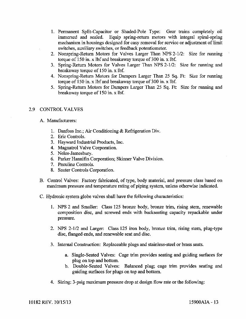


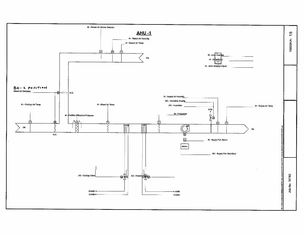


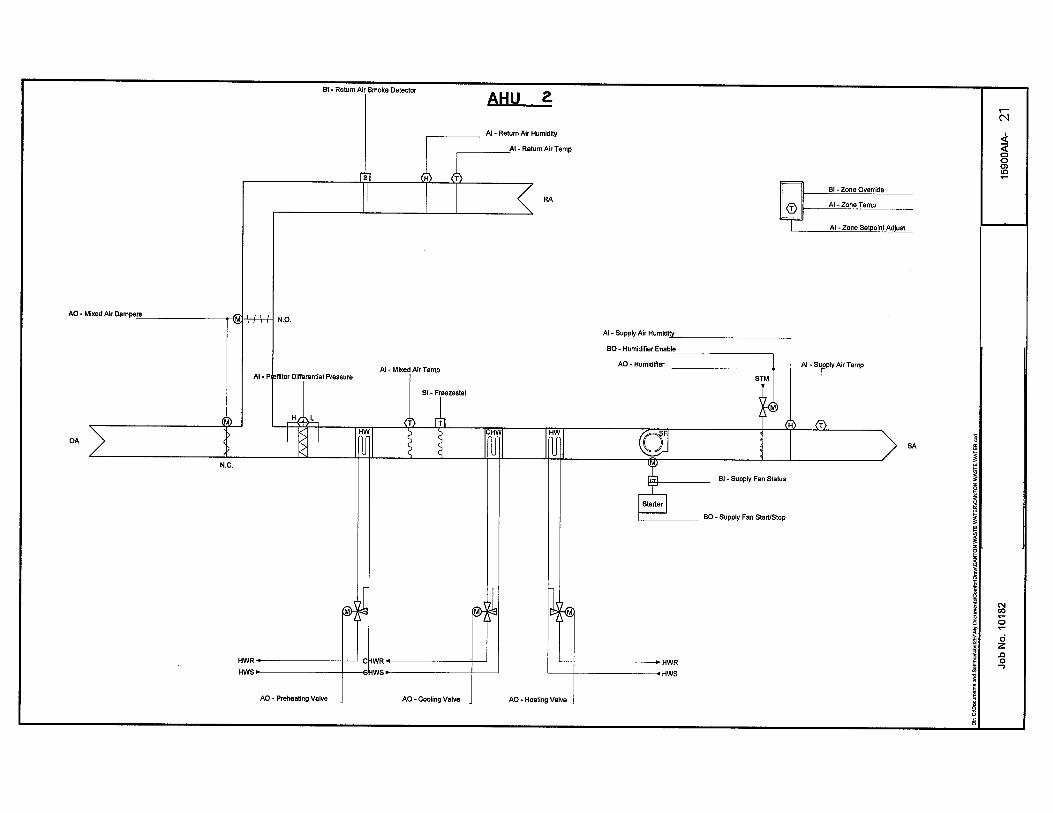


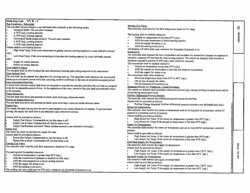


10182 REV. 7/23/13 15950AIA - 1
SECTION 15950AIA - TESTING, ADJUSTING, AND BALANCING
PART 1 - GENERAL
1.1 RELATED DOCUMENTS
A. Drawings and general provisions of the Contract, including General and Supplementary
Conditions and Division 1 Specification Sections, apply to this Section.
1.2 SUMMARY
A. This Section includes TAB to produce design objectives for the following:
1. Air Systems:
a. Constant-volume air systems.
2. HVAC equipment quantitative-performance settings.
3. Verifying that automatic control devices are functioning properly.
4. Reporting results of activities and procedures specified in this Section.
1.3 DEFINITIONS
A. TAB: Testing, adjusting, and balancing.
B. Testing, Adjusting, and Balancing (TAB) Firm: The entity responsible for performing
and reporting TAB procedures.
1.4 SUBMITTALS
A. Certified TAB Reports: Submit two copies of reports prepared, as specified in this
Section, on approved forms certified by TAB firm.
1.5 QUALITY ASSURANCE
A. TAB Firm Qualifications: Engage a TAB firm certified by either AABC or NEBB.
1.6 COORDINATION
A. Coordinate the efforts of factory-authorized service representatives for systems and
equipment, HVAC controls installers, and other mechanics to operate HVAC systems
and equipment to support and assist TAB activities.
PART 2 - PRODUCTS (Not Applicable)

10182 REV. 7/23/13 15950AIA - 2
PART 3 - EXECUTION
3.1 EXAMINATION
A. Examine the Contract Documents to become familiar with Project requirements and to
discover conditions in systems' designs that may preclude proper TAB of systems and
equipment.
B. Examine approved submittal data of HVAC systems and equipment.
C. Examine systems for functional deficiencies that cannot be corrected by adjusting and
balancing.
3.2 GENERAL PROCEDURES FOR TESTING AND BALANCING
A. Perform testing and balancing procedures on each system according to the procedures
contained in AABC's "National Standards for Testing and Balancing Heating,
Ventilating, and Air Conditioning Systems" or NEBB's "Procedural Standards for
Testing, Adjusting, and Balancing of Environmental Systems", and this Section.
B. Take and report testing and balancing measurements in inch-pound (IP) units.
3.3 GENERAL PROCEDURES FOR BALANCING AIR SYSTEMS
A. Prepare test reports for both fans and outlets. Obtain manufacturer's outlet factors and
recommended testing procedures. Crosscheck the summation of required outlet
volumes with required fan volumes.
3.4 PROCEDURES FOR CONSTANT – VOLUME AIR SYSTEMS
A. Adjust fans to deliver total indicated airflows within the maximum allowable fan speed
listed by fan manufacturer.
B. Adjust terminal outlets and inlets for each space to indicated airflows within specified
tolerances of indicated values. Make adjustments using volume dampers rather than
extractors and the dampers at air terminals.
3.5 PROCEDURES FOR MOTORS
A. Motors, 1/2 HP and Larger: Test at final balanced conditions and record the following
data:
1. Manufacturer, model, and serial numbers.
2. Motor horsepower rating.
3. Motor rpm.
4. Efficiency rating.
5. Nameplate and measured voltage, amperage, each phase.
6. Starter thermal-protection-element rating.

10182 REV. 7/23/13 15950AIA - 3
3.6 PROCEDURES FOR CONDENSING UNITS
A. Verify proper rotation of fans.
B. Measure entering and leaving air temperatures.
C. Record compressor data.
3.7 PROCEDURES FOR TEMPERATURE MEASUREMENTS
A. During TAB, report the need for adjustment in temperature regulation within the
automatic temperature-control system.
B. Measure indoor dry-bulb temperatures every other hour for a period of two successive
eight-hour days, in each separately controlled zone, to prove correctness of final
temperature settings.
C. Measure outside-air dry-bulb temperatures.
3.8 TEMPERATURE-CONTROL VERIFICATION
A. Verify that controllers are calibrated and commissioned.
B. Check transmitter and controller locations and note conditions that would adversely
affect control functions.
C. Record controller settings and note variances between set points and actual
measurements.
D. Check the operation of limiting controllers (i.e., high- and low-temperature controllers).
E. Check the interaction of electrically operated switch transducers.
F. Check the interaction of interlock and lockout systems.
G. Record voltages of power supply and controller output. Determine whether the system
operates on a grounded or nongrounded power supply.
H. Note operation of electric actuators using spring return for proper fail-safe operations.
3.9 TOLERANCES
A. Set HVAC system airflow and water flow rates within the following tolerances:
1. Supply, Return, and Exhaust Fans and Equipment with Fans: Plus 5 to plus 10
percent.
2. Air Outlets and Inlets: 0 to minus 10 percent.

10182 REV. 7/23/13 15950AIA - 4
3.10 FINAL REPORT
A. General: Typewritten, or computer printout in letter-quality font, on standard bond
paper, in three-ring binder, tabulated and divided into sections by tested and balanced
systems.
B. Include a certification sheet in front of binder signed and sealed by the certified testing
and balancing engineer.
C. Ventilation and Air-Handling Unit Test Reports: For ventilation and air-handling units,
include the following:
1. Unit Data: Include the following:
a. Unit identification.
b. Location.
c. Make and type.
d. Model number and unit size.
e. Manufacturer's serial number.
f. Unit arrangement and class.
g. Discharge arrangement.
h. Sheave make, size in inches, and bore.
i. Sheave dimensions, center-to-center, and amount of adjustments in inches.
j. Number of belts, make, and size.
k. Number of filters, type, and size.
2. Motor Data:
a. Make and frame type and size.
b. Horsepower and rpm.
c. Volts, phase, and hertz.
d. Full-load amperage and service factor.
3. Test Data (Indicated and Actual Values):
a. Total airflow rate in cfm.
b. Total system static pressure in inches wg.
c. Fan rpm.
d. Discharge static pressure in inches wg.
e. Filter static-pressure differential in inches wg.
f. Preheat coil static-pressure differential.
g. Cooling coil static-pressure differential.
h. Heating coil static-pressure differential.
i. Outside airflow in cfm.
j. Return airflow in cfm.
k. Outside-air damper position.
l. Return-air damper position.

10182 REV. 7/23/13 15950AIA - 5
D. Apparatus-Coil Test Reports:
1. Coil Data:
a. System identification.
b. Location.
c. Coil type.
d. Number of rows.
e. Fin spacing in fins per inch (mm) o.c.
f. Make and model number.
g. Face area in sq. ft. (sq. m).
h. Tube size in NPS (DN).
i. Tube and fin materials.
j. Circuiting arrangement.
2. Test Data (Indicated and Actual Values):
a. Airflow rate in cfm (L/s).
b. Average face velocity in fpm (m/s).
c. Air pressure drop in inches wg (Pa).
d. Outside-air, wet- and dry-bulb temperatures in deg F (deg C).
e. Return-air, wet- and dry-bulb temperatures in deg F (deg C).
f. Entering-air, wet- and dry-bulb temperatures in deg F (deg C).
g. Leaving-air, wet- and dry-bulb temperatures in deg F (deg C).
h. Water flow rate in gpm (L/s).
i. Water pressure differential in feet of head or psig (kPa).
j. Entering-water temperature in deg F (deg C).
k. Leaving-water temperature in deg F (deg C).
E. Gas-Fired Heat Apparatus Test Reports: In addition to manufacturer's factory startup
equipment reports, include the following:
1. Unit Data:
a. System identification.
b. Location.
c. Make and type.
d. Model number and unit size.
e. Manufacturer's serial number.
f. Fuel type in input data.
g. Output capacity in Btuh.
h. Ignition type.
i. Burner-control types.
j. Motor horsepower and rpm.
k. Motor volts, phase, and hertz.
l. Motor full-load amperage and service factor.
m. Sheave make, size in inches, and bore.
n. Sheave dimensions, center-to-center, and amount of adjustments in inches.
2. Test Data (Indicated and Actual Values):

10182 REV. 7/23/13 15950AIA - 6
a. Total airflow rate in cfm.
b. Entering-air temperature in deg F.
c. Leaving-air temperature in deg F.
d. Air temperature differential in deg F.
e. Entering-air static pressure in inches wg.
f. Leaving-air static pressure in inches wg.
g. Air static-pressure differential in inches wg.
h. Low-fire fuel input in Btuh.
i. High-fire fuel input in Btuh.
j. Manifold pressure in psig.
k. High-temperature-limit setting in deg F.
l. Operating set point in Btuh.
m. Motor voltage at each connection.
n. Motor amperage for each phase.
o. Heating value of fuel in Btuh.
F. Fan Test Reports: For supply, return, and exhaust fans, include the following:
1. Fan Data:
a. System identification.
b. Location.
c. Make and type.
d. Model number and size.
e. Manufacturer's serial number.
f. Arrangement and class.
g. Sheave make, size in inches, and bore.
h. Sheave dimensions, center-to-center, and amount of adjustments in inches.
i. Number of belts, make, and size.
2. Motor Data:
a. Make and frame type and size.
b. Horsepower and rpm.
c. Volts, phase, and hertz.
d. Full-load amperage and service factor.
3. Test Data (Indicated and Actual Values):
a. Total airflow rate in cfm.
b. Total system static pressure in inches wg.
c. Fan rpm.
d. Discharge static pressure in inches wg.
e. Suction static pressure in inches wg.
G. Round and Rectangular Duct Traverse Reports: Include a diagram with a grid
representing the duct cross-section and record the following:
1. Report Data:
a. System and air-handling unit number.

10182 REV. 7/23/13 15950AIA - 7
b. Location and zone.
c. Traverse air temperature in deg F.
d. Duct static pressure in inches wg.
e. Duct size in inches.
f. Duct area in sq. ft..
g. Indicated airflow rate in cfm.
h. Indicated velocity in fpm.
i. Actual airflow rate in cfm.
j. Actual average velocity in fpm.
k. Barometric pressure in psig.
H. Air-Terminal-Device Reports:
1. Unit Data:
a. System and air-handling unit identification.
b. Location and zone.
c. Test apparatus used.
d. Area served.
e. Air-terminal-device make.
f. Air-terminal-device number from system diagram.
g. Air-terminal-device type and model number.
h. Air-terminal-device size.
i. Air-terminal-device effective area in sq. ft. (sq. m).
2. Test Data (Indicated and Actual Values):
a. Airflow rate in cfm (L/s).
b. Air velocity in fpm (m/s).
c. Preliminary airflow rate as needed in cfm (L/s).
d. Preliminary velocity as needed in fpm (m/s).
e. Final airflow rate in cfm (L/s).
f. Final velocity in fpm (m/s).
g. Space temperature in deg F (deg C).
I. Packaged Chiller Reports:
1. Unit Data:
a. Unit identification.
b. Make and model number.
c. Manufacturer's serial number.
d. Refrigerant type and capacity in gal. (L).
e. Starter type and size.
f. Starter thermal protection size.
g. Compressor make and model number.
h. Compressor manufacturer's serial number.
2. Air-Cooled Condenser Test Data (Indicated and Actual Values):
a. Refrigerant pressure in psig (kPa).

10182 REV. 7/23/13 15950AIA - 8
b. Refrigerant temperature in deg F (deg C).
c. Entering- and leaving-air temperature in deg F (deg C).
3. Evaporator Test Reports (Indicated and Actual Values):
a. Refrigerant pressure in psig (kPa).
b. Refrigerant temperature in deg F (deg C).
c. Entering-water temperature in deg F (deg C).
d. Leaving-water temperature in deg F (deg C).
e. Entering-water pressure in feet of head or psig (kPa).
f. Water pressure differential in feet of head or psig (kPa).
4. Compressor Test Data (Indicated and Actual Values):
a. Suction pressure in psig (kPa).
b. Suction temperature in deg F (deg C).
c. Discharge pressure in psig (kPa).
d. Discharge temperature in deg F (deg C).
e. Oil pressure in psig (kPa).
f. Oil temperature in deg F (deg C).
g. Voltage at each connection.
h. Amperage for each phase.
i. Kilowatt input.
j. Crankcase heater kilowatt.
k. Chilled-water control set point in deg F (deg C).
l. Condenser-water control set point in deg F (deg C).
m. Refrigerant low-pressure-cutoff set point in psig (kPa).
n. Refrigerant high-pressure-cutoff set point in psig (kPa).
5. Refrigerant Test Data (Indicated and Actual Values):
a. Oil level.
b. Refrigerant level.
c. Relief valve setting in psig (kPa).
d. Unloader set points in psig (kPa).
e. Percentage of cylinders unloaded.
f. Bearing temperatures in deg F (deg C).
g. Vane position.
h. Low-temperature-cutoff set point in deg F (deg C).
J. Pump Test Reports: Calculate impeller size by plotting the shutoff head on pump
curves and include the following:
1. Unit Data:
a. Unit identification.
b. Location.
c. Service.
d. Make and size.
e. Model and serial numbers.
f. Water flow rate in gpm (L/s).

10182 REV. 7/23/13 15950AIA - 9
g. Water pressure differential in feet of head or psig (kPa).
h. Required net positive suction head in feet of head or psig (kPa).
i. Pump rpm.
j. Impeller diameter in inches (mm).
k. Motor make and frame size.
l. Motor horsepower and rpm.
m. Voltage at each connection.
n. Amperage for each phase.
o. Full-load amperage and service factor.
p. Seal type.
2. Test Data (Indicated and Actual Values):
a. Static head in feet of head or psig (kPa).
b. Pump shutoff pressure in feet of head or psig (kPa).
c. Actual impeller size in inches (mm).
d. Full-open flow rate in gpm (L/s).
e. Full-open pressure in feet of head or psig (kPa).
f. Final discharge pressure in feet of head or psig (kPa).
g. Final suction pressure in feet of head or psig (kPa).
h. Final total pressure in feet of head or psig (kPa).
i. Final water flow rate in gpm (L/s).
j. Voltage at each connection.
k. Amperage for each phase.
K. Boiler Test Reports:
1. Unit Data:
a. Unit identification.
b. Location.
c. Service.
d. Make and type.
e. Model and serial numbers.
f. Fuel type and input in Btuh (kW).
g. Number of passes.
h. Ignition type.
i. Burner-control types.
j. Voltage at each connection.
k. Amperage for each phase.
2. Test Data (Indicated and Actual Values):
a. Operating pressure in psig (kPa).
b. Operating temperature in deg F (deg C).
c. Entering-water temperature in deg F (deg C).
d. Leaving-water temperature in deg F (deg C).
e. Number of safety valves and sizes in NPS (DN).
f. Safety valve settings in psig (kPa).
g. High-limit setting in psig (kPa).
h. Operating-control setting.

10182 REV. 7/23/13 15950AIA - 10
i. High-fire set point.
j. Low-fire set point.
k. Voltage at each connection.
l. Amperage for each phase.
m. Manifold pressure in psig (kPa).
3.11 ADDITIONAL TESTS
A. Within 90 days of completing TAB, perform additional testing and balancing to verify
that balanced conditions are being maintained throughout and to correct unusual
conditions.
B. Seasonal Periods: If initial TAB procedures were not performed during near-peak
summer and winter conditions, perform additional testing, inspecting, and adjusting
during near-peak summer and winter conditions.
END OF SECTION 15950AIA 06/01

10182 REV. 10/21/13 T15975 - 1
SECTION T15975 - COMMISSIONING OF HVAC
PART 1 - GENERAL
1.1 RELATED DOCUMENTS
A. Drawings and general provisions of the Contract, including General and Supplementary
Conditions and other Division 01 Specification Sections, apply to this Section.
1.2 SUMMARY
A. Section includes commissioning process requirements for HVAC&R systems,
assemblies, and equipment.
1.3 DEFINITIONS
A. Commissioning Plan: A document that outlines the organization, schedule, allocation
of resources, and documentation requirements of the commissioning process.
B. CxA: Commissioning Authority (Owner or Owner’s Representative).
C. HVAC&R: Heating, Ventilating, Air Conditioning, and Refrigeration.
D. Systems, Subsystems, Equipment, and Components: Where these terms are used
together or separately, they shall mean "as-built" systems, subsystems, equipment, and
components.
1.4 QUALITY ASSURANCE
A. Commissioning firm (contractor) to be a hired by the Contractor.
B. Engage a firm certified by either AABC or NEBB.
C. Utilize practices, guidelines, forms, etc. in accordance with AABC or NEBB standards.
1.5 CONTRACTOR'S RESPONSIBILITIES
A. Provide Project-specific construction checklists and commissioning process test
procedures for actual HVAC&R systems, assemblies, equipment, and components to be
furnished and installed as part of the construction contract.
B. Perform commissioning tests at the direction of the CxA.
C. Attend construction phase controls coordination meeting.
D. Provide test data, inspection reports, and certificates in Systems Manual.

10182 REV. 10/21/13 T15975 - 2
E. Provide information requested by the CxA for final commissioning documentation.
F. Provide measuring instruments and logging devices to record test data, and provide data
acquisition equipment to record data for the complete range of testing for the required
test period.
1.6 CxA'S RESPONSIBILITIES
A. Direct commissioning testing.
B. Verify testing, adjusting, and balancing of Work are complete.
1.7 COMMISSIONING DOCUMENTATION
A. Provide the following information to the CxA for inclusion in the commissioning plan:
1. Plan for delivery and review of submittals, systems manuals, and other documents
and reports.
2. Identification of installed systems, assemblies, equipment, and components
including design changes that occurred during the construction phase.
3. Process and schedule for completing construction checklists and manufacturer's
prestart and startup checklists for HVAC&R systems, assemblies, equipment, and
components to be verified and tested.
4. Certificate of completion certifying that installation, prestart checks, and startup
procedures have been completed.
5. Certificate of readiness certifying that HVAC&R systems, subsystems,
equipment, and associated controls are ready for testing.
6. Test and inspection reports and certificates.
7. Corrective action documents.
8. Verification of testing, adjusting, and balancing reports.
1.8 SUBMITTALS
A. Certificates of readiness.
B. Certificates of completion of installation, prestart, and startup activities.
C. Test data, inspection reports and certificates in systems manual.

10182 REV. 10/21/13 T15975 - 3
PART 2 - PRODUCTS (Not Used)
PART 3 - EXECUTION
3.1 TESTING PREPARATION
A. Certify that HVAC&R systems, subsystems, and equipment have been installed,
calibrated, and started and are operating according to the Contract Documents.
B. Certify that HVAC&R instrumentation and control systems have been completed and
calibrated, that they are operating according to the Contract Documents, and that pretest
set points have been recorded.
C. Certify that testing, adjusting, and balancing procedures have been completed and that
testing, adjusting, and balancing reports have been submitted, discrepancies corrected,
and corrective work approved.
D. Set systems, subsystems, and equipment into operating mode to be tested (e.g., normal
shutdown, normal auto position, normal manual position, unoccupied cycle, emergency
power, and alarm conditions).
E. Inspect and verify the position of each device and interlock identified on checklists.
F. Check safety cutouts, alarms, and interlocks with smoke control and life-safety systems
during each mode of operation.
G. Testing Instrumentation: Install measuring instruments and logging devices to record
test data as directed by the CxA.
3.2 TESTING AND BALANCING VERIFICATION
A. Prior to performance of testing and balancing Work, provide copies of reports, sample
forms, checklists, and certificates to the CxA.
B. Notify the CxA at least 10 days in advance of testing and balancing Work, and provide
access for the CxA to witness testing and balancing Work.
C. Provide technicians, instrumentation, and tools to verify testing and balancing of
HVAC&R systems at the direction of the CxA.
1. The CxA will notify testing and balancing Contractor 10 days in advance of the
date of field verification. Notice will not include data points to be verified.
2. The testing and balancing Contractor shall use the same instruments (by model
and serial number) that were used when original data were collected.
3. Failure of an item includes, a deviation of more than 10 percent. Failure of more
than 10 percent of selected items shall result in rejection of final testing,
adjusting, and balancing report.
4. Remedy the deficiency and notify the CxA so verification of failed portions can
be performed.

10182 REV. 10/21/13 T15975 - 4
3.3 GENERAL TESTING REQUIREMENTS
A. Provide technicians, instrumentation, and tools to perform commissioning test at the
direction of the CxA.
B. Scope of HVAC&R testing shall include entire HVAC&R installation, from central
equipment for heat generation and refrigeration through distribution systems to each
conditioned space. Testing shall include measuring capacities and effectiveness of
operational and control functions.
C. Test all operating modes, interlocks, control responses, and responses to abnormal or
emergency conditions, and verify proper response of building automation system
controllers and sensors.
D. The Contractor along with the HVAC&R Contractor, testing and balancing Contractor,
and HVAC&R Instrumentation and Control Contractor shall prepare detailed testing
plans, procedures, and checklists for HVAC&R systems, subsystems, and equipment.
E. Tests will be performed using design conditions whenever possible.
F. Simulated conditions may need to be imposed using an artificial load when it is not
practical to test under design conditions. Before simulating conditions, calibrate testing
instruments. Provide equipment to simulate loads. Set simulated conditions as directed
by the CxA and document simulated conditions and methods of simulation. After tests,
return settings to normal operating conditions.
G. The CxA may direct that set points be altered when simulating conditions is not
practical.
H. The CxA may direct that sensor values be altered with a signal generator when design
or simulating conditions and altering set points are not practical.
I. If tests cannot be completed because of a deficiency outside the scope of the HVAC&R
system, document the deficiency and report it to the Owner. After deficiencies are
resolved, reschedule tests.
J. If the testing plan indicates specific seasonal testing, complete appropriate initial
performance tests and documentation and schedule seasonal tests.
3.4 HVAC&R SYSTEMS, SUBSYSTEMS, AND EQUIPMENT TESTING
PROCEDURES
A. Boiler Testing and Acceptance Procedures: Testing requirements are specified in
Division 15 Boiler Sections. Provide submittals, test data, inspector record, and boiler
certification to the CxA.
B. HVAC&R Instrumentation and Control System Testing: Field testing plans and testing
requirements are specified in Division 15 Sections "HVAC Instrumentation and
Controls." Prepare testing plans.

10182 REV. 10/21/13 T15975 - 5
C. HVAC&R Distribution System Testing: Provide technicians, instrumentation, tools,
and equipment to test performance of air, steam, and hydronic distribution systems;
special exhaust; and other distribution systems, including HVAC&R terminal
equipment and unitary equipment.
END OF SECTION T15975

DIVISION 16
ELECTRICAL
10182 REV. 11/05/13 16010 - 1
SECTION 16010 - ELECTRICAL GENERAL PROVISIONS
PART 1 - GENERAL
1.1 REFERENCE
A. The provisions of the Instructions to Bidders, General Conditions, Supplementary
Conditions, Alternates, Addenda, and Division 1 are a part of this specification.
Contractors and Subcontractors shall examine same as well as other Divisions of the
specifications which affect work under this Division.
B. The requirements of this Section shall govern all Division 16 work for this project.
Bidders are referred to in this section as "Contractors" and all provisions apply to
each contractor and their subcontractors.
C. The contractor shall be solely responsible for construction means, methods,
sequences of construction and the safety of workmen.
1.2 DESCRIPTION OF WORK
A. Civil, Mechanical, Architectural, Structural, Process and Instrumentation, Electrical
and all other project drawings, as well as the Specifications for all the Divisions, are
a part of the Contract Documents. Work shown on the electrical drawings is for
bidding and permitting only. The electrical contractor shall be responsible for
coordinating with Division 11, 13 and 15 approved shop drawings for installation
requirements. Modify MCC layouts and wiring requirements as needed to
accommodate actual equipment purchased.
B. Drawings and Specifications are to be considered as supplementing each other.
Work specified but not shown, or shown but not specified, shall be performed or
furnished as though mentioned in both Specifications and Drawings. All systems
shall be complete and fully operational upon completion of the project.
C. Contractors shall not construe any correspondence or verbal communications with or
by the Engineer or his representative as authorization for "extra" construction
payment. All requests for additions to this contract shall be submitted in writing by
the contractor to the Engineer for consideration by the Owner's representative.
Work performed without written approval of the Owner and Engineer will be the
contractor's sole responsibility without additional compensation.
D. Contractor shall comply with and schedule work according to the schedule of
construction specified in Division 1. All work shall be completed within these time
constraints and the contractors for the work of this section shall provide all required
temporary utilities and connections necessary to maintain the existing systems in full
operation during the progress of this work. Sections of any systems may be taken
out of service only when approved in writing by the Owner.

10182 REV. 11/05/13 16010 - 2
1.3 RELATED WORK SPECIFIED ELSEWHERE
A. Division 1 - Project Phasing and Temporary Electrical and Telephone Service
B. Division 2 - Demolition, Excavation, Backfill and Seeding
C. Division 3 - Poured-In-Place Concrete and Grout
D. Division 9 - Finish Painting, Coatings and Water Proofing
E. Division 11 - Process Equipment
F. Division 13 - Instrumentation & Controls
G. Division 15 - Mechanical
1.4 QUALITY ASSURANCE
A. Codes and Permits:
1) Work shall be installed in full accordance with all applicable codes, rules and
regulations of public authorities and/or utilities. Included shall be National
Electrical Code, NEMA, U. L. Standards, OSHA, State and local Building
Codes, Ten State Standards and all State of Ohio requirements. All these
Codes, Rules and Regulations are hereby incorporated into this specification.
2) Comply with specification requirements in excess of Code requirements
where no conflicts exist.
3) Prior to starting any work, electrical contractors shall secure all necessary
permits and inspection certificates required. All fees for permits, inspections
and certificates shall be paid for by electrical contractors.
4) Deliver official record of approval, by governing agencies, to Engineer for
transmittal to Owner.
B. Standards:
1) Comply with applicable provisions of code approved editions of following
National Standards:
National Electric Code
NFPA Life Safety Code and Standards under
Appendix B of Life Safety Code
Underwriters Laboratory
NFPA
NEMA
National Electrical Safety Code
ANSI
Americans with Disability Act

10182 REV. 11/05/13 16010 - 3
1.5 SUBMITTALS
A. Shop Drawings:
1) Contractor shall submit shop drawings of fixtures, distribution equipment,
electrical devices, and communication systems for review. Submittals shall
be made in a timely fashion, keeping with the project schedule, and shall be
submitted as described in Division 1. As a minimum, shop drawings shall be
include equipment cut sheets, installation drawings, O&M information,
training lesson plans, test reports and warranties.
2) Contractor shall review and indicate his approval of each shop drawing prior
to submittal for review. Do not start work until shop drawings have been
reviewed and approved by the Engineer and returned to the Contractor.
3) Submittals will be reviewed only for general compliance with the contract
documents and not for dimensions, quantities, etc. The submittal review
shall not relieve the contractor of responsibility for purchase of the item in
full compliance with the contract documents and its complete and proper
installation.
4) Where submittals vary from the contract requirements, the contractor shall
clearly indicate on submittal or accompanying documents the nature and
reason for variations.
5) Refer to various sections for listing of shop drawings required on this project
which are not listed in A.1 above.
6) Each manufacturer or his representative must check the application of his
equipment and certify at time of shop drawing submittal that equipment has
been properly applied and can be installed, serviced and maintained where
indicated on drawings. Advise Engineer in writing with submittal drawings
of any potential problems. The manufacturer shall be responsible for any
changes that might be necessary because of physical characteristics of
equipment that have not been called to the Engineer's attention at the time of
submittal.
7) This contractor shall review process equipment shop drawings, architectural
shop drawings, mechanical shop drawings, and structural shop drawings.
Upon completion of this review, the contractor shall develop conduit/device
layout drawings. The conduit/device layout shall be used as the means and
methods of installation.
B. Record Drawings:
1) Each contractor or subcontractor shall keep one (1) complete set of the
contract working drawings on the job site on which he shall regularly record
any deviations or changes from such contract drawings made during
construction.

10182 REV. 11/05/13 16010 - 4
2) These drawings shall record the location of all electrical equipment, junction
and pull boxes, conduit routing and all below-grade service. All
underground services shall be dimensioned from readily identifiable and
accessible building elements.
3) Record drawings shall be kept clean and undamaged and shall not be used
for any purpose other than recording deviations from working drawings and
exact locations of concealed work.
4) After the project is completed, these sets of drawings shall be delivered to
the Engineer in good condition, as a permanent record of the installation as
actually constructed.
5) Provide record drawing of one-line power diagram on reproducible mylar
and mount in electrical equipment room.
1.6 COORDINATION AND SUPERVISION
A. Examine work of other trades which comes in contact with or is covered by the
work. Do not attach to, cover, or finish against any defective, or install work of this
Division in a manner which will prevent other trades from properly installing their
work. Consult all drawings, specifications and details of other Divisions of the work.
B. Proper clearances and equipment access and service shall be maintained for all items
and components.
C. Contractors shall report any interferences between their and other work or
construction as soon as discovered. If contractor proceeds without coordination,
correction shall be the responsibility of the installing contractor without cost to the
Owner.
D. Drawings are diagrammatic and show approximate location of conduit, devices, etc.
Take all measurements and establish exact locations in the field. Adapt to
construction and work of other trades as required for coordination of the work.
E. Each contractor shall be responsible for layout and coordination of openings and
chases required for these installations, which are provided by other trades. Provide
dimensioned drawing and fully coordinate this work with the contractor providing
the openings or chase.
F. Each contractor shall provide adequate competent supervision on job during all
working hours with authority and instructions to answer questions and carry out
instructions of Engineer or his representative.
G. All light fixtures and ceiling mounted items shall be centered with regard to ceiling.
Failure to observe these requirements shall be cause for correction to be made at the
contractor's expense.
H. The Owner reserves the right to expect reasonable changes in the location of light
fixtures and electrical devices up to the time of roughing-in, without additional cost.

10182 REV. 11/05/13 16010 - 5
1.7 DRAWINGS AND SPECIFICATIONS
A. Drawings and specifications are supplemental to each other. It is intended that work
covered by these specifications and drawings include everything requisite and
necessary to make the various systems complete and operative, irrespective of
whether or not every item is specifically provided for. Any omission of direct
reference herein to any essential item shall not excuse contractor from complying
with the above intent.
B. In case of error or inconsistency, specifications shall take precedence over drawings.
Figured dimensions supersede scaled ones. Contractor shall take no advantage of,
and shall promptly call Engineer’s attention to any error, omission or inconsistency
in specifications and drawings.
C. Special attention is directed to requirements that equipment and materials stated in
specifications and/or indicated on drawings shall be furnished, completely installed,
adjusted and left in safe and satisfactory operating condition. Accessories,
appliances and connections necessary for proper operation of equipment shall be
provided.
D. Materials, apparatus or equipment specified or otherwise provided for on drawings,
addenda, or change orders issued subsequent to award of contract, shall be same
brand, type, quality and character originally specified, unless otherwise provided.
E. Layout of equipment, accessories, specialties and suspended, concealed or exposed
piping systems are diagrammatic, unless dimensioned. In preparing shop drawings,
contractor shall check project conditions before installing work. If there are any
interferences or conflicts, they shall be called to the attention of Engineer
immediately for clarifications.
F. The drawings indicate required size and points of termination of conduit and suggest
proper routes to conform to structure, avoid obstructions and preserve clearances.
However, it is not intended that drawings indicate all necessary offsets and it shall be
the work of the installing contractor to make the installation in such a manner as to
conform to structure, avoid obstructions, preserve headroom and keep openings and
passageways clear, without further instruction or cost to the Owner.
G. It is intended that the electrical items be located symmetrical with architectural
elements, and shall be installed at exact height and locations as shown on the
architectural drawings. Refer to architectural details in completing and correlating
work. Confirm all locations with Engineer prior to rough-in.
1.8 PROVISIONS FOR LATER INSTALLATION
A. Become acquainted with nature and progress of construction against which this work
attaches. Review structural drawings for coordination of openings. Cut no structural
members or slabs without Engineer’s written approval.

10182 REV. 11/05/13 16010 - 6
B. When this work cannot be installed concurrently with the building construction,
arrange for inserts, sleeves, access panels, etc., as necessary for installation at a later
date.
1.9 LOCAL CONDITIONS
A. Visit site and become familiar with facilities and conditions affecting work. No
additional payment will be made on claims that arise from lack of knowledge of
existing condition.
B. Exercise extra care when working in areas where underground services may exist.
Any costs for repair of damage to such services become responsibility of Contractor
causing damage.
1.10 PROTECTION
A. When setting up equipment, protect area against staining, abrasion. Cost of
correcting any such condition will be charged against the respective Contractor.
B. Protect all equipment which has been installed from construction debris and the
work of other trades.
C. Protect finish floors from chips and cutting oil by use of chip receiving pan and oil
proof cover.
D. Protect equipment and finished surfaces from welding and cutting spatters with
baffles and spatter blankets.
E. Protect from paint droppings, insulation adhesive, by use of drop cloths.
F. Contractors shall be responsible for including and maintaining adequate precautions
and safeguards related to their work during all phases of construction. Include
protection, warnings and safety devices and equipment for protection of personnel,
equipment and materials. Comply with all requirements of governing authorities,
including OSHA.
1.11 PRODUCT HANDLING
A. Pay all costs for transportation of materials, equipment to job site.
B. Provide all scaffolding, tackle, hoists, rigging necessary for placing electrical
materials and equipment in their proper place. Remove temporary work when no
longer required. Comply with applicable State, Federal and local regulations.
C. Contractor shall keep materials clean and protected from weather and/or damage
before and after installation until final acceptance by the Owner. Protect all
openings, bearings, controls, motors, etc., from dirt and moisture.

10182 REV. 11/05/13 16010 - 7
1.12 SHUTDOWNS
A. Give five (5) working days notice to Engineer of anticipated shutdown requirements
of an operating system. Tie-ins and modifications to existing facilities and services
must be done with minimum interruption of facilities operation and during hours so
affecting.
1.13 EXISTING SERVICES
A. Active services encountered in work shall be protected and supported. Inactive
services encountered shall be removed or deactivated as shown or directed by
Engineer.
B. All costs for repair of damages to active services shall be paid by the contractor
causing the damage.
1.14 TEMPORARY SERVICES
A. Temporary services shall be provided as stated in Special Conditions and Division 1.
Provide all temporary services and connections as required to accommodate the
phasing sequence of the project.
B. Description of System: Furnish and install temporary electrical power service for
construction needs throughout construction period in accordance with the special
conditions as follows:
1) Provide power for miscellaneous tools and equipment, for pumping, for
temporary heating and ventilating and for temporary storage and construction
buildings. See General Conditions for requirements of temporary service.
2) Provide temporary lighting of minimum 5 foot candles for safe and adequate
working conditions throughout the project, for security and for temporary office
and construction buildings.
3) Provide temporary power and controls for existing process equipment required
to remain in service while the new electrical service is installed. Once
equipment is on new electrical service, remove all temporary equipment and
dispose of properly.
C. Materials (General)
1) Comply with Electrical - Basic Materials and Methods.
2) Materials may be new or used, but must be adequate in capacity for required
purposes, and must not create unsafe conditions or violate requirements of
applicable codes.

10182 REV. 11/05/13 16010 - 8
3) At Contractor's option, patented specialty products may be used, if UL approved.
4) Provide required facilities, including generators transformers, conductors, poles,
conduits, raceways, breakers, fuses, switches and lighting fixtures with lamps.
5) Provide appropriate enclosures for environment in which used, in compliance
with NEMA standards.
D. Installation
1) Install work in neat and orderly manner.
2) Make structurally and electrically sound throughout.
3) Maintain to give continuous service and to provide safe working conditions.
4) Modify and extend service as work progress requires.
5) Locate so that power is available at any desired point with no more than 100'
(30.00 m) extension, and with no more than 5% voltage drop at full load.
6) Provide circuit breaker protection for each outlet with ground fault interrupting
capacity.
7) Provide equipment grounding continuity for entire system.
8) Removal: Completely remove temporary materials and equipment upon
completion of construction. Repair damage caused by installation, and restore to
specified or original condition.
1.15 OPERATING INSTRUCTIONS
A. Owner's representative shall be instructed by contractor and manufacturer's
representatives on system maintenance and operation requirements. Instruction shall
be complete, conducted by qualified service and maintenance specialists. Notify
Engineer of scheduled instruction session to permit his attendance at the session.
B. The following systems shall include training sessions scheduled with the Owner.
Allow a minimum of one (1) hour per system.
1) Medium voltage gear.
2) Motor controls.
3) Transfer switches.

10182 REV. 11/05/13 16010 - 9
1.16 DAMAGE AND EMERGENCY REPAIRS
A. Contractor shall be held responsible for damage to work caused by his work or
through the negligence of his workmen. All patching and repairing of damaged
work and the cost of same shall be paid by the contractor causing the damage. All
existing facilities and installations shall be restored to their original condition when
damaged by the work of this Division, using workmen skilled in each required trade.
B. The Owner reserves the right to make emergency repairs as required to keep
equipment in operation, without voiding Contractor's warranty or relieving him of
responsibility during warranty period.
1.17 WARRANTY
A. Electrical Contractors shall warrant all material, equipment, fixtures and
workmanship for a period of one (1) year from date of final acceptance. This means
after the project Engineer have all signed off on acceptance. Not date of purchase
and not date of installation.
B. Any equipment piping, fixture or other component part of system which fails during
warranty period and all resulting damage shall be replaced or repaired by contractor
without cost to Owner.
C. Warranty on any repairs or replacements shall be extended from date of replacement
or repair of that item for one (1) year.
D. All equipment and fixtures shall be warranted by the manufacturer thru the contract
warranty period. Any extended manufacturers warranties shall be extended to the
Owner.
E. Lamps shall not be excluded from one (1) year warranty, but shall carry a one (1)
year replacement warranty from date of final acceptance spares shall not be used as
replacement.
1.18 REQUIREMENTS FOR FINAL INSPECTION
A. All of the following items must be completed prior to final inspections. No
exceptions will be made and no final payment will be made until all items are
completed.
1) Each contractor's foreman shall perform his own punch list and, upon
completion, notify the Engineer that project is ready for final punch list.
2) Thoroughly clean all parts of the apparatus and equipment. Exposed parts
which are to be painted shall be thoroughly cleaned of cement, plaster and
other materials and all oil and grease spots shall be removed. Such surfaces
shall be carefully wiped and all cracks and corners scraped out.

10182 REV. 11/05/13 16010 - 10
3) Exposed metal work shall be carefully brushed down with steel brushes to
remove rust and other spots and left smooth and clean.
4) All system start ups shall be complete with written certifications submitted
for all systems and major equipment.
5) Certification of test and start-up and training sessions for the systems listed
in operating instructions.
6) All tags and labels are attached. All panel board directories are typed and
installed.
PART 2 - PRODUCTS
2.1 MATERIALS
A. Provide material and labor which is neither drawn nor specified but which is
obviously a component part of and necessary to complete work or comply with code
and which is customarily a part of work of similar character.
B. Provide incidental concrete, trenching and backfilling, reinforcing steel, masonry,
mortar, miscellaneous steel, painting and the like required to complete electrical
installations; perform in manner specified in applicable Division of General Trades
Specification by workmen skilled in that particular trade.
C. All equipment and material shall be new, free from defects, U.L. listed where
applicable and warranted by the manufacturer and the contractor.
D. To the greatest extent possible, provide materials and products of the same kind
from the same manufacturer for this project.
2.2 MATERIAL SUBSTITUTIONS
A. All changes required by substitutions, such as revisions to foundations, bases,
piping, controls, wiring, openings and appurtenances shall be made by the
substituting contractor at no additional cost to the project. Notify all other
contractors affected by substitution and pay all costs related to the substitution
incurred by other contractors.
B. Systems have been laid out around particular fixtures and equipment considered
base items. Manufacturer first listed is base item. Other named manufacturers in
these specifications or on the drawings who can provide equivalent equipment are
acceptable and may be bid, provided performance, construction, components, quality
and appearance, where applicable, are equivalent to base item and can be properly
installed. Acceptable alternate makes of equipment are listed in specifications or
equipment schedules; however, manufacturers other than base manufacturers are
substitutions and shall comply with the following paragraphs. When distribution

10182 REV. 11/05/13 16010 - 11
equipment is substituted, contractor shall submit equipment room shop drawings
showing dimensions of equipment and required N.E.C. clearance. It is the
contractor's sole responsibility that all substituted equipment fits in the allotted space
and maintains all required clearances.
C. Should the contractor propose to furnish materials or equipment other than those
listed in the specification, a written request for substitution shall be submitted as an
alternate to the base bid at the bid opening. Refer to General Conditions Division of
this specification. It is the contractor's responsibility to fully evaluate substitutions
and ascertain that the substitution is equivalent in all respects to the base
specification prior to submittal.
D. Substitutions are subject to approval of Engineer and his decision shall be final. In
submitting substitutions, include make and model number and complete literature
and performance data for evaluation.
E. Substitution of items not named in these specifications or drawings may be offered
for consideration on the substitution sheet included in the Proposal Form of the
contract, under the following conditions:
1) The proposed substitution is proven, to the satisfaction of the Engineer, to be
equal or superior to the specified item in all respects.
2) Extended delivery schedules on specified items, which would delay timely
completion of the job, will be cause for consideration of substitutions. The
Contractor must show proof of delay in delivery from the manufacturer.
3) Changes required by substitution, such as revisions to foundations, bases,
piping, controls, wiring, openings and appurtenances shall be made by the
Contractor at no additional cost to the project and pay all costs related to the
substitution incurred by other contractors.
4) State the amount of credit to be given to the Owner if the substitution is
accepted prior to contract award on the proposal form substitution sheet or if
after award of contract, submit a quotation stating cost reduction resulting
from acceptance of a substitution if executed through a contract change
order.
5) Manufacturers of items not named in these specifications or drawings may
submit a written request with supporting product information to the Engineer
ten (10) days prior to the project bid date for consideration at the sole
determination of the Engineer to become a named product. If approved, the
product name will be added to the list of substitute manufacturers in a
written addendum issued by the Engineer to bidders.

10182 REV. 11/05/13 16010 - 12
PART 3 - EXECUTION
3.1 INSTALLATION REQUIREMENTS
A. Location of conduit, equipment, devices, etc., on the drawings are diagrammatic;
indicated positions shall be followed as closely as possible, exact locations shall be
subject to building construction and interferences with other work. Difficulties
preventing the installation of any part of work as indicated shall be called to the
attention of the Engineer. Engineer shall determine locations and changes,
Contractor shall install the work accordingly. Engineer reserves right to make minor
changes in location of any part of the work up to the time of roughing-in without
additional cost.
B. All materials and equipment shall be installed in a neat and workmanlike manner by
competent specialists for each subtrade. The installation of any materials and
equipment not meeting these standards may require removal and reinstallation at no
additional cost to the Owner.
C. Install, connect equipment, services, materials in accordance with best Engineering
practice and in conformity with manufacturer's printed instructions and U.L. Listing.
D. Take all measurements and determine all elevations at the building prior to
fabrication or rough-in.
3.2 CUTTING AND PATCHING
A. Perform all cutting, framing and patching in completed construction as necessary for
installation of this work. Do not cut any structural member or structural floor slab
without written permission from the Engineer. Have cutting done by skilled
mechanics as carefully as possible, and with as little damage as possible. Have
patching done by first-class mechanics, skilled in the several trades.
B. In new construction, lay out location and size of all openings to be provided by other
trades in advance of their work. Set sleeves, lintels, etc., for openings and provide
layout dimensioned drawings as required for coordination with other contractors. If
openings information and sleeves are not provided to other trades in advance of their
work, this contractor shall provide all required openings as required for existing
construction.
C. In existing construction, contractor shall perform all cutting, patching and framing of
chases and openings required by this work. Properly sized structural lintels shall be
provided above masonry wall openings and steel angle frames around panel walls,
floor or roof openings. Size lintels and frames per schedule on structural plans.
D. Perform all excavation and backfill required for installation of below-grade conduits.
Excavate to depth required to install conduits at required level and pitch. All
backfill shall be compacted in maximum twelve (12) inch layers and conform to all
bearing requirements of site and/or structure above.

10182 REV. 11/05/13 16010 - 13
E. All conduits for below-grade entry of the building shall be pitched away from the
building floor elevation to prevent water entry. Use silicone sealant around conduit
and structure.
F. All openings shall be cut with lintels and frames installed by workmen skilled in the
particular trade.
1) All patching shall be by a skilled general trades contractor and shall be
performed in accordance with requirements of Division 9.
2) All roof cutting and patching installed under this contract shall be performed
by the project roofing contractor. Cost for this work to be included in electrical
contractors bids.
G. Core drill round openings and neatly saw cut rectangular openings in floors or walls.
Sleeves shall be grouted or patched to match existing wall or floor construction.
H. Sleeves for floor or wall penetrations shall extend 2" past opening and be grouted in
place and sealed watertight with silicone caulk. Verify 2” is adequate to hold back
water from going to floor below.
3.3 FIRE STOPPING
A. Where steel conduits pass through fire rated walls, set sleeve in wall, install non-
shrinking grout between conduit and sleeve. Fire seal around wall sleeve with fire
rated sealant. All penetrations shall be protected or rated construction in accordance
with an approved method listed in the U.L. fire resistance directory.
B. Penetrations of fire rated walls and ceilings by exposed cabling system shall be
made with steel conduit sleeves, fire stopped with U.L. listed sealant per U.L.
assembly drawings.
C. Fire rated sealant shall be U.L. listed and applied in accordance with the U.L.
assembly requirements and the manufacturer's recommendations to match the rating
of the penetrated structure. Sealants shall be as manufactured by Hilti, International
Protective Coatings (IPC), Specified Technologies, Inc. (STI), or 3M.
3.04 ACCESS DOORS
A. Proper access for service and maintenance shall be ascertained before installation of
any item. The electrical contractor shall furnish access doors adequately sized for
servicing concealed items furnished under this contract. Doors shall be fire rated
where installed in rated construction and shall have concealed hinge door, screw
drive latch and primed painted finish. Frames shall match the construction of
adjoining surfaces.
B. Doors in new construction shall be furnished to general trades contractor for
installation. In existing construction, doors shall be installed by the electrical
contractor with surrounding surfaces patched and painted to match existing.

10182 REV. 11/05/13 16010 - 14
3.5 PAINTING
A. Finish painting is included under Division 9 - Finishes, except where specifically
called for under this Division.
B. Certain painting specified as part of the electrical Trades Work is included herein
and shall comply with Division 9.
C. Materials and equipment installed under this Division shall be left free from dirt,
grease and foreign matter, ready for painting.
D. No equipment or piping shall be painted before being tested.
E. Damaged surfaces of prefinished materials and equipment shall be touch-up painted
to match existing finish by the contractor.
F. All items to be painted shall be primed and painted with two (2) coats of rust
inhibitive paint on exterior and enamel paint on interior in accordance with the paint
manufacturer's instructions. Engineer shall select a custom color.
3.6 EQUIPMENT IDENTIFICATION
A. Equipment:
Push buttons, selector switches, safety switches, motor starters, time switches,
contactors, panelboards, pull boxes, cabinets, special outlets, etc., shall be identified
as to function with a phenolic engraved nameplate securely attached. Identify
voltage, phase, origin, loop number and load served.
B. Panelboards:
Provide typed directories for distribution and circuit breaker panels describing load
fed and location. Typed directories shall include specific load location information
with final room names and numbers (i.e., Receptacles - Office 120).
C. Nameplates shall be laminated phenolic with a black surface and white core and
shall be mechanically fastened with screws to each item. Use 1/16" thick material
for plates up to 2"x4". For larger sizes, use 1/8" thick material. Lettering shall be
minimum 1/4" height, spaced at four (4) per inch. Safety switches, motor starters,
and panelboard nameplates shall include system voltage, phase and wire count, i.e.
Panel "A" - 208Y/120, circuit origin and load served.
D. Wiring:
1) Color code all wiring in accordance with NEC Standards. All system
and control wiring shall be labeled at each termination and splice, and
continuously color coded.
2) Color coding is to be plainly labeled on all wiring diagrams
submitted for approval and wire installed by this contractor shall comply
with manufacturer's wiring diagram requirements.

10182 REV. 11/05/13 16010 - 15
E. Label all conduits leaving main panelboards where exposed with stick-on labels
indicating circuit contained.
F. Label all junction boxes with circuits contained with indelible marker. Color code
emergency and fire alarm system box covers as directed with permanent paint
markings. Mark conduit at 48" intervals where visible, exposed or above accessible
ceilings.
G. Label inside of device plates with panel and circuit number.
3.7 OPERATING AND MAINTENANCE MANUAL
A. Prepare three (3) complete operating and maintenance manuals in hardback binders
describing operation of the systems and recommended maintenance schedule. Turn
all equipment warranties over to the Owner.
B. Manuals shall be indexed, arranged in the CSI format, and include:
1) Job name and names of contractor with address and telephone number for
service. Include all major emergency service numbers for equipment.
2) Manual index.
3) Identification, name, mark, number as indicated on design drawings.
4) Normal equipment operating characteristics.
5) Performance data and ratings.
6) Wiring diagrams.
7) Manufacturer's descriptive literature.
8) Manufacturer's maintenance and service manuals.
9) Spare parts and replacement parts list for each piece of equipment.
10) Name of service agency and installer.
11) Final accepted shop drawings.
3.8 CLEANING UP
A. From time to time during the operations and at completion thereof, electrical
contractor shall remove from the premises all debris and excess material caused by
their work. Area of operation shall be left broom clean.
B. Construction materials shall be neatly stored in project areas and locations
designated by the Owner and Engineer. Construction materials must not be left
scattered about construction area.

10182 REV. 11/05/13 16010 - 16
C. All electrical equipment to be painted by others shall be thoroughly cleaned by
electrical contractors of grease, rust, shipping tags and construction dirt.
3.9 INSPECTION, TESTING AND REFURBISHING EXISTING ELECTRICAL
GEAR
A. The contractor shall inspect, test, and refurbish all existing low voltage and medium
voltage electrical gear indicated on the drawings and place them in safe operating
condition.
B. Test Equipment:
The following test equipment is required to perform the testing portion related to
Low Voltage and Medium Voltage Electrical Switch Gear:
1) Insulation Resistance Test Set (Megohmeter) 1000 Vdc minimum
One of the following pieces of test equipment is required to perform the contact
resistance testing requirements of this specification:
1) Digital Low Resistance Ohmmeter (DLRO - 10 amp unit is sufficient.)
2) DC Current Source and a Millivoltmeter
One of the following pieces of test equipment may be required to perform the testing
requirements of this specification, depending on the accessories:
1) AC Voltage Supply
2) DC Voltage Supply
Thermal infrared camera.
C. Inspection and Testing Report.
1) Inspection and test results shall be recorded on Inspection and Test forms.
The contractor shall submit blank forms for approval prior to starting this
work. Upon completion of the work, deliver to Owner a report. Included in
the report (as a minimum) shall be an Equipment Inventory, Visual Problem
Summary, and a Test Result Summary. In the course of doing this work the
contractor may find equipment that is not functioning as designed and will
require repair or replacement. The report shall list any recommended
supplemental repair items, each with priority ranking and additional cost for
Owners’ future consideration.
D. The intent of this section is to define the process of returning the existing electrical
equipment to a safe and reliable operating condition based upon the design of the
original manufacturer at the time of manufacturing. It is not intended to bring the
existing gear up to the latest manufacturing requirements. The following lists the
minimum requirements to achieve this.

10182 REV. 11/05/13 16010 - 17
E. Inspection
1) Frame/Enclosure
Ensure that the nameplate/label data is legible and the third party listing
service label is legible. Inspect the overall exterior for missing screws,
bolts, nuts, fasteners, retainers and keepers, for unused openings, for
improper covers, for rust and corrosion.
Inspect main lugs for signs of overheating and missing and defective parts.
Inspect insulation structure for signs of overheating and deterioration.
Inspect for proper alignment of each section. Check that cabinets are
plumb and square.
2) Phase Bus and Ground Bus
Inspect for signs of overheating, for rust and corrosion, for missing and
defective parts, all connection points for loose connections. Inspect
insulation structure for signs of overheating and deterioration. Perform an
infrared thermal inspection of all buses.
3) Panel Indicators and Instrumentation
Check all lens covers and all light bulbs for operation, inspect all control
wiring, check all function switches and Inspect all meters.
4) Interlocks
Check all cabinets for interlock function. Check all Kirk-key systems.
5) Overcurrent Protection Devices
Inspect hinge/pivot joints for missing and defective parts. Inspect current
carrying components for signs of overheating. Inspect current carrying
components for missing and defective parts. Inspect arc contact tip for
excessive deterioration of contact surface area and for cracks, chips and
pitting. Check for proper alignment/seating in the closed position. Inspect
shunt trip unit for missing and defective screws, bolts, nuts, fasteners and
keepers, for signs of overheating and deteriorated insulation and for loose
and defective terminal connectors. Perform an infrared thermal inspection
of all overcurrent protection devices.
6) Protective Relays
Inspect for signs of overheating, contamination or corrosion. Inspect for
missing screws or stripped screws.
7) MCC Buckets
Inspect for proper alignment of bucket. Check bucket for plumb and
square. Inspect for unused openings. Manually operate mechanism three
(3) times while checking for proper operation of the quick-make and
quick-break feature.

10182 REV. 11/05/13 16010 - 18
F. Testing:
1) Insulation Resistance
Perform an insulation resistance at test values at phase to ground and
phase to phase, Correct for temperature, if necessary.
2) Panel Indicators and Instrumentation
Verify the electric operation of all control lights. Verify the electric
operation of all control switches. Test all meters and monitors for proper
functioning. Perform an insulation resistance to the control wiring at 500
Vdc to ground.
3) Overcurrent Protection Devices
Perform an insulation resistance test of circuit breaker or switch in the
open position line to load and in the closed position phase to phase and
phase to ground. Perform a contact resistance, millivolt drop test or watt-
loss test from line to load on each phase of a closed circuit breaker.
Perform a time overcurrent trip test (recommend using 300% of rating) to
the circuit breaker. Perform an instantaneous pickup test. Perform an
instantaneous overcurrent trip test to the circuit breaker. Perform a contact
resistance, millivolt drop test or watt-loss test from line to load on each
phase of a closed switch with the test points at the line lug landing and the
load side if the switch prior to the fuse clip.
4) Protective Relays
Set relay to minimum current setting. Using a multimeter verify each
contact state (NO or NC). Apply rated current to operating coil. Using a
multimeter verify the transfer of each contact.
5) MCC Buckets
Ohm coil and check ohm reading against manufacture recommended or
known ohm value. With contactor de-energized, test across open poles
from line to load at terminals, test phase to phase at the line side terminals,
test phase to phase at the load side terminals, test the load side terminals to
ground,test the line side terminals to ground. With contactor energized,
test phase to phase on each pole, test each phase to ground.
G. Refurbishing:
1) Frame/Enclosure
Clean all parts of contamination and corrosion. Prepare the
frame/enclosure to paint. Paint frame/enclosure. Replace any missing
hardware found during the inspection phase. Lubricate hinges and door
operators.
2) Phase Bus and Ground Bus
Ensure that all bus connection points are clean. Check all screw and bolt
connections for the proper torque per manufacturer's recommendations

10182 REV. 11/05/13 16010 - 19
3) Disconnect Switches
Clean and lubricate operating mechanism. Clean all insulation
components. Remove and clean arc extinguishers. Check for proper torque
on connections. Check for proper tension of fuse clips. Make all checks
and adjustments per manufacturer's recommendations. In the absence of a
manufacturer’s recommendations, any check or adjustment made will be
based upon procedures that will ensure the original manufacturer’s design.
Check all screw and bolt connections for the proper torque per
manufacturer's recommendations. Ensure that all components, structures,
devices and assemblies are complete and equipment is ready for service
prior to beginning operations.
4) Circuit Breakers
Clean case and interphase barriers. Clean operating mechanism and apply
proper lubricant. Manually operate circuit breaker a minimum of five (5)
times while checking for proper operation of the quick-make and quick-
break feature. Check for proper torque on connections. Replace any
control wire that is damaged or shows signs of overheating. Adjust any
thermal/magnetic unit to operate within the time current characteristic
band or the instantaneous band based upon the manufacturer's
recommendations. Make all adjustments per manufacturer's instructions.
In the absence of manufacturer’s instructions, these adjustments will be
based upon a procedure that will ensure the original manufacturer’s
design. Check arcing contacts for proper wipe, pressure and gap. Check
main contacts for proper wipe, pressure and gap.
3.10 TEST, CHECK, START AND BALANCE
A. The electrical contractor shall test, check and start up all systems installed under this
contract and place them in operating condition.
B. All light fixtures, panels and electrical equipment shall be cleaned and labeled.
C. Circuits shall be phased out and connected to the panel or main switch in proper
manner. Loads shall be distributed within 5% between phases when all loads are
energized. All wires shall be entirely free from grounds and short circuits.
D. Distribution voltages shall be checked by this contractor who shall advise the
Engineer in writing in the event that incoming voltages are not within a tolerance of
plus or minus 5% of nominal value. Adjust taps on transformer if required to correct
voltage variations or coordinate with serving utility to adjust incoming service
voltage.
E. Upon completion of the work, deliver to Owner all special tools, keys, fuses and
other detachable portions of the electrical system. Obtain written receipt from
Owner's representative and submit to Engineer with request for final payment.

10182 REV. 11/05/13 16010 - 20
3.11 DEMOLITION
A. This contractor shall perform all demolition of existing electrical systems as
indicated on electrical plans or necessary for project. Remove from site and
properly dispose of all material and debris from this work.
B. Drawings are general in nature showing the scope of demolition work. Contractor
shall visit the site and become familiar with the quantity of switchgear, motor
control centers, light fixtures, outlets, etc. Remove all equipment and devices no
longer required for finished construction. All existing lights, conduit, wire and
devices in project areas shall be removed and disposed of. Remove conduits beyond
new surfaces. Remove all existing wire from conduit back to point of common use
or to panels. Label existing circuit breakers "spare" if not reused for new work.
C. Disconnect existing equipment in building that is to be removed under other
sections.
D. Patch all surfaces to match surrounding for devices to be removed from existing
walls to be maintained.
E. The electrical contractor is to inspect existing conditions and equipment for current
code violations and include in bid the amount to correct these violations.
F. The Owner reserves the right of salvage for all existing electrical equipment. Prior
to demolition, the contractor shall review all materials and deliver to the Owner
those required in their existing condition. All other material shall be removed by
this contractor.
G. All circuits which are required to remain active shall be maintained or reworked as
required.
END OF SECTION

10182 REV. 11/05/13 16050 - 1
SECTION 16050 - BASIC MATERIALS AND METHODS
PART 1 - GENERAL
1.1 REFERENCE
A. Drawings and general provisions of contract, including General and Supplementary
Conditions and Division 1 specification sections apply to work of this section.
B. Division 16, Section 16010 General Provisions and 16400 Distribution apply to
work of this section.
C. Division 11 - Process Equipment
D. Division 13 - Instrumentation & Controls
E. Division 15 - Mechanical
1.2 CONTENTS
A. Specified Herein: Requirements for basic electrical materials, equipment and wiring
methods.
B. Described herein are the following:
Scope
Safety Switches
Motor Starters
Variable Frequency Drives
Fuses
Wiring Devices
Wall Plates
Connectors, Lugs, Taps and Splices
Junction and Pull Boxes
Outlet and Switch Boxes
Conductors
Structured Cabling System
Conduit
Cable Tray
1.3 SCOPE
A. The work under this section shall comprise, but is not necessarily limited to the
following:

10182 REV. 11/05/13 16050 - 2
1) Provide all labor and material required to install a 277/480 volt and a
120/208 volt wiring system, control interlock wiring system, 4-20 mAdc
process wiring system, structured cabling system, lighting, variable
frequency drives, motor starters, utilization outlets, disconnect switches with
fuses, install process equipment, vendor provided wiring.
2) Coordinate with other trades as required to verify all equipment delivered to
the site is rated for use in locations as shown on the electrical drawings.
1.4 PRODUCT DELIVERY, STORAGE AND HANDLING
A. Storage Conditions: It is recognized that space at the project for storage of materials
and products may be limited. Coordinate the deliveries of electrical materials and
products with the scheduling and sequencing of the work so that storage
requirements at the project are minimized. In general, do not deliver individual
items of electrical equipment to the project substantially ahead of the time of
installation. Limit each shipment of bulk and multiple use materials to the quantities
needed for installations within three (3) weeks of receipt.
B. Handle all electrical material carefully to prevent damage, dents or marring of the
finish.
C. Protection and Identification: Deliver products to project properly identified with
names, model numbers, types, grades, compliance labels and similar information
needed for distinct identification; adequately packaged or protected to prevent
deterioration during shipment, storage and handling. Store in a dry, well ventilated,
indoor space, except where prepared and protected by the manufacturer specifically
for exterior storage.
D. Do not install damaged material. Remove from the project site.
PART 2 - PRODUCTS
2.1 SWITCHES, SAFETY
A. Safety switches shall be heavy duty, stainless steel NEMA 4x enclosed, of the type,
size and electrical characteristics indicated, surface mounted, fusible rated at 250
volts on the 208 volt system and 600 volts on the 480 volt system, ampere ratings as
required for the application or as noted on the drawings, 60 Hertz, 3 blades,
incorporating quick-make, quick-break type switches, constructed so switch blades
are visible in "OFF" position with door open; equipped with operating handle which
is easily recognizable, and is padlockable in the "OFF" position; with current
carrying parts constructed of high-conductivity copper and silver-tungsten type
switch contact; with positive pressure type reinforced fuse clips. All switches shall
be of the same manufacturer. Handle shall be interlocked so switch cannot be
opened in the "ON" position. Switches for VFD controlled motors shall have an
auxiliary contact to shut down VFD. Contact shall break before switch opens.

10182 REV. 11/05/13 16050 - 3
B. Fuses: Unless indicated on the drawings as non-fused type, provide fuses for safety
switches, as recommended by the switch manufacturer of class, type and rating
needed to meet electrical requirements.
C. Disconnects for 120 volt, single phase equipment shall be heavy duty type suitable
for the service intended. Include thermal overload protection integral with
disconnect for motors or where required by code.
D. Switches installed in outdoor locations shall be weatherproof NEMA 4X, stainless
steel.
E. Switches manufactured by the following will be acceptable:
Allen Bradley
Square "D"
Siemans
General Electric
Submit complete shop drawings.
2.2 MOTOR STARTERS
A. Provide NEMA rated motor starters, combination magnetic with circuit breaker
disconnect, and control equipment, located in the motor control center where shown.
Magnetic starters shall be with 120 volt coils, three (3) overloads, control
transformer with fused 120 volt secondary control circuit, (2) N.O. and (2) N.C.
contacts hand-off-auto selector switch and push-to-test running pilot light in a 12”
MCC Section, (size 1 minimum), unless otherwise noted. Provide extra contact
blocks on the selector switch for monitoring of switch position. Reversing starters
shall be for single winding three phase squirrel cage motors. Selector switch to be
forward/off/reverse with two (2) pilot lights. Multispeed starters shall be for two (2)
speed single winding variable torque motors. Provide adjustable 0-10 minute time
delay relay for transfer from high to low speed. Selector switch to be high-off-low
with two (2) pilot lights. Wire through control devices furnished by other trades.
Since motor driven equipment is furnished by other trades, the motor starters
furnished by the electrical contractor as indicated on the drawings shall contain all
required terminals, relays, contacts, etc., to comply with the process controls and
one-line diagrams. Fully coordinate with the general contractor. Wire to conform to
the actual equipment supplied and installed by the other trades. All fuses shall be
dual element type. All starters shall be of the same manufacturer. See drawings for
additional information.
1. The unit shall be provided with a circuit breaker disconnect.
2. The unit shall be provided with a 120V control power transformer. The
control power transformer shall be provided with primary and secondary
fusing.
3. Provide a door mounted hand-off-auto selector switch for Auto-Manual
control. In the auto mode, the start command shall be provided through a
remote contact. In the hand mode, the start-stop control shall be provided
through the door mounted selector switch. Provide extra contact blocks on
the selector switch for monitoring of switch position.

10182 REV. 11/05/13 16050 - 4
4. Provide 30.5 mm oil/water tight door mounted selector switch for start-
stop and pump stop control.
B. Each manual motor starter shall include LED pilot light and overload relays in each
phase leg. Starters shall be installed in local motor control center.
C. Starters are designed based on Allen Bradley. Use of another manufacturer such as
Square D, General Electric, Siemans, shall be bid as a substitute. Submit complete
shop drawings.
D. Additional normally open or normally closed auxiliary contacts in each starter may
be required and shall be provided by the Electrical Contractor as determined by the
process equipment shop drawings or general contractor.
E. All starters for motors 10 hp and greater shall be provided with single-phase
protection relay that will shut motor down during a single-phase condition.
F. All starters for motors greater than 50 HP shall be solid state motor controllers
(SSMC)
1. The unit shall be provided with a circuit breaker disconnect.
2. The unit shall be provided with a 120V control power transformer. The
control power transformer shall be provided with primary and secondary
fusing. SSMC shall be located in starter.
3. The SSMC unit shall be provided with a bypass contactor for NEMA 12
designs. The bypass contactor shall be energized once the motor is up to
full speed. The bypass contactor shall be fully rated for the motor load
and be capable of starting the motor if so wired in the field. The unit shall
be provided with a converter module so that the SSMC overload can be
utilized at all times.
4. Provide an input isolation contactor.
5. The SSMC unit shall be provided with line side protective modules. The
modules shall contain capacitors and metal oxide varistors (MOVs) that
protect the internal power circuitry from severe electrical transients and /
or high electrical noise.
6. Provide a door mounted hand-off-auto selector switch for Auto-Manual
control. In the auto mode, the start command shall be provided through a
remote contact. In the hand mode, the start-stop control shall be provided
through the door mounted selector switch. Provide extra contact blocks on
the selector switch for monitoring of switch position.
7. Provide 30.5mm oil/water tight door mounted selector switch for start-stop
and pump stop control.
8. Provide 30.5mm oil/water tight door mounted transformer type push-to-
test pilot lights for indication of Run (Red).
9. Provide an auxiliary contactor that removes power factor correction
capacitors from the motor circuit while SSMC is in operation. Once
SSMC is in bypass the PFCC shall be in the motor circuit.

10182 REV. 11/05/13 16050 - 5
G. Variable Frequency Drives (VFD’s):
1. All variable frequency drives, provided under this Division, must be
supplied by the same manufacturer, located in the motor control center,
meet all specified requirements and shall be as shown on the drawings.
Contractor shall coordinate variable frequency drive manufacturer
selection with all equipment manufacturers, and shall be solely responsible
for ensuring that the individual variable frequency drives furnished are
completely compatible with all requirements and intended functions of the
driven equipment. Data shall be formatted as required to communicate
with the plant SCADA system. The VFD's shall communicate via-
ethernet TCP/IP. The manufacturer shall coordinate with the plant
integrator to map data for SCADA interface.
2. The drive shall be capable of varying the speed of a standard NEMA
Design B induction motor from a virtual standstill to the standard speed of
the motor. The unit shall transform input power into a variable voltage,
adjustable frequency three phase output of suitable capacity and
waveform. The remote speed signal will be 4-20 mAdc.
3. Input voltage shall be as indicated on the Drawings and/or as specified in
the equipment specification sections. Frequency shall be 60 Hz.
4. Output shall be three (3) phase voltage as indicated on the Drawings
and/or as specified in the equipment specification sections.
5. The drive shall be a PWM (Pulse Width Modulated) inverter using IGBT
transistors.
6. The drive manufacturer shall have not less than ten years of experience in
the manufacture of drives in the United States.
7. The drives shall be rated for constant or variable torque applications
(460V - 1 HP to 150 HP), depending on the individual driven load
requirements.
8. Power Line Considerations:
a. The drive shall be designed to operate in accordance with all
performance requirements of the contract documents from a power
source which contains a maximum of 5% total Voltage harmonic
distortion, meet current distortion as defined by IEEE-519-1992.
b. Each VFD or multiple sets of VFD’s shall be designed and
installed such that: the total voltage harmonic distortion reflected
back to the power source is a maximum of 5%.
c. When required line reactors and harmonic filters are required, they
shall be provided by VFD supplier and shall be rated for, and
compatible with, each VFD. They shall function as a complete
system. Additional harmonic filters beyond those shown on
drawings may be required in order to comply with the above
parameters. The line reactors and harmonic traps shall be mounted
inside the respective VFD enclosures.
Traps shall be fuse-protected as a minimum and shall protect
internal wiring and components on each phase and shall be current
limiting. Data on these items shall be included with VFD shop
drawings.

10182 REV. 11/05/13 16050 - 6
d. The VFD supplier shall perform a computer simulated power
system study to verify compliance with the parameters as stated
herein. The results of this study shall be submitted to the engineer.
At a minimum the submitted results of this study shall include:
1) A results summary sheet which briefly describes the power
system configuration analyzed and which states the
calculated values of total harmonic distortion.
2) Detailed list of the amplitude of harmonic currents and
voltages to the 50th harmonic.
3) This report most shows if IEEE 519 is met and where on
the power distribution.
e. The contractor shall supply the VFD supplier with all power
system data required to perform the above described study. These
data may include but are not limited to:
1) A complete one line diagram of the subject electrical
distribution system.
2) Complete electrical data on all equipment shown on the one
line diagram is required. At a minimum this data shall
consist of:
Transformers - kVA, Primary voltage, Secondary voltage,
Short circuit capacity or impedance.
Motors - Horsepower, Base speed, Full load RMS current
(FLA).
Generators - Short circuit capacity or Subtransient
reactances (Xd), Power factor, kW, X/R Ratio.
3) If the distribution system can function in more than one
configuration, the configuration(s) to be analyzed shall be
clearly defined. Any other information which may affect
the behavior of the distribution system shall also be
provided.
9. Provide a door mounted hand-off-auto selector switch for Auto-Manual
control. In the auto mode, the start command shall be provided through a
remote contact. In the hand mode, the start-stop control shall be provided
through the door mounted selector switch. Provide extra contact blocks on
the selector switch for monitoring of switch position.
10. Provide 30.5 mm oil/water tight door mounted selector switch for start-
stop and pump stop control.
11. Provide 30.5 mm oil/water tight door mounted transformer type push-to-
test pilot lights for indication of RUN (Red).
12. The drive shall provide a minimum displacement power factor of 0.95
throughout the speed range.
13. The efficiency of the drive at full speed shall be a minimum of 97.5
percent.
14. The drive shall be provided with a circuit breaker with through-door
disconnect handle, to serve as a disconnecting means, and coordinated
with the drive protective features for the motor to form a complete
combination type starter/controller. Provide with current limiting fuses on
the input side of the drive, sized and rated as required by UL and the drive
manufacturer, so that the drive is rated for the available fault current.

10182 REV. 11/05/13 16050 - 7
15. The drive shall be provided with a Motor-Protecting Output Filter where
noted in the VFD Schedule or where specifically required or
recommended by VFD manufacturer.
16. The drive shall be provided with an EMI/RFI filter
17. The drive shall contain relays, push buttons, timers, and all other
appurtenances necessary for the specific application as specified in the
equipment specification sections, and as shown on the Electrical
Drawings.
18. Enclosure type shall be as required for the specific application as shown
on the Drawings and/or as specified in the equipment specification
sections.
19. Controller:
a. All parameters should be adjustable from the keypad.
b. The drive shall have a reset to factory settings.
c. The keypad shall be NEMA 12 rated and the same as the enclosure
rating.
d. The keypad shall be able to extend up to 15 feet from the drive.
f. The keypad shall allow for parameters to be changed while drive is
running.
20. All models shall be UL listed.
21. Drive shall be capable of PID control.
22. Drive shall be capable of speed feedback control through an optional
control board.
23. Variable frequency drive manufacturer must have a local factory-
authorized parts stocking distributor which has factory-trained service
technicians and warranty authorization; shall have 24 hour service
capabilities.
24. Variable frequency drives are designed based on Allen Bradley. Use of
another manufacturer, such as Square ‘D’, General Electric, Siemens shall
be bid as a substitute. Submit complete shop drawings.
2.3 FUSES - 600 VOLTS AND LESS
A. Fuses shall not be installed until equipment is ready to be energized. All fuses shall
be of the same manufacturer to assure selective coordination.
B. The electrical contractor shall furnish and install a complete set of fuses for all
fusible equipment on the job. Unless otherwise noted all fuses shall be U.L. listed,
current-limiting and have an interrupting rating of 200,000 RMS amperes
symmetrical.
C. All fuses rated 601 amperes or greater shall be time-delay current-limiting U.L.
Class L, unless otherwise noted.
D. All fuses rated 600 amperes or less shall be time-delay current-limiting U.L. Class
RK1, unless otherwise noted.

10182 REV. 11/05/13 16050 - 8
E. All fusible equipment rated 600 volts or less and 600 amperes or less shall be
equipped with factory installed Class "R" rejection clips unless otherwise noted.
F. Spare fuses amounting to 20% (minimum three) of each type and rating shall be
supplied by the electrical contractor. These shall be turned over to the Contracting
Officer upon project completion.
2.4 GRADE ACCESSIBLE PULL BOXES
A. Grade accessible hand holes shall be an aggregate material composed of polymer
and woven glass with sand and gravel filler. The entire assembly of boxes, cover,
etc., shall be by one manufacturer. Material shall conform to the following testing
standards:
Chemical resistance ASTM D-543 Section 7
Accelerated service exposure ASTM D-756
Sunlight exposure ASTM G-53
Water absorption ASTM D-570
Flexural properties ASTM D-790
Flammability ASTM D-635
B. The complete assembly shall comply with AASHTO H-15, meet or exceed Western
Underground Committee Guide 3.6 requirements and have a service load of 22,500
pounds over a 10" square area and a minimum coefficient of friction of .5.
Underground enclosures shall be Composolite. Covers shall be locking type with
stainless steel penta head bolts and logo as specified. Boxes shall have open
bottoms and be stackable for extra depth. Knock outs shall be factory installed or
field made in a manufacturer approved method. As manufactured by NCI,
Synertech, Quazite, or approved equal.
C. Covers shall lie true and square in their boxes without tipping or rocking when top
loaded.
2.5 WIRING DEVICES
A. General: Provide factory-fabricated wiring devices, in type, color and electrical
rating for the service indicated. Type and grade shall be as described in the
following paragraphs and in the symbol legend on the drawings.
B. Receptacles: Comply with NEMA Standards Publication No. WD1 and Federal
Specification WC 596-F, and as follows:
Heavy Duty Duplex: Provide duplex heavy-duty type receptacles, 2-pole, 3-wire
grounding, with green hexagonal equipment ground screw, ground terminals and
poles internally connected to mounting yoke, 20-ampere, 125 volts, with metal
plaster ears, back and side wired, with side screws providing clamping action of the
back wiring slots, NEMA configuration 5-20R, unless otherwise indicated.

10182 REV. 11/05/13 16050 - 9
Heavy-Duty Single: Provide single heavy-duty type receptacles, 2-pole, 3-wire
grounding, with green hexagonal equipment ground screw, 20 ampere, 125 volts,
with metal plaster ears, back and side screws providing clamping action of the back
wiring slots, NEMA configuration 5-20R unless otherwise indicated. Receptacle to
be twist-lock type.
GFCI: Provide heavy-duty, duplex, ground fault circuit interrupter receptacles,
feed-through type, capable of protecting connected downstream receptacles on
single circuit, grounding type, UL rated Class A, Group 1, 20 ampere rating, 125
volts, 60 Hertz; with solid state ground fault sensing and signaling; with five (5)
milliampere ground fault trip lever; equipped with 20-ampere plug configuration,
NEMA 5-20R.
C. Switches: Comply with NEMA Standards Publication No. WD1 and Federal
Specification Test WS-896E, and as follows:
Snap: Provide heavy-duty flush single-pole toggle switches, 20 ampere, 120/277
volts AC, with mounting yoke insulated from mechanism, equipped with plaster ears
and side-wired screw terminals.
Lighted Snap: Same as above, except with lighted handle wired to light when switch
is "on."
3-Way Snap: Provide heavy-duty flush 3-way toggle switches, 20 ampere, 120/277
volts, with mounting yoke insulated from mechanism, equipped with plaster ears and
side-wired screw terminals.
4 Way Snap: Provide heavy-duty flush 4-way toggle switches, 20 ampere, 120/277
volts, with mounting yoke insulated from mechanism, equipped with plaster ears and
side-wired screw terminals.
D. In general, all wiring device colors shall be as shown and verified with engineer and
have smooth finish stainless steel plates with openings to match devices. Contractor
shall provide custom color receptacles and any plate material selected by engineer
and furnish at no additional cost to the contract.
E. Wiring devices and plates shall be as manufactured by Hubbell, P & S or Leviton
F. The contractor shall submit a device schedule for selection of colors with shop
drawings, along with a sample of the manufacturer's standard device colors.
Schedule shall include each room of the project and read as follows:
Room No. Room Name Device Color
Mounting Height

10182 REV. 11/05/13 16050 - 10
2.6 CONNECTORS, LUGS, TAPS AND SPLICES
A. Joints in #10 AWG and smaller wire shall be made with Minnesota Mining and
Manufacturing Company insulated "Scotch Locks", Ideal Company "Wing Nut", or
T & B Company "Piggy Connector".
B. Joints in #8 AWG and larger shall be made with pressure type mechanical
connectors and insulated with electrical tape or manufacturer's insulation kit to
200% of the insulating value of the conductor insulation.
C. Straight taps or taps of multiple and parallel conductors are to be made with
mechanical connectors listed for the quantity and size of conductors.
D. Splices may be made with compression type connectors insulated to 200% of cable
rating. Compression connectors to be long barrel type, ILSCO Type CTL or equal.
E. Lugs to be mechanical type connectors of size and ampacity to match service used.
Provide compression lugs where required by equipment installed. Compression lugs
to be long barrel, heavy duty type.
2.7 JUNCTION AND PULL BOXES
A. Furnish and install junction and pull boxes wherever required or otherwise necessary
to facilitate installation of other equipment. Junction boxes shall be stainless steel of
code thickness, of ample size to properly enclose the conductors terminating in or
passing through them, sized in accordance with NEC 370 or as noted. Junction
boxes shall not be placed in locations made inaccessible by piping, ducts or other
equipment and locations shall be as approved by the Engineer.
2.8 OUTLET AND SWITCH BOXES
A. In the Administration Building, furnish and install outlet boxes of proper type and
size as required at outlets where required, secured firmly in place and set true and
square and flush with the finished surfaces. Boxes shall be rigidly supported from
the building structure independent of the conduit system.
B. All boxes for lighting outlets shall be provided with fixture studs of a size suitable
for the weight of the fixture to be supported. The stud shall be of integral
construction with the box, or of the type which is inserted from the back of the box.
In no case shall the weight of the fixture be dependent upon bolts holding the stud to
the box.
C. Outlet boxes for exterior lights for exposed conduit runs shall be of the cast, rust
resistant metal. Gasketed covers shall be provided where outlet is exposed to
weather or moisture.
D. In the Treatment Plant all wiring device boxes shall be suitable for surface conduit
work and shall be FS Series cast type.

10182 REV. 11/05/13 16050 - 11
2.9 CONDUCTORS
A. All wire shall be in strict accordance with the applicable standards and shall be
delivered on site with original factory tags attached and shall be less than one (1)
year old when installed.
B. Except as specifically designated otherwise, no wire smaller than No. 12 AWG
copper shall be used. Generally, all wire and cable sizes are shown, either directly or
by implication that no marking designates No. 12 size. In the event that size is not
indicated for a feeder or motor run, which obviously could not be interpreted as No.
12, the wire size shall conform to the sizing for the rating of the service protective
device.
C. Single conductor 600 volt wire shall be copper and be equal to or better than THW,
THWN/THHN or XHHW specifications. Wire shall be rated for 75 degrees C.
maximum temperature in dry locations and 90 degrees C. in wet locations and below
grade. Wire shall be listed by UL and conductor identification shall include size,
voltage manufacturer's name and number, UL listing and wire type. All cables
located in cable tray shall be rated for use.
D. Wire sizes up to No. 10 AWG shall be solid or stranded, No. 8 AWG and larger,
stranded.
1) Use stranded conductors for motors and other connections subjected to
vibration.
2) 90 degree C. wire shall be used from outlet boxes to light fixtures.
3) Color code wiring in accordance with N.E.C. standards.
a. Phase conductors on the 120/208 volt system shall be black, red, blue
for Phase A, B, C respectively. Ground conductor shall be green and
neutral shall be white.
b. Phase conductors on the 277/480 volt system shall be brown, orange,
yellow for Phase A, B, and C respectively. Ground conductors shall
be green with yellow stripe and neutral conductor shall be gray.
E. Conductors smaller than #12 AWG shall not be allowed.
1) All wire types shall conform to the U.L. listing requirements of equipment
connected and shall be coordinated with equipment installed.
2) All wire shall be continuously color coded for entire length of circuit.
Conductor color coding shall be clearly noted on all wiring diagrams and
instruction manuals.

10182 REV. 11/05/13 16050 - 12
F. All ground conductors shall be green on the 120/208 volt system and green with a
continuous yellow stripe on the 277/480 volt system. All neutral conductors shall be
white on the 120/208 volt system and gray on the 277 volt system. Where neutrals
of different voltage systems share the same conduit, they shall be of different colors
(as allowed by the NEC) and labeled at all junction and outlet boxes.
G. All 4-20mA signal wiring shall be #16 AWG twisted shielded pairs. Individual
pairs shall have shields that are fully isolated from each other and contain a separate
drain wire for grounding, to provide maximum protection from cross talk, common
mode interference, and electromagnetic interference. Ground at control panel end
only.
H. Wire shall be as manufactured by Belden, Southwire, Essex, Continental, Mohawk
or other approved manufacturer.
2.10 STRUCTURED CABLING SYSTEM
A. The electrical contractor shall provide a certified contractor who shall provide a
structured cabling system that will perform to current TIA/EIA 568B industry
standards. The structured cabling system shall be registered with the
manufacturer as required to receive the 25 year system performance/component
warranty. The electrical contractor shall use structured cabling system
components end to end or approved equal. Verify all cabling requirements and
terminations with system integrator prior to submittal, purchase and installation.
B. Category 6 cables shall meet or exceed TIA/EIA-568-B.2.1 and ISO/IEC 11801
requirements for Category 6 Class F performance. The Category 6 23 AWG, 4-
Pair UTP cabling system shall comply with all performance requirements for
Gigabit Ethernet (1000 Base T). Cable performance shall be independently
verified and characterized to 600 MHz.
C. Fiber optic cables shall meet or exceed TIA/EIA-568-B and ISO/IEC 11801:2000
requirement for laser-based and LED-based performance. The 62.5/125 um, 6
strand multi-mode cabling system shall comply with all performance
requirements for Gigabit Ethernet (1000 Base-T) Cable performance and shall be
independently verified and characterized at 850 nm.
D. Structured cabling system shall be as manufactured by Amp, Leviton, Siemen's or
approved equal.
2.11 POWER AND CONTROL WIRING - BUILDING FACILITIES
A. Electrical Contractor shall provide all single phase and three (3) phase (unless noted)
power wiring in conduit to all motors and equipment. In general, all motors 1/2 h.p.
and larger will be rated three (3) phase, while smaller motors will be rated single
phase unless otherwise noted on drawings.

10182 REV. 11/05/13 16050 - 13
B. Provide all power and interlock wiring for mechanical and process equipment, along
with conduit and wires for control system. Mount all control devices furnished by
mechanical and process contractor and wire per manufacturer's wiring diagrams.
C. This contractor shall review shop drawings and indicate his approval of all
equipment voltages and horsepower prior to any equipment being released. Failure
to do so shall require any revisions to wiring systems, etc., to be revised at the
contractor's expense.
D. Approved shop drawings are to be the means and methods of installation. The wire
size and number of conductors for all wiring shown on plans shall be as required by
the manufacturer's shop drawings. No wire shall be pulled based on fill shown on
plans.
E. Wire all motorized dampers at associated fans.
F. Coordinate conductor sizes shown on drawings with the required terminations on
equipment. Advise contractor of required terminations. Provide lug kits to
terminate conductors shown on drawings where required.
2.12 CONDUIT
A. General: All wiring and cable tray wiring leaving cable trays shall be installed in
conduit with fittings of type, grade, size and weight (wall thickness) indicated for
each service. Where conduit type and grade are not indicated below, conduit shall
be rigid galvanized steel and comply with National Electrical Code for electrical
raceways. Minimum size conduit shall be ¾” unless otherwise noted. No conduit
shall be run in or through ductwork. All conduit shall bear the U.L. label.
B. Rigid Galvanized Steel Conduit: Conduit shall be hot dipped galvanized steel
conduit conforming to Federal Specification WW-C-581 and ANSI C80.1.
Location: All Treatment Plant interior and exterior locations above grade.
C. Liquid-Tight Flexible Metal Conduit: Provide liquid-tight flexible metal conduit
comprised of single strip, continuous, flexible, interlocked, double-wrapped steel,
galvanized inside and outside; forming smooth internal wiring channel; with liquid-
tight jacket of flexible polyvinyl chloride (PVC) (maximum length 5'-0")
conforming to U.L. 360.
Location: Motor connections subject to vibration in wet areas and all connections to
all outdoor equipment.
D. Underground Power Conduit: Schedule 40 direct burial Type PVC conforming to
UL 651, NEMA TC2-1978 and Federal Specification WC-1094A. and shall include
a green ground wire with the circuit conductors. Concrete encase as shown on plans.
Location: Below-grade conduits.

10182 REV. 11/05/13 16050 - 14
E. Underground Data Conduit: Same as underground power conduit, and shall be
separated from power conduits by 2 feet. See duct bank details on drawings.
Location: Below-grade conduits.
F. Electrical Metallic Tubing (EMT): Conduit shall be zinc coated electrical metallic
tubing conforming to Federal Specification WW-C-563 and ANSI C80.3. All EMT
conduit stubs for communications wiring shall have a plastic bushing at both ends.
Location: In stud walls and above ceilings in Administration Building office area.
G. HDPE Innerduct: Innerduct shall be high density polyethylene tubing conforming to
ASTM 3039 and ASTM 2293. Color shall be as indicated on the electrical
drawings.
Location: Cable tray in tunnel system.
H. Corrosive Area Power Conduit: Schedule 80 Type PVC conforming to UL 651.
Location: Grit and grease solids handling building.
2.13 CONDUIT FITTINGS
A. Conduit fittings for Treatment Plant work shall be for rigid galvanized conduit and
be rust resistant. Castings shall provide ample wiring space, shall have smooth
round edges and full-threaded hubs.
B. Fittings shall be as manufactured by Crouse Hinds, Appleton, Killark, or approved
manufacturer.
C. EMT conduit fittings, connections and couplings shall be steel set screw (not pot
metal or zinc) as manufactured by OZ/Gedney, T & B or equal.
D. All conduit fittings shall be U.L. listed for conduit material, in particular, for
transition from one material to another.
2.14 CABLE TRAY
A. Cable Tray: Shall be a wire basket design equal to Cablofil CF Series. Minimum
actual loading depth shall be 4”. All tray and miscellaneous equipment shall be
316L stainless steel.
B. All cable tray brackets, splices, hardware and supports shall be by the same
manufacturer FLEXTRAY and NIEDAX shall be considered equals.
C. Listing: Shall be built and tested to ASTM A 380. Shall have a UL classification
for tray to be used as an equipment grounding conductor.

10182 REV. 11/05/13 16050 - 15
D. Support Options:
1. Single Center Support – using 1/2" rod. Rod inside tray to be protected by
6” long plastic tubing. 6’ span.
2. Wall Brackets – Mounted on wall.
3. Trapeze – Using 1/2" rod directly mounted to strut. Tray resting on strut.
PART 3 - EXECUTION
3.1 INSPECTION
A. Installer must examine the areas and conditions under which electrical work is to be
installed and notify the contractor in writing of conditions detrimental to the proper
and timely completion of the work. Do not proceed with the work until
unsatisfactory conditions have been corrected in a manner acceptable to the installer.
3.2 ELECTRICAL INSTALLATIONS
A. General: Install electrical equipment for this project as indicated, in accordance with
the manufacturer's written instructions, the applicable requirements of NEC and the
National Electrical Contractors Association's "Standard of Installation", and in
accordance with recognized industry practices to ensure that products serve the
intended functions.
3.3 SAFETY SWITCHES
A. Install disconnect switches used with motor-driven appliances and motors and
controllers within sight of the controller position unless otherwise indicated.
B. Do not install switches on equipment to obstruct unit nameplates or access panels.
Exact locations are to be coordinated in field.
C. Install disconnect switches furnished as accessories to equipment. Where equipment
is served by a variable frequency drive, provide label on switch: "Do not open when
equipment is energized variable frequency drive."
3.4 MOTOR STARTERS
A. Provide minimum NEMA size 1 starters located in motor control center.
B. Provide all motor starters and disconnect switches except those furnished as a
factory-installed, integral assembly of packaged equipment.
C. Provide all auxiliary contacts to achieve the sequence of operation described in
Division 11.
D. Do not rough-in wiring for equipment by scaling drawings. Coordinate work based
upon actual location of equipment.

10182 REV. 11/05/13 16050 - 16
E. Final connections to rotating equipment shall be made using flexible conduit.
F. Thermal overload protection shall not exceed 105% of motor full load amperes.
Heater elements for all motors shall be sized from information obtained by taking an
ammeter reading of motor circuit.
3.5 PULL, JUNCTION, OUTLET AND SWITCH BOXES
A. Install electrical boxes as indicated, or in compliance with NEC requirements, in
accordance with the manufacturer's written instructions and with recognized industry
practices to ensure that the boxes and fittings serve the intended purposes.
B. Provide weatherproof outlets for interior and exterior locations exposed to weather
or moisture exposure. Boxes shall be NEMA 4X.
C. Provide knockout closures to cap unused knockout holes where blanks have been
removed.
D. Locate boxes and conduit bodies so as to ensure accessibility of electrical wiring.
E. Avoid using round boxes where conduit must enter box through side of box, which
would result in a difficult and insecure connection with a lock nut or bushing on the
rounded surfaces.
F. Secure boxes rigidly to the substrate upon which they are being mounted, or solidly
embed boxes in concrete or masonry.
G. Pull boxes shall be sized per code and located at maximum 100 foot centers on long
runs where accessible. All wire splices shall be made in outlet or pull boxes.
H. Conduit crossings of building expansion joints shall have expansion fitting with
grounding continuity.
I. Grade accessible pull boxes shall be installed flush with finished grades or paving.
Boxes shall have open bottom and be installed on an 8" gravel sub-drain as detailed.
All conduit penetrations of boxes shall be made with bell ends on conduits and be
with an expanding mortar such as "Water Plug". The entire installation shall comply
with the manufacturer's recommendations.
J. Where multiple switches are installed adjacent to one another, multiple gang boxes
shall be used with single cover and barriers between 277 volt and 120 volt circuits,
where required.
K. Coordinate all outlet and switch locations with finish millwork so as not to cut or
damage trim, as directed by the engineer.

10182 REV. 11/05/13 16050 - 17
3.6 WIRING DEVICES AND PLATES
A. Unless otherwise indicated, detailed or directed, the mounting heights of outlets shall
be as indicated below. All mounting heights shall comply with the ADA where
required if different from below. Dimensions given are from center of outlet to top
of finished floor unless otherwise noted:
Push button for power or signals 40"
Wall switches - 48".
Duplex receptacle - 18" to centerline in office spaces, 36" in Treatment Plant or as
noted.
All mounting heights shall be subject to checking with the details shown on the
drawings and with the engineer and locations shall be verified through the engineer
before installing wiring, apparatus, etc.
B. Delay installation of devices until wiring is completed.
C. Install receptacles and switches only in electrical boxes which are clean; free from
excess building materials, debris, etc.
D. Install plates after installation is complete and inspected.
E. Prior to project completion, replace those items which have been damaged during
construction.
F. Test wiring devices to ensure electrical continuity of grounding connections, and
after energizing circuitry, to demonstrate compliance with requirements.
3.7 CONDUCTORS AND CONDUIT
A. Conduit Installation: Conduit sizes, type and length shall be furnished and installed
as required by the drawings and as specified in these specifications.
The drawings indicate generally the size and location of the conduits. Conduits not
shown but obviously required shall be run where directed, of sizes as approved by
the engineer. The conduit system shall connect all outlet boxes, junction boxes,
panelboards, cabinets, push button stations, motors, etc.
B. Field bends and offsets shall be uniform and symmetrical, without conduit flattening
or finish scarring. Minimum bend radii shall be as required by the NEC, but in no
case less than six (6) times conduit diameter.
C. Motors, process equipment and instruments in a waste water treatment plant require
regular maintenance. Install conduit so as to allow for maintenance and equipment
replacement. Conduit layout shall not interfere with overhead cranes. Conduit
found unacceptable shall be removed and reworked upon notice.

10182 REV. 11/05/13 16050 - 18
D. Approved pipe plugs or caps shall be installed in conduit before pouring of concrete.
Conduit shall also be kept dry and free of water and debris by means of plugs or
caps.
E. Where conduit enters through exterior concrete walls or below grade footings, the
entrance shall be made watertight. Pipe sleeves shall be provided in the concrete
with 1/2" minimum clearance around the conduit for an entrance seal similar to O.Z.
Type FSK or Link Seal mechanical seal fittings. Conduits shall be sloped away
from building and sealed to eliminate water infiltration.
F. At all entrances to panelboards, pull boxes or outlet boxes, conduit runs shall be
secured in place with galvanized lock nuts and bushings; one lock nut inside and one
lock nut outside the box with the bushing on the inside. Bushings shall be of the
insulating type. Conduits at all entrances to panel boards, motor control center and
control panels shall be sealed to eliminate water infiltration.
G. Field bends shall be made with standard tools and equipment manufactured
specifically for conduit bending. Use factory elbows for bends in conduit larger than
2" trade size. Use conduit bodies to make sharp changes in direction.
H. Complete the installation of electrical raceways before starting installation of cables
within raceways.
I. Parallel runs of data conduits and power conduits shall be separated by 2 feet.
J. Provide liquid-tight flexible conduit for connection of motors and for other electrical
equipment where subject to movement and vibration.
K. Where possible, install horizontal raceway runs above water piping.
L. All below grade conduits shall be use wide sweeps. Do not install 90° bends below
grade.
M. Exposed conduit shall run parallel or perpendicular to members of the building
structure, rigidly maintained and clamped with one-hole malleable iron conduit
clamps or conduit supports similar to those of B-Line, Steel City Electric Company
or Unistrut Corporation.
N. All conduit shall be rigidly and independently supported from the structure at 7'-0"
maximum spacing. No conduit shall rest on or be supported from ductwork or
piping. Support outlet boxes directly from the structure or where not possible,
within one (1) foot of box. Provide all miscellaneous steel and support framing for
electrical installation.
O. Locate conduit runs to avoid equipment and items requiring service. Maintain
clearance of six (6) inches minimum from water piping and twelve (12) inches
minimum from heating system piping.
P. All PVC conduits shall have bell ends. Provide expansion fittings at spacing
recommended by the manufacturer.

10182 REV. 11/05/13 16050 - 19
Q. All communications conduits shall have nylon bushings at both ends and pull
strings.
R. All communications conduits shall have wide sweep 90 elbows and pull boxes after
two (2) bends.
S. Penetrations of floor slabs shall be made with rigid galvanized steel conduit. All
conduit below floor slabs shall be run in sub-floor below floor, not in floor pour.
Provide expansion fitting prior to entry into first box, enclosure or conduit section.
T. Maintain 12" clearance minimum for all conduits from heat producing equipment,
such as flues, heat exchangers.
U. Conductor Installation: Conductor sizes, type and quantity shall be furnished and
installed as required by the drawings and as specified in these specifications.
1) All wiring shall be installed in accordance with the applicable provision of
the National Electrical Code and as specified herein and shown on the
drawings.
2) All branch circuit wiring involving a total length over 100' shall use the next
largest wire size for the home run and/or the portion exceeding 100'.
3) Pull conductors together where more than one is being installed in a
raceway.
4) Use pulling compound or lubricant, when necessary; compound must not
deteriorate conductor and insulation.
5) Keep conductor splices to a minimum.
6) Wire shall be installed only after all work that may cause injury is
completed, such as the pouring of concrete.
7) Install splices and taps which have equivalent or better mechanical strength
and insulation as the conductor.
8) Use splice and tap connectors which are compatible with the conductor
material.
V. All below grade conduits entering or leaving the building, electrical enclosure, motor
control center, manhole, cable vault or exposed conduits passing from cold to warm
environments shall have a water tight duct seal. Use silicone sealant around boxes
and exterior of raceways and install an inflatable, sealed bladder of flexible metallic
laminate material capable of providing a watertight duct seal around conductors
when inflated shall be installed within all of the below grade raceways entering or
leaving a building, electrical enclosure or motor control center. As manufactured by
Raychem or approved equal.
END OF SECTION

10182 REV. 11/05/13 16400 - 1
SECTION 16400 - DISTRIBUTION
PART 1 - GENERAL
1.1 REFERENCE
A. Drawings and general provisions of contract including General and Supplementary
Conditions and Division 1 specification sections, apply to work of this section.
B. Division 16, Section 16010, General Provisions and Section 16050, Basic Materials
and Methods apply to work of this section.
1.2 CONTENTS
A. Specified herein: Requirements for distribution.
B. Described herein are the following:
Scope.
Panelboards.
Switchgear.
Motor Control Centers.
Integrated Switchboards.
Transformers.
Grounding.
Transient Voltage Surge Suppression (TVSS).
Automatic Transfer Switch.
1.3 SCOPE
A. The extent of electrical distribution work is indicated by drawings and in schedules,
in other Divisions, and is hereby defined to include, not necessarily limited to:
1) Panelboards.
2) Switchgear.
3) Motor Control Centers.
4) Integrated Switchboards.
5) Distribution Transformers.
6) Grounding.
7) Transient Voltage Surge Suppression (TVSS).
8) Automatic Transfer Switch.

10182 REV. 11/05/13 16400 - 2
PART 2 - PRODUCTS
2.1 PANELBOARDS
A. General: Except as otherwise indicated, provide panelboards, enclosures and
components of types, sizes and ratings indicated, which comply with manufacturer's
standard materials, design and construction, in accordance with published product
information; equip with number of unit panelboard devices as indicated for a
complete installation. Where more than one type of component meets indicated
requirements, selection is installer's option. Where types, sizes or ratings are not
otherwise indicated, comply with NEC, UL and established industry standards for
applications indicated. Panelboard ratings, current and voltage, fused switch or
circuit breaker complement, interrupting ratings and mounting are indicated on the
drawings. Where not noted, the minimum interrupting rating on the 480 volt system
shall be 22 KAIC and 10 KAIC on the 120 volt system.
B. Fused Switch Distribution Panelboards: Provide dead-front safety type fused switch
distribution panelboard as indicated with panelboard switching and protective
devices in quantities, ratings, types and with arrangement shown; with anti-turn
solderless pressure type main lug connectors approved for bottom of panel. Equip
with copper bus bars and full-sized neutral bus; provide suitable lugs on neutral bus
for outgoing feeders requiring neutral connections. Provide fused main branch
circuit switches for each circuit. Fused switches shall be of the quick-make,
quick-break type with external operating handle suitable for padlocking in the
"OFF" position. An interlock shall prevent the opening of the switch cover when
the switch is "ON" unless the interlock release is operated. Provide a bare insulated
ground bus suitable for bolting to the enclosure.
C. Lighting and Power Panelboards: Provide dead-front safety type lighting and power
panelboards as indicated, with switching and protective devices in quantities,
ratings, types and arrangement shown; with anti-turn solderless pressure type lug
connectors approved for copper conductors; construct unit for connecting feeders at
top or bottom of panel to suit field conditions; equipped with copper bus bars,
full-sized neutral bar, with bolt-in type molded case branch circuit breakers for each
circuit, with toggle handles that indicate when tripped. Where multiple-pole
breakers are indicated, provide with common trip so overload on one pole will trip
all poles simultaneously. Provide a bare uninsulated grounding bar suitable for
bolting to enclosure. Provide panelboards fabricated by same manufacturer as
enclosures and which fit properly in motor control center.
D. Panelboard Enclosures: Provide galvanized sheet steel cabinet type enclosures, in
sizes and NEMA types as indicated, code-gage, minimum 16-gage thickness.
Construct with multiple knockouts and wiring gutters.
E. Panelboard Fronts: Provide panelboard fronts with door-in-cover feature with a
hinged door over the interior and the cover to give access to the wiring gutter. The
inner door over the interior shall have flush lock keyed to match other panels.

10182 REV. 11/05/13 16400 - 3
F. All panelboard fronts shall be equipped with interior circuit-directory frame and
card with clear plastic covering. Provide baked gray enamel finish over a rust
inhibitor. Design enclosure for surface or flush mounting, as indicated on the
drawings. Provide enclosures fabricated by same manufacturer as panelboards and
which fit properly with panelboards to be enclosed.
Panelboard Accessories: Provide panelboard accessories and devices, including but
not necessarily limited to, circuit breakers, ground-fault protection units, H.I.D.,
SWD and HACR rated circuit breakers etc., as recommended by panelboard
manufacturer or required by code for ratings and applications indicated.
G. Panelboards shall be of the same manufacturer and the following shall be
acceptable:
1. Square D
2. Siemens
3. General Electric
2.2 SWITCHGEAR – GENERAL
A. Short Circuit Current Rating: Switchboards shall be rated with a minimum short
circuit current rating of 100,000 rms symmetrical amperes at 480 VAC maximum.
B. Future Provisions: All unused spaces provided, unless otherwise specified, shall
be fully equipped for future devices, including all appropriate connectors and
mounting hardware.
C. Enclosure: Type 1 - General Purpose.
1. Sections shall be aligned front and rear.
2. Removable steel base channels (1.5 inch floor sills) shall be bolted to the
frame to rigidly support the entire shipping section for moving on rollers
and floor mounting.
3. The switchboard enclosure shall be painted on all exterior surfaces. The
paint finish shall be a medium gray, ANSI #49, applied by the electro-
deposition process over an iron phosphate pre-treatment.
4. All front covers shall be screw removable with a single tool and all doors
shall be hinged with removable hinge pins.
5. Top and bottom conduit areas shall be clearly indicated on shop drawings.
D. Nameplates: Provide 1 inch high x 3 inches engraved laminated nameplates for
each device. Furnish black letters on a white background for all voltages.
E. Bus Composition: Shall be plated copper. Plating shall be applied continuously
to all bus work. The switchboard bussing shall be of sufficient cross-sectional
area to meet UL Standard 891 temperature rise requirements. The phase and
neutral through-bus shall have an ampacity as shown in the plans.
10182 REV. 11/05/13 16400 - 4
For 4-wire systems, the neutral shall be of equivalent ampacity as the phase bus
bar. Tapered bus is not acceptable. Full provisions for the addition of future
sections shall be provided. Bussing shall include all necessary hardware to
accommodate splicing for future additions.
F. Ground Bus: Sized per NFPA70 and UL 891 Tables 25.1 and 25.2 and shall
extend the entire length of the switchboard. Provisions for the addition of future
sections shall be provided.
G. Fusible Switch
1. Fusible main switch shall be group mounted plug-on with mechanical
restraint. No additional hardware shall be required to mount the fusible
switch into the switchboard.
2. Switch shall have dual cover interlocks designed to prevent the opening of
the cover when the switch is ON. The cover interlock shall prevent the
switch from being turned on with the cover open. Interlock may be
manually overridden for testing purposes. Switch cover shall include a
means by which the cover can be padlocked in the closed position. The
operating handle shall feature positive lock-off means by providing
provisions for (3) .375 in padlocks.
3. Load side fusible switch connections shall be jaw type.
H. Switchgear shall be the same manufacturer and the following shall be acceptable:
1. Square D.
2. Siemens
3. General Electric
2.3 MOTOR CONTROL CENTERS
A. Motor control centers have been designed based on Allen Bradley, use of Siemens,
Square D or General Electric shall be bid as a substitute. Enclosure shall be:
1) NEMA 12, with ANSI 49 finish.
2) Main fusible switch size as noted feeding a fully rated tin plated copper
horizontal bus.
3) Dead front construction, front accessible only, in free standing assembly
with bolted bus connections and be designed for addition of vertical sections
and changing of units by the user.
4) Units shall be combination type with fusible disconnect switch.
5) Comply with NEMA ICS-2-322 and UL 845.

10182 REV. 11/05/13 16400 - 5
B. Motor control center shall be rated 480 volt, three (3) phase, three (3) wire, 60 hz
with KAIC withstand rating indicated on one-line diagram and bare copper ground
bus.
C. Horizontal and vertical wireways shall be continuous in all sections and be isolated
from power bussing and have removable covers with screw connections on the
horizontal wireway and hinged connection on the vertical wireways.
D. All units shall be accessible from the front of the MCC so that the back of the MCC
can be pushed up to the wall with no rear access required.
E. Units:
1) All units shall be plug-in with copper stabs, unit support pan, and over
current protection with externally operable handle which is lockable in the
"off" position and clearly marked "off" and "on."
2) Operating handles shall be interlocked with the door to open only in the
"off" position.
3) Unit shall include all devices shown on one-line diagram or control
diagrams including, but not limited to:
a. Individual control transformer and fuses.
b. Contactor/starter of NEMA size noted.
c. Three (3) pole block type overloads with manual reset on cover.
d. Terminal blocks for all wiring connections.
e. Starters shall have run-time meter, H-O-A control switches with run
pilot in door. Provide extra contact blocks on the selector switch for
monitoring of switch position. Pilot lights shall be L.E.D. type,
long-life lamps. Incandescent lamps are not approved.
f. House Keeping Pad:
1. All motor control centers shall sit on a 4” concrete
housekeeping pad. Pads shall have a 45 degree, 1” chamfer
around upper edge.
g. Variable frequency drives shall have H-O-A control switches,
potentiometer, run pilot, digital display keypad in door. Provide
extra contact blocks on the selector switch for monitoring of switch
position. Pilot lights shall be L.E.D. long-life lamps.

10182 REV. 11/05/13 16400 - 6
h. All auxiliary contacts shown on diagrams or required in Division 11.
i. Fuses and other requirements of Section 16050.
2.4 INTEGRATED SWITCHBOARD
A. Construction
1. Integrated switchboard shall be the modular type construction, constructed
in accordance with the latest NEMA PB-2 and UL 891 standards, with the
required number of vertical sections bolted together to form one metal
enclosed rigid integrated switchboard. The sides, top and rear shall be
covered with removable screw-on code gauge steel plates. Integrated
switchboard shall include a protective devices and equipment as listed on
drawings with necessary interconnections, instrumentation and control
wiring. All groups of control wires leaving the integrated switchboard shall
be provided with terminal blocks with suitable numbering stripes. Service
entrance integrated switchboard shall be suitable only for use as service
equipment and be labeled in accordance with UL requirements. System
voltage amperage and interrupting capacity shall be indicated on the
drawings. Enclosure construction shall be NEMA 12.
B. Bus Requirements
1. The bus shall be braced and supported to withstand mechanical forces
exerted during a short circuit from a power source having the available short
circuit current as indicated on the drawings. Provide a full capacity neutral
where a neutral is indicated on the drawings. The through bus on the end
section shall be extended and pre-drilled to allow the addition of future
sections. Ground bus and grounding conductor lug shall be furnished.
Ground bus shall extend the entire length of the switchboard and shall be
firmly secured to each vertical section. Bus material shall be sliver-plated
copper.
C. Main Protective Device
1. Molded case circuit breaker shall be the quick-make, quick-break, trip-free,
thermal magnetic solid state type. When solid state breakers are used, the
continuous current rating shall be adjustable from 20 to 100% without the
need for a rating plug.
D. Distribution Sections
1. Panel-Mounted, Front Accessible
a. Individual sections shall be front accessible and the rear of all
sections shall align. Incoming line termination, main device
connection and all bolts used to join current-carrying parts shall be
installed so as to permit serving from the front only so that no rear
access is required.

10182 REV. 11/05/13 16400 - 7
The branch devices shall be front removable and panel mounted with
line and load side connections front accessible. The interior shall be
capable of accepting panel mounted molded case circuit breakers or
fusible switches. All three pole circuit breakers shall be capable of
being locked in the open position. This feature for locking shall
remain in place with or without the lock installed.
E. Other Integrated Equipment
1. Integrated panelboards shall be pre-wired from the associated feeder device
located within the switchboard distribution section. Where pre-wiring is
performed by the manufacturer, panelboards served by circuit protective
devices within separate shipping splits shall have conductors terminated to
the circuit protective device and coiled within the shipping split with the
circuit protective device and secured for shipment. Adequate cable lengths
and cable supports shall be provided for ease of installation by the
installation contractor. Integrated switchgear shall have an internal strip
light controlled from a door switch. Integrated switchboard shall be
provided with thermo statically controlled strip heater to minimize
condensation when located outdoors.
2. Dry-Type Transformer
a. The transformer indicated on the contract drawings shall be
integrated into the switchboard. Installation of transformers shall in
no way reduce the integrity of the vertical switchboard section.
b. Adequate ventilation shall be provided such that the switchboard
structural temperature in maintained per UL 891, Section 31. All
ventilation openings shall be provided with a rodent/bug screen.
c. The primary terminations of the integrated transformer shall be pre-
wired from the associated feeder device located within the
switchboard distribution section. Where pre-wiring is performed by
the manufacturer, transformers served by circuit protective devices
within separate shipping splits shall have conductors terminated to
the circuit protective device and coiled within the shipping split with
the circuits protective device and secured for shipment. Adequate
cable lengths and cable supports shall be proved for ease of
installation by the installation contractor.
d. The secondary terminations of the integrated transformer shall be
pre-wired to the associated integrated load device or panelboard
located within the integrated switchboard. Where pre-wiring is
performed by the manufacturer, transformers served by circuit
protective devices within separate shipping splits shall have
conductors terminated to the transformer and coiled within the
shipping split with the transformer and secured for shipment.
Adequate cable lengths and cable supports shall be proved for ease
of installation by the installation contractor.

10182 REV. 11/05/13 16400 - 8
F. Integrated Switchboard shall be as manufactured by:
1. Square D
2. Cutler – Hammer
3. Siemens
4. General Electric
G. House Keeping Pad:
1. All motor control centers shall sit on a 4” concrete housekeeping pad. Pads
shall have a 45 degree, 1” chamfer around upper edge.
2.5 DISTRIBUTION TRANSFORMERS
A. Provide as indicated dry type transformers as manufactured by Allen-Bradley,
Square D, General Electric or Siemen's.
B. Three (3) phase transformers shall be 480 volt delta primary and 120/208 volt wye
secondary, sized as noted with a minimum of four (4) 2-1/2% full capacity primary
taps with copper windings.
C. Transformers shall be 115 degrees C. temperature rise above 40 degrees C. ambient.
All insulating materials to be in accordance with NEMA ST-20 standards for 220
degree C. UL component recognized insulation system.
D. Sound levels shall be guaranteed by the manufacturer not to exceed the following
when tested per NEMA and ANSI Standards.
10 to 50 KVA - 45 DB
51 to 150 KVA - 50 DB
E. Mount transformers in motor control center using vibration isolation mounting as
required unless shown otherwise on drawings. Final connections at transformer to
be made using flexible metallic conduit.
2.6 MATERIALS AND COMPONENTS, GROUNDING
A. The entire electrical system shall be permanently and effectively grounded and
bonded in accordance with the latest issue of the National Electrical Code, including
panels, motor frames and other exposed non-current carrying electrical parts of the
electrical equipment and conductive components of the building structure and
mechanical systems (i.e., piping, ductwork, etc.).
B. Article 250 of the National Electrical Code shall be complied with in its entirety
with regard to this installation. Particular attention shall be paid to Article 250-45 in
reference to appliance and portable equipment grounding.

10182 REV. 11/05/13 16400 - 9
C. Metallic conduit system shall include a green ground wire and shall be electrically
continuous throughout and be grounded at the service entrance. PVC conduits shall
include a green ground wire. Install grounding jumper across all flexible conduit.
D. A green pigtail shall be installed from grounding slots of all grounding outlets to
outlet box in each instance where the receptacle attachment bar is not in direct
contact with the outlet box or outlet box plaster plate.
E. The ground system shall be extended and connected to the incoming cold water line
within the building ahead of main shut-off valve.
F. Connect to building steel with ground loop as shown on drawings. Provide "UFER"
ground in building footing at service entrance.
2.7 TRANSIENT VOLTAGE SURGE SUPPRESSION (TVSS)
A. The manufacturer shall have been engaged in the commercial design and
manufacture of such products for a minimum of five (5) years. TVSS shall be
provided by gear manufacturer or systems by EPI, Liebert, Intermatic and Innovative
Technology are considered equal.
B. Standards. The specified unit shall be designed, manufactured, tested and installed
in compliance with the following standards:
ANSI/IEEE C62.41-1991 and C62.45-1987;
ANSI/IEEE C62.1 and C62.11;
Canadian Standards Association (CSA);
Federal Information Processing Standards Publication 94 (FIPS PUB 94);
National Electrical Manufacturer's Association (NEMA LS1-1992 Guideline);
National Fire Protection (NFPA 70 [NEC], 75 and 78);
Underwriters Laboratories (UL 1449 and 1283);
Underwriters Laboratories (UL 489 and 198)
C. The unit shall be UL 1449 listed and CSA approved as a transient voltage surge
suppressor and UL 1283 listed as an electromagnetic interference filter.
2.8 AUTOMATIC TRANSFER SWITCH
A. The automatic transfer switch shall be rated to withstand the rms symmetrical short
circuit current available at the automatic transfer switch terminals, with the type of
overcurrent protection and voltage as shown on the plans.
B. The automatic transfer switch shall consist of a power transfer module and a control
module, interconnected to provide complete automatic operation. The automatic
transfer switch shall be mechanically held and electrically operated by a mechanism
energized from the source to which the load is to be transferred. The switch shall be
rated for continuous duty and be inherently double-throw. The switch shall be
mechanically held and interlocked.

10182 REV. 11/05/13 16400 - 10
C. The control module shall be supplied with a protective cover and be mounted
separately from the transfer switch for ease of maintenance. Sensing and control
logic shall be microprocessor based and mounted on plug-in printed circuit boards.
Printed circuit boards shall be keyed to prevent incorrect installation. Interfacing
relays shall be industrial control grade, plug-in type with dust covers and locking
clips.
D. Automatic operation of the switch shall not require power from any source other
than the line-to-line voltage of the source to which the switch is transferring.
E. Control panel shall meet ANSI C37.90c-1974 voltage surge withstand capacity.
F. The transfer switch shall be supplied by Asco or Russell.
G. The transfer switch shall include all standard sensing, status lights, and time delays
required by U.L. and NFPA. The transfer switches shall include the following
accessories:
1) Test push button to simulate a power failure on normal. Required by U.L.
2) Disconnect plug on wiring harness to disconnect switch control logic.
3) Main shaft auxiliary contact rated 10 ampere at 480V (one closed on normal
and one closed on emergency).
4) Voltmeter, frequency meter and amp meter to monitor all phases of both
normal and emergency.
5) Momentary lamp test switch.
6) Provide transfer to normal or emergency source for the following
parameters:
Voltage Loss
Phase Rotation
Single Phase Condition in any Phase
PART 3 - EXECUTION
3.1 INSPECTION
A. Installer must examine areas and conditions under which electrical work is to be
installed and notify contractor in writing of conditions detrimental to proper and
timely completion of the work. Do not proceed with the work until unsatisfactory
conditions have been corrected in a manner acceptable to installer.

10182 REV. 11/05/13 16400 - 11
3.2 ELECTRICAL INSTALLATIONS
A. General: Install electrical equipment for this project as indicated, in accordance
with the manufacturer's written instructions, the applicable requirements of NEC
and the National Electrical Contractors Association's "Standard of Installation" and
in accordance with recognized industry functions.
B. Direct all other contractors to maintain required clearances from electrical
equipment to piping and ductwork during construction progress.
C. All panelboards, switchboards, motor control centers and control panels shall be
labeled to warn qualified persons of electric ARC flash hazards per NEC.
3.3 PANELBOARDS
A. Provide electrical connections within enclosures.
B. Fill out typed panelboard's circuit directory card upon completion of the work.
C. The system of branch circuits for power and lighting shall be connected to panel
busses in such a manner as to electrically balance the connected loads as close as is
practicable.
3.4 DISTRIBUTION
A. Provide feeder conduits and wire from main power panel to branch panels and
major mechanical equipment.
B. Conduit and wire shall be as specified in Section 16050.
C. Provide green identified ground wire sized per Table 250-95 N.E.C. in all feeder
conduits.
3.5 INSTALLATION OF ELECTRICAL GROUNDING
A. General: Install electrical grounding systems (including ground rods and water line
tap) where shown, in accordance with applicable portions of National Electrical
Code, with National Electrical Contractors Association's "Standard of Installation"
and in accordance with recognized industry practices to ensure that electrical
grounding complies with requirements and serves intended purposes.
B. Coordinate with other electrical work, as necessary to interface installation of
electrical grounding system with other work.
C. Install braided type bonding jumpers with ground clamps on water meter piping to
electrically bypass water meter.
D. Install clamp-on connectors only on thoroughly cleaned metal contact surfaces, to
ensure electrical conductivity and circuit integrity.
10182 REV. 11/05/13 16400 - 12
E. A green pigtail shall be installed from grounding outlets to outlet box in each
instance where the receptacle attachment bar is not in direct contact with the outlet
box or outlet box plaster plate.
F. Green bonding jumper shall be installed in all flexible metallic conduit.
G. All metal piping systems, ductwork, and steel frames shall be bonded to the
electrical system in compliance with the NEC.
END OF SECTION

10182 REV. 11/05/13 16420-1
SECTION 16420 - MEDIUM VOLTAGE LOAD INTERRUPTER GEAR
PART 1 - GENERAL
1.1 REFERENCES
A. The requirements of the Contract, Division 1, Section 16010 – Electrical General
Provisions and Division 16 apply to work in this Section.
B. The equipment and components in this specification shall be designed and
manufactured according to latest revision of the following standards (unless
otherwise noted).
1) ANSI C37.30 - 1971
2) ANSI C37.32 - 1972
3) ANSI C37.34 - 1970
4) ANSI C37.20C - 1974
1.2 CONTENTS
A. Specified Herein: This specification describes metal enclosed load break vacuum
circuit breaker equipment. The breaker is indicated on the plans or described in
this specification.
B. Described Herein: The breakers shall be applied on a power system nominally
rated at 15 kV.
1.3 SCOPE
A. The work under this section shall comprise, but is not necessarily limited to, the
following:
1) Provide all labor and material required to install a new 15 KV medium
voltage load interrupter gear for facility distribution.
1.4 FIELD MEASUREMENTS
A. Contractor shall make all necessary field measurements to verify that equipment
shall fit in allocated space in full compliance with minimum required clearances
specified in National Electrical Code.

10182 REV. 11/05/13 16420-2
PART 2 - PRODUCTS
2.1 MANUFACTURER
A. ABB Company products have been used as the basis for design. General Electric,
Square "D" and Westinghouse products of equivalent quality, dimensions and
operating features may be acceptable, at the Engineer's discretion, if they comply
with all requirements specified or indicated in these Contract documents.
2.2 COMPONENTS
A. Refer to Contract Drawings for actual layout and location of equipment and
components; current ratings of devices, bus bars, and components; voltage ratings
of devices, components and assemblies; interrupting and withstand ratings of
devices, buses, and components; and other required details.
B. Ratings
1) The lineup shall be rated: 1200 amperes, nominally 15kV, 3 - phase, 3 -
wire. The circuit breakers shall be rated 1200 amperes as shown on the
plans. The lineup shall consist of the required number of main, feeder, and
tie breakers as shown on the plans.
C. Incoming Line Section
1) Incoming power to the lineup shall be from a main circuit breaker section.
If the lineup is fed by cables, the size and number shall be as shown on the
plans. The lineup shall be rated for outdoor use.
D. Construction
1) Each section of the equipment lineup shall be constructed of sheet steel
and shall be bolted frame construction. Each section shall be adequately
braced and shall have adequate venting to prevent distortion of the cubicle
doors and windows under operating conditions. Operating conditions
shall include normal operations under load, short circuits, and interruption
of short circuits up to the specified rating of the breaker.
2) The gear shall be UL listed.
3) Each section shall be front connected and front accessible, unless special
project requirements dictate differently.
4) Each section shall be constructed of 11-gauge sheet steel. This shall
include doors, back panels, and side panels.

10182 REV. 11/05/13 16420-3
5) Each switch section shall have a front steel door with safety protected
observation windows that shall allow sufficient viewing of the breaker
contact position. All steel doors shall have concealed hinges and bolting
hardware secure the door in the closed position. A mechanical switch and
door interlock shall be provided to prevent opening the door when the
breaker is in the "on" position.
6) Individual doors shall be provided for each compartment.
7) Louvered ventilation openings shall be provided as required. Provide
rodent and bug screens.
8) All housings shall be chemically cleaned inside and out and then treated
with a phosphoric acid, etched and cleaned. All surfaces shall be finished
in ANSI 61 medium light gray. The paint finish shall be rated for 1000-
hour salt spray, per ANSI C37.20.3.
9) Outdoor equipment shall be weather resistant, gasketed, and equipped with
long life space heaters. Control power shall be from a CPT mounted in the
lineup. The outdoor equipment shall be provided with removable filters for
the ventilation louvers. The roof shall be sloped for moisture runoff. A
four-inch channel base shall also be provided. The outdoor construction
shall be non-walk-in. The outdoor equipment shall have the same paint
process as above and shall be the same color.
10) Provide undercoating on outdoor equipment base.
11) Provide space heaters. Space heaters shall be fed from local control power
transformer.
12) Space heaters shall be thermostatically controlled.
13) Lifting angles or other suitable means for lifting shall be provided.
14) Provide electrical motor operators for breaker operation. Motor operators
shall be Standard Close type.
E. Bus
1) The gear bus shall be [silver plated] copper. The main bus shall be fully
rated and arranged for future extension. Conical washer bolts shall be
provided on all bus joints. The main bus shall be braced to withstand the
effects of a short circuit within the ratings of the equipment. Supports for
the main bus shall be polyester glass.

10182 REV. 11/05/13 16420-4
2) A full-length ground bus shall be provided in the equipment lineup. A 4/0
lug shall be provided at each end of the ground bus. The ground bus shall
be arranged for future extension.
3) Where bus bars are insulated to allow closer spacing, the insulation used
shall be sleeve type. Where joints are made, the joints shall be sealed with
molded covers.
F. Circuit Breakers
1) The circuit breakers shall be an ABB ADVAC or approved equal three-
pole drawout type breaker, electrically operated, with electric motor
charging of a spring type stored energy operating mechanism. The breaker
is intended for use as a General Purpose device in accordance with
applicable ANSI standards applying to 15kV applications: ANSI C37.04,
C37.06, and C37.09. The circuit breaker shall also conform to the general
purpose capacitor switching ratings referenced in the ANSI standards.
2) Drawout circuit breaker racking system and interlocks: The circuit breaker
shall be inserted and withdrawn by means of a racking system, which can
be operated with the compartment door open or closed. The racking
system shall provide smooth consistent racking, and shall secure the
breaker from both sides of the cell in all racking positions. During
racking, the breaker shall automatically open and close cell-mounted
safety shutters to cover stationary primary contacts when the breaker is not
in the "Connected" position.
3) The racking system shall have three distinct positions. In addition to the
withdrawn position (free movement): "Disconnected" (both primary and
secondary contacts disengaged), "Test" (secondary contacts engaged,
primary contacts disconnected, and shutter closed), and "Connected"
(shutter open, primary and secondary contacts engaged). Positive stops
shall be provided for all three positions, with deliberate operator
intervention required to enable continued insertion or withdrawal of the
circuit breaker from any position.
4) The racking system and all moving parts of the breaker-cell interface,
including the secondary disconnects, shutter actuator and ground contact,
shall be capable of 500 complete rack-in/rack-out operations without
maintenance.
5) It shall not be possible to insert or withdraw a closed breaker, and the
breaker shall not be allowed to close within a cell unless it is in the
"Connected," "Test", or "Disconnected" position. Electrical and
mechanical blocking means shall be employed to preclude breaker contact
closure in any position other than "Connected," "Test", or "Disconnected."

10182 REV. 11/05/13 16420-5
The springs in the stored energy device operating mechanism shall be
automatically discharged prior to removing a circuit breaker from a
compartment other than spring preload charges which do not have the
capacity to operate the circuit breaker.
6) Opening and closing speed shall be independent of the operator or of
control voltage within the rated control voltage range. Circuit breaker
charge, close and trip circuits shall be electrically separate, and control
voltages for each circuit shall be independently selectable from the full
range of ANSI preferred control voltages. Manual provisions shall be
provided for closing, tripping and charging the breaker. These provisions
shall be installed and easily accessible at the front of the breaker.
7) All control components shall be front accessible for quick inspection after
easy removal of the circuit breaker front cover. Mechanism operated cell
switches shall not be allowed; the circuit breaker shall include eight on-
board auxiliary contacts four normally open "a" and four normally closed
"b" for customer use, wired through the secondary disconnects. All
breaker mounted contacts shall operate in both the "Connected" and "Test"
positions.
8) The breaker shall have flags to indicate open or closed position, and spring
charge status. Only the correct status flag for any single function shall be
visible. Pointer systems shall not be used to indicate status. Additionally,
the breaker shall have a five-digit, non-resetting operation counter clearly
visible form the front of the breaker. The operation counter shall advance
when the breaker closes.
All control devices shall be universal AC/DC, for AC or DC application
flexibility with standard parts. All control components shall be front-
accessible for inspections and easily removable for maintenance.
9) Each primary lead assembly shall consist of a vacuum interrupter
completely embedded in an epoxy resin casting. The epoxy casting shall
encapsulate not only the vacuum interrupter, but also the upper and lower
current carrying parts and current transfer assembly. The epoxy casting
shall limit access to any moving parts, protecting them from dirt and
debris. Epoxy encapsulation shall be used on all 1200 ampere circuit
breakers. Connecting directly to the pole pads, silver-plated copper upper
and lower leads shall use tulip type self-aligning primary disconnects. A
dedicated ground contact shall be provided to engage the stationary ground
contact in the circuit breaker compartment to ground the circuit breaker in
all positions from "Disconnect" through "Connected."
G. Each lineup shall be provided with a permanent non-corrosive nameplate. All
units shall have appropriate hazardous danger signs prominently displayed on the
exterior and interior of each section.

10182 REV. 11/05/13 16420-6
H. Provisions for terminations shall be NEMA Drill configuration only.
I. Instrument Transformers.
1) Current transformers with shorting terminal block shall be provided.
Current ratings shall be as indicated on drawings.
2) Provide potential transformers with fused primary, stationary mounted,
rated and configured as indicated on drawings.
J. Control Power
1) Provide a stationary mounted control power transformer, rated 5 kVA
2.3 FINISH
A. All steel surfaces shall be chemically cleaned prior to painting.
B. Exterior paint color shall be ANSI 61 Light Gray over phosphate - type rust
inhibitor.
PART 3 - EXECUTION
3.1 EXAMINATION
A. The following procedures shall be performed by the Contractor.
1) Examine installation area to assure there is enough clearance to install
gear.
2) Check concrete pads for uniformity and level surface.
3) Verify that equipment is ready to install.
4) Verify field measurements are as shown on Drawings and as instructed by
manufacturer.
5) Verify that required utilities are available, in proper location and ready for
use.
6) Beginning of installation means installer accepts conditions.

10182 REV. 11/05/13 16420-7
3.2 INSTALLATION
A. Installation shall be performed by the Contractor.
1) Install per manufacturer's instructions.
2) Install required safety labels.
END OF SECTION

10182 REV. 11/05/13 16430-1
SECTION 16430 - MEDIUM VOLTAGE CONDUCTORS
PART 1 - GENERAL
1.1 REFERENCE
A. Drawings and general provisions of contract, including General and Supplementary
Conditions and Division 1 specification sections apply to work of this section.
B. Division 16, Section 16010 General Provisions apply to work of this section.
C. The medium voltage cable shall be designed, manufactured and tested in accordance
with the latest revisions of the following standards and specification:
1) UL 1072 - Medium Voltage Power Cables.
2) UL 2225 - Safety Metal-Clad Cables and Cable-Sealing Fittings for Use in
Hazardous (Classified) Locations.
3) UL 1309 - Listed as Marine Shipboard Cable.
4) ABS Listed as CWCMC.
5) ICEA S-93-639 (NEMA WC 74) - 5-46 kV Shielded Power Cable for Use
in the Transmission & distribution of Electric Energy.
6) ICEA T-29-520 - Vertical Cable Tray Flame Tests (210,000 Btu/Hr.)
7) IEEE 1202 - Flame Testing of Cable for Use in Cable Tray in Industrial and
Commercial Occupancies (70,000 Btu/hr.)
1.2 CONTENTS
A. Specified Herein: Requirements for medium voltage conductors and wiring
methods.
B. Described herein are the following:
Scope
Medium Voltage Conductors
1.3 SCOPE
A. The work under this section shall comprise, but is not necessarily limited to the
following:
1) Provide all labor and material required to install new 15 KV conductors for
facility distribution.

10182 REV. 11/05/13 16430-2
1.4 PRODUCT DELIVERY, STORAGE AND HANDLING
A. Storage Conditions: It is recognized that space at the project for storage of materials
and products may be limited. Coordinate the deliveries of electrical materials and
products with the scheduling and sequencing of the work so that storage
requirements at the project are minimized. In general, do not deliver individual
items of electrical equipment to the project substantially ahead of the time of
installation. Limit each shipment of bulk and multiple use materials to the
quantities needed for installations within three (3) weeks of receipt.
B. Handle all electrical material carefully to prevent damage or marring.
C. Protection and Identification: Deliver products to project properly identified with
names, model numbers, types, grades, compliance labels and similar information
needed for distinct identification; adequately packaged or protected to prevent
deterioration during shipment, storage and handling. Store in a dry, well ventilated,
indoor space, except where prepared and protected by the manufacturer specifically
for exterior storage.
D. Do not install damaged material. Remove from the project site.
PART 2 - PRODUCTS
2.1 CONDUCTORS
A. All medium voltage wire shall be in strict accordance with the applicable standards
and shall be delivered on site with original factory tags attached and shall be less
than one (1) year old when installed.
B. Medium voltage wire shall be as manufactured by Okonite, Prysmian Cable,
Southwire or other approved manufacturer. Aluminum medium voltage power
cable, 5kV through 35kV shall be insulated with Ethylene Propylene Rubber tape,
shielded and jacketed. The cable shall meet the construction requirements of ICEA
S-93-639 and UL 1072, meet the performance requirements of AEIC CS8 and be
listed as UL Type MV-105 133% EPR insulated cable for NEC applications. The
cable shall be suitable for installation in cable tray, underground duct or conduit.
The cable shall be capable of continuous operation in wet or dry environments at a
conductor temperature of 105 C in normal operation, of 140 C in emergency
overload operation and of 250 C in short-circuit operation.
1) Splices shall be eliminated where possible, but where necessary they shall be
made in strict accordance with manufacturer's recommendations and using
splice kits specifically made up for that purpose.
2) All cables shall be identified as to use and phase in each manhole and
accessible location.

10182 REV. 11/05/13 16430-3
a. Cables shall be identified with plastic laminated printed cards with
1/2" letters and tied to its cable bundle with nylon rope.
b. The method of phase identification shall be similar to ICEA Method
3, using printed circuit numbers and colors 1-black, 2-red, 3-blue.
3) Termination kits shall be suitable for application and shall be as
manufactured by 3M, GE or Raychem or other approved manufacturer.
Field verify termination type and submit for approval.
PART 3 - EXECUTION
3.1 INSPECTION
A. Installer must examine the areas and conditions under which electrical work is to be
installed and notify the contractor in writing of conditions detrimental to the proper
and timely completion of the work. Do not proceed with the work until
unsatisfactory conditions have been corrected in a manner acceptable to the installer.
3.2 ELECTRICAL INSTALLATIONS
A. General: Install electrical equipment for this project as indicated, in accordance with
the manufacturer's written instructions, the applicable requirements of NEC and the
National Electrical Contractors Association's "Standard of Installation" and in
accordance with recognized industry practices to ensure that products serve the
intended functions.
3.3 MEDIUM VOLTAGE CABLE INSTALLATION
A. This contractor shall obtain from the 15KV cable manufacturer, all cable pulling
instructions including the maximum allowable pulling stress for each cable length
installed and the calculated cable stress based on the drawings. These items shall be
written, on the cable manufacturer's letterhead, and submitted to the engineer prior
to any cable pulling. This contractor shall also measure and record the actual
pulling stress and submit results to the engineer immediately after the cable
installation. A representative of the owner shall be present before and during this
cable installation. A representative of the cable manufacturer shall be present for
the initial setup and first cable pull.
B. All manufacturers recommended cable lengths shall be cut cable lengths on
individual reels. Loose cable reels for field cutting will not be acceptable or
approved for installation.
C. Cable testing is to be performed by an independent test agency. All tests are to be
performed to current NETA standards. Testing shall be performed by American
Power Service Company (330-618-5820), Electrical Testing Services (440-327-
0078), or Great Lakes Testing (440-951-5890). Test data shall be submitted with
closeout documentation for use as a baseline for future testing. Provide the
following:

10182 REV. 11/05/13 16430-4
1) All tests shall be made and all feeders meggered and Hy-Pot tested before
any circuit or switch is energized. During this Hy-Pot test, provide a
polarization index graph. Circuits shall be phased out and identified in
each switch and box. All wires shall be entirely free from grounds and
short circuits. Submit book with each phase and feeder test report as a
baseline for future resting.
2) All power cable connections shall be torque wrenched in accordance with
the cable and equipment manufacturer's recommendations. Obtain values
and approvals prior to installation.
D. All power feeders shall be connected in a manner to maintain the existing phase
sequence and shall be identified at each exposed area of cable.
E. All power cable connections shall be torque wrenched in accordance with the cable
and equipment manufacturer's recommendations. Obtain values and approvals prior
to installation.
END OF SECTION

10182 REV. 11/05/13 16600-1
SECTION 16600 - LIGHTNING PROTECTION
PART 1 - GENERAL
1.1 REFERENCE
A. Drawings and general provisions of contract, including General and Supplementary
Conditions and Division 1 specification sections, apply to work of this section.
B. Division 16, Section 16010, General Provisions and Section 16050, Basic Materials
and Methods apply to work of this section.
1.2 CONTENTS
A. Specified herein: Requirements for a basic building lightning protection system.
B. Described herein are the following:
Scope.
Lightning Protection System.
1.3 SCOPE
A. The work under this section shall comprise, but is not necessarily limited to, the
following:
1) Provide all labor and material required to install a complete lightning
protection system around the perimeter of the building and grounding the
steel structure and shell.
2) Provide a complete system of lightning protection in compliance with the
latest edition of the "Lightning Protection Code." NFPA Pamphlet No. 78,
and interim amendments thereto, and applicable requirements of local and
State codes and ordinances.
3) Installation shall be according to the specifications of the Underwriter's
Laboratories Master Code No. UL 96A. Deliver the UL Master Label Plate
to the architect.
4) The system shall be designed, installed and manufactured by an independent
protection company. The installer and manufacturer shall be U.L. listed for
the manufacture and installation.

10182 REV. 11/05/13 16600-2
5) The lightning protection contractor shall provide ULPA approved working
drawings showing all rod and down conductor locations as well as
interconnections and details before start of installation. Lightning protection
contractor shall be responsible for all details, dimensions, and correct fit on
the project.
6) Material shall comply in weight, size and composition with pertinent
requirements relating to the structure, including protrusions such as roof-
mounted mechanical equipment and vent lines.
7) Materials shall include, but are not limited to, air terminals, conductors,
down conductors, ground rods, fasteners, clamps, splicers, etc. The entire
system shall be copper. Size of material shall be heavy duty, according to
UL 96A under proper section.
8) System shall be provided by Western Reserve, Witchey or approved
equivalent supplier/installer.
9) All down conductors or building steel used as down conductors shall
maintain 6'-0" from building electrical systems as required by the N.E.C.
10) Generally, all materials shall be of copper and/or copper-bronze. In
locations where system components are mounted on aluminum surfaces,
aluminum materials shall be used to avoid electrolytic corrosion of the
dissimilar metals.
PART 2 - PRODUCTS
2.1 GROUND RODS
A. Ground rods are to be bare copper, 3/4" in diameter and ten (10) feet long.
B. Grounding conductor to be bare copper, size 1/0 minimum.
C. Connectors shall be cadweld at all locations.
PART 3 - EXECUTION
3.1 DESCRIPTION
A. Installation shall be made during construction in coordination with all other building
trades and shall be installed according to the applicable code requirements.
B. There shall not be any exposed conductors or hardware on the interior or exterior
walls of the building.

10182 REV. 11/05/13 16600-3
C. Provide a 1-1/4" PVC raceway for all down conductors which are to be concealed
within the building construction, as applicable, and sealed at each end.
D. Ground rods are to be driven into the ground around the perimeter of the building at
approximately every third column (90').
E. The bare ground conductor shall be looped to each ground rod and cadwelded to the
rod. The wire shall be installed approximately 24" below grade.
F. The grounding conductor shall be connected to every air terminal around the entire
building and connected to the ground conductor loop. All ground conductors to be
concealed and run below roof and inside structure.
G. All system connections are to be cadweld. Mechanical type connectors will be
acceptable for cable-to-cable connections only.
H. The building electrical system ground shall be extended and tied into the loop
system.
I. Submittals shall include a bound brochure with data sheets for all equipment, and
system installation drawings in floor plan form.
END OF SECTION