section 12 – adjustment, repair and replacement
TRANSCRIPT

Section 12 – Adjustment, Repair, and Replacement Page 12-1 CFP8E Series
Section 12 – Adjustment, Repair and Replacement
Section Contents Page
Overview............................................................................................................................................................12-5
Belts
Belt Guard Removal/Installation .....................................................................................................................12-7
Belt Removal/Installation...............................................................................................................................12-11
Automatic Belt Tensioner Removal/Installation..........................................................................................12-12
Coolant
Coolant Heat Exchanger Removal/Installation............................................................................................12-13
Coolant Heater Removal/Installation ............................................................................................................12-21
Coolant Hose Removal/Installation ..............................................................................................................12-26
Raw Water Pressure Regulator Removal/Installation.................................................................................12-35
Raw Water Solenoid Valve Removal/Installation.........................................................................................12-39
Water Temperature Gauge Removal/Installation ........................................................................................12-43
Coolant Temperature Sender Removal/Installation ....................................................................................12-45
Coolant Temperature Switch Removal/Installation.....................................................................................12-47
Coolant Thermostat Removal/Installation....................................................................................................12-49
Coolant Thermostat Tests .............................................................................................................................12-53
Coolant Water Pump Removal/Installation ..................................................................................................12-56
Coolant Filter Assembly Removal/Installation ............................................................................................12-59
Electrical
Alternator Checks and Testing .....................................................................................................................12-63
Alternator Removal/Installation ....................................................................................................................12-66
Alternator Bracket Removal/Installation ......................................................................................................12-68
Battery Isolator Removal/Installation ...........................................................................................................12-69
Engine Harness Removal/Installation ..........................................................................................................12-72
Voltmeter Removal/Installation .....................................................................................................................12-74
Battery Testing................................................................................................................................................12-76
Battery Removal/Installation .........................................................................................................................12-81
Check Battery Cables and Connections ......................................................................................................12-85
Starter Motor Assembly Removal/Installation.............................................................................................12-86
Crank Solenoid Assembly Removal/Installation .........................................................................................12-89
Control Panel Fuse Replacement .................................................................................................................12-92
Drawing No. 9771, Section 12, Rev. A

Page 12-14 Section 12 – Adjustment, Repair, and Replacement CFP8E Series
Section Contents (Cont) Page
Exhaust
Exhaust Manifold Removal/Installation ....................................................................................................... 12-95
Exhaust Restriction Measurement............................................................................................................... 12-97
Exhaust Shield Removal/Installation ........................................................................................................... 12-98
Fuel
CAPS Fuel System Overview...................................................................................................................... 12-101
Fuel Pump Delivery Valve Removal/Installation....................................................................................... 12-104
Fuel Pump Gear Pump Check..................................................................................................................... 12-107
Fuel Pump Gear Pump Removal/Installation ............................................................................................ 12-110
Adjust Fuel Pump Timing............................................................................................................................ 12-112
Fuel Lift Pump Check .................................................................................................................................. 12-114
Fuel Lift Pump Removal/Installation.......................................................................................................... 12-117
CAPS Fuel Injection Pump Rotor Removal/Installation........................................................................... 12-121
Injection Control Valve Removal/Installation............................................................................................ 12-123
Pumping Control Valve Tests..................................................................................................................... 12-129
Rate Shape Snubber Removal/Installation................................................................................................ 12-131
Fuel Pump Distributor Inlet Fitting............................................................................................................. 12-134
Fuel Pump Accumulator Module................................................................................................................ 12-138
Fuel Pump Distributor and Injection Control Valve Module.................................................................... 12-145
Fuel Pump Cam Housing Module............................................................................................................... 12-151
Fuel Pump Gear Pump Module Check....................................................................................................... 12-157
Fuel Pump Gear Pump Module Removal/Installation .............................................................................. 12-158
Fuel Pump Rate Shape Tube ...................................................................................................................... 12-162
Fuel Pump Head Outlet Fitting ................................................................................................................... 12-165
Fuel Pump Head Checks............................................................................................................................. 12-168
Fuel Pump Head Removal/Installation....................................................................................................... 12-171
Fuel Pump Actuator Housing ..................................................................................................................... 12-177
Fuel Injection Pump Removal/Installation................................................................................................. 12-179
Fuel Cooled ECM Cooling Plate Removal/Installation ............................................................................. 12-184
Measure Fuel Drain Line Restriction ......................................................................................................... 12-188
Fuel Drain Lines Removal/Installation....................................................................................................... 12-190
Spin-On Type Fuel Filter ............................................................................................................................. 12-192
Measure Fuel Inlet Restriction.................................................................................................................... 12-195
Drawing No. 9771, Section 12, Rev. A

Section 12 – Adjustment, Repair, and Replacement Page 12-3 CFP8E Series
Section Contents (Cont) Page
Low Pressure Fuel Supply Lines Removal/Installation ............................................................................12-197
Fuel Injectors Removal/Installation ............................................................................................................12-201
High Pressure Injector Supply Lines Removal/Installation......................................................................12-208
Head Mounted Fuel Connector ...................................................................................................................12-211
Fuel Pump Air Bleed Line ............................................................................................................................12-213
Fuel Rail .........................................................................................................................................................12-218
Fuel Pressure Relief Valve...........................................................................................................................12-220
Fuel Rail High Pressure Fitting ...................................................................................................................12-224
Air in Fuel ......................................................................................................................................................12-226
Fuel Filter Head Bracket Removal/Installation ..........................................................................................12-231
Fuel Pump Removal/Installation .................................................................................................................12-234
Intake Air
Intake Air Filter Removal/Installation .........................................................................................................12-239
Air Crossover Removal/Installation............................................................................................................12-240
Air Inlet Connection Removal/Installation .................................................................................................12-242
Air Leaks, Air Intake and Exhaust Systems...............................................................................................12-243
Air Intake Restriction Removal/Installation ...............................................................................................12-250
Turbocharger Checks...................................................................................................................................12-252
Turbocharger Removal/Installation ............................................................................................................12-257
Turbocharger Oil Drain Line Removal/Installation....................................................................................12-263
Turbocharger Oil Supply Line Removal/Installation.................................................................................12-265
Turbocharger Wastegate Actuator Checks................................................................................................12-267
Turbocharger Wastegate Actuator Removal/Installation .........................................................................12-269
Turbocharger Wastegate Valve Body Inspection......................................................................................12-273
Measure Intake Manifold Pressure .............................................................................................................12-275
Air Intake Connection Removal/Installation ..............................................................................................12-276
Air Intake Manifold Cover Removal/Installation ........................................................................................12-278
Charge Air Cooler (CAC) Removal and Installation ..................................................................................12-281
Clean the Charge Air Cooler........................................................................................................................12-282
Inspect Charge Air Cooler (CAC) ................................................................................................................12-284
Charge Air Cooler Pressure Test ................................................................................................................12-285
Charge Air Cooler Leak Test .......................................................................................................................12-287
Charge Air Cooler (CAC) Temperature Differential Test ..........................................................................12-289
Drawing No. 9771, Section 12, Rev. A

Page 12-14 Section 12 – Adjustment, Repair, and Replacement CFP8E Series
Section Contents (Cont) Page
Oil
Fill and Drain Lubricating Oil...................................................................................................................... 12-291
Lubricating Oil Cooler Removal/Installation............................................................................................. 12-294
Lubricating Oil Dipstick Tube Removal/Installation................................................................................. 12-298
Lubricating Oil Dipstick Calibration........................................................................................................... 12-300
Lubricating Oil Filter Removal/Installation................................................................................................ 12-302
Lubricating Oil Bypass Valve Removal/Installation ................................................................................. 12-304
Lubricating Oil Filter Head Removal/Installation...................................................................................... 12-307
Lubricating Oil High Pressure Relief Valve Removal/Installation........................................................... 12-309
Lubricating Oil Pan Removal/Installation.................................................................................................. 12-310
Lubricating Oil Pressure Regulator Removal/Installation ....................................................................... 12-314
Lubricating Oil Pump Removal/Installation .............................................................................................. 12-317
Lubricating Oil Suction Tube Removal/Installation ................................................................................. 12-323
Lubricating Oil and Filter Analysis ............................................................................................................ 12-326
Oil Pressure Switch Removal/Installation ................................................................................................. 12-328
Oil Pressure Sender Removal/Installation ................................................................................................ 12-329
Oil Pressure Gauge Removal/Installation ................................................................................................. 12-330
Speed
Speed Sensor Removal/Installation........................................................................................................... 12-331
Tachometer Removal/Installation .............................................................................................................. 12-332
Overspeed Switch Removal/Installation.................................................................................................... 12-333
Tachometer Calibration............................................................................................................................... 12-334
Drawing No. 9771, Section 12, Rev. A

Section 12 – Adjustment, Repair, and Replacement Page 12-5 CFP8E Series
Section Contents (Cont) Page
ECM
Primary ECM Removal/Installation .............................................................................................................12-335
Secondary ECM Removal/Installation ........................................................................................................12-336
ECM Harness Removal/Installation ............................................................................................................12-337
ECM Engine Speed Sensor..........................................................................................................................12-338
ECM Engine Position Sensor ......................................................................................................................12-339
ECM Oil Pressure Sensor ............................................................................................................................12-340
ECM Boost Pressure Sensor.......................................................................................................................12-341
ECM Coolant Temperature Sensor .............................................................................................................12-342
ECM Fuel Pressure Sensor..........................................................................................................................12-343
ECM Fuel Temperature Sensor ...................................................................................................................12-344
ECM Ambient Air Pressure Sensor.............................................................................................................12-345
ECM Air Temperature Sensor......................................................................................................................12-346
Drawing No. 9771, Section 12, Rev. A

Page 12-14 Section 12 – Adjustment, Repair, and Replacement CFP8E Series
Overview
Coverage
This section of this manual addresses the Adjustment, Repair, and Replacement of Cummins NPower Fire Pump Engine components. Work this manual with the associated base engine troubleshooting and repair manuals.
Base engine components are addressed in Cummins Manual No. 4021418, ISC, QSC8.3, ISL, and QSL9 Troubleshooting and Repair Manual.
The electronic engine control module and associated components are addressed in Cummins Manual No. 3666271, ISC, ISCe, ISL, QSC8.3, and QSL9 Electronic Control System Troubleshooting and Repair Manual.
Refer to Service Literature Section 13 for additional information about these manuals.
Requirements
Satisfy all code requirements or local regulations necessary to remove the fire pump from service. This may require contacting the local fire department or other authority.
Obtain the required tools and supplies for the intended service. If fluids are to be drained, get appropriate containers. Dispose of any waste fluids or removed components in accordance with applicable environmental requirements.
Ensure that the area is prepared for the intended service.
When work is completed, ensure that the fire pump is operational and correctly aligned for service. As required, notify the local fire department or other authority.
Maintenance must be performed by trained, experienced technicians. Refer to Service Assistance Section 14 for qualified service assistance.
Drawing No. 9771, Section 12, Rev. A

Section 12 – Adjustment, Repair, and Replacement Page 12-7 CFP08E Series
Belt Guard Removal/Installation Prepare
WARNING Coolant is toxic. Keep away from children and pets. If not reused, dispose of in accordance with local environmental regulations.
WARNING Do not remove the pressure cap from a hot engine. Wait until the coolant temperature is below 50°C [122°F] before removing the pressure cap. Heated coolant spray or steam can cause personal injury.
Place the fire protection system in a safe mode for engine service.
Place the AUTO/MANUAL rocker switch in the MANUAL position.
Disconnect or isolate the coolant heater power supply.
Disconnect and insulate the Contactor to Starter Cable (Cummins Fire Power Part No 9762) from the starter (Refer to Drawing 9767 in Section 18).
Drawing No. 9771, Section 12, Rev. A

Page 12-8 Section 12 – Adjustment, Repair, and Replacement CFP08E Series
Belt Guard Removal/Installation (Cont)
Ensure that the engine and engine coolant is cool in order to avoid burns.
Remove the engine coolant pressure cap.
Drain the engine coolant system. Refer to Drain and Flush Coolant System in Section 8.
Remove the Lower Engine Coolant and Fill Hose from the heat exchanger.
Remove
Remove the three bolts and the belt guard.
Drawing No. 9771, Section 12, Rev. A

Section 12 – Adjustment, Repair, and Replacement Page 12-9 CFP08E Series
Belt Guard Removal/Installation (Cont)
Install
NOTE: Install only Cummins approved replacement belt guard (Cummins Fire Power Part No. 9820) or equivalent.
When other work is completed, install the belt guard using the three bolts.
Torque as per Capscrew Markings and Torque Values in Section 15.
Close coolant drain valve.
Refill the engine coolant. Refer to Drain and Flush Coolant System in Section 8.
Install the coolant system pressure cap.
Reconnect the coolant heater power supply.
Drawing No. 9771, Section 12, Rev. A

Page 12-10 Section 12 – Adjustment, Repair, and Replacement CFP08E Series
Belt Guard Removal/Installation (Cont)
Reconnect the Contactor to Starter Cable (Cummins Fire Power Part No 9762) at the starter (Refer to Drawing 9767 in Section 18).
NOTE: Start the engine and do a quick check for leaks. If any coolant leaks are observed, stop the engine, repair the leak, check coolant level, then restart the engine.
Start the engine. Refer to Normal Local Starting Procedure in Section 3.
Check for and repair any coolant leaks.
Ensure that repairs are completed satisfactorily.
Stop the engine.
Drawing No. 9771, Section 12, Rev. A

Section 12 – Adjustment, Repair, and Replacement Page 12-11 CFP08E Series
Belt Removal/Installation
Prepare
Do the preparatory steps and remove the Belt Guard. Refer to Belt Guard Removal / Installation in this section.
Remove
NOTE: The belt tensioner is spring-loaded and must be pivoted away from the drive belt. Pivoting in the wrong direction can result in damage to the belt tensioner.
Lift the tensioner to remove the drive belt.
Install
NOTE: The belt tensioner is spring-loaded and must be pivoted away from the drive belt. Pivoting in the wrong direction can result in damage to the belt tensioner.
Service Tip: If difficulty is experienced installing the drive belt (i.e., the belt seems too short), position the belt over the grooved pulleys first then while holding the tensioner up, slide the belt over the water pump pulley.
NOTE: Install only Cummins approved replacement v-ribbed belts (Cummins Part No. 3289135) or equivalent.
Lift and hold the belt tensioner. Install the drive belt and release the tensioner.
Follow-Up
When work is completed, install the Belt Guard and do the listed follow up steps. Refer to Belt Guard Removal/Installation in this section.
Check that the drive belt operates without unusual noises.
Drawing No. 9771, Section 12, Rev. A

Page 12-12 Section 12 – Adjustment, Repair, and Replacement CFP08E Series
Automatic Belt Tensioner Removal/Installation
Prepare
Do the preparatory steps and remove the Belt Guard. Refer to Belt Guard Removal/Installation in this section.
Remove the Drive Belt. Refer to Belt Removal/ Installation in this section.
Remove
Remove the belt tensioner from the bracket.
Install
NOTE: Install only Cummins approved replacement belt tensioner (Cummins Part No. 3936213) or equivalent.
Install the belt tensioner and cap screw.
Torque Value: 43 N•m [32 ft-lb]
Follow-Up
When work is completed, install the Drive Belt. Refer to Belt Removal/Installation in this section.
When work is completed, install the Belt Guard and do the listed follow up steps. Refer to Belt Guard Removal/Installation in this section.
Check that the drive belt operates without unusual noises.
Drawing No. 9771, Section 12, Rev. A

Section 12 – Adjustment, Repair, and Replacement Page 12-13 CFP08E Series
Coolant Heat Exchanger Removal/Installation
Prepare
WARNING Coolant is toxic. Keep away from children and pets. If not reused, dispose of in accordance with local environmental regulations.
WARNING Do not remove the pressure cap from a hot engine. Wait until the coolant temperature is below 50°C [122°F] before removing the pressure cap. Heated coolant spray or steam can cause personal injury.
Place the fire protection system in a safe mode for engine service.
Place the AUTO/MANUAL rocker switch in the MANUAL position.
Disconnect or isolate the coolant heater power supply.
Disconnect and insulate the Contactor to Starter Cable (Cummins Fire Power Part No 9762) from the starter (Refer to Drawing 9767 in Section 18).
Drawing No. 9771, Section 12, Rev. A
Page 12-14 Section 12 – Adjustment, Repair, and Replacement CFP08E Series
Coolant Heat Exchanger Removal/Installation (Cont)
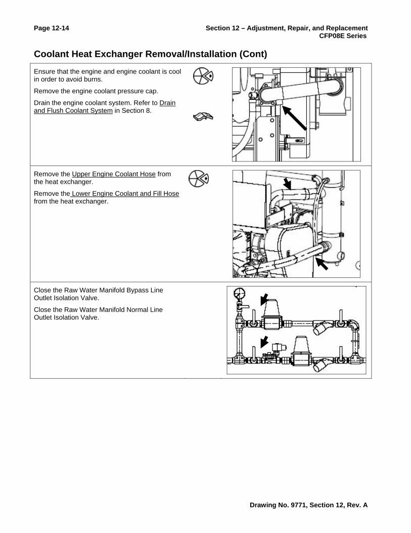
Ensure that the engine and engine coolant is cool in order to avoid burns.
Remove the engine coolant pressure cap.
Drain the engine coolant system. Refer to Drain and Flush Coolant System in Section 8.
Remove the Upper Engine Coolant Hose from the heat exchanger.
Remove the Lower Engine Coolant and Fill Hose from the heat exchanger.
Close the Raw Water Manifold Bypass Line Outlet Isolation Valve.
Close the Raw Water Manifold Normal Line Outlet Isolation Valve.
Drawing No. 9771, Section 12, Rev. A

Section 12 – Adjustment, Repair, and Replacement Page 12-15 CFP08E Series Coolant Heat Exchanger Removal/Installation (Cont)
Remove the 1” NPT raw water inlet piping from the charge air cooler to the heat exchanger. (Refer to Drawing 9595 in Section 18 for raw water supply piping details.)
Also, remove any customer-supplied raw water outlet fittings. Save these components for reuse.
Pressure Test
NOTE: This test is required if internal leakage in the heat exchanger is suspected. It may be performed prior to the removal from the engine.
NOTE: Use teflon tape or other pipe sealant when installing the test setup in order to prevent leaks.
Install a 1-1/4” NPT pipe plug at the raw water outlet of the heat exchanger.
Install a pressure test setup with 700 kPa [100 psi] pressure gauge at the 1” NPT raw water inlet to the heat exchanger.
NOTE: There should be no detectable decrease in the pressure reading for the duration of the test.
Apply air pressure at 621 kPa [90 psig].
Isolate the pressure source and monitor the pressure gauge for 5 minutes.
After testing, release the pressure.
Remove the pipe plug and the test setup.
If leakage is detected, the heat exchanger must be replaced.
Drawing No. 9771, Section 12, Rev. A
Page 12-16 Section 12 – Adjustment, Repair, and Replacement CFP08E Series
Coolant Heat Exchanger Removal/Installation (Cont)
Remove
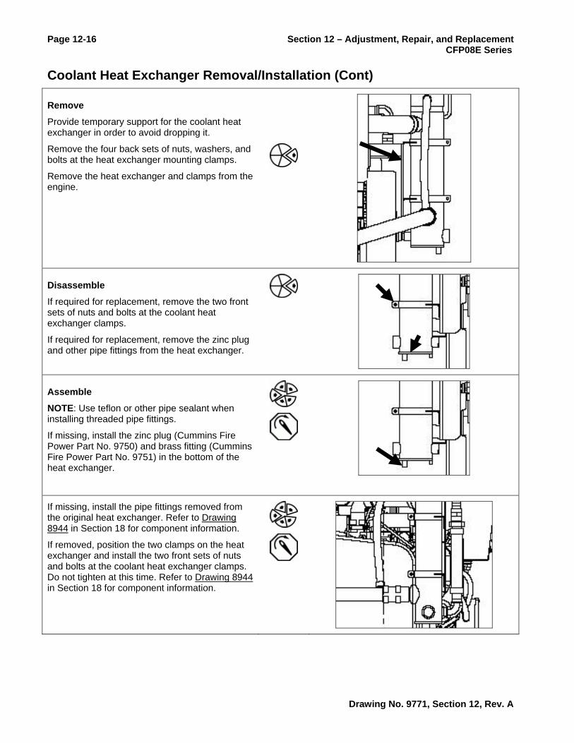
Provide temporary support for the coolant heat exchanger in order to avoid dropping it.
Remove the four back sets of nuts, washers, and bolts at the heat exchanger mounting clamps.
Remove the heat exchanger and clamps from the engine.
Disassemble
If required for replacement, remove the two front sets of nuts and bolts at the coolant heat exchanger clamps.
If required for replacement, remove the zinc plug and other pipe fittings from the heat exchanger.
Assemble
NOTE: Use teflon or other pipe sealant when installing threaded pipe fittings.
If missing, install the zinc plug (Cummins Fire Power Part No. 9750) and brass fitting (Cummins Fire Power Part No. 9751) in the bottom of the heat exchanger.
If missing, install the pipe fittings removed from the original heat exchanger. Refer to Drawing 8944 in Section 18 for component information.
If removed, position the two clamps on the heat exchanger and install the two front sets of nuts and bolts at the coolant heat exchanger clamps. Do not tighten at this time. Refer to Drawing 8944 in Section 18 for component information.
Drawing No. 9771, Section 12, Rev. A

Section 12 – Adjustment, Repair, and Replacement Page 12-17 CFP08E Series Coolant Heat Exchanger Removal/Installation (Cont)
Install
Provide support for the coolant heat exchanger in order to avoid dropping it.
Position the heat exchanger and clamps on the engine’s mounting bracket and start the four bolts.
Start the nut and washers on the four bolts.
Align the heat exchanger with the required hose connections and tighten the four back sets of clamp fasteners.
Tighten the two front sets of clamp fasteners.
Follow-Up
Install the Upper Engine Coolant Hose at the heat exchanger.
Install the Lower Engine Coolant and Fill Hose at the heat exchanger.
Install the 1” NPT raw water inlet piping from the charge air cooler to the heat exchanger. (Refer to Drawing 9595 in Section 18 for raw water supply piping details.)
Also, install any customer-supplied raw water outlet fittings.
Drawing No. 9771, Section 12, Rev. A

Page 12-18 Section 12 – Adjustment, Repair, and Replacement CFP08E Series
Coolant Heat Exchanger Removal/Installation (Cont)
Close coolant drain valve.
Refill the engine coolant. Refer to Drain and Flush Coolant System in Section 8.
Install the coolant system pressure cap.
Reconnect the coolant heater power supply.
Reconnect the Contactor to Starter Cable (Cummins Fire Power Part No 9762) at the starter (Refer to Drawing 9767 in Section 18).
NOTE: Start the engine and do a quick check for leaks. If any coolant leaks are observed, stop the engine, repair the leak, check coolant level, then restart the engine. If no leaks are present, promptly establish raw water flow through the heat exchanger.
Start the engine. Refer to Normal Local Starting Procedure in Section 3.
Check for and repair any coolant leaks.
Drawing No. 9771, Section 12, Rev. A

Section 12 – Adjustment, Repair, and Replacement Page 12-19 CFP08E Series Coolant Heat Exchanger Removal/Installation (Cont)
CAUTION When establishing raw water flow, ensure that the raw water pressure does not exceed 414 kPa (60 psig) at the heat exchanger. Adjust the pressure regulators as required.
Slowly open the Raw Water Manifold Bypass Line Outlet Isolation Valve.
Observe raw water flow through the heat exchanger.
Adjust the bypass pressure regulator if required.
Close the Raw Water Manifold Bypass Line Outlet Isolation Valve.
CAUTION When establishing raw water flow, ensure that the raw water pressure does not exceed 414 kPa (60 psig) at the heat exchanger. Adjust the pressure regulators as required.
Slowly open the Raw Water Manifold Normal Line Outlet Isolation Valve.
Observe raw water flow through the heat exchanger.
Adjust the normal pressure regulator if required.
NOTE: If temperature does not stabilize, stop the engine and refer to Coolant Temperature Above Normal or Coolant Temperature Below Normal (Engine Running) in Troubleshooting Section 17.
Check that engine operating temperature stabilizes between about 82 and 93 oC [180 and 200 oF].
Check that no coolant hoses are collapsed.
When temperature has stabilized, stop the engine.
Ensure that repairs are completed satisfactorily.
Drawing No. 9771, Section 12, Rev. A

Page 12-20 Section 12 – Adjustment, Repair, and Replacement CFP08E Series
Coolant Heat Exchanger Removal/Installation (Cont)
WARNING Do not remove the pressure cap from a hot engine. Wait until the coolant temperature is below 50°C [120°F] before removing the pressure cap. Heated coolant spray or steam can cause personal injury.
Check the coolant level. Refer to Check Coolant Level in Section 5. Add coolant if necessary.
Place the AUTO/MANUAL rocker switch in the AUTO position.
Return the fire protection system to operating status.
Drawing No. 9771, Section 12, Rev. A

Section 12 – Adjustment, Repair, and Replacement Page 12-21 CFP08E Series
Coolant Heater Removal/Installation
Prepare
WARNING Coolant is toxic. Keep away from children and pets. If not reused, dispose of in accordance with local environmental regulations.
WARNING Do not remove the pressure cap from a hot engine. Wait until the coolant temperature is below 50°C [122°F] before removing the pressure cap. Heated coolant spray or steam can cause personal injury.
Place the fire protection system in a safe mode for engine service.
Place the AUTO/MANUAL rocker switch in the MANUAL position.
Disconnect or isolate the coolant heater power supply.
Disconnect and insulate the Contactor to Starter Cable (Cummins Fire Power Part No 9762) from the starter (Refer to Drawing 9767 in Section 18).
Drawing No. 9771, Section 12, Rev. A

Page 12-22 Section 12 – Adjustment, Repair, and Replacement CFP08E Series
Coolant Heater Removal/Installation (Cont)
Ensure that the engine and engine coolant is cool in order to avoid burns.
Remove the engine coolant pressure cap.
Drain the engine coolant system. Refer to Drain and Flush Coolant System in Section 8.
NOTE: Collect the remainder of the coolant in the heater hoses.
NOTE: Refer to Drawing 8941 in Section 18 for detailed component information.
Remove the Upper Coolant Heater Hose.
Remove the Lower Coolant Heater Hose.
Remove
Remove the two capscrews, washers, bracket, and coolant heater. Refer to Drawing 8941 in Section 18 for detailed component information.
If required, remove the nuts, bolts, washers and mounting bracket from the coolant heater.
Drawing No. 9771, Section 12, Rev. A

Section 12 – Adjustment, Repair, and Replacement Page 12-23 CFP08E Series Coolant Heater Removal/Installation (Cont)
Install
If missing, install the nuts, bolts, washers and mounting bracket on the coolant heater. Refer to Drawing 8941 in Section 18 for detailed component information.
Position the coolant heater and mounting bracket and start the two bolts with washers.
Torque the two bolts on the mounting bracket as per Capscrew Markings and Torque Values in Section 15.
Follow-Up
NOTE: Refer to Drawing 8941 in Section 18 for detailed component information.
Install the Upper Coolant Heater Hose.
Install the Lower Coolant Heater Hose.
Close the coolant drain valve.
Drawing No. 9771, Section 12, Rev. A

Page 12-24 Section 12 – Adjustment, Repair, and Replacement CFP08E Series
Coolant Heater Removal/Installation (Cont)
Refill the engine coolant. Refer to Drain and Flush Coolant System in Section 8.
Install the coolant system pressure cap.
Reconnect the Contactor to Starter Cable (Cummins Fire Power Part No 9762) at the starter (Refer to Drawing 9767 in Section 18).
NOTE: Start the engine and do a quick check for leaks. If any coolant leaks are observed, stop the engine, repair the leak, check coolant level, then restart the engine.
Start the engine. Refer to Normal Local Starting Procedure in Section 3.
Check for and repair any coolant leaks.
Stop the engine.
WARNING Do not remove the pressure cap from a hot engine. Wait until the coolant temperature is below 50°C [120°F] before removing the pressure cap. Heated coolant spray or steam can cause personal injury.
Check the coolant level. Refer to Check Coolant Level in Section 5. Add coolant if necessary.
Drawing No. 9771, Section 12, Rev. A

Section 12 – Adjustment, Repair, and Replacement Page 12-25 CFP08E Series
Coolant Heater Removal/Installation (Cont)
Reconnect the coolant heater power supply.
Observe that the coolant temperature cools down but stabilizes.
Check that the engine block remains warm to the touch.
Place the AUTO/MANUAL rocker switch in the AUTO position.
Return the fire protection system to operating status.
Drawing No. 9771, Section 12, Rev. A

Page 12-26 Section 12 – Adjustment, Repair, and Replacement CFP08E Series
Coolant Hose Removal/Installation Identify hose clamps and add manufacturer’s torque value.
NOTE: This section addresses all coolant tubes and hoses. Only remove those coolant hoses that are necessary. It is not required to remove both ends of the hose for the replacement of other components. Use the following sections as applicable:
• Prepare
• Remove the Upper Engine Coolant Hose
• Remove the Lower Engine Coolant and Fill Hoses
• Remove the Upper Coolant Heater Hose
• Remove the Lower Coolant Heater Hose
• Remove the Coolant Vent Hose
• Inspect
• Install the Upper Engine Coolant Hose
• Install the Lower Engine Coolant and Fill Hoses
• Install the Upper Coolant Heater Hose
• Install the Lower Coolant Heater Hose
• Install the Coolant Vent Hose
• Follow-Up
Drawing No. 9771, Section 12, Rev. A

Section 12 – Adjustment, Repair, and Replacement Page 12-27 CFP08E Series Coolant Hose Removal/Installation (Cont)
Prepare
WARNING Coolant is toxic. Keep away from children and pets. If not reused, dispose of in accordance with local environmental regulations.
WARNING Do not remove the pressure cap from a hot engine. Wait until the coolant temperature is below 50°C [122°F] before removing the pressure cap. Heated coolant spray or steam can cause personal injury.
Place the fire protection system in a safe mode for engine service.
Place the AUTO/MANUAL rocker switch in the MANUAL position.
Disconnect or isolate the coolant heater power supply.
Disconnect and insulate the Contactor to Starter Cable (Cummins Fire Power Part No 9762) from the starter (Refer to Drawing 9767 in Section 18).
Drawing No. 9771, Section 12, Rev. A

Page 12-28 Section 12 – Adjustment, Repair, and Replacement CFP08E Series
Coolant Hose Removal/Installation (Cont)
Ensure that the engine and engine coolant is cool in order to avoid burns.
Remove the engine coolant pressure cap.
Drain the engine coolant system. Refer to Drain and Flush Coolant System in Section 8.
Remove the Upper Engine Coolant Hose
NOTE: Refer to Assembly Drawing 8944 in Section 18 for detailed construction.
Loosen the hose clamp at the heat exchanger.
Loosen the hose clamp at the engine.
Pull the hose from the heat exchanger and engine.
Remove the Lower Engine Coolant and Fill Hoses
NOTE: Refer to Assembly Drawing 8944 in Section 18 for detailed construction.
Remove the nuts and U-bolt supporting the lower engine coolant hose.
Loosen the fill hose clamp at the heat exchanger.
Loosen the engine coolant hose clamp at the heat exchanger.
Loosen the engine coolant hose clamp at the engine.
Pull the hoses from the heat exchanger and engine.
If required for replacement, disassemble the components.
Drawing No. 9771, Section 12, Rev. A

Section 12 – Adjustment, Repair, and Replacement Page 12-29 CFP08E Series
Coolant Hose Removal/Installation (Cont)
Remove the Upper Coolant Heater Hose
NOTE: Refer to Assembly Drawing 8941 in Section 18 for detailed construction.
NOTE: Be prepared to collect the residual coolant that may drain from the hose.
Loosen the hose clamp at the engine.
Loosen the hose clamp at the coolant heater.
Pull the hose and tubing from the connections.
Disassemble additional components if this is required for inspection or repairs.
Remove the Lower Coolant Heater Hose
NOTE: Refer to Assembly Drawing 8941 in Section 18 for detailed construction.
NOTE: Be prepared to collect the residual coolant that may drain from the hose.
Loosen the hose clamp at the engine.
Loosen the hose clamp at the coolant heater.
Pull the hose and tubing from the connections.
Disassemble additional components if this is required for inspection or repairs.
Remove the Coolant Vent Hose
NOTE: Refer to Assembly Drawing 9543 in Section 18 for detailed construction.
Loosen the flair fitting at the coolant heat exchanger.
Loosen the flair fitting at the engine.
Pull the hose from the connections.
Drawing No. 9771, Section 12, Rev. A

Page 12-30 Section 12 – Adjustment, Repair, and Replacement CFP08E Series
Coolant Hose Removal/Installation (Cont)
Inspect
NOTE: Inspect the cooling system hoses and hose connection for leaks or deterioration. Particles of deteriorated hose can be carried through the cooling system and slow or partially stop circulation.
Inspect the hoses and hose connections.
Replace any hoses or clamps that are damaged.
Install the Upper Engine Coolant Hose
CAUTION Do not re-install worn or damaged hoses or corroded clamps.
NOTE: Refer to Assembly Drawing 8944 in Section 18 for detailed construction.
Position the hose clamps on the hose.
Push the hose onto the heat exchanger and engine connections.
Tighten the hose clamp at the heat exchanger.
Tighten the hose clamp at the engine.
Drawing No. 9771, Section 12, Rev. A
Section 12 – Adjustment, Repair, and Replacement Page 12-31 CFP08E Series
Coolant Hose Removal/Installation (Cont)
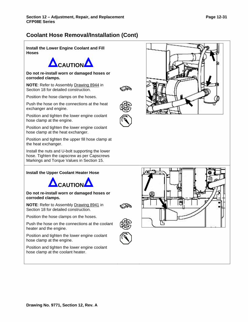
Install the Lower Engine Coolant and Fill Hoses
CAUTION Do not re-install worn or damaged hoses or corroded clamps.
NOTE: Refer to Assembly Drawing 8944 in Section 18 for detailed construction.
Position the hose clamps on the hoses.
Push the hose on the connections at the heat exchanger and engine.
Position and tighten the lower engine coolant hose clamp at the engine.
Position and tighten the lower engine coolant hose clamp at the heat exchanger.
Position and tighten the upper fill hose clamp at the heat exchanger.
Install the nuts and U-bolt supporting the lower hose. Tighten the capscrew as per Capscrews Markings and Torque Values in Section 15.
Install the Upper Coolant Heater Hose
CAUTION Do not re-install worn or damaged hoses or corroded clamps.
NOTE: Refer to Assembly Drawing 8941 in Section 18 for detailed construction.
Position the hose clamps on the hoses.
Push the hose on the connections at the coolant heater and the engine.
Position and tighten the lower engine coolant hose clamp at the engine.
Position and tighten the lower engine coolant hose clamp at the coolant heater.
Drawing No. 9771, Section 12, Rev. A

Page 12-32 Section 12 – Adjustment, Repair, and Replacement CFP08E Series
Coolant Hose Removal/Installation (Cont)
Install the Lower Coolant Heater Hose
CAUTION Do not re-install worn or damaged hoses or corroded clamps.
NOTE: Refer to Assembly Drawing 8941 in Section 18 for detailed construction.
Position the hose clamps on the hoses.
Push the hose on the connections at the coolant heater and the engine.
Position and tighten the lower engine coolant hose clamp at the engine.
Position and tighten the lower engine coolant hose clamp at the coolant heater.
Install the Coolant Vent Hose
CAUTION Do not re-install worn or damaged hoses or corroded clamps.
NOTE: Refer to Assembly Drawing 9543 in Section 18 for detailed construction.
Connect the hose flair connector at the heat exchanger.
Connect the hose flair connector at the engine coolant vent connection.
Follow-Up
Close the coolant drain valve.
Drawing No. 9771, Section 12, Rev. A

Section 12 – Adjustment, Repair, and Replacement Page 12-33 CFP08E Series
Coolant Hose Removal/Installation (Cont)
Refill the engine coolant. Refer to Drain and Flush Coolant System in Section 8.
Install the coolant system pressure cap.
Reconnect the coolant heater power supply.
Reconnect the Contactor to Starter Cable (Cummins Fire Power Part No 9762) at the starter (Refer to Drawing 9767 in Section 18).
NOTE: Start the engine and do a quick check for leaks. If any coolant leaks are observed, stop the engine, repair the leak, check coolant level, then restart the engine.
Start the engine. Refer to Normal Local Starting Procedure in Section 3.
Check for and repair any coolant leaks.
Check that engine operating temperature stabilizes between about 82 and 93 oC [180 and 200 oF].
Check that no coolant hoses are collapsed.
When temperature has stabilized, stop the engine.
Ensure that repairs are completed satisfactorily.
Drawing No. 9771, Section 12, Rev. A

Page 12-34 Section 12 – Adjustment, Repair, and Replacement CFP08E Series
Coolant Hose Removal/Installation (Cont)
WARNING Do not remove the pressure cap from a hot engine. Wait until the coolant temperature is below 50°C [120°F] before removing the pressure cap. Heated coolant spray or steam can cause personal injury.
Check the coolant level. Refer to Check Coolant Level in Section 5. Add coolant if necessary.
Place the AUTO/MANUAL rocker switch in the AUTO position.
Return the fire protection system to operating status.
Drawing No. 9771, Section 12, Rev. A

Section 12 – Adjustment, Repair, and Replacement Page 12-35 CFP08E Series
Raw Water Pressure Regulator Removal/Installation NOTE: This section applies only to pressure regulators supplied by Cummins Fire Power. These procedures should be modified for alternative piping or components as supplied by the customer.
NOTE: This section applies to both the normal and bypass lines. Use the appropriate sections as follows:
• Prepare (Bypass Line)
• Prepare (Normal Line)
• Remove (Bypass Line)
• Remove (Normal Line)
• Install (Bypass Line)
• Install (Normal Line)
• Follow-Up (Bypass Line)
• Follow-Up (Normal Line)
Prepare (Bypass Line)
Place the AUTO/MANUAL Switch at the local panel in the MANUAL position.
Close the Raw Water Manifold Bypass Line Inlet Isolation Valve.
Close the Raw Water Manifold Bypass Line Outlet Isolation Valve.
Prepare (Normal Line)
Place the AUTO/MANUAL Switch at the local panel in the MANUAL position.
Close the Raw Water Manifold Normal Line Inlet Isolation Valve
Close the Raw Water Manifold Normal Line Outlet Isolation Valve.
Drawing No. 9771, Section 12, Rev. A

Page 12-36 Section 12 – Adjustment, Repair, and Replacement CFP08E Series
Raw Water Pressure Regulator Removal/Installation (Cont)
Remove (Bypass Line)
Loosen the pipe union upstream of the pressure regulator.
Unscrew the pressure regulator from the outlet isolation valve.
As required, remove the pipe nipples from the pressure regulator.
Remove (Normal Line)
Loosen the pipe union downstream of the pressure regulator.
Unscrew the pressure regulator from the solenoid valve.
As required, remove the pipe nipples from the pressure regulator.
Install (Bypass Line)
When the pressure regulator is repaired or replaced, prepare it for installation.
NOTE: Use pipe dope or silicon sealant on threaded fittings.
As required, install the pipe nipples on the pressure regulator. Tighten with a pipe wrench or equivalent.
Screw the pressure regulator onto the outlet isolation valve.
Align and connect the pipe union. Tighten with a pipe wrench or equivalent.
Drawing No. 9771, Section 12, Rev. A

Section 12 – Adjustment, Repair, and Replacement Page 12-37 CFP08E Series Raw Water Pressure Regulator Removal/Installation (Cont)
Install (Normal Line)
When the pressure regulator is repaired or replaced, prepare it for installation.
NOTE: Use pipe dope or silicon sealant on threaded fittings.
As required, install the pipe nipples on the pressure regulator. Tighten with a pipe wrench or equivalent.
Screw the pressure regulator onto the solenoid valve.
Align and connect the pipe union. Tighten with a pipe wrench or equivalent.
Follow-Up (Bypass Line)
Check the pressure regulator setpoint (refer to Section 3).
If required, open the Raw Water Manifold Bypass Line Inlet Isolation Valve.
If required, open the Raw Water Manifold Bypass Line Outlet Isolation Valve.
Verify that raw water flow is established through the heat exchanger.
When flow is verified, close the bypass line outlet valve.
Ensure that the normal line inlet and outlet valves are both open.
Ensure that the pressure gauge isolation valve is open.
Ensure that repairs are completed satisfactorily.
Place the AUTO/MANUAL Switch at the local panel in the AUTO position.
Drawing No. 9771, Section 12, Rev. A

Page 12-38 Section 12 – Adjustment, Repair, and Replacement CFP08E Series
Raw Water Pressure Regulator Removal/Installation (Cont)
Follow-Up (Normal Line)
Check the pressure regulator setpoint (refer to Section 3).
If required, open the Raw Water Manifold Normal Line Inlet Isolation Valve.
If required, open the Raw Water Manifold Normal Line Outlet Isolation Valve.
As required, close the bypass line outlet valve.
Ensure that the pressure gauge isolation valve is open.
Start the engine to operate the raw water solenoid valve. (Refer to Section 3),
Verify that raw water flow is established through the heat exchanger.
When flow is verified, stop the engine.
Observe that raw water flow stops.
Ensure that repairs are completed satisfactorily.
Place the AUTO/MANUAL Switch at the local panel in the AUTO position.
Drawing No. 9771, Section 12, Rev. A

Section 12 – Adjustment, Repair, and Replacement Page 12-39 CFP08E Series
Raw Water Solenoid Valve Removal/Installation NOTE: This section applies to solenoid valves supplied by Cummins Fire Power.
Prepare
Place the AUTO/MANUAL Switch at the local panel in the MANUAL position.
WARNING Batteries can emit explosive gases. To reduce the possibility of personal injury, always ventilate the compartment before servicing the batteries. To reduce the possibility of arcing, remove the negative (-) battery cable first and attach the negative (-) battery cable last.
Disconnect the positive battery cables from both batteries.
Disconnect any customer supplied battery chargers.
Close the Raw Water Manifold Normal Line Inlet Isolation Valve.
Close the Raw Water Manifold Normal Line Outlet Isolation Valve.
Remove
NOTE: Minimize the loss of wire when cutting the splices.
NOTE: Tag each end of the wire before making the cut.
Cut the butt-splices at the connection between the two solenoid valve pigtail wires and the fire pump electrical harness.
Loosen the union fitting between the solenoid valve and the pressure regulator.
Unscrew the solenoid valve from the outlet isolation valve or inlet nipple.
Remove the solenoid valve.
If appropriate for replacement, remove the pipe fittings from the solenoid valve.
Drawing No. 9771, Section 12, Rev. A

Page 12-40 Section 12 – Adjustment, Repair, and Replacement CFP08E Series
Raw Water Solenoid Valve Removal/Installation (Cont)
Install
NOTE: Install only Cummins approved replacement solenoid valves [Cummins Fire Power Part No. 8210G14-12VDC (12 VDC) or 8210G14-24VDC (24 VDC)].
NOTE: Use thread sealant when making threaded plumbing connections.
If removed, install the inlet and outlet fittings on the solenoid valve.
Position the solenoid valve and start threading it into the outlet valve or onto the outlet valve nipple.
Thread the valve until it is tight and so that the electrical housing is facing up.
Align and tighten the union connection.
NOTE: Use termination techniques that meet all local requirements. Cummins recommends crimped and insulated butt splices.
NOTE: The solenoid valve’s green pigtail lead is not used. The other two leads are not polarity dependent.
Splice the two solenoid pigtail leads to the fire pump harness solenoid leads.
Drawing No. 9771, Section 12, Rev. A

Section 12 – Adjustment, Repair, and Replacement Page 12-41 CFP08E Series
Raw Water Solenoid Valve Removal/Installation (Cont)
Follow-Up
WARNING Batteries can emit explosive gases. To reduce the possibility of personal injury, always ventilate the compartment before servicing the batteries. To reduce the possibility of arcing, remove the negative (-) battery cable first and attach the negative (-) battery cable last.
Connect the positive battery cables at both batteries,
Open the Raw Water Manifold Normal Line Inlet Isolation Valve.
Open the Raw Water Manifold Normal Line Outlet Isolation Valve.
Operate the engine. Refer to Operating Instructions in Section 3.
Check for leaks. Repair any leaks.
Check that raw water flow starts when the engine starts.
Drawing No. 9771, Section 12, Rev. A

Page 12-42 Section 12 – Adjustment, Repair, and Replacement CFP08E Series
Raw Water Solenoid Valve Removal/Installation (Cont)
Stop the engine.
Check that raw water flow stops shortly after the engine stops.
If raw water flow does not start when the engine starts, refer to Coolant Temperature Above Normal in Troubleshooting Section 17.
If raw water flow does not stop shortly after the engine stops, refer to in Troubleshooting Section 17.
If operation is correct, place the AUTO/MANUAL Switch at the local panel in the AUTO position.
Drawing No. 9771, Section 12, Rev. A

Section 12 – Adjustment, Repair, and Replacement Page 12-43 CFP08E Series
Water Temperature Gauge Removal/Installation
Prepare
Place the AUTO/MANUAL Switch at the local panel in the MANUAL position.
WARNING Batteries can emit explosive gases. To reduce the possibility of personal injury, always ventilate the compartment before servicing the batteries. To reduce the possibility of arcing, remove the negative (-) battery cable first and attach the negative (-) battery cable last.
Disconnect the positive battery cables from both batteries.
Disconnect any customer supplied battery chargers.
Remove
Use a nut driver or equivalent to remove the control panel’s mounting bolt.
Pull the control panel out from the enclosure so that it is supported by the piano hinge on the bottom.
NOTE: Check and tag all wires with location tags prior to removal.
Remove the two dark blue [METER +] wires from the [I] terminal on the gauge.
Remove the single black ground wire from the [G] terminal on the gauge.
Remove the single [WTG] wire from the [S] terminal on the gauge.
NOTE: Catch the gauge as the meter bracket is removed.
Remove the two nuts and the meter bracket from the back of the panel.
Remove the gauge from the panel.
Drawing No. 9771, Section 12, Rev. A

Page 12-44 Section 12 – Adjustment, Repair, and Replacement CFP08E Series
Water Temperature Gauge Removal/Installation (Cont)
Install
Position the gauge in the panel. Orient it for ease of reading.
Position the meter bracket on the gauge’s mounting studs. Start the nuts.
Tighten the nuts hand tight plus a full turn.
Connect the two dark blue [METER +] wires on the [I] terminal on the gauge.
Connect the single black ground wire on the [G] terminal on the gauge.
Connect the single [WTG] wire on the [S] terminal on the gauge.
Raise the control panel and install the panel mounting bolt.
Follow-Up
Reconnect the batteries and any battery chargers.
Observe that the [WATER TEMP] gauge indicates a reasonable value for ambient cooling water temperature.
If the gauge does indicate correctly, place the AUTO/MANUAL Switch at the local panel in the AUTO position.
Drawing No. 9771, Section 12, Rev. A
Section 12 – Adjustment, Repair, and Replacement Page 12-45 CFP08E Series
Coolant Temperature Sender Removal/Installation
Prepare
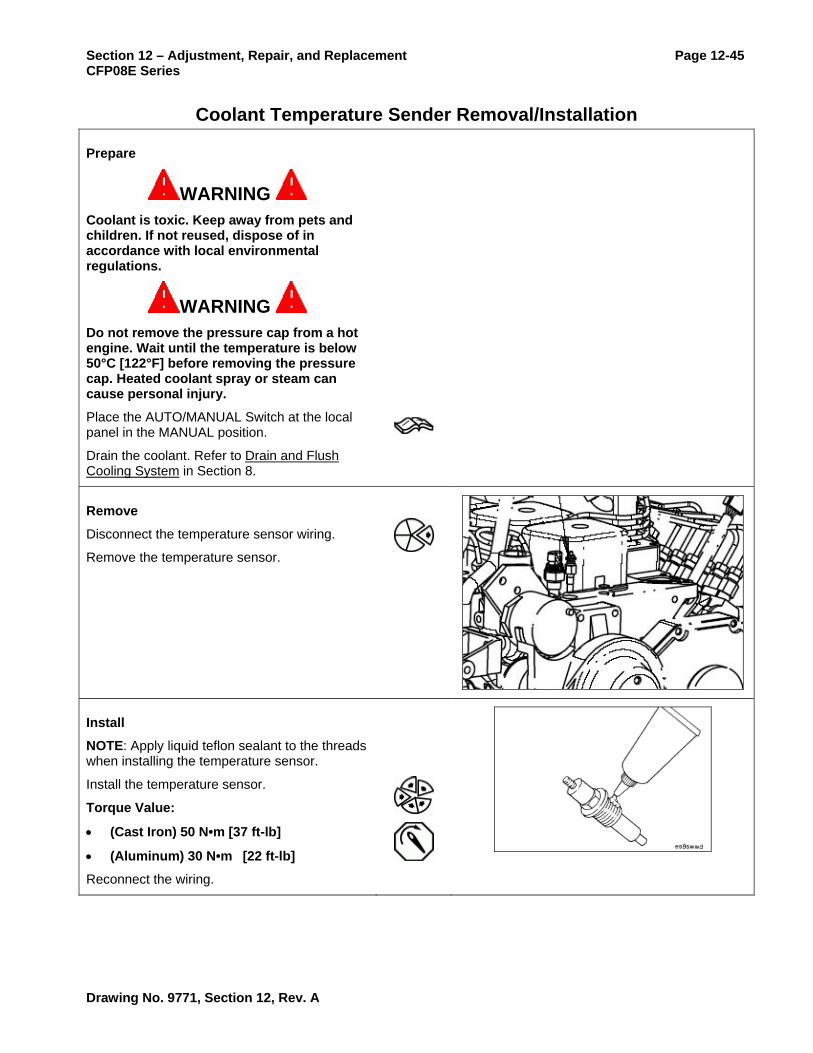
WARNING Coolant is toxic. Keep away from pets and children. If not reused, dispose of in accordance with local environmental regulations.
WARNING Do not remove the pressure cap from a hot engine. Wait until the temperature is below 50°C [122°F] before removing the pressure cap. Heated coolant spray or steam can cause personal injury.
Place the AUTO/MANUAL Switch at the local panel in the MANUAL position.
Drain the coolant. Refer to Drain and Flush Cooling System in Section 8.
Remove
Disconnect the temperature sensor wiring.
Remove the temperature sensor.
Install
NOTE: Apply liquid teflon sealant to the threads when installing the temperature sensor.
Install the temperature sensor.
Torque Value:
• (Cast Iron) 50 N•m [37 ft-lb]
• (Aluminum) 30 N•m [22 ft-lb]
Reconnect the wiring.
Drawing No. 9771, Section 12, Rev. A

Page 12-46 Section 12 – Adjustment, Repair, and Replacement CFP08E Series
Coolant Temperature Sender Removal/Installation (Cont)
Follow-Up
Fill coolant to proper level. Refer to Drain and Flush Cooling System in Section 8.
Operate the engine. Refer to Operating Instructions in Section 3.
Check for leaks. Repair any leaks.
Check that engine operating temperature stabilizes between about 82 and 93 oC [180 and 199 oF].
If temperature does not stabilize in the desired range, stop the engine and refer to refer to Coolant Temperature Above Normal or Coolant Temperature Below Normal (Engine Running) in Troubleshooting Section 17.
If operation is correct, stop the engine and place the AUTO/MANUAL Switch at the local panel in the AUTO position.
Drawing No. 9771, Section 12, Rev. A

Section 12 – Adjustment, Repair, and Replacement Page 12-47 CFP08E Series
Coolant Temperature Switch Removal/Installation
Prepare
WARNING Coolant is toxic. Keep away from pets and children. If not reused, dispose of in accordance with local environmental regulations.
WARNING Do not remove the pressure cap from a hot engine. Wait until the temperature is below 50°C [122°F] before removing the pressure cap. Heated coolant spray or steam can cause personal injury.
Place the AUTO/MANUAL Switch at the local panel in the MANUAL position.
Drain the coolant. Refer to Drain and Flush Cooling System in Section 8.
Remove
Disconnect the temperature switch wiring.
Remove the temperature switch.
Install
Apply liquid teflon sealant to the threads when installing the temperature switch.
Install the temperature switch.
Torque Value:
• (Cast Iron) 50 N•m [37 ft-lb]
• (Aluminum) 30 N•m [22 ft-lb]
Reconnect the wiring.
Drawing No. 9771, Section 12, Rev. A

Page 12-48 Section 12 – Adjustment, Repair, and Replacement CFP08E Series
Coolant Temperature Switch Removal/Installation (Cont)
Follow-Up
Fill coolant to proper level. Refer to Drain and Flush Cooling System in Section 8.
Operate the engine. Refer to Operating Instructions in Section 3.
Check that the High Water Temperature Light on the control panel does not illuminate.
Check for leaks. Repair any leaks.
Observe that engine operating temperature stabilizes between about 82 and 93 oC [180 and 199 oF].
Stop the engine.
If operation is correct, place the AUTO/MANUAL Switch at the local panel in the AUTO position.
Drawing No. 9771, Section 12, Rev. A

Section 12 – Adjustment, Repair, and Replacement Page 12-49 CFP08E Series
Coolant Thermostat Removal/Installation
Prepare
WARNING Coolant is toxic. Keep away from children and pets. If not reused, dispose of in accordance with local environmental regulations.
WARNING Do not remove the pressure cap from a hot engine. Wait until the coolant temperature is below 50°C [120°F] before removing the pressure cap. Heated coolant spray or steam can cause personal injury.
CAUTION Always use the correct thermostat, and never operate the engine without a thermostat installed. The engine can overheat if operated without a thermostat because the path of least resistance for the coolant is through the bypass to the pump inlet. An incorrect thermostat can cause the engine to overheat or run too cold.
Place the AUTO/MANUAL Switch at the local panel in the MANUAL position.
Drain the coolant. Refer to Drain and Flush Cooling System in Section 8.
Disconnect the coolant hose. Refer to Remove Upper Engine Coolant Hose in this section.
Remove
Remove the two mounting capscrews and the water outlet connection.
Remove the thermostat and both the upper and lower seals.
Drawing No. 9771, Section 12, Rev. A

Page 12-50 Section 12 – Adjustment, Repair, and Replacement CFP08E Series
Coolant Thermostat Removal/Installation (Cont)
Clean
NOTE: Do not let any debris fall into the thermostat cavity when cleaning the gasket surfaces. Stuff a clean rag in the hole.
Clean the mating surfaces on the water outlet connection and on the engine with a putty knife and clean cloth.
Inspect for Reuse
Inspect the thermostat for obvious damage such as obstructions caused by debris, broken springs, or stuck or missing vent pins.
Make sure the thermostat is clean and free from corrosion.
NOTE: Do not allow the thermostat or thermometer to touch the side of the container.
NOTE: The fully open distance between the thermostat flange and housing is 9.4 mm [0.370 in].
Suspend the thermostat and a 100°C [212°F] thermometer in a container of water.
Heat the water slowly so the wax element in the thermostat has sufficient time to react to the rising water temperature.
Check the thermostat as follows:
Requirements
• Starts to open within ±1°C [±2°F] of 82°C [180°F].
• Fully open within ±1°C [±2°F] of 93°C [199°F].
If the thermostat does not operate within the required range, it must be replaced.
Drawing No. 9771, Section 12, Rev. A

Section 12 – Adjustment, Repair, and Replacement Page 12-51 CFP08E Series Coolant Thermostat Removal/Installation (Cont)
Install
CAUTION Always use the correct thermostat, and never operate the engine without a thermostat installed. The engine can overheat if operated without a thermostat because the path of least resistance for the coolant is through the bypass to the pump inlet. An incorrect thermostat can cause the engine to overheat or run too cold.
If used, remove the rag from the hole in the engine block.
NOTE: Make sure that the top and bottom seals are in place.
Install the thermostat (Cummins Part No. 3940632) and two new thermostat seals (Cummins Part No. 145581) into the thermostat housing.
Install the water outlet connection (thermostat housing).
Install the two capscrews.
Torque Value: 24 N•m [18 ft-lb]
Install the water outlet hose. Refer to Install Upper Engine Coolant Hose in this section.
Drawing No. 9771, Section 12, Rev. A

Page 12-52 Section 12 – Adjustment, Repair, and Replacement CFP08E Series
Follow-Up
Fill the cooling system. Refer to Drain and Flush Cooling System in Section 8.
Operate the engine. Refer to Operating Instructions in Section 3.
Check for leaks. Repair any leaks.
Check that engine operating temperature stabilizes between about 82 and 93 oC [180 and 199 oF]. If temperature does not stabilize, stop the engine and refer to Coolant Temperature Above Normal or Coolant Temperature Below Normal (Engine Running) in Troubleshooting Section 17.
If operation is correct, place the AUTO/MANUAL Switch at the local panel in the AUTO position.
Drawing No. 9771, Section 12, Rev. A

Section 12 – Adjustment, Repair, and Replacement Page 12-53 CFP08E Series
Coolant Thermostat Tests The thermostat controls the coolant temperature. When the coolant temperature is below operating temperature, coolant is bypassed to the inlet of the water pump. When the coolant temperature reaches the operating range, the thermostat opens, sealing off the bypass, and forcing coolant to flow to the radiator. The thermostat begins opening at 82°C [180°F].
CAUTION Never operate the engine without a thermostat. Without a thermostat, the path of least resistance for the coolant is through the bypass to the pump inlet. This will cause the engine to overheat.
An incorrect or malfunctioning thermostat can cause the engine to run too hot or too cold.
Coolant Thermostat Leak Test
The engine thermostat and thermostat seal must operate properly in order for the engine to operate in the most efficient heat range. Overheating or overcooling will shorten engine life.
WARNING Do not remove the pressure cap from a hot engine. Wait until the coolant temperature is below 50°C [120°F] before removing the pressure cap. Heated coolant spray or steam can cause personal injury.
WARNING Coolant is toxic. Keep away from children and pets. If not reused, dispose of in accordance with local environmental regulations.
Allow the engine to cool well below 83 oC [181 oF].
Place the AUTO/MANUAL Switch at the local panel in the MANUAL position.
Drain the coolant. Refer to Drain and Flush Cooling System in Section 8.
Loosen the hose clamp on the Upper Engine Coolant Hose.
Remove the hose from the thermostat housing.
Drawing No. 9771, Section 12, Rev. A

Page 12-54 Section 12 – Adjustment, Repair, and Replacement CFP08E Series
Coolant Thermostat Tests (Cont)
Use INSITE™ to monitor the coolant temperature. Install a thermocouple or temperature gauge that is known to be accurate, in the cylinder block on the engine side of the thermostat.
Install a hose of the same size on the thermostat housing outlet long enough to reach a remote, dry container used to collect coolant.
Install and tighten a hose clamp on the housing outlet.
Place the other end of the hose in a dry container.
CAUTION Always vent the engine and aftercooler during filling to remove air from the coolant system, or overheating will result.
Refill the cooling system. Refer to Drain and Flush Cooling System in Section 8.
NOTE: The engine coolant temperature must be below the thermostat opening temperature of 82 oC [180 oF] to perform this test.
Operate the engine at rated rpm for 1 minute. Refer to Operating Instructions in Section 3.
Shut off the engine.
NOTE: The amount of coolant collected must not be more than 100 cc [3.3 fl oz].
Measure the amount of coolant collected in the container.
Drawing No. 9771, Section 12, Rev. A

Section 12 – Adjustment, Repair, and Replacement Page 12-55 CFP08E Series
Coolant Thermostat Tests (Cont)
If more than 100 cc [3.3 fl oz] of coolant is collected, the thermostat is leaking and must be replaced. Refer to Coolant Thermostat Removal/Installation in this section.
If leakage is not present, then continue to perform the Coolant Thermostat Function Test below.
Coolant Thermostat Function Test
Start the engine and allow the engine to approach operating temperature.
Monitor the water temperature with an electronic service tool or a gauge.
Monitor the operation of the thermostat.
Thermostat Initial Opening Temperature:
• MIN: 81 oC [178 oF]
• MAX: 83 oC [182 oF]
Stop the engine when the coolant starts to flow.
If the coolant does not start flowing into the container during the initial opening temperature range, the thermostat must be replaced. Refer to Coolant Thermostat Removal/Installation in this section.
Follow-Up
Remove any test instruments.
Install the heat exchanger hose and tighten hose clamp.
Return any coolant to the engine.
If operation is correct, place the AUTO/MANUAL Switch at the local panel in the AUTO position.
Drawing No. 9771, Section 12, Rev. A

Page 12-56 Section 12 – Adjustment, Repair, and Replacement CFP08E Series
Coolant Water Pump Removal/Installation
Prepare
WARNING Coolant is toxic. Keep away from children and pets. If not reused, dispose of in accordance with local environmental regulations.
WARNING Do not remove the pressure cap from a hot engine. Wait until the coolant temperature is below 50C [120F] before removing the pressure cap. Heated coolant spray or steam can cause personal injury.
Place the AUTO/MANUAL Switch at the local panel in the MANUAL position.
Drain engine coolant as required for the intended service. Refer to Drain and Flush Coolant System in Section 8.
If installed, remove the Belt Guard. Refer to Belt Guard Removal/Installation in this section.
If installed, remove the Drive Belt. Refer to Belt Removal/Installation in this section.
Remove
Remove the three water pump capscrews and the water pump.
Drawing No. 9771, Section 12, Rev. A

Section 12 – Adjustment, Repair, and Replacement Page 12-57 CFP08E Series
Coolant Water Pump Removal/Installation (Cont)
Clean and Inspect for Reuse
Clean the o-ring sealing surface on the water pump housing.
Inspect the water pump housing and impeller for cracks or damage.
NOTE: A streak or chemical buildup at the weep hole is not justification for water pump replacement. If a steady flow of coolant or oil is observed, replace the water pump with a new or rebuilt unit.
Inspect the water pump weep hole for an indication of a steady leak.
NOTE: A small screwdriver or a small tool can be used to remove any debris.
Inspect the weep hole to make sure it is open. A plugged weep hole can cause the water pump to fail.
If the water pump has failed, replace it with a new unit (Cummins Part No. 3286293 or 3973114) with new O-Ring (Cummins Part No. 3940386).
Install
Install a new o-ring (Cummins Part No. 3940386) into the groove in the water pump.
Drawing No. 9771, Section 12, Rev. A

Page 12-58 Section 12 – Adjustment, Repair, and Replacement CFP08E Series
Coolant Water Pump Removal/Installation (Cont)
Install the water pump and three water pump mounting capscrews.
Tighten the water pump mounting capscrews.
Torque Value: 24 N•m [212 in-lb]
Follow-Up
Install the Drive Belt. Refer to Belt Removal/Installation in this section.
Install the Belt Guard. Refer to Belt Guard Removal/Installation in this section.
Close the coolant drain valves.
Refill engine coolant as required Refer to Drain and Flush Coolant System in Section 8.
NOTE: Perform the appropriate actions in Initial Start-Up (see Section 3).
Perform a test run. Refer to Operating Instructions in Section 3.
Check for leaks. Repair any leaks.
Check that the alternator is charging.
Check that engine operating temperature stabilizes between about 82 and 93 oC [180 and 199 oF]. If temperature does not stabilize, stop the engine and refer to Coolant Temperature Above Normal or Coolant Temperature Below Normal (Engine Running) in Troubleshooting Section 17.
Stop the engine.
Ensure that repairs are completed satisfactorily.
Place the AUTO/MANUAL Switch at the local panel in the AUTO position.
Drawing No. 9771, Section 12, Rev. A

Section 12 – Adjustment, Repair, and Replacement Page 12-59 CFP08E Series
Coolant Filter Assembly Removal/Installation
Prepare
WARNING Do not remove the pressure cap from a hot engine. Wait until the coolant temperature is below 50°C [120°F] before removing the pressure cap. Heated coolant spray or steam can cause personal injury.
WARNING Coolant is toxic. Keep away from children and pets. If not reused, dispose of in accordance with local environmental regulations.
Place the fire protection system in a safe mode for engine service.
Place the AUTO/MANUAL rocker switch in the MANUAL position.
Disconnect and insulate the Contactor to Starter Cable (Cummins Fire Power Part No 9762) from the starter (Refer to Drawing 9767 in Section 18).
Remove the coolant system pressure cap.
Turn the shutoff valve to the OFF position by rotating the knob from vertical to horizontal in the direction shown.
Drawing No. 9771, Section 12, Rev. A

Page 12-60 Section 12 – Adjustment, Repair, and Replacement CFP08E Series
Coolant Filter Assembly Removal/Installation (Cont)
Remove
WARNING A small amount of coolant can leak when servicing the coolant filter with the shutoff valve in the OFF position. To reduce the possibility of personal injury, avoid contact with hot coolant.
Remove and discard the coolant filter.
Clean the filter housing with a dry clean rag.
Install
CAUTION Do not allow oil to get into the filter.
Apply a thin film of lubricating oil to the gasket sealing surface before installing the new coolant filter.
CAUTION Mechanical over-tightening can distort the threads or damage the filter head.
Install the coolant filter on the filter head. Tighten the filter until the gasket contacts the filter head surface.
Tighten the coolant filter an additional 1/2 to 3/4 of a turn, or as specified by the filter manufacturer.
CAUTION The valve must be in the ON position to prevent engine damage.
Turn the shutoff to the ON position by rotating the knob from horizontal to vertical in the direction shown.
Drawing No. 9771, Section 12, Rev. A

Section 12 – Adjustment, Repair, and Replacement Page 12-61 CFP08E Series
Coolant Filter Assembly Removal/Installation (Cont)
Follow-Up
Install the coolant system pressure cap.
Start the engine. Refer to Normal Local Starting Procedure in Section 3.
Check for and repair any coolant leaks.
After the air has been purged from the system, stop the engine.
WARNING Do not remove the pressure cap from a hot engine. Wait until the coolant temperature is below 50°C [120°F] before removing the pressure cap. Heated coolant spray or steam can cause personal injury.
Check the coolant level. Refer to Check Coolant Level in Section 5. Add coolant if necessary.
Place the AUTO/MANUAL rocker switch in the AUTO position.
Return the fire protection system to operating status.
Drawing No. 9771, Section 12, Rev. A

Page 12-62 Section 12 – Adjustment, Repair, and Replacement CFP08E Series
This Page Intentionally Left Blank
Drawing No. 9771, Section 12, Rev. A

Section 12 – Adjustment, Repair, and Replacement Page 12-63 CFP08E Series
Alternator Checks and Testing
Alternator Wiring Integrity Check
NOTE: Refer to Drawing 8512 Sheet 1, Drawing 8512 Sheet 2, and Drawing 9767 in Section 18 for schematic details.
WARNING Batteries can emit explosive gases. To reduce the possibility of personal injury, always ventilate the battery compartment before servicing the batteries.
WARNING To reduce the possibility of arcing, remove the negative (-) battery cable first and attach the negative (-) battery cable last.
Check the battery and all wiring connections for damage. Refer to Battery Cables and Connections in this section.
Check all connections for tightness and cleanliness. Include both the slip connectors at the alternator and connections at the battery.
NOTE: Continuity should be in the single digit Ohms or less. Resistance to ground should be in the mega-Ohm range. Refer to any applicable customer criteria.
Using a digital multimeter or other test equipment, check for continuity between terminals. Check also the insulation resistance to ground.
Correct any electrical faults.
Alternator Mechanical Check
Start the engine. Refer to Normal Local Starting Procedure in Section 3.
Visually check the drive belt and alternator pulley to be sure the alternator is rotating.
Note any unusual noises such as from belt whine or alternator mechanical fault.
Stop the engine.
Correct any mechanical failures.
Drawing No. 9771, Section 12, Rev. A

Page 12-64 Section 12 – Adjustment, Repair, and Replacement CFP08E Series
Alternator Checks and Testing (Cont)
Alternator Voltage Output Test
CAUTION Batteries must have been satisfactorily load tested and must be charged with a resting voltage of more than 12.4 Volts for this testing.
CAUTION Batteries must have been satisfactorily load tested and must be charged with a resting voltage of more than 12.4 Volts for this testing.
NOTE: Conduct this testing at normal shop temperature.
NOTE: Voltage should not exceed 15.5 V (for a 12 VDC system) or 31 V (for a 24 VDC system).
Start the engine and operate at rated speed. Refer to Normal Local Starting Procedure in Section 3.
Measure the alternator voltage output to the batteries with digital multimeter, Cummins Part Number 3377161.
Stop the engine.
Replace the alternator if the voltage exceeds specification. Refer to Alternator Removal/Installation in this section.
Drawing No. 9771, Section 12, Rev. A

Section 12 – Adjustment, Repair, and Replacement Page 12-65 CFP08E Series
Alternator Checks and Testing (Cont)
Alternator Amperage Output Test
NOTE: Conduct this testing at normal shop temperature.
NOTE: Refer to Electrical Specifications in Section 15 for the minimum required alternator output. Use the value listed for the system voltage.
Connect a carbon pile load in parallel across the battery terminals. Refer to Jumpering the Batteries in Section 3 for how to make a parallel connection.
Connect a clamp-on (induction) ammeter across the alternator output cable.
Start the engine and operate at rated speed. Refer to Normal Local Starting Procedure in Section 3.
Adjust the carbon pile for maximum indication.
Note the amperage indicated on the ammeter.
Stop the engine.
Remove the test equipment.
Replace the alternator if the output is not 90% or more of the specification value. Refer to Alternator Removal/Installation in this section.
Drawing No. 9771, Section 12, Rev. A

Page 12-66 Section 12 – Adjustment, Repair, and Replacement CFP08E Series
Alternator Removal/Installation
Prepare
Remove the belt guard. Refer to Belt Guard Removal/Installation in this section.
Remove the drive belt. Refer to Belt Removal/Installation in this section.
NOTE: Refer to Drawing 8513 Sheet 1 in Section 18 for wiring harness information.
NOTE: Ensure that the connectors are clearly tagged for the correct reconnection.
Disconnect the engine wiring harness connectors from the alternator.
Remove
Remove the alternator link capscrew.
Remove the alternator mounting capscrew.
Remove the alternator.
NOTE: If the alternator bracket must also be removed, go to Alternator Bracket Removal/Installation in this section.
Install
Ensure that the alternator bracket is installed. Refer to Alternator Bracket Removal/Installation in this section.
Install the alternator and alternator capscrews in the reverse order of removal.
Torque Value: 43 N•m [32 ft-lb]
Drawing No. 9771, Section 12, Rev. A

Section 12 – Adjustment, Repair, and Replacement Page 12-67 CFP08E Series
Alternator Removal/Installation (Cont)
Install the alternator link capscrew.
Torque Value: 24 N•m [18 ft-lb]
Follow-Up
NOTE: Refer to Drawing 8513 Sheet 1 in Section 18 for wiring harness information.
Connect the engine wiring harness connectors to the alternator.
Install the drive belt. Refer to Belt Removal/Installation in this section.
Install the belt guard. Refer to Belt Guard Removal/Installation in this section.
Drawing No. 9771, Section 12, Rev. A

Page 12-68 Section 12 – Adjustment, Repair, and Replacement CFP08E Series
Alternator Bracket Removal/Installation
Prepare
Remove the alternator. Refer to Alternator Removal/Installation in this section.
Remove
Remove the alternator bracket mounting capscrews and bracket.
Install
Install the mounting bracket and bracket mounting capscrews.
Torque Value: 24 N•m [18 ft-lb]
Follow-Up
Install the alternator. Refer to Alternator Removal/Installation in this section.
Drawing No. 9771, Section 12, Rev. A

Section 12 – Adjustment, Repair, and Replacement Page 12-69 CFP08E Series
Battery Isolator Removal/Installation
Prepare
Place the fire protection system in a safe mode for engine service.
Place the AUTO/MANUAL rocker switch in the MANUAL position.
NOTE: Refer to Battery Removal/Installation in this section for detailed instructions for disconnecting the battery cable clamps.
Disconnect the negative battery cable from Battery A.
Disconnect the negative battery cable from Battery B.
Remove
NOTE: Ensure that all battery isolator wires are clearly tagged for reconnection. Also note the orientation of the existing isolator.
Drawing No. 9771, Section 12, Rev. A

Page 12-70 Section 12 – Adjustment, Repair, and Replacement CFP08E Series
Battery Isolator Removal/Installation (Cont)
Disconnect the battery cable from terminal 1.
Disconnect the battery cable from terminal 2.
Disconnect the alternator cable from terminal A.
Disconnect the alternator excitation cable from terminal E.
Remove the four mounting nuts and the battery isolator
Install
Align and position the battery isolator on the four mounting studs.
Install the four mounting nuts.
Connect the battery cable at terminal 1.
Connect the battery cable at terminal 2.
Connect the alternator cable at terminal A.
Connect the alternator excitation cable at terminal E.
Ensure that all four rubber caps are in position.
Follow-Up
NOTE: Refer to Battery Removal/Installation in this section for detailed instructions for connecting the battery cable clamps.
Connect the negative battery cable at Battery A.
Connect the negative battery cable at Battery B.
Drawing No. 9771, Section 12, Rev. A

Section 12 – Adjustment, Repair, and Replacement Page 12-71 CFP08E Series
Battery Isolator Removal/Installation (Cont)
NOTE: Refer to Drawing 8512 Sheet 2 for schematic details. Measure voltages at the most convenient location.
With the engine off, verify the following voltages at the battery isolator terminals to ground:
• Terminal 1 indicates battery voltage.
• Terminal 2 indicates the other battery voltage.
• Terminal E indicates no voltage.
Start the engine. Refer to Normal Local Starting Procedure in Section e3.
With the engine running, verify the following voltages at the battery isolator terminals to ground:
• Terminal 1 indicates battery voltage.
• Terminal 2 indicates the other battery voltage.
• Terminal E indicates battery voltage.
• Terminal A indicates about 1 volt higher than battery voltage.
Stop the engine.
Place the AUTO/MANUAL rocker switch in the AUTO position.
Return the fire protection system to operating status.
Drawing No. 9771, Section 12, Rev. A

Page 12-72 Section 12 – Adjustment, Repair, and Replacement CFP08E Series
Engine Harness Removal/Installation NOTE: There are two harness assemblies on this fire pump engine. This section addresses the engine harness connected to the control panel. The ECM harness is addressed in ECM Harness Removal/Installation also in this section.
Prepare
Place the fire protection system in a safe mode for engine service.
Place the AUTO/MANUAL rocker switch in the MANUAL position.
NOTE: Refer to Battery Removal/Installation in this section for detailed instructions for disconnecting the battery cable clamps.
Disconnect the negative battery cable from Battery A.
Disconnect the negative battery cable from Battery B.
Remove
NOTE: Refer to Drawing 8513 Sheet 1 in Section 18 for a depiction of the engine wiring harness.
NOTE: Ensure that each terminal is properly labeled for ease of reconnection.
Disconnect the harness connection at each terminal.
Install
NOTE: Refer to Drawing 8513 Sheet 1 in Section 18 for a depiction of the engine wiring harness.
Connect the harness connection at each terminal.
Drawing No. 9771, Section 12, Rev. A

Section 12 – Adjustment, Repair, and Replacement Page 12-73 CFP08E Series
Engine Harness Removal/Installation (Cont)
Follow-Up
NOTE: Refer to Battery Removal/Installation in this section for detailed instructions for connecting the battery cable clamps.
Connect the negative battery cable at Battery A.
Connect the negative battery cable at Battery B.
NOTE: Refer to Second Start in Section 3 for the suggested checks.
Start the engine. Refer to Normal Local Starting Procedure in Section 3.
Observe that the engine starts with no unusual noises or vibrations.
Verify that the engine reaches operating temperature.
Stop the engine.
Place the AUTO/MANUAL rocker switch in the AUTO position.
Return the fire protection system to operating status.
Drawing No. 9771, Section 12, Rev. A

Page 12-74 Section 12 – Adjustment, Repair, and Replacement CFP08E Series
Voltmeter Removal/Installation
Prepare
Place the fire protection system in a safe mode for engine service.
Place the AUTO/MANUAL rocker switch in the MANUAL position.
Disconnect and insulate the Contactor to Starter Cable (Cummins Fire Power Part No 9762) from the starter (Refer to Drawing 9767 in Section 18).
NOTE: Refer to Control Panel Fuse Replacement in this section for fuse location information.
Remove the electrical fuse from the fuse block as follows:
• For Voltmeter A, remove Fuse F1
• For Voltmeter B, remove Fuse F2
Remove
NOTE: Refer to Drawing 8512 Sheet 1 in Section 18 for electrical schematic details.
Open the local control panel.
NOTE: Ensure that the wires are clearly tagged for reconnection.
Loosen the nuts on the stud and remove the wires.
Remove the nuts on the mounting bracket and remove the voltmeter from the panel.
Drawing No. 9771, Section 12, Rev. A

Section 12 – Adjustment, Repair, and Replacement Page 12-75 CFP08E Series
Voltmeter Removal/Installation (Cont)
Install
Orient the voltmeter in the cutout in the electrical panel.
Position the mounting bracket on the gauge.
Install the mounting nuts.
Reconnect the electrical wires on the studs in the same positions as they were originally installed.
Tighten the nuts on the studs.
Follow-up
Reinstall the electrical fuse in the fuse block.
When the batteries are functional and charged, reconnect the Contactor to Starter Cable (Cummins Fire Power Part No 9762) at the starter (Refer to Drawing 9767 in Section 18).
Place the AUTO/MANUAL rocker switch in the AUTO position.
Return the fire protection system to operating status.
Drawing No. 9771, Section 12, Rev. A

Page 12-76 Section 12 – Adjustment, Repair, and Replacement CFP08E Series
Battery Testing
WARNING Batteries can emit explosive gases. To avoid injury, always ventilate the compartment before servicing the batteries. To avoid arcing, remove the negative (-) battery cable first and attach the negative (-) battery cable last.
WARNING Acid is extremely dangerous and can damage the machinery and can also cause serious burns. Always provide a strong tank of soda water as a neutralizing agent when servicing the batteries. Wear goggles and protective clothing to avoid serious burns.
NOTE: This section is for conventional batteries only. Maintenance-free batteries may be supplied by the customer. These are sealed and do not require the addition of water. Also, specific gravity cannot be checked. If the batteries are not supplied by Cummins Fire Power, follow the battery manufacturer’s recommendations for testing and servicing their batteries.
Prepare
Place the fire protection system in a safe mode for engine service.
Place the AUTO/MANUAL rocker switch in the MANUAL position.
Disconnect and insulate the Contactor to Starter Cable (Cummins Fire Power Part No 9762) from the starter (Refer to Drawing 9767 in Section 18).
Drawing No. 9771, Section 12, Rev. A

Section 12 – Adjustment, Repair, and Replacement Page 12-77 CFP08E Series
Battery Testing (Cont)
Check Electrolyte Level
Remove all cell covers for both sets of batteries.
Check the electrolyte level in each cell of each battery.
NOTE: Cummins recommends the use of a self-leveling filler. If a syringe type filler is used, use care to prevent overflow or splashing of acid from the cell.
CAUTION Do not overfill the cell. Fill only to the level indication.
CAUTION If a syringe type filler is used, use care to prevent overflow or splashing of acid from the cell.
As required, fill each battery cell with distilled water.
Install all cell covers for both sets of batteries.
If water was added, recharge the battery prior to checking specific gravity.
Drawing No. 9771, Section 12, Rev. A

Page 12-78 Section 12 – Adjustment, Repair, and Replacement CFP08E Series
Battery Testing (Cont)
Check Specific Gravity
NOTE: If water has been added to a dry cell, recharge the battery to mix the added water with the existing battery electrolyte. This will prevent incorrect readings.
NOTE: The battery must be more than about ¼ charged before the hydrometer readings can be accurate. Accurate readings may require several hours of charging for a fully discharged battery.
Use a hydrometer to measure the specific gravity of each cell.
State of Charge and Specific Gravity*
% Charged Non-Tropical Tropical
100% 1.265 1.225
75% 1.225 1.185
50% 1.190 1.150
25% 1.155 1.115
0% 1.120 1.080
* At 26.7 oC [80 oF]
Check the battery fluid column in the refractometer to determine the state of charge of each battery cell.
NOTE: Evaluate the state of charge in respect to the local requirements. A cold location will require a greater specific gravity than a hot climate for the necessary cranking amperes.
If charge is low, charge the batteries. Refer to Battery and Electrical Installation in Section 3.
Drawing No. 9771, Section 12, Rev. A

Section 12 – Adjustment, Repair, and Replacement Page 12-79 CFP08E Series
Battery Testing (Cont)
Check Battery Output
CAUTION Do not connect battery charging cables to any electronic control system part. This can damage the electronic control system parts.
NOTE: Use the inductive charging-cranking systems analyzer, Cummins Part Number 3377193, to test the output amperage of either maintenance-free or conventional vent cap batteries. Follow the instructions provided with the test equipment.
NOTE: The required battery output in cold cranking amperes is provided in Electrical System Specifications kin Section 15. Use the listed value for the system voltage.
Test both sets of batteries.
NOTE: For customer supplied batteries, refer to the manufacturer's literature for charging instructions.
If the output amperage is low, charge the battery. Refer to Battery and Electrical Installation in Section 3.
Replace the battery if it will not charge to the manufacturer's specifications or will not maintain a charge.
Follow-up
When the batteries are functional and charged, reconnect the Contactor to Starter Cable (Cummins Fire Power Part No 9762) at the starter (Refer to Drawing 9767 in Section 18).
Drawing No. 9771, Section 12, Rev. A

Page 12-80 Section 12 – Adjustment, Repair, and Replacement CFP08E Series
Battery Testing (Cont)
Place the AUTO/MANUAL rocker switch in the AUTO position.
Return the fire protection system to operating status.
Drawing No. 9771, Section 12, Rev. A

Section 12 – Adjustment, Repair, and Replacement Page 12-81 CFP08E Series
Battery Removal/Installation
WARNING Batteries can emit explosive gases. To avoid injury, always ventilate the compartment before servicing the batteries.
WARNING Acid is extremely dangerous and can damage the machinery and can also cause serious burns. Always provide a strong tank of soda water as a neutralizing agent when servicing the batteries. Wear goggles and protective clothing to avoid serious burns.
Prepare
Place the fire protection system in a safe mode for engine service.
Place the AUTO/MANUAL rocker switch in the MANUAL position.
Disconnect and insulate the Contactor to Starter Cable (Cummins Fire Power Part No 9762) from the starter (Refer to Drawing 9767 in Section 18).
Clear and ventilate the battery storage area.
Collect the necessary tools and safety equipment.
Drawing No. 9771, Section 12, Rev. A

Page 12-82 Section 12 – Adjustment, Repair, and Replacement CFP08E Series
Battery Removal/Installation (Cont)
Remove
NOTE: Use the correct battery tools. Use end wrenches to loosen the battery clamps. Use a battery cable puller to remove tight cable clamps from the battery terminal. Use a battery carrier to lift and carry the battery.
Remove any battery support hardware.
WARNING To reduce the possibility of arcing, remove the negative (-) battery cable first.
Loosen the battery cable clamps.
Remove the negative battery cable first.
Remove the positive battery cable first.
WARNING Do not tip the battery and spill the acid.
Using a battery carrier, lift and remove the battery.
If disposing of the battery, dispose of it in accordance with all applicable environmental regulations.
Clean
NOTE: Use the correct battery tools. Use a terminal cleaning brush for the battery terminal. Use a putty knife and wire brush to remove dirt and corrosion from the battery body and any support.
Clean the battery posts to remove all corrosion and to expose the metal.
Remove any other corrosion or debris from the battery body or battery support.
Drawing No. 9771, Section 12, Rev. A

Section 12 – Adjustment, Repair, and Replacement Page 12-83 CFP08E Series
Battery Removal/Installation (Cont)
Install
NOTE: Use the correct battery tools. Use a battery cable clamp spreader to install tight cable clamps on the battery terminal. Use end wrenches to tighten the battery clamps
WARNING Do not tip the battery and spill the acid.
Using a battery carrier, carry and position the battery.
WARNING To reduce the possibility of arcing, attach the negative (-) battery cable last.
Spread the positive cable clamp and position the clamp on the post.
Tighten the positive cable clamp.
Spread the negative cable clamp and position the clamp on the post.
Tighten the negative cable clamp.
Install any battery support hardware.
Follow-Up
If new batteries are installed, charge the batteries. Refer to Battery and Electrical Installation in Section 3.
When the batteries are charged, reconnect the Contactor to Starter Cable (Cummins Fire Power Part No 9762) at the starter (Refer to Drawing 9767 in Section 18).
Drawing No. 9771, Section 12, Rev. A

Page 12-84 Section 12 – Adjustment, Repair, and Replacement CFP08E Series
Battery Removal/Installation (Cont)
Place the AUTO/MANUAL rocker switch in the AUTO position.
Return the fire protection system to operating status.
Drawing No. 9771, Section 12, Rev. A

Section 12 – Adjustment, Repair, and Replacement Page 12-85 CFP08E Series
Check Battery Cables and Connections
WARNING Batteries can emit explosive gases. To reduce the possibility of personal injury, always ventilate the compartment before servicing the batteries.
WARNING To reduce the possibility of arcing, remove the negative (-) battery cable first and attach the negative (-) battery cable last.
NOTE: There are two possible heavy-duty battery connections:
• Battery terminal and clamp
• Threaded battery terminal and nut
Remove and inspect the battery cables and connections for cracks or corrosion.
Replace broken terminals, connectors, or cables.
If the connections are corroded, use a battery brush or wire brush to clean the connections until shiny.
Alternatively, if a brush won’t do the job, use an acid neutralizing solution to remove the corrosion.
Brush or wipe all residue or debris from the terminals.
NOTE: Coat the terminals with a high temperature grease to prevent corrosion.
Install the cables and tighten the battery connections.
Drawing No. 9771, Section 12, Rev. A

Page 12-86 Section 12 – Adjustment, Repair, and Replacement CFP08E Series
Starter Motor Assembly Removal/Installation
Prepare
Place the fire protection system in a safe mode for engine service.
Place the AUTO/MANUAL rocker switch in the MANUAL position.
Disconnect and insulate the Contactor to Starter Cable (Cummins Fire Power Part No 9762) from the starter (Refer to Drawing 9767 in Section 18).
Remove the grounding strap from the starter, if used.
Remove
Disconnect the ground cable from the battery.
Identify each electrical wire with a tag indicating location.
Remove the battery cable from the solenoid.
Drawing No. 9771, Section 12, Rev. A

Section 12 – Adjustment, Repair, and Replacement Page 12-87 CFP08E Series
Starter Motor Removal/Installation (Cont)
Remove the starting motor and spacer.
Install
Install the starter motor in the reverse order of removal.
Torque Value: 43 N•m [32 ft-lb]
Follow-Up
Reconnect the Contactor to Starter Cable (Cummins Fire Power Part No 9762) at the starter (Refer to Drawing 9767 in Section 18).
Install the grounding strap to the starter, if used.
Start the engine. Refer to Normal Local Starting Procedure in Section 3.
Observe that the engine starts with no unusual noises or vibrations.
Stop the engine.
Drawing No. 9771, Section 12, Rev. A

Page 12-88 Section 12 – Adjustment, Repair, and Replacement CFP08E Series
Starter Motor Removal/Installation (Cont)
Place the AUTO/MANUAL rocker switch in the AUTO position.
Return the fire protection system to operating status.
Drawing No. 9771, Section 12, Rev. A

Section 12 – Adjustment, Repair, and Replacement Page 12-89 CFP08E Series
Crank Solenoid Assembly Removal/Installation NOTE: Use this procedure to remove and install either or both of the crank solenoid assemblies. The crank solenoid assembly sub-components are not serviceable parts as supplied by Cummins Fire Power.
Prepare
Place the fire protection system in a safe mode for engine service.
Place the AUTO/MANUAL rocker switch in the MANUAL position.
NOTE: Refer to Battery Removal/Installation in this section for detailed instructions for disconnecting the battery cable clamps.
Disconnect the negative battery cable from Battery A.
Disconnect the negative battery cable from Battery B.
Remove
NOTE: Refer to Drawing 8512 Sheet 1 in Section 18 for schematic information related to the crank solenoid assemblies.
NOTE: Ensure that the wires are clearly identified for ease of reconnection.
NOTE: Observe the location of flat and lock washers for ease of reconnection.
NOTE: Save the nuts, bolts, flat washers, and lock washers for reuse.
Disconnect all electrical connectors from the solenoid’s four terminal studs.
Loosen the four sets of mounting nuts, bolts, and washers.
Remove the crank solenoid and fasteners from the engine.
Drawing No. 9771, Section 12, Rev. A

Page 12-90 Section 12 – Adjustment, Repair, and Replacement CFP08E Series
Crank Solenoid Assembly Removal/Installation (Cont)
Install
NOTE: Install the correct component. For 12 VDC systems, use Cummins NPower Part No 8824. For 24 VDC systems, use Cummins NPower Part No 8846.
Position the four bolts through the mounting holes.
Position the crank solenoid on the bolts, add the lock washers, and start the nuts.
Tighten the four mounting nuts.
NOTE: Refer to Drawing 8512 Sheet 1 in Section 18 for crank solenoid schematic information.
Position the flat washers, cable lugs, lock washers, and nuts on the studs in the same order as was removed.
Tighten the nuts on the studs.
With power still disconnected, verify that the lever handle on the crank solenoid operates freely.
Follow-Up
NOTE: Refer to Battery Removal/Installation in this section for detailed instructions for reconnecting the battery cable clamps.
Connect the negative battery cable from Battery A.
Connect the negative battery cable from Battery B.
Drawing No. 9771, Section 12, Rev. A

Section 12 – Adjustment, Repair, and Replacement Page 12-91 CFP08E Series
Crank Solenoid Assembly Removal/Installation (Cont)
Demonstrate Local Electrical Start
NOTE: If Crank Solenoid A was replaced, start the engine using CRANK BATT A. Alternatively; use B if B was replaced.
Start the engine electrically from the local control panel.
Verify that the engine starts normally with no unusual indications.
Stop the engine.
Demonstrate Local Manual Start
NOTE: If Crank Solenoid A was replaced, start the engine using CRANK BATT A. Alternatively; use B if B was replaced.
Start the engine manually from the crank solenoid lever handle.
Verify that the engine starts normally with no unusual indications.
Stop the engine.
Place the AUTO/MANUAL rocker switch in the AUTO position.
Return the fire protection system to operating status.
Drawing No. 9771, Section 12, Rev. A

Page 12-92 Section 12 – Adjustment, Repair, and Replacement CFP08E Series
Control Panel Fuse Replacement
Prepare
Place the fire protection system in a safe mode for engine service.
Place the AUTO/MANUAL rocker switch in the MANUAL position.
Disconnect and insulate the Contactor to Starter Cable (Cummins Fire Power Part No 9762) from the starter (Refer to Drawing 9767 in Section 18).
Remove
Open the fire pump engine’s local control panel.
Loosen the cover screw and remove the fuse block cover.
Drawing No. 9771, Section 12, Rev. A

Section 12 – Adjustment, Repair, and Replacement Page 12-93 CFP08E Series
Control Panel Fuse Replacement (Cont)
NOTE: The fuses are ATO/ATC ¼” blade type automotive fuses. The 20 Amp fuses (Fuse 1, 2, and 3) are colored yellow. The five amp fuse is colored tan.
NOTE: Refer to Drawing 8512 Sheet 1 in Section 18 for schematic details.
NOTE: The fuses are ordered from top to bottom as follows:
• 5 A Fuse F4 (Control Panel Indications)
• 20 A Fuse F1 (Battery A)
• 20 A Fuse F2 (Battery B)
• 20 A Fuse F3 (Crank Circuit)
Select the fuse for testing or replacement.
Pull the fuse from the fuse block.
Check for continuity either visually or with an ohmmeter.
Check for short circuits to ground on any fuse circuit that had an open circuited fuse. Correct any faults.
If necessary, remove, test, or replace the engine harness. Refer to Engine Harness Removal/Installation in this section.
Install
Replace any fuse with an open circuit. Place the new fuse into the fuse block and press it in until the fuse is properly inserted.
Install the fuse block cover and tighten the cover screw,
Close the control panel.
Drawing No. 9771, Section 12, Rev. A

Page 12-94 Section 12 – Adjustment, Repair, and Replacement CFP08E Series
Control Panel Fuse Replacement (Cont)
Follow-Up
Reconnect the Contactor to Starter Cable (Cummins Fire Power Part No 9762) from the starter (Refer to Drawing 9767 in Section 18).
NOTE: If Fuse 1 or Fuse 2 was replaced, start the engine using CRANK BATT A or CRANK BATT B respectively.
Start the engine. Refer to Normal Local Starting Procedure in Section 3.
Observe that the engine starts with no unusual indications.
Observe that engine speed is indicated.
Observe that raw water flow has started.
Stop the engine.
Place the AUTO/MANUAL rocker switch in the AUTO position.
Return the fire protection system to operating status.
Drawing No. 9771, Section 12, Rev. A

Section 12 – Adjustment, Repair, and Replacement Page 12-95 CFP08E Series
Exhaust Manifold Removal/Installation
Prepare
Remove the heat shield.
Remove the air intake piping from the turbocharger.
Remove the air outlet piping from the turbocharger.
Remove the exhaust outlet piping from the turbocharger.
Remove the turbocharger.
Remove
Refer to Exhaust Manifold, Dry (45-011-007) in ISC, QSC8.3, ISL, and QSL9 Troubleshooting and Repair Manual, Bulletin Number 4021418.
Clean
Refer to Exhaust Manifold, Dry (45-011-007) in ISC, QSC8.3, ISL, and QSL9 Troubleshooting and Repair Manual, Bulletin Number 4021418.
Drawing No. 9771, Section 12, Rev. A

Page 12-96 Section 12 – Adjustment, Repair, and Replacement CFP08E Series
Exhaust Manifold Removal/Installation (Cont)
Install
Refer to Exhaust Manifold, Dry (45-011-007) in ISC, QSC8.3, ISL, and QSL9 Troubleshooting and Repair Manual, Bulletin Number 4021418.
Follow-Up
Install the turbocharger.
Install the exhaust outlet piping at the turbocharger.
Install the air outlet piping at the turbocharger.
Install the air intake piping at the turbocharger.
Install the heat shield.
Drawing No. 9771, Section 12, Rev. A

Section 12 – Adjustment, Repair, and Replacement Page 12-97 CFP08E Series
Exhaust Restriction Measurement
Measure
NOTE: The maximum acceptable exhaust restriction is listed in Exhaust System Specifications in Section 15.
NOTE: A new pressure tap in the customer-supplied exhaust piping may be required.
Install pressure gauge, Cummins Part Number ST-1273, in the exhaust piping at the connection to the fire pump.
Operate the engine at rated speed and load. Refer to Normal Local Starting Procedure in Section 3.
Observe the exhaust restriction.
Stop the engine. Refer to Normal Local Starting Procedure in Section 3.
Remove the pressure gauge and plug the pressure tap.
If the backpressure exceeds specification, modify the exhaust piping accordingly.
Drawing No. 9771, Section 12, Rev. A

Page 12-98 Section 12 – Adjustment, Repair, and Replacement CFP08E Series
Exhaust Shield Removal/Installation
Prepare
Place the fire protection system in a safe mode for engine service.
Place the AUTO/MANUAL rocker switch in the MANUAL position.
Disconnect and insulate the Contactor to Starter Cable (Cummins Fire Power Part No 9762) from the starter (Refer to Drawing 9767 in Section 18).
Remove
Remove the exhaust shield and fasteners. Refer to Drawing 9515 in Section 18.
Need fastener info
Install
Install the exhaust shield and fasteners. Refer to Drawing 9515 in Section 18.
Need fastener info
Torque Values?
Drawing No. 9771, Section 12, Rev. A

Section 12 – Adjustment, Repair, and Replacement Page 12-99 CFP08E Series
Exhaust Shield Removal/Installation (Cont)
Follow-Up
If work is completed, reconnect the Contactor to Starter Cable (Cummins Fire Power Part No 9762) at the starter (Refer to Drawing 9767 in Section 18).
If functional components were removed, repaired, or replaced, perform the appropriate installation checks and engine starts as listed in Section 3. Verify that the components operate properly.
If testing is completed, place the AUTO/MANUAL rocker switch in the AUTO position.
Drawing No. 9771, Section 12, Rev. A

Page 12-100 Section 12 – Adjustment, Repair, and Replacement CFP08E Series
This Page Intentionally Left Blank
Drawing No. 9771, Section 12, Rev. A

Section 12 – Adjustment, Repair, and Replacement Page 12-101 CFP8E Series
CAPS Fuel System Overview The CAPS fuel system is a distributor-type injection system. CAPS stands for Cummins Accumulator Pump System. An accumulator is used to store pressurized fuel for the injection event. There are four components that provide or receive input to the electronic control module (ECM). There are two pumping control valves (1) that are controlled by the ECM. These valves control the pressure in the accumulator. The accumulator fuel pressure/temperature (2) sensor is located on the accumulator and provides the ECM with pressure and temperature information. The injection control valve (3) is also controlled by the ECM and regulates fuel injected into the cylinder.
The CAPS injection pump can be divided into six distinct units/modules. They are the gear pump, cam housing, accumulator, rate shape tube, injection control valve (ICV), and distributor. Fuel flows through the modules in the following order:
gear pump - 5
cam housing - 6
accumulator - 1
rate shape tube - 2
injector control valve (ICV) - 3
distributor - 4.
A lift pump is used for priming the pump at start-up. The lift pump runs for approximately 30 seconds after key-on. Once the engine is started, the gear pump is able to maintain prime without any assistance from the lift pump.
Drawing No. 9771, Section 12, Rev. A
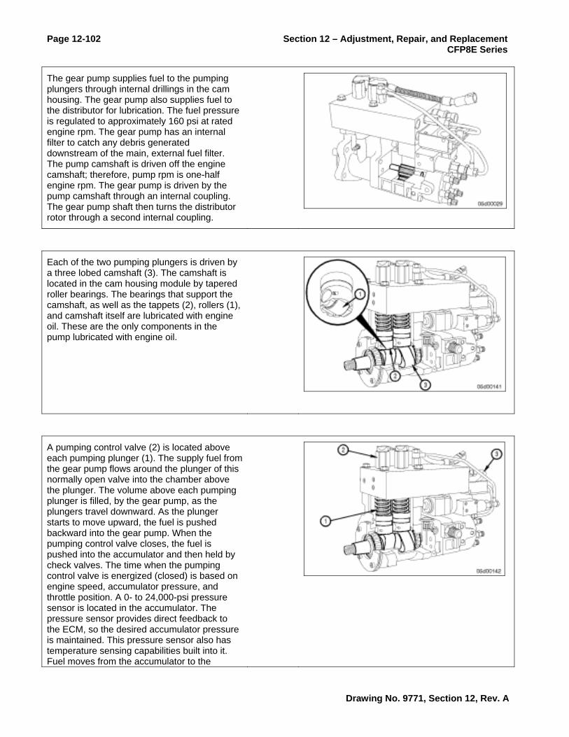
Page 12-102 Section 12 – Adjustment, Repair, and Replacement CFP8E Series
The gear pump supplies fuel to the pumping plungers through internal drillings in the cam housing. The gear pump also supplies fuel to the distributor for lubrication. The fuel pressure is regulated to approximately 160 psi at rated engine rpm. The gear pump has an internal filter to catch any debris generated downstream of the main, external fuel filter. The pump camshaft is driven off the engine camshaft; therefore, pump rpm is one-half engine rpm. The gear pump is driven by the pump camshaft through an internal coupling. The gear pump shaft then turns the distributor rotor through a second internal coupling.
Each of the two pumping plungers is driven by a three lobed camshaft (3). The camshaft is located in the cam housing module by tapered roller bearings. The bearings that support the camshaft, as well as the tappets (2), rollers (1), and camshaft itself are lubricated with engine oil. These are the only components in the pump lubricated with engine oil.
A pumping control valve (2) is located above each pumping plunger (1). The supply fuel from the gear pump flows around the plunger of this normally open valve into the chamber above the plunger. The volume above each pumping plunger is filled, by the gear pump, as the plungers travel downward. As the plunger starts to move upward, the fuel is pushed backward into the gear pump. When the pumping control valve closes, the fuel is pushed into the accumulator and then held by check valves. The time when the pumping control valve is energized (closed) is based on engine speed, accumulator pressure, and throttle position. A 0- to 24,000-psi pressure sensor is located in the accumulator. The pressure sensor provides direct feedback to the ECM, so the desired accumulator pressure is maintained. This pressure sensor also has temperature sensing capabilities built into it. Fuel moves from the accumulator to the
Drawing No. 9771, Section 12, Rev. A

Section 12 – Adjustment, Repair, and Replacement Page 12-103 CFP8E Series
distributor and through the rate shape tube (3).
Fuel is delivered to the injection control valve (1) by the rate shape tube and through a drilling in the distributor (2). The ICV controls both fueling and timing. The injection control valve contains an inner pin and outer valve. The outer valve is moved by magnetic force generated inside the ICV by a current from the ECM. The inner pin is moved by spring force and fuel pressure. When the two pins are in the closed position, no fuel flows through the control valve. The position of these internal parts controls fuel flow to the distributor rotor (3) and to the drain (4). The injection control valve opens and closes once for each injection event.
The distributor (1) directs the fuel to the correct injector using the rotor. The drain fuel from the ICV is routed through the ICV pressure regulator (4) and is returned to the tank.
The position of the rotor directs the fuel to one of six drillings in the distributor housing. These drillings communicate the fuel to six fuel pump delivery valves (3). There is one injector line per delivery valve. The injection line carries the fuel to the injector.
Drawing No. 9771, Section 12, Rev. A

Page 12-104 Section 12 – Adjustment, Repair, and Replacement CFP8E Series
Fuel Pump Delivery Valve Removal/Installation
Prepare
WARNING When using a steam cleaner, wear safety glasses or a face shield, as well as protective clothing. Hot steam can cause serious personal injury.
WARNING Wear appropriate eye and face protection when using compressed air. Flying debris and dirt can cause personal injury.
Thoroughly steam-clean the distributor outlet fitting and fuel pump area.
Dry with compressed air.
Remove the high-pressure fuel supply lines. Refer to Procedure 006-051.
Remove
Remove the distributor outlet fitting and the seal disk.
NOTE: A tool like the one shown here can be made from a 1/8 in or 3/16 in Allen wrench. Use it to remove the seal disc. Refer to Procedure 005-084 for instruction on how to make the tool.
Drawing No. 9771, Section 12, Rev. A

Section 12 – Adjustment, Repair, and Replacement Page 12-105 CFP8E Series
NOTE: The outlet fitting valve and seat are a matched set; do not “mix and match” valves and seats with other outlet fitting assemblies.
If either the outlet fitting valve or seat is damaged, the entire outlet fitting assembly must be replaced. Also, the seal washers must always be replaced.
Clean and Inspect for Reuse
Check for broken parts, debris, or sticking of the outlet fitting valve. Replace the outlet fitting assembly if any parts are damaged. Always replace the seal washer.
Use QD contact cleaner, Part Number 3824510, to clean the delivery valve port in the distributor.
Drawing No. 9771, Section 12, Rev. A
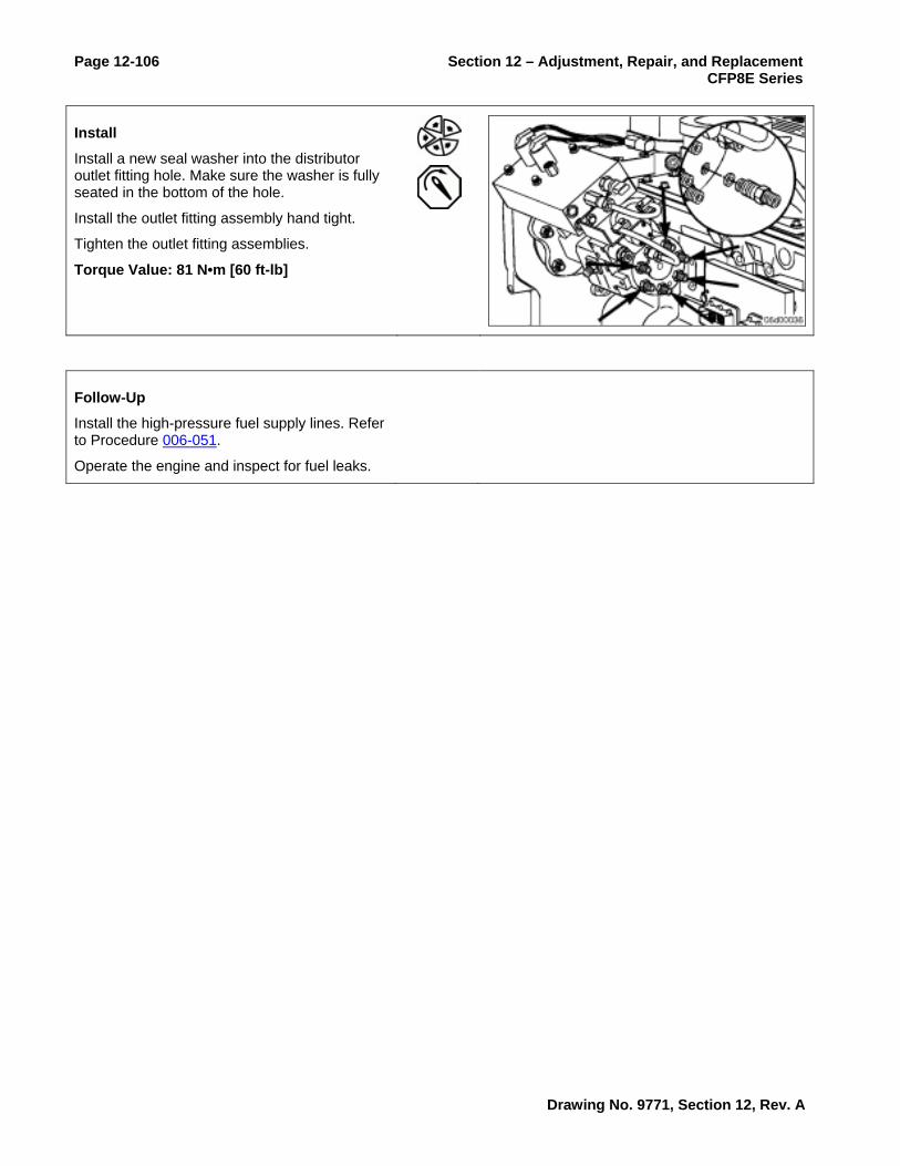
Page 12-106 Section 12 – Adjustment, Repair, and Replacement CFP8E Series
Install
Install a new seal washer into the distributor outlet fitting hole. Make sure the washer is fully seated in the bottom of the hole.
Install the outlet fitting assembly hand tight.
Tighten the outlet fitting assemblies.
Torque Value: 81 N•m [60 ft-lb]
Follow-Up
Install the high-pressure fuel supply lines. Refer to Procedure 006-051.
Operate the engine and inspect for fuel leaks.
Drawing No. 9771, Section 12, Rev. A

Section 12 – Adjustment, Repair, and Replacement Page 12-107 CFP8E Series
Fuel Pump Gear Pump Check
Initial Check
The gear pump shaft incorporates a double seal. The first seals oil in the fuel pump cam housing; the second seals fuel in the gear pump. If either seal fails, a leak will drip from the weep hole. The weep hole is located near the gear pump mounting flange on the inboard side (toward the engine block).
A gear pump gasket seals oil at the gear pump to cam housing interface.
Measuring gear pump pressure with the engine cranking (useful if engine will not start).
Install a pressure gauge at the on engine fuel filter head (M10 x 1.5 Compuchek® fitting, Part Number3824842).
Monitor the gear pump pressure while the engine is cranking.
Measurements Gear Pump Pressure at Cranking (minimum): 69 kPa [10 psi]
If the gear pump pressure is lower than 69 kPa [10 psi] during cranking, make sure that the engine cranking speed is at least 150 rpm. Make sure that the lift pump pressure during cranking is at least 35 kPa [5 psi]. Refer to Procedure 005-045.
Drawing No. 9771, Section 12, Rev. A

Page 12-108 Section 12 – Adjustment, Repair, and Replacement CFP8E Series
Construction of Banjo Pressure Gauge Adapter
A banjo-style pressure gauge adapter can be used to measure pressure or vacuum at any point in the low-pressure fuel system where a banjo bolt exists at a fuel line.
The ISC and ISL engines with high-pressure common rail fuel systems use M12 x 7/16-inch banjo bolt connection. This tool can be used for measurement of drain line restriction (pressure) at the fuel drain manifold.
Make a banjo bolt flow adapter tool by drilling and tapping the hex face of an M12 x 7/16-inch banjo bolt, Part Number 3903035 or similar banjo bolt.
Drill and tap the banjo bolt to the size of Compuchek® fitting (or other hose union) being used (example 1/8-inch NPT Compuchek® fitting, Part Number 3377244, or M10 Compuchek® fitting, Part Number 3824842).
Assemble the banjo pressure gauge adapter as follows.
Install the Compuchek® fitting, or other type fitting, in the hexagon face of the banjo bolt.
Attach a hose or pressure gauge to the banjo pressure adapter.
Drawing No. 9771, Section 12, Rev. A

Section 12 – Adjustment, Repair, and Replacement Page 12-109 CFP8E Series
Measuring Gear Pump Pressure at Rated Condition
Install a M10 x 1.5 Compuchek® fitting, Part Number 3824842, at the diagnostic port on the outlet of the fuel filter head.
Construct a “T” adapter fitting using one quick-disconnects, Part Number 3376859, and two 1/8-inch NPT Compuchek® fitting, Part Number 3042618.
Install a 0.043-inch orificed diagnostic fuel line (Part Number 3164621) at the outlet of the fuel filter head. Run the fuel hose back to the fuel tank.
Install a 0 to 1034 kPa [0 to 150 psi] pressure gauge at the “T” adapter fitting.
Operate the engine at high idle and observe the gear pump pressure.
Measurements Minimum Gear Pump Pressure 483 kPa [70 psi]
If the gear pump pressure is low, check for excessive inlet vacuum. Refer to Procedure 006-020.
Drawing No. 9771, Section 12, Rev. A

Page 12-110 Section 12 – Adjustment, Repair, and Replacement CFP8E Series
Fuel Pump Gear Pump Removal/Installation
Prepare
Clean the fuel, oil and debris from the gear pump.
Remove the fuel supply lines from the gear pump. Refer to Procedure 006-024.
Remove
Remove the four bolts that hold the gear pump to the fuel pump.
Remove the drive coupling if it remains attached to the rear of the fuel pump camshaft.
Remove the gear pump gasket.
Clean and Inspect for Reuse
Inspect the drive coupling for wear. If worn, the drive coupling must be replaced.
Drawing No. 9771, Section 12, Rev. A

Section 12 – Adjustment, Repair, and Replacement Page 12-111 CFP8E Series
Install
Install the drive coupling into the back of the high-pressure pump camshaft.
Insert the mounting bolts through the gear pump flange.
Install a new gasket onto the bolts.
Index the gear pump input shaft to engage the drive coupling and install the gear pump.
Install the four gear pump bolts and tighten.
Torque Value: 34 N•m [25 ft-lb]
Follow-Up
Install the fuel supply lines. Refer to Procedure 006-024.
Drawing No. 9771, Section 12, Rev. A

Page 12-112 Section 12 – Adjustment, Repair, and Replacement CFP8E Series
Adjust Fuel Pump Timing
Prepare
Remove the gear cover. Refer to Procedure 001-031.
Remove the fuel pump camshaft nut. Refer to Procedure 005-016 or 005-229.
Inspect for Reuse
Check that the fuel pump camshaft alignment dowel is present in the fuel pump drive gear keyway. If the alignment dowel is not visible, remove the injection pump, determine the cause of misalignment, and repair or replace any damaged components.
Fuel pump gear keyway
Fuel pump timing dowel pin
Fuel pump camshaft
Fuel pump gear
If this inspection is being performed due to a performance complaint, and the problem first occurred after gear train removal and replacement then check the timing of the camshaft gear to the crankshaft gear and the camshaft gear to the fuel pump drive gear. Refer to Procedure 001-012.
If the engine camshaft gear is mistimed in relation to the crankshaft gear, intake and exhaust valve events will not be optimized. Also, for CAPS injection pump fuel systems, the primary speed sensor reads the tonewheel on the camshaft gear and fuel injection timing will be incorrect.
Drawing No. 9771, Section 12, Rev. A

Section 12 – Adjustment, Repair, and Replacement Page 12-113 CFP8E Series
Follow-Up
Install and tighten the injection pump camshaft nut. Refer to Procedure 005-016 or 005-229.
Install the front gear cover. Refer to Procedure 001-031.
Drawing No. 9771, Section 12, Rev. A

Page 12-114 Section 12 – Adjustment, Repair, and Replacement CFP8E Series
Fuel Lift Pump Check
Initial Check
Block Mounted Lift Pump
A malfunctioning electric fuel lift pump can cause slow engine starts or may result in an engine failing to start. The fuel lift pump can be cleaned and repaired to a limited extent.
The lift pump will operate for 30 to 60 seconds when the key is switched ON. The lift pump will also operate while the engine is cranking.
The lift pump is contained in an assembly that includes fuel supply and drain manifolds. These manifolds provide for OEM connection of fuel supply and return hoses. The fuel supply manifold also contains M10 STORM fittings which allow for pressure and vacuum measurement of the fuel supply at the electric lift pump.
A bypass check valve in the fuel supply manifold ensures that the system is primed by the lift pump. This check valve opens under vacuum created by the fuel injection pump once the engine is started. High vacuum measured between the electric lift pump and the fuel filter may indicate that this check valve has become plugged.
The output of the fuel lift pump can be checked through the following test:
Measure the output pressure using a pressure gauge at the lift pump outlet port.
Drawing No. 9771, Section 12, Rev. A

Section 12 – Adjustment, Repair, and Replacement Page 12-115 CFP8E Series
The lift pump check valve restriction can be determined using the following test:
Install a 0 to 762 mm Hg [0 to 30 in Hg] vacuum gauge at the inlet and outlet M10 STORM ports on the electric lift pump head
Operate the engine at rated power condition
Record the inlet restriction at the inlet and outlet of the lift pump.
Refer to Procedure 006-020.
Maximum Fuel Lift Pump Inlet Restriction:
102 mm-hg 4 in-hg
Initial Check
ECM Cooling Plate Mounted Lift Pump
A malfunctioning electric fuel lift pump can cause slow engine starts or may result in an engine failing to start. The fuel lift pump can be cleaned and repaired to a limited extent.
The lift pump will operate for 30 to 60 seconds when the key is switched ON. The lift pump will also operate while the engine is cranking.
A lift pump is mounted to the back of the ECM cooling plate.
A bypass check valve in the ECM cooling plate ensures that the system is primed by the lift pump. This check valve opens under vacuum created by the gear pump once the engine is started. High vacuum measured between the electric lift pump and the gear pump may indicate that this check valve has become plugged.
The ECM cooling plate check valve is integral with the lower (outlet) fitting of the ECM cooling plate.
Drawing No. 9771, Section 12, Rev. A

Page 12-116 Section 12 – Adjustment, Repair, and Replacement CFP8E Series
The output of the fuel lift pump can be checked through the following test:
Measure the output pressure using a pressure gauge at the inlet to the high-pressure pump gear pump assembly.
Install a pressure gauge at the inlet port of the high-pressure pump gear pump.
Turn the key switch ON and measure the lift pump pressure using a pressure gauge at the gear pump inlet.
NOTE: At initial key-on, the lift pump will run for 30 seconds then stop.
Measurements
Minimum Pressure 34 kPa [5 psi]
NOTE: If the lift pump pressure is low while the lift pump runs, make sure that the ECM cooling plate check valve is not blocked open.
NOTE: If the lift pump pressure is low while the lift pump runs, make sure that fuel is primed. For example, following fuel filter replacement it is necessary to cycle the fuel lift pump three or four times before air is purged.
Drawing No. 9771, Section 12, Rev. A

Section 12 – Adjustment, Repair, and Replacement Page 12-117 CFP8E Series
Fuel Lift Pump Removal/Installation
Prepare
Block Mounted Lift Pump
WARNING Batteries can emit explosive gases. To reduce the possibility of personal injury, always ventilate the compartment before servicing the batteries. To reduce the possibility of arcing, remove the negative (-) battery cable first and attach the negative (-) battery cable last.
Disconnect the negative (-) battery cable first.
NOTE: Thoroughly clean fittings and components before removal. Make sure that the debris, water, steam or cleaning solution does not reach inside the fuel system.
Remove the fuel lift pump inlet and outlet fuel lines. Refer to Procedure 006-024.
Disconnect the fuel pump power lead.
Drawing No. 9771, Section 12, Rev. A

Page 12-118 Section 12 – Adjustment, Repair, and Replacement CFP8E Series
Prepare
ECM Cooling Plate Mounted Lift Pump
WARNING Batteries can emit explosive gases. To reduce the possibility of personal injury, always ventilate the compartment before servicing the batteries. To reduce the possibility of arcing, remove the negative (-) battery cable first and attach the negative (-) battery cable last.
Disconnect the negative (-) battery cable first.
Disconnect the electric fuel priming pump from the engine wiring harness.
NOTE: Thoroughly clean fittings and components before removal. Make sure that the debris, water, steam or cleaning solution does not reach inside the fuel system.
Remove the fuel supply lines. Refer to Procedure 006-024.
Remove the ECM cooling plate. Refer to Procedure 006-006.
Remove
Block Mounted Lift Pump
Remove the three capscrews and the electric lift pump from the engine block.
Drawing No. 9771, Section 12, Rev. A

Section 12 – Adjustment, Repair, and Replacement Page 12-119 CFP8E Series
Remove
ECM Cooling Plate Mounted Lift Pump
Remove the electric lift pump from the ECM cooling plate.
Install
Block Mounted Lift Pump
Install the fuel lift pump to block using the three mounting capscrews.
Tighten the capscrews.
Torque Value: 12 N•m [106 in-lb]
Install
ECM Cooling Plate Mounted Lift Pump
Install the electric lift pump to the ECM cooling plate.
Tighten the mounting capscrews.
Torque Value: 10 N•m [89 in-lb]
NOTE: The ECM cooling plate check valve must be free of debris and installed into the lower ECM cooling plate port (outlet port).
NOTE: Hold the fuel lines as shown so that they can not come into contact with each other or the engine block.
Drawing No. 9771, Section 12, Rev. A

Page 12-120 Section 12 – Adjustment, Repair, and Replacement CFP8E Series
Follow-Up
Block Mounted Lift Pump
WARNING Batteries can emit explosive gases. To reduce the possibility of personal injury, always ventilate the compartment before servicing the batteries. To reduce the possibility of arcing, remove the negative (-) battery cable first and attach the negative (-) battery cable last.
Connect the power lead to the fuel lift pump.
Install all removed fuel lines. Refer to Procedure 006-024.
Connect the battery, negative (-) cable last.
Follow-Up
ECM Cooling Plate Mounted Lift Pump
WARNING Batteries can emit explosive gases. To reduce the possibility of personal injury, always ventilate the compartment before servicing the batteries. To reduce the possibility of arcing, remove the negative (-) battery cable first and attach the negative (-) battery cable last.
Install the ECM cooling plate to the engine block. Refer to Procedure 006-006.
Install all fuel lines. Refer to Procedure 006-024.
Connect the battery, negative (-) cable last.
Drawing No. 9771, Section 12, Rev. A

Section 12 – Adjustment, Repair, and Replacement Page 12-121 CFP8E Series
CAPS Fuel Injection Pump Rotor Removal/Installation
Prepare
WARNING When using solvents, acids, or alkaline materials for cleaning, follow the manufacturers recommendations for use. Wear goggles and protective clothing to reduce the possibility of personal injury.
WARNING Some solvents are flammable and toxic. Read the manufacturer's instructions before using.
WARNING Wear appropriate eye and face protection when using compressed air. Flying debris and dirt can cause personal injury.
Steam clean the fuel injection pump and the engine in the vicinity of the fuel pump.
Dry with compressed air. Pay special attention to the distributor area.
Remove
CAUTION The rotor can slide out during the removal of the distributor plug. If the rotor is dropped, the entire distributor module must be replaced. Do not attempt to start the engine with the distributor plug removed. Doing so can cause the rotor to be ejected from the distributor, causing damage to the rotor.
ISL Only: Remove the air bleed line. Refer to Procedure 006-056.
Remove the distributor plug, being sure the rotor does not fall out.
Drawing No. 9771, Section 12, Rev. A

Page 12-122 Section 12 – Adjustment, Repair, and Replacement CFP8E Series
Clean and Inspect for Reuse
Check the position of the notch on the rotor. It must line up with the alignment mark (A) on the outside of the distributor (when the engine is barred to TDC for the number 1 cylinder). If the alignment is correct, the rotor is properly timed to the engine.
If a mechanical problem exists, indicated by misalignment of the rotor, the entire fuel pump will have to be replaced; refer to Procedure 005-016.
Clean the rotor bore with QD contact cleaner, Part Number 3824510.
Install
Use Lubriplate™ 105, or equivalent, between the drive coupling and the rotor to prevent it from falling off during assembly.
Drawing No. 9771, Section 12, Rev. A

Section 12 – Adjustment, Repair, and Replacement Page 12-123 CFP8E Series
CAUTION The rotor must be properly timed to the fuel pump camshaft. Improper assembly will cause the rotor to be 180 degrees out of time.
Insert the rotor and coupling into the distributor module completely.
Lightly rotate the rotor with finger-pressure until it drops into the slot in the drive coupling.
When properly engaged, the notch in the rotor will align with the hole in the distributor while the engine is at Number cylinder TDC.
If the rotor will not engage, remove the rotor and drive coupling and try again. Do not tighten the rotor cap if the coupling will not engage.
If not properly timed, remove the rotor and drive coupling and repeat the previous step. Make sure the fuel pump camshaft dowel pin is pointing toward the top of the fuel pump before installing.
Install the distributor plug and torque.
Torque Value: 14 N•m [10 ft-lb]
NOTE: Be sure the rotor is fully engaged before replacing the plug.
ISL Only: Install the air bleed line. Refer to Procedure 006-056.
Follow-Up
Drawing No. 9771, Section 12, Rev. A

Page 12-124 Section 12 – Adjustment, Repair, and Replacement CFP8E Series
Injection Control Valve Removal/Installation
Prepare
WARNING When using a steam cleaner, wear safety glasses or a face shield, as well as protective clothing. Hot steam can cause serious personal injury.
WARNING Wear appropriate eye and face protection when using compressed air. Flying debris and dirt can cause personal injury.
CAUTION Fault codes can occur if steam sprays directly on the electrical connections on top of the accumulator block.
Thoroughly steam-clean the entire fuel pump.
Dry the fuel pump with compressed air.
Remove the fuel injection pump accumulator. Refer to Procedure 005-085.
Remove
Unplug the engine wiring harness from the injection control valve connector.
Drawing No. 9771, Section 12, Rev. A

Section 12 – Adjustment, Repair, and Replacement Page 12-125 CFP8E Series
Remove the injection control valve drain line.
Remove the six injection control valve mounting screws.
Remove the injection control valve from the distributor module.
Do not misplace parts during disassembly.
Secure the six bolts, sealing plate, and both crush tubes into a parts bag. The parts are to be returned with the core.
Clean and Inspect for Reuse
Clean the mounting surface of the distributor module and injection control valve.
Use QD contact cleaner, Part Number 3824510.
Spray or wipe debris away from the three distributor module drillings. Do not allow debris to enter the distributor module drillings.
Inspect the distributor module sealing face for cracks, indentations, and damage.
Replace the distributor module if damage is found.
Install
Install guide pins, Part Number 3165166, in the upper left and lower right corner of the distributor module.
Install the o-rings into the sealing plate using Lubriplate™ to hold them in place.
Slide the sealing plate down over the guide pins.
The o-rings must be securely seated in the sealing plate before proceeding.
Insert crush tubes into the sealing plate.
Check the position of the crush tubes. They must sit flush on the distributor module and must not be installed at an angle.
Drawing No. 9771, Section 12, Rev. A

Page 12-126 Section 12 – Adjustment, Repair, and Replacement CFP8E Series
Install the injection control valve on top of the distributor module using guide pins.
Check that the o-rings are still in their grooves.
Install four bolts through the injection control valve and tighten finger tight.
Remove the two guide pins.
Install the two remaining bolts, finger tight, through the injection control valve.
CAUTION Bolts must be torqued as described or the injection control valve/distributor module will not function properly. Use a high-quality, calibrated torque wrench.
Torque bolts in sequence for each pass for six passes. Refer to the accompanying illustration for the torque sequence.
Pass Torque Value
1. 1.8 N•m [16 in-lb]
2. 3.6 N•m [32 in-lb]
3. 5.6 N•m [50 in-lb]
4. 5.6 N•m [50 in-lb]
5. 5.6 N•m [50 in-lb]
6. 5.6 N•m [50 in-lb]
Install the injection control valve drain line.
Drawing No. 9771, Section 12, Rev. A

Section 12 – Adjustment, Repair, and Replacement Page 12-127 CFP8E Series
Click Test
Use INSITE™, with the keyswitch in the ON position, to run the control valve click test.
Select Injection Control Valve to initiate the test.
A click will be heard until None is selected on the Control Valve Click Test screen.
If no click is heard, troubleshoot any active fault codes.
The click test will need to be performed after any repairs are made to clear the fault codes.
Drawing No. 9771, Section 12, Rev. A

Page 12-128 Section 12 – Adjustment, Repair, and Replacement CFP8E Series
Follow-Up
Install the fuel injection pump accumulator. Refer to Procedure 005-085.
Install the air bleed line. Refer to Procedure 006-056.
Install the drive gear cover.
Connect the fuel pressure sensor and the fuel temperature sensors to the engine harness.
Connect the pumping control valve connector to the engine harness.
Connect the stator connector to the engine harness.
Click test the injection control valve stator to check for proper operation. Refer to Click Test in this procedure.
Start the engine and check for fuel leaks or active fault codes.
Recheck for fuel leaks or active fault codes.
Drawing No. 9771, Section 12, Rev. A

Section 12 – Adjustment, Repair, and Replacement Page 12-129 CFP8E Series
Pumping Control Valve Tests
Prepare
Click Test
Use INSITE™, with the keyswitch in the ON position, to run the control valve click test.
Select the Pumping Control Valve to be tested to initiate the test. Select either front control valve or rear control valve.
A “click” will be heard until the other pumping control valve is selected, or None is selected on the Control Valve Click Test screen.
If no “click” is heard, troubleshoot any active fault codes.
NOTE: The click test will need to be performed after any repairs are made to clear the fault codes.
Cutout Test
The plunger cutout test can be used to check performance of the front and rear pumping plungers.
NOTE: When performing this test, the engine load must be the same when each pumping plunger is cut out.
Use INSITE™, with the engine running at idle, to perform this test.
Drawing No. 9771, Section 12, Rev. A

Page 12-130 Section 12 – Adjustment, Repair, and Replacement CFP8E Series
Select the pumping control valve to be cut out.
Select the monitor button and monitor valve close angle, engine speed, and accumulator pressure while the selected plunger is cut out.
Record valve close angle, engine speed, and accumulator pressure after the engine stabilizes.
After testing with one pumping control valve disabled, select “None” so that the engine will run with both valves enabled. Switching directly from “Front” to “Rear” or “Rear” to “Front” will cause the engine to misfire or hesitate.
Cut out the other pumping control valve, and record valve close angle, engine speed, and accumulator pressure after the engine stabilizes.
Compare the results when the rear pumping control valve is cut out, against the results when the front pumping control valve is cut out.
If the engine dies when one of the pumping control valves is cut out, replace the accumulator. Refer to procedure 005-085.
NOTE: The valve close angle must not vary more than 15 degrees crank angle.
If the valve close angle varies more than 15 degrees between the front and rear valves then replace the accumulator module. Refer to Procedure 005-085.
NOTE: Troubleshoot any active fault codes before replacing the pump.
Follow-Up
Drawing No. 9771, Section 12, Rev. A

Section 12 – Adjustment, Repair, and Replacement Page 12-131 CFP8E Series
Rate Shape Snubber Removal/Installation
Prepare
WARNING When using solvents, acids, or alkaline materials for cleaning, follow the manufacturer's recommendations for use. Wear goggles and protective clothing to reduce the possibility of personal injury.
WARNING Some solvents are flammable and toxic. Read the manufacturer's instructions before using.
WARNING Wear appropriate eye and face protection when using compressed air. Flying debris and dirt can cause personal injury.
Thoroughly steam-clean the rate shape tube and fuel pump area.
Dry with compressed air.
Remove the rate shape tube assembly. Refer to Procedure 005-090.
Remove
Remove the rate shape snubber assembly.
Use a center punch to pry the seal disc from the accumulator.
Drawing No. 9771, Section 12, Rev. A

Page 12-132 Section 12 – Adjustment, Repair, and Replacement CFP8E Series
Inspect for Reuse
The parts in the assembly are as shown:
1. Snubber valve seat
2. Spring
3. Rate shape snubber body
4. Seal disc
5. Snubber valve
6. Spring post.
Replace the snubber assembly if the snubber spring is broken.
Do not reuse snubber seal discs.
Early design snubber valves are not reusable.
Part Number 3800351, first snubber valve assembly released for CAPS (one groove, not reusable)
Part Number 3800764, second snubber valve assembly released for CAPS (two grooves, not reusable)
Part Number 4010544, current snubber valve assembly released for CAPS (no grooves, may be reused); always replace the seal disk.
Install
Clean the bore for the distributor outlet fitting with QD cleaner prior to installation of the new snubber assembly.
Install a new seal disc into the accumulator.
Drawing No. 9771, Section 12, Rev. A

Section 12 – Adjustment, Repair, and Replacement Page 12-133 CFP8E Series
Apply lubricating oil to the face of the snubber seat and to the face and threads of the snubber fitting.
Install the snubber assembly.
Torque Value: 14 N•m [124 in-lb]
Rotate 80 degrees
Follow-Up
Install the rate shape tube assembly. Refer to Procedure 005-090.
Operate the engine and check for leaks.
Drawing No. 9771, Section 12, Rev. A

Page 12-134 Section 12 – Adjustment, Repair, and Replacement CFP8E Series
Fuel Pump Distributor Inlet Fitting
Prepare
WARNING When using a steam cleaner, wear safety glasses or a face shield, as well as protective clothing. Hot steam can cause serious personal injury.
WARNING Wear appropriate eye and face protection when using compressed air. Flying debris and dirt can cause personal injury.
Thoroughly steam-clean the distributor outlet fitting and fuel pump area.
Dry with compressed air.
Remove the rate shape tube assembly. Refer to Procedure 005-090.
Remove
Remove the distributor inlet fitting and the seal disc.
NOTE: A tool like the one shown in this procedure can be made from a 1/8-inch or 3/16-inch Allen wrench. Use it to remove the seal disc.
Drawing No. 9771, Section 12, Rev. A

Section 12 – Adjustment, Repair, and Replacement Page 12-135 CFP8E Series
Two (2) types of inlet fittings and sealing washers may be in use. A flat washer will be installed in most new pumps and a piloted washer will be installed in some ReCon® pumps. The piloted washer is provided in service kits to aid installation.
Different removal techniques are necessary based on the type of sealing washer being removed.
Removal of “piloted seal washer”
Using a plastic hammer, tap a spiral easy out into the center hole of the sealing washer. Turn the easy out counterclockwise to dislodge the washer.
Removal of a “flat washer”
The flat sealing washer is swaged into the inlet fitting bore during installation. A special tool can be made to aid in its removal by grinding the short leg of a 1/8-inch or 3/16-inch Allen wrench so that the wrench is no longer than 13-mm [1/2-in] long (measured from the outside of the long leg). This tool acts as a mini heal bar to pry out the sealing washer without damaging the back of the hole.
Drawing No. 9771, Section 12, Rev. A

Page 12-136 Section 12 – Adjustment, Repair, and Replacement CFP8E Series
Pry out the old sealing washer using the modified Allen wrench.
Quite a bit of force is required to remove the sealing washer.
Clean and Inspect for Reuse
CAUTION Any debris left in this fitting during assembly will run through the fuel pump. Damage the to fuel pump can occur.
Using QD contact cleaner, Part Number 3824510, clean the inlet fitting bore from the bottom of the bore outward.
Install
CAUTION Any dirt trapped in this fitting during assembly will run through the fuel pump. Damage to the fuel pump can occur.
Use clean grease to retain the sealing washer to the inlet fitting while it is being installed into the bore. Use Lubriplate™ 105, or equivalent.
Install sealing washer into counterbore in the inlet fitting.
Drawing No. 9771, Section 12, Rev. A
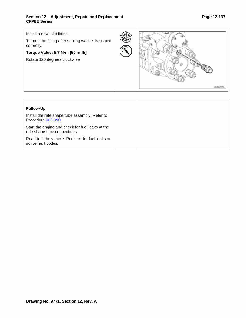
Section 12 – Adjustment, Repair, and Replacement Page 12-137 CFP8E Series
Install a new inlet fitting.
Tighten the fitting after sealing washer is seated correctly.
Torque Value: 5.7 N•m [50 in-lb]
Rotate 120 degrees clockwise
Follow-Up
Install the rate shape tube assembly. Refer to Procedure 005-090.
Start the engine and check for fuel leaks at the rate shape tube connections.
Road-test the vehicle. Recheck for fuel leaks or active fault codes.
Drawing No. 9771, Section 12, Rev. A

Page 12-138 Section 12 – Adjustment, Repair, and Replacement CFP8E Series
Fuel Pump Accumulator Module
Prepare
WARNING When using a steam cleaner, wear safety glasses or a face shield, as well as protective clothing. Hot steam can cause serious personal injury.
WARNING Wear appropriate eye and face protection when using compressed air. Flying debris and dirt can cause personal injury.
CAUTION Make sure that steam does not spray directly on the electrical connections on the top of the accumulator block, or fault codes will possibly occur.
Thoroughly steam-clean the entire fuel pump.
Dry the fuel pump with compressed air.
Remove
Remove the fuel pump drive gear cover.
Locate top dead center for cylinder number 1 by barring the engine slowly until the line on the pump gear lines up with the line on the gear cover.
Drawing No. 9771, Section 12, Rev. A

Section 12 – Adjustment, Repair, and Replacement Page 12-139 CFP8E Series
Remove the rate shape tube assembly. Refer to Procedure 005-090.
Remove the air bleed line. Refer to Procedure 006-056.
Remove the fuel pump upper support bracket.
Disconnect the 4-pin Deutsch connector for the pumping control valves.
Disconnect the pressure and temperature sensors.
NOTE: The pressure sensor connector has a potted pigtail connector. This sensor can only be disconnected at the engine harness end of the pigtail harness.
Drawing No. 9771, Section 12, Rev. A

Page 12-140 Section 12 – Adjustment, Repair, and Replacement CFP8E Series
WARNING The accumulator module weighs 11 kg [25 lb] and is free to move once the capscrews are removed. Do not drop; personal injury can occur.
CAUTION Do not use air tools. The use of air tools will possibly damage the fuel pump.
Remove two of the four capscrews that are located diagonally from one another.
Remove the last two capscrews. Alternately loosen the capscrew to avoid binding. Loosen each capscrew about one turn at a time.
WARNING The accumulator module weighs 11 kg [25 lb] and is free to move once the capscrews are removed. Do not drop; personal injury can occur.
Remove the accumulator module.
Use as much care as possible to avoid dislodging the springs from the bottom of the accumulator.
Drawing No. 9771, Section 12, Rev. A

Section 12 – Adjustment, Repair, and Replacement Page 12-141 CFP8E Series
If the springs are dislodged, the ceramic plungers can fall out. The plungers are matched to each bore.
Reseat the springs fully onto plunger barrels.
Do not interchange the plungers.
NOTE: Before replacing a ceramic plunger, special care needs to be taken to clean it.
Use QD contact cleaner, Part Number 3824510, to clean the plunger.
Remove the oil seal ring and fuel passage o-rings.
Clean and Inspect for Reuse
Clean the small fuel passage using the plastic tube provided with the contact cleaner.
Use QD contact cleaner, Part Number 3824510.
Drawing No. 9771, Section 12, Rev. A

Page 12-142 Section 12 – Adjustment, Repair, and Replacement CFP8E Series
Clean the o-ring groove and mounting surface on the cam housing and the accumulator.
Make sure the top of the tappets in the cam housing are clean. Wipe out debris with a clean towel.
Check the tappets for proper alignment.
The tappets have a slot on the side that engages a pin on the engine side of the cam housing. The pin keeps the roller aligned with the camshaft. Make sure the tappet assembly is properly aligned. Make sure the tappet guide pins and guide pin grooves are not worn excessively.
With the tappets removed, the tappet rollers and camshaft can be inspected. Linear scratches on the cam and rollers is expected; pitting on the nose of the camshaft is not.
Install
Install a new oil ring seal and fuel passage o-ring.
Apply Lubriplate™ 105, or equivalent, to the o-ring grooves to hold the o-rings in place.
Drawing No. 9771, Section 12, Rev. A

Section 12 – Adjustment, Repair, and Replacement Page 12-143 CFP8E Series
CAUTION The ceramic plungers can fall out when removing the plastic caps or old springs. Do not interchange the plungers. If they fall out, use QD contact cleaner, Part Number 3824510, to clean the plungers thoroughly before replacing them.
If replacing the accumulator module with a new one, remove the springs from the old accumulator module.
Fully install the springs on the plunger barrels of the new accumulator module.
NOTE: The use of two 10-mm x 80-mm studs will aid in the installation.
Install the accumulator module.
NOTE: Use care to avoid dislodging the springs on the accumulator and the o-rings on the cam housing.
CAUTION Do not use air tools. The use of air tools will possibly damage the fuel pump.
Install two of the four capscrews.
Draw the accumulator module down evenly. Only turn each capscrew about one turn at a time.
Make sure the o-rings are still in their grooves before the accumulator is fully tightened to the cam housing. Use a mirror if necessary.
Drawing No. 9771, Section 12, Rev. A

Page 12-144 Section 12 – Adjustment, Repair, and Replacement CFP8E Series
Install remaining two capscrews.
Tighten the four capscrews.
Torque Value: 68 N•m [50 ft-lb]
Install the upper support bracket.
Tighten the capscrews.
Torque Value: 44 N•m [32 ft-lb]
Follow-Up
Finishing Steps
Install rate shape tube assembly. Refer to Procedure 005-090.
Install the air bleed line. Refer to Procedure 006-056.
Install the drive gear cover.
Connect the fuel pressure sensor and the fuel temperature sensors to the engine harness.
Connect the pumping control valve connector to the engine harness.
Start the engine and check for fuel leaks or active fault codes.
Road-test the vehicle.
Recheck for fuel leaks or active fault codes.
Drawing No. 9771, Section 12, Rev. A

Section 12 – Adjustment, Repair, and Replacement Page 12-145 CFP8E Series
Fuel Pump Distributor and Injection Control Valve Module
Prepare
WARNING When using a steam cleaner, wear safety glasses or a face shield, as well as protective clothing. Hot steam can cause personal injury.
WARNING Wear appropriate eye and face protection when using compressed air. Flying debris and dirt can cause personal injury.
CAUTION Fault codes can occur if steam sprays directly on the electrical connections on top of the accumulator block.
Thoroughly steam-clean the entire fuel pump.
Dry the fuel pump with compressed air.
Remove the air bleed line. Refer to Procedure 006-056.
Remove the fuel pump from the engine, if necessary. Refer to Procedure 005-016.
Mount the fuel pump in the vise ring. Orient the pump with the distributor facing upward to aid in disassembly.
Remove the rate shape tube assembly. Refer to Procedure 005-090.
Drawing No. 9771, Section 12, Rev. A

Page 12-146 Section 12 – Adjustment, Repair, and Replacement CFP8E Series
Remove
CAUTION The capscrews also fasten the gear pump module. The gear pump is free to move after the capscrews are removed.
Loosen but do not remove the distributor plug.
Remove the four mounting capscrews on the distributor.
Remove the injection control valve/distributor module.
Remove the drive coupling.
Discard the two o-rings.
Place the injection control valve/distributor module on a clean bench vise.
Remove the injection control valve from the distributor module and install the injection control valve on the new distributor module. Refer to Procedure 005-078.
NOTE: Injection control valves built before January 2001 are not reusable. If removing an injection control valve built before January 2001, use the appropriate injection control valve kit to complete the repair.
Drawing No. 9771, Section 12, Rev. A

Section 12 – Adjustment, Repair, and Replacement Page 12-147 CFP8E Series
Clean and Inspect for Reuse
Inspect coupling and gear pump shaft ends for excessive wear. Wear may be found on the inside corners of the coupling groove; such wear is not common.
A polished surface is acceptable.
Replace the gear pump module if wear is visible.
Replace the gear pump module if the gear pump driveshaft is damaged.
NOTE: A distributor rotor seizure can cause damage to the gear pump. If rotor seizure is suspected, inspect the gear pump. Refer to Procedure 005-089.
Install
Install the drive coupling.
Center the coupling on the gear pump shaft.
Apply Lubriplate™ 105, or equivalent, to the coupling to keep it from sliding in the shaft groove during assembly.
Drawing No. 9771, Section 12, Rev. A

Page 12-148 Section 12 – Adjustment, Repair, and Replacement CFP8E Series
Install new o-rings.
Apply Lubriplate™ 105, or equivalent, to the o-rings to keep them from falling out during assembly.
The dowel pin must be facing up toward the top of the pump.
If the shaft needs to be rotated, install the fuel pump drive nut onto the shaft to provide a means for rotating the shaft.
CAUTION The rotor can slide out once the distributor plug is removed.
CAUTION Do not drop the rotor. Damaging the rotor will necessitate replacement of the entire distributor module.
Remove the large plug from the end of the distributor.
Do not remove the rotor.
Drawing No. 9771, Section 12, Rev. A

Section 12 – Adjustment, Repair, and Replacement Page 12-149 CFP8E Series
Install the distributor module.
Lightly rotate the rotor with finger pressure until it drops into the slot in the drive coupling.
When properly engaged, the notch in the rotor will align with the hole in the distributor (when the engine is at top dead center for number 1 cylinder).
Do not pinch the o-rings.
Install the four distributor capscrews.
Tighten the capscrews.
Torque Value: 48 N•m [35 ft-lb]
CAUTION The rotor must be properly timed to the fuel pump camshaft. Improper assembly will cause the rotor to be 180 degrees out of time.
If not properly timed, reinstall the drive coupling and rotor. Refer to Procedure 005-072.
Drawing No. 9771, Section 12, Rev. A

Page 12-150 Section 12 – Adjustment, Repair, and Replacement CFP8E Series
Install a new o-ring on the distributor plug.
Install the large plug at the end of the distributor.
Tighten the distributor plug.
Torque Value: 14 N•m [120 in-lb]
Follow-Up
Install the rate shape tube assembly. Refer to Procedure 005-090.
Install the fuel pump on the engine. Refer to Procedure 005-016.
Install the air bleed line. Refer to Procedure 006-056.
Run the injection control valve click test using INSITE™. Refer to Procedure 005-078.
Start the engine and check for fuel leaks or active fault codes.
Road-test the vehicle for at least one mile. Recheck for fuel leaks or active fault codes.
Drawing No. 9771, Section 12, Rev. A

Section 12 – Adjustment, Repair, and Replacement Page 12-151 CFP8E Series
Fuel Pump Cam Housing Module
Prepare
WARNING When using a steam cleaner, wear safety glasses or a face shield, as well as protective clothing. Hot steam can cause personal injury.
WARNING Wear appropriate eye and face protection when using compressed air. Flying debris and dirt can cause personal injury.
CAUTION Make sure that steam does not spray directly on the electrical connections on the top of the accumulator block, or fault codes will possibly occur.
Thoroughly steam-clean the entire fuel pump.
Dry the pump with compressed air.
Bar the engine to TDC.
Drawing No. 9771, Section 12, Rev. A

Page 12-152 Section 12 – Adjustment, Repair, and Replacement CFP8E Series
Remove
CAPS Fuel System
Remove the air bleed line (1). Refer to Procedure 006-056.
Remove the fuel pump from the engine. Refer to Procedure 005-016.
Mount the fuel pump to the mounting plate, Part Number 3162897, and orient the fuel pump with the distributor facing upward to aid in disassembly.
Remove the rate shape tube assembly. Refer to Procedure 005-090.
Remove the accumulator module. Refer to Procedure 005-085.
Remove the distributor module. Refer to Procedure 005-086.
Remove the gear pump module. Refer to Procedure 005-089.
Clean and Inspect for Reuse
Clean the mounting surfaces of the cam housing.
Use QD contact cleaner, Part Number 3824510.
Inspect the camshaft coupling interface for wear. If the camshaft is worn excessively, replace the cam housing module.
CAUTION If the tappets are removed, be sure to install them in the same bore they were removed from.
Remove the roller tappets from the cam housing bores.
Inspect the roller surfaces for pitting and wear.
Make sure the roller rotates freely and smoothly.
Drawing No. 9771, Section 12, Rev. A

Section 12 – Adjustment, Repair, and Replacement Page 12-153 CFP8E Series
Replace the cam housing module if the rollers are worn.
NOTE: It is normal to see lines (scratches) worn in the direction of roller travel. The cam housing or tappets should be replaced if the rollers are pitted.
Examine the tappets guide pin slots. If the guide pin slot is worn more than 25-percent of its original width, the tappet must be replaced.
Inspect the guide pins. If the guide pins are worn or if oil leaks at the cam housing guide pin press fit, the cam housing must be replaced.
Inspect the camshaft lobes for pitting and wear. Replace the cam housing if there is any pitting or wear.
Inspect for raised burrs in the tappet bore. Replace the cam housing if raised burrs are present. Scratching or polishing is normal.
Inspect the tappet bores for scuffing or wear leading into the housing.
Polishing will occur in vertical bands at many places around the inside of the bores.
Polish in the bores is acceptable.
Replace the cam housing if there is severe tappet guide pin wear (more than 25-percent of tappet pin is worn).
Drawing No. 9771, Section 12, Rev. A

Page 12-154 Section 12 – Adjustment, Repair, and Replacement CFP8E Series
Using fingers, make sure the camshaft turns freely. The bearings must turn smoothly and freely during rotation.
Replace the cam housing if the bearings are tight or rough.
Check the camshaft for end-play.
MAX Camshaft End-Play 0.05 mm [0.002 in]
Inspect the oil feed and pump mounting o-ring.
Install
CAPS Fuel System
Make sure the timing dowel pin in the camshaft points toward the top of the fuel pump.
Drawing No. 9771, Section 12, Rev. A

Section 12 – Adjustment, Repair, and Replacement Page 12-155 CFP8E Series
Lubricate the tappets and camshaft lobes with clean 15W-40 engine oil.
Install the roller tappets into the cam housing. Be sure that the tappets guide grooves are oriented correctly onto the tappet guide pins. Also, be sure that the tappet assemblies are installed in their original bores.
Check the tappets for proper alignment.
The tappets have a slot on the side that engages a pin on the engine side of the cam housing. The pin keeps the roller aligned with the camshaft. Make sure the tappet is properly aligned.
CAUTION The ceramic plungers will possibly fall out when removing the springs. Do not interchange the plungers or change their upwards orientation. If the plungers are removed, use QD contact cleaner, Part Number 3824510, to clean them before replacing.
NOTE: When assembling the fuel injection pump, take care to keep the ceramic pumping plungers in their original orientation in the accumulator module.
If not already done, install the spring and tappet retainers onto the accumulator or fuel pump barrel assemblies.
Install the gear pump module. Refer to Procedure 005-089.
Install the distributor module. Refer to Procedure 005-086.
Install the accumulator module. Refer to Procedure 005-085.
Install the rate shape tube assembly. Refer to Procedure 005-090.
Install the fuel pump onto the engine. Refer to Procedure 005-016.
Install the air bleed line. Refer to Procedure 005-056.
Drawing No. 9771, Section 12, Rev. A

Page 12-156 Section 12 – Adjustment, Repair, and Replacement CFP8E Series
Follow-Up
Start the engine and check for fuel leaks or active fault codes.
Perform repeat throttle snaps to create increased accumulator or fuel rail pressure.
Drawing No. 9771, Section 12, Rev. A

Section 12 – Adjustment, Repair, and Replacement Page 12-157 CFP8E Series
Fuel Pump Gear Pump Module Check
Initial Check
Measure the outlet pressure at the diagnostic fitting on the CAPS pump at a rated flow condition and compare to the following chart.
Engine Speed (rpm)
Gear Pump Pressure kPa [psi]
Engine Speed (rpm) Gear Pump Pressure kPa [psi]
200 14 [2]
700 138 [20]
1300 379 [55]
2200 827 [120]
Drawing No. 9771, Section 12, Rev. A

Page 12-158 Section 12 – Adjustment, Repair, and Replacement CFP8E Series
Fuel Pump Gear Pump Module Removal/Installation
Prepare
WARNING When using a steam cleaner, wear safety glasses or a face shield, as well as protective clothing. Hot steam can cause serious personal injury.
WARNING Wear appropriate eye and face protection when using compressed air. Flying debris or dirt can cause personal injury.
CAUTION Make sure that steam does not spray directly on the electrical connections on the top of the accumulator block, or fault codes will possibly occur.
Thoroughly steam-clean the entire fuel pump.
Dry the fuel pump with compressed air.
Remove the air bleed line. Refer to Procedure 006-056.
Remove the fuel pump from the engine. Refer to Procedure 005-016.
Mount the fuel pump in a vise ring. Orient the pump with the distributor facing upward to aid in disassembly.
Remove the rate shape tube. Refer to Procedure 005-090.
Remove the distributor module. Refer to Procedure 005-086.
Drawing No. 9771, Section 12, Rev. A

Section 12 – Adjustment, Repair, and Replacement Page 12-159 CFP8E Series
Remove
Remove the gear pump module.
NOTE: Do not remove the two capscrews. The gear pump will slide off the dowel pins once the distributor is removed.
Clean and Inspect for Reuse
Clean the mounting surfaces of the gear pump and cam housing.
Use QD contact cleaner, Part Number 3824510.
Inspect the drive coupling and shaft ends for excessive wear.
A polished surface is acceptable.
Replace the coupling if wear is visible.
Drawing No. 9771, Section 12, Rev. A

Page 12-160 Section 12 – Adjustment, Repair, and Replacement CFP8E Series
Install
CAUTION The larger o-rings on either end of the gear pump differ in size. The longer o-ring goes to the side facing the cam housing.
Install new o-rings.
Apply Lubriplate™ 105, or equivalent, to the o-rings to keep them from falling out during assembly.
Install the drive coupling.
Center the coupling in the shaft.
Align the gear pump shaft with drive the coupling and install the gear pump module.
Make sure the o-rings are not pinched.
Make sure the timing dowel pin is facing toward the top of the fuel pump.
Drawing No. 9771, Section 12, Rev. A
Section 12 – Adjustment, Repair, and Replacement Page 12-161 CFP8E Series
Follow-Up
Install the distributor module. Refer to Procedure 005-086.
Install the rate shape tube. Refer to Procedure 005-090.
Install the fuel pump on the engine. Refer to Procedure 005-016.
Install the air bleed line. Refer to Procedure 006-056.
Start the engine and check for fuel leaks or active fault codes.
Road-test the vehicle for at least one mile. Recheck for fuel leaks or active fault codes.
Drawing No. 9771, Section 12, Rev. A

Page 12-162 Section 12 – Adjustment, Repair, and Replacement CFP8E Series
Fuel Pump Rate Shape Tube
Prepare
WARNING When using solvents, acids, or alkaline materials for cleaning, follow the manufacturer's recommendations for use. Wear goggles and protective clothing to reduce the possibility of personal injury.
WARNING Some solvents are flammable and toxic. Read the manufacturer's instructions before using.
WARNING Wear appropriate eye and face protection when using compressed air. Flying debris and dirt can cause personal injury.
CAUTION Make sure that direct steam spray stream does not contact the electrical connections on the top of the accumulator block; fault codes will possibly occur.
Thoroughly steam-clean the entire fuel pump.
Dry the fuel pump with compressed air.
Remove
Loosen the two rate shape tube nuts (1).
Remove the two bracket capscrews (2).
Remove the rate shape tube assembly.
Do not loosen or remove the isolator capscrews (3).
Drawing No. 9771, Section 12, Rev. A

Section 12 – Adjustment, Repair, and Replacement Page 12-163 CFP8E Series
Clean and Inspect for Reuse
Clean the ends of the rate shape tube.
Clean out the rate shape tube with contact cleaner if debris is suspected of entering the tube.
Flush any dirt from the snubber fitting and distributor inlet fitting.
Use QD contact cleaner, Part Number 3824510.
Inspect isolators for signs of wear or cracks.
Replace the rate shape tube assembly if any isolator is worn, cracked, or missing.
Inspect the ends of the rate shape tube for damage.
Drawing No. 9771, Section 12, Rev. A

Page 12-164 Section 12 – Adjustment, Repair, and Replacement CFP8E Series
Install
Install the rate shape tube assembly using the following steps:
Install the tube nuts (1) and capscrews (2) finger tight
ghten the rate shape tube nuts (1)
Torque Value: 46 N•m [34 ft-lb]
Tighten the two bracket capscrews (2).
Capscrew 41 N•m [30 ft-lb]
Thermistor Adapter 34 N•m [25 ft-lb]
NOTE: If any force is required to flex the rate shape tube in order to start the tube nuts, the rate shape tube must be replaced with a new tube.
NOTE: Make sure the harness clip is installed between the bracket and capscrew, not between the bracket and accumulator.
Ti
Follow-Up
Start the engine and check for fuel leaks at the rate shape tube connections.
Drawing No. 9771, Section 12, Rev. A

Section 12 – Adjustment, Repair, and Replacement Page 12-165 CFP8E Series
Fuel Pump Head Outlet Fitting
Prepare
WARNING Wear appropriate eye and face protection when using compressed air. Flying debris or dirt can cause personal injury.
Thoroughly clean the entire fuel pump.
Dry the fuel pump with compressed air.
Remove the high-pressure fuel line from the fuel pump actuator housing. Refer to Procedure 006-051.
Remove the fuel drain line from the actuator housing. Refer to Procedure 006-013.
Remove the fuel supply line from the fuel pump actuator housing. Refer to Procedure 006-024.
Remove the fuel pump actuator housing from the high-pressure fuel pump. Refer to Procedure 005-228.
Remove
Remove the fuel pump head outlet fitting and the seal washer from the threaded hole in the back of the high-pressure pump head.
NOTE: It is necessary to remove the seal washer with the aid of a tapered punch. Insert a tapered punch into the center of the seal washer and work the seal out from the bore in the back of the high-pressure pump head.
Drawing No. 9771, Section 12, Rev. A

Page 12-166 Section 12 – Adjustment, Repair, and Replacement CFP8E Series
Clean and Inspect for Reuse
Clean the threaded hole in the high-pressure pump head with QD contact cleaner, Part Number 3824510.
Inspect the threads and cavity in the high-pressure pump head for burrs or debris.
Inspect the seal washer end of the outlet fitting. There should be a polished crown that is free of nicks or inclusions. If the crown is damaged or severely flattened, the male union must be replaced.
Clean any burrs with a wire brush then flush the bore clean.
Install
NOTE: This joint is designed to seal in excess of 179,264 kPa [26,000 psi]. Seal washers must not be reused.
Install a new seal washer onto the outlet fitting. The seal washer should pilot into the outlet fitting. A small amount of very clean grease, such as Lubriplate™, will help in keeping the seal attached to the outlet fitting during installation.
Torque Value: 5.6 N•m [50 in-lb]
Rotate 120 degrees
Drawing No. 9771, Section 12, Rev. A

Section 12 – Adjustment, Repair, and Replacement Page 12-167 CFP8E Series
Follow-Up
Install the fuel pump actuator housing to the high-pressure fuel pump. Refer to Procedure 005-228.
Install the high-pressure fuel line to the fuel pump actuator housing. Refer to Procedure 006-051.
Install the fuel drain line to the actuator housing. Refer to Procedure 006-013.
Install the fuel supply line to the fuel pump actuator housing. Refer to Procedure 006-024.
Operate the engine and check for leaks.
Perform several throttle snaps so that increased fuel rail pressure may be developed.
Drawing No. 9771, Section 12, Rev. A

Page 12-168 Section 12 – Adjustment, Repair, and Replacement CFP8E Series
Fuel Pump Head Checks
Initial Check
This test utilizes a flow adapter fitting. The purpose of the flow adapter fitting is to route the drain flow of the fuel pump only into a collection device so that leakage may be measured.
This tool, Part Number 3164618, can be purchased or constructed according to the procedures in Procedure 006-026.
Test Setup
Remove the banjo bolt from the fuel pump drain line at the fuel drain manifold.
Install a banjo flow adapter fitting at the fuel drain manifold and route a hose from this adapter to a bucket or the vehicle's fuel tanks.
The pump drain line connects at the center connection point on the fuel drain manifold.
Alternate Test Setup
If the drain manifold is not easily accessed, a M14 banjo may be attached at the pump head drain port with a fuel hose that is routed to the collection container.
In this setup a bolt, nut, and washers are needed to prevent drain flow from flowing backwards and leaking from the unused drain line.
Drawing No. 9771, Section 12, Rev. A

Section 12 – Adjustment, Repair, and Replacement Page 12-169 CFP8E Series
CAUTION The high-pressure leakage test in the INSITE™ electronic service tool will cause the engine to operate at elevated pressures while the engine idles. The engine noise will change when this test is being performed due to the higher fuel injection pressures. Safety glasses should be worn while working near the running engine. Fuel lines should not be adjusted while performing this test.
Close the engine cover(s) while performing these tests.
Test (Engine Will Not Start)
Turn the keyswitch ON and allow the lift pump to complete its cycle. Afterward the cycle is completed, begin cranking the engine until fuel exits the drain line.
When fuel begins to exit the drain line, route the drain flow to a graduated cylinder and continue cranking for 30 seconds.
Maximum Volume of Fuel During Cranking: 200 cc [7 oz] in 30 seconds
If 200 cc [7 oz] pump head drain flow is collected in less than 30 seconds of cranking, the pump head has failed and must be replaced.
Drawing No. 9771, Section 12, Rev. A

Page 12-170 Section 12 – Adjustment, Repair, and Replacement CFP8E Series
Test (Engine Will Start)
If the engine will start, perform the high-pressure leakage test using Cummins INSITE™ electronic service tool.
Connect the INSITE™ electronic service tool.
Start the engine and allow the engine to idle with fuel flowing into a collection device.
Begin the high-pressure leakage test using INSITE™.
Measure the time necessary to collect 300 cc [10 oz] of fuel pump head drain flow while performing the high-pressure leakage test.
Use a graduated cylinder for this measurement.
Maximum Volume of Fuel During High-Pressure Leakage Test: 300 cc [10 oz] in 30 seconds
If 300 cc [10 oz] pump head drain flow is collected in less than 30 seconds, the pump head has failed and must be replaced.
This specification is valid for engines operating on diesel fuels. Low fuel viscosity will increase the leakage rate; for example, kerosene or aviation fuels will result in excessive leakage. Verify the fuel type before replacing a fuel pump head for excessive leakage.
Drawing No. 9771, Section 12, Rev. A

Section 12 – Adjustment, Repair, and Replacement Page 12-171 CFP8E Series
Fuel Pump Head Removal/Installation
Prepare
Remove the high-pressure fuel line from the high-pressure pump. Refer to Procedure 006-051.
Remove the fuel drain line from the fuel pump actuator housing. Refer to Procedure 006-013.
Remove the fuel supply line from the fuel pump actuator housing. Refer to Procedure 006-024.
Disconnect the wire harness from the fuel pump actuator.
Remove the fuel pump actuator housing. Refer to Procedure 005-228
Remove
Remove the fuel pump drive gear cover.
Locate top dead center for cylinder number 1 by barring the engine slowly until the line on the pump gear lines up with the line on the gear cover.
CAUTION Do not use air tool. The use of air tools will possibly damage the fuel pump.
Remove the upper support bracket.
Remove two of the four capscrews that are located diagonally from one another.
Drawing No. 9771, Section 12, Rev. A

Page 12-172 Section 12 – Adjustment, Repair, and Replacement CFP8E Series
Remove the last two capscrews. Alternately loosen the capscrew to avoid binding. Loosen each capscrew about one turn at a time.
Carefully lift the fuel pump head from the cam housing, being careful to keep the tappet springs attached to the pump head, and place the head on a clean surface.
Clean and Inspect for Reuse
Remove the springs and spring retainers from the barrel retainers.
Make certain to keep track of which spring came from the front and rear. It is recommended that these parts be installed in the same order even if a new high-pressure pump head is installed.
CAUTION Do not remove the barrel retainers. Damage to the pump head and barrel retainers will result.
Drawing No. 9771, Section 12, Rev. A

Section 12 – Adjustment, Repair, and Replacement Page 12-173 CFP8E Series
If the plungers are pressed fully upward, the fluid above the plunger and the inlet check valve seal can hold it in place.
Special care must be taken to be sure these parts are kept extremely clean if removed. Cover the cam housing with a clean shop towel while the head is removed.
Do not use cleaning agents, other than contact cleaner, on pump components.
CAUTION Each plunger must be installed in the same orientation and in the same barrel, or engine damage can result. Marking the bottoms of the plungers with a felt tip marker will help to ensure that correct orientation is maintained.
If the plungers are removed, inspect the plungers. Slight discoloration can be evident. Deep scoring must not be evident. If scoring or scratches exist that can be felt, the fuel pump head must be replaced.
While the fuel pump head is removed, inspect the cam housing. The tappets can be removed using an o-ring pick as the removal tool.
Drawing No. 9771, Section 12, Rev. A

Page 12-174 Section 12 – Adjustment, Repair, and Replacement CFP8E Series
Inspect the tappet guide pins and tappet guide pin grooves for excessive wear. If more than 25-percent guide pin or groove wear is observed, the fuel pump must be replaced.
With the cam housing tappets removed, inspect the camshaft for wear. If excessive pitting on the nose of the camshaft is observed, the fuel pump must be replaced.
Inspect the tappet rollers for wear. If excessive pitting on the rollers is observed, the tappet(s) must be replaced.
Drawing No. 9771, Section 12, Rev. A

Section 12 – Adjustment, Repair, and Replacement Page 12-175 CFP8E Series
If damage to the camshaft, tappets, or cam housing is observed, it is possible the fuel pump is not receiving adequate lubricating oil. When replacing the fuel pump, inspect the gear housing to make sure no blockages exist in the oil supply to the fuel pump.
Install
Install the tappets in their original tappet bores.
Be certain the tappets are installed in their original locations.
Be certain that the tappet guide pins engage the guide the guide pin grooves.
Install new fuel pump head o-rings onto the cam housing.
If installing a new or rebuilt pump head, install the new tappet springs and retainers provided with the pump head.
Place the high-pressure pump head onto the high-pressure pump cam housing.
Draw the high-pressure pump head down by alternately tightening the four high-pressure pump head bolts until the head just contacts the cam housing.
Tighten the four high-pressure pump head bolts to their final torque.
Torque Value: 68 N•m [50 ft-lb]
Drawing No. 9771, Section 12, Rev. A

Page 12-176 Section 12 – Adjustment, Repair, and Replacement CFP8E Series
Connect the upper support bracket to the high-pressure pump head in the following order:
Connect the upper support bracket bolts to the high-pressure pump head and tighten finger tight.
Connect the upper support bracket bolts to the cylinder head and tighten to their final torque.
Support Bracket to Cylinder Head 43 N•m [32 ft-lb]
Tighten the bolts that attach to the high-pressure pump head to their final torque.
Support Bracket to Pump Head 43 N•m [32 ft-lb]
Follow-Up
Install the fuel pump actuator housing. Refer to Procedure 005-228.
Connect the high-pressure fuel supply line. Refer to Procedure 006-051.
Connect the fuel drain line from the fuel pump actuator housing. Refer to Procedure 006-013.
Connect the fuel supply line from the fuel pump actuator housing. Refer to Procedure 006-024.
Connect the engine harness to the fuel pump actuator.
Operate the engine and check for leaks.
Drawing No. 9771, Section 12, Rev. A

Section 12 – Adjustment, Repair, and Replacement Page 12-177 CFP8E Series
Fuel Pump Actuator Housing
Prepare
Disconnect the wire harness from the fuel pump actuator.
Disconnect the fuel supply line from the fuel pump actuator housing. Refer to Procedure 006-024.
Disconnect the high-pressure fuel line from the fuel pump actuator housing. Refer to Procedure 006-051.
Disconnect the fuel drain from the fuel pump actuator housing. Refer to Procedure 006-013.
Remove
Remove the three bolts that hold the fuel pump actuator housing to the high-pressure fuel pump head.
Remove the fuel pump actuator housing and the gasket.
Clean and Inspect for Reuse
Inspect the fuel pump actuator housing gasket. Do not reuse the gasket if the material is damaged, cracked, or torn.
Be sure that the mounting surfaces of the high-pressure pump head and the fuel control valve adapter block are clean. Use contact cleaner to clean these surfaces.
Drawing No. 9771, Section 12, Rev. A

Page 12-178 Section 12 – Adjustment, Repair, and Replacement CFP8E Series
Install
Insert the three mounting bolts through the fuel pump actuator housing.
Install the gasket over the bolts. The gasket must be installed dry.
Install the actuator housing.
Tighten the mounting bolts.
Torque Value: 34 N•m [25 ft-lb]
Follow-Up
Connect the high-pressure fuel line to the fuel pump. Refer to Procedure 006-051.
Connect the fuel supply line to the fuel pump. Refer to Procedure 006-024.
Connect the fuel drain line to the fuel pump. Refer to Procedure 006-013.
Connect the wire harness to the fuel pump actuator.
Drawing No. 9771, Section 12, Rev. A

Section 12 – Adjustment, Repair, and Replacement Page 12-179 CFP8E Series
Fuel Injection Pump Removal/Installation
Prepare
Disconnect the injection pump supply line. Refer to Procedure 006-024.
Remove the injector supply lines. Refer to Procedure 006-051.
Disconnect the fuel drain line. Refer to Procedure 006-013.
Disconnect the pumping control valve 4-pin Deutsch connector.
Disconnect the injection control valve 4-pin Deutsch connector.
Disconnect the accumulator pressure sensor.
Disconnect the accumulator temperature sensor.
Remove
Remove the injection pump upper support bracket.
Remove the injection pump tail support bracket.
Remove the fuel pump gear access plug.
Drawing No. 9771, Section 12, Rev. A

Page 12-180 Section 12 – Adjustment, Repair, and Replacement CFP8E Series
Locate top dead center for cylinder number 1 by barring engine slowly until the line on the pump gear lines up with the line on the gear cover.
Remove the fuel pump drive gear retaining nut and washer.
Pull the fuel injection pump drive gear loose from the pump driveshaft.
Remove the four mounting nuts.
Remove the fuel injection pump.
Drawing No. 9771, Section 12, Rev. A

Section 12 – Adjustment, Repair, and Replacement Page 12-181 CFP8E Series
Clean and Inspect for Reuse
The fuel pump driveshaft key must not be sheared.
If the key is sheared, the cam housing module of fuel pump must be replaced and the drive gear must be replaced.
Check that the locating dowel is installed in the cam housing.
Install
Be sure the engine is at number 1 cylinder top dead center. The fuel pump gear timing mark should align with the top dead center mark on the gear housing.
Clean the fuel injection pump drive shaft with an evaporative cleaner.
Clean the fuel pump gear inside diameter with an evaporative cleaner.
The fuel pump drive gear inside diameter and the drive shaft outside diameter must be clean and dry before installing the gear.
Make sure the fuel injection pump is at its top dead center position.
The fuel injection pump is at number 1 cylinder top dead center when the dowel pin in the shaft (A) is perpendicular to the top of the accumulator.
Be sure that the dowel is installed in the pump driveshaft.
Drawing No. 9771, Section 12, Rev. A

Page 12-182 Section 12 – Adjustment, Repair, and Replacement CFP8E Series
Make sure the o-ring seals for the oil feed orifice (A) and pilot (B) are correctly installed and are not damaged.
Lubricate the mounting flange with cleaner.
The fuel pump drive gear inside diameter and the shaft outside diameter must be clean and dry before installing the gear.
Slide the fuel injector pump shaft through the drive gear and position the fuel injection pump flange onto the mounting studs.
Make sure the dowel pin in the shaft (A) lines up with the keyway in the fuel injection pump gear.
Make sure the dowel pin in the fuel injection pump flange lines up with the hole in the gear housing.
Install the mounting nuts.
Install the fuel injection pump upper support bracket.
Install the fuel injection pump tail support bracket.
Fuel Pump Mounting Nuts: 44 N•m [32 ft-lb]
Fuel Pump Support Brackets (8.8 or 9.8 capscrews): 44 N•m [32 ft-lb]
Fuel Pump Support Brackets (10.9 capscrews): 65 N•m [48 ft-lb]
Tighten the fuel injection pump drive gear nut.
Torque Value: 108 N•m [132 ft-lb]
Drawing No. 9771, Section 12, Rev. A

Section 12 – Adjustment, Repair, and Replacement Page 12-183 CFP8E Series
Follow-Up
Install the gear cover access cap hand tight.
Connect the injection pump supply line. Refer to Procedure 006-024.
Connect the injector supply lines. Refer to Procedure 006-051.
Connect the fuel drain line. Refer to Procedure 006-013.
Connect the pumping control valve 4-pin Deutsch connector.
Connect the injection control valve 4-pin Deutsch connector.
Connect the accumulator pressure sensor to the engine harness.
Connect the accumulator temperature sensor to the engine harness.
Operate the engine and check for leaks.
Drawing No. 9771, Section 12, Rev. A

Page 12-184 Section 12 – Adjustment, Repair, and Replacement CFP8E Series
Fuel Cooled ECM Cooling Plate Removal/Installation
Initial Check
The ECM cooling plate assembly provides a vibration isolated mounting location for the ECM. The cooling plate also provides ECM cooling and incorporates the fuel lift pump. A check valve at the outlet port in the ECM cooling plate makes sure that the fuel system is primed while the fuel lift pump is running.
Check the ECM cooling plate for damaged vibration isolators, loose capscrews, or fuel leaks.
Make sure that the ground strap is properly installed. A missing or poorly connected ground strap may cause intermittent engine performance problems.
The ground strap must be connected between the head of the ECM mounting bolt and the ECM.
The ground strap must be connected to an unpainted block surface that is free of corrosion.
Drawing No. 9771, Section 12, Rev. A

Section 12 – Adjustment, Repair, and Replacement Page 12-185 CFP8E Series
Prepare
WARNING Batteries can emit explosive gases. To reduce the possibility of personal injury, always ventilate the compartment before servicing the batteries. To reduce the possibility of arcing, remove the negative (-) battery cable first and attach the negative (-) battery cable last.
Disconnect the negative (-) battery cable first.
Disconnect the harness connections from the ECM.
Disconnect the ECM ground strap.
Disconnect the engine harness from the electric fuel priming pump.
Disconnect the fuel supply lines from the ECM cooling plate. Remove the suction fuel lines, if necessary.
Remove the ECM from the cooling plate. Refer to Procedure 019-031 in Troubleshooting and Repair Manual, CM850 Electronic Control System, ISC, QSC8.3, ISL and QSL9 Engines, Bulletin
Remove
Remove the ECM cooling plate capscrews and the ECM cooling plate form the engine block.
NOTE: The electric fuel priming pump and priming pump fuel lines will be attached to the ECM cooling plate while the cooling plate is being removed.
Drawing No. 9771, Section 12, Rev. A

Page 12-186 Section 12 – Adjustment, Repair, and Replacement CFP8E Series
Disassemble
Remove the following components from the ECM cooling plate:
Male banjo quick disconnect fitting
Male banjo check valve fitting
Fuel lift pump supply lines
Fuel lift pump brackets
Fuel lift pump.
Inspect for Reuse
Inspect the ECM cooling plate for leaks (note that the fuel passages are contained in a tube that is cast into the cooling plate).
Replace any damaged vibration isolators.
Inspect for leaks in the electric fuel supply pump priming circuit; look for cracked fuel tubes, damaged o-rings or damaged seal washers.
Inspect the check valve for debris or damage.
Assemble
Install the electric fuel priming pump. Refer to Procedure 005-045.
Install the fuel priming circuit fuel lines. Refer to Procedure 005-045.
Be sure the lines are supported while tightening the banjo screws. The lines must not be permitted to bind.
Be sure the ECM check valve is installed into the bottom (outlet) fitting of the ECM cooling plate.
Drawing No. 9771, Section 12, Rev. A

Section 12 – Adjustment, Repair, and Replacement Page 12-187 CFP8E Series
Install
Install the ECM cooling plate assembly on the engine block. Tighten the capscrews.
Torque Value: 24 N•m [18 ft-lb ]
Follow-Up
CAUTION Failure to properly install the ECM ground strap may cause intermittent engine symptoms including intermittent engine stalls. One end of the ground strap must be installed between the ECM housing and the head of the bottom most ECM mounting capscrew. The other end of the ground strap must be tightly bolted to an unpainted block surface that is free from corrosion.
NOTE: Be sure the vibrations isolators are installed correctly. The isolators fit in a single direction into the chamfered locators.
Install the ECM on the ECM cooling plate. Refer to Procedure 019-031 in Troubleshooting and Repair Manual, CM850 Electronic Control System, ISC, QSC8.3, ISL and QSL9 Engines, Bulletin 4021416.
Install the fuel supply lines. Refer to 006-024.
Cycle the keyswitch a few times to allow the system to prime.
Operate the engine and check for leaks.
Drawing No. 9771, Section 12, Rev. A

Page 12-188 Section 12 – Adjustment, Repair, and Replacement CFP8E Series
Measure Fuel Drain Line Restriction
Prepare
Obtain or construct a M12 banjo pressure gauge tool.
A banjo-style pressure gauge adapter may be used to measure pressure or vacuum at any point in the low-pressure fuel system where a banjo bolt exists at a fuel line.
The ISC and ISL engines with high-pressure common rail fuel systems use M12 x 1.5 banjo bolt connections. This tool may be used for measurement of drain line restriction (pressure) at the fuel drain manifold.
Make a banjo bolt pressure gauge tool by drilling and tapping the hex face of a M12 x 1.5 banjo bolt, Part Number 3903035, or equivalent.
Drill and tap the banjo bolt to the size of Compuchek® fitting, or other hose union, being used (example 1/8-inch NPT Compuchek® fitting, Part Number 3377244, or M10 Compuchek® fitting, Part Number 3824842).
Assemble the banjo pressure gauge adapter.
Install the Compuchek® or other type fitting in the hex face of the banjo bolt.
Attach a hose or pressure gauge to the banjo pressure adapter.
Drawing No. 9771, Section 12, Rev. A

Section 12 – Adjustment, Repair, and Replacement Page 12-189 CFP8E Series
Install the M12 banjo pressure gauge adapter in place of the injector drain line banjo at the fuel drain manifold (Cummins Common Rail fuel systems).
Install the M12 banjo pressure gauge adapter in place of the banjo bolt that attaches the injector drain line to the electric lift pump drain manifold (CAPS fuel systems).
Install a 0 to 762 mm Hg [0 to 30 in Hg] pressure gauge at the M12 banjo pressure gauge adapter.
Measure
Operate the engine at rated speed and no load.
Observe the reading on the gauge.
Maximum Fuel Drain Line Pressure 254.0 mm-hg [10.0 in-hg]
If the drain line pressure is out of specification, check for bends or kinks in the drain lines. Look for places where the OEM fuel lines may be pinched by wire ties or p-clips. Check for block fuel tank vents.
Follow-Up
Remove all test fittings and reinstall drain lines. Refer to Procedure 006-013.
Drawing No. 9771, Section 12, Rev. A

Page 12-190 Section 12 – Adjustment, Repair, and Replacement CFP8E Series
Fuel Drain Lines Removal/Installation
Prepare
Remove
CAPS Fuel System
There are two drain lines on the engine:
The fuel injection pump drain line routes fuel from the fuel injection pump to the fuel lift pump drain manifold. This line has a p-clip brace that attaches to the cylinder head.
The injector drain line which routes fuel from the rear of the cylinder head to the fuel lift pump drain manifold.
These lines are removed by removing the banjo bolts and sealing washers.
Inspect for Reuse
Inspect the lines for damage.
Inspect the banjo seal washers for damage.
Drawing No. 9771, Section 12, Rev. A

Section 12 – Adjustment, Repair, and Replacement Page 12-191 CFP8E Series
Install
CAPS Fuel System
Connect the fuel drain line at the fuel pump banjo fitting at the rear of the cylinder head and at the lift pump. Use two (2) wrenches when installing the drain line at the fuel pump return.
Style One (1) 24 N•m [18 ft-lb ]
Style Two (2) 24 N•m [18 ft-lb ]
Refer to Procedure 006-056 for the air bleeding installation procedure.
Install and tighten the clamp capscrews.
M12 Banjo Bolts 24 N•m [18 ft-lb]
P-Clip Capscrew 24 N•m [18 ft-lb]
Follow-Up
Operate the engine under a load and check for leaks.
Drawing No. 9771, Section 12, Rev. A

Page 12-192 Section 12 – Adjustment, Repair, and Replacement CFP8E Series
Spin-On Type Fuel Filter
General Information
CAPS Fuel System
The CAPS fuel system requires the use of a single fuel filter. The filter must have the following characteristics:
water-separating
10-micron rating
water-in-fuel sensor
water-drain valve
engine mounted or chassis mounted.
Fleetguard® FS1022 meets these requirements.
Prepare
Remove
Disconnect the wiring harness from the water-in-fuel sensor, if equipped.
Disconnect the wiring harness from the fuel heater, if equipped.
Loosen and remove the fuel filter.
Make sure the seal ring does not stick to the filter head.
Remove the ring with an o-ring pick, if necessary.
Drawing No. 9771, Section 12, Rev. A

Section 12 – Adjustment, Repair, and Replacement Page 12-193 CFP8E Series
Install
CAPS Fuel System
CAUTION Mechanical over-tightening can distort the threads as well as damage the filter element seal or filter canister.
Do not fill the fuel filter with fuel before installation; instead, prime the fuel system using the fuel lift pump.
Be sure the center seal ring is installed onto the filter spud.
Install the filter as specified by the filter manufacturer.
Connect the water-in-fuel sensor and the fuel heater, if equipped.
Prime
WARNING Do not open the high-pressure fuel system with the engine running. Engine operation causes high fuel pressure. High-pressure fuel spray can cause serious injury or death.
Cycle the keyswitch and allow the lift pump to run. The lift pump will run for 30 seconds. Afterwards, turn the keyswitch off and back on again allowing the lift pump to run again.
Allow the lift pump to run for three or four 30-second cycles before attempting to start the engine.
Drawing No. 9771, Section 12, Rev. A

Page 12-194 Section 12 – Adjustment, Repair, and Replacement CFP8E Series
Follow-Up
Operate the fuel lift pump to help prime the fuel system. Turn the keyswitch to RUN, but do not attempt to start the engine. This will cause the ECM to operate the fuel lift pump through a priming cycle which lasts at least 30 seconds. Cycle the lift pump several times by keying off, waiting 10 seconds and keying back on again.
Once the engine is started, slowly increase the engine speed while air is purged from the fuel plumbing.
Drawing No. 9771, Section 12, Rev. A

Section 12 – Adjustment, Repair, and Replacement Page 12-195 CFP8E Series
Measure Fuel Inlet Restriction
Prepare
Set-Up
Obtain a 0.043-inch orificed diagnostic fuel lPart Number 3164621. This tool can also be constructed. Refer to Procedure
ine,
006-003.
Obtain a container suitable for collection of fuel that exits the diagnostic fuel line. A 5-gallon bucket is recommended.
Install a 1/8-inch NPT Compuchek® diagnostic fitting, Part Number 3042618, at the inlet to the fuel injection pump (Cummins Accumulator Pump System only).
Attach the 0.043-inch orificed diagnostic fuel line at the fuel injection pump cam housing Compuchek® fitting. Route this hose into a collection container or into the fuel tank.
Attach a 0 to 762 mm Hg [0 to 30 in Hg] vacuum gauge at the gear pump inlet Compuchek® port.
Measure
Operate the engine at idle and measure the inlet vacuum.
Maximum Fuel Inlet Restriction (CAPS Fuel Systems)
At OEM connection 102.0 mm Hg [4.0 in Hg]
At inlet to fuel gear pump (dirty filter) 254.0 mm Hg [10.0 in Hg]
Maximum Fuel Inlet Restriction (Cummins Common Rail Fuel System)
At OEM connection (dirty filter) loaded condition 203.2 mm Hg [8.0 in Hg]
At inlet to fuel gear pump (dirty filter) loaded condition 304.8 mm Hg [10.0 in Hg]
Drawing No. 9771, Section 12, Rev. A

Page 12-196 Section 12 – Adjustment, Repair, and Replacement CFP8E Series
If the inlet restriction is excessive, look for the root cause:
Suction side fuel filters plugged
Fuel heater valves are restricted
ECM cooling plate plugged
ECM cooling plate check valve restriction
OEM fuel lines pinched or restricted
Fuel tank stand pipes restricted.
NOTE: Do not leave Compuchek® fittings installed on the suction side of the gear pump. A Compuchek® fitting on the suction side of the gear pump can allow air to enter the fuel flow resulting in performance problems.
Disconnect all diagnostic test fittings and reinstall all plugs.
Follow-Up
Drawing No. 9771, Section 12, Rev. A
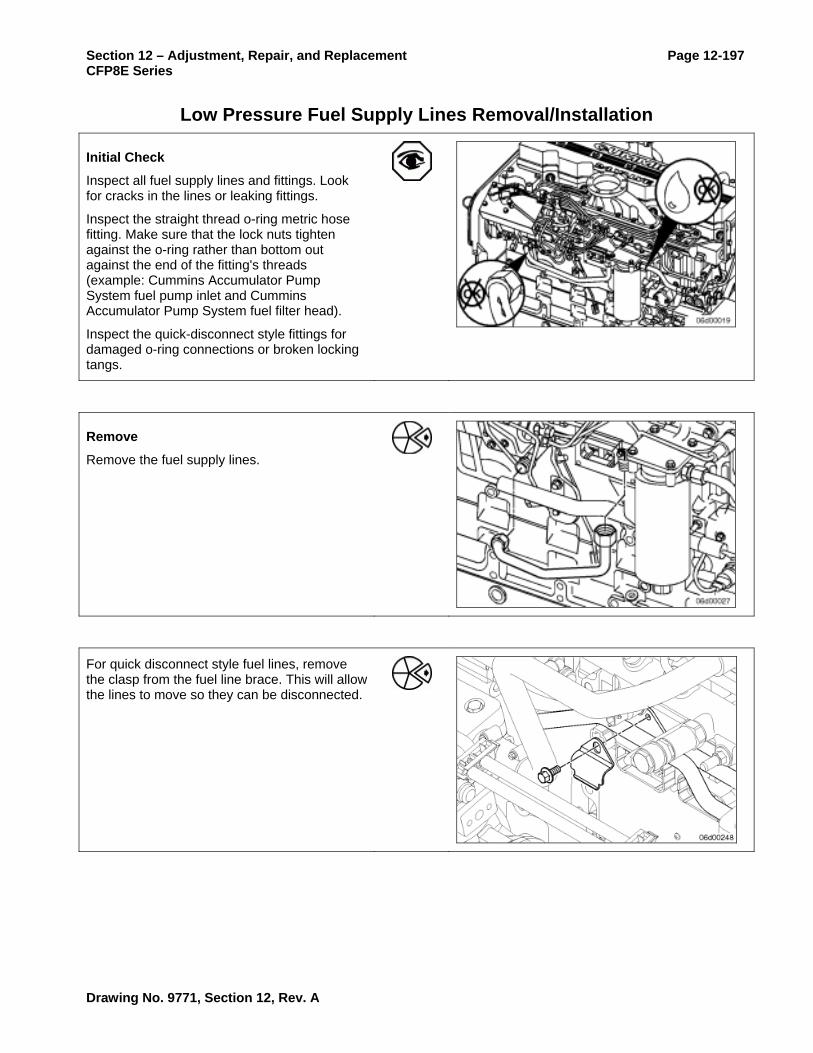
Section 12 – Adjustment, Repair, and Replacement Page 12-197 CFP8E Series
Low Pressure Fuel Supply Lines Removal/Installation
Initial Check
Inspect all fuel supply lines and fittings. Look for cracks in the lines or leaking fittings.
Inspect the straight thread o-ring metric hose fitting. Make sure that the lock nuts tighten against the o-ring rather than bottom out against the end of the fitting's threads (example: Cummins Accumulator Pump System fuel pump inlet and Cummins Accumulator Pump System fuel filter head).
Inspect the quick-disconnect style fittings for damaged o-ring connections or broken locking tangs.
Remove
Remove the fuel supply lines.
For quick disconnect style fuel lines, remove the clasp from the fuel line brace. This will allow the lines to move so they can be disconnected.
Drawing No. 9771, Section 12, Rev. A

Page 12-198 Section 12 – Adjustment, Repair, and Replacement CFP8E Series
Loosen all quick disconnect lines from the brace.
To remove the gear pump outlet line, the gear pump inlet line must be removed first.
Remove the quick disconnect style fuel lines by pressing in the locking tangs on both sides of the quick disconnect fitting.
To aid removal, a screwdriver may be inserted between the fuel line end and quick disconnect male union. After pressing the opposing locking tangs, twisting the flat blade of the screwdriver helps to remove the fuel line.
If fuel leaks or suction side air entry is suspected, remove the fuel hoses or quick disconnect fittings.
Drawing No. 9771, Section 12, Rev. A

Section 12 – Adjustment, Repair, and Replacement Page 12-199 CFP8E Series
Inspect for Reuse
Inspect for burrs or debris on metal connectors that may cause leaks.
On straight thread o-ring metric connectors, be certain the o-rings are not frayed or cut.
On quick disconnect style fittings, be certain the o-rings are not frayed or cut, and that the lock tangs are not damaged.
Inspect the banjo seal washers. Replace and damaged washers.
Install
Install the fuel supply lines.
Number 10 Flare Fitting: 37 N•m [27 ft-lb]
M12 Quick Disconnect Union: 24 N•m [18 ft-lb]
Install the quick disconnect fuel lines (Cummins Common Rail Fuel Systems only).
Install the quick disconnect fittings.
Torque Value 24 N•m [18 ft-lb]
Make sure that the quick disconnect style fuel lines clasp onto the quick disconnect fittings.
Make sure the lines are routed and connected correctly. If the lines are connected incorrectly, the engine will not run.
For quick-disconnect style lines used with the Cummins Common Rail Fuel System, fuel lines are routed in the following order:
OEM connection to the upper fitting at the ECM cooling plate
Lower ECM cooling plate fitting to the upper gear pump fitting
Lower gear pump fitting to the 2-micron fuel filter inlet
2-micron fuel filter outlet to the fuel pump fuel
Drawing No. 9771, Section 12, Rev. A

Page 12-200 Section 12 – Adjustment, Repair, and Replacement CFP8E Series
control actuator housing.
The fuel supply line brace holds the fuel lines in the following order:
The inside line connects the upper gear pump fitting to the lower ECM cooling plate fitting
The middle line connects the 2-micron filter outlet to the fuel pump fuel control actuator housing
The outside line connects the lower gear pump fitting to the 2-micron filter inlet.
Install the fuel line brace clasp (quick disconnect style fuel lines only) and the brace, if necessary.
Fuel Line Brace 24 N•m [18 ft-lb]
Fuel Line Brace Clasp 24 N•m [18 ft-lb]
Follow-Up
Operate the engine and check for leaks.
Drawing No. 9771, Section 12, Rev. A

Section 12 – Adjustment, Repair, and Replacement Page 12-201 CFP8E Series
Fuel Injectors Removal/Installation
Preparatory Steps
CAPS Fuel System
CAUTION Attempting to remove the injector without first removing the fuel connector will cause damage to the injector body and/or fuel connector.
Remove the rocker lever cover. Refer to Procedure 003-011.
Remove the engine brake, if equipped. Refer to Procedure 020-004.
Remove the fuel connector. Refer to Procedure 006-052.
Remove
CAPS Fuel System
Remove the injector hold-down bolt that is nearest the exhaust manifold side of the engine.
Remove the injector hold-down.
Remove the high-pressure fuel connector. Refer to Procedure 006-051.
Using the injector puller, Part No. 3825156, pull the injector out of the head.
Alternatively, a rocker cover capscrew can be installed into the top of the injector and used to pull the injector from the cylinder head.
Be sure that the injector seal washer is removed from the injector bore.
Drawing No. 9771, Section 12, Rev. A

Page 12-202 Section 12 – Adjustment, Repair, and Replacement CFP8E Series
Test
Mechanical Injectors
WARNING While testing the injectors, keep hands and body parts away from the injector nozzle. Fuel coming from the injector is under extreme pressure and can cause serious injury by penetrating the skin.
Install the injectors on an injector test stand. Open the bypass valve for the pressure gauge so the spray pattern can be checked.
Use injector test fixture, Part Number 3162269, with the injector nozzle test, Part Number 3376946.
Operate the test stand lever quickly several times to check the spray pattern of the injectors. Verify that the correct number of plumes are present for the number of holes in the injector. Also pay close attention to the size and shape of each plume. If possible, compare the spray pattern to that of a new injector with the same assembly number.
NOTE: The injector spray pattern is an excellent indicator of the nozzle hole condition. Check each plume carefully. It is possible that only a single hole has been damaged resulting in degraded engine performance.
Close the bypass valve for the pressure gauge and operate the test stand lever to check the nozzle opening pressure. There must be a good crisp pop when the nozzle opens and the pressure must be within specification for the assembly number. Refer to the Master Repair Manual, Injection Pumps and Injectors, Midrange Engines, Bulletin 3666037-05 or later.
Drawing No. 9771, Section 12, Rev. A

Section 12 – Adjustment, Repair, and Replacement Page 12-203 CFP8E Series
If the nozzle opening pressure is excessively low and/or the nozzle sprays excessive fuel, the injector needle can be sticking. The needle can be stuck due to poor lubrication or debris.
Sometimes it is possible to unstick an injector needle by using the injector test stand. Open the bypass valve for the pressure gauge and operate the test stand lever rapidly for 10 to 20 strokes.
Recheck the nozzle opening pressure and spray pattern to see if the injector has returned to normal operation.
If the injector is still out of specification, replace the injector.
Check the injector for drip and/or excessive leak down. Close the bypass valve for the pressure gauge and build pressure to within 10 bars of the opening pressure of the nozzle.
A drop of fuel must not form within 15 seconds.
Disassemble
Mechanical Injectors
Place the injector in the injector clamp and remove the nozzle retaining nut.
NOTE: Injectors covered under warranty by the manufacturer must not be repaired. Refer to the manufacturer's warranty instructions.
Remove the nozzle, intermediate plate, spring, and shims from the injector.
Drawing No. 9771, Section 12, Rev. A

Page 12-204 Section 12 – Adjustment, Repair, and Replacement CFP8E Series
Clean and Inspect for Reuse
Verify the injector sealing washer is the correct thickness. The incorrect sealing washer can cause high pressure fuel leaks, and/or performance problems due to incorrect injector protrusion.
Refer to the injector part number for correct sealing washer shim thickness.
NOTE: All ISC and ISL engines which use mechanical (“POP”) style injectors use a 1.5 mm [0.06 in] injector seal washer.
WARNING When using solvents, acids, or alkaline materials for cleaning, follow the manufacturer's recommendations for use. Wear goggles and protective clothing to avoid personal injury.
WARNING Some solvents are flammable and toxic. Read the manufacturer's instructions before using.
CAUTION Do not use a steel wire brush or glass beading to clean the injectors. This will damage the nozzle holes and cause performance problems.
Clean injector tip and body with safety solvent and soft clean rag.
Drawing No. 9771, Section 12, Rev. A

Section 12 – Adjustment, Repair, and Replacement Page 12-205 CFP8E Series
Inspect the o-ring for damage.
Look for burrs on the inlet to the injector.
Check the nozzle holes for any signs of damage such as hole erosion or hole plugging.
Spray safety solvent on the injector body and inspect the fuel inlet passage for small cracks which can allow high pressure fuel to leak to the injector drain passage.
Assemble
Mechanical Injectors
Clean the injector internal components with clean diesel fuel and a clean rag. Make sure there is no debris in the internal parts of the injector.
Install shims necessary to modify the nozzle opening pressure. More shims raise the nozzle opening pressure, less shims lower the nozzle opening pressure.
Drawing No. 9771, Section 12, Rev. A

Page 12-206 Section 12 – Adjustment, Repair, and Replacement CFP8E Series
Install the spring, button, intermediate plate, and nozzle/needle.
Make sure that the intermediate plate is in the correct orientation with the supply hole on the plate lining up with the supply hole on the holder.
Install the retaining nut finger tight. Place the injector in the injector clamp and tighten the retaining nut. Install the sealing washer and body o-ring.
Torque Value: 47 N•m [35 ft-lb]
Install
CAPS Fuel System
Make sure that the injector bore is clean and that only one (1) sealing washer is installed on the injector nozzle.
Lubricate the injector o-ring with clean engine oil.
Place the injector in the head in the proper orientation.
Place the injector hold-down clamp on top of the injector and make sure that the injector is fully seated in the injector bore.
Install the injector hold-down and tighten.
Torque Value: 10 N•m [89 in-lb]
Drawing No. 9771, Section 12, Rev. A

Section 12 – Adjustment, Repair, and Replacement Page 12-207 CFP8E Series
Follow-Up
CAPS Fuel System
Install the fuel connector. Refer to Procedure 006-052.
Install the rocker lever cover. Refer to Procedure 003-011.
Install the high pressure fuel lines. Refer to Procedure 006-051.
Operate the engine and check for leaks.
Drawing No. 9771, Section 12, Rev. A

Page 12-208 Section 12 – Adjustment, Repair, and Replacement CFP8E Series
High Pressure Injector Supply Lines Removal/Installation
Initial Check
CAPS Fuel System
Inspect the lines for cracks, chafing, or leaks. Make sure that the lines are tightened to the proper specification.
Check the fuel pump connection.
Torque Value: 24 N•m [18 ft-lb]
Check the cylinder head connection.
Torque Value: 38 N•m [28 ft-lb]
Initial Check
Cummins Common Rail Fuel System
Check the fuel pump connection.
Torque Value: 38 N•m [28 ft-lb]
Check the cylinder head connection.
Torque Value: 38 N•m [28 ft-lb]
Check the fuel rail connection.
Torque Value: 38 N•m [28 ft-lb]
Prepare
Remove
CAPS Fuel System
Remove the fuel line from the injection pump.
NOTE: Use two (2) wrenches to prevent the outlet fitting from turning.
Remove the fuel line clamp capscrews from the intake cover. This must be done before injection lines can be pulled loose from cylinder head.
Remove the fuel line from the cylinder head.
Drawing No. 9771, Section 12, Rev. A

Section 12 – Adjustment, Repair, and Replacement Page 12-209 CFP8E Series
Remove
Cummins Common Rail Fuel System
If necessary, remove the air intake connection or turbo control actuator.
Loosen the fuel line at the fuel rail and the fuel connector or high-pressure pump outlet fitting.
Remove the high-pressure fuel line.
Clean and Inspect for Reuse
Check the ferrules of the lines for any signs of burrs or foreign material.
Inspect the sealing surface on the cone for severe deformation that would prohibit reuse.
Check for cracks and deformation.
Install
CAPS Fuel System
Before installing the injector supply lines, make sure that the fuel connector is fully and properly seated against the injector. Refer to Procedure 006-052.
Drawing No. 9771, Section 12, Rev. A

Page 12-210 Section 12 – Adjustment, Repair, and Replacement CFP8E Series
Install the fuel lines in the reverse order of removal.
Check the fuel pump connection.
Torque Value: 24 N•m [18 ft-lb]
Check the cylinder head connection.
Torque Value: 38 N•m [28 ft-lb]
Operate the engine and check for leaks.
Install
Cummins Common Rail Fuel System
Before installing the injector supply lines, make sure that the fuel connector is fully and properly seated against the injector. Refer to Procedure 006-052.
For Cummins Common Rail Fuel Systems, be certain that the high-pressure connector retaining nut is tightened. Refer to Procedure 006-052.
Install the fuel lines in the reverse order of removal.
Check the fuel pump connection.
Torque Value: 38 N•m [28 ft-lb]
Check the cylinder head connection.
Torque Value: 38 N•m [28 ft-lb]
Check the fuel rail connection.
Torque Value: 38 N•m [28 ft-lb]
Operate the engine and check for leaks.
Follow-Up
Drawing No. 9771, Section 12, Rev. A

Section 12 – Adjustment, Repair, and Replacement Page 12-211 CFP8E Series
Head Mounted Fuel Connector
Prepare
Remove
CAPS Fuel System
Remove injector supply line. Refer to Procedure 006-051.
Use fuel connector puller, Part Number 3825157, to remove the fuel connector from the cylinder head.
Inspect for Reuse
A new high-pressure connector must be installed if a new injector is being installed.
Inspect the fuel connector. Look for burrs or deformation around the inlet and outlet sides of the connector.
Check the edge filter for signs of plugging or material contamination. Do not reuse a high-pressure fuel connector debris is present.
Check the o-ring for tearing or deterioration.
Inspect the outlet sealing surface of the high-pressure connector for wear, an uneven seating surface, or signs of leakage.
When a high-pressure fuel leak is present, small lines or cuts in the connector will be eroded into the seating surface.
The high-pressure connector and injector must be replaced when this failure is observed.
Drawing No. 9771, Section 12, Rev. A

Page 12-212 Section 12 – Adjustment, Repair, and Replacement CFP8E Series
Install
CAPS Fuel System
Oil the fuel connector o-ring with clean engine oil.
Carefully push the fuel connector into the head until it stops against the injector. Be certain the injector is fully seated in the injector bore before installing the fuel connector. Refer to Procedure 006-026.
Install the high-pressure fuel lines. Refer to Procedure 006-051.
Operate the engine and check for leaks.
Follow-Up
Drawing No. 9771, Section 12, Rev. A

Section 12 – Adjustment, Repair, and Replacement Page 12-213 CFP8E Series
Fuel Pump Air Bleed Line
Prepare
WARNING When using a steam cleaner, wear safety glasses or a face shield, as well as protective clothing. Hot steam can cause serious personal injury.
WARNING Wear appropriate eye and face protection when using compressed air. Flying debris and dirt can cause personal injury.
CAUTION Do not use the air bleed line as a handle or step. Doing this may result in cracks or damaged air bleed line that will cause fuel leaks. Make sure that steam does not spray directly on the electrical connections on the top of the accumulator block or fault codes will possibly occur.
Thoroughly steam-clean the entire fuel pump.
Dry the fuel pump with compressed air.
Drawing No. 9771, Section 12, Rev. A

Page 12-214 Section 12 – Adjustment, Repair, and Replacement CFP8E Series
Remove
ISC and QSC8.3 With CAPS Injection Pump
WARNING To reduce the possibility of an air bleed line leak due to a broken air bleed line, use two wrenches during removal and installation. Failure to do so may result in a cracked fuel line. In certain applications, with the fuel tank above the head of the engine, this will result in fuel draining from the fuel tank.
NOTE: There are three styles of air bleed lines. Identify your style and use the appropriate procedures that follow.
Style One (1):
Remove the banjo capscrew at the injection control valve drain fitting of the fuel pump. Use two wrenches to prevent the line from being bent.
Style Two (2):
Remove the banjo capscrew at the injection control valve drain fitting of the fuel pump. Remove the hollow banjo fitting holding the air bleed line. Use two wrenches to prevent the line from being bent.
Remove the banjo capscrew at the air bleed fitting on top of the fuel pump. It is located on the accumulator module next to the two pumping control valves.
Use two wrenches to prevent the air bleed fitting from turning.
Drawing No. 9771, Section 12, Rev. A

Section 12 – Adjustment, Repair, and Replacement Page 12-215 CFP8E Series
ISL and QSL9 With CAPS Injection Pump
Remove the banjo bolt from the injection control valve drain fitting and the distributor plug.
Remove the banjo capscrew at the air bleed fitting on top of the fuel pump. It is located on the accumulator module next to the two pumping control valves.
Use two wrenches to prevent the air bleed fitting from turning.
Inspect for Reuse
Inspect the lines for pinches, bends, or damaged connectors.
Drawing No. 9771, Section 12, Rev. A
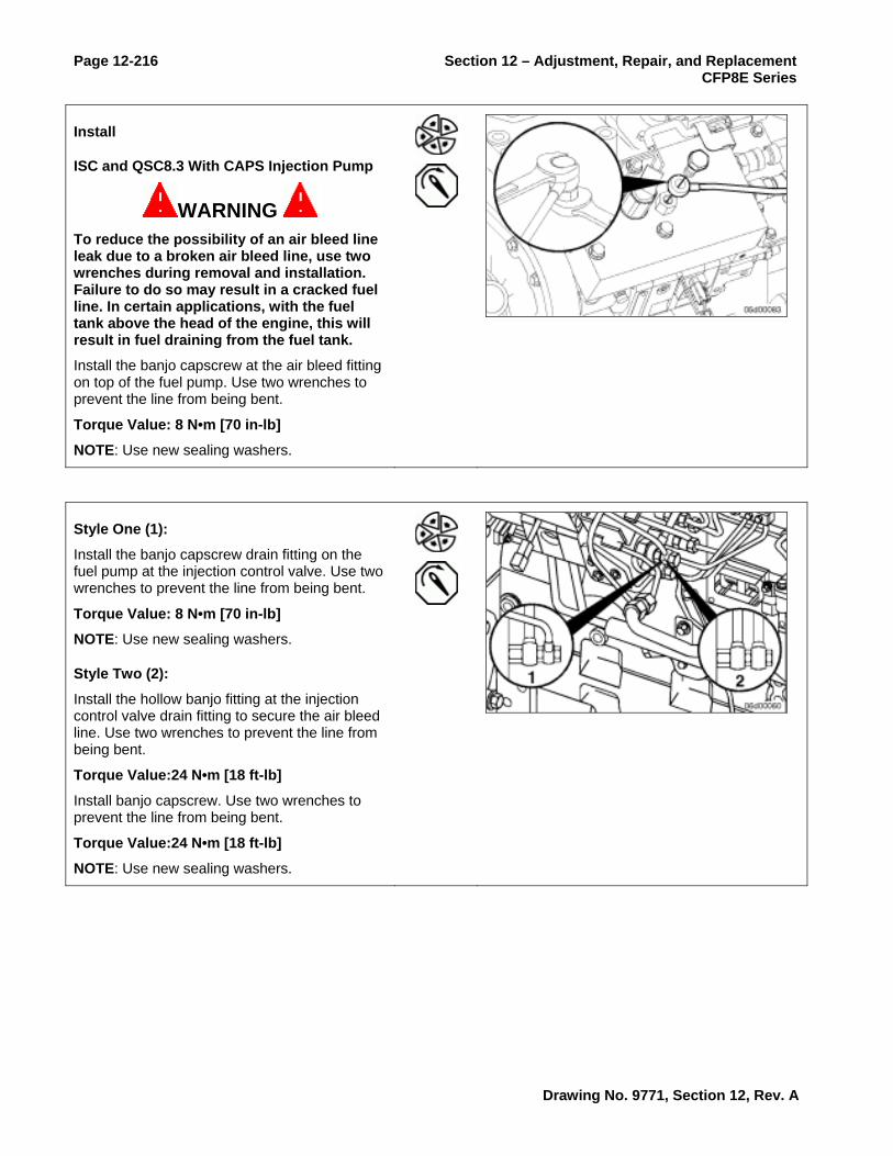
Page 12-216 Section 12 – Adjustment, Repair, and Replacement CFP8E Series
Install
ISC and QSC8.3 With CAPS Injection Pump
WARNING To reduce the possibility of an air bleed line leak due to a broken air bleed line, use two wrenches during removal and installation. Failure to do so may result in a cracked fuel line. In certain applications, with the fuel tank above the head of the engine, this will result in fuel draining from the fuel tank.
Install the banjo capscrew at the air bleed fitting on top of the fuel pump. Use two wrenches to prevent the line from being bent.
Torque Value: 8 N•m [70 in-lb]
NOTE: Use new sealing washers.
Style One (1):
Install the banjo capscrew drain fitting on the fuel pump at the injection control valve. Use two wrenches to prevent the line from being bent.
Torque Value: 8 N•m [70 in-lb]
NOTE: Use new sealing washers.
Style Two (2):
Install the hollow banjo fitting at the injection control valve drain fitting to secure the air bleed line. Use two wrenches to prevent the line from being bent.
Torque Value:24 N•m [18 ft-lb]
Install banjo capscrew. Use two wrenches to prevent the line from being bent.
Torque Value:24 N•m [18 ft-lb]
NOTE: Use new sealing washers.
Drawing No. 9771, Section 12, Rev. A

Section 12 – Adjustment, Repair, and Replacement Page 12-217 CFP8E Series
ISL and QSL9 With CAPS Injection Pump
Install the banjo capscrew at the air bleed fitting on top of the fuel pump. Use two wrenches to prevent the air bleed fitting from turning.
Install the banjo capscrew in the injection control valve drain fitting and the distributor plug.
Torque Value: 8 N•m [70 in-lb]
NOTE: Use new sealing washers.
Follow-Up
Operate the engine and check for leaks.
Drawing No. 9771, Section 12, Rev. A

Page 12-218 Section 12 – Adjustment, Repair, and Replacement CFP8E Series
Fuel Rail
Initial Check
WARNING The pressure within the fuel rail is extremely high. High pressure can penetrate the skin. Stand clear of the engine while it is running.
WARNING The fuel pump high-pressure fuel lines and fuel rail contain very high-pressure fuel. To avoid the possibility of personal injury and property damage, never loosen any fittings while the engine is running.
Inspect the fuel pressure sensor, high-pressure fuel line connections, and male unions for leaks.
Prepare
Disconnect the fuel pressure sensor from the engine wiring harness. Refer to Procedure 019-043 in Troubleshooting and Repair Manual, CM850 Electronic Control System, ISC and ISL Engines, Bulletin 4021416.
Remove
Remove the high-pressure fuel lines from the fuel rail. Refer to Procedure 006-051.
Remove the fuel drain line from the fuel rail pressure relief valve. Refer to Procedure 006-013.
Remove the capscrews that secure the fuel rail to the cylinder head. Remove the fuel rail assembly.
Drawing No. 9771, Section 12, Rev. A

Section 12 – Adjustment, Repair, and Replacement Page 12-219 CFP8E Series
Install
Install the fuel rail assembly. Follow the proper sequence to make sure that high-pressure fuel lines are properly aligned.
Install the fuel rail assembly capscrews finger-tight.
Install the high-pressure fuel lines finger-tight.
Tighten the fuel rail assembly capscrews.
Torque Value: 43 N•m [32 ft-lb]
Tighten the high-pressure fuel lines. Refer to Procedure 006-051.
Follow-Up
Install the fuel drain line to the fuel pressure relief valve. Refer to Procedure 006-013.
Install the fuel pressure sensor to the engine wiring harness. Refer to Procedure 019-043 in Troubleshooting and Repair Manual, CM850 Electronic Control System, ISC and ISL Engines, Bulletin 4021416.
Operate the engine and check for leaks.
Drawing No. 9771, Section 12, Rev. A

Page 12-220 Section 12 – Adjustment, Repair, and Replacement CFP8E Series
Fuel Pressure Relief Valve
Initial Check
WARNING The pressure within the fuel rail is extremely high. High-pressure can penetrate the skin. Stand clear of the engine while it is running.
WARNING The fuel pump high-pressure fuel lines and fuel rail contain very high pressure fuel. To avoid the possibility of personal injury, never loosen any fittings while the engine is running.
Operate the engine and check for external fuel leaks.
Check for a fuel rail pressure relief valve that leaks excessive fuel to drain.
Measurement of fuel rail pressure relief valve leakage requires use of a fuel return hose, Part Number 3164618. If necessary this tool can be constructed. Refer to Procedure 006-026. The tool is used to isolate the leakage from just the fuel rail pressure relief valve so that it can be measured into a graduated cylinder.
NOTE: If Fault Code 449 or 2311 is active, do not replace the fuel rail pressure relief valve without first determining the cause of the fault condition. Refer to the appropriate troubleshooting tree(s).
Remove the M12 banjo bolt that connects the fuel rail pressure relief valve drain line to the fuel drain manifold.
Install a fuel return hose, Part Number 3164618, at the fuel drain manifold.
Route the fuel return hose into a collection device.
Drawing No. 9771, Section 12, Rev. A

Section 12 – Adjustment, Repair, and Replacement Page 12-221 CFP8E Series
Alternatively, fuel rail pressure relief valve leakage measurement tool, Part Number 4164617, can be installed at the fuel rail pressure relief valve.
Test
Start the engine and allow the engine to idle.
Measure the leakage.
Specification:
Less than 30 drops per minute must drain from the fuel rail pressure relief valve while the engine runs at idle.
CAUTION Fuel is at high pressure during this test. After connecting the test fitting, close the engine cover and stand clear of high-pressure fuel lines.
While the engine is running at idle, use the INSITE™ High Pressure Leak Test to create higher fuel rail pressure. INSITE™ will command 1500 BAR fuel rail pressure while the engine is at idle during this test.
Specification:
Less than 30 drops of fuel per minute must drain from the fuel rail pressure relief valve.
If fuel rail pressure relief valve leakage is excessive, it must be replaced. However, make certain that Fault Code 449 or 2311 is not active indicating that a system failure is causing the fuel rail pressure relief valve to open.
Drawing No. 9771, Section 12, Rev. A

Page 12-222 Section 12 – Adjustment, Repair, and Replacement CFP8E Series
Remove the fuel return hose and install the fuel drain line banjo bolt. Refer to Procedure 006-013.
Operate the engine and check for leaks.
Remove
Remove the fuel drain line from the fuel rail pressure relief valve. Refer to Procedure 006-013.
Remove the fuel pressure relief valve adapter and copper seal washer.
Remove the fuel pressure relief valve.
Inspect for Reuse
If the fuel pressure relief valve exhibits excessive leakage to drain, it must not be reused.
Inspect the high-pressure seal surface on the fuel pressure relief valve and also in the fuel rail for damage. Do not reuse components if the high-pressure seal joint is damaged.
Inspect the copper seal washer and adapter fitting for damage.
Drawing No. 9771, Section 12, Rev. A

Section 12 – Adjustment, Repair, and Replacement Page 12-223 CFP8E Series
Install
Install the fuel pressure relief valve with Lubriplate™ on the threads.
Torque Value: 100 N•m [74 ft-lb]
If the reducer has been removed from the fuel rail pressure relief valve, install the reducer with a new copper seal washer.
Torque Value: 37 N•m [27 ft-lb]
Follow-Up
Install the fuel drain line to the fuel pressure relief valve. Refer to Procedure 006-013.
Operate the engine and check for leaks.
Drawing No. 9771, Section 12, Rev. A

Page 12-224 Section 12 – Adjustment, Repair, and Replacement CFP8E Series
Fuel Rail High Pressure Fitting
Initial Check
Operate the engine and check for external leaks.
Remove
Remove the high-pressure fitting only if a leak is detected.
Install
Flush the outlet fitting using contact cleaner.
Apply Lubriplate™ to the high-pressure fitting threads.
Install the high-pressure fitting.
Torque Value: 100 N•m [74 ft-lb]
Reinstall the high-pressure fuel line. Refer to Procedure 006-051.
Operate the engine and check for leaks. If a leak occurs after replacing the fitting, replace the rail.
Drawing No. 9771, Section 12, Rev. A

Section 12 – Adjustment, Repair, and Replacement Page 12-225 CFP8E Series
Follow-Up
Drawing No. 9771, Section 12, Rev. A

Page 12-226 Section 12 – Adjustment, Repair, and Replacement CFP8E Series
Air in Fuel
Prepare
Setup
Obtain a 1.09 mm [0.043 in] orificed diagnostic fuel line, Part Number 3164621. This tool can also be constructed following the steps below.
Obtain a container suitable for collection of fuel that exits the diagnostic fuel line (a five gallon bucket is recommended).
Construct a sight tube (CAPS fuel systems only) using the following steps.
Construct a 1.09 mm [0.043 in] orificed diagnostic fuel line.
NOTE: This tool is available for purchase, Part Number 3164621.
A 0.043-inch orifice diagnostic fuel line is used in procedures to create rated flow through the low pressure fuel system without the need to operate the engine under load.
Tap a female quick connect, Part Number 3376859.
Tap size: 8-36 national fine (U.S.)
WARNING Wear appropriate eye and face protection when using compressed air. Flying debris and dirt can cause personal injury.
Clean the female quick connect, Part Number 3376859, with compressed air.
Drawing No. 9771, Section 12, Rev. A

Section 12 – Adjustment, Repair, and Replacement Page 12-227 CFP8E Series
Assemble a 1.09 mm [0.043 in] injector orifice, Part Number 3045018, with washer, to the female quick connect, Part Number 3376859.
NOTE: To obtain correct flow, use a 1.09 mm [0.043 in] injector orifice, Part Number 3045018.
Attach the orifice to an appropriate length (it must reach from the fuel pump to the fuel tank) of 1/4-inch, or larger, tubing.
NOTE: It is recommended that this tool be marked and identified as having a 1.09 mm [0.043 in] orifice installed. This is to ensure that there is no confusion when using this tool in the future.
Construct a sight tube (CAPS fuel systems only):
Assemble two (one male and one female, 7/8-14 thread barb-tite fittings and hose clamps to a 61 cm [2 ft] long number-10 clear hose approved for use with diesel fuel.
Drawing No. 9771, Section 12, Rev. A

Page 12-228 Section 12 – Adjustment, Repair, and Replacement CFP8E Series
Measure
CAPS Fuel System
Attach the 1.09 mm [0.043 in] diagnostic fuel line at the fuel injection pump's diagnostic fitting.
Run the outlet of the diagnostic fuel line into the fuel collection container (or the vehicles fuel tank).
Install the sight glass between the fuel filter head and the fuel injection pump inlet.
Run the engine from idle to high idle several times to purge the air induced while installing the diagnostic fuel line.
Run the engine up to high idle while another technician checks for air in the system.
NOTE: A small amount of air in the inlet line is acceptable. Ignore any air that is observed in the tube running back to the fuel tank.
Afterwards, operate the engine at idle and observe any air in the fuel supply. If air is observed, isolate the air to the following components:
Fuel filter assembly
Fuel heater
Fuel lift pump assembly
OEM fuel plumbing
Fuel tank stand-pipe
Drawing No. 9771, Section 12, Rev. A

Section 12 – Adjustment, Repair, and Replacement Page 12-229 CFP8E Series
Cummins Common Rail Fuel System
NOTE: A symptom of air-in-fuel for the ISC and ISL engine equipped with a Cummins Common Rail Fuel System is an audible surge associated with fuel system pressure fluctuations due to air in the fuel supply.
The following test method will simulate rated fuel flow through the system so that air in fuel problems may be diagnosed.
Install a Compuchek® fitting, Part Number 3824842, at the inlet to the 2 um fuel filter and attach the 1.09 mm [0.043 in] diagnostic fuel line.
Route the outlet of the 0.043-inch diagnostic fuel line into a collection device of suitable size (a 5-gallon bucket is recommended).
Start the engine and run the engine from idle to high idle several times to purge the air induced while installing the diagnostic fuel line.
Observe the fuel flow exiting the diagnostic fuel line while the engine runs at idle.
A few bubbles exiting the line is expected. A foamy appearance is indication of a leak that allows air to enter, a severe inlet restriction that causes cavitation, or a system that is not yet primed. If fuel inlet restriction (refer to Procedure 006-020) is not excessive, the source of air entry should be isolated to one of the following:
Suction fuel lines
ECM cooling plate assembly
OEM fuel lines
Suction-side fuel filter assemblies
Stand-pipe(s) in the fuel tank(s)
Drawing No. 9771, Section 12, Rev. A

Page 12-230 Section 12 – Adjustment, Repair, and Replacement CFP8E Series
Follow Up
Remove all test fuel lines and install the low pressure fuel lines. Refer to Procedure 006-024.
Drawing No. 9771, Section 12, Rev. A

Section 12 – Adjustment, Repair, and Replacement Page 12-231 CFP8E Series
Fuel Filter Head Bracket Removal/Installation
Prepare
Remove the fuel filter. Refer to Procedure 006-015.
Remove the fuel supply lines from the filter head. Refer to Procedure 006-024.
Remove
Remove the four (4) capscrews retaining the filter head.
Remove the filter head bracket from the engine.
Disassemble
Fuel heater equipped engines have a filter spud that can be removed for the purpose of removing the fuel heater.
Remove the fuel heater and filter spud, if equipped.
Drawing No. 9771, Section 12, Rev. A

Page 12-232 Section 12 – Adjustment, Repair, and Replacement CFP8E Series
Clean and Inspect for Reuse
Inspect the filter head for cracks, passage blockage, material or debris on the sealing surfaces.
Clean any loctite from the filter adapter threads.
Assemble
Apply Loctite™ 277, or equivalent, to the filter adapter threads that are engaging the filter head.
Assemble the filter head.
Install the filter adapter and fuel heater (if equipped).
Torque Value: 27 N•m [20 in-lb]
Install
Install the bracket and filter head. Tighten the retaining capscrews.
Torque Value: 43 N•m [32 ft-lb]
Drawing No. 9771, Section 12, Rev. A

Section 12 – Adjustment, Repair, and Replacement Page 12-233 CFP8E Series
Follow-Up
Install the fuel filter. Refer to Procedure 006-015.
Install the fuel supply lines. Refer to Procedure 006-024.
Operate the engine and check for leaks.
Drawing No. 9771, Section 12, Rev. A

Page 12-234 Section 12 – Adjustment, Repair, and Replacement CFP8E Series
Fuel Pump Removal/Installation
Prepare
Remove the fuel supply lines from the fuel pump. Refer to Procedure 006-024.
Remove the fuel drain line from the fuel pump. Refer to Procedure 006-013.
Disconnect the engine harness from the fuel pump actuator.
Remove the fuel pump gear access cover.
Remove
Remove the fuel pump upper support bracket.
Locate top dead center for cylinder Number 1 by barring the engine until the line on the fuel pump gear aligns with the front cover mark for top dead center.
Remove the fuel pump gear nut and washer.
Pull the fuel injection pump drive gear loose from the pump drive shaft. This can be done using Cummins Gear Puller, Part Number 3824469.
Drawing No. 9771, Section 12, Rev. A

Section 12 – Adjustment, Repair, and Replacement Page 12-235 CFP8E Series
Remove the four mounting nuts that hold the fuel pump to the gear housing.
Remove the fuel pump.
Inspect for Reuse
The dowel pin in the fuel pump driveshaft must not be sheared.
If the dowel is sheared, the cam housing or fuel pump must be replaced and the drive gear must be replaced.
Be sure that the pilot o-ring is not cut or damaged.
Be sure that the pump oil supply o-ring is not damaged.
Drawing No. 9771, Section 12, Rev. A

Page 12-236 Section 12 – Adjustment, Repair, and Replacement CFP8E Series
Install
Be sure that the engine is at Number 1 cylinder top dead center. The fuel pump gear timing mark should align with the top dead center mark on the front cover.
Lubricate the pilot o-ring with clean engine oil.
Clean the nose of the camshaft with an evaporative cleaner.
Clean the fuel pump gear inside diameter with an evaporative cleaner.
The fuel pump drive gear inside diameter and the drive shaft outside diameter must be clean and dry before installing the gear.
Slide the fuel injection pump shaft through the drive gear and position the fuel injection pump flange onto the mounting studs.
Make sure the dowel pin in the drive shaft lines up with the keyway in the fuel injection pump gear.
Installation Sequence:
Install the pump mounting nuts (leave loose).
Install the support bracket bolts (leave loose).
Tighten the pump mounting nuts.
Torque Value: 44 N•m [32 ft-lb]
Tighten the support bracket bolts.
Torque Value: 65 N•m [48 ft-lb]
Drawing No. 9771, Section 12, Rev. A

Section 12 – Adjustment, Repair, and Replacement Page 12-237 CFP8E Series
Tighten the fuel injection pump drive gear nut.
Torque Value: 180 N•m [132 ft-lb]
Follow-Up
Install the access cover in the front cover.
Install the fuel supply lines to the fuel pump. Refer to Procedure 006-024.
Install the fuel drain line to the fuel pump. Refer to Procedure 006-013.
Connect the wire harness to the fuel pump actuator.
Drawing No. 9771, Section 12, Rev. A

Page 12-238 Section 12 – Adjustment, Repair, and Replacement CFP8E Series
This Page Intentionally Left Blank
Drawing No. 9771, Section 12, Rev. A

Section 12 – Adjustment, Repair, and Replacement Page 12-239 CFP08E Series
Intake Air Filter Removal/Installation
Prepare
Remove
Install
Follow-Up
Drawing No. 9771, Section 12, Rev. A

Page 12-240 Section 12 – Adjustment, Repair, and Replacement CFP08E Series
Air Crossover Removal/Installation
Prepare
Remove
Loosen the hose clamps, and position the crossover tube so that it can be removed.
Remove the tube.
Inspect for Reuse
Check the crossover tube for cracks, holes, and worn sections. Replace with a new hose and clamps if necessary.
Install
Install the crossover tube and clamps in the reverse order of removal.
Tighten the clamps.
Torque Value: 5 N•m [44 in-lb]
Drawing No. 9771, Section 12, Rev. A

Section 12 – Adjustment, Repair, and Replacement Page 12-241 CFP08E Series
Follow-Up
Drawing No. 9771, Section 12, Rev. A

Page 12-242 Section 12 – Adjustment, Repair, and Replacement CFP08E Series
Air Inlet Connection Removal/Installation
Prepare
Remove
Loosen air inlet clamps.
Remove the air inlet connection.
Install
Install the air inlet connection.
Tighten air inlet clamps.
Run engine and check for leaks.
Follow-Up
Drawing No. 9771, Section 12, Rev. A

Section 12 – Adjustment, Repair, and Replacement Page 12-243 CFP08E Series
Air Leaks, Air Intake and Exhaust Systems
Initial Check
Leaks in the intake air system are most commonly identified by:
Inspection of piping for cracked or loose clamps.
Applying a solution of soapy water in the suspected area and inspecting for bubbles.
Listening for a high-pitched whining or sucking sound in the suspected area.
CAUTION Engine intake air must be filtered to prevent dirt and debris from entering the engine. If intake air piping is damaged or loose, unfiltered air will enter the engine and cause premature wear.
Inspect the inlet air piping for cracked hoses and damaged or loose clamps.
Operate the engine at high idle, and use a solution of soapy water to spot intake air leaks.
If an air leak exists, the soap bubbles will be drawn in with the air.
Drawing No. 9771, Section 12, Rev. A

Page 12-244 Section 12 – Adjustment, Repair, and Replacement CFP08E Series
Replace damaged pipes and tighten loose clamps to make sure the air inlet system does not leak.
Check for corrosion of the inlet system piping under the clamps and hoses. Corrosion can allow corrosive products and dirt to enter the intake system.
Disassemble and clean as required.
Pressure Side Intake System
Leaks in the intake system will reduce the amount of air to the cylinders during engine operation and decrease engine performance.
Operate the engine at full throttle and rated rpm with maximum load.
Listen for a high-pitched whistling sound from the turbocharger, nearby piping, and connections.
Apply a soapy water solution to sealing surfaces and inspect for bubbles. Bubbles can be easily detected.
Drawing No. 9771, Section 12, Rev. A

Section 12 – Adjustment, Repair, and Replacement Page 12-245 CFP08E Series
Leaks can also be found at the turbocharger outlet connection.
Inspect for damage, replace sealing o-ring, and tighten loose clamps.
Any Charge Air Cooler Tubing or Connecting Hoses
Inspect the hose and tubing for damage.
Tighten loose clamps.
Refer to the equipment manufacturer's specifications for the correct torque value.
Air Intake Connection
Inspect for damage.
If necessary, replace the gasket or tighten loose clamps. Refer to Procedure 010-080.
Drawing No. 9771, Section 12, Rev. A

Page 12-246 Section 12 – Adjustment, Repair, and Replacement CFP08E Series
Intake Manifold
Inspect for damage.
Replace the gasket, if necessary. Refer to Procedure 010-108.
Wastegate Capsule/Plumbing
Inspect for damage.
Variable Geometry Turbocharger Actuator Plumbing
Inspect for cracks and/or air leaks.
Drawing No. 9771, Section 12, Rev. A

Section 12 – Adjustment, Repair, and Replacement Page 12-247 CFP08E Series
Compressor Housing Sealing Surface
Inspect for damage.
Clean surface.
Exhaust System
Leaks in the exhaust system will cause the turbocharger to operate at a lower speed, reducing the amount of air going to the cylinders during engine operation.
Operate the engine at full throttle and rated rpm with maximum load.
Leaks can be identified by noise, soapy water, or discoloration caused by the escaping hot gases.
Drawing No. 9771, Section 12, Rev. A
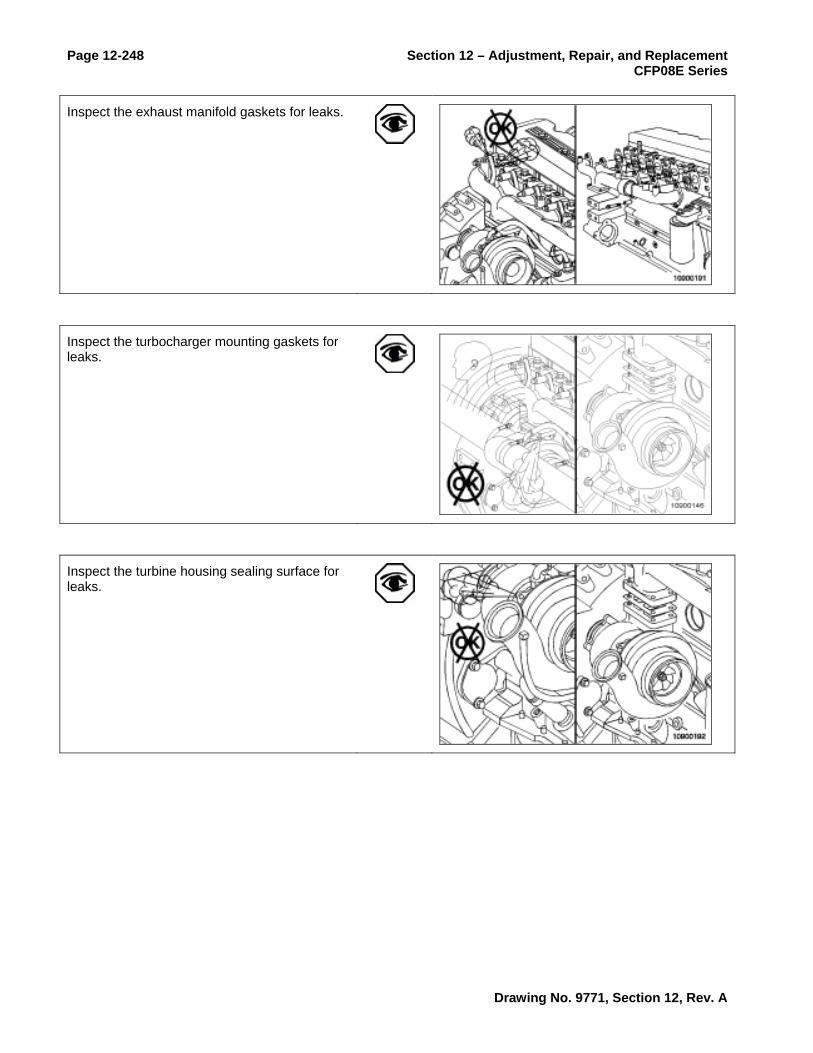
Page 12-248 Section 12 – Adjustment, Repair, and Replacement CFP08E Series
Inspect the exhaust manifold gaskets for leaks.
Inspect the turbocharger mounting gaskets for leaks.
Inspect the turbine housing sealing surface for leaks.
Drawing No. 9771, Section 12, Rev. A

Section 12 – Adjustment, Repair, and Replacement Page 12-249 CFP08E Series
Operate the engine at full throttle and rated rpm with maximum load.
Listen and inspect again for leaks.
Follow-Up
Drawing No. 9771, Section 12, Rev. A

Page 12-250 Section 12 – Adjustment, Repair, and Replacement CFP08E Series
Air Intake Restriction Removal/Installation
Prepare
Measure
Install a vacuum gauge or water manometer in the intake air piping.
The gauge adapter must be installed at a 90-degree angle to the airflow in a straight section of pipe, one pipe diameter before the turbocharger.
Operate the engine at full throttle and rated rpm with maximum load.
Record the data on the gauge or manometer.
MAX Inlet Air Restriction63.5 cm H2O [[25.0 in H2O]
If restriction exceeds specifications, replace or clean the air filter element. Refer to the equipment manufacturer's instructions.
Drawing No. 9771, Section 12, Rev. A

Section 12 – Adjustment, Repair, and Replacement Page 12-251 CFP08E Series
Inspect the intake piping for damage. Refer to the equipment manufacturer's repair instructions.
Remove the test equipment.
Follow-Up
Drawing No. 9771, Section 12, Rev. A

Page 12-252 Section 12 – Adjustment, Repair, and Replacement CFP08E Series
Turbocharger Checks
Prepare
Initial Check
Remove the intake pipe from the turbocharger. See the Remove step in this procedure.
Inspect the turbocharger compressor impeller blades for damage.
Replace the turbocharger if damage is found. See the Remove and Install steps in this procedure.
If the compressor impeller is damaged, inspect the intake piping and filter element for damage.
Repair any damage before operating the engine.
Remove the exhaust pipe from the turbocharger. See the Remove step in this procedure.
Inspect the turbine wheel for damage.
Replace the turbocharger if damage is found. See the Remove and Install steps in this procedure.
Axial Clearance Check
Use dial depth gauge, Part Number ST-537.
Push the rotor assembly away from the gauge.
Set the gauge on zero.
Drawing No. 9771, Section 12, Rev. A
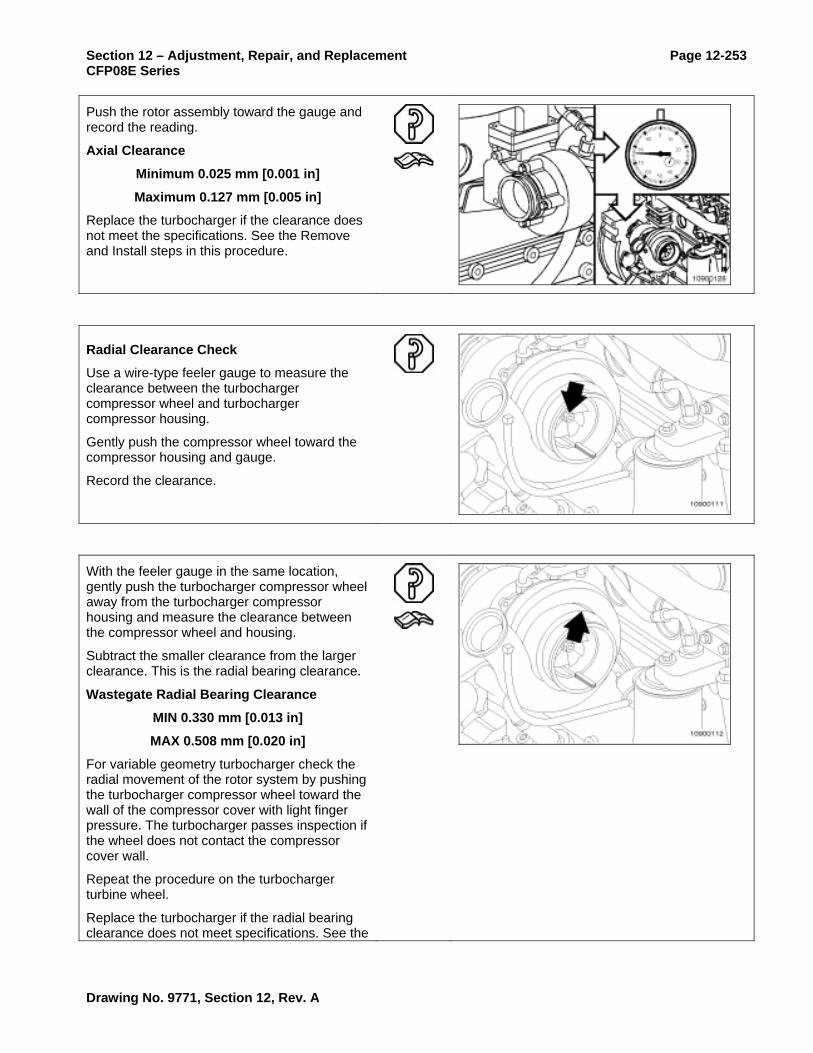
Section 12 – Adjustment, Repair, and Replacement Page 12-253 CFP08E Series
Push the rotor assembly toward the gauge and record the reading.
Axial Clearance
Minimum 0.025 mm [0.001 in]
Maximum 0.127 mm [0.005 in]
Replace the turbocharger if the clearance does not meet the specifications. See the Remove and Install steps in this procedure.
Radial Clearance Check
Use a wire-type feeler gauge to measure the clearance between the turbocharger compressor wheel and turbocharger compressor housing.
Gently push the compressor wheel toward the compressor housing and gauge.
Record the clearance.
With the feeler gauge in the same location, gently push the turbocharger compressor wheel away from the turbocharger compressor housing and measure the clearance between the compressor wheel and housing.
Subtract the smaller clearance from the larger clearance. This is the radial bearing clearance.
Wastegate Radial Bearing Clearance
MIN 0.330 mm [0.013 in]
MAX 0.508 mm [0.020 in]
For variable geometry turbocharger check the radial movement of the rotor system by pushing the turbocharger compressor wheel toward the wall of the compressor cover with light finger pressure. The turbocharger passes inspection if the wheel does not contact the compressor cover wall.
Repeat the procedure on the turbocharger turbine wheel.
Replace the turbocharger if the radial bearing clearance does not meet specifications. See the
Drawing No. 9771, Section 12, Rev. A

Page 12-254 Section 12 – Adjustment, Repair, and Replacement CFP08E Series
Remove and Install steps in this procedure.
Leak Check
Inspect the turbocharger compressor intake and discharge for oil.
If oil is present in the compressor intake as well as in the discharge, check upstream in the turbocharger for the source of the oil.
If oil is present only in the discharge side, install the air intake and charge air cooler piping. Refer to the OEM service manual.
Check for intake restriction. Refer to Procedure 010-031.
If no intake restriction is found, replace the turbocharger. See the Remove and Install steps in this procedure.
NOTE: If the engine experiences a turbocharger failure or any other occasion where oil is put into the charge air system, the charge air system must be inspected and cleaned. Refer to Procedure 010-027.
Add 1 unit of fluorescent tracer, Part Number 3376891, to each 38 liters [10.0 gal] of engine lubricating oil.
Operate the engine at low idle for 10 minutes.
Drawing No. 9771, Section 12, Rev. A

Section 12 – Adjustment, Repair, and Replacement Page 12-255 CFP08E Series
Shut off the engine.
Allow the turbocharger to cool.
Remove the exhaust pipe from the turbine housing. See the Remove step in this procedure.
Use a high-intensity black light, Part Number 3163339, to inspect the turbine outlet for leaks.
A yellow glow indicates an oil leak. A dark blue glow indicates fuel in the oil.
If oil is found on the turbine housing, remove the oil drain line and check for restrictions. Refer to Procedure 010-045.
Clear any restrictions found.
Install the turbocharger drain line. Refer to Procedure 010-045.
Drawing No. 9771, Section 12, Rev. A

Page 12-256 Section 12 – Adjustment, Repair, and Replacement CFP08E Series
If the oil drain line was not restricted, remove the turbocharger. See the Remove and Install steps in this procedure.
Use a high-intensity black light, Part Number 3163339, to inspect the turbine inlet for leaks.
A yellow glow indicates an oil leak from the engine.
If a yellow glow is not seen in the turbine inlet, replace the turbocharger. See the Remove and Install steps in this procedure.
Install the exhaust pipe to the turbocharger turbine outlet and tighten the clamp. See the Install step in this procedure.
Install the intake pipe to the turbocharger compressor inlet and tighten the clamp. See the Install step in this procedure.
Follow-Up
Drawing No. 9771, Section 12, Rev. A

Section 12 – Adjustment, Repair, and Replacement Page 12-257 CFP08E Series
Turbocharger Removal/Installation
Prepare
WARNING Do not remove the pressure cap from a hot engine. Wait until the coolant temperature is below 50°C [120°F] before removing the pressure cap. Heated coolant spray or steam can cause personal injury.
WARNING Coolant is toxic. Keep away from children and pets. If not reused, dispose of in accordance with local environmental regulations.
Drain the coolant, variable geometry turbocharger only. Refer to Procedure 008-018.
Remove the oil supply line from the turbocharger. Refer to Procedure 010-046.
Remove the oil drain line from the turbocharger. Refer to Procedure 010-045.
Remove the turbocharger coolant lines, variable geometry turbocharger only. Refer to Procedure 010-041.
Disconnect the turbocharger actuator air supply line, variable geometry turbocharger only. Refer to Procedure 010-118.
Disconnect the turbocharger speed sensor, variable geometry turbocharger only. Refer to Procedure 019-390 in the CM850 Electronic Control System ISC and ISL Engines Troubleshooting and Repair Manual, Bulletin 4021416.
Disconnect the turbocharger compressor air inlet temperature sensor, if equipped. Refer to Procedure 019-035 in the CM850 Electronic Control System ISC and ISL Engines Troubleshooting and Repair Manual, Bulletin 4021416.
Drawing No. 9771, Section 12, Rev. A

Page 12-258 Section 12 – Adjustment, Repair, and Replacement CFP08E Series
Remove
Remove the exhaust piping.
Remove the turbocharger compressor air inlet pipe.
Remove the turbocharger compressor outlet elbow, v-band clamp, and o-ring from the turbocharger compressor outlet.
Remove the four turbocharger mounting nuts.
Remove the turbocharger and gasket.
Drawing No. 9771, Section 12, Rev. A

Section 12 – Adjustment, Repair, and Replacement Page 12-259 CFP08E Series
Clean and Inspect for Reuse
Clean the turbocharger and exhaust manifold gasket surfaces.
Inspect the turbocharger and exhaust manifold gasket surfaces, and mounting studs for cracks and damage.
Replace the turbocharger if any cracks are found in the mounting flange surfaces. See the Remove and Install steps in this procedure.
Replace the exhaust manifold if any cracks are found in the mounting flange surfaces. Refer to Procedure 011-007.
WARNING When using solvents, acids, or alkaline materials for cleaning, follow the manufacturer's recommendations for use. Wear goggles and protective clothing to reduce the possibility of personal injury.
WARNING When using a steam cleaner, wear safety glasses or a face shield, as well as protective clothing. Hot steam can cause serious personal injury.
WARNING Wear appropriate eye and face protection when using compressed air. Flying debris and dirt can cause personal injury.
Remove all carbon deposits and gasket material from surfaces (1, 2, and 3).
Use solvent or steam to clean the exterior of the turbocharger.
Dry with compressed air.
Drawing No. 9771, Section 12, Rev. A
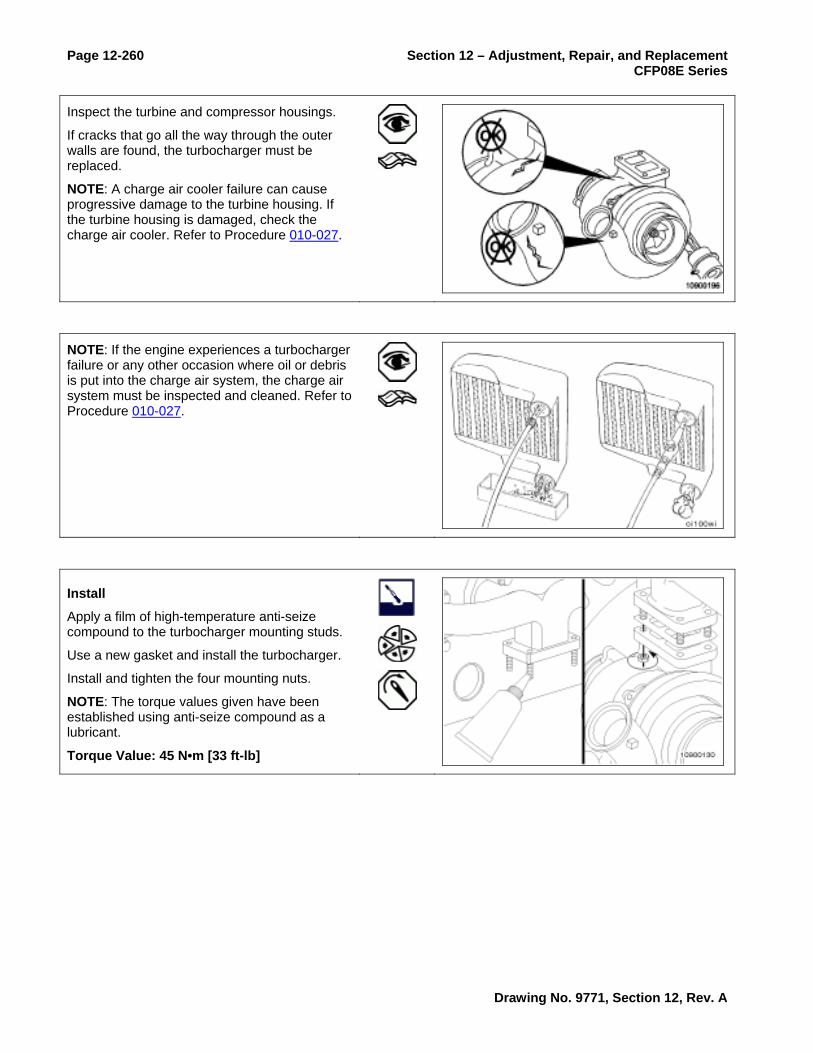
Page 12-260 Section 12 – Adjustment, Repair, and Replacement CFP08E Series
Inspect the turbine and compressor housings.
If cracks that go all the way through the outer walls are found, the turbocharger must be replaced.
NOTE: A charge air cooler failure can cause progressive damage to the turbine housing. If the turbine housing is damaged, check the charge air cooler. Refer to Procedure 010-027.
NOTE: If the engine experiences a turbocharger failure or any other occasion where oil or debris is put into the charge air system, the charge air system must be inspected and cleaned. Refer to Procedure 010-027.
Install
Apply a film of high-temperature anti-seize compound to the turbocharger mounting studs.
Use a new gasket and install the turbocharger.
Install and tighten the four mounting nuts.
NOTE: The torque values given have been established using anti-seize compound as a lubricant.
Torque Value: 45 N•m [33 ft-lb]
Drawing No. 9771, Section 12, Rev. A

Section 12 – Adjustment, Repair, and Replacement Page 12-261 CFP08E Series
Install the turbocharger compressor outlet elbow, v-band clamp, and new o-ring seal on the turbocharger compressor discharge outlet.
Tighten the clamp.
Torque Value: 8 N•m [71 in-lb]
Install the intake pipe to the turbocharger compressor inlet and tighten the clamp.
Torque Value: 8 N•m [71 in-lb]
Install the exhaust pipe to the turbocharger turbine outlet and tighten the clamp.
Torque Value: 8 N•m [71 in-lb]
Prime
Install the turbocharger oil drain line. Refer to Procedure 010-045.
Drawing No. 9771, Section 12, Rev. A

Page 12-262 Section 12 – Adjustment, Repair, and Replacement CFP08E Series
Lubricate the bearings by pouring 59 to 89 ml [2 to 3 oz] of clean 15W40 engine oil into the turbocharger oil supply line fitting. Rotate the turbine wheel to allow oil to enter the bearing. housing.
Install the turbocharger oil supply line. Refer to Procedure 010-046.
Follow-Up
Install the turbocharger coolant lines, variable geometry turbocharger only. Refer to Procedure 010-041.
Connect the turbocharger actuator air supply line, variable geometry turbocharger only. Refer to Procedure 010-118.
Connect the turbocharger speed sensor, variable geometry turbocharger only. Refer to Procedure 019-390 in the CM850 Electronic Control System ISC and ISL Engines Troubleshooting and Repair Manual, Bulletin 4021416.
Connect the turbocharger compressor air inlet temperature sensor, if equipped. Refer to Procedure 019-035 in the CM850 Electronic Control System ISC and ISL Engines Troubleshooting and Repair Manual, Bulletin 4021416.
Fill the cooling system, variable geometry turbocharger only. Refer to Procedure 008-018.
Operate the engine and check for leaks.
Drawing No. 9771, Section 12, Rev. A

Section 12 – Adjustment, Repair, and Replacement Page 12-263 CFP08E Series
Turbocharger Oil Drain Line Removal/Installation
Prepare
Remove
Remove the capscrews from the oil drain tube.
Pull the drain line out of the drain line boss.
Clean and Inspect for Reuse
Clean the gasket sealing surfaces.
Clean the o-ring seating bore and make sure it is free of dirt and debris.
Inspect the line for cracks, wear, and damage.
Inspect the o-ring for fretting and cracking. Replace if necessary.
Check the rubber section of the drain line for deterioration.
Drawing No. 9771, Section 12, Rev. A

Page 12-264 Section 12 – Adjustment, Repair, and Replacement CFP08E Series
Install
Apply a thin film of oil to the drain line o-rings.
Push the drain line into the drain line boss. Be sure both o-rings are completely seated in the bore.
Install a new gasket.
Install and tighten the turbocharger oil drain line.
Torque Value: 27 N•m [20 ft-lb]
Follow-Up
Operate the engine and check for leaks.
Drawing No. 9771, Section 12, Rev. A
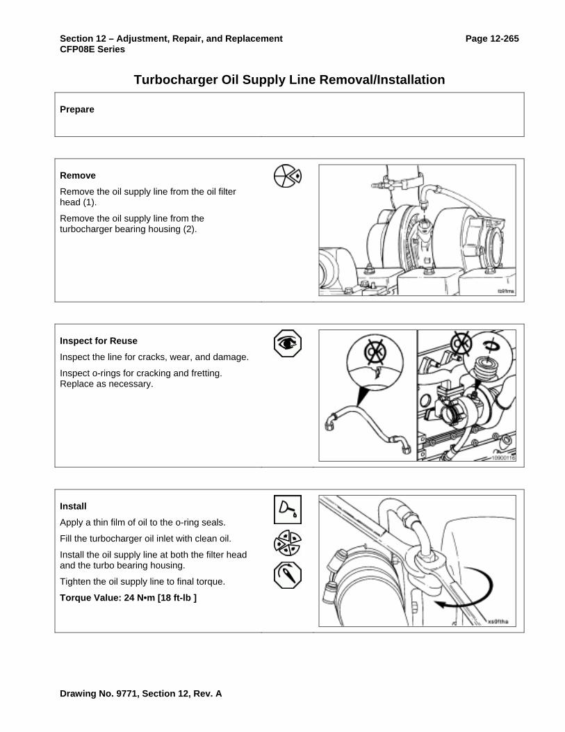
Section 12 – Adjustment, Repair, and Replacement Page 12-265 CFP08E Series
Turbocharger Oil Supply Line Removal/Installation
Prepare
Remove
Remove the oil supply line from the oil filter head (1).
Remove the oil supply line from the turbocharger bearing housing (2).
Inspect for Reuse
Inspect the line for cracks, wear, and damage.
Inspect o-rings for cracking and fretting. Replace as necessary.
Install
Apply a thin film of oil to the o-ring seals.
Fill the turbocharger oil inlet with clean oil.
Install the oil supply line at both the filter head and the turbo bearing housing.
Tighten the oil supply line to final torque.
Torque Value: 24 N•m [18 ft-lb ]
Drawing No. 9771, Section 12, Rev. A

Page 12-266 Section 12 – Adjustment, Repair, and Replacement CFP08E Series
Follow-Up
Drawing No. 9771, Section 12, Rev. A

Section 12 – Adjustment, Repair, and Replacement Page 12-267 CFP08E Series
Turbocharger Wastegate Actuator Checks
Initial Check
CAUTION All wastegates come pre-calibrated and can not be adjusted in the field. Attempts to adjust the wastegate can result in engine damage.
The integral wastegate line takes boost from the turbocharger compressor outlet to the wastegate capsule.
Inspect the integral wastegate actuator hose for cracks or holes. Replace the hose if damaged.
Inspect the wastegate mounting bracket, actuator rod, and lever for damage. A bent wastegate mounting bracket, actuator rod, or lever can cause improper operation.
If the wastegate mounting bracket, actuator rod, or lever is bent, it must be replaced.
Drawing No. 9771, Section 12, Rev. A

Page 12-268 Section 12 – Adjustment, Repair, and Replacement CFP08E Series
Test
In some applications the turbocharger must be removed to test the wastegate actuator. Refer to Procedure 010-033.
Disconnect the integral boost line from the wastegate capsule.
Attach a dial indicator (1) as shown, so that its shaft is in line with the wastegate actuator rod. Set the indicator to zero.
Connect clean, regulated air pressure and a pressure gauge to the capsule. Apply 200 kPa [29 psi] to make sure the wastegate is functioning properly.
The rod must move approximately 5 mm [0.200 in] without any sticking or air leakage.
Air must not be heard, such as air leaking through a functional wastegate capsule.
A small amount of travel when air pressure is first applied is normal. The tolerance is being removed from the system.
If no movement of the actuator rod is detected, detach the actuator control rod from the wastegate lever pin.
Actuate the lever by hand to be sure that the shaft rotates freely and is not seized.
If the wastegate lever can not be moved by hand, replace the turbocharger. Refer to Procedure 010-033.
If the wastegate lever moves freely by hand, replace the turbocharger wastegate actuator.
Drawing No. 9771, Section 12, Rev. A

Section 12 – Adjustment, Repair, and Replacement Page 12-269 CFP08E Series
Turbocharger Wastegate Actuator Removal/Installation
Prepare
Remove
In some applications the turbocharger must be removed in order to remove the wastegate actuator. Refer to Procedure 010-033.
Prior to removal, note position length of the control rod from the boost capsule housing and orientation of the boost capsule hose connector in relation to the mounting bracket.
Remove the retaining clip from the control lever.
Remove the integral boost line from the wastegate capsule.
Drawing No. 9771, Section 12, Rev. A

Page 12-270 Section 12 – Adjustment, Repair, and Replacement CFP08E Series
CAUTION Be careful not to bend the control lever. Engine damage can result.
Air Regulator with Pressure Gauge
Remove the boost capsule actuator rod end from the turbocharger wastegate lever. This can be accomplished by slowly applying regulated air pressure to the boost capsule until the control rod is activated.
Remove the control rod from the turbocharger wastegate lever pin.
If the boost capsule diaphragm material is ruptured and will not hold air pressure, manually pull the control rod outward in order to overcome boost capsule spring tension for removal of the control rod from the turbocharger wastegate lever pin.
Loosen the boost capsule mounting capscrews, disconnect the air supply hose, and remove the assembly from the mounting bracket.
Clean and Inspect for Reuse
Inspect the wastegate actuator hose for cracks or holes. Replace the hose if damaged.
Drawing No. 9771, Section 12, Rev. A

Section 12 – Adjustment, Repair, and Replacement Page 12-271 CFP08E Series
Inspect the wastegate mounting bracket, actuator rod, and lever for damage. A bent wastegate mounting bracket, actuator rod, or lever can cause improper operation.
If the wastegate mounting bracket, actuator rod, or lever is bent, it must be replaced.
Install
Pre-calibrated Wastegate Actuator
In most applications, the turbocharger must be removed in order to remove the wastegate actuator. Refer to Procedure 010-033.
Fit the actuator mounting studs into the holes in the bracket, and fit both actuator mounting capscrews.
Refit the end-link onto the crank-pin. Install the control rod retaining clip.
Torque Value: 8 N•m [71 in-lb ]
Cut the tie wrap and remove the tie wrap and spacer piece.
Drawing No. 9771, Section 12, Rev. A

Page 12-272 Section 12 – Adjustment, Repair, and Replacement CFP08E Series
Refit the air supply hose to the actuator using the new hose clamp provided.
Follow-Up
Drawing No. 9771, Section 12, Rev. A

Section 12 – Adjustment, Repair, and Replacement Page 12-273 CFP08E Series
Turbocharger Wastegate Valve Body Inspection
Prepare
Check
Inspect the lever pin.
Replace the turbocharger if worn excessively, Refer to Procedure 010-033.
Inspect the valve and valve seat for cracks or erosion.
Replace the turbocharger if damage is found. Refer to Procedure 010-033.
Actuate the lever by hand to verify that the shaft rotates freely and is not seized.
Check for excessive movement between the shaft and bushing.
Replace the turbine housing if the shaft and bushing are damaged or seized.
Drawing No. 9771, Section 12, Rev. A

Page 12-274 Section 12 – Adjustment, Repair, and Replacement CFP08E Series
Follow-Up
Drawing No. 9771, Section 12, Rev. A

Section 12 – Adjustment, Repair, and Replacement Page 12-275 CFP08E Series
Measure Intake Manifold Pressure
Prepare
Measure
Measure boost pressure at the intake manifold by using INSITE™ for hookup and monitoring procedures.
Operate the engine at rated rpm and full load. Record the boost reading.
Follow-Up
Drawing No. 9771, Section 12, Rev. A

Page 12-276 Section 12 – Adjustment, Repair, and Replacement CFP08E Series
Air Intake Connection Removal/Installation
Prepare
WARNING
Batteries can emit explosive gases. To reduce the possibility of personal injury, always ventilate the compartment before servicing the batteries. To reduce the possibility of arcing, remove the negative (-) battery cable first and attach the negative (-) battery cable last.
Disconnect the batteries and grid heater wiring.
Remove the air inlet crossover tube. Refer to Procedure 010-019.
Remove the air inlet connection, if equipped. Refer to Procedure 010-022.
Remove the injector supply lines, if required. Refer to Procedure 006-051.
Remove
Remove the mounting capscrews.
Remove the air intake connection.
Tape off the intake manifold opening to prevent debris from entering the intake system.
NOTE: Be sure not to tape over the entire manifold edges so that the surface can be cleaned.
NOTE: On engines with the grid heater mounted on top of the intake manifold cover, the grid heater will now be loose.
Drawing No. 9771, Section 12, Rev. A

Section 12 – Adjustment, Repair, and Replacement Page 12-277 CFP08E Series
Clean and Inspect for Reuse
Clean the sealing surfaces.
NOTE: Keep gasket material and any other material out of the air intake.
Inspect the air intake connection for cracks or other damage.
Install
Install the air intake connection and a new gasket.
Torque Value: 24 N•m [18 ft-lb]
NOTE: Some capscrews are shared with fuel line braces on some engines.
NOTE: On some engines, the air intake connection mounts on top of the grid heater and shares capscrews.
Follow-Up
Install the injector supply lines, if removed. Refer to Procedure 006-051.
Connect the air inlet connection, if equipped. Refer to Procedure 010-022.
Install the air crossover tube. Refer to Procedure 010-019.
Connect the cold starting aid and batteries.
Operate the engine and check for leaks.
Drawing No. 9771, Section 12, Rev. A

Page 12-278 Section 12 – Adjustment, Repair, and Replacement CFP08E Series
Air Intake Manifold Cover Removal/Installation
Prepare
Disconnect the cold starting aid.
Remove the air crossover tube. Refer to Procedure 010-019.
Disconnect the air inlet connection, if equipped. Refer to Procedure 010-022.
Remove the air intake connection. Refer to Procedure 010-080.
Remove the injector supply lines, if required. Refer to Procedure 006-051.
Remove the turbocharger control valve, if equipped. Refer to Procedure 019-388 in Troubleshooting and Repair Manual, CM870 Electronic Control System, ISC and ISL Engines, Bulletin 4021416.
Remove
Some engines have a grid heater mounted on top of the intake manifold cover. Remove the grid heater, if equipped. Refer to Procedure 010-029.
Remove the mounting capscrews and the intake cover.
Tape off the intake manifold opening to prevent debris from entering the intake system.
NOTE: Be sure not to tape over the entire manifold edges so that the surface can be cleaned.
Drawing No. 9771, Section 12, Rev. A

Section 12 – Adjustment, Repair, and Replacement Page 12-279 CFP08E Series
Clean and Inspect for Reuse
Clean the sealing surfaces.
NOTE: Keep the gasket material and any other material out of the air intake.
Remove the tape.
Inspect the intake manifold for cracks or other damage.
NOTE: When inspecting the intake manifold for oil or debris from an air system failure, also inspect the cylinder head for oil and debris.
Install
Install the cover with intake air heater (if equipped) and a new gasket.
Torque Value: 24 N•m [18 ft-lb ]
NOTE: Some capscrews are shared with fuel line braces on some engines.
Drawing No. 9771, Section 12, Rev. A

Page 12-280 Section 12 – Adjustment, Repair, and Replacement CFP08E Series
Follow-Up
Install the grid heater, if equipped. Refer to Procedure 010-029.
Install the injector supply lines, if removed. Refer to Procedure 006-051.
Install the air intake connection. Refer to Procedure 010-080.
Install the air inlet connection, if used. Refer to Procedure 010-022.
Install the turbocharger control valve, if equipped. Refer to Procedure 019-388 in Troubleshooting and Repair Manual, CM870 Electronic Control System, ISC and ISL Engines, Bulletin 4021416.
Install the air crossover tube. Refer to Procedure 010-019.
Connect the cold starting aid.
Operate the engine and check for leaks.
Drawing No. 9771, Section 12, Rev. A

Section 12 – Adjustment, Repair, and Replacement Page 12-281 CFP08E Series
Charge Air Cooler (CAC) Removal and Installation
Prepare
Remove
Install
Follow-Up
Drawing No. 9771, Section 12, Rev. A

Page 12-282 Section 12 – Adjustment, Repair, and Replacement CFP08E Series
Clean the Charge Air Cooler
Clean
If the engine experiences a turbocharger failure or any other occasion where oil or debris is put into the charge air cooler, the charge air cooler must be cleaned.
Remove the charge air cooler piping and charge air cooler from the vehicle. Refer to the equipment manufacturer's instructions.
WARNING When using solvents, acids, or alkaline materials for cleaning, follow the manufacturer's recommendations for use. Wear goggles and protective clothing to reduce the possibility of personal injury.
CAUTION Do not use caustic cleaners to clean the charge air cooler. Damage to the charge air cooler will result.
Flush the charge air cooler internally with solvent in the opposite direction of normal airflow. Shake the charge air cooler, and lightly tap on the end tanks with a rubber mallet to dislodge trapped debris. Continue flushing until all debris or oil is removed (i.e., the water runs clear).
NOTE: Make sure that the tubes are in the vertical direction when flushing.
If the debris can not be totally removed from the charge air cooler, the charge air cooler must be replaced.
Drawing No. 9771, Section 12, Rev. A

Section 12 – Adjustment, Repair, and Replacement Page 12-283 CFP08E Series
WARNING Wear appropriate eye and face protection when using compressed air. Flying debris and dirt can cause personal injury.
CAUTION The charge air cooler must be rinsed, dried, and free of solvent, oil, and debris, or engine damage will result.
After the charge air cooler has been thoroughly cleaned of all oil and debris with solvent, wash the charge air cooler internally with hot soapy water to remove the remaining solvent. Rinse thoroughly with clean water.
Blow compressed air through the inside of the charge air cooler in the opposite direction of normal air flow until the charge air cooler is dry internally.
Drawing No. 9771, Section 12, Rev. A

Page 12-284 Section 12 – Adjustment, Repair, and Replacement CFP08E Series
Inspect Charge Air Cooler (CAC)
Inspect for Reuse
Inspect the charge air cooler for cracks, holes, or damage.
Inspect the tubes, fins, and welds for tears, breaks, or other damage. If any damage causes the charge air cooler to fail the air leak check, the charge air cooler must be replaced. Refer to Procedure 010-024.
Install the charge air cooler and charge air cooler piping on the vehicle. Refer to the vehicle manufacturer's instructions.
NOTE: Always clean and inspect the charge air cooler piping and hoses prior to installation.
Drawing No. 9771, Section 12, Rev. A

Section 12 – Adjustment, Repair, and Replacement Page 12-285 CFP08E Series
Charge Air Cooler Pressure Test
Pressure Test
Mercury Manometer, Part Number ST-1111-3
Preferred Method
Measure the charge air cooler system pressure drop with a mercury manometer.
Install one end of a mercury manometer, Part Number ST-1111-3, in the 1/8-inch fitting in the turbocharger compressor outlet elbow.
Install the other end of the mercury manometer in the intake manifold.
Operate the engine at rated rpm and load. Record the readings on the manometer.
If the differential pressure is greater than 152 mm Hg [6 in Hg], check the charge air cooler and associated piping for plugging, restrictions, or damage.
Clean or replace, if necessary.
Drawing No. 9771, Section 12, Rev. A

Page 12-286 Section 12 – Adjustment, Repair, and Replacement CFP08E Series
Pressure Gauge, Part Number ST-1273
Optional Method
Obtain two pressure gauges, Part Number ST-1273. Check both gauges on the same pressure source at 206 kPa [30 psi] to maintain consistency.
Install one pressure gauge in the 1/8-inch fitting in the turbocharger compressor outlet elbow.
Install the other pressure gauge in the intake manifold.
Operate the engine at rated rpm and load. Record the readings on the two gauges.
If the differential pressure is greater than 152 mm Hg [6 in Hg], check the charge air cooler and associated piping for plugging, restrictions, or damage.
Clean or replace, if necessary.
Drawing No. 9771, Section 12, Rev. A

Section 12 – Adjustment, Repair, and Replacement Page 12-287 CFP08E Series
Charge Air Cooler Leak Test
Leak Test
WARNING To prevent possible injury if either plug blows off during the test, secure safety chains on the test plugs to any convenient capscrew on the radiator assembly. This test must be performed with securely fastened safety chains.
To check the charge air cooler for cracked tubes or header, remove the inlet and outlet hoses from the cooler. The charge air cooler does not have to be removed from the chassis.
Install a plug or cap over the outlet side of the cooler. Install a pressure gauge and a regulated shop air supply line with a shutoff valve to the inlet side of the cooler.
Apply air pressure to the cooler until the pressure gauge reads a steady 207 kPa [30 psi] of air pressure.
Shutoff the air flow to the cooler, and start a stopwatch at the same time. Record the leakage at 15 seconds.
If the pressure drop is 48 kPa [7 psi] or less in 15 seconds, the cooler is operational.
If the pressure drop is greater than 48 kPa [7 psi] in 15 seconds, check all connections again.
Determine if the pressure drop is caused by a leak in the charge air cooler or by a leaky connection. Use a spray bottle filled with soapy water applied to all hose connections, and watch for bubbles to appear at the location of the leak.
If the pressure drop is caused by a leaky connection, repair the connection, and repeat the test. If the leak is within the charge air cooler, repeat the test to verify the accuracy of the pressure drop measurement. Similar pressure drop readings must be obtained at least three consecutive tests before the reading
Drawing No. 9771, Section 12, Rev. A

Page 12-288 Section 12 – Adjustment, Repair, and Replacement CFP08E Series
can be considered accurate.
NOTE: If a charge air cooler leaks more than 48 kPa [7 psi] in 15 seconds, it will appear as a major leak in a leak tank.
If the pressure drop is greater than 48 kPa [7 psi] in 15 seconds, the charge air cooler must be replaced.
Refer to the equipment manufacturer's service manual for replacement instructions.
NOTE: Charge air coolers are not designed to be 100-percent leak-free. If the pressure drop is less than 48 kPa [7 psi] in 15 seconds, then the charge air cooler does not need to be replaced.
Drawing No. 9771, Section 12, Rev. A

Section 12 – Adjustment, Repair, and Replacement Page 12-289 CFP08E Series
Charge Air Cooler (CAC) Temperature Differential Test
Temperature Differential Test
Inspect the charge air cooler fins for obstructions to air flow. Remove obstructions such as a winterfront or debris. Manually lock shutters in the OPEN position, if equipped.
Lock the fan drive in the ON mode to prevent erratic test results. This can be done by installing a jumper wire across the temperature switch.
Install fluke digital thermometer, Part Number 3822666, into the intake manifold at the 1/8-inch NPT tap near the air horn connection with the intake manifold.
Another alternative is to use the monitor mode on the INSITE™ electronic service tool.
Install another thermocouple at the air cleaner inlet to measure ambient air temperature.
Perform a road test with the engine at peak power and a vehicle speed of 48 kph [30 mph] or greater.
Record the intake manifold temperature and the ambient air temperature.
Calculate the differential temperature:
Intake Manifold Temperature minus Ambient Air Temperature equals Differential Temperature
Maximum Differential Temperature equals 28°C [50°F].
Drawing No. 9771, Section 12, Rev. A

Page 12-290 Section 12 – Adjustment, Repair, and Replacement CFP08E Series
If the temperature differential is greater than the specifications, check the charge air cooler for dirt and debris on the fins and clean as necessary. If the problem still exists, check the charge air cooler for debris in the fins or between the charge air cooler and radiator. Confirm full fan engagement.
Drawing No. 9771, Section 12, Rev. A

Section 12 – Adjustment, Repair, and Replacement Page 12-291 CFP8E Series
Fill and Drain Lubricating Oil
Drain
WARNING To reduce the possibility of personal injury, avoid direct contact of hot oil with your skin.
WARNING Some state and federal agencies have determined that used engine oil can be carcinogenic and cause reproductive toxicity. Avoid inhalation of vapors, ingestion, and prolonged contact with used engine oil. If not reused, dispose of in accordance with local environmental regulations.
NOTE: Use a container that can hold at least 23.6 liters [25 qt] of lubricating oil.
NOTE: For composite oil pans, hold the external locking nut in position with a separate wrench while removing the drain plug. This will prevent the bulkhead from loosening during drain plug removal.
Operate the engine until the coolant temperature reaches 60°C [140°F]. Shut off the engine.
Remove the oil drain plug.
Drain the oil immediately to make sure all the oil and suspended contaminants are removed from the engine.
Drawing No. 9771, Section 12, Rev. A

Page 12-292 Section 12 – Adjustment, Repair, and Replacement CFP8E Series
Fill
CAUTION For composite oil pans, always use a new sealing washer on the oil drain plug. Hold the external locking nut in place while tightening the oil drain plug.
Clean and check the lubricating oil drain plug threads and sealing surface.
Install the lubricating oil pan drain plug.
Steel Oil Pan Torque Value 80 N•m [59 ft-lb]
Cast Aluminum Oil Pan Torque Value 60 N•m [45 ft-lb]
Composite Oil Pan Torque Value 60 N•m [45 ft-lb]
NOTE: Use a high quality 15W-40 multiviscosity oil, such as Cummins Premium Blue®, or equivalent, in Cummins engines. Choose the correct oil for your operating climate as outlined in the Operation and Maintenance Manual.
Fill the engine with clean lubricating oil to the proper level.
NOTE: When filling the oil pan, use the fill tube on the side of the engine rather than on top of the rocker lever cover.
Refer to Section V for lubricating oil pan capacities.
Drawing No. 9771, Section 12, Rev. A

Section 12 – Adjustment, Repair, and Replacement Page 12-293 CFP8E Series
WARNING If no oil pressure is noted within 15 seconds after the engine is started, shut down the engine to reduce the possibility of internal damage.
Idle the engine to inspect for leaks at the drain plug.
Shut off the engine. Wait approximately 10 minutes to let the oil drain from the upper parts of the engine. Check the level again.
Add oil as necessary to bring the oil level to the “H” (high) mark on the dipstick.
Drawing No. 9771, Section 12, Rev. A

Page 12-294 Section 12 – Adjustment, Repair, and Replacement CFP8E Series
Lubricating Oil Cooler Removal/Installation
Prepare
WARNING Coolant is toxic. Keep away from children and pets. If not reused, dispose of in accordance with local environmental regulations.
WARNING Do not remove the pressure cap from a hot engine. Wait until the coolant temperature is below 50°C [120°F] before removing the pressure cap. Heated coolant spray or steam can cause personal injury.
WARNING To reduce the possibility of personal injury, avoid direct contact of hot oil with your skin.
WARNING State and federal agencies have determined that used engine oil can be carcinogenic and cause reproductive toxicity. Avoid inhalation of vapors, ingestion, and prolonged contact with used engine oil. If not reused, dispose of in accordance with local environmental regulations.
Drain the coolant. Refer to Procedure 008-018.
Clean the area around the lubricating oil cooler cover.
Remove the lubricating oil filter. Refer to Procedure 007-013.
Remove the turbocharger oil supply line. Refer to Procedure 010-046.
Drawing No. 9771, Section 12, Rev. A

Section 12 – Adjustment, Repair, and Replacement Page 12-295 CFP8E Series
Remove
Remove the lubricating oil cooler cover, gaskets and cooler element.
Clean
Clean the sealing surfaces of the cylinder block and the oil cooler cover.
Leak Test
Pressure-test the lubricating oil cooler element using leak test kit, Part Number 3823876.
Air Pressure Test
Minimum 449 kPa [65 psi]
Maximum 518 kPa [75 psi]
Install
NOTE: Be sure to remove the shipping plugs from a new element.
Assemble the lubricating oil cooler gaskets, element, and cooler cover.
Drawing No. 9771, Section 12, Rev. A

Page 12-296 Section 12 – Adjustment, Repair, and Replacement CFP8E Series
Tighten the capscrews in the sequence shown in the illustration.
Torque Value: 24 N•m [18 ft-lb]
Tighten the capscrews in the sequence shown in the illustration, in two steps. The arrow (A) points to the dimple.
Step one: Torque Value: 24 N•m [18 ft-lb]
Step two: Torque Value: 32 N•m [24 ft-lb]
Drawing No. 9771, Section 12, Rev. A

Section 12 – Adjustment, Repair, and Replacement Page 12-297 CFP8E Series
Follow-Up
WARNING Coolant is toxic. Keep away from children and pets. If not reused, dispose of in accordance with local environmental regulations.
WARNING To reduce the possibility of personal injury, avoid direct contact of hot oil with your skin.
WARNING State and federal agencies have determined that used engine oil can be carcinogenic and cause reproductive toxicity. Avoid inhalation of vapors, ingestion, and prolonged contact with used engine oil. If not reused, dispose of in accordance with local environmental regulations.
Install the turbocharger oil supply line. Refer to Procedure 010-046.
Install the lubricating oil filter. Refer to Procedure 007-013.
Fill the engine with coolant. Refer to Procedure 008-018.
Operate the engine and check for leaks.
Stop the engine and check the coolant and lubricating oil levels.
Drawing No. 9771, Section 12, Rev. A

Page 12-298 Section 12 – Adjustment, Repair, and Replacement CFP8E Series
Lubricating Oil Dipstick Tube Removal/Installation
Prepare
Clean the area around the dipstick tube before removing to prevent debris from entering the oil system.
Remove
Remove dipstick from the dipstick tube.
Remove dipstick tube from the cylinder block.
Service Tip: Use a dent puller and a M8 x 1.25 x 21-mm self-tapping capscrew. Thread the capscrew into the dipstick tube and remove the tube.
Install
Apply a thin bead of Loctite™ 609, part number 3823718 or equivalent, around the bottom of the knurled end of the tube.
Place the knurled end of the tube into the dipstick tube bore in the cylinder block.
Use a flat washer and hex head capscrew to drive the tube into the cylinder block.
Lightly drive the dipstick tube until it seats against the block casting.
Drawing No. 9771, Section 12, Rev. A

Section 12 – Adjustment, Repair, and Replacement Page 12-299 CFP8E Series
Install the dipstick into the dipstick tube.
Follow-Up
Drawing No. 9771, Section 12, Rev. A

Page 12-300 Section 12 – Adjustment, Repair, and Replacement CFP8E Series
Lubricating Oil Dipstick Calibration
Prepare
Calibrate
WARNING Some state and federal agencies have determined that used engine oil can be carcinogenic and can cause reproductive toxicity. Avoid inhalation of vapors, ingestion, and prolonged contact with used engine oil. If not reused, dispose of in accordance with local environmental regulations.
WARNING To reduce the possibility of personal injury, avoid direct contact of hot oil with your skin.
Drain the lubricating oil. Refer to Procedure 007-037.
Install the dipstick in the dipstick tube housing.
Use clean 15W-40 oil to fill the oil pan to the specified LOW oil level. Refer to Lubricating Oil System Specifications in Procedure 018-017 of this manual for the correct engine oil capacity.
CAUTION Use care when marking the dipstick. The dipstick will break if the scribe mark is too deep.
Remove the dipstick and scribe a mark across the stick at the oil level. Label the mark with an L to indicate the "LOW" oil level.
NOTE: If a new blank dipstick is being used, cut the dipstick off approximately 38 mm [1.5 in] below the LOW oil level mark.
Drawing No. 9771, Section 12, Rev. A

Section 12 – Adjustment, Repair, and Replacement Page 12-301 CFP8E Series
Wipe off the dipstick and install it in the dipstick tube housing.
Fill the oil pan to the specified HIGH oil level. Refer to Lubricating Oil System Specifications in Procedure 018-017 of this manual for the correct engine oil capacity.
CAUTION Use care when marking the dipstick. The dipstick will break if the scribe mark is too deep.
Remove the dipstick and scribe a mark across the stick at the oil level. Label the mark with an H to indicate the HIGH oil level.
Follow-Up
Drawing No. 9771, Section 12, Rev. A

Page 12-302 Section 12 – Adjustment, Repair, and Replacement CFP8E Series
Lubricating Oil Filter Removal/Installation
Prepare
Remove
Clean the area around the lubricating oil filter head.
Remove the oil filter with oil filter wrench, Part Number 3375049.
Clean the gasket surface of the filter head.
Install
Lubricate the oil filter gasket with clean engine oil.
Fill the oil filter with clean engine oil.
Install the filter on the oil filter head. Tighten the filter until the gasket contacts the filter head surface.
Use oil filter wrench, Part Number 3375049, to tighten the filter an additional ½ to ¾ of a turn, or follow the instructions supplied with the oil filter.
Drawing No. 9771, Section 12, Rev. A

Section 12 – Adjustment, Repair, and Replacement Page 12-303 CFP8E Series
Follow-Up
Operate the engine and check for leaks.
Drawing No. 9771, Section 12, Rev. A

Page 12-304 Section 12 – Adjustment, Repair, and Replacement CFP8E Series
Lubricating Oil Bypass Valve Removal/Installation
General Information
Whenever the pressure drop across the lubricating oil filter exceeds a predetermined set point, the oil filter bypass valve opens and allows lubricating oil to bypass the lubricating oil filter.
This condition can occur during cold ambient (cold lubricating oil) engine start-ups.
The purpose of the bypass valve is to maintain lubricating oil flow to the engine and prevent an oil filter collapse.
Prepare
Remove the lubricating oil filter. Refer to Procedure 007-013.
Remove the lubricating oil filter head. Refer to Procedure 007-015.
Remove the 3/4-inch pipe plug from the end of the oil filter head.
Remove
Using a screwdriver, gently push down on the top of the bypass valve to remove it from the bore.
Drawing No. 9771, Section 12, Rev. A

Section 12 – Adjustment, Repair, and Replacement Page 12-305 CFP8E Series
Clean and Inspect for Reuse
WARNING When using solvents, acids, or alkaline materials for cleaning, follow the manufacturer's recommendations for use. Wear goggles and protective clothing to reduce the possibility of personal injury.
WARNING Some solvents are flammable and toxic. Read the manufacturer's instructions before using.
WARNING Wear appropriate eye and face protection when using compressed air. Flying debris and dirt can cause personal injury.
Clean the bypass valve with solvent.
Dry with compressed air.
Inspect the bypass valve seat for damage. Make sure the valve fully closes.
Drawing No. 9771, Section 12, Rev. A

Page 12-306 Section 12 – Adjustment, Repair, and Replacement CFP8E Series
Install
Insert the bypass valve into the bore. The spring should be pointing upward into the bore.
Gently seat the bypass valve into the bore until it seats.
Install the 3/4-inch pipe plug into the end of the oil filter head.
Torque Value: 45 N•m [33 ft-lb]
Follow-Up
Install the lubricating oil filter head. Refer to Procedure 007-015.
Install the lubricating oil filter. Refer to Procedure 007-013.
Drawing No. 9771, Section 12, Rev. A

Section 12 – Adjustment, Repair, and Replacement Page 12-307 CFP8E Series
Lubricating Oil Filter Head Removal/Installation
Prepare
WARNING Do not remove the pressure cap from a hot engine. Wait until the coolant temperature is below 50°C [120°F] before removing the pressure cap. Heated coolant spray or steam can cause personal injury.
WARNING Coolant is toxic. Keep away from children and pets. If not reused, dispose of in accordance with local environmental regulations.
Drain the coolant. Refer to Procedure 008-018.
Remove the lubricating oil cooler. Refer to Procedure 007-003.
Remove
Remove the lubricating oil filter head capscrews, filter head, and gasket.
Drawing No. 9771, Section 12, Rev. A

Page 12-308 Section 12 – Adjustment, Repair, and Replacement CFP8E Series
Clean and Inspect for Reuse
WARNING When using solvents, acids, or alkaline materials for cleaning, follow the manufacturer's recommendations for use. Wear goggles and protective clothing to reduce the possibility of personal injury.
WARNING Some solvents are flammable and toxic. Read the manufacturer's instructions before using.
Use solvent to clean the adapter.
Inspect the adapter for cracks and other damage.
Install
Install the oil filter head, gasket, and capscrews.
Torque Value: 24 N•m [18 ft-lb]
Drawing No. 9771, Section 12, Rev. A

Section 12 – Adjustment, Repair, and Replacement Page 12-309 CFP8E Series
Follow-Up
Install the lubricating oil cooler. Refer to Procedure 007-003.
Fill the cooling system. Refer to Procedure 008-018.
Operate engine and check for leaks.
Drawing No. 9771, Section 12, Rev. A

Page 12-310 Section 12 – Adjustment, Repair, and Replacement CFP8E Series
Lubricating Oil High Pressure Relief Valve Removal/Installation
Prepare
Remove
Remove the oil cooler bypass valve.
Inspect for Reuse
Inspect for a damaged o-ring, broken spring or other damage.
Install
Install the oil cooler bypass valve.
Torque Value: 50 N•m [37 ft-lb]
Follow-Up
Lubricating Oil Pan Removal/Installation
Drawing No. 9771, Section 12, Rev. A

Section 12 – Adjustment, Repair, and Replacement Page 12-311 CFP8E Series
Prepare
WARNING To reduce the possibility of personal injury, avoid direct contact of hot oil with your skin.
WARNING Some state and federal agencies have determined that used engine oil can be carcinogenic and cause reproductive toxicity. Avoid inhalation of vapors, ingestion, and prolonged contact with used engine oil. If not reused, dispose of in accordance with local environmental regulations.
Drain the lubricating oil. Refer to Procedure 007-037.
Remove
Remove the lubricating oil pan and gasket.
If suction tube must be removed, refer to Procedure 007-035.
If the engine is equipped with a block stiffener plate, refer to Procedure 001-089.
Drawing No. 9771, Section 12, Rev. A

Page 12-312 Section 12 – Adjustment, Repair, and Replacement CFP8E Series
Clean and Inspect for Reuse
WARNING When using a steam cleaner, wear safety glasses or a face shield, as well as protective clothing. Hot steam can cause serious personal injury.
WARNING Wear appropriate eye and face protection when using compressed air. Flying debris and dirt can cause personal injury.
Remove all gasket material from the cylinder block and oil pan surface.
Steam-clean the oil pan.
Dry with compressed air.
Inspect the oil pan, suction tube, and tube braces for damage.
NOTE: If cracks are found, replace the damaged part. Do not attempt to repair the oil pan by welding.
If the suction tube must be replaced; refer to Procedure 007-035.
Composite Oil Pan Only
Make sure the bulkhead fitting is tight. If it is found to be loose, replace the o-ring and tighten the bulkhead.
Torque Value: 24 N•m [20 ft-lb]
Drawing No. 9771, Section 12, Rev. A

Section 12 – Adjustment, Repair, and Replacement Page 12-313 CFP8E Series
Install
Use Three-Bond™ RTV sealant, or equivalent, to fill the joints between the lubricating oil pan rail, gear housing, and rear seal housing.
If the suction tube has been removed; refer to Procedure 007-035 for installation instructions.
If the engine is equipped with a block stiffener plate, refer to Procedure 001-089.
Install the gasket and lubricating oil pan.
Install the oil pan corner braces, if equipped.
NOTE: New noise isolators must be used with oil pans using the isolated gasket system.
Assemble the washers and capscrews to secure the lubricating oil pan as illustrated.
Tighten all capscrews in the sequence shown in the accompanying chart.
Torque Value: 28 N•m [21 ft-lb]
Follow-Up
Fill the lubricating oil system. Refer to Procedure 007-037.
Operate the engine and check for leaks.
Drawing No. 9771, Section 12, Rev. A

Page 12-314 Section 12 – Adjustment, Repair, and Replacement CFP8E Series
Lubricating Oil Pressure Regulator Removal/Installation
Prepare
Remove
WARNING When using solvents, acids, or alkaline materials for cleaning, follow the manufacturer's recommendations for use. Wear goggles and protective clothing to reduce the possibility of personal injury.
WARNING Some solvents are flammable and toxic. Read the manufacturer's instructions before using.
Thoroughly clean the area around the pressure regulator plug with clean solvent to prevent debris from falling into the plunger bore when the plug is removed.
Remove the threaded plug, spring, and plunger.
Service Tip: The plunger normally can be removed by inserting one finger into the plunger bore until snug and pulling down. If the plunger can not be removed in this manner, the plunger is probably stuck and will require removal of the housing for cleaning the plunger.
Drawing No. 9771, Section 12, Rev. A
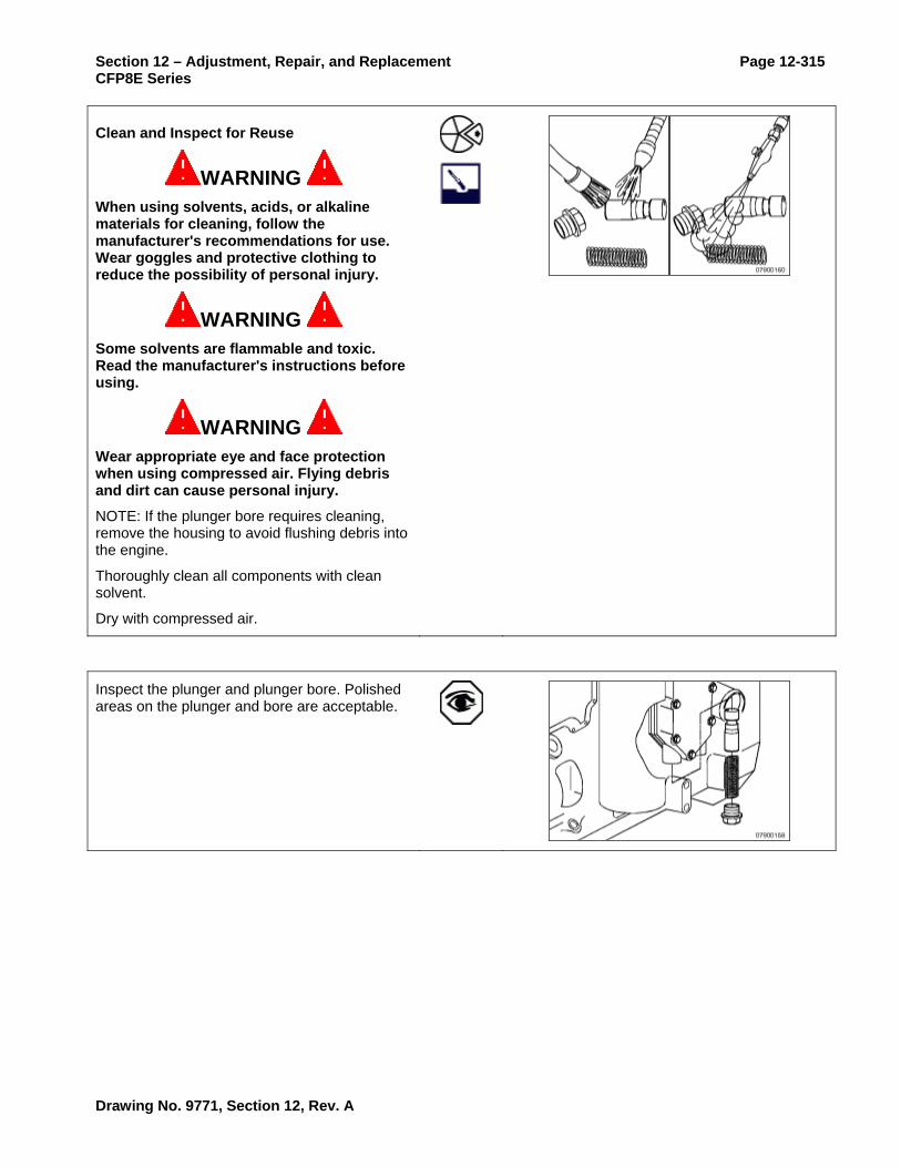
Section 12 – Adjustment, Repair, and Replacement Page 12-315 CFP8E Series
Clean and Inspect for Reuse
WARNING When using solvents, acids, or alkaline materials for cleaning, follow the manufacturer's recommendations for use. Wear goggles and protective clothing to reduce the possibility of personal injury.
WARNING Some solvents are flammable and toxic. Read the manufacturer's instructions before using.
WARNING Wear appropriate eye and face protection when using compressed air. Flying debris and dirt can cause personal injury.
NOTE: If the plunger bore requires cleaning, remove the housing to avoid flushing debris into the engine.
Thoroughly clean all components with clean solvent.
Dry with compressed air.
Inspect the plunger and plunger bore. Polished areas on the plunger and bore are acceptable.
Drawing No. 9771, Section 12, Rev. A

Page 12-316 Section 12 – Adjustment, Repair, and Replacement CFP8E Series
Verify that the plunger moves freely in the bore.
Install
Install a new sealing o-ring on the threaded plug and lubricate with clean engine oil. Install the pressure regulator assembly.
Torque Value: 80 N•m [59 ft-lb]
Follow-Up
Drawing No. 9771, Section 12, Rev. A

Section 12 – Adjustment, Repair, and Replacement Page 12-317 CFP8E Series
Lubricating Oil Pump Removal/Installation
Prepare
Remove the fan drive belt. Refer to Procedure 008-002.
Remove the vibration damper. Refer to Procedure 001-052.
Remove the front cover. Refer to Procedure 001-031.
Remove
Remove the four mounting capscrews.
Remove the pump from the bore in the cylinder block.
Disassemble
If the lubricating oil pump is to be inspected for reuse, follow these steps.
Inspect the lubricating oil pump gears for chips, cracks, or excessive wear.
Remove the back plate.
NOTE: The ISC, QSC8.3, ISL, and QSL9 lubricating oil pump uses a large diameter 5/6 rotor set. The graphics in this manual illustrate a 4/5 rotor set.
Drawing No. 9771, Section 12, Rev. A

Page 12-318 Section 12 – Adjustment, Repair, and Replacement CFP8E Series
Mark TOP on the gerotor planetary.
Remove the gerotor planetary.
Inspect for excessive wear or damage.
Clean and Inspect for Reuse
WARNING When using solvents, acids, or alkaline materials for cleaning, follow the manufacturer's recommendations for use. Wear goggles and protective clothing to reduce the possibility of personal injury.
WARNING Some solvents are flammable and toxic. Read the manufacturer's instructions before using.
WARNING Wear appropriate eye and face protection when using compressed air. Flying debris and dirt can cause personal injury.
Clean all parts in solvent.
Dry with compressed air.
Drawing No. 9771, Section 12, Rev. A

Section 12 – Adjustment, Repair, and Replacement Page 12-319 CFP8E Series
Inspect the lubricating oil pump housing and gerotor drive for damage and excessive wear.
Assemble
CAUTION Make sure that the gerotor planetary is installed in the original position.
Install the gerotor planetary.
Measure the tip clearance.
Tip Clearance
Minimum 0.025 mm [0.001 in]
Maximum 0.1778 mm [0.007 in]
Measure the clearance of the gerotor drive/gerotor planetary to port plate.
Gerotor Drive/Gerotor Planetary to Port Plate Clearance
Minimum 0.025 mm [0.001 in]
Maximum 0.127 mm [0.005 in]
Drawing No. 9771, Section 12, Rev. A

Page 12-320 Section 12 – Adjustment, Repair, and Replacement CFP8E Series
Measure the clearance of the gerotor planetary to the body bore.
Gerotor Planetary to Body Bore Clearance
Minimum 0.1778 mm [0.007 in]
Maximum 0.381 mm [0.015 in]
Measure the backlash.
Lubricating Oil Pump Gears Backlash Limits (Used Pump)
Minimum 0.076 mm [0.003 in]
Maximum 0.330 mm [0.013 in]
Install the back plate.
Install
CAUTION Failure to fill the pump with oil during installation can result in a failure of the lubricating oil pump to prime at initial engine start-up, resulting in severe engine damage.
Lubricate the lubricating oil pump with clean 15W-40 engine oil.
Drawing No. 9771, Section 12, Rev. A

Section 12 – Adjustment, Repair, and Replacement Page 12-321 CFP8E Series
CAUTION Make sure the idler gear pin is installed in the locating bore in the cylinder block.
Install the lubricating oil pump.
Tighten capscrews in an X pattern, starting with the upper right capscrew.
Torque Value: 24 N•m [18 ft-lb]
NOTE: Be sure the gear backlash is correct if installing a new lubricating oil pump.
Measure the gear backlash.
Lubricating Oil Pump Gears Backlash Limits (Installed)
A Minimum 0.076 mm [0.003 in]
A Maximum 0.330 mm [0.013 in]
B Minimum 0.076 mm [0.003 in]
B Maximum 0.330 mm [0.013 in]
NOTE: If the adjoining gear moves when you measure the backlash, the reading will be incorrect.
Lubricate the front gear train with clean 15W-40 engine oil.
Drawing No. 9771, Section 12, Rev. A
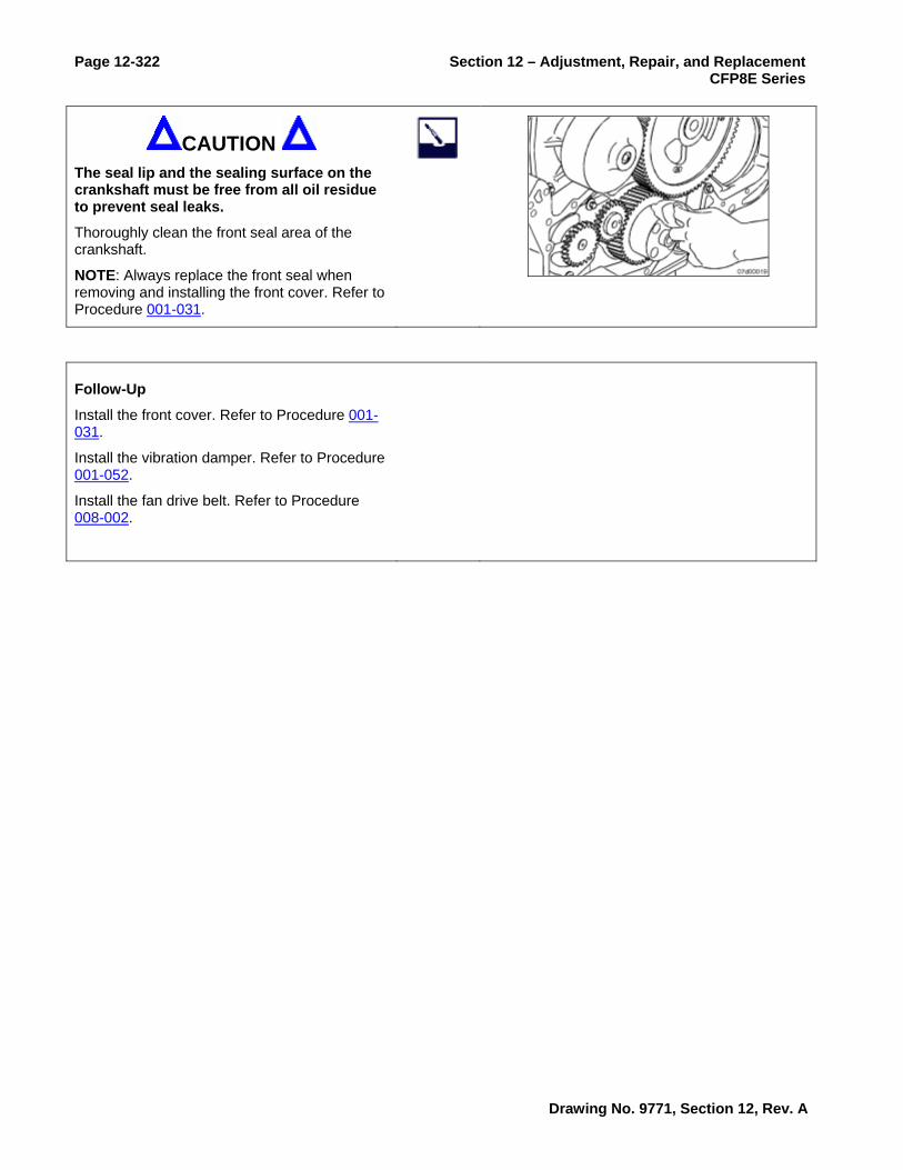
Page 12-322 Section 12 – Adjustment, Repair, and Replacement CFP8E Series
CAUTION The seal lip and the sealing surface on the crankshaft must be free from all oil residue to prevent seal leaks.
Thoroughly clean the front seal area of the crankshaft.
NOTE: Always replace the front seal when removing and installing the front cover. Refer to Procedure 001-031.
Follow-Up
Install the front cover. Refer to Procedure 001-031.
Install the vibration damper. Refer to Procedure 001-052.
Install the fan drive belt. Refer to Procedure 008-002.
Drawing No. 9771, Section 12, Rev. A

Section 12 – Adjustment, Repair, and Replacement Page 12-323 CFP8E Series
Lubricating Oil Suction Tube Removal/Installation
Prepare
WARNING To reduce the possibility of personal injury, avoid direct contact of hot oil with your skin.
WARNING Some state and federal agencies have determined that used engine oil can be carcinogenic and cause reproductive toxicity. Avoid inhalation of vapors, ingestion, and prolonged contact with used engine oil. If not reused, dispose of in accordance with local environmental regulations.
Drain the lubricating oil. Refer to Procedure 007-037.
Remove the lubricating oil pan and gasket. Refer to Procedure 007-025.
Remove
Remove the lubricating oil suction tube.
Clean and Inspect for Reuse
Clean the gasket surfaces.
Drawing No. 9771, Section 12, Rev. A

Page 12-324 Section 12 – Adjustment, Repair, and Replacement CFP8E Series
Inspect the suction tube for cracks.
Install
Install the lubricating oil suction tube and new gasket.
Install all capscrews finger tight and check for correct alignment.
Torque the lubricating oil suction tube to the block.
Torque Value: 10 N•m [89 in-lb]
Torque the lubricating oil suction tube brace to the engine block.
Torque Value: 10 N•m [89 in-lb]
Torque the lubricating oil suction tube to the brace.
Torque Value: 10 N•m [89 in-lb]
Use Three-Bond™ 1207-C, or equivalent, to fill the joints between the lubricating oil pan rail, gear housing, and rear seal housing.
Drawing No. 9771, Section 12, Rev. A
Section 12 – Adjustment, Repair, and Replacement Page 12-325 CFP8E Series
Follow-Up
Install the lubricating oil pan and gasket. Refer to Procedure 007-025.
Operate the engine and check for leaks.
Drawing No. 9771, Section 12, Rev. A

Page 12-326 Section 12 – Adjustment, Repair, and Replacement CFP8E Series
Lubricating Oil and Filter Analysis
Inspect
An analysis of used oil can help diagnose internal engine damage and determine if it was caused by one of the following:
• Intake air filter malfunction
• Coolant leaks
• Oil diluted with fuel
• Metal particles causing wear
For additional oil analysis information, Refer to Cummins Engine Oil Recommendations, Bulletin 3810340.
NOTE: Do not take apart an engine for repair based solely on the results of an oil analysis. Inspect the oil filters. If the oil filter shows evidence of internal damage, find the source of the problem, and repair the damage. Refer to the appropriate procedure(s) based on the following oil filter inspection.
WARNING Restrain the full flow lubricating oil filter, and carefully cut the filter (upper section of combination filter) open. The filter element spring is under compression and can cause personal injury.
Use the tube cutter, Part No. 3376579, to open the full-flow oil filter (upper section of the bypass filter).
Inspect the filter element for evidence of moisture or metal particles.
Metal Possible Source
Copper Bearings and Bushings
Drawing No. 9771, Section 12, Rev. A

Section 12 – Adjustment, Repair, and Replacement Page 12-327 CFP8E Series
Chromium Piston Rings
Iron Cylinder Liners
Lead Bearing Overlay Material
Aluminum Piston Wear or Scuffing
Drawing No. 9771, Section 12, Rev. A

Page 12-328 Section 12 – Adjustment, Repair, and Replacement CFP8E Series
Oil Pressure Switch Removal/Installation
Prepare
Remove
Install
Follow-Up
Drawing No. 9771, Section 12, Rev. A

Section 12 – Adjustment, Repair, and Replacement Page 12-329 CFP8E Series
Oil Pressure Sender Removal/Installation
Prepare
Remove
Install
Follow-Up
Drawing No. 9771, Section 12, Rev. A

Page 12-330 Section 12 – Adjustment, Repair, and Replacement CFP8E Series
Oil Pressure Gauge Removal/Installation
Prepare
Remove
Install
Follow-Up
Drawing No. 9771, Section 12, Rev. A

Section 12 – Adjustment, Repair, and Replacement Page 12-331 CFP8E Series
Speed Sensor Removal/Installation
Prepare
Remove
Install
Follow-Up
Drawing No. 9771, Section 12, Rev. A

Page 12-332 Section 12 – Adjustment, Repair, and Replacement CFP8E Series
Tachometer Removal/Installation
Prepare
Remove
Install
Follow-Up
Drawing No. 9771, Section 12, Rev. A
Section 12 – Adjustment, Repair, and Replacement Page 12-333 CFP8E Series
Overspeed Switch Removal/Installation
Prepare
Remove
Install
Follow-Up
Drawing No. 9771, Section 12, Rev. A

Page 12-334 Section 12 – Adjustment, Repair, and Replacement CFP8E Series
Tachometer Calibration
Drawing No. 9771, Section 12, Rev. A

Section 12 – Adjustment, Repair, and Replacement Page 12-335 CFP8E Series
Primary ECM Removal/Installation
Prepare
Remove
Install
Follow-Up
Drawing No. 9771, Section 12, Rev. A

Page 12-336 Section 12 – Adjustment, Repair, and Replacement CFP8E Series
Secondary ECM Removal/Installation
Prepare
Remove
Install
Follow-Up
Drawing No. 9771, Section 12, Rev. A

Section 12 – Adjustment, Repair, and Replacement Page 12-337 CFP8E Series
ECM Harness Removal/Installation
Prepare
Remove
Install
Follow-Up
Drawing No. 9771, Section 12, Rev. A

Page 12-338 Section 12 – Adjustment, Repair, and Replacement CFP8E Series
ECM Engine Speed Sensor
Prepare
Remove
Install
Follow-Up
Drawing No. 9771, Section 12, Rev. A

Section 12 – Adjustment, Repair, and Replacement Page 12-339 CFP8E Series
ECM Engine Position Sensor
Prepare
Remove
Install
Follow-Up
Drawing No. 9771, Section 12, Rev. A

Page 12-340 Section 12 – Adjustment, Repair, and Replacement CFP8E Series
ECM Oil Pressure Sensor
Prepare
Remove
Install
Follow-Up
Drawing No. 9771, Section 12, Rev. A

Section 12 – Adjustment, Repair, and Replacement Page 12-341 CFP8E Series
ECM Boost Pressure Sensor
Prepare
Remove
Install
Follow-Up
Drawing No. 9771, Section 12, Rev. A

Page 12-342 Section 12 – Adjustment, Repair, and Replacement CFP8E Series
ECM Coolant Temperature Sensor
Prepare
Remove
Install
Follow-Up
Drawing No. 9771, Section 12, Rev. A

Section 12 – Adjustment, Repair, and Replacement Page 12-343 CFP8E Series
ECM Fuel Pressure Sensor
Prepare
Remove
Install
Follow-Up
Drawing No. 9771, Section 12, Rev. A

Page 12-344 Section 12 – Adjustment, Repair, and Replacement CFP8E Series
ECM Fuel Temperature Sensor
Prepare
Remove
Install
Follow-Up
Drawing No. 9771, Section 12, Rev. A

Section 12 – Adjustment, Repair, and Replacement Page 12-345 CFP8E Series
ECM Ambient Air Pressure Sensor
Prepare
Remove
Install
Follow-Up
Drawing No. 9771, Section 12, Rev. A

Page 12-346 Section 12 – Adjustment, Repair, and Replacement CFP8E Series
ECM Air Temperature Sensor
Prepare
Remove
Install
Follow-Up
Drawing No. 9771, Section 12, Rev. A