section 16050 - basic electrical - city of san diego
TRANSCRIPT
SECTION 16050 - BASIC ELECTRICAL MATERIALS AND METHODS
PART 1 -- GENERAL
11 WORK OF THIS SECTION
A The WORK of this Section includes providing the following
1 Raceways Fittings and Supports 2 Concrete Pads Underground Ducts Manholes and Pull-Boxes 3 Conductors Wire and Cable 4 Wiring Devices 5 Lighting and Power Distribution Panelboards 6 Disconnect Switches 7 Electrical Identification 8 Time Clocks 9 Cabinets and Enclosures 10 Electroliers [11 Process Control Devices]
12 RELATED SECTIONS
A The WORK of the following Sections applies to the WORK of this Section Other Sections of the Specifications not referenced below shall also apply to the extent required for proper performance of this WORK
1 Section 02200 Earthwork 2 Section 03300 Cast-In-Place Structural Concrete 3 Section 03310 Cast-In-Place Sitework Concrete 4 Section 05500 Miscellaneous Metalwork 5 Section 09800 Protective Coating 6 Section 13300 Instrumentation and Control 7 Section 15034 Gauges 8 Section 16030 Electrical Tests 9 Section 16170 Grounding System 10 Section 16400 Low Voltage Electrical Service and Distribution 11 Section 16421 Surge Arresters 12 Section 16431 Short Circuit and Coordination Report
13 STANDARD SPECIFICATIONS
A Except as otherwise indicated in this Section of the Specifications the CONTRACTOR shall comply with the Standard Specifications for Public Works Construction (SSPWC) as specified in Section 01090 - REFERENCE STANDARDS
14 CODES
A The WORK of this Section shall comply with the current editions of the following codes as adopted by the City of San Diego Municipal Code
1 Uniform Building Code
[NOVEMBER 1999] BASIC ELECTRICAL MATERIALS AND METHODS [CONTRACT NO]-[CONTRACT TITLE] PAGE 16050-1
2 National Electrical Code
15 SPECIFICATIONS AND STANDARDS
A Except as otherwise indicated the current editions of the following apply to the WORK of this Section
1 Federal Specifications
FS W-C-596EGEN(1)
FS W-S-896EGEN(1)
FS WW-C-581E
WW-C-581E
2 Commercial Standards
ANSI B165
ANSI C801
ANSI Z551
ANSI C801
ANSI C803
ANSIIEEE 386
ANSIIEEE C3730A
ANSI C3732
ANSI C3746
NEMA VE-1
NEMA TC2
NEMA ICS 6
NEMA 250 NEMA WC7
Connector Plug Receptacle and Cable Outlet Electrical Power
Switches Toggle (Toggle and Lode) Flush Mounted (ac)
Conduit Metal Rigid And Intermediate And Coupling Elbow and Nipple Electrical Conduit Steel Zinc Coated
Intermediate and Coupling Elbow and Nipple Electrical Conduit Zinc Coated
Pipe Flanges and Flanged Fittings Steel Nickel Alloy and Other Special Alloys
Rigid Steel Conduit Zinc Coated Specification For
Gray Finishes for Industrial Apparatus and Equipment
Rigid Steel Conduit-Zinc Coated
Electrical Metallic Tubing-Zinc Coated
Separable Insulated Connector Systems for Power Distribution Systems Above 600V
Definitions and Requirements for High- Voltage Air Switches Insulators and Supports Supplement to C3730-1971
Schedules of Preferred Ratings Manufacturing Specifications and Application Guide for High-Voltage Air Switches Bus Supports and Switch Accessories Specifications for Power Fuses and Fused Disconnecting Switches
Ventilated Cable Tray
Electrical Plastic Tubing (EPT) and Conduit (EPC 40 and EPC 80)
Enclosures for Industrial Controls and Systems
Enclosures for Electrical Equipment (1000 volts maximum) Cross-Linked-Thermosetting Insulated Wire and Cable for the Transmission and Distribution of Electric Energy
[FEBRUARY 1992] BASIC ELECTRICAL MATERIALS AND METHODS [CONTRACT NO]-[CONTRACT TITLE] PAGE 16050-2
IPCEA S-61-402 Thermoplastic - Insulated Wire and Cable for the Transmission and Distribution of Electrical Energy
IPCEA S-19 Rubber - Insulated Wire and Cable for the Transmission and Distribution of Electrical Energy
JIC EMP-1-67 Electrical Standards for Mass Production Equipment
AEIC CS6 Ethylene Propylene Rubber Insulated Shielded Power Cables Rated 5 through 69 KV
ASTM B3 Soft or Annealed Copper Wire
ASTM B8 Concentric-Lay-Stranded Copper Conductors Hard Medium-Hard or Soft
ASTM B33 Tinned Soft or Annealed Copper Wire for Electrical Purposes
ASTM B189 Lead Coated and Lead-Alloy-Coated Soft Copper Wire for Electrical Purposes
ASTM A193A193M Alloy-Steel and Stainless Steel Bolting Materials for High Temperature Service
ICEA S-68-516 Ethylene-Propylene-Rubber-Insulated Wire
IEEE 383 Type Test of Class IE Electric Cables Field Splices and Connections for Nuclear Power Generating Stations
UL 1242 Intermediate Metal Conduit
UL 44 Rubber-Insulated Wires and Cable
UL 83 Thermoplastic-Insulated Wires and Cable
UL 67 Underwriters Laboratories Electric Panelboards
UL 489 Molded-Case Circuit Breakers and Circuit Breaker Enclosures
UL 50 Cabinets and Boxes
16 SHOP DRAWINGS AND SAMPLES
A The following shall be submitted in compliance with Section 01300 1 General
Shop drawings including the following
Front side and rear elevations and top views Location of conduit entrances and access plates Identification of conductors not indicated on drawings Identification numbers of conductors Manufacturers equipment drawings
[FEBRUARY 1992] BASIC ELECTRICAL MATERIALS AND METHODS [CONTRACT NO]-[CONTRACT TITLE] PAGE 16050-3
Details of shielded power cable termination Component data Connection terminal and internal wiring diagrams and conductor sizes Layout drawings indicating arrangement dimensions and weights Methods of anchoring Finish Nameplates Temperature limitations as applicable
Manufacturers product data including the following
Catalogue cuts bulletins brochures or photocopies of applicable pages for mass produced non-custom manufactured products stamped to indicate the project name applicable Specification section and paragraph model number ratings and options
Lists of the following
Materials equipment apparatus and fixtures proposed for use with the list including sizes names of manufacturers catalog numbers and such other information required to identify the items
Test reports of the following
Factory-fabricated products Currents resulting from DC high potential testing
2 Lighting and Power Distribution Panelboards
Manufacturers data as follows
Manufacturers certification that bus bracing is capable of withstanding the specified short circuit condition
Quantity and rating of circuit breakers provided with each panelboard
17 OWNERS MANUAL
A The following shall be included in the OWNERS MANUAL in compliance with Section 01300
1 Manufacturers installation instructions 2 Manufacturers maintenance procedures
18 PROJECT RECORD DRAWINGS
A The following shall be included in the PROJECT RECORD DRAWINGS in compliance with Section 01300
1 Accurate location of conductors including depths and routing of concealed below-grade electrical WORK
[FEBRUARY 1992] BASIC ELECTRICAL MATERIALS AND METHODS [CONTRACT NO]-[CONTRACT TITLE] PAGE 16050-4
2 Accurate location of electrical WORK (raceway and conductors) where the location differs substantially from the locations indicated
NTS Please show area classifications in Electrical Drawings in conformance with Chapter D5 - Electrical Design Guidelines
19 AREA DESIGNATIONS
A General For purposes of delineating electrical enclosure and installation requirements certain areas are classified as defined below Electrical installations within these areas shall conform to the indicated code requirements for the area indicated
B General Purpose Locations WORK installed in areas which are not otherwise specifically classified shall be General Purpose Enclosures shall comply with the requirements of these Specifications and shall be NEMA Type 1
C Outdoor Locations In outdoor locations raceway shall be rigid galvanized steel conduit entrances shall be threaded and fittings shall have gasketed covers Fittings and conduit shall be drained Threaded fastening hardware shall be stainless steel Mounting brackets shall be galvanized Attachments or welded assemblies shall be galvanized after fabrication Instruments and control cabinets panels switchboards and motor control centers shall be Weatherproof NEMA Type [3] [3R] Enclosures shall be mounted 14-inch from walls to provide an air space unless specifically shown otherwise
D Damp Location Locations which are indoors and 2 feet below grade elevation or which are indicated as damp locations on the Drawings shall have electrical installations which conform to the requirements for outdoor locations except that the air space from walls may be less than 14-inch and enclosures shall be NEMA Type 2 Damp locations shall include pipe galleries tunnels and basements Rooms housing liquid handling equipment are also classified as damp locations regardless of grade elevation
E Splash Locations Areas indicated as splash-proof locations shall have electrical installations as described for outdoor locations except that NEMA Type 4 enclosures shall be provided for instruments and controls panels switchboards and motor control centers
F Corrosive Locations Areas indicated as corrosive locations shall have stainless steel threaded hardware electrical hardware fittings and raceway systems shall be PVC-coated Enclosures shall be NEMA Type 4X of fiberglass and reinforced polyester or equal Corrosive locations include chemical feeder and chemical storage rooms chlorination rooms reservoir access valve structures and outdoor areas within 10 feet of chemical storage tanks and areas within 10 feet of inlet channels
G Hazardous Locations NEC Hazardous (Classified) Locations shall be as indicated and shall comply with NFPA 820
110 FACTORY TESTING
A Product Testing Products shall be tested at the factory for compliance with the indicated requirements and as follows
[SEPTEMBER 1993] BASIC ELECTRICAL MATERIALS AND METHODS [CONTRACT NO]-[CONTRACT TITLE] PAGE 16050-5
1 Cabinets and Enclosures Each motor control center shall be completed assembled wired and tested at the factory All buses and wiring shall be given a dielectric test in accordance with the latest IEEE and NEMA Standards
B Witnesses The OWNER and the CONSTRUCTION MANAGER (at the option of either) reserves the right to witness factory tests
111 FIELD TESTING
A Testing Products shall be field-tested for compliance with the indicated requirements
B Witnesses The OWNER and the CONSTRUCTION MANAGER (at the option of either) reserves the right to witness field tests
112 PRODUCT DELIVERY STORAGE AND HANDLING
A Delivery of Materials Products shall be delivered in original unbroken packages containers or bundles bearing the name of the manufacturer
B Storage Products shall be carefully stored in a manner that will prevent damage and in an area that is protected from the elements Products shall not be damaged marred or splattered with water foam plaster or paint Moving parts shall be kept clean and dry
C Replacement Damaged materials or equipment including face plates of panels and switchboard sections shall be replaced or refinished by the manufacturer at no expense to the OWNER
113 REGULATORY REQUIREMENTS
A In addition to other indicated regulatory requirements the WORK of this Section shall comply with the requirements of SSPWC Subsection 209-1
114 UTILITY REQUIREMENTS
A The WORK of this Section includes compliance with the requirements of San Diego Gas and Electric Company and payment of related charges
PART 2 -- PRODUCTS
21 GENERAL A Listing Electrical equipment and materials shall be listed for the intended purpose by an independent
testing laboratory including Underwriters Laboratories (UL) [Canadian Standards Association (CSA)] and [Electrical Testing Laboratories (ETL)] Independent testing laboratory shall be acceptable to the inspection authority having jurisdiction
B Unlisted Products When a product is not available with a testing laboratory listing for the intended purpose special testing (if any) required by the authority having jurisdiction shall be included in the original contract price
[SEPTEMBER 1993] BASIC ELECTRICAL MATERIALS AND METHODS [CONTRACT NO]-[CONTRACT TITLE] PAGE 16050-6
C ProjectSite Conditions Unless otherwise indicated equipment and materials shall be sized and rated for the ambient conditions in San Diego but not less than an ambient temperature of 40 degrees C at sea level without exceeding the manufacturers stated tolerances
D Product Qualifications Equipment and materials shall be new and shall bear the UL label where UL requirements apply Equipment and materials shall be the products of reputable manufacturers specializing in the products indicated in this Section Similar items in the project shall be products of the same manufacturer Equipment and materials shall be of industrial grade and standard of construction and shall be of sturdy design and manufacture and shall be capable of reliable trouble-free service
22 RACEWAY FITTINGS AND SUPPORTS
A Raceway Raceway shall comply with the following
1 Rigid Steel Conduit Raceway shall be rigid steel conduit complying with ANSI C801 unless otherwise indicated Rigid steel conduit shall be full weight mild steel hot-dip galvanized and bichromate coated inside and outside after galvanizing
2 Intermediate Metal Conduit Intermediate metal conduit shall comply with UL 1242 and FEDSPEC WW-C-581E and shall have smooth finished surfaces Conduit shall be galvanized Minimum size shall be 34 inch
3 Fittings Locknuts shall be extra heavy electrogalvanized steel for sizes through 2 inches Locknuts larger than 2 inches shall be electrogalvanized malleable iron Bushings shall be electrogalvanized malleable iron with insulating collar Grounding bushings shall be locking type and shall include a feed-through compression lug for securing the ground cables Unions shall be electrogalvanized ferrous alloy type Threadless fittings are not acceptable Gaskets shall be made of neoprene
Expansion fittings in embedded runs shall be watertight and shall be provided with an internal bonding jumper The expansion material shall be neoprene and shall allow for 34-inch movement in any direction
4 Plastic Coated Rigid Steel Conduit and Fittings Plastic coated conduit shall be rigid steel conduit with PVC jacket and shall conform to Federal Specification WW-C-581E ANSI C801 and to Underwriters Laboratories specifications The zinc surfaces of the conduit shall remain intact and undisturbed on both the inside and the outside of the conduit through the preparation and application processing A PVC coating shall be bonded to the galvanized outer surface of the conduit The bond between the PVC coating and the conduit surface shall be greater than the tensile strength of the plastic The thickness of the PVC coating shall be a minimum of 40 mils A PVC jacketed coupling shall be provided with each length of conduit A PVC sleeve equal to the OD of the conduit shall extend 1-12 inches from each end of coupling
Fittings used with plastic coated conduit shall be similarly coated to the same thickness as the conduit and shall be provided with type 304 stainless steel hardware Conduit and fittings shall be manufactured by the same company Minimum size shall be 34 inch
[FEBRUARY 1992] BASIC ELECTRICAL MATERIALS AND METHODS [CONTRACT NO]-[CONTRACT TITLE] PAGE 16050-7
5 Electrical Metallic Tubing Electrical metallic tubing shall be electrogalvanized complying with ANSI C803 Fittings shall be compression type Minimum size shall be 34 inch Electrical metallic tubing shall be galvanized inside and out with an enamel coating inside and a chromate coating outside
6 Flexible Metal Conduit Flexible metal conduit shall be formed from spirally wound galvanized steel strip with successive convolutions securely interlocked Minimum size shall be 12 inch Fittings shall be compression type Flexible metal conduit shall be provided with ground wire
7 Liquidtight Flexible Steel Conduit Liquidtight flexible steel conduit shall be formed from spirally wound galvanized steel strip with successive convolutions securely interlocked and jacketed with liquidtight plastic cover Minimum size shall be 12 inch Fittings for liquidtight conduit shall have cadmium-plated malleable iron body and gland nut with cast-in lug brass grounding ferrule threaded to engage conduit spiral and O-ring seals around the conduit box connection and insulated throat Forty-five and 90-degree fittings shall be used where applicable
8 Explosionproof Flexible Conduit Explosionproof flexible conduit shall be suitable for use in Class I Division 1 Groups C and D hazardous areas complying with NEC and shall be watertight
9 Rigid Nonmetallic Conduit Rigid nonmetallic conduit shall be NEMA TC2 type EPC-40-PVC or EPC-80-PVC high impact polyvinylchloride (PVC) Fittings used with PVC conduit shall be PVC solvent weld type Nonmetallic conduits shall be UL listed for applications indicated Minimum size shall be 1 inch
10 Wireways Wireways and auxiliary gutters shall be JIC EMP-1 sectional flanged oiltight type with hinged covers and shall be 8 inches by 8 inches in cross section unless otherwise indicated
11 Cable Trays Cable trays shall be of 14-gauge minimum sheet steel construction with smooth finished surfaces Trays shall be hot-dip galvanized after fabrication Cable trays shall comply with NEMA VE1
Trays 12 inches wide or less shall be Class I wider trays shall be Class II
Unless otherwise indicated trays shall be ladder type with rungs and side rails Interior depth shall be [3] [ ] inches minimum Exterior height shall be [ ] inches maximum Tray width shall comply with the indicated requirements and trays shall have maximum rung spacing of [6] [ ] inches between centers
Where indicated solid bottom type trays shall have an interior depth of [3] [ ] inches minimum Exterior height shall be [4] [ ] inches maximum Tray width shall be as indicated
Cable tray components shall be fabricated to a 116-inch tolerance Bottom to side rail connections shall be positive mechanical joints designed to assure lateral and longitudinal stability
Fittings barriers and covers shall be of the same materials finish and construction as the straight trays The minimum radius of side rails on horizontal elbows vertical risers tees and crosses shall be [9] [ ] inches except where otherwise indicated
[FEBRUARY 1992] BASIC ELECTRICAL MATERIALS AND METHODS [CONTRACT NO]-[CONTRACT TITLE] PAGE 16050-8
The trays shall be designed and constructed to support a uniformly distributed load of 50 pounds per linear foot with a maximum deflection of 057 inch when tested as a single 10-foot span simple beam
B Boxes and Fittings Boxes and fittings shall comply with the following
1 Sheet Metal Boxes Boxes and fittings installed in areas where electrical metallic tubing is indicated shall be standard UL approved electro-galvanized sheet steel
2 Cast Ferrous Alloy Boxes Boxes shall be hot-dip galvanized cast ferrous alloy unless otherwise indicated Integrally cast threaded hubs or bosses shall be provided for conduit entrances and shall provide for full 5-thread contact on tightening Drilling and threading shall be done before galvanizing A full body neoprene gasket shall be included with the cover Type 304 stainless steel screws shall be provided for covers Where two or more devices are located together outlet and device boxes shall be gang type Cover plates shall be hot-dip galvanized cast ferrous alloy unless the particular device requires a cover that is not manufactured in this material
3 Floor Boxes Floor boxes shall be hot-dip galvanized cast boxes with an NEMA 4 rating Boxes shall include a recessed ring neoprene gasket hot-dip galvanized steel checker cover plates and type 304 stainless steel machine screws of not less than 14 inch diameter The cover screws shall be flat head type or recessed socket head screws designed to be flush with cover plate
4 Welded Sheet Steel Boxes Large boxes shall be fabricated from welded steel and shall be hot-dip galvanized after fabrication Before finish is applied a grounding pad drilled for two bolted grounding lugs or a grounding stud shall be welded to the inside of the box Hardware shall be 304 stainless steel Boxes shall as a minimum meet NEMA 12 and JIC EMP-1 requirements
5 Explosionproof Boxes and Seal Fittings In areas specified as Class I Division 1 or 2 hazardous boxes and fittings shall be NEMA 7 Groups C and D explosionproof Seal fittings for conduit systems in hazardous atmosphere locations shall be hot-dip galvanized cast ferrous alloy Sealing compound shall be hard type and UL listed for explosionproof sealing fittings
6 Hubs Threaded hubs for connection of conduit to junction device or terminal boxes shall be made of cast ferrous alloy electroplated with zinc and shall have insulated liner and insulating bushings The hubs shall utilize a neoprene O-ring and shall ensure a watertight connection
C Raceway Supports Raceway supports shall comply with the following
1 Conduit Supports Hot-dip galvanized framing channel shall be used to support groups of conduit Individual conduit supports shall be one-hole galvanized malleable iron pipe straps used with galvanized clamp backs and nesting backs where required Conduit supports for PVC coated rigid steel and PVC conduit systems shall be one-hole PVC coated clamps or PVC conduit wall hangers
2 Ceiling Hangers Ceiling hangers shall be adjustable galvanized carbon steel rod hangers Straps or hangers of plumbers perforated tape are not acceptable Unless otherwise indicated hanger rods shall be 12-inch full-threaded rods and shall meet ASTM A193 Hanger rods in corrosive areas and those exposed to weather or moisture shall be stainless steel
[FEBRUARY 1992] BASIC ELECTRICAL MATERIALS AND METHODS [CONTRACT NO]-[CONTRACT TITLE] PAGE 16050-9
3 Structural Attachments (Racks) Structural attachments shall be constructed from hot-dip galvanized framing channel as specified Field cuts shall be treated with zinc enriched paint
23 CONCRETE PADS UNDERGROUND DUCTS MANHOLES AND PULL-BOXES
A General The WORK of this Section includes concrete pads manholes pull-boxes and concrete required for encasement installation or construction and shall be 2500-psi concrete conforming to the requirements of Section [03300] [03310] and the following
1 Consolidation of encasement concrete around duct banks shall be by hand puddling and no mechanical vibration will be permitted
2 A workability admixture consisting of a hydroxylated carboxylic acid type in liquid form shall be used in encasement concrete admixtures containing calcium chloride shall not be used
3 Concrete for encasement of conduit or duct banks shall contain an integral red-oxide coloring pigment in the proportion of 8 pounds per cubic yard of concrete
B Concrete Pads Concrete housekeeping pads shall be provided for floor-standing electrical equipment Housekeeping pads shall be [2] [4] [ ] inches above surrounding finished floor or grade and shall be [2] [ ] inches larger in both dimensions than the supported equipment unless otherwise indicated
C Concrete-Encased Ducts Where an underground distribution system is indicated it shall be constructed of multiple runs of single bore [thin-wall] non-metallic ducts concrete encased with steel reinforcing bars with underground manholes and pullboxes
D Manholes and Pull-Boxes Manholes and pullboxes shall comply with the following
1 Manholes and pull-boxes shall be of precast concrete Concrete construction shall be designed for traffic loading Covers shall be [traffic] [parkway] type except as otherwise indicated P covers shall be identified as High Voltage Electric S covers shall be identified as Secondary Electric and C covers as Signal Manholes and pullboxes shall be equipped with pulling-in irons opposite and below each ductway entrance Manholes shall have concrete covers with 30-inch diameter lids Covers and lids shall be bolted to cast-in-place steel frames with corrosion resistant hardware Frames shall be factory-primed covers shall be galvanized and shall have lifting handles
2 Manholes and pullboxes shall have cable supports so that each cable is supported at 3-foot intervals within the manhole or pullbox Cable supports shall be fastened with galvanized bolts and shall be fabricated of fiberglass or galvanized steel
3 Duct entrances shall be grouted smooth Ducts for primary and secondary cables shall be terminated with flush-end bells Sections of prefabricated manholes and pullboxes shall be assembled with waterproof mastic Each manhole or pullbox shall be set on a 6-inch bed of gravel as recommended by the manufacturer
24 CONDUCTORS WIRE AND CABLE
[FEBRUARY 1992] BASIC ELECTRICAL MATERIALS AND METHODS [CONTRACT NO]-[CONTRACT TITLE] PAGE 16050-10
A General The type size and number of conductors shall comply with the indicated requirements Number and types of communication paging and security cables shall be as required for the particular equipment provided
Conductors including ground conductors shall be copper Insulation shall bear the manufacturers trademark type voltage rating and conductor size
B Color Coding Color coding shall comply with the following
1 Control Conductors Control conductors color coding shall be manufacturers standard
2 Power Conductors Single-conductor power conductors shall have the following colors for 600V or less
120208V 480277V Phase A Black Brown Phase B Red Orange Phase C Blue Yellow Ground Green Green Neutral White Grey
Color coding tape shall be used where colored insulation is not available Branch circuit switch shall be yellow Insulated ground wire shall be green and neutral shall be gray Color coding and phasing shall be consistent throughout the site but bars at panelboards switchboards and motor control centers shall be connected Phase A-B-C top to bottom or left to right facing connecting lugs
General purpose ac control conductors shall be pink General purpose dc control conductors shall be blue
Cables sized No 4 AWG and larger may be black with colored 34-inch vinyl plastic tape applied in 3-inch lengths around the cable at each end The cables shall be tagged at terminations and in pull boxes handholes and manholes
C Lighting and Receptacle Branch Circuit Conductors Lighting conductors shall be stranded except for No 12 AWG which shall be solid
1 Conductors shall comply with the following characteristics
Voltage 600 volts
Conductor Bare annealed copper stranded in accordance with ASTM B8
InsulationTHWNTHHN 90 degree C dry 75 degree C wet polyvinylchloride (PVC) per UL 83
Jacket Nylon
Flame resistance UL 83
[FEBRUARY 1992] BASIC ELECTRICAL MATERIALS AND METHODS [CONTRACT NO]-[CONTRACT TITLE] PAGE 16050-11
D Power and Control Conductors and Cable 600 Volts Conductors and cable shall comply with the following
1 Single Conductors Single conductor cable shall be stranded and shall be installed in conduits for power and control circuits
Conductors shall comply with the following characteristics
Voltage 600 volts
Conductor Coated Class B stranded annealed copper per ASTM B8
InsulationXHHW 90 degrees C dry 75 degrees C wet composite of ethylene propylene rubber (EPR) and chlorosulfonated polyethylene (CSPE) per ICEA UL 44 and NEMA WC-7
Jacket Chlorosulfonated polyethylene (CSPE)
Flame resistance IEEE 383
2 Multiconductor Cable Multiconductor cable shall be used for power and control circuits installed in cable tray Cables shall be UL labeled Type TC designed for cable tray installation in accordance with NEC 340 The type of insulation number of conductors and size of conductor shall comply with the indicated requirements
Multiconductor power cable shall contain three or four conductors as indicated plus an equipment grounding conductor
Multiconductor power cables shall comply with the following
Voltage 600 volts
Conductors Annealed copper stranded per ASTM B8 coated per ASTM B33
Insulation THWNTHHN 90 degrees C dry 75 degrees C wet ethylene propylene rubber (EPR) or a composite of EPR and chlorosulfonated polyethylene (CSPE) per ICEA S-68-516 and UL 44
Jacket Polyvinylchloride (PVC)
Flame resistance IEEE 383
Unless otherwise indicated multiconductor control cable shall be size 14 AWG and shall comply with the following
Voltage 600 volts
Conductors Annealed copper stranded per ASTM B8 coated per ASTM B33
[FEBRUARY 1992] BASIC ELECTRICAL MATERIALS AND METHODS [CONTRACT NO]-[CONTRACT TITLE] PAGE 16050-12
Insulation THWNTHHN 90 degrees C dry 75 degrees C wet ethylene propylene rubber (EPR) or a composite of EPR and chlorosulfonated polyethylene (CSPE) per ICEA S-68-516 and UL 44
Jacket Polyvinylchloride (PVC)
Flame resistance IEEE 383
E Direct Burial Direct burial cable shall be multiconductor type MC cable Cable shall be suitable for direct burial or encasement in concrete normal or Class 1 Division 2 atmospheres Cable shall comply with the following
1 Voltage 600 volts
2 Conductor Conductor(s) shall be bare annealed stranded copper Size and number of conductors shall be as specified on the circuit schedule
3 Insulation Insulation shall be Type XHHW meeting NEMA WC-7 and UL 44
4 Assembly The individual conductors shall be cabled together with nonhygroscopic fillers and a binder tape overall An impervious continuous corrugated aluminum sheath shall be welded over the cable core with a black flame-retardant PVC jacket of not less than 50 mils extruded over the armor Nonwelded type sheath is not acceptable The armor shall meet the grounding conductor requirements of Table 250-95 of the NEC and UL requirements
F Medium Voltage Power Conductors and Cable (5 KV-15 KV) Conductors and cable shall comply with the following
1 Conductors Used In Raceway The medium voltage power cable shall be suitable for use in raceways except cable trays Conductors size 250 MCM and larger may be installed in cable trays when permitted by NEC The cable shall comply with the requirements of ICEA S-68-516 AEIC CS6 UL 1072 and the following
Voltage 5 kV or 15 kV as specified
Conductor Single conductor uncoated copper Class B stranded as per ASTM B8
Strand shield Extruded semiconducting stress relief layer
Insulation Ethylene propylene (EPR) Type MV-90 rated continuous 90 degrees C emergency 130 degrees C short circuit 250 degrees C wall thickness rated for 100 percent insulation level
Insulation screen Extruded semiconducting stress relief layer
Shield Coated copper tape with 125 percent overlap
[FEBRUARY 1992] BASIC ELECTRICAL MATERIALS AND METHODS [CONTRACT NO]-[CONTRACT TITLE] PAGE 16050-13
Jacket Polyvinylchloride (PVC)
2 Conductors Used In Cable Tray Or Direct Burial (Armored Cable) The medium voltage power cable shall be UL listed for use in cable trays The cable shall comply with the requirements of ICEA S-68-516 UL 1072 and the following
Voltage 5 KV or 15KV as specified
Conductor Uncoated copper Class B stranded as per ASTM B8
Strand screen Extruded semiconducting stress relief layer
Insulation Ethylene propylene rubber (EPR) rated MV or MC rated continuous 90 degrees C emergency 130 degrees C short circuit 250 degrees C wall thickness rated for 100 percent insulation level
Insulation screen Extruded semiconducting stress relief layer
Shield Copper tape
Jacket Chlorosulfonated polyethylene (CSPE) or chlorinated polyethylene (CPE)
Grounding Bare copper Class B stranded conductor per ASTM B8 and sized in accordance with UL 1072
Armor interlock Aluminum interlocked armor overall
Overall jacket PVC jacket over the armor
Flame resistance IEEE 383 210000 Btuhr
G Signal Cables Signal cables shall comply with the following
1 General Signal cable shall be provided for instrument signal transmission alarm communication and any circuit operating at less than 100 volts Cables shall be color coded black and white for pairs or black white and red for triads Circuit shielding shall be provided in addition to cable shielding
2 Single Circuit Cable shall consist of one pair or triad No 16 AWG conductors with 15 mils of 90 degree C polyvinylchloride (PVC) insulation 4 mils nylon conduit or jacket twisted on a 2-inch lay and covered with a 100 percent 135 mil aluminum-Mylar tape shield with No 18 AWG 7-strand tinned copper drain wire and a 45 mil PVC jacket overall Cable shall be UL listed Type TC rated 600 volts
3 Multiple Circuit Cable shall consist of four or more pairs or triads which are made up of No 18 AWG conductors with 15 mils of 90 degree C PVC insulation 4 mils nylon jacket twisted on a staggered lay 1-12 to 2-12 inches and covered with a 100 percent 135 mil aluminum-Mylar tape shield with No 22 AWG 7-strand tinned copper drain wire Overall cable shield shall be
[FEBRUARY 1992] BASIC ELECTRICAL MATERIALS AND METHODS [CONTRACT NO]-[CONTRACT TITLE] PAGE 16050-14
235 mil aluminum-Mylar tape with a No 20 AWG 7-strand tinned copper drain wire Cable shall be UL listed Type TC 600 volts
4 Thermocouple Extension Extension cable shall be provided for the type of thermocouple circuit indicated Conductors shall be 16 AWG solid alloy with 15 mils of 90 degree C flame-retardant polyvinylchloride insulation twisted and covered with 100 percent 235 mil aluminum polyester tape and a 20 AWG 7-strand tinned-copper drain wire and a 35 mil flame-retardant PVC jacket overall Cable shall be listed for cable tray installation
5 Communication Paging and Security System Communication paging and security system cables shall comply with Section 13300
H Portable Cord Portable cord shall be UL listed Type SO for sizes No 10 AWG and smaller Cords with conductors larger than No 10 AWG shall be UL listed Type G Cords shall contain an equipment grounding conductor
1 Cables shall comply with the following
Conductors Flexible rope stranded per ASTM B189 and B33 Conductors shall be coated except ground conductors may be uncoated
Insulation Insulation shall be ethylenepropylene (EPR) as per ICEA S-68-516 and rated for continuous operation at 90 degrees C
Jacket Heavy-duty neoprene as per ICEA S-68-516
I Splicing and Terminating Materials Splicing and terminating materials shall comply with the following
1 600 Volt Conductor and Cable Connectors Connectors shall be compression type of correct size and UL listed for the specific application Connectors shall be tin-plated high conductivity copper Connectors for wire sizes No 10 AWG and smaller shall be nylon self-insulated ring tongue or locking-spade terminals Connectors for wire sizes No 8 AWG and larger shall be one-hole lugs up to size No 30 AWG and two-hole or four-hole lugs for size No 40 and larger Mechanical clamp dimple screw-type connectors are not acceptable
In-line splices and taps shall be used only where indicated or shown on the shop drawings When used they shall be of the same construction as other connectors Splices shall be compression type made with a compression tool die designed for the purpose Splice shall be covered with a heat-shrinkable sleeve or boot
2 5 KV and 15 KV Cable Terminators Terminations shall be made with a tin-plated compression type lug and a compression pressure tool recommended by the manufacturer of the lug Tool shall be of the hydraulic pump type or the type that crimps to the required size before releasing Electrical voltage stresses shall be controlled by high permitivity high resistivity heat shrinkable polymeric tubing Termination shall be sealed using heat shrinkable tubing and heat activated adhesive Corona extinction level for a completed termination on a cable shall not be less than 1-12 times the rated cable phase to ground voltage
[FEBRUARY 1992] BASIC ELECTRICAL MATERIALS AND METHODS [CONTRACT NO]-[CONTRACT TITLE] PAGE 16050-15
Splices shall be made with a tin-plated copper compression connector and a compression tool as recommended by the manufacturer of the connector Tool shall be of the hydraulic pump type or the type that crimps to the required size before releasing Electrical voltage stresses shall be controlled by utilization of high permitivity high resistivity heat shrinkable polymeric tubing The splice shall be sealed with a heat activated adhesive and an outer heat shrinkable jacket tubing Splice shall provide continuity of the cable shield using a wire mesh and grounding clamps
Load break connectors and bushings shall be rated 83 KV phase to ground and 144 KV phase to phase across contact 95 KV BIL 35 KV 60 Hz 1 minute 11 KV corona extinction 200 amp continuous 300 amps 8 hours 15000 amps RMS (asym) 12 cycles 10000 amps RMS (sym) 30 cycles and shall comply with the requirements of ANSI C1192 Connectors and bushings shall include items necessary for a complete installation
Nonload-break connectors and bushings shall be rated 83 KV phase to ground and 144 KV phase to phase 95 KV BIL 35 KV 60 Hz 1 minute 11 KV corona extinction 600 amps continuous 900 amps 8 hours 40000 amps RMS (asym) 12 cycles 27000 amps RMS (sym) 4 seconds and shall comply with the requirements of ANSI C1192 Connectors and bushings shall include items necessary for a complete installation
3 Portable Cable Fittings Portable cable fittings for terminating the cable shall provide a watertight seal between the cord and the terminator and between the terminator and mounting hub The cable terminator shall include neoprene liner which grips the cord jacket when the back nut on the fitting is tightened
25 WIRING DEVICES
A General Wiring devices shall be UL approved for the current and voltage indicated and shall comply with NEMA WD-1 Devices shall contain provisions for back wiring and side wiring with captively held binding screws
Devices shall be brown except those located in finished areas shall be ivory
Special purpose devices shall be the color indicated
Receptacles and switches shall conform to Federal Specifications W-C-596E and W-S-896E respectively and the indicated standards
B Receptacles and Plugs Receptacles and plugs shall comply with the following 1 General Receptacles shall be grounding type
2 120V Receptacles Receptacles indicated for indoor use in clean areas shall be duplex 20 amp NEMA 5-20R and shall accept NEMA 5-15P and 5-20P plug caps
Receptacle indicated for use outdoors or in process or corrosive areas shall be duplex 20 ampere NEMA 5-20R and shall accept NEMA 5-15P and 5-20P plug caps Receptacle and plug caps shall be corrosion resistant marine duty with yellow polycarbonate weatherproof lift covers
[FEBRUARY 1992] BASIC ELECTRICAL MATERIALS AND METHODS [CONTRACT NO]-[CONTRACT TITLE] PAGE 16050-16
3 Ground Fault Interrupter Receptacles Receptacles shall be NEMA 5-20R configured and shall mount in a standard outlet box Units shall trip at 5 milliamperes of ground current and shall comply with NEMA WD-1-110 and UL 943 GFI receptacles shall be capable of individual as well as downstream operation
4 240V Receptacles 240-volt duplex receptacles shall be 2-pole 3-wire grounding type 240-volt ac 20-amperes NEMA Configuration 6-20R
Single 30-ampere receptacles shall be 2-pole 3-wire grounding type 125-volt ac 30-amperes NEMA Configuration 5-30R
5 Plug Caps Male plug caps for 120 volt and 240 volt receptacles shall be of the cord grip armored type with heavy phenolic housing of the same manufacture as the receptacle Plug caps shall be rated 15 amps One plug cap shall be provided for every four receptacles (minimum [2] [ ] plug caps)
6 Three Phase Receptacles and Plugs Receptacles shall be suitable for 480 volt 3-phase 4-wire service with ampere ratings as indicated Receptacles and plugs shall be designed so that the grounding pole is permanently connected to the housing The grounding pole shall make contact before the line poles are engaged when the plug is connected to the receptacle housing The plug sleeve shall also make contact with the receptacle housing before the line and load poles make contact Receptacles shall include cast back box angle adapter gaskets and a gasketed screw-type weathertight cap with chain fastener Each receptacle shall be provided with one plug
7 Receptacles For Hazardous Areas Receptacles for use in hazardous areas shall be rated in accordance with NEC for the area in which they are to be located and shall be factory sealed Receptacles shall be designed so the plug must be inserted and turned before load is energized Receptacles shall be provided with mounting box sealing chamber and compatible plug
C Switches Switches shall comply with the following
1 General Purpose (Indoor Clean Areas) General purpose switches shall be quiet AC type specification grade and shall comply with rated capacities as required Switches shall match receptacles in color
2 Switches For Hazardous Areas Switches for control of lighting and small single-phase power loads in hazardous areas shall consist of a factory assembled and sealed combination general purpose type switch in an explosion-proof housing The switch shall be rated in accordance with NEC for the area in which it is to be installed The external operating mechanism shall consist of a wing-type handle having the ON and OFF positions visible from the front
3 Switches For Outdoor and Corrosive Areas Switches shall be heavy-duty industrial type 20-ampere presswitch type with weatherproofcorrosion resistant neoprene plate CONTRACTOR shall provide abuse-resistant nylon handles and switches with corrosion-resistant steel nickel plate bridge
D Device Plates Device plates shall be provided with switches In noncorrosive indoor areas receptacle device plates shall be made of sheet steel zinc electroplated with chrome finish
[NOVEMBER 2003] BASIC ELECTRICAL MATERIALS AND METHODS [CONTRACT NO]-[CONTRACT TITLE] PAGE 16050-17
Device plates in corrosive or outdoor areas shall be corrosion-resistantmarine-duty type Device plates for explosionproof equipment shall be factory provided with the equipment
Device plates shall include engraved laminated phenolic nameplates with 18-inch white characters on blackbac kground
Nameplates for switches shall identify panel and circuit number and area served
Nameplates for receptacles shall identify circuit and voltage if other than 120 volts single phase
E Plug Strips Plug strips shall be manufactured of sheet steel with the receptacles mounted on the front cover The front cover shall be removable
Plug strips for office and laboratory areas shall have single 3 wire 20 ampere grounding type receptacles mounted along the strip on a single circuit
Plug strips for work benches in shop and laboratory areas shall have 3 wire 20 ampere grounding type duplex receptacles mounted along the strip on the circuits indicated Sufficient space shall be provided behind the receptacles for ten No 12 AWG conductors in accordance with the NEC space rules
26 LIGHTING AND POWER DISTRIBUTION PANELBOARDS
A General Panelboards shall be flush surface or motor control center mounted as indicated Panelboards shall be dead front factory assembled Panelboards shall comply with NEMA PB-1 and UL circuit breakers shall be group mounted Panelboards used for service equipment shall be UL labeled for such use
Ground fault circuit breakers shall be provided for circuits which supply convenience outlets located outdoors or within lavatory and wash down areas indoors
Handle lock-off devices for circuit breakers which act as motor disconnect switches shall be provided as indicated in panel schedules
Trim and cabinets of surface-mounted panels in general purpose areas shall be phosphate treated primed and finished with baked enamel panels of flush mounted panels shall be finished to match surrounding wall color Surface mounted cabinets and trim in wet and damp areas shall be galvanized Panelboards in corrosive areas shall be encased in fiberglass enclosures The number of circuit breakers and the ampere ratings for lighting panelboard shall be in accordance with panel schedules indicated The panelboard circuit breakers shall be group mounted and shall be Type NQOB with 3- or 2-pole main breakers as required and branch circuit breakers with [10000 AIC] [14000 AIC] minimum or as indicated
Panelboards shall comply with the following
1 Arrangement and Construction The front of the panel shall have concealed trim clamps and hinges The locks shall be flush with cylinder tumbler-type with spring loaded door pulls The fronts shall not be removable with doors in the locked position Panelboard locks shall be keyed alike
[FEBRURAY 1992] BASIC ELECTRICAL MATERIALS AND METHODS [CONTRACT NO]-[CONTRACT TITLE] PAGE 16050-18
Gutter space shall be provided on all sides of the breaker assembly to connect and arrange incoming wiring
A directory holder with clear plastic plate and metal frame shall be mounted on the inside of the door
2 Bus Bus shall be tin-plated copper and shall have current ratings indicated on the panelboard schedules and shall be sized in accordance with UL 67 Ratings shall be determined by temperature rise test Minimum bus size shall be 100 amperes Panel fault withstand rating shall be equal to the interrupting rating of the smallest circuit breaker in the panel
Panelboards shall include a separate ground bus
Neutral bar shall be full-sized and shall have one terminal screw for each branch circuit main bus bar shall be full-sized for entire length
The neutral bus of instrument power panels shall be mounted on insulated stand-offs
Spaces shown shall have cross connections for the maximum sized device that can be fitted
3 Circuit Breakers Circuit breakers for power panelboard shall be molded-case type designed for the current ratings and pole configurations indicated on the panelboard schedule Circuit breakers rated 120208 volt and 120240 volt alternating current shall have a minimum interrupting current rating of 18000 amperes (symmetrical) at 240V AC Circuit breakers rated 277480 volt alternating current shall have a minimum interrupting current rating of 25000 amperes (symmetrical) at 480V AC or as indicated on the panelboard schedule
Circuit breakers shall be bolt-on type and shall be listed in accordance with UL 489 for the service indicated
4 Finish Panelboard cabinet shall be fabricated from hot-dip galvanized steel in accordance with UL 50 Panelboard fronts shall have a gray baked enamel finish
B Lighting Panelboards Except as otherwise indicated lighting panelboards shall be rated for 120208-volt 3-phase operation or 120240-volt for single phase operation Cabinets for building panels shall be 20-inch wide minimum with 4-inch minimum side gutters and 5-inch minimum top and bottom gutters Panelboard trim shall be the same size as cabinet on surface-mounted panels and 34-inch larger all around than cabinet of flush-mounted panels
C Power Panelboards Power panelboards shall be rated for 600 volts 3-phase operation Cabinets for power panelboards shall comply with the following with 225-amp mains 30 inches wide with 400-amp 38 inches wide with 1200-amp mains 42 inches wide Minimum bottom and top gutters shall be 8-inch minimum side gutter shall be 5-inch
27 DISCONNECT SWITCHES
A Disconnect switches shall be externally operated with quick-makequick-break mechanisms The handle shall be interlocked with the switch cover by means of a defeatable interlock device The switch shall be lockable in the off position Switches shall have nameplates with manufacturer rating and catalog number Heavy-duty switches shall have arc suppressors pin hinges and shall be
[FEBRURAY 1992] BASIC ELECTRICAL MATERIALS AND METHODS [CONTRACT NO]-[CONTRACT TITLE] PAGE 16050-19
horsepower rated at 600-volts Heavy-duty switches shall be provided for all motor circuits above 3 horsepower In smaller motor circuits switches shall be general duty Switch enclosure shall be [NEMA 1] [NEMA 3] [NEMA 4] [NEMA 4X]
28 ELECTRICAL IDENTIFICATION
A Nameplates Nameplates shall be fabricated from white-center black-face laminated plastic engraving stock Nameplates shall be fastened securely using fasteners of brass cadmium plated steel or stainless steel screwed into inserts or tapped holes as required Engraved characters shall be block style of adequate size to be read easily at a distance of 6 feet with no characters smaller than 18-inch high
B Conductor and Equipment Identification Conductor and equipment identification devices shall be either imprinted plastic-coated cloth marking devices or shall be heat-shrink plastic tubing imprinted split-sleeve markers cemented in place
C Identification Tape (Buried) Identification tape for protection of buried installation shall be a 6-inch wide green polyethylene tape imprinted CAUTION - ELECTRIC UTILITIES BELOW
29 TIME CLOCKS
A Time clocks shall be commercial electric sealed synchronous motor type 12-inch round dial with white face and black arabic numerals and shall be suitable with one minute sub-divisions a red sweep second hand black hour and minute hands a manual reset knob and a recessed back box with three-pole receptacle
210 CABINETS AND ENCLOSURES
A General The WORK of this Section includes the following requirements for control compartments of motor control sections for control cabinets of lighting panelboards and for separate terminal and control cabinets
1 Terminal Cabinets Terminal cabinets located indoors shall be NEMA 12 Cabinets located outdoors and in corrosive areas shall be NEMA 4X Cabinets shall be provided with hinged doors Cabinets shall be provided with channel mounted terminal blocks rated 30 amperes 600 volt AC Terminals shall be No 8 minimum strap-screw type suitable for ring tongue or locking spade terminals Sufficient terminal blocks to terminate 25 percent more conductors than are indicated shall be provided
2 Components Compartments of motor control centers containing terminal blocks and control components shall be isolated from other compartments of the control center and shall have a separate hinged door with locking handle Internal control components shall be mounted on a removable mounting pan
3 Relay and Control Cabinets Relay and control cabinets shall comply with NEMA 12 for enclosures Floor-standing cabinets shall have locking handles with 3-point catches Bottom conduit entrances shall be located accurately and cut to the conduit diameter using a circle cutter (not a torch) Interiors of relay and control compartments shall be finished whiteTerminal block requirements shall comply with the requirements for Terminal Cabinets
[FEBRURAY 1992] BASIC ELECTRICAL MATERIALS AND METHODS [CONTRACT NO]-[CONTRACT TITLE] PAGE 16050-20
B Wiring Wiring of terminal cabinets and control cabinets shall be accomplished with stranded copper conductor rated for 600-volts and UL listed as Type MTW Wires for annunciator and indication circuits shall be No 16 AWG Other wiring shall be No 14 AWG Color coding shall comply with the indicated requirements Incoming wires to terminal or relay cabinets shall be terminated on a master set of terminal blocks All wiring from the master terminals to internal components shall be factory-installed and shall be contained in plastic raceways with removable covers Wiring to door-mounted devices shall be extra flexible and anchored to doors using wire anchors cemented in place Exposed terminals of door-mounted devices shall be guarded to prevent accidental personnel contact with energized terminals
C Engraving Nameplates shall comply with the indicated requirements
211 ELECTROLIERS
A Electroliers shall comply with the requirements of SSPWC Subsection 209-2
[212 PROCESS CONTROL DEVICES
A Pressure Switches Pressure ranges and settings of the pressure switches shall comply with the indicated requirements The pressure switches shall be single-pole double-throw with fixed differential range indicated Minimum differential shall be less than 10 percent of range Allowable surge pressure shall be 15 times range or better Each pressure switch shall have visible scale and visible contact operation Pressure switches shall be vibration protected and shall have contact rating of 10 amperes at 125 volts ac Pressure switches shall be snap-action switches and shall be in weather-proof enclosures Pressure switches on systems conveying chemicals corrosive fluids sludge sewage or liquids containing solids shall be protected by diaphragm seals complying with Section 15034
Differential pressure type level switches shall be suitable to measure liquid levels over the range specified All process wetted parts shall be Type 316 stainless steel The process connection shall be an ANSI B165 1-12-inch class 150 raised face flange Contact ratings shall be 10 amps at 115 Vac The instrument shall be provided with a diaphragm seal and silicone oil fill fluid Switch setpoints
shall be field adjustable Switches requiring both high and low adjustments for switch points shall be provided with separate setpoint adjustments for switch points
B Liquid Level Controllers Liquid level controllers shall comply with the following
1 Float switches shall be equipped with mercury switches actuated by Karbate displacers Displacer suspension cable shall be stainless steel The switch shall have a 3-inch 150-pound mounting flange Switch enclosure shall be NEMA 4 The number and type of switch poles shall be as indicated
2 High level flood switches shall be of the type that traps air in an inverted column Contact transfer is initiated by a pressure switch actuated by increasing pressure in the column The pressure switch shall be isolated from the process with a diaphragm
3 Induction relay shall be combination of a matched transformer and relay integrally mounted on a common baseplate and connected to the indicated electrodes Transformer secondary voltage shall be 300 volts Enclosure shall be NEMA 1 3 or 4
[FEBRURAY 1992] BASIC ELECTRICAL MATERIALS AND METHODS [CONTRACT NO]-[CONTRACT TITLE] PAGE 16050-21
4 Probe switches shall be of the induction or conduction as shown Where electrode length is over 6 feet electrode shall be stainless steel supported by a suspension cable cable shall be terminated with vendor-supplied electrode fitting in a watertight housing Where electrode length is less than 6 feet electrodes shall be stainless steel rods insulated with a teflon sheath
5 Air bubbler systems required only for pump control and alarm functions shall comply with Section 13300 Bubbler control panels shall include internal pressure switches as indicated]
213 MANUFACTURERS
A Products of the type or model number indicated shall be manufactured by one of the below listed manufacturers (or equal)
1 Unions Appleton UNF or UNY Crouse-Hinds UNF or UNY
2 Device Boxes Appleton FD Crouse-Hinds FD
3 Sealing Compound Chico A
4 Watertight Seals OZ Gedney Co Type CSMC Thunderline Corp Link Seal
5 Lighting and Receptacle Branch Circuit Conductors Okoseal-N Series 116-67-XXXX
6 Single Power and Control Conductors and Cable 600V Okonite-Okolon Series 112-11-XXXX Anaconda Durasheath EP
7 Multiconductor Cables Okonite-Okolon Series 202-11-3XXX Anaconda Durasheath EP
8 Direct Burial Cables Okonite CLX
9 Medium Voltage Power Conductors and Cable (5-15 KV) Installed In Raceway Okoguard-Okoseal Series 114-23-3XXX 5 kVall5-23-2XXX 15kV Anaconda Uniblend EP
10 Armored Cable
[FEBRURAY 1992] BASIC ELECTRICAL MATERIALS AND METHODS [CONTRACT NO]-[CONTRACT TITLE] PAGE 16050-22
Okoguard Series 571-23-3XXX Anaconda Duralox Unishield EP
11 Single Circuit Signal Cable Okoseal-N Type P-OS
12 Multiple Circuit Signal Cable Okoseal-N Type SP-OS
13 Thermocouple Extension Okonite P-OS Type PLTC
14 Portable Cords Okocord
15 Compression Tool Die For Splicing Thomas and Betts Corp
16 Heat Shrinkable Moisture Seal Caps Raychem Corp Thermofit
17 120V Receptacles (Indoor Clean Areas) Hubbell IG-5362 Arrow-Hart 6766 GE 4107-1 (Brown)
18 120V Receptacles (Outdoor Process or Corrosive Areas) Hubbell 53CM6253CM21 General Electric GE5262-C
19 240V Duplex Receptacles (Gray) Hubbell 5462 General Electric GE 4188-9
20 240V Single Receptacles (Black) Hubbell 9308 General Electric GE 4138-3
21 Three Phase Receptacles (60 amps) Crouse-Hinds Catalog No AREA 6424 Hubbell Hubbellock
22 Three Phase Receptacles (30 amps) Crouse-Hinds Catalogue No AREA 3423 Bryant Cat 7223FR Russell Stoll No JRFA6344
23 Toggle Switches Hubbell Bryant Hubbell Bryant
[FEBRURAY 1992] BASIC ELECTRICAL MATERIALS AND METHODS [CONTRACT NO]-[CONTRACT TITLE] PAGE 16050-23
Single Pole 1221 (brown) 4901 (brown) 1221I (ivory) 4901I (ivory) Three Way 1223 4903 1223I 4903I Double Pole 1222 4902 1222I 4902I Momentary 1556 4821 1556I 4821I
24 Switches (Hazardous Areas) Crouse-Hinds EFSC2129 Appleton EFSC175-F1
25 Electrical Identification Nameplates
Formica Type ES-1
Imprinted Plastic Coated Cloth Brady Thomas amp Betts
26 Device Plates Crouse-Hinds Appleton
27 Plug Strips Plugmold
28 Manholes and Pullboxes Brooks Quikset
29 Flexible Conduit American Brass Anaconda Electroflex
30 Cable Trays P-W Cope
31 Compression Connectors Burndt Hi Lug Thomas amp Betts Shure Stake
32 Spring Connectors (Wire Nuts) 3M Scotch Lok Ideal Wing Nuts
33 Insulating Tape Scotch No 33 Plymouth Slip knot
34 High Temperature Insulating Tape (Polyvinyl) Plymouth
[FEBRURAY 1992] BASIC ELECTRICAL MATERIALS AND METHODS [CONTRACT NO]-[CONTRACT TITLE] PAGE 16050-24
3M
35 Pre-Insulated Fork Tongue Lugs Thomas amp Betts RC Series Burndy
36 Epoxy Resin Splicing Kits 3M Scotchcoat 82 Series Burndy Hy Seal
37 Stress Cone Material For Make-up Of Medium Voltage Shielded Cable G amp W 3M duPont
38 Stainless Steel Covers Sierra S-line Hubbell
39 Products For Cast Boxes Switches at outdoor locations
Crouse-Hinds DS 128 Mackworth Rees Style 3845 Joy Flexitite
Switches at damp locations Mackworth Rees Style 3496 Joy Flexitite
Switches at dry locations Crouse-Hinds DS 32G Pyle National SCT-10k
Receptacles at outdoor locations Crouse-Hinds Hubbell
Receptacles at damp or dry locations Crouse-Hinds DS 23G Pyle National N-1
Receptacles at corrosive locations Crouse-Hinds Ark Gard Appleton DTQ Hubbell 52CM21 or 5221
40 Cast Boxes Required for Pull or Junction Boxes Floor boxes with checker plate covers
O-Z Type YR [ ] Surface boxes
O-Z type YH
[FEBRURAY 1992] BASIC ELECTRICAL MATERIALS AND METHODS [CONTRACT NO]-[CONTRACT TITLE] PAGE 16050-25
41 Floor Type Outlet Boxes Hubbell Catalog B-2530 with S-2530 cover plate Steel City (Russell amp Stoll) Catalog 78AL and 889
42 Power Outlet Boxes Hubbell Cat No SC-3098 Steel City Cat No SFH40RG
43 Telephone Outlet Boxes Hubbell Cat No SS-309-T Steel City Cat No SFL10
44 Insulated Bushings O-Z Type A and B Thomas amp Betts Steel City Appleton Efcor Gedney
45 Insulated Grounding Bushings O-Z Type BL Thomas amp Betts Steel City Efcor Gedney
46 Erickson Couplings Appleton Type EC Thomas amp Betts Steel City Efcor Gedney
47 Liquid-tight Fittings Appleton Type ST Thomas amp Betts Crouse-Hinds Efcor Gedney
48 Hubs Appleton Type HUB Thomas amp Betts Myers Scrutite Efcor
49 Sealing Fittings Appleton Type EYS O-Z Type FSK
[FEBRURAY 1992] BASIC ELECTRICAL MATERIALS AND METHODS [CONTRACT NO]-[CONTRACT TITLE] PAGE 16050-26
50 Expansion Couplings O-Z Type D Crouse-Hinds Type
51 Pressure Switches Mercoid Square D Barksdale
52 High Level Flood Switches Autocon Vigitrol Class 7501 Square D
53 Induction Relay (Series 1 Control) CF Warrick BW Controller
54 Probe Switches Series 3W or 3R by BW Controller CF Warrick
55 Level Switches Mercoid Control Ashcroft
56 Clocks Simplex Time Recorder Co Type 78-45 Edwards Co Cat 1882B
PART 3 -- EXECUTION
31 GENERAL
A Field Control of Location and Arrangement The Drawings diagrammatically indicate the location and arrangement of outlets conduit runs equipment and other items Exact locations shall be determined in the field based on the physical size and arrangement of equipment finished elevations and obstructions Locations shown on the Drawings shall be adhered to as closely as possible Omissions or conflicts on Drawings or between Drawings and Specifications shall be brought to the attention of the CONSTRUCTION MANAGER for clarification before proceeding with the WORK
B Installation The CONTRACTOR shall make all necessary provisions throughout the site to receive the work as construction progresses and shall furnish and install adequate backing supports inserts and anchor bolts for the hanging and support of all electrical fixtures conduit panelboard and switches and shall furnish and install sleeves through walls floors or foundations where electrical lines are required to penetrate Conduit and equipment shall be installed in such a manner as to avoid all obstructions and to preserve head room and keep openings and passageways clear Fixtures switches convenience outlets and similar items shall be located within finished rooms as shown Where the Drawings do not indicate exact locations locations of concealed conductors shall be as indicated on the shop drawings
[FEBRURAY 1992] BASIC ELECTRICAL MATERIALS AND METHODS [CONTRACT NO]-[CONTRACT TITLE] PAGE 16050-27
C Workmanship Materials and equipment shall be installed in accordance with printed recommendations of the manufacturer The installation shall be accomplished by workmen skilled in this type of work and installation shall be coordinated in the field with other trades so that interferences are avoided
D Tests The WORK of this Section includes tests required by the authority having jurisdiction Tests shall be performed in the presence of the CONSTRUCTION MANAGER The WORK includes testing equipment replacement parts and labor necessary to repair damage resulting from damaged equipment or from testing and correction of faulty installation The following tests shall be performed
Insulation resistance tests Operational testing of equipment
E Field Quality Control Conduit shall be provided with a number tag at each end and in each manhole and pullbox Trays shall be identified by stencils at intervals not exceeding 50 feet at intersections and at each end
32 RACEWAY FITTINGS AND SUPPORTS
A General Except as otherwise indicated conduit installed in direct contact with earth and in concrete slabs on grade shall be corrosion-protected
[Conduit shall be left exposed until inspected by the CONSTRUCTION MANAGER]
[Intermediate metal conduit may be used in place of rigid steel conduit]
Raceways shall be installed as indicated Raceway systems shall be electrically and mechanically complete before conductors are installed Bends and offsets shall be smooth and symmetrical and shall be accomplished with tools designed for the purpose intended Factory elbows shall be used for all 34-inch conduits Bends in larger sizes of metallic conduit shall be accomplished by field bending or by the use of factory elbows
Conduit may be cast integral with horizontal and vertical concrete slabs providing one-inch clearance is maintained between conduit surface and concrete surface If said clearance cannot be maintained the conduit shall be installed exposed below elevated slabs provided that in the case of slabs on grade conduit shall be installed below the slab and shall be encased with a minimum cover of 3 inches of concrete
Non-metallic conduit may be cast integral with horizontal slabs with placement criteria as stated in the previous paragraph Non-metallic conduit may be run beneath structures or slabs on grade without concrete encasement In these instances conduit shall be placed at least 12 inches below the bottom of the structure or slab Non-metallic conduit may be buried 24 inches minimum below grade with a 3-inch concrete cover in open areas or where otherwise not protected by concrete slab or structures Top of concrete cover shall be colored red Non-metallic conduit shall be permitted only in concealed locations as described above The use of direct burial thinwall duct will be permitted only as indicated for underground ducts
Where a run of concealed PVC conduit becomes exposed a transition to rigid steel conduit is required Such transition shall be accomplished by means of a factory elbow or a minimum 3-foot length of rigid steel conduit either terminating at the exposed concrete surface with a flush coupling
[FEBRURAY 1992] BASIC ELECTRICAL MATERIALS AND METHODS [CONTRACT NO]-[CONTRACT TITLE] PAGE 16050-28
Piercing of concrete walls by non-metallic runs shall be accomplished by means of a short steel nipple terminating with flush couplings
Flexible conduit may be used in lengths required for the connection of recessed lighting fixtures otherwise the maximum length of flexible conduit shall be 18 inches
1 Application Galvanized rigid steel shall be installed in the locations indicated
Embedded or encased in non- Schedule 40 PVC hazardous areas
Exposed in corrosive areas Plastic coated rigid steel Direct buried lighting and Schedule 80 PVC receptacle raceways in non-hazardous areas
Hazardous and corrosive areas Plastic coated rigid within stud walls above metallic tubing suspended ceilings and within elevator machine rooms
Final raceway connections to Flexible metallic lighting fixtures equipment and pressure switches subject to vibration-DRY AREAS
Final raceway connections to Liquidtight flexible metallic equipment
2 Conduit Runs Between Boxes The number of directional changes of the conduit shall be limited to total not more than 270 degrees in any run between pull boxes Conduit runs shall be limited to 400 feet less 100 feet or fraction thereof for every 90 degrees of change in direction Bends and offsets shall be avoided where possible but where necessary shall be made without flattening or kinking or shall be factory preformed bends Turns shall be made with cast metal fittings or conduit bends Welding brazing or otherwise heating of conduit is not acceptable
3 Junction and Pull Boxes Cast junction or pull boxes shall be installed where required for pulling cable and as necessary to meet the indicated requirements Pull boxes used for multiple conduit runs shall not combine circuits of different motor control centers switchboards or switchgear
4 Conduit Terminations The WORK of this Section includes conductors required to interconnect incoming annunciator control and instrumentation except as otherwise indicated
Two- and 3-conductor shielded cables installed in conduit runs which exceed 2000 feet may be spliced in pullboxes These cable runs shall have only one splice per conductor
Control conductors shall be spliced or terminated only at the locations indicated and only on terminal strips or terminal lugs of vendor furnished equipment 120208-volt and 480-volt
[FEBRURAY 1992] BASIC ELECTRICAL MATERIALS AND METHODS [CONTRACT NO]-[CONTRACT TITLE] PAGE 16050-29
branch circuit conductors may be spliced in suitable fittings at locations required 5-kV conductors shall be spliced or terminated only at equipment terminals indicated
Solid conductors shall be terminated at equipment terminal screws such that conductor is tightly wound around screw and does not protrude beyond screw head Stranded conductors shall be terminated directly on equipment box lugs such that all conductor strands are confined within lug Use forked-tongue lugs where equipment box lugs have not been provided
Splices in 600-volt wire which are not pre-insulated shall be insulated with three layers of tape each half lapped except that splices in below grade pull boxes or in any box subject to flooding shall be made watertight using an epoxy resin splicing kit
Splices to motor leads in motor terminal boxes shall be taped with varnished cambric tape and with high temperature tape on the exterior
Shielded power cable shall be terminated with pre-assembled stress cones in a manner approved by the cable manufacturer The CONTRACTOR shall submit the proposed termination procedure as described for shop drawings
Control devices such as solenoid operated valves that are normally supplied with conductor pigtails shall be terminated as described for control conductors
Conduit entering NEMA 1 type sheet steel boxes or cabinets shall be secured by locknuts on both the interior and exterior of the box or cabinet and shall have an insulating grounding or bonding bushing installed over the conduit end Conduit entering other boxes shall be terminated with a threaded hub Cast boxes and nonmetallic enclosures shall have threaded hubs Joints shall be made with standard couplings or threaded unions Metal parts of nonmetallic boxes and plastic coated boxes shall be bonded to the conduit system Running threads shall not be used in lieu of conduit nipples nor shall excessive thread be used on any conduit The ends of conduit shall be cut square reamed and threaded with straight threads Rigid steel conduit shall be made up tight and without thread compound Exposed male threads on rigid steel conduit shall be coated with zinc-rich paint
PVC conduit entering fiberglass boxes or cabinets shall be secured by threaded bushings on the interior of the box and shall be terminated with a threaded male terminal adapter having a neoprene O-ring Joints shall be made with standard PVC couplings
Conduit entering field equipment enclosures shall enter the bottom or side of the box Where conduit comes from above it shall be run down beside the enclosure and a tee conduit and drip leg installed
5 Matching Existing Facilities When new conduit is added to areas which are already painted the conduit and its supports shall be painted to match the existing facilities Where new conduit is used to replace existing conduit the existing conduit and supports shall be removed resulting blemishes shall be patched and repainted to match original conditions Similarly if existing conduits are to be reused and rerouted resulting blemishes shall be corrected in the same manner Coating system shall comply with Section 09900
6 Conduit Support Exposed rigid steel or plastic coated conduit shall be run on supports spaced not more than 10 feet apart and shall be constructed with runs parallel or perpendicular to walls
[FEBRURAY 1992] BASIC ELECTRICAL MATERIALS AND METHODS [CONTRACT NO]-[CONTRACT TITLE] PAGE 16050-30
structural members or intersections of vertical planes and ceiling Exposed PVC conduit shall be run on supports spaced not more than 3 feet apart for conduits up to 1 inch 5 feet apart for conduits 1 14 inches to 2 inches and 6 feet apart for conduits 2 12 inches and larger No conduit shall approach closer than 6 inches to any object operating above 30 degrees C PVC conduit shall not be provided where it will be damaged by heat
Conduit rack and tray supports shall be secured to concrete walls and ceilings by means of cast-in-place anchors Individual conduit supports shall use cast-in-place anchors die-cast rustproof alloy or expansion shields Wooden plugs plastic inserts or gunpowder-driven inserts are not acceptable
7 Conduit Penetrations Unless otherwise indicated conduit routed perpendicular through floors walls or other concrete structures shall pass through cast-in-place openings wherever possible In cases where cast-in-place openings are not possible appropriate size holes shall be bored through the concrete to accommodate the conduit passage The size and location of the holes shall not impair the structures integrity After completion grout or calk around conduit and finish to match existing surroundings Unless otherwise protected conduits that rise vertically through the floor shall be protected by a 3 12-inch high concrete pad with a sloping top
Conduits entering manholes and handholes shall be horizontal Conduits shall not enter through the concrete bottom of handholes and manholes
Wherever conduits penetrate outdoor concrete walls or ceilings below grade watertight seal shall be installed
8 Conduit Separation Signal conduits shall be separated from AC power or control conduits The separation shall be a minimum of 12 inches for metallic conduits and 24 inches for nonmetallic conduits
9 Conduit Seals For Hazardous or Corrosive Areas Conduit passing from a hazardous or corrosive area into a nonhazardous or noncorrosive area shall be provided with a sealing fitting which shall be located at the boundary in accordance with NEC
Seal fittings for conduit systems in hazardous atmosphere locations shall be hot-dip galvanized cast ferrous alloy Sealing compound shall be hard type and shall be UL listed for explosionproof sealing fittings Sealing compound shall be nonhardening type for corrosive areas Sealing compound shall not be poured in place until electrical installation has been otherwise accepted
10 Plastic Coated Conduit Plastic coated conduit shall be made up tight with strap wrenches Conduit threads shall be covered by a plastic overlap which shall be coated and sealed in accordance with manufacturers recommendations Pipe wrenches and channel locks shall not be used for tightening plastic coated conduits Damaged areas shall be patched using manufacturers recommended material The area to be patched shall be built up to the full thickness of the coating Painted fittings are not acceptable
11 Liquidtight Flexible Conduit The length of flexible liquidtight conduit shall not exceed 15 times the trade diameter of the conduit The length of liquidtight conduit shall not exceed 36 inches
[FEBRURAY 1992] BASIC ELECTRICAL MATERIALS AND METHODS [CONTRACT NO]-[CONTRACT TITLE] PAGE 16050-31
12 Conduit Fittings Fittings shall comply with the same requirements as the raceway with which they will be used Fittings having a volume less than 100 cubic inches for use with rigid steel conduit shall be cast or malleable non-ferrous metal Fittings larger than one inch shall be mogul size Fittings shall be of the gland ring compression type Covers of fittings unless in dry locations shall include gaskets Surface-mounted cast fittings housing wiring devices in outdoor and damp locations shall have mounting lugs
Erickson couplings shall be used at all points of union between ends of rigid steel conduits which cannot be coupled Running threads and threadless couplings shall not be used Couplings shall be 3-piece type
Transition fittings to mate steel to PVC conduit and PVC access fitting shall be as furnished or recommended by the manufacturer of the PVC conduit
B Cable Tray Unless otherwise indicated cable trays shall be supported at intervals not exceeding 5 feet Corners shall be supported by two supports installed as close as possible to the corner with one support on each side of the corner Field cuts shall be painted with zinc-rich paint
Expansion-joint splice plates shall be used to allow 1 12-inch free movement between adjacent trays when crossing a building expansion joint
A minimum clearance of 34 inch shall be maintained between trays and concrete surfaces A minimum spacing of 12 inches shall be maintained between trays measured from the top of the upper tray to the top of the lower tray The top of the tray shall be not less than 9 inches from the ceiling
Solid or louvered type covers shall be provided on signal trays
Each tray shall be installed with No 20 AWG minimum bare copper equipment ground conductor unless otherwise specified Ground conductor shall be attached to the outside of each tray section using a bolted bronze or brass ground clamp
Power cables shall not be placed in cable trays more than two layers deep Cables shall be arranged in trays so as to provide a minimum of cable cross-overs
33 UNDERGROUND DUCTS MANHOLES AND PULL-BOXES
A Underground Ducts Where an underground distribution system is indicated installation shall comply with the following
1 Ducts shall be laid on a grade line of at least 4 inches per 100 feet sloping towards pullboxes or manholes Duct shall be installed and pullbox and manhole depths adjusted so that the top of the concrete envelope is a minimum of 24 inches below grade Changes in direction of the duct envelope by more than 10 degrees horizontally or vertically shall be accomplished using bends with a minimum radius 24 times the duct diameter Couplings shall be staggered at least 6 inches vertically Bottom of trench shall be of select backfill or sand Horizontal and vertical duct separation shall be maintained by plastic spacers set every 5 feet The duct array shall be anchored every 4 feet to prevent movement during placement of the concrete envelope Each bore of the completed duct bank shall be cleaned by drawing through it a standard flexible mandrel one foot long and 14-inch smaller than the nominal size of the duct through which the mandrel will be drawn After passing of the mandrel a wire brush and swab shall be drawn
[FEBRURAY 1992] BASIC ELECTRICAL MATERIALS AND METHODS [CONTRACT NO]-[CONTRACT TITLE] PAGE 16050-32
through A raceway in the duct envelope which does not require conductors shall have a 18-inch polypropylene pull cord installed throughout the entire length of the raceway
2 Duct bank markers shall be installed every 200 feet along run of duct bank at changes in horizontal direction of duct bank and at ends of duct bank Concrete markers 6 by 6 inches square and one foot long shall be set flush with grade The letter D and arrow set in the concrete shall be facing in the direction of the duct alignment
B Manholes and Pull-Boxes Manholes and handholes shall be set plumb to limit the depth of standing water to a maximum of 2 inches Manhole covers unless otherwise indicated shall be set at grade Sections of pre-fabricated manholes and pullboxes shall be assembled with waterproof mastic and shall be set on a 6-inch bed of gravel as recommended by the manufacturer
34 CONDUCTORS WIRE AND CABLE
A General Pulling wire and cable into conduit or trays shall be completed without damaging or putting undue stress on the cable insulation Soapstone talc or UL listed pulling compounds are acceptable lubricants for pulling wire and cable Grease is not acceptable Raceway construction shall be complete cleaned and protected from the weather before cable is installed
Whenever a cable leaves a raceway a cable support shall be provided
When flat bus bar connections are made with unplated bar the contact areas shall be scratch-brushed before connection Bolts shall be torqued to the bus manufacturers recommendations
B 600 Volt Conductor and Cable Conductors in panels and electrical equipment No 6 AWG and smaller shall be bundled and laced at intervals not greater than 6 inches spread into trees and connected to their respective terminals Lacing shall be made up with plastic cable ties Lacing is not necessary in plastic panel wiring duct Conductors crossing hinges shall be bundled into groups not exceeding 12 and shall be so arranged that they will be protected from chafing when the hinged member is moved
Slack shall be provided in junction and pull boxes handholes and manholes Slack shall be sufficient to allow cables or conductors to be routed along the walls of the box Amount of slack shall be equal to largest dimension of the box Where plastic panel wiring duct is installed for wire runs lacing is not required Plastic panel wiring duct shall not be used in manholes and handholes
Stranded conductors shall be terminated Conductors shall be terminated directly on the terminal block Compression lugs and connectors shall be installed using manufacturers recommended tools
Lighting and receptacle circuits may be in the same conduit in accordance with derating requirements of the NEC However lighting and receptacle circuits shall not be installed in conduits with power or control conductors
Solid wire shall not be lugged nor shall electrical spring connectors be used on any except for solid wires in lighting and receptacle circuits Lugs and connectors shall be installed with a compression tool
Terminations at 460 volt motors shall be made by bolt-connecting the lugged connectors Connections shall be insulated and sealed with factory-engineered kits Motor connection kits shall consist of heat-
[FEBRURAY 1992] BASIC ELECTRICAL MATERIALS AND METHODS [CONTRACT NO]-[CONTRACT TITLE] PAGE 16050-33
shrinkable polymeric insulating material over the connection area and a high dielectric strength mastic to seal the ends Bolt connection area shall be kept free of mastics and fillers to facilitate rapid stripping and re-entry Motor connection kits shall accommodate a range of cable sizes for both in-line and stub-type configurations In-line splices and tees shall be made with tubular compression connectors and insulated as for motor terminations except that conductors No 10 AWG and smaller may be spliced using self-insulating connectors Splices and tees in underground handholes or pull boxes shall be insulated using Scotch-cast epoxy resin splicing kits Terminations at devices with 120V pigtail leads at solenoid valves 120 volt motors and other devices furnished with pigtail leads shall be made using self-insulating tubular compression connectors
Conductor and cable markers shall be provided at splice points
C Signal Cable Circuits shall be installed as individually shielded twisted pairs or triads In no case shall a circuit be made up using conductors from different pairs or triads Triads shall be used wherever 3-wire circuits are required Terminal blocks shall be provided at instrument cable junctions and circuits shall be identified at such junctions unless otherwise indicated Signal circuits shall be installed without splices between instruments terminal boxes or panels Shields are not acceptable as a signal path except for circuits operating at radio frequencies and utilizing coaxial cables
Common ground return conductors for two or more circuits are not acceptable
Unless otherwise indicated shields shall be bonded to the signal ground bus at the control panel and isolated from ground and other shields at other locations Terminals shall be installed for running signal leads and shield drain wires through junction boxes
Spare circuits and the shield drain wire shall be terminated on terminal blocks at both ends of the cable run and be electrically continuous through terminal boxes Shield drain wires for spare circuits shall not be grounded at either end of the cable run
Terminal boxes shall be installed at instrument cable splices If cable is buried or in raceway below grade at splice an instrument stand shall be provided as specified with terminal box mounted approximately 3 feet above grade
Cable for paging telephone and security systems shall be installed and terminated in compliance with the manufacturers recommendations
D 5 KV and 15 KV Cable Cable shall comply with the following requirements
1 Terminations Terminations shall be in exact conformance with the written instructions accompanying the splicing or terminator kits Special care shall be exercised to ensure that cable insulation is not damaged during stripping back of jacket semiconductor layers shields or penciling operations All stripping back operations involving the cutting of nonmetallic layers of the cable shall be accomplished using a ringing tool The usage of pocket or jack knives for stripping back or penciling operations is prohibited
2 Installation Cable installation shall comply with the following
[FEBRURAY 1992] BASIC ELECTRICAL MATERIALS AND METHODS [CONTRACT NO]-[CONTRACT TITLE] PAGE 16050-34
Cable Placement Cable shall be carefully checked as to condition size and length before being pulled into raceways Cable pulled into the incorrect raceway or cut too short to rack train or splice shall be removed and replaced
Cable In Manholes Cable shall be supported at all times during handling without short bends or excessive sags and shall not be permitted to lie on the manhole floor Cable ends shall be sealed Cable racks or trays shall be installed for permanent support Temporary support required during placement shall be with rope slings or timbers
Supports Cable supports and securing devices shall have bearing surfaces oriented parallel to the surfaces of the cable sheath and shall be installed to provide adequate support without deformation of the cable jackets or insulation Adequate cable end lengths shall be provided and properly placed in electrical equipment or manholes to avoid longitudinal strains and distorting pressures on the cable at termination points and duct end bells Final inspection shall be made after all cable is in place Where supports bushings and end bells deform the cable jacket additional supports shall be installed
Cable Racks Cable racks shall be installed according to the drawings and as required to provide the proper cable support Cable racks shall be installed on spacings of not greater than 36 inches and shall be bolted to permanent wall surfaces with anchors or continuous slot concrete inserts
3 Cable Pulling Cable pulling shall comply with the following
Pulling Lines Raceway cleaning mandrels and cable pulling shall be done with manila hemp line to prevent damage to the raceway Nylon or stranded steel pulling lines shall not be used Fishing may be done with CO2-propelled polyethylene cord
Cable Grips Factory-installed pulling eyes shall be used for pulling cable where they are available Where pulling eyes are not available woven wire cable grips shall be used to pull all single-conductor cable When a cable grip or pulling eye is used for pulling the area of the cable covered by the grip or seal plus 6 inches shall be cut off and discarded when the pull is completed As soon as the cable is pulled into place the pulling eyes on cable grips shall be removed and the cable shall be resealed
Swivels A reliable nonfreezing type of swivel or swivel connection shall be inserted between the pulling rope and the cable pulling eye grip or loop to prevent twisting under strain
Reel Inspection Before unreeling the outside of each cable reel shall be carefully inspected and protruding nails fastenings or other objects which might damage the cable shall be removed A thorough visual inspection for flaws breaks or abrasions in the cable sheath shall be made as the cable leaves the reel and the pulling speed shall be slow enough to permit this inspection Damage to the sheath or finish of the cable shall be sufficient cause for rejecting the cable Cable damaged in any way during installation shall be replaced Feeding Tubes A flexible feeding tube with a removable nozzle sized to fit the raceway shall be used in pulling all cable The feeding tube shall be long enough to extend from the raceway entrance to the outside of the manhole and shall be arranged such that it will be impossible for the cable to drag across the edge of the manhole ring or any other
[FEBRURAY 1992] BASIC ELECTRICAL MATERIALS AND METHODS [CONTRACT NO]-[CONTRACT TITLE] PAGE 16050-35
damaging surface Cable pulling into through or out of new manholes shall be done with the entire concrete manhole lid removed
Lubricant A cable lubricant shall be used on conductors in all pulls and shall be of the type and applied in the quantity recommended by the cable manufacturer Only lubricants recommended by the cable manufacturer shall be used
Pulling Tension The pulling tension of the cable shall not exceed the maximum tension recommended by the cable manufacturer Pulling mechanisms of both manual and power types shall have the rated capacity (in pounds) clearly marked on the mechanism A dynamometer shall be used to show the tension on the cable during all pulls and the indicator shall be constantly watched If any excessive strain develops the pulling operation shall be stopped at once and the difficulty determined and corrected Under no circumstances shall cable be pulled using equipment not monitored by a dynamometer The use of motor vehicles in pulling cable is prohibited Any cable so pulled shall be removed and replaced The dynamometer shall have a maximum tension indicator to show the maximum tension developed during a pull The cable play-out reel shall be equipped with a suitable brake and shall be constantly manned during all pulls
Sidewall Pressure To avoid insulation damage from excessive sidewall pressure at bends in raceway runs the pulling tension in pounds exiting a bend shall not exceed 200 times the radius of the bend in feet
Cable Bends Extreme care shall be exercised during the placement of all cable to prevent tension and bending conditions in excess of the manufacturers recommendations The permanent radius of bend after cable installation shall be in accordance with the
cable manufacturers recommendations
4 Moisture Seals Cable shall be kept sealed except when termination and splicing work is being performed The ends of all cables shall be sealed with heat-shrinkable caps Cap sizes shall be as recommended by the cap manufacturer for the cable outside diameter and insulation Caps shall contain sufficient adhesive that shrinkage of the cap during application results in formation of a positive watertight seal
Before and after pulling the leading end seal of each length of cable shall be examined and replaced if necessary All cut cable ends shall be promptly sealed after cutting except those to be spliced or terminated immediately
5 Splices Power cable circuits may be spliced only at locations indicated Splices shall not be made to utilize short lengths of cable nor shall they be made to provide correct lengths on cable initially cut too short for a particular circuit
6 Terminations Cable shall be trained into place without bending the cable in a radius less than the manufacturers recommended minimum bending radius If the cable is bent at any time to a radius less than the minimum bending radius the cable shall be terminated at a point at least 6 inches below the bend Where the shape and configuration of terminal fittings make workmanlike insulation of the bare connection impractical the contours of the connection shall be smoothed by filling voids and molding over irregular surfaces with a moldable filler material as recommended by the terminator kit manufacturer before application of the recommended thickness of insulating material
[FEBRURAY 1992] BASIC ELECTRICAL MATERIALS AND METHODS [CONTRACT NO]-[CONTRACT TITLE] PAGE 16050-36
E Portable Cord Portable cord feeding permanent equipment such as pendant cords pumps cranes hoists and portable items shall have a wire mesh cord grip of flexible stainless steel wire to take the tension from the cable termination Connection of portable cords to permanent wiring shall be accomplished with the use of terminals In-line taps and splices shall be used only where indicated
F Testing Testing shall comply with the requirements of Section 16030 and the following
1 Signal Cable Each signal pair or triad shall be tested for electrical continuity Any pair or triad exhibiting a loop resistance of less than or equal to 50 ohms shall be deemed satisfactory without further test For pairs with greater than 50 ohm loop resistance the expected loop resistance shall be calculated considering loop length and intrinsic safety barriers if present Loop resistance shall not exceed the calculated value by more than 5 percent Each shield drain conductor shall be tested for continuity Shield drain conductor resistance shall not exceed the loop resistance of the pair or triad
Each conductor (signal and shield drain) shall be tested for insulation resistance with all other conductors in the cable grounded
Instruments used for continuity measurements shall have a resolution of 01 ohms and an accuracy of better than 01 percent of reading plus 03 ohms A 500 volt megohmmeter shall be used for insulation resistance measurements
2 5-15 KV Cable Cables rated 5 kV and above shall be tested using the DC high potential test method and the following
DC High Potential Testing After insulation resistance testing is completed a DC high potential test shall be performed on cables The procedure for DC high potential testing shall be in accordance with Section 16030 as modified below
The test voltage shall be direct current at 80 percent of final factory DC test voltage or approximately 50 percent of the basic impulse level (BIL) voltage The test voltage shall not exceed the maximum voltages specified as follows
Test voltage kV
Rated circuit Voltage Conductor 100 percent 133 percent phase-to-phase size AWG insulation insulation volts or KCMIL level level
2001-5000 8-1000 25 25 5001-8000 6-1000 35 35 8001-15000 2-1000 55 65
Test results shall demonstrate that the leakage current decreases or remains constant after reaching the specified test voltage
35 WIRING DEVICES
[FEBRURAY 1992] BASIC ELECTRICAL MATERIALS AND METHODS [CONTRACT NO]-[CONTRACT TITLE] PAGE 16050-37
A General Boxes shall be independently supported by galvanized brackets expansion bolts toggle bolts or machine or wood screws as appropriate Wooden plugs inserted in masonry or concrete shall not be used as a base to secure boxes nor shall welding or brazing be used for attachment
Unless otherwise indicated receptacles and switches installed in sheet steel boxes shall be flush mounted and shall be located 18 inches above the floor unless otherwise indicated
Switch boxes and receptacles installed in cast device boxes shall be mounted 48 inches above the floor
B Application of Boxes and Covers Boxes and covers shall be installed as follows
1 Outlet switch and junction boxes for flush-mounting in general purpose locations shall be [sheet metal] [or] [cast ferrous alloy] [Ceiling boxes for flush-mounting in concrete shall be welded sheet steel boxes]
2 Outlet switch and junction boxes where surface mounted in exposed locations shall be cast alloy ferrous boxes with mounting lugs zinc or cadmium plating and enamel finish Surface mounted boxes in concealed locations may be welded sheet steel boxes
3 Outlet control station and junction boxes including covers for installation in corrosive locations shall be fiberglass-reinforced polyester and shall include mounting lugs
4 [Sheet metal] [or] [cast ferrous alloy] boxes for flush-mounting in concrete shall include with cast malleable box covers and gaskets Covers for pressed steel boxes shall be one-piece pressed steel cadmium plated except that boxes for installation in plastered areas shall be stainless steel over plaster rings
5 Outlet boxes shall be used as junction boxes wherever possible Where separate pullboxes are indicated they shall include screw covers Outdoors boxes shall be galvanized and shall be provided with gasketed covers and threaded hubs Indoor boxes shall be painted
36 LIGHTING AND POWER DISTRIBUTION PANELBOARDS
A General The circuit description as indicated on the record drawings [or panelboard schedule] shall be typed on the circuit directory
B Testing Panelboards shall be tested for proper operation and function
37 CABINETS AND ENCLOSURES
A The installation of cabinets and enclosures shall comply with the following
1 Cabinets Cabinets shall be set plumb at an elevation such that the maximum circuit breaker height shall be less than 5 ft 6 inches Top edge of trim of adjacent panels shall be at the same height Panels which are indicated as flush mounted shall be set so cabinet is flush and serves as a ground for plaster application
2 Connections Factory bus and wire connections shall be made at shipping splits and all field wiring and grounding connections shall be made after the assemblies are anchored
[FEBRURAY 1992] BASIC ELECTRICAL MATERIALS AND METHODS [CONTRACT NO]-[CONTRACT TITLE] PAGE 16050-38
3 Finishes Enclosures smaller in volume than 500 cubic inches shall be finished in accordance with the manufacturers standard procedures Finish color shall be No 61 complying with ANSI Z551
Enclosures larger in volume than 500 cubic inches shall comply [with Section 09800] [or] [the indicated for transformers distribution switchboards and motor control centers]
38 EQUIPMENT ANCHORING
A Freestanding or wall-hung equipment shall be anchored in place by methods that will meet seismic requirement in the area where project is located Wall-mounted panels that weigh more than 500 pounds or which are within 18 inches of the floor shall be provided with fabricated steel support pedestal(s) Pedestals shall be of welded steel angle sections If the supported equipment is a panel or cabinet and enclosed with removable side plates it shall match supported equipment in physical appearance and dimensions Transformers hung from 4-inch stud walls and weighing more than 300 pounds shall have auxiliary floor supports
B Anchoring methods and leveling shall comply with the printed recommendations of the equipment manufacturers
39 CONDUCTOR AND EQUIPMENT IDENTIFICATION
A The completed electrical installation shall include adequate identification to facilitate proper control of circuits and equipment and to reduce maintenance effort
B Control and instrumentation wire and cable shall be assigned a unique identification number Numbers shall be assigned to conductors having common terminals Identification numbers shall appear within 3 inches of conductor terminals Control shall be defined as any conductor used for alarm annunciator or signal purposes or any connect switch or relay contacts or any relay coils
1 Multiconductor cable shall be assigned a number which shall be attached to the cable at intermediate pull boxes and at stub-up locations beneath free-standing equipment It is expected that the cable number will form a part of the individual wire number All individual control conductors and instrumentation cable shall be identified at pull points as described above
2 The instrumentation cable numbers shall incorporate the loop numbers shown
C Spare conductors shall be terminated on terminal screws and shall be identified with a unique number as well as with destination
D Nameplates shall be provided for panelboards panels starters switches and pushbutton stations In addition to the name plates indicated control devices shall be equipped with standard collar-type legend plates as required
E Terminal strips shall be identified by imprinted varnished marker strips attached under the terminal strip
F Three-phase receptacles shall be consistent with respect to phase connection of receptacle terminals Errors in phasing shall be corrected at the bus not at the receptacle
[FEBRURAY 1992] BASIC ELECTRICAL MATERIALS AND METHODS [CONTRACT NO]-[CONTRACT TITLE] PAGE 16050-39
G oggle switches which control loads out of sight of switch and all multi-switch locations of more than 2 switches shall have suitable inscribed finish plates
H Empty conduits shall be tagged at both ends to indicate the destination at the far end Where it is not possible to tag the conduit destination shall be identified by marking an adjacent surface
I Identification tape shall be installed directly above buried raceway Tape shall be installed 8 inches below grade and parallel with raceway Identification tape shall be installed for buried raceway not under buildings or equipment pads except identification tape is not required for protection of street lighting raceway
END OF SECTION
[FEBRURAY 1992] BASIC ELECTRICAL MATERIALS AND METHODS [CONTRACT NO]-[CONTRACT TITLE] PAGE 16050-40
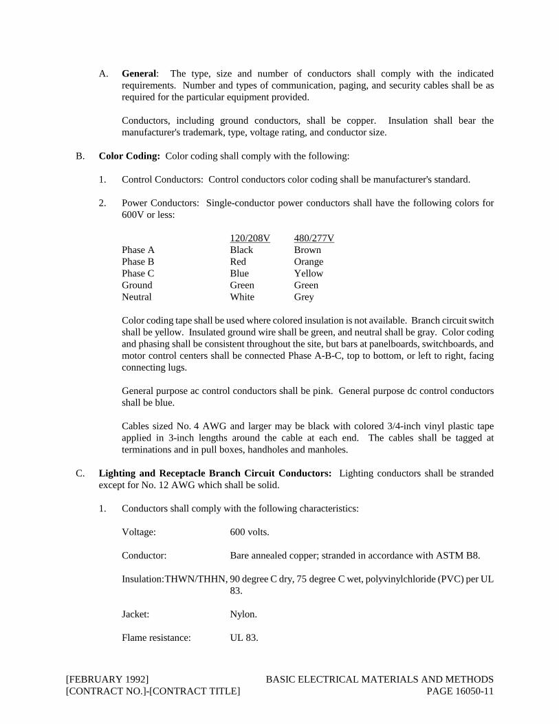
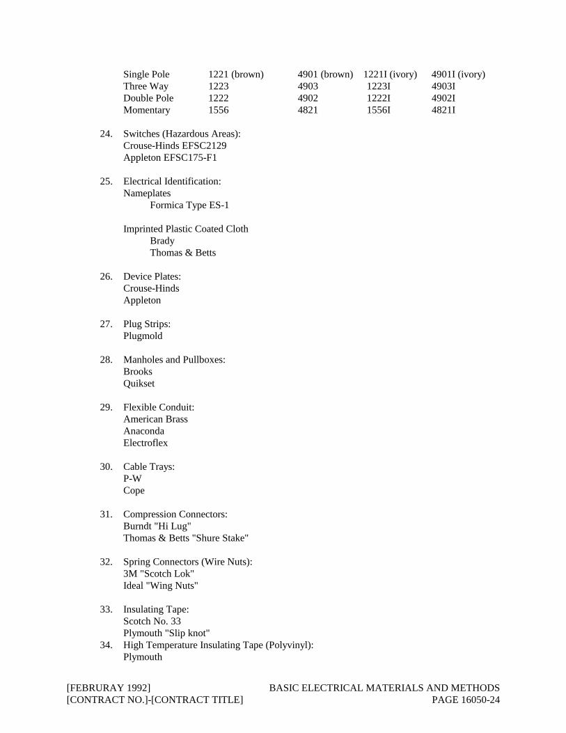
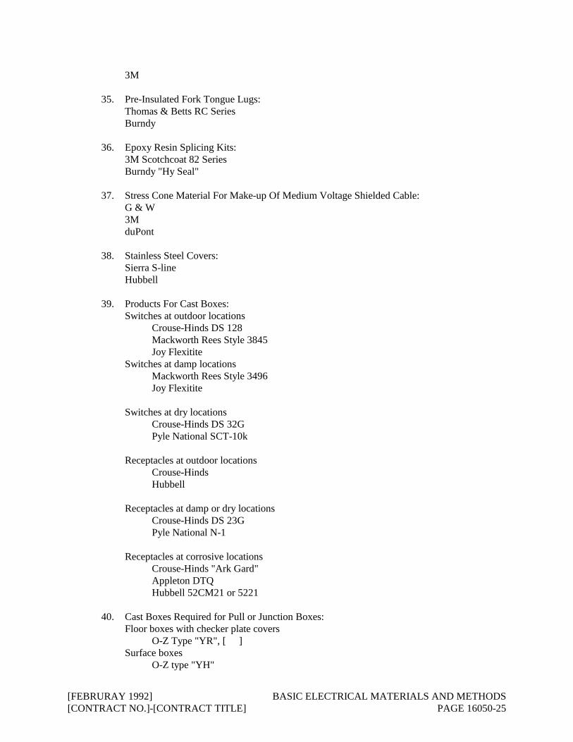
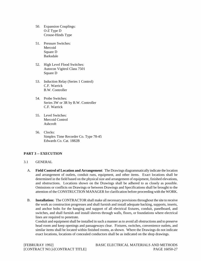
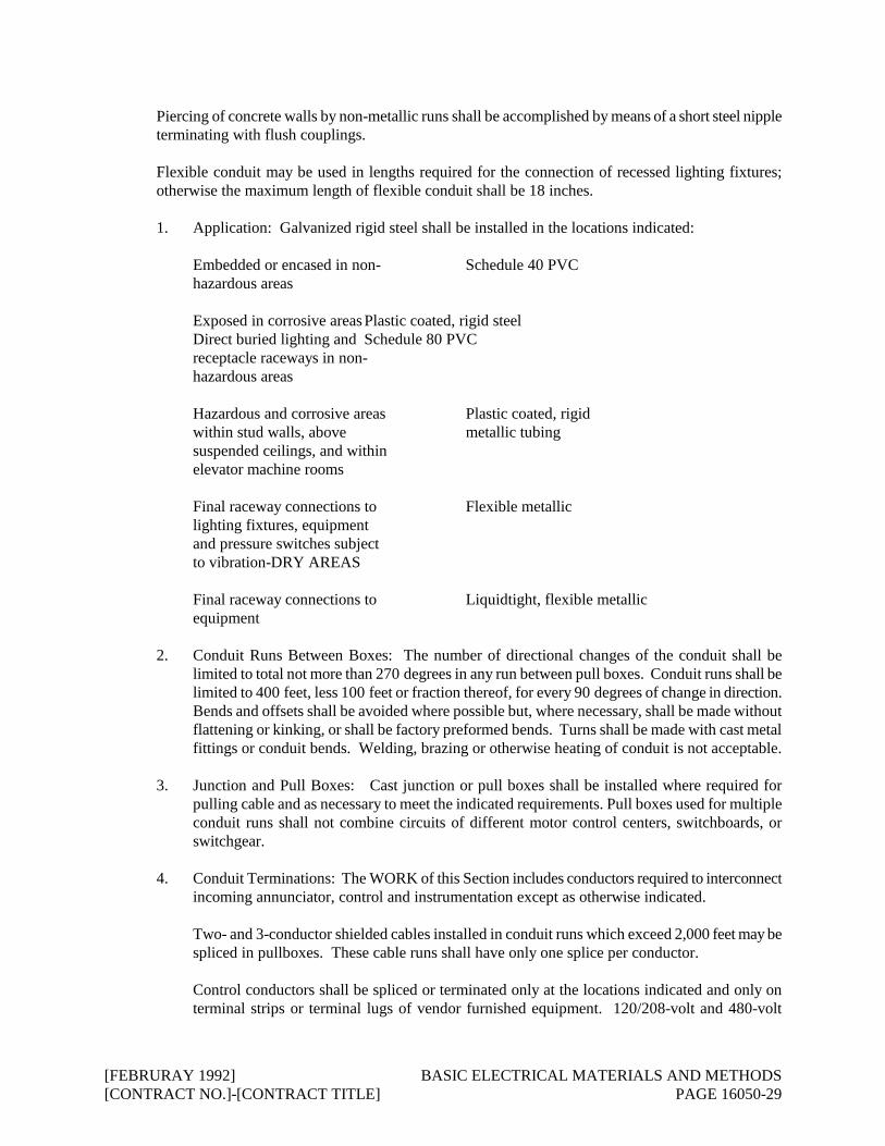