section 200 products and materials i. general 200.pdf · submittal of designs for precast items...
TRANSCRIPT
December 2010 200 - 1
SECTION 200
PRODUCTS AND MATERIALS
I. GENERAL DESCRIPTION
These specifications cover general testing procedures, certifications for material acceptance, and quality standards for products and materials. (See also the Special Provisions for project specific requirements.)
II. QUALITY ASSURANCE
1. GENERAL The Contractor shall comply with all standards specified in this Section. Whenever a specifically named code or standard is referenced, it shall mean the latest revision of said code or standard as amended prior to the date of the Invitation to Bid. Materials that do not conform to these Standards or referenced specifications shall not be used unless specifically approved by the locality. VDOT specification references shall mean the VDOT Road and Bridge Specifications, latest edition, unless otherwise noted.
2. REFERENCE STANDARDS
Reference specifications (latest edition) are hereby incorporated into this document and are referred to by the following abbreviations:
American Association of State Highway and Transportation Officials: AASHTO American Concrete Institute: ACI American National Standards Institute: ANSI American Railway Engineering Association: AREA American Society of Sanitary Engineers: ASSE American Society for Testing and Materials: ASTM American Water Works Association: AWWA American Welding Society: AWS Concrete Reinforcing Steel Institute: CRSI International Plumbing Code: IPC Manual on Uniform Traffic Control Devices (FHWA): MUTCD National Association of Sewer Service Companies: NASSCO National Sanitation Foundation: NSF Underwriters Laboratory: UL Virginia Department of Transportation: VDOT Virginia Erosion and Sedimentation Control Handbook: VESCH Virginia Sewage Collection and Treatment Regulations: VSCAT Virginia Test Methods: VTM Virginia Waterworks Regulations: VWR Virginia Work Area Protection Manual: VWAPM

December 2010 200 - 2
III. SUBMITTALS 3.1. Submittals shall be made by the Contractor in accordance with the procedures set forth in Section 105,
and as described below. 3.2. Products used in this Work shall be produced by manufacturers regularly engaged in the manufacture of
these and/or similar items and with a history or quality production acceptable to the Owner. 3.3. Except as modified herein, all products shall be tested in accordance with the requirements of the
referenced standards as applicable. 3.4. Submittals for imported aggregates shall include certification that the aggregates will be in accordance
with the latest edition of the VDOT Road and Bridge Specifications, for each proposed source, and submittals shall represent materials tested within 90 days of the bid opening. At a minimum, the certification will state:
“Aggregate shipped under this certification has been tested and conforms to the requirements of VDOT” _________________________
Signature & Title 3.5. Compaction testing results shall be submitted upon request by the Owner and shall be performed in
accordance with Section 303, Earthwork. 3.6. If the Contractor desires to substitute another material for that specified, the Contractor shall submit proof
that the substitute material is equal in all respects to the material specified. Proof shall be in the form of specifications for the proposed substitution that may be readily compared with the specifications for the original material. The Contractor shall also certify that this substitution will not adversely affect other elements of the Work or the construction schedule, and shall identify local maintenance service and source(s) of replacement parts and materials.
3.7. Submittal of designs for precast items included in the Standard Details or on VDOT’s approved list, as
appropriate, will not be required provided the Contractor submits a certification that the item will be fabricated in accordance with the pre-approved design drawings. Precast units shall be provided by a Precast Concrete manufacturer that has been approved by VDOT QA/QC Program.
3.8. The Owner reserves the right to request, and the Contractor shall submit, all necessary design data to
indicate VDOT pre-approved designs meet or exceed the Owner’s requirements. Such work shall be at no additional cost to the Owner.
3.9. Requests for approval of a precast design shall include detailed plans and supporting computations that
have been reviewed and approved by a registered Professional Engineer having at least 5 years experience in structural design of the type of precast structures or components proposed. Concrete, Class A-4, shall have a design strength at 28 days of at least 4,000 pounds per square inch and an air content of 6 % (+/- 2 %). The design of the concrete mixture and the method of casting, curing, handling, and erecting shall be subject to review by the Owner.

December 2010 200 - 3
IV. PRODUCT DELIVERY, STORAGE AND HANDLING 4.1. GENERAL
A. The Contractor shall use all means necessary to protect materials and products before, during, and after installation.
B. Material and products shall be loaded, transported, and unloaded in accordance with the
recommendations of the material and product Supplier.
C. Materials and products shall be stored so as to assure the preservation of quality and fitness for the Work.
4.2. ASPHALT
A. Shipments of asphalt material shall be made in transporting media that are free from contamination. Tank trucks or trailers shall be equipped with a sampling device approved by the Owner.
B. Asphalt material to be stored shall be placed in storage tanks that are free from contamination.
4.3. AGGREGATE
A. Stockpiles of all materials shall be constructed on areas that are hard, well drained, and denuded of vegetation. The different sizes and kinds of materials shall be kept separate during handling and storage until batched. Care shall be taken to prevent segregation of coarse and fine particles during handling and storing.
B. Aggregates placed directly on the ground for stockpiling purposes, shall not be removed from
those stockpiles within 1 foot of the ground until final cleanup. (Only clean aggregate shall be used).
C. Materials shall be handled in a manner that will preserve their quality and fitness for the Work.
Aggregates shall be transported from storage to the project in vehicles constructed to prevent loss or segregation of materials.
D. All material stockpiles shall be maintained in accordance with the Virginia Erosion and Sediment
Control Handbook. 4.4. CONCRETE ITEMS
A. Cement
1. Cement that is reclaimed or that shows evidence of hydration, such as lumps or cakes, shall not be used.
2. Loose cement shall be transported to the mixer either in tight compartments for each
batch or between the fine and coarse aggregate. Cement in original shipping packages

December 2010 200 - 4
may be transported on top of the aggregates, with each batch containing the number of bags required.
B. Aggregates
1. Aggregate shall be kept separated by size until batched. Aggregates shall be clean and
shall be maintained in at least a surface-dry condition.
2. Fine aggregate that has been washed shall not be used within 24 hours after being placed in the stockpile or until surplus water has disappeared and the material has a consistent free moisture content. Stockpiles shall be located and constructed so that surplus water will drain from stockpiles and the batcher.
3. Materials shall be handled in a manner that will preserve their quality and fitness for the
Work. Aggregates shall be transported from storage to the project in vehicles constructed to prevent loss or segregation of materials.
C. Admixtures
Admixtures shall be stored and handled so that contamination and deterioration will be prevented. Liquid admixtures shall not be used unless thoroughly agitated. Admixtures that are frozen or partially frozen shall not be used.
D. Latex Modifier
Latex modifier shall be kept in enclosures that will protect it from exposure to temperatures below 40° F or above 85° F. Containers of latex modifier shall be protected from direct sunlight.
4.5. PRECAST CONCRETE
Precast units may be shipped after reaching 85 % of the design strength as determined by control cylinders tested in accordance with the requirements of VDOT Road and Bridge Specifications Section 404. However, units shall retain their structural integrity during shipment and shall be subject to inspection at the job site. Approval to use precast units shall not be construed as waiving the size and weight hauling limitations of VDOT.
4.6. REINFORCING STEEL
A. The Contractor shall use all means necessary to protect materials of this Section before, after and during installation and to protect installed work and materials of other trades.
B. Reinforcing steel shall be delivered to the job site bundled, tagged, and marked. Metal tags shall
be used indicating bar size, lengths, and other information corresponding to markings shown on the Drawings and/or Shop Drawings.
C. Reinforcing steel shall be stored at the job site in a manner to prevent damage and accumulation
of dirt and excessive rust. Storage shall be in separate piles or stacks so as to avoid confusion or loss of identification after bundles are broken. Steel and accessories shall be kept off the ground with pallets, platforms, or other supports.

December 2010 200 - 5
4.7. PIPE
A. The Contractor shall use all means necessary to protect pipe materials, fittings, valves and products before, during, and after installation.
B. Material and products shall be loaded, transported, and unloaded in accordance with the
recommendations of the manufacturer and product Supplier. C. Materials shall be stored so as to assure the preservation of quality and fitness for the Work.
D. All damaged pipe and fittings shall be removed from the site by the Contractor and when directed
to do so by the Owner. 4.8. PLANTING
A. Plants
1. The Contractor shall notify the Owner at least 48 hours in advance of the anticipated delivery date for plants. A legible copy of the invoice showing the kinds and sizes of plants in each shipment shall be furnished the Owner. A copy of the current Certificate of Nursery Inspection shall accompany each shipment of plants.
2. Representative samples of each shipment of plants shall be legibly labeled as to the
genus, species, size, and quantity of the plants. When plants are in bales, bundles, boxes, or other containers, a legible label indicating the genus, species, size, and quantity of the plants shall be attached to each container.
3. Digging of plants for shipment shall be done in a manner that will avoid damage to or
loss of roots, but roots that are cut, shall be cleanly cut. Balled and burlapped plants shall be properly dug and protected to preserve the natural earth in contact with the roots. Manufactured balls will not be accepted. Balls shall be firmly wrapped and tied with approved materials. Balled plants will not be accepted if the ball is broken, cracked, or loose. After plants are dug, their roots shall be protected from damage. Roots of bare root plants shall be kept moist at all times. Bare root plants shall be further protected by wrapping in wet straw, moss, burlap, or other suitable material.
4. In lieu of using burlap with balled plants, plants may be dug as specified herein and
placed in plantable pots. Pots shall be constructed of material that will readily decompose in soil and shall not be smaller in any dimension than the size specified for balled and burlapped root systems. At the time of planting, the lip or rim of pots shall be broken away, and drainage holes shall be provided as directed. Plants with balls that have been grown in pots or with loose stems will be rejected.
5. Plants transported to the project in open vehicles shall be covered with suitable covers
securely fastened to the body of the vehicle. Closed vehicles shall be adequately ventilated to prevent overheating plants. Plants shall be kept moist, fresh, and protected at all times.

December 2010 200 - 6
6. When plants are to be stored, they shall be stored at a location approved by the Owner. Plants stored for more than 30 days shall not be used unless they are approved by the Owner. Unless other methods of storage are approved by the Owner, bare-root plants that are not planted within 24 hours after delivery shall be heeled-in in a moist trench dug in the ground. Bundles shall be opened, and plants shall be separated and placed singly in the trench with the roots spread in a natural position. Roots of each layer of plants shall be immediately covered in a manner satisfactory to the Owner with moist, pulverized soil; moist sawdust; or other approved material. Root-covering materials shall be kept moist at all times. Shade shall be provided as directed by the Owner. At the discretion of the Owner, balled material, container-grown material, and plants in plantable pots that are not planted within 48 hours of delivery shall have their root zone protected by wet sawdust or other approved material. Rejected plants shall be removed from the storage area within 24 hours of rejection; or, with the approval of the Owner, may be marked with yellow paint or otherwise made readily identifiable. If rejected plants have not been removed or acceptably marked within 24 hours, the use of plants from the storage area will not be allowed until rejected plants have been removed or identified.
4.9. SEEDING
Kinds and varieties of seeds shall be delivered to the project in separate bags and shall be mixed under the observation of the Owner on the project site or at other approved locations. The tag from each bag of seed shall be signed by the Contractor and delivered to the Owner after each bag is completely used.
4.10. SODDING
Sod shall be delivered to the project and stored in accordance with the Supplier’s recommendations. 4.11. FERTILIZER
Fertilizer shall be delivered to the project in bags or other convenient containers, each fully labeled, and shall conform to the applicable state and federal regulations. Fertilizer shall be stored in accordance with the Supplier’s recommendations. Fertilizer shall be uniform in composition, free flowing, and suitable for application with approved equipment.
4.12. LIME
Lime shall be delivered to the project in bags or other convenient containers, each fully labeled, and shall conform to the applicable state and federal regulations. Lime shall be stored in accordance with the Supplier’s recommendations. Lime shall be agricultural grade ground limestone. Agricultural grade pulverized limestone may be used at no additional cost to the Owner.
4.13. GEOSYNTHETICS
Geotextile fabric shall be protected from mud, dirt, dust, sunlight, and debris during transport and storage. Material shall be inert to commonly encountered chemicals; resistant to mildew, rot, insects, and rodents; and biologically and thermally stable. Geotextile fabric for subsurface installation shall not be exposed to direct sunlight for more than 24 hours during installation.
4.14. PAVERS

December 2010 200 - 7
A. Delivery
1. Deliver materials in manufacturer’s original, unopened, undamaged containers
packaging with identification labels intact.
2. Pavers shall be delivered to the project site on pallets constructed with non-staining and non-discoloring materials.
3. Deliver concrete pavers to the site in steel banded, plastic banded or plastic wrapped
packaging capable of transfer by forklift or clamp lift.
4. Coordinate delivery and paving schedule to minimize interference with normal use of buildings adjacent to paving.
5. Unload pavers at job site in such a manner that no damage occurs to the product.
B. Storage and Protection
1. Store materials protected such that they are kept free from mud, dirt, and other foreign
materials.
2. Store concrete paver cleaners and sealers per manufacturer’s instructions.
3. Cover bedding sand and joint sand with waterproof covering if needed to prevent exposure to rainfall or removal by wind. Secure the covering in place.
V. PRODUCTS
Unless specifically stated otherwise, all materials shall be new, free from defects, and shall be in accordance with this Section.
5.1. AGGREGATE
A. Select material , Type II
Select material shall consist of approved local or commercial materials free from roots, muck, and debris.
1. Grading
Grading for Type II shall conform to the following when tested in accordance with the requirements of VTM-25:
2 in No. 200
Min. 100 Max. 25

December 2010 200 - 8
2. Atterberg Limits
Atterberg limits shall conform to the following when tested in accordance with the requirements of VTM-7:
Max. Liquid Limit Max. Plasticity Index 30 9
3. CBR
Tests for CBR will be performed in accordance with the requirements of VTM-8 for conformance to the specified value.
B. Suitable and unsuitable fill material shall be defined as follows:
Suitable soil materials are defined as those complying with ASTM D2487 United Soil Classification System (USCS) groups GW, GP, GM, SW, and SP. Suitable backfill materials shall be free of particles of clay, rock or gravel larger than 2-inches in any dimension, debris, waste, frozen material, roots, all organic material, and any other deleterious matter. Unsuitable soil materials are defined as those complying with ASTM D2487 USCS soil classification groups MH, ML, CH, CL, OL, OH, GC, SM, SC, and PT, unless otherwise approved by the Owner.
C. Select Bedding - is bedding material in addition to that required by the Drawings defined on the
bid schedule (For Section 302 and Division 8 activities of this document, bedding material shall be Number 57 stone in accordance with Paragraph V.5.1.G.1) or as otherwise specified and shown on the Drawings.
D. Materials other than suitable fill that are shown on the Drawings or specified in the Contract
Documents shall conform to the applicable requirements of the Contract Documents.
E. Lightweight Aggregate
These specifications cover lightweight aggregate used in hydraulic cement concrete and asphalt surface treatment.
1. Lightweight aggregate shall consist of clay, shale, or slate expanded through a sintering
or rotary kiln.
2. Lightweight aggregate used in hydraulic cement concrete shall conform to the requirements of AASHTO M195.
3. Lightweight aggregate used for asphalt surface treatment shall conform to the
requirements of AASHTO M195 except that Sections 3, 6, and 8 will not apply. Grading shall conform to the requirements of Table 200-5.1-6 except that the maximum percentage by weight of material passing the No. 8 sieve shall be 16 % and passing the No. 16 sieve shall be 9 %.

December 2010 200 - 9
F. Coarse and Fine Aggregate Material for Asphalt Concrete Types S-5 (A, D), I-2 (A, D), B-3 (A, D) and Curb Mixes
1. Coarse Aggregate
Coarse aggregate shall be Grade A or Grade B, unless otherwise specified. The type of aggregate will be specified in the requirements for individual mixes.
The use of coarse aggregates that tend to polish under traffic will not be permitted in the top layer of surface courses, unless specifically permitted by the Contract Documents.
The Owner reserves the right to require the Contractor to discontinue the use of crusher run aggregate blends and to furnish separate sizes of open graded aggregate material where segregation or non-uniformity is evidenced in the finished pavement.
a. Materials
Coarse aggregate shall consist of crushed stone, crushed slag, or crushed or uncrushed gravel. Coarse aggregate shall consist of clean, hard, tough, durable pieces free from adherent coatings and injurious amounts of friable, thin, elongated or laminated pieces; soluble salts; and organic materials and shall conform to these specifications. The use of crushed hydraulic cement concrete will be permitted as a coarse aggregate provided such material conforms to the physical requirements hereinafter and shows no adverse chemical reaction.
b. Detail Requirements
(1) Grading: Open graded aggregates shall be graded from coarse to fine
within the limits specified in Table 200-5.1-1. Tests will be performed in accordance with AASHTO T27.
(2) Soundness: Soundness shall conform to Table 200-5.1-2. Tests will be
performed in accordance with AASHTO T103 or T104.

December 2010 200 - 10
TABLE 200-5.1-1 Sizes of Open Graded Coarse Aggregates for Asphalt Concrete Types S-5 (A, D), I-2 (A, D), B-3 (A, D) and Curb Mixes
Va.
Sieve Size
Amounts Finer than Laboratory Sieve (Square Openings*), Percentage by Weight
4 in. 3 ½ in. 3 in. 2 ½ in. 2 in. 1 ½ in. 1 in. ¾ in. ½ in. 3/8 in. No. 4 No. 8 No. 16 No. 50 No. 100
1 Min. 100 95+5 43+17 Max. 15 Max. 5
2 Min. 100 95+5 43+17 Max. 15 Max. 5
3 Min. 100 63+17 Max. 20 Max. 5
357 Min. 100 60+20 20+10 Max. 5
5 Min. 100 95+5 58+17 Max. 15 Max. 5
56 Min. 100 95+5 58+17 25+10 Max. 15 Max. 5
57 Min. 100 95+5 43+17 Max. 7 Max. 3
68 Min. 100 95+5 48+17 Max. 20 Max. 8 Max. 5
7 Min. 100 95+5 57+17 Max. 15 Max. 5
78 Min. 100 95+5 60+20 Max. 20 Max. 8 Max. 5
8 Min. 100 92+8 25+15 Max. 8 Max. 5
9 Min. 100 92+8 25+15 Max. 10 Max. 5
10 Min. 100 92+8 20+10 * In inches, except where otherwise indicated. Numbered sieves are those of the U.S. Standard Sieve Sizes

December 2010 200- 11
TABLE 200-5.1-2 Soundness
USE
Soundness Loss, Max. % Freeze and Thaw
20 Cycles Magnesium Sulphate
5 Cycles Portland Cement Concrete 5 12 Asphalt Surface Courses 6 15 Asphalt and Aggregate Bases 7 20
(3) Abrasion loss shall conform to Table 200-5.1-3. Tests will be performed
in accordance with AASHTO T96 on aggregate of grading most nearly identical with gradation to be used in the Work.
TABLE 200-5.1-3
Abrasion
Use Loss Angeles Abrasion Loss, Maximum %
100 Rev. 500 Rev. Grade A Stone 9 40 Grade B Stone 12 45 Grade C Stone 14 50 Slag 12 45 Gravel 12 45
(4) Deleterious Material: The amount of deleterious material shall not
exceed the following limits:
% by
Weight
AASHTO Test
Method Soft Fragments 2.00 T189 Coal and Lignite 0.25 T113 Clay Lumps 0.25 T112 Material Passing the No. 200 Sieve by Washing 1.00 T11 When the material passing the No. 200 sieve by washing is dust of fracture, the percentage of deleterious material may be increased to 1.50.
(5) Crushed gravel shall consist of particles of which a minimum of 80 % by weight, or as specified, shall have at least one fractured face by artificial crushing. Tests will be performed in accordance with VTM-15.
(6) Blast furnace slag shall be relatively free of glassy or spongy pieces, and
free of foreign minerals. It must weigh at least 70 pounds per cubic foot, dry rodded, for Size No. 68 and smaller; and at least 65 pounds per cubic foot, dry rodded, for larger sizes. Tests will be performed in accordance with AASHTO T19.

December 2010 200- 12
When used as an asphalt surfacing aggregate, blast furnace slag shall not contain more than 10 % of nonporous material and must have an absorption of at least 3 %. Tests will be performed in accordance with AASHTO T85.
2. Fine Aggregate
Fine aggregate shall have a minimum sand equivalent value of 30, when tested in accordance with AASHTO T176.
The use of fine aggregates that tend to polish under traffic will not be permitted in the top layer of surface courses, unless specifically permitted by the Contract Documents.
a. Materials
Sand, as fine aggregate, is classified herein in accordance with its occurrence or method of manufacture. Natural sand shall consist of grains of hard, sound material, predominantly quartz, occurring as such in natural deposits or in loosely bound deposits of sandstone conglomerate. Stone sand shall consist of sound particles of approved Grade A stone, essentially free from flat or elongated pieces and having sharp edges and corners removed.
b. Detail Requirements
(1) Grading shall conform to Table 200-5.1-4. Tests will be performed in
accordance with AASHTO T27.
TABLE 200-5.1-4 Fine Aggregate
Amounts Finer than Each Laboratory Sieve(Square Openings*),
Percentage by Weight Grading 3/8 No. 4 No. 8 No. 16 No. 50 No. 100
A Min. 100 97 + 3 90 + 10 67 + 18 42 + 17 Max. 10 B Min. 100 97 + 3 Max. 10 C Min. 100 97 + 3 Max. 25
*In inches, unless otherwise specified. Numbered sieves are those of the U.S. Standard Sieve Sizes.
(2) Soundness shall conform to Table 200-5.1-5. Tests will be performed in
accordance with AASHTO T103 or T104.

December 2010 200- 13
TABLE 200-5.1-5 Soundness
USE
Soundness Loss, Max. % Freeze and Thaw
20 Cycles Magnesium Sulphate
5 Cycles Portland Cement Concrete 8 18 Asphalt Surface Courses and Surface Treatment 15 25
Asphalt Concrete Bases 15 30
(3) Organic Impurities shall conform to AASHTO T21 when the fine aggregate is to be used in hydraulic cement concrete, except that material producing a color darker than the standard of AASHTO T21 may be accepted in accordance with AASHTO M6.
(4) Void Content will be tested in accordance with VTM-5.
(5) Deleterious Material: All sands shall be free of injurious amounts of
clay or other adherent coatings and deleterious material. The amounts of deleterious material shall not exceed the following limits:
Clay lumps 0.25% (Test method AASHTO T112) Shale, mica, coated grains, soft or flaky particles 1.0% (Test method AASHTO T113) Injurious amounts of organic material None (Test method AASHTO T21) Material passing the No. 200 sieve by washing (Test method AASHTO T11 and T27) For use in concrete subject to abrasion 3.0% For all other grades 5.0%
In the case of manufactured sand, if the material finer than the No. 200 sieve consists of the dust of fracture, essentially free from clay or shale, the percentages shown for use in concrete subject to abrasion and for all other concrete uses may be increased to 5.0 and 7.0%, respectively.

December 2010 200- 14
G. Coarse and Fine Aggregate Material for Superpave Asphalt Concrete and General Aggregate
1. Coarse Aggregate
a. Materials
Coarse Aggregate shall be Grade A or B. Coarse aggregate shall consist of crushed stone, crushed slag, or crushed or uncrushed gravel with clean, hard, tough, and durable pieces free from adherent coatings and deleterious amounts of friable, thin, elongated, or laminated pieces; soluble salts; or organic materials. In addition, the coarse aggregate sizes retained on and above the No. 4 sieve shall meet the coarse aggregate requirements in the aggregate properties table below. Flat and Elongated (F&E) shall be tested in accordance with ASTM D 4791 and coarse aggregate angularity (CAA) shall be tested, on crushed gravel only, in accordance with ASTM D 5821.
In addition, the coarse aggregate sizes retained on and above the No. 4 sieve shall meet the coarse aggregate requirements in the aggregate properties in Table 200-5.1-11. Flat and Elongated (F&E) shall be tested in accordance with ASTM D 4791 and Coarse Aggregate Angularity (CAA) shall be tested, on crushed gravel only, in accordance with ASTM D 5821.
(1) Crushed hydraulic cement concrete will be permitted for use as a coarse
aggregate provided it conforms to the physical requirements specified herein and shows no adverse chemical reaction. Crushed hydraulic cement concrete will not be permitted in the following: (1) reinforced cement concrete (2) in combination with other materials in contact with geotextile fabric when such fabric is used as a drainage item and (3) in backfill or bedding for perforated pipe.
(2) Crushed gravel shall consist of particles of which at least 80 % by
weight shall have at least one face fractured by artificial crushing. Tests will be performed in accordance with the requirements of VTM-15.
(3) Blast furnace slag shall be relatively free from foreign minerals and
glassy or spongy pieces. It shall weigh at least 70 pounds per cubic foot, dry rodded for size No. 68 and smaller and at least 65 pounds per cubic foot, dry rodded, for larger sizes. Tests will be performed in accordance with the requirements of AASHTO T19. When used in asphalt surface treatments, blast furnace slag shall not contain more than 10 % nonporous material and shall have an absorption of at least 3 %. Tests will be performed in accordance with the requirements of AASHTO T85.
b. Detail Requirements
(1) Grading: Open graded aggregates shall be graded from coarse to fine
within the limits specified in Table 200-5.1-6. Tests will be performed in accordance with AASHTO T27.

December 2010 200- 15
TABLE 200-5.1-6 Sizes of Open Graded Coarse Aggregates
Va. Sieve Size
Amounts Finer than Laboratory Sieve (Square Openings*), Percentage by Weight
4 in. 3 ½ in. 3 in. 2 ½ in. 2 in. 1 ½ in. 1 in. ¾ in. ½ in. 3/8 in. No. 4 No. 8 No. 16 No. 50 No. 100
1 Min. 100 90-100
25-60 Max. 15 Max. 5
2 Min. 100 90-100 35-70 Max. 15
Max. 5
3 Min. 100 90-100 35-70 0-15 Max. 5
357 Min. 100 95-100
35-70
10-30 Max. 5
5 Min. 100 90-100
20-55 Max. 10 Max. 5
56 Min. 100 90-100
40-85
10-40 Max. 15 Max. 5
57 Min. 100 95-100
25-60 Max. 10 Max. 5
67 Min. 100 90-100 20-55 Max. 10 Max. 5
68 Min. 100 90-100
30-65
5-25 Max. 10 Max. 5
7 Min. 100 90-100
40-70 Max. 15 Max. 5
78 Min. 100 90-100
40-75 5-25
Max. 10 Max. 5
8 Min. 100
85-100
10-30 Max. 10 Max. 5
8P Min. 100 75-100 5-30 Max. 5
9 Min. 100
85-100 10-40 Max. 10 Max. 5
10 Min. 100 85-100
10-30 * In inches, except where otherwise indicated. Numbered sieves are those of the U.S. Standard Sieve Sizes.

December 2010 200 - 16
(2) Soundness: Soundness shall conform to the requirements of Table 200-5.1-7. Tests will be performed in accordance with the requirements of AASHTO T103 or T104.
TABLE 200-5.1-7
Soundness
USE Soundness Loss, Max. %
20 Cycles 5 Cycles Asphalt Surface Courses 6 15 Asphalt and Aggregate Bases 7 20
(3) Abrasion Loss: Abrasion loss shall conform to the requirements of
Table 200-5.1-8. Tests will be performed in accordance with the requirements of AASHTO T96 on aggregate with a grading the most nearly identical with the grading to be used in the work.
TABLE 200-5.1-8
Abrasion
Use Loss Angeles Abrasion Loss, Maximum %
100 Rev. 500 Rev. Grade A Stone 9 40 Grade B Stone 12 45 Grade C Stone 14 50 Slag 12 45 Gravel 12 45
(4) Deleterious Material: The amount of deleterious material shall be not
more than the following:
Material % by
Weight AASHTO
Test Method Coal and Lignite 0.25 T113 Clay Lumps 0.25 T112 Total Material Passing No. 200 Sieve By Washing 1 T11 and T21
1
When passing through the No. 200 sieve by washing is of dust fracture, the percentage of deleterious material may be increased to 1.50 %.
Flat & Elongated: Course aggregate to be used as a riding surface during construction or as the riding surface after construction shall contain not more than 30% by mass of aggregate particles retained on and above the 3/8-inch sieve having a maximum to minimum dimensional ratio greater than 5 as determined by ASTM D4791.

December 2010 200 - 17
2. Fine Aggregate
a. Materials
Fine aggregate is classified herein in accordance with its occurrence or method of manufacture as natural sand or stone sand. Natural sand shall consist of grains of hard, sound material, predominantly quartz, occurring in natural deposits or in loosely bound deposits, such as sandstone conglomerate. Stone sand shall consist of sound crushed particles of Table 200-5.1-9 Grade A stone, essentially free from flat or elongated pieces, with sharp edges and corners removed. Fine aggregate shall conform to the fine aggregate requirements in Table 200-5.1-11. Fine Aggregate Angularity (FAA) shall be tested in accordance with AASHTO T 304 (Method A) and sand equivalent (SE) in accordance with AASHTO T 176.
b. Detail Requirements
(1) Grading shall conform to Table 200-5.1-9. Tests will be performed in
accordance with AASHTO T27.
TABLE 200-5.1-9 Fine Aggregate
Grading Amounts Finer than Each Laboratory Sieve(Square Openings*), Percentage by Weight 3/8 No. 4 No. 8 No. 16 No. 30 No. 50 No. 100 No. 200
A Min. 100 97 + 3 90 + 10 67 + 18 42+17 17 + 9 Max. 10 B Min. 100 97 + 3 Max. 10 C Min. 100 97 + 3 Max. 25 F Min. 100 92 + 8 80+20 62+22 39+19 Max. 26 Max. 10 Max. 7 G Min. 100 70+30 50+35 Max. 26 Max. 10 Max. 5
(2) Soundness: Soundness shall conform to the requirements of Table 200-
5.1-10. Tests will be performed in accordance with the requirements of AASHTO T103 or T104.
TABLE 200-5.1-10
Soundness
Use
Soundness Loss Magnesium Sulphate
(5 Cycles)
(Max %)Freeze & Thaw Cycles (100
Cycles) Asphalt Concrete Surfaces and Surface Treatments 25 15
Asphalt Concrete Bases 30 15
December 2010 200 - 18
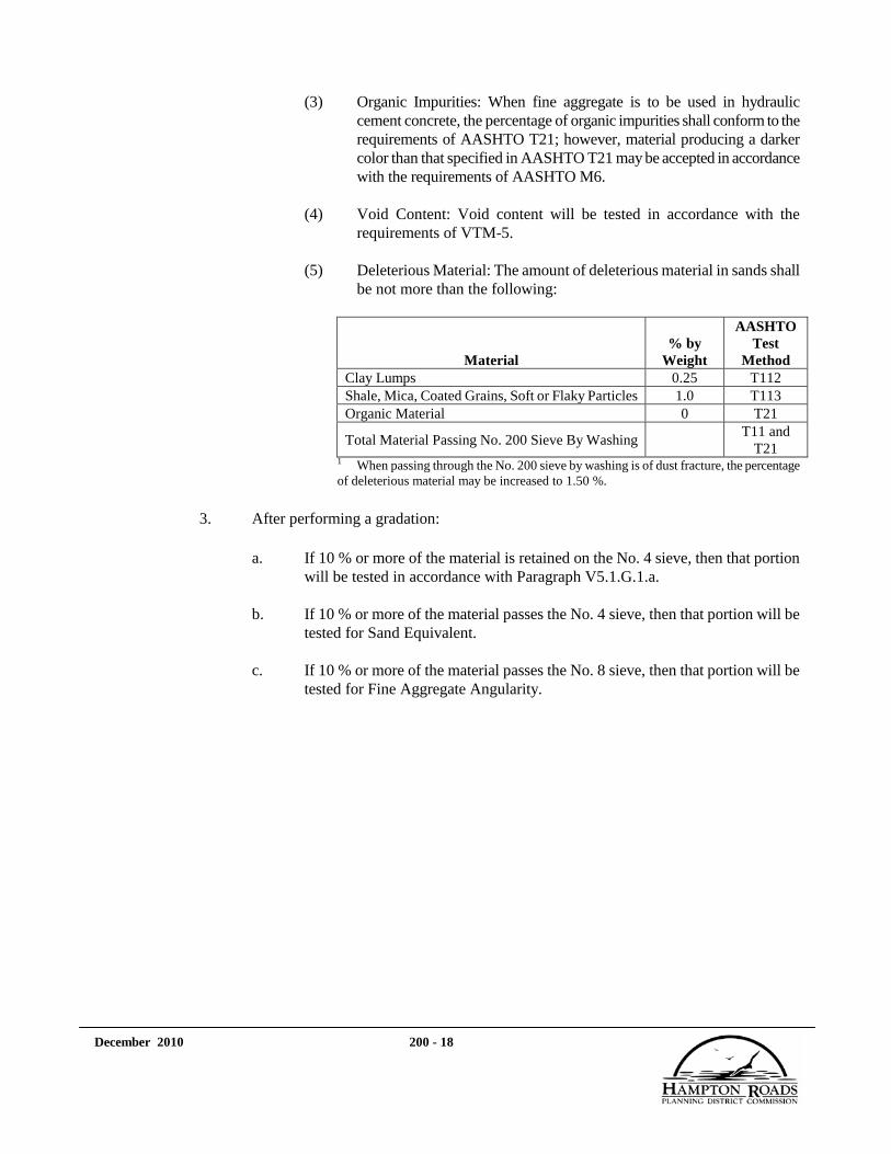
(3) Organic Impurities: When fine aggregate is to be used in hydraulic cement concrete, the percentage of organic impurities shall conform to the requirements of AASHTO T21; however, material producing a darker color than that specified in AASHTO T21 may be accepted in accordance with the requirements of AASHTO M6.
(4) Void Content: Void content will be tested in accordance with the
requirements of VTM-5. (5) Deleterious Material: The amount of deleterious material in sands shall
be not more than the following:
Material % by
Weight
AASHTO Test
Method Clay Lumps 0.25 T112 Shale, Mica, Coated Grains, Soft or Flaky Particles 1.0 T113 Organic Material 0 T21
Total Material Passing No. 200 Sieve By Washing T11 and
T21 1
When passing through the No. 200 sieve by washing is of dust fracture, the percentage of deleterious material may be increased to 1.50 %.
3. After performing a gradation:
a. If 10 % or more of the material is retained on the No. 4 sieve, then that portion will be tested in accordance with Paragraph V5.1.G.1.a.
b. If 10 % or more of the material passes the No. 4 sieve, then that portion will be
tested for Sand Equivalent.
c. If 10 % or more of the material passes the No. 8 sieve, then that portion will be tested for Fine Aggregate Angularity.
December 2010 200 - 19
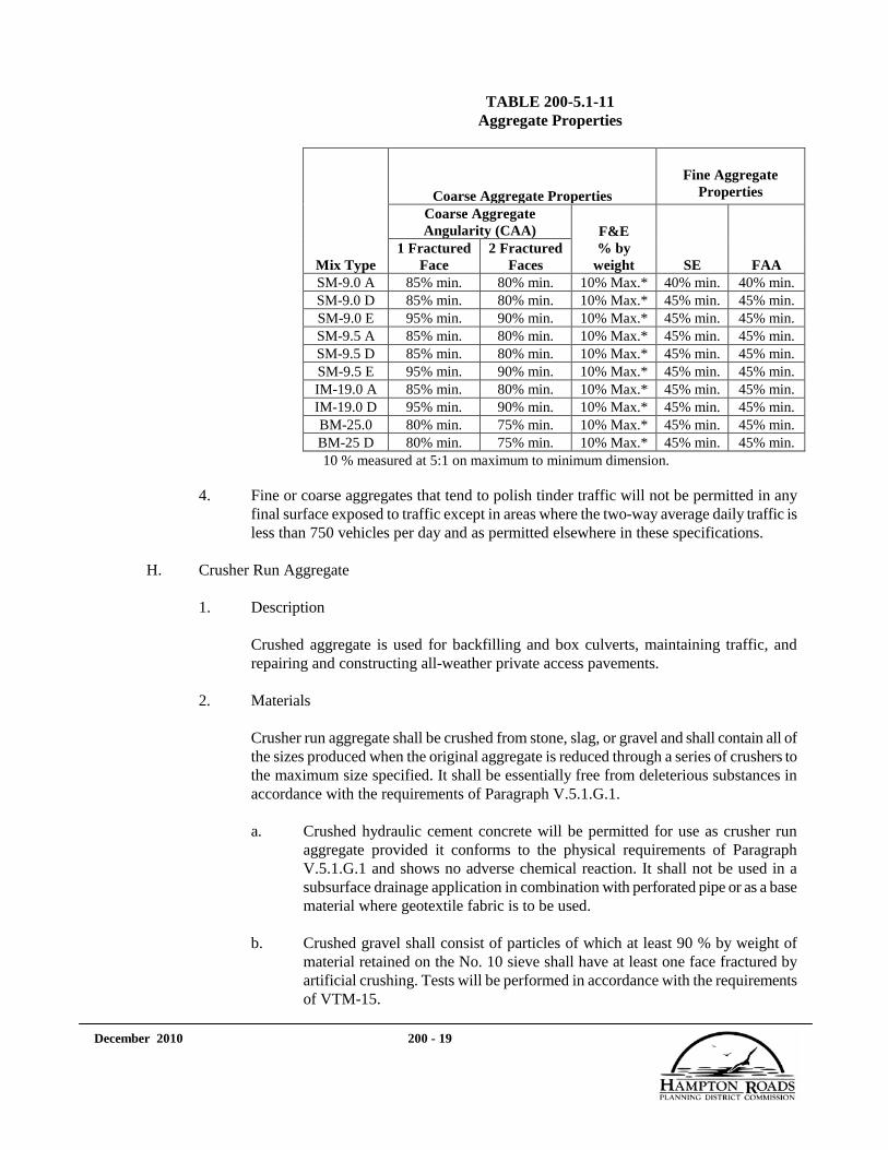
TABLE 200-5.1-11 Aggregate Properties
Mix Type
Coarse Aggregate Properties Fine Aggregate
Properties Coarse Aggregate Angularity (CAA) F&E
% by weight SE FAA
1 Fractured Face
2 Fractured Faces
SM-9.0 A 85% min. 80% min. 10% Max.* 40% min. 40% min. SM-9.0 D 85% min. 80% min. 10% Max.* 45% min. 45% min. SM-9.0 E 95% min. 90% min. 10% Max.* 45% min. 45% min. SM-9.5 A 85% min. 80% min. 10% Max.* 45% min. 45% min. SM-9.5 D 85% min. 80% min. 10% Max.* 45% min. 45% min. SM-9.5 E 95% min. 90% min. 10% Max.* 45% min. 45% min. IM-19.0 A 85% min. 80% min. 10% Max.* 45% min. 45% min. IM-19.0 D 95% min. 90% min. 10% Max.* 45% min. 45% min. BM-25.0 80% min. 75% min. 10% Max.* 45% min. 45% min. BM-25 D 80% min. 75% min. 10% Max.* 45% min. 45% min. 10 % measured at 5:1 on maximum to minimum dimension.
4. Fine or coarse aggregates that tend to polish tinder traffic will not be permitted in any
final surface exposed to traffic except in areas where the two-way average daily traffic is less than 750 vehicles per day and as permitted elsewhere in these specifications.
H. Crusher Run Aggregate
1. Description
Crushed aggregate is used for backfilling and box culverts, maintaining traffic, and repairing and constructing all-weather private access pavements.
2. Materials
Crusher run aggregate shall be crushed from stone, slag, or gravel and shall contain all of the sizes produced when the original aggregate is reduced through a series of crushers to the maximum size specified. It shall be essentially free from deleterious substances in accordance with the requirements of Paragraph V.5.1.G.1.
a. Crushed hydraulic cement concrete will be permitted for use as crusher run
aggregate provided it conforms to the physical requirements of Paragraph V.5.1.G.1 and shows no adverse chemical reaction. It shall not be used in a subsurface drainage application in combination with perforated pipe or as a base material where geotextile fabric is to be used.
b. Crushed gravel shall consist of particles of which at least 90 % by weight of
material retained on the No. 10 sieve shall have at least one face fractured by artificial crushing. Tests will be performed in accordance with the requirements of VTM-15.

December 2010 200 - 20
c. Crusher run aggregate to be used as a wearing surface shall contain not more than 30 % by weight of aggregate particles greater than 3/8 inch having a maximum to minimum dimensional ratio greater than 5 as determined by ASTM D4791.
3. Detail Requirements
a. Grading: Grading shall conform to the following when tested in accordance with the requirements of AASHTO T27:
Size No. % by Weight of Materials Passing Sieve
2½ in 2 in 1½ in 1 in ¾ in No 4
24 Min. 100 95±5 32±18 25 Min. 100 95±5 32±18 26 Min. 100 95±5 38±22
b. Atterberg Limits: The liquid limit shall be not more than 25. The plasticity index
shall be not more than 3. Tests will be performed in accordance with the requirements of VTM-7.
c. Soundness Loss: Soundness loss shall conform to the requirements of Table 200-
5.1-10 for aggregate bases. Tests will be performed in accordance with the requirements of AASHTO T103 or T104.
d. Abrasion Loss: Abrasion loss shall be not more than 45 %. Tests will be performed
in accordance with the requirements of AASHTO T96.
I. All other aggregate material shall conform to the requirements of VDOT Road and Bridge Specifications Section 208 except where other types of aggregate material are specified in which case the applicable specifications governing the material shall apply.
5.2. ASPHALT
A. Asphalt Concrete
Asphalt concrete shall conform to the requirements of Paragraphs V.5.22 or V.5.23, as appropriate.
B. Tack Coat
Asphalt for tack coat shall be RC-250, CRS-1, CRS-2, CRS-1h, or CSS-1h and shall conform to the requirements of Paragraphs V.5.22 or V.5.23, as appropriate. Application shall conform to the requirements of Section 315 or 315A, as appropriate.

December 2010 200 - 21
C. Prime Coat
Unless specified, prime coat is not required for asphalt applications 2-inches or more. When applied, it shall conform to Section 315 or 315A, as appropriate. Cover material, when specified, shall conform to the applicable requirements of Paragraphs V.5.1.G.1 (Coarse Aggregate Grade B) and V.5.1.G.2 (Fine Aggregate Grading B). Lightweight aggregate shall conform to the requirements of Paragraph V.5.1.E. Cover material shall not be hauled directly from a washing plant for immediate use in the Work.
D. Surface Treatment Cover Material shall conform to the applicable requirements of Paragraphs
V.5.1.G.1 (Coarse Aggregate Grade B) and V.5.1.G.2 (Fine Aggregate Grading B). Lightweight aggregate shall conform to the requirements of Paragraph V.5.1.E. Cover material shall not be hauled directly from a washing plant for immediate use in the Work.
E. Curb Backup Material, if required, shall be asphalt concrete conforming to any surface or
intermediate mixture listed in Paragraphs V.5.22 or V.5.23, as appropriate. 5.3. CASING PIPE
A. Steel Casing Pipe
1. Steel casing pipe shall be in accordance with ASTM A53 and ASTM A139, Grade B, 35,000 psi minimum yield strength, seamless (under 26-inch diameter), with beveled joints suitable for welding.
2. The diameter shall be as indicated on the Drawings and shall be in accordance with the
VDOT Road and Bridge Specifications. Wall thickness shall be in accordance with the VDOT Road and Bridge Specifications but in no case shall be less than 1/2-inch. If casing is to be installed under railroad tracks, the railroad owner’s requirements or AREA standards shall govern.
B. Carrier Pipe
1. Carrier pipe shall be as specified on the Drawings.
2. Skids and casing spacers shall be in accordance with the Standard Details.
5.4. CLEARING AND GRUBBING
A. Temporary and /or tree protection fencing shall be as shown on the Drawings and in accordance with Paragraph V.5.25 of the Virginia Erosion and Sedimentation Control Manual, as appropriate.
B. Tree wrapping where shown on the Drawings shall be burlap in accordance with AASHTO
M182, Class 1, and/or waterproof paper, 30-30-30 krinkle-craft or its equivalent, in strips 4-inches in width. Tree wound dressing shall be antiseptic and waterproof, asphalt base.
December 2010 200 - 22
5.5. DRAINAGE STRUCTURES
A. General
1. Pipe shall conform to the requirements of VDOT Road and Bridge Specifications Section 232, and shall be furnished in accordance with the diameter, wall thickness, class, and strength or corrugation specified for the maximum height of fill to be encountered along the length of the pipe culvert, storm drain, or sewer.
2. End sections shall conform to the applicable requirements of VDOT Road and Bridge
Specifications Section 232. End sections used with rigid pipe shall be concrete. End sections used with asphalt-coated or paved pipe shall not be asphalt coated or paved.
3. Pipe fittings, such as tees, elbows, wyes, and bends, shall conform to the applicable
requirements of VDOT Road and Bridge Specifications Section 232. Fittings shall be of the same type, class, thickness, gage, and strength as the line in which they are used.
4. Steel grates, steel frames and structural steel shall conform to the requirements of VDOT
Section Road and Bridge Specifications 226 and shall be galvanized in accordance with the following:
a. Galvanizing of iron and steel hardware shall conform to the requirements of
ASTM A153 for the hot-dip process or ASTM B695, Class 50, for the mechanical process.
b. Galvanizing of rolled, pressed, and forged steel shapes, plates, bars, and strips shall
conform to the requirements of ASTM A123.
c. Galvanizing of fabricated items shall be performed after fabrication.
d. Galvanized items shall be stored off the ground in a manner that will allow free drainage of water from galvanized surfaces.
5. Concrete blocks shall conform to the requirements of VDOT Road and Bridge
Specifications Section 222 for masonry blocks.
6. Brick shall conform to the requirements of VDOT Road and Bridge Specifications Section 222.
7. Hydraulic cement mortar shall conform to the requirements of Paragraph V.5.6.A.1. and
Paragraph V.5.6.F.
8. Cast-in-place concrete shall conform to the requirements of Paragraph V.5.6.A.1.for Class A3.
9. Bedding material shall conform to the requirements of Paragraph V.5.1.G, No. 57 stone.
10. Joint material and gaskets shall conform to the requirements of VDOT Road and Bridge
Specifications Section 212.

December 2010 200 - 23
11. Gray-iron castings shall conform to the requirements of VDOT Road and Bridge Specifications Section 224.
12. Reinforcing steel shall conform to the requirements of Paragraph V.5.8, Grade 40 or 60.
13. Curing materials shall conform to the requirements of Paragraph V.5.6.C.
14. Geotextile material for joint wrapping shall conform to the requirements of Paragraph
V.5.26.B.1.d.
B. Standard precast drainage units shall conform to the material requirements of AASHTO M199 and the following:
1.
If the grade on the adjacent gutter is less than 1.5 %, the grade on the invert of the throat section of the inlet shall be at least 1.5 %. Precast throats having flat inverts will be permitted in sag locations provided the total length of the required throat opening does not exceed 6 feet.
2.
The pipe opening in precast units shall not exceed the outside cross-sectional dimension of the pipes by more than 8-inches regardless of the placement of the pipes, the angles of intersection, or the shapes of the pipes. Pipe openings shall be formed, drilled, or neatly cut as approved by the Owner.
3.
The Contractor may use brick and masonry block or concrete pipe cutoffs in conjunction with mortar to fill the void between pipe culverts and precast structures. Such materials shall be thoroughly wetted and bonded with mortar. The remaining exterior and interior void shall be filled with mortar to the contour of the precast structure.
4.
When precast units are to be located adjacent to the subbase or base course, units with chambers shall be provided with weep holes 3-inches in diameter and hardware cloth and shall be located to drain the subbase or base.
C.
Precast arches shall conform to the applicable requirements of AASHTO’s Standard Specifications for Highway Bridges with the following modifications:
1. Combination of Loads
a. For service load design: E: vertical loads: 1.00; lateral loads: 1.00 and 0.5 (check both loadings).
b. For load factor design: E: vertical loads: 1.00; lateral loads: 1.30 and 0.5 (check
both loadings).
2. Protection Against Corrosion
a. The concrete cover of reinforcement shall be at least 1 1/2-inches.

December 2010 200 - 24
b. In corrosive or marine environments or other severe exposure conditions, reinforcement shall be epoxy coated in accordance with the requirements of Paragraph V.5.8 and as shown on the Drawings.
c. Exposed reinforcing bars, inserts, and plates intended for bonding with future
extensions shall be protected from corrosion as directed by the Owner.
d. Reinforcement shall be designed and detailed in consideration of fabrication and construction tolerances so that the minimum required cover and proper positioning of reinforcement shall be maintained.
3.
Anchorage
Sufficient anchorage shall be provided at the terminus of lines of precast units. Anchorage may consist of a cast-in-place end section at least 3 feet in length with a headwall or collar around the precast unit(s) provided adequate connection can be made between the collar and units.
4.
Joints
Joints between units shall be sealed by preformed plastic or mastic gaskets or grout. When preformed gaskets are used, they shall be of a type listed on the VDOT-approved products list.
5.
Pipe Openings
Pipe openings will not be allowed in the precast arch but may be provided through the wingwalls. When required, openings shall conform to the requirements of Paragraph V.5.5.B.2.
D.
Precast box culverts shall conform to the applicable requirements of AASHTO M259 or M273 and AASHTO's Standard Specifications for Highway Bridges with the following modification:
Combination of loads: For service load design or load factor design: E: new reinforced concrete boxes: vertical loads: lateral loads: 1.00 and 0.5 (check both loadings).
5.6. HYDRAULIC CEMENT CONCRETE
A. General
Unless otherwise specified, hydraulic cement concrete shall be Class A-3 as indicated in Table 200-5.6-1. Upon the approval of the Owner, the design of the mixture may be modified to accommodate the placement equipment to be used. Slump shall be between 2 and 4 inches, unless otherwise noted. Concrete shall conform to the following:
Hydraulic cement concrete shall consist of hydraulic cement, fine aggregate, coarse aggregate, water, and admixture(s) mixed in the approved proportions for the various classes of concrete by one of the methods designated hereinafter.

December 2010 200 - 25
The Contractor shall be responsible for the quality control and condition of materials during handling, blending, and mixing operations and for the initial determination and necessary adjustments in the proportioning of materials used to produce the concrete.
1. Cementitious materials shall be a blend of mineral admixtures and Portland cement or a
blended cement.
a. Blended hydraulic cement shall conform to the requirements of AASHTO M240, Type I (P) or Type I (S).
Portland cements shall conform to the requirements of AASHTO M85 except as follows:
b. The SO3
content as specified in ASTM C150 will be permitted provided the supporting data specified in ASTM C150 are submitted to the Owner for review and acceptance prior to use of the material.
(1) Neither Type I nor Type II cement shall contain more than 1.0 % alkalies (% Na2O + % 0.658K20).

December 2010 200- 26
TABLE 200-5.6-1 Requirements for Hydraulic Cement Concrete
Class of Concrete
Design Min. Laboratory
Compressive Strength at 28
Days (f'c
(psi) )
Aggregate Size No.
Nominal Max.
Aggregate Size (in.)
Min. Grade
Aggregate
Min. Cement Content
(lb/cu yd)
Maximum Water
(lb water/ lb cement)
Consistency (in. of slump)
Air Content
(%)
1
A5 Prestressed and other special designs 5,000 2 57 or 68 1 A 635 0.40 0-4 4±1 A4.5 General 4,500 57 1 A 635 0.45 2-4 6±1 A4 General 4,000 57 1 A 635 0.45 2-4 6±1 A4 Posts & rails 4,000 3 7 1/2 A 635 0.45 2-5 7±2
A3.5 General 3,500 57 1 A 588 0.49 2-4 6±2 A3 General 3,000 57 1 A 588 0.49 2-4 6±2 A3 Paving 3,000 57 1 A 564 0.49 0-3 6±2 B2 Massive or lightly reinforced 2,200 57 1 B 494 0.58 0-4 4±2 C1 Massive unreinforced 1,500 57 1 B 423 0.71 0-3 4±2 T3 Tremie seal 3,000 57 1 A 635 0.49 3-6 4±2
Latex hydraulic cement concrete 3,500 4 7 or 8 1/2 A 658 0.40 4-6 5±2 Silica fume concrete 5,000 7 or 8 1/2 A 658 0.40 5 4-7 6±2
1When a high-range water reducer is used, the upper limit for entrained air may be increased by 1% and the slump shall not exceed 7 inches. 2When Class A5 concrete is used as the finished bridge deck riding surface, or when it is to be covered with asphalt concrete with or without waterproofing, the air content shall be 5±1%. 3When necessary for ease in placement, aggregate No. 7 shall be used in concrete posts, rails, and other thin sections above the top of bridge deck slabs. 4The latex modifier content shall be 3.5 gallons per bag of cement. Slump shall be measured approximately 4 minutes after discharge from the mixer. 5
Minimum 7% silica fume replacement by weight of the total cementitious material.
Note: The Contractor may substitute a higher class of concrete for that specified at its expense

December 2010 200 - 27
(2) When Type II cement is used, a maximum of 65 % C3S will be permitted provided the combined amount of C3S and C3
A is not more than 73 %.
(3) When Type III modified cement is used, the C3
A content of the cement shall be not more than 8 %.
(4) The SiO2
content shall be at least 20 %.
c. Fly ash, granulated iron blast-furnace slag or silica fume shall conform to the following and shall be used with the cement in a quantity sufficient to limit expansion to a maximum of 0.1 % at 56 days when tested in accordance with ASTM C-441:
(1) Fly ash used in hydraulic cement concrete shall conform to the
requirements of ASTM C618, Class F or Class C.
(2) Granulated iron blast-furnace slag shall conform to the requirements of ASTM C989, Grade 100 or 120.
(3) Silica fume shall conform to the requirements of AASHTO M307.
d. If the level of expansion is low enough to permit the use of Portland cement
only, then the cement shall be Type II. As a portion of the cementitious material, the fly ash content shall not exceed 30 % for Class F, the ground granulated blast furnace slag content shall not exceed 50 %, and the silica fume content shall not exceed 10 %.
2. Formulated latex modifier shall be a nontoxic, film-forming, polymeric emulsion of which
90 % of the nonvolatiles are styrenebutadiene polymers. It shall be homogeneous and uniform in composition and free from chlorides. Latex modifier shall conform to the chemical and physical properties specified hereinafter when tested in accordance with the requirements of FHWA’s Report No. RD-78-35. Initial approval of the modifier will be based on an analysis of the results of tests performed by an independent laboratory. After initial acceptance, material will be accepted upon certification subject to periodic testing. A copy of the initial test report shall be submitted to the Owner and shall show the following chemical and physical properties:

December 2010 200 - 28
Property Value Butadiene content (%) 30-40
Solids (%) 46-53 pH 8.5-12
Coagulum (%) Max. 0.10 Surface tension Max. 50 dynes/cm
Particle size Mean Angstrom 1,400-2,500
Median Angstrom 1,400-2,500 Distribution Unimodal
95% range Angstrom Max. 2,000 Freeze-thaw stability (% coagulum after 2 cycles) Max. 0.10
Concrete slump Greater than standard Concrete air content Max. 9%
Time for 50% slump loss ±25% standard Concrete compressive strength (24 hr and 28 days) Min. 75% standard
Compressive strength loss (28-42 days) Max. 20% Concrete flexural strength (24 hr and 28 days) Greater than standard
Flexural strength loss (28-42 days) Max. 25% Bond strength/slant shear (% monolithic latex concrete cylinder) Min. 45
Deicer scaling (50 cycles) Median grading Max. 3
Worst rated Below 5 Chloride permeability (95% absorbed)
1/16-1/2 in (% Cl- Max. 0.320 ) 1/2-1 in (% Cl- Max. 0.064 )
Values for viscosity and density spectrographs of the solid portion and volatile portion shall be provided in the report.
3. Fine aggregate shall conform to the requirements of Paragraph V.5.1.G.2 for Grading A.
4. Coarse aggregate shall be stone, air-cooled blast-furnace slag, or gravel conforming to
the requirements of V.5.1.G.1 for the class of concrete being produced.
5. Water shall conform to the following:
a. Water shall be clean, clear, and free from oil, acid, salt, alkali, organic matter, or other deleterious substances.
b. Water that has been approved for drinking purposes may be accepted without
testing for use in hydraulic cement concrete, cement, or lime stabilization. Water from other sources and pumping methods shall be approved by the Owner before use.
c. The acidity or alkalinity of water will be determined colorimetrically or
electrometrically. Water shall have a pH between 4.5 and 8.5. When subjected to the mortar test in accordance with the requirements of AASHTO T26, water shall produce a mortar having a compressive strength of at least 90 % of a mortar of the same design using distilled water.

December 2010 200 - 29
d. Wash water from hydraulic cement concrete mixer operations will be permitted to be reused in the concrete mixture provided it is metered and is 25 % or less of the total water. A uniform amount of wash water shall be used in consecutive batches, with subsequent admixture rates adjusted accordingly to produce a workable concrete conforming to the specifications. Wash water shall conform to the acceptance criteria of ASTM C94, Tables 1 and 2.
6. Admixtures shall conform to the requirements following:
a. Air-entraining admixtures shall conform to the requirements of AASHTO
M154.
b. Water-reducing and retarding admixtures shall conform to the requirements of AASHTO M194, Type D, and shall be free from water-soluble chlorides.
Use of water-reducing and retarding admixtures that have not been tested for compatibility with the brand, type, source, and quantity of cement proposed for use will not be permitted until tests have been performed in accordance with the requirements of VTM 16 and the test results conform to the requirements of Table I therein.
c. Water-reducing admixtures shall conform to the requirements of AASHTO
M194, Type A, and shall be free from water-soluble chlorides.
d. Accelerating admixtures shall conform to the requirements of AASHTO M194, Type C or E.
e. High-range water-reducing and high-range water-reducing and retarding
admixtures shall conform to the requirements of AASHTO M194, Type F or G, and shall be free from water-soluble chlorides.
f. Calcium chloride shall conform to the requirements of AASHTO M144, Type 2.
g. Fly ash shall conform to the requirements of ASTM C618, Class F or Class C. h. Granulated iron blast-furnace slag shall conform to the requirements of ASTM
C989, Grade 100 or Grade 120. i. Silica fume shall conform to the requirements of AASHTO M307. j. Corrosion inhibitor shall be calcium nitrite solution with 30 % solids or other
approved material. k. Approved admixture(s) shall be used in concrete in the proportions
recommended by the manufacturer to obtain the optimum effect where seasonal, atmospheric, or job conditions dictate its use.

December 2010 200 - 30
Approved admixture(s) shall be used in concrete in the proportions recommended by the manufacturer to obtain the optimum effect where seasonal, atmospheric, or job conditions dictate its use. Only admixtures in Paragraphs V.5.6.A.6.a through V.5.6.A.6.e that appear on VDOT’s approved list shall be used. Initial approval will be based on independent laboratory data submitted by the manufacturer. Following initial approval of concrete admixtures, the manufacturer shall annually certify to the Owner in writing that the material currently being furnished is identical in both composition and chemical concentrations with the material for which the laboratory tests were performed. If the Contractor proposes to use an admixture that differs in concentration from the acceptance sample, a certificate will be required from the manufacturer stating that the material is essentially the same in chemical composition as the approved mixture. When placing concrete by pumping is authorized, the use of pump-aid admixtures approved by VDOT will be allowed provided they are used in accordance with the manufacturer’s recommendations.
7. White Portland cement concrete shall conform to the requirements herein except as follows:
a. Cement shall be white Portland cement conforming to the requirements of
Paragraphs V.5.6.A.1 for Type I Portland cement except that it shall not contain more than 0.55 % by weight of Fe2O3
.
b. Fine aggregate shall consist of clean, hard, durable, uncoated particles of quartz composed of at least 95 % silica; shall be free from lumps of clay, soft or flaky material, loam, organic material, or other deleterious material; and shall conform to the requirements of Paragraph V.5.1.G.2. It shall not contain more than 3 % inorganic silt by actual dry weight when tested in accordance with the requirements of AASHTO T11. Stone sands that produce an acceptable white concrete may also be used.
c. Coarse aggregate shall be crushed stone or crushed or uncrushed gravel
conforming to the requirements of Paragraph V.5.1.G.1.
8. Concrete to which a high-range water reducer is to be added shall conform to the requirements of Table 200-5.6-1. Concrete shall be mixed 70 to 100 revolutions at mixing speed.
9. Handling and Storing Materials
a. Aggregate shall be kept separated by size until batched. Aggregates shall be clean and shall be maintained in at least a saturated, surface-dry condition. Fine aggregate that has been washed shall not be used within 24 hours after being placed in the stockpile or until surplus water has disappeared and the material has a consistent free moisture content. Stockpiles shall be located and constructed so that surplus water will drain from stockpiles and the batcher.

December 2010 200 - 31
b. Cement that is reclaimed or that shows evidence of hydration, such as lumps or cakes, shall not be used. Loose cement shall be transported to the mixer either in tight compartments for each batch or between the fine and coarse aggregate. Cement in original shipping packages may be transported on top of the aggregates, with each batch containing the number of bags required.
c. Latex modifier shall be kept in enclosures that will protect it from exposure to
temperatures below 40°F or above 85°F. Containers of latex modifier shall be protected from direct sunlight.
d. Admixtures shall be stored and handled so that contamination and deterioration
will be prevented. Liquid admixtures shall not be used unless thoroughly agitated. Admixtures that are frozen or partially frozen shall not be used.
e. Aluminum forms, chutes, buckets, pump lines, and other conveying devices
shall not be used if the aluminum comes in contact with concrete.
10. Measurement of Materials
Measuring devices shall be subject to the approval of the Owner.
a. Stationary Production Plant
(1) Cement shall be measured by weight. Cement in standard packages (94 pounds net per bag) need not be weighed, but bulk cement and fractional packages shall be weighed within an accuracy of 1 %.
(2) Mixing water shall be measured by volume or weight. The device shall
have an accuracy of within 1 % of the quantity of water required for the batch.
(3) Aggregates shall be measured by weight within an accuracy of 2 %.
Fine and coarse aggregate shall be weighed separately. Prior to mixing concrete, the moisture content of aggregates shall be determined and proper allowance made for the water content. The Contractor shall perform moisture determinations and tests for slump and air content and provide necessary testing equipment.
(4) Admixtures shall be added within a limit of accuracy of 3 % and
dispensed to the mixing water by means of an approved, graduated, transparent, measuring device before they are introduced into the mixer. If a high-range water reducer is to be used, it shall be added in accordance with the manufacturer’s recommendations. If more than one admixture is to be used, they shall be released into the mixing water in sequence rather than at the same instant. Once established, the sequence of dispensing admixtures shall not be altered. Admixtures shall be used in accordance with the requirements of the manufacturer’s recommendations. However, when the amount of admixture required to

December 2010 200 - 32
give the specified results deviates appreciably from the manufacturer’s recommended dosage, use of the material shall be discontinued.
b. Mobile Production Plant
Aggregates, cement, and water shall be measured by weight or volume. If ingredients are measured by volume, the Contractor shall furnish, at his expense, approved scales and containers suitable for checking the calibration of the equipment’s measuring system. The manufacturer’s recommendations shall be followed in operating the equipment and calibrating the gages and gate openings. Mixing water shall be measured by a calibrated flow meter. The introduction of mixing water to the mixer shall be properly coordinated with the introduction of cement and aggregates. Ingredients shall be proportioned within the following tolerances, which are based on the volume/weight relationship established by calibration of the measuring devices:
Ingredients Tolerance
Cement 0 to +4% Fine aggregate ±2%
Coarse aggregate ±2% Admixtures ±3%
Water ±1%
Tolerances will be applied to approved mixture design quantities.
Means shall be provided whereby samples of the various ingredients can be taken from the feed prior to blending and mixing to test the calibration of the equipment.
11. Equipment
Equipment and tools necessary for handling materials and performing all parts of the Work shall be as approved by the Owner.
a. Batching Equipment
Bins with separate compartments for fine aggregate and for each required size of coarse aggregate shall be provided in the batching plant. Bins for bulk cement shall be arranged so that cement is weighed on a scale separate from those used for other materials and in a hopper free and independent of hoppers used for weighing aggregates. The weighing hopper shall be properly sealed and vented to preclude dusting during operation. Each compartment shall be designed to discharge aggregate efficiently and freely into the weighing hopper. A means of control shall be provided so that material may be added slowly and shut off with precision. A port or other opening shall be provided to remove any overrun of any of the several materials from the weighing hopper. Weighing hoppers shall be constructed to prevent accumulation of materials and to discharge fully.
Scales used for weighing aggregates and cement shall be approved and sealed in accordance with the requirements of VDOT Road and Bridge Specifications

December 2010 200 - 33
Section 109. At least ten 50-pound test weights shall be made available at each plant to verify the continued accuracy of the weighing equipment. Weights shall be calibrated by the Virginia Department of Agriculture and Consumer Services or other approved agencies when new and whenever there is visible evidence that they have been damaged.
When beam scales are used, provision shall be made for indicating to the operator that the required load in the weighing hopper is being approached. The indicator shall indicate at least the last 200 pounds of load. Weighing and indicating devices shall be in full view of the operator while the hopper is charged, and the operator shall have convenient access to all controls.
b. Mixers and Agitators
Mixers may be stationary or truck mixers. Agitators may be truck mixers or truck agitators. Each mixer and agitator shall have a metal plate(s) attached in a prominent place by the manufacturer on which the following are marked: the various uses for which the equipment is designed, capacity of the drum or container in terms of the volume of mixed concrete, and speed of rotation of the mixing drum or blades. Each stationary mixer shall be equipped with an approved timing device that will not permit the batch to be discharged until the specified mixing time has elapsed. Each truck mixer shall be equipped with an approved counter by which the number of revolutions of the drum or blades may be readily verified.
The mixer shall be capable of combining ingredients of concrete into a thoroughly mixed and uniform mass and of discharging concrete with a satisfactory degree of uniformity.
The agitator shall be capable of maintaining mixed concrete in a thoroughly mixed and uniform mass and of discharging concrete within a satisfactory degree of uniformity.
Mechanical details of the mixer or agitator, such as the water measuring and discharge apparatus, condition of the blades, speed of rotation of the drum, general mechanical condition of the unit, and cleanliness of the drum, shall be checked before use of the unit is permitted. Upon request by the Owner, consistency tests of individual samples at approximately the beginning, midpoint, and end of the load shall be conducted. If consistency measurements vary by more than 2 inches for slump between high and low values, the mixer or agitator shall not be used until the condition is corrected.
c. Mobile Production Plants
The Contractor may produce Class A3 general use hydraulic cement concrete for incidental construction items from a mobile production plant. Mobile production plants will not be permitted to produce concrete used in bridges, except overlays; box culverts; pavements, except patching; or retaining walls. If the Contractor elects to use a mobile production plant as permitted, the equipment

December 2010 200 - 34
requirements specified hereinbefore will not apply and the concrete shall be mixed at the point of delivery by a combination materials transport and mixer unit conforming to the following:
(1) The unit shall be capable of carrying ingredients needed for concrete
production in separate compartments and of mixing ingredients at the point of delivery. The unit shall be equipped with calibrated proportioning devices to vary mixture proportions of dry ingredients and water. The unit shall be capable of changing the slump at any interval of continuous discharge of concrete.
(2) The mixing mechanism shall be a part of the transportation unit
carrying dry ingredients. The mixer may be any type capable of combining ingredients of concrete into a thoroughly mixed and uniform mass and of discharging concrete with a satisfactory degree of uniformity within the specified time of mixing.
(3) Each unit shall have a metal plate(s) attached in a prominent place by
the manufacturer on which the following are plainly marked: the gross volume of the transportation unit in terms of mixed concrete, discharge speed, and weight-calibrated constant of the machine in terms of an indicator revolution counter.
(4) During discharge, the consistency, determined by the slump cone
method (AASHTO T119) on representative samples taken from the discharge of the mixer at random intervals, shall not vary by more than 1-inch.
12. Classification of Concrete Mixtures
Classes and uses of concrete are specified in Table 200-5.6-1.
13. Proportioning Concrete Mixtures
The Contractor is responsible for having a Certified Concrete Batcher or a Certified Concrete Plant Technician present during batching operations, and a Certified Concrete Field Technician shall be present during placing operations.
A Certified Concrete Plant Technician is that person who is certified by VDOT and is capable of performing adjustments in the proportioning of materials used to produce the specified concrete should adjustments become necessary.
A Certified Concrete Batcher is that person who is certified by VDOT and who actually performs the batching operation. The Certified Concrete Batcher shall never initiate adjustment and will be permitted to implement adjustment only at the direction of the Certified Concrete Plant Technician unless his certification has this special authorization.
A Certified Concrete Field Technician is that person who is certified by VDOT and who is responsible for quality control of concrete work at the project site. The Contractor shall

December 2010 200 - 35
have at least one Certified Concrete Field Technician on the project for single or multiple incidental concrete placements. The Contractor shall have at least one Certified Concrete Field Technician present at each site during the placement of pavements, bridge decks, bridge piers and abutments, box culverts and any placement of 50 or more cubic yards.
The Certified Concrete Field Technician shall provide control over methods used for discharging, conveying, spreading, consolidating, screeding, finishing, texturing, curing and protecting the concrete. Deficiencies in conformance to specification requirements and good concreting practices shall be corrected as soon as they begin to occur.
The concrete producer shall plan batching operations so that delays do not occur because of the absence of certified personnel.
Concrete shall be proportioned to secure the strength and durability required for the pavement or the part of the structure in which it is to be used.
Prior to mixing concrete, the Contractor shall submit, or shall have his Supplier submit, for approval concrete mixture design(s) conforming to the specifications for the class of concrete specified.
The Contractor shall furnish and incorporate an approved water-reducing and retarding admixture in bridge deck concrete and in other concrete when conditions are such that the initial set may occur prior to completion of approved finishing operations. An approved water-reducing admixture shall be furnished and incorporated in concrete when necessary to provide the required slump without exceeding the maximum water/cement ratio and shall be used in bridge deck concrete when the requirement for a water-reducing and retarding admixture is waived by the Owner. The Contractor shall demonstrate that use of the admixture will not cause segregation. The two admixtures shall not be used together in the same concrete batch unless tests indicate the admixtures are compatible in accordance with the requirements of V.5.6.A.6.b. Costs for admixture(s) shall be included in the contract unit price for the respective concrete item.
Concrete shall be air entrained. The air content shall conform to the requirements of Table 200-5.6-1.
Except for latex hydraulic cement concrete, the quantities of fine and coarse aggregates necessary to conform to these specifications in regard to consistency and workability shall be determined by the method described in ACI 211.2 or ACI 211.1 except that proportions shall be computed on the absolute volume basis and the 10 % adjustment allowed in Table 5.3.6 will not be permitted. The actual quantities used, as determined by the methods described herein, shall not deviate more than ±5 % from such quantities.
For latex hydraulic cement content, the dry weight ratio of cement/fine aggregate/coarse aggregate shall be 1:2.5:2. A maximum adjustment of 10 % may be made in aggregate weights, as approved by the Owner, to compensate for grading changes and variable specific gravity.
Batch quantities shall be adjusted during the course of the Work to compensate for changes in workability caused by differences in characteristics of aggregates and cements within the

December 2010 200 - 36
specification requirements. Such adjustments shall be made only by the Contractor and shall not change the yield.
If concrete cannot be obtained with the required workability or consistency or with the maximum design water content with the materials furnished, the Contractor shall make changes to secure the desired properties subject to the limiting requirements specified in Table 200-5.6-1 and the approval of the Owner. When the void content of the fine aggregate is more than 50.5 % and the concrete does not have the desired properties, the Contractor shall use a fine aggregate having a void content of less than 50.5 %. In lieu of changing the fine aggregate, the Contractor may take one or more of the following actions:
a. Use an approved water-reducing admixture.
b. Increase the cement content.
c. Change the source of coarse aggregate.
d. In hot weather, add ice or otherwise reduce the temperature to increase the
workability.
e. Submit other recommendations to the Owner for approval.
However, when any of the options is exercised, the Contractor shall make trial batches under the observation of the Owner to verify that concrete of the required workability and consistency is obtained within the specified water content. At least one trial batch shall be made with the concrete temperature at approximately 90 °F to verify that the concrete mixture has sufficient workability and consistency without exceeding the specified water content. When the fineness modulus of the fine aggregate changes more than 0.2 from the original design and the concrete does not have the desired properties, the concrete mixture shall be redesigned. Costs incurred because of adjustments of concrete mixture design(s) and for trial batches shall be borne by the Contractor, and no additional compensation will be made.
14. Acceptance
a. Air and Consistency Tests
Air and consistency tests will be performed by the Contractor and approved by the Owner prior to discharge into forms to ensure that specification requirements are consistently being complied with for each class of concrete. The sample secured for the tests will be taken after at least 2 cubic feet of concrete has been discharged from the delivery vehicle. If the Owner decides to perform testing independently, the Contractor shall provide a receptacle conforming to the requirements of AASHTO T23, Section 4.9, for the Owner’s use in obtaining its sample. If either determination yields a result that is outside the allowable range for air content or consistency, the following procedures will be used:
(1) The Contractor shall immediately perform a recheck determination. If
the results confirm the original test results, the load will be rejected.

December 2010 200 - 37
(2) The Contractor’s representative will be immediately informed of the test results.
(3) The Contractor’s representative shall notify the producer of the test
results through a preestablished means of communication.
The Owner may perform any additional tests deemed necessary and reject all remaining material that fails the tests.
Entrained air content will be determined in accordance with the requirements of AASHTO T152, T196, or T199. Rejections will be based on the results of tests performed in accordance with the requirements of AASHTO T152 or T196.
In general, a mixture that contains the minimum amount of water consistent with the required workability shall be used. Consistency will be determined in accordance with the requirements of AASHTO T119. Adding cement to loads previously rejected for excessive water content or consistency will not be permitted.
b. Strength Tests
The 28-day strengths specified in Table 200-5.6-1 are the strengths used in the design calculations. The Contractor will verify design strengths by tests made during the progress of the Work in accordance with the requirements of AASHTO T22, T23, or T24. If the test results do not conform to the strengths specified in Table 200-5.6-1, immediate steps shall be taken to adjust the design mixture and an investigation will be initiated to determine the acceptability of the concrete. The Contractor shall provide a storage chamber at his expense for temporary storage of the concrete cylinders. The chamber shall be designed to maintain test cylinders in a continuously moist condition within a temperature range of 60 °F to 80 °F and shall be equipped with a maximum/minimum thermometer. The chamber shall be located near the concrete placement site in an area where test cylinders will not be subject to vibration and shall be of sufficient size or number to store, without crowding or wedging, the required number of test cylinders as determined by the Contractor based on his plan of operations.
When use of high-early-strength hydraulic cement concrete is required, it shall conform to the requirements of Table 200-5.6-1 except that the 28-day strength shall be obtained in 7 days. Up to 800 pounds per cubic yard of Type I or Type II cement may be used to produce high-early-strength concrete in lieu of using Type III modified cement.

December 2010 200 - 38
15. Mixing
The method of mixing shall be approved by the Owner prior to the start of concrete work. The volume of concrete mixed per batch shall be at least 15 but not more than 110 % of the mixer’s rated capacity.
Concrete that becomes non-plastic, unworkable, or outside the limits of the slump specified shall not be used. Re-tempered concrete shall not be used. Concrete delivery shall be regulated so that placement is at a continuous rate. Intervals between deliveries of batches shall not be so great as to allow concrete in place to begin initial set.
a. Mixing at Job Site
Concrete shall be mixed in a batch mixer designed to ensure a uniform distribution of materials throughout the mass. When bag cement is used, batches shall be proportioned on the basis of integral bags of cement.
Mixing shall be performed in accordance with the requirements of Paragraph V.5.6.A.18.b. (4).
Upon the cessation of mixing for more than 30 minutes, the mixer shall be thoroughly cleaned.
b. Ready-Mixed Concrete
Ready-mixed concrete shall be delivered to the designated point ready for use. Each load of transit or shrink-mixed concrete shall be accompanied by VDOT Form TL-28 issued by the batcher or technician. The form shall be delivered to the Owner at the site of the Work. Loads that do not carry such information or that do not arrive in satisfactory condition shall not be used.
Upon cessation of mixing for more than 30 minutes, the mixer shall be thoroughly cleaned.
Each batch of concrete shall be delivered to the site of Work and discharged within the allotted time. The allotted time will begin the instant the cement is introduced into the mixture. Times given for retarded concrete are provided to accommodate the physical limitations of a formed section or scattered locations of small increment placements and shall not be used to accommodate slow and noncontinuous placements caused by poor planning or scheduling, inadequate equipment or personnel, or excessive haul distances.

December 2010 200 - 39
TABLE 200-5.6-2 Maximum Time Between Introduction of Cement
To the Mix And Completion of Discharge
Concrete Temperature
Up to 80o 80 - 90F o Above 90F oF
Agitator Type Haul Equipment Retarded 2 1/2 hrs. 2 hrs. 1 1/2 hrs. Unretarded 1 1/2 hrs. 1 1/4 hrs. 1 hr.
Nonagitator Type Haul Equipment All Concrete 1 hr. 3/4 hr. 1/2 hr.
Mixing and delivery shall be in accordance with the following:
(1) Transit mixing: Concrete shall be mixed in a truck mixer. Mixing shall
begin immediately after all ingredients are in the mixer and shall continue for at least 70 but not more than 125 revolutions of the drum or blades at the rate of at least 14 but not more than 20 revolutions per minute.
(2) Additional rotations of the drum or blades shall be at the rated agitating
speed. The mixer shall be operated within the capacity and speed of rotation designed by the manufacturer.
(3) Shrink Mixing: Materials, including water, shall be partially mixed in a
stationary mixer for at least 30 seconds. Mixing shall be completed in a truck mixer with at least 60 but not more than 100 revolutions of the drum or blades at the rated mixing speed. Additional rotations of the drum or blades shall be at the rated agitating speed. Mixers shall be operated within the capacity and speed of rotation designated by the manufacturer of the equipment.
(4) Central Mixing: Concrete shall be completely mixed in a stationary mixer
and transported in the agitator equipment to the point of delivery. Use of nonagitator equipment will be approved only when the plant is in the immediate vicinity of the project.
Mixing time for mixers having a capacity of 1 cubic yard or less shall be at least 60 seconds. Mixing time for mixers having a capacity of more than 1 but less than 10 cubic yards shall be at least 75 seconds. Mixing times for mixers having a capacity of more than 10 cubic yards shall be as determined by the Owner. Performance tests shall be conducted in accordance with the requirements of VTM-17 by an approved commercial laboratory at the Contractor’s expense. Lesser times will be approved if the requirements of VTM-17 are conformed to. In any event, mixing time shall be not less than 40 seconds.

December 2010 200 - 40
The requirements of VTM-17 shall not be construed as a nullification of the requirements of Table 200-5.6-1. If subsequent evaluation check tests indicate that the reduced mixing time is not satisfactory, the Contractor shall reestablish the necessary mixing time.
Concrete mixed for less than the specified time will be rejected. Mixing time starts when solid materials are in the mixing compartment and ends when any part of the concrete begins to discharge. The mixer shall be operated at the drum speed specified on the nameplate of the approved mixer.
Bodies of nonagitating equipment used to transport concrete shall be smooth, mortartight, non-aluminum metal containers capable of discharging concrete at a controlled rate without segregation. Upon discharge of concrete, the body of the equipment shall be free from concrete. Concrete shall be delivered to the Work site in a thoroughly mixed and uniform mass. Upon the request of the Owner, consistency tests of individual samples at approximately the beginning, midpoint, and end of the load shall be conducted. If consistency measurements vary by more than 2 inches for slump between high and low values, mixer or agitator equipment shall be used in lieu of nonagitating equipment.
c. Automatic Mobile Continuous Mixers
Mobile continuous mixers shall be calibrated to proportion the mixture accurately and shall have been certified within 60 days prior to use on the project for the type of material specified. Certifications will be valid for 6 months or until the source of materials changes or the grading or moisture changes significantly so as to affect the consistency of the concrete. Evaluation and certification shall be performed by an approved testing agency retained by the Contractor to determine that the true yield is within a tolerance of ±1.0 %. In lieu of Contractor certification, current certification by VDOT will be acceptable provided that the true yield is within a tolerance of ±1.0 %.
A recording meter, visible at all times and equipped with a ticket printout, shall indicate the calibrated measurement.
d. Hand Mixing
Hand mixing will be permitted only in case of emergency and with permission. Batches shall be not more than 1/2 cubic yard and shall be mixed in a watertight container in a manner approved by the Owner. Ingredients shall be measured by placing them in any suitable, rigid container in the volumetric proportions of 1 part cement to 2 parts fine aggregate to 2 1/2 parts coarse aggregate. The container shall be filled and leveled with each ingredient to ensure the proportions specified as nearly as possible. Water shall be added to produce a slump of not more than 3 inches.

December 2010 200 - 41
16. Placement Limitations
The Contractor shall be responsible for the quality of concrete placed in any weather or atmospheric condition. At the time of placement, concrete shall have a temperature in accordance with the following:
a. Class A3 general use concrete used in the construction of incidental items,
except retaining walls, shall have a temperature of at least 40° F but not more than 95° F.
b. Class A3 paving concrete placed by the slipform method and containing an
approved water reducer shall have a temperature of at least 40 ° F but not more than 95° F.
c. Concrete used in the construction of bridge decks shall have a temperature of at
least 40° F but not more than 85° F.
d. Retaining walls and other concrete not specified in Paragraphs V.5.6.A.19.a., b., or c. shall have a temperature of at least 40° F but not more than 90° F.
In cold weather, water and aggregates may be heated to not more than 150° F to maintain concrete at the required temperature. The heating apparatus shall be such that materials will be heated uniformly and the possibility of the occurrence of overheated areas that might damage materials will be precluded. Steam shall not come in contact with aggregates. Cement shall not be heated. Heating equipment or methods that alter or prevent entrainment of the required amount of air in concrete shall not be used. Materials containing frost, lumps, crusts, or hardened material shall not be used.
In hot weather, aggregates or the mixing water shall be cooled as necessary to maintain the temperature of the concrete within the specified maximum.
B. Joint Filler
1. Preformed joint filler shall conform to the requirements of AASHTO M213. Material
shall be approximately 1/2-inch in thickness and shall have a width and depth equal to those of the incidental structure.
2. All other joint filler shall conform to the requirements of VDOT Road and Bridge
Specifications Section 212.
C. Curing Materials
Concrete curing materials shall consist of waterproof paper, PE film, a combination of burlap and PE film, liquid membrane-forming compound, or water. Concrete curing materials shall be free from impurities that may be detrimental to the surface of concrete.
1. Waterproof paper shall conform to the requirements of AASHTO M171. One side shall be
composed of white, light-reflecting paper.

December 2010 200 - 42
2. PE film shall conform to the requirements of AASHTO M171 except that its nominal thickness shall be 3.0 mils. The thickness at any point shall be at least 2.5 mils.
3. Burlap and PE film may be used in combination. They shall be bonded securely so that they
cannot be easily separated in a dry or saturated condition. White PE film shall conform to the reflectance requirements of AASHTO M171. Burlap shall conform to the requirements of AASHTO M182, Class 3. The combination product shall have a total weight of 11 ounces per square yard with 11 threads of burlap per inch.
4. Liquid membrane-forming compounds shall be used on concrete masonry except bridge
substructure elements. Fugitive dye compounds shall be used on bridge substructure elements. The Contractor shall remove liquid membrane-forming compound from concrete surfaces to which a bonding compound, joint sealer, or waterproofing material is to be applied.
Liquid membrane-forming compounds will be tested in accordance with the requirements of VTM-2 and shall conform to the following:
a. Liquid membrane-forming compounds shall contain an easily dispersed opaque,
white, finely ground pigment or a fugitive dye. They shall not react with the components of concrete and shall not contain oils, waxes, or other materials that would prevent bonding of traffic paints. The resulting film shall be continuous, uniform, and free from pinholes, bubbles, or blisters and shall not darken the hardened concrete. The dye shall have sufficient color to be distinctly visible for at least 30 minutes after application and to disappear within 7 days.
b. The membrane shall not peel. It shall disappear by gradual disintegration from
exposure to the elements over a period of at least 30 days but not more than 1 year. Within 60 days after application, the membrane shall be capable of being readily removed by means of steel wire brushes or another abrasive that will not damage the concrete surface.
c. When applied by pressure spray to a troweled, vertical, damp concrete surface at
the rate specified, material shall adhere to the surface in a continuous, tenacious film without running off or sagging appreciably.
d. Shipping containers shall identify the trade name of the material and a lot or batch
number.
e. The average moisture loss at 24 hours shall be not more than 0.0116 grams per square centimeter of exposed surface. At 72 hours, it shall be not more than 0.0232 grams.
f. When applied to the test specimen, white pigmented material shall have a daylight
reflectance of at least 60 % of that of magnesium oxide.
5. Water used for curing concrete shall be clean, clear, and free from oil and other deleterious substances and shall have a pH of at least 4.5.

December 2010 200 - 43
D. Reinforcing steel shall conform to the requirements of Paragraph V.5.8.
E. Rubble stone shall conform to the requirements of V.5.1.H.
F. Grout
1. Materials
a. Hydraulic cement shall conform to the requirements of Paragraph V.5.6.A.1.
b. Fine aggregate shall conform to the requirements of Paragraph V.5.1.G.2.
c. Water shall conform to the requirements of Paragraph V.5.6.A.5.
d. Admixtures shall conform to the requirements of Paragraph V.5.6.A.6.
2. Detail Requirements
Hydraulic cement mortar and grout shall consist of a mixture of hydraulic cement, fine aggregate, water, and admixtures as specified herein. Hydraulic cement mortar and grout shall contain from 3 to 7 % entrained air. Air-entrained hydraulic cement may be used. Hydraulic cement mortar and grout shall be mixed with the minimum amount of water necessary to obtain the required consistency.
a. Hydraulic cement mortar shall consist of 1 part hydraulic cement, 2 1/2 parts fine
aggregate by weight, and sufficient water to produce a stiff mixture. Grading C fine aggregate shall be used.
b. Nonshrink mortar shall consist of 1 part hydraulic cement, 2 parts fine aggregate
by weight, a set retarder or other admixture that will reduce the amount of required mixing water, and sufficient water to produce a stiff mixture. Grading C fine aggregate shall be used.
c. Hydraulic cement grout shall consist of 1 part hydraulic cement, 2 parts fine
aggregate by weight, and sufficient water to produce a free-flowing mixture. Grading A or C fine aggregate shall be used.
d. High-strength grout and mortar shall consist of a prepackaged, nonshrink
hydraulic cement mixture conforming to the requirements of ASTM C1107 modified by the following: the grout/mortar shall develop a 7-day compressive strength of at least 4,000 pounds per square inch when tested in accordance with the requirements of ASTM C109, and a 7-day bond strength of at least 1,000 pounds per square inch when tested in accordance with the requirements of VTM-41, except that epoxy shall not be used to develop the bond.
G. Foundation course shall be aggregate No. 68 conforming to the requirements of Paragraph
V.5.1.G.

December 2010 200 - 44
H. Dry filler shall consist of aggregate conforming to the requirements of Paragraph V.5.1.G.
I. Flowable fill may be used on an Owner approved, case-by-case basis for trench backfill and pipe abandonment fill. Pipe bedding requirements will remain unchanged unless otherwise specified in the Special Provisions. Fly ash may be approved for use provided it complies with the requirements of ASTM C618, Class F or Class C. A mix design certificate shall be submitted for Owner approval prior to placement of the material. Flowable fill shall comply with the following minimum 50 psi mix design:
Pounds /Cubic Yard (Saturated, Surface-dry) Concrete Aggregate, Sand (ASTM C33) 639 Portland Cement, Type I/II (ASTM C150) 125 Fly Ash, Class F (ASTM C618) 1176 Water 626 (75 gallons) Total Air (If air entrainment admixture is used) 15.0 % (+/- 1.5)
Water/Cement Ratio = 0.48 Lbs/Lb.
Slump = Not Applicable Concrete Unit Weight = 95.0 Lbs/Cubic Foot
5.7. PLANTING
A. Plants
1. Plants shall be obtained from approved sources. The owner may withdraw its approval of
sources that do not consistently furnish acceptable plants.
2. The botanical and common name of plants shall be in accordance with the latest edition of Standardized Plant Names, prepared by the Editorial Committee of the American Joint Committee on Horticultural Nomenclature, in effect on the date of the Invitation for Bids.
3. Plants shall be inspected and identified in accordance with the Standardized Plant Names
prepared by the Editorial Committee of the American Joint Committee on Horticultural Nomenclature. The Owner may inspect and reject plants at any time and place. Plants will be inspected immediately prior to being planted. If they are planted prior to inspection and found to be unsatisfactory, they shall be replaced with approved plants at the Contractor’s expense.
4. Plants and sod shipped from geographical areas that are quarantined for fire ant
infestation by the U.S. Department of Agriculture shall have their roots or container contents chemically treated to destroy and/or prevent the transmission of fire ants, their eggs, or larvae. Proper certification of this treatment shall be provided with each shipment.
5. Plants shall conform to the requirements of American National Standard for Nursery
Stock, by the American Association of Nurserymen, Inc. and these specifications. Plants shall be first class representatives of their normal species and varieties; shall have well

December 2010 200 - 45
furnished branch systems and vigorous fibrous root systems characteristic of their respective kinds; shall be nursery grown; and shall bear evidence of proper nursery care, including adequate transplanting and root pruning. Plants shall comply with state and federal laws governing inspection for plant diseases and insect infestation and shall be free from insect pests, plant diseases, disfiguring knots, stubs, sun scalds, bark abrasions, or any other form of damage or objectionable disfigurements. Where a minimum and maximum size or range is specified, an average size shall be furnished. Plants shall not be pruned before delivery or cut back from larger sizes to conform to the sizes specified. Sizes furnished shall be those specified at the time of delivery and before the usual pruning at the time of planting. Nursery-grown trees shall be free from cuts of limbs that are not healing and cuts more than 3/4-inch that have not completely callused over. Deciduous shade trees shall conform to the requirements for street trees as specified in the American National Standard for Nursery Stock. Plants from cold storage will not be accepted.
6. In addition to the requirements of the American National Standard for Nursery Stock,
container-grown plants shall conform to the following:
a. The space between the rim or top of the container and the soil line within the container shall not be more than 1 1/2-inches for the 1 gallon and 2 gallon sizes and not more than 2 1/2-inches for the 5 gallon size.
b. Encircling roots shall not have grown in such a manner that they will cause
girdling of the trunk of the trunk or stems.
c. Roots shall not protrude through drainage holes or over the rim of the container to the extent that they will be damaged while the root ball is removed from the container.
7. Plants shall have been acclimated to outside conditions. Container grown plants may be
used provided their use is approved in writing by the Owner.
8. Collected plants from wild or native stands shall not be used without the written permission of the Owner unless specified on the Drawings. Wild or native plants shall be clean, sound stock, and free from injury, and the quality of the plants shall be similar to that specified for nursery grown material. Stock shall have sufficient root systems to ensure successful transplanting. Balls, when specified, shall be tight and well formed.
9. Clumps shall be dug from good soil that has produced a fibrous root system typical of the
nature of the plant and shall have earth and incidental vegetation adhering to roots.
B. Miscellaneous Planting Materials
1. Peat moss shall be granulated, shredded, or milled sphagnum moss, nearly free from woody materials and consisting of at least 75 % decomposed leaves and stems of sphagnum moss essentially brown in color. The texture may vary from porous to spongy fibrous. Peat moss shall be free from sticks, stones, mineral matter, or other foreign material. Peat moss shall have a pH range between 3.5 and 5.5.

December 2010 200 - 46
2. Tree wrap shall be waterproof paper, 30-30-30 krinklecraft or its equivalent, in strips 4-inches in width.
3. Twine for wrapping trees shall be jute twine, at least two-ply.
4. Soil mixture to backfill planting pits shall consist of 1 part peat moss and 4 parts topsoil
as specified herein. Prior to use, peat moss and topsoil shall be thoroughly mixed. The method of mixing and the area in which the mixing operation is performed shall be approved by the Owner.
5. Water used in watering plants shall be obtained from fresh water sources and shall be
free from chemicals and other toxic substances harmful to plants. Brackish water shall not be used. The source of water will be subject to the approval of the Owner.
6. Mulch used in planting plants shall be pine bark, wood chips, or other material specified
on the Drawings or approved by the Owner. Mulch shall not be used until it has been inspected and approved by the Owner.
5.8. REINFORCING STEEL
A. General
When placed in the Work, steel reinforcement shall be free from dirt, rust, mill scale, paint, oil, or other foreign substances.
B. Reinforcement
Steel reinforcement shall be as specified on the Drawings, Standard Details, and as follows:
1. Deformed bars shall conform to the requirements of ASTM A615, Grade 40 or 60.
2. Plain bars shall conform to the requirements of ASTM A615, Grade 40 or 60,
deformation waived. When used as a dowel, material may be a plain bar, Grade 40 or 60 (ASTM A615), or a plain dowel (ASTM A36).
3. Welded wire fabric shall conform to the requirements of ASTM A185. When used in
continuously reinforced pavement, wire fabric shall be deformed and furnished in flat sheets and shall conform to the requirement of ASTM A497 (high yield of 70,000 pounds per square inch).
4. Longitudinal bars for continuous reinforced concrete pavement shall conform to the
requirements of ASTM A615, Grade 60.
5. Structural steel shall conform to the requirements of VDOT Road and Bridge Specifications Section 226.
6. Bar mats shall conform to the requirements of ASTM A184.
7. Spiral wire shall conform to the requirements of AASHTO M32 (ASTM A82).

December 2010 200 - 47
8. Wire mesh for use in gabions shall be made of galvanized steel wire at least 0.105 inch (12 gage) in diameter. The tensile strength of the wire shall be at least 60,000 pounds per square inch. Wire mesh shall be galvanized in accordance with the requirements of ASTM A641, Class 3. When PVC coating is specified, it shall be at least 0.015 inch in thickness and shall be black.
Wire shall be welded to form rectangular openings or twisted to form hexagonal openings of uniform size. The linear dimension of the openings shall be not more than 4 1/2-inches. The area of the opening shall be not more than 9 square inches. The unit shall be nonraveling. Nonraveling is defined as the ability to resist pulling apart at any of the twists or connections forming the mesh when a single wire strand in a section is cut.
C. Prestressing Tendons
Seven-wire stress-relieved strands, stress-relieved wire, and low-relaxation strands shall conform to the requirements of ASTM A4 16, Grade 270; ASTM A42 1; and ASTM A4 16, Supplement I; respectively, with the following modifications:
1. Strands or wires used in units of any one-bed layout shall be manufactured by the same
plant.
2. A manufacturer’s certification and load-elongation curve, in accordance with the requirements of ASTM A416 or A421, shall be obtained by the prestressed concrete fabricator for each lot of strand. The data shall be submitted to the Owner for approval, in permanent record form.
D. Reinforcing Steel to be Epoxy Coated
Steel shall conform to the requirements herein and shall be coated in accordance with the requirements of AASHTO M284.
1. Plants that epoxy coat reinforcing steel shall be CRST certified for epoxy coating. CRSI
inspection reports shall be on file at the plant and shall be available to the Owner.
2. Handling and storage of the coated bars shall conform to the requirements of AASHTO M284.
3. Visible damage to the epoxy coating shall be patched or repaired with materials
compatible to the existing coating in accordance with AASHTO M284.
E. Reinforcing Steel to be Galvanized
1. Steel shall conform to the requirements herein and shall be galvanized in accordance with requirements of ASTM A767.

December 2010 200 - 48
2. Repair of Galvanized Surfaces Galvanizing surfaces that have been damaged or have uncoated areas shall be repaired in accordance with ASTM A780, except that repair materials shall not contain lead or cadmium.
F. Reinforcing steel procedures shall conform to the requirements of Section 406.
5.9. RIPRAP
A. Stone for riprap shall be sound, durable, and free from seams, cracks, and other structural defects. Riprap stone exposed to the wave action of water shall be of igneous or metamorphic origin. Riprap bedding shall be crushed stone, Grade B, conforming Paragraph V.5.1.G.1.
B. Sand shall conform to the requirements of Paragraph V.5.1.G.2. Grading A, B, or C sand may be
used in mortared or grouted riprap.
C. Mortar and grout shall conform to the requirements of Paragraph V.5.6.A and of Paragraph V.5.6.F.
D. Geotextile bedding fabric shall conform to the requirements of Paragraph V.5.26.
E. Welded wire fabric shall conform to the requirements of Paragraph V.5.8.
F. The classes of dry riprap shall be as follows:
1. Class I:
Stones shall weigh between 50 and 150 pounds each. At least 60 % shall weigh more than 100 pounds, and approximately 10 % may weigh 50 pounds or less.
2. Class II:
Stones shall weigh between 150 pounds to 500 pounds each. At least 50 % shall weigh more than 300 pounds, and approximately 10 % may weigh 150 pounds or less.
3. Class III:
Stones shall weigh from 500 pounds to 1,500 pounds each. At least 50 % shall weigh more than 900 pounds, and approximately 10 % may weigh less than 500 pounds.
4. Class IV:
Stones shall weigh between 25 and 75 pounds each, except that approximately 10 % may weigh 25 pounds or less and 10 % may weigh 75 to 100 pounds.

December 2010 200 - 49
G. Grouted Riprap for Slopes
Grout shall consist of 1 part hydraulic cement and 3 parts sand, thoroughly mixed with water to produce grout having a thick, creamy consistency.
5.10. SANITARY FORCE MAIN SYSTEMS
A. Ductile-Iron (DI) Pipe
1. DI pipe shall be furnished in 18- or 20-foot laying lengths, with push-on joints, except
where mechanical or restrained joint, or flanged pipe is shown on the Drawings
2. DI pipe shall conform to the requirements of ANSI/AWWA C151/A21.51.
3. DI pipe shall be Class 350 minimum pressure classification, or the thickness classification indicated on the Bid Form or the Drawings. The manufacturer’s mark, country where cast, year the pipe was produced, and the letters “DI” or “Ductile Iron” shall be cast or stamped on the pipe.
4. Joints and gaskets shall conform to AWWA/ANSI C111/A21.11 or AWWA/ANSI
C115/A21.15, as applicable. The minimum acceptable pressure rating for all joints is 250 psi. All flanges and glands for pipes shall be made of ductile iron.
5. Fittings shall be manufactured in accordance with ANSI/AWWA C110/A21.10 or
ANSI/AWWA C153/A21.53, and shall be ductile iron. Compact fittings are required, and shall have a minimum acceptable pressure rating of 350 psi.
6. Coatings shall be provided on the exterior of all pipe, joints and fittings as required by
AWWA/ANSI C110/A21.10, C111/A21.11, C115/A21.15, C151/A21.51, or C153/A21.53 as applicable. All pipes, joints, and fittings shall be examined after laying to determine if the coating was damaged during installation. Any damaged areas shall be coated with a minimum of 2 mils of an approved bituminous coating.
7. Pipe diameters 12-inches and smaller shall be gaged and delivered round and true
throughout its entire length. Pipe diameters over 12-inches shall have one piece of gaged pipe delivered for each fitting. Gaged pieces shall be marked as such on the pipe.
8. Corrosion Resistant Linings
a. All ductile iron pipe and fittings shall be double thickness, cement lined and seal
coated in accordance with ANSI/AWWA C104/A21.4. b. Where corrosion resistant linings are identified on the Drawings for ductile iron
pipe and fittings, linings shall be ceramic epoxy, or Owner-approved equal.
If ceramic epoxy is specified, the lining shall be shop applied to bare metal in strict accordance with the manufacturer’s recommendations to cover the inner surface of the pipe and fittings. The lining shall be a nominal thickness of 40 mils and a minimum thickness of 35 mils. The gasket area and spigot end up to

December 2010 200 - 50
6-inches back from the end of the spigot on the outside of the pipe shall be coated with 6 mils nominal, and 10 mils maximum, of Protecto Joint Compound by Enduron Corporation, or approved equal.
The lining in each joint of pipe and fitting shall pass a 2,500 volt pin hole/holiday test. The pin hole/holiday detection testing shall be conducted over 100% of all lined surfaces for the ductile iron pipe and fittings. All holidays shall be repaired in accordance with the manufacturer’s instructions and tested again to ensure a pinhole free lining. Short lengths of pipe required to accommodate the pipeline geometry shall be furnished factory-lined. All outlets for air release assemblies shall be tapped by the pipe manufacturer at the factory prior to applying the pipe lining. Where field touch up is required to seal cut ends and repair damaged areas, Protecto 401 Joint Compound shall be applied by brush to ensure complete coverage in accordance with the manufacturer’s recommendations. Protecto 401 Joint Compound may be used over Protecto 401 lined pipe and fittings, or on bare substrate. Care must be taken that the joint compound is applied smooth, without excessive buildup in the gasket seat or on the spigot ends. At least 1-inch of overlap shall be applied to the area being repaired. Protecto 401 shall not be applied over Protecto 401 Joint Compound. Protecto 401 Joint Compound shall not be applied over wet or frozen surfaces.
B. Polyvinyl Chloride (PVC) Pipe
1. PVC pipe shall be furnished in 20-foot laying lengths, with push-on joints. Pipe shall be
restrained joint where shown on the Drawings.
2. PVC pipe, 4 to 12-inches in diameter, shall conform to the requirements of AWWA C900 - Class 150 (DR-18), unless otherwise indicated on the Drawings. PVC pipe greater than 12-inches in diameter shall be AWWA C-905 - Class 235 (DR 18) or Class 165 (DR 25), as specified on the Drawings.
3. The pipe, couplings, and fabricated fittings shall be made from virgin polyvinyl chloride
resin or clean rework materials generated from the manufacturer’s own pipe or fitting production that equals or exceeds cell class 12454-B as defined by ASTM D 1784, and shall bear the seal of approval by the NSF. The pipe shall be unplasticized polyvinyl chloride plastic pressure pipe with integral wall bell and spigot joints.
4. Joints shall be push-on type with a flexible factory assembled elastomeric ring in the
integral bell-end. O-ring gaskets shall conform to ASTM F 477. Joint material including gaskets and lubricants shall conform to AWWA C900 and ASTM D3139.Fittings shall be manufactured in accordance with ANSI/AWWA C110/A21.10 or ANSI/AWWA C153/A21.53, and shall be ductile iron. Compact fittings are required and shall have a minimum acceptable pressure rating of 350 psi. Pipe smaller than 4-inches in diameter shall be Schedule 80 PVC, in accordance with ASTM D-1785 or ASTM D-2241 for SDR (Standard Dimension Ratio) 13.5, or as specified on the Drawings.

December 2010 200 - 51
5. Solvent cement for non-gasketed PVC pipe shall meet the requirement of ASTM D-2564.
6. Pipe shall bear identification markings that will remain legible during normal handling,
storage, and installation. The markings shall be applied in a manner that will not reduce the strength of the pipe or coupling or otherwise damage either. Pipe markings shall be applied at intervals not to exceed five (5) feet and shall include the nominal size and outside diameter (e.g. 4 CI), PVC, DR 18, AWWA Pressure Class (PC 150), manufacturer’s name or trademark and production record code, and the seal of the testing agency that verified the suitability of the pipe material for potable water service.
C. Molecularly Oriented Polyvinyl Chloride (PVCO) Pipe (4-inch to 12-inch)
1. PVCO pipe shall be furnished in 20-foot laying lengths, with push-on joints. Pipe shall
be restrained in locations as shown on the Drawings. Mechanical joint restraint devices shall be certified for compatibility for use on this pipe.
2. PVCO pipe shall conform to the requirements of AWWA C909 – Class 150 psi. Pipe
shall also be suitable for potable water use meeting ANSI/NSF standard no. 61.
3. PVCO pipe shall be manufactured from rigid Polyvinyl Chloride compound having a cell classification of 12454 in conformance with ASTM D1784. The gasketed joints shall conform to ASTM D3139.
4. PVCO pipe shall be made from standard PVC plastic pipe stock having a Hydrostatic
Design Basis (HDB) of 4,000 psi. The finished PVCO pipe shall have a HDB of 7,100 psi.
5. PVCO pipe shall be manufactured with Ductile Iron outside diameters for all sizes. The
pipe shall be joined by means of bell joint, which are integral and homogeneous part of the pipe barrel and conform to ASTM D3139. Spigot ends shall be chamfered.
D. High Density Polyethylene (HDPE) Pipe
1. HDPE pipe shall be in accordance with AWWA C906 and shall have a nominal DIPS
(Ductile Iron Pipe Size) outside diameter unless otherwise specified. The nominal size and SDR of the pipe shall be as specified on the Drawings.
2. All HDPE fittings shall be molded from PE3408 polyethylene resins in accordance with
the requirements of ASTM D3035 and manufactured to comply with ASTM F714 specifications. Butt fusion fittings shall comply with ASTM D3261 requirements.
3. Pipe sections shall be joined on the job site above ground into continuous lengths by the
butt-fusion method, which shall be performed in strict accordance with the manufacturer’s recommendations. The butt-fusion equipment used in the joining procedures shall be capable of meeting all conditions recommended by the pipe manufacturer, including, but not limited to, temperature requirements of 400 ° F, alignment, and 75 psi interfacial fusion pressure. Butt-fusion joining shall be 100% efficient and shall provide a joint weld strength equal to or greater than the tensile

December 2010 200 - 52
strength of the pipe. Socket-fusion, extrusion welding or hot gas welding of HDPE shall not be used for pressure pipe applications. Flanges, unions, grooved-couplers, transition fittings, and some mechanical couplers may be used to mechanically connect HDPE pipe without butt-fusion, if specified on the Drawings and approved by the manufacturer.
E. Valves
1. Gate Valves
a. Gate valves shall be manufactured by Kennedy Valve Company, Mueller
Company, or approved equal, or as specified in the Special Provisions.
a. Resilient-seated gate valves shall be used on pipelines from 3-inches in diameter up to and including 16-inches in diameter. Valves under 16-inches shall operate in a vertical position (valves 16-inches and larger shall operate in a horizontal position). Gearing shall be provided on 16-inch and larger valves. Resilient-seated gate valves shall be in accordance with AWWA C509 or AWWA C515 and shall be supplied with an interior epoxy coating in accordance with AWWA C550. Resilient-seated gate valves shall be iron body, non-rising bronze or stainless steel stem, rubber encapsulated disc valve seat, o-ring seals, and suitable for buried service. Valve ends shall be flanged, mechanical joint, or mechanical joint by flange to suit the pipe or fittings as indicated on the Drawings. All gate valves for force main installations shall open counter clockwise.
b. Gate valves smaller than 3-inches in diameter shall be cast bronze, solid-wedge
disc, screwed bonnet, inside screw, non-rising stem valves with threaded connections. Valves shall conform to Standard SP-80, Type 2, Class 150, Manufacturer's Standardization Society of the Valve and Fitting Industry, Inc.
b. Coatings
All interior ferrous surfaces of all valves shall be coated in accordance with ANSI/AWWA C550 and shall not contain lead, coal tar resins, lampblack, carbon black or bituminous materials. The exterior surfaces shall receive a factory applied fusion bonded epoxy coating.
c. Valve Operators
Buried valves shall have a 2-inch square operating nut conforming to AWWA C509, and shall open counter-clockwise, unless otherwise noted. A valve key wrench of adequate length and of each type required shall be provided for each Project. Valves in vaults shall have a hand wheel of cast iron conforming to ASTM A 126, Class B.
d. Valve Stem Extensions
Valve stem extensions, when allowed by the locality, shall be furnished when the distance from the operating nut to the top of the valve box frame is greater

December 2010 200 - 53
than 36-inches from finished grade. Extension stems shall have a 2-inch square wrench nut on the top end and shall be at least as strong as the valve stem. Extension stems shall be coated in accordance with Paragraph V.5.10.E.2, above.
2. Ball Valves
Owner-approved ball valves smaller than 3-inches in diameter shall be: a. Brass with threaded connections, O-ring seals, and a coated ball conforming to
AWWA C800 and Standard SP-80, Type 2, Class 150 Manufacturer’s Standard Society of the Valve and Fittings Industry, Inc. Valves shall be manufactured by the Ford Meter Box Company B11, Mueller Company 300 Ball Curb Valve, B-20283, or approved equal.
b. PVC True Union Standards ball valve with steel reinforced threaded-end
connectors, with a minimum pressure rating of 230 psi at 70°F, conforming to ASTM D1784, Cell Classification 12454, as manufactured by Asahi, Spears, or approved equal.
c. NSF approved.
F. Appurtenances
1. Force Main Air Vent Assemblies shall be as indicated in the Standard Details. Air Vent
Assemblies shall be installed where indicated on the Drawings and shall be as specified in the Special Provisions.
2. Brass Pipe shall be red brass pipe meeting the requirements of ASTM B 43. Pipe sizes,
wall thickness and dimensions shall meet the requirements of ASTM B 251 Table I for regular pipe. Brass pipe fittings shall be screwed end malleable iron pattern meeting the requirements of ANSI B16.15. They shall be finished rough, unless otherwise specified. Unions shall be of all brass or bronze with ground joints and shall be left semi-finished. Fittings shall be rated for steam working pressures up to 125 psi. Joints shall be screwed type with threads clean cut, tapered and smooth, meeting the requirements of ANSI B2.1.
3. Service Saddle - Shall be designed and sized for the force main on which the saddle is to
be installed. The service saddle shall also meet the following requirements:
a. Stainless steel saddle bodies shall be 18-8, Type 304, stainless steel with all welds fully passivated to restore stainless steel characteristics.
b. Ductile iron saddle bodies shall conform to ASTM A-536 and have a fusion
applied epoxy coating 12-mils dry thickness (D.T.). Straps shall be stainless steel, 18-8, Type 304 fully passivated for corrosion resistance.
c. Threads shall be AWWA C-800 CC/Taper.
d. The saddle band shall be a minimum of 2-inches in width.

December 2010 200 - 54
e. The saddle shall be provided with a Buna-N rubber gasket meeting ASTM
D2000 to seal the saddle and the main pipe. f. The nuts, washers, bands, and bolts shall be 18-8 stainless steel.
g. Acceptable manufacturers are The Ford Meter Box Co., Inc., Model
FS202/FS303/FRS202, JCM Model 406, Romac Industries Inc., Style 202N, Cascade Products Style CNS2, or approved equal.
G. Joint Restraint Devices
1. Joint restraints shall be provided where indicated on the Drawings.
2. The restrained joint system shall have a pressure rating equal to or greater than that of the
pipe on which it is used. Restrained joint devices shall be installed in strict accordance with the manufacturer’s recommendations.
3. Ductile Iron Pipe
a. Push-on Joints
For push–on joint type pipe, the restrained joint system shall be a manufacturer’s standard restrained joint system, SnapLock (Griffin Pipe), TR Flex (U.S. Pipe), FlexRing (American Pipe), or approved equal.
b. Mechanical Joints
For mechanical joint type pipe, the restrained joint system shall be a manufacturer’s standard restrained joint system, Series 1100 Megalug ductile iron glands (EBAA iron, Inc.), Series 1400 retainer glands (Ford Meter Box Company, Inc.), or approved equal.
4. PVC Pipe (4-inch and larger)
a. Bell and Spigot PVC Joints
The restraint system for bell and spigot PVC joints shall be Series 1600/2800 ductile iron retainers as manufactured by EBAA Iron, Inc, Series 1390 retainers as manufactured by Ford Meter Box Company, Inc., or approved equal.
b. PVC to Mechanical Joint Fittings
The restraint system for restraining PVC pipe to ductile iron mechanical joint fittings shall be Series 2000 PV ductile iron retainers as manufactured by EBAA Iron, Inc., Series 1500 retainers as manufactured by the Ford Meter Box Company, Inc., or approved equal.
5. Concrete Reaction Blocking

December 2010 200 - 55
Concrete reaction blocking shall not be permitted, unless approved by the Owner and only where shown on the Drawings and in accordance with the Standard Details and Special Provisions. a. Concrete shall be in accordance with Paragraph V.5.6.
b. Concrete reinforcement shall be in accordance with Paragraph V.5.8 and shall
be as specified in the Standard Details.
6. Tie Rods
Tie roads shall not be used unless specifically approved by the Owner and shown on the Drawings. When appropriate, a. Tie rods, bolts, washers and nuts shall be stainless steel in accordance with
ASTM A-307.
b. All exposed piping, flanges, couplings, nuts and bolts shall receive a minimum of two coats of an approved protective coating.
H. Tapping Valves and Sleeves
1. Tapping valves and sleeves shall be compatible for use with the pipe being tapped and as
approved by the Owner. The Contractor shall verify the material and diameter of the pipe being tapped prior to ordering tapping valves and sleeves.
2. Tapping valves for ductile iron pipe shall meet the same specifications as gate valves,
except they shall have a full, unobstructed opening to receive a full size shell cutter. Tapping valves shall contain a standard mechanical joint on one end and a flanged joint on the other end. The valves shall be subjected to a factory test pressure of 400 psi and be designed for a working pressure of 200 psi.
3. Tapping sleeves shall be split sleeve with mechanical joint type end seals. Cast sleeves
for tapping cast iron pipe, shall be ductile iron meeting ASTM A536 Grade 65-42-12.
4. Tapping sleeves for Ductile Iron and PVC C-900 Pipe
a. As appropriate, tapping sleeves shall be mechanical joint, furnished complete with plain rubber gaskets, mechanical joint accessories, and approved interior and exterior coatings. The outlet flange shall be 125 pound, drilling per ANSI B16.1, with standard tapping flange counterbore per MSS SP-60. Tapping sleeves shall be in accordance with ANSI/AWWA C110/A21.10.and approved by the manufacturer for use on the type and class of pipe being tapped.
b. Tapping sleeves for PVC Pipe (Other than C-900)
Tapping sleeves shall be complete, furnished with plain rubber gaskets, have a full circumference band made of 18-8 type 304 stainless steel. The flange and all

December 2010 200 - 56
bolts and nuts shall conform to AWWA C207 Class D 150 lb. drilling, made of 18-8 type 304 stainless steel.
5. Gaskets shall conform to the applicable requirements of ANSI/AWWA C111/A21.11,
and shall be clearly marked to identify the diameter range for which intended. 6. When approved by the Owner and indicated on the Drawings, stainless steel tapping
sleeves may be used and shall be constructed of all stainless steel conforming to the following requirements:
a. Flange - The flange shall be 18-8, type 304 stainless steel, with recess to
accept the standard tapping valve according to MSS-SP60. The flange shall also conform to AWWA C207-latest revision, Class D ANSI 150 lb. drilling. The bolt hole shall be aligned to straddle the pipe centerline.
b. Body - The body shall be 18-8, type 304 stainless steel. All welds shall be
fully restored to stainless steel characteristics. c. Gaskets - The gaskets shall be virgin SBR compounded for water service.
ASTM D2000 8M 4AA607. The gasket shall be a full 360 degree pipe coverage. The outlet gasket shall be Buna-N.
d. Test Plug - Provide a waterworks brass 3/4-inch test plug with standard
square head. e. Bolts and Nuts - The bolts and nuts shall be 18-8, type 304 stainless steel NC
threads. Provide heavy hex nuts and washers fluorocarbon coated to prevent galling.
f. Manufacture - Acceptable manufacturer is the Ford Meter Box Co., Inc.,
Model FTSS, Smith-Blair Style 665, Romac Industries Inc., SST or JCM Industries, Inc., Model 432, or approved equal.
I. Sleeves and Couplings
1. Mechanical joint sleeves shall be solid type, long or short body pattern as approved by
the Owner, manufactured in accordance with ANSI/AWWA C110/A21.10. Sleeves shall have a minimum pressure rating of 250 psi. Glands, gaskets, bolts, and nuts shall be in accordance with ANSI/AWWA C111/A21.11.
1. Sleeves shall not be machined in order to facilitate use with pipe of a class or type other
than that for which the sleeve was manufactured.
2. The use of bolted steel couplings shall be restricted to joining pipes of different outside diameters, joining pipes of dissimilar materials, and joining sections of steel pipe. Ferrous surfaces shall be coated with an epoxy coating; enamel coatings are not acceptable.

December 2010 200 - 57
a. Bolted steel transition couplings shall be Rockwell 413, Dresser style 162, or approved equal.
b. Bolted steel reducing couplings shall be Rockwell 415, Dresser style 62, or
approved equal.
c. Bolted steel couplings for joining pipes of the same outside diameter shall be Rockwell 411, Dresser style 38, or approved equal.
5.11. SANITARY GRAVITY SEWER SYSTEMS
A. Ductile-Iron Pipe (DI)
1. DI pipe shall be furnished in 18- or 20-foot laying lengths, with push-on joints, except
where mechanical or restrained joint or flanged pipe is shown on the Drawings. 2. DI pipe shall conform to the requirements of ANSI/AWWA C151/A21.51.
3. DI pipe for gravity sewer systems shall be minimum pressure class 350 psi, unless
otherwise indicated on the Drawings. The manufacturer’s mark, country where cast, year the pipe was produced, and the letters “DI” or “Ductile Iron” shall be cast or stamped on the pipe.
4. Joints and gaskets shall conform to ANSI/AWWA C111/A21.11 or ANSI/AWWA
C115/A21.15 as applicable. The minimum acceptable pressure rating for all joints is 250 psi. All flanges and glands for pipes shall be made of ductile iron.
5. Fittings shall be manufactured in accordance with ANSI/AWWA C110/A21.10 or
ANSI/AWWA C153/A21.53, and shall be ductile iron. Compact fittings are required and shall have a minimum acceptable pressure rating of 350 psi.
6. Coatings shall be provided on the exterior of all pipe, joints and fittings as required by
ANSI/AWWA C110/A21.10, C111/A21.11, C115/A21.15, C151/A21.51, or C153/A21.53 as applicable. All pipes, joints, and fittings shall be examined after laying to determine if the coating was damaged during installation. Any damaged areas shall be coated with a minimum of 2 mil of an approved bituminous coating.
7. Corrosion Resistant Linings
a. All ductile iron pipe and fittings shall be double thickness, cement lined and seal coated in accordance with ANSI/AWWA C104/A21.4.
b. Where corrosion resistant linings are identified on the Drawings for ductile iron
pipe and fittings, linings shall be ceramic epoxy, or Owner-approved equal.
If ceramic epoxy is specified, the lining shall be shop applied to bare metal in strict accordance with the manufacturer’s recommendations to cover the inner surface of the pipe and fittings. The lining shall be a nominal thickness of 40 mils and a minimum thickness of 35 mils. The gasket area and spigot end up to

December 2010 200 - 58
6-inches back from the end of the spigot on the outside of the pipe shall be coated with 6 mils nominal, and 10 mils maximum, of Protecto Joint Compound by Enduron Corporation, or approved equal.
The lining in each joint of pipe and fitting shall pass a 2,500 volt pin hole/holiday test. The pin hole/holiday detection testing shall be conducted over 100% of all lined surfaces for the ductile iron pipe and fittings. All holidays shall be repaired in accordance with the manufacturer’s instructions and tested again to ensure a pinhole free lining. Short lengths of pipe required to accommodate the pipeline geometry shall be furnished factory-lined. All outlets for air release assemblies shall be tapped by the pipe manufacturer at the factory prior to applying the pipe lining. Where field touch up is required to seal cut ends and repair damaged areas, Protecto 401 Joint Compound shall be applied by brush to ensure complete coverage in accordance with the manufacturer’s recommendations. Protecto 401 Joint Compound may be used over Protecto 401 lined pipe and fittings, or on bare substrate. Care must be taken that the joint compound is applied smooth, without excessive buildup in the gasket seat or on the spigot ends. At least 1-inch of overlap shall be applied to the area being repaired. Protecto 401 shall not be applied over Protecto 401 Joint Compound. Protecto 401 Joint Compound shall not be applied over wet or frozen surfaces.
8. Pipe inside diameters 12-inches and smaller shall be gaged and delivered round and true throughout its entire length. Pipe inside diameters greater than 12" inside shall have one piece of gaged pipe delivered for each fitting. Gaged pieces shall be marked as such on the pipe and shall be accompanied by the manufacturer's certification. Manufacturer's certification of inspection and testing shall accompany each delivery.
B. Polyvinyl Chloride (PVC) Non-Pressure Pipe
1. PVC pipe shall be integral bell and shall be furnished in 20-foot laying lengths with
gasketed joints, except where specified otherwise on the Drawings.
2. Pipe and fittings shall be manufactured from approved PVC compound conforming to ASTM D1784.
3. PVC pipe sizes 6-inches through 15-inches in diameter shall conform to ASTM D3034
SDR 26.
4. PVC pipe sizes 18-inch through 27-inch in diameter shall conform to ASTM F679. 5. All PVC service lines 4-inch and 6-inch in diameter shall conform to ASTM D3034,
SDR 23.5 or SDR 26, as indicated on the Drawings.
6. Joints shall meet all requirements of ASTM D3034, Section 6 and shall conform to the performance requirements of ASTM D3212. Restrained joints shall be provided where shown on the Drawings.
December 2010 200 - 59
7. Rubber gaskets shall meet physical requirements specified in ASTM F477 and ASTM D1869.
C. Polyvinyl Chloride (PVC) Pressure Pipe
1. PVC pipe shall be furnished in 20-foot laying lengths with push-on joints.
2. PVC pipe 6 to 12 inches in diameter shall conform to the requirements of AWWA C-900
– DR-18, unless otherwise indicated on the Drawings. PVC pipe greater than 12-inches in diameter shall conform to the requirements of AWWA C-905 – DR 25, unless otherwise indicated on the drawings.
3. PVC pipe shall be plasticized polyvinyl chloride plastic pressure pipe with integral wall
bell and spigot joints and shall bear the seal of approval by the National Sanitation Foundation (NSF).
4. Joints shall be push-on type with a factory assembled elastomeric ring in the integral bell-
end. O-ring gaskets shall conform to ASTM F477. Joint material including gaskets and lubricants shall conform to AWWA C-900/C-905 and ASTM D3139.
5. Pipe shall bear identification markings that will remain legible during normal handling,
storage, and installation. The markings shall be applied in a manner that will not reduce the strength of the pipe or otherwise damage. Pipe markings shall be applied at intervals not to exceed five (5) feet and shall include the nominal size and outside diameter, DR, manufacturer’s name or trademark and production code, and the seal of the testing agency that verified suitability of the pipe material for potable water service.
D. Manholes
1. Precast concrete manholes shall be manufactured in accordance with ASTM C478 and
shall conform to the Standard Details.
2. Lifting devices shall be used in lieu of thru-wall lifting holes, unless approved by the Owner. Lift voids shall be filled with non-shrink grout upon installation. Grout to be in accordance with of Paragraph V.5.6.A.1 and of Paragraph V.5.6.F.
3. Manhole joints may be sealed with “O”-ring rubber gaskets, profile gasket, or butyl resin
sealants, or equal. Gaskets and sealants for section joints shall meet the requirements of ASTM C443 or ASTM C990. Joints shall be watertight.
4. The manhole frame and cover shall conform to ASTM A48. Frame and covers are to be
even grained and free from unsightly defects, and shall be machined to insure a uniform bearing in all positions. The frame and cover; including dust cover, locking cover, and watertight assemblies, where required, shall conform to the Standard Details. Casting shall be finished with a minimum of one coat (2 mils) of bituminous asphaltic coatings, or in accordance with manhole coating procedures, described below.

December 2010 200 - 60
5. When required, manhole steps shall be corrosion-resistant and shall be one-half inch grade 60 steel reinforcing rod encapsulated in a copolymer polypropylene. The steps shall conform with ASTM C478 and to the dimensions shown on the Standard Details.
6. Pipe connections shall be flexible rubber pipe-to-manhole connections of the locked-in
factory assembled rubber ring type utilizing a stainless steel band as manufactured by NPC, Inc. (Kor-N-Seal) or Press-Seal Gasket Corp. (PSX or Press Boot) gasket adjustable ring. The resilient flexible manhole connector shall conform to ASTM C443 and ASTM C923 and the stainless steel band shall be totally non-magnetic Series 304 Stainless. Other flexible connectors must be approved by the Owner.
7. Manhole inverts shall be built up of brickwork and cement mortar to match the inside
diameters of the connecting sewers (bricks shall be surfaced with cement mortar, ½-inch thick and shall be trowel finished). Invert channels and manhole bottoms shall be shaped and smoothed with sand-cement grout or as otherwise approved by the Owner. Inverts shall have a positive slope as indicated on the Standard Details. When benching and channel shaping is performed prior to manhole field installation, adequate clear space must be provided to allow adjacent piping to be properly inserted in the manhole and “brought home” at the pipe joint.
8. To enhance the bonding capacity between the manhole or structure and a coating system,
a Concrete Surface Profile (CSP), as defined by the International Concrete Repair Institute's (ICRI) Guideline No. 03732 dated January 1997, and as specified by the coating Manufacturer’s requirements, shall be provided on all interior surfaces of manholes or structures designated to receive protective coatings.
9. Sections are to be assembled so as to provide a plumb structure with uniform bearing at
all joints, and at the base slab. 10. Stainless Steel Manhole Inserts (If specified):
The manhole insert body shall be manufactured of 304 stainless steel with a minimum thickness of 18 gauge. The insert shall have a straight side design to allow a loose fit into the ring for easy removal. The insert manufacturer shall submit a load test verification showing a load test failure in excess of 3,000 pounds. Inserts shall have a closed cell neoprene gasket with pressure sensitive adhesive backing installed by the manufacturer on one side. Gaskets shall have a minimum thickness of 1/8 inch. The insert shall have one handle made of 3/16 inch plastic coated 304 stainless steel cable. The handle shall be attached with a # 6 high grade stainless steel rivet or with bolts, flat washers and locking nuts, all made of 304 stainless steel. The handle shall be capable of withstanding a pull force of at least 500 pounds before it fails or separates from the insert. The gas relief valve shall be designed using one valve capable of releasing gas at a pressure of 0.5 to 1.5 psi and have a water leak down rate no greater than 5 gallons per 24 hours. The valve shall be installed by means of a hole tapped in the insert by the manufacturer. The valve shall be made of nitrile or similar material for the prevention of corrosion from the contact with hydrogen sulfide, dilute sulfuric acid and other gases associated with wastewater collection systems. The insert shall be custom made to fit the manhole frame, outside diameter (cover), and inside diameter.

December 2010 200 - 61
D. Manhole /Structure Coatings
Sanitary sewer manholes are often exposed to environments with various degrees of aggressiveness thereby degrading the concrete and reinforcing, and shortening the useful life of the structures. A number of measures have been used to maintain manhole structural integrity and component life, including epoxy coatings, concrete additives, embedded liners, etc. Choosing the appropriate protective measure should be determined during the design of the project. Any protective system must be applied in strict accordance with the protective system Manufacturer’s recommendations. The manhole coating specifications presented in this document are intended to be used by experienced Engineers and are not meant to be inclusive of all available protective measures. Because of their current widespread usage in the Hampton Roads area, only epoxy coating systems are addressed herein. Other protective measures may be used if approved by the Owner. See also the Special Provisions for Owner-specified manufacturers, alternative coating systems, and specific coating thickness.
1. Products are to be stored and handled according to their material safety data sheets and
the manufacturer’s instructions. 2. Coatings are to be applied to manholes/structures in strict accordance with the coating
manufacturer’s requirements.
3. Manhole Coatings shall be 100% solids, solvent-free, epoxy resin systems.
4. Manhole Coatings are defined as:
a. Type A Coating (40 to 50 mils thickness) b. Type B Coating (80 to 125 mils thickness), as specified
E. Clean-Out Assemblies
Clean-out assemblies include Fernco coupling or Non-Shear DFW-HPI (if required), mainline or wye, riser pipe, end caps, and clean-out box as indicated on the Standard Details.
5.12. SEEDING
A. Seed
1. Seeds shall comply with applicable state and federal seed laws and the Contract
Documents. Seed shall be accompanied by the Form of Affidavit provided in VDOT Road and Bridge Specifications Section 244.
2. Seed shall be subject to inspection by the Virginia State Seed Regulatory Inspectors of
the Virginia Department of Agriculture and Consumer Services.
3. Seed test shall be completed within the twelve-month period prior to the time the seed is to be used.
4. Seed shall not be, or have been, stored in an enclosure where herbicides, kerosene, or
other material detrimental to seed germination is stored.

December 2010 200 - 62
5. Noxious weed seeds, as defined by the rules and regulations adopted for enforcement of
the Virginia Seed Law, will not be permitted. The number of restricted noxious weed seeds shall be not more than the number per ounce or per pound of noxious weed seeds specified in the rules and regulations.
Schedule of Grass Seed Mixture:
Mix Proportion by Weight
Common Name Botanical Min. %
Germ. Min. %
Pure Seed Max. %
Weed Seed
Permanent 100% Fescue Festuca arundinacea 85 98 0.25
Temporary
100%
Annual
Rye Grass
Lolium
multiflorum
90
95
0.15
B. Fertilizer
1. Fertilizer shall be uniform in composition, free flowing, and suitable for application with approved equipment.
2. Ureaformaldehyde shall be slow-release fertilizer material containing 38 % nitrogen. The
material shall have an activity index of 40 to 50 % as determined by tests in accordance with the Association of Official Agricultural Chemists.
3. Fertilizer for general seeding shall be Grade 15-30-15 fertilizer, uniform in composition,
free flowing, and suitable for application with approved equipment, and shall be applied at the rate of 600 lb/acre (unless specified otherwise by soil tests).
4. Fertilizer for planting plants shall have an analysis of approximately 10-30-6.
Approximately 75 % of the nitrogen shall be slow release nitrogen from methylene ureas, also termed ureaformaldehydes, which become slowly available for plants through nitrogen breakdown by soil microbes. Urea nitrogen shall not be used except as specified hereinafter. The phosphate fraction shall be triple superphosphate. Fertilizers to be mixed shall be delivered to the project or another approved location in separate bags bearing the manufacturer’s label and shall be thoroughly mixed in the presence of the Owner on the job or other approved location in the following amounts: 20 pounds of ureaformaldehyde as specified herein (38%N), 5 pounds of ureas (45%N), 65 pounds of triple superphosphate (46%P205), and 10 pounds of muirate of potash (60%K2
O).
5. Fertilizer shall be accompanied by the Form of Affidavit provided in VDOT Road and Bridge Specifications Section 244.
6. The analysis and rate of application shall be verified by soil testing. The Contractor shall
have the soil tests performed by a state or approved laboratory at no additional cost to the Owner. Analysis and application rates shall be adjusted as recommended by the laboratory.
December 2010 200 - 63
C. Lime
1. Lime shall be agricultural grade ground limestone. Agricultural grade pulverized limestone may be used at no additional cost to the Owner.
2. The material source shall be registered with and approved by the Virginia Department of
Agriculture and Consumer Services in accordance with the Virginia Agricultural Lime Law and shall conform to the following requirements:
3. Ground limestone shall be of such fineness that at least 86 % will pass a No. 20 mesh
screen, at least 47 % will pass a No. 60 mesh screen, and at least 28 % will pass a No. 100 mesh screen. Material shall have a calcium carbonate equivalent of at least 85 %.
4. Pulverized limestone shall be of such fineness that at least 90 % will pass a No. 20 mesh
screen and at least 66 % will pass a No. 100 mesh screen. Material shall have a calcium carbonate equivalent of at least 85 %.
D. Mulch
1. Mulch for seeding (vegetative) shall consist of dry straw, free from noxious weeds.
Mulch shall be reasonably bright in color and shall not be musty, moldy, caked, decayed, or very dusty.
2. Wood cellulose fiber mulch for hydraulic seeding shall consist of specially prepared
wood cellulose processed into a uniform fibrous physical state. Mulch shall be dyed green or contain a green dye in the package that will provide an appropriate color to facilitate visual inspection of the uniformly spread slurry. Mulch, including dye, shall not contain germination inhibiting or growth inhibiting factors. Mulch shall be manufactured and processed so that it will remain in uniform suspension in water under agitation and will blend with seed, fertilizer, and other additives to form homogeneous slurry. Mulch shall form a blotter-like ground cover, on application, having moisture absorption and percolation properties and shall cover and hold grass seed in contact with the soil without inhibiting the growth of grass seedlings. Wood cellulose fiber mulch shall conform to the following:
Property Value
Fiber or particle size: Length To approx. 10 mm Thickness or Diameter Approx. 1 mm Net dry weight (VTM-47) Min. Allowable pH Range (ASTM D778) 4.0 to 8.5 Ash Content (ASTM D586) Max. 7.0% Water Holding Capacity (VTM-46) Min. 90%
3. Mulch shall not contain elements or compounds at concentration levels that will be
phytotoxic.

December 2010 200 - 64
4. Wood chips processed from clearing and grubbing operations may be used for mulch on seeded areas as directed by the Owner. Wood chips shall be not more than 3/8-inch in thickness or 6 square inches in area.
5. Mulch used in planting plants shall be pine bark, wood chips, or other material specified
on the Drawings or approved by the Owner. Mulch shall not be used until it has been inspected and approved by the Owner.
5.13. SODDING
A. Sod
1. Sod shall be cultivated material conforming to the requirements of the State Board of
Agriculture for state-approved sod or the State Sod Certification Agency for state certified sod.
2. Root development shall be such that standard size pads will support their own weight and
retain their size and shape when suspended vertically from a firm grasp on the uppermost ten (10) % of the area.
3. The top growth of sod shall be mowed so that the height of the grass will be 2 to 3 inches
at the time of the stripping operation.
4. Sod may be furnished in any standard pad width and length provided the dimensions do not vary from the average by more than five (5) %.
5. Sod shall be machine stripped at a uniform soil thickness of at least 1-inch.
6. Broken, torn, or irregularly shaped pads will be rejected.
B. Fertilizer
1. Fertilizer shall be uniform in composition, free flowing, and suitable for application with
approved equipment.
2. Ureaformaldehyde shall be slow-release fertilizer material containing 38 % nitrogen. The material shall have an activity index of 40 to 55 % as determined by tests in accordance with the Association of Official Agricultural Chemists.
3. Fertilizer shall be accompanied by the Form of Affidavit provided in VDOT Road and
Bridge Specifications Section 244.
4. The analysis and rate of application shall be verified by soil testing. The Contractor shall have the soil tests performed by a state or approved laboratory at no additional cost to the Owner. Analysis and application rates shall be adjusted as recommended by the laboratory.
C. Lime

December 2010 200 - 65
1. Lime shall be agricultural grade ground limestone. Agricultural grade pulverized limestone may be used at no additional cost to the Owner.
2. The material source shall be registered with and approved by the Virginia Department of
Agriculture and Consumer Services in accordance with the Virginia Agricultural Lime Law and shall conform to the following requirements:
3. Ground limestone shall be of such fineness that at least 86 % will pass a No. 20 mesh
screen, at least 47 % will pass a No. 60 mesh screen, and at least 28 % will pass a No. 100 mesh screen. Material shall have a calcium carbonate equivalent of at least 85 %.
4. Pulverized limestone shall be of such fineness that at least 90 % will pass a No. 20 mesh
screen and at least 66 % will pass a No. 100 mesh screen. Material shall have a calcium carbonate equivalent of at least 85 %.
5.14. SIDEWALKS, STEPS, AND HANDRAILS
A. Concrete shall be Class A3 conforming to the requirements of Paragraph V.5.6.A.
B. Aggregate for exposed aggregate concrete shall be approved by the Owner.
C. Asphalt concrete shall conform to the requirements of Paragraphs V.5.2, V.5.22 and V.5.23.
D. Preformed joint filler shall conform to the requirements of Paragraph V.5.6.B. Material shall be
approximately ½ inch in thickness and shall have a width and depth equal to those of the incidental structure.
E. Curing materials shall conform to the requirements of Paragraph V.5.6.C.
F. Reinforcing steel shall conform to the requirements of Paragraph V.5.8.
G. Rails and posts shall conform to the requirements of VDOT Road and Bridge Specifications
Section 232.02(c)4.b. Rails shall be of standard weight and posts shall be extra strong pipe.
H. Geotextile drainage fabric shall conform to the requirements of Paragraph V.5.26.
I. Detectable warning surface panels shall conform to the requirements of Paragraph V.5.24. 5.15. SOIL RETENTION COVERINGS
A. Jute mesh shall be a uniform, open, plain weave of undyed and unbleached single jute yarn. The yarn shall be loosely twisted and shall not vary in thickness by more than its normal diameter. Jute mesh shall be new, and its length shall be marked on each roll.
B. Openings: Between strands lengthwise, openings shall be 0.60 inch + 25 %. Between strands
crosswise, openings shall be 0.90 inch + 25 %. Jute mesh shall weigh 0.9 pound per square yard + 5 %.

December 2010 200 - 66
C. Soil retention mats shall consist of a machine-produced mat of wood fibers, wood excelsior, or manmade fiber that shall intertwine or interlock.
D. Matting shall be nontoxic to vegetation and germination of seed and shall not be injurious to the
unprotected skin of the human body.
E. Mats shall be of consistent thickness, with fiber evenly distributed over its entire area, and covered on the top and bottom side with netting having a high web strength or covered on the top side with netting having a high web strength and machine sewn on 2-inch centers along the longitudinal axis of the material. Netting shall be entwined with the mat for maximum strength and ease of handling.
5.16. SUBGRADE AND SHOULDERS
A. Materials may consist of material in place, treated material in place, or imported material.
Imported material may be borrow material, select material, or other material as shown on the Drawings or specified in the Contract Documents.
B. Materials other than regular excavation or borrow material that are shown on the Drawings or
specified in the Contract Documents shall conform to the applicable requirements of this Section. 5.17. TOPSOIL
A. Class A topsoil shall be stockpiled topsoil that has been salvaged in accordance with the requirements of Section 303. It shall be free from refuse or any material toxic to plant growth and reasonably free from subsoil, stumps, roots, brush, stones, clay lumps, or similar objects larger than 1-inch in their greatest dimension.
B. Class B topsoil shall be topsoil furnished from sources outside the project limits and shall be the
original top layer of a soil profile formed under natural conditions, technically defined as the "A" horizon by the Soil Society of America. It shall consist of natural, friable, loamy soil without admixtures of subsoil or other foreign materials and shall be reasonably free from stumps, roots, hard lumps, stiff clays, stones, noxious weeds, brush, or other litter. It shall have demonstrated by evidence of healthy vegetation growing or having grown on it prior to stripping that it is reasonably well drained and does not contain substances toxic to plants.
C. Topsoil for planting plants shall have a pH in the range of 6.0 to 7.0 prior to mixing with organic
matter. If the pH is not within this range, the pH shall be corrected at the Contractor's expense or a different source of supply shall be selected. Topsoil shall be subject to inspection by the Owner at the source of supply and immediately prior to use in planting and shall be mixed with organic matter as specified in the Contract Documents.
5.18. UNDERDRAINS
A. Unless specifically stated otherwise, all materials shall be new, free from defects, and shall be in
accordance with this Section.
B. Pipe shall conform to the requirements of VDOT Road and Bridge Specifications Section 232.

December 2010 200 - 67
C. Aggregate shall conform to the requirement of Paragraph V.5.1.G.
D. Geotextile drainage fabric shall conform to the requirements of Paragraph V.5.26. 5.19. WATER DISTRIBUTION SYSTEMS
A. Ductile-Iron (DI) Pipe
1. DI pipe shall be furnished in 18- or 20-foot laying lengths, with push-on joints, except
where mechanical or restrained joint or flanged pipe is shown on the Drawings.
2. DI pipe shall conform to the requirements of ANSI/AWWA C151/A21.51.
3. DI pipe 16-inches in diameter or less shall be Pressure Class 350or the thickness classification indicated on the Bid Form or the Drawings. The manufacturer’s mark, country where cast, year the pipe was produced, and the letters “DI” or “Ductile Iron” shall be cast or stamped on the pipe.
4. Joints and gaskets shall conform to ANSI/AWWA C111/A21.11 or ANSI/AWWA
C115/A21.15 as applicable. The minimum acceptable pressure rating for all joints is 250 psi. All flanges and glands for pipes shall be made of ductile iron.
5. Fittings shall be manufactured in accordance with ANSI/AWWA C110/A21.10 or
ANSI/AWWA C153/A21.53, and shall be ductile iron. Compact fittings are required, and shall have a minimum acceptable pressure rating of 350 psi.
6. Coatings shall be provided on the exterior of all pipe, joints and fittings as required by
ANSI/AWWA C110/A21.10, C111/A21.11, C115/A21.15, C151/A21.51, or C153/A21.53 as applicable. All pipes, joints, and fittings shall be examined after laying to determine if the coating was damaged during installation. Any damaged areas shall be coated with a minimum of 2 mil of an approved bituminous coating.
7. All ductile iron pipe and fittings shall be double thickness cement lined and seal coated
in accordance with ANSI/AWWA C104/A21.4.
8. Pipe diameters 12-inch and smaller shall be gaged and delivered round and true throughout its entire length. Pipe over 12-inches in diameter shall have one piece of gaged pipe delivered for each fitting. Gaged pieces shall be marked as such on the pipe and shall be accompanied by the manufacturer's certification. Manufacturer's certification of inspection and testing shall accompany each delivery.
B. Polyvinyl Chloride (PVC) Pipe
1. PVC pipe shall be furnished in 20-foot laying lengths, with push-on joints. Restrained
joints shall be provided where shown on the Drawings.
2. PVC pipe, 4- to 12-inches in diameter, shall conform to the requirements of AWWA C900 - Class 150 (DR-18), unless otherwise indicated on the Drawings. PVC pipe

December 2010 200 - 68
greater than 12-inches in diameter shall be AWWA C-905 - Class 235 (DR 18) or Class 165 (DR 25), as specified on the Drawings.
3. The pipe, couplings, and fabricated fittings shall be made from virgin polyvinyl chloride
resin or clean rework materials generated from the manufacturer’s own pipe or fitting production that equals or exceeds cell class 12454-B as defined by ASTM D 1784, and shall bear the seal of approval by the NSF.
4. Joints shall be push-on type with a flexible factory assembled elastomeric ring in the
integral bell-end. Joint material including gaskets and lubricants shall conform to AWWA C900.
5. Fittings shall be manufactured in accordance with ANSI/AWWA C110/A21.10 or
ANSI/AWWA C153/A21.53, and shall be ductile iron. The minimum acceptable pressure rating shall be 250 psi. Compact fittings are required and shall have a minimum acceptable pressure rating of 350 psi.
6. Pipe smaller than 4-inch in diameter shall be Schedule 80 PVC, in accordance with
ASTM D-1784 and ASTM D-2241, or as specified on the Drawings. Schedule 80 PVC fittings shall meet the requirements of ASTM D-2467, cell classification 12454B, ASTM D1784.
7. Solvent cement for non-gasketed PVC pipe shall meet the requirement of ASTM D-
2564.
8. Pipe shall bear identification markings that will remain legible during normal handling, storage, and installation. The markings shall be applied in a manner that will not reduce the strength of the pipe or coupling or otherwise damage either. Pipe markings shall be applied at intervals not to exceed five (5) feet and shall include the nominal size and outside diameter (e.g. 4 CI), PVC, DR 18, AWWA Pressure Class (PC 150), manufacturer’s name or trademark and production record code, and the seal of the testing agency that verified the suitability of the pipe material for potable water service.
C. Molecularly Oriented Polyvinyl Chloride (PVCO) Pipe (4-inch to 12-inch)
1. PVCO pipe shall be furnished in 20-ft laying lengths, with push-on joints. Pipe shall be
restrained in locations as shown on the Drawings. Mechanical joint restraint devices shall be certified for compatibility for use on this pipe.
2. PVCO pipe shall conform to the requirements of AWWA C909 – Class 150 psi. Pipe
shall also be suitable for potable water use meeting ANSI/NSF standard no. 61.
3. PVCO pipe shall be manufactured from rigid Polyvinyl Chloride compound having a cell classification of 12454 in conformance with ASTM D1784. The gasketed joints shall conform to ASTM D3139.
4. PVCO pipe shall be made from standard PVC plastic pipe stock having a Hydrostatic
Design Basis (HDB) of 4,000 psi. The finished PVCO pipe shall have a HDB of 7,100 psi.

December 2010 200 - 69
5. PVCO pipe shall be manufactured with Ductile Iron outside diameters for all sizes. The
pipe shall be joined by means of bell joint, which are integral and homogeneous part of the pipe barrel and conform to ASTM D3139. Spigot ends shall be chamfered.
D. High Density Polyethylene (HDPE) Pipe (Directional Drill Applications)
1. HDPE pipe shall only be used for potable water systems where a carrier pipe is required
for directional drill applications.
2. HDPE pipe shall meet the requirements for potable water and have ANSI/NSF No. 61 certification.
3. HDPE pipe 3-inches or less in diameter shall comply with AWWA C901 and shall have
a nominal DIPS (Ductile Iron Pipe Size) outside diameter unless otherwise specified. The nominal size and SDR of the pipe shall be as specified on the Drawings.
4. HDPE pipe greater than 3-inches in diameter shall be in accordance with AWWA C906
and shall have a nominal DIPS (Ductile Iron Pipe Size) outside diameter unless otherwise specified. The nominal size and SDR of the pipe shall be as specified on the Drawings.
5. All HDPE fittings shall be molded from PE3408 polyethylene resins in accordance with
the requirements of ASTM D3035 and manufactured to comply with ASTM F714 specifications. Butt fusion fittings shall comply with ASTM D3261 requirements.
6. Pipe sections shall be joined on the job site above ground into continuous lengths by the
butt-fusion method, which shall be performed in strict accordance with the manufacturer’s recommendations. The butt-fusion equipment used in the joining procedures shall be capable of meeting all conditions recommended by the pipe manufacturer, including, but not limited to, temperature requirements of 400 °F, alignment, and 75 psi interfacial fusion pressure. Butt-fusion joining shall be 100% efficient and shall provide a joint weld strength equal to or greater than the tensile strength of the pipe. Socket-fusion, extrusion welding or hot gas welding of HDPE shall not be used for pressure pipe applications. Flanges, unions, grooved-couplers, transition fittings, and some mechanical couplers may be used to mechanically connect HDPE pipe without butt-fusion, if specified on the Drawings and approved by the manufacturer.
E. Copper Water Pipe
Pipe shall be seamless copper tubing conforming to ASTM B 88, Type K, Temper 060, and shall be of the coiled type. Fittings shall be wrought copper solder-joint pressure fittings conforming to ASME B16.22. Copper tube and fittings shall be rated for a working pressure of 100 psi. Joints shall be compression style.
December 2010 200 - 70
F. Valves
1. Gate Valves
a. Gate valves shall be manufactured by Kennedy Valve Company, Mueller Company, or approved equal, or as specified in the Special Provisions.
b. Resilient-seated gate valves shall be used on pipelines 3-inches in diameter up to
and including 12-inches in diameter. Resilient-seated gate valves shall be in accordance with AWWA C509 or AWWA C515 and shall be supplied with an interior epoxy coating in accordance with AWWA C550. Resilient-seated gate valves shall be iron body, non-rising bronze or stainless steel stem, rubber encapsulated iron disc, o-ring seals, and suitable for buried service. Valve ends shall be flanged, mechanical joint, or mechanical joint by flange to suit the pipe or fittings as indicated on the Drawings.
c. Gate valves smaller than 3-inches in diameter shall be cast bronze, solid-wedge
disc, screwed bonnet, inside screw, non-rising stem valves with threaded connections. Valves shall conform to Standard SP-80, Type 2, Class 150, Manufacturer's Standardization Society of the Valve and Fitting Industry, Inc.
d. Valve Operators
Buried valves shall have a 2-inch square operating nut conforming to AWWA C509, and shall open in a counterclockwise direction, unless otherwise noted. A valve key wrench of adequate length and of each type required shall be provided for each buried valve; however, not more than three of each type are required for each project. Valves in vaults shall have a hand wheel of cast iron conforming to ASTM A126, Class B.
2. Ball Valves Owner-approved ball valves smaller than 3-inches in diameter shall be: a. brass with threaded connections, O-ring seals, and a coated ball conforming to
AWWA C800 and Standard SP-80, Type 2, Class 150 Manufacturer’s Standard Society of the Valve and Fittings Industry, Inc. Valves shall be manufactured by the Ford Meter Box Company B11, Mueller Company 300 Ball Curb Valve, B-20283, or approved equal.
b. PVC True Union Standards ball valve with steel reinforced threaded-end
connectors, with a minimum pressure rating of 230 psi at 70°F, conforming to ASTM D1784, Cell Classification 12454, as manufactured by Asahi, Spears, or approved equal.
c. NSF approved.
3. Butterfly Valves

December 2010 200 - 71
a. Butterfly valves may be used on pipelines 16-inches in diameter and larger and shall be Pressure Class 150B in accordance with the latest revision of AWWA C504. Butterfly valves and operators shall be suitable for buried service. Valve seats shall be of synthetic rubber compound and tested in accordance with ASTM D-429. The valve shall be operable with a maximum input of 150 foot-pounds on the operating nut, and be able to withstand an overload input torque of 150 foot-pounds at full open and full closed positions without damage to the operator nut. Actuator components shall be designed to withstand, without damage, a rim pull of 200 pounds for the hand wheel, and an input torque of 300 Ft-Lbs for wrench nuts, in accordance with AWWA C504.The disc shall be capable of holding in any intermediate position without creep or flutter.
b. Butterfly valve operators may be side-mounted, shall meet the requirements of
AWWA C504, pressure class 150B, shall be capable of seating and unseating the discs against the full design pressure and velocity, and shall transmit sufficient torque to the valve to accomplish this. Buried valves shall contain permanently lubricated operators. Valve operators shall be suitable for a minimum of 10,000 cycles of operations at its rated torque.
4. Coatings
All interior ferrous surfaces of all valves shall be coated in accordance with ANSI/AWWA C550 using a coating approved by the Virginia Department of Health for contact with potable water and shall not contain lead, coal tar resins, lampblack, carbon black or bituminous materials. The exterior surfaces shall receive a factory applied fusion bonded epoxy coating.
5. Valve Stem Extensions
Valve stem extensions, when allowed by the locality, shall be furnished when the distance from the operating nut to the top of the valve box frame is greater than 36-inches. Extension stems shall have a 2-inch square wrench nut on the top end and shall be at least as strong as the valve stem. Extension stems shall be coated in accordance with Paragraph V.5.19.F.3.
6. Valve Markings
Valve markings shall be cast on the bonnet or body of each valve and shall show the manufacturer’s name or mark, the year the valve casting was made, the size of the valve, and the designation of working pressure.
G. Valve Boxes
Valve boxes shall be as indicated in the Standard Details.
H. Fire Hydrants
1. Fire hydrants shall be of the dry-barrel type and shall conform to AWWA C502.

December 2010 200 - 72
2. The hydrant base shall have a 6-inch mechanical joint bell, designed for connection to a horizontal 6-inch ductile iron hydrant branch with retainer glands. The traffic coupling shall allow for 360-degree adjustment of the upper standpipe. The fire hydrant shall be painted with a high gloss, alkyd industrial enamel (colors shall be selected by the Owner). Extension spools shall be available from 6-inches to at least 48-inches, in 6-inch increments. Normal bury depth shall be 3.5 feet.
3. The flow rate shall be a minimum of 1000 gallons per minute with not more than 5-psi
pressure drop through the steamer nozzle, per AWWA C502. 4. The internal valve shall be no smaller than 4½-inches in diameter and have bronze-to-
bronze seating.
5. Hydrants shall include two (2) 2 1/2-inch hose nozzles placed 180 degrees apart; National Standard (American) fire hose coupling screw threads; and one steamer nozzle with 4 1/2-inch National Standard (American) fire hose coupling screw threads (unless specified otherwise by the Owner).
6. Fire Hydrants shall conform to Mueller Super Centurion 250 Model A421 or A-423,
Kennedy Guardian K-81D, or Owner-approved equal.
I. Appurtenances
1. Air Vent and Blow Off Assemblies
a. Air Vent and Blow Off Assemblies shall be as indicated in the Standard Details.
b. Brass Pipe shall be red brass pipe meeting the requirements of ASTM B 43. Pipe sizes, wall thickness and dimensions shall meet the requirements of ASTM B 251, Table I for regular pipe. Brass pipe fittings shall be screwed end malleable iron pattern meeting the requirements of ANSI B16.15. They shall be finished rough, unless otherwise specified. Unions shall be of all brass or bronze with ground joints and shall be left semi-finished. Fittings shall be rated for steam working pressures up to 125 psi. Joints shall be screwed type with threads clean cut, tapered and smooth, meeting the requirements of ANSI B2.1.
2. Water Sampling Stations
Water sampling stations shall conform to Eclipse Model 88 as manufactured by the Kupferle Corporation, or approved equal, in accordance with the Special Provisions. Housing shall be either aluminum or plastic as approved by the Owner. If aluminum, housing shall be painted in a color approved by the Owner. If housing is plastic, the color shall be impregnated in the plastic and approved by the Owner.
3. Corporation Stops
Corporation Stops shall be manufactured to meet or exceed the AWWA C-800 latest revision. The corporation stops shall also meet the following requirements:

December 2010 200 - 73
a. The valve shall be of the ball type construction. A plug valve is not approved. b. The corporation stops shall be designed to withstand working pressures up to
300 psi.
c. The corporation stops shall be manufactured with AWWA/CC tapered threads.
d. Corporation stops joining to copper and plastic tubing shall have pack joint compression couplings.
e. Corporation stops joining to existing galvanized piping shall have female iron
pipe threads.
f. Acceptable manufacturers of corporation stops are: (1) The Ford Meter Box Co. Inc, Model FB 1000 for joining copper and
plastic tubing. For joining to galvanized piping use Model FB 1600. (2) A.Y. McDonald Mfg., Co., Model 4701B-22 for joining copper and
plastic tubing. For joining to galvanized piping use Model 3148B.
(3) Or, approved equal.
4. Service Saddle
Service Saddle shall be designed and sized for the water main on which the saddle is to be installed. The service saddle shall also meet the following requirements:
a. Stainless steel saddle bodies shall be 18-8, Type 304, stainless steel with all
welds fully passivated to restore stainless steel characteristics. b. Ductile iron saddle bodies shall conform to ASTM A-536 and have a fusion
applied epoxy coating 12-mils dry thickness (D.T.). Straps shall be stainless steel, 18-8, Type 304 fully passivated for corrosion resistance.
c. Threads shall be AWWA C-800 CC/Taper.
d. The saddle band shall be a minimum of 2-inches in width.
e. The saddle shall be provided with a Buna-N rubber gasket meeting ASTM
D2000 to seal the saddle and the main pipe.
f. The nuts, washers, bands, and bolts shall be 18-8 stainless steel.
g. Acceptable manufacturers are The Ford Meter Box Co., Inc., Model FS202/FS303/FRS202, JCM Model 406, Romac Industries Inc., Style 202N, Cascade Products Style CNS2, or approved equal.
J. Water Meters

December 2010 200 - 74
1. Meter settings shall include meter setter, meter box, and all appurtenances necessary for providing customer water service at the location designated on the Drawings. See the Special Provisions for additional information.
2. Water meters shall be provided by the Owner.
3. Meter box shall be as specified in the Special Provisions or as shown on the Standard
Details.
K. Joint Restraint Devices
1. Joint restraints shall be provided where indicated on the Drawings.
2. Ductile Iron Pipe
The restrained joint system shall have a pressure rating equal to or greater than that of the pipe on which it is used. Restrained joint devices shall be installed in strict accordance with the manufacturer’s recommendations.
a. Push-On Joints
For push–on joint type pipe, the restrained joint system shall be a manufacturer’s standard restrained joint system, SnapLock (Griffin Pipe), TR Flex (U.S. Pipe), FlexRing (American Pipe), or approved equal.
b. Mechanical Joints
For mechanical joint type pipe, the restrained joint system shall be a manufacturer’s standard restrained joint system, Series 1100 Megalug ductile iron glands (EBBA iron, Inc.), Series 1400 retainer glands (Ford Meter Box Company, Inc.), or approved equal.
3. PVC Pipe (4-inch and larger)
The restrained joint system shall have a pressure rating equal to or greater than that of the pipe on which it is used. Restrained joint devices shall be installed in strict accordance with the manufacturer’s recommendations.
a. Bell and Spigot PVC Joints
The restraint system for bell and spigot PVC joints shall be Series 1600/2800 ductile iron retainers as manufactured by EBAA Iron, Inc, Series 1390 retainers as manufactured by Ford Meter Box Company, Inc., or approved equal.
b. PVC to Mechanical Joint Fittings
The restraint system for restraining PVC pipe to ductile iron mechanical joint fittings shall be Series 2000 PV ductile iron retainers as manufactured by EBAA

December 2010 200 - 75
Iron, Inc., Series 1500 retainers as manufactured by the Ford Meter Box Company, Inc., or approved equal.
4. Concrete Reaction Blocking
a. Concrete reaction blocking shall not be permitted, unless approved by the
Owner and only where shown on the Drawings and in accordance with the Standard Details and Special Provisions.
b. Concrete shall be in accordance Paragraph V.5.6. c. Concrete reinforcement shall be in accordance with Paragraph V.5.8 and shall
be as specified in the Standard Details.
5. Tie Rods
Tie rods shall not be used unless specifically approved by the Owner and only where shown on the Drawings. When appropriate, a. Tie rods, bolts, washers, and nuts shall be stainless steel in accordance with
ASTM A-307.
b. All exposed piping, flanges, couplings, nuts and bolts shall receive a minimum of two coats of an approved protective coating.
L. Tapping Valves and Sleeves
1. Tapping valves and sleeves shall be compatible for use with the pipe being tapped and as
approved by the Owner. The Contractor shall verify the material and diameter of the pipe being tapped prior to ordering tapping valves and sleeves.
2. Tapping valves for ductile iron pipe shall meet the same specifications as gate valves,
except they shall have a full, unobstructed opening to receive a full size shell cutter. Tapping valves shall contain a standard mechanical joint on one end and a flanged joint on the other end. The valves shall be subjected to a factory test pressure of 400 psi and be designed for a working pressure of 200 psi.
3. Tapping sleeves shall be split sleeve with mechanical joint type end seals. Cast sleeves
for tapping cast iron pipe, shall be ductile iron meeting ASTM A536 Grade 65-42-12.
a. Tapping sleeves for Ductile Iron and PVC C-900 Pipe
As appropriate, tapping sleeves shall be mechanical joint, furnished complete with plain rubber gaskets, mechanical joint accessories, and approved interior and exterior coatings. The outlet flange shall be 125 pound, drilling per ANSI B16.1, with standard tapping flange counterbore per MSS SP-60. Tapping sleeves shall be in accordance with ANSI/AWWA C110/A21.10.and approved by the manufacturer for use on the type and class of pipe being tapped.

December 2010 200 - 76
b. PVC Pipe (Other than C-900)
Tapping sleeves shall be complete, furnished with plain rubber gaskets, have a full circumference band made of 18-8 type 304 stainless steel. The flange and all bolts and nuts shall conform to AWWA C207 Class D 150 lb. drilling, made of 18-8 type 304 stainless steel.
Gaskets shall conform to the applicable requirements of ANSI/AWWA C111/A21.11, and shall be clearly marked to identify the diameter range for which intended.
4. When approved by the Owner and indicated on the Drawings, stainless steel tapping
sleeves may be used and shall be constructed of all stainless steel conforming to the following requirements: a. Flange - The flange shall be 18-8, type 304 stainless steel, with recess to
accept the standard tapping valve according to MSS-SP60. The flange shall also conform to AWWA C207-latest revision, Class D ANSI 150 lb. drilling. The bolt hole shall be aligned to straddle the pipe center line.
b. Body - The body shall be 18-8, type 304 stainless steel. All welds shall be
fully restored to stainless steel characteristics. c. Gaskets - The gaskets shall be virgin SBR compounded for water service.
ASTM D2000 8M 4AA607. The gasket shall be a full 360 degree pipe coverage. The outlet gasket shall be Buna-N.
d. Test Plug - Provide a waterworks brass 3/4-inch test plug with standard
square head. e. Bolts and Nuts - The bolts and nuts shall be 18-8, type 304 stainless steel NC
threads. Provide heavy hex nuts and washers fluorocarbon coated to prevent galling.
f. Manufacture - Acceptable manufacturer is the Ford Meter Box Co., Inc.,
Model FTSS, Smith-Blair Style 665, Romac Industries Inc., SST or JCM Industries, Inc., Model 432, or approved equal.
M. Sleeves and Couplings
1. Mechanical joint sleeves shall be solid type, long or short body pattern as approved by
the Owner, manufactured in accordance with ANSI/AWWA C110/A21.10. Sleeves shall have a minimum pressure rating of 350 psi. Glands, gaskets, bolts, and nuts shall be in accordance with ANSI/AWWA C111/A21.11.
2. Sleeves shall not be machined in order to facilitate use with pipe of a class or type other
than that for which the sleeve was manufactured.
3. The use of bolted steel couplings shall be restricted to joining pipes of different outside diameters, joining pipes of dissimilar materials, and joining sections of steel pipe.

December 2010 200 - 77
Ferrous surfaces shall be coated with an epoxy coating; enamel coatings are not acceptable.
4. Bolted steel transition couplings shall be Rockwell 413, Dresser style 162, or approved
equal.
5. Bolted steel reducing couplings shall be Rockwell 415, Dresser style 62, or approved equal.
6. Bolted steel couplings for joining pipes of the same outside diameter shall be Rockwell
411, Dresser style 38, or approved equal.
5.20. MISCELLANEOUS ITEMS
A. Copper Tracer Wire - Shall be 10 Gauge, solid wire with plastic coating. B. Subsurface Utility Warning Tape - Shall be of a durable, metalized, plastic film, similar to Terra
Tape D for identification of water and force mains. Bright blue tape imprinted with the legend “Caution - Waterline Below” and bright green tape imprinted with the legend “Caution - Sewer Below” shall be used as appropriate. The utility warning tape shall be manufactured by Griffolyn Co., or approved equal.
5.21. SANITARY SEWER REHABILITATION
The sanitary sewer rehabilitation specifications presented here and in Section 800 are meant as a guideline for the educated and experienced designer and practitioner of gravity sanitary sewer rehabilitation. Because most of the gravity sanitary sewers in Hampton Roads range in size from 6 to 18 inches, these specifications focus on technologies that are well understood in this geographic area and can be supported with competent contractors. These specifications are not meant to be inclusive of all rehabilitation technologies available today.
A. DVDs
1. All television surveys shall be digitally recorded and supplied to the Owner on DVD
disks. DVDs shall be submitted to the Owner and will become the property of the Owner.
2. Two labels are required for DVDs. One label shall be placed on the plastic storage case
for the CD/DVD and the other on the face of the DVD. Permanently label each DVD and case with the following information:
Plastic case of DVD
Owner Name: Contractor's Name: ______________________ Tape No.: Date Televised: Date Submitted: Project Name: ______________________________ Branch Name:___________ Street Name:_________________________________

December 2010 200 - 78
Face of DVD
Manhole No. From Manhole No. To Pipe Diameter Pipe Length Street
B. Pipe Rehabilitation by Cured-In-Place Pipe Method
1. The product proposed for the cured-in-place rehabilitation of sewers must have been in
use in the United States for at least three years with a minimum of 50,000 linear feet of the product installed to date in this country.
2. The liner shall generally consist of corrosion resistant polyester, vinyl ester, or epoxy
thermosetting resin, or approved equal, impregnated flexible polyester felt or fiberglass fiber.
3. The liner shall meet the requirements of ASTM F 1216 and shall be constructed to
withstand inversion pressures, have sufficient strength to bridge missing pipe, stretch to fit irregular pipe sections, and shall invert smoothly around bends. The liner shall fit tightly to the internal circumference of the existing pipe, and a membrane integrally bonded to the internal circumference of the felt, thus forming a smooth, chemically inert internal flow surface. The membrane shall be a minimum of 0.25 mm +5% and shall not be considered to impart any structural strength of the liner. The liner shall be fabricated to a size that when installed will neatly fit the internal circumference of the pipe to be lined. Allowance for longitudinal and circumferential stretching of the liner during installation shall be made by the Contractor.
4. The resin volume shall be adjusted by adding 5 to 10% excess resin for the change in
resin volume due to polymerization and to allow for any migration of resin into the cracks and joints in the original pipe. The resin used shall not contain fillers, except those required for viscosity control, fire retardance, or as required to obtain the necessary pot life. Thixotropic agents which will not interfere with visual inspection may be added for viscosity control. Resins may contain pigments, dyes or colors that will not interfere with visual inspection of the cured liner. However, the types and quantities of fillers and pigments added shall have prior approval of the Owner. The resin content of the liner shall be 10-15% by volume greater than the volume of felt in the liner bag.
5. The wall color of the interior pipe surface of the cured-in-place pipe after installation
shall be a light reflective color so that a clear detail examination with closed circuit television inspection equipment may be made.
6. Wall Thickness
a. The required structural CIPP wall thickness shall be designed in accordance
with the guidelines in Appendix X1 of ASTM F 1216 98. In cases where ovality

December 2010 200 - 79
exceeds 10%, or where pipes are egg or oval shaped, alternative methods of design may be considered by the Owner. The categories of design parameters noted in Tables 200-5.21.1, 200-5.21.2, and 200-5.21.3 shall be used, unless otherwise directed by the Owner.
b. The Owner reserves the right to change specified thickness based on new
information. The bid prices will be adjusted to increase or decrease unit price as liners are thickened or thinned at the Owner’s direction.
c. Maintenance of flow capacity of existing pipes is essential. Rehabilitated pipe
shall have minimum of no change in capacity. An increase in flow capacity following rehabilitation is preferred, and in no case shall the flow capacity of rehabilitated pipes be reduced.
d. Verify that installed thickness of the CIPP is within minus 5 % and plus 10 % of
the specified thickness. The Contractor shall hire an independent testing laboratory for the purpose of taking samples to determine the installed liner thickness. The results of the liner thickness measurements shall be submitted to the Owner. Samples shall be taken from each liner thickness at each liner insertion. The costs for thickness testing shall be included in the rehabilitation bid price. Additional testing requirements are addressed in Section 813 of this specification.
7. Design inputs generally considered to be the same from site to site for a particular
project, are provided in Table 200-5.21.1.
TABLE 200-5.21.1 Common Design Parameters
Safety Factor 2.0 Soil Modulus 700 psi (1) Soil Density 120 pcf (2)
Notes: (1) In the absence of site-specific information, assume a soil modulus of 700 psi. (2) In the absence of site-specific information, assume a soil density of 120 lb/ft3
(pcf).
8. The information listed in Table 200-5.21.2 is specific to each manhole to manhole run of pipe. The Contractor shall use for design the information provided by the Owner and information the Contractor collects during site visits for each manhole to manhole run.

December 2010 200 - 80
TABLE 200-5.21.2 Site-Specific Design Parameters
Ovality Notes 1, 2
Ground Water Depth Above Invert Notes 1, 3
Soil Depth Above Crown Note 1
Live Load Notes 1, 4
Design Condition (Fully Deteriorated) Notes 1, 5
CIPP Thickness Notes 1, 6, 7 Notes:
(1) Design thickness and complete site-specific designs, in accordance with ASTM F 1216 98 (Appendix XI).
(2) The Contractor shall estimate the ovality by viewing the videotapes and other information provided by the Owner. If tapes are not available, the Contractor shall assume an ovality of 2%. In cases where the ovality exceeds 10%, the Contractor may consider employing alternative design methods (such as beam design methods) to determine the pipe thickness.
(3) In the absence of accurate water table information or high water elevation observed during the site visit (stream, ponds, etc.), the Contractor shall assume a seasonal groundwater elevation variation of 3 feet below the ground surface.
(4) CIPP is subjected to traffic live loads as calculated by AASHTO Standard Specifications for Highway Bridges, HS-20-44 Highway Loading.
(5) The Contractor shall assume the pipe segments are fully deteriorated. (6) Thicknesses specified (designed by the Contractor and approved by the Owner) are the final, in-ground
thickness required. Measured sample thicknesses will not include polyurethane or polyethylene coatings, any layer of the tube not fully and verifiably impregnated with resin, or any portion of the tube not deemed by the Owner to be a structural component of the composite.
(7) The Contractor must consider any factors necessary to ensure the final, cured-in-place pipe thickness is not less than specified above. These factors include any stress applied to the material during transportation, handling, installation and cure; the host pipe’s material type, condition, and configuration; weather (including ambient temperature conditions); and any other factors which are reasonably expected to be found in existing combined or sanitary sewer systems.
Certain design inputs vary by manufacturer, process design, or installation technique. These variables are listed in Table 200-5.21.3 with explanatory notes below.
TABLE 200-5.21.3
Product-Specific Design Parameters
Minimum Enhancement Factor, K K = 7 (1)
Minimum Initial Flexural Strength (ASTM D 790) σ(2) s = 4500 psi
Minimum Initial Flexural Modulus of Elasticity (ASTM D 790) E(2) s = 350,000 psi
Minimum Retention of Properties to Account for Long-Term Effects 50% (3)
Maximum Long-Term Flexural Modulus of Elasticity E(3) L = 175,000 psi Notes: (1) Enhancement factor (K) is the additional buckling or load resistance of the rehabilitation product due
to the restraining action of the host pipe. The tighter the fit of the product within the host pipe, the greater the value of K. Third party testing of external hydrostatic loading capacity of restrained pipe

December 2010 200 - 81
samples shall be conducted to verify the enhancement factor, K. The minimum values provided are based on the “Long-Term Structural Behavior of Pipeline Rehabilitation Systems,” Trenchless Technology Center, 1994.
(2) Initial values are defined in ASTM D 790. The Owner may, at any time prior to installation, direct the Contractor to make cured samples (according to ASTM F 1216 93) and test them in accordance with the listed ASTM standards to verify initial values of physical properties. In such tests the Contractor’s samples must achieve a 95% pass-rate.
(3) The initial flexural modulus is multiplied by the creep factor (or percentage retention) to obtain the long-term values used for design. Long-term values shall be verified by long-term external pressure testing of circular lengths of the pipe material by third-party labs prior to bid (e.g. Trenchless Technology Center - TTC). It is understood that the material’s modulus of elasticity will not change over time; however, by convention the modulus is reduced for design purposes for all plastic pipe sections to account for the reduced ability of plastic pipe to carry loads due to the changes in pipe geometry resulting from the effects of creep over time.
9. The corrosion resistance of the resin system shall be tested by the resin manufacturer in
accordance with ASTM D 543. The result of exposure to the chemical solutions listed in Table 200-5.21.4 shall produce loss of not more than 20 % of the initial physical properties when tested in accordance with ASTM D 543 for a period of not less than 1 year at a temperature of 73.4 °F plus or minus 3.6 °F. For applications other than municipal wastewater, conduct chemical resistance tests with actual samples of the fluid to be transported in the pipe and in accordance with procedures approved by the Owner.
TABLE 200-5.21.4
Concentrations of Chemical Solutions for Chemical Resistance Test
Chemical Solution Concentration, %
Tap Water (pH 6-9) 100
Nitric Acid 5
Phosphoric Acid 10
Sulfuric Acid 10 Petroleum Hydrocarbon Based Fuels (e.g. Gasoline, diesel, etc.) 100
Vegetable Oil 100 1
Detergent 0.1 2
Soap 0.1 2
Domestic Sewage 100 1 Cotton seed, corn, or mineral oil 2
As per ASTM D 543
10. The length of the liner shall be that which is deemed necessary by the Contractor to effectively carry out the insertion and seal the liner at the inlet and outlet of the manhole. Individual inversion runs may be made over one or more manhole to manhole sections as determined.

December 2010 200 - 82
11. The Contractor shall provide a liner exhibiting the previously described properties. Prior approval of Shop Drawings related to any or all materials or methods of installation shall not relieve the Contractor of this responsibility.
12. Manufacturer’s Information
a. It shall be necessary for the Contractor to obtain the Owner's prior approval for
all materials or processes and the Owner shall have the power at any time to order the Contractor to modify or discontinue any practice. All such orders shall be given in writing.
b. The Contractor shall deliver the uncured resin impregnated liner bag to the site.
The bag may not be impregnated at the site unless approved by the Owner. The liner bag shall be impregnated with resin not more than 80 hours before the proposed time of installation and stored out of direct sunlight at a temperature of less than 30 °F.
c. All fabricating and Contractor testing shall be carried out under cover and no
materials shall be exposed to the weather until they are ready to be inserted. All materials should be protected from the weather and exposure to ultra-violet light as practicable during the manufacture and installation process.
d. Each liner shall be accompanied by suitable documentation indicating time and
date of manufacture, felt thickness, number of layers, length of liner, resin types, resin content, catalyst, relevant batch numbers, etc.
C. Pipe Rehabilitation using Fold and Form Pipe Method
1. The product proposed for the fold and form rehabilitation of sewers must have been in
use in the United States for at least three years with a minimum of 50,000 linear feet of the product installed to date in this country.
2. PVC fold and form liner pipe shall be manufactured from polyvinyl chloride (PVC)
compound which meets all the requirements for cell classification 12111-C as defined in Specification ASTM D1784.
3. Installation and material tests of fold and form pipe shall meet the minimum
requirements demonstrated in ASTM F 1871, Standard Specification for Folded/Formed Poly (Vinyl Chloride) Pipe Type A for Existing Sewer and Conduit Rehabilitation.
4. The Owner reserves the right to change specified thickness based on new information.
The unit prices will be adjusted to increase or decrease as liners are thickened or thinned at the Owner’s direction. Minimum liner wall thickness shall be compliant with Standard Dimension Ratio (SDR) 35 requirements unless otherwise noted.
5. Maintenance of flow capacity of existing pipes is essential. Rehabilitated pipe shall have
minimum or no change in capacity. An increase in flow capacity following rehabilitation is preferred, and in no case shall the flow capacity of rehabilitated pipes be reduced.

December 2010 200 - 83
6. The liner shall be fabricated to a size that when installed will neatly fit the internal circumference of the pipe to be lined. Allowance for longitudinal and circumferential stretching of the liner during installation shall be made by the Contractor.
7. The length of the liner shall be that which is deemed necessary by the Contractor to
effectively carry out the insertion and seal the liner at the inlet and outlet of the manhole. Individual runs may be made over one or more manhole to manhole sections as determined.
8. The Contractor shall provide a liner exhibiting the previously described properties. Prior
approval of Shop Drawings related to any or all materials or methods of installation shall not relieve the Contractor of this responsibility.
9. Manufacturer’s Information
a. It shall be necessary for the Contractor to obtain the Owner’s prior approval for
all materials or processes and the Owner shall have the power at any time to order the Contractor to modify or discontinue any practice. All such orders shall be given in writing.
b. The pipe shall be marked at 5-foot intervals or less with identification number of manufacturer, diameter, dimension ratio, material and length.
c. The liner material must exhibit excellent resistance to chemicals normally found
in domestic sewage, including petroleum-based products and animal-grade grease. Part of cell classification.
D. Pipe Saddle Lateral Connection for Rehabilitated Pipes
1. Use pipe saddles only on rehabilitated sanitary sewer mains.
2. Supply one-piece prefabricated saddle, either polyethylene or PVC, with neoprene
gasket.
3. Use 1/2 inch stainless steel bands for securing saddles to liner pipe. Bands shall be resistant to corrosion for a minimum service life of 50 years.
E. Inserta Tee Lateral Connection for Rehabilitated Pipes
1. Use pipe Inserta tees only on rehabilitated sanitary sewer mains.
2. The Inserta Tee is comprised of three parts; PVC hub, stainless steel band and rubber
boot as manufactured by Fowler Manufacturing Co., Inc.
3. PVC hub and rubber boot shall be engineered to accept the wall thickness and internal radius of the pipe. The PVC hub and rubber boot shall not protrude more than ½inchinto the sewer pipe.
4. The PVC hub shall be in accordance with ASTM D 3034.

December 2010 200 - 84
5. The rubber boot shall be in accordance with ASTM C 443.
F. Manhole Rehabilitation using Cementitious Products
1. Contractor may use the following products in conjunction with the liner material to facilitate manhole rehabilitation. Material compatibility of the products must be demonstrated prior to commencement of Work.
a. Mix to be applied according to manufacturer's recommendations and shall have
the following minimum requirements.
Compressive Strength ASTM C 109 6 hr 1,400 psi Shrinkage ASTM C 596 0% at 90% relative humidity Bond ASTM C 321 28 day 150 psi Cement Sulfate resistant Density, when applied 105 ±5 pcf
b. Infiltration Control Mix: A rapid-setting cementitious product specifically
formulated for leak control shall be used to stop minor water infiltration and shall be mixed and applied according to manufacturer's recommendations and shall have the following minimum requirements.
Compressive Strength ASTM C 109 1 hr 600 psi Compressive Strength ASTM C 579 B 24 hr 1,000 psi Bond ASTM C 321 1 hr 30 psi Bond ASTM C 321 24 hr 80 psi.
c. Grouting Mix
(1) A cementitious grout shall be used for stopping very active infiltration
and filling voids and shall be mixed and applied according to manufacturer's recommendations. The cementitious grout shall be volume stable and have a minimum 28 day compressive strength of 250 psi and a 1 day strength of 50 psi.
(2) Chemical grouts may be used for stopping very active infiltration and
shall be mixed and applied per manufacturer's recommendations.
d. Liner Mix
(1) Standard
The cementitious liner shall be used to form a structural/structurally enhanced monolithic liner covering all interior manhole surfaces. The material shall be applied at a minimum ½-inch thickness; but application must be at a thickness to ensure a structurally stable manhole, while forming an infiltration barrier to water and gases. The material shall meet the following minimum requirements at 28 days.

December 2010 200 - 85
Compressive Strength ASTM C 495 3,000 psi Flexural Strength ASTM C 293 600 psi Shrinkage ASTM C 596 0% at 90% relative humidity Tensile Strength ASTM C 496 500 psi Sulfate Resistance ASTM C 267 No visible at pH of 2.
(2) High Performance
The liner mix shall be a cement-based, fiber-reinforced calcium aluminate mortar specifically designed to prevent infiltration and restore structural integrity. The material shall be premixed and specifically formulated to withstand hydrogen sulfide bacterial corrosion and abrasion in municipal sanitary sewer systems. The material shall meet the following minimum requirements at 28 days.
Compressive Strength ASTM C 109 9,000 psi Flexural Strength ASTM C 293 1,200 psi Shrinkage ASTM C 596 0% at 90% relative humidity Tensile Strength ASTM C 496 >800 psi Sulfate Resistance ASTM C 267 No visible at pH of 2 or less
G. Manhole Rehabilitation using Cured-In-Place Fiberglass Insert Liner
1. Cured-In-Place fiberglass insert liner shall contain 68 ounces per square yard of pre-
saturated fabrics. The liner shall contain a felt impregnated non-porous membrane bonded between the layers of structural fiberglass. The cured-in-place fiberglass insert shall have a ten-year labor and materials, non-prorated warranty to stop infiltration and further deterioration of the structure.
2. Cured-In-Place fiberglass insert liner shall meet the minimum applicable requirements:
Test Property Results
ASTM-D-790 Flexural Strength 22,000 psi ASTM-D-695 Compressive Strength, Yield 10,500 psi ASTM-D-638 Tensile Strength 9,500 psi ASTM-D-638 % Elongation @ Max Load 1.53%
ASTM-D-2240 Hardness, Shore D 80 ASTM-D-4541 Bond Strength 900 psi
3. Chemical Resistance: The corrosion resistance of the fiberglass liner insert shall be
tested by the manufacturer in accordance with requirements noted in 5.21.G.4.
4. The manufacturer shall warrant that the products are produced in conformity with its standard specifications or formulations within recognized tolerances, free of adulteration or contamination, and that the product will perform in accordance with representations in the manufacturer's literature and technical data sheets when properly applied in strict conformance with the printed instructions on container and prescribed in technical data instructions and when applied to a properly prepared surface.

December 2010 200 - 86
H. Manhole Rehabilitation using Epoxy Coating
1. The monolithic high-build epoxy coating shall consist of a 100% solids epoxy formulated with exceptionally high physical strengths and broad range chemical resistance. The coating system coverage shall be a minimum of 100 mils and shall be determined by the manufacturer. The manufacturer shall provide documentation for the recommended thickness.
2. The epoxy coating shall have a one-year labor and materials, non-prorated warranty to
stop infiltration and further deterioration of the structure.
3. The epoxy coating shall have the following minimum requirements:
Test Property Results ASTM-D-790 Flexural Strength 12,443 psi ASTM-D-695 Compressive Strength, Yield 12,870 psi ASTM-D-638 Tensile Strength 6,640 psi ASTM-D-638 % Elongation @ Max Load 1.53%
ASTM-D-2240 Hardness, Shore D 80 ASTM-D-256 Impact, IZOD 0.345 ft. lb/in of notch
4. The epoxy coating shall have the following minimum requirements after seven day
curing:
Test Property Results ASTM-D2240-75 Hardness 82 Shore D
ASTM-638 Ultimate Elongation 6%
5. Chemical Resistance: The corrosion resistance of the epoxy coating shall be tested by the coating manufacturer in accordance with ASTM D543. The result of exposure to the chemical solutions listed below shall produce loss of not more than 20 % of the initial physical properties when tested in accordance with ASTM D543 for a period of not less than 1 year at a temperature of 73.4 ºF plus or minus 3.6 ºF. For applications other than municipal wastewater, conduct chemical resistance tests with actual samples of the fluid to be transported through the manhole and in accordance with procedures approved by the Owner.
December 2010 200 - 87
CONCENTRATIONS OF CHEMICAL SOLUTIONS
FOR CHEMICAL RESISTANCE TEST
Chemical Solution Concentration,
(%) Tap Water (pH 6-9) 100 Nitric Acid 5 Phosphoric Acid 10 Sulfuric Acid 10 Petroleum Hydrocarbon Based Fuels (e.g. Gasoline, diesel, etc.) 100 Vegetable Oil 100 1 Detergent 0.1 2 Soap 0.1 2 Domestic Sewage 100
1 Cotton seed, corn, or mineral oil 2
As per ASTM D543
6. Other Materials: No other material shall be used with the above mixes without prior approval or recommendation from the manufacturer.
7. The manufacturer shall warrant that the products are produced in conformity with its
standard specifications or formulations within recognized tolerances, free of adulteration or contamination, and that the product will perform in accordance with representations in the manufacturer's literature and technical data sheets when properly applied in strict conformance with the printed instructions on container and prescribed in technical data instructions and when applied to a properly prepared surface.
I. Manhole Frame Seals
1. Manhole frame seals shall be composed of flexible, pleated, high quality rubber gland
with stainless steel expansion bands, and shall be designed to conform to the inside shape of the chimney area of the manhole frames.
a. The rubber gland material compound shall conform to the applicable
requirements of ASTM C 923, with a minimum tensile strength of 1,500 psi, a maximum compression set of 18 %, and a durometer hardness of 48 (plus/minus 5).
b. The manhole frame seals shall be contained in-place on the inside of the
manhole frame chimney area through the use of stainless steel expansion bands designed to expand to form a compression seal between the rubber gland and the manhole chimney area surface.
c. The bands shall be fabricated of 16 gauge Type 304 stainless steel conforming to
ASTM A 240, and shall be equipped with a positive locking, worm-screw type mechanism. Screw hardware shall be Type 304 stainless steel conforming to ASTM F 593 and ASTM F 594.

December 2010 200 - 88
2. Frame seals shall only be installed with the cementitious lining and epoxy coating
systems. Frame seals are not required with the installation of fiberglass insert liner.
3. Acceptable Manufacturer: Cretex or equal.
J. Manhole Frame Sealants
Internal manhole frame sealant shall be Flex-Seal, or equal, and shall be composed of a corrosion resistant aromatic flexible urethane resin coating to be applied to the internal or external wall of the adjustment ring area. 1. The Aromatic Urethane Resin Liner Primer shall have the following minimum
requirements:
Test Property Results ASTM-D-1004 Tear Resistance 210 lb. l/in ASTM-D-903 Adhesive Strength 400 lb. l/in ASTM-D-412 Tensile Strength 3,200 psi ASTM-D-442 Elongation 400%
ASTM-D-2240 Hardness 85
2. The Aromatic Urethane Resin Liner Final Coat shall have the following minimum requirements:
Test Property Results
ASTM-D-1004 Tear Resistance 155 lb. l/in ASTM-D-903 Adhesive Strength 175 lb. l/in ASTM-D-412 Tensile Strength 1,150 psi ASTM-D-442 Elongation 800%
ASTM-D-2240 Hardness 75
K. Pipe Joint Rehabilitation using Chemical Grouting
1. Chemical joint sealing materials used on this project shall be an acrylamide joint-sealing gel grout plus activators, initiators and inhibitors recommended by the manufacturer.
2. In those lines that had root removal performed, a chemical root inhibitor shall be added
to the grout prior to sealing the joints. Contractor shall submit the chemical to be used for Owner’s approval prior to utilization.
3. In those lines where the grouting material may be exposed to a freeze-thaw cycle (cover
depths of less than 3 feet), ethylene glycol or other Owner approved additive shall be used to prevent chemical grout cracking once set.
4. Acceptable Product and Manufacturer: AV-100 manufactured by Avanti International,
Houston, Texas, or equal.

December 2010 200 - 89
L. Insitu Point Repairs using Cured-In-Place Liner
1. The finished liner shall be in accordance with Section 5.21.B. The cured-in-place
sectional pipelining shall be the New Life System as manufactured by Stephen’s Technologies, Inc. or equal.
2. The liner shall be fabricated to a size that when installed will neatly fit the internal
circumference of the conduit to be repaired as specified by the Owner.
3. The length and number of liners shall be that deemed necessary by the Owner to effectively carry out the repairs. The Contractor shall verify the lengths in the field before cutting liner to length. In general, the length shall vary between 3 and 8 feet.
4. Acceptable Product and Manufacturer: New Life System manufactured by Stephen’s
Technologies, or equal.
M. Insitu Point Repairs using Grouted Structural Sleeve
1. Sleeve: Type 316 stainless steel with a wall thickness sufficient to support the external loading of the host pipe system. The grouting sleeve material shall be of materials resistant to raw domestic sewage and corrosion caused by hydrogen sulfide gas or its derivatives.
2. Sealing Material: Water-cured polyurethane grout that complies with ANSI/NSF
Standard 61. 3. Acceptable Manufacturer: Link-Pipe, Inc. or equal.
5.22. ASPHALT CONCRETE - Types S-5 (A, D), I-2 (A, D), B-3 (A, D) and Curb Mixes
A. Description
Asphalt concrete shall consist of a combination of mineral aggregates and asphalt material mixed mechanically in a plant. Asphalt concrete shall conform to the requirements for the type designated for the Work and shall be produced utilizing any of the following procedures:
1. Conventional plant with gradation unit;
2. Conventional plant using cold feed control methods in lieu of plant screens; or
3. Drier-drum mixing plant using cold feed control methods.
B. Materials
Provisions shall be made for adequate storage and stockpiling facilities of all component materials. Sufficient material shall be on hand prior to starting daily operations to insure continued processing for the working day.

December 2010 200 - 90
1. Asphalt Material
Asphalt materials shall consist of asphalt, asphalt cement, or asphalt emulsion, all of which shall conform to the definitions as given in ASTM D8. Asphalt material shall be homogeneous and shall conform to the following:
a. Rapid Curing and Medium Curing Liquid Asphalts used as surface treatments
shall contain a heat-stable additive conforming to the requirements of Paragraph V.5.22.C, below.
b. Liquid Asphalt Material will be tested for coating ability in accordance with the
requirements of AASHTO T182, with the following modifications:
(1) Material that can coat 95 % of a shady dolomite will be classified Type I.
(2) Material that can coat 95 % of a siliceous gravel wetted with 2 % water
by weight will be classified Type II.
c. Rapid Curing (RC) Asphalts shall conform to the requirements of AASHTO M81.
d. Medium Curing (MC) Asphalts shall conform to the requirements of AASHTO
M82. e. Asphalt Cement Materials shall be Performance Graded (PG) conforming to the
requirements of AASHTO Provisional Specification MP-l. Asphalt Cement Material for “A” designation mixes shall be PG 64-22. Asphalt Cement Material for “D” designation mixes shall be PG 70-22.
f. Emulsions shall conform to AASHTO M208, and shall be Type I as specified in
Paragraph V.5.22.B.1.b.ii except CRS-2 which shall be Type II as specified in V.5.22.B.1.b.i. Emulsions will be sampled and tested in accordance with AASHTO T59, except that viscosity will be tested in accordance with VTM-64.
g. Adjustment System - In the event the material represented by any one sample
does not conform to the requirements herein and such material is a bid item in the Contract Documents, the bid price for such item will be reduced by 4 % for each failing property for the quantity which is represented by the sample and which remains in place. Any unused material represented by the failing sample will be rejected unless otherwise directed by the Owner.
h. In the event there is no bid item in the Contract Documents for material repre-
sented by a failing sample, the material will be considered unacceptable and shall be subject to the requirements of Sections 105.XII.
2. Fine and Course Aggregate
Fine and Course Aggregate shall conform to the requirements of Paragraph V.5.1.F.

December 2010 200 - 91
3. Mineral Filler
Mineral filler shall conform to AASHTO M17. Tests will be performed in accordance with AASHTO T37.
4. Asphalt concrete shall not strip when tested in accordance with VTM-13.
In the event it is necessary to incorporate an additive in the mix to prevent stripping, such additive shall, unless otherwise required, be hydrated lime or a chemical additive from VDOT’s list of approved antistripping agents. The approved list will be available for review in VDOT Residency, District and Central Offices.
In the event a chemical additive is used, it shall be added to the asphalt cement prior to introduction into the mix. Any chemical additive or particular concentration of chemical additive found to be harmful to the asphalt material or which changes the characteristics of the original asphalt cement by more than ±400 poises for viscosity or more than -4 or +10 for penetration, shall be changed to obtain compliance with these characteristics.
In the event lime is used, it shall be incorporated in accordance with the requirements of Paragraph V.5.22.B.6, herein. Material in which lime is used may be accepted for non-stripping characteristics under VTM-13. In the event the mixture fails the field portion of VTM-13, no further material will be accepted, except as permitted hereinafter, until the Contractor takes such action as is necessary to furnish material which does not strip when tested in accordance with VTM-13. Such action may include the utilization of an approved chemical antistrip additive in addition to lime. At his option, the Contractor may elect to have the material which failed the field portion of VTM-13 tested in accordance with VTM-62 by an approved commercial laboratory and such material will be accepted if it can be shown to have a tensile strength ratio of more than 0.75. The Contractor shall bear all cost for such test, and no extension of time will be allowed as a result of running such test.
5. Reclaimed asphalt pavement may be used as a component material of asphalt mixtures in
conformance with the following:
a. Reclaimed asphalt pavement shall not exceed 20 % by weight of the total aggregate unless otherwise approved in writing by the Owner.
b. The asphalt mixtures shall meet all specification requirements for the type
specified.
6. Hydrated lime, when specified for use in asphalt mixtures, shall conform to the grading requirements of ASTM C206, Type N. Hydrated lime shall be added at a rate of not less than one (1) % by weight of the total dry aggregate. A separate bin or tank and feeder system shall be provided to store and accurately proportion the lime onto the aggregate in either dry or slurry form. The lime and aggregate shall be mixed by pugmill or other approved means to achieve a uniform lime coating of the aggregate prior to adding the asphalt material to the mixture. In the event lime is added in dry form, the aggregate shall contain at least 3 % free moisture. Care

December 2010 200 - 92
shall be taken to avoid loss of the lime through the exhaust system of the drier and the plant. The stockpiling of lime treated aggregate will not be permitted.
The feeder system shall be controlled by a proportioning device that shall be accurate to within plus or minus 5 % of the specified amount. The proportioning device shall have a convenient and accurate means of calibration and shall be interlocked with the aggregate feed or weigh system so as to maintain the correct proportion. A flow indicator or sensor shall be provided and interlocked with the plant controls such that production of the mixture will be interrupted if there is a stoppage of the lime feed.
The method of introducing and mixing the lime and aggregate shall be subject to approval by the Owner prior to beginning production.
Hydrated lime will not be measured for separate payment.
C. Job-Mix Formula
The Contractor shall submit, or shall have his source of supply submit, for the Owner’s approval, a job-mix formula for each mixture to be supplied prior to starting work. The job-mix formula shall be within the design range specified in Table 200-5.22-1, Asphalt Concrete Mixtures for the particular type of asphalt concrete specified. The job-mix formula shall establish a single percentage of aggregate passing each required sieve size, a single percentage of asphalt material to be added to the aggregate and a single temperature at which the mixture is to be produced. The job-mix formula for each mixture shall be in effect until modified in writing by the Owner.
TABLE 200-5.22-1 Asphalt Concrete Mixtures
Design Range
Type
Percentage by Weight Passing Square Mesh Sieves*
% Bitumen
Mix Temp. (° F) at Plant
1½ in. 1 in. ¾ in. ½ in. 3/8 in. No. 4 No. 8 No. 30 No. 50
No. 200
S-5 100 53-67 19-27 4-8 5.0-8.5 210-280
I-2 100 63-77 43-57 6-14 2-6 4.5-8.0 210-280
B-3 100 73-85 38-48 28-35 2-6 4.0-7.0 210-280 * In inches, except where otherwise indicated. Numbered sieves are those of the U.S. Standard Sieve Sizes.
1. In conjunction with the submittal of a job mix formula for Asphalt Concrete, the
Contractor shall submit complete Marshall Design test data prepared by an approved testing laboratory for Type S-5 mixes.
2. The Marshall Design test data shall include but not necessarily be limited by the
following information:
a. Gradation test data for each aggregate component of the mixture shown as % passing for sieves 1”, 3/4”, 1/2”, 3/8”, No. 4, No. 8, No. 30, No. 50, No. 100 and No. 200. The gradations shall be reported to the nearest 0.1 %.

December 2010 200 - 93
b. The percentage of each aggregate component as compared to the total aggregate in the asphalt mixture.
c. The aggregate gradation in the asphalt mixture as determined by extracting the
asphalt from a laboratory prepared sample. The laboratory sample shall be batched on the basis of component percentages as indicated in Paragraph V.5.22.C.2.b and at the proposed job mix asphalt content. The extraction shall be in accordance with VTM-36. All sieves noted in Paragraph V.5.22.C.2.a shall be reported.
d. The following volumetric properties of the compacted mixture calculated on the
basis of the mixture’s maximum specific gravity determined by AASHTO T-209 and the bulk specific gravity of the specimens determined by AASHTO T-166, Method A for each asphalt content tested:
(1) Voids in total mix (VTM) (2) Voids in mineral aggregate (VMA) (3) Voids filled with Asphalt (VFA)
These properties shall be calculated and reported in accordance with VTM-58.
e. The value of the maximum specific gravity of the asphalt mixture used in
Paragraph V.5.22.C.2.d reported to three decimal places. f. The stability and flow of the compacted asphalt mixture as determined by VTM-
57 for each asphalt content tested.
g. A minimum of three different asphalt contents shall be evaluated for the properties noted in Paragraphs V.5.22.C.2.d and V.5.22.C.2.f and the results plotted on graphs similar to those typically furnished by VDOT. The asphalt contents evaluated shall approximate the proposed job mix asphalt content and contents approximately 0.5% above and below this value.
3. The Marshall Design test data shall be plotted on graphs similar to those furnished by
VDOT and shall show that the proposed job mix formula complies with the following specifications for the mix type involved.
Mix Type Minimum
Stability (lbs.) Flow
(0.01 inch) V.M.A.
(%) V.F.A.
(%) V.T.M.
(%) S-5 1450 8 - 19 14.8 - 20.0 70 - 85 3.0 - 6.0 I-2 1800 8 - 19 14.0 - 19.0 70 - 85 3.0 - 6.0
The proposed job mix formula shall have an asphalt content not less than the following table, unless the Bulk Specific Gravity of the total aggregate in the mix exceeds 2.65:

December 2010 200 - 94
Mix Type Minimum Asphalt Content %
S-5 5.4 I-2 4.8
If the bulk Specific Gravity of the total aggregate exceeds 2.65, the minimum asphalt content shown in the table may be reduced by 0.01% for each 0.01 that the Bulk Specific Gravity of the total aggregate exceeds 2.65; with the final asphalt content rounded to the nearest 0.1 %. When the preceding reduction in minimum asphalt content is applicable, the computation of such minimum asphalt content shall be included with the Marshall Design test data supporting the job mix formula submission.
The Marshall Design shall show that the proposed job mix formula will produce a mix with a filler/asphalt ratio (F/A) of not more than 1.0 for all asphalt concrete except Types C-l, P-I, P-2 and P-3, unless otherwise provided. The F/A is defined as the % by weight of the aggregate passing the No. 100 sieve divided by the asphalt content expressed as a % by weight. The % passing the No. 200 sieve used in calculating the F/A shall be that obtained after extraction in accordance with Paragraph V.5.22.C.2.c herein.
If a job mix formula has been previously approved by the Owner and no substantial changes are made in the source and size of material, in lieu of submitting the complete Marshall Design testing results as described herein before, the Contractor may submit the approved job mix formula along with gradation results of each aggregate and a sample of the mix produced using the approved job mix formula for a Field Marshall test. If the Field Marshall test complies with the requirements herein, the Owner may approve the job mix formula. If the Field Marshall test falls to meet such requirements, the Contractor may submit a second sample of the mix produced using the approved job mix formula for a Field Marshall test; however, adjustments in the mix or method of production, as necessary, shall be made prior to submission of the sample. If the second Field Marshall test complies with the requirements herein, the Owner may approve the job mix formula. If the second Field Marshall test fails to meet the requirements, the Contractor shall submit Marshall Design data from an approved testing laboratory as stated herein.
The Owner reserves the right to require adjustments in the job mix based upon a plot of aggregate gradation and the maximum density line on 0.45 power graph where such plot indicates gap grading.
D. Asphalt Concrete Mixing Plant
Plants used for the preparation of asphalt concrete mixtures shall conform to the following requirements: 1. Certification for Plant Operation and Sampling - There shall be a VDOT certified Level
1 Asphalt Plant Technician for sampling material at the plant.
2. Plant Scales - Scales shall be approved in accordance with the requirements of the VDOT Road and Bridge Specifications, Section 109.01.
3. Drier - The plant shall include a drier or driers which continuously agitate the aggregate
during the heating and drying process. The aggregate shall be dried to a point at which

December 2010 200 - 95
the moisture content of the completed mixture does not exceed 1 % as determined from samples taken at the point of discharge from the mixing operation.
4. Feeder for Drier - The plant shall be equipped with accurate mechanical means for
uniformly feeding the aggregate into the drier so that uniform production and uniform temperature will be obtained. Where different size aggregates are required to meet grading specifications, they must be proportioned by feeding into the cold elevator through a multiple compartment feeder bin (one bin for each size used) equipped with positive action gates that can be securely locked to maintain desired proportioning.
5. Bins - When bins are used, adequate and convenient facilities shall be provided to make
possible the sampling of representative aggregate material for each bin. Each compartment shall be provided with an overflow pipe of such size and at such location to prevent contamination of the aggregate in adjacent compartments and shall be provided with individual outlet gates which, when closed, will allow no leakage.
6. Thermometric Equipment - The plant shall be equipped with a thermometric instrument
so placed at the discharge chute of the drier as to register automatically or indicate the temperature of the heated aggregate or the completed mix if the drier drum mixing plant is used.
A thermometric device shall be fixed in the asphalt feed line at a suitable location near the charging valve at the mixer unit.
All thermometric devices shall be maintained in good working condition and shall be subject to checking against the laboratory thermometer. Any instruments that do not operate or register properly shall be removed and repaired or replaced.
7. Pollution Control shall conform to the requirements of the VDOT Road and Bridge Specifications, Section 107.14.
8. Equipment for Preparation of Asphalt Material - Tanks for the storage of asphalt material shall be equipped with a heating system capable of heating and holding the material at the required temperatures. A separate storage tank or a storage tank having separate compartments shall be available for each grade of asphalt cement being used. The heating system shall be designed to heat the contents of the tank by means of steam, electricity or other approved means so that no flame is in contact with the heating surface of the tank. The circulating system for the asphalt material shall be designed to assure proper and continuous circulation during the operating period and to minimize oxidation. All pipelines shall be steam jacketed or insulated to prevent undue loss of heat. Storage facilities for asphalt material be sufficient for at least one day’s operation or an equivalent means of supply shall be provided which will insure continuous operation. Provisions shall be made for measuring and sampling storage tanks. When asphalt material is proportioned by volume, the temperature of the asphalt material in storage shall be uniformly maintained (±20° F) during operation of the plant by means of an automatic temperature control device. A sampling valve shall be provided for sampling of each asphalt storage tank used in production of the mix. If there are multiple storage tanks, a dedicated valve for each storage tank shall be provided.
9. Asphalt Control - Asphalt material shall be accurately proportioned by volume or weight.

December 2010 200 - 96
When volumetric methods are used, measurements shall be made by means of meters or pumps, calibrated for accuracy. The section of the asphalt line between the charging valve and the spray bar shall be provided with an outlet valve for checking the meter.
When proportioned by weight, the asphalt material shall be weighed on approved scales. Dial scales shall have a capacity of not more than 15 % of the capacity of the mixer. The value of the minimum graduation shall not be greater than 2 pounds.
Except when drier-drum mixing plant is used, the asphalt material bucket, its valves and spray bar shall be steam jacketed or heated by other approved means. The bucket shall have a capacity of at least 115 % of the weight of the asphalt material required in any mixture and shall be supported by fulcrums.
The asphalt shall be delivered to the mixer in multiple uniform streams for the full width of the mixer.
10. Proportioning Aggregates - Mineral filler and any bag house fines the Contractor uses
shall be metered or introduced by means of an approved device for uniform proportioning by weight or by volume.
The weigh hopper shall be of sufficient size to hold the maximum required weight of aggregate for one batch without hand raking or running over. Sufficient clearance between the weigh hopper and supporting devices shall be provided to prevent accumulation of foreign materials.
The discharge gate of the weigh hopper shall be situated in such a manner that the aggregates will not segregate when dumped into the mixer. Gates on the bins and weigh hopper shall be constructed to prevent leakage when closed.
11. Drum Mixer - The aggregate shall be proportioned by a positive weight control at the
cold aggregate feed by use of a belt scale that will automatically regulate the supply of material being fed and permit instant correction of variations in load. The cold feed flow shall be automatically coupled with the asphalt flow to maintain the required proportions.
12. Batch Mixer - The batch mixer shall be of a twin pugmill or other approved type, steam jacketed or heated by other approved means and capable of producing uniform mixtures within the specified tolerances. It shall be equipped with a sufficient number of paddles or blades, operated at such speeds as to produce a properly and uniformly mixed batch. The number and arrangement of the mixer paddles shall be subject to the approval of the Owner. Worn or defective blades shall not be used in mixing operations. The mixer shall be provided with an approved time lock which will lock the discharge gate after the aggregates and asphalt have been placed in mixer and will not release the gate until the specified time has elapsed.
Batch type mixing plants used to produce asphalt concrete shall be equipped with approved automatic proportioning devices. Such devices shall include equipment for accurately proportioning batches of the various components of the mixture by weight or volume in the proper sequence and for controlling the sequence and timing of mixing operations. The automated system shall be designed to interrupt and stop the batching

December 2010 200 - 97
operation at any time batch quantities are not satisfied for each of the materials. A means shall be provided for observing the weight of each material during the batching operation.
The aggregate may be proportioned by cold feed controls in lieu of plant screens provided the cold aggregate feed conforms to the requirements specified in Paragraph V.5.22.D.10. Should the automatic proportioning devices become inoperative, the plant may be allowed to batch and mix asphalt materials for a period of not more than 48 hours from the time the breakdown occurs provided alternate proportioning facilities are approved by the Owner. Written permission of the Owner will be required for operation without automatic proportioning facilities for periods longer than 48 hours.
13. Continuous Mixing Plant - Continuous mixing plant shall include a means for accurately
proportioning each size of aggregate either by weighing or volumetric measurement. When graduation control is by volume, the unit shall include a feeder mounted under the compartment bins. Each bin shall have an accurately controlled individual gate to form an orifice for volumetrically measuring the material drawn from each respective bin compartment. The orifice shall be rectangular, with one dimension adjustable by positive mechanical means and shall be provided with a lock. Indicators shall be provided to show the material gate opening in inches. The plant shall be equipped with a satisfactory revolution counter.
The plant shall include a means for calibrating gate openings by weight. The materials fed out of the bins through material orifices shall be bypassed to a suitable test box, with each component material confined in a separate section. The plant shall be equipped to conveniently handle test samples weighing up to 200 pounds per bin and accurate platform scales shall be provided for this purpose.
Positive interlocking control shall be provided between the flow of aggregate from the bins and the flow of asphalt material from the meter or other proportioning device. This shall be accomplished by approved interlocking devices or other approved positive means.
Accurate control of the asphalt material shall be obtained by weighing, metering or volumetric measurement.
The aggregate may be proportioned by cold feed controls in lieu of plant screens provided the cold aggregate feed conforming to the requirements specified in Paragraph V.5.22.D.10.
The plant shall include a continuous mixer of an approved type, which is steam jacketed or heated by other approved means. The paddles shall be of any adjustable type for angular position on the shafts and reversible to retard the flow of the mixture.
There shall be interlock cutoff circuits to interrupt and to stop the proportioning and mixing operations when the aggregate level in the plant or the asphalt material in storage fall below that necessary to produce the specified mixture.

December 2010 200 - 98
14. Trucks, Truck Scales, and Automatic Printer System shall conform to the requirements of
the VDOT Road and Bridge Specifications, Section 109.01.
E. Preparation of Mixture
The coarse aggregate shall be separated into appropriate sizes and stored in separate bins. The fine aggregate shall be separated from the coarse aggregate and stored in a separate bin. The dried aggregates shall be combined in the mixer in the amount of each fraction of aggregates required to meet the job-mix formula. The asphalt material shall be weighed or metered, and introduced into the mixer in the amount specified by the job-mix formula.
The asphalt material and aggregate shall be introduced into the mixer at a temperature that will produce a mixture within the requirements of the job-mix formula; however, in no case shall the temperature of the asphalt material exceed 350°
F at the time of introduction into the mixer.
After the required amounts of aggregate and asphalt material have been introduced into the mixer, the materials shall be mixed until a uniform coating of asphalt and a thorough distribution of the aggregate throughout the mixture is secured within the requirements of the Ross Count procedure described in AASHTO T195. Wet mixing time, based on the procedures of AASHTO T195, shall be determined by the Contractor at the beginning of production and approved by the Owner for each individual plant or mixer and for each type of aggregate used; however, in no case shall the wet mixing time be less than 20 seconds. The wet mixing time is the interval of time between the start of introduction of the asphalt material into the mixer and the opening of the discharge gate. A wet mixing time which will result in fully coating a minimum of 95 % of the coarse particles, based on the average of the 3 samples, and provided that none of the 3 samples result in fully coating less than 92 % of the coarse particles, shall be the minimum wet mixing time requirement. A dry mixing time of up to 15 seconds may be required by the Owner to accomplish the degree of aggregate distribution necessary to obtain complete and uniform coating of the aggregate with asphalt.
Field Marshall tests will be performed by the Owner in accordance with VTM-58 during production of the approved job mix used in surface courses. Should any Field Marshall test fail to meet the specified limits contained in Paragraph V.5.22.C, the Owner may require that production be stopped until necessary corrective action is taken by the Contractor.
Type B-3 mixes shall have an F/A ratio of not more than 1.2. All other mixes except C-1, P-1, P-2 and P-3 shall have an F/A ratio of not more than 1.0. During production of asphalt concrete, normal acceptance samples will be used to determine F/A. If the average F/A of the first four tests exceeds the specified F/A ratio, representing the first lot, the Owner may require the Contractor to cease production until changes in gradation have been made to comply with the approved mix design requirements. If after the initial change in gradation, the average F/A for any lot exceeds the specified F/A ratio, the Owner may require the Contractor to cease operation until the source of the problem is discovered and corrected.
When the paving mixture is produced in a continuous mixing plant, the delivery of the aggregates to the mixer shall be by means of accurately metered gates and at such rate that the composition of the finished mixture shall conform to these specifications and the established tolerances. The volume per unit of time shall be determined by weight at least once each day and as often
December 2010 200 - 99
thereafter as may be necessary to secure the desired uniformity. The aggregates shall be combined with the required quantity of asphalt material as the materials enter the mixer. The rate of feed to the mixer shall be such that the combination of bitumen and aggregate shall be mixed for a sufficient time to secure a complete and uniform coating of bitumen and thorough distribution of the aggregate throughout the mixture. In the drier drum mixing plant, the aggregate and asphalt material shall be weighed and metered into the drier in the amounts specified by the job mix formula.
1. Type S-5 Asphalt Concrete shall consist of crushed stone, crushed slag, or crushed gravel
and fine aggregate, slag or stone screenings, or a combination thereof, combined with a asphalt cement, viscosity grade PG 64-22 unless otherwise specified, and shall conform to Table 200-5.22-1.
The combination of aggregate and asphalt shall have a minimum Marshall stability of 1450 pounds at 140
°F. If the stability and flow values cannot be obtained, the addition of mineral filler conforming to Paragraph V.5.22.B.3 in an amount not to exceed 5 % by weight of the completed mixture will be permitted in order to obtain this minimum stability. If the mixture still lacks stability, another source of aggregate shall be used.
Whenever the amount of aggregate passing the No. 200 sieve exceeds 5 %, a minimum of 15 % siliceous sand (Minimum Grading B) may be required to be added to the mix.
Three % (by weight) of the material in the mix may be retained on the 1/2-inch sieve, provided the depth of the course being placed is sufficient to permit placement without tearing or otherwise producing an open surface texture. In the event material is retained on the 1/2-inch sieve, 100 % of the material shall pass the 3/4-inch sieve.
That material retained on the 1/2-inch sieve in excess of 3 % will be averaged for all samples from the lot and price adjustment will be applied in accordance with Paragraph V.5.23.H except that the adjustment points for each 1 % that the 1/2-inch sieve is outside the tolerance permitted herein will be 4. Process tolerance and standard deviation computations for % of material passing the 1/2-inch sieve will not be made.
2. Type I-2 Asphalt Concrete shall consist of crushed stone, crushed slag or crushed gravel,
coarse aggregate and sand, or stone or gravel screenings, or combination thereof, combined with asphalt cement, viscosity grade AC-20 unless otherwise specified, and shall conform to Table 200-5.22-1.
3. Type B-3 Asphalt Concrete shall consist of coarse aggregate (crushed stone, crushed
slag, or crushed gravel); fine aggregate (slag, stone screenings, gravel screenings, or combination thereof); combined with asphalt cement, viscosity grade AC-20 unless otherwise specified, and shall conform to Table 200-5.22-1.
4. Type C-I Asphalt Concrete (Curb Mix) shall consist of a blend of No. 78 crushed aggregate, No. 10 crushed aggregate, fine aggregate, mineral filler and a powdered asphalt (such as gilsonite) or other approved material; combined with asphalt cement, viscosity grade AC-20, unless otherwise specified. Samples of the materials proposed for use shall be submitted to the Owner for evaluation

December 2010 200 - 100
of job-mix.
F. Storage System
In the event the Contractor elects to use a storage system, the system shall be capable of conveying the mix from the plant to the storage bins and storing the mix without a loss in temperature, segregation or oxidation of the mix. Storage time shall be limited by the ability of the bins to maintain the mix within the quality requirements specified herein with a maximum time limit not to exceed 10 days. Material may be stored in bins for no more than 24 hours without an approved heating system.
The conveyor system may be a continuous or skip bucket type. Continuous type conveyors shall be enclosed so that the mix temperature is maintained.
The storage bins shall be designed in such a manner as to prevent segregation of the mix during discharge from the conveyor into the bins and shall be equipped with discharge gates that will not cause segregation of the mix while loading the mix into the trucks.
Approval for the use of storage bins maybe withdrawn by the Owner in the event there is an excessive amount of heat loss, segregation or oxidation of the mix.
G. Initial Production
At the start of production of a mix not previously used on a Owner-approved roadway, the Contractor shall place 100 to 300 tons or up to one day’s production as directed by the Owner at an approved site (may be project site) so the Owner can examine the mixing plant process control, placement procedures, surface appearance of the mix, compaction patterns of the Contractor’s roller(s) and correlation of the nuclear density device. The material placed will be at the specified application rate and shall be paid for at the contract unit price for the specified mix type. The Owner will determine the disposition of material that was not successfully produced and/or placed due to negligence to planning, production or placement by the Contractor.
H. Asphalt for tack coat and prime coat shall conform to the requirements of Section 310. Asphalt
may be changed one viscosity grade by the Owner at no change in the contract unit price. 5.23. ASPHALT CONCRETE (SUPERPAVE)
A. Description
SUPERPAVE asphalt concrete Types SM-9.0 (A, D, E), SM-9.5 (A, D, E), IM-19.0 (A, D), BM-25.0 and BM-25D shall conform to the following:
Asphalt concrete shall consist of a combination of mineral aggregate and asphalt material mixed mechanically in a plant specifically designed for such purpose.
An equivalent single axle load (ESAL) will be established by the Owner and SUPERPAVE mix types may be specified as one of the types listed as follows:
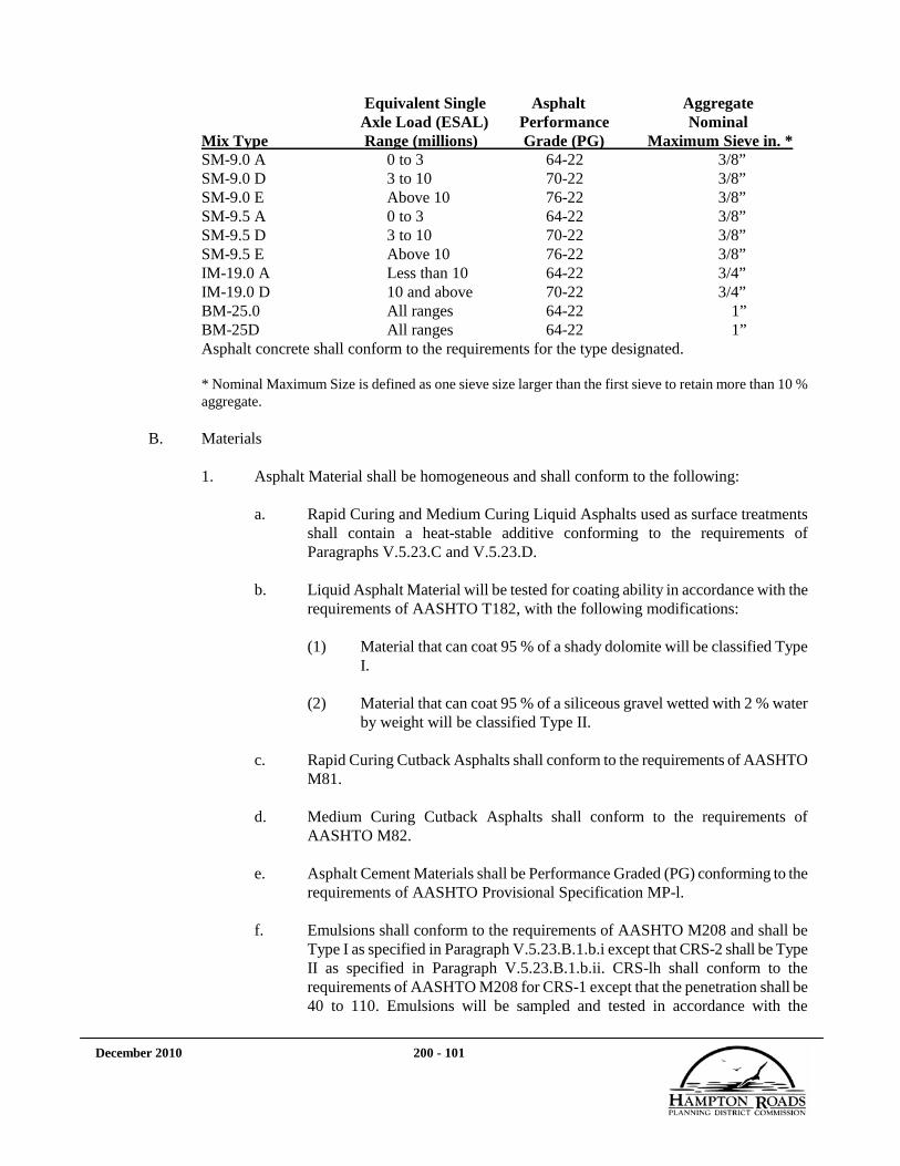
December 2010 200 - 101
Equivalent Single Asphalt Aggregate Axle Load (ESAL) Performance Nominal Mix Type Range (millions) Grade (PG) Maximum Sieve in. * SM-9.0 A 0 to 3 64-22 3/8” SM-9.0 D 3 to 10 70-22 3/8” SM-9.0 E Above 10 76-22 3/8” SM-9.5 A 0 to 3 64-22 3/8” SM-9.5 D 3 to 10 70-22 3/8” SM-9.5 E Above 10 76-22 3/8” IM-19.0 A Less than 10 64-22 3/4” IM-19.0 D 10 and above 70-22 3/4” BM-25.0 All ranges 64-22 1” BM-25D All ranges 64-22 1” Asphalt concrete shall conform to the requirements for the type designated. * Nominal Maximum Size is defined as one sieve size larger than the first sieve to retain more than 10 % aggregate.
B. Materials
1. Asphalt Material shall be homogeneous and shall conform to the following:
a. Rapid Curing and Medium Curing Liquid Asphalts used as surface treatments
shall contain a heat-stable additive conforming to the requirements of Paragraphs V.5.23.C and V.5.23.D.
b. Liquid Asphalt Material will be tested for coating ability in accordance with the
requirements of AASHTO T182, with the following modifications:
(1) Material that can coat 95 % of a shady dolomite will be classified Type I.
(2) Material that can coat 95 % of a siliceous gravel wetted with 2 % water
by weight will be classified Type II.
c. Rapid Curing Cutback Asphalts shall conform to the requirements of AASHTO M81.
d. Medium Curing Cutback Asphalts shall conform to the requirements of
AASHTO M82.
e. Asphalt Cement Materials shall be Performance Graded (PG) conforming to the requirements of AASHTO Provisional Specification MP-l.
f. Emulsions shall conform to the requirements of AASHTO M208 and shall be
Type I as specified in Paragraph V.5.23.B.1.b.i except that CRS-2 shall be Type II as specified in Paragraph V.5.23.B.1.b.ii. CRS-lh shall conform to the requirements of AASHTO M208 for CRS-1 except that the penetration shall be 40 to 110. Emulsions will be sampled and tested in accordance with the

December 2010 200 - 102
requirements of AASHTO T59 except that viscosity will be tested in accordance with the requirements of VTM-64.
2. Fine and Course Aggregate
Fine and Course Aggregate shall conform to the requirements of Paragraph V.5.1.G.
3. Mineral Filler Mineral filler shall conform to AASHTO M17. Tests will be performed in accordance with AASHTO T37.
4. Aggregate for asphalt concrete shall be provided in sufficient sizes to produce a uniform mixture. The Contractor shall indicate on the proposed job-mix formula the separate approximate sizes of aggregate to be used. Where segregation or non-uniformity is evident in the finished pavement, the Owner reserves the right to require the Contractor to discontinue the use of crusher run or aggregate blends and to furnish separate sizes of open graded aggregate material.
5. An antistripping additive shall be used in all asphalt mixes. It may be hydrated lime in accordance with the requirements of Paragraph V.5.23.B.6 or an approved chemical additive from the VDOT’s approved list found in the Materials Division’s Manual of Instructions, or a combination of both. The mixture shall produce a tensile strength ratio (TSR) value not less than 0.80 for the design and production tests. The TSR value shall be determined in accordance with AASHTD T283, including a freeze-thaw cycle, (4-inch specimens compacted with Marshall hammer or 3.5 by 6-inch specimens when compacted with a gyratory), except that the 16 hour curing time requirement and 72 to 96 hour storage period will be waived. Design tests shall use the same materials that are to be used in the production mix and shall be conducted in a VDOT approved laboratory.
When a chemical additive is used, it shall be added to the asphalt cement prior to introduction into the mix. Any chemical additive or particular concentration of chemical additive found to be harmful to the asphalt material or which changes the viscosity of the original asphalt cement more than 400 poises or the penetration more than -4 or ±10 shall be changed to obtain compliance with these values.
6. Hydrated Lime Hydrated lime shall conform to the requirements of ASTM C977. Hydrated lime shall be added at a rate of not less than 1 % by weight of the total dry aggregate.
A separate bin or tank and feeder system shall be provided to store and accurately proportion the time into the aggregate in either dry or slurry form. The lime and aggregate shall be mixed by pugmill or other approved means to achieve a uniform lime coating of the aggregate prior to entering the drier. In the event lime is added in dry form, the aggregate shall contain at least 3 % free moisture. The stockpiling of time treated

December 2010 200 - 103
aggregate will not be permitted.
The feeder system shall he controlled by a proportioning device, which shall be accurate to within ±10 % of the specified amount. The proportioning device shall have a convenient and accurate means of calibration. A flow indicator or sensor shall be provided with the proportioning device and interlocked with the plant controls (aggregate feed or weigh system) such that production of the mixture will be maintained and, if there is a stoppage of the tune feed, interrupted.
The method of introducing and mixing the lime and aggregate shall be subject to approval by the Owner prior to beginning production.
7. Reclaimed Asphalt Pavement Material
Reclaimed Asphalt Pavement (RAP) material may be used as a component material of asphalt mixtures in conformance with the following:
a. Asphalt surface, intermediate, and base mixtures containing RAP shall use the
PG grade of asphalt cement as indicated in Table 200-5.23-2A.
b. The final asphalt mixture shall conform to the requirements for the type specified.
c. During the production process, RAP material shall not be allowed to contact
open flame.
d. RAP material shall be handled, hauled and stored in a manner that will minimize contamination. Further, the material shall be stockpiled and used in such manner that variable asphalt contents and asphalt penetration values will not adversely affect the consistency of the mixture.
e. RAP shall be processed in such a manner as to ensure that the maximum top size
introduced into the mix shall be 2 inches. The Owner may require smaller sized particles be introduced into the mix if the reclaimed particles are not broken down or uniformly distributed throughout the mixture during heating and mixing.
C. Job-Mix Formula
The Contractor shall submit for the Owner’s approval, a job-mix formula for each mixture to be supplied. The job-mix formula shall be within the design range specified. The job-mix formula shall establish a single percentage of aggregate passing each required sieve, a single percentage of asphalt material to be added to the aggregate, a temperature at which the mixture is to be produced, and a temperature at which the mixture is to be compacted for SUPERPAVE testing according to the requirements of AASHTO PP28-99. Each approved job-mix formula shall remain in effect, provided the results of tests performed on material currently being produced consistently meet the requirements of the job-mix for grading, asphalt content, temperature, SUPERPAVE compaction results, and the requirements of Section 315A.

December 2010 200 - 104
1. SUPERPAVE mixes shall be designed and controlled according to the requirements of AASHTO PP28-99 and as specified herein. The Contractor shall have available all of the equipment outlined in AASHTO TP-4 (Section 4-6) and a VDOT certified SUPERPAVE Level I Mix Design Technician. The SUPERPAVE Gyratory Compactor (SGC) shall be one from VDOT’S approved list. The SUPERPAVE mixes shall conform to the requirements of Table 200-5.23-1 and Table 200-5.23-2. Section 7.1.2 of AASHTO PP-2-99 shall be modified such that the compaction temperature is as specified in Paragraph V.5.23.C.4.f.
The mixture shall be designed and compacted at the N design gyrations specified in Table 200-5.23-2. The N max requirement shall be verified as part of the design process by compacting a minimum of 2 specimens at the design asphalt content.
TABLE 200-5.23-1 Asphalt Concrete Mixture-Design Range
Percentage By Weight Passing Square Mesh Sieve (in)
Mix Type 1 1/2
1 3/4 1/2 3/8 No. 4 No. 8 No. 30
No. 50
No. 200
SM-9.0 A,D,E 100 90-100 90 max 47-67 2-10 SM-9.5 A,D,E 100 90-100 80 max 38-67 2-10 IM-19.0 A,D 100 90-100 90 max 28-49 2-8 BM-25.0 100 90-100 90 max 19-38 1-7 BM-25 D 100 90-100 90 max 19-38 1-7 C 100 92-100 70-75 50-60 28-36 15-20 7-9
Legend: SM = Surface Mixture; IM = Intermediate Mixture; BM = Base Mixture; C = Curb Mixture
TABLE 200-5.23-2 Mix Design Criteria
Mix Type
VTM (%)
(Note 1)
VFA (%)
Design
VFA (%) Production
(Note 2)
Min. VMA (%)
Fines/A (Note 3)
Number of Gyrations Density (%) At N
Initial N
Design N
Initial N
Max SM-9.0 A 2.0-5.0 75-80 70-85 16 0.6-1.3 65 7 100 ≤ 90.5 SM-9.0 D 2.0-5.0 75-80 70-85 16 0.6-1.3 65 7 100 ≤ 89.0 SM-9.0 E 2.0-5.0 75-80 70-85 16 0.6-1.3 65 7 100 ≤ 89.0
SM-9.5 A 2.0-5.0 73-79 68-84 15 0.6-1.2 65 7 100 ≤ 90.5 SM-9.5 D 2.0-5.0 73-79 68-84 15 0.6-1.2 65 7 100 ≤ 89.0 SM-9.5 E 2.0-5.0 73-79 68-84 15 0.6-1.2 65 7 100 ≤ 89.0
IM-19.0 A 2.0-5.0 69-76 64-81 13 0.6-1.2 65 7 100 ≤ 90.5 IM-19.0 D 2.0-5.0 69-76 64-81 13 0.6-1.2 65 7 115 ≤ 89.0
BM-25.0 2.0-5.0 4 67-75 62-80 12 0.6-1.3 65 7 100 ≤ 89.0 BM-25 D 2.5-5.5 64-75 59-80 11 0.6-1.3 65 7 100 ≤ 89.0
Note 1: Asphalt content should be selected at the 4.0 % Air Voids. Note 2: During production of an approved job mix, the VFA shall be controlled within these limits. Note 3: Fines-Asphalt Ratio is based on effective asphalt content. Note 4: BM-25.0 shall have a minimum asphalt content of 4.4 %, unless otherwise approved by the Owner.

December 2010 200 - 105
Asphalt surface, intermediate, and base mixtures containing RAP shall use a PG asphalt cement according to Table 200-5.23-2A.
TABLE 200-5.23-2A Recommended Performance Grade of Asphalt
Mix Type Percentage RAP in Mix
0.0-20.0 Over 20.1 SM-9.0, SM-9.5 A, SM-12.5 A PG 64-22 PG 58-28
SM-9.0 OD, SM-9.5 D, SM-12.5 D PG 70-22 PG 64-28 SM-9.0 E, SM-9.5 E, SM-12.5 E PG 76-22 PG 70-28
IM-19.0 A PG 64-22 PG 58-28 IM-19.0 D PG 70-22 PG 64-28 BM-25.0 PG 64-22 PG 64-22* BM-25D PG 70-22 PG 70-22*
* BM-25.0 and BM 25D mixes using more than 25 % RAP shall use a PG 58-22.
2. In conjunction with the submittal of a job-mix formula, the Contractor shall submit complete SUPERPAVE design test data, ignition furnace calibration data according to VTM-102 prepared by an approved testing laboratory and viscosity data or Supplier temperature recommendations for the asphalt cement if different from Paragraph V.5.23.C.4.f.
3. Three trial blends for gradation shall be run at 1 asphalt content. No more than 1 of the trial blend gradations shall pass through the restricted zone defined in Table 200-5.23-1A. An aggregate blend that was previously developed and approved as a job-mix formula at a higher gyration level, may be used for subsequent year’s mix designs which require a lower gyration level in lieu of developing three new trial blends.
TABLE 200-5.23-1A
Minimum and Maximum Boundaries of Restricted Gradation
Minimum and Maximum % Passing Nominal Maximum Aggregate Size
Sieve Size 3/8 1/2 3/4 1 1 ½
Min. Max. Min. Max. Min. Max. Min. Max. Min. Max. No. 4 --- --- --- --- --- --- 39.5 39.5 34.7 34.7 No. 8 47.2 47.2 39.1 39.1 34.6 34.6 26.8 30.8 23.3 27.3 No. 16 31.6 37.6 25.6 31.6 22.3 28.3 18.1 24.1 15.5 21.5 No. 30 23.5 27.5 19.1 23.1 16.7 20.7 13.6 17.6 11.7 15.7 No. 50 18.7 18.7 15.5 15.5 13.7 13.7 11.4 11.4 10.0 10.0
4. The SUPERPAVE design test data shall include, but not be limited to, the following information:
a. Grading data for each aggregate component of 3 trial blends shall be submitted
to the Owner. The data for the mixture will show % passing for sieves 2 inch, 1 1/2 inch, 1 inch, 3/4 inch, 1/2 inch, 3/8 inch, No. 4, No. 8, No. 16, No. 30, No. 50, No. 100 and No. 200. The grading shall be reported to the nearest 1.0 % except the No. 200 sieve shall be reported to nearest 0.1 %.

December 2010 200 - 106
b. The test data shall include, but not be limited to, the percentage of each aggregate component as compared to the total aggregate in the asphalt mixture. The specific gravity and aggregate properties for coarse and fine aggregates defined in the Paragraphs V.5.1.G including flat and elongated properties, for each aggregate component or for the total aggregates used in the mixture shall be reported. Aggregate properties (except Sand Equivalent) shall be reported for RAP portions of a mixture. The aggregate specific gravity of RAP shall be the effective aggregate specific gravity calculated from the results of AASHTO T 209 and VTM 102.
c. The aggregate grading in the asphalt mixture shall be determined by igniting or
extracting the asphalt from a laboratory prepared sample. The laboratory sample shall be batched out the basis of component percentages as indicated in Paragraph V.5.23.C.4.b and at the proposed job-mix asphalt content. The aggregate shall be obtained in accordance with the requirements of VTM-102 or (VTM-36 when approved). Sieves specified in Paragraph V.5.23.C.4.a shall be reported, beginning with the top size for that mix.
d. The following volumetric properties of the compacted mixture, calculated on the
basis of the mixture’s maximum specific gravity determined by AASHTO T-209. The mixture shall be aged in accordance with AASHTO PP-2-99 and the bulk specific gravity of the specimens determined by AASHTO T-166, Method A for each asphalt content tested. Properties shall be determined and reported in accordance with the requirements of AASHTO PP28-99.
(1) Voids in total mix (VTM) (2) Voids in mineral aggregate (VMA) (3) Voids filled with Asphalt (VFA) (4) Fines/Asphalt ratio (F/A)
e. The value of the maximum specific gravity of the asphalt mixture used in
Paragraph V.5.23.C.4.d shall be reported to 3 decimal places.
f. The mixing and compaction temperature for testing shall be as follows:
(1) For mix designation A and all Base mixes, the mix temperature shall be 300 to 310°F and the compaction temperature shall be 285 to 290°F.
(2) For mix designation D, the mix temperature shall be 310 to 320° F and
the compaction temperature shall be 295 to 300° F.
(3) In cases involving PG 76-22 or modified binders, the temperatures shall be based on documented Supplier’s recommendations.
g. Field correction factor. The field correction factor is determined by subtracting
the bulk specific gravity of the aggregate from the effective specific gravity of the aggregate at the design asphalt content.
5. The SUPERPAVE design test data shall be plotted on graphs provided by the software of
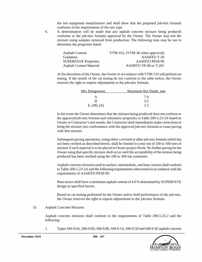
December 2010 200 - 107
the test equipment manufacturer and shall show that the proposed job-mix formula conforms of the requirements of the mix type.
6. A determination will be made that any asphalt concrete mixture being produced conforms to the job-mix formula approved by the Owner. The Owner may test the mixture using samples removed from production. The following tests may be run to determine the properties listed:
Asphalt Content VTM-102, (VTM-36 when approved) Gradation AASHTO T-30 SUPERPAVE Properties AASHTO PP28-99 Asphalt Cement Material AASHTO TP-48 or T-201
At the discretion of the Owner, the Owner in accordance with VTM-110 will perform rut testing. If the results of the rut testing do not conform to the table below, the Owner reserves the right to require adjustments to the job-mix formula.
Mix Designation Maximum Rut Depth, mm
A 7.0 D 5.5 E, (M), (S) 3.5
In the event the Owner determines that the mixture being produced does not conform to the approved job-mix formula and volumetric properties in Table 200-5.23-2A based on Owner or Contractor’s test results, the Contractor shall immediately make corrections to bring the mixture into conformance with the approved job-mix formula or cease paving with that mixture.
Subsequent paving operations, using either a revised or other job-mix formula which has not been verified as described herein, shall be limited to a test run of 100 to 300 tons of mixture if such material is to be placed in Owner project Work. No further paving for the Owner using that specific mixture shall occur until the acceptability of the mixture being produced has been verified using the 100 to 300 ton constraint.
Asphalt concrete mixtures used in surface, intermediate, and base courses shall conform to Table 200-5.23-2A and the following requirements when tested in accordance with the requirements of AASHTO PP28-99:
Base mixes shall have a minimum asphalt content of 4.0 % determined by SUPERPAVE design as specified herein. Based on rut testing performed by the Owner and/or field performance of the job-mix, the Owner reserves the right to require adjustments to the job-mix formula.
D. Asphalt Concrete Mixtures
Asphalt concrete mixtures shall conform to the requirements of Table 200-5.23-2 and the following:
1. Types SM-9.0A, SM-9.0D, SM-9.0E, SM-9.5A, SM-9.5D and SM-9.5E asphalt concrete

December 2010 200 - 108
shall consist of crushed stone, crushed slag, or crushed gravel and fine aggregate, slag or stone screenings or a combination thereof combined with asphalt cement. NOTE: For all surface mixes, except where otherwise noted, no more than 5 % of the aggregate retained on the No. 4 sieve and no more than 20 % of the total aggregate may be polish susceptible. At the discretion of the Owner, a SM-9.5AL may be specified and polish susceptible aggregates may be used (without percentage limits).
2. Types IM-19.0A and IM-19.0D asphalt concrete shall consist of crushed stone, crushed slag, or crushed gravel and fine aggregate, slag or stone screenings or a combination thereof combined with asphalt cement. NOTE: At the discretion of the Owner, an intermediate mix may be designated as either a SM-19.0A or SM-19.0D. When designated as such, no more than 5 % of the aggregate retained on the No. 4 sieve may be polish susceptible. All material passing the No. 4 sieve may be polish susceptible.
3. Types BM-25.0 and BM-25D asphalt concrete shall consist of crushed stone, crushed slag, or crushed gravel and fine aggregate, slag or stone screenings or a combination thereof combined with asphalt cement.
4. Type C (Curb Mix) asphalt concrete shall consist of a blend of No. 78 or No. 8 crushed aggregate, No. 10 crushed aggregate, fine aggregate, mineral filler and a stabilizing additive from the VDOT’s approved list; combined with 6.0-9.0 % of PG 64-22, This mix does not require a volumetric mix design on volumetric testing under the SUPERPAVE system.
5. Asphalt mixtures Type SM-9.5, SM-12.5, IM-19.0, BM-25.0, and BM-25D may be
designated (M) for modified, (S) for stabilized or (M) or (S) for Contractor’s option. Asphalt mixtures with the E designation may be modified, but shall not be stabilized.
a. Type (M) asphalt mixtures shall consist of mixes incorporating a neat asphalt
material with polymer modification meeting the requirements of a PG 76-22 and have a Rolling Thin Film Oven Test residue elastic recovery at 77° F of a minimum 70 %. Modified mixtures shall be designated with a (M) following the standard mix designation. Type (M) asphalt mixtures shall not be permitted to exceed 15 % reclaimed asphalt pavement material.
b. Type (S) asphalt mixtures shall consist of mixes incorporating a stabilizing
additive from the VDOT’s approved list. These mixes shall be designated with a (S) following the standard mix designation. The minimum required additive shall be as specified on the approved list.
E. Testing
Sampling and testing for determination of grading, asphalt cement content and temperature shall be performed by the Contractor. The Contractor shall provide copies of such test results to the Owner. No test results shall relieve the Contractor from furnishing and installing a finished functional product, which conforms to the requirements of the Agreement.

December 2010 200 - 109
The Contractor shall provide the quality control and assurance necessary for the Owner to determine conformance with the required grading, asphalt content and temperature properties for asphalt concrete.
The Contractor shall have a VDOT certified Level 2 Asphalt Plant Technician for designing and adjusting mixes as necessary. Certifications are awarded by the VDOT. The cost and efforts required for acquiring certification shall be the responsibility of the Contractor. The Contractor shall have certified personnel available, as appropriate, throughout the duration of all paving operations including during periods of final inspection and acceptance.
The Level 2 Asphalt Plant Technician or certified Level 1 Asphalt Plant Technician may perform testing of asphalt mixes. The Level 2 Asphalt Plant Technician shall be responsible for reviewing and approving the results of all testing. The Level 2 Asphalt Plant Technician shall be available and have direct communication with the plant for making necessary adjustments in the asphalt concrete mixes at the mixing plant. The Level 2 Asphalt Plant Technician and the Level 1 Asphalt Plant Technician shall be capable of conducting any tests necessary to put the plant into operation and to produce a mixture within the requirements of these specifications.
The Contractor shall maintain all records and test results associated with the material production and shall maintain appropriate current quality control charts. All test results and control charts shall be available for review by the Owner.
The Contractor shall execute a quality control plan of process inspections and tests, including the determination of SUPERPAVE properties. The results of the SUPERPAVE tests shall be used, along with the results of other quality control efforts, to control the quality of the mixture being produced.
The Contractor shall perform at least one field SUPERPAVE test per day per mix or per 1000 tons per mix if more than 1000 tons of a mix is produced per day (aging as described in PP-2-99 shall not be performed). In the event less than 300 tons of asphalt mixture is produced under a single job mix formula in a day, field SUPERPAVE testing will not be required. This tonnage shall be added to subsequent production. When the accumulated tonnage exceeds 300 tons, minimum testing frequency shall apply. Field SUPERPAVE test results shall be plotted and displayed in control chant form in the plant immediately following the completion of each individual test. The tests shall determine asphalt content, VTM, VMA, VFA and F/A in % to the nearest 0.1 %. The Owner may conduct onsite inspections so the Contractor’s Level 2 Asphalt Plant Technician can demonstrate knowledge of SUPERPAVE mix design and production requirements on Owner supplied mixture.
Aggregate specific gravity and aggregate property tests shall be conducted by a VDOT certified SUPERPAVE Asphalt Aggregate technician on each aggregate component (including RAP) or total aggregate mixture once at design and once prior to beginning production in each calendar year. Sand Equivalent shall not be performed on RAP. Additionally, for each 50,000 tons of each aggregate size used at each plant, aggregate specific gravity and aggregate property test shall be reported on each aggregate component or the total aggregate mixture. Otherwise, if the total blend (cold feed) is used to obtain aggregate specific gravity and aggregate properties, then these tests shall be run for each 50,000 tons of the total blend.

December 2010 200 - 110
Field SUPERPAVE tests shall be performed to N design gyrations as specified in Table 200-5.23-2. At the Owner’s discretion, the N max requirement may be checked.
F. Tests
The Owner may sample materials entering into the composition of the asphalt concrete, the mixture and the completed pavement. The Contractor shall cooperate with the Owner in obtaining these samples. When samples are obtained from the pavement, the resulting voids shall be filled and refinished by the Contractor without additional compensation.
When asphalt cement is extracted and recovered in accordance with AASHTO T170, the recovered asphalt cement shall have the following penetration and ductility at 77° F:
Mix Type Recovered Penetration Ductility at 77° F
SM-9.0A, 9.5A min 35 min 40 cm SM-9.0D, 9.5A min 25 min 40 cm IM-19.0A min 35 min 40 cm IM-19.0D min 25 min 40 cm BM-25.0, 25D min 35 min 40 cm NOTE: Recovered Penetration and Ductility shall not be performed on SM-9.5E, and all (M) and (S) mixes.
Abson recovery samples that fail recovered penetration or ductility shall be PG graded according to AASHTO MP-1. If the samples meet the required grade specified in Paragraph V.5.23.A, they shall be deemed acceptable.
When the Owner performs PG grading on a Contractor’s liquid asphalt storage tank, the Owner will notify the Asphalt Concrete Producer and Binder Supplier if tests indicate that the binder properties of the asphalt material differs from the approved job-mix. It will be the responsibility of the Asphalt Concrete Producer and Binder Supplier to determine corrective action with the approval of the Owner.
G. Plant Inspection
The preparation of asphalt concrete mixtures will be accepted under a quality assurance plan. The Contractor shall provide a laboratory as specified in the VDOT Road and Bridge Specifications, Section 106.07.
H. Acceptance
Acceptance shall be made under the Owner’s quality assurance program that includes the testing of production samples by the Contractor and monitor samples by the Owner. Sampling and testing for the determination of grading, asphalt cement content and temperature shall be performed by the Contractor. The Owner will perform independent monitor checks at a laboratory of its discretion. The Contractor shall provide copies of such test results to the Owner. Where the Contractor’s test results indicate that the mixture conforms to the gradation, asphalt cement content and mix temperature requirements of the Specifications, the mixture will be acceptable for these properties; however, nothing herein shall be construed as waiving the requirements of the VDOT Road and Bridge Specifications, Sections 106.06, 200.02, and 200.03, or relieving the

December 2010 200 - 111
Contractor of the obligation to furnish and install a finished functional product which conforms to the requirements of the Contract Documents. In the event a statistical comparative analysis of the Contractor’s test results and the Owner’s monitor tests indicate a statistically significant difference in the results and either of the results indicate that the material does not conform to the grading and asphalt cement content requirements of the Specifications, an investigation will be made to determine the reason for the difference. In the event it is determined from the investigation that the material does not conform to the requirements of the Contract Documents, price adjustments will be made in accordance with the requirements of the Paragraph V.5.23.I.
Acceptance for gradation and asphalt cement content will be based upon a mean of the results of four tests performed on samples taken in a stratified random manner from each 2000 ton lot (4000 ton lots may be used when the normal daily production of the source from which the material is being obtained is in excess of 2000 tons). Unless otherwise approved, samples shall be obtained from the approximate center of randomly selected quadrants of truckloads of material. Any statistically acceptable method of randomization may be used to determine the time and location of the stratified random sample to be taken; however, the Owner shall be advised of the method to be used prior to beginning production.
A lot will be considered to be acceptable for gradation and asphalt content if the mean of the test results obtained is within the tolerance allowed from the job-mix formula, as shown in Table 200-5.23-3.
The temperature of the mixture at the plant shall be controlled to provide load to load uniformity during changing weather conditions and surface temperatures. The maximum temperature of mix designations A and D, and base mixes, shall not exceed 350° F, unless otherwise directed by the Owner. The maximum temperature as recommended by the Supplier shall not be exceeded for an F, (M), or (S) designated mix.
In the event the job-mix formula is modified within a lot, the mean test results of the samples taken will be compared to the applicable process tolerance shown in Table 200-5.23-3.
TABLE 200-5.23-3 Process Tolerance
Tolerance on Each Laboratory Sieve and Asphalt Content – % Plus and Minus Number
Tests Top Size
1 ½ in
1 in
3/4 in
1/2 in
3/8 in
No. 4
No. 8
No. 30
No. 50
No. 200 A.C.
1 0.0 8.0 8.0 8.0 8.0 8.0 8.0 8.0 6.0 5.0 2.0 .60 2 0.0 5.7 5.7 5.7 5.7 5.7 5.7 5.7 4.3 3.6 1.4 0.43 3 0.0 4.4 4.4 4.4 4.4 4.4 4.4 4.4 3.3 2.8 1.1 0.33 4 0.0 4.0 4.0 4.0 4.0 4.0 4.0 4.0 3.0 2.5 1.0 0.31 8 0.0 2.8 2.8 2.8 2.8 2.8 2.8 2.8 2.1 1.8 0.7 0.21
Note: The Top Size is defined as the sieve, which has 100% passing as defined in Table 200-5.1-10. The Top Size tolerance for SM-9.0 and SM-9.5 mixes shall be as follows:

December 2010 200 - 112
Number Tests Top Size 1 2.0 2 1.4 3 1.1 4 1.0 8 0.7
Asphalt content will be measured as extractable asphalt or weight after ignition.
Field SUPERPAVE tests may be performed by the Owner in accordance with the requirements of AASHTO PP28-99 during the production of the approved job-mixes designed by the SUPERPAVE method. Aging, as described in PP-2-99, shall not be performed. Should any Field SUPERPAVE test fail to meet the specified limits contained in Table 200-5.23-2, the Owner may require that production be stopped until necessary corrective action is taken by the Contractor. The Owner will investigate and determine the acceptability of material placed and represented by failing Field SUPERPAVE test results.
Should visual examination by the Owner reveal that the material in any load or portion of the paved roadway is obviously contaminated or segregated, that load or portion of the paved roadway will be rejected without additional sampling or testing of the lot. In the event it is necessary to determine the gradation or asphalt content of the material in any load or portion of the paved roadway, samples will be taken, tested, and the results compared to the requirements of the approved job-mix formula. The results obtained in the testing will apply only to the material in question.
I. Adjustment System
In the event a lot of material does not conform to the acceptance requirements of Paragraph V.5.23.H, adjustment points will be determined as follows:
Adjustment Points for Each 1% that the Gradation is Outside the Process Tolerance
Permitted In Table 200-5.23-3
Sieve Size (Applied in 0.1 increments)
1 1/2 in 1 1 in 1 3/4 in 1 1/2 in 1 No.4 1 No.8 1 No.30 2 No.50 2 No. 200 3
One adjustment will be applied for each 0.1 % that the material is out of the process tolerance for asphalt content.
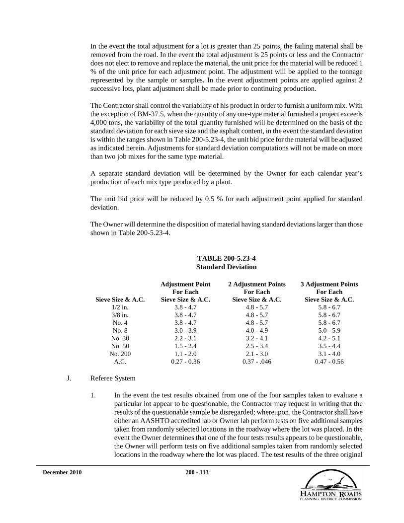
December 2010 200 - 113
In the event the total adjustment for a lot is greater than 25 points, the failing material shall be removed from the road. In the event the total adjustment is 25 points or less and the Contractor does not elect to remove and replace the material, the unit price for the material will be reduced 1 % of the unit price for each adjustment point. The adjustment will be applied to the tonnage represented by the sample or samples. In the event adjustment points are applied against 2 successive lots, plant adjustment shall be made prior to continuing production.
The Contractor shall control the variability of his product in order to furnish a uniform mix. With the exception of BM-37.5, when the quantity of any one-type material furnished a project exceeds 4,000 tons, the variability of the total quantity furnished will be determined on the basis of the standard deviation for each sieve size and the asphalt content, in the event the standard deviation is within the ranges shown in Table 200-5.23-4, the unit bid price for the material will be adjusted as indicated herein. Adjustments for standard deviation computations will not be made on more than two job mixes for the same type material.
A separate standard deviation will be determined by the Owner for each calendar year’s production of each mix type produced by a plant.
The unit bid price will be reduced by 0.5 % for each adjustment point applied for standard deviation.
The Owner will determine the disposition of material having standard deviations larger than those shown in Table 200-5.23-4.
TABLE 200-5.23-4 Standard Deviation
Sieve Size & A.C.
Adjustment Point For Each
Sieve Size & A.C.
2 Adjustment Points For Each
Sieve Size & A.C.
3 Adjustment Points For Each
Sieve Size & A.C. 1/2 in. 3.8 - 4.7 4.8 - 5.7 5.8 - 6.7 3/8 in. 3.8 - 4.7 4.8 - 5.7 5.8 - 6.7 No. 4 3.8 - 4.7 4.8 - 5.7 5.8 - 6.7 No. 8 3.0 - 3.9 4.0 - 4.9 5.0 - 5.9
No. 30 2.2 - 3.1 3.2 - 4.1 4.2 - 5.1 No. 50 1.5 - 2.4 2.5 - 3.4 3.5 - 4.4
No. 200 1.1 - 2.0 2.1 - 3.0 3.1 - 4.0 A.C. 0.27 - 0.36 0.37 - .046 0.47 - 0.56
J. Referee System
1. In the event the test results obtained from one of the four samples taken to evaluate a
particular lot appear to be questionable, the Contractor may request in writing that the results of the questionable sample be disregarded; whereupon, the Contractor shall have either an AASHTO accredited lab or Owner lab perform tests on five additional samples taken from randomly selected locations in the roadway where the lot was placed. In the event the Owner determines that one of the four tests results appears to be questionable, the Owner will perform tests on five additional samples taken from randomly selected locations in the roadway where the lot was placed. The test results of the three original

December 2010 200 - 114
(unquestioned) samples will be averaged with test results of the five road samples and the mean of the test values obtained for the eight samples will be compared to the requirements for the mean of eight tests as shown in Table 200-5.23-4.
2. In the event the Contractor questions the mean of the four original test results obtained
for a particular lot, the Contractor may request in writing approval to have either an AASHTO accredited lab or Owner lab perform additional testing of that lot. In the event the Owner determines that the mean of the four original test results are questionable, the Owner will perform additional testing of that lot. The test results of the original four samples will be averaged with the test results of four additional samples taken from randomly selected locations in the roadway where the lot was placed and the mean of test values obtained for the eight samples will be compared to the requirements for the mean result of eight tests as shown in Table 200-5.23-4.
If the Contractor requests additional tests, as described in Paragraph V.5.23.J.1 or Paragraph V.5.23.J.2, the Contractor shall sample and have either an AASHTO accredited lab or Owner lab test the material in accordance with Owner approved procedures. The Owner reserves the right to observe the sampling and testing.
In the event the mean of the test values obtained for the eight samples conforms to the requirements for the mean results of eight tests, the material will be considered acceptable. In the event the mean of the test values obtained for the eight samples does not conform to the requirements for time mean result of eight tests, the lot will be adjusted in accordance with the adjustment rate specified in Paragraph V.5.23.I.
Samples of the size shown herein shall be saw cut by the Contractor, without the use of liquids, for testing.
Application Rate Minimum Sample Size
125 lbs/sy 8 by 8 inches 150 lbs/sy 7 by 7 inches 200 lbs/sy 6 by 6 inches 300 lbs/sy 5 by 5 inches
K. Asphalt Concrete Mixing Plant
Plants used for the preparation of asphalt concrete mixtures shall conform to the following requirements:
1. Certification for Plant Operation and Sampling - There shall be a VDOT-certified Level
1 Asphalt Plant Technician for sampling material at the plant.
2. Plant Scales - Scales shall be approved in accordance with the requirements of the VDOT Road and Bridge Specifications, Section 109.01.
3. Drier - The plant shall include a drier or driers which continuously agitate the aggregate during the heating and drying process. The aggregate shall be dried to a point at which the moisture content of the completed mixture does not exceed 1 % as determined from samples taken at the point of discharge from the mixing operation.

December 2010 200 - 115
4. Feeder for Drier - The plant shall be equipped with accurate mechanical means for uniformly feeding the aggregate into the drier so that uniform production and uniform temperature will be obtained. Where different size aggregates are required to meet grading specifications, they must be proportioned by feeding into the cold elevator through a multiple compartment feeder bin (one bin for each size used) equipped with positive action gates that can be securely locked to maintain desired proportioning.
5. Bins - When bins are used, adequate and convenient facilities shall be provided to make
possible the sampling of representative aggregate material for each bin. Each compartment shall be provided with an overflow pipe of such size and at such location to prevent contamination of the aggregate in adjacent compartments and shall be provided with individual outlet gates which, when closed, will allow no leakage.
6. Thermometric Equipment - The plant shall be equipped with a thermometric instrument so placed at the discharge chute of the drier as to register automatically or indicate the temperature of the heated aggregate or the completed mix if the drier drum mixing plant is used. A thermometric device shall be fixed in the asphalt feed line at a suitable location near the charging valve at the mixer unit. All thermometric devices shall be maintained in good working condition and shall be subject to checking against the laboratory thermometer. Any instruments that do not operate or register properly shall be removed and repaired or replaced.
7. Pollution Control shall conform to the requirements of the VDOT Road and Bridge Specifications, Section 107.14.
8. Equipment for Preparation of Asphalt Material - Tanks for the storage of asphalt material shall be equipped with a heating system capable of heating and holding the material at the required temperatures. A separate storage tank or a storage tank having separate compartments shall be available for each grade of asphalt cement being used. The heating system shall be designed to heat the contents of the tank by means of steam, electricity or other approved means so that no flame is in contact with the heating surface of the tank. The circulating system for the asphalt material shall be designed to assure proper and continuous circulation during the operating period and to minimize oxidation. All pipelines shall be steam jacketed or insulated to prevent undue loss of heat. Storage facilities for asphalt material shall be sufficient for at least one day’s operation or an equivalent means of supply shall be provided which will insure continuous operation. Provisions shall be made for measuring and sampling storage tanks. When asphalt material is proportioned by volume, the temperature of the asphalt material in storage shall be uniformly maintained (±20° F) during operation of the plant by means of an automatic temperature control device. A sampling valve shall be provided for sampling of each asphalt storage tank used in production of the mix. If there are multiple storage tanks, a dedicated valve for each storage tank shall be provided.
9. Asphalt Control - Asphalt material shall he accurately proportioned by volume or weight. When volumetric methods are used, measurements shall be made by means of meters or

December 2010 200 - 116
pumps, calibrated for accuracy. The section of the asphalt line between the charging valve and the spray bar shall be provided with an outlet valve for checking the meter.
When proportioned by weight, the asphalt material shall be weighed on approved scales. Dial scales shall have a capacity of not more than 15 % of the capacity of the mixer. The value of the minimum graduation shall not be greater than 2 pounds.
Except when drier-drum mixing plant is used, the asphalt material bucket, its valves and spray bar shall be steam jacketed or heated by other approved means. The bucket shall have a capacity of at least 15 % of the weight of the asphalt material required in any mixture and shall be supported by fulcrums.
The asphalt shall be delivered to the mixer in multiple uniform streams for the full width of the mixer.
10. Proportioning Aggregates - Mineral filler and any bag house fines the Contractor uses
shall be metered or introduced by means of an approved device for uniform proportioning by weight or by volume. The weigh hopper shall be of sufficient size to hold the maximum required weight of aggregate for one batch without hand raking or running over. Sufficient clearance between the weigh hopper and supporting devices shall be provided to prevent accumulation of foreign materials. The discharge gate of the weigh hopper shall be situated in such a manner that the aggregates will not segregate when dumped into the mixer. Gates on the bins and weigh hopper shall be constructed to prevent leakage when closed.
11. Drum Mixer - The aggregate shall be proportioned by a positive weight control at the cold aggregate feet by use of a belt scale that will automatically regulate the supply of material being fed and permit instant correction of variations in load. The cold feed flow shall be automatically coupled with the asphalt flow to maintain the required proportions.
12. Batch Mixer - The batch mixer shall be of a twin pugmill or other approved type, steam jacketed or heated by other approved means and capable of producing uniform mixtures within the specified tolerances. It shall be equipped with a sufficient number of paddles or blades, operated at such speeds as to produce a properly and uniformly mixed batch, the number and arrangement of the mixer paddles shall be subject to the approval of the Owner. Worn or defective blades shall not be used in mixing operations.
The mixer shall be provided with an approved time lock which will lock the discharge gate after the aggregates and asphalt have been placed in mixer and will not release the gate until the specified time has elapsed.
Batch type mixing plants used to produce asphalt concrete shall be equipped with approved automatic proportioning devices. Such devices shall include equipment for accurately proportioning batches of the various components of the mixture by weight or volume in the proper sequence and for controlling the sequence and timing of mixing operations. The automated system shall be designed to interrupt and stop the batching

December 2010 200 - 117
operation at any time batch quantities are not satisfied for each of the materials. A means shall be provided for observing the weight of each material during the batching operation.
The aggregate may be proportioned by cold feed controls in lieu of plant screens provided the cold aggregate feed conforms to the requirements specified in Paragraph V.5.23.K.10.
Should the automatic proportioning devices become inoperative, the plant may be allowed to batch and mix asphalt materials for a period of not more than 48 hours from the time the breakdown occurs provided alternate proportioning facilities are approved by the Owner. Written permission of the Owner will be required for operation without automatic proportioning facilities for periods longer than 48 hours.
13. Continuous Mixing Plant - Continuous mixing plant shall include a means for accurately
proportioning each size of aggregate either by weighing or volumetric measurement. When graduation control is by volume, the unit shall include a feeder mounted under the compartment bins. Each bin shall have an accurately controlled individual gate to form an orifice for volumetrically measuring the material drawn from each respective bin compartment. The orifice shall be rectangular, with one dimension adjustable by positive mechanical means and shall be provided with a lock. Indicators shall be provided to show the material gate opening in inches. The plant shall be equipped with a satisfactory revolution counter. The plant shall include a means for calibrating gate openings by weight. The materials fed out of the bins through material orifices shall be bypassed to a suitable test box, with each component material confined in a separate section. The plant shall be equipped to conveniently handle test samples weighing up to 200 pounds per bin and accurate platform scales shall be provided for this purpose. Positive interlocking control shall be provided between the flow of aggregate from the bins and the flow of asphalt material from the meter or other proportioning device. This shall be accomplished by approved interlocking devices or other approved positive means. Accurate control of the asphalt material shall be obtained by weighing, metering or volumetric measurement. The aggregate may be proportioned by cold feed controls in lieu of plant screens provided the cold aggregate feed conforming to the requirements specified in Paragraph V.5.23.K.10.
The plant shall include a continuous mixer of an approved type, which is steam jacketed or heated by other approved means. The paddles shall be of any adjustable type for angular position on the shafts and reversible to retard the flow of the mixture.
There shall be interlock cutoff circuits to interrupt and to stop the proportioning and mixing operations when the aggregate level in the plant or the asphalt material in storage fall below that necessary to produce the specified mixture.

December 2010 200 - 118
14. Trucks, Truck Scales, and Automatic Printer System shall conform to the requirements of the VDOT Road and Bridge Specifications, Section 109.01.
L. Preparation of Mixture
The asphalt and aggregate shall be introduced into the mixer at a temperature that will produce a mixture within the requirements of the job-mix formula. After the required amounts of aggregate and asphalt material have been introduced into the mixer, the materials shall be mixed until a uniform coating of asphalt and a thorough distribution of the aggregate throughout the mixture is secured within the requirements of the Ross Count procedure described in AASHTO T195. Wet mixing time, based on the procedures of AASHTO T195, shall be determined by the Contractor at the beginning of production and approved by the Owner for each individual plant or mixer and for each type of aggregate used; however, in no case shall the wet mixing time be less than 20 seconds. The wet mixing time is the interval of time between the start of introduction of the asphalt material into the mixer and the opening of the discharge gate. A wet mixing time which will result in fully coating a minimum of 95 % of the coarse particles, based on the average of the 3 samples, and provided that none of the 3 samples result in fully coating less than 92 % of the coarse particles, shall be the minimum wet mixing time requirement. A dry mixing time of up to 15 seconds may be required by the Owner to accomplish the degree of aggregate distribution necessary to obtain complete and uniform coating of the aggregate with asphalt.
M. Storage System
In the event the Contractor elects to use a storage system, the system shall be capable of conveying the mix from the plant to the storage bins and storing the mix without a loss in temperature, segregation or oxidation of the mix. Storage time shall be limited by the ability of the bins to maintain the mix within the quality requirements specified herein with a maximum time limit not to exceed 10 days. Material may be stored in bins for no more than 24 hours without an approved heating system.
The conveyor system may be a continuous or skip bucket type. Continuous type conveyors shall be enclosed so that the mix temperature is maintained.
The storage bins shall be designed in such a manner as to prevent segregation of the mix during discharge from the conveyor into the bins and shall be equipped with discharge gates that will not cause segregation of the mix while loading the mix into the trucks.
Approval for the use of storage bins may be withdrawn by the Owner in the event there is an excessive amount of heat loss, segregation or oxidation of the mix.
N. Initial Production
At the start of production of a mix not previously used on a Owner-approved roadway, the Con-tractor shall place 100 to 300 tons or up to one day’s production as directed by the Owner at an approved site (may be project site) so the Owner can examine the mixing plant process control, placement procedures, surface appearance of the mix, compaction patterns of the Contractor’s roller(s) and correlation of the nuclear density device. The material placed will be at the specified

December 2010 200 - 119
application rate and shall be paid for at the contract unit price for the specified mix type. The Owner will determine the disposition of material that was not successfully produced and/or placed due to negligence to planning, production or placement by the Contractor.
O. Asphalt for tack coat and prime coat shall conform to the requirements of Section 310. Asphalt
may be changed one viscosity grade by the Owner at no change in the contract unit price. 5.24. COMPOSITE DETECTABLE WARNING SURFACE PANELS
A. Materials
Detectable Warning Surface shall be “tiles” made of homogeneous glass and carbon, reinforced composite material or vitrified polymer composite (VPC) material with ultraviolet stabilized coating, to minimize color wear, and a “non-slip” surface, incorporating “truncated domes,” made of same material. The nominal thickness of the detectable warning tile shall be 1/8-foot exclusive of the height of the truncated domes. The tiles shall be in compliance with applicable Americans with Disabilities Act Accessibility Guidelines (ADAAG) and American with Disabilities Act (ADA) regulations with regard to detectable warning surfaces.
B. Types
Detectable warning surface shall be classified as follows:
1. Cast-in-Place tile shall be installed in the concrete in accordance with manufacturer’s specifications. The cast-in-place tile shall be used for new construction.
2. Surface Mounted tile shall be secured to the concrete with a structural adhesive system and fasteners that anchors into the concrete. The surface mounted tile shall be installed to existing or proposed smooth finished concrete ramps.
C. Detail Requirements
Requirements for the detectable warning surface tiles shall meet the following:
1. Compressive Strength: 18,000 PSI minimum when tested by ASTM D695.
2. Tensile Strength: 10,000 PSI minimum when tested by ASTM D638-91.
3. Flexural Strength: 24,000 PSI minimum when tested by ASTM C293-94 or ASTM
D790.
4. Water Absorption: 0.35% maximum when tested by ASTM D570.
5. Slip Resistance: 0.9 minimum for the combined wet/dry static co-efficient of friction when tested by ASTM C 1028.
6. Chemical and Stain Resistance: No deterioration, discoloration or staining when tested by ASTM D543-87 or ASTM 1308.

December 2010 200 - 120
7. Fire Resistance: 25 minimum when tested to ASTM E84.
8. Accelerated Weathering: No deterioration, fading or chalking of surface after 2000 hours minimum exposure when tested by ASTM G26-95.
9. Salt and Spray Performance: No deterioration or other detects after 100 hours minimum exposure when tested by ASTM B117.
10. Accelerated Aging and Freeze Thaw: No disintegration, cracking, delamination,
warpage, blistering, color change or other defects when tested by ASTM D037 or ASTM C1026.
D. Pattern/Dimension
Pattern and dimensions of the detectable warning surface tile shall incorporate an “in-line” dome pattern of truncated domes 0.2-inches in height, 0.9-inches diameter at the base and 0.4-inches diameter at top of dome. Domes should be spaced no greater than 2 1/4-inches from center to center. The field area of the detectable warning surface should consist of raised points no greater than 0.045-inches, to create a non-slip surface for wheelchair safety. Surface mounted detectable warning surface tiles shall have countersunk fastening holes and perimeter beveled edges.
Overall dimension of the detectable warning surface tiles shall be in accordance with this specification and the Contract Documents.
E. Color
Unless otherwise called out in the Contract Documents, the detectable warning surface tiles shall be “Brick Red”, Federal Color No. 31136, or Federal Color No. 11302, for applications on standard concrete curb ramps and “Light Gray”, Federal Color No. 26280 for applications on red brick paver or red brick concrete paver ramps, or as approved by Owner. The color shall be integral with the detectable warning device tiles and shall not be surface applied. Paints or other surface coatings shall not be used. Product samples with proposed color shall be submitted to Owner for approval prior to installation.
F. Fasteners
Fasteners shall be flat-head drive anchors made of a corrosion-resistant material ¼-inch in diameter x 1 3/4-inches long.
G. Adhesives
Adhesive shall be a urethane elastomeric adhesive material, as required by the manufacturer’s specifications.
H. Sealants shall be a gray epoxy, two-component sealant, as required by the manufacturer’s
specifications.

December 2010 200 - 121
5.25. FENCE
These specifications cover material requirements for fence components used in the construction of chain link, barbed wire, woven wire, and lawn fences and material specifications for temporary silt fences, geotextile fabric silt barriers, and filter barriers used for erosion control.
Unless otherwise specified hereinafter, metallic fence materials shall conform to the requirements of AASHTO Ml81. Steel posts and braces for standard fence and chain link fence may be fabricated from pre-galvanized material in lieu of galvanizing after fabrication provided ends and other areas of exposed metal are satisfactorily repaired using a material conforming to the requirements of Paragraph V.5.8.E.2.
A. Chain Link Fence
Fabric material shall be 9-gage core, new and shall conform to the following:
1. Galvanized wire fabric for use in chain link fence shall be hot dip galvanized after
weaving in accordance with the requirements of ASTM A392, Class II.
2. Aluminum alloy wire fabric shall conform to the requirements of FS RR-F-191/1B, Type III.
3. Aluminum coated wire fabric shall conform to the requirements of AASHTO M181, Type II.
4. Vinyl coated wire fabric shall conform to the requirements of AASHTO M181 , Type IV, Class B or Class A extruded and bonded except that vinyl coated wire may be No. 9 gage overall, including coating, provided it has a breaking strength of no less than 1290 pounds force.
5. End, corner, and gate posts shall be one of the following:
a. Welded or seamless steel galvanized pipe conforming to the requirements of ASTM F1083, Schedule 40.
b. Roll formed steel sections, galvanized in accordance with the requirements of
ASTM A123.
c. Aluminum alloy pipe conforming to the requirements of ASTM B241, alloy 6063-T6, Schedule 40.
d. Acrylic or polyurethane coated galvanized pipe fabricated from steel conforming
to the requirements of ASTM A569, galvanized with a zinc coating of at least 0.9 ounce per square foot, a chromate coating of at least 15 micrograms per square inch, and an acrylic or polyurethane top coating with a zinc rich exterior thickness of at least 0.3 mil.
e. Vinyl coated pipe conforming to the requirements of AASHTO M181.

December 2010 200 - 122
6. Line posts shall be one of the following:
a. Steel H-columns conforming to the requirements of ASTM A572 or equivalent steel, galvanized in accordance with ASTM A123.
b. Round galvanized steel pipe conforming to the requirements of ASTM A53,
Schedule 40.
c. Roll formed C-section, galvanized in accordance with the requirements of ASTM A123.
d. Aluminum alloy H-columns conforming to the requirements of ASTM B221,
alloy 6063-T6.
e. Aluminum alloy round pipe conforming to the requirements of ASTM B241, alloy 6063-T6, Schedule 40.
f. Acrylic coated or polyurethane coated galvanized pipe conforming to the
requirements of Paragraph V.5.25.A.5.d.
g. Vinyl coated pipe conforming to the requirements of Paragraph V.5.25.A.5.e.
7. Braces shall be one of the following:
a. Welded or seamless steel galvanized pipe conforming to the requirements of ASTM A53, Schedule 40.
b. Roll formed sections, galvanized in accordance with the requirements of ASTM
A12.
c. Aluminum alloy pipe conforming to the requirements of ASTM B241, alloy 6063-T6, Schedule 40.
d. Acrylic coated or polyurethane coated galvanized pipe conforming to the
requirements of Paragraph V.5.25.A.5.d.
e. Vinyl coated pipe conforming to the requirements of Paragraph V.5.25.A.5.e.
8. Gates shall be complete with hinges, latches, stops, and other necessary fittings. Gate frames furnished for use with galvanized or aluminum coated fabric shall be galvanized; those furnished for use with aluminum alloy fabric shall be aluminum alloy or galvanized; and those furnished for use with vinyl coated fabric shall be vinyl coated.
9. Aluminum alloy post surfaces that will be in contact with concrete and up to 1 inch
above concrete shall be uniformly coated with aluminum impregnated caulking compound or a solvent asphalt fiber filled and aluminum pigmented coating conforming to the requirements of FS TT-C-00498. The coating shall be applied with out the addition of thinner. Care shall be taken to prevent voids in the coating and the smearing of visible surfaces of concrete or posts except as otherwise noted herein.

December 2010 200 - 123
10. Tension wire shall be 7 gage, galvanized or vinyl coated coil spring wire.
11. Fittings shall be malleable iron, cast iron, or pressed steel galvanized in accordance with the requirements of ASTM A123; shall have the same finish as posts; or shall be aluminum alloy.
12. Repair of Galvanized Surfaces: Galvanizing surfaces that have been damaged or have
uncoated areas shall be repaired in accordance with ASTM A780, except that repair materials shall not contain lead or cadmium.
B. Barbed Wire Fence, Woven Wire Fence, and Lawn Fence
Barbs shall be locked into position, prohibited from turning or slipping, and spaced on 5-inch (±1/2-inch) centers.
1. Barbed wire shall conform to one of the following:
a. ASTM A121 Class 1 or 2, double strands, 12 gage with four barbs of No. 14
gage wire.
b. ASTM Al21 double strands, 15 1/2 gage with four barbs of No. 16 1/2 gage wire except that the tensile strength of the line wire shall be at least 475 pounds per strand and the zinc coating shall be at least 0.70 ounces per square foot.
c. Single strand oval shaped wire having a diameter of at least 0.08 inch in its least
dimension but not more than 0.135 inch in its greatest dimension and a tensile strength of at least 1,150 pounds; wire shall have four barbs of 14 gage wire and a zinc coating of at least 0.30 ounces per square foot.
2. Woven wire fence fabric shall conform to the requirements of AASHTO M279. Standard
FE-W1 shall conform to Design No. 1047-6-11, Class 3 or No. 1047-6-12, Class 3 having a breaking strength of no less than 685 pounds-force or 960 pounds-force, respectively. Standard FE-W2 shall conform to Design No. 1047-12- 11, Class 3 or No. 1047-12-12, Class 3 having a breaking strength of no less than 685 pounds-force or 960 pounds-force, respectively. Brace wires shall be 9 gage.
3. Lawn fence shall be the type shown on the plans, a similar type that will match the
existing fence, or as desired by the landowner and approved by the Owner.
4. Wood post and braces
a. Species of wood: Posts and braces for standard fence shall be Southern pine, Ponderosa pine, Douglas fir, Western hemlock, larch, or white or red cedar as defined in AASHTO M168. Locust may be used for woven wire farm fence and barbed wire fence.
b. Cutting requirements: Round or square posts and braces shall be cut from live
growing trees.

December 2010 200 - 124
c. Seasoning: Posts and braces shall be sufficiently air seasoned in an approved manner for a suitable length of time under favorable climatic conditions or otherwise conditioned as part of the treating process to permit adequate penetration of preservative without damage to the wood.
d. Peeling: Posts and braces shall have the inner bark removed to the extent
defined by the SPIB. Knots and projections shall be cut or shaved smooth and flush with the surrounding surface of the unit.
e. End finish: Butt ends of posts shall be sawn square.
f. Dimensions: Posts shall not vary from the length specified on the plans by more
than 1 inch. Thickness dimensions shall be undressed dimensions and shall not vary from the dimensions shown on the plans by more than 1/4 inch.
g. Straightness: Wood posts and braces shall be free from bends in more than one
place and free from short or reverse bends. The straightness of the post or brace shall be such that a straight line from the center of the tip to the center of the butt shall not depart from the center of the post by more than 2 % of the length.
h. Grading for square posts and braces: Grading shall conform to the requirements
of Paragraph V.5.25.B.4.a., above.
i. Preservative treatment: Posts and braces, except cedar and locust, shall be treated with a preservative. Waterborne preservatives shall not be used in the treatment of posts and braces to be erected in marshy areas. Oil-borne preservatives shall not be used where posts and braces will come in contact with salt water. Cutting and trimming of ends shall be performed prior to treatment.
j. Timber preservatives shall be used according to their suitability for the condition
of exposure to which they will be subjected and shall not be used interchangeably. Treatments shall conform to the following limitations:
(1) Waterborne preservatives shall be used for timber where a clean surface
is desirable. The moisture content of wood material shall be not more than 19 % at the time of treatment.
(2) Pentachlorophenol may be used for timber that is not to be painted.
(3) Preservatives shall conform to the requirements of AASHTO M133
except that coal tar creosote solution will not be permitted.
k. Pressure treatment shall conform to the requirements of AWPA C2. Gage readings will be the criteria for acceptance except in cases involving referee testing, in which the assay method will be the determining computation.
5. Metal posts and braces: Post anchor plates shall have a surface area of at least 16 square
inches. Posts shall be in accordance with the following:
December 2010 200 - 125
a. Steel posts and braces shall be galvanized and shall conform to the requirements of ASTM A123.
b. Acrylic coated or polyurethane coated galvanized posts for corner and line
braces shall conform to the requirements of Paragraph V.5.25.A.5.d herein.
6. Gates similar in type to those that exist may be substituted for gates shown on the Drawings or Standard Details if preferred by the landowner and approved by the Owner.
C. Temporary Silt Fence, Geotextile Fabric Silt Barrier, and Filter Barrier
1. Geotextile fabric shall conform to the requirements of Paragraph V.5.26.
2. Posts for temporary silt fences shall be a nominal 2 1/2 by 2 1/2 inch or a 3-inch diameter
No. 2 Southern pine, a nominal 2 by 2 inch oak, or steel having a weight of at least 1.25 pounds per linear foot and a length of at least 5 feet.
3. Wire fence reinforcement for temporary silt fences using standard strength geotextile
fabric shall be at least 36-inches in height, at least 14 gage, and shall have a mesh spacing of more than 6-inches.
4. Burlap fabric for temporary filter barriers shall conform to the requirements of AASHTO M182, Class 3 and shall provide at least 3 months of expected usable construction life.
5. Supports for temporary filter barriers shall be a nominal 1 by 2 inch or 1 1/2 inch
diameter No. 2 Southern pine or oak, or steel having a weight of at least 1.00 pound per linear foot.
5.26. GEOSYNTHETICS
A. Tensile strength requirements are in the machine and cross-machine directions.
B. Testing and Documentation
Geosynthetics shall be tested by an independent commercial laboratory, to verify the material requirements specified herein. The Contractor shall provide written documentation of all tests specified. Documentation shall include style, lot, roll numbers, and actual results of each test. In addition, the name, address, phone number of the testing laboratory, and date of testing shall be provided. 1. Geotextile Fabric for Use in Silt Fences, Silt Barriers, or Filter Barriers
Fabric shall contain ultraviolet inhibitors and stabilizers to provide at least 6 months of expected, usable construction life at a temperature range of 0° F to 125 ° F. The tensile strength of the material after 6 months of installation shall be at least 50 % of the initial strength. a. Silt fence

December 2010 200 - 126
Physical Property
Test Method
Requirements (Min.)
Filtering efficiency VTM-51 75% Flow rate VTM-51 0.2 gal/sq ft/minute Tensile strength @ 20% (max.) elongation
VTM-52 Extra strength: 60 lb/lin inch Standard strength: 30 lb/lin inch
b. Silt barrier and filter barrier
Physical Property Test
Method
Requirements (Min.) Filtering efficiency VTM-51 75% Flow rate VTM-51 0.2 gal/sq ft/minute Tensile strength @ 20% (max.) elongation
VTM-52 Standard strength: 30 lb/lin inch
2. Riprap Bedding Material
Physical Property
Test Method
Requirements (Min.)
Apparent opening size ASTM D4751
Equal to or greater than No. 50 sieve
Tensile strength @ 20% (max.) elongation
VTM-52 Min. 30 lb/lin inch
Puncture strength ASTM D4833
Min. 80 lb
Seams shall be equal in strength to the basic material.
Additional fabric material or noncorrosive steel wire may be incorporated into fabric to increase overall strength.
3. Drainage Fabric
Physical Property Test Method Requirements (Min.)
Apparent opening size ASTM D4751 Equal to or greater than No. 50 sieve
Permittivity ASTM 4491 Min. 0.8 sec Tensile strength @ 20% (max.) elongation
VTM-52 Min. 25 lb/lin inch

December 2010 200 - 127
4. Subgrade Stabilization
Physical Property Test Method Requirements (Min.) Tensile strength @ 20% (max.) elongation
ASTM D4595 Min. 80 lb/lin inch
Apparent opening size ASTM D4751 Equal to or smaller than 0.85 mm Secant Modulus @10% Strain ASTM D4595 Min. 500 lb/lin inch * Soil Fabric Friction Angle ASTM D5321 Min. 24 deg. Tear Strength ASTM D4533 75 lbs. Min. Puncture Strength ASTM D4833 75 lbs. Min.
*For test, use Ottowa Sand that passes the No. 20 sieve but can be retained on the No. 30 sieve. Use normal loads of 0.5 ton/sq. ft., 1.0 ton/sq ft and 2.0 ton/sq ft.
5. Geotextile for Embankment Stabilization up to 6 feet in height:
Physical Property Test Method Requirements (Min.)
Tensile Strength (Ultimate) ASTM D4595 Min. 200 lb/lin inch Apparent Opening Size (AOS) ASTM D4751 Equal to or smaller than 0.85 mm Secant Modulus @10% Strain ASTM D4595 Min. 1700 lb/lin inch * Soil Fabric Friction Angle ASTM D5321 Min. 24 deg. Tear Strength ASTM D4533 75 lbs. Min. Puncture Strength ASTM D4833 75 lbs. Min.
*For test, use Ottowa Sand that passes the No. 20 sieve but can be retained on the No. 30 sieve. Use normal loads of 0.5 ton/sq. ft., 1.0 ton/sq ft and 2.0 ton/sq ft.
5.27. PAVERS
A. Concrete Pavers for Crosswalks and Sidewalks
1. Description
This section applies to concrete pavers used in sidewalks, crosswalks, driveways, roadways. This section also applies to concrete truncated dome pavers.
2. Pavers shall meet or exceed ASTM C936 specifications for Solid Concrete Interlocking
Paving Units:

December 2010 200 - 128
Average Compressive Strength (psi) Average of 5 8,000 Individual 7,000 Maximum Cold Water Absorption (%) 5 5 Individual 7 Freeze/Thaw Resistance Resistant to 50 freeze/thaw cycles with no greater than 1% loss of material Freeze-thaw testing requirements shall be waived for applications not exposed to
freezing conditions. Abrasion Resistance Maximum Volume Loss (%) 15 cm3/50cm2 Maximum Average Thickness Loss 3mm
a. Where 3 1/8-inch thick pavers are specified, their compressive strength test
results per ASTM C 140 shall be adjusted by multiplying by 1.18 to equate the results to that from 2 3/8-inch thick pavers.
b. Detectable warning pavers shall meet the latest truncated dome requirements of
the American Disabilities Act (ADA).
c. Color Pigments
(1) Color pigments for integrally colored concrete pavers shall meet or exceed ASTM C979 Standards. Products meeting this specification are concrete color pigments by the manufacturers indicated or approved equivalent if manufacturer is indicated. Integrally colored concrete pavers are defined as an acceptable color throughout the paver block as accepted by the Owner.
(2) Face-mix pavers are acceptable provided the pigment loading in the
base mix is a minimum of 50% of the pigment loading in the face mix based on pigment loading being defined as 1 lb. pigment per 100 lbs. cement.
(3) The Owner shall approve the color.
d. Concrete pavers may have spacer bars on each unit. Verify with manufacturers that overall dimensions do not include spacer bars.
3. Bedding and Joint Sand
Bedding and joint sand shall conform to the following:
a. Washed, clean, non-plastic, free from deleterious or foreign matter,
symmetrically shaped, natural or manufactured from crushed rock.

December 2010 200 - 129
b. Where concrete pavers are subject to vehicular traffic, utilize sands that are as hard as practically available.
c. Bedding Sand Material Requirements
Bedding sand material shall conform to the grading requirements of ASTM C 33 with modifications as shown in Table 200-5.27.1.
TABLE 200-5.27.1
GRADING REQUIREMENTS FOR BEDDING SAND FOR CONCRETE PAVERS
(ASTM C 33 MODIFIED)
Sand Sieve Size % Passing 3/8 in.(9.5 mm) 100 No. 4 (4.75 mm) 95 to 100 No. 8 (2.36 mm) 85 to 100
No. 16 (1.18 mm) 50 to 85 No. 30 (0.600 mm) 25 to 60 No. 50 (0.300 mm) 10 to 30
No. 100 (0.150 mm) 2 to 10 No. 200 (0.075 mm) 0 to 1
(1) Mason sand or sand conforming to ASTM C 144 shall not be used for
bedding sand.
(2) Limestone screenings or stone dust shall not be used for bedding sand.
d. Joint Sand Material Requirements
(1) Joint sand material shall conform to the grading requirements of ASTM C 144 as shown with modifications in Table 200-5.27.2 below:
TABLE 200-5.27.2
GRADING REQUIREMENTS FOR JOINT SAND FOR CONCRETE PAVERS (ASTM C 144 MODIFIED)
Sieve Size
ASTM C 144 Natural Sand
% Passing
ASTM C 144 Manufactured Sand
% Passing No. 4 (4.75 mm) 100 100 No. 8 (2.36 mm) 95 to 100 95 to 100
No. 16 (1.18 mm) 70 to 100 70 to 100 No. 30 (0.600 mm) 40 to 75 40 to 100 No. 50 (0.300 mm) 10 to 35 20 to 40
No. 100 (0.150 mm) 2 to 15 10 to 25 No. 200 (0.075 mm) 0 to 1 0 to 10

December 2010 200 - 130
(2) Coarser sand than that specified above may be used for joint sand including ASTM C 33 material as shown in Table 200-5.27.1. Use material where the largest sieve size easily enters the smallest joints. For example, if the smallest paver joints are 2 mm wide, use sand 2 mm and smaller in particle size. If ASTM C 33 sand is used for joint sand, extra effort may be required in sweeping material and compacting the pavers in order to completely fill the joints.
(3) Sieve according to ASTM C 136.
B. Clay Brick Pavers for Heavy Duty Traffic Loading Conditions
1. Description: This section applies to pavers used in crosswalks in roadways, higher traffic
volume driveways, roadways and other applications where heavy vehicle loading or frequent vehicular traffic is anticipated. See Paragraph V.5.27.C for applications involving sidewalks, driveways and other applications where heavy or frequent vehicle loading is not anticipated.
2. Brick pavers shall conform to ASTM C 1272, Specification for Heavy Vehicular Paving
Brick.
a. Durability
Paver Type Type F (Pavers
placed on sand base)
Type R (Pavers
placed on asphalt or
mortar base) Average Compressive Strength (psi) Average of 5 8,000 10,000 Individual 7,000 8,800 Maximum Cold Water Absorption (%) Average of 5 6 6 Individual 7 7 Freeze/Thaw Resistance Resistant to 50 freeze/thaw cycles with no greater than 1% loss of material
Freeze-thaw testing requirements shall be waived for applications not exposed to freezing conditions.
Minimum Breaking Load (lb/in.) Average of 5 None 475 Individual None 333 Abrasion Resistance Maximum Abrasion Index .011 0.11 Maximum Volume Abrasion Loss 1.7 cm3/cm 1.7 cm2 3/cm2

December 2010 200 - 131
b. Dimensions
(1) Minimum Thickness: Brick pavers used in a heavy vehicular pavement shall have a minimum thickness of 2 5/8-inches. This thickness is exclusive of any chamfers.
(2) Dimensions: Pavers shall be commonly available sizes of pavers for
flexible pavements. Length shall not be more than 4 times the thickness.
(3) Dimensional tolerances for pavers shall be 3/32-inch.
c. Brick pavers shall conform to Application PX as defined in ASTM C902.
C. Clay Brick Pavers for Pedestrian Areas and Light Duty Traffic Loading Conditions
1. Description: This section applies to pavers used in sidewalks, driveways and other applications where heavy or frequent vehicle loading is not anticipated. See Paragraph V.5.27.B for applications involving crosswalks in roadways, higher traffic volume driveways, roadways and other applications where heavy vehicle loading or frequent vehicular traffic is anticipated.
2. Brick pavers shall conform to ASTM C 902, Type SX.
a. Properties
Paver Type Wire Cut Brick
Molded Brick
Average Compressive Strength (psi) Average of 5 8,000 4,000 Individual 7,000 3,500 Maximum Cold Water Absorption (%) Average of 5 8 16 Individual 11 18 Freeze/Thaw Resistance Resistant to 50 freeze/thaw cycles with no greater than 1% loss of material
Freeze-thaw testing requirements shall be waived for applications not exposed to freezing conditions.
Maximum Saturation Coefficient Average of 5 0.78 0.78 Individual 0.80 0.80 Abrasion Resistance Maximum Abrasion Index .011 0.11 Maximum Volume Abrasion Loss 1.7 cm3/cm 1.7 cm2 3/cm2
December 2010 200 - 132
b. Dimensions
(1) Minimum Thickness: Brick pavers used in a heavy vehicular pavement shall have a minimum thickness of 2 1/4-inches. This thickness is exclusive of any chamfers.
(2) Dimensions: Pavers shall be commonly available sizes of pavers for
flexible pavements. Length shall not be more than 4 times the thickness.
(3) Dimensional tolerances for pavers shall be 3/32-inch.
c. Pavers shall conform to Application PX as defined in ASTM C902.
D. Setting Beds
1. Sand Setting Bed
a. Sand shall conform to ASTM C 33. Sand shall be washed, well-graded sand. The amount of material passing the 75 µm (No. 200) sieve shall be no more than 3 %. The sand particles shall be sub-angular. Only naturally occurring, washed silica sand with no silt content shall be used.
b. Mason’s sand, limestone screenings, or stone dust shall not be used.
c. Cement shall not be added to the sand.
2. Sand /Cement Setting Bed
a. Sand shall conform to ASTM C 33. Sand shall be a washed, well-graded sand.
The amount of material passing the 75 µm (No. 200) sieve shall be no more than 3 %. The sand particles shall be sub-angular. Only naturally occurring, washed silica sand with no silt content shall be used.
b. Mason’s sand, limestone screenings, or stone dust shall not be used.
c. Sand/cement mixture shall be 3 parts sand, 1 part cement. Submit each sample
for approval.
3. Mortar Setting Bed
a. Mortar shall be nonshrink.
b. Mortar shall conform to Paragraph 5.6.F.2.
4. Bituminous Setting Bed
a. Tack coat shall be SS-1 or SS-1h asphalt emulsion complying with ASTM D 977 Specification for Emulsified Asphalt.

December 2010 200 - 133
b. The asphalt cement for the bituminous setting bed shall be the same grade as that specified for the adjacent surface course construction. The type of asphalt cement will govern the mixing and rolling temperatures. The fine aggregate for the bituminous setting bed shall be natural or manufactured sand that complies with ASTM D 1073 Specification for fine Aggregate for Asphaltic Paving Mixtures, grading No. 2, or similar material used as fine aggregate at the asphalt plant. All particles shall pass the No. 4 sieve.
c. The proportions shall be 6-8% of asphalt cement with 94-92% of fine aggregate
or approximately 1 gallon of asphalt cement to 110 lbs of fine aggregate. The exact proportions shall be verified before supplying material for the project.
d. The adhesive shall be a neoprene modified asphalt product specifically
developed for setting pavers. It shall consist of rubberized asphalt with inorganic fibers.
E. Jointing Sand
1. Sand Setting Bed Applications
a. Heavy Duty Traffic Loading Conditions: The sand particles shall be sub-
angular. Bedding sand conforming to ASTM C 33 shall be used.
b. Pedestrian Areas and Light Duty Traffic Loading Conditions: The sand particles shall be sub-angular. Bedding sand conforming to ASTM C 33 or Mason Sand conforming to ASTM C 144 shall be used.
2. Bituminous Setting Bed Applications: Stabilized joint sand shall be provided. Stabilizers
shall conform to the brick paver manufacturer’s recommendations. The stabilizers shall bind the sand in the top 1/2 inch of the joint.
F. Surface Coatings
1. Colorless coatings (i.e. water repellents) shall not be used.
2. Coatings that prevent erosion of the jointing sand shall be of a type that has a high vapor
transmission rate and will not affect the slip/skid resistance of the paver. The stabilizer shall be water based.
G. Miscellaneous
1. Edge Restraints shall conform to the type specified in the Drawings or Special
Provisions. Manufactured edge restraints (other than cast-in-place concrete) shall be certified by the manufacturer to be appropriate for the type of application.
2. Mortar shall conform to ANSI 118.3

December 2010 200 - 134
3. Grout
a. Grout shall conform to ANSI 118.3.
b. Grout colors shall be approved by the Owner from the manufacturer's complete color range.
c. Grout products shall be approved the by paver manufacturer.
4. Water: Water that has been approved for drinking purposes is acceptable provided it is
free from minerals or other materials that are detrimental to mortar and grout mixes. 5. Primer shall be as recommended by the mortar material manufacturer.
6. Sealant and backing materials shall conform to ASTM C 920.
7. Mixes - Prepare pre-mix materials in accordance with manufacturer's written instructions.
8. Geotextiles shall conform to Paragraph V.5.26, Geosynthetics. Geotextile fabric
materials shall also be certified by the paver manufacturer to be appropriate for the type of application.
9. Cleaners, sealers, and joint sand stabilizers shall be certified by the paver manufacturer to
be appropriate for the type of application.
End of Section