section 22 - pennagroup 22-2008.pdf · em 385-1-1 15 sep 08 22.a.09 anyone involved in erecting,...
TRANSCRIPT
EM 385-1-1 15 Sep 08
SECTION 22
WORK PLATFORMS AND SCAFFOLDING
22.A GENERAL
22.A.01 Manufactured work platforms shall be erected, used, inspected, tested, maintained, and repaired in accordance with ANSI A10.8 and the manufacturer’s recommendations as outlined in the operating manual or in accordance with guidance from the Scaffolding, Shoring, and Forming Institute. A copy of the manufacturer's recommendations (operating manual) or guidance from the Scaffolding, Shoring, and Forming Institute shall be available at the work site.
22.A.02 Work platforms shall comply with fall protection and appropriate access requirements of Sections 21 and 24.
a. All requirements of this section shall be applied to work platforms and means of access.
b. Standard railing and handrails for work platforms shall be in compliance with the requirements of Section 24.C and E; personal fall protection devices shall be in compliance with Section 21.H; and safety (fall protection) nets shall be in compliance with the requirements of 21.G.
c. Ladders used as work platforms shall be in compliance with the requirements of Section 24.
22.A.03 Prior to commencing any activity that requires work in elevated areas, all provisions for access and fall protection shall be delineated in the Site-Specific Fall Protection and Prevention Plan and AHA, per 21.C and accepted by the GDA for the activity. For specific guidance related to erecting and disassembling scaffolds, see paragraph 21.J.02.
515

EM 385-1-1 15 Sep 08
22.A.04 The following hierarchy and prohibitions shall be followed in selecting appropriate work platforms.
a. Scaffolds, platforms, or temporary floors shall be provided for all work except that can be performed safely from the ground or similar footing.
b. Ladders may be used as work platforms only when use of small hand tools or handling of light material is involved.
c. Ladder jacks, lean-to, and prop-scaffolds are prohibited.
d. Emergency descent devices shall not be used as working platforms.
22.A.05 Erection, moving, dismantling, or altering of work platforms shall be under the supervision of a Competent Person. 22.A.06 Contractors shall use a scaffold tagging system in which all scaffolds are tagged by the Competent Person. Tags shall be color-coded: green indicates the scaffold has been inspected and is safe to use; red indicates the scaffold is unsafe to use. Tags shall be readily visible, made of materials that will withstand the environment in which they are used, be legible and shall include:
a. The Competent Person’s name and signature;
b. Dates of initial and last inspections.
22.A.07 Work platforms shall not be erected or used in the immediate vicinity of power lines or electrical conductors until such are insulated, de-energized, or otherwise rendered safe against accidental contact. > See 11.F.
22.A.08 Where persons are required to work or pass under a working platform, a screen (consisting of No. 18 gauge US Standard wire ½-in (1.2 cm) mesh or the equivalent) shall be provided between the toe board and the guardrail and extending over the entire opening.
516
EM 385-1-1 15 Sep 08
22.A.09 Anyone involved in erecting, disassembling, moving, operating, using, repairing, maintaining or inspecting a scaffold shall be trained by a Competent Person to recognize any hazards associated with the work in question. Proof of training shall be available upon request.
22.B SCAFFOLDS - GENERAL
22.B.01 Capacities.
a. Scaffolds and their components shall meet the requirements contained in ANSI A10.8 and be capable of supporting without failure at least 4 times the maximum anticipated load.
b. Direct connections to roofs and floors, and counterweights used to balance adjustable suspension scaffolds, shall be capable of resisting at least 4 times the tipping moment imposed by the scaffold operating at the rated load of the hoist, or 1.5 (minimum) times the tipping moment imposed by the scaffold operating at the stall load of the hoist, whichever is greater.
22.B.02 Design.
a. The dimensions of the members and materials used in the construction of various working platforms or scaffolds shall conform to the sizes shown in the ANSI A10.8 tables.
b. Factory-fabricated scaffolds and components shall be designed and fabricated in accordance with the applicable ANSI standard. When there is a conflict between the ANSI standard and this manual concerning the design or fabrication of factory-fabricated scaffolds, the ANSI standard shall prevail.
c. Load-carrying timber members shall be a minimum of 1,500 lb-ft/in2 (10,342.1 kPa) (stress grade) construction grade lumber.
(1) All dimensions are nominal sizes (except where rough sizes are noted) as provided by Voluntary Product Standard DOC PS 20, published by NIST of the US Department of Commerce.
517
EM 385-1-1 15 Sep 08
Where rough sizes are noted, only rough or undressed lumber of the size specified will satisfy minimum requirements.
(2) Lumber shall be reasonably straight-grained and free of shakes, checks, splits, cross grains, unsound knots or knots in groups, decay and growth characteristics, or any other condition that will decrease the strength of the material.
22.B.03 Supporting members and foundations shall be of sufficient size and strength to safely distribute loading.
a. Supporting members shall be placed on a firm, smooth foundation that will prevent lateral displacement.
b. Unstable objects such as barrels, boxes, loose bricks, or concrete blocks shall not be used as supports.
c. Vertical members (i.e., poles, legs, or uprights) shall be plumb and securely braced to prevent swaying or displacement.
22.B.04 The design and construction or selection of planking and platform for means of access shall be based upon either the number of persons for which they are rated or the uniform load distribution to which they will be subjected, whichever is the more restrictive, in accordance with Tables 22-1 and 22-2.
518

EM 385-1-1 15 Sep 08
TABLE 22-1
SELECTION CRITERIA FOR PLANKING AND PLATFORMS
Rated Load
Capacity
Designed and Constructed
To CarryLoad
Placed
1 person 250 lb (115 kg) At center of span
250 lb (115 kg) 18 in (45.7 cm) to left of center of span and
2 persons
250 lb (115 kg) 18 in (45.7 cm) to right of center of span
250 lb (115 kg) At center of span and
250 lb (115 kg) 18 in (45.7 cm) to left of center of span and
3 persons
250 lb (115 kg) 18 in (45.7 cm) to right of center of span
TABLE 22-2
MAXIMUM INTENDED LOAD
Rated Load Capacity Maximum Intended Load
light duty 25 lb/ft2 (120 kg/m2) applied uniformly over entire span area
medium duty 50 lb/ft2 (240 kg/m2) applied uniformly over entire span area
heavy duty 75 lb/ft2 (360 kg/m2) applied uniformly over entire span area
519
EM 385-1-1 15 Sep 08
22.B.05 Scaffolds shall be plumb and level.
22.B.06 Scaffolds (other than suspended scaffolds) shall bear on base plates upon mudsills or other adequate foundation.
22.B.07 Working levels of work platforms shall be fully planked or decked.
22.B.08 Planking.
a. All wood planking shall be selected for scaffold plank use as recognized by grading rules established by a recognized independent inspection agency for the species of wood used.
(1) The maximum permissible spans for 2-in x 10-in (5-cm x 25.4-cm) (nominal) or 2-in x 9-in (5-cm x 22.8-cm) (rough) solid sawn wood planks shall be as shown in Table 22-3:
(2) The maximum permissible span for 1 ¼ in x 9 in (3.1 cm x 22.8 cm) or wider wood plank of full thickness with a maximum intended load of 50 lb/ft2 shall be 4 ft (1.2 m).
b. Fabricated planks and platforms may be used in lieu of solid sawn wood planks. Maximum spans for such units shall be as recommended by the manufacturer based on the maximum intended load being calculated as specified in Table 22-3.
c. Planking shall be secured to prevent loosening, tipping, or displacement and supported or braced to prevent excessive spring or deflection. Intermediate beams shall be provided to prevent dislodgement of planks due to deflection. > See 24.A.04.
d. Planking shall be laid with edges close together across the entire access surface. There will be no spaces through which personnel, equipment, or material could fall.
520

EM 385-1-1 15 Sep 08
e. When planking is lapped, each plank shall lap its supports at least 12 in (30.4 cm). Scaffold planks shall extend over their end supports not less than 6 in (15.2 cm) (unless the planking is manufactured with restraining hooks or equivalent means of preventing movement) nor more than 12 in (30.4 cm).
f. Where the ends of planks abut each other to form a flush floor, the butt joint shall be at the centerline of a pole and abutted ends shall rest on separate bearers.
g. For outrigger scaffolds, the platform will be nailed or bolted to the outriggers and shall extend to within 3 in (7.6 cm) of the building wall.
h. Planking shall be supported or braced to prevent excessive spring or deflection and secured and supported to prevent loosening, tipping, or displacement.
i. When a scaffold materially changes its direction, the platform planks shall be laid to prevent tipping.
(1) The planks that meet the corner bearer at an angle shall be laid first, and extend over the diagonally placed bearer far enough to have a good safe bearing but not far enough to involve any danger from tipping, and
(2) The planking running in the opposite direction at an angle shall be laid so as to extend over and rest on the first layer of planking.
j. Planks shall be maintained in good condition. When cracks exceed 1.5 times the width of the board the plank will not be used. Planks with notches deeper than 1/3 the width of the plank will not be used. Planks with saw kerfs shall not be used.
22.B.09 Work platforms shall be securely fastened to the scaffold.
521

EM 385-1-1 15 Sep 08
TABLE 22-3
WOOD PLANK SELECTION
Maximum Intended
Load lb/ft2 (kg/m2)
Maximum Permissible Span -
Full Thickness Undressed Lumber
ft (m)
Maximum Permissible Span - Nominal Thickness Undressed Lumber
ft (m) 25 (122) 10 (3.0) 8 (2.4) 50 (244) 8 (2.4) 6 (1.8) 75 (366) 6 (1.8) n/a
22.B.10 When moving platforms to the next level, the old platform shall be left undisturbed until the new bearers have been set to receive the platform planks.
22.B.11 Access.
a. An access ladder or equivalent safe access shall be provided.
b. Where a built-in ladder is part of a scaffold system, it shall conform to the requirements for ladders.
c. Climbing of braces shall be prohibited.
d. Where end frames are designed to be used as a ladder or where bolted-on ladders are used, the maximum height will be limited to 20 ft (12 m) unless fall protection is used. The distance between rungs shall not exceed 12 in (30.5 cm) and shall be uniform throughout the length of the ladder. The minimum clear length of the rungs shall be 16 in (40.7 cm).
22.B.12 When the scaffold height exceeds four times the minimum scaffold base dimension (and including the width added by
522
EM 385-1-1 15 Sep 08
outriggers, if used), the scaffold shall be secured to the wall or structure.
a. The first vertical and horizontal tie shall be placed at this point.
b. Vertical ties shall be repeated at intervals not greater than 26 ft (7.9 m) with the top tie placed no lower than four times the base dimension from the top of the scaffold.
c. Horizontal ties shall be placed at each end and at intervals not greater than 30 ft (9.1 m).
22.B.13 The use of brackets on scaffolds shall be prohibited unless the tipping effect is controlled.
22.B.14 Use of the following types of scaffolding are permitted if they are designed and constructed in accordance with ANSI A10.8:
a. Outrigger scaffolds;
b. Needle beam scaffolds;
c. Interior hung scaffolds;
d. Bricklayer’s square scaffolds;
e. Float/ship scaffolds;
f. Boatswain’s scaffolds;
g. Window jack scaffolds, and
h. Carpenter’s bracket scaffolds.
22.B.15 Other types of scaffolding not included in ANSI A10.8 may be approved by the GDA provided the design is approved by a
523

EM 385-1-1 15 Sep 08
Registered Professional Engineer (RPE) or they meet a nationally recognized design standard.
22.C METAL SCAFFOLDS AND TOWERS
22.C.01 Scaffold components made of dissimilar metals shall not be used together unless a Competent Person has determined that galvanic action will not reduce the strength of any component to a level below that required by 22.B.01.
22.C.02 The sections of metal scaffolds shall be securely connected and all braces shall be securely fastened.
22.C.03 A ladder or stairway shall be provided for access and shall be affixed or built into all metal scaffolds and so located that, when in use, it will not have a tendency to tip the scaffold.
22.C.04 Tube and coupler scaffolds.
a. Tube and coupler scaffolds shall have posts, runners, and bracing of nominal 2 in (5-cm) (outside diameter) steel tubing or pipe: other structural metals, when used, must be designed to carry an equivalent load. The size of bearers (outside diameter) and the spacing of posts shall meet the requirements contained in ANSI A10.8.
b. Tube and coupler scaffolds shall be limited in heights and working levels to those permitted in ANSI A10.8. Drawings and specifications for tube and coupler scaffolds that exceed the limitations in ANSI A10.8 shall be designed by a RPE.
c. All tube and coupler scaffolds shall be constructed to support four times the maximum intended loads, as set forth by ANSI A10.8 or as specified by a RPE (with knowledge in structural design).
d. Runners shall be erected along the length of the scaffold and shall be located on both the inside and the outside posts at even heights.
524

EM 385-1-1 15 Sep 08
(1) When tube and coupler guardrails and midrails are used on outside posts, they may be used in lieu of outside runners. If guardrail systems are removed to other levels, extra runners shall be installed to compensate.
(2) Runners shall be interlocked to form continuous lengths and coupled to each post.
(3) The bottom runners shall be located as close to the base as possible.
(4) Runners shall be placed not more than 6 ft - 6 in (1.9 m) on center.
e. Bearers.
(1) Bearers shall be installed transversely between posts.
(2) When coupled to the post, the inboard coupler shall bear directly on the runner coupler. When coupled to the runners, the couplers shall be kept as close to the post as possible.
(3) Bearers shall extend beyond the posts and runners and shall provide full contact with the coupler.
f. Bracing across the width of the scaffold shall be installed at the ends of the scaffold at least every fourth level vertically and repeated every third set of posts horizontally.
(1) Such bracing shall extend diagonally from the outer post or runner at this level upward to the inner post or runner at the next level.
(2) Building ties shall be installed adjacent to bracing.
g. Longitudinal diagonal bracing across the inner and outer rows of poles shall be installed at approximately a 45° angle in
525

EM 385-1-1 15 Sep 08
both directions from the base of the end post upward to the extreme top of the scaffold.
(1) Where the longitudinal length of the scaffold permits, such bracing shall be repeated beginning at every fifth post.
(2) On scaffolds where the length is shorter than the height the longitudinal bracing shall extend diagonally from the base of the end posts upward to the opposite end posts and then in alternating directions until reaching the top of the scaffold.
(3) Where conditions preclude the attachment of bracing to the posts, it may be attached to the runners.
22.C.05 Metal frame scaffolds.
a. Spacing of tubular welded panels or frames shall be consistent with the loads imposed.
b. Scaffolds shall be properly braced by cross, horizontal, or diagonal braces (or combination of these) to secure vertical members together laterally, and the cross braces shall be of such length as will automatically square and align vertical members so that the erected scaffold is always plumb, square, and rigid. All brace connections shall be made secure.
c. Scaffold legs shall be set on adjustable bases or plain bases placed on mudsills or other foundations adequate to support the maximum rated loads.
d. Frames shall be placed one on top the other with coupling or stacking pins to provide vertical alignment of the legs.
e. Where uplift may occur, panels shall be locked together vertically by pins or other equivalent suitable means.
526

EM 385-1-1 15 Sep 08
f. Drawings and specifications for all frame scaffolds over 125 ft (38.1 m) in height above the base plates shall be designed by a RPE.
22.C.06 Manually propelled mobile scaffolds.
a. All wheels and casters on rolling scaffolds shall have a positive locking device, securely fastened to the scaffold, to prevent accidental movement.
b. All casters or wheels shall be locked when a scaffold is occupied.
c. The force necessary to move the mobile scaffold shall be applied as close to the base as practical and provision shall be made to stabilize the tower during movement from one location to another.
d. Rolling scaffolds shall be used only on firm, level, clean surfaces.
e. Free-standing mobile scaffold working platform heights shall not exceed three times the smallest base dimension.
f. No person shall be allowed to ride on manually propelled scaffolds unless all of the following conditions exist:
(1) The ground surface is within 3° of level and free from pits, holes, or obstructions;
(2) The minimum dimension of the scaffold base (when ready for rolling) is at least one-half of the height and outriggers, if used, are installed on both sides of staging;
(3) The wheels are equipped with rubber or similar resilient tires; and
527
EM 385-1-1 15 Sep 08
4) All tools and materials are secured or removed from the platform before the scaffold is moved.
22.D WOOD POLE SCAFFOLDS
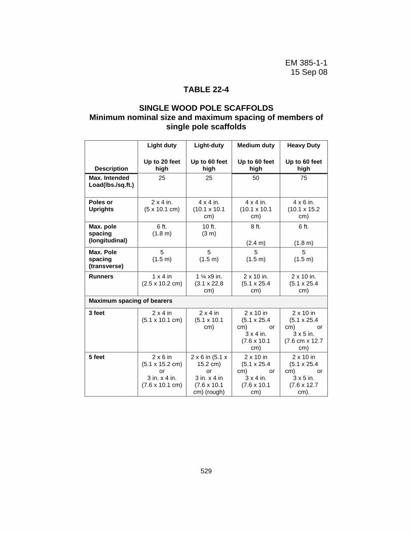
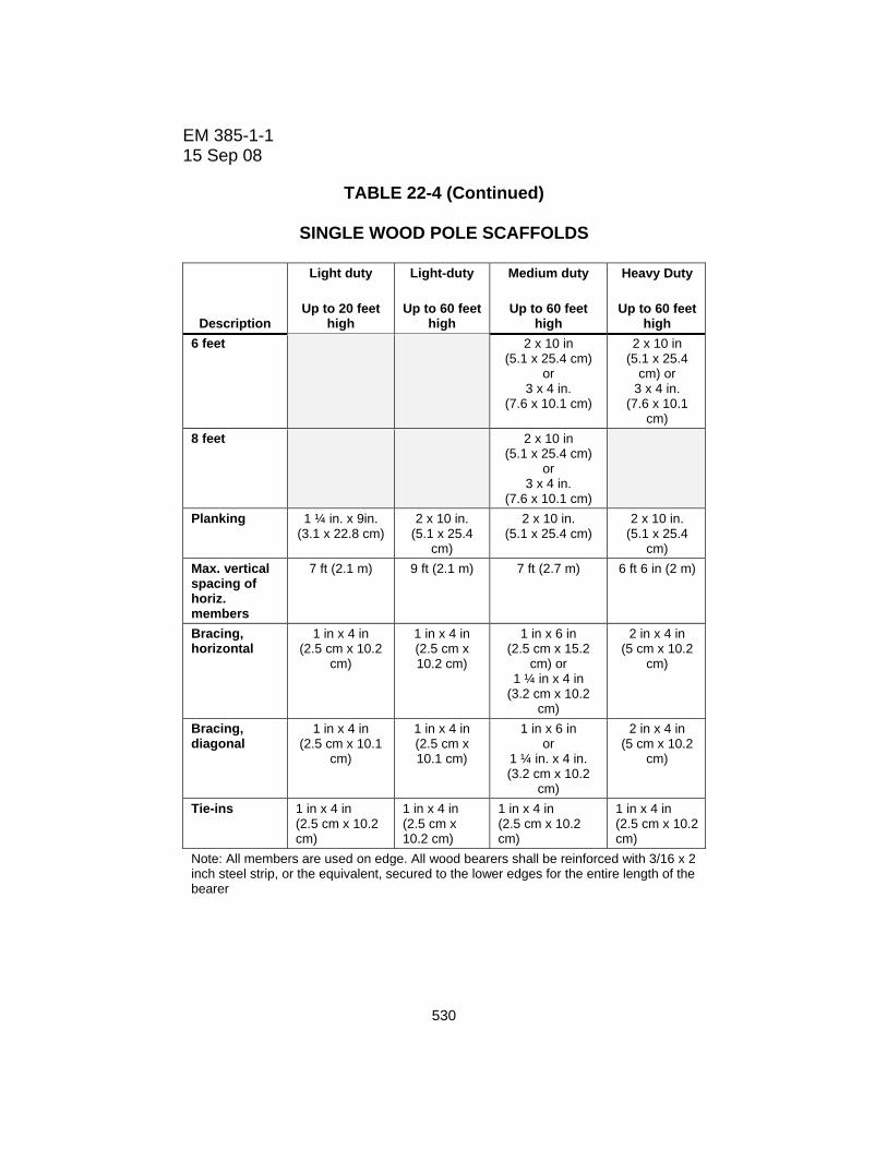
22.D.01 All wood scaffolds 60 ft (18.2 m) or less in height shall be constructed in accordance with Table 22-4 or Table 22-5: wood scaffolds over 60 ft (18.2 m) high shall be designed by a RPE and constructed in accordance with such design.
528
EM 385-1-1 15 Sep 08
TABLE 22-4
SINGLE WOOD POLE SCAFFOLDS Minimum nominal size and maximum spacing of members of
single pole scaffolds
Description
Light duty
Up to 20 feet high
Light-duty
Up to 60 feet high
Medium duty
Up to 60 feet high
Heavy Duty
Up to 60 feet high
Max. Intended Load(lbs./sq.ft.)
25 25 50 75
Poles or Uprights
2 x 4 in. (5 x 10.1 cm)
4 x 4 in. (10.1 x 10.1
cm)
4 x 4 in. (10.1 x 10.1
cm)
4 x 6 in. (10.1 x 15.2
cm)
Max. pole spacing (longitudinal)
6 ft. (1.8 m)
10 ft. (3 m)
8 ft.
(2.4 m)
6 ft.
(1.8 m) Max. Pole spacing (transverse)
5 (1.5 m)
5 (1.5 m)
5 (1.5 m)
5 (1.5 m)
Runners 1 x 4 in (2.5 x 10.2 cm)
1 ¼ x9 in. (3.1 x 22.8
cm)
2 x 10 in. (5.1 x 25.4
cm)
2 x 10 in. (5.1 x 25.4
cm)
Maximum spacing of bearers
3 feet 2 x 4 in (5.1 x 10.1 cm)
2 x 4 in (5.1 x 10.1
cm)
2 x 10 in (5.1 x 25.4
cm) or 3 x 4 in.
(7.6 x 10.1 cm)
2 x 10 in (5.1 x 25.4
cm) or 3 x 5 in.
(7.6 cm x 12.7 cm)
5 feet 2 x 6 in (5.1 x 15.2 cm)
or 3 in. x 4 in.
(7.6 x 10.1 cm)
2 x 6 in (5.1 x 15.2 cm)
or 3 in. x 4 in (7.6 x 10.1 cm) (rough)
2 x 10 in (5.1 x 25.4
cm) or 3 x 4 in.
(7.6 x 10.1 cm)
2 x 10 in (5.1 x 25.4
cm) or 3 x 5 in.
(7.6 x 12.7 cm).
529
EM 385-1-1 15 Sep 08
TABLE 22-4 (Continued)
SINGLE WOOD POLE SCAFFOLDS
Description
Light duty
Up to 20 feet high
Light-duty
Up to 60 feet high
Medium duty
Up to 60 feet high
Heavy Duty
Up to 60 feet high
6 feet 2 x 10 in (5.1 x 25.4 cm)
or 3 x 4 in.
(7.6 x 10.1 cm)
2 x 10 in (5.1 x 25.4
cm) or 3 x 4 in.
(7.6 x 10.1 cm)
8 feet 2 x 10 in (5.1 x 25.4 cm)
or 3 x 4 in.
(7.6 x 10.1 cm)
Planking 1 ¼ in. x 9in. (3.1 x 22.8 cm)
2 x 10 in. (5.1 x 25.4
cm)
2 x 10 in. (5.1 x 25.4 cm)
2 x 10 in. (5.1 x 25.4
cm) Max. vertical spacing of horiz. members
7 ft (2.1 m) 9 ft (2.1 m) 7 ft (2.7 m) 6 ft 6 in (2 m)
Bracing, horizontal
1 in x 4 in (2.5 cm x 10.2
cm)
1 in x 4 in (2.5 cm x 10.2 cm)
1 in x 6 in (2.5 cm x 15.2
cm) or 1 ¼ in x 4 in
(3.2 cm x 10.2 cm)
2 in x 4 in (5 cm x 10.2
cm)
Bracing, diagonal
1 in x 4 in (2.5 cm x 10.1
cm)
1 in x 4 in (2.5 cm x 10.1 cm)
1 in x 6 in or
1 ¼ in. x 4 in. (3.2 cm x 10.2
cm)
2 in x 4 in (5 cm x 10.2
cm)
Tie-ins 1 in x 4 in (2.5 cm x 10.2 cm)
1 in x 4 in (2.5 cm x 10.2 cm)
1 in x 4 in (2.5 cm x 10.2 cm)
1 in x 4 in (2.5 cm x 10.2 cm)
Note: All members are used on edge. All wood bearers shall be reinforced with 3/16 x 2 inch steel strip, or the equivalent, secured to the lower edges for the entire length of the bearer
530

EM 385-1-1 15 Sep 08
TABLE 22-5
INDEPENDENT WOOD POLE SCAFFOLDS
6 feet 10 feet 8 feet 8 feet Runners 1 ¼ x 4 in
(3.2 cm x 10.2 cm)
1 ¼ x 9 in (3.2 cm x 22.8
cm)
2 x 10 in. (5.1 x 25.4
cm)
2 x 10 in. (5.1 x 25.4
cm) Bearers 3 feet 2 x 4
(5.4 x 10.2 cm) 2 x 4
(5.4 x 10.2 cm) 2 x 10 in.
(5.1 x 25.4 cm)
2 x 10 in. (rough)
(5.1 x 25.4 cm)
6 feet 2 x 6 in (5.4 x 15.2 cm)
Or 3 x 4 in
(7.6 x 10.2 cm)
2 x 10 in (rough) (5.4 x 25.4 cm)
Or 2 x 4 in
(5.1 x 10.2 cm)
2 x 10 in. (5.1 x 25.4
cm)
2 x 10 in. (rough)
(5.1 x 25.4 cm)
8 feet 2 x 6 in (5.4 x 15.2 cm)
Or 3 x 4 in
(7.6 x 10.2 cm)
2 x 10 in (rough) (5.4 x 25.4 cm)
Or 2 x 8 in
(5.1 x 20.3 cm)
2 x 10 in. (5.1 x 25.4
cm)
10 feet 2 x 6 in (5.4 x 15.2 cm)
Or 3 x 4 in
(7.6 x 10.2 cm)
2 x 10 in (rough) (5.4 x 25.4 cm)
Or 3 x 3 in
(7.6 x 7.6 cm)
2 x 10 in. (5.1 x 25.4
cm)
Planking 1 ¼ x 9 in (3.2 cm x 22.8
cm)
2 x 10 in. (5.1 x 25.4 cm)
2 x 10 in. (5.1 x 25.4
cm)
2 x 10 in. (5.1 x 25.4
cm) Max. vertical spacing of horizontal members
7 feet (2.1 x 2.1 cm)
7 feet (2.1 x 2.1 cm)
6 feet (1.8 x 1.8
cm)
6 feet (1.8 x 1.8 cm)
Bracing horizontal
1 x 4 in (2.54 x 10.2 cm)
1 x 4 in (2.54 x 10.2 cm)
1 x 4 in (2.54 x 10.2
cm)
2 in x 4 in (5 cm x 10.2
cm) Bracing vertical
1 x 4 in (2.54 x 10.2 cm)
1 x 4 in (2.54 x 10.2 cm)
1 x 4 in (2.54 x 10.2
cm)
2 in x 4 in (5 cm x 10.2
cm) Tie-ins 1 x 4 in
(2.54 x 10.2 cm) 1 x 4 in
(2.54 x 10.2 cm) 1 x 4 in
(2.54 x 10.2 cm)
1 x 4 in (2.54 x 10.2
cm) Note: All members are used on edge. All wood bearers shall be reinforced with 3/16 x 2 inch steel strip, or the equivalent, secured to the lower edges for the entire length of the bearer.
531
EM 385-1-1 15 Sep 08
22.D.02 Bracing.
a. Diagonal bracing shall be provided to prevent the poles from moving in a direction parallel with the wall of the building or from buckling.
b. Full diagonal bracing shall be erected across the entire face of pole scaffolds in both directions. Braces shall be spliced at the poles. The inner row of poles on medium and heavy-duty scaffolds shall be braced in a similar manner.
c. Cross bracing shall be provided between inner and outer sets of poles in independent pole scaffolds.
d. The free ends of pole scaffolds shall be cross-braced.
22.D.03 Splices.
a. Where wood poles are spliced, the ends shall be squared and the upper section shall rest squarely on the lower section. b. Splice plates shall be provided on two adjacent sides and shall be not less than 4 ft (1.2 m) in length, overlapping the abutted ends equally, and have the same width and not less than the cross sectional area of the pole. The splice shall be capable of developing strength in any direction equal to the spliced members.
22.D.04 Ledgers and bearers.
a. Ledgers and bearers shall be installed on edge.
b. Ledgers and bearers shall not be spliced between poles.
c. Ledgers shall be long enough to extend over a minimum of two poles and shall be reinforced by bearing blocks nailed to the side of the pole to form a support for the ledger.
532

EM 385-1-1 15 Sep 08
d. Bearers shall be long enough to project at least 3 in (7.6 cm) over the ledgers of the inner and outer rows of poles for support.
e. Every wooden bearer on single pole scaffolds shall be reinforced with a 3/16-in x 2-in (.47-cm x 5-cm) steel strip, or equivalent, secured to its lower edge throughout the length.
22.D.05 Independent pole scaffolds shall be set as near to the wall of the building as practical.
22.D.06 All pole scaffolds shall be securely guyed or tied to the structure. Where the height or length exceeds 25 ft (7.6 m), the scaffold shall be secured at intervals not greater than 25 ft (7.6 m) vertically and horizontally.
22.E SUSPENDED SCAFFOLDS
22.E.01 Suspended scaffolds are scaffolds/work platforms that are suspended from anchorage points/hoists that allow the scaffold to move up and down as needed for work to be performed. Suspended scaffolds shall be designed, constructed, operated, inspected, tested, and maintained as specified in the operating manual for the device.
22.E.02 Inspections.
a. Suspended scaffold systems shall be inspected prior to being placed in service to determine that the system conforms to this manual and the manufacturer's specifications.
b. Every suspended scaffold shall be tested with twice the maximum anticipated load before being put into operation. > See 22.B.
c. Each hoist shall be inspected before, and trial operated after, every installation and re-rigging in accordance with the manufacturer's specifications.
533
EM 385-1-1 15 Sep 08
d. Connection and anchorage systems of suspended scaffold shall be inspected at the beginning of each shift.
e. All wire ropes, fiber and synthetic ropes, slings, hangers, hoists, rigging, fall protection equipment, platforms, anchorage points and their connections, and other supporting parts shall be inspected before every installation, daily thereafter, and periodic while the scaffold is in use.
f. Governors and secondary brakes for powered hoists shall be inspected and tested per the manufacturer's recommendations: at the minimum, inspections shall be made annually.
(1) Inspections and tests shall include a verification that the initiating device for the secondary braking operates as intended.
(2) A copy of the latest inspection and test report shall be maintained on the job site.
g. Records of inspections conducted while the unit is at the work site shall be maintained at the work site.
22.E.03 Only personnel trained in the use of the suspended work platform shall be authorized to operate it. Training shall include:
a. Reading and understanding the manufacturer's operating manual and any associated rules and instructions, or training by a Qualified Person on the contents on these documents, and
b. Reading and understanding all decals, warnings, and instructions on the device.
22.E.04 All parts of all suspended scaffolds shall have a minimum safety factor of 4. A minimum safety factor of 6 is required for support ropes.
534

EM 385-1-1 15 Sep 08
22.E.05 Support ropes.
a. Support ropes shall be attached at the vertical centerline of the outrigger and the attachment shall be directly over the hoist machine.
b. Support ropes shall be vertical for their entire length. The scaffold shall not be swayed nor the support ropes fixed to any intermediate points to change the original path of travel.
c. Support ropes shall have the fixed end equipped with a proper size thimble and secured by eye splicing or equivalent means. Free ends shall be brazed or secured to prevent fraying.
d. The wire rope for traction hoists shall be of such length that the operator may descend to the lowest point of travel without the end of the wire rope entering the hoist. Where the wire rope is inadequate for the lowest descent, provision shall be made to prevent the hoist from running off the wire rope.
e. On winding drum type hoists, running ends of suspension ropes shall be attached by positive means to the hoisting drum and at least four wraps of the rope shall remain on the drum at all times.
f. Support ropes shall be capable of resisting chemicals or conditions to which they are exposed.
g. No welding, burning, riveting, or open flame work shall be performed on any platform suspended by fiber or synthetic rope.
h. Defective or damaged rope shall not be used as lifelines or suspension lines. The repairing of wire rope is prohibited.
22.E.06 All suspension scaffold support devices such as outrigger beams, cornice hooks, parapet clamps, or similar devices shall:
535
EM 385-1-1 15 Sep 08
a. Be made of mild steel, wrought iron, or equivalent materials;
b. Be supported by bearing blocks;
c. Rest on surfaces capable of supporting the reaction forces imposed by the scaffold hoist operating at its maximum rated load; and
d. Be secured against movement by tiebacks installed at right angles to the face of the building whenever possible and secured to a structurally sound portion of the building. Tiebacks shall be equivalent in strength to the hoisting rope.
22.E.07 Outrigger beams.
a. Outrigger beams shall be made of structural metal and shall be restrained to prevent movement.
b. The inboard ends of outrigger beams shall be stabilized by bolts or other direct connections to the floor or roof deck, or they shall have their inboard ends stabilized by counterweights, except mason's multiple point adjustable suspension scaffold outrigger beams shall not be stabilized by counterweights.
c. Before use, direct connections shall be evaluated by a Competent Person who shall affirm that the supporting surfaces are capable of supporting the loads to be imposed. Mason's multiple point adjustable suspension scaffold connections shall be designed by a licensed engineer experienced in scaffold design.
d. Counterweights shall be made of non-flowable solid material, shall be secured to the outrigger beams by mechanical means, and shall not be removed until the scaffold is disassembled.
e. Outrigger beams shall be secured by tiebacks equivalent in strength to the suspension ropes. Tiebacks shall be secured to a structurally sound portion of the building or structure and shall be installed parallel to the centerline of the beam.
536

EM 385-1-1 15 Sep 08
f. Outrigger beams shall be provided with stop bolts or shackles at both ends.
g. When channel iron beams are used in place of I-beams, the channels shall be securely fastened together with the flanges turned outward.
h. Outrigger beams shall be installed with all bearing supports perpendicular to the beam centerline.
i. Outrigger beams shall be set and maintained with the web in a vertical position.
j. Where a single outrigger beam is used, the steel shackle or clevises with which the wire ropes are attached to the beam shall be placed directly over the hoisting machines.
22.E.08 Hoisting machines
a. Hoisting machines shall be of a type tested and listed by a nationally recognized testing laboratory.
b. Each hoist shall contain a name plate(s) containing:
(1) Manufacturer's name;
(2) Maximum load rating;
(3) Identification number; and
(4) Wire rope specifications.
c. Powered hoists shall be electric-, air-, hydraulic-, or propane-powered. Gasoline-powered hoists are prohibited.
d. All powered hoists shall be equipped with speed reducers and shall be provided with a primary brake and a secondary brake.
537

EM 385-1-1 15 Sep 08
(1) The primary brake shall automatically engage whenever power is interrupted or whenever the operator ceases to apply effort;
(2) The secondary brake shall stop and hold the hoist under over speed or abnormal conditions. Every secondary brake shall be periodically tested under simulated conditions in accordance with the manufacturer's recommendations.
e. Each powered hoist shall have its own separate control.
(1) If the control is of the push-button type, it shall be constant pressure;
(2) If the control is of the fixed-position type, it shall have provision for automatic locking when in the off position, or shall be guarded against accidental actuation; and
(3) If the control is of the lever type, it may be of the constant pressure type or of the fixed-position type.
f. Manual operation of powered hoists may be provided if the hoist is designed so that not more than one person per hoist is required to perform this operation.
(1) During manual operation, a means shall be provided to make the prime mover inoperative.
(2) Instruction shall be provided advising personnel to disconnect the power source before using a manual crank.
g. Manually-operated hoists.
(1) Manual operation shall provide a means to prevent rapid handle movement or fast un-spooling. Mechanisms used to allow fast un-spooling during the erection process shall not be in place on the scaffold.
538

EM 385-1-1 15 Sep 08
(2) In the event a controlled descent device is used, it shall not bypass the secondary brake.
(3) All winding drum hoists shall be provided with a driving pawl and a locking pawl that automatically engages when the driving pawl is released.
(4) Gripping-type hoists shall be designed so that the hoist is engaged on the suspension rope at all times, including all travel actuations of the operating lever.
(5) Each winding drum hoist shall be provided with a positive means of attachment of the suspension hoist. The drum attachment shall develop a minimum of four times the rated capacity of the hoist.
(6) Each hoist shall require a positive crank force to descend.
22.E.09 Platforms.
a. Light metal platforms, when used, shall be of a type tested and listed by a nationally recognized testing laboratory.
b. Ladder-type platforms.
(1) Ladder-type platforms shall be constructed in accordance with Table 22-6.
(2) The side stringer for ladder-type platforms shall be of clear straight-grained spruce or materials of equivalent strength and durability.
(3) The rungs shall be of straight-grained oak, ash, or hickory, at least 1-1/8 in (2.8 cm) in diameter, with 7/8-in (2.2-cm) tenons mortised into the side stringers at least 7/8 in (2.2 cm).
539

EM 385-1-1 15 Sep 08
TABLE 22-6
LADDER-TYPE PLATFORMS
Length of platform (feet, m) Component 12 (3.7) 14 & 16
(4.3 & 4.9)
18 & 20(5.5 & 6.1)
22 & 24 (6.7 & 7.3)
28 & 30 (8.5 & 9.1)
Side stringers, minimum cross sections (finished sizes, inches,): at ends at middle
1-3/4 x 2-3/4 (4.4 x 6.9)
1-3/4 x 3-3/4 (4.4 x 9.5)
1-3/4 x 2-3/4
(4.4 x 6.9)
1-3/4 x 3-3/4
(4.4 x 9.5)
1-3/4 x 3 (4.4 x 7.6)
1-3/4 x 4 (4.4 x 10.1)
1-3/4 x 3 (4.4 x 7.6)
1-3/4 x 4-1/4 (4.4 x 10.8)
1-3/4 x 3-1/2 (4.4 x 8.9)
1-3/4 x 5 (4.4 x 12.7)
Reinforcing strips (1) (1) (1) (1) (1)
Rungs (2) (2) (2) (2) (2)
Tie rods: number (minimum) diameter (minimum) (in/cm)
3 1/4 (0.6)
4 1/4 (0.6)
4 1/4 (0.6)
5 1/4 (0.6)
6 1/4 (0.6)
Flooring, minimum finished sizes (in/cm)
1/2 x 2-3/4 (1.2 x 6.9)
1/2 x 2-3/4(1.2 x 6.9)
1/2 x 2-3/4(1.2 x 6.9)
1/2 x 2-3/4 (1.2 x 6.9)
1/2 x 2-3/4 (1.2 x 6.9)
NOTE: (1) A 1/8 x 7/8 in (0.3 x 2.2 cm) steel reinforcing strip or its equivalent shall be attached to the side or underside, full length. (2) Rungs shall be 1-1/8 in (2.8 cm) diameter tenons and the maximum spacing shall be 12 in (30.4 cm) center to center. (4) The stringers shall be tied with tie rods not less than 1/4 in (0.6 cm) diameter passing through the stringers and riveted up tight against washers on both ends. (5) The flooring strips shall be spaced not more than 5/8 in (1.5 cm) apart except at the side rails where the space may be 1 in (2.5 cm).
540

EM 385-1-1 15 Sep 08
c. Plank platforms.
(1) Plank platforms shall be composed of not less than nominal 2-in x 10-in (5-cm x 25.4-cm) unspliced planks, cleated together on the underside, starting 6 in (15.2 cm) from each end at intervals not to exceed 4 ft (1.2 m).
(2) The plank platform shall not extend beyond the hangers more than 12 in (30.4 cm). A bar or other effective means shall be securely fastened to the platform at each end to prevent its slipping off the hanger.
(3) The span between hangers for plank platforms shall not exceed 8 ft (2.4 m).
d. Beam platforms.
(1) Beam platforms shall have side stringers of lumber not less than 2 in x 6 in (5 cm x 15.2 cm), set on edge.
(2) The span between hangers shall not exceed 12 ft (3.6 m ) when beam platforms are used.
(3) The flooring shall be of 1-in x 6-in (2.5-cm x 15.2-cm) material properly nailed. Floor boards shall not be spaced more than 1/2 in (1.2 cm) apart.
(4) The flooring shall be supported on 2-in x 6-in (5-cm x 15.2-cm) cross beams, laid flat and set into the upper edge of the stringers with a snug fit, at intervals of not more than 4 ft (1.2 m), nailed securely in place.
22.E.10 Suspended scaffolds shall be guyed, braced, guided, or equipped with tag line to prevent swaying.
22.E.11 Two-point suspension scaffolds.
541
EM 385-1-1 15 Sep 08
a. Two-point suspension scaffold platforms shall not be less than 20 in (50.8 cm) or more than 36 in (91.4 cm) wide. The platform shall be securely fastened to the hangers by U-bolts or by other equivalent means.
b. The hangers of two-point suspension scaffolds shall be made of mild steel, or equivalent materials, having a cross sectional area capable of sustaining four times the maximum rated load and shall be designed with a support for a standard railing.
c. Two-point suspension scaffolds shall be securely lashed to the structure. Window cleaner's anchors shall not be used.
d. The platform on every two-point suspension scaffolds shall be of the light metal-, ladder-, plank-, or beam-type.
e. Two-point suspension scaffolds shall not be joined by bridging.
f. Two-point suspension scaffold platforms, when in use, shall be level within 1 in (2.5 cm) for every 1 ft (0.3 m) of platform length.
22.E.12 Mason's multiple-point adjustable suspension scaffolds.
a. When employees on the scaffold are exposed to overhead hazards, overhead protection equivalent in strength to 2-in (5-cm) planking shall be provided on the scaffold not more than 9 ft (2.7 m) above the platform, laid tight and extending the entire width of the scaffold.
b. The scaffold shall be capable of sustaining a load of 50 psf (2394 Pa) and shall not be overloaded.
c. The platform shall be suspended by wire ropes from overhead outrigger beams.
542

EM 385-1-1 15 Sep 08
22.E.13 Stonesetters' multiple-point adjustable suspension scaffolds.
a. Stonesetters' multiple-point adjustable suspension scaffolds shall be capable of sustaining a load of 25 psf (1197 Pa) and shall not be overloaded.
b. Stonesetters' multiple-point adjustable suspension scaffolds shall not be used for storage of stone or other heavy materials.
c. The scaffold platform shall be securely fastened to the hangers by U-bolts or other equivalent means.
d. Stonesetters' multiple-point adjustable suspension scaffolds shall be suspended from metal outriggers, iron brackets, wire rope slings, or iron hooks.
e. When two or more stonesetters' multiple-point adjustable suspension scaffolds are used on a structure, they shall not be bridged one to the other, but shall be maintained at even height with platforms abutting closely.
22.E.14 Working capacities.
a. On suspension scaffolds designed for a working load of 500 lb (226.8 kg), no more than two employees shall be permitted to work at one time.
b. On suspension scaffolds with a working load of 750 lb (340.2 kg), no more than three people shall be permitted to work at one time.
22.E.15 Fall protection.
a. Each person supported by a single-point or two-point adjustable suspended scaffold shall be protected from falling by the use of a fall arrest system. A risk assessment shall be performed when persons are supported on a multi-point adjustable suspended scaffold to evaluate the effectiveness
543
EM 385-1-1 15 Sep 08
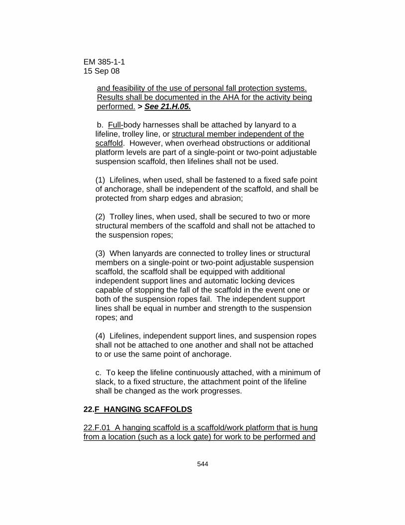
and feasibility of the use of personal fall protection systems. Results shall be documented in the AHA for the activity being performed. > See 21.H.05.
b. Full-body harnesses shall be attached by lanyard to a lifeline, trolley line, or structural member independent of the scaffold. However, when overhead obstructions or additional platform levels are part of a single-point or two-point adjustable suspension scaffold, then lifelines shall not be used.
(1) Lifelines, when used, shall be fastened to a fixed safe point of anchorage, shall be independent of the scaffold, and shall be protected from sharp edges and abrasion;
(2) Trolley lines, when used, shall be secured to two or more structural members of the scaffold and shall not be attached to the suspension ropes;
(3) When lanyards are connected to trolley lines or structural members on a single-point or two-point adjustable suspension scaffold, the scaffold shall be equipped with additional independent support lines and automatic locking devices capable of stopping the fall of the scaffold in the event one or both of the suspension ropes fail. The independent support lines shall be equal in number and strength to the suspension ropes; and
(4) Lifelines, independent support lines, and suspension ropes shall not be attached to one another and shall not be attached to or use the same point of anchorage.
c. To keep the lifeline continuously attached, with a minimum of slack, to a fixed structure, the attachment point of the lifeline shall be changed as the work progresses.
22.F HANGING SCAFFOLDS 22.F.01 A hanging scaffold is a scaffold/work platform that is hung from a location (such as a lock gate) for work to be performed and
544

EM 385-1-1 15 Sep 08
that remains stationary until it is them repositioned with a crane/hoisting device. Hanging scaffolds shall be designed by a Registered Professional Engineer (RPE) competent in structural design. Scaffold performance and components shall meet or exceed those for general scaffolds and platforms found in ANSI A10.8-2001. > See Figure 22-1. 22.F.02 Hanging scaffolds shall meet the following requirements:
a. The scaffold shall be securely fastened to a vertical structure (i.e. wall, lock gate, etc.) by hooks over a secured structural supporting member, bolt-on brackets, or other secure attachment. The maximum span between secure attachments is 8 ft (2.4 m). Fasteners shall be of adequate size to achieve design strength of scaffold. b. The scaffold must be secured against an uplift force equal to two times the weight of the scaffold and its rated load by means of hooks, brackets, or other secure attachments designed and placed to counteract uplift.
c. The scaffold shall have a secondary attachment method to secure it against falling if the primary attachment fails. This should be a flexible attachment, such as wire rope or chain, designed to withstand a minimum of five (5) times the weight of the scaffold and its rated load. The secondary attachment shall be connected to an anchor point of the same load rating or greater. d. The scaffold shall have only one working level. Working platform decks shall be slip resistant and securely attached to the scaffold frame. The maximum width, front to back, of decks is 42 in (106.6 cm). Grating used for deck surfaces shall have a maximum width opening between bars small enough to prevent the rigging components used (slings, chains) from entering.
e. Standard guardrail systems meeting the requirements of 21.E.01 shall be installed on all open sides and ends of the platform.
545
EM 385-1-1 15 Sep 08
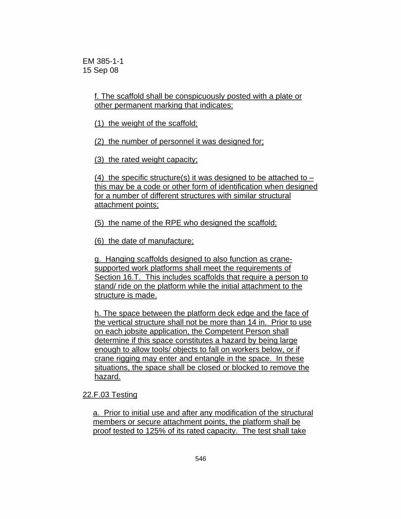
f. The scaffold shall be conspicuously posted with a plate or other permanent marking that indicates: (1) the weight of the scaffold; (2) the number of personnel it was designed for; (3) the rated weight capacity; (4) the specific structure(s) it was designed to be attached to – this may be a code or other form of identification when designed for a number of different structures with similar structural attachment points; (5) the name of the RPE who designed the scaffold; (6) the date of manufacture; g. Hanging scaffolds designed to also function as crane-supported work platforms shall meet the requirements of Section 16.T. This includes scaffolds that require a person to stand/ ride on the platform while the initial attachment to the structure is made. h. The space between the platform deck edge and the face of the vertical structure shall not be more than 14 in. Prior to use on each jobsite application, the Competent Person shall determine if this space constitutes a hazard by being large enough to allow tools/ objects to fall on workers below, or if crane rigging may enter and entangle in the space. In these situations, the space shall be closed or blocked to remove the hazard.
22.F.03 Testing
a. Prior to initial use and after any modification of the structural members or secure attachment points, the platform shall be proof tested to 125% of its rated capacity. The test shall take
546

EM 385-1-1 15 Sep 08
place on a structure the scaffold was designed for or a test structure with similar support member characteristics. b. Prior to use on each jobsite or placement location, hanging scaffolds shall be performance tested to 100% of the maximum intended load for the expected work. This test shall be performed with the scaffold attached to the structure in the work location.
22.F.04 Operations
a. Scaffolds and their attachments shall be inspected by a Competent Person prior to initial use on a worksite, before use on each work shift, and regularly during use until they are removed. b. Workers shall use properly selected and anchored personal fall protection when accessing and working on hanging scaffolds. Personal fall protection system components shall meet the requirements of 21.H.05. No part of a hanging scaffold shall be used as an anchor point for personal fall protection. c. The number of workers on the platform shall not exceed the number listed on the scaffold. d. Ladders may not be used on hanging scaffolds, except as a means of access from above the deck. Ladders used for access must meet the requirements of 24.B.
e. Hanging scaffolds shall be coated or painted to minimize corrosion of the components. Storage between uses shall be designed to minimize damage to the scaffold.
547

EM 385-1-1 15 Sep 08
FIGURE 22-1
Hanging Scaffold
548
EM 385-1-1 15 Sep 08
22.G FORM AND CARPENTER'S BRACKET SCAFFOLDS
22.G.01 At the minimum, form scaffolds shall be designed in accordance with Table 22-7.
22.G.02 Each bracket, except for wooden-bracket form scaffolds, shall be attached to the supporting formwork or structure by means of one or more of the following:
a. Nails;
b. A metal stud attachment device;
c. Welding;
d. Hooking over a secured structural supporting member, provided the form walers are bolted to the form or secured by snap ties or tie-bolts extending through the form and securely anchored; or
e. For carpenter's bracket scaffolds only, by a bolt extending through to the opposite side of the structure's wall.
22.G.03 Wooden form scaffolds shall be an integral part of the form panel.
22.G.04 Folding-type metal brackets, when extended for use, shall be either bolted or secured with a locking-type pin.
22.G.05 Brackets shall consist of a triangular shaped frame made of wood with a cross-section not less than 2-in x 3-in (5-cm x 7.6-cm) or of 1-1/4-in x 1-1/4-in x 1/8-in (3.1-cm x 3.1-cm x 0.3-cm) structural angle iron.
549

EM 385-1-1 15 Sep 08
TABLE 22-7
FORM SCAFFOLDS
Minimum design criteria for light-duty wooden bracket form scaffolds
Members Dimensions Bracket uprights 2 x 4 in or 2 x 6 in
(5 x 10.1 cm or 5 x 15.2 cm) Bracket support ledgers 2 x 6 in
(5 x 15.2 cm) Maximum bracket width 3 ft 6 in (1 m) Bracket braces 1 x 6 in (2.5 x 15.2 cm) Guardrail post 2 x 4 in (5 x 10.1 cm) Guardrail height 36 to 42 in (91.4 to 106.6 cm) Midrail 1 x 6 in (2.5 x 15.2 cm) Toeboards 1 x 6 in (2.5 x 15.2 cm) Bracket upright spacing 8 ft (2.4 m) (on centers)
TABLE 22-7 (CONTINUED)
FORM SCAFFOLDS
Minimum design criteria for light-duty figure-four form scaffolds
Members Dimensions
Bracket uprights 2 x 4 in or 2 x 6 in (5 x 10.1 cm or 5 x 15.2 cm)
Bracket outrigger ledgers (2) 1 x 6 in (2.5 x 15.2 cm)
Bracket braces (2) 1 x 6 in (2.5 x 15.2 cm)
Maximum length of ledgers 3 ft 6 in (1 m) (unsupported) Bracket upright spacing 8 ft (2.4 m) (on centers)
550
EM 385-1-1 15 Sep 08
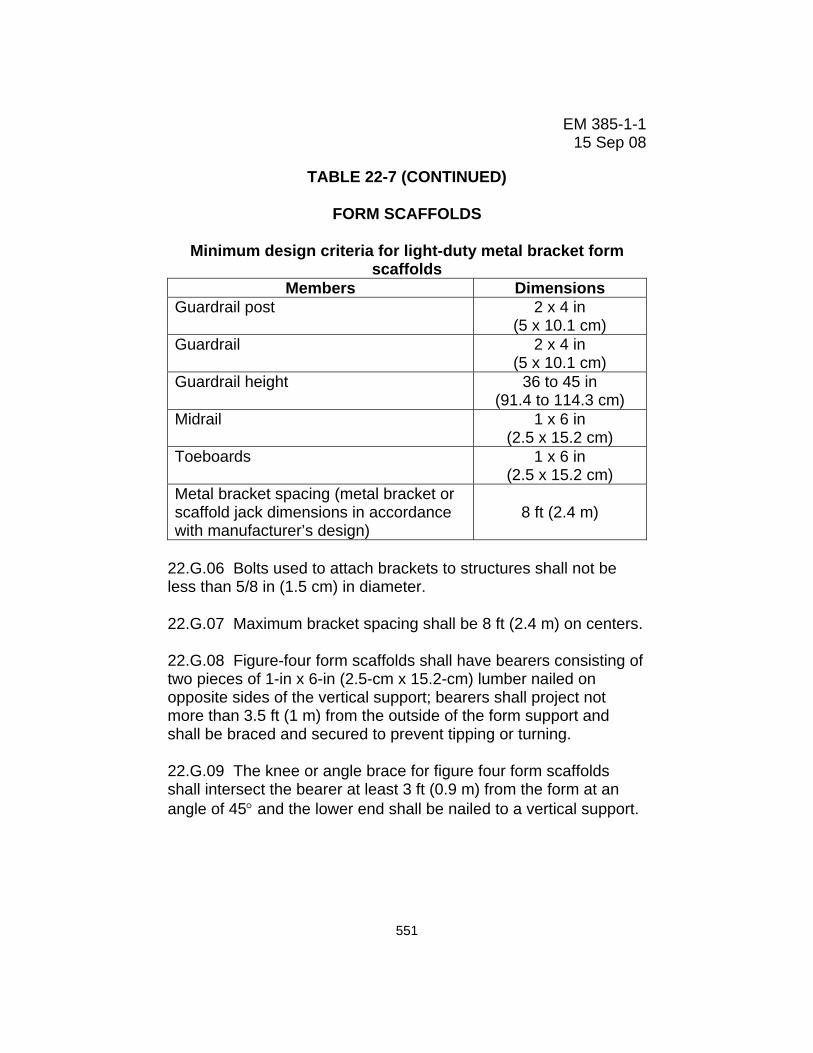
TABLE 22-7 (CONTINUED)
FORM SCAFFOLDS
Minimum design criteria for light-duty metal bracket form scaffolds
Members Dimensions Guardrail post 2 x 4 in
(5 x 10.1 cm) Guardrail 2 x 4 in
(5 x 10.1 cm) Guardrail height 36 to 45 in
(91.4 to 114.3 cm) Midrail 1 x 6 in
(2.5 x 15.2 cm) Toeboards 1 x 6 in
(2.5 x 15.2 cm) Metal bracket spacing (metal bracket or scaffold jack dimensions in accordance with manufacturer’s design)
8 ft (2.4 m)
22.G.06 Bolts used to attach brackets to structures shall not be less than 5/8 in (1.5 cm) in diameter.
22.G.07 Maximum bracket spacing shall be 8 ft (2.4 m) on centers.
22.G.08 Figure-four form scaffolds shall have bearers consisting of two pieces of 1-in x 6-in (2.5-cm x 15.2-cm) lumber nailed on opposite sides of the vertical support; bearers shall project not more than 3.5 ft (1 m) from the outside of the form support and shall be braced and secured to prevent tipping or turning.
22.G.09 The knee or angle brace for figure four form scaffolds shall intersect the bearer at least 3 ft (0.9 m) from the form at an angle of 45° and the lower end shall be nailed to a vertical support.
551
EM 385-1-1 15 Sep 08
22.H HORSE SCAFFOLDS
22.H.01 Horse scaffolds shall not be constructed or arranged more than two tiers or 10 ft (3 m) in height: scaffolds shall be 5° feet or less in height and 5 ft (1.5 m) or more in width.
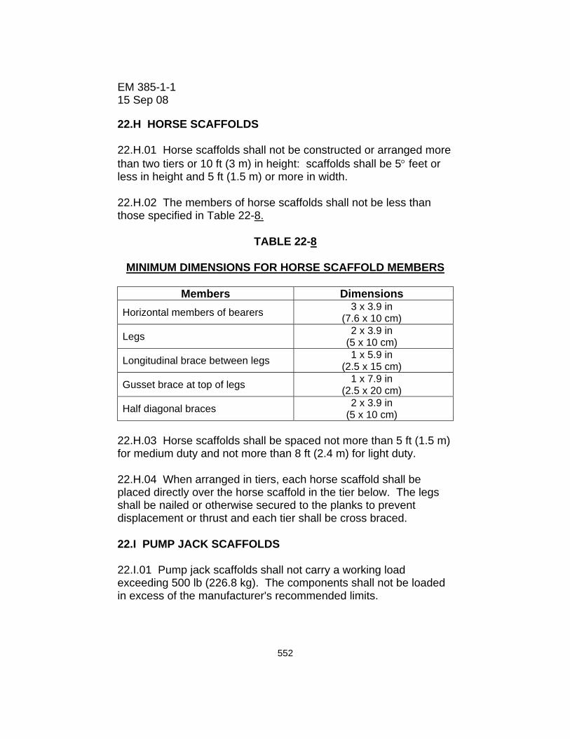
22.H.02 The members of horse scaffolds shall not be less than those specified in Table 22-8.
TABLE 22-8
MINIMUM DIMENSIONS FOR HORSE SCAFFOLD MEMBERS
Members Dimensions Horizontal members of bearers 3 x 3.9 in
(7.6 x 10 cm)
Legs 2 x 3.9 in (5 x 10 cm)
Longitudinal brace between legs 1 x 5.9 in (2.5 x 15 cm)
Gusset brace at top of legs 1 x 7.9 in (2.5 x 20 cm)
Half diagonal braces 2 x 3.9 in (5 x 10 cm)
22.H.03 Horse scaffolds shall be spaced not more than 5 ft (1.5 m) for medium duty and not more than 8 ft (2.4 m) for light duty.
22.H.04 When arranged in tiers, each horse scaffold shall be placed directly over the horse scaffold in the tier below. The legs shall be nailed or otherwise secured to the planks to prevent displacement or thrust and each tier shall be cross braced.
22.I PUMP JACK SCAFFOLDS
22.I.01 Pump jack scaffolds shall not carry a working load exceeding 500 lb (226.8 kg). The components shall not be loaded in excess of the manufacturer's recommended limits.
552

EM 385-1-1 15 Sep 08
22.I.02 Pump jack brackets, braces, and accessories shall be fabricated from metal plates and angles and installed in accordance with the manufacturer’s recommendations. Installation and operational manuals shall be available upon request of the GDA.
22.I.03 Poles.
a. Pole lumber shall be two 2-in x 4-in (5-cm x 10.1-cm) stock, of Douglas fir, or equivalent, straight-grained, clear, free of cross-grain, shakes, large loose or dead knots, and other defects that might impair strength.
b. Poles shall not exceed 30 ft (9.1 m) in height.
c. When poles are constructed of two continuous lengths they shall be of 2-in x 4-in (5-cm x 10.1-cm) stock, spiked together with the seam parallel to the bracket, and with 10d nails, no more than 12 in (30.4 cm) center-to-center, staggered uniformly from opposite outside edges.
d. If 2-in x 4-in (5-cm x 10.1-cm) stock is spliced to make up the pole, the splices shall be so constructed as to develop the full strength of the member.
e. Poles shall be secured to the wall by triangular bracing, or equivalent, at the bottom, top, and other points to provide a maximum vertical spacing of not more than 10 ft (3 m) between braces. Each brace shall be capable of supporting a minimum of 225-lb (102-kg) tension or compression.
f. When wood scaffold planks are used as platforms, poles used for pump jacks shall not be spaced more than 10 ft (3 m) on center. When fabricated platforms are used that comply with all other provisions of this Section, pole spacing may exceed 10 ft on center if permitted by the manufacturer.
553

EM 385-1-1 15 Sep 08
22.I.04 Brackets.
a. Each pump jack bracket shall have two positive gripping mechanisms to prevent any failure or slippage.
b. Platform brackets shall be fully decked and the planking secured.
c. For the pump jack bracket to pass bracing already installed, an extra brace shall be used approximately 4 ft (1.2 m) above the one to be passed until the original brace is reinstalled.
22.I.05 Not more than two persons shall be permitted at one time upon a pump jack scaffold between any two supports.
22.I.06 When a work bench is used at an approximate height of 42 in (106.6 cm), the top guardrail may be eliminated if the work bench is fully decked, the planking secured, and is capable of withstanding 200 lb (90.7 kg) pressure in any direction. Employees shall not be permitted to use a workbench as a scaffold platform.
22.I.07 A ladder shall provide access to the platform during use.
554

EM 385-1-1 15 Sep 08
22.J ADJUSTABLE SCAFFOLDS
22.J.01 Adjustable scaffolds shall be designed and constructed in accordance with ANSI/SIA A10.8.
22.J.02 A copy of the user's manual shall be kept of site at all times.
22.J.03 Adjustable scaffolds will be secured to the structure in accordance with the manufacturer's user manual.
22.J.04 Safe access will be provided in accordance with Section 24.
22.J.05 The leveling of adjustable scaffold will be accomplished by using leveling jacks.
22.J.06 Bridges will not be permitted on a single tower and used as a “mini-mast climbing scaffold”.
22.K CRANE SUPPORTED WORK (PERSONNEL) PLATFORMS. See Section 16.T
22.L ELEVATING WORK PLATFORMS
22.L.01 Elevating work platforms shall be designed and constructed in accordance with ANSI/Scaffold Industry Association (SIA) A92.3, ANSI/SIA A92.5, and ANSI/SIA A92.6, as appropriate.
22.L.02 Elevating work platforms shall be operated, inspected, and maintained as specified in the operating manual for the equipment.
a. Elevating work platforms shall also comply with requirements of this Section and 18.G. b. Records of inspections conducted while the unit is at the work site shall be maintained at the work site.
555

EM 385-1-1 15 Sep 08
c. Height to base width ratio of the scaffold during movement is 2:1 or less, or per manufacturer’s instructions.
22.L.03 All boom-supported elevating work platforms shall be equipped with an alarm, or other suitable warning device, at the platform. The alarm shall be in operable condition and shall automatically activate when the machine base is more than 5° out of level in any direction.
22.L.04 Only personnel trained in the use of the elevating work platform shall be authorized to operate it. Training shall consist of:
a. Reading and understanding the manufacturer's operating manual and any associated rules and instructions, or training by a Qualified Person on the contents on these documents, and
b. Reading and understanding all decals, warnings, and instructions on the elevating work platform.
22.L.05 Before operating the work platform the operator shall:
a. Survey the work area for loose or soft ground, ditches, drop-offs or holes, bumps and floor obstructions, debris, overhead obstructions, ground and elevated energy sources, and other possible hazards;
b. Ensure the elevating work platform is on a firm, level surface;
c. Ensure the work platform is loaded in accordance with the manufacturer's specifications;
d. Ensure that outriggers and/or stabilizers are used if required by the manufacturer;
e. Ensure that, if the vehicle is on wheels, the wheels are locked or chocked; and
f. Ensure that fall protection systems are in place.
556

EM 385-1-1 15 Sep 08
22.L.06 Elevating work platforms shall not be used by persons working on energized electrical wiring and/or equipment.
22.L.07 The use of personal fall protection devices shall be as specified in the manufacturer's operating manual. Personal fall protection devices, if used, may only be secured to manufacturer-approved hard points. > See Section 21.J.
22.M VEHICLE-MOUNTED ELEVATING AND ROTATING WORK PLATFORMS (Aerial Devices/Lifts).
22.M.01 Vehicle-mounted elevating and rotating work platforms (aerial lifts, to include articulating boom platforms/lifts (knuckle boom lifts), trailer-mounted boom lifts) shall be designed and constructed per ANSI/SIA A92.2.
22.M.02 Vehicle-mounted elevating and rotating work platforms shall be operated, inspected, tested, and maintained as specified in the operating manual for that piece of equipment.
a. Vehicle-mounted elevating and rotating work platforms shall also comply with requirements of this Section and 18.G.
b. Records of inspections conducted while the unit is at the work site shall be maintained at the work site. c. All aerial devices shall have manufacturer’s operating manual readily available in or on the vehicle.
d. If the unit is considered rated, and used as an insulating device, copies of the electrical insulating components and system tests conducted while the unit is at the work site shall be maintained at the work site.
e. All required safety decals, labels and signs shall be in place and readable.
557

EM 385-1-1 15 Sep 08
22.M.03 Only personnel trained in the use of the vehicle-mounted elevating and rotating work platform shall be authorized to operate it. Training shall consist of:
a. Reading and understanding the manufacturer's operating manual and any associated rules and instructions, or training by a Qualified Person on the contents on these documents; and
b. Reading and understanding all decals, warnings, and instructions on the vehicle-mounted elevating and rotating work platform.
22.M.04 Transporting.
a. An aerial lift truck, to include cherry pickers, shall not be moved when the boom is elevated in a working position with personnel in the basket except for equipment that is specifically designed for this type of operation.
b. Before moving an aerial lift, the boom(s) shall be inspected to see that it is properly cradled and outriggers are in stowed positions, except as provided in a, above.
c. Aerial ladders shall be secured in the lower traveling position by the locking device on top of the truck cab and the manually operated device at the base of the ladder before the truck is moved for highway travel.
22.M.05 Operating practices.
a. Brakes shall be set and outriggers, when used, shall be positioned on pads or a solid surface. b. Wheel chocks shall be installed before using an aerial lift on an incline.
c. Lift controls shall be tested each day prior to use to ensure
safe working condition.
558

EM 385-1-1 15 Sep 08
d. Boom and basket load limits specified by manufacturer shall not be exceeded.
e. Articulating boom and extensible boom platforms, primarily designed as personnel carriers, shall have both platform (upper) and lower controls.
(1) Upper controls shall be in or beside the platform within easy reach of the operator. (2) Lower controls shall provide for overriding the upper controls. (3) Controls shall be plainly marked as to their function. (4) Lower level controls shall not be operated unless permission has been obtained from the employee in the lift except in case of emergency.
f. Climbers shall not be worn while performing work from an aerial lift. g. The insulated portion of an aerial lift shall not be altered in any manner that might reduce its insulating value.
22.M.06 Fall protection.
a. Tying off to an adjacent pole, structure or equipment while working from an aerial lift shall not be permitted. b. Employees shall always stand firmly on the floor of the basket and shall not sit or climb on the edge of the basket or use planks, ladders, or other devices for a work position. c. A harness and lanyard, or deceleration device of length or design with a suitable height anchorage such that any fall over the platform edge shall not cause impact with the ground, shall be worn by a worker when working from the basket of a vehicle mounted aerial lift. > See Section 21.
559

EM 385-1-1 15 Sep 08
22.N MAST CLIMBING WORK PLATFORMS
22.N.01 Mast Climbing work platforms shall be erected, used, inspected, tested, maintained, and repaired in accordance with ANSI A 92.9 and the manufacturer’s recommendations as outlined in the operating manual.
22.N.02 An inspection will be performed prior to erecting the work platform.
a. An overhead inspection will be done to ensure that the work platform will not come in contact with any obstructions while moving up or down the mast. Special attention will be given to high voltage conductors.
b. An inspection of the ground will be done to ensure that there are no obstacles around the work platform and in the path of travel such as holes, drop-offs, debris, ditches, or soft fill.
c. Daily maintenance and inspections will be performed and documented. Copies will be maintained on the job site.
22.N.03 Only a designated operator will use the platform.
22.N.04 The platform will not be raised on uneven or sloped surfaces unless outriggers are used to level the platform and the ground is suitable to support the load.
22.N.05 Platforms will not be raised without outriggers extended and locked in proper operating position. The unit will be leveled before raising the platform. NOTE: Not all Mast Climbing Work Platforms are designed with freestanding capability. Check the machine and manual to see if the machine being operated has a freestanding height.
22.N.06 The platform must be lowered when moved, and must be set up and leveled each time before it is elevated.
560
EM 385-1-1 15 Sep 08
22.N.07 A mast climbing work platform, with platform elevated or personnel on the platform, will not be driven. The manufacturer’s instructions will be referred to when moving a mast climbing work platform to determine the safe mast height for ground conditions, ground slope, and overhead obstructions.
22.N.08 Mast climbing work platforms will be properly tied to the building (or structure) within the manufacturer’s recommended guidelines unless it is designed to be freestanding.
22.N.09 Mast climbing work platforms will not be moved unless everyone on the platform is aware of the direction the platform is being moved.
22.N.10 No ladders or structures of any kind will be used to increase the size or working height of platform.
22.N.11 Climbing of braces and guardrails is prohibited. When access ladders, including masts designed as ladders, exceed 20 ft (6 m) in height, positive fall protection shall be used.
22.N.12 The work platform will not be raised in windy or gusty conditions. The operation manual will be followed to determine maximum in-service wind speed conditions. A copy of the operation manual will be available on the job site.
22.N.13 Platforms will not be altered or modified in any way. Changing the configuration may change load capacity, freestanding height, and tie frequency. Mechanical, hydraulic, or electrical changes may adversely affect operation of this machine.
22.N.14 A Competent Person will perform daily maintenance and inspections.
22.N.15 Training. Personnel will be trained before using and/or operating mast climbing work platforms. Each user and operator will:
561
EM 385-1-1 15 Sep 08
a. Read and understand all cautions and danger warnings on the machine and in the operator's manual.
b. Have a solid working understanding of the controls.
c. Understand the hazards associated with the use of mast climbing work platforms.
d. Ensure that only authorized personnel use the platform.
22.N.16 A damaged or malfunctioning machine will not be used. Operation of damaged equipment shall be discontinued until the unit is repaired.
22.O ROOFING BRACKETS 22.O.01 Roofing brackets shall be secured by nailing in addition to the pointed metal projections. Nails will be driven into a rafter or beam; not just into the decking. Fasteners will be selected in accordance with the manufacturer’s recommendations. 22.O.02 When it is impractical to nail brackets, rope supports shall be used. When rope supports are used, they shall consist of first-grade manila rope, 3/4 in (1.9 cm) diameter or equivalent. 22.O.03 Positive fall protection will be used when working at heights over six feet. 22.P STILTS 22.P.01 Stilts shall not be used on scaffolds. 22.P.02 Surfaces on which stilts are used shall be flat and free of pits, holes, obstructions, debris and other tripping or slipping hazards. 22.P.03 Stilts shall be properly maintained. Any alteration of the equipment shall be approved by the manufacturer.
562

EM 385-1-1 15 Sep 08
22.P.04 Stilts shall not be used on stairs. When used adjacent to stairs or ramps where a fall to a different level could occur, guardrails or other fall protection shall be provided (increased in height by an amount equal to the height of the stilts). 22.P.05 Employees shall be trained in the proper use of stilts. 22.P.06 When using stilts exposes workers to a fall of 6 ft (1.8 m) or more in areas protected by guardrails, the height of the guardrail must be raised accordingly to maintain a protective height of 42 in (107cm) above the stilt. See 21.E.06.
563

EM 385-1-1 15 Sep 08
564
BLANK