section 25 00 00 integrated automation - general … · section 25 00 00 integrated automation -...
TRANSCRIPT
TECHNICAL STANDARDS SECTION 25 00 00 BURNABY, BC INTEGRATED AUTOMATION - GENERAL NOVEMBER, 2016 PAGE 1 OF 14
This document contains standards that are the minimum requirements for BCIT construction projects. The information in the document is organized using the MasterFormat® and SectionFormat® systems. It is not a specification; it is intended to supplement the Consultant's own documents. Do not use this information as a standalone specification.
SECTION 25 00 00 INTEGRATED AUTOMATION - GENERAL
PART 1 - GENERAL
1.1 RELATED DOCUMENTS
.1 Drawings and general provisions of the Contract, including General Conditions and Division 01 Specification Sections, apply to this Section.
.2 Specifications throughout all Divisions of the Project Manual are directly applicable to this Section, and this Section is directly applicable to them.
.3 Consultant may utilize their own standard Controls specifications or this Guideline as basis for project design. Requirements of this Guideline shall be incorporated in the design. Where Consultant chooses to utilize the Guideline Specification, review in entirety and edit to reflect needs of project.
.4 BCIT Facilities Office assumes no design liability by virtue of having provided this Controls Guideline document. Consultant/Designer retains all legal and contractual responsibilities and obligations as the Engineer of Record for the project.
1.2 SUMMARY
.1 Contractor shall furnish and install an ESC/Delta brand direct digital control and building automation system (BAS). New BAS shall utilize electronic sensing, microprocessor-based digital control, and electronic actuation of dampers and valves to perform control sequences and functions specified, except where noted otherwise. BAS for this Project generally consists of monitoring and control of systems described herein. Refer to control drawings if available, sequence of operation, and points lists.
.2 The building systems being controlled are __________________. This Section defines the manner and method by which these controls function.
.3 Controls Contractor shall furnish the following listed products for installation by others. Controls Contractor shall coordinate with the respective construction trades in regard to quantities, equipment sizes, materials, locations, and the delivery of products and scheduling of the work.
.1 Control valves.
.2 Control dampers (except dampers furnished with HVAC equipment).
.3 Air flow stations and water flow meters, including nipples and block valves if required.
.4 Pipe flow switches.
.5 Temperature wells.
.6 Pipe pressure transmitter taps, including nipple and block valve.
.7 DDC controllers that are specified to be factory installed, such as for VAV terminal units.
.4 Products not furnished or installed by Controls Contractor: Other construction trades and suppliers may furnish products that interface to the Integrated Automation system or that require field installation and control wiring. Controls Contractor shall coordinate with the providing Division(s) in regard to responsibilities, quantities, equipment sizes, materials, locations, and scheduling of the work. Following is a list of examples of typical control and automation products provided by others:

TECHNICAL STANDARDS SECTION 25 00 00 BURNABY, BC INTEGRATED AUTOMATION - GENERAL NOVEMBER, 2016 PAGE 2 OF 14
.1 Temperature, pressure, or other sensors, and flow switches that are furnished with HVAC equipment that requires field installation.
.2 Boiler, chiller and other equipment control and management panels.
.3 Variable Refrigerant Flow (VRF) system OEM control components and systems.
.4 Cooling tower accessory controls.
.5 Sump pumps and controllers
.6 Parkade gas detection and alarm systems including interlocks to ventilation fans.
1.3 REFERENCE STANDARDS
.1 The latest published edition of a reference is applicable to this project unless identified by a specific edition date.
.2 Reference amendments adopted prior to the effective date of this Contract shall be applicable to this project.
.3 Materials, installation and workmanship to be in accordance with requirements and standards addressed within following references.
.4 ASHRAE 135-16 BACnet-A Data Communication Protocol for Building Automation and Control Networks (ANSI Approved).
.5 British Columbia Building Code, 2012 Edition or latest edition (BCBC).
.6 CSA C22.1 -15 Canadian electrical code, part 1 (23rd edition), safety standard for electrical installation, Update No. 1 (2015) or latest edition.
.7 EIA-709.1 Control Network Protocol Specification.
.8 EIA-709.3 Free-Topology Twisted-Pair Channel Specification.
.9 EIA-232 Interface between Data Terminal Equipment and Data Circuit-Terminating Equipment Employing Serial Binary Data Interchange.
.10 EIA-458 Standard Optical Fiber Material Classes and Preferred Sizes.
.11 EIA-485 Standard for Electrical Characteristics of Generator and Receivers for use in Balanced Digital Multipoint Systems.
.12 EIA-472 General and Sectional Specifications for Fiber Optic Cable.
.13 EIA-475 Generic and Sectional Specifications for Fiber Optic Connectors and all Sectional Specifications.
.14 EIA-573 Generic and Sectional Specifications for Field Portable Polishing Device for Preparation Optical Fiber and all Sectional Specifications.
.15 EIA-590 Standard for Physical Location and Protection of Below-Ground Fiber Optic Cable Plant and all Sectional Specifications.
.16 IEEE 142-07 Recommended Practice for Grounding of Industrial and Commercial Power Systems.
.17 IEEE 802.3-13 CSMA/CD (Ethernet – Based) LAN.
.18 IEEE 802.4-90 Token Bus Working Group (ARCNET – Based) LAN.
.19 IEEE 519-14 Recommended Practices and Requirements for Harmonic Control in Electric Power Systems.
.20 NEMA 250-14 Enclosures for Electrical Equipment (1000 Volts Maximum).
.21 NEMA ICS 1 General Standards for Industrial Controls.

TECHNICAL STANDARDS SECTION 25 00 00 BURNABY, BC INTEGRATED AUTOMATION - GENERAL NOVEMBER, 2016 PAGE 3 OF 14
.22 NFPA (Fire) 90A Installation of Air Conditioning and Ventilating Systems, 2015 Edition.
.23 UL 916-15 Energy Management Systems.
.24 UUKL 864 UL Supervised Smoke Control if the BAS is used for smoke control.
1.4 DEFINITIONS
.1 Advanced Application Controller (AAC): Device with limited resources relative to Building Controller (BC). It may support a level of programming and may also be intended for application specific applications.
.2 Application Protocol Data Unit (APDU): Unit of data specified in an application protocol and consisting of application protocol control information and possible application user data (ISO 9545).
.3 Application Specific Controller (ASC): Device with limited resources relative to the Advanced Application Controller (AAC). It may support a level of programming and may also be intended for application-specific applications.
.4 BACnet/BACnet Standard: BACnet communication requirements as defined by ASHRAE/ANSI 135 and all current addenda and annexes.
.5 BACnet Interoperability Building Blocks (BIBB): BIBB defines a small portion of BACnet functionality that is needed to perform a particular task. BIBBS are combined to build the BACnet functional requirements for a device in a Specification.
.6 Binding: Generally, binding refers to associations or mappings of sources network variable and their intended or required destinations.
.7 Building Automation System (BAS): Entire integrated management, monitoring, and control system.
.8 Building Controller (BC): Fully programmable device capable of carrying out a number of tasks including control and monitoring via direct digital control (DDC) of specific systems, acting as communications router between LAN backbone and sub-LANs, and data storage for trend information, time schedules, and alarm data.
.9 Change of Value (COV): Event that occurs when a measured or calculated analog value changes by a predefined amount (ASHRAE/ANSI 135).
.10 Client: Device that is the requestor of services from a server. Client device makes requests of and receives responses from a server device.
.11 Continuous Monitoring: A sampling and recording of a variable based on time or change of state (e.g. trending an analog value, monitoring a binary change of state).
.12 Controller or Control Unit (CU): Intelligent stand-alone control panel. Controller is a generic reference and shall include BCs, AACs, and ASCs as appropriate.
.13 Control Systems Server (CSS): Computer (or computers) that maintains systems configuration and programming database. May double as an operator workstation.
.14 Direct Digital Control (DDC): Microprocessor-based control including Analog/Digital conversion and program logic.
.15 Functional Profile: Collection of variables to define key parameters for standard application. For HVAC industry, includes applications like VAV terminal units, fan coil units, etc.
.16 Gateway (GTWY): Device which contains two (2) or more dissimilar networks/protocols, permitting information exchange between them (ASHRAE/ANSI 135-2001).
.17 Hand Held Device (HHD): Manufacturer’s microprocessor based device for direct connection to a Controller.

TECHNICAL STANDARDS SECTION 25 00 00 BURNABY, BC INTEGRATED AUTOMATION - GENERAL NOVEMBER, 2016 PAGE 4 OF 14
.18 IT LAN: Reference to the facility’s Information Technology network, used for normal business-related e-mail and Internet communication.
.19 LAN Interface Device (LANID): Device or function to facilitate communication and data sharing throughout the BAS.
.20 Local Area Network (LAN): Network segment within the architecture. Various types and functions of LANs are defined herein.
.21 Local Supervisory LAN: Ethernet-based LAN connecting Primary Controller LANs with each other and OWSs and CSSs and the LAN to which the GEMnet will be interfaced. See System Architecture herein.
.22 Master-Slave/Token Passing (MS/TP): Data link protocol as defined by the BACnet standard (ASHRAE/ANSI 135).
.23 MD ANDERSON WAN: Internet-based network connecting multiple facilities with a central data warehouse and server, accessible via standard web-browser.
.24 Open Database Connectivity (ODBC): An open standard application-programming interface (API) for accessing a database developed. ODBC compliant systems make it possible to access any data from any application, regardless of which database management system (DBMS) is handling the data.
.25 Operator Interface (OI): Device used by the operator to manage the BAS including OWSs, POTs, and HHDs.
.26 Operator Workstation (OWS): User’s interface with BAS system. BAS network devices are stand-alone and OWS is not required for communications to occur.
.27 Point-to-Point (PTP): Serial communication as defined in the BACnet Standard.
.28 Portable Operators Terminal (POT): Laptop PC used both for direct connection to a controller and for remote dial up connection.
.29 Protocol Implementation Conformance Statement (PICS): Written document, created by manufacturer of a device, which identifies the particular options specified by BACnet that are implemented in the device (ASHRAE/ANSI 135).
.30 Primary Controlling LAN: High speed, peer-to-peer controller LAN connecting BCs and optionally AACs and ASCs. Refer to System Architecture herein.
.31 Router: A device that connects two (2) or more networks at the network layer.
.32 Secondary Controlling LAN: LAN connecting AACs and ASCs, generally lower speed and less reliable than the Primary Controlling LAN. Refer to System Architecture herein.
.33 Server: A device that is a provider of services to a client. A client device makes requests of and receives responses from a server device.
.34 SQL: Standardized Query Language, a standardized means for requesting information from a database.
.35 Smart Device: A control I/O device such as a sensor or actuator that can directly communicate with the controller network to which it is connected. This differs from an ASC in that it typically deals only with one variable.
.36 XML (Extensible Markup Language): Specification developed by World Wide Web Consortium. XML is pared-down version of SGML, designed especially for Web documents. It allows designers to create their own customized tags, enabling the definition, transmission, validation, and interpretation of data between applications and between organizations.

TECHNICAL STANDARDS SECTION 25 00 00 BURNABY, BC INTEGRATED AUTOMATION - GENERAL NOVEMBER, 2016 PAGE 5 OF 14
1.5 QUALITY ASSURANCE
.1 Product Line Training: Individuals overseeing installation and configuration of proposed product line shall provide evidence of most advanced training offered by manufacturer on that product line for installation and configuration.
.2 Programming Training: Individuals involved with programming site-specific sequences shall provide evidence of most advanced programming training offered by vendor of programming application offered by manufacturer.
.3 Installer’s Service Qualifications: Installer shall be experienced in control system operation, maintenance and service. Installer shall document minimum five (5) year history of servicing installations of similar size and complexity. Installer shall also document at least a one (1) year history of servicing the proposed product line.
.4 Installer’s Response Time and Proximity:
.1 Installer shall maintain fully capable service facility within 60 mile radius of project site. Service facility shall manage emergency service dispatches and maintain inventory of spare parts.
.2 Emergency response times are listed below in this Section. Installer shall demonstrate ability to meet response times.
.5 BAS and components shall be listed by Underwriters Laboratories (UL 916) as an Energy Management System.
.6 BAS shall be listed by Underwriters Laboratories (UUKL 864) for Supervised Smoke Control.
1.6 SUBMITTALS
.1 Submit in accordance with Section 01 33 00 Submittal Procedures.
.2 Deliver two (2) copies of materials to Consultant and BCIT Facilities Office, in addition to copies required by other Sections. Provide electronic version of completed materials. Data can be in native file format or scanned.
.3 Functional Intent: Throughout Contract Documents, detailed requirements are specified, some of which indicate a means, method or configuration acceptable to meet that requirement. Contractor may submit products that utilize alternate means, methods, and configurations that meet the functional intent, and only with prior approval from BCIT Facilities Office. The following Submittals shall also include all changes to existing Controls wiring, panels, devices and programming modifications made to existing DDC systems where a new addition or interior renovations are being made.
.4 Electronic Submittals: While all requirements for hard copy submittal apply, provide control submittals and operation and maintenance (O&M) information in electronic format as follows:
.1 Drawings and Diagrams: Provide Shop Drawings on electronic media as an AutoCAD drawing per BCIT CAD standards. Provide ‘x reference’ and font files with AutoCAD files.
.2 Other Submittals: Provide all other submittals in Adobe Portable Document Format.
.5 Qualifications: Manufacturer, Installer, and key personnel qualifications as indicated for the appropriate items.
.6 Product Data: Submit manufacturer's technical product data for each control device, panel, and accessory furnished, indicating dimensions, capacities, performance and electrical characteristics, and material finishes. Also include installation and start-up instructions.
.1 Shop Drawings: Submit Shop Drawings electronically on AutoCAD software for each control system, including a complete drawing for each air handling unit, system, pump, device, etc. with all point descriptors, addresses and point names indicated. Shop Drawings shall contain the following information:

TECHNICAL STANDARDS SECTION 25 00 00 BURNABY, BC INTEGRATED AUTOMATION - GENERAL NOVEMBER, 2016 PAGE 6 OF 14
.1 System Architecture and System Layout:
.1 One-line diagram indicating schematic locations of all control units, workstations, LAN interface devices, gateways, etc. Indicate network number, device ID, address, device instance, MAC address, drawing reference number, and controller type for each control unit. Indicate media, protocol, baud rate, and type of each LAN. All optical isolators, repeaters, end-of-line resistors, junctions, ground locations etc. shall be located on the diagram.
.2 Provide floor plans locating all control units, workstations, servers, LAN interface devices, gateways, etc. Include all WAN and LAN communication wiring routing, power wiring, power originating sources, and low voltage power wiring. Indicate network number, device ID, address, device instance, MAC address, drawing reference number, and controller type for each control unit. Indicate media, protocol, baud rate, and type of each LAN. All optical isolators, repeaters, end-of-line resistors, junctions, ground locations etc. shall be located on the floor plans. Wiring routing as-built conditions shall be maintained accurately throughout the construction period and the drawing shall be updated to accurately reflect accurate, actual installed conditions.
.2 Schematic flow diagram of each air and water system showing fans, coils, dampers, valves, pumps, heat exchange equipment and control devices. Include written description of sequence of operation.
.3 Indicate physical points on schematic flow diagram with names, descriptors, and point addresses identified as listed in point summary table.
.4 With each schematic, provide a point summary table listing building number and abbreviation, system type, equipment type, full point name, point description, ethernet backbone network number, network number, device ID, object ID (object type, instance number). Where this information is not available at the time of Shop Drawings submittals, furnish with O&M manual documentation for Consultant and BCIT review and approval.
.5 Label each control device with setting or adjustable range of control.
.6 Label each input and output with the appropriate range.
.7 Provide a “Bill of Materials” with each schematic. Indicate device identification to match schematic and actual field labeling, quantity, actual product ordering number, manufacturer, description, size, voltage range, pressure range, temperature range, etc. as applicable.
.8 With each schematic, provide valve and actuator information including size, Cv, design flow, design pressure drop, manufacturer, model number, close off rating, etc. Indicate normal positions of spring return valves and dampers.
.9 Indicate required electrical wiring. Electrical wiring diagrams shall include both ladder logic type diagram for motor starter, control, and safety circuits and detailed digital interface panel point termination diagrams with all wire numbers and terminal block numbers identified. Provide panel termination drawings on separate drawings. Ladder diagrams shall appear on system schematic. Clearly differentiate between portions of wiring that is existing, factory-installed and portions to be field-installed.
.10 Details of control panels, including controls, instruments, and labeling shown in plan or elevation indicating the installed locations.
.11 Sheets shall be consecutively numbered.

TECHNICAL STANDARDS SECTION 25 00 00 BURNABY, BC INTEGRATED AUTOMATION - GENERAL NOVEMBER, 2016 PAGE 7 OF 14
.12 Each sheet shall have a title indicating the type of information included and the HVAC system controlled.
.13 Table of Contents listing sheet titles and sheet numbers.
.14 User Interface Graphic Screens.
.15 Trends.
.16 Alarms.
.17 Legend and list of abbreviations.
.18 Memory allocation projections.
.19 Submit along with Shop Drawings but under separate cover calculated and guaranteed system response times of the most heavily loaded LAN in the system.
.2 BACnet Protocol Information: Submit the following:
.1 BACnet object description, object ID, and device ID, for each I/O point.
.2 Documentation for any non-standard BACnet objects, properties, or enumerations used detailing their structure, data types, and any associated lists of enumerated values.
.3 Submit PICS indicating the BACnet functionality and configuration of each controller.
.3 Framed Control Drawings: Laminated control drawings including system control schematics, sequence of operation and panel termination drawings, shall be provided in panels and mounted in a suitable frame with a .125" Lexan polycarbonate cover for major pieces of equipment, such as air handling units, chillers, boilers, etc. Drawings should be of sufficient size to be easily read. Locate terminal unit drawings in central plant equipment panel or Mechanical Room panel.
.4 Control Logic Documentation:
.1 Submit control logic program listings (for graphical programming) and logic flow charts illustrating (for line type programs) to document the control software of control units.
.2 Annotate control logic to describe how it accomplishes sequences of operation. Annotations shall be sufficient to allow an operator to relate each program component (block or line) to corresponding portions of the specified Sequence of Operation.
.3 Include written description of each control sequence.
.4 Include control response, settings, setpoints, throttling ranges, gains, reset schedules, adjustable parameters and limits.
.5 Consecutively number sheets.
.6 Each sheet shall have a title indicating the controller designations and the system(s) controlled.
.7 Include Table of Contents listing sheet titles and sheet numbers.
.8 Submit one (1) complete set of programming and operating manuals for digital controllers concurrently with control logic documentation.
.7 Record Documents:
.1 Record copies of product data and control Shop Drawings updated to reflect final installed condition.

TECHNICAL STANDARDS SECTION 25 00 00 BURNABY, BC INTEGRATED AUTOMATION - GENERAL NOVEMBER, 2016 PAGE 8 OF 14
.2 Record copies of approved control logic programming and database on paper and on CD’s. Accurately record actual setpoints and settings of controls, final sequence of operation, including changes to programs made after submission and approval of shop drawings and including changes to programs made during specified testing.
.3 Record copies of approved project specific graphic software on CDs.
.4 Provide as-built network architecture drawings showing all nodes. Include description field with specific controller identification, description and location information.
.5 Record copies shall include individual floor plans with controller locations with all interconnecting wiring routing including space sensors, LAN wiring, power wiring, low voltage power wiring. Indicate device instance, MAC address and drawing reference number.
.6 Provide record riser diagram showing the location of all controllers.
.7 Maintain project record documents throughout warranty period and submit final documents at the end of the warranty period.
.8 Operation and Maintenance Data:
.1 Submit maintenance instructions and spare parts lists for each type of control device, control unit, and accessory.
.2 Submit BAS User’s Guides (Operating Manuals) for each controller type and for workstation hardware and software and workstation peripherals.
.3 Submit BAS advanced Programming Manuals for each controller type and for all workstation software.
.4 Include submittals (product data, shop drawings, control logic documentation, hardware manuals, software manuals, installation guides or manuals, maintenance instructions and spare parts lists) in maintenance manual; in accordance with requirements of Division 01.
.1 Provide Consultant and BCIT with all product line technical manuals and technical bulletins to include new and upgraded products, by same distribution channel as to dealers or branches. Provide service for five (5) years as part of Contract price, and offer to BCIT thereafter for same price as to a dealer or branch.
.2 Manufacturer’s Certificates: For certificate of conformance for listed and/or labeled products.
.3 Product Warranty Certificates: Submit manufacturer’s product warranty certificates covering the hardware provided.
1.7 SYSTEM ARCHITECTURE
.1 System provided shall incorporate hardware resources sufficient to meet functional requirements of these Specifications. Controls Vendor/Contractor shall include all items not specifically itemized in these Specifications that are necessary to implement, maintain, and operate the system in compliance with functional intent of these Specifications.
.2 Configure system as a distributed processing network(s) capable of expansion as specified below.
.1 Coordinate requirements of BAS WAN/Primary LAN with BCIT Facility Services Office.
.2 BAS utilization of the BCIT IT network shall be compliant with BCIT’s current IT network standards.
.3 Controls Contractor shall not configure, provide nor install any devices or network cables within/inside the BCIT IT network infrastructure. BAS Gateways and BAS Routers provided by Controls Contractor which utilize BCIT WAN or Primary LAN shall be approved BCIT IT Services prior to connection.

TECHNICAL STANDARDS SECTION 25 00 00 BURNABY, BC INTEGRATED AUTOMATION - GENERAL NOVEMBER, 2016 PAGE 9 OF 14
.4 BCIT IT Department shall grant approval to utilize BCIT IT network and provide Ethernet IP address after their requirements are satisfied. Upon approval, an Ethernet drop will be provided with jackplate, IP address, and computer name specified by BCIT IT Services for utilization by Controls Contractor.
.3 System architecture shall consist of Ethernet-based, wide area network (WAN), a single Local Area Network (LAN) or multi-leveled LANs that support BCs, AACs, ASCs, Operator Workstations (OWS), Smart Devices (SD), and Remote Communication Devices (RCDs) as applicable. The following indicates a functional description of the BAS structure.
.1 BCIT WAN: Internet-based network connecting multiple facilities with a central data warehouse and server, accessible via standard web-browser. This is an existing infrastructure and Controls Contractor shall not configure any components of this WAN. Controls Contractor may request reconfiguration of BCIT WAN. Only BCIT IT approved reconfigurations requests shall be executed by BCIT IT Services.
.2 Local Supervisory LAN/Primary Controller LAN (‘Primary LAN’): Local Supervisory, Primary Controller LAN shall be Ethernet-based, 10/100base-T Ethernet LAN connecting Local Supervisory Controllers, Primary Control LANs, BCs, and OWSs. LAN serves as inter-BC gateway and OWS-to-BC gateway and communications path and as connection point for BCIT WAN. Controls Contractor shall utilize a dedicated LAN for control system. The BAS network configuration shall be the following:
.1 BACnet/IP as defined in the BACnet Standard, shall share a common network number for the Ethernet backbone, as defined in BACnet Standard. Point/Object naming conventions are specified in Section 25 05 00.
.3 Secondary Controller LAN (Secondary LAN): Network used to connect AACs and ASCs. Acceptable communication protocols are BACnet over Ethernet (IEEE802.3), ARCNET (IEEE802.4), Master Slave/ Token Passing or polling as defined in BACnet standard. Secondary LAN shall not directly connect to BCIT WAN or BCIT Primary LAN. Controls Contractor shall provide and install components of Secondary LAN as specified. Network speed vs. number of controllers on LAN shall be dictated by response time and trending requirements and other requirements of Specifications. BAS Secondary LAN shall not utilize Network Data cable trays without BCIT and Electrical Contractors’ approval.
.4 Dynamic Data Access: Any data throughout any level of the network shall be available to and accessible by all other devices, Controllers and OWS, whether directly connected or connected remotely.
.5 Remote Data Access: System shall support the following methods of remote access to building data. Remote access shall be approved by BCIT Information Security department prior to installation.
.1 Browser-based access: Remote user using a standard browser will be able to access all control system facilities and graphics with proper password. BCIT will secure and pay for continuous Internet connection. The following paradigms are acceptable for browser-based access:
.1 Native Internet-based user interfaces (HTML, Java, XML, etc.) that do not require a plug-in.
.2 User interfaces that, via a standard browser, use a freely distributed and automatically downloaded and installed plug-in or ‘thick’ client that presents the user interface across the web.
.6 Communication speed between controllers, LAN interface devices, CSS, and operator interface devices shall be sufficient to ensure fast system response time under any loading condition. Contractor shall submit guaranteed response times with Shop Drawings including calculations to support the guarantee. Delay times between an event, request, or command initiation and its completion shall not be greater than those listed herein. Contractor shall modify their BAS

TECHNICAL STANDARDS SECTION 25 00 00 BURNABY, BC INTEGRATED AUTOMATION - GENERAL NOVEMBER, 2016 PAGE 10 OF 14
control design as necessary to accomplish these performance requirements. Requirements do not apply when a remote connection must be established via modem:
.1 Five (5) seconds between a Level 1 (critical) alarm occurrence and enunciation at Operator Workstation.
.2 10 seconds between a Level 2 alarm occurrence and enunciation at Operator Workstation.
.3 20 seconds between a Level 3 - 5 alarm occurrence and enunciation at Operator Workstation.
.4 10 seconds between an Operator command via the Operator interface to change a setpoint and the subsequent change in the controller.
.5 Five (5) seconds between an Operator command via the operator interface to start/stop a device and the subsequent command to be received at the controller.
.6 10 seconds between a change of value or state of an input and it being updated on the Operator interface.
.7 10 seconds between an Operator selection of a graphic and it completely painting the screen and updating at least 10 points.
.7 Control Systems Server (CSS): Computer (or computers) that maintains systems configuration and programming database. It holds the backup files of the information downloaded into individual controllers and as such supports uploading and downloading information directly to/from the controllers. It shall also act as control information server to non-control system based programs. It shall allow secure multiple-access to the control information.
.8 The Operator Interface shall provide for overall system supervision, graphical user interface, management report generation, alarm annunciation, and remote monitoring.
.9 The BCs, AACs, ASCs, and SDs shall monitor, control, and provide the field interface for points specified. Each BC, AAC, or ASC shall be capable of performing specified energy management functions, and all DDC functions, independent of other BCs, AACs, or ASCs and operator interface devices.
.10 Systems Configuration Database: System architecture shall support maintaining systems configuration database on server or workstation on Local Supervisory LAN. User tools provided to BCIT shall allow configuring, updating, maintaining, etc. current configurations and settings whether they are initiated at the server or the end device.
.1 Publish and provide Database Scheme to BCIT to facilitate easy access to the data.
.2 Database shall be ODBC compliant or provide data access driver to act as an ODBC or OLE DB data provider.
.11 Interruptions or fault at any point on any Primary Controller LAN shall not interrupt communications between other BAS nodes on network. Where LAN is severed, form two (2) separate networks and communications within each network shall continue uninterrupted.
.12 Provide line drivers, signal boosters, and signal conditioners and obtain approval from BCIT IT Services as necessary for proper data communication.
.13 When controller’s database or program is changed in the field, controller shall be capable of automatically uploading the new data to the CSS.
1.8 DELIVERY, STORAGE AND HANDLING
.1 Provide factory-shipping cartons for each piece of equipment and control device. Maintain cartons during shipping, storage and handling as required to prevent equipment damage, and to eliminate dirt and moisture from equipment. Store equipment and materials inside and protect from weather.

TECHNICAL STANDARDS SECTION 25 00 00 BURNABY, BC INTEGRATED AUTOMATION - GENERAL NOVEMBER, 2016 PAGE 11 OF 14
1.9 WARRANTY
.1 Contractor shall warrant all products and labour for two (2) years after Substantial Completion of the project.
.2 BCIT reserves the right to make changes to BAS during the Warranty Period. Changes do not constitute a waiver of warranty. Contractor shall warrant parts and installation work regardless of any such changes made by BCIT, unless Contractor provides clear and convincing evidence that a specific problem is the result of such changes to BAS. Disagreements between BCIT and Contractor on such matters are subject to resolution through Contract “Disputes” clause.
.3 Consultant shall confer with BCIT prior to specifying the response times. Quicker response times may be dictated by type of systems and facility. Nominally two (2) working days (48 hours) shall be maximum response time expected by BCIT Facilities. Response times exceeding this time shall be approved with prior arrangement with BCIT Facilities Office.
.4 During warranty period, Contractor shall provide maintenance services for software, firmware and hardware components at no cost to BCIT, as specified below:
.1 Provide maintenance services for devices and hardware specified in Contract Documents. Service equipment in accordance with manufacturer’s recommendations.
.2 Emergency Service: Malfunctions, failures, defects in hardware components or failure of control programming that results in property damage or loss of comfort control shall be corrected and repaired following telephonic notification by BCIT to Contractor. Provide emergency service 24 hours per day, seven (7) days per week, and 365 days per year with no exceptions and at no cost to BCIT.
.1 Provide response by telephone to any request for service within two (2) hours of BCIT’s initial telephone request for service.
.2 Where malfunction, failure, or defect is not corrected through the telephonic communication, at least one (1) hardware and software technician, trained in the system to be serviced, shall be dispatched to BCIT's site within four (4) hours of BCIT's initial telephone request for such services, as specified.
.3 Normal Service: Any malfunction, failure, or defect in any hardware component or failure of any control programming that would not result in property damage or loss of comfort control shall be corrected and repaired following telephonic notification by BCIT to the Contractor.
.1 Response by telephone to any request for service shall be provided within eight (8) working hours (Contractor specified 40 hours per week normal working period) of BCIT's initial telephone request for service.
.2 Where malfunction, failure, or defect is not corrected through the telephonic communication, at least one (1) hardware and software technician, trained in the system to be serviced, shall be dispatched to BCIT's site within three (3) working days of BCIT's initial telephone request for such services.
.4 At any time during the Warranty Period that Contractor is on site for maintenance, emergency, or normal service, Contractor shall notify BCIT and local building operating personnel. Contractor shall notify said personnel of work anticipated being involved for the service work. No work affecting system operation shall commence until express permission is granted. After the work is completed a work order ticket describing in detail all work performed (i.e. hardware replaced or serviced, software or firmware modifications made, etc.), hours worked, follow-up work required, etc., shall be signed by authorized building operators or Monitoring Services personnel.
.5 BCIT’s Telephonic Request for Service: Contractor shall specify maximum of three (3) telephone numbers for BCIT to call in the event of a need for service. At least one (1) of the lines shall be attended at any given time at all times. Alternatively, pagers can be

TECHNICAL STANDARDS SECTION 25 00 00 BURNABY, BC INTEGRATED AUTOMATION - GENERAL NOVEMBER, 2016 PAGE 12 OF 14
used for technicians trained in system to be serviced. One (1) of the three (3) paged technicians shall respond to every call within 15 minutes.
.6 Technical Support: Contractor shall provide technical support by telephone throughout the warranty period.
.7 Preventive maintenance shall be provided throughout the warranty period in accordance with the hardware component manufacturer's requirements.
.5 In the last month of the warranty period, all system software and controller firmware, software, drivers, etc. will be upgraded to the latest version in effect at the end of Warranty Period.
PART 2 - PRODUCTS
2.1 GENERAL
.1 Materials shall meet or exceed applicable referenced standards, Federal, Provincial and local requirements, and conform to codes and ordinances of Authorities Having Jurisdiction.
2.2 MANUFACTURERS
.1 BAS, digital control, and communications components installed as work of this Contract shall be an integrated distributed processing system of ESC/Delta software and equipment and its’ communication protocol. No other products will be considered as substitutions.
2.3 MATERIALS AND EQUIPMENT
.1 Materials shall be new, the latest iteration of their respective kinds without imperfections or blemishes, and shall not be damaged in any way. Used equipment shall not be used in any way for the permanent installation except where the project requirements specifically allow existing materials to remain in place.
2.4 UNIFORMITY
.1 To the extent practical, equipment of the same type serving the same function shall be identical and from the same manufacturer.
PART 3 - EXECUTION
3.1 PREPARATION
.1 Examine areas and conditions under which control systems are to be installed. Do not proceed with work until unsatisfactory conditions have been corrected in manner acceptable to Installer.
3.2 INSTALLATION
.1 Installation shall meet or exceed all applicable Federal, Provincial, and local requirements, referenced standards and conform to codes and ordinances of Authorities Having Jurisdiction.
.2 Installation shall be in accordance with manufacturer’s published recommendations.
.3 Fasteners requiring explosive powder (shooting) or pneumatic-driven actuation will not be acceptable under any circumstances.
.4 Refer to additional requirements in other Sections of this Specification.
.5 Digital control stations shall be shown on Drawings. Consultant and Controls Contractor shall select appropriate wall/floor locations that minimizes wire runs, and coordinate these locations with other disciplines. Where project is a controls renovation only, locate spare breakers in power panel where BAS Provider can obtain 120V power and indicate on Drawings.
3.3 DIGITAL CONTROL STATIONS, CONTROLLER QUANTITY AND LOCATION
.1 Consultant shall designate locations for control stations and specifically reserve wall/floor space and indicate it on Drawings and coordinate with other disciplines. It is preferable to have the Electrical Contractor provide power (normal, emergency or uninterruptible as applicable).

TECHNICAL STANDARDS SECTION 25 00 00 BURNABY, BC INTEGRATED AUTOMATION - GENERAL NOVEMBER, 2016 PAGE 13 OF 14
.2 Individual Digital Control Stations (DCS) are to be referenced to indicate allocation of points to each DCS and DCS location. Digital control stations shall consist of one or multiple controllers to meet requirements of this Specification.
.3 Where DCS is referenced, Contractor shall provide at least one (1) controller, and additional controllers as required, to meet requirements of this Specification. Contractor shall extend power to DCS from acceptable power panel. Where BAS provider wishes to further distribute panels to other locations, Contractor shall extend power to that location also. Contractor shall ensure adequate locations for panels that do not interfere with other requirements of project and maintain adequate clearance for maintenance access.
.4 Contractor shall locate DCS’s as referenced. Contractor shall provide enough controllers to ensure a completely functioning system, according to the point list and sequence of operations.
.5 Consultant shall consult with BCIT Facilities Office prior to specifying DCS and Controller requirements. Controller requirements shall be dictated by type of systems and facility.
.6 Contractor shall provide a minimum of the following:
1. One (1) DCS (including at least one (1) controller) in each Chilled Water/Hot Water Plant Mechanical Room.
2. One (1) DCS (including at least one (1) controller) for each air handler located in applicable Mechanical Room.
3. One (1) DCS (including at least one (1) controller) for each critical fan system.
4. One (1) DCS (including at least one (1) controller) for each pumping system
5. One (1) DCS (including at least one (1) controller) for each steam pressure reducing station
6. One (1) controller for each piece of terminal equipment located at the equipment.
3.4 SURGE PROTECTION
.1 Contractor shall furnish and install any power supply surge protection, filters, etc. as necessary for proper operation and protection of BCs, AAC/ASCS operator interfaces, printers, routers, gateways and other hardware and interface devices. Equipment shall be capable of handling voltage variations 10% above or below measured nominal value, with no effect on hardware, software, communications, and data storage.
3.5 CONTROL POWER SOURCE AND SUPPLY
.1 It is preferable to have Division 26 Electrical Contractor supply power to DCS locations and provide appropriate level of power for control system components as located by Engineer. For instance, it is good practice to supply emergency power (and sometimes uninterruptible power when available) at critical controllers, control system servers, routers, workstations etc. This Section, however, applies mainly to retrofits with no Division 26 Contractor.
.2 BAS Provider shall extend all power source wiring required for operation of all equipment and devices provided under Division 25 and the Drawings.
.3 Customize the following items for each system and project.
.1 Where to provide power for controllers: For distributed controllers associated with one (1) unit, power them along with the system so the controller can take action based on the presence of power.
.2 On large centralized panels: Put these on most reliable source of power that serves the equipment being controlled and provide for individual monitoring of various system power sources by the controller.

TECHNICAL STANDARDS SECTION 25 00 00 BURNABY, BC INTEGRATED AUTOMATION - GENERAL NOVEMBER, 2016 PAGE 14 OF 14
.3 Objective is for a robust system that does not interpret power failures as device failure. Reliability is compromised when there occurs a need to take down the unit for manual acknowledged reset.
.4 General requirements for obtaining power include the following:
.1 Where additional power is required, obtain power from a source that feeds the equipment being controlled such that both control component and equipment are powered from the same panel. Where equipment is powered from a 575/600V source, obtain power from the electrically most proximate 120V source fed from a common origin.
.2 Where control equipment is located inside a new equipment enclosure, coordinate with equipment manufacturer and feed control with same source as the equipment. Use where equipment’s control transformer is large enough and is the correct voltage to supply the controls. Provide separate transformer where equipment’s control transformer is not large enough or of the correct voltage to supply the controls.
.3 Where a controller controls multiple systems on varying levels of power reliability (normal, emergency, and/or interruptible), controller shall be powered by highest level of reliability served. Controller in that condition shall monitor each power type served to determine whether a failure is due to a power loss and respond appropriately. Three-phase monitor into a digital input shall suffice as power monitoring.
.4 Provide uninterruptible power supply (UPS) system battery backup for each controller or DCS, as shown on Drawings or specified, except terminal equipment controllers. UPS shall protect against blackouts, brownouts, surges and noise.
.1 UPS shall include LAN port and modem line surge protection.
.2 UPS shall be sized for a seven (7) minute full load runtime, 23 minute 1/2 load runtime, with a typical runtime of up to 60 minutes. Transfer time shall be two to four (2-4) milliseconds.
.3 UPS shall provide a 480 joule suppression rating and current suppression protection for 36,000 amps and provide 90% recharge capability in two (2) to four (4) hours. Suppression response time shall be instantaneous. UPS low voltage switching shall occur when supply voltage is less than 94 volts.
.4 Provide Maintenance Bypass Switch that allows input voltage to bypass UPS and directly power the connected equipment if an abnormal condition prevents UPS from supporting the load, or if the UPS is required to be taken out of service. Provide software, cables, peripherals etc. for a complete system.
3.6 BAS START-UP, COMMISSIONING AND TRAINING
.1 Refer to Section 25 08 00 Commissioning of Integrated Automation.
END OF SECTION

TECHNICAL STANDARDS SECTION 25 05 01 BURNABY, BC COMMON WORK RESULTS FOR INTEGRATED AUTOMATION NOVEMBER, 2016 PAGE 1 OF 22
This document contains standards that are the minimum requirements for BCIT construction projects. The information in the document is organized using the MasterFormat® and SectionFormat® systems. It is not a specification; it is intended to supplement the Consultant's own documents. Do not use this information as a standalone specification.
SECTION 25 05 01 COMMON WORK RESULTS FOR INTEGRATED AUTOMATION
PART 1 - GENERAL
1.1 SCOPE OF WORK
.1 Provide a complete, fully tested, commissioned and operational direct digital control (DDC) system compatible with BCIT portable and stationary building automation systems (BAS) workstations operating on MS Windows 7 platform (or newer), utilizing an ESC/Delta automatic building automation controls system.
.2 Installed systems shall be expansion ready for connection to campus wide area network and shall require no additional hardware for future connection.
.3 Provide electronic control devices, components, sensors and transducers, wiring and materials.
.4 Provide a complete set of Operating and Maintenance Manuals for the Owner.
.5 Work in co-operation with other trades on the project.
.6 Any additional job specific requests made in the Controls Section of the Mechanical Specifications.
1.2 QUALITY ASSURANCE
.1 The control system will be tested and operational to the satisfaction of the Consultant and the Commissioning Agent (CxA) prior to the Owner demonstration.
.2 Prior to the Owner’s demonstration period ESC Controls will:
.1 Submit one (1) hard copy of the reviewed and approved as-built drawings and manual.
.2 Submit one (1) electronic copy in PDF format.
.3 Submit one (1) updated copy of the BCIT DDC Panels.xls database.
.4 Submit one (1) updated copy of the Network Riser Diagram.
1.3 SUBMITTALS / DESIGN STANDARDS
.1 Submit in accordance with Section 01 33 00 Submittal Procedures.
.2 Controls Shop Drawings shall be comb-bound, double-sided, and have cardstock covers on the front and back.
.3 Four (4) copies of Controls Shop Drawings shall be produced: One (1) for the BCIT Project Manager to review; and the rest sent to the Mechanical Contractor to be distributed to the other trades involved.
.4 Control Shop Drawings cover page shall have the following information:
.1 The text, “British Columbia Institute of Technology”,
.2 Job name,
.3 ESC job number,
.4 The text, “Shop Drawings”,
.5 Date of submittal.
.5 A table of contents shall be provided.

TECHNICAL STANDARDS SECTION 25 05 01 BURNABY, BC COMMON WORK RESULTS FOR INTEGRATED AUTOMATION NOVEMBER, 2016 PAGE 2 OF 22
.6 The Riser Diagram shall show how new panels will be networked as well as the existing panels in the building. This riser diagram must be complete as it will replace the existing building riser diagram in the graphics once the job is complete.
.7 The Sequence of Operations will include all equipment on DCC and how it is to be controlled in language that does not require knowledge of DDC programming to understand. The sequence shall be complete with any schedules or setpoints required.
.8 The damper schedule shall include the application, type, make, model, size and actuator for all dampers provided by ESC.
.9 The valve schedule shall include the application, type, make, model, size, CV, pressure drop, flow, actuator, action, and piping configuration for all valves provided by ESC.
.10 The valve piping details shall detail the different piping configurations for all the valves provided by ESC to ensure they are installed correctly.
.11 The control panel schedules shall include the control panel number, control panel type, control panel location, all inputs, outputs, parts, and wiring details.
.12 The local panel schedule shall include the panel location, all transformers, AC power distribution information, DC power distribution, breakers, and freeze circuits serving the control panels.
.13 The system drawings shall show all controlled mechanical systems in a simplified system view complete with all DDC points, interlocks, parts, and a description of the system.
.14 The wiring details show the exact wiring used for all inputs and outputs and how each device is connected for both power and control.
.15 The bill of materials shows all the parts used for the job, and brief description of the parts, and the quantity of each part used. After the bill of materials, the product cut sheets shall be listed.
PART 2 - INSTALLATION STANDARDS
2.1 GENERAL
.1 All equipment installed shall be mechanically stable and, as necessary, fixed to wall or floor. Anti-vibration mounts to be provided, if required, for the proper isolation of the equipment.
.2 Equipment shall be installed so as to allow for easy maintenance access. Equipment shall be installed such that it does not interfere in any way with access to adjacent equipment and personnel traffic in the surrounding space.
.3 Equipment shall be installed in locations providing adequate ambient conditions for its specified functioning, allowing for adequate ventilation and with no condensate traps.
.4 All wiring must be run in conduit with a maximum of 18” of flex pipe where exposed or run in plenum neatly, along building lines in concealed accessible areas. Plenum wiring must be approved by BCIT prior to installation.
.5 Permanently identify each wire, cable, conduit and tube at each termination. Labeling shall be done as follows:
.1 ESC stickers on all junction boxes,
.2 Labeled shrink wrap on all wires into the control panel,
.3 Labels on all relays,
.4 “Brother” labels on all room temperature sensors.
.6 Point tags on all inputs and output in the field.
.7 All connectors and couplings will be steel.

TECHNICAL STANDARDS SECTION 25 05 01 BURNABY, BC COMMON WORK RESULTS FOR INTEGRATED AUTOMATION NOVEMBER, 2016 PAGE 3 OF 22
.8 ESC labels will be used to identify any conduit that passes through walls.
.9 Transmitters, interfaces, terminations and control relays, etc. shall be mounted in field cabinets.
.10 Freeze protection devices shall be hard wired, fail safe. Equipment freeze sequences shall be based on freeze interlocking.
.11 Identify controllers and associated devices with symbols relating directly to the control diagram. Provide plastic labels for each input and output point installed neatly with the following information.
.1 Point Descriptor,
.2 Point type and address,
.3 Corresponding controller number.
2.2 SENSORS
.1 Install provided Sensors in accordance with the manufacturer’s prescribed procedures.
.2 Rigidly mount Sensors and ensure they are adequate for the sensor operating environment.
.3 Install averaging type THERMISTOR’s in a serpentine configuration with adequate provision for mechanical protection of the sensor. Support as required along its entire length.
.4 Duct type THERMISTOR’s shall be used for the monitoring of all uniform air temperature. Length shall be such that the sensing element is installed to less than one third of the duct width or duct diameter from the duct wall.
.5 Provide insulated base for any sensors required to be installed on exterior walls.
2.3 ELECTRICAL
.1 Generally, ESC shall provide wiring to mechanical controls including line voltage devices unless they are modified by the contract.
.2 All panels and field devices shall have separate power runs.
.3 ESC is responsible for connections of control to motor starters, unitary equipment, etc. shall be from terminal section within the MCC.
.4 Install wiring, line or low voltage in conduit; shall be governed by the electrical specifications and all local governing codes.
.5 Power supplies for controls are the responsibility of ESC unless otherwise specified in the electrical specifications. ESC will provide additional circuit breakers in existing panels where additional power circuits are required for DDC devices and panels. The existing panel schedule will be modified accordingly.
.6 A minimum of one 200VA transformer is to be installed in each panel main panel. One circuit is to power the panel and another circuit is to power the devices.
.7 Label transformers with the panel and circuit numbers.
.8 Power subnet devices from a main transformer located in a Mechanical Room. Do not use individual transformers to power these devices.
.9 Wiring of hand-off-auto switches on magnetic starters shall be such that the hand position shall by-pass controls which are used to automatically start and stop that particular piece of equipment with the exception of safety controls, such as freeze stats. Interlocks shall not be permitted in the hand position if unsafe or unacceptable conditions can be created.
.10 ESC will provide new interlock wiring required for a hard-wired shut down of air-handling units on smoke and fire alarm.

TECHNICAL STANDARDS SECTION 25 05 01 BURNABY, BC COMMON WORK RESULTS FOR INTEGRATED AUTOMATION NOVEMBER, 2016 PAGE 4 OF 22
2.4 NETWORK
.1 ESC will provide up to 30 M of EMT (if necessary) and CAT5, or other category from the DDC to the WAN.
.2 BCIT will provide a WAN connection within 30 M of the DDC panel.
.3 All CAT5E, or other category drops inside communications rooms will be labeled with ESC labels.
PART 3 - DEVICES AND EQUIPMENT
3.1 GENERAL
.1 Provide control system consisting of thermostats, control valves, dampers, operators, indicating devices, interface equipment and other apparatus required to operate mechanical system and to perform functions specified.
.2 Provide the necessary component to connect factory supplied controls with certain equipment where such controls are specified.
.3 Provide electronic components, unless specified otherwise.
.4 Label components according to as-built control drawings.
3.2 CONTROL VALVES
.1 Provide valves in accordance with general valve specification. Provide position indicators on valves.
.2 Valves shall “spring return” in normally open or closed position as dictated by freeze, humidity, fire or temperature protection.
.3 Two-way valves for liquids shall have equal percentage characteristics. Three-way valves shall have linear characteristics. Size valve operators to close valves against pump shut off head. Size for maximum 20 kPa drop.
.4 Wax type thermal valve operators are not permitted.
.5 Valves for terminal zone reheat coils, fan coils and radiation shall have: 1) NPT fittings for 50 mm and below, or 2) Flanged for 50 mm and above. Approved valves are Belimo, Siemens.
.6 Re-size all new control valves and do not assume that existing valve size is correct. Provide shop drawings of new proposed valves indicating flow characteristics. (Flow as per drawings and new CV).
.7 Three-Way Valves only on retrofits to Reheat Coils. ESC to coordinate with Mechanical Contractors and Consultants on Retro-fits.
3.3 DAMPERS
.1 If the existing dampers in an existing air-handling unit are to be re-used:
.1 Provide the correct size of actuator for size of damper (which may not be as per existing) if new damper actuators are requested.
.2 Report dampers that require service to the Mechanical Consultant.
3.4 VALVE AND DAMPER OPERATORS
.1 Piston or gear driven type damper operators with spring return to “fail safe” in normally closed position as dictated by freeze, fire, or temperature protection.
.2 Provide one damper motor for approximately 1.5 m2 damper section (or minimum of one damper motor per damper section).

TECHNICAL STANDARDS SECTION 25 05 01 BURNABY, BC COMMON WORK RESULTS FOR INTEGRATED AUTOMATION NOVEMBER, 2016 PAGE 5 OF 22
.3 Rigidly attach damper operators to the support structure and linkage shall have no “slop”.
.4 Provide damper motors for valve and similar box operators.
.5 Power valve and damper operators by a common 24Vac power trunk and operate with a 0-10Vdc control signal, setup in a two-wire configuration. Three-wire configuration not permitted.
.6 Damper operators shall be Belimo or Siemens, complete with five year parts and labour warranty.
3.5 PANEL ENCLOSURES
.1 Provide local panel enclosures of unitized cabinet type for each system under automatic control. Mount relays, switches, and controllers with control point adjustment in cabinet and any required temperature indicators, pressure gauges, pilot lights, push buttons, clocks and switches flush on cabinet panel face.
.2 Fabricate panels from 3.0 mm furniture steel with baked enamel finish and hinged key lock door.
.3 Mount panels adjacent to associated equipment on vibration free walls (not plenum walls) or free standing angle iron supports. Attach panels to structure to withstand seismic forces.
.4 Prior to installation, discuss panel locations with BCIT. Centralize all control in the building; the preferred locations are in the following order:
.1 Mechanical Room,
.2 Electrical Room,
.3 Communications Room,
.4 Janitors Closets.
.5 Sufficiently size panel enclosure to provide adequate space for future panels to automate local equipment.
3.6 DDC PANELS
.1 Provide free standing programmable DDC panels and zone controllers capable of standalone operation and operation as part of an integrated BAS. Every DDC panel including zone controllers shall have a local access communication port. Provide local interface communication software and applicable interface hardware.
.2 All DDC panels shall run native BACnet.
.3 DSC-1616E’s are to be used for all major systems like AHU’s, Boilers, Chillers, Cooling Towers and Heat Pumps or when no other existing controllers are present in the building or when the installation is a new construction project. DVC-322-AB’s are to be used for all VAV controls. DAC-633’s or DAC-1180’s are to be used for any zone level control where DSC-1616E’s or DVC-322-AB’s are not nearby and where this product is appropriate in a renovation. If another controller is to be used, seek approval by the facilities manager.
.4 BCIT does not approve the use of expansion cards (DFM modules), except in instances where a system has more points than a DSC-1616E can allow and when the DFM module is located in the same enclosure as the DSC-1616E.
.5 DDC panels shall have the following features:
.1 Control shall be performed by a direct digital controller microprocessor based which incorporates DDC, and all necessary energy management functions.
.2 Control algorithms shall be available and resident in the direct digital controller to permit proportional, integral, derivative and two-position control modes in any combination to meet the requirements of the application.

TECHNICAL STANDARDS SECTION 25 05 01 BURNABY, BC COMMON WORK RESULTS FOR INTEGRATED AUTOMATION NOVEMBER, 2016 PAGE 6 OF 22
.3 Direct digital controller shall have the following additional application programs:
.1 Trending of variables
.2 Any other program necessary for system operation as described under execution in the controls section of the specification.
.4 The controller shall contain all necessary mathematic, logic, utility functions and all standard energy calculation and control functions in ROM to be available in any combination for field programming the unit and shall include:
.1 Math Routines:
.1 Basic Arithmetic.
.2 Binary Logic.
.3 Relational Logic.
.4 Fixed formulae for Psychometric Calculations.
.2 Utility Routines:
.1 Process entry and exit.
.2 Keyboard functions.
.3 Variable adjustments and output.
.4 Alarm indication.
.5 Restart.
.6 Signal compensation.
.7 Loop control.
.8 Energy conservation.
.9 Timed programming.
.5 Adjustments of control variables shall be conveniently available for the controller through the operator terminal. These adjustments shall include proportional gain, integral rate, the velocity and acceleration constants associated with incremental control and on/off values of two-position control.
.6 The DDC system shall be expandable by adding additional panels, which communicate over a peer to peer protocol bus be capable of integrate BACnet devices on to the network.
.7 In order to compensate for power supply drift and voltage changes to ambient conditions, the same power supply must be used to supply the resistance sensing element and correct the sensing circuit.
.8 The digital controller shall be supplied with a minimum of 70 hours of backup for the RAM or EEPROM with an automatic battery charger.
.9 The digital system controller electronics shall be housed in a metal cabinet with key lock utilizing a master key.
.10 Individual standalone controllers shall have their programs stored in battery backed RAM. Parameter changes and manual commands can be made by operators at each panel or at the central operator’s terminal. Programming changes shall only be made at the central operator’s terminal or at local panel. Trend logs shall be run and stored in each standalone controller.

TECHNICAL STANDARDS SECTION 25 05 01 BURNABY, BC COMMON WORK RESULTS FOR INTEGRATED AUTOMATION NOVEMBER, 2016 PAGE 7 OF 22
.11 Designated circuit breaker for DDC panels and control transformers. Provide external line voltage power surge suppression for DDC panels and control transformers consistent with IEEE standard 587-1980.
.6 Provide 10% spare capacity for both input and output points at DDC panel location.
.7 Arrange wiring to/from panel so there is no interaction between wires or components.
.8 Provide a common 24Vac power trunk supplying zone controllers on the same circuit as the future connected associated air-handling unit. Label all terminals provided for future
.9 Appropriately fuse control transformers on primary side, and feed by designated circuit breaker for DDC panels.
.10 Label all DDC points. Labels to match shop drawing designators.
3.7 FLOW SWITCHES
.1 Install flow switches in a horizontal pipe with a minimum of five pipe diameters on each side.
.2 Flow switches shall be McDonnell #FS series, sized according to flow velocity.
.3 The paddle size and length is to be as per the manufacturer’s recommendation for the pipeline size and flow.
.4 Flow switches shall be adjustable to the required flow.
.5 Wetted parts shall be brass unless the application requires stainless steel.
3.8 FREEZE PROTECTION
.1 Freeze protection thermostats in the ductwork shall be manual reset type with 6.1 m averaging element located to ensure maximum protection. Provide multiple thermostats for large duct cross sectional areas.
.2 For liquids, elements shall be rigid bulb type mounted in separable wells.
.3 Wire the freeze protection to provide a hard wired shut down. Wire the fan starter, heating valve, damper actuator and pump starter for failsafe operation, and wired back to the BMS system for alarm.
3.9 FIRE ALARM INTERLOCK
.1 The control contractor shall wire all fan starters to smoke control relays provided by division 16, to shut-down and/or override fan operation.
.2 The electrical sub-contractor will supply and install smoke detectors in the return and supply air of the units and provide multi-pole relays in the associated motor control center terminal box for connection to the associate fan control circuits by the Control Sub-Contractor.
.3 Electrical Sub-Contractor shall supply and install wiring between the smoke detector and the multi-pole relays
.4 Sheet Metal Sub-Contractor shall provide duct access panels as required for the smoke detectors.
.5 Provide sequential restart of all fan systems after fire alarm reset.
3.10 ELECTRONIC CONTROL DEVICES
.1 General: The following are minimum requirements. Where application requires greater quality of characteristics to meet the condition of the application, these shall be supplied as if specified.
.2 Temperature Sensors:
.1 Provide 10000 OHM thermistors throughout. Sensor/transmitters shall have an end to end accuracy of a minimum of ½ EC.

TECHNICAL STANDARDS SECTION 25 05 01 BURNABY, BC COMMON WORK RESULTS FOR INTEGRATED AUTOMATION NOVEMBER, 2016 PAGE 8 OF 22
.2 All sensors provided shall be constructed as follows:
.1 Integral anchored lead wires.
.2 Water-proof sensor to sheath seal (for outdoor and well mounted sensors only).
.3 Strain minimizing construction.
.3 Provide general purpose duct mount thermistor elements as follows:
.1 Copper sheathed construction.
.2 Standard conduit box termination, complete with screw terminal connector block.
.3 Length to extend, at minimum, one-third of the distance across the duct.
.4 Provide, spring-loaded, thermowell mount elements as follows:
.1 Stainless sleet sheath.
.2 Spring loaded construction complete with compression fitting for 20 mm or 12 mm NPT well mounting as applicable.
.3 Length as suitable for the application.
.5 Provide duct averaging type thermistor as follows:
.1 Copper sheathed construction. Standard conduit box termination complete with screw terminal connector box.
.2 Minimum immersion length of 400 cm or greater.
.3 Probe to be capable of being formed, at field installation time, to a minimum radius of 10 cm at any point along the probe length other than within 20 cm of the connector box with no degradation to the specified performance.
.6 Provide shrouded outside air thermistor elements as follows:
.1 Complete with non-corroding outdoor shield designed to minimize the effect of solar heating on the thermistor element.
.2 Threaded fittings for matting to 12 mm conduit or as applicable.
.3 Total probe length of 50 mm
.7 Provide room temperature thermistor elements with wall mounted protective enclosure for room mounted units. For student accessible areas a blank wall stat shall be the standard (RTS-20), for staff only areas a network thermostat shall be supplied complete with a LCD display and setpoint adjustment (DNS-24L or DNT-T305 as required).
.8 Provide “strap-on” thermistor sensors having the following minimum specifications:
.1 Non-corroding sheath construction.
.2 Standard conduit box termination, complete with screw-terminal connector block.
.3 Installed so as to provide a good thermal and mechanical bond with the associated pipework. Replace and restore all pipe-wrap and insulation, as distributed by the installation, to its original condition.
.4 Platinum elements complete with pipe clamps.
.3 Pressure Switches:
.1 Provide pressure switches as follows:
.1 Setpoint adjustment over, at minimum, 80% of the operating range.
.2 Deadband adjustment down to, at a maximum, 10% of the operating range.

TECHNICAL STANDARDS SECTION 25 05 01 BURNABY, BC COMMON WORK RESULTS FOR INTEGRATED AUTOMATION NOVEMBER, 2016 PAGE 9 OF 22
.4 Pressure-to-Current Transmitters:
.1 Provide pressure-to-current transmitters as follows unless specified otherwise elsewhere:
.1 Internal materials of the transducer suitable for the application.
.2 Integral, accessible zero and span adjustment.
.3 Minimum operating temperature range of -5C (23F) to +50C (122F) with 5% - 90% RH (non-condensing).
.4 Overpressure input protection as necessary for the application.
.5 Shock and vibration protection as necessary.
.6 Output shock circuit and open circuit protection.
.5 Motor Control Relays:
.1 Provide motor, start/stop, control relays as follows:
.1 Shock and vibration protection as necessary.
.2 Wire all safety and equipment protection/operation interlocks into the motor starter such that they remain operable in both the “hand” and “auto” modes of the HOA switch. The “auto” side of the HOA switch shall be for motor control by the BMS.
.6 Current Transformers and Relays:
.1 Provide current transformers and relays to indicate motor status as follows:
.1 The output relay contacts shall be SPDT.
.2 The output relay shall have “trip” adjustment, provided by an accessible field adjustment means, over 1-100% of range.
.3 Deadband adjustment to, at maximum, 10% of range.
.4 Current transformer and relay shall have over-current and over-voltage protection as applicable.
.7 Static Pressure Sensor:
.1 Provide static pressure sensor as follows:
.1 Static pressure sensor shall be differential pressure type. Sensor range shall be closely matched to the system static pressure; -12.7 mm to 12.7 mm -25.4 mm to 25.4 mm 0 to 63.5 mm.
.2 Sensor accuracy shall be plus or minus 5% of the sensing range.
.3 Sensor shall be ATI series 860, sized as indicated.
.8 Carbon Dioxide Sensor:
.1 Provide carbon dioxide sensor as follows:
.1 Sensor shall have range of 0-2000 ppm.
.2 Sensor accuracy shall be plus or minus 3% of the sensing range.
.3 Sensor shall be factory calibrated and field calibrate-able.
3.11 STATUS
.1 Indicate status to BMS as required by this section by the following means:
.1 Fractional horsepower fans and pumps shall use auxiliary contacts on starters or, if not available, differential pressure switches or current sensors.

TECHNICAL STANDARDS SECTION 25 05 01 BURNABY, BC COMMON WORK RESULTS FOR INTEGRATED AUTOMATION NOVEMBER, 2016 PAGE 10 OF 22
.2 Constant volume and variable flow fans and pumps shall use calibrated current transformers and relays. Except where variable speed drive feedback signal will indicate true fan status.
.3 Use current sensing relays of size to match motor being monitored, calibrated to indicate no flow or belt failure of pumps, fans, etc.
3.12 WIRING
.1 Wiring for AI, AO and DI point shall be twisted shielded pair, copper #18 minimum to 250 m DO wiring shall be #14 minimum and larger to suit voltage, current, and electrical code with 8A maximum.
.2 All wiring is to be in conduit.
.3 No splices are permitted in these wires. Numbered terminal strips shall be used for any break in the wire flow and shall be identified in the control shop drawings. Junction boxes shall be identified with a DDC sticker.
.4 Line Voltage will not be run with AIs, DIs or AOs. AIs, DIs and trunk may be run in a common conduit if required. Line voltage will not be run with signal or trunk wiring. Line voltage will not be run with low voltage.
.5 4-20 mA analog inputs will be grounded at the DDC panel and prevented from grounding at the terminal end.
.6 Use 1 m of flexible conduit for all connections to vibrating equipment. Use liquid tight flex cable and connections where required.
.7 RS-485 communications trunk shall be #22 twisted shielded pair with no splices and the shield connected to the ground screw at each DDC panel communications board.
.8 Every DDC input/output shall have its own designated terminal on the controllers input/output board and shall be consistent at each controller.
.9 No wire splices from DDC device to the panel shall be permitted.
.10 No changes in colors of wires from DDC device to the panel shall be permitted. All wiring at terminal strips and DDC panels shall be identified.
.11 No BX armored wiring is to be used on site.
PART 4 - GRAPHICS STANDARD
4.1 GENERAL
.1 Design graphics to help BCIT Staff to quickly respond to complaints with the mechanical systems. The main graphics hub for each building shall be the floor plan. The User shall quickly navigate from the floor plan to the systems affecting the area shown on the floor plan. Users shall select the building and find the room that the complaint is about, and by clicking on the thermostat in that room be taken to the mechanical system serving that room.
.2 Once at the mechanical system, there will be links to all relevant systems that serve that mechanical system. For example, if clicking on the room thermostat took the user to a VAV graphic, there would be a link to the hot water system serving the reheat valve on the VAV box, and a link to the air handling unit serving the VAV box. By taking this approach the User will quickly see if there is a problem with the VAV box, or with the systems serving the VAV box. The User shall then navigate to the serving system with a single click to continue troubleshooting the issue until the cause of the issue is discovered.

TECHNICAL STANDARDS SECTION 25 05 01 BURNABY, BC COMMON WORK RESULTS FOR INTEGRATED AUTOMATION NOVEMBER, 2016 PAGE 11 OF 22
PART 5 - SEQUENCE OF OPERATIONS
5.1 GENERAL
.1 The sequence of operations change as the systems controlled will differ slightly depending on gas or hot water heating, DX or chilled water cooling, and other such differences. The concept behind the sequences of operations shall remain the same.
.2 These concepts are as follows:
.1 Optimum start routine with gradual warming (not 100% heating).
.2 Air handler to provide cooling to the hottest room, zone heating to take care of the rest.
.3 Free cool to 21C (69.8°F).
.4 Mechanical cool to 23C (73.4°F), lockout mechanical cooling under 10C (50°F) OAT.
.5 Lockout heating over 21C (69.8°F) OAT.
.3 All sequences shall be fully DDC unless stated otherwise, using electronic valves, dampers, operators, sensors, etc. Sequences are described generally. Refer to the points list and drawings for quantities/arrangements.
5.2 AIR HANDLING UNITS SERVING A VAV SYSTEM WITH REHEAT
.1 Start-up:
.1 Unit shall operate in occupied hours based on in-session and summer weekly schedules subject to the global holiday calendar.
.2 Morning Warm-Up:
.1 The system shall incorporate an optimum start heating routine that will start the unit before an occupied period to have the space at the setpoint at the start of occupancy. The outdoor air damper shall be at minimum position during warm-up. Warm-up mode shall be gradual, with the supply air temperature setpoint being determined by an OAT reset schedule to avoid overheating the space. The space exhaust fans shall operate during warm-up mode.
.3 Occupied Mode:
.1 The supply fan shall run continuously during occupied periods. Once supply fan operation is confirmed, temperature control shall be enabled.
.2 The supply air temperature setpoint shall be staged to provide cooling for the hottest zone. The supply air temperature setpoint shall be limited between 13C (55.4F) minimum and 21C (69.8F) maximum, and shall be reset to maintain the hottest zone at 21C. Every 15 minutes that the space is over/under setpoint the supply air temperature shall be lowered/raised by 1C.
.3 Heating, free cooling, and mechanical cooling shall be modulated in sequence to achieve the supply air temperature setpoint. Simultaneous heating and cooling shall not occur and the transition from heating to cooling shall not effect occupant comfort.
.4 If the outside air temperature plus 1C is more than the return air temperature then free cooling will be disabled and the outside air damper shall be at minimum position.
.5 Mechanical cooling shall be used to maintain the hottest zone below 23C (73.4F). Mechanical cooling will be locked out if the outside air temperature is below 10C (50F) (adjustable).

TECHNICAL STANDARDS SECTION 25 05 01 BURNABY, BC COMMON WORK RESULTS FOR INTEGRATED AUTOMATION NOVEMBER, 2016 PAGE 12 OF 22
.4 Unoccupied Mode:
.1 The mixing dampers shall be in full re-circulation position. The supply fan will run only if the space temperature is below the night set back temperature setting of 15C (59F) (adjustable).
.2 When the outside air temperature is below 5C (41F) (adjustable) the heating control valve shall modulate to satisfy a minimum duct temperature of 15C (59F) (adjustable), the heating coil pump shall operate continuously.
.3 On a freeze condition the following will occur:
.1 The heating valve shall open 100%
.2 The heating pump shall operate
.3 The supply fan shall turn off,
.4 The return fan will operate,
.5 The outside air damper shall close
.6 The return air damper shall open.
.4 All freeze functions to be hardwired interlocked – see standards document and acceptable wiring configurations. Software sequence shall follow to avoid unnecessary alarms and provide correct graphical representation of condition.
.5 Alarms:
.1 Provide the following alarms:
Alarm Alarm Source High Limit Low Limit
Supply Fan Failure Fan Motor Status - -
Supply Temperature Extreme SAT Sensor >35C (95F) <10C (50F)
.6 System Graphics:
.1 System graphics shall be uncluttered, intuitive, self-directing, and easy to navigate. The graphics font, scale, colors and menus are to be consistent throughout. Refer to standards.
.7 Trends:
.1 Provide 300 sample polling trends, at 15-minute intervals for all analog inputs, outputs, setpoints, and other analog variables. Provide 100 sample change of value trends for all binary inputs, outputs, and binary variables. Along with these trends, provide 300 sample polling trends, at 1-minute intervals for all important analog inputs, outputs, and variables as required to troubleshoot controller hunting and tuning issues for all controllers on the panel.
5.3 VAVS WITH REHEAT
.1 Start-up:
.1 The zones shall operate in occupied hours based on in-session and summer weekly schedules subject to the global holiday calendar.
.2 Occupied Mode:
.1 The damper shall modulate open to provide cooling to the zone or modulate closed to minimum ventilation flow when heating is required.
.2 The reheat valve shall modulate open to maintain the room temperature setpoint.

TECHNICAL STANDARDS SECTION 25 05 01 BURNABY, BC COMMON WORK RESULTS FOR INTEGRATED AUTOMATION NOVEMBER, 2016 PAGE 13 OF 22
.3 For zones with radiant heating, the radiant heat shall be the first stage of heating and the reheat shall be the second stage.
.3 Unoccupied Mode:
.1 The VAV boxes shall be closed.
.2 If the unit enters night setback or optimum start mode, then the VAV will control as it does in occupied mode.
.4 Alarms:
.1 Provide the following alarms:
Alarm Alarm Source High Limit Low Limit
Space Temperature Extreme Room Sensor >26C (78.8F) <16C (60.8F)
.5 System Graphics:
.1 System graphics shall be uncluttered, intuitive, self-directing, and easy to navigate. The graphics font, scale, colors and menus are to be consistent throughout. Refer to the graphics standards.
.6 Trends:
.1 Provide 300 sample polling trends, at 15-minute intervals for all analog inputs, outputs, setpoints, and other analog variables. Provide 100 sample change of value trends for all binary inputs, outputs, and binary variables. Along with these trends, provide 300 sample polling trends, at 1-minute intervals for all important analog inputs, outputs, and variables as required to troubleshoot controller hunting and tuning issues for all controllers on the panel.
.2 The computer workstation shall include enough local memory to allow up to 4 weeks (1 Month) of at least 10 selected trended points.
PART 6 - PROGRAMMING STANDARDS
6.1 GENERAL
.1 All programming shall be run on ORCAview version 3.30 and be coded in the programming language GCL+. Lay out the programs on all control panels the same; the first program is the master program that calls all other programs. The second program shall be the transfer program that handles all inter-panel communications. The third program shall be the calculations program that handles all calculations. All additional programs after the third shall be programs for each system controlled on the panel.
6.2 MASTER PROGRAM
.1 Master Program Overview:
.1 The master program executes all other programs on the control panel. This shall be the only purpose of this program; no other code shall be present in this program. The naming convention for this program shall be “Master” followed by the control panel number followed by “pg”. For example, control panel 100 would have a master program of “Master100pg”.
.2 Typical Master Program Code:
Call Transfer100pg Call Calculations100pg Call NE1_AH1_MODE_PG

TECHNICAL STANDARDS SECTION 25 05 01 BURNABY, BC COMMON WORK RESULTS FOR INTEGRATED AUTOMATION NOVEMBER, 2016 PAGE 14 OF 22
Call NE1_AH1_PG Call NE1_EFS1_PG
.1 This would execute the programs for data transfer between panels, panel calculations, air
handler 1 mode select, air handler 1 control, and exhaust fan system 1.
6.3 TRANSFER PROGRAM
.1 Transfer Program Overview:
.1 The transfer program is used to transfer information between panels. The naming convention for this program shall be “Transfer” followed by the control panel number followed by “pg”. For example, control panel 100 would have a transfer program of “Transfer100pg”.
.2 Typical Transfer Program Code:
IF CAL_COM_TEST OnFor 10M Then CP100_CAL_COMFAIL = On Else If CAL_COM_TEST OffFor 10M Then CP100_CAL_COMFAIL = On Else CP100_CAL_COMFAIL = Off End If End If DoEvery 30s NE1_OAT_AV = 200.NE1_OAT NE1_AH1_RT_AV = 200.NE1_AH1_RT End Do
.1 The first part of the sample code is a test for communications between the current panel
and the panel that has the master schedules on it. There is a test variable on the master schedule panel that changes state every eight minutes, this code checks for the state changes and if it does not see one in 10 minutes then a communications error must have occurred. This communications test code should be on all panels that do system scheduling.
.2 The second part of the sample code is transferring information between the current panel and panel 200. These must be inside a doevery loop with a reasonable delay. If it is not inside a doevery loop then the code will request this information each scan causing excess network traffic. Transferred information shall be saved to variables on the current control panel. This allows the last value to be used even if network communications fail.
.3 After the control code is the safety code. This code is placed last to overwrite any values previously determined in the code. For example, if the regular control code determined that the heating valve should be closed, as the room does not require heating, the low outside air temperature will override this and open the heating valve as required to not freeze the heating coil. All freeze and fire conditions should be placed at the end of the program to ensure that they override any previous code.
.4 Information shall be read from other panels, but never written to other panels. Writing to another panel will happen as soon as the code is scanned, and this can cause excess network traffic by sending a write every scan. If information is required to be sent to another panel, then that panel should do a read from its transfer program. The only exception to this rule is for sending a value from a version 3 panel to a version 2 panel.

TECHNICAL STANDARDS SECTION 25 05 01 BURNABY, BC COMMON WORK RESULTS FOR INTEGRATED AUTOMATION NOVEMBER, 2016 PAGE 15 OF 22
Since version 2 cannot see version 3 panels they are unable to read from version 3 panels so you must write from the version 3 panel to the version 2 panel.
6.4 CALCULATIONS PROGRAM
.1 Calculations Program Overview:
.1 The calculations program is for calculations on the control panel. The naming convention for this program shall be “Calculations” followed by the control panel number followed by “pg”. For example, control panel 100 would have a calculations program of “Calculations100pg”.
.2 Typical Calculations Program Code:
If NE1_AH1_SFS > 0.5 Then NE1_AH1_SFS_BV = On Else NE1_AH1_SFS_BV = Off End If NE1_HWS_HWST_SP = Scale (NE1_HWS_OAT, 0, -25, 90, 16, 60) NE1_AH1_SAT_SP = Scale (NE1_AH1_RT_CO, 0, 0, NE1_AH1_SAT_MIN, 100, NE1_AH1_SAT_MAX)
.1 The first part of the sample code checks the status from the current sensor and
determines if the supply fan is running or not. If the supply fan is running it turns the status variable on. This variable can then be used for alarming purposes, and it can also be used in programming the system.
.2 The second part of the sample code is calculating the setpoints for the hot water system and for the air handlers supply air temperature. The hot water setpoint is scaled linearly between 90 and 60°C (194 to 140F) as the outside air temperature goes from –25 to 16°C (-13 to 60.8F). The air handler supply air temperature setpoint is scaled linearly between the minimum and maximum values as the room temperature control loop output goes between 0 and 100%.
6.5 MODE PROGRAM
.1 Mode Program Overview:
.1 The mode program determines the system mode. For a typical air-handling unit the following modes are standard, Occupied, Unoccupied, Night Set-Back (NSB), Optimum Start (OS), and Freeze.
.2 BCIT holiday and summer schedules dictates times at which systems shall be occupied and unoccupied. There are overrides available to manually set when systems shall be occupied without having to modify the schedules. These overrides are available for each system and for each building. Schedule programming shall be at the start of all system mode programs.
.2 Mode Program Objects:
.1 Create the following objects in the control panel databases to deal with scheduling:
Object Name Type Typical Name Details
Weekly Schedule SCH NE1_AH1_WS Weekly schedule for system
Summer Schedule SCH NE1_AH1_SUM_WS Summer weekly schedule for system
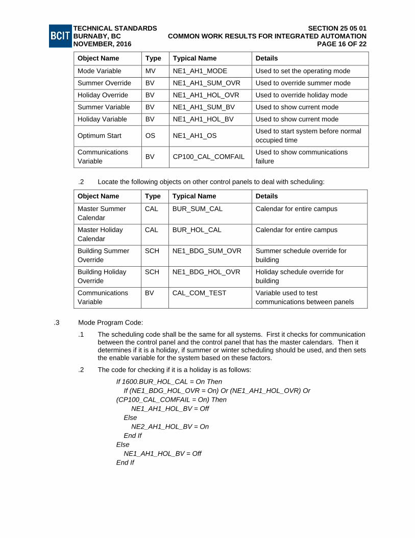
TECHNICAL STANDARDS SECTION 25 05 01 BURNABY, BC COMMON WORK RESULTS FOR INTEGRATED AUTOMATION NOVEMBER, 2016 PAGE 16 OF 22
Object Name Type Typical Name Details
Mode Variable MV NE1_AH1_MODE Used to set the operating mode
Summer Override BV NE1_AH1_SUM_OVR Used to override summer mode
Holiday Override BV NE1_AH1_HOL_OVR Used to override holiday mode
Summer Variable BV NE1_AH1_SUM_BV Used to show current mode
Holiday Variable BV NE1_AH1_HOL_BV Used to show current mode
Optimum Start OS NE1_AH1_OS Used to start system before normal occupied time
Communications Variable
BV CP100_CAL_COMFAIL Used to show communications failure
.2 Locate the following objects on other control panels to deal with scheduling:
Object Name Type Typical Name Details
Master Summer Calendar
CAL BUR_SUM_CAL Calendar for entire campus
Master Holiday Calendar
CAL BUR_HOL_CAL Calendar for entire campus
Building Summer Override
SCH NE1_BDG_SUM_OVR Summer schedule override for building
Building Holiday Override
SCH NE1_BDG_HOL_OVR Holiday schedule override for building
Communications Variable
BV CAL_COM_TEST Variable used to test communications between panels
.3 Mode Program Code:
.1 The scheduling code shall be the same for all systems. First it checks for communication between the control panel and the control panel that has the master calendars. Then it determines if it is a holiday, if summer or winter scheduling should be used, and then sets the enable variable for the system based on these factors.
.2 The code for checking if it is a holiday is as follows:
If 1600.BUR_HOL_CAL = On Then If (NE1_BDG_HOL_OVR = On) Or (NE1_AH1_HOL_OVR) Or (CP100_CAL_COMFAIL = On) Then NE1_AH1_HOL_BV = Off Else NE2_AH1_HOL_BV = On End If Else NE1_AH1_HOL_BV = Off End If

TECHNICAL STANDARDS SECTION 25 05 01 BURNABY, BC COMMON WORK RESULTS FOR INTEGRATED AUTOMATION NOVEMBER, 2016 PAGE 17 OF 22
.1 The NE1_AH1_HOL_BV variable is turned on only if the main campus holiday calendar is on. If the main campus calendar is off, or there is a communications failure, or a building override, or a system override turned on then the NE1_AH1_HOL_BV shall be off.
.3 The code for checking if it is a summer day is as follows:
If 1600.BUR_SUM_CAL = On Then If (NE1_BDG_SUM_OVR = On) Or (NE1_AH1_SUM_OVR) Or (CP100_CAL_COMFAIL = On) Then NE1_AH1_SUM_BV = Off Else NE2_AH1_SUM_BV = On End If Else NE1_AH1_SUM_BV = Off End If
.1 The NE1_AH1_SUM_BV variable is turned on only if the main campus summer
calendar is on. If the main campus calendar is off, or there is a communications failure, or a building override, or a system override turned on then the NE1_AH1_SUM_BV shall be off.
.4 The code for determining occupied and unoccupied periods is as follows:
If SE40_AHU1_HOL_OVR = Off Then If SE40_AHU1_SUM_BV = Off Then If SE40_AHU1_WS = On Then SE40_AHU1_MV = OCCUPIED Else SE40_AHU1_MV = UNOCCUPIED End If Else If SE40_AHU1_SUM_WS = On Then SE40_AHU1_MV = OCCUPIED Else SE40_AHU1_MV = UNOCCUPIED End If End If Else SE40_AHU1_MV = UNOCCUPIED End If
.1 If both the summer and holiday variables are off then the mode variable will be set
to “occupied” if the systems weekly schedule is on. If the summer variable is on then the mode variable will be set to “occupied” based on the summer schedule for the system. If the holiday variable is on then the mode variable shall be “unoccupied”.
.5 The code for determining night set-back periods is as follows:
//NSB MODE If (SE40_AHU1_MV = UNOCCUPIED) And (SE40_AHU1_LO_RT < SE40_AHU1_NSB_SP) Then

TECHNICAL STANDARDS SECTION 25 05 01 BURNABY, BC COMMON WORK RESULTS FOR INTEGRATED AUTOMATION NOVEMBER, 2016 PAGE 18 OF 22
SE40_AHU1_MV = NSB End If If (SE40_AHU1_MV = NSB) And (SE40_AHU1_LO_RT > SE40_AHU1_NSB_SP + 2) Then SE40_AHU1_MV = UNOCCUPIED End If
.1 “Night set-back” mode shall be enabled if the lowest zone room temperature falls
below the night set-back setpoint. The unit will then heat the space until the lowest zone room temperature is 2C higher than the night set-back setpoint and then the unit will go back to “unoccupied” mode.
.6 The code for determining optimum start periods is as follows:
//OS MODE If (SE40_AHU1_OS = On) Then SE40_AHU1_MV = OS End If
.1 The optimum start object turns on up to two hours before an occupied period and
the unit then heats the space to try and get it to the room temperature setpoint before the occupied period starts. The optimum start object will use past history and the outside air temperature to adjust when it comes on to start at the latest possible time to reach room temperature setpoint as the occupied period starts.
.7 The code for determining a freeze condition is as follows:
//FREEZE MODE If (SE40_AHU1_FZ = On) Then SE40_AHU1_MV = FREEZE End If
.1 The Freezestat detects a low temperature at the heating coil and will turn the unit
supply fan off, close the outside air damper, open the heating valve, open the return air damper (if applicable), run the return fan (if applicable), and run the heating coil pump (if applicable). This is all done using hardwire interlocks, but the software will also recognize a freeze condition and follow the hardwired control.
6.6 CONTROL PROGRAM
.1 Control Program Overview:
.1 The control program is used to control the mechanical system. It will command all dampers, valves, fans, pumps, and other control devices. Each control device shall be commanded in one area of the control program to make trouble shooting easier.
.2 Control Program Objects:
.1 Create the following objects in the control panel databases to deal with scheduling:
Object Name Type Typical Name Details
Weekly Schedule SCH NE1_AH1_WS Weekly schedule for system
Summer Schedule SCH NE1_AH1_SUM_WS Summer weekly schedule for system

TECHNICAL STANDARDS SECTION 25 05 01 BURNABY, BC COMMON WORK RESULTS FOR INTEGRATED AUTOMATION NOVEMBER, 2016 PAGE 19 OF 22
Object Name Type Typical Name Details
Mode Variable MV NE1_AH1_MODE Used to set the operating mode
Summer Override BV NE1_AH1_SUM_OVR Used to override summer mode
Holiday Override BV NE1_AH1_HOL_OVR Used to override holiday mode
Summer Variable BV NE1_AH1_SUM_BV Used to show current mode
Holiday Variable BV NE1_AH1_HOL_BV Used to show current mode
Optimum Start OS NE1_AH1_OS Used to start system before normal occupied time
Communications Variable
BV CP100_CAL_COMFAIL Used to show communications failure
.2 Locate the following objects on other control panels to deal with scheduling:
Object Name Type Typical Name Details
Master Summer Calendar
CAL BUR_SUM_CAL Calendar for entire campus
Master Holiday Calendar
.3 BUR_HOL_CAL Calendar for entire campus
Building Summer Override
SCH NE1_BDG_SUM_OVR Summer schedule override for building
Building Holiday Override
SCH NE1_BDG_HOL_OVR Holiday schedule override for building
Communications Variable
BV CAL_COM_TEST Variable used to test communications between panels
.4 Control Program Code:
.1 This part of the program controls the supply and return fans, determining when they should be on, and at what speeds the supply and return fans shall run at. It uses the mode that is set in the mode program to control the fans.
//AHU1 SUPPLY FAN CONTROL If (SE40_AHU1_MV = OCCUPIED) Or (SE40_AHU1_MV = OS) Or (SE40_AHU1_MV = NSB) Then SE40_AHU1_ENABLE = On AHU1_SF_SPD_AV = Min (SE40_AHU1_SF_RAMP, SE40_AHU1_SPD_CO) AHU1_SF_SPD_AV = Limit (AHU1_SF_SPD_AV, SE40_AHU1_SF_MIN_SPD, 100) Else SE40_AHU1_ENABLE = Off AHU1_SF_SPD_AV = 0 End If //AHU1 RETURN FAN CONTROL

TECHNICAL STANDARDS SECTION 25 05 01 BURNABY, BC COMMON WORK RESULTS FOR INTEGRATED AUTOMATION NOVEMBER, 2016 PAGE 20 OF 22
If (SE40_AHU1_MV = OCCUPIED) Or (SE40_AHU1_MV = OS) Or (SE40_AHU1_MV = NSB) Then AHU1_RF_SPD_AV = Min (SE40_AHU1_RF_RAMP, (AHU1_SF_SPD_AV * (SE40_AHU1_RF_PERCENT / 100))) Else AHU1_RF_SPD_AV = 0 End If
.2 This part of the program controls the free cooling. It checks to confirm that the supply fan
is running and then modulates the mixed air damper position between minimum position and 100% open to try and maintain the highest zone temperature at 21C. If the outside air is warmer than the return air, then there is no free cooling as it is warm outside, and the damper will go to minimum position.
//AHU1 FREE COOLING CONTROL If (SE40_AHU1_MV = OCCUPIED) Or (SE40_AHU1_MV = OS) Or (SE40_AHU1_MV = NSB) Then If SE40_AHU1_SFS_BV = On Then SE40_AHU1_MAD_AV = Scale (SE40_AHU1_HI_RT_CO, 0, 0, 100, 50, SE40_AHU1_MAD_MIN) If (SE42_OAT_AV + 1 > SE40_AHU1_RAT) Then SE40_AHU1_MAD_AV = SE40_AHU1_MAD_MIN End If Else SE40_AHU1_MAD_AV = 0 End If Else SE40_AHU1_MAD_AV = 0 End If
.3 This part of the program controls the lockouts for the mechanical cooling. It will not allow the unit to use mechanical cooling if the hottest room temperature is under 23C or if the outside air temperature is cold enough to provide the cooling required as free cooling.
//AHU1 MECHANICAL COOLING CONTROL If (SE40_AHU1_HI_RT < 23) Or (SE42_OAT_AV < 16) Then SE40_AHU1_DX_DISABLE1 = On Else SE40_AHU1_DX_DISABLE1 = Off End If
.4 This part of the program controls the supply air temperature. This code will vary depending on the unit being controlled. In the case below the unit has a built in controller that we are just giving a reset signal to. In this case we want to only adjust the supply air temperature reset signal every 15 minutes to give the built in controller time to adjust. If the air-handling unit had heating and cooling valves instead, we would modulate those to meet a supply air temperature setpoint.
//AHU1 SAT RESET CONTROL If (SE40_AHU1_MV = OCCUPIED) Or (SE40_AHU1_MV = OS) Or (SE40_AHU1_MV = NSB) Then DoEvery 15M

TECHNICAL STANDARDS SECTION 25 05 01 BURNABY, BC COMMON WORK RESULTS FOR INTEGRATED AUTOMATION NOVEMBER, 2016 PAGE 21 OF 22
If (SE40_AHU1_HI_RT > SE40_AHU1_RT_SP) OnFor 10M Then SE40_AHU1_RESET_AV = Limit ((SE40_AHU1_RESET_AV - 5), 0, 100) End If If (SE40_AHU1_HI_RT < SE40_AHU1_RT_SP) OnFor 10M Then SE40_AHU1_RESET_AV = Limit ((SE40_AHU1_RESET_AV + 5), 0, 100) End If End Do Else SE40_AHU1_RESET_AV = 50 End If
.5 This part of the program makes the unit follow the hardwired freeze sequence when a
freeze condition is detected.
//FREEZE CONTROL If SE40_AHU1_MV = FREEZE Then SE40_AHU1_ENABLE = On AHU1_SF_SPD_AV = 0 AHU1_RF_SPD_AV = 50 SE40_AHU1_MAD_AV = 0 SE40_AHU1_RESET_AV = 100 End If
.6 This part of the program assigns the variables used throughout the program to the outputs that they are controlling. Variables are required to be used for analog outputs to ensure that all calculations are correctly handled by the program. This is due to the way that the controllers execute the programming.
//ASSIGN VARIABLES TO OUTPUTS SE40_AHU1_SF_SPD = AHU1_SF_SPD_AV SE40_AHU1_RF_SPD = AHU1_RF_SPD_AV SE40_AHU1_MAD = SE40_AHU1_MAD_AV SE40_AHU1_RESET = SE40_AHU1_RESET_AV
BCIT HVAC NETWORK COMMUNICATION STANDARDS PART 7 - DELTA CONTROLLER DEFAULT COMMUNICATION SETTINGS
7.1 CONNECTION TYPE (MS/TP)
.1 All devices communicating on an MS/TP network should be communicating with the following settings.
.1 Baud Rate: 76.8kbs
.2 All controllers on a Subnet MS/TP connection should have DNA addressing
7.2 CONNECTION TYPE (UDP/IP)
.1 Configure devices that are communicating on the UDP/IP network with the following settings.
.1 The address (both Instance Number and IP information) shall ALWAYS be chosen and updated to the master WAN Excel sheet.

TECHNICAL STANDARDS SECTION 25 05 01 BURNABY, BC COMMON WORK RESULTS FOR INTEGRATED AUTOMATION NOVEMBER, 2016 PAGE 22 OF 22
.2 The Network numbers for any Subnet Devices off of a UDP/IP panel shall be configured using the last three digits of the IP address (eg. IP=10.0.32.18, MS/TP Net#= 20018 and 50018).
.3 The default Data Exchange Broadcast Interval (located in the DES object) shall be set to 300seconds (THIS MUST BE SET BEFORE CONNECTING ANY PANEL TO THE WAN).
.4 The default Broadcast Destination for DSC’s will be NET0, for DCU’s it will be NET40001 and the network number of any subnet networks connected to the UDP panel.
.5 Time Sync parameters shall only have entries for the network numbers of any subnet networks attached to the UDP panel.
.6 The UDP/IP Network number shall always be 40001.
7.3 CONNECTION TYPE (ETHERNET)
.1 This connection type will crash the network. DO NOT USE.
7.4 COMMON PROGRAMMING PRACTICE
.1 When programming, avoid writing programs that pass information from one subnet to another without first passing the information to the master UDP/IP panel associated with each subnet panels network.
.2 For example try not to pass 100101.AV1 to panel 100201.AV1 without first passing the variable to 100100.AV1 first then have 100100.AV1 pass to 100200.AV1 and then 100200.AV1 pass to 100201.AV1.
.3 This practice avoids communication issues with passing variables from one subnet to another.
PART 8 - THIRD PARTY BACNET DEVICES
8.1 THIRD PARTY DEVICES
.1 All third party devices should be BTL listed. This should be required as it means that the equipment has been tested to work correctly with other devices without causing communication issues.
.2 It is recommended that third party devices be MS/TP communications as this adds some separation from the UDP/IP communication.
8.2 CONNECTION TYPE (MS/TP)
.1 This connection type shall be capable of the following settings:
.1 Baud Rate: 76.8kbs.
.2 Bits: 8.
.3 Parity Bit: N.
.4 Stop Bit: 1.
8.3 CONNECTION TYPE (UDP/IP)
.1 This connection type shall be capable of the following settings:
.1 Configurable IP information.
.2 Configurable Instance number.
8.4 CONNECTION TYPE (ETHERNET)
.1 This connection type will crash the network. DO NOT USE.
END OF SECTION

TECHNICAL STANDARDS SECTION 25 08 00 BURNABY, BC COMMISSIONING OF INTEGRATED AUTOMATION NOVEMBER, 2016 PAGE 1 OF 10
This document contains standards that are the minimum requirements for BCIT construction projects. The information in the document is organized using the MasterFormat® and SectionFormat® systems. It is not a specification; it is intended to supplement the Consultant's own documents. Do not use this information as a standalone specification.
SECTION 25 08 00 COMMISSIONING OF INTEGRATED AUTOMATION
PART 1 - GENERAL
1.1 SUMMARY
.1 Standardize completion of temperature control systems installed by ESC Automation for British Columbia Institute of Technology.
.2 Commissioning procedures, temperature control system commissioning procedures, and general project completion requirements, with the intention of minimizing problems and deficiencies at project completion.
1.2 REQUIREMENTS
.1 Building Automation System (BAS) commissioning process provided by Controls Contractor, referred to as Functional Performance Test (FPT) and commissioning support provided by Contractor and third-party Commissioning Agent (CxA) for Integrated Automation and Control System.
.2 Functional Performance Testing:
.1 Controls Contractor shall provide a complete FPT to verify equipment is properly installed, connected, calibrated, programmed, tuned and operational, to be submitted to Consultant and BCIT for acceptance. This work includes development, submission, and execution of a testing plan. Testing results are to be documented and submitted for review by Consultant and BCIT’s Representative.
.3 Software Optimization Assistance:
.1 Contractor shall provide services of controls technician for 16 work-hours at project site at disposal of BCIT’s Representative. Contractor shall make changes, enhancements and additions to controller and workstation software previously identified by BCIT’s Representative during construction and commissioning phases of project and that are beyond specified Contract requirements. Provide service at no additional cost to BCIT. Requests for assistance shall be for contiguous or non-contiguous eight (8) hour days.
.2 Thoroughly train Controls technician in programming and operation of controller and BAS workstation software. Where controls technician cannot perform software tasks requested by BCIT’s Representative in a timely fashion, Contractor shall provide additional qualified personnel at project site as requested by BCIT’s Representative, to meet total combined requirement of project specific work-hours on-site.
.4 Graphic Scheduling:
.1 When I/O is ready to be created, enter the project needs into graphics request scheduler located at G:\Graphics\Graphics Request Sheet.xls, and locations where requested by BCIT. Schedule graphics to be complete for system verification time.
1.3 COMMISSIONING
.1 Commissioning phase of a project typically consists of four parts:
.1 Graphics verification.
.2 Point tag and commissioning sheet generation.
.3 I/O end to end checks.

TECHNICAL STANDARDS SECTION 25 08 00 BURNABY, BC COMMISSIONING OF INTEGRATED AUTOMATION NOVEMBER, 2016 PAGE 2 OF 10
.4 System verification/loop tuning.
.2 DDC System Commissioning:
.1 Hands-On Commissioning of controls systems shall be handled by ESC Service Representative, under direction of BCIT’s Commissioning Agent, where one is appointed on the project.
.2 ESC Service representative shall confirm that points and panels are installed and operational in accordance with Specifications.
.3 ESC Service Representative shall confirm graphic links to points operate in accordance with Specification.
.4 Commissioning Report shall be completed for BCIT and ESC’s records.
.5 Note and correct deficiencies on Report. Itemize and report on corrective actions. Respond to small projects or system upgrades the same way as new construction projects.
.6 ESC Service Representative shall act on behalf of BCIT and Controls System Commissioning person. This shall ensure BCIT Standards are met and follow-up for warranty or deficiencies are met in a timely manner. ESC projects are routinely handed over to ESC service for warranty and warranty maintenance.
.7 ESC recommends commissioning program is ongoing to ensure system operation, ensures energy programs perform as intended, reduces comfort complaints, reduces pressure on Operations Staff, and develops predictive budgeting.
.8 In all service areas, the goal is to:
.1 Incorporate superior quality assurance into all aspects of work.
.2 Represent the BCIT’s best long-term facility interests.
.3 Improve facility operations and energy efficiency.
.4 Maximize the value on the BCIT’s investment.
.5 Be professional, fair and respectful.
.3 Third-Party Commissioning:
.1 Controls Contractor shall provide support to CxA to verify proper installation, connection, calibration, programming, and operation of system. Work includes demonstration of equipment and testing operation of system. Include an allowance of 0.15 hours per point as identified on BAS point schedule.
PART 2 - PRODUCTS
2.1 MATERIALS AND TOOLS
.1 Provide proprietary software, hardware, cables, or other devices required by CxA to perform testing and validation. Loan such materials to CxA for their use in the performance of their work on this project and return to Controls Contractor in good condition. Damage to materials shall be chargeable to CxA at the same cost as if provided to BCIT, including any discounts or rebates.
PART 3 - EXECUTION
3.1 FUNCTIONAL PERFORMANCE TEST PLAN
.1 Submit complete test plan for review by Consultant and BCIT’s Representative. Test plan shall address the following minimum requirements:

TECHNICAL STANDARDS SECTION 25 08 00 BURNABY, BC COMMISSIONING OF INTEGRATED AUTOMATION NOVEMBER, 2016 PAGE 3 OF 10
.1 Proper installation of equipment and control panels, including locations and identifications.
.2 Proper installation and performance of raceways, wiring, cabling, and tubing.
.3 Proper labeling and tagging of wiring, cabling, tubing, equipment, control panels, and terminal strips.
.4 Proper setup and calibration of equipment.
.5 Point-to-point checkout to verify operation of control devices.
.6 Tuning of control loops (PID).
.7 Communication tests to verify proper operation of networks and remote access.
.8 Testing and verification of features, such as schedules, alarms, trends, etc.
.9 Testing and verification of control programs and sequences of operation.
.10 Verification of BAS resource utilization.
.11 Verification of preliminary copy of as-built drawings.
.2 Coordinate testing with other trades as required.
.3 Document each test result with date test performed and initials of the tester.
.4 Correct and re-test until testing is satisfactorily completed and re-record date and initials.
.5 Submit final test reports to Consultant and BCIT’s Representative.
3.2 CONTROL SYSTEM COMMISSIONING
.1 The following description of control system commissioning relates to BCIT projects by ESC.
.1 Ensure Technicians on site are thorough in their end to end verifications.
.2 Ensure items and tools required to perform proper end to end checks are on site, including: amp meter, check sheets, tags, calibration tools, magnahelic gauge and others.
.3 Technicians shall record motor amperages, flow rates, pressure and temperatures on check sheets and keep check sheet documentation up to date and accurate.
.2 Ensure ESC Technicians are on site to perform all end- to-end verifications before arrival of Application Engineer.
.1 Service Technician shall confirm date and time for startup of mechanical systems where Application Engineer is involved with end to end process.
.2 Application Engineer shall have all end-to-end check sheets, point tags, input and output points created in software and programs and ready to install on site the day of the verifications.
.3 Electrician shall ensure power requirements are complete, panels installed and terminated and devices associated with the equipment completely wired.
.4 Final verification to be audited by selected ESC Service Technicians.
.3 End to End Check Sheets:
.1 End to end check sheets shall be used for BCIT control systems commissioning on every project. The following checks shall be documented on end-to-end sheets:
.1 Wiring of the device is complete.
.2 Point tags installed.

TECHNICAL STANDARDS SECTION 25 08 00 BURNABY, BC COMMISSIONING OF INTEGRATED AUTOMATION NOVEMBER, 2016 PAGE 4 OF 10
.3 Point end to end checks verified.
.4 All points calibrated.
.5 Proper scale ranges entered.
.6 Motor amperages noted.
.7 Alarm (event) points confirmed.
.8 Program verifications complete.
.9 Graphic points confirmed.
.2 Ensure all end-to-end sheets are completed, including every point on the system. Application Engineer shall confirm that proper scale range is installed in software and calibration completed for sensors.
.3 End to end check sheets shall document that point tags are installed and checked off for every single point. If point is not tagged or end-to-ended, ensure description of incompletion is written beside the point on commissioning sheet and/or consolidated on Project Deficiency List.
.4 Record all motor amperages on end to end check sheets to ensure high and low scale ranges are correct when the events (alarms) are created. Where multiple wraps around the current sensor are required, ensure scale ranges are adjusted accordingly. Use clamp style amp meter to verify actual motor current.
.5 Document event (alarm) point, program and graphic point verification on end to end check sheets. This shall confirm that every event, program and graphic point in the system is looked into individually, as these items can be missed. ESC service shall complete audit of end to end checks for verification and sign over for BCIT and ESC records.
3.3 THIRD PARTY COMMISSIONING
.1 Review and comment on CxA’s test plan.
.2 Coordinate scheduling of required support with CxA.
.3 Provide access to the work for CxA. This may include, but is not limited to furnishing ladders, lifts or other means to safely access control equipment and devices, removal and reinstallation of ceiling tiles, and other work.
.4 Provide qualified personnel to assist CxA in system testing, and may include the services of a programmer to explain programming.
.5 Assist CxA in identifying solutions for issues uncovered. CxA shall propose required changes to the design for review by Consultant and BCIT’s Representative.
.6 BCIT Facilities Office shall have option to witness, with Contractor present, performance of points validated in commissioning and verification checklists. Contractor shall demonstrate completion of the calibration and function ability of components of system. Undertake a full demonstration of points in primary systems (CHW, HW, Air Handlers), and 10% of secondary systems (VAVs, Fan Coils, Monitoring, etc.).
3.4 TREND LOGS
.1 Prepare controller and workstation software to display graphical format trend logs during Pre-Commissioning period. Refer the specific Contract Drawings for individual trend log matrix BAS point requirements. Set up trend logs to meet the following minimum sample requirements:
.1 Trend logs shall include all analog and digital input values, analog and digital output values, and set points which are on a reset schedule.

TECHNICAL STANDARDS SECTION 25 08 00 BURNABY, BC COMMISSIONING OF INTEGRATED AUTOMATION NOVEMBER, 2016 PAGE 5 OF 10
.2 Label and distinguish lines from each other by using different line types, or different line colors.
.3 Indicate engineering units of the y-axis values; e.g. degrees Fahrenheit, inches w.g., Btu/lb, percent wide open, etc.
.4 Choose the y-axis scale to ensure that all trended values are in a readable range. Do not mix trended values on one graph if their unit ranges are incompatible.
.5 Trend outside air temperature, humidity, and enthalpy during each period in which any other points are trended.
.6 All points trended for one HVAC subsystem (e.g. air handling unit, chilled water system, etc.) shall be trended during the same trend period.
.7 Clearly label each graph with HVAC subsystem title, location, date, and times.
.2 A complete set of trend logs shall consist of all required points, trended for the time period listed for each point category. Record point values based on the change-of-value (COV) differentials listed. Where BAS does not have the capability to trend based on COV, point values shall be trended based on time intervals as specified in trend log matrix specified on each Contract Drawing.
3.5 EXAMINATION AND VERIFICATION
.1 Point tag and commissioning check sheet verification:
.1 Prior to starting programming or generating point tags and commissioning check sheets, the project’s Field Installer shall verify whether control points have been moved, deleted, or added. Where there are changes to control points list, make changes in EngTool database to ensure all point descriptors and point numbers are correct.
.2 Print commissioning check sheets for the project from this database.
.3 Field Installer uses the commissioning check sheets as a checklist when performing end to end verifications. Field Installer shall mark off each box when point has been proven functional.
.4 Using EngTool, print out the point tags onto the waterproof/tear proof paper. These tags will be tie-rapped to appropriate device during end to end verifications by the Field Installer.
.5 Pass finished check sheets to the ESC service representative for auditing and verification of end-to-end checks.
3.6 FIELD QUALITY CONTROL
.1 Project Deficiency List: Create a consolidated Project Deficiency List during the commissioning process when the project is 90-95% complete, to include the following:
.1 Control points not yet installed (i.e. misc. sump pump alarm).
.2 Wiring deficiencies on points that have been installed (i.e. Freezestat wired incorrectly).
.3 Points which require completion by other contractors (i.e. Radiant panel not installed).
.4 Points which we are waiting for information from other contractors (i.e. chiller panel wiring).
.5 Points which are not tagged.
.6 Points where the end to end verification is not complete – and a reason why.
.7 Programming checks still to be completed (i.e. events, trends etc.).

TECHNICAL STANDARDS SECTION 25 08 00 BURNABY, BC COMMISSIONING OF INTEGRATED AUTOMATION NOVEMBER, 2016 PAGE 6 OF 10
.8 All other software and completion items listed on the General Project Completion Checklist at the back of this manual.
.2 Project deficiency lists minimize problems at job completion. The last 5-10% of project can take 15-30% of electrical time and up to 50% of programming and commissioning time when contractors are continually required to tidy up deficiencies. Project deficiency report completion shall be verified by ESC Service.
.3 Functional Performance Tests (FPT):
.1 Perform checks and tests in FPT checklists and complete checklists as required by the CxA.
.2 System Sequence Commissioning Checklists:
.1 Submit with point specific pre-commissioning checklists.
.2 Customize to prove, step-by-step, that performance of each system controlled by BAS and meets requirements of sequences described in the Contract Documents.
.3 Ensure there is a sequence checklist for each system involving the BAS.
.4 Schedule system testing for acceptance at minimum of two (2) weeks after filled-out pre-checklists have been submitted for acceptance by Consultant and BCIT’s Representative.
.5 Begin system testing when Final Balancing Report has been submitted and pre-checklists are accepted for use.
.6 Systems such as air handlers shall have their prerequisite systems (e.g., the chilled water system and the hot water system) accepted and functioning before their tests can commence.
.3 Operational Tests: When System Sequence Commissioning Checklists have been completed successfully, Contractor shall set up routines using BAS to automatically test and record performance of each system.
.1 Operational Tests shall prove that different temperature setpoints and changing pressure setpoints can be attained.
.2 Set up these tests utilizing software routines, and document with printouts of trend results.
.3 Show systems to activate and turn off under the proper circumstances (e.g., timeclock control, the need for chilled water).
.4 Use trends to validate the successful performance of on/off control.
.5 Observe two (2) operational tests: satisfactory recovery from a system-wide power outage and satisfactory performance during fire alarm conditions.
.6 Where emergency generator is utilized, prove satisfactory performance during power transfer.
.7 Operational tests are required for all systems.
.8 For systems with additional features (e.g., humidification), or tests similar to those above, Contractor shall develop and prove systems’ satisfactory performance.
.9 Submit tests with pre-commissioning forms and System Sequence Commissioning Checklists. Each test shall describe its intent, BAS points used to prove this intent, and method by which test shall be executed.
.10 Do not commence operational tests until reviewed and approved by Consultant and BCIT’s Representative.
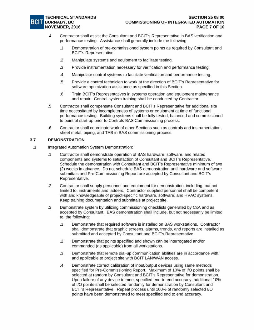
TECHNICAL STANDARDS SECTION 25 08 00 BURNABY, BC COMMISSIONING OF INTEGRATED AUTOMATION NOVEMBER, 2016 PAGE 7 OF 10
.4 Contractor shall assist the Consultant and BCIT’s Representative in BAS verification and performance testing. Assistance shall generally include the following:
.1 Demonstration of pre-commissioned system points as required by Consultant and BCIT’s Representative.
.2 Manipulate systems and equipment to facilitate testing.
.3 Provide instrumentation necessary for verification and performance testing.
.4 Manipulate control systems to facilitate verification and performance testing.
.5 Provide a control technician to work at the direction of BCIT’s Representative for software optimization assistance as specified in this Section.
.6 Train BCIT’s Representatives in systems operation and equipment maintenance and repair. Control system training shall be conducted by Contractor.
.5 Contractor shall compensate Consultant and BCIT’s Representative for additional site time necessitated by incompleteness of systems or equipment at time of functional performance testing. Building systems shall be fully tested, balanced and commissioned to point of start-up prior to Controls BAS Commissioning process.
.6 Contractor shall coordinate work of other Sections such as controls and instrumentation, sheet metal, piping, and TAB in BAS commissioning process.
3.7 DEMONSTRATION
.1 Integrated Automation System Demonstration:
.1 Contractor shall demonstrate operation of BAS hardware, software, and related components and systems to satisfaction of Consultant and BCIT’s Representative. Schedule the demonstration with Consultant and BCIT’s Representative minimum of two (2) weeks in advance. Do not schedule BAS demonstration until hardware and software submittals and Pre-Commissioning Report are accepted by Consultant and BCIT’s Representative.
.2 Contractor shall supply personnel and equipment for demonstration, including, but not limited to, instruments and ladders. Contractor supplied personnel shall be competent with and knowledgeable of project-specific hardware, software, and HVAC systems. Keep training documentation and submittals at project site.
.3 Demonstrate system by utilizing commissioning checklists generated by CxA and as accepted by Consultant. BAS demonstration shall include, but not necessarily be limited to, the following:
.1 Demonstrate that required software is installed on BAS workstations. Contractor shall demonstrate that graphic screens, alarms, trends, and reports are installed as submitted and accepted by Consultant and BCIT’s Representative.
.2 Demonstrate that points specified and shown can be interrogated and/or commanded (as applicable) from all workstations.
.3 Demonstrate that remote dial-up communication abilities are in accordance with, and applicable to project site with BCIT LAN/WAN access.
.4 Demonstrate correct calibration of input/output devices using same methods specified for Pre-Commissioning Report. Maximum of 10% of I/O points shall be selected at random by Consultant and BCIT’s Representative for demonstration. Upon failure of any device to meet specified end-to-end accuracy, additional 10% of I/O points shall be selected randomly for demonstration by Consultant and BCIT’s Representative. Repeat process until 100% of randomly selected I/O points have been demonstrated to meet specified end to end accuracy.

TECHNICAL STANDARDS SECTION 25 08 00 BURNABY, BC COMMISSIONING OF INTEGRATED AUTOMATION NOVEMBER, 2016 PAGE 8 OF 10
.5 Demonstrate and verify that BAS programs accomplish proper sequence of operations by using commissioning checklists included with these specifications to record results. Verify proper sequences of operation of specified functions whether or not listed in commissioning checklists.
.6 Demonstrate that controls panels automatically recover from power failures as.
.7 Demonstrate that stand-alone operation of controls panels meets requirements of Integrated Automation and Control. Contractor shall demonstrate that panels' response to LAN communication failures meets requirements of Integrated Automation and Control Specifications.
.8 Identify access to equipment selected by Consultant and BCIT’s Representative. Demonstrate that access is sufficient to perform required maintenance.
.9 Demonstrate that required trend graphs and trend logs are set up per Project Operational requirements. Provide sample of the data archive. Indicate file names and locations.
.4 Controls Contractor shall configure minimum of four (4) progress reports for Consultant and BCIT’s review and acceptance. These reports shall, at a minimum, be able to provide:
.1 Trend comparison data.
.2 Alarm status and prevalence information.
.3 Energy Consumption data.
.4 System user data.
3.8 CLOSEOUT ACTIVITIES
.1 Training of BCIT Facilities Operations Personnel:
.1 Contractor’s designated training personnel shall meet with BCIT’s Representative to discuss and fine-tune training agenda prior to first training session. Submit training agenda in writing to Consultant and BCIT’s Representative prior to beginning of on-site operator training. Training agenda shall reflect specific needs of on-site personnel to familiarize them with equipment and systems provided with project, and to allow them to operate it correctly. A sample training agenda is shown below:
.1 Day 1:
.1 Brief walk-through of building, including identification of controlled equipment and condensed demonstration of BAS controller local display capabilities.
.2 Brief overview of various parts of O&M manual, including hardware and software programming and operating publications, catalog data, controls installation drawings, and BAS programming documentation.
.3 Demonstration of workstation login/logout procedures, password setup, and exception reporting.
.4 Demonstration of workstation menu penetration and broad overview of various workstation features.
.5 Summary of day’s session.
.2 Day 2:
.1 Introduction to DDC panel programming.
.2 DDC programming examples and demonstrations.

TECHNICAL STANDARDS SECTION 25 08 00 BURNABY, BC COMMISSIONING OF INTEGRATED AUTOMATION NOVEMBER, 2016 PAGE 9 OF 10
.3 Summary of day’s session.
.3 Days 3, 4 & 5:
.1 Review sequence of operation, DDC panel programming, standalone modes, fail modes and graphic workstation screen for each HVAC subsystem.
.4 Day 6:
.1 Review of alarm features.
.2 Review of diagnostics features.
.3 Review of I/O hardware testing, calibration, and replacement.
.4 Summary of day’s session.
.5 Day 7:
.1 Review of trend feature.
.2 Review of workstation reports.
.3 Review of setpoint optimization and fine-tuning concepts.
.4 Summary of day’s session.
.6 Day 8:
.1 Review of all remaining miscellaneous workstation features.
.2 Question and answer period.
.3 Overall review of BAS system.
.2 Final Project Commissioning:
.1 System review: When programming and graphics are complete, prior to BCIT’s demonstration, tune and review the system. Observe the following points:
.1 What is the general feel of the graphics? Is there anything that should be changed from an end user perspective?
.2 On the floor plans graphics - Is there any area that is always hot or cold? Are all setpoint and temperatures correct and close to setpoint? Are the valves etc. for individual rooms operating correctly?
.3 On air handling unit graphics – Are the components (i.e. heating valve, dampers etc.) controlling for the correct setpoint. If an area is requiring heating, is the corresponding unit in heating mode?
.4 On heating or chilled water graphics – Is the heating system controlling for the correct setpoint? Are all correct pumps etc. running? Is the outdoor air temperature resetting the scheduled heating water setpoint?
.5 Can all systems associated with one another be linked together from the graphics?
.2 List areas of concern and reasons for problems, useful to ESC, the Commissioning Agent, Engineer, in determining corrections to the original design.
.3 The points questioned above are examples of issues in final commissioning phase. During commissioning on site, it is easy to lose focus on the project as a whole.
.4 Note: In most cases, the intent of controls system is to provide heating to rooms which need heat or cooling to rooms which need cooling. The “trap” in programming a project can be trying to incorporate complex program strategies, safeties, and software interlocks

TECHNICAL STANDARDS SECTION 25 08 00 BURNABY, BC COMMISSIONING OF INTEGRATED AUTOMATION NOVEMBER, 2016 PAGE 10 OF 10
etc. which can start to detract from the basic concept of providing heating or cooling where needed. Ensure correct specified designed sequence is followed.
.5 ESC service will ensure BCIT standards are followed.
END OF SECTION